Table of Contents
- Command Reference for AlliedWare Plus™ Version 5.4.9-2.x
- Contents
- List of Commands
- Part 1: Setup and Troubleshooting
- CLI Navigation Commands
- File and Configuration Management Commands
- Introduction
- autoboot enable
- boot config-file
- boot config-file backup
- boot system
- boot system backup
- cd
- copy (filename)
- copy current-software
- copy debug
- copy running-config
- copy startup-config
- copy zmodem
- create autoboot
- crypto verify
- delete
- delete debug
- delete stack-wide force
- dir
- dir stack-wide
- edit
- edit (filename)
- erase factory-default
- erase startup-config
- ip tftp source-interface
- ipv6 tftp source-interface
- mkdir
- move
- move debug
- pwd
- rmdir
- show autoboot
- show boot
- show file
- show file systems
- show running-config
- show running-config interface
- show startup-config
- show version
- unmount
- write file
- write memory
- write terminal
- User Access Commands
- Introduction
- aaa authentication enable default local
- aaa local authentication attempts lockout-time
- aaa local authentication attempts max-fail
- aaa login fail-delay
- clear aaa local user lockout
- clear line console
- clear line vty
- enable password
- enable secret
- exec-timeout
- flowcontrol hardware (asyn/console)
- length (asyn)
- line
- privilege level
- security-password history
- security-password forced-change
- security-password lifetime
- security-password min-lifetime-enforce
- security-password minimum-categories
- security-password minimum-length
- security-password reject-expired-pwd
- security-password warning
- service advanced-vty
- service password-encryption
- service telnet
- service terminal-length (deleted)
- show aaa local user locked
- show privilege
- show security-password configuration
- show security-password user
- show telnet
- show users
- telnet
- telnet server
- terminal length
- terminal resize
- username
- Feature Licensing Commands
- Subscription Licensing Commands
- GUI Commands
- System Configuration and Monitoring Commands
- Introduction
- banner exec
- banner login (system)
- banner motd
- clock set
- clock summer-time date
- clock summer-time recurring
- clock timezone
- continuous-reboot-prevention
- crypto secure-mode
- debug core-file
- ecofriendly led
- ecofriendly lpi
- findme
- findme trigger
- hostname
- max-fib-routes
- max-static-routes
- no debug all
- reboot
- reload
- show clock
- show continuous-reboot-prevention
- show cpu
- show cpu history
- show debugging
- show ecofriendly
- show interface memory
- show memory
- show memory allocations
- show memory history
- show memory pools
- show memory shared
- show process
- show reboot history
- show router-id
- show secure-mode
- show system
- show system environment
- show system interrupts
- show system mac
- show system pci device
- show system pci tree
- show system serialnumber
- show tech-support
- speed (asyn)
- system territory (deprecated)
- terminal monitor
- undebug all
- Pluggables and Cabling Commands
- Introduction
- clear fiber-monitoring interface
- clear test cable-diagnostics tdr
- debug fiber-monitoring
- fiber-monitoring action
- fiber-monitoring baseline
- fiber-monitoring enable
- fiber-monitoring interval
- fiber-monitoring sensitivity
- show system fiber-monitoring
- show system pluggable
- show system pluggable detail
- show system pluggable diagnostics
- show test cable-diagnostics tdr
- test cable-diagnostics tdr interface
- Connectivity Fault Management Commands
- Introduction
- cc interval
- cc multicast
- cc unicast
- clear (MEP Attribute)
- clear ethernet cfm errorlog
- clear mep counter
- ethernet cfm domain-name
- ethernet cfm mep
- mep (FNG attributes)
- mep active
- mep ccm-ltm-priority
- mep crosscheck
- service ma-name
- show ethernet cfm details
- show ethernet cfm domain
- show ethernet cfm errorlog
- show ethernet cfm maintenance-points local mep
- show ethernet cfm maintenance-points remote mep
- show ethernet cfm service
- show mep-alarm status
- Logging Commands
- Introduction
- clear exception log
- clear log
- clear log buffered
- clear log external
- clear log permanent
- copy buffered-log
- copy permanent-log
- default log buffered
- default log console
- default log email
- default log external
- default log host
- default log monitor
- default log permanent
- log buffered
- log buffered (filter)
- log buffered exclude
- log buffered size
- log console
- log console (filter)
- log console exclude
- log email
- log email (filter)
- log email exclude
- log email time
- log external
- log external (filter)
- log external exclude
- log external rotate
- log external size
- log facility
- log host
- log host (filter)
- log host exclude
- log host source
- log host startup-delay
- log host time
- log monitor (filter)
- log monitor exclude
- log permanent
- log permanent (filter)
- log permanent exclude
- log permanent size
- log-rate-limit nsm
- log trustpoint
- show counter log
- show exception log
- show log
- show log config
- show log external
- show log permanent
- show running-config log
- unmount
- Scripting Commands
- Interface Commands
- Port Mirroring and Remote Mirroring Commands
- Part 2: Interfaces and Layer 2
- Switching Commands
- Introduction
- backpressure
- clear loop-protection counters
- clear mac address-table dynamic
- clear mac address-table static
- clear port counter
- clear port counter stackports
- clear port-security intrusion
- debug loopprot
- debug platform packet
- duplex
- flowcontrol (switch port)
- linkflap action
- loop-protection loop-detect
- loop-protection action
- loop-protection action-delay-time
- loop-protection timeout
- mac address-table acquire
- mac address-table ageing-time
- mac address-table logging
- mac address-table static
- mac address-table thrash-limit
- platform acls-to-vlanclassifiers
- platform control-plane-prioritization rate
- platform hwfilter-size
- platform jumboframe
- platform l2mc-table mode
- platform l2mc-overlap
- platform load-balancing
- platform multicast-address-mismatch-action
- platform multicast-ratelimit
- platform routingratio
- platform sdn-route-ratio
- platform vlan-stacking-tpid
- polarity
- show debugging loopprot
- show debugging platform packet
- show flowcontrol interface
- show interface err-disabled
- show interface switchport
- show loop-protection
- show mac address-table
- show mac address-table thrash-limit
- show platform
- show platform classifier statistics utilization brief
- show platform port
- show port-security interface
- show port-security intrusion
- show storm-control
- speed
- storm-control level
- switchport port-security
- switchport port-security aging
- switchport port-security maximum
- switchport port-security violation
- thrash-limiting
- undebug loopprot
- undebug platform packet
- VLAN Commands
- Introduction
- clear vlan statistics
- debug private-vlan ufo
- port-vlan-forwarding-priority
- private-vlan
- private-vlan association
- platform acls-to-vlanclassifiers
- platform vlan-stacking-tpid
- private-vlan ufo trap
- show debugging private-vlan
- show port-vlan-forwarding-priority
- show interface switchport vlan translation
- show vlan
- show vlan access-map
- show vlan classifier group
- show vlan classifier group interface
- show vlan classifier interface group
- show vlan classifier rule
- show vlan filter
- show vlan private-vlan
- show vlan private-vlan ufo
- show vlan statistics
- switchport access vlan
- switchport enable vlan
- switchport mode access
- switchport mode private-vlan
- switchport mode private-vlan trunk promiscuous
- switchport mode private-vlan trunk secondary
- switchport mode private-vlan ufo
- switchport mode trunk
- switchport private-vlan host-association
- switchport private-vlan mapping
- switchport trunk allowed vlan
- switchport trunk native vlan
- switchport vlan translation
- switchport vlan translation default drop
- switchport vlan-stacking (double-tagging)
- switchport voice dscp
- switchport voice vlan
- switchport voice vlan priority
- vlan
- vlan access-map
- vlan classifier activate
- vlan classifier group
- vlan classifier rule ipv4
- vlan classifier rule proto
- vlan database
- vlan filter
- vlan mode stack-local-vlan
- vlan statistics
- Spanning Tree Commands
- Introduction
- clear spanning-tree statistics
- clear spanning-tree detected protocols (RSTP and MSTP)
- debug mstp (RSTP and STP)
- instance priority (MSTP)
- instance vlan (MSTP)
- region (MSTP)
- revision (MSTP)
- show debugging mstp
- show spanning-tree
- show spanning-tree brief
- show spanning-tree mst
- show spanning-tree mst config
- show spanning-tree mst detail
- show spanning-tree mst detail interface
- show spanning-tree mst instance
- show spanning-tree mst instance interface
- show spanning-tree mst interface
- show spanning-tree statistics
- show spanning-tree statistics instance
- show spanning-tree statistics instance interface
- show spanning-tree statistics interface
- show spanning-tree vlan range-index
- spanning-tree autoedge (RSTP and MSTP)
- spanning-tree bpdu
- spanning-tree cisco-interoperability (MSTP)
- spanning-tree edgeport (RSTP and MSTP)
- spanning-tree enable
- spanning-tree errdisable-timeout enable
- spanning-tree errdisable-timeout interval
- spanning-tree force-version
- spanning-tree forward-time
- spanning-tree guard root
- spanning-tree hello-time
- spanning-tree link-type
- spanning-tree max-age
- spanning-tree max-hops (MSTP)
- spanning-tree mode
- spanning-tree mst configuration
- spanning-tree mst instance
- spanning-tree mst instance path-cost
- spanning-tree mst instance priority
- spanning-tree mst instance restricted-role
- spanning-tree mst instance restricted-tcn
- spanning-tree path-cost
- spanning-tree portfast (STP)
- spanning-tree portfast bpdu-filter
- spanning-tree portfast bpdu-guard
- spanning-tree priority (bridge priority)
- spanning-tree priority (port priority)
- spanning-tree restricted-role
- spanning-tree restricted-tcn
- spanning-tree transmit-holdcount
- undebug mstp
- Unidirectional Link Detection (UDLD) Commands
- Link Aggregation Commands
- Introduction
- channel-group
- clear lacp counters
- debug lacp
- lacp global-passive-mode enable
- lacp port-priority
- lacp system-priority
- lacp timeout
- platform load-balancing
- show debugging lacp
- show diagnostic channel-group
- show etherchannel
- show etherchannel detail
- show etherchannel summary
- show lacp sys-id
- show lacp-counter
- show port etherchannel
- show static-channel-group
- static-channel-group
- undebug lacp
- Power over Ethernet Commands
- Introduction
- clear power-inline counters interface
- debug power-inline
- power-inline allow-legacy
- power-inline description
- power-inline enable
- power-inline hanp
- power-inline max
- power-inline priority
- power-inline usage-threshold
- service power-inline
- show debugging power-inline
- show power-inline
- show power-inline counters
- show power-inline interface
- show power-inline interface detail
- Switching Commands
- Part 3: Layer 3 Switching
- IP Addressing and Protocol Commands
- Introduction
- arp-aging-timeout
- arp-mac-disparity
- arp
- arp log
- arp opportunistic-nd
- arp-reply-bc-dmac
- clear arp-cache
- debug ip packet interface
- debug ip irdp
- ip address (IP Addressing and Protocol)
- ip directed-broadcast
- ip forward-protocol udp
- ip gratuitous-arp-link
- ip helper-address
- ip irdp
- ip irdp address preference
- ip irdp broadcast
- ip irdp holdtime
- ip irdp lifetime
- ip irdp maxadvertinterval
- ip irdp minadvertinterval
- ip irdp multicast
- ip irdp preference
- ip limited-local-proxy-arp
- ip local-proxy-arp
- ip proxy-arp
- ip redirects
- ip tcp synack-retries
- ip unreachables
- local-proxy-arp
- optimistic-nd
- ping
- platform multicast-address-mismatch-action
- router ip irdp
- show arp
- show debugging ip packet
- show ip flooding-nexthops
- show ip interface
- show ip irdp
- show ip irdp interface
- show ip sockets
- show ip traffic
- tcpdump
- traceroute
- undebug ip packet interface
- undebug ip irdp
- Domain Name Service (DNS) Commands
- Introduction
- clear ip dns forwarding cache
- debug ip dns forwarding
- ip dns forwarding
- ip dns forwarding cache
- ip dns forwarding dead-time
- ip dns forwarding retry
- ip dns forwarding source-interface
- ip dns forwarding timeout
- ip domain-list
- ip domain-lookup
- ip domain-name
- ip name-server
- ip name-server preferred-order
- show debugging ip dns forwarding
- show hosts
- show ip dns forwarding
- show ip dns forwarding cache
- show ip dns forwarding server
- show ip domain-list
- show ip domain-name
- show ip name-server
- IPv6 Commands
- Introduction
- clear ipv6 neighbors
- ipv6 address
- ipv6 address autoconfig
- ipv6 address suffix
- ipv6 enable
- ipv6 eui64-linklocal
- ipv6 forwarding
- ipv6 multicast forward-slow-path-packet
- ipv6 nd accept-ra-pinfo
- ipv6 nd current-hoplimit
- ipv6 nd managed-config-flag
- ipv6 nd minimum-ra-interval
- ipv6 nd other-config-flag
- ipv6 nd prefix
- ipv6 nd ra-interval
- ipv6 nd ra-lifetime
- ipv6 nd raguard
- ipv6 nd reachable-time
- ipv6 nd retransmission-time
- ipv6 nd suppress-ra
- ipv6 neighbor
- ipv6 opportunistic-nd
- ipv6 route
- ipv6 unreachables
- optimistic-nd
- ping ipv6
- show ipv6 forwarding
- show ipv6 interface brief
- show ipv6 neighbors
- show ipv6 route
- show ipv6 route summary
- traceroute ipv6
- Routing Commands
- RIP Commands
- Introduction
- accept-lifetime
- alliedware-behavior
- cisco-metric-behavior (RIP)
- clear ip rip route
- debug rip
- default-information originate (RIP)
- default-metric (RIP)
- distance (RIP)
- distribute-list (RIP)
- fullupdate (RIP)
- ip summary-address rip
- ip prefix-list
- ip rip authentication key-chain
- ip rip authentication mode
- ip rip authentication string
- ip rip receive-packet
- ip rip receive version
- ip rip send-packet
- ip rip send version
- ip rip send version 1-compatible
- ip rip split-horizon
- key
- key chain
- key-string
- maximum-prefix
- neighbor (RIP)
- network (RIP)
- offset-list (RIP)
- passive-interface (RIP)
- recv-buffer-size (RIP)
- redistribute (RIP)
- restart rip graceful
- rip restart grace-period
- route (RIP)
- router rip
- send-lifetime
- show debugging rip
- show ip prefix-list
- show ip protocols rip
- show ip rip
- show ip rip database
- show ip rip interface
- timers (RIP)
- undebug rip
- version (RIP)
- RIPng for IPv6 Commands
- Introduction
- aggregate-address (IPv6 RIPng)
- clear ipv6 rip route
- debug ipv6 rip
- default-information originate (IPv6 RIPng)
- default-metric (IPv6 RIPng)
- distribute-list (IPv6 RIPng)
- ipv6 prefix-list
- ipv6 rip metric-offset
- ipv6 rip split-horizon
- ipv6 router rip
- neighbor (IPv6 RIPng)
- offset-list (IPv6 RIPng)
- passive-interface (IPv6 RIPng)
- recv-buffer-size (IPv6 RIPng)
- redistribute (IPv6 RIPng)
- route (IPv6 RIPng)
- router ipv6 rip
- show debugging ipv6 rip
- show ipv6 prefix-list
- show ipv6 protocols rip
- show ipv6 rip
- show ipv6 rip database
- show ipv6 rip interface
- timers (IPv6 RIPng)
- undebug ipv6 rip
- OSPF Commands
- Introduction
- area default-cost
- area authentication
- area filter-list
- area nssa
- area range
- area stub
- area virtual-link
- auto-cost reference bandwidth
- bandwidth
- capability opaque
- capability restart
- clear ip ospf process
- compatible rfc1583
- debug ospf events
- debug ospf ifsm
- debug ospf lsa
- debug ospf nfsm
- debug ospf nsm
- debug ospf packet
- debug ospf route
- default-information originate
- default-metric (OSPF)
- distance (OSPF)
- distribute-list (OSPF)
- enable db-summary-opt
- host area
- ip ospf authentication
- ip ospf authentication-key
- ip ospf cost
- ip ospf database-filter
- ip ospf dead-interval
- ip ospf disable all
- ip ospf hello-interval
- ip ospf message-digest-key
- ip ospf mtu
- ip ospf mtu-ignore
- ip ospf network
- ip ospf priority
- ip ospf resync-timeout
- ip ospf retransmit-interval
- ip ospf transmit-delay
- max-concurrent-dd
- maximum-area
- neighbor (OSPF)
- network area
- ospf abr-type
- ospf restart grace-period
- ospf restart helper
- ospf router-id
- overflow database
- overflow database external
- passive-interface (OSPF)
- redistribute (OSPF)
- restart ospf graceful
- router ospf
- router-id
- show debugging ospf
- show ip ospf
- show ip ospf border-routers
- show ip ospf database
- show ip ospf database asbr-summary
- show ip ospf database external
- show ip ospf database network
- show ip ospf database nssa-external
- show ip ospf database opaque-area
- show ip ospf database opaque-as
- show ip ospf database opaque-link
- show ip ospf database router
- show ip ospf database summary
- show ip ospf interface
- show ip ospf neighbor
- show ip ospf route
- show ip ospf virtual-links
- show ip protocols ospf
- summary-address
- timers spf exp
- undebug ospf events
- undebug ospf ifsm
- undebug ospf lsa
- undebug ospf nfsm
- undebug ospf nsm
- undebug ospf packet
- undebug ospf route
- OSPFv3 for IPv6 Commands
- Introduction
- abr-type
- area authentication ipsec spi
- area default-cost (IPv6 OSPF)
- area encryption ipsec spi esp
- area range (IPv6 OSPF)
- area stub (IPv6 OSPF)
- area virtual-link (IPv6 OSPF)
- area virtual-link authentication ipsec spi
- area virtual-link encryption ipsec spi
- auto-cost reference bandwidth (IPv6 OSPF)
- bandwidth
- clear ipv6 ospf process
- debug ipv6 ospf events
- debug ipv6 ospf ifsm
- debug ipv6 ospf lsa
- debug ipv6 ospf nfsm
- debug ipv6 ospf packet
- debug ipv6 ospf route
- default-information originate
- default-metric (IPv6 OSPF)
- distance (IPv6 OSPF)
- distribute-list (IPv6 OSPF)
- ipv6 ospf authentication spi
- ipv6 ospf cost
- ipv6 ospf dead-interval
- ipv6 ospf display route single-line
- ipv6 ospf encryption spi esp
- ipv6 ospf hello-interval
- ipv6 ospf neighbor
- ipv6 ospf network
- ipv6 ospf priority
- ipv6 ospf retransmit-interval
- ipv6 ospf transmit-delay
- ipv6 router ospf area
- max-concurrent-dd (IPv6 OSPF)
- passive-interface (IPv6 OSPF)
- redistribute (IPv6 OSPF)
- restart ipv6 ospf graceful
- router ipv6 ospf
- router-id (IPv6 OSPF)
- show debugging ipv6 ospf
- show ipv6 ospf
- show ipv6 ospf database
- show ipv6 ospf database external
- show ipv6 ospf database grace
- show ipv6 ospf database inter-prefix
- show ipv6 ospf database inter-router
- show ipv6 ospf database intra-prefix
- show ipv6 ospf database link
- show ipv6 ospf database network
- show ipv6 ospf database router
- show ipv6 ospf interface
- show ipv6 ospf neighbor
- show ipv6 ospf route
- show ipv6 ospf virtual-links
- summary-address (IPv6 OSPF)
- timers spf (IPv6 OSPF) (deprecated)
- timers spf exp (IPv6 OSPF)
- undebug ipv6 ospf events
- undebug ipv6 ospf ifsm
- undebug ipv6 ospf lsa
- undebug ipv6 ospf nfsm
- undebug ipv6 ospf packet
- undebug ipv6 ospf route
- BGP and BGP4+ Commands
- Introduction
- address-family
- aggregate-address
- auto-summary (BGP only)
- bgp aggregate-nexthop-check
- bgp always-compare-med
- bgp bestpath as-path ignore
- bgp bestpath compare-confed-aspath
- bgp bestpath compare-routerid
- bgp bestpath med
- bgp bestpath med remove-recv-med
- bgp bestpath med remove-send-med
- bgp client-to-client reflection
- bgp cluster-id
- bgp confederation identifier
- bgp confederation peers
- bgp config-type
- bgp dampening
- bgp damp-peer-oscillation (BGP only)
- bgp default ipv4-unicast
- bgp default local-preference (BGP only)
- bgp deterministic-med
- bgp enforce-first-as
- bgp fast-external-failover
- bgp graceful-restart
- bgp graceful-restart graceful-reset
- bgp log-neighbor-changes
- bgp memory maxallocation
- bgp nexthop-trigger-count
- bgp nexthop-trigger delay
- bgp nexthop-trigger enable
- bgp rfc1771-path-select (BGP only)
- bgp rfc1771-strict (BGP only)
- bgp router-id
- bgp scan-time (BGP only)
- bgp update-delay
- clear bgp *
- clear bgp (IPv4 or IPv6 address)
- clear bgp (ASN)
- clear bgp external
- clear bgp peer-group
- clear bgp ipv6 (ipv6 address) (BGP4+ only)
- clear bgp ipv6 dampening (BGP4+ only)
- clear bgp ipv6 flap-statistics (BGP4+ only)
- clear bgp ipv6 (ASN) (BGP4+ only)
- clear bgp ipv6 external (BGP4+ only)
- clear bgp ipv6 peer-group (BGP4+ only)
- clear ip bgp * (BGP only)
- clear ip bgp (IPv4) (BGP only)
- clear ip bgp dampening (BGP only)
- clear ip bgp flap-statistics (BGP only)
- clear ip bgp (ASN) (BGP only)
- clear ip bgp external (BGP only)
- clear ip bgp peer-group (BGP only)
- clear ip prefix-list
- debug bgp (BGP only)
- distance (BGP and BGP4+)
- exit-address-family
- ip as-path access-list
- ip community-list
- ip community-list expanded
- ip community-list standard
- ip extcommunity-list expanded
- ip extcommunity-list standard
- ip prefix-list
- ipv6 prefix-list
- match as-path
- match community
- max-paths
- neighbor activate
- neighbor advertisement-interval
- neighbor allowas-in
- neighbor as-origination-interval
- neighbor attribute-unchanged
- neighbor capability graceful-restart
- neighbor capability orf prefix-list
- neighbor capability route-refresh
- neighbor collide-established
- neighbor default-originate
- neighbor description
- neighbor disallow-infinite-holdtime
- neighbor distribute-list
- neighbor dont-capability-negotiate
- neighbor ebgp-multihop
- neighbor enforce-multihop
- neighbor filter-list
- neighbor interface
- neighbor local-as
- neighbor maximum-prefix
- neighbor next-hop-self
- neighbor override-capability
- neighbor passive
- neighbor password
- neighbor peer-group (add a neighbor)
- neighbor peer-group (create a peer-group)
- neighbor port
- neighbor prefix-list
- neighbor remote-as
- neighbor remove-private-AS (BGP only)
- neighbor restart-time
- neighbor route-map
- neighbor route-reflector-client (BGP only)
- neighbor route-server-client (BGP only)
- neighbor send-community
- neighbor shutdown
- neighbor soft-reconfiguration inbound
- neighbor timers
- neighbor transparent-as
- neighbor transparent-nexthop
- neighbor unsuppress-map
- neighbor update-source
- neighbor version (BGP only)
- neighbor weight
- network (BGP and BGP4+)
- network synchronization
- redistribute (into BGP or BGP4+)
- restart bgp graceful (BGP only)
- router bgp
- route-map
- set as-path
- set community
- show bgp ipv6 (BGP4+ only)
- show bgp ipv6 community (BGP4+ only)
- show bgp ipv6 community-list (BGP4+ only)
- show bgp ipv6 dampening (BGP4+ only)
- show bgp ipv6 filter-list (BGP4+ only)
- show bgp ipv6 inconsistent-as (BGP4+ only)
- show bgp ipv6 longer-prefixes (BGP4+ only)
- show bgp ipv6 neighbors (BGP4+ only)
- show bgp ipv6 paths (BGP4+ only)
- show bgp ipv6 prefix-list (BGP4+ only)
- show bgp ipv6 quote-regexp (BGP4+ only)
- show bgp ipv6 regexp (BGP4+ only)
- show bgp ipv6 route-map (BGP4+ only)
- show bgp ipv6 summary (BGP4+ only)
- show bgp memory maxallocation (BGP only)
- show bgp nexthop-tracking (BGP only)
- show bgp nexthop-tree-details (BGP only)
- show debugging bgp (BGP only)
- show ip bgp (BGP only)
- show ip bgp attribute-info (BGP only)
- show ip bgp cidr-only (BGP only)
- show ip bgp community (BGP only)
- show ip bgp community-info (BGP only)
- show ip bgp community-list (BGP only)
- show ip bgp dampening (BGP only)
- show ip bgp filter-list (BGP only)
- show ip bgp inconsistent-as (BGP only)
- show ip bgp longer-prefixes (BGP only)
- show ip bgp neighbors (BGP only)
- show ip bgp neighbors connection-retrytime (BGP only)
- show ip bgp neighbors hold-time (BGP only)
- show ip bgp neighbors keepalive (BGP only)
- show ip bgp neighbors keepalive-interval (BGP only)
- show ip bgp neighbors notification (BGP only)
- show ip bgp neighbors open (BGP only)
- show ip bgp neighbors rcvd-msgs (BGP only)
- show ip bgp neighbors sent-msgs (BGP only)
- show ip bgp neighbors update (BGP only)
- show ip bgp paths (BGP only)
- show ip bgp prefix-list (BGP only)
- show ip bgp quote-regexp (BGP only)
- show ip bgp regexp (BGP only)
- show ip bgp route-map (BGP only)
- show ip bgp scan (BGP only)
- show ip bgp summary (BGP only)
- show ip community-list
- show ip extcommunity-list
- show ip prefix-list
- show ipv6 prefix-list
- show ip protocols bgp (BGP only)
- show route-map
- synchronization
- timers (BGP)
- undebug bgp (BGP only)
- Route Map Commands
- Introduction
- match as-path
- match community
- match interface
- match ip address
- match ip next-hop
- match ipv6 address
- match ipv6 next-hop
- match metric
- match origin
- match route-type
- match tag
- route-map
- set aggregator
- set as-path
- set atomic-aggregate
- set comm-list delete
- set community
- set dampening
- set extcommunity
- set ip next-hop (route map)
- set ipv6 next-hop
- set local-preference
- set metric
- set metric-type
- set origin
- set originator-id
- set tag
- set weight
- show route-map
- VRF-lite Commands
- Introduction
- address-family
- address-family ipv4 (RIP)
- arp
- arp opportunistic-nd
- clear arp-cache
- clear ip bgp * (BGP only)
- clear ip bgp (IPv4) (BGP only)
- clear ip rip route
- crypto key pubkey-chain knownhosts
- default-metric (RIP)
- description (VRF)
- distance (RIP)
- distribute-list (RIP)
- export map
- fullupdate (RIP)
- import map
- ip route static inter-vrf
- ip route
- ip vrf
- ip vrf forwarding
- max-fib-routes (VRF)
- max-static-routes (VRF)
- neighbor next-hop-self
- neighbor remote-as
- neighbor password
- network (RIP)
- passive-interface (RIP)
- ping
- rd (route distinguisher)
- redistribute (into BGP or BGP4+)
- redistribute (OSPF)
- redistribute (RIP)
- route (RIP)
- route-target
- router ospf
- router-id (VRF)
- show arp
- show crypto key pubkey-chain knownhosts
- show ip bgp cidr-only (BGP only)
- show ip bgp community (BGP only)
- show ip bgp community-list (BGP only)
- show ip bgp dampening (BGP only)
- show ip bgp filter-list (BGP only)
- show ip bgp inconsistent-as (BGP only)
- show ip bgp longer-prefixes (BGP only)
- show ip bgp prefix-list (BGP only)
- show ip bgp quote-regexp (BGP only)
- show ip bgp regexp (BGP only)
- show ip bgp route-map (BGP only)
- show ip bgp summary (BGP only)
- show ip interface vrf
- show ip rip vrf database
- show ip rip vrf interface
- show ip route
- show ip route database
- show ip route summary
- show ip vrf
- show ip vrf detail
- show ip vrf interface
- show running-config vrf
- ssh
- tcpdump
- telnet
- timers (RIP)
- traceroute
- version (RIP)
- IP Addressing and Protocol Commands
- Part 4: Multicast Applications
- IGMP and IGMP Snooping Commands
- Introduction
- clear ip igmp
- clear ip igmp group
- clear ip igmp interface
- debug igmp
- ip igmp
- ip igmp access-group
- ip igmp flood specific-query
- ip igmp immediate-leave
- ip igmp last-member-query-count
- ip igmp last-member-query-interval
- ip igmp limit
- ip igmp maximum-groups
- ip igmp mroute-proxy
- ip igmp proxy-service
- ip igmp querier-timeout
- ip igmp query-holdtime
- ip igmp query-interval
- ip igmp query-max-response-time
- ip igmp ra-option
- ip igmp robustness-variable
- ip igmp snooping
- ip igmp snooping fast-leave
- ip igmp snooping mrouter
- ip igmp snooping querier
- ip igmp snooping report-suppression
- ip igmp snooping routermode
- ip igmp snooping source-timeout
- ip igmp snooping tcn query solicit
- ip igmp source-address-check
- ip igmp ssm
- ip igmp ssm-map enable
- ip igmp ssm-map static
- ip igmp static-group
- ip igmp startup-query-count
- ip igmp startup-query-interval
- ip igmp trusted
- ip igmp version
- show debugging igmp
- show ip igmp groups
- show ip igmp interface
- show ip igmp proxy
- show ip igmp proxy groups
- show ip igmp snooping mrouter
- show ip igmp snooping routermode
- show ip igmp snooping source-timeout
- show ip igmp snooping statistics
- undebug igmp
- MLD and MLD Snooping Commands
- Introduction
- clear ipv6 mld
- clear ipv6 mld group
- clear ipv6 mld interface
- debug mld
- ipv6 mld
- ipv6 mld access-group
- ipv6 mld immediate-leave
- ipv6 mld last-member-query-count
- ipv6 mld last-member-query-interval
- ipv6 mld limit
- ipv6 mld querier-timeout
- ipv6 mld query-interval
- ipv6 mld query-max-response-time
- ipv6 mld robustness-variable
- ipv6 mld snooping
- ipv6 mld snooping fast-leave
- ipv6 mld snooping mrouter
- ipv6 mld snooping querier
- ipv6 mld snooping report-suppression
- ipv6 mld ssm-map enable
- ipv6 mld ssm-map static
- ipv6 mld static-group
- ipv6 mld version
- show debugging mld
- show ipv6 mld groups
- show ipv6 mld interface
- show ipv6 mld snooping mrouter
- show ipv6 mld snooping statistics
- Multicast Commands
- Introduction
- clear ip mroute
- clear ip mroute statistics
- clear ipv6 mroute
- clear ipv6 mroute statistics
- ipv6 multicast forward-slow-path-packet
- debug nsm
- debug nsm mcast
- debug nsm mcast6
- ip mroute
- ip multicast allow-register-fragments
- ip multicast forward-first-packet
- ip multicast route
- ip multicast route-limit
- ip multicast wrong-vif-suppression
- ip multicast-routing
- ipv6 mroute
- ipv6 multicast route
- ipv6 multicast route-limit
- ipv6 multicast-routing
- multicast
- platform multicast-ratelimit
- show debugging nsm mcast
- show ip mroute
- show ip mvif
- show ip rpf
- show ipv6 mroute
- show ipv6 multicast forwarding
- show ipv6 mif
- PIM-SM Commands
- Introduction
- clear ip pim sparse-mode bsr rp-set *
- clear ip pim sparse-mode packet statistics
- clear ip mroute pim sparse-mode
- debug pim sparse-mode
- debug pim sparse-mode timer
- ip multicast allow-register-fragments
- ip pim accept-register list
- ip pim anycast-rp
- ip pim bsr-border
- ip pim bsr-candidate
- ip pim cisco-register-checksum
- ip pim cisco-register-checksum group-list
- ip pim crp-cisco-prefix
- ip pim dr-priority
- ip pim exclude-genid
- ip pim ext-srcs-directly-connected
- ip pim hello-holdtime (PIM-SM)
- ip pim hello-interval (PIM-SM)
- ip pim ignore-rp-set-priority
- ip pim jp-timer
- ip pim neighbor-filter (PIM-SM)
- ip pim register-rate-limit
- ip pim register-rp-reachability
- ip pim register-source
- ip pim register-suppression
- ip pim rp-address
- ip pim rp-candidate
- ip pim rp-register-kat
- ip pim sparse-mode
- ip pim sparse-mode join-prune-batching
- ip pim sparse-mode passive
- ip pim sparse-mode wrong-vif-suppression
- ip pim spt-threshold
- ip pim spt-threshold group-list
- ip pim ssm
- show debugging pim sparse-mode
- show ip pim sparse-mode bsr-router
- show ip pim sparse-mode interface
- show ip pim sparse-mode interface detail
- show ip pim sparse-mode local-members
- show ip pim sparse-mode mroute
- show ip pim sparse-mode mroute detail
- show ip pim sparse-mode neighbor
- show ip pim sparse-mode nexthop
- show ip pim sparse-mode packet statistics
- show ip pim sparse-mode rp-hash
- show ip pim sparse-mode rp mapping
- undebug all pim sparse-mode
- PIM-SMv6 Commands
- Introduction
- clear ipv6 mroute pim
- clear ipv6 mroute pim sparse-mode
- clear ipv6 pim sparse-mode bsr rp-set *
- debug ipv6 pim sparse-mode
- debug ipv6 pim sparse-mode packet
- debug ipv6 pim sparse-mode timer
- ipv6 pim accept-register
- ipv6 pim anycast-rp
- ipv6 pim bsr-border
- ipv6 pim bsr-candidate
- ipv6 pim cisco-register-checksum
- ipv6 pim cisco-register-checksum group-list
- ipv6 pim crp-cisco-prefix
- ipv6 pim dr-priority
- ipv6 pim exclude-genid
- ipv6 pim ext-srcs-directly-connected
- ipv6 pim hello-holdtime
- ipv6 pim hello-interval
- ipv6 pim ignore-rp-set-priority
- ipv6 pim jp-timer
- ipv6 pim neighbor-filter
- ipv6 pim register-rate-limit
- ipv6 pim register-rp-reachability
- ipv6 pim register-source
- ipv6 pim register-suppression
- ipv6 pim rp-address
- ipv6 pim rp-candidate
- ipv6 pim rp embedded
- ipv6 pim rp-register-kat
- ipv6 pim sparse-mode
- ipv6 pim sparse-mode passive
- ipv6 pim spt-threshold
- ipv6 pim spt-threshold group-list
- ipv6 pim ssm
- ipv6 pim unicast-bsm
- show debugging ipv6 pim sparse-mode
- show ipv6 pim sparse-mode bsr-router
- show ipv6 pim sparse-mode interface
- show ipv6 pim sparse-mode interface detail
- show ipv6 pim sparse-mode local-members
- show ipv6 pim sparse-mode mroute
- show ipv6 pim sparse-mode mroute detail
- show ipv6 pim sparse-mode neighbor
- show ipv6 pim sparse-mode nexthop
- show ipv6 pim sparse-mode rp-hash
- show ipv6 pim sparse-mode rp mapping
- show ipv6 pim sparse-mode rp nexthop
- undebug all ipv6 pim sparse-mode
- undebug ipv6 pim sparse-mode
- PIM-DM Commands
- Introduction
- debug pim dense-mode all
- debug pim dense-mode context
- debug pim dense-mode decode
- debug pim dense-mode encode
- debug pim dense-mode fsm
- debug pim dense-mode mrt
- debug pim dense-mode nexthop
- debug pim dense-mode nsm
- debug pim dense-mode vif
- ip pim dense-mode
- ip pim dense-mode passive
- ip pim dense-mode wrong-vif-suppression
- ip pim ext-srcs-directly-connected
- ip pim hello-holdtime (PIM-DM)
- ip pim hello-interval (PIM-DM)
- ip pim max-graft-retries
- ip pim neighbor-filter (PIM-DM)
- ip pim propagation-delay
- ip pim state-refresh origination-interval
- show debugging pim dense-mode
- show ip pim dense-mode interface
- show ip pim dense-mode interface detail
- show ip pim dense-mode mroute
- show ip pim dense-mode neighbor
- show ip pim dense-mode neighbor detail
- show ip pim dense-mode nexthop
- undebug all pim dense-mode
- IGMP and IGMP Snooping Commands
- Part 5: Access and Security
- IPv4 Hardware Access Control List (ACL) Commands
- Introduction
- access-group
- access-list (numbered hardware ACL for ICMP)
- access-list (numbered hardware ACL for IP packets)
- access-list (numbered hardware ACL for IP protocols)
- access-list (numbered hardware ACL for MAC addresses)
- access-list (numbered hardware ACL for TCP or UDP)
- access-list hardware (named hardware ACL)
- (named hardware ACL entry for ICMP)
- (named hardware ACL entry for IP packets)
- (named hardware ACL entry for IP protocols)
- (named hardware ACL entry for MAC addresses)
- (named hardware ACL entry for TCP or UDP)
- commit (IPv4)
- platform acls-to-vlanclassifiers
- show access-group
- show access-list (IPv4 Hardware ACLs)
- show interface access-group
- IPv4 Software Access Control List (ACL) Commands
- Introduction
- access-list extended (named)
- access-list (extended numbered)
- (access-list extended ICMP filter)
- (access-list extended IP filter)
- (access-list extended IP protocol filter)
- (access-list extended TCP UDP filter)
- access-list standard (named)
- access-list (standard numbered)
- (access-list standard named filter)
- (access-list standard numbered filter)
- clear ip prefix-list
- dos
- ip prefix-list
- maximum-access-list
- show access-list (IPv4 Software ACLs)
- show dos interface
- show ip access-list
- show ip prefix-list
- vty access-class (numbered)
- IPv6 Hardware Access Control List (ACL) Commands
- Introduction
- commit (IPv6)
- ipv6 access-list (named IPv6 hardware ACL)
- (named IPv6 hardware ACL: ICMP entry)
- (named IPv6 hardware ACL: IPv6 packet entry)
- (named IPv6 hardware ACL: IP protocol entry)
- (named IPv6 hardware ACL: TCP or UDP entry)
- ipv6 traffic-filter
- platform acls-to-vlanclassifiers
- show ipv6 access-list (IPv6 Hardware ACLs)
- IPv6 Software Access Control List (ACL) Commands
- Introduction
- ipv6 access-list extended (named)
- ipv6 access-list extended proto
- (ipv6 access-list extended IP protocol filter)
- (ipv6 access-list extended TCP UDP filter)
- ipv6 access-list standard (named)
- (ipv6 access-list standard filter)
- ipv6 prefix-list
- show ipv6 access-list (IPv6 Software ACLs)
- show ipv6 prefix-list
- vty ipv6 access-class (named)
- QoS and Policy-based Routing Commands
- Introduction
- class
- class-map
- clear mls qos interface policer-counters
- default-action
- description (QoS policy-map)
- egress-rate-limit
- egress-rate-limit overhead
- match access-group
- match cos
- match dscp
- match eth-format protocol
- match inner-cos
- match inner-tpid
- match inner-vlan
- match ip-precedence
- match mac-type
- match tcp-flags
- match tpid
- match vlan
- mls qos aggregate-police action
- mls qos aggregate-police counters
- mls qos cos
- mls qos enable
- mls qos map cos-queue
- mls qos map premark-dscp
- mls qos queue
- mls qos scheduler-set
- mls qos scheduler-set priority-queue
- mls qos scheduler-set wrr-queue group
- no police
- police-aggregate
- police counters
- police single-rate action
- police twin-rate action
- policy-map
- service-policy input
- set bandwidth-class
- set cos
- set dscp
- set ip next-hop (PBR)
- set queue
- show class-map
- show mls qos
- show mls qos aggregate-policer
- show mls qos interface
- show mls qos interface policer-counters
- show mls qos interface queue-counters
- show mls qos interface storm-status
- show mls qos maps cos-queue
- show mls qos maps premark-dscp
- show mls qos scheduler-set
- show platform classifier statistics utilization brief
- show policy-map
- storm-action
- storm-downtime
- storm-protection
- storm-rate
- storm-window
- strict-priority-queue queue-limit
- trust dscp
- wrr-queue disable queues
- wrr-queue egress-rate-limit queues
- wrr-queue queue-limit
- 802.1X Commands
- Introduction
- dot1x accounting
- dot1x authentication
- debug dot1x
- dot1x control-direction
- dot1x eap
- dot1x eapol-version
- dot1x initialize interface
- dot1x initialize supplicant
- dot1x keytransmit
- dot1x max-auth-fail
- dot1x max-reauth-req
- dot1x port-control
- dot1x timeout tx-period
- show debugging dot1x
- show dot1x
- show dot1x diagnostics
- show dot1x interface
- show dot1x sessionstatistics
- show dot1x statistics interface
- show dot1x supplicant
- show dot1x supplicant interface
- undebug dot1x
- Authentication Commands
- Introduction
- auth auth-fail vlan
- auth critical
- auth dhcp-framed-ip-lease
- auth dynamic-vlan-creation
- auth guest-vlan
- auth guest-vlan forward
- auth host-mode
- auth log
- auth max-supplicant
- auth multi-vlan-session
- auth profile (global)
- auth profile (interface)
- auth reauthentication
- auth roaming disconnected
- auth roaming enable
- auth supplicant-ip
- auth supplicant-mac
- auth timeout connect-timeout
- auth timeout quiet-period
- auth timeout reauth-period
- auth timeout server-timeout
- auth timeout supp-timeout
- auth two-step enable
- auth-mac accounting
- auth-mac authentication
- auth-mac enable
- auth-mac method
- auth-mac password
- auth-mac reauth-relearning
- auth-mac static
- auth-mac username
- auth-web accounting
- auth-web authentication
- auth-web enable
- auth-web forward
- auth-web max-auth-fail
- auth-web method
- auth-web-server blocking-mode
- auth-web-server dhcp ipaddress
- auth-web-server dhcp lease
- auth-web-server dhcp-wpad-option
- auth-web-server host-name
- auth-web-server intercept-port
- auth-web-server ipaddress
- auth-web-server page language
- auth-web-server login-url
- auth-web-server page logo
- auth-web-server page sub-title
- auth-web-server page success-message
- auth-web-server page title
- auth-web-server page welcome-message
- auth-web-server ping-poll enable
- auth-web-server ping-poll failcount
- auth-web-server ping-poll interval
- auth-web-server ping-poll reauth-timer-refresh
- auth-web-server ping-poll timeout
- auth-web-server port
- auth-web-server redirect-delay-time
- auth-web-server redirect-url
- auth-web-server session-keep
- auth-web-server ssl
- auth-web-server ssl intercept-port
- copy proxy-autoconfig-file
- copy web-auth-https-file
- description (auth-profile)
- erase proxy-autoconfig-file
- erase web-auth-https-file
- show auth
- show auth diagnostics
- show auth interface
- show auth sessionstatistics
- show auth statistics interface
- show auth supplicant
- show auth supplicant interface
- show auth two-step supplicant brief
- show auth-web-server
- show auth-web-server page
- show proxy-autoconfig-file
- AAA Commands
- Introduction
- aaa accounting auth-mac
- aaa accounting auth-web
- aaa accounting commands
- aaa accounting dot1x
- aaa accounting login
- aaa accounting update
- aaa authentication auth-mac
- aaa authentication auth-web
- aaa authentication dot1x
- aaa authentication enable default group tacacs+
- aaa authentication enable default local
- aaa authentication login
- aaa authorization commands
- aaa authorization config-commands
- aaa group server
- aaa local authentication attempts lockout-time
- aaa local authentication attempts max-fail
- aaa login fail-delay
- accounting login
- authorization commands
- clear aaa local user lockout
- debug aaa
- login authentication
- proxy-port
- radius-secure-proxy aaa
- server (radsecproxy-aaa)
- server mutual-authentication
- server name-check
- server trustpoint
- show aaa local user locked
- show aaa server group
- show debugging aaa
- show radius server group
- undebug aaa
- RADIUS Commands
- Introduction
- auth radius send nas-identifier
- auth radius send service-type
- deadtime (RADIUS server group)
- debug radius
- group (radproxy)
- help radius-attribute
- ip radius source-interface
- nas (radproxy)
- proxy (radproxy)
- proxy enable
- radius-server deadtime
- radius-server host
- radius-server key
- radius-server proxy-server
- radius-server retransmit
- radius-server timeout
- rule attribute (radproxy)
- rule realm (radproxy)
- server (radproxy-group)
- server (radproxy)
- server deadtime (radproxy)
- server (server group)
- server timeout (radproxy)
- show debugging radius
- show radius
- show radius proxy-server
- show radius proxy-server group
- show radius proxy-server statistics
- show radius statistics
- source-interface (radproxy)
- undebug radius
- Local RADIUS Server Commands
- Introduction
- attribute
- authentication
- client (radsecproxy-srv)
- client mutual-authentication
- client name-check
- client trustpoint
- clear radius local-server statistics
- copy fdb-radius-users (to file)
- copy local-radius-user-db (from file)
- copy local-radius-user-db (to file)
- crypto pki enroll local (deleted)
- crypto pki enroll local local-radius-all-users (deleted)
- crypto pki enroll local user (deleted)
- crypto pki export local pem (deleted)
- crypto pki export local pkcs12 (deleted)
- crypto pki trustpoint local (deleted)
- debug crypto pki (deleted)
- domain-style
- egress-vlan-id
- egress-vlan-name
- group
- nas
- radius-secure-proxy local-server
- radius-server local
- server auth-port
- server enable
- show radius local-server group
- show radius local-server nas
- show radius local-server statistics
- show radius local-server user
- user (RADIUS server)
- vlan (RADIUS server)
- Public Key Infrastructure Commands
- Introduction
- crypto key generate rsa
- crypto key zeroize
- crypto pki authenticate
- crypto pki enroll
- crypto pki enroll user
- crypto pki export pem
- crypto pki export pkcs12
- crypto pki import pem
- crypto pki import pkcs12
- crypto pki trustpoint
- crypto secure-mode
- crypto verify
- enrollment (ca-trustpoint)
- fingerprint (ca-trustpoint)
- no crypto pki certificate
- rsakeypair (ca-trustpoint)
- show crypto key mypubkey rsa
- show crypto pki certificates
- show crypto pki enrollment user
- show crypto pki trustpoint
- show secure-mode
- subject-name (ca-trustpoint)
- TACACS+ Commands
- DHCP Snooping Commands
- Introduction
- arp security
- arp security drop link-local-arps
- arp security violation
- clear arp security statistics
- clear ip dhcp snooping binding
- clear ip dhcp snooping statistics
- debug arp security
- debug ip dhcp snooping
- ip dhcp snooping
- ip dhcp snooping agent-option
- ip dhcp snooping agent-option allow-untrusted
- ip dhcp snooping agent-option circuit-id vlantriplet
- ip dhcp snooping agent-option remote-id
- ip dhcp snooping binding
- ip dhcp snooping database
- ip dhcp snooping delete-by-client
- ip dhcp snooping delete-by-linkdown
- ip dhcp snooping max-bindings
- ip dhcp snooping subscriber-id
- ip dhcp snooping trust
- ip dhcp snooping verify mac-address
- ip dhcp snooping violation
- ip source binding
- service dhcp-snooping
- show arp security
- show arp security interface
- show arp security statistics
- show debugging arp security
- show debugging ip dhcp snooping
- show ip dhcp snooping
- show ip dhcp snooping acl
- show ip dhcp snooping agent-option
- show ip dhcp snooping binding
- show ip dhcp snooping interface
- show ip dhcp snooping statistics
- show ip source binding
- OpenFlow Commands
- Introduction
- openflow
- openflow controller
- openflow datapath-id
- openflow failmode
- openflow inactivity
- openflow native vlan
- openflow ssl peer certificate
- openflow ssl trustpoint
- openflow version
- platform sdn-route-ratio
- show openflow config
- show openflow coverage
- show openflow flows
- show openflow rules
- show openflow ssl
- show openflow status
- IPv4 Hardware Access Control List (ACL) Commands
- Part 6: Network Availability
- Virtual Chassis Stacking (VCStack™) Commands
- Introduction
- clear counter stack
- clear port counter stackports
- debug stack
- delete stack-wide force
- dir stack-wide
- mac address-table vcs-sync-mode
- reboot rolling
- reload rolling
- remote-command (deleted)
- remote-login
- show counter stack
- show debugging stack
- show running-config stack
- show provisioning (stack)
- show stack
- show stack detail
- show stack resiliencylink
- stack mixed-mode
- stack disabled-master-monitoring
- stack enable
- stack management subnet
- stack management vlan
- stack priority
- stack renumber
- stack renumber cascade
- stack resiliencylink
- stack software-auto-synchronize
- stack virtual-chassis-id
- stack virtual-mac
- switch provision (stack)
- switchport resiliencylink
- vlan mode stack-local-vlan
- undebug stack
- VRRP Commands
- Introduction
- advertisement-interval
- alternate-checksum-mode
- circuit-failover
- debug vrrp
- debug vrrp events
- debug vrrp packet
- disable (VRRP)
- enable (VRRP)
- preempt-mode
- priority
- router ipv6 vrrp (interface)
- router vrrp (interface)
- show debugging vrrp
- show running-config router ipv6 vrrp
- show running-config router vrrp
- show vrrp
- show vrrp counters
- show vrrp ipv6
- show vrrp (session)
- transition-mode
- undebug vrrp
- undebug vrrp events
- undebug vrrp packet
- virtual-ip
- virtual-ipv6
- vrrp vmac
- Ethernet Protection Switched Ring (EPSRing™) Commands
- Introduction
- debug epsr
- epsr
- epsr configuration
- epsr datavlan
- epsr enhancedrecovery enable
- epsr flush-type
- epsr mode master controlvlan primary port
- epsr mode transit controlvlan
- epsr priority
- epsr state
- epsr topology-change
- epsr trap
- show debugging epsr
- show epsr
- show epsr common segments
- show epsr config-check
- show epsr <epsr-instance>
- show epsr <epsr-instance> counters
- show epsr counters
- show epsr summary
- undebug epsr
- G.8032 Ethernet Ring Protection Switching Commands
- Introduction
- cfm-sf-notify
- clear g8032 erp-instance
- clear g8032 erp-instance statistics
- data-traffic
- debug g8032
- enable (g8032-profile)
- epsr topology-change
- erp-instance
- g8032 erp-instance
- g8032 forced-switch erp-instance
- g8032 manual-switch erp-instance
- g8032 physical-ring
- g8032 profile
- level (g8032-switch)
- physical-ring
- profile name
- raps-channel
- rpl role
- show debugging g8032
- show g8032 erp-instance
- show g8032 erp-instance statistics
- show g8032 physical-ring
- show g8032 profile
- sub-ring
- timer (g8032-profile)
- topology-change
- trap (g8032-switch)
- undebug g8032
- Virtual Chassis Stacking (VCStack™) Commands
- Part 7: Network Management
- Allied Telesis Management Framework™ (AMF) Commands
- Introduction
- application-proxy ip-filter
- application-proxy quarantine-vlan
- application-proxy redirect-url
- application-proxy threat-protection
- application-proxy threat-protection send-summary
- application-proxy whitelist enable
- application-proxy whitelist server
- area-link
- atmf area
- atmf area password
- atmf authorize
- atmf authorize provision
- atmf backup
- atmf backup area-masters delete
- atmf backup area-masters enable
- atmf backup area-masters now
- atmf backup area-masters synchronize
- atmf backup bandwidth
- atmf backup delete
- atmf backup enable
- atmf backup guests delete
- atmf backup guests enable
- atmf backup guests now
- atmf backup guests synchronize
- atmf backup now
- atmf backup redundancy enable
- atmf backup server
- atmf backup stop
- atmf backup synchronize
- atmf cleanup
- atmf container
- atmf container login
- atmf controller
- atmf distribute firmware
- atmf domain vlan
- atmf enable
- atmf group (membership)
- atmf guest-class
- atmf log-verbose
- atmf management subnet
- atmf management vlan
- atmf master
- atmf mtu
- atmf network-name
- atmf provision (interface)
- atmf provision node
- atmf reboot-rolling
- atmf recover
- atmf recover guest
- atmf recover led-off
- atmf recovery-server
- atmf remote-login
- atmf restricted-login
- atmf secure-mode
- atmf secure-mode certificate expire
- atmf secure-mode certificate expiry
- atmf secure-mode certificate renew
- atmf secure-mode enable-all
- atmf select-area
- atmf topology-gui enable
- atmf trustpoint
- atmf virtual-crosslink
- atmf virtual-link
- atmf virtual-link protection
- atmf working-set
- bridge-group
- clear application-proxy threat-protection
- clear atmf links
- clear atmf links virtual
- clear atmf links statistics
- clear atmf recovery-file
- clear atmf secure-mode certificates
- clear atmf secure-mode statistics
- clone (amf-provision)
- configure boot config (amf-provision)
- configure boot system (amf-provision)
- copy (amf-provision)
- create (amf-provision)
- debug atmf
- debug atmf packet
- delete (amf-provision)
- discovery
- description (amf-container)
- erase factory-default
- http-enable
- identity (amf-provision)
- license-cert (amf-provision)
- locate (amf-provision)
- log event-host
- modeltype
- service atmf-application-proxy
- show application-proxy threat-protection
- show application-proxy whitelist interface
- show application-proxy whitelist server
- show application-proxy whitelist supplicant
- show atmf
- show atmf area
- show atmf area guests
- show atmf area guests-detail
- show atmf area nodes
- show atmf area nodes-detail
- show atmf area summary
- show atmf authorization
- show atmf backup
- show atmf backup area
- show atmf backup guest
- show atmf container
- show atmf detail
- show atmf group
- show atmf group members
- show atmf guests
- show atmf guests detail
- show atmf links
- show atmf links detail
- show atmf links guest
- show atmf links guest detail
- show atmf links statistics
- show atmf nodes
- show atmf provision nodes
- show atmf recovery-file
- show atmf secure-mode
- show atmf secure-mode audit
- show atmf secure-mode audit link
- show atmf secure-mode certificates
- show atmf secure-mode sa
- show atmf secure-mode statistics
- show atmf tech
- show atmf virtual-links
- show atmf working-set
- show debugging atmf
- show debugging atmf packet
- show running-config atmf
- state
- switchport atmf-agentlink
- switchport atmf-arealink remote-area
- switchport atmf-crosslink
- switchport atmf-guestlink
- switchport atmf-link
- type atmf node
- undebug atmf
- username
- Autonomous Wave Control Commands
- Introduction
- airtime-fairness enable (wireless-ap-prof-radio)
- antenna (wireless-ap-prof-radio)
- ap
- ap-profile (wireless)
- ap-profile (wireless-ap)
- authentication (wireless-sec-wep)
- band
- band-steering (wireless-network)
- bandwidth (wireless-ap-prof-radio)
- bcast-key-refresh-interval (wireless-sec-wpa-ent)
- bcast-key-refresh-interval (wireless-sec-wpa-psnl)
- captive-portal
- cb-channel
- channels (wireless-ap-prof-radio)
- channel-blanket
- channel (wireless-ap-radio)
- ciphers (wireless-sec-wpa-ent)
- ciphers (wireless-sec-wpa-psnl)
- control-vlan
- country-code
- day (wireless-task)
- description (wireless-ap)
- description (wireless-ap-prof)
- description (wireless-mac-flt)
- description (wireless-network)
- description (wireless-task)
- designated-ap
- enable (wireless)
- enable (wireless-ap)
- enable (wireless-ap-prof-radio)
- enable (wireless-network-cp)
- enable (wireless-sec-wep)
- enable (wireless-task)
- enable (wireless-wds)
- filter-entry
- force-disable (wireless-ap-radio)
- hide-ssid (wireless-network)
- hwtype
- index
- initialization-button enable
- ip-address (wireless-ap)
- key
- key (wireless-sec-wep)
- key (wireless-sec-wpa-psnl)
- led enable
- length (wireless-sec-wep)
- login username (wireless-ap)
- login-password (wireless-ap)
- mac-address (wireless-ap)
- mac-auth password
- mac-auth radius auth group (wireless-network)
- mac-auth username
- management address
- management-frame-protection enable (wireless-sec-wpa-ent)
- management-frame-protection enable (wireless-sec-wpa-psnl)
- max-clients
- mode (wireless-ap-prof-radio)
- mode (wireless-network-cp)
- network (wireless)
- ntp designated-server
- ntp designated-server enable
- ntp designated-server period
- outdoor
- page-proxy-url
- peer (wireless-wds)
- power (wireless-ap-radio)
- pre-authentication enable (wireless-sec-wpa-ent)
- radio (wireless-ap)
- radio (wireless-ap-profile)
- radius auth group (wireless-network-cp)
- radius auth group (wireless-sec-wpa-ent)
- redirect-url
- rogue-ap-detection enable (wireless)
- security (wireless)
- security (wireless-network)
- security (wireless-wds)
- session-keep
- session-key-refresh-interval
- show wireless
- show wireless ap
- show wireless ap capability
- show wireless ap client
- show wireless ap neighbors
- show wireless ap power-channel
- show wireless ap-profile
- show wireless channel-blanket ap status
- show wireless channel-blanket ap-profile status
- show wireless country-code
- show wireless network
- show wireless power-channel calculate
- show wireless security
- show wireless task
- show wireless wds
- show wireless wireless-mac-filter
- ssid (wireless-network)
- station-isolation enable
- station-isolation enable (wireless-ap-prof-radio)
- task
- time (wireless-task)
- type (wireless-sec-wep)
- type ap-configuration apply ap
- type download ap (wireless-task)
- type power-channel ap all
- vap
- vap network (wireless-ap-prof-radio)
- versions (wireless-sec-wpa-ent)
- versions (wireless-sec-wpa-psnl)
- vlan (wireless-network)
- wds
- wds radio (wireless-ap)
- web-auth radius auth group
- wireless
- wireless ap-configuration apply ap
- wireless download ap url
- wireless export
- wireless import
- wireless power-channel ap all
- wireless reset ap
- wireless-mac-filter (wireless)
- wireless-mac-filter (wireless-ap-prof)
- wireless-mac-filter enable
- Dynamic Host Configuration Protocol (DHCP) Commands
- Introduction
- bootfile
- clear ip dhcp binding
- default-router
- dns-server
- domain-name
- host (DHCP)
- ip address dhcp
- ip dhcp bootp ignore
- ip dhcp leasequery enable
- ip dhcp option
- ip dhcp pool
- ip dhcp-client default-route distance
- ip dhcp-client request vendor-identifying-specific
- ip dhcp-client vendor-identifying-class
- ip dhcp-relay agent-option
- ip dhcp-relay agent-option checking
- ip dhcp-relay agent-option remote-id
- ip dhcp-relay information policy
- ip dhcp-relay maxhops
- ip dhcp-relay max-message-length
- ip dhcp-relay server-address
- ip dhcp-relay use-client-side-address
- lease
- network (DHCP)
- next-server
- option
- probe enable
- probe packets
- probe timeout
- probe type
- range
- route
- service dhcp-relay
- service dhcp-server
- short-lease-threshold
- show counter dhcp-client
- show counter dhcp-relay
- show counter dhcp-server
- show dhcp lease
- show ip dhcp binding
- show ip dhcp pool
- show ip dhcp-relay
- show ip dhcp server statistics
- show ip dhcp server summary
- subnet-mask
- DHCP for IPv6 (DHCPv6) Commands
- Introduction
- address prefix
- address range
- clear counter ipv6 dhcp-client
- clear counter ipv6 dhcp-server
- clear ipv6 dhcp binding
- clear ipv6 dhcp client
- dns-server (DHCPv6)
- domain-name (DHCPv6)
- ip dhcp-relay agent-option
- ip dhcp-relay agent-option subscriber-id-auto-mac
- ip dhcp-relay agent-option checking
- ip dhcp-relay agent-option remote-id
- ip dhcp-relay information policy
- ip dhcp-relay maxhops
- ip dhcp-relay max-message-length
- ip dhcp-relay server-address
- ipv6 address (DHCPv6 PD)
- ipv6 address dhcp
- ipv6 dhcp client pd
- ipv6 dhcp option
- ipv6 dhcp pool
- ipv6 dhcp server
- ipv6 local pool
- ipv6 nd prefix (DHCPv6)
- link-address
- option (DHCPv6)
- prefix-delegation pool
- service dhcp-relay
- show counter dhcp-relay
- show counter ipv6 dhcp-client
- show counter ipv6 dhcp-server
- show ip dhcp-relay
- show ipv6 dhcp
- show ipv6 dhcp binding
- show ipv6 dhcp interface
- show ipv6 dhcp pool
- sntp-address
- NTP Commands
- Introduction
- ntp access-group (deprecated)
- ntp authenticate
- ntp authentication-key
- ntp broadcastdelay
- ntp discard
- ntp master
- ntp peer
- ntp rate-limit
- ntp restrict
- ntp server
- ntp source
- ntp trusted-key (deprecated)
- show counter ntp (deprecated)
- show ntp associations
- show ntp counters
- show ntp counters associations
- show ntp status
- SNMP Commands
- Introduction
- alias (interface)
- debug snmp
- show counter snmp-server
- show debugging snmp
- show running-config snmp
- show snmp-server
- show snmp-server community
- show snmp-server group
- show snmp-server user
- show snmp-server view
- snmp trap link-status
- snmp trap link-status suppress
- snmp-server
- snmp-server community
- snmp-server contact
- snmp-server enable trap
- snmp-server engineID local
- snmp-server engineID local reset
- snmp-server group
- snmp-server host
- snmp-server legacy-ifadminstatus
- snmp-server location
- snmp-server source-interface
- snmp-server startup-trap-delay
- snmp-server user
- snmp-server view
- undebug snmp
- LLDP Commands
- Introduction
- clear lldp statistics
- clear lldp table
- debug lldp
- lldp faststart-count
- lldp holdtime-multiplier
- lldp management-address
- lldp med-notifications
- lldp med-tlv-select
- lldp non-strict-med-tlv-order-check
- lldp notification-interval
- lldp notifications
- lldp port-number-type
- lldp reinit
- lldp run
- lldp timer
- lldp tlv-select
- lldp transmit receive
- lldp tx-delay
- location civic-location configuration
- location civic-location identifier
- location civic-location-id
- location coord-location configuration
- location coord-location identifier
- location coord-location-id
- location elin-location
- location elin-location-id
- show debugging lldp
- show lldp
- show lldp interface
- show lldp local-info
- show lldp neighbors
- show lldp neighbors detail
- show lldp statistics
- show lldp statistics interface
- show location
- Mail (SMTP) Commands
- RMON Commands
- Secure Shell (SSH) Commands
- Introduction
- banner login (SSH)
- clear ssh
- crypto key destroy hostkey
- crypto key destroy userkey
- crypto key generate hostkey
- crypto key generate userkey
- crypto key pubkey-chain knownhosts
- crypto key pubkey-chain userkey
- debug ssh client
- debug ssh server
- service ssh
- show banner login
- show crypto key hostkey
- show crypto key pubkey-chain knownhosts
- show crypto key pubkey-chain userkey
- show crypto key userkey
- show running-config ssh
- show ssh
- show ssh client
- show ssh server
- show ssh server allow-users
- show ssh server deny-users
- ssh
- ssh client
- ssh server
- ssh server allow-users
- ssh server authentication
- ssh server deny-users
- ssh server max-auth-tries
- ssh server resolve-host
- ssh server scp
- ssh server sftp
- undebug ssh client
- undebug ssh server
- Trigger Commands
- Introduction
- active (trigger)
- day
- debug trigger
- description (trigger)
- repeat
- script
- show debugging trigger
- show running-config trigger
- show trigger
- test
- time (trigger)
- trap
- trigger
- trigger activate
- type atmf node
- type cpu
- type interface
- type linkmon-probe
- type log
- type memory
- type periodic
- type ping-poll
- type reboot
- type stack disabled-master
- type stack link
- type stack master-fail
- type stack member
- type time
- type usb
- undebug trigger
- Ping-Polling Commands
- sFlow Commands
- Allied Telesis Management Framework™ (AMF) Commands
Allied Telesis X530L-28GPX User Manual
Displayed below is the user manual for X530L-28GPX by Allied Telesis which is a product in the Network Switches category. This manual has pages.
Related Manuals
C613-50338-01 Rev A
x530 Series
STACKABLE INTELLIGENT LAYER 3 SWITCHES
Command Reference for
AlliedWare Plus™ Version 5.4.9-2.x
x530-28GPXm
x530-28GTXm
x530-52GPXm
x530-52GTXm
x530L-52GPX

Acknowledgments
This product includes software developed by the University of California, Berkeley and its contributors.
Copyright ©1982, 1986, 1990, 1991, 1993 The Regents of the University of California.
All rights reserved.
This product includes software developed by the OpenSSL Project for use in the OpenSSL Toolkit. For information about this see
www.openssl.org/
Copyright ©1998-2008 The OpenSSL Project. All rights reserved.
This product includes software licensed under v2 and v3 of the GNU General Public License, available from: www.gnu.org/licenses/
gpl2.html and www.gnu.org/licenses/gpl.html respectively.
Source code for all GPL licensed software in this product can be obtained from the Allied Telesis GPL Code Download Center at:
www.alliedtelesis.com/support/
Allied Telesis is committed to meeting the requirements of the open source licenses including the GNU General Public License (GPL) and
will make all required source code available.
If you would like a copy of the GPL source code contained in Allied Telesis products, please send us a request by registered mail including
a check for US$15 to cover production and shipping costs and a CD with the GPL code will be mailed to you.
GPL Code Request
Allied Telesis Labs (Ltd)
PO Box 8011
Christchurch
New Zealand
Allied Telesis, AlliedWare Plus, Allied Telesis Management Framework, EPSRing, SwitchBlade, VCStack, and VCStack Plus are trademarks or
registered trademarks in the United States and elsewhere of Allied Telesis, Inc.
Microsoft and Internet Explorer are registered trademarks of Microsoft Corporation. All other product names, company names, logos or
other designations mentioned herein may be trademarks or registered trademarks of their respective owners.
2020 Allied Telesis, Inc.
All rights reserved. No part of this publication may be reproduced without prior written permission from Allied Telesis, Inc.
Allied Telesis, Inc. reserves the right to make changes in specifications and other information contained in this document without prior
written notice. The information provided herein is subject to change without notice. In no event shall Allied Telesis, Inc. be liable for any
incidental, special, indirect, or consequential damages whatsoever, including but not limited to lost profits, arising out of or related to this
manual or the information contained herein, even if Allied Telesis, Inc. has been advised of, known, or should have known, the possibility
of such damages.

C613-50338-01 Rev A Command Reference for x530 Series 3
AlliedWare Plus™ Operating System - Version 5.4.9-2.x
Contents
PART 1: Setup and Troubleshooting . . . . . . . . . . . . . . . . . . . . . . . . . . . 119
Chapter 1: CLI Navigation Commands . . . . . . . . . . . . . . . . . . . . . . . . . . . . 120
Introduction . . . . . . . . . . . . . . . . . . . . . . . . . . . . . . . . . . . . . . . . 120
configure terminal . . . . . . . . . . . . . . . . . . . . . . . . . . . . . . . . . . . . 121
disable (Privileged Exec mode) . . . . . . . . . . . . . . . . . . . . . . . . . . . . 122
do . . . . . . . . . . . . . . . . . . . . . . . . . . . . . . . . . . . . . . . . . . . . . . . 123
enable (Privileged Exec mode) . . . . . . . . . . . . . . . . . . . . . . . . . . . . 124
end . . . . . . . . . . . . . . . . . . . . . . . . . . . . . . . . . . . . . . . . . . . . . . 126
exit . . . . . . . . . . . . . . . . . . . . . . . . . . . . . . . . . . . . . . . . . . . . . . 127
help . . . . . . . . . . . . . . . . . . . . . . . . . . . . . . . . . . . . . . . . . . . . . 128
logout . . . . . . . . . . . . . . . . . . . . . . . . . . . . . . . . . . . . . . . . . . . . 129
show history . . . . . . . . . . . . . . . . . . . . . . . . . . . . . . . . . . . . . . . . 130
Chapter 2: File and Configuration Management Commands . . . . . . . . . . . . . . 131
Introduction . . . . . . . . . . . . . . . . . . . . . . . . . . . . . . . . . . . . . . . . 131
autoboot enable . . . . . . . . . . . . . . . . . . . . . . . . . . . . . . . . . . . . . 135
boot config-file . . . . . . . . . . . . . . . . . . . . . . . . . . . . . . . . . . . . . . 136
boot config-file backup . . . . . . . . . . . . . . . . . . . . . . . . . . . . . . . . . 138
boot system . . . . . . . . . . . . . . . . . . . . . . . . . . . . . . . . . . . . . . . . 139
boot system backup . . . . . . . . . . . . . . . . . . . . . . . . . . . . . . . . . . . 141
cd . . . . . . . . . . . . . . . . . . . . . . . . . . . . . . . . . . . . . . . . . . . . . . . 142
copy (filename) . . . . . . . . . . . . . . . . . . . . . . . . . . . . . . . . . . . . . . 143
copy current-software . . . . . . . . . . . . . . . . . . . . . . . . . . . . . . . . . . 145
copy debug . . . . . . . . . . . . . . . . . . . . . . . . . . . . . . . . . . . . . . . . 146
copy running-config . . . . . . . . . . . . . . . . . . . . . . . . . . . . . . . . . . . 147
copy startup-config . . . . . . . . . . . . . . . . . . . . . . . . . . . . . . . . . . . 148
copy zmodem . . . . . . . . . . . . . . . . . . . . . . . . . . . . . . . . . . . . . . . 149
create autoboot . . . . . . . . . . . . . . . . . . . . . . . . . . . . . . . . . . . . . . 150
crypto verify . . . . . . . . . . . . . . . . . . . . . . . . . . . . . . . . . . . . . . . . 151
delete . . . . . . . . . . . . . . . . . . . . . . . . . . . . . . . . . . . . . . . . . . . . 153
delete debug . . . . . . . . . . . . . . . . . . . . . . . . . . . . . . . . . . . . . . . . 154
delete stack-wide force . . . . . . . . . . . . . . . . . . . . . . . . . . . . . . . . . 155
dir . . . . . . . . . . . . . . . . . . . . . . . . . . . . . . . . . . . . . . . . . . . . . . . 156

C613-50338-01 Rev A Command Reference for x530 Series 4
AlliedWare Plus™ Operating System - Version 5.4.9-2.x
dir stack-wide . . . . . . . . . . . . . . . . . . . . . . . . . . . . . . . . . . . . . . . 158
edit . . . . . . . . . . . . . . . . . . . . . . . . . . . . . . . . . . . . . . . . . . . . . . 160
edit (filename) . . . . . . . . . . . . . . . . . . . . . . . . . . . . . . . . . . . . . . . 161
erase factory-default . . . . . . . . . . . . . . . . . . . . . . . . . . . . . . . . . . . 162
erase startup-config . . . . . . . . . . . . . . . . . . . . . . . . . . . . . . . . . . . 163
ip tftp source-interface . . . . . . . . . . . . . . . . . . . . . . . . . . . . . . . . . 164
ipv6 tftp source-interface . . . . . . . . . . . . . . . . . . . . . . . . . . . . . . . . 165
mkdir . . . . . . . . . . . . . . . . . . . . . . . . . . . . . . . . . . . . . . . . . . . . . 166
move . . . . . . . . . . . . . . . . . . . . . . . . . . . . . . . . . . . . . . . . . . . . . 167
move debug . . . . . . . . . . . . . . . . . . . . . . . . . . . . . . . . . . . . . . . . 168
pwd . . . . . . . . . . . . . . . . . . . . . . . . . . . . . . . . . . . . . . . . . . . . . 169
rmdir . . . . . . . . . . . . . . . . . . . . . . . . . . . . . . . . . . . . . . . . . . . . . 170
show autoboot . . . . . . . . . . . . . . . . . . . . . . . . . . . . . . . . . . . . . . 171
show boot . . . . . . . . . . . . . . . . . . . . . . . . . . . . . . . . . . . . . . . . . 172
show file . . . . . . . . . . . . . . . . . . . . . . . . . . . . . . . . . . . . . . . . . . . 174
show file systems . . . . . . . . . . . . . . . . . . . . . . . . . . . . . . . . . . . . . 175
show running-config . . . . . . . . . . . . . . . . . . . . . . . . . . . . . . . . . . . 177
show running-config interface . . . . . . . . . . . . . . . . . . . . . . . . . . . . 180
show startup-config . . . . . . . . . . . . . . . . . . . . . . . . . . . . . . . . . . . 182
show version . . . . . . . . . . . . . . . . . . . . . . . . . . . . . . . . . . . . . . . . 183
unmount . . . . . . . . . . . . . . . . . . . . . . . . . . . . . . . . . . . . . . . . . . 184
write file . . . . . . . . . . . . . . . . . . . . . . . . . . . . . . . . . . . . . . . . . . . 185
write memory . . . . . . . . . . . . . . . . . . . . . . . . . . . . . . . . . . . . . . . 186
write terminal . . . . . . . . . . . . . . . . . . . . . . . . . . . . . . . . . . . . . . . 187
Chapter 3: User Access Commands . . . . . . . . . . . . . . . . . . . . . . . . . . . . . . 188
Introduction . . . . . . . . . . . . . . . . . . . . . . . . . . . . . . . . . . . . . . . . 188
aaa authentication enable default local . . . . . . . . . . . . . . . . . . . . . . . 190
aaa local authentication attempts lockout-time . . . . . . . . . . . . . . . . . . 191
aaa local authentication attempts max-fail . . . . . . . . . . . . . . . . . . . . . 192
aaa login fail-delay . . . . . . . . . . . . . . . . . . . . . . . . . . . . . . . . . . . . 193
clear aaa local user lockout . . . . . . . . . . . . . . . . . . . . . . . . . . . . . . . 194
clear line console . . . . . . . . . . . . . . . . . . . . . . . . . . . . . . . . . . . . . 195
clear line vty . . . . . . . . . . . . . . . . . . . . . . . . . . . . . . . . . . . . . . . . 196
enable password . . . . . . . . . . . . . . . . . . . . . . . . . . . . . . . . . . . . . 197
enable secret . . . . . . . . . . . . . . . . . . . . . . . . . . . . . . . . . . . . . . . . 200
exec-timeout . . . . . . . . . . . . . . . . . . . . . . . . . . . . . . . . . . . . . . . . 203
flowcontrol hardware (asyn/console) . . . . . . . . . . . . . . . . . . . . . . . . 205
length (asyn) . . . . . . . . . . . . . . . . . . . . . . . . . . . . . . . . . . . . . . . . 207
line . . . . . . . . . . . . . . . . . . . . . . . . . . . . . . . . . . . . . . . . . . . . . . 208
privilege level . . . . . . . . . . . . . . . . . . . . . . . . . . . . . . . . . . . . . . . 210
security-password history . . . . . . . . . . . . . . . . . . . . . . . . . . . . . . . . 211
security-password forced-change . . . . . . . . . . . . . . . . . . . . . . . . . . 212
security-password lifetime . . . . . . . . . . . . . . . . . . . . . . . . . . . . . . . 213
security-password min-lifetime-enforce . . . . . . . . . . . . . . . . . . . . . . 214
security-password minimum-categories . . . . . . . . . . . . . . . . . . . . . . 215
security-password minimum-length . . . . . . . . . . . . . . . . . . . . . . . . . 216
security-password reject-expired-pwd . . . . . . . . . . . . . . . . . . . . . . . 217
security-password warning . . . . . . . . . . . . . . . . . . . . . . . . . . . . . . . 218
service advanced-vty . . . . . . . . . . . . . . . . . . . . . . . . . . . . . . . . . . . 219
service password-encryption . . . . . . . . . . . . . . . . . . . . . . . . . . . . . 220
service telnet . . . . . . . . . . . . . . . . . . . . . . . . . . . . . . . . . . . . . . . . 221
service terminal-length (deleted) . . . . . . . . . . . . . . . . . . . . . . . . . . . 222

C613-50338-01 Rev A Command Reference for x530 Series 5
AlliedWare Plus™ Operating System - Version 5.4.9-2.x
show aaa local user locked . . . . . . . . . . . . . . . . . . . . . . . . . . . . . . . 223
show privilege . . . . . . . . . . . . . . . . . . . . . . . . . . . . . . . . . . . . . . . 224
show security-password configuration . . . . . . . . . . . . . . . . . . . . . . . 225
show security-password user . . . . . . . . . . . . . . . . . . . . . . . . . . . . . 226
show telnet . . . . . . . . . . . . . . . . . . . . . . . . . . . . . . . . . . . . . . . . . 227
show users . . . . . . . . . . . . . . . . . . . . . . . . . . . . . . . . . . . . . . . . . 228
telnet . . . . . . . . . . . . . . . . . . . . . . . . . . . . . . . . . . . . . . . . . . . . . 229
telnet server . . . . . . . . . . . . . . . . . . . . . . . . . . . . . . . . . . . . . . . . 230
terminal length . . . . . . . . . . . . . . . . . . . . . . . . . . . . . . . . . . . . . . 231
terminal resize . . . . . . . . . . . . . . . . . . . . . . . . . . . . . . . . . . . . . . . 232
username . . . . . . . . . . . . . . . . . . . . . . . . . . . . . . . . . . . . . . . . . . 233
Chapter 4: Feature Licensing Commands . . . . . . . . . . . . . . . . . . . . . . . . . . 235
Introduction . . . . . . . . . . . . . . . . . . . . . . . . . . . . . . . . . . . . . . . . 235
license . . . . . . . . . . . . . . . . . . . . . . . . . . . . . . . . . . . . . . . . . . . . 236
show license . . . . . . . . . . . . . . . . . . . . . . . . . . . . . . . . . . . . . . . . 238
show license brief . . . . . . . . . . . . . . . . . . . . . . . . . . . . . . . . . . . . . 240
show license brief member . . . . . . . . . . . . . . . . . . . . . . . . . . . . . . . 242
show license member . . . . . . . . . . . . . . . . . . . . . . . . . . . . . . . . . . 244
Chapter 5: Subscription Licensing Commands . . . . . . . . . . . . . . . . . . . . . . . 246
Introduction . . . . . . . . . . . . . . . . . . . . . . . . . . . . . . . . . . . . . . . . 246
license redistribute . . . . . . . . . . . . . . . . . . . . . . . . . . . . . . . . . . . . 247
license update (filename) . . . . . . . . . . . . . . . . . . . . . . . . . . . . . . . . 248
license update online . . . . . . . . . . . . . . . . . . . . . . . . . . . . . . . . . . 249
show license external . . . . . . . . . . . . . . . . . . . . . . . . . . . . . . . . . . 251
Chapter 6: GUI Commands . . . . . . . . . . . . . . . . . . . . . . . . . . . . . . . . . . . 254
Introduction . . . . . . . . . . . . . . . . . . . . . . . . . . . . . . . . . . . . . . . . 254
atmf topology-gui enable . . . . . . . . . . . . . . . . . . . . . . . . . . . . . . . 255
gui-timeout . . . . . . . . . . . . . . . . . . . . . . . . . . . . . . . . . . . . . . . . . 256
http port . . . . . . . . . . . . . . . . . . . . . . . . . . . . . . . . . . . . . . . . . . 258
http secure-port . . . . . . . . . . . . . . . . . . . . . . . . . . . . . . . . . . . . . . 259
log event-host . . . . . . . . . . . . . . . . . . . . . . . . . . . . . . . . . . . . . . . 260
service http . . . . . . . . . . . . . . . . . . . . . . . . . . . . . . . . . . . . . . . . . 261
show http . . . . . . . . . . . . . . . . . . . . . . . . . . . . . . . . . . . . . . . . . . 262
Chapter 7: System Configuration and Monitoring Commands . . . . . . . . . . . . 263
Introduction . . . . . . . . . . . . . . . . . . . . . . . . . . . . . . . . . . . . . . . . 263
banner exec . . . . . . . . . . . . . . . . . . . . . . . . . . . . . . . . . . . . . . . . 265
banner login (system) . . . . . . . . . . . . . . . . . . . . . . . . . . . . . . . . . . 267
banner motd . . . . . . . . . . . . . . . . . . . . . . . . . . . . . . . . . . . . . . . . 269
clock set . . . . . . . . . . . . . . . . . . . . . . . . . . . . . . . . . . . . . . . . . . . 271
clock summer-time date . . . . . . . . . . . . . . . . . . . . . . . . . . . . . . . . 272
clock summer-time recurring . . . . . . . . . . . . . . . . . . . . . . . . . . . . . 274
clock timezone . . . . . . . . . . . . . . . . . . . . . . . . . . . . . . . . . . . . . . 276
continuous-reboot-prevention . . . . . . . . . . . . . . . . . . . . . . . . . . . . 277
crypto secure-mode . . . . . . . . . . . . . . . . . . . . . . . . . . . . . . . . . . . 279
debug core-file . . . . . . . . . . . . . . . . . . . . . . . . . . . . . . . . . . . . . . 280
ecofriendly led . . . . . . . . . . . . . . . . . . . . . . . . . . . . . . . . . . . . . . . 281
ecofriendly lpi . . . . . . . . . . . . . . . . . . . . . . . . . . . . . . . . . . . . . . . 282
findme . . . . . . . . . . . . . . . . . . . . . . . . . . . . . . . . . . . . . . . . . . . . 284

C613-50338-01 Rev A Command Reference for x530 Series 6
AlliedWare Plus™ Operating System - Version 5.4.9-2.x
findme trigger . . . . . . . . . . . . . . . . . . . . . . . . . . . . . . . . . . . . . . . 286
hostname . . . . . . . . . . . . . . . . . . . . . . . . . . . . . . . . . . . . . . . . . . 287
max-fib-routes . . . . . . . . . . . . . . . . . . . . . . . . . . . . . . . . . . . . . . . 289
max-static-routes . . . . . . . . . . . . . . . . . . . . . . . . . . . . . . . . . . . . . 291
no debug all . . . . . . . . . . . . . . . . . . . . . . . . . . . . . . . . . . . . . . . . 292
reboot . . . . . . . . . . . . . . . . . . . . . . . . . . . . . . . . . . . . . . . . . . . . 294
reload . . . . . . . . . . . . . . . . . . . . . . . . . . . . . . . . . . . . . . . . . . . . 295
show clock . . . . . . . . . . . . . . . . . . . . . . . . . . . . . . . . . . . . . . . . . 296
show continuous-reboot-prevention . . . . . . . . . . . . . . . . . . . . . . . . 298
show cpu . . . . . . . . . . . . . . . . . . . . . . . . . . . . . . . . . . . . . . . . . . 299
show cpu history . . . . . . . . . . . . . . . . . . . . . . . . . . . . . . . . . . . . . 302
show debugging . . . . . . . . . . . . . . . . . . . . . . . . . . . . . . . . . . . . . 305
show ecofriendly . . . . . . . . . . . . . . . . . . . . . . . . . . . . . . . . . . . . . 306
show interface memory . . . . . . . . . . . . . . . . . . . . . . . . . . . . . . . . . 308
show memory . . . . . . . . . . . . . . . . . . . . . . . . . . . . . . . . . . . . . . . 310
show memory allocations . . . . . . . . . . . . . . . . . . . . . . . . . . . . . . . 312
show memory history . . . . . . . . . . . . . . . . . . . . . . . . . . . . . . . . . . 314
show memory pools . . . . . . . . . . . . . . . . . . . . . . . . . . . . . . . . . . . 316
show memory shared . . . . . . . . . . . . . . . . . . . . . . . . . . . . . . . . . . 317
show process . . . . . . . . . . . . . . . . . . . . . . . . . . . . . . . . . . . . . . . 318
show reboot history . . . . . . . . . . . . . . . . . . . . . . . . . . . . . . . . . . . 321
show router-id . . . . . . . . . . . . . . . . . . . . . . . . . . . . . . . . . . . . . . . 323
show secure-mode . . . . . . . . . . . . . . . . . . . . . . . . . . . . . . . . . . . . 324
show system . . . . . . . . . . . . . . . . . . . . . . . . . . . . . . . . . . . . . . . . 325
show system environment . . . . . . . . . . . . . . . . . . . . . . . . . . . . . . . 326
show system interrupts . . . . . . . . . . . . . . . . . . . . . . . . . . . . . . . . . 328
show system mac . . . . . . . . . . . . . . . . . . . . . . . . . . . . . . . . . . . . . 329
show system pci device . . . . . . . . . . . . . . . . . . . . . . . . . . . . . . . . . 330
show system pci tree . . . . . . . . . . . . . . . . . . . . . . . . . . . . . . . . . . . 331
show system serialnumber . . . . . . . . . . . . . . . . . . . . . . . . . . . . . . . 332
show tech-support . . . . . . . . . . . . . . . . . . . . . . . . . . . . . . . . . . . . 333
speed (asyn) . . . . . . . . . . . . . . . . . . . . . . . . . . . . . . . . . . . . . . . . 335
system territory (deprecated) . . . . . . . . . . . . . . . . . . . . . . . . . . . . . 337
terminal monitor . . . . . . . . . . . . . . . . . . . . . . . . . . . . . . . . . . . . . 338
undebug all . . . . . . . . . . . . . . . . . . . . . . . . . . . . . . . . . . . . . . . . 339
Chapter 8: Pluggables and Cabling Commands . . . . . . . . . . . . . . . . . . . . . . 340
Introduction . . . . . . . . . . . . . . . . . . . . . . . . . . . . . . . . . . . . . . . . 340
clear fiber-monitoring interface . . . . . . . . . . . . . . . . . . . . . . . . . . . . 341
clear test cable-diagnostics tdr . . . . . . . . . . . . . . . . . . . . . . . . . . . . 342
debug fiber-monitoring . . . . . . . . . . . . . . . . . . . . . . . . . . . . . . . . . 343
fiber-monitoring action . . . . . . . . . . . . . . . . . . . . . . . . . . . . . . . . . 345
fiber-monitoring baseline . . . . . . . . . . . . . . . . . . . . . . . . . . . . . . . . 347
fiber-monitoring enable . . . . . . . . . . . . . . . . . . . . . . . . . . . . . . . . . 349
fiber-monitoring interval . . . . . . . . . . . . . . . . . . . . . . . . . . . . . . . . 350
fiber-monitoring sensitivity . . . . . . . . . . . . . . . . . . . . . . . . . . . . . . 351
show system fiber-monitoring . . . . . . . . . . . . . . . . . . . . . . . . . . . . . 353
show system pluggable . . . . . . . . . . . . . . . . . . . . . . . . . . . . . . . . . 356
show system pluggable detail . . . . . . . . . . . . . . . . . . . . . . . . . . . . . 358
show system pluggable diagnostics . . . . . . . . . . . . . . . . . . . . . . . . . 361
show test cable-diagnostics tdr . . . . . . . . . . . . . . . . . . . . . . . . . . . . 363
test cable-diagnostics tdr interface . . . . . . . . . . . . . . . . . . . . . . . . . . 364

C613-50338-01 Rev A Command Reference for x530 Series 7
AlliedWare Plus™ Operating System - Version 5.4.9-2.x
Chapter 9: Connectivity Fault Management Commands . . . . . . . . . . . . . . . . 365
Introduction . . . . . . . . . . . . . . . . . . . . . . . . . . . . . . . . . . . . . . . . 365
cc interval . . . . . . . . . . . . . . . . . . . . . . . . . . . . . . . . . . . . . . . . . . 367
cc multicast . . . . . . . . . . . . . . . . . . . . . . . . . . . . . . . . . . . . . . . . . 369
cc unicast . . . . . . . . . . . . . . . . . . . . . . . . . . . . . . . . . . . . . . . . . . 370
clear (MEP Attribute) . . . . . . . . . . . . . . . . . . . . . . . . . . . . . . . . . . . 371
clear ethernet cfm errorlog . . . . . . . . . . . . . . . . . . . . . . . . . . . . . . . 372
clear mep counter . . . . . . . . . . . . . . . . . . . . . . . . . . . . . . . . . . . . 373
ethernet cfm domain-name . . . . . . . . . . . . . . . . . . . . . . . . . . . . . . 374
ethernet cfm mep . . . . . . . . . . . . . . . . . . . . . . . . . . . . . . . . . . . . . 377
mep (FNG attributes) . . . . . . . . . . . . . . . . . . . . . . . . . . . . . . . . . . . 379
mep active . . . . . . . . . . . . . . . . . . . . . . . . . . . . . . . . . . . . . . . . . 381
mep ccm-ltm-priority . . . . . . . . . . . . . . . . . . . . . . . . . . . . . . . . . . 383
mep crosscheck . . . . . . . . . . . . . . . . . . . . . . . . . . . . . . . . . . . . . . 385
service ma-name . . . . . . . . . . . . . . . . . . . . . . . . . . . . . . . . . . . . . 387
show ethernet cfm details . . . . . . . . . . . . . . . . . . . . . . . . . . . . . . . 390
show ethernet cfm domain . . . . . . . . . . . . . . . . . . . . . . . . . . . . . . . 395
show ethernet cfm errorlog . . . . . . . . . . . . . . . . . . . . . . . . . . . . . . 398
show ethernet cfm maintenance-points local mep . . . . . . . . . . . . . . . . 400
show ethernet cfm maintenance-points remote mep . . . . . . . . . . . . . . 406
show ethernet cfm service . . . . . . . . . . . . . . . . . . . . . . . . . . . . . . . 409
show mep-alarm status . . . . . . . . . . . . . . . . . . . . . . . . . . . . . . . . . 412
Chapter 10: Logging Commands . . . . . . . . . . . . . . . . . . . . . . . . . . . . . . . . 413
Introduction . . . . . . . . . . . . . . . . . . . . . . . . . . . . . . . . . . . . . . . . 413
clear exception log . . . . . . . . . . . . . . . . . . . . . . . . . . . . . . . . . . . . 415
clear log . . . . . . . . . . . . . . . . . . . . . . . . . . . . . . . . . . . . . . . . . . . 416
clear log buffered . . . . . . . . . . . . . . . . . . . . . . . . . . . . . . . . . . . . . 417
clear log external . . . . . . . . . . . . . . . . . . . . . . . . . . . . . . . . . . . . . 418
clear log permanent . . . . . . . . . . . . . . . . . . . . . . . . . . . . . . . . . . . 419
copy buffered-log . . . . . . . . . . . . . . . . . . . . . . . . . . . . . . . . . . . . . 420
copy permanent-log . . . . . . . . . . . . . . . . . . . . . . . . . . . . . . . . . . . 421
default log buffered . . . . . . . . . . . . . . . . . . . . . . . . . . . . . . . . . . . 422
default log console . . . . . . . . . . . . . . . . . . . . . . . . . . . . . . . . . . . . 423
default log email . . . . . . . . . . . . . . . . . . . . . . . . . . . . . . . . . . . . . 424
default log external . . . . . . . . . . . . . . . . . . . . . . . . . . . . . . . . . . . . 425
default log host . . . . . . . . . . . . . . . . . . . . . . . . . . . . . . . . . . . . . . 426
default log monitor . . . . . . . . . . . . . . . . . . . . . . . . . . . . . . . . . . . . 427
default log permanent . . . . . . . . . . . . . . . . . . . . . . . . . . . . . . . . . . 428
log buffered . . . . . . . . . . . . . . . . . . . . . . . . . . . . . . . . . . . . . . . . 429
log buffered (filter) . . . . . . . . . . . . . . . . . . . . . . . . . . . . . . . . . . . . 430
log buffered exclude . . . . . . . . . . . . . . . . . . . . . . . . . . . . . . . . . . . 433
log buffered size . . . . . . . . . . . . . . . . . . . . . . . . . . . . . . . . . . . . . 436
log console . . . . . . . . . . . . . . . . . . . . . . . . . . . . . . . . . . . . . . . . . 437
log console (filter) . . . . . . . . . . . . . . . . . . . . . . . . . . . . . . . . . . . . . 438
log console exclude . . . . . . . . . . . . . . . . . . . . . . . . . . . . . . . . . . . 441
log email . . . . . . . . . . . . . . . . . . . . . . . . . . . . . . . . . . . . . . . . . . 444
log email (filter) . . . . . . . . . . . . . . . . . . . . . . . . . . . . . . . . . . . . . . 445
log email exclude . . . . . . . . . . . . . . . . . . . . . . . . . . . . . . . . . . . . . 448
log email time . . . . . . . . . . . . . . . . . . . . . . . . . . . . . . . . . . . . . . . 451
log external . . . . . . . . . . . . . . . . . . . . . . . . . . . . . . . . . . . . . . . . . 453
log external (filter) . . . . . . . . . . . . . . . . . . . . . . . . . . . . . . . . . . . . 455

C613-50338-01 Rev A Command Reference for x530 Series 8
AlliedWare Plus™ Operating System - Version 5.4.9-2.x
log external exclude . . . . . . . . . . . . . . . . . . . . . . . . . . . . . . . . . . . 458
log external rotate . . . . . . . . . . . . . . . . . . . . . . . . . . . . . . . . . . . . 461
log external size . . . . . . . . . . . . . . . . . . . . . . . . . . . . . . . . . . . . . . 463
log facility . . . . . . . . . . . . . . . . . . . . . . . . . . . . . . . . . . . . . . . . . . 464
log host . . . . . . . . . . . . . . . . . . . . . . . . . . . . . . . . . . . . . . . . . . . 466
log host (filter) . . . . . . . . . . . . . . . . . . . . . . . . . . . . . . . . . . . . . . . 468
log host exclude . . . . . . . . . . . . . . . . . . . . . . . . . . . . . . . . . . . . . . 471
log host source . . . . . . . . . . . . . . . . . . . . . . . . . . . . . . . . . . . . . . 474
log host startup-delay . . . . . . . . . . . . . . . . . . . . . . . . . . . . . . . . . . 475
log host time . . . . . . . . . . . . . . . . . . . . . . . . . . . . . . . . . . . . . . . . 477
log monitor (filter) . . . . . . . . . . . . . . . . . . . . . . . . . . . . . . . . . . . . 479
log monitor exclude . . . . . . . . . . . . . . . . . . . . . . . . . . . . . . . . . . . 482
log permanent . . . . . . . . . . . . . . . . . . . . . . . . . . . . . . . . . . . . . . . 485
log permanent (filter) . . . . . . . . . . . . . . . . . . . . . . . . . . . . . . . . . . 486
log permanent exclude . . . . . . . . . . . . . . . . . . . . . . . . . . . . . . . . . 489
log permanent size . . . . . . . . . . . . . . . . . . . . . . . . . . . . . . . . . . . . 492
log-rate-limit nsm . . . . . . . . . . . . . . . . . . . . . . . . . . . . . . . . . . . . . 493
log trustpoint . . . . . . . . . . . . . . . . . . . . . . . . . . . . . . . . . . . . . . . 494
show counter log . . . . . . . . . . . . . . . . . . . . . . . . . . . . . . . . . . . . . 495
show exception log . . . . . . . . . . . . . . . . . . . . . . . . . . . . . . . . . . . 496
show log . . . . . . . . . . . . . . . . . . . . . . . . . . . . . . . . . . . . . . . . . . 497
show log config . . . . . . . . . . . . . . . . . . . . . . . . . . . . . . . . . . . . . . 499
show log external . . . . . . . . . . . . . . . . . . . . . . . . . . . . . . . . . . . . . 501
show log permanent . . . . . . . . . . . . . . . . . . . . . . . . . . . . . . . . . . . 502
show running-config log . . . . . . . . . . . . . . . . . . . . . . . . . . . . . . . . 504
unmount . . . . . . . . . . . . . . . . . . . . . . . . . . . . . . . . . . . . . . . . . . 505
Chapter 11: Scripting Commands . . . . . . . . . . . . . . . . . . . . . . . . . . . . . . . . 506
Introduction . . . . . . . . . . . . . . . . . . . . . . . . . . . . . . . . . . . . . . . . 506
activate . . . . . . . . . . . . . . . . . . . . . . . . . . . . . . . . . . . . . . . . . . . 507
echo . . . . . . . . . . . . . . . . . . . . . . . . . . . . . . . . . . . . . . . . . . . . . 509
wait . . . . . . . . . . . . . . . . . . . . . . . . . . . . . . . . . . . . . . . . . . . . . . 510
Chapter 12: Interface Commands . . . . . . . . . . . . . . . . . . . . . . . . . . . . . . . . 511
Introduction . . . . . . . . . . . . . . . . . . . . . . . . . . . . . . . . . . . . . . . . 511
description (interface) . . . . . . . . . . . . . . . . . . . . . . . . . . . . . . . . . . 512
interface (to configure) . . . . . . . . . . . . . . . . . . . . . . . . . . . . . . . . . 513
mru . . . . . . . . . . . . . . . . . . . . . . . . . . . . . . . . . . . . . . . . . . . . . . 515
platform jumboframe . . . . . . . . . . . . . . . . . . . . . . . . . . . . . . . . . . 516
mtu . . . . . . . . . . . . . . . . . . . . . . . . . . . . . . . . . . . . . . . . . . . . . . 517
service statistics interfaces counter . . . . . . . . . . . . . . . . . . . . . . . . . . 518
show interface . . . . . . . . . . . . . . . . . . . . . . . . . . . . . . . . . . . . . . . 519
show interface brief . . . . . . . . . . . . . . . . . . . . . . . . . . . . . . . . . . . 522
show interface memory . . . . . . . . . . . . . . . . . . . . . . . . . . . . . . . . . 523
show interface status . . . . . . . . . . . . . . . . . . . . . . . . . . . . . . . . . . 525
shutdown . . . . . . . . . . . . . . . . . . . . . . . . . . . . . . . . . . . . . . . . . . 527
Chapter 13: Port Mirroring and Remote Mirroring Commands . . . . . . . . . . . . . 528
Introduction . . . . . . . . . . . . . . . . . . . . . . . . . . . . . . . . . . . . . . . . 528
mirror interface . . . . . . . . . . . . . . . . . . . . . . . . . . . . . . . . . . . . . . 529
remote-mirror interface . . . . . . . . . . . . . . . . . . . . . . . . . . . . . . . . . 531
show mirror . . . . . . . . . . . . . . . . . . . . . . . . . . . . . . . . . . . . . . . . 533

C613-50338-01 Rev A Command Reference for x530 Series 9
AlliedWare Plus™ Operating System - Version 5.4.9-2.x
show mirror interface . . . . . . . . . . . . . . . . . . . . . . . . . . . . . . . . . . 534
show remote-mirror . . . . . . . . . . . . . . . . . . . . . . . . . . . . . . . . . . . 535
switchport remote-mirror-egress . . . . . . . . . . . . . . . . . . . . . . . . . . . 537
vlan mode remote-mirror-vlan . . . . . . . . . . . . . . . . . . . . . . . . . . . . 538
PART 2: Interfaces and Layer 2 . . . . . . . . . . . . . . . . . . . . . . . . . . . . . . . 540
Chapter 14: Switching Commands . . . . . . . . . . . . . . . . . . . . . . . . . . . . . . . 541
Introduction . . . . . . . . . . . . . . . . . . . . . . . . . . . . . . . . . . . . . . . . 541
backpressure . . . . . . . . . . . . . . . . . . . . . . . . . . . . . . . . . . . . . . . . 544
clear loop-protection counters . . . . . . . . . . . . . . . . . . . . . . . . . . . . 546
clear mac address-table dynamic . . . . . . . . . . . . . . . . . . . . . . . . . . . 547
clear mac address-table static . . . . . . . . . . . . . . . . . . . . . . . . . . . . . 549
clear port counter . . . . . . . . . . . . . . . . . . . . . . . . . . . . . . . . . . . . . 550
clear port counter stackports . . . . . . . . . . . . . . . . . . . . . . . . . . . . . 551
clear port-security intrusion . . . . . . . . . . . . . . . . . . . . . . . . . . . . . . 552
debug loopprot . . . . . . . . . . . . . . . . . . . . . . . . . . . . . . . . . . . . . . 555
debug platform packet . . . . . . . . . . . . . . . . . . . . . . . . . . . . . . . . . 556
duplex . . . . . . . . . . . . . . . . . . . . . . . . . . . . . . . . . . . . . . . . . . . . 558
flowcontrol (switch port) . . . . . . . . . . . . . . . . . . . . . . . . . . . . . . . . 559
linkflap action . . . . . . . . . . . . . . . . . . . . . . . . . . . . . . . . . . . . . . . 561
loop-protection loop-detect . . . . . . . . . . . . . . . . . . . . . . . . . . . . . . 562
loop-protection action . . . . . . . . . . . . . . . . . . . . . . . . . . . . . . . . . 563
loop-protection action-delay-time . . . . . . . . . . . . . . . . . . . . . . . . . . 564
loop-protection timeout . . . . . . . . . . . . . . . . . . . . . . . . . . . . . . . . 565
mac address-table acquire . . . . . . . . . . . . . . . . . . . . . . . . . . . . . . . 566
mac address-table ageing-time . . . . . . . . . . . . . . . . . . . . . . . . . . . . 567
mac address-table logging . . . . . . . . . . . . . . . . . . . . . . . . . . . . . . . 568
mac address-table static . . . . . . . . . . . . . . . . . . . . . . . . . . . . . . . . 569
mac address-table thrash-limit . . . . . . . . . . . . . . . . . . . . . . . . . . . . 570
platform acls-to-vlanclassifiers . . . . . . . . . . . . . . . . . . . . . . . . . . . . 571
platform control-plane-prioritization rate . . . . . . . . . . . . . . . . . . . . . 573
platform hwfilter-size . . . . . . . . . . . . . . . . . . . . . . . . . . . . . . . . . . 575
platform jumboframe . . . . . . . . . . . . . . . . . . . . . . . . . . . . . . . . . . 576
platform l2mc-table mode . . . . . . . . . . . . . . . . . . . . . . . . . . . . . . . 577
platform l2mc-overlap . . . . . . . . . . . . . . . . . . . . . . . . . . . . . . . . . . 579
platform load-balancing . . . . . . . . . . . . . . . . . . . . . . . . . . . . . . . . 580
platform multicast-address-mismatch-action . . . . . . . . . . . . . . . . . . . 582
platform multicast-ratelimit . . . . . . . . . . . . . . . . . . . . . . . . . . . . . . 584
platform routingratio . . . . . . . . . . . . . . . . . . . . . . . . . . . . . . . . . . 585
platform sdn-route-ratio . . . . . . . . . . . . . . . . . . . . . . . . . . . . . . . . 587
platform vlan-stacking-tpid . . . . . . . . . . . . . . . . . . . . . . . . . . . . . . 588
polarity . . . . . . . . . . . . . . . . . . . . . . . . . . . . . . . . . . . . . . . . . . . 589
show debugging loopprot . . . . . . . . . . . . . . . . . . . . . . . . . . . . . . . 590
show debugging platform packet . . . . . . . . . . . . . . . . . . . . . . . . . . 591
show flowcontrol interface . . . . . . . . . . . . . . . . . . . . . . . . . . . . . . . 592
show interface err-disabled . . . . . . . . . . . . . . . . . . . . . . . . . . . . . . 593
show interface switchport . . . . . . . . . . . . . . . . . . . . . . . . . . . . . . . 594
show loop-protection . . . . . . . . . . . . . . . . . . . . . . . . . . . . . . . . . . 595
show mac address-table . . . . . . . . . . . . . . . . . . . . . . . . . . . . . . . . 597
show mac address-table thrash-limit . . . . . . . . . . . . . . . . . . . . . . . . 599
show platform . . . . . . . . . . . . . . . . . . . . . . . . . . . . . . . . . . . . . . . 600

C613-50338-01 Rev A Command Reference for x530 Series 10
AlliedWare Plus™ Operating System - Version 5.4.9-2.x
show platform classifier statistics utilization brief . . . . . . . . . . . . . . . . . 603
show platform port . . . . . . . . . . . . . . . . . . . . . . . . . . . . . . . . . . . . 606
show port-security interface . . . . . . . . . . . . . . . . . . . . . . . . . . . . . . 608
show port-security intrusion . . . . . . . . . . . . . . . . . . . . . . . . . . . . . . 609
show storm-control . . . . . . . . . . . . . . . . . . . . . . . . . . . . . . . . . . . 610
speed . . . . . . . . . . . . . . . . . . . . . . . . . . . . . . . . . . . . . . . . . . . . 611
storm-control level . . . . . . . . . . . . . . . . . . . . . . . . . . . . . . . . . . . . 613
switchport port-security . . . . . . . . . . . . . . . . . . . . . . . . . . . . . . . . . 614
switchport port-security aging . . . . . . . . . . . . . . . . . . . . . . . . . . . . 615
switchport port-security maximum . . . . . . . . . . . . . . . . . . . . . . . . . 616
switchport port-security violation . . . . . . . . . . . . . . . . . . . . . . . . . . 617
thrash-limiting . . . . . . . . . . . . . . . . . . . . . . . . . . . . . . . . . . . . . . . 618
undebug loopprot . . . . . . . . . . . . . . . . . . . . . . . . . . . . . . . . . . . . 620
undebug platform packet . . . . . . . . . . . . . . . . . . . . . . . . . . . . . . . 621
Chapter 15: VLAN Commands . . . . . . . . . . . . . . . . . . . . . . . . . . . . . . . . . . 622
Introduction . . . . . . . . . . . . . . . . . . . . . . . . . . . . . . . . . . . . . . . . 622
clear vlan statistics . . . . . . . . . . . . . . . . . . . . . . . . . . . . . . . . . . . . 624
debug private-vlan ufo . . . . . . . . . . . . . . . . . . . . . . . . . . . . . . . . . 625
port-vlan-forwarding-priority . . . . . . . . . . . . . . . . . . . . . . . . . . . . . 626
private-vlan . . . . . . . . . . . . . . . . . . . . . . . . . . . . . . . . . . . . . . . . . 629
private-vlan association . . . . . . . . . . . . . . . . . . . . . . . . . . . . . . . . . 631
platform acls-to-vlanclassifiers . . . . . . . . . . . . . . . . . . . . . . . . . . . . 632
platform vlan-stacking-tpid . . . . . . . . . . . . . . . . . . . . . . . . . . . . . . 634
private-vlan ufo trap . . . . . . . . . . . . . . . . . . . . . . . . . . . . . . . . . . . 635
show debugging private-vlan . . . . . . . . . . . . . . . . . . . . . . . . . . . . . 636
show port-vlan-forwarding-priority . . . . . . . . . . . . . . . . . . . . . . . . . 637
show interface switchport vlan translation . . . . . . . . . . . . . . . . . . . . . 638
show vlan . . . . . . . . . . . . . . . . . . . . . . . . . . . . . . . . . . . . . . . . . . 640
show vlan access-map . . . . . . . . . . . . . . . . . . . . . . . . . . . . . . . . . . 641
show vlan classifier group . . . . . . . . . . . . . . . . . . . . . . . . . . . . . . . 642
show vlan classifier group interface . . . . . . . . . . . . . . . . . . . . . . . . . 643
show vlan classifier interface group . . . . . . . . . . . . . . . . . . . . . . . . . 644
show vlan classifier rule . . . . . . . . . . . . . . . . . . . . . . . . . . . . . . . . . 645
show vlan filter . . . . . . . . . . . . . . . . . . . . . . . . . . . . . . . . . . . . . . 646
show vlan private-vlan . . . . . . . . . . . . . . . . . . . . . . . . . . . . . . . . . . 647
show vlan private-vlan ufo . . . . . . . . . . . . . . . . . . . . . . . . . . . . . . . 648
show vlan statistics . . . . . . . . . . . . . . . . . . . . . . . . . . . . . . . . . . . . 649
switchport access vlan . . . . . . . . . . . . . . . . . . . . . . . . . . . . . . . . . . 650
switchport enable vlan . . . . . . . . . . . . . . . . . . . . . . . . . . . . . . . . . 651
switchport mode access . . . . . . . . . . . . . . . . . . . . . . . . . . . . . . . . . 652
switchport mode private-vlan . . . . . . . . . . . . . . . . . . . . . . . . . . . . . 653
switchport mode private-vlan trunk promiscuous . . . . . . . . . . . . . . . . 654
switchport mode private-vlan trunk secondary . . . . . . . . . . . . . . . . . . 656
switchport mode private-vlan ufo . . . . . . . . . . . . . . . . . . . . . . . . . . 658
switchport mode trunk . . . . . . . . . . . . . . . . . . . . . . . . . . . . . . . . . 660
switchport private-vlan host-association . . . . . . . . . . . . . . . . . . . . . . 661
switchport private-vlan mapping . . . . . . . . . . . . . . . . . . . . . . . . . . . 662
switchport trunk allowed vlan . . . . . . . . . . . . . . . . . . . . . . . . . . . . . 663
switchport trunk native vlan . . . . . . . . . . . . . . . . . . . . . . . . . . . . . . 666
switchport vlan translation . . . . . . . . . . . . . . . . . . . . . . . . . . . . . . . 667
switchport vlan translation default drop . . . . . . . . . . . . . . . . . . . . . . 669
switchport vlan-stacking (double-tagging) . . . . . . . . . . . . . . . . . . . . . 670

C613-50338-01 Rev A Command Reference for x530 Series 11
AlliedWare Plus™ Operating System - Version 5.4.9-2.x
switchport voice dscp . . . . . . . . . . . . . . . . . . . . . . . . . . . . . . . . . . 671
switchport voice vlan . . . . . . . . . . . . . . . . . . . . . . . . . . . . . . . . . . 672
switchport voice vlan priority . . . . . . . . . . . . . . . . . . . . . . . . . . . . . 675
vlan . . . . . . . . . . . . . . . . . . . . . . . . . . . . . . . . . . . . . . . . . . . . . . 676
vlan access-map . . . . . . . . . . . . . . . . . . . . . . . . . . . . . . . . . . . . . . 677
vlan classifier activate . . . . . . . . . . . . . . . . . . . . . . . . . . . . . . . . . . 678
vlan classifier group . . . . . . . . . . . . . . . . . . . . . . . . . . . . . . . . . . . 679
vlan classifier rule ipv4 . . . . . . . . . . . . . . . . . . . . . . . . . . . . . . . . . . 680
vlan classifier rule proto . . . . . . . . . . . . . . . . . . . . . . . . . . . . . . . . . 681
vlan database . . . . . . . . . . . . . . . . . . . . . . . . . . . . . . . . . . . . . . . 684
vlan filter . . . . . . . . . . . . . . . . . . . . . . . . . . . . . . . . . . . . . . . . . . 685
vlan mode stack-local-vlan . . . . . . . . . . . . . . . . . . . . . . . . . . . . . . . 686
vlan statistics . . . . . . . . . . . . . . . . . . . . . . . . . . . . . . . . . . . . . . . . 688
Chapter 16: Spanning Tree Commands . . . . . . . . . . . . . . . . . . . . . . . . . . . . 690
Introduction . . . . . . . . . . . . . . . . . . . . . . . . . . . . . . . . . . . . . . . . 690
clear spanning-tree statistics . . . . . . . . . . . . . . . . . . . . . . . . . . . . . . 692
clear spanning-tree detected protocols (RSTP and MSTP) . . . . . . . . . . . 693
debug mstp (RSTP and STP) . . . . . . . . . . . . . . . . . . . . . . . . . . . . . . 694
instance priority (MSTP) . . . . . . . . . . . . . . . . . . . . . . . . . . . . . . . . . 698
instance vlan (MSTP) . . . . . . . . . . . . . . . . . . . . . . . . . . . . . . . . . . . 700
region (MSTP) . . . . . . . . . . . . . . . . . . . . . . . . . . . . . . . . . . . . . . . 702
revision (MSTP) . . . . . . . . . . . . . . . . . . . . . . . . . . . . . . . . . . . . . . 703
show debugging mstp . . . . . . . . . . . . . . . . . . . . . . . . . . . . . . . . . 704
show spanning-tree . . . . . . . . . . . . . . . . . . . . . . . . . . . . . . . . . . . 705
show spanning-tree brief . . . . . . . . . . . . . . . . . . . . . . . . . . . . . . . . 708
show spanning-tree mst . . . . . . . . . . . . . . . . . . . . . . . . . . . . . . . . 709
show spanning-tree mst config . . . . . . . . . . . . . . . . . . . . . . . . . . . . 710
show spanning-tree mst detail . . . . . . . . . . . . . . . . . . . . . . . . . . . . 711
show spanning-tree mst detail interface . . . . . . . . . . . . . . . . . . . . . . 713
show spanning-tree mst instance . . . . . . . . . . . . . . . . . . . . . . . . . . . 715
show spanning-tree mst instance interface . . . . . . . . . . . . . . . . . . . . 716
show spanning-tree mst interface . . . . . . . . . . . . . . . . . . . . . . . . . . 717
show spanning-tree statistics . . . . . . . . . . . . . . . . . . . . . . . . . . . . . 718
show spanning-tree statistics instance . . . . . . . . . . . . . . . . . . . . . . . 720
show spanning-tree statistics instance interface . . . . . . . . . . . . . . . . . 721
show spanning-tree statistics interface . . . . . . . . . . . . . . . . . . . . . . . 723
show spanning-tree vlan range-index . . . . . . . . . . . . . . . . . . . . . . . . 725
spanning-tree autoedge (RSTP and MSTP) . . . . . . . . . . . . . . . . . . . . . 726
spanning-tree bpdu . . . . . . . . . . . . . . . . . . . . . . . . . . . . . . . . . . . 727
spanning-tree cisco-interoperability (MSTP) . . . . . . . . . . . . . . . . . . . . 729
spanning-tree edgeport (RSTP and MSTP) . . . . . . . . . . . . . . . . . . . . . 730
spanning-tree enable . . . . . . . . . . . . . . . . . . . . . . . . . . . . . . . . . . 731
spanning-tree errdisable-timeout enable . . . . . . . . . . . . . . . . . . . . . . 733
spanning-tree errdisable-timeout interval . . . . . . . . . . . . . . . . . . . . . 734
spanning-tree force-version . . . . . . . . . . . . . . . . . . . . . . . . . . . . . . 735
spanning-tree forward-time . . . . . . . . . . . . . . . . . . . . . . . . . . . . . . 736
spanning-tree guard root . . . . . . . . . . . . . . . . . . . . . . . . . . . . . . . . 737
spanning-tree hello-time . . . . . . . . . . . . . . . . . . . . . . . . . . . . . . . . 738
spanning-tree link-type . . . . . . . . . . . . . . . . . . . . . . . . . . . . . . . . . 739
spanning-tree max-age . . . . . . . . . . . . . . . . . . . . . . . . . . . . . . . . . 740
spanning-tree max-hops (MSTP) . . . . . . . . . . . . . . . . . . . . . . . . . . . 741
spanning-tree mode . . . . . . . . . . . . . . . . . . . . . . . . . . . . . . . . . . . 742

C613-50338-01 Rev A Command Reference for x530 Series 12
AlliedWare Plus™ Operating System - Version 5.4.9-2.x
spanning-tree mst configuration . . . . . . . . . . . . . . . . . . . . . . . . . . . 743
spanning-tree mst instance . . . . . . . . . . . . . . . . . . . . . . . . . . . . . . 744
spanning-tree mst instance path-cost . . . . . . . . . . . . . . . . . . . . . . . . 745
spanning-tree mst instance priority . . . . . . . . . . . . . . . . . . . . . . . . . 747
spanning-tree mst instance restricted-role . . . . . . . . . . . . . . . . . . . . . 748
spanning-tree mst instance restricted-tcn . . . . . . . . . . . . . . . . . . . . . 750
spanning-tree path-cost . . . . . . . . . . . . . . . . . . . . . . . . . . . . . . . . 751
spanning-tree portfast (STP) . . . . . . . . . . . . . . . . . . . . . . . . . . . . . . 752
spanning-tree portfast bpdu-filter . . . . . . . . . . . . . . . . . . . . . . . . . . 754
spanning-tree portfast bpdu-guard . . . . . . . . . . . . . . . . . . . . . . . . . 756
spanning-tree priority (bridge priority) . . . . . . . . . . . . . . . . . . . . . . . 758
spanning-tree priority (port priority) . . . . . . . . . . . . . . . . . . . . . . . . . 759
spanning-tree restricted-role . . . . . . . . . . . . . . . . . . . . . . . . . . . . . 760
spanning-tree restricted-tcn . . . . . . . . . . . . . . . . . . . . . . . . . . . . . . 761
spanning-tree transmit-holdcount . . . . . . . . . . . . . . . . . . . . . . . . . . 762
undebug mstp . . . . . . . . . . . . . . . . . . . . . . . . . . . . . . . . . . . . . . . 763
Chapter 17: Unidirectional Link Detection (UDLD) Commands . . . . . . . . . . . . . 764
Introduction . . . . . . . . . . . . . . . . . . . . . . . . . . . . . . . . . . . . . . . . 764
debug udld . . . . . . . . . . . . . . . . . . . . . . . . . . . . . . . . . . . . . . . . . 765
show debugging udld . . . . . . . . . . . . . . . . . . . . . . . . . . . . . . . . . . 766
show udld . . . . . . . . . . . . . . . . . . . . . . . . . . . . . . . . . . . . . . . . . 767
show udld neighbors . . . . . . . . . . . . . . . . . . . . . . . . . . . . . . . . . . 768
show udld port . . . . . . . . . . . . . . . . . . . . . . . . . . . . . . . . . . . . . . 769
udld aggressive-mode . . . . . . . . . . . . . . . . . . . . . . . . . . . . . . . . . . 770
udld enable . . . . . . . . . . . . . . . . . . . . . . . . . . . . . . . . . . . . . . . . . 771
udld port . . . . . . . . . . . . . . . . . . . . . . . . . . . . . . . . . . . . . . . . . . 772
udld port aggressive-mode . . . . . . . . . . . . . . . . . . . . . . . . . . . . . . 773
udld port disable . . . . . . . . . . . . . . . . . . . . . . . . . . . . . . . . . . . . . 774
udld reset . . . . . . . . . . . . . . . . . . . . . . . . . . . . . . . . . . . . . . . . . . 775
udld time disable-period . . . . . . . . . . . . . . . . . . . . . . . . . . . . . . . . 776
udld time message-interval . . . . . . . . . . . . . . . . . . . . . . . . . . . . . . 777
undebug udld . . . . . . . . . . . . . . . . . . . . . . . . . . . . . . . . . . . . . . . 778
Chapter 18: Link Aggregation Commands . . . . . . . . . . . . . . . . . . . . . . . . . . 779
Introduction . . . . . . . . . . . . . . . . . . . . . . . . . . . . . . . . . . . . . . . . 779
channel-group . . . . . . . . . . . . . . . . . . . . . . . . . . . . . . . . . . . . . . . 781
clear lacp counters . . . . . . . . . . . . . . . . . . . . . . . . . . . . . . . . . . . . 783
debug lacp . . . . . . . . . . . . . . . . . . . . . . . . . . . . . . . . . . . . . . . . . 784
lacp global-passive-mode enable . . . . . . . . . . . . . . . . . . . . . . . . . . . 785
lacp port-priority . . . . . . . . . . . . . . . . . . . . . . . . . . . . . . . . . . . . . 786
lacp system-priority . . . . . . . . . . . . . . . . . . . . . . . . . . . . . . . . . . . 787
lacp timeout . . . . . . . . . . . . . . . . . . . . . . . . . . . . . . . . . . . . . . . . 788
platform load-balancing . . . . . . . . . . . . . . . . . . . . . . . . . . . . . . . . 790
show debugging lacp . . . . . . . . . . . . . . . . . . . . . . . . . . . . . . . . . . 792
show diagnostic channel-group . . . . . . . . . . . . . . . . . . . . . . . . . . . 793
show etherchannel . . . . . . . . . . . . . . . . . . . . . . . . . . . . . . . . . . . . 795
show etherchannel detail . . . . . . . . . . . . . . . . . . . . . . . . . . . . . . . . 796
show etherchannel summary . . . . . . . . . . . . . . . . . . . . . . . . . . . . . 797
show lacp sys-id . . . . . . . . . . . . . . . . . . . . . . . . . . . . . . . . . . . . . . 798
show lacp-counter . . . . . . . . . . . . . . . . . . . . . . . . . . . . . . . . . . . . 799
show port etherchannel . . . . . . . . . . . . . . . . . . . . . . . . . . . . . . . . . 800

C613-50338-01 Rev A Command Reference for x530 Series 13
AlliedWare Plus™ Operating System - Version 5.4.9-2.x
show static-channel-group . . . . . . . . . . . . . . . . . . . . . . . . . . . . . . . 801
static-channel-group . . . . . . . . . . . . . . . . . . . . . . . . . . . . . . . . . . . 802
undebug lacp . . . . . . . . . . . . . . . . . . . . . . . . . . . . . . . . . . . . . . . 804
Chapter 19: Power over Ethernet Commands . . . . . . . . . . . . . . . . . . . . . . . . 805
Introduction . . . . . . . . . . . . . . . . . . . . . . . . . . . . . . . . . . . . . . . . 805
clear power-inline counters interface . . . . . . . . . . . . . . . . . . . . . . . . 807
debug power-inline . . . . . . . . . . . . . . . . . . . . . . . . . . . . . . . . . . . 808
power-inline allow-legacy . . . . . . . . . . . . . . . . . . . . . . . . . . . . . . . 810
power-inline description . . . . . . . . . . . . . . . . . . . . . . . . . . . . . . . . 811
power-inline enable . . . . . . . . . . . . . . . . . . . . . . . . . . . . . . . . . . . 813
power-inline hanp . . . . . . . . . . . . . . . . . . . . . . . . . . . . . . . . . . . . 814
power-inline max . . . . . . . . . . . . . . . . . . . . . . . . . . . . . . . . . . . . . 815
power-inline priority . . . . . . . . . . . . . . . . . . . . . . . . . . . . . . . . . . . 817
power-inline usage-threshold . . . . . . . . . . . . . . . . . . . . . . . . . . . . . 819
service power-inline . . . . . . . . . . . . . . . . . . . . . . . . . . . . . . . . . . . 820
show debugging power-inline . . . . . . . . . . . . . . . . . . . . . . . . . . . . 821
show power-inline . . . . . . . . . . . . . . . . . . . . . . . . . . . . . . . . . . . . 822
show power-inline counters . . . . . . . . . . . . . . . . . . . . . . . . . . . . . . 825
show power-inline interface . . . . . . . . . . . . . . . . . . . . . . . . . . . . . . 827
show power-inline interface detail . . . . . . . . . . . . . . . . . . . . . . . . . . 830
PART 3: Layer 3 Switching . . . . . . . . . . . . . . . . . . . . . . . . . . . . . . . . . . 833
Chapter 20: IP Addressing and Protocol Commands . . . . . . . . . . . . . . . . . . . . 834
Introduction . . . . . . . . . . . . . . . . . . . . . . . . . . . . . . . . . . . . . . . . 834
arp-aging-timeout . . . . . . . . . . . . . . . . . . . . . . . . . . . . . . . . . . . . 836
arp-mac-disparity . . . . . . . . . . . . . . . . . . . . . . . . . . . . . . . . . . . . . 837
arp . . . . . . . . . . . . . . . . . . . . . . . . . . . . . . . . . . . . . . . . . . . . . . 840
arp log . . . . . . . . . . . . . . . . . . . . . . . . . . . . . . . . . . . . . . . . . . . . 842
arp opportunistic-nd . . . . . . . . . . . . . . . . . . . . . . . . . . . . . . . . . . . 845
arp-reply-bc-dmac . . . . . . . . . . . . . . . . . . . . . . . . . . . . . . . . . . . . 847
clear arp-cache . . . . . . . . . . . . . . . . . . . . . . . . . . . . . . . . . . . . . . 848
debug ip packet interface . . . . . . . . . . . . . . . . . . . . . . . . . . . . . . . . 850
debug ip irdp . . . . . . . . . . . . . . . . . . . . . . . . . . . . . . . . . . . . . . . 852
ip address (IP Addressing and Protocol) . . . . . . . . . . . . . . . . . . . . . . . 853
ip directed-broadcast . . . . . . . . . . . . . . . . . . . . . . . . . . . . . . . . . . 855
ip forward-protocol udp . . . . . . . . . . . . . . . . . . . . . . . . . . . . . . . . 857
ip gratuitous-arp-link . . . . . . . . . . . . . . . . . . . . . . . . . . . . . . . . . . 859
ip helper-address . . . . . . . . . . . . . . . . . . . . . . . . . . . . . . . . . . . . . 861
ip irdp . . . . . . . . . . . . . . . . . . . . . . . . . . . . . . . . . . . . . . . . . . . . 863
ip irdp address preference . . . . . . . . . . . . . . . . . . . . . . . . . . . . . . . 864
ip irdp broadcast . . . . . . . . . . . . . . . . . . . . . . . . . . . . . . . . . . . . . 865
ip irdp holdtime . . . . . . . . . . . . . . . . . . . . . . . . . . . . . . . . . . . . . . 866
ip irdp lifetime . . . . . . . . . . . . . . . . . . . . . . . . . . . . . . . . . . . . . . . 867
ip irdp maxadvertinterval . . . . . . . . . . . . . . . . . . . . . . . . . . . . . . . . 868
ip irdp minadvertinterval . . . . . . . . . . . . . . . . . . . . . . . . . . . . . . . . 870
ip irdp multicast . . . . . . . . . . . . . . . . . . . . . . . . . . . . . . . . . . . . . . 872
ip irdp preference . . . . . . . . . . . . . . . . . . . . . . . . . . . . . . . . . . . . . 873
ip limited-local-proxy-arp . . . . . . . . . . . . . . . . . . . . . . . . . . . . . . . . 874
ip local-proxy-arp . . . . . . . . . . . . . . . . . . . . . . . . . . . . . . . . . . . . . 875
ip proxy-arp . . . . . . . . . . . . . . . . . . . . . . . . . . . . . . . . . . . . . . . . 876

C613-50338-01 Rev A Command Reference for x530 Series 14
AlliedWare Plus™ Operating System - Version 5.4.9-2.x
ip redirects . . . . . . . . . . . . . . . . . . . . . . . . . . . . . . . . . . . . . . . . . 877
ip tcp synack-retries . . . . . . . . . . . . . . . . . . . . . . . . . . . . . . . . . . . 878
ip unreachables . . . . . . . . . . . . . . . . . . . . . . . . . . . . . . . . . . . . . . 879
local-proxy-arp . . . . . . . . . . . . . . . . . . . . . . . . . . . . . . . . . . . . . . 881
optimistic-nd . . . . . . . . . . . . . . . . . . . . . . . . . . . . . . . . . . . . . . . . 882
ping . . . . . . . . . . . . . . . . . . . . . . . . . . . . . . . . . . . . . . . . . . . . . 883
platform multicast-address-mismatch-action . . . . . . . . . . . . . . . . . . . 885
router ip irdp . . . . . . . . . . . . . . . . . . . . . . . . . . . . . . . . . . . . . . . . 887
show arp . . . . . . . . . . . . . . . . . . . . . . . . . . . . . . . . . . . . . . . . . . 888
show debugging ip packet . . . . . . . . . . . . . . . . . . . . . . . . . . . . . . . 890
show ip flooding-nexthops . . . . . . . . . . . . . . . . . . . . . . . . . . . . . . . 891
show ip interface . . . . . . . . . . . . . . . . . . . . . . . . . . . . . . . . . . . . . 892
show ip irdp . . . . . . . . . . . . . . . . . . . . . . . . . . . . . . . . . . . . . . . . 893
show ip irdp interface . . . . . . . . . . . . . . . . . . . . . . . . . . . . . . . . . . 894
show ip sockets . . . . . . . . . . . . . . . . . . . . . . . . . . . . . . . . . . . . . . 896
show ip traffic . . . . . . . . . . . . . . . . . . . . . . . . . . . . . . . . . . . . . . . 899
tcpdump . . . . . . . . . . . . . . . . . . . . . . . . . . . . . . . . . . . . . . . . . . 901
traceroute . . . . . . . . . . . . . . . . . . . . . . . . . . . . . . . . . . . . . . . . . . 902
undebug ip packet interface . . . . . . . . . . . . . . . . . . . . . . . . . . . . . . 903
undebug ip irdp . . . . . . . . . . . . . . . . . . . . . . . . . . . . . . . . . . . . . . 904
Chapter 21: Domain Name Service (DNS) Commands . . . . . . . . . . . . . . . . . . . 905
Introduction . . . . . . . . . . . . . . . . . . . . . . . . . . . . . . . . . . . . . . . . 905
clear ip dns forwarding cache . . . . . . . . . . . . . . . . . . . . . . . . . . . . . 907
debug ip dns forwarding . . . . . . . . . . . . . . . . . . . . . . . . . . . . . . . . 908
ip dns forwarding . . . . . . . . . . . . . . . . . . . . . . . . . . . . . . . . . . . . . 909
ip dns forwarding cache . . . . . . . . . . . . . . . . . . . . . . . . . . . . . . . . . 910
ip dns forwarding dead-time . . . . . . . . . . . . . . . . . . . . . . . . . . . . . . 912
ip dns forwarding retry . . . . . . . . . . . . . . . . . . . . . . . . . . . . . . . . . 913
ip dns forwarding source-interface . . . . . . . . . . . . . . . . . . . . . . . . . . 914
ip dns forwarding timeout . . . . . . . . . . . . . . . . . . . . . . . . . . . . . . . 915
ip domain-list . . . . . . . . . . . . . . . . . . . . . . . . . . . . . . . . . . . . . . . 916
ip domain-lookup . . . . . . . . . . . . . . . . . . . . . . . . . . . . . . . . . . . . . 917
ip domain-name . . . . . . . . . . . . . . . . . . . . . . . . . . . . . . . . . . . . . 919
ip name-server . . . . . . . . . . . . . . . . . . . . . . . . . . . . . . . . . . . . . . . 920
ip name-server preferred-order . . . . . . . . . . . . . . . . . . . . . . . . . . . . 922
show debugging ip dns forwarding . . . . . . . . . . . . . . . . . . . . . . . . . 923
show hosts . . . . . . . . . . . . . . . . . . . . . . . . . . . . . . . . . . . . . . . . . 924
show ip dns forwarding . . . . . . . . . . . . . . . . . . . . . . . . . . . . . . . . . 925
show ip dns forwarding cache . . . . . . . . . . . . . . . . . . . . . . . . . . . . . 926
show ip dns forwarding server . . . . . . . . . . . . . . . . . . . . . . . . . . . . . 928
show ip domain-list . . . . . . . . . . . . . . . . . . . . . . . . . . . . . . . . . . . 930
show ip domain-name . . . . . . . . . . . . . . . . . . . . . . . . . . . . . . . . . . 931
show ip name-server . . . . . . . . . . . . . . . . . . . . . . . . . . . . . . . . . . . 932
Chapter 22: IPv6 Commands . . . . . . . . . . . . . . . . . . . . . . . . . . . . . . . . . . . 933
Introduction . . . . . . . . . . . . . . . . . . . . . . . . . . . . . . . . . . . . . . . . 933
clear ipv6 neighbors . . . . . . . . . . . . . . . . . . . . . . . . . . . . . . . . . . . 935
ipv6 address . . . . . . . . . . . . . . . . . . . . . . . . . . . . . . . . . . . . . . . . 936
ipv6 address autoconfig . . . . . . . . . . . . . . . . . . . . . . . . . . . . . . . . . 938
ipv6 address suffix . . . . . . . . . . . . . . . . . . . . . . . . . . . . . . . . . . . . 940
ipv6 enable . . . . . . . . . . . . . . . . . . . . . . . . . . . . . . . . . . . . . . . . . 941

C613-50338-01 Rev A Command Reference for x530 Series 15
AlliedWare Plus™ Operating System - Version 5.4.9-2.x
ipv6 eui64-linklocal . . . . . . . . . . . . . . . . . . . . . . . . . . . . . . . . . . . . 943
ipv6 forwarding . . . . . . . . . . . . . . . . . . . . . . . . . . . . . . . . . . . . . . 944
ipv6 multicast forward-slow-path-packet . . . . . . . . . . . . . . . . . . . . . . 945
ipv6 nd accept-ra-pinfo . . . . . . . . . . . . . . . . . . . . . . . . . . . . . . . . . 946
ipv6 nd current-hoplimit . . . . . . . . . . . . . . . . . . . . . . . . . . . . . . . . 947
ipv6 nd managed-config-flag . . . . . . . . . . . . . . . . . . . . . . . . . . . . . 948
ipv6 nd minimum-ra-interval . . . . . . . . . . . . . . . . . . . . . . . . . . . . . 949
ipv6 nd other-config-flag . . . . . . . . . . . . . . . . . . . . . . . . . . . . . . . . 950
ipv6 nd prefix . . . . . . . . . . . . . . . . . . . . . . . . . . . . . . . . . . . . . . . 951
ipv6 nd ra-interval . . . . . . . . . . . . . . . . . . . . . . . . . . . . . . . . . . . . 953
ipv6 nd ra-lifetime . . . . . . . . . . . . . . . . . . . . . . . . . . . . . . . . . . . . 954
ipv6 nd raguard . . . . . . . . . . . . . . . . . . . . . . . . . . . . . . . . . . . . . . 955
ipv6 nd reachable-time . . . . . . . . . . . . . . . . . . . . . . . . . . . . . . . . . 957
ipv6 nd retransmission-time . . . . . . . . . . . . . . . . . . . . . . . . . . . . . . 958
ipv6 nd suppress-ra . . . . . . . . . . . . . . . . . . . . . . . . . . . . . . . . . . . 959
ipv6 neighbor . . . . . . . . . . . . . . . . . . . . . . . . . . . . . . . . . . . . . . . 960
ipv6 opportunistic-nd . . . . . . . . . . . . . . . . . . . . . . . . . . . . . . . . . . 961
ipv6 route . . . . . . . . . . . . . . . . . . . . . . . . . . . . . . . . . . . . . . . . . . 962
ipv6 unreachables . . . . . . . . . . . . . . . . . . . . . . . . . . . . . . . . . . . . 963
optimistic-nd . . . . . . . . . . . . . . . . . . . . . . . . . . . . . . . . . . . . . . . . 964
ping ipv6 . . . . . . . . . . . . . . . . . . . . . . . . . . . . . . . . . . . . . . . . . . 965
show ipv6 forwarding . . . . . . . . . . . . . . . . . . . . . . . . . . . . . . . . . . 967
show ipv6 interface brief . . . . . . . . . . . . . . . . . . . . . . . . . . . . . . . . 968
show ipv6 neighbors . . . . . . . . . . . . . . . . . . . . . . . . . . . . . . . . . . . 969
show ipv6 route . . . . . . . . . . . . . . . . . . . . . . . . . . . . . . . . . . . . . . 970
show ipv6 route summary . . . . . . . . . . . . . . . . . . . . . . . . . . . . . . . 972
traceroute ipv6 . . . . . . . . . . . . . . . . . . . . . . . . . . . . . . . . . . . . . . 973
Chapter 23: Routing Commands . . . . . . . . . . . . . . . . . . . . . . . . . . . . . . . . 974
Introduction . . . . . . . . . . . . . . . . . . . . . . . . . . . . . . . . . . . . . . . . 974
ip route . . . . . . . . . . . . . . . . . . . . . . . . . . . . . . . . . . . . . . . . . . . 975
ipv6 route . . . . . . . . . . . . . . . . . . . . . . . . . . . . . . . . . . . . . . . . . . 978
max-fib-routes . . . . . . . . . . . . . . . . . . . . . . . . . . . . . . . . . . . . . . . 979
max-static-routes . . . . . . . . . . . . . . . . . . . . . . . . . . . . . . . . . . . . . 981
maximum-paths . . . . . . . . . . . . . . . . . . . . . . . . . . . . . . . . . . . . . . 982
show ip route . . . . . . . . . . . . . . . . . . . . . . . . . . . . . . . . . . . . . . . 983
show ip route database . . . . . . . . . . . . . . . . . . . . . . . . . . . . . . . . . 986
show ip route summary . . . . . . . . . . . . . . . . . . . . . . . . . . . . . . . . . 989
show ipv6 route . . . . . . . . . . . . . . . . . . . . . . . . . . . . . . . . . . . . . . 991
show ipv6 route summary . . . . . . . . . . . . . . . . . . . . . . . . . . . . . . . 993
Chapter 24: RIP Commands . . . . . . . . . . . . . . . . . . . . . . . . . . . . . . . . . . . . 994
Introduction . . . . . . . . . . . . . . . . . . . . . . . . . . . . . . . . . . . . . . . . 994
accept-lifetime . . . . . . . . . . . . . . . . . . . . . . . . . . . . . . . . . . . . . . . 996
alliedware-behavior . . . . . . . . . . . . . . . . . . . . . . . . . . . . . . . . . . . 998
cisco-metric-behavior (RIP) . . . . . . . . . . . . . . . . . . . . . . . . . . . . . . 1000
clear ip rip route . . . . . . . . . . . . . . . . . . . . . . . . . . . . . . . . . . . . . 1001
debug rip . . . . . . . . . . . . . . . . . . . . . . . . . . . . . . . . . . . . . . . . . 1003
default-information originate (RIP) . . . . . . . . . . . . . . . . . . . . . . . . . 1004
default-metric (RIP) . . . . . . . . . . . . . . . . . . . . . . . . . . . . . . . . . . . 1005
distance (RIP) . . . . . . . . . . . . . . . . . . . . . . . . . . . . . . . . . . . . . . . 1006
distribute-list (RIP) . . . . . . . . . . . . . . . . . . . . . . . . . . . . . . . . . . . 1007

C613-50338-01 Rev A Command Reference for x530 Series 16
AlliedWare Plus™ Operating System - Version 5.4.9-2.x
fullupdate (RIP) . . . . . . . . . . . . . . . . . . . . . . . . . . . . . . . . . . . . . 1009
ip summary-address rip . . . . . . . . . . . . . . . . . . . . . . . . . . . . . . . . 1010
ip prefix-list . . . . . . . . . . . . . . . . . . . . . . . . . . . . . . . . . . . . . . . . 1011
ip rip authentication key-chain . . . . . . . . . . . . . . . . . . . . . . . . . . . 1013
ip rip authentication mode . . . . . . . . . . . . . . . . . . . . . . . . . . . . . . 1015
ip rip authentication string . . . . . . . . . . . . . . . . . . . . . . . . . . . . . . 1018
ip rip receive-packet . . . . . . . . . . . . . . . . . . . . . . . . . . . . . . . . . . 1020
ip rip receive version . . . . . . . . . . . . . . . . . . . . . . . . . . . . . . . . . . 1021
ip rip send-packet . . . . . . . . . . . . . . . . . . . . . . . . . . . . . . . . . . . . 1022
ip rip send version . . . . . . . . . . . . . . . . . . . . . . . . . . . . . . . . . . . 1023
ip rip send version 1-compatible . . . . . . . . . . . . . . . . . . . . . . . . . . 1025
ip rip split-horizon . . . . . . . . . . . . . . . . . . . . . . . . . . . . . . . . . . . 1027
key . . . . . . . . . . . . . . . . . . . . . . . . . . . . . . . . . . . . . . . . . . . . . 1028
key chain . . . . . . . . . . . . . . . . . . . . . . . . . . . . . . . . . . . . . . . . . 1029
key-string . . . . . . . . . . . . . . . . . . . . . . . . . . . . . . . . . . . . . . . . . 1030
maximum-prefix . . . . . . . . . . . . . . . . . . . . . . . . . . . . . . . . . . . . 1031
neighbor (RIP) . . . . . . . . . . . . . . . . . . . . . . . . . . . . . . . . . . . . . . 1032
network (RIP) . . . . . . . . . . . . . . . . . . . . . . . . . . . . . . . . . . . . . . . 1033
offset-list (RIP) . . . . . . . . . . . . . . . . . . . . . . . . . . . . . . . . . . . . . . 1035
passive-interface (RIP) . . . . . . . . . . . . . . . . . . . . . . . . . . . . . . . . . 1037
recv-buffer-size (RIP) . . . . . . . . . . . . . . . . . . . . . . . . . . . . . . . . . . 1038
redistribute (RIP) . . . . . . . . . . . . . . . . . . . . . . . . . . . . . . . . . . . . 1039
restart rip graceful . . . . . . . . . . . . . . . . . . . . . . . . . . . . . . . . . . . 1041
rip restart grace-period . . . . . . . . . . . . . . . . . . . . . . . . . . . . . . . . 1042
route (RIP) . . . . . . . . . . . . . . . . . . . . . . . . . . . . . . . . . . . . . . . . . 1043
router rip . . . . . . . . . . . . . . . . . . . . . . . . . . . . . . . . . . . . . . . . . 1044
send-lifetime . . . . . . . . . . . . . . . . . . . . . . . . . . . . . . . . . . . . . . . 1045
show debugging rip . . . . . . . . . . . . . . . . . . . . . . . . . . . . . . . . . . 1047
show ip prefix-list . . . . . . . . . . . . . . . . . . . . . . . . . . . . . . . . . . . . 1048
show ip protocols rip . . . . . . . . . . . . . . . . . . . . . . . . . . . . . . . . . . 1049
show ip rip . . . . . . . . . . . . . . . . . . . . . . . . . . . . . . . . . . . . . . . . 1050
show ip rip database . . . . . . . . . . . . . . . . . . . . . . . . . . . . . . . . . . 1051
show ip rip interface . . . . . . . . . . . . . . . . . . . . . . . . . . . . . . . . . . 1052
timers (RIP) . . . . . . . . . . . . . . . . . . . . . . . . . . . . . . . . . . . . . . . . 1053
undebug rip . . . . . . . . . . . . . . . . . . . . . . . . . . . . . . . . . . . . . . . 1055
version (RIP) . . . . . . . . . . . . . . . . . . . . . . . . . . . . . . . . . . . . . . . 1056
Chapter 25: RIPng for IPv6 Commands . . . . . . . . . . . . . . . . . . . . . . . . . . . 1057
Introduction . . . . . . . . . . . . . . . . . . . . . . . . . . . . . . . . . . . . . . . 1057
aggregate-address (IPv6 RIPng) . . . . . . . . . . . . . . . . . . . . . . . . . . . 1059
clear ipv6 rip route . . . . . . . . . . . . . . . . . . . . . . . . . . . . . . . . . . . 1060
debug ipv6 rip . . . . . . . . . . . . . . . . . . . . . . . . . . . . . . . . . . . . . . 1061
default-information originate (IPv6 RIPng) . . . . . . . . . . . . . . . . . . . . 1062
default-metric (IPv6 RIPng) . . . . . . . . . . . . . . . . . . . . . . . . . . . . . . 1063
distribute-list (IPv6 RIPng) . . . . . . . . . . . . . . . . . . . . . . . . . . . . . . 1064
ipv6 prefix-list . . . . . . . . . . . . . . . . . . . . . . . . . . . . . . . . . . . . . . 1065
ipv6 rip metric-offset . . . . . . . . . . . . . . . . . . . . . . . . . . . . . . . . . . 1067
ipv6 rip split-horizon . . . . . . . . . . . . . . . . . . . . . . . . . . . . . . . . . . 1069
ipv6 router rip . . . . . . . . . . . . . . . . . . . . . . . . . . . . . . . . . . . . . . 1070
neighbor (IPv6 RIPng) . . . . . . . . . . . . . . . . . . . . . . . . . . . . . . . . . 1071
offset-list (IPv6 RIPng) . . . . . . . . . . . . . . . . . . . . . . . . . . . . . . . . . 1072
passive-interface (IPv6 RIPng) . . . . . . . . . . . . . . . . . . . . . . . . . . . . 1073
recv-buffer-size (IPv6 RIPng) . . . . . . . . . . . . . . . . . . . . . . . . . . . . . 1074

C613-50338-01 Rev A Command Reference for x530 Series 17
AlliedWare Plus™ Operating System - Version 5.4.9-2.x
redistribute (IPv6 RIPng) . . . . . . . . . . . . . . . . . . . . . . . . . . . . . . . 1075
route (IPv6 RIPng) . . . . . . . . . . . . . . . . . . . . . . . . . . . . . . . . . . . . 1076
router ipv6 rip . . . . . . . . . . . . . . . . . . . . . . . . . . . . . . . . . . . . . . 1077
show debugging ipv6 rip . . . . . . . . . . . . . . . . . . . . . . . . . . . . . . . 1078
show ipv6 prefix-list . . . . . . . . . . . . . . . . . . . . . . . . . . . . . . . . . . 1079
show ipv6 protocols rip . . . . . . . . . . . . . . . . . . . . . . . . . . . . . . . . 1080
show ipv6 rip . . . . . . . . . . . . . . . . . . . . . . . . . . . . . . . . . . . . . . . 1081
show ipv6 rip database . . . . . . . . . . . . . . . . . . . . . . . . . . . . . . . . 1082
show ipv6 rip interface . . . . . . . . . . . . . . . . . . . . . . . . . . . . . . . . 1083
timers (IPv6 RIPng) . . . . . . . . . . . . . . . . . . . . . . . . . . . . . . . . . . . 1084
undebug ipv6 rip . . . . . . . . . . . . . . . . . . . . . . . . . . . . . . . . . . . . 1085
Chapter 26: OSPF Commands . . . . . . . . . . . . . . . . . . . . . . . . . . . . . . . . . 1086
Introduction . . . . . . . . . . . . . . . . . . . . . . . . . . . . . . . . . . . . . . . 1086
area default-cost . . . . . . . . . . . . . . . . . . . . . . . . . . . . . . . . . . . . 1089
area authentication . . . . . . . . . . . . . . . . . . . . . . . . . . . . . . . . . . . 1090
area filter-list . . . . . . . . . . . . . . . . . . . . . . . . . . . . . . . . . . . . . . . 1091
area nssa . . . . . . . . . . . . . . . . . . . . . . . . . . . . . . . . . . . . . . . . . 1092
area range . . . . . . . . . . . . . . . . . . . . . . . . . . . . . . . . . . . . . . . . 1094
area stub . . . . . . . . . . . . . . . . . . . . . . . . . . . . . . . . . . . . . . . . . 1096
area virtual-link . . . . . . . . . . . . . . . . . . . . . . . . . . . . . . . . . . . . . 1097
auto-cost reference bandwidth . . . . . . . . . . . . . . . . . . . . . . . . . . . 1100
bandwidth . . . . . . . . . . . . . . . . . . . . . . . . . . . . . . . . . . . . . . . . 1102
capability opaque . . . . . . . . . . . . . . . . . . . . . . . . . . . . . . . . . . . . 1103
capability restart . . . . . . . . . . . . . . . . . . . . . . . . . . . . . . . . . . . . 1104
clear ip ospf process . . . . . . . . . . . . . . . . . . . . . . . . . . . . . . . . . . 1105
compatible rfc1583 . . . . . . . . . . . . . . . . . . . . . . . . . . . . . . . . . . . 1106
debug ospf events . . . . . . . . . . . . . . . . . . . . . . . . . . . . . . . . . . . 1107
debug ospf ifsm . . . . . . . . . . . . . . . . . . . . . . . . . . . . . . . . . . . . . 1108
debug ospf lsa . . . . . . . . . . . . . . . . . . . . . . . . . . . . . . . . . . . . . . 1109
debug ospf nfsm . . . . . . . . . . . . . . . . . . . . . . . . . . . . . . . . . . . . 1110
debug ospf nsm . . . . . . . . . . . . . . . . . . . . . . . . . . . . . . . . . . . . . 1111
debug ospf packet . . . . . . . . . . . . . . . . . . . . . . . . . . . . . . . . . . . 1112
debug ospf route . . . . . . . . . . . . . . . . . . . . . . . . . . . . . . . . . . . . 1113
default-information originate . . . . . . . . . . . . . . . . . . . . . . . . . . . . 1114
default-metric (OSPF) . . . . . . . . . . . . . . . . . . . . . . . . . . . . . . . . . 1115
distance (OSPF) . . . . . . . . . . . . . . . . . . . . . . . . . . . . . . . . . . . . . 1116
distribute-list (OSPF) . . . . . . . . . . . . . . . . . . . . . . . . . . . . . . . . . . 1118
enable db-summary-opt . . . . . . . . . . . . . . . . . . . . . . . . . . . . . . . 1121
host area . . . . . . . . . . . . . . . . . . . . . . . . . . . . . . . . . . . . . . . . . 1122
ip ospf authentication . . . . . . . . . . . . . . . . . . . . . . . . . . . . . . . . . 1123
ip ospf authentication-key . . . . . . . . . . . . . . . . . . . . . . . . . . . . . . 1124
ip ospf cost . . . . . . . . . . . . . . . . . . . . . . . . . . . . . . . . . . . . . . . . 1125
ip ospf database-filter . . . . . . . . . . . . . . . . . . . . . . . . . . . . . . . . . 1126
ip ospf dead-interval . . . . . . . . . . . . . . . . . . . . . . . . . . . . . . . . . . 1127
ip ospf disable all . . . . . . . . . . . . . . . . . . . . . . . . . . . . . . . . . . . . 1128
ip ospf hello-interval . . . . . . . . . . . . . . . . . . . . . . . . . . . . . . . . . . 1129
ip ospf message-digest-key . . . . . . . . . . . . . . . . . . . . . . . . . . . . . 1130
ip ospf mtu . . . . . . . . . . . . . . . . . . . . . . . . . . . . . . . . . . . . . . . . 1132
ip ospf mtu-ignore . . . . . . . . . . . . . . . . . . . . . . . . . . . . . . . . . . . 1133
ip ospf network . . . . . . . . . . . . . . . . . . . . . . . . . . . . . . . . . . . . . 1134
ip ospf priority . . . . . . . . . . . . . . . . . . . . . . . . . . . . . . . . . . . . . . 1135
ip ospf resync-timeout . . . . . . . . . . . . . . . . . . . . . . . . . . . . . . . . . 1136

C613-50338-01 Rev A Command Reference for x530 Series 18
AlliedWare Plus™ Operating System - Version 5.4.9-2.x
ip ospf retransmit-interval . . . . . . . . . . . . . . . . . . . . . . . . . . . . . . 1137
ip ospf transmit-delay . . . . . . . . . . . . . . . . . . . . . . . . . . . . . . . . . 1138
max-concurrent-dd . . . . . . . . . . . . . . . . . . . . . . . . . . . . . . . . . . . 1139
maximum-area . . . . . . . . . . . . . . . . . . . . . . . . . . . . . . . . . . . . . 1140
neighbor (OSPF) . . . . . . . . . . . . . . . . . . . . . . . . . . . . . . . . . . . . . 1141
network area . . . . . . . . . . . . . . . . . . . . . . . . . . . . . . . . . . . . . . . 1142
ospf abr-type . . . . . . . . . . . . . . . . . . . . . . . . . . . . . . . . . . . . . . . 1144
ospf restart grace-period . . . . . . . . . . . . . . . . . . . . . . . . . . . . . . . 1145
ospf restart helper . . . . . . . . . . . . . . . . . . . . . . . . . . . . . . . . . . . 1146
ospf router-id . . . . . . . . . . . . . . . . . . . . . . . . . . . . . . . . . . . . . . 1148
overflow database . . . . . . . . . . . . . . . . . . . . . . . . . . . . . . . . . . . 1149
overflow database external . . . . . . . . . . . . . . . . . . . . . . . . . . . . . . 1150
passive-interface (OSPF) . . . . . . . . . . . . . . . . . . . . . . . . . . . . . . . . 1151
redistribute (OSPF) . . . . . . . . . . . . . . . . . . . . . . . . . . . . . . . . . . . 1152
restart ospf graceful . . . . . . . . . . . . . . . . . . . . . . . . . . . . . . . . . . 1154
router ospf . . . . . . . . . . . . . . . . . . . . . . . . . . . . . . . . . . . . . . . . 1155
router-id . . . . . . . . . . . . . . . . . . . . . . . . . . . . . . . . . . . . . . . . . . 1157
show debugging ospf . . . . . . . . . . . . . . . . . . . . . . . . . . . . . . . . . 1158
show ip ospf . . . . . . . . . . . . . . . . . . . . . . . . . . . . . . . . . . . . . . . 1159
show ip ospf border-routers . . . . . . . . . . . . . . . . . . . . . . . . . . . . . 1162
show ip ospf database . . . . . . . . . . . . . . . . . . . . . . . . . . . . . . . . . 1163
show ip ospf database asbr-summary . . . . . . . . . . . . . . . . . . . . . . . 1165
show ip ospf database external . . . . . . . . . . . . . . . . . . . . . . . . . . . 1166
show ip ospf database network . . . . . . . . . . . . . . . . . . . . . . . . . . . 1168
show ip ospf database nssa-external . . . . . . . . . . . . . . . . . . . . . . . . 1169
show ip ospf database opaque-area . . . . . . . . . . . . . . . . . . . . . . . . 1171
show ip ospf database opaque-as . . . . . . . . . . . . . . . . . . . . . . . . . 1172
show ip ospf database opaque-link . . . . . . . . . . . . . . . . . . . . . . . . 1173
show ip ospf database router . . . . . . . . . . . . . . . . . . . . . . . . . . . . 1174
show ip ospf database summary . . . . . . . . . . . . . . . . . . . . . . . . . . 1176
show ip ospf interface . . . . . . . . . . . . . . . . . . . . . . . . . . . . . . . . . 1179
show ip ospf neighbor . . . . . . . . . . . . . . . . . . . . . . . . . . . . . . . . . 1180
show ip ospf route . . . . . . . . . . . . . . . . . . . . . . . . . . . . . . . . . . . 1182
show ip ospf virtual-links . . . . . . . . . . . . . . . . . . . . . . . . . . . . . . . 1183
show ip protocols ospf . . . . . . . . . . . . . . . . . . . . . . . . . . . . . . . . 1184
summary-address . . . . . . . . . . . . . . . . . . . . . . . . . . . . . . . . . . . . 1185
timers spf exp . . . . . . . . . . . . . . . . . . . . . . . . . . . . . . . . . . . . . . 1186
undebug ospf events . . . . . . . . . . . . . . . . . . . . . . . . . . . . . . . . . 1187
undebug ospf ifsm . . . . . . . . . . . . . . . . . . . . . . . . . . . . . . . . . . . 1188
undebug ospf lsa . . . . . . . . . . . . . . . . . . . . . . . . . . . . . . . . . . . . 1189
undebug ospf nfsm . . . . . . . . . . . . . . . . . . . . . . . . . . . . . . . . . . 1190
undebug ospf nsm . . . . . . . . . . . . . . . . . . . . . . . . . . . . . . . . . . . 1191
undebug ospf packet . . . . . . . . . . . . . . . . . . . . . . . . . . . . . . . . . 1192
undebug ospf route . . . . . . . . . . . . . . . . . . . . . . . . . . . . . . . . . . 1193
Chapter 27: OSPFv3 for IPv6 Commands . . . . . . . . . . . . . . . . . . . . . . . . . . 1194
Introduction . . . . . . . . . . . . . . . . . . . . . . . . . . . . . . . . . . . . . . . 1194
abr-type . . . . . . . . . . . . . . . . . . . . . . . . . . . . . . . . . . . . . . . . . . 1197
area authentication ipsec spi . . . . . . . . . . . . . . . . . . . . . . . . . . . . . 1198
area default-cost (IPv6 OSPF) . . . . . . . . . . . . . . . . . . . . . . . . . . . . 1200
area encryption ipsec spi esp . . . . . . . . . . . . . . . . . . . . . . . . . . . . 1201
area range (IPv6 OSPF) . . . . . . . . . . . . . . . . . . . . . . . . . . . . . . . . . 1204
area stub (IPv6 OSPF) . . . . . . . . . . . . . . . . . . . . . . . . . . . . . . . . . 1206

C613-50338-01 Rev A Command Reference for x530 Series 19
AlliedWare Plus™ Operating System - Version 5.4.9-2.x
area virtual-link (IPv6 OSPF) . . . . . . . . . . . . . . . . . . . . . . . . . . . . . 1207
area virtual-link authentication ipsec spi . . . . . . . . . . . . . . . . . . . . . 1209
area virtual-link encryption ipsec spi . . . . . . . . . . . . . . . . . . . . . . . . 1211
auto-cost reference bandwidth (IPv6 OSPF) . . . . . . . . . . . . . . . . . . . 1214
bandwidth . . . . . . . . . . . . . . . . . . . . . . . . . . . . . . . . . . . . . . . . 1216
clear ipv6 ospf process . . . . . . . . . . . . . . . . . . . . . . . . . . . . . . . . 1217
debug ipv6 ospf events . . . . . . . . . . . . . . . . . . . . . . . . . . . . . . . . 1218
debug ipv6 ospf ifsm . . . . . . . . . . . . . . . . . . . . . . . . . . . . . . . . . . 1219
debug ipv6 ospf lsa . . . . . . . . . . . . . . . . . . . . . . . . . . . . . . . . . . . 1220
debug ipv6 ospf nfsm . . . . . . . . . . . . . . . . . . . . . . . . . . . . . . . . . 1221
debug ipv6 ospf packet . . . . . . . . . . . . . . . . . . . . . . . . . . . . . . . . 1222
debug ipv6 ospf route . . . . . . . . . . . . . . . . . . . . . . . . . . . . . . . . . 1223
default-information originate . . . . . . . . . . . . . . . . . . . . . . . . . . . . 1224
default-metric (IPv6 OSPF) . . . . . . . . . . . . . . . . . . . . . . . . . . . . . . 1225
distance (IPv6 OSPF) . . . . . . . . . . . . . . . . . . . . . . . . . . . . . . . . . . 1226
distribute-list (IPv6 OSPF) . . . . . . . . . . . . . . . . . . . . . . . . . . . . . . . 1228
ipv6 ospf authentication spi . . . . . . . . . . . . . . . . . . . . . . . . . . . . . 1230
ipv6 ospf cost . . . . . . . . . . . . . . . . . . . . . . . . . . . . . . . . . . . . . . 1232
ipv6 ospf dead-interval . . . . . . . . . . . . . . . . . . . . . . . . . . . . . . . . 1233
ipv6 ospf display route single-line . . . . . . . . . . . . . . . . . . . . . . . . . 1234
ipv6 ospf encryption spi esp . . . . . . . . . . . . . . . . . . . . . . . . . . . . . 1235
ipv6 ospf hello-interval . . . . . . . . . . . . . . . . . . . . . . . . . . . . . . . . 1238
ipv6 ospf neighbor . . . . . . . . . . . . . . . . . . . . . . . . . . . . . . . . . . . 1239
ipv6 ospf network . . . . . . . . . . . . . . . . . . . . . . . . . . . . . . . . . . . . 1241
ipv6 ospf priority . . . . . . . . . . . . . . . . . . . . . . . . . . . . . . . . . . . . 1242
ipv6 ospf retransmit-interval . . . . . . . . . . . . . . . . . . . . . . . . . . . . . 1243
ipv6 ospf transmit-delay . . . . . . . . . . . . . . . . . . . . . . . . . . . . . . . 1244
ipv6 router ospf area . . . . . . . . . . . . . . . . . . . . . . . . . . . . . . . . . . 1245
max-concurrent-dd (IPv6 OSPF) . . . . . . . . . . . . . . . . . . . . . . . . . . . 1247
passive-interface (IPv6 OSPF) . . . . . . . . . . . . . . . . . . . . . . . . . . . . 1248
redistribute (IPv6 OSPF) . . . . . . . . . . . . . . . . . . . . . . . . . . . . . . . . 1249
restart ipv6 ospf graceful . . . . . . . . . . . . . . . . . . . . . . . . . . . . . . . 1251
router ipv6 ospf . . . . . . . . . . . . . . . . . . . . . . . . . . . . . . . . . . . . . 1252
router-id (IPv6 OSPF) . . . . . . . . . . . . . . . . . . . . . . . . . . . . . . . . . . 1253
show debugging ipv6 ospf . . . . . . . . . . . . . . . . . . . . . . . . . . . . . . 1254
show ipv6 ospf . . . . . . . . . . . . . . . . . . . . . . . . . . . . . . . . . . . . . 1255
show ipv6 ospf database . . . . . . . . . . . . . . . . . . . . . . . . . . . . . . . 1257
show ipv6 ospf database external . . . . . . . . . . . . . . . . . . . . . . . . . 1259
show ipv6 ospf database grace . . . . . . . . . . . . . . . . . . . . . . . . . . . 1260
show ipv6 ospf database inter-prefix . . . . . . . . . . . . . . . . . . . . . . . 1261
show ipv6 ospf database inter-router . . . . . . . . . . . . . . . . . . . . . . . 1262
show ipv6 ospf database intra-prefix . . . . . . . . . . . . . . . . . . . . . . . 1263
show ipv6 ospf database link . . . . . . . . . . . . . . . . . . . . . . . . . . . . 1264
show ipv6 ospf database network . . . . . . . . . . . . . . . . . . . . . . . . . 1265
show ipv6 ospf database router . . . . . . . . . . . . . . . . . . . . . . . . . . . 1267
show ipv6 ospf interface . . . . . . . . . . . . . . . . . . . . . . . . . . . . . . . 1272
show ipv6 ospf neighbor . . . . . . . . . . . . . . . . . . . . . . . . . . . . . . . 1274
show ipv6 ospf route . . . . . . . . . . . . . . . . . . . . . . . . . . . . . . . . . . 1276
show ipv6 ospf virtual-links . . . . . . . . . . . . . . . . . . . . . . . . . . . . . 1278
summary-address (IPv6 OSPF) . . . . . . . . . . . . . . . . . . . . . . . . . . . . 1279
timers spf (IPv6 OSPF) (deprecated) . . . . . . . . . . . . . . . . . . . . . . . . 1281
timers spf exp (IPv6 OSPF) . . . . . . . . . . . . . . . . . . . . . . . . . . . . . . 1282
undebug ipv6 ospf events . . . . . . . . . . . . . . . . . . . . . . . . . . . . . . 1283

C613-50338-01 Rev A Command Reference for x530 Series 20
AlliedWare Plus™ Operating System - Version 5.4.9-2.x
undebug ipv6 ospf ifsm . . . . . . . . . . . . . . . . . . . . . . . . . . . . . . . . 1284
undebug ipv6 ospf lsa . . . . . . . . . . . . . . . . . . . . . . . . . . . . . . . . . 1285
undebug ipv6 ospf nfsm . . . . . . . . . . . . . . . . . . . . . . . . . . . . . . . 1286
undebug ipv6 ospf packet . . . . . . . . . . . . . . . . . . . . . . . . . . . . . . 1287
undebug ipv6 ospf route . . . . . . . . . . . . . . . . . . . . . . . . . . . . . . . 1288
Chapter 28: BGP and BGP4+ Commands . . . . . . . . . . . . . . . . . . . . . . . . . . 1289
Introduction . . . . . . . . . . . . . . . . . . . . . . . . . . . . . . . . . . . . . . . 1289
address-family . . . . . . . . . . . . . . . . . . . . . . . . . . . . . . . . . . . . . . 1295
aggregate-address . . . . . . . . . . . . . . . . . . . . . . . . . . . . . . . . . . . 1297
auto-summary (BGP only) . . . . . . . . . . . . . . . . . . . . . . . . . . . . . . . 1300
bgp aggregate-nexthop-check . . . . . . . . . . . . . . . . . . . . . . . . . . . 1302
bgp always-compare-med . . . . . . . . . . . . . . . . . . . . . . . . . . . . . . 1303
bgp bestpath as-path ignore . . . . . . . . . . . . . . . . . . . . . . . . . . . . . 1305
bgp bestpath compare-confed-aspath . . . . . . . . . . . . . . . . . . . . . . 1306
bgp bestpath compare-routerid . . . . . . . . . . . . . . . . . . . . . . . . . . 1307
bgp bestpath med . . . . . . . . . . . . . . . . . . . . . . . . . . . . . . . . . . . 1308
bgp bestpath med remove-recv-med . . . . . . . . . . . . . . . . . . . . . . . 1310
bgp bestpath med remove-send-med . . . . . . . . . . . . . . . . . . . . . . . 1311
bgp client-to-client reflection . . . . . . . . . . . . . . . . . . . . . . . . . . . . 1312
bgp cluster-id . . . . . . . . . . . . . . . . . . . . . . . . . . . . . . . . . . . . . . 1313
bgp confederation identifier . . . . . . . . . . . . . . . . . . . . . . . . . . . . . 1315
bgp confederation peers . . . . . . . . . . . . . . . . . . . . . . . . . . . . . . . 1316
bgp config-type . . . . . . . . . . . . . . . . . . . . . . . . . . . . . . . . . . . . . 1318
bgp dampening . . . . . . . . . . . . . . . . . . . . . . . . . . . . . . . . . . . . . 1320
bgp damp-peer-oscillation (BGP only) . . . . . . . . . . . . . . . . . . . . . . . 1322
bgp default ipv4-unicast . . . . . . . . . . . . . . . . . . . . . . . . . . . . . . . 1323
bgp default local-preference (BGP only) . . . . . . . . . . . . . . . . . . . . . 1324
bgp deterministic-med . . . . . . . . . . . . . . . . . . . . . . . . . . . . . . . . 1325
bgp enforce-first-as . . . . . . . . . . . . . . . . . . . . . . . . . . . . . . . . . . 1327
bgp fast-external-failover . . . . . . . . . . . . . . . . . . . . . . . . . . . . . . . 1328
bgp graceful-restart . . . . . . . . . . . . . . . . . . . . . . . . . . . . . . . . . . 1329
bgp graceful-restart graceful-reset . . . . . . . . . . . . . . . . . . . . . . . . . 1331
bgp log-neighbor-changes . . . . . . . . . . . . . . . . . . . . . . . . . . . . . . 1332
bgp memory maxallocation . . . . . . . . . . . . . . . . . . . . . . . . . . . . . 1334
bgp nexthop-trigger-count . . . . . . . . . . . . . . . . . . . . . . . . . . . . . 1335
bgp nexthop-trigger delay . . . . . . . . . . . . . . . . . . . . . . . . . . . . . . 1336
bgp nexthop-trigger enable . . . . . . . . . . . . . . . . . . . . . . . . . . . . . 1337
bgp rfc1771-path-select (BGP only) . . . . . . . . . . . . . . . . . . . . . . . . 1338
bgp rfc1771-strict (BGP only) . . . . . . . . . . . . . . . . . . . . . . . . . . . . . 1339
bgp router-id . . . . . . . . . . . . . . . . . . . . . . . . . . . . . . . . . . . . . . . 1340
bgp scan-time (BGP only) . . . . . . . . . . . . . . . . . . . . . . . . . . . . . . . 1342
bgp update-delay . . . . . . . . . . . . . . . . . . . . . . . . . . . . . . . . . . . . 1343
clear bgp * . . . . . . . . . . . . . . . . . . . . . . . . . . . . . . . . . . . . . . . . 1344
clear bgp (IPv4 or IPv6 address) . . . . . . . . . . . . . . . . . . . . . . . . . . . 1345
clear bgp (ASN) . . . . . . . . . . . . . . . . . . . . . . . . . . . . . . . . . . . . . 1347
clear bgp external . . . . . . . . . . . . . . . . . . . . . . . . . . . . . . . . . . . . 1348
clear bgp peer-group . . . . . . . . . . . . . . . . . . . . . . . . . . . . . . . . . 1349
clear bgp ipv6 (ipv6 address) (BGP4+ only) . . . . . . . . . . . . . . . . . . . . 1350
clear bgp ipv6 dampening (BGP4+ only) . . . . . . . . . . . . . . . . . . . . . 1351
clear bgp ipv6 flap-statistics (BGP4+ only) . . . . . . . . . . . . . . . . . . . . 1352
clear bgp ipv6 (ASN) (BGP4+ only) . . . . . . . . . . . . . . . . . . . . . . . . . 1353
clear bgp ipv6 external (BGP4+ only) . . . . . . . . . . . . . . . . . . . . . . . 1354

C613-50338-01 Rev A Command Reference for x530 Series 21
AlliedWare Plus™ Operating System - Version 5.4.9-2.x
clear bgp ipv6 peer-group (BGP4+ only) . . . . . . . . . . . . . . . . . . . . . 1355
clear ip bgp * (BGP only) . . . . . . . . . . . . . . . . . . . . . . . . . . . . . . . 1356
clear ip bgp (IPv4) (BGP only) . . . . . . . . . . . . . . . . . . . . . . . . . . . . 1358
clear ip bgp dampening (BGP only) . . . . . . . . . . . . . . . . . . . . . . . . 1360
clear ip bgp flap-statistics (BGP only) . . . . . . . . . . . . . . . . . . . . . . . 1361
clear ip bgp (ASN) (BGP only) . . . . . . . . . . . . . . . . . . . . . . . . . . . . 1362
clear ip bgp external (BGP only) . . . . . . . . . . . . . . . . . . . . . . . . . . . 1363
clear ip bgp peer-group (BGP only) . . . . . . . . . . . . . . . . . . . . . . . . . 1364
clear ip prefix-list . . . . . . . . . . . . . . . . . . . . . . . . . . . . . . . . . . . . 1365
debug bgp (BGP only) . . . . . . . . . . . . . . . . . . . . . . . . . . . . . . . . . 1366
distance (BGP and BGP4+) . . . . . . . . . . . . . . . . . . . . . . . . . . . . . . 1368
exit-address-family . . . . . . . . . . . . . . . . . . . . . . . . . . . . . . . . . . . 1370
ip as-path access-list . . . . . . . . . . . . . . . . . . . . . . . . . . . . . . . . . . 1371
ip community-list . . . . . . . . . . . . . . . . . . . . . . . . . . . . . . . . . . . . 1373
ip community-list expanded . . . . . . . . . . . . . . . . . . . . . . . . . . . . . 1375
ip community-list standard . . . . . . . . . . . . . . . . . . . . . . . . . . . . . . 1377
ip extcommunity-list expanded . . . . . . . . . . . . . . . . . . . . . . . . . . . 1379
ip extcommunity-list standard . . . . . . . . . . . . . . . . . . . . . . . . . . . . 1381
ip prefix-list . . . . . . . . . . . . . . . . . . . . . . . . . . . . . . . . . . . . . . . . 1383
ipv6 prefix-list . . . . . . . . . . . . . . . . . . . . . . . . . . . . . . . . . . . . . . 1385
match as-path . . . . . . . . . . . . . . . . . . . . . . . . . . . . . . . . . . . . . . 1387
match community . . . . . . . . . . . . . . . . . . . . . . . . . . . . . . . . . . . 1389
max-paths . . . . . . . . . . . . . . . . . . . . . . . . . . . . . . . . . . . . . . . . 1391
neighbor activate . . . . . . . . . . . . . . . . . . . . . . . . . . . . . . . . . . . . 1392
neighbor advertisement-interval . . . . . . . . . . . . . . . . . . . . . . . . . . 1395
neighbor allowas-in . . . . . . . . . . . . . . . . . . . . . . . . . . . . . . . . . . 1398
neighbor as-origination-interval . . . . . . . . . . . . . . . . . . . . . . . . . . 1401
neighbor attribute-unchanged . . . . . . . . . . . . . . . . . . . . . . . . . . . 1403
neighbor capability graceful-restart . . . . . . . . . . . . . . . . . . . . . . . . 1406
neighbor capability orf prefix-list . . . . . . . . . . . . . . . . . . . . . . . . . . 1409
neighbor capability route-refresh . . . . . . . . . . . . . . . . . . . . . . . . . . 1412
neighbor collide-established . . . . . . . . . . . . . . . . . . . . . . . . . . . . . 1415
neighbor default-originate . . . . . . . . . . . . . . . . . . . . . . . . . . . . . . 1418
neighbor description . . . . . . . . . . . . . . . . . . . . . . . . . . . . . . . . . . 1421
neighbor disallow-infinite-holdtime . . . . . . . . . . . . . . . . . . . . . . . . 1424
neighbor distribute-list . . . . . . . . . . . . . . . . . . . . . . . . . . . . . . . . 1426
neighbor dont-capability-negotiate . . . . . . . . . . . . . . . . . . . . . . . . 1429
neighbor ebgp-multihop . . . . . . . . . . . . . . . . . . . . . . . . . . . . . . . 1432
neighbor enforce-multihop . . . . . . . . . . . . . . . . . . . . . . . . . . . . . 1435
neighbor filter-list . . . . . . . . . . . . . . . . . . . . . . . . . . . . . . . . . . . . 1438
neighbor interface . . . . . . . . . . . . . . . . . . . . . . . . . . . . . . . . . . . 1441
neighbor local-as . . . . . . . . . . . . . . . . . . . . . . . . . . . . . . . . . . . . 1442
neighbor maximum-prefix . . . . . . . . . . . . . . . . . . . . . . . . . . . . . . 1445
neighbor next-hop-self . . . . . . . . . . . . . . . . . . . . . . . . . . . . . . . . 1448
neighbor override-capability . . . . . . . . . . . . . . . . . . . . . . . . . . . . . 1451
neighbor passive . . . . . . . . . . . . . . . . . . . . . . . . . . . . . . . . . . . . 1453
neighbor password . . . . . . . . . . . . . . . . . . . . . . . . . . . . . . . . . . . 1456
neighbor peer-group (add a neighbor) . . . . . . . . . . . . . . . . . . . . . . 1460
neighbor peer-group (create a peer-group) . . . . . . . . . . . . . . . . . . . 1462
neighbor port . . . . . . . . . . . . . . . . . . . . . . . . . . . . . . . . . . . . . . 1463
neighbor prefix-list . . . . . . . . . . . . . . . . . . . . . . . . . . . . . . . . . . . 1466
neighbor remote-as . . . . . . . . . . . . . . . . . . . . . . . . . . . . . . . . . . 1469
neighbor remove-private-AS (BGP only) . . . . . . . . . . . . . . . . . . . . . 1472

C613-50338-01 Rev A Command Reference for x530 Series 22
AlliedWare Plus™ Operating System - Version 5.4.9-2.x
neighbor restart-time . . . . . . . . . . . . . . . . . . . . . . . . . . . . . . . . . 1474
neighbor route-map . . . . . . . . . . . . . . . . . . . . . . . . . . . . . . . . . . 1477
neighbor route-reflector-client (BGP only) . . . . . . . . . . . . . . . . . . . . 1481
neighbor route-server-client (BGP only) . . . . . . . . . . . . . . . . . . . . . . 1483
neighbor send-community . . . . . . . . . . . . . . . . . . . . . . . . . . . . . . 1484
neighbor shutdown . . . . . . . . . . . . . . . . . . . . . . . . . . . . . . . . . . 1488
neighbor soft-reconfiguration inbound . . . . . . . . . . . . . . . . . . . . . . 1490
neighbor timers . . . . . . . . . . . . . . . . . . . . . . . . . . . . . . . . . . . . . 1493
neighbor transparent-as . . . . . . . . . . . . . . . . . . . . . . . . . . . . . . . 1496
neighbor transparent-nexthop . . . . . . . . . . . . . . . . . . . . . . . . . . . 1498
neighbor unsuppress-map . . . . . . . . . . . . . . . . . . . . . . . . . . . . . . 1500
neighbor update-source . . . . . . . . . . . . . . . . . . . . . . . . . . . . . . . 1503
neighbor version (BGP only) . . . . . . . . . . . . . . . . . . . . . . . . . . . . . 1507
neighbor weight . . . . . . . . . . . . . . . . . . . . . . . . . . . . . . . . . . . . 1509
network (BGP and BGP4+) . . . . . . . . . . . . . . . . . . . . . . . . . . . . . . 1512
network synchronization . . . . . . . . . . . . . . . . . . . . . . . . . . . . . . . 1515
redistribute (into BGP or BGP4+) . . . . . . . . . . . . . . . . . . . . . . . . . . 1516
restart bgp graceful (BGP only) . . . . . . . . . . . . . . . . . . . . . . . . . . . 1518
router bgp . . . . . . . . . . . . . . . . . . . . . . . . . . . . . . . . . . . . . . . . 1519
route-map . . . . . . . . . . . . . . . . . . . . . . . . . . . . . . . . . . . . . . . . 1520
set as-path . . . . . . . . . . . . . . . . . . . . . . . . . . . . . . . . . . . . . . . . 1523
set community . . . . . . . . . . . . . . . . . . . . . . . . . . . . . . . . . . . . . . 1524
show bgp ipv6 (BGP4+ only) . . . . . . . . . . . . . . . . . . . . . . . . . . . . . 1526
show bgp ipv6 community (BGP4+ only) . . . . . . . . . . . . . . . . . . . . . 1527
show bgp ipv6 community-list (BGP4+ only) . . . . . . . . . . . . . . . . . . 1529
show bgp ipv6 dampening (BGP4+ only) . . . . . . . . . . . . . . . . . . . . . 1530
show bgp ipv6 filter-list (BGP4+ only) . . . . . . . . . . . . . . . . . . . . . . . 1531
show bgp ipv6 inconsistent-as (BGP4+ only) . . . . . . . . . . . . . . . . . . 1532
show bgp ipv6 longer-prefixes (BGP4+ only) . . . . . . . . . . . . . . . . . . 1533
show bgp ipv6 neighbors (BGP4+ only) . . . . . . . . . . . . . . . . . . . . . . 1534
show bgp ipv6 paths (BGP4+ only) . . . . . . . . . . . . . . . . . . . . . . . . . 1537
show bgp ipv6 prefix-list (BGP4+ only) . . . . . . . . . . . . . . . . . . . . . . 1538
show bgp ipv6 quote-regexp (BGP4+ only) . . . . . . . . . . . . . . . . . . . 1539
show bgp ipv6 regexp (BGP4+ only) . . . . . . . . . . . . . . . . . . . . . . . . 1540
show bgp ipv6 route-map (BGP4+ only) . . . . . . . . . . . . . . . . . . . . . 1542
show bgp ipv6 summary (BGP4+ only) . . . . . . . . . . . . . . . . . . . . . . 1543
show bgp memory maxallocation (BGP only) . . . . . . . . . . . . . . . . . . 1544
show bgp nexthop-tracking (BGP only) . . . . . . . . . . . . . . . . . . . . . . 1545
show bgp nexthop-tree-details (BGP only) . . . . . . . . . . . . . . . . . . . . 1546
show debugging bgp (BGP only) . . . . . . . . . . . . . . . . . . . . . . . . . . 1547
show ip bgp (BGP only) . . . . . . . . . . . . . . . . . . . . . . . . . . . . . . . . 1548
show ip bgp attribute-info (BGP only) . . . . . . . . . . . . . . . . . . . . . . . 1549
show ip bgp cidr-only (BGP only) . . . . . . . . . . . . . . . . . . . . . . . . . . 1550
show ip bgp community (BGP only) . . . . . . . . . . . . . . . . . . . . . . . . 1551
show ip bgp community-info (BGP only) . . . . . . . . . . . . . . . . . . . . . 1553
show ip bgp community-list (BGP only) . . . . . . . . . . . . . . . . . . . . . . 1554
show ip bgp dampening (BGP only) . . . . . . . . . . . . . . . . . . . . . . . . 1555
show ip bgp filter-list (BGP only) . . . . . . . . . . . . . . . . . . . . . . . . . . 1557
show ip bgp inconsistent-as (BGP only) . . . . . . . . . . . . . . . . . . . . . . 1558
show ip bgp longer-prefixes (BGP only) . . . . . . . . . . . . . . . . . . . . . . 1559
show ip bgp neighbors (BGP only) . . . . . . . . . . . . . . . . . . . . . . . . . 1560
show ip bgp neighbors connection-retrytime (BGP only) . . . . . . . . . . . 1563
show ip bgp neighbors hold-time (BGP only) . . . . . . . . . . . . . . . . . . 1564

C613-50338-01 Rev A Command Reference for x530 Series 23
AlliedWare Plus™ Operating System - Version 5.4.9-2.x
show ip bgp neighbors keepalive (BGP only) . . . . . . . . . . . . . . . . . . 1565
show ip bgp neighbors keepalive-interval (BGP only) . . . . . . . . . . . . . 1566
show ip bgp neighbors notification (BGP only) . . . . . . . . . . . . . . . . . 1567
show ip bgp neighbors open (BGP only) . . . . . . . . . . . . . . . . . . . . . 1568
show ip bgp neighbors rcvd-msgs (BGP only) . . . . . . . . . . . . . . . . . . 1569
show ip bgp neighbors sent-msgs (BGP only) . . . . . . . . . . . . . . . . . . 1570
show ip bgp neighbors update (BGP only) . . . . . . . . . . . . . . . . . . . . 1571
show ip bgp paths (BGP only) . . . . . . . . . . . . . . . . . . . . . . . . . . . . 1572
show ip bgp prefix-list (BGP only) . . . . . . . . . . . . . . . . . . . . . . . . . . 1573
show ip bgp quote-regexp (BGP only) . . . . . . . . . . . . . . . . . . . . . . . 1574
show ip bgp regexp (BGP only) . . . . . . . . . . . . . . . . . . . . . . . . . . . 1576
show ip bgp route-map (BGP only) . . . . . . . . . . . . . . . . . . . . . . . . . 1578
show ip bgp scan (BGP only) . . . . . . . . . . . . . . . . . . . . . . . . . . . . . 1579
show ip bgp summary (BGP only) . . . . . . . . . . . . . . . . . . . . . . . . . . 1580
show ip community-list . . . . . . . . . . . . . . . . . . . . . . . . . . . . . . . . 1582
show ip extcommunity-list . . . . . . . . . . . . . . . . . . . . . . . . . . . . . . 1583
show ip prefix-list . . . . . . . . . . . . . . . . . . . . . . . . . . . . . . . . . . . . 1584
show ipv6 prefix-list . . . . . . . . . . . . . . . . . . . . . . . . . . . . . . . . . . 1585
show ip protocols bgp (BGP only) . . . . . . . . . . . . . . . . . . . . . . . . . 1586
show route-map . . . . . . . . . . . . . . . . . . . . . . . . . . . . . . . . . . . . 1587
synchronization . . . . . . . . . . . . . . . . . . . . . . . . . . . . . . . . . . . . . 1588
timers (BGP) . . . . . . . . . . . . . . . . . . . . . . . . . . . . . . . . . . . . . . . 1590
undebug bgp (BGP only) . . . . . . . . . . . . . . . . . . . . . . . . . . . . . . . 1592
Chapter 29: Route Map Commands . . . . . . . . . . . . . . . . . . . . . . . . . . . . . . 1593
Introduction . . . . . . . . . . . . . . . . . . . . . . . . . . . . . . . . . . . . . . . 1593
match as-path . . . . . . . . . . . . . . . . . . . . . . . . . . . . . . . . . . . . . . 1595
match community . . . . . . . . . . . . . . . . . . . . . . . . . . . . . . . . . . . 1597
match interface . . . . . . . . . . . . . . . . . . . . . . . . . . . . . . . . . . . . . 1599
match ip address . . . . . . . . . . . . . . . . . . . . . . . . . . . . . . . . . . . . 1600
match ip next-hop . . . . . . . . . . . . . . . . . . . . . . . . . . . . . . . . . . . 1602
match ipv6 address . . . . . . . . . . . . . . . . . . . . . . . . . . . . . . . . . . . 1604
match ipv6 next-hop . . . . . . . . . . . . . . . . . . . . . . . . . . . . . . . . . . 1606
match metric . . . . . . . . . . . . . . . . . . . . . . . . . . . . . . . . . . . . . . . 1607
match origin . . . . . . . . . . . . . . . . . . . . . . . . . . . . . . . . . . . . . . . 1608
match route-type . . . . . . . . . . . . . . . . . . . . . . . . . . . . . . . . . . . . 1610
match tag . . . . . . . . . . . . . . . . . . . . . . . . . . . . . . . . . . . . . . . . . 1611
route-map . . . . . . . . . . . . . . . . . . . . . . . . . . . . . . . . . . . . . . . . 1612
set aggregator . . . . . . . . . . . . . . . . . . . . . . . . . . . . . . . . . . . . . . 1615
set as-path . . . . . . . . . . . . . . . . . . . . . . . . . . . . . . . . . . . . . . . . 1616
set atomic-aggregate . . . . . . . . . . . . . . . . . . . . . . . . . . . . . . . . . 1617
set comm-list delete . . . . . . . . . . . . . . . . . . . . . . . . . . . . . . . . . . 1618
set community . . . . . . . . . . . . . . . . . . . . . . . . . . . . . . . . . . . . . . 1619
set dampening . . . . . . . . . . . . . . . . . . . . . . . . . . . . . . . . . . . . . 1621
set extcommunity . . . . . . . . . . . . . . . . . . . . . . . . . . . . . . . . . . . 1622
set ip next-hop (route map) . . . . . . . . . . . . . . . . . . . . . . . . . . . . . 1624
set ipv6 next-hop . . . . . . . . . . . . . . . . . . . . . . . . . . . . . . . . . . . . 1625
set local-preference . . . . . . . . . . . . . . . . . . . . . . . . . . . . . . . . . . 1626
set metric . . . . . . . . . . . . . . . . . . . . . . . . . . . . . . . . . . . . . . . . . 1627
set metric-type . . . . . . . . . . . . . . . . . . . . . . . . . . . . . . . . . . . . . 1629
set origin . . . . . . . . . . . . . . . . . . . . . . . . . . . . . . . . . . . . . . . . . 1630
set originator-id . . . . . . . . . . . . . . . . . . . . . . . . . . . . . . . . . . . . . 1631
set tag . . . . . . . . . . . . . . . . . . . . . . . . . . . . . . . . . . . . . . . . . . . 1632

C613-50338-01 Rev A Command Reference for x530 Series 24
AlliedWare Plus™ Operating System - Version 5.4.9-2.x
set weight . . . . . . . . . . . . . . . . . . . . . . . . . . . . . . . . . . . . . . . . . 1633
show route-map . . . . . . . . . . . . . . . . . . . . . . . . . . . . . . . . . . . . 1634
Chapter 30: VRF-lite Commands . . . . . . . . . . . . . . . . . . . . . . . . . . . . . . . 1635
Introduction . . . . . . . . . . . . . . . . . . . . . . . . . . . . . . . . . . . . . . . 1635
address-family . . . . . . . . . . . . . . . . . . . . . . . . . . . . . . . . . . . . . . 1638
address-family ipv4 (RIP) . . . . . . . . . . . . . . . . . . . . . . . . . . . . . . . 1640
arp . . . . . . . . . . . . . . . . . . . . . . . . . . . . . . . . . . . . . . . . . . . . . 1641
arp opportunistic-nd . . . . . . . . . . . . . . . . . . . . . . . . . . . . . . . . . . 1643
clear arp-cache . . . . . . . . . . . . . . . . . . . . . . . . . . . . . . . . . . . . . 1645
clear ip bgp * (BGP only) . . . . . . . . . . . . . . . . . . . . . . . . . . . . . . . 1647
clear ip bgp (IPv4) (BGP only) . . . . . . . . . . . . . . . . . . . . . . . . . . . . 1649
clear ip rip route . . . . . . . . . . . . . . . . . . . . . . . . . . . . . . . . . . . . . 1651
crypto key pubkey-chain knownhosts . . . . . . . . . . . . . . . . . . . . . . . 1653
default-metric (RIP) . . . . . . . . . . . . . . . . . . . . . . . . . . . . . . . . . . . 1655
description (VRF) . . . . . . . . . . . . . . . . . . . . . . . . . . . . . . . . . . . . 1656
distance (RIP) . . . . . . . . . . . . . . . . . . . . . . . . . . . . . . . . . . . . . . . 1657
distribute-list (RIP) . . . . . . . . . . . . . . . . . . . . . . . . . . . . . . . . . . . 1658
export map . . . . . . . . . . . . . . . . . . . . . . . . . . . . . . . . . . . . . . . . 1660
fullupdate (RIP) . . . . . . . . . . . . . . . . . . . . . . . . . . . . . . . . . . . . . 1661
import map . . . . . . . . . . . . . . . . . . . . . . . . . . . . . . . . . . . . . . . . 1662
ip route static inter-vrf . . . . . . . . . . . . . . . . . . . . . . . . . . . . . . . . . 1663
ip route . . . . . . . . . . . . . . . . . . . . . . . . . . . . . . . . . . . . . . . . . . 1664
ip vrf . . . . . . . . . . . . . . . . . . . . . . . . . . . . . . . . . . . . . . . . . . . . 1667
ip vrf forwarding . . . . . . . . . . . . . . . . . . . . . . . . . . . . . . . . . . . . 1668
max-fib-routes (VRF) . . . . . . . . . . . . . . . . . . . . . . . . . . . . . . . . . . 1669
max-static-routes (VRF) . . . . . . . . . . . . . . . . . . . . . . . . . . . . . . . . 1671
neighbor next-hop-self . . . . . . . . . . . . . . . . . . . . . . . . . . . . . . . . 1672
neighbor remote-as . . . . . . . . . . . . . . . . . . . . . . . . . . . . . . . . . . 1675
neighbor password . . . . . . . . . . . . . . . . . . . . . . . . . . . . . . . . . . . 1678
network (RIP) . . . . . . . . . . . . . . . . . . . . . . . . . . . . . . . . . . . . . . . 1682
passive-interface (RIP) . . . . . . . . . . . . . . . . . . . . . . . . . . . . . . . . . 1684
ping . . . . . . . . . . . . . . . . . . . . . . . . . . . . . . . . . . . . . . . . . . . . 1685
rd (route distinguisher) . . . . . . . . . . . . . . . . . . . . . . . . . . . . . . . . 1687
redistribute (into BGP or BGP4+) . . . . . . . . . . . . . . . . . . . . . . . . . . 1688
redistribute (OSPF) . . . . . . . . . . . . . . . . . . . . . . . . . . . . . . . . . . . 1690
redistribute (RIP) . . . . . . . . . . . . . . . . . . . . . . . . . . . . . . . . . . . . 1692
route (RIP) . . . . . . . . . . . . . . . . . . . . . . . . . . . . . . . . . . . . . . . . . 1694
route-target . . . . . . . . . . . . . . . . . . . . . . . . . . . . . . . . . . . . . . . 1695
router ospf . . . . . . . . . . . . . . . . . . . . . . . . . . . . . . . . . . . . . . . . 1697
router-id (VRF) . . . . . . . . . . . . . . . . . . . . . . . . . . . . . . . . . . . . . . 1699
show arp . . . . . . . . . . . . . . . . . . . . . . . . . . . . . . . . . . . . . . . . . 1700
show crypto key pubkey-chain knownhosts . . . . . . . . . . . . . . . . . . . 1702
show ip bgp cidr-only (BGP only) . . . . . . . . . . . . . . . . . . . . . . . . . . 1704
show ip bgp community (BGP only) . . . . . . . . . . . . . . . . . . . . . . . . 1705
show ip bgp community-list (BGP only) . . . . . . . . . . . . . . . . . . . . . . 1707
show ip bgp dampening (BGP only) . . . . . . . . . . . . . . . . . . . . . . . . 1708
show ip bgp filter-list (BGP only) . . . . . . . . . . . . . . . . . . . . . . . . . . 1710
show ip bgp inconsistent-as (BGP only) . . . . . . . . . . . . . . . . . . . . . . 1711
show ip bgp longer-prefixes (BGP only) . . . . . . . . . . . . . . . . . . . . . . 1712
show ip bgp prefix-list (BGP only) . . . . . . . . . . . . . . . . . . . . . . . . . . 1713
show ip bgp quote-regexp (BGP only) . . . . . . . . . . . . . . . . . . . . . . . 1714
show ip bgp regexp (BGP only) . . . . . . . . . . . . . . . . . . . . . . . . . . . 1716

C613-50338-01 Rev A Command Reference for x530 Series 25
AlliedWare Plus™ Operating System - Version 5.4.9-2.x
show ip bgp route-map (BGP only) . . . . . . . . . . . . . . . . . . . . . . . . . 1718
show ip bgp summary (BGP only) . . . . . . . . . . . . . . . . . . . . . . . . . . 1719
show ip interface vrf . . . . . . . . . . . . . . . . . . . . . . . . . . . . . . . . . . 1721
show ip rip vrf database . . . . . . . . . . . . . . . . . . . . . . . . . . . . . . . . 1723
show ip rip vrf interface . . . . . . . . . . . . . . . . . . . . . . . . . . . . . . . . 1724
show ip route . . . . . . . . . . . . . . . . . . . . . . . . . . . . . . . . . . . . . . 1725
show ip route database . . . . . . . . . . . . . . . . . . . . . . . . . . . . . . . . 1728
show ip route summary . . . . . . . . . . . . . . . . . . . . . . . . . . . . . . . . 1731
show ip vrf . . . . . . . . . . . . . . . . . . . . . . . . . . . . . . . . . . . . . . . . 1733
show ip vrf detail . . . . . . . . . . . . . . . . . . . . . . . . . . . . . . . . . . . . 1734
show ip vrf interface . . . . . . . . . . . . . . . . . . . . . . . . . . . . . . . . . . 1735
show running-config vrf . . . . . . . . . . . . . . . . . . . . . . . . . . . . . . . 1736
ssh . . . . . . . . . . . . . . . . . . . . . . . . . . . . . . . . . . . . . . . . . . . . . 1737
tcpdump . . . . . . . . . . . . . . . . . . . . . . . . . . . . . . . . . . . . . . . . . 1740
telnet . . . . . . . . . . . . . . . . . . . . . . . . . . . . . . . . . . . . . . . . . . . . 1741
timers (RIP) . . . . . . . . . . . . . . . . . . . . . . . . . . . . . . . . . . . . . . . . 1742
traceroute . . . . . . . . . . . . . . . . . . . . . . . . . . . . . . . . . . . . . . . . . 1744
version (RIP) . . . . . . . . . . . . . . . . . . . . . . . . . . . . . . . . . . . . . . . 1745
PART 4: Multicast Applications . . . . . . . . . . . . . . . . . . . . . . . . . . . . . . 1746
Chapter 31: IGMP and IGMP Snooping Commands . . . . . . . . . . . . . . . . . . . . 1747
Introduction . . . . . . . . . . . . . . . . . . . . . . . . . . . . . . . . . . . . . . . 1747
clear ip igmp . . . . . . . . . . . . . . . . . . . . . . . . . . . . . . . . . . . . . . . 1749
clear ip igmp group . . . . . . . . . . . . . . . . . . . . . . . . . . . . . . . . . . 1750
clear ip igmp interface . . . . . . . . . . . . . . . . . . . . . . . . . . . . . . . . . 1751
debug igmp . . . . . . . . . . . . . . . . . . . . . . . . . . . . . . . . . . . . . . . 1752
ip igmp . . . . . . . . . . . . . . . . . . . . . . . . . . . . . . . . . . . . . . . . . . 1753
ip igmp access-group . . . . . . . . . . . . . . . . . . . . . . . . . . . . . . . . . 1754
ip igmp flood specific-query . . . . . . . . . . . . . . . . . . . . . . . . . . . . . 1755
ip igmp immediate-leave . . . . . . . . . . . . . . . . . . . . . . . . . . . . . . . 1756
ip igmp last-member-query-count . . . . . . . . . . . . . . . . . . . . . . . . . 1757
ip igmp last-member-query-interval . . . . . . . . . . . . . . . . . . . . . . . . 1758
ip igmp limit . . . . . . . . . . . . . . . . . . . . . . . . . . . . . . . . . . . . . . . 1759
ip igmp maximum-groups . . . . . . . . . . . . . . . . . . . . . . . . . . . . . . 1761
ip igmp mroute-proxy . . . . . . . . . . . . . . . . . . . . . . . . . . . . . . . . . 1763
ip igmp proxy-service . . . . . . . . . . . . . . . . . . . . . . . . . . . . . . . . . 1764
ip igmp querier-timeout . . . . . . . . . . . . . . . . . . . . . . . . . . . . . . . 1765
ip igmp query-holdtime . . . . . . . . . . . . . . . . . . . . . . . . . . . . . . . . 1766
ip igmp query-interval . . . . . . . . . . . . . . . . . . . . . . . . . . . . . . . . . 1768
ip igmp query-max-response-time . . . . . . . . . . . . . . . . . . . . . . . . . 1770
ip igmp ra-option . . . . . . . . . . . . . . . . . . . . . . . . . . . . . . . . . . . . 1772
ip igmp robustness-variable . . . . . . . . . . . . . . . . . . . . . . . . . . . . . 1773
ip igmp snooping . . . . . . . . . . . . . . . . . . . . . . . . . . . . . . . . . . . . 1774
ip igmp snooping fast-leave . . . . . . . . . . . . . . . . . . . . . . . . . . . . . 1776
ip igmp snooping mrouter . . . . . . . . . . . . . . . . . . . . . . . . . . . . . . 1777
ip igmp snooping querier . . . . . . . . . . . . . . . . . . . . . . . . . . . . . . . 1778
ip igmp snooping report-suppression . . . . . . . . . . . . . . . . . . . . . . . 1779
ip igmp snooping routermode . . . . . . . . . . . . . . . . . . . . . . . . . . . 1780
ip igmp snooping source-timeout . . . . . . . . . . . . . . . . . . . . . . . . . 1782
ip igmp snooping tcn query solicit . . . . . . . . . . . . . . . . . . . . . . . . . 1784
ip igmp source-address-check . . . . . . . . . . . . . . . . . . . . . . . . . . . . 1787

C613-50338-01 Rev A Command Reference for x530 Series 26
AlliedWare Plus™ Operating System - Version 5.4.9-2.x
ip igmp ssm . . . . . . . . . . . . . . . . . . . . . . . . . . . . . . . . . . . . . . . 1788
ip igmp ssm-map enable . . . . . . . . . . . . . . . . . . . . . . . . . . . . . . . 1789
ip igmp ssm-map static . . . . . . . . . . . . . . . . . . . . . . . . . . . . . . . . 1790
ip igmp static-group . . . . . . . . . . . . . . . . . . . . . . . . . . . . . . . . . . 1792
ip igmp startup-query-count . . . . . . . . . . . . . . . . . . . . . . . . . . . . . 1794
ip igmp startup-query-interval . . . . . . . . . . . . . . . . . . . . . . . . . . . 1795
ip igmp trusted . . . . . . . . . . . . . . . . . . . . . . . . . . . . . . . . . . . . . 1796
ip igmp version . . . . . . . . . . . . . . . . . . . . . . . . . . . . . . . . . . . . . 1797
show debugging igmp . . . . . . . . . . . . . . . . . . . . . . . . . . . . . . . . 1798
show ip igmp groups . . . . . . . . . . . . . . . . . . . . . . . . . . . . . . . . . 1799
show ip igmp interface . . . . . . . . . . . . . . . . . . . . . . . . . . . . . . . . 1801
show ip igmp proxy . . . . . . . . . . . . . . . . . . . . . . . . . . . . . . . . . . 1803
show ip igmp proxy groups . . . . . . . . . . . . . . . . . . . . . . . . . . . . . 1804
show ip igmp snooping mrouter . . . . . . . . . . . . . . . . . . . . . . . . . . 1807
show ip igmp snooping routermode . . . . . . . . . . . . . . . . . . . . . . . . 1809
show ip igmp snooping source-timeout . . . . . . . . . . . . . . . . . . . . . 1810
show ip igmp snooping statistics . . . . . . . . . . . . . . . . . . . . . . . . . . 1812
undebug igmp . . . . . . . . . . . . . . . . . . . . . . . . . . . . . . . . . . . . . 1814
Chapter 32: MLD and MLD Snooping Commands . . . . . . . . . . . . . . . . . . . . . 1815
Introduction . . . . . . . . . . . . . . . . . . . . . . . . . . . . . . . . . . . . . . . 1815
clear ipv6 mld . . . . . . . . . . . . . . . . . . . . . . . . . . . . . . . . . . . . . . 1817
clear ipv6 mld group . . . . . . . . . . . . . . . . . . . . . . . . . . . . . . . . . . 1818
clear ipv6 mld interface . . . . . . . . . . . . . . . . . . . . . . . . . . . . . . . . 1819
debug mld . . . . . . . . . . . . . . . . . . . . . . . . . . . . . . . . . . . . . . . . 1820
ipv6 mld . . . . . . . . . . . . . . . . . . . . . . . . . . . . . . . . . . . . . . . . . . 1821
ipv6 mld access-group . . . . . . . . . . . . . . . . . . . . . . . . . . . . . . . . . 1822
ipv6 mld immediate-leave . . . . . . . . . . . . . . . . . . . . . . . . . . . . . . 1823
ipv6 mld last-member-query-count . . . . . . . . . . . . . . . . . . . . . . . . 1824
ipv6 mld last-member-query-interval . . . . . . . . . . . . . . . . . . . . . . . 1825
ipv6 mld limit . . . . . . . . . . . . . . . . . . . . . . . . . . . . . . . . . . . . . . 1826
ipv6 mld querier-timeout . . . . . . . . . . . . . . . . . . . . . . . . . . . . . . . 1828
ipv6 mld query-interval . . . . . . . . . . . . . . . . . . . . . . . . . . . . . . . . 1829
ipv6 mld query-max-response-time . . . . . . . . . . . . . . . . . . . . . . . . 1830
ipv6 mld robustness-variable . . . . . . . . . . . . . . . . . . . . . . . . . . . . 1831
ipv6 mld snooping . . . . . . . . . . . . . . . . . . . . . . . . . . . . . . . . . . . 1832
ipv6 mld snooping fast-leave . . . . . . . . . . . . . . . . . . . . . . . . . . . . 1834
ipv6 mld snooping mrouter . . . . . . . . . . . . . . . . . . . . . . . . . . . . . 1835
ipv6 mld snooping querier . . . . . . . . . . . . . . . . . . . . . . . . . . . . . . 1837
ipv6 mld snooping report-suppression . . . . . . . . . . . . . . . . . . . . . . 1838
ipv6 mld ssm-map enable . . . . . . . . . . . . . . . . . . . . . . . . . . . . . . 1840
ipv6 mld ssm-map static . . . . . . . . . . . . . . . . . . . . . . . . . . . . . . . 1841
ipv6 mld static-group . . . . . . . . . . . . . . . . . . . . . . . . . . . . . . . . . 1842
ipv6 mld version . . . . . . . . . . . . . . . . . . . . . . . . . . . . . . . . . . . . 1844
show debugging mld . . . . . . . . . . . . . . . . . . . . . . . . . . . . . . . . . 1845
show ipv6 mld groups . . . . . . . . . . . . . . . . . . . . . . . . . . . . . . . . . 1846
show ipv6 mld interface . . . . . . . . . . . . . . . . . . . . . . . . . . . . . . . . 1847
show ipv6 mld snooping mrouter . . . . . . . . . . . . . . . . . . . . . . . . . 1848
show ipv6 mld snooping statistics . . . . . . . . . . . . . . . . . . . . . . . . . 1849
Chapter 33: Multicast Commands . . . . . . . . . . . . . . . . . . . . . . . . . . . . . . . 1850
Introduction . . . . . . . . . . . . . . . . . . . . . . . . . . . . . . . . . . . . . . . 1850

C613-50338-01 Rev A Command Reference for x530 Series 27
AlliedWare Plus™ Operating System - Version 5.4.9-2.x
clear ip mroute . . . . . . . . . . . . . . . . . . . . . . . . . . . . . . . . . . . . . 1852
clear ip mroute statistics . . . . . . . . . . . . . . . . . . . . . . . . . . . . . . . 1853
clear ipv6 mroute . . . . . . . . . . . . . . . . . . . . . . . . . . . . . . . . . . . . 1854
clear ipv6 mroute statistics . . . . . . . . . . . . . . . . . . . . . . . . . . . . . . 1855
ipv6 multicast forward-slow-path-packet . . . . . . . . . . . . . . . . . . . . . 1856
debug nsm . . . . . . . . . . . . . . . . . . . . . . . . . . . . . . . . . . . . . . . . 1857
debug nsm mcast . . . . . . . . . . . . . . . . . . . . . . . . . . . . . . . . . . . . 1858
debug nsm mcast6 . . . . . . . . . . . . . . . . . . . . . . . . . . . . . . . . . . . 1859
ip mroute . . . . . . . . . . . . . . . . . . . . . . . . . . . . . . . . . . . . . . . . . 1860
ip multicast allow-register-fragments . . . . . . . . . . . . . . . . . . . . . . . 1862
ip multicast forward-first-packet . . . . . . . . . . . . . . . . . . . . . . . . . . 1863
ip multicast route . . . . . . . . . . . . . . . . . . . . . . . . . . . . . . . . . . . . 1864
ip multicast route-limit . . . . . . . . . . . . . . . . . . . . . . . . . . . . . . . . 1866
ip multicast wrong-vif-suppression . . . . . . . . . . . . . . . . . . . . . . . . 1867
ip multicast-routing . . . . . . . . . . . . . . . . . . . . . . . . . . . . . . . . . . 1868
ipv6 mroute . . . . . . . . . . . . . . . . . . . . . . . . . . . . . . . . . . . . . . . 1869
ipv6 multicast route . . . . . . . . . . . . . . . . . . . . . . . . . . . . . . . . . . 1871
ipv6 multicast route-limit . . . . . . . . . . . . . . . . . . . . . . . . . . . . . . . 1874
ipv6 multicast-routing . . . . . . . . . . . . . . . . . . . . . . . . . . . . . . . . . 1875
multicast . . . . . . . . . . . . . . . . . . . . . . . . . . . . . . . . . . . . . . . . . 1876
platform multicast-ratelimit . . . . . . . . . . . . . . . . . . . . . . . . . . . . . 1877
show debugging nsm mcast . . . . . . . . . . . . . . . . . . . . . . . . . . . . . 1878
show ip mroute . . . . . . . . . . . . . . . . . . . . . . . . . . . . . . . . . . . . . 1879
show ip mvif . . . . . . . . . . . . . . . . . . . . . . . . . . . . . . . . . . . . . . . 1882
show ip rpf . . . . . . . . . . . . . . . . . . . . . . . . . . . . . . . . . . . . . . . . 1883
show ipv6 mroute . . . . . . . . . . . . . . . . . . . . . . . . . . . . . . . . . . . 1884
show ipv6 multicast forwarding . . . . . . . . . . . . . . . . . . . . . . . . . . . 1886
show ipv6 mif . . . . . . . . . . . . . . . . . . . . . . . . . . . . . . . . . . . . . . 1887
Chapter 34: PIM-SM Commands . . . . . . . . . . . . . . . . . . . . . . . . . . . . . . . . 1888
Introduction . . . . . . . . . . . . . . . . . . . . . . . . . . . . . . . . . . . . . . . 1888
clear ip pim sparse-mode bsr rp-set * . . . . . . . . . . . . . . . . . . . . . . . 1890
clear ip pim sparse-mode packet statistics . . . . . . . . . . . . . . . . . . . . 1891
clear ip mroute pim sparse-mode . . . . . . . . . . . . . . . . . . . . . . . . . . 1892
debug pim sparse-mode . . . . . . . . . . . . . . . . . . . . . . . . . . . . . . . 1893
debug pim sparse-mode timer . . . . . . . . . . . . . . . . . . . . . . . . . . . 1895
ip multicast allow-register-fragments . . . . . . . . . . . . . . . . . . . . . . . 1898
ip pim accept-register list . . . . . . . . . . . . . . . . . . . . . . . . . . . . . . . 1899
ip pim anycast-rp . . . . . . . . . . . . . . . . . . . . . . . . . . . . . . . . . . . . 1900
ip pim bsr-border . . . . . . . . . . . . . . . . . . . . . . . . . . . . . . . . . . . . 1901
ip pim bsr-candidate . . . . . . . . . . . . . . . . . . . . . . . . . . . . . . . . . . 1902
ip pim cisco-register-checksum . . . . . . . . . . . . . . . . . . . . . . . . . . . 1903
ip pim cisco-register-checksum group-list . . . . . . . . . . . . . . . . . . . . 1904
ip pim crp-cisco-prefix . . . . . . . . . . . . . . . . . . . . . . . . . . . . . . . . . 1905
ip pim dr-priority . . . . . . . . . . . . . . . . . . . . . . . . . . . . . . . . . . . . 1906
ip pim exclude-genid . . . . . . . . . . . . . . . . . . . . . . . . . . . . . . . . . 1907
ip pim ext-srcs-directly-connected . . . . . . . . . . . . . . . . . . . . . . . . . 1908
ip pim hello-holdtime (PIM-SM) . . . . . . . . . . . . . . . . . . . . . . . . . . . 1909
ip pim hello-interval (PIM-SM) . . . . . . . . . . . . . . . . . . . . . . . . . . . . 1910
ip pim ignore-rp-set-priority . . . . . . . . . . . . . . . . . . . . . . . . . . . . . 1911
ip pim jp-timer . . . . . . . . . . . . . . . . . . . . . . . . . . . . . . . . . . . . . . 1912
ip pim neighbor-filter (PIM-SM) . . . . . . . . . . . . . . . . . . . . . . . . . . . 1913
ip pim register-rate-limit . . . . . . . . . . . . . . . . . . . . . . . . . . . . . . . 1914

C613-50338-01 Rev A Command Reference for x530 Series 28
AlliedWare Plus™ Operating System - Version 5.4.9-2.x
ip pim register-rp-reachability . . . . . . . . . . . . . . . . . . . . . . . . . . . . 1915
ip pim register-source . . . . . . . . . . . . . . . . . . . . . . . . . . . . . . . . . 1916
ip pim register-suppression . . . . . . . . . . . . . . . . . . . . . . . . . . . . . 1917
ip pim rp-address . . . . . . . . . . . . . . . . . . . . . . . . . . . . . . . . . . . . 1918
ip pim rp-candidate . . . . . . . . . . . . . . . . . . . . . . . . . . . . . . . . . . 1920
ip pim rp-register-kat . . . . . . . . . . . . . . . . . . . . . . . . . . . . . . . . . 1922
ip pim sparse-mode . . . . . . . . . . . . . . . . . . . . . . . . . . . . . . . . . . 1923
ip pim sparse-mode join-prune-batching . . . . . . . . . . . . . . . . . . . . . 1924
ip pim sparse-mode passive . . . . . . . . . . . . . . . . . . . . . . . . . . . . . 1926
ip pim sparse-mode wrong-vif-suppression . . . . . . . . . . . . . . . . . . . 1927
ip pim spt-threshold . . . . . . . . . . . . . . . . . . . . . . . . . . . . . . . . . . 1929
ip pim spt-threshold group-list . . . . . . . . . . . . . . . . . . . . . . . . . . . 1930
ip pim ssm . . . . . . . . . . . . . . . . . . . . . . . . . . . . . . . . . . . . . . . . 1931
show debugging pim sparse-mode . . . . . . . . . . . . . . . . . . . . . . . . 1932
show ip pim sparse-mode bsr-router . . . . . . . . . . . . . . . . . . . . . . . 1933
show ip pim sparse-mode interface . . . . . . . . . . . . . . . . . . . . . . . . 1934
show ip pim sparse-mode interface detail . . . . . . . . . . . . . . . . . . . . 1936
show ip pim sparse-mode local-members . . . . . . . . . . . . . . . . . . . . 1937
show ip pim sparse-mode mroute . . . . . . . . . . . . . . . . . . . . . . . . . 1939
show ip pim sparse-mode mroute detail . . . . . . . . . . . . . . . . . . . . . 1942
show ip pim sparse-mode neighbor . . . . . . . . . . . . . . . . . . . . . . . . 1944
show ip pim sparse-mode nexthop . . . . . . . . . . . . . . . . . . . . . . . . 1946
show ip pim sparse-mode packet statistics . . . . . . . . . . . . . . . . . . . . 1948
show ip pim sparse-mode rp-hash . . . . . . . . . . . . . . . . . . . . . . . . . 1950
show ip pim sparse-mode rp mapping . . . . . . . . . . . . . . . . . . . . . . 1951
undebug all pim sparse-mode . . . . . . . . . . . . . . . . . . . . . . . . . . . . 1952
Chapter 35: PIM-SMv6 Commands . . . . . . . . . . . . . . . . . . . . . . . . . . . . . . 1953
Introduction . . . . . . . . . . . . . . . . . . . . . . . . . . . . . . . . . . . . . . . 1953
clear ipv6 mroute pim . . . . . . . . . . . . . . . . . . . . . . . . . . . . . . . . . 1956
clear ipv6 mroute pim sparse-mode . . . . . . . . . . . . . . . . . . . . . . . . 1957
clear ipv6 pim sparse-mode bsr rp-set * . . . . . . . . . . . . . . . . . . . . . . 1958
debug ipv6 pim sparse-mode . . . . . . . . . . . . . . . . . . . . . . . . . . . . 1959
debug ipv6 pim sparse-mode packet . . . . . . . . . . . . . . . . . . . . . . . 1961
debug ipv6 pim sparse-mode timer . . . . . . . . . . . . . . . . . . . . . . . . 1962
ipv6 pim accept-register . . . . . . . . . . . . . . . . . . . . . . . . . . . . . . . 1964
ipv6 pim anycast-rp . . . . . . . . . . . . . . . . . . . . . . . . . . . . . . . . . . 1965
ipv6 pim bsr-border . . . . . . . . . . . . . . . . . . . . . . . . . . . . . . . . . . 1966
ipv6 pim bsr-candidate . . . . . . . . . . . . . . . . . . . . . . . . . . . . . . . . 1967
ipv6 pim cisco-register-checksum . . . . . . . . . . . . . . . . . . . . . . . . . 1968
ipv6 pim cisco-register-checksum group-list . . . . . . . . . . . . . . . . . . . 1969
ipv6 pim crp-cisco-prefix . . . . . . . . . . . . . . . . . . . . . . . . . . . . . . . 1970
ipv6 pim dr-priority . . . . . . . . . . . . . . . . . . . . . . . . . . . . . . . . . . . 1971
ipv6 pim exclude-genid . . . . . . . . . . . . . . . . . . . . . . . . . . . . . . . . 1972
ipv6 pim ext-srcs-directly-connected . . . . . . . . . . . . . . . . . . . . . . . 1973
ipv6 pim hello-holdtime . . . . . . . . . . . . . . . . . . . . . . . . . . . . . . . 1974
ipv6 pim hello-interval . . . . . . . . . . . . . . . . . . . . . . . . . . . . . . . . . 1975
ipv6 pim ignore-rp-set-priority . . . . . . . . . . . . . . . . . . . . . . . . . . . 1976
ipv6 pim jp-timer . . . . . . . . . . . . . . . . . . . . . . . . . . . . . . . . . . . . 1977
ipv6 pim neighbor-filter . . . . . . . . . . . . . . . . . . . . . . . . . . . . . . . . 1978
ipv6 pim register-rate-limit . . . . . . . . . . . . . . . . . . . . . . . . . . . . . . 1979
ipv6 pim register-rp-reachability . . . . . . . . . . . . . . . . . . . . . . . . . . 1980
ipv6 pim register-source . . . . . . . . . . . . . . . . . . . . . . . . . . . . . . . 1981

C613-50338-01 Rev A Command Reference for x530 Series 29
AlliedWare Plus™ Operating System - Version 5.4.9-2.x
ipv6 pim register-suppression . . . . . . . . . . . . . . . . . . . . . . . . . . . . 1982
ipv6 pim rp-address . . . . . . . . . . . . . . . . . . . . . . . . . . . . . . . . . . 1983
ipv6 pim rp-candidate . . . . . . . . . . . . . . . . . . . . . . . . . . . . . . . . . 1985
ipv6 pim rp embedded . . . . . . . . . . . . . . . . . . . . . . . . . . . . . . . . 1987
ipv6 pim rp-register-kat . . . . . . . . . . . . . . . . . . . . . . . . . . . . . . . . 1988
ipv6 pim sparse-mode . . . . . . . . . . . . . . . . . . . . . . . . . . . . . . . . . 1989
ipv6 pim sparse-mode passive . . . . . . . . . . . . . . . . . . . . . . . . . . . . 1990
ipv6 pim spt-threshold . . . . . . . . . . . . . . . . . . . . . . . . . . . . . . . . 1991
ipv6 pim spt-threshold group-list . . . . . . . . . . . . . . . . . . . . . . . . . . 1992
ipv6 pim ssm . . . . . . . . . . . . . . . . . . . . . . . . . . . . . . . . . . . . . . . 1993
ipv6 pim unicast-bsm . . . . . . . . . . . . . . . . . . . . . . . . . . . . . . . . . 1994
show debugging ipv6 pim sparse-mode . . . . . . . . . . . . . . . . . . . . . 1995
show ipv6 pim sparse-mode bsr-router . . . . . . . . . . . . . . . . . . . . . . 1996
show ipv6 pim sparse-mode interface . . . . . . . . . . . . . . . . . . . . . . . 1997
show ipv6 pim sparse-mode interface detail . . . . . . . . . . . . . . . . . . . 1999
show ipv6 pim sparse-mode local-members . . . . . . . . . . . . . . . . . . . 2000
show ipv6 pim sparse-mode mroute . . . . . . . . . . . . . . . . . . . . . . . . 2002
show ipv6 pim sparse-mode mroute detail . . . . . . . . . . . . . . . . . . . . 2004
show ipv6 pim sparse-mode neighbor . . . . . . . . . . . . . . . . . . . . . . 2006
show ipv6 pim sparse-mode nexthop . . . . . . . . . . . . . . . . . . . . . . . 2007
show ipv6 pim sparse-mode rp-hash . . . . . . . . . . . . . . . . . . . . . . . 2008
show ipv6 pim sparse-mode rp mapping . . . . . . . . . . . . . . . . . . . . . 2009
show ipv6 pim sparse-mode rp nexthop . . . . . . . . . . . . . . . . . . . . . 2010
undebug all ipv6 pim sparse-mode . . . . . . . . . . . . . . . . . . . . . . . . 2012
undebug ipv6 pim sparse-mode . . . . . . . . . . . . . . . . . . . . . . . . . . 2013
Chapter 36: PIM-DM Commands . . . . . . . . . . . . . . . . . . . . . . . . . . . . . . . 2015
Introduction . . . . . . . . . . . . . . . . . . . . . . . . . . . . . . . . . . . . . . . 2015
debug pim dense-mode all . . . . . . . . . . . . . . . . . . . . . . . . . . . . . . 2017
debug pim dense-mode context . . . . . . . . . . . . . . . . . . . . . . . . . . 2018
debug pim dense-mode decode . . . . . . . . . . . . . . . . . . . . . . . . . . 2019
debug pim dense-mode encode . . . . . . . . . . . . . . . . . . . . . . . . . . 2020
debug pim dense-mode fsm . . . . . . . . . . . . . . . . . . . . . . . . . . . . . 2021
debug pim dense-mode mrt . . . . . . . . . . . . . . . . . . . . . . . . . . . . . 2022
debug pim dense-mode nexthop . . . . . . . . . . . . . . . . . . . . . . . . . . 2023
debug pim dense-mode nsm . . . . . . . . . . . . . . . . . . . . . . . . . . . . 2024
debug pim dense-mode vif . . . . . . . . . . . . . . . . . . . . . . . . . . . . . . 2025
ip pim dense-mode . . . . . . . . . . . . . . . . . . . . . . . . . . . . . . . . . . . 2026
ip pim dense-mode passive . . . . . . . . . . . . . . . . . . . . . . . . . . . . . 2027
ip pim dense-mode wrong-vif-suppression . . . . . . . . . . . . . . . . . . . 2028
ip pim ext-srcs-directly-connected . . . . . . . . . . . . . . . . . . . . . . . . . 2030
ip pim hello-holdtime (PIM-DM) . . . . . . . . . . . . . . . . . . . . . . . . . . . 2031
ip pim hello-interval (PIM-DM) . . . . . . . . . . . . . . . . . . . . . . . . . . . . 2032
ip pim max-graft-retries . . . . . . . . . . . . . . . . . . . . . . . . . . . . . . . . 2033
ip pim neighbor-filter (PIM-DM) . . . . . . . . . . . . . . . . . . . . . . . . . . . 2035
ip pim propagation-delay . . . . . . . . . . . . . . . . . . . . . . . . . . . . . . . 2036
ip pim state-refresh origination-interval . . . . . . . . . . . . . . . . . . . . . 2037
show debugging pim dense-mode . . . . . . . . . . . . . . . . . . . . . . . . . 2038
show ip pim dense-mode interface . . . . . . . . . . . . . . . . . . . . . . . . 2039
show ip pim dense-mode interface detail . . . . . . . . . . . . . . . . . . . . 2041
show ip pim dense-mode mroute . . . . . . . . . . . . . . . . . . . . . . . . . 2042
show ip pim dense-mode neighbor . . . . . . . . . . . . . . . . . . . . . . . . 2043
show ip pim dense-mode neighbor detail . . . . . . . . . . . . . . . . . . . . 2044

C613-50338-01 Rev A Command Reference for x530 Series 30
AlliedWare Plus™ Operating System - Version 5.4.9-2.x
show ip pim dense-mode nexthop . . . . . . . . . . . . . . . . . . . . . . . . . 2045
undebug all pim dense-mode . . . . . . . . . . . . . . . . . . . . . . . . . . . . 2046
PART 5: Access and Security . . . . . . . . . . . . . . . . . . . . . . . . . . . . . . . . 2047
Chapter 37: IPv4 Hardware Access Control List (ACL) Commands . . . . . . . . . . 2048
Introduction . . . . . . . . . . . . . . . . . . . . . . . . . . . . . . . . . . . . . . . 2048
access-group . . . . . . . . . . . . . . . . . . . . . . . . . . . . . . . . . . . . . . . 2051
access-list (numbered hardware ACL for ICMP) . . . . . . . . . . . . . . . . . 2053
access-list (numbered hardware ACL for IP packets) . . . . . . . . . . . . . . 2057
access-list (numbered hardware ACL for IP protocols) . . . . . . . . . . . . . 2060
access-list (numbered hardware ACL for MAC addresses) . . . . . . . . . . 2065
access-list (numbered hardware ACL for TCP or UDP) . . . . . . . . . . . . . 2068
access-list hardware (named hardware ACL) . . . . . . . . . . . . . . . . . . . 2072
(named hardware ACL entry for ICMP) . . . . . . . . . . . . . . . . . . . . . . . 2074
(named hardware ACL entry for IP packets) . . . . . . . . . . . . . . . . . . . 2078
(named hardware ACL entry for IP protocols) . . . . . . . . . . . . . . . . . . 2082
(named hardware ACL entry for MAC addresses) . . . . . . . . . . . . . . . . 2087
(named hardware ACL entry for TCP or UDP) . . . . . . . . . . . . . . . . . . 2090
commit (IPv4) . . . . . . . . . . . . . . . . . . . . . . . . . . . . . . . . . . . . . . 2094
platform acls-to-vlanclassifiers . . . . . . . . . . . . . . . . . . . . . . . . . . . 2095
show access-group . . . . . . . . . . . . . . . . . . . . . . . . . . . . . . . . . . . 2097
show access-list (IPv4 Hardware ACLs) . . . . . . . . . . . . . . . . . . . . . . 2098
show interface access-group . . . . . . . . . . . . . . . . . . . . . . . . . . . . . 2100
Chapter 38: IPv4 Software Access Control List (ACL) Commands . . . . . . . . . . . 2101
Introduction . . . . . . . . . . . . . . . . . . . . . . . . . . . . . . . . . . . . . . . 2101
access-list extended (named) . . . . . . . . . . . . . . . . . . . . . . . . . . . . 2104
access-list (extended numbered) . . . . . . . . . . . . . . . . . . . . . . . . . . 2112
(access-list extended ICMP filter) . . . . . . . . . . . . . . . . . . . . . . . . . . 2115
(access-list extended IP filter) . . . . . . . . . . . . . . . . . . . . . . . . . . . . 2117
(access-list extended IP protocol filter) . . . . . . . . . . . . . . . . . . . . . . 2120
(access-list extended TCP UDP filter) . . . . . . . . . . . . . . . . . . . . . . . . 2124
access-list standard (named) . . . . . . . . . . . . . . . . . . . . . . . . . . . . . 2127
access-list (standard numbered) . . . . . . . . . . . . . . . . . . . . . . . . . . 2129
(access-list standard named filter) . . . . . . . . . . . . . . . . . . . . . . . . . 2131
(access-list standard numbered filter) . . . . . . . . . . . . . . . . . . . . . . . 2133
clear ip prefix-list . . . . . . . . . . . . . . . . . . . . . . . . . . . . . . . . . . . . 2135
dos . . . . . . . . . . . . . . . . . . . . . . . . . . . . . . . . . . . . . . . . . . . . . 2136
ip prefix-list . . . . . . . . . . . . . . . . . . . . . . . . . . . . . . . . . . . . . . . . 2139
maximum-access-list . . . . . . . . . . . . . . . . . . . . . . . . . . . . . . . . . . 2141
show access-list (IPv4 Software ACLs) . . . . . . . . . . . . . . . . . . . . . . . 2142
show dos interface . . . . . . . . . . . . . . . . . . . . . . . . . . . . . . . . . . . 2144
show ip access-list . . . . . . . . . . . . . . . . . . . . . . . . . . . . . . . . . . . 2147
show ip prefix-list . . . . . . . . . . . . . . . . . . . . . . . . . . . . . . . . . . . . 2148
vty access-class (numbered) . . . . . . . . . . . . . . . . . . . . . . . . . . . . . 2149
Chapter 39: IPv6 Hardware Access Control List (ACL) Commands . . . . . . . . . . 2150
Introduction . . . . . . . . . . . . . . . . . . . . . . . . . . . . . . . . . . . . . . . 2150
commit (IPv6) . . . . . . . . . . . . . . . . . . . . . . . . . . . . . . . . . . . . . . 2152
ipv6 access-list (named IPv6 hardware ACL) . . . . . . . . . . . . . . . . . . . 2153
(named IPv6 hardware ACL: ICMP entry) . . . . . . . . . . . . . . . . . . . . . 2155

C613-50338-01 Rev A Command Reference for x530 Series 31
AlliedWare Plus™ Operating System - Version 5.4.9-2.x
(named IPv6 hardware ACL: IPv6 packet entry) . . . . . . . . . . . . . . . . . 2159
(named IPv6 hardware ACL: IP protocol entry) . . . . . . . . . . . . . . . . . 2162
(named IPv6 hardware ACL: TCP or UDP entry) . . . . . . . . . . . . . . . . . 2167
ipv6 traffic-filter . . . . . . . . . . . . . . . . . . . . . . . . . . . . . . . . . . . . . 2171
platform acls-to-vlanclassifiers . . . . . . . . . . . . . . . . . . . . . . . . . . . 2173
show ipv6 access-list (IPv6 Hardware ACLs) . . . . . . . . . . . . . . . . . . . 2175
Chapter 40: IPv6 Software Access Control List (ACL) Commands . . . . . . . . . . . 2176
Introduction . . . . . . . . . . . . . . . . . . . . . . . . . . . . . . . . . . . . . . . 2176
ipv6 access-list extended (named) . . . . . . . . . . . . . . . . . . . . . . . . . 2178
ipv6 access-list extended proto . . . . . . . . . . . . . . . . . . . . . . . . . . . 2182
(ipv6 access-list extended IP protocol filter) . . . . . . . . . . . . . . . . . . . 2185
(ipv6 access-list extended TCP UDP filter) . . . . . . . . . . . . . . . . . . . . . 2188
ipv6 access-list standard (named) . . . . . . . . . . . . . . . . . . . . . . . . . . 2190
(ipv6 access-list standard filter) . . . . . . . . . . . . . . . . . . . . . . . . . . . 2192
ipv6 prefix-list . . . . . . . . . . . . . . . . . . . . . . . . . . . . . . . . . . . . . . 2194
show ipv6 access-list (IPv6 Software ACLs) . . . . . . . . . . . . . . . . . . . . 2196
show ipv6 prefix-list . . . . . . . . . . . . . . . . . . . . . . . . . . . . . . . . . . 2198
vty ipv6 access-class (named) . . . . . . . . . . . . . . . . . . . . . . . . . . . . 2199
Chapter 41: QoS and Policy-based Routing Commands . . . . . . . . . . . . . . . . . 2200
Introduction . . . . . . . . . . . . . . . . . . . . . . . . . . . . . . . . . . . . . . . 2200
class . . . . . . . . . . . . . . . . . . . . . . . . . . . . . . . . . . . . . . . . . . . . 2203
class-map . . . . . . . . . . . . . . . . . . . . . . . . . . . . . . . . . . . . . . . . . 2204
clear mls qos interface policer-counters . . . . . . . . . . . . . . . . . . . . . . 2205
default-action . . . . . . . . . . . . . . . . . . . . . . . . . . . . . . . . . . . . . . 2206
description (QoS policy-map) . . . . . . . . . . . . . . . . . . . . . . . . . . . . 2207
egress-rate-limit . . . . . . . . . . . . . . . . . . . . . . . . . . . . . . . . . . . . . 2208
egress-rate-limit overhead . . . . . . . . . . . . . . . . . . . . . . . . . . . . . . 2209
match access-group . . . . . . . . . . . . . . . . . . . . . . . . . . . . . . . . . . 2210
match cos . . . . . . . . . . . . . . . . . . . . . . . . . . . . . . . . . . . . . . . . . 2212
match dscp . . . . . . . . . . . . . . . . . . . . . . . . . . . . . . . . . . . . . . . . 2213
match eth-format protocol . . . . . . . . . . . . . . . . . . . . . . . . . . . . . . 2214
match inner-cos . . . . . . . . . . . . . . . . . . . . . . . . . . . . . . . . . . . . . 2217
match inner-tpid . . . . . . . . . . . . . . . . . . . . . . . . . . . . . . . . . . . . 2218
match inner-vlan . . . . . . . . . . . . . . . . . . . . . . . . . . . . . . . . . . . . 2219
match ip-precedence . . . . . . . . . . . . . . . . . . . . . . . . . . . . . . . . . 2220
match mac-type . . . . . . . . . . . . . . . . . . . . . . . . . . . . . . . . . . . . . 2221
match tcp-flags . . . . . . . . . . . . . . . . . . . . . . . . . . . . . . . . . . . . . 2222
match tpid . . . . . . . . . . . . . . . . . . . . . . . . . . . . . . . . . . . . . . . . 2223
match vlan . . . . . . . . . . . . . . . . . . . . . . . . . . . . . . . . . . . . . . . . 2224
mls qos aggregate-police action . . . . . . . . . . . . . . . . . . . . . . . . . . 2225
mls qos aggregate-police counters . . . . . . . . . . . . . . . . . . . . . . . . . 2227
mls qos cos . . . . . . . . . . . . . . . . . . . . . . . . . . . . . . . . . . . . . . . . 2228
mls qos enable . . . . . . . . . . . . . . . . . . . . . . . . . . . . . . . . . . . . . . 2229
mls qos map cos-queue . . . . . . . . . . . . . . . . . . . . . . . . . . . . . . . . 2230
mls qos map premark-dscp . . . . . . . . . . . . . . . . . . . . . . . . . . . . . . 2231
mls qos queue . . . . . . . . . . . . . . . . . . . . . . . . . . . . . . . . . . . . . . 2233
mls qos scheduler-set . . . . . . . . . . . . . . . . . . . . . . . . . . . . . . . . . 2234
mls qos scheduler-set priority-queue . . . . . . . . . . . . . . . . . . . . . . . 2235
mls qos scheduler-set wrr-queue group . . . . . . . . . . . . . . . . . . . . . 2236
no police . . . . . . . . . . . . . . . . . . . . . . . . . . . . . . . . . . . . . . . . . 2237

C613-50338-01 Rev A Command Reference for x530 Series 32
AlliedWare Plus™ Operating System - Version 5.4.9-2.x
police-aggregate . . . . . . . . . . . . . . . . . . . . . . . . . . . . . . . . . . . . 2238
police counters . . . . . . . . . . . . . . . . . . . . . . . . . . . . . . . . . . . . . 2239
police single-rate action . . . . . . . . . . . . . . . . . . . . . . . . . . . . . . . . 2240
police twin-rate action . . . . . . . . . . . . . . . . . . . . . . . . . . . . . . . . . 2242
policy-map . . . . . . . . . . . . . . . . . . . . . . . . . . . . . . . . . . . . . . . . 2244
service-policy input . . . . . . . . . . . . . . . . . . . . . . . . . . . . . . . . . . 2245
set bandwidth-class . . . . . . . . . . . . . . . . . . . . . . . . . . . . . . . . . . 2246
set cos . . . . . . . . . . . . . . . . . . . . . . . . . . . . . . . . . . . . . . . . . . . 2248
set dscp . . . . . . . . . . . . . . . . . . . . . . . . . . . . . . . . . . . . . . . . . . 2250
set ip next-hop (PBR) . . . . . . . . . . . . . . . . . . . . . . . . . . . . . . . . . . 2252
set queue . . . . . . . . . . . . . . . . . . . . . . . . . . . . . . . . . . . . . . . . . 2254
show class-map . . . . . . . . . . . . . . . . . . . . . . . . . . . . . . . . . . . . . 2256
show mls qos . . . . . . . . . . . . . . . . . . . . . . . . . . . . . . . . . . . . . . 2257
show mls qos aggregate-policer . . . . . . . . . . . . . . . . . . . . . . . . . . 2258
show mls qos interface . . . . . . . . . . . . . . . . . . . . . . . . . . . . . . . . 2259
show mls qos interface policer-counters . . . . . . . . . . . . . . . . . . . . . 2262
show mls qos interface queue-counters . . . . . . . . . . . . . . . . . . . . . 2263
show mls qos interface storm-status . . . . . . . . . . . . . . . . . . . . . . . . 2265
show mls qos maps cos-queue . . . . . . . . . . . . . . . . . . . . . . . . . . . 2266
show mls qos maps premark-dscp . . . . . . . . . . . . . . . . . . . . . . . . . 2267
show mls qos scheduler-set . . . . . . . . . . . . . . . . . . . . . . . . . . . . . 2268
show platform classifier statistics utilization brief . . . . . . . . . . . . . . . . 2269
show policy-map . . . . . . . . . . . . . . . . . . . . . . . . . . . . . . . . . . . . 2272
storm-action . . . . . . . . . . . . . . . . . . . . . . . . . . . . . . . . . . . . . . . 2273
storm-downtime . . . . . . . . . . . . . . . . . . . . . . . . . . . . . . . . . . . . 2274
storm-protection . . . . . . . . . . . . . . . . . . . . . . . . . . . . . . . . . . . . 2275
storm-rate . . . . . . . . . . . . . . . . . . . . . . . . . . . . . . . . . . . . . . . . 2276
storm-window . . . . . . . . . . . . . . . . . . . . . . . . . . . . . . . . . . . . . . 2277
strict-priority-queue queue-limit . . . . . . . . . . . . . . . . . . . . . . . . . . 2278
trust dscp . . . . . . . . . . . . . . . . . . . . . . . . . . . . . . . . . . . . . . . . . 2279
wrr-queue disable queues . . . . . . . . . . . . . . . . . . . . . . . . . . . . . . 2281
wrr-queue egress-rate-limit queues . . . . . . . . . . . . . . . . . . . . . . . . 2282
wrr-queue queue-limit . . . . . . . . . . . . . . . . . . . . . . . . . . . . . . . . 2283
Chapter 42: 802.1X Commands . . . . . . . . . . . . . . . . . . . . . . . . . . . . . . . . 2285
Introduction . . . . . . . . . . . . . . . . . . . . . . . . . . . . . . . . . . . . . . . 2285
dot1x accounting . . . . . . . . . . . . . . . . . . . . . . . . . . . . . . . . . . . . 2287
dot1x authentication . . . . . . . . . . . . . . . . . . . . . . . . . . . . . . . . . . 2288
debug dot1x . . . . . . . . . . . . . . . . . . . . . . . . . . . . . . . . . . . . . . . 2289
dot1x control-direction . . . . . . . . . . . . . . . . . . . . . . . . . . . . . . . . 2290
dot1x eap . . . . . . . . . . . . . . . . . . . . . . . . . . . . . . . . . . . . . . . . . 2292
dot1x eapol-version . . . . . . . . . . . . . . . . . . . . . . . . . . . . . . . . . . 2293
dot1x initialize interface . . . . . . . . . . . . . . . . . . . . . . . . . . . . . . . . 2294
dot1x initialize supplicant . . . . . . . . . . . . . . . . . . . . . . . . . . . . . . 2295
dot1x keytransmit . . . . . . . . . . . . . . . . . . . . . . . . . . . . . . . . . . . 2296
dot1x max-auth-fail . . . . . . . . . . . . . . . . . . . . . . . . . . . . . . . . . . 2297
dot1x max-reauth-req . . . . . . . . . . . . . . . . . . . . . . . . . . . . . . . . . 2299
dot1x port-control . . . . . . . . . . . . . . . . . . . . . . . . . . . . . . . . . . . 2301
dot1x timeout tx-period . . . . . . . . . . . . . . . . . . . . . . . . . . . . . . . . 2303
show debugging dot1x . . . . . . . . . . . . . . . . . . . . . . . . . . . . . . . . 2305
show dot1x . . . . . . . . . . . . . . . . . . . . . . . . . . . . . . . . . . . . . . . . 2306
show dot1x diagnostics . . . . . . . . . . . . . . . . . . . . . . . . . . . . . . . . 2309
show dot1x interface . . . . . . . . . . . . . . . . . . . . . . . . . . . . . . . . . . 2311

C613-50338-01 Rev A Command Reference for x530 Series 33
AlliedWare Plus™ Operating System - Version 5.4.9-2.x
show dot1x sessionstatistics . . . . . . . . . . . . . . . . . . . . . . . . . . . . . 2313
show dot1x statistics interface . . . . . . . . . . . . . . . . . . . . . . . . . . . . 2314
show dot1x supplicant . . . . . . . . . . . . . . . . . . . . . . . . . . . . . . . . 2315
show dot1x supplicant interface . . . . . . . . . . . . . . . . . . . . . . . . . . 2317
undebug dot1x . . . . . . . . . . . . . . . . . . . . . . . . . . . . . . . . . . . . . 2319
Chapter 43: Authentication Commands . . . . . . . . . . . . . . . . . . . . . . . . . . . 2320
Introduction . . . . . . . . . . . . . . . . . . . . . . . . . . . . . . . . . . . . . . . 2320
auth auth-fail vlan . . . . . . . . . . . . . . . . . . . . . . . . . . . . . . . . . . . 2323
auth critical . . . . . . . . . . . . . . . . . . . . . . . . . . . . . . . . . . . . . . . . 2325
auth dhcp-framed-ip-lease . . . . . . . . . . . . . . . . . . . . . . . . . . . . . . 2326
auth dynamic-vlan-creation . . . . . . . . . . . . . . . . . . . . . . . . . . . . . 2328
auth guest-vlan . . . . . . . . . . . . . . . . . . . . . . . . . . . . . . . . . . . . . 2331
auth guest-vlan forward . . . . . . . . . . . . . . . . . . . . . . . . . . . . . . . . 2333
auth host-mode . . . . . . . . . . . . . . . . . . . . . . . . . . . . . . . . . . . . . 2335
auth log . . . . . . . . . . . . . . . . . . . . . . . . . . . . . . . . . . . . . . . . . . 2337
auth max-supplicant . . . . . . . . . . . . . . . . . . . . . . . . . . . . . . . . . . 2339
auth multi-vlan-session . . . . . . . . . . . . . . . . . . . . . . . . . . . . . . . . 2341
auth profile (global) . . . . . . . . . . . . . . . . . . . . . . . . . . . . . . . . . . 2342
auth profile (interface) . . . . . . . . . . . . . . . . . . . . . . . . . . . . . . . . . 2343
auth reauthentication . . . . . . . . . . . . . . . . . . . . . . . . . . . . . . . . . 2344
auth roaming disconnected . . . . . . . . . . . . . . . . . . . . . . . . . . . . . 2345
auth roaming enable . . . . . . . . . . . . . . . . . . . . . . . . . . . . . . . . . . 2347
auth supplicant-ip . . . . . . . . . . . . . . . . . . . . . . . . . . . . . . . . . . . 2349
auth supplicant-mac . . . . . . . . . . . . . . . . . . . . . . . . . . . . . . . . . . 2351
auth timeout connect-timeout . . . . . . . . . . . . . . . . . . . . . . . . . . . 2354
auth timeout quiet-period . . . . . . . . . . . . . . . . . . . . . . . . . . . . . . 2355
auth timeout reauth-period . . . . . . . . . . . . . . . . . . . . . . . . . . . . . 2356
auth timeout server-timeout . . . . . . . . . . . . . . . . . . . . . . . . . . . . . 2358
auth timeout supp-timeout . . . . . . . . . . . . . . . . . . . . . . . . . . . . . 2360
auth two-step enable . . . . . . . . . . . . . . . . . . . . . . . . . . . . . . . . . 2361
auth-mac accounting . . . . . . . . . . . . . . . . . . . . . . . . . . . . . . . . . 2364
auth-mac authentication . . . . . . . . . . . . . . . . . . . . . . . . . . . . . . . 2365
auth-mac enable . . . . . . . . . . . . . . . . . . . . . . . . . . . . . . . . . . . . 2366
auth-mac method . . . . . . . . . . . . . . . . . . . . . . . . . . . . . . . . . . . 2368
auth-mac password . . . . . . . . . . . . . . . . . . . . . . . . . . . . . . . . . . 2370
auth-mac reauth-relearning . . . . . . . . . . . . . . . . . . . . . . . . . . . . . 2371
auth-mac static . . . . . . . . . . . . . . . . . . . . . . . . . . . . . . . . . . . . . 2372
auth-mac username . . . . . . . . . . . . . . . . . . . . . . . . . . . . . . . . . . 2373
auth-web accounting . . . . . . . . . . . . . . . . . . . . . . . . . . . . . . . . . 2374
auth-web authentication . . . . . . . . . . . . . . . . . . . . . . . . . . . . . . . 2375
auth-web enable . . . . . . . . . . . . . . . . . . . . . . . . . . . . . . . . . . . . 2376
auth-web forward . . . . . . . . . . . . . . . . . . . . . . . . . . . . . . . . . . . 2378
auth-web max-auth-fail . . . . . . . . . . . . . . . . . . . . . . . . . . . . . . . . 2381
auth-web method . . . . . . . . . . . . . . . . . . . . . . . . . . . . . . . . . . . 2383
auth-web-server blocking-mode . . . . . . . . . . . . . . . . . . . . . . . . . . 2384
auth-web-server dhcp ipaddress . . . . . . . . . . . . . . . . . . . . . . . . . . 2385
auth-web-server dhcp lease . . . . . . . . . . . . . . . . . . . . . . . . . . . . . 2386
auth-web-server dhcp-wpad-option . . . . . . . . . . . . . . . . . . . . . . . . 2387
auth-web-server host-name . . . . . . . . . . . . . . . . . . . . . . . . . . . . . 2388
auth-web-server intercept-port . . . . . . . . . . . . . . . . . . . . . . . . . . . 2389
auth-web-server ipaddress . . . . . . . . . . . . . . . . . . . . . . . . . . . . . . 2390
auth-web-server page language . . . . . . . . . . . . . . . . . . . . . . . . . . 2391

C613-50338-01 Rev A Command Reference for x530 Series 34
AlliedWare Plus™ Operating System - Version 5.4.9-2.x
auth-web-server login-url . . . . . . . . . . . . . . . . . . . . . . . . . . . . . . . 2392
auth-web-server page logo . . . . . . . . . . . . . . . . . . . . . . . . . . . . . 2393
auth-web-server page sub-title . . . . . . . . . . . . . . . . . . . . . . . . . . . 2394
auth-web-server page success-message . . . . . . . . . . . . . . . . . . . . . 2395
auth-web-server page title . . . . . . . . . . . . . . . . . . . . . . . . . . . . . . 2396
auth-web-server page welcome-message . . . . . . . . . . . . . . . . . . . . 2397
auth-web-server ping-poll enable . . . . . . . . . . . . . . . . . . . . . . . . . 2398
auth-web-server ping-poll failcount . . . . . . . . . . . . . . . . . . . . . . . . 2399
auth-web-server ping-poll interval . . . . . . . . . . . . . . . . . . . . . . . . . 2400
auth-web-server ping-poll reauth-timer-refresh . . . . . . . . . . . . . . . . 2401
auth-web-server ping-poll timeout . . . . . . . . . . . . . . . . . . . . . . . . . 2402
auth-web-server port . . . . . . . . . . . . . . . . . . . . . . . . . . . . . . . . . 2403
auth-web-server redirect-delay-time . . . . . . . . . . . . . . . . . . . . . . . 2404
auth-web-server redirect-url . . . . . . . . . . . . . . . . . . . . . . . . . . . . . 2405
auth-web-server session-keep . . . . . . . . . . . . . . . . . . . . . . . . . . . . 2406
auth-web-server ssl . . . . . . . . . . . . . . . . . . . . . . . . . . . . . . . . . . . 2407
auth-web-server ssl intercept-port . . . . . . . . . . . . . . . . . . . . . . . . . 2408
copy proxy-autoconfig-file . . . . . . . . . . . . . . . . . . . . . . . . . . . . . . 2409
copy web-auth-https-file . . . . . . . . . . . . . . . . . . . . . . . . . . . . . . . 2410
description (auth-profile) . . . . . . . . . . . . . . . . . . . . . . . . . . . . . . . 2411
erase proxy-autoconfig-file . . . . . . . . . . . . . . . . . . . . . . . . . . . . . . 2412
erase web-auth-https-file . . . . . . . . . . . . . . . . . . . . . . . . . . . . . . . 2413
show auth . . . . . . . . . . . . . . . . . . . . . . . . . . . . . . . . . . . . . . . . 2414
show auth diagnostics . . . . . . . . . . . . . . . . . . . . . . . . . . . . . . . . . 2416
show auth interface . . . . . . . . . . . . . . . . . . . . . . . . . . . . . . . . . . 2418
show auth sessionstatistics . . . . . . . . . . . . . . . . . . . . . . . . . . . . . . 2420
show auth statistics interface . . . . . . . . . . . . . . . . . . . . . . . . . . . . 2421
show auth supplicant . . . . . . . . . . . . . . . . . . . . . . . . . . . . . . . . . 2422
show auth supplicant interface . . . . . . . . . . . . . . . . . . . . . . . . . . . 2425
show auth two-step supplicant brief . . . . . . . . . . . . . . . . . . . . . . . . 2426
show auth-web-server . . . . . . . . . . . . . . . . . . . . . . . . . . . . . . . . . 2428
show auth-web-server page . . . . . . . . . . . . . . . . . . . . . . . . . . . . . 2429
show proxy-autoconfig-file . . . . . . . . . . . . . . . . . . . . . . . . . . . . . . 2430
Chapter 44: AAA Commands . . . . . . . . . . . . . . . . . . . . . . . . . . . . . . . . . . 2431
Introduction . . . . . . . . . . . . . . . . . . . . . . . . . . . . . . . . . . . . . . . 2431
aaa accounting auth-mac . . . . . . . . . . . . . . . . . . . . . . . . . . . . . . . 2433
aaa accounting auth-web . . . . . . . . . . . . . . . . . . . . . . . . . . . . . . . 2435
aaa accounting commands . . . . . . . . . . . . . . . . . . . . . . . . . . . . . . 2437
aaa accounting dot1x . . . . . . . . . . . . . . . . . . . . . . . . . . . . . . . . . 2439
aaa accounting login . . . . . . . . . . . . . . . . . . . . . . . . . . . . . . . . . . 2441
aaa accounting update . . . . . . . . . . . . . . . . . . . . . . . . . . . . . . . . 2444
aaa authentication auth-mac . . . . . . . . . . . . . . . . . . . . . . . . . . . . 2446
aaa authentication auth-web . . . . . . . . . . . . . . . . . . . . . . . . . . . . 2448
aaa authentication dot1x . . . . . . . . . . . . . . . . . . . . . . . . . . . . . . . 2450
aaa authentication enable default group tacacs+ . . . . . . . . . . . . . . . 2452
aaa authentication enable default local . . . . . . . . . . . . . . . . . . . . . . 2454
aaa authentication login . . . . . . . . . . . . . . . . . . . . . . . . . . . . . . . 2455
aaa authorization commands . . . . . . . . . . . . . . . . . . . . . . . . . . . . 2457
aaa authorization config-commands . . . . . . . . . . . . . . . . . . . . . . . . 2459
aaa group server . . . . . . . . . . . . . . . . . . . . . . . . . . . . . . . . . . . . 2460
aaa local authentication attempts lockout-time . . . . . . . . . . . . . . . . . 2462
aaa local authentication attempts max-fail . . . . . . . . . . . . . . . . . . . . 2463

C613-50338-01 Rev A Command Reference for x530 Series 35
AlliedWare Plus™ Operating System - Version 5.4.9-2.x
aaa login fail-delay . . . . . . . . . . . . . . . . . . . . . . . . . . . . . . . . . . . 2464
accounting login . . . . . . . . . . . . . . . . . . . . . . . . . . . . . . . . . . . . 2465
authorization commands . . . . . . . . . . . . . . . . . . . . . . . . . . . . . . . 2466
clear aaa local user lockout . . . . . . . . . . . . . . . . . . . . . . . . . . . . . . 2468
debug aaa . . . . . . . . . . . . . . . . . . . . . . . . . . . . . . . . . . . . . . . . 2469
login authentication . . . . . . . . . . . . . . . . . . . . . . . . . . . . . . . . . . 2470
proxy-port . . . . . . . . . . . . . . . . . . . . . . . . . . . . . . . . . . . . . . . . 2471
radius-secure-proxy aaa . . . . . . . . . . . . . . . . . . . . . . . . . . . . . . . . 2472
server (radsecproxy-aaa) . . . . . . . . . . . . . . . . . . . . . . . . . . . . . . . 2473
server mutual-authentication . . . . . . . . . . . . . . . . . . . . . . . . . . . . 2475
server name-check . . . . . . . . . . . . . . . . . . . . . . . . . . . . . . . . . . . 2476
server trustpoint . . . . . . . . . . . . . . . . . . . . . . . . . . . . . . . . . . . . 2477
show aaa local user locked . . . . . . . . . . . . . . . . . . . . . . . . . . . . . . 2479
show aaa server group . . . . . . . . . . . . . . . . . . . . . . . . . . . . . . . . 2480
show debugging aaa . . . . . . . . . . . . . . . . . . . . . . . . . . . . . . . . . . 2481
show radius server group . . . . . . . . . . . . . . . . . . . . . . . . . . . . . . . 2482
undebug aaa . . . . . . . . . . . . . . . . . . . . . . . . . . . . . . . . . . . . . . . 2484
Chapter 45: RADIUS Commands . . . . . . . . . . . . . . . . . . . . . . . . . . . . . . . . 2485
Introduction . . . . . . . . . . . . . . . . . . . . . . . . . . . . . . . . . . . . . . . 2485
auth radius send nas-identifier . . . . . . . . . . . . . . . . . . . . . . . . . . . 2487
auth radius send service-type . . . . . . . . . . . . . . . . . . . . . . . . . . . . 2488
deadtime (RADIUS server group) . . . . . . . . . . . . . . . . . . . . . . . . . . 2489
debug radius . . . . . . . . . . . . . . . . . . . . . . . . . . . . . . . . . . . . . . . 2490
group (radproxy) . . . . . . . . . . . . . . . . . . . . . . . . . . . . . . . . . . . . 2491
help radius-attribute . . . . . . . . . . . . . . . . . . . . . . . . . . . . . . . . . . 2492
ip radius source-interface . . . . . . . . . . . . . . . . . . . . . . . . . . . . . . . 2493
nas (radproxy) . . . . . . . . . . . . . . . . . . . . . . . . . . . . . . . . . . . . . . 2494
proxy (radproxy) . . . . . . . . . . . . . . . . . . . . . . . . . . . . . . . . . . . . 2495
proxy enable . . . . . . . . . . . . . . . . . . . . . . . . . . . . . . . . . . . . . . . 2497
radius-server deadtime . . . . . . . . . . . . . . . . . . . . . . . . . . . . . . . . 2499
radius-server host . . . . . . . . . . . . . . . . . . . . . . . . . . . . . . . . . . . . 2500
radius-server key . . . . . . . . . . . . . . . . . . . . . . . . . . . . . . . . . . . . 2503
radius-server proxy-server . . . . . . . . . . . . . . . . . . . . . . . . . . . . . . 2504
radius-server retransmit . . . . . . . . . . . . . . . . . . . . . . . . . . . . . . . . 2505
radius-server timeout . . . . . . . . . . . . . . . . . . . . . . . . . . . . . . . . . 2507
rule attribute (radproxy) . . . . . . . . . . . . . . . . . . . . . . . . . . . . . . . . 2509
rule realm (radproxy) . . . . . . . . . . . . . . . . . . . . . . . . . . . . . . . . . . 2512
server (radproxy-group) . . . . . . . . . . . . . . . . . . . . . . . . . . . . . . . . 2514
server (radproxy) . . . . . . . . . . . . . . . . . . . . . . . . . . . . . . . . . . . . 2516
server deadtime (radproxy) . . . . . . . . . . . . . . . . . . . . . . . . . . . . . . 2518
server (server group) . . . . . . . . . . . . . . . . . . . . . . . . . . . . . . . . . . 2519
server timeout (radproxy) . . . . . . . . . . . . . . . . . . . . . . . . . . . . . . . 2521
show debugging radius . . . . . . . . . . . . . . . . . . . . . . . . . . . . . . . . 2522
show radius . . . . . . . . . . . . . . . . . . . . . . . . . . . . . . . . . . . . . . . 2523
show radius proxy-server . . . . . . . . . . . . . . . . . . . . . . . . . . . . . . . 2526
show radius proxy-server group . . . . . . . . . . . . . . . . . . . . . . . . . . 2527
show radius proxy-server statistics . . . . . . . . . . . . . . . . . . . . . . . . . 2528
show radius statistics . . . . . . . . . . . . . . . . . . . . . . . . . . . . . . . . . 2530
source-interface (radproxy) . . . . . . . . . . . . . . . . . . . . . . . . . . . . . . 2531
undebug radius . . . . . . . . . . . . . . . . . . . . . . . . . . . . . . . . . . . . . 2532

C613-50338-01 Rev A Command Reference for x530 Series 36
AlliedWare Plus™ Operating System - Version 5.4.9-2.x
Chapter 46: Local RADIUS Server Commands . . . . . . . . . . . . . . . . . . . . . . . 2533
Introduction . . . . . . . . . . . . . . . . . . . . . . . . . . . . . . . . . . . . . . . 2533
attribute . . . . . . . . . . . . . . . . . . . . . . . . . . . . . . . . . . . . . . . . . . 2535
authentication . . . . . . . . . . . . . . . . . . . . . . . . . . . . . . . . . . . . . . 2538
client (radsecproxy-srv) . . . . . . . . . . . . . . . . . . . . . . . . . . . . . . . . 2539
client mutual-authentication . . . . . . . . . . . . . . . . . . . . . . . . . . . . 2541
client name-check . . . . . . . . . . . . . . . . . . . . . . . . . . . . . . . . . . . 2542
client trustpoint . . . . . . . . . . . . . . . . . . . . . . . . . . . . . . . . . . . . . 2543
clear radius local-server statistics . . . . . . . . . . . . . . . . . . . . . . . . . . 2544
copy fdb-radius-users (to file) . . . . . . . . . . . . . . . . . . . . . . . . . . . . 2545
copy local-radius-user-db (from file) . . . . . . . . . . . . . . . . . . . . . . . . 2547
copy local-radius-user-db (to file) . . . . . . . . . . . . . . . . . . . . . . . . . . 2548
crypto pki enroll local (deleted) . . . . . . . . . . . . . . . . . . . . . . . . . . . 2549
crypto pki enroll local local-radius-all-users (deleted) . . . . . . . . . . . . . 2550
crypto pki enroll local user (deleted) . . . . . . . . . . . . . . . . . . . . . . . . 2551
crypto pki export local pem (deleted) . . . . . . . . . . . . . . . . . . . . . . . 2552
crypto pki export local pkcs12 (deleted) . . . . . . . . . . . . . . . . . . . . . 2553
crypto pki trustpoint local (deleted) . . . . . . . . . . . . . . . . . . . . . . . . 2554
debug crypto pki (deleted) . . . . . . . . . . . . . . . . . . . . . . . . . . . . . . 2555
domain-style . . . . . . . . . . . . . . . . . . . . . . . . . . . . . . . . . . . . . . . 2556
egress-vlan-id . . . . . . . . . . . . . . . . . . . . . . . . . . . . . . . . . . . . . . 2557
egress-vlan-name . . . . . . . . . . . . . . . . . . . . . . . . . . . . . . . . . . . . 2559
group . . . . . . . . . . . . . . . . . . . . . . . . . . . . . . . . . . . . . . . . . . . 2561
nas . . . . . . . . . . . . . . . . . . . . . . . . . . . . . . . . . . . . . . . . . . . . . 2562
radius-secure-proxy local-server . . . . . . . . . . . . . . . . . . . . . . . . . . 2563
radius-server local . . . . . . . . . . . . . . . . . . . . . . . . . . . . . . . . . . . 2564
server auth-port . . . . . . . . . . . . . . . . . . . . . . . . . . . . . . . . . . . . . 2565
server enable . . . . . . . . . . . . . . . . . . . . . . . . . . . . . . . . . . . . . . . 2566
show radius local-server group . . . . . . . . . . . . . . . . . . . . . . . . . . . 2567
show radius local-server nas . . . . . . . . . . . . . . . . . . . . . . . . . . . . . 2568
show radius local-server statistics . . . . . . . . . . . . . . . . . . . . . . . . . . 2569
show radius local-server user . . . . . . . . . . . . . . . . . . . . . . . . . . . . 2570
user (RADIUS server) . . . . . . . . . . . . . . . . . . . . . . . . . . . . . . . . . . 2572
vlan (RADIUS server) . . . . . . . . . . . . . . . . . . . . . . . . . . . . . . . . . . 2574
Chapter 47: Public Key Infrastructure Commands . . . . . . . . . . . . . . . . . . . . 2575
Introduction . . . . . . . . . . . . . . . . . . . . . . . . . . . . . . . . . . . . . . . 2575
crypto key generate rsa . . . . . . . . . . . . . . . . . . . . . . . . . . . . . . . . 2577
crypto key zeroize . . . . . . . . . . . . . . . . . . . . . . . . . . . . . . . . . . . 2578
crypto pki authenticate . . . . . . . . . . . . . . . . . . . . . . . . . . . . . . . . 2579
crypto pki enroll . . . . . . . . . . . . . . . . . . . . . . . . . . . . . . . . . . . . . 2580
crypto pki enroll user . . . . . . . . . . . . . . . . . . . . . . . . . . . . . . . . . 2581
crypto pki export pem . . . . . . . . . . . . . . . . . . . . . . . . . . . . . . . . . 2583
crypto pki export pkcs12 . . . . . . . . . . . . . . . . . . . . . . . . . . . . . . . 2584
crypto pki import pem . . . . . . . . . . . . . . . . . . . . . . . . . . . . . . . . . 2586
crypto pki import pkcs12 . . . . . . . . . . . . . . . . . . . . . . . . . . . . . . . 2588
crypto pki trustpoint . . . . . . . . . . . . . . . . . . . . . . . . . . . . . . . . . . 2589
crypto secure-mode . . . . . . . . . . . . . . . . . . . . . . . . . . . . . . . . . . 2590
crypto verify . . . . . . . . . . . . . . . . . . . . . . . . . . . . . . . . . . . . . . . 2591
enrollment (ca-trustpoint) . . . . . . . . . . . . . . . . . . . . . . . . . . . . . . 2593
fingerprint (ca-trustpoint) . . . . . . . . . . . . . . . . . . . . . . . . . . . . . . 2594
no crypto pki certificate . . . . . . . . . . . . . . . . . . . . . . . . . . . . . . . . 2596

C613-50338-01 Rev A Command Reference for x530 Series 37
AlliedWare Plus™ Operating System - Version 5.4.9-2.x
rsakeypair (ca-trustpoint) . . . . . . . . . . . . . . . . . . . . . . . . . . . . . . . 2597
show crypto key mypubkey rsa . . . . . . . . . . . . . . . . . . . . . . . . . . . 2598
show crypto pki certificates . . . . . . . . . . . . . . . . . . . . . . . . . . . . . 2599
show crypto pki enrollment user . . . . . . . . . . . . . . . . . . . . . . . . . . 2601
show crypto pki trustpoint . . . . . . . . . . . . . . . . . . . . . . . . . . . . . . 2602
show secure-mode . . . . . . . . . . . . . . . . . . . . . . . . . . . . . . . . . . . 2603
subject-name (ca-trustpoint) . . . . . . . . . . . . . . . . . . . . . . . . . . . . . 2604
Chapter 48: TACACS+ Commands . . . . . . . . . . . . . . . . . . . . . . . . . . . . . . 2606
Introduction . . . . . . . . . . . . . . . . . . . . . . . . . . . . . . . . . . . . . . . 2606
authorization commands . . . . . . . . . . . . . . . . . . . . . . . . . . . . . . . 2607
aaa authorization commands . . . . . . . . . . . . . . . . . . . . . . . . . . . . 2609
aaa authorization config-commands . . . . . . . . . . . . . . . . . . . . . . . . 2611
ip tacacs source-interface . . . . . . . . . . . . . . . . . . . . . . . . . . . . . . . 2612
show tacacs+ . . . . . . . . . . . . . . . . . . . . . . . . . . . . . . . . . . . . . . 2613
tacacs-server host . . . . . . . . . . . . . . . . . . . . . . . . . . . . . . . . . . . . 2615
tacacs-server key . . . . . . . . . . . . . . . . . . . . . . . . . . . . . . . . . . . . 2617
tacacs-server timeout . . . . . . . . . . . . . . . . . . . . . . . . . . . . . . . . . 2618
Chapter 49: DHCP Snooping Commands . . . . . . . . . . . . . . . . . . . . . . . . . . 2619
Introduction . . . . . . . . . . . . . . . . . . . . . . . . . . . . . . . . . . . . . . . 2619
arp security . . . . . . . . . . . . . . . . . . . . . . . . . . . . . . . . . . . . . . . . 2621
arp security drop link-local-arps . . . . . . . . . . . . . . . . . . . . . . . . . . . 2622
arp security violation . . . . . . . . . . . . . . . . . . . . . . . . . . . . . . . . . . 2623
clear arp security statistics . . . . . . . . . . . . . . . . . . . . . . . . . . . . . . 2625
clear ip dhcp snooping binding . . . . . . . . . . . . . . . . . . . . . . . . . . . 2626
clear ip dhcp snooping statistics . . . . . . . . . . . . . . . . . . . . . . . . . . 2627
debug arp security . . . . . . . . . . . . . . . . . . . . . . . . . . . . . . . . . . . 2628
debug ip dhcp snooping . . . . . . . . . . . . . . . . . . . . . . . . . . . . . . . 2629
ip dhcp snooping . . . . . . . . . . . . . . . . . . . . . . . . . . . . . . . . . . . . 2630
ip dhcp snooping agent-option . . . . . . . . . . . . . . . . . . . . . . . . . . . 2632
ip dhcp snooping agent-option allow-untrusted . . . . . . . . . . . . . . . . 2633
ip dhcp snooping agent-option circuit-id vlantriplet . . . . . . . . . . . . . 2634
ip dhcp snooping agent-option remote-id . . . . . . . . . . . . . . . . . . . . 2635
ip dhcp snooping binding . . . . . . . . . . . . . . . . . . . . . . . . . . . . . . 2636
ip dhcp snooping database . . . . . . . . . . . . . . . . . . . . . . . . . . . . . 2637
ip dhcp snooping delete-by-client . . . . . . . . . . . . . . . . . . . . . . . . . 2638
ip dhcp snooping delete-by-linkdown . . . . . . . . . . . . . . . . . . . . . . 2639
ip dhcp snooping max-bindings . . . . . . . . . . . . . . . . . . . . . . . . . . 2640
ip dhcp snooping subscriber-id . . . . . . . . . . . . . . . . . . . . . . . . . . . 2641
ip dhcp snooping trust . . . . . . . . . . . . . . . . . . . . . . . . . . . . . . . . 2642
ip dhcp snooping verify mac-address . . . . . . . . . . . . . . . . . . . . . . . 2643
ip dhcp snooping violation . . . . . . . . . . . . . . . . . . . . . . . . . . . . . . 2644
ip source binding . . . . . . . . . . . . . . . . . . . . . . . . . . . . . . . . . . . . 2645
service dhcp-snooping . . . . . . . . . . . . . . . . . . . . . . . . . . . . . . . . 2647
show arp security . . . . . . . . . . . . . . . . . . . . . . . . . . . . . . . . . . . . 2649
show arp security interface . . . . . . . . . . . . . . . . . . . . . . . . . . . . . . 2650
show arp security statistics . . . . . . . . . . . . . . . . . . . . . . . . . . . . . . 2652
show debugging arp security . . . . . . . . . . . . . . . . . . . . . . . . . . . . 2654
show debugging ip dhcp snooping . . . . . . . . . . . . . . . . . . . . . . . . 2655
show ip dhcp snooping . . . . . . . . . . . . . . . . . . . . . . . . . . . . . . . . 2656
show ip dhcp snooping acl . . . . . . . . . . . . . . . . . . . . . . . . . . . . . . 2657

C613-50338-01 Rev A Command Reference for x530 Series 38
AlliedWare Plus™ Operating System - Version 5.4.9-2.x
show ip dhcp snooping agent-option . . . . . . . . . . . . . . . . . . . . . . . 2660
show ip dhcp snooping binding . . . . . . . . . . . . . . . . . . . . . . . . . . 2662
show ip dhcp snooping interface . . . . . . . . . . . . . . . . . . . . . . . . . . 2664
show ip dhcp snooping statistics . . . . . . . . . . . . . . . . . . . . . . . . . . 2666
show ip source binding . . . . . . . . . . . . . . . . . . . . . . . . . . . . . . . . 2669
Chapter 50: OpenFlow Commands . . . . . . . . . . . . . . . . . . . . . . . . . . . . . . 2670
Introduction . . . . . . . . . . . . . . . . . . . . . . . . . . . . . . . . . . . . . . . 2670
openflow . . . . . . . . . . . . . . . . . . . . . . . . . . . . . . . . . . . . . . . . . 2671
openflow controller . . . . . . . . . . . . . . . . . . . . . . . . . . . . . . . . . . 2672
openflow datapath-id . . . . . . . . . . . . . . . . . . . . . . . . . . . . . . . . . 2674
openflow failmode . . . . . . . . . . . . . . . . . . . . . . . . . . . . . . . . . . . 2675
openflow inactivity . . . . . . . . . . . . . . . . . . . . . . . . . . . . . . . . . . . 2677
openflow native vlan . . . . . . . . . . . . . . . . . . . . . . . . . . . . . . . . . . 2678
openflow ssl peer certificate . . . . . . . . . . . . . . . . . . . . . . . . . . . . . 2679
openflow ssl trustpoint . . . . . . . . . . . . . . . . . . . . . . . . . . . . . . . . 2680
openflow version . . . . . . . . . . . . . . . . . . . . . . . . . . . . . . . . . . . . 2681
platform sdn-route-ratio . . . . . . . . . . . . . . . . . . . . . . . . . . . . . . . 2682
show openflow config . . . . . . . . . . . . . . . . . . . . . . . . . . . . . . . . . 2683
show openflow coverage . . . . . . . . . . . . . . . . . . . . . . . . . . . . . . . 2685
show openflow flows . . . . . . . . . . . . . . . . . . . . . . . . . . . . . . . . . 2687
show openflow rules . . . . . . . . . . . . . . . . . . . . . . . . . . . . . . . . . . 2690
show openflow ssl . . . . . . . . . . . . . . . . . . . . . . . . . . . . . . . . . . . 2692
show openflow status . . . . . . . . . . . . . . . . . . . . . . . . . . . . . . . . . 2693
PART 6: Network Availability . . . . . . . . . . . . . . . . . . . . . . . . . . . . . . . 2696
Chapter 51: Virtual Chassis Stacking (VCStack™) Commands . . . . . . . . . . . . . 2697
Introduction . . . . . . . . . . . . . . . . . . . . . . . . . . . . . . . . . . . . . . . 2697
clear counter stack . . . . . . . . . . . . . . . . . . . . . . . . . . . . . . . . . . . 2699
clear port counter stackports . . . . . . . . . . . . . . . . . . . . . . . . . . . . 2700
debug stack . . . . . . . . . . . . . . . . . . . . . . . . . . . . . . . . . . . . . . . 2701
delete stack-wide force . . . . . . . . . . . . . . . . . . . . . . . . . . . . . . . . 2702
dir stack-wide . . . . . . . . . . . . . . . . . . . . . . . . . . . . . . . . . . . . . . 2703
mac address-table vcs-sync-mode . . . . . . . . . . . . . . . . . . . . . . . . . 2705
reboot rolling . . . . . . . . . . . . . . . . . . . . . . . . . . . . . . . . . . . . . . 2706
reload rolling . . . . . . . . . . . . . . . . . . . . . . . . . . . . . . . . . . . . . . . 2707
remote-command (deleted) . . . . . . . . . . . . . . . . . . . . . . . . . . . . . 2708
remote-login . . . . . . . . . . . . . . . . . . . . . . . . . . . . . . . . . . . . . . . 2709
show counter stack . . . . . . . . . . . . . . . . . . . . . . . . . . . . . . . . . . . 2710
show debugging stack . . . . . . . . . . . . . . . . . . . . . . . . . . . . . . . . 2714
show running-config stack . . . . . . . . . . . . . . . . . . . . . . . . . . . . . . 2715
show provisioning (stack) . . . . . . . . . . . . . . . . . . . . . . . . . . . . . . . 2716
show stack . . . . . . . . . . . . . . . . . . . . . . . . . . . . . . . . . . . . . . . . 2717
show stack detail . . . . . . . . . . . . . . . . . . . . . . . . . . . . . . . . . . . . 2719
show stack resiliencylink . . . . . . . . . . . . . . . . . . . . . . . . . . . . . . . 2723
stack mixed-mode . . . . . . . . . . . . . . . . . . . . . . . . . . . . . . . . . . . 2725
stack disabled-master-monitoring . . . . . . . . . . . . . . . . . . . . . . . . . 2726
stack enable . . . . . . . . . . . . . . . . . . . . . . . . . . . . . . . . . . . . . . . 2727
stack management subnet . . . . . . . . . . . . . . . . . . . . . . . . . . . . . . 2729
stack management vlan . . . . . . . . . . . . . . . . . . . . . . . . . . . . . . . . 2730
stack priority . . . . . . . . . . . . . . . . . . . . . . . . . . . . . . . . . . . . . . . 2731

C613-50338-01 Rev A Command Reference for x530 Series 39
AlliedWare Plus™ Operating System - Version 5.4.9-2.x
stack renumber . . . . . . . . . . . . . . . . . . . . . . . . . . . . . . . . . . . . . 2732
stack renumber cascade . . . . . . . . . . . . . . . . . . . . . . . . . . . . . . . . 2733
stack resiliencylink . . . . . . . . . . . . . . . . . . . . . . . . . . . . . . . . . . . 2735
stack software-auto-synchronize . . . . . . . . . . . . . . . . . . . . . . . . . . 2737
stack virtual-chassis-id . . . . . . . . . . . . . . . . . . . . . . . . . . . . . . . . . 2738
stack virtual-mac . . . . . . . . . . . . . . . . . . . . . . . . . . . . . . . . . . . . 2739
switch provision (stack) . . . . . . . . . . . . . . . . . . . . . . . . . . . . . . . . 2740
switchport resiliencylink . . . . . . . . . . . . . . . . . . . . . . . . . . . . . . . 2741
vlan mode stack-local-vlan . . . . . . . . . . . . . . . . . . . . . . . . . . . . . . 2742
undebug stack . . . . . . . . . . . . . . . . . . . . . . . . . . . . . . . . . . . . . . 2744
Chapter 52: VRRP Commands . . . . . . . . . . . . . . . . . . . . . . . . . . . . . . . . . 2745
Introduction . . . . . . . . . . . . . . . . . . . . . . . . . . . . . . . . . . . . . . . 2745
advertisement-interval . . . . . . . . . . . . . . . . . . . . . . . . . . . . . . . . 2747
alternate-checksum-mode . . . . . . . . . . . . . . . . . . . . . . . . . . . . . . 2749
circuit-failover . . . . . . . . . . . . . . . . . . . . . . . . . . . . . . . . . . . . . . 2750
debug vrrp . . . . . . . . . . . . . . . . . . . . . . . . . . . . . . . . . . . . . . . . 2752
debug vrrp events . . . . . . . . . . . . . . . . . . . . . . . . . . . . . . . . . . . 2753
debug vrrp packet . . . . . . . . . . . . . . . . . . . . . . . . . . . . . . . . . . . 2754
disable (VRRP) . . . . . . . . . . . . . . . . . . . . . . . . . . . . . . . . . . . . . . 2755
enable (VRRP) . . . . . . . . . . . . . . . . . . . . . . . . . . . . . . . . . . . . . . 2756
preempt-mode . . . . . . . . . . . . . . . . . . . . . . . . . . . . . . . . . . . . . 2757
priority . . . . . . . . . . . . . . . . . . . . . . . . . . . . . . . . . . . . . . . . . . . 2759
router ipv6 vrrp (interface) . . . . . . . . . . . . . . . . . . . . . . . . . . . . . . 2761
router vrrp (interface) . . . . . . . . . . . . . . . . . . . . . . . . . . . . . . . . . 2763
show debugging vrrp . . . . . . . . . . . . . . . . . . . . . . . . . . . . . . . . . 2765
show running-config router ipv6 vrrp . . . . . . . . . . . . . . . . . . . . . . . 2766
show running-config router vrrp . . . . . . . . . . . . . . . . . . . . . . . . . . 2767
show vrrp . . . . . . . . . . . . . . . . . . . . . . . . . . . . . . . . . . . . . . . . . 2768
show vrrp counters . . . . . . . . . . . . . . . . . . . . . . . . . . . . . . . . . . . 2770
show vrrp ipv6 . . . . . . . . . . . . . . . . . . . . . . . . . . . . . . . . . . . . . . 2773
show vrrp (session) . . . . . . . . . . . . . . . . . . . . . . . . . . . . . . . . . . . 2774
transition-mode . . . . . . . . . . . . . . . . . . . . . . . . . . . . . . . . . . . . . 2776
undebug vrrp . . . . . . . . . . . . . . . . . . . . . . . . . . . . . . . . . . . . . . 2778
undebug vrrp events . . . . . . . . . . . . . . . . . . . . . . . . . . . . . . . . . . 2779
undebug vrrp packet . . . . . . . . . . . . . . . . . . . . . . . . . . . . . . . . . 2780
virtual-ip . . . . . . . . . . . . . . . . . . . . . . . . . . . . . . . . . . . . . . . . . 2781
virtual-ipv6 . . . . . . . . . . . . . . . . . . . . . . . . . . . . . . . . . . . . . . . . 2783
vrrp vmac . . . . . . . . . . . . . . . . . . . . . . . . . . . . . . . . . . . . . . . . . 2785
Chapter 53: Ethernet Protection Switched Ring (EPSRing™) Commands . . . . . . 2786
Introduction . . . . . . . . . . . . . . . . . . . . . . . . . . . . . . . . . . . . . . . 2786
debug epsr . . . . . . . . . . . . . . . . . . . . . . . . . . . . . . . . . . . . . . . . 2788
epsr . . . . . . . . . . . . . . . . . . . . . . . . . . . . . . . . . . . . . . . . . . . . . 2789
epsr configuration . . . . . . . . . . . . . . . . . . . . . . . . . . . . . . . . . . . 2791
epsr datavlan . . . . . . . . . . . . . . . . . . . . . . . . . . . . . . . . . . . . . . . 2792
epsr enhancedrecovery enable . . . . . . . . . . . . . . . . . . . . . . . . . . . 2793
epsr flush-type . . . . . . . . . . . . . . . . . . . . . . . . . . . . . . . . . . . . . . 2794
epsr mode master controlvlan primary port . . . . . . . . . . . . . . . . . . . 2796
epsr mode transit controlvlan . . . . . . . . . . . . . . . . . . . . . . . . . . . . 2797
epsr priority . . . . . . . . . . . . . . . . . . . . . . . . . . . . . . . . . . . . . . . 2798
epsr state . . . . . . . . . . . . . . . . . . . . . . . . . . . . . . . . . . . . . . . . . 2799

C613-50338-01 Rev A Command Reference for x530 Series 40
AlliedWare Plus™ Operating System - Version 5.4.9-2.x
epsr topology-change . . . . . . . . . . . . . . . . . . . . . . . . . . . . . . . . . 2800
epsr trap . . . . . . . . . . . . . . . . . . . . . . . . . . . . . . . . . . . . . . . . . . 2801
show debugging epsr . . . . . . . . . . . . . . . . . . . . . . . . . . . . . . . . . 2802
show epsr . . . . . . . . . . . . . . . . . . . . . . . . . . . . . . . . . . . . . . . . . 2803
show epsr common segments . . . . . . . . . . . . . . . . . . . . . . . . . . . . 2808
show epsr config-check . . . . . . . . . . . . . . . . . . . . . . . . . . . . . . . . 2809
show epsr <epsr-instance> . . . . . . . . . . . . . . . . . . . . . . . . . . . . . . 2810
show epsr <epsr-instance> counters . . . . . . . . . . . . . . . . . . . . . . . 2811
show epsr counters . . . . . . . . . . . . . . . . . . . . . . . . . . . . . . . . . . . 2812
show epsr summary . . . . . . . . . . . . . . . . . . . . . . . . . . . . . . . . . . 2813
undebug epsr . . . . . . . . . . . . . . . . . . . . . . . . . . . . . . . . . . . . . . 2814
Chapter 54: G.8032 Ethernet Ring Protection Switching Commands . . . . . . . . 2815
Introduction . . . . . . . . . . . . . . . . . . . . . . . . . . . . . . . . . . . . . . . 2815
cfm-sf-notify . . . . . . . . . . . . . . . . . . . . . . . . . . . . . . . . . . . . . . . 2817
clear g8032 erp-instance . . . . . . . . . . . . . . . . . . . . . . . . . . . . . . . 2819
clear g8032 erp-instance statistics . . . . . . . . . . . . . . . . . . . . . . . . . 2821
data-traffic . . . . . . . . . . . . . . . . . . . . . . . . . . . . . . . . . . . . . . . . 2822
debug g8032 . . . . . . . . . . . . . . . . . . . . . . . . . . . . . . . . . . . . . . . 2824
enable (g8032-profile) . . . . . . . . . . . . . . . . . . . . . . . . . . . . . . . . . 2825
epsr topology-change . . . . . . . . . . . . . . . . . . . . . . . . . . . . . . . . . 2826
erp-instance . . . . . . . . . . . . . . . . . . . . . . . . . . . . . . . . . . . . . . . 2827
g8032 erp-instance . . . . . . . . . . . . . . . . . . . . . . . . . . . . . . . . . . . 2828
g8032 forced-switch erp-instance . . . . . . . . . . . . . . . . . . . . . . . . . 2830
g8032 manual-switch erp-instance . . . . . . . . . . . . . . . . . . . . . . . . . 2832
g8032 physical-ring . . . . . . . . . . . . . . . . . . . . . . . . . . . . . . . . . . 2833
g8032 profile . . . . . . . . . . . . . . . . . . . . . . . . . . . . . . . . . . . . . . . 2835
level (g8032-switch) . . . . . . . . . . . . . . . . . . . . . . . . . . . . . . . . . . 2836
physical-ring . . . . . . . . . . . . . . . . . . . . . . . . . . . . . . . . . . . . . . . 2837
profile name . . . . . . . . . . . . . . . . . . . . . . . . . . . . . . . . . . . . . . . 2838
raps-channel . . . . . . . . . . . . . . . . . . . . . . . . . . . . . . . . . . . . . . . 2839
rpl role . . . . . . . . . . . . . . . . . . . . . . . . . . . . . . . . . . . . . . . . . . . 2840
show debugging g8032 . . . . . . . . . . . . . . . . . . . . . . . . . . . . . . . . 2842
show g8032 erp-instance . . . . . . . . . . . . . . . . . . . . . . . . . . . . . . . 2843
show g8032 erp-instance statistics . . . . . . . . . . . . . . . . . . . . . . . . . 2848
show g8032 physical-ring . . . . . . . . . . . . . . . . . . . . . . . . . . . . . . . 2850
show g8032 profile . . . . . . . . . . . . . . . . . . . . . . . . . . . . . . . . . . . 2852
sub-ring . . . . . . . . . . . . . . . . . . . . . . . . . . . . . . . . . . . . . . . . . . 2854
timer (g8032-profile) . . . . . . . . . . . . . . . . . . . . . . . . . . . . . . . . . . 2855
topology-change . . . . . . . . . . . . . . . . . . . . . . . . . . . . . . . . . . . . 2857
trap (g8032-switch) . . . . . . . . . . . . . . . . . . . . . . . . . . . . . . . . . . . 2859
undebug g8032 . . . . . . . . . . . . . . . . . . . . . . . . . . . . . . . . . . . . . 2860
PART 7: Network Management . . . . . . . . . . . . . . . . . . . . . . . . . . . . . . 2861
Chapter 55: Allied Telesis Management Framework™ (AMF) Commands . . . . . . 2862
Introduction . . . . . . . . . . . . . . . . . . . . . . . . . . . . . . . . . . . . . . . 2862
application-proxy ip-filter . . . . . . . . . . . . . . . . . . . . . . . . . . . . . . . 2867
application-proxy quarantine-vlan . . . . . . . . . . . . . . . . . . . . . . . . . 2868
application-proxy redirect-url . . . . . . . . . . . . . . . . . . . . . . . . . . . . 2869
application-proxy threat-protection . . . . . . . . . . . . . . . . . . . . . . . . 2870
application-proxy threat-protection send-summary . . . . . . . . . . . . . . 2871

C613-50338-01 Rev A Command Reference for x530 Series 41
AlliedWare Plus™ Operating System - Version 5.4.9-2.x
application-proxy whitelist enable . . . . . . . . . . . . . . . . . . . . . . . . . 2872
application-proxy whitelist server . . . . . . . . . . . . . . . . . . . . . . . . . 2873
area-link . . . . . . . . . . . . . . . . . . . . . . . . . . . . . . . . . . . . . . . . . . 2875
atmf area . . . . . . . . . . . . . . . . . . . . . . . . . . . . . . . . . . . . . . . . . 2877
atmf area password . . . . . . . . . . . . . . . . . . . . . . . . . . . . . . . . . . 2879
atmf authorize . . . . . . . . . . . . . . . . . . . . . . . . . . . . . . . . . . . . . . 2881
atmf authorize provision . . . . . . . . . . . . . . . . . . . . . . . . . . . . . . . 2883
atmf backup . . . . . . . . . . . . . . . . . . . . . . . . . . . . . . . . . . . . . . . 2885
atmf backup area-masters delete . . . . . . . . . . . . . . . . . . . . . . . . . . 2886
atmf backup area-masters enable . . . . . . . . . . . . . . . . . . . . . . . . . 2887
atmf backup area-masters now . . . . . . . . . . . . . . . . . . . . . . . . . . . 2888
atmf backup area-masters synchronize . . . . . . . . . . . . . . . . . . . . . . 2889
atmf backup bandwidth . . . . . . . . . . . . . . . . . . . . . . . . . . . . . . . 2890
atmf backup delete . . . . . . . . . . . . . . . . . . . . . . . . . . . . . . . . . . . 2891
atmf backup enable . . . . . . . . . . . . . . . . . . . . . . . . . . . . . . . . . . 2892
atmf backup guests delete . . . . . . . . . . . . . . . . . . . . . . . . . . . . . . 2893
atmf backup guests enable . . . . . . . . . . . . . . . . . . . . . . . . . . . . . . 2894
atmf backup guests now . . . . . . . . . . . . . . . . . . . . . . . . . . . . . . . 2895
atmf backup guests synchronize . . . . . . . . . . . . . . . . . . . . . . . . . . 2896
atmf backup now . . . . . . . . . . . . . . . . . . . . . . . . . . . . . . . . . . . . 2897
atmf backup redundancy enable . . . . . . . . . . . . . . . . . . . . . . . . . . 2899
atmf backup server . . . . . . . . . . . . . . . . . . . . . . . . . . . . . . . . . . . 2900
atmf backup stop . . . . . . . . . . . . . . . . . . . . . . . . . . . . . . . . . . . . 2902
atmf backup synchronize . . . . . . . . . . . . . . . . . . . . . . . . . . . . . . . 2903
atmf cleanup . . . . . . . . . . . . . . . . . . . . . . . . . . . . . . . . . . . . . . . 2904
atmf container . . . . . . . . . . . . . . . . . . . . . . . . . . . . . . . . . . . . . . 2905
atmf container login . . . . . . . . . . . . . . . . . . . . . . . . . . . . . . . . . . 2906
atmf controller . . . . . . . . . . . . . . . . . . . . . . . . . . . . . . . . . . . . . . 2907
atmf distribute firmware . . . . . . . . . . . . . . . . . . . . . . . . . . . . . . . 2908
atmf domain vlan . . . . . . . . . . . . . . . . . . . . . . . . . . . . . . . . . . . . 2910
atmf enable . . . . . . . . . . . . . . . . . . . . . . . . . . . . . . . . . . . . . . . 2913
atmf group (membership) . . . . . . . . . . . . . . . . . . . . . . . . . . . . . . 2914
atmf guest-class . . . . . . . . . . . . . . . . . . . . . . . . . . . . . . . . . . . . . 2916
atmf log-verbose . . . . . . . . . . . . . . . . . . . . . . . . . . . . . . . . . . . . 2918
atmf management subnet . . . . . . . . . . . . . . . . . . . . . . . . . . . . . . 2919
atmf management vlan . . . . . . . . . . . . . . . . . . . . . . . . . . . . . . . . 2922
atmf master . . . . . . . . . . . . . . . . . . . . . . . . . . . . . . . . . . . . . . . 2924
atmf mtu . . . . . . . . . . . . . . . . . . . . . . . . . . . . . . . . . . . . . . . . . 2925
atmf network-name . . . . . . . . . . . . . . . . . . . . . . . . . . . . . . . . . . 2926
atmf provision (interface) . . . . . . . . . . . . . . . . . . . . . . . . . . . . . . . 2927
atmf provision node . . . . . . . . . . . . . . . . . . . . . . . . . . . . . . . . . . 2928
atmf reboot-rolling . . . . . . . . . . . . . . . . . . . . . . . . . . . . . . . . . . . 2930
atmf recover . . . . . . . . . . . . . . . . . . . . . . . . . . . . . . . . . . . . . . . 2934
atmf recover guest . . . . . . . . . . . . . . . . . . . . . . . . . . . . . . . . . . . 2936
atmf recover led-off . . . . . . . . . . . . . . . . . . . . . . . . . . . . . . . . . . 2937
atmf recovery-server . . . . . . . . . . . . . . . . . . . . . . . . . . . . . . . . . . 2938
atmf remote-login . . . . . . . . . . . . . . . . . . . . . . . . . . . . . . . . . . . 2940
atmf restricted-login . . . . . . . . . . . . . . . . . . . . . . . . . . . . . . . . . . 2942
atmf secure-mode . . . . . . . . . . . . . . . . . . . . . . . . . . . . . . . . . . . 2944
atmf secure-mode certificate expire . . . . . . . . . . . . . . . . . . . . . . . . 2946
atmf secure-mode certificate expiry . . . . . . . . . . . . . . . . . . . . . . . . 2947
atmf secure-mode certificate renew . . . . . . . . . . . . . . . . . . . . . . . . 2948
atmf secure-mode enable-all . . . . . . . . . . . . . . . . . . . . . . . . . . . . 2949

C613-50338-01 Rev A Command Reference for x530 Series 42
AlliedWare Plus™ Operating System - Version 5.4.9-2.x
atmf select-area . . . . . . . . . . . . . . . . . . . . . . . . . . . . . . . . . . . . . 2951
atmf topology-gui enable . . . . . . . . . . . . . . . . . . . . . . . . . . . . . . 2952
atmf trustpoint . . . . . . . . . . . . . . . . . . . . . . . . . . . . . . . . . . . . . 2953
atmf virtual-crosslink . . . . . . . . . . . . . . . . . . . . . . . . . . . . . . . . . . 2955
atmf virtual-link . . . . . . . . . . . . . . . . . . . . . . . . . . . . . . . . . . . . . 2957
atmf virtual-link protection . . . . . . . . . . . . . . . . . . . . . . . . . . . . . . 2960
atmf working-set . . . . . . . . . . . . . . . . . . . . . . . . . . . . . . . . . . . . 2962
bridge-group . . . . . . . . . . . . . . . . . . . . . . . . . . . . . . . . . . . . . . . 2964
clear application-proxy threat-protection . . . . . . . . . . . . . . . . . . . . 2965
clear atmf links . . . . . . . . . . . . . . . . . . . . . . . . . . . . . . . . . . . . . . 2966
clear atmf links virtual . . . . . . . . . . . . . . . . . . . . . . . . . . . . . . . . . 2967
clear atmf links statistics . . . . . . . . . . . . . . . . . . . . . . . . . . . . . . . 2968
clear atmf recovery-file . . . . . . . . . . . . . . . . . . . . . . . . . . . . . . . . 2969
clear atmf secure-mode certificates . . . . . . . . . . . . . . . . . . . . . . . . 2970
clear atmf secure-mode statistics . . . . . . . . . . . . . . . . . . . . . . . . . . 2971
clone (amf-provision) . . . . . . . . . . . . . . . . . . . . . . . . . . . . . . . . . 2972
configure boot config (amf-provision) . . . . . . . . . . . . . . . . . . . . . . . 2974
configure boot system (amf-provision) . . . . . . . . . . . . . . . . . . . . . . 2976
copy (amf-provision) . . . . . . . . . . . . . . . . . . . . . . . . . . . . . . . . . . 2978
create (amf-provision) . . . . . . . . . . . . . . . . . . . . . . . . . . . . . . . . . 2979
debug atmf . . . . . . . . . . . . . . . . . . . . . . . . . . . . . . . . . . . . . . . . 2981
debug atmf packet . . . . . . . . . . . . . . . . . . . . . . . . . . . . . . . . . . . 2983
delete (amf-provision) . . . . . . . . . . . . . . . . . . . . . . . . . . . . . . . . . 2986
discovery . . . . . . . . . . . . . . . . . . . . . . . . . . . . . . . . . . . . . . . . . 2988
description (amf-container) . . . . . . . . . . . . . . . . . . . . . . . . . . . . . 2990
erase factory-default . . . . . . . . . . . . . . . . . . . . . . . . . . . . . . . . . . 2991
http-enable . . . . . . . . . . . . . . . . . . . . . . . . . . . . . . . . . . . . . . . . 2992
identity (amf-provision) . . . . . . . . . . . . . . . . . . . . . . . . . . . . . . . . 2994
license-cert (amf-provision) . . . . . . . . . . . . . . . . . . . . . . . . . . . . . 2996
locate (amf-provision) . . . . . . . . . . . . . . . . . . . . . . . . . . . . . . . . . 2998
log event-host . . . . . . . . . . . . . . . . . . . . . . . . . . . . . . . . . . . . . . 3000
modeltype . . . . . . . . . . . . . . . . . . . . . . . . . . . . . . . . . . . . . . . . 3001
service atmf-application-proxy . . . . . . . . . . . . . . . . . . . . . . . . . . . 3002
show application-proxy threat-protection . . . . . . . . . . . . . . . . . . . . 3003
show application-proxy whitelist interface . . . . . . . . . . . . . . . . . . . . 3005
show application-proxy whitelist server . . . . . . . . . . . . . . . . . . . . . . 3007
show application-proxy whitelist supplicant . . . . . . . . . . . . . . . . . . . 3008
show atmf . . . . . . . . . . . . . . . . . . . . . . . . . . . . . . . . . . . . . . . . 3010
show atmf area . . . . . . . . . . . . . . . . . . . . . . . . . . . . . . . . . . . . . 3014
show atmf area guests . . . . . . . . . . . . . . . . . . . . . . . . . . . . . . . . . 3017
show atmf area guests-detail . . . . . . . . . . . . . . . . . . . . . . . . . . . . 3019
show atmf area nodes . . . . . . . . . . . . . . . . . . . . . . . . . . . . . . . . . 3021
show atmf area nodes-detail . . . . . . . . . . . . . . . . . . . . . . . . . . . . . 3023
show atmf area summary . . . . . . . . . . . . . . . . . . . . . . . . . . . . . . . 3025
show atmf authorization . . . . . . . . . . . . . . . . . . . . . . . . . . . . . . . 3026
show atmf backup . . . . . . . . . . . . . . . . . . . . . . . . . . . . . . . . . . . 3029
show atmf backup area . . . . . . . . . . . . . . . . . . . . . . . . . . . . . . . . 3033
show atmf backup guest . . . . . . . . . . . . . . . . . . . . . . . . . . . . . . . 3035
show atmf container . . . . . . . . . . . . . . . . . . . . . . . . . . . . . . . . . . 3037
show atmf detail . . . . . . . . . . . . . . . . . . . . . . . . . . . . . . . . . . . . 3040
show atmf group . . . . . . . . . . . . . . . . . . . . . . . . . . . . . . . . . . . . 3042
show atmf group members . . . . . . . . . . . . . . . . . . . . . . . . . . . . . 3044
show atmf guests . . . . . . . . . . . . . . . . . . . . . . . . . . . . . . . . . . . . 3046

C613-50338-01 Rev A Command Reference for x530 Series 43
AlliedWare Plus™ Operating System - Version 5.4.9-2.x
show atmf guests detail . . . . . . . . . . . . . . . . . . . . . . . . . . . . . . . . 3048
show atmf links . . . . . . . . . . . . . . . . . . . . . . . . . . . . . . . . . . . . . 3051
show atmf links detail . . . . . . . . . . . . . . . . . . . . . . . . . . . . . . . . . 3053
show atmf links guest . . . . . . . . . . . . . . . . . . . . . . . . . . . . . . . . . 3062
show atmf links guest detail . . . . . . . . . . . . . . . . . . . . . . . . . . . . . 3064
show atmf links statistics . . . . . . . . . . . . . . . . . . . . . . . . . . . . . . . 3068
show atmf nodes . . . . . . . . . . . . . . . . . . . . . . . . . . . . . . . . . . . . 3071
show atmf provision nodes . . . . . . . . . . . . . . . . . . . . . . . . . . . . . . 3073
show atmf recovery-file . . . . . . . . . . . . . . . . . . . . . . . . . . . . . . . . 3075
show atmf secure-mode . . . . . . . . . . . . . . . . . . . . . . . . . . . . . . . 3076
show atmf secure-mode audit . . . . . . . . . . . . . . . . . . . . . . . . . . . . 3078
show atmf secure-mode audit link . . . . . . . . . . . . . . . . . . . . . . . . . 3079
show atmf secure-mode certificates . . . . . . . . . . . . . . . . . . . . . . . . 3080
show atmf secure-mode sa . . . . . . . . . . . . . . . . . . . . . . . . . . . . . . 3083
show atmf secure-mode statistics . . . . . . . . . . . . . . . . . . . . . . . . . 3086
show atmf tech . . . . . . . . . . . . . . . . . . . . . . . . . . . . . . . . . . . . . 3088
show atmf virtual-links . . . . . . . . . . . . . . . . . . . . . . . . . . . . . . . . 3091
show atmf working-set . . . . . . . . . . . . . . . . . . . . . . . . . . . . . . . . 3093
show debugging atmf . . . . . . . . . . . . . . . . . . . . . . . . . . . . . . . . . 3094
show debugging atmf packet . . . . . . . . . . . . . . . . . . . . . . . . . . . . 3095
show running-config atmf . . . . . . . . . . . . . . . . . . . . . . . . . . . . . . 3096
state . . . . . . . . . . . . . . . . . . . . . . . . . . . . . . . . . . . . . . . . . . . . 3097
switchport atmf-agentlink . . . . . . . . . . . . . . . . . . . . . . . . . . . . . . 3099
switchport atmf-arealink remote-area . . . . . . . . . . . . . . . . . . . . . . . 3100
switchport atmf-crosslink . . . . . . . . . . . . . . . . . . . . . . . . . . . . . . . 3102
switchport atmf-guestlink . . . . . . . . . . . . . . . . . . . . . . . . . . . . . . 3104
switchport atmf-link . . . . . . . . . . . . . . . . . . . . . . . . . . . . . . . . . . 3106
type atmf node . . . . . . . . . . . . . . . . . . . . . . . . . . . . . . . . . . . . . 3107
undebug atmf . . . . . . . . . . . . . . . . . . . . . . . . . . . . . . . . . . . . . . 3110
username . . . . . . . . . . . . . . . . . . . . . . . . . . . . . . . . . . . . . . . . . 3111
Chapter 56: Autonomous Wave Control Commands . . . . . . . . . . . . . . . . . . . 3113
Introduction . . . . . . . . . . . . . . . . . . . . . . . . . . . . . . . . . . . . . . . 3113
airtime-fairness enable (wireless-ap-prof-radio) . . . . . . . . . . . . . . . . . 3118
antenna (wireless-ap-prof-radio) . . . . . . . . . . . . . . . . . . . . . . . . . . 3120
ap . . . . . . . . . . . . . . . . . . . . . . . . . . . . . . . . . . . . . . . . . . . . . . 3121
ap-profile (wireless) . . . . . . . . . . . . . . . . . . . . . . . . . . . . . . . . . . 3122
ap-profile (wireless-ap) . . . . . . . . . . . . . . . . . . . . . . . . . . . . . . . . 3123
authentication (wireless-sec-wep) . . . . . . . . . . . . . . . . . . . . . . . . . 3124
band . . . . . . . . . . . . . . . . . . . . . . . . . . . . . . . . . . . . . . . . . . . . 3125
band-steering (wireless-network) . . . . . . . . . . . . . . . . . . . . . . . . . . 3126
bandwidth (wireless-ap-prof-radio) . . . . . . . . . . . . . . . . . . . . . . . . 3127
bcast-key-refresh-interval (wireless-sec-wpa-ent) . . . . . . . . . . . . . . . 3128
bcast-key-refresh-interval (wireless-sec-wpa-psnl) . . . . . . . . . . . . . . . 3129
captive-portal . . . . . . . . . . . . . . . . . . . . . . . . . . . . . . . . . . . . . . 3130
cb-channel . . . . . . . . . . . . . . . . . . . . . . . . . . . . . . . . . . . . . . . . 3131
channels (wireless-ap-prof-radio) . . . . . . . . . . . . . . . . . . . . . . . . . . 3132
channel-blanket . . . . . . . . . . . . . . . . . . . . . . . . . . . . . . . . . . . . . 3133
channel (wireless-ap-radio) . . . . . . . . . . . . . . . . . . . . . . . . . . . . . . 3134
ciphers (wireless-sec-wpa-ent) . . . . . . . . . . . . . . . . . . . . . . . . . . . 3135
ciphers (wireless-sec-wpa-psnl) . . . . . . . . . . . . . . . . . . . . . . . . . . . 3136
control-vlan . . . . . . . . . . . . . . . . . . . . . . . . . . . . . . . . . . . . . . . 3137
country-code . . . . . . . . . . . . . . . . . . . . . . . . . . . . . . . . . . . . . . . 3138

C613-50338-01 Rev A Command Reference for x530 Series 44
AlliedWare Plus™ Operating System - Version 5.4.9-2.x
day (wireless-task) . . . . . . . . . . . . . . . . . . . . . . . . . . . . . . . . . . . 3139
description (wireless-ap) . . . . . . . . . . . . . . . . . . . . . . . . . . . . . . . 3140
description (wireless-ap-prof) . . . . . . . . . . . . . . . . . . . . . . . . . . . . 3141
description (wireless-mac-flt) . . . . . . . . . . . . . . . . . . . . . . . . . . . . 3142
description (wireless-network) . . . . . . . . . . . . . . . . . . . . . . . . . . . 3143
description (wireless-task) . . . . . . . . . . . . . . . . . . . . . . . . . . . . . . 3144
designated-ap . . . . . . . . . . . . . . . . . . . . . . . . . . . . . . . . . . . . . . 3145
enable (wireless) . . . . . . . . . . . . . . . . . . . . . . . . . . . . . . . . . . . . 3146
enable (wireless-ap) . . . . . . . . . . . . . . . . . . . . . . . . . . . . . . . . . . 3147
enable (wireless-ap-prof-radio) . . . . . . . . . . . . . . . . . . . . . . . . . . . 3148
enable (wireless-network-cp) . . . . . . . . . . . . . . . . . . . . . . . . . . . . 3149
enable (wireless-sec-wep) . . . . . . . . . . . . . . . . . . . . . . . . . . . . . . 3150
enable (wireless-task) . . . . . . . . . . . . . . . . . . . . . . . . . . . . . . . . . 3151
enable (wireless-wds) . . . . . . . . . . . . . . . . . . . . . . . . . . . . . . . . . 3152
filter-entry . . . . . . . . . . . . . . . . . . . . . . . . . . . . . . . . . . . . . . . . 3153
force-disable (wireless-ap-radio) . . . . . . . . . . . . . . . . . . . . . . . . . . 3155
hide-ssid (wireless-network) . . . . . . . . . . . . . . . . . . . . . . . . . . . . . 3156
hwtype . . . . . . . . . . . . . . . . . . . . . . . . . . . . . . . . . . . . . . . . . . 3157
index . . . . . . . . . . . . . . . . . . . . . . . . . . . . . . . . . . . . . . . . . . . . 3159
initialization-button enable . . . . . . . . . . . . . . . . . . . . . . . . . . . . . 3160
ip-address (wireless-ap) . . . . . . . . . . . . . . . . . . . . . . . . . . . . . . . . 3161
key . . . . . . . . . . . . . . . . . . . . . . . . . . . . . . . . . . . . . . . . . . . . . 3162
key (wireless-sec-wep) . . . . . . . . . . . . . . . . . . . . . . . . . . . . . . . . . 3163
key (wireless-sec-wpa-psnl) . . . . . . . . . . . . . . . . . . . . . . . . . . . . . 3165
led enable . . . . . . . . . . . . . . . . . . . . . . . . . . . . . . . . . . . . . . . . . 3166
length (wireless-sec-wep) . . . . . . . . . . . . . . . . . . . . . . . . . . . . . . . 3167
login username (wireless-ap) . . . . . . . . . . . . . . . . . . . . . . . . . . . . 3168
login-password (wireless-ap) . . . . . . . . . . . . . . . . . . . . . . . . . . . . . 3169
mac-address (wireless-ap) . . . . . . . . . . . . . . . . . . . . . . . . . . . . . . 3170
mac-auth password . . . . . . . . . . . . . . . . . . . . . . . . . . . . . . . . . . 3171
mac-auth radius auth group (wireless-network) . . . . . . . . . . . . . . . . 3172
mac-auth username . . . . . . . . . . . . . . . . . . . . . . . . . . . . . . . . . . 3173
management address . . . . . . . . . . . . . . . . . . . . . . . . . . . . . . . . . 3175
management-frame-protection enable (wireless-sec-wpa-ent) . . . . . . . 3176
management-frame-protection enable (wireless-sec-wpa-psnl) . . . . . . 3177
max-clients . . . . . . . . . . . . . . . . . . . . . . . . . . . . . . . . . . . . . . . . 3178
mode (wireless-ap-prof-radio) . . . . . . . . . . . . . . . . . . . . . . . . . . . . 3179
mode (wireless-network-cp) . . . . . . . . . . . . . . . . . . . . . . . . . . . . . 3181
network (wireless) . . . . . . . . . . . . . . . . . . . . . . . . . . . . . . . . . . . 3183
ntp designated-server . . . . . . . . . . . . . . . . . . . . . . . . . . . . . . . . . 3184
ntp designated-server enable . . . . . . . . . . . . . . . . . . . . . . . . . . . . 3185
ntp designated-server period . . . . . . . . . . . . . . . . . . . . . . . . . . . . 3186
outdoor . . . . . . . . . . . . . . . . . . . . . . . . . . . . . . . . . . . . . . . . . . 3187
page-proxy-url . . . . . . . . . . . . . . . . . . . . . . . . . . . . . . . . . . . . . . 3188
peer (wireless-wds) . . . . . . . . . . . . . . . . . . . . . . . . . . . . . . . . . . . 3190
power (wireless-ap-radio) . . . . . . . . . . . . . . . . . . . . . . . . . . . . . . . 3191
pre-authentication enable (wireless-sec-wpa-ent) . . . . . . . . . . . . . . . 3192
radio (wireless-ap) . . . . . . . . . . . . . . . . . . . . . . . . . . . . . . . . . . . 3193
radio (wireless-ap-profile) . . . . . . . . . . . . . . . . . . . . . . . . . . . . . . . 3194
radius auth group (wireless-network-cp) . . . . . . . . . . . . . . . . . . . . . 3195
radius auth group (wireless-sec-wpa-ent) . . . . . . . . . . . . . . . . . . . . 3197
redirect-url . . . . . . . . . . . . . . . . . . . . . . . . . . . . . . . . . . . . . . . . 3198
rogue-ap-detection enable (wireless) . . . . . . . . . . . . . . . . . . . . . . . 3200

C613-50338-01 Rev A Command Reference for x530 Series 45
AlliedWare Plus™ Operating System - Version 5.4.9-2.x
security (wireless) . . . . . . . . . . . . . . . . . . . . . . . . . . . . . . . . . . . . 3201
security (wireless-network) . . . . . . . . . . . . . . . . . . . . . . . . . . . . . . 3203
security (wireless-wds) . . . . . . . . . . . . . . . . . . . . . . . . . . . . . . . . . 3204
session-keep . . . . . . . . . . . . . . . . . . . . . . . . . . . . . . . . . . . . . . . 3205
session-key-refresh-interval . . . . . . . . . . . . . . . . . . . . . . . . . . . . . 3206
show wireless . . . . . . . . . . . . . . . . . . . . . . . . . . . . . . . . . . . . . . 3207
show wireless ap . . . . . . . . . . . . . . . . . . . . . . . . . . . . . . . . . . . . 3208
show wireless ap capability . . . . . . . . . . . . . . . . . . . . . . . . . . . . . 3213
show wireless ap client . . . . . . . . . . . . . . . . . . . . . . . . . . . . . . . . 3215
show wireless ap neighbors . . . . . . . . . . . . . . . . . . . . . . . . . . . . . 3216
show wireless ap power-channel . . . . . . . . . . . . . . . . . . . . . . . . . . 3217
show wireless ap-profile . . . . . . . . . . . . . . . . . . . . . . . . . . . . . . . 3218
show wireless channel-blanket ap status . . . . . . . . . . . . . . . . . . . . . 3220
show wireless channel-blanket ap-profile status . . . . . . . . . . . . . . . . 3221
show wireless country-code . . . . . . . . . . . . . . . . . . . . . . . . . . . . . 3222
show wireless network . . . . . . . . . . . . . . . . . . . . . . . . . . . . . . . . 3223
show wireless power-channel calculate . . . . . . . . . . . . . . . . . . . . . . 3225
show wireless security . . . . . . . . . . . . . . . . . . . . . . . . . . . . . . . . . 3226
show wireless task . . . . . . . . . . . . . . . . . . . . . . . . . . . . . . . . . . . 3228
show wireless wds . . . . . . . . . . . . . . . . . . . . . . . . . . . . . . . . . . . 3231
show wireless wireless-mac-filter . . . . . . . . . . . . . . . . . . . . . . . . . . 3233
ssid (wireless-network) . . . . . . . . . . . . . . . . . . . . . . . . . . . . . . . . 3235
station-isolation enable . . . . . . . . . . . . . . . . . . . . . . . . . . . . . . . . 3236
station-isolation enable (wireless-ap-prof-radio) . . . . . . . . . . . . . . . . 3237
task . . . . . . . . . . . . . . . . . . . . . . . . . . . . . . . . . . . . . . . . . . . . . 3238
time (wireless-task) . . . . . . . . . . . . . . . . . . . . . . . . . . . . . . . . . . . 3239
type (wireless-sec-wep) . . . . . . . . . . . . . . . . . . . . . . . . . . . . . . . . 3240
type ap-configuration apply ap . . . . . . . . . . . . . . . . . . . . . . . . . . . 3241
type download ap (wireless-task) . . . . . . . . . . . . . . . . . . . . . . . . . . 3242
type power-channel ap all . . . . . . . . . . . . . . . . . . . . . . . . . . . . . . 3243
vap . . . . . . . . . . . . . . . . . . . . . . . . . . . . . . . . . . . . . . . . . . . . . 3244
vap network (wireless-ap-prof-radio) . . . . . . . . . . . . . . . . . . . . . . . 3246
versions (wireless-sec-wpa-ent) . . . . . . . . . . . . . . . . . . . . . . . . . . . 3247
versions (wireless-sec-wpa-psnl) . . . . . . . . . . . . . . . . . . . . . . . . . . 3248
vlan (wireless-network) . . . . . . . . . . . . . . . . . . . . . . . . . . . . . . . . 3249
wds . . . . . . . . . . . . . . . . . . . . . . . . . . . . . . . . . . . . . . . . . . . . . 3250
wds radio (wireless-ap) . . . . . . . . . . . . . . . . . . . . . . . . . . . . . . . . 3251
web-auth radius auth group . . . . . . . . . . . . . . . . . . . . . . . . . . . . . 3252
wireless . . . . . . . . . . . . . . . . . . . . . . . . . . . . . . . . . . . . . . . . . . 3253
wireless ap-configuration apply ap . . . . . . . . . . . . . . . . . . . . . . . . . 3254
wireless download ap url . . . . . . . . . . . . . . . . . . . . . . . . . . . . . . . 3255
wireless export . . . . . . . . . . . . . . . . . . . . . . . . . . . . . . . . . . . . . 3257
wireless import . . . . . . . . . . . . . . . . . . . . . . . . . . . . . . . . . . . . . 3258
wireless power-channel ap all . . . . . . . . . . . . . . . . . . . . . . . . . . . . 3259
wireless reset ap . . . . . . . . . . . . . . . . . . . . . . . . . . . . . . . . . . . . . 3260
wireless-mac-filter (wireless) . . . . . . . . . . . . . . . . . . . . . . . . . . . . . 3261
wireless-mac-filter (wireless-ap-prof) . . . . . . . . . . . . . . . . . . . . . . . 3262
wireless-mac-filter enable . . . . . . . . . . . . . . . . . . . . . . . . . . . . . . 3264
Chapter 57: Dynamic Host Configuration Protocol (DHCP) Commands . . . . . . . 3265
Introduction . . . . . . . . . . . . . . . . . . . . . . . . . . . . . . . . . . . . . . . 3265
bootfile . . . . . . . . . . . . . . . . . . . . . . . . . . . . . . . . . . . . . . . . . . 3267
clear ip dhcp binding . . . . . . . . . . . . . . . . . . . . . . . . . . . . . . . . . 3268

C613-50338-01 Rev A Command Reference for x530 Series 46
AlliedWare Plus™ Operating System - Version 5.4.9-2.x
default-router . . . . . . . . . . . . . . . . . . . . . . . . . . . . . . . . . . . . . . 3269
dns-server . . . . . . . . . . . . . . . . . . . . . . . . . . . . . . . . . . . . . . . . . 3270
domain-name . . . . . . . . . . . . . . . . . . . . . . . . . . . . . . . . . . . . . . 3271
host (DHCP) . . . . . . . . . . . . . . . . . . . . . . . . . . . . . . . . . . . . . . . 3272
ip address dhcp . . . . . . . . . . . . . . . . . . . . . . . . . . . . . . . . . . . . . 3273
ip dhcp bootp ignore . . . . . . . . . . . . . . . . . . . . . . . . . . . . . . . . . 3275
ip dhcp leasequery enable . . . . . . . . . . . . . . . . . . . . . . . . . . . . . . 3276
ip dhcp option . . . . . . . . . . . . . . . . . . . . . . . . . . . . . . . . . . . . . . 3277
ip dhcp pool . . . . . . . . . . . . . . . . . . . . . . . . . . . . . . . . . . . . . . . 3279
ip dhcp-client default-route distance . . . . . . . . . . . . . . . . . . . . . . . 3280
ip dhcp-client request vendor-identifying-specific . . . . . . . . . . . . . . . 3282
ip dhcp-client vendor-identifying-class . . . . . . . . . . . . . . . . . . . . . . 3283
ip dhcp-relay agent-option . . . . . . . . . . . . . . . . . . . . . . . . . . . . . . 3284
ip dhcp-relay agent-option checking . . . . . . . . . . . . . . . . . . . . . . . 3286
ip dhcp-relay agent-option remote-id . . . . . . . . . . . . . . . . . . . . . . . 3287
ip dhcp-relay information policy . . . . . . . . . . . . . . . . . . . . . . . . . . 3288
ip dhcp-relay maxhops . . . . . . . . . . . . . . . . . . . . . . . . . . . . . . . . 3290
ip dhcp-relay max-message-length . . . . . . . . . . . . . . . . . . . . . . . . 3291
ip dhcp-relay server-address . . . . . . . . . . . . . . . . . . . . . . . . . . . . . 3293
ip dhcp-relay use-client-side-address . . . . . . . . . . . . . . . . . . . . . . . 3295
lease . . . . . . . . . . . . . . . . . . . . . . . . . . . . . . . . . . . . . . . . . . . . 3297
network (DHCP) . . . . . . . . . . . . . . . . . . . . . . . . . . . . . . . . . . . . . 3299
next-server . . . . . . . . . . . . . . . . . . . . . . . . . . . . . . . . . . . . . . . . 3300
option . . . . . . . . . . . . . . . . . . . . . . . . . . . . . . . . . . . . . . . . . . . 3301
probe enable . . . . . . . . . . . . . . . . . . . . . . . . . . . . . . . . . . . . . . . 3303
probe packets . . . . . . . . . . . . . . . . . . . . . . . . . . . . . . . . . . . . . . 3304
probe timeout . . . . . . . . . . . . . . . . . . . . . . . . . . . . . . . . . . . . . . 3305
probe type . . . . . . . . . . . . . . . . . . . . . . . . . . . . . . . . . . . . . . . . 3306
range . . . . . . . . . . . . . . . . . . . . . . . . . . . . . . . . . . . . . . . . . . . . 3307
route . . . . . . . . . . . . . . . . . . . . . . . . . . . . . . . . . . . . . . . . . . . . 3308
service dhcp-relay . . . . . . . . . . . . . . . . . . . . . . . . . . . . . . . . . . . 3309
service dhcp-server . . . . . . . . . . . . . . . . . . . . . . . . . . . . . . . . . . . 3310
short-lease-threshold . . . . . . . . . . . . . . . . . . . . . . . . . . . . . . . . . 3311
show counter dhcp-client . . . . . . . . . . . . . . . . . . . . . . . . . . . . . . 3313
show counter dhcp-relay . . . . . . . . . . . . . . . . . . . . . . . . . . . . . . . 3314
show counter dhcp-server . . . . . . . . . . . . . . . . . . . . . . . . . . . . . . 3318
show dhcp lease . . . . . . . . . . . . . . . . . . . . . . . . . . . . . . . . . . . . 3320
show ip dhcp binding . . . . . . . . . . . . . . . . . . . . . . . . . . . . . . . . . 3321
show ip dhcp pool . . . . . . . . . . . . . . . . . . . . . . . . . . . . . . . . . . . 3323
show ip dhcp-relay . . . . . . . . . . . . . . . . . . . . . . . . . . . . . . . . . . . 3328
show ip dhcp server statistics . . . . . . . . . . . . . . . . . . . . . . . . . . . . 3330
show ip dhcp server summary . . . . . . . . . . . . . . . . . . . . . . . . . . . . 3332
subnet-mask . . . . . . . . . . . . . . . . . . . . . . . . . . . . . . . . . . . . . . . 3333
Chapter 58: DHCP for IPv6 (DHCPv6) Commands . . . . . . . . . . . . . . . . . . . . . 3334
Introduction . . . . . . . . . . . . . . . . . . . . . . . . . . . . . . . . . . . . . . . 3334
address prefix . . . . . . . . . . . . . . . . . . . . . . . . . . . . . . . . . . . . . . 3336
address range . . . . . . . . . . . . . . . . . . . . . . . . . . . . . . . . . . . . . . 3338
clear counter ipv6 dhcp-client . . . . . . . . . . . . . . . . . . . . . . . . . . . . 3340
clear counter ipv6 dhcp-server . . . . . . . . . . . . . . . . . . . . . . . . . . . 3341
clear ipv6 dhcp binding . . . . . . . . . . . . . . . . . . . . . . . . . . . . . . . . 3342
clear ipv6 dhcp client . . . . . . . . . . . . . . . . . . . . . . . . . . . . . . . . . 3344
dns-server (DHCPv6) . . . . . . . . . . . . . . . . . . . . . . . . . . . . . . . . . . 3345

C613-50338-01 Rev A Command Reference for x530 Series 47
AlliedWare Plus™ Operating System - Version 5.4.9-2.x
domain-name (DHCPv6) . . . . . . . . . . . . . . . . . . . . . . . . . . . . . . . 3347
ip dhcp-relay agent-option . . . . . . . . . . . . . . . . . . . . . . . . . . . . . . 3348
ip dhcp-relay agent-option subscriber-id-auto-mac . . . . . . . . . . . . . . 3350
ip dhcp-relay agent-option checking . . . . . . . . . . . . . . . . . . . . . . . 3351
ip dhcp-relay agent-option remote-id . . . . . . . . . . . . . . . . . . . . . . . 3352
ip dhcp-relay information policy . . . . . . . . . . . . . . . . . . . . . . . . . . 3353
ip dhcp-relay maxhops . . . . . . . . . . . . . . . . . . . . . . . . . . . . . . . . 3355
ip dhcp-relay max-message-length . . . . . . . . . . . . . . . . . . . . . . . . 3356
ip dhcp-relay server-address . . . . . . . . . . . . . . . . . . . . . . . . . . . . . 3358
ipv6 address (DHCPv6 PD) . . . . . . . . . . . . . . . . . . . . . . . . . . . . . . 3360
ipv6 address dhcp . . . . . . . . . . . . . . . . . . . . . . . . . . . . . . . . . . . 3362
ipv6 dhcp client pd . . . . . . . . . . . . . . . . . . . . . . . . . . . . . . . . . . . 3364
ipv6 dhcp option . . . . . . . . . . . . . . . . . . . . . . . . . . . . . . . . . . . . 3366
ipv6 dhcp pool . . . . . . . . . . . . . . . . . . . . . . . . . . . . . . . . . . . . . 3368
ipv6 dhcp server . . . . . . . . . . . . . . . . . . . . . . . . . . . . . . . . . . . . 3370
ipv6 local pool . . . . . . . . . . . . . . . . . . . . . . . . . . . . . . . . . . . . . . 3371
ipv6 nd prefix (DHCPv6) . . . . . . . . . . . . . . . . . . . . . . . . . . . . . . . . 3373
link-address . . . . . . . . . . . . . . . . . . . . . . . . . . . . . . . . . . . . . . . 3375
option (DHCPv6) . . . . . . . . . . . . . . . . . . . . . . . . . . . . . . . . . . . . 3377
prefix-delegation pool . . . . . . . . . . . . . . . . . . . . . . . . . . . . . . . . . 3379
service dhcp-relay . . . . . . . . . . . . . . . . . . . . . . . . . . . . . . . . . . . 3381
show counter dhcp-relay . . . . . . . . . . . . . . . . . . . . . . . . . . . . . . . 3382
show counter ipv6 dhcp-client . . . . . . . . . . . . . . . . . . . . . . . . . . . 3386
show counter ipv6 dhcp-server . . . . . . . . . . . . . . . . . . . . . . . . . . . 3388
show ip dhcp-relay . . . . . . . . . . . . . . . . . . . . . . . . . . . . . . . . . . . 3390
show ipv6 dhcp . . . . . . . . . . . . . . . . . . . . . . . . . . . . . . . . . . . . . 3392
show ipv6 dhcp binding . . . . . . . . . . . . . . . . . . . . . . . . . . . . . . . 3393
show ipv6 dhcp interface . . . . . . . . . . . . . . . . . . . . . . . . . . . . . . . 3396
show ipv6 dhcp pool . . . . . . . . . . . . . . . . . . . . . . . . . . . . . . . . . . 3398
sntp-address . . . . . . . . . . . . . . . . . . . . . . . . . . . . . . . . . . . . . . . 3400
Chapter 59: NTP Commands . . . . . . . . . . . . . . . . . . . . . . . . . . . . . . . . . . 3401
Introduction . . . . . . . . . . . . . . . . . . . . . . . . . . . . . . . . . . . . . . . 3401
ntp access-group (deprecated) . . . . . . . . . . . . . . . . . . . . . . . . . . . 3403
ntp authenticate . . . . . . . . . . . . . . . . . . . . . . . . . . . . . . . . . . . . 3404
ntp authentication-key . . . . . . . . . . . . . . . . . . . . . . . . . . . . . . . . 3405
ntp broadcastdelay . . . . . . . . . . . . . . . . . . . . . . . . . . . . . . . . . . . 3406
ntp discard . . . . . . . . . . . . . . . . . . . . . . . . . . . . . . . . . . . . . . . . 3407
ntp master . . . . . . . . . . . . . . . . . . . . . . . . . . . . . . . . . . . . . . . . 3408
ntp peer . . . . . . . . . . . . . . . . . . . . . . . . . . . . . . . . . . . . . . . . . . 3409
ntp rate-limit . . . . . . . . . . . . . . . . . . . . . . . . . . . . . . . . . . . . . . . 3411
ntp restrict . . . . . . . . . . . . . . . . . . . . . . . . . . . . . . . . . . . . . . . . 3412
ntp server . . . . . . . . . . . . . . . . . . . . . . . . . . . . . . . . . . . . . . . . . 3414
ntp source . . . . . . . . . . . . . . . . . . . . . . . . . . . . . . . . . . . . . . . . 3416
ntp trusted-key (deprecated) . . . . . . . . . . . . . . . . . . . . . . . . . . . . 3418
show counter ntp (deprecated) . . . . . . . . . . . . . . . . . . . . . . . . . . . 3419
show ntp associations . . . . . . . . . . . . . . . . . . . . . . . . . . . . . . . . . 3420
show ntp counters . . . . . . . . . . . . . . . . . . . . . . . . . . . . . . . . . . . 3422
show ntp counters associations . . . . . . . . . . . . . . . . . . . . . . . . . . . 3423
show ntp status . . . . . . . . . . . . . . . . . . . . . . . . . . . . . . . . . . . . . 3424
Chapter 60: SNMP Commands . . . . . . . . . . . . . . . . . . . . . . . . . . . . . . . . . 3425

C613-50338-01 Rev A Command Reference for x530 Series 48
AlliedWare Plus™ Operating System - Version 5.4.9-2.x
Introduction . . . . . . . . . . . . . . . . . . . . . . . . . . . . . . . . . . . . . . . 3425
alias (interface) . . . . . . . . . . . . . . . . . . . . . . . . . . . . . . . . . . . . . 3427
debug snmp . . . . . . . . . . . . . . . . . . . . . . . . . . . . . . . . . . . . . . . 3428
show counter snmp-server . . . . . . . . . . . . . . . . . . . . . . . . . . . . . . 3429
show debugging snmp . . . . . . . . . . . . . . . . . . . . . . . . . . . . . . . . 3433
show running-config snmp . . . . . . . . . . . . . . . . . . . . . . . . . . . . . . 3434
show snmp-server . . . . . . . . . . . . . . . . . . . . . . . . . . . . . . . . . . . 3435
show snmp-server community . . . . . . . . . . . . . . . . . . . . . . . . . . . 3436
show snmp-server group . . . . . . . . . . . . . . . . . . . . . . . . . . . . . . . 3437
show snmp-server user . . . . . . . . . . . . . . . . . . . . . . . . . . . . . . . . 3438
show snmp-server view . . . . . . . . . . . . . . . . . . . . . . . . . . . . . . . . 3439
snmp trap link-status . . . . . . . . . . . . . . . . . . . . . . . . . . . . . . . . . 3440
snmp trap link-status suppress . . . . . . . . . . . . . . . . . . . . . . . . . . . 3441
snmp-server . . . . . . . . . . . . . . . . . . . . . . . . . . . . . . . . . . . . . . . 3443
snmp-server community . . . . . . . . . . . . . . . . . . . . . . . . . . . . . . . 3445
snmp-server contact . . . . . . . . . . . . . . . . . . . . . . . . . . . . . . . . . . 3446
snmp-server enable trap . . . . . . . . . . . . . . . . . . . . . . . . . . . . . . . 3447
snmp-server engineID local . . . . . . . . . . . . . . . . . . . . . . . . . . . . . 3450
snmp-server engineID local reset . . . . . . . . . . . . . . . . . . . . . . . . . . 3452
snmp-server group . . . . . . . . . . . . . . . . . . . . . . . . . . . . . . . . . . . 3453
snmp-server host . . . . . . . . . . . . . . . . . . . . . . . . . . . . . . . . . . . . 3455
snmp-server legacy-ifadminstatus . . . . . . . . . . . . . . . . . . . . . . . . . 3457
snmp-server location . . . . . . . . . . . . . . . . . . . . . . . . . . . . . . . . . 3458
snmp-server source-interface . . . . . . . . . . . . . . . . . . . . . . . . . . . . 3459
snmp-server startup-trap-delay . . . . . . . . . . . . . . . . . . . . . . . . . . . 3460
snmp-server user . . . . . . . . . . . . . . . . . . . . . . . . . . . . . . . . . . . . 3461
snmp-server view . . . . . . . . . . . . . . . . . . . . . . . . . . . . . . . . . . . . 3464
undebug snmp . . . . . . . . . . . . . . . . . . . . . . . . . . . . . . . . . . . . . 3465
Chapter 61: LLDP Commands . . . . . . . . . . . . . . . . . . . . . . . . . . . . . . . . . 3466
Introduction . . . . . . . . . . . . . . . . . . . . . . . . . . . . . . . . . . . . . . . 3466
clear lldp statistics . . . . . . . . . . . . . . . . . . . . . . . . . . . . . . . . . . . 3468
clear lldp table . . . . . . . . . . . . . . . . . . . . . . . . . . . . . . . . . . . . . . 3469
debug lldp . . . . . . . . . . . . . . . . . . . . . . . . . . . . . . . . . . . . . . . . 3470
lldp faststart-count . . . . . . . . . . . . . . . . . . . . . . . . . . . . . . . . . . . 3472
lldp holdtime-multiplier . . . . . . . . . . . . . . . . . . . . . . . . . . . . . . . . 3473
lldp management-address . . . . . . . . . . . . . . . . . . . . . . . . . . . . . . 3474
lldp med-notifications . . . . . . . . . . . . . . . . . . . . . . . . . . . . . . . . . 3475
lldp med-tlv-select . . . . . . . . . . . . . . . . . . . . . . . . . . . . . . . . . . . 3476
lldp non-strict-med-tlv-order-check . . . . . . . . . . . . . . . . . . . . . . . . 3479
lldp notification-interval . . . . . . . . . . . . . . . . . . . . . . . . . . . . . . . 3480
lldp notifications . . . . . . . . . . . . . . . . . . . . . . . . . . . . . . . . . . . . 3481
lldp port-number-type . . . . . . . . . . . . . . . . . . . . . . . . . . . . . . . . 3482
lldp reinit . . . . . . . . . . . . . . . . . . . . . . . . . . . . . . . . . . . . . . . . . 3483
lldp run . . . . . . . . . . . . . . . . . . . . . . . . . . . . . . . . . . . . . . . . . . 3484
lldp timer . . . . . . . . . . . . . . . . . . . . . . . . . . . . . . . . . . . . . . . . . 3485
lldp tlv-select . . . . . . . . . . . . . . . . . . . . . . . . . . . . . . . . . . . . . . . 3486
lldp transmit receive . . . . . . . . . . . . . . . . . . . . . . . . . . . . . . . . . . 3488
lldp tx-delay . . . . . . . . . . . . . . . . . . . . . . . . . . . . . . . . . . . . . . . 3489
location civic-location configuration . . . . . . . . . . . . . . . . . . . . . . . . 3490
location civic-location identifier . . . . . . . . . . . . . . . . . . . . . . . . . . . 3494
location civic-location-id . . . . . . . . . . . . . . . . . . . . . . . . . . . . . . . 3495
location coord-location configuration . . . . . . . . . . . . . . . . . . . . . . . 3496

C613-50338-01 Rev A Command Reference for x530 Series 49
AlliedWare Plus™ Operating System - Version 5.4.9-2.x
location coord-location identifier . . . . . . . . . . . . . . . . . . . . . . . . . . 3498
location coord-location-id . . . . . . . . . . . . . . . . . . . . . . . . . . . . . . 3499
location elin-location . . . . . . . . . . . . . . . . . . . . . . . . . . . . . . . . . 3501
location elin-location-id . . . . . . . . . . . . . . . . . . . . . . . . . . . . . . . . 3502
show debugging lldp . . . . . . . . . . . . . . . . . . . . . . . . . . . . . . . . . 3503
show lldp . . . . . . . . . . . . . . . . . . . . . . . . . . . . . . . . . . . . . . . . . 3505
show lldp interface . . . . . . . . . . . . . . . . . . . . . . . . . . . . . . . . . . . 3507
show lldp local-info . . . . . . . . . . . . . . . . . . . . . . . . . . . . . . . . . . 3509
show lldp neighbors . . . . . . . . . . . . . . . . . . . . . . . . . . . . . . . . . . 3514
show lldp neighbors detail . . . . . . . . . . . . . . . . . . . . . . . . . . . . . . 3516
show lldp statistics . . . . . . . . . . . . . . . . . . . . . . . . . . . . . . . . . . . 3520
show lldp statistics interface . . . . . . . . . . . . . . . . . . . . . . . . . . . . . 3522
show location . . . . . . . . . . . . . . . . . . . . . . . . . . . . . . . . . . . . . . 3524
Chapter 62: Mail (SMTP) Commands . . . . . . . . . . . . . . . . . . . . . . . . . . . . . 3526
Introduction . . . . . . . . . . . . . . . . . . . . . . . . . . . . . . . . . . . . . . . 3526
debug mail . . . . . . . . . . . . . . . . . . . . . . . . . . . . . . . . . . . . . . . . 3527
delete mail . . . . . . . . . . . . . . . . . . . . . . . . . . . . . . . . . . . . . . . . 3528
mail . . . . . . . . . . . . . . . . . . . . . . . . . . . . . . . . . . . . . . . . . . . . . 3529
mail from . . . . . . . . . . . . . . . . . . . . . . . . . . . . . . . . . . . . . . . . . 3531
mail smtpserver . . . . . . . . . . . . . . . . . . . . . . . . . . . . . . . . . . . . . 3532
mail smtpserver authentication . . . . . . . . . . . . . . . . . . . . . . . . . . . 3533
mail smtpserver port . . . . . . . . . . . . . . . . . . . . . . . . . . . . . . . . . . 3535
show counter mail . . . . . . . . . . . . . . . . . . . . . . . . . . . . . . . . . . . 3537
show mail . . . . . . . . . . . . . . . . . . . . . . . . . . . . . . . . . . . . . . . . . 3538
undebug mail . . . . . . . . . . . . . . . . . . . . . . . . . . . . . . . . . . . . . . 3539
Chapter 63: RMON Commands . . . . . . . . . . . . . . . . . . . . . . . . . . . . . . . . 3540
Introduction . . . . . . . . . . . . . . . . . . . . . . . . . . . . . . . . . . . . . . . 3540
rmon alarm . . . . . . . . . . . . . . . . . . . . . . . . . . . . . . . . . . . . . . . . 3541
rmon collection history . . . . . . . . . . . . . . . . . . . . . . . . . . . . . . . . 3543
rmon collection stats . . . . . . . . . . . . . . . . . . . . . . . . . . . . . . . . . . 3544
rmon event . . . . . . . . . . . . . . . . . . . . . . . . . . . . . . . . . . . . . . . . 3545
show rmon alarm . . . . . . . . . . . . . . . . . . . . . . . . . . . . . . . . . . . . 3546
show rmon event . . . . . . . . . . . . . . . . . . . . . . . . . . . . . . . . . . . . 3547
show rmon history . . . . . . . . . . . . . . . . . . . . . . . . . . . . . . . . . . . 3549
show rmon statistics . . . . . . . . . . . . . . . . . . . . . . . . . . . . . . . . . . 3551
Chapter 64: Secure Shell (SSH) Commands . . . . . . . . . . . . . . . . . . . . . . . . . 3553
Introduction . . . . . . . . . . . . . . . . . . . . . . . . . . . . . . . . . . . . . . . 3553
banner login (SSH) . . . . . . . . . . . . . . . . . . . . . . . . . . . . . . . . . . . 3555
clear ssh . . . . . . . . . . . . . . . . . . . . . . . . . . . . . . . . . . . . . . . . . . 3556
crypto key destroy hostkey . . . . . . . . . . . . . . . . . . . . . . . . . . . . . . 3557
crypto key destroy userkey . . . . . . . . . . . . . . . . . . . . . . . . . . . . . . 3558
crypto key generate hostkey . . . . . . . . . . . . . . . . . . . . . . . . . . . . . 3559
crypto key generate userkey . . . . . . . . . . . . . . . . . . . . . . . . . . . . . 3561
crypto key pubkey-chain knownhosts . . . . . . . . . . . . . . . . . . . . . . . 3562
crypto key pubkey-chain userkey . . . . . . . . . . . . . . . . . . . . . . . . . . 3564
debug ssh client . . . . . . . . . . . . . . . . . . . . . . . . . . . . . . . . . . . . . 3566
debug ssh server . . . . . . . . . . . . . . . . . . . . . . . . . . . . . . . . . . . . 3567
service ssh . . . . . . . . . . . . . . . . . . . . . . . . . . . . . . . . . . . . . . . . 3568
show banner login . . . . . . . . . . . . . . . . . . . . . . . . . . . . . . . . . . . 3570

C613-50338-01 Rev A Command Reference for x530 Series 50
AlliedWare Plus™ Operating System - Version 5.4.9-2.x
show crypto key hostkey . . . . . . . . . . . . . . . . . . . . . . . . . . . . . . . 3571
show crypto key pubkey-chain knownhosts . . . . . . . . . . . . . . . . . . . 3573
show crypto key pubkey-chain userkey . . . . . . . . . . . . . . . . . . . . . . 3575
show crypto key userkey . . . . . . . . . . . . . . . . . . . . . . . . . . . . . . . 3576
show running-config ssh . . . . . . . . . . . . . . . . . . . . . . . . . . . . . . . 3577
show ssh . . . . . . . . . . . . . . . . . . . . . . . . . . . . . . . . . . . . . . . . . 3579
show ssh client . . . . . . . . . . . . . . . . . . . . . . . . . . . . . . . . . . . . . 3581
show ssh server . . . . . . . . . . . . . . . . . . . . . . . . . . . . . . . . . . . . . 3582
show ssh server allow-users . . . . . . . . . . . . . . . . . . . . . . . . . . . . . 3584
show ssh server deny-users . . . . . . . . . . . . . . . . . . . . . . . . . . . . . 3585
ssh . . . . . . . . . . . . . . . . . . . . . . . . . . . . . . . . . . . . . . . . . . . . . 3586
ssh client . . . . . . . . . . . . . . . . . . . . . . . . . . . . . . . . . . . . . . . . . 3589
ssh server . . . . . . . . . . . . . . . . . . . . . . . . . . . . . . . . . . . . . . . . . 3591
ssh server allow-users . . . . . . . . . . . . . . . . . . . . . . . . . . . . . . . . . 3593
ssh server authentication . . . . . . . . . . . . . . . . . . . . . . . . . . . . . . . 3595
ssh server deny-users . . . . . . . . . . . . . . . . . . . . . . . . . . . . . . . . . 3597
ssh server max-auth-tries . . . . . . . . . . . . . . . . . . . . . . . . . . . . . . . 3599
ssh server resolve-host . . . . . . . . . . . . . . . . . . . . . . . . . . . . . . . . 3600
ssh server scp . . . . . . . . . . . . . . . . . . . . . . . . . . . . . . . . . . . . . . 3601
ssh server sftp . . . . . . . . . . . . . . . . . . . . . . . . . . . . . . . . . . . . . . 3602
undebug ssh client . . . . . . . . . . . . . . . . . . . . . . . . . . . . . . . . . . . 3603
undebug ssh server . . . . . . . . . . . . . . . . . . . . . . . . . . . . . . . . . . 3604
Chapter 65: Trigger Commands . . . . . . . . . . . . . . . . . . . . . . . . . . . . . . . . 3605
Introduction . . . . . . . . . . . . . . . . . . . . . . . . . . . . . . . . . . . . . . . 3605
active (trigger) . . . . . . . . . . . . . . . . . . . . . . . . . . . . . . . . . . . . . . 3607
day . . . . . . . . . . . . . . . . . . . . . . . . . . . . . . . . . . . . . . . . . . . . . 3608
debug trigger . . . . . . . . . . . . . . . . . . . . . . . . . . . . . . . . . . . . . . 3610
description (trigger) . . . . . . . . . . . . . . . . . . . . . . . . . . . . . . . . . . 3611
repeat . . . . . . . . . . . . . . . . . . . . . . . . . . . . . . . . . . . . . . . . . . . 3612
script . . . . . . . . . . . . . . . . . . . . . . . . . . . . . . . . . . . . . . . . . . . . 3613
show debugging trigger . . . . . . . . . . . . . . . . . . . . . . . . . . . . . . . 3615
show running-config trigger . . . . . . . . . . . . . . . . . . . . . . . . . . . . . 3616
show trigger . . . . . . . . . . . . . . . . . . . . . . . . . . . . . . . . . . . . . . . 3617
test . . . . . . . . . . . . . . . . . . . . . . . . . . . . . . . . . . . . . . . . . . . . . 3622
time (trigger) . . . . . . . . . . . . . . . . . . . . . . . . . . . . . . . . . . . . . . . 3623
trap . . . . . . . . . . . . . . . . . . . . . . . . . . . . . . . . . . . . . . . . . . . . . 3625
trigger . . . . . . . . . . . . . . . . . . . . . . . . . . . . . . . . . . . . . . . . . . . 3626
trigger activate . . . . . . . . . . . . . . . . . . . . . . . . . . . . . . . . . . . . . 3627
type atmf node . . . . . . . . . . . . . . . . . . . . . . . . . . . . . . . . . . . . . 3628
type cpu . . . . . . . . . . . . . . . . . . . . . . . . . . . . . . . . . . . . . . . . . . 3631
type interface . . . . . . . . . . . . . . . . . . . . . . . . . . . . . . . . . . . . . . 3632
type linkmon-probe . . . . . . . . . . . . . . . . . . . . . . . . . . . . . . . . . . 3633
type log . . . . . . . . . . . . . . . . . . . . . . . . . . . . . . . . . . . . . . . . . . 3635
type memory . . . . . . . . . . . . . . . . . . . . . . . . . . . . . . . . . . . . . . . 3636
type periodic . . . . . . . . . . . . . . . . . . . . . . . . . . . . . . . . . . . . . . . 3637
type ping-poll . . . . . . . . . . . . . . . . . . . . . . . . . . . . . . . . . . . . . . 3638
type reboot . . . . . . . . . . . . . . . . . . . . . . . . . . . . . . . . . . . . . . . . 3639
type stack disabled-master . . . . . . . . . . . . . . . . . . . . . . . . . . . . . . 3640
type stack link . . . . . . . . . . . . . . . . . . . . . . . . . . . . . . . . . . . . . . 3641
type stack master-fail . . . . . . . . . . . . . . . . . . . . . . . . . . . . . . . . . 3642
type stack member . . . . . . . . . . . . . . . . . . . . . . . . . . . . . . . . . . . 3643
type time . . . . . . . . . . . . . . . . . . . . . . . . . . . . . . . . . . . . . . . . . 3644

C613-50338-01 Rev A Command Reference for x530 Series 51
AlliedWare Plus™ Operating System - Version 5.4.9-2.x
type usb . . . . . . . . . . . . . . . . . . . . . . . . . . . . . . . . . . . . . . . . . . 3645
undebug trigger . . . . . . . . . . . . . . . . . . . . . . . . . . . . . . . . . . . . 3646
Chapter 66: Ping-Polling Commands . . . . . . . . . . . . . . . . . . . . . . . . . . . . 3647
Introduction . . . . . . . . . . . . . . . . . . . . . . . . . . . . . . . . . . . . . . . 3647
active (ping-polling) . . . . . . . . . . . . . . . . . . . . . . . . . . . . . . . . . . 3649
clear ping-poll . . . . . . . . . . . . . . . . . . . . . . . . . . . . . . . . . . . . . . 3650
critical-interval . . . . . . . . . . . . . . . . . . . . . . . . . . . . . . . . . . . . . . 3651
debug ping-poll . . . . . . . . . . . . . . . . . . . . . . . . . . . . . . . . . . . . . 3652
description (ping-polling) . . . . . . . . . . . . . . . . . . . . . . . . . . . . . . . 3653
fail-count . . . . . . . . . . . . . . . . . . . . . . . . . . . . . . . . . . . . . . . . . 3654
ip (ping-polling) . . . . . . . . . . . . . . . . . . . . . . . . . . . . . . . . . . . . . 3655
length (ping-poll data) . . . . . . . . . . . . . . . . . . . . . . . . . . . . . . . . . 3656
normal-interval . . . . . . . . . . . . . . . . . . . . . . . . . . . . . . . . . . . . . 3657
ping-poll . . . . . . . . . . . . . . . . . . . . . . . . . . . . . . . . . . . . . . . . . 3658
sample-size . . . . . . . . . . . . . . . . . . . . . . . . . . . . . . . . . . . . . . . . 3659
show counter ping-poll . . . . . . . . . . . . . . . . . . . . . . . . . . . . . . . . 3661
show ping-poll . . . . . . . . . . . . . . . . . . . . . . . . . . . . . . . . . . . . . 3663
source-ip . . . . . . . . . . . . . . . . . . . . . . . . . . . . . . . . . . . . . . . . . 3667
timeout (ping polling) . . . . . . . . . . . . . . . . . . . . . . . . . . . . . . . . . 3669
up-count . . . . . . . . . . . . . . . . . . . . . . . . . . . . . . . . . . . . . . . . . 3670
undebug ping-poll . . . . . . . . . . . . . . . . . . . . . . . . . . . . . . . . . . . 3671
Chapter 67: sFlow Commands . . . . . . . . . . . . . . . . . . . . . . . . . . . . . . . . . 3672
Introduction . . . . . . . . . . . . . . . . . . . . . . . . . . . . . . . . . . . . . . . 3672
debug sflow . . . . . . . . . . . . . . . . . . . . . . . . . . . . . . . . . . . . . . . 3673
debug sflow agent . . . . . . . . . . . . . . . . . . . . . . . . . . . . . . . . . . . 3674
sflow agent . . . . . . . . . . . . . . . . . . . . . . . . . . . . . . . . . . . . . . . . 3675
sflow collector . . . . . . . . . . . . . . . . . . . . . . . . . . . . . . . . . . . . . . 3677
sflow collector max-datagram-size . . . . . . . . . . . . . . . . . . . . . . . . . 3679
sflow enable . . . . . . . . . . . . . . . . . . . . . . . . . . . . . . . . . . . . . . . 3680
sflow max-header-size . . . . . . . . . . . . . . . . . . . . . . . . . . . . . . . . . 3681
sflow polling-interval . . . . . . . . . . . . . . . . . . . . . . . . . . . . . . . . . 3683
sflow sampling-rate . . . . . . . . . . . . . . . . . . . . . . . . . . . . . . . . . . 3684
show debugging sflow . . . . . . . . . . . . . . . . . . . . . . . . . . . . . . . . 3685
show running-config sflow . . . . . . . . . . . . . . . . . . . . . . . . . . . . . . 3687
show sflow . . . . . . . . . . . . . . . . . . . . . . . . . . . . . . . . . . . . . . . . 3688
show sflow interface . . . . . . . . . . . . . . . . . . . . . . . . . . . . . . . . . . 3690
undebug sflow . . . . . . . . . . . . . . . . . . . . . . . . . . . . . . . . . . . . . 3691

C613-50338-01 Rev A Command Reference for x530 Series 52
AlliedWare Plus™ Operating System - Version 5.4.9-2.x
List of Commands
(access-list extended ICMP filter) . . . . . . . . . . . . . . . . . . . . . . . . . . . . . . . . . . . . . . . 2115
(access-list extended IP filter). . . . . . . . . . . . . . . . . . . . . . . . . . . . . . . . . . . . . . . . . . . 2117
(access-list extended IP protocol filter). . . . . . . . . . . . . . . . . . . . . . . . . . . . . . . . . . 2120
(access-list extended TCP UDP filter). . . . . . . . . . . . . . . . . . . . . . . . . . . . . . . . . . . . 2124
(access-list standard named filter) . . . . . . . . . . . . . . . . . . . . . . . . . . . . . . . . . . . . . . 2131
(access-list standard numbered filter). . . . . . . . . . . . . . . . . . . . . . . . . . . . . . . . . . . 2133
(ipv6 access-list extended IP protocol filter). . . . . . . . . . . . . . . . . . . . . . . . . . . . . 2185
(ipv6 access-list extended TCP UDP filter) . . . . . . . . . . . . . . . . . . . . . . . . . . . . . . . 2188
(ipv6 access-list standard filter) . . . . . . . . . . . . . . . . . . . . . . . . . . . . . . . . . . . . . . . . . 2192
(named hardware ACL entry for ICMP) . . . . . . . . . . . . . . . . . . . . . . . . . . . . . . . . . . 2074
(named hardware ACL entry for IP packets) . . . . . . . . . . . . . . . . . . . . . . . . . . . . . 2078
(named hardware ACL entry for IP protocols) . . . . . . . . . . . . . . . . . . . . . . . . . . . 2082
(named hardware ACL entry for MAC addresses) . . . . . . . . . . . . . . . . . . . . . . . . 2087
(named hardware ACL entry for TCP or UDP). . . . . . . . . . . . . . . . . . . . . . . . . . . . 2090
(named IPv6 hardware ACL: ICMP entry) . . . . . . . . . . . . . . . . . . . . . . . . . . . . . . . . 2155
(named IPv6 hardware ACL: IP protocol entry) . . . . . . . . . . . . . . . . . . . . . . . . . . 2162
(named IPv6 hardware ACL: IPv6 packet entry). . . . . . . . . . . . . . . . . . . . . . . . . . 2159
(named IPv6 hardware ACL: TCP or UDP entry). . . . . . . . . . . . . . . . . . . . . . . . . . 2167
aaa accounting auth-mac . . . . . . . . . . . . . . . . . . . . . . . . . . . . . . . . . . . . . . . . . . . . . . 2433
aaa accounting auth-web . . . . . . . . . . . . . . . . . . . . . . . . . . . . . . . . . . . . . . . . . . . . . . 2435
aaa accounting commands. . . . . . . . . . . . . . . . . . . . . . . . . . . . . . . . . . . . . . . . . . . . . 2437
aaa accounting dot1x . . . . . . . . . . . . . . . . . . . . . . . . . . . . . . . . . . . . . . . . . . . . . . . . . . 2439
aaa accounting login. . . . . . . . . . . . . . . . . . . . . . . . . . . . . . . . . . . . . . . . . . . . . . . . . . . 2441
aaa accounting update. . . . . . . . . . . . . . . . . . . . . . . . . . . . . . . . . . . . . . . . . . . . . . . . . 2444
aaa authentication auth-mac. . . . . . . . . . . . . . . . . . . . . . . . . . . . . . . . . . . . . . . . . . . 2446

C613-50338-01 Rev A Command Reference for x530 Series 53
AlliedWare Plus™ Operating System - Version 5.4.9-2.x
aaa authentication auth-web . . . . . . . . . . . . . . . . . . . . . . . . . . . . . . . . . . . . . . . . . . .2448
aaa authentication dot1x . . . . . . . . . . . . . . . . . . . . . . . . . . . . . . . . . . . . . . . . . . . . . . .2450
aaa authentication enable default group tacacs+ . . . . . . . . . . . . . . . . . . . . . . . .2452
aaa authentication enable default local. . . . . . . . . . . . . . . . . . . . . . . . . . . . . . . . . . . 190
aaa authentication enable default local. . . . . . . . . . . . . . . . . . . . . . . . . . . . . . . . . .2454
aaa authentication login . . . . . . . . . . . . . . . . . . . . . . . . . . . . . . . . . . . . . . . . . . . . . . . .2455
aaa authorization commands . . . . . . . . . . . . . . . . . . . . . . . . . . . . . . . . . . . . . . . . . . .2457
aaa authorization commands . . . . . . . . . . . . . . . . . . . . . . . . . . . . . . . . . . . . . . . . . . .2609
aaa authorization config-commands . . . . . . . . . . . . . . . . . . . . . . . . . . . . . . . . . . . .2459
aaa authorization config-commands . . . . . . . . . . . . . . . . . . . . . . . . . . . . . . . . . . . .2611
aaa group server. . . . . . . . . . . . . . . . . . . . . . . . . . . . . . . . . . . . . . . . . . . . . . . . . . . . . . . .2460
aaa local authentication attempts lockout-time. . . . . . . . . . . . . . . . . . . . . . . . . . . 191
aaa local authentication attempts lockout-time. . . . . . . . . . . . . . . . . . . . . . . . . .2462
aaa local authentication attempts max-fail . . . . . . . . . . . . . . . . . . . . . . . . . . . . . . . 192
aaa local authentication attempts max-fail . . . . . . . . . . . . . . . . . . . . . . . . . . . . . .2463
aaa login fail-delay. . . . . . . . . . . . . . . . . . . . . . . . . . . . . . . . . . . . . . . . . . . . . . . . . . . . . . . 193
aaa login fail-delay. . . . . . . . . . . . . . . . . . . . . . . . . . . . . . . . . . . . . . . . . . . . . . . . . . . . . .2464
abr-type. . . . . . . . . . . . . . . . . . . . . . . . . . . . . . . . . . . . . . . . . . . . . . . . . . . . . . . . . . . . . . . .1197
accept-lifetime . . . . . . . . . . . . . . . . . . . . . . . . . . . . . . . . . . . . . . . . . . . . . . . . . . . . . . . . . . 996
access-group . . . . . . . . . . . . . . . . . . . . . . . . . . . . . . . . . . . . . . . . . . . . . . . . . . . . . . . . . . .2051
access-list (extended numbered) . . . . . . . . . . . . . . . . . . . . . . . . . . . . . . . . . . . . . . . .2112
access-list (numbered hardware ACL for ICMP) . . . . . . . . . . . . . . . . . . . . . . . . . .2053
access-list (numbered hardware ACL for IP packets). . . . . . . . . . . . . . . . . . . . . .2057
access-list (numbered hardware ACL for IP protocols). . . . . . . . . . . . . . . . . . . .2060
access-list (numbered hardware ACL for MAC addresses) . . . . . . . . . . . . . . . .2065
access-list (numbered hardware ACL for TCP or UDP) . . . . . . . . . . . . . . . . . . . .2068
access-list (standard numbered). . . . . . . . . . . . . . . . . . . . . . . . . . . . . . . . . . . . . . . . .2129
access-list extended (named) . . . . . . . . . . . . . . . . . . . . . . . . . . . . . . . . . . . . . . . . . . .2104
access-list hardware (named hardware ACL) . . . . . . . . . . . . . . . . . . . . . . . . . . . . .2072
access-list standard (named) . . . . . . . . . . . . . . . . . . . . . . . . . . . . . . . . . . . . . . . . . . . .2127
accounting login . . . . . . . . . . . . . . . . . . . . . . . . . . . . . . . . . . . . . . . . . . . . . . . . . . . . . . .2465
activate . . . . . . . . . . . . . . . . . . . . . . . . . . . . . . . . . . . . . . . . . . . . . . . . . . . . . . . . . . . . . . . . . 507
active (ping-polling) . . . . . . . . . . . . . . . . . . . . . . . . . . . . . . . . . . . . . . . . . . . . . . . . . . . .3649
active (trigger). . . . . . . . . . . . . . . . . . . . . . . . . . . . . . . . . . . . . . . . . . . . . . . . . . . . . . . . . .3607
address prefix . . . . . . . . . . . . . . . . . . . . . . . . . . . . . . . . . . . . . . . . . . . . . . . . . . . . . . . . . .3336

C613-50338-01 Rev A Command Reference for x530 Series 54
AlliedWare Plus™ Operating System - Version 5.4.9-2.x
address range . . . . . . . . . . . . . . . . . . . . . . . . . . . . . . . . . . . . . . . . . . . . . . . . . . . . . . . . . .3338
address-family ipv4 (RIP) . . . . . . . . . . . . . . . . . . . . . . . . . . . . . . . . . . . . . . . . . . . . . . . .1640
address-family. . . . . . . . . . . . . . . . . . . . . . . . . . . . . . . . . . . . . . . . . . . . . . . . . . . . . . . . . .1295
address-family. . . . . . . . . . . . . . . . . . . . . . . . . . . . . . . . . . . . . . . . . . . . . . . . . . . . . . . . . .1638
advertisement-interval. . . . . . . . . . . . . . . . . . . . . . . . . . . . . . . . . . . . . . . . . . . . . . . . . .2747
aggregate-address (IPv6 RIPng) . . . . . . . . . . . . . . . . . . . . . . . . . . . . . . . . . . . . . . . . .1059
aggregate-address. . . . . . . . . . . . . . . . . . . . . . . . . . . . . . . . . . . . . . . . . . . . . . . . . . . . . .1297
airtime-fairness enable (wireless-ap-prof-radio). . . . . . . . . . . . . . . . . . . . . . . . . .3118
alias (interface) . . . . . . . . . . . . . . . . . . . . . . . . . . . . . . . . . . . . . . . . . . . . . . . . . . . . . . . . .3427
alliedware-behavior . . . . . . . . . . . . . . . . . . . . . . . . . . . . . . . . . . . . . . . . . . . . . . . . . . . . . 998
alternate-checksum-mode . . . . . . . . . . . . . . . . . . . . . . . . . . . . . . . . . . . . . . . . . . . . . .2749
antenna (wireless-ap-prof-radio) . . . . . . . . . . . . . . . . . . . . . . . . . . . . . . . . . . . . . . . .3120
ap. . . . . . . . . . . . . . . . . . . . . . . . . . . . . . . . . . . . . . . . . . . . . . . . . . . . . . . . . . . . . . . . . . . . . .3121
application-proxy ip-filter . . . . . . . . . . . . . . . . . . . . . . . . . . . . . . . . . . . . . . . . . . . . . . .2867
application-proxy quarantine-vlan . . . . . . . . . . . . . . . . . . . . . . . . . . . . . . . . . . . . . .2868
application-proxy redirect-url . . . . . . . . . . . . . . . . . . . . . . . . . . . . . . . . . . . . . . . . . . .2869
application-proxy threat-protection send-summary. . . . . . . . . . . . . . . . . . . . . .2871
application-proxy threat-protection . . . . . . . . . . . . . . . . . . . . . . . . . . . . . . . . . . . . .2870
application-proxy whitelist enable . . . . . . . . . . . . . . . . . . . . . . . . . . . . . . . . . . . . . .2872
application-proxy whitelist server . . . . . . . . . . . . . . . . . . . . . . . . . . . . . . . . . . . . . . .2873
ap-profile (wireless). . . . . . . . . . . . . . . . . . . . . . . . . . . . . . . . . . . . . . . . . . . . . . . . . . . . .3122
ap-profile (wireless-ap) . . . . . . . . . . . . . . . . . . . . . . . . . . . . . . . . . . . . . . . . . . . . . . . . .3123
area authentication ipsec spi. . . . . . . . . . . . . . . . . . . . . . . . . . . . . . . . . . . . . . . . . . . .1198
area authentication. . . . . . . . . . . . . . . . . . . . . . . . . . . . . . . . . . . . . . . . . . . . . . . . . . . . .1090
area default-cost (IPv6 OSPF). . . . . . . . . . . . . . . . . . . . . . . . . . . . . . . . . . . . . . . . . . . .1200
area default-cost. . . . . . . . . . . . . . . . . . . . . . . . . . . . . . . . . . . . . . . . . . . . . . . . . . . . . . . .1089
area encryption ipsec spi esp. . . . . . . . . . . . . . . . . . . . . . . . . . . . . . . . . . . . . . . . . . . .1201
area filter-list . . . . . . . . . . . . . . . . . . . . . . . . . . . . . . . . . . . . . . . . . . . . . . . . . . . . . . . . . . .1091
area nssa . . . . . . . . . . . . . . . . . . . . . . . . . . . . . . . . . . . . . . . . . . . . . . . . . . . . . . . . . . . . . . .1092
area range (IPv6 OSPF) . . . . . . . . . . . . . . . . . . . . . . . . . . . . . . . . . . . . . . . . . . . . . . . . . .1204
area range. . . . . . . . . . . . . . . . . . . . . . . . . . . . . . . . . . . . . . . . . . . . . . . . . . . . . . . . . . . . . .1094
area stub (IPv6 OSPF) . . . . . . . . . . . . . . . . . . . . . . . . . . . . . . . . . . . . . . . . . . . . . . . . . . .1206
area stub . . . . . . . . . . . . . . . . . . . . . . . . . . . . . . . . . . . . . . . . . . . . . . . . . . . . . . . . . . . . . . .1096
area virtual-link (IPv6 OSPF) . . . . . . . . . . . . . . . . . . . . . . . . . . . . . . . . . . . . . . . . . . . . .1207
area virtual-link authentication ipsec spi. . . . . . . . . . . . . . . . . . . . . . . . . . . . . . . . .1209

C613-50338-01 Rev A Command Reference for x530 Series 55
AlliedWare Plus™ Operating System - Version 5.4.9-2.x
area virtual-link encryption ipsec spi . . . . . . . . . . . . . . . . . . . . . . . . . . . . . . . . . . . .1211
area virtual-link . . . . . . . . . . . . . . . . . . . . . . . . . . . . . . . . . . . . . . . . . . . . . . . . . . . . . . . . .1097
area-link. . . . . . . . . . . . . . . . . . . . . . . . . . . . . . . . . . . . . . . . . . . . . . . . . . . . . . . . . . . . . . . .2875
arp log . . . . . . . . . . . . . . . . . . . . . . . . . . . . . . . . . . . . . . . . . . . . . . . . . . . . . . . . . . . . . . . . . . 842
arp opportunistic-nd. . . . . . . . . . . . . . . . . . . . . . . . . . . . . . . . . . . . . . . . . . . . . . . . . . . .1643
arp opportunistic-nd. . . . . . . . . . . . . . . . . . . . . . . . . . . . . . . . . . . . . . . . . . . . . . . . . . . . . 845
arp security drop link-local-arps . . . . . . . . . . . . . . . . . . . . . . . . . . . . . . . . . . . . . . . . .2622
arp security violation . . . . . . . . . . . . . . . . . . . . . . . . . . . . . . . . . . . . . . . . . . . . . . . . . . .2623
arp security. . . . . . . . . . . . . . . . . . . . . . . . . . . . . . . . . . . . . . . . . . . . . . . . . . . . . . . . . . . . .2621
arp . . . . . . . . . . . . . . . . . . . . . . . . . . . . . . . . . . . . . . . . . . . . . . . . . . . . . . . . . . . . . . . . . . . . .1641
arp . . . . . . . . . . . . . . . . . . . . . . . . . . . . . . . . . . . . . . . . . . . . . . . . . . . . . . . . . . . . . . . . . . . . . . 840
arp-aging-timeout . . . . . . . . . . . . . . . . . . . . . . . . . . . . . . . . . . . . . . . . . . . . . . . . . . . . . . . 836
arp-mac-disparity. . . . . . . . . . . . . . . . . . . . . . . . . . . . . . . . . . . . . . . . . . . . . . . . . . . . . . . . 837
arp-reply-bc-dmac. . . . . . . . . . . . . . . . . . . . . . . . . . . . . . . . . . . . . . . . . . . . . . . . . . . . . . . 847
atmf area password. . . . . . . . . . . . . . . . . . . . . . . . . . . . . . . . . . . . . . . . . . . . . . . . . . . . .2879
atmf area. . . . . . . . . . . . . . . . . . . . . . . . . . . . . . . . . . . . . . . . . . . . . . . . . . . . . . . . . . . . . . .2877
atmf authorize provision . . . . . . . . . . . . . . . . . . . . . . . . . . . . . . . . . . . . . . . . . . . . . . . .2883
atmf authorize. . . . . . . . . . . . . . . . . . . . . . . . . . . . . . . . . . . . . . . . . . . . . . . . . . . . . . . . . .2881
atmf backup area-masters delete. . . . . . . . . . . . . . . . . . . . . . . . . . . . . . . . . . . . . . . .2886
atmf backup area-masters enable . . . . . . . . . . . . . . . . . . . . . . . . . . . . . . . . . . . . . . .2887
atmf backup area-masters now. . . . . . . . . . . . . . . . . . . . . . . . . . . . . . . . . . . . . . . . . .2888
atmf backup area-masters synchronize . . . . . . . . . . . . . . . . . . . . . . . . . . . . . . . . . .2889
atmf backup bandwidth . . . . . . . . . . . . . . . . . . . . . . . . . . . . . . . . . . . . . . . . . . . . . . . .2890
atmf backup delete . . . . . . . . . . . . . . . . . . . . . . . . . . . . . . . . . . . . . . . . . . . . . . . . . . . . .2891
atmf backup enable . . . . . . . . . . . . . . . . . . . . . . . . . . . . . . . . . . . . . . . . . . . . . . . . . . . .2892
atmf backup guests delete . . . . . . . . . . . . . . . . . . . . . . . . . . . . . . . . . . . . . . . . . . . . . .2893
atmf backup guests enable . . . . . . . . . . . . . . . . . . . . . . . . . . . . . . . . . . . . . . . . . . . . .2894
atmf backup guests now. . . . . . . . . . . . . . . . . . . . . . . . . . . . . . . . . . . . . . . . . . . . . . . .2895
atmf backup guests synchronize . . . . . . . . . . . . . . . . . . . . . . . . . . . . . . . . . . . . . . . .2896
atmf backup now. . . . . . . . . . . . . . . . . . . . . . . . . . . . . . . . . . . . . . . . . . . . . . . . . . . . . . .2897
atmf backup redundancy enable . . . . . . . . . . . . . . . . . . . . . . . . . . . . . . . . . . . . . . . .2899
atmf backup server . . . . . . . . . . . . . . . . . . . . . . . . . . . . . . . . . . . . . . . . . . . . . . . . . . . . .2900
atmf backup stop. . . . . . . . . . . . . . . . . . . . . . . . . . . . . . . . . . . . . . . . . . . . . . . . . . . . . . .2902
atmf backup synchronize . . . . . . . . . . . . . . . . . . . . . . . . . . . . . . . . . . . . . . . . . . . . . . .2903
atmf backup. . . . . . . . . . . . . . . . . . . . . . . . . . . . . . . . . . . . . . . . . . . . . . . . . . . . . . . . . . . .2885

C613-50338-01 Rev A Command Reference for x530 Series 56
AlliedWare Plus™ Operating System - Version 5.4.9-2.x
atmf cleanup . . . . . . . . . . . . . . . . . . . . . . . . . . . . . . . . . . . . . . . . . . . . . . . . . . . . . . . . . . .2904
atmf container login . . . . . . . . . . . . . . . . . . . . . . . . . . . . . . . . . . . . . . . . . . . . . . . . . . . .2906
atmf container. . . . . . . . . . . . . . . . . . . . . . . . . . . . . . . . . . . . . . . . . . . . . . . . . . . . . . . . . .2905
atmf controller . . . . . . . . . . . . . . . . . . . . . . . . . . . . . . . . . . . . . . . . . . . . . . . . . . . . . . . . .2907
atmf distribute firmware . . . . . . . . . . . . . . . . . . . . . . . . . . . . . . . . . . . . . . . . . . . . . . . .2908
atmf domain vlan. . . . . . . . . . . . . . . . . . . . . . . . . . . . . . . . . . . . . . . . . . . . . . . . . . . . . . .2910
atmf enable . . . . . . . . . . . . . . . . . . . . . . . . . . . . . . . . . . . . . . . . . . . . . . . . . . . . . . . . . . . .2913
atmf group (membership) . . . . . . . . . . . . . . . . . . . . . . . . . . . . . . . . . . . . . . . . . . . . . .2914
atmf guest-class . . . . . . . . . . . . . . . . . . . . . . . . . . . . . . . . . . . . . . . . . . . . . . . . . . . . . . . .2916
atmf log-verbose . . . . . . . . . . . . . . . . . . . . . . . . . . . . . . . . . . . . . . . . . . . . . . . . . . . . . . .2918
atmf management subnet . . . . . . . . . . . . . . . . . . . . . . . . . . . . . . . . . . . . . . . . . . . . . .2919
atmf management vlan . . . . . . . . . . . . . . . . . . . . . . . . . . . . . . . . . . . . . . . . . . . . . . . . .2922
atmf master . . . . . . . . . . . . . . . . . . . . . . . . . . . . . . . . . . . . . . . . . . . . . . . . . . . . . . . . . . . .2924
atmf mtu . . . . . . . . . . . . . . . . . . . . . . . . . . . . . . . . . . . . . . . . . . . . . . . . . . . . . . . . . . . . . . .2925
atmf network-name . . . . . . . . . . . . . . . . . . . . . . . . . . . . . . . . . . . . . . . . . . . . . . . . . . . .2926
atmf provision (interface) . . . . . . . . . . . . . . . . . . . . . . . . . . . . . . . . . . . . . . . . . . . . . . .2927
atmf provision node . . . . . . . . . . . . . . . . . . . . . . . . . . . . . . . . . . . . . . . . . . . . . . . . . . . .2928
atmf reboot-rolling . . . . . . . . . . . . . . . . . . . . . . . . . . . . . . . . . . . . . . . . . . . . . . . . . . . . .2930
atmf recover guest. . . . . . . . . . . . . . . . . . . . . . . . . . . . . . . . . . . . . . . . . . . . . . . . . . . . . .2936
atmf recover led-off. . . . . . . . . . . . . . . . . . . . . . . . . . . . . . . . . . . . . . . . . . . . . . . . . . . . .2937
atmf recover. . . . . . . . . . . . . . . . . . . . . . . . . . . . . . . . . . . . . . . . . . . . . . . . . . . . . . . . . . . .2934
atmf recovery-server. . . . . . . . . . . . . . . . . . . . . . . . . . . . . . . . . . . . . . . . . . . . . . . . . . . .2938
atmf remote-login . . . . . . . . . . . . . . . . . . . . . . . . . . . . . . . . . . . . . . . . . . . . . . . . . . . . . .2940
atmf restricted-login. . . . . . . . . . . . . . . . . . . . . . . . . . . . . . . . . . . . . . . . . . . . . . . . . . . .2942
atmf secure-mode certificate expire . . . . . . . . . . . . . . . . . . . . . . . . . . . . . . . . . . . . .2946
atmf secure-mode certificate expiry . . . . . . . . . . . . . . . . . . . . . . . . . . . . . . . . . . . . .2947
atmf secure-mode certificate renew . . . . . . . . . . . . . . . . . . . . . . . . . . . . . . . . . . . . .2948
atmf secure-mode enable-all. . . . . . . . . . . . . . . . . . . . . . . . . . . . . . . . . . . . . . . . . . . .2949
atmf secure-mode . . . . . . . . . . . . . . . . . . . . . . . . . . . . . . . . . . . . . . . . . . . . . . . . . . . . . .2944
atmf select-area . . . . . . . . . . . . . . . . . . . . . . . . . . . . . . . . . . . . . . . . . . . . . . . . . . . . . . . .2951
atmf topology-gui enable. . . . . . . . . . . . . . . . . . . . . . . . . . . . . . . . . . . . . . . . . . . . . . . . 255
atmf topology-gui enable. . . . . . . . . . . . . . . . . . . . . . . . . . . . . . . . . . . . . . . . . . . . . . .2952
atmf trustpoint . . . . . . . . . . . . . . . . . . . . . . . . . . . . . . . . . . . . . . . . . . . . . . . . . . . . . . . . .2953
atmf virtual-crosslink . . . . . . . . . . . . . . . . . . . . . . . . . . . . . . . . . . . . . . . . . . . . . . . . . . .2955
atmf virtual-link protection . . . . . . . . . . . . . . . . . . . . . . . . . . . . . . . . . . . . . . . . . . . . .2960

C613-50338-01 Rev A Command Reference for x530 Series 57
AlliedWare Plus™ Operating System - Version 5.4.9-2.x
atmf virtual-link . . . . . . . . . . . . . . . . . . . . . . . . . . . . . . . . . . . . . . . . . . . . . . . . . . . . . . . .2957
atmf working-set . . . . . . . . . . . . . . . . . . . . . . . . . . . . . . . . . . . . . . . . . . . . . . . . . . . . . . .2962
attribute . . . . . . . . . . . . . . . . . . . . . . . . . . . . . . . . . . . . . . . . . . . . . . . . . . . . . . . . . . . . . . .2535
auth auth-fail vlan . . . . . . . . . . . . . . . . . . . . . . . . . . . . . . . . . . . . . . . . . . . . . . . . . . . . . .2323
auth critical. . . . . . . . . . . . . . . . . . . . . . . . . . . . . . . . . . . . . . . . . . . . . . . . . . . . . . . . . . . . .2325
auth dhcp-framed-ip-lease. . . . . . . . . . . . . . . . . . . . . . . . . . . . . . . . . . . . . . . . . . . . . .2326
auth dynamic-vlan-creation. . . . . . . . . . . . . . . . . . . . . . . . . . . . . . . . . . . . . . . . . . . . .2328
auth guest-vlan forward . . . . . . . . . . . . . . . . . . . . . . . . . . . . . . . . . . . . . . . . . . . . . . . .2333
auth guest-vlan. . . . . . . . . . . . . . . . . . . . . . . . . . . . . . . . . . . . . . . . . . . . . . . . . . . . . . . . .2331
auth host-mode . . . . . . . . . . . . . . . . . . . . . . . . . . . . . . . . . . . . . . . . . . . . . . . . . . . . . . . .2335
auth log . . . . . . . . . . . . . . . . . . . . . . . . . . . . . . . . . . . . . . . . . . . . . . . . . . . . . . . . . . . . . . . .2337
auth max-supplicant. . . . . . . . . . . . . . . . . . . . . . . . . . . . . . . . . . . . . . . . . . . . . . . . . . . .2339
auth multi-vlan-session . . . . . . . . . . . . . . . . . . . . . . . . . . . . . . . . . . . . . . . . . . . . . . . . .2341
auth profile (global). . . . . . . . . . . . . . . . . . . . . . . . . . . . . . . . . . . . . . . . . . . . . . . . . . . . .2342
auth profile (interface) . . . . . . . . . . . . . . . . . . . . . . . . . . . . . . . . . . . . . . . . . . . . . . . . . .2343
auth radius send nas-identifier . . . . . . . . . . . . . . . . . . . . . . . . . . . . . . . . . . . . . . . . . .2487
auth radius send service-type . . . . . . . . . . . . . . . . . . . . . . . . . . . . . . . . . . . . . . . . . . .2488
auth reauthentication. . . . . . . . . . . . . . . . . . . . . . . . . . . . . . . . . . . . . . . . . . . . . . . . . . .2344
auth roaming disconnected. . . . . . . . . . . . . . . . . . . . . . . . . . . . . . . . . . . . . . . . . . . . .2345
auth roaming enable . . . . . . . . . . . . . . . . . . . . . . . . . . . . . . . . . . . . . . . . . . . . . . . . . . .2347
auth supplicant-ip . . . . . . . . . . . . . . . . . . . . . . . . . . . . . . . . . . . . . . . . . . . . . . . . . . . . . .2349
auth supplicant-mac. . . . . . . . . . . . . . . . . . . . . . . . . . . . . . . . . . . . . . . . . . . . . . . . . . . .2351
auth timeout connect-timeout . . . . . . . . . . . . . . . . . . . . . . . . . . . . . . . . . . . . . . . . . .2354
auth timeout quiet-period . . . . . . . . . . . . . . . . . . . . . . . . . . . . . . . . . . . . . . . . . . . . . .2355
auth timeout reauth-period . . . . . . . . . . . . . . . . . . . . . . . . . . . . . . . . . . . . . . . . . . . . .2356
auth timeout server-timeout . . . . . . . . . . . . . . . . . . . . . . . . . . . . . . . . . . . . . . . . . . . .2358
auth timeout supp-timeout . . . . . . . . . . . . . . . . . . . . . . . . . . . . . . . . . . . . . . . . . . . . .2360
auth two-step enable . . . . . . . . . . . . . . . . . . . . . . . . . . . . . . . . . . . . . . . . . . . . . . . . . . .2361
authentication (wireless-sec-wep). . . . . . . . . . . . . . . . . . . . . . . . . . . . . . . . . . . . . . .3124
authentication. . . . . . . . . . . . . . . . . . . . . . . . . . . . . . . . . . . . . . . . . . . . . . . . . . . . . . . . . .2538
auth-mac accounting . . . . . . . . . . . . . . . . . . . . . . . . . . . . . . . . . . . . . . . . . . . . . . . . . . .2364
auth-mac authentication. . . . . . . . . . . . . . . . . . . . . . . . . . . . . . . . . . . . . . . . . . . . . . . .2365
auth-mac enable . . . . . . . . . . . . . . . . . . . . . . . . . . . . . . . . . . . . . . . . . . . . . . . . . . . . . . .2366
auth-mac method . . . . . . . . . . . . . . . . . . . . . . . . . . . . . . . . . . . . . . . . . . . . . . . . . . . . . .2368
auth-mac password. . . . . . . . . . . . . . . . . . . . . . . . . . . . . . . . . . . . . . . . . . . . . . . . . . . . .2370

C613-50338-01 Rev A Command Reference for x530 Series 58
AlliedWare Plus™ Operating System - Version 5.4.9-2.x
auth-mac reauth-relearning. . . . . . . . . . . . . . . . . . . . . . . . . . . . . . . . . . . . . . . . . . . . .2371
auth-mac static . . . . . . . . . . . . . . . . . . . . . . . . . . . . . . . . . . . . . . . . . . . . . . . . . . . . . . . . .2372
auth-mac username . . . . . . . . . . . . . . . . . . . . . . . . . . . . . . . . . . . . . . . . . . . . . . . . . . . .2373
authorization commands . . . . . . . . . . . . . . . . . . . . . . . . . . . . . . . . . . . . . . . . . . . . . . .2466
authorization commands . . . . . . . . . . . . . . . . . . . . . . . . . . . . . . . . . . . . . . . . . . . . . . .2607
auth-web accounting . . . . . . . . . . . . . . . . . . . . . . . . . . . . . . . . . . . . . . . . . . . . . . . . . . .2374
auth-web authentication . . . . . . . . . . . . . . . . . . . . . . . . . . . . . . . . . . . . . . . . . . . . . . .2375
auth-web enable . . . . . . . . . . . . . . . . . . . . . . . . . . . . . . . . . . . . . . . . . . . . . . . . . . . . . . .2376
auth-web forward . . . . . . . . . . . . . . . . . . . . . . . . . . . . . . . . . . . . . . . . . . . . . . . . . . . . . .2378
auth-web max-auth-fail . . . . . . . . . . . . . . . . . . . . . . . . . . . . . . . . . . . . . . . . . . . . . . . . .2381
auth-web method . . . . . . . . . . . . . . . . . . . . . . . . . . . . . . . . . . . . . . . . . . . . . . . . . . . . . .2383
auth-web-server blocking-mode . . . . . . . . . . . . . . . . . . . . . . . . . . . . . . . . . . . . . . . .2384
auth-web-server dhcp ipaddress . . . . . . . . . . . . . . . . . . . . . . . . . . . . . . . . . . . . . . . .2385
auth-web-server dhcp lease. . . . . . . . . . . . . . . . . . . . . . . . . . . . . . . . . . . . . . . . . . . . .2386
auth-web-server dhcp-wpad-option . . . . . . . . . . . . . . . . . . . . . . . . . . . . . . . . . . . .2387
auth-web-server host-name. . . . . . . . . . . . . . . . . . . . . . . . . . . . . . . . . . . . . . . . . . . . .2388
auth-web-server intercept-port . . . . . . . . . . . . . . . . . . . . . . . . . . . . . . . . . . . . . . . . .2389
auth-web-server ipaddress. . . . . . . . . . . . . . . . . . . . . . . . . . . . . . . . . . . . . . . . . . . . . .2390
auth-web-server login-url . . . . . . . . . . . . . . . . . . . . . . . . . . . . . . . . . . . . . . . . . . . . . . .2392
auth-web-server page language . . . . . . . . . . . . . . . . . . . . . . . . . . . . . . . . . . . . . . . .2391
auth-web-server page logo . . . . . . . . . . . . . . . . . . . . . . . . . . . . . . . . . . . . . . . . . . . . .2393
auth-web-server page sub-title. . . . . . . . . . . . . . . . . . . . . . . . . . . . . . . . . . . . . . . . . .2394
auth-web-server page success-message. . . . . . . . . . . . . . . . . . . . . . . . . . . . . . . . .2395
auth-web-server page title . . . . . . . . . . . . . . . . . . . . . . . . . . . . . . . . . . . . . . . . . . . . . .2396
auth-web-server page welcome-message . . . . . . . . . . . . . . . . . . . . . . . . . . . . . . .2397
auth-web-server ping-poll enable . . . . . . . . . . . . . . . . . . . . . . . . . . . . . . . . . . . . . . .2398
auth-web-server ping-poll failcount . . . . . . . . . . . . . . . . . . . . . . . . . . . . . . . . . . . . .2399
auth-web-server ping-poll interval . . . . . . . . . . . . . . . . . . . . . . . . . . . . . . . . . . . . . .2400
auth-web-server ping-poll reauth-timer-refresh . . . . . . . . . . . . . . . . . . . . . . . . .2401
auth-web-server ping-poll timeout. . . . . . . . . . . . . . . . . . . . . . . . . . . . . . . . . . . . . .2402
auth-web-server port . . . . . . . . . . . . . . . . . . . . . . . . . . . . . . . . . . . . . . . . . . . . . . . . . . .2403
auth-web-server redirect-delay-time . . . . . . . . . . . . . . . . . . . . . . . . . . . . . . . . . . . .2404
auth-web-server redirect-url . . . . . . . . . . . . . . . . . . . . . . . . . . . . . . . . . . . . . . . . . . . .2405
auth-web-server session-keep . . . . . . . . . . . . . . . . . . . . . . . . . . . . . . . . . . . . . . . . . .2406
auth-web-server ssl intercept-port . . . . . . . . . . . . . . . . . . . . . . . . . . . . . . . . . . . . . .2408

C613-50338-01 Rev A Command Reference for x530 Series 59
AlliedWare Plus™ Operating System - Version 5.4.9-2.x
auth-web-server ssl . . . . . . . . . . . . . . . . . . . . . . . . . . . . . . . . . . . . . . . . . . . . . . . . . . . . .2407
autoboot enable. . . . . . . . . . . . . . . . . . . . . . . . . . . . . . . . . . . . . . . . . . . . . . . . . . . . . . . . . 135
auto-cost reference bandwidth (IPv6 OSPF). . . . . . . . . . . . . . . . . . . . . . . . . . . . . .1214
auto-cost reference bandwidth . . . . . . . . . . . . . . . . . . . . . . . . . . . . . . . . . . . . . . . . .1100
auto-summary (BGP only) . . . . . . . . . . . . . . . . . . . . . . . . . . . . . . . . . . . . . . . . . . . . . . .1300
backpressure . . . . . . . . . . . . . . . . . . . . . . . . . . . . . . . . . . . . . . . . . . . . . . . . . . . . . . . . . . . . 544
band . . . . . . . . . . . . . . . . . . . . . . . . . . . . . . . . . . . . . . . . . . . . . . . . . . . . . . . . . . . . . . . . . . .3125
band-steering (wireless-network) . . . . . . . . . . . . . . . . . . . . . . . . . . . . . . . . . . . . . . .3126
bandwidth (wireless-ap-prof-radio) . . . . . . . . . . . . . . . . . . . . . . . . . . . . . . . . . . . . .3127
bandwidth . . . . . . . . . . . . . . . . . . . . . . . . . . . . . . . . . . . . . . . . . . . . . . . . . . . . . . . . . . . . .1102
bandwidth . . . . . . . . . . . . . . . . . . . . . . . . . . . . . . . . . . . . . . . . . . . . . . . . . . . . . . . . . . . . .1216
banner exec . . . . . . . . . . . . . . . . . . . . . . . . . . . . . . . . . . . . . . . . . . . . . . . . . . . . . . . . . . . . . 265
banner login (SSH). . . . . . . . . . . . . . . . . . . . . . . . . . . . . . . . . . . . . . . . . . . . . . . . . . . . . .3555
banner login (system). . . . . . . . . . . . . . . . . . . . . . . . . . . . . . . . . . . . . . . . . . . . . . . . . . . . 267
banner motd . . . . . . . . . . . . . . . . . . . . . . . . . . . . . . . . . . . . . . . . . . . . . . . . . . . . . . . . . . . . 269
bcast-key-refresh-interval (wireless-sec-wpa-ent) . . . . . . . . . . . . . . . . . . . . . . . .3128
bcast-key-refresh-interval (wireless-sec-wpa-psnl) . . . . . . . . . . . . . . . . . . . . . . .3129
bgp aggregate-nexthop-check. . . . . . . . . . . . . . . . . . . . . . . . . . . . . . . . . . . . . . . . . .1302
bgp always-compare-med . . . . . . . . . . . . . . . . . . . . . . . . . . . . . . . . . . . . . . . . . . . . . .1303
bgp bestpath as-path ignore. . . . . . . . . . . . . . . . . . . . . . . . . . . . . . . . . . . . . . . . . . . .1305
bgp bestpath compare-confed-aspath . . . . . . . . . . . . . . . . . . . . . . . . . . . . . . . . . .1306
bgp bestpath compare-routerid. . . . . . . . . . . . . . . . . . . . . . . . . . . . . . . . . . . . . . . . .1307
bgp bestpath med remove-recv-med . . . . . . . . . . . . . . . . . . . . . . . . . . . . . . . . . . .1310
bgp bestpath med remove-send-med. . . . . . . . . . . . . . . . . . . . . . . . . . . . . . . . . . .1311
bgp bestpath med. . . . . . . . . . . . . . . . . . . . . . . . . . . . . . . . . . . . . . . . . . . . . . . . . . . . . .1308
bgp client-to-client reflection . . . . . . . . . . . . . . . . . . . . . . . . . . . . . . . . . . . . . . . . . . .1312
bgp cluster-id . . . . . . . . . . . . . . . . . . . . . . . . . . . . . . . . . . . . . . . . . . . . . . . . . . . . . . . . . .1313
bgp confederation identifier . . . . . . . . . . . . . . . . . . . . . . . . . . . . . . . . . . . . . . . . . . . .1315
bgp confederation peers. . . . . . . . . . . . . . . . . . . . . . . . . . . . . . . . . . . . . . . . . . . . . . . .1316
bgp config-type . . . . . . . . . . . . . . . . . . . . . . . . . . . . . . . . . . . . . . . . . . . . . . . . . . . . . . . .1318
bgp dampening . . . . . . . . . . . . . . . . . . . . . . . . . . . . . . . . . . . . . . . . . . . . . . . . . . . . . . . .1320
bgp damp-peer-oscillation (BGP only) . . . . . . . . . . . . . . . . . . . . . . . . . . . . . . . . . . .1322
bgp default ipv4-unicast . . . . . . . . . . . . . . . . . . . . . . . . . . . . . . . . . . . . . . . . . . . . . . . .1323
bgp default local-preference (BGP only) . . . . . . . . . . . . . . . . . . . . . . . . . . . . . . . . .1324
bgp deterministic-med . . . . . . . . . . . . . . . . . . . . . . . . . . . . . . . . . . . . . . . . . . . . . . . . .1325

C613-50338-01 Rev A Command Reference for x530 Series 60
AlliedWare Plus™ Operating System - Version 5.4.9-2.x
bgp enforce-first-as. . . . . . . . . . . . . . . . . . . . . . . . . . . . . . . . . . . . . . . . . . . . . . . . . . . . .1327
bgp fast-external-failover . . . . . . . . . . . . . . . . . . . . . . . . . . . . . . . . . . . . . . . . . . . . . . .1328
bgp graceful-restart graceful-reset . . . . . . . . . . . . . . . . . . . . . . . . . . . . . . . . . . . . . .1331
bgp graceful-restart . . . . . . . . . . . . . . . . . . . . . . . . . . . . . . . . . . . . . . . . . . . . . . . . . . . .1329
bgp log-neighbor-changes . . . . . . . . . . . . . . . . . . . . . . . . . . . . . . . . . . . . . . . . . . . . .1332
bgp memory maxallocation. . . . . . . . . . . . . . . . . . . . . . . . . . . . . . . . . . . . . . . . . . . . .1334
bgp nexthop-trigger delay . . . . . . . . . . . . . . . . . . . . . . . . . . . . . . . . . . . . . . . . . . . . . .1336
bgp nexthop-trigger enable . . . . . . . . . . . . . . . . . . . . . . . . . . . . . . . . . . . . . . . . . . . .1337
bgp nexthop-trigger-count . . . . . . . . . . . . . . . . . . . . . . . . . . . . . . . . . . . . . . . . . . . . .1335
bgp rfc1771-path-select (BGP only). . . . . . . . . . . . . . . . . . . . . . . . . . . . . . . . . . . . . .1338
bgp rfc1771-strict (BGP only). . . . . . . . . . . . . . . . . . . . . . . . . . . . . . . . . . . . . . . . . . . .1339
bgp router-id . . . . . . . . . . . . . . . . . . . . . . . . . . . . . . . . . . . . . . . . . . . . . . . . . . . . . . . . . . .1340
bgp scan-time (BGP only) . . . . . . . . . . . . . . . . . . . . . . . . . . . . . . . . . . . . . . . . . . . . . . .1342
bgp update-delay . . . . . . . . . . . . . . . . . . . . . . . . . . . . . . . . . . . . . . . . . . . . . . . . . . . . . .1343
boot config-file backup . . . . . . . . . . . . . . . . . . . . . . . . . . . . . . . . . . . . . . . . . . . . . . . . . . 138
boot config-file . . . . . . . . . . . . . . . . . . . . . . . . . . . . . . . . . . . . . . . . . . . . . . . . . . . . . . . . . . 136
boot system backup . . . . . . . . . . . . . . . . . . . . . . . . . . . . . . . . . . . . . . . . . . . . . . . . . . . . . 141
boot system . . . . . . . . . . . . . . . . . . . . . . . . . . . . . . . . . . . . . . . . . . . . . . . . . . . . . . . . . . . . . 139
bootfile . . . . . . . . . . . . . . . . . . . . . . . . . . . . . . . . . . . . . . . . . . . . . . . . . . . . . . . . . . . . . . . .3267
bridge-group. . . . . . . . . . . . . . . . . . . . . . . . . . . . . . . . . . . . . . . . . . . . . . . . . . . . . . . . . . .2964
capability opaque . . . . . . . . . . . . . . . . . . . . . . . . . . . . . . . . . . . . . . . . . . . . . . . . . . . . . .1103
capability restart. . . . . . . . . . . . . . . . . . . . . . . . . . . . . . . . . . . . . . . . . . . . . . . . . . . . . . . .1104
captive-portal . . . . . . . . . . . . . . . . . . . . . . . . . . . . . . . . . . . . . . . . . . . . . . . . . . . . . . . . . .3130
cb-channel . . . . . . . . . . . . . . . . . . . . . . . . . . . . . . . . . . . . . . . . . . . . . . . . . . . . . . . . . . . . .3131
cc interval . . . . . . . . . . . . . . . . . . . . . . . . . . . . . . . . . . . . . . . . . . . . . . . . . . . . . . . . . . . . . . . 367
cc multicast . . . . . . . . . . . . . . . . . . . . . . . . . . . . . . . . . . . . . . . . . . . . . . . . . . . . . . . . . . . . . 369
cc unicast . . . . . . . . . . . . . . . . . . . . . . . . . . . . . . . . . . . . . . . . . . . . . . . . . . . . . . . . . . . . . . . 370
cd. . . . . . . . . . . . . . . . . . . . . . . . . . . . . . . . . . . . . . . . . . . . . . . . . . . . . . . . . . . . . . . . . . . . . . . 142
cfm-sf-notify. . . . . . . . . . . . . . . . . . . . . . . . . . . . . . . . . . . . . . . . . . . . . . . . . . . . . . . . . . . .2817
channel (wireless-ap-radio) . . . . . . . . . . . . . . . . . . . . . . . . . . . . . . . . . . . . . . . . . . . . .3134
channel-blanket . . . . . . . . . . . . . . . . . . . . . . . . . . . . . . . . . . . . . . . . . . . . . . . . . . . . . . . .3133
channel-group . . . . . . . . . . . . . . . . . . . . . . . . . . . . . . . . . . . . . . . . . . . . . . . . . . . . . . . . . . 781
channels (wireless-ap-prof-radio). . . . . . . . . . . . . . . . . . . . . . . . . . . . . . . . . . . . . . . .3132
ciphers (wireless-sec-wpa-ent) . . . . . . . . . . . . . . . . . . . . . . . . . . . . . . . . . . . . . . . . . .3135
ciphers (wireless-sec-wpa-psnl) . . . . . . . . . . . . . . . . . . . . . . . . . . . . . . . . . . . . . . . . .3136

C613-50338-01 Rev A Command Reference for x530 Series 61
AlliedWare Plus™ Operating System - Version 5.4.9-2.x
circuit-failover . . . . . . . . . . . . . . . . . . . . . . . . . . . . . . . . . . . . . . . . . . . . . . . . . . . . . . . . . .2750
cisco-metric-behavior (RIP). . . . . . . . . . . . . . . . . . . . . . . . . . . . . . . . . . . . . . . . . . . . . .1000
class. . . . . . . . . . . . . . . . . . . . . . . . . . . . . . . . . . . . . . . . . . . . . . . . . . . . . . . . . . . . . . . . . . . .2203
class-map . . . . . . . . . . . . . . . . . . . . . . . . . . . . . . . . . . . . . . . . . . . . . . . . . . . . . . . . . . . . . .2204
clear (MEP Attribute). . . . . . . . . . . . . . . . . . . . . . . . . . . . . . . . . . . . . . . . . . . . . . . . . . . . . 371
clear aaa local user lockout. . . . . . . . . . . . . . . . . . . . . . . . . . . . . . . . . . . . . . . . . . . . . . . 194
clear aaa local user lockout. . . . . . . . . . . . . . . . . . . . . . . . . . . . . . . . . . . . . . . . . . . . . .2468
clear application-proxy threat-protection. . . . . . . . . . . . . . . . . . . . . . . . . . . . . . . .2965
clear arp security statistics . . . . . . . . . . . . . . . . . . . . . . . . . . . . . . . . . . . . . . . . . . . . . .2625
clear arp-cache . . . . . . . . . . . . . . . . . . . . . . . . . . . . . . . . . . . . . . . . . . . . . . . . . . . . . . . . .1645
clear arp-cache . . . . . . . . . . . . . . . . . . . . . . . . . . . . . . . . . . . . . . . . . . . . . . . . . . . . . . . . . . 848
clear atmf links statistics . . . . . . . . . . . . . . . . . . . . . . . . . . . . . . . . . . . . . . . . . . . . . . . .2968
clear atmf links virtual . . . . . . . . . . . . . . . . . . . . . . . . . . . . . . . . . . . . . . . . . . . . . . . . . .2967
clear atmf links . . . . . . . . . . . . . . . . . . . . . . . . . . . . . . . . . . . . . . . . . . . . . . . . . . . . . . . . .2966
clear atmf recovery-file . . . . . . . . . . . . . . . . . . . . . . . . . . . . . . . . . . . . . . . . . . . . . . . . .2969
clear atmf secure-mode certificates . . . . . . . . . . . . . . . . . . . . . . . . . . . . . . . . . . . . .2970
clear atmf secure-mode statistics. . . . . . . . . . . . . . . . . . . . . . . . . . . . . . . . . . . . . . . .2971
clear bgp (ASN) . . . . . . . . . . . . . . . . . . . . . . . . . . . . . . . . . . . . . . . . . . . . . . . . . . . . . . . . .1347
clear bgp (IPv4 or IPv6 address) . . . . . . . . . . . . . . . . . . . . . . . . . . . . . . . . . . . . . . . . .1345
clear bgp * . . . . . . . . . . . . . . . . . . . . . . . . . . . . . . . . . . . . . . . . . . . . . . . . . . . . . . . . . . . . .1344
clear bgp external . . . . . . . . . . . . . . . . . . . . . . . . . . . . . . . . . . . . . . . . . . . . . . . . . . . . . .1348
clear bgp ipv6 (ASN) (BGP4+ only). . . . . . . . . . . . . . . . . . . . . . . . . . . . . . . . . . . . . . .1353
clear bgp ipv6 (ipv6 address) (BGP4+ only) . . . . . . . . . . . . . . . . . . . . . . . . . . . . . .1350
clear bgp ipv6 dampening (BGP4+ only). . . . . . . . . . . . . . . . . . . . . . . . . . . . . . . . .1351
clear bgp ipv6 external (BGP4+ only) . . . . . . . . . . . . . . . . . . . . . . . . . . . . . . . . . . . .1354
clear bgp ipv6 flap-statistics (BGP4+ only) . . . . . . . . . . . . . . . . . . . . . . . . . . . . . . .1352
clear bgp ipv6 peer-group (BGP4+ only). . . . . . . . . . . . . . . . . . . . . . . . . . . . . . . . .1355
clear bgp peer-group . . . . . . . . . . . . . . . . . . . . . . . . . . . . . . . . . . . . . . . . . . . . . . . . . . .1349
clear counter ipv6 dhcp-client. . . . . . . . . . . . . . . . . . . . . . . . . . . . . . . . . . . . . . . . . . .3340
clear counter ipv6 dhcp-server . . . . . . . . . . . . . . . . . . . . . . . . . . . . . . . . . . . . . . . . . .3341
clear counter stack. . . . . . . . . . . . . . . . . . . . . . . . . . . . . . . . . . . . . . . . . . . . . . . . . . . . . .2699
clear ethernet cfm errorlog. . . . . . . . . . . . . . . . . . . . . . . . . . . . . . . . . . . . . . . . . . . . . . . 372
clear exception log . . . . . . . . . . . . . . . . . . . . . . . . . . . . . . . . . . . . . . . . . . . . . . . . . . . . . . 415
clear fiber-monitoring interface . . . . . . . . . . . . . . . . . . . . . . . . . . . . . . . . . . . . . . . . . . 341
clear g8032 erp-instance statistics. . . . . . . . . . . . . . . . . . . . . . . . . . . . . . . . . . . . . . .2821

C613-50338-01 Rev A Command Reference for x530 Series 62
AlliedWare Plus™ Operating System - Version 5.4.9-2.x
clear g8032 erp-instance. . . . . . . . . . . . . . . . . . . . . . . . . . . . . . . . . . . . . . . . . . . . . . . .2819
clear ip bgp (ASN) (BGP only). . . . . . . . . . . . . . . . . . . . . . . . . . . . . . . . . . . . . . . . . . . .1362
clear ip bgp (IPv4) (BGP only). . . . . . . . . . . . . . . . . . . . . . . . . . . . . . . . . . . . . . . . . . . .1358
clear ip bgp (IPv4) (BGP only). . . . . . . . . . . . . . . . . . . . . . . . . . . . . . . . . . . . . . . . . . . .1649
clear ip bgp * (BGP only) . . . . . . . . . . . . . . . . . . . . . . . . . . . . . . . . . . . . . . . . . . . . . . . .1356
clear ip bgp * (BGP only) . . . . . . . . . . . . . . . . . . . . . . . . . . . . . . . . . . . . . . . . . . . . . . . .1647
clear ip bgp dampening (BGP only). . . . . . . . . . . . . . . . . . . . . . . . . . . . . . . . . . . . . .1360
clear ip bgp external (BGP only) . . . . . . . . . . . . . . . . . . . . . . . . . . . . . . . . . . . . . . . . .1363
clear ip bgp flap-statistics (BGP only) . . . . . . . . . . . . . . . . . . . . . . . . . . . . . . . . . . . .1361
clear ip bgp peer-group (BGP only). . . . . . . . . . . . . . . . . . . . . . . . . . . . . . . . . . . . . .1364
clear ip dhcp binding . . . . . . . . . . . . . . . . . . . . . . . . . . . . . . . . . . . . . . . . . . . . . . . . . . .3268
clear ip dhcp snooping binding . . . . . . . . . . . . . . . . . . . . . . . . . . . . . . . . . . . . . . . . .2626
clear ip dhcp snooping statistics . . . . . . . . . . . . . . . . . . . . . . . . . . . . . . . . . . . . . . . .2627
clear ip dns forwarding cache . . . . . . . . . . . . . . . . . . . . . . . . . . . . . . . . . . . . . . . . . . . . 907
clear ip igmp group. . . . . . . . . . . . . . . . . . . . . . . . . . . . . . . . . . . . . . . . . . . . . . . . . . . . .1750
clear ip igmp interface . . . . . . . . . . . . . . . . . . . . . . . . . . . . . . . . . . . . . . . . . . . . . . . . . .1751
clear ip igmp . . . . . . . . . . . . . . . . . . . . . . . . . . . . . . . . . . . . . . . . . . . . . . . . . . . . . . . . . . .1749
clear ip mroute pim sparse-mode . . . . . . . . . . . . . . . . . . . . . . . . . . . . . . . . . . . . . . .1892
clear ip mroute statistics . . . . . . . . . . . . . . . . . . . . . . . . . . . . . . . . . . . . . . . . . . . . . . . .1853
clear ip mroute . . . . . . . . . . . . . . . . . . . . . . . . . . . . . . . . . . . . . . . . . . . . . . . . . . . . . . . . .1852
clear ip ospf process . . . . . . . . . . . . . . . . . . . . . . . . . . . . . . . . . . . . . . . . . . . . . . . . . . . .1105
clear ip pim sparse-mode bsr rp-set *. . . . . . . . . . . . . . . . . . . . . . . . . . . . . . . . . . . .1890
clear ip pim sparse-mode packet statistics . . . . . . . . . . . . . . . . . . . . . . . . . . . . . . .1891
clear ip prefix-list . . . . . . . . . . . . . . . . . . . . . . . . . . . . . . . . . . . . . . . . . . . . . . . . . . . . . . .1365
clear ip prefix-list . . . . . . . . . . . . . . . . . . . . . . . . . . . . . . . . . . . . . . . . . . . . . . . . . . . . . . .2135
clear ip rip route . . . . . . . . . . . . . . . . . . . . . . . . . . . . . . . . . . . . . . . . . . . . . . . . . . . . . . . .1001
clear ip rip route . . . . . . . . . . . . . . . . . . . . . . . . . . . . . . . . . . . . . . . . . . . . . . . . . . . . . . . .1651
clear ipv6 dhcp binding. . . . . . . . . . . . . . . . . . . . . . . . . . . . . . . . . . . . . . . . . . . . . . . . .3342
clear ipv6 dhcp client . . . . . . . . . . . . . . . . . . . . . . . . . . . . . . . . . . . . . . . . . . . . . . . . . . .3344
clear ipv6 mld group. . . . . . . . . . . . . . . . . . . . . . . . . . . . . . . . . . . . . . . . . . . . . . . . . . . .1818
clear ipv6 mld interface . . . . . . . . . . . . . . . . . . . . . . . . . . . . . . . . . . . . . . . . . . . . . . . . .1819
clear ipv6 mld . . . . . . . . . . . . . . . . . . . . . . . . . . . . . . . . . . . . . . . . . . . . . . . . . . . . . . . . . .1817
clear ipv6 mroute pim sparse-mode . . . . . . . . . . . . . . . . . . . . . . . . . . . . . . . . . . . . .1957
clear ipv6 mroute pim . . . . . . . . . . . . . . . . . . . . . . . . . . . . . . . . . . . . . . . . . . . . . . . . . .1956
clear ipv6 mroute statistics. . . . . . . . . . . . . . . . . . . . . . . . . . . . . . . . . . . . . . . . . . . . . .1855

C613-50338-01 Rev A Command Reference for x530 Series 63
AlliedWare Plus™ Operating System - Version 5.4.9-2.x
clear ipv6 mroute. . . . . . . . . . . . . . . . . . . . . . . . . . . . . . . . . . . . . . . . . . . . . . . . . . . . . . .1854
clear ipv6 neighbors . . . . . . . . . . . . . . . . . . . . . . . . . . . . . . . . . . . . . . . . . . . . . . . . . . . . . 935
clear ipv6 ospf process. . . . . . . . . . . . . . . . . . . . . . . . . . . . . . . . . . . . . . . . . . . . . . . . . .1217
clear ipv6 pim sparse-mode bsr rp-set * . . . . . . . . . . . . . . . . . . . . . . . . . . . . . . . . .1958
clear ipv6 rip route. . . . . . . . . . . . . . . . . . . . . . . . . . . . . . . . . . . . . . . . . . . . . . . . . . . . . .1060
clear lacp counters. . . . . . . . . . . . . . . . . . . . . . . . . . . . . . . . . . . . . . . . . . . . . . . . . . . . . . . 783
clear line console . . . . . . . . . . . . . . . . . . . . . . . . . . . . . . . . . . . . . . . . . . . . . . . . . . . . . . . . 195
clear line vty. . . . . . . . . . . . . . . . . . . . . . . . . . . . . . . . . . . . . . . . . . . . . . . . . . . . . . . . . . . . . 196
clear lldp statistics . . . . . . . . . . . . . . . . . . . . . . . . . . . . . . . . . . . . . . . . . . . . . . . . . . . . . .3468
clear lldp table. . . . . . . . . . . . . . . . . . . . . . . . . . . . . . . . . . . . . . . . . . . . . . . . . . . . . . . . . .3469
clear log buffered. . . . . . . . . . . . . . . . . . . . . . . . . . . . . . . . . . . . . . . . . . . . . . . . . . . . . . . . 417
clear log external . . . . . . . . . . . . . . . . . . . . . . . . . . . . . . . . . . . . . . . . . . . . . . . . . . . . . . . . 418
clear log permanent . . . . . . . . . . . . . . . . . . . . . . . . . . . . . . . . . . . . . . . . . . . . . . . . . . . . . 419
clear log. . . . . . . . . . . . . . . . . . . . . . . . . . . . . . . . . . . . . . . . . . . . . . . . . . . . . . . . . . . . . . . . . 416
clear loop-protection counters . . . . . . . . . . . . . . . . . . . . . . . . . . . . . . . . . . . . . . . . . . . 546
clear mac address-table dynamic. . . . . . . . . . . . . . . . . . . . . . . . . . . . . . . . . . . . . . . . . 547
clear mac address-table static . . . . . . . . . . . . . . . . . . . . . . . . . . . . . . . . . . . . . . . . . . . . 549
clear mep counter . . . . . . . . . . . . . . . . . . . . . . . . . . . . . . . . . . . . . . . . . . . . . . . . . . . . . . . 373
clear mls qos interface policer-counters . . . . . . . . . . . . . . . . . . . . . . . . . . . . . . . . .2205
clear ping-poll . . . . . . . . . . . . . . . . . . . . . . . . . . . . . . . . . . . . . . . . . . . . . . . . . . . . . . . . . .3650
clear port counter stackports. . . . . . . . . . . . . . . . . . . . . . . . . . . . . . . . . . . . . . . . . . . .2700
clear port counter stackports. . . . . . . . . . . . . . . . . . . . . . . . . . . . . . . . . . . . . . . . . . . . . 551
clear port counter . . . . . . . . . . . . . . . . . . . . . . . . . . . . . . . . . . . . . . . . . . . . . . . . . . . . . . . 550
clear port-security intrusion. . . . . . . . . . . . . . . . . . . . . . . . . . . . . . . . . . . . . . . . . . . . . . 552
clear power-inline counters interface. . . . . . . . . . . . . . . . . . . . . . . . . . . . . . . . . . . . . 807
clear radius local-server statistics . . . . . . . . . . . . . . . . . . . . . . . . . . . . . . . . . . . . . . . .2544
clear spanning-tree detected protocols (RSTP and MSTP) . . . . . . . . . . . . . . . . . 693
clear spanning-tree statistics . . . . . . . . . . . . . . . . . . . . . . . . . . . . . . . . . . . . . . . . . . . . . 692
clear ssh. . . . . . . . . . . . . . . . . . . . . . . . . . . . . . . . . . . . . . . . . . . . . . . . . . . . . . . . . . . . . . . .3556
clear test cable-diagnostics tdr . . . . . . . . . . . . . . . . . . . . . . . . . . . . . . . . . . . . . . . . . . . 342
clear vlan statistics. . . . . . . . . . . . . . . . . . . . . . . . . . . . . . . . . . . . . . . . . . . . . . . . . . . . . . . 624
client (radsecproxy-srv) . . . . . . . . . . . . . . . . . . . . . . . . . . . . . . . . . . . . . . . . . . . . . . . . .2539
client mutual-authentication. . . . . . . . . . . . . . . . . . . . . . . . . . . . . . . . . . . . . . . . . . . .2541
client name-check . . . . . . . . . . . . . . . . . . . . . . . . . . . . . . . . . . . . . . . . . . . . . . . . . . . . . .2542
client trustpoint . . . . . . . . . . . . . . . . . . . . . . . . . . . . . . . . . . . . . . . . . . . . . . . . . . . . . . . .2543

C613-50338-01 Rev A Command Reference for x530 Series 64
AlliedWare Plus™ Operating System - Version 5.4.9-2.x
clock set. . . . . . . . . . . . . . . . . . . . . . . . . . . . . . . . . . . . . . . . . . . . . . . . . . . . . . . . . . . . . . . . . 271
clock summer-time date . . . . . . . . . . . . . . . . . . . . . . . . . . . . . . . . . . . . . . . . . . . . . . . . . 272
clock summer-time recurring . . . . . . . . . . . . . . . . . . . . . . . . . . . . . . . . . . . . . . . . . . . . 274
clock timezone . . . . . . . . . . . . . . . . . . . . . . . . . . . . . . . . . . . . . . . . . . . . . . . . . . . . . . . . . . 276
clone (amf-provision) . . . . . . . . . . . . . . . . . . . . . . . . . . . . . . . . . . . . . . . . . . . . . . . . . . .2972
commit (IPv4) . . . . . . . . . . . . . . . . . . . . . . . . . . . . . . . . . . . . . . . . . . . . . . . . . . . . . . . . . .2094
commit (IPv6) . . . . . . . . . . . . . . . . . . . . . . . . . . . . . . . . . . . . . . . . . . . . . . . . . . . . . . . . . .2152
compatible rfc1583 . . . . . . . . . . . . . . . . . . . . . . . . . . . . . . . . . . . . . . . . . . . . . . . . . . . . .1106
configure boot config (amf-provision) . . . . . . . . . . . . . . . . . . . . . . . . . . . . . . . . . . .2974
configure boot system (amf-provision) . . . . . . . . . . . . . . . . . . . . . . . . . . . . . . . . . .2976
configure terminal. . . . . . . . . . . . . . . . . . . . . . . . . . . . . . . . . . . . . . . . . . . . . . . . . . . . . . . 121
continuous-reboot-prevention. . . . . . . . . . . . . . . . . . . . . . . . . . . . . . . . . . . . . . . . . . . 277
control-vlan . . . . . . . . . . . . . . . . . . . . . . . . . . . . . . . . . . . . . . . . . . . . . . . . . . . . . . . . . . . .3137
copy (amf-provision). . . . . . . . . . . . . . . . . . . . . . . . . . . . . . . . . . . . . . . . . . . . . . . . . . . .2978
copy (filename) . . . . . . . . . . . . . . . . . . . . . . . . . . . . . . . . . . . . . . . . . . . . . . . . . . . . . . . . . . 143
copy buffered-log . . . . . . . . . . . . . . . . . . . . . . . . . . . . . . . . . . . . . . . . . . . . . . . . . . . . . . . 420
copy current-software . . . . . . . . . . . . . . . . . . . . . . . . . . . . . . . . . . . . . . . . . . . . . . . . . . . 145
copy debug . . . . . . . . . . . . . . . . . . . . . . . . . . . . . . . . . . . . . . . . . . . . . . . . . . . . . . . . . . . . . 146
copy fdb-radius-users (to file) . . . . . . . . . . . . . . . . . . . . . . . . . . . . . . . . . . . . . . . . . . .2545
copy local-radius-user-db (from file). . . . . . . . . . . . . . . . . . . . . . . . . . . . . . . . . . . . .2547
copy local-radius-user-db (to file) . . . . . . . . . . . . . . . . . . . . . . . . . . . . . . . . . . . . . . .2548
copy permanent-log. . . . . . . . . . . . . . . . . . . . . . . . . . . . . . . . . . . . . . . . . . . . . . . . . . . . . 421
copy proxy-autoconfig-file . . . . . . . . . . . . . . . . . . . . . . . . . . . . . . . . . . . . . . . . . . . . . .2409
copy running-config . . . . . . . . . . . . . . . . . . . . . . . . . . . . . . . . . . . . . . . . . . . . . . . . . . . . . 147
copy startup-config. . . . . . . . . . . . . . . . . . . . . . . . . . . . . . . . . . . . . . . . . . . . . . . . . . . . . . 148
copy web-auth-https-file. . . . . . . . . . . . . . . . . . . . . . . . . . . . . . . . . . . . . . . . . . . . . . . .2410
copy zmodem . . . . . . . . . . . . . . . . . . . . . . . . . . . . . . . . . . . . . . . . . . . . . . . . . . . . . . . . . . . 149
country-code . . . . . . . . . . . . . . . . . . . . . . . . . . . . . . . . . . . . . . . . . . . . . . . . . . . . . . . . . . .3138
create (amf-provision) . . . . . . . . . . . . . . . . . . . . . . . . . . . . . . . . . . . . . . . . . . . . . . . . . .2979
create autoboot . . . . . . . . . . . . . . . . . . . . . . . . . . . . . . . . . . . . . . . . . . . . . . . . . . . . . . . . . 150
critical-interval . . . . . . . . . . . . . . . . . . . . . . . . . . . . . . . . . . . . . . . . . . . . . . . . . . . . . . . . .3651
crypto key destroy hostkey. . . . . . . . . . . . . . . . . . . . . . . . . . . . . . . . . . . . . . . . . . . . . .3557
crypto key destroy userkey. . . . . . . . . . . . . . . . . . . . . . . . . . . . . . . . . . . . . . . . . . . . . .3558
crypto key generate hostkey . . . . . . . . . . . . . . . . . . . . . . . . . . . . . . . . . . . . . . . . . . . .3559
crypto key generate rsa . . . . . . . . . . . . . . . . . . . . . . . . . . . . . . . . . . . . . . . . . . . . . . . . .2577

C613-50338-01 Rev A Command Reference for x530 Series 65
AlliedWare Plus™ Operating System - Version 5.4.9-2.x
crypto key generate userkey . . . . . . . . . . . . . . . . . . . . . . . . . . . . . . . . . . . . . . . . . . . .3561
crypto key pubkey-chain knownhosts . . . . . . . . . . . . . . . . . . . . . . . . . . . . . . . . . . .1653
crypto key pubkey-chain knownhosts . . . . . . . . . . . . . . . . . . . . . . . . . . . . . . . . . . .3562
crypto key pubkey-chain userkey. . . . . . . . . . . . . . . . . . . . . . . . . . . . . . . . . . . . . . . .3564
crypto key zeroize . . . . . . . . . . . . . . . . . . . . . . . . . . . . . . . . . . . . . . . . . . . . . . . . . . . . . .2578
crypto pki authenticate . . . . . . . . . . . . . . . . . . . . . . . . . . . . . . . . . . . . . . . . . . . . . . . . .2579
crypto pki enroll local (deleted) . . . . . . . . . . . . . . . . . . . . . . . . . . . . . . . . . . . . . . . . .2549
crypto pki enroll local local-radius-all-users (deleted) . . . . . . . . . . . . . . . . . . . .2550
crypto pki enroll local user (deleted). . . . . . . . . . . . . . . . . . . . . . . . . . . . . . . . . . . . .2551
crypto pki enroll user . . . . . . . . . . . . . . . . . . . . . . . . . . . . . . . . . . . . . . . . . . . . . . . . . . .2581
crypto pki enroll . . . . . . . . . . . . . . . . . . . . . . . . . . . . . . . . . . . . . . . . . . . . . . . . . . . . . . . .2580
crypto pki export local pem (deleted) . . . . . . . . . . . . . . . . . . . . . . . . . . . . . . . . . . .2552
crypto pki export local pkcs12 (deleted) . . . . . . . . . . . . . . . . . . . . . . . . . . . . . . . . .2553
crypto pki export pem . . . . . . . . . . . . . . . . . . . . . . . . . . . . . . . . . . . . . . . . . . . . . . . . . .2583
crypto pki export pkcs12. . . . . . . . . . . . . . . . . . . . . . . . . . . . . . . . . . . . . . . . . . . . . . . .2584
crypto pki import pem . . . . . . . . . . . . . . . . . . . . . . . . . . . . . . . . . . . . . . . . . . . . . . . . . .2586
crypto pki import pkcs12. . . . . . . . . . . . . . . . . . . . . . . . . . . . . . . . . . . . . . . . . . . . . . . .2588
crypto pki trustpoint local (deleted) . . . . . . . . . . . . . . . . . . . . . . . . . . . . . . . . . . . . .2554
crypto pki trustpoint. . . . . . . . . . . . . . . . . . . . . . . . . . . . . . . . . . . . . . . . . . . . . . . . . . . .2589
crypto secure-mode . . . . . . . . . . . . . . . . . . . . . . . . . . . . . . . . . . . . . . . . . . . . . . . . . . . .2590
crypto secure-mode . . . . . . . . . . . . . . . . . . . . . . . . . . . . . . . . . . . . . . . . . . . . . . . . . . . . . 279
crypto verify. . . . . . . . . . . . . . . . . . . . . . . . . . . . . . . . . . . . . . . . . . . . . . . . . . . . . . . . . . . . . 151
crypto verify. . . . . . . . . . . . . . . . . . . . . . . . . . . . . . . . . . . . . . . . . . . . . . . . . . . . . . . . . . . .2591
data-traffic . . . . . . . . . . . . . . . . . . . . . . . . . . . . . . . . . . . . . . . . . . . . . . . . . . . . . . . . . . . . .2822
day (wireless-task) . . . . . . . . . . . . . . . . . . . . . . . . . . . . . . . . . . . . . . . . . . . . . . . . . . . . . .3139
day. . . . . . . . . . . . . . . . . . . . . . . . . . . . . . . . . . . . . . . . . . . . . . . . . . . . . . . . . . . . . . . . . . . . .3608
deadtime (RADIUS server group) . . . . . . . . . . . . . . . . . . . . . . . . . . . . . . . . . . . . . . . .2489
debug aaa. . . . . . . . . . . . . . . . . . . . . . . . . . . . . . . . . . . . . . . . . . . . . . . . . . . . . . . . . . . . . .2469
debug arp security. . . . . . . . . . . . . . . . . . . . . . . . . . . . . . . . . . . . . . . . . . . . . . . . . . . . . .2628
debug atmf packet . . . . . . . . . . . . . . . . . . . . . . . . . . . . . . . . . . . . . . . . . . . . . . . . . . . . .2983
debug atmf. . . . . . . . . . . . . . . . . . . . . . . . . . . . . . . . . . . . . . . . . . . . . . . . . . . . . . . . . . . . .2981
debug bgp (BGP only) . . . . . . . . . . . . . . . . . . . . . . . . . . . . . . . . . . . . . . . . . . . . . . . . . .1366
debug core-file . . . . . . . . . . . . . . . . . . . . . . . . . . . . . . . . . . . . . . . . . . . . . . . . . . . . . . . . . . 280
debug crypto pki (deleted). . . . . . . . . . . . . . . . . . . . . . . . . . . . . . . . . . . . . . . . . . . . . .2555
debug dot1x . . . . . . . . . . . . . . . . . . . . . . . . . . . . . . . . . . . . . . . . . . . . . . . . . . . . . . . . . . .2289

C613-50338-01 Rev A Command Reference for x530 Series 66
AlliedWare Plus™ Operating System - Version 5.4.9-2.x
debug epsr . . . . . . . . . . . . . . . . . . . . . . . . . . . . . . . . . . . . . . . . . . . . . . . . . . . . . . . . . . . . .2788
debug fiber-monitoring. . . . . . . . . . . . . . . . . . . . . . . . . . . . . . . . . . . . . . . . . . . . . . . . . . 343
debug g8032 . . . . . . . . . . . . . . . . . . . . . . . . . . . . . . . . . . . . . . . . . . . . . . . . . . . . . . . . . . .2824
debug igmp . . . . . . . . . . . . . . . . . . . . . . . . . . . . . . . . . . . . . . . . . . . . . . . . . . . . . . . . . . . .1752
debug ip dhcp snooping. . . . . . . . . . . . . . . . . . . . . . . . . . . . . . . . . . . . . . . . . . . . . . . .2629
debug ip dns forwarding. . . . . . . . . . . . . . . . . . . . . . . . . . . . . . . . . . . . . . . . . . . . . . . . . 908
debug ip irdp. . . . . . . . . . . . . . . . . . . . . . . . . . . . . . . . . . . . . . . . . . . . . . . . . . . . . . . . . . . . 852
debug ip packet interface. . . . . . . . . . . . . . . . . . . . . . . . . . . . . . . . . . . . . . . . . . . . . . . . 850
debug ipv6 ospf events . . . . . . . . . . . . . . . . . . . . . . . . . . . . . . . . . . . . . . . . . . . . . . . . .1218
debug ipv6 ospf ifsm . . . . . . . . . . . . . . . . . . . . . . . . . . . . . . . . . . . . . . . . . . . . . . . . . . .1219
debug ipv6 ospf lsa . . . . . . . . . . . . . . . . . . . . . . . . . . . . . . . . . . . . . . . . . . . . . . . . . . . . .1220
debug ipv6 ospf nfsm. . . . . . . . . . . . . . . . . . . . . . . . . . . . . . . . . . . . . . . . . . . . . . . . . . .1221
debug ipv6 ospf packet . . . . . . . . . . . . . . . . . . . . . . . . . . . . . . . . . . . . . . . . . . . . . . . . .1222
debug ipv6 ospf route . . . . . . . . . . . . . . . . . . . . . . . . . . . . . . . . . . . . . . . . . . . . . . . . . .1223
debug ipv6 pim sparse-mode packet . . . . . . . . . . . . . . . . . . . . . . . . . . . . . . . . . . . .1961
debug ipv6 pim sparse-mode timer . . . . . . . . . . . . . . . . . . . . . . . . . . . . . . . . . . . . .1962
debug ipv6 pim sparse-mode . . . . . . . . . . . . . . . . . . . . . . . . . . . . . . . . . . . . . . . . . . .1959
debug ipv6 rip. . . . . . . . . . . . . . . . . . . . . . . . . . . . . . . . . . . . . . . . . . . . . . . . . . . . . . . . . .1061
debug lacp . . . . . . . . . . . . . . . . . . . . . . . . . . . . . . . . . . . . . . . . . . . . . . . . . . . . . . . . . . . . . . 784
debug lldp . . . . . . . . . . . . . . . . . . . . . . . . . . . . . . . . . . . . . . . . . . . . . . . . . . . . . . . . . . . . .3470
debug loopprot . . . . . . . . . . . . . . . . . . . . . . . . . . . . . . . . . . . . . . . . . . . . . . . . . . . . . . . . . 555
debug mail . . . . . . . . . . . . . . . . . . . . . . . . . . . . . . . . . . . . . . . . . . . . . . . . . . . . . . . . . . . . .3527
debug mld . . . . . . . . . . . . . . . . . . . . . . . . . . . . . . . . . . . . . . . . . . . . . . . . . . . . . . . . . . . . .1820
debug mstp (RSTP and STP) . . . . . . . . . . . . . . . . . . . . . . . . . . . . . . . . . . . . . . . . . . . . . . 694
debug nsm mcast . . . . . . . . . . . . . . . . . . . . . . . . . . . . . . . . . . . . . . . . . . . . . . . . . . . . . .1858
debug nsm mcast6 . . . . . . . . . . . . . . . . . . . . . . . . . . . . . . . . . . . . . . . . . . . . . . . . . . . . .1859
debug nsm . . . . . . . . . . . . . . . . . . . . . . . . . . . . . . . . . . . . . . . . . . . . . . . . . . . . . . . . . . . . .1857
debug ospf events. . . . . . . . . . . . . . . . . . . . . . . . . . . . . . . . . . . . . . . . . . . . . . . . . . . . . .1107
debug ospf ifsm . . . . . . . . . . . . . . . . . . . . . . . . . . . . . . . . . . . . . . . . . . . . . . . . . . . . . . . .1108
debug ospf lsa. . . . . . . . . . . . . . . . . . . . . . . . . . . . . . . . . . . . . . . . . . . . . . . . . . . . . . . . . .1109
debug ospf nfsm . . . . . . . . . . . . . . . . . . . . . . . . . . . . . . . . . . . . . . . . . . . . . . . . . . . . . . .1110
debug ospf nsm . . . . . . . . . . . . . . . . . . . . . . . . . . . . . . . . . . . . . . . . . . . . . . . . . . . . . . . .1111
debug ospf packet. . . . . . . . . . . . . . . . . . . . . . . . . . . . . . . . . . . . . . . . . . . . . . . . . . . . . .1112
debug ospf route . . . . . . . . . . . . . . . . . . . . . . . . . . . . . . . . . . . . . . . . . . . . . . . . . . . . . . .1113
debug pim dense-mode all . . . . . . . . . . . . . . . . . . . . . . . . . . . . . . . . . . . . . . . . . . . . .2017

C613-50338-01 Rev A Command Reference for x530 Series 67
AlliedWare Plus™ Operating System - Version 5.4.9-2.x
debug pim dense-mode context . . . . . . . . . . . . . . . . . . . . . . . . . . . . . . . . . . . . . . . .2018
debug pim dense-mode decode . . . . . . . . . . . . . . . . . . . . . . . . . . . . . . . . . . . . . . . .2019
debug pim dense-mode encode . . . . . . . . . . . . . . . . . . . . . . . . . . . . . . . . . . . . . . . .2020
debug pim dense-mode fsm . . . . . . . . . . . . . . . . . . . . . . . . . . . . . . . . . . . . . . . . . . . .2021
debug pim dense-mode mrt . . . . . . . . . . . . . . . . . . . . . . . . . . . . . . . . . . . . . . . . . . . .2022
debug pim dense-mode nexthop . . . . . . . . . . . . . . . . . . . . . . . . . . . . . . . . . . . . . . .2023
debug pim dense-mode nsm . . . . . . . . . . . . . . . . . . . . . . . . . . . . . . . . . . . . . . . . . . .2024
debug pim dense-mode vif . . . . . . . . . . . . . . . . . . . . . . . . . . . . . . . . . . . . . . . . . . . . .2025
debug pim sparse-mode timer . . . . . . . . . . . . . . . . . . . . . . . . . . . . . . . . . . . . . . . . . .1895
debug pim sparse-mode. . . . . . . . . . . . . . . . . . . . . . . . . . . . . . . . . . . . . . . . . . . . . . . .1893
debug ping-poll . . . . . . . . . . . . . . . . . . . . . . . . . . . . . . . . . . . . . . . . . . . . . . . . . . . . . . . .3652
debug platform packet . . . . . . . . . . . . . . . . . . . . . . . . . . . . . . . . . . . . . . . . . . . . . . . . . . 556
debug power-inline. . . . . . . . . . . . . . . . . . . . . . . . . . . . . . . . . . . . . . . . . . . . . . . . . . . . . . 808
debug private-vlan ufo . . . . . . . . . . . . . . . . . . . . . . . . . . . . . . . . . . . . . . . . . . . . . . . . . . 625
debug radius . . . . . . . . . . . . . . . . . . . . . . . . . . . . . . . . . . . . . . . . . . . . . . . . . . . . . . . . . . .2490
debug rip . . . . . . . . . . . . . . . . . . . . . . . . . . . . . . . . . . . . . . . . . . . . . . . . . . . . . . . . . . . . . .1003
debug sflow agent. . . . . . . . . . . . . . . . . . . . . . . . . . . . . . . . . . . . . . . . . . . . . . . . . . . . . .3674
debug sflow . . . . . . . . . . . . . . . . . . . . . . . . . . . . . . . . . . . . . . . . . . . . . . . . . . . . . . . . . . . .3673
debug snmp. . . . . . . . . . . . . . . . . . . . . . . . . . . . . . . . . . . . . . . . . . . . . . . . . . . . . . . . . . . .3428
debug ssh client . . . . . . . . . . . . . . . . . . . . . . . . . . . . . . . . . . . . . . . . . . . . . . . . . . . . . . . .3566
debug ssh server . . . . . . . . . . . . . . . . . . . . . . . . . . . . . . . . . . . . . . . . . . . . . . . . . . . . . . .3567
debug stack . . . . . . . . . . . . . . . . . . . . . . . . . . . . . . . . . . . . . . . . . . . . . . . . . . . . . . . . . . . .2701
debug trigger . . . . . . . . . . . . . . . . . . . . . . . . . . . . . . . . . . . . . . . . . . . . . . . . . . . . . . . . . .3610
debug udld. . . . . . . . . . . . . . . . . . . . . . . . . . . . . . . . . . . . . . . . . . . . . . . . . . . . . . . . . . . . . . 765
debug vrrp events . . . . . . . . . . . . . . . . . . . . . . . . . . . . . . . . . . . . . . . . . . . . . . . . . . . . . .2753
debug vrrp packet . . . . . . . . . . . . . . . . . . . . . . . . . . . . . . . . . . . . . . . . . . . . . . . . . . . . . .2754
debug vrrp . . . . . . . . . . . . . . . . . . . . . . . . . . . . . . . . . . . . . . . . . . . . . . . . . . . . . . . . . . . . .2752
default log buffered . . . . . . . . . . . . . . . . . . . . . . . . . . . . . . . . . . . . . . . . . . . . . . . . . . . . . 422
default log console . . . . . . . . . . . . . . . . . . . . . . . . . . . . . . . . . . . . . . . . . . . . . . . . . . . . . . 423
default log email . . . . . . . . . . . . . . . . . . . . . . . . . . . . . . . . . . . . . . . . . . . . . . . . . . . . . . . . 424
default log external . . . . . . . . . . . . . . . . . . . . . . . . . . . . . . . . . . . . . . . . . . . . . . . . . . . . . . 425
default log host. . . . . . . . . . . . . . . . . . . . . . . . . . . . . . . . . . . . . . . . . . . . . . . . . . . . . . . . . . 426
default log monitor . . . . . . . . . . . . . . . . . . . . . . . . . . . . . . . . . . . . . . . . . . . . . . . . . . . . . . 427
default log permanent . . . . . . . . . . . . . . . . . . . . . . . . . . . . . . . . . . . . . . . . . . . . . . . . . . . 428
default-action . . . . . . . . . . . . . . . . . . . . . . . . . . . . . . . . . . . . . . . . . . . . . . . . . . . . . . . . . .2206

C613-50338-01 Rev A Command Reference for x530 Series 68
AlliedWare Plus™ Operating System - Version 5.4.9-2.x
default-information originate (IPv6 RIPng). . . . . . . . . . . . . . . . . . . . . . . . . . . . . . .1062
default-information originate (RIP) . . . . . . . . . . . . . . . . . . . . . . . . . . . . . . . . . . . . . .1004
default-information originate . . . . . . . . . . . . . . . . . . . . . . . . . . . . . . . . . . . . . . . . . . .1114
default-information originate . . . . . . . . . . . . . . . . . . . . . . . . . . . . . . . . . . . . . . . . . . .1224
default-metric (IPv6 OSPF) . . . . . . . . . . . . . . . . . . . . . . . . . . . . . . . . . . . . . . . . . . . . . .1225
default-metric (IPv6 RIPng). . . . . . . . . . . . . . . . . . . . . . . . . . . . . . . . . . . . . . . . . . . . . .1063
default-metric (OSPF) . . . . . . . . . . . . . . . . . . . . . . . . . . . . . . . . . . . . . . . . . . . . . . . . . . .1115
default-metric (RIP) . . . . . . . . . . . . . . . . . . . . . . . . . . . . . . . . . . . . . . . . . . . . . . . . . . . . .1005
default-metric (RIP) . . . . . . . . . . . . . . . . . . . . . . . . . . . . . . . . . . . . . . . . . . . . . . . . . . . . .1655
default-router . . . . . . . . . . . . . . . . . . . . . . . . . . . . . . . . . . . . . . . . . . . . . . . . . . . . . . . . . .3269
delete (amf-provision) . . . . . . . . . . . . . . . . . . . . . . . . . . . . . . . . . . . . . . . . . . . . . . . . . .2986
delete debug . . . . . . . . . . . . . . . . . . . . . . . . . . . . . . . . . . . . . . . . . . . . . . . . . . . . . . . . . . . . 154
delete mail . . . . . . . . . . . . . . . . . . . . . . . . . . . . . . . . . . . . . . . . . . . . . . . . . . . . . . . . . . . . .3528
delete stack-wide force . . . . . . . . . . . . . . . . . . . . . . . . . . . . . . . . . . . . . . . . . . . . . . . . . . 155
delete stack-wide force . . . . . . . . . . . . . . . . . . . . . . . . . . . . . . . . . . . . . . . . . . . . . . . . .2702
delete . . . . . . . . . . . . . . . . . . . . . . . . . . . . . . . . . . . . . . . . . . . . . . . . . . . . . . . . . . . . . . . . . . . 153
description (amf-container) . . . . . . . . . . . . . . . . . . . . . . . . . . . . . . . . . . . . . . . . . . . . .2990
description (auth-profile) . . . . . . . . . . . . . . . . . . . . . . . . . . . . . . . . . . . . . . . . . . . . . . .2411
description (interface) . . . . . . . . . . . . . . . . . . . . . . . . . . . . . . . . . . . . . . . . . . . . . . . . . . . 512
description (ping-polling). . . . . . . . . . . . . . . . . . . . . . . . . . . . . . . . . . . . . . . . . . . . . . .3653
description (QoS policy-map) . . . . . . . . . . . . . . . . . . . . . . . . . . . . . . . . . . . . . . . . . . .2207
description (trigger) . . . . . . . . . . . . . . . . . . . . . . . . . . . . . . . . . . . . . . . . . . . . . . . . . . . .3611
description (VRF) . . . . . . . . . . . . . . . . . . . . . . . . . . . . . . . . . . . . . . . . . . . . . . . . . . . . . . .1656
description (wireless-ap) . . . . . . . . . . . . . . . . . . . . . . . . . . . . . . . . . . . . . . . . . . . . . . . .3140
description (wireless-ap-prof) . . . . . . . . . . . . . . . . . . . . . . . . . . . . . . . . . . . . . . . . . . .3141
description (wireless-mac-flt) . . . . . . . . . . . . . . . . . . . . . . . . . . . . . . . . . . . . . . . . . . .3142
description (wireless-network) . . . . . . . . . . . . . . . . . . . . . . . . . . . . . . . . . . . . . . . . . .3143
description (wireless-task) . . . . . . . . . . . . . . . . . . . . . . . . . . . . . . . . . . . . . . . . . . . . . .3144
designated-ap. . . . . . . . . . . . . . . . . . . . . . . . . . . . . . . . . . . . . . . . . . . . . . . . . . . . . . . . . .3145
dir stack-wide . . . . . . . . . . . . . . . . . . . . . . . . . . . . . . . . . . . . . . . . . . . . . . . . . . . . . . . . . . . 158
dir stack-wide . . . . . . . . . . . . . . . . . . . . . . . . . . . . . . . . . . . . . . . . . . . . . . . . . . . . . . . . . .2703
dir. . . . . . . . . . . . . . . . . . . . . . . . . . . . . . . . . . . . . . . . . . . . . . . . . . . . . . . . . . . . . . . . . . . . . . . 156
disable (Privileged Exec mode) . . . . . . . . . . . . . . . . . . . . . . . . . . . . . . . . . . . . . . . . . . . 122
disable (VRRP) . . . . . . . . . . . . . . . . . . . . . . . . . . . . . . . . . . . . . . . . . . . . . . . . . . . . . . . . . .2755
discovery. . . . . . . . . . . . . . . . . . . . . . . . . . . . . . . . . . . . . . . . . . . . . . . . . . . . . . . . . . . . . . .2988

C613-50338-01 Rev A Command Reference for x530 Series 69
AlliedWare Plus™ Operating System - Version 5.4.9-2.x
distance (BGP and BGP4+) . . . . . . . . . . . . . . . . . . . . . . . . . . . . . . . . . . . . . . . . . . . . . .1368
distance (IPv6 OSPF) . . . . . . . . . . . . . . . . . . . . . . . . . . . . . . . . . . . . . . . . . . . . . . . . . . . .1226
distance (OSPF). . . . . . . . . . . . . . . . . . . . . . . . . . . . . . . . . . . . . . . . . . . . . . . . . . . . . . . . .1116
distance (RIP) . . . . . . . . . . . . . . . . . . . . . . . . . . . . . . . . . . . . . . . . . . . . . . . . . . . . . . . . . . .1006
distance (RIP) . . . . . . . . . . . . . . . . . . . . . . . . . . . . . . . . . . . . . . . . . . . . . . . . . . . . . . . . . . .1657
distribute-list (IPv6 OSPF) . . . . . . . . . . . . . . . . . . . . . . . . . . . . . . . . . . . . . . . . . . . . . . .1228
distribute-list (IPv6 RIPng). . . . . . . . . . . . . . . . . . . . . . . . . . . . . . . . . . . . . . . . . . . . . . .1064
distribute-list (OSPF) . . . . . . . . . . . . . . . . . . . . . . . . . . . . . . . . . . . . . . . . . . . . . . . . . . . .1118
distribute-list (RIP) . . . . . . . . . . . . . . . . . . . . . . . . . . . . . . . . . . . . . . . . . . . . . . . . . . . . . .1007
distribute-list (RIP) . . . . . . . . . . . . . . . . . . . . . . . . . . . . . . . . . . . . . . . . . . . . . . . . . . . . . .1658
dns-server (DHCPv6). . . . . . . . . . . . . . . . . . . . . . . . . . . . . . . . . . . . . . . . . . . . . . . . . . . .3345
dns-server . . . . . . . . . . . . . . . . . . . . . . . . . . . . . . . . . . . . . . . . . . . . . . . . . . . . . . . . . . . . . .3270
do. . . . . . . . . . . . . . . . . . . . . . . . . . . . . . . . . . . . . . . . . . . . . . . . . . . . . . . . . . . . . . . . . . . . . . . 123
domain-name (DHCPv6) . . . . . . . . . . . . . . . . . . . . . . . . . . . . . . . . . . . . . . . . . . . . . . . .3347
domain-name . . . . . . . . . . . . . . . . . . . . . . . . . . . . . . . . . . . . . . . . . . . . . . . . . . . . . . . . . .3271
domain-style . . . . . . . . . . . . . . . . . . . . . . . . . . . . . . . . . . . . . . . . . . . . . . . . . . . . . . . . . . .2556
dos. . . . . . . . . . . . . . . . . . . . . . . . . . . . . . . . . . . . . . . . . . . . . . . . . . . . . . . . . . . . . . . . . . . . .2136
dot1x accounting. . . . . . . . . . . . . . . . . . . . . . . . . . . . . . . . . . . . . . . . . . . . . . . . . . . . . . .2287
dot1x authentication . . . . . . . . . . . . . . . . . . . . . . . . . . . . . . . . . . . . . . . . . . . . . . . . . . .2288
dot1x control-direction . . . . . . . . . . . . . . . . . . . . . . . . . . . . . . . . . . . . . . . . . . . . . . . . .2290
dot1x eap . . . . . . . . . . . . . . . . . . . . . . . . . . . . . . . . . . . . . . . . . . . . . . . . . . . . . . . . . . . . . .2292
dot1x eapol-version . . . . . . . . . . . . . . . . . . . . . . . . . . . . . . . . . . . . . . . . . . . . . . . . . . . .2293
dot1x initialize interface . . . . . . . . . . . . . . . . . . . . . . . . . . . . . . . . . . . . . . . . . . . . . . . .2294
dot1x initialize supplicant. . . . . . . . . . . . . . . . . . . . . . . . . . . . . . . . . . . . . . . . . . . . . . .2295
dot1x keytransmit . . . . . . . . . . . . . . . . . . . . . . . . . . . . . . . . . . . . . . . . . . . . . . . . . . . . . .2296
dot1x max-auth-fail. . . . . . . . . . . . . . . . . . . . . . . . . . . . . . . . . . . . . . . . . . . . . . . . . . . . .2297
dot1x max-reauth-req . . . . . . . . . . . . . . . . . . . . . . . . . . . . . . . . . . . . . . . . . . . . . . . . . .2299
dot1x port-control. . . . . . . . . . . . . . . . . . . . . . . . . . . . . . . . . . . . . . . . . . . . . . . . . . . . . .2301
dot1x timeout tx-period . . . . . . . . . . . . . . . . . . . . . . . . . . . . . . . . . . . . . . . . . . . . . . . .2303
duplex . . . . . . . . . . . . . . . . . . . . . . . . . . . . . . . . . . . . . . . . . . . . . . . . . . . . . . . . . . . . . . . . . . 558
echo . . . . . . . . . . . . . . . . . . . . . . . . . . . . . . . . . . . . . . . . . . . . . . . . . . . . . . . . . . . . . . . . . . . . 509
ecofriendly led . . . . . . . . . . . . . . . . . . . . . . . . . . . . . . . . . . . . . . . . . . . . . . . . . . . . . . . . . . 281
ecofriendly lpi . . . . . . . . . . . . . . . . . . . . . . . . . . . . . . . . . . . . . . . . . . . . . . . . . . . . . . . . . . . 282
edit (filename). . . . . . . . . . . . . . . . . . . . . . . . . . . . . . . . . . . . . . . . . . . . . . . . . . . . . . . . . . . 161
edit . . . . . . . . . . . . . . . . . . . . . . . . . . . . . . . . . . . . . . . . . . . . . . . . . . . . . . . . . . . . . . . . . . . . . 160

C613-50338-01 Rev A Command Reference for x530 Series 70
AlliedWare Plus™ Operating System - Version 5.4.9-2.x
egress-rate-limit overhead . . . . . . . . . . . . . . . . . . . . . . . . . . . . . . . . . . . . . . . . . . . . . .2209
egress-rate-limit . . . . . . . . . . . . . . . . . . . . . . . . . . . . . . . . . . . . . . . . . . . . . . . . . . . . . . . .2208
egress-vlan-id . . . . . . . . . . . . . . . . . . . . . . . . . . . . . . . . . . . . . . . . . . . . . . . . . . . . . . . . . .2557
egress-vlan-name. . . . . . . . . . . . . . . . . . . . . . . . . . . . . . . . . . . . . . . . . . . . . . . . . . . . . . .2559
enable (g8032-profile) . . . . . . . . . . . . . . . . . . . . . . . . . . . . . . . . . . . . . . . . . . . . . . . . . .2825
enable (Privileged Exec mode) . . . . . . . . . . . . . . . . . . . . . . . . . . . . . . . . . . . . . . . . . . . 124
enable (VRRP) . . . . . . . . . . . . . . . . . . . . . . . . . . . . . . . . . . . . . . . . . . . . . . . . . . . . . . . . . .2756
enable (wireless). . . . . . . . . . . . . . . . . . . . . . . . . . . . . . . . . . . . . . . . . . . . . . . . . . . . . . . .3146
enable (wireless-ap) . . . . . . . . . . . . . . . . . . . . . . . . . . . . . . . . . . . . . . . . . . . . . . . . . . . .3147
enable (wireless-ap-prof-radio). . . . . . . . . . . . . . . . . . . . . . . . . . . . . . . . . . . . . . . . . .3148
enable (wireless-network-cp) . . . . . . . . . . . . . . . . . . . . . . . . . . . . . . . . . . . . . . . . . . .3149
enable (wireless-sec-wep). . . . . . . . . . . . . . . . . . . . . . . . . . . . . . . . . . . . . . . . . . . . . . .3150
enable (wireless-task) . . . . . . . . . . . . . . . . . . . . . . . . . . . . . . . . . . . . . . . . . . . . . . . . . . .3151
enable (wireless-wds) . . . . . . . . . . . . . . . . . . . . . . . . . . . . . . . . . . . . . . . . . . . . . . . . . . .3152
enable db-summary-opt . . . . . . . . . . . . . . . . . . . . . . . . . . . . . . . . . . . . . . . . . . . . . . . .1121
enable password . . . . . . . . . . . . . . . . . . . . . . . . . . . . . . . . . . . . . . . . . . . . . . . . . . . . . . . . 197
enable secret . . . . . . . . . . . . . . . . . . . . . . . . . . . . . . . . . . . . . . . . . . . . . . . . . . . . . . . . . . . . 200
end . . . . . . . . . . . . . . . . . . . . . . . . . . . . . . . . . . . . . . . . . . . . . . . . . . . . . . . . . . . . . . . . . . . . . 126
enrollment (ca-trustpoint) . . . . . . . . . . . . . . . . . . . . . . . . . . . . . . . . . . . . . . . . . . . . . .2593
epsr configuration . . . . . . . . . . . . . . . . . . . . . . . . . . . . . . . . . . . . . . . . . . . . . . . . . . . . . .2791
epsr datavlan. . . . . . . . . . . . . . . . . . . . . . . . . . . . . . . . . . . . . . . . . . . . . . . . . . . . . . . . . . .2792
epsr enhancedrecovery enable. . . . . . . . . . . . . . . . . . . . . . . . . . . . . . . . . . . . . . . . . .2793
epsr flush-type . . . . . . . . . . . . . . . . . . . . . . . . . . . . . . . . . . . . . . . . . . . . . . . . . . . . . . . . .2794
epsr mode master controlvlan primary port . . . . . . . . . . . . . . . . . . . . . . . . . . . . .2796
epsr mode transit controlvlan . . . . . . . . . . . . . . . . . . . . . . . . . . . . . . . . . . . . . . . . . . .2797
epsr priority . . . . . . . . . . . . . . . . . . . . . . . . . . . . . . . . . . . . . . . . . . . . . . . . . . . . . . . . . . . .2798
epsr state. . . . . . . . . . . . . . . . . . . . . . . . . . . . . . . . . . . . . . . . . . . . . . . . . . . . . . . . . . . . . . .2799
epsr topology-change . . . . . . . . . . . . . . . . . . . . . . . . . . . . . . . . . . . . . . . . . . . . . . . . . .2800
epsr topology-change . . . . . . . . . . . . . . . . . . . . . . . . . . . . . . . . . . . . . . . . . . . . . . . . . .2826
epsr trap . . . . . . . . . . . . . . . . . . . . . . . . . . . . . . . . . . . . . . . . . . . . . . . . . . . . . . . . . . . . . . .2801
epsr . . . . . . . . . . . . . . . . . . . . . . . . . . . . . . . . . . . . . . . . . . . . . . . . . . . . . . . . . . . . . . . . . . . .2789
erase factory-default. . . . . . . . . . . . . . . . . . . . . . . . . . . . . . . . . . . . . . . . . . . . . . . . . . . . . 162
erase factory-default. . . . . . . . . . . . . . . . . . . . . . . . . . . . . . . . . . . . . . . . . . . . . . . . . . . .2991
erase proxy-autoconfig-file . . . . . . . . . . . . . . . . . . . . . . . . . . . . . . . . . . . . . . . . . . . . .2412
erase startup-config . . . . . . . . . . . . . . . . . . . . . . . . . . . . . . . . . . . . . . . . . . . . . . . . . . . . . 163

C613-50338-01 Rev A Command Reference for x530 Series 71
AlliedWare Plus™ Operating System - Version 5.4.9-2.x
erase web-auth-https-file . . . . . . . . . . . . . . . . . . . . . . . . . . . . . . . . . . . . . . . . . . . . . . .2413
erp-instance. . . . . . . . . . . . . . . . . . . . . . . . . . . . . . . . . . . . . . . . . . . . . . . . . . . . . . . . . . . .2827
ethernet cfm domain-name. . . . . . . . . . . . . . . . . . . . . . . . . . . . . . . . . . . . . . . . . . . . . . 374
ethernet cfm mep . . . . . . . . . . . . . . . . . . . . . . . . . . . . . . . . . . . . . . . . . . . . . . . . . . . . . . . 377
exec-timeout . . . . . . . . . . . . . . . . . . . . . . . . . . . . . . . . . . . . . . . . . . . . . . . . . . . . . . . . . . . . 203
exit. . . . . . . . . . . . . . . . . . . . . . . . . . . . . . . . . . . . . . . . . . . . . . . . . . . . . . . . . . . . . . . . . . . . . . 127
exit-address-family . . . . . . . . . . . . . . . . . . . . . . . . . . . . . . . . . . . . . . . . . . . . . . . . . . . . .1370
export map. . . . . . . . . . . . . . . . . . . . . . . . . . . . . . . . . . . . . . . . . . . . . . . . . . . . . . . . . . . . .1660
fail-count. . . . . . . . . . . . . . . . . . . . . . . . . . . . . . . . . . . . . . . . . . . . . . . . . . . . . . . . . . . . . . .3654
fiber-monitoring action . . . . . . . . . . . . . . . . . . . . . . . . . . . . . . . . . . . . . . . . . . . . . . . . . . 345
fiber-monitoring baseline. . . . . . . . . . . . . . . . . . . . . . . . . . . . . . . . . . . . . . . . . . . . . . . . 347
fiber-monitoring enable . . . . . . . . . . . . . . . . . . . . . . . . . . . . . . . . . . . . . . . . . . . . . . . . . 349
fiber-monitoring interval. . . . . . . . . . . . . . . . . . . . . . . . . . . . . . . . . . . . . . . . . . . . . . . . . 350
fiber-monitoring sensitivity . . . . . . . . . . . . . . . . . . . . . . . . . . . . . . . . . . . . . . . . . . . . . . 351
filter-entry. . . . . . . . . . . . . . . . . . . . . . . . . . . . . . . . . . . . . . . . . . . . . . . . . . . . . . . . . . . . . .3153
findme trigger . . . . . . . . . . . . . . . . . . . . . . . . . . . . . . . . . . . . . . . . . . . . . . . . . . . . . . . . . . . 286
findme . . . . . . . . . . . . . . . . . . . . . . . . . . . . . . . . . . . . . . . . . . . . . . . . . . . . . . . . . . . . . . . . . . 284
fingerprint (ca-trustpoint). . . . . . . . . . . . . . . . . . . . . . . . . . . . . . . . . . . . . . . . . . . . . . .2594
flowcontrol (switch port). . . . . . . . . . . . . . . . . . . . . . . . . . . . . . . . . . . . . . . . . . . . . . . . . 559
flowcontrol hardware (asyn/console). . . . . . . . . . . . . . . . . . . . . . . . . . . . . . . . . . . . . 205
force-disable (wireless-ap-radio) . . . . . . . . . . . . . . . . . . . . . . . . . . . . . . . . . . . . . . . .3155
fullupdate (RIP) . . . . . . . . . . . . . . . . . . . . . . . . . . . . . . . . . . . . . . . . . . . . . . . . . . . . . . . . .1009
fullupdate (RIP) . . . . . . . . . . . . . . . . . . . . . . . . . . . . . . . . . . . . . . . . . . . . . . . . . . . . . . . . .1661
g8032 erp-instance . . . . . . . . . . . . . . . . . . . . . . . . . . . . . . . . . . . . . . . . . . . . . . . . . . . . .2828
g8032 forced-switch erp-instance . . . . . . . . . . . . . . . . . . . . . . . . . . . . . . . . . . . . . . .2830
g8032 manual-switch erp-instance . . . . . . . . . . . . . . . . . . . . . . . . . . . . . . . . . . . . . .2832
g8032 physical-ring. . . . . . . . . . . . . . . . . . . . . . . . . . . . . . . . . . . . . . . . . . . . . . . . . . . . .2833
g8032 profile . . . . . . . . . . . . . . . . . . . . . . . . . . . . . . . . . . . . . . . . . . . . . . . . . . . . . . . . . . .2835
group (radproxy) . . . . . . . . . . . . . . . . . . . . . . . . . . . . . . . . . . . . . . . . . . . . . . . . . . . . . . .2491
group . . . . . . . . . . . . . . . . . . . . . . . . . . . . . . . . . . . . . . . . . . . . . . . . . . . . . . . . . . . . . . . . . .2561
gui-timeout . . . . . . . . . . . . . . . . . . . . . . . . . . . . . . . . . . . . . . . . . . . . . . . . . . . . . . . . . . . . . 256
help radius-attribute. . . . . . . . . . . . . . . . . . . . . . . . . . . . . . . . . . . . . . . . . . . . . . . . . . . .2492
help. . . . . . . . . . . . . . . . . . . . . . . . . . . . . . . . . . . . . . . . . . . . . . . . . . . . . . . . . . . . . . . . . . . . . 128
hide-ssid (wireless-network) . . . . . . . . . . . . . . . . . . . . . . . . . . . . . . . . . . . . . . . . . . . .3156
host (DHCP) . . . . . . . . . . . . . . . . . . . . . . . . . . . . . . . . . . . . . . . . . . . . . . . . . . . . . . . . . . . .3272

C613-50338-01 Rev A Command Reference for x530 Series 72
AlliedWare Plus™ Operating System - Version 5.4.9-2.x
host area . . . . . . . . . . . . . . . . . . . . . . . . . . . . . . . . . . . . . . . . . . . . . . . . . . . . . . . . . . . . . . .1122
hostname . . . . . . . . . . . . . . . . . . . . . . . . . . . . . . . . . . . . . . . . . . . . . . . . . . . . . . . . . . . . . . . 287
http port . . . . . . . . . . . . . . . . . . . . . . . . . . . . . . . . . . . . . . . . . . . . . . . . . . . . . . . . . . . . . . . . 258
http secure-port . . . . . . . . . . . . . . . . . . . . . . . . . . . . . . . . . . . . . . . . . . . . . . . . . . . . . . . . . 259
http-enable . . . . . . . . . . . . . . . . . . . . . . . . . . . . . . . . . . . . . . . . . . . . . . . . . . . . . . . . . . . .2992
hwtype. . . . . . . . . . . . . . . . . . . . . . . . . . . . . . . . . . . . . . . . . . . . . . . . . . . . . . . . . . . . . . . . .3157
identity (amf-provision). . . . . . . . . . . . . . . . . . . . . . . . . . . . . . . . . . . . . . . . . . . . . . . . .2994
import map . . . . . . . . . . . . . . . . . . . . . . . . . . . . . . . . . . . . . . . . . . . . . . . . . . . . . . . . . . . .1662
index. . . . . . . . . . . . . . . . . . . . . . . . . . . . . . . . . . . . . . . . . . . . . . . . . . . . . . . . . . . . . . . . . . .3159
initialization-button enable . . . . . . . . . . . . . . . . . . . . . . . . . . . . . . . . . . . . . . . . . . . . .3160
instance priority (MSTP). . . . . . . . . . . . . . . . . . . . . . . . . . . . . . . . . . . . . . . . . . . . . . . . . . 698
instance vlan (MSTP). . . . . . . . . . . . . . . . . . . . . . . . . . . . . . . . . . . . . . . . . . . . . . . . . . . . . 700
interface (to configure) . . . . . . . . . . . . . . . . . . . . . . . . . . . . . . . . . . . . . . . . . . . . . . . . . . 513
ip (ping-polling) . . . . . . . . . . . . . . . . . . . . . . . . . . . . . . . . . . . . . . . . . . . . . . . . . . . . . . . .3655
ip address (IP Addressing and Protocol) . . . . . . . . . . . . . . . . . . . . . . . . . . . . . . . . . . 853
ip address dhcp . . . . . . . . . . . . . . . . . . . . . . . . . . . . . . . . . . . . . . . . . . . . . . . . . . . . . . . .3273
ip as-path access-list . . . . . . . . . . . . . . . . . . . . . . . . . . . . . . . . . . . . . . . . . . . . . . . . . . . .1371
ip community-list expanded . . . . . . . . . . . . . . . . . . . . . . . . . . . . . . . . . . . . . . . . . . . .1375
ip community-list standard . . . . . . . . . . . . . . . . . . . . . . . . . . . . . . . . . . . . . . . . . . . . .1377
ip community-list. . . . . . . . . . . . . . . . . . . . . . . . . . . . . . . . . . . . . . . . . . . . . . . . . . . . . . .1373
ip dhcp bootp ignore . . . . . . . . . . . . . . . . . . . . . . . . . . . . . . . . . . . . . . . . . . . . . . . . . . .3275
ip dhcp leasequery enable . . . . . . . . . . . . . . . . . . . . . . . . . . . . . . . . . . . . . . . . . . . . . .3276
ip dhcp option. . . . . . . . . . . . . . . . . . . . . . . . . . . . . . . . . . . . . . . . . . . . . . . . . . . . . . . . . .3277
ip dhcp pool. . . . . . . . . . . . . . . . . . . . . . . . . . . . . . . . . . . . . . . . . . . . . . . . . . . . . . . . . . . .3279
ip dhcp snooping agent-option allow-untrusted. . . . . . . . . . . . . . . . . . . . . . . . .2633
ip dhcp snooping agent-option circuit-id vlantriplet . . . . . . . . . . . . . . . . . . . . .2634
ip dhcp snooping agent-option remote-id. . . . . . . . . . . . . . . . . . . . . . . . . . . . . . .2635
ip dhcp snooping agent-option . . . . . . . . . . . . . . . . . . . . . . . . . . . . . . . . . . . . . . . . .2632
ip dhcp snooping binding . . . . . . . . . . . . . . . . . . . . . . . . . . . . . . . . . . . . . . . . . . . . . .2636
ip dhcp snooping database . . . . . . . . . . . . . . . . . . . . . . . . . . . . . . . . . . . . . . . . . . . . .2637
ip dhcp snooping delete-by-client . . . . . . . . . . . . . . . . . . . . . . . . . . . . . . . . . . . . . .2638
ip dhcp snooping delete-by-linkdown. . . . . . . . . . . . . . . . . . . . . . . . . . . . . . . . . . .2639
ip dhcp snooping max-bindings . . . . . . . . . . . . . . . . . . . . . . . . . . . . . . . . . . . . . . . .2640
ip dhcp snooping subscriber-id . . . . . . . . . . . . . . . . . . . . . . . . . . . . . . . . . . . . . . . . .2641
ip dhcp snooping trust. . . . . . . . . . . . . . . . . . . . . . . . . . . . . . . . . . . . . . . . . . . . . . . . . .2642

C613-50338-01 Rev A Command Reference for x530 Series 73
AlliedWare Plus™ Operating System - Version 5.4.9-2.x
ip dhcp snooping verify mac-address. . . . . . . . . . . . . . . . . . . . . . . . . . . . . . . . . . . .2643
ip dhcp snooping violation. . . . . . . . . . . . . . . . . . . . . . . . . . . . . . . . . . . . . . . . . . . . . .2644
ip dhcp snooping. . . . . . . . . . . . . . . . . . . . . . . . . . . . . . . . . . . . . . . . . . . . . . . . . . . . . . .2630
ip dhcp-client default-route distance . . . . . . . . . . . . . . . . . . . . . . . . . . . . . . . . . . . .3280
ip dhcp-client request vendor-identifying-specific . . . . . . . . . . . . . . . . . . . . . . .3282
ip dhcp-client vendor-identifying-class . . . . . . . . . . . . . . . . . . . . . . . . . . . . . . . . . .3283
ip dhcp-relay agent-option checking . . . . . . . . . . . . . . . . . . . . . . . . . . . . . . . . . . . .3286
ip dhcp-relay agent-option checking . . . . . . . . . . . . . . . . . . . . . . . . . . . . . . . . . . . .3351
ip dhcp-relay agent-option remote-id . . . . . . . . . . . . . . . . . . . . . . . . . . . . . . . . . . .3287
ip dhcp-relay agent-option remote-id . . . . . . . . . . . . . . . . . . . . . . . . . . . . . . . . . . .3352
ip dhcp-relay agent-option subscriber-id-auto-mac. . . . . . . . . . . . . . . . . . . . . .3350
ip dhcp-relay agent-option . . . . . . . . . . . . . . . . . . . . . . . . . . . . . . . . . . . . . . . . . . . . .3284
ip dhcp-relay agent-option . . . . . . . . . . . . . . . . . . . . . . . . . . . . . . . . . . . . . . . . . . . . .3348
ip dhcp-relay information policy . . . . . . . . . . . . . . . . . . . . . . . . . . . . . . . . . . . . . . . .3288
ip dhcp-relay information policy . . . . . . . . . . . . . . . . . . . . . . . . . . . . . . . . . . . . . . . .3353
ip dhcp-relay maxhops . . . . . . . . . . . . . . . . . . . . . . . . . . . . . . . . . . . . . . . . . . . . . . . . .3290
ip dhcp-relay maxhops . . . . . . . . . . . . . . . . . . . . . . . . . . . . . . . . . . . . . . . . . . . . . . . . .3355
ip dhcp-relay max-message-length. . . . . . . . . . . . . . . . . . . . . . . . . . . . . . . . . . . . . .3291
ip dhcp-relay max-message-length. . . . . . . . . . . . . . . . . . . . . . . . . . . . . . . . . . . . . .3356
ip dhcp-relay server-address . . . . . . . . . . . . . . . . . . . . . . . . . . . . . . . . . . . . . . . . . . . .3293
ip dhcp-relay server-address . . . . . . . . . . . . . . . . . . . . . . . . . . . . . . . . . . . . . . . . . . . .3358
ip dhcp-relay use-client-side-address. . . . . . . . . . . . . . . . . . . . . . . . . . . . . . . . . . . .3295
ip directed-broadcast . . . . . . . . . . . . . . . . . . . . . . . . . . . . . . . . . . . . . . . . . . . . . . . . . . . . 855
ip dns forwarding cache . . . . . . . . . . . . . . . . . . . . . . . . . . . . . . . . . . . . . . . . . . . . . . . . . 910
ip dns forwarding dead-time. . . . . . . . . . . . . . . . . . . . . . . . . . . . . . . . . . . . . . . . . . . . . 912
ip dns forwarding retry . . . . . . . . . . . . . . . . . . . . . . . . . . . . . . . . . . . . . . . . . . . . . . . . . . 913
ip dns forwarding source-interface . . . . . . . . . . . . . . . . . . . . . . . . . . . . . . . . . . . . . . . 914
ip dns forwarding timeout . . . . . . . . . . . . . . . . . . . . . . . . . . . . . . . . . . . . . . . . . . . . . . . 915
ip dns forwarding. . . . . . . . . . . . . . . . . . . . . . . . . . . . . . . . . . . . . . . . . . . . . . . . . . . . . . . . 909
ip domain-list. . . . . . . . . . . . . . . . . . . . . . . . . . . . . . . . . . . . . . . . . . . . . . . . . . . . . . . . . . . . 916
ip domain-lookup . . . . . . . . . . . . . . . . . . . . . . . . . . . . . . . . . . . . . . . . . . . . . . . . . . . . . . . 917
ip domain-name. . . . . . . . . . . . . . . . . . . . . . . . . . . . . . . . . . . . . . . . . . . . . . . . . . . . . . . . . 919
ip extcommunity-list expanded . . . . . . . . . . . . . . . . . . . . . . . . . . . . . . . . . . . . . . . . .1379
ip extcommunity-list standard . . . . . . . . . . . . . . . . . . . . . . . . . . . . . . . . . . . . . . . . . .1381
ip forward-protocol udp . . . . . . . . . . . . . . . . . . . . . . . . . . . . . . . . . . . . . . . . . . . . . . . . . 857

C613-50338-01 Rev A Command Reference for x530 Series 74
AlliedWare Plus™ Operating System - Version 5.4.9-2.x
ip gratuitous-arp-link . . . . . . . . . . . . . . . . . . . . . . . . . . . . . . . . . . . . . . . . . . . . . . . . . . . . 859
ip helper-address . . . . . . . . . . . . . . . . . . . . . . . . . . . . . . . . . . . . . . . . . . . . . . . . . . . . . . . . 861
ip igmp access-group . . . . . . . . . . . . . . . . . . . . . . . . . . . . . . . . . . . . . . . . . . . . . . . . . . .1754
ip igmp flood specific-query . . . . . . . . . . . . . . . . . . . . . . . . . . . . . . . . . . . . . . . . . . . .1755
ip igmp immediate-leave . . . . . . . . . . . . . . . . . . . . . . . . . . . . . . . . . . . . . . . . . . . . . . .1756
ip igmp last-member-query-count . . . . . . . . . . . . . . . . . . . . . . . . . . . . . . . . . . . . . .1757
ip igmp last-member-query-interval. . . . . . . . . . . . . . . . . . . . . . . . . . . . . . . . . . . . .1758
ip igmp limit. . . . . . . . . . . . . . . . . . . . . . . . . . . . . . . . . . . . . . . . . . . . . . . . . . . . . . . . . . . .1759
ip igmp maximum-groups . . . . . . . . . . . . . . . . . . . . . . . . . . . . . . . . . . . . . . . . . . . . . .1761
ip igmp mroute-proxy . . . . . . . . . . . . . . . . . . . . . . . . . . . . . . . . . . . . . . . . . . . . . . . . . .1763
ip igmp proxy-service. . . . . . . . . . . . . . . . . . . . . . . . . . . . . . . . . . . . . . . . . . . . . . . . . . .1764
ip igmp querier-timeout . . . . . . . . . . . . . . . . . . . . . . . . . . . . . . . . . . . . . . . . . . . . . . . .1765
ip igmp query-holdtime . . . . . . . . . . . . . . . . . . . . . . . . . . . . . . . . . . . . . . . . . . . . . . . .1766
ip igmp query-interval . . . . . . . . . . . . . . . . . . . . . . . . . . . . . . . . . . . . . . . . . . . . . . . . . .1768
ip igmp query-max-response-time . . . . . . . . . . . . . . . . . . . . . . . . . . . . . . . . . . . . . .1770
ip igmp ra-option. . . . . . . . . . . . . . . . . . . . . . . . . . . . . . . . . . . . . . . . . . . . . . . . . . . . . . .1772
ip igmp robustness-variable . . . . . . . . . . . . . . . . . . . . . . . . . . . . . . . . . . . . . . . . . . . .1773
ip igmp snooping fast-leave. . . . . . . . . . . . . . . . . . . . . . . . . . . . . . . . . . . . . . . . . . . . .1776
ip igmp snooping mrouter . . . . . . . . . . . . . . . . . . . . . . . . . . . . . . . . . . . . . . . . . . . . . .1777
ip igmp snooping querier . . . . . . . . . . . . . . . . . . . . . . . . . . . . . . . . . . . . . . . . . . . . . . .1778
ip igmp snooping report-suppression . . . . . . . . . . . . . . . . . . . . . . . . . . . . . . . . . . .1779
ip igmp snooping routermode . . . . . . . . . . . . . . . . . . . . . . . . . . . . . . . . . . . . . . . . . .1780
ip igmp snooping source-timeout. . . . . . . . . . . . . . . . . . . . . . . . . . . . . . . . . . . . . . .1782
ip igmp snooping tcn query solicit . . . . . . . . . . . . . . . . . . . . . . . . . . . . . . . . . . . . . .1784
ip igmp snooping. . . . . . . . . . . . . . . . . . . . . . . . . . . . . . . . . . . . . . . . . . . . . . . . . . . . . . .1774
ip igmp source-address-check . . . . . . . . . . . . . . . . . . . . . . . . . . . . . . . . . . . . . . . . . .1787
ip igmp ssm . . . . . . . . . . . . . . . . . . . . . . . . . . . . . . . . . . . . . . . . . . . . . . . . . . . . . . . . . . . .1788
ip igmp ssm-map enable. . . . . . . . . . . . . . . . . . . . . . . . . . . . . . . . . . . . . . . . . . . . . . . .1789
ip igmp ssm-map static . . . . . . . . . . . . . . . . . . . . . . . . . . . . . . . . . . . . . . . . . . . . . . . . .1790
ip igmp startup-query-count . . . . . . . . . . . . . . . . . . . . . . . . . . . . . . . . . . . . . . . . . . . .1794
ip igmp startup-query-interval . . . . . . . . . . . . . . . . . . . . . . . . . . . . . . . . . . . . . . . . . .1795
ip igmp static-group . . . . . . . . . . . . . . . . . . . . . . . . . . . . . . . . . . . . . . . . . . . . . . . . . . . .1792
ip igmp trusted . . . . . . . . . . . . . . . . . . . . . . . . . . . . . . . . . . . . . . . . . . . . . . . . . . . . . . . . .1796
ip igmp version. . . . . . . . . . . . . . . . . . . . . . . . . . . . . . . . . . . . . . . . . . . . . . . . . . . . . . . . .1797
ip igmp. . . . . . . . . . . . . . . . . . . . . . . . . . . . . . . . . . . . . . . . . . . . . . . . . . . . . . . . . . . . . . . . .1753

C613-50338-01 Rev A Command Reference for x530 Series 75
AlliedWare Plus™ Operating System - Version 5.4.9-2.x
ip irdp address preference . . . . . . . . . . . . . . . . . . . . . . . . . . . . . . . . . . . . . . . . . . . . . . . 864
ip irdp broadcast . . . . . . . . . . . . . . . . . . . . . . . . . . . . . . . . . . . . . . . . . . . . . . . . . . . . . . . . 865
ip irdp holdtime . . . . . . . . . . . . . . . . . . . . . . . . . . . . . . . . . . . . . . . . . . . . . . . . . . . . . . . . . 866
ip irdp lifetime. . . . . . . . . . . . . . . . . . . . . . . . . . . . . . . . . . . . . . . . . . . . . . . . . . . . . . . . . . . 867
ip irdp maxadvertinterval . . . . . . . . . . . . . . . . . . . . . . . . . . . . . . . . . . . . . . . . . . . . . . . . 868
ip irdp minadvertinterval . . . . . . . . . . . . . . . . . . . . . . . . . . . . . . . . . . . . . . . . . . . . . . . . 870
ip irdp multicast . . . . . . . . . . . . . . . . . . . . . . . . . . . . . . . . . . . . . . . . . . . . . . . . . . . . . . . . . 872
ip irdp preference . . . . . . . . . . . . . . . . . . . . . . . . . . . . . . . . . . . . . . . . . . . . . . . . . . . . . . . 873
ip irdp. . . . . . . . . . . . . . . . . . . . . . . . . . . . . . . . . . . . . . . . . . . . . . . . . . . . . . . . . . . . . . . . . . . 863
ip limited-local-proxy-arp . . . . . . . . . . . . . . . . . . . . . . . . . . . . . . . . . . . . . . . . . . . . . . . . 874
ip local-proxy-arp. . . . . . . . . . . . . . . . . . . . . . . . . . . . . . . . . . . . . . . . . . . . . . . . . . . . . . . . 875
ip mroute . . . . . . . . . . . . . . . . . . . . . . . . . . . . . . . . . . . . . . . . . . . . . . . . . . . . . . . . . . . . . .1860
ip multicast allow-register-fragments. . . . . . . . . . . . . . . . . . . . . . . . . . . . . . . . . . . .1862
ip multicast allow-register-fragments. . . . . . . . . . . . . . . . . . . . . . . . . . . . . . . . . . . .1898
ip multicast forward-first-packet . . . . . . . . . . . . . . . . . . . . . . . . . . . . . . . . . . . . . . . .1863
ip multicast route. . . . . . . . . . . . . . . . . . . . . . . . . . . . . . . . . . . . . . . . . . . . . . . . . . . . . . .1864
ip multicast route-limit. . . . . . . . . . . . . . . . . . . . . . . . . . . . . . . . . . . . . . . . . . . . . . . . . .1866
ip multicast wrong-vif-suppression. . . . . . . . . . . . . . . . . . . . . . . . . . . . . . . . . . . . . .1867
ip multicast-routing . . . . . . . . . . . . . . . . . . . . . . . . . . . . . . . . . . . . . . . . . . . . . . . . . . . .1868
ip name-server preferred-order . . . . . . . . . . . . . . . . . . . . . . . . . . . . . . . . . . . . . . . . . . 922
ip name-server . . . . . . . . . . . . . . . . . . . . . . . . . . . . . . . . . . . . . . . . . . . . . . . . . . . . . . . . . . 920
ip ospf authentication . . . . . . . . . . . . . . . . . . . . . . . . . . . . . . . . . . . . . . . . . . . . . . . . . .1123
ip ospf authentication-key . . . . . . . . . . . . . . . . . . . . . . . . . . . . . . . . . . . . . . . . . . . . . .1124
ip ospf cost . . . . . . . . . . . . . . . . . . . . . . . . . . . . . . . . . . . . . . . . . . . . . . . . . . . . . . . . . . . . .1125
ip ospf database-filter. . . . . . . . . . . . . . . . . . . . . . . . . . . . . . . . . . . . . . . . . . . . . . . . . . .1126
ip ospf dead-interval. . . . . . . . . . . . . . . . . . . . . . . . . . . . . . . . . . . . . . . . . . . . . . . . . . . .1127
ip ospf disable all . . . . . . . . . . . . . . . . . . . . . . . . . . . . . . . . . . . . . . . . . . . . . . . . . . . . . . .1128
ip ospf hello-interval. . . . . . . . . . . . . . . . . . . . . . . . . . . . . . . . . . . . . . . . . . . . . . . . . . . .1129
ip ospf message-digest-key . . . . . . . . . . . . . . . . . . . . . . . . . . . . . . . . . . . . . . . . . . . . .1130
ip ospf mtu . . . . . . . . . . . . . . . . . . . . . . . . . . . . . . . . . . . . . . . . . . . . . . . . . . . . . . . . . . . . .1132
ip ospf mtu-ignore. . . . . . . . . . . . . . . . . . . . . . . . . . . . . . . . . . . . . . . . . . . . . . . . . . . . . .1133
ip ospf network. . . . . . . . . . . . . . . . . . . . . . . . . . . . . . . . . . . . . . . . . . . . . . . . . . . . . . . . .1134
ip ospf priority. . . . . . . . . . . . . . . . . . . . . . . . . . . . . . . . . . . . . . . . . . . . . . . . . . . . . . . . . .1135
ip ospf resync-timeout . . . . . . . . . . . . . . . . . . . . . . . . . . . . . . . . . . . . . . . . . . . . . . . . . .1136
ip ospf retransmit-interval . . . . . . . . . . . . . . . . . . . . . . . . . . . . . . . . . . . . . . . . . . . . . .1137

C613-50338-01 Rev A Command Reference for x530 Series 76
AlliedWare Plus™ Operating System - Version 5.4.9-2.x
ip ospf transmit-delay. . . . . . . . . . . . . . . . . . . . . . . . . . . . . . . . . . . . . . . . . . . . . . . . . . .1138
ip pim accept-register list . . . . . . . . . . . . . . . . . . . . . . . . . . . . . . . . . . . . . . . . . . . . . . .1899
ip pim anycast-rp . . . . . . . . . . . . . . . . . . . . . . . . . . . . . . . . . . . . . . . . . . . . . . . . . . . . . . .1900
ip pim bsr-border. . . . . . . . . . . . . . . . . . . . . . . . . . . . . . . . . . . . . . . . . . . . . . . . . . . . . . .1901
ip pim bsr-candidate. . . . . . . . . . . . . . . . . . . . . . . . . . . . . . . . . . . . . . . . . . . . . . . . . . . .1902
ip pim cisco-register-checksum group-list . . . . . . . . . . . . . . . . . . . . . . . . . . . . . . .1904
ip pim cisco-register-checksum . . . . . . . . . . . . . . . . . . . . . . . . . . . . . . . . . . . . . . . . .1903
ip pim crp-cisco-prefix . . . . . . . . . . . . . . . . . . . . . . . . . . . . . . . . . . . . . . . . . . . . . . . . . .1905
ip pim dense-mode passive . . . . . . . . . . . . . . . . . . . . . . . . . . . . . . . . . . . . . . . . . . . . .2027
ip pim dense-mode wrong-vif-suppression . . . . . . . . . . . . . . . . . . . . . . . . . . . . . .2028
ip pim dense-mode. . . . . . . . . . . . . . . . . . . . . . . . . . . . . . . . . . . . . . . . . . . . . . . . . . . . .2026
ip pim dr-priority . . . . . . . . . . . . . . . . . . . . . . . . . . . . . . . . . . . . . . . . . . . . . . . . . . . . . . .1906
ip pim exclude-genid . . . . . . . . . . . . . . . . . . . . . . . . . . . . . . . . . . . . . . . . . . . . . . . . . . .1907
ip pim ext-srcs-directly-connected . . . . . . . . . . . . . . . . . . . . . . . . . . . . . . . . . . . . . .1908
ip pim ext-srcs-directly-connected . . . . . . . . . . . . . . . . . . . . . . . . . . . . . . . . . . . . . .2030
ip pim hello-holdtime (PIM-DM). . . . . . . . . . . . . . . . . . . . . . . . . . . . . . . . . . . . . . . . .2031
ip pim hello-holdtime (PIM-SM) . . . . . . . . . . . . . . . . . . . . . . . . . . . . . . . . . . . . . . . . .1909
ip pim hello-interval (PIM-DM) . . . . . . . . . . . . . . . . . . . . . . . . . . . . . . . . . . . . . . . . . .2032
ip pim hello-interval (PIM-SM). . . . . . . . . . . . . . . . . . . . . . . . . . . . . . . . . . . . . . . . . . .1910
ip pim ignore-rp-set-priority . . . . . . . . . . . . . . . . . . . . . . . . . . . . . . . . . . . . . . . . . . . .1911
ip pim jp-timer . . . . . . . . . . . . . . . . . . . . . . . . . . . . . . . . . . . . . . . . . . . . . . . . . . . . . . . . .1912
ip pim max-graft-retries. . . . . . . . . . . . . . . . . . . . . . . . . . . . . . . . . . . . . . . . . . . . . . . . .2033
ip pim neighbor-filter (PIM-DM) . . . . . . . . . . . . . . . . . . . . . . . . . . . . . . . . . . . . . . . . .2035
ip pim neighbor-filter (PIM-SM) . . . . . . . . . . . . . . . . . . . . . . . . . . . . . . . . . . . . . . . . .1913
ip pim propagation-delay . . . . . . . . . . . . . . . . . . . . . . . . . . . . . . . . . . . . . . . . . . . . . . .2036
ip pim register-rate-limit . . . . . . . . . . . . . . . . . . . . . . . . . . . . . . . . . . . . . . . . . . . . . . . .1914
ip pim register-rp-reachability. . . . . . . . . . . . . . . . . . . . . . . . . . . . . . . . . . . . . . . . . . .1915
ip pim register-source . . . . . . . . . . . . . . . . . . . . . . . . . . . . . . . . . . . . . . . . . . . . . . . . . .1916
ip pim register-suppression . . . . . . . . . . . . . . . . . . . . . . . . . . . . . . . . . . . . . . . . . . . . .1917
ip pim rp-address. . . . . . . . . . . . . . . . . . . . . . . . . . . . . . . . . . . . . . . . . . . . . . . . . . . . . . .1918
ip pim rp-candidate. . . . . . . . . . . . . . . . . . . . . . . . . . . . . . . . . . . . . . . . . . . . . . . . . . . . .1920
ip pim rp-register-kat . . . . . . . . . . . . . . . . . . . . . . . . . . . . . . . . . . . . . . . . . . . . . . . . . . .1922
ip pim sparse-mode join-prune-batching. . . . . . . . . . . . . . . . . . . . . . . . . . . . . . . .1924
ip pim sparse-mode passive. . . . . . . . . . . . . . . . . . . . . . . . . . . . . . . . . . . . . . . . . . . . .1926
ip pim sparse-mode wrong-vif-suppression. . . . . . . . . . . . . . . . . . . . . . . . . . . . . .1927

C613-50338-01 Rev A Command Reference for x530 Series 77
AlliedWare Plus™ Operating System - Version 5.4.9-2.x
ip pim sparse-mode . . . . . . . . . . . . . . . . . . . . . . . . . . . . . . . . . . . . . . . . . . . . . . . . . . . .1923
ip pim spt-threshold group-list. . . . . . . . . . . . . . . . . . . . . . . . . . . . . . . . . . . . . . . . . .1930
ip pim spt-threshold . . . . . . . . . . . . . . . . . . . . . . . . . . . . . . . . . . . . . . . . . . . . . . . . . . . .1929
ip pim ssm . . . . . . . . . . . . . . . . . . . . . . . . . . . . . . . . . . . . . . . . . . . . . . . . . . . . . . . . . . . . .1931
ip pim state-refresh origination-interval . . . . . . . . . . . . . . . . . . . . . . . . . . . . . . . . .2037
ip prefix-list. . . . . . . . . . . . . . . . . . . . . . . . . . . . . . . . . . . . . . . . . . . . . . . . . . . . . . . . . . . . .1011
ip prefix-list. . . . . . . . . . . . . . . . . . . . . . . . . . . . . . . . . . . . . . . . . . . . . . . . . . . . . . . . . . . . .1383
ip prefix-list. . . . . . . . . . . . . . . . . . . . . . . . . . . . . . . . . . . . . . . . . . . . . . . . . . . . . . . . . . . . .2139
ip proxy-arp . . . . . . . . . . . . . . . . . . . . . . . . . . . . . . . . . . . . . . . . . . . . . . . . . . . . . . . . . . . . . 876
ip radius source-interface . . . . . . . . . . . . . . . . . . . . . . . . . . . . . . . . . . . . . . . . . . . . . . .2493
ip redirects . . . . . . . . . . . . . . . . . . . . . . . . . . . . . . . . . . . . . . . . . . . . . . . . . . . . . . . . . . . . . . 877
ip rip authentication key-chain . . . . . . . . . . . . . . . . . . . . . . . . . . . . . . . . . . . . . . . . . .1013
ip rip authentication mode. . . . . . . . . . . . . . . . . . . . . . . . . . . . . . . . . . . . . . . . . . . . . .1015
ip rip authentication string. . . . . . . . . . . . . . . . . . . . . . . . . . . . . . . . . . . . . . . . . . . . . .1018
ip rip receive version. . . . . . . . . . . . . . . . . . . . . . . . . . . . . . . . . . . . . . . . . . . . . . . . . . . .1021
ip rip receive-packet . . . . . . . . . . . . . . . . . . . . . . . . . . . . . . . . . . . . . . . . . . . . . . . . . . . .1020
ip rip send version 1-compatible . . . . . . . . . . . . . . . . . . . . . . . . . . . . . . . . . . . . . . . .1025
ip rip send version . . . . . . . . . . . . . . . . . . . . . . . . . . . . . . . . . . . . . . . . . . . . . . . . . . . . . .1023
ip rip send-packet . . . . . . . . . . . . . . . . . . . . . . . . . . . . . . . . . . . . . . . . . . . . . . . . . . . . . .1022
ip rip split-horizon . . . . . . . . . . . . . . . . . . . . . . . . . . . . . . . . . . . . . . . . . . . . . . . . . . . . . .1027
ip route static inter-vrf . . . . . . . . . . . . . . . . . . . . . . . . . . . . . . . . . . . . . . . . . . . . . . . . . .1663
ip route . . . . . . . . . . . . . . . . . . . . . . . . . . . . . . . . . . . . . . . . . . . . . . . . . . . . . . . . . . . . . . . .1664
ip route . . . . . . . . . . . . . . . . . . . . . . . . . . . . . . . . . . . . . . . . . . . . . . . . . . . . . . . . . . . . . . . . . 975
ip source binding . . . . . . . . . . . . . . . . . . . . . . . . . . . . . . . . . . . . . . . . . . . . . . . . . . . . . . .2645
ip summary-address rip . . . . . . . . . . . . . . . . . . . . . . . . . . . . . . . . . . . . . . . . . . . . . . . . .1010
ip tacacs source-interface . . . . . . . . . . . . . . . . . . . . . . . . . . . . . . . . . . . . . . . . . . . . . . .2612
ip tcp synack-retries . . . . . . . . . . . . . . . . . . . . . . . . . . . . . . . . . . . . . . . . . . . . . . . . . . . . . 878
ip tftp source-interface. . . . . . . . . . . . . . . . . . . . . . . . . . . . . . . . . . . . . . . . . . . . . . . . . . . 164
ip unreachables . . . . . . . . . . . . . . . . . . . . . . . . . . . . . . . . . . . . . . . . . . . . . . . . . . . . . . . . . 879
ip vrf forwarding. . . . . . . . . . . . . . . . . . . . . . . . . . . . . . . . . . . . . . . . . . . . . . . . . . . . . . . .1668
ip vrf . . . . . . . . . . . . . . . . . . . . . . . . . . . . . . . . . . . . . . . . . . . . . . . . . . . . . . . . . . . . . . . . . . .1667
ip-address (wireless-ap). . . . . . . . . . . . . . . . . . . . . . . . . . . . . . . . . . . . . . . . . . . . . . . . .3161
ipv6 access-list (named IPv6 hardware ACL) . . . . . . . . . . . . . . . . . . . . . . . . . . . . .2153
ipv6 access-list extended (named). . . . . . . . . . . . . . . . . . . . . . . . . . . . . . . . . . . . . . .2178
ipv6 access-list extended proto . . . . . . . . . . . . . . . . . . . . . . . . . . . . . . . . . . . . . . . . .2182

C613-50338-01 Rev A Command Reference for x530 Series 78
AlliedWare Plus™ Operating System - Version 5.4.9-2.x
ipv6 access-list standard (named) . . . . . . . . . . . . . . . . . . . . . . . . . . . . . . . . . . . . . . .2190
ipv6 address (DHCPv6 PD) . . . . . . . . . . . . . . . . . . . . . . . . . . . . . . . . . . . . . . . . . . . . . .3360
ipv6 address autoconfig . . . . . . . . . . . . . . . . . . . . . . . . . . . . . . . . . . . . . . . . . . . . . . . . . 938
ipv6 address dhcp . . . . . . . . . . . . . . . . . . . . . . . . . . . . . . . . . . . . . . . . . . . . . . . . . . . . . .3362
ipv6 address suffix . . . . . . . . . . . . . . . . . . . . . . . . . . . . . . . . . . . . . . . . . . . . . . . . . . . . . . . 940
ipv6 address. . . . . . . . . . . . . . . . . . . . . . . . . . . . . . . . . . . . . . . . . . . . . . . . . . . . . . . . . . . . . 936
ipv6 dhcp client pd . . . . . . . . . . . . . . . . . . . . . . . . . . . . . . . . . . . . . . . . . . . . . . . . . . . . .3364
ipv6 dhcp option . . . . . . . . . . . . . . . . . . . . . . . . . . . . . . . . . . . . . . . . . . . . . . . . . . . . . . .3366
ipv6 dhcp pool . . . . . . . . . . . . . . . . . . . . . . . . . . . . . . . . . . . . . . . . . . . . . . . . . . . . . . . . .3368
ipv6 dhcp server. . . . . . . . . . . . . . . . . . . . . . . . . . . . . . . . . . . . . . . . . . . . . . . . . . . . . . . .3370
ipv6 enable. . . . . . . . . . . . . . . . . . . . . . . . . . . . . . . . . . . . . . . . . . . . . . . . . . . . . . . . . . . . . . 941
ipv6 eui64-linklocal . . . . . . . . . . . . . . . . . . . . . . . . . . . . . . . . . . . . . . . . . . . . . . . . . . . . . . 943
ipv6 forwarding . . . . . . . . . . . . . . . . . . . . . . . . . . . . . . . . . . . . . . . . . . . . . . . . . . . . . . . . . 944
ipv6 local pool. . . . . . . . . . . . . . . . . . . . . . . . . . . . . . . . . . . . . . . . . . . . . . . . . . . . . . . . . .3371
ipv6 mld access-group. . . . . . . . . . . . . . . . . . . . . . . . . . . . . . . . . . . . . . . . . . . . . . . . . .1822
ipv6 mld immediate-leave . . . . . . . . . . . . . . . . . . . . . . . . . . . . . . . . . . . . . . . . . . . . . .1823
ipv6 mld last-member-query-count . . . . . . . . . . . . . . . . . . . . . . . . . . . . . . . . . . . . .1824
ipv6 mld last-member-query-interval. . . . . . . . . . . . . . . . . . . . . . . . . . . . . . . . . . . .1825
ipv6 mld limit. . . . . . . . . . . . . . . . . . . . . . . . . . . . . . . . . . . . . . . . . . . . . . . . . . . . . . . . . . .1826
ipv6 mld querier-timeout . . . . . . . . . . . . . . . . . . . . . . . . . . . . . . . . . . . . . . . . . . . . . . .1828
ipv6 mld query-interval . . . . . . . . . . . . . . . . . . . . . . . . . . . . . . . . . . . . . . . . . . . . . . . . .1829
ipv6 mld query-max-response-time . . . . . . . . . . . . . . . . . . . . . . . . . . . . . . . . . . . . .1830
ipv6 mld robustness-variable . . . . . . . . . . . . . . . . . . . . . . . . . . . . . . . . . . . . . . . . . . .1831
ipv6 mld snooping fast-leave . . . . . . . . . . . . . . . . . . . . . . . . . . . . . . . . . . . . . . . . . . .1834
ipv6 mld snooping mrouter . . . . . . . . . . . . . . . . . . . . . . . . . . . . . . . . . . . . . . . . . . . . .1835
ipv6 mld snooping querier . . . . . . . . . . . . . . . . . . . . . . . . . . . . . . . . . . . . . . . . . . . . . .1837
ipv6 mld snooping report-suppression . . . . . . . . . . . . . . . . . . . . . . . . . . . . . . . . . .1838
ipv6 mld snooping. . . . . . . . . . . . . . . . . . . . . . . . . . . . . . . . . . . . . . . . . . . . . . . . . . . . . .1832
ipv6 mld ssm-map enable. . . . . . . . . . . . . . . . . . . . . . . . . . . . . . . . . . . . . . . . . . . . . . .1840
ipv6 mld ssm-map static . . . . . . . . . . . . . . . . . . . . . . . . . . . . . . . . . . . . . . . . . . . . . . . .1841
ipv6 mld static-group . . . . . . . . . . . . . . . . . . . . . . . . . . . . . . . . . . . . . . . . . . . . . . . . . . .1842
ipv6 mld version. . . . . . . . . . . . . . . . . . . . . . . . . . . . . . . . . . . . . . . . . . . . . . . . . . . . . . . .1844
ipv6 mld. . . . . . . . . . . . . . . . . . . . . . . . . . . . . . . . . . . . . . . . . . . . . . . . . . . . . . . . . . . . . . . .1821
ipv6 mroute . . . . . . . . . . . . . . . . . . . . . . . . . . . . . . . . . . . . . . . . . . . . . . . . . . . . . . . . . . . .1869
ipv6 multicast forward-slow-path-packet . . . . . . . . . . . . . . . . . . . . . . . . . . . . . . . .1856

C613-50338-01 Rev A Command Reference for x530 Series 79
AlliedWare Plus™ Operating System - Version 5.4.9-2.x
ipv6 multicast forward-slow-path-packet . . . . . . . . . . . . . . . . . . . . . . . . . . . . . . . . . 945
ipv6 multicast route . . . . . . . . . . . . . . . . . . . . . . . . . . . . . . . . . . . . . . . . . . . . . . . . . . . .1871
ipv6 multicast route-limit . . . . . . . . . . . . . . . . . . . . . . . . . . . . . . . . . . . . . . . . . . . . . . .1874
ipv6 multicast-routing . . . . . . . . . . . . . . . . . . . . . . . . . . . . . . . . . . . . . . . . . . . . . . . . . .1875
ipv6 nd accept-ra-pinfo . . . . . . . . . . . . . . . . . . . . . . . . . . . . . . . . . . . . . . . . . . . . . . . . . . 946
ipv6 nd current-hoplimit. . . . . . . . . . . . . . . . . . . . . . . . . . . . . . . . . . . . . . . . . . . . . . . . . 947
ipv6 nd managed-config-flag . . . . . . . . . . . . . . . . . . . . . . . . . . . . . . . . . . . . . . . . . . . . 948
ipv6 nd minimum-ra-interval. . . . . . . . . . . . . . . . . . . . . . . . . . . . . . . . . . . . . . . . . . . . . 949
ipv6 nd other-config-flag . . . . . . . . . . . . . . . . . . . . . . . . . . . . . . . . . . . . . . . . . . . . . . . . 950
ipv6 nd prefix (DHCPv6). . . . . . . . . . . . . . . . . . . . . . . . . . . . . . . . . . . . . . . . . . . . . . . . .3373
ipv6 nd prefix. . . . . . . . . . . . . . . . . . . . . . . . . . . . . . . . . . . . . . . . . . . . . . . . . . . . . . . . . . . . 951
ipv6 nd raguard . . . . . . . . . . . . . . . . . . . . . . . . . . . . . . . . . . . . . . . . . . . . . . . . . . . . . . . . . 955
ipv6 nd ra-interval . . . . . . . . . . . . . . . . . . . . . . . . . . . . . . . . . . . . . . . . . . . . . . . . . . . . . . . 953
ipv6 nd ra-lifetime . . . . . . . . . . . . . . . . . . . . . . . . . . . . . . . . . . . . . . . . . . . . . . . . . . . . . . . 954
ipv6 nd reachable-time . . . . . . . . . . . . . . . . . . . . . . . . . . . . . . . . . . . . . . . . . . . . . . . . . . 957
ipv6 nd retransmission-time . . . . . . . . . . . . . . . . . . . . . . . . . . . . . . . . . . . . . . . . . . . . . 958
ipv6 nd suppress-ra. . . . . . . . . . . . . . . . . . . . . . . . . . . . . . . . . . . . . . . . . . . . . . . . . . . . . . 959
ipv6 neighbor . . . . . . . . . . . . . . . . . . . . . . . . . . . . . . . . . . . . . . . . . . . . . . . . . . . . . . . . . . . 960
ipv6 opportunistic-nd. . . . . . . . . . . . . . . . . . . . . . . . . . . . . . . . . . . . . . . . . . . . . . . . . . . . 961
ipv6 ospf authentication spi. . . . . . . . . . . . . . . . . . . . . . . . . . . . . . . . . . . . . . . . . . . . .1230
ipv6 ospf cost . . . . . . . . . . . . . . . . . . . . . . . . . . . . . . . . . . . . . . . . . . . . . . . . . . . . . . . . . .1232
ipv6 ospf dead-interval . . . . . . . . . . . . . . . . . . . . . . . . . . . . . . . . . . . . . . . . . . . . . . . . .1233
ipv6 ospf display route single-line . . . . . . . . . . . . . . . . . . . . . . . . . . . . . . . . . . . . . . .1234
ipv6 ospf encryption spi esp . . . . . . . . . . . . . . . . . . . . . . . . . . . . . . . . . . . . . . . . . . . .1235
ipv6 ospf hello-interval . . . . . . . . . . . . . . . . . . . . . . . . . . . . . . . . . . . . . . . . . . . . . . . . .1238
ipv6 ospf neighbor . . . . . . . . . . . . . . . . . . . . . . . . . . . . . . . . . . . . . . . . . . . . . . . . . . . . .1239
ipv6 ospf network . . . . . . . . . . . . . . . . . . . . . . . . . . . . . . . . . . . . . . . . . . . . . . . . . . . . . .1241
ipv6 ospf priority . . . . . . . . . . . . . . . . . . . . . . . . . . . . . . . . . . . . . . . . . . . . . . . . . . . . . . .1242
ipv6 ospf retransmit-interval . . . . . . . . . . . . . . . . . . . . . . . . . . . . . . . . . . . . . . . . . . . .1243
ipv6 ospf transmit-delay . . . . . . . . . . . . . . . . . . . . . . . . . . . . . . . . . . . . . . . . . . . . . . . .1244
ipv6 pim accept-register . . . . . . . . . . . . . . . . . . . . . . . . . . . . . . . . . . . . . . . . . . . . . . . .1964
ipv6 pim anycast-rp. . . . . . . . . . . . . . . . . . . . . . . . . . . . . . . . . . . . . . . . . . . . . . . . . . . . .1965
ipv6 pim bsr-border . . . . . . . . . . . . . . . . . . . . . . . . . . . . . . . . . . . . . . . . . . . . . . . . . . . .1966
ipv6 pim bsr-candidate . . . . . . . . . . . . . . . . . . . . . . . . . . . . . . . . . . . . . . . . . . . . . . . . .1967
ipv6 pim cisco-register-checksum group-list. . . . . . . . . . . . . . . . . . . . . . . . . . . . .1969

C613-50338-01 Rev A Command Reference for x530 Series 80
AlliedWare Plus™ Operating System - Version 5.4.9-2.x
ipv6 pim cisco-register-checksum . . . . . . . . . . . . . . . . . . . . . . . . . . . . . . . . . . . . . . .1968
ipv6 pim crp-cisco-prefix. . . . . . . . . . . . . . . . . . . . . . . . . . . . . . . . . . . . . . . . . . . . . . . .1970
ipv6 pim dr-priority . . . . . . . . . . . . . . . . . . . . . . . . . . . . . . . . . . . . . . . . . . . . . . . . . . . . .1971
ipv6 pim exclude-genid. . . . . . . . . . . . . . . . . . . . . . . . . . . . . . . . . . . . . . . . . . . . . . . . .1972
ipv6 pim ext-srcs-directly-connected . . . . . . . . . . . . . . . . . . . . . . . . . . . . . . . . . . . .1973
ipv6 pim hello-holdtime . . . . . . . . . . . . . . . . . . . . . . . . . . . . . . . . . . . . . . . . . . . . . . . .1974
ipv6 pim hello-interval. . . . . . . . . . . . . . . . . . . . . . . . . . . . . . . . . . . . . . . . . . . . . . . . . .1975
ipv6 pim ignore-rp-set-priority . . . . . . . . . . . . . . . . . . . . . . . . . . . . . . . . . . . . . . . . . .1976
ipv6 pim jp-timer . . . . . . . . . . . . . . . . . . . . . . . . . . . . . . . . . . . . . . . . . . . . . . . . . . . . . . .1977
ipv6 pim neighbor-filter. . . . . . . . . . . . . . . . . . . . . . . . . . . . . . . . . . . . . . . . . . . . . . . . .1978
ipv6 pim register-rate-limit. . . . . . . . . . . . . . . . . . . . . . . . . . . . . . . . . . . . . . . . . . . . . .1979
ipv6 pim register-rp-reachability . . . . . . . . . . . . . . . . . . . . . . . . . . . . . . . . . . . . . . . .1980
ipv6 pim register-source . . . . . . . . . . . . . . . . . . . . . . . . . . . . . . . . . . . . . . . . . . . . . . . .1981
ipv6 pim register-suppression. . . . . . . . . . . . . . . . . . . . . . . . . . . . . . . . . . . . . . . . . . .1982
ipv6 pim rp embedded . . . . . . . . . . . . . . . . . . . . . . . . . . . . . . . . . . . . . . . . . . . . . . . . .1987
ipv6 pim rp-address . . . . . . . . . . . . . . . . . . . . . . . . . . . . . . . . . . . . . . . . . . . . . . . . . . . .1983
ipv6 pim rp-candidate . . . . . . . . . . . . . . . . . . . . . . . . . . . . . . . . . . . . . . . . . . . . . . . . . .1985
ipv6 pim rp-register-kat. . . . . . . . . . . . . . . . . . . . . . . . . . . . . . . . . . . . . . . . . . . . . . . . .1988
ipv6 pim sparse-mode passive . . . . . . . . . . . . . . . . . . . . . . . . . . . . . . . . . . . . . . . . . .1990
ipv6 pim sparse-mode . . . . . . . . . . . . . . . . . . . . . . . . . . . . . . . . . . . . . . . . . . . . . . . . . .1989
ipv6 pim spt-threshold group-list . . . . . . . . . . . . . . . . . . . . . . . . . . . . . . . . . . . . . . .1992
ipv6 pim spt-threshold. . . . . . . . . . . . . . . . . . . . . . . . . . . . . . . . . . . . . . . . . . . . . . . . . .1991
ipv6 pim ssm . . . . . . . . . . . . . . . . . . . . . . . . . . . . . . . . . . . . . . . . . . . . . . . . . . . . . . . . . . .1993
ipv6 pim unicast-bsm. . . . . . . . . . . . . . . . . . . . . . . . . . . . . . . . . . . . . . . . . . . . . . . . . . .1994
ipv6 prefix-list . . . . . . . . . . . . . . . . . . . . . . . . . . . . . . . . . . . . . . . . . . . . . . . . . . . . . . . . . .1065
ipv6 prefix-list . . . . . . . . . . . . . . . . . . . . . . . . . . . . . . . . . . . . . . . . . . . . . . . . . . . . . . . . . .1385
ipv6 prefix-list . . . . . . . . . . . . . . . . . . . . . . . . . . . . . . . . . . . . . . . . . . . . . . . . . . . . . . . . . .2194
ipv6 rip metric-offset . . . . . . . . . . . . . . . . . . . . . . . . . . . . . . . . . . . . . . . . . . . . . . . . . . .1067
ipv6 rip split-horizon. . . . . . . . . . . . . . . . . . . . . . . . . . . . . . . . . . . . . . . . . . . . . . . . . . . .1069
ipv6 route . . . . . . . . . . . . . . . . . . . . . . . . . . . . . . . . . . . . . . . . . . . . . . . . . . . . . . . . . . . . . . . 962
ipv6 route . . . . . . . . . . . . . . . . . . . . . . . . . . . . . . . . . . . . . . . . . . . . . . . . . . . . . . . . . . . . . . . 978
ipv6 router ospf area. . . . . . . . . . . . . . . . . . . . . . . . . . . . . . . . . . . . . . . . . . . . . . . . . . . .1245
ipv6 router rip . . . . . . . . . . . . . . . . . . . . . . . . . . . . . . . . . . . . . . . . . . . . . . . . . . . . . . . . . .1070
ipv6 tftp source-interface . . . . . . . . . . . . . . . . . . . . . . . . . . . . . . . . . . . . . . . . . . . . . . . . 165
ipv6 traffic-filter . . . . . . . . . . . . . . . . . . . . . . . . . . . . . . . . . . . . . . . . . . . . . . . . . . . . . . . .2171

C613-50338-01 Rev A Command Reference for x530 Series 81
AlliedWare Plus™ Operating System - Version 5.4.9-2.x
ipv6 unreachables . . . . . . . . . . . . . . . . . . . . . . . . . . . . . . . . . . . . . . . . . . . . . . . . . . . . . . . 963
key (wireless-sec-wep) . . . . . . . . . . . . . . . . . . . . . . . . . . . . . . . . . . . . . . . . . . . . . . . . . .3163
key (wireless-sec-wpa-psnl) . . . . . . . . . . . . . . . . . . . . . . . . . . . . . . . . . . . . . . . . . . . . .3165
key chain . . . . . . . . . . . . . . . . . . . . . . . . . . . . . . . . . . . . . . . . . . . . . . . . . . . . . . . . . . . . . . .1029
key. . . . . . . . . . . . . . . . . . . . . . . . . . . . . . . . . . . . . . . . . . . . . . . . . . . . . . . . . . . . . . . . . . . . .1028
key. . . . . . . . . . . . . . . . . . . . . . . . . . . . . . . . . . . . . . . . . . . . . . . . . . . . . . . . . . . . . . . . . . . . .3162
key-string . . . . . . . . . . . . . . . . . . . . . . . . . . . . . . . . . . . . . . . . . . . . . . . . . . . . . . . . . . . . . .1030
lacp global-passive-mode enable . . . . . . . . . . . . . . . . . . . . . . . . . . . . . . . . . . . . . . . . 785
lacp port-priority . . . . . . . . . . . . . . . . . . . . . . . . . . . . . . . . . . . . . . . . . . . . . . . . . . . . . . . . 786
lacp system-priority. . . . . . . . . . . . . . . . . . . . . . . . . . . . . . . . . . . . . . . . . . . . . . . . . . . . . . 787
lacp timeout. . . . . . . . . . . . . . . . . . . . . . . . . . . . . . . . . . . . . . . . . . . . . . . . . . . . . . . . . . . . . 788
lease . . . . . . . . . . . . . . . . . . . . . . . . . . . . . . . . . . . . . . . . . . . . . . . . . . . . . . . . . . . . . . . . . . .3297
led enable . . . . . . . . . . . . . . . . . . . . . . . . . . . . . . . . . . . . . . . . . . . . . . . . . . . . . . . . . . . . . .3166
length (asyn) . . . . . . . . . . . . . . . . . . . . . . . . . . . . . . . . . . . . . . . . . . . . . . . . . . . . . . . . . . . . 207
length (ping-poll data). . . . . . . . . . . . . . . . . . . . . . . . . . . . . . . . . . . . . . . . . . . . . . . . . .3656
length (wireless-sec-wep) . . . . . . . . . . . . . . . . . . . . . . . . . . . . . . . . . . . . . . . . . . . . . . .3167
level (g8032-switch) . . . . . . . . . . . . . . . . . . . . . . . . . . . . . . . . . . . . . . . . . . . . . . . . . . . .2836
license redistribute . . . . . . . . . . . . . . . . . . . . . . . . . . . . . . . . . . . . . . . . . . . . . . . . . . . . . . 247
license update (filename) . . . . . . . . . . . . . . . . . . . . . . . . . . . . . . . . . . . . . . . . . . . . . . . . 248
license update online . . . . . . . . . . . . . . . . . . . . . . . . . . . . . . . . . . . . . . . . . . . . . . . . . . . . 249
license . . . . . . . . . . . . . . . . . . . . . . . . . . . . . . . . . . . . . . . . . . . . . . . . . . . . . . . . . . . . . . . . . . 236
license-cert (amf-provision) . . . . . . . . . . . . . . . . . . . . . . . . . . . . . . . . . . . . . . . . . . . . .2996
line. . . . . . . . . . . . . . . . . . . . . . . . . . . . . . . . . . . . . . . . . . . . . . . . . . . . . . . . . . . . . . . . . . . . . . 208
link-address . . . . . . . . . . . . . . . . . . . . . . . . . . . . . . . . . . . . . . . . . . . . . . . . . . . . . . . . . . . .3375
linkflap action . . . . . . . . . . . . . . . . . . . . . . . . . . . . . . . . . . . . . . . . . . . . . . . . . . . . . . . . . . . 561
lldp faststart-count . . . . . . . . . . . . . . . . . . . . . . . . . . . . . . . . . . . . . . . . . . . . . . . . . . . . .3472
lldp holdtime-multiplier . . . . . . . . . . . . . . . . . . . . . . . . . . . . . . . . . . . . . . . . . . . . . . . .3473
lldp management-address . . . . . . . . . . . . . . . . . . . . . . . . . . . . . . . . . . . . . . . . . . . . . .3474
lldp med-notifications . . . . . . . . . . . . . . . . . . . . . . . . . . . . . . . . . . . . . . . . . . . . . . . . . .3475
lldp med-tlv-select. . . . . . . . . . . . . . . . . . . . . . . . . . . . . . . . . . . . . . . . . . . . . . . . . . . . . .3476
lldp non-strict-med-tlv-order-check . . . . . . . . . . . . . . . . . . . . . . . . . . . . . . . . . . . . .3479
lldp notification-interval . . . . . . . . . . . . . . . . . . . . . . . . . . . . . . . . . . . . . . . . . . . . . . . .3480
lldp notifications . . . . . . . . . . . . . . . . . . . . . . . . . . . . . . . . . . . . . . . . . . . . . . . . . . . . . . .3481
lldp port-number-type. . . . . . . . . . . . . . . . . . . . . . . . . . . . . . . . . . . . . . . . . . . . . . . . . .3482
lldp reinit. . . . . . . . . . . . . . . . . . . . . . . . . . . . . . . . . . . . . . . . . . . . . . . . . . . . . . . . . . . . . . .3483

C613-50338-01 Rev A Command Reference for x530 Series 82
AlliedWare Plus™ Operating System - Version 5.4.9-2.x
lldp run . . . . . . . . . . . . . . . . . . . . . . . . . . . . . . . . . . . . . . . . . . . . . . . . . . . . . . . . . . . . . . . .3484
lldp timer. . . . . . . . . . . . . . . . . . . . . . . . . . . . . . . . . . . . . . . . . . . . . . . . . . . . . . . . . . . . . . .3485
lldp tlv-select . . . . . . . . . . . . . . . . . . . . . . . . . . . . . . . . . . . . . . . . . . . . . . . . . . . . . . . . . . .3486
lldp transmit receive . . . . . . . . . . . . . . . . . . . . . . . . . . . . . . . . . . . . . . . . . . . . . . . . . . . .3488
lldp tx-delay . . . . . . . . . . . . . . . . . . . . . . . . . . . . . . . . . . . . . . . . . . . . . . . . . . . . . . . . . . . .3489
local-proxy-arp . . . . . . . . . . . . . . . . . . . . . . . . . . . . . . . . . . . . . . . . . . . . . . . . . . . . . . . . . . 881
locate (amf-provision) . . . . . . . . . . . . . . . . . . . . . . . . . . . . . . . . . . . . . . . . . . . . . . . . . .2998
location civic-location configuration . . . . . . . . . . . . . . . . . . . . . . . . . . . . . . . . . . . .3490
location civic-location identifier . . . . . . . . . . . . . . . . . . . . . . . . . . . . . . . . . . . . . . . . .3494
location civic-location-id. . . . . . . . . . . . . . . . . . . . . . . . . . . . . . . . . . . . . . . . . . . . . . . .3495
location coord-location configuration . . . . . . . . . . . . . . . . . . . . . . . . . . . . . . . . . . .3496
location coord-location identifier . . . . . . . . . . . . . . . . . . . . . . . . . . . . . . . . . . . . . . .3498
location coord-location-id . . . . . . . . . . . . . . . . . . . . . . . . . . . . . . . . . . . . . . . . . . . . . .3499
location elin-location . . . . . . . . . . . . . . . . . . . . . . . . . . . . . . . . . . . . . . . . . . . . . . . . . . .3501
location elin-location-id. . . . . . . . . . . . . . . . . . . . . . . . . . . . . . . . . . . . . . . . . . . . . . . . .3502
log buffered (filter) . . . . . . . . . . . . . . . . . . . . . . . . . . . . . . . . . . . . . . . . . . . . . . . . . . . . . . 430
log buffered exclude. . . . . . . . . . . . . . . . . . . . . . . . . . . . . . . . . . . . . . . . . . . . . . . . . . . . . 433
log buffered size. . . . . . . . . . . . . . . . . . . . . . . . . . . . . . . . . . . . . . . . . . . . . . . . . . . . . . . . . 436
log buffered . . . . . . . . . . . . . . . . . . . . . . . . . . . . . . . . . . . . . . . . . . . . . . . . . . . . . . . . . . . . . 429
log console (filter) . . . . . . . . . . . . . . . . . . . . . . . . . . . . . . . . . . . . . . . . . . . . . . . . . . . . . . . 438
log console exclude . . . . . . . . . . . . . . . . . . . . . . . . . . . . . . . . . . . . . . . . . . . . . . . . . . . . . 441
log console. . . . . . . . . . . . . . . . . . . . . . . . . . . . . . . . . . . . . . . . . . . . . . . . . . . . . . . . . . . . . . 437
log email (filter). . . . . . . . . . . . . . . . . . . . . . . . . . . . . . . . . . . . . . . . . . . . . . . . . . . . . . . . . . 445
log email exclude. . . . . . . . . . . . . . . . . . . . . . . . . . . . . . . . . . . . . . . . . . . . . . . . . . . . . . . . 448
log email time . . . . . . . . . . . . . . . . . . . . . . . . . . . . . . . . . . . . . . . . . . . . . . . . . . . . . . . . . . . 451
log email . . . . . . . . . . . . . . . . . . . . . . . . . . . . . . . . . . . . . . . . . . . . . . . . . . . . . . . . . . . . . . . . 444
log event-host. . . . . . . . . . . . . . . . . . . . . . . . . . . . . . . . . . . . . . . . . . . . . . . . . . . . . . . . . . . 260
log event-host. . . . . . . . . . . . . . . . . . . . . . . . . . . . . . . . . . . . . . . . . . . . . . . . . . . . . . . . . .3000
log external (filter) . . . . . . . . . . . . . . . . . . . . . . . . . . . . . . . . . . . . . . . . . . . . . . . . . . . . . . . 455
log external exclude . . . . . . . . . . . . . . . . . . . . . . . . . . . . . . . . . . . . . . . . . . . . . . . . . . . . . 458
log external rotate . . . . . . . . . . . . . . . . . . . . . . . . . . . . . . . . . . . . . . . . . . . . . . . . . . . . . . . 461
log external size . . . . . . . . . . . . . . . . . . . . . . . . . . . . . . . . . . . . . . . . . . . . . . . . . . . . . . . . . 463
log external . . . . . . . . . . . . . . . . . . . . . . . . . . . . . . . . . . . . . . . . . . . . . . . . . . . . . . . . . . . . . 453
log facility . . . . . . . . . . . . . . . . . . . . . . . . . . . . . . . . . . . . . . . . . . . . . . . . . . . . . . . . . . . . . . . 464
log host (filter). . . . . . . . . . . . . . . . . . . . . . . . . . . . . . . . . . . . . . . . . . . . . . . . . . . . . . . . . . . 468

C613-50338-01 Rev A Command Reference for x530 Series 83
AlliedWare Plus™ Operating System - Version 5.4.9-2.x
log host exclude . . . . . . . . . . . . . . . . . . . . . . . . . . . . . . . . . . . . . . . . . . . . . . . . . . . . . . . . . 471
log host source . . . . . . . . . . . . . . . . . . . . . . . . . . . . . . . . . . . . . . . . . . . . . . . . . . . . . . . . . . 474
log host startup-delay . . . . . . . . . . . . . . . . . . . . . . . . . . . . . . . . . . . . . . . . . . . . . . . . . . . 475
log host time . . . . . . . . . . . . . . . . . . . . . . . . . . . . . . . . . . . . . . . . . . . . . . . . . . . . . . . . . . . . 477
log host . . . . . . . . . . . . . . . . . . . . . . . . . . . . . . . . . . . . . . . . . . . . . . . . . . . . . . . . . . . . . . . . . 466
log monitor (filter) . . . . . . . . . . . . . . . . . . . . . . . . . . . . . . . . . . . . . . . . . . . . . . . . . . . . . . . 479
log monitor exclude . . . . . . . . . . . . . . . . . . . . . . . . . . . . . . . . . . . . . . . . . . . . . . . . . . . . . 482
log permanent (filter) . . . . . . . . . . . . . . . . . . . . . . . . . . . . . . . . . . . . . . . . . . . . . . . . . . . . 486
log permanent exclude . . . . . . . . . . . . . . . . . . . . . . . . . . . . . . . . . . . . . . . . . . . . . . . . . . 489
log permanent size . . . . . . . . . . . . . . . . . . . . . . . . . . . . . . . . . . . . . . . . . . . . . . . . . . . . . . 492
log permanent . . . . . . . . . . . . . . . . . . . . . . . . . . . . . . . . . . . . . . . . . . . . . . . . . . . . . . . . . . 485
log trustpoint. . . . . . . . . . . . . . . . . . . . . . . . . . . . . . . . . . . . . . . . . . . . . . . . . . . . . . . . . . . . 494
login authentication . . . . . . . . . . . . . . . . . . . . . . . . . . . . . . . . . . . . . . . . . . . . . . . . . . . .2470
login username (wireless-ap). . . . . . . . . . . . . . . . . . . . . . . . . . . . . . . . . . . . . . . . . . . .3168
login-password (wireless-ap). . . . . . . . . . . . . . . . . . . . . . . . . . . . . . . . . . . . . . . . . . . .3169
logout. . . . . . . . . . . . . . . . . . . . . . . . . . . . . . . . . . . . . . . . . . . . . . . . . . . . . . . . . . . . . . . . . . . 129
log-rate-limit nsm . . . . . . . . . . . . . . . . . . . . . . . . . . . . . . . . . . . . . . . . . . . . . . . . . . . . . . . 493
loop-protection action. . . . . . . . . . . . . . . . . . . . . . . . . . . . . . . . . . . . . . . . . . . . . . . . . . . 563
loop-protection action-delay-time . . . . . . . . . . . . . . . . . . . . . . . . . . . . . . . . . . . . . . . 564
loop-protection loop-detect . . . . . . . . . . . . . . . . . . . . . . . . . . . . . . . . . . . . . . . . . . . . . 562
loop-protection timeout . . . . . . . . . . . . . . . . . . . . . . . . . . . . . . . . . . . . . . . . . . . . . . . . . 565
mac address-table acquire . . . . . . . . . . . . . . . . . . . . . . . . . . . . . . . . . . . . . . . . . . . . . . . 566
mac address-table ageing-time . . . . . . . . . . . . . . . . . . . . . . . . . . . . . . . . . . . . . . . . . . 567
mac address-table logging. . . . . . . . . . . . . . . . . . . . . . . . . . . . . . . . . . . . . . . . . . . . . . . 568
mac address-table static . . . . . . . . . . . . . . . . . . . . . . . . . . . . . . . . . . . . . . . . . . . . . . . . . 569
mac address-table thrash-limit . . . . . . . . . . . . . . . . . . . . . . . . . . . . . . . . . . . . . . . . . . . 570
mac address-table vcs-sync-mode. . . . . . . . . . . . . . . . . . . . . . . . . . . . . . . . . . . . . . .2705
mac-address (wireless-ap). . . . . . . . . . . . . . . . . . . . . . . . . . . . . . . . . . . . . . . . . . . . . . .3170
mac-auth password. . . . . . . . . . . . . . . . . . . . . . . . . . . . . . . . . . . . . . . . . . . . . . . . . . . . .3171
mac-auth radius auth group (wireless-network). . . . . . . . . . . . . . . . . . . . . . . . . .3172
mac-auth username . . . . . . . . . . . . . . . . . . . . . . . . . . . . . . . . . . . . . . . . . . . . . . . . . . . .3173
mail from. . . . . . . . . . . . . . . . . . . . . . . . . . . . . . . . . . . . . . . . . . . . . . . . . . . . . . . . . . . . . . .3531
mail smtpserver authentication . . . . . . . . . . . . . . . . . . . . . . . . . . . . . . . . . . . . . . . . .3533
mail smtpserver port. . . . . . . . . . . . . . . . . . . . . . . . . . . . . . . . . . . . . . . . . . . . . . . . . . . .3535
mail smtpserver . . . . . . . . . . . . . . . . . . . . . . . . . . . . . . . . . . . . . . . . . . . . . . . . . . . . . . . .3532

C613-50338-01 Rev A Command Reference for x530 Series 84
AlliedWare Plus™ Operating System - Version 5.4.9-2.x
mail . . . . . . . . . . . . . . . . . . . . . . . . . . . . . . . . . . . . . . . . . . . . . . . . . . . . . . . . . . . . . . . . . . . .3529
management address. . . . . . . . . . . . . . . . . . . . . . . . . . . . . . . . . . . . . . . . . . . . . . . . . . .3175
management-frame-protection enable (wireless-sec-wpa-ent) . . . . . . . . . . .3176
management-frame-protection enable (wireless-sec-wpa-psnl) . . . . . . . . . .3177
match access-group . . . . . . . . . . . . . . . . . . . . . . . . . . . . . . . . . . . . . . . . . . . . . . . . . . . .2210
match as-path . . . . . . . . . . . . . . . . . . . . . . . . . . . . . . . . . . . . . . . . . . . . . . . . . . . . . . . . . .1387
match as-path . . . . . . . . . . . . . . . . . . . . . . . . . . . . . . . . . . . . . . . . . . . . . . . . . . . . . . . . . .1595
match community . . . . . . . . . . . . . . . . . . . . . . . . . . . . . . . . . . . . . . . . . . . . . . . . . . . . . .1389
match community . . . . . . . . . . . . . . . . . . . . . . . . . . . . . . . . . . . . . . . . . . . . . . . . . . . . . .1597
match cos . . . . . . . . . . . . . . . . . . . . . . . . . . . . . . . . . . . . . . . . . . . . . . . . . . . . . . . . . . . . . .2212
match dscp. . . . . . . . . . . . . . . . . . . . . . . . . . . . . . . . . . . . . . . . . . . . . . . . . . . . . . . . . . . . .2213
match eth-format protocol. . . . . . . . . . . . . . . . . . . . . . . . . . . . . . . . . . . . . . . . . . . . . .2214
match inner-cos . . . . . . . . . . . . . . . . . . . . . . . . . . . . . . . . . . . . . . . . . . . . . . . . . . . . . . . .2217
match inner-tpid . . . . . . . . . . . . . . . . . . . . . . . . . . . . . . . . . . . . . . . . . . . . . . . . . . . . . . .2218
match inner-vlan . . . . . . . . . . . . . . . . . . . . . . . . . . . . . . . . . . . . . . . . . . . . . . . . . . . . . . .2219
match interface. . . . . . . . . . . . . . . . . . . . . . . . . . . . . . . . . . . . . . . . . . . . . . . . . . . . . . . . .1599
match ip address . . . . . . . . . . . . . . . . . . . . . . . . . . . . . . . . . . . . . . . . . . . . . . . . . . . . . . .1600
match ip next-hop. . . . . . . . . . . . . . . . . . . . . . . . . . . . . . . . . . . . . . . . . . . . . . . . . . . . . .1602
match ip-precedence . . . . . . . . . . . . . . . . . . . . . . . . . . . . . . . . . . . . . . . . . . . . . . . . . . .2220
match ipv6 address . . . . . . . . . . . . . . . . . . . . . . . . . . . . . . . . . . . . . . . . . . . . . . . . . . . . .1604
match ipv6 next-hop . . . . . . . . . . . . . . . . . . . . . . . . . . . . . . . . . . . . . . . . . . . . . . . . . . .1606
match mac-type . . . . . . . . . . . . . . . . . . . . . . . . . . . . . . . . . . . . . . . . . . . . . . . . . . . . . . . .2221
match metric . . . . . . . . . . . . . . . . . . . . . . . . . . . . . . . . . . . . . . . . . . . . . . . . . . . . . . . . . . .1607
match origin. . . . . . . . . . . . . . . . . . . . . . . . . . . . . . . . . . . . . . . . . . . . . . . . . . . . . . . . . . . .1608
match route-type. . . . . . . . . . . . . . . . . . . . . . . . . . . . . . . . . . . . . . . . . . . . . . . . . . . . . . .1610
match tag . . . . . . . . . . . . . . . . . . . . . . . . . . . . . . . . . . . . . . . . . . . . . . . . . . . . . . . . . . . . . .1611
match tcp-flags. . . . . . . . . . . . . . . . . . . . . . . . . . . . . . . . . . . . . . . . . . . . . . . . . . . . . . . . .2222
match tpid . . . . . . . . . . . . . . . . . . . . . . . . . . . . . . . . . . . . . . . . . . . . . . . . . . . . . . . . . . . . .2223
match vlan . . . . . . . . . . . . . . . . . . . . . . . . . . . . . . . . . . . . . . . . . . . . . . . . . . . . . . . . . . . . .2224
max-clients. . . . . . . . . . . . . . . . . . . . . . . . . . . . . . . . . . . . . . . . . . . . . . . . . . . . . . . . . . . . .3178
max-concurrent-dd (IPv6 OSPF) . . . . . . . . . . . . . . . . . . . . . . . . . . . . . . . . . . . . . . . . .1247
max-concurrent-dd . . . . . . . . . . . . . . . . . . . . . . . . . . . . . . . . . . . . . . . . . . . . . . . . . . . . .1139
max-fib-routes (VRF) . . . . . . . . . . . . . . . . . . . . . . . . . . . . . . . . . . . . . . . . . . . . . . . . . . . .1669
max-fib-routes. . . . . . . . . . . . . . . . . . . . . . . . . . . . . . . . . . . . . . . . . . . . . . . . . . . . . . . . . . . 289
max-fib-routes. . . . . . . . . . . . . . . . . . . . . . . . . . . . . . . . . . . . . . . . . . . . . . . . . . . . . . . . . . . 979

C613-50338-01 Rev A Command Reference for x530 Series 85
AlliedWare Plus™ Operating System - Version 5.4.9-2.x
maximum-access-list . . . . . . . . . . . . . . . . . . . . . . . . . . . . . . . . . . . . . . . . . . . . . . . . . . .2141
maximum-area . . . . . . . . . . . . . . . . . . . . . . . . . . . . . . . . . . . . . . . . . . . . . . . . . . . . . . . . .1140
maximum-paths . . . . . . . . . . . . . . . . . . . . . . . . . . . . . . . . . . . . . . . . . . . . . . . . . . . . . . . . . 982
maximum-prefix. . . . . . . . . . . . . . . . . . . . . . . . . . . . . . . . . . . . . . . . . . . . . . . . . . . . . . . .1031
max-paths. . . . . . . . . . . . . . . . . . . . . . . . . . . . . . . . . . . . . . . . . . . . . . . . . . . . . . . . . . . . . .1391
max-static-routes (VRF) . . . . . . . . . . . . . . . . . . . . . . . . . . . . . . . . . . . . . . . . . . . . . . . . .1671
max-static-routes . . . . . . . . . . . . . . . . . . . . . . . . . . . . . . . . . . . . . . . . . . . . . . . . . . . . . . . . 291
max-static-routes . . . . . . . . . . . . . . . . . . . . . . . . . . . . . . . . . . . . . . . . . . . . . . . . . . . . . . . . 981
mep (FNG attributes) . . . . . . . . . . . . . . . . . . . . . . . . . . . . . . . . . . . . . . . . . . . . . . . . . . . . 379
mep active . . . . . . . . . . . . . . . . . . . . . . . . . . . . . . . . . . . . . . . . . . . . . . . . . . . . . . . . . . . . . . 381
mep ccm-ltm-priority . . . . . . . . . . . . . . . . . . . . . . . . . . . . . . . . . . . . . . . . . . . . . . . . . . . . 383
mep crosscheck . . . . . . . . . . . . . . . . . . . . . . . . . . . . . . . . . . . . . . . . . . . . . . . . . . . . . . . . . 385
mirror interface. . . . . . . . . . . . . . . . . . . . . . . . . . . . . . . . . . . . . . . . . . . . . . . . . . . . . . . . . . 529
mkdir . . . . . . . . . . . . . . . . . . . . . . . . . . . . . . . . . . . . . . . . . . . . . . . . . . . . . . . . . . . . . . . . . . . 166
mls qos aggregate-police action . . . . . . . . . . . . . . . . . . . . . . . . . . . . . . . . . . . . . . . .2225
mls qos aggregate-police counters . . . . . . . . . . . . . . . . . . . . . . . . . . . . . . . . . . . . . .2227
mls qos cos. . . . . . . . . . . . . . . . . . . . . . . . . . . . . . . . . . . . . . . . . . . . . . . . . . . . . . . . . . . . .2228
mls qos enable . . . . . . . . . . . . . . . . . . . . . . . . . . . . . . . . . . . . . . . . . . . . . . . . . . . . . . . . .2229
mls qos map cos-queue. . . . . . . . . . . . . . . . . . . . . . . . . . . . . . . . . . . . . . . . . . . . . . . . .2230
mls qos map premark-dscp . . . . . . . . . . . . . . . . . . . . . . . . . . . . . . . . . . . . . . . . . . . . .2231
mls qos queue. . . . . . . . . . . . . . . . . . . . . . . . . . . . . . . . . . . . . . . . . . . . . . . . . . . . . . . . . .2233
mls qos scheduler-set priority-queue . . . . . . . . . . . . . . . . . . . . . . . . . . . . . . . . . . . .2235
mls qos scheduler-set wrr-queue group . . . . . . . . . . . . . . . . . . . . . . . . . . . . . . . . .2236
mls qos scheduler-set. . . . . . . . . . . . . . . . . . . . . . . . . . . . . . . . . . . . . . . . . . . . . . . . . . .2234
mode (wireless-ap-prof-radio). . . . . . . . . . . . . . . . . . . . . . . . . . . . . . . . . . . . . . . . . . .3179
mode (wireless-network-cp) . . . . . . . . . . . . . . . . . . . . . . . . . . . . . . . . . . . . . . . . . . . .3181
modeltype . . . . . . . . . . . . . . . . . . . . . . . . . . . . . . . . . . . . . . . . . . . . . . . . . . . . . . . . . . . . .3001
move debug. . . . . . . . . . . . . . . . . . . . . . . . . . . . . . . . . . . . . . . . . . . . . . . . . . . . . . . . . . . . . 168
move. . . . . . . . . . . . . . . . . . . . . . . . . . . . . . . . . . . . . . . . . . . . . . . . . . . . . . . . . . . . . . . . . . . . 167
mru . . . . . . . . . . . . . . . . . . . . . . . . . . . . . . . . . . . . . . . . . . . . . . . . . . . . . . . . . . . . . . . . . . . . . 515
mtu . . . . . . . . . . . . . . . . . . . . . . . . . . . . . . . . . . . . . . . . . . . . . . . . . . . . . . . . . . . . . . . . . . . . . 517
multicast . . . . . . . . . . . . . . . . . . . . . . . . . . . . . . . . . . . . . . . . . . . . . . . . . . . . . . . . . . . . . . .1876
nas (radproxy) . . . . . . . . . . . . . . . . . . . . . . . . . . . . . . . . . . . . . . . . . . . . . . . . . . . . . . . . . .2494
nas. . . . . . . . . . . . . . . . . . . . . . . . . . . . . . . . . . . . . . . . . . . . . . . . . . . . . . . . . . . . . . . . . . . . .2562
neighbor (IPv6 RIPng). . . . . . . . . . . . . . . . . . . . . . . . . . . . . . . . . . . . . . . . . . . . . . . . . . .1071

C613-50338-01 Rev A Command Reference for x530 Series 86
AlliedWare Plus™ Operating System - Version 5.4.9-2.x
neighbor (OSPF) . . . . . . . . . . . . . . . . . . . . . . . . . . . . . . . . . . . . . . . . . . . . . . . . . . . . . . . .1141
neighbor (RIP) . . . . . . . . . . . . . . . . . . . . . . . . . . . . . . . . . . . . . . . . . . . . . . . . . . . . . . . . . .1032
neighbor activate. . . . . . . . . . . . . . . . . . . . . . . . . . . . . . . . . . . . . . . . . . . . . . . . . . . . . . .1392
neighbor advertisement-interval . . . . . . . . . . . . . . . . . . . . . . . . . . . . . . . . . . . . . . . .1395
neighbor allowas-in . . . . . . . . . . . . . . . . . . . . . . . . . . . . . . . . . . . . . . . . . . . . . . . . . . . .1398
neighbor as-origination-interval . . . . . . . . . . . . . . . . . . . . . . . . . . . . . . . . . . . . . . . .1401
neighbor attribute-unchanged. . . . . . . . . . . . . . . . . . . . . . . . . . . . . . . . . . . . . . . . . .1403
neighbor capability graceful-restart . . . . . . . . . . . . . . . . . . . . . . . . . . . . . . . . . . . . .1406
neighbor capability orf prefix-list. . . . . . . . . . . . . . . . . . . . . . . . . . . . . . . . . . . . . . . .1409
neighbor capability route-refresh . . . . . . . . . . . . . . . . . . . . . . . . . . . . . . . . . . . . . . .1412
neighbor collide-established . . . . . . . . . . . . . . . . . . . . . . . . . . . . . . . . . . . . . . . . . . . .1415
neighbor default-originate. . . . . . . . . . . . . . . . . . . . . . . . . . . . . . . . . . . . . . . . . . . . . .1418
neighbor description . . . . . . . . . . . . . . . . . . . . . . . . . . . . . . . . . . . . . . . . . . . . . . . . . . .1421
neighbor disallow-infinite-holdtime. . . . . . . . . . . . . . . . . . . . . . . . . . . . . . . . . . . . .1424
neighbor distribute-list . . . . . . . . . . . . . . . . . . . . . . . . . . . . . . . . . . . . . . . . . . . . . . . . .1426
neighbor dont-capability-negotiate . . . . . . . . . . . . . . . . . . . . . . . . . . . . . . . . . . . . .1429
neighbor ebgp-multihop . . . . . . . . . . . . . . . . . . . . . . . . . . . . . . . . . . . . . . . . . . . . . . .1432
neighbor enforce-multihop . . . . . . . . . . . . . . . . . . . . . . . . . . . . . . . . . . . . . . . . . . . . .1435
neighbor filter-list . . . . . . . . . . . . . . . . . . . . . . . . . . . . . . . . . . . . . . . . . . . . . . . . . . . . . .1438
neighbor interface. . . . . . . . . . . . . . . . . . . . . . . . . . . . . . . . . . . . . . . . . . . . . . . . . . . . . .1441
neighbor local-as . . . . . . . . . . . . . . . . . . . . . . . . . . . . . . . . . . . . . . . . . . . . . . . . . . . . . . .1442
neighbor maximum-prefix . . . . . . . . . . . . . . . . . . . . . . . . . . . . . . . . . . . . . . . . . . . . . .1445
neighbor next-hop-self . . . . . . . . . . . . . . . . . . . . . . . . . . . . . . . . . . . . . . . . . . . . . . . . .1448
neighbor next-hop-self . . . . . . . . . . . . . . . . . . . . . . . . . . . . . . . . . . . . . . . . . . . . . . . . .1672
neighbor override-capability. . . . . . . . . . . . . . . . . . . . . . . . . . . . . . . . . . . . . . . . . . . .1451
neighbor passive . . . . . . . . . . . . . . . . . . . . . . . . . . . . . . . . . . . . . . . . . . . . . . . . . . . . . . .1453
neighbor password . . . . . . . . . . . . . . . . . . . . . . . . . . . . . . . . . . . . . . . . . . . . . . . . . . . . .1456
neighbor password . . . . . . . . . . . . . . . . . . . . . . . . . . . . . . . . . . . . . . . . . . . . . . . . . . . . .1678
neighbor peer-group (add a neighbor) . . . . . . . . . . . . . . . . . . . . . . . . . . . . . . . . . .1460
neighbor peer-group (create a peer-group). . . . . . . . . . . . . . . . . . . . . . . . . . . . . .1462
neighbor port . . . . . . . . . . . . . . . . . . . . . . . . . . . . . . . . . . . . . . . . . . . . . . . . . . . . . . . . . .1463
neighbor prefix-list . . . . . . . . . . . . . . . . . . . . . . . . . . . . . . . . . . . . . . . . . . . . . . . . . . . . .1466
neighbor remote-as . . . . . . . . . . . . . . . . . . . . . . . . . . . . . . . . . . . . . . . . . . . . . . . . . . . .1469
neighbor remote-as . . . . . . . . . . . . . . . . . . . . . . . . . . . . . . . . . . . . . . . . . . . . . . . . . . . .1675
neighbor remove-private-AS (BGP only) . . . . . . . . . . . . . . . . . . . . . . . . . . . . . . . . .1472

C613-50338-01 Rev A Command Reference for x530 Series 87
AlliedWare Plus™ Operating System - Version 5.4.9-2.x
neighbor restart-time . . . . . . . . . . . . . . . . . . . . . . . . . . . . . . . . . . . . . . . . . . . . . . . . . . .1474
neighbor route-map . . . . . . . . . . . . . . . . . . . . . . . . . . . . . . . . . . . . . . . . . . . . . . . . . . . .1477
neighbor route-reflector-client (BGP only) . . . . . . . . . . . . . . . . . . . . . . . . . . . . . . .1481
neighbor route-server-client (BGP only) . . . . . . . . . . . . . . . . . . . . . . . . . . . . . . . . .1483
neighbor send-community. . . . . . . . . . . . . . . . . . . . . . . . . . . . . . . . . . . . . . . . . . . . . .1484
neighbor shutdown . . . . . . . . . . . . . . . . . . . . . . . . . . . . . . . . . . . . . . . . . . . . . . . . . . . .1488
neighbor soft-reconfiguration inbound. . . . . . . . . . . . . . . . . . . . . . . . . . . . . . . . . .1490
neighbor timers . . . . . . . . . . . . . . . . . . . . . . . . . . . . . . . . . . . . . . . . . . . . . . . . . . . . . . . .1493
neighbor transparent-as . . . . . . . . . . . . . . . . . . . . . . . . . . . . . . . . . . . . . . . . . . . . . . . .1496
neighbor transparent-nexthop. . . . . . . . . . . . . . . . . . . . . . . . . . . . . . . . . . . . . . . . . .1498
neighbor unsuppress-map . . . . . . . . . . . . . . . . . . . . . . . . . . . . . . . . . . . . . . . . . . . . . .1500
neighbor update-source . . . . . . . . . . . . . . . . . . . . . . . . . . . . . . . . . . . . . . . . . . . . . . . .1503
neighbor version (BGP only) . . . . . . . . . . . . . . . . . . . . . . . . . . . . . . . . . . . . . . . . . . . .1507
neighbor weight. . . . . . . . . . . . . . . . . . . . . . . . . . . . . . . . . . . . . . . . . . . . . . . . . . . . . . . .1509
network (BGP and BGP4+) . . . . . . . . . . . . . . . . . . . . . . . . . . . . . . . . . . . . . . . . . . . . . .1512
network (DHCP) . . . . . . . . . . . . . . . . . . . . . . . . . . . . . . . . . . . . . . . . . . . . . . . . . . . . . . . .3299
network (RIP) . . . . . . . . . . . . . . . . . . . . . . . . . . . . . . . . . . . . . . . . . . . . . . . . . . . . . . . . . . .1033
network (RIP) . . . . . . . . . . . . . . . . . . . . . . . . . . . . . . . . . . . . . . . . . . . . . . . . . . . . . . . . . . .1682
network (wireless) . . . . . . . . . . . . . . . . . . . . . . . . . . . . . . . . . . . . . . . . . . . . . . . . . . . . . .3183
network area . . . . . . . . . . . . . . . . . . . . . . . . . . . . . . . . . . . . . . . . . . . . . . . . . . . . . . . . . . .1142
network synchronization. . . . . . . . . . . . . . . . . . . . . . . . . . . . . . . . . . . . . . . . . . . . . . . .1515
next-server . . . . . . . . . . . . . . . . . . . . . . . . . . . . . . . . . . . . . . . . . . . . . . . . . . . . . . . . . . . . .3300
no crypto pki certificate. . . . . . . . . . . . . . . . . . . . . . . . . . . . . . . . . . . . . . . . . . . . . . . . .2596
no debug all. . . . . . . . . . . . . . . . . . . . . . . . . . . . . . . . . . . . . . . . . . . . . . . . . . . . . . . . . . . . . 292
no police . . . . . . . . . . . . . . . . . . . . . . . . . . . . . . . . . . . . . . . . . . . . . . . . . . . . . . . . . . . . . . .2237
normal-interval . . . . . . . . . . . . . . . . . . . . . . . . . . . . . . . . . . . . . . . . . . . . . . . . . . . . . . . . .3657
ntp access-group (deprecated). . . . . . . . . . . . . . . . . . . . . . . . . . . . . . . . . . . . . . . . . .3403
ntp authenticate. . . . . . . . . . . . . . . . . . . . . . . . . . . . . . . . . . . . . . . . . . . . . . . . . . . . . . . .3404
ntp authentication-key . . . . . . . . . . . . . . . . . . . . . . . . . . . . . . . . . . . . . . . . . . . . . . . . .3405
ntp broadcastdelay . . . . . . . . . . . . . . . . . . . . . . . . . . . . . . . . . . . . . . . . . . . . . . . . . . . . .3406
ntp designated-server enable . . . . . . . . . . . . . . . . . . . . . . . . . . . . . . . . . . . . . . . . . . .3185
ntp designated-server period . . . . . . . . . . . . . . . . . . . . . . . . . . . . . . . . . . . . . . . . . . .3186
ntp designated-server . . . . . . . . . . . . . . . . . . . . . . . . . . . . . . . . . . . . . . . . . . . . . . . . . .3184
ntp discard . . . . . . . . . . . . . . . . . . . . . . . . . . . . . . . . . . . . . . . . . . . . . . . . . . . . . . . . . . . . .3407
ntp master . . . . . . . . . . . . . . . . . . . . . . . . . . . . . . . . . . . . . . . . . . . . . . . . . . . . . . . . . . . . .3408

C613-50338-01 Rev A Command Reference for x530 Series 88
AlliedWare Plus™ Operating System - Version 5.4.9-2.x
ntp peer. . . . . . . . . . . . . . . . . . . . . . . . . . . . . . . . . . . . . . . . . . . . . . . . . . . . . . . . . . . . . . . .3409
ntp rate-limit . . . . . . . . . . . . . . . . . . . . . . . . . . . . . . . . . . . . . . . . . . . . . . . . . . . . . . . . . . .3411
ntp restrict . . . . . . . . . . . . . . . . . . . . . . . . . . . . . . . . . . . . . . . . . . . . . . . . . . . . . . . . . . . . .3412
ntp server . . . . . . . . . . . . . . . . . . . . . . . . . . . . . . . . . . . . . . . . . . . . . . . . . . . . . . . . . . . . . .3414
ntp source. . . . . . . . . . . . . . . . . . . . . . . . . . . . . . . . . . . . . . . . . . . . . . . . . . . . . . . . . . . . . .3416
ntp trusted-key (deprecated). . . . . . . . . . . . . . . . . . . . . . . . . . . . . . . . . . . . . . . . . . . .3418
offset-list (IPv6 RIPng). . . . . . . . . . . . . . . . . . . . . . . . . . . . . . . . . . . . . . . . . . . . . . . . . . .1072
offset-list (RIP) . . . . . . . . . . . . . . . . . . . . . . . . . . . . . . . . . . . . . . . . . . . . . . . . . . . . . . . . . .1035
openflow controller. . . . . . . . . . . . . . . . . . . . . . . . . . . . . . . . . . . . . . . . . . . . . . . . . . . . .2672
openflow datapath-id . . . . . . . . . . . . . . . . . . . . . . . . . . . . . . . . . . . . . . . . . . . . . . . . . .2674
openflow failmode . . . . . . . . . . . . . . . . . . . . . . . . . . . . . . . . . . . . . . . . . . . . . . . . . . . . .2675
openflow inactivity . . . . . . . . . . . . . . . . . . . . . . . . . . . . . . . . . . . . . . . . . . . . . . . . . . . . .2677
openflow native vlan . . . . . . . . . . . . . . . . . . . . . . . . . . . . . . . . . . . . . . . . . . . . . . . . . . .2678
openflow ssl peer certificate . . . . . . . . . . . . . . . . . . . . . . . . . . . . . . . . . . . . . . . . . . . .2679
openflow ssl trustpoint . . . . . . . . . . . . . . . . . . . . . . . . . . . . . . . . . . . . . . . . . . . . . . . . .2680
openflow version . . . . . . . . . . . . . . . . . . . . . . . . . . . . . . . . . . . . . . . . . . . . . . . . . . . . . . .2681
openflow. . . . . . . . . . . . . . . . . . . . . . . . . . . . . . . . . . . . . . . . . . . . . . . . . . . . . . . . . . . . . . .2671
optimistic-nd . . . . . . . . . . . . . . . . . . . . . . . . . . . . . . . . . . . . . . . . . . . . . . . . . . . . . . . . . . . . 882
optimistic-nd . . . . . . . . . . . . . . . . . . . . . . . . . . . . . . . . . . . . . . . . . . . . . . . . . . . . . . . . . . . . 964
option (DHCPv6). . . . . . . . . . . . . . . . . . . . . . . . . . . . . . . . . . . . . . . . . . . . . . . . . . . . . . . .3377
option. . . . . . . . . . . . . . . . . . . . . . . . . . . . . . . . . . . . . . . . . . . . . . . . . . . . . . . . . . . . . . . . . .3301
ospf abr-type . . . . . . . . . . . . . . . . . . . . . . . . . . . . . . . . . . . . . . . . . . . . . . . . . . . . . . . . . . .1144
ospf restart grace-period. . . . . . . . . . . . . . . . . . . . . . . . . . . . . . . . . . . . . . . . . . . . . . . .1145
ospf restart helper . . . . . . . . . . . . . . . . . . . . . . . . . . . . . . . . . . . . . . . . . . . . . . . . . . . . . .1146
ospf router-id. . . . . . . . . . . . . . . . . . . . . . . . . . . . . . . . . . . . . . . . . . . . . . . . . . . . . . . . . . .1148
outdoor . . . . . . . . . . . . . . . . . . . . . . . . . . . . . . . . . . . . . . . . . . . . . . . . . . . . . . . . . . . . . . . .3187
overflow database external . . . . . . . . . . . . . . . . . . . . . . . . . . . . . . . . . . . . . . . . . . . . .1150
overflow database . . . . . . . . . . . . . . . . . . . . . . . . . . . . . . . . . . . . . . . . . . . . . . . . . . . . . .1149
page-proxy-url . . . . . . . . . . . . . . . . . . . . . . . . . . . . . . . . . . . . . . . . . . . . . . . . . . . . . . . . .3188
passive-interface (IPv6 OSPF). . . . . . . . . . . . . . . . . . . . . . . . . . . . . . . . . . . . . . . . . . . .1248
passive-interface (IPv6 RIPng) . . . . . . . . . . . . . . . . . . . . . . . . . . . . . . . . . . . . . . . . . . .1073
passive-interface (OSPF) . . . . . . . . . . . . . . . . . . . . . . . . . . . . . . . . . . . . . . . . . . . . . . . .1151
passive-interface (RIP) . . . . . . . . . . . . . . . . . . . . . . . . . . . . . . . . . . . . . . . . . . . . . . . . . .1037
passive-interface (RIP) . . . . . . . . . . . . . . . . . . . . . . . . . . . . . . . . . . . . . . . . . . . . . . . . . .1684
peer (wireless-wds) . . . . . . . . . . . . . . . . . . . . . . . . . . . . . . . . . . . . . . . . . . . . . . . . . . . . .3190

C613-50338-01 Rev A Command Reference for x530 Series 89
AlliedWare Plus™ Operating System - Version 5.4.9-2.x
physical-ring . . . . . . . . . . . . . . . . . . . . . . . . . . . . . . . . . . . . . . . . . . . . . . . . . . . . . . . . . . .2837
ping ipv6 . . . . . . . . . . . . . . . . . . . . . . . . . . . . . . . . . . . . . . . . . . . . . . . . . . . . . . . . . . . . . . . . 965
ping. . . . . . . . . . . . . . . . . . . . . . . . . . . . . . . . . . . . . . . . . . . . . . . . . . . . . . . . . . . . . . . . . . . .1685
ping. . . . . . . . . . . . . . . . . . . . . . . . . . . . . . . . . . . . . . . . . . . . . . . . . . . . . . . . . . . . . . . . . . . . . 883
ping-poll . . . . . . . . . . . . . . . . . . . . . . . . . . . . . . . . . . . . . . . . . . . . . . . . . . . . . . . . . . . . . . .3658
platform acls-to-vlanclassifiers . . . . . . . . . . . . . . . . . . . . . . . . . . . . . . . . . . . . . . . . . .2095
platform acls-to-vlanclassifiers . . . . . . . . . . . . . . . . . . . . . . . . . . . . . . . . . . . . . . . . . .2173
platform acls-to-vlanclassifiers . . . . . . . . . . . . . . . . . . . . . . . . . . . . . . . . . . . . . . . . . . . 571
platform acls-to-vlanclassifiers . . . . . . . . . . . . . . . . . . . . . . . . . . . . . . . . . . . . . . . . . . . 632
platform control-plane-prioritization rate. . . . . . . . . . . . . . . . . . . . . . . . . . . . . . . . . 573
platform hwfilter-size . . . . . . . . . . . . . . . . . . . . . . . . . . . . . . . . . . . . . . . . . . . . . . . . . . . . 575
platform jumboframe. . . . . . . . . . . . . . . . . . . . . . . . . . . . . . . . . . . . . . . . . . . . . . . . . . . . 516
platform jumboframe. . . . . . . . . . . . . . . . . . . . . . . . . . . . . . . . . . . . . . . . . . . . . . . . . . . . 576
platform l2mc-overlap . . . . . . . . . . . . . . . . . . . . . . . . . . . . . . . . . . . . . . . . . . . . . . . . . . . 579
platform l2mc-table mode . . . . . . . . . . . . . . . . . . . . . . . . . . . . . . . . . . . . . . . . . . . . . . . 577
platform load-balancing . . . . . . . . . . . . . . . . . . . . . . . . . . . . . . . . . . . . . . . . . . . . . . . . . 580
platform load-balancing . . . . . . . . . . . . . . . . . . . . . . . . . . . . . . . . . . . . . . . . . . . . . . . . . 790
platform multicast-address-mismatch-action . . . . . . . . . . . . . . . . . . . . . . . . . . . . . 582
platform multicast-address-mismatch-action . . . . . . . . . . . . . . . . . . . . . . . . . . . . . 885
platform multicast-ratelimit. . . . . . . . . . . . . . . . . . . . . . . . . . . . . . . . . . . . . . . . . . . . .1877
platform multicast-ratelimit. . . . . . . . . . . . . . . . . . . . . . . . . . . . . . . . . . . . . . . . . . . . . . 584
platform routingratio . . . . . . . . . . . . . . . . . . . . . . . . . . . . . . . . . . . . . . . . . . . . . . . . . . . . 585
platform sdn-route-ratio . . . . . . . . . . . . . . . . . . . . . . . . . . . . . . . . . . . . . . . . . . . . . . . .2682
platform sdn-route-ratio . . . . . . . . . . . . . . . . . . . . . . . . . . . . . . . . . . . . . . . . . . . . . . . . . 587
platform vlan-stacking-tpid . . . . . . . . . . . . . . . . . . . . . . . . . . . . . . . . . . . . . . . . . . . . . . 588
platform vlan-stacking-tpid . . . . . . . . . . . . . . . . . . . . . . . . . . . . . . . . . . . . . . . . . . . . . . 634
polarity. . . . . . . . . . . . . . . . . . . . . . . . . . . . . . . . . . . . . . . . . . . . . . . . . . . . . . . . . . . . . . . . . . 589
police counters . . . . . . . . . . . . . . . . . . . . . . . . . . . . . . . . . . . . . . . . . . . . . . . . . . . . . . . . .2239
police single-rate action . . . . . . . . . . . . . . . . . . . . . . . . . . . . . . . . . . . . . . . . . . . . . . . .2240
police twin-rate action . . . . . . . . . . . . . . . . . . . . . . . . . . . . . . . . . . . . . . . . . . . . . . . . . .2242
police-aggregate . . . . . . . . . . . . . . . . . . . . . . . . . . . . . . . . . . . . . . . . . . . . . . . . . . . . . . .2238
policy-map . . . . . . . . . . . . . . . . . . . . . . . . . . . . . . . . . . . . . . . . . . . . . . . . . . . . . . . . . . . . .2244
port-vlan-forwarding-priority . . . . . . . . . . . . . . . . . . . . . . . . . . . . . . . . . . . . . . . . . . . . 626
power (wireless-ap-radio) . . . . . . . . . . . . . . . . . . . . . . . . . . . . . . . . . . . . . . . . . . . . . . .3191
power-inline allow-legacy. . . . . . . . . . . . . . . . . . . . . . . . . . . . . . . . . . . . . . . . . . . . . . . . 810

C613-50338-01 Rev A Command Reference for x530 Series 90
AlliedWare Plus™ Operating System - Version 5.4.9-2.x
power-inline description. . . . . . . . . . . . . . . . . . . . . . . . . . . . . . . . . . . . . . . . . . . . . . . . . 811
power-inline enable . . . . . . . . . . . . . . . . . . . . . . . . . . . . . . . . . . . . . . . . . . . . . . . . . . . . . 813
power-inline hanp . . . . . . . . . . . . . . . . . . . . . . . . . . . . . . . . . . . . . . . . . . . . . . . . . . . . . . . 814
power-inline max. . . . . . . . . . . . . . . . . . . . . . . . . . . . . . . . . . . . . . . . . . . . . . . . . . . . . . . . 815
power-inline priority. . . . . . . . . . . . . . . . . . . . . . . . . . . . . . . . . . . . . . . . . . . . . . . . . . . . . 817
power-inline usage-threshold. . . . . . . . . . . . . . . . . . . . . . . . . . . . . . . . . . . . . . . . . . . . 819
pre-authentication enable (wireless-sec-wpa-ent) . . . . . . . . . . . . . . . . . . . . . . .3192
preempt-mode . . . . . . . . . . . . . . . . . . . . . . . . . . . . . . . . . . . . . . . . . . . . . . . . . . . . . . . . .2757
prefix-delegation pool . . . . . . . . . . . . . . . . . . . . . . . . . . . . . . . . . . . . . . . . . . . . . . . . . .3379
priority . . . . . . . . . . . . . . . . . . . . . . . . . . . . . . . . . . . . . . . . . . . . . . . . . . . . . . . . . . . . . . . . .2759
private-vlan association. . . . . . . . . . . . . . . . . . . . . . . . . . . . . . . . . . . . . . . . . . . . . . . . . . 631
private-vlan ufo trap . . . . . . . . . . . . . . . . . . . . . . . . . . . . . . . . . . . . . . . . . . . . . . . . . . . . . 635
private-vlan . . . . . . . . . . . . . . . . . . . . . . . . . . . . . . . . . . . . . . . . . . . . . . . . . . . . . . . . . . . . . 629
privilege level . . . . . . . . . . . . . . . . . . . . . . . . . . . . . . . . . . . . . . . . . . . . . . . . . . . . . . . . . . . 210
probe enable . . . . . . . . . . . . . . . . . . . . . . . . . . . . . . . . . . . . . . . . . . . . . . . . . . . . . . . . . . .3303
probe packets . . . . . . . . . . . . . . . . . . . . . . . . . . . . . . . . . . . . . . . . . . . . . . . . . . . . . . . . . .3304
probe timeout. . . . . . . . . . . . . . . . . . . . . . . . . . . . . . . . . . . . . . . . . . . . . . . . . . . . . . . . . .3305
probe type . . . . . . . . . . . . . . . . . . . . . . . . . . . . . . . . . . . . . . . . . . . . . . . . . . . . . . . . . . . . .3306
profile name. . . . . . . . . . . . . . . . . . . . . . . . . . . . . . . . . . . . . . . . . . . . . . . . . . . . . . . . . . . .2838
proxy (radproxy). . . . . . . . . . . . . . . . . . . . . . . . . . . . . . . . . . . . . . . . . . . . . . . . . . . . . . . .2495
proxy enable . . . . . . . . . . . . . . . . . . . . . . . . . . . . . . . . . . . . . . . . . . . . . . . . . . . . . . . . . . .2497
proxy-port. . . . . . . . . . . . . . . . . . . . . . . . . . . . . . . . . . . . . . . . . . . . . . . . . . . . . . . . . . . . . .2471
pwd. . . . . . . . . . . . . . . . . . . . . . . . . . . . . . . . . . . . . . . . . . . . . . . . . . . . . . . . . . . . . . . . . . . . . 169
radio (wireless-ap) . . . . . . . . . . . . . . . . . . . . . . . . . . . . . . . . . . . . . . . . . . . . . . . . . . . . . .3193
radio (wireless-ap-profile) . . . . . . . . . . . . . . . . . . . . . . . . . . . . . . . . . . . . . . . . . . . . . . .3194
radius auth group (wireless-network-cp) . . . . . . . . . . . . . . . . . . . . . . . . . . . . . . . .3195
radius auth group (wireless-sec-wpa-ent). . . . . . . . . . . . . . . . . . . . . . . . . . . . . . . .3197
radius-secure-proxy aaa. . . . . . . . . . . . . . . . . . . . . . . . . . . . . . . . . . . . . . . . . . . . . . . . .2472
radius-secure-proxy local-server. . . . . . . . . . . . . . . . . . . . . . . . . . . . . . . . . . . . . . . . .2563
radius-server deadtime . . . . . . . . . . . . . . . . . . . . . . . . . . . . . . . . . . . . . . . . . . . . . . . . .2499
radius-server host . . . . . . . . . . . . . . . . . . . . . . . . . . . . . . . . . . . . . . . . . . . . . . . . . . . . . .2500
radius-server key . . . . . . . . . . . . . . . . . . . . . . . . . . . . . . . . . . . . . . . . . . . . . . . . . . . . . . .2503
radius-server local . . . . . . . . . . . . . . . . . . . . . . . . . . . . . . . . . . . . . . . . . . . . . . . . . . . . . .2564
radius-server proxy-server . . . . . . . . . . . . . . . . . . . . . . . . . . . . . . . . . . . . . . . . . . . . . .2504
radius-server retransmit. . . . . . . . . . . . . . . . . . . . . . . . . . . . . . . . . . . . . . . . . . . . . . . . .2505

C613-50338-01 Rev A Command Reference for x530 Series 91
AlliedWare Plus™ Operating System - Version 5.4.9-2.x
radius-server timeout . . . . . . . . . . . . . . . . . . . . . . . . . . . . . . . . . . . . . . . . . . . . . . . . . . .2507
range . . . . . . . . . . . . . . . . . . . . . . . . . . . . . . . . . . . . . . . . . . . . . . . . . . . . . . . . . . . . . . . . . .3307
raps-channel . . . . . . . . . . . . . . . . . . . . . . . . . . . . . . . . . . . . . . . . . . . . . . . . . . . . . . . . . . .2839
rd (route distinguisher) . . . . . . . . . . . . . . . . . . . . . . . . . . . . . . . . . . . . . . . . . . . . . . . . .1687
reboot rolling. . . . . . . . . . . . . . . . . . . . . . . . . . . . . . . . . . . . . . . . . . . . . . . . . . . . . . . . . . .2706
reboot . . . . . . . . . . . . . . . . . . . . . . . . . . . . . . . . . . . . . . . . . . . . . . . . . . . . . . . . . . . . . . . . . . 294
recv-buffer-size (IPv6 RIPng) . . . . . . . . . . . . . . . . . . . . . . . . . . . . . . . . . . . . . . . . . . . .1074
recv-buffer-size (RIP) . . . . . . . . . . . . . . . . . . . . . . . . . . . . . . . . . . . . . . . . . . . . . . . . . . . .1038
redirect-url . . . . . . . . . . . . . . . . . . . . . . . . . . . . . . . . . . . . . . . . . . . . . . . . . . . . . . . . . . . . .3198
redistribute (into BGP or BGP4+) . . . . . . . . . . . . . . . . . . . . . . . . . . . . . . . . . . . . . . . .1516
redistribute (into BGP or BGP4+) . . . . . . . . . . . . . . . . . . . . . . . . . . . . . . . . . . . . . . . .1688
redistribute (IPv6 OSPF). . . . . . . . . . . . . . . . . . . . . . . . . . . . . . . . . . . . . . . . . . . . . . . . .1249
redistribute (IPv6 RIPng) . . . . . . . . . . . . . . . . . . . . . . . . . . . . . . . . . . . . . . . . . . . . . . . .1075
redistribute (OSPF) . . . . . . . . . . . . . . . . . . . . . . . . . . . . . . . . . . . . . . . . . . . . . . . . . . . . .1152
redistribute (OSPF) . . . . . . . . . . . . . . . . . . . . . . . . . . . . . . . . . . . . . . . . . . . . . . . . . . . . .1690
redistribute (RIP). . . . . . . . . . . . . . . . . . . . . . . . . . . . . . . . . . . . . . . . . . . . . . . . . . . . . . . .1039
redistribute (RIP). . . . . . . . . . . . . . . . . . . . . . . . . . . . . . . . . . . . . . . . . . . . . . . . . . . . . . . .1692
region (MSTP) . . . . . . . . . . . . . . . . . . . . . . . . . . . . . . . . . . . . . . . . . . . . . . . . . . . . . . . . . . . 702
reload rolling . . . . . . . . . . . . . . . . . . . . . . . . . . . . . . . . . . . . . . . . . . . . . . . . . . . . . . . . . . .2707
reload . . . . . . . . . . . . . . . . . . . . . . . . . . . . . . . . . . . . . . . . . . . . . . . . . . . . . . . . . . . . . . . . . . . 295
remote-command (deleted). . . . . . . . . . . . . . . . . . . . . . . . . . . . . . . . . . . . . . . . . . . . .2708
remote-login . . . . . . . . . . . . . . . . . . . . . . . . . . . . . . . . . . . . . . . . . . . . . . . . . . . . . . . . . . .2709
remote-mirror interface. . . . . . . . . . . . . . . . . . . . . . . . . . . . . . . . . . . . . . . . . . . . . . . . . . 531
repeat. . . . . . . . . . . . . . . . . . . . . . . . . . . . . . . . . . . . . . . . . . . . . . . . . . . . . . . . . . . . . . . . . .3612
restart bgp graceful (BGP only) . . . . . . . . . . . . . . . . . . . . . . . . . . . . . . . . . . . . . . . . . .1518
restart ipv6 ospf graceful. . . . . . . . . . . . . . . . . . . . . . . . . . . . . . . . . . . . . . . . . . . . . . . .1251
restart ospf graceful . . . . . . . . . . . . . . . . . . . . . . . . . . . . . . . . . . . . . . . . . . . . . . . . . . . .1154
restart rip graceful . . . . . . . . . . . . . . . . . . . . . . . . . . . . . . . . . . . . . . . . . . . . . . . . . . . . . .1041
revision (MSTP) . . . . . . . . . . . . . . . . . . . . . . . . . . . . . . . . . . . . . . . . . . . . . . . . . . . . . . . . . . 703
rip restart grace-period . . . . . . . . . . . . . . . . . . . . . . . . . . . . . . . . . . . . . . . . . . . . . . . . .1042
rmdir. . . . . . . . . . . . . . . . . . . . . . . . . . . . . . . . . . . . . . . . . . . . . . . . . . . . . . . . . . . . . . . . . . . . 170
rmon alarm. . . . . . . . . . . . . . . . . . . . . . . . . . . . . . . . . . . . . . . . . . . . . . . . . . . . . . . . . . . . .3541
rmon collection history . . . . . . . . . . . . . . . . . . . . . . . . . . . . . . . . . . . . . . . . . . . . . . . . .3543
rmon collection stats . . . . . . . . . . . . . . . . . . . . . . . . . . . . . . . . . . . . . . . . . . . . . . . . . . .3544
rmon event. . . . . . . . . . . . . . . . . . . . . . . . . . . . . . . . . . . . . . . . . . . . . . . . . . . . . . . . . . . . .3545

C613-50338-01 Rev A Command Reference for x530 Series 92
AlliedWare Plus™ Operating System - Version 5.4.9-2.x
rogue-ap-detection enable (wireless). . . . . . . . . . . . . . . . . . . . . . . . . . . . . . . . . . . .3200
route (IPv6 RIPng) . . . . . . . . . . . . . . . . . . . . . . . . . . . . . . . . . . . . . . . . . . . . . . . . . . . . . .1076
route (RIP) . . . . . . . . . . . . . . . . . . . . . . . . . . . . . . . . . . . . . . . . . . . . . . . . . . . . . . . . . . . . . .1043
route (RIP) . . . . . . . . . . . . . . . . . . . . . . . . . . . . . . . . . . . . . . . . . . . . . . . . . . . . . . . . . . . . . .1694
route . . . . . . . . . . . . . . . . . . . . . . . . . . . . . . . . . . . . . . . . . . . . . . . . . . . . . . . . . . . . . . . . . . .3308
route-map. . . . . . . . . . . . . . . . . . . . . . . . . . . . . . . . . . . . . . . . . . . . . . . . . . . . . . . . . . . . . .1520
route-map. . . . . . . . . . . . . . . . . . . . . . . . . . . . . . . . . . . . . . . . . . . . . . . . . . . . . . . . . . . . . .1612
router bgp . . . . . . . . . . . . . . . . . . . . . . . . . . . . . . . . . . . . . . . . . . . . . . . . . . . . . . . . . . . . .1519
router ip irdp . . . . . . . . . . . . . . . . . . . . . . . . . . . . . . . . . . . . . . . . . . . . . . . . . . . . . . . . . . . . 887
router ipv6 ospf . . . . . . . . . . . . . . . . . . . . . . . . . . . . . . . . . . . . . . . . . . . . . . . . . . . . . . . .1252
router ipv6 rip . . . . . . . . . . . . . . . . . . . . . . . . . . . . . . . . . . . . . . . . . . . . . . . . . . . . . . . . . .1077
router ipv6 vrrp (interface) . . . . . . . . . . . . . . . . . . . . . . . . . . . . . . . . . . . . . . . . . . . . . .2761
router ospf . . . . . . . . . . . . . . . . . . . . . . . . . . . . . . . . . . . . . . . . . . . . . . . . . . . . . . . . . . . . .1155
router ospf . . . . . . . . . . . . . . . . . . . . . . . . . . . . . . . . . . . . . . . . . . . . . . . . . . . . . . . . . . . . .1697
router rip . . . . . . . . . . . . . . . . . . . . . . . . . . . . . . . . . . . . . . . . . . . . . . . . . . . . . . . . . . . . . . .1044
router vrrp (interface) . . . . . . . . . . . . . . . . . . . . . . . . . . . . . . . . . . . . . . . . . . . . . . . . . . .2763
router-id (IPv6 OSPF). . . . . . . . . . . . . . . . . . . . . . . . . . . . . . . . . . . . . . . . . . . . . . . . . . . .1253
router-id (VRF). . . . . . . . . . . . . . . . . . . . . . . . . . . . . . . . . . . . . . . . . . . . . . . . . . . . . . . . . .1699
router-id . . . . . . . . . . . . . . . . . . . . . . . . . . . . . . . . . . . . . . . . . . . . . . . . . . . . . . . . . . . . . . .1157
route-target . . . . . . . . . . . . . . . . . . . . . . . . . . . . . . . . . . . . . . . . . . . . . . . . . . . . . . . . . . . .1695
rpl role . . . . . . . . . . . . . . . . . . . . . . . . . . . . . . . . . . . . . . . . . . . . . . . . . . . . . . . . . . . . . . . . .2840
rsakeypair (ca-trustpoint) . . . . . . . . . . . . . . . . . . . . . . . . . . . . . . . . . . . . . . . . . . . . . . .2597
rule attribute (radproxy) . . . . . . . . . . . . . . . . . . . . . . . . . . . . . . . . . . . . . . . . . . . . . . . .2509
rule realm (radproxy) . . . . . . . . . . . . . . . . . . . . . . . . . . . . . . . . . . . . . . . . . . . . . . . . . . .2512
sample-size. . . . . . . . . . . . . . . . . . . . . . . . . . . . . . . . . . . . . . . . . . . . . . . . . . . . . . . . . . . . .3659
script. . . . . . . . . . . . . . . . . . . . . . . . . . . . . . . . . . . . . . . . . . . . . . . . . . . . . . . . . . . . . . . . . . .3613
security (wireless). . . . . . . . . . . . . . . . . . . . . . . . . . . . . . . . . . . . . . . . . . . . . . . . . . . . . . .3201
security (wireless-network). . . . . . . . . . . . . . . . . . . . . . . . . . . . . . . . . . . . . . . . . . . . . .3203
security (wireless-wds) . . . . . . . . . . . . . . . . . . . . . . . . . . . . . . . . . . . . . . . . . . . . . . . . . .3204
security-password forced-change . . . . . . . . . . . . . . . . . . . . . . . . . . . . . . . . . . . . . . . . 212
security-password history. . . . . . . . . . . . . . . . . . . . . . . . . . . . . . . . . . . . . . . . . . . . . . . . 211
security-password lifetime . . . . . . . . . . . . . . . . . . . . . . . . . . . . . . . . . . . . . . . . . . . . . . . 213
security-password minimum-categories. . . . . . . . . . . . . . . . . . . . . . . . . . . . . . . . . . 215
security-password minimum-length. . . . . . . . . . . . . . . . . . . . . . . . . . . . . . . . . . . . . . 216
security-password min-lifetime-enforce . . . . . . . . . . . . . . . . . . . . . . . . . . . . . . . . . . 214

C613-50338-01 Rev A Command Reference for x530 Series 93
AlliedWare Plus™ Operating System - Version 5.4.9-2.x
security-password reject-expired-pwd. . . . . . . . . . . . . . . . . . . . . . . . . . . . . . . . . . . . 217
security-password warning . . . . . . . . . . . . . . . . . . . . . . . . . . . . . . . . . . . . . . . . . . . . . . 218
send-lifetime . . . . . . . . . . . . . . . . . . . . . . . . . . . . . . . . . . . . . . . . . . . . . . . . . . . . . . . . . . .1045
server (radproxy) . . . . . . . . . . . . . . . . . . . . . . . . . . . . . . . . . . . . . . . . . . . . . . . . . . . . . . .2516
server (radproxy-group). . . . . . . . . . . . . . . . . . . . . . . . . . . . . . . . . . . . . . . . . . . . . . . . .2514
server (radsecproxy-aaa) . . . . . . . . . . . . . . . . . . . . . . . . . . . . . . . . . . . . . . . . . . . . . . . .2473
server (server group). . . . . . . . . . . . . . . . . . . . . . . . . . . . . . . . . . . . . . . . . . . . . . . . . . . .2519
server auth-port . . . . . . . . . . . . . . . . . . . . . . . . . . . . . . . . . . . . . . . . . . . . . . . . . . . . . . . .2565
server deadtime (radproxy) . . . . . . . . . . . . . . . . . . . . . . . . . . . . . . . . . . . . . . . . . . . . .2518
server enable . . . . . . . . . . . . . . . . . . . . . . . . . . . . . . . . . . . . . . . . . . . . . . . . . . . . . . . . . . .2566
server mutual-authentication . . . . . . . . . . . . . . . . . . . . . . . . . . . . . . . . . . . . . . . . . . .2475
server name-check . . . . . . . . . . . . . . . . . . . . . . . . . . . . . . . . . . . . . . . . . . . . . . . . . . . . .2476
server timeout (radproxy) . . . . . . . . . . . . . . . . . . . . . . . . . . . . . . . . . . . . . . . . . . . . . . .2521
server trustpoint. . . . . . . . . . . . . . . . . . . . . . . . . . . . . . . . . . . . . . . . . . . . . . . . . . . . . . . .2477
service advanced-vty . . . . . . . . . . . . . . . . . . . . . . . . . . . . . . . . . . . . . . . . . . . . . . . . . . . . 219
service atmf-application-proxy . . . . . . . . . . . . . . . . . . . . . . . . . . . . . . . . . . . . . . . . . .3002
service dhcp-relay . . . . . . . . . . . . . . . . . . . . . . . . . . . . . . . . . . . . . . . . . . . . . . . . . . . . . .3309
service dhcp-relay . . . . . . . . . . . . . . . . . . . . . . . . . . . . . . . . . . . . . . . . . . . . . . . . . . . . . .3381
service dhcp-server . . . . . . . . . . . . . . . . . . . . . . . . . . . . . . . . . . . . . . . . . . . . . . . . . . . . .3310
service dhcp-snooping. . . . . . . . . . . . . . . . . . . . . . . . . . . . . . . . . . . . . . . . . . . . . . . . . .2647
service http. . . . . . . . . . . . . . . . . . . . . . . . . . . . . . . . . . . . . . . . . . . . . . . . . . . . . . . . . . . . . . 261
service ma-name . . . . . . . . . . . . . . . . . . . . . . . . . . . . . . . . . . . . . . . . . . . . . . . . . . . . . . . . 387
service password-encryption. . . . . . . . . . . . . . . . . . . . . . . . . . . . . . . . . . . . . . . . . . . . . 220
service power-inline . . . . . . . . . . . . . . . . . . . . . . . . . . . . . . . . . . . . . . . . . . . . . . . . . . . . . 820
service ssh. . . . . . . . . . . . . . . . . . . . . . . . . . . . . . . . . . . . . . . . . . . . . . . . . . . . . . . . . . . . . .3568
service statistics interfaces counter. . . . . . . . . . . . . . . . . . . . . . . . . . . . . . . . . . . . . . . 518
service telnet . . . . . . . . . . . . . . . . . . . . . . . . . . . . . . . . . . . . . . . . . . . . . . . . . . . . . . . . . . . . 221
service terminal-length (deleted). . . . . . . . . . . . . . . . . . . . . . . . . . . . . . . . . . . . . . . . . 222
service-policy input. . . . . . . . . . . . . . . . . . . . . . . . . . . . . . . . . . . . . . . . . . . . . . . . . . . . .2245
session-keep . . . . . . . . . . . . . . . . . . . . . . . . . . . . . . . . . . . . . . . . . . . . . . . . . . . . . . . . . . .3205
session-key-refresh-interval . . . . . . . . . . . . . . . . . . . . . . . . . . . . . . . . . . . . . . . . . . . . .3206
set aggregator. . . . . . . . . . . . . . . . . . . . . . . . . . . . . . . . . . . . . . . . . . . . . . . . . . . . . . . . . .1615
set as-path . . . . . . . . . . . . . . . . . . . . . . . . . . . . . . . . . . . . . . . . . . . . . . . . . . . . . . . . . . . . .1523
set as-path . . . . . . . . . . . . . . . . . . . . . . . . . . . . . . . . . . . . . . . . . . . . . . . . . . . . . . . . . . . . .1616
set atomic-aggregate . . . . . . . . . . . . . . . . . . . . . . . . . . . . . . . . . . . . . . . . . . . . . . . . . . .1617

C613-50338-01 Rev A Command Reference for x530 Series 94
AlliedWare Plus™ Operating System - Version 5.4.9-2.x
set bandwidth-class . . . . . . . . . . . . . . . . . . . . . . . . . . . . . . . . . . . . . . . . . . . . . . . . . . . .2246
set comm-list delete . . . . . . . . . . . . . . . . . . . . . . . . . . . . . . . . . . . . . . . . . . . . . . . . . . . .1618
set community . . . . . . . . . . . . . . . . . . . . . . . . . . . . . . . . . . . . . . . . . . . . . . . . . . . . . . . . .1524
set community . . . . . . . . . . . . . . . . . . . . . . . . . . . . . . . . . . . . . . . . . . . . . . . . . . . . . . . . .1619
set cos . . . . . . . . . . . . . . . . . . . . . . . . . . . . . . . . . . . . . . . . . . . . . . . . . . . . . . . . . . . . . . . . .2248
set dampening . . . . . . . . . . . . . . . . . . . . . . . . . . . . . . . . . . . . . . . . . . . . . . . . . . . . . . . . .1621
set dscp . . . . . . . . . . . . . . . . . . . . . . . . . . . . . . . . . . . . . . . . . . . . . . . . . . . . . . . . . . . . . . . .2250
set extcommunity . . . . . . . . . . . . . . . . . . . . . . . . . . . . . . . . . . . . . . . . . . . . . . . . . . . . . .1622
set ip next-hop (PBR). . . . . . . . . . . . . . . . . . . . . . . . . . . . . . . . . . . . . . . . . . . . . . . . . . . .2252
set ip next-hop (route map) . . . . . . . . . . . . . . . . . . . . . . . . . . . . . . . . . . . . . . . . . . . . .1624
set ipv6 next-hop . . . . . . . . . . . . . . . . . . . . . . . . . . . . . . . . . . . . . . . . . . . . . . . . . . . . . . .1625
set local-preference. . . . . . . . . . . . . . . . . . . . . . . . . . . . . . . . . . . . . . . . . . . . . . . . . . . . .1626
set metric . . . . . . . . . . . . . . . . . . . . . . . . . . . . . . . . . . . . . . . . . . . . . . . . . . . . . . . . . . . . . .1627
set metric-type . . . . . . . . . . . . . . . . . . . . . . . . . . . . . . . . . . . . . . . . . . . . . . . . . . . . . . . . .1629
set origin . . . . . . . . . . . . . . . . . . . . . . . . . . . . . . . . . . . . . . . . . . . . . . . . . . . . . . . . . . . . . . .1630
set originator-id . . . . . . . . . . . . . . . . . . . . . . . . . . . . . . . . . . . . . . . . . . . . . . . . . . . . . . . .1631
set queue . . . . . . . . . . . . . . . . . . . . . . . . . . . . . . . . . . . . . . . . . . . . . . . . . . . . . . . . . . . . . .2254
set tag. . . . . . . . . . . . . . . . . . . . . . . . . . . . . . . . . . . . . . . . . . . . . . . . . . . . . . . . . . . . . . . . . .1632
set weight . . . . . . . . . . . . . . . . . . . . . . . . . . . . . . . . . . . . . . . . . . . . . . . . . . . . . . . . . . . . . .1633
sflow agent. . . . . . . . . . . . . . . . . . . . . . . . . . . . . . . . . . . . . . . . . . . . . . . . . . . . . . . . . . . . .3675
sflow collector max-datagram-size . . . . . . . . . . . . . . . . . . . . . . . . . . . . . . . . . . . . . .3679
sflow collector. . . . . . . . . . . . . . . . . . . . . . . . . . . . . . . . . . . . . . . . . . . . . . . . . . . . . . . . . .3677
sflow enable. . . . . . . . . . . . . . . . . . . . . . . . . . . . . . . . . . . . . . . . . . . . . . . . . . . . . . . . . . . .3680
sflow max-header-size . . . . . . . . . . . . . . . . . . . . . . . . . . . . . . . . . . . . . . . . . . . . . . . . . .3681
sflow polling-interval . . . . . . . . . . . . . . . . . . . . . . . . . . . . . . . . . . . . . . . . . . . . . . . . . . .3683
sflow sampling-rate. . . . . . . . . . . . . . . . . . . . . . . . . . . . . . . . . . . . . . . . . . . . . . . . . . . . .3684
short-lease-threshold . . . . . . . . . . . . . . . . . . . . . . . . . . . . . . . . . . . . . . . . . . . . . . . . . . .3311
show aaa local user locked . . . . . . . . . . . . . . . . . . . . . . . . . . . . . . . . . . . . . . . . . . . . . . . 223
show aaa local user locked . . . . . . . . . . . . . . . . . . . . . . . . . . . . . . . . . . . . . . . . . . . . . .2479
show aaa server group. . . . . . . . . . . . . . . . . . . . . . . . . . . . . . . . . . . . . . . . . . . . . . . . . .2480
show access-group . . . . . . . . . . . . . . . . . . . . . . . . . . . . . . . . . . . . . . . . . . . . . . . . . . . . .2097
show access-list (IPv4 Hardware ACLs). . . . . . . . . . . . . . . . . . . . . . . . . . . . . . . . . . .2098
show access-list (IPv4 Software ACLs). . . . . . . . . . . . . . . . . . . . . . . . . . . . . . . . . . . .2142
show application-proxy threat-protection . . . . . . . . . . . . . . . . . . . . . . . . . . . . . . .3003
show application-proxy whitelist interface. . . . . . . . . . . . . . . . . . . . . . . . . . . . . . .3005

C613-50338-01 Rev A Command Reference for x530 Series 95
AlliedWare Plus™ Operating System - Version 5.4.9-2.x
show application-proxy whitelist server . . . . . . . . . . . . . . . . . . . . . . . . . . . . . . . . .3007
show application-proxy whitelist supplicant . . . . . . . . . . . . . . . . . . . . . . . . . . . . .3008
show arp security interface. . . . . . . . . . . . . . . . . . . . . . . . . . . . . . . . . . . . . . . . . . . . . .2650
show arp security statistics. . . . . . . . . . . . . . . . . . . . . . . . . . . . . . . . . . . . . . . . . . . . . .2652
show arp security. . . . . . . . . . . . . . . . . . . . . . . . . . . . . . . . . . . . . . . . . . . . . . . . . . . . . . .2649
show arp . . . . . . . . . . . . . . . . . . . . . . . . . . . . . . . . . . . . . . . . . . . . . . . . . . . . . . . . . . . . . . .1700
show arp . . . . . . . . . . . . . . . . . . . . . . . . . . . . . . . . . . . . . . . . . . . . . . . . . . . . . . . . . . . . . . . . 888
show atmf area guests . . . . . . . . . . . . . . . . . . . . . . . . . . . . . . . . . . . . . . . . . . . . . . . . . .3017
show atmf area guests-detail. . . . . . . . . . . . . . . . . . . . . . . . . . . . . . . . . . . . . . . . . . . .3019
show atmf area nodes . . . . . . . . . . . . . . . . . . . . . . . . . . . . . . . . . . . . . . . . . . . . . . . . . .3021
show atmf area nodes-detail . . . . . . . . . . . . . . . . . . . . . . . . . . . . . . . . . . . . . . . . . . . .3023
show atmf area summary . . . . . . . . . . . . . . . . . . . . . . . . . . . . . . . . . . . . . . . . . . . . . . .3025
show atmf area . . . . . . . . . . . . . . . . . . . . . . . . . . . . . . . . . . . . . . . . . . . . . . . . . . . . . . . . .3014
show atmf authorization . . . . . . . . . . . . . . . . . . . . . . . . . . . . . . . . . . . . . . . . . . . . . . . .3026
show atmf backup area . . . . . . . . . . . . . . . . . . . . . . . . . . . . . . . . . . . . . . . . . . . . . . . . .3033
show atmf backup guest. . . . . . . . . . . . . . . . . . . . . . . . . . . . . . . . . . . . . . . . . . . . . . . .3035
show atmf backup . . . . . . . . . . . . . . . . . . . . . . . . . . . . . . . . . . . . . . . . . . . . . . . . . . . . . .3029
show atmf container. . . . . . . . . . . . . . . . . . . . . . . . . . . . . . . . . . . . . . . . . . . . . . . . . . . .3037
show atmf detail. . . . . . . . . . . . . . . . . . . . . . . . . . . . . . . . . . . . . . . . . . . . . . . . . . . . . . . .3040
show atmf group members . . . . . . . . . . . . . . . . . . . . . . . . . . . . . . . . . . . . . . . . . . . . .3044
show atmf group . . . . . . . . . . . . . . . . . . . . . . . . . . . . . . . . . . . . . . . . . . . . . . . . . . . . . . .3042
show atmf guests detail. . . . . . . . . . . . . . . . . . . . . . . . . . . . . . . . . . . . . . . . . . . . . . . . .3048
show atmf guests. . . . . . . . . . . . . . . . . . . . . . . . . . . . . . . . . . . . . . . . . . . . . . . . . . . . . . .3046
show atmf links detail. . . . . . . . . . . . . . . . . . . . . . . . . . . . . . . . . . . . . . . . . . . . . . . . . . .3053
show atmf links guest detail. . . . . . . . . . . . . . . . . . . . . . . . . . . . . . . . . . . . . . . . . . . . .3064
show atmf links guest. . . . . . . . . . . . . . . . . . . . . . . . . . . . . . . . . . . . . . . . . . . . . . . . . . .3062
show atmf links statistics. . . . . . . . . . . . . . . . . . . . . . . . . . . . . . . . . . . . . . . . . . . . . . . .3068
show atmf links. . . . . . . . . . . . . . . . . . . . . . . . . . . . . . . . . . . . . . . . . . . . . . . . . . . . . . . . .3051
show atmf nodes . . . . . . . . . . . . . . . . . . . . . . . . . . . . . . . . . . . . . . . . . . . . . . . . . . . . . . .3071
show atmf provision nodes . . . . . . . . . . . . . . . . . . . . . . . . . . . . . . . . . . . . . . . . . . . . .3073
show atmf recovery-file . . . . . . . . . . . . . . . . . . . . . . . . . . . . . . . . . . . . . . . . . . . . . . . . .3075
show atmf secure-mode audit link . . . . . . . . . . . . . . . . . . . . . . . . . . . . . . . . . . . . . .3079
show atmf secure-mode audit . . . . . . . . . . . . . . . . . . . . . . . . . . . . . . . . . . . . . . . . . .3078
show atmf secure-mode certificates . . . . . . . . . . . . . . . . . . . . . . . . . . . . . . . . . . . . .3080
show atmf secure-mode sa. . . . . . . . . . . . . . . . . . . . . . . . . . . . . . . . . . . . . . . . . . . . . .3083

C613-50338-01 Rev A Command Reference for x530 Series 96
AlliedWare Plus™ Operating System - Version 5.4.9-2.x
show atmf secure-mode statistics . . . . . . . . . . . . . . . . . . . . . . . . . . . . . . . . . . . . . . .3086
show atmf secure-mode . . . . . . . . . . . . . . . . . . . . . . . . . . . . . . . . . . . . . . . . . . . . . . . .3076
show atmf tech . . . . . . . . . . . . . . . . . . . . . . . . . . . . . . . . . . . . . . . . . . . . . . . . . . . . . . . . .3088
show atmf virtual-links. . . . . . . . . . . . . . . . . . . . . . . . . . . . . . . . . . . . . . . . . . . . . . . . . .3091
show atmf working-set . . . . . . . . . . . . . . . . . . . . . . . . . . . . . . . . . . . . . . . . . . . . . . . . .3093
show atmf. . . . . . . . . . . . . . . . . . . . . . . . . . . . . . . . . . . . . . . . . . . . . . . . . . . . . . . . . . . . . .3010
show auth diagnostics . . . . . . . . . . . . . . . . . . . . . . . . . . . . . . . . . . . . . . . . . . . . . . . . . .2416
show auth interface. . . . . . . . . . . . . . . . . . . . . . . . . . . . . . . . . . . . . . . . . . . . . . . . . . . . .2418
show auth sessionstatistics. . . . . . . . . . . . . . . . . . . . . . . . . . . . . . . . . . . . . . . . . . . . . .2420
show auth statistics interface . . . . . . . . . . . . . . . . . . . . . . . . . . . . . . . . . . . . . . . . . . .2421
show auth supplicant interface. . . . . . . . . . . . . . . . . . . . . . . . . . . . . . . . . . . . . . . . . .2425
show auth supplicant . . . . . . . . . . . . . . . . . . . . . . . . . . . . . . . . . . . . . . . . . . . . . . . . . . .2422
show auth two-step supplicant brief . . . . . . . . . . . . . . . . . . . . . . . . . . . . . . . . . . . .2426
show auth. . . . . . . . . . . . . . . . . . . . . . . . . . . . . . . . . . . . . . . . . . . . . . . . . . . . . . . . . . . . . .2414
show auth-web-server page . . . . . . . . . . . . . . . . . . . . . . . . . . . . . . . . . . . . . . . . . . . .2429
show auth-web-server . . . . . . . . . . . . . . . . . . . . . . . . . . . . . . . . . . . . . . . . . . . . . . . . . .2428
show autoboot . . . . . . . . . . . . . . . . . . . . . . . . . . . . . . . . . . . . . . . . . . . . . . . . . . . . . . . . . . 171
show banner login. . . . . . . . . . . . . . . . . . . . . . . . . . . . . . . . . . . . . . . . . . . . . . . . . . . . . .3570
show bgp ipv6 (BGP4+ only) . . . . . . . . . . . . . . . . . . . . . . . . . . . . . . . . . . . . . . . . . . . .1526
show bgp ipv6 community (BGP4+ only) . . . . . . . . . . . . . . . . . . . . . . . . . . . . . . . .1527
show bgp ipv6 community-list (BGP4+ only). . . . . . . . . . . . . . . . . . . . . . . . . . . . .1529
show bgp ipv6 dampening (BGP4+ only) . . . . . . . . . . . . . . . . . . . . . . . . . . . . . . . .1530
show bgp ipv6 filter-list (BGP4+ only) . . . . . . . . . . . . . . . . . . . . . . . . . . . . . . . . . . .1531
show bgp ipv6 inconsistent-as (BGP4+ only). . . . . . . . . . . . . . . . . . . . . . . . . . . . .1532
show bgp ipv6 longer-prefixes (BGP4+ only). . . . . . . . . . . . . . . . . . . . . . . . . . . . .1533
show bgp ipv6 neighbors (BGP4+ only) . . . . . . . . . . . . . . . . . . . . . . . . . . . . . . . . .1534
show bgp ipv6 paths (BGP4+ only) . . . . . . . . . . . . . . . . . . . . . . . . . . . . . . . . . . . . . .1537
show bgp ipv6 prefix-list (BGP4+ only) . . . . . . . . . . . . . . . . . . . . . . . . . . . . . . . . . .1538
show bgp ipv6 quote-regexp (BGP4+ only) . . . . . . . . . . . . . . . . . . . . . . . . . . . . . .1539
show bgp ipv6 regexp (BGP4+ only). . . . . . . . . . . . . . . . . . . . . . . . . . . . . . . . . . . . .1540
show bgp ipv6 route-map (BGP4+ only) . . . . . . . . . . . . . . . . . . . . . . . . . . . . . . . . .1542
show bgp ipv6 summary (BGP4+ only) . . . . . . . . . . . . . . . . . . . . . . . . . . . . . . . . . .1543
show bgp memory maxallocation (BGP only) . . . . . . . . . . . . . . . . . . . . . . . . . . . .1544
show bgp nexthop-tracking (BGP only). . . . . . . . . . . . . . . . . . . . . . . . . . . . . . . . . .1545
show bgp nexthop-tree-details (BGP only). . . . . . . . . . . . . . . . . . . . . . . . . . . . . . .1546

C613-50338-01 Rev A Command Reference for x530 Series 97
AlliedWare Plus™ Operating System - Version 5.4.9-2.x
show boot. . . . . . . . . . . . . . . . . . . . . . . . . . . . . . . . . . . . . . . . . . . . . . . . . . . . . . . . . . . . . . . 172
show class-map . . . . . . . . . . . . . . . . . . . . . . . . . . . . . . . . . . . . . . . . . . . . . . . . . . . . . . . .2256
show clock . . . . . . . . . . . . . . . . . . . . . . . . . . . . . . . . . . . . . . . . . . . . . . . . . . . . . . . . . . . . . . 296
show continuous-reboot-prevention . . . . . . . . . . . . . . . . . . . . . . . . . . . . . . . . . . . . . 298
show counter dhcp-client. . . . . . . . . . . . . . . . . . . . . . . . . . . . . . . . . . . . . . . . . . . . . . .3313
show counter dhcp-relay . . . . . . . . . . . . . . . . . . . . . . . . . . . . . . . . . . . . . . . . . . . . . . .3314
show counter dhcp-relay . . . . . . . . . . . . . . . . . . . . . . . . . . . . . . . . . . . . . . . . . . . . . . .3382
show counter dhcp-server . . . . . . . . . . . . . . . . . . . . . . . . . . . . . . . . . . . . . . . . . . . . . .3318
show counter ipv6 dhcp-client . . . . . . . . . . . . . . . . . . . . . . . . . . . . . . . . . . . . . . . . . .3386
show counter ipv6 dhcp-server . . . . . . . . . . . . . . . . . . . . . . . . . . . . . . . . . . . . . . . . .3388
show counter log . . . . . . . . . . . . . . . . . . . . . . . . . . . . . . . . . . . . . . . . . . . . . . . . . . . . . . . . 495
show counter mail . . . . . . . . . . . . . . . . . . . . . . . . . . . . . . . . . . . . . . . . . . . . . . . . . . . . . .3537
show counter ntp (deprecated) . . . . . . . . . . . . . . . . . . . . . . . . . . . . . . . . . . . . . . . . .3419
show counter ping-poll . . . . . . . . . . . . . . . . . . . . . . . . . . . . . . . . . . . . . . . . . . . . . . . . .3661
show counter snmp-server. . . . . . . . . . . . . . . . . . . . . . . . . . . . . . . . . . . . . . . . . . . . . .3429
show counter stack . . . . . . . . . . . . . . . . . . . . . . . . . . . . . . . . . . . . . . . . . . . . . . . . . . . . .2710
show cpu history . . . . . . . . . . . . . . . . . . . . . . . . . . . . . . . . . . . . . . . . . . . . . . . . . . . . . . . . 302
show cpu. . . . . . . . . . . . . . . . . . . . . . . . . . . . . . . . . . . . . . . . . . . . . . . . . . . . . . . . . . . . . . . . 299
show crypto key hostkey. . . . . . . . . . . . . . . . . . . . . . . . . . . . . . . . . . . . . . . . . . . . . . . .3571
show crypto key mypubkey rsa. . . . . . . . . . . . . . . . . . . . . . . . . . . . . . . . . . . . . . . . . .2598
show crypto key pubkey-chain knownhosts . . . . . . . . . . . . . . . . . . . . . . . . . . . . .1702
show crypto key pubkey-chain knownhosts . . . . . . . . . . . . . . . . . . . . . . . . . . . . .3573
show crypto key pubkey-chain userkey. . . . . . . . . . . . . . . . . . . . . . . . . . . . . . . . . .3575
show crypto key userkey . . . . . . . . . . . . . . . . . . . . . . . . . . . . . . . . . . . . . . . . . . . . . . . .3576
show crypto pki certificates . . . . . . . . . . . . . . . . . . . . . . . . . . . . . . . . . . . . . . . . . . . . .2599
show crypto pki enrollment user . . . . . . . . . . . . . . . . . . . . . . . . . . . . . . . . . . . . . . . .2601
show crypto pki trustpoint . . . . . . . . . . . . . . . . . . . . . . . . . . . . . . . . . . . . . . . . . . . . . .2602
show debugging aaa . . . . . . . . . . . . . . . . . . . . . . . . . . . . . . . . . . . . . . . . . . . . . . . . . . .2481
show debugging arp security . . . . . . . . . . . . . . . . . . . . . . . . . . . . . . . . . . . . . . . . . . .2654
show debugging atmf packet . . . . . . . . . . . . . . . . . . . . . . . . . . . . . . . . . . . . . . . . . . .3095
show debugging atmf . . . . . . . . . . . . . . . . . . . . . . . . . . . . . . . . . . . . . . . . . . . . . . . . . .3094
show debugging bgp (BGP only) . . . . . . . . . . . . . . . . . . . . . . . . . . . . . . . . . . . . . . . .1547
show debugging dot1x . . . . . . . . . . . . . . . . . . . . . . . . . . . . . . . . . . . . . . . . . . . . . . . . .2305
show debugging epsr . . . . . . . . . . . . . . . . . . . . . . . . . . . . . . . . . . . . . . . . . . . . . . . . . .2802
show debugging g8032. . . . . . . . . . . . . . . . . . . . . . . . . . . . . . . . . . . . . . . . . . . . . . . . .2842

C613-50338-01 Rev A Command Reference for x530 Series 98
AlliedWare Plus™ Operating System - Version 5.4.9-2.x
show debugging igmp. . . . . . . . . . . . . . . . . . . . . . . . . . . . . . . . . . . . . . . . . . . . . . . . . .1798
show debugging ip dhcp snooping . . . . . . . . . . . . . . . . . . . . . . . . . . . . . . . . . . . . .2655
show debugging ip dns forwarding . . . . . . . . . . . . . . . . . . . . . . . . . . . . . . . . . . . . . . 923
show debugging ip packet. . . . . . . . . . . . . . . . . . . . . . . . . . . . . . . . . . . . . . . . . . . . . . . 890
show debugging ipv6 ospf. . . . . . . . . . . . . . . . . . . . . . . . . . . . . . . . . . . . . . . . . . . . . .1254
show debugging ipv6 pim sparse-mode. . . . . . . . . . . . . . . . . . . . . . . . . . . . . . . . .1995
show debugging ipv6 rip . . . . . . . . . . . . . . . . . . . . . . . . . . . . . . . . . . . . . . . . . . . . . . .1078
show debugging lacp. . . . . . . . . . . . . . . . . . . . . . . . . . . . . . . . . . . . . . . . . . . . . . . . . . . . 792
show debugging lldp . . . . . . . . . . . . . . . . . . . . . . . . . . . . . . . . . . . . . . . . . . . . . . . . . . .3503
show debugging loopprot . . . . . . . . . . . . . . . . . . . . . . . . . . . . . . . . . . . . . . . . . . . . . . . 590
show debugging mld . . . . . . . . . . . . . . . . . . . . . . . . . . . . . . . . . . . . . . . . . . . . . . . . . . .1845
show debugging mstp. . . . . . . . . . . . . . . . . . . . . . . . . . . . . . . . . . . . . . . . . . . . . . . . . . . 704
show debugging nsm mcast . . . . . . . . . . . . . . . . . . . . . . . . . . . . . . . . . . . . . . . . . . . .1878
show debugging ospf . . . . . . . . . . . . . . . . . . . . . . . . . . . . . . . . . . . . . . . . . . . . . . . . . .1158
show debugging pim dense-mode. . . . . . . . . . . . . . . . . . . . . . . . . . . . . . . . . . . . . .2038
show debugging pim sparse-mode . . . . . . . . . . . . . . . . . . . . . . . . . . . . . . . . . . . . .1932
show debugging platform packet . . . . . . . . . . . . . . . . . . . . . . . . . . . . . . . . . . . . . . . . 591
show debugging power-inline . . . . . . . . . . . . . . . . . . . . . . . . . . . . . . . . . . . . . . . . . . . 821
show debugging private-vlan . . . . . . . . . . . . . . . . . . . . . . . . . . . . . . . . . . . . . . . . . . . . 636
show debugging radius. . . . . . . . . . . . . . . . . . . . . . . . . . . . . . . . . . . . . . . . . . . . . . . . .2522
show debugging rip . . . . . . . . . . . . . . . . . . . . . . . . . . . . . . . . . . . . . . . . . . . . . . . . . . . .1047
show debugging sflow . . . . . . . . . . . . . . . . . . . . . . . . . . . . . . . . . . . . . . . . . . . . . . . . .3685
show debugging snmp . . . . . . . . . . . . . . . . . . . . . . . . . . . . . . . . . . . . . . . . . . . . . . . . .3433
show debugging stack. . . . . . . . . . . . . . . . . . . . . . . . . . . . . . . . . . . . . . . . . . . . . . . . . .2714
show debugging trigger . . . . . . . . . . . . . . . . . . . . . . . . . . . . . . . . . . . . . . . . . . . . . . . .3615
show debugging udld . . . . . . . . . . . . . . . . . . . . . . . . . . . . . . . . . . . . . . . . . . . . . . . . . . . 766
show debugging vrrp. . . . . . . . . . . . . . . . . . . . . . . . . . . . . . . . . . . . . . . . . . . . . . . . . . .2765
show debugging . . . . . . . . . . . . . . . . . . . . . . . . . . . . . . . . . . . . . . . . . . . . . . . . . . . . . . . . 305
show dhcp lease. . . . . . . . . . . . . . . . . . . . . . . . . . . . . . . . . . . . . . . . . . . . . . . . . . . . . . . .3320
show diagnostic channel-group. . . . . . . . . . . . . . . . . . . . . . . . . . . . . . . . . . . . . . . . . . 793
show dos interface. . . . . . . . . . . . . . . . . . . . . . . . . . . . . . . . . . . . . . . . . . . . . . . . . . . . . .2144
show dot1x diagnostics. . . . . . . . . . . . . . . . . . . . . . . . . . . . . . . . . . . . . . . . . . . . . . . . .2309
show dot1x interface . . . . . . . . . . . . . . . . . . . . . . . . . . . . . . . . . . . . . . . . . . . . . . . . . . .2311
show dot1x sessionstatistics . . . . . . . . . . . . . . . . . . . . . . . . . . . . . . . . . . . . . . . . . . . .2313
show dot1x statistics interface . . . . . . . . . . . . . . . . . . . . . . . . . . . . . . . . . . . . . . . . . .2314

C613-50338-01 Rev A Command Reference for x530 Series 99
AlliedWare Plus™ Operating System - Version 5.4.9-2.x
show dot1x supplicant interface . . . . . . . . . . . . . . . . . . . . . . . . . . . . . . . . . . . . . . . .2317
show dot1x supplicant. . . . . . . . . . . . . . . . . . . . . . . . . . . . . . . . . . . . . . . . . . . . . . . . . .2315
show dot1x. . . . . . . . . . . . . . . . . . . . . . . . . . . . . . . . . . . . . . . . . . . . . . . . . . . . . . . . . . . . .2306
show ecofriendly . . . . . . . . . . . . . . . . . . . . . . . . . . . . . . . . . . . . . . . . . . . . . . . . . . . . . . . . 306
show epsr <epsr-instance> counters . . . . . . . . . . . . . . . . . . . . . . . . . . . . . . . . . . . .2811
show epsr <epsr-instance> . . . . . . . . . . . . . . . . . . . . . . . . . . . . . . . . . . . . . . . . . . . . .2810
show epsr common segments . . . . . . . . . . . . . . . . . . . . . . . . . . . . . . . . . . . . . . . . . .2808
show epsr config-check. . . . . . . . . . . . . . . . . . . . . . . . . . . . . . . . . . . . . . . . . . . . . . . . .2809
show epsr counters . . . . . . . . . . . . . . . . . . . . . . . . . . . . . . . . . . . . . . . . . . . . . . . . . . . . .2812
show epsr summary . . . . . . . . . . . . . . . . . . . . . . . . . . . . . . . . . . . . . . . . . . . . . . . . . . . .2813
show epsr . . . . . . . . . . . . . . . . . . . . . . . . . . . . . . . . . . . . . . . . . . . . . . . . . . . . . . . . . . . . . .2803
show etherchannel detail . . . . . . . . . . . . . . . . . . . . . . . . . . . . . . . . . . . . . . . . . . . . . . . . 796
show etherchannel summary . . . . . . . . . . . . . . . . . . . . . . . . . . . . . . . . . . . . . . . . . . . . 797
show etherchannel . . . . . . . . . . . . . . . . . . . . . . . . . . . . . . . . . . . . . . . . . . . . . . . . . . . . . . 795
show ethernet cfm details . . . . . . . . . . . . . . . . . . . . . . . . . . . . . . . . . . . . . . . . . . . . . . . 390
show ethernet cfm domain . . . . . . . . . . . . . . . . . . . . . . . . . . . . . . . . . . . . . . . . . . . . . . 395
show ethernet cfm errorlog . . . . . . . . . . . . . . . . . . . . . . . . . . . . . . . . . . . . . . . . . . . . . . 398
show ethernet cfm maintenance-points local mep. . . . . . . . . . . . . . . . . . . . . . . . 400
show ethernet cfm maintenance-points remote mep . . . . . . . . . . . . . . . . . . . . . 406
show ethernet cfm service . . . . . . . . . . . . . . . . . . . . . . . . . . . . . . . . . . . . . . . . . . . . . . . 409
show exception log. . . . . . . . . . . . . . . . . . . . . . . . . . . . . . . . . . . . . . . . . . . . . . . . . . . . . . 496
show file systems . . . . . . . . . . . . . . . . . . . . . . . . . . . . . . . . . . . . . . . . . . . . . . . . . . . . . . . . 175
show file . . . . . . . . . . . . . . . . . . . . . . . . . . . . . . . . . . . . . . . . . . . . . . . . . . . . . . . . . . . . . . . . 174
show flowcontrol interface. . . . . . . . . . . . . . . . . . . . . . . . . . . . . . . . . . . . . . . . . . . . . . . 592
show g8032 erp-instance statistics . . . . . . . . . . . . . . . . . . . . . . . . . . . . . . . . . . . . . .2848
show g8032 erp-instance . . . . . . . . . . . . . . . . . . . . . . . . . . . . . . . . . . . . . . . . . . . . . . .2843
show g8032 physical-ring . . . . . . . . . . . . . . . . . . . . . . . . . . . . . . . . . . . . . . . . . . . . . . .2850
show g8032 profile . . . . . . . . . . . . . . . . . . . . . . . . . . . . . . . . . . . . . . . . . . . . . . . . . . . . .2852
show history. . . . . . . . . . . . . . . . . . . . . . . . . . . . . . . . . . . . . . . . . . . . . . . . . . . . . . . . . . . . . 130
show hosts . . . . . . . . . . . . . . . . . . . . . . . . . . . . . . . . . . . . . . . . . . . . . . . . . . . . . . . . . . . . . . 924
show http . . . . . . . . . . . . . . . . . . . . . . . . . . . . . . . . . . . . . . . . . . . . . . . . . . . . . . . . . . . . . . . 262
show interface access-group . . . . . . . . . . . . . . . . . . . . . . . . . . . . . . . . . . . . . . . . . . . .2100
show interface brief. . . . . . . . . . . . . . . . . . . . . . . . . . . . . . . . . . . . . . . . . . . . . . . . . . . . . . 522
show interface err-disabled . . . . . . . . . . . . . . . . . . . . . . . . . . . . . . . . . . . . . . . . . . . . . . 593
show interface memory. . . . . . . . . . . . . . . . . . . . . . . . . . . . . . . . . . . . . . . . . . . . . . . . . . 308

C613-50338-01 Rev A Command Reference for x530 Series 100
AlliedWare Plus™ Operating System - Version 5.4.9-2.x
show interface memory. . . . . . . . . . . . . . . . . . . . . . . . . . . . . . . . . . . . . . . . . . . . . . . . . . 523
show interface status . . . . . . . . . . . . . . . . . . . . . . . . . . . . . . . . . . . . . . . . . . . . . . . . . . . . 525
show interface switchport vlan translation. . . . . . . . . . . . . . . . . . . . . . . . . . . . . . . . 638
show interface switchport . . . . . . . . . . . . . . . . . . . . . . . . . . . . . . . . . . . . . . . . . . . . . . . 594
show interface. . . . . . . . . . . . . . . . . . . . . . . . . . . . . . . . . . . . . . . . . . . . . . . . . . . . . . . . . . . 519
show ip access-list . . . . . . . . . . . . . . . . . . . . . . . . . . . . . . . . . . . . . . . . . . . . . . . . . . . . . .2147
show ip bgp (BGP only) . . . . . . . . . . . . . . . . . . . . . . . . . . . . . . . . . . . . . . . . . . . . . . . . .1548
show ip bgp attribute-info (BGP only) . . . . . . . . . . . . . . . . . . . . . . . . . . . . . . . . . . .1549
show ip bgp cidr-only (BGP only). . . . . . . . . . . . . . . . . . . . . . . . . . . . . . . . . . . . . . . .1550
show ip bgp cidr-only (BGP only). . . . . . . . . . . . . . . . . . . . . . . . . . . . . . . . . . . . . . . .1704
show ip bgp community (BGP only) . . . . . . . . . . . . . . . . . . . . . . . . . . . . . . . . . . . . .1551
show ip bgp community (BGP only) . . . . . . . . . . . . . . . . . . . . . . . . . . . . . . . . . . . . .1705
show ip bgp community-info (BGP only). . . . . . . . . . . . . . . . . . . . . . . . . . . . . . . . .1553
show ip bgp community-list (BGP only). . . . . . . . . . . . . . . . . . . . . . . . . . . . . . . . . .1554
show ip bgp community-list (BGP only). . . . . . . . . . . . . . . . . . . . . . . . . . . . . . . . . .1707
show ip bgp dampening (BGP only) . . . . . . . . . . . . . . . . . . . . . . . . . . . . . . . . . . . . .1555
show ip bgp dampening (BGP only) . . . . . . . . . . . . . . . . . . . . . . . . . . . . . . . . . . . . .1708
show ip bgp filter-list (BGP only) . . . . . . . . . . . . . . . . . . . . . . . . . . . . . . . . . . . . . . . .1557
show ip bgp filter-list (BGP only) . . . . . . . . . . . . . . . . . . . . . . . . . . . . . . . . . . . . . . . .1710
show ip bgp inconsistent-as (BGP only). . . . . . . . . . . . . . . . . . . . . . . . . . . . . . . . . .1558
show ip bgp inconsistent-as (BGP only). . . . . . . . . . . . . . . . . . . . . . . . . . . . . . . . . .1711
show ip bgp longer-prefixes (BGP only). . . . . . . . . . . . . . . . . . . . . . . . . . . . . . . . . .1559
show ip bgp longer-prefixes (BGP only). . . . . . . . . . . . . . . . . . . . . . . . . . . . . . . . . .1712
show ip bgp neighbors (BGP only) . . . . . . . . . . . . . . . . . . . . . . . . . . . . . . . . . . . . . .1560
show ip bgp neighbors connection-retrytime (BGP only). . . . . . . . . . . . . . . . .1563
show ip bgp neighbors hold-time (BGP only) . . . . . . . . . . . . . . . . . . . . . . . . . . . .1564
show ip bgp neighbors keepalive (BGP only) . . . . . . . . . . . . . . . . . . . . . . . . . . . .1565
show ip bgp neighbors keepalive-interval (BGP only) . . . . . . . . . . . . . . . . . . . .1566
show ip bgp neighbors notification (BGP only). . . . . . . . . . . . . . . . . . . . . . . . . . .1567
show ip bgp neighbors open (BGP only). . . . . . . . . . . . . . . . . . . . . . . . . . . . . . . . .1568
show ip bgp neighbors rcvd-msgs (BGP only). . . . . . . . . . . . . . . . . . . . . . . . . . . .1569
show ip bgp neighbors sent-msgs (BGP only). . . . . . . . . . . . . . . . . . . . . . . . . . . .1570
show ip bgp neighbors update (BGP only). . . . . . . . . . . . . . . . . . . . . . . . . . . . . . .1571
show ip bgp paths (BGP only) . . . . . . . . . . . . . . . . . . . . . . . . . . . . . . . . . . . . . . . . . . .1572
show ip bgp prefix-list (BGP only) . . . . . . . . . . . . . . . . . . . . . . . . . . . . . . . . . . . . . . .1573

C613-50338-01 Rev A Command Reference for x530 Series 101
AlliedWare Plus™ Operating System - Version 5.4.9-2.x
show ip bgp prefix-list (BGP only) . . . . . . . . . . . . . . . . . . . . . . . . . . . . . . . . . . . . . . .1713
show ip bgp quote-regexp (BGP only) . . . . . . . . . . . . . . . . . . . . . . . . . . . . . . . . . . .1574
show ip bgp quote-regexp (BGP only) . . . . . . . . . . . . . . . . . . . . . . . . . . . . . . . . . . .1714
show ip bgp regexp (BGP only). . . . . . . . . . . . . . . . . . . . . . . . . . . . . . . . . . . . . . . . . .1576
show ip bgp regexp (BGP only). . . . . . . . . . . . . . . . . . . . . . . . . . . . . . . . . . . . . . . . . .1716
show ip bgp route-map (BGP only) . . . . . . . . . . . . . . . . . . . . . . . . . . . . . . . . . . . . . .1578
show ip bgp route-map (BGP only) . . . . . . . . . . . . . . . . . . . . . . . . . . . . . . . . . . . . . .1718
show ip bgp scan (BGP only) . . . . . . . . . . . . . . . . . . . . . . . . . . . . . . . . . . . . . . . . . . . .1579
show ip bgp summary (BGP only) . . . . . . . . . . . . . . . . . . . . . . . . . . . . . . . . . . . . . . .1580
show ip bgp summary (BGP only) . . . . . . . . . . . . . . . . . . . . . . . . . . . . . . . . . . . . . . .1719
show ip community-list . . . . . . . . . . . . . . . . . . . . . . . . . . . . . . . . . . . . . . . . . . . . . . . . .1582
show ip dhcp binding. . . . . . . . . . . . . . . . . . . . . . . . . . . . . . . . . . . . . . . . . . . . . . . . . . .3321
show ip dhcp pool. . . . . . . . . . . . . . . . . . . . . . . . . . . . . . . . . . . . . . . . . . . . . . . . . . . . . .3323
show ip dhcp server statistics . . . . . . . . . . . . . . . . . . . . . . . . . . . . . . . . . . . . . . . . . . .3330
show ip dhcp server summary . . . . . . . . . . . . . . . . . . . . . . . . . . . . . . . . . . . . . . . . . .3332
show ip dhcp snooping acl. . . . . . . . . . . . . . . . . . . . . . . . . . . . . . . . . . . . . . . . . . . . . .2657
show ip dhcp snooping agent-option . . . . . . . . . . . . . . . . . . . . . . . . . . . . . . . . . . .2660
show ip dhcp snooping binding. . . . . . . . . . . . . . . . . . . . . . . . . . . . . . . . . . . . . . . . .2662
show ip dhcp snooping interface. . . . . . . . . . . . . . . . . . . . . . . . . . . . . . . . . . . . . . . .2664
show ip dhcp snooping statistics . . . . . . . . . . . . . . . . . . . . . . . . . . . . . . . . . . . . . . . .2666
show ip dhcp snooping . . . . . . . . . . . . . . . . . . . . . . . . . . . . . . . . . . . . . . . . . . . . . . . . .2656
show ip dhcp-relay . . . . . . . . . . . . . . . . . . . . . . . . . . . . . . . . . . . . . . . . . . . . . . . . . . . . .3328
show ip dhcp-relay . . . . . . . . . . . . . . . . . . . . . . . . . . . . . . . . . . . . . . . . . . . . . . . . . . . . .3390
show ip dns forwarding cache . . . . . . . . . . . . . . . . . . . . . . . . . . . . . . . . . . . . . . . . . . . 926
show ip dns forwarding server . . . . . . . . . . . . . . . . . . . . . . . . . . . . . . . . . . . . . . . . . . . 928
show ip dns forwarding. . . . . . . . . . . . . . . . . . . . . . . . . . . . . . . . . . . . . . . . . . . . . . . . . . 925
show ip domain-list. . . . . . . . . . . . . . . . . . . . . . . . . . . . . . . . . . . . . . . . . . . . . . . . . . . . . . 930
show ip domain-name . . . . . . . . . . . . . . . . . . . . . . . . . . . . . . . . . . . . . . . . . . . . . . . . . . . 931
show ip extcommunity-list. . . . . . . . . . . . . . . . . . . . . . . . . . . . . . . . . . . . . . . . . . . . . .1583
show ip flooding-nexthops . . . . . . . . . . . . . . . . . . . . . . . . . . . . . . . . . . . . . . . . . . . . . . 891
show ip igmp groups . . . . . . . . . . . . . . . . . . . . . . . . . . . . . . . . . . . . . . . . . . . . . . . . . . .1799
show ip igmp interface . . . . . . . . . . . . . . . . . . . . . . . . . . . . . . . . . . . . . . . . . . . . . . . . .1801
show ip igmp proxy groups . . . . . . . . . . . . . . . . . . . . . . . . . . . . . . . . . . . . . . . . . . . . .1804
show ip igmp proxy. . . . . . . . . . . . . . . . . . . . . . . . . . . . . . . . . . . . . . . . . . . . . . . . . . . . .1803
show ip igmp snooping mrouter . . . . . . . . . . . . . . . . . . . . . . . . . . . . . . . . . . . . . . . .1807

C613-50338-01 Rev A Command Reference for x530 Series 102
AlliedWare Plus™ Operating System - Version 5.4.9-2.x
show ip igmp snooping routermode . . . . . . . . . . . . . . . . . . . . . . . . . . . . . . . . . . . .1809
show ip igmp snooping source-timeout . . . . . . . . . . . . . . . . . . . . . . . . . . . . . . . . .1810
show ip igmp snooping statistics. . . . . . . . . . . . . . . . . . . . . . . . . . . . . . . . . . . . . . . .1812
show ip interface vrf . . . . . . . . . . . . . . . . . . . . . . . . . . . . . . . . . . . . . . . . . . . . . . . . . . . .1721
show ip interface . . . . . . . . . . . . . . . . . . . . . . . . . . . . . . . . . . . . . . . . . . . . . . . . . . . . . . . . 892
show ip irdp interface. . . . . . . . . . . . . . . . . . . . . . . . . . . . . . . . . . . . . . . . . . . . . . . . . . . . 894
show ip irdp . . . . . . . . . . . . . . . . . . . . . . . . . . . . . . . . . . . . . . . . . . . . . . . . . . . . . . . . . . . . . 893
show ip mroute. . . . . . . . . . . . . . . . . . . . . . . . . . . . . . . . . . . . . . . . . . . . . . . . . . . . . . . . .1879
show ip mvif. . . . . . . . . . . . . . . . . . . . . . . . . . . . . . . . . . . . . . . . . . . . . . . . . . . . . . . . . . . .1882
show ip name-server. . . . . . . . . . . . . . . . . . . . . . . . . . . . . . . . . . . . . . . . . . . . . . . . . . . . . 932
show ip ospf border-routers. . . . . . . . . . . . . . . . . . . . . . . . . . . . . . . . . . . . . . . . . . . . .1162
show ip ospf database asbr-summary . . . . . . . . . . . . . . . . . . . . . . . . . . . . . . . . . . .1165
show ip ospf database external . . . . . . . . . . . . . . . . . . . . . . . . . . . . . . . . . . . . . . . . .1166
show ip ospf database network . . . . . . . . . . . . . . . . . . . . . . . . . . . . . . . . . . . . . . . . .1168
show ip ospf database nssa-external . . . . . . . . . . . . . . . . . . . . . . . . . . . . . . . . . . . .1169
show ip ospf database opaque-area . . . . . . . . . . . . . . . . . . . . . . . . . . . . . . . . . . . . .1171
show ip ospf database opaque-as . . . . . . . . . . . . . . . . . . . . . . . . . . . . . . . . . . . . . . .1172
show ip ospf database opaque-link. . . . . . . . . . . . . . . . . . . . . . . . . . . . . . . . . . . . . .1173
show ip ospf database router . . . . . . . . . . . . . . . . . . . . . . . . . . . . . . . . . . . . . . . . . . .1174
show ip ospf database summary . . . . . . . . . . . . . . . . . . . . . . . . . . . . . . . . . . . . . . . .1176
show ip ospf database . . . . . . . . . . . . . . . . . . . . . . . . . . . . . . . . . . . . . . . . . . . . . . . . . .1163
show ip ospf interface . . . . . . . . . . . . . . . . . . . . . . . . . . . . . . . . . . . . . . . . . . . . . . . . . .1179
show ip ospf neighbor . . . . . . . . . . . . . . . . . . . . . . . . . . . . . . . . . . . . . . . . . . . . . . . . . .1180
show ip ospf route. . . . . . . . . . . . . . . . . . . . . . . . . . . . . . . . . . . . . . . . . . . . . . . . . . . . . .1182
show ip ospf virtual-links. . . . . . . . . . . . . . . . . . . . . . . . . . . . . . . . . . . . . . . . . . . . . . . .1183
show ip ospf. . . . . . . . . . . . . . . . . . . . . . . . . . . . . . . . . . . . . . . . . . . . . . . . . . . . . . . . . . . .1159
show ip pim dense-mode interface detail. . . . . . . . . . . . . . . . . . . . . . . . . . . . . . . .2041
show ip pim dense-mode interface. . . . . . . . . . . . . . . . . . . . . . . . . . . . . . . . . . . . . .2039
show ip pim dense-mode mroute . . . . . . . . . . . . . . . . . . . . . . . . . . . . . . . . . . . . . . .2042
show ip pim dense-mode neighbor detail . . . . . . . . . . . . . . . . . . . . . . . . . . . . . . .2044
show ip pim dense-mode neighbor . . . . . . . . . . . . . . . . . . . . . . . . . . . . . . . . . . . . .2043
show ip pim dense-mode nexthop . . . . . . . . . . . . . . . . . . . . . . . . . . . . . . . . . . . . . .2045
show ip pim sparse-mode bsr-router . . . . . . . . . . . . . . . . . . . . . . . . . . . . . . . . . . . .1933
show ip pim sparse-mode interface detail . . . . . . . . . . . . . . . . . . . . . . . . . . . . . . .1936
show ip pim sparse-mode interface . . . . . . . . . . . . . . . . . . . . . . . . . . . . . . . . . . . . .1934

C613-50338-01 Rev A Command Reference for x530 Series 103
AlliedWare Plus™ Operating System - Version 5.4.9-2.x
show ip pim sparse-mode local-members . . . . . . . . . . . . . . . . . . . . . . . . . . . . . . .1937
show ip pim sparse-mode mroute detail. . . . . . . . . . . . . . . . . . . . . . . . . . . . . . . . .1942
show ip pim sparse-mode mroute. . . . . . . . . . . . . . . . . . . . . . . . . . . . . . . . . . . . . . .1939
show ip pim sparse-mode neighbor . . . . . . . . . . . . . . . . . . . . . . . . . . . . . . . . . . . . .1944
show ip pim sparse-mode nexthop. . . . . . . . . . . . . . . . . . . . . . . . . . . . . . . . . . . . . .1946
show ip pim sparse-mode packet statistics . . . . . . . . . . . . . . . . . . . . . . . . . . . . . .1948
show ip pim sparse-mode rp mapping . . . . . . . . . . . . . . . . . . . . . . . . . . . . . . . . . .1951
show ip pim sparse-mode rp-hash . . . . . . . . . . . . . . . . . . . . . . . . . . . . . . . . . . . . . .1950
show ip prefix-list. . . . . . . . . . . . . . . . . . . . . . . . . . . . . . . . . . . . . . . . . . . . . . . . . . . . . . .1048
show ip prefix-list. . . . . . . . . . . . . . . . . . . . . . . . . . . . . . . . . . . . . . . . . . . . . . . . . . . . . . .1584
show ip prefix-list. . . . . . . . . . . . . . . . . . . . . . . . . . . . . . . . . . . . . . . . . . . . . . . . . . . . . . .2148
show ip protocols bgp (BGP only) . . . . . . . . . . . . . . . . . . . . . . . . . . . . . . . . . . . . . . .1586
show ip protocols ospf. . . . . . . . . . . . . . . . . . . . . . . . . . . . . . . . . . . . . . . . . . . . . . . . . .1184
show ip protocols rip . . . . . . . . . . . . . . . . . . . . . . . . . . . . . . . . . . . . . . . . . . . . . . . . . . .1049
show ip rip database. . . . . . . . . . . . . . . . . . . . . . . . . . . . . . . . . . . . . . . . . . . . . . . . . . . .1051
show ip rip interface . . . . . . . . . . . . . . . . . . . . . . . . . . . . . . . . . . . . . . . . . . . . . . . . . . . .1052
show ip rip vrf database. . . . . . . . . . . . . . . . . . . . . . . . . . . . . . . . . . . . . . . . . . . . . . . . .1723
show ip rip vrf interface . . . . . . . . . . . . . . . . . . . . . . . . . . . . . . . . . . . . . . . . . . . . . . . . .1724
show ip rip . . . . . . . . . . . . . . . . . . . . . . . . . . . . . . . . . . . . . . . . . . . . . . . . . . . . . . . . . . . . .1050
show ip route database . . . . . . . . . . . . . . . . . . . . . . . . . . . . . . . . . . . . . . . . . . . . . . . . .1728
show ip route database . . . . . . . . . . . . . . . . . . . . . . . . . . . . . . . . . . . . . . . . . . . . . . . . . . 986
show ip route summary. . . . . . . . . . . . . . . . . . . . . . . . . . . . . . . . . . . . . . . . . . . . . . . . .1731
show ip route summary. . . . . . . . . . . . . . . . . . . . . . . . . . . . . . . . . . . . . . . . . . . . . . . . . . 989
show ip route. . . . . . . . . . . . . . . . . . . . . . . . . . . . . . . . . . . . . . . . . . . . . . . . . . . . . . . . . . .1725
show ip route. . . . . . . . . . . . . . . . . . . . . . . . . . . . . . . . . . . . . . . . . . . . . . . . . . . . . . . . . . . . 983
show ip rpf . . . . . . . . . . . . . . . . . . . . . . . . . . . . . . . . . . . . . . . . . . . . . . . . . . . . . . . . . . . . .1883
show ip sockets. . . . . . . . . . . . . . . . . . . . . . . . . . . . . . . . . . . . . . . . . . . . . . . . . . . . . . . . . . 896
show ip source binding . . . . . . . . . . . . . . . . . . . . . . . . . . . . . . . . . . . . . . . . . . . . . . . . .2669
show ip traffic . . . . . . . . . . . . . . . . . . . . . . . . . . . . . . . . . . . . . . . . . . . . . . . . . . . . . . . . . . . 899
show ip vrf detail . . . . . . . . . . . . . . . . . . . . . . . . . . . . . . . . . . . . . . . . . . . . . . . . . . . . . . .1734
show ip vrf interface . . . . . . . . . . . . . . . . . . . . . . . . . . . . . . . . . . . . . . . . . . . . . . . . . . . .1735
show ip vrf . . . . . . . . . . . . . . . . . . . . . . . . . . . . . . . . . . . . . . . . . . . . . . . . . . . . . . . . . . . . .1733
show ipv6 access-list (IPv6 Hardware ACLs) . . . . . . . . . . . . . . . . . . . . . . . . . . . . . .2175
show ipv6 access-list (IPv6 Software ACLs). . . . . . . . . . . . . . . . . . . . . . . . . . . . . . .2196
show ipv6 dhcp binding . . . . . . . . . . . . . . . . . . . . . . . . . . . . . . . . . . . . . . . . . . . . . . . .3393

C613-50338-01 Rev A Command Reference for x530 Series 104
AlliedWare Plus™ Operating System - Version 5.4.9-2.x
show ipv6 dhcp interface . . . . . . . . . . . . . . . . . . . . . . . . . . . . . . . . . . . . . . . . . . . . . . .3396
show ipv6 dhcp pool . . . . . . . . . . . . . . . . . . . . . . . . . . . . . . . . . . . . . . . . . . . . . . . . . . .3398
show ipv6 dhcp . . . . . . . . . . . . . . . . . . . . . . . . . . . . . . . . . . . . . . . . . . . . . . . . . . . . . . . .3392
show ipv6 forwarding. . . . . . . . . . . . . . . . . . . . . . . . . . . . . . . . . . . . . . . . . . . . . . . . . . . . 967
show ipv6 interface brief. . . . . . . . . . . . . . . . . . . . . . . . . . . . . . . . . . . . . . . . . . . . . . . . . 968
show ipv6 mif . . . . . . . . . . . . . . . . . . . . . . . . . . . . . . . . . . . . . . . . . . . . . . . . . . . . . . . . . .1887
show ipv6 mld groups . . . . . . . . . . . . . . . . . . . . . . . . . . . . . . . . . . . . . . . . . . . . . . . . . .1846
show ipv6 mld interface . . . . . . . . . . . . . . . . . . . . . . . . . . . . . . . . . . . . . . . . . . . . . . . .1847
show ipv6 mld snooping mrouter . . . . . . . . . . . . . . . . . . . . . . . . . . . . . . . . . . . . . . .1848
show ipv6 mld snooping statistics. . . . . . . . . . . . . . . . . . . . . . . . . . . . . . . . . . . . . . .1849
show ipv6 mroute . . . . . . . . . . . . . . . . . . . . . . . . . . . . . . . . . . . . . . . . . . . . . . . . . . . . . .1884
show ipv6 multicast forwarding . . . . . . . . . . . . . . . . . . . . . . . . . . . . . . . . . . . . . . . . .1886
show ipv6 neighbors . . . . . . . . . . . . . . . . . . . . . . . . . . . . . . . . . . . . . . . . . . . . . . . . . . . . 969
show ipv6 ospf database external . . . . . . . . . . . . . . . . . . . . . . . . . . . . . . . . . . . . . . .1259
show ipv6 ospf database grace. . . . . . . . . . . . . . . . . . . . . . . . . . . . . . . . . . . . . . . . . .1260
show ipv6 ospf database inter-prefix . . . . . . . . . . . . . . . . . . . . . . . . . . . . . . . . . . . .1261
show ipv6 ospf database inter-router. . . . . . . . . . . . . . . . . . . . . . . . . . . . . . . . . . . .1262
show ipv6 ospf database intra-prefix . . . . . . . . . . . . . . . . . . . . . . . . . . . . . . . . . . . .1263
show ipv6 ospf database link. . . . . . . . . . . . . . . . . . . . . . . . . . . . . . . . . . . . . . . . . . . .1264
show ipv6 ospf database network . . . . . . . . . . . . . . . . . . . . . . . . . . . . . . . . . . . . . . .1265
show ipv6 ospf database router . . . . . . . . . . . . . . . . . . . . . . . . . . . . . . . . . . . . . . . . .1267
show ipv6 ospf database. . . . . . . . . . . . . . . . . . . . . . . . . . . . . . . . . . . . . . . . . . . . . . . .1257
show ipv6 ospf interface . . . . . . . . . . . . . . . . . . . . . . . . . . . . . . . . . . . . . . . . . . . . . . . .1272
show ipv6 ospf neighbor. . . . . . . . . . . . . . . . . . . . . . . . . . . . . . . . . . . . . . . . . . . . . . . .1274
show ipv6 ospf route . . . . . . . . . . . . . . . . . . . . . . . . . . . . . . . . . . . . . . . . . . . . . . . . . . .1276
show ipv6 ospf virtual-links . . . . . . . . . . . . . . . . . . . . . . . . . . . . . . . . . . . . . . . . . . . . .1278
show ipv6 ospf . . . . . . . . . . . . . . . . . . . . . . . . . . . . . . . . . . . . . . . . . . . . . . . . . . . . . . . . .1255
show ipv6 pim sparse-mode bsr-router. . . . . . . . . . . . . . . . . . . . . . . . . . . . . . . . . .1996
show ipv6 pim sparse-mode interface detail . . . . . . . . . . . . . . . . . . . . . . . . . . . . .1999
show ipv6 pim sparse-mode interface . . . . . . . . . . . . . . . . . . . . . . . . . . . . . . . . . . .1997
show ipv6 pim sparse-mode local-members . . . . . . . . . . . . . . . . . . . . . . . . . . . . .2000
show ipv6 pim sparse-mode mroute detail . . . . . . . . . . . . . . . . . . . . . . . . . . . . . .2004
show ipv6 pim sparse-mode mroute . . . . . . . . . . . . . . . . . . . . . . . . . . . . . . . . . . . .2002
show ipv6 pim sparse-mode neighbor. . . . . . . . . . . . . . . . . . . . . . . . . . . . . . . . . . .2006
show ipv6 pim sparse-mode nexthop . . . . . . . . . . . . . . . . . . . . . . . . . . . . . . . . . . .2007

C613-50338-01 Rev A Command Reference for x530 Series 105
AlliedWare Plus™ Operating System - Version 5.4.9-2.x
show ipv6 pim sparse-mode rp mapping . . . . . . . . . . . . . . . . . . . . . . . . . . . . . . . .2009
show ipv6 pim sparse-mode rp nexthop. . . . . . . . . . . . . . . . . . . . . . . . . . . . . . . . .2010
show ipv6 pim sparse-mode rp-hash . . . . . . . . . . . . . . . . . . . . . . . . . . . . . . . . . . . .2008
show ipv6 prefix-list . . . . . . . . . . . . . . . . . . . . . . . . . . . . . . . . . . . . . . . . . . . . . . . . . . . .1079
show ipv6 prefix-list . . . . . . . . . . . . . . . . . . . . . . . . . . . . . . . . . . . . . . . . . . . . . . . . . . . .1585
show ipv6 prefix-list . . . . . . . . . . . . . . . . . . . . . . . . . . . . . . . . . . . . . . . . . . . . . . . . . . . .2198
show ipv6 protocols rip . . . . . . . . . . . . . . . . . . . . . . . . . . . . . . . . . . . . . . . . . . . . . . . . .1080
show ipv6 rip database . . . . . . . . . . . . . . . . . . . . . . . . . . . . . . . . . . . . . . . . . . . . . . . . .1082
show ipv6 rip interface. . . . . . . . . . . . . . . . . . . . . . . . . . . . . . . . . . . . . . . . . . . . . . . . . .1083
show ipv6 rip . . . . . . . . . . . . . . . . . . . . . . . . . . . . . . . . . . . . . . . . . . . . . . . . . . . . . . . . . . .1081
show ipv6 route summary . . . . . . . . . . . . . . . . . . . . . . . . . . . . . . . . . . . . . . . . . . . . . . . 972
show ipv6 route summary . . . . . . . . . . . . . . . . . . . . . . . . . . . . . . . . . . . . . . . . . . . . . . . 993
show ipv6 route . . . . . . . . . . . . . . . . . . . . . . . . . . . . . . . . . . . . . . . . . . . . . . . . . . . . . . . . . 970
show ipv6 route . . . . . . . . . . . . . . . . . . . . . . . . . . . . . . . . . . . . . . . . . . . . . . . . . . . . . . . . . 991
show lacp sys-id . . . . . . . . . . . . . . . . . . . . . . . . . . . . . . . . . . . . . . . . . . . . . . . . . . . . . . . . . 798
show lacp-counter. . . . . . . . . . . . . . . . . . . . . . . . . . . . . . . . . . . . . . . . . . . . . . . . . . . . . . . 799
show license brief member . . . . . . . . . . . . . . . . . . . . . . . . . . . . . . . . . . . . . . . . . . . . . . 242
show license brief . . . . . . . . . . . . . . . . . . . . . . . . . . . . . . . . . . . . . . . . . . . . . . . . . . . . . . . 240
show license external . . . . . . . . . . . . . . . . . . . . . . . . . . . . . . . . . . . . . . . . . . . . . . . . . . . . 251
show license member. . . . . . . . . . . . . . . . . . . . . . . . . . . . . . . . . . . . . . . . . . . . . . . . . . . . 244
show license. . . . . . . . . . . . . . . . . . . . . . . . . . . . . . . . . . . . . . . . . . . . . . . . . . . . . . . . . . . . . 238
show lldp interface . . . . . . . . . . . . . . . . . . . . . . . . . . . . . . . . . . . . . . . . . . . . . . . . . . . . .3507
show lldp local-info. . . . . . . . . . . . . . . . . . . . . . . . . . . . . . . . . . . . . . . . . . . . . . . . . . . . .3509
show lldp neighbors detail. . . . . . . . . . . . . . . . . . . . . . . . . . . . . . . . . . . . . . . . . . . . . .3516
show lldp neighbors . . . . . . . . . . . . . . . . . . . . . . . . . . . . . . . . . . . . . . . . . . . . . . . . . . . .3514
show lldp statistics interface . . . . . . . . . . . . . . . . . . . . . . . . . . . . . . . . . . . . . . . . . . . .3522
show lldp statistics . . . . . . . . . . . . . . . . . . . . . . . . . . . . . . . . . . . . . . . . . . . . . . . . . . . . .3520
show lldp. . . . . . . . . . . . . . . . . . . . . . . . . . . . . . . . . . . . . . . . . . . . . . . . . . . . . . . . . . . . . . .3505
show location . . . . . . . . . . . . . . . . . . . . . . . . . . . . . . . . . . . . . . . . . . . . . . . . . . . . . . . . . .3524
show log config . . . . . . . . . . . . . . . . . . . . . . . . . . . . . . . . . . . . . . . . . . . . . . . . . . . . . . . . . 499
show log external. . . . . . . . . . . . . . . . . . . . . . . . . . . . . . . . . . . . . . . . . . . . . . . . . . . . . . . . 501
show log permanent. . . . . . . . . . . . . . . . . . . . . . . . . . . . . . . . . . . . . . . . . . . . . . . . . . . . . 502
show log . . . . . . . . . . . . . . . . . . . . . . . . . . . . . . . . . . . . . . . . . . . . . . . . . . . . . . . . . . . . . . . . 497
show loop-protection. . . . . . . . . . . . . . . . . . . . . . . . . . . . . . . . . . . . . . . . . . . . . . . . . . . . 595
show mac address-table thrash-limit . . . . . . . . . . . . . . . . . . . . . . . . . . . . . . . . . . . . . 599

C613-50338-01 Rev A Command Reference for x530 Series 106
AlliedWare Plus™ Operating System - Version 5.4.9-2.x
show mac address-table . . . . . . . . . . . . . . . . . . . . . . . . . . . . . . . . . . . . . . . . . . . . . . . . . 597
show mail . . . . . . . . . . . . . . . . . . . . . . . . . . . . . . . . . . . . . . . . . . . . . . . . . . . . . . . . . . . . . .3538
show memory allocations. . . . . . . . . . . . . . . . . . . . . . . . . . . . . . . . . . . . . . . . . . . . . . . . 312
show memory history. . . . . . . . . . . . . . . . . . . . . . . . . . . . . . . . . . . . . . . . . . . . . . . . . . . . 314
show memory pools . . . . . . . . . . . . . . . . . . . . . . . . . . . . . . . . . . . . . . . . . . . . . . . . . . . . . 316
show memory shared. . . . . . . . . . . . . . . . . . . . . . . . . . . . . . . . . . . . . . . . . . . . . . . . . . . . 317
show memory . . . . . . . . . . . . . . . . . . . . . . . . . . . . . . . . . . . . . . . . . . . . . . . . . . . . . . . . . . . 310
show mep-alarm status . . . . . . . . . . . . . . . . . . . . . . . . . . . . . . . . . . . . . . . . . . . . . . . . . . 412
show mirror interface . . . . . . . . . . . . . . . . . . . . . . . . . . . . . . . . . . . . . . . . . . . . . . . . . . . . 534
show mirror . . . . . . . . . . . . . . . . . . . . . . . . . . . . . . . . . . . . . . . . . . . . . . . . . . . . . . . . . . . . . 533
show mls qos aggregate-policer . . . . . . . . . . . . . . . . . . . . . . . . . . . . . . . . . . . . . . . .2258
show mls qos interface policer-counters. . . . . . . . . . . . . . . . . . . . . . . . . . . . . . . . .2262
show mls qos interface queue-counters . . . . . . . . . . . . . . . . . . . . . . . . . . . . . . . . .2263
show mls qos interface storm-status. . . . . . . . . . . . . . . . . . . . . . . . . . . . . . . . . . . . .2265
show mls qos interface. . . . . . . . . . . . . . . . . . . . . . . . . . . . . . . . . . . . . . . . . . . . . . . . . .2259
show mls qos maps cos-queue . . . . . . . . . . . . . . . . . . . . . . . . . . . . . . . . . . . . . . . . . .2266
show mls qos maps premark-dscp . . . . . . . . . . . . . . . . . . . . . . . . . . . . . . . . . . . . . .2267
show mls qos scheduler-set . . . . . . . . . . . . . . . . . . . . . . . . . . . . . . . . . . . . . . . . . . . . .2268
show mls qos. . . . . . . . . . . . . . . . . . . . . . . . . . . . . . . . . . . . . . . . . . . . . . . . . . . . . . . . . . .2257
show ntp associations . . . . . . . . . . . . . . . . . . . . . . . . . . . . . . . . . . . . . . . . . . . . . . . . . .3420
show ntp counters associations . . . . . . . . . . . . . . . . . . . . . . . . . . . . . . . . . . . . . . . . .3423
show ntp counters. . . . . . . . . . . . . . . . . . . . . . . . . . . . . . . . . . . . . . . . . . . . . . . . . . . . . .3422
show ntp status . . . . . . . . . . . . . . . . . . . . . . . . . . . . . . . . . . . . . . . . . . . . . . . . . . . . . . . .3424
show openflow config . . . . . . . . . . . . . . . . . . . . . . . . . . . . . . . . . . . . . . . . . . . . . . . . . .2683
show openflow coverage . . . . . . . . . . . . . . . . . . . . . . . . . . . . . . . . . . . . . . . . . . . . . . .2685
show openflow flows . . . . . . . . . . . . . . . . . . . . . . . . . . . . . . . . . . . . . . . . . . . . . . . . . . .2687
show openflow rules. . . . . . . . . . . . . . . . . . . . . . . . . . . . . . . . . . . . . . . . . . . . . . . . . . . .2690
show openflow ssl . . . . . . . . . . . . . . . . . . . . . . . . . . . . . . . . . . . . . . . . . . . . . . . . . . . . . .2692
show openflow status . . . . . . . . . . . . . . . . . . . . . . . . . . . . . . . . . . . . . . . . . . . . . . . . . .2693
show ping-poll . . . . . . . . . . . . . . . . . . . . . . . . . . . . . . . . . . . . . . . . . . . . . . . . . . . . . . . . .3663
show platform classifier statistics utilization brief . . . . . . . . . . . . . . . . . . . . . . . .2269
show platform classifier statistics utilization brief . . . . . . . . . . . . . . . . . . . . . . . . . 603
show platform port . . . . . . . . . . . . . . . . . . . . . . . . . . . . . . . . . . . . . . . . . . . . . . . . . . . . . . 606
show platform. . . . . . . . . . . . . . . . . . . . . . . . . . . . . . . . . . . . . . . . . . . . . . . . . . . . . . . . . . . 600
show policy-map . . . . . . . . . . . . . . . . . . . . . . . . . . . . . . . . . . . . . . . . . . . . . . . . . . . . . . .2272

C613-50338-01 Rev A Command Reference for x530 Series 107
AlliedWare Plus™ Operating System - Version 5.4.9-2.x
show port etherchannel . . . . . . . . . . . . . . . . . . . . . . . . . . . . . . . . . . . . . . . . . . . . . . . . . 800
show port-security interface . . . . . . . . . . . . . . . . . . . . . . . . . . . . . . . . . . . . . . . . . . . . . 608
show port-security intrusion . . . . . . . . . . . . . . . . . . . . . . . . . . . . . . . . . . . . . . . . . . . . . 609
show port-vlan-forwarding-priority . . . . . . . . . . . . . . . . . . . . . . . . . . . . . . . . . . . . . . 637
show power-inline counters . . . . . . . . . . . . . . . . . . . . . . . . . . . . . . . . . . . . . . . . . . . . . 825
show power-inline interface detail . . . . . . . . . . . . . . . . . . . . . . . . . . . . . . . . . . . . . . . 830
show power-inline interface . . . . . . . . . . . . . . . . . . . . . . . . . . . . . . . . . . . . . . . . . . . . . 827
show power-inline. . . . . . . . . . . . . . . . . . . . . . . . . . . . . . . . . . . . . . . . . . . . . . . . . . . . . . . 822
show privilege. . . . . . . . . . . . . . . . . . . . . . . . . . . . . . . . . . . . . . . . . . . . . . . . . . . . . . . . . . . 224
show process. . . . . . . . . . . . . . . . . . . . . . . . . . . . . . . . . . . . . . . . . . . . . . . . . . . . . . . . . . . . 318
show provisioning (stack) . . . . . . . . . . . . . . . . . . . . . . . . . . . . . . . . . . . . . . . . . . . . . . .2716
show proxy-autoconfig-file . . . . . . . . . . . . . . . . . . . . . . . . . . . . . . . . . . . . . . . . . . . . .2430
show radius local-server group. . . . . . . . . . . . . . . . . . . . . . . . . . . . . . . . . . . . . . . . . .2567
show radius local-server nas . . . . . . . . . . . . . . . . . . . . . . . . . . . . . . . . . . . . . . . . . . . .2568
show radius local-server statistics . . . . . . . . . . . . . . . . . . . . . . . . . . . . . . . . . . . . . . .2569
show radius local-server user. . . . . . . . . . . . . . . . . . . . . . . . . . . . . . . . . . . . . . . . . . . .2570
show radius proxy-server group. . . . . . . . . . . . . . . . . . . . . . . . . . . . . . . . . . . . . . . . .2527
show radius proxy-server statistics . . . . . . . . . . . . . . . . . . . . . . . . . . . . . . . . . . . . . .2528
show radius proxy-server . . . . . . . . . . . . . . . . . . . . . . . . . . . . . . . . . . . . . . . . . . . . . . .2526
show radius server group . . . . . . . . . . . . . . . . . . . . . . . . . . . . . . . . . . . . . . . . . . . . . . .2482
show radius statistics . . . . . . . . . . . . . . . . . . . . . . . . . . . . . . . . . . . . . . . . . . . . . . . . . . .2530
show radius . . . . . . . . . . . . . . . . . . . . . . . . . . . . . . . . . . . . . . . . . . . . . . . . . . . . . . . . . . . .2523
show reboot history . . . . . . . . . . . . . . . . . . . . . . . . . . . . . . . . . . . . . . . . . . . . . . . . . . . . . 321
show remote-mirror . . . . . . . . . . . . . . . . . . . . . . . . . . . . . . . . . . . . . . . . . . . . . . . . . . . . . 535
show rmon alarm . . . . . . . . . . . . . . . . . . . . . . . . . . . . . . . . . . . . . . . . . . . . . . . . . . . . . . .3546
show rmon event. . . . . . . . . . . . . . . . . . . . . . . . . . . . . . . . . . . . . . . . . . . . . . . . . . . . . . .3547
show rmon history. . . . . . . . . . . . . . . . . . . . . . . . . . . . . . . . . . . . . . . . . . . . . . . . . . . . . .3549
show rmon statistics . . . . . . . . . . . . . . . . . . . . . . . . . . . . . . . . . . . . . . . . . . . . . . . . . . . .3551
show route-map. . . . . . . . . . . . . . . . . . . . . . . . . . . . . . . . . . . . . . . . . . . . . . . . . . . . . . . .1587
show route-map. . . . . . . . . . . . . . . . . . . . . . . . . . . . . . . . . . . . . . . . . . . . . . . . . . . . . . . .1634
show router-id. . . . . . . . . . . . . . . . . . . . . . . . . . . . . . . . . . . . . . . . . . . . . . . . . . . . . . . . . . . 323
show running-config atmf . . . . . . . . . . . . . . . . . . . . . . . . . . . . . . . . . . . . . . . . . . . . . .3096
show running-config interface . . . . . . . . . . . . . . . . . . . . . . . . . . . . . . . . . . . . . . . . . . . 180
show running-config log. . . . . . . . . . . . . . . . . . . . . . . . . . . . . . . . . . . . . . . . . . . . . . . . . 504
show running-config router ipv6 vrrp . . . . . . . . . . . . . . . . . . . . . . . . . . . . . . . . . . .2766

C613-50338-01 Rev A Command Reference for x530 Series 108
AlliedWare Plus™ Operating System - Version 5.4.9-2.x
show running-config router vrrp . . . . . . . . . . . . . . . . . . . . . . . . . . . . . . . . . . . . . . . .2767
show running-config sflow. . . . . . . . . . . . . . . . . . . . . . . . . . . . . . . . . . . . . . . . . . . . . .3687
show running-config snmp . . . . . . . . . . . . . . . . . . . . . . . . . . . . . . . . . . . . . . . . . . . . .3434
show running-config ssh. . . . . . . . . . . . . . . . . . . . . . . . . . . . . . . . . . . . . . . . . . . . . . . .3577
show running-config stack . . . . . . . . . . . . . . . . . . . . . . . . . . . . . . . . . . . . . . . . . . . . . .2715
show running-config trigger . . . . . . . . . . . . . . . . . . . . . . . . . . . . . . . . . . . . . . . . . . . .3616
show running-config vrf . . . . . . . . . . . . . . . . . . . . . . . . . . . . . . . . . . . . . . . . . . . . . . . .1736
show running-config . . . . . . . . . . . . . . . . . . . . . . . . . . . . . . . . . . . . . . . . . . . . . . . . . . . . 177
show secure-mode . . . . . . . . . . . . . . . . . . . . . . . . . . . . . . . . . . . . . . . . . . . . . . . . . . . . .2603
show secure-mode . . . . . . . . . . . . . . . . . . . . . . . . . . . . . . . . . . . . . . . . . . . . . . . . . . . . . . 324
show security-password configuration . . . . . . . . . . . . . . . . . . . . . . . . . . . . . . . . . . . 225
show security-password user. . . . . . . . . . . . . . . . . . . . . . . . . . . . . . . . . . . . . . . . . . . . . 226
show sflow interface . . . . . . . . . . . . . . . . . . . . . . . . . . . . . . . . . . . . . . . . . . . . . . . . . . . .3690
show sflow . . . . . . . . . . . . . . . . . . . . . . . . . . . . . . . . . . . . . . . . . . . . . . . . . . . . . . . . . . . . .3688
show snmp-server community . . . . . . . . . . . . . . . . . . . . . . . . . . . . . . . . . . . . . . . . . .3436
show snmp-server group . . . . . . . . . . . . . . . . . . . . . . . . . . . . . . . . . . . . . . . . . . . . . . .3437
show snmp-server user . . . . . . . . . . . . . . . . . . . . . . . . . . . . . . . . . . . . . . . . . . . . . . . . .3438
show snmp-server view . . . . . . . . . . . . . . . . . . . . . . . . . . . . . . . . . . . . . . . . . . . . . . . . .3439
show snmp-server . . . . . . . . . . . . . . . . . . . . . . . . . . . . . . . . . . . . . . . . . . . . . . . . . . . . . .3435
show spanning-tree brief . . . . . . . . . . . . . . . . . . . . . . . . . . . . . . . . . . . . . . . . . . . . . . . . 708
show spanning-tree mst config . . . . . . . . . . . . . . . . . . . . . . . . . . . . . . . . . . . . . . . . . . 710
show spanning-tree mst detail interface. . . . . . . . . . . . . . . . . . . . . . . . . . . . . . . . . . 713
show spanning-tree mst detail . . . . . . . . . . . . . . . . . . . . . . . . . . . . . . . . . . . . . . . . . . . 711
show spanning-tree mst instance interface . . . . . . . . . . . . . . . . . . . . . . . . . . . . . . . 716
show spanning-tree mst instance . . . . . . . . . . . . . . . . . . . . . . . . . . . . . . . . . . . . . . . . 715
show spanning-tree mst interface . . . . . . . . . . . . . . . . . . . . . . . . . . . . . . . . . . . . . . . . 717
show spanning-tree mst . . . . . . . . . . . . . . . . . . . . . . . . . . . . . . . . . . . . . . . . . . . . . . . . . 709
show spanning-tree statistics instance interface . . . . . . . . . . . . . . . . . . . . . . . . . . 721
show spanning-tree statistics instance . . . . . . . . . . . . . . . . . . . . . . . . . . . . . . . . . . . 720
show spanning-tree statistics interface . . . . . . . . . . . . . . . . . . . . . . . . . . . . . . . . . . . 723
show spanning-tree statistics . . . . . . . . . . . . . . . . . . . . . . . . . . . . . . . . . . . . . . . . . . . . 718
show spanning-tree vlan range-index . . . . . . . . . . . . . . . . . . . . . . . . . . . . . . . . . . . . 725
show spanning-tree . . . . . . . . . . . . . . . . . . . . . . . . . . . . . . . . . . . . . . . . . . . . . . . . . . . . . 705
show ssh client . . . . . . . . . . . . . . . . . . . . . . . . . . . . . . . . . . . . . . . . . . . . . . . . . . . . . . . . .3581
show ssh server allow-users . . . . . . . . . . . . . . . . . . . . . . . . . . . . . . . . . . . . . . . . . . . . .3584

C613-50338-01 Rev A Command Reference for x530 Series 109
AlliedWare Plus™ Operating System - Version 5.4.9-2.x
show ssh server deny-users . . . . . . . . . . . . . . . . . . . . . . . . . . . . . . . . . . . . . . . . . . . . .3585
show ssh server. . . . . . . . . . . . . . . . . . . . . . . . . . . . . . . . . . . . . . . . . . . . . . . . . . . . . . . . .3582
show ssh . . . . . . . . . . . . . . . . . . . . . . . . . . . . . . . . . . . . . . . . . . . . . . . . . . . . . . . . . . . . . . .3579
show stack detail . . . . . . . . . . . . . . . . . . . . . . . . . . . . . . . . . . . . . . . . . . . . . . . . . . . . . . .2719
show stack resiliencylink . . . . . . . . . . . . . . . . . . . . . . . . . . . . . . . . . . . . . . . . . . . . . . . .2723
show stack . . . . . . . . . . . . . . . . . . . . . . . . . . . . . . . . . . . . . . . . . . . . . . . . . . . . . . . . . . . . .2717
show startup-config . . . . . . . . . . . . . . . . . . . . . . . . . . . . . . . . . . . . . . . . . . . . . . . . . . . . . 182
show static-channel-group. . . . . . . . . . . . . . . . . . . . . . . . . . . . . . . . . . . . . . . . . . . . . . . 801
show storm-control. . . . . . . . . . . . . . . . . . . . . . . . . . . . . . . . . . . . . . . . . . . . . . . . . . . . . . 610
show system environment . . . . . . . . . . . . . . . . . . . . . . . . . . . . . . . . . . . . . . . . . . . . . . . 326
show system fiber-monitoring . . . . . . . . . . . . . . . . . . . . . . . . . . . . . . . . . . . . . . . . . . . 353
show system interrupts . . . . . . . . . . . . . . . . . . . . . . . . . . . . . . . . . . . . . . . . . . . . . . . . . . 328
show system mac. . . . . . . . . . . . . . . . . . . . . . . . . . . . . . . . . . . . . . . . . . . . . . . . . . . . . . . . 329
show system pci device . . . . . . . . . . . . . . . . . . . . . . . . . . . . . . . . . . . . . . . . . . . . . . . . . . 330
show system pci tree . . . . . . . . . . . . . . . . . . . . . . . . . . . . . . . . . . . . . . . . . . . . . . . . . . . . 331
show system pluggable detail. . . . . . . . . . . . . . . . . . . . . . . . . . . . . . . . . . . . . . . . . . . . 358
show system pluggable diagnostics . . . . . . . . . . . . . . . . . . . . . . . . . . . . . . . . . . . . . . 361
show system pluggable. . . . . . . . . . . . . . . . . . . . . . . . . . . . . . . . . . . . . . . . . . . . . . . . . . 356
show system serialnumber. . . . . . . . . . . . . . . . . . . . . . . . . . . . . . . . . . . . . . . . . . . . . . . 332
show system . . . . . . . . . . . . . . . . . . . . . . . . . . . . . . . . . . . . . . . . . . . . . . . . . . . . . . . . . . . . 325
show tacacs+. . . . . . . . . . . . . . . . . . . . . . . . . . . . . . . . . . . . . . . . . . . . . . . . . . . . . . . . . . .2613
show tech-support . . . . . . . . . . . . . . . . . . . . . . . . . . . . . . . . . . . . . . . . . . . . . . . . . . . . . . 333
show telnet. . . . . . . . . . . . . . . . . . . . . . . . . . . . . . . . . . . . . . . . . . . . . . . . . . . . . . . . . . . . . . 227
show test cable-diagnostics tdr . . . . . . . . . . . . . . . . . . . . . . . . . . . . . . . . . . . . . . . . . . 363
show trigger. . . . . . . . . . . . . . . . . . . . . . . . . . . . . . . . . . . . . . . . . . . . . . . . . . . . . . . . . . . .3617
show udld neighbors . . . . . . . . . . . . . . . . . . . . . . . . . . . . . . . . . . . . . . . . . . . . . . . . . . . . 768
show udld port . . . . . . . . . . . . . . . . . . . . . . . . . . . . . . . . . . . . . . . . . . . . . . . . . . . . . . . . . . 769
show udld. . . . . . . . . . . . . . . . . . . . . . . . . . . . . . . . . . . . . . . . . . . . . . . . . . . . . . . . . . . . . . . 767
show users . . . . . . . . . . . . . . . . . . . . . . . . . . . . . . . . . . . . . . . . . . . . . . . . . . . . . . . . . . . . . . 228
show version . . . . . . . . . . . . . . . . . . . . . . . . . . . . . . . . . . . . . . . . . . . . . . . . . . . . . . . . . . . . 183
show vlan access-map . . . . . . . . . . . . . . . . . . . . . . . . . . . . . . . . . . . . . . . . . . . . . . . . . . . 641
show vlan classifier group interface . . . . . . . . . . . . . . . . . . . . . . . . . . . . . . . . . . . . . . 643
show vlan classifier group. . . . . . . . . . . . . . . . . . . . . . . . . . . . . . . . . . . . . . . . . . . . . . . . 642
show vlan classifier interface group . . . . . . . . . . . . . . . . . . . . . . . . . . . . . . . . . . . . . . 644
show vlan classifier rule . . . . . . . . . . . . . . . . . . . . . . . . . . . . . . . . . . . . . . . . . . . . . . . . . . 645

C613-50338-01 Rev A Command Reference for x530 Series 110
AlliedWare Plus™ Operating System - Version 5.4.9-2.x
show vlan filter . . . . . . . . . . . . . . . . . . . . . . . . . . . . . . . . . . . . . . . . . . . . . . . . . . . . . . . . . . 646
show vlan private-vlan ufo . . . . . . . . . . . . . . . . . . . . . . . . . . . . . . . . . . . . . . . . . . . . . . . 648
show vlan private-vlan. . . . . . . . . . . . . . . . . . . . . . . . . . . . . . . . . . . . . . . . . . . . . . . . . . . 647
show vlan statistics . . . . . . . . . . . . . . . . . . . . . . . . . . . . . . . . . . . . . . . . . . . . . . . . . . . . . . 649
show vlan . . . . . . . . . . . . . . . . . . . . . . . . . . . . . . . . . . . . . . . . . . . . . . . . . . . . . . . . . . . . . . . 640
show vrrp (session) . . . . . . . . . . . . . . . . . . . . . . . . . . . . . . . . . . . . . . . . . . . . . . . . . . . . .2774
show vrrp counters . . . . . . . . . . . . . . . . . . . . . . . . . . . . . . . . . . . . . . . . . . . . . . . . . . . . .2770
show vrrp ipv6. . . . . . . . . . . . . . . . . . . . . . . . . . . . . . . . . . . . . . . . . . . . . . . . . . . . . . . . . .2773
show vrrp . . . . . . . . . . . . . . . . . . . . . . . . . . . . . . . . . . . . . . . . . . . . . . . . . . . . . . . . . . . . . .2768
show wireless ap capability . . . . . . . . . . . . . . . . . . . . . . . . . . . . . . . . . . . . . . . . . . . . .3213
show wireless ap client . . . . . . . . . . . . . . . . . . . . . . . . . . . . . . . . . . . . . . . . . . . . . . . . .3215
show wireless ap neighbors. . . . . . . . . . . . . . . . . . . . . . . . . . . . . . . . . . . . . . . . . . . . .3216
show wireless ap power-channel . . . . . . . . . . . . . . . . . . . . . . . . . . . . . . . . . . . . . . . .3217
show wireless ap . . . . . . . . . . . . . . . . . . . . . . . . . . . . . . . . . . . . . . . . . . . . . . . . . . . . . . .3208
show wireless ap-profile . . . . . . . . . . . . . . . . . . . . . . . . . . . . . . . . . . . . . . . . . . . . . . . .3218
show wireless channel-blanket ap status . . . . . . . . . . . . . . . . . . . . . . . . . . . . . . . .3220
show wireless channel-blanket ap-profile status . . . . . . . . . . . . . . . . . . . . . . . . .3221
show wireless country-code. . . . . . . . . . . . . . . . . . . . . . . . . . . . . . . . . . . . . . . . . . . . .3222
show wireless network. . . . . . . . . . . . . . . . . . . . . . . . . . . . . . . . . . . . . . . . . . . . . . . . . .3223
show wireless power-channel calculate . . . . . . . . . . . . . . . . . . . . . . . . . . . . . . . . .3225
show wireless security . . . . . . . . . . . . . . . . . . . . . . . . . . . . . . . . . . . . . . . . . . . . . . . . . .3226
show wireless task . . . . . . . . . . . . . . . . . . . . . . . . . . . . . . . . . . . . . . . . . . . . . . . . . . . . . .3228
show wireless wds . . . . . . . . . . . . . . . . . . . . . . . . . . . . . . . . . . . . . . . . . . . . . . . . . . . . . .3231
show wireless wireless-mac-filter. . . . . . . . . . . . . . . . . . . . . . . . . . . . . . . . . . . . . . . .3233
show wireless . . . . . . . . . . . . . . . . . . . . . . . . . . . . . . . . . . . . . . . . . . . . . . . . . . . . . . . . . .3207
shutdown . . . . . . . . . . . . . . . . . . . . . . . . . . . . . . . . . . . . . . . . . . . . . . . . . . . . . . . . . . . . . . . 527
snmp trap link-status suppress . . . . . . . . . . . . . . . . . . . . . . . . . . . . . . . . . . . . . . . . . .3441
snmp trap link-status . . . . . . . . . . . . . . . . . . . . . . . . . . . . . . . . . . . . . . . . . . . . . . . . . . .3440
snmp-server community . . . . . . . . . . . . . . . . . . . . . . . . . . . . . . . . . . . . . . . . . . . . . . . .3445
snmp-server contact. . . . . . . . . . . . . . . . . . . . . . . . . . . . . . . . . . . . . . . . . . . . . . . . . . . .3446
snmp-server enable trap . . . . . . . . . . . . . . . . . . . . . . . . . . . . . . . . . . . . . . . . . . . . . . . .3447
snmp-server engineID local reset. . . . . . . . . . . . . . . . . . . . . . . . . . . . . . . . . . . . . . . .3452
snmp-server engineID local . . . . . . . . . . . . . . . . . . . . . . . . . . . . . . . . . . . . . . . . . . . . .3450
snmp-server group . . . . . . . . . . . . . . . . . . . . . . . . . . . . . . . . . . . . . . . . . . . . . . . . . . . . .3453
snmp-server host . . . . . . . . . . . . . . . . . . . . . . . . . . . . . . . . . . . . . . . . . . . . . . . . . . . . . . .3455

C613-50338-01 Rev A Command Reference for x530 Series 111
AlliedWare Plus™ Operating System - Version 5.4.9-2.x
snmp-server legacy-ifadminstatus. . . . . . . . . . . . . . . . . . . . . . . . . . . . . . . . . . . . . . .3457
snmp-server location . . . . . . . . . . . . . . . . . . . . . . . . . . . . . . . . . . . . . . . . . . . . . . . . . . .3458
snmp-server source-interface . . . . . . . . . . . . . . . . . . . . . . . . . . . . . . . . . . . . . . . . . . .3459
snmp-server startup-trap-delay . . . . . . . . . . . . . . . . . . . . . . . . . . . . . . . . . . . . . . . . .3460
snmp-server user . . . . . . . . . . . . . . . . . . . . . . . . . . . . . . . . . . . . . . . . . . . . . . . . . . . . . . .3461
snmp-server view. . . . . . . . . . . . . . . . . . . . . . . . . . . . . . . . . . . . . . . . . . . . . . . . . . . . . . .3464
snmp-server . . . . . . . . . . . . . . . . . . . . . . . . . . . . . . . . . . . . . . . . . . . . . . . . . . . . . . . . . . . .3443
sntp-address . . . . . . . . . . . . . . . . . . . . . . . . . . . . . . . . . . . . . . . . . . . . . . . . . . . . . . . . . . .3400
source-interface (radproxy) . . . . . . . . . . . . . . . . . . . . . . . . . . . . . . . . . . . . . . . . . . . . .2531
source-ip . . . . . . . . . . . . . . . . . . . . . . . . . . . . . . . . . . . . . . . . . . . . . . . . . . . . . . . . . . . . . . .3667
spanning-tree autoedge (RSTP and MSTP) . . . . . . . . . . . . . . . . . . . . . . . . . . . . . . . . 726
spanning-tree bpdu . . . . . . . . . . . . . . . . . . . . . . . . . . . . . . . . . . . . . . . . . . . . . . . . . . . . . 727
spanning-tree cisco-interoperability (MSTP) . . . . . . . . . . . . . . . . . . . . . . . . . . . . . . 729
spanning-tree edgeport (RSTP and MSTP) . . . . . . . . . . . . . . . . . . . . . . . . . . . . . . . . 730
spanning-tree enable . . . . . . . . . . . . . . . . . . . . . . . . . . . . . . . . . . . . . . . . . . . . . . . . . . . . 731
spanning-tree errdisable-timeout enable . . . . . . . . . . . . . . . . . . . . . . . . . . . . . . . . . 733
spanning-tree errdisable-timeout interval . . . . . . . . . . . . . . . . . . . . . . . . . . . . . . . . 734
spanning-tree force-version. . . . . . . . . . . . . . . . . . . . . . . . . . . . . . . . . . . . . . . . . . . . . . 735
spanning-tree forward-time. . . . . . . . . . . . . . . . . . . . . . . . . . . . . . . . . . . . . . . . . . . . . . 736
spanning-tree guard root . . . . . . . . . . . . . . . . . . . . . . . . . . . . . . . . . . . . . . . . . . . . . . . . 737
spanning-tree hello-time . . . . . . . . . . . . . . . . . . . . . . . . . . . . . . . . . . . . . . . . . . . . . . . . 738
spanning-tree link-type . . . . . . . . . . . . . . . . . . . . . . . . . . . . . . . . . . . . . . . . . . . . . . . . . . 739
spanning-tree max-age . . . . . . . . . . . . . . . . . . . . . . . . . . . . . . . . . . . . . . . . . . . . . . . . . . 740
spanning-tree max-hops (MSTP) . . . . . . . . . . . . . . . . . . . . . . . . . . . . . . . . . . . . . . . . . 741
spanning-tree mode . . . . . . . . . . . . . . . . . . . . . . . . . . . . . . . . . . . . . . . . . . . . . . . . . . . . . 742
spanning-tree mst configuration . . . . . . . . . . . . . . . . . . . . . . . . . . . . . . . . . . . . . . . . . 743
spanning-tree mst instance path-cost . . . . . . . . . . . . . . . . . . . . . . . . . . . . . . . . . . . . 745
spanning-tree mst instance priority . . . . . . . . . . . . . . . . . . . . . . . . . . . . . . . . . . . . . . 747
spanning-tree mst instance restricted-role. . . . . . . . . . . . . . . . . . . . . . . . . . . . . . . . 748
spanning-tree mst instance restricted-tcn . . . . . . . . . . . . . . . . . . . . . . . . . . . . . . . . 750
spanning-tree mst instance . . . . . . . . . . . . . . . . . . . . . . . . . . . . . . . . . . . . . . . . . . . . . . 744
spanning-tree path-cost . . . . . . . . . . . . . . . . . . . . . . . . . . . . . . . . . . . . . . . . . . . . . . . . . 751
spanning-tree portfast (STP) . . . . . . . . . . . . . . . . . . . . . . . . . . . . . . . . . . . . . . . . . . . . . 752
spanning-tree portfast bpdu-filter. . . . . . . . . . . . . . . . . . . . . . . . . . . . . . . . . . . . . . . . 754
spanning-tree portfast bpdu-guard . . . . . . . . . . . . . . . . . . . . . . . . . . . . . . . . . . . . . . 756

C613-50338-01 Rev A Command Reference for x530 Series 112
AlliedWare Plus™ Operating System - Version 5.4.9-2.x
spanning-tree priority (bridge priority) . . . . . . . . . . . . . . . . . . . . . . . . . . . . . . . . . . . 758
spanning-tree priority (port priority). . . . . . . . . . . . . . . . . . . . . . . . . . . . . . . . . . . . . . 759
spanning-tree restricted-role. . . . . . . . . . . . . . . . . . . . . . . . . . . . . . . . . . . . . . . . . . . . . 760
spanning-tree restricted-tcn . . . . . . . . . . . . . . . . . . . . . . . . . . . . . . . . . . . . . . . . . . . . . 761
spanning-tree transmit-holdcount . . . . . . . . . . . . . . . . . . . . . . . . . . . . . . . . . . . . . . . 762
speed (asyn). . . . . . . . . . . . . . . . . . . . . . . . . . . . . . . . . . . . . . . . . . . . . . . . . . . . . . . . . . . . . 335
speed . . . . . . . . . . . . . . . . . . . . . . . . . . . . . . . . . . . . . . . . . . . . . . . . . . . . . . . . . . . . . . . . . . . 611
ssh client . . . . . . . . . . . . . . . . . . . . . . . . . . . . . . . . . . . . . . . . . . . . . . . . . . . . . . . . . . . . . . .3589
ssh server allow-users. . . . . . . . . . . . . . . . . . . . . . . . . . . . . . . . . . . . . . . . . . . . . . . . . . .3593
ssh server authentication . . . . . . . . . . . . . . . . . . . . . . . . . . . . . . . . . . . . . . . . . . . . . . .3595
ssh server deny-users . . . . . . . . . . . . . . . . . . . . . . . . . . . . . . . . . . . . . . . . . . . . . . . . . . .3597
ssh server max-auth-tries . . . . . . . . . . . . . . . . . . . . . . . . . . . . . . . . . . . . . . . . . . . . . . .3599
ssh server resolve-host. . . . . . . . . . . . . . . . . . . . . . . . . . . . . . . . . . . . . . . . . . . . . . . . . .3600
ssh server scp. . . . . . . . . . . . . . . . . . . . . . . . . . . . . . . . . . . . . . . . . . . . . . . . . . . . . . . . . . .3601
ssh server sftp . . . . . . . . . . . . . . . . . . . . . . . . . . . . . . . . . . . . . . . . . . . . . . . . . . . . . . . . . .3602
ssh server . . . . . . . . . . . . . . . . . . . . . . . . . . . . . . . . . . . . . . . . . . . . . . . . . . . . . . . . . . . . . .3591
ssh . . . . . . . . . . . . . . . . . . . . . . . . . . . . . . . . . . . . . . . . . . . . . . . . . . . . . . . . . . . . . . . . . . . . .1737
ssh . . . . . . . . . . . . . . . . . . . . . . . . . . . . . . . . . . . . . . . . . . . . . . . . . . . . . . . . . . . . . . . . . . . . .3586
ssid (wireless-network). . . . . . . . . . . . . . . . . . . . . . . . . . . . . . . . . . . . . . . . . . . . . . . . . .3235
stack disabled-master-monitoring. . . . . . . . . . . . . . . . . . . . . . . . . . . . . . . . . . . . . . .2726
stack enable . . . . . . . . . . . . . . . . . . . . . . . . . . . . . . . . . . . . . . . . . . . . . . . . . . . . . . . . . . . .2727
stack management subnet. . . . . . . . . . . . . . . . . . . . . . . . . . . . . . . . . . . . . . . . . . . . . .2729
stack management vlan . . . . . . . . . . . . . . . . . . . . . . . . . . . . . . . . . . . . . . . . . . . . . . . .2730
stack mixed-mode . . . . . . . . . . . . . . . . . . . . . . . . . . . . . . . . . . . . . . . . . . . . . . . . . . . . . .2725
stack priority . . . . . . . . . . . . . . . . . . . . . . . . . . . . . . . . . . . . . . . . . . . . . . . . . . . . . . . . . . .2731
stack renumber cascade . . . . . . . . . . . . . . . . . . . . . . . . . . . . . . . . . . . . . . . . . . . . . . . .2733
stack renumber. . . . . . . . . . . . . . . . . . . . . . . . . . . . . . . . . . . . . . . . . . . . . . . . . . . . . . . . .2732
stack resiliencylink. . . . . . . . . . . . . . . . . . . . . . . . . . . . . . . . . . . . . . . . . . . . . . . . . . . . . .2735
stack software-auto-synchronize . . . . . . . . . . . . . . . . . . . . . . . . . . . . . . . . . . . . . . . .2737
stack virtual-chassis-id . . . . . . . . . . . . . . . . . . . . . . . . . . . . . . . . . . . . . . . . . . . . . . . . . .2738
stack virtual-mac . . . . . . . . . . . . . . . . . . . . . . . . . . . . . . . . . . . . . . . . . . . . . . . . . . . . . . .2739
state . . . . . . . . . . . . . . . . . . . . . . . . . . . . . . . . . . . . . . . . . . . . . . . . . . . . . . . . . . . . . . . . . . .3097
static-channel-group . . . . . . . . . . . . . . . . . . . . . . . . . . . . . . . . . . . . . . . . . . . . . . . . . . . . 802
station-isolation enable (wireless-ap-prof-radio) . . . . . . . . . . . . . . . . . . . . . . . . .3237
station-isolation enable. . . . . . . . . . . . . . . . . . . . . . . . . . . . . . . . . . . . . . . . . . . . . . . . .3236

C613-50338-01 Rev A Command Reference for x530 Series 113
AlliedWare Plus™ Operating System - Version 5.4.9-2.x
storm-action . . . . . . . . . . . . . . . . . . . . . . . . . . . . . . . . . . . . . . . . . . . . . . . . . . . . . . . . . . .2273
storm-control level . . . . . . . . . . . . . . . . . . . . . . . . . . . . . . . . . . . . . . . . . . . . . . . . . . . . . . 613
storm-downtime . . . . . . . . . . . . . . . . . . . . . . . . . . . . . . . . . . . . . . . . . . . . . . . . . . . . . . .2274
storm-protection . . . . . . . . . . . . . . . . . . . . . . . . . . . . . . . . . . . . . . . . . . . . . . . . . . . . . . .2275
storm-rate. . . . . . . . . . . . . . . . . . . . . . . . . . . . . . . . . . . . . . . . . . . . . . . . . . . . . . . . . . . . . .2276
storm-window. . . . . . . . . . . . . . . . . . . . . . . . . . . . . . . . . . . . . . . . . . . . . . . . . . . . . . . . . .2277
strict-priority-queue queue-limit . . . . . . . . . . . . . . . . . . . . . . . . . . . . . . . . . . . . . . . .2278
subject-name (ca-trustpoint). . . . . . . . . . . . . . . . . . . . . . . . . . . . . . . . . . . . . . . . . . . .2604
subnet-mask . . . . . . . . . . . . . . . . . . . . . . . . . . . . . . . . . . . . . . . . . . . . . . . . . . . . . . . . . . .3333
sub-ring . . . . . . . . . . . . . . . . . . . . . . . . . . . . . . . . . . . . . . . . . . . . . . . . . . . . . . . . . . . . . . . .2854
summary-address (IPv6 OSPF). . . . . . . . . . . . . . . . . . . . . . . . . . . . . . . . . . . . . . . . . . .1279
summary-address . . . . . . . . . . . . . . . . . . . . . . . . . . . . . . . . . . . . . . . . . . . . . . . . . . . . . .1185
switch provision (stack) . . . . . . . . . . . . . . . . . . . . . . . . . . . . . . . . . . . . . . . . . . . . . . . . .2740
switchport access vlan . . . . . . . . . . . . . . . . . . . . . . . . . . . . . . . . . . . . . . . . . . . . . . . . . . . 650
switchport atmf-agentlink . . . . . . . . . . . . . . . . . . . . . . . . . . . . . . . . . . . . . . . . . . . . . .3099
switchport atmf-arealink remote-area . . . . . . . . . . . . . . . . . . . . . . . . . . . . . . . . . . .3100
switchport atmf-crosslink . . . . . . . . . . . . . . . . . . . . . . . . . . . . . . . . . . . . . . . . . . . . . . .3102
switchport atmf-guestlink. . . . . . . . . . . . . . . . . . . . . . . . . . . . . . . . . . . . . . . . . . . . . . .3104
switchport atmf-link . . . . . . . . . . . . . . . . . . . . . . . . . . . . . . . . . . . . . . . . . . . . . . . . . . . .3106
switchport enable vlan. . . . . . . . . . . . . . . . . . . . . . . . . . . . . . . . . . . . . . . . . . . . . . . . . . . 651
switchport mode access . . . . . . . . . . . . . . . . . . . . . . . . . . . . . . . . . . . . . . . . . . . . . . . . . 652
switchport mode private-vlan trunk promiscuous. . . . . . . . . . . . . . . . . . . . . . . . . 654
switchport mode private-vlan trunk secondary . . . . . . . . . . . . . . . . . . . . . . . . . . . 656
switchport mode private-vlan ufo . . . . . . . . . . . . . . . . . . . . . . . . . . . . . . . . . . . . . . . . 658
switchport mode private-vlan. . . . . . . . . . . . . . . . . . . . . . . . . . . . . . . . . . . . . . . . . . . . 653
switchport mode trunk . . . . . . . . . . . . . . . . . . . . . . . . . . . . . . . . . . . . . . . . . . . . . . . . . . 660
switchport port-security aging . . . . . . . . . . . . . . . . . . . . . . . . . . . . . . . . . . . . . . . . . . . 615
switchport port-security maximum. . . . . . . . . . . . . . . . . . . . . . . . . . . . . . . . . . . . . . . 616
switchport port-security violation . . . . . . . . . . . . . . . . . . . . . . . . . . . . . . . . . . . . . . . . 617
switchport port-security . . . . . . . . . . . . . . . . . . . . . . . . . . . . . . . . . . . . . . . . . . . . . . . . . 614
switchport private-vlan host-association . . . . . . . . . . . . . . . . . . . . . . . . . . . . . . . . . 661
switchport private-vlan mapping. . . . . . . . . . . . . . . . . . . . . . . . . . . . . . . . . . . . . . . . . 662
switchport remote-mirror-egress. . . . . . . . . . . . . . . . . . . . . . . . . . . . . . . . . . . . . . . . . 537
switchport resiliencylink . . . . . . . . . . . . . . . . . . . . . . . . . . . . . . . . . . . . . . . . . . . . . . . .2741
switchport trunk allowed vlan. . . . . . . . . . . . . . . . . . . . . . . . . . . . . . . . . . . . . . . . . . . . 663

C613-50338-01 Rev A Command Reference for x530 Series 114
AlliedWare Plus™ Operating System - Version 5.4.9-2.x
switchport trunk native vlan . . . . . . . . . . . . . . . . . . . . . . . . . . . . . . . . . . . . . . . . . . . . . 666
switchport vlan translation default drop. . . . . . . . . . . . . . . . . . . . . . . . . . . . . . . . . . 669
switchport vlan translation. . . . . . . . . . . . . . . . . . . . . . . . . . . . . . . . . . . . . . . . . . . . . . . 667
switchport vlan-stacking (double-tagging) . . . . . . . . . . . . . . . . . . . . . . . . . . . . . . . 670
switchport voice dscp. . . . . . . . . . . . . . . . . . . . . . . . . . . . . . . . . . . . . . . . . . . . . . . . . . . . 671
switchport voice vlan priority . . . . . . . . . . . . . . . . . . . . . . . . . . . . . . . . . . . . . . . . . . . . 675
switchport voice vlan . . . . . . . . . . . . . . . . . . . . . . . . . . . . . . . . . . . . . . . . . . . . . . . . . . . . 672
synchronization . . . . . . . . . . . . . . . . . . . . . . . . . . . . . . . . . . . . . . . . . . . . . . . . . . . . . . . .1588
system territory (deprecated) . . . . . . . . . . . . . . . . . . . . . . . . . . . . . . . . . . . . . . . . . . . . 337
tacacs-server host . . . . . . . . . . . . . . . . . . . . . . . . . . . . . . . . . . . . . . . . . . . . . . . . . . . . . .2615
tacacs-server key . . . . . . . . . . . . . . . . . . . . . . . . . . . . . . . . . . . . . . . . . . . . . . . . . . . . . . .2617
tacacs-server timeout. . . . . . . . . . . . . . . . . . . . . . . . . . . . . . . . . . . . . . . . . . . . . . . . . . .2618
task . . . . . . . . . . . . . . . . . . . . . . . . . . . . . . . . . . . . . . . . . . . . . . . . . . . . . . . . . . . . . . . . . . . .3238
tcpdump . . . . . . . . . . . . . . . . . . . . . . . . . . . . . . . . . . . . . . . . . . . . . . . . . . . . . . . . . . . . . . .1740
tcpdump . . . . . . . . . . . . . . . . . . . . . . . . . . . . . . . . . . . . . . . . . . . . . . . . . . . . . . . . . . . . . . . . 901
telnet server. . . . . . . . . . . . . . . . . . . . . . . . . . . . . . . . . . . . . . . . . . . . . . . . . . . . . . . . . . . . . 230
telnet . . . . . . . . . . . . . . . . . . . . . . . . . . . . . . . . . . . . . . . . . . . . . . . . . . . . . . . . . . . . . . . . . .1741
telnet . . . . . . . . . . . . . . . . . . . . . . . . . . . . . . . . . . . . . . . . . . . . . . . . . . . . . . . . . . . . . . . . . . . 229
terminal length . . . . . . . . . . . . . . . . . . . . . . . . . . . . . . . . . . . . . . . . . . . . . . . . . . . . . . . . . . 231
terminal monitor . . . . . . . . . . . . . . . . . . . . . . . . . . . . . . . . . . . . . . . . . . . . . . . . . . . . . . . . 338
terminal resize. . . . . . . . . . . . . . . . . . . . . . . . . . . . . . . . . . . . . . . . . . . . . . . . . . . . . . . . . . . 232
test cable-diagnostics tdr interface . . . . . . . . . . . . . . . . . . . . . . . . . . . . . . . . . . . . . . . 364
test . . . . . . . . . . . . . . . . . . . . . . . . . . . . . . . . . . . . . . . . . . . . . . . . . . . . . . . . . . . . . . . . . . . .3622
thrash-limiting . . . . . . . . . . . . . . . . . . . . . . . . . . . . . . . . . . . . . . . . . . . . . . . . . . . . . . . . . . 618
time (trigger) . . . . . . . . . . . . . . . . . . . . . . . . . . . . . . . . . . . . . . . . . . . . . . . . . . . . . . . . . . .3623
time (wireless-task) . . . . . . . . . . . . . . . . . . . . . . . . . . . . . . . . . . . . . . . . . . . . . . . . . . . . .3239
timeout (ping polling) . . . . . . . . . . . . . . . . . . . . . . . . . . . . . . . . . . . . . . . . . . . . . . . . . .3669
timer (g8032-profile). . . . . . . . . . . . . . . . . . . . . . . . . . . . . . . . . . . . . . . . . . . . . . . . . . . .2855
timers (BGP) . . . . . . . . . . . . . . . . . . . . . . . . . . . . . . . . . . . . . . . . . . . . . . . . . . . . . . . . . . . .1590
timers (IPv6 RIPng). . . . . . . . . . . . . . . . . . . . . . . . . . . . . . . . . . . . . . . . . . . . . . . . . . . . . .1084
timers (RIP) . . . . . . . . . . . . . . . . . . . . . . . . . . . . . . . . . . . . . . . . . . . . . . . . . . . . . . . . . . . . .1053
timers (RIP) . . . . . . . . . . . . . . . . . . . . . . . . . . . . . . . . . . . . . . . . . . . . . . . . . . . . . . . . . . . . .1742
timers spf (IPv6 OSPF) (deprecated) . . . . . . . . . . . . . . . . . . . . . . . . . . . . . . . . . . . . .1281
timers spf exp (IPv6 OSPF) . . . . . . . . . . . . . . . . . . . . . . . . . . . . . . . . . . . . . . . . . . . . . .1282
timers spf exp . . . . . . . . . . . . . . . . . . . . . . . . . . . . . . . . . . . . . . . . . . . . . . . . . . . . . . . . . .1186

C613-50338-01 Rev A Command Reference for x530 Series 115
AlliedWare Plus™ Operating System - Version 5.4.9-2.x
topology-change . . . . . . . . . . . . . . . . . . . . . . . . . . . . . . . . . . . . . . . . . . . . . . . . . . . . . . .2857
traceroute ipv6 . . . . . . . . . . . . . . . . . . . . . . . . . . . . . . . . . . . . . . . . . . . . . . . . . . . . . . . . . . 973
traceroute . . . . . . . . . . . . . . . . . . . . . . . . . . . . . . . . . . . . . . . . . . . . . . . . . . . . . . . . . . . . . .1744
traceroute . . . . . . . . . . . . . . . . . . . . . . . . . . . . . . . . . . . . . . . . . . . . . . . . . . . . . . . . . . . . . . . 902
transition-mode . . . . . . . . . . . . . . . . . . . . . . . . . . . . . . . . . . . . . . . . . . . . . . . . . . . . . . . .2776
trap (g8032-switch) . . . . . . . . . . . . . . . . . . . . . . . . . . . . . . . . . . . . . . . . . . . . . . . . . . . . .2859
trap . . . . . . . . . . . . . . . . . . . . . . . . . . . . . . . . . . . . . . . . . . . . . . . . . . . . . . . . . . . . . . . . . . . .3625
trigger activate . . . . . . . . . . . . . . . . . . . . . . . . . . . . . . . . . . . . . . . . . . . . . . . . . . . . . . . . .3627
trigger . . . . . . . . . . . . . . . . . . . . . . . . . . . . . . . . . . . . . . . . . . . . . . . . . . . . . . . . . . . . . . . . .3626
trust dscp . . . . . . . . . . . . . . . . . . . . . . . . . . . . . . . . . . . . . . . . . . . . . . . . . . . . . . . . . . . . . .2279
type (wireless-sec-wep) . . . . . . . . . . . . . . . . . . . . . . . . . . . . . . . . . . . . . . . . . . . . . . . . .3240
type ap-configuration apply ap . . . . . . . . . . . . . . . . . . . . . . . . . . . . . . . . . . . . . . . . .3241
type atmf node . . . . . . . . . . . . . . . . . . . . . . . . . . . . . . . . . . . . . . . . . . . . . . . . . . . . . . . . .3107
type atmf node . . . . . . . . . . . . . . . . . . . . . . . . . . . . . . . . . . . . . . . . . . . . . . . . . . . . . . . . .3628
type cpu . . . . . . . . . . . . . . . . . . . . . . . . . . . . . . . . . . . . . . . . . . . . . . . . . . . . . . . . . . . . . . .3631
type download ap (wireless-task). . . . . . . . . . . . . . . . . . . . . . . . . . . . . . . . . . . . . . . .3242
type interface . . . . . . . . . . . . . . . . . . . . . . . . . . . . . . . . . . . . . . . . . . . . . . . . . . . . . . . . . .3632
type linkmon-probe . . . . . . . . . . . . . . . . . . . . . . . . . . . . . . . . . . . . . . . . . . . . . . . . . . . .3633
type log . . . . . . . . . . . . . . . . . . . . . . . . . . . . . . . . . . . . . . . . . . . . . . . . . . . . . . . . . . . . . . . .3635
type memory . . . . . . . . . . . . . . . . . . . . . . . . . . . . . . . . . . . . . . . . . . . . . . . . . . . . . . . . . . .3636
type periodic . . . . . . . . . . . . . . . . . . . . . . . . . . . . . . . . . . . . . . . . . . . . . . . . . . . . . . . . . . .3637
type ping-poll . . . . . . . . . . . . . . . . . . . . . . . . . . . . . . . . . . . . . . . . . . . . . . . . . . . . . . . . . .3638
type power-channel ap all . . . . . . . . . . . . . . . . . . . . . . . . . . . . . . . . . . . . . . . . . . . . . .3243
type reboot . . . . . . . . . . . . . . . . . . . . . . . . . . . . . . . . . . . . . . . . . . . . . . . . . . . . . . . . . . . .3639
type stack disabled-master. . . . . . . . . . . . . . . . . . . . . . . . . . . . . . . . . . . . . . . . . . . . . .3640
type stack link . . . . . . . . . . . . . . . . . . . . . . . . . . . . . . . . . . . . . . . . . . . . . . . . . . . . . . . . . .3641
type stack master-fail . . . . . . . . . . . . . . . . . . . . . . . . . . . . . . . . . . . . . . . . . . . . . . . . . . .3642
type stack member . . . . . . . . . . . . . . . . . . . . . . . . . . . . . . . . . . . . . . . . . . . . . . . . . . . . .3643
type time. . . . . . . . . . . . . . . . . . . . . . . . . . . . . . . . . . . . . . . . . . . . . . . . . . . . . . . . . . . . . . .3644
type usb. . . . . . . . . . . . . . . . . . . . . . . . . . . . . . . . . . . . . . . . . . . . . . . . . . . . . . . . . . . . . . . .3645
udld aggressive-mode . . . . . . . . . . . . . . . . . . . . . . . . . . . . . . . . . . . . . . . . . . . . . . . . . . . 770
udld enable . . . . . . . . . . . . . . . . . . . . . . . . . . . . . . . . . . . . . . . . . . . . . . . . . . . . . . . . . . . . . 771
udld port aggressive-mode . . . . . . . . . . . . . . . . . . . . . . . . . . . . . . . . . . . . . . . . . . . . . . 773
udld port disable . . . . . . . . . . . . . . . . . . . . . . . . . . . . . . . . . . . . . . . . . . . . . . . . . . . . . . . . 774
udld port . . . . . . . . . . . . . . . . . . . . . . . . . . . . . . . . . . . . . . . . . . . . . . . . . . . . . . . . . . . . . . . . 772

C613-50338-01 Rev A Command Reference for x530 Series 116
AlliedWare Plus™ Operating System - Version 5.4.9-2.x
udld reset . . . . . . . . . . . . . . . . . . . . . . . . . . . . . . . . . . . . . . . . . . . . . . . . . . . . . . . . . . . . . . . 775
udld time disable-period. . . . . . . . . . . . . . . . . . . . . . . . . . . . . . . . . . . . . . . . . . . . . . . . . 776
udld time message-interval . . . . . . . . . . . . . . . . . . . . . . . . . . . . . . . . . . . . . . . . . . . . . . 777
undebug aaa . . . . . . . . . . . . . . . . . . . . . . . . . . . . . . . . . . . . . . . . . . . . . . . . . . . . . . . . . . .2484
undebug all ipv6 pim sparse-mode. . . . . . . . . . . . . . . . . . . . . . . . . . . . . . . . . . . . . .2012
undebug all pim dense-mode. . . . . . . . . . . . . . . . . . . . . . . . . . . . . . . . . . . . . . . . . . .2046
undebug all pim sparse-mode . . . . . . . . . . . . . . . . . . . . . . . . . . . . . . . . . . . . . . . . . .1952
undebug all . . . . . . . . . . . . . . . . . . . . . . . . . . . . . . . . . . . . . . . . . . . . . . . . . . . . . . . . . . . . . 339
undebug atmf . . . . . . . . . . . . . . . . . . . . . . . . . . . . . . . . . . . . . . . . . . . . . . . . . . . . . . . . . .3110
undebug bgp (BGP only). . . . . . . . . . . . . . . . . . . . . . . . . . . . . . . . . . . . . . . . . . . . . . . .1592
undebug dot1x. . . . . . . . . . . . . . . . . . . . . . . . . . . . . . . . . . . . . . . . . . . . . . . . . . . . . . . . .2319
undebug epsr . . . . . . . . . . . . . . . . . . . . . . . . . . . . . . . . . . . . . . . . . . . . . . . . . . . . . . . . . .2814
undebug g8032 . . . . . . . . . . . . . . . . . . . . . . . . . . . . . . . . . . . . . . . . . . . . . . . . . . . . . . . .2860
undebug igmp . . . . . . . . . . . . . . . . . . . . . . . . . . . . . . . . . . . . . . . . . . . . . . . . . . . . . . . . .1814
undebug ip irdp . . . . . . . . . . . . . . . . . . . . . . . . . . . . . . . . . . . . . . . . . . . . . . . . . . . . . . . . . 904
undebug ip packet interface . . . . . . . . . . . . . . . . . . . . . . . . . . . . . . . . . . . . . . . . . . . . . 903
undebug ipv6 ospf events . . . . . . . . . . . . . . . . . . . . . . . . . . . . . . . . . . . . . . . . . . . . . .1283
undebug ipv6 ospf ifsm. . . . . . . . . . . . . . . . . . . . . . . . . . . . . . . . . . . . . . . . . . . . . . . . .1284
undebug ipv6 ospf lsa . . . . . . . . . . . . . . . . . . . . . . . . . . . . . . . . . . . . . . . . . . . . . . . . . .1285
undebug ipv6 ospf nfsm . . . . . . . . . . . . . . . . . . . . . . . . . . . . . . . . . . . . . . . . . . . . . . . .1286
undebug ipv6 ospf packet . . . . . . . . . . . . . . . . . . . . . . . . . . . . . . . . . . . . . . . . . . . . . .1287
undebug ipv6 ospf route. . . . . . . . . . . . . . . . . . . . . . . . . . . . . . . . . . . . . . . . . . . . . . . .1288
undebug ipv6 pim sparse-mode . . . . . . . . . . . . . . . . . . . . . . . . . . . . . . . . . . . . . . . .2013
undebug ipv6 rip . . . . . . . . . . . . . . . . . . . . . . . . . . . . . . . . . . . . . . . . . . . . . . . . . . . . . . .1085
undebug lacp . . . . . . . . . . . . . . . . . . . . . . . . . . . . . . . . . . . . . . . . . . . . . . . . . . . . . . . . . . . 804
undebug loopprot. . . . . . . . . . . . . . . . . . . . . . . . . . . . . . . . . . . . . . . . . . . . . . . . . . . . . . . 620
undebug mail . . . . . . . . . . . . . . . . . . . . . . . . . . . . . . . . . . . . . . . . . . . . . . . . . . . . . . . . . .3539
undebug mstp . . . . . . . . . . . . . . . . . . . . . . . . . . . . . . . . . . . . . . . . . . . . . . . . . . . . . . . . . . 763
undebug ospf events . . . . . . . . . . . . . . . . . . . . . . . . . . . . . . . . . . . . . . . . . . . . . . . . . . .1187
undebug ospf ifsm. . . . . . . . . . . . . . . . . . . . . . . . . . . . . . . . . . . . . . . . . . . . . . . . . . . . . .1188
undebug ospf lsa . . . . . . . . . . . . . . . . . . . . . . . . . . . . . . . . . . . . . . . . . . . . . . . . . . . . . . .1189
undebug ospf nfsm. . . . . . . . . . . . . . . . . . . . . . . . . . . . . . . . . . . . . . . . . . . . . . . . . . . . .1190
undebug ospf nsm . . . . . . . . . . . . . . . . . . . . . . . . . . . . . . . . . . . . . . . . . . . . . . . . . . . . .1191
undebug ospf packet . . . . . . . . . . . . . . . . . . . . . . . . . . . . . . . . . . . . . . . . . . . . . . . . . . .1192
undebug ospf route . . . . . . . . . . . . . . . . . . . . . . . . . . . . . . . . . . . . . . . . . . . . . . . . . . . .1193

C613-50338-01 Rev A Command Reference for x530 Series 117
AlliedWare Plus™ Operating System - Version 5.4.9-2.x
undebug ping-poll . . . . . . . . . . . . . . . . . . . . . . . . . . . . . . . . . . . . . . . . . . . . . . . . . . . . .3671
undebug platform packet. . . . . . . . . . . . . . . . . . . . . . . . . . . . . . . . . . . . . . . . . . . . . . . . 621
undebug radius . . . . . . . . . . . . . . . . . . . . . . . . . . . . . . . . . . . . . . . . . . . . . . . . . . . . . . . .2532
undebug rip . . . . . . . . . . . . . . . . . . . . . . . . . . . . . . . . . . . . . . . . . . . . . . . . . . . . . . . . . . . .1055
undebug sflow . . . . . . . . . . . . . . . . . . . . . . . . . . . . . . . . . . . . . . . . . . . . . . . . . . . . . . . . .3691
undebug snmp . . . . . . . . . . . . . . . . . . . . . . . . . . . . . . . . . . . . . . . . . . . . . . . . . . . . . . . . .3465
undebug ssh client . . . . . . . . . . . . . . . . . . . . . . . . . . . . . . . . . . . . . . . . . . . . . . . . . . . . .3603
undebug ssh server. . . . . . . . . . . . . . . . . . . . . . . . . . . . . . . . . . . . . . . . . . . . . . . . . . . . .3604
undebug stack . . . . . . . . . . . . . . . . . . . . . . . . . . . . . . . . . . . . . . . . . . . . . . . . . . . . . . . . .2744
undebug trigger. . . . . . . . . . . . . . . . . . . . . . . . . . . . . . . . . . . . . . . . . . . . . . . . . . . . . . . .3646
undebug udld . . . . . . . . . . . . . . . . . . . . . . . . . . . . . . . . . . . . . . . . . . . . . . . . . . . . . . . . . . . 778
undebug vrrp events . . . . . . . . . . . . . . . . . . . . . . . . . . . . . . . . . . . . . . . . . . . . . . . . . . .2779
undebug vrrp packet . . . . . . . . . . . . . . . . . . . . . . . . . . . . . . . . . . . . . . . . . . . . . . . . . . .2780
undebug vrrp . . . . . . . . . . . . . . . . . . . . . . . . . . . . . . . . . . . . . . . . . . . . . . . . . . . . . . . . . .2778
unmount . . . . . . . . . . . . . . . . . . . . . . . . . . . . . . . . . . . . . . . . . . . . . . . . . . . . . . . . . . . . . . . . 184
unmount . . . . . . . . . . . . . . . . . . . . . . . . . . . . . . . . . . . . . . . . . . . . . . . . . . . . . . . . . . . . . . . . 505
up-count . . . . . . . . . . . . . . . . . . . . . . . . . . . . . . . . . . . . . . . . . . . . . . . . . . . . . . . . . . . . . . .3670
user (RADIUS server) . . . . . . . . . . . . . . . . . . . . . . . . . . . . . . . . . . . . . . . . . . . . . . . . . . . .2572
username . . . . . . . . . . . . . . . . . . . . . . . . . . . . . . . . . . . . . . . . . . . . . . . . . . . . . . . . . . . . . . . 233
username . . . . . . . . . . . . . . . . . . . . . . . . . . . . . . . . . . . . . . . . . . . . . . . . . . . . . . . . . . . . . .3111
vap network (wireless-ap-prof-radio) . . . . . . . . . . . . . . . . . . . . . . . . . . . . . . . . . . . .3246
vap. . . . . . . . . . . . . . . . . . . . . . . . . . . . . . . . . . . . . . . . . . . . . . . . . . . . . . . . . . . . . . . . . . . . .3244
version (RIP) . . . . . . . . . . . . . . . . . . . . . . . . . . . . . . . . . . . . . . . . . . . . . . . . . . . . . . . . . . . .1056
version (RIP) . . . . . . . . . . . . . . . . . . . . . . . . . . . . . . . . . . . . . . . . . . . . . . . . . . . . . . . . . . . .1745
versions (wireless-sec-wpa-ent) . . . . . . . . . . . . . . . . . . . . . . . . . . . . . . . . . . . . . . . . .3247
versions (wireless-sec-wpa-psnl) . . . . . . . . . . . . . . . . . . . . . . . . . . . . . . . . . . . . . . . .3248
virtual-ip . . . . . . . . . . . . . . . . . . . . . . . . . . . . . . . . . . . . . . . . . . . . . . . . . . . . . . . . . . . . . . .2781
virtual-ipv6 . . . . . . . . . . . . . . . . . . . . . . . . . . . . . . . . . . . . . . . . . . . . . . . . . . . . . . . . . . . . .2783
vlan (RADIUS server) . . . . . . . . . . . . . . . . . . . . . . . . . . . . . . . . . . . . . . . . . . . . . . . . . . . .2574
vlan (wireless-network) . . . . . . . . . . . . . . . . . . . . . . . . . . . . . . . . . . . . . . . . . . . . . . . . .3249
vlan access-map . . . . . . . . . . . . . . . . . . . . . . . . . . . . . . . . . . . . . . . . . . . . . . . . . . . . . . . . . 677
vlan classifier activate. . . . . . . . . . . . . . . . . . . . . . . . . . . . . . . . . . . . . . . . . . . . . . . . . . . . 678
vlan classifier group . . . . . . . . . . . . . . . . . . . . . . . . . . . . . . . . . . . . . . . . . . . . . . . . . . . . . 679
vlan classifier rule ipv4 . . . . . . . . . . . . . . . . . . . . . . . . . . . . . . . . . . . . . . . . . . . . . . . . . . . 680
vlan classifier rule proto. . . . . . . . . . . . . . . . . . . . . . . . . . . . . . . . . . . . . . . . . . . . . . . . . . 681

C613-50338-01 Rev A Command Reference for x530 Series 118
AlliedWare Plus™ Operating System - Version 5.4.9-2.x
vlan database . . . . . . . . . . . . . . . . . . . . . . . . . . . . . . . . . . . . . . . . . . . . . . . . . . . . . . . . . . . 684
vlan filter . . . . . . . . . . . . . . . . . . . . . . . . . . . . . . . . . . . . . . . . . . . . . . . . . . . . . . . . . . . . . . . . 685
vlan mode remote-mirror-vlan . . . . . . . . . . . . . . . . . . . . . . . . . . . . . . . . . . . . . . . . . . . 538
vlan mode stack-local-vlan. . . . . . . . . . . . . . . . . . . . . . . . . . . . . . . . . . . . . . . . . . . . . .2742
vlan mode stack-local-vlan. . . . . . . . . . . . . . . . . . . . . . . . . . . . . . . . . . . . . . . . . . . . . . . 686
vlan statistics . . . . . . . . . . . . . . . . . . . . . . . . . . . . . . . . . . . . . . . . . . . . . . . . . . . . . . . . . . . . 688
vlan . . . . . . . . . . . . . . . . . . . . . . . . . . . . . . . . . . . . . . . . . . . . . . . . . . . . . . . . . . . . . . . . . . . . . 676
vrrp vmac . . . . . . . . . . . . . . . . . . . . . . . . . . . . . . . . . . . . . . . . . . . . . . . . . . . . . . . . . . . . . .2785
vty access-class (numbered) . . . . . . . . . . . . . . . . . . . . . . . . . . . . . . . . . . . . . . . . . . . .2149
vty ipv6 access-class (named) . . . . . . . . . . . . . . . . . . . . . . . . . . . . . . . . . . . . . . . . . . .2199
wait . . . . . . . . . . . . . . . . . . . . . . . . . . . . . . . . . . . . . . . . . . . . . . . . . . . . . . . . . . . . . . . . . . . . . 510
wds radio (wireless-ap) . . . . . . . . . . . . . . . . . . . . . . . . . . . . . . . . . . . . . . . . . . . . . . . . .3251
wds . . . . . . . . . . . . . . . . . . . . . . . . . . . . . . . . . . . . . . . . . . . . . . . . . . . . . . . . . . . . . . . . . . . .3250
web-auth radius auth group . . . . . . . . . . . . . . . . . . . . . . . . . . . . . . . . . . . . . . . . . . . .3252
wireless ap-configuration apply ap . . . . . . . . . . . . . . . . . . . . . . . . . . . . . . . . . . . . . .3254
wireless download ap url . . . . . . . . . . . . . . . . . . . . . . . . . . . . . . . . . . . . . . . . . . . . . . .3255
wireless export . . . . . . . . . . . . . . . . . . . . . . . . . . . . . . . . . . . . . . . . . . . . . . . . . . . . . . . . .3257
wireless import . . . . . . . . . . . . . . . . . . . . . . . . . . . . . . . . . . . . . . . . . . . . . . . . . . . . . . . . .3258
wireless power-channel ap all . . . . . . . . . . . . . . . . . . . . . . . . . . . . . . . . . . . . . . . . . . .3259
wireless reset ap . . . . . . . . . . . . . . . . . . . . . . . . . . . . . . . . . . . . . . . . . . . . . . . . . . . . . . . .3260
wireless . . . . . . . . . . . . . . . . . . . . . . . . . . . . . . . . . . . . . . . . . . . . . . . . . . . . . . . . . . . . . . . .3253
wireless-mac-filter (wireless) . . . . . . . . . . . . . . . . . . . . . . . . . . . . . . . . . . . . . . . . . . . .3261
wireless-mac-filter (wireless-ap-prof) . . . . . . . . . . . . . . . . . . . . . . . . . . . . . . . . . . . .3262
wireless-mac-filter enable. . . . . . . . . . . . . . . . . . . . . . . . . . . . . . . . . . . . . . . . . . . . . . .3264
write file. . . . . . . . . . . . . . . . . . . . . . . . . . . . . . . . . . . . . . . . . . . . . . . . . . . . . . . . . . . . . . . . . 185
write memory . . . . . . . . . . . . . . . . . . . . . . . . . . . . . . . . . . . . . . . . . . . . . . . . . . . . . . . . . . . 186
write terminal . . . . . . . . . . . . . . . . . . . . . . . . . . . . . . . . . . . . . . . . . . . . . . . . . . . . . . . . . . . 187
wrr-queue disable queues . . . . . . . . . . . . . . . . . . . . . . . . . . . . . . . . . . . . . . . . . . . . . .2281
wrr-queue egress-rate-limit queues . . . . . . . . . . . . . . . . . . . . . . . . . . . . . . . . . . . . .2282
wrr-queue queue-limit. . . . . . . . . . . . . . . . . . . . . . . . . . . . . . . . . . . . . . . . . . . . . . . . . .2283

C613-50338-01 Rev A Command Reference for x530 Series 119
AlliedWare Plus™ Operating System - Version 5.4.9-2.x
Part 1: Setup and Troubleshooting

1
C613-50338-01 Rev A Command Reference for x530 Series 120
AlliedWare Plus™ Operating System - Version 5.4.9-2.x
CLI Navigation
Commands
Introduction
Overview This chapter provides an alphabetical reference for the commands used to
navigate between different modes. This chapter also provides a reference for the
help and show commands used to help navigate within the CLI.
Command List •“configure terminal” on page 121
•“disable (Privileged Exec mode)” on page 122
•“do” on page 123
•“enable (Privileged Exec mode)” on page 124
•“end” on page 126
•“exit” on page 127
•“help” on page 128
•“logout” on page 129
•“show history” on page 130

C613-50338-01 Rev A Command Reference for x530 Series 121
AlliedWare Plus™ Operating System - Version 5.4.9-2.x
CLI NAVIGATION COMMANDS
CONFIGURE TERMINAL
configure terminal
Overview This command enters the Global Configuration command mode.
Syntax configure terminal
Mode Privileged Exec
Example To enter the Global Configuration command mode (note the change in the
command prompt), enter the command:
awplus# configure terminal
awplus(config)#

C613-50338-01 Rev A Command Reference for x530 Series 122
AlliedWare Plus™ Operating System - Version 5.4.9-2.x
CLI NAVIGATION COMMANDS
DISABLE (PRIVILEGED EXEC MODE)
disable (Privileged Exec mode)
Overview This command exits the Privileged Exec mode, returning the prompt to the User
Exec mode. To end a session, use the exit command.
Syntax disable
Mode Privileged Exec
Example To exit the Privileged Exec mode, enter the command:
awplus# disable
awplus>
Related
Commands
enable (Privileged Exec mode)
end
exit

C613-50338-01 Rev A Command Reference for x530 Series 123
AlliedWare Plus™ Operating System - Version 5.4.9-2.x
CLI NAVIGATION COMMANDS
DO
do
Overview This command lets you to run User Exec and Privileged Exec mode commands
when you are in any configuration mode.
Syntax do <command>
Mode Any configuration mode
Example awplus# configure terminal
awplus(config)# do ping 192.0.2.23
Parameter Description
<command>Specify the command and its parameters.

C613-50338-01 Rev A Command Reference for x530 Series 124
AlliedWare Plus™ Operating System - Version 5.4.9-2.x
CLI NAVIGATION COMMANDS
ENABLE (PRIVILEGED EXEC MODE)
enable (Privileged Exec mode)
Overview This command enters the Privileged Exec mode and optionally changes the
privilege level for a session. If a privilege level is not specified then the maximum
privilege level (15) is applied to the session. If the optional privilege level is omitted
then only users with the maximum privilege level can access Privileged Exec mode
without providing the password as specified by the enable password or enable
secret commands. If no password is specified then only users with the maximum
privilege level set with the username command can assess Privileged Exec mode.
Syntax enable [<privilege-level>]
Mode User Exec
Usage Many commands are available from the Privileged Exec mode that configure
operating parameters for the device, so you should apply password protection to
the Privileged Exec mode to prevent unauthorized use. Passwords can be
encrypted but then cannot be recovered. Note that non-encrypted passwords are
shown in plain text in configurations.
The username command sets the privilege level for the user. After login, users are
given access to privilege level 1. Users access higher privilege levels with the
enable (Privileged Exec mode) command. If the privilege level specified is higher
than the users configured privilege level specified by the username command,
then the user is prompted for the password for that level.
Note that a separate password can be configured for each privilege level using the
enable password and the enable secret commands from the Global Configuration
mode. The service password-encryption command encrypts passwords
configured by the enable password and the enable secret commands, so
passwords are not shown in plain text in configurations.
Example The following example shows the use of the enable command to enter the
Privileged Exec mode (note the change in the command prompt).
awplus> enable
awplus#
The following example shows the enable command enabling access the
Privileged Exec mode for users with a privilege level of 7 or greater. Users with a
privilege level of 7 or greater do not need to enter a password to access Privileged
Exec mode. Users with a privilege level 6 or less need to enter a password to access
Parameter Description
<privilege
- level>Specify the privilege level for a CLI session in the range <1-15>, where
15 is the maximum privilege level, 7 is the intermediate privilege level
and 1 is the minimum privilege level. The privilege level for a user must
match or exceed the privilege level set for the CLI session for the user
to access Privileged Exec mode. Privilege level for a user is configured
by username.

C613-50338-01 Rev A Command Reference for x530 Series 125
AlliedWare Plus™ Operating System - Version 5.4.9-2.x
CLI NAVIGATION COMMANDS
ENABLE (PRIVILEGED EXEC MODE)
Privilege Exec mode. Use the enable password command or the enable secret
commands to set the password to enable access to Privileged Exec mode.
awplus> enable 7
awplus#
Related
Commands
disable (Privileged Exec mode)
enable password
enable secret
exit
service password-encryption
username

C613-50338-01 Rev A Command Reference for x530 Series 126
AlliedWare Plus™ Operating System - Version 5.4.9-2.x
CLI NAVIGATION COMMANDS
END
end
Overview This command returns the prompt to the Privileged Exec command mode from
any other advanced command mode.
Syntax end
Mode All advanced command modes, including Global Configuration and Interface
Configuration modes.
Example The following example shows the use of the end command to return to the
Privileged Exec mode directly from Interface mode.
awplus# configure terminal
awplus(config)# interface vlan2
awplus(config-if)# end
awplus#
Related
Commands
disable (Privileged Exec mode)
enable (Privileged Exec mode)
exit

C613-50338-01 Rev A Command Reference for x530 Series 127
AlliedWare Plus™ Operating System - Version 5.4.9-2.x
CLI NAVIGATION COMMANDS
EXIT
exit
Overview This command exits the current mode, and returns the prompt to the mode at the
previous level. When used in User Exec mode, the exit command terminates the
session.
Syntax exit
Mode All command modes, including Global Configuration and Interface Configuration
modes.
Example The following example shows the use of the exit command to exit Interface mode,
and return to Configure mode.
awplus# configure terminal
awplus(config)# interface vlan2
awplus(config-if)# exit
awplus(config)#
Related
Commands
disable (Privileged Exec mode)
enable (Privileged Exec mode)
end

C613-50338-01 Rev A Command Reference for x530 Series 128
AlliedWare Plus™ Operating System - Version 5.4.9-2.x
CLI NAVIGATION COMMANDS
HELP
help
Overview This command displays a description of the AlliedWare Plus™ OS help system.
Syntax help
Mode All command modes
Example To display a description on how to use the system help, use the command:
awplus# help
Output Figure 1-1: Example output from the help command
When you need help at the command line, press '?'.
If nothing matches, the help list will be empty. Delete
characters until entering a '?' shows the available options.
Enter '?' after a complete parameter to show remaining valid
command parameters (e.g. 'show ?').
Enter '?' after part of a parameter to show parameters that
complete the typed letters (e.g. 'show ip?').

C613-50338-01 Rev A Command Reference for x530 Series 129
AlliedWare Plus™ Operating System - Version 5.4.9-2.x
CLI NAVIGATION COMMANDS
LOGOUT
logout
Overview This command exits the User Exec or Privileged Exec modes and ends the session.
Syntax logout
Mode User Exec and Privileged Exec
Example To exit the User Exec mode, use the command:
awplus# logout

C613-50338-01 Rev A Command Reference for x530 Series 130
AlliedWare Plus™ Operating System - Version 5.4.9-2.x
CLI NAVIGATION COMMANDS
SHOW HISTORY
show history
Overview This command lists the commands entered in the current session. The history
buffer is cleared automatically upon reboot.
The output lists all command line entries, including commands that returned an
error.
For information on filtering and saving command output, see the “Getting Started
with AlliedWare Plus” Feature Overview and Configuration Guide.
Syntax show history
Mode User Exec and Privileged Exec
Example To display the commands entered during the current session, use the command:
awplus# show history
Output Figure 1-2: Example output from the show history command
1 en
2 show ru
3 conf t
4 route-map er deny 3
5 exit
6 ex
7 di

2
C613-50338-01 Rev A Command Reference for x530 Series 131
AlliedWare Plus™ Operating System - Version 5.4.9-2.x
File and
Configuration
Management
Commands
Introduction
Overview This chapter provides an alphabetical reference of AlliedWare Plus™ OS file and
configuration management commands.
Filename Syntax
and Keyword
Usage
Many of the commands in this chapter use the placeholder “filename” to represent
the name and location of the file that you want to act on. The following table
explains the syntax of the filename for each different type of file location.
When you copy a
file... Use this syntax: Example:
Copying in local
Flash memory flash:[/][<directory>/]<filename>To specify a file in the configs directory
in Flash:
flash:configs/example.cfg
Copying to or from
a USB storage
device
usb:[/][<directory>/]<filename>To specify a file in the top-level
directory of the USB stick:
usb:example.cfg
Copying with
HTTP http://[[<username>:<password>]@]
{<hostname>|<host-ip>}[/<filepath
>]/<filename>
To specify a file in the configs directory
on the server:
http://www.company.com/configs/exa
mple.cfg
Copying with TFTP tftp://[[<location>]/<directory>]
/<filename>To specify a file in the top-level
directory of the server:
tftp://172.1.1.1/example.cfg
Copying with SCP scp://<username>@<location>[/<dir
ectory>][/<filename>] To specify a file in the configs directory
on the server, logging on as user “bob”:
e.g.
scp://bob@10.10.0.12/configs/example
.cfg

C613-50338-01 Rev A Command Reference for x530 Series 132
AlliedWare Plus™ Operating System - Version 5.4.9-2.x
FILE AND CONFIGURATION MANAGEMENT COMMANDS
Valid characters The filename and path can include characters from up to four categories. The
categories are:
1) uppercase letters: A to Z
2) lowercase letters: a to z
3) digits: 0 to 9
4) special symbols: most printable ASCII characters not included in the previous
three categories, including the following characters:
•-
•/
•.
•_
•@
•"
•'
•*
•:
•~
•?
Do not use spaces, parentheses or the + symbol within filenames. Use hyphens or
underscores instead.
Syntax for
directory listings
A leading slash (/) indicates the root of the current filesystem location.
In commands where you need to specify the local filesystem’s Flash base directory,
you may use flash or flash: or flash:/. For example, these commands are all the
same:
•dir flash
•dir flash:
•dir flash:/
Copying with SFTP sftp://[[<location>]/<directory>]
/<filename>To specify a file in the top-level
directory of the server:
sftp://10.0.0.5/example.cfg
Copying to or from
stack member
Flash
<hostname>-<stack_ID>/flash:[/][<
directory>/]
<stack_member_filename>
To specify a file in the configs directory
on member 2 of a stack named vcstack:
vcstack-2/flash:/configs/example.cfg
When you copy a
file... Use this syntax: Example:

C613-50338-01 Rev A Command Reference for x530 Series 133
AlliedWare Plus™ Operating System - Version 5.4.9-2.x
FILE AND CONFIGURATION MANAGEMENT COMMANDS
Similarly, you can specify the USB storage device base directory with usb or usb:
or usb:/
You cannot name a directory or subdirectory flash, nvs, usb, card, tftp, scp, sftp
or http. These keywords are reserved for tab completion when using various file
commands.
In a stacked environment you can only access flash and nvs using the stack
member filepath (e.g. dir awplus-2/flash:/). To access a USB storage device on a
backup stack member, use the remote-login command.
Command List •“autoboot enable” on page 135
•“boot config-file” on page 136
•“boot config-file backup” on page 138
•“boot system” on page 139
•“boot system backup” on page 141
•“cd” on page 142
•“copy (filename)” on page 143
•“copy current-software” on page 145
•“copy debug” on page 146
•“copy running-config” on page 147
•“copy startup-config” on page 148
•“copy zmodem” on page 149
•“create autoboot” on page 150
•“crypto verify” on page 151
•“delete” on page 153
•“delete debug” on page 154
•“delete stack-wide force” on page 155
•“dir” on page 156
•“dir stack-wide” on page 158
•“edit” on page 160
•“edit (filename)” on page 161
•“
erase factory-default” on page 162
•“erase startup-config” on page 163
•“ip tftp source-interface” on page 164
•“ipv6 tftp source-interface” on page 165
•“mkdir” on page 166
•“move” on page 167
•“move debug” on page 168

C613-50338-01 Rev A Command Reference for x530 Series 134
AlliedWare Plus™ Operating System - Version 5.4.9-2.x
FILE AND CONFIGURATION MANAGEMENT COMMANDS
•“pwd” on page 169
•“rmdir” on page 170
•“show autoboot” on page 171
•“show boot” on page 172
•“show file” on page 174
•“show file systems” on page 175
•“show running-config” on page 177
•“show running-config interface” on page 180
•“show startup-config” on page 182
•“show version” on page 183
•“unmount” on page 184
•“write file” on page 185
•“write memory” on page 186
•“write terminal” on page 187

C613-50338-01 Rev A Command Reference for x530 Series 135
AlliedWare Plus™ Operating System - Version 5.4.9-2.x
FILE AND CONFIGURATION MANAGEMENT COMMANDS
AUTOBOOT ENABLE
autoboot enable
Overview This command enables the device to restore a release file and/or a configuration
file from a USB storage device.
When the Autoboot feature is enabled, the device looks for a special file called
autoboot.txt on the external media. If this file exists, the device will check the key
and values in the file and recover the device with a new release file and/or
configuration file from the external media. An example of a valid autoboot.txt file
is shown in the following figure.
Figure 2-1: Example autoboot.txt file
Use the no variant of this command to disable the Autoboot feature.
NOTE: This command is not supported in a stacked configuration.
Syntax autoboot enable
no autoboot enable
Default The Autoboot feature operates the first time the device is powered up in the field,
after which the feature is disabled by default.
Mode Global Configuration
Example To enable the Autoboot feature, use the command:
awplus# configure terminal
awplus(config)# autoboot enable
Related
Commands
create autoboot
show autoboot
show boot
[AlliedWare Plus]
Copy_from_external_media_enabled=yes
Boot_Release=x530-5.4.9-2.1.rel
Boot_Config=network1.cfg

C613-50338-01 Rev A Command Reference for x530 Series 136
AlliedWare Plus™ Operating System - Version 5.4.9-2.x
FILE AND CONFIGURATION MANAGEMENT COMMANDS
BOOT CONFIG-FILE
boot config-file
Overview Use this command to set the configuration file to use during the next boot cycle.
Use the no variant of this command to remove the configuration file.
Syntax boot config-file <filepath-filename>
no boot config-file
Mode Global Configuration
Usage You can only specify that the configuration file is on a USB storage device if there
is a backup configuration file already specified in Flash. If you attempt to set the
configuration file on a USB storage device and a backup configuration file is not
specified in Flash, the following error message is displayed:
For an explanation of the configuration fallback order, see the File Management
Feature Overview and Configuration Guide.
Examples To run the configuration file “branch.cfg” the next time the device boots up, when
“branch.cfg” is stored on the device’s Flash filesystem, use the commands:
awplus# configure terminal
awplus(config)# boot config-file flash:/branch.cfg
To stop running the configuration file “branch.cfg” when the device boots up,
when “branch.cfg” is stored on the device’s Flash filesystem, use the commands:
awplus# configure terminal
awplus(config)# no boot config-file flash:/branch.cfg
To run the configuration file “branch.cfg” the next time the device boots up, when
“branch.cfg” is stored on a USB storage device, use the commands:
awplus# configure terminal
awplus(config)# boot config-file usb:/branch.cfg
Parameter Description
<filepath-filename> Filepath and name of a configuration file.
The specified configuration file must exist in the
specified filesystem.
Valid configuration files must have a . cfg extension.
% Backup configuration files must be stored in the flash
filesystem

C613-50338-01 Rev A Command Reference for x530 Series 137
AlliedWare Plus™ Operating System - Version 5.4.9-2.x
FILE AND CONFIGURATION MANAGEMENT COMMANDS
BOOT CONFIG-FILE
To stop running the configuration file “branch.cfg” when the device boots up,
when “branch.cfg” is stored on a USB storage device, use the commands:
awplus# configure terminal
awplus(config)# no boot config-file usb:/branch.cfg
Related
Commands
boot config-file backup
boot system
boot system backup
show boot
C613-50338-01 Rev A Command Reference for x530 Series 138
AlliedWare Plus™ Operating System - Version 5.4.9-2.x
FILE AND CONFIGURATION MANAGEMENT COMMANDS
BOOT CONFIG-FILE BACKUP
boot config-file backup
Overview Use this command to set a backup configuration file to use if the main
configuration file cannot be accessed.
Use the no variant of this command to remove the backup configuration file.
Syntax boot config-file backup <filepath-filename>
no boot config-file backup
Mode Global Configuration
Usage For an explanation of the configuration fallback order, see the File Management
Feature Overview and Configuration Guide.
Examples To set the configuration file backup.cfg as the backup to the main
configuration file, use the commands:
awplus# configure terminal
awplus(config)# boot config-file backup flash:/backup.cfg
To remove the configuration file backup.cfg as the backup to the main
configuration file, use the commands:
awplus# configure terminal
awplus(config)# no boot config-file backup flash:/backup.cfg
Related
Commands
boot config-file
boot system
boot system backup
show boot
Parameter Description
<filepath-filename> Filepath and name of a backup configuration file.
Backup configuration files must be in the Flash filesystem.
Valid backup configuration files must have a . cfg
extension.
backup The specified file is a backup configuration file.

C613-50338-01 Rev A Command Reference for x530 Series 139
AlliedWare Plus™ Operating System - Version 5.4.9-2.x
FILE AND CONFIGURATION MANAGEMENT COMMANDS
BOOT SYSTEM
boot system
Overview Use this command to set the release file to load during the next boot cycle.
Use the no variant of this command to stop specifying a primary release file to boot
from. If the device boots up with no release file set, it will use autoboot or the
backup release file if either of those are configured, or you can use the boot menu
to select a release file source. To access the boot menu, type Ctrl-B at bootup.
Syntax boot system <filepath-filename>
no boot system
Mode Global Configuration
Usage You can only specify that the release file is on a USB storage device if there is a
backup release file already specified in Flash. If you attempt to set the release file
on a USB storage device and a backup release file is not specified in Flash, the
following error message is displayed:
In a VCStack configuration, the stack only accepts a release file on a USB storage
device if a USB storage device is inserted in all stack members and all stack
members have a bootloader version that supports booting from it. If a stack
member has a USB storage device removed an error message is displayed. For
example, if stack member 2 does not have a USB storage device inserted the
following message is displayed:
Examples To boot up with the release x530-5.4.9-2.1.rel file the next time the device boots
up, when the release file is stored on the device’s Flash filesystem, use the
commands:
awplus# configure terminal
awplus(config)# boot system flash:/x530-5.4.9-2.1.rel
Parameter Description
<filepath-filename> Filepath and name of a release file.
The specified release file must exist and must be stored
in the root directory of the specified filesystem.
Valid release files must have a . rel extension.
% A backup boot image must be set before setting a current boot
image on USB storage device
% Stack member 2 has no USB storage device inserted

C613-50338-01 Rev A Command Reference for x530 Series 140
AlliedWare Plus™ Operating System - Version 5.4.9-2.x
FILE AND CONFIGURATION MANAGEMENT COMMANDS
BOOT SYSTEM
To run the release file x530-5.4.9-2.1.rel the next time the device boots up, when
the release file is stored on a USB storage device, use the commands:
awplus# configure terminal
awplus(config)# boot system usb:/x530-5.4.9-2.1.rel
In a VCStack configuration, if there is not enough space to synchronize the new
release across the stack, the boot system command has an interactive mode that
prompts you to delete old releases.
awplus# configure terminal
awplus(config)# boot system x530-5.4.9-2.1.rel
Answering “y” at the prompt will cause the system to delete the specified file:
awplus(config)# y
Related
Commands
boot config-file
boot config-file backup
boot system backup
show boot
Insufficient flash available on stack member-2 (11370496)
to synchronize file x530-5.4.9-2.1.rel (14821895).
List of release files on stack member-2
x530-5.4.9-1.1.rel (14822400)
Select files to free up space,
Delete awplus-2/flash:/x530-5.4.9-1.1.rel? (y/n)[n]:y
Deleting selected files, please wait............................
Successful operation
VCS synchronizing file across the stack, please wait.............
File synchronization with stack member-2 successfully completed
[DONE]

C613-50338-01 Rev A Command Reference for x530 Series 141
AlliedWare Plus™ Operating System - Version 5.4.9-2.x
FILE AND CONFIGURATION MANAGEMENT COMMANDS
BOOT SYSTEM BACKUP
boot system backup
Overview Use this command to set a backup release file to load if the main release file cannot
be loaded.
Use the no variant of this command to stop specifying a backup release file.
Syntax boot system backup <filepath-filename>
no boot system backup
Mode Global Configuration
Examples To specify the file x530-5.4.9-1.1.rel as the backup to the main release file, use the
commands:
awplus# configure terminal
awplus(config)# boot system backup flash:/x530-5.4.9-1.1.rel
To stop specifying a backup to the main release file, use the commands:
awplus# configure terminal
awplus(config)# no boot system backup
Related
Commands
boot config-file
boot config-file backup
boot system
show boot
Parameter Description
<filepath-filename> Filepath and name of a backup release file.
Backup release files must be in the Flash filesystem.
Valid release files must have a . rel extension.
backup The specified file is a backup release file.

C613-50338-01 Rev A Command Reference for x530 Series 142
AlliedWare Plus™ Operating System - Version 5.4.9-2.x
FILE AND CONFIGURATION MANAGEMENT COMMANDS
CD
cd
Overview This command changes the current working directory.
Syntax cd <directory-name>
Mode Privileged Exec
Example To change to the directory called images, use the command:
awplus# cd images
Related
Commands
dir
pwd
show file systems
Parameter Description
<directory-name> Name and path of the directory.

C613-50338-01 Rev A Command Reference for x530 Series 143
AlliedWare Plus™ Operating System - Version 5.4.9-2.x
FILE AND CONFIGURATION MANAGEMENT COMMANDS
COPY (FILENAME)
copy (filename)
Overview This command copies a file. This allows you to:
• copy files from your device to a remote device
• copy files from a remote device to your device
• copy files stored on Flash memory to or from a different memory type, such
as a USB storage device
• create two copies of the same file on your device
Syntax copy [force] <source-name> <destination-name>
Mode Privileged Exec
Examples To use TFTP to copy the file “bob.key” into the current directory from the remote
server at 10.0.0.1, use the command:
awplus# copy tftp://10.0.0.1/bob.key bob.key
To use SFTP to copy the file “new.cfg” into the current directory from a remote
server at 10.0.1.2, use the command:
awplus# copy sftp://10.0.1.2/new.cfg bob.key
To use SCP with the username “beth” to copy the file old.cfg into the directory
config_files on a remote server that is listening on TCP port 2000, use the
command:
awplus# copy scp://beth@serv:2000/config_files/old.cfg old.cfg
To copy the file “newconfig.cfg” onto your device’s Flash from a USB storage
device, use the command:
awplus# copy usb:/newconfig.cfg flash:/newconfig.cfg
To copy the file “newconfig.cfg” to a USB storage device from your device’s Flash,
use the command:
awplus# copy flash:/newconfig.cfg usb:/newconfig.cfg
Parameter Description
force This parameter forces the copy command to overwrite the
destination file, if it already exists, without prompting the
user for confirmation.
<source-name> The filename and path of the source file. See Introduction
on page 131 for valid syntax.
<destination-name> The filename and path for the destination file. See
Introduction on page 131 for valid syntax.

C613-50338-01 Rev A Command Reference for x530 Series 144
AlliedWare Plus™ Operating System - Version 5.4.9-2.x
FILE AND CONFIGURATION MANAGEMENT COMMANDS
COPY (FILENAME)
To copy the file “config.cfg” into the current directory from a USB storage device,
and rename it to “configtest.cfg”, use the command:
awplus# copy usb:/config.cfg configtest.cfg
To copy the file “config.cfg” into the current directory from a remote file server, and
rename it to “configtest.cfg”, use the command:
awplus# copy fserver:/config.cfg configtest.cfg
To copy the file “test.txt” from the top level of Flash on stack member 2 to the
current directory in the stack master, use the command:
awplus# copy awplus-2/flash:/test.txt test.txt
Note that you must specify either the NVS or Flash filesystem on the (backup) stack
member (flash: in this example).
On an AMF network, to copy the device GUI file from the AMF master to the Flash
memory of ‘node_1’, use the command:
master# copy awplus-gui_549_13.gui node_1.atmf/flash:
Related
Commands
copy zmodem
copy buffered-log
copy permanent-log
edit (filename)
show file systems

C613-50338-01 Rev A Command Reference for x530 Series 145
AlliedWare Plus™ Operating System - Version 5.4.9-2.x
FILE AND CONFIGURATION MANAGEMENT COMMANDS
COPY CURRENT-SOFTWARE
copy current-software
Overview This command copies the AlliedWare Plus™ OS software that the device has
booted from, to a destination file. Specify whether the destination is Flash or USB
when saving the software to the local filesystem.
Syntax copy current-software <destination-name>
Mode Privileged Exec
Example To copy the current software as installed in the working directory with the file
name my-release.rel, use the command:
awplus# copy current-software my-release.rel
Related
Commands
boot system backup
show boot
Parameter Description
<destination-name> The filename and path where you would like the current
running-release saved. This command creates a file if no file
exists with the specified filename. If a file already exists,
then the CLI prompts you before overwriting the file. See
Introduction on page 131 for valid syntax.

C613-50338-01 Rev A Command Reference for x530 Series 146
AlliedWare Plus™ Operating System - Version 5.4.9-2.x
FILE AND CONFIGURATION MANAGEMENT COMMANDS
COPY DEBUG
copy debug
Overview This command copies a specified debug file to a destination file.
Syntax copy debug {<destination-name>|debug|flash|nvs|scp|tftp|usb}
{<source-name>|debug|flash|nvs|scp|tftp|usb}
Mode Privileged Exec
Example To copy debug output to a file on flash called “my-debug”, use the following
command:
awplus# copy debug flash:my-debug
To copy debug output to a USB storage device with a filename “my-debug”, use
the following command:
awplus# copy debug usb:my-debug
Output Figure 2-2: CLI prompt after entering the copy debug command
Related
Commands
delete debug
move debug
Parameter Description
<destination-name> The filename and path where you would like the debug
output saved. See Introduction on page 131 for valid
syntax.
<source-name> The filename and path where the debug output originates.
See the Introduction to this chapter for valid syntax.
Enter source file name []:

C613-50338-01 Rev A Command Reference for x530 Series 147
AlliedWare Plus™ Operating System - Version 5.4.9-2.x
FILE AND CONFIGURATION MANAGEMENT COMMANDS
COPY RUNNING-CONFIG
copy running-config
Overview This command copies the running-config to a destination file, or copies a source
file into the running-config. Commands entered in the running-config do not
survive a device reboot unless they are saved in a configuration file.
Syntax copy <source-name> running-config
copy running-config [<destination-name>]
copy running-config startup-config
Mode Privileged Exec
Examples To copy the running-config into the startup-config, use the command:
awplus# copy running-config startup-config
To copy the file layer3.cfg into the running-config, use the command:
awplus# copy layer3.cfg running-config
To use SCP to copy the running-config as current.cfg to the remote server
listening on TCP port 2000, use the command:
awplus# copy running-config
scp://user@server:2000/config_files/current.cfg
Related
Commands
copy startup-config
write file
write memory
Parameter Description
<source-name>The filename and path of a configuration file. This must be
a valid configuration file with a . cfg filename extension.
Specify this when you want the script in the file to become
the new running-config. See Introduction on page 131 for
valid syntax.
<destination-name>The filename and path where you would like the current
running-config saved. This command creates a file if no file
exists with the specified filename. If a file already exists,
then the CLI prompts you before overwriting the file. See
Introduction on page 131 for valid syntax. If you do not
specify a file name, the device saves the running-config to
a file called default.cfg.
startup-config Copies the running-config into the file set as the current
startup-config file.

C613-50338-01 Rev A Command Reference for x530 Series 148
AlliedWare Plus™ Operating System - Version 5.4.9-2.x
FILE AND CONFIGURATION MANAGEMENT COMMANDS
COPY STARTUP-CONFIG
copy startup-config
Overview This command copies the startup-config script into a destination file, or
alternatively copies a configuration script from a source file into the startup-config
file. Specify whether the destination is Flash or USB when loading from the local
filesystem.
Syntax copy <source-name> startup-config
copy startup-config <destination-name>
Mode Privileged Exec
Examples To copy the file Layer3.cfg to the startup-config, use the command:
awplus# copy Layer3.cfg startup-config
To copy the startup-config as the file oldconfig.cfg in the current
directory, use the command:
awplus# copy startup-config oldconfig.cfg
Related
Commands
copy running-config
Parameter Description
<source-name> The filename and path of a configuration file. This must be
a valid configuration file with a . cfg filename extension.
Specify this to copy the script in the file into the startup-
config file. Note that this does not make the copied file the
new startup file, so any further changes made in the
configuration file are not added to the startup-config file
unless you reuse this command. See Introduction on page
131 for valid syntax.
<destination-name> The destination and filename that you are saving the
startup- config as. This command creates a file if no file
exists with the specified filename. If a file already exists,
then the CLI prompts you before overwriting the file. See
Introduction on page 131 for valid syntax.

C613-50338-01 Rev A Command Reference for x530 Series 149
AlliedWare Plus™ Operating System - Version 5.4.9-2.x
FILE AND CONFIGURATION MANAGEMENT COMMANDS
COPY ZMODEM
copy zmodem
Overview This command allows you to copy files using ZMODEM using Minicom. ZMODEM
works over a serial connection and does not need any interfaces configured to do
a file transfer.
Syntax copy <source-name> zmodem
copy zmodem
Mode Privileged Exec
Example To copy the local file asuka.key using ZMODEM, use the command:
awplus# copy asuka.key zmodem
Related
Commands
copy (filename)
show file systems
Parameter Description
<source-name> The filename and path of the source file. See Introduction on
page 131 for valid syntax.

C613-50338-01 Rev A Command Reference for x530 Series 150
AlliedWare Plus™ Operating System - Version 5.4.9-2.x
FILE AND CONFIGURATION MANAGEMENT COMMANDS
CREATE AUTOBOOT
create autoboot
Overview Use this command to create an autoboot.txt file on an external storage device. This
command will automatically ensure that the keys and values that are expected in
this file are correct. After the file is created the create autoboot command will
copy the current release and configuration files across to the external storage
device. The external storage device is then available to restore a release file and/or
a configuration file to the device.
Syntax create autoboot usb
Mode Privileged Exec
Example To create an autoboot.txt file on a USB storage device, use the command:
awplus# create autoboot usb
Related
Commands
autoboot enable
show autoboot
show boot

C613-50338-01 Rev A Command Reference for x530 Series 151
AlliedWare Plus™ Operating System - Version 5.4.9-2.x
FILE AND CONFIGURATION MANAGEMENT COMMANDS
CRYPTO VERIFY
crypto verify
Overview Use this command to compare the SHA256 checksum of the release file with the
correct checksum for the file. This ensures that the release file has not been
corrupted or interfered with during download.
Use the no variant of this command to remove a verified filename/hash
combination from the running configuration.
Syntax crypto verify <filename> <hash-value>
no crypto verify <filename>
Default No default
Mode Global Configuration
Usage If the verification fails, the following error message will be generated:
“% Verification Failed”
If the verification fails, please delete the release file and contact Allied Telesis
support.
All models of a particular series run the same release file and therefore have the
same checksum. For example, all x930 Series switches have the same checksum.
Once the device has successfully verified the release file, it adds the crypto verify
command to the running configuration.
If the device is in secure mode, it will verify the release file every time it boots up.
To do this, it runs the crypto verify command while booting. Therefore, you need
to copy the crypto verify command to the startup configuration, by using the
command copy running-config startup-config. If the crypto verify command is
not in the startup configuration, the device will report a verification error at
bootup.
If there is a verification error at bootup, the device produces an error message and
finishes booting up. If this happens, run the crypto verify command after bootup
finishes, to verify the running release file. If verification of the running release file
fails, delete the release file and contact Allied Telesis support.
Parameter Description
<filename> The AlliedWare Plus release file that you want to verify
<hash-value> The known correct checksum of the file. The correct checksum is
listed in the release’s sha256sum file, which is available from the
Allied Telesis Download Center.

C613-50338-01 Rev A Command Reference for x530 Series 152
AlliedWare Plus™ Operating System - Version 5.4.9-2.x
FILE AND CONFIGURATION MANAGEMENT COMMANDS
CRYPTO VERIFY
Example To verify the release file for 5.4.8-1.2 on an x930 Series switch, use the commands:
awplus# configure terminal
awplus(config)# crypto verify x930-5.4.8-1.2.rel
50fae963b460ba02eb0bd609289c0491de404ba5b0d7e5fa79e64f56082ecf
ee
Related
Commands
crypto secure-mode
show secure-mode

C613-50338-01 Rev A Command Reference for x530 Series 153
AlliedWare Plus™ Operating System - Version 5.4.9-2.x
FILE AND CONFIGURATION MANAGEMENT COMMANDS
DELETE
delete
Overview This command deletes files or directories.
Syntax delete [force] [recursive] <filename>
Mode Privileged Exec
Examples To delete the file temp.cfg from the current directory, use the command:
awplus# delete temp.cfg
To delete the read-only file one.cfg from the current directory, use the
command:
awplus# delete force one.cfg
To delete the directory old_configs, which is not empty, use the command:
awplus# delete recursive old_configs
To delete the directory new_configs, which is not empty, without prompting if
any read-only files are being deleted, use the command:
awplus# delete force recursive new_configs
Related
Commands
erase startup-config
rmdir
Parameter Description
force Ignore nonexistent filenames and never prompt before deletion.
recursive Remove the contents of directories recursively.
<filename>The filename and path of the file to delete. See Introduction on page
131 for valid syntax.

C613-50338-01 Rev A Command Reference for x530 Series 154
AlliedWare Plus™ Operating System - Version 5.4.9-2.x
FILE AND CONFIGURATION MANAGEMENT COMMANDS
DELETE DEBUG
delete debug
Overview Use this command to delete a specified debug output file.
Syntax delete debug <source-name>
Mode Privileged Exec
Example To delete debug output, use the following command:
awplus# delete debug
Output Figure 2-3: CLI prompt after entering the delete debug command
Related
Commands
copy debug
move debug
Parameter Description
<source-name> The filename and path where the debug output originates.
See Introduction on page 131 for valid URL syntax.
Enter source file name []:

C613-50338-01 Rev A Command Reference for x530 Series 155
AlliedWare Plus™ Operating System - Version 5.4.9-2.x
FILE AND CONFIGURATION MANAGEMENT COMMANDS
DELETE STACK-WIDE FORCE
delete stack-wide force
Overview Use this command to delete files from all members of a stack.
Syntax delete stack-wide force [recursive] <name>
Mode Privileged Exec.
Usage This a non-interactive command, so if the specified file or files exist, they are
deleted without question or warning. This is indicated by the mandatory force
parameter.
You can use this command within an AMF working set.
Examples To delete a file “test.scp” that is located in flash memory on all stack members, use
the following command:
awplus# delete stack-wide force test.scp
To remove directories “output1” and “output2” from an external USB memory
device on all stack members, use the following command:
awplus# delete stack-wide force recursive usb:output*
Related
Commands
cd
dir stack-wide
Command
changes
Version 5.4.7-0.1: command added.
Parameter Description
recursive Delete directories that match the name, including their contents.
<name> The name of the files or directories to delete.
The filename can include the wildcard *. Use the wildcard with
caution, because this command does not ask for confirmation
before deleting files.

C613-50338-01 Rev A Command Reference for x530 Series 156
AlliedWare Plus™ Operating System - Version 5.4.9-2.x
FILE AND CONFIGURATION MANAGEMENT COMMANDS
DIR
dir
Overview This command lists the files on a filesystem. If you don’t specify a directory or file,
then this command lists the files in the current directory.
Syntax dir [all] [recursive] [sort [reverse] [name|size|time]]
[<filename>|debug|flash|nvs|usb]
Mode Privileged Exec
Usage In a stacked environment you can use the CLI on a stack master to access
filesystems that are located on another stack member. The syntax is:
<hostname>-<stack_ID>/flash:[/][<directory>/]
<stack_member_filename>
For example, to specify a file in the “configs” directory on member 2 of a stack,
enter:
awplus-2/flash:/configs/example.cfg
Alternatively, you can use the command dir stack-wide to display files on all stack
members.
Examples To list the files in the current working directory, use the command:
awplus# dir
To list the non-hidden files in the root of the Flash filesystem, use the command:
awplus# dir flash
Parameter Description
all List all files.
recursive List the contents of directories recursively.
sort Sort directory listing.
reverse Sort using reverse order.
name Sort by name.
size Sort by size.
time Sort by modification time (default).
<filename>The name of the directory or file. If you don’t specify a
directory or file, then this command lists the files in the
current directory.
debug Debug root directory
flash Flash memory root directory
nvs NVS memory root directory
usb USB storage device root directory

C613-50338-01 Rev A Command Reference for x530 Series 157
AlliedWare Plus™ Operating System - Version 5.4.9-2.x
FILE AND CONFIGURATION MANAGEMENT COMMANDS
DIR
To list all the files in the root of the Flash filesystem, use the command:
awplus# dir all flash:
To list recursively the files in the Flash filesystem, use the command:
awplus# dir recursive flash:
To list the files in alphabetical order, use the command:
awplus# dir sort name
To list the files by size, smallest to largest, use the command:
awplus# dir sort reverse size
To sort the files by modification time, oldest to newest, use the command:
awplus# dir sort reverse time
To list the files within the Flash filesystem for stack member 2, use the command:
awplus# dir awplus-2/flash:/
Note that you must specify the filesystem on the stack member (flash in this
example).
Output Figure 2-4: Example output from the dir command
Related
Commands
cd
pwd
awplus#dir
630 -rw- May 19 2016 23:36:31 example.cfg
23652123 -rw- May 17 2016 03:41:18
149 -rw- Feb 9 2016 00:40:35 exception.log

C613-50338-01 Rev A Command Reference for x530 Series 158
AlliedWare Plus™ Operating System - Version 5.4.9-2.x
FILE AND CONFIGURATION MANAGEMENT COMMANDS
DIR STACK-WIDE
dir stack-wide
Overview This command lists the files on all stack members at once. If you don’t specify a
directory or file, then this command lists the files in the current directory.
Syntax dir stack-wide [all] [recursive] [sort [reverse]
[name|size|time]] [<filename>|debug|flash|nvs|usb]
Mode Privileged Exec
Usage The dir stack-wide command behaves the same as the dir command, except for
running on all stack members.
Examples To list the files in the current directory across all stack members, use the command:
awplus# dir stack-wide
To list files in the root flash directory across all stack members, use the command:
awplus# dir stack-wide flash
To list all files recursively in the root flash directory across all stack members, use
the command:
awplus# dir stack-wide all recursive flash
To list the files in alphabetical order, use the command:
awplus# dir stack-wide sort name
Parameter Description
all List all files.
recursive List the contents of directories recursively.
sort Sort directory listing.
reverse Sort using reverse order.
name Sort by name.
size Sort by size.
time Sort by modification time (default).
<filename>The name of the directory or file. If you don’t specify a
directory or file, then this command lists the files in the
current directory.
debug Debug root directory
flash Flash memory root directory
nvs NVS memory root directory
usb USB storage device root directory

C613-50338-01 Rev A Command Reference for x530 Series 159
AlliedWare Plus™ Operating System - Version 5.4.9-2.x
FILE AND CONFIGURATION MANAGEMENT COMMANDS
DIR STACK-WIDE
To list the files by size, smallest to largest, use the command:
awplus# dir stack-wide sort reverse size
To sort the files by modification time, oldest to newest, use the command:
awplus# dir stack-wide sort reverse time
Output Figure 2-5: Example output from using the dir stack-wide command to list
files that start with atmf
Related
Commands
cd
delete stack-wide force
Command
changes
Version 5.4.8-0.2: command added.
awplus#dir stack-wide atmf*
Stack member 1:
263 rw Nov 15 2017 15:22:52 flash:/atmfStableNodes.sh
3117 rw Nov 14 2017 13:26:31 flash:/atmf-find.sh
2346 rw Nov 14 2017 13:26:19 flash:/atmf-rec.sh
Stack member 2:
263 rw Nov 15 2017 15:22:52 flash:/atmfStableNodes.sh
3117 rw Nov 14 2017 13:26:31 flash:/atmf-find.sh
2346 rw Nov 14 2017 13:26:19 flash:/atmf-rec.sh

C613-50338-01 Rev A Command Reference for x530 Series 160
AlliedWare Plus™ Operating System - Version 5.4.9-2.x
FILE AND CONFIGURATION MANAGEMENT COMMANDS
EDIT
edit
Overview This command opens a text file in the AlliedWare Plus™ text editor. Once opened
you can use the editor to alter to the file.
If a filename is specified and it already exists, then the editor opens it in the text
editor.
If no filename is specified, the editor prompts you for one when you exit it.
Before starting the editor make sure your terminal, terminal emulation program, or
Telnet client is 100% compatible with a VT100 terminal. The editor uses VT100
control sequences to display text on the terminal.
For more information about using the editor, including control sequences, see the
File Management Feature Overview and Configuration Guide.
Syntax edit [<filename>]
Mode Privileged Exec
Examples To create and edit a new text file, use the command:
awplus# edit
To edit the existing configuration file myconfig.cfg stored on your device’s
Flash memory, use the command:
awplus# edit myconfig.cfg
Related
Commands
edit (filename)
show file
Parameter Description
<filename> Name of a file in the local Flash filesystem.

C613-50338-01 Rev A Command Reference for x530 Series 161
AlliedWare Plus™ Operating System - Version 5.4.9-2.x
FILE AND CONFIGURATION MANAGEMENT COMMANDS
EDIT (FILENAME)
edit (filename)
Overview This command opens a remote text file as read-only in the AlliedWare Plus™ text
editor.
Before starting the editor make sure your terminal, terminal emulation program, or
Telnet client is 100% compatible with a VT100 terminal. The editor uses VT100
control sequences to display text on the terminal.
Syntax edit <filename>
Mode Privileged Exec
Example To view the file bob.key stored in the security directory of a TFTP server, use the
command:
awplus# edit tftp://security/bob.key
Related
Commands
copy (filename)
edit
show file
Parameter Description
<filename> The filename and path of the remote file. See Introduction on
page 131 for valid syntax.

C613-50338-01 Rev A Command Reference for x530 Series 162
AlliedWare Plus™ Operating System - Version 5.4.9-2.x
FILE AND CONFIGURATION MANAGEMENT COMMANDS
ERASE FACTORY-DEFAULT
erase factory-default
Overview This command erases all data from NVS and all data from Flash except the
following:
• the boot release file (a .rel file) and its release setting file
• all license files
• the latest GUI release file
The device is then rebooted and returned to its factory default condition. The
device can then be used for AMF automatic node recovery.
Syntax erase factory-default
Mode Privileged Exec.
Usage This command is an alias to the atmf cleanup command.
Note that this command can only be used on standalone switches, not stacked
switches.
Example To erase data, use the command:
Node_1# erase factory-default
This command will erase all NVS, all flash contents except for
the boot release, a GUI resource file, and any license files,
and then reboot the switch. Continue? (y/n):y
Related
Commands
atmf cleanup

C613-50338-01 Rev A Command Reference for x530 Series 163
AlliedWare Plus™ Operating System - Version 5.4.9-2.x
FILE AND CONFIGURATION MANAGEMENT COMMANDS
ERASE STARTUP-CONFIG
erase startup-config
Overview This command deletes the file that is set as the startup-config file, which is the
configuration file that the system runs when it boots up.
At the next restart, the device loads the default configuration file, default.cfg. If
default.cfg no longer exists, then the device loads with the factory default
configuration. This provides a mechanism for you to return the device to the
factory default settings.
Syntax erase startup-config
Mode Privileged Exec
Example To delete the file currently set as the startup-config, use the command:
awplus# erase startup-config
Related
Commands
boot config-file backup
copy running-config
copy startup-config
show boot

C613-50338-01 Rev A Command Reference for x530 Series 164
AlliedWare Plus™ Operating System - Version 5.4.9-2.x
FILE AND CONFIGURATION MANAGEMENT COMMANDS
IP TFTP SOURCE-INTERFACE
ip tftp source-interface
Overview Use this command to manually specify the IP address that all TFTP requests
originate from. This is useful in network configurations where TFTP servers only
accept requests from certain devices, or where the server cannot dynamically
determine the source of the request.
Use the no variant of this command to stop specifying a source.
Syntax ip tftp source-interface [<interface>|<ip-add>]
no ip tftp source-interface
Default There is no default source specified.
Mode Global Configuration
Usage This command is helpful in network configurations where TFTP traffic needs to
traverse point-to-point links or subnets within your network, and you do not want
to propagate those point-to-point links through your routing tables.
In those circumstances, the TFTP server cannot dynamically determine the source
of the TFTP request, and therefore cannot send the requested data to the correct
device. Specifying a source interface or address enables the TFTP server to send the
data correctly.
Example To specify that TFTP requests originate from the IP address 192.0.2.1, use the
following commands:
awplus# configure terminal
awplus(config)# ip tftp source-interface 192.0.2.1
Related
Commands
copy (filename)
Parameter Description
<interface> The VLAN that TFTP requests originate from. The device will use
the IP address of this interface as its source IP address.
<ip-add> The IP address that TFTP requests originate from, in dotted
decimal format

C613-50338-01 Rev A Command Reference for x530 Series 165
AlliedWare Plus™ Operating System - Version 5.4.9-2.x
FILE AND CONFIGURATION MANAGEMENT COMMANDS
IPV6 TFTP SOURCE-INTERFACE
ipv6 tftp source-interface
Overview Use this command to manually specify the IPv6 address that all TFTP requests
originate from. This is useful in network configurations where TFTP servers only
accept requests from certain devices, or where the server cannot dynamically
determine the source of the request.
Use the no variant of this command to stop specifying a source.
Syntax ipv6 tftp source-interface [<interface>|<ipv6-add>]
no ipv6 tftp source-interface
Default There is no default source specified.
Mode Global Configuration
Usage This command is helpful in network configurations where TFTP traffic needs to
traverse point-to-point links or subnets within your network, and you do not want
to propagate those point-to-point links through your routing tables.
In those circumstances, the TFTP server cannot dynamically determine the source
of the TFTP request, and therefore cannot send the requested data to the correct
device. Specifying a source interface or address enables the TFTP server to send the
data correctly.
Example To specify that TFTP requests originate from the IPv6 address 2001:db8::8a2e:7334,
use the following commands:
awplus# configure terminal
awplus(config)# ipv6 tftp source-interface 2001:db8::8a2e:7334
Related
Commands
copy (filename)
Parameter Description
<interface> The VLAN that TFTP requests originate from. The device will use
the IPv6 address of this interface as its source IPv6 address.
<ipv6-add> The IPv6 address that TFTP requests originate from, in the format
x:x::x:x, for example, 2001:db8::8a2e:7334.

C613-50338-01 Rev A Command Reference for x530 Series 166
AlliedWare Plus™ Operating System - Version 5.4.9-2.x
FILE AND CONFIGURATION MANAGEMENT COMMANDS
MKDIR
mkdir
Overview This command makes a new directory.
Syntax mkdir <name>
Mode Privileged Exec
Usage You cannot name a directory or subdirectory flash, nvs, usb, card, tftp, scp, sftp
or http. These keywords are reserved for tab completion when using various file
commands.
Example To make a new directory called images in the current directory, use the
command:
awplus# mkdir images
Related
Commands
cd
dir
pwd
Parameter Description
<name> The name and path of the directory that you are creating.

C613-50338-01 Rev A Command Reference for x530 Series 167
AlliedWare Plus™ Operating System - Version 5.4.9-2.x
FILE AND CONFIGURATION MANAGEMENT COMMANDS
MOVE
move
Overview This command renames or moves a file.
Syntax move <source-name> <destination-name>
Mode Privileged Exec
Examples To rename the file temp.cfg to startup.cfg, use the command:
awplus# move temp.cfg startup.cfg
To move the file temp.cfg from the root of the Flash filesystem to the directory
myconfigs, use the command:
awplus# move temp.cfg myconfigs/temp.cfg
Related
Commands
delete
edit
show file
show file systems
Parameter Description
<source-name> The filename and path of the source file. See Introduction
on page 131 for valid syntax.
<destination-name> The filename and path of the destination file. See
Introduction on page 131 for valid syntax.

C613-50338-01 Rev A Command Reference for x530 Series 168
AlliedWare Plus™ Operating System - Version 5.4.9-2.x
FILE AND CONFIGURATION MANAGEMENT COMMANDS
MOVE DEBUG
move debug
Overview This command moves a specified debug file to a destination debug file.
Syntax move debug {<destination-name>|debug|nvs|flash|usb}
Mode Privileged Exec
Example To move debug output into Flash memory with a filename “my-debug”, use the
following command:
To move debug output onto a USB storage device with a filename “my-debug”, use
the following command:
awplus# move debug usb:my-debug
Output Figure 2-6: CLI prompt after entering the move debug command
Related
Commands
copy debug
delete debug
Parameter Description
<destination-name> The filename and path where you would like the debug
output moved to. See Introduction on page 131 for valid
syntax.
Enter source file name []:

C613-50338-01 Rev A Command Reference for x530 Series 169
AlliedWare Plus™ Operating System - Version 5.4.9-2.x
FILE AND CONFIGURATION MANAGEMENT COMMANDS
PWD
pwd
Overview This command prints the current working directory.
Syntax pwd
Mode Privileged Exec
Example To print the current working directory, use the command:
awplus# pwd
Related
Commands
cd

C613-50338-01 Rev A Command Reference for x530 Series 170
AlliedWare Plus™ Operating System - Version 5.4.9-2.x
FILE AND CONFIGURATION MANAGEMENT COMMANDS
RMDIR
rmdir
Overview This command removes a directory. This command only works on empty
directories, unless you specify the optional force keyword.
Syntax rmdir [force] <name>
Mode Privileged Exec
Usage In a stacked environment you can use the CLI on a stack master to access
filesystems that are located on another stack member. See the Introduction on
page 131 for syntax details.
Examples To remove the directory “images” from the top level of the Flash filesystem, use the
command:
awplus# rmdir flash:/images
To create a directory called “level1” containing a subdirectory called “level2”, and
then force the removal of both directories, use the commands:
awplus# mkdir level1
awplus# mkdir level1/level2
awplus# rmdir force level1
To remove a directory called “test” from the top level of the Flash filesystem on
stack member 3, use the command:
awplus# rmdir awplus-3/flash:/test
Note that you must specify the filesystem (flash: in this example).
Related
Commands
cd
dir
mkdir
pwd
Parameter Description
force Optional keyword that allows you to delete directories that
are not empty and contain files or subdirectories.
<name>The name and path of the directory.

C613-50338-01 Rev A Command Reference for x530 Series 171
AlliedWare Plus™ Operating System - Version 5.4.9-2.x
FILE AND CONFIGURATION MANAGEMENT COMMANDS
SHOW AUTOBOOT
show autoboot
Overview This command displays the Autoboot configuration and status.
Syntax show autoboot
Mode Privileged Exec
Example To show the Autoboot configuration and status, use the command:
awplus# show autoboot
Output Figure 2-7: Example output from the show autoboot command
Figure 2-8: Example output from the show autoboot command when an
external media source is not present
Related
Commands
autoboot enable
create autoboot
show boot
awplus#show autoboot
Autoboot configuration
--------------------------------------------------------------------------------
Autoboot status : enabled
USB file autoboot.txt exists : yes
Restore information on USB
Autoboot enable in autoboot.txt : yes
Restore release file : x530-5.4.9-2.1.rel (file exists)
Restore configuration file : network_1.cfg (file exists)
awplus#show autoboot
Autoboot configuration
--------------------------------------------------------------------------------
Autoboot status : enabled
External media source : USB not found.

C613-50338-01 Rev A Command Reference for x530 Series 172
AlliedWare Plus™ Operating System - Version 5.4.9-2.x
FILE AND CONFIGURATION MANAGEMENT COMMANDS
SHOW BOOT
show boot
Overview This command displays the current boot configuration. We recommend that the
currently running release is set as the current boot image.
Syntax show boot
Mode Privileged Exec
Example To show the current boot configuration, use the command:
awplus# show boot
Output Figure 2-9: Example output from show boot when the current boot config is
on a USB storage device
awplus#show boot
Boot configuration
----------------------------------------------------------------
Current software : x530-5.4.9-2.1.rel
Current boot image : usb:/x530-5.4.9-2.1.rel
Backup boot image : flash:/x530-5.4.9-1.1.rel
Default boot config: flash:/default.cfg
Current boot config: usb:/my.cfg (file exists)
Backup boot config: flash:/backup.cfg (file not found)
Autoboot status : enabled
Table 2-1: Parameters in the output from show boot
Parameter Description
Current software The current software release that the device is using.
Current boot image The boot image currently configured for use during the
next boot cycle.
Backup boot image The boot image to use during the next boot cycle if the
device cannot load the main image.
Default boot
config The default startup configuration file. The device loads
this configuration script if no file is set as the startup-
config file.
Current boot
config The configuration file currently configured as the
startup-config file. The device loads this configuration file
during the next boot cycle if this file exists.

C613-50338-01 Rev A Command Reference for x530 Series 173
AlliedWare Plus™ Operating System - Version 5.4.9-2.x
FILE AND CONFIGURATION MANAGEMENT COMMANDS
SHOW BOOT
Related
Commands
autoboot enable
boot config-file backup
boot system backup
show autoboot
Backup boot config The configuration file to use during the next boot cycle if
the main configuration file cannot be loaded.
Autoboot status The status of the Autoboot feature; either enabled or
disabled.
Table 2-1: Parameters in the output from show boot (cont.)
Parameter Description

C613-50338-01 Rev A Command Reference for x530 Series 174
AlliedWare Plus™ Operating System - Version 5.4.9-2.x
FILE AND CONFIGURATION MANAGEMENT COMMANDS
SHOW FILE
show file
Overview This command displays the contents of a specified file.
Syntax show file <filename>
Mode Privileged Exec
Example To display the contents of the file oldconfig.cfg, which is in the current
directory, use the command:
awplus# show file oldconfig.cfg
Related
Commands
edit
edit (filename)
show file systems
Parameter Description
<filename> Name of a file on the local Flash filesystem, or name and
directory path of a file.

C613-50338-01 Rev A Command Reference for x530 Series 175
AlliedWare Plus™ Operating System - Version 5.4.9-2.x
FILE AND CONFIGURATION MANAGEMENT COMMANDS
SHOW FILE SYSTEMS
show file systems
Overview This command lists the filesystems and their utilization information where
appropriate.
Syntax show file systems
Mode Privileged Exec
Examples To display the filesystems, use the command:
awplus# show file systems
Output Figure 2-10: Example output from the show file systems command
awplus#show file systems
Size(b) Free(b) Type Flags Prefixes S/D/V Lcl/Ntwk Avail
-------------------------------------------------------------------
208.2M 203.6M flash rw flash: static local Y
- - system rw system: virtual local -
10.0M 9.8M debug rw debug: static local Y
443.0K 403.0K nvs rw nvs: static local Y
- - usbstick rw usb: dynamic local N
- - fserver rw fserver: dynamic network N
- - tftp rw tftp: - network -
- - scp rw scp: - network -
- - sftp ro sftp: - network -
- - http ro http: - network -
- - rsync rw rsync: - network -
Table 3: Parameters in the output of the show file systems command
Parameter Description
Size (B) The total memory available to this filesystem. The units are given
after the value and are M for Megabytes or k for kilobytes.
Free (B) The total memory free within this filesystem. The units are given
after the value and are M for Megabytes or k for kilobytes.
Type The memory type used for this filesystem, such as:
flash
system
nvs
usbstick
tftp
scp
sftp
http.
Flags The file setting options: rw (read write), ro (read only).

C613-50338-01 Rev A Command Reference for x530 Series 176
AlliedWare Plus™ Operating System - Version 5.4.9-2.x
FILE AND CONFIGURATION MANAGEMENT COMMANDS
SHOW FILE SYSTEMS
Related
Commands
edit
edit (filename)
show file
Prefixes The prefixes used when entering commands to access the
filesystems, such as:
flash
system
nvs
usb
tftp
scp
sftp
http.
S/V/D The memory type: static, virtual, dynamic.
Lcl / Ntwk Whether the memory is located locally or via a network
connection.
Avail Whether the memory is accessible: Y (yes), N (no), - (not applicable)
Table 3: Parameters in the output of the show file systems command (cont.)
Parameter Description

C613-50338-01 Rev A Command Reference for x530 Series 177
AlliedWare Plus™ Operating System - Version 5.4.9-2.x
FILE AND CONFIGURATION MANAGEMENT COMMANDS
SHOW RUNNING-CONFIG
show running-config
Overview This command displays the current configuration of your device. Its output
includes all non-default configuration. The default settings are not displayed.
NOTE: You can control the output by entering | or > at the end of the command:
• To display only lines that contain a particular word, enter:
| include <word>
• To start the display at the first line that contains a particular word, enter:
| begin <word>
• To save the output to a file, enter:
> <filename>
Syntax show running-config [full|<feature>]
Parameter Description
full Display the running-config for all features. This is the default setting, so
it is the same as entering show running-config.
<feature>Display only the configuration for a single feature. The features
available depend on your device and will be some of the following list:
access-list ACL configuration
antivirus Antivirus configuration
application Application configuration
as-path Autonomous system path filter
configuration
as-path access-list Configuration of ACLs for AS path filtering
atmf Allied Telesis Management Framework
configuration
bgp Border Gateway Protocol (BGP)
configuration
community-list Community-list configuration
crypto Security-specific configuration
dhcp DHCP configuration
dpi Deep Packet Inspection configuration
entity Entity configuration
firewall Firewall configuration
interface Interface configuration. See show
running-config interface for further
options.

C613-50338-01 Rev A Command Reference for x530 Series 178
AlliedWare Plus™ Operating System - Version 5.4.9-2.x
FILE AND CONFIGURATION MANAGEMENT COMMANDS
SHOW RUNNING-CONFIG
ip Internet Protocol (IP) configuration
ip pim dense-mode PIM-DM configuration
ip pim sparse-mode PIM-SM configuration
ip route IP static route configuration
ip-reputation IP Reputation configuration
ips IPS configuration
ipsec Internet Protocol Security (IPsec)
configuration
ipv6 Internet Protocol version 6 (IPv6)
configuration
ipv6 access-list IPv6 ACL configuration
ipv6 mroute IPv6 multicast route configuration
ipv6 prefix-list IPv6 prefix list configuration
ipv6 route IPv6 static route configuration
isakmp Internet Security Association Key
Management Protocol (ISAKMP)
configuration
key chain Authentication key management
configuration
l2tp-profile L2TP tunnel profile configuration
lldp LLDP configuration
log Logging utility configuration
malware-protection Malware protection configuration
nat Network Address Translation configuration
power-inline Power over Ethernet (PoE) configuration
policy-based-routing Policy-based routing (PBR) configuration
pppoe-ac PPPoE access concentrator configuration
prefix-list Prefix-list configuration
route-map Route-map configuration
router Router configuration
router-id Configuration of the router identifier for
this system
security-password Strong password security configuration
snmp SNMP configuration
ssh Secure Shell configuration
Parameter Description

C613-50338-01 Rev A Command Reference for x530 Series 179
AlliedWare Plus™ Operating System - Version 5.4.9-2.x
FILE AND CONFIGURATION MANAGEMENT COMMANDS
SHOW RUNNING-CONFIG
Mode Privileged Exec and Global Configuration
Example To display the current configuration of your device, use the command:
awplus# show running-config
Output Figure 2-11: Example output from show running-config
Related
Commands
copy running-config
show running-config interface
switch Switch configuration
web-control Web Control configuration
Parameter Description
awplus#show running-config
!
service password-encryption
!
no banner motd
!
username manager privilege 15 password 8 $1$bJoVec4D$JwOJGPr7YqoExA0GVasdE0
!
no service ssh
!
service telnet
!
service http
!
no clock timezone
...
line con 0
line vty 0 4
!
end

C613-50338-01 Rev A Command Reference for x530 Series 180
AlliedWare Plus™ Operating System - Version 5.4.9-2.x
FILE AND CONFIGURATION MANAGEMENT COMMANDS
SHOW RUNNING-CONFIG INTERFACE
show running-config interface
Overview This command displays the current configuration of one or more interfaces on the
device.
You can optionally limit the command output to display only information for a
given protocol or feature. The features available depend on your device and will be
a subset of the features listed in the table below.
Syntax show running-config interface [<interface-list>] [dot1x|ip
igmp|ip multicast|ip pim dense-mode|ip pim sparse-mode|ipv6
rip|lacp|mstp|ospf|rip|rstp|stp]
Parameter Description
<interface-list>The interfaces or ports to display information about. An
interface-list can be:
•a VLAN (e.g. vlan2)
• a switchport (e.g. port1.0.4)
• a static channel group (e.g. sa2)
• a dynamic (LACP) channel group (e.g. po2)
• the loopback interface (lo)
• a continuous range of interfaces separated by a hyphen
(e.g. vlan10-20)
• a comma-separated list (e.g. vlan1,vlan10-20). Do not mix
interface types in a list.
The specified interfaces must exist.
dot1x Displays running configuration for 802.1X port
authentication for the specified interfaces.
lacp Displays running configuration for LACP (Link Aggregation
Control Protocol) for the specified interfaces.
ip igmp Displays running configuration for IGMP (Internet Group
Management Protocol) for the specified interfaces.
ip multicast Displays running configuration for general multicast
settings for the specified interfaces.
ip pim sparse-mode Displays running configuration for PIM-SM (Protocol
Independent Multicast - Sparse Mode) for the specified
interfaces.
ip pim dense-mode Displays running configuration for PIM-DM (Protocol
Independent Multicasting - Dense Mode) for the specified
interfaces.
mstp Displays running configuration for MSTP (Multiple
Spanning Tree Protocol) for the specified interfaces.
ospf Displays running configuration for OSPF (Open Shortest
Path First) for the specified interfaces.

C613-50338-01 Rev A Command Reference for x530 Series 181
AlliedWare Plus™ Operating System - Version 5.4.9-2.x
FILE AND CONFIGURATION MANAGEMENT COMMANDS
SHOW RUNNING-CONFIG INTERFACE
Mode Privileged Exec and Global Configuration
Default Displays information for all protocols on all interfaces
Examples To display the current running configuration of your device for ports 1 to 4, use the
command:
awplus# show running-config interface port1.0.1-port1.0.4
To display the current running configuration of a device for vlan2, use the
command:
awplus# show running-config interface vlan2
To display the current OSPF configuration of your device for ports 1 to 4, use the
command:
awplus# show running-config interface port1.0.1-port1.0.4 ospf
Output Figure 2-12: Example output from show running-config interface for a
switchport
Related
Commands
copy running-config
show running-config
rip Displays running configuration for RIP (Routing Information
Protocol) for the specified interfaces.
ipv6 rip Displays running configuration for RIPng (RIP for IPv6) for
the specified interfaces.
rstp Displays running configuration for RSTP (Rapid Spanning
Tree Protocol) for the specified interfaces.
stp Displays running configuration for STP (Spanning Tree
Protocol) for the specified interfaces.
Parameter Description
awplus#show running-config interface port1.0.2
!
interface port1.0.2
switchport
switchport mode access
!

C613-50338-01 Rev A Command Reference for x530 Series 182
AlliedWare Plus™ Operating System - Version 5.4.9-2.x
FILE AND CONFIGURATION MANAGEMENT COMMANDS
SHOW STARTUP-CONFIG
show startup-config
Overview This command displays the contents of the start-up configuration file, which is the
file that the device runs on start-up.
For information on filtering and saving command output, see the “Getting Started
with AlliedWare Plus” Feature Overview and Configuration Guide.
Syntax show startup-config
Mode Privileged Exec
Example To display the contents of the current start-up configuration file, use the
command:
awplus# show startup-config
Output Figure 2-13: Example output from the show startup-config command
Related
Commands
boot config-file backup
copy running-config
copy startup-config
erase startup-config
show boot
awplus#show startup-config
!
service password-encryption
!
no banner motd
!
username manager privilege 15 password 8 $1$bJoVec4D$JwOJGPr7YqoExA0GVasdE0
!
no service ssh
!
service telnet
!
service http
!
no clock timezone
...
line con 0
line vty 0 4
!
end

C613-50338-01 Rev A Command Reference for x530 Series 183
AlliedWare Plus™ Operating System - Version 5.4.9-2.x
FILE AND CONFIGURATION MANAGEMENT COMMANDS
SHOW VERSION
show version
Overview This command displays the version number and copyright details of the current
AlliedWare Plus™ OS your device is running.
Syntax show version
Mode User Exec and Privileged Exec
Example To display the version details of your currently installed software, use the
command:
awplus# show version
Related
Commands
boot system backup
show boot

C613-50338-01 Rev A Command Reference for x530 Series 184
AlliedWare Plus™ Operating System - Version 5.4.9-2.x
FILE AND CONFIGURATION MANAGEMENT COMMANDS
UNMOUNT
unmount
Overview Use this command to unmount an external storage device. We recommend you
unmount storage devices before removing them, to avoid file corruption. This is
especially important if files may be automatically written to the storage device,
such as external log files or AMF backup files.
Syntax unmount usb
unmount usb member [<stack-ID>]
Mode Privileged Exec
Example To unmount a USB storage device and safely remove it from the device, use the
command:
awplus# unmount usb
Related
Commands
clear log external
log external
show file systems
show log config
show log external
Command
changes
Version 5.4.7-1.1: command added
Parameter Description
usb Unmount the USB storage device.
member <stack-ID>Stack member number, from 1 to 8.

C613-50338-01 Rev A Command Reference for x530 Series 185
AlliedWare Plus™ Operating System - Version 5.4.9-2.x
FILE AND CONFIGURATION MANAGEMENT COMMANDS
WRITE FILE
write file
Overview This command copies the running-config into the file that is set as the current
startup-config file. This command is a synonym of the write memory and copy
running-config startup-config commands.
Syntax write [file]
Mode Privileged Exec
Example To write configuration data to the start-up configuration file, use the command:
awplus# write file
Related
Commands
copy running-config
write memory
show running-config

C613-50338-01 Rev A Command Reference for x530 Series 186
AlliedWare Plus™ Operating System - Version 5.4.9-2.x
FILE AND CONFIGURATION MANAGEMENT COMMANDS
WRITE MEMORY
write memory
Overview This command copies the running-config into the file that is set as the current
startup-config file. This command is a synonym of the write file and copy
running-config startup-config commands.
Syntax write [memory]
Mode Privileged Exec
Example To write configuration data to the start-up configuration file, use the command:
awplus# write memory
Related
Commands
copy running-config
write file
show running-config

C613-50338-01 Rev A Command Reference for x530 Series 187
AlliedWare Plus™ Operating System - Version 5.4.9-2.x
FILE AND CONFIGURATION MANAGEMENT COMMANDS
WRITE TERMINAL
write terminal
Overview This command displays the current configuration of the device. This command is a
synonym of the show running-config command.
Syntax write terminal
Mode Privileged Exec
Example To display the current configuration of your device, use the command:
awplus# write terminal
Related
Commands
show running-config

3
C613-50338-01 Rev A Command Reference for x530 Series 188
AlliedWare Plus™ Operating System - Version 5.4.9-2.x
User Access
Commands
Introduction
Overview This chapter provides an alphabetical reference of commands used to configure
user access.
Command List •“aaa authentication enable default local” on page 190
•“aaa local authentication attempts lockout-time” on page 191
•“aaa local authentication attempts max-fail” on page 192
•“aaa login fail-delay” on page 193
•“clear aaa local user lockout” on page 194
•“clear line console” on page 195
•“clear line vty” on page 196
•“enable password” on page 197
•“enable secret” on page 200
•“exec-timeout” on page 203
•“flowcontrol hardware (asyn/console)” on page 205
•“length (asyn)” on page 207
•“line” on page 208
•“privilege level” on page 210
•“security-password history” on page 211
•“security-password forced-change” on page 212
•“security-password lifetime” on page 213
•“security-password min-lifetime-enforce” on page 214
•“security-password minimum-categories” on page 215
•“security-password minimum-length” on page 216

C613-50338-01 Rev A Command Reference for x530 Series 189
AlliedWare Plus™ Operating System - Version 5.4.9-2.x
USER ACCESS COMMANDS
•“security-password reject-expired-pwd” on page 217
•“security-password warning” on page 218
•“service advanced-vty” on page 219
•“service password-encryption” on page 220
•“service telnet” on page 221
•“service terminal-length (deleted)” on page 222
•“show aaa local user locked” on page 223
•“show privilege” on page 224
•“show security-password configuration” on page 225
•“show security-password user” on page 226
•“show telnet” on page 227
•“show users” on page 228
•“telnet” on page 229
•“telnet server” on page 230
•“terminal length” on page 231
•“terminal resize” on page 232
•“username” on page 233

C613-50338-01 Rev A Command Reference for x530 Series 190
AlliedWare Plus™ Operating System - Version 5.4.9-2.x
USER ACCESS COMMANDS
AAA AUTHENTICATION ENABLE DEFAULT LOCAL
aaa authentication enable default local
Overview This command enables local privilege level authentication.
Use the no variant of this command to disable local privilege level authentication.
Syntax aaa authentication enable default local
no aaa authentication enable default
Default Local privilege level authentication is enabled by default.
Mode Global Configuration
Usage The privilege level configured for a particular user in the local user database is the
privilege threshold above which the user is prompted for an enable (Privileged
Exec mode) command.
Examples To enable local privilege level authentication, use the following commands:
awplus# configure terminal
awplus(config)# aaa authentication enable default local
To disable local privilege level authentication, use the following commands:
awplus# configure terminal
awplus(config)# no aaa authentication enable default
Related
Commands
aaa authentication login
enable (Privileged Exec mode)
enable password
enable secret

C613-50338-01 Rev A Command Reference for x530 Series 191
AlliedWare Plus™ Operating System - Version 5.4.9-2.x
USER ACCESS COMMANDS
AAA LOCAL AUTHENTICATION ATTEMPTS LOCKOUT-TIME
aaa local authentication attempts
lockout-time
Overview This command configures the duration of the user lockout period.
Use the no variant of this command to restore the duration of the user lockout
period to its default of 300 seconds (5 minutes).
Syntax aaa local authentication attempts lockout-time <lockout-time>
no aaa local authentication attempts lockout-time
Mode Global Configuration
Default The default for the lockout-time is 300 seconds (5 minutes).
Usage While locked out all attempts to login with the locked account will fail. The lockout
can be manually cleared by another privileged account using the clear aaa local
user lockout command.
Examples To configure the lockout period to 10 minutes (600 seconds), use the commands:
awplus# configure terminal
awplus(config)# aaa local authentication attempts lockout-time
600
To restore the default lockout period of 5 minutes (300 seconds), use the
commands:
awplus# configure terminal
awplus(config)# no aaa local authentication attempts
lockout-time
Related
Commands
aaa local authentication attempts max-fail
Parameter Description
<lockout-time><0-10000>. Time in seconds to lockout the user.

C613-50338-01 Rev A Command Reference for x530 Series 192
AlliedWare Plus™ Operating System - Version 5.4.9-2.x
USER ACCESS COMMANDS
AAA LOCAL AUTHENTICATION ATTEMPTS MAX-FAIL
aaa local authentication attempts max-fail
Overview This command configures the maximum number of failed login attempts before a
user account is locked out. Every time a login attempt fails the failed login counter
is incremented.
Use the no variant of this command to restore the maximum number of failed
login attempts to the default setting (five failed login attempts).
Syntax aaa local authentication attempts max-fail <failed-logins>
no aaa local authentication attempts max-fail
Mode Global Configuration
Default The default for the maximum number of failed login attempts is five failed login
attempts.
Usage When the failed login counter reaches the limit configured by this command that
user account is locked out for a specified duration configured by the aaa local
authentication attempts lockout-time command.
When a successful login occurs the failed login counter is reset to 0. When a user
account is locked out all attempts to login using that user account will fail.
Examples To configure the number of login failures that will lock out a user account to two
login attempts, use the commands:
awplus# configure terminal
awplus(config)# aaa local authentication attempts max-fail 2
To restore the number of login failures that will lock out a user account to the
default number of login attempts (five login attempts), use the commands:
awplus# configure terminal
awplus(config)# no aaa local authentication attempts max-fail
Related
Commands
aaa local authentication attempts lockout-time
clear aaa local user lockout
Parameter Description
<failed-logins><1-32>. Number of login failures allowed before locking out a
user.

C613-50338-01 Rev A Command Reference for x530 Series 193
AlliedWare Plus™ Operating System - Version 5.4.9-2.x
USER ACCESS COMMANDS
AAA LOGIN FAIL-DELAY
aaa login fail-delay
Overview Use this command to configure the minimum time period between failed login
attempts. This setting applies to login attempts via the console, SSH and Telnet.
Use the no variant of this command to reset the minimum time period to its default
value.
Syntax aaa login fail-delay <1-10>
no aaa login fail-delay
Default 1 second
Mode Global configuration
Example To apply a delay of at least 5 seconds between login attempts, use the following
commands:
awplus# configure terminal
awplus(config)# aaa login fail-delay 5
Related
Commands
aaa authentication login
aaa local authentication attempts lockout-time
clear aaa local user lockout
Parameter Description
<1-10> The minimum number of seconds required between login
attempts

C613-50338-01 Rev A Command Reference for x530 Series 194
AlliedWare Plus™ Operating System - Version 5.4.9-2.x
USER ACCESS COMMANDS
CLEAR AAA LOCAL USER LOCKOUT
clear aaa local user lockout
Overview Use this command to clear the lockout on a specific user account or all user
accounts.
Syntax clear aaa local user lockout {username <username>|all}
Mode Privileged Exec
Examples To unlock the user account ‘bob’ use the following command:
awplus# clear aaa local user lockout username bob
To unlock all user accounts use the following command:
awplus# clear aaa local user lockout all
Related
Commands
aaa local authentication attempts lockout-time
Parameter Description
username Clear lockout for the specified user.
<username> Specifies the user account.
all Clear lockout for all user accounts.

C613-50338-01 Rev A Command Reference for x530 Series 195
AlliedWare Plus™ Operating System - Version 5.4.9-2.x
USER ACCESS COMMANDS
CLEAR LINE CONSOLE
clear line console
Overview This command resets a console line. If a terminal session exists on the line then the
terminal session is terminated. If console line settings have changed then the new
settings are applied.
Syntax clear line console 0
Mode Privileged Exec
Example To reset the console line (asyn), use the command:
awplus# clear line console 0
awplus# % The new settings for console line 0 have been applied
Related
Commands
clear line vty
flowcontrol hardware (asyn/console)
line
show users

C613-50338-01 Rev A Command Reference for x530 Series 196
AlliedWare Plus™ Operating System - Version 5.4.9-2.x
USER ACCESS COMMANDS
CLEAR LINE VTY
clear line vty
Overview This command resets a VTY line. If a session exists on the line then it is closed.
Syntax clear line vty <0-32>
Mode Privileged Exec
Example To reset the first VTY line, use the command:
awplus# clear line vty 1
Related
Commands
privilege level
line
show telnet
show users
Parameter Description
<0-32>Line number

C613-50338-01 Rev A Command Reference for x530 Series 197
AlliedWare Plus™ Operating System - Version 5.4.9-2.x
USER ACCESS COMMANDS
ENABLE PASSWORD
enable password
Overview To set a local password to control access to various privilege levels, use the enable
password Global Configuration command. Use the enable password command to
modify or create a password to be used, and use the no enable password
command to remove the password.
Note that the enable secret command is an alias for the enable password
command, and the no enable secret command is an alias for the no enable
password command. Issuing a no enable password command removes a password
configured with the enable secret command. The enable password command is
shown in the running and startup configurations. Note that if the enable secret
command is entered then enable password is shown in the configuration.
NOTE: Do not use encrypted passwords for GUI users. The GUI requires unencrypted
user passwords only - not encrypted user passwords. Do not use option 8 for GUI users.
Syntax enable password [<plain>|8 <hidden>|level <1-15> 8 <hidden>]
no enable password [level <1-15>]
Default The privilege level for enable password is level 15 by default. Previously the default
was level 1.
Mode Global Configuration
Usage This command enables the Network Administrator to set a password for entering
the Privileged Exec mode when using the enable (Privileged Exec mode)
command. There are three methods to enable a password. In the examples below,
for each method, note that the configuration is different and the configuration file
output is different, but the password string to be used to enter the Privileged Exec
mode with the enable command is the same (mypasswd).
A user can now have an intermediate CLI security level set with this command for
privilege level 7 to access all the show commands in Privileged Exec mode and all
Parameter Description
<plain>Specifies the unencrypted password.
8Specifies a hidden password will follow.
<hidden>Specifies the hidden encrypted password. Use an encrypted
password for better security where a password crosses the network
or is stored on a TFTP server.
level Privilege level <1-15>. Level for which the password applies. You can
specify up to 16 privilege levels, using numbers 1 through 15. Level 1
is normal EXEC-mode user privileges for User Exec mode. If this
argument is not specified in the command or the no variant of the
command, the privilege level defaults to 15 (enable mode privileges)
for Privileged Exec mode. A privilege level of 7 can be set for
intermediate CLI security.

C613-50338-01 Rev A Command Reference for x530 Series 198
AlliedWare Plus™ Operating System - Version 5.4.9-2.x
USER ACCESS COMMANDS
ENABLE PASSWORD
the commands in User Exec mode, but not any configuration commands in
Privileged Exec mode.
Note that the enable password command is an alias for the enable secret
command and one password per privilege level is allowed using these commands.
Do not assign one password to a privilege level with enable password and another
password to a privilege level with enable secret. Use enable password or enable
secret commands. Do not use both on the same level.
Using plain
passwords
The plain password is a clear text string that appears in the configuration file as
configured.
awplus# configure terminal
awplus(config)# enable password mypasswd
awplus(config)# end
This results in the following show output:
Using encrypted
passwords
You can configure an encrypted password using the service password-encryption
command. First, use the enable password command to specify the string that you
want to use as a password (mypasswd). Then, use the service
password-encryption command to encrypt the specified string (mypasswd). The
advantage of using an encrypted password is that the configuration file does not
show mypasswd, it will only show the encrypted string fU7zHzuutY2SA.
NOTE: Do not use encrypted passwords for GUI users. The GUI requires unencrypted
user passwords only - not encrypted user passwords. Do not use option 8 for GUI users.
awplus# configure terminal
awplus(config)# enable password mypasswd
awplus(config)# service password-encryption
awplus(config)# end
This results in the following show output:
Using hidden
passwords
You can configure an encrypted password using the HIDDEN parameter (8) with
the enable password command. Use this method if you already know the
encrypted string corresponding to the plain text string that you want to use as a
awplus#show run
Current configuration:
hostname awplus
enable password mypasswd
!
interface lo
awplus#show run
Current configuration:
hostname awplus
enable password 8 fU7zHzuutY2SA
service password-encryption
!
interface lo

C613-50338-01 Rev A Command Reference for x530 Series 199
AlliedWare Plus™ Operating System - Version 5.4.9-2.x
USER ACCESS COMMANDS
ENABLE PASSWORD
password. It is not required to use the service password-encryption command for
this method. The output in the configuration file will show only the encrypted
string, and not the text string.
awplus# configure terminal
awplus(config)# enable password 8 fU7zHzuutY2SA
awplus(config)# end
This results in the following show output:
Related
Commands
enable (Privileged Exec mode)
enable secret
service password-encryption
privilege level
show privilege
username
show running-config
awplus#show run
Current configuration:
hostname awplus
enable password 8 fU7zHzuutY2SA
!
interface lo
C613-50338-01 Rev A Command Reference for x530 Series 200
AlliedWare Plus™ Operating System - Version 5.4.9-2.x
USER ACCESS COMMANDS
ENABLE SECRET
enable secret
Overview To set a local password to control access to various privilege levels, use the enable
secret Global Configuration command. Use the enable secret command to modify
or create a password to be used, and use the no enable secret command to remove
the password.
Note that the enable secret command is an alias for the enable password
command, and the no enable secret command is an alias for the no enable
password command. Issuing a no enable password command removes a password
configured with the enable secret command. The enable password command is
shown in the running and startup configurations. Note that if the enable secret
command is entered then enable password is shown in the configuration.
NOTE: Do not use encrypted passwords for GUI users. The GUI requires unencrypted
user passwords only - not encrypted user passwords. Do not use option 8 for GUI users.
Syntax enable secret [<plain>|8 <hidden>|level <0-15> 8 <hidden>]
no enable secret [level <1-15>]
Default The privilege level for enable secret is level 15 by default.
Mode Global Configuration
Usage This command enables the Network Administrator to set a password for entering
the Privileged Exec mode when using the enable (Privileged Exec mode)
command. There are three methods to enable a password. In the examples below,
for each method, note that the configuration is different and the configuration file
output is different, but the password string to be used to enter the Privileged Exec
mode with the enable command is the same (mypasswd).
A user can have an intermediate CLI security level set with this command for
privilege level 7 to access all the show commands in Privileged Exec mode and all
Parameter Description
<plain>Specifies the unencrypted password.
8Specifies a hidden password will follow.
<hidden>Specifies the hidden encrypted password. Use an encrypted
password for better security where a password crosses the network
or is stored on a TFTP server.
level Privilege level <1-15>. Level for which the password applies. You can
specify up to 16 privilege levels, using numbers 1 through 15. Level 1
is normal EXEC-mode user privileges for User Exec mode. If this
argument is not specified in the command or the no variant of the
command, the privilege level defaults to 15 (enable mode privileges)
for Privileged Exec mode. A privilege level of 7 can be set for
intermediate CLI security.

C613-50338-01 Rev A Command Reference for x530 Series 201
AlliedWare Plus™ Operating System - Version 5.4.9-2.x
USER ACCESS COMMANDS
ENABLE SECRET
the commands in User Exec mode, but not any configuration commands in
Privileged Exec mode.
Note that the enable secret command is an alias for the enable password
command and one password per privilege level is allowed using these commands.
Do not assign one password to a privilege level with enable password and another
password to a privilege level with enable secret. Use enable password or enable
secret commands. Do not use both on the same level.
Using plain
passwords
The plain password is a clear text string that appears in the configuration file as
configured.
awplus# configure terminal
awplus(config)# enable secret mypasswd
awplus(config)# end
This results in the following show output:
Using encrypted
passwords
Configure an encrypted password using the service password-encryption
command. First, use the enable password command to specify the string that you
want to use as a password (mypasswd). Then, use the service
password-encryption command to encrypt the specified string (mypasswd). The
advantage of using an encrypted password is that the configuration file does not
show mypasswd, it will only show the encrypted string fU7zHzuutY2SA.
NOTE: Do not use encrypted passwords for GUI users. The GUI requires unencrypted
user passwords only - not encrypted user passwords. Do not use option 8 for GUI users.
awplus# configure terminal
awplus(config)# enable secret mypasswd
awplus(config)# service password-encryption
awplus(config)# end
This results in the following show output:
Using hidden
passwords
Configure an encrypted password using the HIDDEN parameter (8) with the
enable password command. Use this method if you already know the encrypted
string corresponding to the plain text string that you want to use as a password. It
awplus#show run
Current configuration:
hostname awplus
enable password mypasswd
!
interface lo
awplus#show run
Current configuration:
hostname awplus
enable password 8 fU7zHzuutY2SA
service password-encryption
!
interface lo

C613-50338-01 Rev A Command Reference for x530 Series 202
AlliedWare Plus™ Operating System - Version 5.4.9-2.x
USER ACCESS COMMANDS
ENABLE SECRET
is not required to use the service password-encryption command for this method.
The output in the configuration file will show only the encrypted string, and not
the text string:
awplus# configure terminal
awplus(config)# enable secret 8 fU7zHzuutY2SA
awplus(config)# end
This results in the following show output:
Related
Commands
enable (Privileged Exec mode)
enable secret
service password-encryption
privilege level
show privilege
username
show running-config
awplus#show run
Current configuration:
hostname awplus
enable password 8 fU7zHzuutY2SA
!
interface lo

C613-50338-01 Rev A Command Reference for x530 Series 203
AlliedWare Plus™ Operating System - Version 5.4.9-2.x
USER ACCESS COMMANDS
EXEC-TIMEOUT
exec-timeout
Overview This command sets the interval your device waits for user input from either a
console or VTY connection. Once the timeout interval is reached, the connection is
dropped. This command sets the time limit when the console or VTY connection
automatically logs off after no activity.
The no variant of this command removes a specified timeout and resets to the
default timeout (10 minutes).
Syntax exec-timeout {<minutes>} [<seconds>]
no exec-timeout
Default The default for the exec-timeout command is 10 minutes and 0 seconds
(exec-timeout 10 0).
Mode Line Configuration
Usage This command is used set the time the telnet session waits for an idle VTY session,
before it times out. An exec-timeout 0 0 setting will cause the telnet session to
wait indefinitely. The command exec-timeout 0 0 is useful while configuring a
device, but reduces device security.
If no input is detected during the interval then the current connection resumes. If
no connections exist then the terminal returns to an idle state and disconnects
incoming sessions.
Examples To set VTY connections to timeout after 2 minutes, 30 seconds if there is no
response from the user, use the following commands:
awplus# configure terminal
awplus(config)# line vty 0 32
awplus(config-line)# exec-timeout 2 30
To reset the console connection to the default timeout of 10 minutes 0 seconds if
there is no response from the user, use the following commands:
awplus# configure terminal
awplus(config)# line console 0
awplus(config-line)# no exec-timeout
Validation
Commands
show running-config
Parameter Description
<minutes> <0-35791> Required integer timeout value in minutes
<seconds> <0-2147483> Optional integer timeout value in seconds


C613-50338-01 Rev A Command Reference for x530 Series 205
AlliedWare Plus™ Operating System - Version 5.4.9-2.x
USER ACCESS COMMANDS
FLOWCONTROL HARDWARE (ASYN/CONSOLE)
flowcontrol hardware (asyn/console)
Overview Use this command to enable RTS/CTS (Ready To Send/Clear To Send) hardware
flow control on a terminal console line (asyn port) between the DTE (Data Terminal
Equipment) and the DCE (Data Communications Equipment).
Syntax flowcontrol hardware
no flowcontrol hardware
Mode Line Configuration
Default Hardware flow control is disabled by default.
Usage Hardware flow control makes use of the RTS and CTS control signals between the
DTE and DCE where the rate of transmitted data is faster than the rate of received
data. Flow control is a technique for ensuring that a transmitting entity does not
overwhelm a receiving entity with data. When the buffers on the receiving device
are full, a message is sent to the sending device to suspend the transmission until
the data in the buffers has been processed.
Hardware flow control can be configured on terminal console lines (e.g. asyn0). For
Reverse Telnet connections, hardware flow control must be configured to match
on both the Access Server and the Remote Device. For terminal console sessions,
hardware flow control must be configured to match on both the DTE and the DCE.
Settings are saved in the running configuration. Changes are applied after reboot,
clear line console, or after closing the session.
Use show running-config and show startup-config commands to view hardware
flow control settings that take effect after reboot for a terminal console line. See
the show running-config command output:
Note that line configuration commands do not take effect immediately. Line
configuration commands take effect after one of the following commands or
events:
•issuing a clear line console command
•issuing a reboot command
• logging out of the current session
awplus#show running-config
!
line con 1
speed 9600
mode out 2001
flowcontrol hardware
!

C613-50338-01 Rev A Command Reference for x530 Series 206
AlliedWare Plus™ Operating System - Version 5.4.9-2.x
USER ACCESS COMMANDS
FLOWCONTROL HARDWARE (ASYN/CONSOLE)
Examples To enable hardware flow control on terminal console line asyn0, use the
commands:
awplus# configure terminal
awplus(config)# line console 0
awplus(config-line)# flowcontrol hardware
To disable hardware flow control on terminal console line asyn0, use the
commands:
awplus# configure terminal
awplus(config)# line console 0
awplus(config-line)# no flowcontrol hardware
Related
Commands
clear line console
show running-config
speed (asyn)

C613-50338-01 Rev A Command Reference for x530 Series 207
AlliedWare Plus™ Operating System - Version 5.4.9-2.x
USER ACCESS COMMANDS
LENGTH (ASYN)
length (asyn)
Overview Use this command to specify the number of rows of output that the device will
display before pausing, for the console or VTY line that you are configuring.
The no variant of this command restores the length of a line (terminal session)
attached to a console port or to a VTY to its default length of 22 rows.
Syntax length <0-512>
no length
Mode Line Configuration
Default The length of a terminal session is 22 rows. The no length command restores the
default.
Usage If the output from a command is longer than the length of the line the output will
be paused and the ‘–More–’ prompt allows you to move to the next screen full of
data.
A length of 0 will turn off pausing and data will be displayed to the console as long
as there is data to display.
Examples To set the terminal session length on the console to 10 rows, use the command:
awplus# configure terminal
awplus(config)# line console 0
awplus(config-line)# length 10
To reset the terminal session length on the console to the default (22 rows), use the
command:
awplus# configure terminal
awplus(config)# line console 0
awplus(config-line)# no length
To display output to the console continuously, use the command:
awplus# configure terminal
awplus(config)# line console 0
awplus(config-line)# length 0
Related
Commands
terminal resize
terminal length
Parameter Description
<0-512> Number of lines on screen. Specify 0 for no pausing.

C613-50338-01 Rev A Command Reference for x530 Series 208
AlliedWare Plus™ Operating System - Version 5.4.9-2.x
USER ACCESS COMMANDS
LINE
line
Overview Use this command to enter line configuration mode for the specified VTYs or the
console. The command prompt changes to show that the device is in Line
Configuration mode.
Syntax line vty <first-line> [<last-line>]
line console 0
Mode Global Configuration
Usage This command puts you into Line Configuration mode. Once in Line Configuration
mode, you can configure console and virtual terminal settings, including setting
speed (asyn), length (asyn), privilege level, and authentication (login
authentication) or accounting (accounting login) method lists.
To change the console (asyn) port speed, use this line command to enter Line
Configuration mode before using the speed (asyn)command. Set the console
speed (Baud rate) to match the transmission rate of the device connected to the
console (asyn) port on your device.
Note that line configuration commands do not take effect immediately. Line
configuration commands take effect after one of the following commands or
events:
•issuing a clear line console command
•issuing a reboot command
• logging out of the current session
Examples To enter Line Configuration mode in order to configure all VTYs, use the
commands:
awplus# configure terminal
awplus(config)# line vty 0 32
awplus(config-line)#
Parameter Description
<first-line> <0-32> Specify the first line number.
<last-line> <0-32> Specify the last line number.
console The console terminal line(s) for local access.
vty Virtual terminal for remote console access.

C613-50338-01 Rev A Command Reference for x530 Series 209
AlliedWare Plus™ Operating System - Version 5.4.9-2.x
USER ACCESS COMMANDS
LINE
To enter Line Configuration mode to configure the console (asyn 0) port terminal
line, use the commands:
awplus# configure terminal
awplus(config)# line console 0
awplus(config-line)#
Related
Commands
accounting login
clear line console
clear line vty
flowcontrol hardware (asyn/console)
length (asyn)
login authentication
privilege level
speed (asyn)

C613-50338-01 Rev A Command Reference for x530 Series 210
AlliedWare Plus™ Operating System - Version 5.4.9-2.x
USER ACCESS COMMANDS
PRIVILEGE LEVEL
privilege level
Overview This command sets a privilege level for VTY or console connections. The
configured privilege level from this command overrides a specific user’s initial
privilege level at the console login.
Syntax privilege level <1-15>
Mode Line Configuration
Usage You can set an intermediate CLI security level for a console user with this command
by applying privilege level 7 to access all show commands in Privileged Exec and
all User Exec commands. However, intermediate CLI security will not show
configuration commands in Privileged Exec.
Examples To set the console connection to have the maximum privilege level, use the
following commands:
awplus# configure terminal
awplus(config)# line console 0
awplus(config-line)# privilege level 15
To set all VTY connections to have the minimum privilege level, use the following
commands:
awplus# configure terminal
awplus(config)# line vty 0 5
awplus(config-line)# privilege level 1
To set all VTY connections to have an intermediate CLI security level, to access all
show commands, use the following commands:
awplus# configure terminal
awplus(config)# line vty 0 5
awplus(config-line)# privilege level 7
Related
Commands
enable password
line
show privilege
username

C613-50338-01 Rev A Command Reference for x530 Series 211
AlliedWare Plus™ Operating System - Version 5.4.9-2.x
USER ACCESS COMMANDS
SECURITY-PASSWORD HISTORY
security-password history
Overview This command specifies the number of previous passwords that are unable to be
reused. A new password is invalid if it matches a password retained in the
password history.
The no variant of the command disables this feature.
Syntax security-password history <0-15>
no security-password history
Default The default history value is 0, which will disable the history functionality.
Mode Global Configuration
Examples To restrict reuse of the three most recent passwords, use the command:
awplus# configure terminal
awplus(config)# security-password history 3
To allow the reuse of recent passwords, use the command:
awplus# configure terminal
awplus(config)# no security-password history
Related
Commands
security-password forced-change
security-password lifetime
security-password min-lifetime-enforce
security-password minimum-categories
security-password minimum-length
security-password reject-expired-pwd
security-password warning
show running-config security-password
show security-password configuration
show security-password user
Parameter Description
<0-15> The allowable range of previous passwords to match against. A
value of 0 will disable the history functionality and is equivalent to
the no security-password history command. If the history
functionality is disabled, all users’ password history is reset and all
password history is lost.

C613-50338-01 Rev A Command Reference for x530 Series 212
AlliedWare Plus™ Operating System - Version 5.4.9-2.x
USER ACCESS COMMANDS
SECURITY-PASSWORD FORCED-CHANGE
security-password forced-change
Overview This command specifies whether or not a user is forced to change an expired
password at the next login. If this feature is enabled, users whose passwords have
expired are forced to change to a password that must comply with the current
password security rules at the next login.
Note that to use this command, the lifetime feature must be enabled with the
security-password lifetime command and the reject-expired-pwd feature must be
disabled with the security-password reject-expired-pwd command.
The no variant of the command disables this feature.
Syntax security-password forced-change
no security-password forced-change
Default The forced-change feature is disabled by default.
Mode Global Configuration
Example To force a user to change their expired password at the next login, use the
command:
awplus# configure terminal
awplus(config)# security-password forced-change
Related
Commands
security-password history
security-password lifetime
security-password min-lifetime-enforce
security-password minimum-categories
security-password minimum-length
security-password reject-expired-pwd
security-password warning
show running-config security-password
show security-password configuration
show security-password user

C613-50338-01 Rev A Command Reference for x530 Series 213
AlliedWare Plus™ Operating System - Version 5.4.9-2.x
USER ACCESS COMMANDS
SECURITY-PASSWORD LIFETIME
security-password lifetime
Overview This command enables password expiry by specifying a password lifetime in days.
Note that when the password lifetime feature is disabled, it also disables the
security-password forced-change command and the security-password warning
command.
The no variant of the command disables this feature.
Syntax security-password lifetime <0-1000>
no security-password lifetime
Default The default password lifetime is 0, which will disable the lifetime functionality.
Mode Global Configuration
Example To configure the password lifetime to 10 days, use the command:
awplus# configure terminal
awplus(config)# security-password lifetime 10
Related
Commands
security-password forced-change
security-password history
security-password min-lifetime-enforce
security-password minimum-categories
security-password minimum-length
security-password reject-expired-pwd
security-password warning
show running-config security-password
show security-password configuration
show security-password user
Parameter Description
<0-1000> Password lifetime specified in days. A value of 0 will disable lifetime
functionality and the password will never expire. This is equivalent
to the no security-password lifetime command.

C613-50338-01 Rev A Command Reference for x530 Series 214
AlliedWare Plus™ Operating System - Version 5.4.9-2.x
USER ACCESS COMMANDS
SECURITY-PASSWORD MIN-LIFETIME-ENFORCE
security-password min-lifetime-enforce
Overview Use this command to configure a minimum number of days before a password can
be changed by a user. With this feature enabled, once a user sets the password, the
user cannot change it again until the minimum lifetime has passed.
Use the no variant of this command to remove the minimum lifetime.
Syntax security-password min-lifetime-enforce <0-1000>
no security-password min-lifetime-enforce
Default By default, no minimum lifetime is enforced.
Mode Global Configuration
Usage The minimum lifetime is helpful in conjunction with a security policy that prevents
people from re-using old passwords. For example, if you do not allow people to
re-use any of their last 5 passwords, a person can bypass that restriction by
changing their password 5 times in quick succession and then re-setting it to their
previous password. The minimum lifetime prevents that by preventing people
from changing their password in quick succession.
Example To force users to wait at least 2 days between changing passwords, use the
command:
awplus(config)# security-password min-lifetime-enforce 2
Related
Commands
security-password forced-change
security-password history
security-password lifetime
security-password minimum-categories
security-password minimum-length
security-password reject-expired-pwd
security-password warning
show running-config security-password
show security-password configuration
show security-password user
Command
changes
Version 5.4.7-0.2: command added
Parameter Description
<0-1000> The minimum number of days before a password can be changed

C613-50338-01 Rev A Command Reference for x530 Series 215
AlliedWare Plus™ Operating System - Version 5.4.9-2.x
USER ACCESS COMMANDS
SECURITY-PASSWORD MINIMUM-CATEGORIES
security-password minimum-categories
Overview This command specifies the minimum number of categories that the password
must contain in order to be considered valid. The password categories are:
• uppercase letters: A to Z
• lowercase letters: a to z
• digits: 0 to 9
• special symbols: all printable ASCII characters not included in the previous
three categories. The question mark (?) cannot be used as it is reserved for
help functionality.
Note that to ensure password security, the minimum number of categories should
align with the lifetime selected, i.e. the fewer categories specified the shorter the
lifetime specified.
Syntax security-password minimum-categories <1-4>
Default The default number of categories that the password must satisfy is 1.
Mode Global Configuration
Example To configure the required minimum number of character categories to be 3, use
the command:
awplus# configure terminal
awplus(config)# security-password minimum-categories 3
Related
Commands
security-password forced-change
security-password history
security-password lifetime
security-password min-lifetime-enforce
security-password minimum-length
security-password reject-expired-pwd
security-password warning
show running-config security-password
show security-password configuration
show security-password user
Parameter Description
<1-4> Number of categories the password must satisfy, in the range 1 to 4.

C613-50338-01 Rev A Command Reference for x530 Series 216
AlliedWare Plus™ Operating System - Version 5.4.9-2.x
USER ACCESS COMMANDS
SECURITY-PASSWORD MINIMUM-LENGTH
security-password minimum-length
Overview This command specifies the minimum allowable password length. This value is
checked against when there is a password change or a user account is created.
Syntax security-password minimum-length <1-23>
Default The default minimum password length is 1.
Mode Global Configuration
Example To configure the required minimum password length as 8, use the command:
awplus# configure terminal
awplus(config)# security-password minimum-length 8
Related
Commands
security-password forced-change
security-password history
security-password lifetime
security-password min-lifetime-enforce
security-password minimum-categories
security-password reject-expired-pwd
security-password warning
show running-config security-password
show security-password configuration
show security-password user
Parameter Description
<1-23> Minimum password length in the range from 1 to 23.

C613-50338-01 Rev A Command Reference for x530 Series 217
AlliedWare Plus™ Operating System - Version 5.4.9-2.x
USER ACCESS COMMANDS
SECURITY-PASSWORD REJECT-EXPIRED-PWD
security-password reject-expired-pwd
Overview This command specifies whether or not a user is allowed to login with an expired
password. Users with expired passwords are rejected at login if this functionality is
enabled. Users then have to contact the Network Administrator to change their
password.
CAUTION: Once all users’ passwords are expired you are unable to login to the device
again if the security-password reject-expired-pwd command has been executed. You
will have to reboot the device with a default configuration file, or load an earlier
software version that does not have the security password feature.
We recommend you never have the command line “security-password
reject-expired-pwd” in a default config file.
Note that when the reject-expired-pwd functionality is disabled and a user logs on
with an expired password, if the forced-change feature is enabled with
security-password forced-change command, a user may have to change the
password during login depending on the password lifetime specified by the
security-password lifetime command.
The no variant of the command disables this feature.
Syntax security-password reject-expired-pwd
no security-password reject-expired-pwd
Default The reject-expired-pwd feature is disabled by default.
Mode Global Configuration
Example To configure the system to reject users with an expired password, use the
command:
awplus# configure terminal
awplus(config)# security-password reject-expired-pwd
Related
Commands
security-password forced-change
security-password history
security-password lifetime
security-password min-lifetime-enforce
security-password minimum-categories
security-password minimum-length
security-password warning
show running-config security-password
show security-password configuration
show security-password user

C613-50338-01 Rev A Command Reference for x530 Series 218
AlliedWare Plus™ Operating System - Version 5.4.9-2.x
USER ACCESS COMMANDS
SECURITY-PASSWORD WARNING
security-password warning
Overview This command specifies the number of days before the password expires that the
user will receive a warning message specifying the remaining lifetime of the
password.
Note that the warning period cannot be set unless the lifetime feature is enabled
with the security-password lifetime command.
The no variant of the command disables this feature.
Syntax security-password warning <0-1000>
no security-password warning
Default The default warning period is 0, which disables warning functionality.
Mode Global Configuration
Example To configure a warning period of three days, use the command:
awplus# configure terminal
awplus(config)# security-password warning 3
Related
Commands
security-password forced-change
security-password history
security-password lifetime
security-password min-lifetime-enforce
security-password minimum-categories
security-password minimum-length
security-password reject-expired-pwd
show running-config security-password
show security-password configuration
show security-password user
Parameter Description
<0-1000> Warning period in the range from 0 to 1000 days. A value 0 disables
the warning functionality and no warning message is displayed for
expiring passwords. This is equivalent to the no security-password
warning command. The warning period must be less than, or equal
to, the password lifetime set with the security-password lifetime
command.

C613-50338-01 Rev A Command Reference for x530 Series 219
AlliedWare Plus™ Operating System - Version 5.4.9-2.x
USER ACCESS COMMANDS
SERVICE ADVANCED-VTY
service advanced-vty
Overview This command enables the advanced-vty help feature. This allows you to use TAB
completion for commands. Where multiple options are possible, the help feature
displays the possible options.
The no service advanced-vty command disables the advanced-vty help feature.
Syntax service advanced-vty
no service advanced-vty
Default The advanced-vty help feature is enabled by default.
Mode Global Configuration
Examples To disable the advanced-vty help feature, use the command:
awplus# configure terminal
awplus(config)# no service advanced-vty
To re-enable the advanced-vty help feature after it has been disabled, use the
following commands:
awplus# configure terminal
awplus(config)# service advanced-vty

C613-50338-01 Rev A Command Reference for x530 Series 220
AlliedWare Plus™ Operating System - Version 5.4.9-2.x
USER ACCESS COMMANDS
SERVICE PASSWORD-ENCRYPTION
service password-encryption
Overview Use this command to enable password encryption. This is enabled by default.
When password encryption is enabled, the device displays passwords in the
running config in encrypted form instead of in plain text.
Use the no service password-encryption command to stop the device from
displaying newly-entered passwords in encrypted form. This does not change the
display of existing passwords.
NOTE: Do not use encrypted passwords for GUI users. The GUI requires unencrypted
user passwords only - not encrypted user passwords. Do not use option 8 for GUI users.
Syntax service password-encryption
no service password-encryption
Mode Global Configuration
Example awplus# configure terminal
awplus(config)# service password-encryption
Validation
Commands
show running-config
Related
Commands
enable password

C613-50338-01 Rev A Command Reference for x530 Series 221
AlliedWare Plus™ Operating System - Version 5.4.9-2.x
USER ACCESS COMMANDS
SERVICE TELNET
service telnet
Overview Use this command to enable the telnet server. The server is enabled by default.
Enabling the telnet server starts the device listening for incoming telnet sessions
on the configured port.
The server listens on port 23, unless you have changed the port by using the
privilege level command.
Use the no variant of this command to disable the telnet server. Disabling the
telnet server will stop the device listening for new incoming telnet sessions.
However, existing telnet sessions will still be active.
Syntax service telnet [ip|ipv6]
no service telnet [ip|ipv6]
Default The IPv4 and IPv6 telnet servers are enabled by default.
The configured telnet port is TCP port 23 by default.
Mode Global Configuration
Examples To enable both the IPv4 and IPv6 telnet servers, use the following commands:
awplus# configure terminal
awplus(config)# service telnet
To enable the IPv6 telnet server only, use the following commands:
awplus# configure terminal
awplus(config)# service telnet ipv6
To disable both the IPv4 and IPv6 telnet servers, use the following commands:
awplus# configure terminal
awplus(config)# no service telnet
To disable the IPv6 telnet server only, use the following commands:
awplus# configure terminal
awplus(config)# no service telnet ipv6
Related
Commands
clear line vty
show telnet
telnet server

C613-50338-01 Rev A Command Reference for x530 Series 222
AlliedWare Plus™ Operating System - Version 5.4.9-2.x
USER ACCESS COMMANDS
SERVICE TERMINAL-LENGTH (DELETED)
service terminal-length (deleted)
Overview This command has been deleted in Software Version 5.4.5-0.1 and later.

C613-50338-01 Rev A Command Reference for x530 Series 223
AlliedWare Plus™ Operating System - Version 5.4.9-2.x
USER ACCESS COMMANDS
SHOW AAA LOCAL USER LOCKED
show aaa local user locked
Overview This command displays the current number of failed attempts, last failure time and
location against each user account attempting to log into the device.
Note that once the lockout count has been manually cleared by another privileged
account using the clear aaa local user lockout command or a locked account
successfully logs into the system after waiting for the lockout time, this command
will display nothing for that particular account.
Syntax show aaa local user locked
Mode User Exec and Privileged Exec
Example To display the current failed attempts for local users, use the command:
awplus# show aaa local user locked
Output Figure 3-1: Example output from the show aaa local user locked command
Related
Commands
aaa local authentication attempts lockout-time
aaa local authentication attempts max-fail
clear aaa local user lockout
awplus# show aaa local user locked
Login Failures Latest failure From
bob 3 05/23/14 16:21:37 ttyS0
manager 5 05/23/14 16:31:44 192.168.1.200

C613-50338-01 Rev A Command Reference for x530 Series 224
AlliedWare Plus™ Operating System - Version 5.4.9-2.x
USER ACCESS COMMANDS
SHOW PRIVILEGE
show privilege
Overview This command displays the current user privilege level, which can be any privilege
level in the range <1-15>. Privilege levels <1-6> allow limited user access (all User
Exec commands), privilege levels <7-14> allow restricted user access (all User Exec
commands plus Privileged Exec show commands). Privilege level 15 gives full user
access to all Privileged Exec commands.
Syntax show privilege
Mode User Exec and Privileged Exec
Usage A user can have an intermediate CLI security level set with this command for
privilege levels <7-14> to access all show commands in Privileged Exec mode and
all commands in User Exec mode, but no configuration commands in Privileged
Exec mode.
Example To show the current privilege level of the user, use the command:
awplus# show privilege
Output Figure 3-2: Example output from the show privilege command
Related
Commands
privilege level
awplus#show privilege
Current privilege level is 15
awplus#disable
awplus>show privilege
Current privilege level is 1

C613-50338-01 Rev A Command Reference for x530 Series 225
AlliedWare Plus™ Operating System - Version 5.4.9-2.x
USER ACCESS COMMANDS
SHOW SECURITY-PASSWORD CONFIGURATION
show security-password configuration
Overview This command displays the configuration settings for the various security
password rules.
Syntax show security-password configuration
Mode Privileged Exec
Example To display the current security-password rule configuration settings, use the
command:
awplus# show security-password configuration
Output Figure 3-3: Example output from the show security-password configuration
command
Related
Commands
security-password forced-change
security-password history
security-password lifetime
security-password min-lifetime-enforce
security-password minimum-categories
security-password minimum-length
security-password reject-expired-pwd
security-password warning
show security-password user
Security Password Configuration
Minimum password length ............................ 8
Minimum password character categories to match ..... 3
Number of previously used passwords to restrict..... 4
Password lifetime .................................. 30 day(s)
Warning period before password expires ........... 3 day(s)
Reject expired password at login ................... Disabled
Force changing expired password at login ......... Enabled

C613-50338-01 Rev A Command Reference for x530 Series 226
AlliedWare Plus™ Operating System - Version 5.4.9-2.x
USER ACCESS COMMANDS
SHOW SECURITY-PASSWORD USER
show security-password user
Overview This command displays user account and password information for all users.
Syntax show security-password user
Mode Privileged Exec
Example To display the system users’ remaining lifetime or last password change, use the
command:
awplus# show security-password user
Output Figure 3-4: Example output from the show security-password user command
Related
Commands
security-password forced-change
security-password history
security-password lifetime
security-password min-lifetime-enforce
security-password minimum-categories
security-password minimum-length
security-password reject-expired-pwd
security-password warning
show security-password configuration
User account and password information
UserName Privilege Last-PWD-Change Remaining-lifetime
----------------------------------------------------------------
manager 15 4625 day(s) ago No Expiry
bob15 15 0 day(s) ago 30 days
ted7 7 0 day(s) ago No Expiry
mike1 1 0 day(s) ago No Expiry

C613-50338-01 Rev A Command Reference for x530 Series 227
AlliedWare Plus™ Operating System - Version 5.4.9-2.x
USER ACCESS COMMANDS
SHOW TELNET
show telnet
Overview This command shows the Telnet server settings.
Syntax show telnet
Mode User Exec and Privileged Exec
Example To show the Telnet server settings, use the command:
awplus# show telnet
Output Figure 3-5: Example output from the show telnet command
Related
Commands
clear line vty
service telnet
show users
telnet server
Telnet Server Configuration
------------------------------------------------------------
Telnet server : Enabled
Protocol : IPv4,IPv6
Port : 23
C613-50338-01 Rev A Command Reference for x530 Series 228
AlliedWare Plus™ Operating System - Version 5.4.9-2.x
USER ACCESS COMMANDS
SHOW USERS
show users
Overview This command shows information about the users who are currently logged into
the device.
Syntax show users
Mode User Exec and Privileged Exec
Example To show the users currently connected to the device, use the command:
awplus# show users
Output Figure 3-6: Example output from the show users command
Line User Host(s) Idle Location Priv Idletime Timeout
con 0 manager idle 00:00:00 ttyS0 15 10 N/A
vty 0 bob idle 00:00:03 172.16.11.3 1 0 5
Table 1: Parameters in the output of the show users command
Parameter Description
Line Console port user is connected to.
User Login name of user.
Host(s) Status of the host the user is connected to.
Idle How long the host has been idle.
Location URL location of user.
Priv The privilege level in the range 1 to 15, with 15 being the highest.
Idletime The time interval the device waits for user input from either a
console or VTY connection.
Timeout The time interval before a server is considered unreachable.

C613-50338-01 Rev A Command Reference for x530 Series 229
AlliedWare Plus™ Operating System - Version 5.4.9-2.x
USER ACCESS COMMANDS
TELNET
telnet
Overview Use this command to open a telnet session to a remote device.
Syntax telnet {<hostname>|[ip] <ipv4-addr>|[ipv6] <ipv6-addr>}
[<port>]
Syntax (VRF-lite) telnet [vrf <vrf-name>] {<hostname>|[ip] <ipv4-addr>|[ipv6]
<ipv6-addr>} [<port>]
Mode User Exec and Privileged Exec
Examples To connect to TCP port 2602 on the device at 10.2.2.2, use the command:
awplus# telnet 10.2.2.2 2602
To connect to the telnet server host.example, use the command:
awplus# telnet host.example
To connect to the telnet server host.example on TCP port 100, use the
command:
awplus# telnet host.example 100
Example
(VRF-lite)
To open a telnet session to a remote host 192.168.0.1 associated with VRF
instance red, use the command:
awplus# telnet vrf red ip 192.168.0.1
Parameter Description
vrf Apply this command to a VRF instance.
<vrf-name>The name of the VRF instance.
<hostname>The host name of the remote system.
ip Keyword used to specify the IPv4 address or host name of a remote
system.
<ipv4-addr> An IPv4 address of the remote system.
ipv6 Keyword used to specify the IPv6 address of a remote system
<ipv6-addr> Placeholder for an IPv6 address in the format x:x::x:x, for
example, 2001:db8::8a2e:7334
<port>Specify a TCP port number (well known ports are in the range 1-
1023, registered ports are 1024-49151, and private ports are 49152-
65535).

C613-50338-01 Rev A Command Reference for x530 Series 230
AlliedWare Plus™ Operating System - Version 5.4.9-2.x
USER ACCESS COMMANDS
TELNET SERVER
telnet server
Overview This command enables the telnet server on the specified TCP port. If the server is
already enabled then it will be restarted on the new port. Changing the port
number does not affect the port used by existing sessions.
Syntax telnet server {<1-65535>|default}
Mode Global Configuration
Example To enable the telnet server on TCP port 2323, use the following commands:
awplus# configure terminal
awplus(config)# telnet server 2323
Related
Commands
show telnet
Parameter Description
<1-65535> The TCP port to listen on.
default Use the default TCP port number 23.

C613-50338-01 Rev A Command Reference for x530 Series 231
AlliedWare Plus™ Operating System - Version 5.4.9-2.x
USER ACCESS COMMANDS
TERMINAL LENGTH
terminal length
Overview Use the terminal length command to specify the number of rows of output that
the device will display before pausing, for the currently-active terminal only.
Use the terminal no length command to remove the length specified by this
command. The default length will apply unless you have changed the length for
some or all lines by using the length (asyn) command.
Syntax terminal length <length>
terminal no length [<length>]
Mode User Exec and Privileged Exec
Examples The following example sets the number of lines to 15:
awplus# terminal length 15
The following example removes terminal length set previously:
awplus# terminal no length
Related
Commands
terminal resize
length (asyn)
Parameter Description
<length><0-512> Number of rows that the device will display on the
currently-active terminal before pausing.

C613-50338-01 Rev A Command Reference for x530 Series 232
AlliedWare Plus™ Operating System - Version 5.4.9-2.x
USER ACCESS COMMANDS
TERMINAL RESIZE
terminal resize
Overview Use this command to automatically adjust the number of rows of output on the
console, which the device will display before pausing, to the number of rows
configured on the user’s terminal.
Syntax terminal resize
Mode User Exec and Privileged Exec
Usage When the user’s terminal size is changed, then a remote session via SSH or TELNET
adjusts the terminal size automatically. However, this cannot normally be done
automatically for a serial or console port. This command automatically adjusts the
terminal size for a serial or console port.
Examples The following example automatically adjusts the number of rows shown on the
console:
awplus# terminal resize
Related
Commands
length (asyn)
terminal length
C613-50338-01 Rev A Command Reference for x530 Series 233
AlliedWare Plus™ Operating System - Version 5.4.9-2.x
USER ACCESS COMMANDS
USERNAME
username
Overview This command creates or modifies a user to assign a privilege level and a password.
NOTE: The default username privilege level of 1 is not shown in running-config output.
Any username privilege level that has been modified from the default is shown.
Syntax username <name> privilege <1-15> [password [8] <password>]
username <name> password [8] <password>
no username <name>
Mode Global Configuration
Default The privilege level is 1 by default. Note the default is not shown in running-config
output.
Parameter Description
<name>The login name for the user. Do not use punctuation marks such as single quotes (‘ ‘),
double quotes (“ “), or colons ( : ) with the user login name.
privilege The user’s privilege level. Use the privilege levels to set the access rights for each user.
<1-15> A privilege level: either 1-14 (limited access) or 15 (full access). A user
with privilege level 1-14 can only access higher privilege levels if an
enable password has been configured for the level the user tries to
access and the user enters that password.
A user at privilege level 1 can access the majority of show
commands. A user at privilege level 7 can access the majority of
show commands including platform show commands. Privilege
Level 15 (to access the Privileged Exec command mode) is required
to access configuration commands as well as show commands in
Privileged Exec.
password A password that the user must enter when logging in.
8Specifies that you are entering a password as a string that has
already been encrypted, instead of entering a plain-text password.
The running-config displays the new password as an encrypted
string even if password encryption is turned off.
Note that the user enters the plain-text version of the password
when logging in.
<password>The user’s password. The password can be up to 32 characters in
length and include characters from up to four categories. The
password categories are:
• uppercase letters: A to Z
• lowercase letters: a to z
• digits: 0 to 9
• special symbols: all printable ASCII characters not included in the
previous three categories. The question mark ? cannot be used as
it is reserved for help functionality.

C613-50338-01 Rev A Command Reference for x530 Series 234
AlliedWare Plus™ Operating System - Version 5.4.9-2.x
USER ACCESS COMMANDS
USERNAME
Usage An intermediate CLI security level (privilege level 7 to privilege level 14) allows a
CLI user access to the majority of show commands, including the platform show
commands that are available at privilege level 1 to privilege level 6. Note that some
show commands, such as show running-configuration and show
startup-configuration, are only available at privilege level 15.
Examples To create the user “bob” with a privilege level of 15, for all show commands
including show running-configuration and show startup-configuration and to
access configuration commands in Privileged Exec command mode, and the
password “bobs_secret”, use the commands:
awplus# configure terminal
awplus(config)# username bob privilege 15 password bobs_secret
To create a user “junior_admin” with a privilege level of 7, which will have
intermediate CLI security level access for most show commands, and the password
“show_only”, use the commands:
awplus# configure terminal
awplus(config)# username junior_admin privilege 7 password
show_only
Related
Commands
enable password
security-password minimum-categories
security-password minimum-length

4
C613-50338-01 Rev A Command Reference for x530 Series 235
AlliedWare Plus™ Operating System - Version 5.4.9-2.x
Feature Licensing
Commands
Introduction
Overview This chapter provides an alphabetical reference for each of the Feature Licensing
commands. Feature Licensing enables you to use advanced features such as Layer
3 routing.
To see which Feature Licenses are available for your device, see the AlliedWare Plus
Datasheet.
Allied Telesis Management Framework (AMF) requires a Subscription License. For
information about Subscription Licensing commands, see the Subscription
Licensing Commands chapter.
For step-by-step instructions about how to license AlliedWare Plus devices, see the
Licensing Feature Overview and Configuration_Guide.
Command List •“license” on page 236
•“show license” on page 238
•“show license brief” on page 240
•“show license brief member” on page 242
•“show license member” on page 244

C613-50338-01 Rev A Command Reference for x530 Series 236
AlliedWare Plus™ Operating System - Version 5.4.9-2.x
FEATURE LICENSING COMMANDS
LICENSE
license
Overview This command activates the licensed software feature set on a standalone switch,
or a stack of switches.
Use the no variant of this command to deactivate the licensed software feature set
on a standalone switch, or a stack of switches.
For feature licenses, contact your authorized distributor or reseller. If a license key
expires or is incorrect so the license key is invalid, then some software features will
be unavailable.
NOTE: See the AlliedWare Plus™ datasheet for a list of current feature licenses available
by product. Purchase licenses from your authorized dealer or reseller.
In a live network, only install feature licenses during scheduled maintenance. For
example, if a feature license includes EPSR, installing that licence will cause EPSR to
be restarted with a temporary loss of EPSR network traffic.
Syntax license <label> <key>
no license <label>
Mode Privileged Exec
Usage You can change the license label using this command to make it specific to you
when you initially add a license. Once a license is added, any change to the license
label first requires removal of the license before adding a license again with a new
license label.
The default feature license labels are issued along with encrypted license keys by
e-mail for you to apply using this command to activate features. You can change
default feature license labels, but they must be 15 characters or less.
For example, you may want to change the label of the premium license to
“premium-license”. You can check your new license label by using the show license
command.
In a stacked configuration, the license command will add a license to all stack
members and the no license command will remove a license from all stack
members. If you introduce a new stack member and it lacks a feature license that
is possessed by the other stack members, a warning message will be generated at
bootup. If this occurs, use the the license command to add the license to all stack
members, including the new stack members.
Parameter Description
<label> A name for the feature license. To determine names already in
use, use the show license command. This can be the default
name supplied for the feature, or a renamed feature name.
<key> The encrypted license key to enable a set of software features.

C613-50338-01 Rev A Command Reference for x530 Series 237
AlliedWare Plus™ Operating System - Version 5.4.9-2.x
FEATURE LICENSING COMMANDS
LICENSE
If you add a feature license you will be prompted at the console that the feature
needs to restart. Restarting of individual protocols in this manner could result in
the loss of network traffic. Only install licenses in scheduled maintenance periods
for devices in a live environment.
For example, if the feature license contains a license for the EPSR protocol, then
that protocol will restart, but you do not need to manually restart the whole device
for the new license to take effect.
Examples To activate the license called “Premium” that has the key
12345678ABCDE123456789ABCDE, use the command:
awplus# license Premium 12345678ABCDE123456789ABCDE
To deactivate the license called “Premium”, use the command:
awplus# no license Premium
Related
Commands
show license
show license member

C613-50338-01 Rev A Command Reference for x530 Series 238
AlliedWare Plus™ Operating System - Version 5.4.9-2.x
FEATURE LICENSING COMMANDS
SHOW LICENSE
show license
Overview This command displays information about a specific software feature license, or all
enabled software feature licenses on the device.
Syntax show license [feature] [<label>|index <index-number>]
Mode User Exec and Privileged Exec
Usage In a stacked configuration, this command will display licenses applied to a stack
master only.
Use the show license member command instead if you need to display license
information for a specific stack member or all stack members.
Examples To display full information about all enabled licenses, use the command:
awplus# show license
To display full information about the licenses with index number 1, use the
command:
awplus# show license index 1
Output Figure 4-1: Example output from show license
Parameter Description
feature Only display license information for any applied feature licenses.
<label>The license name to show information about. This can be used
instead of the index number to identify a specific license.
index
<index-number>The index number of the license to show information about. This
can be used instead of the license name to identify a specific
license.
awplus#show license
Board region: Global
Software Licenses
------------------------------------------------------------------------
Index : 1
License name : Base License
Customer name : Base License
Quantity of licenses : 1
Type of license : Full
License issue date : 20-Mar-2019
License expiry date : N/A
Features included : IPv6Basic, LAG-FULL, MLDSnoop, RADIUS-100, ...

C613-50338-01 Rev A Command Reference for x530 Series 239
AlliedWare Plus™ Operating System - Version 5.4.9-2.x
FEATURE LICENSING COMMANDS
SHOW LICENSE
Related
Commands
license
show license brief
show license member
Table 4-1: Parameters in the output of show license
Parameter Description
Board region Name of the region for the Base License features.
Index Index identifying entry. The index is assigned
automatically by the software. It is not configured.
License name Name of the license key bundle (case-sensitive).
Customer name Customer name.
Quantity of licenses Quantity of licensed installations.
Type of license Full or Trial.
License issue date Date the license was generated.
License expiry date Expiry date for trial license.
Features included List of features included in the feature license.

C613-50338-01 Rev A Command Reference for x530 Series 240
AlliedWare Plus™ Operating System - Version 5.4.9-2.x
FEATURE LICENSING COMMANDS
SHOW LICENSE BRIEF
show license brief
Overview This command displays information about a specific software feature license, or all
enabled software feature licenses on the device.
Syntax show license brief
show license [feature] [<label>|index <index-number>] brief
Mode User Exec and Privileged Exec
Usage In a stacked configuration, this command will display licenses applied to a stack
master only.
Use the show license brief member command instead if you need to display license
information for a specific stack member or all stack members.
Examples To display a brief summary of information about all licenses, use the command:
awplus# show license brief
Output Figure 4-2: Example output from show license brief
Parameter Description
feature Only display license information for any applied feature licenses.
<label>The license name to show information about. This can be used
instead of the index number to identify a specific license.
index
<index-number>The index number of the license to show information about. This
can be used instead of the license name to identify a specific
license.
brief Displays a brief summary of license information.
awplus#show license brief
Board region: Global
Software Licenses
------------------------------------------------------------------------
Index License name Quantity Customer name
Type Version Period
------------------------------------------------------------------------
1 Base License 1 Base License
Full N/A
Current enabled features for displayed licenses:
IPv6Basic, LAG-FULL, MLDSnoop ...

C613-50338-01 Rev A Command Reference for x530 Series 241
AlliedWare Plus™ Operating System - Version 5.4.9-2.x
FEATURE LICENSING COMMANDS
SHOW LICENSE BRIEF
Related
Commands
license
show license
show license brief member
show license member
Table 4-2: Parameters in the output of show license brief
Parameter Description
Board region Name of the region for the Base License features.
Index Index identifying entry. The index is assigned
automatically by the software. It is not configured.
License name Name of the license key bundle (case-sensitive).
Quantity Quantity of licensed installations.
Customer name Customer name.
Type Full or Trial.
Period Expiry date for trial license.
Current enabled features for
displayed licenses
List of features included in the license.

C613-50338-01 Rev A Command Reference for x530 Series 242
AlliedWare Plus™ Operating System - Version 5.4.9-2.x
FEATURE LICENSING COMMANDS
SHOW LICENSE BRIEF MEMBER
show license brief member
Overview Use this command to display information about either a specific software license,
or all software feature licenses enabled on either a specific stack member or all
stack members.
Syntax show license [<label>] brief member [1-8|all]
Mode User Exec and Privileged Exec
Usage Use the show license brief member all command for brief table output of all
licenses per stack member.
Examples To display a brief summary of information about all enabled licenses on stack
member 2, use the command:
awplus# show license brief member 2
To display a brief summary about all enabled licenses on all stack members, use the
command:
awplus# show license brief member all
To display a brief summary about the license “name1” on all stack members, use
the command:
awplus# show license name1 brief member all
Parameter Description
<label>The name of the license to show information about.
brief Display a brief summary of license information.
<1-8> The ID of the stack member to show information about.
all Display information about all stack members.

C613-50338-01 Rev A Command Reference for x530 Series 243
AlliedWare Plus™ Operating System - Version 5.4.9-2.x
FEATURE LICENSING COMMANDS
SHOW LICENSE BRIEF MEMBER
Output Figure 4-3: Example output from show license brief member
Related
Commands
license
show license
show license member
awplus#show license brief member 1
Board region: Global
Feature licenses on stack member 1:
--------------------------------------------------------------------------------
Index License name Quantity Customer name
Type Period
--------------------------------------------------------------------------------
1 Base License - Base License
Full N/A
Current enabled features for displayed licenses:
IPv6Basic, LAG-FULL, MLDSnoop, ...
Table 4-3: Parameters in the output of show license brief member
Parameter Description
Board region Name of the region for the Base License features.
Index Index identifying entry. The index is assigned
automatically by the software. It is not configured.
License name Name of the license key bundle (case-sensitive).
Quantity Quantity of licensed installations.
Customer name Customer name.
Type Full or Trial.
Period Expiry date for trial license.
Current enabled
features for displayed
licenses
List of features included in the license.

C613-50338-01 Rev A Command Reference for x530 Series 244
AlliedWare Plus™ Operating System - Version 5.4.9-2.x
FEATURE LICENSING COMMANDS
SHOW LICENSE MEMBER
show license member
Overview Use this command to display information about either a specific software license,
or all software feature licenses enabled on either a specific stack member or all
stack members.
Syntax show license [<label>] member [1-8|all]
Mode User Exec and Privileged Exec
Usage Use the show license member all command to display full list output of all
licenses per stack member.
Examples To display full information about all enabled licenses on all stack members, use the
command:
awplus# show license member all
To display full information about all enabled licenses on stack member 2, use the
command:
awplus# show license member 2
To display full information about the license called “name1” on all stack members,
use the command:
awplus# show license name1 member all
Output Figure 4-4: Example output from show license member
Parameter Description
<label>The name of the license to show information about.
<1-8> The ID of the stack member to show information about.
all Display information about all stack members.
awplus#show license member all
Board region: Global
Software Feature Licenses
------------------------------------------------------------------------
Index : 1
License name : Base License
Customer name : Base License
Quantity of licenses : 1
Type of license : Full
License issue date : 12-Jan-2019
License expiry date : N/A
Features included : IPv6Basic, LAG-FULL, MLDSnoop ...
...

C613-50338-01 Rev A Command Reference for x530 Series 245
AlliedWare Plus™ Operating System - Version 5.4.9-2.x
FEATURE LICENSING COMMANDS
SHOW LICENSE MEMBER
Related
Commands
license
show license
show license brief member
Table 4-4: Parameters in the output of show license member
Parameter Description
Board region Name of the region for the Base License features.
Index Index identifying entry. The index is assigned
automatically by the software. It is not configured.
License name Name of the license key bundle (case-sensitive).
Customer name Customer name.
Quantity of licenses Quantity of licensed installations.
Type of license Full or Trial.
License issue date Date the license was generated.
License expiry date Expiry date for trial license.
Features included List of features included in the license.

5
C613-50338-01 Rev A Command Reference for x530 Series 246
AlliedWare Plus™ Operating System - Version 5.4.9-2.x
Subscription
Licensing
Commands
Introduction
Overview This chapter provides an alphabetical reference for each of the Subscription
Licensing commands.
Subscription Licensing enables you to use Allied Telesis Management Framework
(AMF). You need to purchase an AMF subscription for each AMF master or
controller node in your AMF network. To see the AMF subscriptions for your device,
see the AlliedWare Plus Datasheet.
For step-by-step instructions about how to license AlliedWare Plus devices, see the
Licensing Feature Overview and Configuration Guide.
Command List •“license redistribute” on page 247
•“license update (filename)” on page 248
•“license update online” on page 249
•“show license external” on page 251

C613-50338-01 Rev A Command Reference for x530 Series 247
AlliedWare Plus™ Operating System - Version 5.4.9-2.x
SUBSCRIPTION LICENSING COMMANDS
LICENSE REDISTRIBUTE
license redistribute
Overview For subscription licenses on VCStacks, use this command to force the stack to
re-synchronise its license entitlements. You need to do this when you permanently
replace the stack member that you originally bought the license for. See the
Example section for details.
Syntax license redistribute
Default n/a
Mode User Exec/Privileged Exec
Example If you buy a subscription license for a stack member, and later have to permanently
replace that stack member, you can transfer the license to another stack member.
To do this:
1) Check which stack member the license entitlement came from originally, by
using the command:
awplus# show license external stored
2) If you are replacing that stack member, in the Allied Telesis Download center,
transfer the license to another stack member’s serial number.
3) Update the stack’s licenses by using the command:
awplus# license update online
4) Force the stack to re-synchronise its license entitlement by using the
command:
awplus# license redistribute
Related
Commands
license update online
show license external
Command
changes
Version 5.4.6-2.1: usage changed by introduction of license update online

C613-50338-01 Rev A Command Reference for x530 Series 248
AlliedWare Plus™ Operating System - Version 5.4.9-2.x
SUBSCRIPTION LICENSING COMMANDS
LICENSE UPDATE (FILENAME)
license update (filename)
Overview Use this command to load a license, after you have manually copied the license file
onto the device.
Only use this command if you cannot directly access the Allied Telesis Download
Center from this device. Otherwise, use the command license update online
instead.
Syntax license update <filename>
Mode Privileged Exec
Usage You can download subscription licenses from the Allied Telesis Download Center,
in order to copy them onto the device.
Examples To load a license onto a device from a file called “license_file.bin” that is stored at
the top level of Flash memory, use the following command:
awplus#license update license_file.bin
Related
Commands
license redistribute
license update online
show license external
Command
changes
Version 5.4.6-2.1: usage changed by introduction of license update online
Parameter Description
<filename>Name and path of the license file on the device.

C613-50338-01 Rev A Command Reference for x530 Series 249
AlliedWare Plus™ Operating System - Version 5.4.9-2.x
SUBSCRIPTION LICENSING COMMANDS
LICENSE UPDATE ONLINE
license update online
Overview Use this command to add or update subscription licenses from the Allied Telesis
Download Center, to subscribe to features such as AMF master and OpenFlow.
When you enter this command, the device will:
1) Connect to the Download Center
2) Check if new or changed licenses are available for the device, keyed to the
device’s serial number
3) For each such license it finds, download and install the license.
Syntax license update online
Default AlliedWare Plus devices do not automatically connect to the Download Center and
check whether licenses are available. They only check when you run the license
update online command.
Mode User Exec/Privileged Exec
Usage On VCStacks, running license update online updates all stack members. Each
stack member individually checks for licenses on the Download Center and installs
any that are found.
Verifying the update
The update process normally takes approximately 5 seconds.
If the console does not respond for 10 or more seconds after typing the command,
a network, routing or firewall configuration error is probably preventing the
connection from establishing. If this happens, you can abort the command by
pressing Ctrl-C, or wait for the command to time out after 30 seconds.
If the connection to the Download Centers fails and times out, an error message
will be generated on the CLI to indicate the problem. If you abort the command,
no error message is displayed.
If the update is successful, the device will produce log messages to say which
features have had their licensing state updated (activated, deactivated, number of
items changed, or expiry date changed). If the command completes successfully
but there are no licenses available for the device, or no change in the licenses
already on the device, no log messages will be produced.
You should also use the show license external command to confirm which licenses
are active on the device after the update has been applied.
If show license external shows that the license entitlements are not from the stack
member you expect, run the command license redistribute to re-synchronise the
license entitlements.
Example To add a subscription license, use the command:
awplus# license update online


C613-50338-01 Rev A Command Reference for x530 Series 251
AlliedWare Plus™ Operating System - Version 5.4.9-2.x
SUBSCRIPTION LICENSING COMMANDS
SHOW LICENSE EXTERNAL
show license external
Overview Use this command to show information about subscription (external) licenses.
For products with stacking, additional information may be displayed to indicate
the source of the current feature entitlements. If this information indicates that a
device is “NOT PRESENT”, you need to take action as described in the warning in
the output.
Syntax show license external [stored]
Mode Privileged Exec
Usage If you subscribe to a feature on a VCStack, you only need to purchase a subscription
license for one member of the stack. This command enables you to see which stack
member you purchased the license for.
Subscription licenses are contained in a Capability Response File (CRF). When you
load the license onto the stack, the software checks that the CRF is valid for one of
the stack members (the “source stack member”). The software then applies the
license entitlement to all members of the stack.
If you need to modify the license, for example to extend its expiry date, you need
to know which stack member you purchased the license for. This lets you make
sure you modify the source stack member’s license, instead of accidentally
creating a new license for a different stack member.
Examples To show information about what subscription features the device is licensed for,
use the following command:
awplus#show license external
Parameter Description
stored Display all licenses that are on all stack members, including licenses
that are not currently in use. Without this parameter, the output only
displays licenses that are in use. In most situations, all licenses on the
stack will be in use, so this parameter is only useful if the output of
show license external does not include all the licenses that you expect
to be present.

C613-50338-01 Rev A Command Reference for x530 Series 252
AlliedWare Plus™ Operating System - Version 5.4.9-2.x
SUBSCRIPTION LICENSING COMMANDS
SHOW LICENSE EXTERNAL
Output Figure 5-1: Example output from show license external, when an AMF master
license was bought for stack member 2 and that stack member is
still in the stack.
Figure 5-2: Example output from show license external, when an AMF master
license was bought for stack member 2 but that stack member has
since left the stack.
awplus#show license external
Features with installed entitlements:
AMF Master
Sourced from: stack member 2, serial A04430H101200026
Currently licensed: Yes
Maximum AMF nodes: 20
Start date: 25 Apr 2016 00:00
Expiry date: 19 Apr 2017 23:59
Maximum AMF nodes: 20
Start date: 20 Apr 2017 00:00
Expiry date: 20 Apr 2018 23:59
Maximum AMF nodes: 50
awplus#show license external
Features with installed entitlements:
AMF Master
Sourced from: stack member 2, serial A04430H101200026
[NOT PRESENT]
Currently licensed: Yes
Maximum AMF nodes: 20
Start date: 25 Apr 2016 00:00
Expiry date: 19 Apr 2017 23:59
Maximum AMF nodes: 20
Start date: 20 Apr 2017 00:00
Expiry date: 20 Apr 2018 23:59
Maximum AMF nodes: 50
WARNING: The following features have license entitlements that were sourced
from stack members that are no longer part of the stack. Upon reboot
these entitlements will be lost. To avoid loss of functionality
re-connect the device to the stack, or transfer the license to another
stack member using the RMA feature on the Allied Telesis Download
Center website.
AMF Master from stack member 2, serial A04430H101200026


6
C613-50338-01 Rev A Command Reference for x530 Series 254
AlliedWare Plus™ Operating System - Version 5.4.9-2.x
GUI Commands
Introduction
Overview This chapter provides an alphabetical reference of commands used to configure
the GUI.
For more information, see Getting Started with the Device GUI on Switches.
Command List •“atmf topology-gui enable” on page 255
•“gui-timeout” on page 256
•“http port” on page 258
•“http secure-port” on page 259
•“log event-host” on page 260
•“service http” on page 261
•“show http” on page 262

C613-50338-01 Rev A Command Reference for x530 Series 255
AlliedWare Plus™ Operating System - Version 5.4.9-2.x
GUI COMMANDS
ATMF TOPOLOGY-GUI ENABLE
atmf topology-gui enable
Overview Use this command to enable the operation of Vista Manager EX on the Master
device.
Vista Manager EX delivers state-of-the-art monitoring and management for your
Autonomous Management Framework™ (AMF) network, by automatically creating
a complete topology map of switches, firewalls and wireless access points (APs).
An expanded view includes third-party devices such as security cameras.
Use the no variant of this command to disable operation of Vista Manager EX.
Syntax atmf topology-gui enable
no atmf topology-gui enable
Default Disabled by default on AMF Master and member nodes. Enabled by default on
Controllers.
Mode Global Configuration mode
Usage To use Vista Manager EX, you must also enable the HTTP service on all AMF nodes,
including all AMF masters and controllers. The HTTP service is enabled by default
on AlliedWare Plus switches and disabled by default on AR-Series firewalls. To
enable it, use the commands:
Node1# configure terminal
Node1(config)# service http
On one master in each AMF area in your network, you also need to configure the
master to send event notifications to Vista Manager EX. To do this, use the
commands:
Node1# configure terminal
Node1(config)# log event-host <ip-address> atmf-topology-event
Example To enable Vista Manager EX on Node1, use the following commands:
Node1# configure terminal
Node1(config)# atmf topology-gui enable
To disable Vista Manager EX on Node1, use the following commands:
Node1# configure terminal
Node1(config)# no atmf topology-gui enable
Related
Commands
atmf enable
gui-timeout
log event-host
service http

C613-50338-01 Rev A Command Reference for x530 Series 256
AlliedWare Plus™ Operating System - Version 5.4.9-2.x
GUI COMMANDS
GUI-TIMEOUT
gui-timeout
Overview Use this command to configure an idle timeout period for a GUI session. The time
can be set in minutes and/or seconds.
Use the no variant of this command to disable the GUI session idle timeout.
Syntax gui-timeout <minutes> [<seconds>]
no gui-timeout
Default Disabled
Mode Global Configuration
Usage The GUI uses the configured timeout period (set in either minutes and/or seconds)
to determine when a GUI session should be closed. Once the GUI timeout has
expired, you will need to login to reactivate your session.
To enter seconds only, enter 0 for minutes, followed by a space, and then enter the
seconds.
If the GUI timeout is disabled, a GUI session will remain active until you terminate
it. No idle time will be configured.
The same timeout period will apply to all GUI sessions logged into a specific
stand-alone device or stack.
Examples Use this command to configure the GUI timeout period for 3 minutes and 30
seconds for a GUI session.
awplus# gui-timeout 3 30
Use this command to configure the GUI timeout period for 0 minutes and 61
seconds for a GUI session.
awplus# gui-timeout 0 61
Use this command to disable the GUI timeout period.
awplus# no gui-timeout
Output Figure 6-1: Example output from gui-timeout
Parameter Description
<minutes> Specifies the idle time in minutes from 0 through 35791
<seconds> Specifies the idle time in seconds from 0 through 2147483
awplus#configure terminal
awplus(config)#gui-timeout 3 30
The new gui-timeout settings [3 min 30 sec] will apply to new sessions only


C613-50338-01 Rev A Command Reference for x530 Series 258
AlliedWare Plus™ Operating System - Version 5.4.9-2.x
GUI COMMANDS
HTTP PORT
http port
Overview Use this command to change the HTTP port used to access the web-based device
GUI, or to disable HTTP management.
Use the no variant of this command to return to using the default port, which is 80.
Syntax http port {<1-65535>|none}
no http port
Default The default port for accessing the GUI is port 80.
Mode Global Configuration
Usage Do not configure the HTTP port to be the same as the HTTPS port.
Note that the device will redirect from HTTP to HTTPS unless you have disabled
HTTPS access, which we do not recommend doing.
Example To set the port to 8080, use the commands:
awplus# configure terminal
awplus(config)# http port 8080
To return to using the default port of 80, use the commands:
awplus# configure terminal
awplus(config)# no http port
To stop users from accessing the GUI via HTTP, use the commands:
awplus# configure terminal
awplus(config)# http port none
Related
Commands
http secure-port
service http
show http
Command
changes
Version 5.4.7-2.4: command added on AR-Series devices
Version 5.4.8-0.2: command added on AlliedWare Plus switches
Parameter Description
<1-65535> The HTTP port number
none Disable HTTP management. You may want to do this if you need
to use port 80 for a different service or you do not need to use
HTTP at all.

C613-50338-01 Rev A Command Reference for x530 Series 259
AlliedWare Plus™ Operating System - Version 5.4.9-2.x
GUI COMMANDS
HTTP SECURE-PORT
http secure-port
Overview Use this command to change the HTTPS port used to access the web-based device
GUI, or to disable HTTPS management.
Use the no variant of this command to return to using the default port, which is
443.
Syntax http secure-port {<1-65535>|none}
no http secure-port
Default The default port for accessing the GUI is port 443.
Mode Global Configuration
Usage Do not configure the HTTPS port to be the same as the HTTP port.
Note that if you are using Vista Manager EX and need to change the HTTPS port,
you must use certificate-based authorization in Vista Manager EX. See the Vista
Manager EX Installation and User Guide for instructions.
Example To set the port to 8443, use the commands:
awplus# configure terminal
awplus(config)# http secure-port 8443
To return to using the default port of 443, use the commands:
awplus# configure terminal
awplus(config)# no http secure-port
To stop users from accessing the GUI via HTTPS, use the commands:
awplus# configure terminal
awplus(config)# http secure-port none
Related
Commands
http port
service http
show http
Command
changes
Version 5.4.7-1.1: command added on AR-Series devices
Version 5.4.7-2.4: none parameter added
Version 5.4.8-0.2: command added on AlliedWare Plus switches
Parameter Description
<1-65535> The HTTPS port number
none Disable HTTPS management. Do not do this if you want to use
Vista Manager EX or the GUI.

C613-50338-01 Rev A Command Reference for x530 Series 260
AlliedWare Plus™ Operating System - Version 5.4.9-2.x
GUI COMMANDS
LOG EVENT-HOST
log event-host
Overview Use this command to set up an external host to log AMF topology events through
Vista Manager. This command is run on the Master device.
Use the no variant of this command to disable log events through Vista Manager.
Syntax log event-host [<ipv4-addr>|<ipv6-addr>] atmf-topology-event
no log event-host [<ipv4-addr>|<ipv6-addr>] atmf-topology-event
Default Log events are disabled by default.
Mode Global Configuration
Usage Event hosts are set so syslog sends the messages out as they come.
Note that there is a difference between log event and log host messages:
• Log event messages are sent out as they come by syslog
• Log host messages are set to wait for a number of messages (20) to send
them out together for traffic optimization.
Example To enable Node 1 to log event messages from host IP address 192.0.2.31, use the
following commands:
Node1# configure terminal
Node1(config)# log event-host 192.0.2.31 atmf-topology-event
To disable Node 1 to log event messages from host IP address 192.0.2.31, use the
following commands:
Node1# configure terminal
Node1(config)# no log event-host 192.0.2.31 atmf-topology-event
Related
Commands
atmf topology-gui enable
Parameter Description
<ipv4-addr> ipv4 address of the event host
<ipv6-addr> ipv6 address of the event host

C613-50338-01 Rev A Command Reference for x530 Series 261
AlliedWare Plus™ Operating System - Version 5.4.9-2.x
GUI COMMANDS
SERVICE HTTP
service http
Overview Use this command to enable the HTTP (Hypertext Transfer Protocol) service.
This service is required to support Vista Manager EX™ and the device GUI.
Use the no variant of this command to disable the HTTP feature.
Syntax service http
no service http
Default Enabled
Mode Global Configuration
Example To enable the HTTP service, use the following commands:
awplus# configure terminal
awplus(config)# service http
To disable the HTTP service, use the following commands:
awplus# configure terminal
awplus(config)# no service http
Related
Commands
http port
http secure-port
show http

C613-50338-01 Rev A Command Reference for x530 Series 262
AlliedWare Plus™ Operating System - Version 5.4.9-2.x
GUI COMMANDS
SHOW HTTP
show http
Overview This command shows the HTTP server settings.
Syntax show http
Mode User Exec and Privileged Exec
Example To show the HTTP server settings, use the command:
awplus# show http
Output Figure 6-2: Example output from the show http command
Related
Commands
clear line vty
service http
awplus#show http
HTTP Server Configuration
------------------------------------------------------------
HTTP server : Enabled
Port : 80

7
C613-50338-01 Rev A Command Reference for x530 Series 263
AlliedWare Plus™ Operating System - Version 5.4.9-2.x
System
Configuration and
Monitoring
Commands
Introduction
Overview This chapter provides an alphabetical reference of commands for configuring and
monitoring the system.
Command List •“banner exec” on page 265
•“banner login (system)” on page 267
•“banner motd” on page 269
•“clock set” on page 271
•“clock summer-time date” on page 272
•“clock summer-time recurring” on page 274
•“clock timezone” on page 276
•“continuous-reboot-prevention” on page 277
•“crypto secure-mode” on page 279
•“debug core-file” on page 280
•“ecofriendly led” on page 281
•“ecofriendly lpi” on page 282
•“findme” on page 284
•“findme trigger” on page 286
•“hostname” on page 287
•“max-fib-routes” on page 289
•“max-static-routes” on page 291
•“no debug all” on page 292
•“reboot” on page 294
•“reload” on page 295

C613-50338-01 Rev A Command Reference for x530 Series 264
AlliedWare Plus™ Operating System - Version 5.4.9-2.x
SYSTEM CONFIGURATION AND MONITORING COMMANDS
•“show clock” on page 296
•“show continuous-reboot-prevention” on page 298
•“show cpu” on page 299
•“show cpu history” on page 302
•“show debugging” on page 305
•“show ecofriendly” on page 306
•“show interface memory” on page 308
•“show memory” on page 310
•“show memory allocations” on page 312
•“show memory history” on page 314
•“show memory pools” on page 316
•“show memory shared” on page 317
•“show process” on page 318
•“show reboot history” on page 321
•“show router-id” on page 323
•“show secure-mode” on page 324
•“show system” on page 325
•“show system environment” on page 326
•“show system interrupts” on page 328
•“show system mac” on page 329
•“show system pci device” on page 330
•“show system pci tree” on page 331
•“show system serialnumber” on page 332
•“show tech-support” on page 333
•“speed (asyn)” on page 335
•“system territory (deprecated)” on page 337
•“terminal monitor” on page 338
•“undebug all” on page 339

C613-50338-01 Rev A Command Reference for x530 Series 265
AlliedWare Plus™ Operating System - Version 5.4.9-2.x
SYSTEM CONFIGURATION AND MONITORING COMMANDS
BANNER EXEC
banner exec
Overview This command configures the User Exec mode banner that is displayed on the
console after you login. The banner exec default command restores the User Exec
banner to the default banner. Use the no banner exec command to disable the
User Exec banner and remove the default User Exec banner.
Syntax banner exec <banner-text>
banner exec default
no banner exec
Default By default, the AlliedWare Plus™ version and build date is displayed at console
login, such as:
Mode Global Configuration
Examples To configure a User Exec mode banner after login (in this example, to tell people to
use the enable command to move to Privileged Exec mode), enter the following
commands:
To restore the default User Exec mode banner after login, enter the following
commands:
AlliedWare Plus (TM) 5.4.9 04/05/19 12:00:00
awplus#configure terminal
awplus(config)#banner exec Use enable to move to Priv Exec mode
awplus(config)#exit
awplus#exit
awplus login: manager
Password:
Use enable to move to Priv Exec mode
awplus>
awplus#configure terminal
awplus(config)#banner exec default
awplus(config)#exit
awplus#exit
awplus login: manager
Password:
AlliedWare Plus (TM) 5.4.9 04/05/19 12:00:00
awplus>

C613-50338-01 Rev A Command Reference for x530 Series 266
AlliedWare Plus™ Operating System - Version 5.4.9-2.x
SYSTEM CONFIGURATION AND MONITORING COMMANDS
BANNER EXEC
To remove the User Exec mode banner after login, enter the following commands:
Related
Commands
banner login (system)
banner motd
awplus#configure terminal
awplus(config)#no banner exec
awplus(config)#exit
awplus#exit
awplus login: manager
Password:
awplus>

C613-50338-01 Rev A Command Reference for x530 Series 267
AlliedWare Plus™ Operating System - Version 5.4.9-2.x
SYSTEM CONFIGURATION AND MONITORING COMMANDS
BANNER LOGIN (SYSTEM)
banner login (system)
Overview This command configures the login banner that is displayed on the console when
you login. The login banner is displayed on all connected terminals. The login
banner is displayed after the MOTD (Message-of-the-Day) banner and before the
login username and password prompts.
Use the no banner login command to disable the login banner.
Syntax banner login
no banner login
Default By default, no login banner is displayed at console login.
Mode Global Configuration
Examples To configure a login banner of “Authorised users only” to be displayed when you
login, enter the following commands:
To remove the login banner, enter the following commands:
awplus#configure terminal
awplus(config)#banner login
Type CNTL/D to finish.
Authorised users only
awplus(config)#exit
awplus#exit
Authorised users only
awplus login: manager
Password:
AlliedWare Plus (TM) 5.4.9 04/05/19 12:00:00
awplus>
awplus#configure terminal
awplus(config)#no banner login
awplus(config)#exit
awplus#exit
awplus login: manager
Password:
AlliedWare Plus (TM) 5.4.9 04/05/19 12:00:00
awplus>


C613-50338-01 Rev A Command Reference for x530 Series 269
AlliedWare Plus™ Operating System - Version 5.4.9-2.x
SYSTEM CONFIGURATION AND MONITORING COMMANDS
BANNER MOTD
banner motd
Overview Use this command to create or edit the text MotD (Message-of-the-Day) banner
displayed before login. The MotD banner is displayed on all connected terminals.
The MotD banner is useful for sending messages that affect all network users, for
example, any imminent system shutdowns.
Use the no variant of this command to delete the MotD banner.
Syntax banner motd <motd-text>
no banner motd
Default By default, the device displays the AlliedWare Plus™ OS version and build date
when you login.
Mode Global Configuration
Examples To configure a MotD banner of “System shutdown at 6pm today” to be displayed
when you log in, enter the following commands:
To delete the login banner, enter the following commands:
Parameter Description
<motd-text> The text to appear in the Message of the Day banner.
awplus>enable
awplus#configure terminal
Enter configuration commands, one per line. End with CNTL/Z.
awplus(config)#banner motd System shutdown at 6pm today
awplus(config)#exit
awplus#exit
System shutdown at 6pm today
awplus login: manager
Password:
AlliedWare Plus (TM) 5.4.9 04/05/19 12:00:00
awplus>

C613-50338-01 Rev A Command Reference for x530 Series 270
AlliedWare Plus™ Operating System - Version 5.4.9-2.x
SYSTEM CONFIGURATION AND MONITORING COMMANDS
BANNER MOTD
Related
Commands
banner exec
banner login (system)
awplus>enable
awplus#configure terminal
Enter configuration commands, one per line. End with CNTL/Z.
awplus(config)#no banner motd
awplus(config)#exit
awplus#exit
awplus login: manager
Password:
AlliedWare Plus (TM) 5.4.9 04/05/19 12:00:00
awplus>
C613-50338-01 Rev A Command Reference for x530 Series 271
AlliedWare Plus™ Operating System - Version 5.4.9-2.x
SYSTEM CONFIGURATION AND MONITORING COMMANDS
CLOCK SET
clock set
Overview This command sets the time and date for the system clock.
Syntax clock set <hh:mm:ss> <day> <month> <year>
Mode Privileged Exec
Usage Configure the timezone before setting the local time. Otherwise, when you change
the timezone, the device applies the new offset to the local time.
NOTE: If Network Time Protocol (NTP) is enabled, then you cannot change the time or
date using this command. NTP maintains the clock automatically using an external
time source. If you wish to manually alter the time or date, you must first disable NTP.
Example To set the time and date on your system to 2pm on the 2nd of October 2016, use
the command:
awplus# clock set 14:00:00 2 oct 2016
Related
Commands
clock timezone
Parameter Description
<hh:mm:ss> Local time in 24-hour format
<day> Day of the current month, from 1 to 31
<month> The first three letters of the current month
<year> Current year, from 2000 to 2035

C613-50338-01 Rev A Command Reference for x530 Series 272
AlliedWare Plus™ Operating System - Version 5.4.9-2.x
SYSTEM CONFIGURATION AND MONITORING COMMANDS
CLOCK SUMMER-TIME DATE
clock summer-time date
Overview This command defines the start and end of summertime for a specific year only,
and specifies summertime’s offset value to Standard Time for that year.
The no variant of this command removes the device’s summertime setting. This
clears both specific summertime dates and recurring dates (set with the clock
summer-time recurring command).
By default, the device has no summertime definitions set.
Syntax clock summer-time <timezone-name> date <start-day>
<start-month> <start-year> <start-time> <end-day> <end-month>
<end-year> <end-time> <1-180>
no clock summer-time
Mode Global Configuration
Examples To set a summertime definition for New Zealand using NZST (UTC+12:00) as the
standard time, and NZDT (UTC+13:00) as summertime, with the summertime set to
begin on the 25th of September 2016 and end on the 2nd of April 2017:
awplus(config)# clock summer-time NZDT date 25 sep 2:00 2016 2
apr 2:00 2017 60
To remove any summertime settings on the system, use the command:
awplus(config)# no clock summer-time
Parameter Description
<timezone-name> A description of the summertime zone, up to 6 characters long.
date Specifies that this is a date-based summertime setting for just
the specified year.
<start-day> Day that the summertime starts, from 1 to 31.
<start-month> First three letters of the name of the month that the
summertime starts.
<start-year> Year that summertime starts, from 2000 to 2035.
<start-time> Time of the day that summertime starts, in the 24-hour time
format HH:MM.
<end-day> Day that summertime ends, from 1 to 31.
<end-month> First three letters of the name of the month that the
summertime ends.
<end-year> Year that summertime ends, from 2000 to 2035.
<end-time> Time of the day that summertime ends, in the 24-hour time
format HH:MM.
<1-180> The offset in minutes.


C613-50338-01 Rev A Command Reference for x530 Series 274
AlliedWare Plus™ Operating System - Version 5.4.9-2.x
SYSTEM CONFIGURATION AND MONITORING COMMANDS
CLOCK SUMMER-TIME RECURRING
clock summer-time recurring
Overview This command defines the start and end of summertime for every year, and
specifies summertime’s offset value to Standard Time.
The no variant of this command removes the device’s summertime setting. This
clears both specific summertime dates (set with the clock summer-time date
command) and recurring dates.
By default, the device has no summertime definitions set.
Syntax clock summer-time <timezone-name> recurring <start-week>
<start-day> <start-month> <start-time> <end-week> <end-day>
<end-month> <end-time> <1-180>
no clock summer-time
Parameter Description
<timezone-
name> A description of the summertime zone, up to 6 characters long.
recurring Specifies that this summertime setting applies every year from
now on.
<start-week> Week of the month when summertime starts, in the range 1-5. The
value 5 indicates the last week that has the specified day in it for
the specified month. For example, to start summertime on the last
Sunday of the month, enter 5 for <start-week> and sun for
<start-day>.
<start-day> Day of the week when summertime starts. Valid values are mon,
tue, wed, thu, fri, sat or sun.
<start-month> First three letters of the name of the month that summertime
starts.
<start-time> Time of the day that summertime starts, in the 24-hour time
format HH:MM.
<end-week> Week of the month when summertime ends, in the range 1-5. The
value 5 indicates the last week that has the specified day in it for
the specified month. For example, to end summertime on the last
Sunday of the month, enter 5 for <end-week> and sun for <end-
day>.
<end-day> Day of the week when summertime ends. Valid values are mon,
tue, wed, thu, fri, sat or sun.
<end-month> First three letters of the name of the month that summertime
ends.
<end-time> Time of the day that summertime ends, in the 24-hour time format
HH:MM.
<1-180> The offset in minutes.

C613-50338-01 Rev A Command Reference for x530 Series 275
AlliedWare Plus™ Operating System - Version 5.4.9-2.x
SYSTEM CONFIGURATION AND MONITORING COMMANDS
CLOCK SUMMER-TIME RECURRING
Mode Global Configuration
Examples To set a summertime definition for New Zealand using NZST (UTC+12:00) as the
standard time, and NZDT (UTC+13:00) as summertime, with summertime set to
start on the last Sunday in September, and end on the 1st Sunday in April, use the
command:
awplus(config)# clock summer-time NZDT recurring 5 sun sep 2:00
1 sun apr 2:00 60
To remove any summertime settings on the system, use the command:
awplus(config)# no clock summer-time
Related
Commands
clock summer-time date
clock timezone

C613-50338-01 Rev A Command Reference for x530 Series 276
AlliedWare Plus™ Operating System - Version 5.4.9-2.x
SYSTEM CONFIGURATION AND MONITORING COMMANDS
CLOCK TIMEZONE
clock timezone
Overview This command defines the device’s clock timezone. The timezone is set as a offset
to the UTC.
The no variant of this command resets the system time to UTC.
By default, the system time is set to UTC.
Syntax clock timezone <timezone-name> {minus|plus}
[<0-13>|<0-12>:<00-59>]
no clock timezone
Mode Global Configuration
Usage Configure the timezone before setting the local time. Otherwise, when you change
the timezone, the device applies the new offset to the local time.
Examples To set the timezone to New Zealand Standard Time with an offset from UTC of +12
hours, use the command:
awplus(config)# clock timezone NZST plus 12
To set the timezone to Indian Standard Time with an offset from UTC of +5:30
hours, use the command:
awplus(config)# clock timezone IST plus 5:30
To set the timezone back to UTC with no offsets, use the command:
awplus(config)# no clock timezone
Related
Commands
clock set
clock summer-time date
clock summer-time recurring
Parameter Description
<timezone-name> A description of the timezone, up to 6 characters long.
minusorplus The direction of offset from UTC. The minus option
indicates that the timezone is behind UTC. The plus option
indicates that the timezone is ahead of UTC.
<0-13> The offset in hours or from UTC.
<0-12>:<00-59> The offset in hours or from UTC.

C613-50338-01 Rev A Command Reference for x530 Series 277
AlliedWare Plus™ Operating System - Version 5.4.9-2.x
SYSTEM CONFIGURATION AND MONITORING COMMANDS
CONTINUOUS-REBOOT-PREVENTION
continuous-reboot-prevention
Overview Use this command to enable and to configure the continuous reboot prevention
feature. Continuous reboot prevention allows the user to configure the time
period during which reboot events are counted, the maximum number of times
the switch can reboot within the specified time period, referred to as the threshold,
and the action to take if the threshold is exceeded.
Use the no variant of this command to disable the continuous reboot prevention
feature or to return the period, threshold and action parameters to the defaults.
Syntax continuous-reboot-prevention enable
continuous-reboot-prevention [period <0-604800>] [threshold
<1-10>] [action [linkdown|logonly|stopreboot]]
no continuous-reboot-prevention enable
no continuous-reboot-prevention [period] [threshold] [action]}
Default Continuous reboot prevention is disabled by default. The default period value is
600, the default threshold value is 1 and the default action is linkdown.
Mode Global Configuration
Usage Note that user-initiated reboots via the CLI, and software version
auto-synchronization reboots, are not counted toward the threshold value.
Parameter Description
enable Enable the continuous reboot prevention feature.
period Set the period of time in which reboot events are counted.
<0-604800>Period value in seconds. The default is 600.
threshold Set the maximum number of reboot events allowed in the specified
period.
<1-10>Threshold value. The default is 1.
action Set the action taken if the threshold is exceeded.
linkdown Reboot procedure continues and all switch
ports and stack ports stay link-down. The
reboot event is logged. This is the default
action.
logonly Reboot procedure continues normally and the
reboot event is logged.
stopreboot Reboot procedure stops until the user enters
the key ”c” via the CLI. Normal reboot procedure
then continues and the reboot event is logged.

C613-50338-01 Rev A Command Reference for x530 Series 278
AlliedWare Plus™ Operating System - Version 5.4.9-2.x
SYSTEM CONFIGURATION AND MONITORING COMMANDS
CONTINUOUS-REBOOT-PREVENTION
Examples To enable continuous reboot prevention, use the commands:
awplus# configure terminal
awplus(config)# continuous-reboot-prevention enable
To set the period to 500 and action to stopreboot, use the commands:
awplus# configure terminal
awplus(config)# continuous-reboot-prevention period 500 action
stopreboot
To return the period and action to the defaults and keep the continuous reboot
prevention feature enabled, use the commands:
awplus# configure terminal
awplus(config)# no continuous-reboot-prevention period action
To disable continuous reboot prevention, use the commands:
awplus# configure terminal
awplus(config)# no continuous-reboot-prevention enable
Related
Commands
show continuous-reboot-prevention
show reboot history
show tech-support

C613-50338-01 Rev A Command Reference for x530 Series 279
AlliedWare Plus™ Operating System - Version 5.4.9-2.x
SYSTEM CONFIGURATION AND MONITORING COMMANDS
CRYPTO SECURE-MODE
crypto secure-mode
Overview Use this command to put the device into Secure Mode. When in Secure Mode, the
following are disabled:
•Telnet
• SSHv1
•SNMPv1/v2
• All privilege levels except 1 and 15
• Algorithms that are not supported under FIPS, including MD5, RSA-1 and
DSA
• The ability to store passwords in cleartext and to specify an enable
password.
In Secure Mode, the web server on the device (used by the Device GUI) only
accepts AES128-SHA ciphers.
Use the no variant of this command to leave Secure Mode. You should delete all
sensitive information first; see the Getting Started with AlliedWare Plus Feature
Overview and Configuration Guide.
Syntax crypto secure-mode
no crypto secure-mode
Default By default, the device is not in Secure Mode.
Mode Global Configuration
Example For step-by-step instructions about how to enter and leave Secure Mode, see “How
to Enable Secure Mode” in the Getting Started with AlliedWare Plus Feature
Overview and Configuration Guide.
Related
Commands
boot system
crypto key zeroize
crypto pki trustpoint
crypto verify
show secure-mode
Command
changes
Version 5.4.6-1.1: command added to x930 Series
Version 5.4.8-1.2: command added to x220, XS900MX, x550 Series
Version 5.4.8-2.1: command added to SBx908 GEN2, x950 Series

C613-50338-01 Rev A Command Reference for x530 Series 280
AlliedWare Plus™ Operating System - Version 5.4.9-2.x
SYSTEM CONFIGURATION AND MONITORING COMMANDS
DEBUG CORE-FILE
debug core-file
Overview Use this command to enable the generation of crash core files.
Use the no variant of this command to disable the generation of crash core files.
Syntax debug core-file
no debug core-file
Default Enabled.
Mode Global Configuration
Usage Core files may contain raw memory content. This may not be acceptable in a
security certified network. Use the no debug core-file command to prevent such
core files from being generated.
Example To prevent the generation of core files, use the commands:
awplus# configure terminal
awplus(config)# no debug core-file
Related
Commands
show system
Command
changes
Version 5.4.9-1.0: command added

C613-50338-01 Rev A Command Reference for x530 Series 281
AlliedWare Plus™ Operating System - Version 5.4.9-2.x
SYSTEM CONFIGURATION AND MONITORING COMMANDS
ECOFRIENDLY LED
ecofriendly led
Overview Use this command to enable the eco-friendly LED (Light Emitting Diode) feature
which turns off power to the port LEDs. In addition, only one segment of the seven
segment LED is lit - the top segment if the switch is the VCStack master, the bottom
if it is a VCStack member and the middle if it is a standalone switch.
You can also use the front-panel eco-switch button to enable or disable the
eco-friendly feature. Using this button overrides the configuration set with the
ecofriendly led command.
Use the no variant of this command to disable the eco-friendly LED feature.
Syntax ecofriendly led
no ecofriendly led
Default The eco-friendly LED feature is disabled by default.
Mode Global Configuration
Usage When the eco-friendly LED feature is enabled, a change in port status will not affect
the display of the associated LED. When the eco-friendly LED feature is disabled
and power is returned to port LEDs, the LEDs will correctly show the current state
of the ports.
In a stacked environment, enabling the eco-friendly LED feature on the stack
master will apply the feature to every member of the stack.
For an example of how to configure a trigger to turn off power to port LEDs, see the
Triggers Feature Overview and Configuration Guide.
Examples To enable the eco-friendly LED feature which turns off power to all port LEDs, use
the following commands:
awplus# configure terminal
awplus(config)# ecofriendly led
To disable the eco-friendly LED feature, use the following command:
awplus# configure terminal
awplus(config)# no ecofriendly led
Related
Commands
ecofriendly lpi
show ecofriendly

C613-50338-01 Rev A Command Reference for x530 Series 282
AlliedWare Plus™ Operating System - Version 5.4.9-2.x
SYSTEM CONFIGURATION AND MONITORING COMMANDS
ECOFRIENDLY LPI
ecofriendly lpi
Use this command to conserve power by enabling the eco-friendly LPI (Low Power
Idle) feature. This feature reduces the power supplied to the ports by the switch
whenever the ports are idle and are connected to IEEE 802.3az Energy Efficient
Ethernet compliant host devices.
LPI is a feature of the IEEE 802.3az Energy Efficient Ethernet (EEE) standard. LPI
lowers power consumption of switch ports during periods of low link utilization
when connected to IEEE 802.3az compliant host devices. If no data is sent then the
switch port can enter a sleep state, called Low Power Idle (LPI), to conserve power
used by the switch.
Use the no variant of this command to disable the eco-friendly LPI feature.
Syntax ecofriendly lpi
no ecofriendly lpi
Default The eco-friendly LPI feature is disabled by default.
Mode Interface Configuration for a switch port, or Interface Configuration for a range of
switch ports.
Usage For an example of how to configure a trigger to enable the eco-friendly LPI feature,
see the Triggers Feature Overview and Configuration Guide.
All ports configured for LPI must support LPI in hardware and must be configured
to auto negotiate by default or by using the speed and duplex commands as
needed.
Examples To enable the eco-friendly LPI feature on a switch port, port1.0.2, use the following
commands:
awplus# configure terminal
awplus(config)# interface port1.0.2
awplus(config-if)# ecofriendly lpi
To enable the eco-friendly LPI feature on a range of switch ports, port1.0.2-
port1.0.4, use the following commands:
awplus# configure terminal
awplus(config)# interface port1.0.2-port1.0.4
awplus(config-if)# ecofriendly lpi
To disable the eco-friendly feature on port1.0.2, use the following commands:
awplus# configure terminal
awplus(config)# interface port1.0.2
awplus(config-if)# no ecofriendly lpi


C613-50338-01 Rev A Command Reference for x530 Series 284
AlliedWare Plus™ Operating System - Version 5.4.9-2.x
SYSTEM CONFIGURATION AND MONITORING COMMANDS
FINDME
findme
Overview Use this command to physically locate a specific device from a group of similar
devices. Activating the command causes a selected number of port LEDs to
alternately flash green then amber (if that device has amber LEDs) at a rate of 1 Hz.
Use the no variant of this command to deactivate the Find Me feature prior to the
timeout expiring.
Syntax findme [interface <port-list>|member <stack-ID>] [timeout
<duration>]
no findme
Default By default all port LEDs flash for 60 seconds.
Mode Privileged Exec
Usage Running the findme command causes the device’s port LEDs to flash. An optional
timeout parameter specifies the flash behavior duration. Normal LED behavior is
restored automatically after either the default time, or a specified time has elapsed,
or a no findme command is used. You can specify which interface or interfaces are
flashed with the optional interface parameter.
You can specify a particular stack member with the optional member parameter.
All available interfaces are flashed by default.
NOTE: The interface and member parameters are mutually exclusive.
Example To activate the Find Me feature for the default duration (60 seconds) on all ports,
use the following command:
awplus# findme
To activate the Find Me feature for 120 seconds on all ports, use the following
command:
awplus# findme timeout 120
Parameter Description
interface <port-list> The ports to flash. The port list can be:
• a switch port, e.g. port1.0.4
• a continuous range of ports separated by a hyphen,
e.g. port1.0.1-1.0.4
• a comma-separated list of ports and port ranges,
e.g. port1.0.1,port1.0.5-1.0.6.
member <stack-ID>Stack member number, from 1 to 8.
timeout <duration>How long the LEDs flash, in seconds, in the range 5 to
3600 seconds.

C613-50338-01 Rev A Command Reference for x530 Series 285
AlliedWare Plus™ Operating System - Version 5.4.9-2.x
SYSTEM CONFIGURATION AND MONITORING COMMANDS
FINDME
To activate the Find Me feature for the default duration (60 seconds) on switch port
interfaces port1.0.2 through port1.0.4, use the following command:
awplus# findme interface port1.0.2-1.0.4
In the example above, ports 2 to 4 will flash 4 times and then all ports will flash
twice. Each alternate flash will be amber (if that device has amber LEDs). This
pattern will repeat until timeout (default or set) or no findme commands are used.
To deactivate the Find Me feature, use the following command:
awplus# no findme
To activate the Find Me feature for the default duration on stack member 2, use the
following command:
awplus# findme member 2
In the example above, all ports on member 2 will flash 4 times and then all ports in
the stack will flash twice. Each alternate flash will be amber (if that device has
amber LEDs). This pattern will repeat until the timeout (default or set) expires or
the no findme command is used.

C613-50338-01 Rev A Command Reference for x530 Series 286
AlliedWare Plus™ Operating System - Version 5.4.9-2.x
SYSTEM CONFIGURATION AND MONITORING COMMANDS
FINDME TRIGGER
findme trigger
Overview When this command is enabled, the LED flashing functionality of the find-me
command is applied whenever any or all of the selected parameter conditions is
detected.
Use the no variant to remove the findme trigger function for the selected
parameter.
Syntax findme trigger {all|loopprot|thrash-limit|qsp}
no findme trigger {all|loopprot|thrash-limit|qsp}
Default The findme trigger function is disabled.
Mode Global config
Usage Note that findme trigger is not available if you have set the switch to take the
following actions in response to an event:
• For loop detection, the actions log-only and none
• For MAC address thrash-limiting, the actions learn-disable and none.
Example To enable action LED flashing for the loop protection function:
awplus# findme trigger loopprot
Related
Commands
findme
loop-protection loop-detect
storm-protection
Parameter Description
all Enable the find-me function whenever any of the listed parameter
conditions are detected
loopprot Enable the findme function whenever a loop protection condition
is detected.
thrash-limit Enable the findme function whenever a MAC address
thrash-limiting condition is detected.
qsp Enable the findme function whenever a QoS Storm Protection
condition is detected.

C613-50338-01 Rev A Command Reference for x530 Series 287
AlliedWare Plus™ Operating System - Version 5.4.9-2.x
SYSTEM CONFIGURATION AND MONITORING COMMANDS
HOSTNAME
hostname
Overview This command sets the name applied to the device as shown at the prompt. The
hostname is:
• displayed in the output of the show system command
• displayed in the CLI prompt so you know which device you are configuring
• stored in the MIB object sysName
Use the no variant of this command to revert the hostname setting to its default.
For devices that are not part of an AMF network, the default is “awplus”.
Syntax hostname <hostname>
no hostname [<hostname>]
Default awplus
Mode Global Configuration
Usage On a stack, in a network that is not running AMF, the stack master will have a host
name of “awplus” by default, and this also becomes the name of the stack.
Individual stack members (excluding the master) will have a host name that is the
stack name hyphenated with a numeric suffix. For example, “awplus-1”, “awplus-2”
and so on.
The hostname command can then be used to change the stack name and the
stack master's host name. For example, for the hostname “Lab”, the stack master’s
host name will be “Lab” and the other stack members will have host names “Lab-1”,
“Lab-2” and so on.
In case of stack master fail-over, or stack split, the new stack will use the previous
stack name as its host name and the stack name, unless you change it by executing
the hostname command on the new stack master.
Within an AMF network, any device without a user-defined hostname will
automatically be assigned a name based on its MAC address.
To efficiently manage your network using AMF, we strongly advise that you devise
a naming convention for your network devices and apply an appropriate
hostname to each device.
The name must also follow the rules for ARPANET host names. The name must start
with a letter, end with a letter or digit, and use only letters, digits, and hyphens.
Refer to RFC 1035.
Parameter Description
<hostname> Specifies the name given to a specific device. This is also referred to as
the Node name in AMF output screens.

C613-50338-01 Rev A Command Reference for x530 Series 288
AlliedWare Plus™ Operating System - Version 5.4.9-2.x
SYSTEM CONFIGURATION AND MONITORING COMMANDS
HOSTNAME
Example To set the system name to HQ-Sales, use the command:
awplus# configure terminal
awplus(config)# hostname HQ-Sales
This changes the prompt to:
HQ-Sales(config)#
To revert to the default hostname awplus, use the command:
HQ-Sales(config)# no hostname
This changes the prompt to:
awplus(config)#
NOTE: When AMF is configured, running the no hostname command will apply a
hostname that is based on the MAC address of the device node, for example,
node_0000_5e00_5301.
Related
Commands
show system

C613-50338-01 Rev A Command Reference for x530 Series 289
AlliedWare Plus™ Operating System - Version 5.4.9-2.x
SYSTEM CONFIGURATION AND MONITORING COMMANDS
MAX-FIB-ROUTES
max-fib-routes
Overview This command enables you to control the maximum number of FIB routes
configured. It operates by providing parameters that enable you to configure
preset maximums and warning message thresholds.
NOTE: When using VRF-lite, this command applies to the Global VRF instance; to set
the max-fib-routes for a user-defined VRF instance use the max-fib-routes (VRF)
command. For static routes use the max-static-routes command for the Global VRF
instance and the max-static-routes (VRF) command for a user-defined VRF instance.
Use the no variant of this command to set the maximum number of FIB routes to
the default of 4294967294 FIB routes.
Syntax max-fib-routes <1-4294967294> [<1-100>|warning-only]
no max-fib-routes
Default The default number of FIB routes is the maximum number of FIB routes
(4294967294).
Mode Global Configuration
Examples To set the maximum number of dynamic routes to 2000 and warning threshold of
75%, use the following commands:
awplus# config terminal
awplus(config)# max-fib-routes 2000 75
Parameter Description
max-fib-routes This is the maximum number of routes that can be stored in the
device’s Forwarding Information dataBase. In practice, other
practical system limits would prevent this maximum being
reached.
<1-4294967294>The allowable configurable range for setting the maximum
number of FIB-routes.
<1-100>This parameter enables you to optionally apply a percentage
value. This percentage will be based on the maximum number
of FIB routes you have specified. This will cause a warning
message to appear when your routes reach your specified
percentage value. Routes can continue to be added until your
configured maximum value is reached.
warning-only This parameter enables you to optionally apply a warning
message. If you set this option a warning message will appear if
your maximum configured value is reached. Routes can
continue to be added until your device reaches either the
maximum capacity value of 4294967294, or a practical system
limit.


C613-50338-01 Rev A Command Reference for x530 Series 291
AlliedWare Plus™ Operating System - Version 5.4.9-2.x
SYSTEM CONFIGURATION AND MONITORING COMMANDS
MAX-STATIC-ROUTES
max-static-routes
Overview Use this command to set the maximum number of static routes, excluding FIB
(Forwarding Information Base) routes.
NOTE: For FIB routes use the max-fib-routes command.
Use the no variant of this command to set the maximum number of static routes
to the default of 1000 static routes.
Syntax max-static-routes <1-1000>
no max-static-routes
Default The default number of static routes is the maximum number of static routes (1000).
Mode Global Configuration
Example To reset the maximum number of static routes to the default maximum, use the
command:
awplus# configure terminal
awplus(config)# no max-static-routes
NOTE: Static routes are applied before adding routes to the RIB (Routing Information
Base). Therefore, rejected static routes will not appear in the running config.
Related
Commands
max-fib-routes

C613-50338-01 Rev A Command Reference for x530 Series 292
AlliedWare Plus™ Operating System - Version 5.4.9-2.x
SYSTEM CONFIGURATION AND MONITORING COMMANDS
NO DEBUG ALL
no debug all
Overview This command disables the debugging facility for all features on your device. This
stops the device from generating any diagnostic debugging messages.
You can optionally disable the debugging facility for only the given protocol or
feature. The features available depend on your device and will be a subset of the
features listed in the Syntax section below.
Syntax no debug all [bgp|ipv6|dot1x|nsm|ospf|pim dense-mode|pim
sparse-mode|rip|vrrp]
Default The debugging facility is disabled by default.
Mode Global Configuration and Privileged Exec
Example To disable debugging for all features, use the command:
awplus# no debug all
To disable all BGP debugging, use the command:
awplus# no debug all bgp
To disable all 802.1X debugging, use the command:
awplus# no debug all dot1x
To disable all IPv6 debugging, use the command:
awplus# no debug all ipv6
Parameter Description
bgp Turns off all debugging for BGP (Border Gateway Protocol).
dot1x Turns off all debugging for IEEE 802.1X port-based network
access- control.
ipv6 Turns off all debugging for IPv6 (Internet Protocol version 6).
nsm Turns off all debugging for the NSM (Network Services
Module).
ospf Turns off all debugging for OSPF (Open Shortest Path First).
pim dense-mode Turns off all debugging for PIM (Protocol Independent
Multicast) Dense Mode.
pim sparse-mode Turns off all debugging for PIM (Protocol Independent
Multicast) Sparse Mode.
rip Turns off all debugging for RIP (Routing Information Protocol).
vrrp Turns off all debugging for VRRP (Virtual Router Redundancy
Protocol).

C613-50338-01 Rev A Command Reference for x530 Series 293
AlliedWare Plus™ Operating System - Version 5.4.9-2.x
SYSTEM CONFIGURATION AND MONITORING COMMANDS
NO DEBUG ALL
To disable all NSM debugging, use the command:
awplus# no debug all nsm
To disable all OSPF debugging, use the command:
awplus# no debug all ospf
To disable all PIM Dense Mode debugging, use the command:
awplus# no debug all pim dense-mode
To disable all PIM Sparse Mode debugging, use the command:
awplus# no debug all pim sparse-mode
To disable all RIP debugging, use the command:
awplus# no debug all rip
To disable all VRRP debugging, use the command:
awplus# no debug all vrrp
Related
Commands
undebug all
Command
changes
Version 5.4.7-1.1: PIM Dense Mode parameter added
Version 5.4.7-1.1: PIM Sparse Mode parameter added
Version 5.4.7-1.1: RIP parameter added

C613-50338-01 Rev A Command Reference for x530 Series 294
AlliedWare Plus™ Operating System - Version 5.4.9-2.x
SYSTEM CONFIGURATION AND MONITORING COMMANDS
REBOOT
reboot
Overview This command halts the device and performs a cold restart (also known as reload).
It displays a confirmation request before restarting.
You can reboot a stand-alone device, a stack, or a specified stack member.
Syntax reboot [<stack-ID>]
reload [<stack-ID>]
Mode Privileged Exec
Usage The reboot and reload commands perform the same action.
When restarting the whole stack, you can either use this reboot command to
reboot all stack members immediately, or to minimize downtime, reboot the stack
members in a rolling sequence by using the reboot rolling command.
Examples To restart a stand-alone device, use the command:
awplus# reboot
reboot system? (y/n): y
To restart all devices in a stack, use the command:
awplus# reboot
Are you sure you want to reboot the whole
stack? (y/n): y
To restart stack member 2, use the command:
awplus# reboot stack-member 2
reboot stack-member 2 system? (y/n): y
If the specified stack member ID does not exist in the current stack, the command
is rejected.
Related
Commands
reboot rolling
reload rolling
Parameter Description
<stack-ID>Stack member number, from 1 to 8.


C613-50338-01 Rev A Command Reference for x530 Series 296
AlliedWare Plus™ Operating System - Version 5.4.9-2.x
SYSTEM CONFIGURATION AND MONITORING COMMANDS
SHOW CLOCK
show clock
Overview This command displays the system’s current configured local time and date. It also
displays other clock related information such as timezone and summertime
configuration.
Syntax show clock
Mode User Exec and Privileged Exec
Example To display the system’s current local time, use the command:
awplus# show clock
Output Figure 7-1: Example output from the show clock command for a device using
New Zealand time
Local Time: Mon, 17 Oct 2016 13:56:06 +1200
UTC Time: Mon, 17 Oct 2016 01:56:06 +0000
Timezone: NZST
Timezone Offset: +12:00
Summer time zone: NZDT
Summer time starts: Last Sunday in September at 02:00:00
Summer time ends: First Sunday in April at 02:00:00
Summer time offset: 60 mins
Summer time recurring: Yes
Table 1: Parameters in the output of the show clock command
Parameter Description
Local Time Current local time.
UTC Time Current UTC time.
Timezone The current configured timezone name.
Timezone Offset Number of hours offset to UTC.
Summer time zone The current configured summertime zone name.
Summer time starts Date and time set as the start of summer time.
Summer time ends Date and time set as the end of summer time.
Summer time offset Number of minutes that summer time is offset from the
system’s timezone.
Summer time
recurring Whether the device will apply the summer time settings
every year or only once.


C613-50338-01 Rev A Command Reference for x530 Series 298
AlliedWare Plus™ Operating System - Version 5.4.9-2.x
SYSTEM CONFIGURATION AND MONITORING COMMANDS
SHOW CONTINUOUS-REBOOT-PREVENTION
show continuous-reboot-prevention
Overview This command displays the current continuous reboot prevention configuration.
Syntax show continuous-reboot-prevention
Mode User Exec and Privileged Exec
Examples To show the current continuous reboot prevention configuration, use the
command:
awplus# show continuous-reboot-prevention
Output Figure 7-2: Example output from the show continuous-reboot-prevention
command
Related
Commands
continuous-reboot-prevention
show reboot history
---------------------------------------------
Continuous reboot prevention
---------------------------------------------
status=disabled
period=600
threshold=1
action=linkdown
---------------------------------------------

C613-50338-01 Rev A Command Reference for x530 Series 299
AlliedWare Plus™ Operating System - Version 5.4.9-2.x
SYSTEM CONFIGURATION AND MONITORING COMMANDS
SHOW CPU
show cpu
Overview This command displays a list of running processes with their CPU utilization.
For information on filtering and saving command output, see the “Getting Started
with AlliedWare Plus” Feature Overview and Configuration Guide.
Syntax show cpu [<stack-ID>] [sort {thrds|pri|sleep|runtime}]
Mode User Exec and Privileged Exec
Examples To show the CPU utilization of current processes, sorting them by the number of
threads the processes are using, use the command:
awplus# show cpu sort thrds
To show CPU utilization for a specific stack member (in this example stack member
2), use the following command:
awplus# show cpu 2
Parameter Description
<stack-ID> Stack member number, from 1 to 8.
sort Changes the sorting order using the following fields. If you do not
specify a field, then the list is sorted by percentage CPU
utilization.
thrds Sort by the number of threads.
pri Sort by the process priority.
sleep Sort by the average time sleeping.
runtime Sort by the runtime of the process.

C613-50338-01 Rev A Command Reference for x530 Series 300
AlliedWare Plus™ Operating System - Version 5.4.9-2.x
SYSTEM CONFIGURATION AND MONITORING COMMANDS
SHOW CPU
Output Figure 7-3: Example output from show cpu
Stack member 2:
CPU averages:
1 second: 12%, 20 seconds: 2%, 60 seconds: 2%
System load averages:
1 minute: 0.03, 5 minutes: 0.02, 15 minutes: 0.00
Current CPU load:
userspace: 6%, kernel: 4%, interrupts: 1% iowaits: 0%
user processes
==============
pid name thrds cpu% pri state sleep% runtime
1544 hostd 1 2.8 20 run 0 120
1166 exfx 17 1.8 20 sleep 0 3846
1198 stackd 1 0.9 20 sleep 0 459
1284 aisexec 44 0.9 -2 sleep 0 2606
1 init 1 0.0 20 sleep 0 120
9772 sh 1 0.0 20 sleep 0 0
9773 corerotate 1 0.0 20 sleep 0 0
853 syslog-ng 1 0.0 20 sleep 0 356
859 klogd 1 0.0 20 sleep 0 1
910 inetd 1 0.0 20 sleep 0 3
920 portmap 1 0.0 20 sleep 0 0
931 crond 1 0.0 20 sleep 0 1
1090 openhpid 11 0.0 20 sleep 0 233
1111 hpilogd 1 0.0 20 sleep 0 0
1240 hsl 1 0.0 20 sleep 0 79
1453 authd 1 0.0 20 sleep 0 85
...
Table 2: Parameters in the output of the show cpu command
Parameter Description
Stack member Stack member number.
CPU averages Average CPU utilization for the periods stated.
System load
averages The average number of processes waiting for CPU time for the
periods stated.
Current CPU
load Current CPU utilization specified by load types.
pid Identifier number of the process.
name A shortened name for the process
thrds Number of threads in the process.
cpu% Percentage of CPU utilization that this process is consuming.
pri Process priority state.

C613-50338-01 Rev A Command Reference for x530 Series 301
AlliedWare Plus™ Operating System - Version 5.4.9-2.x
SYSTEM CONFIGURATION AND MONITORING COMMANDS
SHOW CPU
Related
Commands
show memory
show memory allocations
show memory history
show memory pools
show process
state Process state; one of “run”, “sleep”, “zombie”, and “dead”.
sleep% Percentage of time that the process is in the sleep state.
runtime The time that the process has been running for, measured in
jiffies. A jiffy is the duration of one tick of the system timer
interrupt.
Table 2: Parameters in the output of the show cpu command (cont.)
Parameter Description
C613-50338-01 Rev A Command Reference for x530 Series 302
AlliedWare Plus™ Operating System - Version 5.4.9-2.x
SYSTEM CONFIGURATION AND MONITORING COMMANDS
SHOW CPU HISTORY
show cpu history
Overview This command prints a graph showing the historical CPU utilization.
For information on filtering and saving command output, see the “Getting Started
with AlliedWare Plus” Feature Overview and Configuration Guide.
Syntax show [<stack-ID>] cpu history
Mode User Exec and Privileged Exec
Usage This command’s output displays three graphs of the percentage CPU utilization:
• per second for the last minute, then
• per minute for the last hour, then
• per 30 minutes for the last 30 hours.
If this command is entered on the stack master, it will print graphs for all the stack
members. A stack member heading will be displayed to distinguish the different
graphs for every stack member.
Examples To display a graph showing the historical CPU utilization of the device, use the
command:
awplus# show cpu history
To display the CPU utilization history graph for stack member 2, use the command:
awplus# show 2 cpu history
where 2 is the node ID of the stack member.
Parameter Description
<stack-ID>Stack member number, from 1 to 8.

C613-50338-01 Rev A Command Reference for x530 Series 303
AlliedWare Plus™ Operating System - Version 5.4.9-2.x
SYSTEM CONFIGURATION AND MONITORING COMMANDS
SHOW CPU HISTORY
Output Figure 7-4: Example output from the show cpu history command
Per second CPU load history
100
90
80
70
60
50
40
30
20 *
10 ******************************************* ****************
|....|....|....|....|....|....|....|....|....|....|....|....
Oldest Newest
CPU load% per second (last 60 seconds)
* = average CPU load%
Per minute CPU load history
100
90
80
70
60 +
50
40
30
20 ++ +++++++++ +++++++ ++++ + ++++++ ++++ +++ +++++ +++++++++
10 ************************************************************
|....|....|....|....|....|....|....|....|....|....|....|....
Oldest Newest
CPU load% per minute (last 60 minutes)
* = average CPU load%, + = maximum
Per (30) minute CPU load history
100
90
80
70 +
60
50
40
30
20
10 ***
|....|....|....|....|....|....|....|....|....|....|....|....
Oldest Newest
CPU load% per 30 minutes (last 60 values / 30 hours)
* = average, - = minimum, + = maximum


C613-50338-01 Rev A Command Reference for x530 Series 305
AlliedWare Plus™ Operating System - Version 5.4.9-2.x
SYSTEM CONFIGURATION AND MONITORING COMMANDS
SHOW DEBUGGING
show debugging
Overview This command displays all debugging options in alphabetical order, indicating
whether debugging is enabled or disabled for each feature.
For information on filtering and saving command output, see the “Getting Started
with AlliedWare Plus” Feature Overview and Configuration Guide.
Syntax show debugging
Mode User Exec and Privileged Exec
Example To find out what debugging is enabled, use the command:
awplus# show debugging
Output Figure 7-5: Example output from the show debugging command
awplus#show debugging
AAA debugging status:
Authentication debugging is off
Accounting debugging is off
% DHCP Snooping service is disabled
BGP debugging status:
BGP debugging is off
BGP nsm debugging is off
BGP events debugging is off
BGP keepalives debugging is off
BGP updates debugging is off
BGP fsm debugging is off
BGP filter debugging is off
BGP Route Flap Dampening debugging is off
802.1X debugging status:
EPSR debugging status:
EPSR Info debugging is off
EPSR Message debugging is off
EPSR Packet debugging is off
EPSR State debugging is off
IGMP Debugging status:
IGMP Decoder debugging is off
IGMP Encoder debugging is off
...

C613-50338-01 Rev A Command Reference for x530 Series 306
AlliedWare Plus™ Operating System - Version 5.4.9-2.x
SYSTEM CONFIGURATION AND MONITORING COMMANDS
SHOW ECOFRIENDLY
show ecofriendly
Overview This command displays the switch’s eco-friendly configuration status. The
ecofriendly led and ecofriendly lpi configuration status are shown in the show
ecofriendly output.
Syntax show ecofriendly
Mode Privileged Exec and Global Configuration
Example To display the switch’s eco-friendly configuration status, use the following
command:
awplus# show ecofriendly
Output Figure 7-6: Example output from the show ecofriendly command
awplus#show ecofriendly
Front panel port LEDs normal
Energy efficient ethernet
Port Name Configured Status
port1.0.1 Port 1 lpi lpi
port1.0.2 lpi lpi
port1.0.3 lpi lpi
port1.0.4 off off
port1.0.5 lpi off
port1.0.6 Port 6 off off
port1.0.7 off -
port1.0.8 off -
port1.0.9 off -
port1.0.10 off -
...
Table 3: Parameters in the output of the show ecofriendly command
Parameter Description
normal The eco-friendly LED feature is disabled and port LEDs
show the current state of the ports. This is the default
setting.
off The eco-friendly LED feature is enabled and power to
the port LEDs is disabled.
normal
(configuration
overridden by eco
button)
The eco-friendly LED feature has been disabled with
the eco-switch button, overriding the configuration
set with the ecofriendly led command. The port LEDs
show the current state of the ports.

C613-50338-01 Rev A Command Reference for x530 Series 307
AlliedWare Plus™ Operating System - Version 5.4.9-2.x
SYSTEM CONFIGURATION AND MONITORING COMMANDS
SHOW ECOFRIENDLY
Related
Commands
ecofriendly led
ecofriendly lpi
off (configuration
overridden by eco
button)
The eco-friendly LED feature has been enabled with
the eco-switch button, overriding the configuration
set with the ecofriendly led command. Power to the
port LEDs is disabled.
Port Displays the port number as assigned by the switch.
Name Displays the port name if a name is configured for a
port number.
Configured The eco-friendly LPI feature is configured on the port.
Either LPI or off is displayed.
Status The eco-friendly LPI feature is active on the port.
Either LPI or off is displayed. Ports that are not
running show a dash (-).
Table 3: Parameters in the output of the show ecofriendly command (cont.)
Parameter Description

C613-50338-01 Rev A Command Reference for x530 Series 308
AlliedWare Plus™ Operating System - Version 5.4.9-2.x
SYSTEM CONFIGURATION AND MONITORING COMMANDS
SHOW INTERFACE MEMORY
show interface memory
Overview This command displays the shared memory used by either all interfaces, or the
specified interface or interfaces. The output is useful for diagnostic purposes by
Allied Telesis authorized service personnel.
For information on filtering and saving command output, see the “Getting Started
with AlliedWare Plus” Feature Overview and Configuration Guide.
Syntax show interface memory
show interface <port-list> memory
Mode User Exec and Privileged Exec
Example To display the shared memory used by all interfaces, use the command:
awplus# show interface memory
To display the shared memory used by port1.0.1 and port1.0.3 to port1.0.4, use the
command:
awplus# show interface port1.0.1,port1.0.3-port1.0.4 memory
Output Figure 7-7: Example output from the show interface memory command
Parameter Description
<port-list> Display information about only the specified port or ports. The port
list can be:
• a switchport (e.g. port1.0.4)
• a static channel group (e.g. sa2)
• a dynamic (LACP) channel group (e.g. po2)
• a continuous range of ports separated by a hyphen (e.g.
port1.0.1-1.0.4)
• a comma-separated list (e.g. port1.0.1,port1.0.3-1.0.4). Do not mix
port types in the same list.
awplus#show interface memory
Vlan blocking state shared memory usage
---------------------------------------------
Interface shmid Bytes Used nattch Status
port1.0.1 491535 512 1
port1.0.2 393228 512 1
port1.0.3 557073 512 1
...
lo 425997 512 1
po1 1179684 512 1
po2 1212453 512 1
sa3 1245222 512 1

C613-50338-01 Rev A Command Reference for x530 Series 309
AlliedWare Plus™ Operating System - Version 5.4.9-2.x
SYSTEM CONFIGURATION AND MONITORING COMMANDS
SHOW INTERFACE MEMORY
Figure 7-8: Example output from show interface <port-list> memory for a list
of interfaces
Related
Commands
show interface brief
show interface status
show interface switchport
awplus#show interface port1.0.1,port1.0.3-port1.0.4 memory
Vlan blocking state shared memory usage
---------------------------------------------
Interface shmid Bytes Used nattch Status
port1.0.1 589842 512 1
port1.0.3 688149 512 1
port1.0.4 327690 512 1

C613-50338-01 Rev A Command Reference for x530 Series 310
AlliedWare Plus™ Operating System - Version 5.4.9-2.x
SYSTEM CONFIGURATION AND MONITORING COMMANDS
SHOW MEMORY
show memory
Overview This command displays the memory used by each process that is currently running
For information on filtering and saving command output, see the “Getting Started
with AlliedWare Plus” Feature Overview and Configuration Guide.
Syntax show memory [<stack-ID>] [sort {size|peak|stk}]
Mode User Exec and Privileged Exec
Example To display the memory used by the current running processes, use the command:
awplus# show memory
Output Figure 7-9: Example output from show memory
Parameter Description
<stack-ID>Stack member number, from 1 to 8.
sort Changes the sorting order for the list of processes. If you do not
specify this, then the list is sorted by percentage memory
utilization.
size Sort by the amount of memory the process is
currently using.
peak Sort by the amount of memory the process is
currently using.
stk Sort by the stack size of the process.
awplus#show memory
Stack member 1:
RAM total: 514920 kB; free: 382716; buffers: 16368 kB
user processes
==============
pid name mem% size peak data stk
962 pss 6 33112 36260 27696 244
1 init 0 348 1092 288 84
797 syslog-ng 0 816 2152 752 84
803 klogd 0 184 1244 124 84
843 inetd 0 256 1256 136 84
...

C613-50338-01 Rev A Command Reference for x530 Series 311
AlliedWare Plus™ Operating System - Version 5.4.9-2.x
SYSTEM CONFIGURATION AND MONITORING COMMANDS
SHOW MEMORY
Related
Commands
show memory allocations
show memory history
show memory pools
show memory shared
Table 4: Parameters in the output of the show memory command
Parameter Description
Stack member Stack member number.
RAM total Total amount of RAM memory free.
free Available memory size.
buffers Memory allocated kernel buffers.
pid Identifier number for the process.
name Short name used to describe the process.
mem% Percentage of memory utilization the process is currently using.
size Amount of memory currently used by the process.
peak Greatest amount of memory ever used by the process.
data Amount of memory used for data.
stk The stack size.

C613-50338-01 Rev A Command Reference for x530 Series 312
AlliedWare Plus™ Operating System - Version 5.4.9-2.x
SYSTEM CONFIGURATION AND MONITORING COMMANDS
SHOW MEMORY ALLOCATIONS
show memory allocations
Overview This command displays the memory allocations used by processes.
For information on filtering and saving command output, see the “Getting Started
with AlliedWare Plus” Feature Overview and Configuration Guide.
Syntax show memory allocations [<process>]
Mode User Exec and Privileged Exec
Example To display the memory allocations used by all processes on your device, use the
command:
awplus# show memory allocations
Output Figure 7-10: Example output from the show memory allocations command
Parameter Description
<process> Displays the memory allocation used by the specified process.
awplus#show memory allocations
Memory allocations for imi
-----------------------------
Current 15093760 (peak 15093760)
Statically allocated memory:
- binary/exe : 1675264
- libraries : 8916992
- bss/global data : 2985984
- stack : 139264
Dynamically allocated memory (heap):
- total allocated : 1351680
- in use : 1282440
- non-mmapped : 1351680
- maximum total allocated : 1351680
- total free space : 69240
- releasable : 68968
- space in freed fastbins : 16
Context
filename:line allocated freed
+ lib.c:749 484
.
.
.


C613-50338-01 Rev A Command Reference for x530 Series 314
AlliedWare Plus™ Operating System - Version 5.4.9-2.x
SYSTEM CONFIGURATION AND MONITORING COMMANDS
SHOW MEMORY HISTORY
show memory history
Overview This command prints a graph showing the historical memory usage.
For information on filtering and saving command output, see the “Getting Started
with AlliedWare Plus” Feature Overview and Configuration Guide.
Syntax show memory history [<stack-ID>]
Mode User Exec and Privileged Exec
Usage This command’s output displays three graphs of the percentage memory
utilization:
• per second for the last minute, then
• per minute for the last hour, then
• per 30 minutes for the last 30 hours.
Examples To show a graph displaying the historical memory usage for either a single
unstacked device, or a complete stack, use the command:
awplus# show memory history
To show a graph displaying the historical memory usage for specific stack member
(stack member 2 in this example) within a stack, use the command:
awplus# show memory history 2
Parameter Description
<stack-ID>Stack member number, from 1 to 8.

C613-50338-01 Rev A Command Reference for x530 Series 315
AlliedWare Plus™ Operating System - Version 5.4.9-2.x
SYSTEM CONFIGURATION AND MONITORING COMMANDS
SHOW MEMORY HISTORY
Output Figure 7-11: Example output from the show memory history command
Related
Commands
show memory allocations
show memory pools
show memory shared
show tech-support
STACK member 1:
Per minute memory utilization history
100
90
80
70
60
50
40*************************************************************
30
20
10
|....|....|....|....|....|....|....|....|....|....|....|....
Oldest Newest
Memory utilization% per minute (last 60 minutes)
* = average memory utilisation%.
...

C613-50338-01 Rev A Command Reference for x530 Series 316
AlliedWare Plus™ Operating System - Version 5.4.9-2.x
SYSTEM CONFIGURATION AND MONITORING COMMANDS
SHOW MEMORY POOLS
show memory pools
Overview This command shows the memory pools used by processes.
For information on filtering and saving command output, see the “Getting Started
with AlliedWare Plus” Feature Overview and Configuration Guide.
Syntax show memory pools [<process>]
Mode User Exec and Privileged Exec
Example To shows the memory pools used by processes, use the command:
awplus# show memory pools
Output Figure 7-12: Example output from the show memory pools command
Related
Commands
show memory allocations
show memory history
show tech-support
Parameter Description
<process> Displays the memory pools used by the specified process.
awplus#show memory pools
Memory pools for imi
----------------------
Current 15290368 (peak 15290368)
Statically allocated memory:
- binary/exe : 1675264
- libraries : 8916992
- bss/global data : 2985984
- stack : 139264
Dynamically allocated memory (heap):
- total allocated : 1548288
- in use : 1479816
- non-mmapped : 1548288
- maximum total allocated : 1548288
- total free space : 68472
- releasable : 68200
- space in freed fastbins : 16
.
.
.

C613-50338-01 Rev A Command Reference for x530 Series 317
AlliedWare Plus™ Operating System - Version 5.4.9-2.x
SYSTEM CONFIGURATION AND MONITORING COMMANDS
SHOW MEMORY SHARED
show memory shared
Overview This command displays shared memory allocation information. The output is
useful for diagnostic purposes by Allied Telesis authorized service personnel.
For information on filtering and saving command output, see the “Getting Started
with AlliedWare Plus” Feature Overview and Configuration Guide.
Syntax show memory shared
Mode User Exec and Privileged Exec
Example To display information about the shared memory allocation used on the device,
use the command:
awplus# show memory shared
Output Figure 7-13: Example output from the show memory shared command
Related
Commands
show memory allocations
show memory history
show memory
awplus#show memory shared
Shared Memory Status
--------------------------
Segment allocated = 39
Pages allocated = 39
Pages resident = 11
Shared Memory Limits
--------------------------
Maximum number of segments = 4096
Maximum segment size (kbytes) = 32768
Maximum total shared memory (pages) = 2097152
Minimum segment size (bytes) = 1
C613-50338-01 Rev A Command Reference for x530 Series 318
AlliedWare Plus™ Operating System - Version 5.4.9-2.x
SYSTEM CONFIGURATION AND MONITORING COMMANDS
SHOW PROCESS
show process
Overview This command lists a summary of the current running processes.
For information on filtering and saving command output, see the “Getting Started
with AlliedWare Plus” Feature Overview and Configuration Guide.
Syntax show process [<stack-ID>] [sort {cpu|mem}]
Mode User Exec and Privileged Exec
Usage This command displays a snapshot of currently-running processes. If you want to
see CPU or memory utilization history instead, use the commands show cpu
history or show memory history.
Example To display a summary of the current running processes, use the command:
awplus# show process
To display a summary of the current running processes on stack member 2, use the
command:
awplus# show process 2
Parameter Description
<stack-ID>Stack member number, from 1 to 8.
sort Changes the sorting order for the list of processes.
cpu Sorts the list by the percentage of CPU utilization.
mem Sorts the list by the percentage of memory
utilization.

C613-50338-01 Rev A Command Reference for x530 Series 319
AlliedWare Plus™ Operating System - Version 5.4.9-2.x
SYSTEM CONFIGURATION AND MONITORING COMMANDS
SHOW PROCESS
Output Figure 7-14: Example output from the show process command
Stack member 2:
CPU averages:
1 second: 8%, 20 seconds: 5%, 60 seconds: 5%
System load averages:
1 minute: 0.04, 5 minutes: 0.08, 15 minutes: 0.12
Current CPU load:
userspace: 9%, kernel: 9%, interrupts: 0% iowaits: 0%
RAM total: 514920 kB; free: 382600 kB; buffers: 16368 kB
user processes
==============
pid name thrds cpu% mem% pri state sleep%
962 pss 12 0 6 25 sleep 5
1 init 1 0 0 25 sleep 0
797 syslog-ng 1 0 0 16 sleep 88
...
kernel threads
==============
pid name cpu% pri state sleep%
71 aio/0 0 20 sleep 0
3 events/0 0 10 sleep 98
...
Table 5: Parameters in the output from the show process command
Parameter Description
Stack member Stack member number.
CPU averages Average CPU utilization for the periods stated.
System load
averages The average number of processes waiting for CPU time for the
periods stated.
Current CPU
load Current CPU utilization specified by load types
RAM total Total memory size.
free Available memory.
buffers Memory allocated to kernel buffers.
pid Identifier for the process.
name Short name to describe the process.
thrds Number of threads in the process.
cpu% Percentage of CPU utilization that this process is consuming.
mem% Percentage of memory utilization that this process is consuming.

C613-50338-01 Rev A Command Reference for x530 Series 320
AlliedWare Plus™ Operating System - Version 5.4.9-2.x
SYSTEM CONFIGURATION AND MONITORING COMMANDS
SHOW PROCESS
Related
Commands
show cpu
show cpu history
pri Process priority.
state Process state; one of “run”, “sleep”, “stop”, “zombie”, or “dead”.
sleep% Percentage of time the process is in the sleep state.
Table 5: Parameters in the output from the show process command (cont.)
Parameter Description

C613-50338-01 Rev A Command Reference for x530 Series 321
AlliedWare Plus™ Operating System - Version 5.4.9-2.x
SYSTEM CONFIGURATION AND MONITORING COMMANDS
SHOW REBOOT HISTORY
show reboot history
Overview Use this command to display the device’s reboot history.
Syntax show reboot history [<stack-ID>]
Mode User Exec and Privileged Exec
Example To show the reboot history of stack member 2, use the command:
awplus# show reboot history 2
Output Figure 7-15: Example output from the show reboot history command
Parameter Description
<stack-ID>Stack member number, from 1 to 8.
awplus#show reboot history 2
Stack member 2:
<date> <time> <type> <description>
-----------------------------------------------
2016-10-10 01:42:04 Expected User Request
2016-10-10 01:35:31 Expected User Request
2016-10-10 01:16:25 Unexpected Rebooting due to critical process (network/nsm)
failure!
2016-10-10 01:11:04 Unexpected Rebooting due to critical process (network/nsm)
failure!
2016-10-09 20:46:40 Unexpected Rebooting due to VCS duplicate member-ID
2016-10-09 19:56:16 Expected User Request
2016-10-09 20:36:06 Unexpected Rebooting due to VCS duplicate master (Continuous
reboot prevention)
2016-10-09 19:51:20 Expected User Request
Table 6: Parameters in the output from the show reboot history command
Parameter Description
Unexpected A non-intended reboot.
The reboot is counted by the continuous reboot
prevention feature, as long as the reboot occurred in the
time period specified for continuous reboot prevention.
Expected A planned or user-triggered reboot.
The reboot is not counted by the continuous reboot
prevention feature.

C613-50338-01 Rev A Command Reference for x530 Series 322
AlliedWare Plus™ Operating System - Version 5.4.9-2.x
SYSTEM CONFIGURATION AND MONITORING COMMANDS
SHOW REBOOT HISTORY
Related
Commands
show continuous-reboot-prevention
show tech-support
Continuous reboot
prevention A continuous reboot prevention event has occurred. The
action taken is configured with the continuous-reboot-
prevention command. The next time period during which
reboot events are counted begins from this event.
User request User initiated reboot via the CLI.
Table 6: Parameters in the output from the show reboot history command
Parameter Description

C613-50338-01 Rev A Command Reference for x530 Series 323
AlliedWare Plus™ Operating System - Version 5.4.9-2.x
SYSTEM CONFIGURATION AND MONITORING COMMANDS
SHOW ROUTER-ID
show router-id
Overview Use this command to show the Router ID of the current system.
Syntax show router-id
Mode User Exec and Privileged Exec
Example To display the Router ID of the current system, use the command:
awplus# show router-id
Output Figure 7-16: Example output from the show router-id command
awplus>show router-id
Router ID: 10.55.0.2 (automatic)

C613-50338-01 Rev A Command Reference for x530 Series 324
AlliedWare Plus™ Operating System - Version 5.4.9-2.x
SYSTEM CONFIGURATION AND MONITORING COMMANDS
SHOW SECURE-MODE
show secure-mode
Overview Use this command to see whether secure mode is enabled or not. Secure mode
disables a number of insecure features, such as Telnet.
Syntax show secure-mode
Mode User Exec/Privileged Exec
Example To see if secure mode is enabled, use the command:
awplus# show secure-mode
Output Figure 7-17: Example output from show secure-mode
Related
Commands
crypto secure-mode
awplus#show secure-mode
Secure mode is enabled

C613-50338-01 Rev A Command Reference for x530 Series 325
AlliedWare Plus™ Operating System - Version 5.4.9-2.x
SYSTEM CONFIGURATION AND MONITORING COMMANDS
SHOW SYSTEM
show system
Overview This command displays general system information about the device, including
the hardware, memory usage, and software version. It also displays location and
contact details when these have been set.
For information on filtering and saving command output, see the “Getting Started
with AlliedWare Plus” Feature Overview and Configuration Guide.
Syntax show system
Mode User Exec and Privileged Exec
Example To display configuration information, use the command:
awplus# show system
Output Figure 7-18: Example output from show system
Related
Commands
show system environment
System Status Fri Apr 12 02:20:17 2019
Board ID Bay Board Name Rev Serial number
--------------------------------------------------------------------------------
Base 523 Base AT-x530-28GPXm X2-0 A28GPXA173500019
--------------------------------------------------------------------------------
RAM: Total: 985448 kB Free: 825492 kB
Flash: 208.2MB Used: 4.6MB Available: 203.6MB
--------------------------------------------------------------------------------
Environment Status : Normal
Uptime : 0 days 00:18:21
Bootloader version : 6.2.16
Current software : x530-5.4.9-0.1.rel
Software version : 5.4.9-0.1
Build date : Fri Mar 29 02:49:15 UTC 2019
Current boot config: flash:/default.cfg (file exists)
System Name
awplus
System Contact
System Location

C613-50338-01 Rev A Command Reference for x530 Series 326
AlliedWare Plus™ Operating System - Version 5.4.9-2.x
SYSTEM CONFIGURATION AND MONITORING COMMANDS
SHOW SYSTEM ENVIRONMENT
show system environment
Overview This command displays the current environmental status of your device and any
attached PSU, XEM, or other expansion option. The environmental status covers
information about temperatures, fans, and voltage.
For information on filtering and saving command output, see the “Getting Started
with AlliedWare Plus” Feature Overview and Configuration Guide.
Syntax show system environment
Mode User Exec and Privileged Exec
Example To display the system’s environmental status, use the command:
awplus# show system environment
Output Figure 7-19: Example output from show system environment
awplus#show sys env
Environment Monitoring Status
Stack member 1:
Overall Status: Normal
Resource ID: 1 Name: PSU 1 ()
ID Sensor (Units) Reading Low Limit High Limit Status
1 Device Present Yes - - Ok
2 PSU Power Output Yes - - Ok
Resource ID: 2 Name: PSU 2 ()
ID Sensor (Units) Reading Low Limit High Limit Status
1 Device Present Yes - - Ok
2 PSU Power Output Yes - - Ok
Resource ID: 3 Name: AT-x530-28GPXm
ID Sensor (Units) Reading Low Limit High Limit Status
1 Fan: Fan 1 (Rpm) 3089 2025 - Ok
2 Fan: Fan 3 (Rpm) 3172 2025 - Ok
3 Voltage: 1.2V (Volts) 1.261 1.079 1.313 Ok
4 Voltage: 0.98V (Volts) 0.993 0.879 1.066 Ok
5 Voltage: 3.3V (Volts) 3.347 2.960 3.613 Ok
6 Voltage: 1.5V (Volts) 1.512 1.335 1.649 Ok
7 Voltage: 1.5V (Volts) 1.507 1.292 1.600 Ok
8 Temp: Remote1 (Degrees C) 30 -11 58 Ok
9 Temp: System (Degrees C) 32 -11 59 Ok
10 Temp: Remote2 (Degrees C) 31 -11 59 Ok
11 Fan: Fan 2 (Rpm) 3061 2025 - Ok
12 Fan: Fan 4 (Rpm) 3103 2025 - Ok

C613-50338-01 Rev A Command Reference for x530 Series 327
AlliedWare Plus™ Operating System - Version 5.4.9-2.x
SYSTEM CONFIGURATION AND MONITORING COMMANDS
SHOW SYSTEM ENVIRONMENT
Related
Commands
show system
13 Voltage: 2.5V (Volts) 2.528 2.339 2.859 Ok
14 Voltage: 1.8V (Volts) 1.825 1.617 1.969 Ok
15 Voltage: 0.8V (Volts) 0.812 0.707 0.864 Ok
16 Voltage: 0.9V (Volts) 0.923 0.800 0.984 Ok
17 Temp: Remote1 (Degrees C) 28 -11 57 Ok
18 Temp: System (Degrees C) 32 -11 61 Ok
19 Temp: Remote2 (Degrees C) 35 -11 60 Ok
...

C613-50338-01 Rev A Command Reference for x530 Series 328
AlliedWare Plus™ Operating System - Version 5.4.9-2.x
SYSTEM CONFIGURATION AND MONITORING COMMANDS
SHOW SYSTEM INTERRUPTS
show system interrupts
Overview Use this command to display the number of interrupts for each IRQ (Interrupt
Request) used to interrupt input lines on a PIC (Programmable Interrupt Controller)
on your device.
For information on filtering and saving command output, see the “Getting Started
with AlliedWare Plus” Feature Overview and Configuration Guide.
Syntax show system interrupts
Mode User Exec and Privileged Exec
Example To display information about the number of interrupts for each IRQ in your device,
use the command:
awplus# show system interrupts
Output Figure 7-20: Example output from the show system interrupts command
Related
Commands
show system environment
awplus>show system interrupts
CPU0
1: 2 CPM2 SIU Level Enabled 0 i2c-mpc
2: 145 CPM2 SIU Level Enabled 0 spi-mpc
77: 0 OpenPIC Level Enabled 0 enet_tx
78: 2 OpenPIC Level Enabled 0 enet_rx
82: 0 OpenPIC Level Enabled 0 enet_error
90: 5849 OpenPIC Level Enabled 0 serial
91: 2066672 OpenPIC Level Enabled 0 i2c-mpc
94: 147 OpenPIC Level Enabled 0 cpm2_cascade
112: 5 OpenPIC Edge Enabled 0 phy_interrupt
114: 398714 OpenPIC Level Enabled 0 mvPP
115: 26247 OpenPIC Level Enabled 0 mvPP
119: 0 OpenPIC Edge Enabled 0 Power supply status
...
BAD: 0

C613-50338-01 Rev A Command Reference for x530 Series 329
AlliedWare Plus™ Operating System - Version 5.4.9-2.x
SYSTEM CONFIGURATION AND MONITORING COMMANDS
SHOW SYSTEM MAC
show system mac
Overview This command displays the physical MAC address available on a standalone switch
or a stack. This command also shows the virtual MAC address for a stack if the stack
virtual MAC address feature is enabled with the stack virtual-mac command or the
stack enable command.
Syntax show system mac
Mode User Exec and Privileged Exec
Usage For more information about the virtual MAC address feature, see the VCStack
Feature Overview and Configuration Guide.
Example To display the physical MAC address enter the following command:
awplus# show system mac
Output Figure 7-21: Example output from the show system mac command
Output Figure 7-22: Example output showing how to use the stack virtual-mac
command and the show system mac command
Related
Commands
stack virtual-mac
awplus#show system mac
eccd.6d9d.4eed (system)
awplus#configure terminal
Enter configuration commands, one per line. End with CNTL/Z.
awplus(config)#stack virtual-mac
% Please check that the new MAC 0000.cd37.0065 is unique within
the network.
% Save the config and restart the system for this change to take
effect.
Member1#copy run start
Building configuration...
[OK]
Member1#reload
reboot system? (y/n): y
... Rebooting at user request ...
Loading default configuration ....
awplus login: manager
Password:
awplus>show system mac
eccd.6d9d.4eed
Virtual MAC Address 0000.cd37.0065

C613-50338-01 Rev A Command Reference for x530 Series 330
AlliedWare Plus™ Operating System - Version 5.4.9-2.x
SYSTEM CONFIGURATION AND MONITORING COMMANDS
SHOW SYSTEM PCI DEVICE
show system pci device
Overview Use this command to display the PCI devices on your device.
Syntax show system pci device
Mode User Exec and Privileged Exec
Example To display information about the PCI devices on your device, use the command:
awplus# show system pci device
Output Figure 7-23: Example output from the show system pci device command
Related
Commands
show system environment
show system pci tree
awplus#show system pci device
00:0c.0 Class 0200: 11ab:00d1 (rev 01)
Flags: bus master, 66Mhz, medium devsel, latency 128, IRQ 113
Memory at 5ffff000 (32-bit, non-prefetchable) [size=4K]
Memory at 58000000 (32-bit, non-prefetchable) [size=64M]
00:0d.0 Class 0200: 11ab:00d1 (rev 01)
Flags: bus master, 66Mhz, medium devsel, latency 128, IRQ 116
Memory at 57fff000 (32-bit, non-prefetchable) [size=4K]
Memory at 50000000 (32-bit, non-prefetchable) [size=64M]

C613-50338-01 Rev A Command Reference for x530 Series 331
AlliedWare Plus™ Operating System - Version 5.4.9-2.x
SYSTEM CONFIGURATION AND MONITORING COMMANDS
SHOW SYSTEM PCI TREE
show system pci tree
Overview Use this command to display the PCI tree on your device.
Syntax show system pci tree
Mode User Exec and Privileged Exec
Example To display information about the PCI tree on your device, use the command:
awplus# show system pci tree
Output Figure 7-24: Example output from the show system pci tree command
Related
Commands
show system environment
show system pci device
awplus>show system pci tree
-[00]-+-0c.0 11ab:00d1
\-0d.0 11ab:00d1

C613-50338-01 Rev A Command Reference for x530 Series 332
AlliedWare Plus™ Operating System - Version 5.4.9-2.x
SYSTEM CONFIGURATION AND MONITORING COMMANDS
SHOW SYSTEM SERIALNUMBER
show system serialnumber
Overview This command shows the serial number information for the device.
For information on filtering and saving command output, see the “Getting Started
with AlliedWare Plus” Feature Overview and Configuration Guide.
Syntax show system serialnumber
Mode User Exec and Privileged Exec
Example To display the serial number information for the device, use the command:
awplus# show system serialnumber
Output Figure 7-25: Example output from the show system serial number command
awplus#show system serialnumber
45AX5300X

C613-50338-01 Rev A Command Reference for x530 Series 333
AlliedWare Plus™ Operating System - Version 5.4.9-2.x
SYSTEM CONFIGURATION AND MONITORING COMMANDS
SHOW TECH-SUPPORT
show tech-support
Overview This command generates system and debugging information for the device and
saves it to a file.
This command is useful for collecting a large amount of information so that it can
then be analyzed for troubleshooting purposes. The output of this command can
be provided to technical support staff when reporting a problem.
You can optionally limit the command output to display only information for a
given protocol or feature. The features available depend on your device and will be
a subset of the features listed in the table below.
Syntax show tech-support
{[all|atmf|auth|bgp|card|dhcpsn|epsr|firewall|igmp|ip|ipv6|mld
|openflow|ospf|ospf6|pim|rip|ripng|stack|stp|system|tacacs+|
update]} [outfile <filename>]
Parameter Description
all Display full information
atmf Display ATMF-specific information
auth Display authentication-related information
bgp Display BGP-related information
card Display Chassis Card specific information
dhcpsn Display DHCP Snooping specific information
epsr Display EPSR specific information
firewall Display firewall specific information
igmp Display IGMP specific information
ip Display IP specific information
ipv6 Display IPv6 specific information
mld Display MLD specific information
openflow Display information related to OpenFlow
ospf Display OSPF related information
ospf6 Display OSPF6 specific information
pim Display PIM related information
rip RIP related information
ripng Display RIPNG specific information
stack Display stacking device information
stp Display STP specific information
system Display general system information

C613-50338-01 Rev A Command Reference for x530 Series 334
AlliedWare Plus™ Operating System - Version 5.4.9-2.x
SYSTEM CONFIGURATION AND MONITORING COMMANDS
SHOW TECH-SUPPORT
Default Captures all information for the device.
By default the output is saved to the file ‘tech-support.txt.gz’ in the current
directory. If this file already exists in the current directory then a new file is
generated with the time stamp appended to the file name, for example
‘tech-support20161009.txt.gz’, so the previous file is retained.
Usage The command generates a large amount of output, which is saved to a file in
compressed format. The output file name can be specified by outfile option. If the
output file already exists, a new file name is generated with the current time stamp.
If the output filename does not end with “.gz”, then “.gz” is appended to the
filename. Since output files may be too large for Flash on the device we
recommend saving files to external memory or a TFTP server whenever possible to
avoid device lockup. This method is not likely to be appropriate when running the
working set option of AMF across a range of physically separated devices.
Mode Privileged Exec
Examples To produce the output needed by technical support staff, use the command:
awplus# show tech-support
tacacs+ Display TACACS+ information
update Display resource update specific information
|Output modifier
>Output redirection
>> Output redirection (append)
outfile Output file name
<filename>Specifies a name for the output file. If no name is specified, this file
will be saved as: tech-support.txt.gz.
Parameter Description

C613-50338-01 Rev A Command Reference for x530 Series 335
AlliedWare Plus™ Operating System - Version 5.4.9-2.x
SYSTEM CONFIGURATION AND MONITORING COMMANDS
SPEED (ASYN)
speed (asyn)
Overview This command changes the console speed from the device. Note that a change in
console speed is applied for subsequent console sessions. Exit the current session
to enable the console speed change using the clear line console command.
Syntax speed <console-speed-in-bps>
Default The default console speed baud rate is 9600 bps.
Mode Line Configuration
Usage This command is used to change the console (asyn) port speed. Set the console
speed to match the transmission rate of the device connected to the console (asyn)
port on your device.
Example To set the terminal console (asyn0) port speed from the device to 57600 bps, then
exit the session, use the commands:
awplus# configure terminal
awplus(config)# line console 0
awplus(config-line)# speed 57600
awplus(config-line)# exit
awplus(config)# exit
awplus# exit
Then log in again to enable the change:
awplus login:
Password:
awplus>
Parameter Description
<console-speed-in-bps>Console speed Baud rate in bps (bits per second).
1200 1200 Baud
2400 2400 Baud
9600 9600 Baud
19200 19200 Baud
38400 38400 Baud
57600 57600 Baud
115200 115200 Baud


C613-50338-01 Rev A Command Reference for x530 Series 337
AlliedWare Plus™ Operating System - Version 5.4.9-2.x
SYSTEM CONFIGURATION AND MONITORING COMMANDS
SYSTEM TERRITORY (DEPRECATED)
system territory (deprecated)
Overview This command has been deprecated in Software Version 5.4.4-0.1 and later. It now
has no effect.
It is no longer useful to specify a system territory, so there is no alternative
command.

C613-50338-01 Rev A Command Reference for x530 Series 338
AlliedWare Plus™ Operating System - Version 5.4.9-2.x
SYSTEM CONFIGURATION AND MONITORING COMMANDS
TERMINAL MONITOR
terminal monitor
Overview Use this command to display debugging output on a terminal.
To display the cursor after a line of debugging output, press the Enter key.
Use the command terminal no monitor or no terminal monitor to stop
displaying debugging output on the terminal. Alternatively, you can use the
timeout option to stop displaying debugging output on the terminal after a set
time.
Syntax terminal monitor [<1-60>]
terminal no monitor
no terminal monitor
Default Disabled
Mode User Exec and Privileged Exec
Examples To display debugging output on a terminal, enter the command:
awplus# terminal monitor
To display debugging on the terminal for 60 seconds, enter the command:
awplus# terminal monitor 60
To stop displaying debugging output on the terminal, use the command:
awplus# no terminal monitor
Related
Commands
All debug commands
Command
changes
Version 5.4.8-0.2: no terminal monitor added as an alias for terminal no monitor
Parameter Description
<1-60>Set a timeout between 1 and 60 seconds for terminal output.


8
C613-50338-01 Rev A Command Reference for x530 Series 340
AlliedWare Plus™ Operating System - Version 5.4.9-2.x
Pluggables and
Cabling Commands
Introduction
Overview This chapter provides an alphabetical reference of commands used to configure
and monitor Pluggables and Cabling, including:
• Cable Fault Locator for finding faults in copper cabling
• Optical Digital Diagnostic Monitoring (DDM) to help find fiber issues when
links go down
• Active Fiber Monitoring for detecting changes in optical power received over
fiber cables.
For more information, see the Pluggables and Cabling Feature Overview and
Configuration Guide.
Command List •“clear fiber-monitoring interface” on page 341
•“clear test cable-diagnostics tdr” on page 342
•“debug fiber-monitoring” on page 343
•“fiber-monitoring action” on page 345
•“fiber-monitoring baseline” on page 347
•“fiber-monitoring enable” on page 349
•“fiber-monitoring interval” on page 350
•“fiber-monitoring sensitivity” on page 351
•“show system fiber-monitoring” on page 353
•“show system pluggable” on page 356
•“show system pluggable detail” on page 358
•“show system pluggable diagnostics” on page 361
•“show test cable-diagnostics tdr” on page 363
•“test cable-diagnostics tdr interface” on page 364

C613-50338-01 Rev A Command Reference for x530 Series 341
AlliedWare Plus™ Operating System - Version 5.4.9-2.x
PLUGGABLES AND CABLING COMMANDS
CLEAR FIBER-MONITORING INTERFACE
clear fiber-monitoring interface
Overview Use this command to clear the Active Fiber Monitoring state of a port. It clears the
alarm, baseline and history and starts monitoring from the beginning. It does not
change the configuration.
Syntax clear fiber-monitoring interface <port>
Default n/a
Mode Privileged Exec
Usage Normally, you do not need to clear the Active Fiber Monitoring state of a port. If the
issue resolves itself and the monitored optical power returns to the baseline, the
alarm clears automatically.
However, you may need to clear the Active Fiber Monitoring state if the optical
power level reduces for a known reason, causing the port to be stuck in the alarm
state. In this situation, the alarm will not clear automatically, because Active Fiber
Monitoring does not update the baseline when the port is in the alarm state, for
security reasons.
Example To clear the Active Fiber Monitoring state for interface port1.0.25, use the
command:
awplus# clear fiber-monitoring interface port1.0.25
Related
Commands
show system fiber-monitoring
Command
changes
Version 5.4.8-0.2: command added
Parameter Description
<port> The name of the port to reset Active Fiber Monitoring on.

C613-50338-01 Rev A Command Reference for x530 Series 342
AlliedWare Plus™ Operating System - Version 5.4.9-2.x
PLUGGABLES AND CABLING COMMANDS
CLEAR TEST CABLE-DIAGNOSTICS TDR
clear test cable-diagnostics tdr
Overview Use this command to clear the results of the last cable test that was run.
Syntax clear test cable-diagnostics tdr
Mode Privileged Exec
Examples To clear the results of a previous cable-diagnostics test use the following
commands:
awplus# clear test cable-diagnostics tdr
Related
Commands
show test cable-diagnostics tdr
test cable-diagnostics tdr interface

C613-50338-01 Rev A Command Reference for x530 Series 343
AlliedWare Plus™ Operating System - Version 5.4.9-2.x
PLUGGABLES AND CABLING COMMANDS
DEBUG FIBER-MONITORING
debug fiber-monitoring
Overview Use this command to enable debugging of active fiber monitoring on the specified
ports.
Use the no variant of this command to disable debugging on all ports or the
specified ports.
Syntax debug fiber-monitoring interface <port-list>
no debug fiber-monitoring [interface <port-list>]
Default Debugging of active fiber monitoring is disabled by default.
Mode User Exec/Privileged Exec
Usage While debugging is enabled by this command for a port, all the optical power
readings for the port are sent to the console.
Example To enable debugging messages for active fiber monitoring of port1.0.25 to be sent
to the console, use the commands:
awplus# debug fiber-monitoring interface port1.0.25
awplus# terminal monitor
To disable debugging messages for active fiber monitoring on port1.0.25, use the
command:
awplus# no debug fiber-monitoring interface port1.0.25
To disable all debugging messages for active fiber monitoring, use the command:
awplus# no debug fiber-monitoring
Parameter Description
<port-list> The list of fiber ports to enable or disable debugging for, as a
single port, a comma separated list or a hyphenated range.

C613-50338-01 Rev A Command Reference for x530 Series 344
AlliedWare Plus™ Operating System - Version 5.4.9-2.x
PLUGGABLES AND CABLING COMMANDS
DEBUG FIBER-MONITORING
Output Figure 8-1: Example output from debug fiber-monitoring
Related
Commands
show system fiber-monitoring
awplus#debug fiber-monitoring interface port1.0.25
awplus#terminal monitor
% Warning: Console logging enabled
awplus#01:42:50 awplus Pluggable[522]: Fiber-monitor port2.0.1: Channel:1
Reading:1748 Baseline:1708 Threshold:1356
01:42:52 awplus Pluggable[522]: Fiber-monitor port2.0.1: Channel:1 Reading:1717
Baseline:1709 Threshold:1357
01:42:54 awplus Pluggable[522]: Fiber-monitor port2.0.1: Channel:1 Reading:1780
Baseline:1709 Threshold:1357
01:42:56 awplus Pluggable[522]: Fiber-monitor port2.0.1: Channel:1 Reading:1685
Baseline:1710 Threshold:1358
01:42:58 awplus Pluggable[522]: Fiber-monitor port2.0.1: Channel:1 Reading:1701
Baseline:1710 Threshold:1358
01:43:01 awplus Pluggable[522]: Fiber-monitor port2.0.1: Channel:1 Reading:1733
Baseline:1709 Threshold:1357

C613-50338-01 Rev A Command Reference for x530 Series 345
AlliedWare Plus™ Operating System - Version 5.4.9-2.x
PLUGGABLES AND CABLING COMMANDS
FIBER-MONITORING ACTION
fiber-monitoring action
Overview Use this command to specify an action to be taken if the optical power received on
the port changes from the baseline by the amount specified in the
fiber-monitoring sensitivity command.
Use the no variant of this command to remove the specified action or all actions
from the port.
Syntax fiber-monitoring action [trap] [shutdown] [continuous]
no fiber-monitoring action [trap|shutdown]
Default By default a log message is generated, but no additional action is performed.
Mode Interface Configuration mode for a fiber port.
Usage If fiber monitoring is enabled and this command is not used to set an action, a
change in received power on a fiber port only generates a log message.
Example To set the device to send an SNMP trap when port1.0.25 or port1.0.28 receive
reduced power and when that reduced-power alarm is cleared, use the
commands:
awplus(config)# interface port1.0.25-port1.0.28
awplus(config-if)# fiber-monitoring action trap
To set the device to send an SNMP trap when port1.0.25 or port1.0.28 receive
reduced power, and every polling interval after that until the alarm is cleared, use
the commands:
awplus(config)# interface port1.0.25-port1.0.28
awplus(config-if)# fiber-monitoring action trap continuous
To set the device to send an SNMP trap and to shut down the port when port1.0.25
or port1.0.28 receive reduced power, use the commands:
awplus(config)# interface port1.0.25-port1.0.28
awplus(config-if)# fiber-monitoring action trap shutdown
Parameter Description
trap Send an SNMP notification.
shutdown Shutdown the port.
continuous Make the action or actions happen continuously (every polling
interval) while the sensor is in the alarm state. Otherwise, the
action only happens when the alarm is triggered or cleared.

C613-50338-01 Rev A Command Reference for x530 Series 346
AlliedWare Plus™ Operating System - Version 5.4.9-2.x
PLUGGABLES AND CABLING COMMANDS
FIBER-MONITORING ACTION
To set the device to stop shutting down the port if port1.0.25 or port1.0.28 receive
reduced power, use the commands:
awplus(config)# interface port1.0.25-port1.0.28
awplus(config-if)# no fiber-monitoring action shutdown
If the device is set to send an SNMP trap for those ports, it will continue to do so.
To set the device not to perform any action when it receives reduced power on
port1.0.25 or port1.0.28, except sending a log message, use the commands:
awplus(config)# interface port1.0.25-port1.0.28
awplus(config-if)# no fiber-monitoring action
Related
Commands
fiber-monitoring sensitivity
show system fiber-monitoring
Command
changes
Version 5.4.8-0.2: continuous parameter added

C613-50338-01 Rev A Command Reference for x530 Series 347
AlliedWare Plus™ Operating System - Version 5.4.9-2.x
PLUGGABLES AND CABLING COMMANDS
FIBER-MONITORING BASELINE
fiber-monitoring baseline
Overview Use this command to configure how the baseline value for comparison is
calculated for active fiber monitoring on the port.
Note that alarm generation will not commence until the link has been up for a full
averaging period.
Use the no variant of this command to set the fiber-monitoring baseline to its
default value.
Syntax fiber-monitoring baseline average <12-150> [interval <2-86400>]
fiber-monitoring baseline fixed <1-65535>
no fiber-monitoring baseline
Default The default is a moving average of the last 12 values, taken at the same interval as
the monitoring interval. The monitoring interval is set using the fiber-monitoring
interval command. If the monitoring interval is set to its default of 5 seconds, the
fiber-monitoring baseline default will be the average over the last minute.
Mode Interface Configuration for a fiber port
Usage There are two ways to configure the baseline. The first is to choose a number of
readings to average. This is the default and recommended method. The second is
to set a fixed value in units of x0.0001mW.
If a fixed value is required, the easiest way to choose a value is to enable fiber
monitoring on the port and use the show system fiber-monitoring command to
see what readings you can expect.
Parameter Description
average
<12-150> Set the baseline optical power received to be based on the
moving average of the specified number of most recent
(non-zero) values. Default is to use this setting and 12 values.
interval
<2-86400> Optionally, specify the optical power polling interval for
determining the baseline, in seconds. By default, the baseline
polling interval is the same as the monitoring polling interval,
which is 5 seconds by default.
If specified, this baseline interval should be larger than the
monitoring interval.
Even if you specify a baseline interval, Active Fiber Monitoring will
use the monitoring interval to calculate the initial baseline
average. This means the first x baseline readings will be taken at
the monitoring interval, where x is the number of readings
specified in the average parameter.
See Usage below for more information.
fixed
<1-65535> Set the baseline to a fixed level of received optical power in
0.0001mW. Not recommended—see Usage below.

C613-50338-01 Rev A Command Reference for x530 Series 348
AlliedWare Plus™ Operating System - Version 5.4.9-2.x
PLUGGABLES AND CABLING COMMANDS
FIBER-MONITORING BASELINE
CAUTION: We do not recommend setting a fixed value because gradual change over
time caused by temperature fluctuations, etc. could lead to unnecessary alarms.
If you use the averaging method, you can optionally specify how often Active Fiber
Monitoring polls the cable to determine the baseline. This allows Active Fiber
Monitoring to update the baseline less often than it polls the device for
monitoring.
In order to prevent the theoretical possibility of slow clamping, you can set the
baseline interval to a large value, so that the baseline average is only updated with
the current reading (for example) once per day or once per hour.
As fiber attenuation can be affected by ambient temperature, take care if changing
the baseline interval in environments with large daily temperature fluctuations.
Example To set the baseline optical power to a moving average of the last 30 monitoring
readings on port1.0.25 and port1.0.28, use the command:
awplus(config)# interface port1.0.25-port1.0.28
awplus(config-if)# fiber-monitoring baseline average 30
To calculate the baseline based on 12 values taken 24 hours (86400 seconds) apart,
instead of using the monitoring interval, use the command:
awplus(config)# interface port1.0.25-port1.0.28
awplus(config-if)# fiber-monitoring baseline average 12
interval 86400
To set the baseline to its default, averaging the last 12 readings, use the command:
awplus(config)# interface port1.0.25-port1.0.28
awplus(config-if)# no fiber-monitoring baseline
Related
Commands
fiber-monitoring interval
fiber-monitoring sensitivity
Command
changes
Version 5.4.8-0.2: interval parameter added

C613-50338-01 Rev A Command Reference for x530 Series 349
AlliedWare Plus™ Operating System - Version 5.4.9-2.x
PLUGGABLES AND CABLING COMMANDS
FIBER-MONITORING ENABLE
fiber-monitoring enable
Overview Use this command to enable active fiber monitoring on a fiber port. If the port can
support fiber monitoring but does not have the correct SFP or fiber type installed,
the configuration will be saved, and monitoring will commence when a supported
SFP is inserted. Disabling and re-enabling fiber monitoring on a port resets the
baseline calculation.
Use the no variants of this command to disable active fiber monitoring on the
interface, or to remove all the configuration and state for the ports, respectively.
Syntax fiber-monitoring enable
no fiber-monitoring enable
no fiber-monitoring
Default Active fiber monitoring is disabled by default.
Mode Interface Configuration mode for a fiber port
Examples To enable active fiber monitoring on port1.0.25 and port1.0.28, use the
commands:
awplus(config)# interface port1.0.25-port1.0.28
awplus(config-if)# fiber-monitoring enable
To disable fiber monitoring on the ports, use the commands:
awplus(config)# interface port1.0.25-port1.0.28
awplus(config-if)# no fiber-monitoring enable
To remove all fiber-monitoring configuration and state for the ports, use the
commands:
awplus(config)# interface port1.0.25-port1.0.28
awplus(config-if)# no fiber-monitoring
Related
Commands
fiber-monitoring action
fiber-monitoring sensitivity
show system fiber-monitoring

C613-50338-01 Rev A Command Reference for x530 Series 350
AlliedWare Plus™ Operating System - Version 5.4.9-2.x
PLUGGABLES AND CABLING COMMANDS
FIBER-MONITORING INTERVAL
fiber-monitoring interval
Overview Use this command to configure the fiber monitoring polling interval in seconds for
the port. The optical power will be read every <interval> seconds and compared
against the calculated threshold values to see if a log message or other action is
required.
Use the no variant of this command to reset the polling interval to the default (5
seconds).
Syntax fiber-monitoring interval <2-60>
no fiber-monitoring interval
Default The interval is set to 5 seconds by default.
Mode Interface configuration mode for a fiber port.
Example To set the fiber monitoring polling interval for port1.0.25 to 30 seconds, use the
commands:
awplus(config)# interface port1.0.25
awplus(config-if)# fiber-monitoring interval 30
To reset the fiber monitoring polling interval back to the default (5s), use the
commands:
awplus(config)# interface port1.0.25
awplus(config-if)# no fiber-monitoring interval
Related
Commands
fiber-monitoring baseline
show system fiber-monitoring
Parameter Description
<2-60> Optical power polling interval in seconds.

C613-50338-01 Rev A Command Reference for x530 Series 351
AlliedWare Plus™ Operating System - Version 5.4.9-2.x
PLUGGABLES AND CABLING COMMANDS
FIBER-MONITORING SENSITIVITY
fiber-monitoring sensitivity
Overview Use this command to configure the sensitivity of the alarm thresholds on the port
for active fiber monitoring.
Use the no variant of this command to reset the sensitivity to the default.
Syntax fiber-monitoring sensitivity (low|medium|high|highest|fixed
<25-65535>)|relative <0.01-10.0>
no fiber-monitoring sensitivity
Default The default is medium sensitivity.
Mode User Exec/Privileged Exec
Usage A log message is generated and configured actions are taken if the received optical
power drops below the baseline value by the sensitivity configured with this
command.
The sensitivity can be configured to one of four pre-defined levels in decibels or to
a fixed absolute delta in units of 0.0001mW. The alarm thresholds can be seen in
the show system fiber-monitoring output. The maximum absolute sensitivity
configurable is 0.0025 mW. Note that 0.0025 mW equates to a reduction of
approximately 1dB at the maximum attenuation of an AT-SPLX10/1.
Example To set the fiber monitoring sensitivity for port1.0.25 to a relative sensitivity of 0.1
dB, use the commands:
awplus(config)# interface port1.0.25
awplus(config-if)# fiber-monitoring sensitivity relative 0.1
To reset the fiber monitoring sensitivity to the default (medium), use the
commands:
awplus(config)# interface port1.0.25
awplus(config-if)# no fiber-monitoring sensitivity
Related
Commands
fiber-monitoring action
fiber-monitoring baseline
Parameter Description
low Low sensitivity (+/-2 dB)
medium Medium sensitivity (1 dB) (default)
high High sensitivity (the greater of 0.5 dB and 0.0025 mW)
highest The highest sensitivity available: 0.0025mW
fixed<25-65535>Fixed sensitivity at the specified level in 0.0001 mW.
relative <0.01-10.0>Relative sensitivity at the specified level in dB.


C613-50338-01 Rev A Command Reference for x530 Series 353
AlliedWare Plus™ Operating System - Version 5.4.9-2.x
PLUGGABLES AND CABLING COMMANDS
SHOW SYSTEM FIBER-MONITORING
show system fiber-monitoring
Overview Use this command to display settings and current status for Active Fiber
Monitoring.
Syntax show system fiber-monitoring
Mode User Exec and Privileged Exec
Example To display configuration and status for active fiber monitoring on ports, use the
command:
awplus# show system fiber-monitoring
Output Figure 8-2: Example output from show system fiber-monitoring
awplus#show sys fiber-monitoring
Fiber Monitoring Status
Reading units 0.0001mW
Interface port1.0.25
Status: enabled
Supported: Supported pluggable
Debugging: disabled
Interval: 2 seconds
Sensitivity: 1.00dB
Baseline type: average of last 35 values greater than 50
Status:
Baseline value: 496
Alarm threshold: 393
Alarm: no
Last 12 Readings: 498 498 498 498 498 498 498 498 498 498 498 498
Minimum reading: 486
Maximum reading: 498
Interface port1.0.28
Status: enabled
Supported: Supported pluggable
Debugging: disabled
Interval: 2 seconds
Sensitivity: 1.00dB
Baseline type: average of last 30 values greater than 50
Status:
Baseline value: 0
Alarm threshold: 0
Alarm: no
Last 12 Readings: 0 0 0 0 0 0 0 0 0 0 0 0
Minimum reading: 0
Maximum reading: 0

C613-50338-01 Rev A Command Reference for x530 Series 354
AlliedWare Plus™ Operating System - Version 5.4.9-2.x
PLUGGABLES AND CABLING COMMANDS
SHOW SYSTEM FIBER-MONITORING
Related
Commands
debug fiber-monitoring
fiber-monitoring action
fiber-monitoring baseline
fiber-monitoring enable
Table 8-1: Parameters in the output from show system fiber-monitoring
Parameter Description
Reading units The units for optical power readings in the rest of the
display, e.g. 0.0001mW.
Status Whether active fiber monitoring is enabled or disabled for
this port.
Supported Whether the pluggable inserted in this port supports
active fiber monitoring.
Debugging Whether debugging of active fiber monitoring is enabled
or disabled for this port.
Interval The configured interval between readings of optical
power on this port.
Sensitivity The configured sensitivity threshold for optical power
changes on this port.
Baseline type How the baseline optical power level is calculated: either
the average of the specified number of previous readings
or a specified fixed value in 0.0001mW.
Status Current values for the following parameters.
Baseline value The baseline value, calculated according to the configured
baseline method, in 0.0001mW.
Alarm threshold The current threshold for a change in optical power,
calculated according to the configured sensitivity method,
that will result in action.
Alarm Whether the optical power at the most recent reading
fallen below the threshold.
Last 12 readings The last 12 optical power values measured, in 0.0001mW,
with oldest value first.
Minimum reading The lowest optical power reading since the fiber
pluggable was last inserted, or since active fiber
monitoring was last enabled on the port.
Maximum reading The highest optical power reading since the fiber
pluggable was last inserted, or since active fiber
monitoring was last enabled on the port.


C613-50338-01 Rev A Command Reference for x530 Series 356
AlliedWare Plus™ Operating System - Version 5.4.9-2.x
PLUGGABLES AND CABLING COMMANDS
SHOW SYSTEM PLUGGABLE
show system pluggable
Overview This command displays brief pluggable transceiver information showing the
pluggable type, the pluggable serial number, and the pluggable port on the
device. Different types of pluggable transceivers are supported in different models
of device. See your Allied Telesis dealer for more information about the models of
pluggables that your device supports.
Syntax show system pluggable [<port-list>]
Mode User Exec and Privileged Exec
Example To display brief information about all installed pluggable transceivers, use the
command:
awplus# show system pluggable
Output Figure 8-3: Example output from show system pluggable
Parameter Description
<port-list> The ports to display information about. The port list can be:
• a switch port (e.g. port1.0.25)
• a continuous range of ports separated by a hyphen (e.g.
portport1.0.25-port1.0.28)
• a comma-separated list of ports and port ranges (e.g.
port1.0.25,port1.0.28)
awplus#show system pluggable
System Pluggable Information
Port Vendor Device Serial Number Datecode Type
--------------------------------------------------------------------------------
port1.0.25 ATI AT-SPSX A03240R151300867 15032801 1000BASE-SX
port1.0.28 ATI AT-SPSX A03240R111800076 15032801 1000BASE-SX
--------------------------------------------------------------------------------
Table 9: Parameters in the output from the show system pluggable command
Parameter Description
Stack member The stack member number.
Port Specifies the port number for the installed pluggable
transceiver.
Vendor Specifies the vendor’s name for the installed pluggable
transceiver.

C613-50338-01 Rev A Command Reference for x530 Series 357
AlliedWare Plus™ Operating System - Version 5.4.9-2.x
PLUGGABLES AND CABLING COMMANDS
SHOW SYSTEM PLUGGABLE
Related
Commands
show system environment
show system pluggable detail
show system pluggable diagnostics
Device Specifies the device name for the installed pluggable
transceiver.
Serial Number Specifies the serial number for the installed pluggable
transceiver.
Datecode Specifies the manufacturing datecode for the installed
pluggable transceiver. Checking the manufacturing
datecode with the vendor may be useful when
determining Laser Diode aging issues. For more
information, see ”Troubleshooting Fiber and Pluggable
Issues” in the "Pluggables and Cabling" Feature Overview
and Configuration Guide.
Type Specifies the device type for the installed pluggable
transceiver.
Table 9: Parameters in the output from the show system pluggable command
Parameter Description

C613-50338-01 Rev A Command Reference for x530 Series 358
AlliedWare Plus™ Operating System - Version 5.4.9-2.x
PLUGGABLES AND CABLING COMMANDS
SHOW SYSTEM PLUGGABLE DETAIL
show system pluggable detail
Overview This command displays detailed pluggable transceiver information showing the
pluggable type, the pluggable serial number, and the pluggable port on the
device. Different types of pluggable transceivers are supported in different models
of device. See your Allied Telesis dealer for more information about the models of
pluggables that your device supports.
For information on filtering and saving command output, see the “Getting Started
with AlliedWare Plus” Feature Overview and Configuration Guide.
Syntax show system pluggable [<port-list>] detail
Mode User Exec and Privileged Exec
Usage In addition to the information about pluggable transceivers displayed using the
show system pluggable command (port, manufacturer, serial number,
manufacturing datecode, and type information), the show system pluggable
detail command displays the following information:
•SFP Laser Wavelength: Specifies the laser wavelength of the installed
pluggable transceiver
•Single mode Fiber: Specifies the link length supported by the pluggable
transceiver using single mode fiber
•OM1 (62.5μ m) Fiber: Specifies the link length, in meters (m) or kilometers
(km) supported by the pluggable transceiver using 62.5 micron multi-mode
fiber.
•OM2 (50μ m) Fiber: Specifies the link length (in meters or kilometers)
supported by the pluggable transceiver using 50 micron multi-mode fiber.
•Diagnostic Calibration: Specifies whether the pluggable transceiver
supports DDM or DOM Internal or External Calibration.
–Internal is displayed if the pluggable transceiver supports DDM or
DOM Internal Calibration.
–External is displayed if the pluggable transceiver supports DDM or
DOM External Calibration.
– a dash (-) is displayed if neither Internal Calibration or External
Calibration is supported.
Parameter Description
<port-list> The ports to display information about. The port list can be:
• a switch port (e.g. port1.0.25)
• a continuous range of ports separated by a hyphen (e.g.
portport1.0.25-port1.0.28)
• a comma-separated list of ports and port ranges (e.g.
port1.0.25,port1.0.28)

C613-50338-01 Rev A Command Reference for x530 Series 359
AlliedWare Plus™ Operating System - Version 5.4.9-2.x
PLUGGABLES AND CABLING COMMANDS
SHOW SYSTEM PLUGGABLE DETAIL
•Power Monitoring: Displays the received power measurement type, which
can be either OMA(Optical Module Amplitude) or Avg(Average Power)
measured in μW.
NOTE: For parameters that are not supported or not specified, a hyphen is displayed
instead.
Example To display detailed information about the pluggable transceivers installed in a
particular port on the device, use a command like:
awplus# show system pluggable port1.0.25 detail
To display detailed information about all the pluggable transceivers installed on
the device, use the command:
awplus# show system pluggable detail
Output Figure 8-4: Example output from show system pluggable detail for a port
awplus#show system pluggable port1.0.25 detail
System Pluggable Information Detail
port1.0.25
==========
Vendor Name: ATI
Device Name: AT-SPSX
Device Revision: A
Device Type: 1000BASE-SX
Serial Number: A02420N0607J0023
Manufacturing Datecode: 060704
SFP Laser Wavelength: 850nm
Link Length Supported
Single Mode Fiber : -
OM1 (62.5um) Fiber: 150m
OM2 (50um) Fiber : 300m
OM3 (50um) Fiber : -
Diagnostic Calibration: External
Power Monitoring: Average
Table 8-1: Parameters in the output from show system pluggable detail
Parameter Description
Stack member The stack member number.
Port Specifies the port the pluggable transceiver is installed in.
Vendor Name Specifies the vendor’s name for the installed pluggable
transceiver.
Device Name Specifies the device name for the installed pluggable
transceiver.
Device Revision Specifies the hardware revision code for the pluggable
transceiver. This may be useful for troubleshooting because
different devices may support different pluggable
transceiver revisions.

C613-50338-01 Rev A Command Reference for x530 Series 360
AlliedWare Plus™ Operating System - Version 5.4.9-2.x
PLUGGABLES AND CABLING COMMANDS
SHOW SYSTEM PLUGGABLE DETAIL
Related
Commands
show system environment
show system pluggable
show system pluggable diagnostics
Device Type Specifies the device type for the installed pluggable
transceiver.
Serial Number Specifies the serial number for the installed pluggable
transceiver.
Manufacturing
Datecode Specifies the manufacturing datecode for the installed
pluggable transceiver. Checking the manufacturing
datecode with the vendor may be useful when
determining Laser Diode aging issues. For more
information, see “Troubleshooting Fiber and Pluggable
Issues” in the "Pluggables and Cabling" Feature Overview
and Configuration Guide.
SFP Laser
Wavelength Specifies the laser wavelength of the installed pluggable
transceiver.
Single Mode Fiber Specifies the link length supported by the pluggable
transceiver using single mode fiber.
OM1 (62.5um)
Fiber Specifies the link length (in μm - micron) supported by the
pluggable transceiver using 62.5 micron multi-mode fiber.
OM2 (50um) Fiber Specifies the link length (in μm - micron) supported by the
pluggable transceiver using 50 micron multi-mode fiber.
Diagnostic
Calibration Specifies whether the pluggable transceiver supports DDM
or DOM Internal or External Calibration:
Internal is displayed if the pluggable transceiver supports
DDM or DOM Internal Calibration.
External is displayed if the pluggable transceiver supports
DDM or DOM External Calibration.
- is displayed if neither Internal Calibration or External
Calibration is supported.
Power Monitoring Displays the received power measurement type, which can
be either OMA (Optical Module Amplitude) or Avg
(Average Power) measured in μW.
Table 8-1: Parameters in the output from show system pluggable detail (cont.)
Parameter Description
C613-50338-01 Rev A Command Reference for x530 Series 361
AlliedWare Plus™ Operating System - Version 5.4.9-2.x
PLUGGABLES AND CABLING COMMANDS
SHOW SYSTEM PLUGGABLE DIAGNOSTICS
show system pluggable diagnostics
Overview This command displays diagnostic information about pluggable transceivers that
support Digital Diagnostic Monitoring (DDM).
Different types of pluggable transceivers are supported in different models of
device. See your device’s Datasheet for more information about the models of
pluggables that your device supports.
For information on filtering and saving command output, see the “Getting Started
with AlliedWare Plus” Feature Overview and Configuration Guide.
Syntax show system pluggable [<port-list>] diagnostics
Mode User Exec and Privileged Exec
Usage Diagnostic monitoring features allow you to monitor real-time parameters of the
pluggable transceiver, such as optical output power, optical input power,
temperature, laser bias current, and transceiver supply voltage. Additionally, RX
LOS (Loss of Signal) is shown when the received optical level is below a preset
threshold. Monitor these parameters to check on the health of all transceivers,
selected transceivers or a specific transceiver installed in a device.
Examples To display detailed information about all pluggable transceivers installed on a
standalone device, use the command:
awplus# show system pluggable diagnostics
Parameter Description
<port-list> The ports to display information about. The port list can be:
• a switch port (e.g. port1.0.25)
• a continuous range of ports separated by a hyphen (e.g.
portport1.0.25-port1.0.28)
• a comma-separated list of ports and port ranges (e.g.
port1.0.25,port1.0.28)

C613-50338-01 Rev A Command Reference for x530 Series 362
AlliedWare Plus™ Operating System - Version 5.4.9-2.x
PLUGGABLES AND CABLING COMMANDS
SHOW SYSTEM PLUGGABLE DIAGNOSTICS
Output Figure 8-5: Example output from the show system pluggable diagnostics
command on a device
Related
Commands
show system environment
show system pluggable
show system pluggable detail
awplus#show system pluggable diagnostics
System Pluggable Information Diagnostics
port1.0.25 Status Alarms Warnings
Reading Alarm Max Min Warning Max Min
Temp: (Degrees C) 44.871 - 100.00 -40.00 - 95.000 -30.00
Vcc: (Volts) 3.3043 - 3.4650 3.1350 - 3.4000 3.2000
Tx Bias: (mA) 3.468 - 13.264 0.000 - 10.264 0.264
Tx Power: (mW) 0.2376 - 0.7943 0.0562 - 0.6310 0.0708
Rx Power: (mW) 0.2104 - 1.0000 0.0126 - 0.7943 0.0200
Rx LOS: Rx Up
...
Table 9: Parameters in the output from the show system pluggables
diagnostics command
Parameter Description
Temp (Degrees C) Shows the temperature inside the transceiver.
Vcc (Volts) Shows voltage supplied to the transceiver.
Tx Bias (mA) Shows current to the Laser Diode in the transceiver.
Tx Power (mW) Shows the amount of light transmitted from the transceiver.
Rx Power (mW) Shows the amount of light received in the transceiver.
Rx LOS Rx Loss of Signal. This indicates whether:
• light is being received (Rx Up) and therefore the link is up,
or
• light is not being received (Rx Down) and therefore the
link is down

C613-50338-01 Rev A Command Reference for x530 Series 363
AlliedWare Plus™ Operating System - Version 5.4.9-2.x
PLUGGABLES AND CABLING COMMANDS
SHOW TEST CABLE-DIAGNOSTICS TDR
show test cable-diagnostics tdr
Overview Use this command to display the results of the last cable-diagnostics test that was
run using the TDR (Time Domain Reflectometer) on a fixed copper cable port.
The displayed status of the cable can be either:
•OK
•Open
• Short (within-pair)
• Short (across-pair)
• Error
Syntax show test cable-diagnostics tdr
Mode Privileged Exec
Examples To show the results of a cable-diagnostics test use the following command:
awplus# show test cable-diagnostics tdr
Output Figure 8-6: Example output from the show test cable-diagnostics tdr
command
Related
Commands
clear test cable-diagnostics tdr
test cable-diagnostics tdr interface
Port Pair Length Status
-------------------------------------------------
1.0.1 A - OK
B - OK
C - OK
D - OK

C613-50338-01 Rev A Command Reference for x530 Series 364
AlliedWare Plus™ Operating System - Version 5.4.9-2.x
PLUGGABLES AND CABLING COMMANDS
TEST CABLE-DIAGNOSTICS TDR INTERFACE
test cable-diagnostics tdr interface
Overview Use this command to apply the Cable Fault Locator’s cable-diagnostics tests to
twisted pair data cables for a selected port. The tests will detect either correct,
short circuit, or open, circuit terminations. For more information on running the
CFL, see the Pluggables and Cabling Feature Overview and Configuration Guide.
The test can take several seconds to complete. See the related show command to
display the test results.
A new test can only be started if no other test is in progress. CFL cannot run on a
port that is currently supplying power via PoE.
The displayed status of the cable can be either, OK, Short (within-pair), or Open.
The “Open” or “Short” status is accompanied with the distance from the source
port to the incorrect termination.
Syntax test cable-diagnostics tdr interface <interface>
Mode Privileged Exec
Example To run a cable test on the cable inserted into port1.0.1 use the following command:
awplus# test cable-diagnostics tdr interface port1.0.1
You will receive the following message:
Link will go down while test is in progress. Continue? (y/n): y
Select y to continue.
awplus# y
You will then receive the following message:
Test started. This will take several seconds to complete. Use
"show test cable-diagnostics tdr" to print results.
Related
Commands
clear test cable-diagnostics tdr
show test cable-diagnostics tdr
Parameter Description
cable-diagnostics The cable diagnostic tests.
tdr Time Domain Reflectometry.
interface Selects the interface to test.
<interface> Interface number of the port to be tested, e.g. port1.0.2.

9
C613-50338-01 Rev A Command Reference for x530 Series 365
AlliedWare Plus™ Operating System - Version 5.4.9-2.x
Connectivity Fault
Management
Commands
Introduction
Overview This chapter provides an alphabetical reference of commands used to configure
Connectivity Fault Management.
For more information, see the Connectivity Fault Management (CFM) Feature
Overview and Configuration Guide.
Command List •“cc interval” on page 367
•“cc multicast” on page 369
•“cc unicast” on page 370
•“clear (MEP Attribute)” on page 371
•“clear ethernet cfm errorlog” on page 372
•“clear mep counter” on page 373
•“ethernet cfm domain-name” on page 374
•“ethernet cfm mep” on page 377
•“mep (FNG attributes)” on page 379
•“mep active” on page 381
•“mep ccm-ltm-priority” on page 383
•“mep crosscheck” on page 385
•“service ma-name” on page 387
•“show ethernet cfm details” on page 390
•“show ethernet cfm domain” on page 395
•“show ethernet cfm errorlog” on page 398
•“show ethernet cfm maintenance-points local mep” on page 400
•“show ethernet cfm maintenance-points remote mep” on page 406

C613-50338-01 Rev A Command Reference for x530 Series 367
AlliedWare Plus™ Operating System - Version 5.4.9-2.x
CONNECTIVITY FAULT MANAGEMENT COMMANDS
CC INTERVAL
cc interval
Overview Use this command to set the CCM Interval.
Syntax cc ma-name <ma-name> interval <interval>
Default The default interval is 4 (1 second).
Mode Ethernet CFM Configuration
Usage Continuity Checks is another term for connectivity fault detection. This makes use
of Continuity Check Messages (CCMs) that are periodically sent by an MEP
(multicast or unicast) and received by other MEP(s). CCMs can be used to detect
connectivity faults across a link (using Link Level MEPs) or across a segment of a
VLAN using VLAN aware MEPs, both of which are used within an MD/MA. CCMs are
sent periodically at a given rate (or frame interval) that is agreed upon by all the
MEPs in the MA. The faster the rate, the more quickly faults can be detected.
If an MEP does not receive a CCM within 3.5 times the expected interval from a peer
MEP(s), that MEP declares a connectivity fault. This is known as a “defect”. Upon
detecting a defect, the detecting MEP will also set the Remote Defect Indicator
(RDI) bit for its outgoing CCM messages to its peer MEP(s) so as to notify the peer
MEPs that a defect has been detected. If the defect persists long enough (generally
2.5 seconds), then an “alarm” is declared. If an alarm is declared, then the defect has
to abate long enough (generally 10 seconds) for the alarm to clear.
Example To set the CCM interval of a Maintenance Association named “MA-INST2-1” to the
value of “4”, use the commands:
awplus(config)# ethernet cfm domain-name MD-INST2
awplus(config-ether-cfm)# cc ma-name MA-INST2-1 interval 4
Related
Commands
ethernet cfm domain-name
Parameter Description
ma-name Specify the Maintenance Association for which the Interval is
used.
<ma-name> Specify the Maintenance Association's CLI instance name.
interval Specify the CCM Interval.
<interval> Specify the CCM Interval (CCI), using one of the following:
1 - CCI of 3 milliseconds (currently not supported)
2 - CCI of 10 milliseconds (currently not supported)
3 - CCI of 100 milliseconds
4 - CCI of 1 second
5 - CCI of 10 seconds
6 - CCI of 1 minute
7 - CCI of 10 minutes.

C613-50338-01 Rev A Command Reference for x530 Series 368
AlliedWare Plus™ Operating System - Version 5.4.9-2.x
CONNECTIVITY FAULT MANAGEMENT COMMANDS
CC INTERVAL
service ma-name
Command
changes
Version 5.4.7-1.1: command added
Version 5.4.8-0.2: added to SBx8100 series products
Version 5.4.8-1.1: added to SBx908 GEN2 series products

C613-50338-01 Rev A Command Reference for x530 Series 369
AlliedWare Plus™ Operating System - Version 5.4.9-2.x
CONNECTIVITY FAULT MANAGEMENT COMMANDS
CC MULTICAST
cc multicast
Overview Use this command to enable a Local MEP to send CCMs using multicast, or to
disable sending CCMs altogether.
Syntax cc multicast state {enable|disable}
Default Multicast is disabled by default.
Mode Interface Ethernet CFM MEP Configuration
Usage Continuity Checks is another term for connectivity fault detection. This makes use
of Continuity Check Messages (CCMs) that are periodically sent by an MEP
(multicast or unicast) and received by other MEP(s). CCMs can be used to detect
connectivity faults across a link (using Link Level MEPs) or across a segment of a
VLAN using VLAN aware MEPs, both of which are used within an MD/MA. CCMs are
sent using multicast or unicast (but not both).
In order to enable a Local MEP to send, the Local MEP's “active” administrative state
must be set to true, using the command mep active.
Example To configure a Local MEP to send CCMs using multicast, use the commands:
awplus(config)# interface port1.0.2
awplus(config-if)# ethernet cfm mep down mpid 12 domain-name
MD-INST2 ma-name MA-INST2-1
awplus(config-if-eth-cfm-mep)# cc multicast state enable
Related
Commands
ethernet cfm domain-name
ethernet cfm mep
service ma-name
Command
changes
Version 5.4.7-1.1: command added
Version 5.4.8-0.2: added to SBx8100 series products
Version 5.4.8-1.1: added to SBx908 GEN2 series products
Parameter Description
state Specify to either enable or disable CFM multicast CCMs.
enable Start sending periodic multicast frames.
disable Stop sending multicast frames.

C613-50338-01 Rev A Command Reference for x530 Series 370
AlliedWare Plus™ Operating System - Version 5.4.9-2.x
CONNECTIVITY FAULT MANAGEMENT COMMANDS
CC UNICAST
cc unicast
Overview Use this command to enable a Local MEP to send CCMs using unicast, or to disable
sending CCMs altogether.
Syntax cc unicast rmpid <rmep-id> state {enable|disable}
Mode Interface Ethernet CFM MEP Configuration
Usage Continuity Checks is another term for connectivity fault detection. This makes use
of Continuity Check Messages (CCMs) that are periodically sent by an MEP
(multicast or unicast) and received by other MEP(s). CCMs can be used to detect
connectivity faults across a link (using Link Level MEPs) or across a segment of a
VLAN using VLAN aware MEPs, both of which are used within an MD/MA. CCMs are
sent using multicast or unicast (but not both).
In order to enable a Local MEP to send, the Local MEP's “active” administrative state
must be set to true, using the command mep active.
In order to send unicast CCMs, the Remote MEP has to be configured along with its
MAC address.
Example To configure a Local MEP to send CCMs using unicast, use the commands:
awplus(config)# interface port1.0.2
awplus(config-if)# ethernet cfm mep down mpid 12 domain-name
MD-INST2 ma-name MA-INST2-1
awplus(config-if-eth-cfm-mep)# cc unicast rmpid 21 state enable
Related
Commands
ethernet cfm domain-name
ethernet cfm mep
mep crosscheck
service ma-name
Command
changes
Version 5.4.7-1.1: command added
Version 5.4.8-0.2: added to SBx8100 series products
Version 5.4.8-1.1: added to SBx908 GEN2 series products
Parameter Description
rmpid The remote MEP that the Local MEP is to unicast to.
<rmep-id> The remote MEP ID in the range 1-8191.

C613-50338-01 Rev A Command Reference for x530 Series 371
AlliedWare Plus™ Operating System - Version 5.4.9-2.x
CONNECTIVITY FAULT MANAGEMENT COMMANDS
CLEAR (MEP ATTRIBUTE)
clear (MEP Attribute)
Overview Use this command to clear a Local MEP attribute.
Syntax clear {ccm-ltm-priority|lowest-priority-defect|fng-alarm-time
|reset-fng-time|active|all}
Mode Interface Ethernet CFM MEP Configuration
Example To set the active state of the Local MEP to False, use the commands:
awplus(config)# interface port1.0.2
awplus(config-if)# ethernet cfm mep down mpid 12 domain-name
MD-INST2 ma-name MA-INST2-1
awplus(config-if-eth-cfm-mep)# clear active
Related
Commands
ethernet cfm domain-name
ethernet cfm mep
mep (FNG attributes)
service ma-name
Command
changes
Version 5.4.7-1.1: command added
Version 5.4.8-0.2: added to SBx8100 series products
Version 5.4.8-1.1: added to SBx908 GEN2 series products
Parameter Description
ccm-ltm-priority Set the queuing and p-bit priority for CCM messages to their
default value of 7.
lowest-priority-
defect Set the Fault Notification Generation (FNG) lowest alarm
priority defect to the default value of 2.
fng-alarm-time Set the Fault Notification Generation (FNG) time for a defect to
be present before an alarm is raised to the default value of 2.5
seconds.
reset-fng-time Set the Fault Notification Generation (FNG) time for a defect to
abate before an alarm is cleared to the default value of 10
seconds.
active Set the Local MEP's Active state to the default value of False,
which sets the Local MEP's Administrative State to Down.
all Set all of the above attributes to their default values.

C613-50338-01 Rev A Command Reference for x530 Series 372
AlliedWare Plus™ Operating System - Version 5.4.9-2.x
CONNECTIVITY FAULT MANAGEMENT COMMANDS
CLEAR ETHERNET CFM ERRORLOG
clear ethernet cfm errorlog
Overview Use this command to clear the Event List for all Maintenance Associations (MAs)
associated with the specified Maintenance Domain (MD).
Syntax clear ethernet cfm errorlog domain <domain-name>
Mode Privileged Exec
Usage When a new error is detected for an MA that is associated with an MD, and the error
is due to an error from a received or missing CCM from a Remote MEP, an event is
logged to the CFM Errors Event List.
Example To clear the event list for all MA’s associated with an MD named “MD-INST2”, use
the command:
awplus# clear ethernet cfm errorlog domain MD-INST2
Related
Commands
show ethernet cfm errorlog
Command
changes
Version 5.4.7-1.1: command added
Version 5.4.8-0.2: added to SBx8100 series products
Version 5.4.8-1.1: added to SBx908 GEN2 series products
Parameter Description
<domain-name> Specify the domain name

C613-50338-01 Rev A Command Reference for x530 Series 373
AlliedWare Plus™ Operating System - Version 5.4.9-2.x
CONNECTIVITY FAULT MANAGEMENT COMMANDS
CLEAR MEP COUNTER
clear mep counter
Overview Use this command to clear statistics counters for all Local MEPs within a given
Maintenance Association (MA) and its associated Maintenance Domain (MD), or to
optionally clear counters for one specific Local MEP.
Syntax clear mep counter domain <domain-name> service <ma-name>
[mep <mep-id>]
Mode User Exec/Privileged Exec
Example To clear the statistic counter for an MEP with the MEP ID “12”, use the command:
awplus# clear mep counter domain MD-INST1 service MA-INST1-1 mep
12
Related
Commands
show ethernet cfm maintenance-points local mep
Command
changes
Version 5.4.7-1.1: command added
Version 5.4.8-0.2: added to SBx8100 series products
Version 5.4.8-1.1: added to SBx908 GEN2 series products
Parameter Description
domain Specify the Maintenance Domain that Local MEP(s) are to have
their counters cleared for. Both domain and service must be
specified.
<domain-name> Specify the Maintenance Domain's CLI instance name.
service Specify the Maintenance Association that the Local MEP(s) are to
have their counters cleared for. Both domain and service must be
specified.
<ma-name> Specify the CLI name that identifies the service (Maintenance
Association (MA)) instance.
mep Specify one specific Local MEP.
<mep-id> Specify the Local MEP instance by MEP-id.
C613-50338-01 Rev A Command Reference for x530 Series 374
AlliedWare Plus™ Operating System - Version 5.4.9-2.x
CONNECTIVITY FAULT MANAGEMENT COMMANDS
ETHERNET CFM DOMAIN-NAME
ethernet cfm domain-name
Overview Use this command to create and configure a CFM Maintenance Domain, or to enter
Ethernet CFM Configuration mode for an existing Maintenance Domain instance.
Use the no variant of this command to destroy the Maintenance Domain's instance
that was previously created.
Syntax ethernet cfm domain-name <domain-name>
ethernet cfm domain-name <domain-name> md-type character-string
md-type-name <md-type-name> level <level> [mip-creation none]
ethernet cfm domain-name <domain-name> md-type dns-based
md-type-name <md-type-name> level <level> [mip-creation none]
ethernet cfm domain-name <domain-name> md-type mac md-type-name
<md-type-name> level <level> [mip-creation none]
ethernet cfm domain-name <domain-name> md-type no-name level
<level> [mip-creation none]
no ethernet cfm domain-name <domain-name>
Parameter Description
<domain-name> The name that identifies this Maintenance Domain instance. If
creating this instance, specify the remaining parameters. If
re-entering configuration mode for this instance, use this
parameter to identify this instance, and do not enter the
remaining parameters.
md-type Specify the name type. The MD name part of the MAID field
may or may not appear in the CCM message. There are
different formats and conventions for the name depending on
type.
character-string Specify the md-type as Character String-based MD name
format. The <md-type-name> is a character string of 1 to 43
characters. This character string plus the Short MA name that
is configured for an MA make up the MAID field in a CCM
message.
md-type-name The Maintenance Domain type.
<md-type-name> The value of the MD type name, which depends on the
md-type selected.
dns-based Specify the md-type as DNS-based MD name format. The
<md-type-name> is a Domain Name like string of 1 to 43
characters. This is a globally unique text string derived from a
DNS name. This DNS based string plus the Short MA name
that is configured for an MA make up the MAID field in a CCM
message.

C613-50338-01 Rev A Command Reference for x530 Series 375
AlliedWare Plus™ Operating System - Version 5.4.9-2.x
CONNECTIVITY FAULT MANAGEMENT COMMANDS
ETHERNET CFM DOMAIN-NAME
Mode Global Configuration
Usage A Maintenance Domain is a Connectivity Fault Management (CFM) term that
represents the administrative area of a network from which an operator can
manage VLANs that traverse their area. An MD can also be scoped to a simple
Ethernet link. To differentiate different administrative areas, an MD is made up of a
name and a level. As part of CFM, a Connectivity Check Message (CCM) is used to
detect Ethernet connectivity faults amongst nodes that participate in CFM. CCM
messages carry the MD name within the MAID field as well as carries the level of
the MD.
This command is used to configure the MD name, which can be chosen from a
variety of name format types, as well as the level.
Example To create a Maintenance Domain instance named “MD-INST2” with a character
string-based name of “MD-12L3” and a level of 3, use the command:
awplus(config)# ethernet cfm domain-name MD-INST2 md-type
character-string md-type-name MD-12L3 level 3
To enter Ethernet CFM Configuration mode for an existing MD instance named
“MD-INST2”, use the command:
awplus(config)# ethernet cfm domain-name MD-INST2
awplus(config-ether-cfm)#
To destroy a Maintenance Domain instance named “MD-INST2”, use the
command:
awplus(config)# no ethernet cfm domain-name MD-INST2
Related
Commands
cc interval
cc multicast
cc unicast
mac Specify the md-type as MAC-based MD name format. The
<md-type-name> consists of a MAC address + 2-octet
(unsigned) integer in the form of HHHH.HHHH.HHHH:<2-octet
integer>. This MAC based string plus the Short MA name that
is configured for an MA make up the MAID field in a CCM
message.
no-name Specify the md-type whereby no MD name is to appear in the
CCM message.
level Specify the Level the Domain operates in.
<level> 0 to 7.
mip-creation Optional parameter that specifies the MIP creation permission
value.
none Specifies that no MIPs are to be created (default and only
choice).
Parameter Description

C613-50338-01 Rev A Command Reference for x530 Series 376
AlliedWare Plus™ Operating System - Version 5.4.9-2.x
CONNECTIVITY FAULT MANAGEMENT COMMANDS
ETHERNET CFM DOMAIN-NAME
cfm-sf-notify
clear (MEP Attribute)
ethernet cfm mep
mep (FNG attributes)
mep crosscheck
service ma-name
show ethernet cfm domain
show ethernet cfm errorlog
show ethernet cfm maintenance-points remote mep
show ethernet cfm service
Command
changes
Version 5.4.7-1.1: command added
Version 5.4.8-0.2: added to SBx8100 series products
Version 5.4.8-1.1: added to SBx908 GEN2 series products
C613-50338-01 Rev A Command Reference for x530 Series 377
AlliedWare Plus™ Operating System - Version 5.4.9-2.x
CONNECTIVITY FAULT MANAGEMENT COMMANDS
ETHERNET CFM MEP
ethernet cfm mep
Overview Use this command to create a Local MEP instance, or to enter Interface Ethernet
CFM MEP Configuration mode for an existing Local MEP's instance, so you can
configure it.
Use the no variant of this command to destroy the Local MEP instance.
Syntax ethernet cfm mep down mpid <mep-id> domain-name <domain-name>
ma-name <ma-name>
no ethernet cfm mep down mpid <mep-id> domain-name <domain-name>
ma-name <ma-name>
Mode Interface Configuration
Usage Maintenance Points are entities that exist within an MD/MA and can perform the
CFM/802.1ag functions such as Continuity Checks for fault management. The main
type of MP is a Maintenance End Point (MEP). This type of maintenance point sits
at the edges of a Maintenance Domain but is a member of only one MA within the
Maintenance Domain. Thus an MEP is used at the end of a VLAN segment, or it is
used at the end of a link. MPs live on bridge ports and station ports. On a bridge
port, there are two types.
• An Up Maintenance Entity is considered an inward MP. It communicates
across the inside of the bridge to the other side, and this allows it to reach the
outside world. It lives on a bridge port for a given VLAN, but it does not use
this port to send or receive to get to the outside world. Instead, it sends and
receives through the inside of the bridge and communicates to the outside
world through the other VLAN port members. An Up MP cannot be used for
Link Level CFM.
• A Down Maintenance Entity is considered an outward MP. It sends and
receives only through its bridge port outwardly to the outside world, and
does not communicate inside the bridge. A Down MP is not subject to
blocking due to Spanning Tree Protocol (STP) or any other protocol trying to
Parameter Description
down Specify the Local MEP as a Down MEP.
mpid Specify the Local MEP ID.
<mep-id> 1-8191. This must be unique ID for all MEPs in the MA (both local
and remote).
domain-name Specify the Maintenance Domain that the Local MEP is to be
associated with.
<domain-name> Specify the Maintenance Domain's CLI instance name.
ma-name Specify the Maintenance Association that the Local MEP is to be
associated with.
<ma-name> Specify the Maintenance Association's CLI instance name.

C613-50338-01 Rev A Command Reference for x530 Series 378
AlliedWare Plus™ Operating System - Version 5.4.9-2.x
CONNECTIVITY FAULT MANAGEMENT COMMANDS
ETHERNET CFM MEP
prevent loops in the network. As such, it is important that Down MPs be used
in an MD/MA that is not subject to topology loops. A Down MP can be VLAN
aware or link-local.
An MEP can be either Up or Down for a given MD/MA, but within a bridge for the
same MD/MA, there can only be one Up or Down MEP (not both). An Up MEP must
be VLAN aware. A Down MEP may be VLAN aware. Otherwise, a Down MEP is
allowed to be link local (VLAN unaware), and its scope is that of the entire link.
AlliedWare Plus supports Down Maintenance Entities only.
Example To create a local MEP instance context with a domain name of “MD-INST2” and an
MA name of “MA-INST2-1”, use the commands:
awplus(config)# interface port1.0.2
awplus(config-if)# ethernet cfm mep down mpid 12 domain-name
MD-INST2 ma-name MA-INST2-1
To re-enter a local MEP instance context with the domain name “MD-INST2” and
the MA name “MA-INST2-1”, use the commands:
awplus(config-if)# ethernet cfm mep down mpid 12 domain-name
MD-INST2 ma-name MA-INST2-1
awplus(config-if-eth-cfm-mep)#
To destroy a local MEP instance context with the domain name “MD-INST2” and
the MA name “MA-INST2-1”, use the commands:
awplus(config-if)# no ethernet cfm mep down mpid 12 domain-name
MD-INST2 ma-name MA-INST2-1
Related
Commands
cc multicast
cc unicast
cfm-sf-notify
clear (MEP Attribute)
ethernet cfm domain-name
mep (FNG attributes)
mep crosscheck
service ma-name
show ethernet cfm errorlog
show ethernet cfm maintenance-points remote mep
show ethernet cfm service
show mep-alarm status
Command
changes
Version 5.4.7-1.1: command added
Version 5.4.8-0.2: added to SBx8100 series products
Version 5.4.8-1.1: added to SBx908 GEN2 series products

C613-50338-01 Rev A Command Reference for x530 Series 379
AlliedWare Plus™ Operating System - Version 5.4.9-2.x
CONNECTIVITY FAULT MANAGEMENT COMMANDS
MEP (FNG ATTRIBUTES)
mep (FNG attributes)
Overview Use this command to configure the Fault Notification Generation (FNG) attributes
of a Local MEP.
Syntax mep {lowest-priority-defect <defect-priority>|
fng-alarm-time <soak-time>|reset-fng-time <abate-time>}
Mode Interface Ethernet CFM MEP Configuration
Usage Maintenance Points are entities that exist within an MD/MA and can perform the
CFM/802.1ag functions such as Continuity Checks for fault management. The main
type of MP is a Maintenance End Point (MEP). This type of maintenance point sits
at the edges of a Maintenance Domain but is a member of only one MA within the
Maintenance Domain. Thus an MEP is used at the end of a VLAN segment, or it is
used at the end of a link.
A Local MEP can detect defects in connectivity of a VLAN or a local link using
Continuity Check Messages (CCM) by sending and receiving CCMs with Remote
MEP peers. Any defects detected locally can also be conveyed to Remote MEP
peers by sending a Remote Defect Indicator (RDI) to the peers within a Continuity
Check Message (CCM). If defects persist long enough, an alarm can be generated.
Use this command to configure the following attributes of a Local MEP:
• Fault Notification Generation Lowest Alarm Priority Defect — the lowest
defect priority that can cause an alarm to be raised. This configuration
parameter specifies the lowest defect that has to occur before an alarm can
be generated. Any priority less than this will not result in an alarm
notification. Note that if a local defect is detected and its priority is not high
enough to generate an alarm, then the Local MEP will not send an RDI to its
Remote MEP peers, which is used to notify the peers of a connectivity fault.
We recommend you keep the lowest alarm priority defect set to 2.
• Fault Notification Generation Alarm timers — the timers that determine
whether a defect has been present long enough to result in an alarm being
generated, or whether a defect has been abated for long enough to clear an
alarm.
Parameter Description
lowest-priority-defect
<defect-priority> The lowest level defect allowed to generate alarms.
An integer in the range 1 to 6. T he default is 2.
fng-alarm-time
<soak-time> The time that the defects must be present before an
alarm is generated. An integer in the range of 250 to
1000 in increments of 10 ms. The default is 250 (2.5
seconds).
reset-fng-time
<abate-time> The time that the defect must be absent before the
alarm is cleared. An integer in the range of 250 to
1000 in increments of 10 ms. The default is 1000 (10
seconds).

C613-50338-01 Rev A Command Reference for x530 Series 380
AlliedWare Plus™ Operating System - Version 5.4.9-2.x
CONNECTIVITY FAULT MANAGEMENT COMMANDS
MEP (FNG ATTRIBUTES)
Example To clear an alarm after the defect has been abated for 6 seconds, use the
commands:
awplus(config)# interface port1.0.2
awplus(config-if)# ethernet cfm mep down mpid 12 domain-name
MD-INST2 ma-name MA-INST2-1
awplus(config-if-eth-cfm-mep)# mep reset-fng-time 600
Related
Commands
clear (MEP Attribute)
ethernet cfm domain-name
ethernet cfm mep
service ma-name
show mep-alarm status
Command
changes
Version 5.4.7-1.1: command added
Version 5.4.8-0.2: added to SBx8100 series products
Version 5.4.8-1.1: added to SBx908 GEN2 series products
C613-50338-01 Rev A Command Reference for x530 Series 381
AlliedWare Plus™ Operating System - Version 5.4.9-2.x
CONNECTIVITY FAULT MANAGEMENT COMMANDS
MEP ACTIVE
mep active
Overview Use this command to specify the administrative state of the Local MEP.
Syntax mep active {true|false}
Default false
Mode Interface Ethernet CFM MEP Configuration
Usage Maintenance Points are entities that exist within an MD/MA and can perform the
CFM/802.1ag functions such as Continuity Checks for fault management. The main
type of MP is a Maintenance End Point (MEP). This type of maintenance point sits
at the edges of a Maintenance Domain but is a member of only one MA within the
Maintenance Domain. Thus an MEP is used at the end of a VLAN segment, or it is
used at the end of a link.
A Local MEP can detect defects in connectivity of a VLAN or a local link using
Continuity Check Messages (CCM) by sending and receiving CCMs with Remote
MEP peers. Any defects detected locally can also be conveyed to Remote MEP
peers by sending a Remote Defect Indicator (RDI) to the peers within a Continuity
Check Message (CCM). If defects persist long enough, an alarm can be generated.
Setting the Local MEP's Administrative State to true enables it to perform various
functions such as processing CCM messages. Setting the state to false deactivates
the Local MEP.
Example To set the administrative state of the local MEP to “active”, use the commands:
awplus(config)# interface port1.0.2
awplus(config-if)# ethernet cfm mep down mpid 12 domain-name
MD-INST2 ma-name MA-INST2-1
awplus(config-if-eth-cfm-mep)# mep active true
Related
Commands
clear (MEP Attribute)
ethernet cfm domain-name
ethernet cfm mep
service ma-name
show mep-alarm status
Parameter Description
true Put the Local MEP into a state of active, which enables it to
perform various functions such as processing CCM messages.
false Specify the state of the Local MEP to cease functioning.

C613-50338-01 Rev A Command Reference for x530 Series 382
AlliedWare Plus™ Operating System - Version 5.4.9-2.x
CONNECTIVITY FAULT MANAGEMENT COMMANDS
MEP ACTIVE
Command
changes
Version 5.4.7-1.1: command added
Version 5.4.8-0.2: added to SBx8100 series products
Version 5.4.8-1.1: added to SBx908 GEN2 series products

C613-50338-01 Rev A Command Reference for x530 Series 383
AlliedWare Plus™ Operating System - Version 5.4.9-2.x
CONNECTIVITY FAULT MANAGEMENT COMMANDS
MEP CCM-LTM-PRIORITY
mep ccm-ltm-priority
Overview Use this command to specify the queuing and p-bit priority for CCM messages.
Syntax mep ccm-ltm-priority <0-7>
Default 7
Mode Interface Ethernet CFM MEP Configuration
Usage Maintenance Points are entities that exist within an MD/MA and can perform the
CFM/802.1ag functions such as Continuity Checks for fault management. The main
type of MP is a Maintenance End Point (MEP). This type of maintenance point sits
at the edges of a Maintenance Domain but is a member of only one MA within the
Maintenance Domain. Thus an MEP is used at the end of a VLAN segment, or it is
used at the end of a link.
A Local MEP can detect defects in connectivity of a VLAN or a local link using
Continuity Check Messages (CCM) by sending and receiving CCMs with Remote
MEP peers. CCMs are high priority messages by default, but the priority is
configurable, although we do not recommend changing it. Any defects detected
locally can also be conveyed to Remote MEP peers by sending a Remote Defect
Indicator (RDI) to the peers within a Continuity Check Message (CCM). If defects
persist long enough, an alarm can be generated.
Example To set the queuing and p-bit priority for CCM messages to 6, use the commands:
awplus(config)# interface port1.0.2
awplus(config-if)# ethernet cfm mep down mpid 12 domain-name
MD-INST2 ma-name MA-INST2-1
awplus(config-if-eth-cfm-mep)# mep ccm-ltm-priority 6
CCMs should be the highest priority message so we recommend leaving their
priority as 7.
Related
Commands
clear (MEP Attribute)
ethernet cfm domain-name
ethernet cfm mep
service ma-name
show mep-alarm status
Command
changes
Version 5.4.7-1.1: command added
Version 5.4.8-0.2: added to SBx8100 series products
Parameter Description
<0-7> The queuing and p-bit priority for CCM messages.

C613-50338-01 Rev A Command Reference for x530 Series 384
AlliedWare Plus™ Operating System - Version 5.4.9-2.x
CONNECTIVITY FAULT MANAGEMENT COMMANDS
MEP CCM-LTM-PRIORITY
Version 5.4.8-1.1: added to SBx908 GEN2 series products

C613-50338-01 Rev A Command Reference for x530 Series 385
AlliedWare Plus™ Operating System - Version 5.4.9-2.x
CONNECTIVITY FAULT MANAGEMENT COMMANDS
MEP CROSSCHECK
mep crosscheck
Overview Use this command within the MD instance context to create a Remote MEP
instance and configure its parameters.
Use the no variant of this command to destroy the Remote MEP instance.
Syntax mep crosscheck mpid <rmep-id> ma-name <ma-name> [mac
<HHHH.HHHH.HHHH>]
no mep crosscheck mpid <rmep-id> ma-name <ma-name>
Mode Ethernet CFM Configuration
Usage Maintenance Points are entities that exist within an MD/MA and can perform the
CFM/802.1ag functions such as Continuity Checks for fault management. The main
type of MP is a Maintenance End Point (MEP). This type of maintenance point sits
at the edges of a Maintenance Domain but is a member of only one MA within the
Maintenance Domain. Thus an MEP is used at the end of a VLAN segment, or it is
used at the end of a link. MPs live on bridge ports and station ports. On a bridge
port, there are two types.
• An Up Maintenance Entity is considered an inward MP. It communicates
across the inside of the bridge to the other side, and this allows it to reach the
outside world. It lives on a bridge port for a given VLAN, but it does not use
this port to send or receive to get to the outside world. Instead, it sends and
receives through the inside of the bridge and communicates to the outside
world through the other VLAN port members. An Up MP cannot be used for
Link Level CFM.
• A Down Maintenance Entity is considered an outward MP. It sends and
receives only through its bridge port outwardly to the outside world, and
does not communicate inside the bridge. A Down MP is not subject to
blocking due to Spanning Tree Protocol (STP) or any other protocol trying to
prevent loops in the network. As such, it is important that Down MPs be used
Parameter Description
mpid Specify the Remote MEP id.
<rmep-id> 1-8191. This must be unique ID for all MEPs in the MA (both
local and remote).
ma-name Specify the Maintenance Association that the Remote MEP is
to be associated with.
<ma-name> Specify the Maintenance Association's CLI instance name.
mac Optionally, when using unicast for communication between a
Local MEP and a Remote MEP, specify the remote MEP's MAC
address.
<HHHH.HHHH.HHHH> Specify the Remote MEP's MAC address using the
HHHH.HHHH.HHHH format where H is a hexadecimal value.

C613-50338-01 Rev A Command Reference for x530 Series 386
AlliedWare Plus™ Operating System - Version 5.4.9-2.x
CONNECTIVITY FAULT MANAGEMENT COMMANDS
MEP CROSSCHECK
in an MD/MA that is not subject to topology loops. A Down MP can be VLAN
aware or link-local.
An MEP can be either Up or Down for a given MD/MA, but within a bridge for the
same MD/MA, there can only be one Up or Down MEP (not both). An Up MEP must
be VLAN aware. A Down MEP may be VLAN aware. Otherwise, a Down MEP is
allowed to be link local (VLAN unaware), and its scope is that of the entire link.
Example To create a remote MEP instance named “MA-INST2-1” with an MEP ID of 21, use
the command:
awplus(config-ether-cfm)# mep crosscheck mpid 21 ma-name
MA-INST2-1
To destroy the remote MEP instance named “MA-INST2-1” with the MEP ID of 21,
use the command:
awplus(config-ether-cfm)# no mep crosscheck mpid 21 ma-name
MA-INST2-1
Related
Commands
cc unicast
ethernet cfm domain-name
ethernet cfm mep
service ma-name
show ethernet cfm errorlog
show ethernet cfm maintenance-points remote mep
show ethernet cfm service
show mep-alarm status
Command
changes
Version 5.4.7-1.1: command added
Version 5.4.8-0.2: added to SBx8100 series products
Version 5.4.8-1.1: added to SBx908 GEN2 series products
C613-50338-01 Rev A Command Reference for x530 Series 387
AlliedWare Plus™ Operating System - Version 5.4.9-2.x
CONNECTIVITY FAULT MANAGEMENT COMMANDS
SERVICE MA-NAME
service ma-name
Overview Use this command to create a Maintenance Association instance within the MD
instance context and configure its parameters.
Use the no variant of this command to destroy the Maintenance Association
instance.
Syntax service ma-name <ma-name> ma-type
{icc|integer|primary-vid|string|vpn-id} ma-type-name
<ma-type-name> [vlan <primary-vid> [mip-creation {none}]]
no service <ma-name>
Parameter Description
<ma-name> The CLI name that identifies this Maintenance Association (MA)
instance.
ma-type Specify the MA name type. The MA name part of the MAID field
appears in the CCM message. There are different formats and
conventions for the name depending on the type.
icc Specify the ma-type as ICC based MA name format. The
<ma-type-name> is a 13 byte character string consisting of a 1 to
6 character ITU Carrier Code (ICC) plus a 1 to 6 character Unique
MEGID (UMC) code for the name. Any remaining characters are
padding out with NULLs by the system to fill out the 13 bytes.
This can only be used with Maintenance Domain whose name
md-type is set to “No name”.
integer Specify the ma-type as Integer based MA name format. The
<ma-type-name> Is a number up to 2 Bytes (0..65535).
primary-vid Specify the ma-type as Primary VLAN-id based MA name format.
The <ma-type-name> Is the VLAN id number that has been
assigned to the MA as the primary VLAN.
string Specify the ma-type as Character String based MA name format.
The <ma-type-name> is a string of 1 to 45 characters.
vpn-id Specify the ma-type as an RFC2685 VPN ID based MA name
format. The <ma-type-name> is a 7 Byte value divided into two
parts. The first part makes up the VPN's OUI which is three octets
and the remaining four octets make up the VPN Index. The
format is HHHHHH.HHHHHHHH where H is a hexadecimal digit.
ma-type-name The Maintenance Association (MA) name type.
<ma-type-name> The value of the MA type name, which depends on the ma-type
selected (icc, integer, primary-vid, string, vpn-id).
vlan An optional parameter that specifies the VLAN.
<primvary-vid> Specify the ID of the primary VLAN in the MA.

C613-50338-01 Rev A Command Reference for x530 Series 388
AlliedWare Plus™ Operating System - Version 5.4.9-2.x
CONNECTIVITY FAULT MANAGEMENT COMMANDS
SERVICE MA-NAME
Mode Ethernet CFM Configuration
Usage A Maintenance Association is a Connectivity Fault Management (CFM) term that
represents a particular segment of a network within a Maintenance Domain. An
MA can represent a segment of a VLAN that is managed for connectivity within
that segment. As a VLAN is often the granularity that a Network Service Provider
sells to their customer, an MA is often referred to as a “Service”. An MA can also be
used to represent a link and in this case the MA is VLAN unaware.
As part of CFM, a Connectivity Check Message (CCM) is used to detect Ethernet
connectivity faults amongst nodes that participate in CFM. CCM messages carry
the MA name within the MAID field. Within an MD instance context, this command
is used to configure the MA name, which can be chosen from a variety of format
types.
Example To create a Maintenance Association instance named “MA-INST2-1” with an MA
name type of “string” and value of “MA-12V100”, use the command:
awplus(config-ether-cfm)# service ma-name MA-INST2-1 ma-type
string ma-type-name MA-12V100
To destroy a Maintenance Association instance named “MA-INST2-1”, use the
command:
awplus(config-ether-cfm)# no service MA-INST2-1
Related
Commands
cc interval
cc multicast
cc unicast
cfm-sf-notify
clear (MEP Attribute)
ethernet cfm domain-name
ethernet cfm mep
mep (FNG attributes)
mep crosscheck
show ethernet cfm domain
show ethernet cfm errorlog
show ethernet cfm maintenance-points remote mep
show ethernet cfm service
mip-creation Optional parameter that specifies the MIP creation permission
value.
none Specifies that no MIPs are to be created (the default and only
choice).
Parameter Description

C613-50338-01 Rev A Command Reference for x530 Series 389
AlliedWare Plus™ Operating System - Version 5.4.9-2.x
CONNECTIVITY FAULT MANAGEMENT COMMANDS
SERVICE MA-NAME
Command
changes
Version 5.4.7-1.1: command added
Version 5.4.8-0.2: added to SBx8100 series products
Version 5.4.8-1.1: added to SBx908 GEN2 series products

C613-50338-01 Rev A Command Reference for x530 Series 390
AlliedWare Plus™ Operating System - Version 5.4.9-2.x
CONNECTIVITY FAULT MANAGEMENT COMMANDS
SHOW ETHERNET CFM DETAILS
show ethernet cfm details
Overview Use this command to show CFM configuration, status, and statistics in detail for all
CFM entities that the system knows about.
Syntax show ethernet cfm details
Mode User Exec/Privileged Exec
Example To show CFM configuration, status, and statistics in detail for all CFM entities, use
the command:
awplus# show ethernet cfm details
The output loops through the hierarchy of MDs, then MAs within each MD, then
local MEPs within that MA, and finally remote MEPs within that MA.
Output Figure 9-1: Example output from show ethernet cfm details
awplus#show ethernet cfm details
==========================================================
Maintenance Domain
==========================================================
Maintenance Domain Name........... MD-INST1
Maintenance Domain Name Format.... character-string
Maintenance Domain Name Value..... MD-12L3
Level............................. 3
Associated CFM Services........... (VLAN 400 ): MA-INST1-1
(VLAN 300 ): MA-INST1-2
MIP Creation...................... None
Service
-------
CFM Service Name.................. MA-INST1-1
CFM Domain Name................... MD-INST1
CFM Domain Level.................. 3
Primary VLAN...................... 400
Maintenance Assoc Name Format..... string
Maintenance Assoc Name Value...... MA-12V400
CCM Transmission Interval......... 1 second
Local MEPs........................ MEP DOWN
2 (interface port1.0.3)
Configured Remote MEPs............ 102
Missing Remote MEPs............... None
Current MEP Defects............... -
MIP Creation...................... None

C613-50338-01 Rev A Command Reference for x530 Series 391
AlliedWare Plus™ Operating System - Version 5.4.9-2.x
CONNECTIVITY FAULT MANAGEMENT COMMANDS
SHOW ETHERNET CFM DETAILS
Local Maintenance End Point
---------------------------
Domain Name....................... MD-INST1
MA Service Name................... MA-INST1-1
MA Primary VLAN................... 400
MEP ID............................ 2
Direction......................... Down
Interface......................... port1.0.3
MEP Active State.............. True
CC State...................... Enabled
CC Type....................... Multicast
PDU VLAN Priority............. 7
MAC-address................... eccd.6dc9.bef6
Tx-RDI........................ False
Current Defects............... -
Current Highest Defect Alarm.. -
Alarm Minimum Defect.......... 2 (someMACstatusDefect)
Alarm Trip Time............... AUTO (2.5 seconds)
Alarm Reset Time.............. AUTO (10 seconds)
Configured Remote MEPs........ 102
Missing Remote MEPs........... None
Error CCM Reason.............. N/A
Last Error CCM................ N/A
Cross-connect Defect Reason... N/A
Last Cross Connect CCM........ N/A
Counters
Domain Name....................... MD-INST1
MA Service Name................... MA-INST1-1
MA Service VLAN................... 400
MEP ID............................ 2
Direction......................... DOWN
Interface......................... port1.0.3
Tx CCM Count................... 0
Rx Out-of-Sequence CCM......... 0
Remote Maintenance End Point
----------------------------
CFM Service Name.................. MA-INST1-1
CFM Domain Name................... MD-INST1
Remote MEPID...................... 102
Receiving CCMs.................... Wait
Rx RDI............................ -
MAC Address....................... -
Port Status....................... -
Interface Status.................. -

C613-50338-01 Rev A Command Reference for x530 Series 392
AlliedWare Plus™ Operating System - Version 5.4.9-2.x
CONNECTIVITY FAULT MANAGEMENT COMMANDS
SHOW ETHERNET CFM DETAILS
Service
-------
CFM Service Name.................. MA-INST1-2
CFM Domain Name................... MD-INST1
CFM Domain Level.................. 3
Primary VLAN...................... 300
Maintenance Assoc Name Format..... string
Maintenance Assoc Name Value...... MA-12V300
CCM Transmission Interval......... 1 second
Local MEPs........................ MEP DOWN
1 (interface port1.0.1)
MEP DOWN
200 (interface port1.0.2)
Configured Remote MEPs............ 101,1001
Missing Remote MEPs............... 101,1001
Current MEP Defects............... 3 (someRMEPCCMdefect)
MIP Creation...................... None
Local Maintenance End Point
---------------------------
Domain Name....................... MD-INST1
MA Service Name................... MA-INST1-2
MA Primary VLAN................... 300
MEP ID............................ 1
Direction......................... Down
Interface......................... port1.0.1
MEP Active State.............. True
CC State...................... Enabled
CC Type....................... Multicast
PDU VLAN Priority............. 7
MAC-address................... eccd.6dc9.bef6
Tx-RDI........................ True
Current Defects............... 3 (someRMEPCCMdefect)
Current Highest Defect Alarm.. 4 (someRMEPCCMdefect)
Alarm Minimum Defect.......... 2 (someMACstatusDefect)
Alarm Trip Time............... AUTO (2.5 seconds)
Alarm Reset Time.............. AUTO (10 seconds)
Configured Remote MEPs........ 101,1001
Missing Remote MEPs........... 101,1001
Error CCM Reason.............. N/A
Last Error CCM................ N/A
Cross-connect Defect Reason... N/A
Last Cross Connect CCM........ N/A
Counters
Domain Name....................... MD-INST1
MA Service Name................... MA-INST1-2
MA Service VLAN................... 300
MEP ID............................ 1
Direction......................... DOWN
Interface......................... port1.0.1
Tx CCM Count................... 121
Rx Out-of-Sequence CCM......... 0

C613-50338-01 Rev A Command Reference for x530 Series 393
AlliedWare Plus™ Operating System - Version 5.4.9-2.x
CONNECTIVITY FAULT MANAGEMENT COMMANDS
SHOW ETHERNET CFM DETAILS
Local Maintenance End Point
---------------------------
Domain Name....................... MD-INST1
MA Service Name................... MA-INST1-2
MA Primary VLAN................... 300
MEP ID............................ 200
Direction......................... Down
Interface......................... port1.0.2
MEP Active State.............. True
CC State...................... Enabled
CC Type....................... Multicast
PDU VLAN Priority............. 7
MAC-address................... eccd.6dc9.bef6
Tx-RDI........................ True
Current Defects............... 3 (someRMEPCCMdefect)
Current Highest Defect Alarm.. 4 (someRMEPCCMdefect)
Alarm Minimum Defect.......... 2 (someMACstatusDefect)
Alarm Trip Time............... AUTO (2.5 seconds)
Alarm Reset Time.............. AUTO (10 seconds)
Configured Remote MEPs........ 101,1001
Missing Remote MEPs........... 101,1001
Error CCM Reason.............. N/A
Last Error CCM................ N/A
Cross-connect Defect Reason... N/A
Last Cross Connect CCM........ N/A
Counters
Domain Name....................... MD-INST1
MA Service Name................... MA-INST1-2
MA Service VLAN................... 300
MEP ID............................ 200
Direction......................... DOWN
Interface......................... port1.0.2
Tx CCM Count................... 0
Rx Out-of-Sequence CCM......... 0
Remote Maintenance End Point
----------------------------
CFM Service Name.................. MA-INST1-2
CFM Domain Name................... MD-INST1
Remote MEPID...................... 101
Receiving CCMs.................... Fail
Rx RDI............................ -
MAC Address....................... -
Port Status....................... -
Interface Status.................. -
Remote Maintenance End Point
----------------------------
CFM Service Name.................. MA-INST1-2
CFM Domain Name................... MD-INST1
Remote MEPID...................... 1001
Receiving CCMs.................... Fail
Rx RDI............................ -
MAC Address....................... -
Port Status....................... -
Interface Status.................. -

C613-50338-01 Rev A Command Reference for x530 Series 394
AlliedWare Plus™ Operating System - Version 5.4.9-2.x
CONNECTIVITY FAULT MANAGEMENT COMMANDS
SHOW ETHERNET CFM DETAILS
Related
Commands
show ethernet cfm domain
show ethernet cfm maintenance-points local mep
show ethernet cfm maintenance-points remote mep
show ethernet cfm service
Command
changes
Version 5.4.7-1.1: command added
Version 5.4.8-0.2: added to SBx8100 series products
Version 5.4.8-1.1: added to SBx908 GEN2 series products

C613-50338-01 Rev A Command Reference for x530 Series 395
AlliedWare Plus™ Operating System - Version 5.4.9-2.x
CONNECTIVITY FAULT MANAGEMENT COMMANDS
SHOW ETHERNET CFM DOMAIN
show ethernet cfm domain
Overview Use this command to show the Ethernet CFM Domain(s) that have been
configured in summary format. Options include the ability to show all domains
with detailed information, or to show a specified domain with detailed
information.
Syntax show ethernet cfm domain
show ethernet cfm domain details
show ethernet cfm domain <domain-name> details
Mode Privileged Exec
Example To show all domain configurations in summary format, use the command:
awplus# show ethernet cfm domain
To show all domains in detail, use the command:
awplus# show ethernet cfm domain details
To show a specific domain named “MD-INST1” in detail, use the command:
awplus# show ethernet cfm domain MD-INST1 details
Output Figure 9-2: Example output from show ethernet cfm domain
Parameter Description
<domain-name> The CLI name that identifies this Maintenance Domain instance.
details Provide detailed information in the output.
awplus#show ethernet cfm domain
CFM Domain Name Level
---------------------------------------
MD-INST1 0
MD-INST2 3
Table 9-1: Parameters in the output from show ethernet cfm domain
Parameter Description
CFM Domain Name The Maintenance Domain name for the managed object.
Level The level for the domain.

C613-50338-01 Rev A Command Reference for x530 Series 396
AlliedWare Plus™ Operating System - Version 5.4.9-2.x
CONNECTIVITY FAULT MANAGEMENT COMMANDS
SHOW ETHERNET CFM DOMAIN
Figure 9-3: Example output from show ethernet cfm domain details
Figure 9-4: Example output from show ethernet cfm domain MD-INST1
details
Related
Commands
ethernet cfm domain-name
awplus#show ethernet cfm domain details
Maintenance Domain Name.......... MD-INST1
Maintenance Domain Name Format... character-string
Maintenance Domain Name Value.... MD-12L0
Level............................ 0
Associated CFM Services.......... (Link Level ): MA-INST1-1
MIP Creation..................... None
------------------------------------------------------------------
Maintenance Domain Name.......... MD-INST2
Maintenance Domain Name Format... character-string
Maintenance Domain Name Value.... MD-12L3
Level............................ 3
Associated CFM Services.......... (Link Level ): MA-INST2-1
MIP Creation..................... None
------------------------------------------------------------------
awplus#show ethernet cfm domain MD-INST1 details
Maintenance Domain Name.......... MD-INST1
Maintenance Domain Name Format... character-string
Maintenance Domain Name Value.... MD-12L0
Level............................ 0
Associated CFM Services.......... (Link Level ): MA-INST1-1
MIP Creation..................... None
------------------------------------------------------------------
Table 9-2: Parameters in the output from show ethernet cfm domain details
Parameter Description
Domain Name The Maintenance Domain name for the managed object.
Domain Name Format
and Value The Maintenance Domain Name Format and Value. The
format is one of the following:
character-string
DNS
MAC
No name
Level The level for the domain.
Associated CFM
Services The Maintenance Associations (MA) instance names.
MIP Creation The MIP creation value.

C613-50338-01 Rev A Command Reference for x530 Series 397
AlliedWare Plus™ Operating System - Version 5.4.9-2.x
CONNECTIVITY FAULT MANAGEMENT COMMANDS
SHOW ETHERNET CFM DOMAIN
service ma-name
show ethernet cfm details
Command
changes
Version 5.4.7-1.1: command added
Version 5.4.8-0.2: added to SBx8100 series products
Version 5.4.8-1.1: added to SBx908 GEN2 series products

C613-50338-01 Rev A Command Reference for x530 Series 398
AlliedWare Plus™ Operating System - Version 5.4.9-2.x
CONNECTIVITY FAULT MANAGEMENT COMMANDS
SHOW ETHERNET CFM ERRORLOG
show ethernet cfm errorlog
Overview Use this command to list the CFM Errors that are in the CFM Errors Event List,
starting from the oldest at the top to the latest at the end.
Syntax show ethernet cfm errorlog domain <domain-name>
Mode Privileged Exec
Usage When a new error is detected for a Maintenance Association (MA) that is associated
with a Maintenance Domain (MD), and such is due to an error from a received or
missing CCM from a Remote MEP, an event is logged to the CFM Errors Event List.
Example To show the list of errors for an MD named “MD-INST2”, use the command:
awplus# show ethernet cfm errorlog domain MD-INST2
Output Figure 9-5: Example output from show ethernet cfm errorlog domain
MD-INST2
Parameter Description
<domain-name> Specify the domain name value.
awplus#show ethernet cfm errorlog domain MD-INST2
CFM Service Name Level VLAN MEPID Remote MAC Error Reason
------------------------------------------------------------------
MA-INST2-1 0 0 12 0000.0000.0000 Remote MEP Down
Table 9-3: Parameters in the output from show ethernet cfm errorlog domain
MD-INST2
Parameter Description
Level The level configured for the MD.
VLAN The VLAN ID used by the MA if any, otherwise is "0".
MEPID The MEP ID of the local MEP that detected the error.
Remote MAC The source MAC address of the received CCM causing the
error if known, 0000.0000.0000 otherwise.

C613-50338-01 Rev A Command Reference for x530 Series 399
AlliedWare Plus™ Operating System - Version 5.4.9-2.x
CONNECTIVITY FAULT MANAGEMENT COMMANDS
SHOW ETHERNET CFM ERRORLOG
Related
Commands
clear ethernet cfm errorlog
ethernet cfm domain-name
ethernet cfm mep
mep crosscheck
service ma-name
Command
changes
Version 5.4.7-1.1: command added
Version 5.4.8-0.2: added to SBx8100 series products
Version 5.4.8-1.1: added to SBx908 GEN2 series products
Error Reason One of the following:
“Remote MEP Down” - an RMEPCCMDefect has been
declared for this remote MEP. CCMs have not been
received from this remote MEP within the CCM interval.
“MEP Configuration” - the CCM received from the remote
MEP has the same MEP ID as the local MEP that received
the CCM. For unicast remote MEPs this error can also
indicate that even though the CCM received from the
remote MEP has an MEP ID that matches a configured
remote MEP ID in the MA, the source MAC address differs
from the configured MAC address for that remote MEP.
“Forwarding Loop” - the CCM received from the remote
MEP has an MEP ID that matches a configured local MEP ID
in the MA, and also has the same source MAC address as
the local MEP's MAC address that received the CCM.
“Cross Connected” - a xconCCMdefect was detected.
CFM Service Name The name of the MA associated with the MD for this
error(s).
Table 9-3: Parameters in the output from show ethernet cfm errorlog domain
MD-INST2 (cont.)
Parameter Description

C613-50338-01 Rev A Command Reference for x530 Series 400
AlliedWare Plus™ Operating System - Version 5.4.9-2.x
CONNECTIVITY FAULT MANAGEMENT COMMANDS
SHOW ETHERNET CFM MAINTENANCE-POINTS LOCAL MEP
show ethernet cfm maintenance-points
local mep
Overview Use this command to show one or more Local MEPs, and their configuration and
status in summary format. Options include the ability to show Local MEP(s) for a
given interface with further option to show statistics counters. Another option is to
show Local MEPs for a given Maintenance Association (MA) and Maintenance
Domain (MD) either for statistics counters, or for one specific Local MEP with either
detailed information or statistics counters.
Syntax show ethernet cfm maintenance-points local mep interface <port>
[counters]
show ethernet cfm maintenance-points local mep domain
<domain-name> service <ma-name> [counters]
show ethernet cfm maintenance-points local mep domain
<domain-name> service <ma-name> mep <mep-id> {details|counters}
Mode User Exec/Privileged Exec
Examples To show the configuration and status of all the Local MEP(s) on an interface, use the
command:
awplus# show ethernet cfm maintenance-points local mep
interface port1.0.2
Parameter Description
interface Specify the interface for which Local MEP(s) are to be shown.
<interface-
name> Specify the interface by name.
counters Specify that counter statistics are to be shown.
domain Specify the Maintenance Domain that Local MEP(s) are to be
shown for. Both this and service must be specified.
<domain-name> Specify the Maintenance Domain's CLI instance name.
service Specify the Maintenance Association that the Local MEP(s) are to
be shown for. Both this and domain must be specified.
<ma-name> Specify CLI name that identifies the service (Maintenance
Association (MA)) instance of interest.
mep Specify one particular Local MEP of interest.
<mep-id> Specify the Local MEP instance by MEP-id.
details Specify that details are to be included in the output.

C613-50338-01 Rev A Command Reference for x530 Series 401
AlliedWare Plus™ Operating System - Version 5.4.9-2.x
CONNECTIVITY FAULT MANAGEMENT COMMANDS
SHOW ETHERNET CFM MAINTENANCE-POINTS LOCAL MEP
To show details of a specific Local MEP on an MA and its associated MD, use the
command:
awplus# show ethernet cfm maintenance-points local mep domain
MD-INST1 service MA-INST1-1 mep 12 details
Output Figure 9-6: Example output from show ethernet cfm maintenance-points
local mep interface port1.0.2
awplus#show ethernet cfm maintenance-points local mep interface
port1.0.2
Service Name MEPID Dir Interface State Defect
------------------------------------------------------------------
MA-INST1-1 12 D port1.0.2 En ..3..
Table 9-4: Parameters in the output from show ethernet cfm
maintenance-points local mep interface <interface-name>
Parameter Description
Service Name The MA service name.
MEPID The MEP ID of the local MEP of interest within the MA.
Dir The direction of this local MEP:
D - Down MEP.
U - Up MEP.
Note: Only Down is currently supported.
Interface The interface on which the local MEP resides.
State Whether the local MEP's CCM processing is enabled “En”
or disabled “Dis”.
Defect Defect bit list <dbl> indicating which of 5 possible defects
are currently being detected with each bit showing the
detected <defect-number> or . if there is no defect.

C613-50338-01 Rev A Command Reference for x530 Series 402
AlliedWare Plus™ Operating System - Version 5.4.9-2.x
CONNECTIVITY FAULT MANAGEMENT COMMANDS
SHOW ETHERNET CFM MAINTENANCE-POINTS LOCAL MEP
Figure 9-7: Example output from show ethernet cfm maintenance-points
local mep domain MD-INST1 service MA-INST1-1 mep 12
details
awplus#show ethernet cfm maintenance-points local mep domain
MD-INST1 service MA-INST1-1 mep 12 details
Domain Name....................... MD-INST1
MA Service Name................... MA-INST1-1
MA Primary VLAN................... 0
MEP ID............................ 12
Direction......................... Down
Interface......................... port1.0.2
MEP Active State.............. True
CC State...................... Enabled
CC Type....................... Multicast
PDU VLAN Priority............. 7
MAC-address................... 000c.2526.95a1
Tx-RDI........................ True
Current Defects............... 3 (someRMEPCCMdefect)
Current Highest Defect Alarm.. 4 (someRMEPCCMdefect)
Alarm Minimum Defect.......... 2 (someMACstatusDefect)
Alarm Trip Time............... AUTO (2.5 seconds)
Alarm Reset Time.............. AUTO (10 seconds)
Configured Remote MEPs........ 21
Missing Remote MEPs........... 21
Error CCM Reason.............. N/A
Last Error CCM................ N/A
Cross-connect Defect Reason... N/A
Last Cross Connect CCM........ N/A
Table 9-5: Parameters in the output from show ethernet cfm
maintenance-points local mep domain <domain-name> service
<ma-name> mep <mep-id> details
Parameter Description
Domain Name and
MA Service Name Uniquely identify the MD and MA this local MEP is
associated with.
MA Primary VLAN The VLAN used by this MEP. A link-local MEP VLAN is
indicated by “-”.
MEP ID The local MEP's ID.
Direction The direction of the local MEP, either Down or Up.
Interface The Interface port or Interface lag that the local MEP is
configured against.
MEP Active State The MEP’s configured administrative state:
Up: True
Down: False.

C613-50338-01 Rev A Command Reference for x530 Series 403
AlliedWare Plus™ Operating System - Version 5.4.9-2.x
CONNECTIVITY FAULT MANAGEMENT COMMANDS
SHOW ETHERNET CFM MAINTENANCE-POINTS LOCAL MEP
CC State The MEP's CCM configured administrative state:
Up: Enable
Down: Disable.
CC Type The configured CCM sending and receiving type, either
multicast or unicast. If not yet configured, it shows as
None.
Tx-RDI Whether this local MEP is sending RDI or not. An RDI is
sent when one or more of the following defects have been
declared by the local MEP:
someRMEPCCMdefect
someMACstatusDefect
errorCCMdefect
xconCCMdefect
Current Defects A list of defects the local MEP is currently detecting. It
shows the defect(s), as both a defect priority and name.
Current Highest
Defect Alarm The highest defect priority that has been encountered
while the local MEP has been in an alarm state.
Alarm Minimum
Defect The minimum defect the local MEP has to see before
declaring an alarm.
Alarm Trip Time The amount of time the defect has to exist before an alarm
is declared.
Configured Remote
MEP IDs A comma separated list of configured remote MEPs (by
MEP IDs) known by this local MEP. If the remote MEP also
has a configured unicast MAC address, the MEP ID will also
include -HHHH.HHHH.HHHH.
Missing Remote
MEPs The remote MEPs (by MEP ID) that have been configured
against this local MEP but have not been heard from.
Table 9-5: Parameters in the output from show ethernet cfm
maintenance-points local mep domain <domain-name> service
<ma-name> mep <mep-id> details (cont.)
Parameter Description

C613-50338-01 Rev A Command Reference for x530 Series 404
AlliedWare Plus™ Operating System - Version 5.4.9-2.x
CONNECTIVITY FAULT MANAGEMENT COMMANDS
SHOW ETHERNET CFM MAINTENANCE-POINTS LOCAL MEP
Related
Commands
clear mep counter
ethernet cfm mep
show ethernet cfm details
Error CCM Reason The reason that the local MEP is detecting the
errorCCMdefect condition (if any):
Wrong MEP ID Received - CCM received with correct level
and MAID, but MEP ID has not been configured in this MA.
My MEP ID Received - CCM received with correct level and
MAID, but an MEP ID that is the same as a local MEP in this
MA.
My MEP ID Received (loop) - as above, but the CCM
received also has the same MAC address as the local MEP
in the MA.
CCM Interval Mismatch - CCM received with correct level
and MAID, but CCM interval does not match that
configured for this MA.
MAC address mismatch - for a configured unicast RMEP
(via crosscheck) the MAC address did not match the
provisioned value in the associated MA.
N/A - indicates there is no error CCM defect being
detected.
Last Error CCM If an errorCCMdefect condition is detected, portions of the
CCM that caused this condition are displayed.
Cross Connect
Defect Reason The reason that the local MEP is detecting the
xconCCMdefect condition (if any):
Wrong MAID - CCM received with correct level but
incorrect MAID (mismatch in the domain name and/or
short MA name versus configured).
Wrong Level - CCM received with a level that is lower than
the level configured for this local MEP's domain.
N/A - indicates there is no error CCM defect being
detected.
Last Cross Connect
CCM If a xconCCMdefect condition is detected, portions of the
CCM that caused this condition are displayed.
Table 9-5: Parameters in the output from show ethernet cfm
maintenance-points local mep domain <domain-name> service
<ma-name> mep <mep-id> details (cont.)
Parameter Description

C613-50338-01 Rev A Command Reference for x530 Series 405
AlliedWare Plus™ Operating System - Version 5.4.9-2.x
CONNECTIVITY FAULT MANAGEMENT COMMANDS
SHOW ETHERNET CFM MAINTENANCE-POINTS LOCAL MEP
Command
changes
Version 5.4.7-1.1: command added
Version 5.4.8-0.2: added to SBx8100 series products
Version 5.4.8-1.1: added to SBx908 GEN2 series products
C613-50338-01 Rev A Command Reference for x530 Series 406
AlliedWare Plus™ Operating System - Version 5.4.9-2.x
CONNECTIVITY FAULT MANAGEMENT COMMANDS
SHOW ETHERNET CFM MAINTENANCE-POINTS REMOTE MEP
show ethernet cfm maintenance-points
remote mep
Overview Use this command to show one or more Ethernet CFM maintenance points,
namely Remote Maintenance End Points (MEPs) within a given Maintenance
Association (MA) and its associated Maintenance Domain (MD), and their
configuration and status in summary format. Options include the ability to show
an individual Remote MEP in detail.
Syntax show ethernet cfm maintenance-points remote mep domain
<domain-name> service <ma-name> [{mac <rmep-mac-address>|rmep
<mep-id>} details]
Mode User Exec/Privileged Exec
Example To show all the remote MEP(s)'s status for this MA and MD in summary form, use
the command:
awplus# show ethernet cfm maintenance-points remote mep domain
MD-INST1 service MA-INST1-1
To show a specific remote MEP by its ID in detail, use the command:
awplus# show ethernet cfm maintenance-points remote mep domain
MD-INST1 service MA-INST1-1 rmep 21 details
To show a specific remote MEP by its MAC address in detail, use the command:
awplus# show ethernet cfm maintenance-points remote mep domain
MD-INST1 service MA-INST1-1 mac 000c.2526.95bf details
Parameter Description
domain Specify the Maintenance Domain that Remote MEP(s) are to
be shown for.
<domain-name> Specify the Maintenance Domain's CLI instance name.
service Specify the Maintenance Association that the Remote
MEP(s) are to be shown for.
<ma-name> Specify the service's (Maintenance Association (MA)) CLI
instance name.
mac Specify the remote MEP of interest by its MAC address.
<rmep-mac-address> Specify the value of the remote MEP's MAC address using
the format HHHH.HHHH.HHHH where H is a hexadecimal
digit.
rmep Specify the remote MEP of interest by its ID.
<mep-id> Specify the value of the remote MEP's ID in the range 1 to
8191.

C613-50338-01 Rev A Command Reference for x530 Series 407
AlliedWare Plus™ Operating System - Version 5.4.9-2.x
CONNECTIVITY FAULT MANAGEMENT COMMANDS
SHOW ETHERNET CFM MAINTENANCE-POINTS REMOTE MEP
Output Figure 9-8: Example output from show ethernet cfm maintenance-points
remote mep domain MD-INST1 service MA-INST1-1
Figure 9-9: Example output from show ethernet cfm maintenance-points
remote mep domain MD-INST1 service MA-INST1-1 rmep 21
details
Figure 9-10: Example output from show ethernet cfm maintenance-points
remote mep domain MD-INST1 service MA-INST1-1 mac
000c.2526.95bf details
awplus#show ethernet cfm maintenance-points remote mep domain
MD-INST1 service MA-INST1-1
CFM Domain Name: MD-INST1
CFM Service Name: MA-INST1-1
RX RX Port Intf
MEPID CCM RDI Stat Stat
----------------------------
21 Yes No Up Up
awplus#show ethernet cfm maintenance-points remote mep domain
MD-INST1 service MA-INST1-1 rmep 21 details
CFM Service Name..... MA-INST1-1
CFM Domain Name...... MD-INST1
Remote MEPID......... 21
Receiving CCMs....... Yes
Rx RDI............... No
MAC Address.......... 000c.2526.95bf
Port Status.......... Up
Interface Status..... Up
awplus#show ethernet cfm maintenance-points remote mep domain
MD-INST1 service MA-INST1-1 mac 000c.2526.95bf details
CFM Service Name..... MA-INST1-1
CFM Domain Name...... MD-INST1
Remote MEPID......... 21
Receiving CCMs....... Yes
Rx RDI............... No
MAC Address.......... 000c.2526.95bf
Port Status.......... Up
Interface Status..... Up

C613-50338-01 Rev A Command Reference for x530 Series 408
AlliedWare Plus™ Operating System - Version 5.4.9-2.x
CONNECTIVITY FAULT MANAGEMENT COMMANDS
SHOW ETHERNET CFM MAINTENANCE-POINTS REMOTE MEP
Related
Commands
ethernet cfm domain-name
mep crosscheck
service ma-name
show ethernet cfm details
Command
changes
Version 5.4.7-1.1: command added
Version 5.4.8-0.2: added to SBx8100 series products
Version 5.4.8-1.1: added to SBx908 GEN2 series products
Table 9-6: Parameters in the output from show ethernet cfm
maintenance-points remote mep
Parameter Description
CFM Domain Name
and CFM Service
Name
The instance identifiers that uniquely identify the MA and
MD for the remote MEP(s) of interest.
Remote MEPID The remote MEP ID that is configured for this MA.
Receiving CCMs The current state of the 802.1ag remote MEP state
machine:
Yes - RMEP_OK. CCMs are being received without any
error.
Wait - RMEP_START. Still preparing to receive remote MEP
CCMs without a timeout occurring.
Failed - RMEP_FAILED. While waiting to receive CCMs from
a remote MEP, a timeout occurred.
- - the state machine is not running.
RX RDI The current RDI being received from this remote MEP:
True - the last CCM received from the remote MEP has the
RDI set. This means the remote MEP itself is seeing one of
the following defects: someRMEPCCMDefect,
someMACstatusDefect, errorCCMdefect, xconCCMdefect.
False - the last CCM received from the remote MEP does
not have its RDI set.
MAC Address The configured or discovered MAC address of the remote
MEP.
Port Status If the CCM was received with a port status TLV, this
indicates the last value received, or "-" if none received.
Interface Status If the CCM was received with an interface status TLV, this
indicates the last value received, or "-" if none received.

C613-50338-01 Rev A Command Reference for x530 Series 409
AlliedWare Plus™ Operating System - Version 5.4.9-2.x
CONNECTIVITY FAULT MANAGEMENT COMMANDS
SHOW ETHERNET CFM SERVICE
show ethernet cfm service
Overview Use this command to show the Ethernet CFM Services (Maintenance Associations
(MA)) configuration in summary format, or show a specified MA with detailed
information.
Syntax show ethernet cfm service [<ma-name> domain <domain-name>
details]
Mode User Exec/Privileged Exec
Example To show details for all MAs in summary form, use the command:
awplus# show ethernet cfm service
To show a specified MA in detailed form, use the command:
awplus# show ethernet cfm service MA-INST2-1 domain MD-INST2
details
Output Figure 9-11: Example output from show ethernet cfm service
Parameter Description
<ma-name> The CLI name that identifies the service (Maintenance Association
(MA)) instance of interest.
domain Specify the domain name by name.
<domain-name> The CLI name that identifies this Maintenance Domain instance.
awplus#show ethernet cfm service
CFM Domain Name CFM Service Name VLAN Defect
------------------------------------------------------------------
MD-INST1 MA-INST1-1 NONE .....
MD-INST2 MA-INST2-1 NONE ..3..
Table 9-7: Parameters in the output from show ethernet cfm service
Parameter Description
CFM Domain Name The Maintenance Domain name for the managed object.
CFM Service Name The Maintenance Associations (MA) instance name.

C613-50338-01 Rev A Command Reference for x530 Series 410
AlliedWare Plus™ Operating System - Version 5.4.9-2.x
CONNECTIVITY FAULT MANAGEMENT COMMANDS
SHOW ETHERNET CFM SERVICE
Figure 9-12: Example output from show ethernet cfm service MA-INST2-1
domain MD-INST2 details
VLAN The Primary VLAN.
Defect A list of defects detected by the MA’s Local MEPs. The
defects shown can be:
1 - someRDIdefect is declared
2 - someMACstatusDefect is declared
3 - someRMEPCCMdefect is declared
4 - errorCCMdefect is declared
5 - xconCCMdefect is declared
awplus#show ethernet cfm service MA-INST2-1 domain MD-INST2
details
CFM Service Name................ MA-INST2-1
CFM Domain Name................. MD-INST2
CFM Domain Level................ 3
Primary VLAN.................... -
Maintenance Assoc Name Format... string
Maintenance Assoc Name Value.... MA-12V100
CCM Transmission Interval....... 1 second
Local MEPs...................... MEP DOWN
12 (interface port1.0.2)
Configured Remote MEPs.......... 21
Missing Remote MEPs............. 21
Current MEP Defects............. 3 (someRMEPCCMdefect)
MIP Creation.................... None
Table 9-8: Parameters in the output from show ethernet cfm service
<ma-name> domain <domain-name> details
Parameter Description
CFM Service Name The Maintenance Associations (MA) instance name.
CFM Domain Name The Maintenance Domain name for the managed object.
CFM Domain Level The level of the domain.
Primary VLAN The Primary VLAN that was configured (if any).
Table 9-7: Parameters in the output from show ethernet cfm service (cont.)
Parameter Description

C613-50338-01 Rev A Command Reference for x530 Series 411
AlliedWare Plus™ Operating System - Version 5.4.9-2.x
CONNECTIVITY FAULT MANAGEMENT COMMANDS
SHOW ETHERNET CFM SERVICE
Related
Commands
ethernet cfm domain-name
ethernet cfm mep
mep crosscheck
service ma-name
show ethernet cfm details
Command
changes
Version 5.4.7-1.1: command added
Version 5.4.8-0.2: added to SBx8100 series products
Version 5.4.8-1.1: added to SBx908 GEN2 series products
Maintenance Assoc
Name Format and
Value
The name and name format of the MA. The name format is
one of the following:
ICC - ICC string based name format
Integer - Integer based name format
Primary-vid - Primary VLAN based name format
String - Character string based name format
VPN-ID - VPN-ID based name format
CCM Transmission
Interval The CCI that was configured for this MA. It can be one of
the following:
3 - CCI of 100 milliseconds
4 - CCI of 1 second (default)
5 - CCI of 10 seconds
6 - CCI of 1 minute
7 - CCI of 10 minutes
Local MEPs A list of the Local MEPs configured for this MA. For each
MEP, it displays the MEP direction Up or Down, its MEP-id,
and the interface it was configured on.
Configured Remote
MEPs A list of Remote MEPs by MEP-id.
Missing Remote
MEPs A list of the configured Remote MEPs that this MA has not
received any CCM messages from within 3.5 times the
configured CCI.
Defect A list of defects detected by the MA’s Local MEPs. The
defects shown can be:
1 - someRDIdefect is declared
2 - someMACstatusDefect is declared
3 - someRMEPCCMdefect is declared
4 - errorCCMdefect is declared
5 - xconCCMdefect is declared
Table 9-8: Parameters in the output from show ethernet cfm service
<ma-name> domain <domain-name> details (cont.)
Parameter Description
C613-50338-01 Rev A Command Reference for x530 Series 412
AlliedWare Plus™ Operating System - Version 5.4.9-2.x
CONNECTIVITY FAULT MANAGEMENT COMMANDS
SHOW MEP-ALARM STATUS
show mep-alarm status
Overview Use this command to show any alarms that have been declared by Local MEPs, and
the defect(s) that caused the alarm.
Syntax show mep-alarm status
Mode User Exec/Privileged Exec
Usage A Local MEP is used to detect connectivity faults with other remote MEPs that are
in the same Maintenance Association (MA) and Maintenance Domain (MD) as the
Local MEP. A Local MEP looks first for connectivity defects, and if these defects
persist for a long enough period of time (typically 2.5 seconds), then an alarm is
declared.
Example To show the alarms on local MEPs, use the command:
awplus# show mep-alarm status
Output Figure 9-13: Example output from show mep-alarm status
Related
Commands
ethernet cfm mep
mep (FNG attributes)
mep crosscheck
Command
changes
Version 5.4.7-1.1: command added
Version 5.4.8-0.2: added to SBx8100 series products
Version 5.4.8-1.1: added to SBx908 GEN2 series products
awplus#show mep-alarm status
CFM Domain Name CFM Service Name MEP Active Alarm
------------------------------------------------------------------
MD-INST1 MA-INST1-1 12 someRMEPCCM
Table 9-9: Parameters in the output from show mep-alarm status
Parameter Description
CFM Domain Name The domain name.
CFM Service Name The MA name.
Active Alarms The highest priority defect causing the alarm, one of the
following: someRDI, someMACstatus, someRMEPCCM,
errorCCM, or xconCCM.
MEP The local MEP's ID.

10
C613-50338-01 Rev A Command Reference for x530 Series 413
AlliedWare Plus™ Operating System - Version 5.4.9-2.x
Logging Commands
Introduction
Overview This chapter provides an alphabetical reference of commands used to configure
logging. See the Logging Feature Overview and Configuration Guide for more
information about the different types of log and how to filter log messages.
Command List •“clear exception log” on page 415
•“clear log” on page 416
•“clear log buffered” on page 417
•“clear log external” on page 418
•“clear log permanent” on page 419
•“copy buffered-log” on page 420
•“copy permanent-log” on page 421
•“default log buffered” on page 422
•“default log console” on page 423
•“default log email” on page 424
•“default log external” on page 425
•“default log host” on page 426
•“default log monitor” on page 427
•“default log permanent” on page 428
•“log buffered” on page 429
•“log buffered (filter)” on page 430
•“log buffered exclude” on page 433
•“log buffered size” on page 436
•“log console” on page 437

C613-50338-01 Rev A Command Reference for x530 Series 414
AlliedWare Plus™ Operating System - Version 5.4.9-2.x
LOGGING COMMANDS
•“log console (filter)” on page 438
•“log console exclude” on page 441
•“log email” on page 444
•“log email (filter)” on page 445
•“log email exclude” on page 448
•“log email time” on page 451
•“log external” on page 453
•“log external (filter)” on page 455
•“log external exclude” on page 458
•“log external rotate” on page 461
•“log external size” on page 463
•“log facility” on page 464
•“log host” on page 466
•“log host (filter)” on page 468
•“log host exclude” on page 471
•“log host source” on page 474
•“log host startup-delay” on page 475
•“log host time” on page 477
•“log monitor (filter)” on page 479
•“log monitor exclude” on page 482
•“log permanent” on page 485
•“log permanent (filter)” on page 486
•“log permanent exclude” on page 489
•“log permanent size” on page 492
•“log-rate-limit nsm” on page 493
•“log trustpoint” on page 494
•“show counter log” on page 495
•“show exception log” on page 496
•“show log” on page 497
•“show log config” on page 499
•“show log external” on page 501
•“show log permanent” on page 502
•“show running-config log” on page 504
•“unmount” on page 505

C613-50338-01 Rev A Command Reference for x530 Series 415
AlliedWare Plus™ Operating System - Version 5.4.9-2.x
LOGGING COMMANDS
CLEAR EXCEPTION LOG
clear exception log
Overview This command resets the contents of the exception log, but does not remove the
associated core files.
NOTE: When this command is used within a stacked environment, it will remove the
contents of the exception logs in all stack members.
Syntax clear exception log
Mode Privileged Exec
Example awplus# clear exception log

C613-50338-01 Rev A Command Reference for x530 Series 416
AlliedWare Plus™ Operating System - Version 5.4.9-2.x
LOGGING COMMANDS
CLEAR LOG
clear log
Overview This command removes the contents of the buffered and permanent logs.
NOTE: When this command is used within a stacked environment, it will remove the
contents of the buffered and permanent logs in all stack members.
Syntax clear log
Mode Privileged Exec
Example To delete the contents of the buffered and permanent log use the command:
awplus# clear log
Related
Commands
clear log buffered
clear log permanent
show log

C613-50338-01 Rev A Command Reference for x530 Series 417
AlliedWare Plus™ Operating System - Version 5.4.9-2.x
LOGGING COMMANDS
CLEAR LOG BUFFERED
clear log buffered
Overview This command removes the contents of the buffered log.
NOTE: When this command is used within a stacked environment, it will remove the
contents of the buffered logs in all stack members.
Syntax clear log buffered
Mode Privileged Exec
Example To delete the contents of the buffered log use the following commands:
awplus# clear log buffered
Related
Commands
default log buffered
log buffered
log buffered (filter)
log buffered size
log buffered exclude
show log
show log config

C613-50338-01 Rev A Command Reference for x530 Series 418
AlliedWare Plus™ Operating System - Version 5.4.9-2.x
LOGGING COMMANDS
CLEAR LOG EXTERNAL
clear log external
Overview Use this command to delete the external log file from the USB storage device it is
stored on.
If the external log is rotating between multiple files, this command deletes all
those files, not just the most recent one.
When this command is used within a stacked environment, it will delete the
external logs on all stack members.
Syntax clear log external
Mode Privileged Exec
Example To delete the external log file, use the command:
awplus# clear log external
Related
Commands
default log external
log external
log external (filter)
log external exclude
log external rotate
log external size
show log config
show log external
unmount
Command
changes
Version 5.4.7-1.1: command added

C613-50338-01 Rev A Command Reference for x530 Series 419
AlliedWare Plus™ Operating System - Version 5.4.9-2.x
LOGGING COMMANDS
CLEAR LOG PERMANENT
clear log permanent
Overview This command removes the contents of the permanent log.
NOTE: When this command is used within a stacked environment, it will remove the
contents of the permanent logs in all stack members.
Syntax clear log permanent
Mode Privileged Exec
Example To delete the contents of the permanent log use the following commands:
awplus# clear log permanent
Related
Commands
default log permanent
log permanent
log permanent (filter)
log permanent exclude
log permanent size
show log config
show log permanent

C613-50338-01 Rev A Command Reference for x530 Series 420
AlliedWare Plus™ Operating System - Version 5.4.9-2.x
LOGGING COMMANDS
COPY BUFFERED-LOG
copy buffered-log
Overview Use this command to copy the buffered log to an internal or external destination.
Syntax copy buffered-log <destination-name>
Mode Privileged Exec
Example To copy the buffered log file into a folder in Flash named “buffered-log” and name
the file “buffered-log.log”, use the command:
awplus# copy buffered-log flash:/buffered-log/buffered-log.log
To copy the buffered log file onto a USB storage device and name the file
“buffered-log.log”, use the command:
awplus# copy buffered-log usb:/buffered-log.log
Related
Commands
log buffered
show file systems
show log
Command
changes
Version 5.4.7-1.1: command added
Parameter Description
<destination-name> The filename and path for the destination file. See
Introduction on page 131 for valid syntax.
C613-50338-01 Rev A Command Reference for x530 Series 421
AlliedWare Plus™ Operating System - Version 5.4.9-2.x
LOGGING COMMANDS
COPY PERMANENT-LOG
copy permanent-log
Overview Use this command to copy the permanent log to an internal or external
destination.
Syntax copy permanent-log <destination-name>
Mode Privileged Exec
Example To copy the permanent log file into a folder in Flash named “perm-log” and name
the file “permanent-log.log”, use the command:
awplus# copy permanent-log flash:/perm-log/permanent-log.log
To copy the permanent log file onto a USB storage device and name the file
“permanent-log.log”, use the command:
awplus# copy permanent-log usb:/permanent-log.log
Related
Commands
log permanent
show file systems
show log permanent
Command
changes
Version 5.4.7-1.1: command added
Parameter Description
<destination-name> The filename and path for the destination file. See
Introduction on page 131 for valid syntax.

C613-50338-01 Rev A Command Reference for x530 Series 422
AlliedWare Plus™ Operating System - Version 5.4.9-2.x
LOGGING COMMANDS
DEFAULT LOG BUFFERED
default log buffered
Overview This command restores the default settings for the buffered log stored in RAM. By
default the size of the buffered log is 50 kB and it accepts messages with the
severity level of “warnings” and above.
Syntax default log buffered
Default The buffered log is enabled by default.
Mode Global Configuration
Example To restore the buffered log to its default settings use the following commands:
awplus# configure terminal
awplus(config)# default log buffered
Related
Commands
clear log buffered
log buffered
log buffered (filter)
log buffered size
log buffered exclude
show log
show log config

C613-50338-01 Rev A Command Reference for x530 Series 423
AlliedWare Plus™ Operating System - Version 5.4.9-2.x
LOGGING COMMANDS
DEFAULT LOG CONSOLE
default log console
Overview This command restores the default settings for log messages sent to the terminal
when a log console command is issued. By default all messages are sent to the
console when a log console command is issued.
Syntax default log console
Mode Global Configuration
Example To restore the log console to its default settings use the following commands:
awplus# configure terminal
awplus(config)# default log console
Related
Commands
log console
log console (filter)
log console exclude
show log config

C613-50338-01 Rev A Command Reference for x530 Series 424
AlliedWare Plus™ Operating System - Version 5.4.9-2.x
LOGGING COMMANDS
DEFAULT LOG EMAIL
default log email
Overview This command restores the default settings for log messages sent to an email
address. By default no filters are defined for email addresses. Filters must be
defined before messages will be sent. This command also restores the remote
syslog server time offset value to local (no offset).
Syntax default log email <email-address>
Mode Global Configuration
Example To restore the default settings for log messages sent to the email address
admin@alliedtelesis.com use the following commands:
awplus# configure terminal
awplus(config)# default log email admin@alliedtelesis.com
Related
Commands
log email
log email (filter)
log email exclude
log email time
show log config
Parameter Description
<email-address> The email address to send log messages to

C613-50338-01 Rev A Command Reference for x530 Series 425
AlliedWare Plus™ Operating System - Version 5.4.9-2.x
LOGGING COMMANDS
DEFAULT LOG EXTERNAL
default log external
Overview Use this command to restore the default settings for the external log. By default,
the size of the external log is 50 kB, it rotates through 1 additional file, and it
accepts messages with a severity level of notices and above.
Note that this command does not clear the configured filename for the external
log.
Syntax default log external
Mode Global Configuration
Example To restore the default settings for the external log, use the commands:
awplus# configure terminal
awplus(config)# default log external
Related
Commands
clear log external
log external
log external (filter)
log external exclude
log external rotate
log external size
show log config
show log external
unmount
Command
changes
Version 5.4.7-1.1: command added

C613-50338-01 Rev A Command Reference for x530 Series 426
AlliedWare Plus™ Operating System - Version 5.4.9-2.x
LOGGING COMMANDS
DEFAULT LOG HOST
default log host
Overview This command restores the default settings for log sent to a remote syslog server.
By default no filters are defined for remote syslog servers. Filters must be defined
before messages will be sent. This command also restores the remote syslog server
time offset value to local (no offset).
Syntax default log host <ip-addr>
Mode Global Configuration
Example To restore the default settings for messages sent to the remote syslog server with
IP address 10.32.16.21 use the following commands:
awplus# configure terminal
awplus(config)# default log host 10.32.16.21
Related
Commands
log host
log host (filter)
log host exclude
log host source
log host time
show log config
Parameter Description
<ip-addr>The IP address of a remote syslog server

C613-50338-01 Rev A Command Reference for x530 Series 427
AlliedWare Plus™ Operating System - Version 5.4.9-2.x
LOGGING COMMANDS
DEFAULT LOG MONITOR
default log monitor
Overview This command restores the default settings for log messages sent to the terminal
when a terminal monitor command is used.
Syntax default log monitor
Default All messages are sent to the terminal when a terminal monitor command is used.
Mode Global Configuration
Example To restore the log monitor to its default settings use the following commands:
awplus# configure terminal
awplus(config)# default log monitor
Related
Commands
log monitor (filter)
log monitor exclude
show log config
terminal monitor

C613-50338-01 Rev A Command Reference for x530 Series 428
AlliedWare Plus™ Operating System - Version 5.4.9-2.x
LOGGING COMMANDS
DEFAULT LOG PERMANENT
default log permanent
Overview This command restores the default settings for the permanent log stored in NVS.
By default, the size of the permanent log is 50 kB and it accepts messages with the
severity level of warnings and above.
Syntax default log permanent
Default The permanent log is enabled by default.
Mode Global Configuration
Example To restore the permanent log to its default settings use the following commands:
awplus# configure terminal
awplus(config)# default log permanent
Related
Commands
clear log permanent
log permanent
log permanent (filter)
log permanent exclude
log permanent size
show log config
show log permanent

C613-50338-01 Rev A Command Reference for x530 Series 429
AlliedWare Plus™ Operating System - Version 5.4.9-2.x
LOGGING COMMANDS
LOG BUFFERED
log buffered
Overview This command configures the device to store log messages in RAM. Messages
stored in RAM are not retained on the device over a restart. Once the buffered log
reaches its configured maximum allowable size old messages will be deleted to
make way for new ones.
Syntax log buffered
no log buffered
Default The buffered log is configured by default.
Mode Global Configuration
Examples To configured the device to store log messages in RAM use the following
commands:
awplus# configure terminal
awplus(config)# log buffered
To configure the device to not store log messages in a RAM buffer use the
following commands:
awplus# configure terminal
awplus(config)# no log buffered
Related
Commands
clear log buffered
copy buffered-log
default log buffered
log buffered (filter)
log buffered size
log buffered exclude
show log
show log config

C613-50338-01 Rev A Command Reference for x530 Series 430
AlliedWare Plus™ Operating System - Version 5.4.9-2.x
LOGGING COMMANDS
LOG BUFFERED (FILTER)
log buffered (filter)
Overview Use this command to create a filter to select messages to be sent to the buffered
log. Selection can be based on the priority/ severity of the message, the program
that generated the message, the logging facility used, a sub-string within the
message or a combination of some or all of these.
The no variant of this command removes the corresponding filter, so that the
specified messages are no longer sent to the buffered log.
Syntax log buffered [level <level>] [program <program-name>] [facility
<facility>] [msgtext <text-string>]
no log buffered [level <level>] [program <program-name>]
[facility <facility>] [msgtext <text-string>]
Parameter Description
level Filter messages to the buffered log by severity level.
<level>The minimum severity of message to send to the buffered log. The level can be specified as
one of the following numbers or level names, where 0 is the highest severity and 7 is the
lowest severity:
0|emergencies System is unusable
1|alerts Action must be taken immediately
2|critical Critical conditions
3|errors Error conditions
4|warnings Warning conditions
5|notices Normal, but significant, conditions
6|informational Informational messages
7|debugging Debug-level messages
program Filter messages to the buffered log by program. Include messages from a specified program in
the buffered log.
<program-
name>The name of a program to log messages from. You can enter either one of the following
predefined program names (depending on your device model), or another program name
that you find in the log output. The pre-defined names are not case sensitive but other
program names from the log output are.
rip Routing Information Protocol (RIP)
ripng Routing Information Protocol - next generation (RIPng)
ospf Open Shortest Path First (OSPF)
ospfv3 Open Shortest Path First (OSPF) version 3 (OSPFv3)
bgp Border Gateway Protocol (BGP)
rsvp Resource Reservation Protocol (RSVP)
pim-dm Protocol Independent Multicast - Dense Mode (PIM-DM)

C613-50338-01 Rev A Command Reference for x530 Series 431
AlliedWare Plus™ Operating System - Version 5.4.9-2.x
LOGGING COMMANDS
LOG BUFFERED (FILTER)
pim-sm Protocol Independent Multicast - Sparse Mode (PIM-SM)
pim-smv6 PIM-SM version 6 (PIM-SMv6)
dot1x IEEE 802.1X Port-Based Access Control
lacp Link Aggregation Control Protocol (LACP)
stp Spanning Tree Protocol (STP)
rstp Rapid Spanning Tree Protocol (RSTP)
mstp Multiple Spanning Tree Protocol (MSTP)
imi Integrated Management Interface (IMI)
imish Integrated Management Interface Shell (IMISH)
epsr Ethernet Protection Switched Rings (EPSR)
irdp ICMP Router Discovery Protocol (IRDP)
rmon Remote Monitoring
loopprot Loop Protection
poe Power-inline (Power over Ethernet)
dhcpsn DHCP snooping (DHCPSN)
facility Filter messages to the buffered log by syslog facility.
<facility>Specify one of the following syslog facilities to include messages from in the buffered log:
kern Kernel messages
user Random user-level messages
mail Mail system
daemon System daemons
auth Security/authorization messages
syslog Messages generated internally by syslogd
lpr Line printer subsystem
news Network news subsystem
uucp UUCP subsystem
cron Clock daemon
authpriv Security/authorization messages (private)
ftp FTP daemon
msgtext Select messages containing a certain text string.
<text-
string>A text string to match (maximum 128 characters). This is case sensitive, and must be the last
text on the command line.
Parameter Description

C613-50338-01 Rev A Command Reference for x530 Series 432
AlliedWare Plus™ Operating System - Version 5.4.9-2.x
LOGGING COMMANDS
LOG BUFFERED (FILTER)
Default By default the buffered log has a filter to select messages whose severity level is
“notices (5)” or higher. This filter may be removed using the no variant of this
command.
Mode Global Configuration
Examples To add a filter to send all messages generated by EPSR that have a severity of
notices or higher to the buffered log, use the following commands:
awplus# configure terminal
awplus(config)# log buffered level notices program epsr
To add a filter to send all messages containing the text “Bridging initialization” to
the buffered log, use the following commands:
awplus# configure terminal
awplus(config)# log buffered msgtext Bridging initialization
To remove a filter that sends all messages generated by EPSR that have a severity
of notices or higher to the buffered log, use the following commands:
awplus# configure terminal
awplus(config)# no log buffered level notices program epsr
To remove a filter that sends all messages containing the text “Bridging
initialization” to the buffered log, use the following commands:
awplus# configure terminal
awplus(config)# no log buffered msgtext Bridging initialization
Related
Commands
clear log buffered
default log buffered
log buffered
log buffered size
log buffered exclude
show log
show log config

C613-50338-01 Rev A Command Reference for x530 Series 433
AlliedWare Plus™ Operating System - Version 5.4.9-2.x
LOGGING COMMANDS
LOG BUFFERED EXCLUDE
log buffered exclude
Overview Use this command to exclude specified log messages from the buffered log. You
can exclude messages on the basis of:
• the priority/severity of the message
• the program that generated the message
• the logging facility used
• a sub-string within the message, or
• a combination of some or all of these.
Use the no variant of this command to stop excluding the specified messages.
Syntax log buffered exclude [level <level>] [program <program-name>]
[facility <facility>] [msgtext <text-string>]
no log buffered exclude [level <level>] [program
<program-name>] [facility <facility>] [msgtext <text-string>]
Parameter Description
level Exclude messages of the specified severity level.
<level>The severity level to exclude. The level can be specified as one of the following numbers or
level names, where 0 is the highest severity and 7 is the lowest severity:
0|emergencies System is unusable
1|alerts Action must be taken immediately
2|critical Critical conditions
3|errors Error conditions
4|warnings Warning conditions
5|notices Normal, but significant, conditions
6|informational Informational messages
7|debugging Debug-level messages
program Exclude messages from a specified program.
<program-
name>The name of a program. You can enter either one of the following predefined program names
(depending on your device model), or another program name that you find in the log output.
The pre-defined names are not case sensitive but other program names from the log output
are.
rip Routing Information Protocol (RIP)
ripng Routing Information Protocol - next generation (RIPng)
ospf Open Shortest Path First (OSPF)
ospfv3 Open Shortest Path First (OSPF) version 3 (OSPFv3)
bgp Border Gateway Protocol (BGP)

C613-50338-01 Rev A Command Reference for x530 Series 434
AlliedWare Plus™ Operating System - Version 5.4.9-2.x
LOGGING COMMANDS
LOG BUFFERED EXCLUDE
rsvp Resource Reservation Protocol (RSVP)
pim-dm Protocol Independent Multicast - Dense Mode (PIM-DM)
pim-sm Protocol Independent Multicast - Sparse Mode (PIM-SM)
pim-smv6 PIM-SM version 6 (PIM-SMv6)
dot1x IEEE 802.1X Port-Based Access Control
lacp Link Aggregation Control Protocol (LACP)
stp Spanning Tree Protocol (STP)
rstp Rapid Spanning Tree Protocol (RSTP)
mstp Multiple Spanning Tree Protocol (MSTP)
imi Integrated Management Interface (IMI)
imish Integrated Management Interface Shell (IMISH)
epsr Ethernet Protection Switched Rings (EPSR)
irdp ICMP Router Discovery Protocol (IRDP)
rmon Remote Monitoring
loopprot Loop Protection
poe Power-inline (Power over Ethernet)
dhcpsn DHCP snooping (DHCPSN)
facility Exclude messages from a syslog facility.
<facility>Specify one of the following syslog facilities to exclude messages from:
kern Kernel messages
user Random user-level messages
mail Mail system
daemon System daemons
auth Security/authorization messages
syslog Messages generated internally by syslogd
lpr Line printer subsystem
news Network news subsystem
uucp UUCP subsystem
cron Clock daemon
authpriv Security/authorization messages (private)
ftp FTP daemon
msgtext Exclude messages containing a certain text string.
<text-
string>A text string to match (maximum 128 characters). This is case sensitive, and must be the last
text on the command line.
Parameter Description

C613-50338-01 Rev A Command Reference for x530 Series 435
AlliedWare Plus™ Operating System - Version 5.4.9-2.x
LOGGING COMMANDS
LOG BUFFERED EXCLUDE
Default No log messages are excluded
Mode Global configuration
Example To remove messages that contain the string “example of irrelevant message”, use
the following commands:
awplus# configure terminal
awplus(config)# log buffered exclude msgtext example of
irrelevant message
Related
Commands
clear log buffered
default log buffered
log buffered
log buffered (filter)
log buffered size
show log
show log config

C613-50338-01 Rev A Command Reference for x530 Series 436
AlliedWare Plus™ Operating System - Version 5.4.9-2.x
LOGGING COMMANDS
LOG BUFFERED SIZE
log buffered size
Overview This command configures the amount of memory that the buffered log is
permitted to use. Once this memory allocation has been filled old messages will be
deleted to make room for new messages.
Syntax log buffered size <50-250>
Mode Global Configuration
Example To allow the buffered log to use up to 100 kB of RAM use the following commands:
awplus# configure terminal
awplus(config)# log buffered size 100
Related
Commands
clear log buffered
copy buffered-log
default log buffered
log buffered
log buffered (filter)
log buffered exclude
show log
show log config
Parameter Description
<50-250>Size of the RAM log in kilobytes

C613-50338-01 Rev A Command Reference for x530 Series 437
AlliedWare Plus™ Operating System - Version 5.4.9-2.x
LOGGING COMMANDS
LOG CONSOLE
log console
Overview This command configures the device to send log messages to consoles. The
console log is configured by default to send messages to the device’s main console
port.
Use the no variant of this command to configure the device not to send log
messages to consoles.
Syntax log console
no log console
Mode Global Configuration
Examples To configure the device to send log messages use the following commands:
awplus# configure terminal
awplus(config)# log console
To configure the device not to send log messages in all consoles use the following
commands:
awplus# configure terminal
awplus(config)# no log console
Related
Commands
default log console
log console (filter)
log console exclude
show log config

C613-50338-01 Rev A Command Reference for x530 Series 438
AlliedWare Plus™ Operating System - Version 5.4.9-2.x
LOGGING COMMANDS
LOG CONSOLE (FILTER)
log console (filter)
Overview This command creates a filter to select messages to be sent to all consoles when
the log console command is given. Selection can be based on the priority/severity
of the message, the program that generated the message, the logging facility
used, a sub-string within the message or a combination of some or all of these.
Syntax log console [level <level>] [program <program-name>] [facility
<facility>] [msgtext <text-string>]
no log console [level <level>] [program <program-name>]
[facility <facility>] [msgtext <text-string>]
Parameter Description
level Filter messages by severity level.
<level>The minimum severity of message to send. The level can be specified as one of the following
numbers or level names, where 0 is the highest severity and 7 is the lowest severity:
0|emergencies System is unusable
1|alerts Action must be taken immediately
2|critical Critical conditions
3|errors Error conditions
4|warnings Warning conditions
5|notices Normal, but significant, conditions
6|informational Informational messages
7|debugging Debug-level messages
program Filter messages by program. Include messages from a specified program.
<program-
name>The name of a program to log messages from. You can enter either one of the following
predefined program names (depending on your device model), or another program name
that you find in the log output. The pre-defined names are not case sensitive but other
program names from the log output are.
rip Routing Information Protocol (RIP)
ripng Routing Information Protocol - next generation (RIPng)
ospf Open Shortest Path First (OSPF)
ospfv3 Open Shortest Path First (OSPF) version 3 (OSPFv3)
bgp Border Gateway Protocol (BGP)
rsvp Resource Reservation Protocol (RSVP)
pim-dm Protocol Independent Multicast - Dense Mode (PIM-DM)
pim-sm Protocol Independent Multicast - Sparse Mode (PIM-SM)
pim-smv6 PIM-SM version 6 (PIM-SMv6)

C613-50338-01 Rev A Command Reference for x530 Series 439
AlliedWare Plus™ Operating System - Version 5.4.9-2.x
LOGGING COMMANDS
LOG CONSOLE (FILTER)
Default By default the console log has a filter to select messages whose severity level is
critical or higher. This filter may be removed using the no variant of this
command. This filter may be removed and replaced by filters that are more
selective.
dot1x IEEE 802.1X Port-Based Access Control
lacp Link Aggregation Control Protocol (LACP)
stp Spanning Tree Protocol (STP)
rstp Rapid Spanning Tree Protocol (RSTP)
mstp Multiple Spanning Tree Protocol (MSTP)
imi Integrated Management Interface (IMI)
imish Integrated Management Interface Shell (IMISH)
epsr Ethernet Protection Switched Rings (EPSR)
irdp ICMP Router Discovery Protocol (IRDP)
rmon Remote Monitoring
loopprot Loop Protection
poe Power-inline (Power over Ethernet)
dhcpsn DHCP snooping (DHCPSN)
facility Filter messages by syslog facility.
<facility>Specify one of the following syslog facilities to include messages from:
kern Kernel messages
user Random user-level messages
mail Mail system
daemon System daemons
auth Security/authorization messages
syslog Messages generated internally by syslogd
lpr Line printer subsystem
news Network news subsystem
uucp UUCP subsystem
cron Clock daemon
authpriv Security/authorization messages (private)
ftp FTP daemon
msgtext Select messages containing a certain text string.
<text-
string>A text string to match (maximum 128 characters). This is case sensitive, and must be the last
text on the command line.
Parameter Description

C613-50338-01 Rev A Command Reference for x530 Series 440
AlliedWare Plus™ Operating System - Version 5.4.9-2.x
LOGGING COMMANDS
LOG CONSOLE (FILTER)
Mode Global Configuration
Examples To create a filter to send all messages containing the text “Bridging initialization”
to console instances where the log console command has been entered, use the
following commands:
awplus# configure terminal
awplus(config)# log console msgtext "Bridging initialization"
To remove a filter that sends all messages generated by EPSR that have a severity
of notices or higher to consoles, use the following commands:
awplus# configure terminal
awplus(config)# no log console level notices program epsr
To remove a default filter that includes sending critical, alert and emergency
level messages to the console, use the following commands:
awplus# configure terminal
awplus(config)# no log console level critical
Related
Commands
default log console
log console
log console exclude
show log config

C613-50338-01 Rev A Command Reference for x530 Series 441
AlliedWare Plus™ Operating System - Version 5.4.9-2.x
LOGGING COMMANDS
LOG CONSOLE EXCLUDE
log console exclude
Overview Use this command to prevent specified log messages from being sent to the
console, when console logging is turned on. You can exclude messages on the
basis of:
• the priority/severity of the message
• the program that generated the message
• the logging facility used
• a sub-string within the message, or
• a combination of some or all of these.
Use the no variant of this command to stop excluding the specified messages.
Syntax log console exclude [level <level>] [program <program-name>]
[facility <facility>] [msgtext <text-string>]
no log console exclude [level <level>] [program <program-name>]
[facility <facility>] [msgtext <text-string>]
Parameter Description
level Exclude messages of the specified severity level.
<level>The severity level to exclude. The level can be specified as one of the following numbers or
level names, where 0 is the highest severity and 7 is the lowest severity:
0|emergencies System is unusable
1|alerts Action must be taken immediately
2|critical Critical conditions
3|errors Error conditions
4|warnings Warning conditions
5|notices Normal, but significant, conditions
6|informational Informational messages
7|debugging Debug-level messages
program Exclude messages from a specified program.
<program-
name>The name of a program. You can enter either one of the following predefined program names
(depending on your device model), or another program name that you find in the log output.
The pre-defined names are not case sensitive but other program names from the log output
are.
rip Routing Information Protocol (RIP)
ripng Routing Information Protocol - next generation (RIPng)
ospf Open Shortest Path First (OSPF)
ospfv3 Open Shortest Path First (OSPF) version 3 (OSPFv3)

C613-50338-01 Rev A Command Reference for x530 Series 442
AlliedWare Plus™ Operating System - Version 5.4.9-2.x
LOGGING COMMANDS
LOG CONSOLE EXCLUDE
bgp Border Gateway Protocol (BGP)
rsvp Resource Reservation Protocol (RSVP)
pim-dm Protocol Independent Multicast - Dense Mode (PIM-DM)
pim-sm Protocol Independent Multicast - Sparse Mode (PIM-SM)
pim-smv6 PIM-SM version 6 (PIM-SMv6)
dot1x IEEE 802.1X Port-Based Access Control
lacp Link Aggregation Control Protocol (LACP)
stp Spanning Tree Protocol (STP)
rstp Rapid Spanning Tree Protocol (RSTP)
mstp Multiple Spanning Tree Protocol (MSTP)
imi Integrated Management Interface (IMI)
imish Integrated Management Interface Shell (IMISH)
epsr Ethernet Protection Switched Rings (EPSR)
irdp ICMP Router Discovery Protocol (IRDP)
rmon Remote Monitoring
loopprot Loop Protection
poe Power-inline (Power over Ethernet)
dhcpsn DHCP snooping (DHCPSN)
facility Exclude messages from a syslog facility.
<facility>Specify one of the following syslog facilities to exclude messages from:
kern Kernel messages
user Random user-level messages
mail Mail system
daemon System daemons
auth Security/authorization messages
syslog Messages generated internally by syslogd
lpr Line printer subsystem
news Network news subsystem
uucp UUCP subsystem
cron Clock daemon
authpriv Security/authorization messages (private)
ftp FTP daemon
Parameter Description

C613-50338-01 Rev A Command Reference for x530 Series 443
AlliedWare Plus™ Operating System - Version 5.4.9-2.x
LOGGING COMMANDS
LOG CONSOLE EXCLUDE
Default No log messages are excluded
Mode Global configuration
Example To remove messages that contain the string “example of irrelevant message”, use
the following commands:
awplus# configure terminal
awplus(config)# log console exclude msgtext example of
irrelevant message
Related
Commands
default log console
log console
log console (filter)
show log config
msgtext Exclude messages containing a certain text string.
<text-
string>A text string to match (maximum 128 characters). This is case sensitive, and must be the last
text on the command line.
Parameter Description

C613-50338-01 Rev A Command Reference for x530 Series 444
AlliedWare Plus™ Operating System - Version 5.4.9-2.x
LOGGING COMMANDS
LOG EMAIL
log email
Overview This command configures the device to send log messages to an email address.
The email address is specified in this command.
Syntax log email <email-address>
Default By default no filters are defined for email log targets. Filters must be defined before
messages will be sent.
Mode Global Configuration
Example To have log messages emailed to the email address
admin@alliedtelesis.com use the following commands:
awplus# configure terminal
awplus(config)# log email admin@alliedtelesis.com
Related
Commands
default log email
log email (filter)
log email exclude
log email time
show log config
Parameter Description
<email-address> The email address to send log messages to

C613-50338-01 Rev A Command Reference for x530 Series 445
AlliedWare Plus™ Operating System - Version 5.4.9-2.x
LOGGING COMMANDS
LOG EMAIL (FILTER)
log email (filter)
Overview This command creates a filter to select messages to be sent to an email address.
Selection can be based on the priority/ severity of the message, the program that
generated the message, the logging facility used, a sub-string within the message
or a combination of some or all of these.
The no variant of this command configures the device to no longer send log
messages to a specified email address. All configuration relating to this log target
will be removed.
Syntax log email <email-address> [level <level>] [program
<program-name>] [facility <facility>] [msgtext <text-string>]
no log email <email-address> [level <level>] [program
<program-name>] [facility <facility>] [msgtext <text-string>]
Parameter Description
<email-
address> The email address to send logging messages to
level Filter messages by severity level.
<level>The minimum severity of message to send. The level can be specified as one of the following
numbers or level names, where 0 is the highest severity and 7 is the lowest severity:
0|emergencies System is unusable
1|alerts Action must be taken immediately
2|critical Critical conditions
3|errors Error conditions
4|warnings Warning conditions
5|notices Normal, but significant, conditions
6|informational Informational messages
7|debugging Debug-level messages
program Filter messages by program. Include messages from a specified program.
<program-
name>The name of a program to log messages from. You can enter either one of the following
predefined program names (depending on your device model), or another program name
that you find in the log output. The pre-defined names are not case sensitive but other
program names from the log output are.
rip Routing Information Protocol (RIP)
ripng Routing Information Protocol - next generation (RIPng)
ospf Open Shortest Path First (OSPF)
ospfv3 Open Shortest Path First (OSPF) version 3 (OSPFv3)
bgp Border Gateway Protocol (BGP)

C613-50338-01 Rev A Command Reference for x530 Series 446
AlliedWare Plus™ Operating System - Version 5.4.9-2.x
LOGGING COMMANDS
LOG EMAIL (FILTER)
rsvp Resource Reservation Protocol (RSVP)
pim-dm Protocol Independent Multicast - Dense Mode (PIM-DM)
pim-sm Protocol Independent Multicast - Sparse Mode (PIM-SM)
pim-smv6 PIM-SM version 6 (PIM-SMv6)
dot1x IEEE 802.1X Port-Based Access Control
lacp Link Aggregation Control Protocol (LACP)
stp Spanning Tree Protocol (STP)
rstp Rapid Spanning Tree Protocol (RSTP)
mstp Multiple Spanning Tree Protocol (MSTP)
imi Integrated Management Interface (IMI)
imish Integrated Management Interface Shell (IMISH)
epsr Ethernet Protection Switched Rings (EPSR)
irdp ICMP Router Discovery Protocol (IRDP)
rmon Remote Monitoring
loopprot Loop Protection
poe Power-inline (Power over Ethernet)
dhcpsn DHCP snooping (DHCPSN)
facility Filter messages by syslog facility.
<facility>Specify one of the following syslog facilities to include messages from:
kern Kernel messages
user Random user-level messages
mail Mail system
daemon System daemons
auth Security/authorization messages
syslog Messages generated internally by syslogd
lpr Line printer subsystem
news Network news subsystem
uucp UUCP subsystem
cron Clock daemon
authpriv Security/authorization messages (private)
ftp FTP daemon
msgtext Select messages containing a certain text string.
<text-
string>A text string to match (maximum 128 characters). This is case sensitive, and must be the last
text on the command line.
Parameter Description

C613-50338-01 Rev A Command Reference for x530 Series 447
AlliedWare Plus™ Operating System - Version 5.4.9-2.x
LOGGING COMMANDS
LOG EMAIL (FILTER)
Mode Global Configuration
Examples To create a filter to send all messages generated by EPSR that have a severity of
notices or higher to the email address admin@homebase.com, use the following
commands:
awplus# configure terminal
awplus(config)# log email admin@homebase.com level notices
program epsr
To create a filter to send all messages containing the text “Bridging initialization”,
to the email address admin@homebase.com, use the following commands:
awplus# configure terminal
awplus(config)# log email admin@homebase.com msgtext "Bridging
initialization"
To create a filter to send messages with a severity level of informational and
above to the email address admin@alliedtelesis.com, use the following
commands:
awplus# configure terminal
awplus(config)# log email admin@alliedtelesis.com level
informational
To stop the device emailing log messages emailed to the email address
admin@alliedtelesis.com, use the following commands:
awplus# configure terminal
awplus(config)# no log email admin@homebase.com
To remove a filter that sends all messages generated by EPSR that have a severity
of notices or higher to the email address admin@homebase.com, use the
following commands:
awplus# configure terminal
awplus(config)# no log email admin@homebase.com level notices
program epsr
To remove a filter that sends messages with a severity level of informational and
above to the email address admin@alliedtelesis.com, use the following
commands:
awplus# configure terminal
awplus(config)# no log email admin@alliedtelesis.com level
informational
Related
Commands
default log email
log email
log email exclude
log email time
show log config

C613-50338-01 Rev A Command Reference for x530 Series 448
AlliedWare Plus™ Operating System - Version 5.4.9-2.x
LOGGING COMMANDS
LOG EMAIL EXCLUDE
log email exclude
Overview Use this command to prevent specified log messages from being emailed, when
the device is configured to send log messages to an email address. You can
exclude messages on the basis of:
• the priority/severity of the message
• the program that generated the message
• the logging facility used
• a sub-string within the message, or
• a combination of some or all of these.
Use the no variant of this command to stop excluding the specified messages.
Syntax log email exclude [level <level>] [program <program-name>]
[facility <facility>] [msgtext <text-string>]
no log email exclude [level <level>] [program <program-name>]
[facility <facility>] [msgtext <text-string>]
Parameter Description
level Exclude messages of the specified severity level.
<level>The severity level to exclude. The level can be specified as one of the following numbers or
level names, where 0 is the highest severity and 7 is the lowest severity:
0|emergencies System is unusable
1|alerts Action must be taken immediately
2|critical Critical conditions
3|errors Error conditions
4|warnings Warning conditions
5|notices Normal, but significant, conditions
6|informational Informational messages
7|debugging Debug-level messages
program Exclude messages from a specified program.
<program-
name>The name of a program. You can enter either one of the following predefined program names
(depending on your device model), or another program name that you find in the log output.
The pre-defined names are not case sensitive but other program names from the log output
are.
rip Routing Information Protocol (RIP)
ripng Routing Information Protocol - next generation (RIPng)
ospf Open Shortest Path First (OSPF)
ospfv3 Open Shortest Path First (OSPF) version 3 (OSPFv3)

C613-50338-01 Rev A Command Reference for x530 Series 449
AlliedWare Plus™ Operating System - Version 5.4.9-2.x
LOGGING COMMANDS
LOG EMAIL EXCLUDE
bgp Border Gateway Protocol (BGP)
rsvp Resource Reservation Protocol (RSVP)
pim-dm Protocol Independent Multicast - Dense Mode (PIM-DM)
pim-sm Protocol Independent Multicast - Sparse Mode (PIM-SM)
pim-smv6 PIM-SM version 6 (PIM-SMv6)
dot1x IEEE 802.1X Port-Based Access Control
lacp Link Aggregation Control Protocol (LACP)
stp Spanning Tree Protocol (STP)
rstp Rapid Spanning Tree Protocol (RSTP)
mstp Multiple Spanning Tree Protocol (MSTP)
imi Integrated Management Interface (IMI)
imish Integrated Management Interface Shell (IMISH)
epsr Ethernet Protection Switched Rings (EPSR)
irdp ICMP Router Discovery Protocol (IRDP)
rmon Remote Monitoring
loopprot Loop Protection
poe Power-inline (Power over Ethernet)
dhcpsn DHCP snooping (DHCPSN)
facility Exclude messages from a syslog facility.
<facility>Specify one of the following syslog facilities to exclude messages from:
kern Kernel messages
user Random user-level messages
mail Mail system
daemon System daemons
auth Security/authorization messages
syslog Messages generated internally by syslogd
lpr Line printer subsystem
news Network news subsystem
uucp UUCP subsystem
cron Clock daemon
authpriv Security/authorization messages (private)
ftp FTP daemon
Parameter Description

C613-50338-01 Rev A Command Reference for x530 Series 450
AlliedWare Plus™ Operating System - Version 5.4.9-2.x
LOGGING COMMANDS
LOG EMAIL EXCLUDE
Default No log messages are excluded
Mode Global configuration
Example To remove messages that contain the string “example of irrelevant message”, use
the following commands:
awplus# configure terminal
awplus(config)# log email exclude msgtext example of irrelevant
message
Related
Commands
default log email
log email
log email (filter)
log email time
show log config
msgtext Exclude messages containing a certain text string.
<text-
string>A text string to match (maximum 128 characters). This is case sensitive, and must be the last
text on the command line.
Parameter Description

C613-50338-01 Rev A Command Reference for x530 Series 451
AlliedWare Plus™ Operating System - Version 5.4.9-2.x
LOGGING COMMANDS
LOG EMAIL TIME
log email time
Overview This command configures the time used in messages sent to an email address. If
the syslog server is in a different time zone to your device then the time offset can
be configured using either the utc-offset parameter option keyword or the
local-offset parameter option keyword, where utc-offset is the time difference
from UTC (Universal Time, Coordinated) and local-offset is the difference from
local time.
Syntax log email <email-address> time {local|local-offset|utc-offset
{plus|minus}<0-24>}
Default The default is local time.
Mode Global Configuration
Usage Use the local option if the email recipient is in the same time zone as this device.
Messages will display the time as on the local device when the message was
generated.
Use the offset option if the email recipient is in a different time zone to this device.
Specify the time offset of the email recipient in hours. Messages will display the
time they were generated on this device but converted to the time zone of the
email recipient.
Parameter Description
<email-address> The email address to send log messages to
time Specify the time difference between the email recipient and the
device you are configuring.
local The device is in the same time zone as the email recipient
local-offset The device is in a different time zone to the email recipient. Use
the plus or minus keywords and specify the difference (offset)
from local time of the device to the email recipient in hours.
utc-offset The device is in a different time zone to the email recipient. Use
the plus or minus keywords and specify the difference (offset)
from UTC time of the device to the email recipient in hours.
plus Negative offset (difference) from the device to the email
recipient.
minus Positive offset (difference) from the device to the email
recipient.
<0-24> World Time zone offset in hours

C613-50338-01 Rev A Command Reference for x530 Series 452
AlliedWare Plus™ Operating System - Version 5.4.9-2.x
LOGGING COMMANDS
LOG EMAIL TIME
Examples To send messages to the email address test@home.com in the same time zone
as the device’s local time zone, use the following commands:
awplus# configure terminal
awplus(config)# log email admin@base.com time local 0
To send messages to the email address admin@base.com with the time
information converted to the time zone of the email recipient, which is 3 hours
ahead of the device’s local time zone, use the following commands:
awplus# configure terminal
awplus(config)# log email admin@base.com time local-offset plus
3
To send messages to the email address user@remote.com with the time
information converted to the time zone of the email recipient, which is 3 hours
behind the device’s UTC time zone, use the following commands:
awplus# configure terminal
awplus(config)# log email user@remote.com time utc-offset minus
3
Related
Commands
default log email
log email
log email (filter)
log email exclude
show log config

C613-50338-01 Rev A Command Reference for x530 Series 453
AlliedWare Plus™ Operating System - Version 5.4.9-2.x
LOGGING COMMANDS
LOG EXTERNAL
log external
Overview Use this command to enable external logging. External logging sends syslog
messages to a file on a USB storage device.
If the file does not already exist on the storage device, it (and any specified
subdirectory) will be automatically created. If the file already exists, messages are
appended to it.
Use the no variant of this command to disable external logging.
Syntax log external <filename>
no log external
Default External logging is disabled by default.
Mode Global Configuration
Usage We strongly recommend using ext3 or ext4 as the file system on the external
storage device. These file systems have a lower risk of file corruption occurring if
the switch or firewall loses power.
You should also unmount the storage device before removing it from the switch
or firewall, to avoid corrupting the log file. To unmount the device, use the
unmount command.
If you are using this on a VCStack, each stack member needs to have its own
external storage device. Enabling or disabling external logging enables or disables
it on all stack members.
Example To save messages to a file called “messages.log” in a directory called “log” on a USB
storage device, use the command:
awplus# configure terminal
awplus(config)# log external usb:/log/messages.log
Related
Commands
clear log external
default log external
log external (filter)
log external exclude
log external rotate
log external size
show log config
Parameter Description
<filename> The file and optionally directory path to store the log messages in.
See Introduction on page 131 for valid syntax.


C613-50338-01 Rev A Command Reference for x530 Series 455
AlliedWare Plus™ Operating System - Version 5.4.9-2.x
LOGGING COMMANDS
LOG EXTERNAL (FILTER)
log external (filter)
Overview Use this command to create a filter to select messages to be sent to the external
log. You can include messages based on:
• the priority/severity of the message
• the program that generated the message
• the logging facility used
• a sub-string within the message, or
• a combination of some or all of these.
The no variant of this command removes the corresponding filter, so that the
specified messages are no longer sent to the external log.
Syntax log external [level <level>] [program <program-name>] [facility
<facility>] [msgtext <text-string>]
no log external [level <level>] [program <program-name>]
[facility <facility>] [msgtext <text-string>]
Parameter Description
level Filter messages to the external log by severity level.
<level>The minimum severity of message to send to the external log. The level can be specified as
one of the following numbers or level names, where 0 is the highest severity and 7 is the
lowest severity:
0|emergencies System is unusable
1|alerts Action must be taken immediately
2|critical Critical conditions
3|errors Error conditions
4|warnings Warning conditions
5|notices Normal, but significant, conditions
6|informational Informational messages
7|debugging Debug-level messages
program Filter messages to the external log by program. Include messages from a specified program in
the external log.
<program-
name>The name of a program to log messages from. You can enter either one of the following
predefined program names (depending on your device model), or another program name
that you find in the log output. The pre-defined names are not case sensitive but other
program names from the log output are.
rip Routing Information Protocol (RIP)
ripng Routing Information Protocol - next generation (RIPng)
ospf Open Shortest Path First (OSPF)

C613-50338-01 Rev A Command Reference for x530 Series 456
AlliedWare Plus™ Operating System - Version 5.4.9-2.x
LOGGING COMMANDS
LOG EXTERNAL (FILTER)
ospfv3 Open Shortest Path First (OSPF) version 3 (OSPFv3)
bgp Border Gateway Protocol (BGP)
rsvp Resource Reservation Protocol (RSVP)
pim-dm Protocol Independent Multicast - Dense Mode (PIM-DM)
pim-sm Protocol Independent Multicast - Sparse Mode (PIM-SM)
pim-smv6 PIM-SM version 6 (PIM-SMv6)
dot1x IEEE 802.1X Port-Based Access Control
lacp Link Aggregation Control Protocol (LACP)
stp Spanning Tree Protocol (STP)
rstp Rapid Spanning Tree Protocol (RSTP)
mstp Multiple Spanning Tree Protocol (MSTP)
imi Integrated Management Interface (IMI)
imish Integrated Management Interface Shell (IMISH)
epsr Ethernet Protection Switched Rings (EPSR)
irdp ICMP Router Discovery Protocol (IRDP)
rmon Remote Monitoring
loopprot Loop Protection
poe Power-inline (Power over Ethernet)
dhcpsn DHCP snooping (DHCPSN)
facility Filter messages to the external log by syslog facility.
<facility>Specify one of the following syslog facilities to include messages from in the log:
kern Kernel messages
user Random user-level messages
mail Mail system
daemon System daemons
auth Security/authorization messages
syslog Messages generated internally by syslogd
lpr Line printer subsystem
news Network news subsystem
uucp UUCP subsystem
cron Clock daemon
authpriv Security/authorization messages (private)
ftp FTP daemon
Parameter Description

C613-50338-01 Rev A Command Reference for x530 Series 457
AlliedWare Plus™ Operating System - Version 5.4.9-2.x
LOGGING COMMANDS
LOG EXTERNAL (FILTER)
Default By default the external log has a filter to select messages whose severity level is
“notices (5)” or higher. This filter may be removed using the no variant of this
command.
Mode Global Configuration
Examples To add a filter to send all messages generated by EPSR that have a severity of
notices or higher to the external log, use the following commands:
awplus# configure terminal
awplus(config)# log external level notices program epsr
To add a filter to send all messages containing the text “Bridging initialization” to
the external log, use the following commands:
awplus# configure terminal
awplus(config)# log external msgtext Bridging initialization
To remove a filter that sends all messages generated by EPSR that have a severity
of notices or higher to the external log, use the following commands:
awplus# configure terminal
awplus(config)# no log external level notices program epsr
To remove a filter that sends all messages containing the text “Bridging
initialization” to the external log, use the following commands:
awplus# configure terminal
awplus(config)# no log external msgtext Bridging initialization
Related
Commands
clear log external
default log external
log external
log external exclude
log external rotate
log external size
show log config
show log external
unmount
Command
changes
Version 5.4.7-1.1: command added
msgtext Select messages containing a certain text string.
<text-
string>A text string to match (maximum 128 characters). This is case sensitive, and must be the last
text on the command line.
Parameter Description

C613-50338-01 Rev A Command Reference for x530 Series 458
AlliedWare Plus™ Operating System - Version 5.4.9-2.x
LOGGING COMMANDS
LOG EXTERNAL EXCLUDE
log external exclude
Overview Use this command to exclude specified log messages from the external log. You
can exclude messages on the basis of:
• the priority/severity of the message
• the program that generated the message
• the logging facility used
• a sub-string within the message, or
• a combination of some or all of these.
Use the no variant of this command to stop excluding the specified messages.
Syntax log external exclude [level <level>] [program <program-name>]
[facility <facility>] [msgtext <text-string>]
no log external exclude [level <level>] [program
<program-name>] [facility <facility>] [msgtext <text-string>]
Parameter Description
level Exclude messages of the specified severity level.
<level>The severity level to exclude. The level can be specified as one of the following numbers or
level names, where 0 is the highest severity and 7 is the lowest severity:
0|emergencies System is unusable
1|alerts Action must be taken immediately
2|critical Critical conditions
3|errors Error conditions
4|warnings Warning conditions
5|notices Normal, but significant, conditions
6|informational Informational messages
7|debugging Debug-level messages
program Exclude messages from a specified program.
<program-
name>The name of a program. You can enter either one of the following predefined program names
(depending on your device model), or another program name that you find in the log output.
The pre-defined names are not case sensitive but other program names from the log output
are.
rip Routing Information Protocol (RIP)
ripng Routing Information Protocol - next generation (RIPng)
ospf Open Shortest Path First (OSPF)
ospfv3 Open Shortest Path First (OSPF) version 3 (OSPFv3)
bgp Border Gateway Protocol (BGP)

C613-50338-01 Rev A Command Reference for x530 Series 459
AlliedWare Plus™ Operating System - Version 5.4.9-2.x
LOGGING COMMANDS
LOG EXTERNAL EXCLUDE
rsvp Resource Reservation Protocol (RSVP)
pim-dm Protocol Independent Multicast - Dense Mode (PIM-DM)
pim-sm Protocol Independent Multicast - Sparse Mode (PIM-SM)
pim-smv6 PIM-SM version 6 (PIM-SMv6)
dot1x IEEE 802.1X Port-Based Access Control
lacp Link Aggregation Control Protocol (LACP)
stp Spanning Tree Protocol (STP)
rstp Rapid Spanning Tree Protocol (RSTP)
mstp Multiple Spanning Tree Protocol (MSTP)
imi Integrated Management Interface (IMI)
imish Integrated Management Interface Shell (IMISH)
epsr Ethernet Protection Switched Rings (EPSR)
irdp ICMP Router Discovery Protocol (IRDP)
rmon Remote Monitoring
loopprot Loop Protection
poe Power-inline (Power over Ethernet)
dhcpsn DHCP snooping (DHCPSN)
facility Exclude messages from a syslog facility.
<facility>Specify one of the following syslog facilities to exclude messages from:
kern Kernel messages
user Random user-level messages
mail Mail system
daemon System daemons
auth Security/authorization messages
syslog Messages generated internally by syslogd
lpr Line printer subsystem
news Network news subsystem
uucp UUCP subsystem
cron Clock daemon
authpriv Security/authorization messages (private)
ftp FTP daemon
msgtext Exclude messages containing a certain text string.
<text-
string>A text string to match (maximum 128 characters). This is case sensitive, and must be the last
text on the command line.
Parameter Description

C613-50338-01 Rev A Command Reference for x530 Series 460
AlliedWare Plus™ Operating System - Version 5.4.9-2.x
LOGGING COMMANDS
LOG EXTERNAL EXCLUDE
Default No log messages are excluded
Mode Global Configuration
Example To remove messages that contain the string “example of irrelevant message”, use
the following commands:
awplus# configure terminal
awplus(config)# log external exclude msgtext example of
irrelevant message
Related
Commands
clear log external
default log external
log external
log external (filter)
log external rotate
log external size
show log config
show log external
unmount
Command
changes
Version 5.4.7-1.1: command added

C613-50338-01 Rev A Command Reference for x530 Series 461
AlliedWare Plus™ Operating System - Version 5.4.9-2.x
LOGGING COMMANDS
LOG EXTERNAL ROTATE
log external rotate
Overview Use this command to configure the number of files that the external log can rotate
through.
Use the no variant of this command to return to the default.
Syntax log external rotate <0-255>
no log external rotate
Default The default is 1, which rotates between the initial file and 1 additional file (for
example, rotates between messages.log and messages.log.1)
Mode Global Configuration
Usage The device rotates between the initial file and the number of additional files
specified by this command. For example, the diagram below shows how setting
rotate to 2 makes the device rotate through 3 files.
Note that if you set rotate to 0, and the external log file becomes full, then the
device deletes the full log file and creates a new (empty) file of the same name to
save messages into. For this reason, we recommend setting rotate to at least 1.
Example To set the rotation value to 2, and therefore rotate between 3 files, use the
commands:
awplus# configure terminal
awplus(config)# log external rotate 2
Related
Commands
clear log external
Parameter Description
<0-255> The number of additional files to rotate through. Note that the
device rotates between the initial file and the number of
additional files specified by this value - see the Usage section
below.
Subsequent rotationSecond rotationFirst rotationStart of logging
messages.log messages.log messages.logmessages.log
messages.log.1 messages.log.1 messages.log.1
messages.log.2 messages.log.2
log
external
size
renamed to
deleted
renamed to
X

C613-50338-01 Rev A Command Reference for x530 Series 462
AlliedWare Plus™ Operating System - Version 5.4.9-2.x
LOGGING COMMANDS
LOG EXTERNAL ROTATE
default log external
log external
log external (filter)
log external exclude
log external size
show log config
show log external
unmount
Command
changes
Version 5.4.7-1.1: command added

C613-50338-01 Rev A Command Reference for x530 Series 463
AlliedWare Plus™ Operating System - Version 5.4.9-2.x
LOGGING COMMANDS
LOG EXTERNAL SIZE
log external size
Overview Use this command to configure the total amount of size that the external log is
permitted to use, in kilobytes. The maximum possible depends on the storage
device’s file system.
Note that if you are rotating between multiple files, this is the maximum size of all
files, not of each individual file. For example, if you are rotating between 2 files (log
external rotate 1), each file will have a maximum size of 25 kBytes by default.
Use the no variant of this command to return to the default size.
Syntax log external size [<50-4194304>]
no log external size
Default 50 kBytes
Mode Global Configuration
Example To configure a total log size of 100 kBytes, use the commands:
awplus# configure terminal
awplus(config)# log external size 100
Related
Commands
clear log external
default log external
log external
log external (filter)
log external exclude
log external rotate
log external size
show log config
show log external
unmount
Command
changes
Version 5.4.7-1.1: command added
Parameter Description
<50-4194304> The total amount of size that the external log is permitted to use,
in kilobytes.

C613-50338-01 Rev A Command Reference for x530 Series 464
AlliedWare Plus™ Operating System - Version 5.4.9-2.x
LOGGING COMMANDS
LOG FACILITY
log facility
Overview Use this command to assign a facility to all log messages generated on this device.
This facility overrides any facility that is automatically generated as part of the log
message.
Use the no variant of this command to remove the configured facility.
Syntax log facility {kern|user|mail|daemon|auth|syslog|lpr|news|uucp|
cron|authpriv|ftp|local0|local1|local2|local3|local4|local5|
local6|local7}
no log facility
Default None. The outgoing syslog facility depends on the log message.
Mode Global Configuration
Usage Specifying different facilities for log messages generated on different devices can
allow messages from multiple devices sent to a common server to be
distinguished from each other.
Ordinarily, the facility values generated in log messages have meanings as shown
in the following table. Using this command will override these meanings, and the
new meanings will depend on the use you put them to.
Table 10-1: Ordinary meanings of the facility parameter in log messages
Facility Description
kern Kernel messages
user User-level messages
mail Mail system
daemon System daemons
auth Security/authorization messages
syslog Messages generated internally by the syslog daemon
lpr Line printer subsystem
news Network news subsystem
uucp UNIX-to-UNIX Copy Program subsystem
cron Clock daemon
authpriv Security/authorization (private) messages

C613-50338-01 Rev A Command Reference for x530 Series 465
AlliedWare Plus™ Operating System - Version 5.4.9-2.x
LOGGING COMMANDS
LOG FACILITY
Example To specify a facility of local6, use the following commands:
awplus# configure terminal
awplus(config)# log facility local6
Related
Commands
show log config
ftp FTP daemon
local<0..7>The facility labels above have specific meanings, while the
local facility labels are intended to be put to local use. In
AlliedWare Plus, some of these local facility labels are used
in log messages. In particular, local5 is assigned to log
messages generated by UTM Firewall security features.
Table 10-1: Ordinary meanings of the facility parameter in log messages (cont.)
Facility Description

C613-50338-01 Rev A Command Reference for x530 Series 466
AlliedWare Plus™ Operating System - Version 5.4.9-2.x
LOGGING COMMANDS
LOG HOST
log host
Overview This command configures the device to send log messages to a remote syslog
server via UDP port 514. The IP address of the remote server must be specified. By
default no filters are defined for remote syslog servers. Filters must be defined
before messages will be sent.
Use the no variant of this command to stop sending log messages to the remote
syslog server.
Syntax log host <ipv4-addr> [secure]
log host <ipv6-addr>
no log host <ipv4-addr>|<ipv6-addr>
Mode Global Configuration
Usage Use the optional secure parameter to configure a secure IPv4 syslog host. For
secure hosts, syslog over TLS is used to encrypt the logs. The certificate received
from the remote log server must have an issuer chain that terminates with the root
CA certificate for any of the trustpoints that are associated with the application.
The remote server may also request that a certificate is transmitted from the local
device. In this situation the first trustpoint added to the syslog application will be
transmitted to the remote server.
For detailed information about securing syslog, see the PKI Feature Overview_and
Configuration_Guide.
Examples To configure the device to send log messages to a remote secure syslog server with
IP address 10.32.16.99, use the following commands:
awplus# configure terminal
awplus(config)# log host 10.32.16.99 secure
To stop the device from sending log messages to the remote syslog server with IP
address 10.32.16.99, use the following commands:
awplus# configure terminal
awplus(config)# no log host 10.32.16.99
Related
Commands
default log host
log host (filter)
Parameter Description
<ipv4-addr>Specify the source IPv4 address, in dotted decimal notation (A.B.C.D).
<ipv6-addr> Specify the source IPv6 address, in X:X::X:X notation.
secure Optional value to create a secure log destination. This option is only
valid for IPv4 hosts.


C613-50338-01 Rev A Command Reference for x530 Series 468
AlliedWare Plus™ Operating System - Version 5.4.9-2.x
LOGGING COMMANDS
LOG HOST (FILTER)
log host (filter)
Overview This command creates a filter to select messages to be sent to a remote syslog
server. Selection can be based on the priority/severity of the message, the program
that generated the message, the logging facility used, a substring within the
message or a combination of some or all of these.
The no variant of this command configures the device to no longer send log
messages to a remote syslog server. The IP address of the syslog server must be
specified. All configuration relating to this log target will be removed.
Syntax log host <ip-addr> [level <level>] [program <program-name>]
[facility <facility>] [msgtext <text-string>]
no log host <ip-addr> [level <level>] [program <program-name>]
[facility <facility>] [msgtext <text-string>]
Parameter Description
<ip-addr> The IP address of a remote syslog server.
level Filter messages by severity level.
<level>The minimum severity of message to send. The level can be specified as one of the following
numbers or level names, where 0 is the highest severity and 7 is the lowest severity:
0|emergencies System is unusable
1|alerts Action must be taken immediately
2|critical Critical conditions
3|errors Error conditions
4|warnings Warning conditions
5|notices Normal, but significant, conditions
6|informational Informational messages
7|debugging Debug-level messages
program Filter messages by program. Include messages from a specified program.
<program-
name>The name of a program to log messages from. You can enter either one of the following
predefined program names (depending on your device model), or another program name
that you find in the log output. The pre-defined names are not case sensitive but other
program names from the log output are.
rip Routing Information Protocol (RIP)
ripng Routing Information Protocol - next generation (RIPng)
ospf Open Shortest Path First (OSPF)
ospfv3 Open Shortest Path First (OSPF) version 3 (OSPFv3)
bgp Border Gateway Protocol (BGP)
rsvp Resource Reservation Protocol (RSVP)

C613-50338-01 Rev A Command Reference for x530 Series 469
AlliedWare Plus™ Operating System - Version 5.4.9-2.x
LOGGING COMMANDS
LOG HOST (FILTER)
pim-dm Protocol Independent Multicast - Dense Mode (PIM-DM)
pim-sm Protocol Independent Multicast - Sparse Mode (PIM-SM)
pim-smv6 PIM-SM version 6 (PIM-SMv6)
dot1x IEEE 802.1X Port-Based Access Control
lacp Link Aggregation Control Protocol (LACP)
stp Spanning Tree Protocol (STP)
rstp Rapid Spanning Tree Protocol (RSTP)
mstp Multiple Spanning Tree Protocol (MSTP)
imi Integrated Management Interface (IMI)
imish Integrated Management Interface Shell (IMISH)
epsr Ethernet Protection Switched Rings (EPSR)
irdp ICMP Router Discovery Protocol (IRDP)
rmon Remote Monitoring
loopprot Loop Protection
poe Power-inline (Power over Ethernet)
dhcpsn DHCP snooping (DHCPSN)
facility Filter messages by syslog facility.
<facility>Specify one of the following syslog facilities to include messages from:
kern Kernel messages
user Random user-level messages
mail Mail system
daemon System daemons
auth Security/authorization messages
syslog Messages generated internally by syslogd
lpr Line printer subsystem
news Network news subsystem
uucp UUCP subsystem
cron Clock daemon
authpriv Security/authorization messages (private)
ftp FTP daemon
msgtext Select messages containing a certain text string.
<text-
string>A text string to match (maximum 128 characters). This is case sensitive, and must be the last
text on the command line.
Parameter Description

C613-50338-01 Rev A Command Reference for x530 Series 470
AlliedWare Plus™ Operating System - Version 5.4.9-2.x
LOGGING COMMANDS
LOG HOST (FILTER)
Mode Global Configuration
Examples To create a filter to send all messages generated by EPSR that have a severity of
notices or higher to a remote syslog server with IP address 10.32.16.21, use the
following commands:
awplus# configure terminal
awplus(config)# log host 10.32.16.21 level notices program epsr
To create a filter to send all messages containing the text “Bridging initialization”,
to a remote syslog server with IP address 10.32.16.21, use the following
commands:
awplus# configure terminal
awplus(config)# log host 10.32.16.21 msgtext "Bridging
initialization"
To create a filter to send messages with a severity level of informational and
above to the syslog server with IP address 10.32.16.21, use the following
commands:
awplus# configure terminal
awplus(config)# log host 10.32.16.21 level informational
To remove a filter that sends all messages generated by EPSR that have a severity
of notices or higher to a remote syslog server with IP address 10.32.16.21, use the
following commands:
awplus# configure terminal
awplus(config)# no log host 10.32.16.21 level notices program
epsr
To remove a filter that sends all messages containing the text “Bridging
initialization”, to a remote syslog server with IP address 10.32.16.21, use the
following commands:
awplus# configure terminal
awplus(config)# no log host 10.32.16.21 msgtext "Bridging
initialization"
To remove a filter that sends messages with a severity level of informational and
above to the syslog server with IP address 10.32.16.21, use the following
commands:
awplusawpluls# configure terminal
awplus(config)# no log host 10.32.16.21 level informational
Related
Commands
default log host
log host
log host exclude
log host source
log host time
show log config

C613-50338-01 Rev A Command Reference for x530 Series 471
AlliedWare Plus™ Operating System - Version 5.4.9-2.x
LOGGING COMMANDS
LOG HOST EXCLUDE
log host exclude
Overview Use this command to prevent specified log messages from being sent to the
remote syslog server, when log host is enabled. You can exclude messages on the
basis of:
• the priority/severity of the message
• the program that generated the message
• the logging facility used
• a sub-string within the message, or
• a combination of some or all of these.
Use the no variant of this command to stop excluding the specified messages.
Syntax log host exclude [level <level>] [program <program-name>]
[facility <facility>] [msgtext <text-string>]
no log host exclude [level <level>] [program <program-name>]
[facility <facility>] [msgtext <text-string>]
Parameter Description
level Exclude messages of the specified severity level.
<level>The severity level to exclude. The level can be specified as one of the following numbers or
level names, where 0 is the highest severity and 7 is the lowest severity:
0|emergencies System is unusable
1|alerts Action must be taken immediately
2|critical Critical conditions
3|errors Error conditions
4|warnings Warning conditions
5|notices Normal, but significant, conditions
6|informational Informational messages
7|debugging Debug-level messages
program Exclude messages from a specified program.
<program-
name>The name of a program. You can enter either one of the following predefined program names
(depending on your device model), or another program name that you find in the log output.
The pre-defined names are not case sensitive but other program names from the log output
are.
rip Routing Information Protocol (RIP)
ripng Routing Information Protocol - next generation (RIPng)
ospf Open Shortest Path First (OSPF)
ospfv3 Open Shortest Path First (OSPF) version 3 (OSPFv3)

C613-50338-01 Rev A Command Reference for x530 Series 472
AlliedWare Plus™ Operating System - Version 5.4.9-2.x
LOGGING COMMANDS
LOG HOST EXCLUDE
bgp Border Gateway Protocol (BGP)
rsvp Resource Reservation Protocol (RSVP)
pim-dm Protocol Independent Multicast - Dense Mode (PIM-DM)
pim-sm Protocol Independent Multicast - Sparse Mode (PIM-SM)
pim-smv6 PIM-SM version 6 (PIM-SMv6)
dot1x IEEE 802.1X Port-Based Access Control
lacp Link Aggregation Control Protocol (LACP)
stp Spanning Tree Protocol (STP)
rstp Rapid Spanning Tree Protocol (RSTP)
mstp Multiple Spanning Tree Protocol (MSTP)
imi Integrated Management Interface (IMI)
imish Integrated Management Interface Shell (IMISH)
epsr Ethernet Protection Switched Rings (EPSR)
irdp ICMP Router Discovery Protocol (IRDP)
rmon Remote Monitoring
loopprot Loop Protection
poe Power-inline (Power over Ethernet)
dhcpsn DHCP snooping (DHCPSN)
facility Exclude messages from a syslog facility.
<facility>Specify one of the following syslog facilities to exclude messages from:
kern Kernel messages
user Random user-level messages
mail Mail system
daemon System daemons
auth Security/authorization messages
syslog Messages generated internally by syslogd
lpr Line printer subsystem
news Network news subsystem
uucp UUCP subsystem
cron Clock daemon
authpriv Security/authorization messages (private)
ftp FTP daemon
Parameter Description

C613-50338-01 Rev A Command Reference for x530 Series 473
AlliedWare Plus™ Operating System - Version 5.4.9-2.x
LOGGING COMMANDS
LOG HOST EXCLUDE
Default No log messages are excluded
Mode Global configuration
Example To remove messages that contain the string “example of irrelevant message”, use
the following commands:
awplus# configure terminal
awplus(config)# log host exclude msgtext example of irrelevant
message
Related
Commands
default log host
log host
log host (filter)
log host source
log host time
show log config
msgtext Exclude messages containing a certain text string.
<text-
string>A text string to match (maximum 128 characters). This is case sensitive, and must be the last
text on the command line.
Parameter Description
C613-50338-01 Rev A Command Reference for x530 Series 474
AlliedWare Plus™ Operating System - Version 5.4.9-2.x
LOGGING COMMANDS
LOG HOST SOURCE
log host source
Overview Use this command to specify a source interface or IP address for the device to send
syslog messages from. You can specify any one of an interface name, an IPv4
address or an IPv6 address.
This is useful if the device can reach the syslog server via multiple interfaces or
addresses and you want to control which interface/address the device uses.
Note that AlliedWare Plus does not support source interface settings on secure log
hosts (which are hosts configured using “log host <ip-address> secure”).
Use the no variant of this command to stop specifying a source interface or
address.
Syntax log host source {<interface-name>|<ipv4-addr>|<ipv6-addr>}
no log host source
Default None (no source is configured)
Mode Global Configuration
Example To send syslog messages from 192.168.1.1, use the commands:
awplus# configure terminal
awplus(config)# log host source 192.168.1.1
Related
Commands
default log host
log host
log host (filter)
log host exclude
log host time
show log config
Parameter Description
<interface-name> Specify the source interface name. You can enter a VLAN, eth
interface or loopback interface.
<ipv4-addr> Specify the source IPv4 address, in dotted decimal notation
(A.B.C.D).
<ipv6-addr> Specify the source IPv6 address, in X:X::X:X notation.

C613-50338-01 Rev A Command Reference for x530 Series 475
AlliedWare Plus™ Operating System - Version 5.4.9-2.x
LOGGING COMMANDS
LOG HOST STARTUP-DELAY
log host startup-delay
Overview Use this command to set the delay between the device booting up and it
attempting to connect to remote log hosts. This is to allow time for network
connectivity to the remote host to be established. During this period, the device
buffers log messages and sends them once it has connected to the remote host.
The startup delay begins when the message "syslog-ng starting up" appears in the
log.
If the default startup delay is not long enough for the boot and configuration
process to complete and the links to come up, you may see logging failure
messages on startup. In these cases, you can use the command to increase the
startup delay.
Use the no variant of this command to return to the default delay values.
Syntax log host startup-delay [delay <1-600>] [messages <1-5000>]
no log host startup-delay
Default By default the system will buffer up to 2000 messages and wait 120 seconds from
when syslog starts before attempting to filter and transmit the buffered messages
to remote hosts.
Mode Global Configuration
Example To increase the delay to 180 seconds, use the commands:
awplus# configure terminal
awplus(config)# log host startup-delay delay 180
Related
Commands
default log host
log host (filter)
log host exclude
log host source
log host time
log trustpoint
show log config
Parameter Description
delay <1-600> The time, in seconds, from when syslog starts before the
device attempts to filter and transmit the buffered
messages to remote hosts.
messages <1-5000>The maximum number of messages that the device will
buffer during the delay period.

C613-50338-01 Rev A Command Reference for x530 Series 476
AlliedWare Plus™ Operating System - Version 5.4.9-2.x
LOGGING COMMANDS
LOG HOST STARTUP-DELAY
Command
changes
Version 5.4.8-0.2: defaults changed
C613-50338-01 Rev A Command Reference for x530 Series 477
AlliedWare Plus™ Operating System - Version 5.4.9-2.x
LOGGING COMMANDS
LOG HOST TIME
log host time
Overview This command configures the time used in messages sent to a remote syslog
server. If the syslog server is in a different time zone to your device then the time
offset can be configured using either the utc-offset parameter option keyword or
the local-offset parameter option keyword, where utc-offset is the time
difference from UTC (Universal Time, Coordinated) and local-offset is the
difference from local time.
Syntax log host <email-address> time {local|local-offset|utc-offset
{plus|minus} <0-24>}
Default The default is local time.
Mode Global Configuration
Usage Use the local option if the remote syslog server is in the same time zone as the
device. Messages will display the time as on the local device when the message
was generated.
Use the offset option if the email recipient is in a different time zone to this device.
Specify the time offset of the remote syslog server in hours. Messages will display
the time they were generated on this device but converted to the time zone of the
remote syslog server.
Examples To send messages to the remote syslog server with the IP address 10.32.16.21
in the same time zone as the device’s local time zone, use the following
commands:
awplus# configure terminal
awplus(config)# log host 10.32.16.21 time local 0
Parameter Description
<email-address> The email address to send log messages to
time Specify the time difference between the email recipient and the
device you are configuring.
local The device is in the same time zone as the email recipient
local-offset The device is in a different time zone to the email recipient. Use
the plus or minus keywords and specify the difference (offset)
from local time of the device to the email recipient in hours.
utc-offset The device is in a different time zone to the email recipient. Use
the plus or minus keywords and specify the difference (offset)
from UTC time of the device to the email recipient in hours.
plus Negative offset (difference) from the device to the syslog server.
minus Positive offset (difference) from the device to the syslog server.
<0-24> World Time zone offset in hours

C613-50338-01 Rev A Command Reference for x530 Series 478
AlliedWare Plus™ Operating System - Version 5.4.9-2.x
LOGGING COMMANDS
LOG HOST TIME
To send messages to the remote syslog server with the IP address 10.32.16.12
with the time information converted to the time zone of the remote syslog server,
which is 3 hours ahead of the device’s local time zone, use the following
commands:
awplus# configure terminal
awplus(config)# log host 10.32.16.12 time local-offset plus 3
To send messages to the remote syslog server with the IP address 10.32.16.02
with the time information converted to the time zone of the email recipient, which
is 3 hours behind the device’s UTC time zone, use the following commands:
awplus# configure terminal
awplus(config)# log host 10.32.16.02 time utc-offset minus 3
Related
Commands
default log host
log host
log host (filter)
log host exclude
log host source
show log config

C613-50338-01 Rev A Command Reference for x530 Series 479
AlliedWare Plus™ Operating System - Version 5.4.9-2.x
LOGGING COMMANDS
LOG MONITOR (FILTER)
log monitor (filter)
Overview This command creates a filter to select messages to be sent to the terminal when
the terminal monitor command is given. Selection can be based on the
priority/severity of the message, the program that generated the message, the
logging facility used, a sub-string within the message or a combination of some or
all of these.
Syntax log monitor [level <level>] [program <program-name>] [facility
<facility>] [msgtext <text-string>]
no log monitor [level <level>] [program <program-name>]
[facility <facility>] [msgtext <text-string>]
Parameter Description
level Filter messages by severity level.
<level>The minimum severity of message to send. The level can be specified as one of the following
numbers or level names, where 0 is the highest severity and 7 is the lowest severity:
0|emergencies System is unusable
1|alerts Action must be taken immediately
2|critical Critical conditions
3|errors Error conditions
4|warnings Warning conditions
5|notices Normal, but significant, conditions
6|informational Informational messages
7|debugging Debug-level messages
program Filter messages by program. Include messages from a specified program.
<program-
name>The name of a program to log messages from. You can enter either one of the following
predefined program names (depending on your device model), or another program name
that you find in the log output. The pre-defined names are not case sensitive but other
program names from the log output are.
rip Routing Information Protocol (RIP)
ripng Routing Information Protocol - next generation (RIPng)
ospf Open Shortest Path First (OSPF)
ospfv3 Open Shortest Path First (OSPF) version 3 (OSPFv3)
bgp Border Gateway Protocol (BGP)
rsvp Resource Reservation Protocol (RSVP)
pim-dm Protocol Independent Multicast - Dense Mode (PIM-DM)
pim-sm Protocol Independent Multicast - Sparse Mode (PIM-SM)
pim-smv6 PIM-SM version 6 (PIM-SMv6)

C613-50338-01 Rev A Command Reference for x530 Series 480
AlliedWare Plus™ Operating System - Version 5.4.9-2.x
LOGGING COMMANDS
LOG MONITOR (FILTER)
Default By default there is a filter to select all messages. This filter may be removed and
replaced by filters that are more selective.
Mode Global Configuration
dot1x IEEE 802.1X Port-Based Access Control
lacp Link Aggregation Control Protocol (LACP)
stp Spanning Tree Protocol (STP)
rstp Rapid Spanning Tree Protocol (RSTP)
mstp Multiple Spanning Tree Protocol (MSTP)
imi Integrated Management Interface (IMI)
imish Integrated Management Interface Shell (IMISH)
epsr Ethernet Protection Switched Rings (EPSR)
irdp ICMP Router Discovery Protocol (IRDP)
rmon Remote Monitoring
loopprot Loop Protection
poe Power-inline (Power over Ethernet)
dhcpsn DHCP snooping (DHCPSN)
facility Filter messages by syslog facility.
<facility>Specify one of the following syslog facilities to include messages from:
kern Kernel messages
user Random user-level messages
mail Mail system
daemon System daemons
auth Security/authorization messages
syslog Messages generated internally by syslogd
lpr Line printer subsystem
news Network news subsystem
uucp UUCP subsystem
cron Clock daemon
authpriv Security/authorization messages (private)
ftp FTP daemon
msgtext Select messages containing a certain text string.
<text-
string>A text string to match (maximum 128 characters). This is case sensitive, and must be the last
text on the command line.
Parameter Description

C613-50338-01 Rev A Command Reference for x530 Series 481
AlliedWare Plus™ Operating System - Version 5.4.9-2.x
LOGGING COMMANDS
LOG MONITOR (FILTER)
Examples To create a filter to send all messages that are generated by authentication and
have a severity of info or higher to terminal instances where the terminal monitor
command has been given, use the following commands:
awplus# configure terminal
awplus(config)# log monitor level info program auth
To remove a filter that sends all messages generated by EPSR that have a severity
of notices or higher to the terminal, use the following commands:
awplus# configure terminal
awplus(config)# no log monitor level notices program epsr
To remove a default filter that includes sending everything to the terminal, use the
following commands:
awplus# configure terminal
awplus(config)# no log monitor level debugging
Related
Commands
default log monitor
log monitor exclude
show log config
terminal monitor

C613-50338-01 Rev A Command Reference for x530 Series 482
AlliedWare Plus™ Operating System - Version 5.4.9-2.x
LOGGING COMMANDS
LOG MONITOR EXCLUDE
log monitor exclude
Overview Use this command to prevent specified log messages from being displayed on a
terminal, when terminal monitor is enabled. You can exclude messages on the
basis of:
• the priority/severity of the message
• the program that generated the message
• the logging facility used
• a sub-string within the message, or
• a combination of some or all of these.
Use the no variant of this command to stop excluding the specified messages.
Syntax log console exclude [level <level>] [program <program-name>]
[facility <facility>] [msgtext <text-string>]
no log console exclude [level <level>] [program <program-name>]
[facility <facility>] [msgtext <text-string>]
Parameter Description
level Exclude messages of the specified severity level.
<level>The severity level to exclude. The level can be specified as one of the following numbers or
level names, where 0 is the highest severity and 7 is the lowest severity:
0|emergencies System is unusable
1|alerts Action must be taken immediately
2|critical Critical conditions
3|errors Error conditions
4|warnings Warning conditions
5|notices Normal, but significant, conditions
6|informational Informational messages
7|debugging Debug-level messages
program Exclude messages from a specified program.
<program-
name>The name of a program. You can enter either one of the following predefined program names
(depending on your device model), or another program name that you find in the log output.
The pre-defined names are not case sensitive but other program names from the log output
are.
rip Routing Information Protocol (RIP)
ripng Routing Information Protocol - next generation (RIPng)
ospf Open Shortest Path First (OSPF)
ospfv3 Open Shortest Path First (OSPF) version 3 (OSPFv3)

C613-50338-01 Rev A Command Reference for x530 Series 483
AlliedWare Plus™ Operating System - Version 5.4.9-2.x
LOGGING COMMANDS
LOG MONITOR EXCLUDE
bgp Border Gateway Protocol (BGP)
rsvp Resource Reservation Protocol (RSVP)
pim-dm Protocol Independent Multicast - Dense Mode (PIM-DM)
pim-sm Protocol Independent Multicast - Sparse Mode (PIM-SM)
pim-smv6 PIM-SM version 6 (PIM-SMv6)
dot1x IEEE 802.1X Port-Based Access Control
lacp Link Aggregation Control Protocol (LACP)
stp Spanning Tree Protocol (STP)
rstp Rapid Spanning Tree Protocol (RSTP)
mstp Multiple Spanning Tree Protocol (MSTP)
imi Integrated Management Interface (IMI)
imish Integrated Management Interface Shell (IMISH)
epsr Ethernet Protection Switched Rings (EPSR)
irdp ICMP Router Discovery Protocol (IRDP)
rmon Remote Monitoring
loopprot Loop Protection
poe Power-inline (Power over Ethernet)
dhcpsn DHCP snooping (DHCPSN)
facility Exclude messages from a syslog facility.
<facility>Specify one of the following syslog facilities to exclude messages from:
kern Kernel messages
user Random user-level messages
mail Mail system
daemon System daemons
auth Security/authorization messages
syslog Messages generated internally by syslogd
lpr Line printer subsystem
news Network news subsystem
uucp UUCP subsystem
cron Clock daemon
authpriv Security/authorization messages (private)
ftp FTP daemon
Parameter Description

C613-50338-01 Rev A Command Reference for x530 Series 484
AlliedWare Plus™ Operating System - Version 5.4.9-2.x
LOGGING COMMANDS
LOG MONITOR EXCLUDE
Default No log messages are excluded
Mode Global configuration
Example To remove messages that contain the string “example of irrelevant message”, use
the following commands:
awplus# configure terminal
awplus(config)# log monitor exclude msgtext example of
irrelevant message
Related
Commands
default log monitor
log monitor (filter)
show log config
terminal monitor
msgtext Exclude messages containing a certain text string.
<text-
string>A text string to match (maximum 128 characters). This is case sensitive, and must be the last
text on the command line.
Parameter Description

C613-50338-01 Rev A Command Reference for x530 Series 485
AlliedWare Plus™ Operating System - Version 5.4.9-2.x
LOGGING COMMANDS
LOG PERMANENT
log permanent
Overview This command configures the device to send permanent log messages to
non-volatile storage (NVS) on the device. The content of the permanent log is
retained over a reboot. Once the permanent log reaches its configured maximum
allowable size old messages will be deleted to make way for new messages.
The no variant of this command configures the device not to send any messages
to the permanent log. Log messages will not be retained over a restart.
Syntax log permanent
no log permanent
Mode Global Configuration
Examples To enable permanent logging use the following commands:
awplus# configure terminal
awplus(config)# log permanent
To disable permanent logging use the following commands:
awplus# configure terminal
awplus(config)# no log permanent
Related
Commands
clear log permanent
copy permanent-log
default log permanent
log permanent (filter)
log permanent exclude
log permanent size
show log config
show log permanent

C613-50338-01 Rev A Command Reference for x530 Series 486
AlliedWare Plus™ Operating System - Version 5.4.9-2.x
LOGGING COMMANDS
LOG PERMANENT (FILTER)
log permanent (filter)
Overview This command creates a filter to select messages to be sent to the permanent log.
Selection can be based on the priority/ severity of the message, the program that
generated the message, the logging facility used, a sub-string within the message
or a combination of some or all of these.
The no variant of this command removes the corresponding filter, so that the
specified messages are no longer sent to the permanent log.
Syntax log permanent [level <level>] [program <program-name>]
[facility <facility>] [msgtext <text-string>]
no log permanent [level <level>] [program <program-name>]
[facility <facility>] [msgtext <text-string>]
Parameter Description
level Filter messages sent to the permanent log by severity level.
<level>The minimum severity of message to send. The level can be specified as one of the following
numbers or level names, where 0 is the highest severity and 7 is the lowest severity:
0|emergencies System is unusable
1|alerts Action must be taken immediately
2|critical Critical conditions
3|errors Error conditions
4|warnings Warning conditions
5|notices Normal, but significant, conditions
6|informational Informational messages
7|debugging Debug-level messages
program Filter messages by program. Include messages from a specified program.
<program-
name>The name of a program to log messages from. You can enter either one of the following
predefined program names (depending on your device model), or another program name
that you find in the log output. The pre-defined names are not case sensitive but other
program names from the log output are.
rip Routing Information Protocol (RIP)
ripng Routing Information Protocol - next generation (RIPng)
ospf Open Shortest Path First (OSPF)
ospfv3 Open Shortest Path First (OSPF) version 3 (OSPFv3)
bgp Border Gateway Protocol (BGP)
rsvp Resource Reservation Protocol (RSVP)
pim-dm Protocol Independent Multicast - Dense Mode (PIM-DM)
pim-sm Protocol Independent Multicast - Sparse Mode (PIM-SM)

C613-50338-01 Rev A Command Reference for x530 Series 487
AlliedWare Plus™ Operating System - Version 5.4.9-2.x
LOGGING COMMANDS
LOG PERMANENT (FILTER)
Default By default the buffered log has a filter to select messages whose severity level is
notices (5) or higher. This filter may be removed using the no variant of this
command.
pim-smv6 PIM-SM version 6 (PIM-SMv6)
dot1x IEEE 802.1X Port-Based Access Control
lacp Link Aggregation Control Protocol (LACP)
stp Spanning Tree Protocol (STP)
rstp Rapid Spanning Tree Protocol (RSTP)
mstp Multiple Spanning Tree Protocol (MSTP)
imi Integrated Management Interface (IMI)
imish Integrated Management Interface Shell (IMISH)
epsr Ethernet Protection Switched Rings (EPSR)
irdp ICMP Router Discovery Protocol (IRDP)
rmon Remote Monitoring
loopprot Loop Protection
poe Power-inline (Power over Ethernet)
dhcpsn DHCP snooping (DHCPSN)
facility Filter messages by syslog facility.
<facility>Specify one of the following syslog facilities to include messages from:
kern Kernel messages
user Random user-level messages
mail Mail system
daemon System daemons
auth Security/authorization messages
syslog Messages generated internally by syslogd
lpr Line printer subsystem
news Network news subsystem
uucp UUCP subsystem
cron Clock daemon
authpriv Security/authorization messages (private)
ftp FTP daemon
msgtext Select messages containing a certain text string.
<text-
string>A text string to match (maximum 128 characters). This is case sensitive, and must be the last
text on the command line.
Parameter Description

C613-50338-01 Rev A Command Reference for x530 Series 488
AlliedWare Plus™ Operating System - Version 5.4.9-2.x
LOGGING COMMANDS
LOG PERMANENT (FILTER)
Mode Global Configuration
Examples To create a filter to send all messages generated by EPSR that have a severity of
notices or higher to the permanent log use the following commands:
awplus# configure terminal
awplus(config)# log permanent level notices program epsr
To create a filter to send all messages containing the text “Bridging
initialization”, to the permanent log use the following commands:
awplus# configure terminal
awplus(config)# log permanent msgtext Bridging initialization
Related
Commands
clear log permanent
default log permanent
log permanent
log permanent exclude
log permanent size
show log config
show log permanent

C613-50338-01 Rev A Command Reference for x530 Series 489
AlliedWare Plus™ Operating System - Version 5.4.9-2.x
LOGGING COMMANDS
LOG PERMANENT EXCLUDE
log permanent exclude
Overview Use this command to prevent specified log messages from being sent to the
permanent log. You can exclude messages on the basis of:
• the priority/severity of the message
• the program that generated the message
• the logging facility used
• a sub-string within the message, or
• a combination of some or all of these.
Use the no variant of this command to stop excluding the specified messages.
Syntax log permanent exclude [level <level>] [program <program-name>]
[facility <facility>] [msgtext <text-string>]
no log permanent exclude [level <level>] [program
<program-name>] [facility <facility>] [msgtext <text-string>]
Parameter Description
level Exclude messages of the specified severity level.
<level>The severity level to exclude. The level can be specified as one of the following numbers or
level names, where 0 is the highest severity and 7 is the lowest severity:
0|emergencies System is unusable
1|alerts Action must be taken immediately
2|critical Critical conditions
3|errors Error conditions
4|warnings Warning conditions
5|notices Normal, but significant, conditions
6|informational Informational messages
7|debugging Debug-level messages
program Exclude messages from a specified program.
<program-
name>The name of a program. You can enter either one of the following predefined program names
(depending on your device model), or another program name that you find in the log output.
The pre-defined names are not case sensitive but other program names from the log output
are.
rip Routing Information Protocol (RIP)
ripng Routing Information Protocol - next generation (RIPng)
ospf Open Shortest Path First (OSPF)
ospfv3 Open Shortest Path First (OSPF) version 3 (OSPFv3)
bgp Border Gateway Protocol (BGP)

C613-50338-01 Rev A Command Reference for x530 Series 490
AlliedWare Plus™ Operating System - Version 5.4.9-2.x
LOGGING COMMANDS
LOG PERMANENT EXCLUDE
rsvp Resource Reservation Protocol (RSVP)
pim-dm Protocol Independent Multicast - Dense Mode (PIM-DM)
pim-sm Protocol Independent Multicast - Sparse Mode (PIM-SM)
pim-smv6 PIM-SM version 6 (PIM-SMv6)
dot1x IEEE 802.1X Port-Based Access Control
lacp Link Aggregation Control Protocol (LACP)
stp Spanning Tree Protocol (STP)
rstp Rapid Spanning Tree Protocol (RSTP)
mstp Multiple Spanning Tree Protocol (MSTP)
imi Integrated Management Interface (IMI)
imish Integrated Management Interface Shell (IMISH)
epsr Ethernet Protection Switched Rings (EPSR)
irdp ICMP Router Discovery Protocol (IRDP)
rmon Remote Monitoring
loopprot Loop Protection
poe Power-inline (Power over Ethernet)
dhcpsn DHCP snooping (DHCPSN)
facility Exclude messages from a syslog facility.
<facility>Specify one of the following syslog facilities to exclude messages from:
kern Kernel messages
user Random user-level messages
mail Mail system
daemon System daemons
auth Security/authorization messages
syslog Messages generated internally by syslogd
lpr Line printer subsystem
news Network news subsystem
uucp UUCP subsystem
cron Clock daemon
authpriv Security/authorization messages (private)
ftp FTP daemon
msgtext Exclude messages containing a certain text string.
<text-
string>A text string to match (maximum 128 characters). This is case sensitive, and must be the last
text on the command line.
Parameter Description

C613-50338-01 Rev A Command Reference for x530 Series 491
AlliedWare Plus™ Operating System - Version 5.4.9-2.x
LOGGING COMMANDS
LOG PERMANENT EXCLUDE
Default No log messages are excluded
Mode Global configuration
Example To remove messages that contain the string “example of irrelevant message”, use
the following commands:
awplus# configure terminal
awplus(config)# log permanent exclude msgtext example of
irrelevant message
Related
Commands
clear log permanent
default log permanent
log permanent
log permanent (filter)
log permanent size
show log config
show log permanent

C613-50338-01 Rev A Command Reference for x530 Series 492
AlliedWare Plus™ Operating System - Version 5.4.9-2.x
LOGGING COMMANDS
LOG PERMANENT SIZE
log permanent size
Overview This command configures the amount of memory that the permanent log is
permitted to use. Once this memory allocation has been filled old messages will be
deleted to make room for new messages.
Syntax log permanent size <50-250>
Mode Global Configuration
Example To allow the permanent log to use up to 100 kB of NVS use the following
commands:
awplus# configure terminal
awplus(config)# log permanent size 100
Related
Commands
clear log permanent
copy permanent-log
default log permanent
log permanent
log permanent (filter)
log permanent exclude
show log config
show log permanent
Parameter Description
<50-250>Size of the permanent log in kilobytes

C613-50338-01 Rev A Command Reference for x530 Series 493
AlliedWare Plus™ Operating System - Version 5.4.9-2.x
LOGGING COMMANDS
LOG-RATE-LIMIT NSM
log-rate-limit nsm
Overview This command limits the number of log messages generated by the device for a
given interval.
Use the no variant of this command to revert to the default number of log
messages generated by the device of up to 200 log messages per second.
Syntax log-rate-limit nsm messages <message-limit> interval
<time-interval>
no log-rate-limit nsm
Default By default, the device will allow 200 log messages to be generated per second.
Mode Global Configuration
Usage This log rate limiting feature constrains the rate that log messages are generated
by the device. This makes sure that the device does not run out of memory from
generating a lot of log messages in extreme circumstances, such as if a packet
storm occurs.
Note that if within the given time interval, the number of log messages exceeds the
limit, then any excess log messages are discarded. At the end of the time interval,
a single log message is generated indicating that log messages were discarded
due to the log rate limit being exceeded.
If you expect that there will be a lot of discarded log messages due to log rate
limiting, then we recommend setting the time interval to no less than 100, which
means that there would only be one log message, indicating excessive log
messages have been discarded.
Examples To limit the device to generate up to 300 log messages per second, use the
following commands:
awplus# configure terminal
awplus(config)# log-rate-limit nsm messages 300 interval 100
To return the device the default setting, to generate up to 200 log messages per
second, use the following commands:
awplus# configure terminal
awplus(config)# no log-rate-limit nsm
Parameter Description
<message-limit><1-65535>
The number of log messages generated by the device.
<time-interval><0-65535>
The time period for log message generation in 1/100 seconds.
If an interval of 0 is specified then no log message rate limiting
is applied.

C613-50338-01 Rev A Command Reference for x530 Series 494
AlliedWare Plus™ Operating System - Version 5.4.9-2.x
LOGGING COMMANDS
LOG TRUSTPOINT
log trustpoint
Overview This command adds one or more trustpoints to be used with the syslog
application. Multiple trustpoints may be specified, or the command may be
executed multiple times, to add multiple trustpoints to the application.
The no version of this command removes one or more trustpoints from the list of
trustpoints associated with the application.
Syntax log trustpoint [<trustpoint-list>]
no log trustpoint [<trustpoint-list>]
Default No trustpoints are created by default.
Mode Global Configuration
Usage The device certificate associated with first trustpoint added to the application will
be transmitted to remote servers. The certificate received from the remote server
must have an issuer chain that terminates with the root CA certificate for any of the
trustpoints that are associated with the application.
If no trustpoints are specified in the command, the trustpoint list will be
unchanged.
If no log trustpoint is issued without specifying any trustpoints, then all
trustpoints will be disassociated from the application.
Example You can add multiple trustpoints by executing the command multiple times:
awplus# configure terminal
awplus(config)# log trustpoint trustpoint_1
awplus(config)# log trustpoint trustpoint_2
Alternatively, add multiple trustpoints with a single command:
awplus(config)# log trustpoint trustpoint_2 trustpoint_3
Disassociate all trustpoints from the syslog application using the command:
awplus(config)# log trustpoint trustpoint_2 trustpoint_3
Related
Commands
log host
show log config
Parameter Description
<trustpoint-list> Specify one or more trustpoints to be added or deleted.

C613-50338-01 Rev A Command Reference for x530 Series 495
AlliedWare Plus™ Operating System - Version 5.4.9-2.x
LOGGING COMMANDS
SHOW COUNTER LOG
show counter log
Overview This command displays log counter information.
Syntax show counter log
Mode User Exec and Privileged Exec
Example To display the log counter information, use the command:
awplus# show counter log
Output Figure 10-1: Example output from the show counter log command
Related
Commands
show log config
Log counters
Total Received ......... 2328
Total Received P0 ......... 0
Total Received P1 ......... 0
Total Received P2 ......... 1
Total Received P3 ......... 9
Total Received P4 ......... 32
Total Received P5 ......... 312
Total Received P6 ......... 1602
Total Received P7 ......... 372
Table 11: Parameters in output of the show counter log command
Parameter Description
Total Received Total number of messages received by the log
Total Received P0 Total number of Priority 0 (Emergency) messages
received
Total Received P1 Total number of Priority 1 (Alert) messages received
Total Received P2 Total number of Priority 2 (Critical) messages received
Total Received P3 Total number of Priority 3 (Error) messages received
Total Received P4 Total number of Priority 4 (Warning) messages received
Total Received P5 Total number of Priority 5 (Notice) messages received
Total Received P6 Total number of Priority 6 (Info) messages received
Total Received P7 Total number of Priority 7 (Debug) messages received

C613-50338-01 Rev A Command Reference for x530 Series 496
AlliedWare Plus™ Operating System - Version 5.4.9-2.x
LOGGING COMMANDS
SHOW EXCEPTION LOG
show exception log
Overview This command displays the contents of the exception log.
Syntax show exception log
Mode User Exec and Privileged Exec
Example To display the exception log, use the command:
awplus# show exception log
Output Figure 10-2: Example output from the show exception log command on a
device
Output Figure 10-3: Example output from the show exception log command on a
device that has never had an exception occur
awplus#show exception log
<date> <time> <facility>.<severity> <program[<pid>]>: <message>
-------------------------------------------------------------------------
2019 Sep 29 06:07:24 local7.debug awplus corehandler : Process imi (PID:775) signal
5, core dumped to /flash/imi-example-5.4.9-1.4-1-1569737243-775.tgz
-------------------------------------------------------------------------
awplus#show exception log
<date> <time> <facility>.<severity> <program[<pid>]>: <message>
-------------------------------------------------------------------------
None
-------------------------------------------------------------------------
awplus#

C613-50338-01 Rev A Command Reference for x530 Series 497
AlliedWare Plus™ Operating System - Version 5.4.9-2.x
LOGGING COMMANDS
SHOW LOG
show log
Overview This command displays the contents of the buffered log.
For information on filtering and saving command output, see the “Getting Started
with AlliedWare_Plus” Feature Overview and Configuration Guide.
Syntax show log [tail [<10-250>]]
Default By default the entire contents of the buffered log is displayed.
Mode User Exec, Privileged Exec and Global Configuration
Usage If the optional tail parameter is specified, only the latest 10 messages in the
buffered log are displayed. A numerical value can be specified after the tail
parameter to select how many of the latest messages should be displayed.
The show log command is only available to users at privilege level 7 and above. To
set a user’s privilege level, use the command:
awplus(config)# username <name> privilege <1-15>
Examples To display the contents of the buffered log use the command:
awplus# show log
To display the 10 latest entries in the buffered log use the command:
awplus# show log tail 10
Parameter Description
tail Display only the latest log entries.
<10-250>Specify the number of log entries to display.

C613-50338-01 Rev A Command Reference for x530 Series 498
AlliedWare Plus™ Operating System - Version 5.4.9-2.x
LOGGING COMMANDS
SHOW LOG
Output Figure 10-4: Example output from show log
Related
Commands
clear log buffered
copy buffered-log
default log buffered
log buffered
log buffered (filter)
log buffered size
log buffered exclude
show log config
awplus#show log
<date> <time> <facility>.<severity> <program[<pid>]>: <message>
-------------------------------------------------------------------------
2019 Apr 12 02:02:04 syslog.notice awplus syslog-ng[1125]: syslog-ng starting up;
version='3.10.1'
2019 Apr 12 02:02:04 kern.warning awplus kernel: pxa3xx-nand f10d0000.flash: This
platform can't do DMA on this device
2019 Apr 12 02:02:04 kern.notice awplus kernel: 3 ofpart partitions found on MTD
device pxa3xx_nand-0
2019 Apr 12 02:02:04 kern.notice awplus kernel: 4 ofpart partitions found on MTD
device spi1.0
2019 Apr 12 02:02:04 kern.warning awplus kernel: armada_xp_mc_edac f1001400.sdramc:
SDRAM ECC is not enabled
2019 Apr 12 02:02:04 kern.warning awplus kernel: armada_xp_mc_edac: probe of
f1001400.sdramc failed with error -22
2019 Apr 12 02:02:04 kern.notice awplus kernel: Registering SWP/SWPB emulation
handler
2019 Apr 12 02:02:04 kern.notice awplus kernel: RAMDISK: squashfs filesystem found
at block 0
...

C613-50338-01 Rev A Command Reference for x530 Series 499
AlliedWare Plus™ Operating System - Version 5.4.9-2.x
LOGGING COMMANDS
SHOW LOG CONFIG
show log config
Overview This command displays information about the logging system. This includes the
configuration of the various log destinations, such as buffered, permanent, syslog
servers (hosts) and email addresses. This also displays the latest status information
for each log destination.
Syntax show log config
Mode User Exec, Privileged Exec and Global Configuration
Example To display the logging configuration use the command:
awplus# show log config
Output Figure 10-5: Example output from show log config
Facility: default
PKI trustpoints: example_trustpoint
Buffered log:
Status ......... enabled
Maximum size ... 100kb
Filters:
*1 Level ........ notices
Program ...... any
Facility ..... any
Message text . any
2 Level ........ informational
Program ...... auth
Facility ..... daemon
Message text . any
Statistics ..... 1327 messages received, 821 accepted by filter (2016 Oct 11
10:36:16)
Permanent log:
Status ......... enabled
Maximum size ... 60kb
Filters:
1 Level ........ error
Program ...... any
Facility ..... any
Message text . any
*2 Level ........ warnings
Program ...... dhcp
Facility ..... any
Message text . "pool exhausted"
Statistics ..... 1327 messages received, 12 accepted by filter (2016 Oct 11
10:36:16)

C613-50338-01 Rev A Command Reference for x530 Series 500
AlliedWare Plus™ Operating System - Version 5.4.9-2.x
LOGGING COMMANDS
SHOW LOG CONFIG
In the above example the ’*’ next to filter 1 in the buffered log configuration
indicates that this is the default filter. The permanent log has had its default filter
removed, so none of the filters are marked with ‘*’.
NOTE: Terminal log and console log cannot be set at the same time. If console logging
is enabled then the terminal logging is turned off.
Related
Commands
show counter log
show log
show log permanent
Host 10.32.16.21:
Time offset .... +2:00
Offset type .... UTC
Source ......... -
Secured ........ enabled
Filters:
1 Level ........ critical
Program ...... any
Facility ..... any
Message text . any
Statistics ..... 1327 messages received, 1 accepted by filter (2016 Oct 11
10:36:16)
Email admin@alliedtelesis.com:
Time offset .... +0:00
Offset type .... Local
Filters:
1 Level ........ emergencies
Program ...... any
Facility ..... any
Message text . any
Statistics ..... 1327 messages received, 0 accepted by filter (2016 Oct 11
10:36:16)
...
C613-50338-01 Rev A Command Reference for x530 Series 501
AlliedWare Plus™ Operating System - Version 5.4.9-2.x
LOGGING COMMANDS
SHOW LOG EXTERNAL
show log external
Overview Use this command to display the contents of the external log, which is stored on a
USB storage device.
Syntax show log external [tail [<10-250>]]
Mode Global Configuration
Privileged Exec
User Exec
Usage If the optional tail parameter is specified, only the latest 10 messages in the
permanent log are displayed. A numerical value can be specified after the tail
parameter to change how many of the latest messages should be displayed.
Example To display the last 5 entries in the external log, use the command:
awplus# show log external tail 5
Related
Commands
clear log external
default log external
log external
log external (filter)
log external exclude
log external rotate
log external size
show log config
unmount
Command
changes
Version 5.4.7-1.1: command added
Parameter Description
tail Display only the latest log entries.
<10-250>Specify the number of log entries to display.

C613-50338-01 Rev A Command Reference for x530 Series 502
AlliedWare Plus™ Operating System - Version 5.4.9-2.x
LOGGING COMMANDS
SHOW LOG PERMANENT
show log permanent
Overview This command displays the contents of the permanent log.
Syntax show log permanent [<stack-ID>] [tail [<10-250>]]
Usage If the optional tail parameter is specified only, the latest 10 messages in the
permanent log are displayed. A numerical value can be specified after the tail
parameter to change how many of the latest messages should be displayed.
Mode User Exec, Privileged Exec and Global Configuration
Example To display the permanent log of stack member 2, use the command:
awplus# show log permanent 2
Output Figure 10-6: Example output from show log permanent
Related
Commands
clear log permanent
copy permanent-log
default log permanent
Parameter Description
<stack-ID>Stack member number, from 1 to 8.
tail Display only the latest log entries.
<10-250>Specify the number of log entries to display.
awplus#show log permanent 2
Stack member 2:
<date> <time> <facility>.<severity> <program[<pid>]>: <message>
-------------------------------------------------------------------------
2014 Feb 25 09:10:48 daemon.crit awplus-2 HPI: HOTSWAP Pluggable 2.0.51 hotswapped
in: AT-StackXS/1.0
2014 Feb 25 09:10:48 daemon.crit awplus-2 HPI: HOTSWAP Pluggable 2.0.52 hotswapped
in: 2127931-2
2014 Feb 25 09:10:50 user.crit awplus-2 VCS[922]: Member 1 (eccd.6d7d.a50e) has
joined the stack
2014 Feb 25 09:10:52 user.crit awplus-2 VCS[922]: Member 1 (eccd.6d7d.a50e) has
become the Active Master
2014 Feb 25 09:10:52 local6.alert awplus-2 VCS[922]: stack member has booted from
non-default location, SW version auto synchronization cannot be supported.
2014 Feb 25 09:10:52 user.crit awplus-2 VCS[922]: Stack Virtual MAC is
0000.cd37.0002
2014 Feb 25 09:11:46 user.crit awplus-2 ATMF[862]: awplus-x510 has joined. 1
member in total.


C613-50338-01 Rev A Command Reference for x530 Series 504
AlliedWare Plus™ Operating System - Version 5.4.9-2.x
LOGGING COMMANDS
SHOW RUNNING-CONFIG LOG
show running-config log
Overview This command displays the current running configuration of the Log utility.
Syntax show running-config log
Mode Privileged Exec and Global Configuration
Example To display the current configuration of the log utility, use the command:
awplus# show running-config log
Related
Commands
show log
show log config

C613-50338-01 Rev A Command Reference for x530 Series 505
AlliedWare Plus™ Operating System - Version 5.4.9-2.x
LOGGING COMMANDS
UNMOUNT
unmount
Overview Use this command to unmount an external storage device. We recommend you
unmount storage devices before removing them, to avoid file corruption. This is
especially important if files may be automatically written to the storage device,
such as external log files or AMF backup files.
Syntax unmount usb
unmount usb member [<stack-ID>]
Mode Privileged Exec
Example To unmount a USB storage device and safely remove it from the device, use the
command:
awplus# unmount usb
Related
Commands
clear log external
log external
show file systems
show log config
show log external
Command
changes
Version 5.4.7-1.1: command added
Parameter Description
usb Unmount the USB storage device.
member <stack-ID>Stack member number, from 1 to 8.

C613-50338-01 Rev A Command Reference for x530 Series 507
AlliedWare Plus™ Operating System - Version 5.4.9-2.x
SCRIPTING COMMANDS
ACTIVATE
activate
Overview This command activates a script file.
Syntax activate [background] <script>
Mode Privileged Exec
Usage In a stacked environment you can use the CLI on a stack master to access file
systems that are located on a stack backup member. In this case the command
specifies a file on the backup member. The stack member’s file system will be
denoted by: <hostname>- <member-id> For example, awplus-1 for member 1,
awplus-2 for member 2.
When a script is activated, the privilege level is set to 1 enabling User Exec
commands to run in the script. If you need to run Privileged Exec commands in
your script you need to add an enable (Privileged Exec mode) command to the
start of your script. If you need to run Global Configuration commands in your
script you need to add a configure terminal command after the enable command
at the start of your script.
The activate command executes the script in a new shell. A terminal length shell
command, such as terminal length 0 may also be required to disable a delay that
would pause the display.
A script must be a text file with a filename extension of either . sh or . scp only for
the AlliedWare Plus™ CLI to activate the script file. The . sh filename extension
indicates the file is an ASH script, and the . scp filename extension indicates the file
is an AlliedWare Plus™ script.
Examples To activate a command script to run as a background process, use the command:
awplus# activate background test.scp
To activate a script named “/flash:/test.scp” on stack member 2, use the command:
awplus-2# activate awplus-2/flash:/test.scp
Parameter Description
background Activate a script to run in the background. A process that is running in
the background will operate as a separate task, and will not interrupt
foreground processing. Generally, we recommend running short,
interactive scripts in the foreground and longer scripts in the
background. The default is to run the script in the foreground.
<script>The file name of the script to activate. The script is a command script
consisting of commands documented in this software reference.
Note that you must use either a . scp or a . sh filename extension for a
valid script text file, as described below in the usage section for this
command.


C613-50338-01 Rev A Command Reference for x530 Series 509
AlliedWare Plus™ Operating System - Version 5.4.9-2.x
SCRIPTING COMMANDS
ECHO
echo
Overview This command echoes a string to the terminal, followed by a blank line.
Syntax echo <line>
Mode User Exec and Privileged Exec
Usage This command may be useful in CLI scripts, to make the script print user-visible
comments.
Example To echo the string Hello World to the console, use the command:
awplus# echo Hello World
Output
Related
Commands
activate
wait
Parameter Description
<line>The string to echo
Hello World

C613-50338-01 Rev A Command Reference for x530 Series 510
AlliedWare Plus™ Operating System - Version 5.4.9-2.x
SCRIPTING COMMANDS
WAIT
wait
Overview This command pauses execution of the active script for the specified period of
time.
Syntax wait <delay>
Default No wait delay is specified by default.
Mode Privileged Exec (when executed from a script not directly from the command line)
Usage Use this command to pause script execution in an .scp (AlliedWare Plus™ script) or
an .sh (ASH script) file executed by the activate command. The script must contain
an enable command, because the wait command is only executed in the
Privileged Exec mode.
Example See an .scp script file extract below that will show port counters for interface
port1.0.2 over a 10 second interval:
Related
Commands
activate
echo
enable (Privileged Exec mode)
Parameter Description
<delay><1-65335> Specify the time delay in seconds
enable
show interface port1.0.2
wait 10
show interface port1.0.2

12
C613-50338-01 Rev A Command Reference for x530 Series 511
AlliedWare Plus™ Operating System - Version 5.4.9-2.x
Interface
Commands
Introduction
Overview This chapter provides an alphabetical reference of commands used to configure
and display interfaces.
Command List •“description (interface)” on page 512
•“interface (to configure)” on page 513
•“mru” on page 515
•“platform jumboframe” on page 516
•“mtu” on page 517
•“service statistics interfaces counter” on page 518
•“show interface” on page 519
•“show interface brief” on page 522
•“show interface memory” on page 523
•“show interface status” on page 525
•“shutdown” on page 527

C613-50338-01 Rev A Command Reference for x530 Series 512
AlliedWare Plus™ Operating System - Version 5.4.9-2.x
INTERFACE COMMANDS
DESCRIPTION (INTERFACE)
description (interface)
Overview Use this command to add a description to a specific port or interface.
Syntax description <description>
Mode Interface Configuration
Example The following example uses this command to describe the device that a switch
port is connected to.
awplus# configure terminal
awplus(config)# interface port1.0.2
awplus(config-if)# description Boardroom PC
Command
changes
Version 5.4.7-1.1: valid character set changed to printable ASCII characters
Parameter Description
<description>Text describing the specific interface. Descriptions can contain any
printable ASCII characters (ASCII 32-126).

C613-50338-01 Rev A Command Reference for x530 Series 513
AlliedWare Plus™ Operating System - Version 5.4.9-2.x
INTERFACE COMMANDS
INTERFACE (TO CONFIGURE)
interface (to configure)
Overview Use this command to select one or more interfaces to configure.
Syntax interface <interface-list>
Usage A local loopback interface is one that is always available for higher layer protocols
to use and advertise to the network. Although a local loopback interface is
assigned an IP address, it does not have the usual requirement of connecting to a
lower layer physical entity. This lack of physical attachment creates the perception
of a local loopback interface always being accessible via the network.
Local loopback interfaces can be utilized by a number of protocols for various
purposes. They can be used to improve access to the device and also increase its
reliability, security, scalability and protection. In addition, local loopback interfaces
can add flexibility and simplify management, information gathering and filtering.
One example of this increased reliability is for OSPF to advertise a local loopback
interface as an interface-route into the network irrespective of the physical links
that may be “up” or “down” at the time. This provides a higher probability that the
routing traffic will be received and subsequently forwarded.
Mode Global Configuration
Example The following example shows how to enter Interface mode to configure vlan1.
Note how the prompt changes.
awplus# configure terminal
awplus(config)# interface vlan1
awplus(config-if)#
Parameter Description
<interface-list>The interfaces to configure. An interface-list can be:
•a VLAN (e.g. vlan2)
• a switchport (e.g. port1.0.4)
• a static channel group (e.g. sa2)
• a dynamic (LACP) channel group (e.g. po2)
• the loopback interface (lo)
• a continuous range of interfaces separated by a hyphen
(e.g. vlan10-20)
• a comma-separated list (e.g. vlan1,vlan10-20). Do not mix
interface types in a list.
The specified interfaces must exist.

C613-50338-01 Rev A Command Reference for x530 Series 514
AlliedWare Plus™ Operating System - Version 5.4.9-2.x
INTERFACE COMMANDS
INTERFACE (TO CONFIGURE)
The following example shows how to enter Interface mode to configure the local
loopback interface.
awplus# configure terminal
awplus(config)# interface lo
awplus(config-if)#
Related
Commands
ip address (IP Addressing and Protocol)
show interface
show interface brief

C613-50338-01 Rev A Command Reference for x530 Series 515
AlliedWare Plus™ Operating System - Version 5.4.9-2.x
INTERFACE COMMANDS
MRU
mru
Overview Use this command to set the Maximum Receive Unit (MRU) size for switch ports,
where MRU is the maximum frame size (excluding headers) that switch ports can
receive. For more information, see the Switching Feature Overview and
Configuration Guide.
Use the no variant of this command to remove a previously specified Maximum
Receive Unit (MRU) size for switch ports, and restore the default MRU size (1500
bytes) for switch ports.
NOTE: The MRU sizes specify the payload only. For an IEEE 802.1q frame, provision is
made (internally) for the following additional components:
• Source and Destination addresses
• EtherType field
• Priority and VLAN tag fields
•FCS
These additional components increase the frame size internally by 22 bytes. For
example, the default frame size is 1522 bytes, including headers.
Syntax mru <mru-size>
no mru
Default The default MRU size is 1500 bytes for switch ports.
Mode Interface Configuration for switch ports.
Examples To configure an MRU of 10218 bytes on port1.0.2, use the commands:
awplus# configure terminal
awplus(config)# interface port1.0.2
awplus(config-if)# mru 10218
To restore the MRU default size of 1500 bytes on port1.0.2, use the commands:
awplus# configure terminal
awplus(config)# interface port1.0.2
awplus(config-if)# no mru
Related
Commands
show interface
Parameter Description
<mru-size>68-10218. This value specifies the Maximum Receive Unit (MRU) size
in bytes, where 1500 bytes is the default Ethernet MRU size for an
interface.

C613-50338-01 Rev A Command Reference for x530 Series 516
AlliedWare Plus™ Operating System - Version 5.4.9-2.x
INTERFACE COMMANDS
PLATFORM JUMBOFRAME
platform jumboframe
Overview This command enables the device to forward jumbo frames. See the Switching
Feature Overview and Configuration Guide for more information.
When jumbo frame support is enabled, the maximum size of packets that the
device can forward is 10218 bytes of payload.
Use the no variant of this command to remove jumbo frame support. This stops
the ports from forwarding packets larger than VLAN tagged frames (1522 bytes).
NOTE:
The figure above specifies the payload only. For an IEEE 802.1q frame, provision is
made (internally) for the following additional components:
• Source and Destination addresses
• EtherType field
• Priority and VLAN tag fields
•FCS
These additional components increase the frame size (to 1522 bytes in the default
case).
Syntax platform jumboframe
no platform jumboframe
Default By default, jumbo frames is off.
Mode Global Configuration
Usage You must save the configuration and restart the device after entering this
command for it to take effect. You can use the reboot command to restart the
device.
Example To enable the device to forward jumbo frames, use the following commands:
awplus# configure terminal
awplus(config)# platform jumboframe
Related
Commands
show platform
show running-config

C613-50338-01 Rev A Command Reference for x530 Series 517
AlliedWare Plus™ Operating System - Version 5.4.9-2.x
INTERFACE COMMANDS
MTU
mtu
Overview Use this command to set the Maximum Transmission Unit (MTU) size for interfaces,
where MTU is the maximum packet size that interfaces can transmit. The MTU size
setting is applied to both IPv4 and IPv6 packet transmission.
Use the no variant of this command to remove a previously specified Maximum
Transmission Unit (MTU) size, and restore the default MTU size. For example the
VLAN interface default is 1500 bytes.
Syntax mtu <68-1582>
no mtu
Default The default MTU size, for example 1500 bytes for VLAN interfaces.
Mode Interface Configuration
Usage If a device receives an IPv4 packet for Layer 3 switching to another interface with
an MTU size smaller than the packet size, and if the packet has the ‘don’t
fragment’ bit set, then the device will send an ICMP ‘destination unreachable’ (3)
packet type and a ‘fragmentation needed and DF set’ (4) code back to the source.
For IPv6 packets bigger than the MTU size of the transmitting interface, an ICMP
‘packet too big’ (ICMP type 2 code 0) message is sent to the source.
Note that show interface output will only show MTU size for VLAN interfaces.
Examples To configure an MTU size of 1500 bytes on vlan2, use the commands:
awplus# configure terminal
awplus(config)# interface vlan2
awplus(config-if)# mtu 1500
To restore the MTU size to the default MTU size of 1500 bytes on vlan2, use the
commands:
awplus# configure terminal
awplus(config)# interface vlan2
awplus(config-if)# no mtu
Related
Commands
show interface

C613-50338-01 Rev A Command Reference for x530 Series 518
AlliedWare Plus™ Operating System - Version 5.4.9-2.x
INTERFACE COMMANDS
SERVICE STATISTICS INTERFACES COUNTER
service statistics interfaces counter
Overview Use this command to enable the interface statistics counter.
Use the no variant of this command to disable the interface statistics counter.
Syntax service statistics interfaces counter
no service statistics interfaces counter
Default The interface statistics counter is enabled by default.
Mode Global Configuration
Example To enable the interface statistics counter, use the following commands:
awplus# configure terminal
awplus(config)# service statistics interfaces counter
To disable the interface statistics counter, use the following commands:
awplus# configure terminal
awplus(config)# no service statistics interfaces counter
Command
changes
Version 5.4.7-2.1: command added

C613-50338-01 Rev A Command Reference for x530 Series 519
AlliedWare Plus™ Operating System - Version 5.4.9-2.x
INTERFACE COMMANDS
SHOW INTERFACE
show interface
Overview Use this command to display interface configuration and status.
For information on filtering and saving command output, see the “Getting Started
with AlliedWare Plus” Feature Overview and Configuration Guide.
Syntax show interface [<interface-list>]
Mode User Exec and Privileged Exec
Usage Note that the output displayed with this command will show MTU (Maximum
Transmission Unit) size for VLAN interfaces, and MRU (Maximum Received Unit)
size for switch ports.
Example To display configuration and status information for all interfaces, use the
command:
awplus# show interface
Parameter Description
<interface-list>The interfaces or ports to display. An interface-list can be:
•a VLAN (e.g. vlan2)
• a switchport (e.g. port1.0.4)
• a static channel group (e.g. sa2)
•a dynamic (LACP) channel group (e.g. po2)
• the loopback interface (lo)
• a continuous range of interfaces separated by a hyphen
(e.g. vlan10-20)
• a comma-separated list (e.g. vlan1,vlan10-20). Do not mix
interface types in a list.
The specified interfaces must exist.

C613-50338-01 Rev A Command Reference for x530 Series 520
AlliedWare Plus™ Operating System - Version 5.4.9-2.x
INTERFACE COMMANDS
SHOW INTERFACE
Figure 12-1: Example output from the show interface command
To display configuration and status information for the loopback interface lo, use
the command:
awplus# show interface lo
Figure 12-2: Example output from the show interface lo command
To display configuration and status information for interface vlan1, use the
command:
awplus# show interface vlan1
awplus#show interface
Interface port1.0.1
Link is UP, administrative state is UP
Hardware is Ethernet, address is 0000.cd38.026c
index 5001 metric 1 mru 1500
current duplex full, current speed 1000, current polarity mdix
configured duplex auto, configured speed auto, configured polarity auto
<UP,BROADCAST,RUNNING,MULTICAST>
SNMP link-status traps: Disabled
input packets 2927667, bytes 224929311, dropped 0, multicast packets 1242629
output packets 378084, bytes 54372424, multicast packets 1, broadcast packets 10
input average rate : 30 seconds 5.19 Kbps, 5 minutes 8.16 Kbps
output average rate: 30 seconds 6.04 Kbps, 5 minutes 73.89 Kbps
input peak rate 268.60 Kbps at 2018/04/10 17:46:43
output peak rate 6.81 Mbps at 2018/04/10 18:15:44
Time since last state change: 7 days 01:58:10
...
awplus#show interface lo
Interface lo
Scope: both
Link is UP, administrative state is UP
Hardware is Loopback
index 1 metric 1
<UP,LOOPBACK,RUNNING>
SNMP link-status traps: Disabled
Router Advertisement is disabled
Router Advertisement default routes are accepted
Router Advertisement prefix info is accepted
Time since last state change: 8 days 00:01:09

C613-50338-01 Rev A Command Reference for x530 Series 521
AlliedWare Plus™ Operating System - Version 5.4.9-2.x
INTERFACE COMMANDS
SHOW INTERFACE
Figure 12-3: Example output from the show interface vlan1 command
Related
Commands
ecofriendly lpi
mru
mtu
show interface brief
Command
changes
Version 5.4.7-2.1: average rate and peak rate added to output
awplus#show interface vlan1
Interface vlan1
Link is UP, administrative state is UP
Hardware is VLAN, address is 0000.cd38.026c
IPv4 address 192.168.1.1/24 broadcast 192.168.1.255
index 301 metric 1 mtu 1500
arp ageing timeout 300
<UP,BROADCAST,RUNNING,MULTICAST>
VRF Binding: Not bound
SNMP link-status traps: Disabled
Router Advertisement is disabled
Router Advertisement default routes are accepted
Router Advertisement prefix info is accepted
input packets 0, bytes 0, dropped 0, multicast packets 0
output packets 9, bytes 612, multicast packets 0, broadcast packets 0
input average rate : 30 seconds 0 bps, 5 minutes 0 bps
output average rate: 30 seconds 0 bps, 5 minutes 0 bps
output peak rate 140 bps at 2018/04/10 16:40:56
Time since last state change: 8 days 19:09:19

C613-50338-01 Rev A Command Reference for x530 Series 522
AlliedWare Plus™ Operating System - Version 5.4.9-2.x
INTERFACE COMMANDS
SHOW INTERFACE BRIEF
show interface brief
Overview Use this command to display brief interface, configuration, and status information,
including provisioning information.
For information on filtering and saving command output, see the “Getting Started
with AlliedWare Plus” Feature Overview and Configuration Guide.
Syntax show interface brief
Mode User Exec and Privileged Exec
Output Figure 12-4: Example output from show interface brief
Related
Commands
show interface
show interface memory
awplus#show int brief
Interface Status Protocol
port1.0.1 admin up down
port1.0.2 admin up down
port1.0.3 admin up down
port1.0.4 admin up down
port1.0.5 admin up down
port1.0.6 admin up running
lo admin up running
vlan1 admin up down
vlan2 admin up down
Table 12-1: Parameters in the output of show interface brief
Parameter Description
Interface The name or type of interface.
Status The administrative state. This can be either admin up or admin
down.
Protocol The link state. This can be either down, running, or provisioned.

C613-50338-01 Rev A Command Reference for x530 Series 523
AlliedWare Plus™ Operating System - Version 5.4.9-2.x
INTERFACE COMMANDS
SHOW INTERFACE MEMORY
show interface memory
Overview This command displays the shared memory used by either all interfaces, or the
specified interface or interfaces. The output is useful for diagnostic purposes by
Allied Telesis authorized service personnel.
For information on filtering and saving command output, see the “Getting Started
with AlliedWare Plus” Feature Overview and Configuration Guide.
Syntax show interface memory
show interface <port-list> memory
Mode User Exec and Privileged Exec
Example To display the shared memory used by all interfaces, use the command:
awplus# show interface memory
To display the shared memory used by port1.0.1 and port1.0.3 to port1.0.4, use the
command:
awplus# show interface port1.0.1,port1.0.3-port1.0.4 memory
Output Figure 12-5: Example output from the show interface memory command
Parameter Description
<port-list> Display information about only the specified port or ports. The port
list can be:
• a switchport (e.g. port1.0.4)
• a static channel group (e.g. sa2)
• a dynamic (LACP) channel group (e.g. po2)
• a continuous range of ports separated by a hyphen (e.g.
port1.0.1-1.0.4)
• a comma-separated list (e.g. port1.0.1,port1.0.3-1.0.4). Do not mix
port types in the same list.
awplus#show interface memory
Vlan blocking state shared memory usage
---------------------------------------------
Interface shmid Bytes Used nattch Status
port1.0.1 491535 512 1
port1.0.2 393228 512 1
port1.0.3 557073 512 1
...
lo 425997 512 1
po1 1179684 512 1
po2 1212453 512 1
sa3 1245222 512 1

C613-50338-01 Rev A Command Reference for x530 Series 524
AlliedWare Plus™ Operating System - Version 5.4.9-2.x
INTERFACE COMMANDS
SHOW INTERFACE MEMORY
Figure 12-6: Example output from show interface <port-list> memory for a list
of interfaces
Related
Commands
show interface brief
show interface status
show interface switchport
awplus#show interface port1.0.1,port1.0.3-port1.0.4 memory
Vlan blocking state shared memory usage
---------------------------------------------
Interface shmid Bytes Used nattch Status
port1.0.1 589842 512 1
port1.0.3 688149 512 1
port1.0.4 327690 512 1

C613-50338-01 Rev A Command Reference for x530 Series 525
AlliedWare Plus™ Operating System - Version 5.4.9-2.x
INTERFACE COMMANDS
SHOW INTERFACE STATUS
show interface status
Overview Use this command to display the status of the specified interface or interfaces.
Note that when no interface or interfaces are specified then the status of all
interfaces on the device are shown.
Syntax show interface [<port-list>] status
Examples To display the status of port1.0.1 to port1.0.3, use the commands:
awplus# show interface port1.0.1-port1.0.3 status
To display the status of all ports, use the commands:
awplus# show interface status
Parameter Description
<port-list> The ports to display information about. The port list can be:
• a switchport (e.g. port1.0.4)
• a static channel group (e.g. sa2)
• a dynamic (LACP) channel group (e.g. po2)
• a continuous range of ports separated by a hyphen (e.g.
port1.0.1-1.0.4)
• a comma-separated list (e.g. port1.0.1,port1.0.3-1.0.4). Do not mix
port types in the same list.
Table 13: Example output from the show interface <port-list> status command
awplus#show interface port1.0.1-port1.0.3 status
Port Name Status Vlan Duplex Speed Type
port1.0.1 notconnect 1 auto auto 1000BASE-T
port1.0.2 notconnect 1 auto auto 1000BASE-T
port1.0.3 notconnect 1 auto auto 1000BASE-T
Table 14: Example output from the show interface status command
awplus#show interface status
Port Name Status Vlan Duplex Speed Type
port1.0.1 Trunk_Net connected trunk a-full a-1000 1000BaseTX
port1.0.2 Access_Net1 connected 1 full 1000 1000BaseTX
port1.0.3 Access_Net1 disabled 1 auto auto 1000BaseTX
...

C613-50338-01 Rev A Command Reference for x530 Series 526
AlliedWare Plus™ Operating System - Version 5.4.9-2.x
INTERFACE COMMANDS
SHOW INTERFACE STATUS
Related
Commands
show interface
show interface memory
Table 15: Parameters in the output from the show interface status command
Parameter Description
Port Name/Type of the interface.
Name Description of the interface.
Status The administrative and operational status of the interface; one of:
• disabled: the interface is administratively down.
• connect: the interface is operationally up.
• notconnect: the interface is operationally down.
Vlan VLAN type or VLAN IDs associated with the port:
• When the VLAN mode is trunk, it displays trunk (it does not
display the VLAN IDs).
• When the VLAN mode is access, it displays the VLAN ID.
• When the VLAN mode is private promiscuous, it displays the
primary VLAN ID if it has one, and promiscuous if it does not
have a VLAN ID.
• When the VLAN mode is private host, it displays the primary
and secondary VLAN IDs.
• When the port is an Eth port, it displays none: there is no VLAN
associated with it.
• When the VLAN is dynamically assigned, it displays the current
dynamically assigned VLAN ID (not the access VLAN ID), or
dynamic if it has multiple VLANs dynamically assigned.
Duplex The actual duplex mode of the interface, preceded by a- if it has
autonegotiated this duplex mode. If the port is disabled or not
connected, it displays the configured duplex setting.
Speed The actual link speed of the interface, preceded by a- if it has
autonegotiated this speed. If the port is disabled or not
connected, it displays the configured speed setting.
Type The type of interface, e.g. 1000BaseTX. For SFP bays, it displays
Unknown if it does not recognize the type of SFP installed, or Not
present if an SFP is not installed or is faulty.

C613-50338-01 Rev A Command Reference for x530 Series 527
AlliedWare Plus™ Operating System - Version 5.4.9-2.x
INTERFACE COMMANDS
SHUTDOWN
shutdown
Overview This command shuts down the selected interface. This administratively disables
the link and takes the link down at the physical (electrical) layer.
Use the no variant of this command to disable this function and therefore to bring
the link back up again.
Syntax shutdown
no shutdown
Mode Interface Configuration
Usage If you shutdown an aggregator, the device shows the admin status of the
aggregator and its component ports as “admin down”. While the aggregator is
down, the device accepts shutdown and no shutdown commands on
component ports, but these have no effect on port status. Ports will not come up
again while the aggregator is down.
Example To shut down port1.0.1, use the commands:
awplus# configure terminal
awplus(config)# interface port1.0.1
awplus(config-if)# shutdown
To bring up port1.0.1, use the commands:
awplus# configure terminal
awplus(config)# interface port1.0.1
awplus(config-if)# no shutdown
To shut down vlan2, use the commands:
awplus# configure terminal
awplus(config)# interface vlan2
awplus(config-if)# shutdown
To bring up vlan2, use the commands:
awplus# configure terminal
awplus(config)# interface vlan2
awplus(config-if)# no shutdown

13
C613-50338-01 Rev A Command Reference for x530 Series 528
AlliedWare Plus™ Operating System - Version 5.4.9-2.x
Port Mirroring and
Remote Mirroring
Commands
Introduction
Overview This chapter provides an alphabetical reference of commands used to configure
Port Mirroring and Remote Mirroring (also known as RSPAN).
For more information, see the Mirroring Feature Overview and Configuration
Guide.
Command List •“mirror interface” on page 529
•“remote-mirror interface” on page 531
•“show mirror” on page 533
•“show mirror interface” on page 534
•“show remote-mirror” on page 535
•“switchport remote-mirror-egress” on page 537
•“vlan mode remote-mirror-vlan” on page 538
C613-50338-01 Rev A Command Reference for x530 Series 529
AlliedWare Plus™ Operating System - Version 5.4.9-2.x
PORT MIRRORING AND REMOTE MIRRORING COMMANDS
MIRROR INTERFACE
mirror interface
Overview Use this command to define a mirror port and mirrored (monitored) ports and
direction of traffic to be mirrored. The port for which you enter interface mode will
be the mirror port.
The destination port is removed from all VLANs, and no longer participates in other
switching.
Use the no variant of this command to disable port mirroring by the destination
port on the specified source port.
Use the none variant of this command when using copy-to-mirror ACL and QoS
commands.
Syntax mirror interface <source-port-list> direction
{both|receive|transmit}
mirror interface none
no mirror interface <source-port-list>
no mirror interface none
Mode Interface Configuration
Parameter Description
<source-port-list> The source switch ports to mirror. A port-list can be:
• a port (e.g. port1.0.2)
• a continuous range of ports separated by a hyphen, e.g.
port1.0.1-port1.0.3
• a comma-separated list of ports and port ranges, e.g.
port1.0.1,port1.0.2-port1.0.4
The source port list cannot include dynamic or static
channel groups (link aggregators).
direction Specifies whether to mirror traffic that the source port
receives, transmits, or both.
both Mirroring traffic both received and transmitted by the
source port.
receive Mirroring traffic received by the source port.
transmit Mirroring traffic transmitted by the source port.
none Specify this parameter for use with the copy-to-mirror
parameter of:
- the ACL (Access Control List) access-list and ipv6
access-list commands or
- the QoS (Quality of Service) default action command.
The none parameter lets you specify the destination port
(the analyzer port) for the traffic without specifying a
source mirror port.

C613-50338-01 Rev A Command Reference for x530 Series 530
AlliedWare Plus™ Operating System - Version 5.4.9-2.x
PORT MIRRORING AND REMOTE MIRRORING COMMANDS
MIRROR INTERFACE
Usage Use this command to send traffic to another device connected to the mirror port
for monitoring.
For more information, see the Mirroring Feature Overview and Configuration
Guide.
A mirror port cannot be associated with a VLAN. If a switch port is configured to be
a mirror port, it is automatically removed from any VLAN it was associated with.
This command can only be applied to a single mirror (destination) port, not to a
range of ports, nor to a static or dynamic channel group. Do not apply multiple
interfaces with an interface command before issuing the mirror interface
command. One interface may have multiple mirror interfaces.
Access control lists can be used to mirror a subset of traffic from the mirrored port
by using the copy-to-mirror parameter in hardware ACL commands.
Example To mirror traffic received and transmitted on port1.0.1 to destination port1.0.2, use
the commands:
awplus# configure terminal
awplus(config)# interface port1.0.2
awplus(config-if)# mirror interface port1.0.1 direction both
To enable use with the access-list (numbered hardware ACL for IP packets) ACL and
default-action QoS commands to destination port1.0.1 without specifying a source
port, use the commands:
awplus# configure terminal
awplus(config)# interface port1.0.1
awplus(config-if)# mirror interface none
To mirror all received or transmitted TCP traffic to analyzer port1.0.1, use the
sample configuration snippet below:
Related
Commands
access-list (numbered hardware ACL for IP packets)
access-list (numbered hardware ACL for MAC addresses)
default-action
ipv6 access-list (named IPv6 hardware ACL)
awplus#show running-config
mls qos enable
access-list 3000 copy-to-mirror tcp any any
access-group 3000
!
interface port1.0.1
mirror interface none
C613-50338-01 Rev A Command Reference for x530 Series 531
AlliedWare Plus™ Operating System - Version 5.4.9-2.x
PORT MIRRORING AND REMOTE MIRRORING COMMANDS
REMOTE-MIRROR INTERFACE
remote-mirror interface
Overview Use this command on the source device to specify the source port whose traffic is
to be remote-mirrored (monitored), and the remote mirroring VLAN ID these
mirrored frames will be tagged with when they egress from the source device. The
port for which Interface Configuration mode is entered is the port via which the
mirrored traffic egresses the source device towards the remote destination device.
Use the no variant of this command to disable remote mirroring of the specified
mirrored port by the egress (destination) port on the source device.
Syntax remote-mirror interface <port-list> direction
{both|receive|transmit} vlan <2-4090> [priority <0-7>]
remote-mirror interface none vlan <2-4090> [priority <0-7>]
no remote-mirror interface <port-list> [direction
{receive|transmit}]
no remote-mirror interface none
Default No ports are set to be remote mirrored by default.
Mode Interface Configuration
Usage To prevent unwanted processing of mirrored traffic, we recommend configuring
remote monitoring on the receiving device before configuring it on the source
device.
Parameter Description
<port-list> The ports from which to mirror traffic. A port-list can be:
• a port (e.g. port1.0.1)
• a continuous range of ports separated by a hyphen, e.g.
port1.0.1-port1.0.4
• a comma-separated list of ports and port ranges, e.g.
port1.0.1,port1.0.3-port1.0.4
direction Specifies whether to mirror traffic that the source port
receives, transmits, or both.
both Mirroring traffic both received and transmitted by the source
port.
receive Mirroring traffic received by the source port.
transmit Mirroring traffic transmitted by the source port.
2-4090 The VLAN ID of the remote mirroring VLAN that this mirrored
traffic is to be tagged with at the egress port on the source
device.
priority The 802.1p priority tag to apply to mirrored packets.

C613-50338-01 Rev A Command Reference for x530 Series 532
AlliedWare Plus™ Operating System - Version 5.4.9-2.x
PORT MIRRORING AND REMOTE MIRRORING COMMANDS
REMOTE-MIRROR INTERFACE
This command can only be used to configure a single egress port on the source
device, not a range of egress ports. Do not use the interface command with
multiple interfaces before using this remote-mirror interface command. One
egress (destination) port on the source device can transmit mirrored frames from
up to four remote mirrored (source) ports.
The egress port on the source device can be associated with other VLANs in
addition to the remote mirror VLAN, so it can function as an uplink for traffic from
multiple VLANs. This command does not change the VLAN associations of the
mirrored ports.
Only one port on the device can be configured as either a mirror port for port
mirroring (mirror interface command) or as an egress port on the source device
for remote mirroring (remote-mirror interface command).
All mirrored ports on a single device must use the same remote mirror VLAN and
priority.
Access control lists can be used to mirror a subset of traffic from the mirrored port
by using the copy-to-mirror parameter in hardware ACL commands.
Example To configure the source device to send all the traffic that it receives on
remote-mirrored port port1.0.2 out egress port port1.0.1 tagged with remote
mirroring VLAN ID 2, use the commands:
awplus# configure terminal
awplus(config)# interface port1.0.1
awplus(config-if)# remote-mirror interface port1.0.2 direction
receive vlan 2
To stop port1.0.1 remote-mirroring traffic received on mirrored port port1.0.2, use
the commands:
awplus# configure terminal
awplus(config)# interface port1.0.1
awplus(config-if)# no remote-mirror interface port1.0.2
direction receive
Related
Commands
access-list (numbered hardware ACL for IP packets)
access-list (numbered hardware ACL for MAC addresses)
default-action
mirror interface
remote-mirror interface
show remote-mirror
switchport remote-mirror-egress
vlan mode remote-mirror-vlan

C613-50338-01 Rev A Command Reference for x530 Series 533
AlliedWare Plus™ Operating System - Version 5.4.9-2.x
PORT MIRRORING AND REMOTE MIRRORING COMMANDS
SHOW MIRROR
show mirror
Overview Use this command to display the status of all mirrored ports.
Syntax show mirror
Mode User Exec and Privileged Exec
Example To display the status of all mirrored ports, use the following command:
awplus# show mirror
Output Figure 13-1: Example output from the show mirror command
Mirror Test Port Name: port1.0.1
Mirror option: Enabled
Mirror direction: both
Monitored Port Name: port1.0.2

C613-50338-01 Rev A Command Reference for x530 Series 534
AlliedWare Plus™ Operating System - Version 5.4.9-2.x
PORT MIRRORING AND REMOTE MIRRORING COMMANDS
SHOW MIRROR INTERFACE
show mirror interface
Overview Use this command to display port mirroring configuration for a mirrored
(monitored) switch port.
Syntax show mirror interface <port>
Mode User Exec, Privileged Exec and Interface Configuration
Example To display port mirroring configuration for port1.0.2, use the following commands:
awplus# configure terminal
awplus(config)# interface port1.0.2
awplus(config-if)# show mirror interface port1.0.2
Output Figure 13-2: Example output from the show mirror interface command
Parameter Description
<port>The monitored switch port to display information about.
Mirror Test Port Name: port1.0.1
Mirror option: Enabled
Mirror direction: both
Monitored Port Name: port1.0.2

C613-50338-01 Rev A Command Reference for x530 Series 535
AlliedWare Plus™ Operating System - Version 5.4.9-2.x
PORT MIRRORING AND REMOTE MIRRORING COMMANDS
SHOW REMOTE-MIRROR
show remote-mirror
Overview Use this command to display information for remote-mirroring.
Syntax show remote-mirror
Mode User Exec
Example To display information about remote mirroring, use the command:
awplus# show remote-mirror
Output Figure 13-3: Example output from show remote-mirror
awplus#show remote-mirror
Remote mirror information:
Remote mirror destination:
Port: port1.0.3
VLAN: 259
User priority: 0
Monitored ports:
port1.0.1
direction: both
Remote mirror egress ports:
Remote mirror VLANs:
VLAN 259
Table 13-1: Parameters in the output from show remote-mirror
Parameter Description
Remote mirror
destination On the source device, this displays information about:
• the egress port for the mirrored traffic on the source
device
• the remote mirroring VLAN ID this traffic is tagged with
on egress
• the user priority this traffic is tagged with on egress
Monitored ports On the source device, this displays:
• the ports being mirrored (monitored)
• the direction—whether both received traffic,
transmitted traffic or both are mirrored
• ‘none (via ACL)’ if it is configured with the command
remote-mirror interface none to allow ACLs to select
the traffic to be mirrored

C613-50338-01 Rev A Command Reference for x530 Series 536
AlliedWare Plus™ Operating System - Version 5.4.9-2.x
PORT MIRRORING AND REMOTE MIRRORING COMMANDS
SHOW REMOTE-MIRROR
Related
Commands
remote-mirror interface
switchport remote-mirror-egress
vlan mode remote-mirror-vlan
Remote mirror
egress ports On the destination device, this displays :
• the remote mirror egress ports
• the remote mirror VLANs they are associated with
Remote mirror
VLANs On source, destination and intermediate devices, this
displays a list of any VLANs configured in remote mirror
VLAN mode. To see a list of the ports associated with these
VLANs, use the command show vlan brief.
Table 13-1: Parameters in the output from show remote-mirror (cont.)
Parameter Description

C613-50338-01 Rev A Command Reference for x530 Series 537
AlliedWare Plus™ Operating System - Version 5.4.9-2.x
PORT MIRRORING AND REMOTE MIRRORING COMMANDS
SWITCHPORT REMOTE-MIRROR-EGRESS
switchport remote-mirror-egress
Overview Use this command on the device receiving remote mirrored traffic to set the
remote mirroring egress port for the specified remote mirroring VLAN. This port
removes the remote mirror VLAN tagging before transmitting the mirrored traffic.
Ingress traffic on this port is disabled.
Use the no variant of this command to reset the port to no longer function as a
remote mirror egress port.
Syntax switchport remote-mirror-egress vlan <vlan-id>
no switchport remote-mirror-egress
Default There is no remote mirror egress port by default.
Mode Interface Configuration for a switch port
Usage To prevent unwanted processing of mirrored traffic, we recommend configuring
remote monitoring on the receiving device before configuring it on the source
device.
This command would typically be used for the port that transmits the
remote-mirrored traffic to a device that will analyze it. The port effectively
functions as an access port in the remote mirror VLAN, with the added feature of
not allowing ingress traffic on the port.
Example To set port1.0.2 on the destination device as the remote mirror egress port for
mirrored traffic that is tagged with VLAN ID 2, use the commands:
awplus# configure terminal
awplus(config)# interface port1.0.2
awplus(config-if)# switchport remote-mirror-egress vlan 2
To unset port1.0.2 as a remote mirror egress port, use the commands:
awplus# configure terminal
awplus(config)# interface port1.0.2
awplus(config-if)# no switchport remote-mirror-egress
Related
Commands
remote-mirror interface
show remote-mirror
vlan mode remote-mirror-vlan
Parameter Description
<vlan-id> The port will transmit the mirrored traffic it receives from this
remote mirror VLAN.

C613-50338-01 Rev A Command Reference for x530 Series 538
AlliedWare Plus™ Operating System - Version 5.4.9-2.x
PORT MIRRORING AND REMOTE MIRRORING COMMANDS
VLAN MODE REMOTE-MIRROR-VLAN
vlan mode remote-mirror-vlan
Overview Use this command to create a single VLAN or a range of VLANs in remote mirror
mode to be used for remote mirroring.
Use the no variant of this command to remove the remote mirror VLAN from the
VLAN database and its configurations.
Syntax vlan [<vid>|<vid-range>] mode remote-mirror-vlan
no vlan [<vid>|<vid-range>]
Default There is no remote mirror VLAN by default.
Mode VLAN Configuration
Usage This remote mirror VLAN needs to be configured on the remote mirroring source
device, the destination (receiving) device, and any devices in between that are to
forward the mirrored traffic. We recommend configuring this on the receiving
device and intermediate devices before configuring the source device.
The remote mirror VLAN operates in a special mode— all traffic on the remote
mirror VLAN is flooded, and no learning or CPU processing is done for packets in
the VLAN. BPDU packets (link-local packets used to control features like spanning
tree or AMF) are dropped on remote mirror VLANs.
Disabling the remote-mirroring VLAN on the source switch does not prevent the
mirrored packets from being sent with the remote-mirror VLAN tag. To stop the
mirroring, the command no remote-mirror interface must be used.
Example To create a VLAN with VLAN ID 3 in remote mirror VLAN mode, use the commands:
awplus# configure terminal
awplus(config)# vlan database
awplus(config-vlan)# vlan 3 mode remote-mirror-vlan
To remove the remote mirror VLAN with ID 3, use the commands:
awplus# configure terminal
awplus(config)# vlan database
awplus(config-vlan)# no vlan 3
Related
Commands
remote-mirror interface
show remote-mirror
Parameter Description
<vid> The VLAN ID of the remote mirroring VLAN to be created.
<vid-range> The range of VLAN IDs for the remote mirroring VLANs to be
created.


C613-50338-01 Rev A Command Reference for x530 Series 540
AlliedWare Plus™ Operating System - Version 5.4.9-2.x
Part 2: Interfaces and Layer 2

14
C613-50338-01 Rev A Command Reference for x530 Series 541
AlliedWare Plus™ Operating System - Version 5.4.9-2.x
Switching
Commands
Introduction
Overview This chapter provides an alphabetical reference of commands used to configure
switching.
For more information, see the Switching Feature Overview and Configuration
Guide.
Command List •“backpressure” on page 544
•“clear loop-protection counters” on page 546
•“clear mac address-table dynamic” on page 547
•“clear mac address-table static” on page 549
•“clear port counter” on page 550
•“clear port counter stackports” on page 551
•“clear port-security intrusion” on page 552
•“debug loopprot” on page 555
•“debug platform packet” on page 556
•“duplex” on page 558
•“flowcontrol (switch port)” on page 559
•“linkflap action” on page 561
•“loop-protection loop-detect” on page 562
•“loop-protection action” on page 563
•“loop-protection action-delay-time” on page 564
•“loop-protection timeout” on page 565
•“mac address-table acquire” on page 566
•“mac address-table ageing-time” on page 567

C613-50338-01 Rev A Command Reference for x530 Series 542
AlliedWare Plus™ Operating System - Version 5.4.9-2.x
SWITCHING COMMANDS
•“mac address-table logging” on page 568
•“mac address-table static” on page 569
•“mac address-table thrash-limit” on page 570
•“platform acls-to-vlanclassifiers” on page 571
•“platform control-plane-prioritization rate” on page 573
•“platform hwfilter-size” on page 575
•“platform jumboframe” on page 576
•“platform l2mc-table mode” on page 577
•“platform l2mc-overlap” on page 579
•“platform load-balancing” on page 580
•“platform multicast-address-mismatch-action” on page 582
•“platform multicast-ratelimit” on page 584
•“platform routingratio” on page 585
•“platform sdn-route-ratio” on page 587
•“platform vlan-stacking-tpid” on page 588
•“polarity” on page 589
•“show debugging loopprot” on page 590
•“show debugging platform packet” on page 591
•“show flowcontrol interface” on page 592
•“show interface err-disabled” on page 593
•“show interface switchport” on page 594
•“show loop-protection” on page 595
•“show mac address-table” on page 597
•“show mac address-table thrash-limit” on page 599
•“show platform” on page 600
•“show platform classifier statistics utilization brief” on page 603
•“show platform port” on page 606
•“show port-security interface” on page 608
•“show port-security intrusion” on page 609
•“show storm-control” on page 610
•“speed” on page 611
•“storm-control level” on page 613
•“switchport port-security” on page 614
•“
switchport port-security aging” on page 615
•“switchport port-security maximum” on page 616


C613-50338-01 Rev A Command Reference for x530 Series 544
AlliedWare Plus™ Operating System - Version 5.4.9-2.x
SWITCHING COMMANDS
BACKPRESSURE
backpressure
Overview This command provides a method of applying flow control to ports running in half
duplex mode. The setting will only apply when the link is in the half-duplex state.
You can disable backpressure on an interface using the off parameter or the no
variant of this command.
Syntax backpressure {on|off}
no backpressure
Default Backpressure is turned off by default. You can determine whether an interface has
backpressure enabled by viewing the running-config output; backpressure on is
shown for interfaces if this feature is enabled.
Mode Interface Configuration
Usage The backpressure feature enables half duplex Ethernet ports to control traffic flow
during congestion by preventing further packets arriving. Back pressure utilizes a
pre-802.3x mechanism in order to apply Ethernet flow control to switch ports that
are configured in the half duplex mode.
The flow control applied by the flowcontrol (switch port) command operates only
on full-duplex links, whereas back pressure operates only on half-duplex links.
If a port has insufficient capacity to receive further frames, the device will simulate
a collision by transmitting a CSMACD jamming signal from this port until the buffer
empties. The jamming signal causes the sending device to stop transmitting and
wait a random period of time, before retransmitting its data, thus providing time
for the buffer to clear. Although this command is only valid for switch ports
operating in half-duplex mode the remote device (the one sending the data) can
be operating in the full duplex mode.
To see the currently-negotiated duplex mode for ports whose links are up, use the
command show interface. To see the configured duplex mode (when different
from the default), use the command show running-config.
Examples To enable back pressure flow control on interfaces port1.0.1-port1.0.2
enter the following commands:
awplus# configure terminal
awplus(config)# interface port1.0.1-port1.0.2
awplus(config-if)# backpressure on
Parameters Description
on Enables half-duplex flow control.
off Disables half-duplex flow control.

C613-50338-01 Rev A Command Reference for x530 Series 545
AlliedWare Plus™ Operating System - Version 5.4.9-2.x
SWITCHING COMMANDS
BACKPRESSURE
To disable back pressure flow control on interface port1.0.2 enter the following
commands:
awplus# configure terminal
awplus(config)# interface port1.0.2
awplus(config-if)# backpressure off
Validation
Commands
show running-config
show interface
Related
Commands
duplex
C613-50338-01 Rev A Command Reference for x530 Series 546
AlliedWare Plus™ Operating System - Version 5.4.9-2.x
SWITCHING COMMANDS
CLEAR LOOP-PROTECTION COUNTERS
clear loop-protection counters
Overview Use this command to clear the counters for the Loop Protection counters.
Syntax clear loop-protection [interface <port-list>] counters
Mode Privileged Exec
Examples To clear the counter information for all interfaces:
awplus# clear loop-protection counters
To clear the counter information for a single port:
awplus# clear loop-protection interface port1.0.1 counters
Parameters Description
interface The interface whose counters are to be cleared.
<port-list>A port, a port range, or an aggregated link.

C613-50338-01 Rev A Command Reference for x530 Series 547
AlliedWare Plus™ Operating System - Version 5.4.9-2.x
SWITCHING COMMANDS
CLEAR MAC ADDRESS-TABLE DYNAMIC
clear mac address-table dynamic
Overview Use this command to clear the filtering database of all entries learned for a selected
MAC address, an MSTP instance, a switch port interface or a VLAN interface.
Syntax clear mac address-table dynamic
[address <mac-address>|interface <port> [instance <inst>]|
vlan <vid>]
Mode Privileged Exec
Usage Use this command with options to clear the filtering database of all entries learned
for a given MAC address, interface or VLAN. Use this command without options to
clear any learned entries.
Use the optional instance parameter to clear the filtering database entries
associated with a specified MSTP instance Note that you must first specify a switch
port interface before you can specify an MSTP instance.
Compare this usage and operation with the clear mac address-table static
command. Note that an MSTP instance cannot be specified with the command
clear mac address-table static.
Examples This example shows how to clear all dynamically learned filtering database entries.
awplus# clear mac address-table dynamic
This example shows how to clear all dynamically learned filtering database entries
when learned through device operation for the MAC address 0000.5E00.5302.
awplus# clear mac address-table dynamic address 0000.5E00.5302
Parameter Description
address
<mac-address> Specify a MAC (Media Access Control) address to be cleared
from the filtering database, in the format
HHHH.HHHH.HHHH.
interface <port> Specify a switch port to be cleared from the filtering
database. The port can be:
• a switchport (e.g. port1.0.4)
• a static channel group (e.g. sa2)
• a dynamic (LACP) channel group (e.g. po2)
instance <inst> Specify an MSTP (Multiple Spanning Tree) instance in the
range 1 to 63 to be cleared from the filtering database.
vlan <vid> Specify a VID (VLAN ID) in the range 1 to 4094 to be cleared
from the filtering database.

C613-50338-01 Rev A Command Reference for x530 Series 548
AlliedWare Plus™ Operating System - Version 5.4.9-2.x
SWITCHING COMMANDS
CLEAR MAC ADDRESS-TABLE DYNAMIC
This example shows how to clear all dynamically learned filtering database entries
when learned through device operation for a given MSTP instance 1 on switch port
interface port1.0.3.
awplus# clear mac address-table dynamic interface port1.0.3
instance 1
Related
Commands
clear mac address-table static
show mac address-table

C613-50338-01 Rev A Command Reference for x530 Series 549
AlliedWare Plus™ Operating System - Version 5.4.9-2.x
SWITCHING COMMANDS
CLEAR MAC ADDRESS-TABLE STATIC
clear mac address-table static
Overview Use this command to clear the filtering database of all statically configured entries
for a selected MAC address, interface, or VLAN.
Syntax clear mac address-table static [address <mac-address>|interface
<port>|vlan <vid>]
Mode Privileged Exec
Usage Use this command with options to clear the filtering database of all entries made
from the CLI for a given MAC address, interface or VLAN. Use this command
without options to clear any entries made from the CLI.
Compare this usage with clear mac address-table dynamic command.
Examples This example shows how to clear all filtering database entries configured through
the CLI.
awplus# clear mac address-table static
This example shows how to clear all filtering database entries for a specific
interface configured through the CLI.
awplus# clear mac address-table static interface port1.0.3
This example shows how to clear filtering database entries configured through the
CLI for the MAC address 0000.5E00.5302.
awplus# clear mac address-table static address 0000.5E00.5302
Related
Commands
clear mac address-table dynamic
mac address-table static
show mac address-table
Parameter Description
address
<mac-address> Specify a MAC (Media Access Control) address to be cleared
from the filtering database, in the format
HHHH.HHHH.HHHH.
interface <port> Specify the port from which statically configured entries are
to be cleared. The port can be
• a switchport (e.g. port1.0.4)
• a static channel group (e.g. sa2)
• a dynamic (LACP) channel group (e.g. po2)
vlan <vid> Specify a VID (VLAN ID) in the range 1 to 4094 to be cleared
from the filtering database.

C613-50338-01 Rev A Command Reference for x530 Series 550
AlliedWare Plus™ Operating System - Version 5.4.9-2.x
SWITCHING COMMANDS
CLEAR PORT COUNTER
clear port counter
Overview Use this command to clear the packet counters of the port.
Syntax clear port counter [<port>]
Mode Privileged Exec
Example To clear the packet counter for port1.0.1, use the command:
awplus# clear port counter port1.0.1
Related
Commands
show platform port
Parameter Description
<port> The port number or range

C613-50338-01 Rev A Command Reference for x530 Series 551
AlliedWare Plus™ Operating System - Version 5.4.9-2.x
SWITCHING COMMANDS
CLEAR PORT COUNTER STACKPORTS
clear port counter stackports
Overview Use this command to allow accumulating stackport counters to be cleared.
Syntax clear port counter stackports
Mode Privileged Exec
Example To clear the packet counter for all stackports, use the command:
awplus# clear port counter stackports
Related
Commands
clear port counter
Command
changes
Version 5.4.6-0: command added

C613-50338-01 Rev A Command Reference for x530 Series 552
AlliedWare Plus™ Operating System - Version 5.4.9-2.x
SWITCHING COMMANDS
CLEAR PORT-SECURITY INTRUSION
clear port-security intrusion
Overview Use this command to clear the history of the port-security intrusion list on all ports,
or an individual port. If a port is not specified, the intrusion lists of all ports are
cleared. This command does not clear any MAC addresses the device has already
learned on the ports. If you want to clear MAC addresses on a switch port from the
filtering database, you can use the clear mac address-table dynamic command or
the clear mac address-table static command.
Syntax clear port-security intrusion [interface <port>]
Mode Privileged Exec
Examples To see the port-security status on port1.0.2, use the following command:
awplus# show port-security interface port1.0.2
To see the intrusion list on port1.0.2, use the following command:
awplus# show port-security intrusion interface port1.0.2
Parameter Description
<port> Specify the switch port from which the history of violated address
entries will be cleared. The port can be a single switch port, (e.g.
port1.0.4), a static channel group (e.g. sa2), or a dynamic (LACP)
channel group (e.g. po2).
Table 14-1: Example output from show port-security interface
awplus#show port-security interface port1.0.2
Port Security configuration
------------------------------------------------------------
Security Enabled : YES
Port Status : ENABLED
Violation Mode : TRAP
Aging : OFF
Maximum MAC Addresses : 1
Total MAC Addresses : 1
Lock Status : LOCKED
Security Violation Count : 1
Last Violation Source Address : 801f.0200.19da

C613-50338-01 Rev A Command Reference for x530 Series 553
AlliedWare Plus™ Operating System - Version 5.4.9-2.x
SWITCHING COMMANDS
CLEAR PORT-SECURITY INTRUSION
To clear the history of port-security intrusion list on port1.0.2, use the following
command:
awplus# clear port-security intrusion interface port1.0.2
To see the port-security status on port1.0.2, use the following command:
awplus# show port-security interface port1.0.2
NOTE: Note that the port status is still locked while the history of port violation is
cleared from the database.
To see the intrusion list on port1.0.2, use the following command:
awplus# show port-security intrusion interface port1.0.2
Table 14-2: Example output from show port-security intrusion
awplus#show port-security intrusion interface port1.0.2
Port Security Intrusion List
------------------------------------------------------------
Interface: port1.0.2 - 1 intrusion(s) detected
801f.0200.19da
Table 14-3: Example output from show port-security interface
awplus#show port-security interface port1.0.2
Port Security configuration
------------------------------------------------------------
Security Enabled : YES
Port Status : ENABLED
Violation Mode : TRAP
Aging : OFF
Maximum MAC Addresses : 1
Total MAC Addresses : 1
Lock Status : LOCKED
Security Violation Count : 0
Last Violation Source Address : None
Table 14-4: Example output from show port-security intrusion
awplus#show port-security intrusion interface port1.0.2
Port Security Intrusion List
------------------------------------------------------------
Interface: port1.0.2 - no intrusions detected

C613-50338-01 Rev A Command Reference for x530 Series 554
AlliedWare Plus™ Operating System - Version 5.4.9-2.x
SWITCHING COMMANDS
CLEAR PORT-SECURITY INTRUSION
Related
Commands
show port-security interface
show port-security intrusion
switchport port-security
switchport port-security aging
switchport port-security maximum
switchport port-security violation

C613-50338-01 Rev A Command Reference for x530 Series 555
AlliedWare Plus™ Operating System - Version 5.4.9-2.x
SWITCHING COMMANDS
DEBUG LOOPPROT
debug loopprot
Overview This command enables Loop Protection debugging.
The no variant of this command disables Loop Protection debugging.
Syntax debug loopprot {info|msg|pkt|state|nsm|all}
no debug loopprot {info|msg|pkt|state|nsm|all}
Mode Privileged Exec and Global Configuration
Example To enable debug for all state transitions, use the command:
awplus# debug loopprot state
Related
Commands
show debugging loopprot
undebug loopprot
Parameter Description
info General Loop Protection information.
msg Received and transmitted Loop Detection Frames (LDFs).
pkt Echo raw ASCII display of received and transmitted LDF packets to
the console.
state Loop Protection states transitions.
nsm Network Service Module information.
all All debugging information.

C613-50338-01 Rev A Command Reference for x530 Series 556
AlliedWare Plus™ Operating System - Version 5.4.9-2.x
SWITCHING COMMANDS
DEBUG PLATFORM PACKET
debug platform packet
Overview This command enables platform to CPU level packet debug functionality on the
device.
Use the no variant of this command to disable platform to CPU level packet debug.
If the result means both send and receive packet debug are disabled, then any
active timeout will be canceled.
Syntax debug platform packet [recv] [send] [sflow] [timeout <timeout>]
[vlan <vid>|all]
no debug platform packet [recv] [send]
Default A 5 minute timeout is configured by default if no other timeout duration is
specified.
Mode Privileged Exec and Global Configuration
Usage This command can be used to trace packets sent and received by the CPU. If a
timeout is not specified, then a default 5 minute timeout will be applied.
If a timeout of 0 is specified, packet debug will be generated until the no variant of
this command is used or another timeout value is specified. The timeout value
applies to both send and receive debug and is updated whenever the debug
platform packet command is used.
Examples To enable both receive and send packet debug for the default timeout of 5
minutes, enter:
awplus# debug platform packet
To enable receive packet debug for 10 seconds, enter:
awplus# debug platform packet recv timeout 10
To enable packet debug for sFlow packets only for the default timeout of 5
minutes, enter:
awplus# debug platform packet sflow
Parameter Description
recv Debug packets received.
send Debug packets sent.
sflow Debug sFlow packets.
timeout <timeout>Stop debug after a specified time. Specify the time in
seconds.
vlan <vid> Specify a VID (VLAN ID) in the range 1 to 4094 to limit
debug to that VLAN.
all Debug all VLANs (default setting).

C613-50338-01 Rev A Command Reference for x530 Series 557
AlliedWare Plus™ Operating System - Version 5.4.9-2.x
SWITCHING COMMANDS
DEBUG PLATFORM PACKET
To enable send packet debug with no timeout, enter:
awplus# debug platform packet send timeout 0
To enable VLAN packet debug for VLAN 1 with a timeout duration of 3 minutes,
enter:
awplus# debug platform packet vlan 1 timeout 150
To disable receive packet debug, enter:
awplus# no debug platform packet recv
Related
Commands
show debugging platform packet
undebug platform packet

C613-50338-01 Rev A Command Reference for x530 Series 558
AlliedWare Plus™ Operating System - Version 5.4.9-2.x
SWITCHING COMMANDS
DUPLEX
duplex
Overview This command changes the duplex mode for the specified port.
To see the currently-negotiated duplex mode for ports whose links are up, use the
command show interface. To see the configured duplex mode (when different
from the default), use the command show running-config.
Syntax duplex {auto|full|half}
Default By default, ports auto-negotiate duplex mode (except for 100Base-FX ports which
do not support auto-negotiation, so default to full duplex mode).
Mode Interface Configuration
Usage Switch ports in a static or dynamic (LACP) channel group must have the same port
speed and be in full duplex mode. Once switch ports have been aggregated into a
channel group, you can set the duplex mode of all the switch ports in the channel
group by applying this command to the channel group.
Examples To specify full duplex for port1.0.4, enter the following commands:
awplus# configure terminal
awplus(config)# interface port1.0.4
awplus(config-if)# duplex full
To specify half duplex for port1.0.4, enter the following commands:
awplus# configure terminal
awplus(config)# interface port1.0.4
awplus(config-if)# duplex half
To auto-negotiate duplex mode for port1.0.4, enter the following commands:
awplus# configure terminal
awplus(config)# interface port1.0.4
awplus(config-if)# duplex auto
Related
Commands
polarity
speed
show interface
Parameter Description
auto Auto-negotiate duplex mode.
full Operate in full duplex mode only.
half Operate in half duplex mode only.

C613-50338-01 Rev A Command Reference for x530 Series 559
AlliedWare Plus™ Operating System - Version 5.4.9-2.x
SWITCHING COMMANDS
FLOWCONTROL (SWITCH PORT)
flowcontrol (switch port)
Overview Use this command to enable flow control, and configure the flow control mode for
the switch port.
Use the no variant of this command to disable flow control for the specified switch
port.
Syntax flowcontrol {send|receive} {off|on}
no flowcontrol
Default By default, flow control is disabled.
Mode Interface Configuration
Usage The flow control mechanism specified by 802.3x is only for full duplex links. It
operates by sending PAUSE frames to the link partner to temporarily suspend
transmission on the link.
Flow control enables connected Ethernet ports to control traffic rates during
congestion by allowing congested nodes to pause link operation at the other end.
If one port experiences congestion, and cannot receive any more traffic, it notifies
the other port to stop sending until the condition clears. When the local device
detects congestion at its end, it notifies the remote device by sending a pause
frame. On receiving a pause frame, the remote device stops sending data packets,
which prevents loss of data packets during the congestion period.
Flow control is not recommended when running QoS or ACLs, because the
complex queuing, scheduling, and filtering configured by QoS or ACLs may be
slowed by applying flow control.
For half-duplex links, an older form of flow control known as backpressure is
supported. See the related backpressure command.
For flow control on async serial (console) ports, see the flowcontrol hardware
(asyn/console) command.
Parameter Description
receive When the port receives pause frames, it temporarily stops (pauses)
sending traffic.
on Enable the specified flow control.
off Disable the specified flow control.
send When the port is congested (receiving too much traffic), it sends
pause frames to request the other end to temporarily stop (pause)
sending traffic.

C613-50338-01 Rev A Command Reference for x530 Series 560
AlliedWare Plus™ Operating System - Version 5.4.9-2.x
SWITCHING COMMANDS
FLOWCONTROL (SWITCH PORT)
Examples To enable flow control on port1.0.2 (receive only), use the commands:
awplus# configure terminal
awplus(config)# interface port1.0.2
awplus(config-if)# flowcontrol receive on
To enable flow control on port1.0.2 (send only), use the commands:
awplus# configure terminal
awplus(config)# interface port1.0.2
awplus(config-if)# flowcontrol send on
To disable flow control on port1.0.2 (receive only), use the commands:
awplus# configure terminal
awplus(config)# interface port1.0.2
awplus(config-if)# flowcontrol receive off
To disable flow control on port1.0.2 (send only), use the commands:
awplus# configure terminal
awplus(config)# interface port1.0.2
awplus(config-if)# flowcontrol send off
Related
Commands
backpressure
show running-config

C613-50338-01 Rev A Command Reference for x530 Series 561
AlliedWare Plus™ Operating System - Version 5.4.9-2.x
SWITCHING COMMANDS
LINKFLAP ACTION
linkflap action
Overview Use this command to detect flapping on all ports. If more than 15 flaps occur in less
than 15 seconds the flapping port will shut down.
Use the no variant of this command to disable flapping detection at this rate.
Syntax linkflap action [shutdown]
no linkflap action
Default Linkflap action is disabled by default.
Mode Global Configuration
Example To enable the linkflap action command on the device, use the following
commands:
awplus# configure terminal
awplus(config)# linkflap action shutdown
Parameter Description
linkflap Global setting for link flapping.
action Specify the action for port.
shutdown Shutdown the port.

C613-50338-01 Rev A Command Reference for x530 Series 562
AlliedWare Plus™ Operating System - Version 5.4.9-2.x
SWITCHING COMMANDS
LOOP-PROTECTION LOOP-DETECT
loop-protection loop-detect
Overview Use this command to enable the loop-protection loop-detect feature and
configure its parameters.
Use the no variant of this command to disable the loop-protection loop-detect
feature.
Syntax loop-protection loop-detect [ldf-interval <period>]
[ldf-rx-window <frames>] [fast-block]
no loop-protection loop-detect
Default The loop-protection loop-detect feature is disabled by default. The default interval
is 10 seconds, and the default window size is 3 frames.
Mode Global Configuration
Usage See the “Loop Protection” section in the Switching Feature Overview and
Configuration Guide for relevant conceptual, configuration, and overview
information prior to applying this command.
Example To enable the loop-detect mechanism on the switch, and generate loop-detect
frames once every 5 seconds, use the following commands:
awplus# configure terminal
awplus(config)# loop-protection loop-detect ldf-interval 5
Related
Commands
loop-protection action
loop-protection timeout
show loop-protection
Parameter Description
ldf-interval The time (in seconds) between successive loop-detect frames
being sent.
<period> Specify a period between 1 and 600 seconds. The default is 10
seconds.
ldf-rx-window The number of transmitted loop detect frames whose details
are held for comparing with frames arriving at the same port.
<frames> Specify a value for the window size between 1 and 5 frames.
The default is 3 frames.
[fast-block] The fast-block blocks transmitting port to keep partial
connectivity.

C613-50338-01 Rev A Command Reference for x530 Series 563
AlliedWare Plus™ Operating System - Version 5.4.9-2.x
SWITCHING COMMANDS
LOOP-PROTECTION ACTION
loop-protection action
Overview Use this command to specify the protective action to apply when a network loop
is detected on an interface.
Use the no variant of this command to reset the loop protection actions to the
default action, vlan-disable, on an interface.
Syntax loop-protection action
{link-down|log-only|port-disable|vlan-disable|none}
no loop-protection action
Default loop-protection action vlan-disable
Mode Interface Configuration
Usage See the “Loop Protection” section in the Switching Feature Overview and
Configuration Guide for relevant conceptual, configuration, and overview
information prior to applying this command.
Example To disable the interface port1.0.2 and bring the link down when a network
loop is detected, use the commands:
awplus# configure terminal
awplus(config)# interface port1.0.2
awplus(config-if)# loop-protection action link-down
Related
Commands
loop-protection loop-detect
loop-protection timeout
show loop-protection
Parameter Description
link-down Block all traffic on a port (or aggregated link) that detected the
loop, and take down the link.
log-only Details of loop conditions are logged. No action is applied to the
port (or aggregated link).
port-disable Block all traffic on interface for which the loop occurred, but keep
the link in the up state.
vlan-disable Block all traffic for the VLAN on which the loop traffic was
detected. Note that setting this parameter will also enable ingress
filtering. This is the default action.
none Applies no protective action.

C613-50338-01 Rev A Command Reference for x530 Series 564
AlliedWare Plus™ Operating System - Version 5.4.9-2.x
SWITCHING COMMANDS
LOOP-PROTECTION ACTION-DELAY-TIME
loop-protection action-delay-time
Overview Use this command to sets the loop protection action delay time for an interface to
specified values in seconds. The action delay time specifies the waiting period for
the action.
Use the no variant of this command to reset the loop protection action delay time
for an interface to default.
Syntax loop-protection action-delay-time <0-86400>
no loop-protection action
Default Action delay timer is disabled by default.
Mode Interface Configuration
Example To configure a loop protection action delay time of 10 seconds on port1.0.4, use
the commands:
awplus# configure terminal
awplus(config)# interface port1.0.4
awplus(config-if)# loop-protection action-delay-time 10
Related
Commands
loop-protection loop-detect
loop-protection timeout
show loop-protection
Parameter Description
<0-86400> Time in seconds; 0 means action delay timer is disabled.

C613-50338-01 Rev A Command Reference for x530 Series 565
AlliedWare Plus™ Operating System - Version 5.4.9-2.x
SWITCHING COMMANDS
LOOP-PROTECTION TIMEOUT
loop-protection timeout
Overview Use this command to specify the Loop Protection recovery action duration on an
interface.
Use the no variant of this command to set the loop protection timeout to the
default.
Syntax loop-protection timeout <duration>
no loop-protection timeout
Default The default is 7 seconds.
Mode Interface Configuration
Usage See the “Loop Protection” section in the Switching_Feature Overview_and
Configuration_Guide for relevant conceptual, configuration, and overview
information prior to applying this command.
Example To configure a loop protection action timeout of 10 seconds for port1.0.4, use the
command:
awplus# configure terminal
awplus(config)# interface port1.0.4
awplus(config-if)# loop-protection timeout 10
Related
Commands
loop-protection loop-detect
loop-protection action
show loop-protection
Parameter Description
<duration> The time (in seconds) for which the configured action will apply
before being disabled. This duration can be set between 0 and 86400
seconds (24 hours). The set of 0 means infinity so timeout does not
expire.

C613-50338-01 Rev A Command Reference for x530 Series 566
AlliedWare Plus™ Operating System - Version 5.4.9-2.x
SWITCHING COMMANDS
MAC ADDRESS-TABLE ACQUIRE
mac address-table acquire
Overview Use this command to enable MAC address learning on the device.
Use the no variant of this command to disable learning.
Syntax mac address-table acquire
no mac address-table acquire
Default Learning is enabled by default for all instances.
Mode Global Configuration
Example awplus# configure terminal
awplus(config)# mac address-table acquire

C613-50338-01 Rev A Command Reference for x530 Series 567
AlliedWare Plus™ Operating System - Version 5.4.9-2.x
SWITCHING COMMANDS
MAC ADDRESS-TABLE AGEING-TIME
mac address-table ageing-time
Overview Use this command to specify an ageing-out time for a learned MAC address. The
learned MAC address will persist for at least the specified time.
The no variant of this command will reset the ageing-out time back to the default
of 300 seconds (5 minutes).
Syntax mac address-table ageing-time <ageing-timer> none
no mac address-table ageing-time
Default The default ageing time is 300 seconds.
Mode Global Configuration
Examples The following commands specify various ageing timeouts on the device:
awplus# configure terminal
awplus(config)# mac address-table ageing-time 1000
awplus# configure terminal
awplus(config)# mac address-table ageing-time none
awplus# configure terminal
awplus(config)# no mac address-table ageing-time
Parameter Description
<ageing-timer> <10-1000000> The number of seconds of persistence.
none Disable learned MAC address timeout.
C613-50338-01 Rev A Command Reference for x530 Series 568
AlliedWare Plus™ Operating System - Version 5.4.9-2.x
SWITCHING COMMANDS
MAC ADDRESS-TABLE LOGGING
mac address-table logging
Overview Use this command to create log entries when the content of the FDB (forwarding
database) changes. Log messages are produced when a MAC address is added to
or removed from the FDB.
CAUTION: MAC address table logging may impact the performance of the switch. Only
enable it when necessary as a debug tool.
Use the no variant of this command to stop creating log entries when the content
of the FDB changes.
Syntax mac address-table logging
no mac address-table logging
Default MAC address table logging is disabled by default.
Mode User Exec/Privileged Exec
Usage When MAC address table logging is enabled, the switch produces the following
messages:
To see whether MAC address table logging is enabled, use the command show
running-config.
Example To create log messages when the content of the FDB changes, use the command:
awplus# mac address-table logging
Related
Commands
show running-config
Change Message format Example
MAC added MAC add <mac> <port> <vlan>MAC add eccd.6db5.68a7 port1.0.1 vlan2
MAC deleted MAC delete <mac> <port> <vlan>MAC delete eccd.6db5.68a7 port1.0.1 vlan2
MAC aged out MAC age-out <mac> <port> <vlan>MAC age-out eccd.6db5.68a7 port1.0.1 vlan2

C613-50338-01 Rev A Command Reference for x530 Series 569
AlliedWare Plus™ Operating System - Version 5.4.9-2.x
SWITCHING COMMANDS
MAC ADDRESS-TABLE STATIC
mac address-table static
Overview Use this command to statically configure the MAC address-table to forward or
discard frames with a matching destination MAC address.
Syntax mac address-table static <mac-addr> {forward|discard} interface
<port> [vlan <vid>]
no mac address-table static <mac-addr> {forward|discard}
interface <port> [vlan <vid>]
Mode Global Configuration
Usage The mac address-table static command is only applicable to Layer 2 switched
traffic within a single VLAN. Do not apply the mac address-table static command
to Layer 3 switched traffic passing from one VLAN to another VLAN. Frames will not
be discarded across VLANs because packets are routed across VLANs. This
command only works on Layer 2 traffic.
Example awplus# configure terminal
awplus(config)# mac address-table static 2222.2222.2222 forward
interface port1.0.4 vlan 3
Related
Commands
clear mac address-table static
show mac address-table
Parameter Description
<mac-addr> The destination MAC address in HHHH.HHHH.HHHH format.
interface
<port> Specify a switch port to be cleared from the filtering database. The
port can be:
• a switchport (e.g. port1.0.4)
• a static channel group (e.g. sa2)
• a dynamic (LACP) channel group (e.g. po2)
vlan <vid> The ID of a VLAN to apply the command to, in the range 1 to 4094. If
you do not specify a VLAN, the command applies to VLAN1.

C613-50338-01 Rev A Command Reference for x530 Series 570
AlliedWare Plus™ Operating System - Version 5.4.9-2.x
SWITCHING COMMANDS
MAC ADDRESS-TABLE THRASH-LIMIT
mac address-table thrash-limit
Overview Use this command to set the thrash limit on the device or stack.
Thrashing occurs when a MAC address table rapidly “flips” its mapping of a single
MAC address between two switchports on the same VLAN. This is usually because
of a network loop.
Use the no variant of this command to return the thrash limit to its default setting.
Syntax mac address-table thrash-limit <rate>
no mac address-table thrash-limit
Default 10 MAC thrashing flips per second
Mode Global Configuration
Usage Use this command to limit thrashing on the selected port range.
Example To apply a thrash limit of 20 MAC address flips per second:
awplus# configure terminal
awplus(config)# mac address-table thrash-limit 20
Related
Commands
show interface
show mac address-table thrash-limit
thrash-limiting
Parameter Description
<rate> The maximum thrash rate at which limiting is applied. This rate can be set
to between 5 and 255 MAC thrashing flips per second. Once the thrash
limit rate is reached, the port is considered to be thrashing.

C613-50338-01 Rev A Command Reference for x530 Series 571
AlliedWare Plus™ Operating System - Version 5.4.9-2.x
SWITCHING COMMANDS
PLATFORM ACLS-TO-VLANCLASSIFIERS
platform acls-to-vlanclassifiers
Overview Use this command to configure the amount of memory allocated (or split) to ACLs
relative to VLAN classifiers.
Use the no variant of this command to reset the split mode to the default setting.
Syntax platform acls-to-vlanclassifiers {more-vlan-classifiers |
half-and-half | more-acls}
no platform acls-to-vlanclassifiers
Default More multiple dynamic VLAN classifiers.
Mode Global Configuration
Usage Access-lists and VLAN classifiers use the same memory/table in hardware. This
command is used to split this memory to support more ACLs, more VLAN classifiers
or the same number of ACLs and VLAN classifiers.
Note: For this command to take effect, you must copy it to the startup
configuration using the copy running-config startup-config command and then
reboot the switch.
Example To set the split mode to store more multiple dynamic VLAN classifiers, use the
following commands:
awplus# configure terminal
awplus(config)# platform acls-to-vlanclassifiers
more-vlan-classifiers
To set the split mode to store the same number of ACLs and VLAN classifiers, use
the following commands:
awplus# configure terminal
awplus(config)# platform acls-to-vlanclassifiers half-and-half
To set the split mode to store more ACLs, use the following commands:
awplus# configure terminal
awplus(config)# platform acls-to-vlanclassifiers more-acls
Parameter Description
more-vlan-classifiers Split mode to support more multiple dynamic
VLAN classifiers
half-and-half Split mode to support the same number of ACLs
and VLAN classifiers
more-acls Split mode to support more ACLs

C613-50338-01 Rev A Command Reference for x530 Series 572
AlliedWare Plus™ Operating System - Version 5.4.9-2.x
SWITCHING COMMANDS
PLATFORM ACLS-TO-VLANCLASSIFIERS
To reset the split mode to the default settings, use the following commands:
awplus# configure terminal
awplus(config)# no platform acls-to-vlanclassifiers
Related
Commands
show platform
show platform classifier statistics utilization brief
show running-config
show startup-config
Command
changes
Version 5.4.9-0.1: command added
C613-50338-01 Rev A Command Reference for x530 Series 573
AlliedWare Plus™ Operating System - Version 5.4.9-2.x
SWITCHING COMMANDS
PLATFORM CONTROL-PLANE-PRIORITIZATION RATE
platform control-plane-prioritization rate
Overview The feature ensures that different traffic types can share the CPU effectively.
Use this command to set the maximum traffic rate on the CPU port to limit the data
rate to the CPU. This is to prevent the CPU becoming overloaded with unnecessary
data packets, which in turn could result in poor performance in situations such as
a CLI console lock up, or control packet loss following a broadcast storm.
Use the no variant of this command to restore the rate limiting on the CPU port to
the default.
Note that only integer values are accepted for rate limits.
Set the rate to 0 using platform control-plane prioritization rate to disable CPU
protection.
Syntax platform control-plane-prioritization rate <rate-limit>
no platform control-plane-prioritization rate
Default 1000 Mbps
Mode Global Configuration
Usage Confirming default settings:
Use show platform to confirm the default rate limit settings displayed with
platform information:
awplus# show platform
Disabling CPU protection:
To disable the CPU protection feature you can set the control plane prioritization
rate to 0:
awplus# platform control-plane-prioritization 0
Then you can confirm the CPU protection feature has been disabled using show
platform:
awplus# show platform
Parameter Description
<rate-limit> <1000-1000000> 1000Kbps to 1000000Kbps (1 Mbps to 1000Mbps).
Load Balancing srt-dst-mac, src-dst-ip
Control-plane-prioritization Max 0 Mbps
Jumboframe support off
Enhanced mode qos counters
Vlan-stacking TPID 0x8100

C613-50338-01 Rev A Command Reference for x530 Series 574
AlliedWare Plus™ Operating System - Version 5.4.9-2.x
SWITCHING COMMANDS
PLATFORM CONTROL-PLANE-PRIORITIZATION RATE
Examples To set the maximum traffic rate on the CPU port to 20 Mbps enter the following
command:
awplus# configure terminal
awplus(config)# platform control-plane-prioritization 20000
Confirm the maximum traffic rate has been configured using the following show
command:
To reset the maximum traffic rate on the CPU port to the default enter the
following command:
awplus# configure terminal
awplus(config)# no platform control-plane-prioritization
Related
Commands
show platform
show running-config
awplus#show platform
Load Balancing srt-dst-mac, src-dst-ip
Control-plane-prioritization Max 20 Mbps
Jumboframe support off
Enhanced mode qos counters
Vlan-stacking TPID 0x8100

C613-50338-01 Rev A Command Reference for x530 Series 575
AlliedWare Plus™ Operating System - Version 5.4.9-2.x
SWITCHING COMMANDS
PLATFORM HWFILTER-SIZE
platform hwfilter-size
Overview You can use this command to control the configuration of hardware Access
Control Lists (ACLs), which determines the total available number and
functionality of hardware ACLs.
For this command to take effect, you need to reboot the affected service.
You cannot attach an IPv6 ACL to a port if the ACL contains a specified source or
destination IPv6 address or both and the hw-filter size setting is
ipv4-limited-ipv6. If you do so, a diagnostic message will be generated.
Syntax platform hwfilter-size {ipv4-limited-ipv6|ipv4-full-ipv6}
Default The default mode is ipv4-limited-ipv6.
Mode Global Configuration
Example To configure hardware ACLs to filter IPv4 and IPv6 traffic, use the following
commands:
awplus# configure terminal
awplus(config)# platform hwfilter-size ipv4-full-ipv6
Related
Commands
show platform
ipv6 access-list (named IPv6 hardware ACL)
Parameter Description
hwfilter-size Configure hardware ACLs command.
ipv4-full-ipv6 Configure hardware ACLs to filter IPv4 traffic, MAC
addresses and IPv6 traffic, including filtering on source or
destination IPv6 addresses, or both; however, this will
reduce the total number of filters available in the hardware
table.
ipv4-limited-ipv6 Configure hardware ACLs to filter IPv4 traffic, MAC
addresses and IPv6 traffic. Source or destination IPv6
addresses or both are not filtered.

C613-50338-01 Rev A Command Reference for x530 Series 576
AlliedWare Plus™ Operating System - Version 5.4.9-2.x
SWITCHING COMMANDS
PLATFORM JUMBOFRAME
platform jumboframe
Overview This command enables the device to forward jumbo frames. See the Switching
Feature Overview and Configuration Guide for more information.
When jumbo frame support is enabled, the maximum size of packets that the
device can forward is 10218 bytes of payload.
Use the no variant of this command to remove jumbo frame support. This stops
the ports from forwarding packets larger than VLAN tagged frames (1522 bytes).
NOTE:
The figure above specifies the payload only. For an IEEE 802.1q frame, provision is
made (internally) for the following additional components:
• Source and Destination addresses
• EtherType field
• Priority and VLAN tag fields
•FCS
These additional components increase the frame size (to 1522 bytes in the default
case).
Syntax platform jumboframe
no platform jumboframe
Default By default, jumbo frames is off.
Mode Global Configuration
Usage You must save the configuration and restart the device after entering this
command for it to take effect. You can use the reboot command to restart the
device.
Example To enable the device to forward jumbo frames, use the following commands:
awplus# configure terminal
awplus(config)# platform jumboframe
Related
Commands
show platform
show running-config

C613-50338-01 Rev A Command Reference for x530 Series 577
AlliedWare Plus™ Operating System - Version 5.4.9-2.x
SWITCHING COMMANDS
PLATFORM L2MC-TABLE MODE
platform l2mc-table mode
Overview Use this command to control the way in which hardware layer-2 multicast
forwarding entries are allocated to multicast groups. You can choose either to
share entries between groups when possible, or to allocate one entry per mulicast
group. Sharing entries minimizes how many hardware entries are used for L2
multicast forwarding.
Use the no variant of this command to return to the default, which is compact.
Syntax platform l2mc-table mode {compact|entry-per-group}
no platform l2mc-table mode
Default Compact
Mode Global Configuration
Usage This command controls the way in which hardware layer-2 multicast forwarding
entries are allocated to multicast groups. These hardware entries represent a set of
ports in a VLAN, to which a multicast group is being sent.More than one multicast
group may be sent to the same set of egress ports in a given VLAN at the same
time. If this is the case, then the default behaviour is to create just the one
hardware forwarding entry representing that set of egress ports on that VLAN, and
have multiple multicast groups share that one entry.The entry-per-group option
changes this behaviour, so that each multicast group has its own hardware entry
representing the egress ports to which it is being forwarded on a given VLAN. With
this option, if multiple groups are being forwarded to the same set of ports on a
particular VLAN, each group will have its own hardware entry, each comprising
that same set of ports.The default mode (compact) is usually well suited to a core
switch, which is forwarding many groups to a relatively few ports, and not often
changing which groups are sent to which ports.Because the usage of hardware
entries is minimized, this maximises the number of multicast groups that the
switch can forward.However, sometimes the entry-per-group mode is preferable,
especially in the following situations:
• If multicast data is being forwarded out through an aggregated link.
The hardware forwarding entries do not allocate data to aggregated links as
such; they just work with sets of individual ports, and cannot include
aggregations in their set of egress ports. If groups are being forwarded to an
aggregated link, a given forwarding entry will include just one port of that
aggregation. If multiple multicast groups share the same forwarding entry,
they will all be sent down the same single link in the aggregation. The
Parameter Description
compact Share hardware entries across similar groups
entry-per-group Allocate a distinct entry to each group

C613-50338-01 Rev A Command Reference for x530 Series 578
AlliedWare Plus™ Operating System - Version 5.4.9-2.x
SWITCHING COMMANDS
PLATFORM L2MC-TABLE MODE
multicast data will not be shared across the aggregated links, and therefore
the bandwidth of the aggregation will not be fully utilised.
If you change the mode to entry-per-group, then each group will have its
own forwarding entry, and a statistical process will put different members of
the aggregation into different forwarding entries. Therefore, the multicast
data will be statistically distributed across the links in the aggregation.
• If the switch is forwarding a large number of groups to a large number of
ports in a dynamic environment, where end hosts are frequently joining and
leaving groups.
In compact mode, every time a group membership changes, the switch
needs to check to see if the mapping of groups to forwarding entries is still
optimized. If not, then it needs to rearrange the mapping, to return to an
optimized state. In a highly dynamic environment, this activity adds
significant processing overhead, and can lead to some disruption of
multicast forwarding if hardware entries are being frequently updated. In
this case, changing to entry-per-group mode removes the need to perform
frequent re-optimisations, thereby reducing processing overhead, and
avoiding such frequent updating of hardware entries.
Example To change to entry-per-group mode, use the commands:
awplus# configure terminal
awplus(config)# platform l2mc-table mode entry-per-group

C613-50338-01 Rev A Command Reference for x530 Series 579
AlliedWare Plus™ Operating System - Version 5.4.9-2.x
SWITCHING COMMANDS
PLATFORM L2MC-OVERLAP
platform l2mc-overlap
Overview Use this command to enable checking for overlapping (shared) multicast entries,
so that shared entries are not deleted if they are still in use.
Use the no version of this command to disable checking for overlapping entries
before deletion.
Syntax platform l2mc-overlap
no platform l2mc-overlap
Mode Global Configuration
Default By default, Layer 2 multicast overlap checking is disabled.
Example To prevent the deletion of overlapping (shared) Layer 2 multicast entries, use the
command:
awplus# configure terminal
awplus(config)# platform l2mc-overlap
Related
Commands
show platform

C613-50338-01 Rev A Command Reference for x530 Series 580
AlliedWare Plus™ Operating System - Version 5.4.9-2.x
SWITCHING COMMANDS
PLATFORM LOAD-BALANCING
platform load-balancing
Overview This command determines which address fields are used as inputs into the load
balancing algorithm for aggregated links. The output from this algorithm is used
to select which individual path a given packet will traverse within an aggregated
link.
The no variant of this command removes the specified packet type from the
calculation.
Syntax platform load-balancing [src-dst-mac] [src-dst-ip]
[src-dst-port]
no platform load-balancing [src-dst-mac] [src-dst-ip]
[src-dst-port]
Default Includes the src-dst-mac and src-dst-ip addresses as inputs into the platform load
balancing algorithm.
Mode Global configuration
Usage Useful combinations of inputs are:
• MAC address and IP address (the default)
•MAC address only
• MAC address, IP address and Layer 4 port number
• IP address and Layer 4 port number
• IP address only
The following examples show how to configure each of these combinations.
Note the following restrictions:
• you can only stop using MAC addresses (src-dst-mac) if you still have IP
addresses (src-dst-ip) selected
• if you specify Layer 4 ports (src-dst-port), you should also specify IP
addresses (src-dst-ip)
Use the show platform command to verify this command’s setting.
Parameter Description
src-dst-mac The source and destination MAC addresses (Layer 2)
src-dst-ip The source and destination IP addresses (Layer 3)
src-dst-port The source and destination TCP/UDP port data (Layer 4). If you
include this option, make sure that src-dst-ip is also selected.

C613-50338-01 Rev A Command Reference for x530 Series 581
AlliedWare Plus™ Operating System - Version 5.4.9-2.x
SWITCHING COMMANDS
PLATFORM LOAD-BALANCING
Examples To use MAC addresses and IP addresses, you do not have to enter any commands,
because this is the default. Note that this setting is not displayed in the show
running-config output. Use the show platform command to verify this setting.
To use MAC addresses only, remove IP addresses by using the commands:
awplus# configure terminal
awplus(config)# no platform load-balancing src-dst-ip
To use MAC addresses, IP addresses and Layer 4 port numbers, add Layer 4 port
numbers by using the commands:
awplus# configure terminal
awplus(config)# platform load-balancing src-dst-port
To use IP addresses and Layer 4 port numbers, remove MAC addresses and add
Layer 4 port numbers by using the commands:
awplus# configure terminal
awplus(config)# no platform load-balancing src-dst-mac
awplus(config)# platform load-balancing src-dst-port
To use IP addresses only, remove MAC addresses by using the commands:
awplus# configure terminal
awplus(config)# no platform load-balancing src-dst-mac
Related
Commands
show platform

C613-50338-01 Rev A Command Reference for x530 Series 582
AlliedWare Plus™ Operating System - Version 5.4.9-2.x
SWITCHING COMMANDS
PLATFORM MULTICAST-ADDRESS-MISMATCH-ACTION
platform
multicast-address-mismatch-action
Overview Use this command to change the action taken by the switch when it receives IP
multicast packets that have mismatched destination MAC address and destination
IP address. Such packets are used by services like Microsoft Network Load
Balancing (MS-NLB), in which case they need to be flooded across the switch.
Use the no variant of this command to return to the default action.
Syntax platform multicast-address-mismatch-action {bridge|drop}
no platform multicast-address-mismatch-action
Default The default behavior depends on whether arp-mac-disparity multicast or
arp-mac-disparity multicast-igmp has been configured on an interface:
• If one of these has been configured, then the default action is to flood the
packets.
• If neither of these has been configured, then the default action is to drop the
packets.
Mode Global Configuration
Usage You must also turn on L3 multicast, using the ip multicast-routing command.
Otherwise, L2 flooding will occur, because no L3 processing is being done.
Example To ensure that the switch floods packets it receives that have IP multicast packets
with mismatched L2/L3 destination addresses, use the commands:
awplus# configure terminal
awplus(config)# ip multicast-routing
awplus(config)# platform multicast-address-mismatch-action
bridge
To return to the default, where the behavior depends on the arp-mac-disparity
command setting, use the commands:
awplus# configure terminal
awplus(config)# no platform multicast-address-mismatch-action
Parameter Description
drop Drop IP multicast packets with mismatched destination addresses
on ingress.
bridge Flood IP multicast packets with mismatched destination
addresses.


C613-50338-01 Rev A Command Reference for x530 Series 584
AlliedWare Plus™ Operating System - Version 5.4.9-2.x
SWITCHING COMMANDS
PLATFORM MULTICAST-RATELIMIT
platform multicast-ratelimit
Overview Use this command to set the maximum number of multicast packets to be
forwarded to the CPU (in packets per second). Setting the value to zero disables
rate limiting.
This command should be used with care. Increasing or removing the limit could
make the device less responsive under heavy multicast load.
Use the no variant of this command to return the limit to its default.
Syntax platform multicast-ratelimit <0-100>
no platform multicast-ratelimit
Default 10 packets per second (pps)
Mode Global Configuration
Usage If you find that the CPU load on your device from multicast traffic is higher than
desired, reducing this rate may reduce the CPU load.
If you need the device to process a large amount of multicast traffic, increasing this
rate may improve performance.
Example To set the rate to 30pps, use the commands:
awplus# configure terminal
awplus(config)# platform multicast-ratelimit 30
Command
changes
Version 5.4.8-1.1: default changed to 100pps on SBx908 GEN2, SBx8100, and x930
Series switches.

C613-50338-01 Rev A Command Reference for x530 Series 585
AlliedWare Plus™ Operating System - Version 5.4.9-2.x
SWITCHING COMMANDS
PLATFORM ROUTINGRATIO
platform routingratio
Overview This command changes the amount of memory allocated to unicast and multicast
entries.
Use the no variant of this command to restore to the default setting.
For this command or the no variant to take effect, you must copy it to the startup
configuration and then reboot the switch.
Syntax platform routingratio ipv4andipv6 [weighting
{balanced|unicast}]
no platform routingratio
Default The weighting is set to balanced by default.
Mode Global Configuration
Usage The switching hardware contains memory that it uses to store tables of routes and
next hop addresses. This command adjusts the memory allocations.
The default weighting is set to balanced. If you need to maximize the number of
unicast entries, then set the weighting to unicast.
Examples To apply unicast weighting for IPv4 and IPv6 addresses, use the following
commands:
awplus# configure terminal
awplus(config)# platform routingratio ipv4andipv6 weighting
unicast
awplus(config)# exit
awplus# copy running-config startup-config
awplus# reboot
Parameter Description
ipv4andipv6 Allocate 50% of memory resources to IPv4 address entries,
and 50% to IPv6 address entries.
weighting Determine the split between multicast and unicast entries.
balanced Allocate up to 2048 entries to multicast.
unicast Allocate up to 1024 entries to multicast and the rest to unicast.
This option is not available on SBx81XLEM cards.

C613-50338-01 Rev A Command Reference for x530 Series 586
AlliedWare Plus™ Operating System - Version 5.4.9-2.x
SWITCHING COMMANDS
PLATFORM ROUTINGRATIO
To reset the route and next hop tables to the default setting, use the following
commands:
awplus# configure terminal
awplus(config)# no platform routingratio
awplus(config)# exit
awplus# copy running-config startup-config
awplus# reboot
Related
Commands
show platform
show running-config

C613-50338-01 Rev A Command Reference for x530 Series 587
AlliedWare Plus™ Operating System - Version 5.4.9-2.x
SWITCHING COMMANDS
PLATFORM SDN-ROUTE-RATIO
platform sdn-route-ratio
Overview Use this command to reserve 1024 routing entries for policy-based routing (PBR) in
the hardware.
Use the no variant of this command to revert the PBR reservation back to the
default of 128.
Syntax platform sdn-route-ratio enhanced
no platform sdn-route-ratio
Default Not enabled.
Mode Global Configuration
Usage OpenFlow can make use of PBR entries in the hardware to carry out modifications
to the IP header or to set the source MAC address. This command can be used to
reserve 1024 routing entries for PBR in the hardware, which can then be used by
OpenFlow or PBR.
Reserving 1024 entries for PBR reduces the number of entries available for regular
unicast routing. This in turn reduces the number of unicast routes that can be
stored in the device hardware by approximately 700 IPv6 routes or 600 IPv4 routes
(the exact reduction will depend on the route prefixes in use).
NOTE: The command must be saved to the startup configuration and the device
rebooted for this to take effect.
Example To reserve additional entries for use by PBR, use the following commands:
awplus# configure terminal
awplus(config)# platform sdn-route-ratio enhanced
To set the PBR reservation back to the default of 128, use the following commands:
awplus# configure terminal
awplus(config)# no platform sdn-route-ratio
Related
Commands
platform hwfilter-size
platform routingratio
Command
changes
Version 5.4.9-2.1: command added
Parameter Description
enhanced Increase the reserved PBR entries from 128 to 1024.

C613-50338-01 Rev A Command Reference for x530 Series 588
AlliedWare Plus™ Operating System - Version 5.4.9-2.x
SWITCHING COMMANDS
PLATFORM VLAN-STACKING-TPID
platform vlan-stacking-tpid
Overview This command specifies the Tag Protocol Identifier (TPID) value that applies to all
frames that are carrying double tagged VLANs. All nested VLANs must use the
same TPID value. (This feature is sometimes referred to as VLAN stacking or VLAN
double-tagging.)
Use the no variant of this command to revert to the default TPID value (0x8100).
NOTE: Because the additional tag increases the frame size beyond 1522 bytes, you
must increase the MRU size to activate VLAN-stacking. Go into interface mode for the
appropriate ports and use the mru command.
Syntax platform vlan-stacking-tpid <tpid>
no platform vlan-stacking-tpid
Default The default TPID value is 0x8100.
Mode Global Configuration
Examples To set the VLAN stacking TPID value to 0x9100, use the following commands:
awplus# configure terminal
awplus(config)# platform vlan-stacking-tpid 9100
To reset the VLAN stacking TPID value to the default (0x8100), use the following
commands:
awplus# configure terminal
awplus(config)# no platform vlan-stacking-tpid
Related
Commands
switchport vlan-stacking (double-tagging)
show platform
show running-config
Parameter Description
<tpid> The Ethernet type of the tagged packet, as a two byte hexadecimal
number.

C613-50338-01 Rev A Command Reference for x530 Series 589
AlliedWare Plus™ Operating System - Version 5.4.9-2.x
SWITCHING COMMANDS
POLARITY
polarity
Overview This command sets the MDI/MDIX polarity on a copper-based switch port.
Syntax polarity {auto|mdi|mdix}
Default By default, switch ports set the polarity automatically (auto).
Mode Interface Configuration
Usage We recommend the default auto setting for MDI/MDIX polarity. Polarity applies to
copper 10BASE-T, 100BASE-T, and 1000BASE-T switch ports; it does not apply to
fiber ports. See the “MDI/MDIX Connection Modes” section in the Switching
Feature Overview and Configuration Guide for more information.
Example To set the polarity for port1.0.4 to fixed MDI mode, use the following commands:
awplus# configure terminal
awplus(config)# interface port1.0.4
awplus(config-if)# polarity mdi
Parameter Description
mdi Sets the polarity to MDI (medium dependent interface).
mdix Sets the polarity to MDI-X (medium dependent interface crossover).
auto The switch port sets the polarity automatically. This is the default option.

C613-50338-01 Rev A Command Reference for x530 Series 590
AlliedWare Plus™ Operating System - Version 5.4.9-2.x
SWITCHING COMMANDS
SHOW DEBUGGING LOOPPROT
show debugging loopprot
Overview This command shows Loop Protection debugging information.
Syntax show debugging loopprot
Mode User Exec and Privileged Exec
Example To display the enabled Loop Protection debugging modes, use the command:
awplus# show debugging loopprot
Related
Commands
debug loopprot

C613-50338-01 Rev A Command Reference for x530 Series 591
AlliedWare Plus™ Operating System - Version 5.4.9-2.x
SWITCHING COMMANDS
SHOW DEBUGGING PLATFORM PACKET
show debugging platform packet
Overview This command shows platform to CPU level packet debugging information.
Syntax show debugging platform packet
Mode User Exec and Privileged Exec
Example To display the platform packet debugging information, use the command:
awplus# show debugging platform packet
Related
Commands
debug platform packet
undebug platform packet

C613-50338-01 Rev A Command Reference for x530 Series 592
AlliedWare Plus™ Operating System - Version 5.4.9-2.x
SWITCHING COMMANDS
SHOW FLOWCONTROL INTERFACE
show flowcontrol interface
Overview Use this command to display flow control information.
Syntax show flowcontrol interface <port>
Mode User Exec and Privileged Exec
Example To display the flow control for port1.0.3, use the command:
awplus# show flowcontrol interface port1.0.3
Output Figure 14-1: Example output from the show flowcontrol interface command
for a specific interface
Parameter Description
<port> Specifies the name of the port to be displayed.
Port Send FlowControl Receive FlowControl RxPause TxPause
admin oper admin oper
----- ------- -------- ------- -------- ------- -------
port1.0.3 on on on on 0 0

C613-50338-01 Rev A Command Reference for x530 Series 593
AlliedWare Plus™ Operating System - Version 5.4.9-2.x
SWITCHING COMMANDS
SHOW INTERFACE ERR-DISABLED
show interface err-disabled
Overview Use this command to show the ports which have been dynamically shut down by
protocols running on the device and the protocols responsible for the shutdown.
Syntax show interface [<interface-range> err-disabled]
Mode User Exec and Privileged Exec
Example To show which protocols have shut down ports, use the commands:
awplus# show interface err-disabled
Output Figure 14-2: Example output from show interface err-disabled
Parameter Description
<interface-range> Interface range
err-disabled Brief summary of interfaces shut down by protocols
awplus#show interface err-disabled
Interface Reason
port1.0.1 loop protection
port1.0.2 loop protection

C613-50338-01 Rev A Command Reference for x530 Series 594
AlliedWare Plus™ Operating System - Version 5.4.9-2.x
SWITCHING COMMANDS
SHOW INTERFACE SWITCHPORT
show interface switchport
Overview Use this command to show VLAN information about each switch port.
Syntax show interface switchport
Mode User Exec and Privileged Exec
Example To display VLAN information about each switch port, enter the command:
awplus# show interface switchport
Output Figure 14-3: Example output from the show interface switchport command
Related
Commands
show interface memory
Interface name : port1.0.1
Switchport mode : access
Ingress filter : enable
Acceptable frame types : all
Default Vlan : 1
Configured Vlans : 2
Dynamic Vlans :
Interface name : port1.0.2
Switchport mode : trunk
Ingress filter : enable
Acceptable frame types : all
Default Vlan : 1
Configured Vlans : 1 4 5 6 7 8
Dynamic Vlans :
...

C613-50338-01 Rev A Command Reference for x530 Series 595
AlliedWare Plus™ Operating System - Version 5.4.9-2.x
SWITCHING COMMANDS
SHOW LOOP-PROTECTION
show loop-protection
Overview Use this command to display the current loop protection setup for the device.
Syntax show loop-protection [interface <port-list>] [counters]
Mode User Exec and Privileged Exec
Usage This command is used to display the current configuration and operation of the
Loop Protection feature
Examples To display the current configuration status, use the command:
awplus# show loop-protection
Figure 14-4: Example output from the show loop-protection command
To display the counter information, use the command:
awplus# show loop-protection counters
Figure 14-5: Example output from the show loop-protection counters
command
Parameter Description
interface The interface selected for display.
<port-list>A port, a port range, or an aggregated link.
counters Displays counter information for loop protection.
awplus#show loop-protection
LDF Interval: 10
LDF Rx Window: 3
Fast Block: Disabled
Timeout
Int Enabled Action Status Timeout Remain Rx port
--------------------------------------------------------------------------
port1.0.1 Yes vlan-dis Normal 7 - -
port1.0.2 Yes vlan-dis Normal 7 - -
port1.0.3 Yes vlan-dis Normal 7 - -
...

C613-50338-01 Rev A Command Reference for x530 Series 596
AlliedWare Plus™ Operating System - Version 5.4.9-2.x
SWITCHING COMMANDS
SHOW LOOP-PROTECTION
awplus#show loop-protection counters
Switch Loop Detection Counter
Interface Tx Rx Rx Invalid Last LDF Rx
-------------------------------------------------------------------------
port1.0.1
vlan1 60 0 0 -
port1.0.2
vlan1 0 0 0 -
port1.0.3
vlan1 0 0 0 -
...

C613-50338-01 Rev A Command Reference for x530 Series 597
AlliedWare Plus™ Operating System - Version 5.4.9-2.x
SWITCHING COMMANDS
SHOW MAC ADDRESS-TABLE
show mac address-table
Overview Use this command to display the MAC address-table for all
configured VLANs.
Syntax show mac address-table
Mode User Exec and Privileged Exec
Usage The show mac address-table command is only applicable to view a MAC
address-table for Layer 2 switched traffic within VLANs.
Example To display the mac address-table, use the following command:
awplus# show mac address-table
Output See the following sample output captured when there was no traffic being
switched:
See the sample output captured when packets were switched and MAC addresses
were learned:
Note the new MAC addresses learned for port1.0.2 and port1.0.3 added as dynamic
entries.
Note the first column of the output below shows VLAN IDs if multiple VLANs are
configured:
awplus#show mac address-table
VLAN port mac type
1 unknown 0000.cd28.0752 forward static
ARP - 0000.cd00.0000 forward static
awplus#show mac address-table
VLAN port mac type
1 unknown 0000.cd28.0752 forward static
1 port1.0.2 0030.846e.9bf4 forward dynamic
1 port1.0.3 0030.846e.bac7 forward dynamic
ARP - 0000.cd00.0000 forward static
awplus#show mac address-table
VLAN port mac type
1 unknown 0000.cd28.0752 forward static
1 port1.0.2 0030.846e.bac7 forward dynamic
2 unknown 0000.cd28.0752 forward static
2 port1.0.3 0030.846e.9bf4 forward dynamic
ARP - 0000.cd00.0000 forward static

C613-50338-01 Rev A Command Reference for x530 Series 598
AlliedWare Plus™ Operating System - Version 5.4.9-2.x
SWITCHING COMMANDS
SHOW MAC ADDRESS-TABLE
Also note if manually configured static MAC addresses exist, this is shown to the
right of the type column:
Related
Commands
clear mac address-table dynamic
clear mac address-table static
mac address-table static
mac address-table vcs-sync-mode
awplus(config)#mac address-table static 0000.1111.2222 for int
port1.0.3 vlan 1
awplus(config)#end
awplus#
awplus#show mac address-table
VLAN port mac type
1 unknown 0000.cd28.0752 forward static
1 port1.0.2 0030.846e.bac7 forward dynamic
1 port1.0.3 0000.1111.2222 forward static
...

C613-50338-01 Rev A Command Reference for x530 Series 599
AlliedWare Plus™ Operating System - Version 5.4.9-2.x
SWITCHING COMMANDS
SHOW MAC ADDRESS-TABLE THRASH-LIMIT
show mac address-table thrash-limit
Overview Use this command to display the current thrash limit set for all interfaces on the
device.
Syntax show mac address-table thrash-limit
Mode User Exec and Privileged Exec
Example To display the current, use the following command:
awplus# show mac address-table thrash-limit
Output Figure 14-6: Example output from the show mac address-table thrash-limit
command
Related
Commands
mac address-table thrash-limit
% Thrash-limit 7 movements per second

C613-50338-01 Rev A Command Reference for x530 Series 600
AlliedWare Plus™ Operating System - Version 5.4.9-2.x
SWITCHING COMMANDS
SHOW PLATFORM
show platform
Overview This command displays the settings configured by using the platform commands.
Syntax show platform
Mode Privileged Exec
Usage This command displays the settings in the running config. For changes in some of
these settings to take effect, the device must be rebooted with the new settings in
the startup config.
Example To check the settings configured with platform commands on the device, use the
following command:
awplus# show platform
Output Figure 14-7: Example output from the show platform command
awplus# show platform
Routing ratio IPv4 and IPv6
Route Weighting balanced
Load Balancing src-dst-mac,src-dst-ip
Control-plane-prioritization Max 1000 Mbps
L2MC overlapped group check off
fdb-l3-hosts mode Disabled
acls to vlanclassifiers more-vlan-classifiers
MC address mismatch action Drop
Jumboframe support off
Vlan-stacking TPID 0x8100
Table 15: Parameters in the output of the show platform command. Note that the parameters
displayed depend on your device, and that not all displayed parameters can be modified on
all devices.
Parameter Description
Routing Ratio Whether all memory is allocated to IPv4 address table entries only, or whether it is
allocated evenly to both IPv4 and IPv6 addresses (set with the platform
routingratio command).
Route Weighting The split between multicast and unicast route entries (set with the platform
routingratio command).
MAC vlan hashing
algorithm
The MAC VLAN hash-key-generating algorithm (set with the platform
mac-vlan-hashing-algorithm command). The default algorithm is crc32l. The
algorithm may need to be changed in rare circumstances in which hash collisions
occur.

C613-50338-01 Rev A Command Reference for x530 Series 601
AlliedWare Plus™ Operating System - Version 5.4.9-2.x
SWITCHING COMMANDS
SHOW PLATFORM
L3 hashing algorithm The L3 VLAN hash-key-generating algorithm (set with the platform
l3-vlan-hashing-algorithm command). The default algorithm is crc32l. The
algorithm may need to be changed in rare circumstances in which hash collisions
occur.
Load Balancing Which packet fields are used in the channel load balancing algorithm (set with the
platform load-balancing command).
Control-plane-
prioritization
Maximum traffic rate on the CPU port (set with the platform
control-plane-prioritization rate command).
Fdb-chain-length The length of the FDB hash chain (set with the platform fdb-chain-length
command). FDB entries are hashed and indexed using a hash. In rare
circumstances it may be useful to reduce the chain length.
L2MC overlapped group
check
Whether Layer 2 multicast entries are checked before deletion (set with the
platform l2mc-overlap command).
silicon-profile The silicon profile setting (set with the platform silicon-profile command) for the
switch hardware; one of:
•profile 1
•profile 2
•profile 3
• None (default)
fdb-l3-hosts mode Whether Host Mode is turned on or not. Host Mode increases the number of host
entries and is available for systems containing SBx81CFC960 controller cards and
SBx81XLEM line cards. See platform silicon-profile and platform fdb-l3-hosts
for details.
Jumboframe support Whether the jumbo frames setting is enabled or disabled (set with the platform
jumboframe command).
Traffic Manager A test setting that is disabled by default.
stop-unreg-mc-flooding Whether the stop-unreg-mc-flooding feature is on or off (set with the platform
stop-unreg-mc-flooding command). This feature prevents flooding of
unregistered multicast packets in the occasional situations in which IGMP
snooping does not prevent it.
Port Mode Whether each port on the AT-StackQS is configured as one 40Gbps port or four
10Gbps ports, if they are operating as network ports (set with the platform
portmode interface command).
Vlan-stacking TPID The value of the TPID set in the Ethernet type field when a frame has a double
VLAN tag (set with the platform vlan-stacking-tpid command).
PBR enabled Whether policy-based routing is globally enabled or not (set with the platform
pbr-enable command).
Table 15: Parameters in the output of the show platform command. Note that the parameters
displayed depend on your device, and that not all displayed parameters can be modified on
all devices. (cont.)
Parameter Description

C613-50338-01 Rev A Command Reference for x530 Series 602
AlliedWare Plus™ Operating System - Version 5.4.9-2.x
SWITCHING COMMANDS
SHOW PLATFORM
Hardware Filter Size Whether hardware ACLs can filter on IPv6 addresses (ipv4-full-ipv6) or not
(ipv4-limited-ipv6). This is set with the platform hwfilter-size command.
Vlan Ingress Filter Hard
Drop
The Bridge Vlan Ingress Filtering drops traffic if the VID assigned to the packet
does not match with the port’s VLAN membership.
There are two ways the traffic is dropped by the Ingress Filtering mechanism:
• HARD DROP - Traffic is dropped by the Bridge Engine and not forwarded or
trapped.
• SOFT DROP - Traffic may be mirrored or trapped by the Bridge Engine.
Table 15: Parameters in the output of the show platform command. Note that the parameters
displayed depend on your device, and that not all displayed parameters can be modified on
all devices. (cont.)
Parameter Description

C613-50338-01 Rev A Command Reference for x530 Series 603
AlliedWare Plus™ Operating System - Version 5.4.9-2.x
SWITCHING COMMANDS
SHOW PLATFORM CLASSIFIER STATISTICS UTILIZATION BRIEF
show platform classifier statistics utilization
brief
Overview This command displays the number of used entries available for various platform
functions, and the percentage that number of entries represents of the total
available.
Syntax show platform classifier statistics utilization brief
Mode Privileged Exec
Example To display the platform classifier utilization statistics, use the following command:
awplus# show platform classifier statistics utilization brief
Output Figure 14-8: Output from show platform classifier statistics utilization brief
awplus#show platform classifier statistics utilization brief
[Instance 0]
[port1.0.1-port1.0.28]
Usage:
Used / Total
--------------------------------
Ingress:
System 0
MLD Snooping 0
DHCP Snooping 0
Loop Detection 0
EPSR 0
CFM 0
G8032 0
Global ACL 0
ACL 0
VACL 0
QoS 0
RA Guard 0
BFD 0
AMFAPPS 0
Total 0 / 512 (0.00%)

C613-50338-01 Rev A Command Reference for x530 Series 604
AlliedWare Plus™ Operating System - Version 5.4.9-2.x
SWITCHING COMMANDS
SHOW PLATFORM CLASSIFIER STATISTICS UTILIZATION BRIEF
Output
parameters
Depending on your switch, you will see some of the following parameters in the
output from show platform classifier statistics utilization brief
Pre-Ingress:
MAC VLAN 0
Subnet VLAN 0
VLAN Xlate 0
VLAN XlateDef 0
Egress:
VLAN Xlate 0
VLAN Isolate 0
VLAN IsolateDef 0
Total 0 / 3072 (0.00%)
Qos Rule Limit Reached (clear on read): 0
Total Qos Rule Limit Reached from startup: 0
Pre-Ingress Rule Limit Reached (clear on read): 0
Total Pre-Ingress Rule Limit Reached from startup: 0
Egress Rule Limit Reached (clear on read): 0
Total Egress Rule Limit Reached from startup: 0
UDB Usage:
Legend of Offset Type) 1:Ether 2:IP 3:TCP/UDP
UDB Set Offset Type Used / Total
------------- 0------8------15 ------------
IPv4 TCP 00000000000000 0 / 14
IPv4 UDP 00000000000000 0 / 14
MPLS 00000000000000 0 / 14
IPv4 Frag 00000000000000 0 / 14
IPv4 00000000000000 0 / 14
Ethernet 00000000000000 0 / 14
IPv6 00000000000000 0 / 14
IPv6 TCP 00000000000000 0 / 14
IPv6 UDP 00000000000000 0 / 14
User-Def 00000000000000 0 / 14
Index User Shared DSCP Queue CoS Bandwidth-class RefCount
0 Cos 2 queue No 0 2 0 Green 1 1
1 Cos 2 queue No 0 0 1 Green 1 1
2 Cos 2 queue No 0 1 2 Green 1 1
3 Cos 2 queue No 0 3 3 Green 1 1
4 Cos 2 queue No 0 4 4 Green 1 1
5 Cos 2 queue No 0 5 5 Green 1 1
6 Cos 2 queue No 0 6 6 Green 1 1
7 Cos 2 queue No 0 7 7 Green 1 1
8 DSCP Premark No 0 0 0 Green 1 1
9 DSCP Premark No 1 0 0 Green 1 1
...
71 DSCP Premark No 63 0 0 Green 1 1
72 CPU Egress Yes 0 0 0 Green 1 1
73 CPU Egress Yes 0 1 1 Green 1 1
74 CPU Egress Yes 0 2 2 Green 1 1
75 CPU Egress Yes 0 3 3 Green 1 1
...

C613-50338-01 Rev A Command Reference for x530 Series 605
AlliedWare Plus™ Operating System - Version 5.4.9-2.x
SWITCHING COMMANDS
SHOW PLATFORM CLASSIFIER STATISTICS UTILIZATION BRIEF
Related
Commands
show platform
ipv6 access-list (named IPv6 hardware ACL)
Parameter Description
IPv6 Multicast Reserved hardware space for use by IPv6 multicast, when the ipv6
multicast-routing command is used.
System Fixed system entries. For example, resiliency links make use of system ACLs.
MLD Snooping Entries to send various packets that MLD Snooping is interested in to the CPU.
DHCP Snooping Entries used to send DHCP and ARP packets to the CPU. User-added DHCP
Snooping filters under ACLs are counted under the ACL or QoS categories.
Loop Detection Entries uses to send the special loop detection frame to the CPU.
EPSR Entries used to send EPSR control traffic to the CPU.
CFM Entries used by Connectivity Fault Management.
G8032 Entries used to send G.8032 control traffic to the CPU.
Global ACLs Entries for ACLs appear here if the ACLs are applied globally instead of per
switchport.
ACL Entries for ACL filters that have been applied directly to ports using the
access-group command.
VACL Entries for VLAN-based ACLs (ACLs that are applied to VLANs instead of ports).
DOS Entries used for Denial of Service protection.
UFO Entries used by Upward Forwarding Only (UFO).
QoS Entries for ACL filters and other class-map configurations, such as policers, applied
through policy maps using the service input command.
RA Guard Entries used to block IPv6 router advertisements, configured with the ipv6 nd
raguard command.
AMFAPPS Entries used by AMF Application Proxy. These entries enable the SES Controller to
block infected ports.
Pre-Ingress Entries used for VLAN ID Translation (and also for subnet-based and MAC-based
VLAN entries on SBx81XLEM cards).
Egress Entries used for VLAN ID Translation.
UDB User Defined Bytes (UDB), which are a limited resource of bytes that can be used to
implement additional arbitrary matching on packet bytes on some switches. The
software manages the use and allocation of these bytes automatically. The output
of this table is intended for use by Allied Telesis Customer Support only.

C613-50338-01 Rev A Command Reference for x530 Series 606
AlliedWare Plus™ Operating System - Version 5.4.9-2.x
SWITCHING COMMANDS
SHOW PLATFORM PORT
show platform port
Overview This command displays the various port registers or platform counters for
specified switchports.
Syntax show platform port [<port-list>] [counters]
Mode Privileged Exec
Examples To display port registers for port1.0.1 to port1.0.4 use the following command:
awplus# show platform port port1.0.1-port1.0.4
To display platform counters for port1.0.1 to port1.0.4 use the following command:
awplus# show platform port port1.0.1-port1.0.4 counters
Output Figure 14-9: Example output from the show platform port command
Parameter Description
<port-list> The ports to display information about. A port-list can be:
• a switchport (e.g. port1.0.4)
• a continuous range of ports separated by a hyphen (e.g.
port1.0.1-1.0.4)
• a comma-separated list (e.g. port1.0.1,port1.0.3-1.0.4).
counters Show the platform counters.
awplus#show platform port port1.0.1
Phy address is: 01
PHY 88E1680 Registers for dev 0 (port 29)
Page 0 - Copper
0 1140 1 7949 2 0141 3 0ED4 4 0181 5 0000 6 0004 7 2001
8 0000 9 0F00 10 4000 13 0003 14 0000 15 3000 16 3078 17 8040
18 0000 19 0040 20 8020 21 0000 23 0000 26 0040 28 0000 29 0000
Page 2 - Mac
16 6048 18 0000 19 0000 21 1046
Page 3 - LED
16 0088 17 8800 18 4905 19 0073 20 0000 21 00A6 23 0001 24 0000
25 00A6 26 0001 27 0000 28 0003 29 0000
Page 4 - QSGMII
1 0020 16 6224 17 9020 18 0000 19 0000 20 0000 21 0000 23 0000
24 0000 25 0000 26 0002 27 3FA0
Page 5 - VCT
16 0000 17 0000 18 0000 19 0000 20 0000 21 2000 23 0603 24 0000
25 0104 26 0F12 27 0A0C 28 0C06
Page 6 - Packet
16 0000 17 0000 18 0000 19 000B 23 0000 24 0000 25 0000 26 190B
27 0C3A
...

C613-50338-01 Rev A Command Reference for x530 Series 607
AlliedWare Plus™ Operating System - Version 5.4.9-2.x
SWITCHING COMMANDS
SHOW PLATFORM PORT
Clause 45 PHY Information for dev 0 port 29:
Device 3 PCS registers: length 4 devNum 0
0000=0000 0001=0042 0014=0006 0016=0000
Device 7 EEE autoneg registers: length 2 devNum 0
003C=0000 003D=0000
EEE Status and Configuration on dev 0 port 29:
EEE Mode (In Hardware): OFF
EEE Admin Status: Disabled
Link Partner EEE capable: NO
Has Received Tx LP Idle: NO
Has Received Rx LP Idle: NO
Currently Receiving Tx LP Idle: NO
Currently Receiving Rx LP Idle: NO
Port configuration:
lport 29 macStatus: 0x1001D010 value: 0x0000C802
macCtrl: 0x1001D000 value: 0x00008BE5
autoNegCtrl: 0x1001D00C value: 0x0000B0ED
macCtrl1: 0x1001D004 value: 0x00003703
macCtrl2: 0x1001D008 value: 0x0000C008
macCtrl3: 0x1001D048 value: 0x00000300
macCtrl4: 0x1001D090 value: 0x00000502
Port Serdes Configuration:
TX values:
Port Lane Amp Amp Emph0 Emph1 Amp Slew SlewEn
Adj Shft
-------------------------------------------------------------------------------
29 0 12 0 0 0 0 0 0
RX values:
Port Lane Sqlch ffeR ffeC al90 dcGain bandWidth LbandWidth
-------------------------------------------------------------------------------
29 0 0x94 0x06 0x0f 0x00 0x50 0x0d 0x00

C613-50338-01 Rev A Command Reference for x530 Series 608
AlliedWare Plus™ Operating System - Version 5.4.9-2.x
SWITCHING COMMANDS
SHOW PORT-SECURITY INTERFACE
show port-security interface
Overview Use this command to show the current port-security configuration and the switch
port status.
Syntax show port-security interface <port>
Mode Privileged Exec
Example To see the port-security status on port1.0.2, use the following command:
awplus# show port-security interface port1.0.2
Output Figure 14-10: Example output from the show port-security interface command
Related
Commands
clear port-security intrusion
show port-security intrusion
switchport port-security
switchport port-security aging
switchport port-security maximum
switchport port-security violation
Parameter Description
<port> The port to display information about. The port may be a switch
port (e.g. port1.0.2), a static channel group (e.g. sa3), or a
dynamic (LACP) channel group (e.g. po4).
Port Security configuration
Security Enabled : YES
Port Status : ENABLED
Violation Mode : TRAP
Aging : OFF
Maximum MAC Addresses : 3
Total MAC ddresses : 1
Lock Status : UNLOCKED
Security Violation Count : 0
Last Violation Source Address : None

C613-50338-01 Rev A Command Reference for x530 Series 609
AlliedWare Plus™ Operating System - Version 5.4.9-2.x
SWITCHING COMMANDS
SHOW PORT-SECURITY INTRUSION
show port-security intrusion
Overview Use this command to show the intrusion list. If the port is not specified, the entire
intrusion table is shown.
Syntax show port-security intrusion [interface <port>]
Mode Privileged Exec
Example To see the intrusion list on port1.0.2, use the following command:
awplus# show port-security intrusion interface port1.0.2
Output Figure 14-11: Example output from the show port-security intrusion command
for port1.0.2
Related
Commands
clear port-security intrusion
show port-security interface
switchport port-security
switchport port-security aging
switchport port-security maximum
switchport port-security violation
Parameter Description
interface Specify a port
<port>The port to display information about. The port may be a switch
port (e.g. port1.0.2), a static channel group (e.g. sa3), or a
dynamic (LACP) channel group (e.g. po4).
Port Security Intrusion List
Interface: port1.0.2 -3 intrusion(s) detected
11-22-33-44-55-04 11-22-33-44-55-06 11-22-33-44-55- 08

C613-50338-01 Rev A Command Reference for x530 Series 610
AlliedWare Plus™ Operating System - Version 5.4.9-2.x
SWITCHING COMMANDS
SHOW STORM-CONTROL
show storm-control
Overview Use this command to display storm-control information for all interfaces or a
particular interface.
Syntax show storm-control [<port>]
Mode User Exec and Privileged Exec
Example To display storm-control information for port1.0.2, use the following command:
awplus# show storm-control port1.0.2
Output Figure 14-12: Example output from the show storm-control command for
port1.0.2
Related
Commands
storm-control level
Parameter Description
<port>The port to display information about. The port may be:
• a switchport (e.g. port1.0.4)
• a static channel group (e.g. sa2)
• a dynamic (LACP) channel group (e.g. po2)
Port BcastLevel McastLevel DlfLevel
port1.0.2 40. 0% 100. 0% 100. 0%

C613-50338-01 Rev A Command Reference for x530 Series 611
AlliedWare Plus™ Operating System - Version 5.4.9-2.x
SWITCHING COMMANDS
SPEED
speed
Overview This command changes the speed of the specified port. You can optionally specify
the speed or speeds that get autonegotiated, so autonegotiation is only
attempted at the specified speeds.
To see the currently-negotiated speed for ports whose links are up, use the show
interface command. To see the configured speed (when different from the
default), use the show running-config command.
Syntax speed {10|100|1000|2500|5000|10000}
speed auto [10] [100] [1000] [2500] [5000] [10000]
The following table shows the speed options for each type of port.
Mode Interface Configuration
Default By default, ports autonegotiate speed (except for 100Base-FX ports which do not
support auto-negotiation, so default to 100 Mbps).
Usage We recommend having autonegotiation enabled for link speeds of 1000 Mbps and
above. For example, to apply a fixed speed of 1000 Mbps use the command speed
auto 1000.
If multiple speeds are specified after the auto option to autonegotiate speeds, then
the device only attempts autonegotiation at those specified speeds.
Switch ports in a static or dynamic (LACP) channel group must have the same port
speed and be in full duplex mode. Once switch ports have been aggregated into a
channel group, you can set the speed of all the switch ports in the channel group
by applying this command to the channel group.
Port type Speed Options (units are Mbps)
RJ-45 copper ports auto (default)
10
100
1000
2500 (on relevant models)
5000 (on relevant models)
100 Mbps fiber SFPs 100
1000 Mbps fiber SFPs auto (default)
1000
10000 Mbps fiber SFP+ auto (default)
10000
10000 Mbps copper SFP+ auto (default)
10000
10000 Mbps Direct Attach Cable (DAC) auto (default)
10000

C613-50338-01 Rev A Command Reference for x530 Series 612
AlliedWare Plus™ Operating System - Version 5.4.9-2.x
SWITCHING COMMANDS
SPEED
Examples To set a port to auto-negotiate its speed at 1 Gbps only, which will fix this port
speed to 1 Gbps, enter the following commands:
awplus# configure terminal
awplus(config)# interface port1.0.2
awplus(config-if)# speed auto 1000
To return the port to auto-negotiating its speed, enter the following commands:
awplus# configure terminal
awplus(config)# interface port1.0.2
awplus(config-if)# speed auto
Related
Commands
duplex
ecofriendly lpi
polarity
show interface
speed (asyn)

C613-50338-01 Rev A Command Reference for x530 Series 613
AlliedWare Plus™ Operating System - Version 5.4.9-2.x
SWITCHING COMMANDS
STORM-CONTROL LEVEL
storm-control level
Overview Use this command to specify the speed limiting level for broadcast, multicast, or dlf
(destination lookup failure) traffic for the port. Storm-control limits the selected
traffic type to the specified percentage of the maximum port speed.
Use the no variant of this command to disable storm-control for broadcast,
multicast or dlf traffic.
Syntax storm-control {broadcast|multicast|dlf} level <level>
no storm-control {broadcast|multicast|dlf} level
Default Disabled
Mode Interface Configuration
Usage Flooding techniques are used to block the forwarding of unnecessary flooded
traffic. A packet storm occurs when a large number of broadcast packets are
received on a port. Forwarding these packets can cause the network to slow down
or time out.
More than one limit type can be set at a time. For example, you can configure both
broadcast and multicast levels on the same port, at the same time.
Example To limit broadcast traffic on port1.0.2 to 30% of the maximum port speed, use the
following commands:
awplus# configure terminal
awplus(config)# interface port1.0.2
awplus(config-if)# storm-control broadcast level 30
Related
Commands
show storm-control
Command
changes
Version 5.4.9-1.3: Multiple limit types available on x530 series
Parameter Description
<level> <0-100> Specifies the percentage of the maximum port speed
allowed for broadcast, multicast or destination lookup failure traffic.
broadcast Applies the storm-control to broadcast frames.
multicast Applies the storm-control to multicast frames.
dlf Applies the storm-control to destination lookup failure traffic.

C613-50338-01 Rev A Command Reference for x530 Series 614
AlliedWare Plus™ Operating System - Version 5.4.9-2.x
SWITCHING COMMANDS
SWITCHPORT PORT-SECURITY
switchport port-security
Overview Use this command to enable the port-security feature. This feature is also known
as the port-based learn limit. It allows the user to set the maximum number of MAC
addresses that each port can learn.
Use the no variant of this command to disable the port-security feature.
Syntax switchport port-security
no switchport port-security
Mode Interface Configuration
Examples To enable the port-security feature on port1.0.2, use the following commands:
awplus# configure terminal
awplus(config)# interface port1.0.2
awplus(config-if)# switchport port-security
To disable the port-security feature on port1.0.2, use the following commands:
awplus# configure terminal
awplus(config)# interface port1.0.2
awplus(config-if)# no switchport port-security
Related
Commands
clear port-security intrusion
show port-security interface
show port-security intrusion
switchport port-security aging
switchport port-security maximum
switchport port-security violation

C613-50338-01 Rev A Command Reference for x530 Series 615
AlliedWare Plus™ Operating System - Version 5.4.9-2.x
SWITCHING COMMANDS
SWITCHPORT PORT-SECURITY AGING
switchport port-security aging
Overview Use this command to set MAC addresses that have been learned by port security
to age out.
Use the no variant of this command to set the MAC addresses to not age out.
Syntax switchport port-security aging
no switchport port-security aging
Mode Interface Configuration
Examples To set port1.0.2 so that the MAC addresses that have been learned by port security
age out, use the following commands:
awplus# configure terminal
awplus(config)# interface port1.0.2
awplus(config-if)# switchport port-security aging
To stop the MAC addresses that have been learned by port security from aging out
on port1.0.2, use the following commands:
awplus# configure terminal
awplus(config)# interface port1.0.2
awplus(config-if)# no switchport port-security aging
Related
Commands
clear port-security intrusion
show port-security interface
show port-security intrusion
switchport port-security
switchport port-security maximum
switchport port-security violation

C613-50338-01 Rev A Command Reference for x530 Series 616
AlliedWare Plus™ Operating System - Version 5.4.9-2.x
SWITCHING COMMANDS
SWITCHPORT PORT-SECURITY MAXIMUM
switchport port-security maximum
Overview Use this command to set the maximum number of MAC addresses that each port
can learn.
Use the no variant of this command to unset the maximum number of MAC
addresses that each port can learn. This is same as setting the maximum number
to 0. This command also resets the intrusion list table.
If a new MAC is seen on a port with port security enabled and the MAC is statically
configured for another port, a violation is triggered. The maximum learn limit will
be ignored and the specified intrusion action for the port will be carried out.
Syntax switchport port-security maximum <0-256>
no switchport port-security maximum
Mode Interface Configuration
Examples To learn 3 MAC addresses on port1.0.2, use the following commands:
awplus# configure terminal
awplus(config)# interface port1.0.2
awplus(config-if)# switchport port-security maximum 3
To remove the MAC learning limit on port1.0.2, use the following commands:
awplus# configure terminal
awplus(config)# interface port1.0.2
awplus(config-if)# no switchport port-security maximum
Related
Commands
clear port-security intrusion
show port-security interface
show port-security intrusion
switchport port-security
switchport port-security aging
switchport port-security violation
Parameter Description
maximum <0-256> Specify the maximum number of addresses to learn.

C613-50338-01 Rev A Command Reference for x530 Series 617
AlliedWare Plus™ Operating System - Version 5.4.9-2.x
SWITCHING COMMANDS
SWITCHPORT PORT-SECURITY VIOLATION
switchport port-security violation
Overview Use this command to set the action taken on a switch port when the port exceeds
the learning limits. The port action can be either shutdown, restrict or protect. If
shutdown is set, the physical link will be disabled and “shutdown” will be shown
in the config. If restrict is set, the packet from the un-authorized MAC will be
discarded and SNMP TRAP will be generated to alert management. If protect is set,
the packet will simply be discarded by the packet processor silently.
Use the no variant of this command to set the violation action to default. The
default violation action is protect.
Syntax switchport port-security violation {shutdown|restrict|protect}
no switchport port-security violation
Mode Interface Configuration
Examples To set the action to be shutdown on port1.0.2, use the following commands:
awplus# configure terminal
awplus(config)# interface port1.0.2
awplus(config-if)# switchport port-security violation shutdown
To set the port-security action to the default (protect) on port1.0.2, use the
following commands:
awplus# configure terminal
awplus(config)# interface port1.0.2
awplus(config-if)# no switchport port-security violation
Related
Commands
clear port-security intrusion
show port-security interface
show port-security intrusion
switchport port-security
switchport port-security aging
switchport port-security maximum
Parameter Description
shutdown Disable the port.
restrict Alert the network administrator.
protect Discard the packet.

C613-50338-01 Rev A Command Reference for x530 Series 618
AlliedWare Plus™ Operating System - Version 5.4.9-2.x
SWITCHING COMMANDS
THRASH-LIMITING
thrash-limiting
Overview Use this command to configure the thrash limit action that will be applied to a port
on the device when a thrashing condition is detected. The thrash-limiting timeout
specifies the time, in seconds, for which the action is employed.
Use the no variant of this command to return the action or timeout to its default
setting.
Syntax thrash-limiting {[action
{learn-disable|link-down|port-disable|vlan-disable|none}]
[timeout <0-86400>]}
no thrash-limiting {action|timeout}
Default The default action is learn-disable and the default timeout is 1 second.
Mode Interface Configuration
Usage Thrash-limiting actions are initiated when MAC addresses are added and removed
from a port’s MAC table faster than a given rate. The rate is 10 MAC address
changes per second by default. You can change it with the mac address-table
thrash-limit command.
See the “Thrash Limiting” section in the Switching Feature Overview and
Configuration Guide for more information.
Examples To set the action to learn disable for port1.0.1, use the following commands:
awplus# configure terminal
awplus(config)# interface port1.0.1
awplus(config-if)# thrash-limiting action learn-disable
Parameter Description
action The action taken when MAC thrashing is detected.
learn-disable Disable MAC address learning
link-down Block all traffic on an interface - link down
port-disable Block all traffic on an interface - link remains up
vlan-disable Block all traffic on a VLAN if the switch detects thrashing for
that VLAN on the selected port. Note that setting this
parameter will also enable ingress filtering.
none No thrash action
timeout Set the duration for the thrash action
<0-86400> The duration of the applied thrash action in seconds. The
default is 1 seconds.

C613-50338-01 Rev A Command Reference for x530 Series 619
AlliedWare Plus™ Operating System - Version 5.4.9-2.x
SWITCHING COMMANDS
THRASH-LIMITING
To block all traffic on a VLAN on port1.0.1 if the switch detects thrashing for that
VLAN on that port, use the following commands:
awplus# configure terminal
awplus(config)# interface port1.0.1
awplus(config-if)# thrash-limiting action vlan-disable
To set the thrash limiting action to its default on port1.0.1, use the following
commands:
awplus# configure terminal
awplus(config)# interface port1.0.1
awplus(config-if)# no thrash-limiting action
To set the thrash limiting timeout to 5 seconds on port1.0.1, use the following
commands:
awplus# configure terminal
awplus(config)# interface port1.0.1
awplus(config-if)# thrash-limiting timeout 5
To set the thrash limiting timeout value to its default on port1.0.1, use the
following commands:
awplus# configure terminal
awplus(config)# interface port1.0.1
awplus(config-if)# no thrash-limiting timeout
Related
Commands
mac address-table thrash-limit
show interface


15
C613-50338-01 Rev A Command Reference for x530 Series 622
AlliedWare Plus™ Operating System - Version 5.4.9-2.x
VLAN Commands
Introduction
Overview This chapter provides an alphabetical reference of commands used to configure
VLANs. For more information see the VLAN Feature Overview and Configuration
Guide.
Command List •“clear vlan statistics” on page 624
•“debug private-vlan ufo” on page 625
•“port-vlan-forwarding-priority” on page 626
•“private-vlan” on page 629
•“private-vlan association” on page 631
•“platform acls-to-vlanclassifiers” on page 632
•“platform vlan-stacking-tpid” on page 634
•“private-vlan ufo trap” on page 635
•“show debugging private-vlan” on page 636
•“show port-vlan-forwarding-priority” on page 637
•“show interface switchport vlan translation” on page 638
•“show vlan” on page 640
•“show vlan access-map” on page 641
•“show vlan classifier group” on page 642
•“show vlan classifier group interface” on page 643
•“show vlan classifier interface group” on page 644
•“show vlan classifier rule” on page 645
•“show vlan filter” on page 646
•“show vlan private-vlan” on page 647

C613-50338-01 Rev A Command Reference for x530 Series 623
AlliedWare Plus™ Operating System - Version 5.4.9-2.x
VLAN COMMANDS
•“show vlan private-vlan ufo” on page 648
•“show vlan statistics” on page 649
•“switchport access vlan” on page 650
•“switchport enable vlan” on page 651
•“switchport mode access” on page 652
•“switchport mode private-vlan” on page 653
•“switchport mode private-vlan trunk promiscuous” on page 654
•“switchport mode private-vlan trunk secondary” on page 656
•“switchport mode private-vlan ufo” on page 658
•“switchport mode trunk” on page 660
•“switchport private-vlan host-association” on page 661
•“switchport private-vlan mapping” on page 662
•“switchport trunk allowed vlan” on page 663
•“switchport trunk native vlan” on page 666
•“switchport vlan translation” on page 667
•“switchport vlan translation default drop” on page 669
•“switchport vlan-stacking (double-tagging)” on page 670
•“switchport voice dscp” on page 671
•“switchport voice vlan” on page 672
•“switchport voice vlan priority” on page 675
•“vlan” on page 676
•“vlan access-map” on page 677
•“vlan classifier activate” on page 678
•“vlan classifier group” on page 679
•“vlan classifier rule ipv4” on page 680
•“vlan classifier rule proto” on page 681
•“vlan database” on page 684
•“vlan filter” on page 685
•“vlan mode stack-local-vlan” on page 686
•“vlan statistics” on page 688

C613-50338-01 Rev A Command Reference for x530 Series 624
AlliedWare Plus™ Operating System - Version 5.4.9-2.x
VLAN COMMANDS
CLEAR VLAN STATISTICS
clear vlan statistics
Overview This command resets the counters for either a specific VLAN statistics instance or
(by not specifying an instance) resets the counters for all instances.
The terms frame and packet are used interchangeably.
Syntax clear vlan statistics [name <instance-name>]
Mode Privileged Exec
Examples To reset all packet counters for the packet counter instance “vlan2-data”, use the
command:
awplus# clear vlan statistics name vlan2-data
To reset all packet counters for all packet counter instances, use the command:
awplus# clear vlan statistics
Related
Commands
show vlan statistics
vlan statistics
Parameter Description
vlan statistics The count of incoming frames or bytes collected on a per VLAN
basis.
<instance-name>The name of the instance for which incoming frames and their
bytes are counted.

C613-50338-01 Rev A Command Reference for x530 Series 625
AlliedWare Plus™ Operating System - Version 5.4.9-2.x
VLAN COMMANDS
DEBUG PRIVATE-VLAN UFO
debug private-vlan ufo
Overview Use this command to enable private-vlan Upward Forwarding Only (UFO)
debugging.
Use the no variant of this command to disable private-vlan UFO debugging.
Syntax debug private-vlan ufo
no debug private-vlan ufo
Mode Privileged Exec
Usage Use this command to enable or disable private-vlan ufo debugging.
Example To enable private-vlan UFO debugging, use the commands:
awplus# configure terminal
awplus(config)# debug private-vlan ufo
Related
Commands
show debugging private-vlan
private-vlan ufo trap
switchport mode private-vlan ufo
Command
changes
Version 5.4.7-2.1: command added
Version 5.4.8-2.1: added to SBx8100 Series products
Version 5.4.9-0.1: added to x530 Series products

C613-50338-01 Rev A Command Reference for x530 Series 626
AlliedWare Plus™ Operating System - Version 5.4.9-2.x
VLAN COMMANDS
PORT-VLAN-FORWARDING-PRIORITY
port-vlan-forwarding-priority
Overview Use this command to specify which protocol has the highest priority for controlling
transitions from blocking to forwarding traffic, when more than one of EPSR, Loop
Protection, and MAC thrashing protection are used on the switch.
These protocols use the same mechanism to block or forward traffic. This
command specifies either EPSR or Loop Protection as the highest priority protocol.
Setting the priority stops contention between protocols.
For more information, see the Usage section below.
CAUTION: The loop-protection and none parameter options must not be set on an
EPSR master node. Use the epsr parameter option on an EPSR master node instead.
Setting this command incorrectly on an EPSR master node could cause unexpected
broadcast storms.
Use the no variant of this command to restore the default highest priority protocol
back to the default of EPSR.
For more information about EPSR, see the EPSR Feature Overview and
Configuration_Guide.
Syntax port-vlan-forwarding-priority {epsr|loop-protection|none}
no port-vlan-forwarding-priority
Default By default, the highest priority protocol is EPSR
Mode Global Configuration
Usage Usually, you only need to configure one of EPSR, Loop Protection and MAC
Thrashing protection on a switch, because they perform similar functions—each
prevents network loops by blocking a selected port for each (loop-containing)
VLAN.
However, if more than one of these three features is configured on a switch, you
can use this command to prioritize either EPSR or Loop Protection when their
Parameter Description
epsr Sets EPSR as the highest priority protocol. Use this parameter on
an EPSR master node to avoid unexpected broadcast storms.
loop-protection Sets Loop Protection as the highest priority protocol.
Note that this option must not be set on an EPSR master node.
Use the epsr parameter option on an EPSR master node to avoid
unexpected broadcast storms.
none Sets the protocols to have equal priority. This allows protocols to
override each other to set a port to forwarding for a VLAN.
Note that this option must not be set on a EPSR master node.
Use the epsr parameter option on an EPSR master node to avoid
unexpected broadcast storms.

C613-50338-01 Rev A Command Reference for x530 Series 627
AlliedWare Plus™ Operating System - Version 5.4.9-2.x
VLAN COMMANDS
PORT-VLAN-FORWARDING-PRIORITY
effects on a port would conflict and override each other. Without this command,
each protocol could set a port to forwarding for a VLAN, sometimes overriding the
previous setting by another protocol to block the port. This could sometimes lead
to unexpected broadcast storms.
This command means that, when a protocol is set to have the highest priority over
a data VLAN on a port, it will not allow other protocols to put that port-vlan into a
forwarding state if the highest priority protocol blocked it.
The priority mechanism is only used for blocking-to-forwarding transitions;
protocols remain independent on the forwarding-to-blocking transitions.
For example, consider an EPSR master node in a two-node ESPR ring with the
following settings:
• The EPSR master node primary port is configured to switchport interface
port1.0.1
• The EPSR master node secondary port is configured to switchport interface
port1.0.2
• The EPSR master node control VLAN is configured to VLAN interface vlan10
• The EPSR master node has a first data VLAN configured to VLAN interface
vlan20
• The EPSR master node has a second data VLAN configured to VLAN interface
vlan30.
Initially, the EPSR ring is complete, with port1.0.2 blocking data VLANs vlan20 and
vlan30 and some broadcast traffic flowing through. If the user removes vlan30
from EPSR, a storm is created on vlan30. MAC thrashing protection detects it and
blocks vlan30.
Then after the storm has stopped, MAC thrashing protection sets it to forwarding
again and it keeps oscillating between forwarding and blocking. In the meantime,
the user adds back vlan30 to EPSR as a data VLAN and EPSR blocks it on port1.0.2.
If the priority is set to none (port-vlan-forwarding-priority none), MAC thrashing
protection notices that the storm has stopped again and decides to put vlan30 on
port1.0.2 into forwarding state. This overrides what EPSR requires for this
port-VLAN and creates a storm.
If the priority is set to EPSR or default (port-vlan-forwarding-priority epsr), MAC
thrashing protection notices that the storm has stopped again and attempts to put
vlan30 on port1.0.2 into forwarding state. The higher priority protocol (EPSR) is
blocking the VLAN on this port, so it stays blocking and no storm occurs.
Example To prioritize EPSR over Loop Protection or MAC Thrashing protection settings, so
that Loop Protection or MAC Thrashing protection cannot set a port to the
forwarding state for a VLAN if EPSR has set it to the blocking state, use the
commands:
awplus# configure terminal
awplus(config)# port-vlan-forwarding-priority epsr

C613-50338-01 Rev A Command Reference for x530 Series 628
AlliedWare Plus™ Operating System - Version 5.4.9-2.x
VLAN COMMANDS
PORT-VLAN-FORWARDING-PRIORITY
To prioritize Loop Protection over EPSR or MAC Thrashing protection settings, so
that EPSR or MAC Thrashing protection cannot set a port to the forwarding state
for a VLAN if Loop Protection has set it to the blocking state, use the commands:
awplus# configure terminal
awplus(config)# port-vlan-forwarding-priority loop-protection
To set EPSR, Loop Protection, and MAC Thrashing protection protocols to have
equal priority for port forwarding and blocking, which allows the protocols to
override each other to set a port to the forwarding or blocking states, use the
commands:
awplus# configure terminal
awplus(config)# port-vlan-forwarding-priority none
To restore the default highest priority protocol back to the default of EPSR, use the
commands:
awplus# configure terminal
awplus(config)# no port-vlan-forwarding-priority
Related
Commands
show port-vlan-forwarding-priority

C613-50338-01 Rev A Command Reference for x530 Series 629
AlliedWare Plus™ Operating System - Version 5.4.9-2.x
VLAN COMMANDS
PRIVATE-VLAN
private-vlan
Overview Use this command to a create a private VLAN. Private VLANs can be either primary
or secondary. Secondary VLANs can be either community or isolated.
Alternatively, private VLANs can be UFO (Upstream Forwarding Only). Private
VLAN port members are either ‘downstream’ or ‘upstream’. Once a private VLAN is
configured as UFO, its port members by default are downstream.
Use the no variant of this command to remove the specified private VLAN.
For more information, see the VLAN Feature Overview and Configuration Guide.
Syntax private-vlan <vlan-id> {community|isolated|primary|ufo}
no private-vlan <vlan-id> {community|isolated|primary|ufo}
Mode VLAN Configuration
Examples To configure a set of private VLANs, use the following commands:
awplus# configure terminal
awplus(config)# vlan database
awplus(config-vlan)# vlan 2 name vlan2 state enable
awplus(config-vlan)# vlan 3 name vlan3 state enable
awplus(config-vlan)# vlan 4 name vlan4 state enable
awplus(config-vlan)# private-vlan 2 primary
awplus(config-vlan)# private-vlan 3 isolated
awplus(config-vlan)# private-vlan 4 community
To remove a set of private VLANs, use the following commands:
awplus# configure terminal
awplus(config)# vlan database
awplus(config-vlan)# no private-vlan 2 primary
awplus(config-vlan)# no private-vlan 3 isolated
awplus(config-vlan)# no private-vlan 4 community
Parameter Description
<vlan-id> VLAN ID in the range <2-4094> for the VLAN which is to be made a
private VLAN.
community Community VLAN.
isolated Isolated VLAN.
primary Primary VLAN.
ufo Upstream Forwarding Only (UFO) VLAN.

C613-50338-01 Rev A Command Reference for x530 Series 630
AlliedWare Plus™ Operating System - Version 5.4.9-2.x
VLAN COMMANDS
PRIVATE-VLAN
To configure a private VLAN for Upward Forwarding Only (UFO), use the following
commands:
awplus# configure terminal
awplus(config)# vlan database
awplus(config-vlan)# vlan 512 name vlan512 state enable
awplus(config-vlan)# private-vlan 512 ufo
Related
Commands
show vlan private-vlan
Command
changes
Version 5.4.7-2.1: ufo parameter added
Version 5.4.8-2.1: ufo parameter added to SBx8100 Series products
Version 5.4.9-0.1: ufo parameter added to x530 Series products
C613-50338-01 Rev A Command Reference for x530 Series 631
AlliedWare Plus™ Operating System - Version 5.4.9-2.x
VLAN COMMANDS
PRIVATE-VLAN ASSOCIATION
private-vlan association
Overview Use this command to associate a secondary VLAN to a primary VLAN. Only one
isolated VLAN can be associated to a primary VLAN. Multiple community VLANs
can be associated to a primary VLAN.
Use the no variant of this command to remove association of all the secondary
VLANs to a primary VLAN.
For more information, see the VLAN_Feature Overview and Configuration Guide.
Syntax private-vlan <primary-vlan-id> association {add
<secondary-vlan-id>|remove <secondary-vlan-id>}
no private-vlan <primary-vlan-id> association
Mode VLAN Configuration
Examples The following commands associate primary VLAN 2 with secondary VLAN 3:
awplus# configure terminal
awplus(config)# vlan database
awplus(config-vlan)# private-vlan 2 association add 3
The following commands remove the association of primary VLAN 2 with
secondary VLAN 3:
awplus# configure terminal
awplus(config)# vlan database
awplus(config-vlan)# private-vlan 2 association remove 3
The following commands remove all secondary VLAN associations of primary
VLAN 2:
awplus# configure terminal
awplus(config)# vlan database
awplus(config-vlan)# no private-vlan 2 association
Parameter Description
<primary-vlan-id>VLAN ID of the primary VLAN.
<secondary-vlan-id>VLAN ID of the secondary VLAN
(either isolated or community).

C613-50338-01 Rev A Command Reference for x530 Series 632
AlliedWare Plus™ Operating System - Version 5.4.9-2.x
VLAN COMMANDS
PLATFORM ACLS-TO-VLANCLASSIFIERS
platform acls-to-vlanclassifiers
Overview Use this command to configure the amount of memory allocated (or split) to ACLs
relative to VLAN classifiers.
Use the no variant of this command to reset the split mode to the default setting.
Syntax platform acls-to-vlanclassifiers {more-vlan-classifiers |
half-and-half | more-acls}
no platform acls-to-vlanclassifiers
Default More multiple dynamic VLAN classifiers.
Mode Global Configuration
Usage Access-lists and VLAN classifiers use the same memory/table in hardware. This
command is used to split this memory to support more ACLs, more VLAN classifiers
or the same number of ACLs and VLAN classifiers.
Note: For this command to take effect, you must copy it to the startup
configuration using the copy running-config startup-config command and then
reboot the switch.
Example To set the split mode to store more multiple dynamic VLAN classifiers, use the
following commands:
awplus# configure terminal
awplus(config)# platform acls-to-vlanclassifiers
more-vlan-classifiers
To set the split mode to store the same number of ACLs and VLAN classifiers, use
the following commands:
awplus# configure terminal
awplus(config)# platform acls-to-vlanclassifiers half-and-half
To set the split mode to store more ACLs, use the following commands:
awplus# configure terminal
awplus(config)# platform acls-to-vlanclassifiers more-acls
Parameter Description
more-vlan-classifiers Split mode to support more multiple dynamic
VLAN classifiers
half-and-half Split mode to support the same number of ACLs
and VLAN classifiers
more-acls Split mode to support more ACLs

C613-50338-01 Rev A Command Reference for x530 Series 633
AlliedWare Plus™ Operating System - Version 5.4.9-2.x
VLAN COMMANDS
PLATFORM ACLS-TO-VLANCLASSIFIERS
To reset the split mode to the default settings, use the following commands:
awplus# configure terminal
awplus(config)# no platform acls-to-vlanclassifiers
Related
Commands
show platform
show platform classifier statistics utilization brief
show running-config
show startup-config
Command
changes
Version 5.4.9-0.1: command added

C613-50338-01 Rev A Command Reference for x530 Series 634
AlliedWare Plus™ Operating System - Version 5.4.9-2.x
VLAN COMMANDS
PLATFORM VLAN-STACKING-TPID
platform vlan-stacking-tpid
Overview This command specifies the Tag Protocol Identifier (TPID) value that applies to all
frames that are carrying double tagged VLANs. All nested VLANs must use the
same TPID value. (This feature is sometimes referred to as VLAN stacking or VLAN
double-tagging.)
Use the no variant of this command to revert to the default TPID value (0x8100).
NOTE: Because the additional tag increases the frame size beyond 1522 bytes, you
must increase the MRU size to activate VLAN-stacking. Go into interface mode for the
appropriate ports and use the mru command.
Syntax platform vlan-stacking-tpid <tpid>
no platform vlan-stacking-tpid
Default The default TPID value is 0x8100.
Mode Global Configuration
Examples To set the VLAN stacking TPID value to 0x9100, use the following commands:
awplus# configure terminal
awplus(config)# platform vlan-stacking-tpid 9100
To reset the VLAN stacking TPID value to the default (0x8100), use the following
commands:
awplus# configure terminal
awplus(config)# no platform vlan-stacking-tpid
Related
Commands
switchport vlan-stacking (double-tagging)
show platform
show running-config
Parameter Description
<tpid> The Ethernet type of the tagged packet, as a two byte hexadecimal
number.

C613-50338-01 Rev A Command Reference for x530 Series 635
AlliedWare Plus™ Operating System - Version 5.4.9-2.x
VLAN COMMANDS
PRIVATE-VLAN UFO TRAP
private-vlan ufo trap
Overview Use this command to enable the sending of SNMP traps for private VLAN UFO.
Use the no variant of this command to disable the sending of SNMP traps for
private VLAN UFO.
Syntax private-vlan ufo trap
no private-vlan ufo trap
Default Enabled.
Mode Global Configuration
Usage This command enables SNMP traps for private-vlan UFO. If enabled, traps will be
sent when any UFO VLAN becomes "isolated", which occurs when traffic can not be
forwarded at Layer 2 because there is no upstream port for the UFO VLAN, and
Layer3 forwarding has not been configured for the VLAN.
Example To configure a private-vlan UFO trap use the commands:
awplus# configure terminal
awplus(config)# private-vlan ufo trap
Related
Commands
private-vlan
snmp-server enable trap
Command
changes
Version 5.4.7-2.1: command added
Version 5.4.8-2.1: added to SBx8100 Series products
Version 5.4.9-0.1: added to x530 Series products
Parameter Description
ufo Specifies private-vlan for those VLANs in UFO mode.
trap Enables or disables SNMP trap sending for private-vlan UFO.

C613-50338-01 Rev A Command Reference for x530 Series 636
AlliedWare Plus™ Operating System - Version 5.4.9-2.x
VLAN COMMANDS
SHOW DEBUGGING PRIVATE-VLAN
show debugging private-vlan
Overview Use this command to show whether debugging for a private-vlan, namely UFO, is
enabled.
Syntax show debugging private-vlan
Mode Privileged Exec
Example To show if debugging is enabled for private-vlan UFO, use the command:
awplus# show debugging private-vlan
Output Figure 15-1: Example output from show debugging private-vlan
Related
Commands
debug private-vlan ufo
Command
changes
Version 5.4.7-2.1: command added.
Version 5.4.8-2.1: added to SBx8100 Series products
Version 5.4.9-0.1: added to x530 Series products
awplus#show debugging private-vlan
Private-VLAN debugging status:
UFO debugging is off

C613-50338-01 Rev A Command Reference for x530 Series 637
AlliedWare Plus™ Operating System - Version 5.4.9-2.x
VLAN COMMANDS
SHOW PORT-VLAN-FORWARDING-PRIORITY
show port-vlan-forwarding-priority
Overview Use this command to display the highest priority protocol that controls port-vlan
forwarding or blocking traffic. This command displays whether EPSR or Loop
Protection is set as the highest priority for determining whether a port forwards a
VLAN, as set by the port-vlan-forwarding-priority command.
For more information about EPSR, see the EPSR Feature Overview and
Configuration_Guide.
Syntax show port-vlan-forwarding-priority
Mode Privileged Exec
Example To display the highest priority protocol, use the command:
awplus# show port-vlan-forwarding-priority
Output Figure 15-2: Example output from the show port-vlan-forwarding-priority
command
Related
Commands
port-vlan-forwarding-priority
Port-vlan Forwarding Priority: EPSR

C613-50338-01 Rev A Command Reference for x530 Series 638
AlliedWare Plus™ Operating System - Version 5.4.9-2.x
VLAN COMMANDS
SHOW INTERFACE SWITCHPORT VLAN TRANSLATION
show interface switchport vlan translation
Overview Use this command to display VLAN translation information for some or all
interfaces.
Syntax show interface switchport vlan translation [interface <int>]
Mode User Exec/Privileged Exec
Example To display VLAN translation information for port1.0.1, use the command:
awplus# show interface switchport vlan translation interface
port1.0.1
Output Figure 15-3: Example output from show interface switchport vlan translation
interface port1.0.1
Output Figure 15-4: Example output from show interface switchport vlan translation
Parameter Description
interface <int> The interface to display information about. An interface can
be a switch port (e.g. port1.0.4), a static channel group (e.g.
sa2) or a dynamic (LACP) channel group (e.g. po2).
awplus#show interface switchport vlan translation interface
port1.0.1
Interface: port1.0.1
VLAN on Wire VLAN
------------- ---------------
1649 100
default drop
awplus#show interface switchport vlan translation
Interface: port1.0.1
VLAN on Wire VLAN
------------- ---------------
1649 100
default drop
Interface: port1.0.2
VLAN on Wire VLAN
------------- ---------------
69 1
default accept

C613-50338-01 Rev A Command Reference for x530 Series 639
AlliedWare Plus™ Operating System - Version 5.4.9-2.x
VLAN COMMANDS
SHOW INTERFACE SWITCHPORT VLAN TRANSLATION
Related
Commands
switchport vlan translation
switchport vlan translation default drop
Command
changes
Version 5.4.8-0.2: added to SBx908 GEN2, x930 Series products
Version 5.4.8-1.1: added to SBx8100 Series products
Version 5.4.9-0.1: added to x530 Series products
Table 15-1: Parameters in the output from show interface switchport vlan
translation
Parameter Description
Interface The interface on which VLAN-IDs will be translated.
VLAN on Wire VLAN-ID of the packet as it will be seen on the wire.
VLAN VLAN-ID of the VLAN as it was assigned when the VLAN
was created.
default The action taken on inbound tagged packets that do not
match a VLAN translation entry; either drop or accept.

C613-50338-01 Rev A Command Reference for x530 Series 640
AlliedWare Plus™ Operating System - Version 5.4.9-2.x
VLAN COMMANDS
SHOW VLAN
show vlan
Overview Use this command to display information about a particular VLAN by specifying its
VLAN ID. Selecting all will display information for all the VLANs configured.
Syntax show vlan
{all|brief|dynamic|static|auto|static-ports|<1-4094>}
Mode User Exec and Privileged Exec
Example To display information about VLAN 2, use the command:
awplus# show vlan 2
Output Figure 15-5: Example output from the show vlan command
Related
Commands
vlan
Parameter Description
<1-4094> Display information about the VLAN specified by the VLAN ID.
all Display information about all VLANs on the device.
brief Display information about all VLANs on the device.
dynamic Display information about all VLANs learned dynamically.
static Display information about all statically configured VLANs.
auto Display information about all auto-configured VLANs.
static-ports Display static egress/forbidden ports.
VLAN ID Name Type State Member ports
(u)-Untagged, (t)-Tagged
======= ================ ======= ======= ====================================
2 VLAN0002 STATIC ACTIVE port1.0.3(u) port1.0.4(u) port1.0.5(u)
port1.0.6(u)
...

C613-50338-01 Rev A Command Reference for x530 Series 641
AlliedWare Plus™ Operating System - Version 5.4.9-2.x
VLAN COMMANDS
SHOW VLAN ACCESS-MAP
show vlan access-map
Overview Use this command to display information about the configured VLAN
access-maps. VLAN access-maps contain a series of ACLs and enable you to filter
traffic ingressing specified VLANs.
Syntax show vlan access-map [<name>]
Mode User Exec/Privileged Exec
Example To display the ACLs in all access-maps, use the command:
awplus# show vlan access-map
Output Figure 15-6: Example output from show vlan access-map
Related
Commands
vlan access-map
Command
changes
Version 5.4.6-2.1: command added
Parameter Description
<name> The name of the access-map to display.
awplus#show vlan access-map
Vlan access map : deny_all
Hardware MAC access list 4000
10 deny any any
Vlan access map : ip_range
Hardware IP access list 3000
10 deny ip 192.168.1.1/24 any

C613-50338-01 Rev A Command Reference for x530 Series 642
AlliedWare Plus™ Operating System - Version 5.4.9-2.x
VLAN COMMANDS
SHOW VLAN CLASSIFIER GROUP
show vlan classifier group
Overview Use this command to display information about all configured VLAN classifier
groups or a specific group.
Syntax show vlan classifier group [<1-16>]
Mode User Exec and Privileged Exec
Usage If a group ID is not specified, all configured VLAN classifier groups are shown. If a
group ID is specified, a specific configured VLAN classifier group is shown.
Example To display information about VLAN classifier group 1, enter the command:
awplus# show vlan classifier group 1
Related
Commands
vlan classifier group
Parameter Description
<1-16> VLAN classifier group identifier

C613-50338-01 Rev A Command Reference for x530 Series 643
AlliedWare Plus™ Operating System - Version 5.4.9-2.x
VLAN COMMANDS
SHOW VLAN CLASSIFIER GROUP INTERFACE
show vlan classifier group interface
Overview Use this command to display information about a single switch port interface for
all configured VLAN classifier groups.
Syntax show vlan classifier group interface <switch-port>
Mode User Exec and Privileged Exec
Usage All configured VLAN classifier groups are shown for a single interface.
Example To display VLAN classifier group information for switch port interface port1.0.2,
enter the command:
awplus# show vlan classifier group interface port1.0.2
Output Figure 15-7: Example output from the show vlan classifier group interface
port1.0.1 command:
Related
Commands
vlan classifier group
show vlan classifier interface group
Parameter Description
<switch-port> Specify the switch port interface classifier group identifier
vlan classifier group 1 interface port1.0.1

C613-50338-01 Rev A Command Reference for x530 Series 644
AlliedWare Plus™ Operating System - Version 5.4.9-2.x
VLAN COMMANDS
SHOW VLAN CLASSIFIER INTERFACE GROUP
show vlan classifier interface group
Overview Use this command to display information about all interfaces configured for a
VLAN group or all the groups.
Syntax show vlan classifier interface group [<1-16>]
Mode User Exec and Privileged Exec
Usage If a group ID is not specified, all interfaces configured for all VLAN classifier groups
are shown. If a group ID is specified, the interfaces configured for this VLAN
classifier group are shown.
Example To display information about all interfaces configured for all VLAN groups, enter
the command:
awplus# show vlan classifier interface group
To display information about all interfaces configured for VLAN group 1, enter the
command:
awplus# show vlan classifier interface group 1
Output Figure 15-8: Example output from the show vlan classifier interface group
command
Figure 15-9: Example output from the show vlan classifier interface group 1
command
Related
Commands
vlan classifier group
show vlan classifier group interface
Parameter Description
<1-16> VLAN classifier interface group identifier
vlan classifier group 1 interface port1.0.1
vlan classifier group 1 interface port1.0.2
vlan classifier group 2 interface port1.0.3
vlan classifier group 2 interface port1.0.4
vlan classifier group 1 interface port1.0.1
vlan classifier group 1 interface port1.0.2

C613-50338-01 Rev A Command Reference for x530 Series 645
AlliedWare Plus™ Operating System - Version 5.4.9-2.x
VLAN COMMANDS
SHOW VLAN CLASSIFIER RULE
show vlan classifier rule
Overview Use this command to display information about all configured VLAN classifier rules
or a specific rule.
Syntax show vlan classifier rule [<1-256>]
Mode User Exec and Privileged Exec
Usage If a rule ID is not specified, all configured VLAN classifier rules are shown. If a rule ID
is specified, a specific configured VLAN classifier rule is shown.
Example To display information about VLAN classifier rule 1, enter the command:
awplus# show vlan classifier rule 1
Output Figure 15-10: Example output from the show vlan classifier rule1 command
Related
Commands
vlan classifier activate
vlan classifier rule ipv4
vlan classifier rule proto
Parameter Description
<1-256> VLAN classifier rule identifier
vlan classifier group 1 add rule 1

C613-50338-01 Rev A Command Reference for x530 Series 646
AlliedWare Plus™ Operating System - Version 5.4.9-2.x
VLAN COMMANDS
SHOW VLAN FILTER
show vlan filter
Overview Use this command to display information about the configured VLAN filters. VLAN
filters apply access-maps (and therefore ACLs) to VLANs. This enables you to filter
traffic ingressing specified VLANs.
Syntax show vlan filter [<access-map-name>]
Mode User Exec/Privileged Exec
Example To display information about the filter that uses the access-map named “deny_all”,
use the command:
awplus# show vlan filter deny_all
Output Figure 15-11: Example output from show vlan filter
Related
Commands
vlan access-map
vlan filter
Command
changes
Version 5.4.6-2.1: command added
Parameter Description
<access-map-name> The name of an access-map. The command output displays
only the filters that use that access-map.
awplus#show vlan filter deny_all
Vlan filter : deny_all
direction : ingress
vlan list : 48-49
access map : deny_all
Hardware MAC access list 4000
10 deny any any

C613-50338-01 Rev A Command Reference for x530 Series 647
AlliedWare Plus™ Operating System - Version 5.4.9-2.x
VLAN COMMANDS
SHOW VLAN PRIVATE-VLAN
show vlan private-vlan
Overview Use this command to display the private VLAN configuration and associations.
Syntax show vlan private-vlan
Mode User Exec and Privileged Exec
Example To display the private VLAN configuration and associations, enter the command:
awplus# show vlan private-vlan
Output Figure 15-12: Example output from the show vlan private-vlan command
Related
Commands
private-vlan
private-vlan association
awplus#show vlan private-vlan
PRIMARY SECONDARY TYPE INTERFACES
------- --------- ---------- ----------
2 3 isolated
2 4 community
8 isolated

C613-50338-01 Rev A Command Reference for x530 Series 648
AlliedWare Plus™ Operating System - Version 5.4.9-2.x
VLAN COMMANDS
SHOW VLAN PRIVATE-VLAN UFO
show vlan private-vlan ufo
Overview Use this command to show the configuration status of a private VLAN UFO-based
VLAN(s) and member interfaces.
Syntax show vlan private-vlan ufo {all|<vlan-id>}
Mode User Exec/Privileged Exec.
Usage Private VLANs can be UFO (Upstream Forwarding Only). Private VLAN port
members are either "downstream" or "upstream" which are controlled by a
protocol or by static configuration.
Example To show all the private-vlan UFO interfaces, use the command:
awplus# show vlan private-vlan ufo all
Output Figure 15-13: Example output from show vlan private-vlan ufo all
Command
changes
Version 5.4.7-2.1: command added
Version 5.4.8-2.1: added to SBx8100 Series products
Version 5.4.9-0.1: added to x530 Series products
Parameter Description
<vlan-id> A specific VLAN. This must have been configured previously as a
private-vlan UFO.
all All VLANs that have been configured previously as private-vlan
UFO.
awplus#show vlan private-vlan ufo all
VLAN INTERFACES CONFIGURED TYPE PROTOCOL MISC
-----------------------------------------------------------------------------
100 port1.0.1 primary-upstream upstream UFO -
100 port1.0.2 secondary-upstream downstream UFO -
100 port1.0.3 - downstream Static -
200 port1.0.4 epsr downstream EPSR -
200 sa1 epsr upstream EPSR 0030.846e.bac7
200 port1.0.5 - downstream Static -
300 port1.0.6 - downstream-fault Static -
300 port1.0.7 - downstream-fault Static -
300 port1.0.8 - downstream-fault Static -
400 Port1.0.9 stp upstream STP 0030.846e.9bf4
400 Port1.0.10 stp downstream STP -
400 Port1.0.11 downstream Static -

C613-50338-01 Rev A Command Reference for x530 Series 649
AlliedWare Plus™ Operating System - Version 5.4.9-2.x
VLAN COMMANDS
SHOW VLAN STATISTICS
show vlan statistics
Overview Use this command to display the current configuration for either a specific VLAN
statistics instance, or (by not specifying an instance) display all VLAN packet
counter instances.
Syntax show vlan statistics [name <instance-name>]
Mode User Exec and Privileged Exec
Examples To display all packet counters for the packet counter instance “vlan2-data”, use the
command:
awplus# show vlan statistics name vlan2-data
To display all packet counters for all packet counter instances, use the command:
awplus# show vlan statistics
Related
Commands
clear vlan statistics
vlan statistics
Parameter Description
<vid>The VID of the VLAN that is associated with <instance-name>.
<instance-name>The name of the instance for which incoming frames and their
bytes are counted.
Table 16: Example output from the show vlan statistics command
VLAN Stats Collection: vlan2-data
VLAN ID: 2
Port Map: port1.0.1, port1.0.2, port1.0.4
Ingress Packets: total 941, bytes 66185

C613-50338-01 Rev A Command Reference for x530 Series 650
AlliedWare Plus™ Operating System - Version 5.4.9-2.x
VLAN COMMANDS
SWITCHPORT ACCESS VLAN
switchport access vlan
Overview Use this command to change the port-based VLAN of the current port.
Use the no variant of this command to change the port-based VLAN of this port to
the default VLAN, vlan1.
Syntax switchport access vlan <vlan-id>
no switchport access vlan
Default Reset the default VLAN 1 to specified switchports using the negated form of this
command.
Mode Interface Configuration
Usage Any untagged frame received on this port will be associated with the specified
VLAN.
Examples To change the port-based VLAN to VLAN 3 for port1.0.2, use the commands:
awplus# configure terminal
awplus(config)# interface port1.0.2
awplus(config-if)# switchport access vlan 3
To reset the port-based VLAN to the default VLAN 1 for port1.0.2, use the
commands:
awplus# configure terminal
awplus(config)# interface port1.0.2
awplus(config-if)# no switchport access vlan
Related
Commands
show interface switchport
show vlan
Parameter Description
<vlan-id><1-4094> The port-based VLAN ID for the port.

C613-50338-01 Rev A Command Reference for x530 Series 651
AlliedWare Plus™ Operating System - Version 5.4.9-2.x
VLAN COMMANDS
SWITCHPORT ENABLE VLAN
switchport enable vlan
Overview This command enables the VLAN on the port manually once disabled by certain
actions, such as QSP (QoS Storm Protection) or EPSR (Ethernet Protection
Switching Ring). Note that if the VID is not given, all disabled VLANs are re-enabled.
Syntax switchport enable vlan [<1-4094>]
Mode Interface Configuration
Example To re-enable port1.0.2 from VLAN 1:
awplus# configure terminal
awplus(config)# interface port1.0.2
awplus(config-if)# switchport enable vlan 1
Related
Commands
show mls qos interface storm-status
storm-window
Parameter Description
vlan Re-enables the VLAN on the port.
<1-4094> VLAN ID.

C613-50338-01 Rev A Command Reference for x530 Series 652
AlliedWare Plus™ Operating System - Version 5.4.9-2.x
VLAN COMMANDS
SWITCHPORT MODE ACCESS
switchport mode access
Overview Use this command to set the switching characteristics of the port to access mode.
Received frames are classified based on the VLAN characteristics, then accepted or
discarded based on the specified filtering criteria.
Syntax switchport mode access [ingress-filter {enable|disable}]
Default By default, ports are in access mode with ingress filtering on.
Usage Use access mode to send untagged frames only.
Mode Interface Configuration
Example awplus# configure terminal
awplus(config)# interface port1.0.2
awplus(config-if)# switchport mode access ingress-filter enable
Validation
Command
show interface switchport
Parameter Description
ingress-filter Set the ingress filtering for the received frames.
enable Turn on ingress filtering for received frames. This is the default.
disable Turn off ingress filtering to accept frames that do not meet the
classification criteria.

C613-50338-01 Rev A Command Reference for x530 Series 653
AlliedWare Plus™ Operating System - Version 5.4.9-2.x
VLAN COMMANDS
SWITCHPORT MODE PRIVATE-VLAN
switchport mode private-vlan
Overview Use this command to make a Layer 2 port a private VLAN host port or a
promiscuous port.
Use the no variant of this command to remove the configuration.
Syntax switchport mode private-vlan {host|promiscuous}
no switchport mode private-vlan {host|promiscuous}
Mode Interface Configuration
Examples To configure host mode, use the commands:
awplus# configure terminal
awplus(config)# interface port1.0.2
awplus(config-if)# switchport mode private-vlan host
To configure promiscuous mode, use the commands:
awplus# configure terminal
awplus(config)# interface port1.0.3
awplus(config-if)# switchport mode private-vlan promiscuous
To remove promiscuous mode, use the commands:
awplus# configure terminal
awplus(config)# interface port1.0.3
awplus(config-if)# no switchport mode private-vlan promiscuous
Related
Commands
switchport private-vlan mapping
Parameter Description
host This port type can communicate with all other host ports assigned to
the same community VLAN, but it cannot communicate with the
ports in the same isolated VLAN. All communications outside of this
VLAN must pass through a promiscuous port in the associated
primary VLAN.
promiscuous A promiscuous port can communicate with all interfaces, including
the community and isolated ports within a private VLAN.

C613-50338-01 Rev A Command Reference for x530 Series 654
AlliedWare Plus™ Operating System - Version 5.4.9-2.x
VLAN COMMANDS
SWITCHPORT MODE PRIVATE-VLAN TRUNK PROMISCUOUS
switchport mode private-vlan trunk
promiscuous
Overview Use this command to enable a port in trunk mode to be a promiscuous port for
isolated VLANs.
Use the no variant of this command to remove a port in trunk mode as a
promiscuous port for isolated VLANs. You must first remove the secondary port, or
ports, in trunk mode associated with the promiscuous port with the no switchport
mode private-vlan trunk secondary command.
Syntax switchport mode private-vlan trunk promiscuous group <group-id>
no switchport mode private-vlan trunk promiscuous
Default By default, a port in trunk mode is disabled as a promiscuous port.
Mode Interface Configuration
Usage A port must be put in trunk mode with switchport mode trunk command before it
can be enabled as a promiscuous port.
To add VLANs to be trunked over the promiscuous port, use the switchport trunk
allowed vlan command. These VLANs can be isolated VLANs, or non-private VLANs.
To configure the native VLAN for the promiscuous port, use the switchport trunk
native vlan command. The native VLAN can be an isolated VLAN, or a non-private
VLAN.
When you enable a promiscuous port, all of the secondary port VLANs associated
with the promiscuous port via the group ID number must be added to the
promiscuous port. In other words, the set of VLANs on the promiscuous port must
be a superset of all the VLANs on the secondary ports within the group.
Parameter Description
<group-id>The group ID is a numeric value in the range 1 to 32 that is
used to associate the promiscuous port with secondary ports.

C613-50338-01 Rev A Command Reference for x530 Series 655
AlliedWare Plus™ Operating System - Version 5.4.9-2.x
VLAN COMMANDS
SWITCHPORT MODE PRIVATE-VLAN TRUNK PROMISCUOUS
Examples To create the isolated VLANs 2, 3 and 4 and then enable port1.0.2 in trunk mode as
a promiscuous port for these VLANs with the group ID of 3, use the following
commands:
awplus# configure terminal
awplus(config)# vlan database
awplus(config-vlan)# vlan 2-4
awplus(config-vlan)# private-vlan 2 isolated
awplus(config-vlan)# private-vlan 3 isolated
awplus(config-vlan)# private-vlan 4 isolated
awplus(config-vlan)# exit
awplus(config)# interface port1.0.2
awplus(config-if)# switchport mode trunk
awplus(config-if)# switchport trunk allowed vlan add 2-4
awplus(config-if)# switchport mode private-vlan trunk
promiscuous group 3
To remove port1.0.2 in trunk mode as a promiscuous port for a private VLAN, use
the commands:
awplus# configure terminal
awplus(config)# interface port1.0.2
awplus(config-if)# no switchport mode private-vlan trunk
promiscuous
Note that you must remove the secondary port or ports enabled as trunk ports that
are associated with the promiscuous port before removing the promiscuous port.
Related
Commands
switchport mode private-vlan trunk secondary
switchport mode trunk
switchport trunk allowed vlan
switchport trunk native vlan
show vlan private-vlan

C613-50338-01 Rev A Command Reference for x530 Series 656
AlliedWare Plus™ Operating System - Version 5.4.9-2.x
VLAN COMMANDS
SWITCHPORT MODE PRIVATE-VLAN TRUNK SECONDARY
switchport mode private-vlan trunk
secondary
Overview Use this command to enable a port in trunk mode to be a secondary port for
isolated VLANs.
Use the no variant of this command to remove a port in trunk mode as a secondary
port for isolated VLANs.
Syntax switchport mode private-vlan trunk secondary group <group-id>
no switchport mode private-vlan trunk secondary
Default By default, a port in trunk mode is disabled as a secondary port.
When a port in trunk mode is enabled to be a secondary port for isolated VLANs,
by default it will have a native VLAN of none (no native VLAN specified).
Mode Interface Configuration
Usage A port must be put in trunk mode with switchport mode trunk command before
the port is enabled as a secondary port in trunk mode.
To add VLANs to be trunked over the secondary port use the switchport trunk
allowed vlan command. These must be isolated VLANs and must exist on the
associated promiscuous port.
To configure the native VLAN for the secondary port, use the switchport trunk
native vlan command. The native VLAN must be an isolated VLAN and must exist
on the associated promiscuous port.
Parameter Description
<group-id>The group ID is a numeric value in the range 1 to 32 that is
used to associate a secondary port with its promiscuous port.

C613-50338-01 Rev A Command Reference for x530 Series 657
AlliedWare Plus™ Operating System - Version 5.4.9-2.x
VLAN COMMANDS
SWITCHPORT MODE PRIVATE-VLAN TRUNK SECONDARY
Examples To create isolated private VLAN 2 and then enable port1.0.3 in trunk mode as a
secondary port for the this VLAN with the group ID of 3, use the following
commands:
awplus# configure terminal
awplus(config)# vlan database
awplus(config-vlan)# vlan 2
awplus(config-vlan)# private-vlan 2 isolated
awplus(config-vlan)# exit
awplus(config)# interface port1.0.3
awplus(config-if)# switchport mode trunk
awplus(config-if)# switchport trunk allowed vlan add 2
awplus(config-if)# switchport mode private-vlan trunk secondary
group 3
To remove port1.0.3 in trunk mode as a secondary port, use the commands:
awplus# configure terminal
awplus(config)# interface port1.0.3
awplus(config-if)# no switchport mode private-vlan trunk
secondary
Related
Commands
switchport mode private-vlan trunk promiscuous
switchport mode trunk
switchport trunk allowed vlan
switchport trunk native vlan
show vlan private-vlan

C613-50338-01 Rev A Command Reference for x530 Series 658
AlliedWare Plus™ Operating System - Version 5.4.9-2.x
VLAN COMMANDS
SWITCHPORT MODE PRIVATE-VLAN UFO
switchport mode private-vlan ufo
Overview Use this command to allow private VLAN UFO 802.1q member ports to be
configured as upstream or downstream.
Use the no variant of this command to change the role of the private VLAN UFO
802.1q member port to downstream.
Syntax switchport mode private-vlan ufo <vid-list>
{primary-upstream|secondary-upstream|stp|epsr}
no switchport mode private-vlan ufo <vid-list>
Default Downstream.
Note: The default setting for a private VLAN UFO member interface is downstream,
but it is not explicitly configured. Use the no variant of this command to make the
member interface downstream.
Mode Interface Configuration
Parameter Description
<vid-list> A hyphen-separated range or a comma-separated list of
VLAN IDs, all of which must have previously been configured
with the private-vlan setting of "ufo".
primary-upstream The primary interface port/LAG that this UFO VLAN will
attempt to use as the Upstream interface. More than one
primary-upstream interface can be configured.
secondary-upstream The interface that this UFO VLAN will revert to use as the
Upstream port if all the primary-upstream ports are
unavailable due to being either operationally down (i.e. Link
Down) or blocked from forwarding (e.g. STP). More than one
secondary-upstream interface can be configured.
stp Let STP determine whether this interface is upstream or
downstream. STP will determine if this interface plays the
role of an STP Root Port for the CIST, or for the MSTI that this
UFO VLAN belongs to. If it is, then UFO will designate this
interface as an Upstream interface member for this UFO
VLAN. Otherwise it is Downstream.
epsr Let EPSR determine whether this interface is upstream or
downstream. If this UFO VLAN is a protected data VLAN in an
EPSR instance, and this interface is one of the transit node's
interfaces, then this interface will determine if an EPSR
Master is reachable from this interface. If it is, then UFO will
designate this interface as an Upstream interface member
for this UFO VLAN. Otherwise it is Downstream.

C613-50338-01 Rev A Command Reference for x530 Series 659
AlliedWare Plus™ Operating System - Version 5.4.9-2.x
VLAN COMMANDS
SWITCHPORT MODE PRIVATE-VLAN UFO
Example To configure a private VLAN UFO trunk port as primary-upstream, use the
commands:
awplus# configure terminal
awplus(config)# interface port1.0.2
awplus(config-if)# switchport mode trunk
awplus(config-if)# switchport trunk allowed vlan add 100
awplus(config-if)# switchport mode private-vlan ufo 100
primary-upstream
To change the role of the private VLAN UFO 802.1q member port back to the
default of downstream, use the commands:
awplus# configure terminal
awplus(config)# interface port1.0.2
awplus(config-if)# no switchport mode private-vlan ufo 100
Related
Commands
private-vlan
show vlan private-vlan ufo
Command
changes
Version 5.4.7-2.1: command added
Version 5.4.8-2.1: added to SBx8100 Series products
Version 5.4.9-0.1: added to x530 Series products

C613-50338-01 Rev A Command Reference for x530 Series 660
AlliedWare Plus™ Operating System - Version 5.4.9-2.x
VLAN COMMANDS
SWITCHPORT MODE TRUNK
switchport mode trunk
Overview Use this command to set the switching characteristics of the port to trunk.
Received frames are classified based on the VLAN characteristics, then accepted or
discarded based on the specified filtering criteria.
Syntax switchport mode trunk [ingress-filter {enable|disable}]
Default By default, ports are in access mode, are untagged members of the default VLAN
(vlan1), and have ingress filtering on.
Mode Interface Configuration
Usage A port in trunk mode can be a tagged member of multiple VLANs, and an untagged
member of one native VLAN.
To configure which VLANs this port will trunk for, use the switchport trunk allowed
vlan command.
Example awplus# configure terminal
awplus(config)# interface port1.0.3
awplus(config-if)# switchport mode trunk ingress-filter enable
Validation
Command
show interface switchport
Parameter Description
ingress-filter Set the ingress filtering for the frames received.
enable Turn on ingress filtering for received frames. This is the default.
disable Turn off ingress filtering to accept frames that do not meet the
classification criteria.

C613-50338-01 Rev A Command Reference for x530 Series 661
AlliedWare Plus™ Operating System - Version 5.4.9-2.x
VLAN COMMANDS
SWITCHPORT PRIVATE-VLAN HOST-ASSOCIATION
switchport private-vlan host-association
Overview Use this command to associate a primary VLAN and a secondary VLAN to a host
port. Only one primary and secondary VLAN can be associated to a host port.
Use the no variant of this command to remove the association.
Syntax switchport private-vlan host-association <primary-vlan-id> add
<secondary-vlan-id>
no switchport private-vlan host-association
Mode Interface Configuration
Examples awplus# configure terminal
awplus(config)# interface port1.0.2
awplus(config-if)# switchport private-vlan host-association 2
add 3
awplus# configure terminal
awplus(config)# interface port1.0.2
awplus(config-if)# no switchport private-vlan host-association
Parameter Description
<primary-vlan-id>VLAN ID of the primary VLAN.
<secondary-vlan-id>VLAN ID of the secondary VLAN (either isolated or com
munity).

C613-50338-01 Rev A Command Reference for x530 Series 662
AlliedWare Plus™ Operating System - Version 5.4.9-2.x
VLAN COMMANDS
SWITCHPORT PRIVATE-VLAN MAPPING
switchport private-vlan mapping
Overview Use this command to associate a primary VLAN and a set of secondary VLANs to a
promiscuous port.
Use the no variant of this to remove all the association of secondary VLANs to
primary VLANs for a promiscuous port.
Syntax switchport private-vlan mapping <primary-vlan-id> add
<secondary-vid-list>
switchport private-vlan mapping <primary-vlan-id> remove
<secondary-vid-list>
no switchport private-vlan mapping
Mode Interface Configuration
Usage This command can be applied to a switch port or a static channel group, but not a
dynamic (LACP) channel group. LACP channel groups (dynamic/LACP
aggregators) cannot be promiscuous ports in private VLANs.
Examples awplus# configure terminal
awplus(config)# interface port1.0.2
awplus(config-if)# switchport private-vlan mapping 2 add 3-4
awplus(config-if)# switchport private-vlan mapping 2 remove 3-4
awplus(config-if)# no switchport private-vlan mapping
Related
Commands
switchport mode private-vlan
Parameter Description
<primary-vlan-id>VLAN ID of the primary VLAN.
<secondary-vid-list>VLAN ID of the secondary VLAN (either isolated or
community), or a range of VLANs, or a comma-separated
list of VLANs and ranges.

C613-50338-01 Rev A Command Reference for x530 Series 663
AlliedWare Plus™ Operating System - Version 5.4.9-2.x
VLAN COMMANDS
SWITCHPORT TRUNK ALLOWED VLAN
switchport trunk allowed vlan
Overview Use this command to add VLANs to be trunked over this switch port. Traffic for
these VLANs can be sent and received on the port.
Use the no variant of this command to reset switching characteristics of a specified
interface to negate a trunked configuration specified with switchport trunk
allowed vlan command.
Syntax switchport trunk allowed vlan all
switchport trunk allowed vlan none
switchport trunk allowed vlan add <vid-list>
switchport trunk allowed vlan remove <vid-list>
switchport trunk allowed vlan except <vid-list>
no switchport trunk
Default By default, ports are untagged members of the default VLAN (vlan1).
Mode Interface Configuration
Parameter Description
all Allow all VLANs to transmit and receive through the port.
none Allow no VLANs to transmit and receive through the port.
add Add a VLAN to the list of VLANs that are allowed to transmit and
receive through the port. Only use this parameter if a list of VLANs is
already configured on a port.
remove Remove a VLAN from the list of VLANs that are allowed to transmit
and receive through the port. Only use this parameter if a list of
VLANs is already configured on a port.
If you are removing VLAN port membership for a large number of
switchports and VLANs, note that this command may take a number
of minutes to run.
except All VLANs, except the VLAN for which the VID is specified, are part of
its port member set. Only use this parameter to remove VLANs after
either this parameter or the all parameter have added VLANs to a
port.
<vid-list><2-4094> The ID of the VLAN or VLANs that will be added to, or
removed from, the port. A single VLAN, VLAN range, or comma-
separated VLAN list can be set.
For a VLAN range, specify two VLAN numbers: lowest, then highest
number in the range, separated by a hyphen.
For a VLAN list, specify the VLAN numbers separated by commas.
Do not enter spaces between hyphens or commas when setting
parameters for VLAN ranges or lists.

C613-50338-01 Rev A Command Reference for x530 Series 664
AlliedWare Plus™ Operating System - Version 5.4.9-2.x
VLAN COMMANDS
SWITCHPORT TRUNK ALLOWED VLAN
Usage The all parameter sets the port to be a tagged member of all the VLANs configured
on the device. The none parameter removes all VLANs from the port’s tagged
member set. The add and remove parameters will add and remove VLANs to and
from the port’s member set. The except parameter creates an exception to the list.
If you use the all parameter, and then you want to remove VLANs from the port’s
member list, you must use the except parameter to remove the unwanted VLANs.
Similarly, if you use the except parameter to remove a list of VLANs, and you want
to change that list, you must use the except parameter to make that change (not
the add and remove parameters).
For example, if you want to remove VLAN3-5 from a port and the port’s
configuration is currently switchport trunk allowed vlan all, then you should
remove VLAN3-5 by entering the except parameter, instead of using the remove
parameter. This means using the following commands:
awplus# configure terminal
awplus(config)# interface port1.0.6
awplus(config-if)# switchport trunk allowed vlan except 3-5
If you do this, then the configuration changes to:
For example, if you want to add VLAN4 back in again, and the port configuration is
currently switchport trunk allowed vlan except 3-5, then you should add VLAN4
by re-entering the except parameter with the list of VLANs to remove, instead of
using the add parameter. This means using the following commands:
awplus# configure terminal
awplus(config)# interface port1.0.5
awplus(config-if)# switchport trunk allowed vlan except 3,5
If you do this, then the configuration changes to:
awplus#show running-config
interface port1.0.6
switchport
switchport mode trunk
switchport trunk allowed vlan except 3-5
awplus#show running-config
interface port1.0.5
switchport
switchport mode trunk
switchport trunk allowed vlan except 3,5

C613-50338-01 Rev A Command Reference for x530 Series 665
AlliedWare Plus™ Operating System - Version 5.4.9-2.x
VLAN COMMANDS
SWITCHPORT TRUNK ALLOWED VLAN
Examples The following shows adding a single VLAN to the port’s member set.
awplus# configure terminal
awplus(config)# interface port1.0.2
awplus(config-if)# switchport trunk allowed vlan add 2
The following shows adding a range of VLANs to the port’s member set.
awplus# configure terminal
awplus(config)# interface port1.0.2
awplus(config-if)# switchport trunk allowed vlan add 2-4
The following shows adding a list of VLANs to the port’s member set.
awplus# configure terminal
awplus(config)# interface port1.0.2
awplus(config-if)# switchport trunk allowed vlan add 2,3,4

C613-50338-01 Rev A Command Reference for x530 Series 666
AlliedWare Plus™ Operating System - Version 5.4.9-2.x
VLAN COMMANDS
SWITCHPORT TRUNK NATIVE VLAN
switchport trunk native vlan
Overview Use this command to configure the native VLAN for this port. The native VLAN is
used for classifying the incoming untagged packets. Use the none parameter with
this command to remove the native VLAN from the port and set the acceptable
frame types to vlan-tagged only.
Use the no variant of this command to revert the native VLAN to the default VLAN
ID 1. Command negation removes tagged VLANs, and sets the native VLAN to the
default VLAN.
Syntax switchport trunk native vlan {<vid>|none}
no switchport trunk native vlan
Default VLAN 1 (the default VLAN), which is reverted to using the no form of this
command.
Mode Interface Configuration
Examples The following commands show configuration of VLAN 2 as the native VLAN for
port1.0.2:
awplus# configure terminal
awplus(config)# interface port1.0.2
awplus(config-if)# switchport trunk native vlan 2
The following commands show the removal of the native VLAN for interface
port1.0.2:
awplus# configure terminal
awplus(config)# interface port1.0.2
awplus(config-if)# switchport trunk native vlan none
The following commands revert the native VLAN to the default VLAN 1 for interface
port1.0.2:
awplus# configure terminal
awplus(config)# interface port1.0.2
awplus(config-if)# no switchport trunk native vlan
Parameter Description
<vid>The ID of the VLAN that will be used to classify the incoming
untagged packets, in the range 2-2094. The VLAN ID must be a part of
the VLAN member set of the port.
none No native VLAN specified. This option removes the native VLAN from
the port and sets the acceptable frame types to vlan-tagged only.
Note: Use the no variant of this command to revert to the default
VLAN 1 as the native VLAN for the specified interface switchport - not
none.

C613-50338-01 Rev A Command Reference for x530 Series 667
AlliedWare Plus™ Operating System - Version 5.4.9-2.x
VLAN COMMANDS
SWITCHPORT VLAN TRANSLATION
switchport vlan translation
Overview Use this command to create a VLAN translation entry on an interface. The
translation entry translates a packet's VLAN ID as seen on the wire.
Use the no variant of this command to remove all translation entries or a specific
entry.
Syntax switchport vlan translation vlan <wire-vid> vlan <vid>
no switchport vlan translation [all|vlan <wire-vid>]
Default None (By default, no translation entries exist.)
Mode Interface Configuration for a switch port, a static channel group, or a dynamic
(LACP) channel group. Switch ports must be trunked.
Usage This command configures trunked ports only. For information on double-tagging
on access ports, and for more information about VLAN ID translation on trunk
ports, see the VLAN Feature Overview and Configuration Guide.
Example To translate between internal VLAN100 and wire-VID 200 on port1.0.1, use the
commands:
awplus# configure terminal
awplus(config)# interface port1.0.1
awplus(config-if)# switchport vlan translation vlan 200 vlan
100
To remove a translation entry from port1.0.1 for wire-VID 200, use the commands:
awplus# configure terminal
awplus(config)# interface port1.0.1
awplus(config-if)# no switchport vlan translation vlan 200
To remove all translation entries from port1.0.1, use the commands:
awplus# configure terminal
awplus(config)# interface port1.0.1
awplus(config-if)# no switchport vlan translation all
Related
Commands
show interface switchport vlan translation
Parameter Description
vlan <wire-vid>VLAN-ID of the packet as it is seen on the wire.
vlan <vid>VLAN-ID of the VLAN as it was assigned when the VLAN was
created.
all Delete all translation entries.

C613-50338-01 Rev A Command Reference for x530 Series 668
AlliedWare Plus™ Operating System - Version 5.4.9-2.x
VLAN COMMANDS
SWITCHPORT VLAN TRANSLATION
switchport mode trunk
switchport vlan translation default drop
Command
changes
Version 5.4.8-0.2: added to SBx908 GEN2, x930 Series products
Version 5.4.8-1.1: added to SBx8100 Series products
Version 5.4.9-0.1: added to x530 Series products
Version 5.4.9-1.1: added outer-vlan parameter for SBx908 GEN2, x950, x930, x510,
x510L, IE510-28GSX and IE300 Series switches.

C613-50338-01 Rev A Command Reference for x530 Series 669
AlliedWare Plus™ Operating System - Version 5.4.9-2.x
VLAN COMMANDS
SWITCHPORT VLAN TRANSLATION DEFAULT DROP
switchport vlan translation default drop
Overview Use this command to drop inbound tagged packets if their VLAN-ID does not
match any entries in the VLAN translation table for an interface.
Use the no variant of this command to stop dropping non-matching inbound
packets and let them be accepted as is for further processing.
Syntax switchport vlan translation default drop
no switchport vlan translation default drop
Default Do not drop packets
Mode Interface Configuration for a switch port or a static channel group, or a dynamic
(LACP) channel group. The interface must be in a mode that supports tagged
packets.
Example To drop inbound tagged packets arriving at port1.0.1 unless they match a VLAN
translation entry, use the commands:
awplus# configure terminal
awplus(config)# interface port1.0.1
awplus(config-if)# switchport vlan translation default drop
To accept inbound tagged packets arriving at port1.0.1 regardless of whether they
match a VLAN translation entry, use the commands:
awplus# configure terminal
awplus(config)# interface port1.0.1
awplus(config-if)# no switchport vlan translation default drop
Related
Commands
show interface switchport vlan translation
switchport vlan translation
Command
changes
Version 5.4.8-0.2: added to SBx908 GEN2, x930 Series products
Version 5.4.8-1.1: added to SBx8100 Series products
Version 5.4.9-0.1: added to x530 Series products

C613-50338-01 Rev A Command Reference for x530 Series 670
AlliedWare Plus™ Operating System - Version 5.4.9-2.x
VLAN COMMANDS
SWITCHPORT VLAN-STACKING (DOUBLE-TAGGING)
switchport vlan-stacking (double-tagging)
Overview Use this command to enable VLAN stacking on a port and set it to be a
customer-edge-port or provider-port. This is sometimes referred to as VLAN
double-tagging, nested VLANs, or Q in Q.
Use no parameter with this command to disable VLAN stacking on an interface.
The port must be in access mode.
Syntax switchport vlan-stacking {customer-edge-port|provider-port}
no switchport vlan-stacking
Default By default, ports are not VLAN stacking ports.
Mode Interface Configuration
Usage Use VLAN stacking to separate traffic from different customers to that they can be
managed over a provider network.
For more information about how to configure this feature, see the VLAN Feature
Overview and Configuration Guide.
Note that you must also set an MRU of 1504 or higher on the customer edge port,
using the mru command.
Traffic with an extra VLAN header added by VLAN stacking cannot be routed.
Example To apply vlan-stacking to the selected port, configure it to be a customer edge
port, and increase the MRU, use the following commands:
awplus# configure terminal
awplus(config)# interface port1.0.2
awplus(config-if)# switchport vlan-stacking customer-edge-port
awplus(config-if)# mru 10240
Related
Commands
mru
Parameter Description
customer-edge-port Set the port to be a customer edge port. This port must
already be in access mode.
provider-port Set the port to be a provider port. This port must already
be in trunk mode.

C613-50338-01 Rev A Command Reference for x530 Series 671
AlliedWare Plus™ Operating System - Version 5.4.9-2.x
VLAN COMMANDS
SWITCHPORT VOICE DSCP
switchport voice dscp
Overview Use this command for a specific port to configure the Layer 3 DSCP value
advertised when the transmission of LLDP-MED Network Policy TLVs for voice
devices is enabled. When LLDP-MED capable IP phones receive this network policy
information, they transmit voice data with the specified DSCP value.
Use the no variant of this command to reset the DSCP value to the default, 0.
Syntax switchport voice dscp <0-63>
no switchport voice dscp
Default A DSCP value of 0 will be advertised.
Mode Interface Configuration
Usage LLDP-MED advertisements including Network Policy TLVs are transmitted via a
port if:
•LLDP is enabled (lldp run command)
• Voice VLAN is configured for the port (switchport voice vlan command)
• The port is configured to transmit LLDP advertisements—enabled by default
(lldp transmit receive command)
• The port is configured to transmit Network Policy TLVs—enabled by default
(lldp med-tlv-select command)
• There is an LLDP-MED device connected to the port
Example To tell IP phones connected to port1.0.2 to send voice data with DSCP value 27, use
the commands:
awplus# configure terminal
awplus(config)# interface port1.0.2
awplus(config-if)# switchport voice dscp 27
Related
Commands
lldp med-tlv-select
show lldp
switchport voice vlan
Parameter Description
dscp Specify a DSCP value for voice data.
<0-63>DSCP value.
C613-50338-01 Rev A Command Reference for x530 Series 672
AlliedWare Plus™ Operating System - Version 5.4.9-2.x
VLAN COMMANDS
SWITCHPORT VOICE VLAN
switchport voice vlan
Overview Use this command to configure the Voice VLAN tagging advertised when the
transmission of LLDP-MED Network Policy TLVs for voice endpoint devices is
enabled. When LLDP-MED capable IP phones receive this network policy
information, they transmit voice data with the specified tagging. This command
also sets the ports to be spanning tree edge ports, that is, it enables spanning tree
portfast on the ports.
Use the no variant of this command to remove LLDP-MED network policy
configuration for voice devices connected to these ports. This does not change the
spanning tree edge port status.
Syntax switchport voice vlan [<vid>|dot1p|dynamic|untagged]
no switchport voice vlan
Default By default, no Voice VLAN is configured, and therefore no network policy is
advertised for voice devices.
Mode Interface Configuration
Usage LLDP-MED advertisements including Network Policy TLVs are transmitted via a
port if:
•LLDP is enabled (lldp run command)
• Voice VLAN is configured for the port using this command (switchport voice
vlan)
• The port is configured to transmit LLDP advertisements—enabled by default
(lldp transmit receive command)
• The port is configured to transmit Network Policy TLVs—enabled by default
(lldp med-tlv-select command)
• There is an LLDP-MED device connected to the port.
To set the priority value to be advertised for tagged frames, use the switchport
voice vlan priority command.
Parameter Description
<vid>VLAN identifier, in the range 1 to 4094.
dot1p The IP phone should send User Priority tagged packets, that is, packets in
which the tag contains a User Priority value, and a VID of 0. (The User
Priority tag is also known as the 802.1p priority tag, or the Class of Service
(CoS) tag.)
dynamic The VLAN ID with which the IP phone should send tagged packets will be
assigned by RADIUS authentication.
untagged The IP phone should send untagged packets.

C613-50338-01 Rev A Command Reference for x530 Series 673
AlliedWare Plus™ Operating System - Version 5.4.9-2.x
VLAN COMMANDS
SWITCHPORT VOICE VLAN
If the Voice VLAN details are to be assigned by RADIUS, then the RADIUS server
must be configured to send the attribute “Egress-VLANID (56)” or
“Egress-VLAN-Name (58)” in the RADIUS Accept message when authenticating a
phone attached to this port.
To set these attributes on the local RADIUS server, use the egress-vlan-id command
or the egress-vlan-name command.
For more information about configuring authentication for Voice VLAN, see the
LLDP Feature Overview and Configuration Guide.
If the ports have been set to be edge ports by the switchport voice vlan command,
the no variant of this command will leave them unchanged as edge ports. To set
them back to their default non-edge port configuration, use the spanning-tree
edgeport (RSTP and MSTP) command.
Examples To tell IP phones connected to port1.0.4 to send voice data tagged for VLAN 10, use
the commands:
awplus# configure terminal
awplus(config)# interface port1.0.4
awplus(config-if)# switchport voice vlan 10
To tell IP phones connected to port1.0.2-port1.0.8 to send priority tagged packets
(802.1p priority tagged with VID 0, so that they will be assigned to the port VLAN)
use the following commands. The priority value is 5 by default, but can be
configured with the switchport voice vlan priority command.
awplus# configure terminal
awplus(config)# interface port1.0.2-port1.0.8
awplus(config-if)# switchport voice vlan dot1p
To dynamically configure the VLAN ID advertised to IP phones connected to
port1.0.1 based on the VLAN assigned by RADIUS authentication (with RADIUS
attribute “Egress- VLANID” or “Egress-VLAN-Name” in the RADIUS accept packet),
use the commands:
awplus# configure terminal
awplus(config)# interface port1.0.1
awplus(config-if)# switchport voice vlan dynamic
To remove the Voice VLAN, and therefore disable the transmission of LLDP-MED
network policy information for voice devices on port1.0.8, use the following
commands:
awplus# configure terminal
awplus(config)# interface port1.0.8
awplus(config-if)# no switchport voice vlan
Related
Commands
egress-vlan-id
egress-vlan-name
lldp med-tlv-select
spanning-tree edgeport (RSTP and MSTP)


C613-50338-01 Rev A Command Reference for x530 Series 675
AlliedWare Plus™ Operating System - Version 5.4.9-2.x
VLAN COMMANDS
SWITCHPORT VOICE VLAN PRIORITY
switchport voice vlan priority
Overview Use this command to configure the Layer 2 user priority advertised when the
transmission of LLDP-MED Network Policy TLVs for voice devices is enabled. This is
the priority in the User Priority field of the IEEE 802.1Q VLAN tag, also known as the
Class of Service (CoS), or 802.1p priority. When LLDP-MED capable IP phones
receive this network policy information, they transmit voice data with the specified
priority.
Syntax switchport voice vlan priority <0-7>
no switchport voice vlan priority
Default By default, the Voice VLAN user priority value is 5.
Mode Interface Configuration
Usage LLDP-MED advertisements including Network Policy TLVs are transmitted via a
port if:
•LLDP is enabled (lldp run command)
• Voice VLAN is configured for the port (switchport voice vlan command)
• The port is configured to transmit LLDP advertisements—enabled by default
(lldp transmit receive command)
• The port is configured to transmit Network Policy TLVs—enabled by default
(lldp med-tlv-select command)
• There is an LLDP-MED device connected to the port.
To set the Voice VLAN tagging to be advertised, use the switchport voice vlan
command.
Example To remove the Voice VLAN, and therefore disable the transmission of LLDP-MED
network policy information for voice devices on port1.0.6, use the following
commands:
awplus# configure terminal
awplus(config)# interface port1.0.6
awplus(config-if)# no switchport voice vlan
Related
Commands
lldp med-tlv-select
show lldp
switchport voice vlan
Parameter Description
priority Specify a user priority value for voice data.
<0-7>Priority value.

C613-50338-01 Rev A Command Reference for x530 Series 676
AlliedWare Plus™ Operating System - Version 5.4.9-2.x
VLAN COMMANDS
VLAN
vlan
Overview This command creates VLANs, assigns names to them, and enables or disables
them. Disabling the VLAN causes all forwarding over the specified VLAN ID to
cease. Enabling the VLAN allows forwarding of frames on the specified VLAN.
The no variant of this command destroys the specified VLANs or returns their MTU
to the default.
Syntax vlan <vid> [name <vlan-name>] [state {enable|disable}]
vlan <vid-range> [state {enable|disable}]
vlan {<vid>|<vlan-name>} [mtu <mtu-value>]
no vlan {<vid>|<vid-range>} [mtu]
Default By default, VLANs are enabled when they are created.
Mode VLAN Configuration
Examples To enable vlan 45, use the commands:
awplus# configure terminal
awplus(config)# vlan database
awplus(config-vlan)# vlan 45 name accounts state enable
To destroy vlan 45, use the commands:
awplus# configure terminal
awplus(config)# vlan database
awplus(config-vlan)# no vlan 45
Related
Commands
mtu
vlan database
show vlan
Parameter Description
<vid>The VID of the VLAN to enable or disable, in the range 1-4094.
<vlan-name>The ASCII name of the VLAN. Maximum length: 32 characters.
<vid-range>Specifies a range of VLAN identifiers.
<mtu-value>Specifies the Maximum Transmission Unit (MTU) size in bytes, in the
range 68 to 1500 bytes, for the VLAN.
enable Puts the VLAN into an enabled state.
disable Puts the VLAN into a disabled state.

C613-50338-01 Rev A Command Reference for x530 Series 677
AlliedWare Plus™ Operating System - Version 5.4.9-2.x
VLAN COMMANDS
VLAN ACCESS-MAP
vlan access-map
Overview Use this command to create a VLAN access-map and enter into VLAN access-map
mode, so you can add ACLs to the map. You can use any IPv4 or IPv6 hardware
ACLs. VLAN access-maps are used to attach ACLs to VLANs, and therefore to filter
traffic as it ingresses VLANs.
See the ACL Feature Overview and Configuration Guide for more information,
including information about the number of rules consumed by per-VLAN ACLs,
and ACL processing order.
Use the no variant of this command to delete a VLAN access-map.
Syntax vlan access-map <name>
no vlan access-map <name>
Default By default, no VLAN access-maps exist.
Mode Global Configuration
Example To apply ACL 3001 to VLAN 48, where the ACL drops IP traffic from any source to
any destination, use the commands:
awplus# configure terminal
awplus(config)# access-list 3001 deny ip any any
awplus(config)# vlan access-map deny_all
awplus(config-vlan-access-map)# match access-group 3001
awplus(config-vlan-access-map)# exit
awplus(config)# vlan filter deny_all vlan-list 48 input
Related
Commands
match access-group
show vlan access-map
vlan filter
Command
changes
Version 5.4.6-2.1: command added
Parameter Description
<name> A name for the access-map.

C613-50338-01 Rev A Command Reference for x530 Series 678
AlliedWare Plus™ Operating System - Version 5.4.9-2.x
VLAN COMMANDS
VLAN CLASSIFIER ACTIVATE
vlan classifier activate
Overview Use this command in Interface Configuration mode to associate a VLAN classifier
group with the switch port.
Use the no variant of this command to remove the VLAN classifier group from the
switch port.
Syntax vlan classifier activate <vlan-class-group-id>
no vlan classifier activate <vlan-class-group-id>
Mode Interface Configuration mode for a switch port or link aggregator.
Usage See the protocol-based VLAN configuration example in the VLAN Feature
Overview and Configuration Guide for configuration details.
Example To associate VLAN classifier group 3 with switch port1.0.3, enter the following
commands:
awplus# configure terminal
awplus(config)# interface port1.0.3
awplus(config-if)# vlan classifier activate 3
To remove VLAN classifier group 3 from switch port1.0.3, enter the following
commands:
awplus# configure terminal
awplus(config)# interface port1.0.3
awplus(config-if)# no vlan classifier activate 3
Related
Commands
show vlan classifier rule
vlan classifier group
vlan classifier rule ipv4
vlan classifier rule proto
Parameter Description
<vlan-class-group-id>Specify a VLAN classifier group identifier in the range
<1-16>.

C613-50338-01 Rev A Command Reference for x530 Series 679
AlliedWare Plus™ Operating System - Version 5.4.9-2.x
VLAN COMMANDS
VLAN CLASSIFIER GROUP
vlan classifier group
Overview Use this command to create a group of VLAN classifier rules. The rules must already
have been created.
Use the no variant of this command to delete a group of VLAN classifier rules.
Syntax vlan classifier group <1-16> {add|delete} rule
<vlan-class-rule-id>
no vlan classifier group <1-16>
Mode Global Configuration
Example awplus# configure terminal
awplus(config)# vlan classifier group 3 add rule 5
Related
Commands
show vlan classifier rule
vlan classifier activate
vlan classifier rule ipv4
vlan classifier rule proto
Parameter Description
<1-16> VLAN classifier group identifier
add Add the rule to the group.
delete Delete the rule from the group.
<vlan-class-rule-id> The VLAN classifier rule identifier.

C613-50338-01 Rev A Command Reference for x530 Series 680
AlliedWare Plus™ Operating System - Version 5.4.9-2.x
VLAN COMMANDS
VLAN CLASSIFIER RULE IPV4
vlan classifier rule ipv4
Overview Use this command to create an IPv4 subnet-based VLAN classifier rule and map it
to a specific VLAN. Use the no variant of this command to delete the VLAN classifier
rule.
Syntax vlan classifier rule <1-256> ipv4 <ip-addr/prefix-length> vlan
<1-4094>
no vlan classifier rule <1-256>
Mode Global Configuration
Usage If the source IP address matches the IP subnet specified in the VLAN classifier rule,
the received packets are mapped to the specified VLAN.
NOTE: The subnet VLAN classifier only matches IPv4 packets. It does not match ARP
packets. To ensure ARP traffic is classified into the correct subnet VLAN, you can use a
hardware based policy map that sends ARP packets to the CPU, which will then process
them appropriately. This means that if you use subnet-based VLANs, you should also
configure the following:
NOTE: The policy map should be applied to each port that uses a subnet based VLAN
using the service-policy input command:
Example awplus# configure terminal
awplus(config)# vlan classifier rule 3 ipv4 3.3.3.3/8 vlan 5
Related
Commands
show vlan classifier rule
vlan classifier activate
vlan classifier rule proto
Parameter Description
<1-256>Specify the VLAN Classifier Rule identifier.
<ip-addr/prefix-length> Specify the IP address and prefix length.
<1-4094>Specify a VLAN ID to which an untagged packet is
mapped in the range <1-4094>.

C613-50338-01 Rev A Command Reference for x530 Series 681
AlliedWare Plus™ Operating System - Version 5.4.9-2.x
VLAN COMMANDS
VLAN CLASSIFIER RULE PROTO
vlan classifier rule proto
Overview Use this command to create a protocol type-based VLAN classifier rule, and map it
to a specific VLAN. See the published IANA EtherType IEEE 802 numbers here:
www.iana.org/assignments/ieee-802-numbers/ieee-802-numbers.txt.
Instead of a protocol name the decimal value of the protocol's EtherType can be
entered. The EtherType field is a two-octet field in an Ethernet frame. It is used to
show which protocol is encapsulated in the payload of the Ethernet frame. Note
that EtherTypes in the IANA 802 numbers are given as hexadecimal values.
The no variant of this command removes a previously set rule.
Syntax vlan classifier rule <1-256> proto <protocol> encap
{ethv2|nosnapllc|snapllc} vlan <1-4094>
no vlan classifier rule <1-256>
Parameter Description
<1-256> VLAN Classifier identifier
proto Protocol type
<protocol> Specify a protocol either by its decimal number (0-65535) or by one
of the following protocol names:
[arp|2054] Address Resolution
protocol
[atalkaarp|33011] Appletalk AARP protocol
[atalkddp|32923] Appletalk DDP protocol
[atmmulti|34892] MultiProtocol Over ATM
protocol
[atmtransport|34948] Frame-based ATM
Transport protocol
[dec|24576] DEC Assigned protocol
[deccustom|24582] DEC Customer use
protocol
[decdiagnostics|24581] DEC Systems Comms
Arch protocol
[decdnadumpload|24577] DEC DNA Dump/Load
protocol
[decdnaremoteconsole|24578] DEC DNA Remote
Console protocol
[decdnarouting|24579] DEC DNA Routing
protocol
[declat|24580] DEC LAT protocol

C613-50338-01 Rev A Command Reference for x530 Series 682
AlliedWare Plus™ Operating System - Version 5.4.9-2.x
VLAN COMMANDS
VLAN CLASSIFIER RULE PROTO
Mode Global Configuration
Usage If the protocol type matches the protocol specified in the VLAN classifier rule, the
received packets are mapped to the specified VLAN. Ethernet Frame Numbers may
be entered in place of the protocol names listed. For a full list please refer to the
IANA list online:
www.iana.org/assignments/ieee-802-numbers/ieee-802-numbers.txt
[decsyscomm|24583] DEC Systems Comms
Arch protocol
[g8bpqx25|2303] G8BPQ AX.25 protocol
[ieeeaddrtrans|2561] Xerox IEEE802.3 PUP
Address
[ieeepup|2560] Xerox IEEE802.3 PUP
protocol
[ip|2048] IP protocol
[ipv6|34525] IPv6 protocol
[ipx|33079] IPX protocol
[netbeui|61680] IBM NETBIOS/NETBEUI
protocol
[netbeui|61681] IBM NETBIOS/NETBEUI
protocol
[pppdiscovery|34915] PPPoE discovery protocol
[pppsession|34916] PPPoE session protocol
[rarp|32821] Reverse Address
Resolution protocol
[x25|2056] CCITT.25 protocol
[xeroxaddrtrans|513] Xerox PUP Address
Translation protocol
[xeroxpup|512] Xerox PUP protocol
ethv2 Ethernet Version 2 encapsulation
nosnapllc LLC without SNAP encapsulation
snapllc LLC SNAP encapsulation
<1-4094> Specify a VLAN ID to which an untagged packet is mapped in the
range <1-4094>
Parameter Description

C613-50338-01 Rev A Command Reference for x530 Series 683
AlliedWare Plus™ Operating System - Version 5.4.9-2.x
VLAN COMMANDS
VLAN CLASSIFIER RULE PROTO
Example awplus# configure terminal
awplus(config)# vlan classifier rule 1 proto x25 encap ethv2
vlan 2
awplus(config)# vlan classifier rule 2 proto 512 encap ethv2
vlan 2
awplus(config)# vlan classifier rule 3 proto 2056 encap ethv2
vlan 2
awplus(config)# vlan classifier rule 4 proto 2054 encap ethv2
vlan 2
Validation
Output awplus# show vlan classifier rule
Related
Commands
show vlan classifier rule
vlan classifier activate
vlan classifier group
vlan classifier rule 16 proto rarp encap ethv2 vlan 2
vlan classifier rule 8 proto encap ethv2 vlan 2
vlan classifier rule 4 proto arp encap ethv2 vlan 2
vlan classifier rule 3 proto xeroxpup encap ethv2 vlan 2
vlan classifier rule 2 proto ip encap ethv2 vlan 2
vlan classifier rule 1 proto ipv6 encap ethv2 vlan 2

C613-50338-01 Rev A Command Reference for x530 Series 684
AlliedWare Plus™ Operating System - Version 5.4.9-2.x
VLAN COMMANDS
VLAN DATABASE
vlan database
Overview Use this command to enter the VLAN Configuration mode.
Syntax vlan database
Mode Global Configuration
Usage Use this command to enter the VLAN configuration mode. You can then add or
delete a VLAN, or modify its values.
Example In the following example, note the change to VLAN configuration mode from
Configure mode:
awplus# configure terminal
awplus(config)# vlan database
awplus(config-vlan)#
Related
Commands
vlan

C613-50338-01 Rev A Command Reference for x530 Series 685
AlliedWare Plus™ Operating System - Version 5.4.9-2.x
VLAN COMMANDS
VLAN FILTER
vlan filter
Overview Use this command to apply a VLAN access-map to a list of VLANs. The switch uses
the ACLs in the access-map to filter traffic ingressing those VLANs.
See the ACL Feature Overview and Configuration Guide for more information,
including information about the number of rules consumed by per-VLAN ACLs,
and ACL processing order.
Use the no variant of this command to to remove the access-map filter from the
listed VLANs.
Syntax vlan filter <access-map-name> vlan-list <vid> input
no vlan filter <access-map-name> vlan-list <vid> input
Default By default, no VLAN filters exist.
Mode Global Configuration
Example To apply ACL 3001 to VLAN 48, where the ACL drops IP traffic from any source to
any destination, use the commands:
awplus# configure terminal
awplus(config)# access-list 3001 deny ip any any
awplus(config)# vlan access-map deny_all
awplus(config-vlan-access-map)# match access-group 3001
awplus(config-vlan-access-map)# exit
awplus(config)# vlan filter deny_all vlan-list 48 input
Related
Commands
match access-group
show vlan filter
vlan access-map
Command
changes
Version 5.4.6-2.1: command added
Parameter Description
<access-map-name> The name of the VLAN access-map to apply to the
specified list of VLANs
vlan-list <vid>The list of VLANs to filter. You can specify a single VLAN
(e.g. 49), a comma-separated list of VLANs (e.g. 49, 51), a
hyphenated range of VLANs (e.g. 49-51), or a combination
(e.g. 49,51-53)
input Apply the filter to ingress traffic

C613-50338-01 Rev A Command Reference for x530 Series 686
AlliedWare Plus™ Operating System - Version 5.4.9-2.x
VLAN COMMANDS
VLAN MODE STACK-LOCAL-VLAN
vlan mode stack-local-vlan
Overview This command enables you to create stack-local-VLANs and use ICMP to monitor
and diagnose issues within specific members of the stack. When a VLAN is added
using this method, all its traffic will be trapped to and processed by the CPU of the
specific local stack member, rather than the CPU of the stack master.
The no variant of this command destroys the specified VLAN.
Syntax vlan <vid> mode stack-local-vlan <member-id>
no vlan <vid>
Default By default, VLANs are automatically enabled as they are added.
Mode VLAN Configuration
Usage If IGMP snooping is operating on a stack-local-VLAN, the device will try to process
some multicast traffic via that VLAN, if it is connected to a Microsoft Windows PC.
To avoid this, we recommend disabling IGMP snooping on stack-local-VLANs, by
using the command no ip igmp snooping.
Examples To add a stack-local-VLAN with the VID of 4002 and assign it to stack member 2, use
the following commands:
awplus# configure terminal
awplus(config)# vlan database
awplus(config-vlan)# vlan 4002 mode stack-local-vlan 2
awplus(config-vlan)# exit
awplus(config)# interface vlan4002
awplus(config-if)# no ip igmp snooping
Parameter Description
<vid>The VID of the VLAN to be created in the range 2-4094. We
recommend that the first stack-local-vlan be assigned the
number 4001 for the first stack member, then incremented
by one for each stack member. For example, a stack of four
members would be assigned the following VID numbers:
• stack member one: VID 4001
• stack member two: VID 4002
• stack member three: VID 4003
• stack member four: VID 4004
mode stack-local-
vlan Specifies that the new VLAN will function as a stack-local-
VLAN.
<member-id>Specifies the stack member ID. Enter a decimal number in
the range 1-8.

C613-50338-01 Rev A Command Reference for x530 Series 687
AlliedWare Plus™ Operating System - Version 5.4.9-2.x
VLAN COMMANDS
VLAN MODE STACK-LOCAL-VLAN
To remove VLAN 4002, use the following commands:
awplus# configure terminal
awplus(config)# vlan database
awplus(config-vlan)# no vlan 4002
Related
Commands
ip igmp snooping
mtu
vlan database

C613-50338-01 Rev A Command Reference for x530 Series 688
AlliedWare Plus™ Operating System - Version 5.4.9-2.x
VLAN COMMANDS
VLAN STATISTICS
vlan statistics
Overview This command creates a VLAN packet counter instance, and enables you to add
one or more ports to a defined counter instance. This command can only be
applied to switch ports. You cannot apply it to aggregated links or eth ports.
The no variant of this command enables the deletion of VLAN packet counter
instances, or for removing one or more ports that are currently mapped to a
counter instance. Note that the selected range of ports must all be switch ports.
NOTE: In describing this command, the terms frame and packet are used
interchangeably.
Syntax vlan <vid> statistics name <instance-name>
no vlan statistics name <instance-name>
Mode Interface Configuration
Usage A maximum of 128 packet counter instances can be created. When the first
instance is configured, the switch will reserve sufficient resources to support 128
packet counter instances. These resources are also shared with other features such
as QoS and ACLs. Where the remaining resources are insufficient to support the
VLAN Statistics feature the feature will not be enabled, and an error message will
display.
Examples To create a VLAN packet counter instance named “vlan2-data”, and apply this to
count incoming vlan2 tagged frames on port1.0.3 and port1.0.4, use the
commands:
awplus# configure terminal
awplus(config)# interface port1.0.3,port1.0.4
awplus(config-if)# vlan 2 statistics name vlan2-data
To extend the previous example by adding port1.0.1 and port1.0.2 to the VLAN
packet counter instance, use the following commands. The vlan2-data instance
will now count all incoming vlan2 tagged frames on ports within the range
port1.0.1 to port1.0.4
awplus(config)# interface port1.0.1-port1.0.2
awplus(config-if)# vlan 2 statistics name vlan2-data
Parameter Description
<vid>The VID of the VLAN that is associated with <instance-name>.
<instance-name>The name of the instance for which incoming frames and their
bytes are counted.

C613-50338-01 Rev A Command Reference for x530 Series 689
AlliedWare Plus™ Operating System - Version 5.4.9-2.x
VLAN COMMANDS
VLAN STATISTICS
To remove port1.0.4 from the packet counter instance named vlan2-data, use the
commands:
awplus(config)# interface port1.0.4
awplus(config-if)# no vlan statistics name vlan2-data
To remove the remaining ports port1.0.1 to port1.0.3 from the packet counter
instance named vlan2-data, use the following commands. Note that because there
will then be no ports associated with the vlan2-data, this instance will be removed.
awplus(config)# interface port1.0.1-port1.0.3
awplus(config-if)# no vlan statistics name vlan2-data
Related
Commands
clear vlan statistics
show vlan statistics

16
C613-50338-01 Rev A Command Reference for x530 Series 690
AlliedWare Plus™ Operating System - Version 5.4.9-2.x
Spanning Tree
Commands
Introduction
Overview This chapter provides an alphabetical reference for commands used to configure
RSTP, STP or MSTP. For information about spanning trees, including configuration
procedures, see the STP Feature Overview and Configuration Guide.
Command List •“clear spanning-tree statistics” on page 692
•“clear spanning-tree detected protocols (RSTP and MSTP)” on page 693
•“debug mstp (RSTP and STP)” on page 694
•“instance priority (MSTP)” on page 698
•“instance vlan (MSTP)” on page 700
•“region (MSTP)” on page 702
•“revision (MSTP)” on page 703
•“show debugging mstp” on page 704
•“show spanning-tree” on page 705
•“show spanning-tree brief” on page 708
•“show spanning-tree mst” on page 709
•“show spanning-tree mst config” on page 710
•“show spanning-tree mst detail” on page 711
•“show spanning-tree mst detail interface” on page 713
•“show spanning-tree mst instance” on page 715
•“show spanning-tree mst instance interface” on page 716
•“show spanning-tree mst interface” on page 717
•“show spanning-tree statistics” on page 718
•“show spanning-tree statistics instance” on page 720

C613-50338-01 Rev A Command Reference for x530 Series 691
AlliedWare Plus™ Operating System - Version 5.4.9-2.x
SPANNING TREE COMMANDS
•“show spanning-tree statistics instance interface” on page 721
•“show spanning-tree statistics interface” on page 723
•“show spanning-tree vlan range-index” on page 725
•“spanning-tree autoedge (RSTP and MSTP)” on page 726
•“spanning-tree bpdu” on page 727
•“spanning-tree cisco-interoperability (MSTP)” on page 729
•“spanning-tree edgeport (RSTP and MSTP)” on page 730
•“spanning-tree enable” on page 731
•“spanning-tree errdisable-timeout enable” on page 733
•“spanning-tree errdisable-timeout interval” on page 734
•“spanning-tree force-version” on page 735
•“spanning-tree forward-time” on page 736
•“spanning-tree guard root” on page 737
•“spanning-tree hello-time” on page 738
•“spanning-tree link-type” on page 739
•“spanning-tree max-age” on page 740
•“spanning-tree max-hops (MSTP)” on page 741
•“spanning-tree mode” on page 742
•“spanning-tree mst configuration” on page 743
•“spanning-tree mst instance” on page 744
•“spanning-tree mst instance path-cost” on page 745
•“spanning-tree mst instance priority” on page 747
•“spanning-tree mst instance restricted-role” on page 748
•“spanning-tree mst instance restricted-tcn” on page 750
•“spanning-tree path-cost” on page 751
•“spanning-tree portfast (STP)” on page 752
•“spanning-tree portfast bpdu-filter” on page 754
•“spanning-tree portfast bpdu-guard” on page 756
•“spanning-tree priority (bridge priority)” on page 758
•“spanning-tree priority (port priority)” on page 759
•“spanning-tree restricted-role” on page 760
•“spanning-tree restricted-tcn” on page 761
•“spanning-tree transmit-holdcount” on page 762
•“
undebug mstp” on page 763

C613-50338-01 Rev A Command Reference for x530 Series 692
AlliedWare Plus™ Operating System - Version 5.4.9-2.x
SPANNING TREE COMMANDS
CLEAR SPANNING-TREE STATISTICS
clear spanning-tree statistics
Overview Use this command to clear all the STP BPDU (Bridge Protocol Data Unit) statistics.
Syntax clear spanning-tree statistics
clear spanning-tree statistics [instance <mstp-instance>]
clear spanning-tree statistics [interface <port> [instance
<mstp-instance>]]
Mode User Exec and Privileged Exec
Usage Use this command with the instance parameter in MSTP mode. Specifying this
command with the interface parameter only not the instance parameter will work
in STP and RSTP mode.
Examples awplus# clear spanning-tree statistics
awplus# clear spanning-tree statistics instance 1
awplus# clear spanning-tree statistics interface port1.0.2
awplus# clear spanning-tree statistics interface port1.0.2
instance 1
Parameter Description
<port>The port to clear STP BPDU statistics for. The port may be a switch
port (e.g. port1.0.4), a static channel group (e.g. sa2), or a
dynamic (LACP) channel group (e.g. po2).
<mstp-
instance>The MSTP instance (MSTI - Multiple Spanning Tree Instance) to clear
MSTP BPDU statistics.
C613-50338-01 Rev A Command Reference for x530 Series 693
AlliedWare Plus™ Operating System - Version 5.4.9-2.x
SPANNING TREE COMMANDS
CLEAR SPANNING-TREE DETECTED PROTOCOLS (RSTP AND MSTP)
clear spanning-tree detected protocols
(RSTP and MSTP)
Overview Use this command to clear the detected protocols for a specific port, or all ports.
Use this command in RSTP or MSTP mode only.
Syntax clear spanning-tree detected protocols [interface <port>]
Mode Privileged Exec
Example awplus# clear spanning-tree detected protocols
Parameter Description
<port>The port to clear detected protocols for. The port may be a switch
port (e.g. port1.0.4), a static channel group (e.g. sa2), or a
dynamic (LACP) channel group (e.g. po2).

C613-50338-01 Rev A Command Reference for x530 Series 694
AlliedWare Plus™ Operating System - Version 5.4.9-2.x
SPANNING TREE COMMANDS
DEBUG MSTP (RSTP AND STP)
debug mstp (RSTP and STP)
Overview Use this command to enable debugging for the configured spanning tree mode,
and echo data to the console, at various levels. Note that although this command
uses the keyword mstp it displays debugging output for RSTP and STP protocols
as well the MSTP protocol.
Use the no variant of this command to disable spanning tree debugging.
Syntax debug mstp {all|cli|protocol [detail]|timer [detail]}
debug mstp {packet {rx|tx} [decode] [interface <interface>]}
debug mstp {topology-change [interface <interface>]}
no debug mstp {all|cli|protocol [detail]|timer [detail]}
no debug mstp {packet {rx|tx} [decode] [interface <interface>]}
no debug mstp {topology-change [interface <interface>]}
Mode Privileged Exec and Global Configuration mode
Usage 1 Use the debug mstp topology-change interface command to generate
debugging messages when the device receives an indication of a topology change
in a BPDU from another device. The debugging can be activated on a per-port
basis. Although this command uses the keyword mstp, it displays debugging
output for RSTP and STP protocols as well as the MSTP protocol.
Due to the likely volume of output, these debug messages are best viewed using
the terminal monitor command before issuing the relevant debug mstp
Parameter Description
all Echoes all spanning tree debugging levels to the console.
cli Echoes spanning tree commands to the console.
packet Echoes spanning tree packets to the console.
rx Received packets.
tx Transmitted packets.
protocol Echoes protocol changes to the console.
timer Echoes timer information to the console.
detail Detailed output.
decode Interprets packet contents
topology-change Interprets topology change messages
interface Keyword before <interface> placeholder to specify an
interface to debug
<interface>Placeholder used to specify the name of the interface to
debug.

C613-50338-01 Rev A Command Reference for x530 Series 695
AlliedWare Plus™ Operating System - Version 5.4.9-2.x
SPANNING TREE COMMANDS
DEBUG MSTP (RSTP AND STP)
command. The default terminal monitor filter will select and display these
messages. Alternatively, the messages can be directed to any of the other log
outputs by adding a filter for the MSTP application using log buffered (filter)
command:
awplus# configure terminal
awplus(config)# log buffered program mstp
Output 1
Usage 2 Use the debug mstp packet rx|tx decode interface command to generate
debugging messages containing the entire contents of a BPDU displayed in
readable text for transmitted and received xSTP BPDUs. The debugging can be
activated on a per-port basis and transmit and receive debugging is controlled
independently. Although this command uses the keyword mstp, it displays
debugging output for RSTP and STP protocols as well as the MSTP protocol.
Due to the likely volume of output, these debug messages are best viewed using
the terminal monitor command before issuing the relevant debug mstp
command. The default terminal monitor filter will select and display these
messages. Alternatively, the messages can be directed to any of the other log
outputs by adding a filter for the MSTP application using the log buffered (filter)
command:
awplus(config)# log buffered program mstp
Output 2 In MSTP mode - an MSTP BPDU with 1 MSTI:
awplus#terminal monitor
awplus#debug mstp topology-change interface port1.0.4
10:09:09 awplus MSTP[1409]: Topology change rcvd on port1.0.4 (internal)
10:09:09 awplus MSTP[1409]: Topology change rcvd on MSTI 1 port1.0.4
awplus#debug mstp topology-change interface port1.0.6
10:09:29 awplus MSTP[1409]: Topology change rcvd on port1.0.6 (external)
10:09:29 awplus MSTP[1409]: Topology change rcvd on MSTI 1 port1.0.6

C613-50338-01 Rev A Command Reference for x530 Series 696
AlliedWare Plus™ Operating System - Version 5.4.9-2.x
SPANNING TREE COMMANDS
DEBUG MSTP (RSTP AND STP)
In STP mode transmitting a TCN BPDU:
In STP mode receiving an STP BPDU:
In RSTP mode receiving an RSTP BPDU:
awplus#terminal monitor
awplus#debug mstp packet rx decode interface port1.0.4
17:23:42 awplus MSTP[1417]: port1.0.4 xSTP BPDU rx - start
17:23:42 awplus MSTP[1417]: Protocol version: MSTP, BPDU type: RST
17:23:42 awplus MSTP[1417]: CIST Flags: Agree Forward Learn role=Desig
17:23:42 awplus MSTP[1417]: CIST root id : 0000:0000cd1000fe
17:23:42 awplus MSTP[1417]: CIST ext pathcost : 0
17:23:42 awplus MSTP[1417]: CIST reg root id : 0000:0000cd1000fe
17:23:42 awplus MSTP[1417]: CIST port id : 8001 (128:1)
17:23:42 awplus MSTP[1417]: msg age: 0 max age: 20 hellotime: 2 fwd delay: 15
17:23:42 awplus MSTP[1417]: Version 3 length : 80
17:23:42 awplus MSTP[1417]: Format id : 0
17:23:42 awplus MSTP[1417]: Config name : test
17:23:42 awplus MSTP[1417]: Revision level : 0
17:23:42 awplus MSTP[1417]: Config digest : 3ab68794d602fdf43b21c0b37ac3bca8
17:23:42 awplus MSTP[1417]: CIST int pathcost : 0
17:23:42 awplus MSTP[1417]: CIST bridge id : 0000:0000cd1000fe
17:23:42 awplus MSTP[1417]: CIST hops remaining : 20
17:23:42 awplus MSTP[1417]: MSTI flags : Agree Forward Learn role=Desig
17:23:42 awplus MSTP[1417]: MSTI reg root id : 8001:0000cd1000fe
17:23:42 awplus MSTP[1417]: MSTI pathcost : 0
17:23:42 awplus MSTP[1417]: MSTI bridge priority : 32768 port priority : 128
17:23:42 awplus MSTP[1417]: MSTI hops remaining : 20
17:23:42 awplus MSTP[1417]: port1.0.4 xSTP BPDU rx - finish
awplus#terminal monitor
awplus#debug mstp packet tx decode interface port1.0.4
17:28:09 awplus MSTP[1417]: port1.0.4 xSTP BPDU tx - start
17:28:09 awplus MSTP[1417]: Protocol version: STP, BPDU type: TCN
17:28:09 awplus MSTP[1417]: port1.0.4 xSTP BPDU tx - finish
awplus#terminal monitor
awplus#debug mstp packet rx decode interface port1.0.4
17:31:36 awplus MSTP[1417]: port1.0.4 xSTP BPDU rx - start
17:31:36 awplus MSTP[1417]: Protocol version: STP, BPDU type: Config
17:31:36 awplus MSTP[1417]: Flags: role=none
17:31:36 awplus MSTP[1417]: Root id : 8000:0000cd1000fe
17:31:36 awplus MSTP[1417]: Root pathcost : 0
17:31:36 awplus MSTP[1417]: Bridge id : 8000:0000cd1000fe
17:31:36 awplus MSTP[1417]: Port id : 8001 (128:1)
17:31:36 awplus MSTP[1417]: msg age: 0 max age: 20 hellotime: 2 fwd delay: 15
17:31:36 awplus MSTP[1417]: port1.0.4 xSTP BPDU rx - finish

C613-50338-01 Rev A Command Reference for x530 Series 697
AlliedWare Plus™ Operating System - Version 5.4.9-2.x
SPANNING TREE COMMANDS
DEBUG MSTP (RSTP AND STP)
Examples awplus# debug mstp all
awplus# debug mstp cli
awplus# debug mstp packet rx
awplus# debug mstp protocol detail
awplus# debug mstp timer
awplus# debug mstp packet rx decode interface port1.0.2
awplus# debug mstp packet tx decode interface port1.0.6
Related
Commands
log buffered (filter)
show debugging mstp
terminal monitor
undebug mstp
awplus#terminal monitor
awplus#debug mstp packet rx decode interface port1.0.4
awplus#17:30:17 awplus MSTP[1417]: port1.0.4 xSTP BPDU rx - start
17:30:17 awplus MSTP[1417]: Protocol version: RSTP, BPDU type: RST
17:30:17 awplus MSTP[1417]: CIST Flags: Forward Learn role=Desig
17:30:17 awplus MSTP[1417]: CIST root id : 8000:0000cd1000fe
17:30:17 awplus MSTP[1417]: CIST ext pathcost : 0
17:30:17 awplus MSTP[1417]: CIST reg root id : 8000:0000cd1000fe
17:30:17 awplus MSTP[1417]: CIST port id : 8001 (128:1)
17:30:17 awplus MSTP[1417]: msg age: 0 max age: 20 hellotime: 2 fwd delay: 15
17:30:17 awplus MSTP[1417]: port1.0.4 xSTP BPDU rx - finish

C613-50338-01 Rev A Command Reference for x530 Series 698
AlliedWare Plus™ Operating System - Version 5.4.9-2.x
SPANNING TREE COMMANDS
INSTANCE PRIORITY (MSTP)
instance priority (MSTP)
Overview Use this command to set the priority for this device to become the root bridge for
the specified MSTI (Multiple Spanning Tree Instance).
Use this command for MSTP only.
Use the no variant of this command to restore the root bridge priority of the device
for the instance to the default.
Syntax instance <instance-id> priority <priority>
no instance <instance-id> priority
Default The default priority value for all instances is 32768.
Mode MST Configuration
Usage MSTP lets you distribute traffic more efficiently across a network by blocking
different links for different VLANs. You do this by making different devices into the
root bridge for each MSTP instance, so that each instance blocks a different link.
If all devices have the same root bridge priority for the instance, MSTP selects the
device with the lowest MAC address to be the root bridge. Give the device a higher
priority for becoming the root bridge for a particular instance by assigning it a
lower priority number, or vice versa.
Examples To set the root bridge priority for MSTP instance 2 to be the highest (0), so that it
will be the root bridge for this instance when available, use the commands:
awplus# configure terminal
awplus(config)# spanning-tree mst configuration
awplus(config-mst)# instance 2 priority 0
To reset the root bridge priority for instance 2 to the default (32768), use the
commands:
awplus# configure terminal
awplus(config)# spanning-tree mst configuration
awplus(config-mst)# no instance 2 priority
Parameter Description
<instance-id>Specify an MSTP instance in the range 1-15.
<priority> Specify the root bridge priority for the device for the MSTI in the
range <0-61440>. Note that a lower priority number indicates a
greater likelihood of the device becoming the root bridge. The
priority values can be set only in increments of 4096. If you
specify a number that is not a multiple of 4096, it will be rounded
down. The default priority is 32768.


C613-50338-01 Rev A Command Reference for x530 Series 700
AlliedWare Plus™ Operating System - Version 5.4.9-2.x
SPANNING TREE COMMANDS
INSTANCE VLAN (MSTP)
instance vlan (MSTP)
Overview Use this command to create an MST Instance (MSTI), and associate the specified
VLANs with it. An MSTI is a spanning tree instance that exists within an MST region
(MSTR).
When a VLAN is associated with an MSTI the member ports of the VLAN are
automatically configured to send and receive spanning-tree information for the
associated MSTI. You can disable this automatic configuration of member ports of
the VLAN to the associated MSTI by using a no spanning-tree mst instance
command to remove the member port from the MSTI.
Use the instance vlan command for MSTP only.
Use the no variant of this command to remove the specified VLANs from the MSTI.
Syntax instance <instance-id> vlan <vid-list>
no instance <instance-id> vlan <vid-list>
Mode MST Configuration
Usage The VLANs must be created before being associated with an MST instance (MSTI).
If the VLAN range is not specified, the MSTI will not be created.
This command removes the specified VLANs from the CIST and adds them to the
specified MSTI. If you use the no variant of this command to remove the VLAN from
the MSTI, it returns it to the CIST. To move a VLAN from one MSTI to another, you
must first use the no variant of this command to return it to the CIST.
Ports in these VLANs will remain in the control of the CIST until you associate the
ports with the MSTI using the spanning-tree mst instance command.
Example To associate VLAN 30 with MSTI 2, use the commands:
awplus# configure terminal
awplus(config)# spanning-tree mode mstp
awplus(config)# spanning-tree mst configuration
awplus(config-mst)# instance 2 vlan 30
Parameter Description
<instance-id>Specify an MSTP instance in the range 1-15.
<vid-list> Specify one or more VLAN identifiers (VID) to be associated with
the MSTI specified. This can be a single VID in the range 1-4094,
or a hyphen-separated range or a comma-separated list of VLAN
IDs.


C613-50338-01 Rev A Command Reference for x530 Series 702
AlliedWare Plus™ Operating System - Version 5.4.9-2.x
SPANNING TREE COMMANDS
REGION (MSTP)
region (MSTP)
Overview Use this command to assign a name to the device’s MST Region. MST Instances
(MSTI) of a region form different spanning trees for different VLANs.
Use this command for MSTP only.
Use the no variant of this command to remove this region name and reset it to the
default.
Syntax region <region-name>
no region
Default By default, the region name is My Name.
Mode MST Configuration
Usage The region name, the revision number, and the digest of the VLAN to MSTI
configuration table must be the same on all devices that are intended to be in the
same MST region.
Example awplus# configure terminal
awplus(config)# spanning-tree mst configuration
awplus(config-mst)# region ATL
Related
Commands
revision (MSTP)
show spanning-tree mst config
Parameter Description
<region-name>Specify the name of the region, up to 32 characters. Valid
characters are upper-case, lower-case, digits, underscore.

C613-50338-01 Rev A Command Reference for x530 Series 703
AlliedWare Plus™ Operating System - Version 5.4.9-2.x
SPANNING TREE COMMANDS
REVISION (MSTP)
revision (MSTP)
Overview Use this command to specify the MST revision number to be used in the
configuration identifier.
Use this command for MSTP only.
Syntax revision <revision-number>
Default The default of revision number is 0.
Mode MST Configuration
Usage The region name, the revision number, and the digest of the VLAN to MSTI
configuration table must be the same on all devices that are intended to be in the
same MST region.
Example awplus# configure terminal
awplus(config)# spanning-tree mst configuration
awplus(config-mst)# revision 25
Related
Commands
region (MSTP)
show spanning-tree mst config
instance vlan (MSTP)
Parameter Description
<revision-number><0-65535> Revision number.

C613-50338-01 Rev A Command Reference for x530 Series 704
AlliedWare Plus™ Operating System - Version 5.4.9-2.x
SPANNING TREE COMMANDS
SHOW DEBUGGING MSTP
show debugging mstp
Overview Use this command to show the MSTP debugging options set.
For information on filtering and saving command output, see the “Getting Started
with AlliedWare Plus” Feature Overview and Configuration Guide.
Syntax show debugging mstp
Mode User Exec and Privileged Exec mode
Example To display the MSTP debugging options set, enter the command:
awplus# show debugging mstp
Output Figure 16-1: Example output from show debugging mstp
Related
Commands
debug mstp (RSTP and STP)
MSTP debugging status:
MSTP receiving packet debugging is on

C613-50338-01 Rev A Command Reference for x530 Series 705
AlliedWare Plus™ Operating System - Version 5.4.9-2.x
SPANNING TREE COMMANDS
SHOW SPANNING-TREE
show spanning-tree
Overview Use this command to display detailed spanning tree information on the specified
port or on all ports. Use this command for RSTP, MSTP or STP.
For information on filtering and saving command output, see the “Getting Started
with AlliedWare Plus” Feature Overview and Configuration Guide.
Syntax show spanning-tree [interface <port-list>]
Mode User Exec and Privileged Exec
Usage Note that any list of interfaces specified must not span any interfaces that are not
installed.
A topology change counter has been included for RSTP and MSTP. You can see the
topology change counter for RSTP by using the show spanning-tree command.
You can see the topology change counter for MSTP by using the show
spanning-tree mst instance command.
Example To display spanning tree information about port1.0.3, use the command:
awplus# show spanning-tree interface port1.0.3
Parameter Description
interface Display information about the following port only.
<port-list>The ports to display information about. A port-list can be:
• a switch port (e.g. port1.0.6) a static channel group (e.g. sa2) or a
dynamic (LACP) channel group (e.g. po2)
• a continuous range of ports separated by a hyphen, e.g.
port1.0.1-1.0.4, or sa1-2, or po1-2
• a comma-separated list of ports and port ranges, e.g.
port1.0.1,port1.0.4-1.0.6. Do not mix switch ports, static channel
groups, and dynamic (LACP) channel groups in the same list

C613-50338-01 Rev A Command Reference for x530 Series 706
AlliedWare Plus™ Operating System - Version 5.4.9-2.x
SPANNING TREE COMMANDS
SHOW SPANNING-TREE
Output Figure 16-2: Example output from show spanning-tree in RSTP mode
Output Figure 16-3: Example output from show spanning-tree
awplus#show spanning-tree
% 1: Bridge up - Spanning Tree Enabled
% 1: Root Path Cost 0 - Root Port 0 - Bridge Priority 32768
% 1: Forward Delay 15 - Hello Time 2 - Max Age 20
% 1: Root Id 80000000cd24ff2d
% 1: Bridge Id 80000000cd24ff2d
% 1: last topology change Mon Oct 3 02:06:26 2016
% 1: portfast bpdu-filter disabled
% 1: portfast bpdu-guard disabled
% 1: portfast errdisable timeout disabled
% 1: portfast errdisable timeout interval 300 sec
% port1.0.1: Port 5001 - Id 8389 - Role Disabled - State Discarding
% port1.0.1: Designated Path Cost 0
% port1.0.1: Configured Path Cost 20000000 - Add type Explicit ref count 1
% port1.0.1: Designated Port Id 8389 - Priority 128 -
% port1.0.1: Root 80000000cd24ff2d
% port1.0.1: Designated Bridge 80000000cd24ff2d
% port1.0.1: Message Age 0 - Max Age 20
% port1.0.1: Hello Time 2 - Forward Delay 15
% port1.0.1: Forward Timer 0 - Msg Age Timer 0 - Hello Timer 0 - topo change
timer 0
% port1.0.1: forward-transitions 0
% port1.0.1: Version Rapid Spanning Tree Protocol - Received None - Send STP
% port1.0.1: No portfast configured - Current portfast off
% port1.0.1: portfast bpdu-guard default - Current portfast bpdu-guard off
% port1.0.1: portfast bpdu-filter default - Current portfast bpdu-filter off
% port1.0.1: no root guard configured - Current root guard off
% port1.0.1: Configured Link Type point-to-point - Current shared
%
% port1.0.2: Port 5002 - Id 838a - Role Disabled - State Discarding
% port1.0.2: Designated Path Cost 0
% port1.0.2: Configured Path Cost 20000000 - Add type Explicit ref count 1
% port1.0.2: Designated Port Id 838a - Priority 128 -
% port1.0.2: Root 80000000cd24ff2d
% port1.0.2: Designated Bridge 80000000cd24ff2d
% port1.0.2: Message Age 0 - Max Age 20
% port1.0.2: Hello Time 2 - Forward Delay 15
% port1.0.2: Forward Timer 0 - Msg Age Timer 0 - Hello Timer 0 - topo change
timer 0
% port1.0.2: forward-transitions 0
% port1.0.2: Version Rapid Spanning Tree Protocol - Received None - Send STP
% port1.0.2: No portfast configured - Current portfast off
% port1.0.2: portfast bpdu-guard default - Current portfast bpdu-guard off
% port1.0.2: portfast bpdu-filter default - Current portfast bpdu-filter off
% port1.0.2: no root guard configured - Current root guard off
% port1.0.2: Configured Link Type point-to-point - Current shared

C613-50338-01 Rev A Command Reference for x530 Series 707
AlliedWare Plus™ Operating System - Version 5.4.9-2.x
SPANNING TREE COMMANDS
SHOW SPANNING-TREE
% 1: Bridge up - Spanning Tree Enabled
% 1: Root Path Cost 0 - Root Port 0 - Bridge Priority 32768
% 1: Forward Delay 15 - Hello Time 2 - Max Age 20
% 1: Root Id 80000000cd20f093
% 1: Bridge Id 80000000cd20f093
% 1: last topology change Mon Oct 3 02:06:26 2016
% 1: portfast bpdu-filter disabled
% 1: portfast bpdu-guard disabled
% 1: portfast errdisable timeout disabled
% 1: portfast errdisable timeout interval 300 sec
% port1.0.3: Port 5023 - Id 839f - Role Designated - State Forwarding
% port1.0.3: Designated Path Cost 0
% port1.0.3: Configured Path Cost 200000 - Add type Explicit ref count 1
% port1.0.3: Designated Port Id 839f - Priority 128 -
% port1.0.3: Root 80000000cd20f093
% port1.0.3: Designated Bridge 80000000cd20f093
% port1.0.3: Message Age 0 - Max Age 20
% port1.0.3: Hello Time 2 - Forward Delay 15
% port1.0.3: Forward Timer 0 - Msg Age Timer 0 - Hello Timer 1 - topo change
timer 0
% port1.0.3: forward-transitions 32
% port1.0.3: Version Rapid Spanning Tree Protocol - Received None - Send RSTP
% port1.0.3: No portfast configured - Current portfast off
% port1.0.3: portfast bpdu-guard default - Current portfast bpdu-guard off
% port1.0.3: portfast bpdu-filter default - Current portfast bpdu-filter off
% port1.0.3: no root guard configured - Current root guard off
% port1.0.3: Configured Link Type point-to-point - Current point-to-point
...

C613-50338-01 Rev A Command Reference for x530 Series 708
AlliedWare Plus™ Operating System - Version 5.4.9-2.x
SPANNING TREE COMMANDS
SHOW SPANNING-TREE BRIEF
show spanning-tree brief
Overview Use this command to display a summary of spanning tree status information on all
ports. Use this command for RSTP, MSTP or STP.
Syntax show spanning-tree brief
Mode User Exec and Privileged Exec
Usage Note that any list of interfaces specified must not span any interfaces that are not
installed.
A topology change counter has been included for RSTP and MSTP. You can see the
topology change counter for RSTP by using the show spanning-tree command.
You can see the topology change counter for MSTP by using the show
spanning-tree mst instance command.
Example To display a summary of spanning tree status information, use the command:
awplus# show spanning-tree brief
Output Figure 16-4: Example output from show spanning-tree brief
Related
Commands
show spanning-tree
Parameter Description
brief A brief summary of spanning tree information.
Default: Bridge up - Spanning Tree Enabled
Default: Root Path Cost 40000 - Root Port 4501 - Bridge Priority 32768
Default: Root Id 8000:0000cd250001
Default: Bridge Id 8000:0000cd296eb1
Port Designated Bridge Port Id Role State
sa1 8000:001577c9744b 8195 Rootport Forwarding
po1 8000:0000cd296eb1 81f9 Designated Forwarding
port1.0.1 8000:0000cd296eb1 8389 Disabled Discarding
port1.0.2 8000:0000cd296eb1 838a Disabled Discarding
port1.0.3 8000:0000cd296eb1 838b Disabled Discarding
...

C613-50338-01 Rev A Command Reference for x530 Series 709
AlliedWare Plus™ Operating System - Version 5.4.9-2.x
SPANNING TREE COMMANDS
SHOW SPANNING-TREE MST
show spanning-tree mst
Overview This command displays bridge-level information about the CIST and VLAN to MSTI
mappings.
For information on filtering and saving command output, see the “Getting Started
with AlliedWare Plus” Feature Overview and Configuration Guide.
Syntax show spanning-tree mst
Mode User Exec, Privileged Exec and Interface Configuration
Example To display bridge-level information about the CIST and VLAN to MSTI mappings,
enter the command:
awplus# show spanning-tree mst
Output Figure 16-5: Example output from show spanning-tree mst
Related
Commands
show spanning-tree mst interface
% 1: Bridge up - Spanning Tree Enabled
% 1: CIST Root Path Cost 0 - CIST Root Port 0 - CIST Bridge
Priority 32768
% 1: Forward Delay 15 - Hello Time 2 - Max Age 20 - Max-hops 20
% 1: CIST Root Id 8000000475e93ffe
% 1: CIST Reg Root Id 8000000475e93ffe
% 1: CST Bridge Id 8000000475e93ffe
% 1: portfast bpdu-filter disabled
% 1: portfast bpdu-guard disabled
% 1: portfast errdisable timeout disabled
% 1: portfast errdisable timeout interval 300 sec
%
% Instance VLAN
% 0: 1
% 2: 4

C613-50338-01 Rev A Command Reference for x530 Series 710
AlliedWare Plus™ Operating System - Version 5.4.9-2.x
SPANNING TREE COMMANDS
SHOW SPANNING-TREE MST CONFIG
show spanning-tree mst config
Overview Use this command to display MSTP configuration identifier for the device.
Syntax show spanning-tree mst config
Mode User Exec, Privileged Exec and Interface Configuration
Usage The region name, the revision number, and the digest of the VLAN to MSTI
configuration table must be the same on all devices that are intended to be in the
same MST region.
Example To display MSTP configuration identifier information, enter the command:
awplus# show spanning-tree mst config
Output Figure 16-6: Example output from show spanning-tree mst config
Related
Commands
instance vlan (MSTP)
region (MSTP)
revision (MSTP)
awplus#show spanning-tree mst config
%
% MSTP Configuration Information:
%------------------------------------------------------
% Format Id : 0
% Name : My Name
% Revision Level : 0
% Digest : 0x80DEE46DA92A98CF21C603291B22880A
%------------------------------------------------------

C613-50338-01 Rev A Command Reference for x530 Series 711
AlliedWare Plus™ Operating System - Version 5.4.9-2.x
SPANNING TREE COMMANDS
SHOW SPANNING-TREE MST DETAIL
show spanning-tree mst detail
Overview This command displays detailed information about each instance, and all
interfaces associated with that particular instance.
For information on filtering and saving command output, see the “Getting Started
with AlliedWare Plus” Feature Overview and Configuration Guide.
Syntax show spanning-tree mst detail
Mode User Exec, Privileged Exec and Interface Configuration
Example To display detailed information about each instance, and all interfaces associated
with them, enter the command:
awplus# show spanning-tree mst detail
Output Figure 16-7: Example output from show spanning-tree mst detail
% 1: Bridge up - Spanning Tree Enabled
% 1: CIST Root Path Cost 0 - CIST Root Port 0 - CIST Bridge Priority 32768
% 1: Forward Delay 15 - Hello Time 2 - Max Age 20 - Max-hops 20
% 1: CIST Root Id 80000000cd24ff2d
% 1: CIST Reg Root Id 80000000cd24ff2d
% 1: CIST Bridge Id 80000000cd24ff2d
% 1: portfast bpdu-filter disabled
% 1: portfast bpdu-guard disabled
% 1: portfast errdisable timeout disabled
% 1: portfast errdisable timeout interval 300 sec
% port1.0.1: Port 5001 - Id 8389 - Role Disabled - State Discarding
% port1.0.1: Designated External Path Cost 0 -Internal Path Cost 0
% port1.0.1: Configured Path Cost 20000000 - Add type Explicit ref count 1
% port1.0.1: Designated Port Id 8389 - CIST Priority 128 -
% port1.0.1: CIST Root 80000000cd24ff2d
% port1.0.1: Regional Root 80000000cd24ff2d
% port1.0.1: Designated Bridge 80000000cd24ff2d
% port1.0.1: Message Age 0 - Max Age 20
% port1.0.1: CIST Hello Time 2 - Forward Delay 15
% port1.0.1: CIST Forward Timer 0 - Msg Age Timer 0 - Hello Timer 0 - topo
change timer 0
...
% port1.0.2: forward-transitions 0
% port1.0.2: Version Multiple Spanning Tree Protocol - Received None - Send STP
% port1.0.2: No portfast configured - Current portfast off
% port1.0.2: portfast bpdu-guard default - Current portfast bpdu-guard off
% port1.0.2: portfast bpdu-filter default - Current portfast bpdu-filter off
% port1.0.2: no root guard configured - Current root guard off
% port1.0.2: Configured Link Type point-to-point - Current shared
%

C613-50338-01 Rev A Command Reference for x530 Series 712
AlliedWare Plus™ Operating System - Version 5.4.9-2.x
SPANNING TREE COMMANDS
SHOW SPANNING-TREE MST DETAIL
% port1.0.3: Port 5003 - Id 838b - Role Disabled - State Discarding
% port1.0.3: Designated External Path Cost 0 -Internal Path Cost 0
% port1.0.3: Configured Path Cost 20000000 - Add type Explicit ref count 1
% port1.0.3: Designated Port Id 838b - CIST Priority 128 -
% port1.0.3: CIST Root 80000000cd24ff2d
% port1.0.3: Regional Root 80000000cd24ff2d
% port1.0.3: Designated Bridge 80000000cd24ff2d
% port1.0.3: Message Age 0 - Max Age 20
% port1.0.3: CIST Hello Time 2 - Forward Delay 15
% port1.0.3: CIST Forward Timer 0 - Msg Age Timer 0 - Hello Timer 0 - topo
change timer 0
% port1.0.3: forward-transitions 0
% port1.0.3: Version Multiple Spanning Tree Protocol - Received None - Send STP
% port1.0.3: No portfast configured - Current portfast off
% port1.0.3: portfast bpdu-guard default - Current portfast bpdu-guard off
% port1.0.3: portfast bpdu-filter default - Current portfast bpdu-filter off
% port1.0.3: no root guard configured - Current root guard off
% port1.0.3: Configured Link Type point-to-point - Current shared

C613-50338-01 Rev A Command Reference for x530 Series 713
AlliedWare Plus™ Operating System - Version 5.4.9-2.x
SPANNING TREE COMMANDS
SHOW SPANNING-TREE MST DETAIL INTERFACE
show spanning-tree mst detail interface
Overview This command displays detailed information about the specified switch port, and
the MST instances associated with it.
For information on filtering and saving command output, see the “Getting Started
with AlliedWare Plus” Feature Overview and Configuration Guide.
Syntax show spanning-tree mst detail interface <port>
Mode User Exec, Privileged Exec and Interface Configuration
Example To display detailed information about port1.0.3 and the instances associated with
it, enter the command:
awplus# show spanning-tree mst detail interface port1.0.3
Output Figure 16-8: Example output from show spanning-tree mst detail interface
Parameter Description
<port>The port to display information about. The port may be a switch port
(e.g. port1.0.4), a static channel group (e.g. sa2), or a dynamic
(LACP) channel group (e.g. po2).
% 1: Bridge up - Spanning Tree Enabled
% 1: CIST Root Path Cost 0 - CIST Root Port 0 - CIST Bridge Priority 32768
% 1: Forward Delay 15 - Hello Time 2 - Max Age 20 - Max-hops 20
% 1: CIST Root Id 80000000cd24ff2d
% 1: CIST Reg Root Id 80000000cd24ff2d
% 1: CIST Bridge Id 80000000cd24ff2d
% 1: portfast bpdu-filter disabled
% 1: portfast bpdu-guard disabled
% 1: portfast errdisable timeout disabled
% 1: portfast errdisable timeout interval 300 sec
% port1.0.2: Port 5002 - Id 838a - Role Disabled - State Discarding
% port1.0.2: Designated External Path Cost 0 -Internal Path Cost 0
% port1.0.2: Configured Path Cost 20000000 - Add type Explicit ref count 2
% port1.0.2: Designated Port Id 838a - CIST Priority 128 -
% port1.0.2: CIST Root 80000000cd24ff2d
% port1.0.2: Regional Root 80000000cd24ff2d
% port1.0.2: Designated Bridge 80000000cd24ff2d
% port1.0.2: Message Age 0 - Max Age 20
% port1.0.2: CIST Hello Time 2 - Forward Delay 15
% port1.0.2: CIST Forward Timer 0 - Msg Age Timer 0 - Hello Timer 0 - topo
change timer 0
% port1.0.2: forward-transitions 0
% port1.0.2: Version Multiple Spanning Tree Protocol - Received None - Send STP

C613-50338-01 Rev A Command Reference for x530 Series 714
AlliedWare Plus™ Operating System - Version 5.4.9-2.x
SPANNING TREE COMMANDS
SHOW SPANNING-TREE MST DETAIL INTERFACE
% port1.0.2: No portfast configured - Current portfast off
% port1.0.2: portfast bpdu-guard default - Current portfast bpdu-guard off
% port1.0.2: portfast bpdu-filter default - Current portfast bpdu-filter off
% port1.0.2: no root guard configured - Current root guard off
% port1.0.2: Configured Link Type point-to-point - Current shared
%
% Instance 2: Vlans: 2
% 1: MSTI Root Path Cost 0 -MSTI Root Port 0 - MSTI Bridge Priority 32768
% 1: MSTI Root Id 80020000cd24ff2d
% 1: MSTI Bridge Id 80020000cd24ff2d
% port1.0.2: Port 5002 - Id 838a - Role Disabled - State Discarding
% port1.0.2: Designated Internal Path Cost 0 - Designated Port Id 838a
% port1.0.2: Configured Internal Path Cost 20000000
% port1.0.2: Configured CST External Path cost 20000000
% port1.0.2: CST Priority 128 - MSTI Priority 128
% port1.0.2: Designated Root 80020000cd24ff2d
% port1.0.2: Designated Bridge 80020000cd24ff2d
% port1.0.2: Message Age 0 - Max Age 0
% port1.0.2: Hello Time 2 - Forward Delay 15
% port1.0.2: Forward Timer 0 - Msg Age Timer 0 - Hello Timer 0

C613-50338-01 Rev A Command Reference for x530 Series 715
AlliedWare Plus™ Operating System - Version 5.4.9-2.x
SPANNING TREE COMMANDS
SHOW SPANNING-TREE MST INSTANCE
show spanning-tree mst instance
Overview This command displays detailed information for the specified instance, and all
switch ports associated with that instance.
A topology change counter has been included for RSTP and MSTP. You can see the
topology change counter for RSTP by using the show spanning-tree command.
You can see the topology change counter for MSTP by using the show
spanning-tree mst instance command.
For information on filtering and saving command output, see the “Getting Started
with AlliedWare Plus” Feature Overview and Configuration Guide.
Syntax show spanning-tree mst instance <instance-id>
Mode User Exec, Privileged Exec, and Interface Configuration
Example To display detailed information for instance 2, and all switch ports associated with
that instance, use the command:
awplus# show spanning-tree mst instance 2
Output Figure 16-9: Example output from show spanning-tree mst instance
Parameter Description
<instance-id>Specify an MSTP instance in the range 1-15.
% 1: MSTI Root Path Cost 0 - MSTI Root Port 0 - MSTI Bridge Priority 32768
% 1: MSTI Root Id 80020000cd24ff2d
% 1: MSTI Bridge Id 80020000cd24ff2d
% port1.0.2: Port 5002 - Id 838a - Role Disabled - State Discarding
% port1.0.2: Designated Internal Path Cost 0 - Designated Port Id 838a
% port1.0.2: Configured Internal Path Cost 20000000
% port1.0.2: Configured CST External Path cost 20000000
% port1.0.2: CST Priority 128 - MSTI Priority 128
% port1.0.2: Designated Root 80020000cd24ff2d
% port1.0.2: Designated Bridge 80020000cd24ff2d
% port1.0.2: Message Age 0 - Max Age 0
% port1.0.2: Hello Time 2 - Forward Delay 15
% port1.0.2: Forward Timer 0 - Msg Age Timer 0 - Hello Timer 0
%

C613-50338-01 Rev A Command Reference for x530 Series 716
AlliedWare Plus™ Operating System - Version 5.4.9-2.x
SPANNING TREE COMMANDS
SHOW SPANNING-TREE MST INSTANCE INTERFACE
show spanning-tree mst instance interface
Overview This command displays detailed information for the specified MST (Multiple
Spanning Tree) instance, and the specified switch port associated with that MST
instance.
For information on filtering and saving command output, see the “Getting Started
with AlliedWare Plus” Feature Overview and Configuration Guide.
Syntax show spanning-tree mst instance <instance-id> interface <port>
Mode User Exec, Privileged Exec, and Interface Configuration
Example To display detailed information for instance 2, interface port1.0.2, use the
command:
awplus# show spanning-tree mst instance 2 interface port1.0.2
Output Figure 16-10: Example output from show spanning-tree mst instance
Parameter Description
<instance-id>Specify an MSTP instance in the range 1-15.
<port>The port to display information about. The port may be a switch
port (e.g. port1.0.4), a static channel group (e.g. sa2), or a dynamic
(LACP) channel group (e.g. po2).
% 1: MSTI Root Path Cost 0 - MSTI Root Port 0 - MSTI Bridge Priority 32768
% 1: MSTI Root Id 80020000cd24ff2d
% 1: MSTI Bridge Id 80020000cd24ff2d
% port1.0.2: Port 5002 - Id 838a - Role Disabled - State Discarding
% port1.0.2: Designated Internal Path Cost 0 - Designated Port Id 838a
% port1.0.2: Configured Internal Path Cost 20000000
% port1.0.2: Configured CST External Path cost 20000000
% port1.0.2: CST Priority 128 - MSTI Priority 128
% port1.0.2: Designated Root 80020000cd24ff2d
% port1.0.2: Designated Bridge 80020000cd24ff2d
% port1.0.2: Message Age 0 - Max Age 0
% port1.0.2: Hello Time 2 - Forward Delay 15
% port1.0.2: Forward Timer 0 - Msg Age Timer 0 - Hello Timer 0
%

C613-50338-01 Rev A Command Reference for x530 Series 717
AlliedWare Plus™ Operating System - Version 5.4.9-2.x
SPANNING TREE COMMANDS
SHOW SPANNING-TREE MST INTERFACE
show spanning-tree mst interface
Overview This command displays the number of instances created, and VLANs associated
with it for the specified switch port.
For information on filtering and saving command output, see the “Getting Started
with AlliedWare Plus” Feature Overview and Configuration Guide.
Syntax show spanning-tree mst interface <port>
Mode User Exec, Privileged Exec, and Interface Configuration
Example To display detailed information about each instance, and all interfaces associated
with them, for port1.0.4, use the command:
awplus# show spanning-tree mst interface port1.0.4
Output Figure 16-11: Example output from show spanning-tree mst interface
Parameter Description
<port>The port to display information about. The port may be a switch port
(e.g. port1.0.4), a static channel group (e.g. sa2), or a dynamic
(LACP) channel group (e.g. po2).
% 1: Bridge up - Spanning Tree Enabled
% 1: CIST Root Path Cost 0 - CIST Root Port 0 - CIST Bridge Priority 32768
% 1: Forward Delay 15 - Hello Time 2 - Max Age 20 - Max-hops 20
% 1: CIST Root Id 80000008c73a2b22
% 1: CIST Reg Root Id 80000008c73a2b22
% 1: CST Bridge Id 80000008c73a2b22
% 1: portfast bpdu-filter disabled
% 1: portfast bpdu-guard disabled
% 1: portfast errdisable timeout disabled
% 1: portfast errdisable timeout interval 1 sec
%
% Instance VLAN
% 0: 1
% 1: 2-3
% 2: 4-5

C613-50338-01 Rev A Command Reference for x530 Series 718
AlliedWare Plus™ Operating System - Version 5.4.9-2.x
SPANNING TREE COMMANDS
SHOW SPANNING-TREE STATISTICS
show spanning-tree statistics
Overview This command displays BPDU (Bridge Protocol Data Unit) statistics for all
spanning-tree instances, and all switch ports associated with all spanning-tree
instances.
For information on filtering and saving command output, see the “Getting Started
with AlliedWare Plus” Feature Overview and Configuration Guide.
Syntax show spanning-tree statistics
Mode Privileged Exec
Usage To display BPDU statistics for all spanning-tree instances, and all switch ports
associated with all spanning-tree instances, use the command:
awplus# show spanning-tree statistics
Output Figure 16-12: Example output from show spanning-tree statistics
Port number = 915 Interface = port1.0.6
================================
% BPDU Related Parameters
% -----------------------
% Port Spanning Tree : Disable
% Spanning Tree Type : Rapid Spanning Tree Protocol
% Current Port State : Discarding
% Port ID : 8393
% Port Number : 393
% Path Cost : 20000000
% Message Age : 0
% Designated Root : ec:cd:6d:20:c0:ed
% Designated Cost : 0
% Designated Bridge : ec:cd:6d:20:c0:ed
% Designated Port Id : 8393
% Top Change Ack : FALSE
% Config Pending : FALSE
% PORT Based Information & Statistics
% -----------------------------------
% Config Bpdu's xmitted : 0
% Config Bpdu's received : 0
% TCN Bpdu's xmitted : 0
% TCN Bpdu's received : 0
% Forward Trans Count : 0

C613-50338-01 Rev A Command Reference for x530 Series 719
AlliedWare Plus™ Operating System - Version 5.4.9-2.x
SPANNING TREE COMMANDS
SHOW SPANNING-TREE STATISTICS
% STATUS of Port Timers
% ---------------------
% Hello Time Configured : 2
% Hello timer : INACTIVE
% Hello Time Value : 0
% Forward Delay Timer : INACTIVE
% Forward Delay Timer Value : 0
% Message Age Timer : INACTIVE
% Message Age Timer Value : 0
% Topology Change Timer : INACTIVE
% Topology Change Timer Value : 0
% Hold Timer : INACTIVE
% Hold Timer Value : 0
% Other Port-Specific Info
------------------------
% Max Age Transitions : 1
% Msg Age Expiry : 0
% Similar BPDUS Rcvd : 0
% Src Mac Count : 0
% Total Src Mac Rcvd : 0
% Next State : Learning
% Topology Change Time : 0

C613-50338-01 Rev A Command Reference for x530 Series 720
AlliedWare Plus™ Operating System - Version 5.4.9-2.x
SPANNING TREE COMMANDS
SHOW SPANNING-TREE STATISTICS INSTANCE
show spanning-tree statistics instance
Overview This command displays BPDU (Bridge Protocol Data Unit) statistics for the specified
MST (Multiple Spanning Tree) instance, and all switch ports associated with that
MST instance.
For information on filtering and saving command output, see the “Getting Started
with AlliedWare Plus” Feature Overview and Configuration Guide.
Syntax show spanning-tree statistics instance <instance-id>
Mode Privileged Exec
Example To display BPDU statistics information for MST instance 2, and all switch ports
associated with that MST instance, use the command:
awplus# show spanning-tree statistics instance 2
Output Figure 16-13: Example output from show spanning-tree statistics instance
Related
Commands
show spanning-tree statistics
Parameter Description
<instance-id>Specify an MSTP instance in the range 1-15.
% % INST_PORT port1.0.3 Information & Statistics
% ----------------------------------------
% Config Bpdu's xmitted (port/inst) : (0/0)
% Config Bpdu's received (port/inst) : (0/0)
% TCN Bpdu's xmitted (port/inst) : (0/0)
% TCN Bpdu's received (port/inst) : (0/0)
% Message Age(port/Inst) : (0/0)
% port1.0.3: Forward Transitions : 0
% Next State : Learning
% Topology Change Time : 0
...
C613-50338-01 Rev A Command Reference for x530 Series 721
AlliedWare Plus™ Operating System - Version 5.4.9-2.x
SPANNING TREE COMMANDS
SHOW SPANNING-TREE STATISTICS INSTANCE INTERFACE
show spanning-tree statistics instance
interface
Overview This command displays BPDU (Bridge Protocol Data Unit) statistics for the specified
MST (Multiple Spanning Tree) instance and the specified switch port associated
with that MST instance.
For information on filtering and saving command output, see the “Getting Started
with AlliedWare Plus” Feature Overview and Configuration Guide.
Syntax show spanning-tree statistics instance <instance-id> interface
<port>
Mode Privileged Exec
Example To display BPDU statistics for MST instance 2, interface port1.0.2, use the
command:
awplus# show spanning-tree statistics instance 2 interface
port1.0.2
Parameter Description
<instance-id>Specify an MSTP instance in the range 1-15.
<port>The port to display information about. The port may be a switch
port (e.g. port1.0.4), a static channel group (e.g. sa2), or a
dynamic (LACP) channel group (e.g. po2).

C613-50338-01 Rev A Command Reference for x530 Series 722
AlliedWare Plus™ Operating System - Version 5.4.9-2.x
SPANNING TREE COMMANDS
SHOW SPANNING-TREE STATISTICS INSTANCE INTERFACE
Output Figure 16-14: Example output from show spanning-tree statistics instance
interface
Related
Commands
show spanning-tree statistics
awplus#sh spanning-tree statistics interface port1.0.2 instance 1
Spanning Tree Enabled for Instance : 1
==================================
% INST_PORT port1.0.2 Information & Statistics
% ----------------------------------------
% Config Bpdu's xmitted (port/inst) : (0/0)
% Config Bpdu's received (port/inst) : (0/0)
% TCN Bpdu's xmitted (port/inst) : (0/0)
% TCN Bpdu's received (port/inst) : (0/0)
% Message Age(port/Inst) : (0/0)
% port1.0.2: Forward Transitions : 0
% Next State : Learning
% Topology Change Time : 0
% Other Inst/Vlan Information & Statistics
% ----------------------------------------
% Bridge Priority : 0
% Bridge Mac Address : ec:cd:6d:20:c0:ed
% Topology Change Initiator : 5023
% Last Topology Change Occured : Mon Oct 3 05:42:06 2016
% Topology Change : FALSE
% Topology Change Detected : FALSE
% Topology Change Count : 1
% Topology Change Last Recvd from : 00:00:00:00:00:00

C613-50338-01 Rev A Command Reference for x530 Series 723
AlliedWare Plus™ Operating System - Version 5.4.9-2.x
SPANNING TREE COMMANDS
SHOW SPANNING-TREE STATISTICS INTERFACE
show spanning-tree statistics interface
Overview This command displays BPDU (Bridge Protocol Data Unit) statistics for the specified
switch port, and all MST instances associated with that switch port.
For information on filtering and saving command output, see the “Getting Started
with AlliedWare Plus” Feature Overview and Configuration Guide.
Syntax show spanning-tree statistics interface <port>
Mode Privileged Exec
Example To display BPDU statistics about each MST instance for port1.0.2, use the
command:
awplus# show spanning-tree statistics interface port1.0.2
Output Figure 16-15: Example output from show spanning-tree statistics interface
Parameter Description
<port>The port to display information about. The port may be a switch port
(e.g. port1.0.2), a static channel group (e.g. sa2), or a dynamic (LACP)
channel group (e.g. po2).
awplus#show spanning-tree statistics interface port1.0.2
Port number = 906 Interface = port1.0.2
================================
% BPDU Related Parameters
% -----------------------
% Port Spanning Tree : Disable
% Spanning Tree Type : Multiple Spanning Tree Protocol
% Current Port State : Discarding
% Port ID : 838a
% Port Number : 38a
% Path Cost : 20000000
% Message Age : 0
% Designated Root : ec:cd:6d:20:c0:ed
% Designated Cost : 0
% Designated Bridge : ec:cd:6d:20:c0:ed
% Designated Port Id : 838a
% Top Change Ack : FALSE
% Config Pending : FALSE

C613-50338-01 Rev A Command Reference for x530 Series 724
AlliedWare Plus™ Operating System - Version 5.4.9-2.x
SPANNING TREE COMMANDS
SHOW SPANNING-TREE STATISTICS INTERFACE
Related
Commands
show spanning-tree statistics
% PORT Based Information & Statistics
% -----------------------------------
% Config Bpdu's xmitted : 0
% Config Bpdu's received : 0
% TCN Bpdu's xmitted : 0
% TCN Bpdu's received : 0
% Forward Trans Count : 0
% STATUS of Port Timers
% ---------------------
% Hello Time Configured : 2
% Hello timer : INACTIVE
% Hello Time Value : 0
% Forward Delay Timer : INACTIVE
% Forward Delay Timer Value : 0
% Message Age Timer : INACTIVE
% Message Age Timer Value : 0
% Topology Change Timer : INACTIVE
% Topology Change Timer Value : 0
% Hold Timer : INACTIVE
% Hold Timer Value : 0
% Other Port-Specific Info
------------------------
% Max Age Transitions : 1
% Msg Age Expiry : 0
% Similar BPDUS Rcvd : 0
% Src Mac Count : 0
% Total Src Mac Rcvd : 0
% Next State : Learning
% Topology Change Time : 0
% Other Bridge information & Statistics
--------------------------------------
% STP Multicast Address : 01:80:c2:00:00:00
% Bridge Priority : 32768
% Bridge Mac Address : ec:cd:6d:20:c0:ed
% Bridge Hello Time : 2
% Bridge Forward Delay : 15
% Topology Change Initiator : 5023
% Last Topology Change Occured : Mon Oct 3 05:41:20 2016
% Topology Change : FALSE
% Topology Change Detected : TRUE
% Topology Change Count : 1
% Topology Change Last Recvd from : 00:00:00:00:00:00

C613-50338-01 Rev A Command Reference for x530 Series 725
AlliedWare Plus™ Operating System - Version 5.4.9-2.x
SPANNING TREE COMMANDS
SHOW SPANNING-TREE VLAN RANGE-INDEX
show spanning-tree vlan range-index
Overview Use this command to display information about MST (Multiple Spanning Tree)
instances and the VLANs associated with them including the VLAN range-index
value for the device.
Syntax show spanning-tree vlan range-index
Mode Privileged Exec
Example To display information about MST instances and the VLANs associated with them
for the device, including the VLAN range-index value, use the following command:
awplus# show spanning-tree vlan range-index
Output Figure 16-16: Example output from show spanning-tree vlan range-index
Related
Commands
show spanning-tree statistics
awplus#show spanning-tree vlan range-index
% MST Instance VLAN RangeIdx
% 1 1 1%

C613-50338-01 Rev A Command Reference for x530 Series 726
AlliedWare Plus™ Operating System - Version 5.4.9-2.x
SPANNING TREE COMMANDS
SPANNING-TREE AUTOEDGE (RSTP AND MSTP)
spanning-tree autoedge (RSTP and MSTP)
Overview Use this command to enable the autoedge feature on the port.
The autoedge feature allows the port to automatically detect that it is an edge
port. If it does not receive any BPDUs in the first three seconds after linkup,
enabling, or entering RSTP or MSTP mode, it sets itself to be an edgeport and
enters the forwarding state.
Use this command for RSTP or MSTP.
Use the no variant of this command to disable this feature.
Syntax spanning-tree autoedge
no spanning-tree autoedge
Default Disabled
Mode Interface Configuration
Example awplus# configure terminal
awplus(config)# interface port1.0.3
awplus(config-if)# spanning-tree autoedge
Related
Commands
spanning-tree edgeport (RSTP and MSTP)

C613-50338-01 Rev A Command Reference for x530 Series 727
AlliedWare Plus™ Operating System - Version 5.4.9-2.x
SPANNING TREE COMMANDS
SPANNING-TREE BPDU
spanning-tree bpdu
Overview Use this command to configure BPDU (Bridge Protocol Data Unit) discarding or
forwarding, when STP is disabled on the switch. This may be needed for correct STP
operation in complex networks.
There is no no variant for this command. Instead, apply the discard parameter to
reset it back to the default then re-enable STP with the command spanning-tree
enable.
Syntax spanning-tree bpdu
{discard|forward|forward-untagged-vlan|forward-vlan}
Default The discard parameter is enabled by default.
Mode Global Configuration
Usage This command enables the switch to forward unsupported BPDUs with an
unsupported Spanning Tree Protocol, such as proprietary STP protocols with
unsupported BPDUs, by forwarding BDPU (Bridge Protocol Data Unit) frames
unchanged through the switch.
You must disable RSTP with the no spanning-tree rstp enable command before
you can use this command.
When you want to revert to default behavior on the switch, issue a spanning-tree
bdpu discard command and re-enable Spanning Tree with a spanning-tree rstp
enable command.
Parameter Description
bpdu A port that has BPDU filtering enabled will not transmit any BPDUs
and will ignore any BPDUs received. This port type has one of the
following parameters (in Global Configuration mode):
discard Discards all ingress STP BPDU frames.
forward Forwards any ingress STP BPDU packets to all ports,
regardless of any VLAN membership.
forward-
untagged-
vlan
Forwards any ingress STP BPDU frames to all ports
that are untagged members of the ingress port’s
native VLAN.
forward-
vlan Forwards any ingress STP BPDU frames to all ports
that are tagged members of the ingress port’s native
VLAN.

C613-50338-01 Rev A Command Reference for x530 Series 728
AlliedWare Plus™ Operating System - Version 5.4.9-2.x
SPANNING TREE COMMANDS
SPANNING-TREE BPDU
Examples To enable STP BPDU discard in Global Configuration mode with STP disabled,
which discards all ingress STP BPDU frames, enter the commands:
awplus# configure terminal
awplus(config)# no spanning-tree rstp enable
awplus(config)# spanning-tree bpdu discard
To enable STP BPDU forward in Global Configuration mode with STP disabled,
which forwards any ingress STP BPDU frames to all ports regardless of any VLAN
membership, enter the commands:
awplus# configure terminal
awplus(config)# no spanning-tree rstp enable
awplus(config)# spanning-tree bpdu forward
To enable STP BPDU forwarding for untagged frames in Global Configuration
mode with STP disabled, which forwards any ingress STP BPDU frames to all ports
that are untagged members of the ingress port’s native VLAN, enter the
commands:
awplus# configure terminal
awplus(config)# no spanning-tree rstp enable
awplus(config)# spanning-tree bpdu forward-untagged-vlan
To enable STP BPDU forwarding for tagged frames in Global Configuration mode
with STP disabled, which forwards any ingress STP BPDU frames to all ports that are
tagged members of the ingress port’s native VLAN, enter the commands:
awplus# configure terminal
awplus(config)# no spanning-tree rstp enable
awplus(config)# spanning-tree bpdu forward-vlan
To reset STP BPDU back to the default discard parameter and re-enable RSTP on
the switch, enter the commands:
awplus# configure terminal
awplus(config)# spanning-tree bpdu discard
awplus(config)# spanning-tree rstp enable
Related
Commands
show spanning-tree
spanning-tree enable

C613-50338-01 Rev A Command Reference for x530 Series 729
AlliedWare Plus™ Operating System - Version 5.4.9-2.x
SPANNING TREE COMMANDS
SPANNING-TREE CISCO-INTEROPERABILITY (MSTP)
spanning-tree cisco-interoperability (MSTP)
Overview Use this command to enable/disable Cisco-interoperability for MSTP.
Use this command for MSTP only.
Syntax spanning-tree cisco-interoperability {enable|disable}
Default If this command is not used, Cisco interoperability is disabled.
Mode Global Configuration
Usage For compatibility with certain Cisco devices, all devices in the switched LAN
running the AlliedWare Plus™ Operating System must have Cisco-interoperability
enabled. When the AlliedWare Plus Operating System is interoperating with Cisco,
the only criteria used to classify a region are the region name and revision level.
VLAN to instance mapping is not used to classify regions when interoperating with
Cisco.
Examples To enable Cisco interoperability on a Layer 2 device:
awplus# configure terminal
awplus(config)# spanning-tree cisco-interoperability enable
To disable Cisco interoperability on a Layer 2 device:
awplus# configure terminal
awplus(config)# spanning-tree cisco-interoperability disable
Parameter Description
enable Enable Cisco interoperability for MSTP.
disable Disable Cisco interoperability for MSTP.

C613-50338-01 Rev A Command Reference for x530 Series 730
AlliedWare Plus™ Operating System - Version 5.4.9-2.x
SPANNING TREE COMMANDS
SPANNING-TREE EDGEPORT (RSTP AND MSTP)
spanning-tree edgeport (RSTP and MSTP)
Overview Use this command to set a port as an edge-port.
Use this command for RSTP or MSTP.
This command has the same effect as the spanning-tree portfast (STP) command,
but the configuration displays differently in the output of some show commands.
Use the no variant of this command to set a port to its default state (not an
edge-port).
Syntax spanning-tree edgeport
no spanning-tree edgeport
Default Not an edge port.
Mode Interface Configuration
Usage Use this command on a switch port connected to a LAN that has no other bridges
attached. If a BPDU is received on the port that indicates that another bridge is
connected to the LAN, then the port is no longer treated as an edge port.
Example awplus# configure terminal
awplus(config)# interface port1.0.2
awplus(config-if)# spanning-tree edgeport
Related
Commands
spanning-tree autoedge (RSTP and MSTP)

C613-50338-01 Rev A Command Reference for x530 Series 731
AlliedWare Plus™ Operating System - Version 5.4.9-2.x
SPANNING TREE COMMANDS
SPANNING-TREE ENABLE
spanning-tree enable
Overview Use this command in Global Configuration mode to enable the specified spanning
tree protocol for all switch ports. Note that this must be the spanning tree protocol
that is configured on the device by the spanning-tree mode command.
Use the no variant of this command to disable the configured spanning tree
protocol. This places all switch ports in the forwarding state.
Syntax spanning-tree {mstp|rstp|stp} enable
no spanning-tree {mstp|rstp|stp} enable
Default RSTP is enabled by default for all switch ports.
Mode Global Configuration
Usage With no configuration, spanning tree is enabled, and the spanning tree mode is set
to RSTP. To change the mode, see spanning-tree mode command.
Examples To enable STP in Global Configuration mode, enter the below commands:
awplus# configure terminal
awplus(config)# spanning-tree stp enable
To disable STP in Global Configuration mode, enter the below commands:
awplus# configure terminal
awplus(config)# no spanning-tree stp enable
To enable MSTP in Global Configuration mode, enter the below commands:
awplus# configure terminal
awplus(config)# spanning-tree mstp enable
To disable MSTP in Global Configuration mode, enter the below commands:
awplus# configure terminal
awplus(config)# no spanning-tree mstp enable
To enable RSTP in Global Configuration mode, enter the below commands:
awplus# configure terminal
awplus(config)# spanning-tree rstp enable
Parameter Description
mstp Enables or disables MSTP (Multiple Spanning Tree Protocol).
rstp Enables or disables RSTP (Rapid Spanning Tree Protocol).
stp Enables or disables STP (Spanning Tree Protocol).

C613-50338-01 Rev A Command Reference for x530 Series 732
AlliedWare Plus™ Operating System - Version 5.4.9-2.x
SPANNING TREE COMMANDS
SPANNING-TREE ENABLE
To disable RSTP in Global Configuration mode, enter the below commands:
awplus# configure terminal
awplus(config)# no spanning-tree rstp enable
Related
Commands
spanning-tree bpdu
spanning-tree mode

C613-50338-01 Rev A Command Reference for x530 Series 733
AlliedWare Plus™ Operating System - Version 5.4.9-2.x
SPANNING TREE COMMANDS
SPANNING-TREE ERRDISABLE-TIMEOUT ENABLE
spanning-tree errdisable-timeout enable
Overview Use this command to enable the errdisable-timeout facility, which sets a timeout
for ports that are disabled due to the BPDU guard feature.
Use this command for RSTP or MSTP.
Use the no variant of this command to disable the errdisable-timeout facility.
Syntax spanning-tree errdisable-timeout enable
no spanning-tree errdisable-timeout enable
Default By default, the errdisable-timeout is disabled.
Mode Global Configuration
Usage The BPDU guard feature shuts down the port on receiving a BPDU on a
BPDU-guard enabled port. This command associates a timer with the feature such
that the port is re- enabled without manual intervention after a set interval. This
interval can be configured by the user using the spanning-tree errdisable-timeout
interval command.
Example awplus# configure terminal
awplus(config)# spanning-tree errdisable-timeout enable
Related
Commands
show spanning-tree
spanning-tree errdisable-timeout interval
spanning-tree portfast bpdu-guard

C613-50338-01 Rev A Command Reference for x530 Series 734
AlliedWare Plus™ Operating System - Version 5.4.9-2.x
SPANNING TREE COMMANDS
SPANNING-TREE ERRDISABLE-TIMEOUT INTERVAL
spanning-tree errdisable-timeout interval
Overview Use this command to specify the time interval after which a port is brought back
up when it has been disabled by the BPDU guard feature.
Use this command for RSTP or MSTP.
Syntax spanning-tree errdisable-timeout interval <10-1000000>
no spanning-tree errdisable-timeout interval
Default By default, the port is re-enabled after 300 seconds.
Mode Global Configuration
Example awplus# configure terminal
awplus(config)# spanning-tree errdisable-timeout interval 34
Related
Commands
show spanning-tree
spanning-tree errdisable-timeout enable
spanning-tree portfast bpdu-guard
Parameter Description
<10-1000000> Specify the errdisable-timeout interval in seconds.

C613-50338-01 Rev A Command Reference for x530 Series 735
AlliedWare Plus™ Operating System - Version 5.4.9-2.x
SPANNING TREE COMMANDS
SPANNING-TREE FORCE-VERSION
spanning-tree force-version
Overview Use this command in Interface Configuration mode for a switch port interface only
to force the protocol version for the switch port. Use this command for RSTP or
MSTP only.
Syntax spanning-tree force-version <version>
no spanning-tree force-version
Default By default, no version is forced for the port. The port is in the spanning tree mode
configured for the device, or a lower version if it automatically detects one.
Mode Interface Configuration mode for a switch port interface only.
Examples Set the value to enforce the spanning tree protocol (STP):
awplus# configure terminal
awplus(config)# interface port1.0.2
awplus(config-if)# spanning-tree force-version 0
Set the default protocol version:
awplus# configure terminal
awplus(config)# interface port1.0.2
awplus(config-if)# no spanning-tree force-version
Related
Commands
show spanning-tree
Parameter Description
<version> <0-3> Version identifier.
0Forces the port to operate in STP mode.
1Not supported.
2Forces the port to operate in RSTP mode. If it receives STP
BPDUs, it can automatically revert to STP mode.
3Forces the port to operate in MSTP mode (this option is only
available if MSTP mode is configured). If it receives RSTP or
STP BPDUs, it can automatically revert to RSTP or STP mode.

C613-50338-01 Rev A Command Reference for x530 Series 736
AlliedWare Plus™ Operating System - Version 5.4.9-2.x
SPANNING TREE COMMANDS
SPANNING-TREE FORWARD-TIME
spanning-tree forward-time
Overview Use this command to set the forward delay value. Use the no variant of this
command to reset the forward delay value to the default setting of 15 seconds.
The forward delay sets the time (in seconds) to control how fast a port changes its
spanning tree state when moving towards the forwarding state. If the mode is set
to STP, the value determines how long the port stays in each of the listening and
learning states which precede the forwarding state. If the mode is set to RSTP or
MSTP, this value determines the maximum time taken to transition from
discarding to learning and from learning to forwarding.
This value is used only when the device is acting as the root bridge. Devices not
acting as the Root Bridge use a dynamic value for the forward delay set by the root
bridge. The forward delay, max-age, and hello time parameters are interrelated.
Syntax spanning-tree forward-time <forward-delay>
no spanning-tree forward-time
Default The default is 15 seconds.
Mode Global Configuration
Usage The allowable range for forward-time is 4-30 seconds.
The forward delay, max-age, and hello time parameters should be set according
to the following formula, as specified in IEEE Standard 802.1d:
2 x (forward delay - 1.0 seconds) >= max-age
max-age >= 2 x (hello time + 1.0 seconds)
Example awplus# configure terminal
awplus(config)# spanning-tree forward-time 6
Related
Commands
show spanning-tree
spanning-tree forward-time
spanning-tree hello-time
spanning-tree mode
Parameter Description
<forward-delay> <4-30> The forwarding time delay in seconds.

C613-50338-01 Rev A Command Reference for x530 Series 737
AlliedWare Plus™ Operating System - Version 5.4.9-2.x
SPANNING TREE COMMANDS
SPANNING-TREE GUARD ROOT
spanning-tree guard root
Overview Use this command in Interface Configuration mode for a switch port only to enable
the Root Guard feature for the switch port. The root guard feature disables
reception of superior BPDUs. You can use this command for RSTP, STP or MSTP.
Use the no variant of this command to disable the root guard feature for the port.
Syntax spanning-tree guard root
no spanning-tree guard root
Mode Interface Configuration mode for a switch port interface only.
Usage The Root Guard feature makes sure that the port on which it is enabled is a
designated port. If the Root Guard enabled port receives a superior BPDU, it goes
to a Listening state (for STP) or discarding state (for RSTP and MSTP).
Example awplus# configure terminal
awplus(config)# interface port1.0.2
awplus(config-if)# spanning-tree guard root

C613-50338-01 Rev A Command Reference for x530 Series 738
AlliedWare Plus™ Operating System - Version 5.4.9-2.x
SPANNING TREE COMMANDS
SPANNING-TREE HELLO-TIME
spanning-tree hello-time
Overview Use this command to set the hello-time. This sets the time in seconds between the
transmission of device spanning tree configuration information when the device is
the Root Bridge of the spanning tree or is trying to become the Root Bridge.
Use this command for RSTP, STP or MSTP.
Use the no variant of this command to restore the default of the hello time.
Syntax spanning-tree hello-time <hello-time>
no spanning-tree hello-time
Default Default is 2 seconds.
Mode Global Configuration and Interface Configuration for switch ports.
Usage The allowable range of values is 1-10 seconds.
The forward delay, max-age, and hello time parameters should be set according to
the following formula, as specified in IEEE Standard 802.1d:
2 x (forward delay - 1.0 seconds) >= max-age
max-age>= 2 x (hello time + 1.0 seconds)
Example awplus# configure terminal
awplus(config)# spanning-tree hello-time 3
Related
Commands
spanning-tree forward-time
spanning-tree max-age
show spanning-tree
Parameter Description
<hello-time><1-10> The hello BPDU interval in seconds.

C613-50338-01 Rev A Command Reference for x530 Series 739
AlliedWare Plus™ Operating System - Version 5.4.9-2.x
SPANNING TREE COMMANDS
SPANNING-TREE LINK-TYPE
spanning-tree link-type
Overview Use this command in Interface Configuration mode for a switch port interface only
to enable or disable point-to-point or shared link types on the switch port.
Use this command for RSTP or MSTP only.
Use the no variant of this command to return the port to the default link type.
Syntax spanning-tree link-type {point-to-point|shared}
no spanning-tree link-type
Default The default link type is point-to-point.
Mode Interface Configuration mode for a switch port interface only.
Usage You may want to set link type to shared if the port is connected to a hub with
multiple devices connected to it.
Examples awplus# configure terminal
awplus(config)# interface port1.0.2
awplus(config-if)# spanning-tree link-type point-to-point
Parameter Description
shared Disable rapid transition.
point-to-point Enable rapid transition.

C613-50338-01 Rev A Command Reference for x530 Series 740
AlliedWare Plus™ Operating System - Version 5.4.9-2.x
SPANNING TREE COMMANDS
SPANNING-TREE MAX-AGE
spanning-tree max-age
Overview Use this command to set the max-age. This sets the maximum age, in seconds, that
dynamic spanning tree configuration information is stored in the device before it
is discarded.
Use this command for RSTP, STP or MSTP.
Use the no variant of this command to restore the default of max-age.
Syntax spanning-tree max-age <max-age>
no spanning-tree max-age
Default The default of spanning-tree max-age is 20 seconds.
Mode Global Configuration
Usage Max-age is the maximum time in seconds for which a message is considered valid.
Configure this value sufficiently high, so that a frame generated by the root bridge
can be propagated to the leaf nodes without exceeding the max-age.
The forward delay, max-age, and hello time parameters should be set according
to the following formula, as specified in IEEE Standard 802.1d:
2 x (forward delay - 1.0 seconds) >= max-age
max-age >= 2 x (hello time + 1.0 seconds)
Example awplus# configure terminal
awplus(config)# spanning-tree max-age 12
Related
Commands
show spanning-tree
spanning-tree forward-time
spanning-tree hello-time
Parameter Description
<max-age><6-40> The maximum time, in seconds.

C613-50338-01 Rev A Command Reference for x530 Series 741
AlliedWare Plus™ Operating System - Version 5.4.9-2.x
SPANNING TREE COMMANDS
SPANNING-TREE MAX-HOPS (MSTP)
spanning-tree max-hops (MSTP)
Overview Use this command to specify the maximum allowed hops for a BPDU in an MST
region. This parameter is used by all the instances of the MST region.
Use the no variant of this command to restore the default.
Use this command for MSTP only.
Syntax spanning-tree max-hops <hop-count>
no spanning-tree max-hops <hop-count>
Default The default max-hops in a MST region is 20.
Mode Global Configuration
Usage Specifying the max hops for a BPDU prevents the messages from looping
indefinitely in the network. The hop count is decremented by each receiving port.
When a device receives an MST BPDU that has a hop count of zero, it discards the
BPDU.
Examples awplus# configure terminal
awplus(config)# spanning-tree max-hops 25
awplus# configure terminal
awplus(config)# no spanning-tree max-hops
Parameter Description
<hop-count> Specify the maximum hops the BPDU will be valid for in the range
<1-40>.

C613-50338-01 Rev A Command Reference for x530 Series 742
AlliedWare Plus™ Operating System - Version 5.4.9-2.x
SPANNING TREE COMMANDS
SPANNING-TREE MODE
spanning-tree mode
Overview Use this command to change the spanning tree protocol mode on the device. The
spanning tree protocol mode on the device can be configured to either STP, RSTP
or MSTP.
Syntax spanning-tree mode {stp|rstp|mstp}
Default The default spanning tree protocol mode on the device is RSTP.
Mode Global Configuration
Usage With no configuration, the device will have spanning tree enabled, and the
spanning tree mode will be set to RSTP. Use this command to change the spanning
tree protocol mode on the device. MSTP is VLAN aware, but RSTP and STP are not
VLAN aware. To enable or disable spanning tree operation, see the spanning-tree
enable command.
Examples To change the spanning tree mode from the default of RSTP to MSTP, use the
following commands:
awplus# configure terminal
awplus(config)# spanning-tree mode mstp
Related
Commands
spanning-tree enable

C613-50338-01 Rev A Command Reference for x530 Series 743
AlliedWare Plus™ Operating System - Version 5.4.9-2.x
SPANNING TREE COMMANDS
SPANNING-TREE MST CONFIGURATION
spanning-tree mst configuration
Overview Use this command to enter the MST Configuration mode to configure the Multiple
Spanning-Tree Protocol.
Syntax spanning-tree mst configuration
Mode Global Configuration
Examples The following example uses this command to enter MST Configuration mode. Note
the change in the command prompt.
awplus# configure terminal
awplus(config)# spanning-tree mst configuration
awplus(config-mst)#

C613-50338-01 Rev A Command Reference for x530 Series 744
AlliedWare Plus™ Operating System - Version 5.4.9-2.x
SPANNING TREE COMMANDS
SPANNING-TREE MST INSTANCE
spanning-tree mst instance
Overview Use this command to assign a Multiple Spanning Tree instance (MSTI) to a switch
port or channel group.
Note that ports are automatically configured to send and receive spanning-tree
information for the associated MSTI when VLANs are assigned to MSTIs using the
instance vlan (MSTP) command.
Use the no variant of this command in Interface Configuration mode to remove the
MSTI from the specified switch port or channel group.
Syntax spanning-tree mst instance <instance-id>
no spanning-tree mst instance <instance-id>
Default A port automatically becomes a member of an MSTI when it is assigned to a VLAN.
Mode Interface Configuration mode for a switch port or channel group.
Usage You can disable automatic configuration of member ports of a VLAN to an
associated MSTI by using a no spanning-tree mst instance command to remove
the member port from the MSTI. Use the spanning-tree mst instance command
to add a VLAN member port back to the MSTI.
Examples To assign instance 3 to a switch port, use the commands:
awplus# configure terminal
awplus(config)# interface port1.0.2
awplus(config-if)# spanning-tree mst instance 3
To remove instance 3 from a switch port, use the commands:
awplus# configure terminal
awplus(config)# interface port1.0.2
awplus(config-if)# no spanning-tree mst instance 3
Related
Commands
instance vlan (MSTP)
spanning-tree mst instance path-cost
spanning-tree mst instance priority
spanning-tree mst instance restricted-role
spanning-tree mst instance restricted-tcn
Parameter Description
<instance-id>Specify an MSTP instance in the range 1-15. The MST instance must
have already been created using the instance vlan (MSTP)
command.

C613-50338-01 Rev A Command Reference for x530 Series 745
AlliedWare Plus™ Operating System - Version 5.4.9-2.x
SPANNING TREE COMMANDS
SPANNING-TREE MST INSTANCE PATH-COST
spanning-tree mst instance path-cost
Overview Use this command to set the cost of a path associated with a switch port, for the
specified MSTI.
This specifies the switch port’s contribution to the cost of a path to the MSTI
regional root via that port. This applies when the port is the root port for the MSTI.
Use the no variant of this command to restore the default cost value of the path.
Syntax spanning-tree mst instance <instance-id> path-cost <path-cost>
no spanning-tree mst instance <instance-id> path-cost
Default The default path cost values and the range of recommended path cost values
depend on the port speed, as shown in the following table from the IEEE
802.1q-2003 standard.
Mode Interface Configuration mode for a switch port interface only.
Usage Before you can use this command to set a path-cost in a VLAN configuration, you
must explicitly add an MST instance to a port using the spanning-tree mst instance
command.
Examples To set a path cost of 1000 on instance 3, use the commands:
awplus# configure terminal
awplus(config)# interface port1.0.2
awplus(config-if)# spanning-tree mst instance 3 path-cost 1000
Parameter Description
<instance-id>Specify an MSTP instance in the range 1-15.
<path-cost> Specify the cost of path in the range of <1-200000000>, where
a lower path-cost indicates a greater likelihood of the specific
interface becoming a root.
Port speed Default path cost Recommended path cost range
Less than 100 Kb/s
1Mbps
10Mbps
100 Mbps
1 Gbps
10 Gbps
100 Gbps
1Tbps
10 Tbps
200,000,000
20,000,000
2,000,000
200,000
20,000
2,000
200
20
2
20,000,000-200,000,000
2,000,000-20,000,000
200,000-2,000,000
20,000-200,000
2,000-20,000
200-2,000
20-200
2-200
2-20

C613-50338-01 Rev A Command Reference for x530 Series 746
AlliedWare Plus™ Operating System - Version 5.4.9-2.x
SPANNING TREE COMMANDS
SPANNING-TREE MST INSTANCE PATH-COST
To return the path cost to its default value on instance 3, use the commands:
awplus# configure terminal
awplus(config)# interface port1.0.2
awplus(config-if)# no spanning-tree mst instance 3 path-cost
Related
Commands
instance vlan (MSTP)
spanning-tree mst instance
spanning-tree mst instance priority
spanning-tree mst instance restricted-role
spanning-tree mst instance restricted-tcn

C613-50338-01 Rev A Command Reference for x530 Series 747
AlliedWare Plus™ Operating System - Version 5.4.9-2.x
SPANNING TREE COMMANDS
SPANNING-TREE MST INSTANCE PRIORITY
spanning-tree mst instance priority
Overview Use this command in Interface Configuration mode for a switch port interface only
to set the port priority for an MST instance (MSTI).
Use the no variant of this command to restore the default priority value (128).
Syntax spanning-tree mst instance <instance-id> priority <priority>
no spanning-tree mst instance <instance-id> [priority]
Default The default is 128.
Mode Interface Configuration mode for a switch port interface.
Usage This command sets the value of the priority field contained in the port identifier.
The MST algorithm uses the port priority when determining the root port for the
switch in the MSTI. The port with the lowest value has the highest priority, so it will
be chosen as root port over a port that is equivalent in all other aspects but with a
higher priority value.
Examples To set the priority to 112 on instance 3, use the commands:
awplus# configure terminal
awplus(config)# interface port1.0.2
awplus(config-if)# spanning-tree mst instance 3 priority 112
To return the priority to its default value of 128 on instance 3, use the commands:
awplus# configure terminal
awplus(config)# interface port1.0.2
awplus(config-if)# no spanning-tree mst instance 3 priority
Related
Commands
instance vlan (MSTP)
spanning-tree priority (port priority)
spanning-tree mst instance
spanning-tree mst instance path-cost
spanning-tree mst instance restricted-role
spanning-tree mst instance restricted-tcn
Parameter Description
<instance-id>Specify an MSTP instance in the range 1-15.
<priority>This must be a multiple of 16 and within the range <0-240>. A
lower priority indicates greater likelihood of the port becoming
the root port.

C613-50338-01 Rev A Command Reference for x530 Series 748
AlliedWare Plus™ Operating System - Version 5.4.9-2.x
SPANNING TREE COMMANDS
SPANNING-TREE MST INSTANCE RESTRICTED-ROLE
spanning-tree mst instance restricted-role
Overview Use this command in Interface Configuration mode for a switch port interface only
to enable the restricted role for an MSTI (Multiple Spanning Tree Instance) on a
switch port. Configuring the restricted role for an MSTI on a switch port prevents
the switch port from becoming the root port in a spanning tree topology.
Use the no variant of this command to disable the restricted role for an MSTI on a
switch port. Removing the restricted role for an MSTI on a switch port allows the
switch port to become the root port in a spanning tree topology.
Syntax spanning-tree mst instance <instance-id> restricted-role
no spanning-tree mst instance <instance-id> restricted-role
Default The restricted role for an MSTI instance on a switch port is disabled by default.
Mode Interface Configuration mode for a switch port interface only.
Usage The root port is the port providing the best path from the bridge to the root bridge.
Use this command to disable a port from becoming a root port. Use the no variant
of this command to enable a port to become a root port. See the STP Feature
Overview and Configuration Guide for root port information.
Examples To prevent a switch port from becoming the root port, use the commands:
awplus# configure terminal
awplus(config)# interface port1.0.2
awplus(config-if)# spanning-tree mst instance 3 restricted-role
To stop preventing the switch port from becoming the root port, use the
commands:
awplus# configure terminal
awplus(config)# interface port1.0.2
awplus(config-if)# no spanning-tree mst instance 3
restricted-role
Parameter Description
<instance-id>Specify an MSTP instance in the range 1-15. The MST instance must
have already been created using the instance vlan (MSTP)
command.

C613-50338-01 Rev A Command Reference for x530 Series 749
AlliedWare Plus™ Operating System - Version 5.4.9-2.x
SPANNING TREE COMMANDS
SPANNING-TREE MST INSTANCE RESTRICTED-ROLE
Related
Commands
instance vlan (MSTP)
spanning-tree priority (port priority)
spanning-tree mst instance
spanning-tree mst instance path-cost
spanning-tree mst instance restricted-tcn

C613-50338-01 Rev A Command Reference for x530 Series 750
AlliedWare Plus™ Operating System - Version 5.4.9-2.x
SPANNING TREE COMMANDS
SPANNING-TREE MST INSTANCE RESTRICTED-TCN
spanning-tree mst instance restricted-tcn
Overview Use this command to prevent a switch port from propagating received topology
change notifications and topology changes to other switch ports. This is named
restricted TCN (Topology Change Notification). A TCN is a simple Bridge Protocol
Data Unit (BPDU) that a bridge sends out to its root port to signal a topology
change.
Use the no variant of this command to stop preventing the switch port from
propagating received topology change notifications and topology changes to
other switch ports for the specified MSTI (Multiple Spanning Tree Instance).
The restricted TCN setting applies only to the specified MSTI (Multiple Spanning
Tree Instance).
Syntax spanning-tree mst instance <instance-id> restricted-tcn
no spanning-tree mst instance <instance-id> restricted-tcn
Default Disabled. By default, switch ports propagate TCNs.
Mode Interface Configuration mode for a switch port interface only.
Examples To prevent a switch port from propagating received topology change notifications
and topology changes to other switch ports, use the commands:
awplus# configure terminal
awplus(config)# interface port1.0.2
awplus(config-if)# spanning-tree mst instance 3 restricted-tcn
To stop preventing a switch port from propagating received topology change
notifications and topology changes to other switch ports, use the commands:
awplus# configure terminal
awplus(config)# interface port1.0.2
awplus(config-if)# no spanning-tree mst instance 3
restricted-tcn
Related
Commands
instance vlan (MSTP)
spanning-tree priority (port priority)
spanning-tree mst instance
spanning-tree mst instance path-cost
spanning-tree mst instance restricted-role
Parameter Description
<instance-id>Specify an MSTP instance in the range 1-15. The MST instance must
have already been created using the instance vlan (MSTP)
command.
C613-50338-01 Rev A Command Reference for x530 Series 751
AlliedWare Plus™ Operating System - Version 5.4.9-2.x
SPANNING TREE COMMANDS
SPANNING-TREE PATH-COST
spanning-tree path-cost
Overview Use this command in Interface Configuration mode for a switch port interface only
to set the cost of a path for the specified port. This value then combines with others
along the path to the root bridge in order to determine the total cost path value
from the particular port, to the root bridge. The lower the numeric value, the
higher the priority of the path. This applies when the port is the root port.
Use this command for RSTP, STP or MSTP. When MSTP mode is configured, this will
apply to the port’s path cost for the CIST.
Syntax spanning-tree path-cost <pathcost>
no spanning-tree path-cost
Default The default path cost values and the range of recommended path cost values
depend on the port speed, as shown in the following table from the IEEE
802.1q-2003 and IEEE 802.1d-2004 standards.
Mode Interface Configuration mode for switch port interface only.
Example awplus# configure terminal
awplus(config)# interface port1.0.2
awplus(config-if)# spanning-tree path-cost 123
Parameter Description
<pathcost><1-200000000> The cost to be assigned to the port.
Port speed Default path cost Recommended path cost range
Less than 100 Kb/s
1Mbps
10Mbps
100 Mbps
1 Gbps
10 Gbps
100 Gbps
1Tbps
10 Tbps
200,000,000
20,000,000
2,000,000
200,000
20,000
2,000
200
20
2
20,000,000-200,000,000
2,000,000-20,000,000
200,000-2,000,000
20,000-200,000
2,000-20,000
200-2, 000
20-200
2-200
2-20

C613-50338-01 Rev A Command Reference for x530 Series 752
AlliedWare Plus™ Operating System - Version 5.4.9-2.x
SPANNING TREE COMMANDS
SPANNING-TREE PORTFAST (STP)
spanning-tree portfast (STP)
Overview Use this command in Interface Configuration mode for a switch port interface only
to set a port as an edge-port. The portfast feature enables a port to rapidly move
to the forwarding state, without having first to pass through the intermediate
spanning tree states. This command has the same effect as the spanning-tree
edgeport (RSTP and MSTP) command, but the configuration displays differently in
the output of some show commands.
NOTE: You can run either of two additional parameters with this command. To simplify
the syntax these are documented as separate commands. See the following additional
portfast commands:
•spanning-tree portfast bpdu-filter command
•spanning-tree portfast bpdu-guard command.
You can obtain the same effect by running the spanning-tree edgeport (RSTP and
MSTP) command. However, the configuration output may display differently in
some show commands.
Use the no variant of this command to set a port to its default state (not an
edge-port).
Syntax spanning-tree portfast
no spanning-tree portfast
Default Not an edge port.
Mode Interface Configuration mode for a switch port interface only.
Usage Portfast makes a port move from a blocking state to a forwarding state, bypassing
both listening and learning states. The portfast feature is meant to be used for
ports connected to end-user devices. Enabling portfast on ports that are
connected to a workstation or server allows devices to connect to the network
without waiting for spanning-tree to converge.
For example, you may need hosts to receive a DHCP address quickly and waiting
for STP to converge would cause the DHCP request to time out. Ensure you do not
use portfast on any ports connected to another device to avoid creating a
spanning-tree loop on the network.
Use this command on a switch port that connects to a LAN with no other bridges
attached. An edge port should never receive BPDUs. Therefore if an edge port
receives a BPDU, the portfast feature takes one of three actions.
• Cease to act as an edge port and pass BPDUs as a member of a spanning tree
network (spanning-tree portfast (STP) command disabled).
• Filter out the BPDUs and pass only the data and continue to act as a edge
port (spanning-tree portfast bpdu-filter command enabled).
• Block the port to all BPDUs and data (spanning-tree portfast bpdu-guard
command enabled).

C613-50338-01 Rev A Command Reference for x530 Series 753
AlliedWare Plus™ Operating System - Version 5.4.9-2.x
SPANNING TREE COMMANDS
SPANNING-TREE PORTFAST (STP)
Example awplus# configure terminal
awplus(config)# interface port1.0.2
awplus(config-if)# spanning-tree portfast
Related
Commands
spanning-tree edgeport (RSTP and MSTP)
show spanning-tree
spanning-tree portfast bpdu-filter
spanning-tree portfast bpdu-guard

C613-50338-01 Rev A Command Reference for x530 Series 754
AlliedWare Plus™ Operating System - Version 5.4.9-2.x
SPANNING TREE COMMANDS
SPANNING-TREE PORTFAST BPDU-FILTER
spanning-tree portfast bpdu-filter
Overview This command sets the bpdu-filter feature and applies a filter to any BPDUs (Bridge
Protocol Data Units) received. Enabling this feature ensures that configured ports
will not transmit any BPDUs and will ignore (filter out) any BPDUs received. BPDU
Filter is not enabled on a port by default.
Using the no variant of this command to turn off the bpdu-filter, but retain the
port’s status as an enabled port. If the port then receives a BPDU it will change its
role from an edge-port to a non edge-port.
Syntax (Global
Configuration) spanning-tree portfast bpdu-filter
no spanning-tree portfast bpdu-filter
Syntax (Interface
Configuration) spanning-tree portfast bpdu-filter
{default|disable|enable}
no spanning-tree portfast bpdu-filter
Default BPDU Filter is not enabled on any ports by default.
Mode Global Configuration and Interface Configuration
Usage This command filters the BPDUs and passes only data to continue to act as an edge
port. Using this command in Global Configuration mode applies the portfast
bpdu-filter feature to all ports on the device. Using it in Interface mode applies the
feature to a specific port, or range of ports.The command will operate in both RSTP
and MSTP networks.
Use the show spanning-tree command to display status of the bpdu-filter
parameter for the switch ports.
Example To enable STP BPDU filtering in Global Configuration mode, enter the commands:
awplus# configure terminal
awplus(config)# spanning-tree portfast bpdu-filter
Parameter Description
bpdu-filter A port that has bpdu-filter enabled will not transmit any BPDUs and
will ignore any BPDUs received. This port type has one of the
following parameters (in Interface Configuration mode):
default Takes the setting that has been configured for the whole
device, i.e. the setting made from the Global
configuration mode.
disable Turns off BPDU filter.
enable Turns on BPDU filter.

C613-50338-01 Rev A Command Reference for x530 Series 755
AlliedWare Plus™ Operating System - Version 5.4.9-2.x
SPANNING TREE COMMANDS
SPANNING-TREE PORTFAST BPDU-FILTER
To enable STP BPDU filtering in Interface Configuration mode, enter the
commands:
awplus# configure terminal
awplus(config)# interface port1.0.2
awplus(config-if)# spanning-tree portfast bpdu-filter enable
Related
Commands
spanning-tree edgeport (RSTP and MSTP)
show spanning-tree
spanning-tree portfast (STP)
spanning-tree portfast bpdu-guard
C613-50338-01 Rev A Command Reference for x530 Series 756
AlliedWare Plus™ Operating System - Version 5.4.9-2.x
SPANNING TREE COMMANDS
SPANNING-TREE PORTFAST BPDU-GUARD
spanning-tree portfast bpdu-guard
Overview This command applies a BPDU (Bridge Protocol Data Unit) guard to the port. A port
with the bpdu-guard feature enabled will block all traffic (BPDUs and user data), if
it starts receiving BPDUs.
Use this command in Global Configuration mode to apply BPDU guard to all ports
on the device. Use this command in Interface mode for an individual interface or a
range of interfaces specified. BPDU Guard is not enabled on a port by default.
Use the no variant of this command to disable the BPDU Guard feature on a device
in Global Configuration mode or to disable the BPDU Guard feature on a port in
Interface mode.
Syntax (Global
Configuration) spanning-tree portfast bpdu-guard
no spanning-tree portfast bpdu-guard
Syntax (Interface
Configuration) spanning-tree portfast bpdu-guard
{default|disable|enable}
no spanning-tree portfast bpdu-guard
Default BPDU Guard is not enabled on any ports by default.
Mode Global Configuration or Interface Configuration
Usage This command blocks the port(s) to all devices and data when enabled. BPDU
Guard is a port-security feature that changes how a portfast-enabled port behaves
if it receives a BPDU. When bpdu-guard is set, then the port shuts down if it
receives a BPDU. It does not process the BPDU as it is considered suspicious. When
bpdu-guard is not set, then the port will negotiate spanning-tree with the device
sending the BPDUs. By default, bpdu- guard is not enabled on a port.
You can configure a port disabled by the bpdu-guard to re-enable itself after a
specific time interval. This interval is set with the spanning-tree errdisable-timeout
interval command. If you do not use the errdisable-timeout feature, then you will
need to manually re-enable the port by using the no shutdown command.
Parameter Description
bpdu-guard A port that has bpdu-guard turned on will enter the STP blocking state
if it receives a BPDU. This port type has one of the following
parameters (in Interface Configuration mode):
default Takes the setting that has been configured for the whole
device, i.e. the setting made from the Global configuration
mode.
disable Turns off BPDU guard.
enable Turns on BPDU guard and will also set the port as an edge
port.

C613-50338-01 Rev A Command Reference for x530 Series 757
AlliedWare Plus™ Operating System - Version 5.4.9-2.x
SPANNING TREE COMMANDS
SPANNING-TREE PORTFAST BPDU-GUARD
Use the show spanning-tree command to display the device and port
configurations for the BPDU Guard feature. It shows both the administratively
configured and currently running values of bpdu-guard.
Example To enable STP BPDU guard in Global Configuration mode, enter the below
commands:
awplus# configure terminal
awplus(config)# spanning-tree portfast bpdu-guard
To enable STP BPDU guard in Interface Configuration mode, enter the below
commands:
awplus# configure terminal
awplus(config)# interface port1.0.2
awplus(config-if)# spanning-tree portfast bpdu-guard enable
Related
Commands
spanning-tree edgeport (RSTP and MSTP)
show spanning-tree
spanning-tree portfast (STP)
spanning-tree portfast bpdu-filter

C613-50338-01 Rev A Command Reference for x530 Series 758
AlliedWare Plus™ Operating System - Version 5.4.9-2.x
SPANNING TREE COMMANDS
SPANNING-TREE PRIORITY (BRIDGE PRIORITY)
spanning-tree priority (bridge priority)
Overview Use this command to set the bridge priority for the device. A lower priority value
indicates a greater likelihood of the device becoming the root bridge.
Use this command for RSTP, STP or MSTP. When MSTP mode is configured, this will
apply to the CIST.
Use the no variant of this command to reset it to the default.
Syntax spanning-tree priority <priority>
no spanning-tree priority
Default The default priority is 32678.
Mode Global Configuration
Usage To force a particular device to become the root bridge use a lower value than other
devices in the spanning tree.
Example awplus# configure terminal
awplus(config)# spanning-tree priority 4096
Related
Commands
spanning-tree mst instance priority
show spanning-tree
Parameter Description
<priority><0-61440> The bridge priority, which will be rounded to a multiple of
4096.

C613-50338-01 Rev A Command Reference for x530 Series 759
AlliedWare Plus™ Operating System - Version 5.4.9-2.x
SPANNING TREE COMMANDS
SPANNING-TREE PRIORITY (PORT PRIORITY)
spanning-tree priority (port priority)
Overview Use this command in Interface Configuration mode for a switch port interface only
to set the port priority for port. A lower priority value indicates a greater likelihood
of the port becoming part of the active topology.
Use this command for RSTP, STP, or MSTP. When the device is in MSTP mode, this
will apply to the CIST.
Use the no variant of this command to reset it to the default.
Syntax spanning-tree priority <priority>
no spanning-tree priority
Default The default priority is 128.
Mode Interface Configuration mode for a switch port interface only.
Usage To force a port to be part of the active topology (for instance, become the root port
or a designated port) use a lower value than other ports on the device. (This
behavior is subject to network topology, and more significant factors, such as
bridge ID.)
Example awplus# configure terminal
awplus(config)# interface port1.0.2
awplus(config-if)# spanning-tree priority 16
Related
Commands
spanning-tree mst instance priority
spanning-tree priority (bridge priority)
show spanning-tree
Parameter Description
<priority><0-240>, in increments of 16. The port priority, which will be rounded
down to a multiple of 16.

C613-50338-01 Rev A Command Reference for x530 Series 760
AlliedWare Plus™ Operating System - Version 5.4.9-2.x
SPANNING TREE COMMANDS
SPANNING-TREE RESTRICTED-ROLE
spanning-tree restricted-role
Overview Use this command in Interface Configuration mode for a switch port interface only
to restrict the port from becoming a root port.
Use the no variant of this command to disable the restricted role functionality.
Syntax spanning-tree restricted-role
no spanning-tree restricted-role
Default The restricted role is disabled.
Mode Interface Configuration mode for a switch port interface only.
Example awplus# configure terminal
awplus(config)# interface port1.0.2
awplus(config-if)# spanning-tree restricted-role

C613-50338-01 Rev A Command Reference for x530 Series 761
AlliedWare Plus™ Operating System - Version 5.4.9-2.x
SPANNING TREE COMMANDS
SPANNING-TREE RESTRICTED-TCN
spanning-tree restricted-tcn
Overview Use this command in Interface Configuration mode for a switch port interface only
to prevent TCN (Topology Change Notification) BPDUs (Bridge Protocol Data
Units) from being sent on a port. If this command is enabled, after a topology
change a bridge is prevented from sending a TCN to its designated bridge.
Use the no variant of this command to disable the restricted TCN functionality.
Syntax spanning-tree restricted-tcn
no spanning-tree restricted-tcn
Default The restricted TCN is disabled.
Mode Interface Configuration mode for a switch port interface only.
Example awplus# configure terminal
awplus(config)# interface port1.0.2
awplus(config-if)# spanning-tree restricted-tcn

C613-50338-01 Rev A Command Reference for x530 Series 762
AlliedWare Plus™ Operating System - Version 5.4.9-2.x
SPANNING TREE COMMANDS
SPANNING-TREE TRANSMIT-HOLDCOUNT
spanning-tree transmit-holdcount
Overview Use this command to set the maximum number of BPDU transmissions that are
held back.
Use the no variant of this command to restore the default transmit hold-count
value.
Syntax spanning-tree transmit-holdcount
no spanning-tree transmit-holdcount
Default Transmit hold-count default is 3.
Mode Global Configuration
Example awplus# configure terminal
awplus(config)# spanning-tree transmit-holdcount


17
C613-50338-01 Rev A Command Reference for x530 Series 764
AlliedWare Plus™ Operating System - Version 5.4.9-2.x
Unidirectional Link
Detection (UDLD)
Commands
Introduction
Overview This chapter provides an alphabetical reference of commands used to configure
the Unidirectional Link Detection (UDLD) protocol.
UDLD is a data link protocol which monitors network cables and detects broken
bidirectional links. It complements the spanning tree protocol (STP), which is used
to eliminate Layer 2 loops.
A license is required to use this feature. Please contact your authorized Allied
Telesis representative for more information.
Command List •“debug udld” on page 765
•“show debugging udld” on page 766
•“show udld” on page 767
•“show udld neighbors” on page 768
•“show udld port” on page 769
•“udld aggressive-mode” on page 770
•“udld enable” on page 771
•“udld port” on page 772
•“udld port aggressive-mode” on page 773
•“udld port disable” on page 774
•“udld reset” on page 775
•“udld time disable-period” on page 776
•“udld time message-interval” on page 777
•“undebug udld” on page 778

C613-50338-01 Rev A Command Reference for x530 Series 765
AlliedWare Plus™ Operating System - Version 5.4.9-2.x
UNIDIRECTIONAL LINK DETECTION (UDLD) COMMANDS
DEBUG UDLD
debug udld
Overview Use this command to enable UDLD debugging.
Use the no variant of this command to disable UDLD debugging.
Syntax debug udld [info|pkt|state|nsm|all]
no debug udld [info|pkt|state|nsm|all]
Default Debugging is disabled for all by default.
Mode Global Configuration
Privileged Exec
Example To enable UDLD packet debugging, use the commands:
awplus# configure terminal
awplus(config)# debug udld pkt
Related
Commands
show debugging udld
undebug udld
Parameter Description
info Enable or disable general UDLD debugging information.
pkt Enable or disable debugging of UDLD packets.
state Enable or disable UDLD state transition debugging.
nsm Enable or disable UDLD Network Service Module (NSM)
debugging information.
all Enable or disable the all UDLD debugging.

C613-50338-01 Rev A Command Reference for x530 Series 766
AlliedWare Plus™ Operating System - Version 5.4.9-2.x
UNIDIRECTIONAL LINK DETECTION (UDLD) COMMANDS
SHOW DEBUGGING UDLD
show debugging udld
Overview Use this command to show which UDLD debugging options are set.
Syntax show debugging udld
Mode Privileged Exec
Example To show which UDLD debugging options are set, use the command:
awplus# show debugging udld
Output Figure 17-1: Example output from show debugging udld
Related
Commands
debug udld
awplus# show debugging udld
UDLD debugging status:
Info debugging : off
Packet debugging: off
State debugging : on
NSM debugging : off

C613-50338-01 Rev A Command Reference for x530 Series 767
AlliedWare Plus™ Operating System - Version 5.4.9-2.x
UNIDIRECTIONAL LINK DETECTION (UDLD) COMMANDS
SHOW UDLD
show udld
Overview Use this command to display global UDLD status and configuration settings.
Syntax show udld
Mode Privileged Exec
Example To show global UDLD information, use the command:
awplus# show udld
Output Figure 17-2: Example output from show udld
Related
Commands
udld port
udld port disable
udld enable
awplus#show udld
Status : Enabled
Mode : Normal
Message-Interval: 7 seconds
Timeout-Interval: 5 seconds
Disable-Period : 15 seconds
[Fiber-Ports]
Port Status Mode Directional-State
------------ -------- ---------- -----------------
port1.0.1 Enabled Aggressive Bidirectional
port1.0.2 Disabled Normal -

C613-50338-01 Rev A Command Reference for x530 Series 768
AlliedWare Plus™ Operating System - Version 5.4.9-2.x
UNIDIRECTIONAL LINK DETECTION (UDLD) COMMANDS
SHOW UDLD NEIGHBORS
show udld neighbors
Overview Use this command to display UDLD neighbor status.
Syntax show udld neighbors [<interface-name>] [detail]
Mode Privileged Exec
Example To show UDLD information for all neighbors, use the command:
awplus# show udld neighbors
To show detailed UDLD neighbor information for port1.0.1, use the command:
awplus# show udld neighbours port1.0.1 detail
Output Figure 17-3: Example output from show udld neighbors
Figure 17-4: Example output from show udld neighbor port1.0.1 detail
Related
Commands
udld port
udld port disable
udld enable
Parameter Description
<interface-name>Show UDLD neighbor information for a specified interface.
detail This option provides a greater level of detail.
awplus#show udld neighbors
Port Device-ID Port-ID Device-Name Neighbor-State
----------- ------------ ------------ ------------- --------------
port1.0.1 0000F4272DA2 port2.0.1 X930 Bidirectional
port1.0.2 0000F5572632 port1.0.15 X610 Bidirectional
awplus# show udld neighbor port1.0.1 detail
[port1.0.1]
Device-ID : 0000F4272DA2
Port-ID : port2.0.1
Device-Name : X930
Operational-State: Bidirectional
Expiration-time : 35 seconds
Message-Interval : 15 seconds
Timeout-Interval : 5 seconds
Neighbors in Echo:
Device-ID Port-ID
------------ ------------
0000F4272DA2 port2.0.1
0000F5572632 port1.0.15

C613-50338-01 Rev A Command Reference for x530 Series 769
AlliedWare Plus™ Operating System - Version 5.4.9-2.x
UNIDIRECTIONAL LINK DETECTION (UDLD) COMMANDS
SHOW UDLD PORT
show udld port
Overview Use this command to display UDLD port status and configuration settings.
Syntax show udld port [<interface-name>] [detail]
Mode Privileged Exec
Example To show UDLD information for all ports, use the command:
awplus# show udld port
To show detailed UDLD information for port1.0.1, use the command:
awplus# show udld port port1.0.1 detail
Output Figure 17-5: Example output from show udld port
Figure 17-6: Example output from show udld port port1.0.1 detail
Related
Commands
udld port
udld port disable
udld enable
Parameter Description
<interface-name>Show UDLD information for a specified interface.
detail This option provides a greater level of detail.
awplus#show udld port
Port Status Mode Directional-State
------------ -------- ---------- -----------------
port1.0.1 Enabled Aggressive Bidirectional
port1.0.2 Disabled Normal -
awplus#show udld port port1.0.1 detail
[port1.0.1]
Status : Enabled
Mode : Aggressive
Directional-State: Bidirectional
Operational-State: Advertisement - single neighbor detected
Neighbors:
Device-ID Port-ID Device-Name Directional-State
------------ ------------ ---------------- -----------------
0000F4272DA2 port2.0.1 awplus Bidirectional

C613-50338-01 Rev A Command Reference for x530 Series 770
AlliedWare Plus™ Operating System - Version 5.4.9-2.x
UNIDIRECTIONAL LINK DETECTION (UDLD) COMMANDS
UDLD AGGRESSIVE-MODE
udld aggressive-mode
Overview Use this command to set UDLD to aggressive mode on all interfaces.
In normal mode, when the UDLD information times out:
• No action is taken by UDLD.
• The UDLD port state is set to undetermined.
• The port behaves according to its STP state.
In aggressive mode, when the UDLD information times out:
• UDLD tries to re-establish the state of the port.
• If not successful, after 8 retries, the port is disabled.
NOTE: If stacking is configured with UDLD then only configure aggressive-mode on the
ports that require it. If it is configured on all ports, it will be disabled on all but the
resilience link when a stack member reboots.
Use the no variant of this command to disable aggressive mode on all interfaces.
Syntax udld aggressive-mode
no udld aggressive-mode
Default Aggressive mode is disabled by default.
Mode Global Configuration
Example To enable aggressive mode on interfaces, use the commands:
awplus# configure terminal
awplus(config)# udld aggressive-mode
To disable aggressive mode, use the commands:
awplus# configure terminal
awplus(config)# no udld aggressive-mode
Related
Commands
udld port aggressive-mode
show udld

C613-50338-01 Rev A Command Reference for x530 Series 771
AlliedWare Plus™ Operating System - Version 5.4.9-2.x
UNIDIRECTIONAL LINK DETECTION (UDLD) COMMANDS
UDLD ENABLE
udld enable
Overview Use this command to enable UDLD on all of a device’s fiber-optic ports. It has no
effect on copper ports. Use the udld port command to enable UDLD on copper
ports.
Use the no variant of this command to disable the UDLD feature on all of a device’s
fiber interfaces.
Syntax udld enable
no udld enable
Default UDLD is disabled by default.
Mode Global Configuration
Example To enable the UDLD feature on all fiber interfaces, use the command:
awplus# configure terminal
awplus(config)# udld enable
Related
Commands
show udld
show udld neighbors
udld aggressive-mode
udld port
udld port disable
udld reset
udld time disable-period
udld time message-interval

C613-50338-01 Rev A Command Reference for x530 Series 772
AlliedWare Plus™ Operating System - Version 5.4.9-2.x
UNIDIRECTIONAL LINK DETECTION (UDLD) COMMANDS
UDLD PORT
udld port
Overview Use this command to enable UDLD on an interface.This command enables UDLD
on both copper and fiber ports.
Use the no variant of this command to disable UDLD on an interface.
Syntax udld port
no udld port
Default UDLD is disabled on an interface by default.
Mode Interface Configuration
Usage • This command always enables the UDLD feature on a port.
•The udld port disable command overwrites this command and disables
UDLD on an interface.
• If UDLD has been set globally, using the udld enable command, then
AlliedWare Plus ignores the no udld port command on a fiber interface.
Example To enable UDLD on port1.0.1, use the commands:
awplus# configure terminal
awplus(config)# interface port1.0.1
awplus(config-if)# udld port
To disable UDLD on port1.0.1, use the commands:
awplus# configure terminal
awplus(config)# interface port1.0.1
awplus(config-if)# no udld port
Related
Commands
show udld port
show udld neighbors
udld enable
udld port disable
udld reset
udld time disable-period
udld time message-interval

C613-50338-01 Rev A Command Reference for x530 Series 773
AlliedWare Plus™ Operating System - Version 5.4.9-2.x
UNIDIRECTIONAL LINK DETECTION (UDLD) COMMANDS
UDLD PORT AGGRESSIVE-MODE
udld port aggressive-mode
Overview Use this command to enable UDLD aggressive mode on an interface.
In normal mode, when the UDLD information times out:
• No action is taken by UDLD.
• The UDLD port state is set to undetermined.
• The port behaves according to its STP state.
In aggressive mode, when the UDLD information times out:
• UDLD tries to re-establish the state of the port.
• If not successful, after 8 retries, the port is disabled.
Use the no variant of this command to disable aggressive mode on an interface.
Syntax udld port aggressive-mode
no udld port aggressive-mode
Default Aggressive mode is disabled on an interface by default.
Mode Interface Configuration
Example To change the UDLD mode to aggressive on port1.0.1, use the commands:
awplus# configure terminal
awplus(config)# interface port1.0.1
awplus(config-if)# udld port aggressive-mode
To disable aggressive mode on port1.0.1, use the commands:
awplus# configure terminal
awplus(config)# interface port1.0.1
awplus(config-if)# no port aggressive-mode
Related
Commands
udld aggressive-mode
show udld port

C613-50338-01 Rev A Command Reference for x530 Series 774
AlliedWare Plus™ Operating System - Version 5.4.9-2.x
UNIDIRECTIONAL LINK DETECTION (UDLD) COMMANDS
UDLD PORT DISABLE
udld port disable
Overview Use this command to disable UDLD on an interface. This command disables UDLD
on both copper and fiber ports
Use the no variant of this command to allow UDLD on a fiber port.
Syntax udld port disable
no udld port disable
Default UDLD disable is not set by default.
Usage • This command always disables the UDLD feature on a port.
•The udld port command overwrites this command and enables UDLD on an
interface.
• If UDLD has been set globally, using the udld enable command, then
AlliedWare Plus ignores the no udld port command on a fiber interface.
Mode Interface Configuration
Example To disable UDLD on port1.0.1, use the commands:
awplus# configure terminal
awplus(config)# interface port1.0.1
awplus(config-if)# udld port disable
To enable UDLD on port1.0.1, use the commands:
awplus# configure terminal
awplus(config)# interface port1.0.1
awplus(config-if)# no udld port disable
Related
Commands
udld enable
udld port
show udld port

C613-50338-01 Rev A Command Reference for x530 Series 775
AlliedWare Plus™ Operating System - Version 5.4.9-2.x
UNIDIRECTIONAL LINK DETECTION (UDLD) COMMANDS
UDLD RESET
udld reset
Overview Use this command to reset the status of any interface disabled by UDLD.
Syntax udld reset
Mode Global Configuration
Example To reset an interface that has been disabled by UDLD, use the commands:
awplus# configure terminal
awplus(config)# udld reset
Output Figure 17-7: Example output from udld reset, when 2 ports are disabled
Figure 17-8: Example output from udld reset, when no ports are disabled
Related
Commands
show udld
udld enable
awplus#udld reset
2 ports disabled by udld reset
awplus#udld reset
No ports are disabled by udld reset

C613-50338-01 Rev A Command Reference for x530 Series 776
AlliedWare Plus™ Operating System - Version 5.4.9-2.x
UNIDIRECTIONAL LINK DETECTION (UDLD) COMMANDS
UDLD TIME DISABLE-PERIOD
udld time disable-period
Overview Use this command to set the UDLD disable period on all interfaces. The disable
period is the time (in seconds) that a port is marked disabled before UDLD
attempts to recheck it.
Manually reset the UDLD status of a port using the udld reset command.
Use the no variant of this command to reset the disable period to infinite.
Syntax udld time disable-period <seconds>
no udld time disable-period
Default The default time disable period is infinite.
Mode Global Configuration
Example To change the UDLD disable period to 60 sec on all interfaces, use the commands:
awplus# configure terminal
awplus(config)# udld time disable-period 60
To reset the disable period to infinite, use the commands:
awplus# configure terminal
awplus(config)# no udld time disable-period
Related
Commands
udld enable
udld port
show udld
Parameter Description
<seconds>30-86400
Specify the disable period in seconds.

C613-50338-01 Rev A Command Reference for x530 Series 777
AlliedWare Plus™ Operating System - Version 5.4.9-2.x
UNIDIRECTIONAL LINK DETECTION (UDLD) COMMANDS
UDLD TIME MESSAGE-INTERVAL
udld time message-interval
Overview Use this command to set the UDLD message send interval on all interfaces.
This is the time, in seconds, between UDLD probe messages.
Use the no variant of this command to reset the message send interval to 15
seconds.
Syntax udld time message-interval <seconds>
no udld time message-interval
Default The default message send interval is 15 seconds.
Mode Global Configuration
Example To change UDLD message sending interval to 30 sec on all interfaces, use the
commands:
awplus# configure terminal
awplus(config)# udld time message-interval 30
To reset the message sending interval to 15 seconds, use the commands:
awplus# configure terminal
awplus(config)# no udld time message-interval
Related
Commands
udld enable
udld port
show udld
Parameter Description
<seconds>7-90
Specify the message send interval in seconds.


18
C613-50338-01 Rev A Command Reference for x530 Series 779
AlliedWare Plus™ Operating System - Version 5.4.9-2.x
Link Aggregation
Commands
Introduction
Overview This chapter provides an alphabetical reference of commands used to configure a
static channel group (static aggregator) and dynamic channel group (LACP
channel group, etherchannel or LACP aggregator). Link aggregation is also
sometimes referred to as channeling.
NOTE: AlliedWare Plus™ supports IEEE 802.3ad link aggregation and uses the Link
Aggregation Control Protocol (LACP). LACP does not interoperate with devices that use
Port Aggregation Protocol (PAgP).
Link aggregation does not necessarily achieve exact load balancing across the links.
The load sharing algorithm is designed to ensure that any given data flow always goes
down the same link. It also aims to spread data flows across the links as evenly as
possible.
For example, for a 2 Gbps LAG that is a combination of two 1 Gbps ports, any one flow
of traffic can only ever reach a maximum throughput of 1 Gbps. However, the hashing
algorithm should spread the flows across the links so that when many flows are
operating, the full 2 Gbps can be utilized.
For information about load balancing see the platform load-balancing command.
For a description of static and dynamic link aggregation (LACP), and configuration
examples, see the Link Aggregation Feature Overview and Configuration Guide.
Command List •“channel-group” on page 781
•“clear lacp counters” on page 783
•“debug lacp” on page 784
•“lacp global-passive-mode enable” on page 785
•“lacp port-priority” on page 786
•“lacp system-priority” on page 787
•“lacp timeout” on page 788
•“platform load-balancing” on page 790

C613-50338-01 Rev A Command Reference for x530 Series 780
AlliedWare Plus™ Operating System - Version 5.4.9-2.x
LINK AGGREGATION COMMANDS
•“show debugging lacp” on page 792
•“show diagnostic channel-group” on page 793
•“show etherchannel” on page 795
•“show etherchannel detail” on page 796
•“show etherchannel summary” on page 797
•“show lacp sys-id” on page 798
•“show lacp-counter” on page 799
•“show port etherchannel” on page 800
•“show static-channel-group” on page 801
•“static-channel-group” on page 802
•“undebug lacp” on page 804

C613-50338-01 Rev A Command Reference for x530 Series 781
AlliedWare Plus™ Operating System - Version 5.4.9-2.x
LINK AGGREGATION COMMANDS
CHANNEL-GROUP
channel-group
Overview Use this command to create a dynamic channel group, or to add a port to an
existing dynamic channel group.
You can create up to 124 channel groups, in any combination of static and
dynamic (LACP) groups. This means you can create up to 124 dynamic channel
groups, if you have no static channel groups.
Use the no variant of this command to turn off link aggregation on the device port.
You will be returned to Global Configuration mode from Interface Configuration
mode.
Syntax channel-group <dynamic-channel-group-number> mode
{active|passive}
no channel-group
Mode Interface Configuration
Usage All the device ports in a channel-group must belong to the same VLANs, have the
same tagging status, and can only be operated on as a group. All device ports
within a channel group must have the same port speed and be in full duplex mode.
Once the LACP channel group has been created, it is treated as a device port. You
can specify it in other commands. If you are specifying it in:
• an LACP command, then use the channel-group number on its own. For
example, use the command show etherchannel 2 to show details about
channel group 2.
• a non-LACP command, then use po followed by the channel-group number.
For example, use the command show interface po2 to show details about
channel group 2's interface.
For more information about LACP, see the Link Aggregation Feature Overview and
Configuration Guide which is available on our website at alliedtelesis.com.
Parameter Description
<dynamic-channel-
group-number><1-248> Dynamic channel group number for an LACP link.
You can create up to 124 dynamic channel groups,
numbered in the range 1-248.
active Enables initiation of LACP negotiation on a port. The port
will transmit LACP dialogue messages whether or not it
receives them from the partner device.
passive Disables initiation of LACP negotiation on a port. The port
will only transmit LACP dialogue messages if the partner
device is transmitting them, i.e., the partner is in the active
mode.

C613-50338-01 Rev A Command Reference for x530 Series 782
AlliedWare Plus™ Operating System - Version 5.4.9-2.x
LINK AGGREGATION COMMANDS
CHANNEL-GROUP
Examples To add device port1.0.2 to a newly created LACP channel group 2, in active mode,
use the commands below:
awplus# configure terminal
awplus(config)# interface port1.0.2
awplus(config-if)# channel-group 2 mode active
To remove device port1.0.2 from any created LACP channel groups, use the
command below:
awplus# configure terminal
awplus(config)# interface port1.0.2
awplus(config-if)# no channel-group
To reference channel group 2 as an interface, use the following commands:
awplus# configure terminal
awplus(config)# interface po2
awplus(config-if)#
Related
Commands
show etherchannel
show etherchannel detail
show etherchannel summary
show port etherchannel
Command
changes
Version 5.4.9-0.1: Ability added to create up to 124 groups as any combination of
static and dynamic channel groups. Also, numbering changed to 1-248.

C613-50338-01 Rev A Command Reference for x530 Series 783
AlliedWare Plus™ Operating System - Version 5.4.9-2.x
LINK AGGREGATION COMMANDS
CLEAR LACP COUNTERS
clear lacp counters
Overview Use this command to clear all counters of all present LACP aggregators (channel
groups) or a given LACP aggregator.
Syntax clear lacp [<1-248>] counters
Mode Privileged Exec
Example awplus# clear lacp 2 counters
Parameter Description
<1-248>Channel-group number.

C613-50338-01 Rev A Command Reference for x530 Series 784
AlliedWare Plus™ Operating System - Version 5.4.9-2.x
LINK AGGREGATION COMMANDS
DEBUG LACP
debug lacp
Overview Use this command to enable all LACP troubleshooting functions.
Use the no variant of this command to disable this function.
Syntax debug lacp {all|cli|event|ha|packet|sync|timer[detail]}
no debug lacp {all|cli|event|ha|packet|sync|timer[detail]}
Mode Privileged Exec and Global Configuration
Examples awplus# debug lacp timer detail
awplus# debug lacp all
Related
Commands
show debugging lacp
undebug lacp
Parameter Description
all Turn on all debugging for LACP.
cli Specifies debugging for CLI messages.
Echoes commands to the console.
event Specifies debugging for LACP events.
Echoes events to the console.
ha Specifies debugging for HA (High Availability) events.
Echoes High Availability events to the console.
packet Specifies debugging for LACP packets.
Echoes packet contents to the console.
sync Specified debugging for LACP synchronization.
Echoes synchronization to the console.
timer Specifies debugging for LACP timer.
Echoes timer expiry to the console.
detail Optional parameter for LACP timer-detail.
Echoes timer start/stop details to the console.

C613-50338-01 Rev A Command Reference for x530 Series 785
AlliedWare Plus™ Operating System - Version 5.4.9-2.x
LINK AGGREGATION COMMANDS
LACP GLOBAL-PASSIVE-MODE ENABLE
lacp global-passive-mode enable
Overview Use this command to enable LACP channel-groups to dynamically self-configure
when they are connected to another device that has LACP channel-groups
configured with Active Mode.
Syntax lacp global-passive-mode enable
no lacp global-passive-mode enable
Default Enabled
Mode Global Configuration
Usage Do not mix LACP configurations (manual and dynamic). When LACP global passive
mode is turned on (by using the lacp global-passive-mode enable command),
we do not recommend using a mixed configuration in a LACP channel-group; i.e.
some links are manually configured (by the channel-group command) and others
are dynamically learned in the same channel-group.
Example To enable global passive mode for LACP channel groups, use the command:
awplus(config)# lacp global-passive-mode enable
To disable global passive mode for LACP channel groups, use the command:
awplus(config)# no lacp global-passive-mode enable
Related
Commands
show etherchannel
show etherchannel detail

C613-50338-01 Rev A Command Reference for x530 Series 786
AlliedWare Plus™ Operating System - Version 5.4.9-2.x
LINK AGGREGATION COMMANDS
LACP PORT-PRIORITY
lacp port-priority
Overview Use this command to set the priority of a device port. Ports are selected for
aggregation based on their priority, with the higher priority (numerically lower)
ports selected first.
Use the no variant of this command to reset the priority of port to the default.
Syntax lacp port-priority <1-65535>
no lacp port-priority
Default The default is 32768.
Mode Interface Configuration
Example awplus# configure terminal
awplus(config)# interface port1.0.2
awplus(config-if)# lacp port-priority 34
Parameter Description
<1-65535> Specify the LACP port priority.

C613-50338-01 Rev A Command Reference for x530 Series 787
AlliedWare Plus™ Operating System - Version 5.4.9-2.x
LINK AGGREGATION COMMANDS
LACP SYSTEM-PRIORITY
lacp system-priority
Overview Use this command to set the system priority of a local system. This is used in
determining the system responsible for resolving conflicts in the choice of
aggregation groups.
Use the no variant of this command to reset the system priority of the local system
to the default.
Syntax lacp system-priority <1-65535>
no lacp system-priority
Default The default is 32768.
Mode Global Configuration
Example awplus# configure terminal
awplus(config)# lacp system-priority 6700
Parameter Description
<1-65535> LACP system priority. Lower numerical values have higher priorities.

C613-50338-01 Rev A Command Reference for x530 Series 788
AlliedWare Plus™ Operating System - Version 5.4.9-2.x
LINK AGGREGATION COMMANDS
LACP TIMEOUT
lacp timeout
Overview Use this command to set the short or long timeout on a port. Ports will time out of
the aggregation if three consecutive updates are lost.
Syntax lacp timeout {short|long}
Default The default is long timeout (30 seconds).
Mode Interface Configuration
Usage This command enables the device to indicate the rate at which it expects to receive
LACPDUs from its neighbor.
If the timeout is set to long, then the device expects to receive an update every 30
seconds, and this will time a port out of the aggregation if no updates are seen for
90 seconds (i.e. 3 consecutive updates are lost).
If the timeout is set to short, then the device expects to receive an update every
second, and this will time a port a port out of the aggregation if no updates are
seen for 3 seconds (i.e. 3 consecutive updates are lost).
The device indicates its preference by means of the Timeout field in the Actor
section of its LACPDUs. If the Timeout field is set to 1, then the device has set the
short timeout. If the Timeout field is set to 0, then the device has set the long
timeout.
Setting the short timeout enables the device to be more responsive to
communication failure on a link, and does not add too much processing overhead
to the device (1 packet per second).
NOTE: It is not possible to configure the rate that the device sends LACPDUs; the device
must send at the rate which the neighbor indicates it expects to receive LACPDUs.
Examples The following commands set the LACP long timeout period for 30 seconds on
port1.0.2.
awplus# configure terminal
awplus(config)# interface port1.0.2
awplus(config-if)# lacp timeout long
Parameter Description
timeout Number of seconds before invalidating a received LACP data unit
(DU).
short LACP short timeout. The short timeout value is 1 second.
long LACP long timeout. The long timeout value is 30 seconds.

C613-50338-01 Rev A Command Reference for x530 Series 789
AlliedWare Plus™ Operating System - Version 5.4.9-2.x
LINK AGGREGATION COMMANDS
LACP TIMEOUT
The following commands set the LACP short timeout for 1 second on port1.0.2.
awplus# configure terminal
awplus(config)# interface port1.0.2
awplus(config-if)# lacp timeout short

C613-50338-01 Rev A Command Reference for x530 Series 790
AlliedWare Plus™ Operating System - Version 5.4.9-2.x
LINK AGGREGATION COMMANDS
PLATFORM LOAD-BALANCING
platform load-balancing
Overview This command determines which address fields are used as inputs into the load
balancing algorithm for aggregated links. The output from this algorithm is used
to select which individual path a given packet will traverse within an aggregated
link.
The no variant of this command removes the specified packet type from the
calculation.
Syntax platform load-balancing [src-dst-mac] [src-dst-ip]
[src-dst-port]
no platform load-balancing [src-dst-mac] [src-dst-ip]
[src-dst-port]
Default Includes the src-dst-mac and src-dst-ip addresses as inputs into the platform load
balancing algorithm.
Mode Global configuration
Usage Useful combinations of inputs are:
• MAC address and IP address (the default)
•MAC address only
• MAC address, IP address and Layer 4 port number
• IP address and Layer 4 port number
• IP address only
The following examples show how to configure each of these combinations.
Note the following restrictions:
• you can only stop using MAC addresses (src-dst-mac) if you still have IP
addresses (src-dst-ip) selected
• if you specify Layer 4 ports (src-dst-port), you should also specify IP
addresses (src-dst-ip)
Use the show platform command to verify this command’s setting.
Parameter Description
src-dst-mac The source and destination MAC addresses (Layer 2)
src-dst-ip The source and destination IP addresses (Layer 3)
src-dst-port The source and destination TCP/UDP port data (Layer 4). If you
include this option, make sure that src-dst-ip is also selected.

C613-50338-01 Rev A Command Reference for x530 Series 791
AlliedWare Plus™ Operating System - Version 5.4.9-2.x
LINK AGGREGATION COMMANDS
PLATFORM LOAD-BALANCING
Examples To use MAC addresses and IP addresses, you do not have to enter any commands,
because this is the default. Note that this setting is not displayed in the show
running-config output. Use the show platform command to verify this setting.
To use MAC addresses only, remove IP addresses by using the commands:
awplus# configure terminal
awplus(config)# no platform load-balancing src-dst-ip
To use MAC addresses, IP addresses and Layer 4 port numbers, add Layer 4 port
numbers by using the commands:
awplus# configure terminal
awplus(config)# platform load-balancing src-dst-port
To use IP addresses and Layer 4 port numbers, remove MAC addresses and add
Layer 4 port numbers by using the commands:
awplus# configure terminal
awplus(config)# no platform load-balancing src-dst-mac
awplus(config)# platform load-balancing src-dst-port
To use IP addresses only, remove MAC addresses by using the commands:
awplus# configure terminal
awplus(config)# no platform load-balancing src-dst-mac
Related
Commands
show platform

C613-50338-01 Rev A Command Reference for x530 Series 792
AlliedWare Plus™ Operating System - Version 5.4.9-2.x
LINK AGGREGATION COMMANDS
SHOW DEBUGGING LACP
show debugging lacp
Overview Use this command to display the LACP debugging option set.
For information on filtering and saving command output, see the “Getting Started
with AlliedWare Plus” Feature Overview and Configuration Guide.
Syntax show debugging lacp
Mode User Exec and Privileged Exec
Example awplus# show debugging lacp
Output Figure 18-1: Example output from the show debugging lacp command
Related
Commands
debug lacp
LACP debugging status:
LACP timer debugging is on
LACP timer-detail debugging is on
LACP cli debugging is on
LACP packet debugging is on
LACP event debugging is on
LACP sync debugging is on

C613-50338-01 Rev A Command Reference for x530 Series 793
AlliedWare Plus™ Operating System - Version 5.4.9-2.x
LINK AGGREGATION COMMANDS
SHOW DIAGNOSTIC CHANNEL-GROUP
show diagnostic channel-group
Overview This command displays dynamic and static channel group interface status
information. The output of this command is useful for Allied Telesis authorized
service personnel for diagnostic purposes.
For information on filtering and saving command output, see the “Getting Started
with AlliedWare Plus” Feature Overview and Configuration Guide.
Syntax show diagnostic channel-group
Mode User Exec and Privileged Exec
Example awplus# show diagnostic channel-group
Output Figure 18-2: Example output from the show diagnostic channel-group
command
awplus#show diagnostic channel-group
Channel Group Info based on NSM:
Note: Pos - position in hardware table
-------------------------------------------------------------
Dev Interface IfIndex Member port IfIndex Active Pos
-------------------------------------------------------------
sa3 4503 port1.0.15 5015 No
sa3 4503 port1.0.18 5018 No
po1 4601 port1.0.7 5007 No
po1 4601 port1.0.8 5008 No
po1 4601 port1.0.9 5009 No
Channel Group Info based on HSL:
Note: Pos - position in hardware table
-------------------------------------------------------------
Dev Interface IfIndex Member port IfIndex Active Pos
-------------------------------------------------------------
sa3 4503 N/a
po1 4601 N/a
Channel Group Info based on IPIFWD:
Note: Pos - position in hardware table
-------------------------------------------------------------
Dev Interface IfIndex Member port IfIndex Active Pos
-------------------------------------------------------------
sa3 4503 N/a
po1 4601 N/a

C613-50338-01 Rev A Command Reference for x530 Series 794
AlliedWare Plus™ Operating System - Version 5.4.9-2.x
LINK AGGREGATION COMMANDS
SHOW DIAGNOSTIC CHANNEL-GROUP
Related
Commands
show tech-support
Channel Group Info based on HW:
Note: Pos - position in hardware table
Only entries from first device are displayed.
-------------------------------------------------------------
Dev Interface IfIndex Member port IfIndex Active Pos
-------------------------------------------------------------
sa3 4503 N/a
po1 4601 N/a
No error found

C613-50338-01 Rev A Command Reference for x530 Series 795
AlliedWare Plus™ Operating System - Version 5.4.9-2.x
LINK AGGREGATION COMMANDS
SHOW ETHERCHANNEL
show etherchannel
Overview Use this command to display information about an LACP channel specified by the
channel group number.
The command output also shows the thrash limiting status. If thrash limiting is
detected and the action parameter of the thrash-limiting command is set to
vlan-disable, the output will also show the VLANs on which thrashing is detected.
For information on filtering and saving command output, see the “Getting Started
with AlliedWare Plus” Feature Overview and Configuration Guide, which is
available on our website at alliedtelesis.com.
Syntax show etherchannel [<1-248>]
Mode User Exec and Privileged Exec
Example awplus# show etherchannel
Output Figure 18-3: Example output from show etherchannel
Example awplus# show etherchannel 1
Output Figure 18-4: Example output from show etherchannel for a particular channel
Parameter Description
<1-248>Channel-group number.
awplus#show etherchannel
LAG Maximum : 124
LAG Static Count : 0
LAG Dynamic Count : 1
LAG Total Count : 1
Lacp Aggregator: po1
Member:
port1.0.1
port1.0.2
awplus#show etherchannel 1
Aggregator po1 (4601)
Mac address: 00:00:00:00:00:00
Admin Key: 0001 - Oper Key 0000
Receive link count: 0 - Transmit link count: 0
Individual: 0 - Ready: 0
Partner LAG: 0x0000,00-00-00-00-00-00
Link: port1.0.1 (5001) disabled
Link: port1.0.2 (5002) disabled

C613-50338-01 Rev A Command Reference for x530 Series 796
AlliedWare Plus™ Operating System - Version 5.4.9-2.x
LINK AGGREGATION COMMANDS
SHOW ETHERCHANNEL DETAIL
show etherchannel detail
Overview Use this command to display detailed information about all LACP channels.
For information on filtering and saving command output, see the “Getting Started
with AlliedWare Plus” Feature Overview and Configuration Guide, which is
available on our website at alliedtelesis.com.
Syntax show etherchannel detail
Mode User Exec and Privileged Exec
Example awplus# show etherchannel detail
Output Example output from show etherchannel detail
awplus#show etherchannel detail
Aggregator po1 (IfIndex: 4601)
Mac address: 00:00:cd:37:05:17
Admin Key: 0001 - Oper Key 0001
Receive link count: 2 - Transmit link count: 2
Individual: 0 - Ready: 1
Partner LAG: 0x8000,00-00-cd-37-02-9a,0x0001
Link: port1.0.1 (IfIndex: 8002) synchronized
Link: port1.0.2 (IfIndex: 20002) synchronized
Aggregator po2 (IfIndex: 4602)
Mac address: 00:00:cd:37:05:17
Admin Key: 0002 - Oper Key 0002
Receive link count: 2 - Transmit link count: 2
Individual: 0 - Ready: 1
Partner LAG: 0x8000,ec-cd-6d-aa-c8-56,0x0002
Link: port1.0.3 (IfIndex: 8001) synchronized
Link: port1.0.4 (IfIndex: 20001) synchronized

C613-50338-01 Rev A Command Reference for x530 Series 797
AlliedWare Plus™ Operating System - Version 5.4.9-2.x
LINK AGGREGATION COMMANDS
SHOW ETHERCHANNEL SUMMARY
show etherchannel summary
Overview Use this command to display a summary of all LACP channels.
For information on filtering and saving command output, see the “Getting Started
with AlliedWare Plus” Feature Overview and Configuration Guide, which is
available on our website at alliedtelesis.com.
Syntax show etherchannel summary
Mode User Exec and Privileged Exec
Example awplus# show etherchannel summary
Output Example output from show etherchannel summary
awplus#show etherchannel summary
Aggregator po10 (IfIndex: 4610)
Admin Key: 0010 - Oper Key 0010
Link: port1.0.1 (IfIndex: 7007) synchronized
Link: port1.0.2 (IfIndex: 8007) synchronized
Link: port1.0.3 (IfIndex: 11007) synchronized

C613-50338-01 Rev A Command Reference for x530 Series 798
AlliedWare Plus™ Operating System - Version 5.4.9-2.x
LINK AGGREGATION COMMANDS
SHOW LACP SYS-ID
show lacp sys-id
Overview Use this command to display the LACP system ID and priority.
For information on filtering and saving command output, see the “Getting Started
with AlliedWare Plus” Feature Overview and Configuration Guide, which is
available on our website at alliedtelesis.com.
Syntax show lacp sys-id
Mode User Exec and Privileged Exec
Example awplus# show lacp sys-id
Output Example output from show lacp sys-id
System Priority: 0x8000 (32768)
MAC Address: 0200.0034.5684

C613-50338-01 Rev A Command Reference for x530 Series 799
AlliedWare Plus™ Operating System - Version 5.4.9-2.x
LINK AGGREGATION COMMANDS
SHOW LACP-COUNTER
show lacp-counter
Overview Use this command to display the packet traffic on all ports of all present LACP
aggregators, or a given LACP aggregator.
For information on filtering and saving command output, see the “Getting Started
with AlliedWare Plus” Feature Overview and Configuration Guide, which is
available on our website at alliedtelesis.com.
Syntax show lacp-counter [<1-248>]
Mode User Exec and Privileged Exec
Example awplus# show lacp-counter 2
Output Example output from show lacp-counter
Parameter Description
<1-248>Channel-group number.
% Traffic statistics
Port LACPDUs Marker Pckt err
Sent Recv Sent Recv Sent Recv
% Aggregator po2 (IfIndex: 4604)
port1.0.2 0 0 0 0 0 0

C613-50338-01 Rev A Command Reference for x530 Series 800
AlliedWare Plus™ Operating System - Version 5.4.9-2.x
LINK AGGREGATION COMMANDS
SHOW PORT ETHERCHANNEL
show port etherchannel
Overview Use this command to show LACP details of the device port specified.
For information on filtering and saving command output, see the “Getting Started
with AlliedWare Plus” Feature Overview and Configuration Guide, which is
available on our website at alliedtelesis.com.
Syntax show port etherchannel <port>
Mode User Exec and Privileged Exec
Example awplus# show port etherchannel port1.0.2
Output Example output from show port etherchannel
Parameter Description
<port> Name of the device port to display LACP information about.
awplus#show port etherchannel port1.0.2
LACP link info: port1.0.2 - 7007
Link: port1.0.2 (IfIndex: 7007)
Aggregator: po10 (IfIndex: 4610)
Receive machine state: Current
Periodic Transmission machine state: Slow periodic
Mux machine state: Collecting/Distributing
Actor Information: Partner Information:
Selected ................. Selected Partner Sys Priority ....... 0x8000
Physical Admin Key .............. 2 Partner System .. ec-cd-6d-d1-64-d0
Port Key ....................... 10 Port Key ....................... 10
Port Priority ............... 32768 Port Priority ............... 32768
Port Number .................. 7007 Port Number .................. 5001
Mode ....................... Active Mode ....................... Active
Timeout ...................... Long Timeout ...................... Long
Individual .................... Yes Individual .................... Yes
Synchronised .................. Yes Synchronised .................. Yes
Collecting .................... Yes Collecting .................... Yes
Distributing .................. Yes Distributing .................. Yes
Defaulted ...................... No Defaulted ...................... No
Expired ........................ No Expired ........................ No

C613-50338-01 Rev A Command Reference for x530 Series 801
AlliedWare Plus™ Operating System - Version 5.4.9-2.x
LINK AGGREGATION COMMANDS
SHOW STATIC-CHANNEL-GROUP
show static-channel-group
Overview Use this command to display all configured static channel groups and their
corresponding member ports. Note that a static channel group is the same as a
static aggregator.
The command output also shows the thrash limiting status. If thrash limiting is
detected and the action parameter of the thrash-limiting command is set to
vlan-disable, the output will also show the VLANs on which thrashing is detected.
For information on filtering and saving command output, see the “Getting Started
with AlliedWare Plus” Feature Overview and Configuration Guide, which is
available on our website at alliedtelesis.com.
Syntax show static-channel-group
Mode User Exec and Privileged Exec
Example awplus# show static-channel-group
Output Example output from show static-channel-group
Related
Commands
static-channel-group
% LAG Maximum : 124
% LAG Static Count : 2
% LAG Dynamic Count : 0
% LAG Total Count : 2
% Static Aggregator: sa2
% Member:
port1.0.1
port1.0.2
% Static Aggregator: sa3
% Member:
port1.0.3
port1.0.4

C613-50338-01 Rev A Command Reference for x530 Series 802
AlliedWare Plus™ Operating System - Version 5.4.9-2.x
LINK AGGREGATION COMMANDS
STATIC-CHANNEL-GROUP
static-channel-group
Overview Use this command to create a static channel group, or to add a port to an existing
static channel group. Static channel groups are also known as static aggregators.
You can create up to 124 channel groups, in any combination of static and
dynamic (LACP) groups. This means you can create up to 124 static channel
groups, if you have no dynamic channel groups.
Use the no variant of this command to remove the device port from the static
channel group.
Syntax static-channel-group <static-channel-group-number>
[member-filters]
no static-channel-group
Mode Interface Configuration
Usage This command adds the device port to the static channel group with the specified
channel group number. If the channel group does not exist, it is created, and the
port is added to it. The no prefix detaches the port from the static channel group.
If the port is the last member to be removed, the static channel group is deleted.
All the ports in a channel group must have the same VLAN configuration: they
must belong to the same VLANs and have the same tagging status, and can only
be operated on as a group.
Once the static channel group has been created, it is treated as a device port. You
can specify it in other commands by using sa followed by the channel-group
number. For example, use the command show interface sa2 to show details
about channel group 2's interface:
Examples To define static channel group 2 on port1.0.2, use the commands:
awplus# configure terminal
awplus(config)# interface port1.0.2
awplus(config-if)# static-channel-group 2
Parameter Description
<static-channel-
group-number> <1-248> Static channel group number.
You can create up to 124 static channel groups, numbered in
the range 1-248.
member-filters Allow QoS and ACL settings to be configured on the
aggregator’s individual member ports, instead of the
aggregator itself. This configuration is required when using
QoS Storm Protection on a static aggregator.

C613-50338-01 Rev A Command Reference for x530 Series 803
AlliedWare Plus™ Operating System - Version 5.4.9-2.x
LINK AGGREGATION COMMANDS
STATIC-CHANNEL-GROUP
To reference static channel group 2 as an interface, use the commands:
awplus# configure terminal
awplus(config)# interface sa2
awplus(config-if)#
To make it possible to use QoS Storm Protection on static channel group 2 on
port1.0.2, with an ACL named “test-acl”, use the commands:
awplus# configure terminal
awplus(config)# interface port1.0.2
awplus(config-if)# static-channel-group 2 member-filters
awplus(config-if)# access-group test-acl
Related
Commands
show static-channel-group
Command
changes
Version 5.4.9-0.1: Ability added to create up to 124 groups as any combination of
static and dynamic channel groups. Also, numbering changed to 1-248.


19
C613-50338-01 Rev A Command Reference for x530 Series 805
AlliedWare Plus™ Operating System - Version 5.4.9-2.x
Power over
Ethernet
Commands
Introduction
Overview This chapter contains an alphabetical list of commands used to configure Power
over Ethernet (PoE). Each command contains a functional description and shows
examples of configuration and output screens for show commands. These
commands are only supported on PoE capable ports. An error message will display
on the console if you enter a PoE command on a port that does not support PoE.
The following documents offer further information for configuring PoE on
AlliedWare Plus switches.
•the PoE Feature Overview and Configuration_Guide.
•the Support for Allied Telesis Enterprise_MIBs_in AlliedWare Plus, for
information about which PoE MIB objects are supported.
•the SNMP Feature Overview and Configuration_Guide, for information about
SNMP traps.
Power over Ethernet (PoE) is a technology allowing devices such as security
cameras to receive power over LAN cabling.
The Powered Device (PD) referred to throughout this chapter is a PoE or PoE+
powered device, such as an IP phone or a Wireless Access Point (WAP).
Command List •“clear power-inline counters interface” on page 807
•“debug power-inline” on page 808
•“power-inline allow-legacy” on page 810
•“power-inline description” on page 811
•“power-inline enable” on page 813
•“power-inline hanp” on page 814
•“power-inline max” on page 815
•“power-inline priority” on page 817
•“power-inline usage-threshold” on page 819

C613-50338-01 Rev A Command Reference for x530 Series 806
AlliedWare Plus™ Operating System - Version 5.4.9-2.x
POWER OVER ETHERNET COMMANDS
•“service power-inline” on page 820
•“show debugging power-inline” on page 821
•“show power-inline” on page 822
•“show power-inline counters” on page 825
•“show power-inline interface” on page 827
•“show power-inline interface detail” on page 830

C613-50338-01 Rev A Command Reference for x530 Series 807
AlliedWare Plus™ Operating System - Version 5.4.9-2.x
POWER OVER ETHERNET COMMANDS
CLEAR POWER-INLINE COUNTERS INTERFACE
clear power-inline counters interface
Overview This command will clear the counters from a specified port, a range of ports, or all
ports on the switch. If no ports are entered then PoE counters for all ports are
cleared. It will also clear all Power over Ethernet (PoE) counters supported by the
Power Ethernet MIB (RFC 3621).
Syntax clear power-inline counters interface [<port-list>]
Mode Privileged Exec
Usage The PoE counters are displayed with the show power-inline counters command.
Examples To clear the PoE counters for port1.0.2 only, use the following command:
awplus# clear power-inline counters interface port1.0.2
To clear the PoE counters for port1.0.5 through port1.0.8, use the following
command:
awplus# clear power-inline counters interface
port1.0.5-port1.0.8
To clear the PoE counters for all ports, use the following command:
awplus# clear power-inline counters interface
Related
Commands
show power-inline counters
Command
changes
Version 5.4.8-0.2: added to x550 series products
Parameter Description
<port-list>Selects the port or ports whose counters are to be cleared.

C613-50338-01 Rev A Command Reference for x530 Series 808
AlliedWare Plus™ Operating System - Version 5.4.9-2.x
POWER OVER ETHERNET COMMANDS
DEBUG POWER-INLINE
debug power-inline
Overview This command enables debugging display for messages that are specific to Power
over Ethernet (PoE).
Use the no variant of this command to disable the specified PoE debugging
messages.
Syntax debug power-inline [all|event|info|power]
no debug power-inline [all|event|info|power]
Default No debug messages are enabled by default.
Mode Privileged Exec
Usage Use the terminal monitor command to display PoE debug messages on the
console.
Use the show debugging power-inline command to show the PoE debug
configuration.
Examples To enable PoE debugging and start the display of PoE event and info debug
messages on the console, use the following commands:
awplus# terminal monitor
awplus# debug power-inline event info
To enable PoE debugging and start the display of all PoE debugging messages on
the console, use the following commands:
awplus# terminal monitor
awplus# debug power-inline all
To stop the display of PoE info debug messages on the console, use the following
command:
awplus# no debug power-inline info
To disable all PoE debugging and stop the display of any PoE debugging messages
on the console, use the following command:
awplus# no debug power-inline all
Parameter Description
all Displays all (event, info, nsm, power) debug messages.
event Displays event debug information, showing any error conditions
that may occur during PoE operation.
info Displays informational level debug information, showing high-level
essential debugging, such as information about message types.
power Displays power management debug information.


C613-50338-01 Rev A Command Reference for x530 Series 810
AlliedWare Plus™ Operating System - Version 5.4.9-2.x
POWER OVER ETHERNET COMMANDS
POWER-INLINE ALLOW-LEGACY
power-inline allow-legacy
Overview This command enables detection of pre-IEEE 802.3af Power Ethernet standard
legacy Powered Devices (PDs).
The no variant of this command disables detection of pre-IEEE 802.3af Power
Ethernet standard legacy Powered Devices (PDs).
Syntax power-inline allow-legacy
no power-inline allow-legacy
Default Detection of legacy PDs is disabled on all ports
Mode Global Configuration
Examples To enable detection of legacy PDs, use the following commands:
awplus# configure terminal
awplus(config)# power-inline allow-legacy
To disable detection of legacy PDs, use the following commands:
awplus# configure terminal
awplus(config)# no power-inline allow-legacy
Validation
Commands
show power-inline
show running-config power-inline
Command
changes
Version 5.4.8-0.2: added to x550 series products
Version 5.4.9-0.1: default changed to “disabled”

C613-50338-01 Rev A Command Reference for x530 Series 811
AlliedWare Plus™ Operating System - Version 5.4.9-2.x
POWER OVER ETHERNET COMMANDS
POWER-INLINE DESCRIPTION
power-inline description
Overview This command adds a description for a Powered Device (PD) connected to a PoE
port.
The no variant of this command clears a previously entered description for a
connected PD, resetting the PD description to the default (null).
Syntax power-inline description <pd-description>
no power-inline description
Default No description for a connected PD is set by default.
Mode Interface Configuration
Usage Select a PoE port, a list of PoE ports, or a range of PoE ports with the preceding
interface (to configure) command. If you specify a range or list of ports they must
all be PoE capable ports.
In a VCStack of switches this command is supported on all PoE capable ports.
To configure the same description on a port on more than one stack member you
specify the interface range and apply the description. Note the command will only
be successfully applied to PoE capable ports.
To give ports different descriptions, select the ports separately, then configure the
desired description on each.
Examples To add the description “Desk Phone” for a connected PD on port1.0.2, use the
following commands:
awplus# configure terminal
awplus(config)# interface port1.0.2
awplus(config-if)# power-inline description Desk Phone
To clear the description for the connected PD on port1.0.2, use the following
commands:
awplus# configure terminal
awplus(config)# interface port1.0.2
awplus(config-if)# no power-inline description
Related
Commands
show power-inline interface
show running-config <power-inline>
Parameter Description
<pd-description>Description of the PD connected to the PoE capable port
(with a maximum 256 character string limit per PD
description).

C613-50338-01 Rev A Command Reference for x530 Series 812
AlliedWare Plus™ Operating System - Version 5.4.9-2.x
POWER OVER ETHERNET COMMANDS
POWER-INLINE DESCRIPTION
Command
changes
Version 5.4.8-0.2: added to x550 series products

C613-50338-01 Rev A Command Reference for x530 Series 813
AlliedWare Plus™ Operating System - Version 5.4.9-2.x
POWER OVER ETHERNET COMMANDS
POWER-INLINE ENABLE
power-inline enable
Overview This command enables Power over Ethernet (PoE) to detect a connected Powered
Device (PD) and supply power.
The no variant of this command disables PoE functionality on the selected PoE
port(s). No power is supplied to a connected PD after PoE is disabled on the
selected PoE port(s).
Ports still provide Ethernet connectivity after PoE is disabled.
Syntax power-inline enable
no power-inline enable
Default PoE is enabled by default on all ports
Mode Interface Configuration for one or more PoE switchports.
Usage No PoE log messages are generated for ports on which PoE is disabled.
Examples To disable PoE on port1.0.1 to port1.0.4, use the following commands:
awplus# configure terminal
awplus(config)# interface port1.0.1-port1.0.4
awplus(config-if)# no power-inline enable
To enable PoE on port1.0.1 to port1.0.4, use the following commands:
awplus# configure terminal
awplus(config)# interface port1.0.1-port1.0.4
awplus(config-if)# power-inline enable
Related
Commands
show power-inline
show power-inline interface
show power-inline interface detail
show running-config power-inline
Command
changes
Version 5.4.8-0.2: added to x550 series products

C613-50338-01 Rev A Command Reference for x530 Series 814
AlliedWare Plus™ Operating System - Version 5.4.9-2.x
POWER OVER ETHERNET COMMANDS
POWER-INLINE HANP
power-inline hanp
Overview Use this command to enable High Availability Network Power (HANP), also known
as Continuous PoE. Continuous PoE enables the switches to perform actions such
as software upgrades without forcing the Powered Devices to power cycle. This
means, for example, if you are rebooting a switch connected to a PD such as a
camera, Continuous PoE allows the camera to buffer while the switch is rebooted.
You can configure it on a global or per port level. Enabling it globally enables it on
all PoE ports.
Use the no variant of this command to disable Continuous PoE globally or on the
specified ports.
Syntax power-inline hanp
no power-inline hanp
Default Continuous PoE is disabled globally by default. If you enable it globally, that
enables it on all ports.
Mode User Exec/Privileged Exec or Interface Configuration for a PoE port
Example To enable Continuous PoE on all ports, use the commands:
awplus# configure terminal
awplus(config)# power-inline hanp
To enable Continuous PoE on all ports except port 1.0.5, use the commands:
awplus# configure terminal
awplus(config)# power-inline hanp
awplus(config)# interface port1.0.5
awplus(config-if)# no power-inline hanp
Related
Commands
show power-inline
show power-inline interface
show power-inline interface detail
Command
changes
Version 5.4.6-2.1: command added
Version 5.4.7-0.1: added to x930 series products
Version 5.4.8-0.2: added to x550 series products
Version 5.4.8-2.1: added to x220 series products

C613-50338-01 Rev A Command Reference for x530 Series 815
AlliedWare Plus™ Operating System - Version 5.4.9-2.x
POWER OVER ETHERNET COMMANDS
POWER-INLINE MAX
power-inline max
Overview This command sets the maximum power allocated to a Power over an Ethernet
(PoE and PoE+) port. The amount of power actually supplied to the port depends
on the power requirements of the connected PD. It is also a function of the total
PoE power loading on the switch and the PoE priority set for the port by the
power-inline priority command. However this command (power-inline max) does
apply a maximum value to the power that the port is able to supply.
This switch allocates power dynamically, so you do not need to use this command
to set it statically. If you do use this command, the values specified in this
command will override the dynamic allocation and will control the power output
for each port.
Note that the value set by this command will be the figure the switch will use when
apportioning the power budget for its ports. For example, if 15.4 W is assigned to
a port whose PD only consumes 5 W, the switch will reserve the full 15.4 W for this
port when determining its total power PoE power requirement.
The no variant of this command sets the maximum power supplied to a PoE port
to the default, which is set to the maximum power limit for the class of the
connected Powered Device (PD).
Syntax power-inline max <4000-30000>
no power-inline max
Default By default, the switch dynamically determines the power used by the PD
connected to the port.
Mode Interface Configuration for one or more ports. If you specify a range or list of ports,
they must all be PoE capable ports.
Usage If you select a range of PoE ports in Interface Configuration mode before issuing
this command, then each port in the range selected will have the same maximum
power value configured.
If a PoE port attempts to draw more than the maximum power, this is logged and
all power is removed.
Note that the value entered is rounded up to the next value supported by the
hardware. The actual value used is displayed after you enter the command, such as
in the following sample console output:
Parameter Description
<4000-30000>The maximum power supplied to a PoE port in milliwatts
(mW).

C613-50338-01 Rev A Command Reference for x530 Series 816
AlliedWare Plus™ Operating System - Version 5.4.9-2.x
POWER OVER ETHERNET COMMANDS
POWER-INLINE MAX
See the LLDP Feature Overview and Configuration Guide for information about
power monitoring at the PD.
Note the difference in power supplied from the PSE to the power available at the
PD due to line loss.
See the PoE Feature Overview and Configuration Guide for further information
about the difference between the power supplied from the PSE and the power
available at the PD.
Examples To set the maximum power supplied to ports in the range port1.0.1 to port1.0.4 to
6450mW per port, use the following commands:
awplus# configure terminal
awplus(config)# interface port1.0.2-port1.0.4
awplus(config-if)# power-inline max 6450
To clear the user-configured maximum power supplied to port1.0.1, and revert to
using the default maximum power, use the following commands:
awplus# configure terminal
awplus(config)# interface port1.0.1
awplus(config-if)# no power-inline max
Related
Commands
show power-inline interface
show running-config power-inline
Command
changes
Version 5.4.8-0.2: added to x550 series products
awplus#configure terminal
awplus(config)#interface port1.0.1
awplus(config-if)#power-line max 5300
% The maximum power has been rounded to 5450mW in hardware.

C613-50338-01 Rev A Command Reference for x530 Series 817
AlliedWare Plus™ Operating System - Version 5.4.9-2.x
POWER OVER ETHERNET COMMANDS
POWER-INLINE PRIORITY
power-inline priority
Overview This command sets the Power over Ethernet (PoE) priority level of a PoE port to one
of three available priority levels:
•low
•high
•critical
The no variant of this command restores the PoE port priority to the default (low).
Syntax power-inline priority {low|high|critical}
no power-inline priority
Default The default priority is low for all PoE ports
Mode Interface Configuration
Usage This command is supported on all PoE capable ports, whether operating as a
stand-alone switch, or within a VCStack.
Select a PoE port, a list of PoE ports, or a range of PoE ports with the preceding
interface (to configure) command. If you specify a range or list of ports they must
all be PoE capable ports.
PoE ports with higher priorities are given power before PoE ports with lower
priorities. If the priorities for two PoE ports are the same then the lower numbered
PoE port is given power before the higher numbered PoE port.
See the PoE Feature Overview and Configuration Guide for further information
about PoE priority.
Parameter Description
low The lowest priority for a PoE enabled port (default). PoE ports
set to low only receive power if all the PoE ports assigned to
the other two levels are already receiving power.
high The second highest priority for a PoE enabled port. PoE ports
set to high receive power only if all the ports set to critical
are already receiving power.
critical The highest priority for a PoE enabled port. PoE ports set to
critical are guaranteed power before any ports assigned to
the other two priority levels. Ports assigned to the other
priority levels receive power only if all critical ports are
receiving power.

C613-50338-01 Rev A Command Reference for x530 Series 818
AlliedWare Plus™ Operating System - Version 5.4.9-2.x
POWER OVER ETHERNET COMMANDS
POWER-INLINE PRIORITY
Examples To set the priority level to high on port1.0.1 to port1.0.4, use the following
commands:
awplus# configure terminal
awplus(config)# interface port1.0.1-port1.0.4
awplus(config-if)# power-inline priority high
To reset the priority level to the default of low on port1.0.1 to port1.0.4, use the
following commands:
awplus# configure terminal
awplus(config)# interface port1.0.1-port1.0.4
awplus(config-if)# no power-inline priority
Related
Commands
power-inline usage-threshold
show power-inline
show power-inline interface
show running-config power-inline
Command
changes
Version 5.4.8-0.2: added to x550 series products

C613-50338-01 Rev A Command Reference for x530 Series 819
AlliedWare Plus™ Operating System - Version 5.4.9-2.x
POWER OVER ETHERNET COMMANDS
POWER-INLINE USAGE-THRESHOLD
power-inline usage-threshold
Overview This command sets the level at which the switch will issue a message that the
power supplied to all Powered Devices (PDs) has reached a critical level of the
nominal power rating for the switch. The level is set as a percentage of total
available power.
The no variant of this command resets the notification usage-threshold to the
default (80% of the nominal power rating).
Syntax power-inline usage-threshold <1-99>
no power-inline usage-threshold
Default The default power usage threshold is 80% of the nominal power rating
Mode Global Configuration
Usage Use the snmp-server enable trap command to configure SNMP notification. An
SNMP notification is sent when the usage-threshold, as configured in the example,
is exceeded.
Examples To generate SNMP notifications when power supplied exceeds 70% of the nominal
power rating, use the following commands:
awplus# configure terminal
awplus(config)# snmp-server enable trap power-inline
awplus(config)# power-inline usage-threshold 70
To reset the notification threshold to the default (80% of the nominal power
rating), use the following commands:
awplus# configure terminal
awplus(config)# no power-inline usage-threshold
Related
Commands
snmp-server enable trap
show power-inline interface
show running-config power-inline
Command
changes
Version 5.4.8-0.2: added to x550 series products
Parameter Description
<1-99>The usage-threshold percentage configured with this
command.

C613-50338-01 Rev A Command Reference for x530 Series 820
AlliedWare Plus™ Operating System - Version 5.4.9-2.x
POWER OVER ETHERNET COMMANDS
SERVICE POWER-INLINE
service power-inline
Overview This command enables Power over Ethernet (PoE) globally on the switch, for all
PoE ports.
Syntax service power-inline
no service power-inline
Default PoE functionality is enabled by default
Mode Global Configuration
Usage In a stack, issuing this command enables PoE globally for all PoE ports.
In a stack configuration, only stack members containing PoE hardware will have
PoE enabled by default in software.
Examples To disable PoE, use the following commands:
awplus# configure terminal
awplus(config)# no service power-inline
To re-enable PoE, if PoE has been disabled, use the following commands:
awplus# configure terminal
awplus(config)# service power-inline
Related
Commands
show power-inline
show running-config power-inline
Command
changes
Version 5.4.8-0.2: added to x550 series products

C613-50338-01 Rev A Command Reference for x530 Series 821
AlliedWare Plus™ Operating System - Version 5.4.9-2.x
POWER OVER ETHERNET COMMANDS
SHOW DEBUGGING POWER-INLINE
show debugging power-inline
Overview This command displays Power over Ethernet (PoE) debug settings.
Syntax show debugging power-inline
Mode User Exec and Privileged Exec
Example To display PoE debug settings, use the following command:
awplus# show debugging power-inline
Output Figure 19-1: Example output from the show debugging power-inline
command
Related
Commands
debug power-inline
terminal monitor
Command
changes
Version 5.4.8-0.2: added to x550 series products
awplus#show debugging power-inline
PoE Debugging status:
PoE Informational debugging is disabled
PoE Event debugging is disabled
PoE Power Management debugging is disabled
PoE NSM debugging is enabled

C613-50338-01 Rev A Command Reference for x530 Series 822
AlliedWare Plus™ Operating System - Version 5.4.9-2.x
POWER OVER ETHERNET COMMANDS
SHOW POWER-INLINE
show power-inline
Overview This command displays the Power over Ethernet (PoE) status for all ports.
For information on filtering and saving command output, see the “Getting Started
with AlliedWare Plus” Feature Overview and Configuration Guide.
Syntax show power-inline
Mode User Exec and Privileged Exec
Example To display the PoE status for all ports, use the following command:
awplus# show power-inline
Output Figure 19-2: Example output from show power-inline.
awplus#show power-inline
PoE Status:
Stack member 1
Nominal Power: 740W
Power Allocated: 66W
Power Requested: 66W
Actual Power Consumption: 58W
Operational Status: On
Power Usage Threshold: 80% (592W)
Detection of legacy devices is disabled
Allow power to pre-802.3bt devices is disabled
Power Source: AC
High Availability Network Power: Disabled
Power management mode: Dynamic
PoE Interface:
Interface Admin Pri Oper Power Device Class Max
(mW) (mW)
port1.0.1 Enabled Low Powered 23300 n/a 4 30000 [C]
port1.0.2 Enabled Low Powered 7100 n/a 2 7000 [C]
port1.0.3 Enabled Low Powered 13100 n/a 0 15400 [C]
port1.0.4 Enabled Low Off 0 n/a n/a n/a
port1.0.5 Enabled Low Off 0 n/a n/a n/a
port1.0.6 Enabled Low Powered 7100 n/a 2 7000 [C]
...
Table 1: Parameters in the show power-inline command output
Parameter Description
Nominal Power The nominal power available on the switch in watts (W).
Power Allocated The current power allocated in watts (W) that is available to
be drawn by any connected Powered Devices (PDs). This is
updated every 5 seconds.

C613-50338-01 Rev A Command Reference for x530 Series 823
AlliedWare Plus™ Operating System - Version 5.4.9-2.x
POWER OVER ETHERNET COMMANDS
SHOW POWER-INLINE
Actual Power
Consumption
The current power consumption in watts (W) drawn by all
connected Powered Devices (PDs). This is updated every 5
seconds.
Operational Status The operational status of the PSU hardware when this
command was issued:
•On if the PSU is installed and switched on.
•Off when the PSU is switched off (an RPS may be
connected to the switch to power PoE instead of the
PSU).
•Fault when there is an issue with the PSU hardware.
Power Usage Threshold
(%)
The configured SNMP trap / log threshold, as configured
from a power-inline usage-threshold command.
Power management
mode: Dynamic
Indicates that PoE power is allocated dynamically, based on
the current usage of each PD attached to the switch’s ports.
When you connect a new PD to the switch, the switch
determines whether it can power that device by measuring
the power the existing PDs are currently using. If there is
sufficient power available, the switch will allocate it to the
new device.
High Availability
Network Power
Whether High Availability Network Power is enabled or
disabled globally. HANP is also known as Continuous PoE.
Continuous PoE enables the switch to perform actions such
as software upgrades without forcing the Powered Devices
to power cycle. This allows, for example, IP cameras to
buffer data instead of losing it.
Interface The PoE port(s) in the format portx.y.z, where x is the device
number, y is the module number within the device, and z is
the PoE port number within the module.
Admin The administrative state of PoE on a PoE port, either
Enabled or Disabled.
Pri The current PoE priorities for PoE ports, as configured using
the power-inline priority command:
•Low is the lowest priority (this is the default).
•High is the second highest priority.
•Crit (critical) is the highest priority.
If the switch cannot supply all ports, it will supply critical
ports, then high-priority ports, then low-priority ports.
Table 1: Parameters in the show power-inline command output (cont.)
Parameter Description

C613-50338-01 Rev A Command Reference for x530 Series 824
AlliedWare Plus™ Operating System - Version 5.4.9-2.x
POWER OVER ETHERNET COMMANDS
SHOW POWER-INLINE
Related
Commands
show power-inline counters
show power-inline interface
Command
changes
Version 5.4.8-0.2: added to x550 series products
Oper The current PoE port state when this command was issued:
•Powered displays if there is a PD connected and power
is being supplied.
•Denied displays if supplying power would make the
switch go over the power budget.
•Off displays if the port is not supplying power but has
not been denied power by the switch. This is the default
state for ports that are not connected to a PD.
•Disabled displays if the PoE port is administratively
disabled.
•Syncing displays if PoE is still initializing the port when
you issue the command.
•Fault displays if there is a problem with PoE on the port.
•Unknown displays if PoE cannot determine the state of
the port.
Power The power consumption in milliwatts (mW) for the PoE
port when this command was entered.
Device The description of the connected PD device if a description
has been added with the power-inline description
command. No description is shown for PDs not configured
with the power-inline description command.
Class The class of the connected PD, if power is being supplied to
the PD.
Max (mW) The power in milliwatts (mW) allocated for the PoE port.
Additionally, note the following as displayed per PoE port:
•[U] if the power limit for a port was user configured (with
the power-inline max command).
•[L] if the power limit for a port was supplied by LLDP.
•[C] if the power limit for a port was supplied by the PD
class.
HANP Whether High Availability Network Power is enabled (on) or
not (off) on the port. HANP is also known as Continuous
PoE. Continuous PoE enables the switch to perform actions
such as software upgrades without forcing the Powered
Devices to power cycle. This allows, for example, IP cameras
to buffer data instead of losing it. This column only displays
if Continuous PoE has been enabled globally on the switch.
Table 1: Parameters in the show power-inline command output (cont.)
Parameter Description
C613-50338-01 Rev A Command Reference for x530 Series 825
AlliedWare Plus™ Operating System - Version 5.4.9-2.x
POWER OVER ETHERNET COMMANDS
SHOW POWER-INLINE COUNTERS
show power-inline counters
Overview This command displays Power over Ethernet (PoE) event counters for ports on the
Power Sourcing Equipment (PSE). The PoE event counters displayed can also be
accessed by objects in the PoE MIB (RFC 3621). See the MIB Objects Feature
Overview and Configuration Guide for information about which PoE MIB objects
are supported.
For information on filtering and saving command output, see the “Getting Started
with AlliedWare Plus” Feature Overview and Configuration Guide.
Syntax show power-inline counters [<port-list>]
Mode User Exec and Privileged Exec
Examples To display all PoE event counters for all PoE ports, use the command:
awplus# show power-inline counters
To display the PoE event counters for port1.0.1, use the command:
awplus# show power-inline counters port1.0.1
Output Figure 19-3: Example output from the show power-inline counters command
Parameter Description
<port-list>Enter the PoE port(s) to display PoE event counters for them.
awplus#show power-inline counters interface -
PoE Counters:
Interface MPSAbsent Overload Short Invalid Denied
0 0 0 0 0
0 0 0 0 0
0 0 0 0 0
Table 2: Parameters in the show power-inline counters command output
Parameter Description
Interface The PoE port(s) in the format portx.y.z, where x is the device
number, y is the module number within the device, and z is the
PoE port number within the module.
MPSAbsent The number of instances when the PoE MPS (Maintain Power
Signature) signal has been lost. The PoE MPS signal is lost when a
PD is disconnected from the PSE. Also increments
pethPsePortMPSAbsentCounter in the PoE MIB.

C613-50338-01 Rev A Command Reference for x530 Series 826
AlliedWare Plus™ Operating System - Version 5.4.9-2.x
POWER OVER ETHERNET COMMANDS
SHOW POWER-INLINE COUNTERS
Related
Commands
clear power-inline counters interface
show power-inline
show power-inline interface
Command
changes
Version 5.4.8-0.2: added to x550 series products
Overload The number of instances when a PD exceeds its configured power
limit (as configured by the power-inline max command). Also
increments pethPsePortOverLoadCounter in the PoE MIB.
Short The number of short circuits that have happened with a PD. Also
increments pethPsePortShortCounter in the PoE MIB.
Invalid The number of times a PD with an Invalid Signature (where the PD
has an open or short circuit, or is a legacy PD) is detected. Also
increments pethPseInvalidSignatureCounter in the PoE
MIB.
Denied The number of times a PD has been refused power due to power
budget limitations for the PSE. Also increments
pethPsePortPowerDeniedCounter in the PoE MIB.
Table 2: Parameters in the show power-inline counters command output
Parameter Description

C613-50338-01 Rev A Command Reference for x530 Series 827
AlliedWare Plus™ Operating System - Version 5.4.9-2.x
POWER OVER ETHERNET COMMANDS
SHOW POWER-INLINE INTERFACE
show power-inline interface
Overview This command displays a summary of Power over Ethernet (PoE) information for
specified ports. If no ports are specified then PoE information is displayed for all
ports.
For information on filtering and saving command output, see the “Getting Started
with AlliedWare Plus” Feature Overview and Configuration Guide.
Syntax show power-inline interface [<port-list>]
Mode User Exec and Privileged Exec
Example To display the PoE port-specific information for all PoE ports on the switch, use the
following command:
awplus# show power-inline interface
To display the PoE port specific information for port1.0.1 to port1.0.3, use the
following command:
awplus# show power-inline interface port1.0.1-port1.0.3
Output Figure 19-4: Example output from show power-inline interface
Parameter Description
<port-list>Enter the PoE port(s) to display PoE specific information in the show
output.
awplus#show power-inline interface
Interface Admin Pri Oper Power Device Class Max
(mW) (mW)
port1.0.1 Enabled Low Powered 2700 IP-Phone 0 15400[C]
port1.0.2 Enabled Low Off 0 n/a n/a n/a
port1.0.3 Enabled Low Off 0 n/a n/a n/a
port1.0.4 Enabled Low Off 0 n/a n/a n/a
...
Table 3: Parameters in show power-inline interface output
Parameter Description
Interface The PoE port(s) in the format portx.y.z, where x is the device
number, y is the module number within the device, and z is the
PoE port number within the module.
Admin The administrative state of PoE on a PoE port, either Enabled or
Disabled.

C613-50338-01 Rev A Command Reference for x530 Series 828
AlliedWare Plus™ Operating System - Version 5.4.9-2.x
POWER OVER ETHERNET COMMANDS
SHOW POWER-INLINE INTERFACE
Pri The current PoE priorities for PoE ports on the PSE, as configured
from a power-inline priority command:
•Low displays when the low parameter is issued. The lowest
priority for a PoE enabled port (default).
•High displays when the high parameter is issued. The
second highest priority for a PoE enabled port.
•Crit displays when the critical parameter is issued. The
highest priority for a PoE enabled port.
Oper The current PoE port state when this command was issued:
•Powered displays if there is a PD connected and power is
being supplied.
•Denied displays if supplying power would make the switch
go over the power budget.
•Off displays if the port is not supplying power but has not
been denied power by the switch. This is the default state for
ports that are not connected to a PD.
•Disabled displays if the PoE port is administratively disabled.
•Syncing displays if PoE is still initializing the port when you
issue the command.
•Fault displays if there is a problem with PoE on the port.
•Unknown displays if PoE cannot determine the state of the
port.
Power The power consumption in milliwatts (mW) for the PoE port
when this command was entered.
Device The description of the connected PD device if a description has
been added with the power-inline description command. No
description is shown for PDs not configured with the
power-inline description command.
Class The class of the connected PD, if power is being supplied to the
PD from the PSE.
See the PoE Feature Overview and Configuration Guide for
further information about power classes.
Table 3: Parameters in show power-inline interface output (cont.)
Parameter Description

C613-50338-01 Rev A Command Reference for x530 Series 829
AlliedWare Plus™ Operating System - Version 5.4.9-2.x
POWER OVER ETHERNET COMMANDS
SHOW POWER-INLINE INTERFACE
Related
Commands
show power-inline
show power-inline interface detail
Command
changes
Version 5.4.8-0.2: added to x550 series products
Max (mW) The power in milliwatts (mW) allocated for the PoE port.
Additionally, note the following is displayed per PoE port:
•[U] if the power limit for a port was user configured (with the
power-inline max command).
•[L] if the power limit for a port was supplied by LLDP.
•[C] if the power limit for a port was supplied by the PD class.
HANP Whether High Availability Network Power is enabled (on) or not
(off) on the port. HANP is also known as Continuous PoE. It
enables the switch to perform actions such as software
upgrades without forcing the Powered Devices to power cycle.
This allows, for example, IP cameras to buffer data instead of
losing it. This column only displays if Continuous PoE has been
enabled globally on the switch.
Table 3: Parameters in show power-inline interface output (cont.)
Parameter Description

C613-50338-01 Rev A Command Reference for x530 Series 830
AlliedWare Plus™ Operating System - Version 5.4.9-2.x
POWER OVER ETHERNET COMMANDS
SHOW POWER-INLINE INTERFACE DETAIL
show power-inline interface detail
Overview This command displays detailed information for one or more Power over Ethernet
(PoE) ports.
For information on filtering and saving command output, see the “Getting Started
with AlliedWare Plus” Feature Overview and Configuration Guide.
Syntax show power-inline interface [<port-list>] detail
Mode User Exec and Privileged Exec
Usage The power allocated to each port is listed in the Power allocated row, and is
limited by the maximum power per Powered Device (PD) class, or a user
configured power limit.
Examples To display detailed PoE port specific information for the port range port1.0.1 to
port1.0.2, use the command:
awplus# show power-inline interface port1.0.1-port1.0.2 detail
Output Figure 19-5: Example output from show power-inline interface detail
Parameter Description
<port-list>Enter the PoE port(s) to display information about only the specified
port or ports.
awplus#show power-inline interface port1.0.1 detail
Interface port1.0.1
Powered device type: IP-Phone
PoE admin: on
Configured Priority: Low
Actual Priority: Low
Detection status: Powered
High Availability Network Power: On
Last negotiated time: mon Sep 2 21:01:24 2019
Current power consumption: 23000 mW
Powered device class: 4
Power allocated: 30000 mW (from powered device class)
Powered pairs: Data

C613-50338-01 Rev A Command Reference for x530 Series 831
AlliedWare Plus™ Operating System - Version 5.4.9-2.x
POWER OVER ETHERNET COMMANDS
SHOW POWER-INLINE INTERFACE DETAIL
Table 4: Parameters in show power-inline interface detail output
Parameter Description
Interface The PoE port(s) in the format portx.y.z, where x is the device
number, y is the module number within the device, and z is the
PoE port number within the module.
Powered
device type: The name of the PD, if connected and if power is being supplied
to the PD from the PSE, configured with the power-inline
description command. n/a displays if a description has not been
configured for the PD.
PoE admin The administrative state of PoE on a PoE capable port, either
Enabled or Disabled as configured from the power-inline enable
command or the no power-inline enable command
respectively.
Priority The PoE priority of a port, which is either Low, or High, or
Critical, as configured by the power-inline priority command.
Detection
status: The current PSE PoE port state when this command was issued:
•Powered displays when there is a PD connected and power is
being supplied from the PSE.
•Denied displays when supplying power would make the PSE
go over the power budget.
•Disabled displays when the PoE port is administratively
disabled.
•Off displays when PoE has been disabled for the port.
•Fault displays when a PSE goes over its power allocation.
High
Availability
Network
Power:
Whether HANP is enabled or disabled on the port. HANP is also
known as Continuous PoE. It enables the switch to perform
actions such as software upgrades without forcing the Powered
Devices to power cycle. This allows, for example, IP cameras to
buffer data instead of losing it. Note that this information is only
displayed if Continuous PoE is enabled globally on the switch.
Current power
consumption: The power consumption for the PoE port when this command
was entered. Note that the power consumption may have
changed since the command was entered and the power is
displayed.
Powered
device class: The class of the connected PD if connected, and if power is being
supplied to the PD from the PSE.
See the PoE Feature Overview and Configuration Guide for
further information about power classes.
Power
allocated The power in milliwatts (mW) allocated for the PoE port.
Additionally, note the following as displayed per PoE port:
•[U] if the power limit for a port was user configured (with the
power-inline max command).
•[L] if the power limit for a port was supplied by LLDP.
•[C] if the power limit for a port was supplied by the PD class.

C613-50338-01 Rev A Command Reference for x530 Series 832
AlliedWare Plus™ Operating System - Version 5.4.9-2.x
POWER OVER ETHERNET COMMANDS
SHOW POWER-INLINE INTERFACE DETAIL
Related
Commands
show power-inline
show power-inline interface
Command
changes
Version 5.4.8-0.2: added to x550 series products
Detection of
legacy
devices is
The status of legacy PoE detection on the PoE port (enabled or
disabled), as configured for the PoE port with the power-inline
allow-legacy command. Legacy detection involves measuring for
a large capacitance value to confirm the presence of a legacy PD.
Powered pairs The IEEE 802.3af and IEEE 802.3at standards allow for either data
or spare twisted pairs to be used to transfer power to a PD.
Table 4: Parameters in show power-inline interface detail output (cont.)
Parameter Description

C613-50338-01 Rev A Command Reference for x530 Series 833
AlliedWare Plus™ Operating System - Version 5.4.9-2.x
Part 3: Layer 3 Switching

20
C613-50338-01 Rev A Command Reference for x530 Series 834
AlliedWare Plus™ Operating System - Version 5.4.9-2.x
IP Addressing and
Protocol Commands
Introduction
Overview This chapter provides an alphabetical reference of commands used to configure
various IP features, including the following protocols:
• Address Resolution Protocol (ARP)
• ICMP Router Discovery Advertisements (IRDP)
For more information, see the IP Feature Overview and Configuration Guide.
Command List •“arp-aging-timeout” on page 836
•“arp-mac-disparity” on page 837
•“arp” on page 840
•“arp log” on page 842
•“arp opportunistic-nd” on page 845
•“arp-reply-bc-dmac” on page 847
•“clear arp-cache” on page 848
•“debug ip packet interface” on page 850
•“debug ip irdp” on page 852
•“ip address (IP Addressing and Protocol)” on page 853
•“ip directed-broadcast” on page 855
•“ip forward-protocol udp” on page 857
•“ip gratuitous-arp-link” on page 859
•“ip helper-address” on page 861
•“ip irdp” on page 863
•“ip irdp address preference” on page 864
•“ip irdp broadcast” on page 865

C613-50338-01 Rev A Command Reference for x530 Series 835
AlliedWare Plus™ Operating System - Version 5.4.9-2.x
IP ADDRESSING AND PROTOCOL COMMANDS
•“ip irdp holdtime” on page 866
•“ip irdp lifetime” on page 867
•“ip irdp maxadvertinterval” on page 868
•“ip irdp minadvertinterval” on page 870
•“ip irdp multicast” on page 872
•“ip irdp preference” on page 873
•“ip limited-local-proxy-arp” on page 874
•“ip local-proxy-arp” on page 875
•“ip proxy-arp” on page 876
•“ip redirects” on page 877
•“ip tcp synack-retries” on page 878
•“ip unreachables” on page 879
•“local-proxy-arp” on page 881
•“optimistic-nd” on page 882
•“ping” on page 883
•“platform multicast-address-mismatch-action” on page 885
•“router ip irdp” on page 887
•“show arp” on page 888
•“show debugging ip packet” on page 890
•“show ip flooding-nexthops” on page 891
•“show ip interface” on page 892
•“show ip irdp” on page 893
•“show ip irdp interface” on page 894
•“show ip sockets” on page 896
•“show ip traffic” on page 899
•“tcpdump” on page 901
•“traceroute” on page 902
•“undebug ip packet interface” on page 903
•“undebug ip irdp” on page 904

C613-50338-01 Rev A Command Reference for x530 Series 836
AlliedWare Plus™ Operating System - Version 5.4.9-2.x
IP ADDRESSING AND PROTOCOL COMMANDS
ARP-AGING-TIMEOUT
arp-aging-timeout
Overview This command sets a timeout period on dynamic ARP entries associated with a
specific interface. If your device stops receiving traffic for the host specified in a
dynamic ARP entry, it deletes the ARP entry from the ARP cache after this timeout
is reached.
Your device times out dynamic ARP entries to ensure that the cache does not fill
with entries for hosts that are no longer active. Static ARP entries are not aged or
automatically deleted.
By default the time limit for dynamic ARP entries is 300 seconds on all interfaces.
The no variant of this command sets the time limit to the default of 300 seconds.
Syntax arp-aging-timeout <0-432000>
no arp-aging timeout
Default 300 seconds (5 minutes)
Mode Interface Configuration for a VLAN interface.
Example To set the ARP entries on interface vlan2 to time out after two minutes, use the
commands:
awplus# configure terminal
awplus(config)# interface vlan2
awplus(config-if)# arp-aging-timeout 120
Related
Commands
clear arp-cache
show arp
Parameter Description
<0-432000> The timeout period in seconds.
C613-50338-01 Rev A Command Reference for x530 Series 837
AlliedWare Plus™ Operating System - Version 5.4.9-2.x
IP ADDRESSING AND PROTOCOL COMMANDS
ARP-MAC-DISPARITY
arp-mac-disparity
Overview Use this command to enable the switch to support services like Microsoft Network
Load Balancing (MS-NLB).
Such services use ARP with disparate MAC addresses to ensure that packets
destined for a server cluster virtual address are sent to all servers in the cluster.
Disparate MAC addresses mean that the MAC address in the “sender hardware
address” field of an ARP reply is different to the MAC address in the “Source MAC
address” field of the Ethernet header that the ARP packet is encapsulated in.
The no variant of this command reverts to the default behavior. See the Default
section below for more information.
Syntax arp-mac-disparity {multicast|multicast-igmp|unicast}
no arp-mac-disparity {multicast|multicast-igmp|unicast}
Default The default behavior upon receiving a Disparate ARP response depends on
whether arp-mac-disparity multicast or arp-mac-disparity multicast-igmp has
been configured on an interface.
• If one of these has been configured, then the default action is to flood the
packets.
• If neither of these has been configured, then the default action is to drop the
packets.
• The command platform multicast-address-mismatch-action
{drop|bridge} overrides the default behavior regardless of the
arp-mac-disparity configuration. An action of bridge will cause disparate
ARPs to be flooded.
Mode Interface Configuration for a VLAN interface.
Usage Disabling L2 load balancing
You cannot use the command arp-mac-disparity if L2 load balancing is enabled,
due to a hashing incompatibility. Use the command no platform load-balancing
src-dst-mac to turn off L2 load balancing.
Parameter Description
multicast Enables support of server clusters operating in multicast mode.
Packets destined for the server cluster are flooded to all ports
in the VLAN.
multicast-igmp Enables support of server clusters operating in multicast/IGMP
mode. In multicast/IGMP mode, the MS-NLB server cluster uses
IGMP reports to forward server traffic to a limited set of ports.
unicast Enables support of server clusters operating in unicast mode.
Packets destined for the server cluster are flooded to all ports
in the VLAN.

C613-50338-01 Rev A Command Reference for x530 Series 838
AlliedWare Plus™ Operating System - Version 5.4.9-2.x
IP ADDRESSING AND PROTOCOL COMMANDS
ARP-MAC-DISPARITY
Multicast mode
When you are using multicast mode, you can limit the number of ports that
packets are flooded to, instead of flooding to all ports in the VLAN. To do this,
specify the list of ports when creating the ARP entry.
For example, to flood only port1.0.1 to port1.0.3, use the commands:
awplus# configure terminal
awplus(config)# no platform load-balancing src-dst-mac
awplus(config)# interface vlan2
awplus(config-if)# arp-mac-disparity multicast
awplus(config-if)# arp 10.10.1.100 010e.11ff.2222
port1.0.1-port1.0.3
Multicast IGMP mode
You can enable Multicast-IGMP mode by using the command arp-mac-disparity
multicast-igmp.
In this mode, the only difference to standard multicast mode is that the reception
of IGMP reports now controls the ports to which the L3 switch floods traffic. That
is, rather than simply flooding each packet destined for the NLB cluster IP address
to all ports on the egress VLAN, those packets are only sent to the switchports in
the VLAN that have received IGMP reports for the multicast group corresponding
to the NLB cluster MAC address.
Like arp-mac-disparity multicast, the command arp-mac-disparity
multicast-igmp puts the switch into a mode where it will accept Disparate ARP
responses. Similarly, upon receiving a Disparate ARP response, an ARP entry is
created for the IP/MAC in the content of the ARP packet. The difference with the
arp-mac-disparity multicast-igmp command is that the egress port is set to the
subset of ports in the VLAN that have received IGMP reports for the NLB cluster
MAC address.
Note that the ARP entry is updated as ports join/leave the IGMP group. If no ports
have received IGMP reports for the NLB cluster MAC address then the ARP entry
will have no egress ports and will simply drop packets destined for the NLB cluster
IP address.
Again, no FDB entry is created in response to receiving the ARP packet. However,
since the NLB server is operating in multicast mode with the IGMP option set and
is sending IGMP reports, an FDB entry will already exist for the IGMP group (and, as
a result, the NLB cluster MAC address).
When the arp-mac-disparity multicast-igmp command is configured on the
VLAN, ARP entries appear in the output of the command show arp like this:
awplus#show arp
IP Address MAC Address Interface Port Type
10.100.0.56 0100.5e7f.0038 vlan200 igmp-group dynamic

C613-50338-01 Rev A Command Reference for x530 Series 839
AlliedWare Plus™ Operating System - Version 5.4.9-2.x
IP ADDRESSING AND PROTOCOL COMMANDS
ARP-MAC-DISPARITY
Examples To enable support for MS-NLB in unicast mode on interface vlan2, use the
following commands:
awplus# configure terminal
awplus(config)# no platform load-balancing src-dst-mac
awplus(config)# interface vlan2
awplus(config-if)# arp-mac-disparity unicast
To disable support for MS-NLB in unicast mode on interface vlan2, use the
following commands:
awplus# configure terminal
awplus(config)# interface vlan2
awplus(config-if)# no arp-mac-disparity unicast
Related
Commands
arp
clear arp-cache
platform load-balancing
platform multicast-address-mismatch-action
show arp
C613-50338-01 Rev A Command Reference for x530 Series 840
AlliedWare Plus™ Operating System - Version 5.4.9-2.x
IP ADDRESSING AND PROTOCOL COMMANDS
ARP
arp
Overview This command adds a static ARP entry to the ARP cache. This is typically used to
add entries for hosts that do not support ARP or to speed up the address resolution
function for a host. The ARP entry must not already exist. Use the alias parameter
to allow your device to respond to ARP requests for this IP address.
If VRF-lite is configured, you can add ARP entries to either the global cache or for a
specific VRF instance.
The no variant of this command removes the static ARP entry. Use the clear
arp-cache command to remove the dynamic ARP entries in the ARP cache.
Syntax arp <ip-addr> <mac-address> [<port-number>] [alias]
arp <ip-addr> <multicast-mac-address> [<port-list>]
no arp <ip-addr>
Syntax (VRF-lite) arp [vrf <vrf-name>] <ip-addr> <mac-address> [<port-number>]
[alias]
arp [vrf <vrf-name>] <ip-addr> <multicast-mac-address>
[<port-list>]
no arp [vrf <vrf-name>] <ip-addr>
Mode Global Configuration
Parameter Description
<ip-addr> The IPv4 address of the device you are adding as a static ARP
entry.
<mac-address> The MAC address of the device you are adding as a static ARP
entry, in hexadecimal notation with the format
HHHH.HHHH.HHHH.
<port-number> The port number associated with the IP address. Specify this
when the IP address is part of a VLAN.
<multicast-mac-
address> The multicast MAC address for which you are adding a static
ARP entry, in hexadecimal notation with the format
HHHH.HHHH.HHHH.
<port-list> The list of port numbers associated with the IP address. You can
only specify multiple egress ports when the MAC address is a
multicast MAC address.
alias Allows your device to respond to ARP requests for the IP
address. Proxy ARP must be enabled on the interface before
using this parameter.
vrf Apply this command to a VRF instance.
<vrf-name>The name of the VRF instance.

C613-50338-01 Rev A Command Reference for x530 Series 841
AlliedWare Plus™ Operating System - Version 5.4.9-2.x
IP ADDRESSING AND PROTOCOL COMMANDS
ARP
Usage One use of this command is to limit packet flooding when using services like
Microsoft Network Load Balancing (MS-NLB). With such services, packets destined
for server cluster virtual address must be sent to all servers in the cluster. The server
cluster can operate in multicast mode, in which it uses a multicast MAC address. To
support this, this command allows you to create a static ARP entry with a multicast
MAC address, and specify which ports the packets will be forwarded out.
Creating a static ARP entry enables the switch to correctly forward server cluster
traffic. If you want the switch to also respond to pings from the server cluster, you
need to also enable server cluster support, using the arp-mac-disparity command.
Examples To add the IP address 10.10.10.9 with the MAC address 0010.2533.4655 into the
ARP cache, and have your device respond to ARP requests for this address, use the
commands:
awplus# configure terminal
awplus(config)# arp 10.10.10.9 0010.2355.4566 alias
Example
(VRF-lite)
To apply the above example within a VRF instance called red use the following
commands:
awplus# configure terminal
awplus(config)# arp vrf red 10.10.10.9 0010.2355.4566 alias
Related
Commands
arp-mac-disparity
clear arp-cache
ip proxy-arp
show arp

C613-50338-01 Rev A Command Reference for x530 Series 842
AlliedWare Plus™ Operating System - Version 5.4.9-2.x
IP ADDRESSING AND PROTOCOL COMMANDS
ARP LOG
arp log
Overview This command enables the logging of dynamic and static ARP entries in the ARP
cache. The ARP cache contains mappings of device ports, VLAN IDs, and IP
addresses to physical MAC addresses for hosts.
This command can display the MAC addresses in the ARP log either using the
notation HHHH.HHHH.HHHH, or using the IEEE standard hexadecimal notation
(HH-HH-HH-HH-HH-HH).
Use the no variant of this command to disable the logging of ARP entries.
Syntax arp log [mac-address-format ieee]
no arp log [mac-address-format ieee]
Default The ARP logging feature is disabled by default.
Mode Global Configuration
Usage You have the option to change how the MAC address is displayed in the ARP log
message. The output can either use the notation HHHH.HHHH.HHHH or
HH-HH-HH-HH-HH-HH.
Enter arp log to use HHHH.HHHH.HHHH notation.
Enter arp log mac-address-format ieee to use HH-HH-HH-HH-HH-HH notation.
Enter no arp log mac-address-format ieee to revert from HH-HH-HH-HH-HH-HH
to HHHH.HHHH.HHHH.
Enter no arp log to disable ARP logging.
To display ARP log messages use the command show log | include ARP_LOG.
Examples To enable ARP logging and specify that the MAC address in the log message is
displayed in HHHH.HHHH.HHHH notation, use the following commands:
awplus# configure terminal
awplus(config)# arp log
To disable ARP logging on the device, use the following commands:
awplus# configure terminal
awplus(config)# no arp log
Parameter Description
mac-address-format ieee Display the MAC address in the standard IEEE
format (HH-HH-HH-HH-HH-HH), instead of
displaying the MAC address with the format
HHHH.HHHH.HHHH.

C613-50338-01 Rev A Command Reference for x530 Series 843
AlliedWare Plus™ Operating System - Version 5.4.9-2.x
IP ADDRESSING AND PROTOCOL COMMANDS
ARP LOG
To enable ARP logging and specify that the MAC address in the log message is
displayed in the standard IEEE format hexadecimal notation
(HH-HH-HH-HH-HH-HH), use the following commands:
awplus# configure terminal
awplus(config)# arp log mac-address-format ieee
To leave ARP logging enabled, but stop using HH-HH-HH-HH-HH-HH format and
use HHHH.HHHH.HHHH format instead, use the following commands:
awplus# configure terminal
awplus(config)# no arp log mac-address-format ieee
To display ARP log messages, use the following command:
awplus# show log | include ARP_LOG
Output Figure 20-1: Output from show log | include ARP_LOG after enabling ARP
logging using arp log. Note that this output uses
HHHH.HHHH.HHHH format.
Figure 20-2: Output from show log | include ARP_LOG after enabling ARP
logging using arp log mac-address format ieee. Note that this
output uses HH-HH-HH-HH-HH-HH format.
awplus#configure terminal
awplus(config)#arp log
awplus(config)#exit
awplus#show log | include ARP_LOG
2018 Oct 6 06:21:01 user.notice awplus HSL[1007]: ARP_LOG port1.0.1 vlan1 add
0013.4078.3b98 (192.168.2.4)
2018 Oct 6 06:22:30 user.notice awplus HSL[1007]: ARP_LOG port1.0.1 vlan1 del
0013.4078.3b98 (192.168.2.4)
2018 Oct 6 06:23:26 user.notice awplus HSL[1007]: ARP_LOG port1.0.1 vlan1 add
0030.940e.136b (192.168.2.20)
2018 Oct 6 06:23:30 user.notice awplus IMISH[1830]: show log | include ARP_LOG
awplus#configure terminal
awplus(config)#arp log mac-address-format ieee
awplus(config)#exit
awplus#show log | include ARP_LOG
2018 Oct 6 06:25:28 user.notice awplus HSL[1007]: ARP_LOG port1.0.1 vlan1 add
00-17-9a-b6-03-69 (192.168.2.12)
2018 Oct 6 06:25:30 user.notice awplus HSL[1007]: ARP_LOG port1.0.1 vlan1 add
00-03-37-6b-a6-a5 (192.168.2.10)
2018 Oct 6 06:26:53 user.notice awplus HSL[1007]: ARP_LOG port1.0.1 vlan1 del
00-30-94-0e-13-6b (192.168.2.20)
2018 Oct 6 06:27:31 user.notice awplus HSL[1007]: ARP_LOG port1.0.1 vlan1 del
00-17-9a-b6-03-69 (192.168.2.12)
2018 Oct 6 06:28:09 user.notice awplus HSL[1007]: ARP_LOG port1.0.1 vlan1 del
00-03-37-6b-a6-a5 (192.168.2.10)
2018 Oct 6 06:28:14 user.notice awplus IMISH[1830]: show log | include ARP_LOG

C613-50338-01 Rev A Command Reference for x530 Series 844
AlliedWare Plus™ Operating System - Version 5.4.9-2.x
IP ADDRESSING AND PROTOCOL COMMANDS
ARP LOG
The following table lists the parameters in output of the show log | include
ARP_LOG command. The ARP log message format is:
<date> <time> <severity> <hostname> <program-name>
ARP_LOG <port-number> <vid> <operation> <MAC> <IP>
Related
Commands
show log
show running-config
Table 20-1: Parameters in the output from show log | include ARP_LOG
Parameter Description
ARP_LOG Indicates that ARP log entry information follows.
<port-number>Indicates device port number for the ARP log entry.
<vid>Indicates the VLAN ID for the ARP log entry.
<operation>Indicates “add” if the ARP log entry displays an ARP addition.
Indicates “del” if the ARP log entry displays an ARP deletion.
<MAC>Indicates the MAC address for the ARP log entry, either in the
default hexadecimal notation (HHHH.HHHH.HHHH) or in the
IEEE standard format hexadecimal notation
(HH-HH-HH-HH-HH-HH) as specified with the arp log or the arp
log mac-address-format ieee command.
<IP>Indicates the IP address for the ARP log entry.

C613-50338-01 Rev A Command Reference for x530 Series 845
AlliedWare Plus™ Operating System - Version 5.4.9-2.x
IP ADDRESSING AND PROTOCOL COMMANDS
ARP OPPORTUNISTIC-ND
arp opportunistic-nd
Overview Use this command to enable opportunistic neighbor discovery for the global ARP
cache. This command changes the behavior for unsolicited ARP packet forwarding
on the device.
When using VRF-lite, you can use this command to enable opportunistic neighbor
discovery for a named VRF instance.
Use the no variant of this command to disable opportunistic neighbor discovery
for the global ARP cache.
Syntax arp opportunistic-nd
no arp opportunistic-nd
Syntax (VRF-lite) arp opportunistic-nd [vrf <vrf-name>]
no arp opportunistic-nd [vrf <vrf-name>]
Default Opportunistic neighbor discovery is disabled by default.
Mode Global Configuration
Usage When opportunistic neighbor discovery is enabled, the device will reply to any
received unsolicited ARP packets (but not gratuitous ARP packets). The source
MAC address for the unsolicited ARP packet is added to the ARP cache, so the
device forwards the ARP packet. When opportunistic neighbor discovery is
disabled, the source MAC address for the ARP packet is not added to the ARP
cache, so the ARP packet is not forwarded by the device.
Note this command enables or disables opportunistic neighbor discovery for a VRF
instance if the vrf parameter and an instance name are applied. If a VRF instance is
not specified, then opportunistic neighbor discovery is enabled or disabled for
device ports configured for IPv4.
Examples To enable opportunistic neighbor discovery for the global ARP cache, enter:
awplus# configure terminal
awplus(config)# arp opportunistic-nd
To disable opportunistic neighbor discovery for the global ARP cache, enter:
awplus# configure terminal
awplus(config)# no arp opportunistic-nd
Parameter Description
vrf Apply this command to a VRF instance.
<vrf-name>The name of the VRF instance.

C613-50338-01 Rev A Command Reference for x530 Series 846
AlliedWare Plus™ Operating System - Version 5.4.9-2.x
IP ADDRESSING AND PROTOCOL COMMANDS
ARP OPPORTUNISTIC-ND
Example
(VRF-lite)
To enable opportunistic neighbor discovery for the VRF instance ‘blue’, enter:
awplus# configure terminal
awplus(config)# arp opportunistic-nd vrf blue
To disable opportunistic neighbor discovery for the VRF instance ‘blue’, enter:
awplus# configure terminal
awplus(config)# no arp opportunistic-nd vrf blue
Related
Commands
ipv6 opportunistic-nd
show arp
show running-config interface

C613-50338-01 Rev A Command Reference for x530 Series 847
AlliedWare Plus™ Operating System - Version 5.4.9-2.x
IP ADDRESSING AND PROTOCOL COMMANDS
ARP-REPLY-BC-DMAC
arp-reply-bc-dmac
Overview Use this command to allow processing of ARP replies that arrive with a broadcast
destination MAC (ffff.ffff.ffff). This makes neighbors reachable if they send ARP
responses that contain a broadcast destination MAC.
Use the no variant of this command to turn off processing of ARP replies that arrive
with a broadcast destination MAC.
Syntax arp-reply-bc-dmac
no arp-reply-bc-dmac
Default By default, this functionality is disabled.
Mode Interface Configuration for VLAN interfaces
Example To allow processing of ARP replies that arrive on vlan2 with a broadcast destination
MAC, use the commands:
awplus# configure terminal
awplus(config)# interface vlan2
awplus(config-if)# arp-reply-bc-dmac
Related
Commands
clear arp-cache
show arp

C613-50338-01 Rev A Command Reference for x530 Series 848
AlliedWare Plus™ Operating System - Version 5.4.9-2.x
IP ADDRESSING AND PROTOCOL COMMANDS
CLEAR ARP-CACHE
clear arp-cache
Overview This command deletes dynamic ARP entries from the ARP cache. You can
optionally specify the IPv4 address of an ARP entry to be cleared from the ARP
cache.
When running VRF-lite, this command deletes dynamic ARP entries either from the
ARP cache of a specific VRF instance, or from the ARP cache of the Global VRF
instance. To delete all ARP entries from both the Global VRF instance and all VRF
instances, use the command with no parameters. You can optionally specify the
IPv4 address for the VRF instance to clear an ARP entry from the ARP cache.
Syntax clear arp-cache [<ip-address>]
Syntax (VRF-lite) clear arp-cache [vrf <vrf-name>|global] [<ip-address>]
Mode Privileged Exec
Usage To display the entries in the ARP cache, use the show arp command. To remove
static ARP entries, use the no variant of the arp command.
Example To clear all dynamic ARP entries, use the command:
awplus# clear arp-cache
To clear all dynamic ARP entries associated with the IPv4 address 192.168.1.1, use
the command:
awplus# clear arp-cache 192.168.1.1
Example
(VRF-lite)
To clear the dynamic ARP entries from the VRF instance named blue, use the
commands:
awplus# clear arp-cache vrf blue
To clear the dynamic ARP entries from the VRF instance named blue with the IPv4
address 192.168.1.1, use the commands:
awplus# clear arp-cache vrf blue 192.168.1.1
Parameter Description
<ip-address> Specifies a specific IPv4 address for a VRF instance whose
entries are to be cleared from the ARP cache.
global When VRF-lite is configured, apply this command to the
global routing and forwarding table.
vrf Apply this command to the specified VRF instance.
<vrf-name>The VRF instance name

C613-50338-01 Rev A Command Reference for x530 Series 849
AlliedWare Plus™ Operating System - Version 5.4.9-2.x
IP ADDRESSING AND PROTOCOL COMMANDS
CLEAR ARP-CACHE
When running VRF-lite, to clear the dynamic ARP entries from the global VRF-lite
and all VRF instances, use the command:
awplus# clear arp-cache
Related
Commands
arp-mac-disparity
arp
show arp

C613-50338-01 Rev A Command Reference for x530 Series 850
AlliedWare Plus™ Operating System - Version 5.4.9-2.x
IP ADDRESSING AND PROTOCOL COMMANDS
DEBUG IP PACKET INTERFACE
debug ip packet interface
Overview The debug ip packet interface command enables IP packet debug and is
controlled by the terminal monitor command.
If the optional icmp keyword is specified then ICMP packets are shown in the
output.
The no variant of this command disables the debug ip interface command.
Syntax debug ip packet interface {<interface-name>|all} [address
<ip-address>|verbose|hex|arp|udp|tcp|icmp]
no debug ip packet interface [<interface-name>]
Mode Privileged Exec and Global Configuration
Parameter Description
<interface> Specify a single Layer 3 interface name (not a range of interfaces)
This keyword can be specified as either all or as a single Layer 3
interface to show debugging for either all interfaces or a single
interface.
all Specify all Layer 3 interfaces on the device.
<ip-address> Specify an IPv4 address.
If this keyword is specified, then only packets with the specified IP
address as specified in the ip-address placeholder are shown in the
output.
verbose Specify verbose to output more of the IP packet.
If this keyword is specified then more of the packet is shown in the
output.
hex Specify hex to output the IP packet in hexadecimal.
If this keyword is specified, then the output for the packet is shown
in hex.
arp Specify arp to output ARP protocol packets.
If this keyword is specified, then ARP packets are shown in the
output.
udp Specify udp to output UDP protocol packets.
If this keyword is specified then UDP packets are shown in the
output.
tcp Specify tcp to output TCP protocol packets.
If this keyword is specified, then TCP packets are shown in the
output.
icmp Specify icmp to output ICMP protocol packets.
If this keyword is specified, then ICMP packets are shown in the
output.

C613-50338-01 Rev A Command Reference for x530 Series 851
AlliedWare Plus™ Operating System - Version 5.4.9-2.x
IP ADDRESSING AND PROTOCOL COMMANDS
DEBUG IP PACKET INTERFACE
Examples To turn on ARP packet debugging on vlan2, use the command:
awplus# debug ip packet interface vlan2 arp
To turn off IP packet interface debugging on interface vlan2, use the command:
awplus# no debug ip packet interface vlan2
To turn on all packet debugging on all interfaces on the device, use the command:
awplus# debug ip packet interface all
To turn off IP packet interface debugging on all interfaces, use the command:
awplus# no debug ip packet interface
To turn on TCP packet debugging on vlan2 and IP address 192.168.2.4, use the
command:
awplus# debug ip packet interface vlan2 address 192.168.2.4 tcp
Related
Commands
no debug all
show debugging ip dns forwarding
tcpdump
terminal monitor
undebug ip packet interface

C613-50338-01 Rev A Command Reference for x530 Series 852
AlliedWare Plus™ Operating System - Version 5.4.9-2.x
IP ADDRESSING AND PROTOCOL COMMANDS
DEBUG IP IRDP
debug ip irdp
Overview This command enables debugging of ICMP Router Discovery Protocol (IRDP)
events and messages on your device. IRDP debugging is disabled by default.
The no variant of this command disables IRDP debugging. Negating any packet
debug mode will switch detail off.
Syntax debug ip irdp {event|nsm|receive|send|both|detail|all}
no debug ip irdp {event|nsm|receive|send|both|detail|all}
Default IRDP protocol debugging is disabled by default.
Mode Privileged Exec and Global Configuration
Examples To enable IRDP input packet process debugging, use the following command:
awplus# debug ip irdp receive
To disable all IRDP debugging, use the following command:
awplus# no debug ip irdp all
Related
Commands
ip irdp
router ip irdp
show ip irdp
undebug ip irdp
Parameter Description
event Enables debugging of IRDP events.
nsm Enables debugging of IRDP processing of NSM messages.
receive Enables debugging of IRDP input packet processing.
send Enables debugging of IRDP output packet processing.
both Enables debugging of both IRDP input and output packet processing.
detail Enables detailed debugging of both IRDP input and output packet
processing. Note that setting detail also sets both, so if you set detail, the
output will show “packet debugging mode is all”. Negating any packet
debug mode will switch detail off.
all Enables all IRDP debugging types.

C613-50338-01 Rev A Command Reference for x530 Series 853
AlliedWare Plus™ Operating System - Version 5.4.9-2.x
IP ADDRESSING AND PROTOCOL COMMANDS
IP ADDRESS (IP ADDRESSING AND PROTOCOL)
ip address (IP Addressing and Protocol)
Overview This command sets a static IP address on an interface.
The no variant of this command removes the IP address from the interface.
You cannot remove the primary address when a secondary address is present.
Syntax ip address <ip-addr/prefix-length> [secondary] [label <label>]
no ip address [<ip-addr/prefix-length>] [secondary]
Mode Interface Configuration for a VLAN interface or a local loopback interface.
Usage To set the primary IP address on the interface, specify only ip address
<ip-address/m>. This overwrites any configured primary IP address. To add
additional IP addresses on this interface, use the secondary parameter. You must
configure a primary address on the interface before configuring a secondary
address.
NOTE: Use show running-config interface not show ip interface brief when you
need to view a secondary address configured on an interface. show ip interface brief
will only show the primary address, not a secondary address for an interface.
Examples To add the IP address 10.10.10.50/24 to the interface vlan2, use the following
commands:
awplus# configure terminal
awplus(config)# interface vlan2
awplus(config-if)# ip address 10.10.10.50/24
To add the secondary IP address 10.10.11.50/24 to the same interface, use the
following commands:
awplus# configure terminal
awplus(config)# interface vlan2
awplus(config-if)# ip address 10.10.11.50/24 secondary
Parameter Description
<ip-addr/prefix-
length> The IPv4 address and prefix length you are assigning to the
interface.
secondary Secondary IP address.
label Adds a user-defined description of the secondary IP address.
<label> A user-defined description of the secondary IP address. Valid
characters are any printable character and spaces.

C613-50338-01 Rev A Command Reference for x530 Series 854
AlliedWare Plus™ Operating System - Version 5.4.9-2.x
IP ADDRESSING AND PROTOCOL COMMANDS
IP ADDRESS (IP ADDRESSING AND PROTOCOL)
To add the IP address 10.10.11.50/24 to the local loopback interface lo, use the
following commands:
awplus# configure terminal
awplus(config)# interface lo
awplus(config-if)# ip address 10.10.11.50/24
Related
Commands
interface (to configure)
show ip interface
show running-config interface

C613-50338-01 Rev A Command Reference for x530 Series 855
AlliedWare Plus™ Operating System - Version 5.4.9-2.x
IP ADDRESSING AND PROTOCOL COMMANDS
IP DIRECTED-BROADCAST
ip directed-broadcast
Overview Use this command to enable flooding of directed broadcast packets into a directly
connected subnet. If this command is configured on a VLAN interface, then
directed broadcasts received on other VLAN interfaces, destined for the subnet on
this VLAN, will be flooded to the subnet broadcast address of this VLAN.
Use the no variant of this command to disable ip directed-broadcast. When this
feature is disabled using the no variant of this command, directed broadcasts are
not forwarded.
Syntax ip directed-broadcast
no ip directed-broadcast
Default The ip directed-broadcast command is disabled by default.
Mode Interface Configuration for a VLAN interface or a local loopback interface.
Usage IP directed-broadcast is enabled and disabled per VLAN interface. When enabled a
directed broadcast packet is forwarded to an enabled VLAN interface if received on
another subnet.
An IP directed broadcast is an IP packet whose destination address is a broadcast
address for some IP subnet, but originates from a node that is not itself part of that
destination subnet. When a directed broadcast packet reaches a device that is
directly connected to its destination subnet, that packet is flooded as a broadcast
on the destination subnet.
The ip directed-broadcast c ommand controls the flooding of directed
broadcasts when they reach target subnets. The command affects the final
transmission of the directed broadcast on its destination subnet. It does not affect
the transit unicast routing of IP directed broadcasts. If directed broadcast is
enabled for an interface, incoming directed broadcast IP packets intended for the
subnet assigned to interface will be flooded as broadcasts on that subnet.
If the no ip directed-broadcast command is configured for an interface, directed
broadcasts destined for the subnet where the interface is attached will be dropped
instead of broadcast.
Examples To enable the flooding of broadcast packets out via vlan2, enter the following
commands:
awplus# configure terminal
awplus(config)# interface vlan2
awplus(config-if)# ip directed-broadcast
To disable the flooding of broadcast packets via vlan2, enter the following
commands:
awplus# configure terminal
awplus(config)# interface vlan2
awplus(config-if)# no ip directed-broadcast


C613-50338-01 Rev A Command Reference for x530 Series 857
AlliedWare Plus™ Operating System - Version 5.4.9-2.x
IP ADDRESSING AND PROTOCOL COMMANDS
IP FORWARD-PROTOCOL UDP
ip forward-protocol udp
Overview This command enables you to control which UDP broadcasts will be forwarded to
the helper address(es). A UDP broadcast will only be forwarded if the destination
UDP port number in the packet matches one of the port numbers specified using
this command.
Refer to the IANA site (www.iana.org) for a list of assigned UDP port numbers for
protocols to forward using ip forward-protocol udp.
Use the no variant of this command to remove a port number from the list of
destination port numbers that are used as the criterion for deciding if a given UDP
broadcast should be forwarded to the IP helper address(es).
Syntax ip forward-protocol udp <port>
no ip forward-protocol udp <port>
Default The ip forward-protocol udp command is not enabled by default.
Mode Global Configuration
Usage Combined with the ip helper-address command in interface mode, the ip
forward-protocol udp command in Global Configuration mode allows control of
which protocols (destination port numbers) are forwarded. The ip
forward-protocol udp command configures protocols for forwarding, and the ip
helper-address command configures the destination address(es).
NOTE:
The types of UDP broadcast packets that the device will forward are ONLY those
specified by the ip forward-protocol command(s). There are no other UDP packet
types that the IP helper process forwards by default.
NOTE:
The ip forward-protocol udp command does not support BOOTP / DHCP Relay. The
ip dhcp-relay command must be used instead. For this reason, you may not configure
UDP ports 67 and 68 with the ip forward-protocol udp command.
See the IP Feature Overview and Configuration Guide for more information about
DNS Relay.
Examples To configure forwarding of packets on a UDP port, use the following commands:
awplus# configure terminal
awplus(config)# ip forward-protocol udp <port>
Parameter Description
<port>UDP Port Number.

C613-50338-01 Rev A Command Reference for x530 Series 858
AlliedWare Plus™ Operating System - Version 5.4.9-2.x
IP ADDRESSING AND PROTOCOL COMMANDS
IP FORWARD-PROTOCOL UDP
To delete a UDP port from the UDP ports that the device forwards, use the
following commands:
awplus# configure terminal
awplus(config)# no ip forward-protocol udp <port>
Related
Commands
ip helper-address
ip directed-broadcast
show running-config

C613-50338-01 Rev A Command Reference for x530 Series 859
AlliedWare Plus™ Operating System - Version 5.4.9-2.x
IP ADDRESSING AND PROTOCOL COMMANDS
IP GRATUITOUS-ARP-LINK
ip gratuitous-arp-link
Overview This command sets the Gratuitous ARP time limit for all switchports. The time limit
restricts the sending of Gratuitous ARP packets to one Gratuitous ARP packet
within the time in seconds.
NOTE: This command specifies time between sequences of Gratuitous ARP packets,
and time between individual Gratuitous ARP packets occurring in a sequence, to allow
legacy support for older devices and interoperation between other devices that are not
ready to receive and forward data until several seconds after linkup.
Additionally, jitter has been applied to the delay following linkup, so Gratuitous ARP
packets applicable to a given port are spread over a period of 1 second so are not all
sent at once. Remaining Gratuitous ARP packets in the sequence occur after a fixed
delay from the first one.
Syntax ip gratuitous-arp-link <0-300>
no ip gratuitous-arp-link
Default The default Gratuitous ARP time limit for all switchports is 8 seconds.
Mode Global Configuration
Usage Every switchport will send a sequence of 3 Gratuitous ARP packets to each VLAN
that the switchport is a member of, whenever the switchport moves to the
forwarding state. The first Gratuitous ARP packet is sent 1 second after the
switchport becomes a forwarding switchport. The second and third Gratuitous
ARP packets are each sent after the time period specified by the Gratuitous ARP
time limit.
Additionally, the Gratuitous ARP time limit specifies the minimum time between
the end of one Gratuitous ARP sequence and the start of another Gratuitous ARP
sequence. When a link is flapping, the switchport’s state is set to forwarding several
times. The Gratuitous ARP time limit is imposed to prevent Gratuitous ARP packets
from being sent undesirably often.
Examples To disable the sending of Gratuitous ARP packets, use the commands :
awplus# configure terminal
awplus(config)# ip gratuitous-arp-link 0
Parameter Description
<0-300>Specify the minimum time between sequences of Gratuitous ARPs and
the fixed time between Gratuitous ARPs occurring in a sequence, in
seconds.
0 disables the sending of Gratuitous ARP packets.
The default is 8 seconds.

C613-50338-01 Rev A Command Reference for x530 Series 860
AlliedWare Plus™ Operating System - Version 5.4.9-2.x
IP ADDRESSING AND PROTOCOL COMMANDS
IP GRATUITOUS-ARP-LINK
To restrict the sending of Gratuitous ARP packets to one every 20 seconds, use the
commands:
awplus# configure terminal
awplus(config)# ip gratuitous-arp-link 20
Validation
Commands
show running-config

C613-50338-01 Rev A Command Reference for x530 Series 861
AlliedWare Plus™ Operating System - Version 5.4.9-2.x
IP ADDRESSING AND PROTOCOL COMMANDS
IP HELPER-ADDRESS
ip helper-address
Overview Use this command to add a forwarding destination address for IP Helper to enable
forwarding of User Datagram Protocol (UDP) broadcasts on an interface.
Use the no variant of this command to disable the forwarding of broadcast packets
to specific addresses.
Syntax ip helper-address <ip-addr>
no ip helper-address <ip-addr>
Default The destination address for the ip helper-address command is not configured by
default.
Mode Interface Configuration for a VLAN interface or a local loopback interface.
Usage Combined with the ip forward-protocol udp command in global configuration
mode, the ip helper-address command in interface mode allows control of which
protocols (destination port numbers) are forwarded. The ip forward-protocol
udp command configures protocols for forwarding, and the ip helper-address
command configures the destination address(es).
The destination address can be a unicast address or a subnet broadcast address.
The UDP destination port is configured separately with the ip forward-protocol
udp command. If multiple destination addresses are registered then UDP packets
are forwarded to each IP address added to an IP Helper. Up to 32 destination
addresses may be added using IP Helper.
The device will only forward the types of UDP broadcast packets that are specified
by the ip forward-protocol command(s). The device does not forward any other
UDP packet types by default.
The ip helper-address command does not support BOOTP / DHCP Relay. The
service dhcp-relay command must be used instead. For this reason, you may not
configure UDP ports 67 and 68 with the ip forward-protocol command.
See the IP Feature Overview and Configuration Guide for more information about
DHCP Relay.
Examples The following example defines IPv4 address 192.168.1.100 as an IP Helper
destination address to which to forward UDP broadcasts received on vlan2:
awplus# configure terminal
awplus(config)# interface vlan2
awplus(config-if)# ip helper-address 192.168.1.100
Parameter Description
<ip-addr>Forwarding destination IP address for IP Helper.

C613-50338-01 Rev A Command Reference for x530 Series 862
AlliedWare Plus™ Operating System - Version 5.4.9-2.x
IP ADDRESSING AND PROTOCOL COMMANDS
IP HELPER-ADDRESS
The following example removes IPv4 address 192.168.1.100 as an IP Helper
destination address to which to forward UDP broadcasts received on vlan2:
awplus# configure terminal
awplus(config)# interface vlan2
awplus(config-if)# no ip helper-address 192.168.1.100
Related
Commands
ip forward-protocol udp
ip directed-broadcast
show running-config

C613-50338-01 Rev A Command Reference for x530 Series 863
AlliedWare Plus™ Operating System - Version 5.4.9-2.x
IP ADDRESSING AND PROTOCOL COMMANDS
IP IRDP
ip irdp
Overview This command enables ICMP Router Discovery advertising on an interface.
However, the interface does not send or process Router Discovery messages until
at least one IP address is configured on the interface with the ip address (IP
Addressing and Protocol) command.
The no variant of this command disables ICMP Router Discovery advertisements
on an IP interface. All transmitting and processing of Router Discovery messages
ceases immediately on the interface.
Syntax ip irdp
no ip irdp
Mode Interface Configuration for a VLAN interface or a local loopback interface.
Examples To enable Router Discovery advertisements on vlan4, use the following
commands:
awplus# configure terminal
awplus(config)# interface vlan4
awplus(config-if)# ip irdp
To disable Router Discovery advertisements on vlan4, use the following
commands:
awplus# configure terminal
awplus(config)# interface vlan4
awplus(config-if)# no ip irdp
Related
Commands
ip address (IP Addressing and Protocol)
show ip irdp
show ip irdp interface

C613-50338-01 Rev A Command Reference for x530 Series 864
AlliedWare Plus™ Operating System - Version 5.4.9-2.x
IP ADDRESSING AND PROTOCOL COMMANDS
IP IRDP ADDRESS PREFERENCE
ip irdp address preference
Overview When multiple routers connected to a LAN are all sending Router Discovery
advertisements, hosts need to be able to choose the best router to use. Therefore
the IRDP defines a preference value to place in the Router Discovery
advertisements. Hosts choose the router with the highest preference value.
This command sets the preference value to include in Router Discovery
advertisements sent for the specified IP address.
The no variant of this command sets the preference for a specific address to the
default of 0.
Syntax ip irdp address <ip-address> preference <0-2147483647>
no ip irdp address <ip-address> preference
Default The default preference value is 0.
Mode Interface Configuration for a VLAN interface or a local loopback interface.
Examples To set the preference value to 3000 for the address 192.168.1.1 advertised on
vlan5, use the following commands:
awplus# configure terminal
awplus(config)# interface vlan5
awplus(config-if)# ip irdp address 192.168.1.1 preference 3000
To set the preference value to the default of 0 for the address 192.168.1.1
advertised on vlan5, use the following commands:
awplus# configure terminal
awplus(config)# interface vlan5
awplus(config-if)# no ip irdp address 192.168.1.1 preference
Related
Commands
ip irdp
ip irdp preference
show ip irdp interface
Parameter Description
<ip-address> The IP address to be advertised with the specified preference
value.
<0-2147483647> The preference value advertised. A higher number increases
the preference level for this address.

C613-50338-01 Rev A Command Reference for x530 Series 865
AlliedWare Plus™ Operating System - Version 5.4.9-2.x
IP ADDRESSING AND PROTOCOL COMMANDS
IP IRDP BROADCAST
ip irdp broadcast
Overview This command configures broadcast Router Discovery advertisements on an
interface. The interface sends IRDP advertisements with the broadcast address
(255.255.255.255) as the IP destination address.
The no variant of this command configures multicast Router Discovery
advertisements on an interface. The interface sends IRDP advertisements with the
all-system multicast address (224.0.0.1) as the IP destination address.
Syntax ip irdp broadcast
no ip irdp broadcast
Mode Interface Configuration for a VLAN interface or a local loopback interface.
Examples To enable broadcast Router Discovery advertisements on vlan13, use the
following commands:
awplus# configure terminal
awplus(config)# interface vlan13
awplus(config-if)# ip irdp broadcast
To enable multicast Router Discovery advertisements on vlan13, use the
following commands:
awplus# configure terminal
awplus(config)# interface vlan13
awplus(config-if)# no ip irdp broadcast
Related
Commands
ip irdp
ip irdp multicast
show ip irdp interface

C613-50338-01 Rev A Command Reference for x530 Series 866
AlliedWare Plus™ Operating System - Version 5.4.9-2.x
IP ADDRESSING AND PROTOCOL COMMANDS
IP IRDP HOLDTIME
ip irdp holdtime
Overview This command sets the maximum length of time that the advertised addresses are
to be considered as valid router addresses by hosts.
The no variant of this command resets the holdtime back to the default of 1800
seconds.
Syntax ip irdp holdtime <0-9000>
no ip irdp holdtime
Default The IRDP holdtime is set to 1800 seconds (30 minutes) by default.
Mode Interface Configuration for a VLAN interface or a local loopback interface.
Examples To set the holdtime value of addresses advertised on vlan2 to 4000 seconds, use
the following commands:
awplus# configure terminal
awplus(config)# interface vlan2
awplus(config-if)# ip irdp holdtime 4000
To set the holdtime value of addresses advertised on vlan2 back to the default,
use the following commands:
awplus# configure terminal
awplus(config)# interface vlan2
awplus(config-if)# no ip irdp holdtime
Related
Commands
show ip irdp interface
Parameter Description
<0-9000> The holdtime value in seconds of addresses advertised.

C613-50338-01 Rev A Command Reference for x530 Series 867
AlliedWare Plus™ Operating System - Version 5.4.9-2.x
IP ADDRESSING AND PROTOCOL COMMANDS
IP IRDP LIFETIME
ip irdp lifetime
Overview This command sets the maximum length of time that hosts should consider the
Router Discovery advertised addresses as valid router addresses. If you change the
lifetime value, also change the maxadvertisementinterval and the
minadvertisementinterval to maintain the following ratios:
This command is synonymous with the ip irdp hostname<0-9000> command.
The no variant of this command sets the lifetime back to the default of 1800
seconds.
Syntax ip irdp lifetime <0-9000>
no ip irdp lifetime
Default The lifetime value is 1800 seconds.
Mode Interface Configuration for a VLAN interface or a local loopback interface.
Examples To set the lifetime value to 4000 seconds for addresses advertised on vlan6, use
the following commands:
awplus# configure terminal
awplus(config)# interface vlan6
awplus(config-if)# ip irdp lifetime 4000
To set the lifetime value to the default of 1800 seconds for addresses advertised on
vlan6, use the following commands:
awplus# configure terminal
awplus(config)# interface vlan6
awplus(config-if)# no ip irdp lifetime
Related
Commands
ip irdp
ip irdp maxadvertinterval
ip irdp minadvertinterval
show ip irdp interface
Parameter Description
<0-9000> Lifetime value in seconds of the advertised addresses.

C613-50338-01 Rev A Command Reference for x530 Series 868
AlliedWare Plus™ Operating System - Version 5.4.9-2.x
IP ADDRESSING AND PROTOCOL COMMANDS
IP IRDP MAXADVERTINTERVAL
ip irdp maxadvertinterval
Overview This command sets the maximum time allowed between sending router
advertisements from the interface. If you change the maxadvertisementinterval
value, also change the lifetime and the minadvertisementinterval to maintain
the following ratios:
You cannot set the maximum advertisement interval below the minimum interval.
If you are lowering the maximum interval to a value below the current minimum
interval, you must change the minimum value first.
The no variant of this command sets the maxadvertinterval back to the default of
600 seconds.
Syntax ip irdp maxadvertinterval <4-1800>
no ip irdp maxadvertinterval
Default The IRDP maximum advertisement interval is set to 600 seconds (10 minutes) by
default.
Mode Interface Configuration for a VLAN interface or a local loopback interface.
Examples To set the maximum interval between Router Discovery advertisements on vlan7
to 950 seconds, use the following commands:
awplus# configure terminal
awplus(config)# interface vlan7
awplus(config-if)# ip irdp maxadvertinterval 950
To set the maximum interval between advertisements on vlan7 back to the
default, use the following commands:
awplus# configure terminal
awplus(config)# interface vlan7
awplus(config-if)# no ip irdp maxadvertinterval
lifetime=3 x maxadvertisementinterval
minadvertisementinterval=0.75 x maxadvertisementinterval
Parameter Description
<4-1800> The maximum time, in seconds, between Router Discovery
advertisements.


C613-50338-01 Rev A Command Reference for x530 Series 870
AlliedWare Plus™ Operating System - Version 5.4.9-2.x
IP ADDRESSING AND PROTOCOL COMMANDS
IP IRDP MINADVERTINTERVAL
ip irdp minadvertinterval
Overview This command sets the minimum time allowed between sending router
advertisements from the interface. If you change the minadvertisementinterval
value, also change the lifetime and the maxadvertisementinterval to maintain
the following ratios:
You cannot set the minimum advertisement interval above the maximum interval.
If you are raising the minimum interval to a value above the current maximum
interval, you must change the maximum value first.
The no variant of this command sets the minadvertinterval back to the default of
450 seconds.
Syntax ip irdp minadvertinterval <3-1800>
no ip irdp minadvertinterval
Default The IRDP minimum advertisement interval is set to 450 seconds (7.5 minutes) by
default.
Mode Interface Configuration for a VLAN interface or a local loopback interface.
Examples To set the minimum interval between advertisements on vlan4 to 900 seconds,
use the following commands:
awplus# configure terminal
awplus(config)# interface vlan4
awplus(config-if)# ip irdp minadvertinterval 900
To set the minimum interval between advertisements on vlan4 back to the
default of 450 seconds, use the following commands:
awplus# configure terminal
awplus(config)# interface vlan4
awplus(config-if)# no ip irdp minadvertinterval
lifetime=3 x maxadvertisementinterval
minadvertisementinterval=0.75 x maxadvertisementinterval
Parameter Description
<3-1800> The minimum time between advertisements in seconds.


C613-50338-01 Rev A Command Reference for x530 Series 872
AlliedWare Plus™ Operating System - Version 5.4.9-2.x
IP ADDRESSING AND PROTOCOL COMMANDS
IP IRDP MULTICAST
ip irdp multicast
Overview This command configures multicast Router Discovery advertisements on an
interface. The interface sends IRDP advertisements with the all-system multicast
address (224.0.0.1) as the IP destination address.
The no variant of this command configures broadcast Router Discovery
advertisements on an interface. The interface sends IRDP advertisements with the
broadcast address (255.255.255.255) as the IP destination address.
The multicast address is the default IP destination address for Router Discovery
advertisements.
Syntax ip irdp multicast
no ip irdp multicast
Mode Interface Configuration for a VLAN interface or a local loopback interface.
Examples To enable multicast Router Discovery advertisements on vlan5, use the following
commands:
awplus# configure terminal
awplus(config)# interface vlan5
awplus(config-if)# ip irdp multicast
To enable broadcast Router Discovery advertisements on vlan5, use the
following commands:
awplus# configure terminal
awplus(config)# interface vlan5
awplus(config-if)# no ip irdp multicast
Related
Commands
ip irdp
ip irdp broadcast
show ip irdp interface

C613-50338-01 Rev A Command Reference for x530 Series 873
AlliedWare Plus™ Operating System - Version 5.4.9-2.x
IP ADDRESSING AND PROTOCOL COMMANDS
IP IRDP PREFERENCE
ip irdp preference
Overview When multiple routers connected to a LAN are all sending Router Discovery
advertisements, hosts need to be able to choose the best router to use. Therefore
the IRDP defines a preference value to place in the Router Discovery
advertisements. Hosts choose the router with the highest preference value.
This command sets the preference value to include in Router Discovery
advertisements sent for the specified interface.
When this command is used, all IP addresses on the interface are assigned the
same preference value, except the addresses that have specific preference value
assignment using the command ip irdp address preference.
The no variant of this command sets the preference value to the default of 0.
Syntax ip irdp preference <0-2147483647>
no ip irdp preference
Default The default preference value is 0.
Mode Interface Configuration for a VLAN interface or a local loopback interface.
Examples To set the preference of addresses advertised on vlan6 to 500, use the following
commands:
awplus# configure terminal
awplus(config)# interface vlan6
awplus(config-if)# ip irdp preference 500
To set the preference value for addresses on vlan6 back to the default of 0, use
the following commands:
awplus# configure terminal
awplus(config)# interface vlan6
awplus(config-if)# no ip irdp preference
Related
Commands
ip irdp
ip irdp address preference
show ip irdp interface
Parameter Description
<0-2147483647> The preference value for the interface. A higher number
increases the preference level for addresses on the specific
interface.

C613-50338-01 Rev A Command Reference for x530 Series 874
AlliedWare Plus™ Operating System - Version 5.4.9-2.x
IP ADDRESSING AND PROTOCOL COMMANDS
IP LIMITED-LOCAL-PROXY-ARP
ip limited-local-proxy-arp
Overview Use this command to enable local proxy ARP, but only for a specified set of IP
addresses. This makes the device respond to ARP requests for those IP addresses
when the addresses are reachable via the interface you are configuring.
To specify the IP addresses, use the command local-proxy-arp.
Use the no variant of this command to disable limited local proxy ARP. This stops
your device from intercepting and responding to ARP requests for the specified
hosts. This allows the hosts to use MAC address resolution to communicate directly
with one another.
Syntax ip limited-local-proxy-arp
no ip limited-local-proxy-arp
Default Limited local proxy ARP is disabled by default.
Mode Interface Configuration
Usage This command allows you to stop MAC address resolution for specified hosts.
Limited local proxy ARP works by intercepting ARP requests for the specified hosts
and responding with your device’s own MAC address details instead of the
destination host’s details. This stops hosts from learning the MAC address of the
other hosts through ARP requests.
Limited local proxy ARP ensures that the specified devices cannot send traffic that
bypasses Layer 3 routing on your device. This gives you control over which hosts
may communicate with one another.
Example To enable limited local proxy ARP, so that the device makes ARP responses to ARP
requests for specified addresses, when the ARP requests are received on VLAN2
and the addresses are routed out VLAN2, use the commands:
awplus# configure terminal
awplus(config)# interface vlan2
awplus(config-if)# ip limited-local-proxy-arp
Related
Commands
ip local-proxy-arp
local-proxy-arp

C613-50338-01 Rev A Command Reference for x530 Series 875
AlliedWare Plus™ Operating System - Version 5.4.9-2.x
IP ADDRESSING AND PROTOCOL COMMANDS
IP LOCAL-PROXY-ARP
ip local-proxy-arp
Overview This command allows you to stop MAC address resolution between hosts within a
private VLAN edge interface. Local Proxy ARP works by intercepting ARP requests
between hosts within a subnet and responding with your device’s own MAC
address details instead of the destination host’s details. This stops hosts from
learning the MAC address of other hosts within its subnet through ARP requests.
Local Proxy ARP ensures that devices within a subnet cannot send traffic that
bypasses Layer 3 routing on your device. This lets you monitor and filter traffic
between hosts in the same subnet, and enables you to have control over which
hosts may communicate with one another.
When Local Proxy ARP is operating on an interface, your device does not generate
or forward any ICMP-Redirect messages on that interface. This command does not
enable proxy ARP on the interface; see the ip proxy-arp command for more
information on enabling proxy ARP.
The no variant of this command disables Local Proxy ARP to stop your device from
intercepting and responding to ARP requests between hosts within a subnet. This
allows the hosts to use MAC address resolution to communicate directly with one
another. Local Proxy ARP is disabled by default.
Syntax ip local-proxy-arp
no ip local-proxy-arp
Default Local proxy ARP is disabled by default
Mode Interface Configuration for a VLAN interface or a local loopback interface.
Examples To enable your device to apply Local Proxy ARP on the interface vlan2, use the
following commands:
awplus# configure terminal
awplus(config)# interface vlan2
awplus(config-if)# ip local-proxy-arp
To disable your device to apply Local Proxy ARP on the interface vlan2, use the
following commands:
awplus# configure terminal
awplus(config)# interface vlan2
awplus(config-if)# no ip local-proxy-arp
Related
Commands
ip proxy-arp
show arp
show running-config

C613-50338-01 Rev A Command Reference for x530 Series 876
AlliedWare Plus™ Operating System - Version 5.4.9-2.x
IP ADDRESSING AND PROTOCOL COMMANDS
IP PROXY-ARP
ip proxy-arp
Overview This command enables Proxy ARP responses to ARP requests on an interface.
When enabled, your device intercepts ARP broadcast packets and substitutes its
own physical address for that of the remote host. By responding to the ARP
request, your device ensures that subsequent packets from the local host are
directed to its physical address, and it can then forward these to the remote host.
Your device responds only when it has a specific route to the address being
requested, excluding the interface route that the ARP request arrived from. It
ignores all other ARP requests. See the ip local-proxy-arp command about
enabling your device to respond to other ARP messages.
The no variant of this command disables Proxy ARP responses on an interface.
Proxy ARP is disabled by default.
Syntax ip proxy-arp
no ip proxy-arp
Default Proxy ARP is disabled by default.
Mode Interface Configuration for a VLAN interface or a local loopback interface.
Examples To enable your device to Proxy ARP on the interface vlan2, use the following
commands:
awplus# configure terminal
awplus(config)# interface vlan2
awplus(config-if)# ip proxy-arp
To disable your device to Proxy ARP on the interface vlan2, use the following
commands:
awplus# configure terminal
awplus(config)# interface vlan2
awplus(config-if)# no ip proxy-arp
Related
Commands
arp
ip local-proxy-arp
show arp
show running-config

C613-50338-01 Rev A Command Reference for x530 Series 877
AlliedWare Plus™ Operating System - Version 5.4.9-2.x
IP ADDRESSING AND PROTOCOL COMMANDS
IP REDIRECTS
ip redirects
Overview This command enables the device to send ICMP redirects on one or more
interfaces.
Use the no variant of this command to stop the device from sending ICMP redirects
on one or more interfaces.
Syntax ip redirects
no ip redirects
Default ICMP redirects are disabled by default.
Mode Interface Configuration for a VLAN interface.
Usage ICMP redirect messages are used to notify hosts that a better route is available to a
destination.
ICMP redirects are used when a packet is routed into the device on the same
interface that the packet is routed out of the device. ICMP redirects are only sent to
packet sources that are directly connected to the device.
Examples To enable the device to send ICMP redirects on interface vlan2, use the following
commands:
awplus# configure terminal
awplus(config)# interface vlan2
awplus(config-if)# ip redirects
To stop the device from sending ICMP redirects on interface vlan2, use the
following commands:
awplus# configure terminal
awplus(config)# interface vlan2
awplus(config-if)# no ip redirects
C613-50338-01 Rev A Command Reference for x530 Series 878
AlliedWare Plus™ Operating System - Version 5.4.9-2.x
IP ADDRESSING AND PROTOCOL COMMANDS
IP TCP SYNACK-RETRIES
ip tcp synack-retries
Overview Use this command to specify how many times the switch will retry sending a SYN
ACK for a TCP connection for which it has received a SYN but not an ACK. Such
connections are called half-open TCP connections. This command allows you to
influence how long half-open TCP connections take to time out.
Use the no variant of this command to return to the default setting of 5 retries.
Syntax ip tcp synack-retries <0-255>
no ip tcp synack-retries
Default 5 retries
Mode Global Configuration
Usage The following table shows the approximate correlation between the number of
retries and the time half-open TCP connections take to time out.
Example To retry twice, which leads to a timeout of approximately 7 seconds, use the
commands:
awplus# configure terminal
awplus(config)# ip tcp synack-retries 2
Related
Commands
show running-config
Command
changes
Version 5.4.7-0.2: command added
Parameter Description
<0-255> Number of times to retry sending the SYN ACK
Number of retries Approximate lower bound for the timeout
0 retries 1 second
1 retry 3 seconds
2 retries 7 seconds
3 retries 15 seconds
4 retries 31 seconds
5 retries 63 seconds

C613-50338-01 Rev A Command Reference for x530 Series 879
AlliedWare Plus™ Operating System - Version 5.4.9-2.x
IP ADDRESSING AND PROTOCOL COMMANDS
IP UNREACHABLES
ip unreachables
Overview Use this command to enable ICMP (Internet Control Message Protocol) type 3,
destination unreachable, messages.
Use the no variant of this command to disable destination unreachable messages.
This prevents an attacker from using these messages to discover the topology of a
network.
Syntax ip unreachables
no ip unreachables
Default Destination unreachable messages are enabled by default.
Mode Global Configuration
Usage When a device receives a packet for a destination that is unreachable it returns an
ICMP type 3 message, this message includes a reason code, as per the table below.
An attacker can use these messages to obtain information regarding the topology
of a network. Disabling destination unreachable messages, using the no ip
unreachables command, secures your network against this type of probing.
NOTE: Disabling ICMP destination unreachable messages breaks applications such as
traceroute and Path MTU Discovery (PMTUD), which depend on these messages to
operate correctly.
Table 20-2: ICMP type 3 reason codes and description
Code Description [RFC]
0Network unreachable [RFC792]
1Host unreachable [RFC792]
2Protocol unreachable [RFC792]
3Port unreachable [RFC792]
4Fragmentation required, and DF flag set [RFC792]
5Source route failed [RFC792]
6Destination network unknown [RFC1122]
7Destination host unknown [RFC1122]
8Source host isolated [RFC1122]
9Network administratively prohibited [RFC768]
10 Host administratively prohibited [RFC869]
11 Network unreachable for Type of Service [RFC908]
12 Host unreachable for Type of Service [RFC938]
13 Communication administratively prohibited [RFC905]

C613-50338-01 Rev A Command Reference for x530 Series 880
AlliedWare Plus™ Operating System - Version 5.4.9-2.x
IP ADDRESSING AND PROTOCOL COMMANDS
IP UNREACHABLES
Example To disable destination unreachable messages, use the commands
awplus# configure terminal
awplus(config)# no ip unreachables
To enable destination unreachable messages, use the commands
awplus# configure terminal
awplus(config)# ip unreachables
14 Host Precedence Violation [RFC1812]
15 Precedence cutoff in effect [RFC1812]
Table 20-2: ICMP type 3 reason codes and description (cont.)
Code Description [RFC]

C613-50338-01 Rev A Command Reference for x530 Series 881
AlliedWare Plus™ Operating System - Version 5.4.9-2.x
IP ADDRESSING AND PROTOCOL COMMANDS
LOCAL-PROXY-ARP
local-proxy-arp
Overview Use this command to specify an IP subnet for use with limited local proxy ARP.
When limited local proxy ARP is enabled with the command ip
limited-local-proxy-arp, the device will respond to ARP requests for addresses in
that subnet.
Use the no variant of this command to stop specifying a subnet for use with limited
local proxy ARP.
Syntax local-proxy-arp [<ip-add/mask>]
no local-proxy-arp [<ip-add/mask>]
Default No subnets are specified for use with limited local proxy ARP.
Mode Global Configuration
Example To specify limited local proxy ARP for the address 172.22.0.3, use the following
commands:
awplus# configure terminal
awplus(config)# local-proxy-arp 172.22.0.3/32
Related
Commands
ip limited-local-proxy-arp
Parameter Description
<ip-add/mask> The IP subnet to use with limited local proxy ARP, in dotted
decimal format (A.B.C.D/M). To specify a single IP address, use a
32-bit mask.

C613-50338-01 Rev A Command Reference for x530 Series 882
AlliedWare Plus™ Operating System - Version 5.4.9-2.x
IP ADDRESSING AND PROTOCOL COMMANDS
OPTIMISTIC-ND
optimistic-nd
Overview Use this command to enable the optimistic neighbor discovery feature for both
IPv4 and IPv6.
Use the no variant of this command to disable the optimistic neighbor discovery
feature.
Syntax optimistic-nd
no optimistic-nd
Default The optimistic neighbor discovery feature is enabled by default.
Mode Interface Configuration for a VLAN interface.
Usage The optimistic neighbor discovery feature allows the device, after learning an IPv4
or IPv6 neighbor, to refresh the neighbor before the neighbor is deleted from the
hardware L3 switching table. The device puts the neighbour entry into the "stale"
state in the software switching table if is it not refreshed, then the 'stale' neighbors
are deleted from the hardware L3 switching table.
The optimistic neighbor discovery feature enables the device to sustain L3 traffic
switching to a neighbor without interruption. Without the optimistic neighbor
discovery feature enabled L3 traffic is interrupted when a neighbor is “stale” and is
then deleted from the L3 switching table.
If a neighbor receiving optimistic neighbor solicitations does not answer
optimistic neighbor solicitations with neighbor advertisements, then the neighbor
will be put into the “stale” state, and subsequently deleted from both the software
and the hardware L3 switching tables.
Examples To enable the optimistic neighbor discovery feature on vlan2, use the following
commands:
awplus# configure terminal
awplus(config)# interface vlan2
awplus(config-if)# optimistic-nd
To disable the optimistic neighbor discovery feature on vlan2, use the following
commands:
awplus# configure terminal
awplus(config)# interface vlan2
awplus(config-if)# no optimistic-nd
Related
Commands
show running-config
C613-50338-01 Rev A Command Reference for x530 Series 883
AlliedWare Plus™ Operating System - Version 5.4.9-2.x
IP ADDRESSING AND PROTOCOL COMMANDS
PING
ping
Overview This command sends a query to another IPv4 host (send Echo Request messages).
Syntax ping [ip] <host> [broadcast] [df-bit {yes|no}] [interval
<0-128>] [pattern <hex-data-pattern>] [repeat
{<1-2147483647>|continuous}] [size <36-18024>] [source
<ip-addr>] [timeout <1-65535>] [tos <0-255>]
Syntax (VRF-lite) ping [vrf <vrf-name>] [ip] <host> [broadcast] [df-bit {yes|no}]
[interval <0-128>] [pattern <hex-data-pattern>] [repeat
{<1-2147483647>|continuous}] [size <36-18024>] [source
<ip-addr>] [timeout <1-65535>] [tos <0-255>]
Mode User Exec and Privileged Exec
Example To ping the IP address 10.10.0.5 use the following command:
awplus# ping 10.10.0.5
Parameter Description
<host>The destination IP address or hostname.
broadcast Allow pinging of a broadcast address.
df-bit Enable or disable the do-not-fragment bit in the IP header.
interval <0-128> Specify the time interval in seconds between sending ping
packets. The default is 1. You can use decimal places to
specify fractions of a second. For example, to ping every
millisecond, set the interval to 0.001.
pattern <hex-
data-pattern> Specify the hex data pattern.
repeat Specify the number of ping packets to send.
<1-2147483647> Specify repeat count. The default is 5.
continuous Continuous ping
size <36-18024> The number of data bytes to send, excluding the 8 byte ICMP
header. The default is 56 (64 ICMP data bytes).
source <ip-addr> The IP address of a configured IP interface to use as the
source in the IP header of the ping packet.
timeout
<1-65535> The time in seconds to wait for echo replies if the ARP entry is
present, before reporting that no reply was received. If no
ARP entry is present, it does not wait.
tos <0-255> The value of the type of service in the IP header.
vrf Apply the command to the specified VRF instance.
<vrf-name>The name of the VRF instance.

C613-50338-01 Rev A Command Reference for x530 Series 884
AlliedWare Plus™ Operating System - Version 5.4.9-2.x
IP ADDRESSING AND PROTOCOL COMMANDS
PING
Example
(VRF-lite)
To ping the IP address 10.10.0.5 from VRF instance ‘red’, use the following
command:
awplus# ping vrf red 10.10.0.5
NOTE: Unless a cross-domain static or leaked route exists to the destination IP address,
you must run this command from within the same routing domain as the address
being pinged.

C613-50338-01 Rev A Command Reference for x530 Series 885
AlliedWare Plus™ Operating System - Version 5.4.9-2.x
IP ADDRESSING AND PROTOCOL COMMANDS
PLATFORM MULTICAST-ADDRESS-MISMATCH-ACTION
platform
multicast-address-mismatch-action
Overview Use this command to change the action taken by the switch when it receives IP
multicast packets that have mismatched destination MAC address and destination
IP address. Such packets are used by services like Microsoft Network Load
Balancing (MS-NLB), in which case they need to be flooded across the switch.
Use the no variant of this command to return to the default action.
Syntax platform multicast-address-mismatch-action {bridge|drop}
no platform multicast-address-mismatch-action
Default The default behavior depends on whether arp-mac-disparity multicast or
arp-mac-disparity multicast-igmp has been configured on an interface:
• If one of these has been configured, then the default action is to flood the
packets.
• If neither of these has been configured, then the default action is to drop the
packets.
Mode Global Configuration
Usage You must also turn on L3 multicast, using the ip multicast-routing command.
Otherwise, L2 flooding will occur, because no L3 processing is being done.
Example To ensure that the switch floods packets it receives that have IP multicast packets
with mismatched L2/L3 destination addresses, use the commands:
awplus# configure terminal
awplus(config)# ip multicast-routing
awplus(config)# platform multicast-address-mismatch-action
bridge
To return to the default, where the behavior depends on the arp-mac-disparity
command setting, use the commands:
awplus# configure terminal
awplus(config)# no platform multicast-address-mismatch-action
Parameter Description
drop Drop IP multicast packets with mismatched destination addresses
on ingress.
bridge Flood IP multicast packets with mismatched destination
addresses.


C613-50338-01 Rev A Command Reference for x530 Series 887
AlliedWare Plus™ Operating System - Version 5.4.9-2.x
IP ADDRESSING AND PROTOCOL COMMANDS
ROUTER IP IRDP
router ip irdp
Overview This command globally enables ICMP Router Discovery (IRDP) advertisements on
your device. However, your device does not send or process IRDP messages until
at least one interface is configured to use IP and has had IRDP enabled on the
interface with the ip irdp command.
The no variant of this command globally disables IRDP advertisements on the
device. All interfaces immediately stop transmitting and processing Router
Discovery messages.
Syntax router ip irdp
no router ip irdp
Mode Global Configuration
Examples To enable Router Discovery advertisements on your device, use the following
commands:
awplus# configure terminal
awplus(config)# router ip irdp
To disable Router Discovery advertisements on your device, use the following
commands:
awplus# configure terminal
awplus(config)# no router ip irdp
Related
Commands
ip irdp
show ip irdp

C613-50338-01 Rev A Command Reference for x530 Series 888
AlliedWare Plus™ Operating System - Version 5.4.9-2.x
IP ADDRESSING AND PROTOCOL COMMANDS
SHOW ARP
show arp
Overview Use this command to display entries in the ARP routing and forwarding table—the
ARP cache contains mappings of IP addresses to physical addresses for hosts. To
have a dynamic entry in the ARP cache, a host must have used the ARP protocol to
access another host.
For information on filtering and saving command output, see the “Getting Started
with AlliedWare Plus” Feature Overview and Configuration Guide.
Syntax show arp
Syntax (VRF-lite) show arp [global|security|vrf <vrf-name>]
Mode User Exec and Privileged Exec
Usage Running this command with no additional parameters will display all entries in the
ARP routing and forwarding table.
With VRF-lite configured, and no additional parameters entered, the command
output displays all entries, listed by their VRF instance. By adding either a specific
VRF instance or global parameter entry, you can selectively list ARP entries by their
membership of a specific VRF instance.
Example To display all ARP entries in the ARP cache, use the following command:
awplus# show arp
Output Figure 20-3: Example output from the show arp command
Example
(VRF-lite)
To display the dynamic ARP entries in the global routing instance, use the
command:
awplus# show arp global
Parameter Description
global When VRF-lite is configured, apply this command to the
global routing and forwarding table
vrf Apply this command to the specified VRF instance.
<vrf-name>The VRF instance name
awplus#show arp
IP Address LL Address Interface Port Type
192.168.27.10 192.168.4.1 vlan1 port1.0.1 dynamic
192.168.27.100 0000.daaf.cd24 vlan1 port1.0.2 dynamic
192.168.1.100 192.168.20.1 vlan2 port1.0.3 static

C613-50338-01 Rev A Command Reference for x530 Series 889
AlliedWare Plus™ Operating System - Version 5.4.9-2.x
IP ADDRESSING AND PROTOCOL COMMANDS
SHOW ARP
Output Figure 20-4: Example output from the show arp global command
Example
(VRF-lite)
To display the dynamic ARP entries for a VRF instance ‘red’, use the command:
awplus# show arp vrf red
Output Figure 20-5: Example output from the show arp vrf red command
Related
Commands
arp
clear arp-cache
ip vrf
Command
changes
Version 5.4.9-0.1: Link layer addresses now shown as the hardware address (MAC
Address output parameter has been renamed to LL Address).
awplus#show arp global
IP Address LL Address Interface Port Type
192.168.10.2 0015.77ad.fad8 vlan1 port1.0.1 dynamic
192.168.20.2 0015.77ad.fa48 vlan2 port1.0.2 dynamic
192.168.1.100 00d0.6b04.2a42 vlan2 port1.0.3 static
awplus# show arp vrf red
[VRF: red]
IP Address LL Address Interface Port Type
192.168.10.2 0015.77ad.fad8 vlan1 port1.0.1 dynamic
Table 21: Parameters in the output of the show arp command
Parameter Meaning
IP Address IP address of the network device this entry maps to.
LL Address Hardware address of the network device.
Interface Interface over which the network device is accessed.
Port Physical port that the network device is attached to.
Type Whether the entry is a static or dynamic entry. Static
entries are added using the arp command. Dynamic entries
are learned from ARP request/reply message exchanges.
VRF The name of the VRF instance. The VRF-lite components
only display when VRF-lite is configured.

C613-50338-01 Rev A Command Reference for x530 Series 890
AlliedWare Plus™ Operating System - Version 5.4.9-2.x
IP ADDRESSING AND PROTOCOL COMMANDS
SHOW DEBUGGING IP PACKET
show debugging ip packet
Overview Use this command to show the IP interface debugging status. IP interface
debugging is set using the debug ip packet interface command.
For information on filtering and saving command output, see the “Getting Started
with AlliedWare Plus” Feature Overview and Configuration Guide.
Syntax show debugging ip packet
Mode User Exec and Privileged Exec
Example To display the IP interface debugging status when the terminal monitor off, use the
command:
awplus# terminal no monitor
awplus# show debug ip packet
Output Figure 20-6: Example output from the show debugging ip packet command
with terminal monitor off
Example To display the IP interface debugging status when the terminal monitor is on, use
the command:
awplus# terminal monitor
awplus# show debug ip packet
Output Figure 20-7: Example output from the show debugging ip packet command
with terminal monitor on
Related
Commands
debug ip packet interface
terminal monitor
awplus#terminal no monitor
awplus#show debug ip packet
IP debugging status:
interface all tcp (stopped)
interface vlan1 arp verbose (stopped)
awplus#terminal monitor
awplus#show debug ip packet
IP debugging status:
interface all tcp (running)
interface vlan1 arp verbose (running)

C613-50338-01 Rev A Command Reference for x530 Series 891
AlliedWare Plus™ Operating System - Version 5.4.9-2.x
IP ADDRESSING AND PROTOCOL COMMANDS
SHOW IP FLOODING-NEXTHOPS
show ip flooding-nexthops
Overview Use this command to display the static and dynamic ARP entries in the ARP cache
that flood packets to multiple ports.
When VRF-lite is configured, you can apply this command to a specific VRF
instance.
Syntax show ip flooding-nexthops
Syntax (VRF-lite) show ip flooding-nexthops [vrf <vrf-name>|global]
Mode User Exec and Privileged Exec
Usage To display the flooding nexthop entries associated with a VRF instance, use the
show ip flooding-nexthops vrf command in User Exec and Privileged Exec mode.
To display the entries in the global ARP table only, use the show ip
flooding-nexthop global command.
Example To display all of the flooding nexthop entries in the ARP cache, use the command:
awplus# show ip flooding-nexthops
Output Figure 20-8: Example output from show ip flooding-nexthops
Related
Commands
show arp
Command
changes
Version 5.4.8-2.1: command added
Parameter Description
vrf <vrf-name> VRF instance
global Global Routing/Forwarding table
awplus#show ip flooding-nexthops
IP Address MAC Address Interface Flooding Mode Type
11.11.11.10 0300.0000.0011 vlan1 port-group static
[VRF: test]
IP Address MAC Address Interface Flooding Mode Type
10.10.10.10 0100.0000.0000 vlan2 port-group static

C613-50338-01 Rev A Command Reference for x530 Series 892
AlliedWare Plus™ Operating System - Version 5.4.9-2.x
IP ADDRESSING AND PROTOCOL COMMANDS
SHOW IP INTERFACE
show ip interface
Overview Use this command to display information about interfaces and the IP addresses
assigned to them. To display information about a specific interface, specify the
interface name with the command.
For information on filtering and saving command output, see the “Getting Started
with AlliedWare Plus” Feature Overview and Configuration Guide.
Syntax show ip interface [<interface-list>] [brief]
Mode User Exec and Privileged Exec
Examples To show brief information for the assigned IP address for interface port1.0.2 use
the command:
awplus# show ip interface port1.0.2 brief
To show the IP addresses assigned to vlan2, use the command:
awplus# show ip interface vlan2 brief
Output Figure 20-9: Example output from the show ip interface brief command
Parameter Description
<interface-list> The interfaces to display information about. An interface-list
can be:
•a VLAN (e.g. vlan2)
• the loopback interface (lo)
• a continuous range of interfaces separated by a hyphen
(e.g. vlan10-20)
• a comma-separated list (e.g. vlan1,vlan10-20). Do not mix
interface types in a list.
The specified interfaces must exist.
Interface IP-Address Status Protocol
port1.0.1 unassigned admin up down
...
vlan1 192.168.1.1 admin up running
...

C613-50338-01 Rev A Command Reference for x530 Series 893
AlliedWare Plus™ Operating System - Version 5.4.9-2.x
IP ADDRESSING AND PROTOCOL COMMANDS
SHOW IP IRDP
show ip irdp
Overview This command displays whether IRDP is globally enabled on your device, and the
status of the debugging modes.
If the debug ip irdp command has been set with the detail parameter then the
both parameter is also set and the output will show “packet debugging mode is
all”.
For information on filtering and saving command output, see the “Getting Started
with AlliedWare Plus” Feature Overview and Configuration Guide.
Syntax show ip irdp
Mode User Exec and Privileged Exec
Example To display global IRDP configuration, use the command:
awplus# show ip irdp
Output Figure 20-10: Example output from the show ip irdp command
Figure 20-11: Example output from the show ip irdp command with debug ip
irdp detail set
Figure 20-12: Example output from the show ip irdp command with debug ip
irdp both set
Related
Commands
debug ip irdp
router ip irdp
IRDP is enabled
event debugging is disabled
nsm debugging is disabled
packet debugging mode is disabled
IRDP is enabled
event debugging is disabled
nsm debugging is disabled
packet debugging mode is all
IRDP is enabled
event debugging is disabled
nsm debugging is disabled
packet debugging mode is both

C613-50338-01 Rev A Command Reference for x530 Series 894
AlliedWare Plus™ Operating System - Version 5.4.9-2.x
IP ADDRESSING AND PROTOCOL COMMANDS
SHOW IP IRDP INTERFACE
show ip irdp interface
Overview This command displays the configuration of IRDP on all interfaces, or for a specified
interface.
For information on filtering and saving command output, see the “Getting Started
with AlliedWare Plus” Feature Overview and Configuration Guide.
Syntax show ip irdp interface [<interface-name>]
Mode User Exec and Privileged Exec
Example To display the IRDP configuration for vlan4, use the command:
awplus# show ip irdp interface vlan4
Output Figure 20-13: Example output from the show ip irdp interface command
Parameter Description
<interface-
name> Displays the interface status and configuration details of the
specified interface.
vlan13 is up, line protocol is up
ICMP Router Discovery Protocol
Sending mode multicast
Router Lifetime 1350 seconds
Default Preference 0
Min Adv Interval 450 seconds
Max Adv Interval 600 seconds
Next advertisement in 551 seconds
Non default prefix preferences
192.168.1.1 preference 25000
In packets 0 Out packets 3
In bad packets 0 Out bad packets 0
In good packets 0 Out good packets 3
In ignored packets 0

C613-50338-01 Rev A Command Reference for x530 Series 895
AlliedWare Plus™ Operating System - Version 5.4.9-2.x
IP ADDRESSING AND PROTOCOL COMMANDS
SHOW IP IRDP INTERFACE
Related
Commands
ip irdp
show ip irdp
Table 22: Parameters in the output of the show ip irdp interface command
Parameter Description
Sending mode Whether this interface is sending broadcast or multicast router
advertisements. This means the destination IP address of
router advertisements will be either the multicast address
224.0.0.1, or the broadcast address 255.255.255.255.
Router
Lifetime The lifetime value set for router advertisements sent from this
interface. This is the maximum time that other devices should
treat the advertised address as valid.
Default
Preference The preference value for IP addresses as default router
addresses, relative to other router addresses on the same
subnet. This preference value is used for all IP addresses on this
interface, except for those listed under the heading “non
default prefix preferences”.
Min Adv
Interval Minimum time allowed between sending router
advertisements from this interface.
Max Adv
Interval Maximum time allowed between sending router
advertisements from this interface.
Non default
prefix
preferences
List of the IP addresses on this interface that have been set
with a specific router preference value. These addresses use
the preference value listed beside them, rather than the
interface’s default preference value.
In packets The total number of packets received by IRDP on this interface.
IRDP processes all ICMP packets received on this interface.
Out packets The number of packets sent by IRDP on this interface.
In bad packets The number of packets received by IRDP that it has discarded
because they do not conform or corrupted.
Out bad
packets The number of packets that IRDP generated but failed to send
to the network layer.
In good
packets The number of packets received and processed by IRDP.
Out good
packets The number of packets generated and successfully sent by
IRDP.
In ignored
packets The number of incoming packets ignored, like ICMP packets
other than IRDP.

C613-50338-01 Rev A Command Reference for x530 Series 896
AlliedWare Plus™ Operating System - Version 5.4.9-2.x
IP ADDRESSING AND PROTOCOL COMMANDS
SHOW IP SOCKETS
show ip sockets
Overview Use this command to display information about the IP or TCP sockets that are
present on the device. It includes TCP and UDP listen sockets, and displays the
associated IP address and port.
The information displayed for established TCP sessions includes the remote IP
address, port, and session state. Raw IP protocol listen socket information is also
displayed for protocols such as VRRP and ICMP6, which are configured to receive
IP packets with the associated protocol number.
For information on filtering and saving command output, see the “Getting Started
with AlliedWare Plus” Feature Overview and Configuration Guide.
Syntax show ip sockets
Mode Privileged Exec
Usage Use this command to verify that the socket being used is opening correctly. If there
is a local and remote endpoint, a connection is established with the ports
indicated.
Note that this command does not display sockets that are used internally for
exchanging data between the various processes that exist on the device and are
involved in its operation and management. It only displays sockets that are present
for the purposes of communicating with other external devices.
Example To display IP sockets currently present on the device, use the command:
awplus# show ip sockets
Output Figure 20-14: Example output from show ip sockets
Socket information
Not showing 40 local connections
Not showing 7 local listening ports
Typ Local Address Remote Address State
tcp 0.0.0.0:111 0.0.0.0:* LISTEN
tcp 0.0.0.0:80 0.0.0.0:* LISTEN
tcp 0.0.0.0:23 0.0.0.0:* LISTEN
tcp 0.0.0.0:443 0.0.0.0:* LISTEN
tcp 0.0.0.0:4743 0.0.0.0:* LISTEN
tcp 0.0.0.0:873 0.0.0.0:* LISTEN
tcp :::23 :::* LISTEN
udp 0.0.0.0:111 0.0.0.0:*
udp 226.94.1.1:5405 0.0.0.0:*
udp 0.0.0.0:161 0.0.0.0:*
udp :::161 :::*
raw 0.0.0.0:112 0.0.0.0:* 112
raw :::58 :::* 58
raw :::112 :::* 112

C613-50338-01 Rev A Command Reference for x530 Series 897
AlliedWare Plus™ Operating System - Version 5.4.9-2.x
IP ADDRESSING AND PROTOCOL COMMANDS
SHOW IP SOCKETS
Table 20-1: Parameters in the output from show ip sockets
Parameter Description
Not showing
<number>
local
connections
This field refers to established sessions between processes internal
to the device, that are used in its operation and management.
These sessions are not displayed as they are not useful to the user.
<number> is some positive integer.
Not showing
<number>
local
listening
ports
This field refers to listening sockets belonging to processes internal
to the device, that are used in its operation and management. They
are not available to receive data from other devices. These sessions
are not displayed as they are not useful to the user. <number> is
some positive integer.
Typ This column displays the type of the socket. Possible values for this
column are:
tcp : IP Protocol 6
udp : IP Protocol 17
raw : Indicates that socket is for a non port-orientated protocol (i.e.
a protocol other than TCP or UDP) where all packets of a specified IP
protocol type are accepted. For raw socket entries the protocol type
is indicated in subsequent columns.
Local
Address For TCP and UDP listening sockets this shows the destination IP
address (either IPv4 or IPv6) and destination TCP or UDP port
number for which the socket will receive packets. The address and
port are separated by ’:’. If the socket will accept packets addressed
to any of the device’s IP addresses, the IP address will be 0.0.0.0 for
IPv4 or :: for IPv6. For active TCP sessions the IP address will display
which of the devices addresses the session was established with.
For raw sockets this displays the IP address and IP protocol for
which the socket will accept IP packets. The address and protocol
are separated by ’:’. If the socket will accept packets addressed to
any of the device’s IP addresses, the IP address will be 0.0.0.0 for
IPv4 and :: for IPv6. IP Protocol assignments are described
at:www.iana.org/assignments/protocol-numbers

C613-50338-01 Rev A Command Reference for x530 Series 898
AlliedWare Plus™ Operating System - Version 5.4.9-2.x
IP ADDRESSING AND PROTOCOL COMMANDS
SHOW IP SOCKETS
Remote
Address For TCP and UDP listening sockets this shows the source IP address
(either IPv4 or IPv6) and source TCP or UDP port number for which
the socket will accept packets. The address and port are separated
by ’:’. If the socket will accept packets addressed from any IP
address, the IP address will be 0.0.0.0 for IPv4 or :: for IPv6. This is the
usual case for a listening socket. Normally for a listen socket any
source port will be accepted. This is indicated by “. For active TCP
sessions the IP address will display the remote address and port the
session was established with. For raw sockets the entry in this
column will be 0.0.0.0: or ::: for IPv4 and IPv6, respectively.
State This column shows the state of the socket. For TCP sockets this
shows the state of the TCP state machine. For UDP sockets this
column is blank. For raw sockets it contains the IP protocol number.
The possible TCP states are:
LISTEN
SYN-SENT
SYN-RECEIVED
ESTABLISHED
FIN-WAIT-1
FIN-WAIT-2
CLOSE-WAIT
CLOSING
LAST-ACK
TIME-WAIT
CLOSED
RFC793 contains the TCP state machine diagram with Section 3.2
describing each of the states.
Table 20-1: Parameters in the output from show ip sockets (cont.)
Parameter Description

C613-50338-01 Rev A Command Reference for x530 Series 899
AlliedWare Plus™ Operating System - Version 5.4.9-2.x
IP ADDRESSING AND PROTOCOL COMMANDS
SHOW IP TRAFFIC
show ip traffic
Overview Use this command to display statistics regarding IP traffic sent and received by all
interfaces on the device, showing totals for IP and IPv6 and then broken down into
sub-categories such as TCP, UDP, ICMP and their IPv6 equivalents when
appropriate.
For information on filtering and saving command output, see the “Getting Started
with AlliedWare Plus” Feature Overview and Configuration Guide.
Syntax show ip traffic
Mode Privileged Exec
Example To display IP traffic statistics, use the command:
awplus# show ip traffic
Output Figure 20-15: Example output from the show ip traffic command
awplus#show ip traffic
IP:
168475 packets received
168475 delivered
208099 sent
35 dropped due to missing route
22646409 bytes received
126783216 bytes sent
InCsumErrors 0
InNoECTPkts 168475
InECT1Pkts 0
InECT0Pkts 0
InCEPkts 0
In107 Destination Unreachable
Out11 Destination Unreachable
IPv6:
14 packets received
14 received packets delivered
18 packets transmitted
...
ICMP6:
4 messages sent
...
UDP6:
Udp6RcvbufErrors 0
...
UDPLite6:
UdpLite6RcvbufErrors 0
...

C613-50338-01 Rev A Command Reference for x530 Series 900
AlliedWare Plus™ Operating System - Version 5.4.9-2.x
IP ADDRESSING AND PROTOCOL COMMANDS
SHOW IP TRAFFIC
TCP:
8 remote connections established
...
UDP:
79797 datagrams received
...
UDPLite:
InCsumErrors 0
...
C613-50338-01 Rev A Command Reference for x530 Series 901
AlliedWare Plus™ Operating System - Version 5.4.9-2.x
IP ADDRESSING AND PROTOCOL COMMANDS
TCPDUMP
tcpdump
Overview Use this command to start a tcpdump, which gives the same output as the
Unix-like tcpdump command to display TCP/IP traffic. Press <ctrl> + c to stop
a running tcpdump.
Syntax tcpdump <line>
Syntax (VRF-lite) tcpdump [vrf <vrf-name>] <line>
Mode Privileged Exec
Example To start a tcpdump running to capture IP packets, enter the command:
awplus# tcpdump ip
Example
(VRF-lite)
To start a tcpdump on interface vlan2 associated with a VRF instance red, enter the
command:
awplus# tcpdump vrf red vlan2
Output Figure 20-16: Example output from the tcpdump command
Related
Commands
debug ip packet interface
Parameter Description
<line>Specify the dump options. For more information on the
options for this placeholder see
http://www.tcpdump.org/tcpdump_man.html
vrf Apply the command to the specified VRF instance.
<vrf-name>The name of the VRF instance.
03:40:33.221337 IP 192.168.1.1 > 224.0.0.13: PIMv2, Hello,
length: 34
1 packets captured
2 packets received by filter
0 packets dropped by kernel

C613-50338-01 Rev A Command Reference for x530 Series 902
AlliedWare Plus™ Operating System - Version 5.4.9-2.x
IP ADDRESSING AND PROTOCOL COMMANDS
TRACEROUTE
traceroute
Overview Use this command to trace the route to the specified IPv4 host.
Syntax traceroute {<ip-addr>|<hostname>}
Syntax (VRF-lite) traceroute [vrf <vrf-name>] {<ip-addr>|<hostname>}
Mode User Exec and Privileged Exec
Example awplus# traceroute 10.10.0.5
Example
(VRF-lite) awplus# traceroute vrf red 192.168.0.1
Parameter Description
<ip-addr> The destination IPv4 address. The IPv4 address uses the
format A.B.C.D.
<hostname>The destination hostname.
vrf Apply the command to the specified VRF instance.
<vrf-name>The name of the VRF instance.


21
C613-50338-01 Rev A Command Reference for x530 Series 905
AlliedWare Plus™ Operating System - Version 5.4.9-2.x
Domain Name
Service (DNS)
Commands
Introduction
Overview This chapter provides an alphabetical reference of commands used to configure
Domain Name Service (DNS) features, including the following:
•DNS client
• DNS forwarding (DNS relay)
For more information about DNS for Switches, see the Domain Name System (DNS)
for AlliedWare Plus Switches Feature Overview and Configuration Guide
Command List •“clear ip dns forwarding cache” on page 907
•“debug ip dns forwarding” on page 908
•“ip dns forwarding” on page 909
•“ip dns forwarding cache” on page 910
•“ip dns forwarding dead-time” on page 912
•“ip dns forwarding retry” on page 913
•“ip dns forwarding source-interface” on page 914
•“ip dns forwarding timeout” on page 915
•“ip domain-list” on page 916
•“ip domain-lookup” on page 917
•“ip domain-name” on page 919
•“ip name-server” on page 920
•“ip name-server preferred-order” on page 922
•“show debugging ip dns forwarding” on page 923
•“show hosts” on page 924
•“show ip dns forwarding” on page 925

C613-50338-01 Rev A Command Reference for x530 Series 906
AlliedWare Plus™ Operating System - Version 5.4.9-2.x
DOMAIN NAME SERVICE (DNS) COMMANDS
•“show ip dns forwarding cache” on page 926
•“show ip dns forwarding server” on page 928
•“show ip domain-list” on page 930
•“show ip domain-name” on page 931
•“show ip name-server” on page 932

C613-50338-01 Rev A Command Reference for x530 Series 907
AlliedWare Plus™ Operating System - Version 5.4.9-2.x
DOMAIN NAME SERVICE (DNS) COMMANDS
CLEAR IP DNS FORWARDING CACHE
clear ip dns forwarding cache
Overview Use this command to clear the DNS Relay name resolver cache.
When using VRF-lite, use this command to clear the DNS Relay name resolver
cache for either the whole device or for a specific VRF instance.
Syntax clear ip dns forwarding cache
Syntax (VRF-lite) clear ip dns [vrf <name>|global] forwarding cache
Mode Privileged Exec
Examples To clear all cached data, use the command:
awplus# clear ip dns forwarding cache
Example
(VRF-lite)
To clear the cached data for VRF instance red, use the command:
awplus# clear ip dns vrf red forwarding cache
To clear the cached data for the default global VRF instance only, use the
command:
awplus# clear ip dns global forwarding cache
Related
Commands
ip dns forwarding cache
Parameter Description
vrf Apply this command to the specified VRF instance.
<name> The name of the specific VRF instance
global When VRF-lite is configured, apply this command to the global
routing and forwarding table.

C613-50338-01 Rev A Command Reference for x530 Series 908
AlliedWare Plus™ Operating System - Version 5.4.9-2.x
DOMAIN NAME SERVICE (DNS) COMMANDS
DEBUG IP DNS FORWARDING
debug ip dns forwarding
Overview Use this command to enable DNS Relay debugging.
Use the no variant of this command to disable DNS Relay debugging.
Syntax debug ip dns forwarding
no debug ip dns forwarding
Default DNS Relay debugging is disabled by default.
Mode Privileged Exec
Examples To enable DNS forwarding debugging, use the commands:
awplus# debug ip dns forwarding
To disable DNS forwarding debugging, use the commands:
awplus# no debug ip dns forwarding
Related
Commands
ip dns forwarding
show debugging ip dns forwarding

C613-50338-01 Rev A Command Reference for x530 Series 909
AlliedWare Plus™ Operating System - Version 5.4.9-2.x
DOMAIN NAME SERVICE (DNS) COMMANDS
IP DNS FORWARDING
ip dns forwarding
Overview Use this command to enable DNS Relay, the forwarding of incoming DNS queries
for IP hostname-to-address translation.
Use the no variant of this command to disable the forwarding of incoming DNS
queries for IP hostname-to-address translation.
Syntax ip dns forwarding
no ip dns forwarding
Default The forwarding of incoming DNS query packets is disabled by default.
Mode Global Configuration
Usage DNS Relay is independent of the configuration of ip domain-lookup (which is
enabled by default). If ip domain-lookup is disabled, but DNS Relay is enabled, the
router will continue to forward DNS queries by hosts in the network to its
configured name-servers.
See the ip dns forwarding dead-time command used with this command.
NOTE: When running VRF-lite, the DNS Relay functions will apply separately within
each VRF instance.
Examples To enable the forwarding of incoming DNS query packets, use the commands:
awplus# configure terminal
awplus(config)# ip dns forwarding
To disable the forwarding of incoming DNS query packets, use the commands:
awplus# configure terminal
awplus(config)# no ip dns forwarding
Related
Commands
clear ip dns forwarding cache
debug ip dns forwarding
ip dns forwarding cache
ip dns forwarding dead-time
ip dns forwarding retry
ip dns forwarding source-interface
ip dns forwarding timeout
ip domain-lookup
ip name-server
show ip dns forwarding
show ip dns forwarding cache
show ip dns forwarding server

C613-50338-01 Rev A Command Reference for x530 Series 910
AlliedWare Plus™ Operating System - Version 5.4.9-2.x
DOMAIN NAME SERVICE (DNS) COMMANDS
IP DNS FORWARDING CACHE
ip dns forwarding cache
Overview Use this command to set the DNS Relay name resolver cache size and cache entry
lifetime period. The DNS Relay name resolver cache stores the mappings between
domain names and IP addresses.
Use the no variant of this command to set the default DNS Relay name resolver
cache size and cache entry lifetime period.
Note that the lifetime period of the cache entry can be overwritten by the time-out
period of the DNS reply from the DNS server if the time-out period of the DNS reply
from the DNS server is smaller than the configured time-out period. The time-out
period of the cache entry will only be used when the time-out period of the DNS
reply from the DNS server is bigger than the time-out period configured on the
device.
Syntax ip dns forwarding cache [size <0-10000>] [timeout <60-3600>]
no ip dns forwarding cache [size|timeout]
Default The default cache size is 0 (no entries) and the default lifetime is 1800 seconds.
Mode Global Configuration
Examples To set the cache size to 10 entries and the lifetime to 500 seconds, use the
commands:
awplus# configure terminal
awplus(config)# ip dns forwarding cache size 10 time 500
To set the cache size to the default, use the commands:
awplus# configure terminal
awplus(config)# no ip dns forwarding cache size
Related
Commands
clear ip dns forwarding cache
debug ip dns forwarding
ip dns forwarding
show ip dns forwarding
show ip dns forwarding cache
Parameter Description
<0-10000>Number of entries in the DNS Relay name resolver cache.
Note that when running VRF-lite the number of entries configured
will apply to each VRF instance.
<60-3600>Timeout value in seconds.
Note that when running VRF-lite the number of entries configured
will apply to each VRF instance.

C613-50338-01 Rev A Command Reference for x530 Series 911
AlliedWare Plus™ Operating System - Version 5.4.9-2.x
DOMAIN NAME SERVICE (DNS) COMMANDS
IP DNS FORWARDING CACHE
Command
changes
Version 5.4.8-1.1: maximum cache limit increased to 10000

C613-50338-01 Rev A Command Reference for x530 Series 912
AlliedWare Plus™ Operating System - Version 5.4.9-2.x
DOMAIN NAME SERVICE (DNS) COMMANDS
IP DNS FORWARDING DEAD-TIME
ip dns forwarding dead-time
Overview Use this command to set the time period in seconds when the device stops
sending any DNS requests to an unresponsive server and all retries set using ip dns
forwarding retry are used. This time period is the DNS forwarding dead-time. The
device stops sending DNS requests at the DNS forwarding dead-time configured
and when all of the retries are used.
Use the no variant of this command to restore the default DNS forwarding
dead-time value of 3600 seconds.
Syntax ip dns forwarding dead-time <60-43200>
no ip dns forwarding retry
Default The default time to stop sending DNS requests to an unresponsive server is 3600
seconds.
Mode Global Configuration
Usage See the ip dns forwarding retry command used with this command.
Examples To set the DNS forwarding retry count to 50 and to set the DNS forwarding
dead-time to 1800 seconds, use the commands:
awplus# configure terminal
awplus(config)# ip dns forwarding dead-time 1800
awplus(config)# ip dns forwarding retry 50
To reset the DNS retry count to the default of 2 and the DNS forwarding dead-time
to the default of 3600, use the commands:
awplus# configure terminal
awplus(config)# no ip dns forwarding dead-time
awplus(config)# no ip dns forwarding retry
Related
Commands
debug ip dns forwarding
ip dns forwarding
ip dns forwarding retry
show ip dns forwarding
show ip dns forwarding server
Parameter Description
<60-43200>Set the DNS forwarding dead-time in seconds. At the dead-time set,
the switch stops sending DNS requests to an unresponsive server.

C613-50338-01 Rev A Command Reference for x530 Series 913
AlliedWare Plus™ Operating System - Version 5.4.9-2.x
DOMAIN NAME SERVICE (DNS) COMMANDS
IP DNS FORWARDING RETRY
ip dns forwarding retry
Overview Use this command to set the number of times DNS Relay will retry to forward DNS
queries. The device stops sending DNS requests to an unresponsive server at the
time set using the ip dns forwarding dead-time command and when all of the
retries are used.
Use the no variant of this command to set the number of retries to the default of 2.
Syntax ip dns forwarding retry <0-100>
no ip dns forwarding retry
Default The default number of retries is 2 DNS requests to an unresponsive server.
Mode Global Configuration
Usage See the ip dns forwarding dead-time command used with this command.
Examples To set the DNS forwarding retry count to 50 and to set the DNS forwarding
dead-time to 1800 seconds, use the commands:
awplus# configure terminal
awplus(config)# ip dns forwarding retry 50
awplus(config)# ip dns forwarding dead-time 1800
To reset the DNS retry count to the default of 2 and the DNS forwarding dead-time
to the default of 3600 seconds, use the commands:
awplus# configure terminal
awplus(config)# no ip dns forwarding retry
awplus(config)# no ip dns forwarding dead-time
Related
Commands
debug ip dns forwarding
ip dns forwarding
ip dns forwarding dead-time
show ip dns forwarding
Parameter Description
<0-100>Set the number of times DNS Relay will retry to forward a DNS query.

C613-50338-01 Rev A Command Reference for x530 Series 914
AlliedWare Plus™ Operating System - Version 5.4.9-2.x
DOMAIN NAME SERVICE (DNS) COMMANDS
IP DNS FORWARDING SOURCE-INTERFACE
ip dns forwarding source-interface
Overview Use this command to set the interface to use for forwarding and receiving DNS
queries.
Use the no variant of this command to unset the interface used for forwarding and
receiving DNS queries.
Syntax ip dns forwarding source-interface <interface-name>
no ip dns forwarding source-interface
Default The default is that no interface is set and the device selects the appropriate source
IP address automatically.
Mode Global Configuration
Examples To set vlan1 as the source interface for relayed DNS queries, use the commands:
awplus# configure terminal
awplus(config)# ip dns forwarding source-interface vlan1
To clear the source interface for relayed DNS queries, use the commands:
awplus# configure terminal
awplus(config)# no ip dns forwarding source-interface
Related
Commands
debug ip dns forwarding
ip dns forwarding
show ip dns forwarding
Parameter Description
<interface-name>An alphanumeric string that is the interface name.

C613-50338-01 Rev A Command Reference for x530 Series 915
AlliedWare Plus™ Operating System - Version 5.4.9-2.x
DOMAIN NAME SERVICE (DNS) COMMANDS
IP DNS FORWARDING TIMEOUT
ip dns forwarding timeout
Overview Use this command to set the time period for the DNS Relay to wait for a DNS
response.
Use the no variant of this command to set the time period to wait for a DNS
response to the default of 3 seconds.
Syntax ip dns forwarding timeout <0-3600>
no ip dns forwarding timeout
Default The default timeout value is 3 seconds.
Mode Global Configuration
Examples To set the timeout value to 12 seconds, use the commands:
awplus# configure terminal
awplus(config)# ip dns forwarding timeout 12
To set the timeout value to the default of 3 seconds, use the commands:
awplus# configure terminal
awplus(config)# no ip dns forwarding timeout
Related
Commands
debug ip dns forwarding
ip dns forwarding
show ip dns forwarding
Parameter Description
<0-3600>Timeout value in seconds.

C613-50338-01 Rev A Command Reference for x530 Series 916
AlliedWare Plus™ Operating System - Version 5.4.9-2.x
DOMAIN NAME SERVICE (DNS) COMMANDS
IP DOMAIN-LIST
ip domain-list
Overview This command adds a domain to the DNS list. Domains are appended to
incomplete host names in DNS requests. Each domain in this list is tried in turn in
DNS lookups. This list is ordered so that the first entry you create is checked first.
The no variant of this command deletes a domain from the list.
Syntax ip domain-list <domain-name>
no ip domain-list <domain-name>
Mode Global Configuration
Usage If there are no domains in the DNS list, then your device uses the domain specified
with the ip domain-name command. If any domain exists in the DNS list, then the
device does not use the domain set using the ip domain-name command.
Example To add the domain example.net to the DNS list, use the following commands:
awplus# configure terminal
awplus(config)# ip domain-list example.net
Related
Commands
ip domain-lookup
ip domain-name
show ip domain-list
Parameter Description
<domain-name> Domain string, for example “company.com”.

C613-50338-01 Rev A Command Reference for x530 Series 917
AlliedWare Plus™ Operating System - Version 5.4.9-2.x
DOMAIN NAME SERVICE (DNS) COMMANDS
IP DOMAIN-LOOKUP
ip domain-lookup
Overview This command enables the DNS client on your device. This allows you to use
domain names instead of IP addresses in commands. The DNS client resolves the
domain name into an IP address by sending a DNS inquiry to a DNS server,
specified with the ip name-server command.
It is possible to configure the DNS client to use the DNS relay to resolve domain
lookups originating from the device itself. This configuration may be preferred, as
the DNS relay provides additional functionality that is not available in the DNS
client, such as caching, a configurable timeout length, and other options.
The no variant of this command disables the DNS client. The client will not attempt
to resolve domain names. You must use IP addresses to specify hosts in
commands.
Syntax ip domain-lookup [via-relay]
no ip domain-lookup
Mode Global Configuration
Usage The client is enabled by default. However, it does not attempt DNS inquiries unless
there is a DNS server configured.
Examples To enable the DNS client on your device, use the following commands:
awplus# configure terminal
awplus(config)# ip domain-lookup
To configure the DNS client to perform resolution via the DNS relay, use the
following commands:
awplus# configure terminal
awplus(config)# ip domain-lookup via-relay
awplus(config)# ip dns forwarding
To disable the DNS client on your device, use the following commands:
awplus# configure terminal
awplus(config)# no ip domain-lookup
Parameter Description
via-relay Perform resolution via DNS relay

C613-50338-01 Rev A Command Reference for x530 Series 918
AlliedWare Plus™ Operating System - Version 5.4.9-2.x
DOMAIN NAME SERVICE (DNS) COMMANDS
IP DOMAIN-LOOKUP
Related
Commands
ip domain-list
ip domain-name
ip name-server
show hosts
show ip name-server
Command
changes
Version 5.4.8-1.1: via-relay parameter added

C613-50338-01 Rev A Command Reference for x530 Series 919
AlliedWare Plus™ Operating System - Version 5.4.9-2.x
DOMAIN NAME SERVICE (DNS) COMMANDS
IP DOMAIN-NAME
ip domain-name
Overview This command sets a default domain for the DNS. The DNS client appends this
domain to incomplete host-names in DNS requests.
The no variant of this command removes the domain-name previously set by this
command.
Syntax ip domain-name <domain-name>
no ip domain-name <domain-name>
Mode Global Configuration
Usage If there are no domains in the DNS list (created using the ip domain-list command)
then your device uses the domain specified with this command. If any domain
exists in the DNS list, then the device does not use the domain configured with this
command.
When your device is using its DHCP client for an interface, it can receive Option 15
from the DHCP server. This option replaces the domain name set with this
command.
Example To configure the domain name, enter the following commands:
awplus# configure terminal
awplus(config)# ip domain-name company.com
Related
Commands
ip domain-list
show ip domain-list
show ip domain-name
Parameter Description
<domain-name> Domain string, for example “company.com”.

C613-50338-01 Rev A Command Reference for x530 Series 920
AlliedWare Plus™ Operating System - Version 5.4.9-2.x
DOMAIN NAME SERVICE (DNS) COMMANDS
IP NAME-SERVER
ip name-server
Overview Use this command to add IPv4 or IPv6 DNS server addresses. The DNS client on
your device sends DNS queries to IP addresses in this list when trying to resolve a
host name. Host names cannot be resolved until you have added at least one
server to this list. A maximum of three name servers can be added to this list.
If you are running VRF-lite, you can add IPv4 or IPv6 DNS server addresses for either
the global VRF instance or for a specific VRF instance. Host names cannot be
resolved from within a VRF instance until you have added at least one name-server
to that VRF instance.
The no variant of this command removes the specified DNS name-server address.
Syntax ip name-server <ip-addr>
no ip name-server <ip-addr>
Syntax (VRF-lite) ip name-server [vrf <name>] <ip-addr>
no ip name-server [vrf <name>] <ip-addr>
Mode Global Configuration
Usage To allow the device to operate as a DNS proxy, your device must have learned
about a DNS name-server to forward requests to. Name-servers can be learned
through the following means:
• Manual configuration, using the ip name-server command
• Learned from DHCP server with Option 6
Use this command to statically configure a DNS name-server for the device to use.
The order that you enter the servers in, is the order in which they will be used.
Examples To allow a device to send DNS queries to a DNS server with the IPv4 address
10.10.10.5, use the commands:
awplus# configure terminal
awplus(config)# ip name-server 10.10.10.5
Parameter Description
<ip-addr> The IP address of the DNS server that is being added to the name
server list. The address is entered in the form A.B.C.D for an IPv4
address, or in the form X:X::X:X for an IPv6 address.
The order that you enter the servers in, is the order in which they
will be used.
vrf Apply this command to the specified VRF instance.
<name> The name of the specific VRF instance

C613-50338-01 Rev A Command Reference for x530 Series 921
AlliedWare Plus™ Operating System - Version 5.4.9-2.x
DOMAIN NAME SERVICE (DNS) COMMANDS
IP NAME-SERVER
To enable your device to send DNS queries to a DNS server with the IPv6 address
2001:0db8:010d::1, use the commands:
awplus# configure terminal
awplus(config)# ip name-server 2001:0db8:010d::1
Example
(VRF-lite)
To enable your switch to send DNS queries (on VRF instance RED) to a DNS server
with the IPv4 address 10.10.10.5 use the commands:
awplus# configure terminal
awplus(config)# ip name-server vrf RED 10.10.10.5
Related
Commands
ip domain-list
ip domain-lookup
ip domain-name
show ip dns forwarding cache
show ip name-server
Command
changes
Version 5.4.6-2.1: VRF-lite support added to AR-series devices.

C613-50338-01 Rev A Command Reference for x530 Series 922
AlliedWare Plus™ Operating System - Version 5.4.9-2.x
DOMAIN NAME SERVICE (DNS) COMMANDS
IP NAME-SERVER PREFERRED-ORDER
ip name-server preferred-order
Overview Use this command to choose between using statically-configured DNS servers or
dynamically-learned DNS servers.
Use the no variant of this command to set the DNS servers back to the default
setting of dynamic.
Syntax ip name-server preferred-order {dynamic|static}
no ip name-server preferred-order
Default dynamic
Mode Global Configuration
Usage This command is used to choose which DNS server set to use first. Select either the
dynamic or static parameter.
Examples To configure the preference to use static servers first, use the commands:
awplus# configure terminal
awplus(config)# ip name-server preferred-order static
To configure the preference to use dynamically-learned servers first, use the
commands:
awplus# configure terminal
awplus(config)# ip name-server preferred-order dynamic
or
awplus# configure terminal
awplus(config)# no ip name-server preferred-order
Related
Commands
ip address dhcp
ip name-server
ipv6 address dhcp
show ip name-server
Command
changes
Version 5.4.9-0.1: command added
Parameter Description
dynamic Use dynamically learned DNS servers first.
static Use statically configured DNS servers first.

C613-50338-01 Rev A Command Reference for x530 Series 923
AlliedWare Plus™ Operating System - Version 5.4.9-2.x
DOMAIN NAME SERVICE (DNS) COMMANDS
SHOW DEBUGGING IP DNS FORWARDING
show debugging ip dns forwarding
Overview Use this command to display the DNS Relay debugging status. DNS Relay
debugging is set using the debug ip dns forwarding command.
For information on filtering and saving command output, see the “Getting_Started
with AlliedWare Plus” Feature Overview and Configuration_Guide.
Syntax show debugging ip dns forwarding
Mode User Exec and Privileged Exec
Example To display the DNS Relay debugging status, use the command:
awplus# show debugging ip dns forwarding
Output Figure 21-1: Example output from the show debugging ip dns forwarding
command
Related
Commands
debug ip dns forwarding
awplus#show debugging ip dns forwarding
DNS Relay debugging status:
debugging is on

C613-50338-01 Rev A Command Reference for x530 Series 924
AlliedWare Plus™ Operating System - Version 5.4.9-2.x
DOMAIN NAME SERVICE (DNS) COMMANDS
SHOW HOSTS
show hosts
Overview This command shows the default domain, domain list, and name servers
configured on your device.
For information on filtering and saving command output, see the “Getting Started
with AlliedWare Plus” Feature Overview and Configuration Guide.
Syntax show hosts
Mode User Exec and Privileged Exec
Example To display the default domain, use the command:
awplus# show hosts
Output Figure 21-2: Example output from the show hosts command when no ip
domain-lookup is configured
Figure 21-3: Example output from the show hosts command when ip
domain-lookup is configured
Figure 21-4: Example output from the show hosts command when ip
domain-lookup via-relay is configured
Related
Commands
ip domain-list
ip domain-lookup
ip domain-name
ip name-server
awplus#show hosts
Default domain is not set
Name/address lookup is disabled
awplus#show hosts
Default domain is mycompany.com
Domain list: company.com
Name/address lookup uses domain service
Name servers are 10.10.0.2 10.10.0.88
awplus#show hosts
Default domain is mycompany.com
Domain list: company.com
Name/address lookup uses domain relay service
Name servers are 10.10.0.2 10.10.0.88

C613-50338-01 Rev A Command Reference for x530 Series 925
AlliedWare Plus™ Operating System - Version 5.4.9-2.x
DOMAIN NAME SERVICE (DNS) COMMANDS
SHOW IP DNS FORWARDING
show ip dns forwarding
Overview Use this command to display the DNS Relay status.
Syntax show ip dns forwarding
Mode User Exec and Privileged Exec
Examples To display the DNS Relay status, use the command:
awplus# show ip dns forwarding
Output Figure 21-5: Example output from the show ip dns forwarding command
Related
Commands
ip dns forwarding
awplus#show ip dns forwarding
Max-Retry : 2
Timeout : 3 second(s)
Dead-Time : 3600 second(s)
Source-Interface: not specified
DNS Cache : disabled

C613-50338-01 Rev A Command Reference for x530 Series 926
AlliedWare Plus™ Operating System - Version 5.4.9-2.x
DOMAIN NAME SERVICE (DNS) COMMANDS
SHOW IP DNS FORWARDING CACHE
show ip dns forwarding cache
Overview Use this command to display the DNS Relay name resolver cache.
Syntax show ip dns forwarding cache
Syntax (VRF-lite) show ip dns [vrf <name>|global] forwarding cache
Mode User Exec and Privileged Exec
Example To display the DNS Relay name resolver cache, use the command:
awplus# show ip dns forwarding cache
Output Figure 21-6: Example output from the show ip dns forwarding cache
command
Example
(VRF-lite)
To display the DNS Relay name resolver cache with output for VRF instance RED,
use the command:
awplus# show ip dns vrf RED forwarding cache
Parameter Description
vrf Apply this command to the specified VRF instance.
<name> The name of the specific VRF instance
global When VRF-lite is configured, apply this command to the global
routing and forwarding table.
awplus#show ip dns forwarding cache
IPv4 addresses in cache: 3
IPv6 addresses in cache: 0
Cache size: 1000
Host Address Expires Flags
www.example.com 172.16.1.1. 180
mail.example.com www.example.com 180 CNAME
www.example.com 172.16.1.1. 180 REVERSE
mail.example.com 172.16.1.5. 180

C613-50338-01 Rev A Command Reference for x530 Series 927
AlliedWare Plus™ Operating System - Version 5.4.9-2.x
DOMAIN NAME SERVICE (DNS) COMMANDS
SHOW IP DNS FORWARDING CACHE
Output Figure 21-7: Example output from the show ip dns forwarding cache
command that includes output for VRF instance RED.
Related
Commands
ip dns forwarding cache
ip name-server
awplus#show ip dns vrf RED forwarding cache
IPv4 addresses in cache: 3
IPv6 addresses in cache: 0
Cache size: 1000
Host Address Expires Flags
www.example.com 172.16.1.1. 180
mail.example.com www.example.com 180 CNAME
www.example.com 172.16.1.1. 180 REVERSE
mail.example.com 172.16.1.5. 180
[VRF: RED]
www.example2.com 10.25.1.1. 180
mail.example2.com www.example2.com 180 CNAME
www.example2.com 10.25.1.1. 180 REVERSE
mail.example2.com 10.25.1.6. 180

C613-50338-01 Rev A Command Reference for x530 Series 928
AlliedWare Plus™ Operating System - Version 5.4.9-2.x
DOMAIN NAME SERVICE (DNS) COMMANDS
SHOW IP DNS FORWARDING SERVER
show ip dns forwarding server
Overview Use this command to display the status of DNS forwarding name servers.
If you are running VRF, you can also use this command to display the status for DNS
forwarding name servers operating on a specific VRF instance.
Syntax show ip dns forwarding server
Syntax (VRF-lite) show ip dns [vrf <name>|global] forwarding server
Mode User Exec and Privileged Exec
Examples To display the status of DNS Relay name servers, use the command:
awplus# show ip dns forwarding server
Output Figure 21-8: Example output from the show ip dns forwarding server
command
Example
(VRF-lite)
To display the status of DNS Relay name-servers for VRF-lite instance red, use the
command:
awplus# show ip dns vrf red forwarding server
Output Figure 21-9: Example output from the show ip dns forwarding server
command
Parameter Description
vrf Apply this command to the specified VRF instance.
<name> The name of the specific VRF instance
global When VRF-lite is configured, apply this command to the global
routing and forwarding table.
forwarding
server Display information about the DNS forwarding name servers for
either the switch (when not using VRF-lite) or for a specific VRF
instance (when using VRF-lite).
awplus#show ip dns forwarding server
Servers Forwards Fails Dead-Time
172.16.1.1 12 0 active
172.16.1.2 6 3 3900
awplus#show ip dns forwarding server
[VRF: red]
Servers Forwards Fails Dead-Time
172.16.1.1 12 0 active
172.16.1.2 6 3 3900


C613-50338-01 Rev A Command Reference for x530 Series 930
AlliedWare Plus™ Operating System - Version 5.4.9-2.x
DOMAIN NAME SERVICE (DNS) COMMANDS
SHOW IP DOMAIN-LIST
show ip domain-list
Overview This command shows the domains configured in the domain list. The DNS client
uses the domains in this list to append incomplete hostnames when sending a
DNS inquiry to a DNS server.
For information on filtering and saving command output, see the “Getting Started
with AlliedWare Plus” Feature Overview and Configuration Guide.
Syntax show ip domain-list
Mode User Exec and Privileged Exec
Example To display the list of domains in the domain list, use the command:
awplus# show ip domain-list
Output Figure 21-10: Example output from the show ip domain-list command
Related
Commands
ip domain-list
ip domain-lookup
awplus#show ip domain-list
alliedtelesis.com
mycompany.com

C613-50338-01 Rev A Command Reference for x530 Series 931
AlliedWare Plus™ Operating System - Version 5.4.9-2.x
DOMAIN NAME SERVICE (DNS) COMMANDS
SHOW IP DOMAIN-NAME
show ip domain-name
Overview This command shows the default domain configured on your device. When there
are no entries in the DNS list, the DNS client appends this domain to incomplete
hostnames when sending a DNS inquiry to a DNS server.
For information on filtering and saving command output, see the “Getting Started
with AlliedWare Plus” Feature Overview and Configuration Guide.
Syntax show ip domain-name
Mode User Exec and Privileged Exec
Example To display the default domain configured on your device, use the command:
awplus# show ip domain-name
Output Figure 21-11: Example output from the show ip domain-name command
Related
Commands
ip domain-name
ip domain-lookup
awplus#show ip domain-name
alliedtelesis.com

C613-50338-01 Rev A Command Reference for x530 Series 932
AlliedWare Plus™ Operating System - Version 5.4.9-2.x
DOMAIN NAME SERVICE (DNS) COMMANDS
SHOW IP NAME-SERVER
show ip name-server
Overview This command displays a list of IPv4 and IPv6 DNS server addresses that your
device will send DNS requests to. This is a static list configured using the ip
name-server command.
When running VRF-lite, this command displays a list of IPv4 and IPv6 addresses of
DNS servers that your device will send DNS requests to for either the global VRF
instance or a selected VRF instance.
For information on filtering and saving command output, see the “Getting Started
with AlliedWare Plus” Feature Overview and Configuration Guide.
Syntax show ip name-server
Syntax (VRF-lite) show ip name-server [vrf <name>|global]
Mode User Exec and Privileged Exec
Example To display the list of DNS servers that your device sends DNS requests to, use the
command:
awplus# show ip name-server
Output Figure 21-12: Example output from the show ip name-server command
Output (VRF-lite) Figure 21-13: Example output from the show ip name-server command for the
VRF instance “red”
Related
Commands
ip domain-lookup
ip name-server
Parameter Description
vrf A VRF instance
<name> The name of the specific VRF instance
global The global VRF instance
awplus# show ip name-server
10.10.0.123
10.10.0.124
2001:0db8:010d::1
awplus# show ip name-server vrf red
[VRF: red]
10.10.0.123
10.10.0.124
2001:0db8:010d::1

22
C613-50338-01 Rev A Command Reference for x530 Series 933
AlliedWare Plus™ Operating System - Version 5.4.9-2.x
IPv6 Commands
Introduction
Overview This chapter provides an alphabetical reference of commands used to configure
IPv6. For more information, see the IPv6 Feature Overview and Configuration
Guide.
Command List •“clear ipv6 neighbors” on page 935
•“ipv6 address” on page 936
•“ipv6 address autoconfig” on page 938
•“ipv6 address suffix” on page 940
•“ipv6 enable” on page 941
•“ipv6 eui64-linklocal” on page 943
•“ipv6 forwarding” on page 944
•“ipv6 multicast forward-slow-path-packet” on page 945
•“ipv6 nd accept-ra-pinfo” on page 946
•“ipv6 nd current-hoplimit” on page 947
•“ipv6 nd managed-config-flag” on page 948
•“ipv6 nd minimum-ra-interval” on page 949
•“ipv6 nd other-config-flag” on page 950
•“ipv6 nd prefix” on page 951
•“ipv6 nd ra-interval” on page 953
•“ipv6 nd ra-lifetime” on page 954
•“ipv6 nd raguard” on page 955
•“ipv6 nd reachable-time” on page 957
•“ipv6 nd retransmission-time” on page 958

C613-50338-01 Rev A Command Reference for x530 Series 934
AlliedWare Plus™ Operating System - Version 5.4.9-2.x
IPV6 COMMANDS
•“ipv6 nd suppress-ra” on page 959
•“ipv6 neighbor” on page 960
•“ipv6 opportunistic-nd” on page 961
•“ipv6 route” on page 962
•“ipv6 unreachables” on page 963
•“optimistic-nd” on page 964
•“ping ipv6” on page 965
•“show ipv6 forwarding” on page 967
•“show ipv6 interface brief” on page 968
•“show ipv6 neighbors” on page 969
•“show ipv6 route” on page 970
•“show ipv6 route summary” on page 972
•“traceroute ipv6” on page 973

C613-50338-01 Rev A Command Reference for x530 Series 935
AlliedWare Plus™ Operating System - Version 5.4.9-2.x
IPV6 COMMANDS
CLEAR IPV6 NEIGHBORS
clear ipv6 neighbors
Overview Use this command to clear all dynamic IPv6 neighbor entries.
Syntax clear ipv6 neighbors
Mode Privileged Exec
Example awplus# clear ipv6 neighbors

C613-50338-01 Rev A Command Reference for x530 Series 936
AlliedWare Plus™ Operating System - Version 5.4.9-2.x
IPV6 COMMANDS
IPV6 ADDRESS
ipv6 address
Overview Use this command to set the IPv6 address of an interface. The command also
enables IPv6 on the interface, which creates an EUI-64 link-local address as well as
enabling RA processing and SLAAC.
To stop the device from processing prefix information (routes and addresses from
the received Router Advertisements) use the command no ipv6 nd
accept-ra-pinfo.
To remove the EUI-64 link-local address, use the command no ipv6
eui64-linklocal.
Use the no variant of this command to remove the IPv6 address assigned and
disable IPv6. Note that if no global addresses are left after removing the IPv6
address then IPv6 is disabled.
Syntax ipv6 address <ipv6-addr/prefix-length>
no ipv6 address <ipv6-addr/prefix-length>
Mode Interface Configuration for a VLAN interface.
Usage Note that link-local addresses are retained in the system until they are negated by
using the no variant of the command that established them. See the ipv6 enable
command for more information.
Also note that the link-local address is retained in the system if the global address
is removed using another command, which was not used to establish the link-local
address. For example, if a link local address is established with the ipv6 enable
command then it will not be removed using a no ipv6 address command.
Examples To assign the IPv6 address 2001:0db8::a2/64 to the VLAN interface vlan2, use the
following commands:
awplus# configure terminal
awplus(config)# interface vlan2
awplus(config-if)# ipv6 address 2001:0db8::a2/64
Parameter Description
<ipv6-addr/prefix-
length>Specifies the IPv6 address to be set. The IPv6
address uses the format X:X::X:X/Prefix-Length. The
prefix-length is usually set between 0 and 64.
Note that your switch will not accept prefix lengths
greater than 64.

C613-50338-01 Rev A Command Reference for x530 Series 937
AlliedWare Plus™ Operating System - Version 5.4.9-2.x
IPV6 COMMANDS
IPV6 ADDRESS
To remove the IPv6 address 2001:0db8::a2/64 from the VLAN interface vlan2, use
the following commands:
awplus# configure terminal
awplus(config)# interface vlan2
awplus(config-if)# no ipv6 address 2001:0db8::a2/64
Related
Commands
ipv6 address autoconfig
ipv6 address dhcp
ipv6 dhcp server
ipv6 enable
ipv6 eui64-linklocal
show running-config
show ipv6 interface brief
show ipv6 route

C613-50338-01 Rev A Command Reference for x530 Series 938
AlliedWare Plus™ Operating System - Version 5.4.9-2.x
IPV6 COMMANDS
IPV6 ADDRESS AUTOCONFIG
ipv6 address autoconfig
Overview Use this command to enable IPv6 stateless address autoconfiguration (SLAAC) for
an interface. This configures an IPv6 address on an interface derived from the MAC
address on the interface.
Use the no variant of this command to disable IPv6 SLAAC on an interface. Note
that if no global addresses are left after removing all IPv6 autoconfigured
addresses then IPv6 is disabled.
Syntax ipv6 address autoconfig
no ipv6 address autoconfig
Mode Interface Configuration for a VLAN interface.
Usage Use this command to enable automatic configuration of IPv6 addresses using
stateless autoconfiguration on an interface and enables IPv6.
IPv6 hosts can configure themselves when connected to an IPv6 network using
ICMPv6 (Internet Control Message Protocol version 6) router discovery messages.
Configured routers respond with a Router Advertisement (RA) containing
configuration parameters for IPv6 hosts.
The SLAAC process derives the interface identifier of the IPv6 address from the
MAC address of the interface. When applying SLAAC to an interface, note that the
MAC address of the default VLAN is applied to the interface if the interface does not
have its own MAC address.
If SLAAC is not suitable then a network can use stateful configuration with DHCPv6
(Dynamic Host Configuration Protocol version 6) Relay, or hosts can be configured
statically. See ip dhcp-relay server-address for the DHCPv6 Relay server command
description and examples. See the IP Feature Overview and Configuration Guide
for more information about DNS Relay.
Note that link-local addresses are retained in the system until they are negated by
using the no variant of the command that established them. See the ipv6 enable
command for more information.
Also note that the link-local address is retained in the system if the global address
is removed using another command that was not used to establish the link-local
address. For example, if a link local address is established with the ipv6 enable
command then it will not be removed using a no ipv6 address command.
Examples To enable SLAAC on vlan2, use the following commands:
awplus# configure terminal
awplus(config)# interface vlan2
awplus(config-if)# ipv6 address autoconfig

C613-50338-01 Rev A Command Reference for x530 Series 939
AlliedWare Plus™ Operating System - Version 5.4.9-2.x
IPV6 COMMANDS
IPV6 ADDRESS AUTOCONFIG
To disable SLAAC on vlan2, use the following commands:
awplus# configure terminal
awplus(config)# interface vlan2
awplus(config-if)# no ipv6 address autoconfig
Related
Commands
ipv6 address
ipv6 enable
show ipv6 interface brief
show running-config

C613-50338-01 Rev A Command Reference for x530 Series 940
AlliedWare Plus™ Operating System - Version 5.4.9-2.x
IPV6 COMMANDS
IPV6 ADDRESS SUFFIX
ipv6 address suffix
Overview Use this command to configure the suffix to use when generating an address from
prefix information. Any addresses that were created with the EUI-64 suffix will be
removed, and new addresses will be added after the next Router Advertisement.
Use the no variant of this command to set it back to the default of disabled or set
to :: for the same result as the no variant.
Syntax ipv6 address suffix <ipv6-addr-suffix>
no ipv6 address suffix
Default Disabled
Mode Interface Configuration
Example To configure the suffix to use when generating an address from prefix information
on vlan2, use the command:
awplus# configure terminal
awplus(config)# interface vlan2
awplus(config-if)# ipv6 address suffix ::a2d8:0fd8
Related
Commands
ipv6 nd accept-ra-pinfo
show running-config interface
Command
changes
Version 5.4.8-2.1: command added
Parameter Description
<ipv6-addr-suffix> In the format of ::X:X:X:X, for example ::a2d8:0fd8

C613-50338-01 Rev A Command Reference for x530 Series 941
AlliedWare Plus™ Operating System - Version 5.4.9-2.x
IPV6 COMMANDS
IPV6 ENABLE
ipv6 enable
Overview Use this command to enable automatic configuration of a link-local IPv6 address
on an interface using Stateless Automatic Address Configuration (SLAAC). By
default, the EUI-64 method is used to generate the link-local address.
Use the no variant of this command to disable IPv6 on an interface without a global
address. Note, to stop EUI-64 from generating the automatic link-local address, use
the command no ipv6 eui64-linklocal.
Syntax ipv6 enable
no ipv6 enable
Mode Interface Configuration for a VLAN interface.
Usage The ipv6 enable command automatically configures an IPv6 link-local address on
the interface and enables the interface for IPv6 processing.
A link-local address is an IP (Internet Protocol) address that is only used for
communications in the local network, or for a point-to-point connection. Routing
does not forward packets with link-local addresses. IPv6 requires that a link-local
address is assigned to each interface that has the IPv6 protocol enabled, and when
addresses are assigned to interfaces for routing IPv6 packets.
Note that link-local addresses are retained in the system until they are negated by
using the no variant of the command that established them.
Also note that the link-local address is retained in the system if the global address
is removed using another command that was not used to establish the link-local
address. For example, if a link local address is established with the ipv6 enable
command then it will not be removed using a no ipv6 address command.
Default All interfaces default to IPv6-down with no address.
Examples To enable IPv6 with only a link-local IPv6 address on the VLAN interface vlan2, use
the following commands:
awplus# configure terminal
awplus(config)# interface vlan2
awplus(config-if)# ipv6 enable
To disable IPv6 with only a link-local IPv6 address on the VLAN interface vlan2, use
the following commands:
awplus# configure terminal
awplus(config)# interface vlan2
awplus(config-if)# no ipv6 enable

C613-50338-01 Rev A Command Reference for x530 Series 942
AlliedWare Plus™ Operating System - Version 5.4.9-2.x
IPV6 COMMANDS
IPV6 ENABLE
Related
Commands
ipv6 address
ipv6 address autoconfig
ipv6 address dhcp
ipv6 address (DHCPv6 PD)
ipv6 dhcp client pd
ipv6 nd prefix
show ipv6 interface brief
show ipv6 route
show running-config

C613-50338-01 Rev A Command Reference for x530 Series 943
AlliedWare Plus™ Operating System - Version 5.4.9-2.x
IPV6 COMMANDS
IPV6 EUI64-LINKLOCAL
ipv6 eui64-linklocal
Overview When IPv6 is enabled on an interface, an EUI link-local address is generated and
installed on the interface. In other words, ipv6 eui64-linklocal is enabled by
default on any IPv6 enabled interface.
Use the no variant of this command to disallow the automatic generation of the
EUI-64 link-local address on an IPv6 enabled interface.
Syntax ipv6 eui64-linklocal
no ipv6 eui64-linklocal
Default The command ipv6 eui64-linklocal is enabled by default on any IPv6 enabled
interface.
Mode Interface
Example To enable IPv6 on the interface vlan1, and use the link-local address of fe80 : :1/10
instead of the EUI-64 link-local that is automatically generated, use the following
commands:
awplus# configure terminal
awplus(config)# interface vlan1
awplus(config-if)# ipv6 enable
awplus(config-if)# no ipv6 eui64-linklocal
awplus(config-if)# ipv6 address fe80::1/10
Related
Commands
ipv6 address
ipv6 address autoconfig
ipv6 enable
Command
changes
Version 5.4.7-0.1: command added

C613-50338-01 Rev A Command Reference for x530 Series 944
AlliedWare Plus™ Operating System - Version 5.4.9-2.x
IPV6 COMMANDS
IPV6 FORWARDING
ipv6 forwarding
Overview Use this command to turn on IPv6 unicast routing for IPv6 packet forwarding.
Execute this command globally on your device prior to issuing ipv6 enable on
individual interfaces.
Use this no variant of this command to turn off IPv6 unicast routing. Note IPv6
unicast routing is disabled by default.
NOTE: Use this command to enable IPv6 unicast routing before configuring either
RIPng or OSPFv3 IPv6 routing protocols and static or multicast IPv6 routing.
IPv6 must be enabled on an interface with the ipv6 enable command, IPv6 forwarding
must be enabled globally for routing IPv6 with the ipv6 forwarding command, and
IPv6 multicasting must be enabled globally with the ipv6 multicast-routing command
before using PIM-SMv6 commands.
Syntax ipv6 forwarding
no ipv6 forwarding
Mode Global Configuration
Default IPv6 unicast forwarding is disabled by default.
Usage Enable IPv6 unicast forwarding globally for all interface on your device with this
command. Use the no variant of this command to disable IPv6 unicast forwarding
globally for all interfaces on your device.
IPv6 unicast forwarding allows devices to communicate with devices that are more
than one hop away, providing that there is a route to the destination address. If
IPv6 forwarding is not enabled then pings to addresses on devices that are more
than one hop away will fail, even if there is a route to the destination address.
Examples To enable IPv6 unicast routing, use this command as shown below:
awplus# configure terminal
awplus(config)# ipv6 forwarding
To disable IPv6 unicast routing, use the no variant of this command as shown
below:
awplus# configure terminal
awplus(config)# no ipv6 forwarding
Related
Commands
ipv6 enable
ipv6 multicast-routing

C613-50338-01 Rev A Command Reference for x530 Series 945
AlliedWare Plus™ Operating System - Version 5.4.9-2.x
IPV6 COMMANDS
IPV6 MULTICAST FORWARD-SLOW-PATH-PACKET
ipv6 multicast forward-slow-path-packet
Overview Use this command to enable multicast packets to be forwarded to the CPU.
Enabling this command will ensure that the layer L3 MTU is set correctly for each
IP multicast group and will apply the value of the smallest MTU among the
outgoing interfaces for the multicast group.
It will also ensure that a received packet that is larger than the MTU value will result
in the generation of an ICMP Too Big message.
Use the no variant of this command to disable the above functionality.
Syntax ipv6 multicast forward-slow-path-packet
no ipv6 multicast forward-slow-path-packet
Default Disabled.
Mode Privileged Exec
Example To enable the ipv6 multicast forward-slow-path-packet function, use the following
commands:
awplus# configure terminal
awplus(config)# ip multicast forward-slow-path-packet
Related
Commands
show ipv6 forwarding

C613-50338-01 Rev A Command Reference for x530 Series 946
AlliedWare Plus™ Operating System - Version 5.4.9-2.x
IPV6 COMMANDS
IPV6 ND ACCEPT-RA-PINFO
ipv6 nd accept-ra-pinfo
Overview Use this command to allow the processing of the prefix information included in a
received RA (Router Advertisement) on an IPv6 enabled interface.
Use the no variant of this command to disable an IPv6 interface from using the
prefix information within a received RA.
Syntax ipv6 nd accept-ra-pinfo
no ipv6 nd accept-ra-pinfo
Default The command ipv6 nd accept-ra-pinfo is enabled by default on any IPv6
interface.
Mode Interface
Usage By default, when IPv6 is enabled on an interface, SLAAC is also enabled. SLAAC
addressing along with the EUI-64 process, uses the prefix information included in
a received RA to generate an automatic link-local address on the IPv6 interface.
Note: an AlliedWare Plus device will, by default, add a prefix for the connected
interface IPv6 address(es) to the RA it transmits. However, this behavior can be
changed by using the command no ipv6 nd prefix auto-advertise, so there is no
guarantee that an RA will contain a prefix.
Example To enable IPv6 on vlan1 without installing a SLAAC address on the interface, use
the following commands:
awplus# configure terminal
awplus(config)# interface vlan1
awplus(config-if)# ipv6 enable
awplus(config-if)# no ipv6 nd accept-ra-pinfo
Related
Commands
ipv6 address
ipv6 address autoconfig
ipv6 enable
Command
changes
Version 5.4.7-0.1: command added

C613-50338-01 Rev A Command Reference for x530 Series 947
AlliedWare Plus™ Operating System - Version 5.4.9-2.x
IPV6 COMMANDS
IPV6 ND CURRENT-HOPLIMIT
ipv6 nd current-hoplimit
Overview Use this command to specify the advertised current hop limit used between IPv6
Routers.
Use the no variant of this command to reset the current advertised hop limit to its
default “0”.
Syntax ipv6 nd current-hoplimit <hoplimit>
no ipv6 nd current-hoplimit
Default 0 (No advertised current hop limit specified)
Mode Interface Configuration for a VLAN interface.
Examples To set the advertised current hop limit to 2 between IPv6 Routers on vlan2, use the
following commands:
awplus# configure terminal
awplus(config)# interface vlan2
awplus(config-if)# ipv6 nd current-hoplimit 2
To reset the advertised current hop limit to the default 0 on vlan2, use the
following commands:
awplus# configure terminal
awplus(config)# interface vlan2
awplus(config-if)# no ipv6 nd current-hoplimit
Related
Commands
ipv6 nd managed-config-flag
ipv6 nd prefix
ipv6 nd suppress-ra
Parameter Description
<hoplimit>Specifies the advertised current hop limit value.
Valid values are from 0 to 255 hops.

C613-50338-01 Rev A Command Reference for x530 Series 948
AlliedWare Plus™ Operating System - Version 5.4.9-2.x
IPV6 COMMANDS
IPV6 ND MANAGED-CONFIG-FLAG
ipv6 nd managed-config-flag
Overview Use this command to set the managed address configuration flag, contained
within the router advertisement field.
Setting this flag indicates the operation of a stateful autoconfiguration protocol
such as DHCPv6 for address autoconfiguration, and that address information (i.e.
the network prefix) and other (non-address) information can be requested from
the device.
An unset flag enables hosts receiving the advertisements to use a stateless
autoconfiguration mechanism to establish their IPv6 addresses. The default is flag
unset.
Use the no variant of this command to reset this command to its default of having
the flag unset.
Syntax ipv6 nd managed-config-flag
no ipv6 nd managed-config-flag
Default Unset
Mode Interface Configuration for a VLAN interface.
Usage Advertisement flags will not be transmitted unless you have applied the ipv6 nd
suppress-ra command. This step is included in the example below.
Example To set the managed address configuration flag on the VLAN interface vlan2, use
the following commands:
awplus# configure terminal
awplus(config)# interface vlan2
awplus(config-if)# ipv6 nd managed-config-flag
awplus(config-if)# no ipv6 nd suppress-ra
Related
Commands
ipv6 nd suppress-ra
ipv6 nd prefix
ipv6 nd other-config-flag

C613-50338-01 Rev A Command Reference for x530 Series 949
AlliedWare Plus™ Operating System - Version 5.4.9-2.x
IPV6 COMMANDS
IPV6 ND MINIMUM-RA-INTERVAL
ipv6 nd minimum-ra-interval
Overview Use this command in Interface Configuration mode to set a minimum Router
Advertisement (RA) interval for a VLAN interface.
Use the no variant of this command in Interface Configuration mode to remove the
minimum RA interval for a VLAN interface.
Syntax ipv6 nd minimum-ra-interval <seconds>
no ipv6 nd minimum-ra-interval
Default The RA interval for a VLAN interface is unset by default.
Mode Interface Configuration for a VLAN interface.
Examples To set the minimum RA interval for the VLAN interface vlan2, use the following
commands:
awplus# configure terminal
awplus(config)# interface vlan2
awplus(config-if)# ipv6 nd minimum-ra-interval 60
To remove the minimum RA interval for the VLAN interface vlan2, use the following
commands:
awplus# configure terminal
awplus(config)# interface vlan2
awplus(config-if)# no ipv6 nd minimum-ra-interval
Related
Commands
ipv6 nd ra-interval
ipv6 nd suppress-ra
ipv6 nd prefix
ipv6 nd other-config-flag
Parameter Description
<seconds>Specifies the number of seconds between IPv6 Router
Advertisements (RAs). Valid values are from 3 to 1350
seconds.

C613-50338-01 Rev A Command Reference for x530 Series 950
AlliedWare Plus™ Operating System - Version 5.4.9-2.x
IPV6 COMMANDS
IPV6 ND OTHER-CONFIG-FLAG
ipv6 nd other-config-flag
Overview Use this command to set the other stateful configuration flag (contained within
the router advertisement field) to be used for IPv6 address auto-configuration. This
flag is used to request the router to provide information in addition to providing
addresses.
Setting the ipv6 nd managed-config-flag command implies that the ipv6 nd
other-config-flag will also be set.
Use no variant of this command to reset the value to the default.
Syntax ipv6 nd other-config-flag
no ipv6 nd other-config-flag
Default Unset
Mode Interface Configuration for a VLAN interface.
Usage Advertisement flags will not be transmitted unless you have applied the ipv6 nd
suppress-ra command. This step is included in the example below.
Example To set the IPv6 other-config-flag on the VLAN interface vlan2, use the following
commands:
awplus# configure terminal
awplus(config)# interface vlan2
awplus(config-if)# ipv6 nd other-config-flag
awplus(config-if)# no ipv6 nd suppress-ra
Related
Commands
ipv6 nd suppress-ra
ipv6 nd prefix
ipv6 nd managed-config-flag

C613-50338-01 Rev A Command Reference for x530 Series 951
AlliedWare Plus™ Operating System - Version 5.4.9-2.x
IPV6 COMMANDS
IPV6 ND PREFIX
ipv6 nd prefix
Overview Use this command in Interface Configuration mode for a VLAN interface to specify
the IPv6 prefix information that is advertised by the router advertisement for IPv6
address auto-configuration.
Use the no parameter with this command to reset the IPv6 prefix for a VLAN
interface in Interface Configuration mode.
Syntax ipv6 nd prefix <ipv6-prefix/length>
ipv6 nd prefix <ipv6-prefix/length> [<valid-lifetime>]
ipv6 nd prefix <ipv6-prefix/length>
<valid-lifetime><preferred-lifetime> [no-autoconfig]
ipv6 nd prefix <ipv6-prefix/length>
<valid-lifetime><preferred-lifetime> off-link [no-autoconfig]
no ipv6 nd prefix [<ipv6-addr/prefix-length>|all]
Default Valid-lifetime default is 2592000 seconds (30 days). Preferred-lifetime default is
604800 seconds (7 days).
Mode Interface Configuration for a VLAN interface.
Parameter Description
<ipv6-prefix/
length> The prefix to be advertised by the router advertisement
message.
The IPv6 address prefix uses the format X:X::/prefix-length.
The prefix-length is usually set between 0 and 64. The
default is X:X::/64.
<valid-lifetime> The the period during which the specified IPv6 address
prefix is valid. This can be set to a value between 0 and
4294967295 seconds. The default is 2592000 (30 days).
Note that this period should be set to a value greater than
that set for the prefix preferred-lifetime.
<preferred-
lifetime> Specifies theIPv6 prefix preferred lifetime. This is the period
during which the IPv6 address prefix is considered a current
(undeprecated) value. After this period, the command is still
valid but should not be used in new communications. Set to
a value between 0 and 4294967295 seconds. The default is
604800 seconds (7 days).
Note that this period should be set to a value less than that
set for the prefix valid-lifetime.
off-link Specify the IPv6 prefix off-link flag. The default is flag set.
no-autoconfig Specify the IPv6 prefix no autoconfiguration flag. Setting
this flag indicates that the prefix is not to be used for
autoconfiguration. The default is flag set.
all Specify all IPv6 prefixes associated with the VLAN interface.

C613-50338-01 Rev A Command Reference for x530 Series 952
AlliedWare Plus™ Operating System - Version 5.4.9-2.x
IPV6 COMMANDS
IPV6 ND PREFIX
Usage This command specifies the IPv6 prefix flags that are advertised by the router
advertisement message.
Examples To configure the device to issue router advertisements on vlan2, and advertise the
address prefix of 2001:0db8::/64, use the commands:
awplus# configure terminal
awplus(config)# interface vlan2
awplus(config-if)# ipv6 nd prefix 2001:0db8::/64
To configure the device to issue router advertisements on vlan2, and advertise the
address prefix of 2001:0db8::/64 with a valid lifetime of 10 days and a preferred
lifetime of 5 days, use the commands:
awplus# configure terminal
awplus(config)# interface vlan2
awplus(config-if)# ipv6 nd prefix 2001:0db8::/64 864000 432000
To configure the device to issue router advertisements on vlan2 and advertise the
address prefix of 2001:0db8::/64 with a valid lifetime of 10 days, a preferred lifetime
of 5 days, and no prefix used for autoconfiguration, use the commands:
awplus# configure terminal
awplus(config)# interface vlan2
awplus(config-if)# ipv6 nd prefix 2001:0db8::/64 864000 432000
no-autoconfig
To reset router advertisements on vlan2, so the address prefix of 2001:0db8::/64 is
not advertised from the device, use the commands:
awplus# configure terminal
awplus(config)# interface vlan2
awplus(config-if)# no ipv6 nd prefix 2001:0db8::/64
To reset all router advertisements on vlan2, use the commands:
awplus# configure terminal
awplus(config)# interface vlan2
awplus(config-if)# no ipv6 nd prefix all
Related
Commands
ipv6 nd suppress-ra

C613-50338-01 Rev A Command Reference for x530 Series 953
AlliedWare Plus™ Operating System - Version 5.4.9-2.x
IPV6 COMMANDS
IPV6 ND RA-INTERVAL
ipv6 nd ra-interval
Overview Use this command to specify the interval between IPv6 Router Advertisements
(RA) transmissions.
Use no parameter with this command to reset the value to the default value (600
seconds).
Syntax ipv6 nd ra-interval <seconds>
no ipv6 nd ra-interval
Default 600 seconds.
Mode Interface Configuration for a VLAN interface.
Usage Advertisement flags will not be transmitted unless you have applied the ipv6 nd
suppress-ra command as shown in the example below.
Example To set the advertisements interval on vlan2 to be 60 seconds, use the following
commands:
awplus# configure terminal
awplus(config)# interface vlan2
awplus(config-if)# ipv6 nd ra-interval 60
awplus(config-if)# no ipv6 nd suppress-ra
Related
Commands
ipv6 nd minimum-ra-interval
ipv6 nd suppress-ra
ipv6 nd prefix
Parameter Description
<seconds>Specifies the number of seconds between IPv6 Router
Advertisements (RAs). Valid values are from 4 to 1800 seconds.

C613-50338-01 Rev A Command Reference for x530 Series 954
AlliedWare Plus™ Operating System - Version 5.4.9-2.x
IPV6 COMMANDS
IPV6 ND RA-LIFETIME
ipv6 nd ra-lifetime
Overview Use this command to specify the time period that this router can usefully act as a
default gateway for the network. Each router advertisement resets this time
period.
Use no parameter with this command to reset the value to default.
Syntax ipv6 nd ra-lifetime <seconds>
no ipv6 nd ra-lifetime
Default 1800 seconds
Mode Interface Configuration for a VLAN interface.
Usage This command specifies the lifetime of the current router to be announced in IPv6
Router Advertisements.
Advertisement flags will not be transmitted unless you have applied the ipv6 nd
suppress-ra command. This instruction is included in the example shown below.
Examples To set the advertisement lifetime of 8000 seconds on the VLAN interface vlan2, use
the following commands:
awplus# configure terminal
awplus(config)# interface vlan2
awplus(config-if)# ipv6 nd ra-lifetime 8000
awplus(config-if)# no ipv6 nd suppress-ra
Related
Commands
ipv6 nd suppress-ra
ipv6 nd prefix
Parameter Description
<seconds>Time period in seconds. Valid values are from 0 to 9000.
Note that you should set this time period to a value greater than the
value you have set using the ipv6 nd ra-interval command.

C613-50338-01 Rev A Command Reference for x530 Series 955
AlliedWare Plus™ Operating System - Version 5.4.9-2.x
IPV6 COMMANDS
IPV6 ND RAGUARD
ipv6 nd raguard
Overview Use this command to apply the Router Advertisements (RA) Guard feature from the
Interface Configuration mode for a device port. This blocks all RA messages
received on a device port.
For more information about RA Guard, see the IPv6 Feature Overview and
Configuration Guide.
Use the no parameter with this command to disable RA Guard for a specified
device port.
Syntax ipv6 nd raguard
no ipv6 nd raguard
Default RA Guard is not disabled by default.
Mode Interface Configuration for a port.
Usage Router Advertisements (RAs) are used by Routers to announce themselves on the
link. Applying RA Guard to a device port disallows Router Advertisements and
redirect messages. RA Guard blocks RAs from untrusted hosts. Blocking RAs stops
untrusted hosts from flooding malicious RAs and stops any misconfigured hosts
from disrupting traffic on the local network.
Enabling RA Guard on a port blocks RAs from a connected host and indicates the
port and host are untrusted. Disabling RA Guard on a port allows RAs from a
connected host and indicates the port and host are trusted. Ports and hosts are
trusted by default to allow RAs.
Example To enable RA Guard on port1.0.1-port1.0.4, use the following commands:
awplus# configure terminal
awplus(config)# interface port1.0.1-port1.0.4
awplus(config-if)# ipv6 nd raguard
To verify RA Guard is enabled on port1.0.1, use the command:
awplus# show running-config interface port1.0.1
To disable RA Guard on port1.0.1-port1.0.4, use the following commands:
awplus# configure terminal
awplus(config)# interface port1.0.1-port1.0.4
awplus(config-if)# no ipv6 nd raguard
When RA Guard is disabled on a port it is not displayed in show running-config
output.
Output Example output from using show running-config interface port1.0.1 to verify RA
Guard:


C613-50338-01 Rev A Command Reference for x530 Series 957
AlliedWare Plus™ Operating System - Version 5.4.9-2.x
IPV6 COMMANDS
IPV6 ND REACHABLE-TIME
ipv6 nd reachable-time
Overview Use this command to specify the reachable time in the router advertisement to be
used for detecting reachability of the IPv6 neighbor.
Use the no variant of this command to reset the value to default.
Syntax ipv6 nd reachable-time <milliseconds>
no ipv6 nd reachable-time
Default 0 milliseconds
Mode Interface Configuration for a VLAN interface.
Usage This command specifies the reachable time of the current router to be announced
in IPv6 Router Advertisements.
Advertisement flags will not be transmitted unless you have applied the ipv6 nd
suppress-ra command. This instruction is included in the example shown below.
Example To set the reachable-time in router advertisements on the VLAN interface vlan2 to
be 1800000 milliseconds, enter the following commands:
awplus# configure terminal
awplus(config)# interface vlan2
awplus(config-if)# ipv6 nd reachable-time 1800000
awplus(config-if)# no ipv6 nd suppress-ra
To reset the reachable-time in router advertisements on the VLAN interface vlan2
to an unspecified reachable-time (0 milliseconds), enter the following commands:
awplus# configure terminal
awplus(config)# interface vlan2
awplus(config-if)# no ipv6 nd reachable-time
Related
Commands
ipv6 nd suppress-ra
ipv6 nd prefix
Parameter Description
<milliseconds>Time period in milliseconds. Valid values are from 1000 to
3600000.
Setting this value to 0 indicates an unspecified reachable-time.

C613-50338-01 Rev A Command Reference for x530 Series 958
AlliedWare Plus™ Operating System - Version 5.4.9-2.x
IPV6 COMMANDS
IPV6 ND RETRANSMISSION-TIME
ipv6 nd retransmission-time
Overview Use this command to specify the advertised retransmission interval for Neighbor
Solicitation in milliseconds between IPv6 Routers.
Use the no variant of this command to reset the retransmission time to the default
(1 second).
Syntax ipv6 nd retransmission-time <milliseconds>
no ipv6 nd retransmission-time
Default 1000 milliseconds (1 second)
Mode Interface Configuration for a VLAN interface.
Examples To set the retransmission-time of Neighbor Solicitation on the VLAN interface
vlan2 to be 800000 milliseconds, enter the following commands:
awplus# configure terminal
awplus(config)# interface vlan2
awplus(config-if)# ipv6 nd retransmission-time 800000
To reset the retransmission-time of Neighbor Solicitation on the VLAN interface
vlan2 to the default 1000 milliseconds (1 second), enter the following commands:
awplus# configure terminal
awplus(config)# interface vlan2
awplus(config-if)# no ipv6 nd retransmission-time
Related
Commands
ipv6 nd suppress-ra
ipv6 nd prefix
Parameter Description
<milliseconds>Time period in milliseconds. Valid values are from 1000 to
3600000.

C613-50338-01 Rev A Command Reference for x530 Series 959
AlliedWare Plus™ Operating System - Version 5.4.9-2.x
IPV6 COMMANDS
IPV6 ND SUPPRESS-RA
ipv6 nd suppress-ra
Overview Use this command to inhibit IPv6 Router Advertisement (RA) transmission for the
current interface. Router advertisements are used when applying IPv6 stateless
auto-configuration.
Use no parameter with this command to enable Router Advertisement
transmission.
Syntax ipv6 nd suppress-ra
no ipv6 nd suppress-ra
Default Router Advertisement (RA) transmission is suppressed by default.
Mode Interface Configuration for a VLAN interface.
Example To enable the transmission of router advertisements from vlan2 on the device, use
the following commands:
awplus# configure terminal
awplus(config)# interface vlan2
awplus(config-if)# no ipv6 nd suppress-ra
Related
Commands
ipv6 nd ra-interval
ipv6 nd prefix

C613-50338-01 Rev A Command Reference for x530 Series 960
AlliedWare Plus™ Operating System - Version 5.4.9-2.x
IPV6 COMMANDS
IPV6 NEIGHBOR
ipv6 neighbor
Overview Use this command to add a static IPv6 neighbor entry.
Use the no variant of this command to remove a specific IPv6 neighbor entry.
Syntax ipv6 neighbor <ipv6-address> <vlan-name> <mac-address>
<port-list>
no ipv6 neighbor <ipv6-address> <vlan-name> <port-list>
Mode Global Configuration
Usage Use this command to clear a specific IPv6 neighbor entry. To clear all dynamic
address entries, use the clear ipv6 neighbors command.
Example To create a static neighbor entry for IPv6 address 2001:0db8::a2, on vlan2, with
MAC address 0000.cd28.0880, on port1.0.1, use the command:
awplus# configure terminal
awplus(config)# ipv6 neighbor 2001:0db8::a2 vlan2
0000.cd28.0880 port1.0.1
Related
Commands
clear ipv6 neighbors
Parameter Description
<ipv6-address>Specify the neighbor’s IPv6 address in the format X:X::X:X.
<vlan-name>Specify the neighbor’s VLAN name.
<mac-address>Specify the MAC hardware address in hexadecimal notation in
the format HHHH.HHHH.HHHH.
<port-list> Specify the port number, or port range.

C613-50338-01 Rev A Command Reference for x530 Series 961
AlliedWare Plus™ Operating System - Version 5.4.9-2.x
IPV6 COMMANDS
IPV6 OPPORTUNISTIC-ND
ipv6 opportunistic-nd
Overview Use this command to enable opportunistic neighbor discovery for the global IPv6
ND cache. Opportunistic neighbor discovery changes the behavior for unsolicited
ICMPv6 ND packet forwarding on the device.
Use the no variant of this command to disable opportunistic neighbor discovery
for the global IPv6 ND cache.
Syntax ipv6 opportunistic-nd
no ipv6 opportunistic-nd
Default Opportunistic neighbor discovery is disabled by default.
Mode Global Configuration
Usage When opportunistic neighbor discovery is enabled, the device will reply to any
received unsolicited ICMPv6 ND packets. The source MAC address for the
unsolicited ICMPv6 ND packet is added to the IPv6 ND cache, so the device
forwards the ICMPv6 ND packet. When opportunistic neighbor discovery is
disabled, the source MAC address for the ICMPv6 packet is not added to the IPv6
ND cache, so the ICMPv6 ND packet is not forwarded by the device.
Examples To enable opportunistic neighbor discovery for the IPv6 ND cache, enter:
awplus# configure terminal
awplus(config)# ipv6 opportunistic-nd
To disable opportunistic neighbor discovery for the IPv6 ND cache, enter:
awplus# configure terminal
awplus(config)# no ipv6 opportunistic-nd
Related
Commands
arp opportunistic-nd
show ipv6 neighbors
show running-config interface

C613-50338-01 Rev A Command Reference for x530 Series 962
AlliedWare Plus™ Operating System - Version 5.4.9-2.x
IPV6 COMMANDS
IPV6 ROUTE
ipv6 route
Overview This command adds a static IPv6 route to the Routing Information Base (RIB). If this
route is the best route for the destination, then your device adds it to the
Forwarding Information Base (FIB). Your device uses the FIB to advertise routes to
neighbors and forward packets.
The no variant of this command removes the static route.
Syntax ipv6 route <dest-prefix> <dest-prefix/length>
{<gateway-ip>|<gateway-name>} [<distvalue>]
no ipv6 route <dest-prefix> <dest-prefix/length>
{<gateway-ip>|<gateway-name>} [<distvalue>]
Mode Global Configuration
Usage You can use administrative distance to determine which routes take priority over
other routes.
Example awplus# configure terminal
awplus(config)# ipv6 route 2001:0db8::1/128 vlan2 32
Validation
Commands
show running-config
show ipv6 route
Parameter Description
<dest-prefix/
length>Specifies the IP destination prefix.
The IPv6 address prefix uses the format X:X::/prefix-length.
The prefix-length is usually set between 0 and 64.
<gateway-ip>Specifies the IP gateway (or next hop) address. The IPv6
address uses the format X:X::X:X/Prefix-Length. The
prefix-length is usually set between 0 and 64.
<gateway-name>Specifies the name of the gateway (or next hop) interface.
<distvalue>Specifies the administrative distance for the route. Valid
values are from 1 to 255.

C613-50338-01 Rev A Command Reference for x530 Series 963
AlliedWare Plus™ Operating System - Version 5.4.9-2.x
IPV6 COMMANDS
IPV6 UNREACHABLES
ipv6 unreachables
Overview Use this command to enable ICMPv6 (Internet Control Message Protocol version 6)
type 1, destination unreachable, messages.
Use the no variant of this command to disable destination unreachable messages.
This prevents an attacker from using these messages to discover the topology of a
network.
Syntax ipv6 unreachables
no ipv6 unreachables
Default Destination unreachable messages are enabled by default.
Mode Global Configuration
Usage When a device receives a packet for a destination that is unreachable it returns an
ICMPv6 type 1 message. This message includes a reason code, as per the table
below. An attacker can use these messages to obtain information regarding the
topology of a network. Disabling destination unreachable messages, using the no
ipv6 unreachables command, secures your network against this type of probing.
NOTE: Disabling ICMPv6 destination unreachable messages breaks applications such
as traceroute, which depend on these messages to operate correctly.
Example To disable destination unreachable messages, use the commands
awplus# configure terminal
awplus(config)# no ipv6 unreachables
To enable destination unreachable messages, use the commands
awplus# configure terminal
awplus(config)# ipv6 unreachables
Table 22-1: ICMPv6 type 1 reason codes and description
Code Description [RFC]
0No route to destination [RFC4443]
1Communication with destination administratively prohibited [RFC4443]
2Beyond scope of source address [RFC4443]
3Address unreachable [RF4443]
4Port unreachable [RFC4443]
5Source address failed ingress/egress policy [RFC4443]
6Reject route to destination [RFC4443
7Error in Source Routing Header [RFC6554]

C613-50338-01 Rev A Command Reference for x530 Series 964
AlliedWare Plus™ Operating System - Version 5.4.9-2.x
IPV6 COMMANDS
OPTIMISTIC-ND
optimistic-nd
Overview Use this command to enable the optimistic neighbor discovery feature for both
IPv4 and IPv6.
Use the no variant of this command to disable the optimistic neighbor discovery
feature.
Syntax optimistic-nd
no optimistic-nd
Default The optimistic neighbor discovery feature is enabled by default.
Mode Interface Configuration for a VLAN interface.
Usage The optimistic neighbor discovery feature allows the device, after learning an IPv4
or IPv6 neighbor, to refresh the neighbor before the neighbor is deleted from the
hardware L3 switching table. The device puts the neighbour entry into the "stale"
state in the software switching table if is it not refreshed, then the 'stale' neighbors
are deleted from the hardware L3 switching table.
The optimistic neighbor discovery feature enables the device to sustain L3 traffic
switching to a neighbor without interruption. Without the optimistic neighbor
discovery feature enabled L3 traffic is interrupted when a neighbor is “stale” and is
then deleted from the L3 switching table.
If a neighbor receiving optimistic neighbor solicitations does not answer
optimistic neighbor solicitations with neighbor advertisements, then the neighbor
will be put into the “stale” state, and subsequently deleted from both the software
and the hardware L3 switching tables.
Examples To enable the optimistic neighbor discovery feature on vlan2, use the following
commands:
awplus# configure terminal
awplus(config)# interface vlan2
awplus(config-if)# optimistic-nd
To disable the optimistic neighbor discovery feature on vlan2, use the following
commands:
awplus# configure terminal
awplus(config)# interface vlan2
awplus(config-if)# no optimistic-nd
Related
Commands
show running-config

C613-50338-01 Rev A Command Reference for x530 Series 965
AlliedWare Plus™ Operating System - Version 5.4.9-2.x
IPV6 COMMANDS
PING IPV6
ping ipv6
Overview This command sends a query to another IPv6 host (send Echo Request messages).
Syntax ping ipv6 {<host>|<ipv6-address>} [repeat
{<1-2147483647>|continuous}] [size <10-1452>] [interface
<interface-list>] [timeout <1-65535>]
Mode User Exec and Privileged Exec
Example awplus# ping ipv6 2001:0db8::a2
Parameter Description
<ipv6-addr> The destination IPv6 address. The IPv6 address uses the
format X:X::X:X.
<hostname>The destination hostname.
repeat Specify the number of ping packets to send.
<1-2147483647> Specify repeat count. The default is 5.
size <10-1452> The number of data bytes to send, excluding the 8 byte ICMP
header. The default is 56 (64 ICMP data bytes).
interface
<interface-list> The interface or range of configured IP interfaces to use as the
source in the IP header of the ping packet. The interface can
be one of:
•a VLAN (e.g. vlan2)
• the loopback interface (lo)
• a continuous range of interfaces separated by a hyphen
(e.g. vlan10-20)
• a comma-separated list (e.g. vlan1,vlan10-20). Do not mix
interface types in a list.
You can only specify the interface when pinging a link local
address.
timeout
<1-65535> The time in seconds to wait for echo replies if the ARP entry is
present, before reporting that no reply was received. If no ARP
entry is present, it does not wait.
repeat Specify the number of ping packets to send.
<1-2147483647> Specify repeat count. The default is 5.
continuous Continuous ping.
size <10-1452> The number of data bytes to send, excluding the 8 byte ICMP
header. The default is 56 (64 ICMP data bytes).
timeout
<1-65535> The time in seconds to wait for echo replies if the ARP entry is
present, before reporting that no reply was received. If no ARP
entry is present, it does not wait.


C613-50338-01 Rev A Command Reference for x530 Series 967
AlliedWare Plus™ Operating System - Version 5.4.9-2.x
IPV6 COMMANDS
SHOW IPV6 FORWARDING
show ipv6 forwarding
Overview Use this command to display IPv6 forwarding status.
Syntax show ipv6 forwarding
Mode User Exec and Privileged Exec
Example awplus# show ipv6 forwarding
Output Figure 22-1: Example output from the show ipv6 forwarding command
ipv6 forwarding is on

C613-50338-01 Rev A Command Reference for x530 Series 968
AlliedWare Plus™ Operating System - Version 5.4.9-2.x
IPV6 COMMANDS
SHOW IPV6 INTERFACE BRIEF
show ipv6 interface brief
Overview Use this command to display brief information about interfaces and the IPv6
address assigned to them.
For information on filtering and saving command output, see the “Getting_Started
with AlliedWare Plus” Feature Overview and Configuration_Guide.
Syntax show ipv6 interface [brief]
Mode User Exec and Privileged Exec
Examples awplus# show ipv6 interface brief
Output Figure 22-2: Example output from the show ipv6 interface brief command
Related
Commands
show interface brief
Parameter Description
brief Specify this optional parameter to display brief IPv6 interface
information.
awplus#show ipv6 interface brief
Interface IPv6-Address Status Protocol
lo unassigned admin up running
vlan1 2001:db8::1/48 admin up down
fe80::215:77ff:fee9:5c50/64

C613-50338-01 Rev A Command Reference for x530 Series 969
AlliedWare Plus™ Operating System - Version 5.4.9-2.x
IPV6 COMMANDS
SHOW IPV6 NEIGHBORS
show ipv6 neighbors
Overview Use this command to display all IPv6 neighbors.
For information on filtering and saving command output, see the “Getting_Started
with AlliedWare Plus” Feature Overview and Configuration_Guide.
Syntax show ipv6 neighbors
Mode User Exec and Privileged Exec

C613-50338-01 Rev A Command Reference for x530 Series 970
AlliedWare Plus™ Operating System - Version 5.4.9-2.x
IPV6 COMMANDS
SHOW IPV6 ROUTE
show ipv6 route
Overview Use this command to display the IPv6 routing table for a protocol or from a
particular table.
For information on filtering and saving command output, see the “Getting Started
with AlliedWare Plus” Feature Overview and Configuration Guide.
Syntax show ipv6 route
[connected|database|ospf|rip|static|summary|<ipv6-address>|
<ipv6-addr/prefix-length>)]
Mode User Exec and Privileged Exec
Example To display an IP route with all parameters turned on, use the following command:
awplus# show ipv6 route
To display all database entries for an IP route, use the following command:
awplus# show ipv6 route database
Parameter Description
connected Displays only the routes learned from connected
interfaces.
database Displays only the IPv6 routing information extracted
from the database.
ospf Displays only the routes learned from IPv6 Open
Shortest Path First (OSPFv3).
rip Displays only the routes learned from IPv6 Routing
Information Protocol (RIPng).
static Displays only the IPv6 static routes you have configured.
summary Displays summary information from the IPv6 routing
table.
<ipv6-address> Displays the routes for the specified address in the IP
routing table. The IPv6 address uses the format
X:X::X:X/Prefix-Length. The prefix-length is usually set
between 0 and 64.
<ipv6-prefix/length> Displays only the routes for the specified IP prefix.

C613-50338-01 Rev A Command Reference for x530 Series 971
AlliedWare Plus™ Operating System - Version 5.4.9-2.x
IPV6 COMMANDS
SHOW IPV6 ROUTE
Output Figure 22-3: Example output of the show ipv6 route command
Output Figure 22-4: Example output of the show ipv6 route database command
IPv6 Routing Table
Codes: C - connected, S - static, R - RIP, O - OSPF, B - BGP
S ::/0 [1/0] via 2001::a:0:0:c0a8:a6, vlan10
C 2001:db8::a:0:0:0:0/64 via ::, vlan10
C 2001:db8::14:0:0:0:0/64 via ::, vlan20
C 2001:db8::0:0:0:0/64 via ::, vlan30
C 2001:db8::28:0:0:0:0/64 via ::, vlan40
C 2001:db8::fa:0:0:0:0/64 via ::, vlan250
C 2001:db8::/64 via ::, vlan250
C 2001:db8::/64 via ::, vlan40
C 2001:db8::/64 via ::, vlan20
C 2001:db8::/64 via ::, vlan10
IPv6 Routing Table
Codes: C - connected, S - static, R - RIP, O - OSPF, B - BGP
> - selected route, * - FIB route, p - stale info
Timers: Uptime
S ::/0 [1/0] via 2001::a:0:0:c0a8:a01 inactive, 6d22h12m
[1/0] via 2001::fa:0:0:c0a8:fa01 inactive, 6d22h12m

C613-50338-01 Rev A Command Reference for x530 Series 972
AlliedWare Plus™ Operating System - Version 5.4.9-2.x
IPV6 COMMANDS
SHOW IPV6 ROUTE SUMMARY
show ipv6 route summary
Overview Use this command to display the summary of the current NSM RIB entries.
For information on filtering and saving command output, see the “Getting Started
with AlliedWare Plus” Feature Overview and Configuration Guide.
Syntax show ipv6 route summary
Mode User Exec and Privileged Exec
Example To display IP route summary, use the following command:
awplus# show ipv6 route summary
Output Figure 22-5: Example output from the show ipv6 route summary command
Related
Commands
show ip route database
IPv6 routing table name is Default-IPv6-Routing-Table(0)
IPv6 routing table maximum-paths is 4
RouteSource Networks
connected 4
rip 5
Total 9
FIB 5

C613-50338-01 Rev A Command Reference for x530 Series 973
AlliedWare Plus™ Operating System - Version 5.4.9-2.x
IPV6 COMMANDS
TRACEROUTE IPV6
traceroute ipv6
Overview Use this command to trace the route to the specified IPv6 host.
Syntax traceroute ipv6 {<ipv6-addr>|<hostname>}
Mode User Exec and Privileged Exec
Example To run a traceroute for the IPv6 address 2001:0db8::a2, use the following
command:
awplus# traceroute ipv6 2001:0db8::a2
Related
Commands
ping ipv6
Parameter Description
<ipv6-addr> The destination IPv6 address. The IPv6 address uses the format
X:X::X:X.
<hostname>The destination hostname.

23
C613-50338-01 Rev A Command Reference for x530 Series 974
AlliedWare Plus™ Operating System - Version 5.4.9-2.x
Routing Commands
Introduction
Overview This chapter provides an alphabetical reference of routing commands that are
common across the routing IP protocols. For more information, see the Route
Selection Feature Overview and Configuration Guide.
Command List •“ip route” on page 975
•“ipv6 route” on page 978
•“max-fib-routes” on page 979
•“max-static-routes” on page 981
•“maximum-paths” on page 982
•“show ip route” on page 983
•“show ip route database” on page 986
•“show ip route summary” on page 989
•“show ipv6 route” on page 991
•“show ipv6 route summary” on page 993

C613-50338-01 Rev A Command Reference for x530 Series 975
AlliedWare Plus™ Operating System - Version 5.4.9-2.x
ROUTING COMMANDS
IP ROUTE
ip route
Overview This command adds a static route to the Routing Information Base (RIB). If this
route is the best route for the destination, then your device adds it to the
Forwarding Information Base (FIB). Your device uses the FIB to advertise routes to
neighbors and forward packets.
When using VRF (Virtual Routing and Forwarding), you can use this command to
configure a static inter-VRF route to a destination network that is reachable by a
remote gateway located in a different VRF instance. Note that to apply the
command in this way, the ip route static inter-vrf command must be in enabled (its
default condition). For more information about VRF, see the VRF Feature Overview
and Configuration Guide and the VRF-lite Commands chapter.
The no variant of this command removes the static route from the RIB and FIB.
Syntax ip route <subnet&mask> {<gateway-ip>|<interface>} [<distance>]
no ip route <subnet&mask> {<gateway-ip>|<interface>}
[<distance>]
Syntax (VRF-lite) ip route [vrf <vrf-name>] <subnet&mask> [<gateway-ip>]
[<interface>] [<distance>]
no ip route [vrf <vrf-name>] <subnet&mask> [<gateway-ip>]
[<interface>] [<distance>]
Parameter Description
<subnet&mask>The IPv4 address of the destination subnet defined using either a
prefix length or a separate mask specified in one of the following
formats:
• The IPv4 subnet address in dotted decimal notation followed by
the subnet mask, also in dotted decimal notation.
• The IPv4 subnet address in dotted decimal notation, followed
by a forward slash, then the prefix length
<gateway-ip>The IPv4 address of the gateway device.
<interface>The interface that connects your device to the network. Enter the
name of the VLAN or its VID. You can also enter ‘null’ as an
interface. Specify a ‘null’ interface to add a null or blackhole route
to the switch.
The gateway IP address or the interface is required if VRF-lite is not
configured.
If VRF-lite is configured: When adding a static intra-VRF route, you
must specify either the gateway IP address or the interface.
When adding a static inter-VRF route, you must specify both the
gateway IP address and the interface.
<distance>The administrative distance for the static route in the range
<1-255>. Static routes by default have an administrative distance
of 1, which gives them the highest priority possible.

C613-50338-01 Rev A Command Reference for x530 Series 976
AlliedWare Plus™ Operating System - Version 5.4.9-2.x
ROUTING COMMANDS
IP ROUTE
Mode Global Configuration
Default The default administrative distance for a static route is 1.
Usage You can use administrative distance to determine which routes take priority over
other routes.
Specify a ‘Null’ interface to add a null or blackhole route to the switch. A null or
blackhole route is a routing table entry that does not forward packets, so any
packets sent to it are dropped.
Examples To add the destination 192.168.3.0 with the mask 255.255.255.0 as a static route
available through the device at “10.10.0.2” with the default administrative
distance, use the commands:
awplus# configure terminal
awplus(config)# ip route 192.168.3.0 255.255.255.0 10.10.0.2
To remove the destination 192.168.3.0 with the mask 255.255.255.0 as a static
route available through the device at “10.10.0.2” with the default administrative
distance, use the commands:
awplus# configure terminal
awplus(config)# no ip route 192.168.3.0 255.255.255.0 10.10.0.2
To specify a null or blackhole route 192.168.4.0/24, so packets forwarded to this
route are dropped, use the commands:
awplus# configure terminal
awplus(config)# ip route 192.168.4.0/24 null
To add the destination 192.168.3.0 with the mask 255.255.255.0 as a static route
available through the device at “10.10.0.2” with an administrative distance of 128,
use the commands:
awplus# configure terminal
awplus(config)# ip route 192.168.3.0 255.255.255.0 10.10.0.2
128
Examples
(VRF-lite)
To create a static route from source VRF instance red, to the subnet
192.168.50.0/24 with a next hop of 192.168.20.6, use the following commands for
static intra-VRF routing configuration:
awplus# configure terminal
awplus(config)# ip route vrf red 192.168.50.0/24 192.168.20.6
vrf Applies the command to the specified VRF instance.
<vrf-name>The name of the VRF instance to enter IPv4 Address-Family mode
for.
Parameter Description

C613-50338-01 Rev A Command Reference for x530 Series 977
AlliedWare Plus™ Operating System - Version 5.4.9-2.x
ROUTING COMMANDS
IP ROUTE
To remove a static route from source VRF red, to the subnet 192.168.50.0/24 with
a next hop of 192.168.20.6, use the following commands for static intra-VRF
routing configuration:
awplus# configure terminal
awplus(config)# no ip route vrf red 192.168.50.0/24
192.168.20.6
To create a static route from source VRF red, to the subnet 192.168.50.0/24 with a
next hop of 192.168.20.6 via vlan10, use the following commands for static
inter-VRF routing configuration:
awplus# configure terminal
awplus(config)# ip route vrf red 192.168.50.0/24 192.168.20.6
vlan10
Related
Commands
show ip route
show ip route database

C613-50338-01 Rev A Command Reference for x530 Series 978
AlliedWare Plus™ Operating System - Version 5.4.9-2.x
ROUTING COMMANDS
IPV6 ROUTE
ipv6 route
Overview This command adds a static IPv6 route to the Routing Information Base (RIB). If this
route is the best route for the destination, then your device adds it to the
Forwarding Information Base (FIB). Your device uses the FIB to advertise routes to
neighbors and forward packets.
The no variant of this command removes the static route.
Syntax ipv6 route <dest-prefix> <dest-prefix/length>
{<gateway-ip>|<gateway-name>} [<distvalue>]
no ipv6 route <dest-prefix> <dest-prefix/length>
{<gateway-ip>|<gateway-name>} [<distvalue>]
Mode Global Configuration
Usage You can use administrative distance to determine which routes take priority over
other routes.
Example awplus# configure terminal
awplus(config)# ipv6 route 2001:0db8::1/128 vlan2 32
Validation
Commands
show running-config
show ipv6 route
Parameter Description
<dest-prefix/
length>Specifies the IP destination prefix.
The IPv6 address prefix uses the format X:X::/prefix-length.
The prefix-length is usually set between 0 and 64.
<gateway-ip>Specifies the IP gateway (or next hop) address. The IPv6
address uses the format X:X::X:X/Prefix-Length. The
prefix-length is usually set between 0 and 64.
<gateway-name>Specifies the name of the gateway (or next hop) interface.
<distvalue>Specifies the administrative distance for the route. Valid
values are from 1 to 255.

C613-50338-01 Rev A Command Reference for x530 Series 979
AlliedWare Plus™ Operating System - Version 5.4.9-2.x
ROUTING COMMANDS
MAX-FIB-ROUTES
max-fib-routes
Overview This command enables you to control the maximum number of FIB routes
configured. It operates by providing parameters that enable you to configure
preset maximums and warning message thresholds.
NOTE: When using VRF-lite, this command applies to the Global VRF instance; to set
the max-fib-routes for a user-defined VRF instance use the max-fib-routes (VRF)
command. For static routes use the max-static-routes command for the Global VRF
instance and the max-static-routes (VRF) command for a user-defined VRF instance.
Use the no variant of this command to set the maximum number of FIB routes to
the default of 4294967294 FIB routes.
Syntax max-fib-routes <1-4294967294> [<1-100>|warning-only]
no max-fib-routes
Default The default number of FIB routes is the maximum number of FIB routes
(4294967294).
Mode Global Configuration
Examples To set the maximum number of dynamic routes to 2000 and warning threshold of
75%, use the following commands:
awplus# config terminal
awplus(config)# max-fib-routes 2000 75
Parameter Description
max-fib-routes This is the maximum number of routes that can be stored in the
device’s Forwarding Information dataBase. In practice, other
practical system limits would prevent this maximum being
reached.
<1-4294967294>The allowable configurable range for setting the maximum
number of FIB-routes.
<1-100>This parameter enables you to optionally apply a percentage
value. This percentage will be based on the maximum number
of FIB routes you have specified. This will cause a warning
message to appear when your routes reach your specified
percentage value. Routes can continue to be added until your
configured maximum value is reached.
warning-only This parameter enables you to optionally apply a warning
message. If you set this option a warning message will appear if
your maximum configured value is reached. Routes can
continue to be added until your device reaches either the
maximum capacity value of 4294967294, or a practical system
limit.


C613-50338-01 Rev A Command Reference for x530 Series 981
AlliedWare Plus™ Operating System - Version 5.4.9-2.x
ROUTING COMMANDS
MAX-STATIC-ROUTES
max-static-routes
Overview Use this command to set the maximum number of static routes, excluding FIB
(Forwarding Information Base) routes.
NOTE: For FIB routes use the max-fib-routes command.
Use the no variant of this command to set the maximum number of static routes
to the default of 1000 static routes.
Syntax max-static-routes <1-1000>
no max-static-routes
Default The default number of static routes is the maximum number of static routes (1000).
Mode Global Configuration
Example To reset the maximum number of static routes to the default maximum, use the
command:
awplus# configure terminal
awplus(config)# no max-static-routes
NOTE: Static routes are applied before adding routes to the RIB (Routing Information
Base). Therefore, rejected static routes will not appear in the running config.
Related
Commands
max-fib-routes

C613-50338-01 Rev A Command Reference for x530 Series 982
AlliedWare Plus™ Operating System - Version 5.4.9-2.x
ROUTING COMMANDS
MAXIMUM-PATHS
maximum-paths
Overview This command enables ECMP on your device, and sets the maximum number of
paths that each route has in the Forwarding Information Base (FIB). ECMP is
enabled by default.
The no variant of this command sets the maximum paths to the default of 4.
Syntax maximum-paths <1-8>
no maximum-paths
Default By default the maximum number of paths is 4.
Mode Global Configuration
Examples To set the maximum number of paths for each route in the FIB to 5, use the
command:
awplus# configure terminal
awplus(config)# maximum-paths 5
To set the maximum paths for a route to the default of 4, use the command:
awplus# configure terminal
awplus(config)# no maximum-paths
Parameter Description
<1-8> The maximum number of paths that a route can have in the FIB.
C613-50338-01 Rev A Command Reference for x530 Series 983
AlliedWare Plus™ Operating System - Version 5.4.9-2.x
ROUTING COMMANDS
SHOW IP ROUTE
show ip route
Overview Use this command to display routing entries in the FIB (Forwarding Information
Base). The FIB contains the best routes to a destination, and your device uses these
routes when forwarding traffic. You can display a subset of the entries in the FIB
based on protocol.
To modify the lines displayed, use the | (output modifier token); to save the output
to a file, use the > output redirection token.
VRF-lite If VRF-lite is configured, you can display routing entries in the FIB associated with
either the global routing domain or a named VRF.
Syntax show ip route [bgp|connected|ospf|rip|static|
<ip-addr>|<ip-addr/prefix-length>]
Syntax (VRF-lite) show ip route {vrf <vrf-name>|global}
[bgp|connected|ospf|rip|static]
Mode User Exec and Privileged Exec
Example To display the static routes in the FIB, use the command:
awplus# show ip route static
To display the OSPF routes in the FIB, use the command:
awplus# show ip route ospf
Parameter Description
global If VRF-lite is configured, apply the command to the
global routing and forwarding table.
vrf Apply the command to the specified VRF instance.
<vrf-name> The name of the VRF instance.
bgp Displays only the routes learned from BGP.
connected Displays only the routes learned from connected
interfaces.
ospf Displays only the routes learned from OSPF.
rip Displays only the routes learned from RIP.
static Displays only the static routes you have configured.
<ip-addr> Displays the routes for the specified address. Enter
an IPv4 address.
<ip-addr/prefix-length> Displays the routes for the specified network. Enter
an IPv4 address and prefix length.

C613-50338-01 Rev A Command Reference for x530 Series 984
AlliedWare Plus™ Operating System - Version 5.4.9-2.x
ROUTING COMMANDS
SHOW IP ROUTE
Example
(VRF-lite)
To display all routing entries in the FIB associated with a VRF instance red, use the
command:
awplus# show ip route vrf red
Output Each entry in the output from this command has a code preceding it, indicating the
source of the routing entry. For example, O indicates OSPF as the origin of the
route. The first few lines of the output list the possible codes that may be seen with
the route entries.
Typically, route entries are composed of the following elements:
•code
• a second label indicating the sub-type of the route
• network or host IP address
• administrative distance and metric
• next hop IP address
• outgoing interface name
• time since route entry was added
Figure 23-1: Example output from the show ip route command
Connected Route The connected route entry consists of:
This route entry denotes:
• Route entries for network 10.10.31.0/24 are derived from the IP address of
local interface vlan2.
• These routes are marked as Connected routes (C) and always preferred over
routes for the same network learned from other routing protocols.
OSPF Route The OSPF route entry consists of:
Codes: C - connected, S - static, R - RIP, B - BGP
O - OSPF, IA - OSPF inter area
N1 - OSPF NSSA external type 1, N2 - OSPF NSSA external type 2
E1 - OSPF external type 1, E2 - OSPF external type 2
* - candidate default
O 10.10.37.0/24 [110/11] via 10.10.31.16, vlan2, 00:20:54
C 3.3.3.0/24 is directly connected, vlan1
C 10.10.31.0/24 is directly connected, vlan2
C 10.70.0.0/24 is directly connected, vlan4
O E2 14.5.1.0/24 [110/20] via 10.10.31.16, vlan2, 00:18:56
C 33.33.33.33/32 is directly connected, lo
C 10.10.31.0/24 is directly connected, vlan2
O 10.10.37.0/24 [110/11] via 10.10.31.16, vlan2, 00:20:54

C613-50338-01 Rev A Command Reference for x530 Series 985
AlliedWare Plus™ Operating System - Version 5.4.9-2.x
ROUTING COMMANDS
SHOW IP ROUTE
This route entry denotes:
• This route in the network 10.10.37.0/24 was added by OSPF.
• This route has an administrative distance of 110 and metric/cost of 11.
• This route is reachable via next hop 10.10.31.16.
• The outgoing local interface for this route is vlan2.
• This route was added 20 minutes and 54 seconds ago.
OSPF External
Route
The OSPF external route entry consists of:
This route entry denotes that this route is the same as the other OSPF route
explained above; the main difference is that it is a Type 2 External OSPF route.
Related
Commands
ip route
maximum-paths
show ip route database
O E2 14.5.1.0/24 [110/20] via 10.10.31.16, vlan2, 00:18:56
C613-50338-01 Rev A Command Reference for x530 Series 986
AlliedWare Plus™ Operating System - Version 5.4.9-2.x
ROUTING COMMANDS
SHOW IP ROUTE DATABASE
show ip route database
Overview This command displays the routing entries in the RIB (Routing Information Base).
When multiple entries are available for the same prefix, RIB uses the routes’
administrative distances to choose the best route. All best routes are entered into
the FIB (Forwarding Information Base). To view the routes in the FIB, use the show
ip route command.
To modify the lines displayed, use the | (output modifier token); to save the output
to a file, use the > output redirection token.
Syntax show ip route database [bgp|connected|ospf|rip|static]
Syntax (VRF-lite) show ip route [vrf <vrf-name>|global] database
[bgp|connected|ospf|rip|static]
Mode User Exec and Privileged Exec
Example To display the static routes in the RIB, use the command:
awplus# show ip route database static
Parameter Description
global If VRF-lite is configured, apply the command to the global routing
and forwarding table.
vrf Apply the command to the specified VRF instance.
<vrf-name> The name of the VRF instance.
connected Displays only the routes learned from connected interfaces.
ospf Displays only the routes learned from OSPF.
rip Displays only the routes learned from RIP.
static Displays only the static routes you have configured.

C613-50338-01 Rev A Command Reference for x530 Series 987
AlliedWare Plus™ Operating System - Version 5.4.9-2.x
ROUTING COMMANDS
SHOW IP ROUTE DATABASE
Output Figure 23-2: Example output from the show ip route database command
Example
(VRF-lite)
To display all routing entries in the RIB associated with a VRF instance red, use the
command:
awplus# show ip route vrf red database
Output Figure 23-3: Example output from the show ip route vrf red database
command
The routes added to the FIB are marked with a *. When multiple routes are
available for the same prefix, the best route is indicated with the > symbol. All
unselected routes have neither the * nor the > symbol.
These route entries denote:
• The same prefix was learned from OSPF and from static route configuration.
Codes: C - connected, S - static, R - RIP, B - BGP
O - OSPF, IA - OSPF inter area
N1 - OSPF NSSA external type 1, N2 - OSPF NSSA external type 2
E1 - OSPF external type 1, E2 - OSPF external type 2
> - selected route, * - FIB route, p - stale info
O *> 9.9.9.9/32 [110/31] via 10.10.31.16, vlan2, 00:19:21
O 10.10.31.0/24 [110/1] is directly connected, vlan2, 00:28:20
C *> 10.10.31.0/24 is directly connected, vlan2
S *> 10.10.34.0/24 [1/0] via 10.10.31.16, vlan2
O 10.10.34.0/24 [110/31] via 10.10.31.16, vlan2, 00:21:19
O *> 10.10.37.0/24 [110/11] via 10.10.31.16, vlan2, 00:21:19
C *> 10.30.0.0/24 is directly connected, vlan6
S *> 11.22.11.0/24 [1/0] via 10.10.31.16, vlan2
O E2 *> 14.5.1.0/24 [110/20] via 10.10.31.16,vlan2, 00:19:21
O 16.16.16.16/32 [110/11] via 10.10.31.16, vlan2, 00:21:19
S *> 16.16.16.16/32 [1/0] via 10.10.31.16, vlan2
O *> 17.17.17.17/32 [110/31] via 10.10.31.16, vlan2, 00:21:19
C *> 45.45.45.45/32 is directly connected, lo
O *> 55.55.55.55/32 [110/21] via 10.10.31.16, vlan2, 00:21:19
C *> 127.0.0.0/8 is directly connected, lo
[VRF: red]
Codes: C - connected, S - static, R - RIP, B - BGP
O - OSPF, IA - OSPF inter area
N1 - OSPF NSSA external type 1, N2 - OSPF NSSA external type 2
E1 - OSPF external type 1, E2 - OSPF external type 2
> - selected route, * - FIB route, p - stale info
O 192.168.10.0/24 [110/1] is directly connected, vlan1, 06:45:51
C *> 192.168.10.0/24 is directly connected, vlan1
B > 192.168.33.0/24 [20/0] via 192.168.30.3, 06:45:52
O E2 *> 192.168.110.0/24 [110/20] via 192.168.10.2, vlan1, 06:45:00
O E2 *> 192.168.111.0/24 [110/20] via 192.168.10.2, vlan1, 06:45:00
S *> 10.10.34.0/24 [1/0] via 10.10.31.16, vlan2
O 10.10.34.0/24 [110/31] via 10.10.31.16, vlan2, 00:21:19

C613-50338-01 Rev A Command Reference for x530 Series 988
AlliedWare Plus™ Operating System - Version 5.4.9-2.x
ROUTING COMMANDS
SHOW IP ROUTE DATABASE
• Since this static route has a lower administrative distance than the OSPF
route (110), the static route (1) is selected and installed in the FIB.
If the static route becomes unavailable, then the device automatically selects the
OSPF route and installs it in the FIB.
Related
Commands
maximum-paths
show ip route

C613-50338-01 Rev A Command Reference for x530 Series 989
AlliedWare Plus™ Operating System - Version 5.4.9-2.x
ROUTING COMMANDS
SHOW IP ROUTE SUMMARY
show ip route summary
Overview This command displays a summary of the current RIB (Routing Information Base)
entries.
To modify the lines displayed, use the | (output modifier token); to save the output
to a file, use the > output redirection token.
Syntax show ip route summary
Syntax (VRF-lite) show ip route summary [vrf <vrf-name>|global]
Mode User Exec and Privileged Exec
Example To display a summary of the current RIB entries, use the command:
awplus# show ip route summary
Output Figure 23-4: Example output from the show ip route summary command
Example
(VRF-lite)
To display a summary of the current RIB entries associated with a VRF instance red,
use the command:
awplus# show ip route summary vrf red
Parameter Description
vrf Specific VRF instance.
<vrf-name> The name of the VRF instance.
global The global routing and forwarding table.
IP routing table name is Default-IP-Routing-Table(0)
IP routing table maximum-paths is 4
Route Source Networks
connected 5
ospf 2
Total 8

C613-50338-01 Rev A Command Reference for x530 Series 990
AlliedWare Plus™ Operating System - Version 5.4.9-2.x
ROUTING COMMANDS
SHOW IP ROUTE SUMMARY
Output Figure 23-5: Example output from the show ip route summary vrf red
command
Related
Commands
show ip route
show ip route database
IP routing table name is Default-IP-Routing-Table(0)
IP routing table maximum-paths is 4
Route Source Networks
connected 1
Total 1
FIB 0
[VRF: red]
Route Source Networks
connected 1
ospf 2
Total 3

C613-50338-01 Rev A Command Reference for x530 Series 991
AlliedWare Plus™ Operating System - Version 5.4.9-2.x
ROUTING COMMANDS
SHOW IPV6 ROUTE
show ipv6 route
Overview Use this command to display the IPv6 routing table for a protocol or from a
particular table.
For information on filtering and saving command output, see the “Getting Started
with AlliedWare Plus” Feature Overview and Configuration Guide.
Syntax show ipv6 route
[connected|database|ospf|rip|static|summary|<ipv6-address>|
<ipv6-addr/prefix-length>)]
Mode User Exec and Privileged Exec
Example To display an IP route with all parameters turned on, use the following command:
awplus# show ipv6 route
To display all database entries for an IP route, use the following command:
awplus# show ipv6 route database
Parameter Description
connected Displays only the routes learned from connected
interfaces.
database Displays only the IPv6 routing information extracted
from the database.
ospf Displays only the routes learned from IPv6 Open
Shortest Path First (OSPFv3).
rip Displays only the routes learned from IPv6 Routing
Information Protocol (RIPng).
static Displays only the IPv6 static routes you have configured.
summary Displays summary information from the IPv6 routing
table.
<ipv6-address> Displays the routes for the specified address in the IP
routing table. The IPv6 address uses the format
X:X::X:X/Prefix-Length. The prefix-length is usually set
between 0 and 64.
<ipv6-prefix/length> Displays only the routes for the specified IP prefix.

C613-50338-01 Rev A Command Reference for x530 Series 992
AlliedWare Plus™ Operating System - Version 5.4.9-2.x
ROUTING COMMANDS
SHOW IPV6 ROUTE
Output Figure 23-6: Example output of the show ipv6 route command
Output Figure 23-7: Example output of the show ipv6 route database command
IPv6 Routing Table
Codes: C - connected, S - static, R - RIP, O - OSPF, B - BGP
S ::/0 [1/0] via 2001::a:0:0:c0a8:a6, vlan10
C 2001:db8::a:0:0:0:0/64 via ::, vlan10
C 2001:db8::14:0:0:0:0/64 via ::, vlan20
C 2001:db8::0:0:0:0/64 via ::, vlan30
C 2001:db8::28:0:0:0:0/64 via ::, vlan40
C 2001:db8::fa:0:0:0:0/64 via ::, vlan250
C 2001:db8::/64 via ::, vlan250
C 2001:db8::/64 via ::, vlan40
C 2001:db8::/64 via ::, vlan20
C 2001:db8::/64 via ::, vlan10
IPv6 Routing Table
Codes: C - connected, S - static, R - RIP, O - OSPF, B - BGP
> - selected route, * - FIB route, p - stale info
Timers: Uptime
S ::/0 [1/0] via 2001::a:0:0:c0a8:a01 inactive, 6d22h12m
[1/0] via 2001::fa:0:0:c0a8:fa01 inactive, 6d22h12m

C613-50338-01 Rev A Command Reference for x530 Series 993
AlliedWare Plus™ Operating System - Version 5.4.9-2.x
ROUTING COMMANDS
SHOW IPV6 ROUTE SUMMARY
show ipv6 route summary
Overview Use this command to display the summary of the current NSM RIB entries.
For information on filtering and saving command output, see the “Getting Started
with AlliedWare Plus” Feature Overview and Configuration Guide.
Syntax show ipv6 route summary
Mode User Exec and Privileged Exec
Example To display IP route summary, use the following command:
awplus# show ipv6 route summary
Output Figure 23-8: Example output from the show ipv6 route summary command
Related
Commands
show ip route database
IPv6 routing table name is Default-IPv6-Routing-Table(0)
IPv6 routing table maximum-paths is 4
RouteSource Networks
connected 4
rip 5
Total 9
FIB 5

24
C613-50338-01 Rev A Command Reference for x530 Series 994
AlliedWare Plus™ Operating System - Version 5.4.9-2.x
RIP Commands
Introduction
Overview This chapter provides an alphabetical reference of commands used to configure
RIP.
For information about configuring RIP, see the RIP Feature Overview and
Configuration Guide.
Command List •“accept-lifetime” on page 996
•“alliedware-behavior” on page 998
•“cisco-metric-behavior (RIP)” on page 1000
•“clear ip rip route” on page 1001
•“debug rip” on page 1003
•“default-information originate (RIP)” on page 1004
•“default-metric (RIP)” on page 1005
•“distance (RIP)” on page 1006
•“distribute-list (RIP)” on page 1007
•“fullupdate (RIP)” on page 1009
•“ip summary-address rip” on page 1010
•“ip prefix-list” on page 1011
•“ip rip authentication key-chain” on page 1013
•“ip rip authentication mode” on page 1015
•“ip rip authentication string” on page 1018
•“ip rip receive-packet” on page 1020
•“ip rip receive version” on page 1021
•“ip rip send-packet” on page 1022

C613-50338-01 Rev A Command Reference for x530 Series 995
AlliedWare Plus™ Operating System - Version 5.4.9-2.x
RIP COMMANDS
•“ip rip send version” on page 1023
•“ip rip send version 1-compatible” on page 1025
•“ip rip split-horizon” on page 1027
•“key” on page 1028
•“key chain” on page 1029
•“key-string” on page 1030
•“maximum-prefix” on page 1031
•“neighbor (RIP)” on page 1032
•“network (RIP)” on page 1033
•“offset-list (RIP)” on page 1035
•“passive-interface (RIP)” on page 1037
•“recv-buffer-size (RIP)” on page 1038
•“redistribute (RIP)” on page 1039
•“restart rip graceful” on page 1041
•“rip restart grace-period” on page 1042
•“route (RIP)” on page 1043
•“router rip” on page 1044
•“send-lifetime” on page 1045
•“show debugging rip” on page 1047
•“show ip prefix-list” on page 1048
•“show ip protocols rip” on page 1049
•“show ip rip” on page 1050
•“show ip rip database” on page 1051
•“show ip rip interface” on page 1052
•“timers (RIP)” on page 1053
•“undebug rip” on page 1055
•“version (RIP)” on page 1056
C613-50338-01 Rev A Command Reference for x530 Series 996
AlliedWare Plus™ Operating System - Version 5.4.9-2.x
RIP COMMANDS
ACCEPT-LIFETIME
accept-lifetime
Overview Use this command to specify the time period during which the authentication key
on a key chain is received as valid.
Use the no variant of this command to remove a specified time period for an
authentication key on a key chain as set previously with the accept-lifetime
command.
Syntax accept-lifetime <start-date> {<end-date>|
duration <seconds>|infinite}
no accept-lifetime
Mode Keychain-key Configuration
Examples The following examples show the setting of accept-lifetime for key 1 on the key
chain named “mychain”.
awplus# configure terminal
awplus(config)# key chain mychain
awplus(config-keychain)# key 1
awplus(config-keychain-key)# accept-lifetime 03:03:01 Sep 3
2016 04:04:02 Oct 6 2016
Parameter Description
<start-date> Specifies the start time and date in the format:
<hh:mm:ss> <day> <month> <year> or
<hh:mm:ss> <month> <day> <year>, where:
<hh:mm:ss> The time of the day, in hours, minutes and seconds
<day> <1-31> The day of the month
<month> The month of the year (the first three letters of the
month, for example, Jan)
<year> <1993-2035> The year
<end-date> Specifies the end time and date in the format:
<hh:mm:ss> <day> <month> <year> or
<hh:mm:ss> <month> <day> <year>, where:
<hh:mm:ss> The time of the day, in hours, minutes and seconds
<day> <1-31> The day of the month
<month> The month of the year (the first three letters of the
month, for example, Jan)
<year> <1993-2035> The year
<seconds> <1-2147483646> Duration of the key in seconds.
infinite Never expires.

C613-50338-01 Rev A Command Reference for x530 Series 997
AlliedWare Plus™ Operating System - Version 5.4.9-2.x
RIP COMMANDS
ACCEPT-LIFETIME
or:
awplus# configure terminal
awplus(config)# key chain mychain
awplus(config-keychain)# key 1
awplus(config-keychain-key)# accept-lifetime 03:03:01 3 Sep
2016 04:04:02 6 Oct 2016
Related
Commands
key
key-string
key chain
send-lifetime

C613-50338-01 Rev A Command Reference for x530 Series 998
AlliedWare Plus™ Operating System - Version 5.4.9-2.x
RIP COMMANDS
ALLIEDWARE-BEHAVIOR
alliedware-behavior
Overview This command configures your device to exhibit AlliedWare behavior when
sending RIPv1 response/update messages. Configuring for this behavior may be
necessary if you are replacing an AlliedWare device with an AlliedWare Plus device
and wish to ensure consistent RIPv1 behavior.
Use the no variant of this command to implement AlliedWare Plus behavior.
This command has no impact on devices running RIPv2. Reception and
transmission can be independently altered to conform to AlliedWare standard.
Syntax alliedware-behavior {rip1-send|rip1-recv}
no alliedware-behavior {rip1-send|rip1-recv}
Default By default when sending out RIPv1 updates on an interface, if the prefix (learned
through RIPv2 or otherwise redistributed into RIP) being advertised does not
match the subnetting used on the outgoing RIPv1 interface it will be filtered. The
alliedware-behavior command returns your router’s RIPv1 behavior to the
AlliedWare format, where the prefix will be advertised as-is.
For example, if a RIPv1 update is being sent over interface 192.168.1.4/26, by
default the prefix 192.168.1.64/26 will be advertised, but the prefix
192.168.1.144/28 will be filtered because the mask /28 does not match the
interface's mask of /26. If alliedware- behavior r ip1-send is configured, the prefix
192.168.1.144 would be sent as-is.
Mode Router Configuration
Examples To configure your device for alliedware-behavior when sending and receiving
RIPv1 update messages, enter the commands:
awplus# configure terminal
awplus(config)# router rip
awplus(config-router)# alliedware-behavior rip1-send
awplus(config-router)# alliedware-behavior rip1-recv
Parameter Description
rip1-send Configures the router to behave in AlliedWare mode when sending
update messages.
rip1-recv Configures the router to behave in AlliedWare mode when receiving
update messages.

C613-50338-01 Rev A Command Reference for x530 Series 999
AlliedWare Plus™ Operating System - Version 5.4.9-2.x
RIP COMMANDS
ALLIEDWARE-BEHAVIOR
To return your device to AlliedWare Plus-like behavior when sending and
receiving RIPv1 update messages, enter the commands:
awplus# configure terminal
awplus(config)# router rip
awplus(config-router)# no alliedware-behavior rip1-send
awplus(config-router)# no alliedware-behavior rip1-recv
Validation
Commands
show ip protocols rip
show running-config
Related
Commands
fullupdate (RIP)

C613-50338-01 Rev A Command Reference for x530 Series 1000
AlliedWare Plus™ Operating System - Version 5.4.9-2.x
RIP COMMANDS
CISCO-METRIC-BEHAVIOR (RIP)
cisco-metric-behavior (RIP)
Overview Use this command to enable or disable the RIP routing metric update to conform
to Cisco’s implementation. This command is provided to allow inter-operation
with older Cisco devices that do not conform to the RFC standard for RIP route
metrics.
Use the no variant of this command to disable this feature.
Syntax cisco-metric-behavior {enable|disable}
no cisco-metric-behavior
Default By default, the Cisco metric-behavior is disabled.
Mode Router Configuration
Examples To enable the routing metric update to behave as per the Cisco implementation,
enter the commands:
awplus# configure terminal
awplus(config)# router rip
awplus(config-router)# cisco-metric-behavior enable
To disable the routing metric update to behave as per the default setting, enter the
commands:
awplus# configure terminal
awplus(config)# router rip
awplus(config-router)# no cisco-metric-behavior
Validation
Commands
show running-config
Parameter Description
enable Enables updating the metric consistent with Cisco.
disable Disables updating the metric consistent with Cisco.

C613-50338-01 Rev A Command Reference for x530 Series 1001
AlliedWare Plus™ Operating System - Version 5.4.9-2.x
RIP COMMANDS
CLEAR IP RIP ROUTE
clear ip rip route
Overview Use this command to clear specific data from the RIP routing table.
Syntax clear ip rip route <ip-dest-network/prefix-length>
clear ip rip route
{static|connected|rip|ospf|bgp|invalid-routes|all}
Syntax (VRF-lite) clear ip rip [vrf <vrf-name>] route
<ip-dest-network/prefix-length>
clear ip rip [vrf <vrf-name>] route
{static|connected|rip|ospf|bgp|invalid-routes|all}
Mode Privileged Exec
Usage Using this command with the all parameter clears the RIP table of all the routes.
Examples To clear the route 10.0.0.0/8 from the RIP routing table, use the following
command:
awplus# clear ip rip route 10.0.0.0/8
Examples
(VRF-lite)
To clear RIP routes associated with the VRF instance ‘red’ for OSPF routes, use the
following command:
awplus# clear ip rip vrf red route ospf
Parameter Description
vrf Apply this command to a VRF instance.
<vrf-name>The name of the VRF instance.
<ip-dest-network/
prefix-length> Removes entries which exactly match this destination
address from RIP routing table. Enter the IP address and
prefix length of the destination network.
static Removes static entries from the RIP routing table.
connected Removes entries for connected routes from the RIP routing
table.
rip Removes only RIP routes from the RIP routing table.
ospf Removes only OSPF routes from the RIP routing table.
bgp Removes only BGP routes from the RIP routing table.
invalid-routes Removes routes with metric 16 immediately. Otherwise,
these routes are not removed until RIP times out the route
after 2 minutes.
all Clears the entire RIP routing table.

C613-50338-01 Rev A Command Reference for x530 Series 1002
AlliedWare Plus™ Operating System - Version 5.4.9-2.x
RIP COMMANDS
CLEAR IP RIP ROUTE
To clear the route 10.0.0.0/8 from the RIP routing table for the VRF instance ‘red’,
use the following command:
awplus# clear ip rip vrf red route 10.0.0.0/8

C613-50338-01 Rev A Command Reference for x530 Series 1003
AlliedWare Plus™ Operating System - Version 5.4.9-2.x
RIP COMMANDS
DEBUG RIP
debug rip
Overview Use this command to specify the options for the displayed debugging information
for RIP events and RIP packets.
Use the no variant of this command to disable the specified debug option.
Syntax debug rip {events|nsm|<packet>|all}
no debug rip {events|nsm|<packet>|all}
Default Disabled
Mode Privileged Exec and Global Configuration
Example The following example displays information about the RIP packets that are
received and sent out from the device.
awplus# debug rip packet
Related
Commands
undebug rip
Parameter Description
events RIP events debug information is displayed.
nsm RIP and NSM communication is displayed.
<packet>packet [recv|send] [detail] Specifies RIP packets only.
recv Specifies that information for received packets be displayed.
send Specifies that information for sent packets be displayed.
detail Displays detailed information for the sent or received packet.
all Displays all RIP debug information.

C613-50338-01 Rev A Command Reference for x530 Series 1004
AlliedWare Plus™ Operating System - Version 5.4.9-2.x
RIP COMMANDS
DEFAULT-INFORMATION ORIGINATE (RIP)
default-information originate (RIP)
Overview Use this command to generate a default route into the Routing Information
Protocol (RIP).
Use the no variant of this command to disable this feature.
Syntax default-information originate
no default-information originate
Default Disabled
Mode Router Configuration
Usage If routes are being redistributed into RIP and the router’s route table contains a
default route, within one of the route categories that are being redistributed, the
RIP protocol will advertise this default route, irrespective of whether the
default-information originate command has been configured or not. However,
if the router has not redistributed any default route into RIP, but you want RIP to
advertise a default route anyway, then use this command.
This will cause RIP to create a default route entry in the RIP database. The entry will
be of type RS (Rip Static). Unless actively filtered out, this default route will be
advertised out every interface that is sending RIP. Split horizon does not apply to
this route, as it is internally generated. This operates quite similarly to the OSPF
default-information originate always command.
Example awplus# configure terminal
awplus(config)# router rip
awplus(config-router)# default-information originate

C613-50338-01 Rev A Command Reference for x530 Series 1005
AlliedWare Plus™ Operating System - Version 5.4.9-2.x
RIP COMMANDS
DEFAULT-METRIC (RIP)
default-metric (RIP)
Overview Use this command to specify the metrics to be assigned to redistributed RIP routes.
Use the no variant of this command to reset the RIP metric back to its default (1).
Syntax default-metric <metric>
no default-metric [<metric>]
Default By default, the RIP metric value is set to 1.
Mode RIP Router Configuration or RIP Router Address Family Configuration for a VRF
instance.
Usage This command is used with the redistribute (RIP) command to make the routing
protocol use the specified metric value for all redistributed routes, regardless of
the original protocol that the route has been redistributed from.
Examples This example assigns the cost of 10 to the routes that are redistributed into RIP.
awplus# configure terminal
awplus(config)# router rip
awplus(config-router)# default-metric 10
awplus(config-router)# redistribute ospf
awplus(config-router)# redistribute connected
Example
(VRF-lite)
This example assigns the cost of 10 to the routes which are redistributed into RIP
for the VRF instance blue.
awplus# configure terminal
awplus(config)# router rip
awplus(config-router)# address family ipv4 vrf blue
awplus(config-router-af)# default-metric 10
awplus(config-router-af)# redistribute ospf
awplus(config-router-af)# redistribute connected
Related
Commands
redistribute (RIP)
Parameter Description
<metric> <1-16> Specifies the value of the default metric.

C613-50338-01 Rev A Command Reference for x530 Series 1006
AlliedWare Plus™ Operating System - Version 5.4.9-2.x
RIP COMMANDS
DISTANCE (RIP)
distance (RIP)
Overview This command sets the administrative distance for RIP routes. Your device uses this
value to select between two or more routes to the same destination obtained from
two different routing protocols. The route with the smallest administrative
distance value is added to the Forwarding Information Base (FIB). For more
information, see the Route Selection Feature Overview and Configuration Guide.
The no variant of this command sets the administrative distance for the RIP route
to the default of 120.
Syntax distance <1-255> [<ip-addr/prefix-length> [<access-list>]]
no distance [<1-255>] [<ip-addr/prefix-length> [<access-list>]]
Mode RIP Router Configuration or RIP Router Address Family Configuration for a VRF
instance.
Examples To set the administrative distance to 8 for the RIP routes within the 10.0.0.0/8
network that match the access-list “mylist”, use the commands:
awplus# configure terminal
awplus(config)# router rip
awplus(config-router)# distance 8 10.0.0.0/8 mylist
To set the administrative distance to the default of 120 for the RIP routes within the
10.0.0.0/8 network that match the access-list “mylist”, use the commands:
awplus# configure terminal
awplus(config)# router rip
awplus(config-router)# no distance 8 10.0.0.0/8 mylist
Example
(VRF-lite)
This example assigns a cost of 10 to the routes for the VRF instance blue, when
redistributed into RIP.
awplus# configure terminal
awplus(config)# router rip
awplus(config-router)# address family ipv4 blue
awplus(config-router-af)# distance 10
Parameter Description
<1-255> The administrative distance value you are setting for this RIP
route.
<ip-addr/
prefix-length> The network IP address and prefix-length that you are changing
the administrative distance for.
<access-list> Specifies the access-list name. This access list specifies which
routes within the specified network this command applies to.

C613-50338-01 Rev A Command Reference for x530 Series 1007
AlliedWare Plus™ Operating System - Version 5.4.9-2.x
RIP COMMANDS
DISTRIBUTE-LIST (RIP)
distribute-list (RIP)
Overview Use this command to filter incoming or outgoing route updates using the
access-list or the prefix-list.
When running VRF-lite, this command can be applied to a specific VRF instance.
Use the no variant of this command to disable this feature.
Syntax distribute-list {<access-list> | prefix <prefix-list>} {in|out}
[<interface>]
no distribute-list {<access-list> | prefix <prefix-list>}
{in|out} [<interface>]
Default Disabled
Mode RIP Router Configuration or RIP Router Address Family Configuration for a VRF
instance.
Usage Filter out incoming or outgoing route updates using access-list or prefix-list. If you
do not specify the name of the interface, the filter will be applied to all interfaces.
Examples In this example the following commands are used to apply an access list called
myfilter to filter incoming routing updates in vlan2
awplus# configure terminal
awplus(config)# router rip
awplus(config-router)# distribute-list prefix myfilter in vlan2
Example
(VRF-lite)
This example applies the commands of the previous example, but to a specific VRF
named blue:
awplus# configure terminal
awplus(config)# router rip
awplus(config-router)# address-family ipv4 vrf blue
awplus(config-router-af)# distribute-list prefix myfilter in
vlan2
Parameter Description
prefix Filter prefixes in routing updates.
<access-list> Specifies the IPv4 access-list number or name to use.
<prefix-list> Specifies the name of the IPv4 prefix-list to use.
in Filter incoming routing updates.
out Filter outgoing routing updates.
<interface>The interface on which distribute-list applies. For instance: vlan2


C613-50338-01 Rev A Command Reference for x530 Series 1009
AlliedWare Plus™ Operating System - Version 5.4.9-2.x
RIP COMMANDS
FULLUPDATE (RIP)
fullupdate (RIP)
Overview Use this command to specify which routes RIP should advertise when performing
a triggered update. By default, when a triggered update is sent, RIP will only
advertise those routes that have changed since the last update. When fullupdate
is configured, the device advertises the full RIP route table in outgoing triggered
updates, including routes that have not changed. This enables faster convergence
times, or allows inter-operation with legacy network equipment, but at the
expense of larger update messages.
Use the no variant of this command to disable this feature.
Syntax fullupdate
no fullupdate
Default By default this feature is disabled.
Mode RIP Router Configuration or RIP Router Address Family Configuration for a VRF
instance.
Usage (VRF-lite) If VRF-lite is configured, you can apply this command for either the global routing
environment, or to a specific VRF instance.
Example To enable the fullupdate (RIP) function, use the commands:
awplus# configure terminal
awplus(config)# router rip
awplus(config-router)# fullupdate
Example
(VRF-lite)
To enable the full update (RIP) function on the VRF instance named ‘blue’, use the
commands:
awplus# configure terminal
awplus(config)# router rip
awplus(config-router)# address-family ipv4 vrf blue
awplus(config-router-af)# fullupdate

C613-50338-01 Rev A Command Reference for x530 Series 1010
AlliedWare Plus™ Operating System - Version 5.4.9-2.x
RIP COMMANDS
IP SUMMARY-ADDRESS RIP
ip summary-address rip
Overview Use this command to configure a summary IP address on a RIPv2 interface.
Use the no variant of this command to remove a summary IP address from a
selected RIPv2 interface.
Syntax ip summary-address rip {<ip-address/prefix-length>}
no ip summary-address rip {<ip-address/prefix-length>}
Usage Route summarization is a technique that helps network administrators in reducing
the size of the routing tables by advertising a single super-network that covers a
range of subnets.
You statically configure an IP summary address on a router interface. The router
then advertises the summary address downstream through this interface. This
means that:
• all the routers that are downstream from the configured interface will
receive only the summary route, and none of the child routes via the RIP
advertisement.
• As long as any of the child routes is valid, the router will propagate the
summary route. But when the last child that is part of the summarized range
disappears, then the router will stop advertising the summary route through
the interface.
This command will be rejected if there is no IP address configured on the interface.
NOTE: Manual route summarization is not supported when the interface/router is
running in RIPv1.
Example The subnets: 10.4.1.0/24, 10.4.2.128/25, 10.4.3.0/24 can be summarized and
advertised as 10.4.0.0/16 on vlan1 using the following commands:
awplus# configure terminal
awplus(config)# interface vlan1
awplus(config-if)# ip summary-address rip 10.4.0.0/16
Related
Commands
show ip rip database
show ip protocols rip
Command
changes
Version 5.4.8-0.2 command added
Parameter Description
<ip-address/prefix-length> The summary IPv4 address to be advertised

C613-50338-01 Rev A Command Reference for x530 Series 1011
AlliedWare Plus™ Operating System - Version 5.4.9-2.x
RIP COMMANDS
IP PREFIX-LIST
ip prefix-list
Overview Use this command to create an entry for an IPv4 prefix list.
Use the no variant of this command to delete the IPv4 prefix-list entry.
Syntax ip prefix-list <list-name> [seq <1-429496725>] {deny|permit}
{any|<ip-prefix>} [ge <0-32>] [le <0-32>]
ip prefix-list <list-name> description <text>
ip prefix-list sequence-number
no ip prefix-list <list-name> [seq <1-429496725>]
no ip prefix-list <list-name> [description <text>]
no ip prefix-list sequence-number
Mode Global Configuration
Usage When the device processes a prefix list, it starts to match prefixes from the top of
the prefix list, and stops whenever a permit or deny occurs. To promote efficiency,
use the seq parameter and place common permits or denials towards the top of
the list. If you do not use the seq parameter, the sequence values are generated in
a sequence of 5.
The parameters ge and le specify the range of the prefix lengths to be matched.
When setting these parameters, set the le value to be less than 32, and the ge value
to be less than or equal to the le value and greater than the ip-prefix mask length.
Prefix lists implicitly exclude prefixes that are not explicitly permitted in the prefix
list. This means if a prefix that is being checked against the prefix list reaches the
end of the prefix list without matching a permit or deny, this prefix will be denied.
Parameter Description
<list-name> Specifies the name of a prefix list.
seq <1-429496725>Sequence number of the prefix list entry.
deny Specifies that the prefixes are excluded from the list.
permit Specifies that the prefixes are included in the list.
<ip-prefix> Specifies the IPv4 address and length of the network
mask in dotted decimal in the format A.B.C.D/M.
any Any prefix match. Same as 0.0.0.0/0 le 32.
ge<0-32>Specifies the minimum prefix length to be matched.
le<0-32>Specifies the maximum prefix length to be matched.
<text> Text description of the prefix list.
sequence-number Specify sequence numbers included or excluded in prefix
list.

C613-50338-01 Rev A Command Reference for x530 Series 1012
AlliedWare Plus™ Operating System - Version 5.4.9-2.x
RIP COMMANDS
IP PREFIX-LIST
Example In the following sample configuration, the last ip prefix-list command in the
below list matches all, and the first ip prefix-list command denies the IP network
76.2.2.0:
awplus(config)# router bgp 100
awplus(config-router)# network 172.1.1.0
awplus(config-router)# network 172.1.2.0
awplus(config-router)# neighbor 10.6.5.3 remote-as 300
awplus(config-router)# neighbor 10.6.5.3 prefix-list mylist out
awplus(config-router)# exit
awplus(config)# ip prefix-list mylist seq 5 deny 76.2.2.0/24
awplus(config)# ip prefix-list mylist seq 100 permit any
To deny the IP addresses between 10.0.0.0/14 (10.0.0.0 255.252.0.0) and
10.0.0.0/22 (10.0.0.0 255.255.252.0) within the 10.0.0.0/8 (10.0.0.0 255.0.0.0)
addressing range, enter the following commands:
awplus# configure terminal
awplus(config)# ip prefix-list mylist seq 12345 deny 10.0.0.0/8
ge 14 le 22
Related
Commands
match ip address
neighbor prefix-list
area filter-list
clear ip prefix-list
match route-type
show ip prefix-list

C613-50338-01 Rev A Command Reference for x530 Series 1013
AlliedWare Plus™ Operating System - Version 5.4.9-2.x
RIP COMMANDS
IP RIP AUTHENTICATION KEY-CHAIN
ip rip authentication key-chain
Overview Use this command to enable RIPv2 authentication on an interface and specify the
name of the key chain to be used.
Use the no variant of this command to disable this function.
Syntax ip rip authentication key-chain <key-chain-name>
no ip rip authentication key-chain
Mode Interface Configuration for a VLAN interface.
Usage This command can only be used on VLAN interfaces.
Use this command to perform authentication on the interface. Not configuring the
key chain results in no authentication at all.
The AlliedWare Plus™ implementation provides the choice of configuring
authentication for single key or multiple keys at different times. Use the ip rip
authentication string command for single key authentication. Use the ip rip
authentication key-chain command for multiple keys authentication. See the RIP
Feature Overview and Configuration Guide for illustrated RIP configuration
examples.
For multiple key authentication, use the following steps to configure a route to
enable RIPv2 authentication using multiple keys at different times:
1) Define a key chain with a key chain name, using the following commands:
awplus# configure terminal
awplus(config)# key chain <key-chain-name>
2) Define a key on this key chain, using the following command:
awplus(config-keychain)# key <keyid>
3) Define the password used by the key, using the following command:
awplus(config-keychain-key)# key-string <key-password>
4) Enable authentication on the desired interface and specify the key chain to
be used, using the following commands:
awplus# configure terminal
awplus(config)# interface <id>
awplus(config-if)# ip rip authentication key-chain
<key-chain-name>
Parameter Description
<key-chain-name>Specify the name of the key chain. This is an alpha-numeric
string, but it cannot include spaces.

C613-50338-01 Rev A Command Reference for x530 Series 1014
AlliedWare Plus™ Operating System - Version 5.4.9-2.x
RIP COMMANDS
IP RIP AUTHENTICATION KEY-CHAIN
5) Specify the mode of authentication for the given interface (text or MD5),
using the following command:
awplus(config-if)# ip rip authentication mode {md5|text}
Example In the following example of a configuration for multiple keys authentication, a
password “toyota” is set for key 1 in key chain “cars”. Authentication is enabled on
vlan2 and the authentication mode is set to MD5:
awplus# configure terminal
awplus(config)# key chain cars
awplus(config-keychain)# key 1
awplus(config-keychain-key)# key-string toyota
awplus(config-keychain-key)# accept-lifetime 10:00:00 Oct 08
2016 duration 43200
awplus(config-keychain-key)# send-lifetime 10:00:00 Oct 08 2016
duration 43200
awplus(config-keychain-key)# exit
awplus(config-keychain)# exit
awplus(config)# interface vlan2
awplus(config-if)# ip rip authentication key-chain cars
awplus(config-if)# ip rip authentication mode md5
Example In the following example, the VLAN interface vlan23 is configured to use key-chain
authentication with the keychain “mykey”. See the key command for a description
of how a key chain is created.
awplus# configure terminal
awplus(config)# interface vlan23
awplus(config-if)# ip rip authentication key-chain mykey
Related
Commands
accept-lifetime
send-lifetime
ip rip authentication mode
ip rip authentication string
key
key chain

C613-50338-01 Rev A Command Reference for x530 Series 1015
AlliedWare Plus™ Operating System - Version 5.4.9-2.x
RIP COMMANDS
IP RIP AUTHENTICATION MODE
ip rip authentication mode
Overview Use this command to specify the type of authentication mode used for RIP v2
packets.
Use the no variant of this command to restore clear text authentication.
Syntax ip rip authentication mode {md5|text}
no ip rip authentication mode
Default Text authentication is enabled
Mode Interface Configuration for a VLAN interface.
Usage This command can only be used on VLAN interfaces.
The AlliedWare Plus™ implementation provides the choice of configuring
authentication for single key or multiple keys at different times. Use the ip rip
authentication string command for single key authentication. Use the ip rip
authentication key-chain command for multiple keys authentication. See the RIP
Feature Overview and Configuration Guide for illustrated RIP configuration
examples.
Usage: single key Use the following steps to configure a route to enable RIPv2 authentication using
a single key or password:
1) Define the authentication string or password used by the key for the desired
interface, using the following commands:
awplus# configure terminal
awplus(config)# interface <id>
awplus(config-if)# ip rip authentication string <auth-string>
2) Specify the mode of authentication for the given interface (text or MD5),
using the following commands:
awplus# configure terminal
awplus(config)# interface <id>
awplus(config-if)# ip rip authentication mode {md5|text}
Parameter Description
md5 Uses the keyed MD5 authentication algorithm.
text Specifies clear text or simple password authentication.

C613-50338-01 Rev A Command Reference for x530 Series 1016
AlliedWare Plus™ Operating System - Version 5.4.9-2.x
RIP COMMANDS
IP RIP AUTHENTICATION MODE
Usage: multiple
key
For multiple keys authentication, use the following steps to configure a route to
enable RIPv2 authentication using multiple keys at different times:
1) Define a key chain with a key chain name, using the following commands:
awplus# configure terminal
awplus(config)# key chain <key-chain-name>
2) Define a key on this key chain using the following command:
awplus(config-keychain)# key <keyid>
3) Define the password used by the key, using the following command:
awplus(config-keychain-key)# key-string <key-password>
4) Enable authentication on the desired interface and specify the key chain to
be used, using the following commands:
awplus(config-if)# ip rip authentication key-chain
<key-chain-name>
5) Specify the mode of authentication for the given interface (text or MD5),
using the following commands:
awplus(config-if)# ip rip authentication mode {md5|text}
Example 1 In the following example of a configuration for multiple keys authentication, a
password of “toyota” is set for key 1 in key chain “cars”. Authentication is enabled
on vlan2 and the authentication mode is set to MD5:
awplus# configure terminal
awplus(config)# key chain cars
awplus(config-keychain)# key 1
awplus(config-keychain-key)# key-string toyota
awplus(config-keychain-key)# accept-lifetime 10:00:00 Oct 08
2016 duration 43200
awplus(config-keychain-key)# send-lifetime 10:00:00 Oct 08 2016
duration 43200
awplus(config-keychain-key)# exit
awplus(config-keychain)# exit
awplus(config)# interface vlan2
awplus(config-if)# ip rip authentication key-chain cars
awplus(config-if)# ip rip authentication mode md5
Example 2 The following example shows MD5 authentication configured on VLAN interface
vlan2, ensuring authentication of RIP packets received on this interface.
awplus# configure terminal
awplus(config)# interface vlan2
awplus(config-if)# ip rip authentication mode md5

C613-50338-01 Rev A Command Reference for x530 Series 1017
AlliedWare Plus™ Operating System - Version 5.4.9-2.x
RIP COMMANDS
IP RIP AUTHENTICATION MODE
Example 3 The following example specifies “mykey” as the authentication string with MD5
authentication, for the VLAN interface vlan2:
awplus# configure terminal
awplus(config)# interface vlan2
awplus(config-if)# ip rip authentication string mykey
awplus(config-if)# ip rip authentication mode md5
Related
Commands
ip rip authentication string
ip rip authentication key-chain

C613-50338-01 Rev A Command Reference for x530 Series 1018
AlliedWare Plus™ Operating System - Version 5.4.9-2.x
RIP COMMANDS
IP RIP AUTHENTICATION STRING
ip rip authentication string
Overview Use this command to specify the authentication string or password used by a key.
Use the no variant of this command to remove the authentication string.
Syntax ip rip authentication string <auth-string>
no ip rip authentication string
Mode Interface Configuration for a VLAN interface.
Usage This command can only be used on VLAN interfaces.
The AlliedWare Plus™ implementation provides the choice of configuring
authentication for single key or multiple keys at different times. Use this command
to specify the password for a single key on an interface. Use the ip rip
authentication key-chain command for multiple keys authentication. For
information about configuring RIP, see the RIP Feature Overview and
Configuration Guide.
Use the following steps to configure a route to enable RIPv2 authentication using
a single key or password:
1) Define the authentication string or password used by the key for the desired
interface, using the following commands:
awplus# configure terminal
awplus(config)# interface <id>
2) Specify the mode of authentication for the given interface (text or MD5),
using the following commands:
awplus# configure terminal
awplus(config-if)# ip rip authentication string <auth-string>
awplus(config)# interface <id>
awplus(config-if)# ip rip authentication mode {md5|text}
Example See the example below to specify mykey as the authentication string with MD5
authentication for the VLAN interface vlan2:
awplus# configure terminal
awplus(config)# interface vlan2
awplus(config-if)# ip rip authentication string mykey
awplus(config-if)# ip rip authentication mode md5
Parameter Description
<auth-string> The authentication string or password used by a key. It is an alpha-
numeric string and can include spaces.

C613-50338-01 Rev A Command Reference for x530 Series 1019
AlliedWare Plus™ Operating System - Version 5.4.9-2.x
RIP COMMANDS
IP RIP AUTHENTICATION STRING
Example In the following example, the VLAN interface vlan2 is configured to have an
authentication string as guest. Any received RIP packet in that interface should
have the same string as password.
awplus# configure terminal
awplus(config)# interface vlan2
awplus(config-if)# ip rip authentication string guest
Related
commands
ip rip authentication key-chain
ip rip authentication mode

C613-50338-01 Rev A Command Reference for x530 Series 1020
AlliedWare Plus™ Operating System - Version 5.4.9-2.x
RIP COMMANDS
IP RIP RECEIVE-PACKET
ip rip receive-packet
Overview Use this command to configure the interface to enable the reception of RIP
packets.
Use the no variant of this command to disable this feature.
Syntax ip rip receive-packet
no ip rip receive-packet
Default Receive-packet is enabled
Mode Interface Configuration for a VLAN interface.
Usage This command can only be configured on VLAN interfaces.
Example This example shows packet receiving being turned on for the VLAN interface
vlan3:
awplus# configure terminal
awplus(config)# interface vlan3
awplus(config-if)# ip rip receive-packet
Related
Commands
ip rip send-packet

C613-50338-01 Rev A Command Reference for x530 Series 1021
AlliedWare Plus™ Operating System - Version 5.4.9-2.x
RIP COMMANDS
IP RIP RECEIVE VERSION
ip rip receive version
Overview Use this command to specify the version of RIP packets accepted on an interface
and override the setting of the version command.
Use the no variant of this command to use the setting specified by the version (RIP)
command.
Syntax ip rip receive version {[1][2]}
no ip rip receive version
Default Version 2
Mode Interface Configuration for a VLAN interface.
Usage This command can only be used on VLAN interfaces.
This command applies to a specific VLAN interface and overrides any the version
specified by the version (RIP) command.
RIP can be run in version 1 or version 2 mode. Version 2 has more features than
version 1; in particular RIP version 2 supports authentication and classless routing.
Once the RIP version is set, RIP packets of that version will be received and sent on
all the RIP-enabled interfaces.
Example In the following example, the VLAN interface vlan3 is configured to receive both
RIP version 1 and 2 packets:
awplus# configure terminal
awplus(config)# interface vlan3
awplus(config-if)# ip rip receive version 1 2
Related
Commands
version (RIP)
Parameter Description
1Specifies acceptance of RIP version 1 packets on the interface.
2Specifies acceptance of RIP version 2 packets on the interface.

C613-50338-01 Rev A Command Reference for x530 Series 1022
AlliedWare Plus™ Operating System - Version 5.4.9-2.x
RIP COMMANDS
IP RIP SEND-PACKET
ip rip send-packet
Overview Use this command to enable sending RIP packets through the current interface.
Use the no variant of this command to disable this feature.
Syntax ip rip send-packet
no ip rip send-packet
Default Send packet is enabled
Mode Interface Configuration for a VLAN interface.
Usage This command can only be configured on VLAN interfaces.
Example This example shows packet sending being turned on for the VLAN interface
vlan4:
awplus# configure terminal
awplus(config)# interface vlan4
awplus(config-if)# ip rip send-packet
Related
Commands
ip rip receive-packet

C613-50338-01 Rev A Command Reference for x530 Series 1023
AlliedWare Plus™ Operating System - Version 5.4.9-2.x
RIP COMMANDS
IP RIP SEND VERSION
ip rip send version
Overview Use this command in Interface Configuration mode to specify the version of RIP
packets sent on an interface and override the setting of the version (RIP)
command. This mechanism causes RIP version 2 interfaces to send multicast
packets instead of broadcasting packets.
Use the no variant of this command to use the setting specified by the version (RIP)
command.
Syntax ip rip send version {1|2|1 2|2 1}
no ip rip send version
Default RIP version 2 is enabled by default.
Mode Interface Configuration for a VLAN interface.
Usage This command applies to a specific interface and overrides the version specified by
the version (RIP) command.
RIP can be run in version 1 or version 2 mode. Version 2 has more features than
version 1; in particular RIP version 2 supports authentication and classless routing.
Once the RIP version is set, RIP packets of that version will be received and sent on
all the RIP-enabled interfaces. Selecting version parameters 1 2 or 2 1 sends RIP
version 1 and 2 packets.
Use the ip rip send version 1-compatible command in an environment where you
cannot send multicast packets. For example, in environments where multicast is
not enabled and where hosts do not listen to multicast.
Examples In the following example, the VLAN interface vlan4 is configured to send both RIP
version 1 and 2 packets.
awplus# configure terminal
awplus(config)# interface vlan4
awplus(config-if)# ip rip send version 1 2
Parameter Description
1Specifies the sending of RIP version 1 packets out of an interface.
2Specifies the sending of RIP version 2 packets out of an interface.
12 Specifies the sending of both RIP version 1 and RIP version 2
packets out of an interface.
21 Specifies the sending of both RIP version 2 and RIP version 1
packets out of an interface.

C613-50338-01 Rev A Command Reference for x530 Series 1024
AlliedWare Plus™ Operating System - Version 5.4.9-2.x
RIP COMMANDS
IP RIP SEND VERSION
In the following example, the VLAN interface vlan4 is configured to send both RIP
version 2 and 1 packets.
awplus# configure terminal
awplus(config)# interface vlan4
awplus(config-if)# ip rip send version 2 1
In the following example, the VLAN interface vlan4 is configured to send RIP
version 1 packets only.
awplus# configure terminal
awplus(config)# interface vlan4
awplus(config-if)# ip rip send version 1
In the following example, the VLAN interface vlan4 is configured to send RIP
version 2 packets only.
awplus# configure terminal
awplus(config)# interface vlan4
awplus(config-if)# ip rip send version 2
In the following example, the VLAN interface vlan3 is configured to use the RIP
version specified by the version (RIP) command.
awplus# configure terminal
awplus(config)# interface vlan3
awplus(config-if)# no ip rip send version
Related
Commands
ip rip send version 1-compatible
version (RIP)

C613-50338-01 Rev A Command Reference for x530 Series 1025
AlliedWare Plus™ Operating System - Version 5.4.9-2.x
RIP COMMANDS
IP RIP SEND VERSION 1-COMPATIBLE
ip rip send version 1-compatible
Overview Use this command in Interface Configuration mode to send RIP version 1
compatible packets from a RIP version 2 interfaces to other RIP Interfaces. This
mechanism causes RIP version 2 interfaces to send broadcast packets instead of
multicasting packets, and is used in environments where multicast is not enabled
or where hosts do not listen to multicast.
Use the no variant of this command to use the setting specified by the version (RIP)
command, and disable the broadcast of RIP version 2 packets that are sent as
broadcast packets.
Syntax ip rip send version 1-compatible
no ip rip send version
Default RIP version 2 is enabled by default.
Mode Interface Configuration for a VLAN interface.
Usage This command applies to a specific interface and overrides the version specified by
the version (RIP) command.
RIP can be run in version 1 compatible mode. Version 2 has more features than
version 1; in particular RIP version 2 supports authentication and classless routing.
Once the RIP version is set, RIP packets of that version will be received and sent on
all the RIP-enabled interfaces.
Use the ip rip send version command in an environment where you can send
multicast packets. For example, in environments where multicast is enabled and
where hosts listen to multicast.
Examples In the following example, the VLAN interface vlan2 is configured to send RIP
version 1- compatible packets.
awplus# configure terminal
awplus(config)# interface vlan2
awplus(config-if)# ip rip send version 1-compatible
In the following example, the VLAN interface vlan3 is configured to use the RIP
version specified by the version (RIP) command.
awplus# configure terminal
awplus(config)# interface vlan3
awplus(config-if)# no ip rip send version
Parameter Description
1-compatible Specify this parameter to send RIP version 1 compatible packets
from a version 2 RIP interface to other RIP interfaces.
This mechanism causes version 2 RIP interfaces to broadcast
packets instead of multicasting packets.


C613-50338-01 Rev A Command Reference for x530 Series 1027
AlliedWare Plus™ Operating System - Version 5.4.9-2.x
RIP COMMANDS
IP RIP SPLIT-HORIZON
ip rip split-horizon
Overview Use this command to turn on the split-horizon mechanism on the interface.
Use the no variant of this command to disable this mechanism.
Syntax ip rip split-horizon [poisoned]
no ip rip split-horizon
Default Split horizon poisoned
Mode Interface Configuration for a VLAN interface.
Usage Use this command to avoid including routes in updates sent to the same gateway
from which they were learned. Without the poisoned parameter, using this
command causes routes learned from a neighbor to be omitted from updates sent
to that neighbor. With the poisoned parameter, using this command causes such
routes to be included in updates, but sets their metrics to infinity. This advertises
that these routes are not reachable.
Example To turn on split horizon poisoned on vlan2, use the following commands:
awplus# configure terminal
awplus(config)# interface vlan2
awplus(config-if)# ip rip split-horizon poisoned
Parameter Description
poisoned Performs split-horizon with poison-reverse. See “Usage” below for
more information.

C613-50338-01 Rev A Command Reference for x530 Series 1028
AlliedWare Plus™ Operating System - Version 5.4.9-2.x
RIP COMMANDS
KEY
key
Overview Use this command to manage, add and delete authentication keys in a key-chain.
Use the no variant of this command to delete the authentication key.
Syntax key <keyid>
no key <keyid>
Mode Keychain Configuration
Usage This command allows you to enter the keychain-key mode where a password can
be set for the key.
Example The following example configures a key number 1 and shows the change into a
keychain- key command mode prompt.
awplus# configure terminal
awplus(config)# key chain mychain
awplus(config-keychain)# key 1
awplus(config-keychain-key)#
Related
Commands
key chain
key-string
accept-lifetime
send-lifetime
Parameter Description
<keyid> <0-2147483647> Key identifier number.

C613-50338-01 Rev A Command Reference for x530 Series 1029
AlliedWare Plus™ Operating System - Version 5.4.9-2.x
RIP COMMANDS
KEY CHAIN
key chain
Overview Use this command to enter the key chain management mode and to configure a
key chain with a key chain name.
Use the no variant of this command to remove the key chain and all configured
keys.
Syntax key chain <key-chain-name>
no key chain <key-chain-name>
Mode Global Configuration
Usage This command allows you to enter the keychain mode from which you can specify
keys on this key chain.
Example The following example shows the creation of a key chain named mychain and the
change into keychain mode prompt.
awplus# configure terminal
awplus(config)# key chain mychain
awplus(config-keychain)#
Related
Commands
key
key-string
accept-lifetime
send-lifetime
Parameter Description
<key-chain-name> Specify the name of the key chain to manage.

C613-50338-01 Rev A Command Reference for x530 Series 1030
AlliedWare Plus™ Operating System - Version 5.4.9-2.x
RIP COMMANDS
KEY-STRING
key-string
Overview Use this command to define the password to be used by a key.
Use the no variant of this command to remove a password.
Syntax key-string <key-password>
no key-string
Mode Keychain-key Configuration
Usage Use this command to specify passwords for different keys.
Examples In the following example, the password for key1 in the key chain named
mychain is set to password prime:
awplus# configure terminal
awplus(config)# key chain mychain
awplus(config-keychain)# key 1
awplus(config-keychain-key)# key-string prime
In the following example, the password for key1 in the key chain named
mychain is removed:
awplus# configure terminal
awplus(config)# key chain mychain
awplus(config-keychain)# key 1
awplus(config-keychain-key)# no key-string
Related
Commands
key
key chain
accept-lifetime
send-lifetime
Parameter Description
<key-password> A string of characters to be used as a password by the key.

C613-50338-01 Rev A Command Reference for x530 Series 1031
AlliedWare Plus™ Operating System - Version 5.4.9-2.x
RIP COMMANDS
MAXIMUM-PREFIX
maximum-prefix
Overview Use this command to configure the maximum number of RIP routes stored in the
routing table.
Use the no variant of this command to disable all limiting of the number of RIP
routes stored in the routing table.
Syntax maximum-prefix <maxprefix> [<threshold>]
no maximum-prefix
Mode Router Configuration
Example To configure the maximum number of RIP routes to 150, use the following
command:
awplus# configure terminal
awplus(config)# router rip
awplus(config-router)# maximum-prefix 150
Parameter Description
<maxprefix> <1-65535> The maximum number of RIP routes allowed.
<threshold> <1-100> Percentage of maximum routes to generate a warning. The
default threshold is 75%.

C613-50338-01 Rev A Command Reference for x530 Series 1032
AlliedWare Plus™ Operating System - Version 5.4.9-2.x
RIP COMMANDS
NEIGHBOR (RIP)
neighbor (RIP)
Overview Use this command to specify a neighbor router. It is used for each router to which
you wish to send unicast RIP updates.
Use the no variant of this command to stop sending unicast updates to the specific
router.
Syntax neighbor <ip-address>
no neighbor <ip-address>
Default Disabled
Mode Router Configuration
Usage Use this command to exchange nonbroadcast routing information. It can be used
multiple times for additional neighbors.
The passive-interface (RIP) command disables sending routing updates on an
interface. Use the neighbor command in conjunction with the passive-interface
(RIP) to send routing updates to specific neighbors.
Example To specify the neighbor router to 1.1.1.1, use the following command:
awplus# configure terminal
awplus(config)# router rip
awplus(config-router)# passive-interface vlan1
awplus(config-router)# neighbor 1.1.1.1
Related
Commands
passive-interface (RIP)
Parameter Description
<ip-address> The IP address of a neighboring router with which the routing
information will be exchanged.

C613-50338-01 Rev A Command Reference for x530 Series 1033
AlliedWare Plus™ Operating System - Version 5.4.9-2.x
RIP COMMANDS
NETWORK (RIP)
network (RIP)
Overview Use this command to activate the transmission of RIP routing information on the
defined network.
Use the no variant of this command to remove the specified network or VLAN as
one that runs RIP.
Syntax network {<network-address>[/<subnet-mask>]|<vlan-name>}
no network {<network-address>[/<subnet-mask>]|<vlan-name>}
Default Disabled
Mode RIP Router Configuration or RIP Router Address Family Configuration for a VRF
instance.
Usage Use this command to specify networks, or VLANs, to which routing updates will be
sent and received. The connected routes corresponding to the specified network,
or VLANs, will be automatically advertised in RIP updates. RIP updates will be sent
and received within the specified network or VLAN.
When running VRF-lite, this command can be applied to a VRF instance.
Example Use the following commands to activate RIP routing updates on network
172.16.20.0/24:
awplus# configure terminal
awplus(config)# router rip
awplus(config-router)# network 172.16.20.0/24
Example
(VRF-lite)
To activate RIP routing updates on vlan3 for VRF instance ‘blue’.
awplus# configure terminal
awplus(config)# router rip
awplus(config-router)# address-family ipv4 vrf blue
awplus(config-router-af)# network vlan3
Parameter Description
<network-address>
[/<subnet-mask>] Specifies the network address to run RIP. Entering a subnet
mask (or prefix length) for the network address is optional.
Where no mask is entered, the device will attempt to apply a
mask that is appropriate to the class (A, B, or C) of the
address entered, e.g. an IP address of 10.0.0.0 will have a
prefix length of 8 applied to it.
<vlan-name> Specify a VLAN name with up to 32 alphanumeric characters
to run RIP.


C613-50338-01 Rev A Command Reference for x530 Series 1035
AlliedWare Plus™ Operating System - Version 5.4.9-2.x
RIP COMMANDS
OFFSET-LIST (RIP)
offset-list (RIP)
Overview Use this command to add an offset to the in and out metrics of routes learned
through RIP.
Use the no variant of this command to remove the offset list.
Syntax offset-list <access-list> {in|out} <offset> [<interface>]
no offset-list <access-list> {in|out} <offset> [<interface>]
Default The default offset value is the metric value of the interface over which the updates
are being exchanged.
Mode RIP Router Configuration or RIP Router Address Family Configuration for a VRF
instance.
Usage Use this command to specify the offset value that is added to the routing metric.
When the networks match the access list the offset is applied to the metrics. No
change occurs if the offset value is zero.
Examples In this example the router examines the RIP updates being sent out from interface
vlan2 and adds 5 hops to the routes matching the ip addresses specified in the
access list 8.
awplus# configure terminal
awplus(config)# router rip
awplus(config-router)# offset-list 8 in 5 vlan2
To apply this same command within the specific VRF instance named ‘blue’, use
the following commands:
awplus# configure terminal
awplus(config)# router rip
awplus(config-router)# address-family ipv4 vrf blue
awplus(config-router-af)# offset-list 8 in 5 vlan2
Parameter Description
<access-list>Specifies the access-list number or names to apply.
in Indicates the access list will be used for metrics of incoming
advertised routes.
out Indicates the access list will be used for metrics of outgoing
advertised routes.
<offset><0-16> Specifies that the offset is used for metrics of networks
matching the access list.
<interface>An alphanumeric string that specifies the interface to match.


C613-50338-01 Rev A Command Reference for x530 Series 1037
AlliedWare Plus™ Operating System - Version 5.4.9-2.x
RIP COMMANDS
PASSIVE-INTERFACE (RIP)
passive-interface (RIP)
Overview Use this command to block RIP broadcasts on the interface.
Use the no variant of this command to disable this function.
Syntax passive-interface <interface>
no passive-interface <interface>
Default Disabled
Mode RIP Router Configuration or RIP Router Address Family Configuration for a VRF
instance.
Example Use the following commands to block RIP broadcasts on vlan20:
awplus# configure terminal
awplus(config)# router rip
awplus(config-router)# passive-interface vlan20
Example
(VRF-lite)
To apply this above example to a specific VRF instance named ‘green’, use the
following commands:
awplus# configure terminal
awplus(config)# router rip
awplus(config-router)# address-family ipv4 vrf green
awplus(config-router-af)# passive-interface vlan20
Related
Commands
show ip rip
Parameter Description
<interface> Specifies the interface name.

C613-50338-01 Rev A Command Reference for x530 Series 1038
AlliedWare Plus™ Operating System - Version 5.4.9-2.x
RIP COMMANDS
RECV-BUFFER-SIZE (RIP)
recv-buffer-size (RIP)
Overview Use this command to run-time configure the RIP UDP (User Datagram Protocol)
receive-buffer size to improve UDP reliability by avoiding UDP receive buffer
overrun.
Use the no variant of this command to reset the configured RIP UDP receive-buffer
size to the system default (196608 bits).
Syntax recv-buffer-size <8192-2147483647>
no recv-buffer-size [<8192-2147483647>]
Default 196608 bits is the system default when reset using the no variant of this command.
Mode Router Configuration
Examples To run-time configure the RIP UDP, use the following commands:
awplus# configure terminal
awplus(config)# router rip
awplus(config-router)# recv-buffer-size 23456789
awplus# configure terminal
awplus(config)# router rip
awplus(config-router)# no recv-buffer-size 23456789
Parameter Description
<8192-2147483647>Specify the RIP UDP (User Datagram Protocol) buffer size
value in bits.

C613-50338-01 Rev A Command Reference for x530 Series 1039
AlliedWare Plus™ Operating System - Version 5.4.9-2.x
RIP COMMANDS
REDISTRIBUTE (RIP)
redistribute (RIP)
Overview Use this command to redistribute information from other routing protocols into
RIP.
When using VRF-lite, you can apply this command to a specific VRF instance.
Use the no variant of this command to disable the specified redistribution. The
parameters metric and routemap may be used with the no variant, but have no
effect.
Syntax redistribute {connected|static|ospf|bgp} [metric <0-16>]
[routemap <routemap>]
no redistribute {connected|static|ospf|bgp} [metric] [routemap]
Default By default, the RIP metric value is set to 1.
Mode RIP Router Configuration or RIP Router Address Family Configuration for a VRF
instance.
Example To apply the metric value 15 to static routes being redistributed into RIP, use the
commands:
awplus# configure terminal
awplus(config)# router rip
awplus(config-router)# redistribute static metric 15
Parameter Description
routemap Optional. Specifies route-map that controls how routes are
redistributed.
<routemap>Optional. The name of the route map.
connected Redistribute from connected routes.
static Redistribute from static routes.
ospf Redistribute from Open Shortest Path First (OSPF).
bgp Redistribute from Border Gateway Protocol (BGP).
metric <0-16>Optional. Sets the value of the metric that will be applied to
routes redistributed into RIP from other protocols. If a value is not
specified, and no value is specified using the default-metric (RIP)
command, the default is one.

C613-50338-01 Rev A Command Reference for x530 Series 1040
AlliedWare Plus™ Operating System - Version 5.4.9-2.x
RIP COMMANDS
REDISTRIBUTE (RIP)
Example
(VRF-lite)
To apply the metric value 15 to static routes in address-family ipv4 VRF instance
blue being redistributed into RIP, use the following commands:
awplus# configure terminal
awplus(config)# router rip
awplus(config-router)# address-family ipv4 vrf blue
awplus(config-router-af)# redistribute static metric 15
Related
Commands
default-metric (RIP)

C613-50338-01 Rev A Command Reference for x530 Series 1041
AlliedWare Plus™ Operating System - Version 5.4.9-2.x
RIP COMMANDS
RESTART RIP GRACEFUL
restart rip graceful
Overview Use this command to force the RIP process to restart, and optionally set the
grace-period.
Syntax restart rip graceful [grace-period <1-65535>]
Mode Privileged Exec
Default The default RIP grace-period is 60 seconds.
Usage After this command is executed, the RIP process immediately shuts down. It
notifies the system that RIP has performed a graceful shutdown. Routes that have
been installed into the route table by RIP are preserved until the specified
grace-period expires.
When a restart rip graceful command is issued, the RIP configuration is reloaded
from the last saved configuration. Ensure you first enter the command copy
running-config startup-config.
When a master failover happens on a VCStack, the RIP grace-period will apply the
larger value of either the setting's configured value, or its default of 60 seconds.
Example To apply a restart rip graceful setting, grace-period to 100 seconds use the
following commands:
awplus# copy running-config startup-config
awplus# restart rip graceful grace-period 100

C613-50338-01 Rev A Command Reference for x530 Series 1042
AlliedWare Plus™ Operating System - Version 5.4.9-2.x
RIP COMMANDS
RIP RESTART GRACE-PERIOD
rip restart grace-period
Overview Use this command to change the grace period of RIP graceful restart.
Use the no variant of this command to disable this function.
Syntax rip restart grace-period <1-65535>
no rip restart grace-period <1-65535>
Mode Global Configuration
Default The default RIP grace-period is 60 seconds.
Usage Use this command to enable the Graceful Restart feature on the RIP process.
Entering this command configures a grace period for RIP.
When a master failover happens on a VCStack, the RIP grace-period will be the
longest period between the default value (60 seconds is the default RIP
grace-period) and the configured RIP grace-period value from this command. So
the configured RIP grace-period value will not be used for a VCStack master
failover if it is shorter than the default RIP grace-period value.
Example awplus# configure terminal
awplus(config)# rip restart grace-period 200

C613-50338-01 Rev A Command Reference for x530 Series 1043
AlliedWare Plus™ Operating System - Version 5.4.9-2.x
RIP COMMANDS
ROUTE (RIP)
route (RIP)
Overview Use this command to add a static RIP route.
Use the no variant of this command to remove a static RIP route.
Syntax route <ip-addr/prefix-length>
no route <ip-addr/prefix-length>
Default No static RIP route is added by default.
Mode RIP Router Configuration or RIP Router Address Family Configuration for a VRF
instance.
Usage Use this command to add a static RIP route. After adding the RIP route, the route
can be checked in the RIP routing table.
Example To create a static RIP route to IP subnet 192.168.1.0/24, use the following
commands:
awplus# configure terminal
awplus(config)# router rip
awplus(config-router)# route 192.168.1.0/24
Example
(VRF-lite)
To create a static RIP route to IP subnet 192.168.1.0/24, for the VRF instance
red, use the following commands
awplus# configure terminal
awplus(config)# router rip
awplus(config-router)# address-family ipv4 vrf red
awplus(config-router-af)# route 192.168.1.0/24
Related
Commands
show ip rip
clear ip rip route
Parameter Description
<ip-addr/prefix-length> The IPv4 address and prefix length.

C613-50338-01 Rev A Command Reference for x530 Series 1044
AlliedWare Plus™ Operating System - Version 5.4.9-2.x
RIP COMMANDS
ROUTER RIP
router rip
Overview Use this global command to enter Router Configuration mode to enable the RIP
routing process.
Use the no variant of this command to disable the RIP routing process.
Syntax router rip
no router rip
Mode Global Configuration
Example This command is used to begin the RIP routing process:
awplus# configure terminal
awplus(config)# router rip
awplus(config-router)# version 1
awplus(config-router)# network 10.10.10.0/24
awplus(config-router)# network 10.10.11.0/24
awplus(config-router)# neighbor 10.10.10.10
Related
Commands
network (RIP)
version (RIP)
C613-50338-01 Rev A Command Reference for x530 Series 1045
AlliedWare Plus™ Operating System - Version 5.4.9-2.x
RIP COMMANDS
SEND-LIFETIME
send-lifetime
Overview Use this command to specify the time period during which the authentication key
on a key chain can be sent.
Syntax send-lifetime <start-date> {<end-date>|
duration <seconds>|infinite}
no send-lifetime
Mode Keychain-key Configuration
Example The following example shows the setting of send-lifetime for key 1 on the key
chain named “mychain”.
awplus# configure terminal
awplus(config)# key chain mychain
awplus(config-keychain)# key 1
awplus(config-keychain-key)# send-lifetime 03:03:01 Jan 3 2016
04:04:02 Dec 6 2016
Parameter Description
<start-date> Specifies the start time and date in the format:
<hh:mm:ss> <day> <month> <year> or
<hh:mm:ss> <month> <day> <year>, where:
<hh:mm:ss> The time of the day, in hours, minutes and
seconds
<day> <1-31> The day of the month
<month> The month of the year (the first three letters of
the month, for example, Jan)
<year> <1993-2035> The year
<end-date> Specifies the end time and date in the format:
<hh:mm:ss> <day> <month> <year> or
<hh:mm:ss> <month> <day> <year>, where:
<hh:mm:ss> The time of the day, in hours, minutes and
seconds
<day> <1-31> The day of the month
<month> The month of the year (the first three letters of
the month, for example, Jan)
<year> <1993-2035> The year
<seconds> <1-2147483646> Duration of the key in seconds.
infinite Never expires.


C613-50338-01 Rev A Command Reference for x530 Series 1047
AlliedWare Plus™ Operating System - Version 5.4.9-2.x
RIP COMMANDS
SHOW DEBUGGING RIP
show debugging rip
Overview Use this command to display the RIP debugging status for these debugging
options: nsm debugging, RIP event debugging, RIP packet debugging and RIP nsm
debugging.
For information on filtering and saving command output, see the “Getting_Started
with AlliedWare Plus” Feature Overview and Configuration_Guide.
Syntax show debugging rip
Mode User Exec and Privileged Exec
Usage Use this command to display the debug status of RIP.
Example awplus# show debugging rip

C613-50338-01 Rev A Command Reference for x530 Series 1048
AlliedWare Plus™ Operating System - Version 5.4.9-2.x
RIP COMMANDS
SHOW IP PREFIX-LIST
show ip prefix-list
Overview Use this command to display the IPv4 prefix-list entries.
Note that this command is valid for RIP and BGP routing protocols only.
Syntax show ip prefix-list [<name>|detail|summary]
Mode User Exec and Privileged Exec
Example awplus# show ip prefix-list
awplus# show ip prefix-list 10.10.0.98/8
awplus# show ip prefix-list detail
Related
Commands
ip prefix-list
Parameter Description
<name> Specify the name of a prefix list in this placeholder.
detail Specify this parameter to show detailed output for all IPv4 prefix lists.
summary Specify this parameter to show summary output for all IPv4 prefix lists.

C613-50338-01 Rev A Command Reference for x530 Series 1049
AlliedWare Plus™ Operating System - Version 5.4.9-2.x
RIP COMMANDS
SHOW IP PROTOCOLS RIP
show ip protocols rip
Overview Use this command to display RIP process parameters and statistics.
For information on filtering and saving command output, see the “Getting_Started
with AlliedWare Plus” Feature Overview and Configuration_Guide.
Syntax show ip protocols rip
Mode User Exec and Privileged Exec
Example awplus# show ip protocols rip
Output Figure 24-1: Example output from the show ip protocols rip command
Routing Protocol is "rip"
Sending updates every 30 seconds with +/-50%, next due in 12
seconds
Timeout after 180 seconds, garbage collect after 120 seconds
Outgoing update filter list for all interface is not set
Incoming update filter list for all interface is not set
Default redistribution metric is 1
Redistributing: connected static
Default version control: send version 2, receive version 2
Interface Send Recv Key-chain
vlan25 2 2
Routing for Networks:
10.10.0.0/24
Routing Information Sources:
Gateway BadPackets BadRoutes Distance Last Update
Distance: (default is 120

C613-50338-01 Rev A Command Reference for x530 Series 1050
AlliedWare Plus™ Operating System - Version 5.4.9-2.x
RIP COMMANDS
SHOW IP RIP
show ip rip
Overview Use this command to show RIP routes.
For information on filtering and saving command output, see the “Getting Started
with AlliedWare Plus” Feature Overview and Configuration Guide.
Syntax show ip rip
Mode User Exec and Privileged Exec
Example awplus# show ip rip
Output Figure 24-2: Example output from the show ip rip command
Related
Commands
route (RIP)
network (RIP)
clear ip rip route
show ip rip vrf interface
awplus#show ip rip
Codes: R - RIP, Rc - RIP connected, Rs - RIP static
C - Connected, S - Static, O - OSPF, B - BGP
Network Next Hop Metric From If Time
C 10.0.1.0/24 1 vlan20
S 10.10.10.0/24 1 vlan20
C 10.10.11.0/24 1 vlan20
S 192.168.101.0/24 1 vlan20
R 192.192.192.0/24 1 --

C613-50338-01 Rev A Command Reference for x530 Series 1051
AlliedWare Plus™ Operating System - Version 5.4.9-2.x
RIP COMMANDS
SHOW IP RIP DATABASE
show ip rip database
Overview Use this command to display information about the RIP database.
For information on filtering and saving command output, see the “Getting_Started
with AlliedWare Plus” Feature Overview and Configuration_Guide.
Syntax show ip rip database [full]
Mode User Exec and Privileged Exec
Example awplus# show ip rip database
awplus# show ip rip database full
Related
Commands
show ip rip
Parameter Description
full Specify the full RIP database including sub-optimal RIP routes.

C613-50338-01 Rev A Command Reference for x530 Series 1052
AlliedWare Plus™ Operating System - Version 5.4.9-2.x
RIP COMMANDS
SHOW IP RIP INTERFACE
show ip rip interface
Overview Use this command to display information about the RIP interfaces. You can specify
an interface name to display information about a specific interface.
Syntax show ip rip interface [<interface>]
Mode User Exec and Privileged Exec
Example awplus# show ip rip interface
Parameter Description
<interface>The interface to display information about. For instance: vlan2.

C613-50338-01 Rev A Command Reference for x530 Series 1053
AlliedWare Plus™ Operating System - Version 5.4.9-2.x
RIP COMMANDS
TIMERS (RIP)
timers (RIP)
Overview Use this command to adjust routing network timers.
Use the no variant of this command to restore the defaults.
Syntax timers basic <update> <timeout> <garbage>
no timers basic
Default Enabled
Mode RIP Router Configuration or RIP Router Address Family Configuration for a VRF
instance.
Usage This command adjusts the RIP timing parameters.
The update timer is the time between sending out updates, that contain the
complete routing table, to every neighboring router.
If an update for a given route has not been seen for the time specified by the
timeout parameter, that route is no longer valid. However, it is retained in the
routing table for a short time, with metric 16, so that neighbors are notified that the
route has been dropped.
When the time specified by the garbage parameter expires the metric 16 route is
finally removed from the routing table. Until the garbage time expires, the route is
included in all updates sent by the router.
All the routers in the network must have the same timers to ensure the smooth
operation of RIP throughout the network.
Examples To set the update timer to 30, the routing information timeout timer to 180, and
the routing garbage collection timer to 120, use the following command:
awplus# configure terminal
awplus(config)# router rip
awplus(config-router)# timers basic 30 180 120
Parameter Description
<update> <5-2147483647>
Specifies the period at which RIP route update packets are
transmitted. The default is 30 seconds.
<timeout> <5-2147483647>
Specifies the routing information timeout timer in seconds. The
default is 180 seconds. After this interval has elapsed and no updates
for a route are received, the route is declared invalid.
<garbage> <5-2147483647>
Specifies the routing garbage collection timer in seconds. The default
is 120 seconds.

C613-50338-01 Rev A Command Reference for x530 Series 1054
AlliedWare Plus™ Operating System - Version 5.4.9-2.x
RIP COMMANDS
TIMERS (RIP)
To set the update timer to 30, the routing information timeout timer to 180, and
the routing garbage collection timer to 120 with VRF, use the following command:
awplus# configure terminal
awplus(config)# router rip
awplus(config-router)# address-family ipv4 vrf blue
awplus(config-router-af)# timers basic 30 180 120

C613-50338-01 Rev A Command Reference for x530 Series 1055
AlliedWare Plus™ Operating System - Version 5.4.9-2.x
RIP COMMANDS
UNDEBUG RIP
undebug rip
Overview Use this command to disable the options set for debugging information of RIP
events, packets and communication between RIP and NSM.
This command has the same effect as the no debug rip command.
Syntax undebug rip {all|events|nsm|<packet>}
Mode Privileged Exec
Example To disable the options set for debugging RIP information events, use the following
command:
awplus# undebug rip packet
Related
Commands
debug rip
Parameter Description
all Disables all RIP debugging.
events Disables the logging of RIP events.
nsm Disables the logging of RIP and NSM communication.
<packet> packet [recv|send] [detail]
Disables the debugging of RIP packets.
recv Disables the logging of received packet information.
send Disables the logging of sent packet information.
detail Disables the logging of sent or received RIP packets.

C613-50338-01 Rev A Command Reference for x530 Series 1056
AlliedWare Plus™ Operating System - Version 5.4.9-2.x
RIP COMMANDS
VERSION (RIP)
version (RIP)
Overview Use this command to specify a RIP version used globally by the router.
If VRF-lite is configured, you can specify a RIP version either globally, or for a
particular VRF instance.
Use the no variant of this command to restore the default version.
Syntax version {1|2}
no version
Default Version 2
Mode RIP Router Configuration or RIP Router Address Family Configuration for a VRF
instance.
Usage RIP can be run in version 1 or version 2 mode. Version 2 has more features than
version 1; in particular RIP version 2 supports authentication and classless routing.
Once the RIP version is set, RIP packets of that version will be received and sent on
all the RIP-enabled interfaces.
Setting the version command has no impact on receiving updates, only on
sending them. The ip rip send version command overrides the value set by the
version (RIP) command on an interface-specific basis. The ip rip receive version
command allows you to configure a specific interface to accept only packets of the
specified RIP version. The ip rip receive version command and the ip rip send
version command override the value set by this command.
Examples To specify a RIP version, use the following commands:
awplus# configure terminal
awplus(config)# router rip
awplus(config-router)# version 1
To specify a RIP version with VRF, use the following commands:
awplus# configure terminal
awplus(config)# router rip
awplus(config-router)# address-family ipv4 vrf blue
awplus(config-router-af)# version 1
Related
Commands
ip rip receive version
ip rip send version
show running-config
Parameter Description
1|2 Specifies the version of RIP processing.

25
C613-50338-01 Rev A Command Reference for x530 Series 1057
AlliedWare Plus™ Operating System - Version 5.4.9-2.x
RIPng for IPv6
Commands
Introduction
Overview This chapter contains RIPng commands. RIPng (Routing Information Protocol next
generation) is an extension of RIPv2 to support IPv6. RFC 2080 specifies RIPng. The
differences between RIPv2 and RIPng are:
• RIPng does not support RIP updates authentication
• RIPng does not allow the attachment of arbitrary tags to routes
• RIPng requires the encoding of the next-hop for a set of routes
For more information, see the RIPng Feature Overview and Configuration Guide.
Command List •“aggregate-address (IPv6 RIPng)” on page 1059
•“clear ipv6 rip route” on page 1060
•“debug ipv6 rip” on page 1061
•“default-information originate (IPv6 RIPng)” on page 1062
•“default-metric (IPv6 RIPng)” on page 1063
•“distribute-list (IPv6 RIPng)” on page 1064
•“ipv6 prefix-list” on page 1065
•“ipv6 rip metric-offset” on page 1067
•“ipv6 rip split-horizon” on page 1069
•“ipv6 router rip” on page 1070
•“neighbor (IPv6 RIPng)” on page 1071
•“offset-list (IPv6 RIPng)” on page 1072
•“passive-interface (IPv6 RIPng)” on page 1073
•“recv-buffer-size (IPv6 RIPng)” on page 1074
•“redistribute (IPv6 RIPng)” on page 1075

C613-50338-01 Rev A Command Reference for x530 Series 1058
AlliedWare Plus™ Operating System - Version 5.4.9-2.x
RIPNG FOR IPV6 COMMANDS
•“route (IPv6 RIPng)” on page 1076
•“router ipv6 rip” on page 1077
•“show debugging ipv6 rip” on page 1078
•“show ipv6 prefix-list” on page 1079
•“show ipv6 protocols rip” on page 1080
•“show ipv6 rip” on page 1081
•“show ipv6 rip database” on page 1082
•“show ipv6 rip interface” on page 1083
•“timers (IPv6 RIPng)” on page 1084
•“undebug ipv6 rip” on page 1085

C613-50338-01 Rev A Command Reference for x530 Series 1059
AlliedWare Plus™ Operating System - Version 5.4.9-2.x
RIPNG FOR IPV6 COMMANDS
AGGREGATE-ADDRESS (IPV6 RIPNG)
aggregate-address (IPv6 RIPng)
Overview Use this command to add an aggregate route to RIPng.
Use the no variant of this command to remove the aggregate route from RIPng.
Syntax aggregate-address <ipv6-addr/prefix-length>
no aggregate-address <ipv6-addr/prefix-length>
Mode Router Configuration
Usage The route will not be added to the RIPng database unless the database contains at
least one route which is contained within the address range covered by the
aggregate route. As soon as there are any such component routes in the RIPng
database, then the following occurs:
• the aggregate route is added to the RIPng database
• all the component routes that are within the address range covered by the
aggregate route are retained in the RIPng database, but are marked as
suppressed routes. The aggregate route will be advertised in RIPng updates,
and the component route will no longer be advertised.
Note that simply having a component route in the IPv6 route database is not a
sufficient condition for the aggregate route to be included into the RIPng
database. The component route(s) must be in the RIPng database before the
aggregate route will be included in the RIPng database. There is no restriction on
the method by which the component routes have arrived into the RIPng database,
it can be by being connected RIP interfaces, by redistribution or by direct inclusion
using the route command in router IPv6 RIP configuration mode.
Example awplus# configure terminal
awplus(config)# router ipv6 rip
awplus(config-router)# aggregate-address 2001:db8::/32
Parameter Description
<ipv6-addr/prefix-length>Specify the IPv6 Address in the format X:X::X:X/
Prefix-Length. The prefix-length is a decimal
integer between 1 and 128.

C613-50338-01 Rev A Command Reference for x530 Series 1060
AlliedWare Plus™ Operating System - Version 5.4.9-2.x
RIPNG FOR IPV6 COMMANDS
CLEAR IPV6 RIP ROUTE
clear ipv6 rip route
Overview Use this command to clear specific data from the RIPng routing table.
Syntax clear ipv6 rip route
{<ipv6-addr/prefix-length>|all|connected|rip|static|ospf}
Mode Privileged Exec
Example awplus# clear ipv6 rip route all
awplus# clear ipv6 rip route 2001:db8::/32
Parameter Description
<ipv6-addr/
prefix-length>Specify the IPv6 Address in format X:X::X:X/Prefix-Length.
The prefix-length is a decimal integer between 1 and 128.
Removes entries which exactly match this destination address
from the RIPng routing table.
connected Removes redistributed connected entries from RIPng routing
table.
static Removes redistributed static entries from the RIPng routing
table.
rip Removes RIPng routes from the RIPng routing table.
ospf Removes redistributed OSPFv3 routes from the RIPng routing
table.
all Clears the entire RIPng routing table.

C613-50338-01 Rev A Command Reference for x530 Series 1061
AlliedWare Plus™ Operating System - Version 5.4.9-2.x
RIPNG FOR IPV6 COMMANDS
DEBUG IPV6 RIP
debug ipv6 rip
Overview Use this command to enable RIPng debugging and specify debugging for RIPng
events, RIPng packets, or RIPng communication with NSM processes.
Use the no variant of this command to disable RIPng debugging.
Syntax debug ipv6 rip [all|events|nsm|packet [detail]|recv
[detail]|send [detail]]
no debug ipv6 rip [all|events|nsm|packet [detail]|recv
[detail]|send [detail]]
Default RIPng debugging is disabled by default.
Mode Privileged Exec and Global Configuration
Example awplus# debug ipv6 rip events
awplus# debug ipv6 rip packet send detail
awplus# debug ipv6 rip nsm
Related
Commands
undebug ipv6 rip
Parameter Description
all Displays all RIPng debugging showing RIPng events debug
information, RIPng received packets information, and RIPng sent
packets information.
events Displays RIPng events debug information.
nsm Displays RIPng and NSM communication.
packet Displays RIPng packets only.
recv Displays information for received packets.
send Displays information for sent packets.
detail Displays detailed information for the sent or received packet.

C613-50338-01 Rev A Command Reference for x530 Series 1062
AlliedWare Plus™ Operating System - Version 5.4.9-2.x
RIPNG FOR IPV6 COMMANDS
DEFAULT-INFORMATION ORIGINATE (IPV6 RIPNG)
default-information originate (IPv6 RIPng)
Overview Use this command to generate a default route into RIPng.
Use the no variant of this command to disable this feature.
Syntax default-information originate
no default-information originate
Default Disabled
Mode Router Configuration
Example awplus# configure terminal
awplus(config)# router ipv6 rip
awplus(config-router)# default-information originate

C613-50338-01 Rev A Command Reference for x530 Series 1063
AlliedWare Plus™ Operating System - Version 5.4.9-2.x
RIPNG FOR IPV6 COMMANDS
DEFAULT-METRIC (IPV6 RIPNG)
default-metric (IPv6 RIPng)
Overview Use this command to specify the metrics to be assigned to redistributed RIPng
routes.
Use the no variant of this command to reset the RIPng metric back to its default (1).
Syntax default-metric <1-16>
no default-metric [<1-16>]
Default By default, the RIPng metric value is set to 1.
Mode Router Configuration
Usage This command is used with the redistribute (IPv6 RIPng) command to make the
routing protocol use the specified metric value for all redistributed RIPng routes,
regardless of the original protocol that the route has been redistributed from.
Note, this metric is not applied to routes that are brought into RIPng by using the
route command in router IPv6 RIP configuration mode. This metric is, though,
applied to any RIPng aggregate routes that have been brought into the RIPng
database due to the presence of a component route that was redistributed into
RIPng.
Also note that the default-metric is applied to routes redistributed into RIPng with
no metric assignment in the routemap associated with redistribution.
Example awplus# configure terminal
awplus(config)# router ipv6 rip
awplus(config-router)# default-metric 8
Related
Commands
ipv6 rip metric-offset
redistribute (IPv6 RIPng)
Parameter Description
<1-16> Metric value.

C613-50338-01 Rev A Command Reference for x530 Series 1064
AlliedWare Plus™ Operating System - Version 5.4.9-2.x
RIPNG FOR IPV6 COMMANDS
DISTRIBUTE-LIST (IPV6 RIPNG)
distribute-list (IPv6 RIPng)
Overview Use this command to filter incoming or outgoing route updates using the
access-list or the prefix-list.
Use the no variant of this command to disable this feature.
Syntax distribute-list [<access-list>|prefix <prefix-list-name>]
[in|out] [<interface>]
no distribute-list [<access-list>|prefix <prefix-list-name>]
[in|out] [<interface>]
no distribute-list [prefix <prefix-list-name>] [in|out]
[<interface>]
Default Disabled
Mode Router Configuration
Usage Filter out incoming or outgoing route updates using the access-list or the
prefix-list. If you do not specify the name of the interface, the filter is applied to all
the interfaces.
Example To filter incoming or outgoing route updates, use the following commands:
awplus# configure terminal
awplus(config)# router ipv6 rip
awplus(config-router)# distribute-list prefix myfilter in vlan2
Related
Commands
ipv6 access-list extended (named)
ipv6 nd prefix
Parameter Description
<access-list> Specifies the IPv6 access-list number or name to use.
<prefix-list-name> Filter prefixes in routing updates.
Specify the name of the IPv6 prefix-list to use.
<interface>The interface for which distribute-list applies. For instance:
vlan2.
in Filter incoming routing updates.
out Filter outgoing routing updates.

C613-50338-01 Rev A Command Reference for x530 Series 1065
AlliedWare Plus™ Operating System - Version 5.4.9-2.x
RIPNG FOR IPV6 COMMANDS
IPV6 PREFIX-LIST
ipv6 prefix-list
Overview Use this command to create an IPv6 prefix list or an entry in an existing prefix list.
Use the no variant of this command to delete a whole prefix list, a prefix list entry,
or a description.
Syntax ipv6 prefix-list <list-name> [seq <1-429496725>] {deny|permit}
{any|<ipv6-prefix>} [ge <0-128>] [le <0-128>]
ipv6 prefix-list <list-name> description <text>
no ipv6 prefix-list <list-name> [seq <1-429496725>]
no ipv6 prefix-list <list-name> [description <text>]
Mode Global Configuration
Usage When the device processes a prefix list, it starts to match prefixes from the top of
the prefix list, and stops whenever a permit or deny occurs. To promote efficiency,
use the seq parameter and place common permits or denials towards the top of
the list. If you do not use the seq parameter, the sequence values are generated in
a sequence of 5.
The parameters ge and le specify the range of the prefix lengths to be matched.
The parameters ge and le are only used if an ip-prefix is stated. When setting these
parameters, set the le value to be less than 128, and the ge value to be less than or
equal to the le value and greater than the ip-prefix mask length.
Prefix lists implicitly exclude prefixes that are not explicitly permitted in the prefix
list. This means if a prefix that is being checked against the prefix list reaches the
end of the prefix list without matching a permit or deny, this prefix will be denied.
Parameter Description
<list-name> Specifies the name of a prefix list.
seq <1-429496725>Sequence number of the prefix list entry.
deny Specifies that the prefixes are excluded from the list.
permit Specifies that the prefixes are included in the list.
<ipv6-prefix> Specifies the IPv6 prefix and prefix length in hexadecimal
in the format X:X::X:X/M.
any Any prefix match. Same as ::0/0 le 128.
ge <0-128>Specifies the minimum prefix length to be matched.
le <0-128>Specifies the maximum prefix length to be matched.
description Prefix list specific description.
<text> Up to 80 characters of text description of the prefix list.

C613-50338-01 Rev A Command Reference for x530 Series 1066
AlliedWare Plus™ Operating System - Version 5.4.9-2.x
RIPNG FOR IPV6 COMMANDS
IPV6 PREFIX-LIST
Example To check the first 32 bits of the prefix 2001:db8:: and that the subnet mask must be
greater than or equal to 34 and less than or equal to 40, enter the following
commands:
awplus# configure terminal
awplus(config)# ipv6 prefix-list mylist seq 12345 permit
2001:db8::/32 ge 34 le 40
Related
Commands
match ipv6 address
show ipv6 prefix-list
show running-config ipv6 prefix-list

C613-50338-01 Rev A Command Reference for x530 Series 1067
AlliedWare Plus™ Operating System - Version 5.4.9-2.x
RIPNG FOR IPV6 COMMANDS
IPV6 RIP METRIC-OFFSET
ipv6 rip metric-offset
Overview Use this command to increment the metric value on incoming routes for a
specified interface. This command can be used to artificially inflate the metric
value for routes learned on the specified interface. Routes learned on the specified
interface are only used if the routes to the same destination with a lower metric
value in the routing table are down.
Use the no variant of this command to reset the metric value on incoming routes
to the default value (1). You can set the metric value for redistributed routes with
default-metric (IPv6 RIPng) and redistribute (IPv6 RIPng) commands in Router
Configuration mode.
Syntax ipv6 rip metric-offset <1-16>
no ipv6 rip metric-offset <1-16>
Default The default RIPng metric value is 1.
Mode Interface Configuration for a VLAN interface only.
Usage When a RIPng route is received on a VLAN interface, the metric value for the
interface set by this command is added to the metric value of the route in the
routing table. Note this command only increments the metric for incoming routes
on a specified interface. Increasing the metric value for a VLAN interface increases
the metric value of routes received on that VLAN interface. This changes the route
selected from the routing table.
The RIPng metric is the hop count. At regular intervals of the routing update timer
(which has a default value of 30 seconds), and at the time of change in the
topology, the RIPng router sends update messages to other routers. The listening
routers update their route table with the new route, and increase the metric value
of the path by one (referred to as a hop count). The router recognizes the IPv6
address advertising router as the next hop, then sends the routing updates to
other routers. A maximum allowable hop count is 15. If a router reaches a metric
value of 16 or more, the destination is identified as unreachable.
For information about how AlliedWare Plus adds routes, see the “Route Selection”
Feature Overview and Configuration Guide. See also the default-metric (IPv6
RIPng)and redistribute (IPv6 RIPng) commands to specify the metric for
redistributed RIPng routes.
Parameter Description
<1-16> Specify an increment to the metric value on an incoming route.
The metric value for RIPng routes is the hop count for the route.

C613-50338-01 Rev A Command Reference for x530 Series 1068
AlliedWare Plus™ Operating System - Version 5.4.9-2.x
RIPNG FOR IPV6 COMMANDS
IPV6 RIP METRIC-OFFSET
Examples To increment the metric-offset on the VLAN interface vlan2, enter the below
commands:
awplus# configure terminal
awplus(config)# router ipv6 rip
awplus(config-router)# exit
awplus(config)# interface vlan2
awplus(config-if)# ipv6 rip metric-offset 1
To reset the metric-offset on the VLAN interface vlan2 to the default value, enter
the below commands:
awplus# configure terminal
awplus(config)# interface vlan2
awplus(config-if)# no ipv6 rip metric-offset 1
Validation
Commands
show running-config
Related
Commands
default-metric (IPv6 RIPng)

C613-50338-01 Rev A Command Reference for x530 Series 1069
AlliedWare Plus™ Operating System - Version 5.4.9-2.x
RIPNG FOR IPV6 COMMANDS
IPV6 RIP SPLIT-HORIZON
ipv6 rip split-horizon
Overview Use this command to perform the split-horizon action on the interface. The default
is split-horizon with poisoned reverse.
Use the no variant of this command to disable this function.
Syntax ipv6 rip split-horizon [poisoned]
no ipv6 rip split-horizon
Default Split-horizon with poisoned reverse is the default.
Mode Interface Configuration for a VLAN interface only.
Usage Use this command to avoid including routes in updates sent to the same gateway
from which they were learned. Using the split horizon command omits routes
learned from one neighbor, in updates sent to that neighbor. Using the poisoned
parameter with this command includes such routes in updates, but sets their
metrics to infinity. Thus, advertising that these routes are not reachable.
Examples To perform split-horizon with poisoned reverse on the VLAN interface vlan2,
enter the below commands:
awplus# configure terminal
awplus(config)# router ipv6 rip
awplus(config-router)# exit
awplus(config)# interface vlan2
awplus(config-if)# ipv6 rip split-horizon poisoned
To disable split-horizon on the VLAN interface vlan2, enter the below commands:
awplus# configure terminal
awplus(config)# interface vlan2
awplus(config-if)# no ipv6 rip split-horizon
Validation
Commands
show running-config
Parameter Description
split-horizon Perform split-horizon without poisoned reverse
poisoned Performs split-horizon with poisoned reverse.

C613-50338-01 Rev A Command Reference for x530 Series 1070
AlliedWare Plus™ Operating System - Version 5.4.9-2.x
RIPNG FOR IPV6 COMMANDS
IPV6 ROUTER RIP
ipv6 router rip
Overview Use this command to enable RIPng routing on an interface.
Use the no variant of this command to disable RIPng routing on an interface.
Syntax ipv6 router rip
no ipv6 router rip
Default RIPng routing is disabled by default.
Mode Interface Configuration for a VLAN interface only.
Usage This command can only be configured on VLAN interfaces.
Examples To enable RIPng routing on the VLAN interface vlan2, enter the below commands:
awplus# configure terminal
awplus(config)# router ipv6 rip
awplus(config-router)# exit
awplus(config)# interface vlan2
awplus(config-if)# ipv6 router rip
To disable RIPng routing on the VLAN interface vlan2, enter the below commands:
awplus# configure terminal
awplus(config)# interface vlan2
awplus(config-if)# no ipv6 router rip

C613-50338-01 Rev A Command Reference for x530 Series 1071
AlliedWare Plus™ Operating System - Version 5.4.9-2.x
RIPNG FOR IPV6 COMMANDS
NEIGHBOR (IPV6 RIPNG)
neighbor (IPv6 RIPng)
Overview Use this command to specify a neighbor router.
Use the no variant of this command to disable the specific router.
Syntax neighbor <ipv6-link-local-addr> <interface>
no neighbor <ipv6-link-local-addr> <interface>
Mode Router Configuration
Usage Use this command to exchange non broadcast routing information. It can be used
multiple times for additional neighbors.
The passive-interface (IPv6 RIPng) command disables sending routing updates on
an interface. Use the neighbor command in conjunction with the
passive-interface (IPv6 RIPng) command to send routing updates to specific
neighbors.
Examples awplus# configure terminal
awplus(config)# router ipv6 rip
awplus(config-router)# neighbor 2001:db8:1::1 vlan2
awplus# configure terminal
awplus(config)# router ipv6 rip
awplus(config-router)# no neighbor 2001:db8:1::1 vlan2
Related
Commands
passive-interface (IPv6 RIPng)
Parameter Description
<ipv6-link-local-addr> Specify the link-local IPv6 address (in the format
X:X::X:X) of a neighboring router to exchange routing
information with.
<interface>The interface. For instance: vlan2.

C613-50338-01 Rev A Command Reference for x530 Series 1072
AlliedWare Plus™ Operating System - Version 5.4.9-2.x
RIPNG FOR IPV6 COMMANDS
OFFSET-LIST (IPV6 RIPNG)
offset-list (IPv6 RIPng)
Overview Use this command to add an offset to in and out metrics to routes learned through
RIPng.
Use the no variant of this command to remove an offset list.
Syntax offset-list {<access-list-number>|<access-list-name>} {in|out}
<offset> [<interface>]
no offset-list {<access-list-number>|<access-list-name>}
{in|out} <offset> [<interface>]
Default The default offset value is the metric value of the interface over which the updates
are being exchanged.
Mode Router Configuration
Usage Use this command to specify the offset value that is added to the routing metric.
When the networks match the access list the offset is applied to the metrics. No
change occurs if the offset value is zero.
Example In this example the router examines the RIPng updates being sent out from
interface vlan2 and adds 8 hops to the routes matching the ip addresses
specified in the access list 2.
awplus# configure terminal
awplus(config)# router ipv6 rip
awplus(config-router)# offset-list mylist in 8 vlan2
Parameter Description
<access-list-number>Specify an access-list number to apply to an offset-list.
<access-list-name>Specify and access-list name to apply to an offset-list.
in Indicates the access-list will be used for metrics of
incoming advertised routes
out Indicates the access-list will be used for metrics of
outgoing advertised routes
<offset><0-16> Specifies that the offset is used for metrics of
networks matching the access-list
<interface>The interface to match. For instance: vlan2.

C613-50338-01 Rev A Command Reference for x530 Series 1073
AlliedWare Plus™ Operating System - Version 5.4.9-2.x
RIPNG FOR IPV6 COMMANDS
PASSIVE-INTERFACE (IPV6 RIPNG)
passive-interface (IPv6 RIPng)
Overview Use this command to enable suppression of routing updates on an interface.
Use the no variant of this command to disable this function.
Syntax passive-interface <interface>
no passive-interface <interface>
Default Disabled
Mode Router Configuration
Examples To enable suppression of routing updates, use the following commands:
awplus# configure terminal
awplus(config)# router ipv6 rip
awplus(config-router)# passive-interface vlan2
awplus# configure terminal
awplus(config)# router ipv6 rip
awplus(config-router)# no passive-interface vlan2
Parameter Description
<interface>The interface. For instance: vlan2.

C613-50338-01 Rev A Command Reference for x530 Series 1074
AlliedWare Plus™ Operating System - Version 5.4.9-2.x
RIPNG FOR IPV6 COMMANDS
RECV-BUFFER-SIZE (IPV6 RIPNG)
recv-buffer-size (IPv6 RIPng)
Overview Use this command to configure the RIPng UDP (User Datagram Protocol)
receive-buffer size. This should improve UDP reliability by avoiding UDP receive
buffer overruns.
Use the no variant of this command to unset the configured RIPng UDP
receive-buffer size and set it back to the system default of 196608 bits.
Syntax recv-buffer-size <8192-2147483647>
no recv-buffer-size [<8192-2147483647>]
Default The RIPng UDP receive-buffer-size is 196608 bits by default, and is reset to the
default using the no variant of this command.
Mode Router Configuration
Examples To configure the RIPng UPD, use the following commands:
awplus# configure terminal
awplus(config)# router ipv6 rip
awplus(config-router)# recv-buffer-size 23456789
awplus# configure terminal
awplus(config)# router ipv6 rip
awplus(config-router)# no recv-buffer-size 23456789
awplus# configure terminal
awplus(config)# router ipv6 rip
awplus(config-router)# no recv-buffer-size

C613-50338-01 Rev A Command Reference for x530 Series 1075
AlliedWare Plus™ Operating System - Version 5.4.9-2.x
RIPNG FOR IPV6 COMMANDS
REDISTRIBUTE (IPV6 RIPNG)
redistribute (IPv6 RIPng)
Overview Use this command to redistribute information from other routing protocols into
RIPng.
Use the no variant of this command to disable the specified redistribution. The
parameters metric and routemap may be used on this command, but have no
effect.
Syntax redistribute {connected|static|ospf} [metric <0-16>] [route-map
<route-map>]
no redistribute {connected|static|ospf} [metric <0-16>]
[route-map <route-map>]
Default By default, the RIPng metric value is set to 1.
Mode Router Configuration
Example To redistribute information from other routing protocols into RIPng, use the
following commands:
awplus# configure terminal
awplus(config)# router ipv6 rip
awplus(config-router)# redistribute static route-map mymap
awplus(config-router)# redistribute static metric 8
Related
Commands
default-metric (IPv6 RIPng)
Parameter Description
<0-16> Optional. Specifies the metric value to be used when
redistributing information. If a value is not specified, and no value
is specified using the default-metric (IPv6 RIPng) command, the
default is one.
<route-map> Optional. Specifies route-map to be used to redistribute
information.
connected Redistribute from connected routes.
static Redistribute from static routes.
ospf Redistribute from Open Shortest Path First (OSPF).

C613-50338-01 Rev A Command Reference for x530 Series 1076
AlliedWare Plus™ Operating System - Version 5.4.9-2.x
RIPNG FOR IPV6 COMMANDS
ROUTE (IPV6 RIPNG)
route (IPv6 RIPng)
Overview Use this command to configure static RIPng routes.
Use the no variant of this command to disable this function.
Syntax route <ipv6-addr/prefix-length>
no route <ipv6-addr/prefix-length>
Mode Router Configuration
Usage Use this command to add a static RIPng route. After adding the RIPng route, the
route can be checked in the RIPng routing table.
Example To configure static RIPng routes, use the following commands:
awplus# configure terminal
awplus(config)# router ipv6 rip
awplus(config-router)# route 2001:db8::1/64
Related
Commands
show ipv6 rip
clear ipv6 rip route
Parameter Description
<ipv6-addr/prefix-length>Specify the IPv6 Address in format X:X::X:X/Prefix-
Length. The prefix-length is a decimal integer
between 1 and 128.

C613-50338-01 Rev A Command Reference for x530 Series 1077
AlliedWare Plus™ Operating System - Version 5.4.9-2.x
RIPNG FOR IPV6 COMMANDS
ROUTER IPV6 RIP
router ipv6 rip
Overview Use this global command to enter Router Configuration mode to enable a RIPng
routing process.
Use the no variant of this command to disable the RIPng routing process.
Syntax router ipv6 rip
no router ipv6 rip
Mode Global Configuration
Example To enable a RIPng routing process, use the following commands:
awplus# configure terminal
awplus(config)# router ipv6 rip
awplus(config-router)#

C613-50338-01 Rev A Command Reference for x530 Series 1078
AlliedWare Plus™ Operating System - Version 5.4.9-2.x
RIPNG FOR IPV6 COMMANDS
SHOW DEBUGGING IPV6 RIP
show debugging ipv6 rip
Overview Use this command to display the RIPng debugging status for the debugging
options of: nsm debugging, RIPng event debugging, RIPng packet debugging, and
RIPng nsm debugging.
For information on filtering and saving command output, see the “Getting_Started
with AlliedWare Plus” Feature Overview and Configuration_Guide.
Syntax show debugging ipv6 rip
Mode User Exec and Privileged Exec
Usage Use this command to display the debug status of RIPng.
Example To display the RIPng debugging status, use the following command:
awplus# show debugging ipv6 rip

C613-50338-01 Rev A Command Reference for x530 Series 1079
AlliedWare Plus™ Operating System - Version 5.4.9-2.x
RIPNG FOR IPV6 COMMANDS
SHOW IPV6 PREFIX-LIST
show ipv6 prefix-list
Overview Use this command to display the prefix-list entries.
Note that this command is valid for RIPng and BGP4+ routing protocols only.
Syntax show ipv6 prefix-list [<name>|detail|summary]
Mode User Exec and Privileged Exec
Example awplus# show ipv6 prefix-list
awplus# show ipv6 prefix-list 10.10.0.98/8
awplus# show ipv6 prefix-list detail
Related
Commands
ipv6 prefix-list
Parameter Description
<name> Specify the name of an individual IPv6 prefix list.
detail Specify this parameter to show detailed output for all IPv6 prefix lists.
summary Specify this parameter to show summary output for all IPv6 prefix lists.

C613-50338-01 Rev A Command Reference for x530 Series 1080
AlliedWare Plus™ Operating System - Version 5.4.9-2.x
RIPNG FOR IPV6 COMMANDS
SHOW IPV6 PROTOCOLS RIP
show ipv6 protocols rip
Overview Use this command to display RIPng process parameters and statistics.
For information on filtering and saving command output, see the “Getting Started
with AlliedWare Plus” Feature Overview and Configuration Guide.
Syntax show ipv6 protocols rip
Mode User Exec and Privileged Exec
Example To display RIPng process parameters and statistics, use the following command:
awplus# show ipv6 protocols rip
Output
awplus#show ipv6 protocols rip
Routing Protocol is "RIPng"
Sending updates every 30 seconds with +/-5 seconds, next due
in 6 seconds
Timeout after 180 seconds, garbage collect after 120 seconds
Outgoing update filter list for all interface is not set
Incoming update filter list for all interface is not set
Default redistribute metric is 1
Redistributing:
Interface
vlan3
Routing for Networks:
fe80::200:cdff:fe27:c086 vlan1

C613-50338-01 Rev A Command Reference for x530 Series 1081
AlliedWare Plus™ Operating System - Version 5.4.9-2.x
RIPNG FOR IPV6 COMMANDS
SHOW IPV6 RIP
show ipv6 rip
Overview Use this command to show RIPng routes.
For information on filtering and saving command output, see the “Getting Started
with AlliedWare Plus” Feature Overview and Configuration Guide.
Syntax show ipv6 rip
Mode User Exec and Privileged Exec
Example To display RIPng routes, use the following command:
awplus# show ipv6 rip
Output
Related
Commands
show ipv6 rip database
Codes: R - RIP, Rc - RIP connected, Rs - RIP static, Ra - RIP
aggregated, Rcx - RIP connect suppressed, Rsx - RIP static
suppressed, C - Connected, S - Static, O - OSPF, B - BGP
Network Next Hop If Met Tag Time
R 2001:db8:1::/48 2001:db8:2::/48 vlan3 3 0 02:28
C 2001:db8:3::/48 :: vlan2 1 0
Ra 2001:db8:4::/48 -- 1 0
Rs 2001:db8:5::/48 2001:db8:1::/48 vlan3 3 0 02:32
Cs 2001:db8:6::/48 :: vlan3 1 0

C613-50338-01 Rev A Command Reference for x530 Series 1082
AlliedWare Plus™ Operating System - Version 5.4.9-2.x
RIPNG FOR IPV6 COMMANDS
SHOW IPV6 RIP DATABASE
show ipv6 rip database
Overview Use this command to display information about the RIPng database.
For information on filtering and saving command output, see the “Getting Started
with AlliedWare Plus” Feature Overview and Configuration Guide.
Syntax show ipv6 rip database [full]
Mode User Exec and Privileged Exec
Example To display information about the RIPng database, use the following command:
awplus# show ipv6 rip database
Output
Related
Commands
show ipv6 rip
Parameter Description
full Display all IPv6 RIPng full database entries including sub-optimal
routes.
Codes: R - RIP, Rc - RIP connected, Rs - RIP static, Ra - RIP
aggregated, Rcx - RIP connect suppressed, Rsx - RIP static
suppressed, C - Connected, S - Static, O - OSPF, B - BGP
Network Next Hop If Met Tag Time
R 2001:db8:1::/48 2001:db8:2::/48 vlan3 3 0 02:28
C 2001:db8:3::/48 :: vlan2 1 0
Ra 2001:db8:4::/48 -- 1 0
Rs 2001:db8:5::/48 2001:db8:1::/48 vlan3 3 0 02:32
Cs 2001:db8:6::/48 :: vlan3 1 0

C613-50338-01 Rev A Command Reference for x530 Series 1083
AlliedWare Plus™ Operating System - Version 5.4.9-2.x
RIPNG FOR IPV6 COMMANDS
SHOW IPV6 RIP INTERFACE
show ipv6 rip interface
Overview Use this command to display information about the RIPng interfaces. You can
specify an interface name to display information about a specific interface.
For information on filtering and saving command output, see the “Getting_Started
with AlliedWare Plus” Feature Overview and Configuration_Guide.
Syntax show ipv6 rip interface [<interface>]
Mode User Exec and Privileged Exec
Example To display RIPng interface information, use the following command:
awplus# show ipv6 rip interface
Output
Parameter Description
<interface>The interface to display information about. For instance: vlan2.
lo is up, line protocol is up
RIPng is not enabled on this interface
vlan1 is up, line protocol is up
RIPng is not enabled on this interface
vlan2 is down, line protocol is down
RIPng is not enabled on this interface
vlan3 is up, line protocol is up
Routing Protocol: RIPng
Passive interface: Disabled
Split horizon: Enabled with Poisoned Reversed
IP interface address:
2001:db8:1::1/64
2001:db8:1::2/64

C613-50338-01 Rev A Command Reference for x530 Series 1084
AlliedWare Plus™ Operating System - Version 5.4.9-2.x
RIPNG FOR IPV6 COMMANDS
TIMERS (IPV6 RIPNG)
timers (IPv6 RIPng)
Overview Use this command to adjust the RIPng routing network timers.
Use the no variant of this command to restore the defaults.
Syntax timers basic <update> <timeout> <garbage>
no timers basic
Default The default RIPng routing table update timer default is 30 seconds, the default
RIPng routing information timeout timer is 180 seconds, and the default RIPng
routing garbage collection timer is 120 seconds. The no variant of this command
restores the default RIPng routing timers.
Mode Router Configuration
Example To adjust the RIPng routing network timers, use the following commands:
awplus# configure terminal
awplus(config)# router ipv6 rip
awplus(config-router)# timers basic 30 180 120
Parameter Description
<update><5-2147483647> Specifies the RIPng routing table update timer in
seconds. The default is 30 seconds.
<timeout> <5-2147483647> Specifies the RIPng routing information timeout
timer in seconds. The default is 180 seconds. After this interval has
elapsed and no updates for a route are received, the route is declared
invalid.
<garbage> <5-2147483647> Specifies the RIPng routing garbage collection
timer in seconds. The default is 120 seconds.

C613-50338-01 Rev A Command Reference for x530 Series 1085
AlliedWare Plus™ Operating System - Version 5.4.9-2.x
RIPNG FOR IPV6 COMMANDS
UNDEBUG IPV6 RIP
undebug ipv6 rip
Overview Use this command to disable debugging options of RIPng events, RIPng packets,
and communication between RIPng and NSM processes.
Syntax undebug ipv6 rip [all|events|nsm|packet [recv|send][detail]]
Mode Privileged Exec and Global Configuration
Example To disable debugging options, use the following command:
awplus# undebug ipv6 rip events
awplus# undebug ipv6 rip all
awplus# undebug ipv6 rip packet send
awplus# undebug ipv6 rip packet recv detail
Related
Commands
debug ipv6 rip
Parameter Description
all Disables all RIPng debugging.
events Disable the display of RIPng events information.
nsm Disable the display of RIPng and NSM communication.
packet Disable debugging of specified RIPng packets only.
recv Disable the display of information for received packets.
send Disable the display of information for sent packets.
detail Disable the display of detailed information for sent or received
packets.

26
C613-50338-01 Rev A Command Reference for x530 Series 1086
AlliedWare Plus™ Operating System - Version 5.4.9-2.x
OSPF Commands
Introduction
Overview This chapter provides an alphabetical reference of commands used to configure
OSPF. For more information, see the OSPF Feature Overview and Configuration
Guide.
Command List •“area default-cost” on page 1089
•“area authentication” on page 1090
•“area filter-list” on page 1091
•“area nssa” on page 1092
•“area range” on page 1094
•“area stub” on page 1096
•“area virtual-link” on page 1097
•“auto-cost reference bandwidth” on page 1100
•“bandwidth” on page 1102
•“capability opaque” on page 1103
•“capability restart” on page 1104
•“clear ip ospf process” on page 1105
•“compatible rfc1583” on page 1106
•“debug ospf events” on page 1107
•“debug ospf ifsm” on page 1108
•“debug ospf lsa” on page 1109
•“debug ospf nfsm” on page 1110
•“debug ospf nsm” on page 1111
•“debug ospf packet” on page 1112

C613-50338-01 Rev A Command Reference for x530 Series 1087
AlliedWare Plus™ Operating System - Version 5.4.9-2.x
OSPF COMMANDS
•“debug ospf route” on page 1113
•“default-information originate” on page 1114
•“default-metric (OSPF)” on page 1115
•“distance (OSPF)” on page 1116
•“distribute-list (OSPF)” on page 1118
•“enable db-summary-opt” on page 1121
•“host area” on page 1122
•“ip ospf authentication” on page 1123
•“ip ospf authentication-key” on page 1124
•“ip ospf cost” on page 1125
•“ip ospf database-filter” on page 1126
•“ip ospf dead-interval” on page 1127
•“ip ospf disable all” on page 1128
•“ip ospf hello-interval” on page 1129
•“ip ospf message-digest-key” on page 1130
•“ip ospf mtu” on page 1132
•“ip ospf mtu-ignore” on page 1133
•“ip ospf network” on page 1134
•“ip ospf priority” on page 1135
•“ip ospf resync-timeout” on page 1136
•“ip ospf retransmit-interval” on page 1137
•“ip ospf transmit-delay” on page 1138
•“max-concurrent-dd” on page 1139
•“maximum-area” on page 1140
•“neighbor (OSPF)” on page 1141
•“network area” on page 1142
•“ospf abr-type” on page 1144
•“ospf restart grace-period” on page 1145
•“ospf restart helper” on page 1146
•“ospf router-id” on page 1148
•“overflow database” on page 1149
•“overflow database external” on page 1150
•“passive-interface (OSPF)” on page 1151
•“redistribute (OSPF)” on page 1152
•“restart ospf graceful” on page 1154

C613-50338-01 Rev A Command Reference for x530 Series 1088
AlliedWare Plus™ Operating System - Version 5.4.9-2.x
OSPF COMMANDS
•“router ospf” on page 1155
•“router-id” on page 1157
•“show debugging ospf” on page 1158
•“show ip ospf” on page 1159
•“show ip ospf border-routers” on page 1162
•“show ip ospf database” on page 1163
•“show ip ospf database asbr-summary” on page 1165
•“show ip ospf database external” on page 1166
•“show ip ospf database network” on page 1168
•“show ip ospf database nssa-external” on page 1169
•“show ip ospf database opaque-area” on page 1171
•“show ip ospf database opaque-as” on page 1172
•“show ip ospf database opaque-link” on page 1173
•“show ip ospf database router” on page 1174
•“show ip ospf database summary” on page 1176
•“show ip ospf interface” on page 1179
•“show ip ospf neighbor” on page 1180
•“show ip ospf route” on page 1182
•“show ip ospf virtual-links” on page 1183
•“show ip protocols ospf” on page 1184
•“summary-address” on page 1185
•“timers spf exp” on page 1186
•“undebug ospf events” on page 1187
•“undebug ospf ifsm” on page 1188
•“undebug ospf lsa” on page 1189
•“undebug ospf nfsm” on page 1190
•“undebug ospf nsm” on page 1191
•“undebug ospf packet” on page 1192
•“undebug ospf route” on page 1193

C613-50338-01 Rev A Command Reference for x530 Series 1089
AlliedWare Plus™ Operating System - Version 5.4.9-2.x
OSPF COMMANDS
AREA DEFAULT-COST
area default-cost
Overview This command specifies a cost for the default summary route sent into a stub or
NSSA area.
The no variant of this command removes the assigned default-route cost.
Syntax area <area-id> default-cost <0-16777215>
no area <area-id> default-cost
Mode Router Configuration
Usage The default-cost option provides the metric for the summary default route,
generated by the area border router, into the NSSA or stub area. Use this option
only on an area border router that is attached to the NSSA or stub area. Refer to the
RFC 3101 for information on NSSA.
Example To set the default cost to 10 in area 1 for the OSPF instance 100, use the commands:
awplus# configure terminal
awplus(config)# router ospf 100
awplus(config-router)# area 1 default-cost 10
Related
Commands
area nssa
area stub
Parameter Description
<area-id>The OSPF area that you are specifying the default summary route
cost for. Use one of the following formats: This can be entered in
either dotted decimal format or normal decimal format.
<ip-addr> OSPF Area ID expressed in IPv4 address
format A.B.C.D.
<0-4294967295> OSPF Area ID expressed as a decimal number
within the range shown.
For example the values dotted decimal 0.0.1.2 and decimal 258
would both define the same area ID.
default-cost Indicates the cost for the default summary route used for a stub or
NSSA area.
Default: 1

C613-50338-01 Rev A Command Reference for x530 Series 1090
AlliedWare Plus™ Operating System - Version 5.4.9-2.x
OSPF COMMANDS
AREA AUTHENTICATION
area authentication
Overview Use this command to enable authentication for an OSPF area. Specifying the area
authentication sets the authentication to Type 1 authentication or the Simple Text
password authentication (details in RFC 2328).
The no variant of this command removes the authentication specification for an
area.
Syntax area <area-id> authentication [message-digest]
no area <area-id> authentication
Default By default, no authentication occurs.
Mode Router Configuration
Usage All OSPF packets transmitted in this area must have the same password in their
OSPF header. This ensures that only routers that have the correct password may
join the routing domain.
Give all routers that are to communicate with each other through OSPF the same
authentication password.
Use the ip ospf authentication-key command to specify a Simple Text password.
Use the ip ospf message-digest-key command to specify MD5 password.
Example awplus# configure terminal
awplus(config)# router ospf 100
awplus(config-router)# area 1 authentication
Related
Commands
ip ospf authentication
ip ospf message-digest-key
Parameter Description
<area-id> The OSPF area that you are enabling authentication for. This can
be entered in either dotted decimal format or normal decimal
format.
<ip-addr> OSPF Area ID expressed in IPv4 address,
entered in the form A.B.C.D.
<0-4294967295> OSPF Area ID expressed as a decimal
number within the range shown.
For example the values dotted decimal 0.0.1.2 and decimal 258
would both define the same area OSPF Area ID.
message-digest Enables MD5 authentication in the OSPF area.
C613-50338-01 Rev A Command Reference for x530 Series 1091
AlliedWare Plus™ Operating System - Version 5.4.9-2.x
OSPF COMMANDS
AREA FILTER-LIST
area filter-list
Overview This command configures filters to advertise summary routes on Area Border
Routers (ABR).
This command is used to suppress particular intra-area routes from/to an area
to/from the other areas. You can use this command in conjunction with either the
access-list or the prefix-list command.
The no variant of this command removes the filter configuration.
Syntax area <area-id> filter-list access <access-list> {in|out}
area <area-id> filter-list prefix <prefix-list>} {in|out}
no area <area-id> filter-list access <access-list> {in|out}
no area <area-id> filter-list prefix <prefix-list>} {in|out}
Mode Router Configuration
Example To configure filters to advertise summary routes, use the following commands:
awplus# configure terminal
awplus(config)# access-list 1 deny 172.22.0.0
awplus(config)# router ospf 100
awplus(config-router)# area 1 filter-list access 1 in
Parameter Description
<area-id> The OSPF area that you are configuring the filter for. Use one of
the following formats: This can be entered in either dotted
decimal format or normal decimal format.
<ip-addr> OSPF Area ID expressed in IPv4 address
format A.B.C.D.
<0-4294967295> OSPF Area ID expressed as a decimal
number within the range shown.
For example the values dotted decimal 0.0.1.2 and decimal 258
would both define the same area ID.
access Use access-list to filter summary.
<access-list> Name of an access-list.
prefix Use prefix-list to filter summary.
<prefix-list> Name of a prefix-list.
in Filter routes from the other areas to this area.
out Filter routes from this area to the other areas.

C613-50338-01 Rev A Command Reference for x530 Series 1092
AlliedWare Plus™ Operating System - Version 5.4.9-2.x
OSPF COMMANDS
AREA NSSA
area nssa
Overview This command sets an area as a Not-So-Stubby-Area (NSSA). By default, no NSSA
area is defined.
Use this command to simplify administration if you are connecting a central site
using OSPF to a remote site that is using a different routing protocol. You can
extend OSPF to cover the remote connection by defining the area between the
central router and the remote router as an NSSA.
There are no external routes in an OSPF stub area, so you cannot redistribute from
another protocol into a stub area. A NSSA allows external routes to be flooded
within the area. These routes are then leaked into other areas. Although, the
external routes from other areas still do not enter the NSSA. You can either
configure an area to be a stub area or an NSSA, not both.
The no variant of this command removes this designation.
Syntax area <area-id> nssa [default-information-originate <metric> |
no-redistribution | no-summary | translator-role <role> ]
no area <area-id> nssa [default-information-originate |
no-redistribution | no-summary | translator-role ]
Parameter Description
<area-id> The OSPF area that you are configuring as an NSSA. Use
one of the following formats: This can be entered in either
dotted decimal format or normal decimal format.
<ip-addr> OSPF Area ID expressed in IPv4
address format A.B.C.D.
<0-4294967295> OSPF Area ID expressed as a
decimal number within the
range shown.
For example the values dotted decimal 0.0.1.2 and
decimal 258 would both define the same area ID.
default-information-
originate Originate Type-7 default LSA into NSSA.
<metric> The external or internal metric. Specify the following:
metric<0-1677721
4> The metric value.
metric-type<1-2> External metric type.
no-redistribution Do not redistribute external route into NSSA.
no-summary Do not inject inter-area route into NSSA.
translator-role Specify NSSA-ABR translator-role.

C613-50338-01 Rev A Command Reference for x530 Series 1093
AlliedWare Plus™ Operating System - Version 5.4.9-2.x
OSPF COMMANDS
AREA NSSA
Mode Router Configuration
Example awplus# configure terminal
awplus(config)# router ospf 100
awplus(config-router)# area 0.0.0.51 nssa
awplus(config-router)# area 3 nssa translator-role candidate
no-redistribution default-information-originate metric 34
metric-type 2
Related
Commands
area default-cost
<role>The role type. Specify one of the following keywords:
always Router always translate NSSA-
LSA to Type-5 LSA.
candidate Router may translate NSSA-LSA
to Type-5 LSA if it is elected.
never Router never translate NSSA-
LSA.
Parameter Description

C613-50338-01 Rev A Command Reference for x530 Series 1094
AlliedWare Plus™ Operating System - Version 5.4.9-2.x
OSPF COMMANDS
AREA RANGE
area range
Overview Use this command to summarize OSPF routes at an area boundary, configuring an
IPv4 address range which consolidates OSPF routes. By default, this feature is not
enabled.
A summary route created by this command is then advertised to other areas by the
Area Border Routers (ABRs). In this way, routing information is condensed at area
boundaries and outside the area so that routes are exchanged between areas in an
efficient manner.
If the network numbers in an area are arranged into sets of contiguous routes, the
ABRs can be configured to advertise a summary route that covers all the individual
networks within the area that fall into the specified range.
The no variant of this command disables this function and restores default
behavior.
Syntax area <area-id> range <ip-addr/prefix-length>
[advertise|not-advertise]
no area <area-id> range <ip-addr/prefix-length>
Default The area range is not configured by default. The area range is advertised if it is
configured.
Mode Router Configuration
Usage You can configure multiple ranges on a single area with multiple instances of this
command, so OSPF summarizes addresses for different sets of IPv4 address ranges.
Parameter Description
<area-id> The OSPF area that you summarizing the routes for.
Use one of the following formats: This can be entered
in either dotted decimal format or normal decimal
format.
<ip-addr>OSPF Area ID expressed in
IPv4 address format A.B.C.D.
<0-4294967295>OSPF Area ID expressed as a
decimal number within the
range shown.
For example the values dotted decimal 0.0.1.2 and
decimal 258 would both define the same area ID.
<ip-addr/prefix-
length> The area range prefix and length.
advertise Advertise this range as a summary route into other
areas.
not-advertise Does not advertise this range.

C613-50338-01 Rev A Command Reference for x530 Series 1095
AlliedWare Plus™ Operating System - Version 5.4.9-2.x
OSPF COMMANDS
AREA RANGE
Ensure OSPF IPv4 routes exist in the area range for advertisement before using this
command.
Example awplus# configure terminal
awplus(config)# router ospf 100
awplus(config-router)# area 1 range 192.16.0.0/16
awplus(config-router)# area 1 range 203.18.0.0/16

C613-50338-01 Rev A Command Reference for x530 Series 1096
AlliedWare Plus™ Operating System - Version 5.4.9-2.x
OSPF COMMANDS
AREA STUB
area stub
Overview This command defines an OSPF area as a stub area. By default, no stub area is
defined.
Use this command when routers in the area do not require learning about
summary LSAs from other areas. You can define the area as a totally stubby area by
configuring the Area Border Router of that area using the area stub no-summary
command.
There are two stub area router configuration commands: the area stub and area
default-cost commands. In all routers attached to the stub area, configure the
area by using the area stub command. For an area border router (ABR) attached to
the stub area, also use the area default-cost command.
The no variant of this command removes this definition.
Syntax area <area-id> stub [no-summary]
no area <area-id> stub [no-summary]
Mode Router Configuration
Example awplus# configure terminal
awplus(config)# router ospf 100
awplus(config-router)# area 1 stub
Related
Commands
area default-cost
Parameter Description
<area-id> The OSPF area that you are configuring as a stub area. Use one of
the following formats: This can be entered in either dotted decimal
format or normal decimal format. For example the values dotted
decimal 0.0.1.2 and decimal 258 would both define the same area
ID.
<ip-addr> OSPF Area ID expressed in IPv4 address in
the format A.B.C.D.
<0-4294967295> OSPF Area ID expressed as a decimal number
within the range shown.
For example the values dotted decimal 0.0.1.2 and decimal 258
would both define the same area ID.
no-summary Stops an ABR from sending summary link advertisements into the
stub area.

C613-50338-01 Rev A Command Reference for x530 Series 1097
AlliedWare Plus™ Operating System - Version 5.4.9-2.x
OSPF COMMANDS
AREA VIRTUAL-LINK
area virtual-link
Overview This command configures a link between two backbone areas that are physically
separated through other non-backbone areas.
In OSPF, all non-backbone areas must be connected to a backbone area. If the
connection to the backbone is lost, the virtual link repairs the connection.
The no variant of this command removes the virtual link.
Syntax area <area-id> virtual-link <ip-addr> [<auth-key>|<msg-key>]
no area <area-id> virtual-link <ip-addr>[<auth-key>|<msg-key>]
area <area-id> virtual-link <ip-addr> authentication
[message-digest|null] [<auth-key>|<msg-key>]
no area <area-id> virtual-link <ip-addr> authentication
[message-digest|null] [<auth-key>|<msg-key>]
area <area-id> virtual-link <ip-addr> [authentication]
[dead-interval <1-65535>] [hello-interval <1-65535>]
[retransmit-interval <1-3600>] [transmit-delay <1-3600>]
no area <area-id> virtual-link <ip-addr>[authentication]
[dead-interval] [hello-interval] [retransmit-interval]
[transmit-delay]
Parameter Description
<area-id> The area ID of the transit area that the virtual link passes
through. Use one of the following formats: This can be entered
in either dotted decimal format or normal decimal format.
<ip-addr> OSPF Area ID expressed in IPv4 address
format A.B.C.D.
<0-4294967295> OSPF Area ID expressed as a decimal
number within the range shown.
For example the values dotted decimal 0.0.1.2 and decimal 258
would both define the same area ID.
<ip-address> The OSPF router ID of the virtual link neighbor.
<auth-key> Specifies the password used for this virtual link. Use the format:
authentication-key<pswd-short>
<pswd-short> An 8 character password.
<msg-key> Specifies a message digest key using the MD5 encryption
algorithm. Use the following format:
message-digest-key<1-255> md5 <pswd-long>
<1-255> The key ID.
<pswd-long> Authentication password of 16
characters.
authentication Enables authentication on this virtual link.

C613-50338-01 Rev A Command Reference for x530 Series 1098
AlliedWare Plus™ Operating System - Version 5.4.9-2.x
OSPF COMMANDS
AREA VIRTUAL-LINK
Mode Router Configuration
Usage You can configure virtual links between any two backbone routers that have an
interface to a common non-backbone area. The protocol treats these two routers,
joined by a virtual link, as if they were connected by an unnumbered
point-to-point network. To configure a virtual link, you require:
• The transit area ID, i.e. the area ID of the non backbone area that the two
backbone routers are both connected to.
• The corresponding virtual link neighbor’s router ID. To see the router ID use
the show ip ospf command.
Configure the hello-interval to be the same for all routers attached to a common
network. A short hello-interval results in the router detecting topological changes
faster but also an increase in the routing traffic.
The retransmit-interval is the expected round-trip delay between any two
routers in a network. Set the value to be greater than the expected round-trip delay
to avoid needless retransmissions.
The transmit-delay is the time taken to transmit a link state update packet on the
interface. Before transmission, the link state advertisements in the update packet,
are incremented by this amount. Set the transmit-delay to be greater than zero.
Also, take into account the transmission and propagation delays for the interface.
Example awplus# configure terminal
awplus(config)# router ospf 100
awplus(config-router)# area 1 virtual-link 10.10.11.50 hello 5
dead 10
message-digest Use message-digest authentication.
null Use null authentication to override password or message
digest.
dead-interval If no packets are received from a particular neighbor for
dead-interval seconds, the router considers that neighboring
router as being off-line.
Default: 40 seconds
<1-65535> The number of seconds in the interval.
hello-interval The interval the router waits before it sends a hello packet.
Default: 10 seconds
<1-65535> The number of seconds in the interval.
retransmit-
interval The interval the router waits before it retransmits a packet.
Default: 5 seconds
<1-3600> The number of seconds in the interval.
transmit-delay The interval the router waits before it transmits a packet.
Default: 1 seconds
<1-3600> The number of seconds in the interval.
Parameter Description


C613-50338-01 Rev A Command Reference for x530 Series 1100
AlliedWare Plus™ Operating System - Version 5.4.9-2.x
OSPF COMMANDS
AUTO-COST REFERENCE BANDWIDTH
auto-cost reference bandwidth
Overview This command controls how OSPF calculates default metrics for the interface.
Use the no variant of this command to assign cost based only on the interface
bandwidth.
Syntax auto-cost reference-bandwidth <1-4294967>
no auto-cost reference-bandwidth
Default 1000 Mbps
Usage By default, OSPF calculates the OSPF metric for an interface by dividing the
reference bandwidth by the interface bandwidth. The default for the reference
bandwidth is 1000 Mbps. As a result, if this default is used, there is very little
difference between the metrics applied to interfaces of increasing bandwidth
beyond 1000 Mbps.
The auto-cost command is used to alter this reference bandwidth in order to give
a real difference between the metrics of high bandwidth links of differing
bandwidths. In a network that has multiple links with high bandwidths, specify a
larger reference bandwidth value to differentiate the costs on those links.
Cost is calculated by dividing the reference bandwidth (Mbps) by the layer 3
interface (Switched Virtual Interface (SVI), Loopback or Ethernet interface)
bandwidth. Interface bandwidth may be altered by using the bandwidth
command as the SVI does not auto detect the bandwidth based on the speed of
associated switch ports.
When the reference bandwidth calculation results in a cost integer greater than 1
but contains a fractional value (value after the decimal point), the result rounds
down to the nearest integer. The following example shows how the cost is
calculated.
The reference bandwidth is 1000 Mbps and the interface bandwidth is 7 Mbps.
Calculation = 1000/7
Calculation result = 142.85 (integer of 142, fractional value of 0.85)
Result after rounding down to the nearest integer = 142 (Interface cost is 142)
When the reference bandwidth calculation results in a cost less than 1, it is
rounded up to the nearest integer which is 1. The following example shows how
the cost is calculated.
The reference bandwidth is 1000 Mbps and the interface bandwidth is 10000
Mbps.
Calculation = 1000/10000
Parameter Description
<1-4294967>The reference bandwidth in terms of Mbits per second (Mbps).

C613-50338-01 Rev A Command Reference for x530 Series 1101
AlliedWare Plus™ Operating System - Version 5.4.9-2.x
OSPF COMMANDS
AUTO-COST REFERENCE BANDWIDTH
Calculation result = 0.1
Result after rounding up to the nearest integer = 1 (Interface cost is 1)
The auto-cost reference bandwidth value should be consistent across all OSPF
routers in the OSPF process.
Note that using the ip ospf cost command on a layer 3 interface will override the
cost calculated by this command.
Mode Router Configuration
Example awplus# configure terminal
awplus(config)# router ospf 100
awplus(config-router)# auto-cost reference-bandwidth 1000
Related
Commands
ip ospf cost

C613-50338-01 Rev A Command Reference for x530 Series 1102
AlliedWare Plus™ Operating System - Version 5.4.9-2.x
OSPF COMMANDS
BANDWIDTH
bandwidth
Overview Use this command to specify the maximum bandwidth to be used for each VLAN
interface. The bandwidth value is in bits per second. OSPF uses this to calculate
metrics for the VLAN interface.
The no variant of this command removes any applied bandwidth value and
replaces it with a value equal to the lowest port speed within that VLAN.
Syntax bandwidth <bandwidth-setting>
no bandwidth
Mode Interface Configuration for a VLAN interface.
Example To set the bandwidth on VLAN2 to be 1 Mbps, use the following commands:
awplus# configure terminal
awplus(config)# interface vlan2
awplus(config-if)# bandwidth 1000000
Or
awplus(config-if)# bandwidth 1m
Related
Commands
show running-config access-list
show interface
Parameter Description
<bandwidth-setting>Sets the bandwidth for the interface. Enter a value in
the range 1 to 10000000000 bits per second. Note that
to avoid entering many zeros, you can add k, m, or g to
internally add 3, 6 or 9 zeros to the number entered. For
example entering 1k is the same as entering 1000.

C613-50338-01 Rev A Command Reference for x530 Series 1103
AlliedWare Plus™ Operating System - Version 5.4.9-2.x
OSPF COMMANDS
CAPABILITY OPAQUE
capability opaque
Overview This command enables opaque-LSAs. Opaque-LSAs are Type 9, 10 and 11 LSAs that
deliver information used by external applications.
Use the no variant of this command to disable opaque-LSAs.
Syntax capability opaque
no capability opaque
Default By default, opaque-LSAs are enabled.
Mode Router Configuration
Example awplus# configure terminal
awplus(config)# router ospf 100
awplus(config-router)# no capability opaque

C613-50338-01 Rev A Command Reference for x530 Series 1104
AlliedWare Plus™ Operating System - Version 5.4.9-2.x
OSPF COMMANDS
CAPABILITY RESTART
capability restart
Overview This command enables OSPF Graceful Restart or restart signaling features. By
default, this is enabled.
Use the no variant of this command to disable OSPF Graceful Restart and restart
signaling features.
Syntax capability restart [graceful|signaling]
no capability restart
Default Graceful restart
Mode Router Configuration
Example awplus# configure terminal
awplus(config)# router ospf 100
awplus(config-router)# capability restart graceful
Parameter Description
graceful Enable graceful OSPF restart.
signaling Enable OSPF restart signaling.

C613-50338-01 Rev A Command Reference for x530 Series 1105
AlliedWare Plus™ Operating System - Version 5.4.9-2.x
OSPF COMMANDS
CLEAR IP OSPF PROCESS
clear ip ospf process
Overview This command clears and restarts the OSPF routing process. Specify the Process ID
to clear one particular OSPF process. When no Process ID is specified, this
command clears all running OSPF processes.
Syntax clear ip ospf [<0-65535>] process
Mode Privileged Exec
Example awplus# clear ip ospf process
Parameter Description
<0-65535>The Routing Process ID.

C613-50338-01 Rev A Command Reference for x530 Series 1106
AlliedWare Plus™ Operating System - Version 5.4.9-2.x
OSPF COMMANDS
COMPATIBLE RFC1583
compatible rfc1583
Overview This command changes the method used to calculate summary route to the that
specified in RFC 1583. By default, OSPF uses the method specified in RFC 2328.
RFC 1583 specifies a method for calculating the metric for summary routes based
on the minimum metric of the component paths available. RFC 2328 specifies a
method for calculating metrics based on maximum cost.
It is possible that some ABRs in an area might conform to RFC 1583 and others
support RFC 2328, which could lead to incompatibility in their interoperation. This
command addresses this issue by allowing you to selectively disable compatibility
with RFC 2328.
Use the no variant of this command to disable RFC 1583 compatibility.
Syntax compatible rfc1583
no compatible rfc1583
Mode Router Configuration
Example awplus# configure terminal
awplus(config)# router ospf 100
awplus(config-router)# compatible rfc1583

C613-50338-01 Rev A Command Reference for x530 Series 1107
AlliedWare Plus™ Operating System - Version 5.4.9-2.x
OSPF COMMANDS
DEBUG OSPF EVENTS
debug ospf events
Overview This command enables OSPF debugging for OSPF event troubleshooting.
To enable all debugging options, specify debug ospf event with no additional
parameters.
The no and undebug variant of this command disable OSPF debugging. Use this
command without parameters to disable all the options.
Syntax debug ospf events [abr] [asbr] [lsa] [nssa] [os] [router]
[vlink]
no debug ospf events [abr] [asbr] [lsa] [nssa] [os] [router]
[vlink]
Mode Privileged Exec and Global Configuration
Example awplus# debug ospf events asbr lsa
Related
Commands
terminal monitor
undebug ospf events
Parameter Description
abr Shows ABR events.
asbr Shows ASBR events.
lsa Shows LSA events.
nssa Shows NSSA events.
os Shows OS interaction events.
router Shows other router events.
vlink Shows virtual link events.

C613-50338-01 Rev A Command Reference for x530 Series 1108
AlliedWare Plus™ Operating System - Version 5.4.9-2.x
OSPF COMMANDS
DEBUG OSPF IFSM
debug ospf ifsm
Overview This command specifies debugging options for OSPF Interface Finite State
Machine (IFSM) troubleshooting.
To enable all debugging options, specify debug ospf ifsm with no additional
parameters.
The no and undebug variant of this command disable OSPF IFSM debugging. Use
this command without parameters to disable all the options.
Syntax debug ospf ifsm [status] [events] [timers]
no debug ospf ifsm [status] [events] [timers]
Mode Privileged Exec and Global Configuration
Example awplus# no debug ospf ifsm events status
awplus# debug ospf ifsm status
awplus# debug ospf ifsm timers
Related
Commands
terminal monitor
undebug ospf ifsm
Parameter Description
events Displays IFSM event information.
status Displays IFSM status information.
timers Displays IFSM timer information.

C613-50338-01 Rev A Command Reference for x530 Series 1109
AlliedWare Plus™ Operating System - Version 5.4.9-2.x
OSPF COMMANDS
DEBUG OSPF LSA
debug ospf lsa
Overview This command enables debugging options for OSPF Link State Advertisements
(LSA) troubleshooting. This displays information related to internal operations of
LSAs.
To enable all debugging options, specify debug ospf lsa with no additional
parameters.
The no and undebug variant of this command disable OSPF LSA debugging. Use
this command without parameters to disable all the options.
Syntax debug ospf lsa [flooding] [generate] [install] [maxage]
[refresh]
no debug ospf lsa [flooding] [generate] [install] [maxage]
[refresh]
Mode Privileged Exec and Global Configuration
Examples awplus# undebug ospf lsa refresh
Output Figure 26-1: Example output from the debug ospf lsa command
Related
Commands
terminal monitor
undebug ospf lsa
Parameter Description
flooding Displays LSA flooding.
generate Displays LSA generation.
install Show LSA installation.
maxage Shows maximum age of the LSA in seconds.
refresh Displays LSA refresh.
2002/05/09 14:08:11 OSPF: LSA[10.10.10.10:10.10.10.70]: instance(0x8139cd0)
created with Link State Update
2002/05/09 14:08:11 OSPF: RECV[LS-Upd]: From 10.10.10.70 via vlan5:10.10.10.50
(10.10.10.10 -> 224.0.0.5)
2002/05/09 14:12:33 OSPF: SEND[LS-Upd]: Begin send queue
2002/05/09 14:12:33 OSPF: SEND[LS-Upd]: # of LSAs 1, destination 224.0.0.5
2002/05/09 14:12:33 OSPF: SEND[LS-Upd]: End send queue
2002/05/09 14:12:33 OSPF: SEND[LS-Upd]: To 224.0.0.5 via vlan5:10.10.10.50

C613-50338-01 Rev A Command Reference for x530 Series 1110
AlliedWare Plus™ Operating System - Version 5.4.9-2.x
OSPF COMMANDS
DEBUG OSPF NFSM
debug ospf nfsm
Overview This command enables debugging options for OSPF Neighbor Finite State
Machines (NFSMs).
To enable all debugging options, specify debug ospf nfsm with no additional
parameters.
The no and undebug variant of this command disable OSPF NFSM debugging. Use
this command without parameters to disable all the options.
Syntax debug ospf nfsm [events] [status] [timers]
no debug ospf nfsm [events] [status] [timers]
Mode Privileged Exec and Global Configuration
Examples awplus# debug ospf nfsm events
awplus# no debug ospf nfsm timers
awplus# undebug ospf nfsm events
Related
Commands
terminal monitor
undebug ospf nfsm
Parameter Description
events Displays NFSM event information.
status Displays NSFM status information.
timers Displays NFSM timer information.

C613-50338-01 Rev A Command Reference for x530 Series 1111
AlliedWare Plus™ Operating System - Version 5.4.9-2.x
OSPF COMMANDS
DEBUG OSPF NSM
debug ospf nsm
Overview This command enables debugging options for the OSPF Network Service Module.
To enable both debugging options, specify debug ospf nsm with no additional
parameters.
The no and undebug variant of this command disable OSPF NSM debugging. Use
this command without parameters to disable both options.
Syntax debug ospf nsm [interface] [redistribute]
no debug ospf nsm [interface] [redistribute]
Mode Priviledged Exec and Global Configuration
Examples awplus# debug ospf nsm interface
awplus# no debug ospf nsm redistribute
awplus# undebug ospf nsm interface
Related
Commands
terminal monitor
undebug ospf nsm
Parameter Description
interface Specify NSM interface information.
redistribute Specify NSM redistribute information.

C613-50338-01 Rev A Command Reference for x530 Series 1112
AlliedWare Plus™ Operating System - Version 5.4.9-2.x
OSPF COMMANDS
DEBUG OSPF PACKET
debug ospf packet
Overview This command enables debugging options for OSPF packets.
To enable all debugging options, specify debug ospf packet with no additional
parameters.
The no and undebug variant of this command disable OSPF packet debugging.
Use this command without parameters to disable all options.
Syntax debug ospf packet [dd] [detail] [hello] [ls-ack] [ls-request]
[ls-update] [recv] [send]
no debug ospf packet [dd] [detail] [hello] [ls-ack] [ls-request]
[ls-update] [recv] [send]
Mode Privileged Exec and Global Configuration
Examples awplus# debug ospf packet detail
awplus# debug ospf packet dd send detail
awplus# no debug ospf packet ls-request recv detail
awplus# undebug ospf packet ls-request recv detail
Related
Commands
terminal monitor
undebug ospf packet
Parameter Description
dd Specifies debugging for OSPF database descriptions.
detail Sets the debug option to detailed information.
hello Specifies debugging for OSPF hello packets.
ls-ack Specifies debugging for OSPF link state acknowledgments.
ls-request Specifies debugging for OSPF link state requests.
ls-update Specifies debugging for OSPF link state updates.
recv Specifies the debug option set for received packets.
send Specifies the debug option set for sent packets.

C613-50338-01 Rev A Command Reference for x530 Series 1113
AlliedWare Plus™ Operating System - Version 5.4.9-2.x
OSPF COMMANDS
DEBUG OSPF ROUTE
debug ospf route
Overview This command enables debugging of route calculation. Use this command
without parameters to turn on all the options.
To enable all debugging options, specify debug ospf route with no additional
parameters.
The no and undebug variant of this command disable OSPF route debugging. Use
this command without parameters to disable all options.
Syntax debug ospf route [ase] [ia] [install] [spf]
no debug ospf route [ase] [ia] [install] [spf]
Mode Privileged Exec and Global Configuration
Examples awplus# debug ospf route
awplus# no debug ospf route ia
awplus# debug ospf route install
awplus# undebug ospf route install
Related
Commands
terminal monitor
undebug ospf route
Parameter Description
ia Specifies the debugging of Inter-Area route calculation.
ase Specifies the debugging of external route calculation.
install Specifies the debugging of route installation.
spf Specifies the debugging of SPF calculation.

C613-50338-01 Rev A Command Reference for x530 Series 1114
AlliedWare Plus™ Operating System - Version 5.4.9-2.x
OSPF COMMANDS
DEFAULT-INFORMATION ORIGINATE
default-information originate
Overview This command creates a default external route into an OSPF routing domain.
When you use the default-information originate command to redistribute
routes into an OSPF routing domain, then the system acts like an Autonomous
System Boundary Router (ASBR). By default, an ASBR does not generate a default
route into the OSPF routing domain.
When using this command, also specify the route-map <route-map> option to
avoid a dependency on the default network in the routing table.
The metric-type is an external link type associated with the default route
advertised into the OSPF routing domain. The value of the external route could be
either Type 1 or 2. The default is Type 2.
The no variant of this command disables this feature.
Syntax default-information originate [always] [metric <metric>]
[metric-type <1-2>] [route-map <route-map>]
no default-information originate [always] [metric]
[metric-type] [route-map]
Mode Router Configuration
Example awplus# configure terminal
awplus(config)# router ospf 100
awplus(config-router)# default-information originate always
metric 23 metric-type 2 route-map myinfo
Related
Commands
route-map
Parameter Description
always Used to advertise the default route regardless of whether
there is a default route.
<metric> The metric value used in creating the default route. Enter a
value in the range 0 to 16777214.
The default metric value is 10. The value used is specific to
the protocol.
<1-2> External metric type for default routes, either OSPF External
Type 1 or Type 2 metrics. Enter the value 1 or 2.
route-map Specifies to use a specific route-map.
<route-map> The route-map name. It is a string comprised of any
characters, numbers or symbols.

C613-50338-01 Rev A Command Reference for x530 Series 1115
AlliedWare Plus™ Operating System - Version 5.4.9-2.x
OSPF COMMANDS
DEFAULT-METRIC (OSPF)
default-metric (OSPF)
Overview This command sets default metric values for the OSPF routing protocol.
The no variant of this command returns OSPF to using built-in, automatic metric
translations, as appropriate for each routing protocol.
Syntax default-metric <1-16777214>
no default-metric [<1-16777214>]
Mode Router Configuration
Usage A default metric facilitates redistributing routes even with incompatible metrics. If
the metrics do not convert, the default metric provides an alternative and enables
the redistribution to continue. The effect of this command is that OSPF will use the
same metric value for all redistributed routes. Use this command in conjunction
with the redistribute (OSPF) command.
Examples awplus# configure terminal
awplus(config)# router ospf 100
awplus(config-router)# default-metric 100
awplus# configure terminal
awplus(config)# router ospf 100
awplus(config-router)# no default-metric
Related
commands
redistribute (OSPF)
Parameter Description
<1-16777214>Default metric value appropriate for the specified routing protocol.

C613-50338-01 Rev A Command Reference for x530 Series 1116
AlliedWare Plus™ Operating System - Version 5.4.9-2.x
OSPF COMMANDS
DISTANCE (OSPF)
distance (OSPF)
Overview This command sets the administrative distance for OSPF routes based on the route
type. Your device uses this value to select between two or more routes to the same
destination from two different routing protocols. The route with the smallest
administrative distance value is added to the Forwarding Information Base (FIB).
See the Route_Selection Feature Overview and Configuration Guide for more
information.
Use the command distance ospf to set the distance for an entire category of OSPF
routes, rather than the specific routes that pass an access list.
Use the command distance <1-255>, with no other parameter, to set the same
distance for all OSPF route types.
The no variant of this command sets the administrative distance for all OSPF routes
to the default of 110.
Syntax distance <1-255>
distance ospf {external <1-255>|inter-area <1-255>|intra-area
<1-255>}
no distance {ospf|<1-255>}
Default The default OSPF administrative distance is 110. The default Administrative
Distance for each type of route (intra, inter, or external) is 110.
Mode Router Configuration
Usage The administrative distance rates the trustworthiness of a routing information
source. The distance could be any integer from 0 to 255. A higher distance value
indicates a lower trust rating. For example, an administrative distance of 255
indicates that the routing information source cannot be trusted and should be
ignored.
Use this command to set the distance for an entire group of routes, rather than a
specific route that passes an access list.
Examples To set the following administrative distances for route types in OSPF 100:
• 20 for inter-area routes
Parameter Description
<1-255>Specify the Administrative Distance value for OSPF routes.
external Sets the distance for routes from other routing domains, learned by
redistribution. Specify an OSPF external distance in the range <1-255>.
inter-area Sets the distance for all routes from one area to another area.
Specify an OSPF inter-area distance in the range <1-255>.
intra-area Sets the distance for all routes within an area.
Specify an OSPF intra-area distance in the range <1-255>.

C613-50338-01 Rev A Command Reference for x530 Series 1117
AlliedWare Plus™ Operating System - Version 5.4.9-2.x
OSPF COMMANDS
DISTANCE (OSPF)
• 10 for intra-area routes
• 40 for external routes
use the commands:
awplus(config)# router ospf 100
awplus(config-router)# distance ospf inter-area 20 intra-area
10 external 40
To set the administrative distance for all routes in OSPF 100 back to the default of
110, use the commands:
awplus(config)# router ospf 100
awplus(config-router)# no distance ospf

C613-50338-01 Rev A Command Reference for x530 Series 1118
AlliedWare Plus™ Operating System - Version 5.4.9-2.x
OSPF COMMANDS
DISTRIBUTE-LIST (OSPF)
distribute-list (OSPF)
Overview Use this command to apply filtering to the transfer of routing information between
OSPF and the IP route table. You can apply filtering in either direction, from OSPF
to the IP route table using an in distribute-list, or from the IP route table to OSPF
using an out distribute-list.
The effect of an in filter is that some route information that OSPF has learned from
LSA updates will not be installed into the IP route table. The effect of an out filter
is that some route information that could be redistributed to OSPF will not be
redistributed to OSPF. See the Usage section below for the distinction between
the in and out distribute-lists.
The entities that are used to perform filtering are ACLs or route-maps, which match
on certain attributes in the routes that are being transferred.
For information about ACLs and route maps, see the ACL Feature Overview and
Configuration Guide and the Routemaps Feature Overview and Configuration
Guide.
The no variant of this command removes the configured distribute-list command
entry.
Syntax distribute-list {<access-list-name>|route-map
<route-map-name>} in
distribute-list <access-list-name> out
{bgp|connected|rip|static}
no distribute-list <access-list-name> in
no distribute-list <access-list-name> out
{bgp|connected|rip|static}
Mode Router Configuration
Parameter Description
<access-list-name>Specifies the name of the access list. The access list defines
which networks are received and which are suppressed.
in Indicates that this applies to incoming advertised routes.
out Indicates that this applies to outgoing advertised routes.
<route-map-name>The name of the route-map that the distribute-list applies.
This defines which networks are installed in the IP route
table and which networks are filtered from the IP route
table.
bgp Specify the redistribution of BGP routes.
connected Specify the redistribution of connected routes.
rip Specify the redistribution of RIP routes.
static Specify the redistribution of static routes.

C613-50338-01 Rev A Command Reference for x530 Series 1119
AlliedWare Plus™ Operating System - Version 5.4.9-2.x
OSPF COMMANDS
DISTRIBUTE-LIST (OSPF)
Usage There are in and out distribute-lists, which carry out different route filtering
activities:
•The in distribute list is applied to the process of installing OSPF routes into
the IP route table. The SPF calculation generate a set of routes calculated
from the LSA database. By default, all of these routes become OSPF’s
candidate routes for inclusion into the IP route table.
•An in distribute-list can be used to control whether or not certain routes
generated by the SPF calculation are included into the set of candidates for
inclusion into the IP route table. Those routes that match deny entries in the
distribute-list will not be considered for inclusion into the IP route table.
•The out distribute-list applies the process of redistributing non-OSPF routes
into OSPF. If OSPF redistribution is configured, and an out distribute-list is
also configured, then routes that match deny entries in the distribute-list will
not be redistributed into OSPF.
Examples The following example shows the distribution of BGP routing updates into OSPF,
based on the access list “myacl1” that is defined to permit network 172.10.0.0:
awplus# configure terminal
awplus(config)# access-list standard myacl1 permit
172.10.0.0/16
awplus(config)# router ospf 100
awplus(config-router)# distribute-list myacl1 out bgp
awplus(config-router)# redistribute bgp
The following example shows the installation of OSPF routes into the IP route table
with route map “mymap1” applied, which will process routes that have been
tagged 100:
awplus# configure terminal
awplus(config)# route-map mymap1 permit 10
awplus(config-route-map)# match tag 100
awplus(config-route-map)# exit
awplus(config)# router ospf 100
awplus(config-router)# distribute-list route-map mymap1 in
Use the following commands to configure a route-map to specifically prevent
OSPF from offering 192.168.1.0/24 as a candidate for inclusion into the IP route
table:
awplus# configure terminal
awplus(config)# ip prefix-list 100 seq 5 permit 192.168.1.0/24
awplus(config)# route-map 100 deny 10
awplus(config-route-map)# match ip address prefix-list 100
awplus(config-route-map)# exit
awplus(config)# route-map 100 permit 20
awplus(config-router)# router ospf 1
awplus(config-router)# distribute-list route-map 100 in


C613-50338-01 Rev A Command Reference for x530 Series 1121
AlliedWare Plus™ Operating System - Version 5.4.9-2.x
OSPF COMMANDS
ENABLE DB-SUMMARY-OPT
enable db-summary-opt
Overview This command enables OSPF database summary list optimization.
The no variant of this command disables database summary list optimization.
Syntax enable db-summary-opt
no enable db-summary-opt
Default The default setting is disabled.
Mode Router Configuration
Usage When this feature is enabled, the database exchange process is optimized by
removing the LSA from the database summary list for the neighbor, if the LSA
instance in the database summary list is the same as, or less recent than, the listed
LSA in the database description packet received from the neighbor.
Examples To enable OSPF database summary list optimization, use the commands:
awplus# configure terminal
awplus(config)# router ospf
awplus(config-router)# enable db-summary-opt
To disable OSPF database summary list optimization, use the commands:
awplus# configure terminal
awplus(config)# router ospf
awplus(config-router)# no enable db-summary-opt
Validation
Commands
show running-config

C613-50338-01 Rev A Command Reference for x530 Series 1122
AlliedWare Plus™ Operating System - Version 5.4.9-2.x
OSPF COMMANDS
HOST AREA
host area
Overview This command configures a stub host entry belonging to a particular area. You can
use this command to advertise specific host routes in the router-LSA as stub link.
Since stub host belongs to the specified router, specifying cost is optional.
The no variant of this command removes the host area configuration.
Syntax host <ip-address> area <area-id> [cost <0-65535>]
no host <ip-address> area <area-id> [cost <0-65535>]
Default By default, no host entry is configured.
Mode Router Configuration
Example awplus# configure terminal
awplus(config)# router ospf 100
awplus(config-router)# host 172.16.10.100 area 1
awplus(config-router)# host 172.16.10.101 area 2 cost 10
Parameter Description
<ip-address>The IPv4 address of the host, in dotted decimal notation.
<area-id>The OSPF area ID of the transit area that configuring the stub
host entry for. Use one of the following formats:
• dotted decimal format, e.g. 0.0.1.2.
• normal decimal format in the range <0-4294967295>, e.g.
258.
cost <0-65535>The cost for the stub host entry.

C613-50338-01 Rev A Command Reference for x530 Series 1123
AlliedWare Plus™ Operating System - Version 5.4.9-2.x
OSPF COMMANDS
IP OSPF AUTHENTICATION
ip ospf authentication
Overview This command sets the authentication method used when sending and receiving
OSPF packets on the current VLAN interface. The default is to use no
authentication. If no authentication method is specified in this command, then
plain text authentication will be used.
The no variant of this command disables the authentication.
Syntax ip ospf [<ip-address>] authentication [message-digest|null]
no ip ospf [<ip-address>] authentication
Mode Interface Configuration for a VLAN interface.
Usage Use the ip ospf authentication command to specify a Simple Text password. Use
the ip ospf message-digest-key command to specify MD5 password.
Example In this example, VLAN interface vlan2 is configured to have no authentication.
This will override any text or MD5 authentication configured on this interface.
awplus# configure terminal
awplus(config)# interface vlan2
awplus(config-if)# ip ospf authentication null
Related
Commands
ip ospf authentication-key
area authentication
ip ospf message-digest-key
Parameter Description
<ip-address>The IP address of the interface.
message-digest Use the message digest authentication.
null Use no authentication. It overrides password or message-
digest authentication of the interface.

C613-50338-01 Rev A Command Reference for x530 Series 1124
AlliedWare Plus™ Operating System - Version 5.4.9-2.x
OSPF COMMANDS
IP OSPF AUTHENTICATION-KEY
ip ospf authentication-key
Overview This command specifies an OSPF authentication password for the neighboring
routers.
The no variant of this command removes the OSPF authentication password.
Syntax ip ospf [<ip-address>] authentication-key <pswd-long>
no ip ospf [<ip-address>] authentication-key
Default By default, an authentication password is not specified.
Mode Interface Configuration for a VLAN interface.
Usage This command creates a password (key) that is inserted into the OSPF header when
AlliedWare Plus™ software originates routing protocol packets. Assign a separate
password to each network for different VLAN interfaces. All neighboring routers on
the same network with the same password exchange OSPF routing data.
The key can be used only when authentication is enabled for an area. Use the area
authentication command to enable authentication.
Simple password authentication allows a password to be configured for each area.
Configure the routers in the same routing domain with the same password.
Example In the following example, an authentication key test is created on VLAN interface
vlan2 in area 0. Note that first authentication is enabled for area 0.
awplus# configure terminal
awplus(config)# router ospf 100
awplus(config-router)# network 10.10.10.0/24 area 0
awplus(config-router)# area 0 authentication
awplus(config-router)# exit
awplus(config)# interface vlan2
awplus(config-if)# ip ospf 3.3.3.3 authentication-key test
Related
Commands
area authentication
ip ospf authentication
Parameter Description
<ip-address>The IPv4 address of the interface, in dotted decimal notation.
<pswd-long>Specifies the authentication password.
The string by the end of line will be used.

C613-50338-01 Rev A Command Reference for x530 Series 1125
AlliedWare Plus™ Operating System - Version 5.4.9-2.x
OSPF COMMANDS
IP OSPF COST
ip ospf cost
Overview This command explicitly specifies the cost of the link-state metric in a router-LSA.
The no variant of this command resets the VLAN interface cost to the default.
Syntax ip ospf [<ip-address>] cost <1-65535>
no ip ospf [<ip-address>] cost
Default By default there is no static value set and the OSPF cost is automatically calculated
by using the auto-cost reference bandwidth command.
Mode Interface Configuration for a VLAN interface.
Usage This command explicitly sets a user specified cost of sending packets out the
interface. Using this command overrides the cost value calculated automatically
with the auto-cost reference bandwidth feature.
The interface cost indicates the overhead required to send packets across a certain
VLAN interface. This cost is stated in the Router-LSA’s link. Typically, the cost is
inversely proportional to the bandwidth of an interface. By default, the cost of a
VLAN interface is calculated according to the following formula:
reference bandwidth/interface bandwidth
To set the VLAN interface cost manually, use this command.
Example The following example shows setting ospf cost to 10 on VLAN interface vlan25
for IP address 10.10.10.50
awplus# configure terminal
awplus(config)# interface vlan25
awplus(config-if)# ip ospf 10.10.10.50 cost 10
Related
Commands
show ip ospf interface
auto-cost reference bandwidth
Parameter Description
<ip-address>The IPv4 address of the interface, in dotted decimal notation.
<1-65535>The link-state metric.

C613-50338-01 Rev A Command Reference for x530 Series 1126
AlliedWare Plus™ Operating System - Version 5.4.9-2.x
OSPF COMMANDS
IP OSPF DATABASE-FILTER
ip ospf database-filter
Overview This command turns on the LSA database-filter for a particular VLAN interface.
The no variant of this command turns off the LSA database-filter.
Syntax ip ospf [<ip-address>] database-filter all out
no ip ospf [<ip-address>] database-filter
Default By default, all outgoing LSAs are flooded to the interface.
Mode Interface Configuration for a VLAN interface.
Usage OSPF floods new LSAs over all interfaces in an area, except the interface on which
the LSA arrives. This redundancy ensures robust flooding. However, too much
redundancy can waste bandwidth and might lead to excessive link and CPU usage
in certain topologies, resulting in destabilizing the network. To avoid this, use the
ip ospf database-filter command to block flooding of LSAs over specified
interfaces.
Example awplus# configure terminal
awplus(config)# interface vlan1
awplus(config-if# ip ospf database-filter all out
Parameter Description
<ip-address>The IPv4 address of the interface, in dotted decimal notation.

C613-50338-01 Rev A Command Reference for x530 Series 1127
AlliedWare Plus™ Operating System - Version 5.4.9-2.x
OSPF COMMANDS
IP OSPF DEAD-INTERVAL
ip ospf dead-interval
Overview This command sets the interval during which no hello packets are received and
after which a neighbor is declared dead.
The dead-interval is the amount of time that OSPF waits to receive an OSPF hello
packet from the neighbor before declaring the neighbor is down. This value is
advertised in the router’s hello packets. It must be a multiple of the hello-interval
and be the same for all routers on a specific network.
The no variant of this command returns the interval to the default of 40 seconds. If
you have configured this command specifying the IP address of the interface and
want to remove the configuration, specify the IP address ( no ip ospf<ip-address>
dead-interval).
Syntax ip ospf [<ip-address>] dead-interval <1-65535>
no ip ospf [<ip-address>] dead-interval
Mode Interface Configuration for a VLAN interface.
Example The following example shows configuring the dead-interval to 10 seconds on the
VLAN interface vlan2.
awplus# configure terminal
awplus(config)# interface vlan2
awplus(config-if)# ip ospf dead-interval 10
Related
Commands
ip ospf hello-interval
show ip ospf interface
Parameter Description
<ip-address> The IPv4 address of the interface, in dotted decimal notation.
<1-65545>The interval in seconds.
Default: 40

C613-50338-01 Rev A Command Reference for x530 Series 1128
AlliedWare Plus™ Operating System - Version 5.4.9-2.x
OSPF COMMANDS
IP OSPF DISABLE ALL
ip ospf disable all
Overview This command completely disables OSPF packet processing on a VLAN interface. It
overrides the network area command and disables the processing of packets on
the specific interface.
Use the no variant of this command to restore OSPF packet processing on a
selected interface.
Syntax ip ospf disable all
no ip ospf disable all
Mode Interface Configuration for a VLAN interface.
Example awplus# configure terminal
awplus(config)# interface vlan2
awplus(config-if)# ip ospf disable all

C613-50338-01 Rev A Command Reference for x530 Series 1129
AlliedWare Plus™ Operating System - Version 5.4.9-2.x
OSPF COMMANDS
IP OSPF HELLO-INTERVAL
ip ospf hello-interval
Overview This command specifies the interval between hello packets.
The hello-interval is advertised in the hello packets. Configure the same
hello-interval for all routers on a specific network. A shorter hello interval ensures
faster detection of topological changes, but results in more routing traffic.
The no variant of this command returns the interval to the default of 10 seconds.
Syntax ip ospf [<ip-address>] hello-interval <1-65535>
no ip ospf [<ip-address>] hello-interval
Default The default interval is 10 seconds.
Mode Interface Configuration for a VLAN interface.
Example The following example shows setting the hello-interval to 3 seconds on VLAN
interface vlan2.
awplus# configure terminal
awplus(config)# interface vlan2
awplus(config-if)# ip ospf hello-interval 3
Related
Commands
ip ospf dead-interval
show ip ospf interface
Parameter Description
<ip-address>The IP address of the interface, in dotted decimal notation.
<1-65535>The interval in seconds.
Default: 10

C613-50338-01 Rev A Command Reference for x530 Series 1130
AlliedWare Plus™ Operating System - Version 5.4.9-2.x
OSPF COMMANDS
IP OSPF MESSAGE-DIGEST-KEY
ip ospf message-digest-key
Overview This command registers an MD5 key for OSPF MD5 authentication.
Message Digest Authentication is a cryptographic authentication. A key
(password) and key-id are configured on each router. The router uses an algorithm
based on the OSPF packet, the key, and the key-id to generate a message digest
that gets appended to the packet.
The no variant of this command removes the MD5 key.
Syntax ip ospf [<ip-address>] message-digest-key <key-id> md5
<pswd-long>
no ip ospf [<ip-address>] message-digest-key <key-id>
Default By default, there is no MD5 key registered.
Mode Interface Configuration for a VLAN interface.
Usage Use this command for uninterrupted transitions between passwords. It allows you
to add a new key without having to delete the existing key. While multiple keys
exist, all OSPF packets will be transmitted in duplicate; one copy of the packet will
be transmitted for each of the current keys. This is helpful for administrators who
want to change the OSPF password without disrupting communication. The
system begins a rollover process until all the neighbors have adopted the new
password. This allows neighboring routers to continue communication while the
network administrator is updating them with a new password. The router will stop
sending duplicate packets once it detects that all of its neighbors have adopted
the new password.
Maintain only one password per interface, removing the old password whenever
you add a new one. This will prevent the local system from continuing to
communicate with the system that is using the old password. Removing the old
password also reduces overhead during rollover. All neighboring routers on the
same network must have the same password value to enable exchange of OSPF
routing data.
Parameter Description
<ip-address>The IPv4 address of the interface, in dotted decimal notation.
<key-id>A key ID number specified as an integer between 1 and 255.
md5 Use the MD5 algorithm.
<pswd-long>The OSPF password. This is a string of 1 to 16 characters including
spaces.

C613-50338-01 Rev A Command Reference for x530 Series 1131
AlliedWare Plus™ Operating System - Version 5.4.9-2.x
OSPF COMMANDS
IP OSPF MESSAGE-DIGEST-KEY
Examples The following example shows OSPF authentication on the VLAN interface vlan5
when IP address has not been specified.
awplus# configure terminal
awplus(config)# interface vlan5
awplus(config-if)# ip ospf authentication message-digest
awplus(config-if)# ip ospf message-digest-key 1 md5 yourpass
The following example shows configuring OSPF authentication on the VLAN
interface vlan2 for the IP address 1.1.1.1. (If the interface has two IP addresses
assigned-- 1.1.1.1 & 2.2.2.2, OSPF authentication will be enabled only for the IP
address 1.1.1.1).
awplus# configure terminal
awplus(config)# interface vlan2
awplus(config-if)# ip ospf 1.1.1.1 authentication
message-digest
awplus(config-if)# ip ospf 1.1.1.1 message-digest-key 2 md5
yourpass

C613-50338-01 Rev A Command Reference for x530 Series 1132
AlliedWare Plus™ Operating System - Version 5.4.9-2.x
OSPF COMMANDS
IP OSPF MTU
ip ospf mtu
Overview This command sets the MTU size for OSPF. Whenever OSPF constructs packets, it
uses the interface MTU size as Maximum IP packet size. This command forces OSPF
to use the specified value, instead of the actual interface MTU size.
Use the no variant of this command to return the MTU size to the default.
Syntax ip ospf mtu <576-65535>
no ip ospf mtu
Default By default, OSPF uses interface MTU derived from the interface.
Mode Interface Configuration for VLANs
Usage This command allows an administrator to configure the MTU size recognized by
the OSPF protocol. It does not configure the MTU settings on the interface.
This command can be useful to ensure the OSPF neighbor relationship can fully
establish via a network link, where the neighboring devices may have mismatched
interface MTUs.
Example To change the OSPF MTU to 1446 on VLAN2, use the commands:
awplus# configure terminal
awplus(config)# interface vlan2
awplus(config-if)# ip ospf mtu 1446

C613-50338-01 Rev A Command Reference for x530 Series 1133
AlliedWare Plus™ Operating System - Version 5.4.9-2.x
OSPF COMMANDS
IP OSPF MTU-IGNORE
ip ospf mtu-ignore
Overview Use this command to configure OSPF so that OSPF does not check the MTU size
during DD (Database Description) exchange.
Use the no variant of this command to make sure that OSPF checks the MTU size
during DD exchange.
Syntax ip ospf [<ip-address>] mtu-ignore
no ip ospf [<ip-address>] mtu-ignore
Mode Interface Configuration for a VLAN interface.
Usage By default, during the DD exchange process, OSPF checks the MTU size described
in the DD packets received from the neighbor. If the MTU size does not match the
interface MTU, the neighbor adjacency is not established. Using this command
makes OSPF ignore this check and allows establishing of adjacency regardless of
MTU size in the DD packet.
Example awplus# configure terminal
awplus(config)# interface vlan2
awplus(config-if)# ip ospf mtu-ignore
Parameter Description
<ip-address>IPv4 address of the interface, in dotted decimal notation.

C613-50338-01 Rev A Command Reference for x530 Series 1134
AlliedWare Plus™ Operating System - Version 5.4.9-2.x
OSPF COMMANDS
IP OSPF NETWORK
ip ospf network
Overview This command configures the OSPF network type to a type different from the
default for the particular VLAN interface.
The no variant of this command returns the network type to the default for the
particular VLAN interface.
Syntax ip ospf network [broadcast|non-broadcast|point-to-point|
point-to-multipoint]
no ip ospf network
Default The default is the broadcast OSPF network type for a VLAN interface.
Mode Interface Configuration for a VLAN interface.
Usage This command forces the interface network type to the specified type. Depending
on the network type, OSPF changes the behavior of the packet transmission and
the link description in LSAs.
Example The following example shows setting the network type to point-to-point on the
VLAN interface vlan2.
awplus# configure terminal
awplus(config)# interface vlan2
awplus(config-if)# ip ospf network point-to-point
Parameter Description
broadcast Sets the network type to broadcast.
non-broadcast Sets the network type to NBMA.
point-to-multipoint Sets the network type to point-to-multipoint.
point-to-point Sets the network type to point-to-point.

C613-50338-01 Rev A Command Reference for x530 Series 1135
AlliedWare Plus™ Operating System - Version 5.4.9-2.x
OSPF COMMANDS
IP OSPF PRIORITY
ip ospf priority
Overview This command sets the router priority, which is a parameter used in the election of
the designated router for the network.
The no variant of this command returns the router priority to the default of 1.
Syntax ip ospf [<ip-address>] priority <priority>
no ip ospf [<ip-address>] priority
Default The router priority for an interface is set to 1 by default.
Mode Interface Configuration for a VLAN interface.
Usage Set the priority to help determine the OSPF Designated Router (DR) for a network.
If two routers attempt to become the DR, the router with the higher router priority
becomes the DR. If the router priority is the same for two routers, the router with
the higher router ID takes precedence.
Only routers with nonzero router priority values are eligible to become the
designated or backup designated router.
Configure router priority for multi-access networks only and not for point-to-point
networks.
Example The following example shows setting the OSPF priority value to 3 on the VLAN
interface vlan2.
awplus# configure terminal
awplus(config)# interface vlan2
awplus(config-if)# ip ospf priority 3
Related
Commands
ip ospf network
Parameter Description
<ip-address>The IP address of the interface.
<priority><0-255> Specifies the Router Priority of the interface.

C613-50338-01 Rev A Command Reference for x530 Series 1136
AlliedWare Plus™ Operating System - Version 5.4.9-2.x
OSPF COMMANDS
IP OSPF RESYNC-TIMEOUT
ip ospf resync-timeout
Overview Use this command to set the interval after which adjacency is reset if out-of-band
resynchronization has not occurred. The interval period starts from the time a
restart signal is received from a neighbor.
Use the no variant of this command to return to the default.
Syntax ip ospf [<ip-address>] resync-timeout <1-65535>
no ip ospf [<ip-address>] resync-timeout
Mode Interface Configuration for a VLAN interface.
Example The following example shows setting the OSPF resynchronization timeout value to
65 seconds on the VLAN interface vlan2.
awplus# configure terminal
awplus(config)# interface vlan2
awplus(config-if)# ip ospf resync-timeout 65
Parameter Description
<ip-address>The IP address of the interface.
<1-65535>Specifies the resynchronization timeout value of the interface in
seconds.

C613-50338-01 Rev A Command Reference for x530 Series 1137
AlliedWare Plus™ Operating System - Version 5.4.9-2.x
OSPF COMMANDS
IP OSPF RETRANSMIT-INTERVAL
ip ospf retransmit-interval
Overview Use this command to specify the time between link-state advertisement (LSA)
retransmissions for adjacencies belonging to the interface.
Use the no variant of this command to return to the default of 5 seconds.
Syntax ip ospf [<ip-address>] retransmit-interval <1-65535>
no ip ospf [<ip-address>] retransmit-interval
Default The default interval is 5 seconds.
Mode Interface Configuration for a VLAN interface.
Usage After sending an LSA to a neighbor, the router keeps the LSA until it receives an
acknowledgment. In case the router does not receive an acknowledgment during
the set time (the retransmit interval value) it retransmits the LSA. Set the
retransmission interval value conservatively to avoid needless retransmission. The
interval should be greater than the expected round-trip delay between two
routers.
Example The following example shows setting the ospf retransmit interval to 6
seconds on the VLAN interface vlan2.
awplus# configure terminal
awplus(config)# interface vlan2
awplus(config-if)# ip ospf retransmit-interval 6
Parameter Description
<ip-address>The IP address of the interface.
<1-65535>Specifies the interval in seconds.

C613-50338-01 Rev A Command Reference for x530 Series 1138
AlliedWare Plus™ Operating System - Version 5.4.9-2.x
OSPF COMMANDS
IP OSPF TRANSMIT-DELAY
ip ospf transmit-delay
Overview Use this command to set the estimated time it takes to transmit a link-state-update
packet on the VLAN interface.
Use the no variant of this command to return to the default of 1 second.
Syntax ip ospf [<ip-address>] transmit-delay <1-65535>
no ip ospf [<ip-address>] transmit-delay
Default The default interval is 1 second.
Mode Interface Configuration for a VLAN interface.
Usage The transmit delay value adds a specified time to the age field of an update. If the
delay is not added, the time in which the LSA transmits over the link is not
considered. This command is especially useful for low speed links. Add
transmission and propagation delays when setting the transmit delay value.
Example The following example shows setting the OSPF transmit delay time to 3 seconds on
the VLAN interface vlan2.
awplus# configure terminal
awplus(config)# interface vlan2
awplus(config-if)# ip ospf transmit-delay 3
Parameter Description
<ip-address>The IP address of the VLAN interface.
<1-65535>Specifies the time, in seconds, to transmit a link-state update.

C613-50338-01 Rev A Command Reference for x530 Series 1139
AlliedWare Plus™ Operating System - Version 5.4.9-2.x
OSPF COMMANDS
MAX-CONCURRENT-DD
max-concurrent-dd
Overview Use this command to set the limit for the number of Database Descriptors (DD)
that can be processed concurrently.
Use the no variant of this command to reset the limit for the number of Database
Descriptors (DD) that can be processed concurrently.
Syntax max-concurrent-dd <1-65535>
no max-concurrent-dd
Mode Router Configuration
Usage This command is useful when a router's performance is affected from
simultaneously bringing up several OSPF adjacencies. This command limits the
maximum number of DD exchanges that can occur concurrently per OSPF
instance, thus allowing for all of the adjacencies to come up.
Example The following example sets the max-concurrent-dd value to 4, so that only 4 DD
exchanges will be processed at a time.
awplus# configure terminal
awplus(config)# router ospf 100
awplus(config-router# max-concurrent-dd 4
Parameter Description
<1-65535>Specify the number of DD processes.

C613-50338-01 Rev A Command Reference for x530 Series 1140
AlliedWare Plus™ Operating System - Version 5.4.9-2.x
OSPF COMMANDS
MAXIMUM-AREA
maximum-area
Overview Use this command to set the maximum number of OSPF areas.
Use the no variant of this command to set the maximum number of OSPF areas to
the default.
Syntax maximum-area <1-4294967294>
no maximum-area
Default The default for the maximum number of OSPF areas is 4294967294.
Mode Router Configuration
Usage Use this command in router OSPF mode to specify the maximum number of OSPF
areas.
Examples The following example sets the maximum number of OSPF areas to 2:
awplus# configure terminal
awplus(config)# router ospf 100
awplus(config-router)# maximum-area 2
The following example removes the maximum number of OSPF areas and resets to
default:
awplus# configure terminal
awplus(config)# router ospf 100
awplus(config-router)# no maximum-area
Parameter Description
<1-4294967294>Specify the maximum number of OSPF areas.

C613-50338-01 Rev A Command Reference for x530 Series 1141
AlliedWare Plus™ Operating System - Version 5.4.9-2.x
OSPF COMMANDS
NEIGHBOR (OSPF)
neighbor (OSPF)
Overview Use this command to inform the router of other neighboring routers that are
connected to the same NBMA network.
Use the no variant of this command to remove a configuration.
Syntax neighbor <ip-address> [<cost>]{<priority>|<poll-interval>}
no neighbor <ip-address> [<cost>]{<priority>|<poll-interval>}
Mode Router Configuration
Usage To configure a neighbor on an NBMA network manually, use the neighbor
command and include one neighbor entry for each known nonbroadcast network
neighbor. The IP address used in this command is the neighbor’s primary IP
address on the interface where that neighbor connects to the NBMA network.
The poll interval is the reduced rate at which routers continue to send hello
packets, when a neighboring router has become inactive. Set the poll interval to be
much larger than hello interval.
Examples This example shows a neighbor configured with a priority value, poll interval time,
and cost.
awplus# configure terminal
awplus(config)# router ospf 100
awplus(config-router)# neighbor 1.2.3.4 priority 1
poll-interval 90
awplus(config-router)# neighbor 1.2.3.4 cost 15
Parameter Description
<ip-address>Specifies the interface IP address of the neighbor.
<priority>priority <0-255>
Specifies the router priority value of the non-broadcast
neighbor associated with the specified IP address. The default is
0. This keyword does not apply to point-to-multipoint
interfaces.
<poll-interval>poll-interval <1-2147483647>
Dead neighbor polling interval in seconds. It is recommended
to set this value much higher than the hello interval. The default
is 120 seconds.
<cost>cost <1-65535>
Specifies the link-state metric to this neighbor.
C613-50338-01 Rev A Command Reference for x530 Series 1142
AlliedWare Plus™ Operating System - Version 5.4.9-2.x
OSPF COMMANDS
NETWORK AREA
network area
Overview Use this command to enable OSPF routing with a specified Area ID on any
interfaces with IP addresses that match the specified network address.
Use the no variant of this command to disable OSPF routing on the interfaces.
Syntax network <network-address> area <area-id>
no network <network-address> area <area-id>
Default No network area is configured by default.
Mode Router Configuration
Usage OSPF routing can be enabled per IPv4 subnet. The network address can be defined
using either the prefix length or a wild card mask. A wild card mask is comprised of
consecutive 0’s as network bits and consecutive 1’s as host bits.
Examples The following commands show the use of the network area command with OSPF
multiple instance support disabled:
awplus# configure terminal
awplus(config)# router ospf 100
awplus(config-router)# network 10.0.0.0/8 area 3
awplus(config-router)# network 10.0.0.0/8 area 1.1.1.1
Parameter Description
<network-address>{<ip-network/m>|<ip-addr>
<reverse-mask>}
<ip-network/m>IP address of the network, entered in the form
A.B.C.D/M.
Dotted decimal notation followed by a forward slash,
and then the subnet mask length.
<ip-addr>
<reverse-mask>IPv4 network address, entered in the form A.B.C.D,
followed by the mask. Enter the mask as a wildcard, or
reverse, mask (e.g. 0.0.0.255). Note that the device
displays the mask as a subnet mask in the running
configuration.
<area-id>{<ip-addr>|<0-4294967295>}
<ip-addr>OSPF Area ID in IPv4 address format, in the form A.B.C.D.
<0-4294967295>OSPF Area ID as 4 octets unsigned integer value.

C613-50338-01 Rev A Command Reference for x530 Series 1143
AlliedWare Plus™ Operating System - Version 5.4.9-2.x
OSPF COMMANDS
NETWORK AREA
The following commands disable OSPF routing with Area ID 3 on all interfaces:
awplus# configure terminal
awplus(config)# router ospf 100
awplus(config-router)# no network 10.0.0.0/8 area3

C613-50338-01 Rev A Command Reference for x530 Series 1144
AlliedWare Plus™ Operating System - Version 5.4.9-2.x
OSPF COMMANDS
OSPF ABR-TYPE
ospf abr-type
Overview Use this command to set an OSPF Area Border Router (ABR) type.
Use the no variant of this command to revert the ABR type to the default setting
(Cisco).
Syntax ospf abr-type {cisco|ibm|standard}
no ospf abr-type {cisco|ibm|standard}
Default ABR type Cisco
Mode Router Configuration
Usage Specifying the ABR type allows better interoperation between different
implementations. This command is specially useful in a multi-vendor environment.
The different ABR types are:
• Cisco ABR Type: By this definition, a router is considered an ABR if it has more
than one area actively attached and one of them is the backbone area.
• IBM ABR Type: By this definition, a router is considered an ABR if it has more
than one area actively attached and the backbone area is configured. In this
case the configured backbone need not be actively connected.
• Standard ABR Type: By this definition, a router is considered an ABR if it has
more than one area actively attached to it.
Example awplus# configure terminal
awplus(config)# router ospf 100
awplus(config-router)# ospf abr-type ibm
Parameter Description
cisco Specifies an alternative ABR using Cisco implementation (RFC 3509).
This is the default ABR type.
ibm Specifies an alternative ABR using IBM implementation (RFC 3509).
standard Specifies a standard behavior ABR (RFC 2328).

C613-50338-01 Rev A Command Reference for x530 Series 1145
AlliedWare Plus™ Operating System - Version 5.4.9-2.x
OSPF COMMANDS
OSPF RESTART GRACE-PERIOD
ospf restart grace-period
Overview Use this command to configure the grace-period for restarting OSPF routing.
Use the no variant of this command to revert to the default grace-period.
Syntax ospf restart grace-period <1-1800>
no ospf restart grace-period
Default In the AlliedWare Plus™ OSPF implementation, the default OSPF grace-period is
180 seconds.
Mode Global Configuration
Usage Use this command to enable the OSPF Graceful Restart feature and set the restart
grace-period. Changes from the default restart grace-period are displayed in the
running- config. The restart grace-period is not displayed in the running-config if
it has been reset to the default using the no variant of this command.
When a master failover happens on a VCStack, the grace-period will be the longer
of the default value (180 seconds) and the configured value from this command.
Therefore, the configured grace-period value will only be used in a master failover
if it is longer than 180 seconds.
Example To set the OSPF restart grace-period to 250 seconds, use the commands:
awplus# configure terminal
awplus(config)# ospf restart grace-period 250
To reset the OSPF restart grace-period to the default (180 seconds), use the
commands:
awplus# configure terminal
awplus(config)# no ospf restart grace-period
Validation
Commands
show running-config
Related
Commands
ospf restart helper
restart ospf graceful
Parameter Description
<1-1800>Specifies the grace period in seconds.

C613-50338-01 Rev A Command Reference for x530 Series 1146
AlliedWare Plus™ Operating System - Version 5.4.9-2.x
OSPF COMMANDS
OSPF RESTART HELPER
ospf restart helper
Overview Use this command to configure the helper behavior for the OSPF Graceful Restart
feature.
Use the no variant of this command to revert to the default grace-period.
Syntax ospf restart helper {max-grace-period
<grace-period>|only-reload|only-upgrade}
ospf restart helper {never router-id <router-id>}
no ospf restart helper [max-grace-period]
Default In the AlliedWare Plus™ OSPF implementation, the default OSPF grace-period is
180 seconds.
Mode Global Configuration
Usage The ospf restart helper command requires at least one parameter, but you may
use more than one in the same command (excluding parameter never).
The no version of this command turns off the OSPF restart helper, while the no
ospf restart helper max-grace-period command resets the max-grace-period,
rather than the helper policy itself.
Example awplus# configure terminal
awplus(config)# ospf restart helper only-reload
awplus# configure terminal
awplus(config)# ospf restart helper never router-id 10.10.10.1
awplus# configure terminal
awplus(config)# no ospf restart helper max-grace-period
Parameter Description
max-grace-period Specify help if received grace-period is less than a specified
value.
<grace-period>Maximum grace period accepted in seconds in range <1-
1800>.
never Specify the local policy to never to act as a helper for this
feature.
only-reload Specify help only on software reloads not software upgrades.
only-upgrade Specify help only on software upgrades not software reloads.
router-id Enter the router-id keyword to specify the OSPF Router ID that
is never to act as a helper for the OSPF Graceful Restart feature.
<router-id><A.B.C.D>
Specify the OSPF Router ID in dotted decimal format A.B.C.D


C613-50338-01 Rev A Command Reference for x530 Series 1148
AlliedWare Plus™ Operating System - Version 5.4.9-2.x
OSPF COMMANDS
OSPF ROUTER-ID
ospf router-id
Overview Use this command to specify a router ID for the OSPF process.
Use the no variant of this command to disable this function.
Syntax ospf router-id <ip-address>
no ospf router-id
Mode Router Configuration
Usage Configure each router with a unique router-id. In an OSPF router process that has
active neighbors, a new router-id takes effect at the next reload or when you
restart OSPF manually.
Example The following example shows a specified router ID 2.3.4.5.
awplus# configure terminal
awplus(config)# router ospf 100
awplus(config-router)# ospf router-id 2.3.4.5
Related
Commands
show ip ospf
Parameter Description
<ip-address>Specifies the router ID in IPv4 address format.

C613-50338-01 Rev A Command Reference for x530 Series 1149
AlliedWare Plus™ Operating System - Version 5.4.9-2.x
OSPF COMMANDS
OVERFLOW DATABASE
overflow database
Overview Use this command to limit the maximum number of Link State Advertisements
(LSAs) that can be supported by the current OSPF instance.
Use the no variant of this command to have no limit on the maximum number of
LSAs.
Syntax overflow database <0-4294967294> {hard|soft}
no overflow database
Mode Router Configuration
Usage Use hard with this command if a shutdown is required if the number of LSAs
exceeds the specified number. Use soft with this command if a shutdown is not
required, but a warning message is required, if the number of LSAs exceeds the
specified number.
Example The following example shows setting the database overflow to 500, and a
shutdown to occur, if the number of LSAs exceeds 500.
awplus# configure terminal
awplus(config)# router ospf 100
awplus(config-router)# overflow database 500 hard
Parameter Description
<0-4294967294>The maximum number of LSAs.
hard Shutdown occurs if the number of LSAs exceeds the specified
value.
soft Warning message appears if the number of LSAs exceeds the
specified value.

C613-50338-01 Rev A Command Reference for x530 Series 1150
AlliedWare Plus™ Operating System - Version 5.4.9-2.x
OSPF COMMANDS
OVERFLOW DATABASE EXTERNAL
overflow database external
Overview Use this command to configure the size of the external database and the time the
router waits before it tries to exit the overflow state.
Use the no variant of this command to revert to default.
Syntax overflow database external <max-lsas> <recover-time>
no overflow database external
Mode Router Configuration
Usage Use this command to limit the number of AS-external-LSAs a router can receive,
once it is in the wait state. It takes the number of seconds specified as the
<recover-time> to recover from this state.
Example The following example shows setting the maximum number of LSAs to 5 and the
time to recover from overflow state to be 3:
awplus# configure terminal
awplus(config)# router ospf 100
awplus(config-router)# overflow database external 50 3
Parameter Description
<max-lsas><0-2147483647> The maximum number of Link State
Advertisements (LSAs). Note that this value should be the same
on all routers in the AS.
<recover-time><0-65535> the number of seconds the router waits before trying
to exit the database overflow state. If this parameter is 0, router
exits the overflow state only after an explicit administrator
command.

C613-50338-01 Rev A Command Reference for x530 Series 1151
AlliedWare Plus™ Operating System - Version 5.4.9-2.x
OSPF COMMANDS
PASSIVE-INTERFACE (OSPF)
passive-interface (OSPF)
Overview Use this command to suppress the sending of Hello packets on all interfaces, or on
a specified interface. If you use the passive-interface command without the
optional parameters then all interfaces are put into passive mode.
Use the no variant of this command to allow the sending of Hello packets on all
interfaces, or on the specified interface. If you use the no variant of this command
without the optional parameters then all interfaces are removed from passive
mode.
Syntax passive-interface [<interface>][<ip-address>]
no passive-interface [<interface>][<ip-address>]
Mode Router Configuration
Usage Configure an interface to be passive if you wish its connected route to be treated
as an OSPF route (rather than an AS-external route), but do not wish to actually
exchange any OSPF packets via this interface.
Examples To configure passive interface mode on all interfaces, enter the following
commands:
awplus(config)# router ospf 100
awplus(config-router)# passive-interface
To remove passive interface mode on interface vlan2, enter the following
commands:
awplus(config)# router ospf 100
awplus(config-router)# no passive-interface vlan2
To remove passive interface mode on all interfaces, enter the following
commands:
awplus(config)# router ospf 100
awplus(config-router)# no passive-interface
Parameter Description
<interface> The name of the interface.
<ip-address> IP address of the interface, entered in the form A.B.C.D.

C613-50338-01 Rev A Command Reference for x530 Series 1152
AlliedWare Plus™ Operating System - Version 5.4.9-2.x
OSPF COMMANDS
REDISTRIBUTE (OSPF)
redistribute (OSPF)
Overview Use this command to redistribute routes from other routing protocols, static
routes and connected routes into an OSPF routing table.
Use the no variant of this command to disable this function.
Syntax redistribute {bgp|connected|rip|static} {metric
<0-16777214>|metric-type {1|2}|route-map <name>|tag
<0-4294967295>}
no redistribute {bgp|connected|rip|static} {metric
<0-16777214>|metric-type {1|2}|route-map <name>|tag
<0-4294967295>}
Default The default metric value for routes redistributed into OSPF is 20. The metric can
also be defined using the set metric command for a route map. Note that a metric
defined using the set metric command for a route map overrides a metric defined
with this command.
Mode Router Configuration
Usage You use this command to inject routes, learned from other routing protocols, into
the OSPF domain to generate AS-external-LSAs. If a route-map is configured by
this command, then that route-map is used to control which routes are
redistributed and can set metric and tag values on particular routes.
The metric, metric-type, and tag values specified on this command are applied to
any redistributed routes that are not explicitly given a different metric,
metric-type, or tag value by the route map.
See the OSPF Feature Overview and Configuration Guide for more information
about metrics, and about behavior when configured in route maps.
Note that this command does not redistribute the default route. To redistribute the
default route, use the default-information originate command.
Parameter Description
bgp Specifies that this applies to the redistribution of BGP routes.
connected Specifies that this applies to the redistribution of connected
routes.
rip Specifies that this applies to the redistribution of RIP routes.
static Specifies that this applies to the redistribution of static routes.
metric Specifies the external metric.
metric-type Specifies the external metric-type.
route-map Specifies name of the route-map.
tag Specifies the external route tag.

C613-50338-01 Rev A Command Reference for x530 Series 1153
AlliedWare Plus™ Operating System - Version 5.4.9-2.x
OSPF COMMANDS
REDISTRIBUTE (OSPF)
Example The following example shows redistribution of BGP routes into OSPF routing table
100, with metric 12.
awplus# configure terminal
awplus(config)# router ospf 100
awplus(config-router)# redistribute bgp metric 12
The following example shows the configuration of a route-map named rmap2,
which is then applied using the redistribute route-map command, so routes
learned via interface vlan1 can be redistributed as type-1 external LSAs:
awplus# configure terminal
awplus(config)# route-map rmap2 permit 3
awplus(config-route-map)# match interface vlan1
awplus(config-route-map)# set metric-type 1
awplus(config-route-map)# exit
awplus(config)# router ospf 100
awplus(config-router)# redistribute rip route-map rmap2
Note that configuring a route-map and applying it with the redistribute
route-map command allows you to filter which routes are distributed from
another routing protocol (such as RIP). A route-map can also set the metric, tag,
and metric-type of the redistributed routes.
Related
Commands
distribute-list (OSPF)
match interface
route-map
show ip ospf database external

C613-50338-01 Rev A Command Reference for x530 Series 1154
AlliedWare Plus™ Operating System - Version 5.4.9-2.x
OSPF COMMANDS
RESTART OSPF GRACEFUL
restart ospf graceful
Overview Use this command to force the OSPF process to restart, and optionally set the
grace-period.
Syntax restart ospf graceful [grace-period <1-1800>]
Default In the AlliedWare Plus™ OSPF implementation, the default OSPF grace-period is
180 seconds.
Mode Privileged Exec
Usage After this command is executed, the OSPF process immediately shuts down. It
notifies the system that OSPF has performed a graceful shutdown. Routes installed
by OSPF are preserved until the grace-period expires.
When a restart ospf graceful command is issued, the OSPF configuration is
reloaded from the last saved configuration. Ensure you first enter the command
copy running-config startup-config.
When a master failover happens on a VCStack, the grace-period will be the longer
of the default value (180 seconds) and the configured value from this command.
Therefore, the configured grace-period value will only be used in a master failover
if it is longer than 180 seconds.
Example awplus# copy running-config startup-config
awplus# restart ospf graceful grace-period 200
Related
Commands
ospf restart grace-period
ospf restart helper
Parameter Description
grace-period Specify the grace period.
<1-1800>The grace period in seconds.

C613-50338-01 Rev A Command Reference for x530 Series 1155
AlliedWare Plus™ Operating System - Version 5.4.9-2.x
OSPF COMMANDS
ROUTER OSPF
router ospf
Overview Use this command to enter Router Configuration mode to configure an OSPF
routing process. You must specify the process ID with this command for multiple
OSPF routing processes on the device.
Use the no variant of this command to terminate an OSPF routing process.
Use the no parameter with the process-id parameter, to terminate and delete a
specific OSPF routing process. If no process-id is specified on the no variant of this
command, then all OSPF routing processes are terminated, and all OSPF
configuration is removed.
Syntax router ospf [<process-id>]
no router ospf [<process-id>]
Syntax (VRF-lite) router ospf [<process-id>] [<vrf-instance>]
no router ospf [<process-id>]
Default No routing process is defined by default.
Mode Global Configuration
Usage The process ID of OSPF is an optional parameter for the no variant of this command
only. When removing all instances of OSPF, you do not need to specify each
Process ID, but when removing particular instances of OSPF you must specify each
Process ID to be removed.
When using VRF-lite, this command can be used to associate a process-id with a
VRF instance that has been created using the ip vrf command.
Example To enter Router Configuration mode to configure an existing OSPF routing process
100, use the commands:
awplus# configure terminal
awplus(config)# router ospf 100
awplus(config-router)#
Parameter Description
<process-id>A positive number from 1 to 65535, that is used to define a
routing process.
<vrf-instance> The VRF instance to be associated with the OSPF routing
process.

C613-50338-01 Rev A Command Reference for x530 Series 1156
AlliedWare Plus™ Operating System - Version 5.4.9-2.x
OSPF COMMANDS
ROUTER OSPF
Example
(VRF-lite)
To enter Router Configuration mode to configure an existing OSPF routing process
100 for VRF instance red, use the commands:
awplus# configure terminal
awplus(config)# router ospf 100 red
awplus(config-router)#

C613-50338-01 Rev A Command Reference for x530 Series 1157
AlliedWare Plus™ Operating System - Version 5.4.9-2.x
OSPF COMMANDS
ROUTER-ID
router-id
Overview Use this command to specify a router ID for the OSPF process.
Use the no variant of this command to force OSPF to use the previous OSPF
router-id behavior.
Syntax router-id <ip-address>
no router-id
Mode Router Configuration
Usage Configure each router with a unique router-id. In an OSPF router process that has
active neighbors, a new router-id is used at the next reload or when you restart
OSPF manually.
Example The following example shows a fixed router ID 10.10.10.60
awplus# configure terminal
awplus(config)# router ospf 100
awplus(config-router)# router-id 10.10.10.60
Related
Commands
show ip ospf
Parameter Description
<ip-address>Specifies the router ID in IPv4 address format.

C613-50338-01 Rev A Command Reference for x530 Series 1158
AlliedWare Plus™ Operating System - Version 5.4.9-2.x
OSPF COMMANDS
SHOW DEBUGGING OSPF
show debugging ospf
Overview Use this command to display which OSPF debugging options are currently
enabled.
For information on filtering and saving command output, see the “Getting_Started
with AlliedWare Plus” Feature Overview and Configuration_Guide.
Syntax show debugging ospf
Mode User Exec and Privileged Exec
Example awplus# show debugging ospf
Output Figure 26-2: Example output from the show debugging ospf command
OSPF debugging status:
OSPF packet Link State Update debugging is on
OSPF all events debugging is on
C613-50338-01 Rev A Command Reference for x530 Series 1159
AlliedWare Plus™ Operating System - Version 5.4.9-2.x
OSPF COMMANDS
SHOW IP OSPF
show ip ospf
Overview Use this command to display general information about all OSPF routing
processes. Include the process ID parameter with this command to display
information about specified instances.
For information on filtering and saving command output, see the “Getting Started
with AlliedWare Plus” Feature Overview and Configuration Guide.
Syntax show ip ospf
show ip ospf <process-id>
Mode User Exec and Privileged Exec
Examples To display general information about all OSPF routing processes, use the
command:
awplus# show ip ospf
To display general information about OSPF routing process 100, use the
command:
awplus# show ip ospf 100
Parameter Description
<process-id><0-65535> The ID of the router process for which information will
be displayed. If this parameter is included, only the information for
the specified routing process is displayed.
Table 1: Example output from the show ip ospf command
Route Licence: Route : Limit=0, Allocated=0, Visible=0, Internal=0
Route Licence: Breach: Current=0, Watermark=0
Routing Process "ospf 10" with ID 192.168.1.1
Process uptime is 10 hours 24 minutes
Process bound to VRF default
Conforms to RFC2328, and RFC1583 Compatibility flag is disabled
Supports only single TOS(TOS0) routes
Supports opaque LSA
Supports Graceful Restart
SPF schedule delay min 0.500 secs, SPF schedule delay max 50.0 secs
Refresh timer 10 secs
Number of incomming current DD exchange neighbors 0/5
Number of outgoing current DD exchange neighbors 0/5
Number of external LSA 0. Checksum 0x000000
Number of opaque AS LSA 0. Checksum 0x000000
Number of non-default external LSA 0

C613-50338-01 Rev A Command Reference for x530 Series 1160
AlliedWare Plus™ Operating System - Version 5.4.9-2.x
OSPF COMMANDS
SHOW IP OSPF
External LSA database is unlimited.
Number of LSA originated 0
Number of LSA received 0
Number of areas attached to this router: 2
Area 0 (BACKBONE) (Inactive)
Number of interfaces in this area is 0(0)
Number of fully adjacent neighbors in this area is 0
Area has no authentication
SPF algorithm executed 0 times
Number of LSA 0. Checksum 0x000000
Area 1 (Inactive)
Number of interfaces in this area is 0(0)
Number of fully adjacent neighbors in this area is 0
Number of fully adjacent virtual neighbors through this area is 0
Area has no authentication
SPF algorithm executed 0 times
Number of LSA 0. Checksum 0x000000
Table 1: Example output from the show ip ospf command (cont.)
Table 2: Example output from the show ip ospf <process-id> command
Routing Process "ospf 100" with ID 10.10.11.146
Process uptime is 0 minute
Conforms to RFC2328, and RFC1583Compatibility flag is disabled
Supports only single TOS(TOS0) routes
Supports opaque LSA
SPF schedule delay 5 secs, Hold time between two SPFs 10 secs
Refresh timer 10 secs
Number of external LSA 0. Checksum Sum 0x0
Number of non-default external LSA 0
External LSA database is unlimited.
Number of areas attached to this router: 1
Area 1
Number of interfaces in this area is 1(1)
Number of fully adjacent neighbors in this area is 0
Number of fully adjacent virtual neighbors through this area is 0
Area has no authentication
SPF algorithm executed 0 times
Number of LSA 1. Checksum Sum 0x00e3e2

C613-50338-01 Rev A Command Reference for x530 Series 1161
AlliedWare Plus™ Operating System - Version 5.4.9-2.x
OSPF COMMANDS
SHOW IP OSPF
Related
Commands
router ospf
Table 3: Parameters in the output of the show ip ospf command
Output Parameter Meaning
Route Licence: Route: Limit The maximum number of OSPF
routes which may be used for
forwarding.
Allocated The current total number of OSPF
routes allocated in the OSPF module.
Visible The current number of OSPF routes
which may be used for forwarding.
Internal The number of OSPF internal routes
used for calculating paths to ASBRs.
Number of external LSA The number of external link-state
advertisements
Number of opaque AS LSA Number of opaque link-state
advertisements

C613-50338-01 Rev A Command Reference for x530 Series 1162
AlliedWare Plus™ Operating System - Version 5.4.9-2.x
OSPF COMMANDS
SHOW IP OSPF BORDER-ROUTERS
show ip ospf border-routers
Overview Use this command to display the ABRs and ASBRs for all OSPF instances. Include
the process ID parameter with this command to view data about specified
instances.
For information on filtering and saving command output, see the “Getting Started
with AlliedWare Plus” Feature Overview and Configuration Guide.
Syntax show ip ospf border-routers
show ip ospf <process-id> border-routers
Mode User Exec and Privileged Exec
Output Figure 26-3: Example output from the show ip ospf border-routers command
Parameter Description
<process-id> <0-65535> The ID of the router process for which information will
be displayed.
OSPF process 1 internal Routing Table
Codes: i - Intra-area route, I - Inter-area route
i 10.15.0.1 [10] via 10.10.0.1, vlan2, ASBR, Area 0.0.0.0
i 172.16.10.1 [10] via 10.10.11.50, vlan3, ABR, ASBR, Area
0.0.0.0
C613-50338-01 Rev A Command Reference for x530 Series 1163
AlliedWare Plus™ Operating System - Version 5.4.9-2.x
OSPF COMMANDS
SHOW IP OSPF DATABASE
show ip ospf database
Overview Use this command to display a database summary for OSPF information. Include
the process ID parameter with this command to display information about
specified instances.
For information on filtering and saving command output, see the “Getting Started
with AlliedWare Plus” Feature Overview and Configuration Guide.
Syntax show ip ospf [<process-id>] database
[self-originate|max-age|adv router <adv-router-id>]
Mode User Exec and Privileged Exec
Examples To display the ABRs and ASBRs for all OSPF instances, use the command:
awplus# show ip ospf border-routers
To display the ABRs and ASBRs for the specific OSPF instance 721, use the
command:
awplus# show ip ospf 721 border-routers
Output Figure 26-4: Example output from the show ip ospf database command
Parameter Description
<process-id><0-65535> The ID of the router process for which information
will be displayed.
self-originate Displays self-originated link states.
max-age Displays LSAs in MaxAge list. It maintains the list of the all LSAs in
the database which have reached the max-age which is 3600
seconds.
adv-router Advertising Router LSA.
<adv-router-id> The Advertising Router ID (usually entered in IPv4 address
format A.B.C.D).
Note that this ID component no longer represents an address; it
is simply a character string that has an IPv4 address format.
OSPF Router process 1 with ID (10.10.11.60)
Router Link States (Area 0.0.0.1)
Link ID ADV Router Age Seq# CkSum Link
count
10.10.11.60 10.10.11.60 32 0x80000002 0x472b 1
OSPF Router process 100 with ID (10.10.11.60)
Router Link States (Area 0.0.0.0)
Link ID ADV Router Age Seq# CkSum Link
count
10.10.11.60 10.10.11.60 219 0x80000001 0x4f5d 0

C613-50338-01 Rev A Command Reference for x530 Series 1164
AlliedWare Plus™ Operating System - Version 5.4.9-2.x
OSPF COMMANDS
SHOW IP OSPF DATABASE
Example awplus# show ip ospf database external 1.2.3.4 self-originate
awplus# show ip ospf database self-originate
Figure 26-5: Example output from the show ip ospf database self-originate
command
OSPF Router process 100 with ID (10.10.11.50)
Router Link States (Area 0.0.0.1 [NSSA])
Link ID ADV Router Age Seq# CkSum Link
count
10.10.11.50 10.10.11.50 20 0x80000007 0x65c3 2
Area-Local Opaque-LSA (Area 0.0.0.1 [NSSA])
Link ID ADV Router Age Seq# CkSum Opaque ID
67.1.4.217 10.10.11.50 37 0x80000001 0x2129 66777
AS-Global Opaque-LSA
Link ID ADV Router Age Seq# CkSum Opaque ID
67.1.4.217 10.10.11.50 37 0x80000001 0x2daa 66777

C613-50338-01 Rev A Command Reference for x530 Series 1165
AlliedWare Plus™ Operating System - Version 5.4.9-2.x
OSPF COMMANDS
SHOW IP OSPF DATABASE ASBR-SUMMARY
show ip ospf database asbr-summary
Overview Use this command to display information about the Autonomous System
Boundary Router (ASBR) summary LSAs.
For information on filtering and saving command output, see the “Getting Started
with AlliedWare Plus”_Feature Overview and Configuration Guide.
Syntax show ip ospf database asbr-summary [<ip-addr>]
[self-originate|adv-router <advrouter-ip-addr>]
Mode User Exec and Privileged Exec
Examples awplus# show ip ospf database asbr-summary 1.2.3.4
self-originate
awplus# show ip ospf database asbr-summary self-originate
awplus# show ip ospf database asbr-summary 1.2.3.4 adv-router
2.3.4.5
Parameter Description
<ip-addr> A link state ID, as an IP address.
self-originate Displays self-originated link states.
adv-router
<advrouter-ip-addr> Displays all the LSAs of the specified router.

C613-50338-01 Rev A Command Reference for x530 Series 1166
AlliedWare Plus™ Operating System - Version 5.4.9-2.x
OSPF COMMANDS
SHOW IP OSPF DATABASE EXTERNAL
show ip ospf database external
Overview Use this command to display information about the external LSAs.
For information on filtering and saving command output, see the “Getting Started
with AlliedWare Plus” Feature Overview and Configuration Guide.
Syntax show ip ospf database external adv-router[<adv-router-id>]
[self-originate|adv-router<adv-router-id>]
Mode User Exec and Privileged Exec
Examples awplus# show ip ospf database external 1.2.3.4 self-originate
awplus# show ip ospf database external self-originate
awplus# show ip ospf database external 1.2.3.4 adv-router
2.3.4.5
Output Figure 26-6: Example output from the show ip ospf database external
self-originate command
Parameter Description
adv-router Displays all the LSAs of the specified router.
self-originate Displays self-originated link states.
<adv-router- id> The Advertising Router ID (usually entered in IPv4 address
format A.B.C.D).
Note that this ID component no longer represents an
address; it is simply a character string that has an IPv4
address format.
OSPF Router process 100 with ID (10.10.11.50)
AS External Link States
LS age: 298
Options: 0x2 (*|-|-|-|-|-|E|-)
LS Type: AS-external-LSA
Link State ID: 10.10.100.0 (External Network Number)
Advertising Router: 10.10.11.50
LS Seq Number: 80000001
Checksum: 0x7033
Length: 36
Network Mask: /24
Metric Type: 2 (Larger than any link state path)
TOS: 0
Metric: 20
Forward Address: 10.10.11.50
External Route Tag: 0

C613-50338-01 Rev A Command Reference for x530 Series 1167
AlliedWare Plus™ Operating System - Version 5.4.9-2.x
OSPF COMMANDS
SHOW IP OSPF DATABASE EXTERNAL
Output Figure 26-7: Example output from the show ip ospf database external
adv-router command
awplus#show ip ospf database external adv-router 1.1.1.1
AS External Link States
LS age: 273
Options: 0x2 (-|-|-|-|-|-|E|-)
LS Type: AS-external-LSA
Link State ID: 172.16.0.0 (External Network Number)
Advertising Router: 1.1.1.1
LS Seq Number: 80000004
Checksum: 0x02f8
Length: 36
Network Mask: /24
Metric Type: 2 (Larger than any link state path)
TOS: 0
Metric: 20
Forward Address: 0.0.0.0
External Route Tag: 0
C613-50338-01 Rev A Command Reference for x530 Series 1168
AlliedWare Plus™ Operating System - Version 5.4.9-2.x
OSPF COMMANDS
SHOW IP OSPF DATABASE NETWORK
show ip ospf database network
Overview Use this command to display information about the network LSAs.
For information on filtering and saving command output, see the “Getting Started
with AlliedWare Plus” Feature Overview and Configuration Guide.
Syntax show ip ospf database network [<adv-router-id>]
[self-originate|<adv-router-id>]
Mode User Exec and Privileged Exec
Examples awplus# show ip ospf database network 1.2.3.4 self-originate
awplus# show ip ospf database network self-originate
awplus# show ip ospf database network 1.2.3.4 adv-router 2.3.4.5
Output Figure 26-8: Example output from the show ip ospf database network
command
Parameter Description
<adv-router-id> The router ID of the advertising router, in IPv4 address format.
Note however, that this no longer represents a real address.
self-originate Displays self-originated link states.
adv-router Displays all the LSAs of the specified router.
OSPF Router process 200 with ID (192.30.30.2)
Net Link States (Area 0.0.0.0)
LS age: 1387
Options: 0x2 (*|-|-|-|-|-|E|-)
LS Type: network-LSA
Link State ID: 192.10.10.9 (address of Designated Router)
Advertising Router: 192.30.30.3
LS Seq Number: 80000001
Checksum: 0xe1b0
Length: 32
Network Mask: /24
Attached Router: 192.20.20.1
Attached Router: 192.30.30.3
OSPF Router process 200 with ID (192.30.30.2)
Net Link States (Area 0.0.0.0)
...

C613-50338-01 Rev A Command Reference for x530 Series 1169
AlliedWare Plus™ Operating System - Version 5.4.9-2.x
OSPF COMMANDS
SHOW IP OSPF DATABASE NSSA-EXTERNAL
show ip ospf database nssa-external
Overview Use this command to display information about the NSSA external LSAs.
For information on filtering and saving command output, see the “Getting Started
with AlliedWare Plus” Feature Overview and Configuration Guide.
Syntax show ip ospf database nssa-external [<ip-address>]
[self-originate|<advrouter>]
Mode User Exec and Privileged Exec
Examples awplus# show ip ospf database nssa-external 1.2.3.4
self-originate
awplus# show ip ospf database nssa-external self-originate
awplus# show ip ospf database nssa-external 1.2.3.4 adv-router
2.3.4.5
Output Figure 26-9: Example output from the show ip ospf database nssa-external
adv-router command
Parameter Description
<advrouter> adv-router <ip-address>
adv-router Displays all the LSAs of the specified router.
<ip-address> A link state ID, as an IP address.
self-originate Displays self-originated link states.
OSPF Router process 100 with ID (10.10.11.50)
NSSA-external Link States (Area 0.0.0.0)
NSSA-external Link States (Area 0.0.0.1 [NSSA])
LS age: 78
Options: 0x0 (*|-|-|-|-|-|-|-)
LS Type: AS-NSSA-LSA
Link State ID: 0.0.0.0 (External Network Number For NSSA)
Advertising Router: 10.10.11.50
LS Seq Number: 80000001
Checksum: 0xc9b6
Length: 36
Network Mask: /0
Metric Type: 2 (Larger than any link state path)
TOS: 0
Metric: 1
NSSA: Forward Address: 0.0.0.0

C613-50338-01 Rev A Command Reference for x530 Series 1170
AlliedWare Plus™ Operating System - Version 5.4.9-2.x
OSPF COMMANDS
SHOW IP OSPF DATABASE NSSA-EXTERNAL
OSPF Router process 100 with ID (10.10.11.50)
NSSA-external Link States (Area 0.0.0.0)
NSSA-external Link States (Area 0.0.0.1 [NSSA])
LS age: 78
Options: 0x0 (*|-|-|-|-|-|-|-)
LS Type: AS-NSSA-LSA
Link State ID: 0.0.0.0 (External Network Number For NSSA)
Advertising Router: 10.10.11.50
LS Seq Number: 80000001
Checksum: 0xc9b6
Length: 36
Network Mask: /0
Metric Type: 2 (Larger than any link state path)
TOS: 0
Metric: 1
NSSA: Forward Address: 0.0.0.0
External Route Tag: 0
NSSA-external Link States (Area 0.0.0.1 [NSSA])
C613-50338-01 Rev A Command Reference for x530 Series 1171
AlliedWare Plus™ Operating System - Version 5.4.9-2.x
OSPF COMMANDS
SHOW IP OSPF DATABASE OPAQUE-AREA
show ip ospf database opaque-area
Overview Use this command to display information about the area-local (link state type 10)
scope LSAs. Type-10 Opaque LSAs are not flooded beyond the borders of their
associated area.
For information on filtering and saving command output, see the “Getting Started
with AlliedWare Plus” Feature Overview and Configuration Guide.
Syntax show ip ospf database opaque-area [<ip-address>]
[self-originate|<advrouter>]
Mode User Exec and Privileged Exec
Examples awplus# show ip ospf database opaque-area 1.2.3.4
self-originate
awplus# show ip ospf database opaque-area self-originate
awplus# show ip ospf database opaque-area 1.2.3.4 adv-router
2.3.4.5
Output Figure 26-10: Example output from the show ip ospf database opaque-area
command
Parameter Description
<advrouter> adv-router <ip-address>
adv-router Displays all the LSAs of the specified router.
<ip-address> A link state ID, as an IP address.
self-originate Displays self-originated link states.
OSPF Router process 100 with ID (10.10.11.50)
Area-Local Opaque-LSA (Area 0.0.0.0)
LS age: 262
Options: 0x2 (*|-|-|-|-|-|E|-)
LS Type: Area-Local Opaque-LSA
Link State ID: 10.0.25.176 (Area-Local Opaque-Type/ID)
Opaque Type: 10
Opaque ID: 6576
Advertising Router: 10.10.11.50
LS Seq Number: 80000001
Checksum: 0xb413
Length: 26

C613-50338-01 Rev A Command Reference for x530 Series 1172
AlliedWare Plus™ Operating System - Version 5.4.9-2.x
OSPF COMMANDS
SHOW IP OSPF DATABASE OPAQUE-AS
show ip ospf database opaque-as
Overview Use this command to display information about the link-state type 11 LSAs. This
type of link-state denotes that the LSA is flooded throughout the Autonomous
System (AS).
For information on filtering and saving command output, see the “Getting Started
with AlliedWare Plus” Feature Overview and Configuration Guide.
Syntax show ip ospf database opaque-as [<ip-address>]
[self-originate|<advrouter>]
Mode User Exec and Privileged Exec
Examples awplus# show ip ospf database opaque-as 1.2.3.4 self-originate
awplus# show ip ospf database opaque-as self-originate
awplus# show ip ospf database opaque-as 1.2.3.4 adv-router
2.3.4.5
Output Figure 26-11: Example output from the show ip ospf database opaque-as
command
Parameter Description
<advrouter> adv-router <ip-address>
adv-router Displays all the LSAs of the specified router.
<ip-address> A link state ID, as an IP address.
self-originate Displays self-originated link states.
OSPF Router process 100 with ID (10.10.11.50)
AS-Global Opaque-LSA
LS age: 325
Options: 0x2 (*|-|-|-|-|-|E|-)
LS Type: AS-external Opaque-LSA
Link State ID: 11.10.9.23 (AS-external Opaque-Type/ID)
Opaque Type: 11
Opaque ID: 657687
Advertising Router: 10.10.11.50
LS Seq Number: 80000001
Checksum: 0xb018
Length: 25
C613-50338-01 Rev A Command Reference for x530 Series 1173
AlliedWare Plus™ Operating System - Version 5.4.9-2.x
OSPF COMMANDS
SHOW IP OSPF DATABASE OPAQUE-LINK
show ip ospf database opaque-link
Overview Use this command to display information about the link-state type 9 LSAs. This
type denotes a link-local scope. The LSAs are not flooded beyond the local
network.
For information on filtering and saving command output, see the “Getting Started
with AlliedWare Plus” Feature Overview and Configuration Guide.
Syntax show ip ospf database opaque-link [<ip-address>]
[self-originate|<advrouter>]
Mode User Exec and Privileged Exec
Examples awplus# show ip ospf database opaque-link 1.2.3.4
self-originate
awplus# show ip ospf database opaque-link self-originate
awplus# show ip ospf database opaque-link 1.2.3.4 adv-router
2.3.4.5
Output Figure 26-12: Example output from the show ip ospf database opaque-link
command
Parameter Description
<advrouter> adv-router <ip-address>
adv-router Displays all the LSAs of the specified router.
<ip-address> A link state ID, as an IP address.
self-originate Displays self-originated link states.
OSPF Router process 100 with ID (10.10.11.50)
Link-Local Opaque-LSA (Link hme0:10.10.10.50)
LS age: 276
Options: 0x2 (*|-|-|-|-|-|E|-)
LS Type: Link-Local Opaque-LSA
Link State ID: 10.0.220.247 (Link-Local Opaque-Type/ID)
Opaque Type: 10
Opaque ID: 56567
Advertising Router: 10.10.11.50
LS Seq Number: 80000001
Checksum: 0x744e
Length: 26
Link-Local Opaque-LSA (Link hme1:10.10.11.50)

C613-50338-01 Rev A Command Reference for x530 Series 1174
AlliedWare Plus™ Operating System - Version 5.4.9-2.x
OSPF COMMANDS
SHOW IP OSPF DATABASE ROUTER
show ip ospf database router
Overview Use this command to display information only about the router LSAs.
For information on filtering and saving command output, see the “Getting Started
with AlliedWare Plus” Feature Overview and Configuration Guide.
Syntax show ip ospf database router [<adv-router-id>
self-originate|<adv-router-id>]
Mode User Exec and Privileged Exec
Examples awplus# show ip ospf database router 1.2.3.4 self-originate
awplus# show ip ospf database router self-originate
awplus# show ip ospf database router 1.2.3.4 adv-router 2.3.4.5
Output Figure 26-13: Example output from the show ip ospf database router command
Parameter Description
adv-router Displays all the LSAs of the specified router.
self-originate Displays self-originated link states.
<adv-router- id> The router ID of the advertising router, in IPv4 address format.
Note however, that this no longer represents a real address.
OSPF Router process 100 with ID (10.10.11.50)
Router Link States (Area 0.0.0.0)
LS age: 878
Options: 0x2 (*|-|-|-|-|-|E|-)
Flags: 0x3 : ABR ASBR
LS Type: router-LSA
Link State ID: 10.10.11.50
Advertising Router: 10.10.11.50
LS Seq Number: 80000004
Checksum: 0xe39e
Length: 36
Number of Links: 1
Link connected to: Stub Network
(Link ID) Network/subnet number: 10.10.10.0
(Link Data) Network Mask: 255.255.255.0
Number of TOS metrics: 0
TOS 0 Metric: 10

C613-50338-01 Rev A Command Reference for x530 Series 1175
AlliedWare Plus™ Operating System - Version 5.4.9-2.x
OSPF COMMANDS
SHOW IP OSPF DATABASE ROUTER
Router Link States (Area 0.0.0.1)
LS age: 877
Options: 0x2 (*|-|-|-|-|-|E|-)
Flags: 0x3 : ABR ASBR
LS Type: router-LSA
Link State ID: 10.10.11.50
Advertising Router: 10.10.11.50
LS Seq Number: 80000003
Checksum: 0xee93
Length: 36
Number of Links: 1
Link connected to: Stub Network
(Link ID) Network/subnet number: 10.10.11.0
(Link Data) Network Mask: 255.255.255.0
Number of TOS metrics: 0
TOS 0 Metric: 10

C613-50338-01 Rev A Command Reference for x530 Series 1176
AlliedWare Plus™ Operating System - Version 5.4.9-2.x
OSPF COMMANDS
SHOW IP OSPF DATABASE SUMMARY
show ip ospf database summary
Overview Use this command to display information about the summary LSAs.
For information on filtering and saving command output, see the “Getting Started
with AlliedWare Plus” Feature Overview and Configuration Guide.
Syntax show ip ospf database summary [<ip-address>]
[self-originate|<advrouter>]
Mode User Exec and Privileged Exec
Examples awplus# show ip ospf database summary 1.2.3.4 self-originate
awplus# show ip ospf database summary self-originate
awplus# show ip ospf database summary 1.2.3.4 adv-router 2.3.4.5
Output Figure 26-14: Example output from the show ip ospf database summary
command
Parameter Description
<advrouter> adv-router <ip-address>
adv-router Displays all the LSAs of the specified router.
<ip-address> A link state ID, as an IP address.
self-originate Displays self-originated link states.
OSPF Router process 100 with ID (10.10.11.50)
Summary Link States (Area 0.0.0.0)
Summary Link States (Area 0.0.0.1)
LS age: 1124
Options: 0x2 (*|-|-|-|-|-|E|-)
LS Type: summary-LSA
Link State ID: 10.10.10.0 (summary Network Number)
Advertising Router: 10.10.11.50
LS Seq Number: 80000001
Checksum: 0x41a2
Length: 28
Network Mask: /24
TOS: 0 Metric: 10

C613-50338-01 Rev A Command Reference for x530 Series 1177
AlliedWare Plus™ Operating System - Version 5.4.9-2.x
OSPF COMMANDS
SHOW IP OSPF DATABASE SUMMARY
Figure 26-15: Example output from the show ip ospf database summary
self-originate command
OSPF Router process 100 with ID (10.10.11.50)
Summary Link States (Area 0.0.0.0)
LS age: 1061
Options: 0x2 (*|-|-|-|-|-|E|-)
LS Type: summary-LSA
Link State ID: 10.10.11.0 (summary Network Number)
Advertising Router: 10.10.11.50
LS Seq Number: 80000001
Checksum: 0x36ac
Length: 28
Network Mask: /24
TOS: 0 Metric: 10
Summary Link States (Area 0.0.0.1)
LS age: 1061
Options: 0x2 (*|-|-|-|-|-|E|-)
LS Type: summary-LSA
Link State ID: 10.10.11.0 (summary Network Number)
Advertising Router: 10.10.11.50
LS Seq Number: 80000001
Checksum: 0x36ac
Length: 28
Network Mask: /24
TOS: 0 Metric: 10
Summary Link States (Area 0.0.0.1)
LS age: 1061
Options: 0x2 (*|-|-|-|-|-|E|-)
LS Type: summary-LSA
Link State ID: 10.10.10.0 (summary Network Number)
Advertising Router: 10.10.11.50
LS Seq Number: 80000001
Checksum: 0x41a2
Length: 28
Network Mask: /24
TOS: 0 Metric: 10

C613-50338-01 Rev A Command Reference for x530 Series 1178
AlliedWare Plus™ Operating System - Version 5.4.9-2.x
OSPF COMMANDS
SHOW IP OSPF DATABASE SUMMARY
Figure 26-16: Example output from the show ip ospf database summary
adv-router <ip-address> command
OSPF Router process 100 with ID (10.10.11.50)
Summary Link States (Area 0.0.0.0)
LS age: 989
Options: 0x2 (*|-|-|-|-|-|E|-)
LS Type: summary-LSA
Link State ID: 10.10.11.0 (summary Network Number)
Advertising Router: 10.10.11.50
LS Seq Number: 80000001
Checksum: 0x36ac
Length: 28
Network Mask: /24
TOS: 0 Metric: 10
Summary Link States (Area 0.0.0.1)
LS age: 989
Options: 0x2 (*|-|-|-|-|-|E|-)
LS Type: summary-LSA
Link State ID: 10.10.11.0 (summary Network Number)
Advertising Router: 10.10.11.50
LS Seq Number: 80000001
Checksum: 0x36ac
Length: 28
Network Mask: /24
TOS: 0 Metric: 10

C613-50338-01 Rev A Command Reference for x530 Series 1179
AlliedWare Plus™ Operating System - Version 5.4.9-2.x
OSPF COMMANDS
SHOW IP OSPF INTERFACE
show ip ospf interface
Overview Use this command to display interface information for OSPF.
For information on filtering and saving command output, see the “Getting_Started
with AlliedWare Plus” Feature Overview and Configuration_Guide.
Syntax show ip ospf interface [<interface-name>]
Mode User Exec and Privileged Exec
Examples awplus# show ip ospf interface vlan2
Output Figure 26-17: Example output from the show ip ospf interface command
Parameter Description
<interface-name>The VLAN name, for example vlan3.
vlan2 is up, line protocol is up
Internet Address 1.1.1.1/24, Area 0.0.0.0, MTU 1500
Process ID 0, Router ID 33.33.33.33, Network Type BROADCAST, Cost: 10
Transmit Delay is 1 sec, State Waiting, Priority 1, TE Metric 0
No designated router on this network
No backup designated router on this network
Timer intervals configured, Hello 10, Dead 40, Wait 40, Retransmit 5
Hello due in 00:00:02
Neighbor Count is 0, Adjacent neighbor count is 0
Crypt Sequence Number is 1106347721
Hello received 0 sent 1, DD received 0 sent 0
LS-Req received 0 sent 0, LS-Upd received 0 sent 0
LS-Ack received 0 sent 0, Discarded 0
C613-50338-01 Rev A Command Reference for x530 Series 1180
AlliedWare Plus™ Operating System - Version 5.4.9-2.x
OSPF COMMANDS
SHOW IP OSPF NEIGHBOR
show ip ospf neighbor
Overview Use this command to display information on OSPF neighbors. Include the ospf-id
parameter with this command to display information about specified instances.
For information on filtering and saving command output, see the “Getting Started
with AlliedWare Plus” Feature Overview and Configuration Guide.
Syntax show ip ospf [<ospf-id>] neighbor <neighbor-ip-addr> [detail]
show ip ospf [<ospf-id>] neighbor detail [all]
show ip ospf [<ospf-id>] neighbor [all]
show ip ospf [<ospf-id>] neighbor interface <ip-addr>
Mode User Exec and Privileged Exec
Examples awplus# show ip ospf neighbor detail
awplus# show ip ospf neighbor 1.2.3.4
awplus# show ip ospf neighbor interface 10.10.10.50 detail all
Output Note that before a device enters OSPF Graceful Restart it first informs its OSPF
neighbors. In the show output, the * symbol beside the Dead Time parameter
indicates that the device has been notified of a neighbor entering the graceful
restart state, as shown in the figures below.
Figure 26-18: Example output from the show ip ospf neighbor command
Parameter Description
<ospf-id> <0-65535> The ID of the router process for which
information will be displayed.
<neighbor-ip-addr> The Neighbor ID, entered as an IP address.
all Include downstatus neighbor.
detail Detail of all neighbors.
<ip-addr> IP address of the interface.
OSPF process 1:
Neighbor ID Pri State Dead Time Address Interface
10.10.10.50 1 Full/DR 00:00:38 10.10.10.50 vlan1
OSPF process 100:
Neighbor ID Pri State Dead Time Address Interface
10.10.11.50 1 Full/Backup 00:00:31 10.10.11.50 vlan2
awplus#show ip ospf 1 neighbor
OSPF process 1:
Neighbor ID Pri State Dead Time Address Interface
10.10.10.50 1 Full/DR 00:00:38* 10.10.10.50 vlan1

C613-50338-01 Rev A Command Reference for x530 Series 1181
AlliedWare Plus™ Operating System - Version 5.4.9-2.x
OSPF COMMANDS
SHOW IP OSPF NEIGHBOR
Figure 26-19: Example output from the show ip ospf <ospf-id> neighbor
command
Figure 26-20: Example output from the show ip ospf neighbor detail command
OSPF process 100:
Neighbor ID Pri State Dead Time Address Interface
192.168.0.3 50 2-Way/DROther 00:01:59* 192.168.200.3 vlan200
Neighbor 10.10.10.50, interface address 10.10.10.50
In the area 0.0.0.0 via interface vlan5
Neighbor priority is 1, State is Full, 5 state changes
DR is 10.10.10.50, BDR is 10.10.10.10
Options is 0x42 (*|O|-|-|-|-|E|-)
Dead timer due in 00:00:38
Neighbor is up for 00:53:07
Database Summary List 0
Link State Request List 0
Link State Retransmission List 0
Crypt Sequence Number is 0
Thread Inactivity Timer on
Thread Database Description Retransmission off
Thread Link State Request Retransmission off
Thread Link State Update Retransmission on
Neighbor 10.10.11.50, interface address 10.10.11.50
In the area 0.0.0.0 via interface vlan2
Neighbor priority is 1, State is Full, 5 state changes
DR is 10.10.11.10, BDR is 10.10.11.50
Options is 0x42 (*|O|-|-|-|-|E|-)
Dead timer due in 00:00:31
Neighbor is up for 00:26:50
Database Summary List 0
Link State Request List 0
Link State Retransmission List 0
Crypt Sequence Number is 0
Thread Inactivity Timer on
Thread Database Description Retransmission off
Thread Link State Request Retransmission off
Thread Link State Update Retransmission on

C613-50338-01 Rev A Command Reference for x530 Series 1182
AlliedWare Plus™ Operating System - Version 5.4.9-2.x
OSPF COMMANDS
SHOW IP OSPF ROUTE
show ip ospf route
Overview Use this command to display the OSPF routing table. Include the ospf-id
parameter with this command to display the OSPF routing table for specified
instances.
For information on filtering and saving command output, see the “Getting Started
with AlliedWare Plus” Feature Overview and Configuration Guide.
Syntax show ip ospf [<ospf-id>] route
Mode User Exec and Privileged Exec
Examples To display the OSPF routing table, use the command:
awplus# show ip ospf route
Output Figure 26-21: Example output from the show ip ospf route command for a
specific process
Parameter Description
<ospf-id> <0-65535> The ID of the router process for which information will be
displayed. If this parameter is included, only the information for this
specified routing process is displayed.
OSPF process 1:
Codes: C - connected, D - Discard, O - OSPF, IA - OSPF inter area
N1 - OSPF NSSA external type 1, N2 - OSPF NSSA external type 2
E1 - OSPF external type 1, E2 - OSPF external type 2
O 10.10.0.0/24 [10] is directly connected, vlan1, Area 0.0.0.0
O 10.10.11.0/24 [10] is directly connected, vlan2, Area 0.0.0.0
O 10.10.11.100/32 [10] is directly connected, lo, Area 0.0.0.0
E2 10.15.0.0/24 [10/50] via 10.10.0.1, vlan1
IA 172.16.10.0/24 [30] via 10.10.11.50, vlan2, Area 0.0.0.0
E2 192.168.0.0/16 [10/20] via 10.10.11.50, vlan2

C613-50338-01 Rev A Command Reference for x530 Series 1183
AlliedWare Plus™ Operating System - Version 5.4.9-2.x
OSPF COMMANDS
SHOW IP OSPF VIRTUAL-LINKS
show ip ospf virtual-links
Overview Use this command to display virtual link information.
For information on filtering and saving command output, see the “Getting Started
with AlliedWare Plus” Feature Overview and Configuration Guide.
Syntax show ip ospf virtual-links
Mode User Exec and Privileged Exec
Examples To display virtual link information, use the command:
awplus# show ip ospf virtual-links
Output Figure 26-22: Example output from the show ip ospf virtual-links command
Virtual Link VLINK0 to router 10.10.0.9 is up
Transit area 0.0.0.1 via interface vlan5
Transmit Delay is 1 sec, State Point-To-Point,
Timer intervals configured, Hello 10, Dead 40, Wait 40,
Retransmit 5
Hello due in 00:00:02
Adjacency state Full
Virtual Link VLINK1 to router 10.10.0.123 is down
Transit area 0.0.0.1 via interface *
Transmit Delay is 1 sec, State Down,
Timer intervals configured, Hello 10, Dead 40, Wait 40,
Retransmit 5
Hello due in inactive
Adjacency state Down

C613-50338-01 Rev A Command Reference for x530 Series 1184
AlliedWare Plus™ Operating System - Version 5.4.9-2.x
OSPF COMMANDS
SHOW IP PROTOCOLS OSPF
show ip protocols ospf
Overview Use this command to display OSPF process parameters and statistics.
For information on filtering and saving command output, see the “Getting Started
with AlliedWare Plus” Feature Overview and Configuration Guide.
Syntax show ip protocols ospf
Mode User Exec and Privileged Exec
Examples To display OSPF process parameters and statistics, use the command:
awplus# show ip protocols ospf
Output Figure 26-23: Example output from the show ip protocols ospf command
Routing Protocol is "ospf 200"
Invalid after 0 seconds, hold down 0, flushed after 0
Outgoing update filter list for all interfaces is
Redistributed kernel filtered by filter1
Incoming update filter list for all interfaces is
Redistributing: kernel
Routing for Networks:
192.30.30.0/24
192.40.40.0/24
Routing Information Sources:
Gateway Distance Last Update
Distance: (default is 110)
Address Mask Distance List

C613-50338-01 Rev A Command Reference for x530 Series 1185
AlliedWare Plus™ Operating System - Version 5.4.9-2.x
OSPF COMMANDS
SUMMARY-ADDRESS
summary-address
Overview Use this command to summarize, or possibly suppress, external routes that have
the specified address range.
Use the no variant of this command to stop summarizing, or suppressing, external
routes that have the specified address range.
Syntax summary-address <ip-addr/prefix-length> [not-advertise] [tag
<0-4294967295>]
no summary-address <ip-addr/prefix-length> [not-advertise] [tag
<0-4294967295>]
Default The default tag value for a summary address is 0.
Mode Router Configuration
Usage An address range is a pairing of an address and a mask that is almost the same as
IP network number. For example, if the specified address range is
192.168.0.0/255.255.240.0, it matches: 192.168.1.0/24, 192.168.4.0/22,
192.168.8.128/25 and so on.
Redistributing routes from other protocols into OSPF requires the router to
advertise each route individually in an external LSA. Use the summary address
command to advertise one summary route for all redistributed routes covered by
a specified network address and mask. This helps decrease the size of the OSPF link
state database.
Ensure OSPF routes exist in the summary address range for advertisement before
using this command.
Example The following example uses the summary-address command to aggregate
external LSAs that match the network 172.16.0.0/16 and assign a Tag value of 3.
awplus# configure terminal
awplus(config)# router ospf 100
awplus(config-router)# summary-address 172.16.0.0/16 tag 3
Parameter Description
<ip-addr/prefix-
length> Specifies the base IP address of the summary address.The
range of addresses given as IPv4 starting address and a
prefix length.
not-advertise Set the not-advertise option if you do not want OSPF to
advertise either the summary address or the individual
networks within the range of the summary address.
tag <0-4294967295>The tag parameter specifies the tag value that OSPF places
in the AS external LSAs created as a result of redistributing
the summary route. The tag overrides tags set by the
original route.

C613-50338-01 Rev A Command Reference for x530 Series 1186
AlliedWare Plus™ Operating System - Version 5.4.9-2.x
OSPF COMMANDS
TIMERS SPF EXP
timers spf exp
Overview Use this command to adjust route calculation timers using exponential back-off
delays.
Use no form of this command to return to the default exponential back-off timer
values.
Syntax timers spf exp <min-holdtime> <max-holdtime>
no timers spf exp
Mode Router Configuration
Default The default SPF min-holdtime is 50 milliseconds. The default SPF max-holdtime is
40 seconds.
Usage This command configures the minimum and maximum delay time between the
receipt of a topology change and the calculation of the Shortest Path First (SPF).
Examples To set the minimum delay time to 5 milliseconds and maximum delay time to 10
milliseconds, use the commands:
awplus# configure terminal
awplus(config)# router ospf 100
awplus(config-router)# timers spf exp 5 10
To reset the minimum and maximum delay times to the default values, use the
commands:
awplus# configure terminal
awplus(config)# router ospf 100
awplus(config-router)# no timers spf exp
Related
Commands
timers spf exp
Parameter Description
<min-holdtime><0-2147483647>
Specifies the minimum delay between receiving a change to the
SPF calculation in milliseconds. The default SPF min-holdtime
value is 50 milliseconds.
<max-holdtime><0-2147483647>
Specifies the maximum delay between receiving a change to the
SPF calculation in milliseconds. The default SPF max-holdtime
value is 50 seconds.


27
C613-50338-01 Rev A Command Reference for x530 Series 1194
AlliedWare Plus™ Operating System - Version 5.4.9-2.x
OSPFv3 for IPv6
Commands
Introduction
Overview This chapter provides an alphabetical reference of commands used to configure
OSPFv3 for IPv6. See the OSPFv3 Feature Overview and Configuration Guide for
more information and examples.
Command List •“abr-type” on page 1197
•“area authentication ipsec spi” on page 1198
•“area default-cost (IPv6 OSPF)” on page 1200
•“area encryption ipsec spi esp” on page 1201
•“area range (IPv6 OSPF)” on page 1204
•“area stub (IPv6 OSPF)” on page 1206
•“area virtual-link (IPv6 OSPF)” on page 1207
•“area virtual-link authentication ipsec spi” on page 1209
•“area virtual-link encryption ipsec spi” on page 1211
•“auto-cost reference bandwidth (IPv6 OSPF)” on page 1214
•“bandwidth” on page 1216
•“clear ipv6 ospf process” on page 1217
•“debug ipv6 ospf events” on page 1218
•“debug ipv6 ospf ifsm” on page 1219
•“debug ipv6 ospf lsa” on page 1220
•“debug ipv6 ospf nfsm” on page 1221
•“debug ipv6 ospf packet” on page 1222
•“debug ipv6 ospf route” on page 1223
•“default-information originate” on page 1224

C613-50338-01 Rev A Command Reference for x530 Series 1195
AlliedWare Plus™ Operating System - Version 5.4.9-2.x
OSPFV3 FOR IPV6 COMMANDS
•“default-metric (IPv6 OSPF)” on page 1225
•“distance (IPv6 OSPF)” on page 1226
•“distribute-list (IPv6 OSPF)” on page 1228
•“ipv6 ospf authentication spi” on page 1230
•“ipv6 ospf cost” on page 1232
•“ipv6 ospf dead-interval” on page 1233
•“ipv6 ospf display route single-line” on page 1234
•“ipv6 ospf encryption spi esp” on page 1235
•“ipv6 ospf hello-interval” on page 1238
•“ipv6 ospf neighbor” on page 1239
•“ipv6 ospf network” on page 1241
•“ipv6 ospf priority” on page 1242
•“ipv6 ospf retransmit-interval” on page 1243
•“ipv6 ospf transmit-delay” on page 1244
•“ipv6 router ospf area” on page 1245
•“max-concurrent-dd (IPv6 OSPF)” on page 1247
•“passive-interface (IPv6 OSPF)” on page 1248
•“redistribute (IPv6 OSPF)” on page 1249
•“restart ipv6 ospf graceful” on page 1251
•“router ipv6 ospf” on page 1252
•“router-id (IPv6 OSPF)” on page 1253
•“show debugging ipv6 ospf” on page 1254
•“show ipv6 ospf” on page 1255
•“show ipv6 ospf database” on page 1257
•“show ipv6 ospf database external” on page 1259
•“show ipv6 ospf database grace” on page 1260
•“show ipv6 ospf database inter-prefix” on page 1261
•“show ipv6 ospf database inter-router” on page 1262
•“show ipv6 ospf database intra-prefix” on page 1263
•“show ipv6 ospf database link” on page 1264
•“show ipv6 ospf database network” on page 1265
•“show ipv6 ospf database router” on page 1267
•“show ipv6 ospf interface” on page 1272
•“
show ipv6 ospf neighbor” on page 1274
•“show ipv6 ospf route” on page 1276

C613-50338-01 Rev A Command Reference for x530 Series 1196
AlliedWare Plus™ Operating System - Version 5.4.9-2.x
OSPFV3 FOR IPV6 COMMANDS
•“show ipv6 ospf virtual-links” on page 1278
•“summary-address (IPv6 OSPF)” on page 1279
•“timers spf (IPv6 OSPF) (deprecated)” on page 1281
•“timers spf exp (IPv6 OSPF)” on page 1282
•“undebug ipv6 ospf events” on page 1283
•“undebug ipv6 ospf ifsm” on page 1284
•“undebug ipv6 ospf lsa” on page 1285
•“undebug ipv6 ospf nfsm” on page 1286
•“undebug ipv6 ospf packet” on page 1287
•“undebug ipv6 ospf route” on page 1288

C613-50338-01 Rev A Command Reference for x530 Series 1197
AlliedWare Plus™ Operating System - Version 5.4.9-2.x
OSPFV3 FOR IPV6 COMMANDS
ABR-TYPE
abr-type
Overview Use this command to set an OSPF Area Border Router (ABR) type.
Use the no variant of this command to revert the ABR type to the default setting
(cisco).
Syntax abr-type {cisco|ibm|standard}
no abr-type {cisco|ibm|standard}
Default ABR type cisco
Mode Router Configuration
Usage Specifying the ABR type allows better interoperation between different
implementations. This command is specially useful in a multi-vendor environment.
The different ABR types are:
• Cisco ABR Type: By this definition, a router is considered an ABR if it has more
than one area actively attached and one of them is the backbone area.
• IBM ABR Type: By this definition, a router is considered an ABR if it has more
than one area actively attached and the backbone area is configured. In this
case the configured backbone need not be actively connected.
• Standard ABR Type: By this definition, a router is considered an ABR if it has
more than one area actively attached to it.
Example To set the ABR type to “ibm” use the following commands:
awplus# configure terminal
awplus(config)# router ipv6 ospf 100
awplus(config-router)# abr-type ibm
Parameter Description
cisco Specifies an alternative ABR using Cisco implementation (RFC 3509).
This is the default ABR type.
ibm Specifies an alternative ABR using IBM implementation (RFC 3509).
standard Specifies a standard behavior ABR (RFC 2328).

C613-50338-01 Rev A Command Reference for x530 Series 1198
AlliedWare Plus™ Operating System - Version 5.4.9-2.x
OSPFV3 FOR IPV6 COMMANDS
AREA AUTHENTICATION IPSEC SPI
area authentication ipsec spi
Overview Use this command in Router Configuration mode to enable either MD5
(Message-Digest 5) or SHA1 (Secure Hash Algorithm 1) authentication for a
specified OSPF area.
Use the no variant of this command in Router Configuration mode to disable the
authentication configured for a specified OSPF area.
Syntax area <area-id> authentication ipsec spi <256-4294967295> {md5
<MD5-key>|sha1 <SHA1-key>}
no area <area-id> authentication ipsec spi <256-4294967295>
Mode Router Configuration
Usage Use this command on an OSPFv3 area; use the area virtual-link authentication
ipsec spi command on an OSPFv3 area virtual link. Configure the same SPI (Security
Parameters Index) value on all interfaces that connect to the same link. SPI values
are used by link interfaces. Use a different SPI value for a different link interface
when using OSPFv3 with link interfaces.
Use the sha1 keyword to choose SHA-1 authentication instead of entering the
md5 keyword to use MD5 authentication. The SHA-1 algorithm is more secure
than the MD5 algorithm. SHA-1 uses a 40 hexadecimal character key instead of a
32 hexadecimal character key as used for MD5 authentication.
See the OSPFv3 Feature Overview and Configuration Guide for more information
and examples.
Parameter Description
<area-id>The OSPF area that you are specifying the summary route default-
cost for. This can be entered in either dotted decimal format or
normal decimal format. Use one of the following formats:
<ip-addr> OSPF area-ID expressed in IPv4 address
format A.B.C.D.
<0-4294967295> OSPF area-ID expressed as a decimal number
within the range shown.
For example, the values 0.0.1.2 and decimal 258 would both define
the same area-ID.
<256-
4294967295>Specify an SPI (Security Parameters Index) value in the range 256 to
4294967295, entered as a decimal integer.
md5 Specify the MD5 (Message-Digest 5) hashing algorithm.
<MD5-key>Enter an MD5 key containing up to 32 hexadecimal characters.
sha1 Specify the SHA-1 (Secure Hash Algorithm 1) hashing algorithm.
<SHA1-key>Enter an SHA-1 key containing up to 40 hexadecimal characters.

C613-50338-01 Rev A Command Reference for x530 Series 1199
AlliedWare Plus™ Operating System - Version 5.4.9-2.x
OSPFV3 FOR IPV6 COMMANDS
AREA AUTHENTICATION IPSEC SPI
NOTE: You can configure an authentication security policy (SPI) on an OSPFv3 area
with this command, or on a VLAN interface with the ipv6 ospf authentication spi
command.
When you configure authentication for an area, the security policy is applied to all
VLAN interfaces in the area. However, we recommend a different authentication
security policy is applied to each interface for higher security.
If you apply the ipv6 ospf authentication null command, this affects authentication
configured on both the VLAN interface and the OSPFv3 area.
This is due to OSPFv3 hello messages ingressing VLAN interfaces, which are part of area
authentication, not being authenticated. So neighbors time out.
Example To enable MD5 authentication with a 32 hexadecimal character key for OPSPF area
1, use the commands:
awplus# configure terminal
awplus(config)# router ipv6 ospf
awplus(config-router)# area 1 authentication ipsec spi 1000 md5
1234567890ABCDEF1234567890ABCDEF
To enable SHA-1 authentication with a 40 hexadecimal character key for OPSPF
area 1, use the commands:
awplus# configure terminal
awplus(config)# router ipv6 ospf
awplus(config-router)# area 1 authentication ipsec spi 1000
sha1 1234567890ABCDEF1234567890ABCDEF12345678
To disable authentication for OPSPF area 1, use the commands:
awplus# configure terminal
awplus(config)# router ipv6 ospf
awplus(config-router)# no area 1 authentication ipsec spi 1000
Related
Commands
area encryption ipsec spi esp
area virtual-link authentication ipsec spi
area virtual-link encryption ipsec spi
ipv6 ospf authentication spi
ipv6 ospf encryption spi esp
show ipv6 ospf
C613-50338-01 Rev A Command Reference for x530 Series 1200
AlliedWare Plus™ Operating System - Version 5.4.9-2.x
OSPFV3 FOR IPV6 COMMANDS
AREA DEFAULT-COST (IPV6 OSPF)
area default-cost (IPv6 OSPF)
Overview This command specifies a cost for the default summary route sent into a stub area.
The no variant of this command removes the assigned default-route cost.
Syntax area <area-id> default-cost <0-16777215>
no area <area-id> default-cost
Mode Router Configuration
Usage The default-cost option provides the metric for the summary default route,
generated by the area border router, into the stub area. Use this option only on an
area border router that is attached to the stub area.
Example To set the default cost to 10 in area 1 for the OSPF process P2, use the commands:
awplus# configure terminal
awplus(config)# router ipv6 ospf P2
awplus(config-router)# area 1 default-cost 10
Related
Commands
area stub (IPv6 OSPF)
Parameter Description
<area-id>The OSPF area that you are specifying the summary route default-
cost for. This can be entered in either dotted decimal format or
normal decimal format. Use one of the following formats:
<ip-addr> OSPF area-ID expressed in IPv4 address
format A.B.C.D.
<0-4294967295> OSPF area-ID expressed as a decimal number
within the range shown.
For example, the values 0.0.1.2 and decimal 258 would both define
the same area-ID.
default-cost Indicates the cost for the default summary route used for a stub
area.
Default: 1

C613-50338-01 Rev A Command Reference for x530 Series 1201
AlliedWare Plus™ Operating System - Version 5.4.9-2.x
OSPFV3 FOR IPV6 COMMANDS
AREA ENCRYPTION IPSEC SPI ESP
area encryption ipsec spi esp
Overview Use this command in Router Configuration mode to enable either AES-CBC
(Advanced Encryption Standard-Cipher Block Chaining) or 3DES (Triple Data
Encryption Standard) ESP (Encapsulating Security Payload) encryption for a
specified OSPF area.
Use the no variant of this command in Router Configuration mode to disable the
encryption configured for a specified OSPF area.
Syntax area <area-id> encryption ipsec spi <256-4294967295> esp
{aes-cbc <AES-CBC-key>|3des <3DES-key>|null}{md5
<MD5-key>|sha1 <SHA1-key>}
no area <area-id> encryption ipsec spi <256-4294967295>
Mode Router Configuration
Parameter Description
<area-id>The OSPF area that you are specifying the summary route default-
cost for. This can be entered in either dotted decimal format or
normal decimal format. Use one of the following formats:
<ip-addr> OSPF area-ID expressed in IPv4 address
format A.B.C.D.
<0-4294967295> OSPF area-ID expressed as a decimal number
within the range shown.
For example, the values 0.0.1.2 and decimal 258 would both define
the same area-ID.
<256-
4294967295>Specify an SPI (Security Parameters Index) value in the range 256 to
4294967295, entered as a decimal integer.
esp Specify the esp keyword (Encapsulating Security Payload) to then
apply either AES-CBC or 3DES encryption.
aes-cbc Specify this keyword to enable AES-CBC (Advanced Encryption
Standard-Cipher Block Chaining) encryption.
<AES-CBC-
key>Enter an AES-CBC key containing either 32, 48, or 64 hexadecimal
characters.
3des Specify 3DES (Triple Data Encryption Standard) encryption.
<3DES-key>Enter a 3DES key containing 48 hexadecimal characters.
null Specify ESP without AES-CBC or 3DES encryption applied.
md5 Specify the MD5 (Message-Digest 5) encryption algorithm.
<MD5-key>Enter an MD5 key containing 32 hexadecimal characters.
sha1 Specify the SHA-1 (Secure Hash Algorithm 1) encryption algorithm.
<SHA1-key>Enter an SHA-1 key containing 40 hexadecimal characters.

C613-50338-01 Rev A Command Reference for x530 Series 1202
AlliedWare Plus™ Operating System - Version 5.4.9-2.x
OSPFV3 FOR IPV6 COMMANDS
AREA ENCRYPTION IPSEC SPI ESP
Usage When you issue this command, authentication and encryption are both enabled.
Use this command on an OSPFv3 area, use the area virtual-link encryption ipsec spi
command on an OSPFv3 area virtual link. Configure the same SPI (Security
Parameters Index) value on all interfaces that connect to the same link. SPI values
are used by link interfaces. Use a different SPI value for a different link interface
when using OSPFv3 with link interfaces.
Security is achieved using the IPv6 ESP extension header. The IPv6 ESP extension
header is used to provide confidentiality, integrity, authentication, and
confidentiality. Authentication fields are removed from OSPF for IPv6 packet
headers, so applying IPv6 ESP extension headers are required for integrity,
authentication, and confidentiality.
Use the sha1 keyword to choose SHA-1 authentication instead of entering the
md5 keyword to use MD5 authentication. The SHA-1 algorithm is more secure
than the MD5 algorithm. SHA-1 uses a 40 hexadecimal character key instead of a
32 hexadecimal character key as used for MD5 authentication.
See the OSPFv3 Feature Overview and Configuration Guide for more information
and examples.
NOTE: You can configure an encryption security policy (SPI) on an OSPFv3 area with
this command, or on a VLAN interface with the ipv6 ospf encryption spi esp command.
When you configure encryption for an area, the security policy is applied to all VLAN
interfaces in the area. However, we recommend a different encryption security policy is
applied to each interface for higher security.
If you apply the ipv6 ospf encryption null command, this affects encryption
configured on both the VLAN interface and the OSPFv3 area.
This is due to OSPFv3 hello messages ingressing VLAN interfaces, which are part of area
encryption, not being being encrypted. So neighbors time out.
Example To enable ESP encryption, but not apply an AES-CBC key or an 3DES key, and MD5
authentication with a 32 hexadecimal character key for OPSPF area 1, use the
commands:
awplus# configure terminal
awplus(config)# router ipv6 ospf
awplus(config-router)# area 1 encryption ipsec spi 1000 esp null
md5 1234567890ABCDEF1234567890ABCDEF
To enable ESP encryption, but not apply an AES-CBC key or an 3DES key, and SHA-1
authentication with a 40 hexadecimal character key for OPSPF area 1, use the
commands:
awplus# configure terminal
awplus(config)# router ipv6 ospf
awplus(config-router)# area 1 encryption ipsec spi 1000 esp null
sha1 1234567890ABCDEF1234567890ABCDEF12345678

C613-50338-01 Rev A Command Reference for x530 Series 1203
AlliedWare Plus™ Operating System - Version 5.4.9-2.x
OSPFV3 FOR IPV6 COMMANDS
AREA ENCRYPTION IPSEC SPI ESP
To enable ESP encryption with a 48 hexadecimal character 3DES key and a 32
hexadecimal character MD5 authentication for OPSPF area 1, use the commands:
awplus# configure terminal
awplus(config)# router ipv6 ospf
awplus(config-router)# area 1 encryption ipsec spi 1000 esp 3des
1234567890ABCDEF1234567890ABCDEF1234567890ABCDEF md5
1234567890ABCDEF1234567890ABCDEF
To enable ESP encryption with a 32 hexadecimal character AES-CBC key, and a 40
hexadecimal character SHA-1 authentication key for OPSPF area 1, use the
commands:
awplus# configure terminal
awplus(config)# router ipv6 ospf
awplus(config-router)# area 1 encryption ipsec spi 1000 esp
aes-cbc 1234567890ABCDEF1234567890ABCDEF sha1
1234567890ABCDEF1234567890ABCDEF12345678
To disable ESP encryption for OPSPF area 1, use the commands:
awplus# configure terminal
awplus(config)# router ipv6 ospf
awplus(config-router)# no area 1 encryption ipsec spi 1000
Related
Commands
area authentication ipsec spi
area virtual-link authentication ipsec spi
area virtual-link encryption ipsec spi
ipv6 ospf authentication spi
ipv6 ospf encryption spi esp
show ipv6 ospf

C613-50338-01 Rev A Command Reference for x530 Series 1204
AlliedWare Plus™ Operating System - Version 5.4.9-2.x
OSPFV3 FOR IPV6 COMMANDS
AREA RANGE (IPV6 OSPF)
area range (IPv6 OSPF)
Overview Use this command to summarize OSPFv3 routes at an area boundary, configuring
an IPv6 address range which consolidates OSPFv3 routes. By default, this feature is
not enabled.
A summary route created by this command is then advertised to other areas by the
Area Border Routers (ABRs). In this way, routing information is condensed at area
boundaries and outside the area so that routes are exchanged between areas in an
efficient manner.
If the network numbers in an area are arranged into sets of contiguous routes, the
ABRs can be configured to advertise a summary route that covers all the individual
networks within the area that fall into the specified range.
The no variant of this command disables this function and restores default
behavior.
Syntax area <area-id> range <ipv6address/prefix-length>
[advertise|not-advertise]
no area <area-id> range <ipv6address/prefix-length>
Default The area range is not configured by default. The area range is advertised if it is
configured.
Mode Router Configuration
Usage You can configure multiple ranges on a single area with multiple instances of this
command, so OSPFv3 summarizes addresses for different sets of IPv6 address
ranges.
Parameter Description
<area-id> The OSPFv3 area that you summarizing the routes for. Use one of
the following formats: This can be entered in either dotted
decimal format or normal decimal format.
<A.B.C.D>OSPF area-ID expressed in IPv4 address
format A.B.C.D.
<0-4294967295>OSPF area-ID expressed as a decimal
number within the range shown.
For example the values 0.0.1.2 and decimal 258 would both
define the same area-ID.
<ip-addr/
prefix-length> The IPv6 address uses the format X:X::X:X/Prefix-Length. The
prefix-length is usually set between 0 and 64.
advertise Advertise this range as a summary route into other areas.
not-advertise Do not advertise this range.

C613-50338-01 Rev A Command Reference for x530 Series 1205
AlliedWare Plus™ Operating System - Version 5.4.9-2.x
OSPFV3 FOR IPV6 COMMANDS
AREA RANGE (IPV6 OSPF)
Ensure OSPFv3 IPv6 routes exist in the area range for advertisement before using
this command.
Example awplus# configure terminal
awplus(config)# router ipv6 ospf P2
awplus(config-router)# area 1 range 2000::/3
C613-50338-01 Rev A Command Reference for x530 Series 1206
AlliedWare Plus™ Operating System - Version 5.4.9-2.x
OSPFV3 FOR IPV6 COMMANDS
AREA STUB (IPV6 OSPF)
area stub (IPv6 OSPF)
Overview This command defines an OSPF area as a stub area. By default, no stub area is
defined.
Use this command when routers in the area do not require learning about external
LSAs. You can define the area as a totally stubby area by configuring the Area
Border Router of that area using the area stub no-summary command.
The no variant of this command removes this definition.
Syntax area <area-id> stub [no-summary]
no area <area-id> stub [no-summary]
Mode Router Configuration
Usage There are two stub area router configuration commands: the area stub and area
default- cost commands. In all routers attached to the stub area, configure the
area by using the area stub command. For an area border router (ABR) attached to
the stub area, also use the area default-cost command.
Example awplus# configure terminal
awplus(config)# router ipv6 ospf 100
awplus(config-router)# area 100 stub
Related
Commands
area default-cost (IPv6 OSPF)
Parameter Description
<area-id> The OSPF area that you are configuring as a stub area. Use one of
the following formats: This can be entered in either dotted decimal
format or normal decimal format. For example the values dotted
decimal 0.0.1.2 and decimal 258 would both define the same area-
ID.
<A.B.C.D> OSPF area-ID, expressed in the IPv4 address
format <A.B.C.D>.
<0-4294967295> OSPF area-ID expressed as a decimal number
within the range shown.
For example the values dotted decimal 0.0.1.2 and decimal 258
would both define the same area-ID.
no-summary Stops an ABR from sending summary link advertisements into the
stub area.

C613-50338-01 Rev A Command Reference for x530 Series 1207
AlliedWare Plus™ Operating System - Version 5.4.9-2.x
OSPFV3 FOR IPV6 COMMANDS
AREA VIRTUAL-LINK (IPV6 OSPF)
area virtual-link (IPv6 OSPF)
Overview This command configures a link between a non-backbone area and the backbone,
through other non-backbone areas.
In OSPF, all non-backbone areas must be connected to a backbone area. If the
connection to the backbone is lost, the virtual link repairs the connection.
The no variant of this command removes the virtual link.
Syntax area <area-id> virtual-link <router-id>
no area <area-id> virtual-link <router-id>
area <area-id> virtual-link <router-id>
no area <area-id> virtual-link <router-id>
area <area-id> virtual-link <router-id> [hello-interval
<1-65535>] [retransmit-interval <1-65535>] [transmit-delay
<1-65535>]
no area <area-id> virtual-link <router-id> [hello-interval]
[retransmit-interval] [transmit-delay]
Parameter Description
<area-id> The area-ID of the transit area that the virtual link passes
through. This can be entered in either dotted decimal format or
normal decimal format as shown below.
<A.B.C.D> OSPF area-ID, expressed in the IPv4
address format <A.B.C.D>.
<0-4294967295> OSPF area-ID expressed as a decimal
number within the range shown.
For example the values dotted decimal 0.0.1.2 and decimal 258
would both define the same area-ID.
<router-id> The OSPF router ID of the virtual link neighbor.
dead-interval If no packets are received from a particular neighbor for
dead-interval seconds, the router considers the neighbor router
to be off-line.
Default: 40 seconds
<1-65535> The number of seconds in the interval.
hello-interval The interval the router waits before it sends a hello packet.
Default: 10 seconds
<1-65535> The number of seconds in the interval.
retransmit-
interval The interval the router waits before it retransmits a packet.
Default: 5 seconds
<1-65535> The number of seconds in the interval.

C613-50338-01 Rev A Command Reference for x530 Series 1208
AlliedWare Plus™ Operating System - Version 5.4.9-2.x
OSPFV3 FOR IPV6 COMMANDS
AREA VIRTUAL-LINK (IPV6 OSPF)
Mode Router Configuration
Usage You can configure virtual links between any two backbone routers that have an
interface to a common non-backbone area. The protocol treats these two routers,
joined by a virtual link, as if they were connected by an unnumbered
point-to-point network. To configure a virtual link, you require:
• The transit area-ID, i.e. the area-ID of the non-backbone area that the two
backbone routers are both connected to.
• The corresponding virtual link neighbor’s router ID. To see the router ID use
the show ipv6 ospf command.
Configure the hello-interval to be the same for all routers attached to a common
network. A short hello-interval results in the router detecting topological changes
faster but also an increase in the routing traffic.
The retransmit-interval is the expected round-trip delay between any two
routers in a network. Set the value to be greater than the expected round-trip delay
to avoid needless retransmissions.
The transmit-delay is the time taken to transmit a link state update packet on the
interface. Before transmission, the link state advertisements in the update packet,
are incremented by this amount. Set the transmit-delay to be greater than zero.
Also, take into account the transmission and propagation delays for the interface.
Example To configure a virtual link through area 1to the router with router-ID 10.10.11.50,
use the following commands:
awplus# configure terminal
awplus(config)# router ipv6 ospf 100
awplus(config-router)# area 1 virtual-link 10.10.11.50 hello 5
dead 10
Related
Commands
show ipv6 ospf
transmit-delay The interval the router waits before it transmits a packet.
Default: 1 seconds
<1-65535> The number of seconds in the interval.
Parameter Description

C613-50338-01 Rev A Command Reference for x530 Series 1209
AlliedWare Plus™ Operating System - Version 5.4.9-2.x
OSPFV3 FOR IPV6 COMMANDS
AREA VIRTUAL-LINK AUTHENTICATION IPSEC SPI
area virtual-link authentication ipsec spi
Overview Use this command in Router Configuration mode to enable authentication for
virtual links in a specified OSPF area.
Use the no variant of this command in Router Configuration mode to disable
authentication for virtual links in a specified OSPF area.
Syntax area <area-id> virtual-link <router-ID> authentication ipsec
spi <256-4294967295> {md5 <MD5-key>|sha1 <SHA1-key>}
no area <area-id> virtual-link <router-ID> authentication ipsec
spi <256-4294967295>
Mode Router Configuration
Usage Use this command on an OSPFv3 area virtual link, use the area authentication ipsec
spi command on an OSPFv3 area. Configure the same SPI (Security Parameters
Index) value on all interfaces that connect to the same link. SPI values are used by
Parameter Description
<area-id>The OSPF area that you are specifying the summary route
default-cost for. This can be entered in either dotted decimal
format or normal decimal format. Use one of the following
formats:
<ip-addr> OSPF area-ID expressed in IPv4 address
format A.B.C.D.
<0-
4294967295> OSPF area-ID expressed as a decimal
number within the range shown.
For example, the values 0.0.1.2 and decimal 258 would both
define the same area-ID.
virtual-link Specify a virtual link and its parameters.
<router-ID>Enter a router ID associated with a virtual link neighbor in IPv4
address format A.B.C.D.
authentication Specify this keyword to enable authentication.
ipsec Specify this keyword to use IPsec authentication.
spi Specify this keyword to set the SPI (Security Parameters Index).
<256-
4294967295>Specify an SPI (Security Parameters Index) value in the range 256
to 4294967295, entered as a decimal integer.
md5 Specify the MD5 (Message-Digest 5) encryption algorithm.
<MD5-key>Enter an MD5 key containing 32 hexadecimal characters.
sha1 Specify the SHA-1 (Secure Hash Algorithm 1) encryption
algorithm.
<SHA1-key>Enter an SHA-1 key containing 40 hexadecimal characters.

C613-50338-01 Rev A Command Reference for x530 Series 1210
AlliedWare Plus™ Operating System - Version 5.4.9-2.x
OSPFV3 FOR IPV6 COMMANDS
AREA VIRTUAL-LINK AUTHENTICATION IPSEC SPI
link interfaces. Use a different SPI value for a different link interface when using
OSPFv3 with link interfaces.
OSPFv3 areas are connected to a backbone area. Virtual links can be configured to
repair lost connections to a backbone area for OSPFv3 areas. To configure an
OSPFv3 virtual link, use a router ID instead of the IPv6 prefix of the router.
Use the sha1 keyword to choose SHA-1 authentication instead of entering the
md5 keyword to use MD5 authentication. The SHA-1 algorithm is more secure
than the MD5 algorithm. SHA-1 uses a 40 hexadecimal character key instead of a
32 hexadecimal character key as used for MD5 authentication.
See the OSPFv3 Feature Overview and Configuration Guide for more information
and examples.
Example To enable MD5 authentication with a 32 hexadecimal character key for virtual links
in OPSPF area 1, use the commands:
awplus# configure terminal
awplus(config)# router ipv6 ospf
awplus(config-router)# area 1 virtual-link 10.0.0.1
authentication ipsec spi 1000 md5
1234567890ABCDEF1234567890ABCDEF
To enable SHA-1 authentication with a 40 hexadecimal character key for virtual
links in OPSPF area 1, use the commands:
awplus# configure terminal
awplus(config)# router ipv6 ospf
awplus(config-router)# area 1 virtual-link 10.0.0.1
authentication ipsec spi 1000 sha1
1234567890ABCDEF1234567890ABCDEF12345678
To disable authentication for virtual links in OPSPF area 1, use the commands:
awplus# configure terminal
awplus(config)# router ipv6 ospf
awplus(config-router)# no area 1 virtual-link ipsec spi 1000
Related
Commands
area authentication ipsec spi
area encryption ipsec spi esp
area virtual-link encryption ipsec spi
show ipv6 ospf virtual-links

C613-50338-01 Rev A Command Reference for x530 Series 1211
AlliedWare Plus™ Operating System - Version 5.4.9-2.x
OSPFV3 FOR IPV6 COMMANDS
AREA VIRTUAL-LINK ENCRYPTION IPSEC SPI
area virtual-link encryption ipsec spi
Overview Use this command in Router Configuration mode to enable either AES-CBC
(Advanced Encryption Standard-Cipher Block Chaining) or 3DES (Triple Data
Encryption Standard) ESP (Encapsulating Security Payload) encryption for virtual
links in a specified OSPF area.
Use the no variant of this command in Router Configuration mode to disable
encryption configured for virtual links in a specified OSPF area.
Syntax area <area-id> virtual-link <router-ID> encryption ipsec spi
<256-4294967295> esp {aes-cbc <AES-CBC-key>|3des
<3DES-key>|null}{md5 <MD5-key>|sha1 <SHA1-key>}
no area <area-id> encryption ipsec spi <256-4294967295>
Parameter Description
<area-id>The OSPF area that you are specifying the summary route
default- cost for. This can be entered in either dotted decimal
format or normal decimal format. Use one of the following
formats:
<ip-addr> OSPF area-ID expressed in IPv4
address format A.B.C.D.
<0-4294967295> OSPF area-ID expressed as a decimal
number within the range shown.
For example, the values 0.0.1.2 and decimal 258 would both
define the same area-ID.
virtual-link Specify a virtual link and its parameters.
<router-ID>Enter a router ID associated with a virtual link neighbor in
IPv4 address format A.B.C.D.
encryption Specify this keyword to enable encryption.
ipsec Specify this keyword to use IPsec authentication.
spi Specify this keyword to set the SPI (Security Parameters
Index).
<256-4294967295>Specify an SPI (Security Parameters Index) value in the range
256 to 4294967295, entered as a decimal integer.
esp Specify the esp keyword (Encapsulating Security Payload) to
then apply either AES-CBC or 3DES encryption.
aes-cbc Specify this keyword to enable AES-CBC (Advanced
Encryption Standard-Cipher Block Chaining) encryption.
<AES-CBC-key>Enter an AES-CBC key containing either 32, 48, or 64
hexadecimal characters.
3des Specify 3DES (Triple Data Encryption Standard) encryption.
<3DES-key>Enter a 3DES key containing 48 hexadecimal characters.

C613-50338-01 Rev A Command Reference for x530 Series 1212
AlliedWare Plus™ Operating System - Version 5.4.9-2.x
OSPFV3 FOR IPV6 COMMANDS
AREA VIRTUAL-LINK ENCRYPTION IPSEC SPI
Mode Router Configuration
Usage When you issue this command, authentication and encryption are both enabled.
Use this command on an OSPFv3 area virtual link, use the area encryption ipsec spi
esp command on an OSPFv3 area. Configure the same SPI (Security Parameters
Index) value on all interfaces that connect to the same link. SPI values are used by
link interfaces. Use a different SPI value for a different link interface when using
OSPFv3 with link interfaces.
Security is achieved using the IPv6 ESP extension header. ESP is used to provide
confidentiality, integrity, authentication, and confidentiality. Authentication fields
are removed from OSPF for IPv6 packet headers. The IPv6 ESP extension header is
required for integrity, authentication, and confidentiality.
Note that interface configuration takes priority over area configuration. If an
interface configuration is removed then an area configuration is applied to an
interface instead.
Use the sha1 keyword to choose SHA-1 authentication instead of entering the
md5 keyword to use MD5 authentication. The SHA-1 algorithm is more secure
than the MD5 algorithm. SHA-1 uses a 40 hexadecimal character key instead of a
32 hexadecimal character key as used for MD5 authentication.
See the OSPFv3 Feature Overview and Configuration Guide for more information
and examples.
Example To enable ESP encryption, but not apply an AES-CBC key or a 3DES key, and MD5
authentication with a 32 hexadecimal character key for virtual links in OPSPF area
1, use the commands:
awplus# configure terminal
awplus(config)# router ipv6 ospf
awplus(config-router)# area 1 virtual-link 10.0.0.1 encryption
ipsec spi 1000 esp null md5 1234567890ABCDEF1234567890ABCDEF
null Specify ESP without AES-CBC or 3DES encryption applied.
md5 Specify the MD5 (Message-Digest 5) encryption algorithm.
<MD5-key>Enter an MD5 key containing 32 hexadecimal characters.
sha1 Specify the SHA-1 (Secure Hash Algorithm 1) encryption
algorithm.
<SHA1-key>Enter an SHA-1 key containing 40 hexadecimal characters.
Parameter Description

C613-50338-01 Rev A Command Reference for x530 Series 1213
AlliedWare Plus™ Operating System - Version 5.4.9-2.x
OSPFV3 FOR IPV6 COMMANDS
AREA VIRTUAL-LINK ENCRYPTION IPSEC SPI
To enable ESP encryption, but not apply an AES-CBC key or a 3DES key, and SHA-1
authentication with a 40 hexadecimal character key for virtual links in OPSPF area
1, use the commands:
awplus# configure terminal
awplus(config)# router ipv6 ospf
awplus(config-router)# area 1 virtual-link 10.0.0.1 encryption
ipsec spi 1000 esp null sha1
1234567890ABCDEF1234567890ABCDEF12345678
To enable ESP encryption with a 32 hexadecimal character AES-CBC key and a 40
hexadecimal character SHA-1 authentication key for virtual links in OPSPF area 1,
use the commands:
awplus# configure terminal
awplus(config)# router ipv6 ospf
awplus(config-router)# area 1 virtual-link 10.0.0.1 encryption
ipsec spi 1000 esp aes-cbc 1234567890ABCDEF1234567890ABCDEF
sha1 1234567890ABCDEF1234567890ABCDEF12345678
To enable ESP encryption with a 48 hexadecimal character 3DES key and a 40
hexadecimal character SHA-1 authentication key for virtual links in OPSPF area 1,
use the commands:
awplus# configure terminal
awplus(config)# router ipv6 ospf
awplus(config-router)# area 1 virtual-link 10.0.0.1 encryption
ipsec spi 1000 esp 3des
1234567890ABCDEF1234567890ABCDEF1234567890ABCDEF sha1
1234567890ABCDEF1234567890ABCDEF12345678
To disable authentication for virtual links in OPSPF area 1, use the commands:
awplus# configure terminal
awplus(config)# router ipv6 ospf
awplus(config-router)# no area 1 virtual-link 10.0.0.1
authentication ipsec spi 1000
Related
Commands
area authentication ipsec spi
area encryption ipsec spi esp
area virtual-link authentication ipsec spi
show ipv6 ospf virtual-links

C613-50338-01 Rev A Command Reference for x530 Series 1214
AlliedWare Plus™ Operating System - Version 5.4.9-2.x
OSPFV3 FOR IPV6 COMMANDS
AUTO-COST REFERENCE BANDWIDTH (IPV6 OSPF)
auto-cost reference bandwidth (IPv6 OSPF)
Overview This command controls how OSPF calculates default metrics for the interface.
Use the no variant of this command to assign cost based only on the interface
bandwidth.
Syntax auto-cost reference-bandwidth <1-4294967>
no auto-cost reference-bandwidth
Default 1000 Mbps
Usage By default, OSPF calculates the OSPF metric for an interface by dividing the
reference bandwidth by the interface bandwidth. The default for the reference
bandwidth is 1000 Mbps. As a result, if this default is used, there is very little
difference between the metrics applied to interfaces of increasing bandwidth
beyond 1000 Mbps.
The auto-cost command is used to alter this reference bandwidth in order to give
a real difference between the metrics of high bandwidth links of differing
bandwidths. In a network that has multiple links with high bandwidths, specify a
larger reference bandwidth value to differentiate the costs on those links.
Cost is calculated by dividing the reference bandwidth (Mbps) by the layer 3
interface (Switched Virtual Interface (SVI), Loopback or Ethernet interface)
bandwidth. Interface bandwidth may be altered by using the bandwidth
command as the SVI does not auto-detect the bandwidth based on the speed of
associated device ports.
When the reference bandwidth calculation results in a cost integer greater than 1
but contains a fractional value (the value after the decimal point), the result rounds
down to the nearest integer. The following example shows how the cost is
calculated.
The reference bandwidth is 1000 Mbps and the interface bandwidth is 7 Mbps.
Calculation = 1000/7
Calculation result = 142.85 (integer of 142, fractional value of 0.85)
Result after rounding down to the nearest integer = 142 (Interface cost is 142)
When the reference bandwidth calculation results in a cost less than 1, it is
rounded up to the nearest integer which is 1. The following example shows how
the cost is calculated.
The reference bandwidth is 1000 Mbps and the interface bandwidth is 10000
Mbps.
Calculation = 1000/10000
Parameter Description
<1-4294967>The reference bandwidth, measured in Mbits per second (Mbps).

C613-50338-01 Rev A Command Reference for x530 Series 1215
AlliedWare Plus™ Operating System - Version 5.4.9-2.x
OSPFV3 FOR IPV6 COMMANDS
AUTO-COST REFERENCE BANDWIDTH (IPV6 OSPF)
Calculation result = 0.1
Result after rounding up to the nearest integer = 1 (Interface cost is 1)
The auto-cost reference bandwidth value should be consistent across all OSPF
routers in the OSPF process.
Note that using the ipv6 ospf cost command on a layer 3 interface will override the
cost calculated by this command.
Mode Router Configuration
Example awplus# configure terminal
awplus(config)# router ipv6 ospf 20
awplus(config-router)# auto-cost reference-bandwidth 1000
Related
Commands
ipv6 ospf cost

C613-50338-01 Rev A Command Reference for x530 Series 1216
AlliedWare Plus™ Operating System - Version 5.4.9-2.x
OSPFV3 FOR IPV6 COMMANDS
BANDWIDTH
bandwidth
Overview Use this command to specify the maximum bandwidth to be used for each VLAN
interface. The bandwidth value is in bits per second. OSPF uses this to calculate
metrics for the VLAN interface.
The no variant of this command removes any applied bandwidth value and
replaces it with a value equal to the lowest port speed within that VLAN.
Syntax bandwidth <bandwidth-setting>
no bandwidth
Mode Interface Configuration for a VLAN interface.
Example To set the bandwidth on VLAN2 to be 1 Mbps, use the following commands:
awplus# configure terminal
awplus(config)# interface vlan2
awplus(config-if)# bandwidth 1000000
Or
awplus(config-if)# bandwidth 1m
Related
Commands
show running-config access-list
show interface
Parameter Description
<bandwidth-setting>Sets the bandwidth for the interface. Enter a value in
the range 1 to 10000000000 bits per second. Note that
to avoid entering many zeros, you can add k, m, or g to
internally add 3, 6 or 9 zeros to the number entered. For
example entering 1k is the same as entering 1000.

C613-50338-01 Rev A Command Reference for x530 Series 1217
AlliedWare Plus™ Operating System - Version 5.4.9-2.x
OSPFV3 FOR IPV6 COMMANDS
CLEAR IPV6 OSPF PROCESS
clear ipv6 ospf process
Overview This command clears and restarts the IPv6 OSPF routing process. Specify the
Process ID to clear one particular OSPF process. When no Process ID is specified,
this command clears all running OSPF processes.
Syntax clear ipv6 ospf [<0-65535>] process
Mode Privileged Exec
Example awplus# clear ipv6 ospf process
Parameter Description
<0-65535> The routing process ID.

C613-50338-01 Rev A Command Reference for x530 Series 1218
AlliedWare Plus™ Operating System - Version 5.4.9-2.x
OSPFV3 FOR IPV6 COMMANDS
DEBUG IPV6 OSPF EVENTS
debug ipv6 ospf events
Overview This command enables IPv6 OSPF debugging for event troubleshooting.
To enable all debugging options, specify debug ipv6 ospf event with no
additional parameters.
The no and undebug variants of this command disable OSPF debugging. Using
this command with no parameters entered, will disable debugging for all
parameter options.
Syntax debug ipv6 ospf events [abr] [asbr] [os][router] [vlink]
no debug ipv6 ospf events [abr] [asbr] [os] [router] [vlink]
Mode Privileged Exec and Global Configuration
Example To enable IPv6 event debugging and show ABR events, use the following
command:
awplus# debug ipv6 ospf events asbr
Parameter Description
abr Shows ABR events.
asbr Shows ASBR events.
router Shows other router events.
os Shows OS events.
vlink Shows virtual link events.

C613-50338-01 Rev A Command Reference for x530 Series 1219
AlliedWare Plus™ Operating System - Version 5.4.9-2.x
OSPFV3 FOR IPV6 COMMANDS
DEBUG IPV6 OSPF IFSM
debug ipv6 ospf ifsm
Overview This command specifies debugging options for IPv6 OSPF Interface Finite State
Machine (IFSM) troubleshooting.
To enable all debugging options, specify debug ipv6 ospf ifsm with no additional
parameters.
The no and undebug variants of this command disable IPv6 OSPF IFSM
debugging. Use these commands without parameters to disable all the options.
Syntax debug ipv6 ospf ifsm [events] [status] [timers]
no debug ipv6 ospf ifsm [events] [status] [timers]
Mode Privileged Exec and Global Configuration
Example To specify IPv6 OSPF debugging options to display IPv6 OSPF IFSM events
information, use the following commands:
awplus# debug ipv6 ospf ifsm events
Related
Commands
terminal monitor
undebug ipv6 ospf ifsm
Parameter Description
events Displays IFSM event information.
status Displays IFSM status information.
timers Displays IFSM timer information.

C613-50338-01 Rev A Command Reference for x530 Series 1220
AlliedWare Plus™ Operating System - Version 5.4.9-2.x
OSPFV3 FOR IPV6 COMMANDS
DEBUG IPV6 OSPF LSA
debug ipv6 ospf lsa
Overview This command enables debugging options for IPv6 OSPF Link State
Advertisements (LSA) troubleshooting. This displays information related to
internal operations of LSAs.
To enable all debugging options, specify debug ipv6 ospf lsa with no additional
parameters.
The no and undebug variants of this command disable IPv6 OSPF LSA debugging.
Use this command without parameters to disable all the options.
Syntax debug ipv6 ospf lsa [flooding] [generate] [install] [maxage]
[refresh]
no debug ipv6 ospf lsa [flooding] [generate] [install] [maxage]
[refresh]
Mode Privileged Exec and Global Configuration
Examples To enable debugging for IPv6 OSPF refresh LSA, use the following commands:
awplus# debug ipv6 ospf lsa refresh
Related
Commands
terminal monitor
undebug ipv6 ospf lsa
Parameter Description
flooding Displays LSA flooding.
generate Displays LSA generation.
install Show LSA installation.
maxage Shows maximum age of the LSA in seconds.
refresh Displays LSA refresh.

C613-50338-01 Rev A Command Reference for x530 Series 1221
AlliedWare Plus™ Operating System - Version 5.4.9-2.x
OSPFV3 FOR IPV6 COMMANDS
DEBUG IPV6 OSPF NFSM
debug ipv6 ospf nfsm
Overview This command enables debugging options for IPv6 OSPF Neighbor Finite State
Machines (NFSMs).
To enable all debugging options, specify debug ipv6 ospf nfsm with no
additional parameters.
The no and undebug variants of this command disable IPv6 OSPF NFSM
debugging. Use this command without parameters to disable all the options.
Syntax debug ipv6 ospf nfsm [events] [status] [timers]
no debug ipv6 ospf nfsm [events] [status] [timers]
Mode Privileged Exec and Global Configuration
Examples To enable IPv6 debugging option to display timer information, use the following
command:
awplus# debug ipv6 ospf nfsm timers
Related
Commands
terminal monitor
undebug ipv6 ospf nfsm
Parameter Description
events Displays NFSM event information.
status Displays NSFM status information.
timers Displays NFSM timer information.

C613-50338-01 Rev A Command Reference for x530 Series 1222
AlliedWare Plus™ Operating System - Version 5.4.9-2.x
OSPFV3 FOR IPV6 COMMANDS
DEBUG IPV6 OSPF PACKET
debug ipv6 ospf packet
Overview This command enables debugging options for IPv6 OSPF packets.
To enable all debugging options, specify debug ipv6 ospf packet with no
additional parameters.
The no and undebug variants of this command disable IPv6 OSPF packet
debugging. Use this command without parameters to disable all options.
Syntax debug ipv6 ospf packet [dd] [detail] [hello] [ls-ack]
[ls-request] [ls-update] [recv] [send]
no debug ipv6 ospf packet [dd] [detail] [hello] [ls-ack]
[ls-request] [ls-update] [recv] [send]
Mode Privileged Exec and Global Configuration
Examples To enable debugging for hello packets, use the following command:
awplus# debug ipv6 ospf packet hello
Related
Commands
terminal monitor
undebug ipv6 ospf packet
Parameter Description
dd Specifies debugging for IPv6 OSPF database descriptions.
detail Sets the debug option to detailed information.
hello Specifies debugging for IPv6 OSPF hello packets.
ls-ack Specifies debugging for IPv6 OSPF link state acknowledgments.
ls-request Specifies debugging for IPv6 OSPF link state requests.
ls-update Specifies debugging for IPv6 OSPF link state updates.
recv Specifies the debug option set for received packets.
send Specifies the debug option set for sent packets.

C613-50338-01 Rev A Command Reference for x530 Series 1223
AlliedWare Plus™ Operating System - Version 5.4.9-2.x
OSPFV3 FOR IPV6 COMMANDS
DEBUG IPV6 OSPF ROUTE
debug ipv6 ospf route
Overview This command enables debugging of route calculation. Use this command
without parameters to turn on all the options.
The no and undebug variants of this command disable IPv6 OSPF route
debugging. Use this command without parameters to disable all options.
Syntax debug ipv6 ospf route [ase] [ia] [install] [spf]
no debug ipv6 ospf route [ase] [ia] [install] [spf]
Mode Privileged Exec and Global Configuration
Examples To enable IPv6 route debugging of inter-area route calculations, use the following
command:
awplus# debug ipv6 ospf route ia
Related
Commands
terminal monitor
undebug ipv6 ospf route
Parameter Description
ase Specifies the debugging of external route calculation.
ia Specifies the debugging of inter-area route calculation.
install Specifies the debugging of route installation.
spf Specifies the debugging of SPF calculation.

C613-50338-01 Rev A Command Reference for x530 Series 1224
AlliedWare Plus™ Operating System - Version 5.4.9-2.x
OSPFV3 FOR IPV6 COMMANDS
DEFAULT-INFORMATION ORIGINATE
default-information originate
Overview This command creates a default external route into an OSPF routing domain.
When you use the default-information originate command to redistribute
routes into an OSPF routing domain, then the system acts like an Autonomous
System Boundary Router (ASBR). By default, an ASBR does not generate a default
route into the OSPF routing domain.
When using this command, also specify the route-map <route-map> option to
avoid a dependency on the default network in the routing table.
The metric-type is an external link type associated with the default route
advertised into the OSPF routing domain. The value of the external route could be
either Type 1 or 2. The default is Type 2.
The no variant of this command disables this feature.
Syntax default-information originate [always] [metric <metric>]
[metric-type <1-2>] [route-map <route-map>]
no default-information originate [always] [metric]
[metric-type] [route-map]
Mode Router Configuration
Example awplus# configure terminal
awplus(config)# router ospf 100
awplus(config-router)# default-information originate always
metric 23 metric-type 2 route-map myinfo
Related
Commands
route-map
Parameter Description
always Used to advertise the default route regardless of whether
there is a default route.
<metric> The metric value used in creating the default route. Enter a
value in the range 0 to 16777214.
The default metric value is 10. The value used is specific to
the protocol.
<1-2> External metric type for default routes, either OSPF External
Type 1 or Type 2 metrics. Enter the value 1 or 2.
route-map Specifies to use a specific route-map.
<route-map> The route-map name. It is a string comprised of any
characters, numbers or symbols.

C613-50338-01 Rev A Command Reference for x530 Series 1225
AlliedWare Plus™ Operating System - Version 5.4.9-2.x
OSPFV3 FOR IPV6 COMMANDS
DEFAULT-METRIC (IPV6 OSPF)
default-metric (IPv6 OSPF)
Overview This command sets default metric value for routes redistributed into the IPv6 OSPF
routing protocol.
The no variant of this command returns IPv6 OSPF to using built-in, automatic
metric translations, as appropriate for each routing protocol.
Syntax default-metric <0-16777214>
no default-metric [<0-16777214>]
Mode Router Configuration
Usage A default metric facilitates redistributing routes even with incompatible metrics. If
the metrics do not convert, the default metric provides an alternative and enables
the redistribution to continue. The effect of this command is that IPv6 OSPF will use
the same metric value for all redistributed routes. Use this command in
conjunction with the redistribute (IPv6 OSPF) command.
Examples awplus# configure terminal
awplus(config)# router ipv6 ospf 100
awplus(config-router)# default-metric 100
awplus# configure terminal
awplus(config)# router ipv6 ospf 100
awplus(config-router)# no default-metric
Related
commands
redistribute (IPv6 OSPF)
Parameter Description
<1-16777214>Default metric value appropriate for the specified routing protocol.
C613-50338-01 Rev A Command Reference for x530 Series 1226
AlliedWare Plus™ Operating System - Version 5.4.9-2.x
OSPFV3 FOR IPV6 COMMANDS
DISTANCE (IPV6 OSPF)
distance (IPv6 OSPF)
Overview This command sets the administrative distance for OSPFv3 routes based on the
route type. Your device uses this value to select between two or more routes to the
same destination from two different routing protocols. The route with the smallest
administrative distance value is added to the Forwarding Information Base (FIB).
See the OSPFv3 Feature Overview and Configuration Guide for more information.
Use the command distance ospfv3 to set the distance for an entire category of
OSPFv3 routes, rather than the specific routes that pass an access list.
Use the command distance <1-254>, with no other parameter, to set the same
distance for all OSPFv3 route types.
The no variant of this command sets the administrative distance for OSPFv3 routes
to the default of 110.
Syntax distance <1-254>
distance ospfv3 {external <1-254>|inter-area <1-254>|intra-area
<1-254>}
no distance {ospfv3|<1-254>}
Default The default OSPFv3 administrative distance is 110. The default Administrative
Distance for each type of route (intra, inter, or external) is 110.
Mode Router Configuration
Usage The administrative distance rates the trustworthiness of a routing information
source. The distance could be any integer from 0 to 254. A higher distance value
indicates a lower trust rating. For example, an administrative distance of 254
indicates that the routing information source cannot be trusted and should be
ignored.
Use this command to set the distance for an entire group of routes, rather than a
specific route that passes an access list.
Examples To set the following administrative distances for route types in OSPF 100:
• 20 for inter-area routes
Parameter Description
<1-254>Specify the Administrative Distance value for OSPFv3 routes.
external Sets the distance for routes from other routing domains, learned by
redistribution.
Specify an OSPFv3 external distance in the range <1-254>.
inter-area Sets the distance for all routes from one area to another area.
Specify an OSPFv3 inter-area distance in the range<1-254>.
intra-area Sets the distance for all routes within an area.
Specify an OSPFv3 intra-area distance in the range <1-254>.

C613-50338-01 Rev A Command Reference for x530 Series 1227
AlliedWare Plus™ Operating System - Version 5.4.9-2.x
OSPFV3 FOR IPV6 COMMANDS
DISTANCE (IPV6 OSPF)
• 10 for intra-area routes
• 40 for external routes
use the commands:
awplus(config)# router ipv6 ospf 100
awplus(config-router)# distance ospfv3 inter-area 20 intra-area
10 external 40
To set the administrative distance for all routes in OSPFv3 100 back to the default
of 110, use the commands:
awplus(config)# router ipv6 ospf 100
awplus(config-router)# no distance ospfv3

C613-50338-01 Rev A Command Reference for x530 Series 1228
AlliedWare Plus™ Operating System - Version 5.4.9-2.x
OSPFV3 FOR IPV6 COMMANDS
DISTRIBUTE-LIST (IPV6 OSPF)
distribute-list (IPv6 OSPF)
Overview Use this command to apply filtering to the transfer of routing information between
OSPFv3 and the IPv6 route table.
The entities that are used to perform filtering are ACLs (Access Control Lists), which
match on certain attributes in the routes that are being transferred. For
information about ACLs, see the ACL Feature Overview and Configuration Guide.
Use the no variant of this command to disable this feature for networks as defined
in an associated access-list.
Syntax distribute-list <access-list> in
no distribute-list [<access-list>] in
distribute-list <access-list> out {connected|ospf
[<process-tag>]|rip|static}
no distribute-list <access-list> out {connected|ospf
[<process-tag>]|rip|static}
Default Disabled
Mode Router Configuration
Usage This command applies filtering to the transfer of routing information between
OSPFv3 and the IPv6 route table. You can apply filtering in either direction, from
OSPFv3 to the IPv6 route table using an in distribute-list, or from the IPv6 route
table to OSPFv3 using an out distribute-list.
The effect of an in filter is that some route information that OSPFv3 has learned
from LSA updates will not be installed into the IPv6 route table. The effect of an out
filter is that some route information that could be redistributed to OSPFv3 will not
be redistributed to OSPFv3.
Parameter Description
<access-list> Specifies the IPv6 access-list number or name to use. The
specified access list defines which networks are received and
which are suppressed.
in Indicates that this applies to incoming advertised routes.
out Indicates that this applies to outgoing advertised routes.
connected Specify the redistribution of connected routes.
ospf Specify the redistribution of OSPFv3 routes.
<process-tag>Optionally specify an OSPFv3 process tag for OSPFv3 routes.
rip Specify the redistribution of RIPng routes.
static Specify the redistribution of connected routes.

C613-50338-01 Rev A Command Reference for x530 Series 1229
AlliedWare Plus™ Operating System - Version 5.4.9-2.x
OSPFV3 FOR IPV6 COMMANDS
DISTRIBUTE-LIST (IPV6 OSPF)
There are in and out distribute-lists, which carry out different route filtering
activities:
•The in distribute list is applied to the process of installing OSPFv3 routes into
the IPv6 route table. The SPF calculation generate a set of routes calculated
from the LSA database. By default, all of these routes become OSPFv3
candidate routes for inclusion into the IPv6 route table.
•An in distribute-list can be used to control whether or not certain routes
generated by the SPF calculation are included into the set of candidates for
inclusion into the IP route table. Those routes that match deny entries in the
distribute-list will not be considered for inclusion into the IPv6 route table.
•The out distribute-list applies the process of redistributing non-OSPFv3
routes into OSPFv3. If OSPFv3 redistribution is configured, and an out
distribute-list is also configured, then routes that match deny entries in the
distribute-list will not be redistributed into OSPFv3.
Example The below commands redistribute incoming route updates from networks defined
with the standard named access-list called myacl:
awplus# configure terminal
awplus(config)# ipv6 access-list standard myacl permit
2001:db8:1::/64
awplus(config)# router ipv6 ospf
awplus(config-router)# distribute-list myacl in
The below commands redistribute outgoing connected route updates from
networks defined with the standard named access-list called myacl:
awplus# configure terminal
awplus(config)# ipv6 access-list standard myacl permit
2001:db8:1::/64
awplus(config)# router ipv6 ospf
awplus(config-router)# distribute-list myacl out connected
The below commands disable incoming route updates from networks defined
with the standard named access-list called myacl:
awplus# configure terminal
awplus(config)# router ipv6 ospf
awplus(config-router)# no distribute-list myacl in
The below commands disable outgoing connected route updates from networks
defined with the standard named access-list called myacl:
awplus# configure terminal
awplus(config)# router ipv6 ospf
awplus(config-router)# no distribute-list myacl out connected
Related
Commands
ipv6 access-list extended (named)
ipv6 access-list standard (named)

C613-50338-01 Rev A Command Reference for x530 Series 1230
AlliedWare Plus™ Operating System - Version 5.4.9-2.x
OSPFV3 FOR IPV6 COMMANDS
IPV6 OSPF AUTHENTICATION SPI
ipv6 ospf authentication spi
Overview Use this command in Interface Configuration mode to enable either MD5
(Message-Digest 5) or SHA1 (Secure Hash Algorithm 1) authentication for a
specified interface.
Use the no variant of this command in Interface Configuration mode to disable the
authentication configured for a specified interface.
Syntax ipv6 ospf authentication ipsec spi <256-4294967295> {md5
<MD5-key>|sha1 <SHA1-key>}
ipv6 ospf authentication null
no ipv6 ospf authentication ipsec spi <256-4294967295>
Mode Interface Configuration
Default Authentication is not configured on an interface by default.
Usage Configure the same SPI (Security Parameters Index) value on all interfaces that
connect to the same link. SPI values are used by link interfaces. Use a different SPI
value for a different link interface when using OSPFv3 with link interfaces.
Use the sha1 keyword to choose SHA-1 authentication instead of entering the
md5 keyword to use MD5 authentication. The SHA-1 algorithm is more secure
than the MD5 algorithm. SHA-1 uses a 40 hexadecimal character key instead of a
32 hexadecimal character key as used for MD5 authentication.
Use the null keyword to override existing area authentication. Apply the null
keyword if area authentication is already configured to configure authentication
on an interface.
Parameter Description
authentication Specify this keyword to enable authentication.
ipsec Specify this keyword to use IPsec authentication.
spi Specify this keyword to set the SPI (Security Parameters Index).
<256-
4294967295>Specify an SPI (Security Parameters Index) value in the range 256
to 4294967295, entered as a decimal integer.
md5 Specify the MD5 (Message-Digest 5) hashing algorithm.
<MD5-key>Enter an MD5 key containing up to 32 hexadecimal characters.
sha1 Specify the SHA-1 (Secure Hash Algorithm 1) hashing algorithm.
<SHA1-key>Enter an SHA-1 key containing up to 40 hexadecimal characters.
null Specify no authentication is applied when no other parameters
are applied after this keyword (ipv6 ospf
authentication null). Note this overrides any existing
area authentication configured.

C613-50338-01 Rev A Command Reference for x530 Series 1231
AlliedWare Plus™ Operating System - Version 5.4.9-2.x
OSPFV3 FOR IPV6 COMMANDS
IPV6 OSPF AUTHENTICATION SPI
See the OSPFv3 Feature Overview and Configuration Guide for more information
and examples.
NOTE: You can configure an authentication security policy (SPI) on a VLAN interface
with this command, or an OSPFv3 area with the area authentication ipsec spi
command.
When you configure authentication for an area, the security policy is applied to all
VLAN interfaces in the area. Allied Telesis recommends a different authentication
security policy is applied to each interface for higher security.
If you apply the ipv6 ospf authentication null command, this affects authentication
configured on both the VLAN interface and the OSPFv3 area.
This is due to OSPFv3 hello messages ingressing VLAN interfaces, which are part of area
authentication, not being authenticated. So neighbors time out.
Example To enable MD5 authentication with a 32 hexadecimal character key for interface
VLAN 2, use the commands:
awplus# configure terminal
awplus(config)# interface vlan2
awplus(config-if)# area 1 authentication ipsec spi 1000 md5
1234567890ABCDEF1234567890ABCDEF
To enable SHA-1 authentication with a 40 hexadecimal character key for interface
VLAN 2, use the commands:
awplus# configure terminal
awplus(config)# interface vlan2
awplus(config-if)# ipv6 ospf authentication ipsec spi 1000 sha1
1234567890ABCDEF1234567890ABCDEF12345678
To specify no authentication is applied to interface VLAN 2, use the commands:
awplus# configure terminal
awplus(config)# interface vlan2
awplus(config-if)# ipv6 ospf authentication null
To disable authentication for interface VLAN 2, use the commands:
awplus# configure terminal
awplus(config)# interface vlan2
awplus(config-if)# no ipv6 ospf authentication ipsec spi 1000
Related
Commands
area authentication ipsec spi
area encryption ipsec spi esp
ipv6 ospf encryption spi esp
show ipv6 ospf interface

C613-50338-01 Rev A Command Reference for x530 Series 1232
AlliedWare Plus™ Operating System - Version 5.4.9-2.x
OSPFV3 FOR IPV6 COMMANDS
IPV6 OSPF COST
ipv6 ospf cost
Overview This command explicitly specifies the cost of the link-state metric in a router-LSA.
The interface cost indicates the overhead required to send packets across a certain
VLAN interface. Use this command to set the VLAN interface cost manually.
The no variant of this command resets the VLAN interface cost to the default.
Syntax ipv6 ospf cost <1-65535>
no ipv6 ospf cost
Default By default there is no static value set and the OSPF cost is automatically calculated
by using the command auto-cost reference bandwidth (IPv6 OSPF).
Mode Interface Configuration for a VLAN interface.
Usage This command explicitly sets a user specified cost of sending packets out the
interface. Using this command overrides the cost value calculated automatically
with the auto-cost reference bandwidth (IPv6 OSPF) feature.
The link-state metric cost is stated in the Router-LSA’s link. Typically, the cost is
inversely proportional to the bandwidth of an interface. By default, the cost of a
VLAN interface is calculated according to the following formula:
reference bandwidth / interface bandwidth
The reference bandwidth is set by default at 1000000 kbps (or 1000 Mbps), but can
be changed by the command auto-cost reference bandwidth (IPv6 OSPF).
The interface bandwidth is set by default to 1000000 kbps (or 1000 Mbps), but can
be changed by the bandwidth command.
Example To set the IPv6 OSPF cost to 10 on the VLAN interface vlan25, use the following
commands:
awplus# configure terminal
awplus(config)# interface vlan25
awplus(config-if)# ipv6 ospf cost 10
Related
Commands
show ipv6 ospf interface
auto-cost reference bandwidth (IPv6 OSPF)
bandwidth
Parameter Description
<1-65535>The link-state metric.

C613-50338-01 Rev A Command Reference for x530 Series 1233
AlliedWare Plus™ Operating System - Version 5.4.9-2.x
OSPFV3 FOR IPV6 COMMANDS
IPV6 OSPF DEAD-INTERVAL
ipv6 ospf dead-interval
Overview This command sets the interval during which no hello packets are received and
after which a neighbor is declared dead.
The dead-interval is the amount of time that OSPF waits to receive an OSPF hello
packet from the neighbor before declaring the neighbor is down. This value is
advertised in the router’s hello packets. It must be a multiple of the hello-interval
and be the same for all routers on a specific network.
The no variant of this command returns the interval to the default of 40 seconds.
Syntax ipv6 ospf dead-interval <1-65535> [<inst-id>]
no ipv6 ospf dead-interval
Mode Interface Configuration for a VLAN interface.
Example The following example shows configuring the dead-interval to 10 seconds on the
VLAN interface vlan2:
awplus# configure terminal
awplus(config)# interface vlan2
awplus(config-if)# ipv6 ospf dead-interval 10
Related
Commands
ipv6 ospf hello-interval
show ipv6 ospf interface
Parameter Description
<1-65535>The interval in seconds.
Default: 40
<inst-id>The instance ID
Default: 0

C613-50338-01 Rev A Command Reference for x530 Series 1234
AlliedWare Plus™ Operating System - Version 5.4.9-2.x
OSPFV3 FOR IPV6 COMMANDS
IPV6 OSPF DISPLAY ROUTE SINGLE-LINE
ipv6 ospf display route single-line
Overview Use this command to change the result of the show ipv6 route command to
display each route entry on a single line.
Syntax ipv6 ospf display route single-line
no ipv6 ospf display route single-line
Mode Global Configuration
Example To display each route entry on a single line.
awplus# configure terminal
awplus(config)# ipv6 ospf display route single-line
Related
Commands
show ipv6 ospf route

C613-50338-01 Rev A Command Reference for x530 Series 1235
AlliedWare Plus™ Operating System - Version 5.4.9-2.x
OSPFV3 FOR IPV6 COMMANDS
IPV6 OSPF ENCRYPTION SPI ESP
ipv6 ospf encryption spi esp
Overview Use this command in Interface Configuration mode to enable either AES-CBC
(Advanced Encryption Standard-Cipher Block Chaining) or 3DES (Triple Data
Encryption Standard) ESP (Encapsulating Security Payload) encryption for a
specified interface.
Use the no variant of this command in Interface Configuration mode to disable the
encryption configured for a specified interface.
Syntax ipv6 ospf encryption ipsec spi <256-4294967295> esp {aes-cbc
<AES-CBC-key>|3des <3DES-key>|null}{md5 <MD5-key>|sha1
<SHA1-key>}
ipv6 ospf encryption null
no ipv6 ospf encryption ipsec spi <256-4294967295>
Default Authentication is not configured on an interface by default.
Mode Interface Configuration
Usage When you issue this command, authentication and encryption are both enabled.
Configure the same SPI (Security Parameters Index) value on all interfaces that
connect to the same link. SPI values are used by link interfaces. Use a different SPI
value for a different link interface when using OSPFv3 with link interfaces.
Parameter Description
<256-
4294967295>Specify an SPI (Security Parameters Index) value in the range 256 to
4294967295, entered as a decimal integer.
esp Specify the esp keyword (Encapsulating Security Payload) to then
apply either AES-CBC or 3DES encryption.
aes-cbc Specify this keyword to enable AES-CBC (Advanced Encryption
Standard-Cipher Block Chaining) encryption.
<AES-CBC-
key>Enter an AES-CBC key containing either 32, 48, or 64 hexadecimal
characters.
3des Specify 3DES (Triple Data Encryption Standard) encryption.
<3DES-key>Enter a 3DES key containing 48 hexadecimal characters.
null Specify ESP without AES-CBC or 3DES encryption applied.
md5 Specify the MD5 (Message-Digest 5) encryption algorithm.
<MD5-key>Enter an MD5 key containing 32 hexadecimal characters.
sha1 Specify the SHA-1 (Secure Hash Algorithm 1) encryption algorithm.
<SHA1-key>Enter an SHA-1 key containing 40 hexadecimal characters.
null Specify no encryption is applied when no other parameters are
applied after this keyword (ipv6 ospf encryption null).

C613-50338-01 Rev A Command Reference for x530 Series 1236
AlliedWare Plus™ Operating System - Version 5.4.9-2.x
OSPFV3 FOR IPV6 COMMANDS
IPV6 OSPF ENCRYPTION SPI ESP
Security is achieved using the IPv6 ESP extension header. The IPv6 ESP extension
header is used to provide confidentiality, integrity, authentication, and
confidentiality. Authentication fields are removed from OSPF for IPv6 packet
headers, so applying IPv6 ESP extension headers are required for integrity,
authentication, and confidentiality.
Use the null keyword to override existing area encryption. Apply the null keyword
if area encryption is already configured to then configure encryption on an
interface instead.
Use the sha1 keyword to choose SHA-1 authentication instead of entering the
md5 keyword to use MD5 authentication. The SHA-1 algorithm is more secure
than the MD5 algorithm. SHA-1 uses a 40 hexadecimal character key instead of a
32 hexadecimal character key as used for MD5 authentication.
See the OSPFv3 Feature Overview and Configuration Guide for more information
and examples.
NOTE: You can configure an encryption security policy (SPI) on a VLAN interface with
this command, or an OSPFv3 area with the area encryption ipsec spi esp command.
When you configure encryption for an area, the security policy is applied to all VLAN
interfaces in the area. Allied Telesis recommends a different encryption security policy
is applied for each interface for higher security.
If you apply the ipv6 ospf encryption null command this affects encryption
configured on both the VLAN interface and the OSPFv3 area.
This is due to OSPFv3 hello messages ingressing VLAN interfaces, which are part of area
encryption, not being encrypted. So neighbors time out.
Example To enable ESP encryption, but not apply an AES-CBC key or a 3DES key, for interface
VLAN 2 and MD5 authentication with a 32 hexadecimal character key, use the
commands:
awplus# configure terminal
awplus(config)# interface vlan2
awplus(config-if)# ipv6 ospf encryption ipsec spi 1000 esp null
md5 1234567890ABCDEF1234567890ABCDEF
To enable ESP encryption, but not apply an AES-CBC key or a 3DES key, for interface
VLAN 2 and SHA-1 authentication with a 40 hexadecimal character key, use the
commands:
awplus# configure terminal
awplus(config)# interface vlan2
awplus(config-if)# ipv6 ospf encryption ipsec spi 1000 esp null
sha1 1234567890ABCDEF1234567890ABCDEF12345678

C613-50338-01 Rev A Command Reference for x530 Series 1237
AlliedWare Plus™ Operating System - Version 5.4.9-2.x
OSPFV3 FOR IPV6 COMMANDS
IPV6 OSPF ENCRYPTION SPI ESP
To enable ESP encryption with an 3DES key with a 48 hexadecimal character key
and MD5 authentication with a 32 hexadecimal character key for interface VLAN 2,
use the commands:
awplus# configure terminal
awplus(config)# interface vlan2
awplus(config-if)# ipv6 ospf encryption ipsec spi 1000 esp 3des
1234567890ABCDEF1234567890ABCDEF1234567890ABCDEF md5
1234567890ABCDEF1234567890ABCDEF
To enable ESP encryption with an AES-CBC key with a 32 hexadecimal character
key and SHA-1 authentication with a 40 hexadecimal character key for interface
VLAN 2, use the commands:
awplus# configure terminal
awplus(config)# interface vlan2
awplus(config-if)# ipv6 ospf encryption ipsec spi 1000 esp
aes-cbc 1234567890ABCDEF1234567890ABCDEF sha1
1234567890ABCDEF1234567890ABCDEF12345678
To specify no ESP encryption is applied to interface VLAN 2, use the commands:
awplus# configure terminal
awplus(config)# interface vlan2
awplus(config-if)# ipv6 ospf encryption null
To disable ESP encryption for interface VLAN 2, use the commands:
awplus# configure terminal
awplus(config)# interface vlan2
awplus(config-if)# no ipv6 ospf encryption ipsec spi 1000
Related
Commands
area authentication ipsec spi
area encryption ipsec spi esp
ipv6 ospf authentication spi
show ipv6 ospf interface

C613-50338-01 Rev A Command Reference for x530 Series 1238
AlliedWare Plus™ Operating System - Version 5.4.9-2.x
OSPFV3 FOR IPV6 COMMANDS
IPV6 OSPF HELLO-INTERVAL
ipv6 ospf hello-interval
Overview This command specifies the interval between hello packets.
The hello-interval is advertised in the hello packets. Configure the same
hello-interval for all routers on a specific network. A shorter interval ensures faster
detection of topological changes, but results in more routing traffic.
The no variant of this command returns the interval to the default of 10 seconds.
Syntax ipv6 ospf hello-interval <1-65535>
no ipv6 ospf hello-interval
Default The default interval is 10 seconds.
Mode Interface Configuration for a VLAN interface.
Example The following example shows setting the hello-interval to 3 seconds on the
VLAN interface vlan2:
awplus# configure terminal
awplus(config)# interface vlan2
awplus(config-if)# ipv6 ospf hello-interval 3
Related
Commands
ipv6 ospf dead-interval
show ipv6 ospf interface
Parameter Description
<1-65535>The hello-interval in seconds.
Default: 10

C613-50338-01 Rev A Command Reference for x530 Series 1239
AlliedWare Plus™ Operating System - Version 5.4.9-2.x
OSPFV3 FOR IPV6 COMMANDS
IPV6 OSPF NEIGHBOR
ipv6 ospf neighbor
Overview Use this command to configure static OSPFv3 IPv6 neighbors when using the
OSPFv3 "non-broadcast" (NBMA) and "point-to-multipoint non-broadcast" (P2MP
NBMA) network types. OSPFv3 messages exchanged between the neighbors are
unicast only.
Use the no variant of this command to remove a configuration.
Syntax ipv6 ospf neighbor <ipv6-address>
[<cost>|<instance-id>|<poll-interval>|<priority>]
no ipv6 ospf neighbor <ipv6-address>
[<cost>|<instacne-id>|<poll-interval>|<priority>]
Mode Interface Configuration
Usage To configure a neighbor on an NBMA network manually, use the ipv6 ospf
neighbor command and include one neighbor entry for each known
non-broadcast network neighbor. The IPv6 address used in this command is the
neighbor’s primary IPv6 address on the interface where that neighbor connects to
the NBMA network.
The poll interval is the reduced rate at which routers continue to send hello
packets, when a neighboring router has become inactive. Set the poll interval to be
much larger than hello interval.
You can use this command to configure static OSPFv3 IPv6 neighbors for Layer 3
interfaces, such as Ethernet or tunnel interfaces on routers or a VLAN interface on
switches or routers.
Parameter Description
<ipv6-address>Specifies the interface IPv6 address of the neighbor.
<cost>cost <1-65535>
OSPF cost for point-to-multipoint neighbor.
<instance-id>instance-id <0-255>
Interface instance ID.
<poll-interval>poll-interval <0-4294967295>
Dead neighbor polling interval in seconds. It is recommended
to set this value much higher than the hello interval. The default
is 120 seconds.
<priority>priority <0-255>
Specifies the router priority value of the non-broadcast
neighbor associated with the specified IP address. The default is
0. This keyword does not apply to point-to-multipoint
interfaces.

C613-50338-01 Rev A Command Reference for x530 Series 1240
AlliedWare Plus™ Operating System - Version 5.4.9-2.x
OSPFV3 FOR IPV6 COMMANDS
IPV6 OSPF NEIGHBOR
Examples To configure a neighbor with a priority value, poll interval time, and cost, use the
commands:
awplus# configure terminal
awplus(config)# interface vlan2
awplus(config-if)# ipv6 ospf neighbor fe80::c:20:0:1 priority 1
poll-interval 90
awplus(config-router)# ipv6 ospf neighbor fe80::c:20:0:1 cost
15
Related
Commands
show ipv6 ospf neighbor

C613-50338-01 Rev A Command Reference for x530 Series 1241
AlliedWare Plus™ Operating System - Version 5.4.9-2.x
OSPFV3 FOR IPV6 COMMANDS
IPV6 OSPF NETWORK
ipv6 ospf network
Overview This command configures the OSPF network type to a type different from the
default for the particular VLAN interface.
The no variant of this command returns the network type to the default for the
particular VLAN interface.
Syntax ipv6 ospf network [broadcast | non-broadcast | point-to-point |
point-to-multipoint]
no ipv6 ospf network
Default The default is the broadcast OSPF network type for a VLAN interface.
Mode Interface Configuration for a VLAN interface.
Usage This command forces the interface network type to the specified type. Depending
on the network type, OSPF changes the behavior of the packet transmission and
the link description in LSAs.
Example The following example shows setting the network type to point-to-point on
the VLAN interface vlan1:
awplus# configure terminal
awplus(config)# interface vlan1
awplus(config-if)# ipv6 ospf network point-to-point
Parameter Description
broadcast Sets the network type to broadcast.
non-broadcast Sets the network type to NBMA.
point-to-multipoint Sets the network type to point-to-multipoint.
point-to-point Sets the network type to point-to-point.

C613-50338-01 Rev A Command Reference for x530 Series 1242
AlliedWare Plus™ Operating System - Version 5.4.9-2.x
OSPFV3 FOR IPV6 COMMANDS
IPV6 OSPF PRIORITY
ipv6 ospf priority
Overview This command sets the router priority, which is a parameter used in the election of
the designated router for the link.
The no variant of this command returns the router priority to the default of 1.
Syntax ipv6 ospf priority <priority>
no ipv6 ospf priority
Default The default priority is 1.
Mode Interface Configuration for a VLAN interface.
Usage Set the priority to help determine the OSPF Designated Router (DR) for a link. If two
routers attempt to become the DR, the router with the higher router priority
becomes the DR. If the router priority is the same for two routers, the router with
the higher router ID takes precedence.
Routers with zero router priority values cannot become the designated or backup
designated router.
Example The following example shows setting the OSPFv3 priority value to 3 on the VLAN
interface vlan2:
awplus# configure terminal
awplus(config)# interface vlan2
awplus(config-if)# ipv6 ospf priority 3
Parameter Description
<priority><0-255>
Specifies the router priority of the interface. The larger the value,
the greater the priority level. The value 0 defines that the device
cannot become either the DR, or backup DR for the link.

C613-50338-01 Rev A Command Reference for x530 Series 1243
AlliedWare Plus™ Operating System - Version 5.4.9-2.x
OSPFV3 FOR IPV6 COMMANDS
IPV6 OSPF RETRANSMIT-INTERVAL
ipv6 ospf retransmit-interval
Overview Use this command to specify the time between link-state advertisement (LSA)
retransmissions for adjacencies belonging to the interface.
Use the no variant of this command to return to the default of 5 seconds.
Syntax ipv6 ospf retransmit-interval <1-65535>
no ipv6 ospf retransmit-interval
Default The default interval is 5 seconds.
Mode Interface Configuration for a VLAN interface.
Usage After sending an LSA to a neighbor, the router keeps the LSA until it receives an
acknowledgment. In case the router does not receive an acknowledgment during
the set time (the retransmit interval value) it retransmits the LSA. Set the
retransmission interval value conservatively to avoid needless retransmission. The
interval should be greater than the expected round-trip delay between two
routers.
Example The following example shows setting the ospf retransmit interval to 6
seconds on the VLAN interface vlan2:
awplus# configure terminal
awplus(config)# interface vlan2
awplus(config-if)# ipv6 ospf retransmit-interval 6
Parameter Description
<1-65535>Specifies the interval in seconds.

C613-50338-01 Rev A Command Reference for x530 Series 1244
AlliedWare Plus™ Operating System - Version 5.4.9-2.x
OSPFV3 FOR IPV6 COMMANDS
IPV6 OSPF TRANSMIT-DELAY
ipv6 ospf transmit-delay
Overview Use this command to set the estimated time it takes to transmit a link-state-update
packet on the VLAN interface.
Use the no variant of this command to return to the default of 1 second.
Syntax ipv6 ospf transmit-delay <1-65535>
no ipv6 ospf transmit-delay
Default The default interval is 1 second.
Mode Interface Configuration for a VLAN interface.
Usage The transmit delay value adds a specified time to the age field of an update. If the
delay is not added, the time in which the LSA transmits over the link is not
considered. This command is especially useful for low speed links. Add
transmission and propagation delays when setting the transmit delay value.
Example To set the IPv6 OSPF transmit delay time to 3 seconds on the VLAN interface
vlan2, use the following commands:
awplus# configure terminal
awplus(config)# interface vlan2
awplus(config-if)# ipv6 ospf transmit-delay 3
Parameter Description
<1-65535>Specifies the time, in seconds, to transmit a link-state update.

C613-50338-01 Rev A Command Reference for x530 Series 1245
AlliedWare Plus™ Operating System - Version 5.4.9-2.x
OSPFV3 FOR IPV6 COMMANDS
IPV6 ROUTER OSPF AREA
ipv6 router ospf area
Overview Use this command to enable IPv6 OSPF routing on an interface.
Use the no variant of this command to disable IPv6 OSPF routing on an interface.
Syntax ipv6 router ospf area <area-id> [tag <process-id>] [instance
<inst-id>]
no ipv6 router ospf area <area-id>
Defaults IPv6 OSPF routing is disabled by default.
When enabling IPv6 OSPF routing:
• the process-tag will default to a null value if not set.
• the Instance ID defaults to 0 if not set.
Mode Interface Configuration for a VLAN interface.
Usage When enabling IPv6 OSPF routing on an interface, specifying the area-ID is
mandatory, but the Process tag and Instance are optional.
See the OSPFv3 Feature Overview and Configuration Guide for more information
and examples.
Examples The following commands enable IPv6 OSPF on VLAN interface vlan2, OSPF area
1, tag PT2, and instance 2:
awplus# configure terminal
awplus(config)# interface vlan2
awplus(config-if)# ipv6 router ospf area 1 tag PT2 instance-id 2
Parameter Description
<area-id>The ID of the IPv6 OSPF routing area. Can be entered as either an
IPv4 A.B.C.D address format, or as an unsigned integer in the
range, 0 to 4294967295. Use either of the following forms when
entering an area-ID:
•area-id <A.B.C.D> where A.B.C.D is a number entered in IPv4
address format.
•area-id <0 to 4294967295>.
<process-id>The process tag denotes a separate router process. It can comprise
any string of alphanumeric characters.
Note that this tag is local to the router on which it is set and does
not appear in any OSPF packets or LSA.
<instance-id>The OSPF instance ID, entered as an integer between 0 and 255.
This is the value that will appear in the instance field of the IPv6
OSPF hello packet.

C613-50338-01 Rev A Command Reference for x530 Series 1246
AlliedWare Plus™ Operating System - Version 5.4.9-2.x
OSPFV3 FOR IPV6 COMMANDS
IPV6 ROUTER OSPF AREA
The following commands disable IPv6 OSPF on VLAN interface vlan2 and OSPF
area 1:
awplus# configure terminal
awplus(config)# interface vlan2
awplus(config-if)# no ipv6 router ospf area 1

C613-50338-01 Rev A Command Reference for x530 Series 1247
AlliedWare Plus™ Operating System - Version 5.4.9-2.x
OSPFV3 FOR IPV6 COMMANDS
MAX-CONCURRENT-DD (IPV6 OSPF)
max-concurrent-dd (IPv6 OSPF)
Overview Use this command to limit the number of neighbors that can be concurrently
processed in the database exchange. The specified value limits the number of
neighbors from all interfaces, not per interface.
Use the no variant of this command to have no limit on the maximum number of
LSAs.
Syntax max-concurrent-dd <max-neighbors>
no max-concurrent-dd
Mode Router Configuration
Usage This command is useful where bringing up several adjacencies on a router is
affecting performance. In this situation, you can often enhance the system
performance by limiting the number of neighbors that can be processed
concurrently.
Example The following example sets the max-concurrent-dd value to allow only 4
neighbors to be processed at a time.
awplus# configure terminal
awplus(config)# router ipv6 ospf
awplus(config-router)# max-concurrent-dd 4
Related
Commands
router ipv6 ospf
Parameter Description
<max-neighbors><1-65535> The maximum number of neighbors.

C613-50338-01 Rev A Command Reference for x530 Series 1248
AlliedWare Plus™ Operating System - Version 5.4.9-2.x
OSPFV3 FOR IPV6 COMMANDS
PASSIVE-INTERFACE (IPV6 OSPF)
passive-interface (IPv6 OSPF)
Overview Use this command to suppress the sending of Hello packets on a specified
interface. If you use the passive-interface command without the optional
parameters then all interfaces are put into passive mode.
Use the no variant of this command to allow the sending of Hello packets on all
interfaces, or on the specified interface. If you use the no variant of this command
without the optional parameters then all interfaces are removed from passive
mode.
Syntax passive-interface [<interface>]
no passive-interface [<interface>]
Mode Router Configuration
Usage Configure an interface to be passive if you wish its connected route to be treated
as an OSPF route (rather than an AS-external route), but do not wish to actually
exchange any OSPF packets via this interface.
Examples To configure passive interface mode on interface vlan2, enter the following
commands:
awplus(config)# router ipv6 ospf
awplus(config-router)# passive-interface vlan2
To configure passive interface mode on all interfaces, enter the following
commands:
awplus(config)# router ipv6 ospf
awplus(config-router)# passive-interface
To remove passive interface mode on interface vlan2, enter the following
commands:
awplus(config)# router ipv6 ospf
awplus(config-router)# no passive-interface vlan2
To remove passive interface mode on all interfaces, enter the following
commands:
awplus(config)# router ipv6 ospf
awplus(config-router)# no passive-interface
Parameter Description
<interface> The name or the VID of the VLAN interface.

C613-50338-01 Rev A Command Reference for x530 Series 1249
AlliedWare Plus™ Operating System - Version 5.4.9-2.x
OSPFV3 FOR IPV6 COMMANDS
REDISTRIBUTE (IPV6 OSPF)
redistribute (IPv6 OSPF)
Overview Use this command to redistribute routes from other routing protocols, static
routes and connected routes into an IPv6 OSPF routing table.
Use the no variant of this command to disable this function.
Syntax redistribute <protocol>} [metric <0-16777214>] [metric-type
{1|2}] [route-map <route-map-entry>]
no redistribute <protocol>
Default The default metric value for routes redistributed into OSPFv3 is 20. The metric can
also be defined using the set metric command for a route map. Note that a metric
defined using the set metric command for a route map overrides a metric defined
with this command.
Mode Router Configuration
Usage You use this command to inject routes, learned from other routing protocols, into
the OSPF domain to generate AS-external-LSAs. If a route-map is configured by
this command, then that route-map is used to control which routes are
redistributed and can set metric and tag values on particular routes.
The metric, metric-type, and tag values specified on this command are applied to
any redistributed routes that are not explicitly given a different metric,
metric-type, or tag value by the route map.
See the OSPFv3 Feature Overview and Configuration Guide for more information
about metrics, and about behavior when configured in route maps.
Note that this command does not redistribute the default route. To redistribute the
default route, use the default-information originate command.
Parameter Description
<protocol>The routing protocol to be redistributed, can be one of:
connected Connected routes
rip Routing Internet Protocol
static Static Routes
metric Specifies the external metric.
metric-type Specifies the external metric-type, either type 1 or type 2.
•For Metric Type 1: The best route is based on the external
redistributed path cost plus the internal path cost presented by
the native routing protocol.
•For Metric Type 2: The best route is based only on the external
redistributed path cost. The internal path cost is only used to break
a “tie” situation between two identical external path costs.
route-map The name of the specific route-map.

C613-50338-01 Rev A Command Reference for x530 Series 1250
AlliedWare Plus™ Operating System - Version 5.4.9-2.x
OSPFV3 FOR IPV6 COMMANDS
REDISTRIBUTE (IPV6 OSPF)
Example The following example shows the redistribution of RIP routes into the IPv6 OSPF
routing table, with a metric of 10 and a metric type of 1.
awplus# configure terminal
awplus(config)# router ipv6 ospf
awplus(config-router)# redistribute rip metric 10 metric-type 1

C613-50338-01 Rev A Command Reference for x530 Series 1251
AlliedWare Plus™ Operating System - Version 5.4.9-2.x
OSPFV3 FOR IPV6 COMMANDS
RESTART IPV6 OSPF GRACEFUL
restart ipv6 ospf graceful
Overview Use this command to force the OSPFv3 process to restart. You may optionally
specify a grace-period value. If a grace-period is not specified then a default value
of 120 seconds is applied.
You should specify a grace-period value of 120 seconds or more. Low grace-period
values may cause the graceful restart process on neighboring routers to terminate
with routes missing.
Syntax restart ipv6 ospf graceful [grace-period <1-1800>]
Default The default OSPF grace-period is 120 seconds.
Mode Privileged Exec
Usage After this command is executed, the OSPFv3 process immediately shuts down. It
notifies the system that OSPF has performed a graceful shutdown. Routes installed
by OSPF are preserved until the grace-period expires.
When a restart ospf graceful command is issued, the OSPF configuration is
reloaded from the last saved configuration. Ensure you first enter the copy
running-config startup- config command.
Example To restart OSPFv3, use the following commands:
awplus# copy running-config startup-config
awplus# restart ipv6 ospf graceful grace-period 200
To apply the default grace-period (120 seconds), use the following commands:
awplus# copy running-config startup-config
awplus# restart ipv6 ospf graceful
Parameter Description
grace-period Specify the grace period.
<1-1800>The grace period in seconds.

C613-50338-01 Rev A Command Reference for x530 Series 1252
AlliedWare Plus™ Operating System - Version 5.4.9-2.x
OSPFV3 FOR IPV6 COMMANDS
ROUTER IPV6 OSPF
router ipv6 ospf
Overview Use this command to create or remove an IPv6 OSPF routing process, or to enter
the Router Configuration mode to configure a specific IPv6 OSPF routing process.
Use the no variant of this command to terminate an IPv6 OSPF routing process.
Use the no parameter with the process-id parameter, to terminate and delete a
specific IPv6 OSPF routing process.
Syntax router ipv6 ospf [<process-id>]
no router ipv6 ospf [<process-id>]
Default No routing process is defined by default.
Mode Global Configuration
Usage The process ID enables you to run more than one OSPF session within the same
router, then configure each session to a different router port. Note that this
function is internal to the router, and other routers (neighbors) have no knowledge
of these different processes. The hello and LSAs issued from each process will
appear as if coming from a separate physical router.
To a large extent the requirement for multiple processes has been replaced by the
ability within IPv6 OSPF of running simultaneous router instances.
The process ID of IPv6 OSPF is an optional parameter for the no variant of this
command only. When removing all IPv6 OSPF processes on the device, you do not
need to specify each Process ID, but when removing particular IPv6 OSPF
processes, you must specify each Process ID to be removed.
For a description of processes and instances and their configuration relationships,
see the OSPFv3 Feature Overview and Configuration Guide.
Example This example shows the use of this command to enter Router Configuration mode.
awplus# configure terminal
awplus(config)# router ipv6 ospf P100
awplus(config-router)#
Parameter Description
<process-id>A character string that identifies a routing process.
If you do not specify the process-id a “null” process ID will be
applied.
Note that this will appear in show output as *null* However you
cannot select the null process by using the character string *null* as
command entry characters.

C613-50338-01 Rev A Command Reference for x530 Series 1253
AlliedWare Plus™ Operating System - Version 5.4.9-2.x
OSPFV3 FOR IPV6 COMMANDS
ROUTER-ID (IPV6 OSPF)
router-id (IPv6 OSPF)
Overview Use this command to specify a router ID for the IPv6 OSPF process.
Use the no variant of this command to disable this function.
Syntax router-id <router-id>
no router-id
Mode Router Configuration
Usage Configure each router with a unique router-id. In an IPv6 OSPF router process that
has active neighbors, a new router-id takes effect at the next reload or when you
restart OSPF manually.
Example The following example shows a specified router ID 0.0.4.5.
awplus# configure terminal
awplus(config)# router ipv6 ospf
awplus(config-router)# router-id 0.0.4.5
Related
Commands
show ipv6 ospf
Parameter Description
<router-id>Specifies the router ID in IPv4 address format.

C613-50338-01 Rev A Command Reference for x530 Series 1254
AlliedWare Plus™ Operating System - Version 5.4.9-2.x
OSPFV3 FOR IPV6 COMMANDS
SHOW DEBUGGING IPV6 OSPF
show debugging ipv6 ospf
Overview Use this command in User Exec or Privileged Exec modes to display which OSPFv3
debugging options are currently enabled.
For information on filtering and saving command output, see the “Getting_Started
with AlliedWare Plus” Feature Overview and Configuration_Guide.
Syntax show debugging ipv6 ospf
Mode User Exec and Privileged Exec
Example awplus# show debugging ipv6 ospf
Output Figure 27-1: Example output from the show debugging ipv6 ospf command
OSPFv3 debugging status:
OSPFv3 all packet detail debugging is on
OSPFv3 all IFSM debugging is on
OSPFv3 all NFSM debugging is on
OSPFv3 all LSA debugging is on
OSPFv3 all NSM debugging is on
OSPFv3 all route calculation debugging is on
OSPFv3 all event debugging is on

C613-50338-01 Rev A Command Reference for x530 Series 1255
AlliedWare Plus™ Operating System - Version 5.4.9-2.x
OSPFV3 FOR IPV6 COMMANDS
SHOW IPV6 OSPF
show ipv6 ospf
Overview Use this command in User Exec or Privileged Exec modes to display general
information about all IPv6 OSPF routing processes, including OSPFv3
Authentication configuration and status information.
Include the process ID parameter with this command to display information about
specified processes.
For information on filtering and saving command output, see the “Getting Started
with AlliedWare Plus” Feature Overview and Configuration Guide.
Syntax show ipv6 ospf
show ipv6 ospf <process-id>
Mode User Exec and Privileged Exec
Examples To display general information about all IPv6 OSPF routing processes, use the
command:
awplus# show ipv6 ospf
To display general information about IPv6 OSPF (OSPFv3) routing process P10, use
the command:
awplus# show ipv6 ospf P10
Parameter Description
<process-id><0-65535>
The ID of the router process for which information will be displayed.
If this parameter is included, only the information for the specified
routing process is displayed.

C613-50338-01 Rev A Command Reference for x530 Series 1256
AlliedWare Plus™ Operating System - Version 5.4.9-2.x
OSPFV3 FOR IPV6 COMMANDS
SHOW IPV6 OSPF
Output Figure 27-2: Example output from the show ipv6 ospf command for process
P10, showing OSPFv3 Authentication configuration information
highlighted in bold
Related
Commands
area authentication ipsec spi
area encryption ipsec spi esp
router ipv6 ospf
awplus#show ipv6 ospf
Routing Process "OSPFv3 (10)" with ID 192.168.1.2
Route Licence: Route : Limit=Unlimited, Allocated=0, Visible=0,
Internal=0
Route Licence: Breach: Current=0, Watermark=0
Process uptime is 6 minutes
Current grace period is 120 secs (default)
SPF schedule delay min 0.500 secs, SPF schedule delay max 50.0
secs
Minimum LSA interval 5 secs, Minimum LSA arrival 1 secs
Number of incoming current DD exchange neighbors 0/5
Number of outgoing current DD exchange neighbors 0/5
Number of external LSA 0. Checksum Sum 0x0000
Number of AS-Scoped Unknown LSA 0
Number of LSA originated 4
Number of LSA received 10
Number of areas in this router is 1
Area BACKBONE(0)
Number of interfaces in this area is 1(1)
MD5 Authentication SPI 1000
NULL Encryption SHA-1 Auth, SPI 1001
SPF algorithm executed 9 times
Number of LSA 3. Checksum Sum 0xF9CC
Number of Unknown LSA 0

C613-50338-01 Rev A Command Reference for x530 Series 1257
AlliedWare Plus™ Operating System - Version 5.4.9-2.x
OSPFV3 FOR IPV6 COMMANDS
SHOW IPV6 OSPF DATABASE
show ipv6 ospf database
Overview Use this command in User Exec or Privileged Exec modes to display a database
summary for IPv6 OSPF information. Include the process ID parameter with this
command to display information about specified processes.
For information on filtering and saving command output, see the “Getting Started
with AlliedWare Plus” Feature Overview and Configuration Guide.
Syntax show ipv6 ospf <process-id> database
[self-originate|max-age|adv router <adv-router-id>]
Mode User Exec and Privileged Exec
Example To display the database summary for IPv6 OSPF information on process P10, use
the command:
awplus# show ipv6 ospf P10 database
Output Figure 27-3: Example output from the show ipv6 ospf P10 database command
Parameter Description
<process-id><0-65535>
The ID of the router process for which information will be
displayed.
self-originate Displays self-originated link states.
max-age Displays LSAs in MaxAge list. It maintains the list of the all LSAs
in the database which have reached the max-age which is
3600 seconds.
adv-router Advertising Router LSA.
<adv-router- id> The Advertising Router ID
(usually entered in IPv4 address format A.B.C.D).
Note that this ID component no longer represents an address;
it is simply a character string that has an IPv4 address format.

C613-50338-01 Rev A Command Reference for x530 Series 1258
AlliedWare Plus™ Operating System - Version 5.4.9-2.x
OSPFV3 FOR IPV6 COMMANDS
SHOW IPV6 OSPF DATABASE
OSPFv3 Router with ID (0.0.1.1) (Process P10)
Link-LSA (Interface vlan2)
Link State ID ADV Router Age Seq# CkSum Prefix
0.0.0.202 0.0.1.1 46 0x800000c3 0x5f50 1
0.0.0.202 0.0.1.2 8 0x800000c3 0x4ca0 1
Link-LSA (Interface vlan3)
Link State ID ADV Router Age Seq# CkSum Prefix
0.0.0.203 0.0.1.1 1071 0x8000000e 0xe082 1
0.0.0.203 0.0.1.3 1057 0x8000000e 0xb8aa 1
Router-LSA (Area 0.0.0.0)
Link State ID ADV Router Age Seq# CkSum Link
0.0.0.0 0.0.1.1 1016 0x800000cd 0xa426 2
0.0.0.0 0.0.1.2 979 0x800000d8 0xad2b 1
0.0.0.0 0.0.1.3 1005 0x800000cf 0xefed 1
Network-LSA (Area 0.0.0.0)
Link State ID ADV Router Age Seq# CkSum
0.0.0.202 0.0.1.2 1764 0x800000c2 0x94c3
0.0.0.203 0.0.1.3 1010 0x800000c4 0x8ac8
Intra-Area-Prefix-LSA (Area 0.0.0.0)
Link State ID ADV Router Age Seq# CkSum Prefix Reference
0.0.0.2 0.0.1.2 978 0x800000a1 0x699a 1 Router-LSA
0.0.0.4 0.0.1.2 1764 0x800000c2 0xca4d 1 Network-LSA
0.0.0.1 0.0.1.3 1004 0x80000012 0xaee2 1 Router-LSA
0.0.0.7 0.0.1.3 1005 0x8000000e 0x3c89 1 Network-LSA
AS-external-LSA
Link State ID ADV Router Age Seq# CkSum
0.0.0.13 0.0.1.1 1071 0x8000000e 0xca9f E2
0.0.0.14 0.0.1.1 1071 0x8000000e 0xcc9b E2
0.0.0.15 0.0.1.1 1071 0x8000000e 0xce97 E2
0.0.0.16 0.0.1.1 1071 0x8000000e 0xd093 E2
0.0.0.17 0.0.1.1 1071 0x8000000e 0xd28f E2
0.0.0.18 0.0.1.1 1071 0x8000000e 0xd48b E2

C613-50338-01 Rev A Command Reference for x530 Series 1259
AlliedWare Plus™ Operating System - Version 5.4.9-2.x
OSPFV3 FOR IPV6 COMMANDS
SHOW IPV6 OSPF DATABASE EXTERNAL
show ipv6 ospf database external
Overview Use this command in User Exec or Privileged Exec modes to display information
about the external LSAs.
For information on filtering and saving command output, see the “Getting Started
with AlliedWare Plus” Feature Overview and Configuration Guide.
Syntax show ipv6 ospf database external <adv-router-id>
[self-originate|adv-router <adv-router-id>]
Mode User Exec and Privileged Exec
Examples To display information about the external LSAs, use the following command:
awplus# show ipv6 ospf database external adv-router 10.10.10.1
Output Figure 27-4: Example output from the show ipv6 ospf database external
command
Parameter Description
<adv-router-id> The Advertising Router ID
(usually entered in IPv4 address format A.B.C.D).
Note that this ID component no longer represents an address; it
is simply a character string that has an IPv4 address format.
self-originate Self-originated link states.
adv-router Displays all the LSAs of the specified router.
LS age: 1087
LS Type: AS-External-LSA
Link State ID: 0.0.0.13
Advertising Router: 0.0.1.1
LS Seq Number: 0x8000000C
Checksum: 0xCE9D
Length: 52
Metric Type: 2 (Larger than any link state path)
Metric: 20
Prefix: 2010:2222::/64
Prefix Options: 0 (-|-|-|-)
Forwarding Address: 2003:1111::1
...
C613-50338-01 Rev A Command Reference for x530 Series 1260
AlliedWare Plus™ Operating System - Version 5.4.9-2.x
OSPFV3 FOR IPV6 COMMANDS
SHOW IPV6 OSPF DATABASE GRACE
show ipv6 ospf database grace
Overview Use this command in User Exec or Privileged Exec modes to display information
about the grace LSAs.
For information on filtering and saving command output, see the “Getting Started
with AlliedWare Plus” Feature Overview and Configuration Guide.
Syntax show ipv6 ospf database grace <adv-router-id>
[self-originate|adv-router <adv-router-id>]
Mode User Exec and Privileged Exec
Examples To display information about the grace LSAs, use the following command:
awplus# show ipv6 ospf database grace adv-router 10.10.10.1
Output Figure 27-5: Example output from the show ipv6 ospf database grace
command
Parameter Description
<adv-router-id> The Advertising Router ID
(usually entered in IPv4 address format A.B.C.D).
Note that this ID component no longer represents an address; it
is simply a character string that has an IPv4 address format.
adv-router Displays all the LSAs of the specified router.
self-originate Self-originated link states.
LS age: 1087
LS Type: AS-External-LSA
Link State ID: 0.0.0.13
Advertising Router: 0.0.1.1
LS Seq Number: 0x8000000C
Checksum: 0xCE9D
Length: 52
Metric Type: 2 (Larger than any link state path)
Metric: 20
Prefix: 2010:2222::/64
Prefix Options: 0 (-|-|-|-)
Forwarding Address: 2003:1111::1

C613-50338-01 Rev A Command Reference for x530 Series 1261
AlliedWare Plus™ Operating System - Version 5.4.9-2.x
OSPFV3 FOR IPV6 COMMANDS
SHOW IPV6 OSPF DATABASE INTER-PREFIX
show ipv6 ospf database inter-prefix
Overview Use this command in User Exec or Privileged Exec modes to display information
about the inter-prefix LSAs.
For information on filtering and saving command output, see the “Getting Started
with AlliedWare Plus” Feature Overview and Configuration Guide.
Syntax show ipv6 ospf database inter-prefix <adv-router-id>
[self-originate|adv-router <adv-router-id>]
Mode User Exec and Privileged Exec
Examples To display information about the inter-prefix LSAs, use the following command:
awplus# show ipv6 ospf database external adv-router 10.10.10.1
Output Figure 27-6: Example output from the show ipv6 ospf database inter-prefix
command
Parameter Description
<adv-router-id> The Advertising Router ID
(usually entered in IPv4 address format A.B.C.D).
Note that this ID component no longer represents an address; it
is simply a character string that has an IPv4 address format.
adv-router Displays all the LSAs of the specified router.
self-originate Self-originated link states.
LS age: 1087
LS Type: AS-External-LSA
Link State ID: 0.0.0.13
Advertising Router: 0.0.1.1
LS Seq Number: 0x8000000C
Checksum: 0xCE9D
Length: 52
Metric Type: 2 (Larger than any link state path)
Metric: 20
Prefix: 2010:2222::/64
Prefix Options: 0 (-|-|-|-)
Forwarding Address: 2003:1111::1
...
C613-50338-01 Rev A Command Reference for x530 Series 1262
AlliedWare Plus™ Operating System - Version 5.4.9-2.x
OSPFV3 FOR IPV6 COMMANDS
SHOW IPV6 OSPF DATABASE INTER-ROUTER
show ipv6 ospf database inter-router
Overview Use this command in User Exec or Privileged Exec modes to display information
about the inter-router LSAs.
For information on filtering and saving command output, see the “Getting Started
with AlliedWare Plus” Feature Overview and Configuration Guide.
Syntax show ipv6 ospf database inter-router <adv-router-id>
[self-originate| adv-router <adv-router-id>]
Mode User Exec and Privileged Exec
Examples To display information about the inter-router LSAs, use the following command:
awplus# show ipv6 ospf database inter-router adv-router
10.10.10.1
Output Figure 27-7: Example output from the show ipv6 ospf database inter-router
command
Parameter Description
<adv-router-id> The Advertising Router ID
(usually entered in IPv4 address format A.B.C.D).
Note that this ID component no longer represents an address; it
is simply a character string that has an IPv4 address format.
adv-router Displays all the LSAs of the specified router.
self-originate Self-originated link states.
LS age: 1087
LS Type: AS-External-LSA
Link State ID: 0.0.0.13
Advertising Router: 0.0.1.1
LS Seq Number: 0x8000000C
Checksum: 0xCE9D
Length: 52
Metric Type: 2 (Larger than any link state path)
Metric: 20
Prefix: 2010:2222::/64
Prefix Options: 0 (-|-|-|-)
Forwarding Address: 2003:1111::1
...

C613-50338-01 Rev A Command Reference for x530 Series 1263
AlliedWare Plus™ Operating System - Version 5.4.9-2.x
OSPFV3 FOR IPV6 COMMANDS
SHOW IPV6 OSPF DATABASE INTRA-PREFIX
show ipv6 ospf database intra-prefix
Overview Use this command in User Exec or Privileged Exec modes to display information
about the intra-prefix LSAs.
For information on filtering and saving command output, see the “Getting Started
with AlliedWare Plus” Feature Overview and Configuration Guide.
Syntax show ipv6 ospf database intra-prefix <adv-router-id>
[self-originate|adv-router <adv-router-id>]
Mode User Exec and Privileged Exec
Examples To display information about the intra-prefix LSAs, use the following command:
awplus# show ipv6 ospf database intra-prefix adv-router
10.10.10.1
Output Figure 27-8: Example output from the show ipv6 ospf database intra-prefix
command
Parameter Description
<adv-router-id> The Advertising Router ID
(usually entered in IPv4 address format A.B.C.D).
Note that this ID component no longer represents an address; it
is simply a character string that has an IPv4 address format.
adv-router Displays all the LSAs of the specified router.
self-originate Self-originated link states.
LS age: 1087
LS Type: AS-External-LSA
Link State ID: 0.0.0.13
Advertising Router: 0.0.1.1
LS Seq Number: 0x8000000C
Checksum: 0xCE9D
Length: 52
Metric Type: 2 (Larger than any link state path)
Metric: 20
Prefix: 2010:2222::/64
Prefix Options: 0 (-|-|-|-)
Forwarding Address: 2003:1111::1
...

C613-50338-01 Rev A Command Reference for x530 Series 1264
AlliedWare Plus™ Operating System - Version 5.4.9-2.x
OSPFV3 FOR IPV6 COMMANDS
SHOW IPV6 OSPF DATABASE LINK
show ipv6 ospf database link
Overview Use this command in User Exec or Privileged Exec modes to display information
about the link LSAs.
For information on filtering and saving command output, see the “Getting Started
with AlliedWare Plus” Feature Overview and Configuration Guide.
Syntax show ipv6 ospf database link <adv-router-id>
[self-originate|adv-router <adv-router-id>]
Mode User Exec and Privileged Exec
Examples To display information about the link LSAs, use the following command:
awplus# show ipv6 ospf database link adv-router 10.10.10.1
Output Figure 27-9: Example output from the show ipv6 ospf database link command
Parameter Description
<adv-router-id> The Advertising Router ID
(usually entered in IPv4 address format A.B.C.D).
Note that this ID component no longer represents an address; it
is simply a character string that has an IPv4 address format.
adv-router Displays all the LSAs of the specified router.
self-originate Self-originated link states.
LS age: 1087
LS Type: AS-External-LSA
Link State ID: 0.0.0.13
Advertising Router: 0.0.1.1
LS Seq Number: 0x8000000C
Checksum: 0xCE9D
Length: 52
Metric Type: 2 (Larger than any link state path)
Metric: 20
Prefix: 2010:2222::/64
Prefix Options: 0 (-|-|-|-)
Forwarding Address: 2003:1111::1
...

C613-50338-01 Rev A Command Reference for x530 Series 1265
AlliedWare Plus™ Operating System - Version 5.4.9-2.x
OSPFV3 FOR IPV6 COMMANDS
SHOW IPV6 OSPF DATABASE NETWORK
show ipv6 ospf database network
Overview Use this command in User Exec or Privileged Exec modes to display information
about the network LSAs.
For information on filtering and saving command output, see the “Getting Started
with AlliedWare Plus” Feature Overview and Configuration Guide.
Syntax show ipv6 ospf database network <adv-router-id>
[self-originate|adv-router <adv-router-id>]
Mode User Exec and Privileged Exec
Examples To display information about the OSPFv3 network LSAs, use the following
command:
awplus# show ipv6 ospf database network
Output Figure 27-10: Example output from the show ipv6 ospf database network
command
Parameter Description
<adv-router-id> The router ID of the advertising router, in IPv4 address format.
Note, however, that this no longer represents a real address.
self-originate Self-originated link states.
adv-router The advertising router selected.
OSPFv3 Router with ID (0.0.1.1) (Process P10)
Network-LSA (Area 0.0.0.0)
LS age: 97
LS Type: Network-LSA
Link State ID: 0.0.0.202
Advertising Router: 0.0.1.2
LS Seq Number: 0x800000C3
Checksum: 0x92C4
Length: 32
Options: 0x000013 (-|R|-|-|E|V6)
Attached Router: 0.0.1.2
Attached Router: 0.0.1.1

C613-50338-01 Rev A Command Reference for x530 Series 1266
AlliedWare Plus™ Operating System - Version 5.4.9-2.x
OSPFV3 FOR IPV6 COMMANDS
SHOW IPV6 OSPF DATABASE NETWORK
LS age: 1144
LS Type: Network-LSA
Link State ID: 0.0.0.203
Advertising Router: 0.0.1.3
LS Seq Number: 0x800000C4
Checksum: 0x8AC8
Length: 32
Options: 0x000013 (-|R|-|-|E|V6)
Attached Router: 0.0.1.3
Attached Router: 0.0.1.1

C613-50338-01 Rev A Command Reference for x530 Series 1267
AlliedWare Plus™ Operating System - Version 5.4.9-2.x
OSPFV3 FOR IPV6 COMMANDS
SHOW IPV6 OSPF DATABASE ROUTER
show ipv6 ospf database router
Overview Use this command in User Exec or Privileged Exec modes to display information
only about the router LSAs.
For information on filtering and saving command output, see the “Getting Started
with AlliedWare Plus” Feature Overview and Configuration Guide.
Syntax show ipv6 ospf database router <adv-router-id>
[self-originate|adv-router <adv-router-id>]
Mode User Exec and Privileged Exec
Examples To display information about the OSPFv3 router LSAs, use the following command:
awplus# show ipv6 ospf database router
Output Figure 27-11: Example output from the show ipv6 ospf database router
command
Parameter Description
<adv-router-id> The router ID of the advertising router, in IPv4 address format.
Note, however, that this no longer represents a real address.
self-originate Self-originated link states.
adv-router The advertising router selected.
OSPFv3 Router with ID (0.0.1.3) (Process P10)
Router-LSA (Area 0.0.0.0)
LS age: 556
LS Type: Router-LSA
Link State ID: 0.0.0.0
Advertising Router: 0.0.1.1
LS Seq Number: 0x800000CA
Checksum: 0xAA23
Length: 56
Flags: 0x02 (-|-|E|-)
Options: 0x000013 (-|R|-|-|E|V6)

C613-50338-01 Rev A Command Reference for x530 Series 1268
AlliedWare Plus™ Operating System - Version 5.4.9-2.x
OSPFV3 FOR IPV6 COMMANDS
SHOW IPV6 OSPF DATABASE ROUTER
Link connected to: a Transit Network
Metric: 1
Interface ID: 203
Neighbor Interface ID: 203
Neighbor Router ID: 0.0.1.3
Link connected to: a Transit Network
Metric: 1
Interface ID: 202
Neighbor Interface ID: 202
Neighbor Router ID: 0.0.1.2
LS age: 520
LS Type: Router-LSA
Link State ID: 0.0.0.0
Advertising Router: 0.0.1.2
LS Seq Number: 0x800000D5
Checksum: 0xB328
Length: 40
Flags: 0x00 (-|-|-|-)
Options: 0x000013 (-|R|-|-|E|V6)
Link connected to: a Transit Network
Metric: 1
Interface ID: 202
Neighbor Interface ID: 202
Neighbor Router ID: 0.0.1.2
LS age: 543
LS Type: Router-LSA
Link State ID: 0.0.0.0
Advertising Router: 0.0.1.3
LS Seq Number: 0x800000CC
Checksum: 0xF5EA
Length: 40
Flags: 0x00 (-|-|-|-)
Options: 0x000013 (-|R|-|-|E|V6)
Link connected to: a Transit Network
Metric: 1
Interface ID: 203
Neighbor Interface ID: 203
Neighbor Router ID: 0.0.1.3
OSPFv3 Router with ID (0.0.1.3) (Process P10)
AS-external-LSA

C613-50338-01 Rev A Command Reference for x530 Series 1269
AlliedWare Plus™ Operating System - Version 5.4.9-2.x
OSPFV3 FOR IPV6 COMMANDS
SHOW IPV6 OSPF DATABASE ROUTER
LS age: 1384
LS Type: AS-External-LSA
Link State ID: 0.0.0.13
Advertising Router: 0.0.1.1
LS Seq Number: 0x80000009
Checksum: 0xD49A
Length: 52
Metric Type: 2 (Larger than any link state path)
Metric: 20
Prefix: 2010:2222::/64
Prefix Options: 0 (-|-|-|-)
Forwarding Address: 2003:1111::1
LS age: 1384
LS Type: AS-External-LSA
Link State ID: 0.0.0.14
Advertising Router: 0.0.1.1
LS Seq Number: 0x80000009
Checksum: 0xD696
Length: 52
Metric Type: 2 (Larger than any link state path)
Metric: 20
Prefix: 2011:2222::/64
Prefix Options: 0 (-|-|-|-)
Forwarding Address: 2003:1111::1
LS age: 1384
LS Type: AS-External-LSA
Link State ID: 0.0.0.15
Advertising Router: 0.0.1.1
LS Seq Number: 0x80000009
Checksum: 0xD892
Length: 52
Metric Type: 2 (Larger than any link state path)
Metric: 20
Prefix: 2012:2222::/64
Prefix Options: 0 (-|-|-|-)
Forwarding Address: 2003:1111::1
LS age: 1087
LS Type: AS-External-LSA
Link State ID: 0.0.0.13
Advertising Router: 0.0.1.1
LS Seq Number: 0x8000000C
Checksum: 0xCE9D
Length: 52
Metric Type: 2 (Larger than any link state path)
Metric: 20
Prefix: 2010:2222::/64
Prefix Options: 0 (-|-|-|-)
Forwarding Address: 2003:1111::1

C613-50338-01 Rev A Command Reference for x530 Series 1270
AlliedWare Plus™ Operating System - Version 5.4.9-2.x
OSPFV3 FOR IPV6 COMMANDS
SHOW IPV6 OSPF DATABASE ROUTER
LS age: 1087
LS Type: AS-External-LSA
Link State ID: 0.0.0.14
Advertising Router: 0.0.1.1
LS Seq Number: 0x8000000C
Checksum: 0xD099
Length: 52
Metric Type: 2 (Larger than any link state path)
Metric: 20
Prefix: 2011:2222::/64
Prefix Options: 0 (-|-|-|-)
Forwarding Address: 2003:1111::1
LS age: 1087
LS Type: AS-External-LSA
Link State ID: 0.0.0.15
Advertising Router: 0.0.1.1
LS Seq Number: 0x8000000C
Checksum: 0xD295
Length: 52
Metric Type: 2 (Larger than any link state path)
Metric: 20
Prefix: 2012:2222::/64
Prefix Options: 0 (-|-|-|-)
Forwarding Address: 2003:1111::1
LS age: 1087
LS Type: AS-External-LSA
Link State ID: 0.0.0.16
Advertising Router: 0.0.1.1
LS Seq Number: 0x8000000C
Checksum: 0xD491
Length: 52
Metric Type: 2 (Larger than any link state path)
Metric: 20
Prefix: 2013:2222::/64
Prefix Options: 0 (-|-|-|-)
Forwarding Address: 2003:1111::1
LS age: 1087
LS Type: AS-External-LSA
Link State ID: 0.0.0.17
Advertising Router: 0.0.1.1
LS Seq Number: 0x8000000C
Checksum: 0xD68D
Length: 52
Metric Type: 2 (Larger than any link state path)
Metric: 20
Prefix: 2014:2222::/64
Prefix Options: 0 (-|-|-|-)
Forwarding Address: 2003:1111::1

C613-50338-01 Rev A Command Reference for x530 Series 1271
AlliedWare Plus™ Operating System - Version 5.4.9-2.x
OSPFV3 FOR IPV6 COMMANDS
SHOW IPV6 OSPF DATABASE ROUTER
LS age: 1087
LS Type: AS-External-LSA
Link State ID: 0.0.0.18
Advertising Router: 0.0.1.1
LS Seq Number: 0x8000000C
Checksum: 0xD889
Length: 52
Metric Type: 2 (Larger than any link state path)
Metric: 20
Prefix: 2015:2222::/64
Prefix Options: 0 (-|-|-|-)
Forwarding Address: 2003:1111::1

C613-50338-01 Rev A Command Reference for x530 Series 1272
AlliedWare Plus™ Operating System - Version 5.4.9-2.x
OSPFV3 FOR IPV6 COMMANDS
SHOW IPV6 OSPF INTERFACE
show ipv6 ospf interface
Overview Use this command in User Exec or Privileged Exec modes to display interface
information for OSPF for all interfaces or a specified interface, including OSPFv3
Authentication status for all interfaces or for a specified interface.
For information on filtering and saving command output, see the “Getting Started
with AlliedWare Plus” Feature Overview and Configuration Guide.
Syntax show ipv6 ospf interface [<interface-name>]
Mode User Exec and Privileged Exec
Examples awplus# show ipv6 ospf interface vlan2
Output Figure 27-12: Example output from the show ipv6 ospf interface command
showing OSPFv3 Authentication configuration information
highlighted in bold
Parameter Description
<interface-name>An alphanumeric string that is the interface name. Omit the
optional interface to display OSPF
awplus#show ipv6 ospf interface
vlan2 is up, line protocol is up
Interface ID 302
IPv6 Prefixes
fe80::215:77ff:fead:f87e/64 (Link-Local Address)
Security Policy
MD5 Authentication SPI 1000
NULL Encryption SHA-1 Auth, SPI 1001
OSPFv3 Process (10), Area 0.0.0.0, Instance ID 0
Router ID 192.168.1.2, Network Type BROADCAST, Cost: 1
Transmit Delay is 1 sec, State Backup, Priority 1
Interface state Backup
Designated Router (ID) 192.168.1.1
Interface Address fe80::21d:e5ff:fec9:cfbe
Backup Designated Router (ID) 192.168.1.2
Interface Address fe80::215:77ff:fead:f87e
Timer interval configured, Hello 10, Dead 40, Wait 40,
Retransmit 5
Hello due in 00:00:07
Neighbor Count is 1, Adjacent neighbor count is 1

C613-50338-01 Rev A Command Reference for x530 Series 1273
AlliedWare Plus™ Operating System - Version 5.4.9-2.x
OSPFV3 FOR IPV6 COMMANDS
SHOW IPV6 OSPF INTERFACE
Figure 27-13: Example output from the show ipv6 ospf interface vlan3
command
Related
Commands
ipv6 ospf authentication spi
ipv6 ospf encryption spi esp
awplus#show ipv6 ospf interface vlan3
vlan3 is up, line protocol is up
Interface ID 203
IPv6 Prefixes
fe80::200:cdff:fe24:daae/64 (Link-Local Address)
2003:1111::2/64
OSPFv3 Process (P1), Area 0.0.0.0, Instance ID 0
Router ID 0.0.1.1, Network Type BROADCAST, Cost: 1
Transmit Delay is 1 sec, State DR, Priority 1
Designated Router (ID) 0.0.1.1
Interface Address fe80::200:cdff:fe24:daae
No backup designated router on this link
Timer interval configured, Hello 10, Dead 40, Wait 40,
Retransmit 5
Hello due in 00:00:02
Neighbor Count is 0, Adjacent neighbor count is 0
C613-50338-01 Rev A Command Reference for x530 Series 1274
AlliedWare Plus™ Operating System - Version 5.4.9-2.x
OSPFV3 FOR IPV6 COMMANDS
SHOW IPV6 OSPF NEIGHBOR
show ipv6 ospf neighbor
Overview Use this command in User Exec or Privileged Exec modes to display information on
OSPF neighbors. Include the process ID parameter with this command to display
information about specified processes.
For information on filtering and saving command output, see the “Getting Started
with AlliedWare Plus” Feature Overview and Configuration Guide.
Syntax show ipv6 ospf [<process-id>] neighbor <neighbor-id>
show ipv6 ospf [<process-id>] neighbor detail
show ipv6 ospf [<process-id>] neighbor <interface> [detail]
Mode User Exec and Privileged Exec
Examples awplus# show ipv6 ospf neighbor
Output Figure 27-14: Example output from show ipv6 ospf neighbor
Parameter Description
<process-id> <character string>
The ID of the OSPF process for which information will be
displayed.
<neighbor-id> The Neighbor ID, entered in IP address (A.B.C.D) format.
detail Detail of all neighbors.
<interface>IP address of the interface.
awplus#show ipv6 ospf P1 neighbor 2.2.2.2
OSPFv3 Process (P1)
Neighbor ID Pri State Dead Time Interface Instance ID
2.2.2.2 5 2-Way/DROther 00:00:33 vlan3 0

C613-50338-01 Rev A Command Reference for x530 Series 1275
AlliedWare Plus™ Operating System - Version 5.4.9-2.x
OSPFV3 FOR IPV6 COMMANDS
SHOW IPV6 OSPF NEIGHBOR
Figure 27-15: Example output from show ipv6 ospf neighbor detail
awplus#show ipv6 ospf neighbor detail
Neighbor 0.0.1.2, interface address fe80::215:77ff:fec9:7472
In the area 0.0.0.0 via interface vlan2
Neighbor priority is 1, State is Full, 6 state changes
DR is 0.0.1.2 BDR is 0.0.1.1
Options is 0x000013 (-|R|-|-|E|V6)
Dead timer due in 00:00:33
Database Summary List 0
Link State Request List 0
Link State Retransmission List 0

C613-50338-01 Rev A Command Reference for x530 Series 1276
AlliedWare Plus™ Operating System - Version 5.4.9-2.x
OSPFV3 FOR IPV6 COMMANDS
SHOW IPV6 OSPF ROUTE
show ipv6 ospf route
Overview Use this command in User Exec or Privileged Exec modes to display the OSPF
routing table. Include the process ID parameter with this command to display the
OSPF routing table for specified processes.
For information on filtering and saving command output, see the “Getting Started
with AlliedWare Plus” Feature Overview and Configuration Guide.
Syntax show ipv6 ospf [<process-id>] route
Mode User Exec and Privileged Exec
Examples To display the OSPF routing table, use the command:
awplus# show ipv6 ospf route
Parameter Description
<process-id> A character string that specifies the router process. If this
parameter is included, only the information for this specified
routing process is displayed.

C613-50338-01 Rev A Command Reference for x530 Series 1277
AlliedWare Plus™ Operating System - Version 5.4.9-2.x
OSPFV3 FOR IPV6 COMMANDS
SHOW IPV6 OSPF ROUTE
Output Figure 27-16: Example output from the show ipv6 ospf P10 route command for
a specific process
OSPFv3 Process (P1)
Codes: C - connected, D - Discard, O - OSPF, IA - OSPF inter
area
E1 - OSPF external type 1, E2 - OSPF external type 2
Destination Metric
Next-hop
O 2002:1111::/64 2
via fe80::200:cdff:fe24:daae, vlan3, Area 0.0.0.0
C 2003:1111::/64 1
directly connected, vlan3, Area 0.0.0.0
O 2004:1111::/64 3
via fe80::200:cdff:fe24:daae, vlan3, Area 0.0.0.0
C 2005:1111::/64 1
directly connected, vlan5, Area 0.0.0.0
E2 2010:2222::/64 1/20
via 2003:1111::1, vlan3
E2 2011:2222::/64 1/20
via 2003:1111::1, vlan3
E2 2012:2222::/64 1/20
via 2003:1111::1, vlan3
E2 2013:2222::/64 1/20
via 2003:1111::1, vlan3
E2 2014:2222::/64 1/20
via 2003:1111::1, vlan3
E2 2015:2222::/64 1/20
via 2003:1111::1, vlan3

C613-50338-01 Rev A Command Reference for x530 Series 1278
AlliedWare Plus™ Operating System - Version 5.4.9-2.x
OSPFV3 FOR IPV6 COMMANDS
SHOW IPV6 OSPF VIRTUAL-LINKS
show ipv6 ospf virtual-links
Overview Use this command in User Exec or Privileged Exec modes to display virtual link
information, including OSPFv3 Authentication status for virtual links.
For information on filtering and saving command output, see the “Getting Started
with AlliedWare Plus” Feature Overview and Configuration Guide.
Syntax show ipv6 ospf virtual-links
Mode User Exec and Privileged Exec
Usage See the OSPFv3 Feature Overview and Configuration Guide for more information
and examples.
Examples To display virtual link information, use the command:
awplus# show ipv6 ospf virtual-links
Output Figure 27-17: Example output from the show ipv6 ospf virtual-links command
showing OSPFv3 Authentication configuration information
highlighted in bold
Related
Commands
area virtual-link authentication ipsec spi
area virtual-link encryption ipsec spi
awplus#show ipv6 ospf virtual-links
Virtual Link VLINK1 to router 192.168.1.10 is down
Transit area 0.0.0.1 via interface *, instance ID 0
Local address
Remote address
MD5 Authentication SPI 1000
NULL encryption SHA-1 auth SPI 1001
Transmit Delay is 1 sec, State Down,
Timer intervals configured, Hello 10, Dead 40, Wait 40,
Retransmit 5
Hello due in inactive
Adjacency state Down

C613-50338-01 Rev A Command Reference for x530 Series 1279
AlliedWare Plus™ Operating System - Version 5.4.9-2.x
OSPFV3 FOR IPV6 COMMANDS
SUMMARY-ADDRESS (IPV6 OSPF)
summary-address (IPv6 OSPF)
Overview Use this command in Router Configuration mode to summarize, or possibly
suppress, external redistributed OSPFv3 routes within the specified address range.
Use the no variant of this command in Router Configuration mode to stop
summarizing, or suppressing, external redistributed OSPFv3 routes within the
specified address range.
Syntax summary-address <ipv6-addr/prefix-length> [not-advertise] [tag
<0-4294967295>]
no summary-address <ipv6-addr/prefix-length> [not-advertise]
[tag <0-4294967295>]
Default The default tag value for a summary address is 0.
Mode Router Configuration
Usage An address range is a pairing of an address and a prefix length. Redistributing
routes from other protocols into OSPFv3 requires the router to advertise each
route individually in an external LSA. Use this command to advertise one summary
route for all redistributed routes covered by a specified prefix to decrease the size
of the OSPFv3 link state database.
For example, if the specified address range is 2001:0db8:44::/48, then
summary-address functionality will match 2001:0db8:4400:0000::1/128 through
2001:0db8:44ff:ffff::1/128.
Ensure OSPFv3 routes exist in the summary address range for advertisement
before using this command.
Parameter Description
<ipv6-addr/prefix-
length> Specifies the base IPv6 address of the IPv6 summary
address. The range of addresses given as IPv6 starting
address and an IPv6 prefix length.
not-advertise Set the not-advertise option if you do not want OSPFv3 to
advertise either the summary address or the individual
networks within the range of the summary address.
tag <0-4294967295>The tag parameter specifies the tag value that OSPFv3
places in the AS external LSAs created as a result of
redistributing the summary route. The tag overrides tags
set by the original route.

C613-50338-01 Rev A Command Reference for x530 Series 1280
AlliedWare Plus™ Operating System - Version 5.4.9-2.x
OSPFV3 FOR IPV6 COMMANDS
SUMMARY-ADDRESS (IPV6 OSPF)
Example The following example uses the summary-address command to aggregate
external LSAs that match the IPv6 prefix 2001:0db8::/32 and assigns a tag
value of 3.
awplus# configure terminal
awplus(config)# router ipv6 ospf
awplus(config-router)# summary-address 2001:0db8::/32 tag 3
The following example uses the no summary-address command to stop
summarizing IPv6 addresses in the address range covered within the IPv6 prefix
2001:0db8::/32.
awplus# configure terminal
awplus(config)# router ipv6 ospf
awplus(config-router)# no summary-address 2001:0db8::/32

C613-50338-01 Rev A Command Reference for x530 Series 1281
AlliedWare Plus™ Operating System - Version 5.4.9-2.x
OSPFV3 FOR IPV6 COMMANDS
TIMERS SPF (IPV6 OSPF) (DEPRECATED)
timers spf (IPv6 OSPF) (deprecated)
Overview This command has been deprecated because SPF timers have been replaced by
exponential SPF timers. To configure the exponential timers, please use the timers
spf exp (IPv6 OSPF) command instead.

C613-50338-01 Rev A Command Reference for x530 Series 1282
AlliedWare Plus™ Operating System - Version 5.4.9-2.x
OSPFV3 FOR IPV6 COMMANDS
TIMERS SPF EXP (IPV6 OSPF)
timers spf exp (IPv6 OSPF)
Overview Use this command to adjust route calculation timers using exponential back-off
delays.
Use no form of this command to return to the default exponential back-off timer
values.
Syntax timers spf exp <min-holdtime> <max-holdtime>
no timers spf exp <min-holdtime> <max-holdtime>
Mode Router Configuration
Usage This command configures the minimum and maximum delay time between the
receipt of a topology change and the calculation of the Shortest Path First (SPF).
The time between SPF runs increases if a topology change occurs (and triggers a
new SPF run) before the last SPF holdtimer has finished. The time between runs
may increase up to the max-holdtime value.This increase in holdtime prevents too
many SPF runs from occurring if multiple OSPF topology change events occur.
Examples To set the minimum delay time to 5 milliseconds and maximum delay time to 2
seconds, use the commands:
awplus# configure terminal
awplus(config)# router ipv6 ospf 100
awplus(config-router)# timers spf exp 5 2000
Related
Commands
timers spf (IPv6 OSPF) (deprecated)
Parameter Description
<min-holdtime>Specifies the minimum delay between receiving a change to the
SPF calculation in milliseconds. The range is 0-2147483647. The
default SPF min-holdtime value is 50 milliseconds.
<max-holdtime>Specifies the maximum delay between receiving a change to the
SPF calculation in milliseconds. The range is 0-2147483647. The
default SPF max-holdtime value is 50 seconds.


28
C613-50338-01 Rev A Command Reference for x530 Series 1289
AlliedWare Plus™ Operating System - Version 5.4.9-2.x
BGP and BGP4+
Commands
Introduction
Overview This chapter provides an alphabetical reference of commands used to configure
the Border Gateway Protocol for IPv4 (BGP) and for IPv6 (BGP4+).
For basic BGP and BGP4+ introduction information and configuration examples,
see the Routing_Protocol Guide.
Command List •“address-family” on page 1295
•“aggregate-address” on page 1297
•“auto-summary (BGP only)” on page 1300
•“bgp aggregate-nexthop-check” on page 1302
•“bgp always-compare-med” on page 1303
•“bgp bestpath as-path ignore” on page 1305
•“bgp bestpath compare-confed-aspath” on page 1306
•“bgp bestpath compare-routerid” on page 1307
•“bgp bestpath med” on page 1308
•“bgp bestpath med remove-recv-med” on page 1310
•“bgp bestpath med remove-send-med” on page 1311
•“bgp client-to-client reflection” on page 1312
•“bgp cluster-id” on page 1313
•“bgp confederation identifier” on page 1315
•“bgp confederation peers” on page 1316
•“bgp config-type” on page 1318
•“bgp dampening” on page 1320
•“bgp damp-peer-oscillation (BGP only)” on page 1322

C613-50338-01 Rev A Command Reference for x530 Series 1290
AlliedWare Plus™ Operating System - Version 5.4.9-2.x
BGP AND BGP4+ COMMANDS
•“bgp default ipv4-unicast” on page 1323
•“bgp default local-preference (BGP only)” on page 1324
•“bgp deterministic-med” on page 1325
•“bgp enforce-first-as” on page 1327
•“bgp fast-external-failover” on page 1328
•“bgp graceful-restart” on page 1329
•“bgp graceful-restart graceful-reset” on page 1331
•“bgp log-neighbor-changes” on page 1332
•“bgp memory maxallocation” on page 1334
•“bgp nexthop-trigger-count” on page 1335
•“bgp nexthop-trigger delay” on page 1336
•“bgp nexthop-trigger enable” on page 1337
•“bgp rfc1771-path-select (BGP only)” on page 1338
•“bgp rfc1771-strict (BGP only)” on page 1339
•“bgp router-id” on page 1340
•“bgp scan-time (BGP only)” on page 1342
•“bgp update-delay” on page 1343
•“clear bgp *” on page 1344
•“clear bgp (IPv4 or IPv6 address)” on page 1345
•“clear bgp (ASN)” on page 1347
•“clear bgp external” on page 1348
•“clear bgp peer-group” on page 1349
•“clear bgp ipv6 (ipv6 address) (BGP4+ only)” on page 1350
•“clear bgp ipv6 dampening (BGP4+ only)” on page 1351
•“clear bgp ipv6 flap-statistics (BGP4+ only)” on page 1352
•“clear bgp ipv6 (ASN) (BGP4+ only)” on page 1353
•“clear bgp ipv6 external (BGP4+ only)” on page 1354
•“clear bgp ipv6 peer-group (BGP4+ only)” on page 1355
•“clear ip bgp * (BGP only)” on page 1356
•“clear ip bgp (IPv4) (BGP only)” on page 1358
•“clear ip bgp dampening (BGP only)” on page 1360
•“clear ip bgp flap-statistics (BGP only)” on page 1361
•“clear ip bgp (ASN) (BGP only)” on page 1362
•“clear ip bgp external (BGP only)” on page 1363
•“clear ip bgp peer-group (BGP only)” on page 1364

C613-50338-01 Rev A Command Reference for x530 Series 1291
AlliedWare Plus™ Operating System - Version 5.4.9-2.x
BGP AND BGP4+ COMMANDS
•“clear ip prefix-list” on page 1365
•“debug bgp (BGP only)” on page 1366
•“distance (BGP and BGP4+)” on page 1368
•“exit-address-family” on page 1370
•“ip as-path access-list” on page 1371
•“ip community-list” on page 1373
•“ip community-list expanded” on page 1375
•“ip community-list standard” on page 1377
•“ip extcommunity-list expanded” on page 1379
•“ip extcommunity-list standard” on page 1381
•“ip prefix-list” on page 1383
•“ipv6 prefix-list” on page 1385
•“match as-path” on page 1387
•“match community” on page 1389
•“max-paths” on page 1391
•“neighbor activate” on page 1392
•“neighbor advertisement-interval” on page 1395
•“neighbor allowas-in” on page 1398
•“neighbor as-origination-interval” on page 1401
•“neighbor attribute-unchanged” on page 1403
•“neighbor capability graceful-restart” on page 1406
•“neighbor capability orf prefix-list” on page 1409
•“neighbor capability route-refresh” on page 1412
•“neighbor collide-established” on page 1415
•“neighbor default-originate” on page 1418
•“neighbor description” on page 1421
•“neighbor disallow-infinite-holdtime” on page 1424
•“neighbor distribute-list” on page 1426
•“neighbor dont-capability-negotiate” on page 1429
•“neighbor ebgp-multihop” on page 1432
•“neighbor enforce-multihop” on page 1435
•“neighbor filter-list” on page 1438
•“neighbor interface” on page 1441
•“neighbor local-as” on page 1442
•“neighbor maximum-prefix” on page 1445

C613-50338-01 Rev A Command Reference for x530 Series 1292
AlliedWare Plus™ Operating System - Version 5.4.9-2.x
BGP AND BGP4+ COMMANDS
•“neighbor next-hop-self” on page 1448
•“neighbor override-capability” on page 1451
•“neighbor passive” on page 1453
•“neighbor password” on page 1456
•“neighbor peer-group (add a neighbor)” on page 1460
•“neighbor peer-group (create a peer-group)” on page 1462
•“neighbor port” on page 1463
•“neighbor prefix-list” on page 1466
•“neighbor remote-as” on page 1469
•“neighbor remove-private-AS (BGP only)” on page 1472
•“neighbor restart-time” on page 1474
•“neighbor route-map” on page 1477
•“neighbor route-reflector-client (BGP only)” on page 1481
•“neighbor route-server-client (BGP only)” on page 1483
•“neighbor send-community” on page 1484
•“neighbor shutdown” on page 1488
•“neighbor soft-reconfiguration inbound” on page 1490
•“neighbor timers” on page 1493
•“neighbor transparent-as” on page 1496
•“neighbor transparent-nexthop” on page 1498
•“neighbor unsuppress-map” on page 1500
•“neighbor update-source” on page 1503
•“neighbor version (BGP only)” on page 1507
•“neighbor weight” on page 1509
•“network (BGP and BGP4+)” on page 1512
•“network synchronization” on page 1515
•“redistribute (into BGP or BGP4+)” on page 1516
•“restart bgp graceful (BGP only)” on page 1518
•“router bgp” on page 1519
•“route-map” on page 1520
•“set as-path” on page 1523
•“set community” on page 1524
•“show bgp ipv6 (BGP4+ only)” on page 1526
•“show bgp ipv6 community (BGP4+ only)” on page 1527
•“show bgp ipv6 community-list (BGP4+ only)” on page 1529

C613-50338-01 Rev A Command Reference for x530 Series 1293
AlliedWare Plus™ Operating System - Version 5.4.9-2.x
BGP AND BGP4+ COMMANDS
•“show bgp ipv6 dampening (BGP4+ only)” on page 1530
•“show bgp ipv6 filter-list (BGP4+ only)” on page 1531
•“show bgp ipv6 inconsistent-as (BGP4+ only)” on page 1532
•“show bgp ipv6 longer-prefixes (BGP4+ only)” on page 1533
•“show bgp ipv6 neighbors (BGP4+ only)” on page 1534
•“show bgp ipv6 paths (BGP4+ only)” on page 1537
•“show bgp ipv6 prefix-list (BGP4+ only)” on page 1538
•“show bgp ipv6 quote-regexp (BGP4+ only)” on page 1539
•“show bgp ipv6 regexp (BGP4+ only)” on page 1540
•“show bgp ipv6 route-map (BGP4+ only)” on page 1542
•“show bgp ipv6 summary (BGP4+ only)” on page 1543
•“show bgp memory maxallocation (BGP only)” on page 1544
•“show bgp nexthop-tracking (BGP only)” on page 1545
•“show bgp nexthop-tree-details (BGP only)” on page 1546
•“show debugging bgp (BGP only)” on page 1547
•“show ip bgp (BGP only)” on page 1548
•“show ip bgp attribute-info (BGP only)” on page 1549
•“show ip bgp cidr-only (BGP only)” on page 1550
•“show ip bgp community (BGP only)” on page 1551
•“show ip bgp community-info (BGP only)” on page 1553
•“show ip bgp community-list (BGP only)” on page 1554
•“show ip bgp dampening (BGP only)” on page 1555
•“show ip bgp filter-list (BGP only)” on page 1557
•“show ip bgp inconsistent-as (BGP only)” on page 1558
•“show ip bgp longer-prefixes (BGP only)” on page 1559
•“show ip bgp neighbors (BGP only)” on page 1560
•“show ip bgp neighbors connection-retrytime (BGP only)” on page 1563
•“show ip bgp neighbors hold-time (BGP only)” on page 1564
•“show ip bgp neighbors keepalive (BGP only)” on page 1565
•“show ip bgp neighbors keepalive-interval (BGP only)” on page 1566
•“show ip bgp neighbors notification (BGP only)” on page 1567
•“show ip bgp neighbors open (BGP only)” on page 1568
•“show ip bgp neighbors rcvd-msgs (BGP only)” on page 1569
•“show ip bgp neighbors sent-msgs (BGP only)” on page 1570
•“show ip bgp neighbors update (BGP only)” on page 1571

C613-50338-01 Rev A Command Reference for x530 Series 1294
AlliedWare Plus™ Operating System - Version 5.4.9-2.x
BGP AND BGP4+ COMMANDS
•“show ip bgp paths (BGP only)” on page 1572
•“show ip bgp prefix-list (BGP only)” on page 1573
•“show ip bgp quote-regexp (BGP only)” on page 1574
•“show ip bgp regexp (BGP only)” on page 1576
•“show ip bgp route-map (BGP only)” on page 1578
•“show ip bgp scan (BGP only)” on page 1579
•“show ip bgp summary (BGP only)” on page 1580
•“show ip community-list” on page 1582
•“show ip extcommunity-list” on page 1583
•“show ip prefix-list” on page 1584
•“show ipv6 prefix-list” on page 1585
•“show ip protocols bgp (BGP only)” on page 1586
•“show route-map” on page 1587
•“synchronization” on page 1588
•“timers (BGP)” on page 1590
•“undebug bgp (BGP only)” on page 1592

C613-50338-01 Rev A Command Reference for x530 Series 1295
AlliedWare Plus™ Operating System - Version 5.4.9-2.x
BGP AND BGP4+ COMMANDS
ADDRESS-FAMILY
address-family
Overview This command enters the IPv4 or IPv6 Address-Family Configuration command
mode. In this mode you can configure address-family specific parameters.
Syntax [BGP] address-family ipv4 [unicast]
no address-family ipv4 [unicast]
Syntax (VRF-lite)
Syntax [BGP4+] address-family ipv6 [unicast]
no address-family ipv6 [unicast]
Mode [BGP] Router Configuration
Mode [BGP4+] Router Configuration
Usage To leave the IPv4 or IPv6 Address Family Configuration mode, and return to the
Router Configuration mode, use the exit-address-family command.
Example [BGP] awplus# configure terminal
awplus(config)# router bgp 100
awplus(config-router)# neighbor 192.168.0.1 remote-as 100
awplus(config-router)# address-family ipv4
awplus(config-router-af)# neighbor 192.168.0.1 activate
awplus(config-router-af)# exit-address-family
awplus(config-router)#
Example [BGP4+] awplus# configure terminal
awplus(config)# router bgp 100
awplus(config-router)# neighbor 2001:0db8:010d::1 remote-as 100
awplus(config-router)# address-family ipv6
awplus(config-router-af)# neighbor 2001:0db8:010d::1 activate
awplus(config-router-af)# exit-address-family
awplus(config-router)#
Parameter Description
ipv4 Configure parameters relating to the exchange of IPv4 prefixes.
ipv6 Configure parameters relating to the exchange of IPv6 prefixes.
unicast Configure parameters relating to the exchange of routes to unicast
destinations.

C613-50338-01 Rev A Command Reference for x530 Series 1296
AlliedWare Plus™ Operating System - Version 5.4.9-2.x
BGP AND BGP4+ COMMANDS
ADDRESS-FAMILY
Related
Commands
exit-address-family
Command
changes
Added to AlliedWare Plus prior to 5.4.6-1
Version 5.4.6-2.1: VRF-lite support added to BGP for AR-series products
Version 5.4.7-2.1: BGP support added for IEx510, x550 series
Version 5.4.7-2.4: BGP support added for IE300 series

C613-50338-01 Rev A Command Reference for x530 Series 1297
AlliedWare Plus™ Operating System - Version 5.4.9-2.x
BGP AND BGP4+ COMMANDS
AGGREGATE-ADDRESS
aggregate-address
Overview This command adds an aggregate route that can be advertised to BGP or BGP4+
neighbors. This command creates an aggregate entry in the BGP or BGP4+ routing
table if the device learns, by any means, any routes that are within the range
configured by the aggregate address/mask.
When this command is used with the summary-only option, the more-specific
routes of the aggregate are suppressed to all neighbors. Use the neighbor
unsuppress-map command instead to selectively leak more-specific routes to a
particular neighbor.
The no variant of this command removes the aggregate configured by the
aggregate-address command.
Syntax [BGP] aggregate-address <ip-addr/m> {summary-only|as-set}
no aggregate-address <ip-addr/m> {summary-only|as-set}
Syntax [BGP4+] aggregate-address <ipv6-addr/prefix-length>
{summary-only|as-set}
no aggregate-address <ipv6-addr/prefix-length>
{summary-only|as-set}
Mode [BGP] Router Configuration or IPv4 Address Family Configuration
Mode [BGP4+] IPv6 Address Family Configuration
Usage [BGP] If the summary-only parameter is specified, then only the aggregate
address/mask will be advertised, and none of the component addresses that fall
within the range of the aggregate address/mask. For example, if you configure:
Parameter Description
<ip-addr/m> Specifies the aggregate IPv4 address and mask.
<ipv6-addr/
prefix-length> Specifies the aggregate IPv6 address. The IPv6 address uses
the format X:X::X:X/Prefix-Length. The prefix-length is usually
set between 0 and 64.
summary-only Filters more specific routes from updates. Only the aggregate
address/mask will be advertised, and none of the component
addresses that fall within the range of the aggregate address/
mask.
as-set Generates AS set path information. The AS-path advertised
with the aggregate is an unordered list of all the AS-numbers
that appear in any of the AS-paths of the component routes,
with each AS-number appearing just once in the list.

C613-50338-01 Rev A Command Reference for x530 Series 1298
AlliedWare Plus™ Operating System - Version 5.4.9-2.x
BGP AND BGP4+ COMMANDS
AGGREGATE-ADDRESS
then the device will advertise the prefix 172.0.0.0/8, but no component routes
like 172.10.0.0/16
The as-set parameter controls the AS-path attribute that is advertised with the
aggregate route. If the device has learned multiple routes that are within the range
of the aggregate address/mask, and the AS-paths associated with those routes
contain different sets of AS-numbers, then it is not possible to create a single
AS-path that accurately represents the AS-paths of all those component routes. In
this case, the device will, by default, advertise a NULL AS-path with the aggregate.
Usage [BGP4+] If the summary-only parameter is specified, then only the aggregate
address/mask will be advertised, and none of the component addresses that fall
within the range of the aggregate address/mask. For example, if you configure:
then the device will advertise the prefix 2001:0db8::/64, but no component routes
like 2001:0db8:010d::1/128
Examples [BGP] awplus# configure terminal
awplus(config)# router bgp 100
awplus(config-router)# aggregate-address 192.0.0.0/8 as-set
summary-only
awplus# configure terminal
awplus(config)# router bgp 100
awplus(config-router)# no aggregate-address 192.0.0.0/8 as-set
summary-only
awplus# configure terminal
awplus(config)# router bgp 100
awplus(config-router)# aggregate-address 172.0.0.0/8 summary-
only
awplus# configure terminal
awplus(config)# router bgp 100
awplus(config-router)#address-family ipv6
awplus(config-router-af)# aggregate-address 2001:0db8::/64
summary-only

C613-50338-01 Rev A Command Reference for x530 Series 1299
AlliedWare Plus™ Operating System - Version 5.4.9-2.x
BGP AND BGP4+ COMMANDS
AGGREGATE-ADDRESS
Examples
[BGP4+] awplus# configure terminal
awplus(config)# router bgp 100
awplus(config-router)# address family ipv6
awplus(config-router-af)# aggregate-address 2001:0db8::/64
as-set summary-only
awplus# configure terminal
awplus(config)# router bgp 100
awplus(config-router)# address family ipv6
awplus(config-router-af)# no aggregate-address 2001:0db8::/64
as-set summary-only
Related
Commands
aggregate-address
match as-path
Command
changes
Added to AlliedWare Plus prior to 5.4.6-1
Version 5.4.7-2.1: BGP support added for IEx510, x550 series
Version 5.4.7-2.4: BGP support added for IE300 series

C613-50338-01 Rev A Command Reference for x530 Series 1300
AlliedWare Plus™ Operating System - Version 5.4.9-2.x
BGP AND BGP4+ COMMANDS
AUTO-SUMMARY (BGP ONLY)
auto-summary (BGP only)
Overview Use this command to enable sending summarized routes by a BGP speaker to its
peers in the Router Configuration mode or in the Address-Family Configuration
mode. BGP uses auto-summary to advertise summarized routes.
Use the no variant of this command to disable BGP auto-summary.
Syntax auto-summary
no auto-summary
Default The auto-summary function is disabled by default.
Mode Router Configuration and Address Family IPv4 mode
Usage If certain routes have already been advertised, enabling auto-summary results in
non- summarized routes being withdrawn and only summarized routes are
advertised. Summarized routes are advertised before non-summarized routes are
withdrawn from all connected peers.
If certain routes have already been advertised, disabling auto-summary results in
summarized routes being withdrawn and only non-summarized routes are
advertised. Non-summarized routes are advertised before summarized routes are
withdrawn from all connected peers.
Examples The following example enables auto-summary in Router Configuration mode:
awplus# configure
awplus(config)# router bgp 100
awplus(config-router)# auto-summary
The following example disables auto-summary in Router Configuration mode:
awplus# configure terminal
awplus(config)# router bgp 100
awplus(config-router)# no auto-summary
The following example enables auto-summary in Address Family IPv4 mode:
awplus# configure terminal
awplus(config)# router bgp 100
awplus(config-router)# address-family ipv4
awplus(config-router-af)# auto-summary
The following example disables auto-summary in Address Family IPv4 mode:
awplus# configure terminal
awplus(config)# router bgp 100
awplus(config-router)# address-family ipv4
awplus(config-router-af)# no auto-summary

C613-50338-01 Rev A Command Reference for x530 Series 1301
AlliedWare Plus™ Operating System - Version 5.4.9-2.x
BGP AND BGP4+ COMMANDS
AUTO-SUMMARY (BGP ONLY)
Command
changes
Added to AlliedWare Plus prior to 5.4.6-1
Version 5.4.7-2.1: BGP support added for IEx510, x550 series
Version 5.4.7-2.4: BGP support added for IE300 series

C613-50338-01 Rev A Command Reference for x530 Series 1302
AlliedWare Plus™ Operating System - Version 5.4.9-2.x
BGP AND BGP4+ COMMANDS
BGP AGGREGATE-NEXTHOP-CHECK
bgp aggregate-nexthop-check
Overview This command affects the operation of the summary-only option on the
aggregate-address command.
This command enables a mode whereby the summary-only option will only
suppress the component routes if those component routes all have the same next
hop. If the routes have different next hops, then they will continue to be advertised
to peers even if the summary-only option is configured. By default this is disabled.
The no variant of this command disables this function.
Syntax bgp aggregate-nexthop-check
no bgp aggregate-nexthop-check
Default Disabled by default.
Mode Global Configuration
Example awplus# configure terminal
awplus(config)# bgp aggregate-nexthop-check
Command
changes
Added to AlliedWare Plus prior to 5.4.6-1
Version 5.4.7-2.1: BGP support added for IEx510, x550 series
Version 5.4.7-2.4: BGP support added for IE300 series

C613-50338-01 Rev A Command Reference for x530 Series 1303
AlliedWare Plus™ Operating System - Version 5.4.9-2.x
BGP AND BGP4+ COMMANDS
BGP ALWAYS-COMPARE-MED
bgp always-compare-med
Overview This command enables BGP to compare the Multi Exit Discriminator (MED) for
paths from neighbors in different autonomous systems.
Multi Exit Discriminator (MED) is used in best path selection by BGP. MED is
compared after BGP attributes weight, local preference, AS-path and origin have
been compared and are equal.
By default, MED comparison is done only among routes from the same
autonomous system (AS). Use the bgp always-compare-mode command to allow
comparison of MEDs from different ASs.
A path with a lower MED value is preferred. For example, if the bgp table contains
the following entries, and the bgp always-compare-med command has been
issued to enable this feature:
• Route1: as-path 400, med 300
• Route2: as-path 200, med 200
• Route3: as-path 400, med 250
Route1 is compared to Route2. Route2 is best of the two (lower MED). Next, Route2
is compared to Route3 and Route2 is chosen best path again (lower MED). If
always-compare-med was disabled, MED is not taken into account when Route1
and Route2 are compared, because of different ASs and MED is compared for only
Route1 and Route3. In this case, Route3 would be the best path. The selected route
is also affected by the bgp deterministic-med command. See the bgp
deterministic-med command for details.
If this command is used to compare MEDs for all paths, it should be configured on
every BGP router in the AS.
The no variant of this command disallows the comparison.
Syntax bgp always-compare-med
no bgp always-compare-med
Default By default this feature is disabled.
Mode Router Configuration
Example awplus# configure terminal
awplus(config)# router bgp 100
awplus(config-router)# bgp always-compare-med
Related
Commands
bgp bestpath med
bgp bestpath as-path ignore
bgp bestpath compare-routerid
bgp deterministic-med

C613-50338-01 Rev A Command Reference for x530 Series 1304
AlliedWare Plus™ Operating System - Version 5.4.9-2.x
BGP AND BGP4+ COMMANDS
BGP ALWAYS-COMPARE-MED
Command
changes
Added to AlliedWare Plus prior to 5.4.6-1
Version 5.4.7-2.1: BGP support added for IEx510, x550 series
Version 5.4.7-2.4: BGP support added for IE300 series

C613-50338-01 Rev A Command Reference for x530 Series 1305
AlliedWare Plus™ Operating System - Version 5.4.9-2.x
BGP AND BGP4+ COMMANDS
BGP BESTPATH AS-PATH IGNORE
bgp bestpath as-path ignore
Overview This command prevents the router from considering as-path as a factor in the
algorithm for choosing a route.
The no variant of this command allows the router to consider as-path in choosing
a route.
Syntax bgp bestpath as-path ignore
no bgp bestpath as-path ignore
Mode Router Configuration
Example awplus# configure terminal
awplus(config)# router bgp 100
awplus(config-router)# bgp bestpath as-path ignore
Related
Commands
bgp always-compare-med
bgp bestpath med
bgp bestpath compare-routerid
Command
changes
Added to AlliedWare Plus prior to 5.4.6-1
Version 5.4.7-2.1: BGP support added for IEx510, x550 series
Version 5.4.7-2.4: BGP support added for IE300 series

C613-50338-01 Rev A Command Reference for x530 Series 1306
AlliedWare Plus™ Operating System - Version 5.4.9-2.x
BGP AND BGP4+ COMMANDS
BGP BESTPATH COMPARE-CONFED-ASPATH
bgp bestpath compare-confed-aspath
Overview This command specifies that the AS confederation path length must be used,
when available, in the BGP best path decision process. It is effective only when bgp
bestpath as-path ignore command has not been specified.
By default, if BGP receives routes with identical eBGP paths from eBGP peers, BGP
does not continue to consider any AS confederation path length attributes that
may be associated with the routes.
The no variant of this command returns the device to the default state, where the
device ignores AS confederation path length in the BGP best path selection
process.
Syntax bgp bestpath compare-confed-aspath
no bgp bestpath compare-confed-aspath
Mode Router Configuration
Example awplus# configure terminal
awplus(config)# router bgp 100
awplus(config-router)# bgp bestpath compare-confed-aspath
Related
Commands
bgp bestpath as-path ignore
Command
changes
Added to AlliedWare Plus prior to 5.4.6-1
Version 5.4.7-2.1: BGP support added for IEx510, x550 series
Version 5.4.7-2.4: BGP support added for IE300 series

C613-50338-01 Rev A Command Reference for x530 Series 1307
AlliedWare Plus™ Operating System - Version 5.4.9-2.x
BGP AND BGP4+ COMMANDS
BGP BESTPATH COMPARE-ROUTERID
bgp bestpath compare-routerid
Overview By default, when comparing similar routes from peers, BGP does not consider the
router ID of neighbors advertising the routes - BGP simply selects the first received
route. Use this command to include router ID in the selection process; similar
routes are compared and the route with the lowest router ID is selected.
The no variant of this command disables this feature, and returns the device to the
default state, where the device ignores the router ID in the BGP best path selection
process.
Syntax bgp bestpath compare-routerid
no bgp bestpath compare-routerid
Mode Router Configuration
Example awplus# configure terminal
awplus(config)# router bgp 100
awplus(config-router)# bgp bestpath compare-routerid
Related
Commands
show ip bgp (BGP only)
show bgp ipv6 neighbors (BGP4+ only)
Command
changes
Added to AlliedWare Plus prior to 5.4.6-1
Version 5.4.7-2.1: BGP support added for IEx510, x550 series
Version 5.4.7-2.4: BGP support added for IE300 series

C613-50338-01 Rev A Command Reference for x530 Series 1308
AlliedWare Plus™ Operating System - Version 5.4.9-2.x
BGP AND BGP4+ COMMANDS
BGP BESTPATH MED
bgp bestpath med
Overview This command controls how the Multi Exit Discriminator (MED) attribute
comparison is performed.
Use the no variant of this command to prevent BGP from considering the MED
attribute when comparing paths.
Syntax bgp bestpath med {[confed] [missing-as-worst]}
Mode Router Configuration
Usage The confed parameter enables MED comparison among paths learned from
confederation peers. The MED attributes are compared only if there is no external
AS (Autonomous System), where an external AS is one that is not within the
confederation. If there is an external AS in the path, then the MED comparison is
not made.
For example, in the following paths the MED value is not compared with Path3
since it is not in the confederation. MED is compared for Path1 and Path2 only.
• Path1 = 32000 32004, med=4
• Path2 = 32001 32004, med=2
• Path3 = 32003 1, med=1
The effect of the missing-as-worst parameter is to treat a missing MED attribute
in a path as having a value of infinity, making the path without a MED value the
least desirable path. If the missing-as-worst parameter is not configured, the
missing MED attribute is assigned the value of 0, making the path with the missing
MED attribute the best path.
Examples awplus# configure terminal
awplus(config)# router bgp 100
awplus(config-router)# bgp bestpath med missing-as-worst
awplus# configure terminal
awplus(config)# router bgp 100
awplus(config-router)# bgp bestpath med confed
awplus# configure terminal
awplus(config)# router bgp 100
awplus(config-router)# bgp bestpath med confed missing-as-worst
Parameter Description
confed Compares MED among confederation paths.
missing-as-worst Treats missing MED as the least preferred one.

C613-50338-01 Rev A Command Reference for x530 Series 1309
AlliedWare Plus™ Operating System - Version 5.4.9-2.x
BGP AND BGP4+ COMMANDS
BGP BESTPATH MED
Related
Commands
bgp always-compare-med
bgp bestpath as-path ignore
bgp deterministic-med
Command
changes
Added to AlliedWare Plus prior to 5.4.6-1
Version 5.4.7-2.1: BGP support added for IEx510, x550 series
Version 5.4.7-2.4: BGP support added for IE300 series

C613-50338-01 Rev A Command Reference for x530 Series 1310
AlliedWare Plus™ Operating System - Version 5.4.9-2.x
BGP AND BGP4+ COMMANDS
BGP BESTPATH MED REMOVE-RECV-MED
bgp bestpath med remove-recv-med
Overview This command removes the Multi Exit Discriminator (MED) attribute from the
update messages received by the BGP speaker from its peers. However, the local
BGP speaker will send MED attributes in the update messages to its peers, unless
specified not to by the bgp bestpath med remove-send-med command.
Use the no variant of this command to disable this feature.
Syntax bgp bestpath med remove-recv-med
no bgp bestpath med remove-recv-med
Mode Router Configuration
Example To enable the remove-recv-med feature on the BGP speaker belonging to the
Autonomous System (AS) 100, enter the command:
awplus# configure terminal
awplus(config)# router bgp 100
awplus(config-router)# bgp bestpath med remove-recv-med
Related
Commands
bgp bestpath med remove-send-med
Command
changes
Added to AlliedWare Plus prior to 5.4.6-1
Version 5.4.7-2.1: BGP support added for IEx510, x550 series
Version 5.4.7-2.4: BGP support added for IE300 series

C613-50338-01 Rev A Command Reference for x530 Series 1311
AlliedWare Plus™ Operating System - Version 5.4.9-2.x
BGP AND BGP4+ COMMANDS
BGP BESTPATH MED REMOVE-SEND-MED
bgp bestpath med remove-send-med
Overview This command removes the Multi Exit Discriminator (MED) attribute from the
update messages sent by the BGP speaker to its peers. However, the local BGP
speaker will consider the MED attribute received from other peers during the
decision and route selection process, unless specified not to by the bgp bestpath
med remove-recv-med command.
Use the no variant of this command to disable this feature.
Syntax bgp bestpath med remove-send-med
no bgp bestpath med remove-send-med
Mode Router Configuration
Example To enable the remove-send-med feature on the BGP speaker belonging to the
Autonomous System (AS) 100, enter the command:
awplus# configure terminal
awplus(config)# router bgp 100
awplus(config-router)# bgp bestpath med remove-send-med
Related
Commands
bgp bestpath med remove-recv-med
Command
changes
Added to AlliedWare Plus prior to 5.4.6-1
Version 5.4.7-2.1: BGP support added for IEx510, x550 series
Version 5.4.7-2.4: BGP support added for IE300 series

C613-50338-01 Rev A Command Reference for x530 Series 1312
AlliedWare Plus™ Operating System - Version 5.4.9-2.x
BGP AND BGP4+ COMMANDS
BGP CLIENT-TO-CLIENT REFLECTION
bgp client-to-client reflection
Overview This command restores route reflection from a BGP route reflector to clients, and is
used to configure routers as route reflectors. Route reflectors are used when all
Interior Border Gateway Protocol (iBGP) speakers are not fully meshed.
If the clients are fully meshed the route reflector is not required, use the no variant
of this command to disable the client-to-client route reflection.
When a router is configured as a route reflector, client-to-client reflection is
enabled by default.
The no variant of this command turns off client-to-client reflection.
Syntax bgp client-to-client reflection
no bgp client-to-client reflection
Default This command is enabled by default.
Mode Router Configuration
Example awplus# configure terminal
awplus(config)# router bgp 100
awplus(config-router)# no bgp client-to-client reflection
Related
Commands
bgp cluster-id
neighbor route-reflector-client (BGP only)
show bgp ipv6 (BGP4+ only)
show ip bgp (BGP only)
Command
changes
Added to AlliedWare Plus prior to 5.4.6-1
Version 5.4.7-2.1: BGP support added for IEx510, x550 series
Version 5.4.7-2.4: BGP support added for IE300 series

C613-50338-01 Rev A Command Reference for x530 Series 1313
AlliedWare Plus™ Operating System - Version 5.4.9-2.x
BGP AND BGP4+ COMMANDS
BGP CLUSTER-ID
bgp cluster-id
Overview This command configures the cluster-id if the BGP cluster has more than one route
reflector. A cluster includes one or more route reflectors and their clients. Usually,
each cluster is identified by the router-id of its single route reflector. However, to
increase redundancy, a cluster may sometimes have more than one route reflector.
All router reflectors in such a cluster are then identified by a cluster-id.
The bgp cluster-id command is used to configure the 4 byte cluster ID for clusters
with more than one route reflector.
The no variant of this command removes the cluster ID.
Syntax bgp cluster-id {<ip-address>|<cluster-id>}
no bgp cluster-id
Mode Router Configuration
Usage The following configuration creates cluster-id 5 including two
route-reflector- clients.
awplus(config)# router bgp 200
awplus(config-router)# neighbor 2.2.2.2 remote-as 200
awplus(config-router)# neighbor 3.3.3.3 remote-as 200
awplus(config-router)# neighbor 3.3.3.3 route-reflector-client
awplus(config-router)# neighbor 5.5.5.5 remote-as 200
awplus(config-router)# neighbor 5.5.5.5 route-reflector-client
awplus(config-router)# neighbor 6.6.6.6 remote-as 200
awplus(config-router)# bgp cluster-id 5
Examples To add a bgp cluster-id, apply the example commands as shown below:
awplus# configure terminal
awplus(config)# router bgp 100
awplus(config-router)# bgp cluster-id 10.10.1.1
Parameter Description
<cluster-id> <1-4294967295> Route Reflector cluster-id as a 32 bit
quantity.
<ip-address> A.B.C.D Route Reflector Cluster-id in IP address
format.

C613-50338-01 Rev A Command Reference for x530 Series 1314
AlliedWare Plus™ Operating System - Version 5.4.9-2.x
BGP AND BGP4+ COMMANDS
BGP CLUSTER-ID
To remove a bgp cluster-id apply the example commands as shown below:
awplus# configure terminal
awplus(config)# router bgp 100
awplus(config-router)# no bgp cluster-id 10.10.1.1
Related
Commands
bgp client-to-client reflection
neighbor route-reflector-client (BGP only)
show bgp ipv6 (BGP4+ only)
show ip bgp (BGP only)
Command
changes
Added to AlliedWare Plus prior to 5.4.6-1
Version 5.4.7-2.1: BGP support added for IEx510, x550 series
Version 5.4.7-2.4: BGP support added for IE300 series

C613-50338-01 Rev A Command Reference for x530 Series 1315
AlliedWare Plus™ Operating System - Version 5.4.9-2.x
BGP AND BGP4+ COMMANDS
BGP CONFEDERATION IDENTIFIER
bgp confederation identifier
Overview This command specifies a BGP confederation identifier.
The no variant of this command removes all BGP confederation identifiers.
Syntax bgp confederation identifier <1-4294967295>
no bgp confederation identifier
Mode Router Configuration
Examples awplus# configure terminal
awplus(config)# router bgp 100
awplus(config-router)# bgp confederation identifier 1
awplus# configure terminal
awplus(config)# router bgp 100
awplus(config-router)# no bgp confederation identifier
Related
Commands
bgp confederation peers
Command
changes
Added to AlliedWare Plus prior to 5.4.6-1
Version 5.4.7-2.1: BGP support added for IEx510, x550 series
Version 5.4.7-2.4: BGP support added for IE300 series
Parameter Description
<1-4294967295>Set routing domain confederation AS number.
C613-50338-01 Rev A Command Reference for x530 Series 1316
AlliedWare Plus™ Operating System - Version 5.4.9-2.x
BGP AND BGP4+ COMMANDS
BGP CONFEDERATION PEERS
bgp confederation peers
Overview This command configures the Autonomous Systems (AS) that belong to the same
confederation as the current device.
A confederation allows an AS to be divided into several sub-ASs. The overall AS is
given a confederation identifier. External routers view only the whole
confederation as one AS, whose AS number is the confederation identifier. Each
sub-AS is fully meshed within itself and is visible internally to the confederation.
Use the bgp confederation peer command to define the list of AS numbers of the
sub-ASs in the confederation containing the current device.
The no variant of this command removes an autonomous system from the
confederation.
Syntax bgp confederation peers <1-4294967295>
no bgp confederation peers <1-4294967295>
Mode Router Configuration
Usage In the following configuration of Router 1 the neighbor 172.210.30.2 and
172.210.20.1 have iBGP connection within AS 100. The neighbor
173.213.30.1 has an BGP connection, but it is within AS 200, which is part of
the same confederation. The neighbor 6.6.6.6 has an eBGP connection to
external AS 500.
In the configuration of Router 2, neighbor 5.5.5.4 has an eBGP connection to
confederation 300. Router2 does not know about the ASs 100 and 200, it only
knows about confederation 300.
Router 1
awplus(config)# router bgp 100
awplus(config-router)# bgp confederation identifier 300
awplus(config-router)# bgp confederation peers 200
awplus(config-router)# neighbor 172.210.30.2 remote-as 100
awplus(config-router)# neighbor 172.210.20.1 remote-as 100
awplus(config-router)# neighbor 173.213.30.1 remote-as 200
awplus(config-router)# neighbor 6.6.6.6 remote-as 300
Router 2
awplus(config)# router bgp 500
awplus(config-router)# neighbor 5.5.5.4 remote-as 300
Parameter Description
<1-4294967295> AS numbers of eBGP peers that are under same confederation
but in a different sub-AS.

C613-50338-01 Rev A Command Reference for x530 Series 1317
AlliedWare Plus™ Operating System - Version 5.4.9-2.x
BGP AND BGP4+ COMMANDS
BGP CONFEDERATION PEERS
Example awplus# configure terminal
awplus(config)# router bgp 100
awplus(config-router)# bgp confederation peers 1234
Related
Commands
bgp confederation identifier
Command
changes
Added to AlliedWare Plus prior to 5.4.6-1
Version 5.4.7-2.1: BGP support added for IEx510, x550 series
Version 5.4.7-2.4: BGP support added for IE300 series

C613-50338-01 Rev A Command Reference for x530 Series 1318
AlliedWare Plus™ Operating System - Version 5.4.9-2.x
BGP AND BGP4+ COMMANDS
BGP CONFIG-TYPE
bgp config-type
Overview Use this command to set the BGP configuration type to either standard or
enhanced types. When you configure the enhanced type, then BGP and BGP4+
communities are allowed to be sent and received by default. The enhanced type
is configured by default.
Use the no variant of this command to restore the default BGP configuration type
(enhanced).
Syntax bgp config-type {standard|enhanced}
no bgp config-type
Default By default, the BGP configuration type is enhanced.
Mode Global Configuration
Usage Note that the enhanced type default configuration may cause issues in some
networks if unauthorized BGP peers are advertising BGP communities to adjust
routing decisions.
Changing modes requires you to reload your device for the change to take effect:
When your device reloads, it will load with the standard BGP settings commonly
used by most vendors. Apply the standard type configuration if you have
interoperability issues.
Examples To specify the standard BGP configuration type, enter the following commands:
awplus# configure terminal
awplus(config)# bgp config-type standard
Parameter Description
standard Specifies the industry standard style configuration. After setting the
configuration to standard, make sure to use the neighbor
send-community command to send out BGP community attributes.
The synchronization command is enabled in the Global
Configuration mode and is shown in the configuration.
enhanced Specifies the enhanced style configuration. The enhanced
configuration type requires no specific configuration for sending out
BGP standard community and extended community attributes. The
synchronization command is enabled by default in the Global
Configuration mode and is not shown in configuration output.
awplus(config)#bgp config-type standard
awplus(config)#exit
awplus#reload
reboot system? (y/n): y

C613-50338-01 Rev A Command Reference for x530 Series 1319
AlliedWare Plus™ Operating System - Version 5.4.9-2.x
BGP AND BGP4+ COMMANDS
BGP CONFIG-TYPE
To specify the enhanced BGP configuration type, enter the following commands:
awplus# configure terminal
awplus(config)# bgp config-type enhanced
To restore the default BGP configuration type (enhanced), enter the following
commands:
awplus# configure terminal
awplus(config)# no bgp config-type
Related
Commands
neighbor send-community
synchronization
Command
changes
Added to AlliedWare Plus prior to 5.4.6-1
Version 5.4.7-2.1: BGP support added for IEx510, x550 series
Version 5.4.7-2.4: BGP support added for IE300 series

C613-50338-01 Rev A Command Reference for x530 Series 1320
AlliedWare Plus™ Operating System - Version 5.4.9-2.x
BGP AND BGP4+ COMMANDS
BGP DAMPENING
bgp dampening
Overview This command enables BGP and BGP4+ dampening and sets BGP and BGP4+
dampening parameters. BGP4+ dampening is available from the IPv6 Address
Family Configuration mode. BGP dampening is available from the Router
Configuration mode.
The no variant of this command disables BGP dampening or unsets the BGP
dampening parameters.
Syntax bgp dampening
no bgp dampening
bgp dampening <reachtime>
no bgp dampening <reachtime>
bgp dampening <reachtime> <reuse> <suppress> <maxsuppress>
<unreachtime>
no bgp dampening <reachtime> <reuse> <suppress> <maxsuppress>
<unreachtime>
bgp dampening route-map <routemap-name>
no bgp dampening route-map <routemap-name>
Mode [BGP] Router Configuration
Parameter Description
<reachtime><1-45>
Specifies the reachability half-life time in minutes. The time for
the penalty to decrease to one-half of its current value. The
default is 15 minutes.
<reuse> <1-20000> Specifies the reuse limit value. When the penalty
for a suppressed route decays below the reuse value, the routes
become unsuppressed. The default reuse limit is 750
<suppress> <1-20000>
Specifies the suppress limit value. When the penalty for a route
exceeds the suppress value, the route is suppressed. The default
suppress limit is 2000.
<maxsuppress> <1-255>
Specifies the max-suppress-time. Maximum time that a
dampened route is suppressed. The default max-suppress value
is 4 times the half-life time (60 minutes).
<unreachtime> <1-45>
Specifies the un-reachability half-life time for penalty, in
minutes.
route-map Route-map to specify criteria for dampening.
<routemap-name> Specify the name of the route-map.

C613-50338-01 Rev A Command Reference for x530 Series 1321
AlliedWare Plus™ Operating System - Version 5.4.9-2.x
BGP AND BGP4+ COMMANDS
BGP DAMPENING
Mode [BGP4+] IPv6 Address Family Configuration
Usage Route dampening minimizes the instability caused by route flapping. A penalty is
added for every flap in a flapping route. As soon as the total penalty reaches the
suppress limit the advertisement of the route is suppressed. This penalty is
decayed according to the configured half time value. Once the penalty is lower
than the reuse limit, the route advertisement is un-suppressed.
The dampening information is purged from the router once the penalty becomes
less than half of the reuse limit.
Example [BGP] awplus# configure terminal
awplus(config)# router bgp 11
awplus(config-router)# bgp dampening 20 800 2500 80 25
Example [BGP4+] awplus# configure terminal
awplus(config)# router bgp 11
awplus(config-router)# address-family ipv6
awplus(config-router-af)# bgp dampening 20 800 2500 80 25
Command
changes
Added to AlliedWare Plus prior to 5.4.6-1
Version 5.4.7-2.1: BGP support added for IEx510, x550 series
Version 5.4.7-2.4: BGP support added for IE300 series

C613-50338-01 Rev A Command Reference for x530 Series 1322
AlliedWare Plus™ Operating System - Version 5.4.9-2.x
BGP AND BGP4+ COMMANDS
BGP DAMP-PEER-OSCILLATION (BGP ONLY)
bgp damp-peer-oscillation (BGP only)
Overview Use this command to enable BGP peer oscillating connection damping.
Use the no variant of this command to disable BGP peer oscillating connection
damping.
Syntax bgp damp-peer-oscillations
no bgp damp-peer-oscillations
Default By default, this functionality is enabled and will not appear in the show
running-config command output.
Mode Router Configuration
Usage BGP peers in AlliedWare Plus will automatically attempt to form connections with
configured neighbors. Due to misconfiguration these connections may fail and
continue to fail until such time as the misconfiguration is detected and fixed.
During this time, BGP can quickly cycle through the state machine from Idle
through the various Connect states, which can result in large numbers of TCP
sessions being opened in a short period of time.
This command instead adds a delay after a peer enters the Idle state before it can
progress to the later states. The default delay is 0 second, increasing by 1 second
for each unsuccessful connection attempt, to a maximum of 5 seconds. After a
successful BGP route update has been received over a connection, the delay will be
reset to 0. This command implements the DampPeerOscillations FSM behavior
described in section 8.1 of RFC 4271.
The command is enabled by default. When disabled, peers will transition out of the
Idle state immediately. The command applies globally to all currently configured
BGP peers and all future peers to be created.
Example To disable peer connection damping, use the commands:
awplus# configure terminal
awplus(config)# router bgp 1
awplus(config-router)# no bgp damp-peer-oscillations
Command
changes
Added to AlliedWare Plus prior to 5.4.6-1
Version 5.4.7-2.1: BGP support added for IEx510, x550 series
Version 5.4.7-2.4: BGP support added for IE300 series

C613-50338-01 Rev A Command Reference for x530 Series 1323
AlliedWare Plus™ Operating System - Version 5.4.9-2.x
BGP AND BGP4+ COMMANDS
BGP DEFAULT IPV4-UNICAST
bgp default ipv4-unicast
Overview This command configures BGP defaults and activates IPv4-unicast for a peer by
default. This affects BGP global configuration. By default, BGP exchanges IPv4
prefixes with a peer.
The no variant of this command disables this function. The BGP routing process
will no longer exchange IPv4 addressing information with BGP neighbor routers.
Note that disabling the exchange of IPv4 prefixes will also enable an IPv6 only
BGP4+ network.
Syntax bgp default ipv4-unicast
no bgp default ipv4-unicast
Default This is enabled by default.
Mode Router Configuration
Usage Use the negated form of this command to enable an IPv6 only BGP4+ network.
Examples awplus# configure terminal
awplus(config)# router bgp 100
awplus(config-router)# bgp default ipv4-unicast
awplus# configure terminal
awplus(config)# router bgp 100
awplus(config-router)# no bgp default ipv4-unicast
Command
changes
Added to AlliedWare Plus prior to 5.4.6-1
Version 5.4.7-2.1: BGP support added for IEx510, x550 series
Version 5.4.7-2.4: BGP support added for IE300 series

C613-50338-01 Rev A Command Reference for x530 Series 1324
AlliedWare Plus™ Operating System - Version 5.4.9-2.x
BGP AND BGP4+ COMMANDS
BGP DEFAULT LOCAL-PREFERENCE (BGP ONLY)
bgp default local-preference (BGP only)
Overview This command changes the default local preference value.
The local preference indicates the preferred path when there are multiple paths to
the same destination. The path with the higher preference is preferred.
Use this command to define the default local preference value that the device will
advertise for the routes it sends. The preference is sent to all routers and access
servers in the local autonomous system.
The no variant of this command reverts to the default local preference value of
100.
Syntax bgp default local-preference <pref-value>
no bgp default local-preference [<pref-value>]
Default By default the local-preference value is 100.
Mode Router Configuration
Examples awplus# configure terminal
awplus(config)# router bgp 100
awplus(config-router)# bgp default local-preference 2345555
awplus# configure terminal
awplus(config)# router bgp 100
awplus(config-router)# no bgp default local-preference
Command
changes
Added to AlliedWare Plus prior to 5.4.6-1
Version 5.4.7-2.1: BGP support added for IEx510, x550 series
Version 5.4.7-2.4: BGP support added for IE300 series
Parameter Description
<pref-value><0-4294967295> Configure default local preference value.
The default local preference value is 100.

C613-50338-01 Rev A Command Reference for x530 Series 1325
AlliedWare Plus™ Operating System - Version 5.4.9-2.x
BGP AND BGP4+ COMMANDS
BGP DETERMINISTIC-MED
bgp deterministic-med
Overview Use this command to allow or disallow the device to compare the Multi Exit
Discriminator (MED) variable when choosing among routes advertised by different
peers in the same autonomous system (AS).
Use the bgp deterministic-med command to enable this feature to allow the
comparison of MED variables when choosing among routes advertised by
different peers in the same AS.
Use the no variant of this command to disable this feature to disallow the
comparison of the MED variable when choosing among routes advertised by
different peers in the same AS.
Syntax bgp deterministic-med
no bgp deterministic-med
Default Disabled
Mode Router Configuration
Usage When the bgp deterministic-med command is enabled, routes from the same AS
are grouped together and ordered according to their MED values, and the best
routes of each group are compared.
The main benefit of this is that the choice of best route then does not depend on
the order in which the routes happened to be received, which is rather random and
arbitrary.
To see how this works, consider the following set of bgp table entries, all for the
same route:
If bgp deterministic-med is not enabled, then entry 3 will be chosen, because it is
an external route.
But if BGP deterministic-MED is enabled, the entries will be grouped as follows:
NOTE: Routes from the same AS are grouped together and ordered by MED.
Entry 1 is chosen as the best route from Group 1, since this route has the lowest
MED value. Entry 2 has to be the best route in Group 2, since this is the only route
in that group. These two group winners are compared against each other, and
1: ASPATH 234, MED 120, internal, IGP metric to NEXT_HOP 40
2: ASPATH 389, MED 190, internal, IGP metric to NEXT_HOP 35
3: ASPATH 234, MED 245, external
Group 1: 1: ASPATH 234, MED 120, internal, IGP metric to NEXT_HOP 40
3: ASPATH 234, MED 245, external
Group 2: 2: ASPATH 389, MED 190, internal, IGP metric to NEXT_HOP 35

C613-50338-01 Rev A Command Reference for x530 Series 1326
AlliedWare Plus™ Operating System - Version 5.4.9-2.x
BGP AND BGP4+ COMMANDS
BGP DETERMINISTIC-MED
Entry 2 is chosen as the best route because Entry 2 has the lower metric to
next-hop.
All routers in an AS should have the same setting for BGP deterministic-MED. All
routers in an AS should have BGP deterministic-MED enabled with bgp
deterministic-med, or all routers in an AS should have BGP deterministic-MED
disabled with no bgp-deterministic- med.
In the example above, the MED values were not considered when comparing the
winners of the two groups (the best routes from the different ASs). To use MED in
the comparison of routes from different ASs, use the bgp always-compare-med
command.
Examples awplus# configure terminal
awplus(config)# router bgp 100
awplus(config-router)# bgp deterministic-med
awplus# configure terminal
awplus(config)# router bgp 100
awplus(config-router)# no bgp deterministic-med
Related
Commands
show ip bgp (BGP only)
show bgp ipv6 neighbors (BGP4+ only)
show ip bgp neighbors (BGP only)
Command
changes
Added to AlliedWare Plus prior to 5.4.6-1
Version 5.4.7-2.1: BGP support added for IEx510, x550 series
Version 5.4.7-2.4: BGP support added for IE300 series

C613-50338-01 Rev A Command Reference for x530 Series 1327
AlliedWare Plus™ Operating System - Version 5.4.9-2.x
BGP AND BGP4+ COMMANDS
BGP ENFORCE-FIRST-AS
bgp enforce-first-as
Overview Use this command to enforce the denying of eBGP updates in which the
neighbor's AS number is not the first AS in the AS-path attribute.
Use the no variant of this command to disable this feature.
Syntax bgp enforce-first-as
no bgp enforce-first-as
Mode Router Configuration
Usage This command specifies that any updates received from an external neighbor that
do not have the neighbor’s configured Autonomous System (AS) at the beginning
of the AS_PATH in the received update must be denied. Enabling this feature adds
to the security of the BGP network by not allowing traffic from unauthorized
systems.
Example awplus# configure terminal
awplus(config)# router bgp 100
awplus(config-router# bgp enforce-first-as
Command
changes
Added to AlliedWare Plus prior to 5.4.6-1
Version 5.4.7-2.1: BGP support added for IEx510, x550 series
Version 5.4.7-2.4: BGP support added for IE300 series

C613-50338-01 Rev A Command Reference for x530 Series 1328
AlliedWare Plus™ Operating System - Version 5.4.9-2.x
BGP AND BGP4+ COMMANDS
BGP FAST-EXTERNAL-FAILOVER
bgp fast-external-failover
Overview Use this command to reset a BGP session immediately if the interface used for BGP
connection goes down.
Use the no variant of this command to disable this feature.
Syntax bgp fast-external-failover
no bgp fast-external-failover
Default Enabled
Mode Router Configuration
Example awplus# configure terminal
awplus(config)# router bgp 100
awplus(config-router)# bgp fast-external-failover
Command
changes
Added to AlliedWare Plus prior to 5.4.6-1
Version 5.4.7-2.1: BGP support added for IEx510, x550 series
Version 5.4.7-2.4: BGP support added for IE300 series

C613-50338-01 Rev A Command Reference for x530 Series 1329
AlliedWare Plus™ Operating System - Version 5.4.9-2.x
BGP AND BGP4+ COMMANDS
BGP GRACEFUL-RESTART
bgp graceful-restart
Overview Use this command to enable BGP and BGP4+ graceful-restart capabilities for
restart and stalepath times.
Use the no variant of this command to restore restart timers to their default
settings.
Syntax bgp graceful-restart [restart-time <delay-value>|
stalepath-time <delay-value>]
no bgp graceful-restart [restart-time|stalepath-time]
Default Graceful restart is disabled by default. If you enable it and do not specify the
restart-time and stalepath-time, they default to 120 seconds.
Mode Router Configuration
Usage The restart-time parameter is used for setting the maximum time that a
graceful-restart neighbor waits to come back up after a restart. This restart-time
value is applied to neighbors unless you explicitly override it by configuring the
corresponding value on the neighbor.
The stalepath-time parameter is used to set the maximum time to preserve stale
paths from a gracefully restarted neighbor. All stalepaths, unless reinstated by the
neighbor after a re-establishment, will be deleted when time, as specified by the
stalepath-time parameter, expires.
Examples To enable graceful restart, use the commands:
awplus# configure terminal
awplus(config)# router bgp 10
awplus(config-router)# bgp graceful-restart
To disable graceful restart, use the commands:
awplus# configure terminal
awplus(config)# router bgp 10
awplus(config-router)# no bgp graceful-restart
Parameter Description
restart-time The maximum time needed for neighbors to restart, in
seconds.
The default restart-time is 120 seconds.
stalepath-time The maximum time to retain stale paths from restarting
neighbors, in seconds. The default stalepath-time is 120
seconds.
<delay-value> <1-3600> Maximum time in seconds.

C613-50338-01 Rev A Command Reference for x530 Series 1330
AlliedWare Plus™ Operating System - Version 5.4.9-2.x
BGP AND BGP4+ COMMANDS
BGP GRACEFUL-RESTART
To enable graceful restart and set the restart time to 150 seconds, use the
commands:
awplus# configure terminal
awplus(config)# router bgp 10
awplus(config-router)# bgp graceful-restart restart-time 150
To return the restart-time to its default of 120 seconds, use the commands:
awplus# configure terminal
awplus(config)# router bgp 10
awplus(config-router)# no bgp graceful-restart restart-time
Related
Commands
bgp graceful-restart graceful-reset
restart bgp graceful (BGP only)
Command
changes
Added to AlliedWare Plus prior to 5.4.6-1
Version 5.4.7-2.1: BGP support added for IEx510, x550 series
Version 5.4.7-2.4: BGP support added for IE300 series

C613-50338-01 Rev A Command Reference for x530 Series 1331
AlliedWare Plus™ Operating System - Version 5.4.9-2.x
BGP AND BGP4+ COMMANDS
BGP GRACEFUL-RESTART GRACEFUL-RESET
bgp graceful-restart graceful-reset
Overview This command enables BGP and BGP4+ graceful-restart when a configuration
change forces a peer restart.
Use the no variant of this command to restore the device to its default state.
Syntax bgp graceful-restart graceful-reset
no bgp graceful-restart graceful-reset
Default Disabled
Mode Router Configuration
Usage The bgp graceful-restart command must be enabled before this command is
enabled. All events that cause BGP peer reset, including all session reset
commands, can trigger graceful-restart.
Example To enable the graceful-restart graceful-reset feature on the BGP or BGP4+ peer
belonging to Autonomous System (AS) 10, use the commands:
awplus# configure terminal
awplus(config)# router bgp 10
awplus(config-router)# bgp graceful-restart graceful-reset
To disable the graceful-restart graceful-reset feature on the BGP or BGP4+ peer
belonging to Autonomous System (AS) 10, use the commands:
awplus# configure terminal
awplus(config)# router bgp 10
awplus(config-router)# no bgp graceful-restart graceful-reset
Related
Commands
bgp graceful-restart
Command
changes
Added to AlliedWare Plus prior to 5.4.6-1
Version 5.4.7-2.1: BGP support added for IEx510, x550 series
Version 5.4.7-2.4: BGP support added for IE300 series

C613-50338-01 Rev A Command Reference for x530 Series 1332
AlliedWare Plus™ Operating System - Version 5.4.9-2.x
BGP AND BGP4+ COMMANDS
BGP LOG-NEIGHBOR-CHANGES
bgp log-neighbor-changes
Overview Use this command to enable logging of status change messages without turning
on debug bgp commands.
Use the no variant of this command to disable this feature.
Syntax bgp log-neighbor-changes
no bgp log-neighbor-changes
Default Disabled
Mode Router Configuration
Usage AlliedWare Plus™ provides other kinds of logging services for neighbor status, for
example, debug bgp fsm and debug bgp events.
However, these commands create a significant hit in the logging performance. If
you need to log neighbor status changes only, we recommend turning off all the
debug commands, and then use this command.
To see BGP neighbor changes in the log you must also set the log level to
informational using the log buffered command.
A sample output of this log is:
A sample output of the log for an interface down event is:
The bgp log-neighbor-changes command logs the following events:
• BGP Notification Received
• Erroneous BGP Update Received
• User reset request
• Peer time-out
• Peer Closing down the session
•Interface flap
•Router ID changed
•Neighbor deleted
• Member added to peer group
• Administrative shutdown
%Protocol-Severity-Events: Message-text
%BGP-5-ADJCHANGE: neighbor 10.10.0.24 Down Interface flap

C613-50338-01 Rev A Command Reference for x530 Series 1333
AlliedWare Plus™ Operating System - Version 5.4.9-2.x
BGP AND BGP4+ COMMANDS
BGP LOG-NEIGHBOR-CHANGES
• Remote AS changed
• RR client configuration modification
• Soft reconfiguration modification
Example To enable the logging of BGP status changes without using the debug bgp
command:
awplus# configure terminal
awplus(config)# router bgp 100
awplus(config-router)# bgp log-neighbor-changes
Command
changes
Added to AlliedWare Plus prior to 5.4.6-1
Version 5.4.7-2.1: BGP support added for IEx510, x550 series
Version 5.4.7-2.4: BGP support added for IE300 series

C613-50338-01 Rev A Command Reference for x530 Series 1334
AlliedWare Plus™ Operating System - Version 5.4.9-2.x
BGP AND BGP4+ COMMANDS
BGP MEMORY MAXALLOCATION
bgp memory maxallocation
Overview This command allocates a maximum percentage of the RAM (Random Access
Memory) available on the device for BGP processes.
When this percentage is exceeded, BGP peering terminates and an out of
resources error displays. The default setting for bgp memory maxallocation is
100% memory allocation.
Use the no variant of this command to reset memory allocation to the default.
Syntax bgp memory maxallocation <1-100>
no bgp memory maxallocation
Default BGP processes are allocated the maximum percentage of 100% of the device’s
available RAM memory by default. Note only non-default BGP memory allocation
values are shown in the running or startup configuration files:
Mode Global Configuration
Examples To limit the maximum amount of memory used by BGP processes to 65% of the
total RAM memory available on the device, use the commands:
awplus# configure terminal
awplus(config)# bgp memory maxallocation 65
To return to the default 100% maximum RAM memory allocation available on the
device for BGP processes, use the commands:
awplus# configure terminal
awplus(config)# no bgp memory maxallocation
Command
changes
Added to AlliedWare Plus prior to 5.4.6-1
Version 5.4.7-2.1: BGP support added for IEx510, x550 series
Version 5.4.7-2.4: BGP support added for IE300 series
Parameter Description
<1-100>Percentage of device memory allocated to BGP processes.
Note this is RAM (Random Access Memory), not device flash
memory.
awplus#show running-config
!
bgp memory maxallocation 50
!

C613-50338-01 Rev A Command Reference for x530 Series 1335
AlliedWare Plus™ Operating System - Version 5.4.9-2.x
BGP AND BGP4+ COMMANDS
BGP NEXTHOP-TRIGGER-COUNT
bgp nexthop-trigger-count
Overview Use this command to configure the display of BGP next hop tracking status.
Use the no variant of this command to disable this function.
Syntax bgp nexthop-trigger-count <0-127>
no bgp nexthop-trigger-count
Mode Router Configuration
Example To enable next-hop-tracking status on the BGP peer belonging to the Autonomous
System (AS) 100, enter the following commands:
awplus# configure terminal
awplus(config)# router bgp 100
awplus(config-router)# bgp nexthop-trigger-count 10
To disable next-hop-tracking status, enter the following commands:
awplus# configure terminal
awplus(config)# router bgp 100
awplus(config-router)# no bgp nexthop-trigger-count
Related
Commands
bgp nexthop-trigger delay
bgp nexthop-trigger enable
show bgp nexthop-tracking (BGP only)
Command
changes
Added to AlliedWare Plus prior to 5.4.6-1
Version 5.4.7-2.1: BGP support added for IEx510, x550 series
Version 5.4.7-2.4: BGP support added for IE300 series
Parameter Description
<0-127>BGP next hop tracking status.

C613-50338-01 Rev A Command Reference for x530 Series 1336
AlliedWare Plus™ Operating System - Version 5.4.9-2.x
BGP AND BGP4+ COMMANDS
BGP NEXTHOP-TRIGGER DELAY
bgp nexthop-trigger delay
Overview Use this command to set the delay interval for next hop address tracking.
Use the no variant of this command to reset the timer value to the default.
Syntax bgp nexthop-trigger delay <1-100>
no bgp nexthop-trigger delay
Default The default next hop delay interval is 5 seconds.
Mode Global Configuration
Usage This command configures the delay interval between routing table waits for next
hop delay tracking. The delay interval determines how long BGP waits after it
receives the trigger from the system about one or more next hop changes before
it walks the full BGP table to determine which prefixes are affected by the next hop
changes.
Example To set the next hop delay interval to 6 seconds, enter the command:
awplus# configure terminal
awplus(config)# bgp nexthop-trigger delay 6
Related
Commands
bgp nexthop-trigger-count
bgp nexthop-trigger enable
Command
changes
Added to AlliedWare Plus prior to 5.4.6-1
Version 5.4.7-2.1: BGP support added for IEx510, x550 series
Version 5.4.7-2.4: BGP support added for IE300 series
Parameter Description
<1-100>Next hop trigger delay interval in seconds.

C613-50338-01 Rev A Command Reference for x530 Series 1337
AlliedWare Plus™ Operating System - Version 5.4.9-2.x
BGP AND BGP4+ COMMANDS
BGP NEXTHOP-TRIGGER ENABLE
bgp nexthop-trigger enable
Overview Use this command to enable next hop address tracking. If next hop address
tracking is enabled and a next hop trigger delay interval has not been explicitly set
with the bgp nexthop-trigger delay command, the default delay interval of 5
seconds is used.
Use the no variant of this command to disable this feature.
Syntax bgp nexthop-trigger enable
no bgp nexthop-trigger enable
Default Disabled.
Mode Global Configuration
Usage Next hop address tracking is an event driven notification system that monitors the
status of routes installed in the Routing Information Base (RIB) and reports next
hop changes that affect internal BGP (iBGP) or external BGP (eBGP) prefixes directly
to the BGP process. This improves the overall BGP convergence time, by allowing
BGP to respond rapidly to next hop changes for routes installed in the RIB.
If next hop tracking is enabled after certain routes are learned, the registration of
all the next hops of selected BGP routes are done immediately after the next hop
tracking feature is enabled.
If next hop tracking is disabled, and if there are still some selected BGP routes, BGP
deregisters the next hops of all of the selected BGP routes from the system.
If next hop tracking is disabled when next hop tracking is in the process of
execution, an error appears, and next hop tracking is not disabled. However, if the
next hop tracking timer is running at the time of negation, the next hop tracking
timer is stopped, and next hop tracking is disabled.
Example To enable next hop address tracking, enter the command:
awplus# configure terminal
awplus(config)# bgp nexthop-trigger enable
Related
Commands
bgp nexthop-trigger-count
bgp nexthop-trigger delay
show bgp nexthop-tracking (BGP only)
Command
changes
Added to AlliedWare Plus prior to 5.4.6-1
Version 5.4.7-2.1: BGP support added for IEx510, x550 series
Version 5.4.7-2.4: BGP support added for IE300 series

C613-50338-01 Rev A Command Reference for x530 Series 1338
AlliedWare Plus™ Operating System - Version 5.4.9-2.x
BGP AND BGP4+ COMMANDS
BGP RFC1771-PATH-SELECT (BGP ONLY)
bgp rfc1771-path-select (BGP only)
Overview Use this command to set the RFC1771 compatible path selection mechanism.
Use the no variant of this command to revert this setting.
Syntax bgp rfc1771-path-select
no bgp rfc1771-path-select
Default Industry standard compatible path selection mechanism.
Mode Global Configuration
Example awplus# configure terminal
awplus(config)# bgp rfc1771-path-select
Command
changes
Added to AlliedWare Plus prior to 5.4.6-1
Version 5.4.7-2.1: BGP support added for IEx510, x550 series
Version 5.4.7-2.4: BGP support added for IE300 series

C613-50338-01 Rev A Command Reference for x530 Series 1339
AlliedWare Plus™ Operating System - Version 5.4.9-2.x
BGP AND BGP4+ COMMANDS
BGP RFC1771-STRICT (BGP ONLY)
bgp rfc1771-strict (BGP only)
Overview Use this command to set the Strict RFC1771 setting.
Use the no variant of this command to revert this setting.
Syntax bgp rfc1771-strict
no bgp rfc1771-strict
Default Disabled
Mode Global Configuration
Example awplus# configure terminal
awplus(config)# bgp rfc1771-strict
Command
changes
Added to AlliedWare Plus prior to 5.4.6-1
Version 5.4.7-2.1: BGP support added for IEx510, x550 series
Version 5.4.7-2.4: BGP support added for IE300 series

C613-50338-01 Rev A Command Reference for x530 Series 1340
AlliedWare Plus™ Operating System - Version 5.4.9-2.x
BGP AND BGP4+ COMMANDS
BGP ROUTER-ID
bgp router-id
Overview Use this command to configure the router identifier. The IPv4 address specified in
this command does not have to be an IPv4 address that is configured on any of the
interfaces on the device. Note that you must specify an IPv4 address with this when
used for BGP4+.
Use the no variant of this command to return the router-id to its default value (as
described in Default below).
Syntax bgp router-id <routerid>
no bgp router-id [<routerid>]
Default If the BGP router ID is not specified, the IPv4 address of the loopback interface is
used. When there is no address on the loopback interface, the highest IP address
among the VLAN interfaces is used.
Mode [BGP] Router Configuration or IPv4 Address Family Configuration
Mode [BGP4+] Router Configuration
Usage Use the bgp router-id command to manually configure a fixed router ID as a BGP
or BGP4+ router identifier. This router ID takes precedence over all other possible
router ID sources. The order of precedence is:
1) router ID configured with this command
2) IP address of the loopback interface
3) highest IP address from the VLAN interfaces
Examples To configure a router ID with an IPv4 address for a BGP or BGP4+ router identifier,
enter the commands listed below:
awplus# configure terminal
awplus(config)# router bgp 100
awplus(config-router)# bgp router-id 1.1.2.3
To disable the router ID for a BGP or BGP4+ router identifier enter the commands
listed below:
awplus# configure terminal
awplus(config)# router bgp 100
awplus(config-router)# no bgp router-id
Parameter Description
<routerid> Specify the IPv4 address without mask for a manually configured
router ID, in the format A.B.C.D.

C613-50338-01 Rev A Command Reference for x530 Series 1341
AlliedWare Plus™ Operating System - Version 5.4.9-2.x
BGP AND BGP4+ COMMANDS
BGP ROUTER-ID
Command
changes
Added to AlliedWare Plus prior to 5.4.6-1
Version 5.4.7-2.1: BGP support added for IEx510, x550 series
Version 5.4.7-2.4: BGP support added for IE300 series

C613-50338-01 Rev A Command Reference for x530 Series 1342
AlliedWare Plus™ Operating System - Version 5.4.9-2.x
BGP AND BGP4+ COMMANDS
BGP SCAN-TIME (BGP ONLY)
bgp scan-time (BGP only)
Overview Use this command to set the interval for BGP route next-hop scanning.
Use the no variant of this command to disable this function.
Syntax bgp scan-time <time>
no bgp scan-time [<time>]
Default The default scanning interval is 60 seconds.
Mode Router Configuration
Usage Use this command to configure scanning intervals of BGP routers. This interval is
the period after which router checks the validity of the routes in its database.
To disable BGP scanning, set the scan time interval to 0 seconds.
Example awplus# configure terminal
awplus(config)# router bgp 100
awplus(config-router)# bgp scan-time 10
Command
changes
Added to AlliedWare Plus prior to 5.4.6-1
Version 5.4.7-2.1: BGP support added for IEx510, x550 series
Version 5.4.7-2.4: BGP support added for IE300 series
Parameter Description
<time> <0-60> Scanning interval in seconds.

C613-50338-01 Rev A Command Reference for x530 Series 1343
AlliedWare Plus™ Operating System - Version 5.4.9-2.x
BGP AND BGP4+ COMMANDS
BGP UPDATE-DELAY
bgp update-delay
Overview Use this command to specify the update-delay value for a graceful-restart capable
router.
Use the no variant of this command to revert to the default update-delay value.
Syntax bgp update-delay <1-3600>
no bgp update-delay [<1-3600>]
Default The default update-delay value is 120 seconds.
Mode Router Configuration
Usage The update-delay value is the maximum time a graceful-restart capable router
which is restarting will defer route-selection and advertisements to all its
graceful-restart capable neighbors. This maximum time starts from the instance
the first neighbor attains established state after restart. The restarting router
prematurely terminates this timer when end-of-rib markers are received from all its
graceful-restart capable neighbors.
Example awplus# configure terminal
awplus(config)# router bgp 10
awplus(config-router)# bgp update-delay 345
Command
changes
Added to AlliedWare Plus prior to 5.4.6-1
Version 5.4.7-2.1: BGP support added for IEx510, x550 series
Version 5.4.7-2.4: BGP support added for IE300 series
Parameter Description
<1-3600>Delay value in seconds.

C613-50338-01 Rev A Command Reference for x530 Series 1344
AlliedWare Plus™ Operating System - Version 5.4.9-2.x
BGP AND BGP4+ COMMANDS
CLEAR BGP *
clear bgp *
Overview Use this command to reset the BGP and BGP4+ connections for all peers.
Syntax clear bgp *
clear bgp * in [prefix-filter]
clear bgp * out
clear bgp * soft [in|out]
Mode Privileged Exec
Examples awplus# clear bgp * soft in
awplus# clear bgp * in prefix-filter
Command
changes
Added to AlliedWare Plus prior to 5.4.6-1
Version 5.4.7-2.1: BGP support added for IEx510, x550 series
Version 5.4.7-2.4: BGP support added for IE300 series
Parameter Description
*Clears all BGP and BGP4+ peers.
in Indicates that incoming advertised routes will be cleared.
prefix-filter Specifies that a prefix-list will be sent, by the ORF mechanism, to
those neighbors with which the ORF capability has been
negotiated. The neighbors will be triggered to resend updates,
which match the prefix-list filter, to the local router. The local
router will then perform a soft reconfiguration.
out Indicates that outgoing advertised routes will be cleared.
soft in Soft inbound reset causes the neighbors to resend all their
updates to the local device, without resetting the connection or
clearing the entries in the local device. So, the local device stores
new updates, and uses them to systematically replace existing
table entries. This process can use a considerable amount of
memory.
soft out Soft outbound reset causes the device to simply resend all its
updates to the specified neighbor(s), without resetting the
connection, or clearing table entries.
C613-50338-01 Rev A Command Reference for x530 Series 1345
AlliedWare Plus™ Operating System - Version 5.4.9-2.x
BGP AND BGP4+ COMMANDS
CLEAR BGP (IPV4 OR IPV6 ADDRESS)
clear bgp (IPv4 or IPv6 address)
Overview Use this command to reset the BGP and BGP4+ connections for specified peers.
When VRF-lite is configured, you can apply this command to a specific VRF
instance. This command resets all BGP connections from any address family (from
either IPv4 or IPv6 Address Families).
Syntax [BGP] clear bgp <ip-addr>
clear bgp <ip-addr> in [prefix-filter]
clear bgp <ip-addr> out
clear bgp <ip-addr> soft [in|out]
Syntax (VRF-lite) clear ip bgp <ip-addr> [vrf <vrf-name>] [in|out|soft [in|out]]
Syntax [BGP4+] clear bgp <ipv6-addr>
clear bgp <ipv6-addr> in [prefix-filter]
clear bgp <ipv6-addr> out
clear bgp <ipv6-addr> soft [in|out]
Parameter Description
<ip-addr> Specifies the IPv4 address of the neighbor whose connection is to
be reset, entered in the form A.B.C.D.
<ipv6-addr> Specifies the IPv6 address of the neighbor whose connection is to
be reset, entered in hexadecimal in the format X:X::X:X.
in Indicates that incoming advertised routes will be cleared.
prefix-filter Specifies that a prefix-list will be sent, by the ORF mechanism, to
those neighbors with which the ORF capability has been
negotiated. The neighbors will be triggered to resend updates,
which match the prefix-list filter, to the local router. The local
router will then perform a soft reconfiguration.
out Indicates that outgoing advertised routes will be cleared.
soft in Soft inbound reset causes the neighbors to resend all their
updates to the local device, without resetting the connection or
clearing the entries in the local device. So, the local device stores
new updates, and uses them to systematically replace existing
table entries. This process can use a considerable amount of
memory.
soft out Soft outbound reset causes the device to simply resend all its
updates to the specified neighbor(s), without resetting the
connection, or clearing table entries.
vrf Applies the command to the specified VRF instance.
<vrf-name>The name of the VRF instance.

C613-50338-01 Rev A Command Reference for x530 Series 1346
AlliedWare Plus™ Operating System - Version 5.4.9-2.x
BGP AND BGP4+ COMMANDS
CLEAR BGP (IPV4 OR IPV6 ADDRESS)
Mode Privileged Exec
Examples [BGP] awplus# clear bgp 3.3.3.3 soft in prefix-filter
awplus# clear bgp 2.2.2.2 out
Example
(VRF-lite)
To apply the above example to clear the BGP connection to peer at IP address
192.0.2.11 for the VRF instance blue, use the following commands:
awplus# clear bgp 192.0.2.11 vrf blue in
Examples
[BGP4+] awplus# clear bgp 2001:0db8:010d::1 soft in prefix-filter
awplus# clear bgp 2001:0db8:010d::1 out
Related
Commands
clear bgp (IPv4 or IPv6 address)
Command
changes
Added to AlliedWare Plus prior to 5.4.6-1
Version 5.4.6-2.1: VRF-lite support added to BGP for AR-series products
Version 5.4.7-2.1: BGP support added for IEx510, x550 series
Version 5.4.7-2.4: BGP support added for IE300 series

C613-50338-01 Rev A Command Reference for x530 Series 1347
AlliedWare Plus™ Operating System - Version 5.4.9-2.x
BGP AND BGP4+ COMMANDS
CLEAR BGP (ASN)
clear bgp (ASN)
Overview Use this command to reset the BGP and BGP4+ connections for peers in the
specified Autonomous System Number (ASN).
Syntax clear bgp <asn> [in [prefix-filter]|out|soft [in|out]]
Mode Privileged Exec
Examples awplus# clear bgp 300 soft in prefix-filter
awplus# clear bgp 500 soft out
awplus# clear bgp 300 soft in
awplus# clear bgp 1 in prefix-filter
Command
changes
Added to AlliedWare Plus prior to 5.4.6-1
Version 5.4.7-2.1: BGP support added for IEx510, x550 series
Version 5.4.7-2.4: BGP support added for IE300 series
Parameter Description
<asn><1-4294967295>
The AS Number for which all routes will be cleared.
in Indicates that incoming advertised routes will be cleared.
prefix-filter Specifies that a prefix-list will be sent, by the ORF mechanism, to
those neighbors with which the ORF capability has been
negotiated. The neighbors will be triggered to resend updates,
which match the prefix-list filter, to the local router. The local
router will then perform a soft reconfiguration.
out Indicates that outgoing advertised routes will be cleared.
soft in Soft inbound reset causes the neighbors to resend all their
updates to the local device, without resetting the connection or
clearing the entries in the local device. So, the local device stores
new updates, and uses them to systematically replace existing
table entries. This process can use a considerable amount of
memory.
soft out Soft outbound reset causes the device to simply resend all its
updates to the specified neighbor(s), without resetting the
connection, or clearing table entries.
C613-50338-01 Rev A Command Reference for x530 Series 1348
AlliedWare Plus™ Operating System - Version 5.4.9-2.x
BGP AND BGP4+ COMMANDS
CLEAR BGP EXTERNAL
clear bgp external
Overview Use this command to reset the BGP and BGP4+ connections for all external peers.
Syntax clear bgp external [in [prefix-filter]|out|soft [in|out]]
Mode Privileged Exec
Examples awplus# clear bgp external soft in
awplus# clear bgp external in prefix-filter
Command
changes
Added to AlliedWare Plus prior to 5.4.6-1
Version 5.4.7-2.1: BGP support added for IEx510, x550 series
Version 5.4.7-2.4: BGP support added for IE300 series
Parameter Description
external Clears all external peers.
in Indicates that incoming advertised routes will be cleared.
prefix-filter Specifies that a prefix-list will be sent, by the ORF mechanism, to
those neighbors with which the ORF capability has been
negotiated. The neighbors will be triggered to resend updates,
which match the prefix-list filter, to the local router. The local
router will then perform a soft reconfiguration.
out Indicates that outgoing advertised routes will be cleared.
soft in Soft inbound reset causes the neighbors to resend all their
updates to the local device, without resetting the connection or
clearing the entries in the local device. So, the local device stores
new updates, and uses them to systematically replace existing
table entries. This process can use a considerable amount of
memory.
soft out Soft outbound reset causes the device to simply resend all its
updates to the specified neighbor(s), without resetting the
connection, or clearing table entries.

C613-50338-01 Rev A Command Reference for x530 Series 1349
AlliedWare Plus™ Operating System - Version 5.4.9-2.x
BGP AND BGP4+ COMMANDS
CLEAR BGP PEER-GROUP
clear bgp peer-group
Overview Use this command to reset the BGP and BGP4+ connections for all members of a
peer group.
Syntax clear bgp peer-group <peer-group> [in [prefix-filter]|out|soft
[in|out]]
Mode Privileged Exec
Examples awplus# clear bgp peer-group P1 soft in
awplus# clear bgp peer-group P2 in
Command
changes
Added to AlliedWare Plus prior to 5.4.6-1
Version 5.4.7-2.1: BGP support added for IEx510, x550 series
Version 5.4.7-2.4: BGP support added for IE300 series
Parameter Description
peer-group Clears all members of a peer group.
<peer-group>Name of the BGP peer group
in Indicates that incoming advertised routes will be cleared.
prefix-filter Specifies that a prefix-list will be sent, by the ORF mechanism, to
those neighbors with which the ORF capability has been
negotiated. The neighbors will be triggered to resend updates,
which match the prefix-list filter, to the local router. The local
router will then perform a soft reconfiguration.
out Indicates that outgoing advertised routes will be cleared.
soft in Soft inbound reset causes the neighbors to resend all their
updates to the local device, without resetting the connection or
clearing the entries in the local device. So, the local device stores
new updates, and uses them to systematically replace existing
table entries. This process can use a considerable amount of
memory.
soft out Soft outbound reset causes the device to simply resend all its
updates to the specified neighbor(s), without resetting the
connection, or clearing table entries.

C613-50338-01 Rev A Command Reference for x530 Series 1350
AlliedWare Plus™ Operating System - Version 5.4.9-2.x
BGP AND BGP4+ COMMANDS
CLEAR BGP IPV6 (IPV6 ADDRESS) (BGP4+ ONLY)
clear bgp ipv6 (ipv6 address) (BGP4+ only)
Overview Use this command to reset the IPv6 BGP4+ connection to the peer specified by the
IP address.
Syntax clear bgp ipv6 <ipv6-addr> [in [prefix-filter]|out|soft
[in|out]]
Mode Privileged Exec
Examples Use the following command to clear the BGP4+ connection to peer at IPv6 address
2001:0db8:010d::1, and clearing all incoming routes.
awplus# clear ip bgp 2001:0db8:010d::1 in
Command
changes
Added to AlliedWare Plus prior to 5.4.6-1
Version 5.4.7-2.1: BGP support added for IEx510, x550 series
Version 5.4.7-2.4: BGP support added for IE300 series
Parameter Description
<ipv6-addr> Specifies the IPv6 address of the neighbor whose connection is to
be reset, entered in hexadecimal in the format X:X::X:X.
ipv6 Clears all IPv6 address family peers. Configure parameters relating
to the BGP4+ exchange of IPv6 prefixes.
in Indicates that incoming advertised routes will be cleared.
prefix-filter Specifies that a prefix-list will be sent, by the ORF mechanism, to
those neighbors with which the ORF capability has been
negotiated. The neighbors will be triggered to resend updates,
which match the prefix-list filter, to the local router. The local
router will then perform a soft reconfiguration.
out Indicates that outgoing advertised routes will be cleared.
soft in Soft inbound reset causes the neighbors to resend all their
updates to the local device, without resetting the connection or
clearing the entries in the local device. So, the local device stores
new updates, and uses them to systematically replace existing
table entries. This process can use a considerable amount of
memory.
soft out Soft outbound reset causes the device to simply resend all its
updates to the specified neighbor(s), without resetting the
connection, or clearing table entries.

C613-50338-01 Rev A Command Reference for x530 Series 1351
AlliedWare Plus™ Operating System - Version 5.4.9-2.x
BGP AND BGP4+ COMMANDS
CLEAR BGP IPV6 DAMPENING (BGP4+ ONLY)
clear bgp ipv6 dampening (BGP4+ only)
Overview Use this command to clear route dampening information and unsuppress routes
that have been suppressed routes.
Syntax clear bgp ipv6 dampening
[<ipv6-addr>|<ipv6-addr/prefix-length>]
Mode Privileged Exec
Examples awplus# clear bgp ipv6 dampening 2001:0db8:010d::1
awplus# clear bgp ipv6 dampening 2001:0db8::/64
Command
changes
Added to AlliedWare Plus prior to 5.4.6-1
Version 5.4.7-2.1: BGP support added for IEx510, x550 series
Version 5.4.7-2.4: BGP support added for IE300 series
Parameter Description
<ipv6-addr> Specifies the IPv6 address for which BGP4+ dampening is to
be cleared, entered in hexadecimal in the format X:X::X:X.
<ipv6-addr/
prefix-length> Specifies the IPv6 address and prefix-length for which BGP4+
dampening is to be cleared. The IPv6 address uses the format
X:X::X:X/Prefix-Length. The prefix-length is usually set
between 0 and 64.

C613-50338-01 Rev A Command Reference for x530 Series 1352
AlliedWare Plus™ Operating System - Version 5.4.9-2.x
BGP AND BGP4+ COMMANDS
CLEAR BGP IPV6 FLAP-STATISTICS (BGP4+ ONLY)
clear bgp ipv6 flap-statistics (BGP4+ only)
Overview Use this command to clear the flap count and history duration for the specified
prefixes.
Syntax clear bgp ipv6 flap-statistics
[<ipv6-addr>|<ipv6-addr/prefix-length>]
Mode Privileged Exec
Examples awplus# clear bgp ipv6 flap-statistics 2001:0db8:010d::1
awplus# clear bgp ipv6 flap-statistics 2001:0db8::/64
Command
changes
Added to AlliedWare Plus prior to 5.4.6-1
Version 5.4.7-2.1: BGP support added for IEx510, x550 series
Version 5.4.7-2.4: BGP support added for IE300 series
Parameter Description
<ipv6-addr> Specifies the IPv6 address for which BGP4+ flap count and
history duration are to be cleared, entered in hexadecimal in
the format X:X::X:X.
<ipv6-addr/
prefix-length> Specifies the IPv6 address with prefix length for which BGP4+
flap count and history duration are to be cleared. The IPv6
address uses the format X:X::X:X/Prefix-Length. The
prefix-length is usually set between 0 and 64.

C613-50338-01 Rev A Command Reference for x530 Series 1353
AlliedWare Plus™ Operating System - Version 5.4.9-2.x
BGP AND BGP4+ COMMANDS
CLEAR BGP IPV6 (ASN) (BGP4+ ONLY)
clear bgp ipv6 (ASN) (BGP4+ only)
Overview Use this command to reset the BGP4+ connections to all peers in a specified
Autonomous System Number (ASN).
Syntax clear bgp ipv6 <asn> [in [prefix-filter]|out|soft [in|out]]
clear bgp ipv6 <asn>
clear bgp ipv6 <asn> in [prefix-filter]
clear bgp ipv6 <asn> out
clear bgp ipv6 <asn> soft [in|out]
Mode Privileged Exec
Examples awplus# clear bgp ipv6 100
awplus# clear bgp ipv6 100 in
awplus# clear bgp ipv6 100 in prefix-filter
awplus# clear bgp ipv6 100 out
awplus# clear bgp ipv6 100 soft out
awplus# clear bgp ipv6 100 soft in
Command
changes
Added to AlliedWare Plus prior to 5.4.6-1
Version 5.4.7-2.1: BGP support added for IEx510, x550 series
Version 5.4.7-2.4: BGP support added for IE300 series
Parameter Description
<asn> <1-4294967295>
Specifies the ASN for which all routes will be cleared.
in Indicates that incoming advertised routes will be cleared.
prefix-filter Specifies that a prefix-list will be sent, by the ORF mechanism, to
those neighbors with which the ORF capability has been
negotiated. The neighbors will be triggered to resend updates,
which match the prefix-list filter, to the local router. The local router
will then perform a soft reconfiguration.
out Indicates that outgoing advertised routes will be cleared.
soft in Soft inbound reset causes the neighbors to resend all their updates
to the local device, without resetting the connection or clearing
the entries in the local device. So, the local device stores new
updates, and uses them to systematically replace existing table
entries. This process can use a considerable amount of memory.
soft out Soft outbound reset causes the device to simply resend all its
updates to the specified neighbor(s), without resetting the
connection, or clearing table entries.
C613-50338-01 Rev A Command Reference for x530 Series 1354
AlliedWare Plus™ Operating System - Version 5.4.9-2.x
BGP AND BGP4+ COMMANDS
CLEAR BGP IPV6 EXTERNAL (BGP4+ ONLY)
clear bgp ipv6 external (BGP4+ only)
Overview Use this command to reset the BGP4+ connections to all external peers.
Syntax clear bgp ipv6 external [in [prefix-filter]|out|soft [in|out]]
clear bgp ipv6 external
clear bgp ipv6 external in [prefix-filter]
clear bgp ipv6 external out
clear bgp ipv6 external soft [in|out]
Mode Privileged Exec
Examples awplus# clear bgp ipv6 external in
awplus# clear bgp ipv6 external in prefix
awplus# clear bgp ipv6 external out
awplus# clear bgp ipv6 external soft out
awplus# clear bgp ipv6 external soft in
Command
changes
Added to AlliedWare Plus prior to 5.4.6-1
Version 5.4.7-2.1: BGP support added for IEx510, x550 series
Version 5.4.7-2.4: BGP support added for IE300 series
Parameter Description
external Clears all external peers.
in Indicates that incoming advertised routes will be cleared.
prefix-filter Specifies that a prefix-list will be sent, by the ORF mechanism, to
those neighbors with which the ORF capability has been
negotiated. The neighbors will be triggered to resend updates,
which match the prefix-list filter, to the local router. The local
router will then perform a soft reconfiguration.
out Indicates that outgoing advertised routes will be cleared.
soft in Soft inbound reset causes the neighbors to resend all their
updates to the local device, without resetting the connection or
clearing the entries in the local device. So, the local device stores
new updates, and uses them to systematically replace existing
table entries. This process can use a considerable amount of
memory.
soft out Soft outbound reset causes the device to simply resend all its
updates to the specified neighbor(s), without resetting the
connection, or clearing table entries.

C613-50338-01 Rev A Command Reference for x530 Series 1355
AlliedWare Plus™ Operating System - Version 5.4.9-2.x
BGP AND BGP4+ COMMANDS
CLEAR BGP IPV6 PEER-GROUP (BGP4+ ONLY)
clear bgp ipv6 peer-group (BGP4+ only)
Overview Use this command to reset the BGP4+ connections to all members of a peer group.
Syntax clear bgp ipv6 peer-group <peer-name>
clear bgp ipv6 peer-group <peer-name> in [prefix-filter]
clear bgp ipv6 peer-group <peer-name> out
clear bgp ipv6 peer-group <peer-name> soft [in|out]
Mode Privileged Exec
Example awplus# clear bgp ipv6 peer-group Peer1 out
Command
changes
Added to AlliedWare Plus prior to 5.4.6-1
Version 5.4.7-2.1: BGP support added for IEx510, x550 series
Version 5.4.7-2.4: BGP support added for IE300 series
Parameter Description
peer-group Clears all members of a peer group.
<peer-name> Specifies the name of the peer group for which all members will be
cleared.
ipv6 Clears all IPv6 address family peers. Configure parameters relating
to the BGP4+ exchange of IPv6 prefixes.
in Indicates that incoming advertised routes will be cleared.
prefix-filte
rSpecifies that a prefix-list will be sent, by the ORF mechanism, to
those neighbors with which the ORF capability has been
negotiated. The neighbors will be triggered to resend updates,
which match the prefix-list filter, to the local router. The local router
will then perform a soft reconfiguration.
out Indicates that outgoing advertised routes will be cleared.
soft in Soft inbound reset causes the neighbors to resend all their updates
to the local device, without resetting the connection or clearing
the entries in the local device. So, the local device stores new
updates, and uses them to systematically replace existing table
entries. This process can use a considerable amount of memory.
soft out Soft outbound reset causes the device to simply resend all its
updates to the specified neighbor(s), without resetting the
connection, or clearing table entries.

C613-50338-01 Rev A Command Reference for x530 Series 1356
AlliedWare Plus™ Operating System - Version 5.4.9-2.x
BGP AND BGP4+ COMMANDS
CLEAR IP BGP * (BGP ONLY)
clear ip bgp * (BGP only)
Overview Use this command to reset all BGP connections, either by fully resetting sessions or
by performing soft resets.
If VRF-lite is configured, you can reset BGP connections for all VRF instances or for
a specified VRF instance.
Syntax clear ip bgp *
clear ip bgp * in
clear ip bgp * out
clear ip bgp * soft [in|out]
clear ip bgp * in [prefix-filter]
Syntax (VRF-lite) clear ip bgp * [vrf <vrf-name>]
clear ip bgp * [vrf <vrf-name>] in
clear ip bgp * [vrf <vrf-name>] out
clear ip bgp * [vrf <vrf-name>] soft [in|out]
clear ip bgp * in [prefix-filter]
Mode Privileged Exec
Parameter Description
*Clears all BGP peers.
in Indicates that incoming advertised routes will be cleared.
prefix-filter Specifies that a prefix-list will be sent, by the ORF mechanism, to
those neighbors with which the ORF capability has been
negotiated. The neighbors will be triggered to resend updates,
which match the prefix-list filter, to the local router. The local
router will then perform a soft reconfiguration.
out Indicates that outgoing advertised routes will be cleared.
soft in Soft inbound reset causes the neighbors to resend all their
updates to the local device, without resetting the connection or
clearing the entries in the local device. So, the local device stores
new updates, and uses them to systematically replace existing
table entries. This process can use a considerable amount of
memory.
soft out Soft outbound reset causes the device to simply resend all its
updates to the specified neighbor(s), without resetting the
connection, or clearing table entries.
vrf Applies the command to the specified VRF instance.
<vrf-name>The name of the VRF instance.

C613-50338-01 Rev A Command Reference for x530 Series 1357
AlliedWare Plus™ Operating System - Version 5.4.9-2.x
BGP AND BGP4+ COMMANDS
CLEAR IP BGP * (BGP ONLY)
Examples To clear all BGP peers, use the command:
awplus# clear ip bgp *
Example
(VRF-lite)
To clear all BGP peers in VRF instance red, use the command:
awplus# clear ip bgp * vrf red
To clear all outbound BGP peers in VRF instance red, use the command:
awplus# clear ip bgp * out vrf red
Command
changes
Added to AlliedWare Plus prior to 5.4.6-1
Version 5.4.6-2.1: VRF-lite support added to BGP for AR-series products
Version 5.4.7-2.1: BGP support added for IEx510, x550 series
Version 5.4.7-2.4: BGP support added for IE300 series

C613-50338-01 Rev A Command Reference for x530 Series 1358
AlliedWare Plus™ Operating System - Version 5.4.9-2.x
BGP AND BGP4+ COMMANDS
CLEAR IP BGP (IPV4) (BGP ONLY)
clear ip bgp (IPv4) (BGP only)
Overview Use this command to reset the IPv4 BGP connection to the peer specified by the IP
address. When VRF-lite is configured, you can apply this command to a specific VRF
instance.
Syntax [BGP] clear ip bgp <ipv4-addr> [in [prefix-filter]|out|soft [in|out]]
Syntax (VRF-lite) clear ip bgp <ipv4-address> [vrf <vrf-name>] [in|out|soft
[in|out]]
Mode [BGP] Privileged Exec
Examples [BGP] To clear the BGP connection to the peer at IPv4 address 192.168.1.1 and clear all
incoming routes, use the following command:
awplus# clear ip bgp 192.168.1.1 in
To apply the above example to clear the BGP connection to the peer at IP address
192.0.2.11 for the VRF instance blue, use the following commands:
awplus# clear ip bgp 192.0.2.11 vrf blue in
Command
changes
Added to AlliedWare Plus prior to 5.4.6-1
Version 5.4.6-2.1: VRF-lite support added to BGP for AR-series products
Parameter Description
<ipv4-addr> Specifies the IPv4 address of the neighbor whose connection is to
be reset, entered in the form A.B.C.D.
in Indicates that incoming advertised routes will be cleared.
prefix-filter Specifies that a prefix-list will be sent, by the ORF mechanism, to
those neighbors with which the ORF capability has been
negotiated. The neighbors will be triggered to resend updates,
which match the prefix-list filter, to the local router. The local
router will then perform a soft reconfiguration.
out Indicates that outgoing advertised routes will be cleared.
soft in Soft inbound reset causes the neighbors to resend all their
updates to the local switch, without resetting the connection or
clearing the entries in the local switch. So, the local switch stores
new updates, and uses them to systematically replace existing
table entries. This process can use a considerable amount of
memory.
soft out Soft outbound reset causes the switch to simply resend all its
updates to the specified neighbor(s), without resetting the
connection, or clearing table entries.
vrf Applies the command to the specified VRF instance.
<vrf-name>The name of the VRF instance.

C613-50338-01 Rev A Command Reference for x530 Series 1359
AlliedWare Plus™ Operating System - Version 5.4.9-2.x
BGP AND BGP4+ COMMANDS
CLEAR IP BGP (IPV4) (BGP ONLY)
Version 5.4.7-2.1: BGP support added for IEx510, x550 series
Version 5.4.7-2.4: BGP support added for IE300 series

C613-50338-01 Rev A Command Reference for x530 Series 1360
AlliedWare Plus™ Operating System - Version 5.4.9-2.x
BGP AND BGP4+ COMMANDS
CLEAR IP BGP DAMPENING (BGP ONLY)
clear ip bgp dampening (BGP only)
Overview Use this command to clear route dampening information and unsuppress routes
that have been suppressed.
Syntax clear ip bgp dampening [<ip-address>|<ip-address/m>]
Mode Privileged Exec
Examples awplus# clear ip bgp dampening 10.10.0.121
Command
changes
Added to AlliedWare Plus prior to 5.4.6-1
Version 5.4.7-2.1: BGP support added for IEx510, x550 series
Version 5.4.7-2.4: BGP support added for IE300 series
Parameter Description
<ip-address> Specifies the IPv4 address for which BGP dampening is to be
cleared, in dotted decimal format.
<ip-address/m> Specifies the IPv4 address with mask for which BGP dampening
is to be cleared, entered in the form A.B.C.D/M. Where M is the
subnet mask
ipv4 Clears all IPv4 address family peers. Configure parameters
relating to the BGP exchange of IPv4 prefixes.

C613-50338-01 Rev A Command Reference for x530 Series 1361
AlliedWare Plus™ Operating System - Version 5.4.9-2.x
BGP AND BGP4+ COMMANDS
CLEAR IP BGP FLAP-STATISTICS (BGP ONLY)
clear ip bgp flap-statistics (BGP only)
Overview Use this command to clear the flap count and history duration for the specified
prefixes.
Syntax clear ip bgp flap-statistics [<ip-address>|<ip-address/m>]
Mode Privileged Exec
Examples awplus# clear ip bgp flap-statistics 10.10.0.121
Command
changes
Added to AlliedWare Plus prior to 5.4.6-1
Version 5.4.7-2.1: BGP support added for IEx510, x550 series
Version 5.4.7-2.4: BGP support added for IE300 series
Parameter Description
<ip-address> Specifies the IPv4 address for which BGP flap count and history
duration are to be cleared.
<ip-address/m> Specifies the IPv4 address with mask for which BGP flap count
and history duration are to be cleared.
ipv4 Clears all IPv4 address family peers. Configure parameters
relating to the BGP exchange of IPv4 prefixes.

C613-50338-01 Rev A Command Reference for x530 Series 1362
AlliedWare Plus™ Operating System - Version 5.4.9-2.x
BGP AND BGP4+ COMMANDS
CLEAR IP BGP (ASN) (BGP ONLY)
clear ip bgp (ASN) (BGP only)
Overview Use this command to reset the BGP connections to all peers in a specified
Autonomous System Number (ASN).
Syntax clear ip bgp <asn> [in [prefix-filter]|out|soft [in|out]]
clear ip bgp <asn> ipv4
clear ip bgp <asn> ipv4 in [prefix-filter]
clear ip bgp <asn> ipv4 out
clear ip bgp <asn> ipv4 soft [in|out]
Mode Privileged Exec
Examples awplus# clear ip bgp 100
Command
changes
Added to AlliedWare Plus prior to 5.4.6-1
Version 5.4.7-2.1: BGP support added for IEx510, x550 series
Version 5.4.7-2.4: BGP support added for IE300 series
Parameter Description
<asn> <1-4294967295>
Specifies the ASN for which all routes will be cleared.
ipv4 Clears all IPv4 address family peers. Configure parameters
relating to the BGP exchange of IPv4 prefixes.
in Indicates that incoming advertised routes will be cleared.
prefix-filter Specifies that a prefix-list will be sent, by the ORF mechanism, to
those neighbors with which the ORF capability has been
negotiated. The neighbors will be triggered to resend updates,
which match the prefix-list filter, to the local router. The local
router will then perform a soft reconfiguration.
out Indicates that outgoing advertised routes will be cleared.
soft in Soft inbound reset causes the neighbors to resend all their
updates to the local device, without resetting the connection or
clearing the entries in the local device. So, the local device stores
new updates, and uses them to systematically replace existing
table entries. This process can use a considerable amount of
memory.
soft out Soft outbound reset causes the device to simply resend all its
updates to the specified neighbor(s), without resetting the
connection, or clearing table entries.
C613-50338-01 Rev A Command Reference for x530 Series 1363
AlliedWare Plus™ Operating System - Version 5.4.9-2.x
BGP AND BGP4+ COMMANDS
CLEAR IP BGP EXTERNAL (BGP ONLY)
clear ip bgp external (BGP only)
Overview Use this command to reset the BGP connections to all external peers.
Syntax clear ip bgp external [in [prefix-filter]|out|soft [in|out]]
clear ip bgp external
clear ip bgp external in [prefix-filter]
clear ip bgp external out
clear ip bgp external soft [in|out]
Mode Privileged Exec
Examples awplus# clear ip bgp external out
Command
changes
Added to AlliedWare Plus prior to 5.4.6-1
Version 5.4.7-2.1: BGP support added for IEx510, x550 series
Version 5.4.7-2.4: BGP support added for IE300 series
Parameter Description
external Clears all external peers.
ipv4 Clears all IPv4 address family peers. Configure parameters relating
to the BGP exchange of IPv4 prefixes.
in Indicates that incoming advertised routes will be cleared.
prefix-filter Specifies that a prefix-list will be sent, by the ORF mechanism, to
those neighbors with which the ORF capability has been
negotiated. The neighbors will be triggered to resend updates,
which match the prefix-list filter, to the local router. The local
router will then perform a soft reconfiguration.
out Indicates that outgoing advertised routes will be cleared.
soft in Soft inbound reset causes the neighbors to resend all their
updates to the local device, without resetting the connection or
clearing the entries in the local device. So, the local device stores
new updates, and uses them to systematically replace existing
table entries. This process can use a considerable amount of
memory.
soft out Soft outbound reset causes the device to simply resend all its
updates to the specified neighbor(s), without resetting the
connection, or clearing table entries.

C613-50338-01 Rev A Command Reference for x530 Series 1364
AlliedWare Plus™ Operating System - Version 5.4.9-2.x
BGP AND BGP4+ COMMANDS
CLEAR IP BGP PEER-GROUP (BGP ONLY)
clear ip bgp peer-group (BGP only)
Overview Use this command to reset the BGP connections to all members of a peer group.
Syntax clear ip bgp peer-group <peer-name>
clear ip bgp peer-group <peer-name> in [prefix-filter]
clear ip bgp peer-group <peer-name> out
clear ip bgp peer-group <peer-name> soft [in|out]
clear ip bgp peer-group <peer-name> out
clear ip bgp peer-group <peer-name> soft [in|out]
Mode Privileged Exec
Examples awplus# clear ip bgp peer-group Peer1 out
Command
changes
Added to AlliedWare Plus prior to 5.4.6-1
Version 5.4.7-2.1: BGP support added for IEx510, x550 series
Version 5.4.7-2.4: BGP support added for IE300 series
Parameter Description
peer-group Clears all members of a peer group.
<peer-name> Specifies the name of the peer group for which all members will be
cleared.
ipv4 Clears all IPv4 address family peers. Configure parameters relating
to the BGP exchange of IPv4 prefixes.
in Indicates that incoming advertised routes will be cleared.
prefix-filter Specifies that a prefix-list will be sent, by the ORF mechanism, to
those neighbors with which the ORF capability has been
negotiated. The neighbors will be triggered to resend updates,
which match the prefix-list filter, to the local router. The local router
will then perform a soft reconfiguration.
out Indicates that outgoing advertised routes will be cleared.
soft in Soft inbound reset causes the neighbors to resend all their updates
to the local device, without resetting the connection or clearing
the entries in the local device. So, the local device stores new
updates, and uses them to systematically replace existing table
entries. This process can use a considerable amount of memory.
soft out Soft outbound reset causes the device to simply resend all its
updates to the specified neighbor(s), without resetting the
connection, or clearing table entries.

C613-50338-01 Rev A Command Reference for x530 Series 1365
AlliedWare Plus™ Operating System - Version 5.4.9-2.x
BGP AND BGP4+ COMMANDS
CLEAR IP PREFIX-LIST
clear ip prefix-list
Overview Use this command to reset the hit count to zero in the prefix-list entries.
Syntax clear ip prefix-list [<list-name>] [<ip-address>/<mask>]
Mode Privileged Exec
Example To clear a prefix-list named List1:
awplus# clear ip prefix-list List1
Parameter Description
<list-name> The name of the prefix-list.
<ip-address>/<mask> The IP prefix and length.

C613-50338-01 Rev A Command Reference for x530 Series 1366
AlliedWare Plus™ Operating System - Version 5.4.9-2.x
BGP AND BGP4+ COMMANDS
DEBUG BGP (BGP ONLY)
debug bgp (BGP only)
Overview Use this command to turn on one or more BGP debug options.
Use the no variant of this command to disable one or more BGP debug options.
Syntax debug bgp
[all|dampening|events|filters|fsm|keepalives|nht|nsm|updates
[in|out]]
no debug all bgp
no debug bgp
[all|dampening|events|filters|fsm|keepalives|nht|nsm|updates
[in|out]]
Mode Privileged Exec and Global Configuration
Usage If the command is entered with no parameters, then all debug options are enabled.
Examples awplus# debug bgp
awplus# debug bgp events
awplus# debug bgp nht
awplus# debug bgp updates in
Related
Commands
show debugging bgp (BGP only)
undebug bgp (BGP only)
Command
changes
Added to AlliedWare Plus prior to 5.4.6-1
Parameter Description
all Turns on all debugging for BGP.
dampening Specifies debugging for BGP dampening.
events Specifies debugging for BGP events.
filters Specifies debugging for BGP filters.
fsm Specifies debugging for BGP Finite State Machine (FSM).
keepalives Specifies debugging for BGP keepalives.
nht Specifies debugging for BGP NHT (Next Hop Tracking) messages.
nsm Specifies debugging for NSM messages.
updates [in|out]
Specifies debugging for BGP updates.
in Inbound updates.
out Outbound updates.

C613-50338-01 Rev A Command Reference for x530 Series 1367
AlliedWare Plus™ Operating System - Version 5.4.9-2.x
BGP AND BGP4+ COMMANDS
DEBUG BGP (BGP ONLY)
Version 5.4.7-2.1: BGP support added for IEx510, x550 series
Version 5.4.7-2.4: BGP support added for IE300 series

C613-50338-01 Rev A Command Reference for x530 Series 1368
AlliedWare Plus™ Operating System - Version 5.4.9-2.x
BGP AND BGP4+ COMMANDS
DISTANCE (BGP AND BGP4+)
distance (BGP and BGP4+)
Overview This command sets the administrative distance for BGP and BGP4+ routes. The
device uses this value to select between two or more routes to the same
destination from two different routing protocols. Set the administrative distance
for BGP routes in the Router Configuration mode, and for BGP4+ routes in IPv6
Address Family Configuration mode.
The route with the smallest administrative distance value is added to the
Forwarding Information Base (FIB). For more information, see the Route Selection
Feature Overview and Configuration Guide, which is available from the above link
at alliedtelesis.com.
The no variant of this command sets the administrative distance for the route to
the default for the route type.
Syntax distance <1-255> <ip-address/m> [<listname>]
distance bgp <ebgp> <ibgp> <local>
no distance <1-255> <ip-address/m> [<listname>]
no distance bgp <ebgp> <ibgp> <local>
Mode [BGP] Router Configuration
Mode [BGP4+] IPv6 Address Family Configuration
Usage You can use this command to set the administrative distance:
Parameter Description
<1-255> The administrative distance value you are setting for the route.
<ip-address/m> The IP source prefix that you are changing the administrative
distance for, entered in the form A.B.C.D/M. This is an IPv4
address in dotted decimal notation followed by a forward slash,
and then the prefix length.
<listname> The name of the access list to be applied to the administrative
distance to selected routes.
<ebgp> Specifies the administrative distance of external BGP (eBGP)
routes. These are routes learned from a neighbor out of the AS.
Specify the distance as a number between 1 and 255.
Default: 20
<ibgp> Specifies the administrative distance of internal BGP (iBGP)
routes. These are routes learned from a neighbor within the
same AS. Specify the distance as a number between 1 and 255.
Default: 200
<local> Specifies the administrative distance of local BGP routes. These
are routes redistributed from another protocol within your
device. Specify the distance as a number between 1 and 255.
Default: 200

C613-50338-01 Rev A Command Reference for x530 Series 1369
AlliedWare Plus™ Operating System - Version 5.4.9-2.x
BGP AND BGP4+ COMMANDS
DISTANCE (BGP AND BGP4+)
• for each BGP route type by specifying:
awplus(config-router)# distance <ebgp> <igbp> <local>
• for a specific route by specifying:
awplus(config-router)# distance <1-255> <ip-address/m>
[<listname>]
If the administrative distance is changed, it could create inconsistency in the
routing table and obstruct routing.
Examples [BGP] For BGP IPv4, to set the administrative distance to 34 for the route 10.10.0.0/24 in
BGP 100, and use the access list “mylist” to filter the routes, use the commands:
awplus# configure terminal
awplus(config)# router bgp 100
awplus(config-router)# distance 34 10.10.0.0/24 mylist
For BGP IPv4, to set BGP 100’s administrative distances for eBGP routes to 34, iBGP
routes to 23, and local BGP routes to 15, use the commands:
awplus# configure terminal
awplus(config)# router bgp 100
awplus(config-router)# distance bgp 34 23 15
Example [BGP4+] For BGP4+ IPv6, to set BGP 100’s administrative distances for eBGP routes to 34,
iBGP routes to 23, and local BGP routes to 15, use the commands:
awplus# configure terminal
awplus(config)# router bgp 100
awplus(config-router)# address-family ipv6
awplus(config-router-af)# distance bgp 34 23 15
Command
changes
Added to AlliedWare Plus prior to 5.4.6-1
Version 5.4.7-2.1: BGP support added for IEx510, x550 series
Version 5.4.7-2.4: BGP support added for IE300 series

C613-50338-01 Rev A Command Reference for x530 Series 1370
AlliedWare Plus™ Operating System - Version 5.4.9-2.x
BGP AND BGP4+ COMMANDS
EXIT-ADDRESS-FAMILY
exit-address-family
Overview Use this command to exit either the IPv4 or the IPv6 Address Family Configuration
mode.
Syntax exit-address-family
Mode [BGP] IPv4 Address Family Configuration
Mode [BGP4+] IPv6 Address Family Configuration
Examples [BGP] To enter and then exit IPv4 Address Family Configuration mode, use the
commands:
awplus# configure terminal
awplus(config)# router bgp 100
awplus(config-router)# address-family ipv4
awplus(config-router-af)# exit-address-family
awplus(config-router)#
Example
(VRF-lite)
To enter and then exit IPv4 Address Family Configuration mode for VRF instance
red, use the commands:
awplus# configure terminal
awplus(config)# router bgp 100
awplus(config-router)# address-family ipv4 vrf red
awplus(config-router-af)# exit-address-family
awplus(config-router)#
Example [BGP4+] To enter and then exit IPv6 Address Family Configuration mode, use the
commands:
awplus# configure terminal
awplus(config)# router bgp 100
awplus(config-router)# address-family ipv6
awplus(config-router-af)# exit-address-family
awplus(config-router)#
Related
Commands
address-family
Command
changes
Added to AlliedWare Plus prior to 5.4.6-1
Version 5.4.6-2.1: VRF-lite support added to BGP for AR-series products
Version 5.4.7-2.1: BGP support added for IEx510, x550 series
Version 5.4.7-2.4: BGP support added for IE300 series

C613-50338-01 Rev A Command Reference for x530 Series 1371
AlliedWare Plus™ Operating System - Version 5.4.9-2.x
BGP AND BGP4+ COMMANDS
IP AS-PATH ACCESS-LIST
ip as-path access-list
Overview This command defines a BGP and BGP4+ Autonomous System (AS) path access list.
The named AS path list is a filter based on regular expressions. If the regular
expression matches the AS path in a BGP update message, then the permit or deny
condition applies to that update. Use this command to define the BGP access list
globally, then use neighbor configuration commands to apply the list to a
particular neighbor.
The no variant of this command disables the use of the access list.
Syntax ip as-path access-list <listname> {deny|permit} <reg-exp>
no ip as-path access-list <listname> {deny|permit} <reg-exp>
Regular expressions listed below can be used with the ip as-path-access-list
command:
Mode Global Configuration
Parameter Description
<listname>Specifies the name of the access list.
deny Denies access to matching conditions.
permit Permits access to matching conditions.
<reg-exp>Specifies a regular expression to match the BGP AS paths.
Symbol Character Meaning
^Caret Used to match the beginning of the input string. When used
at the beginning of a string of characters, it negates a pattern
match.
$Dollar sign Used to match the end of the input string.
.Period Used to match a single character (white spaces included).
*Asterisk Used to match none or more sequences of a pattern.
+Plus sign Used to match one or more sequences of a pattern.
?Question
mark
Used to match none or one occurrence of a pattern.
_Underscore Used to match spaces, commas, braces, parenthesis, or the
beginning and end of an input string.
[ ] Brackets Specifies a range of single-characters.
-Hyphen Separates the end points of a range.

C613-50338-01 Rev A Command Reference for x530 Series 1372
AlliedWare Plus™ Operating System - Version 5.4.9-2.x
BGP AND BGP4+ COMMANDS
IP AS-PATH ACCESS-LIST
Example awplus# configure terminal
awplus(config)# ip as-path access-list mylist deny ^65535$
Command
changes
Added to AlliedWare Plus prior to 5.4.6-1
Version 5.4.7-2.1: BGP support added for IEx510, x550 series
Version 5.4.7-2.4: BGP support added for IE300 series

C613-50338-01 Rev A Command Reference for x530 Series 1373
AlliedWare Plus™ Operating System - Version 5.4.9-2.x
BGP AND BGP4+ COMMANDS
IP COMMUNITY-LIST
ip community-list
Overview Use this command to add an entry to a standard or extended BGP community-list
filter.
Use the no variant of this command to delete a standard or extended community
list entry.
Syntax ip community-list <listname> {deny|permit} .<community>
no ip community-list <listname> {deny|permit} .<community>
Mode Global Configuration
Usage A community-list can be used as a filter to BGP updates. Use this command to
define the community access list globally, then use neighbor configuration
commands to apply the list to a particular neighbor.
There are two kinds of community-lists: expanded and standard. A standard
community- list defines the community attributes explicitly and not via a regular
expression. An expanded community-list defines the communities attributes with
regular expressions.
The standard community-list is compiled into binary format and is directly
compared with the BGP communities attribute in the BGP updates. The
comparison is faster than the expanded community-list. Any community value
that does not match the standard community value is automatically treated as
expanded.
Example awplus# configure terminal
awplus(config)# ip community-list mylist permit 7675:80 7675:90
Parameter Description
<listname>Specifies the community listname.
deny Specifies the community to reject.
permit Specifies the community to accept.
.<community>{<AS:VAL>|local-AS|no-advertise|no-export}
<AS:VAL> Specifies the valid value for the community number. This format
represents the 32 bit communities value, where AS is the high order
16 bits and VAL is the low order 16 bits in digit format.
local-AS Specifies routes not to be advertised to external BGP peers.
no-advertise Specifies routes not to be advertised to other BGP peers.
no-export Specifies routes not to be advertised outside of Autonomous System
boundary.

C613-50338-01 Rev A Command Reference for x530 Series 1374
AlliedWare Plus™ Operating System - Version 5.4.9-2.x
BGP AND BGP4+ COMMANDS
IP COMMUNITY-LIST
Related
Commands
ip community-list standard
ip community-list expanded
show ip community-list
Command
changes
Added to AlliedWare Plus prior to 5.4.6-1
Version 5.4.7-2.1: BGP support added for IEx510, x550 series
Version 5.4.7-2.4: BGP support added for IE300 series
C613-50338-01 Rev A Command Reference for x530 Series 1375
AlliedWare Plus™ Operating System - Version 5.4.9-2.x
BGP AND BGP4+ COMMANDS
IP COMMUNITY-LIST EXPANDED
ip community-list expanded
Overview Use this command to add an entry to an expanded BGP community-list filter.
Use the no variant of this command to delete the community list entry.
Syntax ip community-list <100-199> {deny|permit} .<line>
no ip community-list <100-199> {deny|permit} .<line>
ip community-list expanded <expanded-listname> {deny|permit}
.<line>
no ip community-list expanded <expanded-listname> {deny|permit}
.<line>
Regular expressions listed below can be used with the ip community-list
expanded command:
Parameter Description
<100-199>Expanded community list number.
expanded Specifies an expanded community list.
<expanded-listname>Expanded community list entry.
deny Specifies community to reject.
permit Specifies community to accept.
.<line>Specifies community attributes with regular expressions.
Symbo
lCharacter Meaning
^Caret Used to match the beginning of the input string. When used at
the beginning of a string of characters, it negates a pattern
match.
$Dollar sign Used to match the end of the input string.
.Period Used to match a single character (white spaces included).
*Asterisk Used to match none or more sequences of a pattern.
+Plus sign Used to match one or more sequences of a pattern.
?Question
mark
Used to match none or one occurrence of a pattern.
_Underscor
e
Used to match spaces, commas, braces, parenthesis, or the
beginning and end of an input string.
[ ] Brackets Specifies a range of single-characters.
-Hyphen Separates the end points of a range.

C613-50338-01 Rev A Command Reference for x530 Series 1376
AlliedWare Plus™ Operating System - Version 5.4.9-2.x
BGP AND BGP4+ COMMANDS
IP COMMUNITY-LIST EXPANDED
Mode Global Configuration
Usage A community-list can be used as a filter to BGP updates. Use this command to
define the community access list globally, then use neighbor configuration
commands to apply the list to a particular neighbor.
There are two kinds of community-lists: expanded and standard. A standard
community- list defines the community attributes explicitly and not via a regular
expression. An expanded community-list defines the communities attributes with
regular expressions.
The standard community-list is compiled into binary format and is directly
compared with the BGP communities attribute in the BGP updates. The
comparison is faster than the expanded community-list. Any community value
that does not match the standard community value is automatically treated as
expanded.
Examples awplus# configure terminal
awplus(config)# ip community-list 125 permit 6789906
awplus(config)# ip community-list expanded CLIST permit .*
Related
Commands
ip community-list
ip community-list standard
show ip community-list
Command
changes
Added to AlliedWare Plus prior to 5.4.6-1
Version 5.4.7-2.1: BGP support added for IEx510, x550 series
Version 5.4.7-2.4: BGP support added for IE300 series

C613-50338-01 Rev A Command Reference for x530 Series 1377
AlliedWare Plus™ Operating System - Version 5.4.9-2.x
BGP AND BGP4+ COMMANDS
IP COMMUNITY-LIST STANDARD
ip community-list standard
Overview Use this command to add an entry to a standard BGP community-list filter.
Use the no variant of this command to delete the standard community-list entry.
Syntax ip community-list <1-99> {deny|permit} [.<community>]
no ip community-list <1-99> {deny|permit} [.<community>]
ip community-list standard <standard-listname> {deny|permit}
[.<community>]
no ip community-list standard <standard-listname> {deny|permit}
[.<community>]
Mode Global Configuration
Usage A community-list can be used as a filter to BGP updates. Use this command to
define the community access list globally, then use neighbor configuration
commands to apply the list to a particular neighbor.
There are two kinds of community-lists: expanded and standard. The standard
community-list defines the community attributes as explicit values, without
regular expressions. The expanded community-list defines the communities
attributes with regular expressions.
The standard community-list is compiled into binary format and is directly
compared with the BGP communities attribute in the BGP updates. The
comparison is faster than the expanded community-list. Any community value
Parameter Description
<1-99>Standard community list number.
standard Specifies a standard community list.
<standard-listname>Standard community list entry.
deny Specifies community to reject.
permit Specifies community to accept.
<community> {<AS:VAL>| local-AS| no-advertise| no-export}
<AS:VAL>Specifies the valid value for the community number. This
format represents the 32 bit communities value, where
AS is the high order 16 bits and VAL is the low order 16
bits in digit format.
local-AS Specifies routes not to be advertised to external BGP
peers.
no-advertise Specifies routes not to be advertised to other BGP peers.
no-export Specifies routes not to be advertised outside of the
Autonomous System boundary.

C613-50338-01 Rev A Command Reference for x530 Series 1378
AlliedWare Plus™ Operating System - Version 5.4.9-2.x
BGP AND BGP4+ COMMANDS
IP COMMUNITY-LIST STANDARD
that does not match the standard community value is automatically treated as
expanded.
Examples awplus# configure terminal
awplus(config)# ip community-list standard CLIST permit 7675:80
7675:90 no-export
awplus(config)# ip community-list 34 permit 5675:50
no-advertise
Related
Commands
ip community-list
ip community-list expanded
show ip community-list
Command
changes
Added to AlliedWare Plus prior to 5.4.6-1
Version 5.4.7-2.1: BGP support added for IEx510, x550 series
Version 5.4.7-2.4: BGP support added for IE300 series

C613-50338-01 Rev A Command Reference for x530 Series 1379
AlliedWare Plus™ Operating System - Version 5.4.9-2.x
BGP AND BGP4+ COMMANDS
IP EXTCOMMUNITY-LIST EXPANDED
ip extcommunity-list expanded
Overview Use this command to create or delete an expanded extended community list.
Use the no variant of this command to delete the expanded extended
community-list entry.
Syntax ip extcommunity-list <100-199> {deny|permit}
{.<line>|.<AS:NN>|.<ip-address>}
no ip extcommunity-list <100-199> {deny|permit}
{.<line>|.<AS:NN>|.<ip-address>}
ip extcommunity-list expanded <expanded-listname> {deny|permit}
{.<line>|.<AS:NN>|.<ip-address>}
no ip extcommunity-list expanded <expanded-listname>
{deny|permit} {.<line>|.<AS:NN>|.<ip-address>}
no ip extcommunity-list <100-199>
no ip extcommunity-list expanded <expanded-listname>
Regular expressions listed below are used with the ip extcommunity-list
expanded command:
Parameter Description
<100-199>Expanded extcommunity list number.
expanded Specifies an expanded extcommunity list.
<expanded-listname>Expanded extcommunity list entry.
deny Specifies the extcommunity to reject.
permit Specifies the extcommunity to accept.
.<line> Specifies extcommunity attributes with regular
expression.
<AS:NN>Specifies the valid value for an extcommunity number.
This format represents the 32 bit extcommunities value,
where AA is the high order 16 bits and NN is the low order
16 bits in digit format.
<ip-address>Specifies the IP address to deny or permit.
Symbol Character Meaning
^Caret Used to match the beginning of the input string.
When used at the beginning of a string of
characters, it negates a pattern match.
$Dollar sign Used to match the end of the input string.

C613-50338-01 Rev A Command Reference for x530 Series 1380
AlliedWare Plus™ Operating System - Version 5.4.9-2.x
BGP AND BGP4+ COMMANDS
IP EXTCOMMUNITY-LIST EXPANDED
Mode Global Configuration
Examples awplus# configure terminal
awplus(config)# ip extcommunity-list 125 permit 4567335
awplus(config)# ip extcommunity-list expanded CLIST permit .*
Related
Commands
ip extcommunity-list standard
show ip extcommunity-list
Command
changes
Added to AlliedWare Plus prior to 5.4.6-1
Version 5.4.7-2.1: BGP support added for IEx510, x550 series
Version 5.4.7-2.4: BGP support added for IE300 series
.Period Used to match a single character (white spaces
included).
*Asterisk Used to match none or more sequences of a
pattern.
+Plus sign Used to match one or more sequences of a
pattern.
?Question mark Used to match none or one occurrence of a
pattern.
_Underscore Used to match spaces, commas, braces,
parenthesis, or the beginning and end of an input
string.
[ ] Brackets Specifies a range of single-characters.
-Hyphen Separates the end points of a range.
Symbol Character Meaning

C613-50338-01 Rev A Command Reference for x530 Series 1381
AlliedWare Plus™ Operating System - Version 5.4.9-2.x
BGP AND BGP4+ COMMANDS
IP EXTCOMMUNITY-LIST STANDARD
ip extcommunity-list standard
Overview Use this command to create and delete a standard extended community list.
Use the no variant of this command to delete a standard extended community-list
entry.
Syntax ip extcommunity-list <1-99> {deny|permit} {rt|soo}
<community-number>
ip extcommunity-list standard <standard-listname> {deny|permit}
{rt|soo} <community-number>
no ip extcommunity-list <1-99> [{deny|permit} {rt|soo}
<community-number>]
no ip extcommunity-list standard <standard-listname>
[{deny|permit} {rt|soo} <community-number>]
Mode Global Configuration
Parameter Description
<1-99>Standard extcommunity list number.
standard Specifies a standard extended community list.
<standard-listname>Standard extended community list entry.
deny Specifies the extended community to reject.
permit Specifies the extended community to accept.
rt Specifies the route target of the extended community.
soo Specifies the site of origin of the extended community.
<community-number> Specifies the valid value for an extended community
number.
This can be one of two formats:
•<ASN:NN> where ASN is an AS (Autonomous System)
number and NN is a value chosen by the ASN
administrator
•<A.B.C.D:NN> where A.B.C.D is an IPv4 address, and
NN is a value chosen by the ASN administrator.
Note that ASN and NN are both integers from 1 to
4294967295.
AS numbers are assigned to the regional registries by
IANA (www.iana.org) and must be obtained in your
region.

C613-50338-01 Rev A Command Reference for x530 Series 1382
AlliedWare Plus™ Operating System - Version 5.4.9-2.x
BGP AND BGP4+ COMMANDS
IP EXTCOMMUNITY-LIST STANDARD
Examples awplus# configure terminal
awplus(config)# ip extcommunity-list 36 permit rt 5675:50
awplus(config)# ip extcommunity-list standard CLIST permit soo
7645:70
awplus# configure terminal
awplus(config)# ip extcommunity-list 36 deny rt 192.168.1.1:70
awplus(config)# ip extcommunity-list standard CLIST deny soo
10.10.1.1:50
Related
Commands
ip extcommunity-list expanded
show ip extcommunity-list
Command
changes
Added to AlliedWare Plus prior to 5.4.6-1
Version 5.4.7-2.1: BGP support added for IEx510, x550 series
Version 5.4.7-2.4: BGP support added for IE300 series

C613-50338-01 Rev A Command Reference for x530 Series 1383
AlliedWare Plus™ Operating System - Version 5.4.9-2.x
BGP AND BGP4+ COMMANDS
IP PREFIX-LIST
ip prefix-list
Overview Use this command to create an entry for an IPv4 prefix list.
Use the no variant of this command to delete the IPv4 prefix-list entry.
Syntax ip prefix-list <list-name> [seq <1-429496725>] {deny|permit}
{any|<ip-prefix>} [ge <0-32>] [le <0-32>]
ip prefix-list <list-name> description <text>
ip prefix-list sequence-number
no ip prefix-list <list-name> [seq <1-429496725>]
no ip prefix-list <list-name> [description <text>]
no ip prefix-list sequence-number
Mode Global Configuration
Usage When the device processes a prefix list, it starts to match prefixes from the top of
the prefix list, and stops whenever a permit or deny occurs. To promote efficiency,
use the seq parameter and place common permits or denials towards the top of
the list. If you do not use the seq parameter, the sequence values are generated in
a sequence of 5.
The parameters ge and le specify the range of the prefix lengths to be matched.
When setting these parameters, set the le value to be less than 32, and the ge value
to be less than or equal to the le value and greater than the ip-prefix mask length.
Prefix lists implicitly exclude prefixes that are not explicitly permitted in the prefix
list. This means if a prefix that is being checked against the prefix list reaches the
end of the prefix list without matching a permit or deny, this prefix will be denied.
Parameter Description
<list-name> Specifies the name of a prefix list.
seq <1-429496725>Sequence number of the prefix list entry.
deny Specifies that the prefixes are excluded from the list.
permit Specifies that the prefixes are included in the list.
<ip-prefix> Specifies the IPv4 address and length of the network
mask in dotted decimal in the format A.B.C.D/M.
any Any prefix match. Same as 0.0.0.0/0 le 32.
ge<0-32>Specifies the minimum prefix length to be matched.
le<0-32>Specifies the maximum prefix length to be matched.
<text> Text description of the prefix list.
sequence-number Specify sequence numbers included or excluded in prefix
list.

C613-50338-01 Rev A Command Reference for x530 Series 1384
AlliedWare Plus™ Operating System - Version 5.4.9-2.x
BGP AND BGP4+ COMMANDS
IP PREFIX-LIST
Example In the following sample configuration, the last ip prefix-list command in the
below list matches all, and the first ip prefix-list command denies the IP network
76.2.2.0:
awplus(config)# router bgp 100
awplus(config-router)# network 172.1.1.0
awplus(config-router)# network 172.1.2.0
awplus(config-router)# neighbor 10.6.5.3 remote-as 300
awplus(config-router)# neighbor 10.6.5.3 prefix-list mylist out
awplus(config-router)# exit
awplus(config)# ip prefix-list mylist seq 5 deny 76.2.2.0/24
awplus(config)# ip prefix-list mylist seq 100 permit any
To deny the IP addresses between 10.0.0.0/14 (10.0.0.0 255.252.0.0) and
10.0.0.0/22 (10.0.0.0 255.255.252.0) within the 10.0.0.0/8 (10.0.0.0 255.0.0.0)
addressing range, enter the following commands:
awplus# configure terminal
awplus(config)# ip prefix-list mylist seq 12345 deny 10.0.0.0/8
ge 14 le 22
Related
Commands
match ip address
neighbor prefix-list
area filter-list
clear ip prefix-list
match route-type
show ip prefix-list

C613-50338-01 Rev A Command Reference for x530 Series 1385
AlliedWare Plus™ Operating System - Version 5.4.9-2.x
BGP AND BGP4+ COMMANDS
IPV6 PREFIX-LIST
ipv6 prefix-list
Overview Use this command to create an IPv6 prefix list or an entry in an existing prefix list.
Use the no variant of this command to delete a whole prefix list, a prefix list entry,
or a description.
Syntax ipv6 prefix-list <list-name> [seq <1-429496725>] {deny|permit}
{any|<ipv6-prefix>} [ge <0-128>] [le <0-128>]
ipv6 prefix-list <list-name> description <text>
no ipv6 prefix-list <list-name> [seq <1-429496725>]
no ipv6 prefix-list <list-name> [description <text>]
Mode Global Configuration
Usage When the device processes a prefix list, it starts to match prefixes from the top of
the prefix list, and stops whenever a permit or deny occurs. To promote efficiency,
use the seq parameter and place common permits or denials towards the top of
the list. If you do not use the seq parameter, the sequence values are generated in
a sequence of 5.
The parameters ge and le specify the range of the prefix lengths to be matched.
The parameters ge and le are only used if an ip-prefix is stated. When setting these
parameters, set the le value to be less than 128, and the ge value to be less than or
equal to the le value and greater than the ip-prefix mask length.
Prefix lists implicitly exclude prefixes that are not explicitly permitted in the prefix
list. This means if a prefix that is being checked against the prefix list reaches the
end of the prefix list without matching a permit or deny, this prefix will be denied.
Parameter Description
<list-name> Specifies the name of a prefix list.
seq <1-429496725>Sequence number of the prefix list entry.
deny Specifies that the prefixes are excluded from the list.
permit Specifies that the prefixes are included in the list.
<ipv6-prefix> Specifies the IPv6 prefix and prefix length in hexadecimal
in the format X:X::X:X/M.
any Any prefix match. Same as ::0/0 le 128.
ge <0-128>Specifies the minimum prefix length to be matched.
le <0-128>Specifies the maximum prefix length to be matched.
description Prefix list specific description.
<text> Up to 80 characters of text description of the prefix list.

C613-50338-01 Rev A Command Reference for x530 Series 1386
AlliedWare Plus™ Operating System - Version 5.4.9-2.x
BGP AND BGP4+ COMMANDS
IPV6 PREFIX-LIST
Example To check the first 32 bits of the prefix 2001:db8:: and that the subnet mask must be
greater than or equal to 34 and less than or equal to 40, enter the following
commands:
awplus# configure terminal
awplus(config)# ipv6 prefix-list mylist seq 12345 permit
2001:db8::/32 ge 34 le 40
Related
Commands
match ipv6 address
show ipv6 prefix-list
show running-config ipv6 prefix-list

C613-50338-01 Rev A Command Reference for x530 Series 1387
AlliedWare Plus™ Operating System - Version 5.4.9-2.x
BGP AND BGP4+ COMMANDS
MATCH AS-PATH
match as-path
Overview Use this command to add an autonomous system (AS) path match clause to a route
map entry. Specify the AS path attribute value or values to match by specifying the
name of an AS path access list. To create the AS path access list, enter Global
Configuration mode and use the ip as-path access-list command.
A BGP update message matches the route map if its attributes include AS path
values that match the AS path access list.
Each entry of a route map can only match against one AS path access list in one AS
path match clause. If the route map entry already has an AS path match clause,
entering this command replaces that match clause with the new clause.
Note that AS path access lists and route map entries both specify an action of deny
or permit. The action in the AS path access list determines whether the route map
checks update messages for a given AS path value. The route map action and its
set clauses determine what the route map does with update messages that
contain that AS path value.
Use the no variant of this command to remove the AS path match clause from a
route map entry.
Syntax match as-path <as-path-listname>
no match as-path [<as-path-listname>]
Mode Route-map Configuration
Usage This command is valid for BGP update messages only.
Example To add entry 34 to the route map called myroute, which will discard update
messages if they contain the AS path values that are included in myaccesslist,
use the commands:
awplus# configure terminal
awplus(config)# route-map myroute deny 34
awplus(config-route-map)# match as-path myaccesslist
Related
Commands
route-map
set as-path
show route-map
Command
changes
Added to AlliedWare Plus prior to 5.4.6-1
Version 5.4.7-2.1: BGP support added for IEx510, x550 series
Parameter Description
<as-path-listname> Specifies an AS path access list name.

C613-50338-01 Rev A Command Reference for x530 Series 1388
AlliedWare Plus™ Operating System - Version 5.4.9-2.x
BGP AND BGP4+ COMMANDS
MATCH AS-PATH
Version 5.4.7-2.4: BGP support added for IE300 series

C613-50338-01 Rev A Command Reference for x530 Series 1389
AlliedWare Plus™ Operating System - Version 5.4.9-2.x
BGP AND BGP4+ COMMANDS
MATCH COMMUNITY
match community
Overview Use this command to add a community match clause to a route map entry. Specify
the community value or values to match by specifying a community list. To create
the community list, enter Global Configuration mode and use the ip
community-list command.
A BGP update message matches the route map if its attributes include community
values that match the community list.
Each entry of a route map can only match against one community list in one
community match clause. If the route map entry already has a community match
clause, entering this command replaces that match clause with the new clause.
Note that community lists and route map entries both specify an action of deny or
permit. The action in the community list determines whether the route map checks
update messages for a given community value. The route map action and its set
clauses determine what the route map does with update messages that contain
that community value.
Use the no variant of this command to remove the community match clause from
a route map.
Syntax match community
{<community-listname>|<1-99>|<100-199>}[exact-match]
no match community
[<community-listname>|<1-99>|<100-199>|exact-match]
Mode Route-map Configuration
Usage This command is valid for BGP update messages only.
Communities are used to group and filter routes. They are designed to provide the
ability to apply policies to large numbers of routes by using match and set
commands. Community lists are used to identify and filter routes by their common
attributes.
Parameter Description
<community-listname>The community list name or number.
<1-99>Community list number (standard range).
<100-199>Community list number (expanded range).
exact-match Exact matching of communities.

C613-50338-01 Rev A Command Reference for x530 Series 1390
AlliedWare Plus™ Operating System - Version 5.4.9-2.x
BGP AND BGP4+ COMMANDS
MATCH COMMUNITY
Example To add entry 3 to the route map called myroute, which will process update
messages if they contain the community values that are included in mylist, use
the commands:
awplus# configure terminal
awplus(config)# route-map myroute permit 3
awplus(config-route-map)# match community mylist
Related
Commands
ip community-list
route-map
set comm-list delete
set community
show route-map
Command
changes
Added to AlliedWare Plus prior to 5.4.6-1
Version 5.4.7-2.1: BGP support added for IEx510, x550 series
Version 5.4.7-2.4: BGP support added for IE300 series

C613-50338-01 Rev A Command Reference for x530 Series 1391
AlliedWare Plus™ Operating System - Version 5.4.9-2.x
BGP AND BGP4+ COMMANDS
MAX-PATHS
max-paths
Overview Use this command to set the number of equal-cost multi-path (ECMP) routes for
eBGP or iBGP. You can install multiple BGP paths to the same destination to
balance the load on the forwarding path.
Use the no variant of this command to disable this feature.
Syntax max-paths {ebgp|ibgp} <2-64>
no max-paths ebgp [<2-64>]
no max-paths ibgp [<2-64>]
Mode Global Configuration
Usage This command is available for the default BGP instance and for IPV4 and IPv6
unicast addresses.
Example awplus# configure terminal
awplus(config)# router bgp 64501
awplus(config-router)# max-paths ebgp 2
Related
commands
show ip route summary
Command
changes
Added to AlliedWare Plus prior to 5.4.6-1
Version 5.4.7-2.1: BGP support added for IEx510, x550 series
Version 5.4.7-2.4: BGP support added for IE300 series
Parameter Description
ebgp eBGP ECMP session.
ibgp iBGP ECMP session.
<2-64> Specifies the number of routes.

C613-50338-01 Rev A Command Reference for x530 Series 1392
AlliedWare Plus™ Operating System - Version 5.4.9-2.x
BGP AND BGP4+ COMMANDS
NEIGHBOR ACTIVATE
neighbor activate
Overview Use this command to enable the exchange of BGP IPv4 and BGP4+ IPv6 routes with
a neighboring router, and also within either an IPv4 or an IPv6 specific
address-family.
Use the no variant of this command to disable the exchange of information with a
BGP or BGP4+ neighbor, in the Router Configuration or the Address Family
Configuration mode.
Syntax neighbor <neighborid> activate
no neighbor <neighborid> activate
Mode [BGP] Router Configuration or IPv4 Address Family Configuration
Mode [BGP4+] IPv6 Address Family Configuration
Usage [BGP] Use this command to enable the exchange of information to a neighbor. To
exchange IPv4 or IPv6 prefixes with a BGP or a BGP4+ peer, you must configure this
command for the peer or the peer group. This command only enables the
exchange of information. You can establish peering without this command, but no
prefixes and other information is sent until you apply this command to the
neighbor.
This command triggers the device to start a BGP or BGP4+ peering relationship
with the specified BGP or BGP4+ neighbor and start exchanging routes with that
neighbor.
The command is required for neighbors configured in Address-Family
Configuration mode, but it is not required in Router Configuration mode (that is, it
does not affect the device’s behavior).
Parameter Description
<neighborid> {<ip-address>|<ipv6-addr>|<peer-group>}
<ip-address> Specify the address of an IPv4 BGP neighbor, in
dotted decimal notation A.B.C.D.
<ipv6-addr> Specify the address of an IPv6 BGP4+ neighbor,
entered in hexadecimal in the format X:X::X:X.
<peer-group> Enter the name of an existing peer-group. For
information on how to create peer groups, refer
to the neighbor peer-group (add a neighbor)
command, and neighbor route-map command.
When this parameter is used with this
command, the command applies on all peers in
the specified group.

C613-50338-01 Rev A Command Reference for x530 Series 1393
AlliedWare Plus™ Operating System - Version 5.4.9-2.x
BGP AND BGP4+ COMMANDS
NEIGHBOR ACTIVATE
Examples [BGP] To enable an exchange of routes with a neighboring router with the IPv4 address
10.10.10.1, enter the commands as shown below:
awplus# configure terminal
awplus(config)# router bgp 10
awplus(config-router)# neighbor 10.10.10.1 activate
To disable an exchange of routes with a neighboring router with the IPv4 address
10.10.10.1, enter the commands as shown below:
awplus# configure terminal
awplus(config)# router bgp 10
awplus(config-router)# no neighbor 10.10.10.1 activate
To enable an exchange of routes in Address Family Configuration mode with a
neighboring router with the IPv4 address 10.10.10.1, enter the commands as
shown below:
awplus# configure terminal
awplus(config)# router bgp 10
awplus(config-router)# address-family ipv4
awplus(config-router-af)# neighbor 10.10.10.1 activate
To disable an exchange of routes in Address Family Configuration mode with a
neighboring router with the IPv4 address 10.10.10.1, enter the commands as
shown below:
awplus# configure terminal
awplus(config)# router bgp 10
awplus(config-router)# address-family ipv4
awplus(config-router-af)# no neighbor 10.10.10.1 activate
To enable an exchange of routes with a neighboring router with the peer-group
named group1, enter the commands as shown below:
awplus# configure terminal
awplus(config)# router bgp 10
awplus(config-router)# neighbor group1 peer-group
awplus(config-router)# neighbor 10.10.0.63 remote-as 10
awplus(config-router)# neighbor 10.10.0.63 peer-group group1
awplus(config-router)# neighbor group1 activate
To disable an exchange of routes with a neighboring router with the peer-group
named group1, enter the commands as shown below:
awplus# configure terminal
awplus(config)# router bgp 10
awplus(config-router)# no neighbor group1 activate

C613-50338-01 Rev A Command Reference for x530 Series 1394
AlliedWare Plus™ Operating System - Version 5.4.9-2.x
BGP AND BGP4+ COMMANDS
NEIGHBOR ACTIVATE
Examples
[BGP4+]
To enable an exchange of routes in IPv6 Address Family Configuration mode with
a neighboring router with the IPv6 address 2001:0db8:010d::1, enter the
commands as shown below:
awplus# configure terminal
awplus(config)# router bgp 10
awplus(config-router)# address-family ipv6
awplus(config-router-af)# neighbor 2001:0db8:010d::1 activate
To disable an exchange of routes in IPv6 Address Family Configuration mode with
a neighboring router with the IPv6 address 2001:0db8:010d::1, enter the
commands as shown below:
awplus# configure terminal
awplus(config)# router bgp 10
awplus(config-router)# address-family ipv6
awplus(config-router-af)# no neighbor 2001:0db8:010d::1
activate
To enable an exchange of routes with a neighboring router with the peer-group
named group1, enter the commands as shown below:
awplus# configure terminal
awplus(config)# router bgp 10
awplus(config-router)# neighbor group1 peer-group
awplus(config-router)# neighbor 2001:0db8:010d::1 remote-as 10
awplus(config-router)# address-family ipv6
awplus(config-router-af)# neighbor 2001:0db8:010d::1
peer-group group1
awplus(config-router-af)# neighbor group1 activate
To disable an exchange of routes with a neighboring router with the peer-group
named group1, enter the commands as shown below:
awplus# configure terminal
awplus(config)# router bgp 10
awplus(config-router)# address-family ipv6
awplus(config-router-af)# no neighbor group1 activate
Related
Commands
neighbor peer-group (add a neighbor)
neighbor route-map
Command
changes
Added to AlliedWare Plus prior to 5.4.6-1
Version 5.4.6-2.1: VRF-lite support added to BGP for AR-series products
Version 5.4.7-2.1: BGP support added for IEx510, x550 series
Version 5.4.7-2.4: BGP support added for IE300 series

C613-50338-01 Rev A Command Reference for x530 Series 1395
AlliedWare Plus™ Operating System - Version 5.4.9-2.x
BGP AND BGP4+ COMMANDS
NEIGHBOR ADVERTISEMENT-INTERVAL
neighbor advertisement-interval
Overview Use this command to set the minimum interval between sending iBGP or eBGP
routing updates for a given route. This command reduces the flapping of
individual routes.
Use the no variant of this command to set the interval time to the default values
(30 seconds for eBGP peers and 5 seconds for iBGP peers) for a given route.
Syntax neighbor <neighborid> advertisement-interval <time>
no neighbor <neighborid> advertisement-interval [<time>]
Default The default interval between sending routing updates for a given route to eBGP
peers is 30 seconds, and the default interval for a given route to iBGP peers is 5
seconds.
Mode Router Configuration
Usage Use this command to set the minimum interval between sending iBGP or eBGP
routing updates for a given route. To reduce the flapping of routes to the internet,
set a minimum advertisement interval, so iBGP or eBGP routing updates are sent
per interval seconds.
BGP dampening can also be used to control the effects of flapping routes. See the
bgp dampening command in this chapter, and the Routing_Protocol Guide for
more information.
The advertisement-interval time value is the minimum time between the
advertisement of Update messages sent from a BGP speaker to report changes to
Parameter Description
<neighborid> {<ip-address>|<ipv6-addr>|<peer-group>}
<ip-address> Specify the address of an IPv4 BGP neighbor,
in dotted decimal notation A.B.C.D.
<ipv6-addr> Specify the address of an IPv6 BGP4+
neighbor, entered in hexadecimal in the
format X:X::X:X.
<peer-group> Enter the name of an existing peer-group. For
information on how to create peer groups,
refer to the neighbor peer-group (add a
neighbor) command, and neighbor
route-map command. When this parameter is
used with this command, the command
applies on all peers in the specified group.
Note that if you apply an
advertisement-interval value to a peer group
it will apply to all members in the peer group.
<time> <0-600>Advertisement -interval value in seconds.

C613-50338-01 Rev A Command Reference for x530 Series 1396
AlliedWare Plus™ Operating System - Version 5.4.9-2.x
BGP AND BGP4+ COMMANDS
NEIGHBOR ADVERTISEMENT-INTERVAL
eBGP or iBGP peers. This is the minimum time between two Update messages sent
to iBGP or eBGP peers.
See the neighbor as-origination-interval command to set the interval time
between messages to iBGP peers, which have prefixes within the local AS. Use this
command instead of the neighbor as-origination-interval command for eBGP
peers with prefixes not in the same AS and updates not in a local AS.
Examples [BGP] awplus# configure terminal
awplus(config)# router bgp 10
awplus(config-router)# neighbor 10.10.0.3
advertisement-interval 45
awplus# configure terminal
awplus(config)# router bgp 10
awplus(config-router)# no neighbor 10.10.0.3
advertisement-interval
awplus# configure terminal
awplus(config)# router bgp 10
awplus(config-router)# neighbor group1 peer-group
awplus(config-router)# neighbor 10.10.0.3 remote-as 10
awplus(config-router)# neighbor 10.10.0.3 peer-group group1
awplus(config-router)# neighbor group1 advertisement-interval
45
awplus# configure terminal
awplus(config)# router bgp 10
awplus(config-router)# no neighbor group1
advertisement-interval

C613-50338-01 Rev A Command Reference for x530 Series 1397
AlliedWare Plus™ Operating System - Version 5.4.9-2.x
BGP AND BGP4+ COMMANDS
NEIGHBOR ADVERTISEMENT-INTERVAL
Examples
[BGP4+] awplus# configure terminal
awplus(config)# router bgp 10
awplus(config-router)# neighbor 2001:0db8:010d::1
advertisement-interval 45
awplus# configure terminal
awplus(config)# router bgp 10
awplus(config-router)# no neighbor 2001:0db8:010d::1
advertisement-interval
awplus# configure terminal
awplus(config)# router bgp 10
awplus(config-router)# neighbor group1 peer-group
awplus(config-router)# neighbor 2001:0db8:010d::1 remote-as 10
awplus(config-router)# address-family ipv6
awplus(config-router-af)# neighbor 2001:0db8:010d::1
peer-group group1
awplus(config-router-af)# neighbor group1
advertisement-interval 45
awplus# configure terminal
awplus(config)# router bgp 10
awplus(config-router)# address-family ipv6
awplus(config-router-af)# no neighbor group1
advertisement-interval
Related
Commands
neighbor as-origination-interval
neighbor peer-group (add a neighbor)
neighbor route-map
show bgp ipv6 neighbors (BGP4+ only)
show ip bgp neighbors (BGP only)
Command
changes
Added to AlliedWare Plus prior to 5.4.6-1
Version 5.4.7-2.1: BGP support added for IEx510, x550 series
Version 5.4.7-2.4: BGP support added for IE300 series

C613-50338-01 Rev A Command Reference for x530 Series 1398
AlliedWare Plus™ Operating System - Version 5.4.9-2.x
BGP AND BGP4+ COMMANDS
NEIGHBOR ALLOWAS-IN
neighbor allowas-in
Overview Use this command to accept an AS_PATH with the specified Autonomous System
(AS) number from inbound updates for both BGP and BGP4+ routes.
This command allows BGP and BGP4+ to accept prefixes with the same ASN in the
AS_PATH attribute. This command allows BGP and BGP4+ to accept up to 10
instances, configured by the <occurrences> placeholder, of its own AN in the
AS_PATH for a prefix.
Use the no variant of this command to revert to default functionality (disabled by
default).
Syntax neighbor <neighborid> allowas-in <occurrences>
no neighbor <neighborid> allowas-in
Default Disabled
Mode [BGP] Router Configuration or IPv4 Address Family Configuration
Mode [BGP4+] IPv6 Address Family Configuration
Usage Use this command to configure PE (Provider Edge) routers to allow
re-advertisement of all prefixes containing duplicate Autonomous System
Numbers (ASNs). In a hub and spoke configuration, a PE router re-advertises all
prefixes containing duplicate ASNs. Specify the remote-as or peer-group first using
the related commands. The command allows a receiving peer to accept prefixes
with its own AN in the AS_PATH, up the maximum number of instances, as
configured by the <occurrences> placeholder.
Parameter Description
<neighborid> {<ip-address>|<ipv6-addr>|<peer-group>}
<ip-address> Specify the address of an IPv4 BGP neighbor, in
dotted decimal notation A.B.C.D.
<ipv6-addr> Specify the address of an IPv6 BGP4+ neighbor,
entered in hexadecimal in the format X:X::X:X.
<peer-group> Enter the name of an existing peer-group. For
information on how to create peer groups,
refer to the neighbor peer-group (add a
neighbor) command, and neighbor route-map
command. When this parameter is used with
this command, the command applies on all
peers in the specified group.
<occurrences><1-10> Specifies the number of occurrences of the AS number.

C613-50338-01 Rev A Command Reference for x530 Series 1399
AlliedWare Plus™ Operating System - Version 5.4.9-2.x
BGP AND BGP4+ COMMANDS
NEIGHBOR ALLOWAS-IN
Examples [BGP] awplus# configure terminal
awplus(config)# router bgp 10
awplus(config-router)# neighbor 10.10.0.1 allowas-in 3
awplus# configure terminal
awplus(config)# router bgp 10
awplus(config-router)# address-family ipv4
awplus(config-router-af)# neighbor 10.10.0.1 allowas-in 3
awplus# configure terminal
awplus(config)# router bgp 10
awplus(config-router)# no neighbor 10.10.0.1 allowas-in
awplus# configure terminal
awplus(config)# router bgp 10
awplus(config-router)# address-family ipv4
awplus(config-router-af)# no neighbor 10.10.0.1 allowas-in
awplus# configure terminal
awplus(config)# router bgp 10
awplus(config-router)# neighbor group1 peer-group
awplus(config-router)# neighbor 10.10.0.1 remote-as 10
awplus(config-router)# neighbor 10.10.0.1 peer-group group1
awplus(config-router)# neighbor group1 allowas-in 3
awplus# configure terminal
awplus(config)# router bgp 10
awplus(config-router)# address-family ipv4
awplus(config-router-af)# neighbor group1 allowas-in 3

C613-50338-01 Rev A Command Reference for x530 Series 1400
AlliedWare Plus™ Operating System - Version 5.4.9-2.x
BGP AND BGP4+ COMMANDS
NEIGHBOR ALLOWAS-IN
Examples
[BGP4+] awplus# configure terminal
awplus(config)# router bgp 10
awplus(config-router)# address-family ipv6
awplus(config-router-af)# neighbor 2001:0db8:010d::1
allowas-in 3
awplus# configure terminal
awplus(config)# router bgp 10
awplus(config-router)# address-family ipv6
awplus(config-router-af)# no neighbor 2001:0db8:010d::1
allowas-in
awplus# configure terminal
awplus(config)# router bgp 10
awplus(config-router)# neighbor group1 peer-group
awplus(config-router)# neighbor 2001:0db8:010d::1 remote-as 10
awplus(config-router)# address-family ipv6
awplus(config-router-af)# neighbor 2001:0db8:010d::1
peer-group group1
awplus(config-router-af)# neighbor group1 allowas-in 3
awplus# configure terminal
awplus(config)# router bgp 10
awplus(config-router)# address-family ipv6
awplus(config-router-af)# neighbor group1 allowas-in 3
Related
Commands
neighbor peer-group (add a neighbor)
neighbor route-map
Command
changes
Added to AlliedWare Plus prior to 5.4.6-1
Version 5.4.7-2.1: BGP support added for IEx510, x550 series
Version 5.4.7-2.4: BGP support added for IE300 series
C613-50338-01 Rev A Command Reference for x530 Series 1401
AlliedWare Plus™ Operating System - Version 5.4.9-2.x
BGP AND BGP4+ COMMANDS
NEIGHBOR AS-ORIGINATION-INTERVAL
neighbor as-origination-interval
Overview Use this command to adjust the sending of AS (Autonomous System) origination
routing updates to a specified iBGP peer. This command adjusts the rate at which
updates are sent to a specified iBGP peer (15 seconds by default). You must set a
rate when you enable it.
The as-origination-interval is the minimum time set between the advertisement of
Update messages sent from a BGP speaker to an iBGP peer to report changes
within the local AS.
Use the no variant of this command to reset the timer to the default value of 15
seconds.
Syntax [BGP] neighbor <neighbor_address> as-origination-interval <time>
no neighbor <neighbor_address> as-origination-interval [<time>]
Syntax [BGP4+] neighbor <ipv6-addr> as-origination-interval <time>
no neighbor <ipv6-addr> as-origination-interval [<time>]
Default The default interval between sending routing updates to iBGP peers, which
include a prefix that originates from the local AS, is 15 seconds by default.
Mode Router Configuration
Usage This command is used to change the minimum interval between sending
AS-origination routing updates. The update interval for iBGP peers can be set from
1 to 600 seconds.
For interoperability with other vendors’ devices, we recommend using the default
value. The AS origination interval timer may not be available to adjust on other
vendors’ devices. Applying the default of 15 seconds across the AS maintains a
common timer policy.
AlliedWare Plus devices use the default 15 second AS Origination Interval timer as
per RFC 4271, a 30 second keepalive timer, a 90 second hold timer, a 120 second
connect timer, a 5 second iBGP peer route advertisement interval, and a 30 second
eBGP peer route advertisement interval.
Cisco devices use a 60 second keepalive timer, a 180 second hold timer, and no
iBGP peer route interval timer (0). Juniper devices use a 10 second AS Origination
Interval timer.
Parameter Description
<neighbor_address>Specify a neighbor IPv4 address, in dotted decimal in the
format A.B.C.D.
<ipv6-addr>Specify an address of an IPv6 BGP4+ neighbor, entered in
hexadecimal in the format X:X::X:X.
<time><1-600> Time in seconds.

C613-50338-01 Rev A Command Reference for x530 Series 1402
AlliedWare Plus™ Operating System - Version 5.4.9-2.x
BGP AND BGP4+ COMMANDS
NEIGHBOR AS-ORIGINATION-INTERVAL
The as-origination-interval time value is the minimum amount of time between
the advertisement of Update messages sent from a BGP speaker to report changes
within the local AS. This is the minimum time between two Update messages to
iBGP peers, which contain a prefix that originates from the same AS. See the
neighbor advertisement-interval command to set time between messages to
eBGP peers.
Use this command instead of the neighbor advertisement-interval command for
iBGP peers with prefixes in the same AS for updates only within a local AS.
Examples [BGP] awplus# configure terminal
awplus(config)# router bgp 100
awplus(config-router)# neighbor 10.10.0.1
as-origination-interval 10
awplus# configure terminal
awplus(config)# router bgp 100
awplus(config-router)# no neighbor 10.10.0.1
as-origination-interval
Examples
[BGP4+] awplus# configure terminal
awplus(config)# router bgp 100
awplus(config-router)# neighbor 2001:0db8:010d::1
as-origination-interval 10
awplus# configure terminal
awplus(config)# router bgp 100
awplus(config-router)# no neighbor 2001:0db8:010d::1
as-origination-interval
Validation
Commands
show bgp ipv6 neighbors (BGP4+ only)
show ip bgp neighbors (BGP only)
Related
Commands
neighbor advertisement-interval
address-family
Command
changes
Added to AlliedWare Plus prior to 5.4.6-1
Version 5.4.7-2.1: BGP support added for IEx510, x550 series
Version 5.4.7-2.4: BGP support added for IE300 series

C613-50338-01 Rev A Command Reference for x530 Series 1403
AlliedWare Plus™ Operating System - Version 5.4.9-2.x
BGP AND BGP4+ COMMANDS
NEIGHBOR ATTRIBUTE-UNCHANGED
neighbor attribute-unchanged
Overview Use this command to advertise unchanged BGP or BGP4+ attributes to the
specified BGP or BGP4+ neighbor.
Use the no variant of this command to disable this function.
Syntax neighbor <neighborid> attribute-unchanged
{as-path|next-hop|med}
no neighbor <neighborid> attribute-unchanged
{as-path|next-hop|med}
Mode [BGP] Router Configuration or IPv4 Address Family Configuration
Mode [BGP4+] IPv6 Address Family Configuration
Usage Note that specifying this command with the optional as-path parameter has the
same effect as invoking the neighbor transparent-as command.
Note this specifying this command with the optional next-hop parameter has the
same effect as invoking the neighbor transparent-nexthop command.
Parameter Description
<neighborid> {<ip-address>|ipv6-addr>|<peer-group>}
<ip-address> Specify the address of an IPv4 BGP neighbor, in
dotted decimal notation A.B.C.D.
<ipv6-addr> Specify the address of an IPv6 BGP4+ neighbor,
entered in hexadecimal in the format X:X::X:X.
<peer-group> Enter the name of an existing peer-group. For
information on how to create peer groups, refer
to the neighbor peer-group (add a neighbor)
command, and neighbor route-map command.
When this parameter is used with this
command, the command applies on all peers in
the specified group.
as-path AS path attribute.
next-hop Next hop attribute.
med Multi Exit Discriminator.

C613-50338-01 Rev A Command Reference for x530 Series 1404
AlliedWare Plus™ Operating System - Version 5.4.9-2.x
BGP AND BGP4+ COMMANDS
NEIGHBOR ATTRIBUTE-UNCHANGED
Examples [BGP] awplus# configure terminal
awplus(config)# router bgp 10
awplus(config-router)# neighbor 10.10.0.75 attribute-unchanged
as-path med
awplus# configure terminal
awplus(config)# router bgp 10
awplus(config-router)# no neighbor 10.10.0.75
attribute-unchanged as-path med
awplus# configure terminal
awplus(config)# router bgp 10
awplus(config-router)# address-family ipv4
awplus(config-router-af)# neighbor 10.10.0.75
attribute-unchanged as-path med
awplus# configure terminal
awplus(config)# router bgp 10
awplus(config-router)# address-family ipv4
awplus(config-router-af)# no neighbor 10.10.0.75
attribute-unchanged as-path med
awplus# configure terminal
awplus(config)# router bgp 10
awplus(config-router)# neighbor group1 peer-group
awplus(config-router)# neighbor 10.10.0.75 remote-as 10
awplus(config-router)# neighbor 10.10.0.75 peer-group group1
awplus(config-router)# neighbor group1 attribute-unchanged
as-path med
awplus# configure terminal
awplus(config)# router bgp 10
awplus(config-router)# no neighbor group1 attribute-unchanged
as-path med

C613-50338-01 Rev A Command Reference for x530 Series 1405
AlliedWare Plus™ Operating System - Version 5.4.9-2.x
BGP AND BGP4+ COMMANDS
NEIGHBOR ATTRIBUTE-UNCHANGED
Examples
[BGP4+] awplus# configure terminal
awplus(config)# router bgp 10
awplus(config-router)# address-family ipv6
awplus(config-router-af)# neighbor 2001:0db8:010d::1
attribute-unchanged as-path med
awplus# configure terminal
awplus(config)# router bgp 10
awplus(config-router)# address-family ipv6
awplus(config-router-af)# no neighbor 2001:0db8:010d::1
attribute-unchanged as-path med
awplus# configure terminal
awplus(config)# router bgp 10
awplus(config-router)# neighbor group1 peer-group
awplus(config-router)# neighbor 2001:0db8:010d::1 remote-as 10
awplus(config-router)# address-family ipv6
awplus(config-router-af)# neighbor 2001:0db8:010d::1
peer-group group1
awplus(config-router-af)# neighbor group1 attribute-unchanged
as-path med
awplus# configure terminal
awplus(config)# router bgp 10
awplus(config-router)# address-family ipv6
awplus(config-router-af)# no neighbor group1
attribute-unchanged as-path med
Related
Commands
neighbor peer-group (add a neighbor)
neighbor route-map
neighbor transparent-as
neighbor transparent-nexthop
Command
changes
Added to AlliedWare Plus prior to 5.4.6-1
Version 5.4.7-2.1: BGP support added for IEx510, x550 series
Version 5.4.7-2.4: BGP support added for IE300 series

C613-50338-01 Rev A Command Reference for x530 Series 1406
AlliedWare Plus™ Operating System - Version 5.4.9-2.x
BGP AND BGP4+ COMMANDS
NEIGHBOR CAPABILITY GRACEFUL-RESTART
neighbor capability graceful-restart
Overview Use this command to configure the device to advertise the Graceful Restart
Capability to BGP and BGP4+ neighbors.
Use the no variant of this command to configure the device so it does not advertise
the Graceful Restart Capability to its neighbor.
Syntax neighbor <neighborid> capability graceful-restart
no neighbor <neighborid> capability graceful-restart
Default Disabled
Mode [BGP] Router Configuration or IPv4 Address Family Configuration
Mode [BGP4+] IPv6 Address Family Configuration
Usage Use the neighbor capability graceful-restart command to advertise to the BGP
or BGP4+ neighbor routers the capability of graceful restart. First specify the BGP
or BGP4+ neighbor’s remote-as identification number as assigned by the
neighbor router.
The graceful restart capability is advertised only when the graceful restart
capability has been enabled using the bgp graceful-restart command.
Parameter Description
<neighborid> {<ip-address>|<ipv6-addr>|<peer-group>}
<ip-address> Specify the address of an IPv4 BGP neighbor, in
dotted decimal notation A.B.C.D.
<ipv6-addr> Specify the address of an IPv6 BGP4+ neighbor,
entered in hexadecimal in the format X:X::X:X.
<peer-group> Enter the name of an existing peer-group. For
information on how to create peer groups, refer
to the neighbor peer-group (add a neighbor)
command, and neighbor route-map command.
When this parameter is used with this
command, the command applies on all peers in
the specified group.

C613-50338-01 Rev A Command Reference for x530 Series 1407
AlliedWare Plus™ Operating System - Version 5.4.9-2.x
BGP AND BGP4+ COMMANDS
NEIGHBOR CAPABILITY GRACEFUL-RESTART
Examples [BGP] awplus# configure terminal
awplus(config)# router bgp 10
awplus(config-router)# neighbor 10.10.10.50 capability
graceful-restart
awplus# configure terminal
awplus(config)# router bgp 10
awplus(config-router)# no neighbor 10.10.10.50 capability
graceful-restart
awplus# configure terminal
awplus(config)# router bgp 10
awplus(config-router)# address-family ipv4
awplus(config-router-af)# neighbor 10.10.10.50 capability
graceful-restart
awplus# configure terminal
awplus(config)# router bgp 10
awplus(config-router)# address-family ipv4
awplus(config-router-af)# no neighbor 10.10.10.50 capability
graceful-restart
awplus# configure terminal
awplus(config)# router bgp 10
awplus(config-router)# neighbor group1 peer-group
awplus(config-router)# neighbor 10.10.10.50 remote-as 10
awplus(config-router)# neighbor 10.10.10.50 peer-group group1
awplus(config-router)# neighbor group1 capability
graceful-restart
awplus# configure terminal
awplus(config)# router bgp 10
awplus(config-router)# no neighbor group1 capability
graceful-restart

C613-50338-01 Rev A Command Reference for x530 Series 1408
AlliedWare Plus™ Operating System - Version 5.4.9-2.x
BGP AND BGP4+ COMMANDS
NEIGHBOR CAPABILITY GRACEFUL-RESTART
Examples
[BGP4+] awplus# configure terminal
awplus(config)# router bgp 10
awplus(config-router)# address-family ipv6
awplus(config-router-af)# neighbor 2001:0db8:010d::1
capability graceful-restart
awplus# configure terminal
awplus(config)# router bgp 10
awplus(config-router)# address-family ipv6
awplus(config-router-af)# no neighbor 2001:0db8:010d::1
capability graceful-restart
awplus# configure terminal
awplus(config)# router bgp 10
awplus(config-router)# neighbor group1 peer-group
awplus(config-router)# neighbor 2001:0db8:010d::1 remote-as 10
awplus(config-router)# address-family ipv6
awplus(config-router-af)# neighbor 2001:0db8:010d::1
peer-group group1
awplus(config-router-af)# neighbor group1 capability
graceful-restart
awplus# configure terminal
awplus(config)# router bgp 10
awplus(config-router)# address-family ipv6
awplus(config-router-af)# no neighbor group1 capability
graceful-restart
Related
Commands
bgp graceful-restart
neighbor peer-group (add a neighbor)
neighbor route-map
restart bgp graceful (BGP only)
Command
changes
Added to AlliedWare Plus prior to 5.4.6-1
Version 5.4.7-2.1: BGP support added for IEx510, x550 series
Version 5.4.7-2.4: BGP support added for IE300 series

C613-50338-01 Rev A Command Reference for x530 Series 1409
AlliedWare Plus™ Operating System - Version 5.4.9-2.x
BGP AND BGP4+ COMMANDS
NEIGHBOR CAPABILITY ORF PREFIX-LIST
neighbor capability orf prefix-list
Overview Use this command to advertise ORF (Outbound Route Filters) capability to
neighbors. Use this command to dynamically filter updates. The BGP speaker can
advertise a prefix list with prefixes it wishes the peer to prune or filter from
outgoing updates.
Use the no variant of this command to disable this function.
Syntax neighbor <neighborid> capability orf prefix-list
{both|receive|send}
no neighbor <neighborid> capability orf prefix-list
{both|receive|send}
Mode [BGP] Router Configuration or IPv4 Address Family Configuration
Mode [BGP4+] IPv6 Address Family Configuration
Default Disabled
Usage Outbound Route Filters (ORFs) send and receive capabilities to lessen the number
of updates exchanged between neighbors. By filtering updates, this option
minimizes generating and processing of updates. The local router advertises the
ORF capability in send mode and the remote router receives the ORF capability in
Parameter Description
<neighborid> {<ip-address>|<ipv6-addr>|<peer-group>}
<ip-address> Specify the address of an IPv4 BGP neighbor,
in dotted decimal notation A.B.C.D.
<ipv6-addr> Specify the address of an IPv6 BGP4+
neighbor, entered in hexadecimal in the
format X:X::X:X.
<peer-group>Enter the name of an existing peer-group. For
information on how to create peer groups,
refer to the neighbor peer-group (add a
neighbor) command, and neighbor
route-map command. When this parameter is
used with this command, the command
applies on all peers in the specified group.
orf Advertises ORF capability to its neighbors.
both Indicates that the local router can send ORF entries to its peer as
well as receive ORF entries from its peer.
receive Indicates that the local router is willing to receive ORF entries from
its peer.
send Indicates that the local router is willing to send ORF entries to its
peer.

C613-50338-01 Rev A Command Reference for x530 Series 1410
AlliedWare Plus™ Operating System - Version 5.4.9-2.x
BGP AND BGP4+ COMMANDS
NEIGHBOR CAPABILITY ORF PREFIX-LIST
receive mode applying the filter as outbound policy. The two routers exchange
updates to maintain the ORF for each router. Only an individual router or a
peer-group can be configured to be in receive or send mode. A peer-group
member cannot be configured in receive or send mode.
Examples [BGP] awplus# configure terminal
awplus(config)# router bgp 10
awplus(config-router)# neighbor 10.10.0.5 capability orf
prefix-list both
awplus# configure terminal
awplus(config)# router bgp 10
awplus(config-router)# no neighbor 10.10.0.5 capability orf
prefix-list both
awplus# configure terminal
awplus(config)# router bgp 10
awplus(config-router)# address-family ipv4
awplus(config-router)# neighbor 10.10.0.5 capability orf
prefix-list both
awplus# configure terminal
awplus(config)# router bgp 10
awplus(config-router)# address-family ipv4
awplus(config-router)# no neighbor 10.10.0.5 capability orf
prefix-list both
awplus# configure terminal
awplus(config)# router bgp 10
awplus(config-router)# neighbor group1 peer-group
awplus(config-router)# neighbor 10.10.0.5 remote-as 10
awplus(config-router)# neighbor 10.10.0.5 peer-group group1
awplus(config-router)# neighbor group1 capability orf
prefix-list both
awplus# configure terminal
awplus(config)# router bgp 10
awplus(config-router)# no neighbor group1 capability orf
prefix-list both

C613-50338-01 Rev A Command Reference for x530 Series 1411
AlliedWare Plus™ Operating System - Version 5.4.9-2.x
BGP AND BGP4+ COMMANDS
NEIGHBOR CAPABILITY ORF PREFIX-LIST
Examples
[BGP4+] awplus# configure terminal
awplus(config)# router bgp 10
awplus(config-router)# address-family ipv6
awplus(config-router)# neighbor 2001:0db8:010d::1 capability
orf prefix-list both
awplus# configure terminal
awplus(config)# router bgp 10
awplus(config-router)# address-family ipv6
awplus(config-router)# no neighbor 2001:0db8:010d::1 capability
orf prefix-list both
awplus# configure terminal
awplus(config)# router bgp 10
awplus(config-router)# neighbor group1 peer-group
awplus(config-router)# neighbor 2001:0db8:010d::1 remote-as 10
awplus(config-router)# address-family ipv6
awplus(config-router-af)# neighbor 2001:0db8:010d::1
peer-group group1
awplus(config-router-af)# neighbor group1 capability orf
prefix-list both
awplus# configure terminal
awplus(config)# router bgp 10
awplus(config-router)# address-family ipv6
awplus(config-router-af)# no neighbor group1 capability orf
prefix-list both
Related
Commands
neighbor capability orf prefix-list
neighbor peer-group (add a neighbor)
neighbor route-map
Command
changes
Added to AlliedWare Plus prior to 5.4.6-1
Version 5.4.7-2.1: BGP support added for IEx510, x550 series
Version 5.4.7-2.4: BGP support added for IE300 series

C613-50338-01 Rev A Command Reference for x530 Series 1412
AlliedWare Plus™ Operating System - Version 5.4.9-2.x
BGP AND BGP4+ COMMANDS
NEIGHBOR CAPABILITY ROUTE-REFRESH
neighbor capability route-refresh
Overview Use this command to advertise route-refresh capability to the specified BGP and
BGP4+ neighbors.
Use the no variant of this command to disable this function
Syntax neighbor <neighborid> capability route-refresh
no neighbor <neighborid> capability route-refresh
Mode Router Configuration
Default Enabled
Usage Use this command to advertise to peer about route refresh capability support. If
route refresh capability is supported, then router can dynamically request that the
peer readvertises its Adj-RIB-Out.
Parameter Description
<neighborid> {<ip-address>|ipv6-addr>|<peer-group>}
<ip-address> Specify the address of an IPv4 BGP neighbor, in
dotted decimal notation A.B.C.D.
<ipv6-addr> Specify the address of an IPv6 BGP4+ neighbor,
entered in hexadecimal in the format X:X::X:X.
<peer-group> Enter the name of an existing peer-group. For
information on how to create peer groups, refer
to the neighbor peer-group (add a neighbor)
command, and neighbor route-map command.
When this parameter is used with this
command, the command applies on all peers in
the specified group.

C613-50338-01 Rev A Command Reference for x530 Series 1413
AlliedWare Plus™ Operating System - Version 5.4.9-2.x
BGP AND BGP4+ COMMANDS
NEIGHBOR CAPABILITY ROUTE-REFRESH
Examples [BGP] awplus# configure terminal
awplus(config)# router bgp 10
awplus(config-router)# neighbor 10.10.10.1 capability
route-refresh
awplus# configure terminal
awplus(config)# router bgp 10
awplus(config-router)# no neighbor 10.10.10.1 capability
route-refresh
awplus# configure terminal
awplus(config)# router bgp 10
awplus(config-router)# neighbor group1 peer-group
awplus(config-router)# neighbor 10.10.1.1 remote-as 10
awplus(config-router)# neighbor 10.10.1.1 peer-group group1
awplus(config-router)# neighbor group1 capability route-refresh
awplus# configure terminal
awplus(config)# router bgp 10
awplus(config-router)# no neighbor group1 capability
route-refresh
Examples
[BGP4+] awplus# configure terminal
awplus(config)# router bgp 10
awplus(config-router)# neighbor 2001:0db8:010d::1 capability
route-refresh
awplus# configure terminal
awplus(config)# router bgp 10
awplus(config-router)# no neighbor 2001:0db8:010d::1 capability
route-refresh
awplus# configure terminal
awplus(config)# router bgp 10
awplus(config-router)# neighbor group1 peer-group
awplus(config-router)# neighbor 2001:0db8:010d::1 remote-as 10
awplus(config-router)# address-family ipv6
awplus(config-router-af)# neighbor 2001:0db8:010d::1
peer-group group1
awplus(config-router-af)# exit
awplus(config-router)# neighbor group1 capability route-refresh
awplus# configure terminal
awplus(config)# router bgp 10
awplus(config-router)# no neighbor group1 capability
route-refresh

C613-50338-01 Rev A Command Reference for x530 Series 1414
AlliedWare Plus™ Operating System - Version 5.4.9-2.x
BGP AND BGP4+ COMMANDS
NEIGHBOR CAPABILITY ROUTE-REFRESH
Related
Commands
neighbor peer-group (add a neighbor)
neighbor route-map
Command
changes
Added to AlliedWare Plus prior to 5.4.6-1
Version 5.4.7-2.1: BGP support added for IEx510, x550 series
Version 5.4.7-2.4: BGP support added for IE300 series
C613-50338-01 Rev A Command Reference for x530 Series 1415
AlliedWare Plus™ Operating System - Version 5.4.9-2.x
BGP AND BGP4+ COMMANDS
NEIGHBOR COLLIDE-ESTABLISHED
neighbor collide-established
Overview Use this command to specify including a BGP or BGP4+ neighbor, already in an
'established' state, for conflict resolution when a TCP connection collision is
detected.
Use the no variant of this command to remove a BGP or BGP4+ neighbor, already
in an ‘established’ state, for conflict resolution when a TCP connection collision is
detected.
Syntax neighbor <neighborid> collide-established
no neighbor <neighborid> collide-established
Mode Router Configuration
Usage This command must be used only when specially required. It is not required in
most network deployments.
The associated functionality of including an 'established' neighbor into TCP
connection collision conflict resolution is automatically enabled when neighbor is
configured for BGP graceful-restart.
Parameter Description
<neighborid> {<ip-address>|<ipv6-addr>|<peer-group>}
<ip-address> Specify the address of an IPv4 BGP neighbor,
in dotted decimal notation A.B.C.D.
<ipv6-addr> Specify the address of an IPv6 BGP4+
neighbor, entered in hexadecimal in the
format X:X::X:X.
<peer-group> Enter the name of an existing peer-group. For
information on how to create peer groups,
refer to the neighbor peer-group (add a
neighbor) command, and neighbor
route-map command. When this parameter is
used with this command, the command
applies on all peers in the specified group.

C613-50338-01 Rev A Command Reference for x530 Series 1416
AlliedWare Plus™ Operating System - Version 5.4.9-2.x
BGP AND BGP4+ COMMANDS
NEIGHBOR COLLIDE-ESTABLISHED
Examples [BGP] awplus# configure terminal
awplus(config)# router bgp 10
awplus(config-router)# neighbor 10.10.10.1 collide-established
awplus# configure terminal
awplus(config)# router bgp 10
awplus(config-router)# no neighbor 10.10.10.1
collide-established
awplus# configure terminal
awplus(config)# router bgp 10
awplus(config-router)# neighbor group1 peer-group
awplus(config-router)# neighbor 10.10.10.1 remote-as 10
awplus(config-router)# neighbor 10.10.10.1 peer-group group1
awplus(config-router)# neighbor group1 collide-established
awplus# configure terminal
awplus(config)# router bgp 10
awplus(config-router)# no neighbor group1 collide-established
Examples
[BGP4+] awplus# configure terminal
awplus(config)# router bgp 10
awplus(config-router)# neighbor 2001:0db8:010d::1
collide-established
awplus# configure terminal
awplus(config)# router bgp 10
awplus(config-router)# no neighbor 2001:0db8:010d::1
collide-established
awplus# configure terminal
awplus(config)# router bgp 10
awplus(config-router)# neighbor group1 peer-group
awplus(config-router)# neighbor 2001:0db8:010d::1 remote-as 10
awplus(config-router)# address-family ipv6
awplus(config-router-af)# neighbor 2001:0db8:010d::1
peer-group group1
awplus(config-router-af)# exit
awplus(config-router)# neighbor group1 collide-established
awplus# configure terminal
awplus(config)# router bgp 10
awplus(config-router)# no neighbor group1 collide-established
Related
Commands
neighbor peer-group (add a neighbor)
neighbor route-map

C613-50338-01 Rev A Command Reference for x530 Series 1417
AlliedWare Plus™ Operating System - Version 5.4.9-2.x
BGP AND BGP4+ COMMANDS
NEIGHBOR COLLIDE-ESTABLISHED
Command
changes
Added to AlliedWare Plus prior to 5.4.6-1
Version 5.4.7-2.1: BGP support added for IEx510, x550 series
Version 5.4.7-2.4: BGP support added for IE300 series

C613-50338-01 Rev A Command Reference for x530 Series 1418
AlliedWare Plus™ Operating System - Version 5.4.9-2.x
BGP AND BGP4+ COMMANDS
NEIGHBOR DEFAULT-ORIGINATE
neighbor default-originate
Overview Use this command to allow a BGP or BGP4+ local router to send the default route
to a neighbor.
Use the no variant of this command to send no route as a default route.
Syntax neighbor {<neighborid>} default-originate [route-map
<routemap-name>]
no neighbor {<neighborid>} default-originate [route-map
<routemap-name>]
Mode [BGP] Router Configuration or IPv4 Address Family Configuration
Mode [BGP4+] IPv6 Address Family Configuration
Parameter Description
<neighborid> {<ip-address>|<ipv6-addr>|<peer-group>}
<ip-
address> Specify the address of an IPv4 BGP neighbor,
in dotted decimal notation A.B.C.D.
<ipv6-addr> Specify the address of an IPv6 BGP4+
neighbor, entered in hexadecimal in the
format X:X::X:X.
<peer-
group> Enter the name of an existing peer-group.
For information on how to create peer
groups, refer to the neighbor peer-group
(add a neighbor) command, and neighbor
route-map command. When this parameter
is used with this command, the command
applies on all peers in the specified group.
route-map If a route-map is specified, then the route table must contain at
least one route that matches the permit criteria of the route
map before the default route will be advertised to the specified
neighbor.
<routemap-name>Enter the route-map name.

C613-50338-01 Rev A Command Reference for x530 Series 1419
AlliedWare Plus™ Operating System - Version 5.4.9-2.x
BGP AND BGP4+ COMMANDS
NEIGHBOR DEFAULT-ORIGINATE
Examples [BGP] awplus# configure terminal
awplus(config)# router bgp 10
awplus(config-router)# neighbor 10.10.10.1 default-originate
route-map myroute
awplus# configure terminal
awplus(config)# router bgp 10
awplus(config-router)# no neighbor 10.10.10.1 default-originate
route-map myroute
awplus# configure terminal
awplus(config)# router bgp 10
awplus(config)# address-family ipv4
awplus(config-router-af)# neighbor 10.10.10.1
default-originate route-map myroute
awplus# configure terminal
awplus(config)# router bgp 10
awplus(config)# address-family ipv4
awplus(config-router-af)# no neighbor 10.10.10.1
default-originate route-map myroute
awplus# configure terminal
awplus(config)# router bgp 10
awplus(config-router)# neighbor group1 peer-group
awplus(config-router)# neighbor 10.10.10.1 remote-as 10
awplus(config-router)# neighbor 10.10.10.1 peer-group group1
awplus(config-router)# neighbor group1 default-originate
route-map myroute
awplus# configure terminal
awplus(config)# router bgp 10
awplus(config-router)# no neighbor group1 default-originate
route-map myroute

C613-50338-01 Rev A Command Reference for x530 Series 1420
AlliedWare Plus™ Operating System - Version 5.4.9-2.x
BGP AND BGP4+ COMMANDS
NEIGHBOR DEFAULT-ORIGINATE
Examples
[BGP4+] awplus# configure terminal
awplus(config)# router bgp 10
awplus(config-router)# address-family ipv6
awplus(config-router-af)# neighbor 2001:0db8:010d::1
default-originate route-map myroute
awplus# configure terminal
awplus(config)# router bgp 10
awplus(config-router)# address-family ipv6
awplus(config-router-af)# no neighbor 2001:0db8:010d::1
default-originate route-map myroute
awplus# configure terminal
awplus(config)# router bgp 10
awplus(config-router)# neighbor group1 peer-group
awplus(config-router)# neighbor 2001:0db8:010d::1 remote-as 10
awplus(config-router)# address-family ipv6
awplus(config-router-af)# neighbor 2001:0db8:010d::1
peer-group group1
awplus(config-router-af)# neighbor group1 default-originate
route-map myroute
awplus# configure terminal
awplus(config)# router bgp 10
awplus(config-router)# address-family ipv6
awplus(config-router-af)# no neighbor group1 default-originate
route-map myroute
Related
Commands
neighbor peer-group (add a neighbor)
neighbor route-map
Command
changes
Added to AlliedWare Plus prior to 5.4.6-1
Version 5.4.7-2.1: BGP support added for IEx510, x550 series
Version 5.4.7-2.4: BGP support added for IE300 series
C613-50338-01 Rev A Command Reference for x530 Series 1421
AlliedWare Plus™ Operating System - Version 5.4.9-2.x
BGP AND BGP4+ COMMANDS
NEIGHBOR DESCRIPTION
neighbor description
Overview Use this command to associate a description with a BGP or a BGP4+ neighbor. We
recommend adding descriptions to defined neighbors, so any network
administrators or network engineers can see a description of connected BGP or
BGP4+ peers on the device.
Use the no variant of this command to remove the description from a BGP or a
BGP4+ neighbor.
Syntax neighbor <neighborid> description <description>
no neighbor <neighborid> description [<description>]
Mode [BGP] Router Configuration or IPv4 Address Family Configuration
Mode [BGP4+] Router Configuration
Parameter Description
<neighborid> {<ip-address>|<ipv6-addr>|<peer-group>}
<ip-address
>Specify the address of an IPv4 BGP neighbor, in
dotted decimal notation A.B.C.D.
<ipv6-addr> Specify the address of an IPv6 BGP4+
neighbor, entered in hexadecimal in the
format X:X::X:X.
<peer-group
>Enter the name of an existing peer-group. For
information on how to create peer groups,
refer to the neighbor peer-group (add a
neighbor) command, and neighbor route-map
command. When this parameter is used with
this command, the command applies on all
peers in the specified group.
<description> Enter up to 80 characters of text describing the neighbor.

C613-50338-01 Rev A Command Reference for x530 Series 1422
AlliedWare Plus™ Operating System - Version 5.4.9-2.x
BGP AND BGP4+ COMMANDS
NEIGHBOR DESCRIPTION
Examples [BGP] awplus# configure terminal
awplus(config)# router bgp 10
awplus(config-router)# neighbor 10.10.10.1 description Backup
router for sales
awplus# configure terminal
awplus(config)# router bgp 10
awplus(config-router)# no neighbor 10.10.10.1 description
awplus# configure terminal
awplus(config)# router bgp 10
awplus(config-router)# neighbor group1 peer-group
awplus(config-router)# neighbor 10.10.10.1 remote-as 10
awplus(config-router)# neighbor 10.10.10.1 peer-group group1
awplus(config-router)# neighbor group1 description Backup
router for sales
awplus# configure terminal
awplus(config)# router bgp 10
awplus(config-router)# neighbor group1 description Backup
router for sales.
Examples
[BGP4+] awplus# configure terminal
awplus(config)# router bgp 10
awplus(config-router)# neighbor 2001:0db8:010d::1 description
Backup router for sales
awplus# configure terminal
awplus(config)# router bgp 10
awplus(config-router)# no neighbor 2001:0db8:010d::1
description
awplus# configure terminal
awplus(config)# router bgp 10
awplus(config-router)# neighbor group1 peer-group
awplus(config-router)# neighbor 2001:0db8:010d::1 remote-as 10
awplus(config-router)# address-family ipv6
awplus(config-router-af)# neighbor 2001:0db8:010d::1
peer-group group1
awplus(config-router-af)# exit
awplus(config-router)# neighbor group1 description Backup
router for sales
awplus# configure terminal
awplus(config)# router bgp 10
awplus(config-router)# no neighbor group1 description Backup
router for sales

C613-50338-01 Rev A Command Reference for x530 Series 1423
AlliedWare Plus™ Operating System - Version 5.4.9-2.x
BGP AND BGP4+ COMMANDS
NEIGHBOR DESCRIPTION
Related
Commands
neighbor peer-group (add a neighbor)
neighbor route-map
Command
changes
Added to AlliedWare Plus prior to 5.4.6-1
Version 5.4.7-2.1: BGP support added for IEx510, x550 series
Version 5.4.7-2.4: BGP support added for IE300 series

C613-50338-01 Rev A Command Reference for x530 Series 1424
AlliedWare Plus™ Operating System - Version 5.4.9-2.x
BGP AND BGP4+ COMMANDS
NEIGHBOR DISALLOW-INFINITE-HOLDTIME
neighbor disallow-infinite-holdtime
Overview Use this command to disallow the configuration of infinite holdtime for BGP and
BGP4+.
Use the no variant of this command to allow the configuration of infinite holdtime
for BGP or BGP4+.
Syntax [BGP] neighbor {<ip-address>} disallow-infinite-holdtime
no neighbor {<ip-address>} disallow-infinite-holdtime
Syntax [BGP4+] neighbor {<ipv6-addr>} disallow-infinite-holdtime
no neighbor {<ipv6-addr>} disallow-infinite-holdtime
Mode Router Configuration
Usage This command enables the local BGP or BGP4+ speaker to reject holdtime “0”
seconds from the peer during exchange of open messages or the user during
configuration.
The no variant of this command allows the BGP speaker to accept “0” holdtime
from the peer or during configuration.
Examples [BGP] To enable the disallow-infinite-holdtime feature on the BGP speaker with the IP
address of 10.10.10.1, enter the command:
awplus# configure terminal
awplus(config)# router bgp 10
awplus(config-router)# neighbor 10.10.10.1
disallow-infinite-holdtime
To disable the disallow-infinite-holdtime feature on the BGP speaker with the IP
address of 10.10.10.10, enter the command:
awplus# configure terminal
awplus(config)# router bgp 10
awplus(config-router)# no neighbor 10.10.10.1
disallow-infinite-holdtime
Parameter Description
<ip-address> Specify the address of an IPv4 BGP neighbor, in dotted decimal
notation A.B.C.D.
<ipv6-addr> Specify the address of an IPv6 BGP4+ neighbor, entered in
hexadecimal in the format X:X::X:X.

C613-50338-01 Rev A Command Reference for x530 Series 1425
AlliedWare Plus™ Operating System - Version 5.4.9-2.x
BGP AND BGP4+ COMMANDS
NEIGHBOR DISALLOW-INFINITE-HOLDTIME
Examples
[BGP4+]
To enable the disallow-infinite-holdtime feature on the BGP4+ speaker with the
IPv6 address of 2001:0db8:010d::1, enter the commands:
awplus# configure terminal
awplus(config)# router bgp 10
awplus(config-router)# neighbor
disallow-infinite-holdtime2001:0db8:010d::1
To disable the disallow-infinite-holdtime feature on the BGP4+ speaker with the
IPv6 address of 2001:0db8:010d::1, enter the commands:
awplus# configure terminal
awplus(config)# router bgp 10
awplus(config-router)# no neighbor
disallow-infinite-holdtime2001:0db8:010d::1
Related
Commands
neighbor timers
Command
changes
Added to AlliedWare Plus prior to 5.4.6-1
Version 5.4.7-2.1: BGP support added for IEx510, x550 series
Version 5.4.7-2.4: BGP support added for IE300 series

C613-50338-01 Rev A Command Reference for x530 Series 1426
AlliedWare Plus™ Operating System - Version 5.4.9-2.x
BGP AND BGP4+ COMMANDS
NEIGHBOR DISTRIBUTE-LIST
neighbor distribute-list
Overview This command filters route updates from a particular BGP or BGP4+ neighbor
using an access control list.
You can add one incoming and one outgoing distribute-list for each BGP or BGP4+
neighbor.
The no variant of this command removes a previously configured BGP or BGP4+
distribute-list.
Syntax neighbor <neighborid> distribute-list <access-list> {in|out}
no neighbor <neighborid> distribute-list <access-list> {in|out}
Mode [BGP] Router Configuration or IPv4 Address Family Configuration
Mode [BGP4+] IPv6 Address Family Configuration
Parameter Description
<neighborid>Specify an identification method for the BGP or BGP4+ peer. Use
one of the following formats:
<ip-address> Specify the address of an IPv4 BGP neighbor,
in dotted decimal notation A.B.C.D.
<ipv6-addr> Specify the address of an IPv6 BGP4+
neighbor, entered in hexadecimal in the
format X:X::X:X.
<peer-group> Enter the name of an existing peer-group. For
information on how to create peer groups,
refer to the neighbor peer-group (add a
neighbor) and neighbor route-map
commands. When this parameter is used with
this command, the command applies on all
peers in the specified group.
<access-list>The specific access-list used to filter routes. Specify one of the
following types of access-lists:
<WORD> The name of IP access-list.
<1-199> The ID number of a standard IP access-list.
<1300-2699> The ID number of an extended IP access-list.
in Indicates that incoming advertised routes will be filtered.
out Indicates that outgoing advertised routes will be filtered.

C613-50338-01 Rev A Command Reference for x530 Series 1427
AlliedWare Plus™ Operating System - Version 5.4.9-2.x
BGP AND BGP4+ COMMANDS
NEIGHBOR DISTRIBUTE-LIST
Examples [BGP] awplus# configure terminal
awplus(config)# router bgp 10
awplus(config-router)# neighbor 10.10.10.1 distribute-list
mylist out
awplus# configure terminal
awplus(config)# router bgp 10
awplus(config-router)# no neighbor 10.10.10.1 distribute-list
mylist out
awplus# configure terminal
awplus(config)# router bgp 10
awplus(config-router)# address-family ipv4
awplus(config-router-af)# neighbor 10.10.10.1 distribute-list
mylist out
awplus# configure terminal
awplus(config)# router bgp 10
awplus(config)# address-family ipv4
awplus(config-router-af)# no neighbor 10.10.10.1
distribute-list mylist out
awplus# configure terminal
awplus(config)# router bgp 10
awplus(config-router)# neighbor group1 peer-group
awplus(config-router)# neighbor 10.10.10.1 remote-as 10
awplus(config-router)# neighbor 10.10.10.1 peer-group group1
awplus(config-router)# neighbor 10.10.10.1 distribute-list
mylist out
awplus# configure terminal
awplus(config)# router bgp 10
awplus(config-router)# no neighbor 10.10.10.1 distribute-list
mylist out

C613-50338-01 Rev A Command Reference for x530 Series 1428
AlliedWare Plus™ Operating System - Version 5.4.9-2.x
BGP AND BGP4+ COMMANDS
NEIGHBOR DISTRIBUTE-LIST
Examples
[BGP4+] awplus# configure terminal
awplus(config)# router bgp 10
awplus(config-router)# address-family ipv6
awplus(config-router-af)# neighbor 2001:0db8:010d::1
distribute-list mylist out
awplus# configure terminal
awplus(config)# router bgp 10
awplus(config-router)# address-family ipv6
awplus(config-router-af)# no neighbor 2001:0db8:010d::1
distribute-list mylist out
awplus# configure terminal
awplus(config)# router bgp 10
awplus(config-router)# neighbor group1 peer-group
awplus(config-router)# neighbor 2001:0db8:010d::1 remote-as 10
awplus(config-router# address-family ipv6
awplus(config-router-af)# neighbor 2001:0db8:010d::1
peer-group group1
awplus(config-router-af)# neighbor 2001:0db8:010d::1
distribute-list mylist out
awplus# configure terminal
awplus(config)# router bgp 10
awplus(config-router)# address-family ipv6
awplus(config-router-af)# no neighbor 2001:0db8:010d::1
distribute-list mylist out
Related
Commands
neighbor peer-group (add a neighbor)
neighbor route-map
Command
changes
Added to AlliedWare Plus prior to 5.4.6-1
Version 5.4.7-2.1: BGP support added for IEx510, x550 series
Version 5.4.7-2.4: BGP support added for IE300 series

C613-50338-01 Rev A Command Reference for x530 Series 1429
AlliedWare Plus™ Operating System - Version 5.4.9-2.x
BGP AND BGP4+ COMMANDS
NEIGHBOR DONT-CAPABILITY-NEGOTIATE
neighbor dont-capability-negotiate
Overview Use this command to disable capability negotiation for BGP and BGP4+.
The capability negotiation is performed by default. This command is used to allow
compatibility with older BGP versions that have no capability parameters used in
open messages between peers.
Use the no variant of this command to enable capability negotiation.
Syntax neighbor <neighborid> dont-capability-negotiate
no neighbor <neighborid> dont-capability-negotiate
Mode Router Configuration
Parameter Description
<neighborid> {<ip-address>|<ipv6-addr>|<peer-group>}
<ip-address> Specify the IPv4 address of the BGP neighbor
in dotted decimal, in the format A.B.C.D.
<ipv6-addr> Specify the IPv6 address of the BGP4+
neighbor, entered in hexadecimal in the
format X:X::X:X.
<peer-group> Enter the name of an existing peer-group. For
information on how to create peer groups,
refer to the neighbor peer-group (add a
neighbor) and neighbor route-map
commands. When this parameter is used with
this command, the command applies on all
peers in the specified group.

C613-50338-01 Rev A Command Reference for x530 Series 1430
AlliedWare Plus™ Operating System - Version 5.4.9-2.x
BGP AND BGP4+ COMMANDS
NEIGHBOR DONT-CAPABILITY-NEGOTIATE
Examples [BGP] awplus# configure terminal
awplus(config)# router bgp 10
awplus(config-router)# neighbor 10.10.0.34
dont-capability-negotiate
awplus# configure terminal
awplus(config)# router bgp 10
awplus(config-router)# no neighbor 10.10.0.34
dont-capability-negotiate
awplus# configure terminal
awplus(config)# router bgp 10
awplus(config-router)# neighbor group1 peer-group
awplus(config-router)# neighbor 10.10.10.34 remote-as 100
awplus(config-router)# neighbor 10.10.10.34 peer-group group1
awplus(config-router)# neighbor group1
dont-capability-negotiate
awplus# configure terminal
awplus(config)# router bgp 10
awplus(config-router)# no neighbor group1
dont-capability-negotiate
Examples
[BGP4+] awplus# configure terminal
awplus(config)# router bgp 10
awplus(config-router)# neighbor 2001:0db8:010d::1
dont-capability-negotiate
awplus# configure terminal
awplus(config)# router bgp 10
awplus(config-router)# no neighbor 2001:0db8:010d::1
dont-capability-negotiate
awplus# configure terminal
awplus(config)# router bgp 10
awplus(config-router)# neighbor group1 peer-group
awplus(config-router)# neighbor 2001:0db8:010d::1 remote-as 100
awplus(config-router)# address-family ipv6
awplus(config-router-af)# neighbor 2001:0db8:010d::1
peer-group group1
awplus(config-router-af)# exit
awplus(config-router)# neighbor group1
dont-capability-negotiate
awplus# configure terminal
awplus(config)# router bgp 10
awplus(config-router)# no neighbor group1
dont-capability-negotiate

C613-50338-01 Rev A Command Reference for x530 Series 1431
AlliedWare Plus™ Operating System - Version 5.4.9-2.x
BGP AND BGP4+ COMMANDS
NEIGHBOR DONT-CAPABILITY-NEGOTIATE
Related
Commands
neighbor peer-group (add a neighbor)
neighbor route-map
Command
changes
Added to AlliedWare Plus prior to 5.4.6-1
Version 5.4.7-2.1: BGP support added for IEx510, x550 series
Version 5.4.7-2.4: BGP support added for IE300 series

C613-50338-01 Rev A Command Reference for x530 Series 1432
AlliedWare Plus™ Operating System - Version 5.4.9-2.x
BGP AND BGP4+ COMMANDS
NEIGHBOR EBGP-MULTIHOP
neighbor ebgp-multihop
Overview Use this command to accept and attempt BGP or BGP4+ connections to external
peers on indirectly connected networks.
Effectively, this command sets the TTL value in the BGP or BGP4+ packets that the
router sends to the neighbor, so that the packets may traverse the network route
to the neighbor.
The device will not establish a connection to a multihop neighbor, if the only route
to the multihop peer is a default route.
Use the no variant of this command to return to the default.
Syntax neighbor <neighborid> ebgp-multihop [<count>]
no neighbor <neighborid> ebgp-multihop [<count>]
Mode [BGP] Router Configuration or IPv4 Address Family Configuration
Mode [BGP4+] Router Configuration
Parameter Description
<neighborid> {<ip-address|ipv6-addr|<peer-group>}
<ip-addr> Specify the address of an IPv4 BGP neighbor,
entered in dotted decimal notation A.B.C.D.
<ipv6-addr> Specify the address of an IPv6 BGP4+ neighbor,
entered in hexadecimal in the format X:X::X:X.
<peer-group> Enter the name of an existing peer-group. For
information on how to create peer groups, refer
to the neighbor peer-group (add a neighbor)
command, and neighbor route-map command.
When this parameter is used with this
command, the command applies on all peers in
the specified group.
<count> <1-255> The Maximum hop count, that is set in the TTL field of the
BGP packets. If this optional parameter is not specified with the
command, then the Maximum hop count is set to 255.

C613-50338-01 Rev A Command Reference for x530 Series 1433
AlliedWare Plus™ Operating System - Version 5.4.9-2.x
BGP AND BGP4+ COMMANDS
NEIGHBOR EBGP-MULTIHOP
Examples [BGP] awplus# configure terminal
awplus(config)# router bgp 10
awplus(config-router)# neighbor 10.10.10.34 remote-as 10
awplus(config-router)# neighbor 10.10.10.34 ebgp-multihop 5
awplus# configure terminal
awplus(config)# router bgp 10
awplus(config-router)# no neighbor 10.10.10.34 ebgp-multihop 5
awplus# configure terminal
awplus(config)# router bgp 10
awplus(config-router)# neighbor group1 peer-group
awplus(config-router)# neighbor 10.10.10.34 remote-as 10
awplus(config-router)# neighbor 10.10.10.34 peer-group group1
awplus(config-router)# neighbor group1 ebgp-multihop 5
awplus# configure terminal
awplus(config)# router bgp 10
awplus(config-router)# no neighbor group1 ebgp-multihop 5
Examples
[BGP4+] awplus# configure terminal
awplus(config)# router bgp 10
awplus(config-router)# neighbor 2001:0db8:010d::1 remote-as 10
awplus(config-router)# neighbor 2001:0db8:010d::1
ebgp-multihop 5
awplus# configure terminal
awplus(config)# router bgp 10
awplus(config-router)# no neighbor 2001:0db8:010d::1
ebgp-multihop 5
awplus# configure terminal
awplus(config)# router bgp 10
awplus(config-router)# neighbor group1 peer-group
awplus(config-router)# neighbor 2001:0db8:010d::1 remote-as 10
awplus(config-router)# address-family ipv6
awplus(config-router-af)# neighbor 2001:0db8:010d::1
peer-group group1
awplus(config-router-af)# exit
awplus(config-router)# neighbor group1 ebgp-multihop 5
awplus# configure terminal
awplus(config)# router bgp 10
awplus(config-router)# no neighbor group1 ebgp-multihop 5

C613-50338-01 Rev A Command Reference for x530 Series 1434
AlliedWare Plus™ Operating System - Version 5.4.9-2.x
BGP AND BGP4+ COMMANDS
NEIGHBOR EBGP-MULTIHOP
Related
Commands
neighbor ebgp-multihop
neighbor peer-group (add a neighbor)
neighbor route-map
Command
changes
Added to AlliedWare Plus prior to 5.4.6-1
Version 5.4.7-2.1: BGP support added for IEx510, x550 series
Version 5.4.7-2.4: BGP support added for IE300 series

C613-50338-01 Rev A Command Reference for x530 Series 1435
AlliedWare Plus™ Operating System - Version 5.4.9-2.x
BGP AND BGP4+ COMMANDS
NEIGHBOR ENFORCE-MULTIHOP
neighbor enforce-multihop
Overview Use this command to enforce the requirement that BGP and BGP4+ neighbors
form multihop connections.
Use the no variant of this command to turn off this feature.
Syntax neighbor <neighborid> enforce-multihop
no neighbor <neighborid> enforce-multihop
Mode [BGP] Router Configuration or IPv4 Address Family Configuration
Mode [BGP4+] Router Configuration
Parameter Description
<neighborid> {<ip-address>|<ipv6-addr>|<peer-group>}
<ip-address> The address of an IPv4 BGP neighbor, in dotted
decimal notation A.B.C.D.
<ipv6-addr> The address of an IPv6 BGP4+ neighbor, entered
in hexadecimal in the format X:X::X:X.
<peer-group> Name of an existing peer-group. For
information on how to create peer groups, refer
to the neighbor peer-group (add a neighbor)
command, and neighbor route-map command.
When this parameter is used with this
command, the command applies on all peers in
the specified group.

C613-50338-01 Rev A Command Reference for x530 Series 1436
AlliedWare Plus™ Operating System - Version 5.4.9-2.x
BGP AND BGP4+ COMMANDS
NEIGHBOR ENFORCE-MULTIHOP
Examples [BGP] awplus# configure terminal
awplus(config)# router bgp 10
awplus(config-router)# neighbor 10.10.0.34 remote-as 10
awplus(config-router)# neighbor 10.10.0.34 enforce-multihop
awplus# configure terminal
awplus(config)# router bgp 10
awplus(config-router)# no neighbor 10.10.0.34 enforce-multihop
awplus# configure terminal
awplus(config)# router bgp 10
awplus(config-router)# neighbor group1 peer-group
awplus(config-router)# neighbor 10.10.10.34 remote-as 10
awplus(config-router)# neighbor 10.10.10.34 peer-group group1
awplus(config-router)# neighbor group1 enforce-multihop
awplus# configure terminal
awplus(config)# router bgp 10
awplus(config-router)# no neighbor group1 enforce-multihop
Examples
[BGP4+] awplus# configure terminal
awplus(config)# router bgp 10
awplus(config-router)# neighbor 2001:0db8:010d::1 remote-as 10
awplus(config-router)# neighbor 2001:0db8:010d::1
enforce-multihop
awplus# configure terminal
awplus(config)# router bgp 10
awplus(config-router)# no neighbor 2001:0db8:010d::1
enforce-multihop
awplus# configure terminal
awplus(config)# router bgp 10
awplus(config-router)# neighbor group1 peer-group
awplus(config-router)# neighbor 2001:0db8:010d::1 remote-as 10
awplus(config-router)# address-family ipv6
awplus(config-router-af)# neighbor 2001:0db8:010d::1
peer-group group1
awplus(config-router-af)# exit
awplus(config-router)# neighbor group1 enforce-multihop
awplus# configure terminal
awplus(config)# router bgp 10
awplus(config-router)# no neighbor group1 enforce-multihop

C613-50338-01 Rev A Command Reference for x530 Series 1437
AlliedWare Plus™ Operating System - Version 5.4.9-2.x
BGP AND BGP4+ COMMANDS
NEIGHBOR ENFORCE-MULTIHOP
Related
Commands
neighbor peer-group (add a neighbor)
neighbor route-map
Command
changes
Added to AlliedWare Plus prior to 5.4.6-1
Version 5.4.7-2.1: BGP support added for IEx510, x550 series
Version 5.4.7-2.4: BGP support added for IE300 series

C613-50338-01 Rev A Command Reference for x530 Series 1438
AlliedWare Plus™ Operating System - Version 5.4.9-2.x
BGP AND BGP4+ COMMANDS
NEIGHBOR FILTER-LIST
neighbor filter-list
Overview This command creates a BGP or BGP4+ filter using an AS (Autonomous System)
path list. This command specifies an AS path list, which it then applies to filter
updates to and from a BGP or a BGP4+ neighbor
The no variant of this command removes the previously specified BGP or BGP4+
filter using access control lists.
Syntax neighbor <neighborid> filter-list <listname> {in|out}
no neighbor <neighborid> filter-list <listname> {in|out}
Mode [BGP] Router Configuration or IPv4 Address Family Configuration
Mode [BGP4+] IPv6 Address Family Configuration
Usage This command specifies a filter for updates based on a BGP AS (Autonomous
System) path list.
Parameter Description
<neighborid>Specify the identification method for the BGP or BGP4+ peer. Use
one of the following formats:
<ip-address> Specify the address of an IPv4 BGP neighbor, in
dotted decimal notation A.B.C.D.
<ipv6-addr> Specify the address of an IPv6 BGP4+ neighbor,
entered in hexadecimal in the format X:X::X:X.
<peer-group> Enter the name of an existing peer-group. For
information on how to create peer groups,
refer to the neighbor peer-group (add a
neighbor) command, and neighbor route-map
command. When this parameter is used with
this command, the command applies on all
peers in the specified group.
<listname>Specify the name of an AS (Autonomous System) path list.
in Indicates that incoming advertised routes will be filtered.
out Indicates that outgoing advertised routes will be filtered.

C613-50338-01 Rev A Command Reference for x530 Series 1439
AlliedWare Plus™ Operating System - Version 5.4.9-2.x
BGP AND BGP4+ COMMANDS
NEIGHBOR FILTER-LIST
Examples [BGP] awplus# configure terminal
awplus(config)# router bgp 10
awplus(config-router)# neighbor 10.10.0.34 filter-list list1
out
awplus# configure terminal
awplus(config)# router bgp 10
awplus(config-router)# no neighbor 10.10.0.34 filter-list list1
out
awplus# configure terminal
awplus(config)# router bgp 10
awplus(config-router)# address-family ipv4
awplus(config-router-af)# neighbor 10.10.0.34 filter-list list1
out
awplus# configure terminal
awplus(config)# router bgp 10
awplus(config-router)# address-family ipv4
awplus(config-router-af)# no neighbor 10.10.0.34 filter-list
list1 out
awplus# configure terminal
awplus(config)# router bgp 10
awplus(config-router)# neighbor group1 peer-group
awplus(config-router)# neighbor 10.10.10.34 remote-as 10
awplus(config-router)# neighbor 10.10.10.34 peer-group group1
awplus(config-router)# neighbor group1 filter-list list1 out
awplus# configure terminal
awplus(config)# router bgp 10
awplus(config-router)# no neighbor group1 filter-list list1 out

C613-50338-01 Rev A Command Reference for x530 Series 1440
AlliedWare Plus™ Operating System - Version 5.4.9-2.x
BGP AND BGP4+ COMMANDS
NEIGHBOR FILTER-LIST
Examples
[BGP4+] awplus# configure terminal
awplus(config)# router bgp 10
awplus(config-router)# address-family ipv6
awplus(config-router-af)# neighbor 2001:0db8:010d::1
filter-list list1 out
awplus# configure terminal
awplus(config)# router bgp 10
awplus(config-router)# address-family ipv6
awplus(config-router-af)# no neighbor 2001:0db8:010d::1
filter-list list1 out
awplus# configure terminal
awplus(config)# router bgp 10
awplus(config-router)# neighbor group1 peer-group
awplus(config-router)# neighbor 2001:0db8:010d::1 remote-as 10
awplus(config-router)# address-family ipv6
awplus(config-router-af)# neighbor 2001:0db8:010d::1
peer-group group1
awplus(config-router-af)# neighbor group1 filter-list list1 out
awplus# configure terminal
awplus(config)# router bgp 10
awplus(config-router)# address-family ipv6
awplus(config-router-af)# no neighbor group1 filter-list list1
out
Related
Commands
neighbor peer-group (add a neighbor)
neighbor route-map
Command
changes
Added to AlliedWare Plus prior to 5.4.6-1
Version 5.4.7-2.1: BGP support added for IEx510, x550 series
Version 5.4.7-2.4: BGP support added for IE300 series

C613-50338-01 Rev A Command Reference for x530 Series 1441
AlliedWare Plus™ Operating System - Version 5.4.9-2.x
BGP AND BGP4+ COMMANDS
NEIGHBOR INTERFACE
neighbor interface
Overview Use this command to configure the interface name of a BGP4+ speaking neighbor.
Use the no variant of this command to disable this function.
Syntax [BGP4+] neighbor {<ipv6-addr>|<ipaddress>} interface <interface>
no neighbor {<ipv6-addr>|<ipaddress>} interface <interface>
Mode [BGP4+] Router Configuration
Usage [BGP4+] This command is for use with BGP4+ peering. Use this command for BGP peering
with IPv6 link local addresses.
Examples
[BGP4+] awplus# configure terminal
awplus(config)# router bgp 10
awplus(config-router)# neighbor 10.10.0.72 interface vlan2
awplus# configure terminal
awplus(config)# router bgp 10
awplus(config-router)# no neighbor 10.10.0.72 interface vlan2
awplus# configure terminal
awplus(config)# router bgp 10
awplus(config-router)# neighbor 2001:0db8:010d::1 interface
vlan2
awplus# configure terminal
awplus(config)# router bgp 10
awplus(config-router)# no neighbor 2001:0db8:010d::1 interface
vlan2
Command
changes
Added to AlliedWare Plus prior to 5.4.6-1
Version 5.4.7-2.1: BGP support added for IEx510, x550 series
Version 5.4.7-2.4: BGP support added for IE300 series
Parameter Description
<ipaddress> Specifies the IPv4 address of the BGP neighbor - entered in dotted
decimal notation in the format A.B.C.D.
<ipv6-addr> Specifies the IPv6 address of the BGP4+ neighbor, entered in
hexadecimal in the format X:X::X:X.
<interface> Specifies the interface name of BGP neighbor, e.g. vlan2.

C613-50338-01 Rev A Command Reference for x530 Series 1442
AlliedWare Plus™ Operating System - Version 5.4.9-2.x
BGP AND BGP4+ COMMANDS
NEIGHBOR LOCAL-AS
neighbor local-as
Overview Use this command to configure a local AS number for the specified BGP or BGP4+
neighbor. This overrides the local AS number specified by the router bgp
command.
Use the no variant of this command to remove the local AS number for the
specified BGP or BGP4+ neighbor.
Syntax neighbor <neighborid> local-as <as-number>
no neighbor <neighborid> local-as <as-number>
Mode [BGP] Router Configuration or IPv4 Address Family Configuration
Mode [BGP4+] Router Configuration
When VRF-lite is configured, this command allows internal BGP loopback
connections between named VRFs and the default global routing instance to be
configured to act as eBGP connections, instead of only iBGP.
Usage [BGP4+] When BGP4+ is configured, this command prepends the ASN as defined by the
router bgp command, and adds the ASN as defined by the neighbor local-as
command in front of the actual ASN as defined by the router bgp command. This
makes the peer believe it is peering with the ASN as defined by the neighbor
local-as command.
Parameter Description
<neighborid> {<ip-address>|<ipv6-addr>|<peer-group>}
<ip-address> The address of an IPv4 BGP neighbor, in
dotted decimal notation A.B.C.D.
<ipv6-addr> The address of an IPv6 BGP4+ neighbor,
entered in hexadecimal in the format X:X::X:X.
<peer-group> Enter the name of an existing peer-group. For
information on how to create peer groups,
refer to the neighbor peer-group (add a
neighbor) and neighbor route-map
commands. When this parameter is used with
this command, the command applies on all
peers in the specified group.
<as-number> <1-4294967295> Neighbor’s Autonomous System (AS) number.

C613-50338-01 Rev A Command Reference for x530 Series 1443
AlliedWare Plus™ Operating System - Version 5.4.9-2.x
BGP AND BGP4+ COMMANDS
NEIGHBOR LOCAL-AS
Examples [BGP] awplus# configure terminal
awplus(config)# router bgp 10
awplus(config-router)# neighbor 10.10.0.34 local-as 1
awplus# configure terminal
awplus(config)# router bgp 10
awplus(config-router)# no neighbor 10.10.0.34 local-as 1
awplus# configure terminal
awplus(config)# router bgp 10
awplus(config-router)# neighbor group1 peer-group
awplus(config-router)# neighbor 10.10.10.34 remote-as 10
awplus(config-router)# neighbor 10.10.10.34 peer-group group1
awplus(config-router)# neighbor group1 local-as 1
awplus# configure terminal
awplus(config)# router bgp 10
awplus(config-router)# no neighbor group1 local-as 1
Examples
[BGP4+] awplus# configure terminal
awplus(config)# router bgp 10
awplus(config-router)# neighbor 2001:0db8:010d::1 local-as 1
awplus# configure terminal
awplus(config)# router bgp 10
awplus(config-router)# no neighbor 2001:0db8:010d::1 local-as 1
awplus# configure terminal
awplus(config)# router bgp 10
awplus(config-router)# neighbor group1 peer-group
awplus(config-router)# address-family ipv6
awplus(config-router-af)# neighbor 2001:0db8:010d::1
peer-group group1
awplus(config-router-af)# exit
awplus(config-router)# neighbor group1 local-as 1
awplus# configure terminal
awplus(config)# router bgp 10
awplus(config-router)# no neighbor group1 local-as 1
Related
Commands
neighbor peer-group (add a neighbor)
neighbor route-map
router bgp
Command
changes
Added to AlliedWare Plus prior to 5.4.6-1
Version 5.4.6-2.1: VRF-lite support added to BGP for AR-series products

C613-50338-01 Rev A Command Reference for x530 Series 1444
AlliedWare Plus™ Operating System - Version 5.4.9-2.x
BGP AND BGP4+ COMMANDS
NEIGHBOR LOCAL-AS
Version 5.4.7-2.1: BGP support added for IEx510, x550 series
Version 5.4.7-2.4: BGP support added for IE300 series

C613-50338-01 Rev A Command Reference for x530 Series 1445
AlliedWare Plus™ Operating System - Version 5.4.9-2.x
BGP AND BGP4+ COMMANDS
NEIGHBOR MAXIMUM-PREFIX
neighbor maximum-prefix
Overview Use this command to control the number of prefixes that can be received from a
BGP or a BGP4+ neighbor.
Use the no variant of this command to disable this function. Do not specify
threshold to apply the default threshold of 75% for the maximum number of
prefixes before this is applied.
Syntax neighbor <neighborid> maximum-prefix <maximum>
no neighbor <neighborid> maximum-prefix [<maximum>]
Default The default threshold value is 75%. If the threshold value is not specified this
default is applied.
Mode [BGP] Router Configuration or IPv4 Address Family Configuration
Mode [BGP4+] IPv6 Address Family Configuration
Usage The neighbor maximum-prefix command allows the configuration of a specified
number of prefixes that a BGP or a BGP4+ router is allowed to receive from a
neighbor. When the warning-only option is not used, if any extra prefixes are
received, the router ends the peering. A terminated peer, stays down until the
clear ip bgp command is used.
Parameter Description
<neighborid> {<ip-address>|<ipv6-addr>|<peer-group>}
<ip-address> Specify the address of an IPv4 BGP neighbor, in
dotted decimal notation A.B.C.D.
<ipv6-addr> Specify the address of an IPv6 BGP4+ neighbor,
entered in hexadecimal in the format X:X::X:X.
<peer-group> Name of an existing peer-group. For
information on how to create peer groups, refer
to the neighbor peer-group (add a neighbor)
command, and neighbor route-map command.
When this parameter is used with this
command, the command applies on all peers in
the specified group.
<maximum> <maxprefix>[<threshold>] [warning-only]
<maxprefix> <1-4294967295>
Specifies the maximum number of prefixes permitted.
<threshold> <1-100> Specifies the threshold value, 1 to 100 percent. 75% by
default.
warning-only Only gives a warning message when the limit is exceeded.

C613-50338-01 Rev A Command Reference for x530 Series 1446
AlliedWare Plus™ Operating System - Version 5.4.9-2.x
BGP AND BGP4+ COMMANDS
NEIGHBOR MAXIMUM-PREFIX
Examples [BGP] awplus# configure terminal
awplus(config)# router bgp 10
awplus(config-router)# neighbor 10.10.0.72 maximum-prefix 1244
warning-only
awplus# configure terminal
awplus(config)# router bgp 10
awplus(config-router)# no neighbor 10.10.0.72 maximum-prefix
1244 warning-only
awplus# configure terminal
awplus(config)# router bgp 10
awplus(config-router)# neighbor group1 peer-group
awplus(config-router)# neighbor 10.10.10.72 remote-as 10
awplus(config-router)# neighbor 10.10.10.72 peer-group group1
awplus(config-router)# neighbor group1 maximum-prefix 1244
warning-only
awplus# configure terminal
awplus(config)# router bgp 10
awplus(config-router)# no neighbor group1 maximum-prefix 1244
warning-only

C613-50338-01 Rev A Command Reference for x530 Series 1447
AlliedWare Plus™ Operating System - Version 5.4.9-2.x
BGP AND BGP4+ COMMANDS
NEIGHBOR MAXIMUM-PREFIX
Examples
[BGP4+] awplus# configure terminal
awplus(config)# router bgp 10
awplus(config-router)# address-family ipv6
awplus(config-router-af)# neighbor 2001:0db8:010d::1
maximum-prefix 1244 warning-only
awplus# configure terminal
awplus(config)# router bgp 10
awplus(config-router)# address-family ipv6
awplus(config-router-af)# no neighbor 2001:0db8:010d::1
maximum-prefix 1244 warning-only
awplus# configure terminal
awplus(config)# router bgp 10
awplus(config-router)# neighbor group1 peer-group
awplus(config-router)# address-family ipv6
awplus(config-router-af)# neighbor 2001:0db8:010d::1
peer-group group1
awplus(config-router-af)# neighbor group1 maximum-prefix 1244
warning-only
awplus# configure terminal
awplus(config)# router bgp 10
awplus(config-router)# address-family ipv6
awplus(config-router-af)# no neighbor group1 maximum-prefix
1244 warning-only
Related
Commands
neighbor peer-group (add a neighbor)
neighbor route-map
Command
changes
Added to AlliedWare Plus prior to 5.4.6-1
Version 5.4.7-2.1: BGP support added for IEx510, x550 series
Version 5.4.7-2.4: BGP support added for IE300 series

C613-50338-01 Rev A Command Reference for x530 Series 1448
AlliedWare Plus™ Operating System - Version 5.4.9-2.x
BGP AND BGP4+ COMMANDS
NEIGHBOR NEXT-HOP-SELF
neighbor next-hop-self
Overview Use this command to configure the BGP or BGP4+ router as the next hop for a BGP
or BGP4+ speaking neighbor or peer group.
Use the no variant of this command to disable this feature.
Syntax neighbor <neighborid> next-hop-self
no neighbor <neighborid> next-hop-self
Mode [BGP] Router Configuration or IPv4 Address Family Configuration
Mode [BGP4+] IPv6 Address Family Configuration
Usage This command allows a BGP or BGP4+ router to change the next hop information
that is sent to the iBGP peer. The next hop information is set to the IP address of the
interface used to communicate with the neighbor.
This command can be run for a specific VRF instance.
Parameter Description
<neighborid> {<ip-address>|<ipv6-addr>|<peer-group>}
<ip-address> Specify the address of an IPv4 BGP neighbor, in
dotted decimal notation A.B.C.D.
<ipv6-addr> Specify the address of an IPv6 BGP4+ neighbor,
entered in hexadecimal in the format X:X::X:X.
<peer-group> Enter the name of an existing peer-group. For
information on how to create peer groups, refer
to the neighbor peer-group (add a neighbor)
command, and neighbor route-map command.
When this parameter is used with this
command, the command applies on all peers in
the specified group.

C613-50338-01 Rev A Command Reference for x530 Series 1449
AlliedWare Plus™ Operating System - Version 5.4.9-2.x
BGP AND BGP4+ COMMANDS
NEIGHBOR NEXT-HOP-SELF
Examples [BGP] awplus# configure terminal
awplus(config)# router bgp 10
awplus(config-router)# neighbor 10.10.0.72 next-hop-self
awplus# configure terminal
awplus(config)# router bgp 10
awplus(config-router)# no neighbor 10.10.0.72 next-hop-self
awplus# configure terminal
awplus(config)# router bgp 10
awplus(config-router)# address-family ipv4
awplus(config-router)# neighbor 10.10.0.72 next-hop-self
awplus# configure terminal
awplus(config)# router bgp 10
awplus(config-router)# address-family ipv4
awplus(config-router)# no neighbor 10.10.0.72 next-hop-self
awplus# configure terminal
awplus(config)# router bgp 10
awplus(config-router)# neighbor group1 peer-group
awplus(config-router)# neighbor 10.10.10.72 remote-as 10
awplus(config-router)# neighbor 10.10.10.72 peer-group group1
awplus(config-router)# neighbor group1 next-hop-self
awplus# configure terminal
awplus(config)# router bgp 10
awplus(config-router)# no neighbor group1 next-hop-self

C613-50338-01 Rev A Command Reference for x530 Series 1450
AlliedWare Plus™ Operating System - Version 5.4.9-2.x
BGP AND BGP4+ COMMANDS
NEIGHBOR NEXT-HOP-SELF
Examples
[BGP4+] awplus# configure terminal
awplus(config)# router bgp 10
awplus(config-router)# address-family ipv6
awplus(config-router-af)# neighbor 2001:0db8:010d::1
next-hop-self
awplus# configure terminal
awplus(config)# router bgp 10
awplus(config-router)# address-family ipv6
awplus(config-router-af)# no neighbor 2001:0db8:010d::1
next-hop-self
awplus# configure terminal
awplus(config)# router bgp 10
awplus(config-router)# neighbor group1 peer-group
awplus(config-router)# neighbor 2001:0db8:010d::1 remote-as 10
awplus(config-router)# address-family ipv6
awplus(config-router-af)# neighbor 2001:0db8:010d::1
peer-group group1
awplus(config-router-af)# neighbor group1 next-hop-self
awplus# configure terminal
awplus(config)# router bgp 10
awplus(config-router)# address-family ipv6
awplus(config-router-af)# no neighbor group1 next-hop-self
Related
Commands
neighbor peer-group (add a neighbor)
neighbor route-map
Command
changes
Added to AlliedWare Plus prior to 5.4.6-1
Version 5.4.7-2.1: BGP support added for IEx510, x550 series
Version 5.4.7-2.4: BGP support added for IE300 series

C613-50338-01 Rev A Command Reference for x530 Series 1451
AlliedWare Plus™ Operating System - Version 5.4.9-2.x
BGP AND BGP4+ COMMANDS
NEIGHBOR OVERRIDE-CAPABILITY
neighbor override-capability
Overview Use this command to override a capability negotiation result for BGP and BGP4+.
Use the no variant of with this command to disable this function.
Syntax neighbor <neighborid> override-capability
no neighbor <neighborid> override-capability
Mode Router Configuration
Examples [BGP] awplus# configure terminal
awplus(config)# router bgp 10
awplus(config-router)# neighbor 10.10.0.72 override-capability
awplus# configure terminal
awplus(config)# router bgp 10
awplus(config-router)# no neighbor 10.10.0.72
override-capability
awplus# configure terminal
awplus(config)# router bgp 10
awplus(config-router)# neighbor group1 peer-group
awplus(config-router)# neighbor 10.10.10.72 remote-as 10
awplus(config-router)# neighbor 10.10.10.72 peer-group group1
awplus(config-router)# neighbor group1 override-capability
awplus# configure terminal
awplus(config)# router bgp 10
awplus(config-router)# no neighbor group1 override-capability
Parameter Description
<neighborid> {<ip-address>|<ipv6-addr>|<peer-group>}
<ip-address> Specify the address of an IPv4 BGP neighbor,
in dotted decimal notation A.B.C.D.
<ipv6-addr> Specify the address of an IPv6 BGP4+
neighbor, entered in hexadecimal in the
format X:X::X:X.
<peer-group> Enter the name of an existing peer-group. For
information on how to create peer groups,
refer to the neighbor peer-group (add a
neighbor) command, and neighbor
route-map command. When this parameter is
used with this command, the command
applies on all peers in the specified group.

C613-50338-01 Rev A Command Reference for x530 Series 1452
AlliedWare Plus™ Operating System - Version 5.4.9-2.x
BGP AND BGP4+ COMMANDS
NEIGHBOR OVERRIDE-CAPABILITY
Examples
[BGP4+] awplus# configure terminal
awplus(config)# router bgp 12
awplus(config-router)# neighbor 2001:0db8:010d::1
override-capability
awplus# configure terminal
awplus(config)# router bgp 12
awplus(config-router)# no neighbor 2001:0db8:010d::1
override-capability
awplus# configure terminal
awplus(config)# router bgp 12
awplus(config-router)# neighbor group1 peer-group
awplus(config-router)# neighbor 2001:0db8:010d::1 remote-as 10
awplus(config-router)# address-family ipv6
awplus(config-router-af)# neighbor 2001:0db8:010d::1
peer-group group1
awplus(config-router-af)# exit
awplus(config-router)# neighbor group1 override-capability
awplus# configure terminal
awplus(config)# router bgp 12
awplus(config-router)# no neighbor group1 override-capability
Related
Commands
neighbor peer-group (add a neighbor)
neighbor route-map
Command
changes
Added to AlliedWare Plus prior to 5.4.6-1
Version 5.4.7-2.1: BGP support added for IEx510, x550 series
Version 5.4.7-2.4: BGP support added for IE300 series
C613-50338-01 Rev A Command Reference for x530 Series 1453
AlliedWare Plus™ Operating System - Version 5.4.9-2.x
BGP AND BGP4+ COMMANDS
NEIGHBOR PASSIVE
neighbor passive
Overview Use this command to configure the local BGP or BGP4+ router to be passive with
regard to the specified BGP or BGP4+ neighbor. This has the effect that the BGP or
BGP4+ router will not attempt to initiate connections to this BGP or BGP4+
neighbor, but will accept incoming connection attempts from the BGP or BGP4+
neighbor.
Use the no variant of this command to disable this function.
Syntax neighbor <neighborid> passive
no neighbor <neighborid> passive
Mode [BGP] Router Configuration or IPv4 Address Family Configuration
Mode [BGP4+] Router Configuration
Parameter Description
<neighborid> {<ip-address>|<ipv6-addr>|<peer-group>}
<ip-address> Specify the address of an IPv4 BGP neighbor, in
dotted decimal notation A.B.C.D.
<ipv6-addr> Specify the address of an IPv6 BGP4+ neighbor,
entered in hexadecimal in the format X:X::X:X.
<peer-group> Enter the name of an existing peer-group. For
information on how to create peer groups, refer
to the neighbor peer-group (add a neighbor)
command, and neighbor route-map command.
When this parameter is used with this
command, the command applies on all peers in
the specified group.

C613-50338-01 Rev A Command Reference for x530 Series 1454
AlliedWare Plus™ Operating System - Version 5.4.9-2.x
BGP AND BGP4+ COMMANDS
NEIGHBOR PASSIVE
Examples [BGP] awplus# configure terminal
awplus(config)# router bgp 10
awplus(config-router)# neighbor 10.10.0.72 passive
awplus# configure terminal
awplus(config)# router bgp 10
awplus(config-router)# no neighbor 10.10.0.72 passive
awplus# configure terminal
awplus(config)# router bgp 10
awplus(config-router)# neighbor group1 peer-group
awplus(config-router)# neighbor 10.10.10.72 remote-as 10
awplus(config-router)# neighbor 10.10.10.72 peer-group group1
awplus(config-router)# neighbor group1 passive
awplus# configure terminal
awplus(config)# router bgp 10
awplus(config-router)# no neighbor group1 passive
Examples
[BGP4+] awplus# configure terminal
awplus(config)# router bgp 10
awplus(config-router)# neighbor 2001:0db8:010d::1 passive
awplus# configure terminal
awplus(config)# router bgp 10
awplus(config-router)# no neighbor 2001:0db8:010d::1 passive
awplus# configure terminal
awplus(config)# router bgp 10
awplus(config-router)# neighbor group1 peer-group
awplus(config-router)# neighbor 2001:0db8:010d::1 remote-as 10
awplus(config-router)# address-family ipv6
awplus(config-router-af)# neighbor 2001:0db8:010d::1
peer-group group1
awplus(config-router-af)# exit
awplus(config-router)# neighbor group1 passive
awplus# configure terminal
awplus(config)# router bgp 10
awplus(config-router)# no neighbor group1 passive
Related
Commands
neighbor peer-group (add a neighbor)
neighbor route-map
Command
changes
Added to AlliedWare Plus prior to 5.4.6-1
Version 5.4.7-2.1: BGP support added for IEx510, x550 series

C613-50338-01 Rev A Command Reference for x530 Series 1455
AlliedWare Plus™ Operating System - Version 5.4.9-2.x
BGP AND BGP4+ COMMANDS
NEIGHBOR PASSIVE
Version 5.4.7-2.4: BGP support added for IE300 series

C613-50338-01 Rev A Command Reference for x530 Series 1456
AlliedWare Plus™ Operating System - Version 5.4.9-2.x
BGP AND BGP4+ COMMANDS
NEIGHBOR PASSWORD
neighbor password
Overview Use this command to enable MD5 authentication on a TCP connection between
BGP and BGP4+ neighbors. No authentication is applied by default. To setup
authentication for the session, you must first apply authentication on each
connected peer for the session.
Use the no variant of this command to disable this function.
Syntax [BGP] neighbor {<ip-address>|<peer-group-name>} password <password>
no neighbor {<ip-address>|<peer-group-name>} password
[<password>]
Syntax [BGP4+] neighbor {<ipv6-addr>|<peer-group-name>} password <password>
no neighbor {<ipv6-addr>|<peer-group-name>} password
[<password>]
Default No authentication is applied by default.
Mode [BGP] Router Configuration or IPv4 Address Family Configuration
Mode [BGP4+] Router Configuration
Usage When using the <peer-group-name> parameter with this command (to apply this
command to all peers in the group), see the related commands neighbor
peer-group (add a neighbor) and neighbor route-map for information about how
to create peer groups first.
Examples [BGP] This example specifies the encryption type and the password ‘manager’ for the
neighbor 10.10.10.1:
awplus# configure terminal
awplus(config)# router bgp 10
awplus(config-router)# neighbor 10.10.10.1 password manager
Parameter Description
<ip-address>Specifies the IP address of the BGP neighbor, in A.B.C.D
format.
<ipv6-addr>Specifies the IPv6 address of the BGP4+ neighbor, entered
in hexadecimal in the format X:X::X:X.
<peer-group-name>Name of an existing peer-group. When this parameter is
used with this command, the command applies on all peers
in the specified group.
<password>An alphanumeric string of characters to be used as
password.

C613-50338-01 Rev A Command Reference for x530 Series 1457
AlliedWare Plus™ Operating System - Version 5.4.9-2.x
BGP AND BGP4+ COMMANDS
NEIGHBOR PASSWORD
This example removes the password set for the neighbor 10.10.10.1:
awplus# configure terminal
awplus(config)# router bgp 10
awplus(config-router)# no neighbor 10.10.10.1 password
This example specifies the encryption type and the password ‘manager’ for the
neighbor peer group named ‘group1’:
awplus# configure terminal
awplus(config)# router bgp 10
awplus(config-router)# neighbor group1 peer-group
awplus(config-router)# neighbor 10.10.10.1 remote-as 10
awplus(config-router)# neighbor 10.10.10.1 peer-group group1
awplus(config-router)# neighbor group1 password manager
This example removes the password set for the neighbor peer group named
group1:
awplus# configure terminal
awplus(config)# router bgp 10
awplus(config-router)# no neighbor group1 password
Examples
(VRF-lite)
This example specifies the password (‘manager’) for the neighbor peer group
named ‘group1’ for an IPv4 address-family VRF instance name ‘red’, and router bgp
10:
awplus# configure terminal
awplus(config)# router bgp 10
awplus(config-router)# address-family ipv4 vrf red
awplus(config-router-af)# neighbor 10.10.10.1 password manager
This example removes the password (‘manager’) for the neighbor peer group
named ‘group1’ for an IPv4 address-family, VRF instance name ‘red’, and router
bgp 10:
awplus# configure terminal
awplus(config)# router bgp 10
awplus(config-router)# address-family ipv4 vrf red
awplus(config-router-af)# no neighbor 10.10.10.1 password
manager

C613-50338-01 Rev A Command Reference for x530 Series 1458
AlliedWare Plus™ Operating System - Version 5.4.9-2.x
BGP AND BGP4+ COMMANDS
NEIGHBOR PASSWORD
This example specifies the password (‘manager’) for the neighbor peer group
named ‘group1’ for an IPv4 address-family, VRF instance name ‘red’, and router
bgp 10:
awplus# configure terminal
awplus(config)# router bgp 10
awplus(config-router)# neighbor group1 peer-group
awplus(config-router)# neighbor 10.10.10.1 remote-as 10
awplus(config-router)# neighbor 10.10.10.1 peer-group group1
awplus(config-router)# address-family ipv4 vrf red
awplus(config-router-af)# neighbor group1 password manager
Examples
[BGP4+]
This example specifies the encryption type and the password ‘manager’ for the
neighbor 2001:0db8:010d::1:
awplus# configure terminal
awplus(config)# router bgp 10
awplus(config-router)# neighbor password manager
2001:0db8:010d::1
This example removes the password set for the neighbor 2001:0db8:010d::1:
awplus# configure terminal
awplus(config)# router bgp 10
awplus(config-router)# no neighbor password 2001:0db8:010d::1
This example specifies the encryption type and the password ‘manager’ for the
neighbor peer group named group1:
awplus# configure terminal
awplus(config)# router bgp 10
awplus(config-router)# neighbor group1 peer-group
awplus(config-router)# neighbor remote-as 102001:0db8:010d::1
awplus(config-router)# address-family ipv6
awplus(config-router-af)# neighbor peer-group group1
2001:0db8:010d::1
awplus(config-router-af)# exit
awplus(config-router)# neighbor group1 password manager
This example removes the password set for the neighbor peer group named
‘group1’:
awplus# configure terminal
awplus(config)# router bgp 10
awplus(config-router)# no neighbor group1 password
Related
Commands
neighbor peer-group (add a neighbor)
neighbor route-map

C613-50338-01 Rev A Command Reference for x530 Series 1459
AlliedWare Plus™ Operating System - Version 5.4.9-2.x
BGP AND BGP4+ COMMANDS
NEIGHBOR PASSWORD
Command
changes
Added to AlliedWare Plus prior to 5.4.6-1
Version 5.4.6-2.1: VRF-lite support added to BGP for AR-series products
Version 5.4.7-2.1: BGP support added for IEx510, x550 series
Version 5.4.7-2.4: BGP support added for IE300 series

C613-50338-01 Rev A Command Reference for x530 Series 1460
AlliedWare Plus™ Operating System - Version 5.4.9-2.x
BGP AND BGP4+ COMMANDS
NEIGHBOR PEER-GROUP (ADD A NEIGHBOR)
neighbor peer-group (add a neighbor)
Overview Use this command to add a BGP or a BGP4+ neighbor to an existing peer-group.
Use the no variant of this command to disable this function.
Syntax [BGP] neighbor <ip-address> peer-group <peer-group>
no neighbor <ip-address> peer-group <peer-group>
Syntax [BGP4+] neighbor <ipv6-addr> peer-group <peer-group>
no neighbor <ipv6-addr> peer-group <peer-group>
Mode [BGP] Router Configuration or IPv4 Address Family Configuration
Mode [BGP4+] IPv6 Address Family Configuration
Usage Use this command to add neighbors with the same update policies to a peer
group. This facilitates the updates of various policies, such as, distribute and filter
lists. The peer-group is then configured easily with many of the neighbor
commands. Any changes made to the peer group affect all members.
To create a peer-group use the neighbor port command and then use this
command to add neighbors to the group.
Examples [BGP] This example shows a new peer-group group1 and the addition of a neighbor
10.10.0.63 to the group.
awplus# configure terminal
awplus(config)# router bgp 10
awplus(config-router)# neighbor group1 peer-group
awplus(config-router)# neighbor 10.10.0.63 peer-group group1
Parameter Description
<ip-address> Specify the IPv4 address of the BGP neighbor, entered in the format
A.B.C.D.
<ipv6-addr> Specify the IPv6 address of the BGP4+ neighbor, entered in
hexadecimal in the format X:X::X:X.
<peer-group>Enter the name of the peer-group. When this parameter is used with
this command, the command applies on all peers in the specified
group.

C613-50338-01 Rev A Command Reference for x530 Series 1461
AlliedWare Plus™ Operating System - Version 5.4.9-2.x
BGP AND BGP4+ COMMANDS
NEIGHBOR PEER-GROUP (ADD A NEIGHBOR)
This example shows a new peer-group group1 and the removal of a neighbor
10.10.0.63 to the group.
awplus# configure terminal
awplus(config)# router bgp 10
awplus(config-router)# neighbor group1 peer-group
awplus(config-router)# no neighbor 10.10.0.63 peer-group group1
Examples
[BGP4+]
This example shows a new peer-group group1 and the addition of a neighbor
2001:0db8:010d::1 to the group.
awplus# configure terminal
awplus(config)# router bgp 10
awplus(config-router)# neighbor group1 peer-group
awplus(config-router)# address-family ipv6
awplus(config-router-af)# neighbor peer-group
group12001:0db8:010d::1
This example shows a new peer-group group1 and the removal of a neighbor
2001:0db8:010d::1 to the group.
awplus# configure terminal
awplus(config)# router bgp 10
awplus(config-router)# neighbor group1 peer-group
awplus(config-router)# address-family ipv6
awplus(config-router-af)# no neighbor peer-group
group12001:0db8:010d::1
Related
Commands
neighbor peer-group (create a peer-group)
neighbor port
Command
changes
Added to AlliedWare Plus prior to 5.4.6-1
Version 5.4.7-2.1: BGP support added for IEx510, x550 series
Version 5.4.7-2.4: BGP support added for IE300 series

C613-50338-01 Rev A Command Reference for x530 Series 1462
AlliedWare Plus™ Operating System - Version 5.4.9-2.x
BGP AND BGP4+ COMMANDS
NEIGHBOR PEER-GROUP (CREATE A PEER-GROUP)
neighbor peer-group (create a peer-group)
Overview Use this command to create a peer-group for BGP and BGP4+.
Use the no variant of this command to disable this function.
Syntax neighbor <peer-group> peer-group
no neighbor <peer-group> peer-group
Mode [BGP] Router Configuration or IPv4 Address Family Configuration
Mode [BGP4+] Router Configuration
Usage Neighbors with the same update policies are grouped into peer groups. This
facilitates the updates of various policies, such as, distribute and filter lists.
The peer-group is then configured easily with many of the neighbor commands.
Any changes made to the peer group affect all members.
Use this command to create a peer-group, then use the neighbor peer-group (add
a neighbor) command to add neighbors to the group.
Examples awplus# configure terminal
awplus(config)# router bgp 10
awplus(config-router)# neighbor group1 peer-group
awplus# configure terminal
awplus(config)# router bgp 10
awplus(config-router)# no neighbor group1 peer-group
Related
Commands
neighbor peer-group (add a neighbor)
Command
changes
Added to AlliedWare Plus prior to 5.4.6-1
Version 5.4.7-2.1: BGP support added for IEx510, x550 series
Version 5.4.7-2.4: BGP support added for IE300 series
Parameter Description
<peer-group>Enter the name of the peer-group.

C613-50338-01 Rev A Command Reference for x530 Series 1463
AlliedWare Plus™ Operating System - Version 5.4.9-2.x
BGP AND BGP4+ COMMANDS
NEIGHBOR PORT
neighbor port
Overview Use this command to specify the TCP port to which packets are sent to on a BGP or
a BGP4+ neighbor. TCP port 179 is the default port used to connect BGP and BGP4+
peers. You can specify a different destination port for the TCP session with this
command.
Use the no variant of this command to reset the port number back to the default
value (TCP port 179).
Syntax [BGP] neighbor <neighborid> port <portnum>
no neighbor <neighborid> port [<portnum>]
Default TCP port 179 is the default port used to connect BGP and BGP4+ peers.
Mode [BGP] Router Configuration or IPv4 Address Family Configuration
Mode [BGP4+] Router Configuration
Parameter Description
<neighborid> {<ip-address>|ipv6-addr>|<peer-group>}
<ip-address> Specify the address of an IPv4 BGP neighbor,
in dotted decimal notation A.B.C.D.
<ipv6-addr> Specify the address of an IPv6 BGP4+
neighbor, entered in hexadecimal in the
format X:X::X:X.
<peer-group> Enter the name of an existing peer-group. For
information on how to create peer groups,
refer to the neighbor peer-group (add a
neighbor) command, and neighbor
route-map command. When this parameter is
used with this command, the command
applies on all peers in the specified group.
<portnum> <0-65535> Specifies the TCP port number.

C613-50338-01 Rev A Command Reference for x530 Series 1464
AlliedWare Plus™ Operating System - Version 5.4.9-2.x
BGP AND BGP4+ COMMANDS
NEIGHBOR PORT
Examples [BGP] awplus# configure terminal
awplus(config)# router bgp 12
awplus(config-router)# neighbor 10.10.10.10 port 643
awplus# configure terminal
awplus(config)# router bgp 12
awplus(config-router)# no neighbor 10.10.10.10 port 643
awplus# configure terminal
awplus(config)# router bgp 12
awplus(config-router)# neighbor group1 peer-group
awplus(config-router)# neighbor 10.10.10.1 remote-as 10
awplus(config-router)# neighbor 10.10.10.1 peer-group group1
awplus(config-router)# neighbor group1 port 643
awplus# configure terminal
awplus(config)# router bgp 12
awplus(config-router)# no neighbor group1 port 643
Examples
[BGP4+] awplus# configure terminal
awplus(config)# router bgp 12
awplus(config-router)# neighbor port 6432001:0db8:010d::1
awplus# configure terminal
awplus(config)# router bgp 12
awplus(config-router)# no neighbor port 6432001:0db8:010d::1
awplus# configure terminal
awplus(config)# router bgp 12
awplus(config-router)# neighbor group1 peer-group
awplus(config-router)# neighbor 2001:0db8:010d::1 remote-as 10
awplus(awplus-router)# address-family ipv6
awplus(config-router-af)# neighbor 2001:0db8:010d::1
peer-group group1
awplus(config-router-af)# exit
awplus(config-router)# neighbor group1 port 643
awplus# configure terminal
awplus(config)# router bgp 12
awplus(config-router)# no neighbor group1 port 643
Related
Commands
neighbor peer-group (add a neighbor)
neighbor route-map
Command
changes
Added to AlliedWare Plus prior to 5.4.6-1
Version 5.4.7-2.1: BGP support added for IEx510, x550 series

C613-50338-01 Rev A Command Reference for x530 Series 1465
AlliedWare Plus™ Operating System - Version 5.4.9-2.x
BGP AND BGP4+ COMMANDS
NEIGHBOR PORT
Version 5.4.7-2.4: BGP support added for IE300 series

C613-50338-01 Rev A Command Reference for x530 Series 1466
AlliedWare Plus™ Operating System - Version 5.4.9-2.x
BGP AND BGP4+ COMMANDS
NEIGHBOR PREFIX-LIST
neighbor prefix-list
Overview Use this command to distribute BGP and BGP4+ neighbor information as specified
in a prefix list.
Use the no variant of this command to remove an entry.
Syntax neighbor <neighborid> prefix-list <listname> {in|out}
no neighbor <neighborid> prefix-list <listname> {in|out}
Mode [BGP] Router Configuration or IPv4 Address Family Configuration
Mode [BGP4+] IPv6 Address Family Configuration
Usage Use this command to specify a prefix list for filtering BGP or BGP4+ advertisements.
Filtering by prefix list matches the prefixes of routes with those listed in the prefix
list. If there is a match, the route is used. An empty prefix list permits all prefixes. If
a given prefix does not match any entries of a prefix list, the route is denied access.
The router begins the search at the top of the prefix list, with the sequence number
1. Once a match or deny occurs, the router does not need to go through the rest of
the prefix list. For efficiency the most common matches or denies are listed at the
top.
The neighbor distribute-list command is an alternative to the neighbor
prefix-list command and only one of them can be used for filtering to the same
neighbor in any direction.
Parameter Description
<neighborid> <ip-address>|<ipv6-addr>|<peer-group>
<ip-address> Specify the address of an IPv4 BGP neighbor, in
dotted decimal notation A.B.C.D.
<ipv6-addr> Specify the address of an IPv6 BGP4+ neighbor,
entered in hexadecimal in the format X:X::X:X.
<peer-group> Enter the name of an existing peer-group. For
information on how to create peer groups, refer
to the neighbor peer-group (add a neighbor)
command, and neighbor route-map command.
When this parameter is used with this
command, the command applies on all peers in
the specified group.
<listname> The name of an IP prefix list.
in Specifies that the IP prefix list applies to incoming advertisements.
out Specifies that the IP prefix list applies to outgoing advertisements.

C613-50338-01 Rev A Command Reference for x530 Series 1467
AlliedWare Plus™ Operating System - Version 5.4.9-2.x
BGP AND BGP4+ COMMANDS
NEIGHBOR PREFIX-LIST
Examples [BGP] awplus# configure terminal
awplus(config)# ip prefix-list list1 deny 30.0.0.0/24
awplus(config)# router bgp 10
awplus(config-router)# neighbor 10.10.10.1 prefix-list list1 in
awplus# configure terminal
awplus(config)# router bgp 10
awplus(config-router)# no neighbor 10.10.10.1 prefix-list list1
in
awplus# configure terminal
awplus(config)# ip prefix-list list1 deny 30.0.0.0/24
awplus(config)# router bgp 10
awplus(config-router)# address-family ipv4
awplus(config-router-af)# neighbor 10.10.10.1 prefix-list list1
in
awplus# configure terminal
awplus(config)# router bgp 10
awplus(config-router)# address-family ipv4
awplus(config-router-af)# no neighbor 10.10.10.1 prefix-list
list1 in
awplus# configure terminal
awplus(config)# ip prefix-list list1 deny 30.0.0.0/24
awplus(config)# router bgp 10
awplus(config-router)# neighbor group1 peer-group
awplus(config-router)# neighbor 10.10.10.1 remote-as 10
awplus(config-router)# neighbor 10.10.10.1 peer-group group1
awplus(config-router)# neighbor group1 prefix-list list1 in
awplus# configure terminal
awplus(config)# router bgp 10
awplus(config-router)# no neighbor group1 prefix-list list1 in

C613-50338-01 Rev A Command Reference for x530 Series 1468
AlliedWare Plus™ Operating System - Version 5.4.9-2.x
BGP AND BGP4+ COMMANDS
NEIGHBOR PREFIX-LIST
Examples
[BGP4+] awplus# configure terminal
awplus(config)# ipv6 prefix-list list1 deny
2001:0db8:010d::1/128
awplus(config)# router bgp 10
awplus(config-router)# address-family ipv6
awplus(config-router-af)# neighbor 2001:0db8:: prefix-list
list1 in
awplus# configure terminal
awplus(config)# router bgp 10
awplus(config-router)# address-family ipv6
awplus(config-router-af)# no neighbor 2001:0db8:: prefix-list
list1 in
awplus# configure terminal
awplus(config)# ip prefix-list list1 deny 2001:0db8:010d::1/128
awplus(config)# router bgp 10
awplus(config-router)# neighbor group1 peer-group
awplus(config-router)# neighbor 2001:0db8:010d::1 remote-as 10
awplus(config-router)# address-family ipv6
awplus(config-router-af)# neighbor 2001:0db8:010d::1
peer-group group1
awplus(config-router-af)# neighbor group1 prefix-list list1 in
awplus# configure terminal
awplus(config)# router bgp 10
awplus(config-router)# address-family ipv6
awplus(config-router-af)# no neighbor group1 prefix-list list1
in
Related
Commands
ip prefix-list
neighbor peer-group (add a neighbor)
neighbor route-map
Command
changes
Added to AlliedWare Plus prior to 5.4.6-1
Version 5.4.7-2.1: BGP support added for IEx510, x550 series
Version 5.4.7-2.4: BGP support added for IE300 series
C613-50338-01 Rev A Command Reference for x530 Series 1469
AlliedWare Plus™ Operating System - Version 5.4.9-2.x
BGP AND BGP4+ COMMANDS
NEIGHBOR REMOTE-AS
neighbor remote-as
Overview Use this command to configure an internal or external BGP or BGP4+ (iBGP or
eBGP) peering relationship with another router.
Use the no variant of this command to remove a previously configured BGP or
BGP4+ peering relationship.
Syntax neighbor <neighborid> remote-as <as-number>
no neighbor <neighborid> remote-as <as-number>
Syntax (VRF- lite) neighbor <neighborid> remote-as <as-number> [global|vrf
<vrf-name>]
no neighbor <neighborid> remote-as <as-number>
Mode [BGP] Router Configuration or IPv4 Address Family Configuration
Mode [BGP4+] Router Configuration
Usage This command is used to configure iBGP and eBGP peering relationships with
other BGP or BGP4+ neighbors. A peer-group support of this command is
configured only after creating a specific peer-group. Use the no variant of this
command to remove a previously configured BGP peering relationship.
Parameter Description
<neighborid> {<ip-address>|ipv6-addr>|<peer-group>}
<ip-address> Specify the address of an IPv4 BGP neighbor,
in dotted decimal notation A.B.C.D.
<ipv6-addr> Specify the address of an IPv6 BGP4+
neighbor, entered in hexadecimal in the
format X:X::X:X.
<peer-group> Enter the name of an existing peer-group. For
information on how to create peer groups,
refer to the neighbor peer-group (add a
neighbor) command, and neighbor
route-map command. When this parameter is
used with this command, the command
applies on all peers in the specified group.
<as-number> <1-4294967295> Neighbor’s Autonomous System (AS) number.
global Specify that the remote neighbor exists locally within the device,
in the global routing domain
vrf Specify that the remote neighbor exists locally within the device,
in the specified VRF instance.
<vrf-name> The name of the VRF instance.

C613-50338-01 Rev A Command Reference for x530 Series 1470
AlliedWare Plus™ Operating System - Version 5.4.9-2.x
BGP AND BGP4+ COMMANDS
NEIGHBOR REMOTE-AS
The vrf and global parameters are used to create internal 'loopback' BGP
connections within the device between two VRF instances. This is used to leak BGP
routes between a named VRF instance and the global routing instance. This
requires BGP neighbors to be configured in both the global routing instance and
in the named VRF instance.
Examples [BGP] To configure a BGP peering relationship from the neighbor with the IPv4 address
10.10.0.73 with another router:
awplus# configure terminal
awplus(config)# router bgp 10
awplus(config-router)# neighbor 10.10.0.73 remote-as 10
To remove a configured BGP peering relationship from the neighbor with the IPv4
address 10.10.0.73 from another router:
awplus# configure terminal
awplus(config)# router bgp 10
awplus(config-router)# no neighbor 10.10.0.73 remote-as 10
To configure a BGP peering relationship from the neighbor with the peer group
named group1 with another router:
awplus# configure terminal
awplus(config)# router bgp 10
awplus(config-router)# neighbor group1 peer-group
awplus(config-router)# neighbor 10.10.10.1 remote-as 10
awplus(config-router)# neighbor 10.10.10.1 peer-group group1
awplus(config-router)# neighbor group1 remote-as 10
To remove a configured BGP peering relationship from the neighbor with the peer
group named group1 with another router:
awplus# configure terminal
awplus(config)# router bgp 10
awplus(config-router)# no neighbor group1 remote-as 10
Examples
[BGP4+]
To configure a BGP4+ peering relationship with another router:
awplus# configure terminal
awplus(config)# router bgp 11
awplus(config-router)# neighbor 2001:0db8:010d::1 remote-as 345
To remove a configured BGP4+ peering relationship from another router:
awplus# configure terminal
awplus(config)# router bgp 11
awplus(config-router)# no neighbor 2001:0db8:010d::1 remote-as
345

C613-50338-01 Rev A Command Reference for x530 Series 1471
AlliedWare Plus™ Operating System - Version 5.4.9-2.x
BGP AND BGP4+ COMMANDS
NEIGHBOR REMOTE-AS
To configure a BGP4+ peering relationship from the neighbor with the peer group
named group1 with another router:
awplus# configure terminal
awplus(config)# router bgp 10
awplus(config-router)# neighbor group1 peer-group
awplus(config-router)# neighbor 2001:0db8:010d::1 remote-as 10
awplus(config-router)# address-family ipv6
awplus(config-router-af)# neighbor 2001:0db8:010d::1
peer-group group1
awplus(config-router-af)# exit
awplus(config-router)# neighbor group1 remote-as 10
To remove a configured BGP4+ peering relationship from the neighbor with the
peer group named group1 with another router:
awplus# configure terminal
awplus(config)# router bgp 10
awplus(config-router)# no neighbor group1 remote-as 10
Command
changes
Added to AlliedWare Plus prior to 5.4.6-1
Version 5.4.6-2.1: VRF-lite support added to BGP for AR-series products
Version 5.4.7-2.1: BGP support added for IEx510, x550 series
Version 5.4.7-2.4: BGP support added for IE300 series

C613-50338-01 Rev A Command Reference for x530 Series 1472
AlliedWare Plus™ Operating System - Version 5.4.9-2.x
BGP AND BGP4+ COMMANDS
NEIGHBOR REMOVE-PRIVATE-AS (BGP ONLY)
neighbor remove-private-AS (BGP only)
Overview Use this command to remove the private Autonomous System (AS) number from
external outbound updates. Use the no variant of this command to revert to the
default (disabled).
Syntax neighbor <neighborid> remove-private-AS
no neighbor <neighborid> remove-private-AS
Default This command is disabled by default.
Mode Router Configuration or IPv4 Address Family Configuration
Usage The private AS numbers range from <64512-65535>. Private AS numbers are not
advertised to the Internet. This command is used with external BGP peers only. The
router removes the AS numbers only if the update includes private AS numbers. If
the update includes both private and public AS numbers, the system treats it as an
error.
This command removes private AS numbers for BGP in Router Configuration
mode. This command is not supported for BGP4+ in IPv6 Address Family
Configuration mode. This command removes a private AS number and makes an
update packet with a public AS number as the AS path attribute. So only public AS
numbers are entered in Internet BGP routing tables, and private AS numbers are
not entered in Internet BGP tables.
For the filtering to apply, both peering devices must be set to use either 2-byte or
extended 4- byte ASN (with the same ASN type set on both peers). For example, if
a device (which defaults to use a 4-byte ASN), is peered with a device that defaults
to a 2-byte ASN, then the device using a 2-byte ASN device also needs to be
configured with the command bgp extended-asn-cap for the filtering to apply.
Parameter Description
<neighborid> {<ip-address>|<tag>}
<ip-address> The address of an IPv4 BGP neighbor, in dotted
decimal notation A.B.C.D.
<tag> Name of an existing peer-group. For
information on how to create peer groups, refer
to the neighbor peer-group (add a neighbor)
command, and neighbor remote-as command.
When this parameter is used with a command,
the command applies on all peers in the
specified group.

C613-50338-01 Rev A Command Reference for x530 Series 1473
AlliedWare Plus™ Operating System - Version 5.4.9-2.x
BGP AND BGP4+ COMMANDS
NEIGHBOR REMOVE-PRIVATE-AS (BGP ONLY)
Examples awplus# configure terminal
awplus(config)# router bgp 10
awplus(config-router)# neighbor 10.10.0.63 remove-private-AS
awplus# configure terminal
awplus(config)# router bgp 10
awplus(config-router)# no neighbor 10.10.0.63 remove-private-AS
Related
Commands
show ip bgp (BGP only)
Command
changes
Added to AlliedWare Plus prior to 5.4.6-1
Version 5.4.7-2.1: BGP support added for IEx510, x550 series
Version 5.4.7-2.4: BGP support added for IE300 series

C613-50338-01 Rev A Command Reference for x530 Series 1474
AlliedWare Plus™ Operating System - Version 5.4.9-2.x
BGP AND BGP4+ COMMANDS
NEIGHBOR RESTART-TIME
neighbor restart-time
Overview Use this command to set a different restart-time other than the global restart-time
configured using the bgp graceful-restart command for BGP and BGP4+.
Use the no variant of this command to restore the device to its default state (see
the default value of the bgp graceful-restart command).
Syntax neighbor <neighborid> restart-time <delay-value>
no neighbor <neighborid> restart-time <delay-value>
Mode [BGP] Router Configuration or IPv4 Address Family Configuration
Mode [BGP4+] Router Configuration
Usage This command takes precedence over the restart-time value specified using the
bgp graceful-restart command.
The restart-time value is the maximum time that a graceful-restart neighbor waits
to come back up after a restart. The default is 120 seconds.
Make sure that the restart time specified using this command does not exceed the
stalepath-time specified in the Router Configuration mode.
Parameter Description
<neighborid> {<ip-address>|<ipv6-addr>|<peer-group>}
<ip-address> Specify the address of an IPv4 BGP neighbor, in
dotted decimal notation A.B.C.D.
<ipv6-addr> Specify the address of an IPv6 BGP4+ neighbor,
entered in hexadecimal in the format X:X::X:X.
<peer-group> Enter the name of an existing peer-group. For
information on how to create peer groups,
refer to the neighbor peer-group (add a
neighbor) command, and neighbor route-map
command. When this parameter is used with
this command, the command applies on all
peers in the specified group.
<delay-value><1-3600>Delay value in seconds.

C613-50338-01 Rev A Command Reference for x530 Series 1475
AlliedWare Plus™ Operating System - Version 5.4.9-2.x
BGP AND BGP4+ COMMANDS
NEIGHBOR RESTART-TIME
Examples [BGP] awplus# configure terminal
awplus(config)# router bgp 10
awplus(config-router)# neighbor 10.10.10.1 restart-time 45
awplus# configure terminal
awplus(config)# router bgp 10
awplus(config-router)# no neighbor 10.10.10.1 restart-time 45
awplus# configure terminal
awplus(config)# router bgp 10
awplus(config-router)# neighbor group1 peer-group
awplus(config-router)# neighbor 10.10.10.1 remote-as 10
awplus(config-router)# neighbor 10.10.10.1 peer-group group1
awplus(config-router)# neighbor group1 restart-time 45
awplus# configure terminal
awplus(config)# router bgp 10
awplus(config-router)# no neighbor group1 restart-time 45
Examples
[BGP4+] awplus# configure terminal
awplus(config)# router bgp 10
awplus(config-router)# neighbor 2001:0db8:010d::1 restart-time
45
awplus# configure terminal
awplus(config)# router bgp 10
awplus(config-router)# no neighbor 2001:0db8:010d::1
restart-time 45
awplus# configure terminal
awplus(config)# router bgp 10
awplus(config-router)# neighbor group1 peer-group
awplus(config-router)# neighbor 2001:0db8:010d::1 remote-as 10
awplus(config-router)# address-family ipv6
awplus(config-router-af)# neighbor 2001:0db8:010d::1
peer-group group1
awplus(config-router-af)# exit
awplus(config-router)# neighbor group1 restart-time 45
awplus# configure terminal
awplus(config)# router bgp 10
awplus(config-router)# no neighbor group1 restart-time 45
Related
Commands
bgp graceful-restart
neighbor peer-group (add a neighbor)
neighbor route-map

C613-50338-01 Rev A Command Reference for x530 Series 1476
AlliedWare Plus™ Operating System - Version 5.4.9-2.x
BGP AND BGP4+ COMMANDS
NEIGHBOR RESTART-TIME
Command
changes
Added to AlliedWare Plus prior to 5.4.6-1
Version 5.4.7-2.1: BGP support added for IEx510, x550 series
Version 5.4.7-2.4: BGP support added for IE300 series

C613-50338-01 Rev A Command Reference for x530 Series 1477
AlliedWare Plus™ Operating System - Version 5.4.9-2.x
BGP AND BGP4+ COMMANDS
NEIGHBOR ROUTE-MAP
neighbor route-map
Overview Use this command to apply a route map to incoming or outgoing routes for BGP or
BGP4+.
Use the no variant of this command to remove a route map from a BGP or BGP4+
route.
Syntax neighbor <neighborid> route-map <mapname> {in|out}
no neighbor <neighborid> route-map <mapname> {in|out}
Mode [BGP] Router Configuration or IPv4 Address Family Configuration
Mode [BGP4+] IPv6 Address Family Configuration
Usage Use the neighbor route-map command to filter updates and modify attributes. A
route map is applied to inbound or outbound updates. Only the routes that pass
the route map are sent or accepted in updates.
Parameter Description
<neighborid> {<ip-address>|ipv6-addr>|<peer-group>}
<ip-address> Specify the address of an IPv4 BGP neighbor, in
dotted decimal notation A.B.C.D.
<ipv6-addr> Specify the address of an IPv6 BGP4+ neighbor,
entered in hexadecimal in the format X:X::X:X.
<peer-group> Enter the name of an existing peer-group. For
information on how to create peer groups, refer
to the neighbor peer-group (add a neighbor)
command, and neighbor route-map command.
When this parameter is used with this
command, the command applies on all peers in
the specified group.
<mapname> Specifies name of the route-map.
in Specifies that the access list applies to incoming advertisements.
out Specifies that the access list applies to outgoing advertisements.

C613-50338-01 Rev A Command Reference for x530 Series 1478
AlliedWare Plus™ Operating System - Version 5.4.9-2.x
BGP AND BGP4+ COMMANDS
NEIGHBOR ROUTE-MAP
Examples [BGP] The following example shows the configuration of the route-map name rmap2
and then the use of this map name in the neighbor route-map command for the
neighbor with the IPv4 address 10.10.10.1 in the Router Configuration mode.
awplus# configure terminal
awplus(config)# route-map rmap2 permit 6
awplus(config-route-map)# match origin incomplete
awplus(config-route-map)# set metric 100
awplus(config-route-map)# exit
awplus(config)# router bgp 10
awplus(config-router)# neighbor 10.10.10.1 route-map rmap2 in
The following example shows the removal of the route-map name rmap2 in the
neighbor route-map command for the neighbor with the IPv4 address 10.10.10.1
in the Router Configuration mode.
awplus# configure terminal
awplus(config)# router bgp 10
awplus(config-router)# no neighbor 10.10.10.1 route-map rmap2
in
The following example shows the configuration of the route-map name rmap2
and then the use of this map name in the neighbor route-map command for the
neighbor with the IPv4 address 10.10.10.1 in the IPv4 Address Family
Configuration mode.
awplus# configure terminal
awplus(config)# route-map rmap2 permit 6
awplus(config-route-map)# match origin incomplete
awplus(config-route-map)# set metric 100
awplus(config-route-map)# exit
awplus(config)# router bgp 10
awplus(config-router)# address-family ipv4
awplus(config-router-af)# neighbor 10.10.10.1 route-map rmap2
in
The following example shows the removal of the route-map name rmap2 in the
neighbor route-map command for the neighbor with the IPv4 address 10.10.10.1
in the IPv4 Address Family Configuration mode.
awplus# configure terminal
awplus(config)# router bgp 10
awplus(config-router)# address-family ipv4
awplus(config-router-af)# no neighbor 10.10.10.1 route-map
rmap2 in

C613-50338-01 Rev A Command Reference for x530 Series 1479
AlliedWare Plus™ Operating System - Version 5.4.9-2.x
BGP AND BGP4+ COMMANDS
NEIGHBOR ROUTE-MAP
The following example shows the configuration of the route-map name rmap2
and then the use of this map name in the neighbor route-map command for the
neighbor with the peer group named group1 in the Router Configuration mode.
awplus# configure terminal
awplus(config)# route-map rmap2 permit 6
awplus(config-route-map)# match origin incomplete
awplus(config-route-map)# set metric 100
awplus(config-route-map)# exit
awplus(config)# router bgp 10
awplus(config-router)# neighbor group1 peer-group
awplus(config-router)# neighbor 10.10.10.1 remote-as 10
awplus(config-router)# neighbor 10.10.10.1 peer-group group1
awplus(config-router)# neighbor group1 route-map rmap2 in
The following example shows the removal the route-map name rmap2 in the
neighbor route-map command for the neighbor with the peer group named
group1 in the Router Configuration mode.
awplus# configure terminal
awplus(config)# router bgp 10
awplus(config-router)# no neighbor group1 route-map rmap2 in
Examples
[BGP4+]
The following example shows the configuration of the route-map name rmap2
and then the use of this map name in the neighbor route-map command for the
neighbor with the IPv6 address 2001:0db8:010d::1 in the IPv6 Address Family
Configuration mode.
awplus# configure terminal
awplus(config)# route-map rmap2 permit 6
awplus(config-route-map)# match origin incomplete
awplus(config-route-map)# set metric 100
awplus(config-route-map)# exit
awplus(config)# router bgp 10
awplus(config-router)# address-family ipv6
awplus(config-router-af)# neighbor 2001:0db8:010d::1 route-map
rmap2 in
The following example shows the removal of the route-map name rmap2 in the
neighbor route-map command for the neighbor with the IPv6 address
2001:0db8:010d::1 in the IPv6 Address Family Configuration mode.
awplus# configure terminal
awplus(config)# router bgp 10
awplus(config-router)# address-family ipv6
awplus(config-router-af)# no neighbor 2001:0db8:010d::1
route-map rmap2 in

C613-50338-01 Rev A Command Reference for x530 Series 1480
AlliedWare Plus™ Operating System - Version 5.4.9-2.x
BGP AND BGP4+ COMMANDS
NEIGHBOR ROUTE-MAP
The following example shows the configuration of the route-map name rmap2
and then the use of this map name in the neighbor route-map command for the
neighbor with the peer group named group1 in the Router Configuration mode.
awplus# configure terminal
awplus(config)# route-map rmap2 permit 6
awplus(config-route-map)# match origin incomplete
awplus(config-route-map)# set metric 100
awplus(config-route-map)# exit
awplus(config)# router bgp 10
awplus(config-router)# neighbor group1 peer-group
awplus(config-router)# neighbor 2001:0db8:010d::1 remote-as 10
awplus(config-router)# address-family ipv6
awplus(config-router-af)# neighbor 2001:0db8:010d::1
peer-group group1
awplus(config-router-af)# neighbor group1 route-map rmap2 in
The following example shows the removal the route-map name rmap2 in the
neighbor route-map command for the neighbor with the peer group named
group1 in the Router Configuration mode.
awplus# configure terminal
awplus(config)# router bgp 10
awplus(config-router)# address-family ipv6
awplus(config-router-af)# no neighbor group1 route-map rmap2 in
Related
Commands
address-family
neighbor peer-group (add a neighbor)
route-map
Command
changes
Added to AlliedWare Plus prior to 5.4.6-1
Version 5.4.7-2.1: BGP support added for IEx510, x550 series
Version 5.4.7-2.4: BGP support added for IE300 series
C613-50338-01 Rev A Command Reference for x530 Series 1481
AlliedWare Plus™ Operating System - Version 5.4.9-2.x
BGP AND BGP4+ COMMANDS
NEIGHBOR ROUTE-REFLECTOR-CLIENT (BGP ONLY)
neighbor route-reflector-client (BGP only)
Overview Use this command to configure the router as a BGP route reflector and configure
the specified neighbor as its client.
Use the no variant of this command to indicate that the neighbor is not a client.
Syntax neighbor <neighborid> route-reflector-client
no neighbor <neighborid> route-reflector-client
Mode Router Configuration or IPv4 Address Family Configuration
Usage Route reflectors are a solution for the explosion of iBGP peering within an
autonomous system. By route reflection the number of iBGP peers within an AS is
reduced. Use the neighbor route-reflector-client command to configure the
local router as the route reflector and specify neighbors as its client.
An AS can have more than one route reflector. One route reflector treats the other
route reflector as another iBGP speaker.
In the following configuration, Router1 is the route reflector for clients 3.3.3.3
and 2.2.2.2; it also has a non-client peer 6.6.6.6:
Parameter Description
<neighborid> {<ip-address>|<peer-group>}
<ip-address> The address of an IPv4 BGP neighbor, in dotted
decimal notation A.B.C.D.
<peer-group> Enter the name of an existing peer-group. For
information on how to create peer groups, refer
to the neighbor peer-group (add a neighbor)
command, and neighbor route-map command.
When this parameter is used with this
command, the command applies on all peers in
the specified group.
Router1#
router bgp 200
neighbor 3.3.3.3 remote-as 200
neighbor 3.3.3.3 route-reflector-client
neighbor 2.2.2.2 remote-as 200
neighbor 2.2.2.2 route-reflector-client
neighbor 6.6.6.6 remote-as 200

C613-50338-01 Rev A Command Reference for x530 Series 1482
AlliedWare Plus™ Operating System - Version 5.4.9-2.x
BGP AND BGP4+ COMMANDS
NEIGHBOR ROUTE-REFLECTOR-CLIENT (BGP ONLY)
Examples awplus# configure terminal
awplus(config)# router bgp 10
awplus(config-router)# neighbor 10.10.0.72
route-reflector-client
awplus# configure terminal
awplus(config)# router bgp 10
awplus(config-router)# no neighbor 10.10.0.72
route-reflector-client
Command
changes
Added to AlliedWare Plus prior to 5.4.6-1
Version 5.4.7-2.1: BGP support added for IEx510, x550 series
Version 5.4.7-2.4: BGP support added for IE300 series

C613-50338-01 Rev A Command Reference for x530 Series 1483
AlliedWare Plus™ Operating System - Version 5.4.9-2.x
BGP AND BGP4+ COMMANDS
NEIGHBOR ROUTE-SERVER-CLIENT (BGP ONLY)
neighbor route-server-client (BGP only)
Overview Use this command to specify the peer as route server client.
Use the no variant of this command to disable this function.
Syntax neighbor <neighborid> route-server-client
no neighbor <neighborid> route-server-client
Mode Router Configuration
Examples awplus# configure terminal
awplus(config)# router bgp 10
awplus(config-router)# neighbor 10.10.0.72 route-server-client
awplus# configure terminal
awplus(config)# router bgp 10
awplus(config-router)# no neighbor 10.10.0.72
route-server-client
Command
changes
Added to AlliedWare Plus prior to 5.4.6-1
Version 5.4.7-2.1: BGP support added for IEx510, x550 series
Version 5.4.7-2.4: BGP support added for IE300 series
Parameter Description
<neighborid> {<ip-address>|<peer-group>}
<ip-address> The address of an IPv4 BGP neighbor, in dotted
decimal notation A.B.C.D.
<peer-group> Enter the name of an existing peer-group. For
information on how to create peer groups,
refer to the neighbor peer-group (add a
neighbor) command, and neighbor route-map
command. When this parameter is used with
this command, the command applies on all
peers in the specified group.

C613-50338-01 Rev A Command Reference for x530 Series 1484
AlliedWare Plus™ Operating System - Version 5.4.9-2.x
BGP AND BGP4+ COMMANDS
NEIGHBOR SEND-COMMUNITY
neighbor send-community
Overview Use this command to specify that a community attribute should be sent to a BGP
or BGP4+ neighbor.
Use the no variant of this command to remove the entry for the community
attribute.
Syntax neighbor <neighborid> send-community {both|extended|standard}
no neighbor <neighborid> send-community
{both|extended|standard}
Default Both standard and extended community attributes are sent to a neighbor.
Mode [BGP] Router Configuration or IPv4 Address Family Configuration
Mode [BGP4+] Router Configuration and IPv6 Address Family Configuration
Usage This command is used to specify a community attribute to be sent to a neighbor.
The community attribute groups destinations in a certain community and applies
routing decisions according to those communities. On receiving community
attributes the router reannounces them to the neighbor. Only when the no
Parameter Description
<neighborid> {<ip-address>|<ipv6-addr>|<peer-group>}
<ip-address> Specify the address of an IPv4 BGP neighbor, in
dotted decimal notation A.B.C.D.
<ipv6-addr> Specify the address of an IPv6 BGP4+ neighbor,
entered in hexadecimal in the format X:X::X:X.
<peer-group> Enter the name of an existing peer-group. For
information on how to create peer groups, refer
to the neighbor peer-group (add a neighbor)
command, and neighbor route-map command.
When this parameter is used with this
command, the command applies on all peers in
the specified group.
both Sends Standard and Extended Community attributes. Specifying
this parameter with the no variant of this command results in no
standard or extended community attributes being sent.
extended Sends Extended Community attributes. Specifying this parameter
with the no variant of this command results in no extended
community attributes being sent.
standard Sends Standard Community attributes. Specifying this parameter
with the no variant of this command results in no standard
community attributes being sent.

C613-50338-01 Rev A Command Reference for x530 Series 1485
AlliedWare Plus™ Operating System - Version 5.4.9-2.x
BGP AND BGP4+ COMMANDS
NEIGHBOR SEND-COMMUNITY
parameter is used with this command the community attributes are not
reannounced to the neighbor.
By default, both standard and extended community attributes are sent to a
neighbor.
Examples [BGP] awplus# configure terminal
awplus(config)# bgp config-type standard
awplus(config)# router bgp 10
awplus(config-router)# neighbor 10.10.0.72 send-community
extended
awplus# configure terminal
awplus(config)# bgp config-type standard
awplus(config)# router bgp 10
awplus(config-router)# no neighbor 10.10.0.72 send-community
extended
awplus# configure terminal
awplus(config)# bgp config-type standard
awplus(config)# router bgp 10
awplus(config-router)# address-family ipv4
awplus(config-router-af)# neighbor 10.10.0.72 send-community
extended
awplus# configure terminal
awplus(config)# bgp config-type standard
awplus(config)# router bgp 10
awplus(config-router)# address-family ipv4
awplus(config-router-af)# no neighbor 10.10.0.72 send-community
extended
awplus# configure terminal
awplus(config)# bgp config-type standard
awplus(config)# router bgp 10
awplus(config-router)# neighbor group1 peer-group
awplus(config-router)# neighbor 10.10.10.1 remote-as 10
awplus(config-router)# neighbor 10.10.10.1 peer-group group1
awplus(config-router)# neighbor group1 send-community extended

C613-50338-01 Rev A Command Reference for x530 Series 1486
AlliedWare Plus™ Operating System - Version 5.4.9-2.x
BGP AND BGP4+ COMMANDS
NEIGHBOR SEND-COMMUNITY
Examples
[BGP4+] awplus# configure terminal
awplus(config)# bgp config-type standard
awplus(config)# router bgp 10
awplus(config-router)# neighbor 2001:0db8:010d::1
send-community extended
awplus# configure terminal
awplus(config)# bgp config-type standard
awplus(config)# router bgp 10
awplus(config-router)# no neighbor 2001:0db8:010d::1
send-community extended
awplus# configure terminal
awplus(config)# bgp config-type standard
awplus(config)# router bgp 10
awplus(config-router)# address-family ipv6
awplus(config-router-af)# neighbor 2001:0db8:010d::1
send-community extended
awplus# configure terminal
awplus(config)# bgp config-type standard
awplus(config)# router bgp 10
awplus(config-router)# address-family ipv6
awplus(config-router-af)# no neighbor 2001:0db8:010d::1
send-community extended
awplus# configure terminal
awplus(config)# bgp config-type standard
awplus(config)# router bgp 10
awplus(config-router)# neighbor group1 peer-group
awplus(config-router)# neighbor 2001:0db8:010d::1 remote-as 10
awplus(config-router)# address-family ipv6
awplus(config-router-af)# neighbor 2001:0db8:010d::1
peer-group group1
awplus(config-router-af)# exit
awplus(config-router)# neighbor group1 send-community extended
awplus# configure terminal
awplus(config)# bgp config-type standard
awplus(config)# router bgp 10
awplus(config-router)# no neighbor group1 send-community
extended
Related
Commands
bgp config-type
neighbor peer-group (add a neighbor)
neighbor route-map

C613-50338-01 Rev A Command Reference for x530 Series 1487
AlliedWare Plus™ Operating System - Version 5.4.9-2.x
BGP AND BGP4+ COMMANDS
NEIGHBOR SEND-COMMUNITY
Command
changes
Added to AlliedWare Plus prior to 5.4.6-1
Version 5.4.7-2.1: BGP support added for IEx510, x550 series
Version 5.4.7-2.4: BGP support added for IE300 series

C613-50338-01 Rev A Command Reference for x530 Series 1488
AlliedWare Plus™ Operating System - Version 5.4.9-2.x
BGP AND BGP4+ COMMANDS
NEIGHBOR SHUTDOWN
neighbor shutdown
Overview Use this command to disable a peering relationship with a BGP or BGP4+ neighbor.
Use the no variant of this command to re-enable the BGP or BGP4+ neighbor.
Syntax neighbor <neighborid> shutdown
no neighbor <neighborid> shutdown
Mode [BGP] Router Configuration or IPv4 Address Family Configuration
Mode [BGP4+] Router Configuration
Usage This command shuts down any active session for the specified BGP or BGP4+
neighbor and clears all related routing data.
Examples [BGP] awplus# configure terminal
awplus(config)# router bgp 10
awplus(config-router)# neighbor 10.10.0.72 shutdown
awplus# configure terminal
awplus(config)# router bgp 10
awplus(config-router)# no neighbor 10.10.0.72 shutdown
awplus# configure terminal
awplus(config)# router bgp 10
awplus(config-router)# neighbor group1 shutdown
awplus# configure terminal
awplus(config)# router bgp 10
awplus(config-router)# no neighbor group1 shutdown
Parameter Description
<neighborid> {<ip-address>|<peer-group>}
<ip-address> Specify the address of an IPv4 BGP neighbor, in
dotted decimal notation A.B.C.D.
<ipv6-addr> Specify the address of an IPv6 BGP4+ neighbor,
entered in hexadecimal in the format X:X::X:X.
<peer-group> Enter the name of an existing peer-group. For
information on how to create peer groups,
refer to the neighbor peer-group (add a
neighbor) command, and neighbor route-map
command. When this parameter is used with
this command, the command applies on all
peers in the specified group.

C613-50338-01 Rev A Command Reference for x530 Series 1489
AlliedWare Plus™ Operating System - Version 5.4.9-2.x
BGP AND BGP4+ COMMANDS
NEIGHBOR SHUTDOWN
Examples
[BGP4+] awplus# configure terminal
awplus(config)# router bgp 10
awplus(config-router)# neighbor 2001:0db8:010d::1 shutdown
awplus# configure terminal
awplus(config)# router bgp 10
awplus(config-router)# no neighbor 2001:0db8:010d::1 shutdown
awplus# configure terminal
awplus(config)# router bgp 10
awplus(config-router)# neighbor group1 shutdown
awplus# configure terminal
awplus(config)# router bgp 10
awplus(config-router)# no neighbor group1 shutdown
Related
Commands
neighbor peer-group (add a neighbor)
neighbor route-map
Command
changes
Added to AlliedWare Plus prior to 5.4.6-1
Version 5.4.7-2.1: BGP support added for IEx510, x550 series
Version 5.4.7-2.4: BGP support added for IE300 series

C613-50338-01 Rev A Command Reference for x530 Series 1490
AlliedWare Plus™ Operating System - Version 5.4.9-2.x
BGP AND BGP4+ COMMANDS
NEIGHBOR SOFT-RECONFIGURATION INBOUND
neighbor soft-reconfiguration inbound
Overview Use this command to configure the device to start storing all updates from the BGP
or BGP4+ neighbor, without any consideration of any inward route filtering policy
that might be applied to the connection with this BGP or BGP4+ neighbor. This is
so that the full set of the neighbor’s updates are available locally to be used in a
soft-reconfiguration event.
You may need to apply this older method of clearing routes if the peer does not
support route refresh.
Use the no variant of this command to disable this function for a BGP or BGP4+
neighbor.
Syntax neighbor <neighborid> soft-reconfiguration inbound
no neighbor <neighborid> soft-reconfiguration inbound
Mode [BGP] Router Configuration or IPv4 Address Family Configuration
Mode [BGP4+] IPv6 Address Family Configuration
Usage Use this command to store updates for inbound soft reconfiguration.
Soft-reconfiguration may be used in lieu of BGP route refresh capability. Using this
command enables local storage of all the received routes and their attributes. This
requires additional memory. When a soft reset (inbound) is done on this neighbor,
the locally stored routes are re- processed according to the inbound policy. The
BGP neighbor connection is not affected.
Parameter Description
<neighborid> {<ip-address>|<ipv6-addr>|<peer-group>}
<ip-address> Specify the address of an IPv4 BGP neighbor, in
dotted decimal notation A.B.C.D.
<ipv6-addr> Specify the address of an IPv6 BGP4+ neighbor,
entered in hexadecimal in the format X:X::X:X.
<peer-group> Enter the name of an existing peer-group. For
information on how to create peer groups, refer
to the neighbor peer-group (add a neighbor)
command, and neighbor route-map command.
When this parameter is used with this
command, the command applies on all peers in
the specified group.

C613-50338-01 Rev A Command Reference for x530 Series 1491
AlliedWare Plus™ Operating System - Version 5.4.9-2.x
BGP AND BGP4+ COMMANDS
NEIGHBOR SOFT-RECONFIGURATION INBOUND
Examples [BGP] awplus# configure terminal
awplus(config)# router bgp 12
awplus(config-router)# neighbor 10.10.10.10
soft-reconfiguration inbound
awplus# configure terminal
awplus(config)# router bgp 12
awplus(config-router)# no neighbor 10.10.10.10
soft-reconfiguration inbound
awplus# configure terminal
awplus(config)# router bgp 12
awplus(config-router)# address-family ipv4
awplus(config-router-
af)# neighbor 10.10.10.10 soft-reconfiguration inbound
awplus# configure terminal
awplus(config)# router bgp 12
awplus(config-router)# address-family ipv4
awplus(config-router-
af)# no neighbor 10.10.10.10 soft-reconfiguration inbound
awplus# configure terminal
awplus(config)# router bgp 10
awplus(config-router)# neighbor group1 peer-group
awplus(config-router)# neighbor 10.10.10.1 remote-as 10
awplus(config-router)# neighbor 10.10.10.1 peer-group group1
awplus(config-router)# neighbor group1 soft-reconfiguration
inbound
awplus# configure terminal
awplus(config)# router bgp 12
awplus(config-router)# no neighbor group1 soft-reconfiguration
inbound

C613-50338-01 Rev A Command Reference for x530 Series 1492
AlliedWare Plus™ Operating System - Version 5.4.9-2.x
BGP AND BGP4+ COMMANDS
NEIGHBOR SOFT-RECONFIGURATION INBOUND
Examples
[BGP4+] awplus# configure terminal
awplus(config)# router bgp 12
awplus(config-router)# address-family ipv6
awplus(config-router-af)# neighbor 2001:0db8:010d::1
soft-reconfiguration inbound
awplus# configure terminal
awplus(config)# router bgp 12
awplus(config-router)# address-family ipv6
awplus(config-router-af)# no neighbor 2001:0db8:010d::1
soft-reconfiguration inbound
awplus# configure terminal
awplus(config)# router bgp 10
awplus(config-router)# neighbor group1 peer-group
awplus(config-router)# neighbor 2001:0db8:010d::1 remote-as 10
awplus(config-router)# address-family ipv6
awplus(config-router-af)# neighbor 2001:0db8:010d::1
peer-group group1
awplus(config-router-af)# neighbor group1 soft-reconfiguration
inbound
awplus# configure terminal
awplus(config)# router bgp 12
awplus(config-router)# address-family ipv6
awplus(config-router-
af)# no neighbor group1 soft-reconfiguration inbound
Related
Commands
neighbor peer-group (add a neighbor)
neighbor route-map
Command
changes
Added to AlliedWare Plus prior to 5.4.6-1
Version 5.4.7-2.1: BGP support added for IEx510, x550 series
Version 5.4.7-2.4: BGP support added for IE300 series

C613-50338-01 Rev A Command Reference for x530 Series 1493
AlliedWare Plus™ Operating System - Version 5.4.9-2.x
BGP AND BGP4+ COMMANDS
NEIGHBOR TIMERS
neighbor timers
Overview Use this command to set the keepalive, holdtime, and connect timers for a specific
BGP or BGP4+ neighbor.
Use the no variant of this command to clear the timers for a specific BGP or BGP4+
neighbor.
Syntax neighbor <neighborid> timers {<keepalive> <holdtime>|connect
<connect>}
no neighbor <neighborid> timers [connect]
Default The keepalive timer default is 60 seconds, the holdtime timer default is 90 seconds,
and the connect timer default is 120 seconds as per RFC 4271. Holdtime is
keepalive * 3.
Mode [BGP] Router Configuration or IPv4 Address Family Configuration
Mode [BGP4+] Router Configuration
Usage Keepalive messages are sent by a router to inform another router that the BGP
connection between the two is still active. The keepalive interval is the period of
time between each keepalive message sent by the router. The holdtime interval is
the time the router waits to receive a keepalive message and if it does not receive
Parameter Description
<neighborid> {<ip-address>|<ipv6-addr>|<peer-group>}
<ip-address> Specify the address of an IPv4 BGP neighbor, in
dotted decimal notation A.B.C.D.
<ipv6-addr> Specify the address of an IPv6 BGP4+ neighbor,
entered in hexadecimal in the format X:X::X:X.
<peer-group> Enter the name of an existing peer-group. For
information on how to create peer groups, refer
to the neighbor peer-group (add a neighbor)
command, and neighbor route-map command.
When this parameter is used with this
command, the command applies on all peers in
the specified group.
<keepalive> <0-65535> Frequency (in seconds) at which a router sends keepalive
messages to its neighbor.
<holdtime> <0-65535> Interval (in seconds) after which, on not receiving a
keepalive message, the router declares a neighbor dead.
<connect>connect <1-65535> Specifies the connect timer in seconds. The
default connect timer value is 120 seconds as per RFC 4271. Modify
this value as needed for interoperability.

C613-50338-01 Rev A Command Reference for x530 Series 1494
AlliedWare Plus™ Operating System - Version 5.4.9-2.x
BGP AND BGP4+ COMMANDS
NEIGHBOR TIMERS
a message for this period it declares the neighbor dead. The holdtime value must
be 3 times the value of the keepalive value.
Examples [BGP] awplus# configure terminal
awplus(config)# router bgp 10
awplus(config-router)# neighbor 10.10.10.1 timers 60 120
awplus# configure terminal
awplus(config)# router bgp 10
awplus(config-router)# no neighbor 10.10.10.1 timers
awplus# configure terminal
awplus(config)# router bgp 10
awplus(config-router)# neighbor group1 peer-group
awplus(config-router)# neighbor 10.10.10.1 remote-as 10
awplus(config-router)# neighbor 10.10.10.1 peer-group group1
awplus(config-router)# neighbor group1 timers 60 120
awplus# configure terminal
awplus(config)# router bgp 10
awplus(config-router)# no neighbor group1 timers
Examples
[BGP4+] awplus# configure terminal
awplus(config)# router bgp 10
awplus(config-router)# neighbor 2001:0db8:010d::1 timers 60 120
awplus# configure terminal
awplus(config)# router bgp 10
awplus(config-router)# no neighbor 2001:0db8:010d::1 timers
awplus# configure terminal
awplus(config)# router bgp 10
awplus(config-router)# neighbor group1 peer-group
awplus(config-router)# neighbor 2001:0db8:010d::1 remote-as 10
awplus(config-router)# address-family ipv6
awplus(config-router-af)# neighbor 2001:0db8:010d::1
peer-group group1
awplus(config-router-af)# exit
awplus(config-router)# neighbor group1 timers 60 120
awplus# configure terminal
awplus(config)# router bgp 10
awplus(config-router)# no neighbor group1 timers

C613-50338-01 Rev A Command Reference for x530 Series 1495
AlliedWare Plus™ Operating System - Version 5.4.9-2.x
BGP AND BGP4+ COMMANDS
NEIGHBOR TIMERS
Related
Commands
neighbor peer-group (add a neighbor)
neighbor route-map
show ip bgp neighbors hold-time (BGP only)
show ip bgp neighbors keepalive-interval (BGP only)
timers (BGP)
Command
changes
Added to AlliedWare Plus prior to 5.4.6-1
Version 5.4.7-2.1: BGP support added for IEx510, x550 series
Version 5.4.7-2.4: BGP support added for IE300 series

C613-50338-01 Rev A Command Reference for x530 Series 1496
AlliedWare Plus™ Operating System - Version 5.4.9-2.x
BGP AND BGP4+ COMMANDS
NEIGHBOR TRANSPARENT-AS
neighbor transparent-as
Overview Use this command to specify not to append your AS path number even if the BGP
or BGP4+ peer is an eBGP peer.
Note this command has the same effect as invoking neighbor
attribute-unchanged and specifying the optional as-path parameter.
Syntax neighbor <neighborid> transparent-as
Mode Router Configuration
Examples [BGP] awplus# configure terminal
awplus(config)# router bgp 10
awplus(config-router)# neighbor 10.10.10.1 transparent-as
awplus# configure terminal
awplus(config)# router bgp 10
awplus(config-router)# neighbor group1 peer-group
awplus(config-router)# neighbor 10.10.10.1 remote-as 10
awplus(config-router)# neighbor 10.10.10.1 peer-group group1
awplus(config-router)# neighbor group1 transparent-as
Parameter Description
<neighborid> {<ip-address>|<ipv6-addr>|<peer-group>}
<ip-address> Specify the address of an IPv4 BGP neighbor, in
dotted decimal notation A.B.C.D.
<ipv6-addr> Specify the address of an IPv6 BGP4+ neighbor,
entered in hexadecimal in the format X:X::X:X.
<peer-group> Enter the name of an existing peer-group. For
information on how to create peer groups, refer
to the neighbor peer-group (add a neighbor)
command, and neighbor route-map command.
When this parameter is used with this
command, the command applies on all peers in
the specified group.

C613-50338-01 Rev A Command Reference for x530 Series 1497
AlliedWare Plus™ Operating System - Version 5.4.9-2.x
BGP AND BGP4+ COMMANDS
NEIGHBOR TRANSPARENT-AS
Examples
[BGP4+] awplus# configure terminal
awplus(config)# router bgp 10
awplus(config-router)# neighbor 2001:0db8:010d::1
transparent-as
awplus# configure terminal
awplus(config)# router bgp 10
awplus(config-router)# neighbor group1 peer-group
awplus(config-router)# neighbor 2001:0db8:010d::1 remote-as 10
awplus(config-router)# address-family ipv6
awplus(config-router-af)# neighbor 2001:0db8:010d::1
peer-group group1
awplus(config-router-af)# exit
awplus(config-router)# neighbor group1 transparent-as
Related
Commands
neighbor attribute-unchanged
neighbor peer-group (add a neighbor)
neighbor route-map
neighbor transparent-nexthop
Command
changes
Added to AlliedWare Plus prior to 5.4.6-1
Version 5.4.7-2.1: BGP support added for IEx510, x550 series
Version 5.4.7-2.4: BGP support added for IE300 series

C613-50338-01 Rev A Command Reference for x530 Series 1498
AlliedWare Plus™ Operating System - Version 5.4.9-2.x
BGP AND BGP4+ COMMANDS
NEIGHBOR TRANSPARENT-NEXTHOP
neighbor transparent-nexthop
Overview Use this command to keep the next hop value of the route even if the BGP or
BGP4+ peer is an eBGP peer.
Note this command has the same effect as invoking neighbor
attribute-unchanged and specifying the optional next-hop parameter.
Syntax neighbor <neighborid> transparent-nexthop
Mode Router Configuration
Examples [BGP] awplus# configure terminal
awplus(config)# router bgp 10
awplus(config-router)# neighbor 10.10.10.1 transparent-nexthop
awplus# configure terminal
awplus(config)# router bgp 10
awplus(config-router)# neighbor group1 peer-group
awplus(config-router)# neighbor 10.10.10.1 remote-as 10
awplus(config-router)# neighbor 10.10.10.1 peer-group group1
awplus(config-router)# neighbor group1 transparent-nexthop
Parameter Description
<neighborid> {<ip-address>|<ipv6-addr>|<peer-group>}
<ip-address> Specify the address of an IPv4 BGP neighbor, in
dotted decimal notation A.B.C.D.
<ipv6-addr> Specify the address of an IPv6 BGP4+ neighbor,
entered in hexadecimal in the format X:X::X:X.
<peer-group> Enter the name of an existing peer-group. For
information on how to create peer groups, refer
to the neighbor peer-group (add a neighbor)
command, and neighbor route-map command.
When this parameter is used with this
command, the command applies on all peers in
the specified group.

C613-50338-01 Rev A Command Reference for x530 Series 1499
AlliedWare Plus™ Operating System - Version 5.4.9-2.x
BGP AND BGP4+ COMMANDS
NEIGHBOR TRANSPARENT-NEXTHOP
Examples
[BGP4+] awplus# configure terminal
awplus(config)# router bgp 10
awplus(config-router)# neighbor 2001:0db8:010d::1
transparent-nexthop
awplus# configure terminal
awplus(config)# router bgp 10
awplus(config-router)# neighbor group1 peer-group
awplus(config-router)# neighbor 2001:0db8:010d::1 remote-as 10
awplus(config-router)# address-family ipv6
awplus(config-router-af)# neighbor 2001:0db8:010d::1
peer-group group1
awplus(config-router-af)# exit
awplus(config-router)# neighbor group1 transparent-nexthop
Related
Commands
neighbor attribute-unchanged
neighbor peer-group (add a neighbor)
neighbor route-map
neighbor transparent-as
Command
changes
Added to AlliedWare Plus prior to 5.4.6-1
Version 5.4.7-2.1: BGP support added for IEx510, x550 series
Version 5.4.7-2.4: BGP support added for IE300 series

C613-50338-01 Rev A Command Reference for x530 Series 1500
AlliedWare Plus™ Operating System - Version 5.4.9-2.x
BGP AND BGP4+ COMMANDS
NEIGHBOR UNSUPPRESS-MAP
neighbor unsuppress-map
Overview Use this command to selectively leak more specific routes to a particular BGP or
BGP4+ neighbor.
Use the no variant of this command to remove selectively leaked specific routes to
a particular BGP or BGP4+ neighbor.
Syntax neighbor <neighborid> unsuppress-map <route-map-name>
no neighbor <neighborid> unsuppress-map <route-map-name>
Mode [BGP] Router Configuration or IPv4 Address Family Configuration
Mode [BGP4+] IPv6 Address Family Configuration
Usage When the aggregate-address command is used with the summary-only option,
the more-specific routes of the aggregate are suppressed to all neighbors. Use this
command instead to selectively leak more-specific routes to a particular neighbor.
Parameter Description
<neighborid> {<ip-address>|<ipv6-addr>|<peer-group>}
<ip-address> Specify the address of an IPv4 BGP
neighbor, in dotted decimal notation
A.B.C.D.
<ipv6-addr> Specify the address of an IPv6 BGP4+
neighbor, entered in hexadecimal in the
format X:X::X:X.
<peer-group> Enter the name of an existing peer-
group. For information on how to create
peer groups, refer to the neighbor
peer-group (add a neighbor) command,
and neighbor route-map command.
When this parameter is used with this
command, the command applies on all
peers in the specified group.
<route-map-name> The name of the route-map used to select routes to be
unsuppressed.

C613-50338-01 Rev A Command Reference for x530 Series 1501
AlliedWare Plus™ Operating System - Version 5.4.9-2.x
BGP AND BGP4+ COMMANDS
NEIGHBOR UNSUPPRESS-MAP
Examples [BGP] awplus# configure terminal
awplus(config)# router bgp 10
awplus(config-router)# neighbor 10.10.0.73 unsuppress-map mymap
awplus# configure terminal
awplus(config)# router bgp 10
awplus(config-router)# address-family ipv4 unicast
awplus(config-router-af)# neighbor 10.10.0.70 unsuppress-map
mymap
awplus# configure terminal
awplus(config)# router bgp 10
awplus(config-router)# no neighbor 10.10.0.73 unsuppress-map
mymap
awplus# configure terminal
awplus(config)# router bgp 10
awplus(config-router)# address-family ipv4 unicast
awplus(config-router-af)# no neighbor 10.10.0.70 unsuppress-map
mymap
awplus# configure terminal
awplus(config)# router bgp 10
awplus(config-router)# neighbor group1 peer-group
awplus(config-router)# neighbor 10.10.10.1 remote-as 10
awplus(config-router)# neighbor 10.10.10.1 peer-group group1
awplus(config-router)# neighbor group1 unsuppress-map mymap
awplus# configure terminal
awplus(config)# router bgp 10
awplus(config-router)# no neighbor group1 unsuppress-map mymap

C613-50338-01 Rev A Command Reference for x530 Series 1502
AlliedWare Plus™ Operating System - Version 5.4.9-2.x
BGP AND BGP4+ COMMANDS
NEIGHBOR UNSUPPRESS-MAP
Examples
[BGP4+] awplus# configure terminal
awplus(config)# router bgp 10
awplus(config-router)# address-family ipv6 unicast
awplus(config-router-af)# neighbor 2001:0db8:010d::1
unsuppress-map mymap
awplus# configure terminal
awplus(config)# router bgp 10
awplus(config-router)# address-family ipv6 unicast
awplus(config-router-af)# no neighbor 2001:0db8:010d::1
unsuppress-map mymap
awplus# configure terminal
awplus(config)# router bgp 10
awplus(config-router)# neighbor group1 peer-group
awplus(config-router)# neighbor 2001:0db8:010d::1 remote-as 10
awplus(config-router)# address-family ipv6
awplus(config-router-af)# neighbor 2001:0db8:010d::1
peer-group group1
awplus(config-router-af)# neighbor group1 unsuppress-map mymap
awplus# configure terminal
awplus(config)# router bgp 10
awplus(config-router)# address-family ipv6
awplus(config-router-af)# no neighbor group1 unsuppress-map
mymap
Related
Commands
aggregate-address
neighbor peer-group (add a neighbor)
neighbor route-map
Command
changes
Added to AlliedWare Plus prior to 5.4.6-1
Version 5.4.7-2.1: BGP support added for IEx510, x550 series
Version 5.4.7-2.4: BGP support added for IE300 series
C613-50338-01 Rev A Command Reference for x530 Series 1503
AlliedWare Plus™ Operating System - Version 5.4.9-2.x
BGP AND BGP4+ COMMANDS
NEIGHBOR UPDATE-SOURCE
neighbor update-source
Overview Use this command to specify the source IPv4 or IPv6 address of BGP or BGP4+
packets, which are sent to the neighbor for routing updates, as the IPv4 or IPv6
address configured on the specified interface. The specified interface is usually the
local loopback (lo) interface to allow internal BGP or BGP4+ connections to stay up
regardless of which interface is used to reach a neighbor.
Use the no variant of this command to remove the IPv4 or IPv6 address from the
interface as the source IPv4 or IPv6 address of BGP or BGP4+ packets sent to the
neighbor, and restores the interface assignment to the closest interface, which is
also called the best local address.
Syntax neighbor <neighborid> update-source <interface>
no neighbor <neighborid> update-source
Default Use of this command sets a default value of 2 for the maximum hop count.
Mode [BGP] Router Configuration or IPv4 Address Family Configuration
Mode [BGP4+] Router Configuration
Usage Use this command in conjunction with any specified interface on the router. The
local loopback interface is the interface that is most commonly used with this
command. The use of local loopback interface eliminates a dependency and BGP
or BGP4+ does not have to rely on the availability of a particular interface for
making BGP or BGP4+ peer relationships.
Parameter Description
<neighborid> {<ip-address>|<ipv6-addr>|<peer-group>}
<ip-address> Specify the address of an IPv4 BGP neighbor, in
dotted decimal notation A.B.C.D.
<ipv6-addr> Specify the address of an IPv6 BGP4+ neighbor,
entered in hexadecimal in the format X:X::X:X.
<peer-group> Enter the name of an existing peer-group. For
information on how to create peer groups, refer
to the neighbor peer-group (add a neighbor)
command, and neighbor route-map command.
When this parameter is used with this
command, the command applies on all peers in
the specified group.
<interface> Specifies the local loopback interface (lo).

C613-50338-01 Rev A Command Reference for x530 Series 1504
AlliedWare Plus™ Operating System - Version 5.4.9-2.x
BGP AND BGP4+ COMMANDS
NEIGHBOR UPDATE-SOURCE
Examples [BGP] To source BGP connections for neighbor 10.10.0.72 with the IP address of the local
loopback address instead of the best local address, enter the commands listed
below:
awplus(config)# interface lo
awplus(config-if)# ip address 10.10.0.73/24
awplus(config-if)# exit
awplus(config)# router bgp 100
awplus(config-router)# network 10.10.0.0
awplus(config-router)# neighbor 10.10.0.72 remote-as 110
awplus(config-router)# neighbor 10.10.0.72 update-source lo
To remove BGP connections for neighbor 10.10.0.72 with the IP address of the local
loopback address instead of the best local address, enter the commands listed
below:
awplus(config)# router bgp 100
awplus(config-router)# no neighbor 10.10.0.72 update-source
To source BGP connections for neighbor group1 with the IP address of the local
loopback address instead of the best local address, enter the commands listed
below:
awplus(config)# interface lo
awplus(config-if)# ip address 10.10.0.73/24
awplus(config-if)# exit
awplus(config)# router bgp 100
awplus(config-router)# network 10.10.0.0
awplus(config-router)# neighbor group1 peer-group
awplus(config-router)# neighbor 10.10.0.72 remote-as 100
awplus(config-router)# neighbor 10.10.0.72 peer-group group1
awplus(config-router)# neighbor group1 update-source lo
To remove BGP connections for neighbor group1 with the IP address of the local
loopback address instead of the best local address, enter the commands listed
below:
awplus(config)# router bgp 100
awplus(config-router)# neighbor group1 update-source lo

C613-50338-01 Rev A Command Reference for x530 Series 1505
AlliedWare Plus™ Operating System - Version 5.4.9-2.x
BGP AND BGP4+ COMMANDS
NEIGHBOR UPDATE-SOURCE
Examples
[BGP4+]
To source BGP connections for neighbor 2001:0db8:010d::1 with the IPv6 address
of the local loopback address instead of the best local address, enter the
commands listed below:
awplus(config)# interface lo
awplus(config-if)# ipv6 address 2001:0db8:010d::1/128
awplus(config-if)# exit
awplus(config)# router bgp 100
awplus(config-router)# neighbor 2001:0db8:010d::1 remote-as 110
awplus(config-router)# neighbor 2001:0db8:010d::1
update-source lo
To remove BGP connections for neighbor 2001:0db8:010d::1 with the IPv6 address
of the local loopback address instead of the best local address, enter the
commands listed below:
awplus(config)# router bgp 100
awplus(config-router)# no neighbor 2001:0db8:010d::1
update-source
To source BGP connections for neighbor group1 with the IPv6 address of the local
loopback address instead of the best local address, enter the commands listed
below:
awplus(config)# interface lo
awplus(config-if)# ipv6 address 2001:0db8:010d::1/128
awplus(config-if)# exit
awplus(config)# router bgp 100
awplus(config-router)# neighbor group1 peer-group
awplus(config-router)# neighbor 2001:0db8:010d::1 remote-as 100
awplus(config-router)# address-family ipv6
awplus(config-router-
af)# neighbor 2001:0db8:010d::1 peer-group group1
awplus(config-router-
af)# exit
awplus(config-router)# neighbor group1 update-source lo
To remove BGP connections for neighbor group1 with the IPv6 address of the local
loopback address instead of the best local address, enter the commands listed
below:
awplus(config)# router bgp 100
awplus(config-router)# neighbor group1 update-source lo
Related
Commands
neighbor peer-group (add a neighbor)
neighbor route-map
Command
changes
Added to AlliedWare Plus prior to 5.4.6-1
Version 5.4.7-2.1: BGP support added for IEx510, x550 series

C613-50338-01 Rev A Command Reference for x530 Series 1506
AlliedWare Plus™ Operating System - Version 5.4.9-2.x
BGP AND BGP4+ COMMANDS
NEIGHBOR UPDATE-SOURCE
Version 5.4.7-2.4: BGP support added for IE300 series

C613-50338-01 Rev A Command Reference for x530 Series 1507
AlliedWare Plus™ Operating System - Version 5.4.9-2.x
BGP AND BGP4+ COMMANDS
NEIGHBOR VERSION (BGP ONLY)
neighbor version (BGP only)
Overview Use this command to configure the device to accept only a particular BGP version.
Use the no variant of this command to use the default BGP version (version 4).
Syntax neighbor <neighborid> version <version>
no neighbor <neighborid> version
Mode Router Configuration or IPv4 Address Family Configuration
Usage By default, the system uses BGP version 4 and on request dynamically negotiates
down to version 2. Using this command disables the router’s version-negotiation
capability and forces the router to use only a specified version with the neighbor.
Parameter Description
<neighborid> {<ip-address>|<peer-group>}
<ip-address> The address of an IPv4 BGP neighbor, in dotted
decimal notation A.B.C.D.
<peer-group> Enter the name of an existing peer-group. For
information on how to create peer groups,
refer to the neighbor peer-group (add a
neighbor) command, and neighbor route-map
command. When this parameter is used with
this command, the command applies on all
peers in the specified group.
<version> {4} Specifies the BGP version number.

C613-50338-01 Rev A Command Reference for x530 Series 1508
AlliedWare Plus™ Operating System - Version 5.4.9-2.x
BGP AND BGP4+ COMMANDS
NEIGHBOR VERSION (BGP ONLY)
Examples awplus# configure terminal
awplus(config)# router bgp 10
awplus(config-router)# neighbor 10.10.10.1 version 4
awplus# configure terminal
awplus(config)# router bgp 10
awplus(config-router)# neighbor group1 peer-group
awplus(config-router)# neighbor 10.10.10.1 remote-as 10
awplus(config-router)# neighbor 10.10.10.1 peer-group group1
awplus(config-router)# neighbor group1 version 4
awplus# configure terminal
awplus(config)# router bgp 10
awplus(config-router)# no neighbor 10.10.10.1 version
awplus# configure terminal
awplus(config)# router bgp 10
awplus(config-router)# no neighbor group1 version
Related
Commands
neighbor peer-group (add a neighbor)
neighbor route-map
Command
changes
Added to AlliedWare Plus prior to 5.4.6-1
Version 5.4.7-2.1: BGP support added for IEx510, x550 series
Version 5.4.7-2.4: BGP support added for IE300 series
C613-50338-01 Rev A Command Reference for x530 Series 1509
AlliedWare Plus™ Operating System - Version 5.4.9-2.x
BGP AND BGP4+ COMMANDS
NEIGHBOR WEIGHT
neighbor weight
Overview Use this command to set default weights for routes from this BGP or BGP4+
neighbor.
Use the no variant of this command to remove a weight assignment.
Syntax neighbor <neighborid> weight <weight>
no neighbor <neighborid> weight [<weight>]
Mode [BGP] Router Configuration or IPv4 Address Family Configuration
Mode [BGP4+] IPv6 Address Family Configuration
Usage Use this command to specify a weight value to all routes learned from a BGP or
BGP4+ neighbor. The route with the highest weight gets preference when there
are other routes on the network.
Unlike the local-preference attribute, the weight attribute is relevant only to the
local router.
The weights assigned using the set weight command overrides the weights
assigned using this command.
Parameter Description
<neighborid> {<ip-address>|<ipv6-addr>|<peer-group>}
<ip-address> Specify the address of an IPv4 BGP neighbor, in
dotted decimal notation A.B.C.D.
<ipv6-addr> Specify the address of an IPv6 BGP4+ neighbor,
entered in hexadecimal in the format X:X::X:X.
<peer- group> Enter the name of an existing peer-group.
For information on how to create peer groups,
refer to the neighbor peer-group (add a
neighbor) command, and neighbor route-map
command.
When this parameter is used with this
command, the command applies on all peers
in the specified group.
<weight> <0-65535> Specifies the weight this command assigns to the route.

C613-50338-01 Rev A Command Reference for x530 Series 1510
AlliedWare Plus™ Operating System - Version 5.4.9-2.x
BGP AND BGP4+ COMMANDS
NEIGHBOR WEIGHT
Examples [BGP] awplus# configure terminal
awplus(config)# router bgp 10
awplus(config-router)# neighbor 10.10.10.1 weight 60
awplus# configure terminal
awplus(config)# router bgp 10
awplus(config-router)# no neighbor 10.10.10.1 weight
awplus# configure terminal
awplus(config)# router bgp 10
awplus(config-router)# address-family ipv4
awplus(config-router-af)# neighbor 10.10.10.1 weight 60
awplus# configure terminal
awplus(config)# router bgp 10
awplus(config-router)# address-family ipv4
awplus(config-router-af)# no neighbor 10.10.10.1 weight
awplus# configure terminal
awplus(config)# router bgp 10
awplus(config-router)# neighbor group1 peer-group
awplus(config-router)# neighbor 10.10.10.1 remote-as 10
awplus(config-router)# neighbor 10.10.10.1 peer-group group1
awplus(config-router)# neighbor group1 weight 60
awplus# configure terminal
awplus(config)# router bgp 10
awplus(config-router)# no neighbor group1 weight

C613-50338-01 Rev A Command Reference for x530 Series 1511
AlliedWare Plus™ Operating System - Version 5.4.9-2.x
BGP AND BGP4+ COMMANDS
NEIGHBOR WEIGHT
Examples
[BGP4+] awplus# configure terminal
awplus(config)# router bgp 10
awplus(config-router)# address-family ipv6
awplus(config-router-af)# neighbor 2001:0db8:010d::1 weight 60
awplus# configure terminal
awplus(config)# router bgp 10
awplus(config-router)# address-family ipv6
awplus(config-router-af)# no neighbor 2001:0db8:010d::1 weight
awplus# configure terminal
awplus(config)# router bgp 10
awplus(config-router)# neighbor group1 peer-group
awplus(config-router)# neighbor 2001:0db8:010d::1 remote-as 10
awplus(config-router)# address-family ipv6
awplus(config-router-af)# neighbor 2001:0db8:010d::1
peer-group group1
awplus(config-router-af)# neighbor group1 weight 60
awplus# configure terminal
awplus(config)# router bgp 10
awplus(config-router)# address-family ipv6
awplus(config-router-af)# no neighbor group1 weight
Related
Commands
neighbor peer-group (add a neighbor)
neighbor route-map
Command
changes
Added to AlliedWare Plus prior to 5.4.6-1
Version 5.4.7-2.1: BGP support added for IEx510, x550 series
Version 5.4.7-2.4: BGP support added for IE300 series

C613-50338-01 Rev A Command Reference for x530 Series 1512
AlliedWare Plus™ Operating System - Version 5.4.9-2.x
BGP AND BGP4+ COMMANDS
NETWORK (BGP AND BGP4+)
network (BGP and BGP4+)
Overview Use this command to specify particular routes to be advertised into the BGP or
BGP4+ routing process. A unicast network address without a mask is accepted if it
falls into the natural boundary of its class. A class-boundary mask is derived if the
address matches its natural class-boundary.
Note that you can specify a prefix length for the prefix being added, and you can
also specify a classful network without a prefix length and an appropriate prefix
length is added. Note that specifying a non-classful prefix without a prefix length
results in a /32 prefix length on an IPv4 route.
Use the no variant of this command to remove a network route entry.
Syntax [BGP] network {<ip-prefix/length>|<ip-network-addr>} [mask
<network-mask>] [route-map <route-map-name>] [backdoor]
no network {<ip-prefix/length>|<ip-network-addr>} [mask
<network-mask>] [route-map <route-map-name>] [backdoor]
Syntax [BGP4+] network {<ipv6-prefix/length>|<ipv6-network-addr>} [route-map
<route-map-name>]
no network {<ipv6-prefix/length>|<ipv6-network-addr>}
[route-map <route-map-name>]
Mode [BGP] Router Configuration and IPv4 Address Family [ipv4 unicast] mode
Mode [BGP4+] IPv6 Address Family Configuration
Parameter Description
<ip-prefix/length> IP network prefix and prefix length entered in dotted
decimal format for the IP network prefix, then slash
notation for the prefix length in the format A.B.C.D/M, e.g.
192.168.1.224/27
<ip-network-addr> IP network prefix entered in dotted decimal format
A.B.C.D, e.g. 192.168.1.224
<network-mask>Specify a network mask in the format A.B.C.D, e.g.
255.255.255.224.
<ipv6-prefix/
length> IPv6 network prefix and prefix length entered in dotted
decimal format for the IPv6 network prefix, then slash
notation for the IPv6 prefix length in the format X:X::X:X/
M, e.g. 2001:db8::/64
<ipv6-network-addr> IP network prefix entered in dotted decimal format
A.B.C.D, e.g. 192.168.1.224
<route-map-name> Specify the name of the route map.
backdoor Specify a BGP backdoor route that is not advertised.

C613-50338-01 Rev A Command Reference for x530 Series 1513
AlliedWare Plus™ Operating System - Version 5.4.9-2.x
BGP AND BGP4+ COMMANDS
NETWORK (BGP AND BGP4+)
Usage It does not matter how the route is arranged in the IP or IPv6 routing table. The
route can arrive in the IP routing table by a static route, or the route can be learned
from OSPF or OSPFv3 or RIP or RIPng routing.
If you configure a route-map, then that route-map will be used in filtering the
network, or the route-map will be used to modify the attributes that are advertised
with the route.
Example [BGP] The following example illustrates a Class-A address configured as a network route.
The natural Class-A network prefix mask length of 8 will be internally derived, that
is, 2.0.0.0/8.
awplus(config)# router bgp 100
awplus(config-router)# network 2.0.0.0
Output [BGP] Figure 28-1: Example output from the show running-config command after
entering network 2.0.0.0
Example [BGP] The following example illustrates a network address which does not fall into its
natural class boundary, and hence, is perceived as a host route, that is,
192.0.2.224/27.
awplus(config)# router bgp 100
awplus(config-router)# network 192.0.2.224 mask 255.255.255.224
Output [BGP] Figure 28-2: Example output from the show running-config command after
entering network 192.0.2.224 mask 255.255.255.224
Example [BGP] The following example is the same as the previous example for host route
192.0.2.224/27, but is entered in prefix/length format using slash notation (instead
of prefix plus mask in dotted decimal format using the mask keyword before the
network mask in dotted decimal format):
awplus(config)# router bgp 100
awplus(config-router)# network 192.0.2.224/27
Example [BGP4+] The following example is the same as the previous example for host route
2001:db8::/32:
awplus(config)# router bgp 100
awplus(config-router)# address-family ipv6
awplus(config-router-af)# network 2001:db8::/32
awplus#show running-config
router bgp 100
network 2.0.0.0/8
awplus#show running-config
router bgp 100
network 192.0.2.224/27

C613-50338-01 Rev A Command Reference for x530 Series 1514
AlliedWare Plus™ Operating System - Version 5.4.9-2.x
BGP AND BGP4+ COMMANDS
NETWORK (BGP AND BGP4+)
Output [BGP4+] Figure 28-3: Example output from the show running-config command after
entering network 2001:db8::/32
Command
changes
Added to AlliedWare Plus prior to 5.4.6-1
Version 5.4.7-2.1: BGP support added for IEx510, x550 series
Version 5.4.7-2.4: BGP support added for IE300 series
awplus#show running-config
router bgp 100
network 2001:db8::/32

C613-50338-01 Rev A Command Reference for x530 Series 1515
AlliedWare Plus™ Operating System - Version 5.4.9-2.x
BGP AND BGP4+ COMMANDS
NETWORK SYNCHRONIZATION
network synchronization
Overview Use this command to ensure the exact same static network prefix, specified
through any of the network commands, is local or has IGP reachability before
introduction to BGP or BGP4+.
Use the no variant of this command to disable this function.
Syntax network synchronization
no network synchronization
Default Network synchronization is disabled by default.
Mode [BGP] Router Configuration and IPv4 Address Family [ipv4 unicast] Configuration
Mode [BGP4+] IPv6 Address Family [ipv6 unicast] Configuration
Examples [BGP] The following example enables IGP synchronization of BGP static network routes
in the Router Configuration mode.
awplus# configure terminal
awplus(config)# router bgp 11
awplus(config-router)# network synchronization
The following example enables IGP synchronization of BGP static network routes
in the IPv4-Unicast address family.
awplus# configure terminal
awplus(config)# router bgp 11
awplus(config-router)# address-family ipv4 unicast
awplus(config-router-af)# network synchronization
Example [BGP4+] The following example enables IGP synchronization of BGP4+ static network
routes in the IPv6-Unicast address family.
awplus# configure terminal
awplus(config)# router bgp 11
awplus(config-router)# address-family ipv6 unicast
awplus(config-router-af)# network synchronization
Command
changes
Added to AlliedWare Plus prior to 5.4.6-1
Version 5.4.7-2.1: BGP support added for IEx510, x550 series
Version 5.4.7-2.4: BGP support added for IE300 series

C613-50338-01 Rev A Command Reference for x530 Series 1516
AlliedWare Plus™ Operating System - Version 5.4.9-2.x
BGP AND BGP4+ COMMANDS
REDISTRIBUTE (INTO BGP OR BGP4+)
redistribute (into BGP or BGP4+)
Overview Use this command to inject routes from one routing process into a BGP or BGP4+
routing table.
Use the no variant of this command to disable this function.
Syntax redistribute {ospf|rip|connected|static} [route-map
<route-map-entry-pointer>]
no redistribute {ospf|rip|connected|static} [route-map
<route-map-entry-pointer>]
Mode [BGP] Router Configuration or IPv4 Address Family Configuration
Mode [BGP4+] Router Configuration or IPv6 Address Family Configuration
Usage Redistribution is used by routing protocols to advertise routes that are learned by
some other means, such as by another routing protocol or by static routes. Since
all internal routes are dumped into BGP, careful filtering is applied to make sure
that only routes to be advertised reach the internet, not everything. This command
allows redistribution by injecting prefixes from one routing protocol into another
routing protocol.
Examples [BGP/
BGP+]
The following example shows the configuration of a route-map named rmap1,
which is then applied using the redistribute route-map command.
awplus# configure terminal
awplus(config)# route-map rmap1 permit 1
awplus(config-route-map)# match origin incomplete
awplus(config-route-map)# set metric 100
awplus(config-route-map)# exit
awplus(config)# router bgp 12
awplus(config-router)# redistribute ospf route-map rmap1
Parameter Description
connected Specifies the redistribution of connected routes
for both BGP and BGP4+.
ospf Specifies the redistribution of OSPF information
for BGP or OSPFv3 information for BGP4+.
rip Specifies the redistribution of RIP information for
BGP or RIPng information for BGP4+.
static Specifies the redistribution of Static routes for
both BGP and BGP4+.
route-map Route map reference for both BGP and BGP4+.
<route-map-entry-pointer>Pointer to route-map entries.

C613-50338-01 Rev A Command Reference for x530 Series 1517
AlliedWare Plus™ Operating System - Version 5.4.9-2.x
BGP AND BGP4+ COMMANDS
REDISTRIBUTE (INTO BGP OR BGP4+)
To apply the above example to a specific VRF instance named blue, use the
following commands:
awplus(config)# router bgp 12
awplus(config-router)# address-family ipv4 vrf blue
awplus(config-router-af)# redistribute ospf route-map rmap1
The following example shows the configuration of a route-map named rmap2,
which is then applied using the redistribute route-map command.
awplus# configure terminal
awplus(config)# route-map rmap2 permit 3
awplus(config-route-map)# match interface vlan1
awplus(config-route-map)# set metric-type 1
awplus(config-route-map)# exit
awplus(config)# router ospf 100
awplus(config-router)# redistribute bgp route-map rmap2
Note that configuring a route-map and applying it with the redistribute route-map
command allows you to filter which router are distributed from another routing
protocol (such as OSPF with BGP). A route-map can also set the metric, tag, and
metric-type of the redistributed routes.
Command
changes
Added to AlliedWare Plus prior to 5.4.6-1
Version 5.4.6-2.1: VRF-lite support added to BGP for AR-series products
Version 5.4.7-2.1: BGP support added for IEx510, x550 series
Version 5.4.7-2.4: BGP support added for IE300 series

C613-50338-01 Rev A Command Reference for x530 Series 1518
AlliedWare Plus™ Operating System - Version 5.4.9-2.x
BGP AND BGP4+ COMMANDS
RESTART BGP GRACEFUL (BGP ONLY)
restart bgp graceful (BGP only)
Overview Use this command to force the device to perform a graceful BGP restart.
Syntax restart bgp graceful
Mode Privileged Exec
Usage Before using this command, BGP graceful-restart capabilities must be enabled
within the router BGP (bgp graceful-restart command), and each neighbor
configured on the device should be set to advertise its graceful-restart capability
(bgp graceful-restart graceful-reset command). The neighbor devices also need to
have BGP graceful-restart capabilities enabled (bgp graceful-restart command).
This command stops the whole BGP process and makes the device retain the BGP
routes and mark them as stale. Receiving BGP speakers, retain and mark as stale all
BGP routes received from the restarting speaker for all the address families
received in the Graceful Restart Capability exchange.
When a restart bgp graceful command is issued, the BGP configuration is
reloaded from the last saved configuration. Ensure you first issue a copy
running-config startup-config.
Example awplus# restart bgp graceful
Related
Commands
bgp graceful-restart
bgp graceful-restart graceful-reset
Command
changes
Added to AlliedWare Plus prior to 5.4.6-1
Version 5.4.7-2.1: BGP support added for IEx510, x550 series
Version 5.4.7-2.4: BGP support added for IE300 series

C613-50338-01 Rev A Command Reference for x530 Series 1519
AlliedWare Plus™ Operating System - Version 5.4.9-2.x
BGP AND BGP4+ COMMANDS
ROUTER BGP
router bgp
Overview Use this command to configure a BGP routing process, specifying the 32-bit
Autonomous System (AS) number.
Use the no variant of this command to disable a BGP routing process, specifying
the 32-bit AS number.
Syntax router bgp <asn>
no router bgp <asn>
Mode Global Configuration
Usage The router bgp command enables a BGP routing process:
Examples awplus# configure terminal
awplus(config)# router bgp 12
awplus(config-router)#
awplus# configure terminal
awplus(config)# no router bgp 12
awplus(config)#
Command
changes
Added to AlliedWare Plus prior to 5.4.6-1
Version 5.4.7-2.1: BGP support added for IEx510, x550 series
Version 5.4.7-2.4: BGP support added for IE300 series
Parameter Description
<asn> <1-4294967295> Specifies the 32-bit Autonomous System (AS)
number.
router bgp 1
neighbor 10.0.0.1 remote-as 1
neighbor 10.0.0.2 remote-as 1
!
router bgp 2
neighbor 10.0.0.3 remote-as 2
neighbor 10.0.0.4 remote-as 2

C613-50338-01 Rev A Command Reference for x530 Series 1520
AlliedWare Plus™ Operating System - Version 5.4.9-2.x
BGP AND BGP4+ COMMANDS
ROUTE-MAP
route-map
Overview Use this command to configure a route map entry, and to specify whether the
device will process or discard matching routes and BGP update messages.
The device uses a name to identify the route map, and a sequence number to
identify each entry in the route map.
The route-map command puts you into route-map configuration mode. In this
mode, you can use the following:
• one or more of the match commands to create match clauses. These specify
what routes or update messages match the entry.
• one or more of the set commands to create set clauses. These change the
attributes of matching routes or update messages.
Use the no variant of this command to delete a route map or to delete an entry
from a route map.
Syntax route-map <mapname> {deny|permit} <seq>
no route-map <mapname>
no route-map <mapname> {deny|permit} <seq>
Mode Global Configuration
Usage Route maps allow you to control and modify routing information by filtering
routes and setting route attributes. You can apply route maps when the device:
• processes BGP update messages that it has received from a peer
• prepares BGP update messages to send to peers
• redistributes routes from one routing protocol into another
• redistributes static routes into routing protocols
• uses BGP route flap dampening
When a routing protocol passes a route or update message through a route map,
it checks the entries in order of their sequence numbers, starting with the lowest
numbered entry.
Parameter Description
<mapname> A name to identify the route map.
deny The route map causes a routing process to discard matching routes
or BGP update messages.
permit The route map causes a routing process to use matching routes or
BGP update messages.
<seq> <1-65535> The sequence number of the entry. You can use this
parameter to control the order of entries in this route map.

C613-50338-01 Rev A Command Reference for x530 Series 1521
AlliedWare Plus™ Operating System - Version 5.4.9-2.x
BGP AND BGP4+ COMMANDS
ROUTE-MAP
If it finds a match on a route map with an action of permit, then it applies any set
clauses and accepts the route. Having found a match, the route is not compared
against any further entries of the route map.
If it finds a match on a route map with an action of deny, it will discard the
matching route.
If it does not find a match, it discards the route or update message. This means that
route maps end with an implicit deny entry. To permit all non-matching routes or
update messages, end your route map with an entry that has an action of permit
and no match clause.
Examples To enter route-map mode for entry 1 of the route map called “route1”, and then
add a match and set clause to it, use the commands:
awplus# configure terminal
awplus(config)# route-map route1 permit 1
awplus(config-route-map)# match as-path 60
awplus(config-route-map)# set weight 70
To enter route-map mode for entry 2 of the route map called “route1”, and then
add a match and set clause to it, use the commands:
awplus# configure terminal
awplus(config)# route-map route1 permit 2
awplus(config-route-map)# match interface vlan2
awplus(config-route-map)# set metric 20
Note how the prompt changes when you go into route map configuration mode.
To make the device process non-matching routes instead of discarding them, add
a command like the following one:
awplus(config)# route-map route1 permit 100
Related
Commands
For BGP:
show route-map
bgp dampening
neighbor default-originate
neighbor route-map
neighbor unsuppress-map
network (BGP and BGP4+)
redistribute (into BGP or BGP4+)
show ip bgp route-map (BGP only)
For OSPF:
distribute-list (OSPF)
default-information originate
redistribute (OSPF)


C613-50338-01 Rev A Command Reference for x530 Series 1523
AlliedWare Plus™ Operating System - Version 5.4.9-2.x
BGP AND BGP4+ COMMANDS
SET AS-PATH
set as-path
Overview Use this command to add an AS path set clause to a route map entry.
When a BGP update message matches the route map entry, the device prepends
the specified Autonomous System Number (ASN) or ASNs to the update’s AS path
attribute.
The AS path attribute is a list of the autonomous systems through which the
announcement for the prefix has passed. As prefixes pass between autonomous
systems, each autonomous system adds its ASN to the beginning of the list. This
means that the AS path attribute can be used to make routing decisions.
Use the no variant of this command to remove the set clause.
Syntax set as-path prepend <1-65535> [<1-65535>]...
no set as-path prepend [<1-65535> [<1-65535>]...]
Mode Route-map mode
Usage Use the set as-path command to specify an autonomous system path. By
specifying the length of the AS-Path, the device influences the best path selection
by a neighbor. Use the prepend parameter with this command to prepend an AS
path string to routes increasing the AS path length.
This command is valid for BGP update messages only.
Example To use entry 3 of the route map called myroute to prepend ASN 8 and 24 to the
AS path of matching update messages, use the commands:
awplus# configure terminal
awplus(config)# route-map myroute permit 3
awplus(config-route-map)# set as-path prepend 8 24
Related
Commands
match as-path
route-map
show route-map
Command
changes
Added to AlliedWare Plus prior to 5.4.6-1
Version 5.4.7-2.1: BGP support added for IEx510, x550 series
Version 5.4.7-2.4: BGP support added for IE300 series
Parameter Description
prepend Prepends the autonomous system path.
<1-65535> The number to prepend to the AS path. If you specify multiple ASNs,
separate them with spaces.

C613-50338-01 Rev A Command Reference for x530 Series 1524
AlliedWare Plus™ Operating System - Version 5.4.9-2.x
BGP AND BGP4+ COMMANDS
SET COMMUNITY
set community
Overview Use this command to add a community set clause to a route map entry.
When a BGP update message matches the route map entry, the device takes one
of the following actions:
• changes the update’s community attribute to the specified value or values,
or
• adds the specified community value or values to the update’s community
attribute, if you specify the additive parameter after specifying another
parameter. or
• removes the community attribute from the update, if you specify the none
parameter
Use the no variant of this command to remove the set clause.
Syntax set community {[<1-65535>][AA:NN] [internet] [local-AS]
[no-advertise] [no-export] [additive]}
no set community {[AA:NN] [internet] [local-AS] [no-advertise]
[no-export] [additive]}
set community none
no set community none
Parameter Description
<1-65535> The AS number of the community as an integer not in AA:NN
format.
AA:NN The Autonomous System (AS) number of the community, in AA:NN
format. AS numbers are assigned to the regional registries by the
IANA (www.iana.org) and can be obtained from the registry in your
region.
AA and NN are both integers from 1 to 65535.
AA is the AS number; NN is a value chosen by the ASN administrator.
local-AS The community of routes that must not be advertised to external
BGP peers (this includes peers in other members’ Autonomous
Systems inside a BGP confederation).
internet The community of routes that can be advertised to all BGP peers.
no-advertise The community of routes that must not be advertised to other BGP
peers.
no-export The community of routes that must not be advertised outside a BGP
confederation boundary (a standalone Autonomous System that is
not part of a confederation should be considered a confederation
itself).

C613-50338-01 Rev A Command Reference for x530 Series 1525
AlliedWare Plus™ Operating System - Version 5.4.9-2.x
BGP AND BGP4+ COMMANDS
SET COMMUNITY
Mode Route-map Configuration
Usage This command is valid for BGP update messages only.
Examples To use entry 3 of the route map called rmap1 to put matching routes into the no-
advertise community, use the commands:
awplus# configure terminal
awplus(config)# route-map rmap1 permit 3
awplus(config-route-map)# set community no-advertise
To use entry 3 of the route map called rmap1 to put matching routes into several
communities, use the commands:
awplus# configure terminal
awplus(config)# route-map rmap1 permit 3
awplus(config-route-map)# set community 10:01 23:34 12:14
no-export
To use entry 3 of the route map called rmap1 to put matching routes into a single
AS community numbered 16384, use the commands:
awplus# configure terminal
awplus(config)# route-map rmap1 permit 3
awplus(config-route-map)# set community 16384 no-export
Related
Commands
match community
route-map
set aggregator
set comm-list delete
set extcommunity
show route-map
Command
changes
Added to AlliedWare Plus prior to 5.4.6-1
Version 5.4.7-2.1: BGP support added for IEx510, x550 series
Version 5.4.7-2.4: BGP support added for IE300 series
none The device removes the community attribute from matching
update messages.
additive The device adds the specified community value to the update
message’s community attribute, instead of replacing the existing
attribute. By default this parameter is not included, so the device
replaces the existing attribute.
Parameter Description

C613-50338-01 Rev A Command Reference for x530 Series 1526
AlliedWare Plus™ Operating System - Version 5.4.9-2.x
BGP AND BGP4+ COMMANDS
SHOW BGP IPV6 (BGP4+ ONLY)
show bgp ipv6 (BGP4+ only)
Overview Use this command to display BGP4+ network information for a specified IPv6
address.
For information on filtering and saving command output, see the “Getting Started
with AlliedWare Plus” Feature Overview and Configuration Guide.
Syntax show bgp ipv6 <ipv6-addr>
Mode User Exec and Privileged Exec
Example awplus# show bgp ipv6 2001:0db8:010d::1
Related
Commands
show bgp ipv6 longer-prefixes (BGP4+ only)
Command
changes
Added to AlliedWare Plus prior to 5.4.6-1
Version 5.4.7-2.1: BGP support added for IEx510, x550 series
Version 5.4.7-2.4: BGP support added for IE300 series
Parameter Description
<ipv6-addr>Specifies the IPv6 address, entered in hexadecimal in the format
X:X::X:X.
C613-50338-01 Rev A Command Reference for x530 Series 1527
AlliedWare Plus™ Operating System - Version 5.4.9-2.x
BGP AND BGP4+ COMMANDS
SHOW BGP IPV6 COMMUNITY (BGP4+ ONLY)
show bgp ipv6 community (BGP4+ only)
Overview Use this command to display routes that match specified communities within an
IPv6 environment. Use the show ip bgp community (BGP only) command within an
IPv4 environment.
For information on filtering and saving command output, see the “Getting Started
with AlliedWare Plus” Feature Overview and Configuration Guide.
You may use any combination and repetition of parameters listed in the <type>
placeholder.
Syntax show bgp ipv6 community [<type>] [exact-match]
Mode User Exec and Privileged Exec
Examples Note that the AS numbers shown are examples only.
awplus# show bgp ipv6 community 64497:64499 exact-match
awplus# show bgp ipv6 community 64497:64499 64500:64501
exact-match
awplus# show bgp ipv6 community 64497:64499 64500:64501
64510:64511no-advertise
awplus# show bgp ipv6 community no-advertise
no-advertiseno-advertise exact-match
awplus# show bgp ipv6 community no-export 64510:64511
no-advertise local-AS no-export
awplus# show bgp ipv6 community no-export 64510:64511
no-advertise 64497:64499 64500:64501 no-export
awplus# show bgp ipv6 community no-export 64497:64499
no-advertise local-AS no-export
Parameter Description
<type>{[AA:NN][local-AS][no-advertise][no-export]}
AA:NN Specifies the Autonomous System (AS)
community number, in AA:NN format.
local-AS Do not send outside local Autonomous Systems
(well-known community).
no-advertise Do not advertise to any peer (well-known
community).
no-export Do not export to next AS (well-known
community).
exact-match Specifies that the exact match of the communities is displayed. This
optional parameter cannot be repeated.

C613-50338-01 Rev A Command Reference for x530 Series 1528
AlliedWare Plus™ Operating System - Version 5.4.9-2.x
BGP AND BGP4+ COMMANDS
SHOW BGP IPV6 COMMUNITY (BGP4+ ONLY)
Related
Commands
show ip bgp community (BGP only)
Command
changes
Added to AlliedWare Plus prior to 5.4.6-1
Version 5.4.7-2.1: BGP support added for IEx510, x550 series
Version 5.4.7-2.4: BGP support added for IE300 series

C613-50338-01 Rev A Command Reference for x530 Series 1529
AlliedWare Plus™ Operating System - Version 5.4.9-2.x
BGP AND BGP4+ COMMANDS
SHOW BGP IPV6 COMMUNITY-LIST (BGP4+ ONLY)
show bgp ipv6 community-list (BGP4+ only)
Overview Use this command to display routes that match the given community-list within an
IPv6 environment. Use the show ip bgp community-list (BGP only) command
within an IPv4 environment.
For information on filtering and saving command output, see the “Getting Started
with AlliedWare Plus” Feature Overview and Configuration Guide.
Syntax show bgp ipv6 community-list <listname> [exact-match]
Mode User Exec and Privileged Exec
Example awplus# show bgp ipv6 community-list mylist exact-match
Related
Commands
show ip bgp community-list (BGP only)
Command
changes
Added to AlliedWare Plus prior to 5.4.6-1
Version 5.4.7-2.1: BGP support added for IEx510, x550 series
Version 5.4.7-2.4: BGP support added for IE300 series
Parameter Description
<listname>Specifies the community list name.
exact-match Displays only routes that have exactly the same specified
communities.

C613-50338-01 Rev A Command Reference for x530 Series 1530
AlliedWare Plus™ Operating System - Version 5.4.9-2.x
BGP AND BGP4+ COMMANDS
SHOW BGP IPV6 DAMPENING (BGP4+ ONLY)
show bgp ipv6 dampening (BGP4+ only)
Overview Use this command to show dampened routes from a BGP4+ instance within an
IPv6 environment. Use the show ip bgp dampening (BGP only) command to show
dampened routes from a BGP instance within an IPv4 environment.
For information on filtering and saving command output, see the “Getting Started
with AlliedWare Plus” Feature Overview and Configuration Guide.
Syntax show bgp ipv6 dampening
{dampened-paths|flap-statistics|parameters}
Mode User Exec and Privileged Exec
Usage Enable BGP4+ dampening to maintain dampened-path information in memory.
Examples awplus# show bgp ipv6 dampening dampened-path
awplus# show bgp ipv6 dampening flap-statistics
awplus# show bgp ipv6 dampening parameter
Related
Commands
show ip bgp dampening (BGP only)
Command
changes
Added to AlliedWare Plus prior to 5.4.6-1
Version 5.4.7-2.1: BGP support added for IEx510, x550 series
Version 5.4.7-2.4: BGP support added for IE300 series
Parameter Description
dampened-paths Display paths suppressed due to dampening.
flap-statistics Display flap statistics of routes.
parameters Display details of configured dampening parameters.

C613-50338-01 Rev A Command Reference for x530 Series 1531
AlliedWare Plus™ Operating System - Version 5.4.9-2.x
BGP AND BGP4+ COMMANDS
SHOW BGP IPV6 FILTER-LIST (BGP4+ ONLY)
show bgp ipv6 filter-list (BGP4+ only)
Overview Use this command to display routes conforming to the filter-list within an IPv6
environment. Use the show ip bgp filter-list (BGP only) command to display routes
conforming to the filter-list within an IPv4 environment.
For information on filtering and saving command output, see the “Getting Started
with AlliedWare Plus” Feature Overview and Configuration Guide.
Syntax show bgp ipv6 filter-list <listname>
Mode User Exec and Privileged Exec
Example awplus# show bgp ipv6 filter-list mylist
Related
Commands
show ip bgp filter-list (BGP only)
Command
changes
Added to AlliedWare Plus prior to 5.4.6-1
Version 5.4.7-2.1: BGP support added for IEx510, x550 series
Version 5.4.7-2.4: BGP support added for IE300 series
Parameter Description
<listname>Specifies the regular-expression access list name.

C613-50338-01 Rev A Command Reference for x530 Series 1532
AlliedWare Plus™ Operating System - Version 5.4.9-2.x
BGP AND BGP4+ COMMANDS
SHOW BGP IPV6 INCONSISTENT-AS (BGP4+ ONLY)
show bgp ipv6 inconsistent-as (BGP4+ only)
Overview Use this command to display routes with inconsistent AS Paths within an IPv6
environment. Use the show ip bgp inconsistent-as (BGP only) command to display
routes with inconsistent AS paths within an IPv4 environment.
For information on filtering and saving command output, see the “Getting Started
with AlliedWare Plus” Feature Overview and Configuration Guide.
Syntax show bgp ipv6 inconsistent-as
Mode User Exec and Privileged Exec
Example awplus# show bgp ipv6 inconsistent-as
Related
Commands
show ip bgp inconsistent-as (BGP only)
Command
changes
Added to AlliedWare Plus prior to 5.4.6-1
Version 5.4.7-2.1: BGP support added for IEx510, x550 series
Version 5.4.7-2.4: BGP support added for IE300 series

C613-50338-01 Rev A Command Reference for x530 Series 1533
AlliedWare Plus™ Operating System - Version 5.4.9-2.x
BGP AND BGP4+ COMMANDS
SHOW BGP IPV6 LONGER-PREFIXES (BGP4+ ONLY)
show bgp ipv6 longer-prefixes (BGP4+ only)
Overview Use this command to display the route of the local BGP4+ routing table for a
specific prefix with a specific mask or for any prefix having a longer mask than the
one specified.
For information on filtering and saving command output, see the “Getting Started
with AlliedWare Plus” Feature Overview and Configuration Guide.
Syntax show bgp ipv6 <ipv6-addr/prefix-length> longer-prefixes
Mode User Exec and Privileged Exec
Example awplus# show bgp ipv6 2001:0db8::/64 longer-prefixes
Related
Commands
show bgp ipv6 (BGP4+ only)
Command
changes
Added to AlliedWare Plus prior to 5.4.6-1
Version 5.4.7-2.1: BGP support added for IEx510, x550 series
Version 5.4.7-2.4: BGP support added for IE300 series
Parameter Description
<ipv6-addr/
prefix-length>Specifies the IPv6 address with prefix length. The IPv6
address uses the format X:X::X:X/Prefix-Length. The
prefix-length is usually set between 0 and 64.

C613-50338-01 Rev A Command Reference for x530 Series 1534
AlliedWare Plus™ Operating System - Version 5.4.9-2.x
BGP AND BGP4+ COMMANDS
SHOW BGP IPV6 NEIGHBORS (BGP4+ ONLY)
show bgp ipv6 neighbors (BGP4+ only)
Overview Use this command to display detailed information on peering connections to all
BGP4+ neighbors within an IPv6 environment.
Use the show ip bgp neighbors (BGP only) command to display detailed
information on peering connections to all BGP neighbors within an IPv4
environment.
For information on filtering and saving command output, see the “Getting Started
with AlliedWare Plus” Feature Overview and Configuration Guide.
Syntax show bgp ipv6 neighbors [<ipv6-addr> [advertised-routes|
received prefix-filter|received-routes|routes]]
Mode User Exec and Privileged Exec
Examples
[BGP4+] awplus# show bgp ipv6 neighbors 2001:0db8:010d::1
advertised-routes
awplus# show bgp ipv6 neighbors 2001:0db8:010d::1 received
prefix-filter
awplus# show bgp ipv6 neighbors 2001:0db8:010d::1
received-routes
awplus# show bgp ipv6 neighbors 2001:0db8:010d::1 routes
Parameter Description
<ipv6-addr>Specifies the IPv6 address, entered in hexadecimal in the
format X:X::X:X.
advertised-routes Displays the routes advertised to a BGP4+ neighbor.
received prefix-
filter Displays received prefix-list filters.
received-routes Displays the received routes from the neighbor. To display
all the received routes from the neighbor, configure the
BGP4+ soft reconfigure first.
routes Displays all accepted routes learned from neighbors.

C613-50338-01 Rev A Command Reference for x530 Series 1535
AlliedWare Plus™ Operating System - Version 5.4.9-2.x
BGP AND BGP4+ COMMANDS
SHOW BGP IPV6 NEIGHBORS (BGP4+ ONLY)
Output Figure 28-4: Example output from show bgp ipv6 neighbors 2001:db8:b::1
If available the following is shown:
awplus#show bgp ipv6 neighbors 2001:db8:b::1
BGP neighbor is 2001:db8:b::1, remote AS 200, local AS 100, external link
BGP version 4, remote router ID 2.2.2.1
BGP state = Established, up for 01:03:26
Last read 01:03:26, hold time is 90, keepalive interval is 30 seconds
Neighbor capabilities:
Route refresh: advertised and received (old and new)
4-Octet ASN Capability: advertised and received
Address family IPv4 Unicast: advertised and received
Address family IPv6 Unicast: advertised and received
Received 157 messages, 0 notifications, 0 in queue
Sent 228 messages, 0 notifications, 0 in queue
Route refresh request: received 0, sent 0
Minimum time between advertisement runs is 30 seconds
Update source is lo
For address family: IPv4 Unicast
BGP table version 1, neighbor version 1
Index 2, Offset 0, Mask 0x4
Community attribute sent to this neighbor (both)
0 accepted prefixes
0 announced prefixes
For address family: IPv6 Unicast
BGP table version 66, neighbor version 66
Index 2, Offset 0, Mask 0x4
AF-dependant capabilities:
Graceful restart: advertised, received
Community attribute sent to this neighbor (both)
Default information originate, default sent
Inbound path policy configured
Incoming update prefix filter list is *BGP_FILTER_LIST
Route map for incoming advertisements is *BGP_LOCAL_PREF_MAP
8 accepted prefixes
8 announced prefixes
Connections established 1; dropped 0
Graceful-restart Status:
Remote restart-time is 90 sec
External BGP neighbor may be up to 2 hops away.
Local host: 2001:db8:a::1, Local port: 179
Foreign host: 2001:db8:b::1, Foreign port: 50672
Nexthop: 1.1.1.1
Nexthop global: 2001:db8:a::1
Nexthop local: ::
BGP connection: non shared network

C613-50338-01 Rev A Command Reference for x530 Series 1536
AlliedWare Plus™ Operating System - Version 5.4.9-2.x
BGP AND BGP4+ COMMANDS
SHOW BGP IPV6 NEIGHBORS (BGP4+ ONLY)
•Session information
– Neighbor address, ASN information and if the link is external or
internal
– BGP version and status
– Neighbor capabilities for the BGP session
– Number of messages transmitted and received
• IPv6 unicast address family information
–BGP4+ table version
– IPv6 Address Family dependent capabilities
– IPv6 Communities
– IPv6 Route filters for ingress and egress updates
– Number of announced and accepted IPv6 prefixes
• Connection information
– Connection counters
– Graceful restart timer
– Hop count to the peer
– Next hop information
– Local and external port numbers
Related
Commands
show ip bgp neighbors (BGP only)
Command
changes
Added to AlliedWare Plus prior to 5.4.6-1
Version 5.4.7-2.1: BGP support added for IEx510, x550 series
Version 5.4.7-2.4: BGP support added for IE300 series

C613-50338-01 Rev A Command Reference for x530 Series 1537
AlliedWare Plus™ Operating System - Version 5.4.9-2.x
BGP AND BGP4+ COMMANDS
SHOW BGP IPV6 PATHS (BGP4+ ONLY)
show bgp ipv6 paths (BGP4+ only)
Overview Use this command to display BGP4+ path information within an IPv6 environment.
Use the show ip bgp paths (BGP only) command to display BGP path information
within an IPv4 environment.
For information on filtering and saving command output, see the “Getting Started
with AlliedWare Plus” Feature Overview and Configuration Guide.
Syntax show bgp ipv6 paths
Mode User Exec and Privileged Exec
Example awplus# show bgp ipv6 paths
Related
Commands
show ip bgp paths (BGP only)
Command
changes
Added to AlliedWare Plus prior to 5.4.6-1
Version 5.4.7-2.1: BGP support added for IEx510, x550 series
Version 5.4.7-2.4: BGP support added for IE300 series

C613-50338-01 Rev A Command Reference for x530 Series 1538
AlliedWare Plus™ Operating System - Version 5.4.9-2.x
BGP AND BGP4+ COMMANDS
SHOW BGP IPV6 PREFIX-LIST (BGP4+ ONLY)
show bgp ipv6 prefix-list (BGP4+ only)
Overview Use this command to display routes matching the prefix-list within an IPv6
environment. Use the show ip bgp prefix-list (BGP only) command to display
routes matching the prefix-list within an IPv4 environment.
For information on filtering and saving command output, see the “Getting Started
with AlliedWare Plus” Feature Overview and Configuration Guide.
Syntax show bgp ipv6 prefix-list <list>
Mode User Exec and Privileged Exec
Example awplus# show bgp ipv6 prefix-list mylist
Related
Commands
show ip bgp prefix-list (BGP only)
Command
changes
Added to AlliedWare Plus prior to 5.4.6-1
Version 5.4.7-2.1: BGP support added for IEx510, x550 series
Version 5.4.7-2.4: BGP support added for IE300 series
Parameter Description
<list>Specifies the name of the IPv6 prefix list.

C613-50338-01 Rev A Command Reference for x530 Series 1539
AlliedWare Plus™ Operating System - Version 5.4.9-2.x
BGP AND BGP4+ COMMANDS
SHOW BGP IPV6 QUOTE-REGEXP (BGP4+ ONLY)
show bgp ipv6 quote-regexp (BGP4+ only)
Overview Use this command to display routes matching the AS path regular expression
within an IPv6 environment. Use the show ip bgp quote-regexp (BGP only)
command to display routes matching the AS path regular expression within an
IPv4 environment.
Note that you must use quotes to enclose the regular expression with this
command. Use the regular expressions listed below with the <expression>
parameter:
For information on filtering and saving command output, see the “Getting Started
with AlliedWare Plus” Feature Overview and Configuration Guide.
Syntax show bgp ipv6 quote-regexp <expression>
Mode User Exec and Privileged Exec
Example awplus# show bgp ipv6 quote-regexp myexpression
Related
Commands
show ip bgp quote-regexp (BGP only)
Command
changes
Added to AlliedWare Plus prior to 5.4.6-1
Version 5.4.7-2.1: BGP support added for IEx510, x550 series
Version 5.4.7-2.4: BGP support added for IE300 series
Symbol Character Meaning
^Caret Used to match the beginning of the input string. When used
at the beginning of a string of characters, it negates a
pattern match.
$Dollar sign Used to match the end of the input string.
.Period Used to match a single character (white spaces included).
*Asterisk Used to match none or more sequences of a pattern.
+Plus sign Used to match one or more sequences of a pattern.
?Question
mark
Used to match none or one occurrence of a pattern.
_Underscore Used to match spaces, commas, braces, parenthesis, or the
beginning and end of an input string.
[ ] Brackets Specifies a range of single-characters.
-Hyphen Separates the end points of a range.

C613-50338-01 Rev A Command Reference for x530 Series 1540
AlliedWare Plus™ Operating System - Version 5.4.9-2.x
BGP AND BGP4+ COMMANDS
SHOW BGP IPV6 REGEXP (BGP4+ ONLY)
show bgp ipv6 regexp (BGP4+ only)
Overview Use this command to display routes matching the AS path regular expression
within an IPv6 environment. Use the show ip bgp regexp (BGP only) command to
display routes matching the AS path regular expression within an IPv4
environment.
Use the regular expressions listed below with the <expression> parameter:
For information on filtering and saving command output, see the “Getting Started
with AlliedWare Plus” Feature Overview and Configuration Guide.
Syntax show bgp ipv6 regexp <expression>
Mode User Exec and Privileged Exec
Example awplus# show bgp ipv6 regexp myexpression
Related
Commands
show ip bgp regexp (BGP only)
Command
changes
Added to AlliedWare Plus prior to 5.4.6-1
Version 5.4.7-2.1: BGP support added for IEx510, x550 series
Symbol Character Meaning
^Caret Used to match the beginning of the input string. When used
at the beginning of a string of characters, it negates a pattern
match.
$Dollar sign Used to match the end of the input string.
.Period Used to match a single character (white spaces included).
*Asterisk Used to match none or more sequences of a pattern.
+Plus sign Used to match one or more sequences of a pattern.
?Question
mark
Used to match none or one occurrence of a pattern.
_Underscore Used to match spaces, commas, braces, parenthesis, or the
beginning and end of an input string.
[ ] Brackets Specifies a range of single-characters.
-Hyphen Separates the end points of a range.
Parameter Description
<expression>Specifies a regular-expression to match the BGP4+ AS paths.

C613-50338-01 Rev A Command Reference for x530 Series 1541
AlliedWare Plus™ Operating System - Version 5.4.9-2.x
BGP AND BGP4+ COMMANDS
SHOW BGP IPV6 REGEXP (BGP4+ ONLY)
Version 5.4.7-2.4: BGP support added for IE300 series

C613-50338-01 Rev A Command Reference for x530 Series 1542
AlliedWare Plus™ Operating System - Version 5.4.9-2.x
BGP AND BGP4+ COMMANDS
SHOW BGP IPV6 ROUTE-MAP (BGP4+ ONLY)
show bgp ipv6 route-map (BGP4+ only)
Overview Use this command to display BGP4+ routes that match the specified route-map
within an IPv6 environment. Use the show ip bgp route-map (BGP only) command
to display BGP routes that match the specified route-map within an IPv4
environment.
For information on filtering and saving command output, see the “Getting Started
with AlliedWare Plus” Feature Overview and Configuration Guide.
Syntax show bgp ipv6 route-map <route-map>
Mode User Exec and Privileged Exec
Example To show routes that match the route-map myRouteMap, use the command:
awplus# show bgp ipv6 route-map myRouteMap
Related
Commands
show ip bgp route-map (BGP only)
Command
changes
Added to AlliedWare Plus prior to 5.4.6-1
Version 5.4.7-2.1: BGP support added for IEx510, x550 series
Version 5.4.7-2.4: BGP support added for IE300 series
Parameter Description
<route-map>Specifies a route-map that is matched.

C613-50338-01 Rev A Command Reference for x530 Series 1543
AlliedWare Plus™ Operating System - Version 5.4.9-2.x
BGP AND BGP4+ COMMANDS
SHOW BGP IPV6 SUMMARY (BGP4+ ONLY)
show bgp ipv6 summary (BGP4+ only)
Overview Use this command to display a summary of a BGP4+ neighbor status within an IPv6
environment. Use the show ip bgp summary (BGP only) command to display a
summary of a BGP neighbor status within an IPv4 environment.
For information on filtering and saving command output, see the “Getting Started
with AlliedWare Plus” Feature Overview and Configuration Guide.
Syntax show bgp ipv6 summary
Mode User Exec and Privileged Exec
Example awplus# show bgp ipv6 summary
Output Figure 28-5: Example output from the show ip bgp summary command
The Up/Down column in this output is a timer that shows:
• "never" if the peer session has never been established
• The up time, if the peer session is currently up
• The down time, if the peer session is currently down.
In the example above, the session with 2001:0db8:eeee::1 has been down for 4
seconds, and the session with 2001:0db8:dddd::1 has never been established.
Related
Commands
show ip bgp summary (BGP only)
Command
changes
Added to AlliedWare Plus prior to 5.4.6-1
Version 5.4.7-2.1: BGP support added for IEx510, x550 series
Version 5.4.7-2.4: BGP support added for IE300 series
awplus>show ip bgp summary
BGP router identifier 1.0.0.1, local AS number 65541
BGP table version is 12
4 BGP AS-PATH entries
0 BGP community entries
Neighbor V AS MsgRc MsgSnt TblVer InOutQ Up/Down State/PfxRcd
2001:0db8:cccc::1 4 65544 20 24 11 0/0 00:07:19 1
2001:0db8:dddd::1 4 65545 0 0 0 0/0 never Active
2001:0db8:eeee::1 4 65542 34 40 0 0/0 00:00:04 Active
2001:0db8:ffff::1 4 65543 29 32 11 0/0 00:07:03 13
Number of neighbors 4

C613-50338-01 Rev A Command Reference for x530 Series 1544
AlliedWare Plus™ Operating System - Version 5.4.9-2.x
BGP AND BGP4+ COMMANDS
SHOW BGP MEMORY MAXALLOCATION (BGP ONLY)
show bgp memory maxallocation (BGP only)
Overview This command displays the maximum percentage of total memory that is
allocated to BGP processes.
For information on filtering and saving command output, see the “Getting Started
with AlliedWare Plus” Feature Overview and Configuration Guide.
Syntax show bgp memory maxallocation
Mode User Exec and Privileged Exec
Example To display the maximum amount of memory allocated for BGP processes, use the
command:
awplus# show bgp memory maxallocation
Output Figure 28-6: Example output from the show bgp memory maxallocation
command
Command
changes
Added to AlliedWare Plus prior to 5.4.6-1
Version 5.4.7-2.1: BGP support added for IEx510, x550 series
Version 5.4.7-2.4: BGP support added for IE300 series
BGP maximum RAM allocation is 100%

C613-50338-01 Rev A Command Reference for x530 Series 1545
AlliedWare Plus™ Operating System - Version 5.4.9-2.x
BGP AND BGP4+ COMMANDS
SHOW BGP NEXTHOP-TRACKING (BGP ONLY)
show bgp nexthop-tracking (BGP only)
Overview Use this command to display BGP next hop tracking status.
Syntax show bgp nexthop-tracking
Mode User Exec and Privileged Exec
Example To display BGP next hop tracking status, use the command:
awplus# show bgp nexthop-tracking
Related
Commands
bgp nexthop-trigger-count
show bgp nexthop-tree-details (BGP only)
Command
changes
Added to AlliedWare Plus prior to 5.4.6-1
Version 5.4.7-2.1: BGP support added for IEx510, x550 series
Version 5.4.7-2.4: BGP support added for IE300 series

C613-50338-01 Rev A Command Reference for x530 Series 1546
AlliedWare Plus™ Operating System - Version 5.4.9-2.x
BGP AND BGP4+ COMMANDS
SHOW BGP NEXTHOP-TREE-DETAILS (BGP ONLY)
show bgp nexthop-tree-details (BGP only)
Overview Use this command to display BGP next hop tree details.
Syntax show bgp nexthop-tree-details
Mode User Exec and Privileged Exec
Example To display BGP next hop tree details, use the command:
awplus# show bgp nexthop-tree-details
Related
Commands
show bgp nexthop-tracking (BGP only)
Command
changes
Added to AlliedWare Plus prior to 5.4.6-1
Version 5.4.7-2.1: BGP support added for IEx510, x550 series
Version 5.4.7-2.4: BGP support added for IE300 series

C613-50338-01 Rev A Command Reference for x530 Series 1547
AlliedWare Plus™ Operating System - Version 5.4.9-2.x
BGP AND BGP4+ COMMANDS
SHOW DEBUGGING BGP (BGP ONLY)
show debugging bgp (BGP only)
Overview Use this command to display the BGP debugging option set.
For information on filtering and saving command output, see the “Getting Started
with AlliedWare Plus” Feature Overview and Configuration Guide.
Syntax show debugging bgp
Mode User Exec and Privileged Exec
Example awplus# show debugging bgp
Output Figure 28-7: Example output from the show debugging bgp command
Related
Commands
debug bgp (BGP only)
Command
changes
Added to AlliedWare Plus prior to 5.4.6-1
Version 5.4.7-2.1: BGP support added for IEx510, x550 series
Version 5.4.7-2.4: BGP support added for IE300 series
BGP debugging status:
BGP debugging is on
BGP events debugging is on
BGP updates debugging is on
BGP fsm debugging is on

C613-50338-01 Rev A Command Reference for x530 Series 1548
AlliedWare Plus™ Operating System - Version 5.4.9-2.x
BGP AND BGP4+ COMMANDS
SHOW IP BGP (BGP ONLY)
show ip bgp (BGP only)
Overview Use this command to display BGP network information.
For information on filtering and saving command output, see the “Getting Started
with AlliedWare Plus” Feature Overview and Configuration Guide.
Syntax show ip bgp [<ip-addr>|<ip-addr/m>]
Mode User Exec and Privileged Exec
Example awplus# show ip bgp 10.10.1.34/24
Output Figure 28-8: Example output from the show ip bgp command
Related
Commands
neighbor remove-private-AS (BGP only)
Command
changes
Added to AlliedWare Plus prior to 5.4.6-1
Version 5.4.7-2.1: BGP support added for IEx510, x550 series
Version 5.4.7-2.4: BGP support added for IE300 series
Parameter Description
<ip-addr>
<ip-addr/m>Specifies the IPv4 address and the optional prefix mask length.
BGP table version is 7, local router ID is 80.80.80.80
Status codes: s suppressed, d damped, h history, * valid, >
best, i - internal, S Stale
Origin codes: i - IGP, e - EGP, ? - incomplete
Network Next Hop Metric LocPrf Weight
Path
S>i10.70.0.0/24 192.10.23.67 0 100 0 ?
S>i30.30.30.30/32 192.10.23.67 0 100 0 ?
S>i63.63.63.1/32 192.10.23.67 0 100 0 ?
S>i67.67.67.67/32 192.10.23.67 0 100 0 ?
S>i172.22.10.0/24 192.10.23.67 0 100 0 ?
S>i192.10.21.0 192.10.23.67 0 100 0 ?
S>i192.10.23.0 192.10.23.67 0 100 0 ?
Total number of prefixes 7

C613-50338-01 Rev A Command Reference for x530 Series 1549
AlliedWare Plus™ Operating System - Version 5.4.9-2.x
BGP AND BGP4+ COMMANDS
SHOW IP BGP ATTRIBUTE-INFO (BGP ONLY)
show ip bgp attribute-info (BGP only)
Overview Use this command to show internal attribute hash information.
For information on filtering and saving command output, see the “Getting Started
with AlliedWare Plus” Feature Overview and Configuration Guide.
Syntax show ip bgp attribute-info
Mode User Exec and Privileged Exec
Example awplus# show ip bgp attribute-info
Output Figure 28-9: Example output from the show ip bgp attribute-info command
Command
changes
Added to AlliedWare Plus prior to 5.4.6-1
Version 5.4.7-2.1: BGP support added for IEx510, x550 series
Version 5.4.7-2.4: BGP support added for IE300 series
attr[1] nexthop 0.0.0.0
attr[1] nexthop 10.10.10.10
attr[1] nexthop 10.10.10.50

C613-50338-01 Rev A Command Reference for x530 Series 1550
AlliedWare Plus™ Operating System - Version 5.4.9-2.x
BGP AND BGP4+ COMMANDS
SHOW IP BGP CIDR-ONLY (BGP ONLY)
show ip bgp cidr-only (BGP only)
Overview Use this command to display routes with non-natural network masks.
For information on filtering and saving command output, see the “Getting Started
with AlliedWare Plus” Feature Overview and Configuration Guide.
Syntax show ip bgp cidr-only
Syntax [VRF] show ip bgp [global|vrf <vrf-name>] cidr-only
Mode User Exec and Privileged Exec
Example awplus# show ip bgp cidr-only
awplus# show ip bgp vrf red cidr-only
Output Figure 28-10: Example output from the show ip bgp cidr-only command
Command
changes
Added to AlliedWare Plus prior to 5.4.6-1
Version 5.4.6-2.1: VRF-lite support added to BGP for AR-series products
Version 5.4.7-2.1: BGP support added for IEx510, x550 series
Version 5.4.7-2.4: BGP support added for IE300 series
Parameter Description
global When VRF-lite is configured, apply the command to the global
routing and forwarding table.
vrf Apply the command to the specified VRF instance.
<vrf-name> The name of the VRF instance.
BGP table version is 0, local router ID is 10.10.10.50
Status codes: s suppressed, d damped, h history, p stale, *
valid, > best, i - internal
Origin codes: i - IGP, e - EGP, ? - incomplete
Network Next Hop Metric LocPrf Weight Path
*> 3.3.3.0/24 10.10.10.10 0 11 i
*> 6.6.6.0/24 0.0.0.0 32768 i
Total number of prefixes 2

C613-50338-01 Rev A Command Reference for x530 Series 1551
AlliedWare Plus™ Operating System - Version 5.4.9-2.x
BGP AND BGP4+ COMMANDS
SHOW IP BGP COMMUNITY (BGP ONLY)
show ip bgp community (BGP only)
Overview Use this command to display routes that match specified communities from a BGP
instance within an IPv4 environment. Use the show bgp ipv6 community (BGP4+
only) command within an IPv6 environment.
For information on filtering and saving command output, see the “Getting Started
with AlliedWare Plus” Feature Overview and Configuration Guide.
You may use any combination and repetition of parameters listed in the <type>
placeholder.
Syntax show ip bgp community [<type>] [exact-match]
Syntax [VRF] show ip bgp [global|vrf <vrf-name>] community [<type>]
[exact-match]
Mode User Exec and Privileged Exec
Parameter Description
global When VRF-lite is configured, apply the command to the global
routing and forwarding table.
vrf Apply the command to the specified VRF instance.
<vrf-name> The name of the VRF instance.
<type>{[AA:NN][local-AS][no-advertise][no-export]}
AA:NN Specifies the Autonomous System (AS)
community number, in AA:NN format.
local-AS Do not send outside local Autonomous Systems
(well-known community).
no-advertise Do not advertise to any peer (well-known
community).
no-export Do not export to next AS (well-known
community).
exact-match Specifies that the exact match of the communities is displayed. This
optional parameter cannot be repeated.

C613-50338-01 Rev A Command Reference for x530 Series 1552
AlliedWare Plus™ Operating System - Version 5.4.9-2.x
BGP AND BGP4+ COMMANDS
SHOW IP BGP COMMUNITY (BGP ONLY)
Examples Note that the AS numbers shown are examples only.
awplus# show ip bgp community 64497:64499 exact-match
awplus# show ip bgp community 64497:64499 64500:64501
exact-match
awplus# show ip bgp community 64497:64499 64500:64501
64510:64511no-advertise
awplus# show ip bgp community no-advertise
no-advertiseno-advertise exact-match
awplus# show ip bgp community no-export 64510:64511
no-advertise local-AS no-export
awplus# show ip bgp community no-export 64510:64511
no-advertise 64497:64499 64500:64501 no-export
awplus# show ip bgp community no-export 64497:64499
no-advertise local-AS no-export
awplus# show ip bgp vrf red no-export
awplus# show ip bgp global 65500:2 65500:3 exact-match
Related
Commands
set community
show bgp ipv6 community (BGP4+ only)
Command
changes
Added to AlliedWare Plus prior to 5.4.6-1
Version 5.4.6-2.1: VRF-lite support added to BGP for AR-series products
Version 5.4.7-2.1: BGP support added for IEx510, x550 series
Version 5.4.7-2.4: BGP support added for IE300 series

C613-50338-01 Rev A Command Reference for x530 Series 1553
AlliedWare Plus™ Operating System - Version 5.4.9-2.x
BGP AND BGP4+ COMMANDS
SHOW IP BGP COMMUNITY-INFO (BGP ONLY)
show ip bgp community-info (BGP only)
Overview Use this command to list all BGP community information.
For information on filtering and saving command output, see the “Getting Started
with AlliedWare Plus” Feature Overview and Configuration Guide.
Syntax show ip bgp community-info
Mode User Exec and Privileged Exec
Example awplus# show ip bgp community-info
Command
changes
Added to AlliedWare Plus prior to 5.4.6-1
Version 5.4.7-2.1: BGP support added for IEx510, x550 series
Version 5.4.7-2.4: BGP support added for IE300 series

C613-50338-01 Rev A Command Reference for x530 Series 1554
AlliedWare Plus™ Operating System - Version 5.4.9-2.x
BGP AND BGP4+ COMMANDS
SHOW IP BGP COMMUNITY-LIST (BGP ONLY)
show ip bgp community-list (BGP only)
Overview Use this command to display routes that match the given community-list from a
BGP instance within an IPv4 environment. Use the show bgp ipv6 community-list
(BGP4+ only) command within an IPv6 environment.
For information on filtering and saving command output, see the “Getting Started
with AlliedWare Plus” Feature Overview and Configuration Guide.
Syntax show ip bgp community-list <listname> [exact-match]
Syntax [VRF] show ip bgp [global|vrf <vrf-name>] community-list <listname>
[exact-match]
Mode User Exec and Privileged Exec
Example awplus# show ip bgp community-list mylist exact-match
awplus# show ip bgp vrf red community-list myCommunity
awplus# show ip bgp global community-list myExactCommunity
exact-match
Related
Commands
show bgp ipv6 community-list (BGP4+ only)
Command
changes
Added to AlliedWare Plus prior to 5.4.6-1
Version 5.4.6-2.1: VRF-lite support added to BGP for AR-series products
Version 5.4.7-2.1: BGP support added for IEx510, x550 series
Version 5.4.7-2.4: BGP support added for IE300 series
Parameter Description
global When VRF-lite is configured, apply the command to the global
routing and forwarding table.
vrf Apply the command to the specified VRF instance.
<vrf-name> The name of the VRF instance.
<listname>Specifies the community list name.
exact-match Displays only routes that have exactly the same specified
communities.

C613-50338-01 Rev A Command Reference for x530 Series 1555
AlliedWare Plus™ Operating System - Version 5.4.9-2.x
BGP AND BGP4+ COMMANDS
SHOW IP BGP DAMPENING (BGP ONLY)
show ip bgp dampening (BGP only)
Overview Use this command to show dampened routes from a BGP instance within an IPv4
environment. Use the show bgp ipv6 dampening (BGP4+ only) command within
an IPv6 environment.
For information on filtering and saving command output, see the “Getting Started
with AlliedWare Plus” Feature Overview and Configuration Guide.
Syntax show ip bgp dampening
{dampened-paths|flap-statistics|parameters}
Syntax [VRF] show ip bgp [global|vrf <vrf-name>] dampening
{dampened-paths|flap-statistics|parameters}
Mode User Exec and Privileged Exec
Usage Enable BGP dampening to maintain dampened-path information in memory.
Examples awplus# show ip bgp dampening dampened-paths
awplus# show ip bgp vrf red dampening dampened-paths
awplus# show ip bgp global dampening flap-statistics
Output Figure 28-11: Example output from the show ip bgp dampening command
The following example output shows that the internal route (i), has flapped 3
times and is now categorized as history (h).
Parameter Description
global When VRF-lite is configured, apply the command to the global
routing and forwarding table.
vrf Apply the command to the specified VRF instance.
<vrf-name> The name of the VRF instance.
dampened-paths Display paths suppressed due to dampening.
flap-statistics Display flap statistics of routes.
parameters Display details of configured dampening parameters.
dampening 15 750 2000 60 15
Reachability Half-Life time : 15 min
Reuse penalty : 750
Suppress penalty : 2000
Max suppress time : 60 min
Un-reachability Half-Life time : 15 min
Max penalty (ceil) : 11999
Min penalty (floor) : 375

C613-50338-01 Rev A Command Reference for x530 Series 1556
AlliedWare Plus™ Operating System - Version 5.4.9-2.x
BGP AND BGP4+ COMMANDS
SHOW IP BGP DAMPENING (BGP ONLY)
Figure 28-12: Example output from the show ip bgp dampening flap-statistics
command
The following example output shows a dampened route in the 1.1.1.0/24
network.
Figure 28-13: Example output from the show ip bgp dampening
dampened-path command
Related
Commands
show bgp ipv6 dampening (BGP4+ only)
Command
changes
Added to AlliedWare Plus prior to 5.4.6-1
Version 5.4.6-2.1: VRF-lite support added to BGP for AR-series products
Version 5.4.7-2.1: BGP support added for IEx510, x550 series
Version 5.4.7-2.4: BGP support added for IE300 series
awplus# show ip bgp dampening flap-statistics
BGP table version is 1, local router ID is 30.30.30.77
Status codes: s suppressed, d damped, h history, * valid, > best, i - internal,S
Stale
Origin codes: i - IGP, e - EGP, ? - incomplete
Network From Flaps Duration Reuse Path
hi1.1.1.0/24 10.100.0.62 3 00:01:20 i
awplus# show ip bgp dampening dampened-paths
BGP table version is 1, local router ID is 30.30.30.77
Status codes: s suppressed, d damped, h history, * valid, > best, i - internal,S
Stale
Origin codes: i - IGP, e - EGP, ? - incomplete
Network From Reuse Path
di 1.1.1.0/24 10.100.0.62 00:35:10 i
Total number of prefixes 1
C613-50338-01 Rev A Command Reference for x530 Series 1557
AlliedWare Plus™ Operating System - Version 5.4.9-2.x
BGP AND BGP4+ COMMANDS
SHOW IP BGP FILTER-LIST (BGP ONLY)
show ip bgp filter-list (BGP only)
Overview Use this command to display routes conforming to the filter-list within an IPv4
environment. Use the show bgp ipv6 filter-list (BGP4+ only) command to display
routes conforming to the filter-list within an IPv6 environment
For information on filtering and saving command output, see the “Getting Started
with AlliedWare Plus” Feature Overview and Configuration Guide.
Syntax show ip bgp filter-list <listname>
Syntax [VRF] show ip bgp [global|vrf <vrf-name>] filter-list <listname>
Mode User Exec and Privileged Exec
Example awplus# show ip bgp filter-list mylist
awplus# show ip bgp vrf red filter-list mylist
Related
Commands
show bgp ipv6 filter-list (BGP4+ only)
Command
changes
Added to AlliedWare Plus prior to 5.4.6-1
Version 5.4.6-2.1: VRF-lite support added to BGP for AR-series products
Version 5.4.7-2.1: BGP support added for IEx510, x550 series
Version 5.4.7-2.4: BGP support added for IE300 series
Parameter Description
global When VRF-lite is configured, apply the command to the global routing
and forwarding table.
vrf Apply the command to the specified VRF instance.
<vrf-name> The name of the VRF instance.
<listname>Specifies the regular-expression access list name.

C613-50338-01 Rev A Command Reference for x530 Series 1558
AlliedWare Plus™ Operating System - Version 5.4.9-2.x
BGP AND BGP4+ COMMANDS
SHOW IP BGP INCONSISTENT-AS (BGP ONLY)
show ip bgp inconsistent-as (BGP only)
Overview Use this command to display routes with inconsistent AS Paths within an IPv4
environment. Use the show bgp ipv6 inconsistent-as (BGP4+ only) command to
display routes with inconsistent AS paths within an IPv6 environment.
For information on filtering and saving command output, see the “Getting Started
with AlliedWare Plus” Feature Overview and Configuration Guide.
Syntax show ip bgp inconsistent-as
Syntax [VRF] show ip bgp [global|vrf <vrf-name>] inconsistent-as
Mode User Exec and Privileged Exec
Example awplus# show ip bgp inconsistent-as
awplus# show ip bgp global inconsistent-as
Related
Commands
show bgp ipv6 inconsistent-as (BGP4+ only)
Command
changes
Added to AlliedWare Plus prior to 5.4.6-1
Version 5.4.6-2.1: VRF-lite support added to BGP for AR-series products
Version 5.4.7-2.1: BGP support added for IEx510, x550 series
Version 5.4.7-2.4: BGP support added for IE300 series
Parameter Description
global When VRF-lite is configured, apply the command to the global
routing and forwarding table.
vrf Apply the command to the specified VRF instance.
<vrf-name> The name of the VRF instance.

C613-50338-01 Rev A Command Reference for x530 Series 1559
AlliedWare Plus™ Operating System - Version 5.4.9-2.x
BGP AND BGP4+ COMMANDS
SHOW IP BGP LONGER-PREFIXES (BGP ONLY)
show ip bgp longer-prefixes (BGP only)
Overview Use this command to display the route of the local BGP routing table for a specific
prefix with a specific mask, or for any prefix having a longer mask than the one
specified.
For information on filtering and saving command output, see the “Getting Started
with AlliedWare Plus” Feature Overview and Configuration Guide.
Syntax show ip bgp <ip-address/m> longer-prefixes
Syntax [VRF] show ip bgp [global|vrf <vrf-name>] <ip-address/m>
longer-prefixes
Mode User Exec and Privileged Exec
Example awplus# show ip bgp 10.10.0.10/24 longer-prefixes
awplus# show ip bgp vrf red 172.16.4.0/24
awplus# show ip bgp global 172.16.0.0/16 longer-prefixes
Command
changes
Added to AlliedWare Plus prior to 5.4.6-1
Version 5.4.6-2.1: VRF-lite support added to BGP for AR-series products
Version 5.4.7-2.1: BGP support added for IEx510, x550 series
Version 5.4.7-2.4: BGP support added for IE300 series
Parameter Description
global When VRF-lite is configured, apply the command to the global
routing and forwarding table.
vrf Apply the command to the specified VRF instance.
<vrf-name> The name of the VRF instance.
<ip-address/m> Neighbor’s IP address and subnet mask, entered in the form
A.B.C.D/M, where M is the subnet mask length.
C613-50338-01 Rev A Command Reference for x530 Series 1560
AlliedWare Plus™ Operating System - Version 5.4.9-2.x
BGP AND BGP4+ COMMANDS
SHOW IP BGP NEIGHBORS (BGP ONLY)
show ip bgp neighbors (BGP only)
Overview Use this command to display detailed information on peering connections to all
BGP neighbors within an IPv4 environment.
Use the show bgp ipv6 neighbors (BGP4+ only) command to display detailed
information on peering connections to all BGP4+ neighbors within an IPv6
environment.
For information on filtering and saving command output, see the “Getting Started
with AlliedWare Plus” Feature Overview and Configuration Guide.
Syntax [BGP] show ip bgp neighbors [<ipv4-addr> [advertised-routes|received
prefix-filter|received-routes|routes]]
Syntax [VRF] show ip bgp [global|vrf <vrf-name>] neighbors [<ipv4-addr>
routes]
Mode [BGP] User Exec and Privileged Exec
Examples [BGP] awplus# show ip bgp neighbors 10.10.10.72 advertised-routes
awplus# show ip bgp neighbors 10.10.10.72 received
prefix-filter
awplus# show ip bgp neighbors 10.10.10.72 received-routes
awplus# show ip bgp neighbors 10.10.10.72 routes
Parameter Description
<ipv4-addr> The IPv4 address of an IPv4 BGP neighbor, in dotted decimal
notation A.B.C.D.
advertised-routes Displays the routes advertised to a BGP neighbor.
received prefix-
filter Displays the received prefix-list filters.
received-routes Displays the received routes from the neighbor. To display
all the received routes from the neighbor, configure the BGP
soft reconfigure first.
routes Displays all accepted routes learned from neighbors.
global When VRF-lite is configured, apply the command to the
global routing and forwarding table.
vrf Apply the command to the specified VRF instance.
<vrf-name> The name of the VRF instance.

C613-50338-01 Rev A Command Reference for x530 Series 1561
AlliedWare Plus™ Operating System - Version 5.4.9-2.x
BGP AND BGP4+ COMMANDS
SHOW IP BGP NEIGHBORS (BGP ONLY)
Output Figure 28-14: Example output from show ip bgp neighbors 10.10.10.72
If available the following is shown:
•Session information
– Neighbor address, ASN information and if the link is external or
internal
– BGP version and status
– Neighbor capabilities for the BGP session
– Number of messages transmitted and received
• IPv4 unicast address family information
–BGP table version
– IPv4 Address Family dependent capabilities
– IPv4 Communities
– IPv4 Route filters for ingress and egress updates
– Number of announced and accepted IPv4 prefixes
• Connection information
– Connection counters
– Graceful restart timer
– Hop count to the peer
– Next hop information
– Local and external port numbers
awplus#show ip bgp neighbors 10.10.10.72
BGP neighbor is 10.10.10.72, remote AS 100, local AS 100, internal
link
Member of peer-group group1 for session parameters
BGP version 4, remote router ID 0.0.0.0
BGP state = Active
Last read , hold time is 90, keepalive interval is 30 seconds
Received 0 messages, 0 notifications, 0 in queue
Sent 0 messages, 0 notifications, 0 in queue
Route refresh request: received 0, sent 0
Minimum time between advertisement runs is 5 seconds
For address family: IPv4 Unicast
BGP table version 1, neighbor version 0
Index 1, Offset 0, Mask 0x2
group1 peer-group member
NEXT_HOP is always this router
0 accepted prefixes
0 announced prefixes
Connections established 0; dropped 0
Next connect timer due in 33 seconds

C613-50338-01 Rev A Command Reference for x530 Series 1562
AlliedWare Plus™ Operating System - Version 5.4.9-2.x
BGP AND BGP4+ COMMANDS
SHOW IP BGP NEIGHBORS (BGP ONLY)
Related
Commands
show bgp ipv6 neighbors (BGP4+ only)
Command
changes
Added to AlliedWare Plus prior to 5.4.6-1
Version 5.4.6-2.1: VRF-lite support added to BGP for AR-series products
Version 5.4.7-2.1: BGP support added for IEx510, x550 series
Version 5.4.7-2.4: BGP support added for IE300 series

C613-50338-01 Rev A Command Reference for x530 Series 1563
AlliedWare Plus™ Operating System - Version 5.4.9-2.x
BGP AND BGP4+ COMMANDS
SHOW IP BGP NEIGHBORS CONNECTION-RETRYTIME (BGP ONLY)
show ip bgp neighbors
connection-retrytime (BGP only)
Overview Use this command to display the configured connection-retrytime value of the
peer at the session establishment time with the neighbor.
For information on filtering and saving command output, see the “Getting Started
with AlliedWare Plus” Feature Overview and Configuration Guide.
Syntax show ip bgp neighbors <ipv4-addr> connection-retrytime
Mode User Exec and Privileged Exec
Example awplus# show ip bgp neighbors 10.11.4.26 connection-retrytime
Command
changes
Added to AlliedWare Plus prior to 5.4.6-1
Version 5.4.7-2.1: BGP support added for IEx510, x550 series
Version 5.4.7-2.4: BGP support added for IE300 series
Parameter Description
<ipv4-addr> The IPv4 address of an IPv4 BGP neighbor, in dotted decimal
notation A.B.C.D.

C613-50338-01 Rev A Command Reference for x530 Series 1564
AlliedWare Plus™ Operating System - Version 5.4.9-2.x
BGP AND BGP4+ COMMANDS
SHOW IP BGP NEIGHBORS HOLD-TIME (BGP ONLY)
show ip bgp neighbors hold-time (BGP only)
Overview Use this command to display the configured holdtime value of the peer at the
session establishment time with the neighbor.
For information on filtering and saving command output, see the “Getting Started
with AlliedWare Plus” Feature Overview and Configuration Guide.
Syntax show ip bgp neighbors <ipv4-addr> hold-time
Default The holdtime timer default is 90 seconds as per RFC 4271. Holdtime is keepalive * 3.
Mode User Exec and Privileged Exec
Examples awplus# show ip bgp neighbors 10.11.4.26 hold-time
Related
Commands
neighbor timers
show ip bgp neighbors keepalive-interval (BGP only)
timers (BGP)
Command
changes
Added to AlliedWare Plus prior to 5.4.6-1
Version 5.4.7-2.1: BGP support added for IEx510, x550 series
Version 5.4.7-2.4: BGP support added for IE300 series
Parameter Description
<ipv4-addr> The IPv4 address of an IPv4 BGP neighbor, in dotted decimal
notation A.B.C.D.
C613-50338-01 Rev A Command Reference for x530 Series 1565
AlliedWare Plus™ Operating System - Version 5.4.9-2.x
BGP AND BGP4+ COMMANDS
SHOW IP BGP NEIGHBORS KEEPALIVE (BGP ONLY)
show ip bgp neighbors keepalive (BGP only)
Overview Use this command to display the number of keepalive messages sent to the
neighbor from the peer throughout the session.
For information on filtering and saving command output, see the “Getting Started
with AlliedWare Plus” Feature Overview and Configuration Guide.
Syntax show ip bgp neighbors <ipv4-addr> keepalive
Mode User Exec and Privileged Exec
Examples awplus# show ip bgp neighbors 10.11.4.26 keepalive
Related
Commands
show ip bgp neighbors keepalive-interval (BGP only)
Command
changes
Added to AlliedWare Plus prior to 5.4.6-1
Version 5.4.7-2.1: BGP support added for IEx510, x550 series
Version 5.4.7-2.4: BGP support added for IE300 series
Parameter Description
<ipv4-addr> The IPv4 address of an IPv4 BGP neighbor, in dotted decimal
notation A.B.C.D.

C613-50338-01 Rev A Command Reference for x530 Series 1566
AlliedWare Plus™ Operating System - Version 5.4.9-2.x
BGP AND BGP4+ COMMANDS
SHOW IP BGP NEIGHBORS KEEPALIVE-INTERVAL (BGP ONLY)
show ip bgp neighbors keepalive-interval
(BGP only)
Overview Use this command to display the configured keepalive-interval value of the peer at
the session establishment time with the neighbor.
For information on filtering and saving command output, see the “Getting Started
with AlliedWare Plus” Feature Overview and Configuration Guide.
Syntax show ip bgp neighbors <ipv4-addr> keepalive-interval
Default The keepalive timer default is 60 seconds as per RFC 4271. Keepalive is holdtime / 3.
Mode User Exec and Privileged Exec
Examples awplus# show ip bgp neighbors 10.11.4.26 keepalive-interval
Related
Commands
neighbor timers
show ip bgp neighbors hold-time (BGP only)
timers (BGP)
Command
changes
Added to AlliedWare Plus prior to 5.4.6-1
Version 5.4.7-2.1: BGP support added for IEx510, x550 series
Version 5.4.7-2.4: BGP support added for IE300 series
Parameter Description
<ipv4-addr> The IPv4 address of an IPv4 BGP neighbor, in dotted decimal
notation A.B.C.D.

C613-50338-01 Rev A Command Reference for x530 Series 1567
AlliedWare Plus™ Operating System - Version 5.4.9-2.x
BGP AND BGP4+ COMMANDS
SHOW IP BGP NEIGHBORS NOTIFICATION (BGP ONLY)
show ip bgp neighbors notification (BGP
only)
Overview Use this command to display the number of notification messages sent to the
neighbor from the peer throughout the session.
For information on filtering and saving command output, see the “Getting Started
with AlliedWare Plus” Feature Overview and Configuration Guide.
Syntax show ip bgp neighbors <ipv4-addr> notification
Mode User Exec and Privileged Exec
Example awplus# show ip bgp neighbors 10.11.4.26 notification
Command
changes
Added to AlliedWare Plus prior to 5.4.6-1
Version 5.4.7-2.1: BGP support added for IEx510, x550 series
Version 5.4.7-2.4: BGP support added for IE300 series
Parameter Description
<ipv4-addr> The IPv4 address of an IPv4 BGP neighbor, in dotted decimal
notation A.B.C.D.

C613-50338-01 Rev A Command Reference for x530 Series 1568
AlliedWare Plus™ Operating System - Version 5.4.9-2.x
BGP AND BGP4+ COMMANDS
SHOW IP BGP NEIGHBORS OPEN (BGP ONLY)
show ip bgp neighbors open (BGP only)
Overview Use this command to display the number of open messages sent to the neighbor
from the peer throughout the session.
For information on filtering and saving command output, see the “Getting Started
with AlliedWare Plus” Feature Overview and Configuration Guide.
Syntax show ip bgp neighbors <ipv4-addr> open
Mode User Exec and Privileged Exec
Example awplus# show ip bgp neighbors 10.11.4.26 open
Command
changes
Added to AlliedWare Plus prior to 5.4.6-1
Version 5.4.7-2.1: BGP support added for IEx510, x550 series
Version 5.4.7-2.4: BGP support added for IE300 series
Parameter Description
<ipv4-addr> The IPv4 address of an IPv4 BGP neighbor, in dotted decimal
notation A.B.C.D.

C613-50338-01 Rev A Command Reference for x530 Series 1569
AlliedWare Plus™ Operating System - Version 5.4.9-2.x
BGP AND BGP4+ COMMANDS
SHOW IP BGP NEIGHBORS RCVD-MSGS (BGP ONLY)
show ip bgp neighbors rcvd-msgs (BGP
only)
Overview Use this command to display the number of messages received by the neighbor
from the peer throughout the session.
For information on filtering and saving command output, see the “Getting Started
with AlliedWare Plus” Feature Overview and Configuration Guide.
Syntax show ip bgp neighbors <ipv4-addr> rcvd-msgs
Mode User Exec and Privileged Exec
Example awplus# show ip bgp neighbors 10.11.4.26 rcvd-msgs
Command
changes
Added to AlliedWare Plus prior to 5.4.6-1
Version 5.4.7-2.1: BGP support added for IEx510, x550 series
Version 5.4.7-2.4: BGP support added for IE300 series
Parameter Description
<ipv4-addr> The IPv4 address of an IPv4 BGP neighbor, in dotted decimal
notation A.B.C.D.

C613-50338-01 Rev A Command Reference for x530 Series 1570
AlliedWare Plus™ Operating System - Version 5.4.9-2.x
BGP AND BGP4+ COMMANDS
SHOW IP BGP NEIGHBORS SENT-MSGS (BGP ONLY)
show ip bgp neighbors sent-msgs (BGP only)
Overview Use this command to display the number of messages sent to the neighbor from
the peer throughout the session.
For information on filtering and saving command output, see the “Getting Started
with AlliedWare Plus” Feature Overview and Configuration Guide.
Syntax show ip bgp neighbors <ipv4-addr> sent-msgs
Mode User Exec and Privileged Exec
Example awplus# show ip bgp neighbors 10.11.4.26 sent-msgs
Command
changes
Added to AlliedWare Plus prior to 5.4.6-1
Version 5.4.7-2.1: BGP support added for IEx510, x550 series
Version 5.4.7-2.4: BGP support added for IE300 series
Parameter Description
<ipv4-addr> The IPv4 address of an IPv4 BGP neighbor, in dotted decimal
notation A.B.C.D.

C613-50338-01 Rev A Command Reference for x530 Series 1571
AlliedWare Plus™ Operating System - Version 5.4.9-2.x
BGP AND BGP4+ COMMANDS
SHOW IP BGP NEIGHBORS UPDATE (BGP ONLY)
show ip bgp neighbors update (BGP only)
Overview Use this command to display the number of update messages sent to the neighbor
from the peer throughout the session.
For information on filtering and saving command output, see the “Getting Started
with AlliedWare Plus” Feature Overview and Configuration Guide.
Syntax show ip bgp neighbors <ipv4-addr> update
Mode User Exec and Privileged Exec
Example awplus# show ip bgp neighbors 10.11.4.26 update
Command
changes
Added to AlliedWare Plus prior to 5.4.6-1
Version 5.4.7-2.1: BGP support added for IEx510, x550 series
Version 5.4.7-2.4: BGP support added for IE300 series
Parameter Description
<ipv4-addr> The IPv4 address of an IPv4 BGP neighbor, in dotted decimal
notation A.B.C.D.

C613-50338-01 Rev A Command Reference for x530 Series 1572
AlliedWare Plus™ Operating System - Version 5.4.9-2.x
BGP AND BGP4+ COMMANDS
SHOW IP BGP PATHS (BGP ONLY)
show ip bgp paths (BGP only)
Overview Use this command to display BGP4 path information within an IPv4 environment.
Use the show bgp ipv6 paths (BGP4+ only) command to display BGP4+ path
information within an IPv4 environment.
For information on filtering and saving command output, see the “Getting Started
with AlliedWare Plus” Feature Overview and Configuration Guide.
Syntax show ip bgp paths
Mode User Exec and Privileged Exec
Example awplus# show ip bgp paths
Related
Commands
show bgp ipv6 paths (BGP4+ only)
Command
changes
Added to AlliedWare Plus prior to 5.4.6-1
Version 5.4.7-2.1: BGP support added for IEx510, x550 series
Version 5.4.7-2.4: BGP support added for IE300 series

C613-50338-01 Rev A Command Reference for x530 Series 1573
AlliedWare Plus™ Operating System - Version 5.4.9-2.x
BGP AND BGP4+ COMMANDS
SHOW IP BGP PREFIX-LIST (BGP ONLY)
show ip bgp prefix-list (BGP only)
Overview Use this command to display routes matching the prefix-list within an IPv4
environment. Use the show bgp ipv6 prefix-list (BGP4+ only) command to display
routes matching the prefix-list within an IPv6 environment.
For information on filtering and saving command output, see the “Getting Started
with AlliedWare Plus” Feature Overview and Configuration Guide.
Syntax show ip bgp prefix-list <list>
Syntax [VRF] show ip bgp [global|vrf <vrf-name>] prefix-list <list>
Mode User Exec and Privileged Exec
Examples awplus# show ip bgp prefix-list mylist
awplus# show ip bgp vrf red prefix-list myPrefixes
Related
Commands
show bgp ipv6 prefix-list (BGP4+ only)
Command
changes
Added to AlliedWare Plus prior to 5.4.6-1
Version 5.4.6-2.1: VRF-lite support added to BGP for AR-series products
Version 5.4.7-2.1: BGP support added for IEx510, x550 series
Version 5.4.7-2.4: BGP support added for IE300 series
Parameter Description
global When VRF-lite is configured, apply the command to the global
routing and forwarding table.
vrf Apply the command to the specified VRF instance.
<vrf-name> The name of the VRF instance.
<list>Specifies the name of the IP prefix list.
C613-50338-01 Rev A Command Reference for x530 Series 1574
AlliedWare Plus™ Operating System - Version 5.4.9-2.x
BGP AND BGP4+ COMMANDS
SHOW IP BGP QUOTE-REGEXP (BGP ONLY)
show ip bgp quote-regexp (BGP only)
Overview Use this command to display routes matching the AS path regular expression
within an IPv4 environment. Use the show bgp ipv6 quote-regexp (BGP4+ only)
command to display routes matching the AS path regular expression within an
IPv6 environment.
Note that you must use quotes to enclose the regular expression with this
command. Use the regular expressions listed below with the <expression>
parameter:
For information on filtering and saving command output, see the “Getting Started
with AlliedWare Plus” Feature Overview and Configuration Guide.
Syntax show ip bgp quote-regexp <expression>
Syntax [VRF] show ip bgp [global|vrf <vrf-name>] quote-regexp <expression>
Mode User Exec and Privileged Exec
Symbol Character Meaning
^Caret Used to match the beginning of the input string. When used
at the beginning of a string of characters, it negates a
pattern match.
$Dollar sign Used to match the end of the input string.
.Period Used to match a single character (white spaces included).
*Asterisk Used to match none or more sequences of a pattern.
+Plus sign Used to match one or more sequences of a pattern.
?Question
mark
Used to match none or one occurrence of a pattern.
_Underscore Used to match spaces, commas, braces, parenthesis, or the
beginning and end of an input string.
[ ] Brackets Specifies a range of single-characters.
-Hyphen Separates the end points of a range.
Parameter Description
global When VRF-lite is configured, apply the command to the global
routing and forwarding table.
vrf Apply the command to the specified VRF instance.
<vrf-name> The name of the VRF instance.
<expression>Specifies a regular-expression to match the BGP AS paths.

C613-50338-01 Rev A Command Reference for x530 Series 1575
AlliedWare Plus™ Operating System - Version 5.4.9-2.x
BGP AND BGP4+ COMMANDS
SHOW IP BGP QUOTE-REGEXP (BGP ONLY)
Examples awplus# show ip bgp quote-regexp myexpression
awplus# show ip bgp global quote-regexp 65550 65555
Related
Commands
show bgp ipv6 quote-regexp (BGP4+ only)
Command
changes
Added to AlliedWare Plus prior to 5.4.6-1
Version 5.4.6-2.1: VRF-lite support added to BGP for AR-series products
Version 5.4.7-2.1: BGP support added for IEx510, x550 series
Version 5.4.7-2.4: BGP support added for IE300 series

C613-50338-01 Rev A Command Reference for x530 Series 1576
AlliedWare Plus™ Operating System - Version 5.4.9-2.x
BGP AND BGP4+ COMMANDS
SHOW IP BGP REGEXP (BGP ONLY)
show ip bgp regexp (BGP only)
Overview Use this command to display routes matching the AS path regular expression
within an IPv4 environment. Use the show bgp ipv6 regexp (BGP4+ only)
command to display routes matching the AS path regular expression within an
IPv6 environment.
Use the regular expressions listed below with the <expression> parameter:
For information on filtering and saving command output, see the “Getting Started
with AlliedWare Plus” Feature Overview and Configuration Guide.
Syntax show ip bgp regexp <expression>
Syntax [VRF] show ip bgp [global|vrf <vrf-name>] regexp <expression>
Mode User Exec and Privileged Exec
Symbol Character Meaning
^Caret Used to match the beginning of the input string. When used
at the beginning of a string of characters, it negates a pattern
match.
$Dollar sign Used to match the end of the input string.
.Period Used to match a single character (white spaces included).
*Asterisk Used to match none or more sequences of a pattern.
+Plus sign Used to match one or more sequences of a pattern.
?Question
mark
Used to match none or one occurrence of a pattern.
_Underscore Used to match spaces, commas, braces, parenthesis, or the
beginning and end of an input string.
[ ] Brackets Specifies a range of single-characters.
-Hyphen Separates the end points of a range.
Parameter Description
global When VRF-lite is configured, apply the command to the global
routing and forwarding table.
vrf Apply the command to the specified VRF instance.
<vrf-name> The name of the VRF instance.
<expression>Specifies a regular-expression to match the BGP AS paths.

C613-50338-01 Rev A Command Reference for x530 Series 1577
AlliedWare Plus™ Operating System - Version 5.4.9-2.x
BGP AND BGP4+ COMMANDS
SHOW IP BGP REGEXP (BGP ONLY)
Examples awplus# show ip bgp regexp myexpression
awplus# show ip bgp vrf red regexp 65550 65555
Related
Commands
show bgp ipv6 regexp (BGP4+ only)
Command
changes
Added to AlliedWare Plus prior to 5.4.6-1
Version 5.4.6-2.1: VRF-lite support added to BGP for AR-series products
Version 5.4.7-2.1: BGP support added for IEx510, x550 series
Version 5.4.7-2.4: BGP support added for IE300 series

C613-50338-01 Rev A Command Reference for x530 Series 1578
AlliedWare Plus™ Operating System - Version 5.4.9-2.x
BGP AND BGP4+ COMMANDS
SHOW IP BGP ROUTE-MAP (BGP ONLY)
show ip bgp route-map (BGP only)
Overview Use this command to display BGP routes that match the specified route-map
within an IPv4 environment. Use the show bgp ipv6 route-map (BGP4+ only)
command to display BGP4+ routes that match the specified route-map within an
IPv6 environment.
For information on filtering and saving command output, see the “Getting Started
with AlliedWare Plus” Feature Overview and Configuration Guide.
Syntax show ip bgp route-map <route-map>
Syntax [VRF] show ip bgp [global|vrf <vrf-name>] route-map <route-map>
Mode User Exec and Privileged Exec
Examples To show routes that match the route-map myRouteMap for the global routing
instance, use the command:
awplus# show ip bgp global route-map myRouteMap
To show routes that match the route-map myRouteMap, use the command:
awplus# show ip bgp route-map myRouteMap
Related
Commands
show bgp ipv6 route-map (BGP4+ only)
Command
changes
Added to AlliedWare Plus prior to 5.4.6-1
Version 5.4.6-2.1: VRF-lite support added to BGP for AR-series products
Version 5.4.7-2.1: BGP support added for IEx510, x550 series
Version 5.4.7-2.4: BGP support added for IE300 series
Parameter Description
global When VRF-lite is configured, apply the command to the global
routing and forwarding table.
vrf Apply the command to the specified VRF instance.
<vrf-name> The name of the VRF instance.
<route-map>Specifies a route-map that is matched.

C613-50338-01 Rev A Command Reference for x530 Series 1579
AlliedWare Plus™ Operating System - Version 5.4.9-2.x
BGP AND BGP4+ COMMANDS
SHOW IP BGP SCAN (BGP ONLY)
show ip bgp scan (BGP only)
Overview Use this command to display BGP scan status.
For information on filtering and saving command output, see the “Getting Started
with AlliedWare Plus” Feature Overview and Configuration Guide.
Syntax show ip bgp scan
Mode User Exec and Privileged Exec
Example awplus# show ip bgp scan
Output Figure 28-15: Example output from the show ip bgp scan command
Command
changes
Added to AlliedWare Plus prior to 5.4.6-1
Version 5.4.7-2.1: BGP support added for IEx510, x550 series
Version 5.4.7-2.4: BGP support added for IE300 series
BGP scan is running
BGP scan interval is 60
BGP instance : AS is 11,DEFAULT
Current BGP nexthop cache:
BGP connected route:
10.10.10.0/24
10.10.11.0/24
C613-50338-01 Rev A Command Reference for x530 Series 1580
AlliedWare Plus™ Operating System - Version 5.4.9-2.x
BGP AND BGP4+ COMMANDS
SHOW IP BGP SUMMARY (BGP ONLY)
show ip bgp summary (BGP only)
Overview Use this command to display a summary of a BGP neighbor status within an IPv4
environment. Use the show bgp ipv6 summary (BGP4+ only) command to display
a summary of BGP4+ neighbors.
For information on filtering and saving command output, see the “Getting Started
with AlliedWare Plus” Feature Overview and Configuration Guide.
Syntax show ip bgp summary
Syntax [VRF] show ip bgp [global|vrf <vrf-name>] summary
Mode User Exec and Privileged Exec
Examples awplus# show ip bgp summary
awplus# show ip bgp vrf red summary
Output Figure 28-16: Example output from the show ip bgp summary command
The Up/Down column in this output is a timer that shows:
• "never" if the peer session has never been established
• The up time, if the peer session is currently up
• The down time, if the peer session is currently down.
Parameter Description
global When VRF-lite is configured, apply the command to the global
routing and forwarding table.
vrf Apply the command to the specified VRF instance.
<vrf-name> The name of the VRF instance.
awplus>show ip bgp summary
BGP router identifier 1.0.0.1, local AS number 65541
BGP table version is 12
4 BGP AS-PATH entries
0 BGP community entries
Neighbor V AS MsgRc MsgSnt TblVer InOutQ Up/Down State/PfxRcd
192.168.3.2 4 65544 20 24 11 0/0 00:07:19 1
192.168.4.2 4 65545 0 0 0 0/0 never Active
192.168.11.2 4 65542 34 40 0 0/0 00:00:04 Active
192.168.21.2 4 65543 29 32 11 0/0 00:07:03 13
Number of neighbors 4

C613-50338-01 Rev A Command Reference for x530 Series 1581
AlliedWare Plus™ Operating System - Version 5.4.9-2.x
BGP AND BGP4+ COMMANDS
SHOW IP BGP SUMMARY (BGP ONLY)
In the example above, the session with 192.168.11.2 has been down for 4 seconds,
and the session with 192.168.4.2 has never been established.
Related
Commands
show bgp ipv6 summary (BGP4+ only)
Command
changes
Added to AlliedWare Plus prior to 5.4.6-1
Version 5.4.6-2.1: VRF-lite support added to BGP for AR-series products
Version 5.4.7-2.1: BGP support added for IEx510, x550 series
Version 5.4.7-2.4: BGP support added for IE300 series

C613-50338-01 Rev A Command Reference for x530 Series 1582
AlliedWare Plus™ Operating System - Version 5.4.9-2.x
BGP AND BGP4+ COMMANDS
SHOW IP COMMUNITY-LIST
show ip community-list
Overview Use this command to display routes that match a specified community-list name
or number.
For information on filtering and saving command output, see the “Getting Started
with AlliedWare Plus” Feature Overview and Configuration Guide.
Syntax show ip community-list [<listnumber>|<listname>]
Mode User Exec and Privileged Exec
Examples awplus# show ip community-list mylist
awplus# show ip community-list 99
Related
Commands
ip community-list
ip community-list expanded
ip community-list standard
Command
changes
Added to AlliedWare Plus prior to 5.4.6-1
Version 5.4.7-2.1: BGP support added for IEx510, x550 series
Version 5.4.7-2.4: BGP support added for IE300 series
Parameter Description
<listnumber> Specifies the community list number in the range <1-199>
as specified by a previously issued ip community-list
command.
<listname> Specifies the community list name as specified by a previously
issued ip community-list command.

C613-50338-01 Rev A Command Reference for x530 Series 1583
AlliedWare Plus™ Operating System - Version 5.4.9-2.x
BGP AND BGP4+ COMMANDS
SHOW IP EXTCOMMUNITY-LIST
show ip extcommunity-list
Overview Use this command to display a configured extcommunity-list.
For information on filtering and saving command output, see the “Getting Started
with AlliedWare Plus” Feature Overview and Configuration Guide.
Syntax show ip extcommunity-list [<1-199>|<extcommunity-listname>]
Mode User Exec and Privileged Exec
Example awplus# show ip extcommunity-list 33
Related
Commands
ip extcommunity-list expanded
ip extcommunity-list standard
Command
changes
Added to AlliedWare Plus prior to 5.4.6-1
Version 5.4.7-2.1: BGP support added for IEx510, x550 series
Version 5.4.7-2.4: BGP support added for IE300 series
Parameter Description
<1-199> Extcommunity-list number
<extcommunity-listname> Extcommunity-list name

C613-50338-01 Rev A Command Reference for x530 Series 1584
AlliedWare Plus™ Operating System - Version 5.4.9-2.x
BGP AND BGP4+ COMMANDS
SHOW IP PREFIX-LIST
show ip prefix-list
Overview Use this command to display the IPv4 prefix-list entries.
Note that this command is valid for RIP and BGP routing protocols only.
Syntax show ip prefix-list [<name>|detail|summary]
Mode User Exec and Privileged Exec
Example awplus# show ip prefix-list
awplus# show ip prefix-list 10.10.0.98/8
awplus# show ip prefix-list detail
Related
Commands
ip prefix-list
Parameter Description
<name> Specify the name of a prefix list in this placeholder.
detail Specify this parameter to show detailed output for all IPv4 prefix lists.
summary Specify this parameter to show summary output for all IPv4 prefix lists.

C613-50338-01 Rev A Command Reference for x530 Series 1585
AlliedWare Plus™ Operating System - Version 5.4.9-2.x
BGP AND BGP4+ COMMANDS
SHOW IPV6 PREFIX-LIST
show ipv6 prefix-list
Overview Use this command to display the prefix-list entries.
Note that this command is valid for RIPng and BGP4+ routing protocols only.
Syntax show ipv6 prefix-list [<name>|detail|summary]
Mode User Exec and Privileged Exec
Example awplus# show ipv6 prefix-list
awplus# show ipv6 prefix-list 10.10.0.98/8
awplus# show ipv6 prefix-list detail
Related
Commands
ipv6 prefix-list
Parameter Description
<name> Specify the name of an individual IPv6 prefix list.
detail Specify this parameter to show detailed output for all IPv6 prefix lists.
summary Specify this parameter to show summary output for all IPv6 prefix lists.

C613-50338-01 Rev A Command Reference for x530 Series 1586
AlliedWare Plus™ Operating System - Version 5.4.9-2.x
BGP AND BGP4+ COMMANDS
SHOW IP PROTOCOLS BGP (BGP ONLY)
show ip protocols bgp (BGP only)
Overview Use this command to display BGP process parameters and statistics.
For information on filtering and saving command output, see the “Getting Started
with AlliedWare Plus” Feature Overview and Configuration Guide.
Syntax show ip protocols bgp
Mode User Exec and Privileged Exec
Example To display BGP process parameters and statistics, use the command:
awplus# show ip protocols bgp
Output Figure 28-17: Example output from the show ip protocols bgp command
Command
changes
Added to AlliedWare Plus prior to 5.4.6-1
Version 5.4.7-2.1: BGP support added for IEx510, x550 series
Version 5.4.7-2.4: BGP support added for IE300 series
Routing Protocol is "bgp 100"
IGP synchronization is disabled
Automatic route summarization is disabled
Default local-preference applied to incoming route is 100
Redistributing:
Neighbor(s):
Address AddressFamily FiltIn FiltOut DistIn DistOut RouteMapIn RouteMapOut
Weight
10.10.10.1 unicast

C613-50338-01 Rev A Command Reference for x530 Series 1587
AlliedWare Plus™ Operating System - Version 5.4.9-2.x
BGP AND BGP4+ COMMANDS
SHOW ROUTE-MAP
show route-map
Overview Use this command to display information about one or all route maps.
Syntax show route-map <map-name>
Mode User Exec and Privileged Exec
Example To display information about the route-map named example-map, use the
command:
awplus# show route-map example-map
Output Figure 28-18: Example output from the show route-map command
Related
Commands
route-map
Parameter Description
<map-name> A name to identify the route map.
route-map example-map, permit, sequence 1
Match clauses:
ip address prefix-list example-pref
Set clauses:
metric 100
route-map example-map, permit, sequence 200
Match clauses:
Set clauses:

C613-50338-01 Rev A Command Reference for x530 Series 1588
AlliedWare Plus™ Operating System - Version 5.4.9-2.x
BGP AND BGP4+ COMMANDS
SYNCHRONIZATION
synchronization
Overview Use this command in Router Configuration mode or in Address Family
Configuration mode to ensure BGP does not advertise router learned from iBGP
peers until they are learned locally, or are propagated throughout the AS via an
IGP.
Use the no variant of this command to disable this function.
Syntax synchronization
no synchronization
Default Disabled.
Mode Router Configuration and Address Family Configuration mode
Usage Synchronization is used when a BGP router should not advertise routes learned
from iBGP neighbors, unless those routes are also present in an IGP (for example,
OSPF). These routes must be in the RIB (Routing Information Base) learned locally
or via an IGP.
Synchronization may be enabled when all the routers in an autonomous system do
not speak BGP, and the autonomous system is a transit for other autonomous
systems.
Use the no synchronization command when BGP router can advertise routes
learned from iBGP neighbors, without waiting for IGP reachability, when routes are
in the RIB.
Example The following example enables IGP synchronization of iBGP routes in Router
Configuration mode:
awplus# configure terminal
awplus(config)# router bgp 11
awplus(config-router)# synchronization
The following example enables IGP synchronization of iBGP routes in IPv4 unicast
Address Family Configuration mode:
awplus# configure terminal
awplus(config)# router bgp 11
awplus(config)# address-family ipv4 unicast
awplus(config-af)# synchronization
The following example enables IGP synchronization of iBGP routes in the IPv6
unicast Address Family Configuration mode:
awplus# configure terminal
awplus(config)# router bgp 11
awplus(config)# address-family ipv6 unicast
awplus(config-af)# synchronization

C613-50338-01 Rev A Command Reference for x530 Series 1589
AlliedWare Plus™ Operating System - Version 5.4.9-2.x
BGP AND BGP4+ COMMANDS
SYNCHRONIZATION
Command
changes
Added to AlliedWare Plus prior to 5.4.6-1
Version 5.4.7-2.1: BGP support added for IEx510, x550 series
Version 5.4.7-2.4: BGP support added for IE300 series

C613-50338-01 Rev A Command Reference for x530 Series 1590
AlliedWare Plus™ Operating System - Version 5.4.9-2.x
BGP AND BGP4+ COMMANDS
TIMERS (BGP)
timers (BGP)
Overview Use this command sets the BGP keepalive timer and holdtime timer values.
Use the no variant of this command to reset timers to the default.
Syntax timers bgp <keepalive> <holdtime>
no timers bgp [<keepalive> <holdtime>]
Default The keepalive timer default is 60 seconds, the holdtime timer default is 90 seconds,
and the connect timer default is 120 seconds as per RFC 4271. Holdtime is
keepalive * 3.
Mode Router Configuration
Usage This command is used globally to set or unset the keepalive and holdtime values
for all the neighbors.
Examples awplus# configure terminal
awplus(config)# router bgp 10
awplus(config-router)# timers bgp 40 120
awplus# configure terminal
awplus(config)# router bgp 10
awplus(config-router)# no timers bgp 30 90
awplus# configure terminal
awplus(config)# router bgp 10
awplus(config-router)# no timers bgp
Related
Commands
neighbor timers
show ip bgp neighbors hold-time (BGP only)
show ip bgp neighbors keepalive-interval (BGP only)
Parameter Description
<keepalive> <0-65535> The frequency with which the keepalive messages are
sent to the neighbors. The default is 30 seconds as per RFC 4271.
Cisco IOS uses a 60 second keepalive timer default value. Adjust
keepalive timers for interoperability as required. Maintain the
keepalive value at the holdtime value / 3.
<holdtime> <0-65535> The interval after which the neighbor is considered
dead if keepalive messages are not received. The default
holdtime value is 90 seconds as per RFC 4271.
Cisco IOS uses a 180 second holdtime timer default value. Adjust
holdtime timers for interoperability as required. Maintain the
holdtime value at the keepalive value * 3.

C613-50338-01 Rev A Command Reference for x530 Series 1591
AlliedWare Plus™ Operating System - Version 5.4.9-2.x
BGP AND BGP4+ COMMANDS
TIMERS (BGP)
Command
changes
Added to AlliedWare Plus prior to 5.4.6-1
Version 5.4.7-2.1: BGP support added for IEx510, x550 series
Version 5.4.7-2.4: BGP support added for IE300 series

C613-50338-01 Rev A Command Reference for x530 Series 1592
AlliedWare Plus™ Operating System - Version 5.4.9-2.x
BGP AND BGP4+ COMMANDS
UNDEBUG BGP (BGP ONLY)
undebug bgp (BGP only)
Overview Use this command to disable BGP debugging functions.
Syntax undebug bgp
[all|dampening|events|filters|fsm|keepalives|nht|nsm|updates]
undebug all bgp
Mode Privileged Exec and Global Configuration
Example awplus# undebug bgp events
awplus# undebug bgp nht
awplus# undebug bgp updates
Related
Commands
debug bgp (BGP only)
Command
changes
Added to AlliedWare Plus prior to 5.4.6-1
Version 5.4.7-2.1: BGP support added for IEx510, x550 series
Version 5.4.7-2.4: BGP support added for IE300 series
Parameter Description
all Disable all debugging for BGP.
dampening Disable debugging for BGP dampening.
events Disable debugging for BGP events.
filters Disable debugging for BGP filters.
fsm Disable debugging for BGP Finite State Machine (FSM).
keepalives Disable debugging for BGP keepalives.
nht Disable debugging for BGP NHT (Next Hop Tracking) messages.
nsm Disable debugging for NSM messages.
updates Disable debugging for BGP updates.

29
C613-50338-01 Rev A Command Reference for x530 Series 1593
AlliedWare Plus™ Operating System - Version 5.4.9-2.x
Route Map
Commands
Introduction
Overview This chapter provides an alphabetical reference for route map commands. For
more information, see the Routemaps Feature Overview and Configuration Guide.
These commands can be divided into the following categories:
•the route-map command, which is used to create a route map and/or route
map entry, and to put you into route map mode
•match commands, used to determine which routes or BGP update messages
the route map applies to
•set commands, used to modify matching routes or BGP update messages
Command List •“match as-path” on page 1595
•“match community” on page 1597
•“match interface” on page 1599
•“match ip address” on page 1600
•“match ip next-hop” on page 1602
•“match ipv6 address” on page 1604
•“match ipv6 next-hop” on page 1606
•“match metric” on page 1607
•“match origin” on page 1608
•“match route-type” on page 1610
•“match tag” on page 1611
•“route-map” on page 1612
•“set aggregator” on page 1615
•“set as-path” on page 1616
•“set atomic-aggregate” on page 1617

C613-50338-01 Rev A Command Reference for x530 Series 1594
AlliedWare Plus™ Operating System - Version 5.4.9-2.x
ROUTE MAP COMMANDS
•“set comm-list delete” on page 1618
•“set community” on page 1619
•“set dampening” on page 1621
•“set extcommunity” on page 1622
•“set ip next-hop (route map)” on page 1624
•“set ipv6 next-hop” on page 1625
•“set local-preference” on page 1626
•“set metric” on page 1627
•“set metric-type” on page 1629
•“set origin” on page 1630
•“set originator-id” on page 1631
•“set tag” on page 1632
•“set weight” on page 1633
•“show route-map” on page 1634

C613-50338-01 Rev A Command Reference for x530 Series 1595
AlliedWare Plus™ Operating System - Version 5.4.9-2.x
ROUTE MAP COMMANDS
MATCH AS-PATH
match as-path
Overview Use this command to add an autonomous system (AS) path match clause to a route
map entry. Specify the AS path attribute value or values to match by specifying the
name of an AS path access list. To create the AS path access list, enter Global
Configuration mode and use the ip as-path access-list command.
A BGP update message matches the route map if its attributes include AS path
values that match the AS path access list.
Each entry of a route map can only match against one AS path access list in one AS
path match clause. If the route map entry already has an AS path match clause,
entering this command replaces that match clause with the new clause.
Note that AS path access lists and route map entries both specify an action of deny
or permit. The action in the AS path access list determines whether the route map
checks update messages for a given AS path value. The route map action and its
set clauses determine what the route map does with update messages that
contain that AS path value.
Use the no variant of this command to remove the AS path match clause from a
route map entry.
Syntax match as-path <as-path-listname>
no match as-path [<as-path-listname>]
Mode Route-map Configuration
Usage This command is valid for BGP update messages only.
Example To add entry 34 to the route map called myroute, which will discard update
messages if they contain the AS path values that are included in myaccesslist,
use the commands:
awplus# configure terminal
awplus(config)# route-map myroute deny 34
awplus(config-route-map)# match as-path myaccesslist
Related
Commands
route-map
set as-path
show route-map
Command
changes
Added to AlliedWare Plus prior to 5.4.6-1
Version 5.4.7-2.1: BGP support added for IEx510, x550 series
Parameter Description
<as-path-listname> Specifies an AS path access list name.

C613-50338-01 Rev A Command Reference for x530 Series 1596
AlliedWare Plus™ Operating System - Version 5.4.9-2.x
ROUTE MAP COMMANDS
MATCH AS-PATH
Version 5.4.7-2.4: BGP support added for IE300 series
C613-50338-01 Rev A Command Reference for x530 Series 1597
AlliedWare Plus™ Operating System - Version 5.4.9-2.x
ROUTE MAP COMMANDS
MATCH COMMUNITY
match community
Overview Use this command to add a community match clause to a route map entry. Specify
the community value or values to match by specifying a community list. To create
the community list, enter Global Configuration mode and use the ip
community-list command.
A BGP update message matches the route map if its attributes include community
values that match the community list.
Each entry of a route map can only match against one community list in one
community match clause. If the route map entry already has a community match
clause, entering this command replaces that match clause with the new clause.
Note that community lists and route map entries both specify an action of deny or
permit. The action in the community list determines whether the route map checks
update messages for a given community value. The route map action and its set
clauses determine what the route map does with update messages that contain
that community value.
Use the no variant of this command to remove the community match clause from
a route map.
Syntax match community
{<community-listname>|<1-99>|<100-199>}[exact-match]
no match community
[<community-listname>|<1-99>|<100-199>|exact-match]
Mode Route-map Configuration
Usage This command is valid for BGP update messages only.
Communities are used to group and filter routes. They are designed to provide the
ability to apply policies to large numbers of routes by using match and set
commands. Community lists are used to identify and filter routes by their common
attributes.
Parameter Description
<community-listname>The community list name or number.
<1-99>Community list number (standard range).
<100-199>Community list number (expanded range).
exact-match Exact matching of communities.

C613-50338-01 Rev A Command Reference for x530 Series 1598
AlliedWare Plus™ Operating System - Version 5.4.9-2.x
ROUTE MAP COMMANDS
MATCH COMMUNITY
Example To add entry 3 to the route map called myroute, which will process update
messages if they contain the community values that are included in mylist, use
the commands:
awplus# configure terminal
awplus(config)# route-map myroute permit 3
awplus(config-route-map)# match community mylist
Related
Commands
ip community-list
route-map
set comm-list delete
set community
show route-map
Command
changes
Added to AlliedWare Plus prior to 5.4.6-1
Version 5.4.7-2.1: BGP support added for IEx510, x550 series
Version 5.4.7-2.4: BGP support added for IE300 series

C613-50338-01 Rev A Command Reference for x530 Series 1599
AlliedWare Plus™ Operating System - Version 5.4.9-2.x
ROUTE MAP COMMANDS
MATCH INTERFACE
match interface
Overview Use this command to add an interface match clause to a route map entry. Specify
the interface name to match.
A route matches the route map if its interface matches the interface name.
Each entry of a route map can only match against one interface in one interface
match clause. If the route map entry already has an interface match clause,
entering this command replaces that match clause with the new clause.
Use the no variant of this command to remove the interface match clause from the
route map entry. Use the no variant of this command without a specified interface
to remove all interfaces.
Syntax match interface <interface>
no match interface [<interface>]
Mode Route-map Configuration
Usage This command is valid for RIP and OSPF routes only.
Example To add entry 10 to the route map called mymap1, which will process routes if they
use the interface vlan1, use the commands:
awplus# configure terminal
awplus(config)# route-map mymap1 permit 10
awplus(config-route-map)# match interface vlan1
To remove all interfaces from the route map called mymap1, use the commands:
awplus# configure terminal
awplus(config)# route-map mymap1 permit 10
awplus(config-route-map)# no match interface
Related
Commands
match ip address
match ip next-hop
match route-type
match tag
route-map
show route-map
Parameter Description
<interface>The VLAN to match, e.g. vlan2.

C613-50338-01 Rev A Command Reference for x530 Series 1600
AlliedWare Plus™ Operating System - Version 5.4.9-2.x
ROUTE MAP COMMANDS
MATCH IP ADDRESS
match ip address
Overview Use this command to add an IP address prefix match clause to a route map entry.
You can specify the prefix or prefixes to match by either:
• specifying the name of an access list. To create the access list, enter Global
Configuration mode and use the access-list command.
• specifying the name of a prefix list. To create the prefix list, enter Global
Configuration mode and use the ip prefix-list command.
A route matches the route map entry if the route’s prefix matches the access list or
prefix list.
Use the no variant of this command to remove the IP address match clause from a
route map entry. To remove a prefix list-based match clause you must also specify
the prefix-list parameter.
Syntax match ip address <access-list-id>
match ip address prefix-list <prefix-listname>
no match ip address
no match ip address <access-list-id>
no match ip address prefix-list <prefix-listname>
Mode Route-map Configuration
Usage Each entry of a route map can have at most one access list-based IP address match
clause and one prefix list-based IP address match clause. If the route map entry
already has one of these match clauses, entering this command replaces that
match clause with the new clause.
Note that access lists, prefix lists and route map entries all specify an action of deny
or permit. The action in the access list or prefix list determines whether the route
map checks update messages and routes for a given prefix. The action in the route
map, and the map’s set clauses, determine what the device does with update
messages or routes that contain that prefix.
Parameter Description
<access-list-id>{<access-list-name>|<1-199>|<1300-2699>}
The IP access list name or number.
<access-list-name>The IP access list name.
<1-199> The IP access list number.
<1300-2699> The IP access list number (expanded range).
prefix-list Use an IP prefix list to specify which prefixes to match.
<prefix-listname>The prefix list name.

C613-50338-01 Rev A Command Reference for x530 Series 1601
AlliedWare Plus™ Operating System - Version 5.4.9-2.x
ROUTE MAP COMMANDS
MATCH IP ADDRESS
If the match ip address command results in a match against the specified IP
address, then the outcome is:
•If permit is specified, then the route is redistributed or controlled, as
specified by the set action.
•If deny is specified, then the route is not redistributed or controlled.
If the match criteria are not met, the route is neither accepted nor forwarded,
irrespective of permit or deny specifications.
This command is valid for:
•OSPF routes
• routes in BGP update messages
•RIP routes.
Examples To add entry 3 to the route map called “myroute”, which will process routes that
match the ACL called “List1”, use the commands:
awplus# configure terminal
awplus(config)# route-map myroute permit 3
awplus(config-route-map)# match ip address List1
To add entry 3 to the route map called “rmap1”, which will process routes that
match the prefix list called “mylist”, use the commands:
awplus# configure terminal
awplus(config)# route-map rmap1 permit 3
awplus(config-route-map)# match ip address prefix-list mylist
Related
Commands
access-list (extended numbered)
access-list (standard numbered)
ip prefix-list
route-map
show ip access-list
show route-map

C613-50338-01 Rev A Command Reference for x530 Series 1602
AlliedWare Plus™ Operating System - Version 5.4.9-2.x
ROUTE MAP COMMANDS
MATCH IP NEXT-HOP
match ip next-hop
Overview Use this command to add a next-hop match clause to a route map entry. You can
specify the next hop to match by either:
• specifying the name of an access list. To create the access list, enter Global
Configuration mode and use the access-list command.
• specifying the name of a prefix list. To create the prefix list, enter Global
Configuration mode and use the ip prefix-list command.
A route matches the route map if the route’s next hop matches the access list or
prefix list.
Each entry of a route map can have at most one access list-based next-hop match
clause and one prefix list-based next-hop match clause. If the route map entry
already has one of these match clauses, entering this command replaces that
match clause with the new clause.
Note that access lists, prefix lists and route map entries all specify an action of deny
or permit. The action in the access list or prefix list determines whether the route
map checks update messages and routes for a given next-hop value. The route
map action and its set clauses determine what the route map does with update
messages and routes that contain that next hop.
Use the no variant of this command to remove the next-hop match clause from a
route map entry. To remove a prefix list-based match clause you must also specify
the prefix-list parameter.
Syntax match ip next-hop {<access-list-id>|prefix-list
<prefix-listname>}
no match ip next-hop [<access-list-id>]
no match ip next-hop prefix-list [<prefix-listname>]
Mode Route-map Configuration
Usage This command is valid for:
•OSPF routes
Parameter Description
<access-list-id>{<access-list-name>|<1-199>|<1300-2699>}
The IP access list name or number.
<access-list-name> The IP access list name.
<1-199> The IP access list number.
<1300-2699> The IP access list number (expanded range).
prefix-list Use an IP prefix list to specify which next hop to match.
<prefix-listname>The prefix list name.

C613-50338-01 Rev A Command Reference for x530 Series 1603
AlliedWare Plus™ Operating System - Version 5.4.9-2.x
ROUTE MAP COMMANDS
MATCH IP NEXT-HOP
• routes in BGP update messages
•RIP routes.
Examples To add entry 3 to the route map called “rmap1”, which will process routes whose
next hop matches the ACL called “mylist”, use the commands:
awplus# configure terminal
awplus(config)# route-map rmap1 permit 3
awplus(config-route-map)# match ip next-hop mylist
To add entry 3 to the route map called “mymap”, which will process routes whose
next hop matches the prefix list called “list1”, use the commands:
awplus# configure terminal
awplus(config)# route-map mymap permit 3
awplus(config-route-map)# match ip next-hop prefix-list list1
Related
Commands
access-list (extended numbered)
access-list (standard numbered)
ip prefix-list
route-map
show ip access-list
show ip prefix-list
show route-map

C613-50338-01 Rev A Command Reference for x530 Series 1604
AlliedWare Plus™ Operating System - Version 5.4.9-2.x
ROUTE MAP COMMANDS
MATCH IPV6 ADDRESS
match ipv6 address
Overview Use this command to add an IPv6 address prefix match clause to a route map entry.
You can specify the prefix or prefixes to match by either:
• specifying the name of an access list. To create the access list, enter Global
Configuration mode and use the access-list command.
• specifying the name of a prefix list. To create the prefix list, enter Global
Configuration mode and use the ipv6 prefix-list command.
A route matches the route map entry if the route’s prefix matches the access list or
prefix list.
Use the no variant of this command to remove the IPv6 address match clause from
a route map entry.
Syntax match ipv6 address <access-list-id>
match ipv6 address prefix-list <prefix-listname>
no match ipv6 address
no match ipv6 address <access-list-id>
no match ipv6 address prefix-list <prefix-listname>
Mode Route-map Configuration
Usage Each entry of a route map can have at most one access list-based IPv6 address
match clause and one prefix list-based IPv6 address match clause. If the route map
entry already has one of these match clauses, entering this command replaces that
match clause with the new clause.
Note that access lists, prefix lists and route map entries all specify an action of deny
or permit. The action in the access list or prefix list determines whether the route
map checks update messages and routes for a given prefix. The action in the route
map, and the map’s set clauses, determine what the device does with update
messages or routes that contain that prefix.
If the match ipv6 address command results in a match against the specified IPv6
address, then the outcome is:
Parameter Description
<access-list-id>{<access-list-name>|<1-199>|<1300-2699>}
The IP access list name or number.
<access-list-name>The IP access list name.
<1-199> The IP access list number.
<1300-2699> The IP access list number (expanded range).
prefix-list Use an IP prefix list to specify which prefixes to match.
<prefix-listname>The prefix list name.

C613-50338-01 Rev A Command Reference for x530 Series 1605
AlliedWare Plus™ Operating System - Version 5.4.9-2.x
ROUTE MAP COMMANDS
MATCH IPV6 ADDRESS
•If permit is specified, then the route is redistributed or controlled, as
specified by the set action.
•If deny is specified, then the route is not redistributed or controlled.
If the match criteria are not met, the route is neither accepted nor forwarded,
irrespective of permit or deny specifications.
This command is valid for:
•OSPF routes
• routes in BGP update messages
•RIP routes.
Examples To avoid processing the routes specified by the ACL named “acl1”, use the
commands:
awplus# configure terminal
awplus(config)# route-map rmap1 deny 1
awplus(config-route-map)# match ipv6 address acl1
To match traffic according to the prefix list named “mylist”, use the commands:
awplus# configure terminal
awplus(config)# route-map rmap1 permit 3
awplus(config-route-map)# match ipv6 address prefix-list mylist

C613-50338-01 Rev A Command Reference for x530 Series 1606
AlliedWare Plus™ Operating System - Version 5.4.9-2.x
ROUTE MAP COMMANDS
MATCH IPV6 NEXT-HOP
match ipv6 next-hop
Overview Use this command to specify a next-hop address to be matched by the route-map.
Use the no variant of this command to disable this function.
Syntax match ipv6 next-hop <access-list-name>
match ipv6 next-hop <ipv6-addr>
match ipv6 next-hop prefix-list <prefix-listname>
no match ipv6 next-hop [<access-list-name>]
match ipv6 next-hop [<ipv6-addr>]
match ipv6 next-hop [prefix-list <prefix-listname>]
Mode Route-map Configuration
Usage The match ipv6 next-hop command specifies the next-hop address to be
matched. If there is a match for the specified next-hop address, and permit is
specified, the route is redistributed or controlled as specified by the set action. If
the match criteria are met, and deny is specified, the route is not redistributed or
controlled. If the match criteria are not met, the route is neither accepted nor
forwarded, irrespective of permit or deny specifications.
NOTE: This command is valid only for BGP.
Example awplus# configure terminal
awplus(config)# route-map rmap1 permit 3
awplus(config-route-map)# match ipv6 next-hop 2001:0db8::/32
Parameter Description
<access-list-name> The name of the IPv6 access list that specifies criteria for
the addresses to match.
<ipv6-addr> The IPv6 address of the next hop. The IPv6 address uses the
format X:X::X:X.
<prefix-listname>The name of the IPv6 prefix list that specifies criteria for the
addresses to be matched.

C613-50338-01 Rev A Command Reference for x530 Series 1607
AlliedWare Plus™ Operating System - Version 5.4.9-2.x
ROUTE MAP COMMANDS
MATCH METRIC
match metric
Overview Use this command to add a metric match clause to a route map entry. Specify the
metric value to match.
A route matches the route map if its metric matches the route map’s metric.
A BGP update message matches the route map if its MED attribute value matches
the route map’s metric.
Each entry of a route map can only match against one metric value in one metric
match clause. If the route map entry already has a metric match clause, entering
this command replaces that match clause with the new clause.
Use the no variant of this command to remove the metric match clause from the
route map entry.
Syntax match metric <metric>
no match metric [<metric>]
Mode Route-map Configuration
Usage This command is valid for:
•OSPF routes
• routes in BGP update messages
•RIP routes.
Example To stop entry 3 of the route map called “myroute” from processing routes with a
metric of 888999, use the commands:
awplus# configure terminal
awplus(config)# route-map myroute permit 3
awplus(config-route-map)# no match metric 888999
Related
Commands
route-map
set metric
show route-map
Parameter Description
<metric> <0-4294967295> Specifies the metric value.
C613-50338-01 Rev A Command Reference for x530 Series 1608
AlliedWare Plus™ Operating System - Version 5.4.9-2.x
ROUTE MAP COMMANDS
MATCH ORIGIN
match origin
Overview Use this command to add an origin match clause to a route map entry. Specify the
origin attribute value to match.
A BGP update message matches the route map if its origin attribute value matches
the route map’s origin value.
Each entry of a route map can only match against one origin in one origin match
clause. If the route map entry already has an origin match clause, entering this
command replaces that match clause with the new clause.
Use the no variant of this command to remove the origin match clause from the
route map entry.
Syntax match origin {egp|igp|incomplete}
no match origin [egp|igp|incomplete]
Mode Route-map Configuration
Usage The origin attribute defines the origin of the path information. The egp parameter
is indicated as an e in the routing table, and it indicates that the origin of the
information is learned via Exterior Gateway Protocol. The igp parameter is
indicated as an i in the routing table, and it indicates the origin of the path
information is interior to the originating AS. The incomplete parameter is
indicated as a ? in the routing table, and indicates that the origin of the path
information is unknown or learned through other means. If a static route is
redistributed into BGP, the origin of the route is incomplete.
The match origin command specifies the origin to be matched. If there is a match
for the specified origin, and permitis specified, the route is redistributed or
controlled as specified by the set action. If the match criteria are met, and deny is
specified, the route is not redistributed or controlled. If the match criteria are not
met, the route is neither accepted nor forwarded, irrespective of permit or deny
specifications.
This command is valid for BGP update messages only.
Example To add entry 34 to the route map called “rmap1”, which will drop
externally-originated routes, use the commands:
awplus# configure terminal
awplus(config)# route-map myroute deny 34
awplus(config-route-map)# match origin egp
Parameter Description
egp Learned from an exterior gateway protocol.
igp Learned from a local interior gateway protocol.
incomplete Of unknown heritage, for example a static route.


C613-50338-01 Rev A Command Reference for x530 Series 1610
AlliedWare Plus™ Operating System - Version 5.4.9-2.x
ROUTE MAP COMMANDS
MATCH ROUTE-TYPE
match route-type
Overview Use this command to add an external route-type match clause to a route map
entry. Specify whether to match OSPF type-1 external routes or OSPF type-2
external routes.
An OSPF route matches the route map if its route type matches the route map’s
route type.
Each entry of a route map can only match against one route type in one match
clause. If the route map entry already has a route type match clause, entering this
command replaces that match clause with the new clause.
Use the no variant of this command to remove the route type match clause from
the route map entry.
Syntax match route-type external {type-1|type-2}
no match route-type external [type-1|type-2]
Mode Route-map Configuration
Usage Use the match route-type externalcommand to match specific external route
types. AS- external LSA is either Type-1 or Type-2. external type-1 matches only
Type 1 external routes, and external type-2 matches only Type 2 external routes.
This command is valid for OSPF routes only.
Example To add entry 10 to the route map called mymap1, which will process type-1
external routes, use the commands:
awplus# configure terminal
awplus(config)# route-map mymap1 permit 10
awplus(config-route-map)# match route-type external type-1
Related
Commands
match interface
match ip address
match ip next-hop
match tag
route-map
set metric-type
show route-map
Parameter Description
type-1 OSPF type-1 external routes.
type-2 OSPF type-2 external routes.

C613-50338-01 Rev A Command Reference for x530 Series 1611
AlliedWare Plus™ Operating System - Version 5.4.9-2.x
ROUTE MAP COMMANDS
MATCH TAG
match tag
Overview Use this command to add a tag match clause to a route map entry. Specify the
route tag value to match.
An OSPF route matches the route map if it has been tagged with the route map’s
tag value. Routes can be tagged through OSPF commands or through another
route map’s set clause.
Each entry of a route map can only match against one tag in one match clause. If
the route map entry already has a tag match clause, entering this command
replaces that match clause with the new clause.
Use the no variant of this command to remove the tag match clause from the route
map entry.
Syntax match tag <0-4294967295>
no match tag [<0-4294967295>]
Mode Route-map Configuration
Usage This command is valid for OSPF routes only.
Example To add entry 10 to the route map called mymap1, which will process routes that are
tagged 100, use the following commands:
awplus# configure terminal
awplus(config)# route-map mymap1 permit 10
awplus(config-route-map)# match tag 100
Related
Commands
match interface
match ip address
match ip next-hop
match route-type
route-map
set tag
show route-map

C613-50338-01 Rev A Command Reference for x530 Series 1612
AlliedWare Plus™ Operating System - Version 5.4.9-2.x
ROUTE MAP COMMANDS
ROUTE-MAP
route-map
Overview Use this command to configure a route map entry, and to specify whether the
device will process or discard matching routes and BGP update messages.
The device uses a name to identify the route map, and a sequence number to
identify each entry in the route map.
The route-map command puts you into route-map configuration mode. In this
mode, you can use the following:
• one or more of the match commands to create match clauses. These specify
what routes or update messages match the entry.
• one or more of the set commands to create set clauses. These change the
attributes of matching routes or update messages.
Use the no variant of this command to delete a route map or to delete an entry
from a route map.
Syntax route-map <mapname> {deny|permit} <seq>
no route-map <mapname>
no route-map <mapname> {deny|permit} <seq>
Mode Global Configuration
Usage Route maps allow you to control and modify routing information by filtering
routes and setting route attributes. You can apply route maps when the device:
• processes BGP update messages that it has received from a peer
• prepares BGP update messages to send to peers
• redistributes routes from one routing protocol into another
• redistributes static routes into routing protocols
• uses BGP route flap dampening
When a routing protocol passes a route or update message through a route map,
it checks the entries in order of their sequence numbers, starting with the lowest
numbered entry.
Parameter Description
<mapname> A name to identify the route map.
deny The route map causes a routing process to discard matching routes
or BGP update messages.
permit The route map causes a routing process to use matching routes or
BGP update messages.
<seq> <1-65535> The sequence number of the entry. You can use this
parameter to control the order of entries in this route map.

C613-50338-01 Rev A Command Reference for x530 Series 1613
AlliedWare Plus™ Operating System - Version 5.4.9-2.x
ROUTE MAP COMMANDS
ROUTE-MAP
If it finds a match on a route map with an action of permit, then it applies any set
clauses and accepts the route. Having found a match, the route is not compared
against any further entries of the route map.
If it finds a match on a route map with an action of deny, it will discard the
matching route.
If it does not find a match, it discards the route or update message. This means that
route maps end with an implicit deny entry. To permit all non-matching routes or
update messages, end your route map with an entry that has an action of permit
and no match clause.
Examples To enter route-map mode for entry 1 of the route map called “route1”, and then
add a match and set clause to it, use the commands:
awplus# configure terminal
awplus(config)# route-map route1 permit 1
awplus(config-route-map)# match as-path 60
awplus(config-route-map)# set weight 70
To enter route-map mode for entry 2 of the route map called “route1”, and then
add a match and set clause to it, use the commands:
awplus# configure terminal
awplus(config)# route-map route1 permit 2
awplus(config-route-map)# match interface vlan2
awplus(config-route-map)# set metric 20
Note how the prompt changes when you go into route map configuration mode.
To make the device process non-matching routes instead of discarding them, add
a command like the following one:
awplus(config)# route-map route1 permit 100
Related
Commands
For BGP:
show route-map
bgp dampening
neighbor default-originate
neighbor route-map
neighbor unsuppress-map
network (BGP and BGP4+)
redistribute (into BGP or BGP4+)
show ip bgp route-map (BGP only)
For OSPF:
distribute-list (OSPF)
default-information originate
redistribute (OSPF)


C613-50338-01 Rev A Command Reference for x530 Series 1615
AlliedWare Plus™ Operating System - Version 5.4.9-2.x
ROUTE MAP COMMANDS
SET AGGREGATOR
set aggregator
Overview Use this command to add an aggregator set clause to a route map entry.
When a BGP update message matches the route map entry, the device sets the
update’s aggregator attribute. The aggregator attribute specifies the AS and IP
address of the device that performed the aggregation.
Use the no variant of this command to remove the set clause.
Syntax set aggregator as <asnum> <ip-address>
no set aggregator as
Mode Route-map Configuration
Usage An Autonomous System (AS) is a collection of networks under a common
administration sharing a common routing strategy. It is subdivided by areas, and is
assigned a unique 16- bit number. Use the set aggregator command to assign an
AS number for the aggregator.
This command is valid for BGP update messages only.
Example To use entry 3 of the route map called myroute to set the aggregator attribute to
43 10.10.0.3 in matching update messages, use the commands:
awplus# configure terminal
awplus(config)# route-map myroute permit 3
awplus(config-route-map)# set aggregator as 43 10.10.0.3
To remove all aggregator attributes for entry 3 of the route map called myroute,
use the commands:
awplus# configure terminal
awplus(config)# route-map myroute permit 3
awplus(config-route-map)# no set aggregator as
Related
Commands
route-map
show route-map
Parameter Description
<asnum> The AS number of the aggregator.
<ip-address> The IP address of the aggregator.

C613-50338-01 Rev A Command Reference for x530 Series 1616
AlliedWare Plus™ Operating System - Version 5.4.9-2.x
ROUTE MAP COMMANDS
SET AS-PATH
set as-path
Overview Use this command to add an AS path set clause to a route map entry.
When a BGP update message matches the route map entry, the device prepends
the specified Autonomous System Number (ASN) or ASNs to the update’s AS path
attribute.
The AS path attribute is a list of the autonomous systems through which the
announcement for the prefix has passed. As prefixes pass between autonomous
systems, each autonomous system adds its ASN to the beginning of the list. This
means that the AS path attribute can be used to make routing decisions.
Use the no variant of this command to remove the set clause.
Syntax set as-path prepend <1-65535> [<1-65535>]...
no set as-path prepend [<1-65535> [<1-65535>]...]
Mode Route-map mode
Usage Use the set as-path command to specify an autonomous system path. By
specifying the length of the AS-Path, the device influences the best path selection
by a neighbor. Use the prepend parameter with this command to prepend an AS
path string to routes increasing the AS path length.
This command is valid for BGP update messages only.
Example To use entry 3 of the route map called myroute to prepend ASN 8 and 24 to the
AS path of matching update messages, use the commands:
awplus# configure terminal
awplus(config)# route-map myroute permit 3
awplus(config-route-map)# set as-path prepend 8 24
Related
Commands
match as-path
route-map
show route-map
Command
changes
Added to AlliedWare Plus prior to 5.4.6-1
Version 5.4.7-2.1: BGP support added for IEx510, x550 series
Version 5.4.7-2.4: BGP support added for IE300 series
Parameter Description
prepend Prepends the autonomous system path.
<1-65535> The number to prepend to the AS path. If you specify multiple ASNs,
separate them with spaces.

C613-50338-01 Rev A Command Reference for x530 Series 1617
AlliedWare Plus™ Operating System - Version 5.4.9-2.x
ROUTE MAP COMMANDS
SET ATOMIC-AGGREGATE
set atomic-aggregate
Overview Use this command to add an atomic aggregate set clause to a route map entry.
When a BGP update message matches the route map entry, the device adds the
atomic aggregate attribute to the update.
Use the no variant of this command to remove the set clause.
Syntax set atomic-aggregate
no set atomic-aggregate
Mode Route-map Configuration
Usage This command is valid for BGP update messages only.
Example To use entry 3 of the route map called rmap1 to add the atomic aggregator
attribute to matching update messages, use the commands:
awplus# configure terminal
awplus(config)# route-map rmap1 permit 3
awplus(config-route-map)# set atomic-aggregate
Related
Commands
route-map
show route-map

C613-50338-01 Rev A Command Reference for x530 Series 1618
AlliedWare Plus™ Operating System - Version 5.4.9-2.x
ROUTE MAP COMMANDS
SET COMM-LIST DELETE
set comm-list delete
Overview Use this command to delete one or more communities from the community
attribute of a BGP update message. Specify the communities to delete by
specifying a community list. To create the community list, enter Global
Configuration mode and use the ip community-list command.
When a BGP update message matches the route map entry, the device deletes the
specified communities from the update’s community attribute.
Use the no variant of this command to stop deleting the communities.
Syntax set comm-list {<1-199>|<100-199>|<word>} delete
no set comm-list {<1-199>|<100-199>|<word>} delete
Mode Route-map Configuration
Usage This command is valid for BGP update messages only.
Example To use entry 3 of the route map called myroute to delete the communities in
community list 34 from matching update messages, use the commands:
awplus# configure terminal
awplus(config)# route-map myroute permit 3
awplus(config-route-map)# set comm-list 34 delete
Related
Commands
ip community-list
match community
route-map
set community
show route-map
Parameter Description
<1-99> Standard community-list number.
<100-199> Expanded community-list number.
<word> Name of the Community-list.

C613-50338-01 Rev A Command Reference for x530 Series 1619
AlliedWare Plus™ Operating System - Version 5.4.9-2.x
ROUTE MAP COMMANDS
SET COMMUNITY
set community
Overview Use this command to add a community set clause to a route map entry.
When a BGP update message matches the route map entry, the device takes one
of the following actions:
• changes the update’s community attribute to the specified value or values,
or
• adds the specified community value or values to the update’s community
attribute, if you specify the additive parameter after specifying another
parameter. or
• removes the community attribute from the update, if you specify the none
parameter
Use the no variant of this command to remove the set clause.
Syntax set community {[<1-65535>][AA:NN] [internet] [local-AS]
[no-advertise] [no-export] [additive]}
no set community {[AA:NN] [internet] [local-AS] [no-advertise]
[no-export] [additive]}
set community none
no set community none
Parameter Description
<1-65535> The AS number of the community as an integer not in AA:NN
format.
AA:NN The Autonomous System (AS) number of the community, in AA:NN
format. AS numbers are assigned to the regional registries by the
IANA (www.iana.org) and can be obtained from the registry in your
region.
AA and NN are both integers from 1 to 65535.
AA is the AS number; NN is a value chosen by the ASN administrator.
local-AS The community of routes that must not be advertised to external
BGP peers (this includes peers in other members’ Autonomous
Systems inside a BGP confederation).
internet The community of routes that can be advertised to all BGP peers.
no-advertise The community of routes that must not be advertised to other BGP
peers.
no-export The community of routes that must not be advertised outside a BGP
confederation boundary (a standalone Autonomous System that is
not part of a confederation should be considered a confederation
itself).

C613-50338-01 Rev A Command Reference for x530 Series 1620
AlliedWare Plus™ Operating System - Version 5.4.9-2.x
ROUTE MAP COMMANDS
SET COMMUNITY
Mode Route-map Configuration
Usage This command is valid for BGP update messages only.
Examples To use entry 3 of the route map called rmap1 to put matching routes into the no-
advertise community, use the commands:
awplus# configure terminal
awplus(config)# route-map rmap1 permit 3
awplus(config-route-map)# set community no-advertise
To use entry 3 of the route map called rmap1 to put matching routes into several
communities, use the commands:
awplus# configure terminal
awplus(config)# route-map rmap1 permit 3
awplus(config-route-map)# set community 10:01 23:34 12:14
no-export
To use entry 3 of the route map called rmap1 to put matching routes into a single
AS community numbered 16384, use the commands:
awplus# configure terminal
awplus(config)# route-map rmap1 permit 3
awplus(config-route-map)# set community 16384 no-export
Related
Commands
match community
route-map
set aggregator
set comm-list delete
set extcommunity
show route-map
Command
changes
Added to AlliedWare Plus prior to 5.4.6-1
Version 5.4.7-2.1: BGP support added for IEx510, x550 series
Version 5.4.7-2.4: BGP support added for IE300 series
none The device removes the community attribute from matching
update messages.
additive The device adds the specified community value to the update
message’s community attribute, instead of replacing the existing
attribute. By default this parameter is not included, so the device
replaces the existing attribute.
Parameter Description

C613-50338-01 Rev A Command Reference for x530 Series 1621
AlliedWare Plus™ Operating System - Version 5.4.9-2.x
ROUTE MAP COMMANDS
SET DAMPENING
set dampening
Overview

C613-50338-01 Rev A Command Reference for x530 Series 1622
AlliedWare Plus™ Operating System - Version 5.4.9-2.x
ROUTE MAP COMMANDS
SET EXTCOMMUNITY
set extcommunity
Overview Use this command to add an extended community set clause to a route map entry.
A route map entry can have a route target extended community set clause, a
site-of-origin extended community set clause, or both.
When a BGP update message matches the route map entry, the device sets the
update’s extended community attribute to the specified value or values.
Use the no variant of this command to remove the set clause.
Syntax set extcommunity {rt|soo} <extcomm-number>
no set extcommunity {rt|soo} [<extcomm-number>]
Mode Route-map Configuration
Usage This command is valid for BGP update messages only.
Examples To use entry 3 of the route map called rmap1 to set the route target extended
community attribute to 06:01, use the commands:
awplus# configure terminal
awplus(config)# route-map rmap1 permit 3
awplus(config-route-map)# set extcommunity rt 06:01
To instead specify the extended community number in dotted decimal notation,
use the command:
awplus# configure terminal
awplus(config)# route-map rmap1 permit 3
awplus(config-route-map)# set extcommunity rt 0.0.0.6:01
To use entry 3 of the route map called rmap1 to set the site-of-origin extended
community attribute to 06:01, use the commands:
awplus# configure terminal
awplus(config)# route-map rmap1 permit 3
awplus(config-route-map)# set extcommunity soo 06:01
Parameter Description
rt Configure a route target extended community. This consists
of routers that will receive matching routes.
soo Configure a site-of-origin extended community. This
consists of routers that will inject matching routes into BGP.
<extcomm-number> The extended community number, in the format AA:NN or
IPADD:N.

C613-50338-01 Rev A Command Reference for x530 Series 1623
AlliedWare Plus™ Operating System - Version 5.4.9-2.x
ROUTE MAP COMMANDS
SET EXTCOMMUNITY
To instead specify the extended community number in dotted decimal notation,
use the command:
awplus# configure terminal
awplus(config)# route-map rmap1 permit 3
awplus(config-route-map)# set extcommunity soo 0.0.0.6:01
Related
Commands
match community
route-map
set comm-list delete
set community
show route-map

C613-50338-01 Rev A Command Reference for x530 Series 1624
AlliedWare Plus™ Operating System - Version 5.4.9-2.x
ROUTE MAP COMMANDS
SET IP NEXT-HOP (ROUTE MAP)
set ip next-hop (route map)
Overview Use this command to add a next-hop set clause to a route map entry.
When a route or BGP update message matches the route map entry, the device
sets the route’s next hop to the specified IP address.
Use the no variant of this command to remove the set clause.
Syntax set ip next-hop <ip-address>
no set ip next-hop [<ip-address>]
Mode Route-map Configuration
Usage Use this command to set the next-hop IP address to the routes.
This command is valid for:
•OSPF routes
• routes in BGP update messages
•RIP routes.
Example To use entry 3 of the route map called mymap to give matching routes a next hop
of 10.10.0.67, use the commands:
awplus# configure terminal
awplus(config)# route-map mymap permit 3
awplus(config-route-map)# set ip next-hop 10.10.0.67
Related
Commands
match ip next-hop
route-map
show route-map
Parameter Description
<ip-address> The IP address of the next hop, entered in the form A.B.C.D.

C613-50338-01 Rev A Command Reference for x530 Series 1625
AlliedWare Plus™ Operating System - Version 5.4.9-2.x
ROUTE MAP COMMANDS
SET IPV6 NEXT-HOP
set ipv6 next-hop
Overview Use this command to set a next hop-address.
Use the no variant of this command to delete an entry.
Syntax set ipv6 next-hop {<ipv6-addr-global>|local <ipv6-addr>}
no set ipv6 next-hop [<ipv6-addr-global>|local [<ipv6-addr>]]
Mode Route-map Configuration
Usage Use this command to set the next-hop IPv6 address to the routes.
This command is valid only for BGP.
Examples awplus# configure terminal
awplus(config)# route-map rmap1 permit 3
awplus(config-route-map)# set ipv6 next-hop local
fe80::203:47ff:fe97:66dc
awplus(config-route-map)# no set ipv6 next-hop
Parameter Description
<ipv6-addr-global> The IPv6 global address of next hop. The IPv6 address
uses the format X:X::X:X.
local Specifies that the address is local.
<ipv6-addr> The IPv6 local address of next hop. The IPv6 address
uses the format X:X::X:X.
C613-50338-01 Rev A Command Reference for x530 Series 1626
AlliedWare Plus™ Operating System - Version 5.4.9-2.x
ROUTE MAP COMMANDS
SET LOCAL-PREFERENCE
set local-preference
Overview This command changes the default local preference value.
The local preference indicates the BGP local preference path attribute when there
are multiple paths to the same destination. The path with the higher preference is
chosen.
Use this command to define the preference of a particular path. The preference is
sent to all routers and access servers in the local autonomous system.
The no variant of this command reverts to the default setting.
Syntax set local-preference <pref-value>
no set local-preference [<pref-value>]
Mode Route-map Configuration
Examples awplus# configure terminal
awplus(config)# route-map rmap1 permit 3
awplus(config-route-map)# set local-preference 2345555
awplus# configure terminal
awplus(config)# router bgp 100
awplus(config-route-map)# no set local-preference
Related
Commands
For related Route Map commands:
route-map
show route-map
For related BGP commands:
bgp default local-preference (BGP only)
neighbor route-map
Parameter Description
<pref-value> <0-4294967295> Configure local preference value.
The default local preference value is 100.

C613-50338-01 Rev A Command Reference for x530 Series 1627
AlliedWare Plus™ Operating System - Version 5.4.9-2.x
ROUTE MAP COMMANDS
SET METRIC
set metric
Overview Use this command to add a metric set clause to a route map entry.
When a route or BGP update message matches the route map entry, the device
takes one of the following actions:
• changes the metric (or for BGP, the MED attribute value) to the specified
value, or
• adds or subtracts the specified value from the metric or MED attribute, if you
specify + or - before the value (for example, to increase the metric by 2, enter
+2)
Use the no variant of this command to remove the set clause.
Syntax set metric {+<metric-value>|-<metric-value>|<metric-value>}
no set metric [+<metric-value>|-<metric-value>|<metric-value>]
Default The default metric value for routes redistributed into OSPF and OSPFv3 is 20.
Mode Route-map Configuration
Usage For BGP, if you want the device to compare MED values in update messages from
peers in different ASes, also enter the command bgp always-compare-med. You do
not need to enter this command if you only want the device to compare MED
values in update messages from peers in the same AS, because it always does.
This command is valid for:
•OSPF routes
• routes in BGP update messages
•RIP routes.
Note that defining the OSPF metric in a route map supersedes the metric defined
using a redistribute (OSPF) or a redistribute (IPv6 OSPF) command. For more
information, see the OSPFv3 Feature Overview and Configuration Guide and the
OSPF Feature Overview and Configuration Guide.
Parameter Description
+Increase the metric or MED attribute by the specified amount.
-Decrease the metric or MED attribute by the specified amount.
<metric-value> <0-4294967295>
The new metric or MED attribute value, or the amount by which
to increase or decrease the existing value.

C613-50338-01 Rev A Command Reference for x530 Series 1628
AlliedWare Plus™ Operating System - Version 5.4.9-2.x
ROUTE MAP COMMANDS
SET METRIC
Examples To use entry 3 of the route map called “rmap1” to give matching routes a metric of
600, use the commands:
awplus# configure terminal
awplus(config)# route-map rmap1 permit 3
awplus(config-route-map)# set metric 600
To use entry 3 of the route map called “rmap1” to increase the metric of matching
routes by 2, use the commands:
awplus# configure terminal
awplus(config)# route-map rmap1 permit 3
awplus(config-route-map)# set metric +2
Related
Commands
match metric
route-map
show route-map

C613-50338-01 Rev A Command Reference for x530 Series 1629
AlliedWare Plus™ Operating System - Version 5.4.9-2.x
ROUTE MAP COMMANDS
SET METRIC-TYPE
set metric-type
Overview Use this command to add a metric-type set clause to a route map entry.
When a route matches the route map entry, the device sets its route type to the
specified value.
Use the no variant of this command to remove the set clause.
Syntax set metric-type {type-1|type-2}
no set metric-type [type-1|type-2]
Mode Route-map Configuration
Usage This command is valid for OSPF routes only.
Example To use entry 3 of the route map called rmap1 to redistribute matching routes into
OSPF as type-1 external routes, use the commands:
awplus# configure terminal
awplus(config)# route-map rmap1 permit 3
awplus(config-route-map)# set metric-type 1
Related
Commands
default-information originate
redistribute (OSPF)
match route-type
route-map
show route-map
Parameter Description
type-1 Redistribute matching routes into OSPF as type-1 external routes.
type-2 Redistribute matching routes into OSPF as type-2 external routes.

C613-50338-01 Rev A Command Reference for x530 Series 1630
AlliedWare Plus™ Operating System - Version 5.4.9-2.x
ROUTE MAP COMMANDS
SET ORIGIN
set origin
Overview Use this command to add an origin set clause to a route map entry.
When a BGP update message matches the route map entry, the device sets its
origin attribute to the specified value.
Use the no variant of this command to remove the set clause.
Syntax set origin {egp|igp|incomplete}
no set origin [egp|igp|incomplete]
Mode Route-map Configuration
Usage This command is valid for BGP update messages only.
Example To use entry 3 of the route map called rmap1 to give matching update messages
an origin of egp, use the commands:
awplus# configure terminal
awplus(config)# route-map rmap1 permit 3
awplus(config-route-map)# set origin egp
Related
Commands
match origin
route-map
show route-map
Parameter Description
egp Learned from an exterior gateway protocol.
igp Learned from a local interior gateway protocol.
incomplete Of unknown heritage, for example a static route.

C613-50338-01 Rev A Command Reference for x530 Series 1631
AlliedWare Plus™ Operating System - Version 5.4.9-2.x
ROUTE MAP COMMANDS
SET ORIGINATOR-ID
set originator-id
Overview Use this command to add an originator ID set clause to a route map entry.
The originator ID is the router ID of the IBGP peer that first learned this route, either
via an EBGP peer or by some other means such as importing it.
When a BGP update message matches the route map entry, the device sets its
originator ID attribute to the specified value.
Use the no variant of this command to remove the set clause.
Syntax set originator-id <ip-address>
no set originator-id [<ip-address>]
Mode Route-map Configuration
Usage This command is valid for BGP update messages only.
Example To use entry 3 of the route map called rmap1 to give matching update messages
an originator ID of 1.1.1.1, use the commands:
awplus# configure terminal
awplus(config)# route-map rmap1 permit 3
awplus(config-route-map)# set originator-id 1.1.1.1
Related
Commands
route-map
show route-map
Parameter Description
<ip-address> The IP address of the originator, entered in the form A.B.C.D.

C613-50338-01 Rev A Command Reference for x530 Series 1632
AlliedWare Plus™ Operating System - Version 5.4.9-2.x
ROUTE MAP COMMANDS
SET TAG
set tag
Overview Use this command to add a tag set clause to a route map entry.
When a route matches the route map entry, the device sets its tag to the specified
value when it redistributes the route into OSPF.
Use the no variant of this command to remove the set clause.
Syntax set tag <tag-value>
no set tag [<tag-value>]
Mode Route-map Configuration
Usage This command is valid only when redistributing routes into OSPF.
Example To use entry 3 of the route map called rmap1 to tag matching routes with the
number 6, use the commands:
awplus# configure terminal
awplus(config)# route-map rmap1 permit 3
awplus(config-route-map)# set tag 6
Related
Commands
default-information originate
redistribute (OSPF)
match tag
route-map
show route-map
Parameter Description
<tag-value> <0-4294967295>
Value to tag matching routes with.
C613-50338-01 Rev A Command Reference for x530 Series 1633
AlliedWare Plus™ Operating System - Version 5.4.9-2.x
ROUTE MAP COMMANDS
SET WEIGHT
set weight
Overview Use this command to add a weight set clause to a route map entry.
The weight value assists in best path selection of BGP routes. It is stored with the
route in the BGP routing table, but is not advertised to peers. When there are
multiple routes with a common destination, the device uses the route with the
highest weight value.
When a route matches the route map entry, the device sets its weight to the
specified value.
Use the no variant of this command to remove the set clause.
Syntax set weight <weight>
no set weight [<weight>]
Mode Route-map Configuration
Usage This command is valid for BGP routes only.
Example To use entry 3 of the route map called rmap1 to give matching routes a weight of
60, use the commands:
awplus# configure terminal
awplus(config)# route-map rmap1 permit 3
awplus(config-route-map)# set weight 60
Related
Commands
route-map
show route-map
Parameter Description
<weight><0-4294967295>
The weight value.

C613-50338-01 Rev A Command Reference for x530 Series 1634
AlliedWare Plus™ Operating System - Version 5.4.9-2.x
ROUTE MAP COMMANDS
SHOW ROUTE-MAP
show route-map
Overview Use this command to display information about one or all route maps.
Syntax show route-map <map-name>
Mode User Exec and Privileged Exec
Example To display information about the route-map named example-map, use the
command:
awplus# show route-map example-map
Output Figure 29-1: Example output from the show route-map command
Related
Commands
route-map
Parameter Description
<map-name> A name to identify the route map.
route-map example-map, permit, sequence 1
Match clauses:
ip address prefix-list example-pref
Set clauses:
metric 100
route-map example-map, permit, sequence 200
Match clauses:
Set clauses:

30
C613-50338-01 Rev A Command Reference for x530 Series 1635
AlliedWare Plus™ Operating System - Version 5.4.9-2.x
VRF-lite Commands
Introduction
Overview This chapter provides an alphabetical reference of commands used to configure
Virtual Routing and Forwarding Lite (VRF-lite). See the VRF Lite Feature Overview
and Configuration Guide for more information and examples.
Command List •“address-family” on page 1638
•“address-family ipv4 (RIP)” on page 1640
•“arp” on page 1641
•“arp opportunistic-nd” on page 1643
•“clear arp-cache” on page 1645
•“clear ip bgp * (BGP only)” on page 1647
•“clear ip bgp (IPv4) (BGP only)” on page 1649
•“clear ip rip route” on page 1651
•“crypto key pubkey-chain knownhosts” on page 1653
•“default-metric (RIP)” on page 1655
•“description (VRF)” on page 1656
•“distance (RIP)” on page 1657
•“distribute-list (RIP)” on page 1658
•“export map” on page 1660
•“fullupdate (RIP)” on page 1661
•“import map” on page 1662
•“ip route static inter-vrf” on page 1663
•“ip route” on page 1664
•“ip vrf” on page 1667

C613-50338-01 Rev A Command Reference for x530 Series 1636
AlliedWare Plus™ Operating System - Version 5.4.9-2.x
VRF-LITE COMMANDS
•“ip vrf forwarding” on page 1668
•“max-fib-routes (VRF)” on page 1669
•“max-static-routes (VRF)” on page 1671
•“neighbor next-hop-self” on page 1672
•“neighbor remote-as” on page 1675
•“neighbor password” on page 1678
•“network (RIP)” on page 1682
•“passive-interface (RIP)” on page 1684
•“ping” on page 1685
•“rd (route distinguisher)” on page 1687
•“redistribute (into BGP or BGP4+)” on page 1688
•“redistribute (OSPF)” on page 1690
•“redistribute (RIP)” on page 1692
•“route (RIP)” on page 1694
•“route-target” on page 1695
•“router ospf” on page 1697
•“router-id (VRF)” on page 1699
•“show arp” on page 1700
•“show crypto key pubkey-chain knownhosts” on page 1702
•“show ip bgp cidr-only (BGP only)” on page 1704
•“show ip bgp community (BGP only)” on page 1705
•“show ip bgp community-list (BGP only)” on page 1707
•“show ip bgp dampening (BGP only)” on page 1708
•“show ip bgp filter-list (BGP only)” on page 1710
•“show ip bgp inconsistent-as (BGP only)” on page 1711
•“show ip bgp longer-prefixes (BGP only)” on page 1712
•“show ip bgp prefix-list (BGP only)” on page 1713
•“show ip bgp quote-regexp (BGP only)” on page 1714
•“show ip bgp regexp (BGP only)” on page 1716
•“show ip bgp route-map (BGP only)” on page 1718
•“show ip bgp summary (BGP only)” on page 1719
•“show ip interface vrf” on page 1721
•“show ip rip vrf database” on page 1723
•“show ip rip vrf interface” on page 1724
•“show ip route” on page 1725

C613-50338-01 Rev A Command Reference for x530 Series 1637
AlliedWare Plus™ Operating System - Version 5.4.9-2.x
VRF-LITE COMMANDS
•“show ip route database” on page 1728
•“show ip route summary” on page 1731
•“show ip vrf” on page 1733
•“show ip vrf detail” on page 1734
•“show ip vrf interface” on page 1735
•“show running-config vrf” on page 1736
•“ssh” on page 1737
•“tcpdump” on page 1740
•“telnet” on page 1741
•“timers (RIP)” on page 1742
•“traceroute” on page 1744
•“version (RIP)” on page 1745

C613-50338-01 Rev A Command Reference for x530 Series 1638
AlliedWare Plus™ Operating System - Version 5.4.9-2.x
VRF-LITE COMMANDS
ADDRESS-FAMILY
address-family
Overview This command enters the IPv4 or IPv6 Address-Family Configuration command
mode. In this mode you can configure address-family specific parameters.
Syntax [BGP] address-family ipv4 [unicast]
no address-family ipv4 [unicast]
Syntax (VRF-lite)
Syntax [BGP4+] address-family ipv6 [unicast]
no address-family ipv6 [unicast]
Mode [BGP] Router Configuration
Mode [BGP4+] Router Configuration
Usage To leave the IPv4 or IPv6 Address Family Configuration mode, and return to the
Router Configuration mode, use the exit-address-family command.
Example [BGP] awplus# configure terminal
awplus(config)# router bgp 100
awplus(config-router)# neighbor 192.168.0.1 remote-as 100
awplus(config-router)# address-family ipv4
awplus(config-router-af)# neighbor 192.168.0.1 activate
awplus(config-router-af)# exit-address-family
awplus(config-router)#
Example [BGP4+] awplus# configure terminal
awplus(config)# router bgp 100
awplus(config-router)# neighbor 2001:0db8:010d::1 remote-as 100
awplus(config-router)# address-family ipv6
awplus(config-router-af)# neighbor 2001:0db8:010d::1 activate
awplus(config-router-af)# exit-address-family
awplus(config-router)#
Parameter Description
ipv4 Configure parameters relating to the exchange of IPv4 prefixes.
ipv6 Configure parameters relating to the exchange of IPv6 prefixes.
unicast Configure parameters relating to the exchange of routes to unicast
destinations.

C613-50338-01 Rev A Command Reference for x530 Series 1639
AlliedWare Plus™ Operating System - Version 5.4.9-2.x
VRF-LITE COMMANDS
ADDRESS-FAMILY
Related
Commands
exit-address-family
Command
changes
Added to AlliedWare Plus prior to 5.4.6-1
Version 5.4.6-2.1: VRF-lite support added to BGP for AR-series products
Version 5.4.7-2.1: BGP support added for IEx510, x550 series
Version 5.4.7-2.4: BGP support added for IE300 series

C613-50338-01 Rev A Command Reference for x530 Series 1640
AlliedWare Plus™ Operating System - Version 5.4.9-2.x
VRF-LITE COMMANDS
ADDRESS-FAMILY IPV4 (RIP)
address-family ipv4 (RIP)
Overview This command enters the IPv4 address-family command mode. In this mode you
can configure address-family specific parameters for a specific VRF (RIP) instance.
Syntax address-family ipv4 vrf <vrf-name>
no address-family ipv4 vrf <vrf-name>
Mode Router Configuration
Usage To leave Address Family mode and return to Router Configuration mode, use the
exit-address-family command.
Example In this example the address family “green” is entered, and then exited by using the
exit-address-family command.
awplus# configure terminal
awplus(config)# router rip
awplus(config-router)# address-family ipv4 vrf green
awplus(config-router-af)# exit-address-family
awplus(config-router)#
Related
Commands
exit-address-family
Parameter Description
ipv4 Configure parameters relating to the RIP exchange of IPv4 prefixes.
vrf Apply this command to a VRF instance.
<vrf-name>The name of the VRF instance.

C613-50338-01 Rev A Command Reference for x530 Series 1641
AlliedWare Plus™ Operating System - Version 5.4.9-2.x
VRF-LITE COMMANDS
ARP
arp
Overview This command adds a static ARP entry to the ARP cache. This is typically used to
add entries for hosts that do not support ARP or to speed up the address resolution
function for a host. The ARP entry must not already exist. Use the alias parameter
to allow your device to respond to ARP requests for this IP address.
If VRF-lite is configured, you can add ARP entries to either the global cache or for a
specific VRF instance.
The no variant of this command removes the static ARP entry. Use the clear
arp-cache command to remove the dynamic ARP entries in the ARP cache.
Syntax arp <ip-addr> <mac-address> [<port-number>] [alias]
arp <ip-addr> <multicast-mac-address> [<port-list>]
no arp <ip-addr>
Syntax (VRF-lite) arp [vrf <vrf-name>] <ip-addr> <mac-address> [<port-number>]
[alias]
arp [vrf <vrf-name>] <ip-addr> <multicast-mac-address>
[<port-list>]
no arp [vrf <vrf-name>] <ip-addr>
Mode Global Configuration
Parameter Description
<ip-addr> The IPv4 address of the device you are adding as a static ARP
entry.
<mac-address> The MAC address of the device you are adding as a static ARP
entry, in hexadecimal notation with the format
HHHH.HHHH.HHHH.
<port-number> The port number associated with the IP address. Specify this
when the IP address is part of a VLAN.
<multicast-mac-
address> The multicast MAC address for which you are adding a static
ARP entry, in hexadecimal notation with the format
HHHH.HHHH.HHHH.
<port-list> The list of port numbers associated with the IP address. You can
only specify multiple egress ports when the MAC address is a
multicast MAC address.
alias Allows your device to respond to ARP requests for the IP
address. Proxy ARP must be enabled on the interface before
using this parameter.
vrf Apply this command to a VRF instance.
<vrf-name>The name of the VRF instance.

C613-50338-01 Rev A Command Reference for x530 Series 1642
AlliedWare Plus™ Operating System - Version 5.4.9-2.x
VRF-LITE COMMANDS
ARP
Usage One use of this command is to limit packet flooding when using services like
Microsoft Network Load Balancing (MS-NLB). With such services, packets destined
for server cluster virtual address must be sent to all servers in the cluster. The server
cluster can operate in multicast mode, in which it uses a multicast MAC address. To
support this, this command allows you to create a static ARP entry with a multicast
MAC address, and specify which ports the packets will be forwarded out.
Creating a static ARP entry enables the switch to correctly forward server cluster
traffic. If you want the switch to also respond to pings from the server cluster, you
need to also enable server cluster support, using the arp-mac-disparity command.
Examples To add the IP address 10.10.10.9 with the MAC address 0010.2533.4655 into the
ARP cache, and have your device respond to ARP requests for this address, use the
commands:
awplus# configure terminal
awplus(config)# arp 10.10.10.9 0010.2355.4566 alias
Example
(VRF-lite)
To apply the above example within a VRF instance called red use the following
commands:
awplus# configure terminal
awplus(config)# arp vrf red 10.10.10.9 0010.2355.4566 alias
Related
Commands
arp-mac-disparity
clear arp-cache
ip proxy-arp
show arp
C613-50338-01 Rev A Command Reference for x530 Series 1643
AlliedWare Plus™ Operating System - Version 5.4.9-2.x
VRF-LITE COMMANDS
ARP OPPORTUNISTIC-ND
arp opportunistic-nd
Overview Use this command to enable opportunistic neighbor discovery for the global ARP
cache. This command changes the behavior for unsolicited ARP packet forwarding
on the device.
When using VRF-lite, you can use this command to enable opportunistic neighbor
discovery for a named VRF instance.
Use the no variant of this command to disable opportunistic neighbor discovery
for the global ARP cache.
Syntax arp opportunistic-nd
no arp opportunistic-nd
Syntax (VRF-lite) arp opportunistic-nd [vrf <vrf-name>]
no arp opportunistic-nd [vrf <vrf-name>]
Default Opportunistic neighbor discovery is disabled by default.
Mode Global Configuration
Usage When opportunistic neighbor discovery is enabled, the device will reply to any
received unsolicited ARP packets (but not gratuitous ARP packets). The source
MAC address for the unsolicited ARP packet is added to the ARP cache, so the
device forwards the ARP packet. When opportunistic neighbor discovery is
disabled, the source MAC address for the ARP packet is not added to the ARP
cache, so the ARP packet is not forwarded by the device.
Note this command enables or disables opportunistic neighbor discovery for a VRF
instance if the vrf parameter and an instance name are applied. If a VRF instance is
not specified, then opportunistic neighbor discovery is enabled or disabled for
device ports configured for IPv4.
Examples To enable opportunistic neighbor discovery for the global ARP cache, enter:
awplus# configure terminal
awplus(config)# arp opportunistic-nd
To disable opportunistic neighbor discovery for the global ARP cache, enter:
awplus# configure terminal
awplus(config)# no arp opportunistic-nd
Parameter Description
vrf Apply this command to a VRF instance.
<vrf-name>The name of the VRF instance.

C613-50338-01 Rev A Command Reference for x530 Series 1644
AlliedWare Plus™ Operating System - Version 5.4.9-2.x
VRF-LITE COMMANDS
ARP OPPORTUNISTIC-ND
Example
(VRF-lite)
To enable opportunistic neighbor discovery for the VRF instance ‘blue’, enter:
awplus# configure terminal
awplus(config)# arp opportunistic-nd vrf blue
To disable opportunistic neighbor discovery for the VRF instance ‘blue’, enter:
awplus# configure terminal
awplus(config)# no arp opportunistic-nd vrf blue
Related
Commands
ipv6 opportunistic-nd
show arp
show running-config interface

C613-50338-01 Rev A Command Reference for x530 Series 1645
AlliedWare Plus™ Operating System - Version 5.4.9-2.x
VRF-LITE COMMANDS
CLEAR ARP-CACHE
clear arp-cache
Overview This command deletes dynamic ARP entries from the ARP cache. You can
optionally specify the IPv4 address of an ARP entry to be cleared from the ARP
cache.
When running VRF-lite, this command deletes dynamic ARP entries either from the
ARP cache of a specific VRF instance, or from the ARP cache of the Global VRF
instance. To delete all ARP entries from both the Global VRF instance and all VRF
instances, use the command with no parameters. You can optionally specify the
IPv4 address for the VRF instance to clear an ARP entry from the ARP cache.
Syntax clear arp-cache [<ip-address>]
Syntax (VRF-lite) clear arp-cache [vrf <vrf-name>|global] [<ip-address>]
Mode Privileged Exec
Usage To display the entries in the ARP cache, use the show arp command. To remove
static ARP entries, use the no variant of the arp command.
Example To clear all dynamic ARP entries, use the command:
awplus# clear arp-cache
To clear all dynamic ARP entries associated with the IPv4 address 192.168.1.1, use
the command:
awplus# clear arp-cache 192.168.1.1
Example
(VRF-lite)
To clear the dynamic ARP entries from the VRF instance named blue, use the
commands:
awplus# clear arp-cache vrf blue
To clear the dynamic ARP entries from the VRF instance named blue with the IPv4
address 192.168.1.1, use the commands:
awplus# clear arp-cache vrf blue 192.168.1.1
Parameter Description
<ip-address> Specifies a specific IPv4 address for a VRF instance whose
entries are to be cleared from the ARP cache.
global When VRF-lite is configured, apply this command to the
global routing and forwarding table.
vrf Apply this command to the specified VRF instance.
<vrf-name>The VRF instance name

C613-50338-01 Rev A Command Reference for x530 Series 1646
AlliedWare Plus™ Operating System - Version 5.4.9-2.x
VRF-LITE COMMANDS
CLEAR ARP-CACHE
When running VRF-lite, to clear the dynamic ARP entries from the global VRF-lite
and all VRF instances, use the command:
awplus# clear arp-cache
Related
Commands
arp-mac-disparity
arp
show arp
C613-50338-01 Rev A Command Reference for x530 Series 1647
AlliedWare Plus™ Operating System - Version 5.4.9-2.x
VRF-LITE COMMANDS
CLEAR IP BGP * (BGP ONLY)
clear ip bgp * (BGP only)
Overview Use this command to reset all BGP connections, either by fully resetting sessions or
by performing soft resets.
If VRF-lite is configured, you can reset BGP connections for all VRF instances or for
a specified VRF instance.
Syntax clear ip bgp *
clear ip bgp * in
clear ip bgp * out
clear ip bgp * soft [in|out]
clear ip bgp * in [prefix-filter]
Syntax (VRF-lite) clear ip bgp * [vrf <vrf-name>]
clear ip bgp * [vrf <vrf-name>] in
clear ip bgp * [vrf <vrf-name>] out
clear ip bgp * [vrf <vrf-name>] soft [in|out]
clear ip bgp * in [prefix-filter]
Mode Privileged Exec
Parameter Description
*Clears all BGP peers.
in Indicates that incoming advertised routes will be cleared.
prefix-filter Specifies that a prefix-list will be sent, by the ORF mechanism, to
those neighbors with which the ORF capability has been
negotiated. The neighbors will be triggered to resend updates,
which match the prefix-list filter, to the local router. The local
router will then perform a soft reconfiguration.
out Indicates that outgoing advertised routes will be cleared.
soft in Soft inbound reset causes the neighbors to resend all their
updates to the local device, without resetting the connection or
clearing the entries in the local device. So, the local device stores
new updates, and uses them to systematically replace existing
table entries. This process can use a considerable amount of
memory.
soft out Soft outbound reset causes the device to simply resend all its
updates to the specified neighbor(s), without resetting the
connection, or clearing table entries.
vrf Applies the command to the specified VRF instance.
<vrf-name>The name of the VRF instance.

C613-50338-01 Rev A Command Reference for x530 Series 1648
AlliedWare Plus™ Operating System - Version 5.4.9-2.x
VRF-LITE COMMANDS
CLEAR IP BGP * (BGP ONLY)
Examples To clear all BGP peers, use the command:
awplus# clear ip bgp *
Example
(VRF-lite)
To clear all BGP peers in VRF instance red, use the command:
awplus# clear ip bgp * vrf red
To clear all outbound BGP peers in VRF instance red, use the command:
awplus# clear ip bgp * out vrf red
Command
changes
Added to AlliedWare Plus prior to 5.4.6-1
Version 5.4.6-2.1: VRF-lite support added to BGP for AR-series products
Version 5.4.7-2.1: BGP support added for IEx510, x550 series
Version 5.4.7-2.4: BGP support added for IE300 series

C613-50338-01 Rev A Command Reference for x530 Series 1649
AlliedWare Plus™ Operating System - Version 5.4.9-2.x
VRF-LITE COMMANDS
CLEAR IP BGP (IPV4) (BGP ONLY)
clear ip bgp (IPv4) (BGP only)
Overview Use this command to reset the IPv4 BGP connection to the peer specified by the IP
address. When VRF-lite is configured, you can apply this command to a specific VRF
instance.
Syntax [BGP] clear ip bgp <ipv4-addr> [in [prefix-filter]|out|soft [in|out]]
Syntax (VRF-lite) clear ip bgp <ipv4-address> [vrf <vrf-name>] [in|out|soft
[in|out]]
Mode [BGP] Privileged Exec
Examples [BGP] To clear the BGP connection to the peer at IPv4 address 192.168.1.1 and clear all
incoming routes, use the following command:
awplus# clear ip bgp 192.168.1.1 in
To apply the above example to clear the BGP connection to the peer at IP address
192.0.2.11 for the VRF instance blue, use the following commands:
awplus# clear ip bgp 192.0.2.11 vrf blue in
Command
changes
Added to AlliedWare Plus prior to 5.4.6-1
Version 5.4.6-2.1: VRF-lite support added to BGP for AR-series products
Parameter Description
<ipv4-addr> Specifies the IPv4 address of the neighbor whose connection is to
be reset, entered in the form A.B.C.D.
in Indicates that incoming advertised routes will be cleared.
prefix-filter Specifies that a prefix-list will be sent, by the ORF mechanism, to
those neighbors with which the ORF capability has been
negotiated. The neighbors will be triggered to resend updates,
which match the prefix-list filter, to the local router. The local
router will then perform a soft reconfiguration.
out Indicates that outgoing advertised routes will be cleared.
soft in Soft inbound reset causes the neighbors to resend all their
updates to the local switch, without resetting the connection or
clearing the entries in the local switch. So, the local switch stores
new updates, and uses them to systematically replace existing
table entries. This process can use a considerable amount of
memory.
soft out Soft outbound reset causes the switch to simply resend all its
updates to the specified neighbor(s), without resetting the
connection, or clearing table entries.
vrf Applies the command to the specified VRF instance.
<vrf-name>The name of the VRF instance.

C613-50338-01 Rev A Command Reference for x530 Series 1650
AlliedWare Plus™ Operating System - Version 5.4.9-2.x
VRF-LITE COMMANDS
CLEAR IP BGP (IPV4) (BGP ONLY)
Version 5.4.7-2.1: BGP support added for IEx510, x550 series
Version 5.4.7-2.4: BGP support added for IE300 series

C613-50338-01 Rev A Command Reference for x530 Series 1651
AlliedWare Plus™ Operating System - Version 5.4.9-2.x
VRF-LITE COMMANDS
CLEAR IP RIP ROUTE
clear ip rip route
Overview Use this command to clear specific data from the RIP routing table.
Syntax clear ip rip route <ip-dest-network/prefix-length>
clear ip rip route
{static|connected|rip|ospf|bgp|invalid-routes|all}
Syntax (VRF-lite) clear ip rip [vrf <vrf-name>] route
<ip-dest-network/prefix-length>
clear ip rip [vrf <vrf-name>] route
{static|connected|rip|ospf|bgp|invalid-routes|all}
Mode Privileged Exec
Usage Using this command with the all parameter clears the RIP table of all the routes.
Examples To clear the route 10.0.0.0/8 from the RIP routing table, use the following
command:
awplus# clear ip rip route 10.0.0.0/8
Examples
(VRF-lite)
To clear RIP routes associated with the VRF instance ‘red’ for OSPF routes, use the
following command:
awplus# clear ip rip vrf red route ospf
Parameter Description
vrf Apply this command to a VRF instance.
<vrf-name>The name of the VRF instance.
<ip-dest-network/
prefix-length> Removes entries which exactly match this destination
address from RIP routing table. Enter the IP address and
prefix length of the destination network.
static Removes static entries from the RIP routing table.
connected Removes entries for connected routes from the RIP routing
table.
rip Removes only RIP routes from the RIP routing table.
ospf Removes only OSPF routes from the RIP routing table.
bgp Removes only BGP routes from the RIP routing table.
invalid-routes Removes routes with metric 16 immediately. Otherwise,
these routes are not removed until RIP times out the route
after 2 minutes.
all Clears the entire RIP routing table.

C613-50338-01 Rev A Command Reference for x530 Series 1652
AlliedWare Plus™ Operating System - Version 5.4.9-2.x
VRF-LITE COMMANDS
CLEAR IP RIP ROUTE
To clear the route 10.0.0.0/8 from the RIP routing table for the VRF instance ‘red’,
use the following command:
awplus# clear ip rip vrf red route 10.0.0.0/8

C613-50338-01 Rev A Command Reference for x530 Series 1653
AlliedWare Plus™ Operating System - Version 5.4.9-2.x
VRF-LITE COMMANDS
CRYPTO KEY PUBKEY-CHAIN KNOWNHOSTS
crypto key pubkey-chain knownhosts
Overview This command adds a public key of the specified SSH server to the known host
database on your device. The SSH client on your device uses this public key to
verify the remote SSH server.
The key is retrieved from the server. Before adding a key to this database, check
that the key sent to you is correct.
If the server’s key changes, or if your SSH client does not have the public key of the
remote SSH server, then your SSH client will inform you that the public key of the
server is unknown or altered.
The no variant of this command deletes the public key of the specified SSH server
from the known host database on your device.
Syntax crypto key pubkey-chain knownhosts [ip|ipv6] <hostname>
[rsa|dsa|rsa1]
no crypto key pubkey-chain knownhosts <1-65535>
Syntax (VRF-lite) crypto key pubkey-chain knownhosts [vrf <vrf-name>]
[ip|ipv6] <hostname> [rsa|dsa|rsa1]
no crypto key pubkey-chain knownhosts [vrf <vrf-name>]
<1-65535>
Default If no cryptography algorithm is specified, then rsa is used as the default
cryptography algorithm.
Mode Privilege Exec
Parameter Description
vrf Apply this command to the specified VRF instance.
<vrf-name>The VRF instance name
ip Keyword used prior to specifying an IPv4 address
ipv6 Keyword used prior to specifying an IPv6 address
<hostname> IPv4/IPv6 address or hostname of a remote server in the
format a.b.c.d for an IPv4 address, or in the format
x:x::x:x for an IPv6 address.
rsa Specify the RSA public key of the server to be added to the
known host database.
dsa Specify the DSA public key of the server to be added to the
known host database.
rsa1 Specify the SSHv1 public key of the server to be added to the
know host database.
<1-65535>Specify a key identifier when removing a key using the no
parameter.

C613-50338-01 Rev A Command Reference for x530 Series 1654
AlliedWare Plus™ Operating System - Version 5.4.9-2.x
VRF-LITE COMMANDS
CRYPTO KEY PUBKEY-CHAIN KNOWNHOSTS
Usage This command adds a public key of the specified SSH server to the known host
database on the device. The key is retrieved from the server. The remote SSH server
is verified by using this public key. The user is requested to check the key is correct
before adding it to the database.
If the remote server’s host key is changed, or if the device does not have the public
key of the remote server, then SSH clients will inform the user that the public key
of the server is altered or unknown.
Examples To add the RSA host key of the remote SSH host IPv4 address 192.0.2.11 to the
known host database, use the command:
awplus# crypto key pubkey-chain knownhosts 192.0.2.11
To delete the second entry in the known host database, use the command:
awplus# no crypto key pubkey-chain knownhosts 2
Examples
(VRF-lite)
To add the RSA host key of the remote SSH host IPv4 address 192.0.2.11 in VRF
red to the known host database, use the command:
awplus# crypto key pubkey-chain knownhosts vrf red 192.0.2.11
To delete the second entry in the known host database in VRF red, use the
command:
awplus# no crypto key pubkey-chain knownhosts vrf red 2
Validation
Commands
show crypto key pubkey-chain knownhosts

C613-50338-01 Rev A Command Reference for x530 Series 1655
AlliedWare Plus™ Operating System - Version 5.4.9-2.x
VRF-LITE COMMANDS
DEFAULT-METRIC (RIP)
default-metric (RIP)
Overview Use this command to specify the metrics to be assigned to redistributed RIP routes.
Use the no variant of this command to reset the RIP metric back to its default (1).
Syntax default-metric <metric>
no default-metric [<metric>]
Default By default, the RIP metric value is set to 1.
Mode RIP Router Configuration or RIP Router Address Family Configuration for a VRF
instance.
Usage This command is used with the redistribute (RIP) command to make the routing
protocol use the specified metric value for all redistributed routes, regardless of
the original protocol that the route has been redistributed from.
Examples This example assigns the cost of 10 to the routes that are redistributed into RIP.
awplus# configure terminal
awplus(config)# router rip
awplus(config-router)# default-metric 10
awplus(config-router)# redistribute ospf
awplus(config-router)# redistribute connected
Example
(VRF-lite)
This example assigns the cost of 10 to the routes which are redistributed into RIP
for the VRF instance blue.
awplus# configure terminal
awplus(config)# router rip
awplus(config-router)# address family ipv4 vrf blue
awplus(config-router-af)# default-metric 10
awplus(config-router-af)# redistribute ospf
awplus(config-router-af)# redistribute connected
Related
Commands
redistribute (RIP)
Parameter Description
<metric> <1-16> Specifies the value of the default metric.

C613-50338-01 Rev A Command Reference for x530 Series 1656
AlliedWare Plus™ Operating System - Version 5.4.9-2.x
VRF-LITE COMMANDS
DESCRIPTION (VRF)
description (VRF)
Overview Use this command to add text that describes a specific VRF instance. Descriptions
can be up to 80 characters long.
The no variant of this command removes the description of the selected VRF
instance.
Syntax description <descriptive-text>
no description
Mode VRF Configuration
Example To add the description for a VRF instance named blue, use the following
commands:
awplus# config terminal
awplus(config)# ip vrf blue
awplus(config-vrf)# description the text description of vrf
blue
Related
Commands
show ip vrf
Parameter Description
<descriptive-text>A string of up to 80 characters that describes the VRF
instance.

C613-50338-01 Rev A Command Reference for x530 Series 1657
AlliedWare Plus™ Operating System - Version 5.4.9-2.x
VRF-LITE COMMANDS
DISTANCE (RIP)
distance (RIP)
Overview This command sets the administrative distance for RIP routes. Your device uses this
value to select between two or more routes to the same destination obtained from
two different routing protocols. The route with the smallest administrative
distance value is added to the Forwarding Information Base (FIB). For more
information, see the Route Selection Feature Overview and Configuration Guide.
The no variant of this command sets the administrative distance for the RIP route
to the default of 120.
Syntax distance <1-255> [<ip-addr/prefix-length> [<access-list>]]
no distance [<1-255>] [<ip-addr/prefix-length> [<access-list>]]
Mode RIP Router Configuration or RIP Router Address Family Configuration for a VRF
instance.
Examples To set the administrative distance to 8 for the RIP routes within the 10.0.0.0/8
network that match the access-list “mylist”, use the commands:
awplus# configure terminal
awplus(config)# router rip
awplus(config-router)# distance 8 10.0.0.0/8 mylist
To set the administrative distance to the default of 120 for the RIP routes within the
10.0.0.0/8 network that match the access-list “mylist”, use the commands:
awplus# configure terminal
awplus(config)# router rip
awplus(config-router)# no distance 8 10.0.0.0/8 mylist
Example
(VRF-lite)
This example assigns a cost of 10 to the routes for the VRF instance blue, when
redistributed into RIP.
awplus# configure terminal
awplus(config)# router rip
awplus(config-router)# address family ipv4 blue
awplus(config-router-af)# distance 10
Parameter Description
<1-255> The administrative distance value you are setting for this RIP
route.
<ip-addr/
prefix-length> The network IP address and prefix-length that you are changing
the administrative distance for.
<access-list> Specifies the access-list name. This access list specifies which
routes within the specified network this command applies to.

C613-50338-01 Rev A Command Reference for x530 Series 1658
AlliedWare Plus™ Operating System - Version 5.4.9-2.x
VRF-LITE COMMANDS
DISTRIBUTE-LIST (RIP)
distribute-list (RIP)
Overview Use this command to filter incoming or outgoing route updates using the
access-list or the prefix-list.
When running VRF-lite, this command can be applied to a specific VRF instance.
Use the no variant of this command to disable this feature.
Syntax distribute-list {<access-list> | prefix <prefix-list>} {in|out}
[<interface>]
no distribute-list {<access-list> | prefix <prefix-list>}
{in|out} [<interface>]
Default Disabled
Mode RIP Router Configuration or RIP Router Address Family Configuration for a VRF
instance.
Usage Filter out incoming or outgoing route updates using access-list or prefix-list. If you
do not specify the name of the interface, the filter will be applied to all interfaces.
Examples In this example the following commands are used to apply an access list called
myfilter to filter incoming routing updates in vlan2
awplus# configure terminal
awplus(config)# router rip
awplus(config-router)# distribute-list prefix myfilter in vlan2
Example
(VRF-lite)
This example applies the commands of the previous example, but to a specific VRF
named blue:
awplus# configure terminal
awplus(config)# router rip
awplus(config-router)# address-family ipv4 vrf blue
awplus(config-router-af)# distribute-list prefix myfilter in
vlan2
Parameter Description
prefix Filter prefixes in routing updates.
<access-list> Specifies the IPv4 access-list number or name to use.
<prefix-list> Specifies the name of the IPv4 prefix-list to use.
in Filter incoming routing updates.
out Filter outgoing routing updates.
<interface>The interface on which distribute-list applies. For instance: vlan2


C613-50338-01 Rev A Command Reference for x530 Series 1660
AlliedWare Plus™ Operating System - Version 5.4.9-2.x
VRF-LITE COMMANDS
EXPORT MAP
export map
Overview This command associates a route map with a specific VRF instance. It provides a
finer control over the routes that are exported out of a VRF instance by the
route-target command. Note, however, that this command does not replace the
need for a route-target export in the VRF configuration.
The no variant of this command disables the capability to export route map entries
for a specified VRF instance.
Syntax export map <route-map>
no export map
Mode VRF Configuration
Usage Use this command to export route-map entries in VRF configuration mode.
Example To export the route map named routemap2 for the VRF instance named blue, use
the following commands:
awplus# config terminal
awplus(config)# ip vrf blue
awplus(config-vrf)# export map routemap2
Related
Commands
import map
Parameter Description
<route-map>The route-map name.

C613-50338-01 Rev A Command Reference for x530 Series 1661
AlliedWare Plus™ Operating System - Version 5.4.9-2.x
VRF-LITE COMMANDS
FULLUPDATE (RIP)
fullupdate (RIP)
Overview Use this command to specify which routes RIP should advertise when performing
a triggered update. By default, when a triggered update is sent, RIP will only
advertise those routes that have changed since the last update. When fullupdate
is configured, the device advertises the full RIP route table in outgoing triggered
updates, including routes that have not changed. This enables faster convergence
times, or allows inter-operation with legacy network equipment, but at the
expense of larger update messages.
Use the no variant of this command to disable this feature.
Syntax fullupdate
no fullupdate
Default By default this feature is disabled.
Mode RIP Router Configuration or RIP Router Address Family Configuration for a VRF
instance.
Usage (VRF-lite) If VRF-lite is configured, you can apply this command for either the global routing
environment, or to a specific VRF instance.
Example To enable the fullupdate (RIP) function, use the commands:
awplus# configure terminal
awplus(config)# router rip
awplus(config-router)# fullupdate
Example
(VRF-lite)
To enable the full update (RIP) function on the VRF instance named ‘blue’, use the
commands:
awplus# configure terminal
awplus(config)# router rip
awplus(config-router)# address-family ipv4 vrf blue
awplus(config-router-af)# fullupdate

C613-50338-01 Rev A Command Reference for x530 Series 1662
AlliedWare Plus™ Operating System - Version 5.4.9-2.x
VRF-LITE COMMANDS
IMPORT MAP
import map
Overview The import map command associates a route map with a specific VRF instance. The
import map command does not replace the need for a route-target import in the
VRF configuration. It provides a finer control over the routes imported into a VRF
instance by the route-target command.
The no variant of this command disables the capability to import route map entries
for a specified VRF instance.
Syntax import map <route-map>
no import map
Mode VRF Configuration
Usage Use this command to import route-map entries into the specified VRF instance.
Example To import the route map named routemap2 for the VRF instance named blue,
use the following commands:
awplus# config terminal
awplus(config)# ip vrf blue
awplus(config-vrf)# import map routemap2
Related
Commands
export map
Parameter Description
<route-map>The route-map name.

C613-50338-01 Rev A Command Reference for x530 Series 1663
AlliedWare Plus™ Operating System - Version 5.4.9-2.x
VRF-LITE COMMANDS
IP ROUTE STATIC INTER-VRF
ip route static inter-vrf
Overview Applying this command enables static inter-VRF routing. Note that static inter-VRF
routing must be enabled before you can use the ip route command to create a
static inter-VRF route.
The no variant of this command disables static inter-VRF routing.
Syntax ip route static inter-vrf
no ip route static inter-vrf
Mode VRF Configuration
Default Static inter-VRF routing is enabled.
Example To enable static inter-VRF routing, use the following commands:
awplus# config terminal
awplus(config)# ip route static inter-vrf
Related
Commands
ip route
show ip route

C613-50338-01 Rev A Command Reference for x530 Series 1664
AlliedWare Plus™ Operating System - Version 5.4.9-2.x
VRF-LITE COMMANDS
IP ROUTE
ip route
Overview This command adds a static route to the Routing Information Base (RIB). If this
route is the best route for the destination, then your device adds it to the
Forwarding Information Base (FIB). Your device uses the FIB to advertise routes to
neighbors and forward packets.
When using VRF (Virtual Routing and Forwarding), you can use this command to
configure a static inter-VRF route to a destination network that is reachable by a
remote gateway located in a different VRF instance. Note that to apply the
command in this way, the ip route static inter-vrf command must be in enabled (its
default condition). For more information about VRF, see the VRF Feature Overview
and Configuration Guide and the VRF-lite Commands chapter.
The no variant of this command removes the static route from the RIB and FIB.
Syntax ip route <subnet&mask> {<gateway-ip>|<interface>} [<distance>]
no ip route <subnet&mask> {<gateway-ip>|<interface>}
[<distance>]
Syntax (VRF-lite) ip route [vrf <vrf-name>] <subnet&mask> [<gateway-ip>]
[<interface>] [<distance>]
no ip route [vrf <vrf-name>] <subnet&mask> [<gateway-ip>]
[<interface>] [<distance>]
Parameter Description
<subnet&mask>The IPv4 address of the destination subnet defined using either a
prefix length or a separate mask specified in one of the following
formats:
• The IPv4 subnet address in dotted decimal notation followed by
the subnet mask, also in dotted decimal notation.
• The IPv4 subnet address in dotted decimal notation, followed
by a forward slash, then the prefix length
<gateway-ip>The IPv4 address of the gateway device.
<interface>The interface that connects your device to the network. Enter the
name of the VLAN or its VID. You can also enter ‘null’ as an
interface. Specify a ‘null’ interface to add a null or blackhole route
to the switch.
The gateway IP address or the interface is required if VRF-lite is not
configured.
If VRF-lite is configured: When adding a static intra-VRF route, you
must specify either the gateway IP address or the interface.
When adding a static inter-VRF route, you must specify both the
gateway IP address and the interface.
<distance>The administrative distance for the static route in the range
<1-255>. Static routes by default have an administrative distance
of 1, which gives them the highest priority possible.

C613-50338-01 Rev A Command Reference for x530 Series 1665
AlliedWare Plus™ Operating System - Version 5.4.9-2.x
VRF-LITE COMMANDS
IP ROUTE
Mode Global Configuration
Default The default administrative distance for a static route is 1.
Usage You can use administrative distance to determine which routes take priority over
other routes.
Specify a ‘Null’ interface to add a null or blackhole route to the switch. A null or
blackhole route is a routing table entry that does not forward packets, so any
packets sent to it are dropped.
Examples To add the destination 192.168.3.0 with the mask 255.255.255.0 as a static route
available through the device at “10.10.0.2” with the default administrative
distance, use the commands:
awplus# configure terminal
awplus(config)# ip route 192.168.3.0 255.255.255.0 10.10.0.2
To remove the destination 192.168.3.0 with the mask 255.255.255.0 as a static
route available through the device at “10.10.0.2” with the default administrative
distance, use the commands:
awplus# configure terminal
awplus(config)# no ip route 192.168.3.0 255.255.255.0 10.10.0.2
To specify a null or blackhole route 192.168.4.0/24, so packets forwarded to this
route are dropped, use the commands:
awplus# configure terminal
awplus(config)# ip route 192.168.4.0/24 null
To add the destination 192.168.3.0 with the mask 255.255.255.0 as a static route
available through the device at “10.10.0.2” with an administrative distance of 128,
use the commands:
awplus# configure terminal
awplus(config)# ip route 192.168.3.0 255.255.255.0 10.10.0.2
128
Examples
(VRF-lite)
To create a static route from source VRF instance red, to the subnet
192.168.50.0/24 with a next hop of 192.168.20.6, use the following commands for
static intra-VRF routing configuration:
awplus# configure terminal
awplus(config)# ip route vrf red 192.168.50.0/24 192.168.20.6
vrf Applies the command to the specified VRF instance.
<vrf-name>The name of the VRF instance to enter IPv4 Address-Family mode
for.
Parameter Description

C613-50338-01 Rev A Command Reference for x530 Series 1666
AlliedWare Plus™ Operating System - Version 5.4.9-2.x
VRF-LITE COMMANDS
IP ROUTE
To remove a static route from source VRF red, to the subnet 192.168.50.0/24 with
a next hop of 192.168.20.6, use the following commands for static intra-VRF
routing configuration:
awplus# configure terminal
awplus(config)# no ip route vrf red 192.168.50.0/24
192.168.20.6
To create a static route from source VRF red, to the subnet 192.168.50.0/24 with a
next hop of 192.168.20.6 via vlan10, use the following commands for static
inter-VRF routing configuration:
awplus# configure terminal
awplus(config)# ip route vrf red 192.168.50.0/24 192.168.20.6
vlan10
Related
Commands
show ip route
show ip route database
C613-50338-01 Rev A Command Reference for x530 Series 1667
AlliedWare Plus™ Operating System - Version 5.4.9-2.x
VRF-LITE COMMANDS
IP VRF
ip vrf
Overview This command creates a VRF instance and specifies its unique name. You can also
optionally specify a VRF ID. If you do not specify the VRF ID, a unique ID will
automatically be created and assigned to the VRF instance.
The no variant of this command removes a selected VRF instance. All interfaces
previously belonging to the removed instance are then returned to the global
routing and forwarding environment.
Syntax ip vrf <vrf-name> [<vrf-inst-id>]
no ip vrf <vrf-name> [<vrf-inst-id>]
Mode Global Configuration
Default Static inter-VRF routing is enabled.
Example To create a VRF instance named vrf blue and assign it the ID number 2, use the
following commands:
awplus# config terminal
awplus(config)# ip vrf blue 2
Parameter Description
<vrf-name>The name of the VRF instance.
<vrf-inst-id>The ID of the VRF instance, a number in the range 1 to 8.

C613-50338-01 Rev A Command Reference for x530 Series 1668
AlliedWare Plus™ Operating System - Version 5.4.9-2.x
VRF-LITE COMMANDS
IP VRF FORWARDING
ip vrf forwarding
Overview This command associates a VRF instance with an interface.
The no variant of this command disassociates the VRF instance from its interface.
Syntax ip vrf forwarding <vrf-name>
no ip vrf <vrf-name>
Mode Interface Configuration
Default The default for an interface is the global routing table.
Examples For LAN interfaces, to associate the VRF instance named blue with the VLAN
interface vlan-admin, use the following commands:
awplus# config terminal
awplus(config)# interface vlan-admin
awplus(config-if)# ip vrf forwarding blue
Related
Commands
show ip vrf
show ip vrf detail
Parameter Description
<vrf-name>The name of the VRF instance.

C613-50338-01 Rev A Command Reference for x530 Series 1669
AlliedWare Plus™ Operating System - Version 5.4.9-2.x
VRF-LITE COMMANDS
MAX-FIB-ROUTES (VRF)
max-fib-routes (VRF)
Overview This command now enables you to control the maximum number of FIB routes
configured for a VRF instance. It operates by providing parameters that enable you
to configure preset maximums and warning message thresholds.
NOTE: This command applies to a user-defined VRF instance; to set the max-fib-routes
for the Global VRF instance use the max-fib-routes command. For static routes use the
max-static-routes command for the Global VRF instance and the max-static-routes
(VRF) command for a user-defined VRF instance.
Use the no variant of this command to set the maximum number of FIB routes to
the default of 4294967294 FIB routes.
Syntax max-fib-routes <1-4294967294> [<1-100>|warning-only]
no max-fib-routes
Mode VRF Configuration
Default Sets the maximum number of dynamic routes to 4294967294 and no warning
threshold.
Examples To set the maximum number of dynamic routes to 2000 and warning threshold of
75% on VRF instance blue, use the commands:
awplus# config terminal
awplus(config)# ip vrf blue
awplus(config-vrf)# max-fib-routes 2000 75
Parameter Description
max-fib-routes The maximum number of routes that can be stored in
Forwarding Information dataBase for either the Global VRF or a
VRF instance.
<1-4294967294>The allowable configurable range for setting the maximum
number of FIB-routes.
<1-100>This parameter enables you to optionally apply a percentage
value. This percentage will be based on the maximum number
of FIB routes you have specified. This will cause a warning
message to appear when your routes reach your specified
percentage value. Routes can continue to be added until your
configured maximum value is reached.
warning-only This parameter enables you to optionally apply a warning
message. If you set this option a warning message will appear if
your maximum configured value configured. Routes can
continue to be added until your switch reaches either the
maximum capacity value of 4294967294, or a practical system
limit.


C613-50338-01 Rev A Command Reference for x530 Series 1671
AlliedWare Plus™ Operating System - Version 5.4.9-2.x
VRF-LITE COMMANDS
MAX-STATIC-ROUTES (VRF)
max-static-routes (VRF)
Overview Use this command to set the maximum number of static routes (excluding
FIB—Forwarding Information Base routes) for VRF instances. A limit of 1000 static
routes can be assigned to each individual VRF instance. For example you can
assign 800 static routes to the Global VRF, then also assign 600 static routes to VRF
instance Blue, and a further 600 routes to VRF instance Green.
NOTE: This command applies to a user-defined VRF instance; to set the
max-static-routes for the Global VRF instance use the max-static-routes command. For
FIB routes use the max-fib-routes command for the Global VRF instance and the
max-fib-routes (VRF) command for a user-defined VRF instance.
Use the no variant of this command to reset the maximum number of static routes
to the default value of 1000.
Syntax max-static-routes <1-1000>
no max-static-routes
Default The default number of static routes is the maximum number of static routes (1000).
Mode VRF Configuration
Example To assign 200 static routes to VRF instance Blue, use the following commands:
awplus# configure terminal
awplus(config)# ip vrf blue
awplus(condig-vrf)# max-static-routes 200
NOTE: Static routes are applied before adding routes to the RIB (Routing Information
Base). Therefore, rejected static routes will not appear in the running config.
Related
Commands
max-fib-routes (VRF)

C613-50338-01 Rev A Command Reference for x530 Series 1672
AlliedWare Plus™ Operating System - Version 5.4.9-2.x
VRF-LITE COMMANDS
NEIGHBOR NEXT-HOP-SELF
neighbor next-hop-self
Overview Use this command to configure the BGP or BGP4+ router as the next hop for a BGP
or BGP4+ speaking neighbor or peer group.
Use the no variant of this command to disable this feature.
Syntax neighbor <neighborid> next-hop-self
no neighbor <neighborid> next-hop-self
Mode [BGP] Router Configuration or IPv4 Address Family Configuration
Mode [BGP4+] IPv6 Address Family Configuration
Usage This command allows a BGP or BGP4+ router to change the next hop information
that is sent to the iBGP peer. The next hop information is set to the IP address of the
interface used to communicate with the neighbor.
This command can be run for a specific VRF instance.
Parameter Description
<neighborid> {<ip-address>|<ipv6-addr>|<peer-group>}
<ip-address> Specify the address of an IPv4 BGP neighbor, in
dotted decimal notation A.B.C.D.
<ipv6-addr> Specify the address of an IPv6 BGP4+ neighbor,
entered in hexadecimal in the format X:X::X:X.
<peer-group> Enter the name of an existing peer-group. For
information on how to create peer groups, refer
to the neighbor peer-group (add a neighbor)
command, and neighbor route-map command.
When this parameter is used with this
command, the command applies on all peers in
the specified group.

C613-50338-01 Rev A Command Reference for x530 Series 1673
AlliedWare Plus™ Operating System - Version 5.4.9-2.x
VRF-LITE COMMANDS
NEIGHBOR NEXT-HOP-SELF
Examples [BGP] awplus# configure terminal
awplus(config)# router bgp 10
awplus(config-router)# neighbor 10.10.0.72 next-hop-self
awplus# configure terminal
awplus(config)# router bgp 10
awplus(config-router)# no neighbor 10.10.0.72 next-hop-self
awplus# configure terminal
awplus(config)# router bgp 10
awplus(config-router)# address-family ipv4
awplus(config-router)# neighbor 10.10.0.72 next-hop-self
awplus# configure terminal
awplus(config)# router bgp 10
awplus(config-router)# address-family ipv4
awplus(config-router)# no neighbor 10.10.0.72 next-hop-self
awplus# configure terminal
awplus(config)# router bgp 10
awplus(config-router)# neighbor group1 peer-group
awplus(config-router)# neighbor 10.10.10.72 remote-as 10
awplus(config-router)# neighbor 10.10.10.72 peer-group group1
awplus(config-router)# neighbor group1 next-hop-self
awplus# configure terminal
awplus(config)# router bgp 10
awplus(config-router)# no neighbor group1 next-hop-self

C613-50338-01 Rev A Command Reference for x530 Series 1674
AlliedWare Plus™ Operating System - Version 5.4.9-2.x
VRF-LITE COMMANDS
NEIGHBOR NEXT-HOP-SELF
Examples
[BGP4+] awplus# configure terminal
awplus(config)# router bgp 10
awplus(config-router)# address-family ipv6
awplus(config-router-af)# neighbor 2001:0db8:010d::1
next-hop-self
awplus# configure terminal
awplus(config)# router bgp 10
awplus(config-router)# address-family ipv6
awplus(config-router-af)# no neighbor 2001:0db8:010d::1
next-hop-self
awplus# configure terminal
awplus(config)# router bgp 10
awplus(config-router)# neighbor group1 peer-group
awplus(config-router)# neighbor 2001:0db8:010d::1 remote-as 10
awplus(config-router)# address-family ipv6
awplus(config-router-af)# neighbor 2001:0db8:010d::1
peer-group group1
awplus(config-router-af)# neighbor group1 next-hop-self
awplus# configure terminal
awplus(config)# router bgp 10
awplus(config-router)# address-family ipv6
awplus(config-router-af)# no neighbor group1 next-hop-self
Related
Commands
neighbor peer-group (add a neighbor)
neighbor route-map
Command
changes
Added to AlliedWare Plus prior to 5.4.6-1
Version 5.4.7-2.1: BGP support added for IEx510, x550 series
Version 5.4.7-2.4: BGP support added for IE300 series

C613-50338-01 Rev A Command Reference for x530 Series 1675
AlliedWare Plus™ Operating System - Version 5.4.9-2.x
VRF-LITE COMMANDS
NEIGHBOR REMOTE-AS
neighbor remote-as
Overview Use this command to configure an internal or external BGP or BGP4+ (iBGP or
eBGP) peering relationship with another router.
Use the no variant of this command to remove a previously configured BGP or
BGP4+ peering relationship.
Syntax neighbor <neighborid> remote-as <as-number>
no neighbor <neighborid> remote-as <as-number>
Syntax (VRF- lite) neighbor <neighborid> remote-as <as-number> [global|vrf
<vrf-name>]
no neighbor <neighborid> remote-as <as-number>
Mode [BGP] Router Configuration or IPv4 Address Family Configuration
Mode [BGP4+] Router Configuration
Usage This command is used to configure iBGP and eBGP peering relationships with
other BGP or BGP4+ neighbors. A peer-group support of this command is
configured only after creating a specific peer-group. Use the no variant of this
command to remove a previously configured BGP peering relationship.
Parameter Description
<neighborid> {<ip-address>|ipv6-addr>|<peer-group>}
<ip-address> Specify the address of an IPv4 BGP neighbor,
in dotted decimal notation A.B.C.D.
<ipv6-addr> Specify the address of an IPv6 BGP4+
neighbor, entered in hexadecimal in the
format X:X::X:X.
<peer-group> Enter the name of an existing peer-group. For
information on how to create peer groups,
refer to the neighbor peer-group (add a
neighbor) command, and neighbor
route-map command. When this parameter is
used with this command, the command
applies on all peers in the specified group.
<as-number> <1-4294967295> Neighbor’s Autonomous System (AS) number.
global Specify that the remote neighbor exists locally within the device,
in the global routing domain
vrf Specify that the remote neighbor exists locally within the device,
in the specified VRF instance.
<vrf-name> The name of the VRF instance.

C613-50338-01 Rev A Command Reference for x530 Series 1676
AlliedWare Plus™ Operating System - Version 5.4.9-2.x
VRF-LITE COMMANDS
NEIGHBOR REMOTE-AS
The vrf and global parameters are used to create internal 'loopback' BGP
connections within the device between two VRF instances. This is used to leak BGP
routes between a named VRF instance and the global routing instance. This
requires BGP neighbors to be configured in both the global routing instance and
in the named VRF instance.
Examples [BGP] To configure a BGP peering relationship from the neighbor with the IPv4 address
10.10.0.73 with another router:
awplus# configure terminal
awplus(config)# router bgp 10
awplus(config-router)# neighbor 10.10.0.73 remote-as 10
To remove a configured BGP peering relationship from the neighbor with the IPv4
address 10.10.0.73 from another router:
awplus# configure terminal
awplus(config)# router bgp 10
awplus(config-router)# no neighbor 10.10.0.73 remote-as 10
To configure a BGP peering relationship from the neighbor with the peer group
named group1 with another router:
awplus# configure terminal
awplus(config)# router bgp 10
awplus(config-router)# neighbor group1 peer-group
awplus(config-router)# neighbor 10.10.10.1 remote-as 10
awplus(config-router)# neighbor 10.10.10.1 peer-group group1
awplus(config-router)# neighbor group1 remote-as 10
To remove a configured BGP peering relationship from the neighbor with the peer
group named group1 with another router:
awplus# configure terminal
awplus(config)# router bgp 10
awplus(config-router)# no neighbor group1 remote-as 10
Examples
[BGP4+]
To configure a BGP4+ peering relationship with another router:
awplus# configure terminal
awplus(config)# router bgp 11
awplus(config-router)# neighbor 2001:0db8:010d::1 remote-as 345
To remove a configured BGP4+ peering relationship from another router:
awplus# configure terminal
awplus(config)# router bgp 11
awplus(config-router)# no neighbor 2001:0db8:010d::1 remote-as
345

C613-50338-01 Rev A Command Reference for x530 Series 1677
AlliedWare Plus™ Operating System - Version 5.4.9-2.x
VRF-LITE COMMANDS
NEIGHBOR REMOTE-AS
To configure a BGP4+ peering relationship from the neighbor with the peer group
named group1 with another router:
awplus# configure terminal
awplus(config)# router bgp 10
awplus(config-router)# neighbor group1 peer-group
awplus(config-router)# neighbor 2001:0db8:010d::1 remote-as 10
awplus(config-router)# address-family ipv6
awplus(config-router-af)# neighbor 2001:0db8:010d::1
peer-group group1
awplus(config-router-af)# exit
awplus(config-router)# neighbor group1 remote-as 10
To remove a configured BGP4+ peering relationship from the neighbor with the
peer group named group1 with another router:
awplus# configure terminal
awplus(config)# router bgp 10
awplus(config-router)# no neighbor group1 remote-as 10
Command
changes
Added to AlliedWare Plus prior to 5.4.6-1
Version 5.4.6-2.1: VRF-lite support added to BGP for AR-series products
Version 5.4.7-2.1: BGP support added for IEx510, x550 series
Version 5.4.7-2.4: BGP support added for IE300 series

C613-50338-01 Rev A Command Reference for x530 Series 1678
AlliedWare Plus™ Operating System - Version 5.4.9-2.x
VRF-LITE COMMANDS
NEIGHBOR PASSWORD
neighbor password
Overview Use this command to enable MD5 authentication on a TCP connection between
BGP and BGP4+ neighbors. No authentication is applied by default. To setup
authentication for the session, you must first apply authentication on each
connected peer for the session.
Use the no variant of this command to disable this function.
Syntax [BGP] neighbor {<ip-address>|<peer-group-name>} password <password>
no neighbor {<ip-address>|<peer-group-name>} password
[<password>]
Syntax [BGP4+] neighbor {<ipv6-addr>|<peer-group-name>} password <password>
no neighbor {<ipv6-addr>|<peer-group-name>} password
[<password>]
Default No authentication is applied by default.
Mode [BGP] Router Configuration or IPv4 Address Family Configuration
Mode [BGP4+] Router Configuration
Usage When using the <peer-group-name> parameter with this command (to apply this
command to all peers in the group), see the related commands neighbor
peer-group (add a neighbor) and neighbor route-map for information about how
to create peer groups first.
Examples [BGP] This example specifies the encryption type and the password ‘manager’ for the
neighbor 10.10.10.1:
awplus# configure terminal
awplus(config)# router bgp 10
awplus(config-router)# neighbor 10.10.10.1 password manager
Parameter Description
<ip-address>Specifies the IP address of the BGP neighbor, in A.B.C.D
format.
<ipv6-addr>Specifies the IPv6 address of the BGP4+ neighbor, entered
in hexadecimal in the format X:X::X:X.
<peer-group-name>Name of an existing peer-group. When this parameter is
used with this command, the command applies on all peers
in the specified group.
<password>An alphanumeric string of characters to be used as
password.

C613-50338-01 Rev A Command Reference for x530 Series 1679
AlliedWare Plus™ Operating System - Version 5.4.9-2.x
VRF-LITE COMMANDS
NEIGHBOR PASSWORD
This example removes the password set for the neighbor 10.10.10.1:
awplus# configure terminal
awplus(config)# router bgp 10
awplus(config-router)# no neighbor 10.10.10.1 password
This example specifies the encryption type and the password ‘manager’ for the
neighbor peer group named ‘group1’:
awplus# configure terminal
awplus(config)# router bgp 10
awplus(config-router)# neighbor group1 peer-group
awplus(config-router)# neighbor 10.10.10.1 remote-as 10
awplus(config-router)# neighbor 10.10.10.1 peer-group group1
awplus(config-router)# neighbor group1 password manager
This example removes the password set for the neighbor peer group named
group1:
awplus# configure terminal
awplus(config)# router bgp 10
awplus(config-router)# no neighbor group1 password
Examples
(VRF-lite)
This example specifies the password (‘manager’) for the neighbor peer group
named ‘group1’ for an IPv4 address-family VRF instance name ‘red’, and router bgp
10:
awplus# configure terminal
awplus(config)# router bgp 10
awplus(config-router)# address-family ipv4 vrf red
awplus(config-router-af)# neighbor 10.10.10.1 password manager
This example removes the password (‘manager’) for the neighbor peer group
named ‘group1’ for an IPv4 address-family, VRF instance name ‘red’, and router
bgp 10:
awplus# configure terminal
awplus(config)# router bgp 10
awplus(config-router)# address-family ipv4 vrf red
awplus(config-router-af)# no neighbor 10.10.10.1 password
manager

C613-50338-01 Rev A Command Reference for x530 Series 1680
AlliedWare Plus™ Operating System - Version 5.4.9-2.x
VRF-LITE COMMANDS
NEIGHBOR PASSWORD
This example specifies the password (‘manager’) for the neighbor peer group
named ‘group1’ for an IPv4 address-family, VRF instance name ‘red’, and router
bgp 10:
awplus# configure terminal
awplus(config)# router bgp 10
awplus(config-router)# neighbor group1 peer-group
awplus(config-router)# neighbor 10.10.10.1 remote-as 10
awplus(config-router)# neighbor 10.10.10.1 peer-group group1
awplus(config-router)# address-family ipv4 vrf red
awplus(config-router-af)# neighbor group1 password manager
Examples
[BGP4+]
This example specifies the encryption type and the password ‘manager’ for the
neighbor 2001:0db8:010d::1:
awplus# configure terminal
awplus(config)# router bgp 10
awplus(config-router)# neighbor password manager
2001:0db8:010d::1
This example removes the password set for the neighbor 2001:0db8:010d::1:
awplus# configure terminal
awplus(config)# router bgp 10
awplus(config-router)# no neighbor password 2001:0db8:010d::1
This example specifies the encryption type and the password ‘manager’ for the
neighbor peer group named group1:
awplus# configure terminal
awplus(config)# router bgp 10
awplus(config-router)# neighbor group1 peer-group
awplus(config-router)# neighbor remote-as 102001:0db8:010d::1
awplus(config-router)# address-family ipv6
awplus(config-router-af)# neighbor peer-group group1
2001:0db8:010d::1
awplus(config-router-af)# exit
awplus(config-router)# neighbor group1 password manager
This example removes the password set for the neighbor peer group named
‘group1’:
awplus# configure terminal
awplus(config)# router bgp 10
awplus(config-router)# no neighbor group1 password
Related
Commands
neighbor peer-group (add a neighbor)
neighbor route-map

C613-50338-01 Rev A Command Reference for x530 Series 1681
AlliedWare Plus™ Operating System - Version 5.4.9-2.x
VRF-LITE COMMANDS
NEIGHBOR PASSWORD
Command
changes
Added to AlliedWare Plus prior to 5.4.6-1
Version 5.4.6-2.1: VRF-lite support added to BGP for AR-series products
Version 5.4.7-2.1: BGP support added for IEx510, x550 series
Version 5.4.7-2.4: BGP support added for IE300 series

C613-50338-01 Rev A Command Reference for x530 Series 1682
AlliedWare Plus™ Operating System - Version 5.4.9-2.x
VRF-LITE COMMANDS
NETWORK (RIP)
network (RIP)
Overview Use this command to activate the transmission of RIP routing information on the
defined network.
Use the no variant of this command to remove the specified network or VLAN as
one that runs RIP.
Syntax network {<network-address>[/<subnet-mask>]|<vlan-name>}
no network {<network-address>[/<subnet-mask>]|<vlan-name>}
Default Disabled
Mode RIP Router Configuration or RIP Router Address Family Configuration for a VRF
instance.
Usage Use this command to specify networks, or VLANs, to which routing updates will be
sent and received. The connected routes corresponding to the specified network,
or VLANs, will be automatically advertised in RIP updates. RIP updates will be sent
and received within the specified network or VLAN.
When running VRF-lite, this command can be applied to a VRF instance.
Example Use the following commands to activate RIP routing updates on network
172.16.20.0/24:
awplus# configure terminal
awplus(config)# router rip
awplus(config-router)# network 172.16.20.0/24
Example
(VRF-lite)
To activate RIP routing updates on vlan3 for VRF instance ‘blue’.
awplus# configure terminal
awplus(config)# router rip
awplus(config-router)# address-family ipv4 vrf blue
awplus(config-router-af)# network vlan3
Parameter Description
<network-address>
[/<subnet-mask>] Specifies the network address to run RIP. Entering a subnet
mask (or prefix length) for the network address is optional.
Where no mask is entered, the device will attempt to apply a
mask that is appropriate to the class (A, B, or C) of the
address entered, e.g. an IP address of 10.0.0.0 will have a
prefix length of 8 applied to it.
<vlan-name> Specify a VLAN name with up to 32 alphanumeric characters
to run RIP.


C613-50338-01 Rev A Command Reference for x530 Series 1684
AlliedWare Plus™ Operating System - Version 5.4.9-2.x
VRF-LITE COMMANDS
PASSIVE-INTERFACE (RIP)
passive-interface (RIP)
Overview Use this command to block RIP broadcasts on the interface.
Use the no variant of this command to disable this function.
Syntax passive-interface <interface>
no passive-interface <interface>
Default Disabled
Mode RIP Router Configuration or RIP Router Address Family Configuration for a VRF
instance.
Example Use the following commands to block RIP broadcasts on vlan20:
awplus# configure terminal
awplus(config)# router rip
awplus(config-router)# passive-interface vlan20
Example
(VRF-lite)
To apply this above example to a specific VRF instance named ‘green’, use the
following commands:
awplus# configure terminal
awplus(config)# router rip
awplus(config-router)# address-family ipv4 vrf green
awplus(config-router-af)# passive-interface vlan20
Related
Commands
show ip rip
Parameter Description
<interface> Specifies the interface name.

C613-50338-01 Rev A Command Reference for x530 Series 1685
AlliedWare Plus™ Operating System - Version 5.4.9-2.x
VRF-LITE COMMANDS
PING
ping
Overview This command sends a query to another IPv4 host (send Echo Request messages).
Syntax ping [ip] <host> [broadcast] [df-bit {yes|no}] [interval
<0-128>] [pattern <hex-data-pattern>] [repeat
{<1-2147483647>|continuous}] [size <36-18024>] [source
<ip-addr>] [timeout <1-65535>] [tos <0-255>]
Syntax (VRF-lite) ping [vrf <vrf-name>] [ip] <host> [broadcast] [df-bit {yes|no}]
[interval <0-128>] [pattern <hex-data-pattern>] [repeat
{<1-2147483647>|continuous}] [size <36-18024>] [source
<ip-addr>] [timeout <1-65535>] [tos <0-255>]
Mode User Exec and Privileged Exec
Example To ping the IP address 10.10.0.5 use the following command:
awplus# ping 10.10.0.5
Parameter Description
<host>The destination IP address or hostname.
broadcast Allow pinging of a broadcast address.
df-bit Enable or disable the do-not-fragment bit in the IP header.
interval <0-128> Specify the time interval in seconds between sending ping
packets. The default is 1. You can use decimal places to
specify fractions of a second. For example, to ping every
millisecond, set the interval to 0.001.
pattern <hex-
data-pattern> Specify the hex data pattern.
repeat Specify the number of ping packets to send.
<1-2147483647> Specify repeat count. The default is 5.
continuous Continuous ping
size <36-18024> The number of data bytes to send, excluding the 8 byte ICMP
header. The default is 56 (64 ICMP data bytes).
source <ip-addr> The IP address of a configured IP interface to use as the
source in the IP header of the ping packet.
timeout
<1-65535> The time in seconds to wait for echo replies if the ARP entry is
present, before reporting that no reply was received. If no
ARP entry is present, it does not wait.
tos <0-255> The value of the type of service in the IP header.
vrf Apply the command to the specified VRF instance.
<vrf-name>The name of the VRF instance.

C613-50338-01 Rev A Command Reference for x530 Series 1686
AlliedWare Plus™ Operating System - Version 5.4.9-2.x
VRF-LITE COMMANDS
PING
Example
(VRF-lite)
To ping the IP address 10.10.0.5 from VRF instance ‘red’, use the following
command:
awplus# ping vrf red 10.10.0.5
NOTE: Unless a cross-domain static or leaked route exists to the destination IP address,
you must run this command from within the same routing domain as the address
being pinged.

C613-50338-01 Rev A Command Reference for x530 Series 1687
AlliedWare Plus™ Operating System - Version 5.4.9-2.x
VRF-LITE COMMANDS
RD (ROUTE DISTINGUISHER)
rd (route distinguisher)
Overview This command creates a Route Distinguisher (RD). The RD forms part of the route
table creation process for a VRF instance and is implemented only when using BGP
routing.
Syntax rd {<ASN:n>|<ip-address:n>}
CAUTION: This command does not have a “no” variant. To remove the RD requires
deleting the VRF instance to which it is assigned. Therefore, it is important that you
carefully enter the correct value for the RD.
NOTE: The above table refers to an ASN or Autonomous System Number. If you have a
formal ASN number assigned to your BGP network, you should enter this value.
Alternatively; because the Route Distinguisher has limited functionality in VRF-lite, you
can use an unofficial value for your ASN when configuring this particular command.
Mode VRF Configuration
Usage For the implementation of VRF-lite installed on your switch, this command has
little practical functionality. However, the switch does check certain components
of the RD that you enter. For this reason, the RD syntax must comply with the
structural formats defined above, and each value that you assign to a VRF instance
must be unique on the switch. Good networking practice is to use common values
for the RD and RT within a VRF instance.
Default No default RD is configured.
Example To create an RD 100:2 that is associated with VRF “red” use the following
commands:
awplus# config terminal
awplus(config)# ip vrf red
awplus(config-vrf)# rd 100:2
Related
Commands
show ip vrf
Parameter Description
<ASN:n>The RD reference number. This is based on the formal RD format
structure of ASN number:Ref number.
The ASN value can be any number between 1 and 4294967295,
and the value n can be any number between 1 and 65535.
<ip-address:n>The RD reference number. This is based on the formal RD format
structure of IP-address:Ref number.
The IP-address must be in IPv4 format. The value n can be any
number between 1 and 65535.

C613-50338-01 Rev A Command Reference for x530 Series 1688
AlliedWare Plus™ Operating System - Version 5.4.9-2.x
VRF-LITE COMMANDS
REDISTRIBUTE (INTO BGP OR BGP4+)
redistribute (into BGP or BGP4+)
Overview Use this command to inject routes from one routing process into a BGP or BGP4+
routing table.
Use the no variant of this command to disable this function.
Syntax redistribute {ospf|rip|connected|static} [route-map
<route-map-entry-pointer>]
no redistribute {ospf|rip|connected|static} [route-map
<route-map-entry-pointer>]
Mode [BGP] Router Configuration or IPv4 Address Family Configuration
Mode [BGP4+] Router Configuration or IPv6 Address Family Configuration
Usage Redistribution is used by routing protocols to advertise routes that are learned by
some other means, such as by another routing protocol or by static routes. Since
all internal routes are dumped into BGP, careful filtering is applied to make sure
that only routes to be advertised reach the internet, not everything. This command
allows redistribution by injecting prefixes from one routing protocol into another
routing protocol.
Examples [BGP/
BGP+]
The following example shows the configuration of a route-map named rmap1,
which is then applied using the redistribute route-map command.
awplus# configure terminal
awplus(config)# route-map rmap1 permit 1
awplus(config-route-map)# match origin incomplete
awplus(config-route-map)# set metric 100
awplus(config-route-map)# exit
awplus(config)# router bgp 12
awplus(config-router)# redistribute ospf route-map rmap1
Parameter Description
connected Specifies the redistribution of connected routes
for both BGP and BGP4+.
ospf Specifies the redistribution of OSPF information
for BGP or OSPFv3 information for BGP4+.
rip Specifies the redistribution of RIP information for
BGP or RIPng information for BGP4+.
static Specifies the redistribution of Static routes for
both BGP and BGP4+.
route-map Route map reference for both BGP and BGP4+.
<route-map-entry-pointer>Pointer to route-map entries.

C613-50338-01 Rev A Command Reference for x530 Series 1689
AlliedWare Plus™ Operating System - Version 5.4.9-2.x
VRF-LITE COMMANDS
REDISTRIBUTE (INTO BGP OR BGP4+)
To apply the above example to a specific VRF instance named blue, use the
following commands:
awplus(config)# router bgp 12
awplus(config-router)# address-family ipv4 vrf blue
awplus(config-router-af)# redistribute ospf route-map rmap1
The following example shows the configuration of a route-map named rmap2,
which is then applied using the redistribute route-map command.
awplus# configure terminal
awplus(config)# route-map rmap2 permit 3
awplus(config-route-map)# match interface vlan1
awplus(config-route-map)# set metric-type 1
awplus(config-route-map)# exit
awplus(config)# router ospf 100
awplus(config-router)# redistribute bgp route-map rmap2
Note that configuring a route-map and applying it with the redistribute route-map
command allows you to filter which router are distributed from another routing
protocol (such as OSPF with BGP). A route-map can also set the metric, tag, and
metric-type of the redistributed routes.
Command
changes
Added to AlliedWare Plus prior to 5.4.6-1
Version 5.4.6-2.1: VRF-lite support added to BGP for AR-series products
Version 5.4.7-2.1: BGP support added for IEx510, x550 series
Version 5.4.7-2.4: BGP support added for IE300 series

C613-50338-01 Rev A Command Reference for x530 Series 1690
AlliedWare Plus™ Operating System - Version 5.4.9-2.x
VRF-LITE COMMANDS
REDISTRIBUTE (OSPF)
redistribute (OSPF)
Overview Use this command to redistribute routes from other routing protocols, static
routes and connected routes into an OSPF routing table.
Use the no variant of this command to disable this function.
Syntax redistribute {bgp|connected|rip|static} {metric
<0-16777214>|metric-type {1|2}|route-map <name>|tag
<0-4294967295>}
no redistribute {bgp|connected|rip|static} {metric
<0-16777214>|metric-type {1|2}|route-map <name>|tag
<0-4294967295>}
Default The default metric value for routes redistributed into OSPF is 20. The metric can
also be defined using the set metric command for a route map. Note that a metric
defined using the set metric command for a route map overrides a metric defined
with this command.
Mode Router Configuration
Usage You use this command to inject routes, learned from other routing protocols, into
the OSPF domain to generate AS-external-LSAs. If a route-map is configured by
this command, then that route-map is used to control which routes are
redistributed and can set metric and tag values on particular routes.
The metric, metric-type, and tag values specified on this command are applied to
any redistributed routes that are not explicitly given a different metric,
metric-type, or tag value by the route map.
See the OSPF Feature Overview and Configuration Guide for more information
about metrics, and about behavior when configured in route maps.
Note that this command does not redistribute the default route. To redistribute the
default route, use the default-information originate command.
Parameter Description
bgp Specifies that this applies to the redistribution of BGP routes.
connected Specifies that this applies to the redistribution of connected
routes.
rip Specifies that this applies to the redistribution of RIP routes.
static Specifies that this applies to the redistribution of static routes.
metric Specifies the external metric.
metric-type Specifies the external metric-type.
route-map Specifies name of the route-map.
tag Specifies the external route tag.

C613-50338-01 Rev A Command Reference for x530 Series 1691
AlliedWare Plus™ Operating System - Version 5.4.9-2.x
VRF-LITE COMMANDS
REDISTRIBUTE (OSPF)
Example The following example shows redistribution of BGP routes into OSPF routing table
100, with metric 12.
awplus# configure terminal
awplus(config)# router ospf 100
awplus(config-router)# redistribute bgp metric 12
The following example shows the configuration of a route-map named rmap2,
which is then applied using the redistribute route-map command, so routes
learned via interface vlan1 can be redistributed as type-1 external LSAs:
awplus# configure terminal
awplus(config)# route-map rmap2 permit 3
awplus(config-route-map)# match interface vlan1
awplus(config-route-map)# set metric-type 1
awplus(config-route-map)# exit
awplus(config)# router ospf 100
awplus(config-router)# redistribute rip route-map rmap2
Note that configuring a route-map and applying it with the redistribute
route-map command allows you to filter which routes are distributed from
another routing protocol (such as RIP). A route-map can also set the metric, tag,
and metric-type of the redistributed routes.
Related
Commands
distribute-list (OSPF)
match interface
route-map
show ip ospf database external

C613-50338-01 Rev A Command Reference for x530 Series 1692
AlliedWare Plus™ Operating System - Version 5.4.9-2.x
VRF-LITE COMMANDS
REDISTRIBUTE (RIP)
redistribute (RIP)
Overview Use this command to redistribute information from other routing protocols into
RIP.
When using VRF-lite, you can apply this command to a specific VRF instance.
Use the no variant of this command to disable the specified redistribution. The
parameters metric and routemap may be used with the no variant, but have no
effect.
Syntax redistribute {connected|static|ospf|bgp} [metric <0-16>]
[routemap <routemap>]
no redistribute {connected|static|ospf|bgp} [metric] [routemap]
Default By default, the RIP metric value is set to 1.
Mode RIP Router Configuration or RIP Router Address Family Configuration for a VRF
instance.
Example To apply the metric value 15 to static routes being redistributed into RIP, use the
commands:
awplus# configure terminal
awplus(config)# router rip
awplus(config-router)# redistribute static metric 15
Parameter Description
routemap Optional. Specifies route-map that controls how routes are
redistributed.
<routemap>Optional. The name of the route map.
connected Redistribute from connected routes.
static Redistribute from static routes.
ospf Redistribute from Open Shortest Path First (OSPF).
bgp Redistribute from Border Gateway Protocol (BGP).
metric <0-16>Optional. Sets the value of the metric that will be applied to
routes redistributed into RIP from other protocols. If a value is not
specified, and no value is specified using the default-metric (RIP)
command, the default is one.

C613-50338-01 Rev A Command Reference for x530 Series 1693
AlliedWare Plus™ Operating System - Version 5.4.9-2.x
VRF-LITE COMMANDS
REDISTRIBUTE (RIP)
Example
(VRF-lite)
To apply the metric value 15 to static routes in address-family ipv4 VRF instance
blue being redistributed into RIP, use the following commands:
awplus# configure terminal
awplus(config)# router rip
awplus(config-router)# address-family ipv4 vrf blue
awplus(config-router-af)# redistribute static metric 15
Related
Commands
default-metric (RIP)

C613-50338-01 Rev A Command Reference for x530 Series 1694
AlliedWare Plus™ Operating System - Version 5.4.9-2.x
VRF-LITE COMMANDS
ROUTE (RIP)
route (RIP)
Overview Use this command to add a static RIP route.
Use the no variant of this command to remove a static RIP route.
Syntax route <ip-addr/prefix-length>
no route <ip-addr/prefix-length>
Default No static RIP route is added by default.
Mode RIP Router Configuration or RIP Router Address Family Configuration for a VRF
instance.
Usage Use this command to add a static RIP route. After adding the RIP route, the route
can be checked in the RIP routing table.
Example To create a static RIP route to IP subnet 192.168.1.0/24, use the following
commands:
awplus# configure terminal
awplus(config)# router rip
awplus(config-router)# route 192.168.1.0/24
Example
(VRF-lite)
To create a static RIP route to IP subnet 192.168.1.0/24, for the VRF instance
red, use the following commands
awplus# configure terminal
awplus(config)# router rip
awplus(config-router)# address-family ipv4 vrf red
awplus(config-router-af)# route 192.168.1.0/24
Related
Commands
show ip rip
clear ip rip route
Parameter Description
<ip-addr/prefix-length> The IPv4 address and prefix length.

C613-50338-01 Rev A Command Reference for x530 Series 1695
AlliedWare Plus™ Operating System - Version 5.4.9-2.x
VRF-LITE COMMANDS
ROUTE-TARGET
route-target
Overview Use this command within a specific VRF instance, to create a route-target within
the BGP extended communities path attribute field. This value can then be
included in a list of import and export route target extended communities for the
specified VRF instance. Learned routes that carry a specific route-target extended
community are then imported into all VRFs configured with that extended
community as an imported route-target.
The no variant of this command removes a route-target extended community for
the VRF instance specified.
Syntax route-target {import|export|both} {ASN:n|ip-address:n}
no route-target {import|export|both} {ASN:n|ip-address:n}
Mode VRF Configuration
Default No route-target community attributes are associated with a VRF instance.
Usage In VRF systems that use MPLS, there is an close relationship between the Route
Target (RT) and the Route Distinguisher (RD) values. For VRF-lite however, this
relationship is only implicit in that they share the same format structure.
Example Use the following commands to create a route-target extended community for
ASN value 200, and a Reference number of 3, within the VRF instance blue:
awplus# config terminal
awplus(config)# ip vrf blue
awplus(config-vrf)# route-target import 200:1
Parameter Description
route-target Specifies a BGP extended community as a route-target.
import Adds the route target to its import list.
export Adds the route target to its export list.
both Adds the route target to both the import and export lists.
<ASN:n>The route target reference number. This uses the same structure
that is defined for the RD. This being, ASN number:Ref number.
The ASN value can be any number between 1 and 65535, and the
value n can be any number between 1 and 4294967295.
<ip-address:n>The route target reference number. This uses the same structure
that is defined for the RD (Route Distinguisher). This being
IP-address:Ref number.
In practice, the IP-address can be an entry in IPv4 format, or an
integer number between 1 and 4294967295. The value n can be
any number between 1 and 65535.


C613-50338-01 Rev A Command Reference for x530 Series 1697
AlliedWare Plus™ Operating System - Version 5.4.9-2.x
VRF-LITE COMMANDS
ROUTER OSPF
router ospf
Overview Use this command to enter Router Configuration mode to configure an OSPF
routing process. You must specify the process ID with this command for multiple
OSPF routing processes on the device.
Use the no variant of this command to terminate an OSPF routing process.
Use the no parameter with the process-id parameter, to terminate and delete a
specific OSPF routing process. If no process-id is specified on the no variant of this
command, then all OSPF routing processes are terminated, and all OSPF
configuration is removed.
Syntax router ospf [<process-id>]
no router ospf [<process-id>]
Syntax (VRF-lite) router ospf [<process-id>] [<vrf-instance>]
no router ospf [<process-id>]
Default No routing process is defined by default.
Mode Global Configuration
Usage The process ID of OSPF is an optional parameter for the no variant of this command
only. When removing all instances of OSPF, you do not need to specify each
Process ID, but when removing particular instances of OSPF you must specify each
Process ID to be removed.
When using VRF-lite, this command can be used to associate a process-id with a
VRF instance that has been created using the ip vrf command.
Example To enter Router Configuration mode to configure an existing OSPF routing process
100, use the commands:
awplus# configure terminal
awplus(config)# router ospf 100
awplus(config-router)#
Parameter Description
<process-id>A positive number from 1 to 65535, that is used to define a
routing process.
<vrf-instance> The VRF instance to be associated with the OSPF routing
process.

C613-50338-01 Rev A Command Reference for x530 Series 1698
AlliedWare Plus™ Operating System - Version 5.4.9-2.x
VRF-LITE COMMANDS
ROUTER OSPF
Example
(VRF-lite)
To enter Router Configuration mode to configure an existing OSPF routing process
100 for VRF instance red, use the commands:
awplus# configure terminal
awplus(config)# router ospf 100 red
awplus(config-router)#

C613-50338-01 Rev A Command Reference for x530 Series 1699
AlliedWare Plus™ Operating System - Version 5.4.9-2.x
VRF-LITE COMMANDS
ROUTER-ID (VRF)
router-id (VRF)
Overview Use this command to specify a router identifier (in IP address format). When using
VRF-Lite, the router-id is configured for the specified VRF instance.
Use the no variant of this command to force OSPF to use the previous OSPF
router-id behavior.
Syntax router-id <ip-address>
no router-id
Mode Router Configuration
Usage Configure each router with a unique router-id. In an OSPF router process that has
active neighbors, a new router-id is used at the next reload or when you restart
OSPF manually.
Example The following example shows a fixed router ID 10.10.10.60 for the VRF
instance red:
awplus# configure terminal
awplus(config)# ip vrf red
awplus(config-router)# router-id 10.10.10.60
Related
Commands
show ip ospf
show ip vrf
Parameter Description
<ip-address>Specifies the router ID in IPv4 address format.

C613-50338-01 Rev A Command Reference for x530 Series 1700
AlliedWare Plus™ Operating System - Version 5.4.9-2.x
VRF-LITE COMMANDS
SHOW ARP
show arp
Overview Use this command to display entries in the ARP routing and forwarding table—the
ARP cache contains mappings of IP addresses to physical addresses for hosts. To
have a dynamic entry in the ARP cache, a host must have used the ARP protocol to
access another host.
For information on filtering and saving command output, see the “Getting Started
with AlliedWare Plus” Feature Overview and Configuration Guide.
Syntax show arp
Syntax (VRF-lite) show arp [global|security|vrf <vrf-name>]
Mode User Exec and Privileged Exec
Usage Running this command with no additional parameters will display all entries in the
ARP routing and forwarding table.
With VRF-lite configured, and no additional parameters entered, the command
output displays all entries, listed by their VRF instance. By adding either a specific
VRF instance or global parameter entry, you can selectively list ARP entries by their
membership of a specific VRF instance.
Example To display all ARP entries in the ARP cache, use the following command:
awplus# show arp
Output Figure 30-1: Example output from the show arp command
Example
(VRF-lite)
To display the dynamic ARP entries in the global routing instance, use the
command:
awplus# show arp global
Parameter Description
global When VRF-lite is configured, apply this command to the
global routing and forwarding table
vrf Apply this command to the specified VRF instance.
<vrf-name>The VRF instance name
awplus#show arp
IP Address LL Address Interface Port Type
192.168.27.10 192.168.4.1 vlan1 port1.0.1 dynamic
192.168.27.100 0000.daaf.cd24 vlan1 port1.0.2 dynamic
192.168.1.100 192.168.20.1 vlan2 port1.0.3 static

C613-50338-01 Rev A Command Reference for x530 Series 1701
AlliedWare Plus™ Operating System - Version 5.4.9-2.x
VRF-LITE COMMANDS
SHOW ARP
Output Figure 30-2: Example output from the show arp global command
Example
(VRF-lite)
To display the dynamic ARP entries for a VRF instance ‘red’, use the command:
awplus# show arp vrf red
Output Figure 30-3: Example output from the show arp vrf red command
Related
Commands
arp
clear arp-cache
ip vrf
Command
changes
Version 5.4.9-0.1: Link layer addresses now shown as the hardware address (MAC
Address output parameter has been renamed to LL Address).
awplus#show arp global
IP Address LL Address Interface Port Type
192.168.10.2 0015.77ad.fad8 vlan1 port1.0.1 dynamic
192.168.20.2 0015.77ad.fa48 vlan2 port1.0.2 dynamic
192.168.1.100 00d0.6b04.2a42 vlan2 port1.0.3 static
awplus# show arp vrf red
[VRF: red]
IP Address LL Address Interface Port Type
192.168.10.2 0015.77ad.fad8 vlan1 port1.0.1 dynamic
Table 1: Parameters in the output of the show arp command
Parameter Meaning
IP Address IP address of the network device this entry maps to.
LL Address Hardware address of the network device.
Interface Interface over which the network device is accessed.
Port Physical port that the network device is attached to.
Type Whether the entry is a static or dynamic entry. Static
entries are added using the arp command. Dynamic entries
are learned from ARP request/reply message exchanges.
VRF The name of the VRF instance. The VRF-lite components
only display when VRF-lite is configured.

C613-50338-01 Rev A Command Reference for x530 Series 1702
AlliedWare Plus™ Operating System - Version 5.4.9-2.x
VRF-LITE COMMANDS
SHOW CRYPTO KEY PUBKEY-CHAIN KNOWNHOSTS
show crypto key pubkey-chain knownhosts
Overview This command displays the list of public keys maintained in the known host
database on the device.
Syntax show crypto key pubkey-chain knownhosts [<1-65535>]
Syntax (VRF-lite) show crypto key pubkey-chain knownhosts [vrf <vrf-name>|global]
[<1-65535>]
Default Display all keys.
Mode User Exec, Privileged Exec and Global Configuration
When VRF-lite is configured:
•If vrf is specified, this command displays the known host database from the
specified VRF instance.
•If global is specified, this command displays the known host database from
the global routing environment.
•If neither vrf nor global is specified, this command displays the known host
database from the global routing environment and each configured VRF.
For more information about VRF, see the VRF Lite Feature Overview and
Configuration Guide.
Examples To display public keys of known SSH servers, use the command:
awplus# show crypto key pubkey-chain knownhosts
To display the key data of the first entry in the known host data, use the command:
awplus# show crypto key pubkey-chain knownhosts 1
Parameter Description
global When VRF-lite is configured, apply the command to the global
routing and forwarding table.
vrf Apply the command to the specified VRF instance.
<vrf-name> The name of the VRF instance.
<1-65535>Key identifier for a specific key. Displays the public key of the entry if
specified.

C613-50338-01 Rev A Command Reference for x530 Series 1703
AlliedWare Plus™ Operating System - Version 5.4.9-2.x
VRF-LITE COMMANDS
SHOW CRYPTO KEY PUBKEY-CHAIN KNOWNHOSTS
Output Figure 30-4: Example output from the show crypto key public-chain
knownhosts command
Related
Commands
crypto key pubkey-chain knownhosts
No Hostname Type Fingerprint
-------------------------------------------------------------------------
1 172.16.23.1 rsa c8:33:b1:fe:6f:d3:8c:81:4e:f7:2a:aa:a5:be:df:18
2 172.16.23.10 rsa c4:79:86:65:ee:a0:1d:a5:6a:e8:fd:1d:d3:4e:37:bd
3 5ffe:1053:ac21:ff00:0101:bcdf:ffff:0001
rsa1 af:4e:b4:a2:26:24:6d:65:20:32:d9:6f:32:06:ba:57
Table 2: Parameters in the output of the show crypto key public-chain
knownhosts command
Parameter Description
No Number ID of the key.
Hostname Host name of the known SSH server.
Type The algorithm used to generate the key.
Fingerprint Checksum value for the public key.

C613-50338-01 Rev A Command Reference for x530 Series 1704
AlliedWare Plus™ Operating System - Version 5.4.9-2.x
VRF-LITE COMMANDS
SHOW IP BGP CIDR-ONLY (BGP ONLY)
show ip bgp cidr-only (BGP only)
Overview Use this command to display routes with non-natural network masks.
For information on filtering and saving command output, see the “Getting Started
with AlliedWare Plus” Feature Overview and Configuration Guide.
Syntax show ip bgp cidr-only
Syntax [VRF] show ip bgp [global|vrf <vrf-name>] cidr-only
Mode User Exec and Privileged Exec
Example awplus# show ip bgp cidr-only
awplus# show ip bgp vrf red cidr-only
Output Figure 30-5: Example output from the show ip bgp cidr-only command
Command
changes
Added to AlliedWare Plus prior to 5.4.6-1
Version 5.4.6-2.1: VRF-lite support added to BGP for AR-series products
Version 5.4.7-2.1: BGP support added for IEx510, x550 series
Version 5.4.7-2.4: BGP support added for IE300 series
Parameter Description
global When VRF-lite is configured, apply the command to the global
routing and forwarding table.
vrf Apply the command to the specified VRF instance.
<vrf-name> The name of the VRF instance.
BGP table version is 0, local router ID is 10.10.10.50
Status codes: s suppressed, d damped, h history, p stale, *
valid, > best, i - internal
Origin codes: i - IGP, e - EGP, ? - incomplete
Network Next Hop Metric LocPrf Weight Path
*> 3.3.3.0/24 10.10.10.10 0 11 i
*> 6.6.6.0/24 0.0.0.0 32768 i
Total number of prefixes 2

C613-50338-01 Rev A Command Reference for x530 Series 1705
AlliedWare Plus™ Operating System - Version 5.4.9-2.x
VRF-LITE COMMANDS
SHOW IP BGP COMMUNITY (BGP ONLY)
show ip bgp community (BGP only)
Overview Use this command to display routes that match specified communities from a BGP
instance within an IPv4 environment. Use the show bgp ipv6 community (BGP4+
only) command within an IPv6 environment.
For information on filtering and saving command output, see the “Getting Started
with AlliedWare Plus” Feature Overview and Configuration Guide.
You may use any combination and repetition of parameters listed in the <type>
placeholder.
Syntax show ip bgp community [<type>] [exact-match]
Syntax [VRF] show ip bgp [global|vrf <vrf-name>] community [<type>]
[exact-match]
Mode User Exec and Privileged Exec
Parameter Description
global When VRF-lite is configured, apply the command to the global
routing and forwarding table.
vrf Apply the command to the specified VRF instance.
<vrf-name> The name of the VRF instance.
<type>{[AA:NN][local-AS][no-advertise][no-export]}
AA:NN Specifies the Autonomous System (AS)
community number, in AA:NN format.
local-AS Do not send outside local Autonomous Systems
(well-known community).
no-advertise Do not advertise to any peer (well-known
community).
no-export Do not export to next AS (well-known
community).
exact-match Specifies that the exact match of the communities is displayed. This
optional parameter cannot be repeated.

C613-50338-01 Rev A Command Reference for x530 Series 1706
AlliedWare Plus™ Operating System - Version 5.4.9-2.x
VRF-LITE COMMANDS
SHOW IP BGP COMMUNITY (BGP ONLY)
Examples Note that the AS numbers shown are examples only.
awplus# show ip bgp community 64497:64499 exact-match
awplus# show ip bgp community 64497:64499 64500:64501
exact-match
awplus# show ip bgp community 64497:64499 64500:64501
64510:64511no-advertise
awplus# show ip bgp community no-advertise
no-advertiseno-advertise exact-match
awplus# show ip bgp community no-export 64510:64511
no-advertise local-AS no-export
awplus# show ip bgp community no-export 64510:64511
no-advertise 64497:64499 64500:64501 no-export
awplus# show ip bgp community no-export 64497:64499
no-advertise local-AS no-export
awplus# show ip bgp vrf red no-export
awplus# show ip bgp global 65500:2 65500:3 exact-match
Related
Commands
set community
show bgp ipv6 community (BGP4+ only)
Command
changes
Added to AlliedWare Plus prior to 5.4.6-1
Version 5.4.6-2.1: VRF-lite support added to BGP for AR-series products
Version 5.4.7-2.1: BGP support added for IEx510, x550 series
Version 5.4.7-2.4: BGP support added for IE300 series

C613-50338-01 Rev A Command Reference for x530 Series 1707
AlliedWare Plus™ Operating System - Version 5.4.9-2.x
VRF-LITE COMMANDS
SHOW IP BGP COMMUNITY-LIST (BGP ONLY)
show ip bgp community-list (BGP only)
Overview Use this command to display routes that match the given community-list from a
BGP instance within an IPv4 environment. Use the show bgp ipv6 community-list
(BGP4+ only) command within an IPv6 environment.
For information on filtering and saving command output, see the “Getting Started
with AlliedWare Plus” Feature Overview and Configuration Guide.
Syntax show ip bgp community-list <listname> [exact-match]
Syntax [VRF] show ip bgp [global|vrf <vrf-name>] community-list <listname>
[exact-match]
Mode User Exec and Privileged Exec
Example awplus# show ip bgp community-list mylist exact-match
awplus# show ip bgp vrf red community-list myCommunity
awplus# show ip bgp global community-list myExactCommunity
exact-match
Related
Commands
show bgp ipv6 community-list (BGP4+ only)
Command
changes
Added to AlliedWare Plus prior to 5.4.6-1
Version 5.4.6-2.1: VRF-lite support added to BGP for AR-series products
Version 5.4.7-2.1: BGP support added for IEx510, x550 series
Version 5.4.7-2.4: BGP support added for IE300 series
Parameter Description
global When VRF-lite is configured, apply the command to the global
routing and forwarding table.
vrf Apply the command to the specified VRF instance.
<vrf-name> The name of the VRF instance.
<listname>Specifies the community list name.
exact-match Displays only routes that have exactly the same specified
communities.

C613-50338-01 Rev A Command Reference for x530 Series 1708
AlliedWare Plus™ Operating System - Version 5.4.9-2.x
VRF-LITE COMMANDS
SHOW IP BGP DAMPENING (BGP ONLY)
show ip bgp dampening (BGP only)
Overview Use this command to show dampened routes from a BGP instance within an IPv4
environment. Use the show bgp ipv6 dampening (BGP4+ only) command within
an IPv6 environment.
For information on filtering and saving command output, see the “Getting Started
with AlliedWare Plus” Feature Overview and Configuration Guide.
Syntax show ip bgp dampening
{dampened-paths|flap-statistics|parameters}
Syntax [VRF] show ip bgp [global|vrf <vrf-name>] dampening
{dampened-paths|flap-statistics|parameters}
Mode User Exec and Privileged Exec
Usage Enable BGP dampening to maintain dampened-path information in memory.
Examples awplus# show ip bgp dampening dampened-paths
awplus# show ip bgp vrf red dampening dampened-paths
awplus# show ip bgp global dampening flap-statistics
Output Figure 30-6: Example output from the show ip bgp dampening command
The following example output shows that the internal route (i), has flapped 3
times and is now categorized as history (h).
Parameter Description
global When VRF-lite is configured, apply the command to the global
routing and forwarding table.
vrf Apply the command to the specified VRF instance.
<vrf-name> The name of the VRF instance.
dampened-paths Display paths suppressed due to dampening.
flap-statistics Display flap statistics of routes.
parameters Display details of configured dampening parameters.
dampening 15 750 2000 60 15
Reachability Half-Life time : 15 min
Reuse penalty : 750
Suppress penalty : 2000
Max suppress time : 60 min
Un-reachability Half-Life time : 15 min
Max penalty (ceil) : 11999
Min penalty (floor) : 375

C613-50338-01 Rev A Command Reference for x530 Series 1709
AlliedWare Plus™ Operating System - Version 5.4.9-2.x
VRF-LITE COMMANDS
SHOW IP BGP DAMPENING (BGP ONLY)
Figure 30-7: Example output from the show ip bgp dampening flap-statistics
command
The following example output shows a dampened route in the 1.1.1.0/24
network.
Figure 30-8: Example output from the show ip bgp dampening
dampened-path command
Related
Commands
show bgp ipv6 dampening (BGP4+ only)
Command
changes
Added to AlliedWare Plus prior to 5.4.6-1
Version 5.4.6-2.1: VRF-lite support added to BGP for AR-series products
Version 5.4.7-2.1: BGP support added for IEx510, x550 series
Version 5.4.7-2.4: BGP support added for IE300 series
awplus# show ip bgp dampening flap-statistics
BGP table version is 1, local router ID is 30.30.30.77
Status codes: s suppressed, d damped, h history, * valid, > best, i - internal,S
Stale
Origin codes: i - IGP, e - EGP, ? - incomplete
Network From Flaps Duration Reuse Path
hi1.1.1.0/24 10.100.0.62 3 00:01:20 i
awplus# show ip bgp dampening dampened-paths
BGP table version is 1, local router ID is 30.30.30.77
Status codes: s suppressed, d damped, h history, * valid, > best, i - internal,S
Stale
Origin codes: i - IGP, e - EGP, ? - incomplete
Network From Reuse Path
di 1.1.1.0/24 10.100.0.62 00:35:10 i
Total number of prefixes 1

C613-50338-01 Rev A Command Reference for x530 Series 1710
AlliedWare Plus™ Operating System - Version 5.4.9-2.x
VRF-LITE COMMANDS
SHOW IP BGP FILTER-LIST (BGP ONLY)
show ip bgp filter-list (BGP only)
Overview Use this command to display routes conforming to the filter-list within an IPv4
environment. Use the show bgp ipv6 filter-list (BGP4+ only) command to display
routes conforming to the filter-list within an IPv6 environment
For information on filtering and saving command output, see the “Getting Started
with AlliedWare Plus” Feature Overview and Configuration Guide.
Syntax show ip bgp filter-list <listname>
Syntax [VRF] show ip bgp [global|vrf <vrf-name>] filter-list <listname>
Mode User Exec and Privileged Exec
Example awplus# show ip bgp filter-list mylist
awplus# show ip bgp vrf red filter-list mylist
Related
Commands
show bgp ipv6 filter-list (BGP4+ only)
Command
changes
Added to AlliedWare Plus prior to 5.4.6-1
Version 5.4.6-2.1: VRF-lite support added to BGP for AR-series products
Version 5.4.7-2.1: BGP support added for IEx510, x550 series
Version 5.4.7-2.4: BGP support added for IE300 series
Parameter Description
global When VRF-lite is configured, apply the command to the global routing
and forwarding table.
vrf Apply the command to the specified VRF instance.
<vrf-name> The name of the VRF instance.
<listname>Specifies the regular-expression access list name.

C613-50338-01 Rev A Command Reference for x530 Series 1711
AlliedWare Plus™ Operating System - Version 5.4.9-2.x
VRF-LITE COMMANDS
SHOW IP BGP INCONSISTENT-AS (BGP ONLY)
show ip bgp inconsistent-as (BGP only)
Overview Use this command to display routes with inconsistent AS Paths within an IPv4
environment. Use the show bgp ipv6 inconsistent-as (BGP4+ only) command to
display routes with inconsistent AS paths within an IPv6 environment.
For information on filtering and saving command output, see the “Getting Started
with AlliedWare Plus” Feature Overview and Configuration Guide.
Syntax show ip bgp inconsistent-as
Syntax [VRF] show ip bgp [global|vrf <vrf-name>] inconsistent-as
Mode User Exec and Privileged Exec
Example awplus# show ip bgp inconsistent-as
awplus# show ip bgp global inconsistent-as
Related
Commands
show bgp ipv6 inconsistent-as (BGP4+ only)
Command
changes
Added to AlliedWare Plus prior to 5.4.6-1
Version 5.4.6-2.1: VRF-lite support added to BGP for AR-series products
Version 5.4.7-2.1: BGP support added for IEx510, x550 series
Version 5.4.7-2.4: BGP support added for IE300 series
Parameter Description
global When VRF-lite is configured, apply the command to the global
routing and forwarding table.
vrf Apply the command to the specified VRF instance.
<vrf-name> The name of the VRF instance.

C613-50338-01 Rev A Command Reference for x530 Series 1712
AlliedWare Plus™ Operating System - Version 5.4.9-2.x
VRF-LITE COMMANDS
SHOW IP BGP LONGER-PREFIXES (BGP ONLY)
show ip bgp longer-prefixes (BGP only)
Overview Use this command to display the route of the local BGP routing table for a specific
prefix with a specific mask, or for any prefix having a longer mask than the one
specified.
For information on filtering and saving command output, see the “Getting Started
with AlliedWare Plus” Feature Overview and Configuration Guide.
Syntax show ip bgp <ip-address/m> longer-prefixes
Syntax [VRF] show ip bgp [global|vrf <vrf-name>] <ip-address/m>
longer-prefixes
Mode User Exec and Privileged Exec
Example awplus# show ip bgp 10.10.0.10/24 longer-prefixes
awplus# show ip bgp vrf red 172.16.4.0/24
awplus# show ip bgp global 172.16.0.0/16 longer-prefixes
Command
changes
Added to AlliedWare Plus prior to 5.4.6-1
Version 5.4.6-2.1: VRF-lite support added to BGP for AR-series products
Version 5.4.7-2.1: BGP support added for IEx510, x550 series
Version 5.4.7-2.4: BGP support added for IE300 series
Parameter Description
global When VRF-lite is configured, apply the command to the global
routing and forwarding table.
vrf Apply the command to the specified VRF instance.
<vrf-name> The name of the VRF instance.
<ip-address/m> Neighbor’s IP address and subnet mask, entered in the form
A.B.C.D/M, where M is the subnet mask length.

C613-50338-01 Rev A Command Reference for x530 Series 1713
AlliedWare Plus™ Operating System - Version 5.4.9-2.x
VRF-LITE COMMANDS
SHOW IP BGP PREFIX-LIST (BGP ONLY)
show ip bgp prefix-list (BGP only)
Overview Use this command to display routes matching the prefix-list within an IPv4
environment. Use the show bgp ipv6 prefix-list (BGP4+ only) command to display
routes matching the prefix-list within an IPv6 environment.
For information on filtering and saving command output, see the “Getting Started
with AlliedWare Plus” Feature Overview and Configuration Guide.
Syntax show ip bgp prefix-list <list>
Syntax [VRF] show ip bgp [global|vrf <vrf-name>] prefix-list <list>
Mode User Exec and Privileged Exec
Examples awplus# show ip bgp prefix-list mylist
awplus# show ip bgp vrf red prefix-list myPrefixes
Related
Commands
show bgp ipv6 prefix-list (BGP4+ only)
Command
changes
Added to AlliedWare Plus prior to 5.4.6-1
Version 5.4.6-2.1: VRF-lite support added to BGP for AR-series products
Version 5.4.7-2.1: BGP support added for IEx510, x550 series
Version 5.4.7-2.4: BGP support added for IE300 series
Parameter Description
global When VRF-lite is configured, apply the command to the global
routing and forwarding table.
vrf Apply the command to the specified VRF instance.
<vrf-name> The name of the VRF instance.
<list>Specifies the name of the IP prefix list.

C613-50338-01 Rev A Command Reference for x530 Series 1714
AlliedWare Plus™ Operating System - Version 5.4.9-2.x
VRF-LITE COMMANDS
SHOW IP BGP QUOTE-REGEXP (BGP ONLY)
show ip bgp quote-regexp (BGP only)
Overview Use this command to display routes matching the AS path regular expression
within an IPv4 environment. Use the show bgp ipv6 quote-regexp (BGP4+ only)
command to display routes matching the AS path regular expression within an
IPv6 environment.
Note that you must use quotes to enclose the regular expression with this
command. Use the regular expressions listed below with the <expression>
parameter:
For information on filtering and saving command output, see the “Getting Started
with AlliedWare Plus” Feature Overview and Configuration Guide.
Syntax show ip bgp quote-regexp <expression>
Syntax [VRF] show ip bgp [global|vrf <vrf-name>] quote-regexp <expression>
Mode User Exec and Privileged Exec
Symbol Character Meaning
^Caret Used to match the beginning of the input string. When used
at the beginning of a string of characters, it negates a
pattern match.
$Dollar sign Used to match the end of the input string.
.Period Used to match a single character (white spaces included).
*Asterisk Used to match none or more sequences of a pattern.
+Plus sign Used to match one or more sequences of a pattern.
?Question
mark
Used to match none or one occurrence of a pattern.
_Underscore Used to match spaces, commas, braces, parenthesis, or the
beginning and end of an input string.
[ ] Brackets Specifies a range of single-characters.
-Hyphen Separates the end points of a range.
Parameter Description
global When VRF-lite is configured, apply the command to the global
routing and forwarding table.
vrf Apply the command to the specified VRF instance.
<vrf-name> The name of the VRF instance.
<expression>Specifies a regular-expression to match the BGP AS paths.

C613-50338-01 Rev A Command Reference for x530 Series 1715
AlliedWare Plus™ Operating System - Version 5.4.9-2.x
VRF-LITE COMMANDS
SHOW IP BGP QUOTE-REGEXP (BGP ONLY)
Examples awplus# show ip bgp quote-regexp myexpression
awplus# show ip bgp global quote-regexp 65550 65555
Related
Commands
show bgp ipv6 quote-regexp (BGP4+ only)
Command
changes
Added to AlliedWare Plus prior to 5.4.6-1
Version 5.4.6-2.1: VRF-lite support added to BGP for AR-series products
Version 5.4.7-2.1: BGP support added for IEx510, x550 series
Version 5.4.7-2.4: BGP support added for IE300 series
C613-50338-01 Rev A Command Reference for x530 Series 1716
AlliedWare Plus™ Operating System - Version 5.4.9-2.x
VRF-LITE COMMANDS
SHOW IP BGP REGEXP (BGP ONLY)
show ip bgp regexp (BGP only)
Overview Use this command to display routes matching the AS path regular expression
within an IPv4 environment. Use the show bgp ipv6 regexp (BGP4+ only)
command to display routes matching the AS path regular expression within an
IPv6 environment.
Use the regular expressions listed below with the <expression> parameter:
For information on filtering and saving command output, see the “Getting Started
with AlliedWare Plus” Feature Overview and Configuration Guide.
Syntax show ip bgp regexp <expression>
Syntax [VRF] show ip bgp [global|vrf <vrf-name>] regexp <expression>
Mode User Exec and Privileged Exec
Symbol Character Meaning
^Caret Used to match the beginning of the input string. When used
at the beginning of a string of characters, it negates a pattern
match.
$Dollar sign Used to match the end of the input string.
.Period Used to match a single character (white spaces included).
*Asterisk Used to match none or more sequences of a pattern.
+Plus sign Used to match one or more sequences of a pattern.
?Question
mark
Used to match none or one occurrence of a pattern.
_Underscore Used to match spaces, commas, braces, parenthesis, or the
beginning and end of an input string.
[ ] Brackets Specifies a range of single-characters.
-Hyphen Separates the end points of a range.
Parameter Description
global When VRF-lite is configured, apply the command to the global
routing and forwarding table.
vrf Apply the command to the specified VRF instance.
<vrf-name> The name of the VRF instance.
<expression>Specifies a regular-expression to match the BGP AS paths.

C613-50338-01 Rev A Command Reference for x530 Series 1717
AlliedWare Plus™ Operating System - Version 5.4.9-2.x
VRF-LITE COMMANDS
SHOW IP BGP REGEXP (BGP ONLY)
Examples awplus# show ip bgp regexp myexpression
awplus# show ip bgp vrf red regexp 65550 65555
Related
Commands
show bgp ipv6 regexp (BGP4+ only)
Command
changes
Added to AlliedWare Plus prior to 5.4.6-1
Version 5.4.6-2.1: VRF-lite support added to BGP for AR-series products
Version 5.4.7-2.1: BGP support added for IEx510, x550 series
Version 5.4.7-2.4: BGP support added for IE300 series

C613-50338-01 Rev A Command Reference for x530 Series 1718
AlliedWare Plus™ Operating System - Version 5.4.9-2.x
VRF-LITE COMMANDS
SHOW IP BGP ROUTE-MAP (BGP ONLY)
show ip bgp route-map (BGP only)
Overview Use this command to display BGP routes that match the specified route-map
within an IPv4 environment. Use the show bgp ipv6 route-map (BGP4+ only)
command to display BGP4+ routes that match the specified route-map within an
IPv6 environment.
For information on filtering and saving command output, see the “Getting Started
with AlliedWare Plus” Feature Overview and Configuration Guide.
Syntax show ip bgp route-map <route-map>
Syntax [VRF] show ip bgp [global|vrf <vrf-name>] route-map <route-map>
Mode User Exec and Privileged Exec
Examples To show routes that match the route-map myRouteMap for the global routing
instance, use the command:
awplus# show ip bgp global route-map myRouteMap
To show routes that match the route-map myRouteMap, use the command:
awplus# show ip bgp route-map myRouteMap
Related
Commands
show bgp ipv6 route-map (BGP4+ only)
Command
changes
Added to AlliedWare Plus prior to 5.4.6-1
Version 5.4.6-2.1: VRF-lite support added to BGP for AR-series products
Version 5.4.7-2.1: BGP support added for IEx510, x550 series
Version 5.4.7-2.4: BGP support added for IE300 series
Parameter Description
global When VRF-lite is configured, apply the command to the global
routing and forwarding table.
vrf Apply the command to the specified VRF instance.
<vrf-name> The name of the VRF instance.
<route-map>Specifies a route-map that is matched.

C613-50338-01 Rev A Command Reference for x530 Series 1719
AlliedWare Plus™ Operating System - Version 5.4.9-2.x
VRF-LITE COMMANDS
SHOW IP BGP SUMMARY (BGP ONLY)
show ip bgp summary (BGP only)
Overview Use this command to display a summary of a BGP neighbor status within an IPv4
environment. Use the show bgp ipv6 summary (BGP4+ only) command to display
a summary of BGP4+ neighbors.
For information on filtering and saving command output, see the “Getting Started
with AlliedWare Plus” Feature Overview and Configuration Guide.
Syntax show ip bgp summary
Syntax [VRF] show ip bgp [global|vrf <vrf-name>] summary
Mode User Exec and Privileged Exec
Examples awplus# show ip bgp summary
awplus# show ip bgp vrf red summary
Output Figure 30-9: Example output from the show ip bgp summary command
The Up/Down column in this output is a timer that shows:
• "never" if the peer session has never been established
• The up time, if the peer session is currently up
• The down time, if the peer session is currently down.
Parameter Description
global When VRF-lite is configured, apply the command to the global
routing and forwarding table.
vrf Apply the command to the specified VRF instance.
<vrf-name> The name of the VRF instance.
awplus>show ip bgp summary
BGP router identifier 1.0.0.1, local AS number 65541
BGP table version is 12
4 BGP AS-PATH entries
0 BGP community entries
Neighbor V AS MsgRc MsgSnt TblVer InOutQ Up/Down State/PfxRcd
192.168.3.2 4 65544 20 24 11 0/0 00:07:19 1
192.168.4.2 4 65545 0 0 0 0/0 never Active
192.168.11.2 4 65542 34 40 0 0/0 00:00:04 Active
192.168.21.2 4 65543 29 32 11 0/0 00:07:03 13
Number of neighbors 4

C613-50338-01 Rev A Command Reference for x530 Series 1720
AlliedWare Plus™ Operating System - Version 5.4.9-2.x
VRF-LITE COMMANDS
SHOW IP BGP SUMMARY (BGP ONLY)
In the example above, the session with 192.168.11.2 has been down for 4 seconds,
and the session with 192.168.4.2 has never been established.
Related
Commands
show bgp ipv6 summary (BGP4+ only)
Command
changes
Added to AlliedWare Plus prior to 5.4.6-1
Version 5.4.6-2.1: VRF-lite support added to BGP for AR-series products
Version 5.4.7-2.1: BGP support added for IEx510, x550 series
Version 5.4.7-2.4: BGP support added for IE300 series

C613-50338-01 Rev A Command Reference for x530 Series 1721
AlliedWare Plus™ Operating System - Version 5.4.9-2.x
VRF-LITE COMMANDS
SHOW IP INTERFACE VRF
show ip interface vrf
Overview Use this command to display protocol and status information about configured
interfaces and their assigned IP addresses in VRF instances.
For information on filtering and saving command output, see the “Getting Started
with AlliedWare Plus” Feature Overview and Configuration Guide.
Syntax show ip interface [vrf <vrf-name>|global]
Mode User Exec and Privileged Exec
Examples To display all interfaces and IP addresses associated with a VRF instance ‘red’, use
the command:
awplus# show ip interface vrf red
Output Figure 30-10: Example output from show ip interface vrf red
Example To display all interfaces and IP addresses associated with all VRF instances, use the
command:
awplus# show ip interface
Parameter Description
vrf A VRF instance.
<vrf-name>The name of a specific VRF instance.
global The global routing and forwarding table.
[VRF: red]
Interface IP-Address Status Protocol
lo1 unassigned admin up running
vlan1 192.168.10.1/24 admin up running

C613-50338-01 Rev A Command Reference for x530 Series 1722
AlliedWare Plus™ Operating System - Version 5.4.9-2.x
VRF-LITE COMMANDS
SHOW IP INTERFACE VRF
Output Figure 30-11: Example output from the show ip interface with VRF-lite
configured
Interface IP-Address Status Protocol
eth0 unassigned admin up down
lo unassigned admin up running
vlan1 192.168.1.1/24 admin up running
vlan4 172.30.4.43/24 admin up down
[VRF: red]
Interface IP-Address Status
Protocol
lo1 unassigned admin up running
[VRF: blue]
Interface IP-Address Status
Protocol
lo2 unassigned admin up running
C613-50338-01 Rev A Command Reference for x530 Series 1723
AlliedWare Plus™ Operating System - Version 5.4.9-2.x
VRF-LITE COMMANDS
SHOW IP RIP VRF DATABASE
show ip rip vrf database
Overview Use this command to display information about the RIP database that is associated
with a specific VRF instance.
Entering this command with the full option included, will display information
about the full RIP database (including sub-optimal routes) associated with a
specific VRF instance.
For information on filtering and saving command output, see the “Getting Started
with AlliedWare Plus” Feature Overview and Configuration Guide.
Syntax show ip rip {vrf <vrf-name>|global} database [full]
Mode User Exec and Privileged Exec
Example To display information about the RIP database associated with a VRF instance
‘blue’, use the command:
awplus# show ip rip vrf blue database
Output Figure 30-12: Example output from the show ip rip vrf blue database command
Related
Commands
show ip rip
Parameter Description
vrf Specific VRF instance.
<vrf-name> The name of the VRF instance.
global The global routing and forwarding table.
full Specify the full RIP database including sub-optimal RIP routes.
Codes: R - RIP, Rc - RIP connected, Rs - RIP static
C - Connected, S - Static, O - OSPF, B - BGP
Network Next Hop Metric From If Time
Rc 192.168.30.0/24 1 vlan3
R 192.168.45.0/24 192.168.30.1 2 192.168.30.1 vlan3 02:46

C613-50338-01 Rev A Command Reference for x530 Series 1724
AlliedWare Plus™ Operating System - Version 5.4.9-2.x
VRF-LITE COMMANDS
SHOW IP RIP VRF INTERFACE
show ip rip vrf interface
Overview Use this command to display information about the RIP interfaces that are
associated with a specific VRF instance.
For information on filtering and saving command output, see the “Getting Started
with AlliedWare Plus” Feature Overview and Configuration Guide.
Syntax show ip rip {vrf <vrf-name>|global} interface
[<interface-name>]
Mode User Exec and Privileged Exec
Example To display information about the RIP database associated with a VRF instance
‘blue’, use the command:
awplus# show ip rip vrf blue interface
Output Figure 30-13: Example output from show ip rip vrf blue interface vlan3
NOTE: The Time parameter operates as follows:
• RIP updates occur approximately every 30 seconds.
• Each update resets a count-down timer to 180 seconds (3 minutes).
• The Time parameter displays the count-down from the last reset.
Related
Commands
show ip rip
Parameter Description
vrf Specific VRF instance.
<vrf-name> The name of the VRF instance.
global The global routing and forwarding table.
<interface-name> The IP RIP interface (VLAN).
Codes: R - RIP, Rc - RIP connected, Rs - RIP static
C - Connected, S - Static, O - OSPF, B - BGP
Network Next Hop Metric From If Time
Rc 192.168.30.0/24 1 vlan3
R 192.168.45.0/24 192.168.30.1 2 192.168.30.1 vlan3 02:46

C613-50338-01 Rev A Command Reference for x530 Series 1725
AlliedWare Plus™ Operating System - Version 5.4.9-2.x
VRF-LITE COMMANDS
SHOW IP ROUTE
show ip route
Overview Use this command to display routing entries in the FIB (Forwarding Information
Base). The FIB contains the best routes to a destination, and your device uses these
routes when forwarding traffic. You can display a subset of the entries in the FIB
based on protocol.
To modify the lines displayed, use the | (output modifier token); to save the output
to a file, use the > output redirection token.
VRF-lite If VRF-lite is configured, you can display routing entries in the FIB associated with
either the global routing domain or a named VRF.
Syntax show ip route [bgp|connected|ospf|rip|static|
<ip-addr>|<ip-addr/prefix-length>]
Syntax (VRF-lite) show ip route {vrf <vrf-name>|global}
[bgp|connected|ospf|rip|static]
Mode User Exec and Privileged Exec
Example To display the static routes in the FIB, use the command:
awplus# show ip route static
To display the OSPF routes in the FIB, use the command:
awplus# show ip route ospf
Parameter Description
global If VRF-lite is configured, apply the command to the
global routing and forwarding table.
vrf Apply the command to the specified VRF instance.
<vrf-name> The name of the VRF instance.
bgp Displays only the routes learned from BGP.
connected Displays only the routes learned from connected
interfaces.
ospf Displays only the routes learned from OSPF.
rip Displays only the routes learned from RIP.
static Displays only the static routes you have configured.
<ip-addr> Displays the routes for the specified address. Enter
an IPv4 address.
<ip-addr/prefix-length> Displays the routes for the specified network. Enter
an IPv4 address and prefix length.

C613-50338-01 Rev A Command Reference for x530 Series 1726
AlliedWare Plus™ Operating System - Version 5.4.9-2.x
VRF-LITE COMMANDS
SHOW IP ROUTE
Example
(VRF-lite)
To display all routing entries in the FIB associated with a VRF instance red, use the
command:
awplus# show ip route vrf red
Output Each entry in the output from this command has a code preceding it, indicating the
source of the routing entry. For example, O indicates OSPF as the origin of the
route. The first few lines of the output list the possible codes that may be seen with
the route entries.
Typically, route entries are composed of the following elements:
•code
• a second label indicating the sub-type of the route
• network or host IP address
• administrative distance and metric
• next hop IP address
• outgoing interface name
• time since route entry was added
Figure 30-14: Example output from the show ip route command
Connected Route The connected route entry consists of:
This route entry denotes:
• Route entries for network 10.10.31.0/24 are derived from the IP address of
local interface vlan2.
• These routes are marked as Connected routes (C) and always preferred over
routes for the same network learned from other routing protocols.
OSPF Route The OSPF route entry consists of:
Codes: C - connected, S - static, R - RIP, B - BGP
O - OSPF, IA - OSPF inter area
N1 - OSPF NSSA external type 1, N2 - OSPF NSSA external type 2
E1 - OSPF external type 1, E2 - OSPF external type 2
* - candidate default
O 10.10.37.0/24 [110/11] via 10.10.31.16, vlan2, 00:20:54
C 3.3.3.0/24 is directly connected, vlan1
C 10.10.31.0/24 is directly connected, vlan2
C 10.70.0.0/24 is directly connected, vlan4
O E2 14.5.1.0/24 [110/20] via 10.10.31.16, vlan2, 00:18:56
C 33.33.33.33/32 is directly connected, lo
C 10.10.31.0/24 is directly connected, vlan2
O 10.10.37.0/24 [110/11] via 10.10.31.16, vlan2, 00:20:54

C613-50338-01 Rev A Command Reference for x530 Series 1727
AlliedWare Plus™ Operating System - Version 5.4.9-2.x
VRF-LITE COMMANDS
SHOW IP ROUTE
This route entry denotes:
• This route in the network 10.10.37.0/24 was added by OSPF.
• This route has an administrative distance of 110 and metric/cost of 11.
• This route is reachable via next hop 10.10.31.16.
• The outgoing local interface for this route is vlan2.
• This route was added 20 minutes and 54 seconds ago.
OSPF External
Route
The OSPF external route entry consists of:
This route entry denotes that this route is the same as the other OSPF route
explained above; the main difference is that it is a Type 2 External OSPF route.
Related
Commands
ip route
maximum-paths
show ip route database
O E2 14.5.1.0/24 [110/20] via 10.10.31.16, vlan2, 00:18:56

C613-50338-01 Rev A Command Reference for x530 Series 1728
AlliedWare Plus™ Operating System - Version 5.4.9-2.x
VRF-LITE COMMANDS
SHOW IP ROUTE DATABASE
show ip route database
Overview This command displays the routing entries in the RIB (Routing Information Base).
When multiple entries are available for the same prefix, RIB uses the routes’
administrative distances to choose the best route. All best routes are entered into
the FIB (Forwarding Information Base). To view the routes in the FIB, use the show
ip route command.
To modify the lines displayed, use the | (output modifier token); to save the output
to a file, use the > output redirection token.
Syntax show ip route database [bgp|connected|ospf|rip|static]
Syntax (VRF-lite) show ip route [vrf <vrf-name>|global] database
[bgp|connected|ospf|rip|static]
Mode User Exec and Privileged Exec
Example To display the static routes in the RIB, use the command:
awplus# show ip route database static
Parameter Description
global If VRF-lite is configured, apply the command to the global routing
and forwarding table.
vrf Apply the command to the specified VRF instance.
<vrf-name> The name of the VRF instance.
connected Displays only the routes learned from connected interfaces.
ospf Displays only the routes learned from OSPF.
rip Displays only the routes learned from RIP.
static Displays only the static routes you have configured.

C613-50338-01 Rev A Command Reference for x530 Series 1729
AlliedWare Plus™ Operating System - Version 5.4.9-2.x
VRF-LITE COMMANDS
SHOW IP ROUTE DATABASE
Output Figure 30-15: Example output from the show ip route database command
Example
(VRF-lite)
To display all routing entries in the RIB associated with a VRF instance red, use the
command:
awplus# show ip route vrf red database
Output Figure 30-16: Example output from the show ip route vrf red database
command
The routes added to the FIB are marked with a *. When multiple routes are
available for the same prefix, the best route is indicated with the > symbol. All
unselected routes have neither the * nor the > symbol.
These route entries denote:
• The same prefix was learned from OSPF and from static route configuration.
Codes: C - connected, S - static, R - RIP, B - BGP
O - OSPF, IA - OSPF inter area
N1 - OSPF NSSA external type 1, N2 - OSPF NSSA external type 2
E1 - OSPF external type 1, E2 - OSPF external type 2
> - selected route, * - FIB route, p - stale info
O *> 9.9.9.9/32 [110/31] via 10.10.31.16, vlan2, 00:19:21
O 10.10.31.0/24 [110/1] is directly connected, vlan2, 00:28:20
C *> 10.10.31.0/24 is directly connected, vlan2
S *> 10.10.34.0/24 [1/0] via 10.10.31.16, vlan2
O 10.10.34.0/24 [110/31] via 10.10.31.16, vlan2, 00:21:19
O *> 10.10.37.0/24 [110/11] via 10.10.31.16, vlan2, 00:21:19
C *> 10.30.0.0/24 is directly connected, vlan6
S *> 11.22.11.0/24 [1/0] via 10.10.31.16, vlan2
O E2 *> 14.5.1.0/24 [110/20] via 10.10.31.16,vlan2, 00:19:21
O 16.16.16.16/32 [110/11] via 10.10.31.16, vlan2, 00:21:19
S *> 16.16.16.16/32 [1/0] via 10.10.31.16, vlan2
O *> 17.17.17.17/32 [110/31] via 10.10.31.16, vlan2, 00:21:19
C *> 45.45.45.45/32 is directly connected, lo
O *> 55.55.55.55/32 [110/21] via 10.10.31.16, vlan2, 00:21:19
C *> 127.0.0.0/8 is directly connected, lo
[VRF: red]
Codes: C - connected, S - static, R - RIP, B - BGP
O - OSPF, IA - OSPF inter area
N1 - OSPF NSSA external type 1, N2 - OSPF NSSA external type 2
E1 - OSPF external type 1, E2 - OSPF external type 2
> - selected route, * - FIB route, p - stale info
O 192.168.10.0/24 [110/1] is directly connected, vlan1, 06:45:51
C *> 192.168.10.0/24 is directly connected, vlan1
B > 192.168.33.0/24 [20/0] via 192.168.30.3, 06:45:52
O E2 *> 192.168.110.0/24 [110/20] via 192.168.10.2, vlan1, 06:45:00
O E2 *> 192.168.111.0/24 [110/20] via 192.168.10.2, vlan1, 06:45:00
S *> 10.10.34.0/24 [1/0] via 10.10.31.16, vlan2
O 10.10.34.0/24 [110/31] via 10.10.31.16, vlan2, 00:21:19

C613-50338-01 Rev A Command Reference for x530 Series 1730
AlliedWare Plus™ Operating System - Version 5.4.9-2.x
VRF-LITE COMMANDS
SHOW IP ROUTE DATABASE
• Since this static route has a lower administrative distance than the OSPF
route (110), the static route (1) is selected and installed in the FIB.
If the static route becomes unavailable, then the device automatically selects the
OSPF route and installs it in the FIB.
Related
Commands
maximum-paths
show ip route

C613-50338-01 Rev A Command Reference for x530 Series 1731
AlliedWare Plus™ Operating System - Version 5.4.9-2.x
VRF-LITE COMMANDS
SHOW IP ROUTE SUMMARY
show ip route summary
Overview This command displays a summary of the current RIB (Routing Information Base)
entries.
To modify the lines displayed, use the | (output modifier token); to save the output
to a file, use the > output redirection token.
Syntax show ip route summary
Syntax (VRF-lite) show ip route summary [vrf <vrf-name>|global]
Mode User Exec and Privileged Exec
Example To display a summary of the current RIB entries, use the command:
awplus# show ip route summary
Output Figure 30-17: Example output from the show ip route summary command
Example
(VRF-lite)
To display a summary of the current RIB entries associated with a VRF instance red,
use the command:
awplus# show ip route summary vrf red
Parameter Description
vrf Specific VRF instance.
<vrf-name> The name of the VRF instance.
global The global routing and forwarding table.
IP routing table name is Default-IP-Routing-Table(0)
IP routing table maximum-paths is 4
Route Source Networks
connected 5
ospf 2
Total 8

C613-50338-01 Rev A Command Reference for x530 Series 1732
AlliedWare Plus™ Operating System - Version 5.4.9-2.x
VRF-LITE COMMANDS
SHOW IP ROUTE SUMMARY
Output Figure 30-18: Example output from the show ip route summary vrf red
command
Related
Commands
show ip route
show ip route database
IP routing table name is Default-IP-Routing-Table(0)
IP routing table maximum-paths is 4
Route Source Networks
connected 1
Total 1
FIB 0
[VRF: red]
Route Source Networks
connected 1
ospf 2
Total 3

C613-50338-01 Rev A Command Reference for x530 Series 1733
AlliedWare Plus™ Operating System - Version 5.4.9-2.x
VRF-LITE COMMANDS
SHOW IP VRF
show ip vrf
Overview This command displays brief configurations for a specific VRF instance.
Syntax show ip vrf <vrf-name>
Mode User Exec and Privileged Exec
Example To display brief information for the VRF instance red, use the command:
awplus# show ip vrf red
Output Figure 30-19: Example output from the show ip vrf red command
Related
Commands
show ip vrf interface
Parameter Description
<vrf-name>The name of the VRF instance.
Name Default RD Interfaces
red 500:1 lo1, vlan1

C613-50338-01 Rev A Command Reference for x530 Series 1734
AlliedWare Plus™ Operating System - Version 5.4.9-2.x
VRF-LITE COMMANDS
SHOW IP VRF DETAIL
show ip vrf detail
Overview This command displays the detailed configuration for a specific VRF instance.
Syntax show ip vrf detail <vrf-name>
Mode User Exec and Privileged Exec
Example To display the detailed information for all VRF instances, use the command:
awplus# show ip vrf detail
Output Figure 30-20: Example output from the show ip detail command, for all VRF
instances
Related
Commands
show ip vrf
Parameter Description
<vrf-name>The name of the VRF instance.
VRF blue; Description: VRF for customer blue
FIB ID 3; Router ID: 192.168.30.1 (automatic)
Default RD 500:3
Interfaces:
lo3, vlan3
Export route-target communities
RT: 500:3
Import route-target communities
RT: 500:4
Import route-map: blue45
No export route-map
VRF red
FIB ID 1; Router ID: 192.168.10.1 (automatic)
Default RD 500:1
Interfaces:
lo1, vlan1
Export route-target communities
RT: 500:1
Import route-target communities
RT: 500:1
Import route-map: red43
No export route-map

C613-50338-01 Rev A Command Reference for x530 Series 1735
AlliedWare Plus™ Operating System - Version 5.4.9-2.x
VRF-LITE COMMANDS
SHOW IP VRF INTERFACE
show ip vrf interface
Overview This command displays protocol, operational status, and address information, for
interfaces existing within either a specified VRF instance, or all VRF instances.
Syntax show ip vrf interface <vrf-name>
Mode User Exec and Privileged Exec
Example To display all interfaces and IP addresses associated with all VRF instances, use the
command:
awplus# show ip vrf interface
Output Figure 30-21: Example output from the show ip vrf interface command
Example To display all interfaces and IP addresses associated with the VRF instance red, use
the command:
awplus# show ip vrf interface red
Output Figure 30-22: Example output from the show ip vrf interface red command
Related
Commands
show ip vrf
Parameter Description
<vrf-name>The name of the VRF instance.
Interface IP-Address Status Protocol Vrf
lo1 unassigned admin up running red
lo2 unassigned admin up running green
vlan1 192.168.10.1/24 admin up running red
vlan2 192.168.20.1/24 admin up running green
Interface IP-Address Status Protocol Vrf
lo1 unassigned admin up running red
vlan1 192.168.10.1/24 admin up running red

C613-50338-01 Rev A Command Reference for x530 Series 1736
AlliedWare Plus™ Operating System - Version 5.4.9-2.x
VRF-LITE COMMANDS
SHOW RUNNING-CONFIG VRF
show running-config vrf
Overview This command displays the running system VRF-related configurations for all VRF
instances.
Syntax show running-config vrf
Mode Privileged Exec
Example To display the running system VRF-related configurations, use the command:
awplus# show running-config vrf
Output Figure 30-23: Example output from the show running config vrf command
Related
Commands
show ip vrf
ip vrf red
rd 500:1
route-target export 500:1
route-target export 500:4
import map red 43
!

C613-50338-01 Rev A Command Reference for x530 Series 1737
AlliedWare Plus™ Operating System - Version 5.4.9-2.x
VRF-LITE COMMANDS
SSH
ssh
Overview Use this command to initiate a Secure Shell connection to a remote SSH server.
If the server requests a password to login, you need to type in the correct password
at the “Password:” prompt.
An SSH client identifies the remote SSH server by its public key registered on the
client device. If the server identification is changed, server verification fails. If the
public key of the server has been changed, the public key of the server must be
explicitly added to the known host database.
NOTE: A hostname specified with SSH cannot begin with a hyphen (-) character.
Syntax ssh [ip|ipv6] [user <username>|port <1-65535>|version {1|2}]
<remote-device> [<command>]
Syntax in secure
mode ssh [cipher {aes128-cbc|aes256-cbc}] [hmac {hmac-sha2-256}]
[public-key {ecdsa-sha2-nistp256|ecdsa-sha2-nistp384}] [key
exchange {ecdh-sha2-nistp256|ecdh-sha2-nistp384}] [ip|ipv6]
[user <username>|port <1-65535>|version {1|2}] <remote-device>
[<command>]
Syntax (VRF-lite) If the platform supports multicast for VRFs then specifying a VRF name the
command will take effect on that VRF and not specifying a VRF will do it for the
global VRF.
ssh vrf <vrf-name> [ip|ipv6] [user <username>|port
<1-65535>|version {1|2}] <remote-device> [<command>]
Parameter Description
cipher The supported cipher name.
Select either: aes128-cbc or aes256-cbc.
hmac The supported hmac name: hmac-sha2-256
public-key The supported public-key name.
Select either:
ecdsa-sha2-nistp256 or ecdsa-sha2-nistp384
key-exchange The supported key-exchange name.
Select either:
ecdsa-sha2-nistp256 or ecdsa-sha2-nistp384
vrf Apply the command to the specified VRF instance.
<vrf-name>The name of the VRF instance.
ip Specify IPv4 SSH.
ipv6 Specify IPv6 SSH.

C613-50338-01 Rev A Command Reference for x530 Series 1738
AlliedWare Plus™ Operating System - Version 5.4.9-2.x
VRF-LITE COMMANDS
SSH
Mode User Exec and Privileged Exec
Usage This command contains some additional security parameters (cipher, hmac,
public-key, and key exchange). To access these parameters you must enable
Secure Mode on the device by using the command: crypto secure-mode.
awplus(config)# crypto secure-mode
Examples To login to the remote SSH server at 192.0.2.5, use the command:
awplus# ssh ip 192.0.2.5
To login to the remote SSH server at 192.0.2.5 as user “manager”, use the
command:
awplus# ssh ip user manager 192.0.2.5
To login to the remote SSH server at 192.0.2.5 that is listening on TCP port 2000, use
the command:
awplus# ssh port 2000 192.0.2.5
To login to the remote SSH server with “example_host” using an IPv6 session, use
the command:
awplus# ssh ipv6 example_host
user Login user. If user is specified, the username is used for login
to the remote SSH server when user authentication is
required. Otherwise the current user name is used.
<username>User name to login on the remote server.
port SSH server port. If port is specified, the SSH client connects to
the remote SSH server with the specified TCP port. Other-
wise, the client port configured by “ssh client” command or
the default TCP port (22) is used.
<1-65535>TCP port.
version SSH client version. If version is specified, the SSH client
supports only the specified SSH version. By default, SSH client
uses SSHv2 first. If the server does not support SSHv2, it will
try SSHv1. The default version can be configured by “ssh
client” command.
1Use SSH version 1.
2Use SSH version 2.
<remote-device>IPv4/IPv6 address or hostname of a remote server. The
address is in the format A.B.C.D for an IPv4 address, or in the
format X:X::X:X for an IPv6 address. Note that a hostname
specified with SSH cannot begin with a hyphen (-) character.
<command> A command to execute on the remote server. If a command is
specified, the command is executed on the remote SSH server
and the session is disconnected when the remote command
finishes.
Parameter Description

C613-50338-01 Rev A Command Reference for x530 Series 1739
AlliedWare Plus™ Operating System - Version 5.4.9-2.x
VRF-LITE COMMANDS
SSH
To run the cmd command on the remote SSH server at 192.0.2.5, use the
command:
awplus# ssh ip 192.0.2.5 cmd
Example
(VRF-lite)
To login to the remote SSH server at 192.168.1.1 on VRF “red”, use the command:
awplus# ssh vrf red 192.168.1.1
Related
Commands
crypto key generate userkey
crypto secure-mode
crypto key pubkey-chain knownhosts
debug ssh client
ssh client
Command
changes
Version 5.4.6-2.1: VRF-lite support added for AR-Series devices.
Version 5.4.8-1.2: secure mode syntax added for x220, x930, x550, XS900MX.
Version 5.4.8-2.1: secure mode syntax added for x950, SBx908 GEN2.

C613-50338-01 Rev A Command Reference for x530 Series 1740
AlliedWare Plus™ Operating System - Version 5.4.9-2.x
VRF-LITE COMMANDS
TCPDUMP
tcpdump
Overview Use this command to start a tcpdump, which gives the same output as the
Unix-like tcpdump command to display TCP/IP traffic. Press <ctrl> + c to stop
a running tcpdump.
Syntax tcpdump <line>
Syntax (VRF-lite) tcpdump [vrf <vrf-name>] <line>
Mode Privileged Exec
Example To start a tcpdump running to capture IP packets, enter the command:
awplus# tcpdump ip
Example
(VRF-lite)
To start a tcpdump on interface vlan2 associated with a VRF instance red, enter the
command:
awplus# tcpdump vrf red vlan2
Output Figure 30-24: Example output from the tcpdump command
Related
Commands
debug ip packet interface
Parameter Description
<line>Specify the dump options. For more information on the
options for this placeholder see
http://www.tcpdump.org/tcpdump_man.html
vrf Apply the command to the specified VRF instance.
<vrf-name>The name of the VRF instance.
03:40:33.221337 IP 192.168.1.1 > 224.0.0.13: PIMv2, Hello,
length: 34
1 packets captured
2 packets received by filter
0 packets dropped by kernel

C613-50338-01 Rev A Command Reference for x530 Series 1741
AlliedWare Plus™ Operating System - Version 5.4.9-2.x
VRF-LITE COMMANDS
TELNET
telnet
Overview Use this command to open a telnet session to a remote device.
Syntax telnet {<hostname>|[ip] <ipv4-addr>|[ipv6] <ipv6-addr>}
[<port>]
Syntax (VRF-lite) telnet [vrf <vrf-name>] {<hostname>|[ip] <ipv4-addr>|[ipv6]
<ipv6-addr>} [<port>]
Mode User Exec and Privileged Exec
Examples To connect to TCP port 2602 on the device at 10.2.2.2, use the command:
awplus# telnet 10.2.2.2 2602
To connect to the telnet server host.example, use the command:
awplus# telnet host.example
To connect to the telnet server host.example on TCP port 100, use the
command:
awplus# telnet host.example 100
Example
(VRF-lite)
To open a telnet session to a remote host 192.168.0.1 associated with VRF
instance red, use the command:
awplus# telnet vrf red ip 192.168.0.1
Parameter Description
vrf Apply this command to a VRF instance.
<vrf-name>The name of the VRF instance.
<hostname>The host name of the remote system.
ip Keyword used to specify the IPv4 address or host name of a remote
system.
<ipv4-addr> An IPv4 address of the remote system.
ipv6 Keyword used to specify the IPv6 address of a remote system
<ipv6-addr> Placeholder for an IPv6 address in the format x:x::x:x, for
example, 2001:db8::8a2e:7334
<port>Specify a TCP port number (well known ports are in the range 1-
1023, registered ports are 1024-49151, and private ports are 49152-
65535).

C613-50338-01 Rev A Command Reference for x530 Series 1742
AlliedWare Plus™ Operating System - Version 5.4.9-2.x
VRF-LITE COMMANDS
TIMERS (RIP)
timers (RIP)
Overview Use this command to adjust routing network timers.
Use the no variant of this command to restore the defaults.
Syntax timers basic <update> <timeout> <garbage>
no timers basic
Default Enabled
Mode RIP Router Configuration or RIP Router Address Family Configuration for a VRF
instance.
Usage This command adjusts the RIP timing parameters.
The update timer is the time between sending out updates, that contain the
complete routing table, to every neighboring router.
If an update for a given route has not been seen for the time specified by the
timeout parameter, that route is no longer valid. However, it is retained in the
routing table for a short time, with metric 16, so that neighbors are notified that the
route has been dropped.
When the time specified by the garbage parameter expires the metric 16 route is
finally removed from the routing table. Until the garbage time expires, the route is
included in all updates sent by the router.
All the routers in the network must have the same timers to ensure the smooth
operation of RIP throughout the network.
Examples To set the update timer to 30, the routing information timeout timer to 180, and
the routing garbage collection timer to 120, use the following command:
awplus# configure terminal
awplus(config)# router rip
awplus(config-router)# timers basic 30 180 120
Parameter Description
<update> <5-2147483647>
Specifies the period at which RIP route update packets are
transmitted. The default is 30 seconds.
<timeout> <5-2147483647>
Specifies the routing information timeout timer in seconds. The
default is 180 seconds. After this interval has elapsed and no updates
for a route are received, the route is declared invalid.
<garbage> <5-2147483647>
Specifies the routing garbage collection timer in seconds. The default
is 120 seconds.

C613-50338-01 Rev A Command Reference for x530 Series 1743
AlliedWare Plus™ Operating System - Version 5.4.9-2.x
VRF-LITE COMMANDS
TIMERS (RIP)
To set the update timer to 30, the routing information timeout timer to 180, and
the routing garbage collection timer to 120 with VRF, use the following command:
awplus# configure terminal
awplus(config)# router rip
awplus(config-router)# address-family ipv4 vrf blue
awplus(config-router-af)# timers basic 30 180 120

C613-50338-01 Rev A Command Reference for x530 Series 1744
AlliedWare Plus™ Operating System - Version 5.4.9-2.x
VRF-LITE COMMANDS
TRACEROUTE
traceroute
Overview Use this command to trace the route to the specified IPv4 host.
Syntax traceroute {<ip-addr>|<hostname>}
Syntax (VRF-lite) traceroute [vrf <vrf-name>] {<ip-addr>|<hostname>}
Mode User Exec and Privileged Exec
Example awplus# traceroute 10.10.0.5
Example
(VRF-lite) awplus# traceroute vrf red 192.168.0.1
Parameter Description
<ip-addr> The destination IPv4 address. The IPv4 address uses the
format A.B.C.D.
<hostname>The destination hostname.
vrf Apply the command to the specified VRF instance.
<vrf-name>The name of the VRF instance.

C613-50338-01 Rev A Command Reference for x530 Series 1745
AlliedWare Plus™ Operating System - Version 5.4.9-2.x
VRF-LITE COMMANDS
VERSION (RIP)
version (RIP)
Overview Use this command to specify a RIP version used globally by the router.
If VRF-lite is configured, you can specify a RIP version either globally, or for a
particular VRF instance.
Use the no variant of this command to restore the default version.
Syntax version {1|2}
no version
Default Version 2
Mode RIP Router Configuration or RIP Router Address Family Configuration for a VRF
instance.
Usage RIP can be run in version 1 or version 2 mode. Version 2 has more features than
version 1; in particular RIP version 2 supports authentication and classless routing.
Once the RIP version is set, RIP packets of that version will be received and sent on
all the RIP-enabled interfaces.
Setting the version command has no impact on receiving updates, only on
sending them. The ip rip send version command overrides the value set by the
version (RIP) command on an interface-specific basis. The ip rip receive version
command allows you to configure a specific interface to accept only packets of the
specified RIP version. The ip rip receive version command and the ip rip send
version command override the value set by this command.
Examples To specify a RIP version, use the following commands:
awplus# configure terminal
awplus(config)# router rip
awplus(config-router)# version 1
To specify a RIP version with VRF, use the following commands:
awplus# configure terminal
awplus(config)# router rip
awplus(config-router)# address-family ipv4 vrf blue
awplus(config-router-af)# version 1
Related
Commands
ip rip receive version
ip rip send version
show running-config
Parameter Description
1|2 Specifies the version of RIP processing.

C613-50338-01 Rev A Command Reference for x530 Series 1746
AlliedWare Plus™ Operating System - Version 5.4.9-2.x
Part 4: Multicast Applications

31
C613-50338-01 Rev A Command Reference for x530 Series 1747
AlliedWare Plus™ Operating System - Version 5.4.9-2.x
IGMP and IGMP
Snooping
Commands
Introduction
Overview Devices running AlliedWare Plus use IGMP (Internet Group Management Protocol)
and MLD (Multicast Listener Discovery) to track which multicast groups their clients
belong to. This enables them to send the correct multimedia streams to the correct
destinations. IGMP is used for IPv4 multicasting, and MLD is used for IPv6
multicasting.
This chapter describes the commands to configure IGMP Querier behaviour and
selection, IGMP Snooping and IGMP Proxy.
Command List •“clear ip igmp” on page 1749
•“clear ip igmp group” on page 1750
•“clear ip igmp interface” on page 1751
•“debug igmp” on page 1752
•“ip igmp” on page 1753
•“ip igmp access-group” on page 1754
•“ip igmp flood specific-query” on page 1755
•“ip igmp immediate-leave” on page 1756
•“ip igmp last-member-query-count” on page 1757
•“ip igmp last-member-query-interval” on page 1758
•“ip igmp limit” on page 1759
•“ip igmp maximum-groups” on page 1761
•“ip igmp mroute-proxy” on page 1763
•“ip igmp proxy-service” on page 1764
•“ip igmp querier-timeout” on page 1765
•“ip igmp query-holdtime” on page 1766

C613-50338-01 Rev A Command Reference for x530 Series 1748
AlliedWare Plus™ Operating System - Version 5.4.9-2.x
IGMP AND IGMP SNOOPING COMMANDS
•“ip igmp query-interval” on page 1768
•“ip igmp query-max-response-time” on page 1770
•“ip igmp ra-option” on page 1772
•“ip igmp robustness-variable” on page 1773
•“ip igmp snooping” on page 1774
•“ip igmp snooping fast-leave” on page 1776
•“ip igmp snooping mrouter” on page 1777
•“ip igmp snooping querier” on page 1778
•“ip igmp snooping report-suppression” on page 1779
•“ip igmp snooping routermode” on page 1780
•“ip igmp snooping source-timeout” on page 1782
•“ip igmp snooping tcn query solicit” on page 1784
•“ip igmp source-address-check” on page 1787
•“ip igmp ssm” on page 1788
•“ip igmp ssm-map enable” on page 1789
•“ip igmp ssm-map static” on page 1790
•“ip igmp static-group” on page 1792
•“ip igmp startup-query-count” on page 1794
•“ip igmp startup-query-interval” on page 1795
•“ip igmp trusted” on page 1796
•“ip igmp version” on page 1797
•“show debugging igmp” on page 1798
•“show ip igmp groups” on page 1799
•“show ip igmp interface” on page 1801
•“show ip igmp proxy” on page 1803
•“show ip igmp proxy groups” on page 1804
•“show ip igmp snooping mrouter” on page 1807
•“show ip igmp snooping routermode” on page 1809
•“show ip igmp snooping source-timeout” on page 1810
•“show ip igmp snooping statistics” on page 1812
•“undebug igmp” on page 1814

C613-50338-01 Rev A Command Reference for x530 Series 1749
AlliedWare Plus™ Operating System - Version 5.4.9-2.x
IGMP AND IGMP SNOOPING COMMANDS
CLEAR IP IGMP
clear ip igmp
Overview Use this command to clear all IGMP group membership records on all VLAN
interfaces.
When VRF-lite is configured, you can apply this command to a specific VRF
instance.
Syntax clear ip igmp
Syntax (VRF-lite) clear ip igmp [vrf <vrf-name>]
Mode Privileged Exec
Example awplus# clear ip igmp
Related
Commands
clear ip igmp group
clear ip igmp interface
show ip igmp interface
show running-config
Command
changes
Version 5.4.7-1.1: VRF-lite support added SBx8100.
Version 5.4.8-1.1: VRF-lite support added x930, SBx908 GEN2.
Parameter Description
vrf Applies the command to the specified VRF instance.
<vrf-name>The VRF instance name

C613-50338-01 Rev A Command Reference for x530 Series 1750
AlliedWare Plus™ Operating System - Version 5.4.9-2.x
IGMP AND IGMP SNOOPING COMMANDS
CLEAR IP IGMP GROUP
clear ip igmp group
Overview Use this command to clear IGMP group membership records for a specific group
on either all interfaces, a single interface, or for a range of interfaces.
When VRF-lite is configured, you can apply this command to a specific VRF
instance.
Syntax clear ip igmp group *
clear ip igmp group <ip-address> <interface>
Syntax (VRF-lite) clear ip igmp [vrf <vrf-name>] group <ip-address> <interface>
Mode Privileged Exec
Usage This command applies to groups learned by IGMP, IGMP Snooping, or IGMP Proxy.
In addition to the group, an interface can be specified. Specifying this will mean
that only entries with the group learned on the interface will be deleted.
Examples To delete all group records, use the command:
awplus# clear ip igmp group *
To delete records for 224.1.1.1 on vlan1, use the command:
awplus# clear ip igmp group 224.1.1.1 vlan1
Related
Commands
clear ip igmp
clear ip igmp interface
show ip igmp interface
show running-config
Command
changes
Version 5.4.7-1.1: VRF-lite support added SBx8100.
Version 5.4.8-1.1: VRF-lite support added x930, SBx908 GEN2.
Parameter Description
*Clears all groups on all interfaces. This has the same effect as the
clear ip igmp command.
vrf Applies the command to the specified VRF instance.
<vrf-name>The VRF instance name
<ip-address> Specifies the group whose membership records will be cleared
from all interfaces, entered in the form A.B.C.D.
<interface>Specifies the name of the interface; all groups learned on this
interface are deleted.

C613-50338-01 Rev A Command Reference for x530 Series 1751
AlliedWare Plus™ Operating System - Version 5.4.9-2.x
IGMP AND IGMP SNOOPING COMMANDS
CLEAR IP IGMP INTERFACE
clear ip igmp interface
Overview Use this command to clear IGMP group membership records on a particular
interface.
When VRF-lite is configured, you can apply this command to a specific VRF
instance.
Syntax clear ip igmp interface <interface>
Syntax (VRF-lite) clear ip igmp [vrf <vrf-name>] interface <interface>
Mode Privileged Exec
Usage This command applies to interfaces configured for IGMP, IGMP Snooping, or IGMP
Proxy.
Example To delete records for VRF red on vlan2, use the command:
awplus# clear ip igmp vrf red interface vlan2
Related
Commands
clear ip igmp
clear ip igmp group
show ip igmp interface
show running-config
Command
changes
Version 5.4.7-1.1: VRF-lite support added SBx8100.
Version 5.4.8-1.1: VRF-lite support added x930, SBx908 GEN2.
Parameter Description
vrf Applies the command to the specified VRF instance.
<vrf-name>The VRF instance name
<interface>Specifies the name of the interface. All groups learned on this
interface are deleted.

C613-50338-01 Rev A Command Reference for x530 Series 1752
AlliedWare Plus™ Operating System - Version 5.4.9-2.x
IGMP AND IGMP SNOOPING COMMANDS
DEBUG IGMP
debug igmp
Overview Use this command to enable debugging of either all IGMP or a specific component
of IGMP.
Use the no variant of this command to disable all IGMP debugging, or debugging
of a specific component of IGMP.
When VRF-lite is configured, you can apply this command to a specific VRF
instance.
Syntax debug igmp {all|decode|encode|events|fsm|tib}
no debug igmp {all|decode|encode|events|fsm|tib}
Syntax (VRF-lite) debug igmp [vrf <vrf-name>] {all|decode|encode|events|fsm|tib}
no debug igmp [vrf <vrf-name>]
{all|decode|encode|events|fsm|tib}
Modes Privileged Exec and Global Configuration
Example awplus# configure terminal
awplus(config)# debug igmp all
Related
Commands
show debugging igmp
undebug igmp
Command
changes
Version 5.4.7-1.1: VRF-lite support added SBx8100.
Version 5.4.8-1.1: VRF-lite support added x930, SBx908 GEN2.
Parameter Description
vrf Applies the command to the specified VRF instance.
<vrf-name>The VRF instance name.
all Enable or disable all debug options for IGMP
decode Debug of IGMP packets that have been received
encode Debug of IGMP packets that have been sent
events Debug IGMP events
fsm Debug IGMP Finite State Machine (FSM)
tib Debug IGMP Tree Information Base (TIB)

C613-50338-01 Rev A Command Reference for x530 Series 1753
AlliedWare Plus™ Operating System - Version 5.4.9-2.x
IGMP AND IGMP SNOOPING COMMANDS
IP IGMP
ip igmp
Overview Use this command to enable IGMP on an interface. The command configures the
device as an IGMP querier.
Use the no variant of this command to return all IGMP related configuration to the
default on this interface.
Syntax ip igmp
no ip igmp
Default Disabled
Mode Interface Configuration for a VLAN interface.
Usage An IP address must be assigned to the interface first, before this command will
work.
Example To specify an interface as an IGMP querier, use the commands:
awplus# configure terminal
awplus(config)# interface vlan2
awplus(config-if)# ip igmp
Validation
Commands
show ip igmp interface
show running-config

C613-50338-01 Rev A Command Reference for x530 Series 1754
AlliedWare Plus™ Operating System - Version 5.4.9-2.x
IGMP AND IGMP SNOOPING COMMANDS
IP IGMP ACCESS-GROUP
ip igmp access-group
Overview This command adds an access control list to a VLAN interface configured for IGMP,
IGMP Snooping, or IGMP Proxy. The access control list is used to control and filter
the multicast groups learned on the VLAN interface.
The no variant of this command disables the access control filtering on the
interface.
Syntax ip igmp access-group {<access-list-number>|<access-list-name>}
no ip igmp access-group
Default By default there are no access lists configured on any interface.
Mode Interface Configuration for a VLAN interface.
Usage This command applies to VLAN interfaces configured for IGMP, IGMP Snooping, or
IGMP Proxy.
Example In the following example, hosts serviced by VLAN interface vlan2 can only join the
group 225.2.2.2:
awplus# configure terminal
awplus(config)# access-list 1 permit 225.2.2.2 0.0.0.0
awplus(config)# interface vlan2
awplus(config-if)# ip igmp access-group 1
Parameter Description
<access-list-number>Standard IP access-list number, in the range <1-99>.
<access-list-name>Standard IP access-list name.

C613-50338-01 Rev A Command Reference for x530 Series 1755
AlliedWare Plus™ Operating System - Version 5.4.9-2.x
IGMP AND IGMP SNOOPING COMMANDS
IP IGMP FLOOD SPECIFIC-QUERY
ip igmp flood specific-query
Overview Use this command if you want IGMP to flood specific queries to all VLAN member
ports, instead of only sending the queries to multicast group member ports.
Use the no variant of this command if you want IGMP to only send the queries to
multicast group member ports.
When VRF-lite is configured, you can apply this command to a specific VRF
instance.
Syntax ip igmp flood specific-query
no ip igmp flood specific-query
Syntax (VRF-lite) ip igmp [vrf <vrf-name>] flood specific-query
no ip igmp [vrf <vrf-name>] flood specific-query
Default By default, specific queries are flooded to all VLAN member ports.
Mode Global Configuration
Usage In an L2 switched network running IGMP, it is considered more robust to flood all
specific queries. In most cases, the benefit of flooding specific queries to all VLAN
member ports outweighs the disadvantages.
However, sometimes this is not the case. For example, if hosts with very low CPU
capability receive specific queries for multicast groups they are not members of,
their performance may degrade unacceptably. In this situation, it is desirable for
IGMP to send specific queries to known member ports only. This minimizes the
performance degradation of such hosts. In those circumstances, use this
command to turn off flooding of specific queries.
Example To cause IGMP to flood specific queries only to multicast group member ports, use
the commands:
awplus# configure terminal
awplus(config)# no ip igmp flood specific-query
Related
Commands
show ip igmp interface
Command
changes
Version 5.4.7-1.1: VRF-lite support added SBx8100.
Version 5.4.8-1.1: VRF-lite support added x930, SBx908 GEN2.
Parameter Description
vrf Applies the command to the specified VRF instance.
<vrf-name>The VRF instance name.

C613-50338-01 Rev A Command Reference for x530 Series 1756
AlliedWare Plus™ Operating System - Version 5.4.9-2.x
IGMP AND IGMP SNOOPING COMMANDS
IP IGMP IMMEDIATE-LEAVE
ip igmp immediate-leave
Overview In IGMP version 2, use this command to minimize the leave latency of IGMP
memberships for specified multicast groups. The specified access list number or
name defines the multicast groups in which the immediate leave feature is
enabled.
Use the no variant of this command to disable this feature.
Syntax ip igmp immediate-leave group-list
{<access-list-number>|<access-list-number-expanded>|
<access-list-name>}
no ip igmp immediate-leave
Default Disabled by default.
Mode Interface Configuration for a VLAN interface.
Usage This command applies to VLAN interfaces configured for IGMP, IGMP Snooping, or
IGMP Proxy.
Example The following example shows how to enable the immediate-leave feature on the
VLAN interface vlan2 for a specific range of multicast groups:
awplus# configure terminal
awplus(config)# interface vlan2
awplus(config-if)# ip igmp immediate-leave group-list 34
awplus(config-if)# exit
awplus(config)# access-list 34 permit 225.192.20.0 0.0.0.255
Related
Commands
ip igmp last-member-query-interval
Parameter Description
<access-list-number>Access-list number, in the range <1-99>.
<access-list-number-expanded>Access-list number (expanded range), in
the range <1300-1999>.
<access-list-name>Standard IP access-list name.

C613-50338-01 Rev A Command Reference for x530 Series 1757
AlliedWare Plus™ Operating System - Version 5.4.9-2.x
IGMP AND IGMP SNOOPING COMMANDS
IP IGMP LAST-MEMBER-QUERY-COUNT
ip igmp last-member-query-count
Overview Use this command to set the last-member query-count value for an interface.
Use the no variant of this command to return to the default on an interface.
Syntax ip igmp last-member-query-count <2-7>
no ip igmp last-member-query-count
Default The default last member query count value is 2.
Mode Interface Configuration for a VLAN interface.
Usage This command applies to VLAN interfaces configured for IGMP, IGMP Snooping, or
IGMP Proxy.
Example To set the last-member query-count to 3 on vlan2, use the commands:
awplus# configure terminal
awplus(config)# interface vlan2
awplus(config-if)# ip igmp last-member-query-count 3
Related
Commands
ip igmp last-member-query-interval
ip igmp startup-query-count
show ip igmp interface
show running-config
Parameter Description
<2-7>Last member query count value.

C613-50338-01 Rev A Command Reference for x530 Series 1758
AlliedWare Plus™ Operating System - Version 5.4.9-2.x
IGMP AND IGMP SNOOPING COMMANDS
IP IGMP LAST-MEMBER-QUERY-INTERVAL
ip igmp last-member-query-interval
Overview Use this command to configure the frequency at which the router sends IGMP
group specific host query messages.
Use the no variant of this command to set this frequency to the default.
Syntax ip igmp last-member-query-interval <interval>
no ip igmp last-member-query-interval
Default 1000 milliseconds
Mode Interface Configuration for a VLAN interface.
Usage This command applies to VLAN interfaces configured for IGMP, IGMP Snooping, or
IGMP Proxy.
Example To change the IGMP group-specific host query message interval to 2 seconds
(2000 milliseconds) on vlan2, use the commands:
awplus# configure terminal
awplus(config)# interface vlan2
awplus(config-if)# ip igmp last-member-query-interval 2000
Related
Commands
ip igmp immediate-leave
ip igmp last-member-query-count
show ip igmp interface
show running-config
Parameter Description
<interval>The frequency in milliseconds at which IGMP group-specific host
query messages are sent, in the range 1000-25500.

C613-50338-01 Rev A Command Reference for x530 Series 1759
AlliedWare Plus™ Operating System - Version 5.4.9-2.x
IGMP AND IGMP SNOOPING COMMANDS
IP IGMP LIMIT
ip igmp limit
Overview Use this command to configure the limit on the maximum number of group
membership entries for the device as a whole or for the specified interface (if in
interface mode). Once the specified number of group memberships is reached, all
further membership reports will be ignored.
Optionally, you can configure an access-list to stop certain addresses from being
subject to the limit.
Use the no variant of this command to unset the limit and any specified exception
access-list.
Syntax ip igmp limit <limit-value> [except
{<access-list-number>|<access-list-number-extended>|
<access-list-name>}]
no ip igmp limit
Default The default limit, which is reset by the no variant of this command, is 512.
Mode Global Configuration and Interface Configuration for a VLAN interface.
Usage This command applies to VLAN interfaces configured for IGMP, IGMP Snooping, or
IGMP Proxy.
Example To configure an IGMP limit of 100 group membership entries on vlan2, use the
commands:
awplus# configure terminal
awplus(config)# interface vlan2
awplus(config-if)# ip igmp limit 100
To configure an IGMP limit of 100 group membership entries across all interfaces
on which IGMP is enabled, and exclude group 224.1.1.1 from this limitation, use
the commands:
awplus# configure terminal
awplus(config)# access-list 1 permit 224.1.1.1 0.0.0.0
awplus(config)# ip igmp limit 100 except 1
Parameter Description
<limit-value> Maximum number of group membership
entries, from 2 to 512.
<access-list-number>Access-list number, in the range 1 to 99.
<access-list-number-extended>Access-list number (expanded range), in
the range 1300 to 1999.
<access-list-name>IP access-list name.

C613-50338-01 Rev A Command Reference for x530 Series 1760
AlliedWare Plus™ Operating System - Version 5.4.9-2.x
IGMP AND IGMP SNOOPING COMMANDS
IP IGMP LIMIT
Command
changes
Version 5.4.7-1.1: VRF-lite support added to SBx8100.
Version 5.4.8-1.1: VRF-lite support added to x930, SBx908 GEN2.

C613-50338-01 Rev A Command Reference for x530 Series 1761
AlliedWare Plus™ Operating System - Version 5.4.9-2.x
IGMP AND IGMP SNOOPING COMMANDS
IP IGMP MAXIMUM-GROUPS
ip igmp maximum-groups
Overview Use this command to set a limit, per switch port, on the number of IGMP groups
clients can join. This stops a single client from using all the switch’s available
group-entry resources, and ensures that clients on all ports have a chance to join
IGMP groups.
Use the no variant of this command to remove the limit.
Syntax ip igmp maximum-groups <0-65535>
no ip igmp maximum-groups
Default The default is 0, which means no limit
Mode Interface mode for a switch port
Usage We recommend using this command with IGMP snooping fast leave on the
relevant VLANs. To enable fast leave, use the command:
awplus(config-if)# ip igmp snooping fast-leave
The device keeps count of the number of groups learned by each port. This counter
is incremented when group joins are received via IGMP reports. It is decremented
when:
• Group memberships time out
• Group leaves are received via leave messages or reports
Also, the port's group counter is cleared when:
• The port goes down
• You run the command clear ip igmp group *
• The port is removed from a VLAN
• The port is on a VCStack back-up member, and that member reboots or
otherwise leaves the stack.
You can see the current value of the group counter by using either of the
commands:
awplus# show ip igmp snooping statistics interface <port-list>
awplus# show ip igmp interface <port>
Parameter Description
<0-65535> The maximum number of IGMP groups clients can join on this
switch port. 0 means no limit.

C613-50338-01 Rev A Command Reference for x530 Series 1762
AlliedWare Plus™ Operating System - Version 5.4.9-2.x
IGMP AND IGMP SNOOPING COMMANDS
IP IGMP MAXIMUM-GROUPS
Example To limit clients to 10 groups on port 1.0.1, which is in vlan1, use the commands:
awplus# configure terminal
awplus(config)# interface port1.0.1
awplus(config-if)# ip igmp maximum-groups 10
awplus(config-if)# exit
awplus(config)# interface vlan1
awplus(config-if)# ip igmp snooping fast-leave
Related
Commands
clear ip igmp group
ip igmp snooping fast-leave
show ip igmp interface
show ip igmp snooping statistics

C613-50338-01 Rev A Command Reference for x530 Series 1763
AlliedWare Plus™ Operating System - Version 5.4.9-2.x
IGMP AND IGMP SNOOPING COMMANDS
IP IGMP MROUTE-PROXY
ip igmp mroute-proxy
Overview Use this command to enable IGMP mroute proxy on this downstream interface and
associate it with the upstream proxy service interface.
Use the no variant of this command to remove the association with the
proxy-service interface.
Syntax ip igmp mroute-proxy <interface>
no ip igmp mroute-proxy
Mode Interface Configuration for a VLAN interface.
Usage This command applies to VLAN interfaces configured for IGMP Proxy.
You must also enable the IGMP proxy service on the upstream interface, using the
ip igmp proxy-service command. You can associate one or more downstream
mroute proxy interfaces on the device with a single upstream proxy service
interface. This downstream mroute proxy interface listens for IGMP reports, and
forwards them to the upstream IGMP proxy service interface.
IGMP Proxy does not work with other multicast routing protocols, such as PIM-SM
or PIM-DM.
Example To configure vlan2 as the upstream proxy-service interface for the downstream
vlan3 interface, use the commands:
awplus# configure terminal
awplus(config)# interface vlan3
awplus(config-if)# ip igmp mroute-proxy vlan2
Related
Commands
ip igmp proxy-service
Parameter Description
<interface>The name of the interface.

C613-50338-01 Rev A Command Reference for x530 Series 1764
AlliedWare Plus™ Operating System - Version 5.4.9-2.x
IGMP AND IGMP SNOOPING COMMANDS
IP IGMP PROXY-SERVICE
ip igmp proxy-service
Overview Use this command to enable the VLAN interface to be the upstream IGMP
proxy-service interface for the device. All associated downstream IGMP mroute
proxy interfaces on this device will have their memberships consolidated on this
proxy service interface, according to IGMP host-side functionality.
Use the no variant of this command to remove the designation of the VLAN
interface as an upstream proxy-service interface.
Syntax ip igmp proxy-service
no ip igmp proxy-service
Mode Interface Configuration for a VLAN interface.
Usage This command applies to VLAN interfaces configured for IGMP Proxy.
This command is used with the ip igmp mroute-proxy command to enable
forwarding of IGMP reports to a proxy service interface for all forwarding entries for
this interface. You must also enable the downstream IGMP mroute proxy interfaces
on this device using the command ip igmp mroute-proxy.
IGMP Proxy does not work with other multicast routing protocols, such as PIM-SM
or PIM-DM.
From version 5.4.7-1.1 onwards, IGMP mroute proxy interfaces do not have to be
configured with an IP address before they can operate. Instead, it is possible to
have an address-less interface operate as an IGMP mroute proxy interface.
This feature is useful when IGMP Proxy needs to run on many downstream
interfaces. For example, you may want to use it if your device has one subscriber
(multicast receiver) per VLAN, and many receivers (many VLANs) connected to the
device. In such a situation, assigning IP addresses to each VLAN may not be
practicable.
Note that for such interface to be able to send queries to hosts directly attached to
the interface, it is necessary to enable IGMP snooping querier on the interface,
using the command ip igmp snooping querier.
Example To designate VLAN1 as the upstream proxy-service interface, use the commands:
awplus# configure terminal
awplus(config)# interface vlan1
awplus(config-if)# ip igmp proxy-service
Related
Commands
ip igmp mroute-proxy
ip igmp snooping querier
Command
changes
Version 5.4.7-1.1: Address-less interface support added.
Version 5.4.7-1.1: VRF-lite support added to SBx8100.
Version 5.4.8-1.1: VRF-lite support added to x930, SBx908 GEN2.

C613-50338-01 Rev A Command Reference for x530 Series 1765
AlliedWare Plus™ Operating System - Version 5.4.9-2.x
IGMP AND IGMP SNOOPING COMMANDS
IP IGMP QUERIER-TIMEOUT
ip igmp querier-timeout
Overview Use this command to configure the timeout period before the device takes over as
the querier for the interface after the previous querier has stopped querying.
Use the no variant of this command to restore the default.
Syntax ip igmp querier-timeout <timeout>
no ip igmp querier-timeout
Default The default timeout interval is 255 seconds.
Mode Interface Configuration for a VLAN interface.
Usage This command applies to VLAN interfaces configured for IGMP.
The timeout value should not be less than the current active querier’s general
query interval.
Example To configure the device to wait 130 seconds from the time it received the last query
before it takes over as the querier for vlan2, use the commands:
awplus# configure terminal
awplus(config)# interface vlan2
awplus(config-if)# ip igmp querier-timeout 130
Related
Commands
ip igmp query-interval
show ip igmp interface
show running-config
Parameter Description
<timeout>IGMP querier timeout interval value in seconds, in the range 1-
65535.

C613-50338-01 Rev A Command Reference for x530 Series 1766
AlliedWare Plus™ Operating System - Version 5.4.9-2.x
IGMP AND IGMP SNOOPING COMMANDS
IP IGMP QUERY-HOLDTIME
ip igmp query-holdtime
Overview This command sets the time that an IGMP Querier waits after receiving a query
solicitation before it sends an IGMP Query. IGMP General Query messages will not
be sent during the hold time interval.
Use the no variant of this command to return to the default query hold time
period.
Syntax ip igmp query-holdtime <interval>
no ip igmp query-holdtime
Default By default the delay before sending IGMP General Query messages is 500
milliseconds.
Mode Interface Configuration for a VLAN interface.
Usage Use this command to configure a value for the IGMP query hold time in the current
network. IGMP Queries can be generated after receiving Query Solicitation (QS)
packets and there is a possibility of a DoS (Denial of Service) attack if a stream of
Query Solicitation (QS) packets are sent to the IGMP Querier, eliciting a rapid
stream of IGMP Queries. This command applies to interfaces on which the device
is acting as an IGMP Querier.
Use the ip igmp query-interval command when a delay for IGMP general query
messages is required and IGMP general query messages are required. The ip igmp
query-holdtime command stops IGMP query messages during the configured
holdtime interval, so the rate of IGMP Queries that can be sent out of an interface
can be restricted.
See the IGMP Feature Overview and Configuration Guide for introductory
information about the Query Solicitation feature.
NOTE: This command will function on the switch in the stand-alone mode, but it is not
supported when the device forms part of a VCS Stack.
Examples To set the IGMP query holdtime to 900 ms for vlan20, use the following commands:
awplus# configure terminal
awplus(config)# interface vlan20
awplus(config-if)# ip igmp query-holdtime 900
Parameter Description
<interval>Query interval value in milliseconds, in the range <100-5000>.

C613-50338-01 Rev A Command Reference for x530 Series 1767
AlliedWare Plus™ Operating System - Version 5.4.9-2.x
IGMP AND IGMP SNOOPING COMMANDS
IP IGMP QUERY-HOLDTIME
To reset the IGMP query holdtime to the default (500 ms) for vlan10, use the
following commands:
awplus# configure terminal
awplus(config)# interface vlan10
awplus(config-if)# no ip igmp query-holdtime
Related
Commands
ip igmp query-interval
ip igmp snooping tcn query solicit
show ip igmp interface
show running-config

C613-50338-01 Rev A Command Reference for x530 Series 1768
AlliedWare Plus™ Operating System - Version 5.4.9-2.x
IGMP AND IGMP SNOOPING COMMANDS
IP IGMP QUERY-INTERVAL
ip igmp query-interval
Overview Use this command to configure the period for sending IGMP General Query
messages.
The IGMP query interval specifies the time between IGMP General Query messages
being sent.
Use the no variant of this command to return to the default query interval period.
NOTE: The IGMP query interval must be greater than IGMP query maximum response
time.
Syntax ip igmp query-interval <interval>
no ip igmp query-interval
Default The default IGMP query interval is 125 seconds.
Mode Interface Configuration for a VLAN interface.
Usage This command applies to interfaces configured for IGMP. Note that the IGMP query
interval is automatically set to a greater value than the IGMP query max response
time.
For example, if you set the IGMP query max response time to 2 seconds using the
ip igmp query-max-response-time command, and the IGMP query interval is
currently less than 3 seconds, then the IGMP query interval period will be
automatically reconfigured to be 3 seconds, so it is greater than the IGMP query
maximum response time.
Use the ip igmp query-interval command when a non-default interval for IGMP
General Query messages is required.
The ip igmp query-holdtime command can occasionally delay the sending of IGMP
Queries.
Examples To set the period between IGMP host-query messages to 3 minutes (180 seconds)
for vlan20, use the following commands:
awplus# configure terminal
awplus(config)# interface vlan20
awplus(config-if)# ip igmp query-interval 180
Parameter Description
<interval>Query interval value in seconds, in the range <2-18000>.

C613-50338-01 Rev A Command Reference for x530 Series 1769
AlliedWare Plus™ Operating System - Version 5.4.9-2.x
IGMP AND IGMP SNOOPING COMMANDS
IP IGMP QUERY-INTERVAL
To reset the period between sending IGMP host-query messages to the default
(125 seconds) for vlan10, use the following commands:
awplus# configure terminal
awplus(config)# interface vlan10
awplus(config-if)# no ip igmp query-interval
Related
Commands
ip igmp query-holdtime
ip igmp query-max-response-time
ip igmp startup-query-interval
show ip igmp interface
show running-config

C613-50338-01 Rev A Command Reference for x530 Series 1770
AlliedWare Plus™ Operating System - Version 5.4.9-2.x
IGMP AND IGMP SNOOPING COMMANDS
IP IGMP QUERY-MAX-RESPONSE-TIME
ip igmp query-max-response-time
Overview Use this command to configure the maximum response time advertised in IGMP
Queries.
Use the no variant of this command to restore the default.
NOTE: The IGMP query maximum response time must be less than the IGMP query
interval.
Syntax ip igmp query-max-response-time <response-time>
no ip igmp query-max-response-time
Default The default IGMP query maximum response time is 10 seconds.
Mode Interface Configuration for a VLAN interface.
Usage This command applies to interfaces configured for IGMP.
Note that the IGMP query interval is automatically set to a greater value than the
IGMP query maximum response time.
For example, if you set the IGMP query interval to 3 seconds using the ip igmp
query-interval command, and the current IGMP query interval is less than 3
seconds, then the IGMP query maximum response time will be automatically
reconfigured to be 2 seconds, so it is less than the IGMP query interval time.
To get the network to converge faster, use the ip igmp
query-max-response-time command and set a low response time value, such as
one or two seconds, so that the clients will respond immediately with a report as a
response to the IGMP Queries.
Examples To set a maximum response time of 8 seconds for vlan20, use the following
commands:
awplus# configure terminal
awplus(config)# interface vlan20
awplus(config-if)# ip igmp query-max-response-time 8
To reset the default maximum response time to the default (10 seconds) for vlan10,
use the following commands:
awplus# configure terminal
awplus(config)# interface vlan10
awplus(config-if)# no ip igmp query-max-response-time
Parameter Description
<response-time>Response time value in seconds, in the range 1-3180.


C613-50338-01 Rev A Command Reference for x530 Series 1772
AlliedWare Plus™ Operating System - Version 5.4.9-2.x
IGMP AND IGMP SNOOPING COMMANDS
IP IGMP RA-OPTION
ip igmp ra-option
Overview Use this command to enable strict Router Alert (RA) option validation. With strict
RA option enabled, IGMP packets without RA options are ignored.
Use the no variant of this command to disable strict RA option validation.
Syntax ip igmp ra-option
no ip igmp ra-option
Default The default state of RA validation is unset.
Mode Interface Configuration for a VLAN interface.
Usage This command applies to interfaces configured for IGMP and IGMP Snooping.
Examples To enable strict Router Alert (RA) option validation on vlan20, use the following
commands:
awplus# configure terminal
awplus(config)# interface vlan20
awplus(config-if)# ip igmp ra-option

C613-50338-01 Rev A Command Reference for x530 Series 1773
AlliedWare Plus™ Operating System - Version 5.4.9-2.x
IGMP AND IGMP SNOOPING COMMANDS
IP IGMP ROBUSTNESS-VARIABLE
ip igmp robustness-variable
Overview Use this command to change the robustness variable value on an interface.
Use the no variant of this command to return to the default on an interface.
Syntax ip igmp robustness-variable <1-7>
no ip igmp robustness-variable
Default The default robustness variable value is 2.
Mode Interface Configuration for a VLAN interface.
Usage This command applies to interfaces configured for IGMP and IGMP Snooping.
Examples To set the robustness variable to 3 on vlan20, use the following commands:
awplus# configure terminal
awplus(config)# interface vlan20
awplus(config-if)# ip igmp robustness-variable 3
Related
Commands
show ip igmp interface
show running-config
Parameter Description
<1-7>The robustness variable value.
C613-50338-01 Rev A Command Reference for x530 Series 1774
AlliedWare Plus™ Operating System - Version 5.4.9-2.x
IGMP AND IGMP SNOOPING COMMANDS
IP IGMP SNOOPING
ip igmp snooping
Overview Use this command to enable IGMP Snooping. When this command is used in the
Global Configuration mode, IGMP Snooping is enabled at the device level. When
this command is used in Interface Configuration mode, IGMP Snooping is enabled
for the specified VLANs.
Use the no variant of this command to either globally disable IGMP Snooping, or
disable IGMP Snooping on a specified interface.
When VRF-lite is configured, you can apply this command to a specific VRF
instance.
NOTE: IGMP snooping cannot be disabled on an interface if IGMP snooping has
already been disabled globally. IGMP snooping can be disabled on both an interface
and globally if disabled on the interface first and then disabled globally.
Syntax ip igmp snooping
no ip igmp snooping
Syntax (VRF-lite) ip igmp [vrf <vrf-name>] snooping
no ip igmp [vrf <vrf-name>] snooping
Default By default, IGMP Snooping is enabled both globally and on all VLANs.
Mode Global Configuration and Interface Configuration for a VLAN interface.
Usage For IGMP snooping to operate on particular VLAN interfaces, it must be enabled
both globally by using this command in Global Configuration mode, and on
individual VLAN interfaces by using this command in Interface Configuration
mode (both are enabled by default.)
Both IGMP snooping and MLD snooping must be enabled globally on the device
for IGMP snooping to operate. MLD snooping is also enabled by default. To enable
it if it has been disabled, use the ipv6 mld snooping command in Global
Configuration mode.
Examples To enable IGMP Snooping on vlan2, use the commands:
awplus# configure terminal
awplus(config)# ip igmp snooping
awplus(config)# interface vlan2
awplus(config-if)# ip igmp snooping
Parameter Description
vrf Applies the command to the specified VRF
instance.
<vrf-name>The VRF instance name.


C613-50338-01 Rev A Command Reference for x530 Series 1776
AlliedWare Plus™ Operating System - Version 5.4.9-2.x
IGMP AND IGMP SNOOPING COMMANDS
IP IGMP SNOOPING FAST-LEAVE
ip igmp snooping fast-leave
Overview Use this command to enable IGMP Snooping fast-leave processing. Fast-leave
processing is analogous to immediate-leave processing. The IGMP
group-membership entry is removed as soon as an IGMP leave group message is
received, without sending out a group-specific query.
Use the no variant of this command to disable fast-leave processing.
Syntax ip igmp snooping fast-leave
no ip igmp snooping fast-leave
Default IGMP Snooping fast-leave processing is disabled.
Mode Interface Configuration for a VLAN interface.
Usage This IGMP Snooping command can only be configured on VLAN interfaces.
Example To enable fast-leave processing on vlan2, use the commands:
awplus# configure terminal
awplus(config)# interface vlan2
awplus(config-if)# ip igmp snooping fast-leave
Related
Commands
show ip igmp interface
show running-config

C613-50338-01 Rev A Command Reference for x530 Series 1777
AlliedWare Plus™ Operating System - Version 5.4.9-2.x
IGMP AND IGMP SNOOPING COMMANDS
IP IGMP SNOOPING MROUTER
ip igmp snooping mrouter
Overview Use this command to statically configure the specified port as a multicast router
port for IGMP Snooping for an interface. This command applies to interfaces
configured for IGMP Snooping.
Use the no variant of this command to remove the static configuration of the port
as a multicast router port.
Syntax ip igmp snooping mrouter interface <port>
no ip igmp snooping mrouter interface <port>
Mode Interface Configuration for a VLAN interface.
Example To configure port1.0.2 statically as a multicast router interface for vlan2, use the
commands:
awplus# configure terminal
awplus(config)# interface vlan2
awplus(config-if)# ip igmp snooping mrouter interface port1.0.2
Related
Commands
show ip igmp snooping mrouter
Parameter Description
<port>The port may be a device port (e.g. port1.0.2), a static channel group
(e.g. sa3), or a dynamic (LACP) channel group (e.g. po4).

C613-50338-01 Rev A Command Reference for x530 Series 1778
AlliedWare Plus™ Operating System - Version 5.4.9-2.x
IGMP AND IGMP SNOOPING COMMANDS
IP IGMP SNOOPING QUERIER
ip igmp snooping querier
Overview Use this command to enable IGMP querier operation when no multicast routing
protocol is configured. When enabled, the IGMP Snooping querier sends out
periodic IGMP queries for all interfaces. This command applies to interfaces
configured for IGMP Snooping.
Use the no variant of this command to disable IGMP querier configuration.
Syntax ip igmp snooping querier
no ip igmp snooping querier
Mode Interface Configuration for a VLAN interface.
Usage The IGMP Snooping querier uses the 0.0.0.0 Source IP address because it only
masquerades as a proxy IGMP querier for faster network convergence.
It does not start, or automatically cease, the IGMP Querier operation if it detects
query message(s) from a multicast router.
If an IP address is assigned to a VLAN, which has IGMP querier enabled on it, then
the IGMP Snooping querier uses the VLAN’s IP address as the Source IP Address in
IGMP queries.
The IGMP Snooping Querier will not stop sending IGMP Queries if there is another
IGMP Snooping Querier in the network with a lower Source IP Address.
NOTE: Do not enable the IGMP Snooping Querier feature on a Layer 2 device when
there is an operational IGMP Querier in the network.
Example To configure vlan2 as a Snooping querier, use the commands:
awplus# configure terminal
awplus(config)# interface vlan2
awplus(config-if)# ip igmp snooping querier
Related
Commands
show ip igmp interface
show running-config

C613-50338-01 Rev A Command Reference for x530 Series 1779
AlliedWare Plus™ Operating System - Version 5.4.9-2.x
IGMP AND IGMP SNOOPING COMMANDS
IP IGMP SNOOPING REPORT-SUPPRESSION
ip igmp snooping report-suppression
Overview Use this command to enable report suppression for IGMP versions 1 and 2. This
command applies to interfaces configured for IGMP Snooping.
Report suppression stops reports being sent to an upstream multicast router port
when there are already downstream ports for this group on this interface.
Use the no variant of this command to disable report suppression.
Syntax ip igmp snooping report-suppression
no ip igmp snooping report-suppression
Default Report suppression does not apply to IGMPv3, and is turned on by default for
IGMPv1 and IGMPv2 reports.
Mode Interface Configuration for a VLAN interface.
Example To enable report suppression for IGMPv2 reports for vlan2, use the commands:
awplus# configure terminal
awplus(config)# interface vlan2
awplus(config-if)# ip igmp version 2
awplus(config-if)# ip igmp snooping report-suppression
Related
Commands
show ip igmp interface
show running-config

C613-50338-01 Rev A Command Reference for x530 Series 1780
AlliedWare Plus™ Operating System - Version 5.4.9-2.x
IGMP AND IGMP SNOOPING COMMANDS
IP IGMP SNOOPING ROUTERMODE
ip igmp snooping routermode
Overview Use this command to set the destination IP addresses as router multicast
addresses.
Use the no variant of this command to set it to the default. You can also remove a
specified IP address from a custom list of multicast addresses.
When VRF-lite is configured, you can apply this command to a specific VRF
instance.
Syntax ip igmp snooping routermode
{all|default|ip|multicastrouter|address <ip-address>}
no ip igmp snooping routermode [address <ip-address>]
Syntax (VRF-lite) ip igmp [vrf <vrf-name>] snooping routermode
{all|default|ip|multicastrouter|address <ip-address>}
no ip igmp [vrf <vrf-name>] snooping routermode [address
<ip-address>]
Default The default routermode is default (not all) and shows the following reserved
multicast addresses:
Parameter Description
vrf Applies the command to the specified VRF instance.
<vrf-name>The VRF instance name
all All reserved multicast addresses (224.0.0.x).
Packets from all possible addresses in range 224.0.0.x are
treated as coming from routers.
default Default set of reserved multicast addresses.
Packets from 224.0.0.1, 224.0.0.2, 224.0.0.4, 224.0.0.5,
224.0.0.6, 224.0.0.9, 224.0.0.13, 224.0.0.15 and 224.0.0.24
are treated as coming from routers.
ip Custom reserved multicast addresses.
Packets from custom IP address in the 224.0.0.x range are
treated as coming from routers.
multicastrouter Packets from DVMRP (224.0.0.4) and PIM (224.0.0.13)
multicast addresses are treated as coming from routers.
address
<ip-address> Packets from the specified multicast address are treated as
coming from routers. The address must be in the 224.0.0.x
range.

C613-50338-01 Rev A Command Reference for x530 Series 1781
AlliedWare Plus™ Operating System - Version 5.4.9-2.x
IGMP AND IGMP SNOOPING COMMANDS
IP IGMP SNOOPING ROUTERMODE
Mode Global Configuration
Examples To set ip igmp snooping routermode for all default reserved addresses enter:
awplus(config)# ip igmp snooping routermode default
To remove the multicast address 224.0.0.5 from the custom list of multicast
addresses enter:
awplus(config)# no ip igmp snooping routermode address
224.0.0.5
Related
commands
ip igmp trusted
show ip igmp snooping routermode
Command
changes
Version 5.4.7-1.1: VRF-lite support added SBx8100.
Version 5.4.8-1.1: VRF-lite support added x930, SBx908 GEN2.
Router mode.............Def
Reserved multicast address
224.0.0.1
224.0.0.2
224.0.0.4
224.0.0.5
224.0.0.6
224.0.0.9
224.0.0.13
224.0.0.15
224.0.0.24

C613-50338-01 Rev A Command Reference for x530 Series 1782
AlliedWare Plus™ Operating System - Version 5.4.9-2.x
IGMP AND IGMP SNOOPING COMMANDS
IP IGMP SNOOPING SOURCE-TIMEOUT
ip igmp snooping source-timeout
Overview Use this command to set the global IGMP Snooping source time-out value (in
seconds) on the switch.
Use the no variant of this command to set the source time-out value to be the
same as the group membership timeout.
When VRF-lite is configured, you can apply this command to a specific VRF
instance.
If the platform supports multicast for VRFs, then specifying a VRF name will
configure the command on that VRF. If you do not specify a VRF, the command will
configure the global VRF. The VRF option is only available for the global command
and not the interface command.
Syntax ip igmp snooping source-timeout <timeout>
no ip igmp snooping source-timeout <timeout>
Syntax (VRF-lite) ip igmp [vrf <vrf-name>] snooping source-timeout <timeout>
no ip igmp [vrf <vrf-name>] snooping source-timeout <timeout>
Default Global IGMP Snooping source-timeout is disabled by default, and unregistered
multicast will be timed-out like normal entries.
Interface IGMP Snooping source timeout is disabled by default, and unregistered
multicast will be timed-out like normal entries, unless VRF global settings override.
Mode Interface/Global Configuration
Usage The timeout determines how long unregistered multicast entries will be kept for.
If the value ‘0’ is specified, then effectively all unregistered multicast entries will
never be timed out, and can only be cleared by using the command clear ip igmp
group. The interface settings will always take precedence over the global setting.
Example To configure IGMP Snooping source timeout on ‘vlan1’, use the commands:
awplus# configure terminal
awplus(config)# interface vlan1
awplus(config-if)# ip igmp snooping source-timeout 200
Parameter Description
vrf Applies the command to the specified VRF instance.
<vrf-name>The VRF instance name
<timeout> Time-out value in seconds <0-86400>

C613-50338-01 Rev A Command Reference for x530 Series 1783
AlliedWare Plus™ Operating System - Version 5.4.9-2.x
IGMP AND IGMP SNOOPING COMMANDS
IP IGMP SNOOPING SOURCE-TIMEOUT
Example To configure IGMP Snooping source timeout globally on a switch, use the
commands:
awplus# configure terminal
awplus(config)# ip igmp snooping source-timeout 200
Related
Commands
show ip igmp snooping source-timeout
Command
changes
Version 5.4.7-1.1: command added

C613-50338-01 Rev A Command Reference for x530 Series 1784
AlliedWare Plus™ Operating System - Version 5.4.9-2.x
IGMP AND IGMP SNOOPING COMMANDS
IP IGMP SNOOPING TCN QUERY SOLICIT
ip igmp snooping tcn query solicit
Overview Use this command to enable IGMP (Internet Group Management Protocol)
Snooping TCN (Topology Change Notification) Query Solicitation feature. When
this command is used in the Global Configuration mode, Query Solicitation is
enabled.
Use the no variant of this command to disable IGMP Snooping TCN Query
Solicitation. When the no variant of this command is used in Interface
Configuration mode, this overrides the Global Configuration mode setting and
Query Solicitation is disabled.
When VRF-lite is configured, you can apply this command to a specific VRF
instance.
Syntax ip igmp snooping tcn query solicit
no ip igmp snooping tcn query solicit
Syntax (VRF-lite) ip igmp [vrf <vrf-name>] snooping tcn query solicit
no ip igmp [vrf <vrf-name>] snooping tcn query solicit
Default IGMP Snooping TCN Query Solicitation is disabled by default on the device, unless
the device is the Master Node in an EPSR ring, or is the Root Bridge in a Spanning
Tree.
When the device is the Master Node in an EPSR ring, or the device is the Root
Bridge in a Spanning Tree, then IGMP Snooping TCN Query Solicitation is enabled
by default and cannot be disabled using the Global Configuration mode
command. However, Query Solicitation can be disabled for specified interfaces
using the no variant of this command from the Interface Configuration mode.
Mode Global Configuration, and Interface Configuration for a VLAN interface.
Usage Once enabled, if the device is not an IGMP Querier, on detecting a topology
change, the device generates IGMP Query Solicit messages that are sent to all the
ports of the vlan configured for IGMP Snooping on the device.
On a device that is not the Master Node in an EPSR ring or the Root Bridge in a
Spanning Tree, Query Solicitation can be disabled using the no variant of this
command after being enabled.
If the device that detects a topology change is an IGMP Querier then the device will
generate an IGMP Query message.
Parameter Description
vrf Applies the command to the specified VRF
instance.
<vrf-name>The VRF instance name.

C613-50338-01 Rev A Command Reference for x530 Series 1785
AlliedWare Plus™ Operating System - Version 5.4.9-2.x
IGMP AND IGMP SNOOPING COMMANDS
IP IGMP SNOOPING TCN QUERY SOLICIT
Note that the no variant of this command when issued in Global Configuration
mode has no effect on a device that is the Master Node in an EPSR ring or on a
device that is a Root Bridge in a Spanning Tree. Query Solicitation is not disabled
for the device these instances. However, Query Solicitation can be disabled on a
per-vlan basis from the Interface Configuration mode.
See the following state table that shows when Query Solicit messages are sent in
these instances:
See the IGMP Feature Overview and Configuration Guide for introductory
information about the Query Solicitation feature.
NOTE: This command will function on the switch in the stand-alone mode, but it is not
supported when the device forms part of a VCS Stack.
Examples To enable Query Solicitation on a device, use the commands:
awplus# configure terminal
awplus(config)# ip igmp snooping tcn query solicit
To disable Query Solicitation on a device, use the commands:
awplus# configure terminal
awplus(config)# no ip igmp snooping tcn query solicit
To enable Query Solicitation for vlan2, use the commands:
awplus# configure terminal
awplus(config)# interface vlan2
awplus(config-if)# ip igmp snooping tcn query solicit
To disable Query Solicitation for vlan2, use the commands:
awplus# configure terminal
awplus(config)# interface vlan2
awplus(config-if)# no ip igmp snooping tcn query solicit
Related
Commands
ip igmp query-holdtime
show ip igmp interface
show running-config
Command
issued from
Global
Configuration
Command issued
from Interface
Configuration
Device is STP Root
Bridge or the
EPSR Master Node
IGMP Query Solicit
message sent on VLAN
No Yes Yes Yes
Yes No Yes No
Yes Yes Yes Yes

C613-50338-01 Rev A Command Reference for x530 Series 1786
AlliedWare Plus™ Operating System - Version 5.4.9-2.x
IGMP AND IGMP SNOOPING COMMANDS
IP IGMP SNOOPING TCN QUERY SOLICIT
Command
changes
Version 5.4.7-1.1: VRF-lite support added SBx8100.
Version 5.4.8-1.1: VRF-lite support added x930, SBx908 GEN2.

C613-50338-01 Rev A Command Reference for x530 Series 1787
AlliedWare Plus™ Operating System - Version 5.4.9-2.x
IGMP AND IGMP SNOOPING COMMANDS
IP IGMP SOURCE-ADDRESS-CHECK
ip igmp source-address-check
Overview This command enables the checking of the Source Address for an IGMP Report,
rejecting any IGMP Reports originating on devices outside of the local subnet.
Use the no variant of this command to disable the checking of the Source Address
for an IGMP Report, which allows IGMP Reports from devices outside of the local
subnet.
Syntax ip igmp source-address-check
no ip igmp source-address-check
Default Source address checking for IGMP Reports is enabled by default.
Mode Interface Configuration for a VLAN interface.
Usage This is a security feature, and should be enabled unless IGMP Reports from outside
the local subnet are expected, for example, if Multicast VLAN Registration is active
in the network.
The no variant of this command is required to disable the IGMP Report source
address checking feature in networks that use Multicast VLAN Registration to allow
IGMP Reports from devices outside of the local subnet.
Examples To deny IGMP Reports from outside the current subnet for vlan20, use the
following commands:
awplus# configure terminal
awplus(config)# interface vlan20
awplus(config-if)# ip igmp source-address-check
To allow IGMP Reports from outside the current subnet for vlan10, use the
following commands:
awplus# configure terminal
awplus(config)# interface vlan10
awplus(config-if)# no ip igmp source-address-check
Validation
Commands
show ip igmp interface
show running-config

C613-50338-01 Rev A Command Reference for x530 Series 1788
AlliedWare Plus™ Operating System - Version 5.4.9-2.x
IGMP AND IGMP SNOOPING COMMANDS
IP IGMP SSM
ip igmp ssm
Overview Use this command to define a non-default Source Specific Multicast (SSM) range of
IP multicast addresses in IGMP. Incoming IGMPv1 and IGMPv2 join requests are
ignored if the multicast IP address is in the SSM range and no SSM mapping is
configured for these addresses. By default, the SSM range is 232/8. To define the
SSM range to be other than the default, use one of the access-list parameter
options.
Use the no variant of this command to change the SSM range in IGMP back to the
default.
Syntax ip igmp ssm range {<access-list-number>|<access-list-name>}
no ip igmp ssm
Default By default the SSM range is 232/8.
Mode Global Configuration
Examples To configure a non-default SSM range to be used in IGMP enter the commands:
awplus# configure terminal
awplus(config)# access-list 10 permit 224.1.1.0 0.0.0.255
awplus(config)# ip igmp ssm range 10
To return to the default configuration enter the commands:
awplus# configure terminal
awplus(config)# no ip igmp ssm
Related
Commands
access-list (standard numbered)
ip pim ssm
Parameter Description
<access-list-number>Access-list number, in the range 1 to 99.
<access-list-name>Standard IP access-list name.

C613-50338-01 Rev A Command Reference for x530 Series 1789
AlliedWare Plus™ Operating System - Version 5.4.9-2.x
IGMP AND IGMP SNOOPING COMMANDS
IP IGMP SSM-MAP ENABLE
ip igmp ssm-map enable
Overview Use this command to enable Source Specific Multicast (SSM) mapping on the
device.
Use the no variant of this command to disable SSM mapping.
Syntax ip igmp ssm-map enable
no ip igmp ssm-map enable
Mode Global Configuration
Usage This command applies to VLAN interfaces configured for IGMP.
Example To enable SSM on the device enter the commands:
awplus# configure terminal
awplus(config)# ip igmp ssm-map enable
Related
Commands
ip igmp ssm-map static
C613-50338-01 Rev A Command Reference for x530 Series 1790
AlliedWare Plus™ Operating System - Version 5.4.9-2.x
IGMP AND IGMP SNOOPING COMMANDS
IP IGMP SSM-MAP STATIC
ip igmp ssm-map static
Overview Use this command to specify the static mode of defining Source Specific Multicast
(SSM) mapping. SSM statically assigns sources to IGMPv1 and IGMPv2 groups to
translate such (*,G) groups’ memberships to (S,G) memberships for use with
PIM-SSM.
Use the no variant of this command to remove the SSM map association.
Syntax ip igmp ssm-map static
{<access-list-number>|<access-list-number-extended>|
<access-list-name>} <ip-address>
no ip igmp ssm-map static
{<access-list-number>|<access-list-number-extended>|
<access-list-name>} <ip-address>
Mode Global Configuration
Usage This command applies to VLAN interfaces configured for IGMP. You can use
Standard numbered and Standard named ACLs plus Expanded Numbered ACLs.
Examples This example shows how to configure an SSM static mapping for group-address
224.1.1.1, using a standard numbered ACL shown as 10:
awplus# configure terminal
awplus(config)# access-list 10 permit 224.1.1.1 0.0.0.0
awplus(config)# ip igmp ssm-map static 10 1.2.3.4
This example shows how to configure an SSM static mapping for group-address
224.1.1.1, using an expanded numbered ACL shown as 1301:
awplus# configure terminal
awplus(config)# access-list 1301 permit 224.1.1.1 0.0.0.0
awplus(config)# ip igmp ssm-map static 1301 1.2.3.4
Parameter Description
<access-list-number>Access-list number, in the range 1 to 99.
<access-list-number-extended>Access-list number (expanded range), in
the range 1300 to 1999.
<access-list-name>Standard IP access-list name.
<ip-address> Source address to use for static map
group, entered in the form A.B.C.D.

C613-50338-01 Rev A Command Reference for x530 Series 1791
AlliedWare Plus™ Operating System - Version 5.4.9-2.x
IGMP AND IGMP SNOOPING COMMANDS
IP IGMP SSM-MAP STATIC
This example shows how to configure an SSM static mapping for group-address
224.1.1.1, using a standard named ACL shown as sales:
awplus# configure terminal
awplus(config)# access-list sales permit 224.1.1.1 0.0.0.0
awplus(config)# ip igmp ssm-map static sales 1.2.3.4
Related
Commands
ip igmp ssm-map enable

C613-50338-01 Rev A Command Reference for x530 Series 1792
AlliedWare Plus™ Operating System - Version 5.4.9-2.x
IGMP AND IGMP SNOOPING COMMANDS
IP IGMP STATIC-GROUP
ip igmp static-group
Overview Use this command to statically configure multicast group membership entries on
a VLAN interface, or to statically forward a multicast channel out a particular port
or port range.
To statically add only a group membership, do not specify any parameters.
To statically add a (*,g) entry to forward a channel out of a port, specify only the
multicast group address and the switch port range.
To statically add an (s,g) entry to forward a channel out of a port, specify the
multicast group address, the source IP address, and the switch port range.
To use Source Specific Multicast mapping to determine the source IP address of
the multicast server use the ssm-map parameter instead of specifying the source
IP address.
Use the no variant of this command to delete static group membership entries.
Syntax ip igmp static-group <ip-address> [source
{<ip-source-addr>|ssm-map}] [interface <port>]
no ip igmp static-group <ip-address> [source
{<ip-source-addr>|ssm-map}] [interface <port>]
Mode Interface Configuration for a VLAN interface.
Usage This command applies to IGMP operation, or to IGMP Snooping on a VLAN
interface.
Parameter Description
<ip-address> Standard IP Multicast group address, entered in the form
A.B.C.D, to be configured as a static group member.
source Optional.
<ip-source-addr> Standard IP source address, entered in the form A.B.C.D, to be
configured as a static source from where multicast packets
originate.
ssm-map This parameter uses Source Specific Multicast (SSM) Mapping
to determine the source IP address associated with the
specified IP Multicast group address. SSM mappings are
configured using the ip igmp ssm-map static command.
interface Use this parameter to specify a specific switch port or switch
port range to statically forward the multicast group out of. If
not used, static configuration is applied on all ports in the
VLAN.
<port>The port or port range to statically forward the group out of.
The port may be a switch port (e.g. port1.0.4), a static
channel group (e.g. sa2), or a dynamic (LACP) channel group
(e.g. po2).

C613-50338-01 Rev A Command Reference for x530 Series 1793
AlliedWare Plus™ Operating System - Version 5.4.9-2.x
IGMP AND IGMP SNOOPING COMMANDS
IP IGMP STATIC-GROUP
Example The following example show how to statically add group and source records for
IGMP on vlan3:
awplus# configure terminal
awplus(config)# interface vlan3
awplus(config-if)# ip igmp
awplus(config-if)# ip igmp static-group 226.1.2.4 source
10.2.3.4

C613-50338-01 Rev A Command Reference for x530 Series 1794
AlliedWare Plus™ Operating System - Version 5.4.9-2.x
IGMP AND IGMP SNOOPING COMMANDS
IP IGMP STARTUP-QUERY-COUNT
ip igmp startup-query-count
Overview Use this command to configure the IGMP startup query count for an interface. The
IGMP startup query count is the number of IGMP General Query messages sent by
a querier at startup. The default IGMP startup query count is 2.
Use the no variant of this command to return an interface’s configured IGMP
startup query count to the default.
Syntax ip igmp startup-query-count <startup-query-count>
no ip igmp startup-query-count
Default The default IGMP startup query count is 2.
Mode Interface Configuration for a VLAN interface.
Example To set the IGMP startup query count to 4 on vlan2, use the commands:
awplus# configure terminal
awplus(config)# interface vlan2
awplus(config-if)# ip igmp startup-query-count 4
Related
Commands
ip igmp last-member-query-count
ip igmp startup-query-interval
Parameter Description
<startup-query-count> Specify the IGMP startup query count, in the range
2-10.

C613-50338-01 Rev A Command Reference for x530 Series 1795
AlliedWare Plus™ Operating System - Version 5.4.9-2.x
IGMP AND IGMP SNOOPING COMMANDS
IP IGMP STARTUP-QUERY-INTERVAL
ip igmp startup-query-interval
Overview Use this command to configure the IGMP startup query interval for an interface.
The IGMP startup query interval is the amount of time in seconds between
successive IGMP General Query messages sent by a querier during startup. The
default IGMP startup query interval is one quarter of the IGMP query interval value.
Use the no variant of this command to return an interface’s configured IGMP
startup query interval to the default.
Syntax ip igmp startup-query-interval <startup-query-interval>
no ip igmp startup-query-interval
Default The default IGMP startup query interval is one quarter of the IGMP query interval
value.
NOTE: The IGMP startup query interval must be one quarter of the IGMP query interval.
Mode Interface Configuration for a VLAN interface.
Example To set the IGMP startup query interval to 15 seconds for vlan2, which is one quarter
of the IGMP query interval of 60 seconds, use the commands:
awplus# configure terminal
awplus(config)# interface vlan2
awplus(config-if)# ip igmp query-interval 60
awplus(config-if)# ip igmp startup-query-interval 15
Related
Commands
ip igmp last-member-query-interval
ip igmp query-interval
ip igmp startup-query-count
Parameter Description
<startup-query-interval> Specify the IGMP startup query interval, in the
range of 2-1800 seconds. The value must be one
quarter of the IGMP query interval value.

C613-50338-01 Rev A Command Reference for x530 Series 1796
AlliedWare Plus™ Operating System - Version 5.4.9-2.x
IGMP AND IGMP SNOOPING COMMANDS
IP IGMP TRUSTED
ip igmp trusted
Overview Use this command to allow IGMP to process packets received on certain trusted
ports only.
Use the no variant of this command to stop IGMP from processing specified
packets if the packets are received on the specified ports or aggregator.
Syntax ip igmp trusted {all|query|report|routermode}
no ip igmp trusted {all|query|report|routermode}
Default By default, all ports and aggregators are trusted interfaces, so IGMP is allowed to
process all IGMP query, report, and router mode packets arriving on all interfaces.
Mode Interface mode for one or more switch ports or aggregators
Usage Because all ports are trusted by default, use this command in its no variant to stop
IGMP processing packets on ports you do not trust.
For example, you can use this command to make sure that only ports attached to
approved IGMP routers are treated as router ports.
Example To stop ports port1.0.3-port1.0.6 from being treated as router ports by IGMP, use
the commands:
awplus(config)# interface port1.0.3-port1.0.6
awplus(config-if)# no ip igmp trusted routermode
Related
Commands
ip igmp snooping routermode
Parameter Description
all Specifies whether or not the interface is allowed to receive all
IGMP and other routermode packets
query Specifies whether or not the interface is allowed to receive IGMP
queries
report Specifies whether or not the interface is allowed to receive IGMP
membership reports
routermode Specifies whether or not the interface is allowed to receive
routermode packets

C613-50338-01 Rev A Command Reference for x530 Series 1797
AlliedWare Plus™ Operating System - Version 5.4.9-2.x
IGMP AND IGMP SNOOPING COMMANDS
IP IGMP VERSION
ip igmp version
Overview Use this command to set the current IGMP version (IGMP version 1, 2 or 3) on an
interface.
Use the no variant of this command to return to the default version.
Syntax ip igmp version <1-3>
no ip igmp version
Default The default IGMP version is 3.
Mode Interface Configuration for a VLAN interface.
Example To set the IGMP version to 2 for vlan2, use the commands:
awplus# configure terminal
awplus(config)# interface vlan2
awplus(config-if)# ip igmp version 2
Related
Commands
show ip igmp interface
Parameter Description
version <1-3>IGMP protocol version number

C613-50338-01 Rev A Command Reference for x530 Series 1798
AlliedWare Plus™ Operating System - Version 5.4.9-2.x
IGMP AND IGMP SNOOPING COMMANDS
SHOW DEBUGGING IGMP
show debugging igmp
Overview Use this command to display the IGMP debugging options set.
For information on filtering and saving command output, see the “Getting Started
with AlliedWare Plus” Feature Overview and Configuration Guide.
When VRF-lite is configured, you can apply this command to a specific VRF
instance.
Syntax show debugging igmp
Syntax (VRF-lite) show debugging igmp [vrf <vrf-name>]
Mode User Exec and Privileged Exec
Example To display the IGMP debugging options set, enter the command:
awplus# show debugging igmp
Output Figure 31-1: Example output from the show debugging igmp command
Related
Commands
debug igmp
Command
changes
Version 5.4.7-1.1: VRF-lite support added SBx8100.
Version 5.4.8-1.1: VRF-lite support added x930, SBx908 GEN2.
Parameter Description
vrf Applies the command to the specified VRF
instance.
<vrf-name>The VRF instance name.
IGMP Debugging status:
IGMP Decoder debugging is on
IGMP Encoder debugging is on
IGMP Events debugging is on
IGMP FSM debugging is on
IGMP Tree-Info-Base (TIB) debugging is on

C613-50338-01 Rev A Command Reference for x530 Series 1799
AlliedWare Plus™ Operating System - Version 5.4.9-2.x
IGMP AND IGMP SNOOPING COMMANDS
SHOW IP IGMP GROUPS
show ip igmp groups
Overview Use this command to display the multicast groups with receivers directly
connected to the router, and learned through IGMP.
For information on filtering and saving command output, see the “Getting Started
with AlliedWare Plus” Feature Overview and Configuration Guide.
When VRF-lite is configured, you can apply this command to a specific VRF
instance.
Syntax show ip igmp groups [<ip-address>|<interface> detail | brief]
Syntax (VRF-lite) show ip igmp [vrf <vrf-name>|global] groups [<ip-address>|
<interface> detail| brief]
Mode User Exec and Privileged Exec
Example The following command displays local-membership information for all ports in all
interfaces:
awplus# show ip igmp groups
Output Figure 31-2: Example output from show ip igmp groups
Parameter Description
vrf Applies the command to the specified VRF instance.
<vrf-name>The VRF instance name
global The global routing and forwarding table
<ip-address> Address of the multicast group, entered in the form A.B.C.D.
<interface> Interface name for which to display local information.
brief Brief display of all interfaces
IGMP Connected Group Membership
Group Address Interface U ptime Expires Last Reporter
224.0.1.1 port1.0.1 00:00:09 00:04:17 10.10.0.82
224.0.1.24 port1.0.2 00:00:06 00:04:14 10.10.0.84
...

C613-50338-01 Rev A Command Reference for x530 Series 1800
AlliedWare Plus™ Operating System - Version 5.4.9-2.x
IGMP AND IGMP SNOOPING COMMANDS
SHOW IP IGMP GROUPS
Command
changes
Version 5.4.7-1.1: VRF-lite support added SBx8100.
Version 5.4.8-1.1: VRF-lite support added x930, SBx908 GEN2.
Version 5.4.8-2.3: brief parameter added.
Table 31-1: Parameters in the output of show ip igmp groups
Parameter Description
Group
Address Address of the multicast group.
Interface Port through which the group is reachable.
Uptime The time in weeks, days, hours, minutes, and seconds that this
multicast group has been known to the device.
Expires Time (in hours, minutes, and seconds) until the entry expires.
Last
Reporter Last host to report being a member of the multicast group.

C613-50338-01 Rev A Command Reference for x530 Series 1801
AlliedWare Plus™ Operating System - Version 5.4.9-2.x
IGMP AND IGMP SNOOPING COMMANDS
SHOW IP IGMP INTERFACE
show ip igmp interface
Overview Use this command to display the state of IGMP, IGMP Proxy service, and IGMP
Snooping for a specified VLAN, or all VLANs. IGMP is shown as Active or Disabled in
the show output. You can also display the number of groups a switch port belongs
to.
When VRF-lite is configured, you can apply this command to a specific VRF
instance.
For information on filtering and saving command output, see the “Getting Started
with AlliedWare Plus” Feature Overview and Configuration Guide.
Syntax show ip igmp interface [<interface>]
Syntax (VRF-lite) show ip igmp [vrf <vrf-name>|global] interface [<interface>]
Mode User Exec and Privileged Exec
Output The following output shows IGMP interface status for vlan2 with IGMP Snooping
enabled:
Parameter Description
vrf Applies the command to the specified VRF instance.
<vrf-name>The VRF instance name
global The global routing and forwarding table
<interface>The name of the interface.
If you specify a switch port number, the output displays the number
of groups the port belongs to, and the port’s group membership
limit, if a limit has been set (with the command ip igmp
maximum-groups).
awplus#show ip igmp interface vlan2
Interface vlan2 (Index 202)
IGMP Disabled, Inactive, Version 3 (default)
IGMP interface has 0 group-record states
IGMP activity: 0 joins, 0 leaves
IGMP robustness variable is 2
IGMP last member query count is 2
IGMP query interval is 125 seconds

C613-50338-01 Rev A Command Reference for x530 Series 1802
AlliedWare Plus™ Operating System - Version 5.4.9-2.x
IGMP AND IGMP SNOOPING COMMANDS
SHOW IP IGMP INTERFACE
The following output shows IGMP interface status for vlan2 with IGMP Snooping
disabled:
The following output displays membership information for port1.0.1:
Command
changes
Version 5.4.7-1.1: VRF-lite support added SBx8100.
Version 5.4.8-1.1: VRF-lite support added x930, SBx908 GEN2.
IGMP query holdtime is 500 milliseconds
IGMP querier timeout is 255 seconds
IGMP max query response time is 10 seconds
Last member query response interval is 1000 milliseconds
Group Membership interval is 260 seconds
Strict IGMPv3 ToS checking is disabled on this interface
Source Address checking is enabled
IGMP Snooping is globally enabled
IGMP Snooping query solicitation is globally disabled
Num. query-solicit packets: 57 sent, 0 recvd
IGMP Snooping is enabled on this interface
IGMP Snooping fast-leave is not enabled
IGMP Snooping querier is not enabled
IGMP Snooping report suppression is enabled
awplus#show ip igmp interface vlan2
Interface vlan2 (Index 202)
IGMP Disabled, Inactive, Version 3 (default)
IGMP interface has 0 group-record states
IGMP activity: 0 joins, 0 leaves
IGMP robustness variable is 2
IGMP last member query count is 2
IGMP query interval is 125 seconds
IGMP query holdtime is 500 milliseconds
IGMP querier timeout is 255 seconds
IGMP max query response time is 10 seconds
Last member query response interval is 1000 milliseconds
Group Membership interval is 260 seconds
Strict IGMPv3 ToS checking is disabled on this interface
Source Address checking is enabled
IGMP Snooping is globally enabled
IGMP Snooping query solicitation is globally disabled
Num. query-solicit packets: 57 sent, 0 recvd
IGMP Snooping is not enabled on this interface
IGMP Snooping fast-leave is not enabled
IGMP Snooping querier is not enabled
IGMP Snooping report suppression is enabled
awplus#show ip igmp interface port1.0.1
IGMP information for port1.0.1
Maximum groups limit set: 10
Number of groups port belongs to: 0

C613-50338-01 Rev A Command Reference for x530 Series 1803
AlliedWare Plus™ Operating System - Version 5.4.9-2.x
IGMP AND IGMP SNOOPING COMMANDS
SHOW IP IGMP PROXY
show ip igmp proxy
Overview Use this command to display the state of IGMP Proxy services for a specified
interface or for all interfaces.
For information on filtering and saving command output, see the “Getting Started
with AlliedWare Plus” Feature Overview and Configuration Guide.
When VRF-lite is configured, you can apply this command to a specific VRF
instance.
Syntax show ip igmp proxy
Syntax (VRF-lite) show ip igmp [vrf <vrf-name>|global] proxy
Mode User Exec and Privileged Exec
Example To display the state of IGMP Proxy services for all interfaces, enter the command:
awplus# show ip igmp proxy
Output Figure 31-3: Example output from show ip igmp proxy
Related
Commands
ip igmp proxy-service
Command
changes
Version 5.4.7-1.1: VRF-lite support added.
Parameter Description
vrf Applies the command to the specified VRF instance.
<vrf-name>The VRF instance name.
global The global routing and forwarding table
awplus#show ip igmp proxy
Interface vlan40 (Index 340)
Administrative status: enabled
Operational status: up
Upstream interface is vlan30
Number of multicast groups: 1
C613-50338-01 Rev A Command Reference for x530 Series 1804
AlliedWare Plus™ Operating System - Version 5.4.9-2.x
IGMP AND IGMP SNOOPING COMMANDS
SHOW IP IGMP PROXY GROUPS
show ip igmp proxy groups
Overview Use this command to display multicast groups with receivers directly connected to
the router, learned through IGMP, which use a proxy service. You can also use a
filter to specify a multicast group IP address and /or interface.
For information on filtering and saving command output, see the “Getting Started
with AlliedWare Plus” Feature Overview and Configuration Guide.
When VRF-lite is configured, you can apply this command to a specific VRF
instance.
Syntax show ip igmp proxy groups [detail]
show ip igmp proxy groups <multicast-group> [detail]
show ip igmp proxy groups <vlan> [detail]
show ip igmp proxy groups <vlan> <multicast-group> [detail]
Syntax (VRF-lite) show ip igmp [vrf <vrf-name>|global] proxy groups [detail]
show ip igmp [vrf <vrf-name>|global] proxy groups <multicast-
group> [detail]
show ip igmp [vrf <vrf-name>|global] proxy groups <vlan>
[detail]
show ip igmp [vrf <vrf-name>|global] proxy groups <vlan>
<multicast-group> [detail]
Mode User Exec
Example To display local membership information for IGMP proxy service interfaces, use the
command:
awplus# show ip igmp proxy groups
Parameter Description
vrf Applies the command to the specified VRF instance.
<vrf-name>The VRF instance name.
global The global routing and forwarding table
groups Specify IGMP proxy group membership information.
detail Specify detailed IGMPv3 source information.
<vlan>Specify the name of a single VLAN interface, for example vlan1.
<multicast-
group>Specify the IPv4 address in of the multicast group, in the format
A.B.C.D.

C613-50338-01 Rev A Command Reference for x530 Series 1805
AlliedWare Plus™ Operating System - Version 5.4.9-2.x
IGMP AND IGMP SNOOPING COMMANDS
SHOW IP IGMP PROXY GROUPS
Output Figure 31-4: Example output from show ip igmp proxy groups
Example To display local membership information for IGMP proxy service interfaces, use the
command:
awplus# show ip igmp proxy groups detail
Output Figure 31-5: Example output from show ip igmp proxy groups detail
Related
Commands
show ip igmp proxy
awplus#show ip igmp proxy groups
IGMP Connected Proxy Group Membership
Group Address Interface Member state
224.9.10.11 vlan10 Delay
awplus#show ip igmp proxy groups detail
Interface: vlan10
Group: 224.9.10.11
Group mode: Exclude
Member state: Delay
Source list is empty
Summary :
IGMP Connected Proxy Group Membership
Group Address Interface Member state
224.9.10.11 vlan10 DelayDetail :
Interface: vlan10
Group: 224.9.10.11
Group mode: Exclude
Member state: Delay
Source list is empty
Table 31-2: Parameters in the output of show ip igmp proxy groups
Parameter Description
Interface The interface that received the IGMP report.
Group The multicast group address that has been requested by the IGMP
report.
Group mode Includemode indicates that the multicast receiver has sent an
IGMPv3 report for a group with a list of addresses that it wants to
receive traffic from.
Exclude mode indicates that the multicast receiver has sent an
IGMPv3 report for a group with a list of addresses that it does not
want to receive traffic from.
Member state Delay indicates that no group or source query timers are running
for the specified group, otherwise the member state is shown as
Idle.

C613-50338-01 Rev A Command Reference for x530 Series 1806
AlliedWare Plus™ Operating System - Version 5.4.9-2.x
IGMP AND IGMP SNOOPING COMMANDS
SHOW IP IGMP PROXY GROUPS
Command
changes
Version 5.4.7-1.1: VRF-lite support added SBx8100.
Version 5.4.8-1.1: VRF-lite support added x930, SBx908 GEN2.
C613-50338-01 Rev A Command Reference for x530 Series 1807
AlliedWare Plus™ Operating System - Version 5.4.9-2.x
IGMP AND IGMP SNOOPING COMMANDS
SHOW IP IGMP SNOOPING MROUTER
show ip igmp snooping mrouter
Overview Use this command to display the multicast router ports, both static and dynamic,
in a VLAN.
For information on filtering and saving command output, see the “Getting Started
with AlliedWare Plus” Feature Overview and Configuration Guide.
When VRF-lite is configured, you can apply this command to a specific VRF
instance.
Syntax show ip igmp snooping mrouter [interface <interface>]
Syntax (VRF-lite) show ip igmp [vrf <vrf-name>|global] snooping mrouter
[interface <interface>]
Mode User Exec and Privileged Exec
Example To show all multicast router interfaces, use the command:
awplus# show ip igmp snooping mrouter
To show the multicast router interfaces in vlan1, use the command:
awplus# show ip igmp snooping mrouter interface vlan1
Output Figure 31-6: Example output from show ip igmp snooping mrouter
Figure 31-7: Example output from show ip igmp snooping mrouter interface
vlan1
Related
Commands
ip igmp snooping mrouter
Parameter Description
vrf Applies the command to the specified VRF instance.
<vrf-name>The VRF instance name.
global The global routing and forwarding table
interface A specific interface.
<interface>The name of the VLAN interface.
VLAN Interface Static/Dynamic
1 port1.0.1 Statically configured
200 port1.0.2 Statically configured
VLAN Interface Static/Dynamic
1 port1.0.1 Statically configured

C613-50338-01 Rev A Command Reference for x530 Series 1808
AlliedWare Plus™ Operating System - Version 5.4.9-2.x
IGMP AND IGMP SNOOPING COMMANDS
SHOW IP IGMP SNOOPING MROUTER
Command
changes
Version 5.4.7-1.1: VRF-lite support added SBx8100.
Version 5.4.8-1.1: VRF-lite support added x930, SBx908 GEN2.

C613-50338-01 Rev A Command Reference for x530 Series 1809
AlliedWare Plus™ Operating System - Version 5.4.9-2.x
IGMP AND IGMP SNOOPING COMMANDS
SHOW IP IGMP SNOOPING ROUTERMODE
show ip igmp snooping routermode
Overview Use this command to display the current router mode and the list of IP addresses
set as router multicast addresses from the ip igmp snooping routermode
command.
For information on filtering and saving command output, see the “Getting Started
with AlliedWare Plus” Feature Overview and Configuration Guide.
When VRF-lite is configured, you can apply this command to a specific VRF
instance.
Syntax show ip igmp snooping routermode
Syntax (VRF-lite) show ip igmp [vrf <vrf-name>|global] snooping routermode
Mode User Exec and Privileged Exec
Example To show the router mode and the list of router multicast addresses, use the
command:
awplus# show ip igmp snooping routermode
Output Figure 31-8: Example output from show ip igmp snooping routermode
Related
Commands
ip igmp snooping routermode
Command
changes
Version 5.4.7-1.1: VRF-lite support added SBx8100.
Version 5.4.8-1.1: VRF-lite support added x930, SBx908 GEN2.
Parameter Description
vrf Applies the command to the specified VRF instance.
<vrf-name>The VRF instance name
global The global routing and forwarding table
awplus#show ip igmp snooping routermode
Router mode.............Def
Reserved multicast address
224.0.0.1
224.0.0.2
224.0.0.4
224.0.0.5
224.0.0.6
224.0.0.9
224.0.0.13
224.0.0.15
224.0.0.24

C613-50338-01 Rev A Command Reference for x530 Series 1810
AlliedWare Plus™ Operating System - Version 5.4.9-2.x
IGMP AND IGMP SNOOPING COMMANDS
SHOW IP IGMP SNOOPING SOURCE-TIMEOUT
show ip igmp snooping source-timeout
Overview Use this command to display the configured IGMP snooping source timeouts for a
specified VLAN or VLAN range.
When VRF-lite is configured, you can apply this command to a specific VRF
instance.
Specifying a VRF name will show the IGMP source timeouts for that VRF or use
global for the global VRF. Not specifying a VRF will display the information for all
VRFs.
Syntax show ip igmp snooping source-timeout [interface|
<interface-range>]
Syntax (VRF-lite) show ip igmp [vrf <vrf-name>|global] snooping source-timeout
[interface|<interface-range>]
Mode Privileged Exec
Example To display the configured IGMP snooping source timeouts for all VLANs, use the
command:
awplus# show ip igmp snooping source-timeout
Output Figure 31-9: Example output from show ip igmp snooping source-timeout
Example To display the configured IGMP snooping source timeouts for VLAN1, use the
command:
awplus# show ip igmp snooping source-timeout int vlan1
Parameter Description
vrf Applies the command to the specified VRF instance.
<vrf-name>The VRF instance name
global The global routing and forwarding table
<interface-range>The name of the VLAN interface or VLAN range
awplus#show ip igmp snooping source-timeout
Global IGMP snooping source-timeout is enabled (60 secs)
vlan1 enabled (300 secs)
vlan2 inherits global setting
vlan1000 inherits global settingawplus#show ip igmp
snooping source-timeout int vlan1
Global IGMP snooping source-timeout is enabled (60 secs)vlan1
enabled (300 secs)

C613-50338-01 Rev A Command Reference for x530 Series 1811
AlliedWare Plus™ Operating System - Version 5.4.9-2.x
IGMP AND IGMP SNOOPING COMMANDS
SHOW IP IGMP SNOOPING SOURCE-TIMEOUT
Output Figure 31-10: Example output from show ip igmp snooping source-timeout int
vlan1
Related
Commands
ip igmp snooping source-timeout
Command
changes
Version 5.4.7-1.1: VRF-lite support added SBx8100.
Version 5.4.8-1.1: VRF-lite support added x930, SBx908 GEN2.
awplus#show ip igmp snooping source-timeout int vlan1
Global IGMP snooping source-timeout is enabled (60 secs)vlan1
enabled (300 secs)

C613-50338-01 Rev A Command Reference for x530 Series 1812
AlliedWare Plus™ Operating System - Version 5.4.9-2.x
IGMP AND IGMP SNOOPING COMMANDS
SHOW IP IGMP SNOOPING STATISTICS
show ip igmp snooping statistics
Overview Use this command to display IGMP Snooping statistics data.
For information on filtering and saving command output, see the “Getting Started
with AlliedWare Plus” Feature Overview and Configuration Guide.
When VRF-lite is configured, you can apply this command to a specific VRF
instance.
Syntax show ip igmp snooping statistics interface <interface-range>
[group [<ip-address>]]
Syntax (VRF-lite) show ip igmp [vrf <vrf-name>|global] snooping statistics
interface <interface-range> [group [<ip-address>]]
Mode Privileged Exec
Example To display IGMP statistical information for vlan1 and vlan2, use the command:
awplus# show ip igmp snooping statistics interface vlan1-vlan2
Parameter Description
vrf Applies the command to the specified VRF instance.
<vrf-name>The VRF instance name
global The global routing and forwarding table
<ip-address> Optionally specify the address of the multicast group, entered in
the form A.B.C.D.
<interface> Specify the name of the interface or interface range. If you
specify a port number, the output displays the number of
groups the port belongs to, and the port’s group membership
limit, if a limit has been set (with the command ip igmp
maximum-groups)

C613-50338-01 Rev A Command Reference for x530 Series 1813
AlliedWare Plus™ Operating System - Version 5.4.9-2.x
IGMP AND IGMP SNOOPING COMMANDS
SHOW IP IGMP SNOOPING STATISTICS
Output Figure 31-11: Example output from the show ip igmp snooping statistics
command for VLANs
Figure 31-12: Example output from the show ip igmp snooping statistics
command for a switch port
Command
changes
Version 5.4.7-1.1: VRF-lite support added SBx8100.
Version 5.4.8-1.1: VRF-lite support added x930, SBx908 GEN2.
awplus#show ip igmp interface vlan1-vlan2
IGMP Snooping statistics for vlan1
Interface: port1.0.1
Group: 224.1.1.1
Uptime: 00:00:09
Group mode: Exclude (Expires: 00:04:10)
Last reporter: 10.4.4.5
Source list is empty
IGMP Snooping statistics for vlan2
Interface: port1.0.2
Group: 224.1.1.2
Uptime: 00:00:19
Group mode: Exclude (Expires: 00:05:10)
Last reporter: 10.4.4.6
Source list is empty
awplus#show ip igmp interface port1.0.1
IGMP information for port1.0.1
Maximum groups limit set: 10
Number of groups port belongs to: 0


32
C613-50338-01 Rev A Command Reference for x530 Series 1815
AlliedWare Plus™ Operating System - Version 5.4.9-2.x
MLD and MLD
Snooping
Commands
Introduction
Overview This chapter provides an alphabetical reference of configuration, clear, and show
commands related to MLD and MLD Snooping.
The Multicast Listener Discovery (MLD) module includes the MLD Proxy service and
MLD Snooping functionality. Some of the following commands may have
commonalities and restrictions; these are described under the Usage section for
each command.
MLD and MLD Snooping commands only apply to switch ports, not ETH interfaces.
Before using PIM-SMv6:
• IPv6 must be enabled on an interface (ipv6 enable),
• IPv6 forwarding must be enabled globally for routing IPv6 (ipv6 forwarding),
and
• IPv6 multicasting must be enabled globally (ipv6 multicast-routing).
Command List •“clear ipv6 mld” on page 1817
•“clear ipv6 mld group” on page 1818
•“clear ipv6 mld interface” on page 1819
•“debug mld” on page 1820
•“ipv6 mld” on page 1821
•“ipv6 mld access-group” on page 1822
•“ipv6 mld immediate-leave” on page 1823
•“ipv6 mld last-member-query-count” on page 1824
•“ipv6 mld last-member-query-interval” on page 1825
•“ipv6 mld limit” on page 1826
•“ipv6 mld querier-timeout” on page 1828

C613-50338-01 Rev A Command Reference for x530 Series 1816
AlliedWare Plus™ Operating System - Version 5.4.9-2.x
MLD AND MLD SNOOPING COMMANDS
•“ipv6 mld query-interval” on page 1829
•“ipv6 mld query-max-response-time” on page 1830
•“ipv6 mld robustness-variable” on page 1831
•“ipv6 mld snooping” on page 1832
•“ipv6 mld snooping fast-leave” on page 1834
•“ipv6 mld snooping mrouter” on page 1835
•“ipv6 mld snooping querier” on page 1837
•“ipv6 mld snooping report-suppression” on page 1838
•“ipv6 mld ssm-map enable” on page 1840
•“ipv6 mld ssm-map static” on page 1841
•“ipv6 mld static-group” on page 1842
•“ipv6 mld version” on page 1844
•“show debugging mld” on page 1845
•“show ipv6 mld groups” on page 1846
•“show ipv6 mld interface” on page 1847
•“show ipv6 mld snooping mrouter” on page 1848
•“show ipv6 mld snooping statistics” on page 1849

C613-50338-01 Rev A Command Reference for x530 Series 1817
AlliedWare Plus™ Operating System - Version 5.4.9-2.x
MLD AND MLD SNOOPING COMMANDS
CLEAR IPV6 MLD
clear ipv6 mld
Overview Use this command to clear all MLD local memberships on all interfaces.
Syntax clear ipv6 mld
Mode Privileged Exec
Usage This command applies to interfaces configured for MLD Layer-3 multicast
protocols and learned by MLD Snooping.
Example awplus# clear ipv6 mld
Related
Commands
clear ipv6 mld group
clear ipv6 mld interface

C613-50338-01 Rev A Command Reference for x530 Series 1818
AlliedWare Plus™ Operating System - Version 5.4.9-2.x
MLD AND MLD SNOOPING COMMANDS
CLEAR IPV6 MLD GROUP
clear ipv6 mld group
Overview Use this command to clear MLD specific local-membership(s) on all interfaces, for
a particular group.
Syntax clear ipv6 mld group {*|<ipv6-address>}
Mode Privileged Exec
Usage This command applies to interfaces configured for MLD Layer-3 multicast
protocols and learned by MLD Snooping.
Example awplus# clear ipv6 mld group *
Related
Commands
clear ipv6 mld
clear ipv6 mld interface
Parameter Description
*Clears all groups on all interfaces. This is an alias to the clear
ipv6 mld command.
<ipv6-address>Specify the group address for which MLD local-memberships
are to be cleared from all interfaces.
Specify the IPv6 multicast group address in the format in the
format X:X::X:X.

C613-50338-01 Rev A Command Reference for x530 Series 1819
AlliedWare Plus™ Operating System - Version 5.4.9-2.x
MLD AND MLD SNOOPING COMMANDS
CLEAR IPV6 MLD INTERFACE
clear ipv6 mld interface
Overview Use this command to clear MLD interface entries.
Syntax clear ipv6 mld interface <interface>
Mode Privileged Exec
Usage This command applies to interfaces configured for MLD Layer-3 multicast
protocols and learned by MLD Snooping.
Example awplus# clear ipv6 mld interface vlan2
Related
Commands
clear ipv6 mld
clear ipv6 mld group
Parameter Description
<interface> Specifies name of the interface; all groups learned from this interface
are deleted.

C613-50338-01 Rev A Command Reference for x530 Series 1820
AlliedWare Plus™ Operating System - Version 5.4.9-2.x
MLD AND MLD SNOOPING COMMANDS
DEBUG MLD
debug mld
Overview Use this command to enable all MLD debugging modes, or a specific MLD
debugging mode.
Use the no variant of this command to disable all MLD debugging modes, or a
specific MLD debugging mode.
Syntax debug mld {all|decode|encode|events|fsm|tib}
no debug mld {all|decode|encode|events|fsm|tib}
Mode Privileged Exec and Global Configuration
Usage This command applies to interfaces configured for MLD Layer 3 multicast
protocols and learned by MLD Snooping.
Examples awplus# configure terminal
awplus(config)# debug mld all
awplus# configure terminal
awplus(config)# debug mld decode
awplus# configure terminal
awplus(config)# debug mld encode
awplus# configure terminal
awplus(config)# debug mld events
Related
Commands
show debugging mld
Parameter Description
all Debug all MLD.
decode Debug MLD decoding.
encode Debug MLD encoding.
events Debug MLD events.
fsm Debug MLD Finite State Machine (FSM).
tib Debug MLD Tree Information Base (TIB).

C613-50338-01 Rev A Command Reference for x530 Series 1821
AlliedWare Plus™ Operating System - Version 5.4.9-2.x
MLD AND MLD SNOOPING COMMANDS
IPV6 MLD
ipv6 mld
Overview Use this command to enable the MLD protocol operation on an interface. This
command enables MLD protocol operation in stand-alone mode, and can be used
to learn local-membership information prior to enabling a multicast routing
protocol on the interface.
Use the no variant of this command to return all MLD related configuration to the
default (including MLD Snooping).
NOTE: There is a 100 MLD interface limit when applying MLD commands to multiple
VLANs. Only the first 100 VLANs have the required multicast structures added to the
interfaces that allow multicast routing.
Syntax ipv6 mld
no ipv6 mld
Default MLD is disabled by default.
Mode Interface Configuration for a specified VLAN interface or a range of VLAN
interfaces.
Usage MLD requires memory for storing data structures, as well as the hardware tables to
implement hardware routing. As the number of ports, VLANs, static and dynamic
groups increases then more memory is consumed. You can track the memory used
for MLD with the command:
awplus# show memory pools nsm | grep MLD
Static and dynamic groups (LACP), ports and VLANs are not limited for MLD. For
VLANs, this allows you to configure MLD across more VLANs with fewer ports per
VLAN, or fewer VLANs with more ports per VLAN. For LACPs, you can configure
MLD across more LACP groups with fewer ports per LACP, or fewer LACP groups
with more ports per LACP.
Example awplus# configure terminal
awplus(config)# ipv6 forwarding
awplus(config)# ipv6 multicast-routing
awplus(config)# interface vlan1
awplus(config-if)# ipv6 enable
awplus(config-if)# ipv6 mld

C613-50338-01 Rev A Command Reference for x530 Series 1822
AlliedWare Plus™ Operating System - Version 5.4.9-2.x
MLD AND MLD SNOOPING COMMANDS
IPV6 MLD ACCESS-GROUP
ipv6 mld access-group
Overview Use this command to control the multicast local-membership groups learned on
an interface.
Use the no variant of this command to disable this access control.
Syntax ipv6 mld access-group <IPv6-access-list-name>
no ipv6 mld access-group
Default No access list is configured by default.
Mode Interface Configuration for a specified VLAN interface or a range of VLAN
interfaces.
Examples In the following example, the VLAN interface vlan2 will only accept MLD joins for
groups in the range ff1e:0db8:0001::/64:
awplus# configure terminal
awplus(config)# ipv6 forwarding
awplus(config)# ipv6 multicast-routing
awplus(config)# ipv6 access-list standard group1 permit
ff1e:0db8:0001::/64
awplus(config)# interface vlan2
awplus(config-if)# ipv6 enable
awplus(config-if)# ipv6 mld access-group group1
In the following example, the VLAN interfaces vlan2-vlan4 will only accept
MLD joins for groups in the range ff1e:0db8:0001::/64:
awplus# configure terminal
awplus(config)# ipv6 forwarding
awplus(config)# ipv6 multicast-routing
awplus(config)# ipv6 access-list standard group1 permit
ff1e:0db8:0001::/64
awplus(config)# interface vlan2-vlan4
awplus(config-if)# ipv6 enable
awplus(config-if)# ipv6 mld access-group group1
Parameter Description
<IPv6-access-list-
name>Specify a Standard or an Extended software IPv6
access-list name. See IPv6 Software Access Control List
(ACL) Commands for supported IPv6 ACLs.

C613-50338-01 Rev A Command Reference for x530 Series 1823
AlliedWare Plus™ Operating System - Version 5.4.9-2.x
MLD AND MLD SNOOPING COMMANDS
IPV6 MLD IMMEDIATE-LEAVE
ipv6 mld immediate-leave
Overview Use this command to minimize the leave latency of MLD memberships.
Use the no variant of this command to disable this feature.
Syntax ipv6 mld immediate-leave group-list <IPv6-access-list-name>
no ipv6 mld immediate-leave
Default Disabled
Mode Interface Configuration for a specified VLAN interface or a range of VLAN
interfaces.
Example The following example shows how to enable the immediate-leave feature on an
interface for a specific range of multicast groups. In this example, the router
assumes that the group access-list consists of groups that have only one node
membership at a time per interface:
awplus# configure terminal
awplus(config)# ipv6 forwarding
awplus(config)# ipv6 multicast-routing
awplus(config)# interface vlan2
awplus(config-if)# ipv6 enable
awplus(config-if)# ipv6 mld immediate-leave v6grp
awplus(config-if)# exit
Related
Commands
ipv6 mld last-member-query-interval
Parameter Description
<IPv6-access-
list-name> Specify a Standard or an Extended software IPv6 access-list
name that defines multicast groups in which the
immediate leave feature is enabled.
See IPv6 Software Access Control List (ACL) Commands for
supported IPv6 ACLs.

C613-50338-01 Rev A Command Reference for x530 Series 1824
AlliedWare Plus™ Operating System - Version 5.4.9-2.x
MLD AND MLD SNOOPING COMMANDS
IPV6 MLD LAST-MEMBER-QUERY-COUNT
ipv6 mld last-member-query-count
Overview Use this command to set the last-member query-count value.
Use the no variant of this command to return to the default on an interface.
Syntax ipv6 mld last-member-query-count <value>
no ipv6 mld last-member-query-count
Default The default last-member query-count value is 2.
Mode Interface Configuration for a specified VLAN interface or a range of VLAN
interfaces.
Example awplus# configure terminal
awplus(config)# ipv6 forwarding
awplus(config)# ipv6 multicast-routing
awplus(config)# interface vlan2
awplus(config-if)# ipv6 enable
awplus(config-if)# ipv6 mld last-member-query-count 3
Parameter Description
<value> Count value. Valid values are from 2 to 7.

C613-50338-01 Rev A Command Reference for x530 Series 1825
AlliedWare Plus™ Operating System - Version 5.4.9-2.x
MLD AND MLD SNOOPING COMMANDS
IPV6 MLD LAST-MEMBER-QUERY-INTERVAL
ipv6 mld last-member-query-interval
Overview Use this command to configure the interval at which the router sends MLD
group-specific host query messages.
Use the no variant of this command to set this frequency to the default.
Syntax ipv6 mld last-member-query-interval <milliseconds>
no ipv6 mld last-member-query-interval
Default 1000 milliseconds
Mode Interface Configuration for a specified VLAN interface or a range of VLAN
interfaces.
Example The following example changes the MLD group-specific host query message
interval to 2 seconds:
awplus# configure terminal
awplus(config)# ipv6 forwarding
awplus(config)# ipv6 multicast-routing
awplus(config)# interface vlan2
awplus(config-if)# ipv6 enable
awplus(config-if)# ipv6 mld last-member-query-interval 2000
Related
Commands
ipv6 mld immediate-leave
Parameter Description
<milliseconds> The time delay between successive query messages (in
milliseconds). Valid values are from 1000 to 25500 milliseconds.

C613-50338-01 Rev A Command Reference for x530 Series 1826
AlliedWare Plus™ Operating System - Version 5.4.9-2.x
MLD AND MLD SNOOPING COMMANDS
IPV6 MLD LIMIT
ipv6 mld limit
Overview Use this command to configure a limit on the maximum number of group
memberships that may be learned. The limit may be set for the device as a whole,
or for a specific interface.
Once the specified group membership limit is reached, all further
local-memberships will be ignored.
Optionally, an exception access-list can be configured to specify the
group-address(es) that are exempted from being subject to the limit.
Use the no variant of this command to unset the limit and any specified exception
access-list.
Syntax ipv6 mld limit <limitvalue> [except <IPv6-access-list-name>]
no ipv6 mld limit
Default The default limit, which is reset by the no variant of this command, is the same as
maximum number of group membership entries that can be learned with the ipv6
mld limit command.
The default limit of group membership entries that can be learned is 512 entries.
Mode Global Configuration and Interface Configuration for a specified VLAN interface or
a range of VLAN interfaces.
Usage This command applies to interfaces configured for MLD Layer-3 multicast
protocols and learned by MLD Snooping.
Examples The following example configures an MLD limit of 100 group-memberships across
all VLAN interfaces on which MLD is enabled, and excludes groups in the range
ff1e:0db8:0001::/64 from this limitation:
awplus# configure terminal
awplus(config)# ipv6 forwarding
awplus(config)# ipv6 multicast-routing
awplus(config)# ipv6 access-list standard v6grp permit
ff1e:0db8:0001::/64
awplus(config)# ipv6 mld limit 100 except v6grp
Parameter Description
<limitvalue><2-512> Maximum number of group membership states.
<IPv6-access-list-
name>Specify a Standard or an Extended software IPv6 access-list
name that defines multicast groups, which are exempted
from being subject to the configured limit.
See IPv6 Software Access Control List (ACL) Commands for
supported IPv6 ACLs.

C613-50338-01 Rev A Command Reference for x530 Series 1827
AlliedWare Plus™ Operating System - Version 5.4.9-2.x
MLD AND MLD SNOOPING COMMANDS
IPV6 MLD LIMIT
The following example configures an MLD limit of 100 group-membership states
on the VLAN interface vlan2:
awplus# configure terminal
awplus(config)# ipv6 forwarding
awplus(config)# ipv6 multicast-routing
awplus(config)# interface vlan2
awplus(config-if)# ipv6 enable
awplus(config-if)# ipv6 mld limit 100
The following example configures an MLD limit of 100 group-membership states
on the VLAN interfaces vlan2-vlan4:
awplus# configure terminal
awplus(config)# ipv6 forwarding
awplus(config)# ipv6 multicast-routing
awplus(config)# interface vlan2-vlan4
awplus(config-if)# ipv6 enable
awplus(config-if)# ipv6 mld limit 100
Related
Commands
ipv6 mld immediate-leave
show ipv6 mld groups

C613-50338-01 Rev A Command Reference for x530 Series 1828
AlliedWare Plus™ Operating System - Version 5.4.9-2.x
MLD AND MLD SNOOPING COMMANDS
IPV6 MLD QUERIER-TIMEOUT
ipv6 mld querier-timeout
Overview Use this command to configure the timeout period before the router takes over as
the querier for the interface after the previous querier has stopped querying.
Use the no variant of this command to restore the default.
Syntax ipv6 mld querier-timeout <seconds>
no ipv6 mld querier-timeout
Default 255 seconds
Mode Interface Configuration for a specified VLAN interface or a range of VLAN
interfaces.
Usage This command applies to interfaces configured for MLD Layer-3 multicast
protocols.
Example The following example configures the router to wait 120 seconds from the time it
received the last query before it takes over as the querier for the interface:
awplus# configure terminal
awplus(config)# ipv6 forwarding
awplus(config)# ipv6 multicast-routing
awplus(config)# interface vlan2
awplus(config-if)# ipv6 enable
awplus(config-if)# ipv6 mld querier-timeout 120
Related
Commands
ipv6 mld query-interval
Parameter Description
<seconds>Number of seconds that the router waits after the previous querier
has stopped querying before it takes over as the querier. Valid values
are from 2 to 65535 seconds.

C613-50338-01 Rev A Command Reference for x530 Series 1829
AlliedWare Plus™ Operating System - Version 5.4.9-2.x
MLD AND MLD SNOOPING COMMANDS
IPV6 MLD QUERY-INTERVAL
ipv6 mld query-interval
Overview Use this command to configure the frequency of sending MLD host query
messages.
Use the no variant of this command to return to the default frequency.
Syntax ipv6 mld query-interval <seconds>
no ipv6 mld query-interval
Default The default query interval is 125 seconds.
Mode Interface Configuration for a specified VLAN interface or a range of VLAN
interfaces.
Usage This command applies to interfaces configured for MLD Layer-3 multicast
protocols.
Example The following example changes the frequency of sending MLD host-query
messages to 2 minutes:
awplus# configure terminal
awplus(config)# ipv6 forwarding
awplus(config)# ipv6 multicast-routing
awplus(config)# interface vlan2
awplus(config-if)# ipv6 enable
awplus(config-if)# ipv6 mld query-interval 120
Related
Commands
ipv6 mld querier-timeout
Parameter Description
<seconds>Variable that specifies the time delay between successive MLD host
query messages (in seconds). Valid values are from 1 to 18000
seconds.

C613-50338-01 Rev A Command Reference for x530 Series 1830
AlliedWare Plus™ Operating System - Version 5.4.9-2.x
MLD AND MLD SNOOPING COMMANDS
IPV6 MLD QUERY-MAX-RESPONSE-TIME
ipv6 mld query-max-response-time
Overview Use this command to configure the maximum response time advertised in MLD
queries.
Use the no variant of with this command to restore the default.
Syntax ipv6 mld query-max-response-time <seconds>
no ipv6 mld query-max-response-time
Default 10 seconds
Mode Interface Configuration for a specified VLAN interface or a range of VLAN
interfaces.
Usage This command applies to interfaces configured for MLD Layer-3 multicast
protocols.
Example The following example configures a maximum response time of 8 seconds:
awplus# configure terminal
awplus(config)# ipv6 forwarding
awplus(config)# ipv6 multicast-routing
awplus(config)# interface vlan2
awplus(config-if)# ipv6 enable
awplus(config-if)# ipv6 mld query-max-response-time 8
Parameter Description
<seconds>Maximum response time (in seconds) advertised in MLD queries.
Valid values are from 1 to 240 seconds.

C613-50338-01 Rev A Command Reference for x530 Series 1831
AlliedWare Plus™ Operating System - Version 5.4.9-2.x
MLD AND MLD SNOOPING COMMANDS
IPV6 MLD ROBUSTNESS-VARIABLE
ipv6 mld robustness-variable
Overview Use this command to change the robustness variable value on an interface.
Use the no variant of this command to return to the default on an interface.
Syntax ipv6 mld robustness-variable <value>
no ipv6 mld robustness-variable
Default The default robustness variable value is 2.
Mode Interface Configuration for a specified VLAN interface or a range of VLAN
interfaces.
Usage This command applies to interfaces configured for MLD Layer-3 multicast
protocols.
Example awplus# configure terminal
awplus(config)# ipv6 forwarding
awplus(config)# ipv6 multicast-routing
awplus(config)# interface vlan2
awplus(config-if)# ipv6 enable
awplus(config-if)# ipv6 mld robustness-variable 3
Parameter Description
<value>Valid values are from 1 to 7.

C613-50338-01 Rev A Command Reference for x530 Series 1832
AlliedWare Plus™ Operating System - Version 5.4.9-2.x
MLD AND MLD SNOOPING COMMANDS
IPV6 MLD SNOOPING
ipv6 mld snooping
Overview Use this command to enable MLD Snooping. When this command is issued in the
Global Configuration mode, MLD Snooping is enabled globally for the device.
When this command is issued in Interface mode for a VLAN then MLD Snooping is
enabled for the specified VLAN. Note that MLD Snooping is enabled on the VLAN
only if it is enabled globally and on the VLAN.
Use the no variant of this command to globally disable MLD Snooping in Global
Configuration mode, or for the specified VLAN interface in Interface mode.
NOTE: There is a 100 MLD interface limit when applying MLD commands to multiple
VLANs. Only the first 100 VLANs have the required multicast structures added to the
interfaces that allow multicast routing.
Syntax ipv6 mld snooping
no ipv6 mld snooping
Default By default, MLD Snooping is enabled both globally and on all VLANs.
Mode Global Configuration and Interface Configuration for a specified VLAN interface or
a range of VLAN interfaces.
Usage For MLD Snooping to operate on particular VLAN interfaces, it must be enabled
both globally by using this command in Global Configuration mode, and on
individual VLAN interfaces by using this command in Interface Configuration
mode (both are enabled by default).
MLD requires memory for storing data structures, as well as the hardware tables to
implement hardware routing. As the number of ports, VLANs, static and dynamic
groups increases then more memory is consumed. You can track the memory used
for MLD with the command:
awplus# show memory pools nsm | grep MLD
Static and dynamic groups (LACP), ports and VLANs are not limited for MLD. For
VLANs, this allows you to configure MLD across more VLANs with fewer ports per
VLAN, or fewer VLANs with more ports per VLAN. For LACPs, you can configure
MLD across more LACP groups with fewer ports per LACP, or fewer LACP groups
with more ports per LACP.
Examples To configure MLD Snooping on the VLAN interfaces vlan2-vlan4, enter the
following commands:
awplus# configure terminal
awplus(config)# interface vlan2-vlan4
awplus(config-if)# ipv6 mld snooping

C613-50338-01 Rev A Command Reference for x530 Series 1833
AlliedWare Plus™ Operating System - Version 5.4.9-2.x
MLD AND MLD SNOOPING COMMANDS
IPV6 MLD SNOOPING
To disable MLD Snooping for the VLAN interfaces vlan2-vlan4, enter the
following commands:
awplus# configure terminal
awplus(config)# interface vlan2-vlan4
awplus(config)# no ipv6 mld snooping
To configure MLD Snooping globally for the device, enter the following
commands:
awplus# configure terminal
awplus(config)# ipv6 mld snooping
To disable MLD Snooping globally for the device, enter the following commands:
awplus# configure terminal
awplus(config)# no ipv6 mld snooping

C613-50338-01 Rev A Command Reference for x530 Series 1834
AlliedWare Plus™ Operating System - Version 5.4.9-2.x
MLD AND MLD SNOOPING COMMANDS
IPV6 MLD SNOOPING FAST-LEAVE
ipv6 mld snooping fast-leave
Overview Use this command to enable MLD Snooping fast-leave processing. Fast-leave
processing is analogous to immediate-leave processing; the MLD
group-membership is removed as soon as an MLD leave group message is
received, without sending out a group-specific query.
Use the no variant of this command to disable fast-leave processing.
Syntax ipv6 mld snooping fast-leave
no ipv6 mld snooping fast-leave
Default MLD Snooping fast-leave processing is disabled.
Mode Interface Configuration for a specified VLAN interface or a range of VLAN
interfaces.
Usage This MLD Snooping command can only be configured on VLAN interfaces.
Examples This example shows how to enable fast-leave processing on the VLAN interface
vlan2.
awplus# configure terminal
awplus(config)# interface vlan2
awplus(config-if)# ipv6 mld snooping fast-leave
This example shows how to enable fast-leave processing on the VLAN interface
vlan2-vlan4.
awplus# configure terminal
awplus(config)# interface vlan2-vlan4
awplus(config-if)# ipv6 mld snooping fast-leave

C613-50338-01 Rev A Command Reference for x530 Series 1835
AlliedWare Plus™ Operating System - Version 5.4.9-2.x
MLD AND MLD SNOOPING COMMANDS
IPV6 MLD SNOOPING MROUTER
ipv6 mld snooping mrouter
Overview Use this command to statically configure the specified port as a Multicast Router
interface for MLD Snooping within the specified VLAN.
See detailed usage notes below to configure static multicast router ports when
using static IPv6 multicast routes with EPSR, and the destination VLAN is an EPSR
data VLAN.
Use the no variant of this command to remove the static configuration of the
interface as a Multicast Router interface.
Syntax ipv6 mld snooping mrouter interface <port>
no ipv6 mld snooping mrouter interface <port>
Mode Interface Configuration for a specified VLAN interface or a range of VLAN
interfaces.
Usage This MLD Snooping command statically configures a switch port as a Multicast
Router interface.
Note that if static IPv6 multicast routing is being used with EPSR and the
destination VLAN is an EPSR data VLAN, then multicast router (mrouter) ports must
be statically configured. This minimizes disruption for multicast traffic in the event
of ring failure or restoration.
When configuring the EPSR data VLAN, statically configure mrouter ports so that
the multicast router can be reached in either direction around the EPSR ring.
For example, if port1.0.1 and port1.0.6 are ports on an EPSR data VLAN vlan101,
which is the destination for a static IPv6 multicast route, then configure both ports
as multicast router (mrouter) ports as shown in the example commands listed
below:
Figure 32-1: Example ipv6 mld snooping mrouter commands when static IPv6
multicast routing is being used and the destination VLAN is an EPSR
data VLAN:
Parameter Description
<port>Specify the name of the port.
awplus>enable
awplus#configure terminal
awplus(config)#interface vlan101
awplus(config-if)#ipv6 mld snooping mrouter interface port1.0.1
awplus(config-if)#ipv6 mld snooping mrouter interface port1.0.6

C613-50338-01 Rev A Command Reference for x530 Series 1836
AlliedWare Plus™ Operating System - Version 5.4.9-2.x
MLD AND MLD SNOOPING COMMANDS
IPV6 MLD SNOOPING MROUTER
Examples This example shows how to specify the next-hop interface to the multicast router
for VLAN interface vlan2:
awplus# configure terminal
awplus(config)# interface vlan2
awplus(config-if)# ipv6 mld snooping mrouter interface
port1.0.5
This example shows how to specify the next-hop interface to the multicast router
for VLAN interfaces vlan2-vlan4:
awplus# configure terminal
awplus(config)# interface vlan2-vlan4
awplus(config-if)# ipv6 mld snooping mrouter interface
port1.0.5
Related
Commands
ipv6 multicast route

C613-50338-01 Rev A Command Reference for x530 Series 1837
AlliedWare Plus™ Operating System - Version 5.4.9-2.x
MLD AND MLD SNOOPING COMMANDS
IPV6 MLD SNOOPING QUERIER
ipv6 mld snooping querier
Overview Use this command to enable MLD querier operation on a subnet (VLAN) when no
multicast routing protocol is configured in the subnet (VLAN). When enabled, the
MLD Snooping querier sends out periodic MLD queries for all interfaces on that
VLAN.
Use the no variant of this command to disable MLD querier configuration.
Syntax ipv6 mld snooping querier
no ipv6 mld snooping querier
Mode Interface Configuration for a specified VLAN interface.
Usage This command can only be configured on a single VLAN interface - not on multiple
VLANs.
The MLD Snooping querier uses the 0.0.0.0 Source IP address because it only
masquerades as an MLD querier for faster network convergence.
The MLD Snooping querier does not start, or automatically cease, the MLD Querier
operation if it detects query message(s) from a multicast router. It restarts as an
MLD Snooping querier if no queries are seen within the other querier interval.
Do not enable MLD Snooping querier if you have already enabled MLD on your
device.
Do not enable MLD Snooping querier on your device and then enable MLD
afterwards.
Example awplus# configure terminal
awplus(config)# interface vlan2
awplus(config-if)# ipv6 mld snooping querier

C613-50338-01 Rev A Command Reference for x530 Series 1838
AlliedWare Plus™ Operating System - Version 5.4.9-2.x
MLD AND MLD SNOOPING COMMANDS
IPV6 MLD SNOOPING REPORT-SUPPRESSION
ipv6 mld snooping report-suppression
Overview Use this command to enable report suppression from hosts for Multicast Listener
Discovery version 1 (MLDv1) on a VLAN in Interface Configuration mode.
Use the no variant of this command to disable report suppression on a VLAN in
Interface Configuration mode.
Syntax ipv6 mld snooping report-suppression
no ipv6 mld snooping report-suppression
Default Report suppression does not apply to MLDv2, and is turned on by default for
MLDv1 reports.
Mode Interface Configuration for a specified VLAN interface or a range of VLAN
interfaces.
Usage This MLD Snooping command can only be configured on VLAN interfaces.
MLDv1 Snooping maybe configured to suppress reports from hosts. When a
querier sends a query, only the first report for particular set of group(s) from a host
will be forwarded to the querier by the MLD Snooping device. Similar reports (to
the same set of groups) from other hosts, which would not change group
memberships in the querier, will be suppressed by the MLD Snooping device to
prevent 'flooding' of query responses.
Examples This example shows how to enable report suppression for MLD reports on VLAN
interface vlan2:
awplus# configure terminal
awplus(config)# interface vlan2
awplus(config-if)# ipv6 mld snooping report-suppression
This example shows how to disable report suppression for MLD reports on VLAN
interface vlan2:
awplus# configure terminal
awplus(config)# interface vlan2
awplus(config-if)# no ipv6 mld snooping report-suppression
This example shows how to enable report suppression for MLD reports on VLAN
interfaces vlan2-vlan4:
awplus# configure terminal
awplus(config)# interface vlan2-vlan4
awplus(config-if)# ipv6 mld snooping report-suppression

C613-50338-01 Rev A Command Reference for x530 Series 1839
AlliedWare Plus™ Operating System - Version 5.4.9-2.x
MLD AND MLD SNOOPING COMMANDS
IPV6 MLD SNOOPING REPORT-SUPPRESSION
This example shows how to disable report suppression for MLD reports on VLAN
interfaces vlan2-vlan4:
awplus# configure terminal
awplus(config)# interface vlan2-vlan4
awplus(config-if)# no ipv6 mld snooping report-suppression

C613-50338-01 Rev A Command Reference for x530 Series 1840
AlliedWare Plus™ Operating System - Version 5.4.9-2.x
MLD AND MLD SNOOPING COMMANDS
IPV6 MLD SSM-MAP ENABLE
ipv6 mld ssm-map enable
Overview Use this command to enable the Source Specific Multicast (SSM) mapping feature
on the device.
Use the no variant of this command to disable the SSM mapping feature on the
device.
Syntax ipv6 mld ssm-map enable
no ipv6 mld ssm-map enable
Mode Global Configuration
Usage This command enables the SSM mapping feature for group members in the
defined SSM range. Configure the group member and the SSM range using the
ipv6 mld ssm-map static command.
Example This example shows how to enable the MLD SSM mapping feature on the device.
awplus# configure terminal
awplus(config)# ipv6 mld ssm-map enable
Related
Commands
ipv6 mld ssm-map static

C613-50338-01 Rev A Command Reference for x530 Series 1841
AlliedWare Plus™ Operating System - Version 5.4.9-2.x
MLD AND MLD SNOOPING COMMANDS
IPV6 MLD SSM-MAP STATIC
ipv6 mld ssm-map static
Overview Use this command to statically define a Source Specific Multicast (SSM) mapping.
The SSM mapping statically assigns sources to MLDv1 groups to translate such
(*,G) groups' memberships to (S,G) memberships for use with PIM-SSM.
Use the no variant of this command to remove the SSM map association.
Syntax ipv6 mld ssm-map static <access-list-name> X:X::X:X
no ipv6 mld ssm-map static <access-list-name> X:X::X:X
Mode Global Configuration
Usage Use this command to configure SSM mappings after enabling SSM mapping with
the ipv6 mld ssm-map enable command.
Example This example shows how to configure an SSM static mapping for the
group-address ff0e::1/128.
awplus# configure terminal
awplus(config)# ipv6 mld ssm-map enable
awplus(config)# ipv6 access-list standard v6grp permit
ff0e::1/128
awplus(config)# ipv6 mld ssm-map static v6grp 2006::3
Related
Commands
ipv6 mld ssm-map enable
Parameter Description
<access-list-name>IPv6 named standard access-list.
X:X::X:X IPv6 source address that is associated with the above
access-list. The IPv6 address uses the format X:X::X:X.

C613-50338-01 Rev A Command Reference for x530 Series 1842
AlliedWare Plus™ Operating System - Version 5.4.9-2.x
MLD AND MLD SNOOPING COMMANDS
IPV6 MLD STATIC-GROUP
ipv6 mld static-group
Overview Use this command to statically configure IPv6 group membership entries on an
interface. To statically add only a group membership, do not specify any
parameters.
Use the no variant of this command to delete static group membership entries.
Syntax ipv6 mld static-group <ipv6-group-address> [source
<ipv6-source-address>|ssm-map] [interface <port>]
no ipv6 mld static-group <ipv6-group-address> [source
<ipv6-source-address>|ssm-map] [interface <port>]
Mode Interface Configuration for a VLAN interface.
Usage This command applies to MLD Snooping on a VLAN interface to statically add
groups and/or source records.
Examples To add a static group record, use the following commands:
awplus# configure terminal
awplus(config)# interface vlan2
awplus(config-if)# ipv6 mld static-group ff1e::10
To add a static group and source record, use the following commands:
awplus# configure terminal
awplus(config)# interface vlan2
awplus(config-if)# ipv6 mld static-group ff1e::10 source
fe80::2fd:6cff:fe1c:b
Parameter Description
<ipv6-group-
address>Specify a standard IPv6 Multicast group address to be
configured as a static group member.
The IPv6 address uses the format X:X::X:X.
<ipv6-source-
address>Optional. Specify a standard IPv6 source address to be
configured as a static source from where multicast
packets originate.
The IPv6 address uses the format X:X::X:X.
ssm-map Mode of defining SSM mapping. SSM mapping statically
assigns sources to MLDv1 groups to translate these (*,G)
groups' memberships to (S,G) memberships for use with
PIM-SSM.
<port>Optional. Physical interface. This parameter specifies a
physical port. If this parameter is used, the static
configuration is applied to just to that physical interface.
If this parameter is not used, the static configuration is
applied on all ports in the VLAN.

C613-50338-01 Rev A Command Reference for x530 Series 1843
AlliedWare Plus™ Operating System - Version 5.4.9-2.x
MLD AND MLD SNOOPING COMMANDS
IPV6 MLD STATIC-GROUP
To add a static group record on a specific port on vlan2, use the following
commands:
awplus# configure terminal
awplus(config)# interface vlan2
awplus(config-if)# ipv6 mld static-group ff1e::10 interface
port1.0.4
To add an SSM mapping record on a specific port on vlan2, use the following
commands:
awplus# configure terminal
awplus(config)# interface vlan2
awplus(config-if)# ipv6 mld static-group ff1e::10 source
ssm-map interface port1.0.4

C613-50338-01 Rev A Command Reference for x530 Series 1844
AlliedWare Plus™ Operating System - Version 5.4.9-2.x
MLD AND MLD SNOOPING COMMANDS
IPV6 MLD VERSION
ipv6 mld version
Overview Use this command to set the current MLD protocol version on an interface.
Use the no variant of this command to return to the default version on an interface.
Syntax ipv6 mld version <version>
no ipv6 mld version
Default The default MLD protocol version number is 2.
Mode Interface Configuration for a VLAN interface.
Usage This command applies to interfaces configured for MLD Layer-3 multicast
protocols and MLD Snooping. Note this command is intended for use where there
is another querier (when there is another device with MLD enabled) on the same
link that can only operate with MLD version 1. Otherwise, the default MLD version
2 is recommended for performance.
Example awplus# configure terminal
awplus(config)# ipv6 forwarding
awplus(config)# ipv6 multicast-routing
awplus(config)# interface vlan2
awplus(config-if)# ipv6 enable
awplus(config-if)# ipv6 mld version 1
Parameter Description
<version>MLD protocol version number. Valid version numbers are 1 and 2

C613-50338-01 Rev A Command Reference for x530 Series 1845
AlliedWare Plus™ Operating System - Version 5.4.9-2.x
MLD AND MLD SNOOPING COMMANDS
SHOW DEBUGGING MLD
show debugging mld
Overview Use this command to display the MLD debugging modes enabled with the debug
mld command.
For information on filtering and saving command output, see the “Getting_Started
with AlliedWare Plus” Feature Overview and Configuration_Guide.
Syntax show debugging mld
Mode Privileged Exec
Example awplus# show debugging mld
Output
Related
Commands
debug mld
show debugging mld
MLD Debugging status:
MLD Decoder debugging is on
MLD Encoder debugging is on
MLD Events debugging is on
MLD FSM debugging is on
MLD Tree-Info-Base (TIB) debugging is on
C613-50338-01 Rev A Command Reference for x530 Series 1846
AlliedWare Plus™ Operating System - Version 5.4.9-2.x
MLD AND MLD SNOOPING COMMANDS
SHOW IPV6 MLD GROUPS
show ipv6 mld groups
Overview Use this command to display the multicast groups that have receivers directly
connected to the router and learned through MLD.
For information on filtering and saving command output, see the “Getting Started
with AlliedWare Plus” Feature Overview and Configuration Guide.
Syntax show ipv6 mld groups [<ipv6-address>|<interface>] [detail]
Mode User Exec and Privileged Exec
Examples The following command displays local-membership information for all interfaces:
awplus# show ipv6 mld groups
Output Figure 32-2: Example output for show ipv6 mld groups
The following command displays local-membership information for all interfaces:
awplus# show ipv6 mld groups detail
Output Figure 32-3: Example output for show ipv6 mld groups detail
Parameter Description
<ipv6-address>Optional. Specify Address of the multicast group in format
X:X::X:X.
<interface>Optional. Specify the Interface name for which to display local
information.
awplus#show ipv6 mld groups
MLD Connected Group Membership
Group Address Interface Uptime Expires
Last Reporter
ff08::1 vlan10 (port1.0.1) 00:07:27 00:03:10
fe80::200:1ff:fe20:b5ac
MLD Connected Group Membership Details for port1.0.1
Interface: port1.0.1
Group: ff08::1
Uptime: 00:00:13
Group mode: Include ()
Last reporter: fe80::eecd:6dff:fe6b:4783
Group source list: (R - Remote, M - SSM Mapping, S - Static )
Source Address Uptime v2 Exp Fwd Flags
2001:db8::1 00:00:13 00:04:07 Yes R
2002:db8::3 00:00:13 00:04:07 Yes R

C613-50338-01 Rev A Command Reference for x530 Series 1847
AlliedWare Plus™ Operating System - Version 5.4.9-2.x
MLD AND MLD SNOOPING COMMANDS
SHOW IPV6 MLD INTERFACE
show ipv6 mld interface
Overview Use this command to display the state of MLD and MLD Snooping for a specified
interface, or all interfaces.
For information on filtering and saving command output, see the “Getting Started
with AlliedWare Plus” Feature Overview and Configuration Guide.
Syntax show ipv6 mld interface [<interface>]
Mode User Exec and Privileged Exec
Example The following command displays MLD interface status on all interfaces enabled for
MLD:
awplus# show ipv6 mld interface
Output
Parameter Description
<interface>Interface name.
awplus#show ipv6 mld interface
Interface vlan1 (Index 301)
MLD Enabled, Active, Querier, Version 2 (default)
Internet address is fe80::215:77ff:fec9:7468
MLD interface has 0 group-record states
MLD activity: 0 joins, 0 leaves
MLD robustness variable is 2
MLD last member query count is 2
MLD query interval is 125 seconds
MLD querier timeout is 255 seconds
MLD max query response time is 10 seconds
Last member query response interval is 1000 milliseconds
Group Membership interval is 260 seconds
MLD Snooping is globally enabled
MLD Snooping is enabled on this interface
MLD Snooping fast-leave is not enabled
MLD Snooping querier is enabled
MLD Snooping report suppression is enabled

C613-50338-01 Rev A Command Reference for x530 Series 1848
AlliedWare Plus™ Operating System - Version 5.4.9-2.x
MLD AND MLD SNOOPING COMMANDS
SHOW IPV6 MLD SNOOPING MROUTER
show ipv6 mld snooping mrouter
Overview Use this command to display the multicast router interfaces, both configured and
learned, in a VLAN. If you do not specify a VLAN interface then all the VLAN
interfaces are displayed.
For information on filtering and saving command output, see the “Getting_Started
with AlliedWare Plus” Feature Overview and Configuration_Guide.
Syntax show ipv6 mld snooping mrouter [<interface>]
Mode User Exec and Privileged Exec
Examples The following command displays the multicast router interfaces in vlan2:
awplus# show ipv6 mld snooping mrouter vlan2
Output
The following command displays the multicast router interfaces for all VLAN
interfaces:
awplus# show ipv6 mld snooping mrouter
Output
Parameter Description
<interface>Optional. Specify the name of the VLAN interface. Note: If you do not
specify a single VLAN interface, then all VLAN interfaces are shown.
awplus#show ipv6 mld snooping mrouter vlan2
VLAN Interface Static/Dynamic
2 port1.0.2 Dynamically Learned
2 port1.0.3 Dynamically Learned
awplus#show ipv6 mld snooping mrouter
VLAN Interface Static/Dynamic
2 port1.0.2 Dynamically Learned
2 port1.0.3 Dynamically Learned
3 port1.0.4 Statically Assigned
3 port1.0.5 Statically Assigned

C613-50338-01 Rev A Command Reference for x530 Series 1849
AlliedWare Plus™ Operating System - Version 5.4.9-2.x
MLD AND MLD SNOOPING COMMANDS
SHOW IPV6 MLD SNOOPING STATISTICS
show ipv6 mld snooping statistics
Overview Use this command to display MLD Snooping statistics data.
For information on filtering and saving command output, see the “Getting Started
with AlliedWare Plus”_Feature Overview and Configuration Guide.
Syntax show ipv6 mld snooping statistics interface <interface>
Mode User Exec and Privileged Exec
Example The following command displays MLDv2 statistical information for vlan1:
awplus# show ipv6 mld snooping statistics interface vlan1
Output
Parameter Description
<interface>The name of the VLAN interface.
awplus#show ipv6 mld snooping statistics interface vlan1
MLD Snooping statistics for vlan1
Interface: port1.0.1
Group: ff08::1
Uptime: 00:02:18
Group mode: Include ()
Last reporter: fe80::eecd:6dff:fe6b:4783
Group source list: (R - Remote, M - SSM Mapping, S - Static )
Source Address Uptime v2 Exp Fwd Flags
2001:db8::1 00:02:18 00:02:02 Yes R
2001:db8::3 00:02:18 00:02:02 Yes R

33
C613-50338-01 Rev A Command Reference for x530 Series 1850
AlliedWare Plus™ Operating System - Version 5.4.9-2.x
Multicast
Commands
Introduction
Overview This chapter provides an alphabetical reference of multicast commands for
configuring:
• IPv4 and IPv6 multicast forwarding
• IPv4 and IPv6 static multicast routes
• mroutes (routes back to a multicast source)
For commands for other multicast protocols, see:
•IGMP and IGMP Snooping Commands
•MLD and MLD Snooping Commands
•PIM-SM Commands
•PIM-SMv6 Commands
•PIM-DM Commands
NOTE: Before using PIM-SMv6 commands, IPv6 must be enabled on an interface with
the ipv6 enable command, IPv6 forwarding must be enabled globally for routing IPv6
with the ipv6 forwarding command, and IPv6 multicasting must be enabled globally
with the ipv6 multicast-routing command.
Static IPv6 multicast routes take priority over dynamic IPv6 multicast routes. Use the
clear ipv6 mroute command to clear static IPv6 multicast routes and ensure dynamic
IPv6 multicast routes can take over from previous static IPv6 multicast routes.
The IPv6 Multicast addresses shown can be derived from IPv6 unicast prefixes as per
RFC 3306. The IPv6 unicast prefix reserved for documentation is 2001:0db8::/32 as per
RFC 3849. Using the base /32 prefix the IPv6 multicast prefix for 2001:0db8::/32 is
ff3x:20:2001:0db8::/64. Where an RP address is 2001:0db8::1 the embedded RP
multicast prefix is ff7x:120:2001:0db8::/96. For ASM (Any-Source Multicast) the IPV6
multicast addresses allocated for documentation purposes are ff0x::0db8:0:0/96 as per
RFC 6676. This is a /96 prefix so that it can be used with group IDs as per RFC 3307. These
addresses should not be used for practical networks (other than for testing purposes),
nor should they appear in any public network.

C613-50338-01 Rev A Command Reference for x530 Series 1851
AlliedWare Plus™ Operating System - Version 5.4.9-2.x
MULTICAST COMMANDS
The IPv6 addresses shown use the address space 2001:0db8::/32, defined in RFC 3849
for documentation purposes. These addresses should not be used for practical
networks (other than for testing purposes) nor should they appear on any public
network.
Command List •“clear ip mroute” on page 1852
•“clear ip mroute statistics” on page 1853
•“clear ipv6 mroute” on page 1854
•“clear ipv6 mroute statistics” on page 1855
•“ipv6 multicast forward-slow-path-packet” on page 1856
•“debug nsm” on page 1857
•“debug nsm mcast” on page 1858
•“debug nsm mcast6” on page 1859
•“ip mroute” on page 1860
•“ip multicast allow-register-fragments” on page 1862
•“ip multicast forward-first-packet” on page 1863
•“ip multicast route” on page 1864
•“ip multicast route-limit” on page 1866
•“ip multicast wrong-vif-suppression” on page 1867
•“ip multicast-routing” on page 1868
•“ipv6 mroute” on page 1869
•“ipv6 multicast route” on page 1871
•“ipv6 multicast route-limit” on page 1874
•“ipv6 multicast-routing” on page 1875
•“multicast” on page 1876
•“platform multicast-ratelimit” on page 1877
•“show debugging nsm mcast” on page 1878
•“show ip mroute” on page 1879
•“show ip mvif” on page 1882
•“show ip rpf” on page 1883
•“show ipv6 mroute” on page 1884
•“show ipv6 multicast forwarding” on page 1886
•“show ipv6 mif” on page 1887

C613-50338-01 Rev A Command Reference for x530 Series 1852
AlliedWare Plus™ Operating System - Version 5.4.9-2.x
MULTICAST COMMANDS
CLEAR IP MROUTE
clear ip mroute
Overview Use this command to delete entries from the IPv4 multicast routing table.
NOTE: If you use this command, you should also use the clear ip igmp group command
to clear IGMP group membership records.
When VRF-lite is configured, you can apply this command to a specific VRF
instance.
Syntax clear ip mroute {*|<ipv4-group-address>
[<ipv4-source-address>]} [pim sparse-mode]
Syntax (VRF-lite) clear ip mroute [vrf <vrf-name>] {*|<ipv4-group-address>
[<ipv4-source-address>]} [pim sparse-mode]
Mode Privileged Exec
Usage When this command is used, the Multicast Routing Information Base (MRIB) clears
the IPv4 multicast route entries in its IPv4 multicast route table, and removes the
entries from the multicast forwarder. The MRIB sends a “clear” message to the
multicast protocols. Each multicast protocol has its own “clear” multicast route
command. The protocol-specific “clear” command clears multicast routes from
PIM Sparse Mode, and also clears the routes from the MRIB.
Examples awplus# clear ip mroute 225.1.1.1 192.168.3.3
awplus# clear ip mroute *
Related
Commands
ip multicast route
show ip mroute
Command
changes
Version 5.4.7-1.1: VRF-lite support added SBx8100.
Version 5.4.8-1.1: VRF-lite support added x930, SBx908 GEN2.
Parameter Description
vrf Applies the command to the specified VRF instance.
<vrf-name>The VRF instance name.
*Deletes all multicast routes.
<ipv4-group-
address> Group IPv4 address, in dotted decimal notation in the format
A.B.C.D.
<ipv4-source-
address> Source IPv4 address, in dotted decimal notation in the format
A.B.C.D.
pim sparse-mode Clear specified IPv4 multicast route(s) for PIM Sparse Mode only.

C613-50338-01 Rev A Command Reference for x530 Series 1853
AlliedWare Plus™ Operating System - Version 5.4.9-2.x
MULTICAST COMMANDS
CLEAR IP MROUTE STATISTICS
clear ip mroute statistics
Overview Use this command to delete multicast route statistics entries from the IP multicast
routing table.
Syntax clear ip mroute statistics {*|<ipv4-group-addr>
[<ipv4-source-addr>]}
Mode Privileged Exec
Example awplus# clear ip mroute statistics 225.1.1.2 192.168.4.4
awplus# clear ip mroute statistics *
Parameter Description
*All multicast route entries.
<ipv4-group-addr> Group IPv4 address, in dotted decimal notation in
the format A.B.C.D.
<ipv4-source-addr> Source IPv4 address, in dotted decimal notation in
the format A.B.C.D.

C613-50338-01 Rev A Command Reference for x530 Series 1854
AlliedWare Plus™ Operating System - Version 5.4.9-2.x
MULTICAST COMMANDS
CLEAR IPV6 MROUTE
clear ipv6 mroute
Overview Use this command to delete one or more dynamically-added route entries from
the IPv6 multicast routing table.
You need to do this, for example, if you want to create a static route instead of an
existing dynamic route.
Syntax clear ipv6 mroute {*|<ipv6-group-address>
[<ipv6-source-address>]}
Mode Privileged Exec
Usage When this command is used, the Multicast Routing Information Base (MRIB) clears
the relevant IPv6 multicast route entries in its IPv6 multicast route table, and
removes the entries from the multicast forwarder. The MRIB sends a “clear”
message to the multicast protocols. Each multicast protocol has its own “clear”
multicast route command.
This command does not remove static routes from the routing table or the
configuration. To remove static routes, use the no parameter of the command ipv6
multicast route.
Example awplus# clear ipv6 mroute 2001::2 ff08::1
Related
Commands
ipv6 multicast route
show ipv6 mroute
Parameter Description
*Deletes all dynamically-learned IPv6 multicast routes.
<ipv6-group-address> Group IPv6 address, in hexadecimal notation in the
format X.X::X.X.
<ipv6-source-address> Source IPv6 address, in hexadecimal notation in the
format X.X::X.X.

C613-50338-01 Rev A Command Reference for x530 Series 1855
AlliedWare Plus™ Operating System - Version 5.4.9-2.x
MULTICAST COMMANDS
CLEAR IPV6 MROUTE STATISTICS
clear ipv6 mroute statistics
Overview Use this command to delete multicast route statistics entries from the IPv6
multicast routing table.
NOTE: Static IPv6 multicast routes take priority over dynamic IPv6 multicast routes. Use
the clear ipv6 mroute command to clear static IPv6 multicast routes and ensure
dynamic IPv6 multicast routes can take over from previous static IPv6 multicast routes.
Syntax clear ipv6 mroute statistics {*|<ipv6-group-address>
[<ipv6-source-address>]}
Mode Privileged Exec
Examples awplus# clear ipv6 mroute statistics 2001::2 ff08::1
awplus# clear ipv6 mroute statistics *
Parameter Description
*All multicast route entries.
<ipv6-group-addr> Group IPv6 address, in hexadecimal notation in the
format X.X::X.X.
<ipv6-source-addr> Source IPv6 address, in hexadecimal notation in
the format X.X::X.X.

C613-50338-01 Rev A Command Reference for x530 Series 1856
AlliedWare Plus™ Operating System - Version 5.4.9-2.x
MULTICAST COMMANDS
IPV6 MULTICAST FORWARD-SLOW-PATH-PACKET
ipv6 multicast forward-slow-path-packet
Overview Use this command to enable multicast packets to be forwarded to the CPU.
Enabling this command will ensure that the layer L3 MTU is set correctly for each
IP multicast group and will apply the value of the smallest MTU among the
outgoing interfaces for the multicast group.
It will also ensure that a received packet that is larger than the MTU value will result
in the generation of an ICMP Too Big message.
Use the no variant of this command to disable the above functionality.
Syntax ipv6 multicast forward-slow-path-packet
no ipv6 multicast forward-slow-path-packet
Default Disabled.
Mode Privileged Exec
Example To enable the ipv6 multicast forward-slow-path-packet function, use the following
commands:
awplus# configure terminal
awplus(config)# ip multicast forward-slow-path-packet
Related
Commands
show ipv6 forwarding

C613-50338-01 Rev A Command Reference for x530 Series 1857
AlliedWare Plus™ Operating System - Version 5.4.9-2.x
MULTICAST COMMANDS
DEBUG NSM
debug nsm
Overview This command specifies a set of debug options for use by Allied Telesis authorized
service personnel only.
Use the no variant of this command to remove debug options.
Syntax debug nsm [all|events|ha|kernel]
no debug nsm [all|events|ha|kernel]
Mode Global Configuration, Privileged Exec
Usage This command is intended for use by Allied Telesis authorized service personnel
for diagnostic purposes.
Related
Commands
show debugging nsm mcast
Command
changes
Version 5.4.7-2.1 command added.
Parameter Description
all Enables all the nsm debugging options
events Enables the nsm events debugging options
ha Enables the nsm high availability debugging options
kernel Enables the nsm kernel debugging options

C613-50338-01 Rev A Command Reference for x530 Series 1858
AlliedWare Plus™ Operating System - Version 5.4.9-2.x
MULTICAST COMMANDS
DEBUG NSM MCAST
debug nsm mcast
Overview Use this command to debug IPv4 events in the Multicast Routing Information Base
(MRIB).
This command is intended for use by Allied Telesis authorized service personnel
for diagnostic purposes.
When VRF-lite is configured, you can apply this command to a specific VRF
instance.
Syntax debug nsm mcast
{all|fib-msg|mrt|mtrace|mtrace-detail|register|stats|vif}
Syntax (VRF-lite) debug nsm mcast [vrf <vrf-name>]
{all|fib-msg|mrt|mtrace|mtrace-detail|register|stats|vif}
Mode Privileged Exec and Global Configuration
Examples To enable debugging of all multicast route events, use the commands:
awplus# configure terminal
awplus(config)# debug nsm mcast all
To enable debugging of PIM register entries, use the commands:
awplus# configure terminal
awplus(config)# debug nsm mcast register
Command
changes
Version 5.4.7-1.1: VRF-lite support added SBx8100.
Version 5.4.8-1.1: VRF-lite support added x930, SBx908 GEN2.
Parameter Description
vrf Applies the command to the specified VRF instance.
<vrf-name>The VRF instance name.
all All IPv4 multicast debugging.
fib-msg Forwarding Information Base (FIB) messages.
mrt Multicast routes.
mtrace Multicast traceroute.
mtrace-detail Multicast traceroute detailed debugging.
register Multicast PIM register messages.
stats Multicast statistics.
vif Multicast interface.

C613-50338-01 Rev A Command Reference for x530 Series 1859
AlliedWare Plus™ Operating System - Version 5.4.9-2.x
MULTICAST COMMANDS
DEBUG NSM MCAST6
debug nsm mcast6
Overview Use this command to debug IPv6 events in the Multicast Routing Information Base
(MRIB).
This command is intended for use by Allied Telesis authorized service personnel
for diagnostic purposes.
Syntax debug nsm mcast6 {all|fib-msg|mrt|register|stats|vif}
no debug nsm mcast6 {all|fib-msg|mrt|register|stats|vif}
Mode Privileged Exec and Global Configuration
Examples To enable debugging of all multicast route events, use the commands:
awplus# configure terminal
awplus(config)# debug nsm mcast6 all
To enable debugging of PIM register entries, use the commands:
awplus# configure terminal
awplus(config)# debug nsm mcast6 register
Parameter Description
all All IPv6 multicast route debugging.
fib-msg Forwarding Information Base (FIB) messages.
mrt Multicast routes.
register Multicast PIM register messages.
stats Multicast statistics.
vif Multicast interfaces.
C613-50338-01 Rev A Command Reference for x530 Series 1860
AlliedWare Plus™ Operating System - Version 5.4.9-2.x
MULTICAST COMMANDS
IP MROUTE
ip mroute
Overview Use this command to inform multicast of the RPF (Reverse Path Forwarding) route
to a given IPv4 multicast source.
Use the no variant of this command to delete a route to an IPv4 multicast source.
When VRF-lite is configured, you can apply this command to a specific VRF
instance.
Syntax ip mroute <ipv4-source-address/mask-length>
[bgp|ospf|rip|static] <rpf-address> [<admin-distance>]
no ip mroute <ipv4-source-address/mask-length>
[bgp|ospf|rip|static]
Syntax (VRF-lite) ip mroute [vrf <vrf-name>] <ipv4-source-address/mask-length>
[bgp|ospf|rip|static] <rpf-address> [<admin-distance>]
no ip mroute [vrf <vrf-name>] <ipv4-source-address/mask-length>
[bgp|ospf|rip|static]
Mode Global Configuration
Parameter Description
vrf Applies the command to the specified VRF instance.
<vrf-name>The name of the VRF instance.
<ipv4-source-
address/mask-length>A multicast source IPv4 address and mask length, in
dotted decimal notation in the format A.B.C.D/M.
bgp BGP unicast routing protocol.
ospf OSPF unicast routing protocol.
rip RIP unicast routing protocol.
static Specifies a static route.
<rpf-address>A.B.C.D
The closest known address on the multicast route back
to the specified source. This host IPv4 address can be
within a directly connected subnet or within a remote
subnet. In the case that the address is in a remote
subnet, a lookup is done from the unicast route table to
find the next hop address on the path to this host.
<admin-distance>The administrative distance. Use this to determine
whether the RPF lookup selects the unicast or multicast
route. Lower distances have preference. If the multicast
static route has the same distance as the other RPF
sources, the multicast static route takes precedence.
The default is 0 and the range available is 0-255.

C613-50338-01 Rev A Command Reference for x530 Series 1861
AlliedWare Plus™ Operating System - Version 5.4.9-2.x
MULTICAST COMMANDS
IP MROUTE
Usage Typically, when a Layer 3 multicast routing protocol is determining the RPF
(Reverse Path Forwarding) interface for the path to an IPv4 multicast source, it uses
the unicast route table to find the best path to the source. However, in some
networks a deliberate choice is made to send multicast via different paths to those
used for unicast. In this case, the interface via which a multicast stream from a
given source enters a router may not be the same as the interface that connects to
the best unicast route to that source.
This command enables the user to statically configure the device with “multicast
routes” back to given sources. When performing the RPF check on a stream from a
given IPv4 source, the multicast routing protocol will look at these static entries as
well as looking into the unicast routing table. The route with the lowest
administrative distance - whether a static “multicast route” or a route from the
unicast route table - will be chosen as the RPF route to the source.
Note that in this context the term “multicast route” does not imply a route via
which the current router will forward multicast; instead it refers to the route the
multicast will have traversed in order to arrive at the current router.
Examples The following example creates a static multicast IPv4 route back to the sources in
the 10.10.3.0/24 subnet. The multicast route is via the host 192.168.2.3, and has an
administrative distance of 2:
awplus# configure terminal
awplus(config)# ip mroute 10.10.3.0/24 static 2 192.168.2.3 2
The following example creates a static multicast IPv4 route back to the sources in
the 192.168.3.0/24 subnet. The multicast route is via the host 10.10.10.50. The
administrative distance on this route has the default value of 0:
awplus# configure terminal
awplus(config)# ip mroute 192.168.3.0/24 10.10.10.50
Validation
Commands
show ip rpf
Command
changes
Version 5.4.6-2.1: VRF-lite support added.

C613-50338-01 Rev A Command Reference for x530 Series 1862
AlliedWare Plus™ Operating System - Version 5.4.9-2.x
MULTICAST COMMANDS
IP MULTICAST ALLOW-REGISTER-FRAGMENTS
ip multicast allow-register-fragments
Overview Use this command to allow PIM to register fragmented packets. It is disabled by
default.
Use the no variant of this command to stop PIM from registering fragmented
packets.
Syntax ip multicast allow-register-fragments
no ip multicast allow-register-fragments
Default This command is disabled by default
Mode Global Configuration
Usage Most multicast streams are not fragmented, and therefore this command is
unnecessary. By default, when IP multicast packets are fragmented, the switch
attempts to reassemble them before registering the packets. This is necessary for
tasks such as network address translation, or a firewall.
However, reassembly may be difficult for switches where the CPU cannot handle a
large amount of traffic. In that situation, with the CPU failing to reassemble the
fragmented packets, there can be a delay in forwarding multicast streams.
We do not recommend enabling this feature if a firewall or network address
translation is being used. This feature should only be enabled if multicast data is
fragmented and the data rate is too high for the CPU to manage reassembly.
Example To allow PIM to register fragmented packets, use the commands:
awplus# configure terminal
awplus(config)# ip multicast allow-register-fragments

C613-50338-01 Rev A Command Reference for x530 Series 1863
AlliedWare Plus™ Operating System - Version 5.4.9-2.x
MULTICAST COMMANDS
IP MULTICAST FORWARD-FIRST-PACKET
ip multicast forward-first-packet
Overview Use this command to enable multicast to forward the first multicast packets
coming to the device.
Use the no variant of this command to disable this feature.
Syntax ip multicast forward-first-packet
no ip multicast forward-first-packet
Default By default, this feature is disabled.
Mode Global Configuration
Usage If this command is enabled, the device will forward the first packets in a multicast
stream that create the multicast route, possibly causing degradation in the quality
of the multicast stream, such as the pixelation of video and audio data.
NOTE: If you use this command, ensure that the ip igmp snooping command is
enabled, the default setting, otherwise the device will not process the first packets of
the multicast stream correctly.
The device will forward the first multicast packets to all interfaces which are on the
same VLAN as those which asked for this multicast group.
Examples To enable the forwarding of the first multicast packets, use the following
commands:
awplus# configure terminal
awplus(config)# ip multicast forward-first-packet
To disable the forwarding of the first multicast packets, use the following
commands:
awplus# configure terminal
awplus(config)# no ip multicast forward-first-packet

C613-50338-01 Rev A Command Reference for x530 Series 1864
AlliedWare Plus™ Operating System - Version 5.4.9-2.x
MULTICAST COMMANDS
IP MULTICAST ROUTE
ip multicast route
Overview Use this command to add an IPv4 static multicast route for a specific multicast
source and group IPv4 address to the multicast Routing Information Base (RIB).
This IPv4 multicast route is used to forward multicast traffic from a specific source
and group ingressing on an upstream VLAN to a single or range of downstream
VLANs.
Use the no variant of this command to either remove an IPv4 static multicast route
set with this command or to remove a specific downstream VLAN interface from an
IPv4 static multicast route for a specific multicast source and group IPv4 address.
Syntax ip multicast route <ipv4-source-addr> <ipv4-group-addr>
<upstream-vlan-id> [<downstream-vlan-id>]
no ip multicast route <ipv4-source-addr> <ipv4-group-addr>
[<upstream-vlan-id> <downstream-vlan-id>]
Default By default, this feature is disabled.
Mode Global Configuration
Usage Only one multicast route entry per IPv4 address and multicast group can be
specified. Therefore, if one entry for a static multicast route is configured, PIM will
not be able to update this multicast route in any way.
If a dynamic multicast route exists you cannot create a static multicast route with
same source IPv4 address, group IPv4 address, upstream VLAN and downstream
VLANs. An error message is displayed and logged. To add a new static multicast
route, either wait for the dynamic multicast route to timeout or clear the dynamic
multicast route with the clear ip mroute command.
To update an existing static multicast route entry with more or a new set of
downstream VLANs, you must firstly remove the existing static multicast route and
then add the new static multicast route with all downstream VLANs specified. If
you attempt to update an existing static multicast route entry with an additional
VLAN or VLANs an error message is displayed and logged.
To create a blackhole or null route where packets from a specified source and
group address coming from an upstream VLAN are dropped rather than
Parameter Description
<ipv4-source-addr> Source IPv4 address, in dotted decimal notation in the
format A.B.C.D.
<ipv4-group-addr> Group IPv4 address, in dotted decimal notation in the
format A.B.C.D.
<upstream-vlan-id> Upstream VLAN interface on which the multicast
packets ingress.
<downstream-vlan-id>Downstream VLAN interface or range of VLAN interfaces
to which the multicast packets are sent.

C613-50338-01 Rev A Command Reference for x530 Series 1865
AlliedWare Plus™ Operating System - Version 5.4.9-2.x
MULTICAST COMMANDS
IP MULTICAST ROUTE
forwarded, do not specify the optional <downstream-vlan-id> parameter when
entering this command.
To remove a specific downstream VLAN from an existing static multicast route
entry, specify the VLAN you want to remove with the <downstream-vlan-id>
parameter when entering the no variant of this command.
Examples To create a static multicast route for the multicast source IPv4 address 2.2.2.2
and group IPv4 address 224.9.10.11, specifying the upstream VLAN interface
as vlan10 and the downstream VLAN interface as vlan20, use the following
commands:
awplus# configure terminal
awplus(config)# ip multicast route 2.2.2.2 224.9.10.11 vlan10
vlan20
To create a blackhole route for the multicast source IPv4 address 2.2.2.2 and
group IPv4 address 224.9.10.11, specifying the upstream VLAN interface as
vlan10, use the following commands:
awplus# configure terminal
awplus(config)# ip multicast route 2.2.2.2 224.9.10.11 vlan10
To create an IPv4 static multicast route for the multicast source IPv4 address
2.2.2.2 and group IP address 224.9.10.11, specifying the upstream VLAN
interface as vlan10 and the downstream VLAN range as vlan20-25, use the
following commands:
awplus# configure terminal
awplus(config)# ip multicast route 2.2.2.2 224.9.10.11 vlan10
vlan20-25
To remove the downstream VLAN 23 from the IPv4 static multicast route created
with the above command, use the following commands:
awplus# configure terminal
awplus(config)# no ip multicast route 2.2.2.2 224.9.10.11
vlan10 vlan23
To delete an IPv4 static multicast route for the multicast source IP address
2.2.2.2 and group IP address 224.9.10.11, use the following commands:
awplus# configure terminal
awplus(config)# no ip multicast route 2.2.2.2 224.9.10.11
Related
Commands
clear ip mroute
show ip mroute

C613-50338-01 Rev A Command Reference for x530 Series 1866
AlliedWare Plus™ Operating System - Version 5.4.9-2.x
MULTICAST COMMANDS
IP MULTICAST ROUTE-LIMIT
ip multicast route-limit
Overview Use this command to limit the number of multicast routes that can be added to an
IPv4 multicast routing table.
Use the no variant of this command to return the IPv4 route limit to the default.
Syntax ip multicast route-limit <limit> [<threshold>]
no ip multicast route-limit
Syntax (VRF-lite) ip multicast [vrf <vrf-name>] route-limit <limit> [<threshold>]
no ip multicast [vrf <vrf-name>] route-limit
Default The default limit and threshold value is 2147483647.
Mode Global Configuration
Usage This command limits the number of multicast IPv4 routes (mroutes) that can be
added to a router, and generates an error message when the limit is exceeded. If
the threshold parameter is set, a threshold warning message is generated when
this threshold is exceeded, and the message continues to occur until the number
of mroutes reaches the limit set by the limit argument.
When VRF-lite is configured you can apply this command to a specific VRF
instance. If you don’t specify a specific VRF instance the command is applied to the
global VRF. Note there is a hardware limit for all VRFs combined and it is possible
for one VRF to consume all these routes and therefore other VRFs will not be able
to create additional routes. To prevent this situation from occurring, consider the
multicast route limit per VRF carefully.
Examples awplus# configure terminal
awplus(config)# ip multicast route-limit 34 24
awplus# configure terminal
awplus(config)# no ip multicast route-limit
Command
changes
Version 5.4.7-1.1: VRF-lite support added SBx8100.
Version 5.4.8-1.1: VRF-lite support added x930, SBx908 GEN2.
Parameter Description
vrf Applies the command to the specified VRF instance.
<vrf-name>The VRF instance name.
<limit> <1-2147483647> Number of routes.
<threshold> <1-2147483647> Threshold above which to generate a warning
message. The mroute warning threshold must not exceed the
mroute limit.

C613-50338-01 Rev A Command Reference for x530 Series 1867
AlliedWare Plus™ Operating System - Version 5.4.9-2.x
MULTICAST COMMANDS
IP MULTICAST WRONG-VIF-SUPPRESSION
ip multicast wrong-vif-suppression
Overview Use this command to prevent unwanted multicast packets received on an
unexpected VLAN being trapped to the CPU.
Use the no variant of this command to disable wrong VIF suppression.
Syntax ip ip multicast wrong-vif-suppression
no ip multicast wrong-vif-suppression
Default By default, this feature is disabled.
Mode Global Configuration
Usage Use this command if there is excessive CPU load and multicast traffic is enabled. To
confirm that VIF messages are being sent to the CPU use the debug nsm mcast6
command.
Examples To enable the suppression of wrong VIF packets, use the following commands:
awplus# configure terminal
awplus(config)# ip multicast wrong-vif-suppression
To disable the suppression of wrong VIF packets, use the following commands:
awplus# configure terminal
awplus(config)# no ip multicast wrong-vif-suppression

C613-50338-01 Rev A Command Reference for x530 Series 1868
AlliedWare Plus™ Operating System - Version 5.4.9-2.x
MULTICAST COMMANDS
IP MULTICAST-ROUTING
ip multicast-routing
Overview Use this command to turn on/off IPv4 multicast routing on the router; when turned
off the device does not perform multicast functions.
Use the no variant of this command to disable IPv4 multicast routing after
enabling it. Note the default stated below.
When VRF-lite is configured, you can apply this command to a specific VRF
instance.
Syntax ip multicast-routing
no ip multicast-routing
Syntax (VRF-lite) ip multicast-routing [vrf <vrf-name>]
no ip multicast-routing [vrf <vrf-name>]
Default By default, IPv4 multicast routing is off.
Mode Global Configuration
Usage When the no variant of this command is used, the Multicast Routing Information
Base (MRIB) cleans up Multicast Routing Tables (MRT), stops IGMP operation, and
stops relaying multicast forwarder events to multicast protocols.
When multicast routing is enabled, the MRIB starts processing any MRT
addition/deletion requests, and any multicast forwarding events.
You must enable multicast routing before issuing other multicast commands.
Example awplus# configure terminal
awplus(config)# ip multicast-routing
Validation
Commands
show running-config
Command
changes
Version 5.4.7-1.1: VRF-lite support added SBx8100.
Version 5.4.8-1.1: VRF-lite support added x930, SBx908 GEN2.
Parameter Description
vrf Applies the command to the specified VRF instance.
<vrf-name>The VRF instance name

C613-50338-01 Rev A Command Reference for x530 Series 1869
AlliedWare Plus™ Operating System - Version 5.4.9-2.x
MULTICAST COMMANDS
IPV6 MROUTE
ipv6 mroute
Overview Use this command to inform multicast of the RPF (Reverse Path Forwarding) route
to a given IPv6 multicast source.
Use the no variant of this command to delete a route to an IPv6 multicast source.
Syntax ipv6 mroute <ipv6-source-address/mask-length> [rip|static]
<rpf-address> [<admin-distance>]
no ipv6 mroute <ipv6-source-address/mask-length> [rip|static]
Mode Global Configuration
Usage Typically, when a Layer 3 multicast routing protocol is determining the RPF
(Reverse Path Forwarding) interface for the path to a multicast source, it uses the
unicast IPv6 route table to find the best path to the source. However, in some
networks a deliberate choice is made to send multicast via different paths to those
used for unicast. In this case, the interface via which a multicast stream from a
given source enters a router may not be the same as the interface that connects to
the best unicast route to that source.
This command enables the user to statically configure the switch with “multicast
routes” back to given sources. When performing the RPF check on a stream from a
given IPv6 source, the multicast routing protocol will look at these static entries as
well as looking into the unicast routing table. The route with the lowest
administrative distance - whether a static “multicast route” or a route from the
unicast route table - will be chosen as the RPF route to the source.
Parameter Description
<ipv6-source-
address/mask-length>A multicast source IPv6 address and mask length, in
hexadecimal notation in the format X.X::X.X/M.
rip RIPng IPv6 unicast routing protocol.
static Specifies a static route.
<rpf-address>X.X::X:X
The closest known address on the IPv6 multicast route
back to the specified source. This host IPv6 address can
be within a directly connected subnet or within a
remote subnet. In the case that the address is in a
remote subnet, a lookup is done from the unicast route
table to find the nexthop address on the path to this
host.
<admin-distance>The administrative distance. Use this to determine
whether the RPF lookup selects the unicast or multicast
route. Lower distances have preference. If the multicast
static route has the same distance as the other RPF
sources, the multicast static route takes precedence. The
default is 0 and the range available is 0-255.

C613-50338-01 Rev A Command Reference for x530 Series 1870
AlliedWare Plus™ Operating System - Version 5.4.9-2.x
MULTICAST COMMANDS
IPV6 MROUTE
Note that in this context the term “multicast route” does not imply a route via
which the current router will forward multicast; instead it refers to the route the
multicast will have traversed in order to arrive at the current router.
Examples The following example creates a static multicast route back to the sources in the
2001::1/64 subnet. The multicast route is via the host 2002::2, and has an
administrative distance of 2:
awplus# configure terminal
awplus(config)# ipv6 mroute 2001::1/64 static 2 2002::2
The following example creates a static multicast route back to the sources in the
2002::2/64subnet. The multicast route is via the host 2001::1. The administrative
distance on this route has the default value of 0:
awplus# configure terminal
awplus(config)# ipv6 mroute 2002::2/64 2001::1
Validation
Commands
show ipv6 mroute

C613-50338-01 Rev A Command Reference for x530 Series 1871
AlliedWare Plus™ Operating System - Version 5.4.9-2.x
MULTICAST COMMANDS
IPV6 MULTICAST ROUTE
ipv6 multicast route
Overview Use this command to add an IPv6 static multicast route for a specific multicast
source and group IPv6 address to the multicast Routing Information Base (RIB).
This IPv6 multicast route is used to forward IPv6 multicast traffic from a specific
source and group ingressing on an upstream VLAN to a single or range of
downstream VLANs.
See detailed usage notes below to configure static multicast router ports when
using static IPv6 multicast routes with EPSR, and the destination VLAN is an EPSR
data VLAN.
Use the no variant of this command to either remove an IPv6 static multicast route
set with this command or to remove a specific downstream VLAN interface from an
IPv6 static multicast route for a specific IPv6 multicast source and group address.
Syntax ipv6 multicast route <ipv6-source-addr> <ipv6-group-addr>
<upstream-vlan-id> [<downstream-vlan-id>]
no ipv6 multicast route <ipv6-source-addr> <ipv6-group-addr>
[<upstream-vlan-id> <downstream-vlan-id>]
Default By default, no static routes exist.
Mode Global Configuration
Usage Only one multicast route entry per IPv6 address and multicast group can be
specified. Therefore, if one entry for an IPv6 static multicast route is configured,
PIM will not be able to update this multicast route in any way.
If a dynamic multicast route exists, you cannot create a static multicast route with
the same source IPv6 address and group IPv6 address. An error message is
displayed and logged. To add a new static multicast route, either wait for the
dynamic multicast route to time out or clear the dynamic multicast route with the
clear ipv6 mroute command.
To update an existing IPv6 static multicast route entry with new or additional
downstream VLANs, you must firstly remove the existing static multicast route and
then add the new static multicast route with all downstream VLANs specified. If
Parameter Description
<ipv6-group-addr>Source IPv6 address, in dotted decimal notation in the
format X.X::X.X.
<ipv6-group-addr>Group IP address, in dotted decimal notation in the
format X.X::X.X.
<upstream-vlan-id>Upstream VLAN interface on which the multicast
packets ingress.
<downstream-vlan-id>Downstream VLAN interface or range of VLAN interfaces
to which the multicast packets are sent.

C613-50338-01 Rev A Command Reference for x530 Series 1872
AlliedWare Plus™ Operating System - Version 5.4.9-2.x
MULTICAST COMMANDS
IPV6 MULTICAST ROUTE
you attempt to update an existing static multicast route entry with an additional
VLAN or VLANs an error message is displayed and logged.
To create a blackhole or null route where packets from a specified source and
group address coming from an upstream VLAN are dropped rather than
forwarded, do not specify the optional <downstream-vlan-id> parameter when
entering this command.
To remove a specific downstream VLAN from an existing static multicast route
entry, specify the VLAN you want to remove with the <downstream-vlan-id>
parameter when entering the no variant of this command.
Note that if static IPv6 multicast routing is being used with EPSR and the
destination VLAN is an EPSR data VLAN, then multicast router (mrouter) ports must
be statically configured. This minimizes disruption for multicast traffic in the event
of ring failure or restoration.
When configuring the EPSR data VLAN, statically configure mrouter ports so that
the multicast router can be reached in either direction around the EPSR ring.
For example, if port1.0.1 and port1.0.14 are ports on an EPSR data VLAN vlan101,
which is the destination for a static IPv6 multicast route, then configure both ports
as multicast router (mrouter) ports as shown in the example commands listed
below:
Figure 33-1: Example ipv6 mld snooping mrouter commands when static IPv6
multicast routing is being used and the destination VLAN is an EPSR
data VLAN:
See ipv6 mld snooping mrouter for a command description and command
examples.
Examples To create an IPv6 static multicast route for the multicast source IPv6 address
2001::1 and group IPv6 address ff08::1, specifying the upstream VLAN
interface as vlan10 and the downstream VLAN interface as vlan20, use the
following commands:
awplus# configure terminal
awplus(config)# ipv6 multicast route 2001::1 ff08::1 vlan10
vlan20
awplus>enable
awplus#configure terminal
awplus(config)#interface vlan101
awplus(config-if)#ipv6 mld snooping mrouter interface port1.0.1
awplus(config-if)#ipv6 mld snooping mrouter interface port1.0.14

C613-50338-01 Rev A Command Reference for x530 Series 1873
AlliedWare Plus™ Operating System - Version 5.4.9-2.x
MULTICAST COMMANDS
IPV6 MULTICAST ROUTE
To create a blackhole route for the IPv6 multicast source IP address 2001::1 and
group IP address ff08::1, specifying the upstream VLAN interface as vlan10, use
the following commands:
awplus# configure terminal
awplus(config)# ipv6 multicast route 2001::1 ff08::1 vlan10
To create an IPv6 static multicast route for the multicast source IPv6 address
2001::1 and group IPv6 address ff08::1, specifying the upstream VLAN interface as
vlan10 and the downstream VLAN range as vlan20-25, use the following
commands:
awplus# configure terminal
awplus(config)# ipv6 multicast route 2001::1 ff08::1 vlan10
vlan20-25
To remove the downstream VLAN 23 from the IPv6 static multicast route created
with the above command, use the following commands:
awplus# configure terminal
awplus(config)# no ipv6 multicast route 2001::1 ff08::1 vlan10
vlan23
To delete an IPv6 static multicast route for the multicast source IPv6 address
2001::1 and group IPv6 address ff08::1, use the following commands:
awplus# configure terminal
awplus(config)# no ipv6 multicast route 2001::1 ff08::1
Related
Commands
clear ipv6 mroute
ipv6 mld snooping mrouter
show ipv6 mroute

C613-50338-01 Rev A Command Reference for x530 Series 1874
AlliedWare Plus™ Operating System - Version 5.4.9-2.x
MULTICAST COMMANDS
IPV6 MULTICAST ROUTE-LIMIT
ipv6 multicast route-limit
Overview Use this command to limit the number of multicast routes that can be added to an
IPv6 multicast routing table.
Use the no variant of this command to return the IPv6 route limit to the default.
Syntax ipv6 multicast route-limit <limit> [<threshold>]
no ipv6 multicast route-limit
Default The default limit and threshold value is 2147483647.
Mode Global Configuration
Usage This command limits the number of multicast IPv6 routes (mroutes) that can be
added to a router, and generates an error message when the limit is exceeded. If
the threshold parameter is set, a threshold warning message is generated when
this threshold is exceeded, and the message continues to occur until the number
of mroutes reaches the limit set by the limit argument.
Examples awplus# configure terminal
awplus(config)# ipv6 multicast route-limit 34 24
awplus# configure terminal
awplus(config)# no ipv6 multicast route-limit
Parameter Description
<limit> <1-2147483647> Number of routes.
<threshold> <1-2147483647> Threshold above which to generate a warning
message. The mroute warning threshold must not exceed the
mroute limit.

C613-50338-01 Rev A Command Reference for x530 Series 1875
AlliedWare Plus™ Operating System - Version 5.4.9-2.x
MULTICAST COMMANDS
IPV6 MULTICAST-ROUTING
ipv6 multicast-routing
Overview Use this command to turn on/off IPv6 multicast routing on the router; when turned
off the device does not perform multicast functions.
Use the no variant of this command to disable IPv6 multicast routing after
enabling it. Note the default stated below.
Syntax ipv6 multicast-routing
no ipv6 multicast-routing
Default By default, IPv6 multicast routing is off.
Mode Global Configuration
Usage When the no variant of this command is used, the Multicast Routing Information
Base (MRIB) cleans up Multicast Routing Tables (MRT, and stops relaying multicast
forwarder events to multicast protocols.
When multicast routing is enabled, the MRIB starts processing any MRT
addition/deletion requests, and any multicast forwarding events.
You must enable multicast routing before issuing other multicast commands.
Examples awplus# configure terminal
awplus(config)# ipv6 multicast-routing
awplus# configure terminal
awplus(config)# no ipv6 multicast-routing
Validation
Commands
show running-config

C613-50338-01 Rev A Command Reference for x530 Series 1876
AlliedWare Plus™ Operating System - Version 5.4.9-2.x
MULTICAST COMMANDS
MULTICAST
multicast
Overview Use this command to enable a device port to route multicast packets that ingress
the port.
Use the no variant of this command to stop the device port from routing multicast
packets that ingress the port. Note that this does not affect Layer 2 forwarding of
multicast packets. If you enter no multicast on a port, multicast packets received
on that port will not be forwarded to other VLANs, but ports in the same VLANs as
the receiving port will still receive the multicast packets.
CAUTION: We do not recommend disabling multicast routing in a live network. Some
non-multicast protocols use multicast packets and will not function correctly if you
disable it.
Syntax multicast
no multicast
Default By default, all device ports route multicast packets.
Mode Interface Configuration
Examples To disable routing of multicast packets on a port, use the commands:
awplus# configure terminal
awplus(config)# interface port1.0.1
awplus(config-if)# no multicast
To re-enable routing of multicast packets on a port, use the commands:
awplus# configure terminal
awplus(config)# interface port1.0.1
awplus(config-if)# multicast
Validation
Commands
show running-config

C613-50338-01 Rev A Command Reference for x530 Series 1877
AlliedWare Plus™ Operating System - Version 5.4.9-2.x
MULTICAST COMMANDS
PLATFORM MULTICAST-RATELIMIT
platform multicast-ratelimit
Overview Use this command to set the maximum number of multicast packets to be
forwarded to the CPU (in packets per second). Setting the value to zero disables
rate limiting.
This command should be used with care. Increasing or removing the limit could
make the device less responsive under heavy multicast load.
Use the no variant of this command to return the limit to its default.
Syntax platform multicast-ratelimit <0-100>
no platform multicast-ratelimit
Default 10 packets per second (pps)
Mode Global Configuration
Usage If you find that the CPU load on your device from multicast traffic is higher than
desired, reducing this rate may reduce the CPU load.
If you need the device to process a large amount of multicast traffic, increasing this
rate may improve performance.
Example To set the rate to 30pps, use the commands:
awplus# configure terminal
awplus(config)# platform multicast-ratelimit 30
Command
changes
Version 5.4.8-1.1: default changed to 100pps on SBx908 GEN2, SBx8100, and x930
Series switches.

C613-50338-01 Rev A Command Reference for x530 Series 1878
AlliedWare Plus™ Operating System - Version 5.4.9-2.x
MULTICAST COMMANDS
SHOW DEBUGGING NSM MCAST
show debugging nsm mcast
Overview Use this command to show the status of the NSM multicast debugging.
Syntax show debugging nsm mcast
Syntax (VRF-lite) show debugging nsm mcast [<vrf-name>]
Mode Privileged Exec
Usage This command is intended for use by Allied Telesis authorized service personnel
for diagnostic purposes.
Example To show debugging for NSM multicast, use the following command:
awplus# show debug nsm mcast
Output Figure 33-2: Example output from show debug nsm mcast
Related
Commands
debug nsm mcast
Command
changes
Version 5.4.7-2.1: command added
Version 5.4.8-1.1: VRF-lite support added x930, SBx908 GEN2
Parameter Description
<vrf-name>VRF instance name
awplus# show debugging nsm mcast
Debugging status:
NSM multicast vif debugging is on
NSM multicast route debugging is on
NSM multicast route statistics debugging is on
NSM multicast FIB message debugging is on
NSM multicast PIM Register message debugging is on
NSM multicast traceroute debugging is on
NSM multicast traceroute detailed debugging is on
C613-50338-01 Rev A Command Reference for x530 Series 1879
AlliedWare Plus™ Operating System - Version 5.4.9-2.x
MULTICAST COMMANDS
SHOW IP MROUTE
show ip mroute
Overview Use this command to display the contents of the IPv4 multicast routing (mroute)
table.
When VRF-lite is configured, you can apply this command to a specific VRF
instance.
Syntax show ip mroute [<ipv4-group-addr>] [<ipv4-source-addr>]
[{dense|sparse}] [{count|summary}]
Syntax (VRF-lite) show ip mroute [vrf <vrf-name>|global][<ipv4-group-addr>]
[<ipv4-source-addr>] [{dense|sparse}] [{count|summary}]
Mode User Exec and Privileged Exec
Examples awplus# show ip mroute 10.10.3.34 224.1.4.3
awplus# show ip mroute 10.10.5.24 225.2.2.2 count
awplus# show ip mroute 10.10.1.34 summary
Output The following is a sample output of this command displaying the IPv4 multicast
routing table, with and without specifying the group and source IPv4 address:
Parameter Description
vrf Applies the command to the specified VRF instance.
<vrf-name>The VRF instance name.
global The global routing and forwarding table
<ipv4-group-addr> Group IPv4 address, in dotted decimal notation in the
format A.B.C.D.
<ipv4-source-addr> Source IPv4 address, in dotted decimal notation in the
format A.B.C.D.
dense Display dense IPv4 multicast routes.
sparse Display sparse IPv4 multicast routes.
count Display the route and packet count from the IPv4 multicast
routing (mroute) table.
summary Display the contents of the IPv4 multicast routing (mroute)
table in an abbreviated form.

C613-50338-01 Rev A Command Reference for x530 Series 1880
AlliedWare Plus™ Operating System - Version 5.4.9-2.x
MULTICAST COMMANDS
SHOW IP MROUTE
Figure 33-3: Example output from the show ip mroute command
Figure 33-4: Example output from the show ip mroute command with the
source and group IPv4 address specified
The following is a sample output of this command displaying the packet count
from the IPv4 multicast routing table:
Figure 33-5: Example output from the show ip mroute count command
awplus# show ip mroute
IP Multicast Routing Table
Flags: I - Immediate Stat, T - Timed Stat, F - Forwarder
installed
Timers: Uptime/Stat Expiry
Interface State: Interface (TTL)
(10.10.1.52, 224.0.1.3), uptime 00:00:31, stat expires 00:02:59
Owner PIM-SM, Flags: TF
Incoming interface: vlan2
Outgoing interface list:
vlan3 (1)
awplus# show ip mroute 10.10.1.52 224.0.1.3
IP Multicast Routing Table
Flags: I - Immediate Stat, T - Timed Stat, F - Forwarder
installed
Timers: Uptime/Stat Expiry
Interface State: Interface (TTL)
(10.10.1.52, 224.0.1.3), uptime 00:03:24, stat expires 00:01:28
Owner PIM-SM, Flags: TF
Incoming interface: vlan2
Outgoing interface list:
vlan3 (1)
awplus# show ip mroute count
IP Multicast Statistics
Total 1 routes using 132 bytes memory
Route limit/Route threshold: 2147483647/2147483647
Total NOCACHE/WRONGVIF/WHOLEPKT recv from fwd: 1/0/0
Total NOCACHE/WRONGVIF/WHOLEPKT sent to clients: 1/0/0
Immediate/Timed stat updates sent to clients: 0/0
Reg ACK recv/Reg NACK recv/Reg pkt sent: 0/0/0
Next stats poll: 00:01:10
Forwarding Counts: Pkt count/Byte count, Other Counts: Wrong If
pkts
Fwd msg counts: WRONGVIF/WHOLEPKT recv
Client msg counts: WRONGVIF/WHOLEPKT/Imm Stat/Timed Stat sent
Reg pkt counts: Reg ACK recv/Reg NACK recv/Reg pkt sent
(10.10.1.52, 224.0.1.3), Forwarding: 2/19456, Other: 0
Fwd msg: 0/0, Client msg: 0/0/0/0, Reg: 0/0/0

C613-50338-01 Rev A Command Reference for x530 Series 1881
AlliedWare Plus™ Operating System - Version 5.4.9-2.x
MULTICAST COMMANDS
SHOW IP MROUTE
The following is a sample output for this command displaying the IPv4 multicast
routing table in an abbreviated form:
Figure 33-6: Example output from the show ip mroute summary command
Command
changes
Version 5.4.7-1.1: VRF-lite support added SBx8100.
Version 5.4.8-1.1: VRF-lite support added x930, SBx908 GEN2.
awplus# show ip mroute summary
IP Multicast Routing Table
Flags: I - Immediate Stat, T - Timed Stat, F - Forwarder
installed
Timers: Uptime/Stat Expiry
Interface State: Interface (TTL)
(10.10.1.52, 224.0.1.3), 00:01:32/00:03:20, PIM-SM, Flags: TF

C613-50338-01 Rev A Command Reference for x530 Series 1882
AlliedWare Plus™ Operating System - Version 5.4.9-2.x
MULTICAST COMMANDS
SHOW IP MVIF
show ip mvif
Overview Use this command to display the contents of the IPv4 Multicast Routing
Information Base (MRIB) VIF table.
When VRF-lite is configured, you can apply this command to a specific VRF
instance.
Syntax show ip mvif <interface>
Syntax (VRF-lite) show ip mvif [vrf <vrf-name>|global] <interface>
Mode User Exec and Privileged Exec
Example awplus# show ip mvif vlan2
Output Figure 33-7: Example output from the show ip mvif command
Figure 33-8: Example output from the show ip mvif command with the
interface parameter vlan2 specified
Command
changes
Version 5.4.7-1.1: VRF-lite support added SBx8100.
Version 5.4.8-1.1: VRF-lite support added x930, SBx908 GEN2.
Parameter Description
vrf Applies the command to the specified VRF instance.
<vrf-name>The VRF instance name.
global The global routing and forwarding table
<interface>The interface to display information about.
Interface Vif Owner TTL Local Remote Uptime
Idx Module Address Address
vlan2 0 PIM-SM 1 192.168.1.53 0.0.0.0 00:04:26
Register 1 1 192.168.1.53 0.0.0.0 00:04:26
vlan3 2 PIM-SM 1 192.168.10.53 0.0.0.0 00:04:25
Interface Vif Owner TTL Local Remote Uptime
Idx Module Address Address
vlan2 0 PIM-SM 1 192.168.1.53 0.0.0.0 00:05:17

C613-50338-01 Rev A Command Reference for x530 Series 1883
AlliedWare Plus™ Operating System - Version 5.4.9-2.x
MULTICAST COMMANDS
SHOW IP RPF
show ip rpf
Overview Use this command to display Reverse Path Forwarding (RPF) information for the
specified IPv4 source address.
When VRF-lite is configured, you can apply this command to a specific VRF
instance.
Syntax show ip rpf <source-addr>
Syntax (VRF-lite) show ip rpf [vrf <vrf-name>|global] <source-addr>
Mode User Exec and Privileged Exec
Example awplus# show ip rpf 10.10.10.50
Command
changes
Version 5.4.7-1.1: VRF-lite support added SBx8100.
Version 5.4.8-1.1: VRF-lite support added x930, SBx908 GEN2.
Parameter Description
vrf Applies the command to the specified VRF instance.
<vrf-name>The VRF instance name.
global The global routing and forwarding table
<source-addr>Source IPv4 address, in dotted decimal notation in the
format A.B.C.D.
C613-50338-01 Rev A Command Reference for x530 Series 1884
AlliedWare Plus™ Operating System - Version 5.4.9-2.x
MULTICAST COMMANDS
SHOW IPV6 MROUTE
show ipv6 mroute
Overview Use this command to display the contents of the IPv6 multicast routing (mroute)
table.
Syntax show ipv6 mroute [<ipv6-group-addr>] [<ipv6-source-addr>]
[{count|summary}]
Mode User Exec and Privileged Exec
Examples awplus# show ipv6 mroute
awplus# show ipv6 mroute count
awplus# show ipv6 mroute summary
awplus# show ipv6 mroute 2001::2 ff08::1 count
awplus# show ipv6 mroute 2001::2 ff08::1
awplus# show ipv6 mroute 2001::2 summary
Output The following is a sample output of this command displaying the IPv6 multicast
routing table for a single static IPv6 Multicast route:
Figure 33-9: Example output from the show ipv6 mroute command
Parameter Description
<ipv6-group-addr> Group IPv6 address, in hexadecimal notation in the format
X.X::X.X.
<ipv6-source-addr> Source IPv6 address, in hexadecimal notation in the format
X.X::X.X.
count Display the route and packet count from the IPv6 multicast
routing (mroute) table.
summary Display the contents of the IPv6 multicast routing (mroute)
table in an abbreviated form.
awplus#show ipv6 mroute
IPv6 Multicast Routing Table
Flags: I - Immediate Stat, T - Timed Stat, F - Forwarder
installed
Timers: Uptime/Stat Expiry
Interface State: Interface
(2001::2, ff08::1), uptime 03:18:38
Owner IMI, Flags: F
Incoming interface: vlan2
Outgoing interface list:
vlan3

C613-50338-01 Rev A Command Reference for x530 Series 1885
AlliedWare Plus™ Operating System - Version 5.4.9-2.x
MULTICAST COMMANDS
SHOW IPV6 MROUTE
The following is a sample output of this command displaying the IPv6 multicast
routing count table for a single static IPv6 Multicast route:
Figure 33-10: Example output from the show ipv6 mroute count command
The following is a sample output of this command displaying the IPv6 multicast
routing summary table for a single static IPv6 Multicast route:
Figure 33-11: Example output from the show ipv6 mroute summary command
awplus#show ipv6 mroute count
IPv6 Multicast Statistics
Total 1 routes using 152 bytes memory
Route limit/Route threshold: 1024/1024
Total NOCACHE/WRONGmif/WHOLEPKT recv from fwd: 6/0/0
Total NOCACHE/WRONGmif/WHOLEPKT sent to clients: 6/0/0
Immediate/Timed stat updates sent to clients: 0/0
Reg ACK recv/Reg NACK recv/Reg pkt sent: 0/0/0
Next stats poll: 00:01:14
Forwarding Counts: Pkt count/Byte count, Other Counts: Wrong If
pkts
Fwd msg counts: WRONGmif/WHOLEPKT recv
Client msg counts: WRONGmif/WHOLEPKT/Imm Stat/Timed Stat sent
Reg pkt counts: Reg ACK recv/Reg NACK recv/Reg pkt sent
(2001::2, ff08::1), Forwarding: 0/0, Other: 0
Fwd msg: 0/0, Client msg: 0/0/0/0, Reg: 0/0/0
awplus#show ipv6 mroute summary
IPv6 Multicast Routing Table
Flags: I - Immediate Stat, T - Timed Stat, F - Forwarder
installed
Timers: Uptime/Stat Expiry
Interface State: Interface
(2001::2, ff08::1), 03:20:28/-, IMI, Flags: F

C613-50338-01 Rev A Command Reference for x530 Series 1886
AlliedWare Plus™ Operating System - Version 5.4.9-2.x
MULTICAST COMMANDS
SHOW IPV6 MULTICAST FORWARDING
show ipv6 multicast forwarding
Overview Use this command to view the status of multicast forwarding slow-path-packet
setting.
Syntax show ipv6 multicast forwarding
Mode User Exec
Example To show the status of the multicast forwarding, slow-path-packet setting, use the
following command:
awplus# show ipv6 multicast forwarding
Output Figure 33-12: Example output from the show ipv6 multicast forwarding
command:
Related
Commands
ipv6 multicast forward-slow-path-packet
ipv6 multicast forwarding is disabled

C613-50338-01 Rev A Command Reference for x530 Series 1887
AlliedWare Plus™ Operating System - Version 5.4.9-2.x
MULTICAST COMMANDS
SHOW IPV6 MIF
show ipv6 mif
Overview Use this command to display the contents of the IPv6 Multicast Routing
Information Base (MRIB) MIF table.
Syntax show ipv6 mif [<interface>]
Mode User Exec and Privileged Exec
Example awplus# show ipv6 mif
awplus# show ipv6 mif vlan2
Output Figure 33-13: Example output from the show ipv6 mif command
Figure 33-14: Example output from the show ipv6 mif command with the
interface parameter vlan2 specified
Parameter Description
<interface>The interface to display information about.
awplus#show ipv6 mif
Interface Mif Owner Uptime
Idx Module
vlan3 0 MLD/MLD Proxy-Service 03:28:48
vlan2 1 MLD/MLD Proxy-Service 03:28:48
vlan1 2 MLD/MLD Proxy-Service 03:28:48
Interface Mif Owner TTL Remote Uptime
Idx Module Address
vlan2 0 PIM-SMv6 1 0.0.0.0 00:05:17

34
C613-50338-01 Rev A Command Reference for x530 Series 1888
AlliedWare Plus™ Operating System - Version 5.4.9-2.x
PIM-SM Commands
Introduction
Overview This chapter provides an alphabetical reference of PIM-SM commands. For
commands common to PIM-SM and PIM-DM, see the Multicast Commands
chapter.
Command List •“clear ip pim sparse-mode bsr rp-set *” on page 1890
•“clear ip pim sparse-mode packet statistics” on page 1891
•“clear ip mroute pim sparse-mode” on page 1892
•“debug pim sparse-mode” on page 1893
•“debug pim sparse-mode timer” on page 1895
•“ip multicast allow-register-fragments” on page 1898
•“ip pim accept-register list” on page 1899
•“ip pim anycast-rp” on page 1900
•“ip pim bsr-border” on page 1901
•“ip pim bsr-candidate” on page 1902
•“ip pim cisco-register-checksum” on page 1903
•“ip pim cisco-register-checksum group-list” on page 1904
•“ip pim crp-cisco-prefix” on page 1905
•“ip pim dr-priority” on page 1906
•“ip pim exclude-genid” on page 1907
•“ip pim ext-srcs-directly-connected” on page 1908
•“ip pim hello-holdtime (PIM-SM)” on page 1909
•“ip pim hello-interval (PIM-SM)” on page 1910
•“ip pim ignore-rp-set-priority” on page 1911

C613-50338-01 Rev A Command Reference for x530 Series 1889
AlliedWare Plus™ Operating System - Version 5.4.9-2.x
PIM-SM COMMANDS
•“ip pim jp-timer” on page 1912
•“ip pim neighbor-filter (PIM-SM)” on page 1913
•“ip pim register-rate-limit” on page 1914
•“ip pim register-rp-reachability” on page 1915
•“ip pim register-source” on page 1916
•“ip pim register-suppression” on page 1917
•“ip pim rp-address” on page 1918
•“ip pim rp-candidate” on page 1920
•“ip pim rp-register-kat” on page 1922
•“ip pim sparse-mode” on page 1923
•“ip pim sparse-mode join-prune-batching” on page 1924
•“ip pim sparse-mode passive” on page 1926
•“ip pim sparse-mode wrong-vif-suppression” on page 1927
•“ip pim spt-threshold” on page 1929
•“ip pim spt-threshold group-list” on page 1930
•“ip pim ssm” on page 1931
•“show debugging pim sparse-mode” on page 1932
•“show ip pim sparse-mode bsr-router” on page 1933
•“show ip pim sparse-mode interface” on page 1934
•“show ip pim sparse-mode interface detail” on page 1936
•“show ip pim sparse-mode local-members” on page 1937
•“show ip pim sparse-mode mroute” on page 1939
•“show ip pim sparse-mode mroute detail” on page 1942
•“show ip pim sparse-mode neighbor” on page 1944
•“show ip pim sparse-mode nexthop” on page 1946
•“show ip pim sparse-mode packet statistics” on page 1948
•“show ip pim sparse-mode rp-hash” on page 1950
•“show ip pim sparse-mode rp mapping” on page 1951
•“undebug all pim sparse-mode” on page 1952

C613-50338-01 Rev A Command Reference for x530 Series 1890
AlliedWare Plus™ Operating System - Version 5.4.9-2.x
PIM-SM COMMANDS
CLEAR IP PIM SPARSE-MODE BSR RP-SET *
clear ip pim sparse-mode bsr rp-set *
Overview Use this command to clear all Rendezvous Point (RP) sets learned through the
PIMv2 Bootstrap Router (BSR).
When VRF-lite is configured, you can apply this command to a specific VRF
instance.
Syntax clear ip pim sparse-mode bsr rp-set *
Syntax (VRF-lite) clear ip pim [vrf <vrf-name>] sparse-mode bsr rp-set *
Mode Privileged Exec
Usage For multicast clients, note that one router will be automatically or statically
designated as the RP, and all routers must explicitly join through the RP. A
Designated Router (DR) sends periodic Join/Prune messages toward a
group-specific RP for each group that it has active members.
For multicast sources, note that the Designated Router (DR) unicasts Register
messages to the RP encapsulating the data packets from the multicast source. The
RP forwards decapsulated data packets toward group members.
Example awplus# clear ip pim sparse-mode bsr rp-set *
Command
changes
Version 5.4.7-1.1: VRF-lite support added SBx8100.
Version 5.4.8-1.1: VRF-lite support added x930, SBx908 GEN2.
Parameter Description
vrf Applies the command to the specified VRF instance.
<vrf-name>The VRF instance name.
*Clears all RP sets.

C613-50338-01 Rev A Command Reference for x530 Series 1891
AlliedWare Plus™ Operating System - Version 5.4.9-2.x
PIM-SM COMMANDS
CLEAR IP PIM SPARSE-MODE PACKET STATISTICS
clear ip pim sparse-mode packet statistics
Overview Use this command to clear the PIM sparse mode packet statistics counter.
If the platform supports multicast for VRFs, then specifying a VRF name will clear
the counters for that VRF. If you do not specify a VRF, then the counters will be
cleared for the global VRF.
Syntax clear ip pim sparse-mode packet statistics
Syntax (VRF-lite) clear ip pim [<vrf-name>|global] sparse-mode packet statistics
Mode Privileged Exec
Example The following command clears the current packet receive counts for PIM
sparse-mode:
awplus# configure terminal
awplus(config)# clear ip pim sparse-mode statistics
Output Figure 34-1: Example output from clear ip pim sparse-mode statistics
Related
Commands
show ip pim sparse-mode packet statistics
Command
changes
Version 5.4.7-1.1: VRF-lite support added SBx8100.
Version 5.4.8-1.1: VRF-lite support added x930, SBx908 GEN2.
Parameter Description
<vrf-name>The VRF instance name
global The global routing and forwarding table
awplus(config)#clear ip pim sparse-mode statistics
PIM-SM Receive Packet Statistics :
All PIM-SM : Total : 0 Valid : 0
Hello : Total : 0 Valid : 0
Register : Total : 0 Valid : 0
Register Stop : Total : 0 Valid : 0
Join/Prune : Total : 0 Valid : 0
Bootstrap : Total : 0 Valid : 0
Assert : Total : 0 Valid : 0
Candidate-RP : Total : 0 Valid : 0
C613-50338-01 Rev A Command Reference for x530 Series 1892
AlliedWare Plus™ Operating System - Version 5.4.9-2.x
PIM-SM COMMANDS
CLEAR IP MROUTE PIM SPARSE-MODE
clear ip mroute pim sparse-mode
Overview Use this command to clear all multicast route table entries learned through
PIM-SM for a specified multicast group address, and optionally a specified
multicast source address.
When VRF-lite is configured, you can apply this command to a specific VRF
instance.
Syntax clear ip mroute <Group-IP-address> pim sparse-mode
clear ip mroute <Group-IP-address> <Source-IP-address> pim
sparse-mode
Syntax (VRF-lite) clear ip mroute [vrf <vrf-name>] <Group-IP-address> pim
sparse-mode
clear ip mroute [vrf <vrf-name>] <Group-IP-address>
<Source-IP-address> pim sparse-mode
Mode Privileged Exec
Example awplus# clear ip mroute pim sparse-mode 224.0.0.0
awplus# clear ip mroute 192.168.7.1 pim sparse-mode 224.0.0.0
Command
changes
Version 5.4.7-1.1: VRF-lite support added SBx8100.
Version 5.4.8-1.1: VRF-lite support added x930, SBx908 GEN2.
Parameter Description
vrf Applies the command to the specified VRF instance.
<vrf-name>The VRF instance name.
<Group-IP-address>Specify a multicast group IPv6 address, entered in the
form A.B.C.D.
<Source-IP-address>Specify a source group IP address, entered in the form
A.B.C.D.

C613-50338-01 Rev A Command Reference for x530 Series 1893
AlliedWare Plus™ Operating System - Version 5.4.9-2.x
PIM-SM COMMANDS
DEBUG PIM SPARSE-MODE
debug pim sparse-mode
Overview Use this command to turn on some or all PIM-SM debugging.
When VRF-lite is configured, you can apply this command to a specific VRF
instance.
Use the no variant of this command to turn off some or all PIM-SM debugging.
Syntax debug pim sparse-mode [all] [events] [mfc] [mib] [nexthop] [nsm]
[packet] [state] [mtrace]
no debug pim sparse-mode [all] [events] [mfc] [mib] [nexthop]
[nsm] [packet] [state] [mtrace]
Syntax (VRF-lite) debug pim [vrf <vrf-name>] sparse-mode [all] [events] [mfc]
[mib] [nexthop] [nsm] [packet] [state] [mtrace]
no debug pim [vrf <vrf-name>] sparse-mode [all] [events] [mfc]
[mib] [nexthop] [nsm] [packet] [state] [mtrace]
Mode Privileged Exec and Global Configuration
Example awplus# configure terminal
awplus(config)# debug pim sparse-mode all
Related
Commands
show debugging pim sparse-mode
Parameter Description
vrf Applies the command to the specified VRF instance.
<vrf-name>The VRF instance name.
all Activates/deactivates all PIM-SM debugging.
events Activates debug printing of events.
mfc Activates debug printing of MFC (Multicast Forwarding Cache in
kernel) add/delete/updates.
mib Activates debug printing of PIM-SM MIBs.
nexthop Activates debug printing of PIM-SM next hop communications.
nsm Activates debugging of PIM-SM Network Services Module
communications.
packet Activates debug printing of incoming and/or outgoing packets.
state Activates debug printing of state transition on all PIM-SM FSMs.
mtrace Activates debug printing of multicast traceroute.

C613-50338-01 Rev A Command Reference for x530 Series 1894
AlliedWare Plus™ Operating System - Version 5.4.9-2.x
PIM-SM COMMANDS
DEBUG PIM SPARSE-MODE
Command
changes
Version 5.4.7-1.1: VRF-lite support added SBx8100.
Version 5.4.8-1.1: VRF-lite support added x930, SBx908 GEN2.

C613-50338-01 Rev A Command Reference for x530 Series 1895
AlliedWare Plus™ Operating System - Version 5.4.9-2.x
PIM-SM COMMANDS
DEBUG PIM SPARSE-MODE TIMER
debug pim sparse-mode timer
Overview Use this command to enable debugging for the specified PIM-SM timers.
Use the no variants of this command to disable debugging for the specified
PIM-SM timers.
When VRF-lite is configured, you can apply this command to a specific VRF
instance.
Syntax debug pim sparse-mode timer assert [at]
no debug pim sparse-mode timer assert [at]
debug pim sparse-mode timer bsr [bst|crp]
no debug pim sparse-mode timer bsr [bst|crp]
debug pim sparse-mode timer hello [ht|nlt|tht]
no debug pim sparse-mode timer hello [ht|nlt|tht]
debug pim sparse-mode timer joinprune [jt|et|ppt|kat|ot]
no debug pim sparse-mode timer joinprune [jt|et|ppt|kat|ot]
debug pim sparse-mode timer register [rst]
no debug pim sparse-mode timer register [rst]
Syntax (VRF-lite) debug pim [vrf <vrf-name>] sparse-mode timer assert [at]
no debug pim [vrf <vrf-name>] sparse-mode timer assert [at]
debug pim [vrf <vrf-name>] sparse-mode timer bsr [bst|crp]
no debug pim [vrf <vrf-name>] sparse-mode timer bsr [bst|crp]
debug pim [vrf <vrf-name>] sparse-mode timer hello [ht|nlt|tht]
no debug pim [vrf <vrf-name>] sparse-mode timer hello
[ht|nlt|tht]
debug pim [vrf <vrf-name>] sparse-mode timer joinprune
[jt|et|ppt|kat|ot]
no debug pim [vrf <vrf-name>] sparse-mode timer joinprune
[jt|et|ppt|kat|ot]
debug pim [vrf <vrf-name>] sparse-mode timer register [rst]
no debug pim [vrf <vrf-name>] sparse-mode timer register [rst]
Parameter Description
vrf Applies the command to the specified VRF instance.
<vrf-name>The VRF instance name.
assert Enable or disable debugging for the Assert timers.
at Enable or disable debugging for the Assert Timer.

C613-50338-01 Rev A Command Reference for x530 Series 1896
AlliedWare Plus™ Operating System - Version 5.4.9-2.x
PIM-SM COMMANDS
DEBUG PIM SPARSE-MODE TIMER
Default By default, all debugging is disabled.
Mode Privileged Exec and Global Configuration
Examples To enable debugging for the PIM-SM Bootstrap Router bootstrap timer, use the
commands:
awplus(config)# debug pim sparse-mode timer bsr bst
To enable debugging for the PIM-SM Hello: neighbor liveness timer, use the
command:
awplus(config)# debug pim sparse-mode timer hello ht
To enable debugging for the PIM-SM Joinprune expiry timer, use the command:
awplus# debug pim sparse-mode timer joinprune et
bsr Enable or disable debugging for the specified Bootstrap Router
timer, or all Bootstrap Router timers.
bst Enable or disable debugging for the Bootstrap Router: Bootstrap
Timer.
crp Enable or disable debugging for the Bootstrap Router: Candidate-RP
Timer.
hello Enable or disable debugging for the specified Hello timer, or all Hello
timers.
ht Enable or disable debugging for the Hello timer: Hello Timer.
nlt Enable or disable debugging for the Hello timer: Neighbor Liveness
Timer.
tht Enable or disable debugging for the Hello timer: Triggered Hello
Timer.
joinprune Enable or disable debugging for the specified JoinPrune timer, or all
JoinPrune timers.
jt Enable or disable debugging for the JoinPrune timer: upstream Join
Timer.
et Enable or disable debugging for the JoinPrune timer: Expiry Timer.
ppt Enable or disable debugging for the JoinPrune timer: PrunePending
Timer.
kat Enable or disable debugging for the JoinPrune timer: KeepAlive
Timer.
ot Enable or disable debugging for the JoinPrune timer: Upstream
Override Timer.
register Enable or disable debugging for the Register timers.
rst Enable or disable debugging for the Register timer: Register Stop
Timer.
Parameter Description

C613-50338-01 Rev A Command Reference for x530 Series 1897
AlliedWare Plus™ Operating System - Version 5.4.9-2.x
PIM-SM COMMANDS
DEBUG PIM SPARSE-MODE TIMER
To disable debugging for the PIM-SM Register timer, use the command:
awplus# no debug pim sparse-mode timer register
Related
Commands
show debugging pim sparse-mode
Command
changes
Version 5.4.7-1.1: VRF-lite support added SBx8100.
Version 5.4.8-1.1: VRF-lite support added x930, SBx908 GEN2.

C613-50338-01 Rev A Command Reference for x530 Series 1898
AlliedWare Plus™ Operating System - Version 5.4.9-2.x
PIM-SM COMMANDS
IP MULTICAST ALLOW-REGISTER-FRAGMENTS
ip multicast allow-register-fragments
Overview Use this command to allow PIM to register fragmented packets. It is disabled by
default.
Use the no variant of this command to stop PIM from registering fragmented
packets.
Syntax ip multicast allow-register-fragments
no ip multicast allow-register-fragments
Default This command is disabled by default
Mode Global Configuration
Usage Most multicast streams are not fragmented, and therefore this command is
unnecessary. By default, when IP multicast packets are fragmented, the switch
attempts to reassemble them before registering the packets. This is necessary for
tasks such as network address translation, or a firewall.
However, reassembly may be difficult for switches where the CPU cannot handle a
large amount of traffic. In that situation, with the CPU failing to reassemble the
fragmented packets, there can be a delay in forwarding multicast streams.
We do not recommend enabling this feature if a firewall or network address
translation is being used. This feature should only be enabled if multicast data is
fragmented and the data rate is too high for the CPU to manage reassembly.
Example To allow PIM to register fragmented packets, use the commands:
awplus# configure terminal
awplus(config)# ip multicast allow-register-fragments

C613-50338-01 Rev A Command Reference for x530 Series 1899
AlliedWare Plus™ Operating System - Version 5.4.9-2.x
PIM-SM COMMANDS
IP PIM ACCEPT-REGISTER LIST
ip pim accept-register list
Overview Use this command to configure the ability to filter out multicast sources specified
by the given access-list at the Rendezvous Point (RP), so that the RP will
accept/refuse to perform the register mechanism for the packets sent by the
specified sources. By default, the RP accepts register packets from all multicast
sources.
Use the no variant of this command to revert to default.
Syntax ip pim accept-register
list{<simplerange>|<exprange>|<access-list>}
no ip pim accept-register
Mode Global Configuration
Example awplus# configure terminal
awplus(config)# ip pim accept-register list 121
awplus(config)# access-list 121 permit ip 100.1.1.1 0.0.0.0 any
Parameter Description
<simplerange><100-199> IP extended access-list.
<exprange><2000-2699> IP extended access list (expanded range).
<access-list>IP Named Standard Access list.
C613-50338-01 Rev A Command Reference for x530 Series 1900
AlliedWare Plus™ Operating System - Version 5.4.9-2.x
PIM-SM COMMANDS
IP PIM ANYCAST-RP
ip pim anycast-rp
Overview Use this command to configure Anycast RP (Rendezvous Point) in a RP set.
Use the no variant of this command to remove the configuration.
Syntax ip pim anycast-rp <anycast-rp-address> <member-rp-address>
no ip pim anycast-rp <anycast-rp-address> [<member-rp-address>]
Mode Global Configuration
Usage Anycast is a network addressing and routing scheme where data is routed to the
nearest or best destination as viewed by the routing topology. Compared to
unicast with a one-to- one association between network address and network
endpoint, and multicast with a one-to-many association between network address
and network endpoint; anycast has a one-to-many association between network
address and network endpoint. For anycast, each destination address identifies a
set of receiver endpoints, from which only one receiver endpoint is chosen.
Anycast is often implemented using BGP to simultaneously advertise the same
destination IP address range from many sources, resulting in packets address to
destination addresses in this range being routed to the nearest source announcing
the given destination IP address.
Use this command to specify the Anycast RP configuration in the Anycast RP set.
Use the no variant of this command to remove the Anycast RP configuration. Note
that the member RP address is optional when using the no parameter to remove
the Anycast RP configuration. removing the anycast RP address also removes the
member RP address.
Examples The following example shows how to configure the Anycast RP address with ip
pim anycast-rp:
awplus# configure terminal
awplus(config)# ip pim anycast-rp 1.1.1.1 10.10.10.10
The following example shows how to remove the Anycast RP in the RP set
specifying only the anycast RP address with no ip pim anycast-rp, but not
specifying the member RP address:
awplus# configure terminal
awplus(config)# no ip pim anycast-rp 1.1.1.1
Parameter Description
<anycast-rp-address><A.B.C.D> Specify an anycast IP address to configure an
Anycast RP (Rendezvous Point) in a RP set.
<member-rp-address><A.B.C.D> Specify an Anycast RP (Rendezvous Point)
address to configure an Anycast RP in a RP set.

C613-50338-01 Rev A Command Reference for x530 Series 1901
AlliedWare Plus™ Operating System - Version 5.4.9-2.x
PIM-SM COMMANDS
IP PIM BSR-BORDER
ip pim bsr-border
Overview Use the ip pim bsr-border command to prevent Bootstrap Router (BSR) messages
from being sent or received through a VLAN interface. The BSR border is the border
of the PIM domain.
Use the no variant of this command to disable the configuration set with ip pim
bsr-border.
Syntax ip pim bsr-border
no ip pim bsr-border
Mode Interface Configuration for a VLAN interface.
Usage When this command is configured on a VLAN interface, no PIM version 2 BSR
messages will be sent or received through the interface. Configure an interface
bordering another PIM domain with this command to avoid BSR messages from
being exchanged between the two PIM domains.
BSR messages should not be exchanged between different domains, because
devices in one domain may elect Rendezvous Points (RPs) in the other domain,
resulting in loss of isolation between the two PIM domains that would stop the PIM
protocol from working as intended.
Examples The following example configures the VLAN interface vlan2 to be the PIM domain
border:
awplus# configure terminal
awplus(config)# interface vlan2
awplus(config-if)# ip pim bsr-border
The following example removes the VLAN interface vlan2 from the PIM domain
border:
awplus# configure terminal
awplus(config)# interface vlan2
awplus(config-if)# no ip pim bsr-border

C613-50338-01 Rev A Command Reference for x530 Series 1902
AlliedWare Plus™ Operating System - Version 5.4.9-2.x
PIM-SM COMMANDS
IP PIM BSR-CANDIDATE
ip pim bsr-candidate
Overview Use this command to give the device the candidate BSR (Bootstrap Router) status
using the specified IP address mask of the interface.
When VRF-lite is configured, you can apply this command to a specific VRF
instance.
Use the no variant of this command to withdraw the address of the interface from
being offered as a BSR candidate.
Syntax ip pim bsr-candidate <interface> [<hash>] [<priority>]
no ip pim bsr-candidate [<interface>]
Syntax (VRF-lite) ip pim [vrf <vrf-name>] bsr-candidate <interface> [<hash>]
[<priority>]
no ip pim [vrf <vrf-name>] bsr-candidate [<interface>]
Mode Global Configuration
Default The default hash parameter value is 10 and the default priority parameter value is
64.
Examples To set the BSR candidate to the VLAN interface vlan2, with the optional mask
length and BSR priority parameters, enter the commands shown below:
awplus# configure terminal
awplus(config)# ip pim bsr-candidate vlan2 20 30
To withdraw the address of vlan2 from being offered as a BSR candidate, enter:
awplus# configure terminal
awplus(config)# no ip pim bsr-candidate vlan2
Command
changes
Version 5.4.7-1.1: VRF-lite support added SBx8100.
Version 5.4.8-1.1: VRF-lite support added x930, SBx908 GEN2.
Parameter Description
vrf Applies the command to the specified VRF instance.
<vrf-name>The VRF instance name.
<interface>The interface. For instance, vlan2.
<hash><0-32> configure hash mask length for RP selection. The default hash
value if you do not configure this parameter is 10.
<priority><0-255> configure priority for a BSR candidate. Note that you must
also specify the <hash> (mask length) when specifying the <priority>.
The default priority if you do not configure this parameter is 64.

C613-50338-01 Rev A Command Reference for x530 Series 1903
AlliedWare Plus™ Operating System - Version 5.4.9-2.x
PIM-SM COMMANDS
IP PIM CISCO-REGISTER-CHECKSUM
ip pim cisco-register-checksum
Overview Use this command to configure the option to calculate the Register checksum over
the whole packet. This command is used to inter-operate with older Cisco IOS
versions.
When VRF-lite is configured, you can apply this command to a specific VRF
instance.
Use the no variant of this command to disable this option.
Syntax ip pim cisco-register-checksum
no ip pim cisco-register-checksum
Syntax (VRF-lite) ip pim [vrf <vrf-name>] cisco-register-checksum
no ip pim [vrf <vrf-name>] cisco-register-checksum
Default This command is disabled by default. By default, Register Checksum is calculated
only over the header.
Mode Global Configuration
Example awplus# configure terminal
awplus(config)# ip pim cisco-register-checksum
Command
changes
Version 5.4.7-1.1: VRF-lite support added SBx8100.
Version 5.4.8-1.1: VRF-lite support added x930, SBx908 GEN2.
Parameter Description
vrf Applies the command to the specified VRF instance.
<vrf-name>The VRF instance name.

C613-50338-01 Rev A Command Reference for x530 Series 1904
AlliedWare Plus™ Operating System - Version 5.4.9-2.x
PIM-SM COMMANDS
IP PIM CISCO-REGISTER-CHECKSUM GROUP-LIST
ip pim cisco-register-checksum group-list
Overview Use this command to configure the option to calculate the Register checksum over
the whole packet on multicast groups specified by the access-list. This command
is used to inter-operate with older Cisco IOS versions.
When VRF-lite is configured, you can apply this command to a specific VRF
instance.
Use the no variant of this command to revert to default settings.
Syntax ip pim cisco-register-checksum group-list <acl>
no ip pim cisco-register-checksum group-list <acl>
Syntax (VRF-lite) ip pim [vrf <vrf-name>] cisco-register-checksum group-list
<acl>
no ip pim [vrf <vrf-name>] cisco-register-checksum group-list
<acl>
Mode Global Configuration
Example awplus# configure terminal
awplus(config)# ip pim cisco-register-checksum group-list 34
awplus(config)# access-list 34 permit 224.0.1.3
Command
changes
Version 5.4.7-1.1: VRF-lite support added SBx8100.
Version 5.4.8-1.1: VRF-lite support added x930, SBx908 GEN2.
Parameter Description
vrf Applies the command to the specified VRF instance.
<vrf-name>The VRF instance name
<acl>The standard, expanded or named ACL to use.

C613-50338-01 Rev A Command Reference for x530 Series 1905
AlliedWare Plus™ Operating System - Version 5.4.9-2.x
PIM-SM COMMANDS
IP PIM CRP-CISCO-PREFIX
ip pim crp-cisco-prefix
Overview Use this command to interoperate with Cisco devices that conform to an earlier
draft standard. Some Cisco devices might not accept candidate RPs with a group
prefix number of zero. Note that the latest BSR specification prohibits sending RP
advertisements with prefix 0. RP advertisements for the default IPv4 multicast
group range 224/4 are sent with a prefix of 1.
When VRF-lite is configured, you can apply this command to a specific VRF
instance.
Use the no variant of this command to revert to the default settings.
Syntax ip pim crp-cisco-prefix
no ip pim crp-cisco-prefix
Syntax (VRF-lite) ip pim [vrf <vrf-name>] crp-cisco-prefix
no ip pim [vrf <vrf-name>] crp-cisco-prefix
Mode Global Configuration
Usage Cisco’s BSR code does not conform to the latest BSR draft. It does not accept
candidate RPs with a group prefix number of zero. To make the candidate RP work
with a Cisco BSR, use the ip pim crp-cisco-prefix command when interoperating
with older versions of Cisco IOS.
Example awplus# configure terminal
awplus(config)# ip pim crp-cisco-prefix
awplus# configure terminal
awplus(config)# no ip pim crp-cisco-prefix
Related
Commands
ip pim rp-candidate
Command
changes
Version 5.4.7-1.1: VRF-lite support added SBx8100.
Version 5.4.8-1.1: VRF-lite support added x930, SBx908 GEN2.
Parameter Description
vrf Applies the command to the specified VRF instance.
<vrf-name>The VRF instance name.

C613-50338-01 Rev A Command Reference for x530 Series 1906
AlliedWare Plus™ Operating System - Version 5.4.9-2.x
PIM-SM COMMANDS
IP PIM DR-PRIORITY
ip pim dr-priority
Overview Use this command to set the Designated Router priority value.
Use the no variant of this command to disable this function.
Syntax ip pim dr-priority <priority>
no ip pim dr-priority [<priority>]
Default The default is 1. The negated form of this command restores the value to the
default.
Mode Interface Configuration for a VLAN interface.
Examples To set the Designated Router priority value to 11234 for the VLAN interface vlan2,
apply the commands as shown below:
awplus# configure terminal
awplus(config)# interface vlan2
awplus(config-if)# ip pim dr-priority 11234
To disable the Designated Router priority value for the VLAN interface vlan2, apply
the commands as shown below:
awplus# configure terminal
awplus(config)# interface vlan2
awplus(config-if)# no ip pim dr-priority
Related
Commands
ip pim ignore-rp-set-priority
Parameter Description
<priority><0-4294967294>
The Designated Router priority value.
A higher value has a higher preference.

C613-50338-01 Rev A Command Reference for x530 Series 1907
AlliedWare Plus™ Operating System - Version 5.4.9-2.x
PIM-SM COMMANDS
IP PIM EXCLUDE-GENID
ip pim exclude-genid
Overview Use this command to exclude the GenID option from Hello packets sent out by the
PIM module on a particular interface.This command is used to inter-operate with
older Cisco IOS versions.
Use the no variant of this command to revert to default settings.
Syntax ip pim exclude-genid
no ip pim exclude-genid
Default By default, this command is disabled; the GenID option is included.
Mode Interface Configuration for a VLAN interface.
Example awplus# configure terminal
awplus(config)# interface vlan2
awplus(config-if)# ip pim exclude-genid

C613-50338-01 Rev A Command Reference for x530 Series 1908
AlliedWare Plus™ Operating System - Version 5.4.9-2.x
PIM-SM COMMANDS
IP PIM EXT-SRCS-DIRECTLY-CONNECTED
ip pim ext-srcs-directly-connected
Overview Use this command to configure PIM to treat all source traffic arriving on the
interface as though it was sent from a host directly connected to the interface.
Use the no variant of this command to configure PIM to treat only directly
connected sources as directly connected.
Syntax ip pim ext-srcs-directly-connected
no ip pim ext-srcs-directly-connected
Default The no variant of this command is the default behavior.
Mode Interface Configuration for a VLAN interface.
Example To configure PIM to treat all sources as directly connected for VLAN interface vlan2,
use the following commands:
awplus# configure terminal
awplus(config)# interface vlan2
awplus(config-if)# ip pim ext-srcs-directly-connected
To configure PIM to treat only directly connected sources as directly connected for
VLAN interface vlan2, use the following commands:
awplus# configure terminal
awplus(config)# interface vlan2
awplus(config-if)# no ip pim ext-srcs-directly-connected

C613-50338-01 Rev A Command Reference for x530 Series 1909
AlliedWare Plus™ Operating System - Version 5.4.9-2.x
PIM-SM COMMANDS
IP PIM HELLO-HOLDTIME (PIM-SM)
ip pim hello-holdtime (PIM-SM)
Overview This command configures a hello-holdtime value. You cannot configure a
hello-holdtime value that is less than the current hello-interval.
Use the no variant of this command to return it to its default of 3.5 * the current
hello-interval.
Syntax ip pim hello-holdtime <holdtime>
no ip pim hello-holdtime
Default The default hello-holdtime value is 3.5 * the current hello-interval. The default
hello- holdtime is restored using the negated form of this command.
Mode Interface Configuration for a VLAN interface.
Usage Each time the hello interval is updated, the hello holdtime is also updated,
according to the following rules:
If the hello holdtime is not configured; or if the hello holdtime is configured and
less than the current hello-interval value, it is modified to the (3.5 * hello interval).
Otherwise, it retains the configured value.
Example awplus# configure terminal
awplus(config)# interface vlan2
awplus(config-if)# ip pim hello-holdtime 123
Parameter Description
<holdtime><1-65535>
The holdtime value in seconds (no fractional seconds are accepted).

C613-50338-01 Rev A Command Reference for x530 Series 1910
AlliedWare Plus™ Operating System - Version 5.4.9-2.x
PIM-SM COMMANDS
IP PIM HELLO-INTERVAL (PIM-SM)
ip pim hello-interval (PIM-SM)
Overview This command configures a hello-interval value.
Use the no variant of this command to reset the hello-interval to the default.
Syntax ip pim hello-interval <interval>
no ip pim hello-interval
Default The default hello-interval value is 30 seconds. The default is restored using the
negated form of this command.
Mode Interface Configuration for a VLAN interface.
Usage When the hello interval is configured, and the hello holdtime is not configured, or
when the configured hello-holdtime value is less than the new hello-interval value;
the holdtime value is modified to the (3.5 * hello interval). Otherwise, the
hello-holdtime value is the configured value.
Example awplus# configure terminal
awplus(config)# interface vlan2
awplus(config-if)# ip pim hello-interval 123
Parameter Description
<interval><1-65535> The value in seconds (no fractional seconds accepted).

C613-50338-01 Rev A Command Reference for x530 Series 1911
AlliedWare Plus™ Operating System - Version 5.4.9-2.x
PIM-SM COMMANDS
IP PIM IGNORE-RP-SET-PRIORITY
ip pim ignore-rp-set-priority
Overview Use this command to ignore the RP-SET priority value, and use only the hashing
mechanism for RP selection.
This command is used to inter-operate with older Cisco IOS versions.
Use the no variant of this command to disable this setting.
Syntax ip pim ignore-rp-set-priority
no ip pim ignore-rp-set-priority
Mode Global Configuration
Example awplus# configure terminal
awplus(config)# ip pim ignore-rp-set-priority

C613-50338-01 Rev A Command Reference for x530 Series 1912
AlliedWare Plus™ Operating System - Version 5.4.9-2.x
PIM-SM COMMANDS
IP PIM JP-TIMER
ip pim jp-timer
Overview Use this command to set the PIM-SM join/prune timer. Note that the value the
device puts into the holdtime field of the join/prune packets it sends to its
neighbors is 3.5 times the join/prune timer value set using this command.
Use the no variant of this command to return the PIM-SM join/prune timer to its
default value of 60 seconds, which corresponds to a join/prune packet holdtime of
210 seconds.
When VRF-lite is configured, you can apply this command to a specific VRF
instance.
Syntax ip pim jp-timer <1-65535>
no ip pim jp-timer [<1-65535>]
Syntax (VRF-lite) ip pim [vrf <vrf-name>] jp-timer <1-65535>
no ip pim [vrf <vrf-name>] jp-timer [<1-65535>]
Default The default join/prune timer value is 60 seconds.
Mode Global Configuration
Example To set the join/prune timer value to 300 seconds, use the commands:
awplus# configure terminal
awplus(config)# ip pim jp-timer 300
To return the join/prune timer to its default value of 60 seconds, use the
commands:
awplus# configure terminal
awplus(config)# no ip pim jp-timer
Command
changes
Version 5.4.7-1.1: VRF-lite support added SBx8100.
Version 5.4.8-1.1: VRF-lite support added x930, SBx908 GEN2.
Parameter Description
vrf Applies the command to the specified VRF instance.
<vrf-name>The VRF instance name
<1-65535>Specifies the join/prune timer value. The default value is 60 seconds.

C613-50338-01 Rev A Command Reference for x530 Series 1913
AlliedWare Plus™ Operating System - Version 5.4.9-2.x
PIM-SM COMMANDS
IP PIM NEIGHBOR-FILTER (PIM-SM)
ip pim neighbor-filter (PIM-SM)
Overview This command enables filtering of neighbors on the VLAN interface. When
configuring a neighbor filter, PIM-SM will either not establish adjacency with the
neighbor, or terminate adjacency with the existing neighbors if denied by the
filtering access list.
Use the no variant of this command to disable this function.
Syntax ip pim neighbor-filter {<number>|<accesslist>}
no ip pim neighbor-filter {<number>|<accesslist>}
Default By default, there is no filtering.
Mode Interface Configuration for a VLAN interface.
Example awplus# configure terminal
awplus(config)# interface vlan2
awplus(config-if)# ip pim neighbor-filter 14
Parameter Description
<number><1-99> Standard IP access-list number.
<accesslist>IP access list name.

C613-50338-01 Rev A Command Reference for x530 Series 1914
AlliedWare Plus™ Operating System - Version 5.4.9-2.x
PIM-SM COMMANDS
IP PIM REGISTER-RATE-LIMIT
ip pim register-rate-limit
Overview Use this command to configure the rate of register packets sent by this DR, in units
of packets per second.
Use the no variant of this command to remove the limit.
When VRF-lite is configured, you can apply this command to a specific VRF
instance.
Syntax ip pim register-rate-limit <1-65535>
no ip pim register-rate-limit
Syntax (VRF-lite) ip pim [vrf <vrf-name>] register-rate-limit <1-65535>
no ip pim [vrf <vrf-name>] register-rate-limit
Mode Global Configuration
Example awplus# configure terminal
awplus(config)# ip pim register-rate-limit 3444
Command
changes
Version 5.4.7-1.1: VRF-lite support added SBx8100.
Version 5.4.8-1.1: VRF-lite support added x930, SBx908 GEN2.
Parameter Description
vrf Applies the command to the specified VRF instance.
<vrf-name>The VRF instance name
<1-65535>Specifies the maximum number of packets that can be sent per
second.

C613-50338-01 Rev A Command Reference for x530 Series 1915
AlliedWare Plus™ Operating System - Version 5.4.9-2.x
PIM-SM COMMANDS
IP PIM REGISTER-RP-REACHABILITY
ip pim register-rp-reachability
Overview Use this command to enable the RP reachability check for PIM Register processing
at the DR. The default setting is no checking for RP-reachability.
Use the no variant of this command to disable this processing.
When VRF-lite is configured, you can apply this command to a specific VRF
instance.
Syntax ip pim register-rp-reachability
no ip pim register-rp-reachability
Syntax (VRF-lite) ip pim [vrf <vrf-name>] register-rp-reachability
no ip pim [vrf <vrf-name>] register-rp-reachability
Default This command is disabled; by default, there is no checking for RP-reachability.
Mode Global Configuration
Example awplus# configure terminal
awplus(config)# ip pim register-rp-reachability
Command
changes
Version 5.4.7-1.1: VRF-lite support added SBx8100.
Version 5.4.8-1.1: VRF-lite support added x930, SBx908 GEN2.
Parameter Description
vrf Applies the command to the specified VRF instance.
<vrf-name>The VRF instance name.

C613-50338-01 Rev A Command Reference for x530 Series 1916
AlliedWare Plus™ Operating System - Version 5.4.9-2.x
PIM-SM COMMANDS
IP PIM REGISTER-SOURCE
ip pim register-source
Overview Use this command to configure the source address of register packets sent by this
DR, overriding the default source address, which is the address of the RPF interface
toward the source host.
Use the no variant of this command to un-configure the source address of Register
packets sent by this DR, reverting back to use the default source address that is the
address of the RPF interface toward the source host.
When VRF-lite is configured, you can apply this command to a specific VRF
instance.
Syntax ip pim register-source [<source-address>|<interface>]
no ip pim register-source
Syntax (VRF-lite) ip pim [vrf <vrf-name>] register-source
[<source-address>|<interface>]
no ip pim [vrf <vrf-name>] register-source
Usage The configured address must be a reachable address to be used by the RP to send
corresponding Register-Stop messages in response. It is normally the local
loopback interface address, but can also be a physical address. This address must
be advertised by unicast routing protocols on the DR. The configured interface
does not have to be PIM enabled.
Mode Global Configuration
Example awplus# configure terminal
awplus(config)# ip pim register-source 10.10.1.3
Command
changes
Version 5.4.7-1.1: VRF-lite support added SBx8100.
Version 5.4.8-1.1: VRF-lite support added x930, SBx908 GEN2.
Parameter Description
vrf Applies the command to the specified VRF instance.
<vrf-name>The VRF instance name
<source-address>The IP address, entered in the form A.B.C.D, to be used as the
source of the register packets.
<interface>The name of the interface to be used as the source of the
register packets.

C613-50338-01 Rev A Command Reference for x530 Series 1917
AlliedWare Plus™ Operating System - Version 5.4.9-2.x
PIM-SM COMMANDS
IP PIM REGISTER-SUPPRESSION
ip pim register-suppression
Overview Use this command to configure the register-suppression time, in seconds,
overriding the default of 60 seconds. Configuring this value modifies
register-suppression time at the DR. Configuring this value at the RP modifies the
RP-keepalive-period value if the ip pim rp-register-kat command is not used.
When VRF-lite is configured, you can apply this command to a specific VRF
instance.
Use the no variant of this command to reset the value to its default of 60 seconds.
Syntax ip pim register-suppression <1-65535>
no ip pim register-suppression
Syntax (VRF-lite) ip pim [vrf <vrf-name>] register-suppression <1-65535>
no ip pim [vrf <vrf-name>] register-suppression
Mode Global Configuration
Example awplus# configure terminal
awplus(config)# ip pim register-suppression 192
Command
changes
Version 5.4.7-1.1: VRF-lite support added SBx8100.
Version 5.4.8-1.1: VRF-lite support added x930, SBx908 GEN2.
Parameter Description
vrf Applies the command to the specified VRF instance.
<vrf-name>The VRF instance name.
<1-65535>Register suppression time in seconds.

C613-50338-01 Rev A Command Reference for x530 Series 1918
AlliedWare Plus™ Operating System - Version 5.4.9-2.x
PIM-SM COMMANDS
IP PIM RP-ADDRESS
ip pim rp-address
Overview Use this command to statically configure the RP (Rendezvous Point) address for
multicast groups.
Use the no variant of this command to remove a statically configured RP address
for multicast groups.
When VRF-lite is configured, you can apply this command to a specific VRF
instance.
Syntax ip pim rp-address <ip-address> group-list <group-prefix>
[override]
no ip pim rp-address <ip-address> group-list <group-prefix>
[override]
Syntax (VRF-lite) ip pim [vrf <vrf-name>] rp-address <ip-address> group-list
<group-prefix> [override]
no ip pim [vrf <vrf-name>] rp-address <ip-address> group-list
<group-prefix> [override]
Mode Global Configuration
Usage The AlliedWare Plus PIM-SM implementation supports multiple static RPs. It also
supports usage of static RP and the BSR (Bootstrap Router) mechanism
simultaneously. The ip pim rp-address command is used to statically configure
the RP address for multicast groups.
You need to understand the following information before using this command.
If the RP address configured by the BSR, and the statically configured RP address
are both available for a group range, then the RP address configured through the
BSR is chosen over the statically configured RP address, unless the ‘override’
parameter is specified, in which case, the static RP will be chosen.
After configuration, the RP address is inserted into a static RP group tree based on
the configured group ranges. For each group range, multiple static RPs are
maintained in a linked list. This list is sorted in a descending order of IP addresses.
Parameter Description
vrf Applies the command to the specified VRF instance.
<vrf-name>The VRF instance name
<ip-address>IP address of RP, entered in the form A.B.C.D.
<group-prefix>Multicast group IP prefix address of RP, entered in the form
A.B.C.D/M
override Enables statically defined RPs to override dynamically learned
RPs.

C613-50338-01 Rev A Command Reference for x530 Series 1919
AlliedWare Plus™ Operating System - Version 5.4.9-2.x
PIM-SM COMMANDS
IP PIM RP-ADDRESS
When selecting static RPs for a group range, the first element (which is the static RP
with highest IP address) is chosen.
RP address deletion is handled by removing the static RP from all the existing
group ranges and recalculating the RPs for existing TIB states if required.
NOTE: A unique RP address may only be specified once as a static RP.
Example awplus# configure terminal
awplus(config)# ip pim rp-address 192.0.2.10 group-list
233.252.0.0/24 override
Figure 34-2: Output from the show ip pim sparse-mode rp mapping
command
Related
Commands
ip pim rp-candidate
ip pim rp-register-kat
show ip pim sparse-mode rp mapping
Command
changes
Version 5.4.7-1.1: VRF-lite support added SBx8100.
Version 5.4.8-0.5: Replaced <acl> parameter with <group-list> parameter.
Version 5.4.8-1.1: VRF-lite support added x930, SBx908 GEN2.
awplus#show ip pim sp rp mapping
PIM Group-to-RP Mappings
Group(s): 233.252.0.0/24, Static
RP: 192.0.2.10
Uptime: 00:00:17

C613-50338-01 Rev A Command Reference for x530 Series 1920
AlliedWare Plus™ Operating System - Version 5.4.9-2.x
PIM-SM COMMANDS
IP PIM RP-CANDIDATE
ip pim rp-candidate
Overview Use this command to make the router an RP (Rendezvous Point) candidate, using
the IP address of the specified interface.
Use the no variant of this command to remove the RP status set using the ip pim
rp-candidate command.
When VRF-lite is configured, you can apply this command to a specific VRF
instance.
Syntax ip pim rp-candidate <interface> [priority <priority> | interval
<interval> | grouplist <grouplist>]
no ip pim rp-candidate [<interface>]
Syntax (VRF-lite) ip pim [vrf <vrf-name>] rp-candidate <interface> [priority
<priority> | interval <interval> | grouplist <acl>]
no ip pim [vrf <vrf-name>] rp-candidate [<interface>]
Default The priority value for a candidate RP is 0 by default until specified using the
priority parameter.
Mode Global Configuration
Usage Note that issuing the command ip pim rp-candidate <interface> without optional
priority, interval, or grouplist parameters will configure the candidate RP with a
priority value of 0.
Examples To specify a priority of 3, use the following commands:
awplus# configure terminal
awplus(config)# ip pim rp-candidate vlan2 priority 3
To use the ACL numbered 3 to specify the group prefixes that are advertised in
association with the RP address, use the following commands:
awplus# configure terminal
awplus(config)# ip pim rp-candidate vlan2 group-list 3
Parameter Description
vrf Applies the command to the specified VRF instance.
<vrf-name>The VRF instance name
<interface>Interface name
<priority><0-255> configure priority for an RP candidate.
<interval>advertisement interval specified in the range <1-16383> (in seconds).
<acl>The standard, expanded or named ACL to use.

C613-50338-01 Rev A Command Reference for x530 Series 1921
AlliedWare Plus™ Operating System - Version 5.4.9-2.x
PIM-SM COMMANDS
IP PIM RP-CANDIDATE
To stop the device from being an RP candidate on vlan2 , use the following
commands:
awplus# configure terminal
awplus(config)# no ip pim rp-candidate vlan2
Related
Commands
ip pim rp-address
ip pim rp-register-kat
ip pim crp-cisco-prefix
Command
changes
Version 5.4.7-1.1: VRF-lite support added SBx8100.
Version 5.4.8-1.1: VRF-lite support added x930, SBx908 GEN2.

C613-50338-01 Rev A Command Reference for x530 Series 1922
AlliedWare Plus™ Operating System - Version 5.4.9-2.x
PIM-SM COMMANDS
IP PIM RP-REGISTER-KAT
ip pim rp-register-kat
Overview Use this command to configure the Keep Alive Time (KAT) for (S,G) states at the RP
(Rendezvous Point) to monitor PIM-SM Register packets.
Use the no variant of this command to return the PIM-SM KAT timer to its default
value of 210 seconds.
When VRF-lite is configured, you can apply this command to a specific VRF
instance.
Syntax ip pim rp-register-kat <1-65535>
no ip pim rp-register-kat
Syntax (VRF-lite) ip pim [vrf <vrf-name>] rp-register-kat <1-65535>
no ip pim [vrf <vrf-name>] rp-register-kat
Mode Global Configuration
Default The default PIM-SM KAT timer value is 210 seconds.
Examples awplus# configure terminal
awplus(config)# ip pim rp-register-kat 3454
awplus# configure terminal
awplus(config)# no ip pim rp-register-kat
Related
Commands
ip pim rp-address
ip pim rp-candidate
Command
changes
Version 5.4.7-1.1: VRF-lite support added SBx8100.
Version 5.4.8-1.1: VRF-lite support added x930, SBx908 GEN2.
Parameter Description
vrf Applies the command to the specified VRF instance.
<vrf-name>The VRF instance name
<1-65535>Specify the KAT timer in seconds. The default value is 210 seconds.

C613-50338-01 Rev A Command Reference for x530 Series 1923
AlliedWare Plus™ Operating System - Version 5.4.9-2.x
PIM-SM COMMANDS
IP PIM SPARSE-MODE
ip pim sparse-mode
Overview Use this command to enable PIM-SM on the VLAN interface.
Use the no variant of this command to disable PIM-SM on the VLAN interface.
Syntax ip pim sparse-mode
no ip pim sparse-mode
Mode Interface Configuration for a VLAN interface.
Examples awplus# configure terminal
awplus(config)# interface vlan2
awplus(config-if)# ip pim sparse-mode
awplus# configure terminal
awplus(config)# interface vlan2
awplus(config-if)# no ip pim sparse-mode

C613-50338-01 Rev A Command Reference for x530 Series 1924
AlliedWare Plus™ Operating System - Version 5.4.9-2.x
PIM-SM COMMANDS
IP PIM SPARSE-MODE JOIN-PRUNE-BATCHING
ip pim sparse-mode join-prune-batching
Overview Use this command to enable batching of Join and Prune messages in PIM-SM. This
functionality reduces the number of PIM packets that must be sent to maintain a
large number of groups
When using VRF-lite, you can use this command to enable Join and Prune batching
in PIM-SM for a named VRF instance.
Use the no variant of this command to disable batching of Join and Prune
messages in PIM-SM.
Syntax ip pim sparse-mode join-prune-batching
no ip pim sparse-mode join-prune-batching
Syntax (VRF-lite) ip pim [vrf <vrf-name>]sparse-mode join-prune-batching
no ip pim [vrf <vrf-name>]sparse-mode join-prune-batching
Default Disabled.
Mode Global Configuration
Examples To enable Join/Prune batching for PIM-SM, use the commands:
awplus# configure terminal
awplus(config)# ip pim sparse-mode join-prune-batching
To disable Join/Prune batching for PIM-SM, use the commands:
awplus# configure terminal
awplus(config)# no ip pim sparse-mode join-prune-batching
Example
(VRF-lite)
To enable Join/Prune batching for the VRF instance ‘red’, use the commands:
awplus# configure terminal
awplus(config)# ip pim vrf red sparse-mode join-prune-batching
To disable Join/Prune batching for the VRF instance ‘red’, use the commands:
awplus# configure terminal
awplus(config)# no ip pim vrf red sparse-mode
join-prune-batching
Related
Commands
ip pim sparse-mode wrong-vif-suppression
Parameter Description
vrf Apply this command to a VRF instance.
<vrf-name>The name of the VRF instance.

C613-50338-01 Rev A Command Reference for x530 Series 1925
AlliedWare Plus™ Operating System - Version 5.4.9-2.x
PIM-SM COMMANDS
IP PIM SPARSE-MODE JOIN-PRUNE-BATCHING
Command
changes
Version 5.4.8-2.3: command added.

C613-50338-01 Rev A Command Reference for x530 Series 1926
AlliedWare Plus™ Operating System - Version 5.4.9-2.x
PIM-SM COMMANDS
IP PIM SPARSE-MODE PASSIVE
ip pim sparse-mode passive
Overview Use this command to enable and disable passive mode operation for local
members on the VLAN interface.
Use the no variant of this command to disable passive mode operation for local
members on the VLAN interface.
Syntax ip pim sparse-mode passive
no ip pim sparse-mode passive
Mode Interface Configuration for a VLAN interface.
Usage Passive mode essentially stops PIM transactions on the interface, allowing only
IGMP mechanism to be active. To turn off passive mode, use the no ip pim
sparse-mode passive or the ip pim sparse-mode command. To turn off PIM
activities on the VLAN interface, use the no ip pim sparse-mode command.
Examples awplus# configure terminal
awplus(config)# interface vlan2
awplus(config-if)# ip pim sparse-mode passive
awplus# configure terminal
awplus(config)# interface vlan2
awplus(config-if)# no ip pim sparse-mode passive

C613-50338-01 Rev A Command Reference for x530 Series 1927
AlliedWare Plus™ Operating System - Version 5.4.9-2.x
PIM-SM COMMANDS
IP PIM SPARSE-MODE WRONG-VIF-SUPPRESSION
ip pim sparse-mode wrong-vif-suppression
Overview Use this command to permit or block multicast packets that arrive on the wrong
VLAN Interface (VIF).
When using VRF-lite, you can use this command to enable wrong VIF suppression
for a named VRF instance.
Use the no variant of this command to disable wrong VIF suppression.
Syntax ip pim sparse-mode wrong-vif-suppression
no ip pim sparse-mode wrong-vif-suppression
Syntax (VRF-lite) ip pim [vrf <vrf-name>]sparse-mode wrong-vif-suppression
no ip pim [vrf <vrf-name>]sparse-mode wrong-vif-suppression
Default Disabled.
Mode Global Configuration
Usage This command enables wrong VIF suppression for PIM sparse-mode. Wrong VIF
suppression prevents multicast packets received on the wrong upstream interface
from being copied to the CPU.
Examples To enable wrong VIF suppression, use the commands:
awplus# configure terminal
awplus(config)# ip pim sparse-mode wrong-vif-suppression
To disable wrong VIF suppression, use the commands:
awplus# configure terminal
awplus(config)# no ip pim sparse-mode wrong-vif-suppression
Example
(VRF-lite)
To enable wrong VIF suppression for the VRF instance ‘green’, use the commands:
awplus# configure terminal
awplus(config)# ip pim vrf green sparse-mode
wrong-vif-suppression
To disable wrong VIF suppression for the VRF instance ‘green’, use the commands:
awplus# configure terminal
awplus(config)# no ip pim vrf green sparse-mode
wrong-vif-suppression
Parameter Description
vrf Apply this command to a VRF instance.
<vrf-name>The name of the VRF instance.


C613-50338-01 Rev A Command Reference for x530 Series 1929
AlliedWare Plus™ Operating System - Version 5.4.9-2.x
PIM-SM COMMANDS
IP PIM SPT-THRESHOLD
ip pim spt-threshold
Overview This command turns on the ability for the last-hop PIM router to switch to SPT
(shortest-path tree).
The no variant of this command turns off the ability for the last-hop PIM router to
switch to SPT.
NOTE: The switching to SPT happens either at the receiving of the first data packet, or
not at all; it is not rate-based.
When VRF-lite is configured, you can apply this command to a specific VRF
instance.
Syntax ip pim spt-threshold
no ip pim spt-threshold
Syntax (VRF-lite) ip pim [vrf <vrf-name>] spt-threshold
no ip pim [vrf <vrf-name>] spt-threshold
Mode Global Configuration
Examples To enable the last-hop PIM-SM router to switch to SPT, use the following
commands:
awplus# configure terminal
awplus(config)# ip pim spt-threshold
To stop the last-hop PIM-SM router from being able to switch to SPT, use the
following commands:
awplus# configure terminal
awplus(config)# no ip pim spt-threshold
Related
Commands
ip pim spt-threshold group-list
Command
changes
Version 5.4.7-1.1: VRF-lite support added SBx8100.
Version 5.4.8-1.1: VRF-lite support added x930, SBx908 GEN2.
Parameter Description
vrf Applies the command to the specified VRF
instance.
<vrf-name>The VRF instance name.
C613-50338-01 Rev A Command Reference for x530 Series 1930
AlliedWare Plus™ Operating System - Version 5.4.9-2.x
PIM-SM COMMANDS
IP PIM SPT-THRESHOLD GROUP-LIST
ip pim spt-threshold group-list
Overview Use this command to turn on the ability for the last-hop PIM router to switch to SPT
(shortest-path tree) for multicast group addresses specified by the given
access-list.
The switching to SPT happens either at the receiving of the first data packet, or not
at all; it is not rate-based.
Use the no variant of this command to turn off switching to the SPT.
When VRF-lite is configured, you can apply this command to a specific VRF
instance.
Syntax ip pim spt-threshold group-list <acl>
no ip pim spt-threshold group-list [<acl>]
Syntax (VRF-lite) ip pim [vrf <vrf-name>] spt-threshold group-list <acl>
no ip pim [vrf <vrf-name>] spt-threshold group-list [<acl>]
Mode Global Configuration
Usage Turn on/off the ability for the last-hop PIM router to switch to SPT for multicast
group addresses specified by the given access-list.
Example awplus# configure terminal
awplus(config)# ip pim spt-threshold group-list 1
awplus(config)# access-list 1 permit 224.0.1.3
Related
Commands
ip pim spt-threshold
Command
changes
Version 5.4.7-1.1: VRF-lite support added SBx8100.
Version 5.4.8-1.1: VRF-lite support added x930, SBx908 GEN2.
Parameter Description
vrf Applies the command to the specified VRF instance.
<vrf-name>The VRF instance name
<acl>The standard, expanded or named ACL to use.

C613-50338-01 Rev A Command Reference for x530 Series 1931
AlliedWare Plus™ Operating System - Version 5.4.9-2.x
PIM-SM COMMANDS
IP PIM SSM
ip pim ssm
Overview Use this command to define the Source Specific Multicast (SSM) range of IP
multicast addresses. The default keyword defines the SSM range as 232/8.
To define the SSM range to be other than the default, use the access-list parameter
option.
Use the no variant of this command to disable the SSM range.
Syntax ip pim ssm default
ip pim ssm range {<access-list>|<named-access-list>}
no ip pim ssm
Default By default, the command is disabled.
Mode Global Configuration
Usage When an SSM range of IP multicast addresses is defined by the ip pim ssm
command, the no (*,G) or (S,G,rpt) state will be initiated for groups in the SSM
range.
The messages corresponding to these states will not be accepted or originated in
the SSM range.
Examples The following commands show how to configure SSM service for the IP address
range defined by access list 10:
awplus# configure terminal
awplus(config)# access-list 10 permit 225.1.1.1
awplus(config)# ip pim ssm range 10
The following commands show how to set PIM-SSM as default:
awplus# configure terminal
awplus(config)# ip pim ssm default
The following commands show how to disable PIM-SSM:
awplus# configure terminal
awplus(config)# no ip pim ssm
Parameter Description
<access-list><1-99> Simple access-list.
<named-access-list>Named Standard Access List.

C613-50338-01 Rev A Command Reference for x530 Series 1932
AlliedWare Plus™ Operating System - Version 5.4.9-2.x
PIM-SM COMMANDS
SHOW DEBUGGING PIM SPARSE-MODE
show debugging pim sparse-mode
Overview This command displays the status of the debugging of the system.
For information on filtering and saving command output, see the “Getting Started
with AlliedWare Plus” Feature Overview and Configuration Guide.
When VRF-lite is configured, you can apply this command to a specific VRF
instance.
Syntax show debugging pim sparse-mode
Syntax (VRF-lite) show debugging pim [vrf <vrf-name>|global] sparse-mode
Mode User Exec and Privileged Exec
Example To display PIM-SM debugging settings, use the command:
awplus# show debugging pim sparse-mode
Figure 34-3: Output from show debugging pim sparse-mode
Related
Commands
debug pim sparse-mode
Command
changes
Version 5.4.7-1.1: VRF-lite support added SBx8100.
Version 5.4.8-1.1: VRF-lite support added x930, SBx908 GEN2.
Parameter Description
vrf Applies the command to the specified VRF instance.
<vrf-name>The VRF instance name.
global The global routing and forwarding table
Debugging status:
PIM event debugging is on
PIM Hello THT timer debugging is on
PIM event debugging is on
PIM MFC debugging is on
PIM state debugging is on
PIM packet debugging is on
PIM incoming packet debugging is on
PIM outgoing packet debugging is on
C613-50338-01 Rev A Command Reference for x530 Series 1933
AlliedWare Plus™ Operating System - Version 5.4.9-2.x
PIM-SM COMMANDS
SHOW IP PIM SPARSE-MODE BSR-ROUTER
show ip pim sparse-mode bsr-router
Overview Use this command to show the Bootstrap Router (BSR) (v2) address.
For information on filtering and saving command output, see the “Getting Started
with AlliedWare Plus” Feature Overview and Configuration Guide.
When VRF-lite is configured, you can apply this command to a specific VRF
instance.
Syntax show ip pim sparse-mode bsr-router
Syntax (VRF-lite) show ip pim [vrf <vrf-name>|global] sparse-mode bsr-router
Mode User Exec and Privileged Exec
Output Figure 34-4: Output from the show ip pim sparse-mode bsr-router command
Related
Commands
show ip pim sparse-mode rp mapping
show ip pim sparse-mode neighbor
Command
changes
Version 5.4.7-1.1: VRF-lite support added SBx8100.
Version 5.4.8-1.1: VRF-lite support added x930, SBx908 GEN2.
Parameter Description
vrf Applies the command to the specified VRF instance.
<vrf-name>The VRF instance name.
global The global routing and forwarding table
PIMv2 Bootstrap information
BSR address: 10.10.11.35 (?)
Uptime: 00:00:38, BSR Priority: 0, Hash mask length: 10
Expires: 00:01:32
Role: Non-candidate BSR
State: Accept Preferred

C613-50338-01 Rev A Command Reference for x530 Series 1934
AlliedWare Plus™ Operating System - Version 5.4.9-2.x
PIM-SM COMMANDS
SHOW IP PIM SPARSE-MODE INTERFACE
show ip pim sparse-mode interface
Overview Use this command to show PIM-SM interface information.
For information on filtering and saving command output, see the “Getting Started
with AlliedWare Plus” Feature Overview and Configuration Guide
When VRF-lite is configured, you can apply this command to a specific VRF
instance.
Syntax show ip pim sparse-mode interface
Syntax (VRF-lite) show ip pim [vrf <vrf-name>|global] sparse-mode interface
Mode User Exec and Privileged Exec
Example To display information about PIM-SM interfaces, use the command:
awplus# show ip pim sparse-mode interface
Output Figure 34-5: Example output from show ip pim sparse-mode interface
Parameter Description
vrf Applies the command to the specified VRF instance.
<vrf-name>The VRF instance name.
global The global routing and forwarding table
Total configured interfaces: 16 Maximum allowed: 31
Total active interfaces: 12
Address Interface VIFindex Ver/ Nbr DR DR
Mode Count Prior
192.168.1.53 vlan2 0 v2/S 2 2 192.168.1.53
192.168.10.53 vlan3 2 v2/S 0 2 192.168.10.53
... Note that this screen has been edited to remove any additional interfaces.
Table 1: Parameters in the output from the show ip pim sparse-mode interface
command
Parameters Description
Total configured
interfaces The number of configured PIM Sparse Mode interfaces.
Maximum allowed The maximum number of PIM Sparse Mode interfaces that
can be configured.

C613-50338-01 Rev A Command Reference for x530 Series 1935
AlliedWare Plus™ Operating System - Version 5.4.9-2.x
PIM-SM COMMANDS
SHOW IP PIM SPARSE-MODE INTERFACE
Related
Commands
ip pim sparse-mode
show ip pim sparse-mode rp mapping
show ip pim sparse-mode neighbor
Command
changes
Version 5.4.7-1.1: VRF-lite support added SBx8100.
Version 5.4.8-1.1: VRF-lite support added x930, SBx908 GEN2.
Total active
interfaces The number of active PIM Sparse Mode interfaces.
Address Primary PIM-SM address.
Interface Name of the PIM-SM interface.
VIF Index The Virtual Interface index of the VLAN.
Ver/Mode PIM version/Sparse mode.
Nbr Count Neighbor count of the PIM-SM interface.
DR Priority Designated Router priority.
DR The IP address of the Designated Router.
Table 1: Parameters in the output from the show ip pim sparse-mode interface
command (cont.)
Parameters Description

C613-50338-01 Rev A Command Reference for x530 Series 1936
AlliedWare Plus™ Operating System - Version 5.4.9-2.x
PIM-SM COMMANDS
SHOW IP PIM SPARSE-MODE INTERFACE DETAIL
show ip pim sparse-mode interface detail
Overview Use this command to show detailed information on a PIM-SM interface.
For information on filtering and saving command output, see the “Getting Started
with AlliedWare Plus” Feature Overview and Configuration Guide.
When VRF-lite is configured, you can apply this command to a specific VRF
instance.
Syntax show ip pim sparse-mode interface detail
Syntax (VRF-lite) show ip pim [vrf <vrf-name>|global] sparse-mode interface
detail
Mode User Exec and Privileged Exec
Output Figure 34-6: Example output from the show ip pim sparse-mode interface
detail command
Command
changes
Version 5.4.7-1.1: VRF-lite support added SBx8100.
Version 5.4.8-1.1: VRF-lite support added x930, SBx908 GEN2.
Parameter Description
vrf Applies the command to the specified VRF instance.
<vrf-name>The VRF instance name.
global The global routing and forwarding table
vlan3 (vif 3):
Address 192.168.1.149, DR 192.168.1.149
Hello period 30 seconds, Next Hello in 15 seconds
Triggered Hello period 5 seconds
Neighbors:
192.168.1.22
vlan2 (vif 0):
Address 10.10.11.149, DR 10.10.11.149
Hello period 30 seconds, Next Hello in 18 seconds
Triggered Hello period 5 seconds
Neighbors:
10.10.11.4
C613-50338-01 Rev A Command Reference for x530 Series 1937
AlliedWare Plus™ Operating System - Version 5.4.9-2.x
PIM-SM COMMANDS
SHOW IP PIM SPARSE-MODE LOCAL-MEMBERS
show ip pim sparse-mode local-members
Overview Use this command to show detailed local member information on a VLAN interface
configured for PIM-SM. If you do not specify a VLAN interface then detailed local
member information is shown for all VLAN interfaces configured for PIM-SM.
When VRF-lite is configured, you can apply this command to a specific VRF
instance.
For information on filtering and saving command output, see the “Getting Started
with AlliedWare Plus” Feature Overview and Configuration Guide.
Syntax show ip pim sparse-mode local-members [<interface>]
Syntax (VRF-lite) show ip pim [vrf <vrf-name>|global] sparse-mode local-members
[<interface>]
Mode User Exec and Privileged Exec
Example To show detailed PIM-SM information for all PIM-SM configured VLAN interfaces,
use the command:
awplus# show ip pim sparse-mode local-members
Output Figure 34-7: Example output from the show ip pim sparse-mode
local-members command
Example To show detailed PIM-SM information for the PIM-SM configured interface vlan1,
use the command:
awplus# show ip pim sparse-mode local-members vlan1
Parameter Description
vrf Applies the command to the specified VRF instance.
<vrf-name>The VRF instance name.
global The global routing and forwarding table
<interface>Optional. Specify the interface. For instance, VLAN interface vlan2.
awplus#show ip pim sparse-mode local-members
PIM Local membership information
vlan1:
(*, 224.0.0.4) : Include
vlan203:
(*, 223.0.0.3) : Include

C613-50338-01 Rev A Command Reference for x530 Series 1938
AlliedWare Plus™ Operating System - Version 5.4.9-2.x
PIM-SM COMMANDS
SHOW IP PIM SPARSE-MODE LOCAL-MEMBERS
Output Figure 34-8: Example output from the show ip pim sparse-mode
local-members vlan1 command
Command
changes
Version 5.4.7-1.1: VRF-lite support added SBx8100.
Version 5.4.8-1.1: VRF-lite support added x930, SBx908 GEN2.
awplus#show ip pim sparse-mode local-members vlan1
PIM Local membership information
vlan1:
(*, 224.0.0.4) : Include

C613-50338-01 Rev A Command Reference for x530 Series 1939
AlliedWare Plus™ Operating System - Version 5.4.9-2.x
PIM-SM COMMANDS
SHOW IP PIM SPARSE-MODE MROUTE
show ip pim sparse-mode mroute
Overview Use this command to display the IP multicast routing table or the IP multicast
routing table based on a specific address or addresses.
When VRF-lite is configured, you can apply this command to a specific VRF
instance.
If the platform supports multicast for VRFs then specifying a VRF name will show
the multicast routing table for that VRF or use global for the global VRF. Not
specifying a VRF will display the information for all VRFs.
Syntax show ip pim sparse-mode mroute brief
show ip pim sparse-mode mroute
show ip pim sparse-mode mroute <group-address>
show ip pim sparse-mode mroute <source-address>
show ip pim sparse-mode mroute <source-address> <group-address>
Syntax (VRF-lite) show ip pim [vrf <vrf-name>|global] sparse-mode mroute brief
show ip pim [vrf <vrf-name>|global] sparse-mode mroute
show ip pim [vrf <vrf-name>|global] sparse-mode mroute
<group-address>
show ip pim [vrf <vrf-name>|global] sparse-mode mroute
<source-address>
show ip pim [vrf <vrf-name>|global] sparse-mode mroute
<source-address> <group-address>
Mode Privileged Exec
Usage Note that when a feature license is enabled, the output for the show ip pim
sparse-mode mroute command will only show 32 interfaces because of the
terminal display width limit. Use the show ip pim sparse-mode mroute detail
command to display detailed entries of the IP multicast routing table.
Parameter Description
vrf Applies the command to the specified VRF instance.
<vrf-name>The VRF instance name.
global The global routing and forwarding table
brief Shows only a summary of the number of each type of
multicast entry and the cache.
<group-address>Group IP address, entered in the form A.B.C.D. Output is all
multicast entries belonging to that group.
<source-address>Source IP address, entered in the form A.B.C.D. Output is all
multicast entries belonging to that source.

C613-50338-01 Rev A Command Reference for x530 Series 1940
AlliedWare Plus™ Operating System - Version 5.4.9-2.x
PIM-SM COMMANDS
SHOW IP PIM SPARSE-MODE MROUTE
Example To display the IP multicast routing table for the address 40.40.40.11, enter the
command:
awplus# show ip pim sparse-mode mroute 40.40.40.11
Output Figure 34-9: Example output from show ip pim sparse-mode mroute brief
Output Figure 34-10: Example output from show ip pim sparse-mode mroute
Related
Commands
show ip pim sparse-mode mroute detail
awplus#show ip pim sparse-mode mroute brief
IP Multicast Routing Table
(*,*,RP) Entries: 0
(*,G) Entries: 0
(S,G) Entries: 99
(S,G,rpt) Entries: 99
FCR Entries: 0
MRIB Msg Cache Hit: 0
awplus#show ip pim sparse-mode mroute
IP Multicast Routing Table
(*,*,RP) Entries: 0
(*,G) Entries: 0
(S,G) Entries: 99
(S,G,rpt) Entries: 99
FCR Entries: 0
MRIB Msg Cache Hit: 0
(10.200.0.2, 224.1.1.1)
RPF nbr: 0.0.0.0
RPF idx: None
SPT bit: 1
Upstream State: JOINED
Local 1
Joined 0
Asserted Winner 0
Asserted Loser 0
Outgoing 1
Interop listener rx-data flags (ES,EDW,RXD,DAJ,EOE)
0x00000000 0x00000000 0x00000001
(10.200.0.2, 224.1.1.1, rpt)
RP: 0.0.0.0
RPF nbr: 0.0.0.0
RPF idx: None
Upstream State: RPT NOT JOINED
Local 0
Pruned 0
Outgoing 0
Interop listener rx-data flags (ES,EDW,RXD,DAJ,EOE)
0x00000000 0x00000000 0x00000001
...

C613-50338-01 Rev A Command Reference for x530 Series 1941
AlliedWare Plus™ Operating System - Version 5.4.9-2.x
PIM-SM COMMANDS
SHOW IP PIM SPARSE-MODE MROUTE
Command
changes
Version 5.4.7-1.1: VRF-lite support added to SBx8100.
Version 5.4.8-1.1: VRF-lite support added to x930, SBx908 GEN2.
Version 5.4.8-2.1: brief parameter added.
C613-50338-01 Rev A Command Reference for x530 Series 1942
AlliedWare Plus™ Operating System - Version 5.4.9-2.x
PIM-SM COMMANDS
SHOW IP PIM SPARSE-MODE MROUTE DETAIL
show ip pim sparse-mode mroute detail
Overview This command displays detailed entries of the IP multicast routing table, or
detailed entries of the IP multicast routing table based on the specified address or
addresses.
For information on filtering and saving command output, see the “Getting Started
with AlliedWare Plus” Feature Overview and Configuration Guide.
When VRF-lite is configured, you can apply this command to a specific VRF
instance.
If the platform supports multicast for VRFs then specifying a VRF name will show
the PIM-SM RP mappings for that VRF or use global for the global VRF. Not
specifying a VRF will display the information for all VRFs.
Syntax show ip pim sparse-mode mroute [<group-address>] detail
show ip pim sparse-mode mroute [<source-address>] detail
show ip pim sparse-mode mroute [<group-address>
<source-address>] detail
show ip pim sparse-mode mroute [<source-address>
<group-address>] detail
Syntax (VRF-lite) show ip pim [vrf <vrf-name>|global] sparse-mode mroute
[<group-address>] detail
show ip pim [vrf <vrf-name>|global] sparse-mode mroute
[<source-address>] detail
show ip pim [vrf <vrf-name>|global] sparse-mode mroute
[<group-address> <source-address>] detail
show ip pim [vrf <vrf-name>|global] sparse-mode mroute
[<source-address> <group-address>] detail
Usage Based on the group and source address, the output is the selected route if present
in the multicast route tree.
Parameter Description
vrf Applies the command to the specified VRF instance.
<vrf-name>The VRF instance name.
global The global routing and forwarding table
<group-address>Group IP address, entered in the form A.B.C.D. Output is all
multicast entries belonging to that group.
<source-address>Source IP address, entered in the form A.B.C.D. Output is all
multicast entries belonging to that source.
detail Show detailed information.

C613-50338-01 Rev A Command Reference for x530 Series 1943
AlliedWare Plus™ Operating System - Version 5.4.9-2.x
PIM-SM COMMANDS
SHOW IP PIM SPARSE-MODE MROUTE DETAIL
Mode User Exec and Privileged Exec
Examples awplus# show ip pim sparse-mode mroute detail
awplus# show ip pim sparse-mode mroute 40.40.40.11 detail
awplus# show ip pim sparse-mode mroute 224.1.1.1 detail
awplus# show ip pim sparse-mode mroute 224.1.1.1 40.40.40.11
detail
Figure 34-11: Example output from the show ip pim sparse-mode mroute
detail command
Command
changes
Version 5.4.7-1.1: VRF-lite support added SBx8100.
Version 5.4.8-1.1: VRF-lite support added x930, SBx908 GEN2.
IP Multicast Routing Table
(*,*,RP) Entries: 0
(*,G) Entries: 4
(S,G) Entries: 0
(S,G,rpt) Entries: 0
FCR Entries: 0
(*, 224.0.1.24) Uptime: 00:06:42
RP: 0.0.0.0, RPF nbr: None, RPF idx: None
Upstream:
State: JOINED, SPT Switch: Disabled, JT: off
Macro state: Join Desired,
Downstream:
vlan2:
State: NO INFO, ET: off, PPT: off
Assert State: NO INFO, AT: off
Winner: 0.0.0.0, Metric: 4294967295l, Pref: 4294967295l,
RPT bit: on
Macro state: Could Assert, Assert Track
Local Olist:
vlan2

C613-50338-01 Rev A Command Reference for x530 Series 1944
AlliedWare Plus™ Operating System - Version 5.4.9-2.x
PIM-SM COMMANDS
SHOW IP PIM SPARSE-MODE NEIGHBOR
show ip pim sparse-mode neighbor
Overview Use this command to show the PIM-SM neighbor information.
For information on filtering and saving command output, see the “Getting Started
with AlliedWare Plus” Feature Overview and Configuration Guide.
When VRF-lite is configured, you can apply this command to a specific VRF
instance.
Syntax show ip pim sparse-mode neighbor [<interface>] [<ip-address>]
[detail]
Syntax (VRF-lite) show ip pim [vrf <vrf-name>|global] sparse-mode neighbor
[<interface>] [<ip-address>] [detail]
Mode Privileged Exec
Examples awplus# show ip pim sparse-mode neighbor
awplus# show ip pim sparse-mode neighbor vlan5 detail
Figure 34-12: Example output from the show ip pim sparse-mode neighbor
command
Parameter Description
vrf Applies the command to the specified VRF instance.
<vrf-name>The VRF instance name.
global The global routing and forwarding table
<interface>Interface name (e.g. vlan2). Show neighbors on an interface.
<ip-address>Show neighbors with a particular address on an interface. The IP
address entered in the form A.B.C.D.
detail Show detailed information.
Neighbor Interface Uptime/Expires Ver DR
Address Priority/
Mode
10.10.0.9 vlan2 00:55:33/00:01:44 v2 1 /
10.10.0.136 vlan2 00:55:20/00:01:25 v2 1 /
10.10.0.172 vlan2 00:55:33/00:01:32 v2 1 / DR
192.168.0.100 vlan3 00:55:30/00:01:20 v2 N / DR

C613-50338-01 Rev A Command Reference for x530 Series 1945
AlliedWare Plus™ Operating System - Version 5.4.9-2.x
PIM-SM COMMANDS
SHOW IP PIM SPARSE-MODE NEIGHBOR
Figure 34-13: Example output from the show ip pim sparse-mode neighbor
interface detail command
Command
changes
Version 5.4.7-1.1: VRF-lite support added SBx8100.
Version 5.4.8-1.1: VRF-lite support added x930, SBx908 GEN2.
Nbr 10.10.3.180 (vlan5), DR
Expires in 55 seconds, uptime 00:00:15
Holdtime: 70 secs, T-bit: off, Lan delay: 1, Override interval:
3
DR priority: 100, Gen ID: 625159467,
Secondary addresses:
192.168.30.1
C613-50338-01 Rev A Command Reference for x530 Series 1946
AlliedWare Plus™ Operating System - Version 5.4.9-2.x
PIM-SM COMMANDS
SHOW IP PIM SPARSE-MODE NEXTHOP
show ip pim sparse-mode nexthop
Overview Use this command to see the next hop information as used by PIM-SM.
For information on filtering and saving command output, see the “Getting Started
with AlliedWare Plus” Feature Overview and Configuration Guide
When VRF-lite is configured, you can apply this command to a specific VRF
instance.
Syntax show ip pim sparse-mode nexthop
Syntax (VRF-lite) show ip pim [vrf <vrf-name>|global]sparse-mode nexthop
Mode User Exec and Privileged Exec
Example awplus# show ip pim sparse-mode nexthop
Figure 34-14: Example output from the show ip pim sparse-mode nexthop
command
Parameter Description
vrf Applies the command to the specified VRF instance.
<vrf-name>The VRF instance name.
global The global routing and forwarding table
Flags: N = New, R = RP, S = Source, U = Unreachable
Destination Type Nexthop Nexthop Nexthop Nexthop Metric Pref Refcnt
Num Addr Ifindex Name
____________________________________________________________________________
10.10.0.9 .RS. 1 0.0.0.0 4 0 0 1
Table 2: Parameters in output of the show ip pim sparse-mode nexthop
command
Parameter Description
Destination The destination address for which PIM-SM requires next hop
information.
Type The type of destination, as indicated by the Flags description. N =
New, R= RP, S = Source, U = Unreachable.
Nexthop Num The number of next hops to the destination. PIM-SM always uses
only 1 next hop.
Nexthop Addr The address of the primary next hop gateway.

C613-50338-01 Rev A Command Reference for x530 Series 1947
AlliedWare Plus™ Operating System - Version 5.4.9-2.x
PIM-SM COMMANDS
SHOW IP PIM SPARSE-MODE NEXTHOP
Command
changes
Version 5.4.7-1.1: VRF-lite support added SBx8100.
Version 5.4.8-1.1: VRF-lite support added x930, SBx908 GEN2.
Nexthop
IfIndex The interface on which the next hop gateway can be reached.
Nexthop Name The name of next hop interface.
Metric The metric of the route towards the destination.
Preference The preference of the route towards destination.
Refcnt Only used for debugging.
Table 2: Parameters in output of the show ip pim sparse-mode nexthop
command (cont.)
Parameter Description

C613-50338-01 Rev A Command Reference for x530 Series 1948
AlliedWare Plus™ Operating System - Version 5.4.9-2.x
PIM-SM COMMANDS
SHOW IP PIM SPARSE-MODE PACKET STATISTICS
show ip pim sparse-mode packet statistics
Overview Use this command to display the current packet receive counts for PIM
sparse-mode.
If the device supports multicast for VRFs, then specifying a VRF name will show the
PIM sparse-mode packet statistics for that VRF or use global for the global VRF. Not
specifying a VRF will display the information for all VRFs.
Syntax show ip pim sparse-mode packet statistics
Syntax (VRF-lite) show ip pim [vrf <vrf-name>|global] sparse-mode packet
statistics
Mode Privileged Exec
Example The following command displays the current packet receive counts for PIM
sparse-mode:
awplus# configure terminal
awplus(config)# show ip pim sparse-mode statistics
Output Figure 34-15: Example output from show ip pim sparse-mode statistics
Example The following command displays the current packet receive counts for PIM
sparse-mode on VRF Red:
awplus# configure terminal
awplus(config)# show ip pim vrf red sparse-mode statistics
Parameter Description
vrf Applies the command to the specified VRF instance.
<vrf-name>The VRF instance name.
global The global routing and forwarding table
awplus(config)#show ip pim sparse-mode statistics
PIM-SM Receive Packet Statistics :
All PIM-SM : Total : 25 Valid : 25
Hello : Total : 14 Valid : 14
Register : Total : 5 Valid : 5
Register Stop : Total : 0 Valid : 0
Join/Prune : Total : 0 Valid : 0
Bootstrap : Total : 6 Valid : 6
Assert : Total : 0 Valid : 0
Candidate-RP : Total : 0 Valid : 0

C613-50338-01 Rev A Command Reference for x530 Series 1949
AlliedWare Plus™ Operating System - Version 5.4.9-2.x
PIM-SM COMMANDS
SHOW IP PIM SPARSE-MODE PACKET STATISTICS
Output Figure 34-16: Example output from show ip pim vrf red sparse-mode statistics
Related
Commands
clear ip pim sparse-mode packet statistics
Command
changes
Version 5.4.7-1.1: VRF-lite support added SBx8100.
Version 5.4.8-1.1: VRF-lite support added x930, SBx908 GEN2.
awplus(config)#show ip pim vrf red sparse-mode statistics
[VRF: red]
PIM-SM Receive Packet Statistics :
All PIM-SM : Total : 32 Valid : 32
Hello : Total : 19 Valid : 19
Register : Total : 5 Valid : 5
Register Stop : Total : 0 Valid : 0
Join/Prune : Total : 0 Valid : 0
Bootstrap : Total : 8 Valid : 8
Assert : Total : 0 Valid : 0
Candidate-RP : Total : 0 Valid : 0

C613-50338-01 Rev A Command Reference for x530 Series 1950
AlliedWare Plus™ Operating System - Version 5.4.9-2.x
PIM-SM COMMANDS
SHOW IP PIM SPARSE-MODE RP-HASH
show ip pim sparse-mode rp-hash
Overview Use this command to display the Rendezvous Point (RP) to be chosen based on the
group selected.
For information on filtering and saving command output, see the “Getting Started
with AlliedWare Plus” Feature Overview and Configuration Guide.
When VRF-lite is configured, you can apply this command to a specific VRF
instance.
Syntax show ip pim sparse-mode rp-hash <group-addr>
Syntax (VRF-lite) show ip pim [vrf <vrf-name>|global] sparse-mode rp-hash
<group-addr>
Mode User Exec and Privileged Exec
Example awplus# show ip pim sparse-mode rp-hash 224.0.1.3
Figure 34-17: Output from the show ip pim sparse-mode rp-hash command
Related
Commands
show ip pim sparse-mode rp mapping
Command
changes
Version 5.4.7-1.1: VRF-lite support added SBx8100.
Version 5.4.8-1.1: VRF-lite support added x930, SBx908 GEN2.
Parameter Description
vrf Applies the command to the specified VRF instance.
<vrf-name>The VRF instance name.
global The global routing and forwarding table
<group-addr>The group address for which to find the RP, entered in the form
A.B.C.D.
RP: 10.10.11.35
Info source: 10.10.11.35, via bootstrap

C613-50338-01 Rev A Command Reference for x530 Series 1951
AlliedWare Plus™ Operating System - Version 5.4.9-2.x
PIM-SM COMMANDS
SHOW IP PIM SPARSE-MODE RP MAPPING
show ip pim sparse-mode rp mapping
Overview Use this command to show group-to-RP (Rendezvous Point) mappings, and the RP
set.
For information on filtering and saving command output, see the “Getting Started
with AlliedWare Plus” Feature Overview and Configuration Guide.
When VRF-lite is configured, you can apply this command to a specific VRF
instance.
If the platform supports multicast for VRFs then specifying a VRF name will show
the PIM-SM RP mappings for that VRF or use global for the global VRF. Not
specifying a VRF will display the information for all VRFs.
Syntax show ip pim sparse-mode rp mapping
Syntax (VRF-lite) show ip pim [vrf <vrf-name>|global] sparse-mode rp mapping
Mode Privileged Exec
Example awplus# show ip pim sparse-mode rp mapping
Figure 34-18: Output from the show ip pim sparse-mode rp mapping
command
Related
Commands
show ip pim sparse-mode rp-hash
Command
changes
Version 5.4.7-1.1: VRF-lite support added SBx8100.
Version 5.4.8-1.1: VRF-lite support added x930, SBx908 GEN2.
Parameter Description
vrf Applies the command to the specified VRF instance.
<vrf-name>The VRF instance name.
global The global routing and forwarding table
PIM Group-to-RP Mappings
Group(s): 224.0.0.0/4
RP: 10.10.0.9
Info source: 10.10.0.9, via bootstrap, priority 192
Uptime: 16:52:39, expires: 00:02:50

C613-50338-01 Rev A Command Reference for x530 Series 1952
AlliedWare Plus™ Operating System - Version 5.4.9-2.x
PIM-SM COMMANDS
UNDEBUG ALL PIM SPARSE-MODE
undebug all pim sparse-mode
Overview Use this command to disable all PIM-SM debugging.
Use this command if the device supports multicast for VRFs. This command will
disable all PIM-SM debugging for all VRFs.
Syntax undebug all pim sparse-mode
Mode Privileged Exec
Example awplus# undebug all pim sparse-mode
Related
Commands
debug pim sparse-mode
Command
changes
Version 5.4.7-1.1: VRF-lite support added SBx8100.
Version 5.4.8-1.1: VRF-lite support added x930, SBx908 GEN2.

35
C613-50338-01 Rev A Command Reference for x530 Series 1953
AlliedWare Plus™ Operating System - Version 5.4.9-2.x
PIM-SMv6
Commands
Introduction
Overview This chapter provides an alphabetical reference of PIM-SMv6 commands. For IPv6
Multicast commands, see Multicast Commands. For an overview of PIM-SMv6, see
the PIM-SMv6 Feature Overview and Configuration Guide.
IPv6 must be enabled on an interface with the ipv6 enable command, IPv6
forwarding must be enabled globally for routing IPv6 with the ipv6 forwarding
command, and IPv6 multicasting must be enabled globally with the ipv6
multicast-routing command before using PIM-SMv6 commands.
Static IPv6 multicast routes take priority over dynamic IPv6 multicast routes. Use
the clear ipv6 mroute command to clear static IPv6 multicast routes and ensure
dynamic IPv6 multicast routes can take over from previous IPv6 static multicast
routes.
NOTE: The IPv6 Multicast addresses shown can be derived from IPv6 unicast prefixes as
per RFC 3306.The IPv6 unicast prefix reserved for documentation is 2001:0db8::/32 as
per RFC 3849. Using the base /32 prefix the IPv6 multicast prefix for 2001:0db8::/32 is
ff3x:20:2001:0db8::/64. Where an RP address is 2001:0db8::1 the embedded RP
multicast prefix is ff7x:120:2001:0db8::/96. For ASM (Any-Source Multicast) the IPV6
multicast addresses allocated for documentation purposes are ff0x::0db8:0:0/96 as per
RFC 6676. This is a /96 prefix so that it can be used with group IDs as per RFC 3307. These
addresses should not be used for practical networks (other than for testing purposes),
nor should they appear in any public network.
The IPv6 addresses shown use the address space 2001:0db8::/32, defined in RFC 3849
for documentation purposes. These addresses should not be used for practical
networks (other than for testing purposes) nor should they appear on any public
network.
Command List •“clear ipv6 mroute pim” on page 1956
•“clear ipv6 mroute pim sparse-mode” on page 1957
•“clear ipv6 pim sparse-mode bsr rp-set *” on page 1958
•“debug ipv6 pim sparse-mode” on page 1959

C613-50338-01 Rev A Command Reference for x530 Series 1954
AlliedWare Plus™ Operating System - Version 5.4.9-2.x
PIM-SMV6 COMMANDS
•“debug ipv6 pim sparse-mode packet” on page 1961
•“debug ipv6 pim sparse-mode timer” on page 1962
•“ipv6 pim accept-register” on page 1964
•“ipv6 pim anycast-rp” on page 1965
•“ipv6 pim bsr-border” on page 1966
•“ipv6 pim bsr-candidate” on page 1967
•“ipv6 pim cisco-register-checksum” on page 1968
•“ipv6 pim cisco-register-checksum group-list” on page 1969
•“ipv6 pim crp-cisco-prefix” on page 1970
•“ipv6 pim dr-priority” on page 1971
•“ipv6 pim exclude-genid” on page 1972
•“ipv6 pim ext-srcs-directly-connected” on page 1973
•“ipv6 pim hello-holdtime” on page 1974
•“ipv6 pim hello-interval” on page 1975
•“ipv6 pim ignore-rp-set-priority” on page 1976
•“ipv6 pim jp-timer” on page 1977
•“ipv6 pim neighbor-filter” on page 1978
•“ipv6 pim register-rate-limit” on page 1979
•“ipv6 pim register-rp-reachability” on page 1980
•“ipv6 pim register-source” on page 1981
•“ipv6 pim register-suppression” on page 1982
•“ipv6 pim rp-address” on page 1983
•“ipv6 pim rp-candidate” on page 1985
•“ipv6 pim rp embedded” on page 1987
•“ipv6 pim rp-register-kat” on page 1988
•“ipv6 pim sparse-mode” on page 1989
•“ipv6 pim sparse-mode passive” on page 1990
•“ipv6 pim spt-threshold” on page 1991
•“ipv6 pim spt-threshold group-list” on page 1992
•“ipv6 pim ssm” on page 1993
•“ipv6 pim unicast-bsm” on page 1994
•“show debugging ipv6 pim sparse-mode” on page 1995
•“show ipv6 pim sparse-mode bsr-router” on page 1996
•“show ipv6 pim sparse-mode interface” on page 1997
•“show ipv6 pim sparse-mode interface detail” on page 1999

C613-50338-01 Rev A Command Reference for x530 Series 1955
AlliedWare Plus™ Operating System - Version 5.4.9-2.x
PIM-SMV6 COMMANDS
•“show ipv6 pim sparse-mode local-members” on page 2000
•“show ipv6 pim sparse-mode mroute” on page 2002
•“show ipv6 pim sparse-mode mroute detail” on page 2004
•“show ipv6 pim sparse-mode neighbor” on page 2006
•“show ipv6 pim sparse-mode nexthop” on page 2007
•“show ipv6 pim sparse-mode rp-hash” on page 2008
•“show ipv6 pim sparse-mode rp mapping” on page 2009
•“show ipv6 pim sparse-mode rp nexthop” on page 2010
•“undebug all ipv6 pim sparse-mode” on page 2012
•“undebug ipv6 pim sparse-mode” on page 2013

C613-50338-01 Rev A Command Reference for x530 Series 1956
AlliedWare Plus™ Operating System - Version 5.4.9-2.x
PIM-SMV6 COMMANDS
CLEAR IPV6 MROUTE PIM
clear ipv6 mroute pim
Overview Use this command to clear all Multicast Forwarding Cache (MFC) entries in
PIM-SMv6.
NOTE: Static IPv6 multicast routes take priority over dynamic IPv6 multicast routes. Use
the clear ipv6 mroute command to clear static IPv6 multicast routes and ensure
dynamic IPv6 multicast routes can take over from previous static IPv6 multicast routes.
Syntax clear ipv6 mroute [*] pim sparse-mode
Mode Privileged Exec
Example awplus# clear ipv6 mroute pim sparse-mode
awplus# clear ipv6 mroute * pim sparse-mode
Parameter Description
*Clears all PIM-SMv6 multicast routes. Using this command without
this optional operator only deletes the multicast router table entries.
C613-50338-01 Rev A Command Reference for x530 Series 1957
AlliedWare Plus™ Operating System - Version 5.4.9-2.x
PIM-SMV6 COMMANDS
CLEAR IPV6 MROUTE PIM SPARSE-MODE
clear ipv6 mroute pim sparse-mode
Overview Use this command to clear all multicast route table entries learned through
PIM-SMv6 for a specified multicast group address, and optionally a specified
multicast source address.
NOTE: Static IPv6 multicast routes take priority over dynamic IPv6 multicast routes. Use
the clear ipv6 mroute command to clear static IPv6 multicast routes and ensure
dynamic IPv6 multicast routes can take over from previous static IPv6 multicast routes.
Syntax clear ipv6 mroute <Group-IPv6-add> pim sparse-mode
clear ipv6 mroute <Group-IPv6-add> <Source-IPv6-add> pim
sparse-mode
Mode Privileged Exec
Example awplus# clear ipv6 mroute 2001:db8:: pim sparse-mode
awplus# clear ipv6 mroute 2001:db8:: 2002:db8:: pim sparse-mode
Parameter Description
<Group-IPv6-add>Specify a multicast group IPv6 address, entered in the form
X:X::X:X.
<Source-IPv6-add>Specify a source group IPv6 address, entered in the form
X:X::X:X.

C613-50338-01 Rev A Command Reference for x530 Series 1958
AlliedWare Plus™ Operating System - Version 5.4.9-2.x
PIM-SMV6 COMMANDS
CLEAR IPV6 PIM SPARSE-MODE BSR RP-SET *
clear ipv6 pim sparse-mode bsr rp-set *
Overview Use this command to clear all Rendezvous Point (RP) sets learned through the
PIM-SMv6 Bootstrap Router (BSR).
NOTE: Static IPv6 multicast routes take priority over dynamic IPv6 multicast routes. Use
the clear ipv6 mroute command to clear static IPv6 multicast routes and ensure
dynamic IPv6 multicast routes can take over from previous static IPv6 multicast routes.
Syntax clear ipv6 pim sparse-mode bsr rp-set *
Mode Privileged Exec
Usage For multicast clients, note that one router will be automatically or statically
designated as the RP, and all routers must explicitly join through the RP. A
Designated Router (DR) sends periodic Join/Prune messages toward a
group-specific RP for each group that it has active members.
For multicast sources, note that the Designated Router (DR) unicasts Register
messages to the RP encapsulating the data packets from the multicast source. The
RP forwards decapsulated data packets toward group members.
Example awplus# clear ipv6 pim sparse-mode bsr rp-set *
Parameter Description
*Clears all RP sets.

C613-50338-01 Rev A Command Reference for x530 Series 1959
AlliedWare Plus™ Operating System - Version 5.4.9-2.x
PIM-SMV6 COMMANDS
DEBUG IPV6 PIM SPARSE-MODE
debug ipv6 pim sparse-mode
Overview Use this command to activate PIM-SMv6 debugging.
Use the no variant of this command to deactivate PIMv6 debugging. Note that the
undebug ipv6 pim sparse-mode command is an alias of the no variant of this
command.
Syntax debug ipv6 pim sparse-mode [all] [events] [mfc] [mib] [nexthop]
[nsm] [state] [timer]
no debug ipv6 pim sparse-mode [all] [events] [mfc] [mib]
[nexthop] [nsm] [state] [timer]
Mode Privileged Exec and Global Configuration
Example awplus# configure terminal
awplus(config)# terminal monitor
awplus(config)# debug ipv6 pim sparse-mode all
awplus# configure terminal
awplus(config)# terminal monitor
awplus(config)# debug ipv6 pim sparse-mode events
awplus# configure terminal
awplus(config)# terminal monitor
awplus(config)# debug ipv6 pim sparse-mode nexthop
Parameter Description
all Activates/deactivates all PIM-SMv6 debugging.
events Activates debug printing of PIM-SMv6 events.
mfc Activates debug printing of MFC (Multicast Forwarding Cache).
mib Activates debug printing of PIM-SMv6 MIBs.
nexthop Activates debug printing of PIM-SMv6 next hop communications.
nsm Activates debugging of PIM-SMv6 NSM (Network Services Module)
communications.
state Activates debug printing of state transition on all PIM-SMv6 FSMs.
timer Activates debug printing of PIM-SMv6 timers.

C613-50338-01 Rev A Command Reference for x530 Series 1960
AlliedWare Plus™ Operating System - Version 5.4.9-2.x
PIM-SMV6 COMMANDS
DEBUG IPV6 PIM SPARSE-MODE
Validation
output
Figure 35-1: Example output from the show debugging ipv6 pim
sparse-mode command after issuing multiple debug ipv6 pim
sparse-mode commands
Related
commands
show debugging ipv6 pim sparse-mode
undebug all ipv6 pim sparse-mode
undebug ipv6 pim sparse-mode
awplus#debug ipv6 pim sparse-mode state
awplus#debug ipv6 pim sparse-mode events
awplus#debug ipv6 pim sparse-mode packet
awplus#show debugging ipv6 pim sparse-mode
PIM-SMv6 debugging status:
PIM event debugging is on
PIM MFC debugging is off
PIM state debugging is on
PIM packet debugging is on
PIM Hello HT timer debugging is off
PIM Hello NLT timer debugging is off
PIM Hello THT timer debugging is off
PIM Join/Prune JT timer debugging is off
PIM Join/Prune ET timer debugging is off
PIM Join/Prune PPT timer debugging is off
PIM Join/Prune KAT timer debugging is off
PIM Join/Prune OT timer debugging is off
PIM Assert AT timer debugging is off
PIM Register RST timer debugging is off
PIM Bootstrap BST timer debugging is off
PIM Bootstrap CRP timer debugging is off
PIM mib debugging is off
PIM nsm debugging is off
PIM nexthop debugging is off

C613-50338-01 Rev A Command Reference for x530 Series 1961
AlliedWare Plus™ Operating System - Version 5.4.9-2.x
PIM-SMV6 COMMANDS
DEBUG IPV6 PIM SPARSE-MODE PACKET
debug ipv6 pim sparse-mode packet
Overview Use this command to activate PIM-SMv6 packet debugging.
Use the no variant of this command to deactivate PIMv6 packet debugging.
Syntax debug ipv6 pim sparse-mode packet {in|out}
no debug ipv6 pim sparse-mode packet {in|out}
Mode Privileged Exec and Global Configuration
Example awplus# configure terminal
awplus(config)# terminal monitor
awplus(config)# debug ipv6 pim sparse-mode packet in
awplus# configure terminal
awplus(config)# terminal monitor
awplus(config)# debug ipv6 pim sparse-mode packet out
awplus# configure terminal
awplus(config)# terminal monitor
awplus(config)# no debug ipv6 pim sparse-mode packet in
awplus# configure terminal
awplus(config)# terminal monitor
awplus(config)# no debug ipv6 pim sparse-mode packet out
Related
commands
show debugging ipv6 pim sparse-mode
undebug all ipv6 pim sparse-mode
Parameter Description
packet Activates debug printing of incoming and/or outgoing IPv6 packets.
in Specify incoming packet debugging.
out Specify outgoing packet debugging.

C613-50338-01 Rev A Command Reference for x530 Series 1962
AlliedWare Plus™ Operating System - Version 5.4.9-2.x
PIM-SMV6 COMMANDS
DEBUG IPV6 PIM SPARSE-MODE TIMER
debug ipv6 pim sparse-mode timer
Overview Use this command to enable debugging for the specified PIM-SMv6 timers.
Use the no variants of this command to disable debugging for the specified
PIM-SMv6 timers.
Syntax debug ipv6 pim sparse-mode timer assert [at]
no debug ipv6 pim sparse-mode timer assert [at]
debug pim ipv6 sparse-mode timer bsr [bst|crp]
no debug pim ipv6 sparse-mode timer bsr [bst|crp]
debug pim ipv6 sparse-mode timer hello [ht|nlt|tht]
no debug pim ipv6 sparse-mode timer hello [ht|nlt|tht]
debug pim ipv6 sparse-mode timer joinprune [jt|et|ppt|kat|ot]
no debug pim ipv6 sparse-mode timer joinprune
[jt|et|ppt|kat|ot]
debug pim ipv6 sparse-mode timer register [rst]
no debug pim ipv6 sparse-mode timer register [rst]
Parameter Description
assert Enable or disable debugging for the Assert timers.
at Enable or disable debugging for the Assert Timer.
bsr Enable or disable debugging for the specified Bootstrap Router timer, or
all Bootstrap Router timers.
bst Enable or disable debugging for the Bootstrap Router: Bootstrap Timer.
crp Enable or disable debugging for the Bootstrap Router: Candidate-RP
Timer.
hello Enable or disable debugging for the specified Hello timer, or all Hello
timers.
ht Enable or disable debugging for the Hello timer: Hello Timer.
nlt Enable or disable debugging for the Hello timer: Neighbor Liveness
Timer.
tht Enable or disable debugging for the Hello timer: Triggered Hello Timer.
joinprune Enable or disable debugging for the specified JoinPrune timer, or all
JoinPrune timers.
jt Enable or disable debugging for the JoinPrune timer: upstream Join
Timer.
et Enable or disable debugging for the JoinPrune timer: Expiry Timer.
ppt Enable or disable debugging for the JoinPrune timer: PrunePending
Timer.

C613-50338-01 Rev A Command Reference for x530 Series 1963
AlliedWare Plus™ Operating System - Version 5.4.9-2.x
PIM-SMV6 COMMANDS
DEBUG IPV6 PIM SPARSE-MODE TIMER
Default By default, all debugging is disabled.
Mode Privileged Exec and Global Configuration
Examples To enable debugging for the PIM-SMv6 Bootstrap Router bootstrap timer, use the
commands:
awplus(config)# debug ipv6 pim sparse-mode timer bsr bst
To enable debugging for the PIM-SMv6 Hello: neighbor liveness timer, use the
command:
awplus(config)# debug ipv6 pim sparse-mode timer hello ht
To enable debugging for the PIM-SMv6 Joinprune expiry timer, use the command:
awplus# debug ipv6 pim sparse-mode timer joinprune et
To disable debugging for the PIM-SMv6 Register timer, use the command:
awplus# no debug ipv6 pim sparse-mode timer register
Related
commands
show debugging ipv6 pim sparse-mode
kat Enable or disable debugging for the JoinPrune timer: KeepAlive Timer.
ot Enable or disable debugging for the JoinPrune timer: Upstream Override
Timer.
register Enable or disable debugging for the Register timers.
rst Enable or disable debugging for the Register timer: Register Stop Timer.
Parameter Description

C613-50338-01 Rev A Command Reference for x530 Series 1964
AlliedWare Plus™ Operating System - Version 5.4.9-2.x
PIM-SMV6 COMMANDS
IPV6 PIM ACCEPT-REGISTER
ipv6 pim accept-register
Overview Use this command to configure the ability to filter out multicast sources specified
by the given software IPv6 access-list at the Rendezvous Point (RP), so that the RP
will accept/refuse to perform the register mechanism for the packets sent by the
specified sources. By default, the RP accepts register packets from all multicast
sources.
Use the no variant of this command to revert to default.
Syntax ipv6 pim accept-register list{<access-list>}
no ipv6 pim accept-register
Mode Global Configuration
Example awplus# configure terminal
awplus(config)# ipv6 forwarding
awplus(config)# ipv6 multicast-routing
awplus(config)# ipv6 pim accept-register list G2
awplus(config)# ipv6 access-list standard G2 permit
2001:db8::/128
awplus# configure terminal
awplus(config)# no ipv6 pim accept-register
Parameter Description
<access-list>Specify a Standard or an Extended software IPv6 Access list.
See IPv6 Software Access Control List (ACL) Commands for
supported IPv6 ACLs.

C613-50338-01 Rev A Command Reference for x530 Series 1965
AlliedWare Plus™ Operating System - Version 5.4.9-2.x
PIM-SMV6 COMMANDS
IPV6 PIM ANYCAST-RP
ipv6 pim anycast-rp
Overview Use this command to configure Anycast RP (Rendezvous Point) in an RP set.
Use the no variant of this command to remove the configuration.
Syntax ipv6 pim anycast-rp <anycast-rp-address> <member-rp-address>
no ipv6 pim anycast-rp <anycast-rp-address>
[<member-rp-address>]
Mode Global Configuration
Usage Anycast is a network addressing and routing scheme where data is routed to the
nearest or best destination as viewed by the routing topology. Compared to
unicast with a one-to-one association between network address and network
endpoint, and multicast with a one-to-many association between network address
and network endpoint; anycast has a one-to-many association between network
address and network endpoint. For anycast, each destination address identifies a
set of receiver endpoints, from which only one receiver endpoint is chosen.
Use this command to specify the Anycast RP configuration in the Anycast RP set.
Use the no variant of this command to remove the Anycast RP configuration. Note
that the member RP address is optional when using the no parameter to remove
the Anycast RP configuration. removing the anycast RP address also removes the
member RP address.
Examples The following example shows how to configure the Anycast RP address with ipv6
pim anycast-rp:
awplus# configure terminal
awplus(config)# ipv6 forwarding
awplus(config)# ipv6 multicast-routing
awplus(config)# ipv6 pim anycast-rp 2:2::2:2 20:20::20:20
The following example shows how to remove the Anycast RP in the RP set
specifying only the anycast RP address with no ipv6 pim anycast-rp, but not
specifying the member RP address:
awplus# configure terminal
awplus(config)# no ipv6 pim anycast-rp 2:2::2:2 20:20::20:20
Parameter Description
<anycast-rp-address><X:X::X:X> Specify an Anycast IPv6 address to configure
an Anycast RP (Rendezvous Point) in a RP set.
<member-rp-address><A:B::C:D> Specify an Anycast RP (Rendezvous
Point)IPv6 address to configure an Anycast RP in a RP set.

C613-50338-01 Rev A Command Reference for x530 Series 1966
AlliedWare Plus™ Operating System - Version 5.4.9-2.x
PIM-SMV6 COMMANDS
IPV6 PIM BSR-BORDER
ipv6 pim bsr-border
Overview Use the ipv6 pim bsr-border command to prevent Bootstrap Router (BSR)
messages from being sent or received through a VLAN interface. The BSR border is
the border of the PIM-SMv6 domain.
Use the no variant of this command to disable the configuration set with ipv6 pim
bsr-border.
Syntax ipv6 pim bsr-border
no ipv6 pim bsr-border
Mode Interface Configuration for a VLAN interface.
Usage When this command is configured on a VLAN interface, no PIM-SMv6 BSR
messages will be sent or received through the interface. Configure an interface
bordering another PIM- SMv6 domain with this command to avoid BSR messages
from being exchanged between the two PIM-SMv6 domains.
BSR messages should not be exchanged between different domains, because
devices in one domain may elect Rendezvous Points (RPs) in the other domain,
resulting in loss of isolation between the two PIM domains that would stop the
PIM-SMv6 protocol from working as intended.
Examples The following example configures the VLAN interface vlan2 to be the PIM-SMv6
domain border:
awplus# configure terminal
awplus(config)# ipv6 forwarding
awplus(config)# ipv6 multicast-routing
awplus(config)# interface vlan2
awplus(config-if)# ipv6 enable
awplus(config-if)# ipv6 pim bsr-border
The following example removes the VLAN interface vlan2 from the PIM-SMv6
domain border:
awplus# configure terminal
awplus(config)# interface vlan2
awplus(config-if)# no ipv6 pim bsr-border

C613-50338-01 Rev A Command Reference for x530 Series 1967
AlliedWare Plus™ Operating System - Version 5.4.9-2.x
PIM-SMV6 COMMANDS
IPV6 PIM BSR-CANDIDATE
ipv6 pim bsr-candidate
Overview Use this command to give the device the candidate BSR (Bootstrap Router) status
using the specified IPv6 address mask of the interface.
Use the no variant of this command to withdraw the address of the interface from
being offered as a BSR candidate.
Syntax ipv6 pim bsr-candidate <interface> [<hash>] [<priority>]
no ipv6 pim bsr-candidate [<interface>]
Mode Global Configuration
Default The default hash parameter value is 126 and the default priority parameter value is
64.
Examples To set the BSR candidate to the VLAN interface vlan2, with the optional mask
length and BSR priority parameters, enter the commands shown below:
awplus# configure terminal
awplus(config)# ipv6 forwarding
awplus(config)# ipv6 multicast-routing
awplus(config)# ipv6 pim bsr-candidate vlan2 20 30
To withdraw the address of vlan2 from being offered as a BSR candidate, enter:
awplus# configure terminal
awplus(config)# no ipv6 pim bsr-candidate vlan2
Parameter Description
<interface>Specify the interface. For instance, VLAN interface vlan2.
<hash><0-128> configure the hash mask length used for RP selection. The
default hash value if you do not configure this parameter is 126.
<priority><0-255> configure priority for a BSR candidate. Note that you must
also specify the <hash> (mask length) when specifying the <priority>.
The default priority if you do not configure this parameter is 64.

C613-50338-01 Rev A Command Reference for x530 Series 1968
AlliedWare Plus™ Operating System - Version 5.4.9-2.x
PIM-SMV6 COMMANDS
IPV6 PIM CISCO-REGISTER-CHECKSUM
ipv6 pim cisco-register-checksum
Overview Use this command to configure the option to calculate the Register Checksum
over the whole packet. This command is used to inter-operate with older Cisco IOS
versions.
Use the no variant of this command to disable this option.
Syntax ipv6 pim cisco-register-checksum
no ipv6 pim cisco-register-checksum
Default This command is disabled by default. By default, Register Checksum is calculated
only over the header.
Mode Global Configuration
Example awplus# configure terminal
awplus(config)# ipv6 forwarding
awplus(config)# ipv6 multicast-routing
awplus(config)# ipv6 pim cisco-register-checksum
awplus# configure terminal
awplus(config)# no ipv6 pim cisco-register-checksum

C613-50338-01 Rev A Command Reference for x530 Series 1969
AlliedWare Plus™ Operating System - Version 5.4.9-2.x
PIM-SMV6 COMMANDS
IPV6 PIM CISCO-REGISTER-CHECKSUM GROUP-LIST
ipv6 pim cisco-register-checksum group-list
Overview Use this command to configure the option to calculate the Register Checksum
over the whole packet on multicast groups as specified by the software IPv6
access-list. This command is used to inter-operate with older Cisco IOS versions.
Use the no variant of this command to revert to default settings.
Syntax ipv6 pim cisco-register-checksum group-list <IPv6-access-list>
no ipv6 pim cisco-register-checksum group-list
<IPv6-access-list>
Mode Global Configuration
Default This command is disabled by default. By default, Register Checksum is calculated
only over the header.
Example awplus# configure terminal
awplus(config)# ipv6 forwarding
awplus(config)# ipv6 multicast-routing
awplus(config)# ipv6 pim cisco-register-checksum group-list G1
awplus(config)# ipv6 access-list standard G1 permit
ff0x::db8:0:0/96
Parameter Description
<IPv6-access-list>Optional. Specify a Standard or Extended software IPv6
access list.
See IPv6 Software Access Control List (ACL) Commands for
supported IPv6 ACLs.
Use this parameter to configure the option to calculate the
Register Checksum over the whole packet on multicast
groups as specified by an IPv6 access list entered after this
command.

C613-50338-01 Rev A Command Reference for x530 Series 1970
AlliedWare Plus™ Operating System - Version 5.4.9-2.x
PIM-SMV6 COMMANDS
IPV6 PIM CRP-CISCO-PREFIX
ipv6 pim crp-cisco-prefix
Overview Use this command to interoperate with Cisco devices that conform to an earlier
draft standard. Some Cisco devices might not accept candidate RPs with a group
prefix number of zero. Note that the latest BSR specification prohibits sending RP
advertisements with prefix 0.
Use the no variant of this command to revert to the default settings.
Syntax ipv6 pim crp-cisco-prefix
no ipv6 pim crp-cisco-prefix
Mode Global Configuration
Usage Cisco’s BSR code does not conform to the latest BSR draft, it does not accept
candidate RPs with a group prefix number of zero. To make the candidate RP work
with a Cisco BSR, use the ipv6 pim crp-cisco-prefix command when
interoperating with older versions of Cisco IOS.
Example awplus# configure terminal
awplus(config)# ipv6 forwarding
awplus(config)# ipv6 multicast-routing
awplus(config)# ipv6 pim crp-cisco-prefix
awplus# configure terminal
awplus(config)# no ipv6 pim crp-cisco-prefix
Related
commands
ipv6 pim rp-candidate

C613-50338-01 Rev A Command Reference for x530 Series 1971
AlliedWare Plus™ Operating System - Version 5.4.9-2.x
PIM-SMV6 COMMANDS
IPV6 PIM DR-PRIORITY
ipv6 pim dr-priority
Overview Use this command to set the Designated Router priority value.
Use the no variant of this command to disable this function.
Syntax ipv6 pim dr-priority <priority>
no ipv6 pim dr-priority [<priority>]
Default The default value is 1. The negated form of this command restores the value to the
default.
Mode Interface Configuration for a VLAN interface.
Examples To set the Designated Router priority value to 11234 for the VLAN interface vlan2,
apply the commands as shown below:
awplus# configure terminal
awplus(config)# ipv6 forwarding
awplus(config)# ipv6 multicast-routing
awplus(config)# interface vlan2
awplus(config-if)# ipv6 enable
awplus(config-if)# ipv6 pim dr-priority 11234
To disable the Designated Router priority value for the VLAN interface vlan2, apply
the commands as shown below:
awplus# configure terminal
awplus(config)# interface vlan2
awplus(config-if)# no ipv6 pim dr-priority
Related
commands
ipv6 pim ignore-rp-set-priority
Parameter Description
<priority><0-4294967294> Specify the Designated Router priority value. Note
that a higher value has a higher preference or higher priority.

C613-50338-01 Rev A Command Reference for x530 Series 1972
AlliedWare Plus™ Operating System - Version 5.4.9-2.x
PIM-SMV6 COMMANDS
IPV6 PIM EXCLUDE-GENID
ipv6 pim exclude-genid
Overview Use this command to exclude the GenID option from Hello packets sent out by the
PIM-SMv6 module on a particular interface. This command is used to inter-operate
with older Cisco IOS versions.
Use the no variant of this command to revert to default settings.
Syntax ipv6 pim exclude-genid
no ipv6 pim exclude-genid
Default By default, this command is disabled; the GenID option is included.
Mode Interface Configuration for a VLAN interface.
Examples awplus# configure terminal
awplus(config)# ipv6 forwarding
awplus(config)# ipv6 multicast-routing
awplus(config)# interface vlan2
awplus(config-if)# ipv6 enable
awplus(config-if)# ipv6 pim exclude-genid
awplus# configure terminal
awplus(config)# interface vlan2
awplus(config-if)# no ipv6 pim exclude-genid

C613-50338-01 Rev A Command Reference for x530 Series 1973
AlliedWare Plus™ Operating System - Version 5.4.9-2.x
PIM-SMV6 COMMANDS
IPV6 PIM EXT-SRCS-DIRECTLY-CONNECTED
ipv6 pim ext-srcs-directly-connected
Overview Use this command to configure PIM-SMv6 to treat all source traffic arriving on the
interface as though it was sent from a host directly connected to the interface.
Use the no variant of this command to configure PIM-SMv6 to treat only directly
connected sources as directly connected.
Syntax ipv6 pim ext-srcs-directly-connected
no ipv6 pim ext-srcs-directly-connected
Default The no variant of this command is the default behavior.
Mode Interface Configuration for a VLAN interface.
Example To configure PIM-SMv6 to treat all sources as directly connected for VLAN interface
vlan2, use the following commands:
awplus# configure terminal
awplus(config)# ipv6 forwarding
awplus(config)# ipv6 multicast-routing
awplus(config)# interface vlan2
awplus(config-if)# ipv6 enable
awplus(config-if)# ipv6 pim ext-srcs-directly-connected
To configure PIM-SMv6 to treat only directly connected sources as directly
connected for VLAN interface vlan2, use the following commands:
awplus# configure terminal
awplus(config)# interface vlan2
awplus(config-if)# no ipv6 pim ext-srcs-directly-connected

C613-50338-01 Rev A Command Reference for x530 Series 1974
AlliedWare Plus™ Operating System - Version 5.4.9-2.x
PIM-SMV6 COMMANDS
IPV6 PIM HELLO-HOLDTIME
ipv6 pim hello-holdtime
Overview This command configures a hello-holdtime value. You cannot configure a
hello-holdtime value that is less than the current hello-interval.
Use the no variant of this command to return it to its default of 3.5 * the current
hello-interval.
Syntax ipv6 pim hello-holdtime <holdtime>
no ipv6 pim hello-holdtime
Default The default hello-holdtime value is 3.5 * the current hello-interval. The default
hello- holdtime is restored using the negated form of this command.
Mode Interface Configuration for a VLAN interface.
Usage Each time the hello interval is updated, the hello holdtime is also updated,
according to the following rules:
If the hello holdtime is not configured; or if the hello holdtime is configured and
less than the current hello-interval value, it is modified to the (3.5 * hello interval).
Otherwise, it retains the configured value.
Examples awplus# configure terminal
awplus(config)# ipv6 forwarding
awplus(config)# ipv6 multicast-routing
awplus(config)# interface vlan2
awplus(config-if)# ipv6 enable
awplus(config-if)# ipv6 pim hello-holdtime 123
Parameter Description
<holdtime><1-65535>
The holdtime value in seconds (no fractional seconds are accepted).

C613-50338-01 Rev A Command Reference for x530 Series 1975
AlliedWare Plus™ Operating System - Version 5.4.9-2.x
PIM-SMV6 COMMANDS
IPV6 PIM HELLO-INTERVAL
ipv6 pim hello-interval
Overview This command configures a hello-interval value for PIM-SMv6.
Use the no variant of this command to reset the hello-interval for PIM-SMv6 to the
default.
Syntax ipv6 pim hello-interval <interval>
no ipv6 pim hello-interval
Default The default hello-interval value is 30 seconds. The default is restored using the
negated form of this command.
Mode Interface Configuration for a VLAN interface.
Usage When the hello interval is configured, and the hello holdtime is not configured, or
when the configured hello-holdtime value is less than the new hello-interval value;
the holdtime value is modified to the (3.5 * hello interval). Otherwise, the
hello-holdtime value is the configured value.
Example awplus# configure terminal
awplus(config)# ipv6 forwarding
awplus(config)# ipv6 multicast-routing
awplus(config)# interface vlan2
awplus(config-if)# ipv6 enable
awplus(config-if)# ipv6 pim hello-interval 123
Parameter Description
<interval><1-65535> The value in seconds (no fractional seconds accepted).

C613-50338-01 Rev A Command Reference for x530 Series 1976
AlliedWare Plus™ Operating System - Version 5.4.9-2.x
PIM-SMV6 COMMANDS
IPV6 PIM IGNORE-RP-SET-PRIORITY
ipv6 pim ignore-rp-set-priority
Overview Use this command to ignore the RP-SET priority value, and use only the hashing
mechanism for RP selection.
Use the no variant of this command to disable this setting.
Syntax ipv6 pim ignore-rp-set-priority
no ipv6 pim ignore-rp-set-priority
Mode Global Configuration
Usage This command is used to inter-operate with older Cisco IOS versions.
Example awplus# configure terminal
awplus(config)# ipv6 forwarding
awplus(config)# ipv6 multicast-routing
awplus(config)# ipv6 pim ignore-rp-set-priority
awplus# configure terminal
awplus(config)# no ipv6 pim ignore-rp-set-priority

C613-50338-01 Rev A Command Reference for x530 Series 1977
AlliedWare Plus™ Operating System - Version 5.4.9-2.x
PIM-SMV6 COMMANDS
IPV6 PIM JP-TIMER
ipv6 pim jp-timer
Overview Use this command to set the PIM-SMv6 join/prune timer. Note that the value set by
the join/prune timer is the value that the device puts into the holdtime field of the
join/prune packets it sends to its neighbors.
Use the no variant of this command to return the PIM-SMv6 join/prune timer to its
default value of 210 seconds.
Syntax ipv6 pim jp-timer <1-65535>
no ipv6 pim jp-timer [<1-65535>]
Default The default PIM-SMv6 join/prune timer value is 210 seconds.
Mode Global Configuration
Example awplus# configure terminal
awplus(config)# ipv6 forwarding
awplus(config)# ipv6 multicast-routing
awplus(config)# ipv6 pim jp-timer 300
awplus# configure terminal
awplus(config)# no ipv6 pim jp-timer
Parameter Description
<1-65535>Specifies the Join/Prune timer value. The default value is 210
seconds.

C613-50338-01 Rev A Command Reference for x530 Series 1978
AlliedWare Plus™ Operating System - Version 5.4.9-2.x
PIM-SMV6 COMMANDS
IPV6 PIM NEIGHBOR-FILTER
ipv6 pim neighbor-filter
Overview This command enables filtering of neighbors on the VLAN interface. When
configuring a neighbor filter, PIM-SMv6 will either not establish adjacency with the
neighbor, or terminate adjacency with the existing neighbors if denied by the
filtering IPv6 access list.
Use the no variant of this command to disable this function.
Syntax ipv6 pim neighbor-filter <IPv6-accesslist>
no ipv6 pim neighbor-filter <IPv6-accesslist>
Default By default, there is no neighbor filtering applied to an interface.
Mode Interface Configuration for a VLAN interface.
Example awplus# configure terminal
awplus(config)# ipv6 forwarding
awplus(config)# ipv6 multicast-routing
awplus(config)# interface vlan2
awplus(config)# ipv6 enable
awplus(config-if)# ipv6 pim neighbor-filter filter1
awplus(config-if)# ipv6 access-list standard filter1 deny
fe80:20e:cff:fe01:facc
awplus(config-if)# ipv6 access-list standard filter1 permit any
awplus(config-if)# exit
Parameter Description
<IPv6-
accesslist>Specify a Standard or an Extended software IPv6 access list name for
the PIM-SMv6 neighbor filter.
See the IPv6 Software Access Control List (ACL) Commands chapter
for supported IPv6 ACLs.

C613-50338-01 Rev A Command Reference for x530 Series 1979
AlliedWare Plus™ Operating System - Version 5.4.9-2.x
PIM-SMV6 COMMANDS
IPV6 PIM REGISTER-RATE-LIMIT
ipv6 pim register-rate-limit
Overview Use this command to configure the rate of register packets sent by this DR, in units
of packets per second. The configured rate is per (S, G) state, and is not a system
wide rate.
Use the no variant of this command to remove the limit and reset to the default
rate limit.
Syntax ipv6 pim register-rate-limit <1-65535>
no ipv6 pim register-rate-limit
Mode Global Configuration
Default The default is 0, as reset with the no variant, which also specifies an unlimited rate
limit.
Examples awplus# configure terminal
awplus(config)# ipv6 forwarding
awplus(config)# ipv6 multicast-routing
awplus(config)# ipv6 pim register-rate-limit 3444
awplus# configure terminal
awplus(config)# no ipv6 pim register-rate-limit 3444
Parameter Description
<1-65535>Specifies the maximum number of packets that can be sent per second.

C613-50338-01 Rev A Command Reference for x530 Series 1980
AlliedWare Plus™ Operating System - Version 5.4.9-2.x
PIM-SMV6 COMMANDS
IPV6 PIM REGISTER-RP-REACHABILITY
ipv6 pim register-rp-reachability
Overview Use this command to enable the RP reachability check for PIMv6 Register
processing at the DR. The default setting is no checking for RP-reachability.
Use the no variant of this command to disable this processing.
Syntax ipv6 pim register-rp-reachability
no ipv6 pim register-rp-reachability
Default This command is disabled; by default, there is no checking for RP-reachability.
Mode Global Configuration
Examples awplus# configure terminal
awplus(config)# ipv6 forwarding
awplus(config)# ipv6 multicast-routing
awplus(config)# ipv6 pim register-rp-reachability
awplus# configure terminal
awplus(config)# no ipv6 pim register-rp-reachability
C613-50338-01 Rev A Command Reference for x530 Series 1981
AlliedWare Plus™ Operating System - Version 5.4.9-2.x
PIM-SMV6 COMMANDS
IPV6 PIM REGISTER-SOURCE
ipv6 pim register-source
Overview Use this command to configure the source IPv6 address of register packets sent by
this DR, overriding the default source IPv6 address, which is the IPv6 address of the
RPF interface toward the source host.
Use the no variant of this command to remove the IPv6 source address of Register
packets sent by this DR, reverting back to use the default IPv6 source address that
is the address of the RPF interface toward the source host.
Syntax ipv6 pim register-source [<source-IPv6-address>|<interface>]
no ipv6 pim register-source
Usage The configured address must be a reachable address to be used by the RP to send
corresponding Register-Stop messages in response. It is normally the local
loopback IPv6 interface address, but can also be a physical IPv6 address. This IPv6
address must be advertised by unicast routing protocols on the DR. The configured
interface does not have to be PIM-SMv6 enabled.
Mode Global Configuration
Examples awplus# configure terminal
awplus(config)# ipv6 forwarding
awplus(config)# ipv6 multicast-routing
awplus(config)# ipv6 pim register-source 3ffe::24:2
awplus# configure terminal
awplus(config)# ipv6 forwarding
awplus(config)# ipv6 multicast-routing
awplus(config)# ipv6 pim register-source vlan2
awplus# configure terminal
awplus(config)# ipv6 forwarding
awplus(config)# ipv6 multicast-routing
awplus(config)# no ipv6 pim register-source
Parameter Description
<source-IPv6-
address>The IPv6 address, entered in the form X:X::X:X, to be used as the
source of the register packets.
<interface>The name of the VLAN interface to be used as the source of the
register packets.

C613-50338-01 Rev A Command Reference for x530 Series 1982
AlliedWare Plus™ Operating System - Version 5.4.9-2.x
PIM-SMV6 COMMANDS
IPV6 PIM REGISTER-SUPPRESSION
ipv6 pim register-suppression
Overview Use this command to configure the register-suppression time, in seconds,
overriding the default of 60 seconds.
Use the no variant of this command to reset the value to its default of 60 seconds.
Syntax ipv6 pim register-suppression <1-65535>
no ipv6 pim register-suppression
Mode Global Configuration
Default The default PIM-SMv6 register suppression time is 60 seconds, and is restored with
the no variant of this command.
Usage Configuring this value modifies register-suppression time at the DR. Configuring
this value at the RP modifies the RP-keepalive-period value if the ipv6 pim
rp-register-kat command is not used.
Examples awplus# configure terminal
awplus(config)# ipv6 forwarding
awplus(config)# ipv6 multicast-routing
awplus(config)# ipv6 pim register-suppression 192
awplus# configure terminal
awplus(config)# no ipv6 pim register-suppression
Parameter Description
<1-65535>Register suppression on time in seconds.

C613-50338-01 Rev A Command Reference for x530 Series 1983
AlliedWare Plus™ Operating System - Version 5.4.9-2.x
PIM-SMV6 COMMANDS
IPV6 PIM RP-ADDRESS
ipv6 pim rp-address
Overview Use this command to statically configure RP (Rendezvous Point) address for IPv6
multicast groups.
Use the no variant of this command to remove a statically configured RP
(Rendezvous Point) address for IPv6 multicast groups.
Syntax ipv6 pimv6 rp-address <IPv6-address> [<IPv6-access-list>]
[override]
no ipv6 pim rp-address <IPv6-address> [<IPv6-access-list>]
[override]
Mode Global Configuration
Usage The AlliedWare Plus™ PIM-SMv6 implementation supports multiple static RPs. It
also supports usage of static-RP and BSR mechanism simultaneously. The ipv6 pim
rp-address command is used to statically configure the RP address for IPv6
multicast groups.
You need to understand the following information before using this command.
If the RP-address that is configured by the BSR, and the RP-address that is
configured statically, are both available for a group range, then the RP-address
configured through BSR is chosen over the statically configured RP-address.
A single static-RP can be configured for multiple group ranges using software IPv6
access- lists (ACLs). However, configuring multiple static RPs (using ipv6 pim
rp-address command) with the same RP address is not allowed. The static-RP can
either be configured for the whole multicast group range ff00::/8 (without
using IPv6 ACLs) or for specific group ranges (when using IPv6 ACLs).
For example, configuring ipv6 pim rp-address 3ffe:10:10:5::153 will configure
static-RP 3ffe:10:10:5::153 for the default group range ff00::/8.
Configuring ipv6 pim rp-address 3ffee:20:20:5::153 grp-list will configure
static-RP 3ffe:20:20:5::153 for all the group ranges represented by permit
filters in the defined named grp-list ACL.
If multiple static-RPs are available for a group range, then one with the highest IPv6
address is chosen.
Parameter Description
<IPv6-address>Specify the IPv6 address of the Rendezvous Point, entered
in the form X:X::X:X.
<IPv6-access-list>Specify a Standard or an Extended software IPv6 access-list
name.
See IPv6 Software Access Control List (ACL) Commands for
supported IPv6 ACLs.
override Specify this optional parameter keyword to enable any
statically defined RPs to override dynamically learned RPs.

C613-50338-01 Rev A Command Reference for x530 Series 1984
AlliedWare Plus™ Operating System - Version 5.4.9-2.x
PIM-SMV6 COMMANDS
IPV6 PIM RP-ADDRESS
Only permit filters in IPv6 ACL are considered as valid group ranges. The default
permit filter ::/0 is converted to the default multicast filter ff00::/8.
After configuration, the RP-address is inserted into a static-RP group tree based on
the configured group ranges. For each group range, multiple static-RPs are
maintained in a list. This list is sorted in a descending order of IPv6 addresses. When
selecting static-RPs for a group range, the first element (which is the static-RP with
highest IPv6 address) is chosen.
RP-address deletion is handled by removing the static-RP from all the existing
group ranges and recalculating the RPs for existing TIB states if required.
Group mode and RP address mappings learned through BSR take precedence over
mappings statistically defined by the ipv6 pim rp-address command. Commands
with the override keyword take precedence over dynamically learned mappings.
Examples awplus# configure terminal
awplus(config)# ipv6 forwarding
awplus(config)# ipv6 multicast-routing
awplus(config)# ipv6 access-list standard G2 permit
2001:db8::/128
awplus(config)# ipv6 pim rp-address 3ffe:30:30:5::153 G2
awplus# configure terminal
awplus(config)# no ipv6 pim rp-address 3ffe:30:30:5::153 G2
Related
commands
ipv6 pim rp-candidate
ipv6 pim rp-register-kat

C613-50338-01 Rev A Command Reference for x530 Series 1985
AlliedWare Plus™ Operating System - Version 5.4.9-2.x
PIM-SMV6 COMMANDS
IPV6 PIM RP-CANDIDATE
ipv6 pim rp-candidate
Overview Use this command to make the device an RP (Rendezvous Point) candidate, using
the IPv6 address of the specified VLAN interface.
Use the no variant of this command to stop the device from being an RP candidate.
Syntax ipv6 pim rp-candidate <interface> [priority <priority>|interval
<interval>|grouplist <accesslist>]
no ipv6 pim rp-candidate [<interface>]
Default The priority value for a candidate RP is 192 by default until specified using the
priority parameter.
Mode Global Configuration
Usage Note that issuing the command ipv6 pim rp-candidate <interface> without
optional priority, interval, or grouplist parameters will configure the candidate
RP with a priority value of 192.
Examples To specify a priority of 3, use the following commands:
awplus# configure terminal
awplus(config)# ipv6 forwarding
awplus(config)# ipv6 multicast-routing
awplus(config)# ipv6 pim rp-candidate vlan2 priority 3
To use the ACL named G2 to specify the group prefixes that are advertised in
association with the RP address, use the following commands:
awplus# configure terminal
awplus(config)# ipv6 forwarding
awplus(config)# ipv6 multicast-routing
awplus(config)# ipv6 access-list standard G2 permit
2001:db8::/128
awplus(config)# ipv6 pim rp-candidate vlan2 group-list G2
Parameter Description
<interface>Specify a VLAN interface name.
<priority>Specify the priority for the RP candidate in the range 0 to 255.
<interval>Specify a candidate RP advertisement interval in the range 1 to
16383 (seconds).
<accesslist>Specify a Standard or an Extended software IPv6 access list name.
See the IPv6 Software Access Control List (ACL) Commands chapter
for supported IPv6 ACLs.

C613-50338-01 Rev A Command Reference for x530 Series 1986
AlliedWare Plus™ Operating System - Version 5.4.9-2.x
PIM-SMV6 COMMANDS
IPV6 PIM RP-CANDIDATE
To stop the device from being an RP candidate on vlan2 , use the following
commands:
awplus# configure terminal
awplus(config)# no ipv6 pim rp-candidate vlan2
Related
commands
ipv6 pim rp-address
ipv6 pim rp-register-kat

C613-50338-01 Rev A Command Reference for x530 Series 1987
AlliedWare Plus™ Operating System - Version 5.4.9-2.x
PIM-SMV6 COMMANDS
IPV6 PIM RP EMBEDDED
ipv6 pim rp embedded
Overview Use this command to configure and enable embedded RP (Rendezvous Point) in
PIM-SMv6.
This command only applies to the embedded RP group range ff7x::/12 and
fffx::/12.
Use the no variant of this command to disable embedded RP support. Since
embedded RP support is enabled by default, use the no variant of this command
to disable the default.
Syntax ipv6 pim rp embedded
no ipv6 pim rp embedded
Mode Global Configuration
Default Embedded RP is enabled by default in the AlliedWare Plus implementation of
PIM-SMv6.
Examples The following example re-enables embedded RP support, the default state in
PIM-SMv6:
awplus# configure terminal
awplus(config)# ipv6 forwarding
awplus(config)# ipv6 multicast-routing
awplus(config)# ipv6 pim rp embedded
The following example disables embedded RP support, which is enabled by
default in PIM-SMv6:
awplus# configure terminal
awplus(config)# no ipv6 pim rp embedded

C613-50338-01 Rev A Command Reference for x530 Series 1988
AlliedWare Plus™ Operating System - Version 5.4.9-2.x
PIM-SMV6 COMMANDS
IPV6 PIM RP-REGISTER-KAT
ipv6 pim rp-register-kat
Overview Use this command to configure the Keep Alive Time (KAT) for (S,G) states at the RP
(Rendezvous Point) to monitor PIM-SMv6 Register packets.
Use the no variant of this command to return the PIM-SMv6 KAT timer to its default
value of 210 seconds.
Syntax ipv6 pim rp-register-kat <1-65535>
no ipv6 pim rp-register-kat
Mode Global Configuration
Default The default PIM-SMv6 KAT timer value is 210 seconds.
Examples awplus# configure terminal
awplus(config)# ipv6 forwarding
awplus(config)# ipv6 multicast-routing
awplus(config)# ipv6 pim rp-register-kat 3454
awplus# configure terminal
awplus(config)# no ipv6 pim rp-register-kat
Related
commands
ipv6 pim rp-address
ipv6 pim rp-candidate
Parameter Description
<1-65536>Specify the KAT timer in seconds. The default value is 210 seconds.

C613-50338-01 Rev A Command Reference for x530 Series 1989
AlliedWare Plus™ Operating System - Version 5.4.9-2.x
PIM-SMV6 COMMANDS
IPV6 PIM SPARSE-MODE
ipv6 pim sparse-mode
Overview Use this command to enable PIM-SMv6 on a VLAN interface.
Use the no variant of this command to disable PIM-SMv6 on a VLAN interface.
Syntax ipv6 pim sparse-mode
no ipv6 pim sparse-mode
Mode Interface Configuration for a VLAN interface.
Examples awplus# configure terminal
awplus(config)# ipv6 forwarding
awplus(config)# ipv6 multicast-routing
awplus(config)# interface vlan2
awplus(config-if)# ipv6 enable
awplus(config-if)# ipv6 pim sparse-mode
awplus# configure terminal
awplus(config)# interface vlan2
awplus(config-if)# no ipv6 pim sparse-mode

C613-50338-01 Rev A Command Reference for x530 Series 1990
AlliedWare Plus™ Operating System - Version 5.4.9-2.x
PIM-SMV6 COMMANDS
IPV6 PIM SPARSE-MODE PASSIVE
ipv6 pim sparse-mode passive
Overview Use this command to enable and disable PIM-SMv6 passive mode operation for
local members on a VLAN interface.
Use the no variant of this command to disable PIM-SMv6 passive mode operation
for local members on a VLAN interface.
Syntax ipv6 pim sparse-mode passive
no ipv6 pim sparse-mode passive
Mode Interface Configuration for a VLAN interface.
Usage Passive mode essentially stops PIM-SMv6 transactions on the interface, allowing
only the MLD mechanism to be active.
Examples awplus# configure terminal
awplus(config)# ipv6 forwarding
awplus(config)# ipv6 multicast-routing
awplus(config)# interface vlan2
awplus(config-if)# ipv6 enable
awplus(config-if)# ipv6 pim sparse-mode passive
awplus# configure terminal
awplus(config)# interface vlan2
awplus(config-if)# no ipv6 pim sparse-mode passive

C613-50338-01 Rev A Command Reference for x530 Series 1991
AlliedWare Plus™ Operating System - Version 5.4.9-2.x
PIM-SMV6 COMMANDS
IPV6 PIM SPT-THRESHOLD
ipv6 pim spt-threshold
Overview This command turns on the ability for the last-hop PIM-SMv6 router to switch to
SPT (shortest-path tree).
The no variant of this command turns off the ability for the last-hop PIM-SMv6
router to switch to SPT.
NOTE: The switching to SPT happens either at the receiving of the first data packet, or
not at all; it is not rate-based.
Syntax ipv6 pim spt-threshold
no ipv6 pim spt-threshold
Mode Global Configuration
Examples To enable the last-hop PIM-SMv6 router to switch to SPT, use the following
commands:
awplus# configure terminal
awplus(config)# ipv6 forwarding
awplus(config)# ipv6 multicast-routing
awplus(config)# ipv6 pim spt-threshold
To stop the last-hop PIM-SMv6 router from being able to switch to SPT, use the
following commands:
awplus# configure terminal
awplus(config)# no ipv6 pim spt-threshold
Related
Commands
ipv6 pim spt-threshold group-list

C613-50338-01 Rev A Command Reference for x530 Series 1992
AlliedWare Plus™ Operating System - Version 5.4.9-2.x
PIM-SMV6 COMMANDS
IPV6 PIM SPT-THRESHOLD GROUP-LIST
ipv6 pim spt-threshold group-list
Overview Use this command to turn on/off the ability for the last-hop PIM-SMv6 router to
switch to SPT (shortest-path tree) for multicast group addresses as specified by the
given software IPv6 access-list.
Use the no variant of this command to turn off switching to the SPT.
NOTE: The switching to SPT happens either at the receiving of the first data packet, or
not at all; it is not rate-based.
Syntax ipv6 pim spt-threshold group-list <IPv6-access-list>
no ipv6 pim spt-threshold group-list <IPv6-access-list>
Mode Global Configuration
Examples To enable the last-hop PIM-SMv6 router to switch to SPT for groups specified by
the ACL named G1, use the following commands:
awplus# configure terminal
awplus(config)# ipv6 forwarding
awplus(config)# ipv6 multicast-routing
awplus(config)# ipv6 pim spt-threshold group-list G1
awplus(config)# ipv6 access-list standard G1 permit
2001:db8::/128
To stop the last-hop PIM-SMv6 router from being able to switch to SPT for groups
specified by the ACL named G1, use the following commands:
awplus# configure terminal
awplus(config)# no ipv6 pim spt-threshold group-list G1
Related
Commands
ipv6 pim spt-threshold
Parameter Description
<IPv6-access-list>Specify a Standard or an Extended software IPv6 access-
list name.
See the IPv6 Software Access Control List (ACL)
Commands chapter for supported IPv6 ACLs.

C613-50338-01 Rev A Command Reference for x530 Series 1993
AlliedWare Plus™ Operating System - Version 5.4.9-2.x
PIM-SMV6 COMMANDS
IPV6 PIM SSM
ipv6 pim ssm
Overview Use this command to define the Source Specific Multicast (SSM) range of IPv6
multicast addresses. PIM-SMv6 routers will only install (S,G) entries for multicast
groups (addresses) residing in the SSM range.
Use the no variant of this command to disable the SSM range.
Syntax ipv6 pim ssm [default|range <named-access-list>]
no ipv6 pim ssm
Default By default, the command is disabled.
Mode Global Configuration
Usage Any (*,G) or (S,G,rpt) joins received for multicast groups (addresses) within the
range, are not installed in PIM-SMv6 mroute table.
Examples The following example shows how to configure SSM service for the IPv6 address
range defined by IPv6 access list IPv6-PIM-SSM-RANGE:
awplus# configure terminal
awplus(config)# ipv6 access-list standard IPv6-PIM-SSM-RANGE
permit ff3e::/32
awplus(config)# ipv6 pim ssm range IPv6-PIM-SSM-RANGE
The following commands show how to set PIM-SSM as default:
awplus# configure terminal
awplus(config)# ipv6 pim ssm default
The following commands show how to disable PIM-SSM:
awplus# configure terminal
awplus(config)# no ipv6 pim ssm
Parameter Description
default Named Standard Access List. Use FF3x::/32 group range
for SSM.
range Specify an ACL for group range to be used for SSM.
<named-access-list>Specify a named standard access list.

C613-50338-01 Rev A Command Reference for x530 Series 1994
AlliedWare Plus™ Operating System - Version 5.4.9-2.x
PIM-SMV6 COMMANDS
IPV6 PIM UNICAST-BSM
ipv6 pim unicast-bsm
Overview Use this command to enable support for the sending and receiving of unicast Boot
Strap Messages (BSM) on a VLAN interface.
Use the no variant of this command to disable the sending and receiving of unicast
BSM on a VLAN interface.
Syntax ipv6 pim unicast-bsm
no ipv6 pim unicast-bsm
Mode Interface Configuration for a VLAN interface.
Default Unicast BSM is disabled by default on an interface.
Usage This command provides backward compatibility with older versions of the Boot
Strap Router (BSR) specification, which directs unicast BSM to refresh the state of
new or restarting neighbors. The current BSR specification defines a No Forward
BSM to achieve the same result.
Examples awplus# configure terminal
awplus(config)# ipv6 forwarding
awplus(config)# ipv6 multicast-routing
awplus(config)# interface vlan2
awplus(config-if)# ipv6 enable
awplus(config-if)# ipv6 pim unicast-bsm
awplus# configure terminal
awplus(config)# interface vlan2
awplus(config-if)# no ipv6 pim unicast-bsm

C613-50338-01 Rev A Command Reference for x530 Series 1995
AlliedWare Plus™ Operating System - Version 5.4.9-2.x
PIM-SMV6 COMMANDS
SHOW DEBUGGING IPV6 PIM SPARSE-MODE
show debugging ipv6 pim sparse-mode
Overview This command displays the status of the PIM-SMv6 debugging on your device.
For information on filtering and saving command output, see the “Getting_Started
with AlliedWare Plus” Feature Overview and Configuration_Guide.
Syntax show debugging ipv6 pim sparse-mode
Mode User Exec and Privileged Exec
Example To display PIM-SMv6 debugging settings, use the command:
awplus# show debugging ipv6 pim sparse-mode
Figure 35-2: Example output from the show debugging ipv6 pim
sparse-mode command
Related
commands
debug ipv6 pim sparse-mode
undebug ipv6 pim sparse-mode
awplus#show debugging ipv6 pim sparse-mode
Debugging status:
PIM event debugging is on
PIM MFC debugging is on
PIM state debugging is on
PIM packet debugging is on
PIM Hello HT timer debugging is on
PIM Hello NLT timer debugging is on
PIM Hello THT timer debugging is on
PIM Join/Prune JT timer debugging is on
PIM Join/Prune ET timer debugging is on
PIM Join/Prune PPT timer debugging is on
PIM Join/Prune KAT timer debugging is on
PIM Join/Prune OT timer debugging is on
PIM Assert AT timer debugging is on
PIM Register RST timer debugging is on
PIM Bootstrap BST timer debugging is on
PIM Bootstrap CRP timer debugging is on

C613-50338-01 Rev A Command Reference for x530 Series 1996
AlliedWare Plus™ Operating System - Version 5.4.9-2.x
PIM-SMV6 COMMANDS
SHOW IPV6 PIM SPARSE-MODE BSR-ROUTER
show ipv6 pim sparse-mode bsr-router
Overview Use this command to show the PIM-SMv6 Bootstrap Router (BSR) IPv6 address.
For information on filtering and saving command output, see the “Getting_Started
with AlliedWare Plus” Feature Overview and Configuration_Guide.
Syntax show ipv6 pim sparse-mode bsr-router
Mode User Exec and Privileged Exec
Example To display the BSR IPv6 address, use the command:
awplus# show ipv6 pim sparse-mode bsr-router
Output Figure 35-3: Example output from the show ipv6 pim sparse-mode bsr-router
command
Related
commands
show ipv6 pim sparse-mode rp mapping
show ipv6 pim sparse-mode neighbor
awplus#show ipv6 pim sparse-mode bsr-router
PIM6v2 Bootstrap information
BSR address: 2001:203::213 (?)
Uptime: 00:36:25, BSR Priority: 64, Hash mask length: 126
Expires: 00:01:46
Role: Candidate BSR
State: Candidate BSR
Candidate RP: 2001:5::211(vlan5)
Advertisement interval 60 seconds
Next C-RP advertisement in 00:00:43

C613-50338-01 Rev A Command Reference for x530 Series 1997
AlliedWare Plus™ Operating System - Version 5.4.9-2.x
PIM-SMV6 COMMANDS
SHOW IPV6 PIM SPARSE-MODE INTERFACE
show ipv6 pim sparse-mode interface
Overview Use this command to show PIM-SMv6 interface information. Note that you can
specify an individual VLAN interface with the optional parameter. Alternatively,
you can display PIM-SMv6 interface information for all interfaces if you omit the
optional interface parameter.
For information on filtering and saving command output, see the “Getting_Started
with AlliedWare Plus” Feature Overview and Configuration_Guide.
Syntax show ipv6 pim sparse-mode interface
Mode User Exec and Privileged Exec
Examples To display information about all PIM-SMv6 interfaces, use the command:
awplus# show ipv6 pim sparse-mode interface
awplus#show ipv6 pim sparse-mode interface
Interface VIFindex Ver/ Nbr DR
Mode Count Priority
vlan2 0 v2/S 2 1
Address : fe80::207:e9ff:fe02:81d
Global Address: 3ffe:192:168:1::53
DR : fe80::20e:cff:fe01:facc
vlan3 2 v2/S 2 1
Address : fe80::207:e9ff:fe02:21a2
Global Address: 3ffe:192:168:10::53
DR : this system
Table 1: Parameters in the output from the show ipv6 pim sparse-mode
interface command
Parameters Description
Address Primary PIM-SMv6 address.
Interface Name of the PIM-SMv6 interface.
VIF Index The Virtual Interface index of the VLAN.
Ver/Mode PIMv6 version/Sparse mode.
Nbr Count Neighbor count of the PIM-SMv6 interface.
DR Priority Designated Router priority.
DR The IPv6 address of the Designated Router.


C613-50338-01 Rev A Command Reference for x530 Series 1999
AlliedWare Plus™ Operating System - Version 5.4.9-2.x
PIM-SMV6 COMMANDS
SHOW IPV6 PIM SPARSE-MODE INTERFACE DETAIL
show ipv6 pim sparse-mode interface detail
Overview Use this command to show detailed PIM-SMv6 information for all PIM-SMv6
configured interfaces.
For information on filtering and saving command output, see the “Getting_Started
with AlliedWare Plus” Feature Overview and Configuration_Guide.
Syntax show ipv6 pim sparse-mode interface detail
Mode User Exec and Privileged Exec
Example To show detailed PIM-SMv6 information for all PIM-SMv6 configured interfaces,
use the command:
awplus# show ipv6 pim sparse-mode interface detail
Output Figure 35-4: Example output from the show ipv6 pim sparse-mode interface
detail command
awplus#show ipv6 pim sparse-mode interface detail
vlan2 (vif 0)
Address fe80::207:e9ff:fe02:81d, DR fe80::20e:cff:fe01:facc
Hello period 30 seconds, Next Hello in 21 seconds
Triggered Hello period 5 seconds
Secondary addresses:
3ffe:192:168:1::53
Neighbors:
fe80::202:b3ff:fed4:69fe
fe80::20e:cff:fe01:facc
vlan3 (vif 2):
Address fe80::207:e9ff:fe02:21a2, DR fe80::207:e9ff:fe02:21a2
Hello period 30 seconds, Next Hello in 20 seconds
Triggered Hello period 5 seconds
Secondary addresses:
3ffe:192:168:10::53
Neighbors:

C613-50338-01 Rev A Command Reference for x530 Series 2000
AlliedWare Plus™ Operating System - Version 5.4.9-2.x
PIM-SMV6 COMMANDS
SHOW IPV6 PIM SPARSE-MODE LOCAL-MEMBERS
show ipv6 pim sparse-mode local-members
Overview Use this command to show detailed local member information on a VLAN interface
configured for PIM-SMv6. If you do not specify a VLAN interface then detailed local
member information is shown for all VLAN interfaces configured for PIM-SMv6.
For information on filtering and saving command output, see the “Getting_Started
with AlliedWare Plus” Feature Overview and Configuration_Guide.
Syntax show ipv6 pim sparse-mode local-members [<interface>]
Mode User Exec and Privileged Exec
Example To show detailed PIM-SMv6 information for all PIM-SMv6 configured VLAN
interfaces, use the command:
awplus# show ipv6 pim sparse-mode local-members
Output Figure 35-5: Example output from the show ipv6 pim sparse-mode
local-members command
Example To show detailed PIM-SMv6 information for the PIM-SMv6 configured interface
vlan1, use the command:
awplus# show ipv6 pim sparse-mode local-members vlan1
Parameter Description
<interface>Optional Specify the interface. For instance, VLAN interface vlan2.
awplus#show ipv6 pim sparse-mode local-members
PIM Local membership information
vlan1:
(*, ff02::1:ff6b:4783) : Include
vlan203:
(*, ff0e:1::4) : Include

C613-50338-01 Rev A Command Reference for x530 Series 2001
AlliedWare Plus™ Operating System - Version 5.4.9-2.x
PIM-SMV6 COMMANDS
SHOW IPV6 PIM SPARSE-MODE LOCAL-MEMBERS
Output Figure 35-6: Example output from the show ipv6 pim sparse-mode
local-members vlan1 command
awplus#show ipv6 pim sparse-mode local-members vlan1
PIM Local membership information
vlan1:
(*, ff02::1:ff6b:4783) : Include

C613-50338-01 Rev A Command Reference for x530 Series 2002
AlliedWare Plus™ Operating System - Version 5.4.9-2.x
PIM-SMV6 COMMANDS
SHOW IPV6 PIM SPARSE-MODE MROUTE
show ipv6 pim sparse-mode mroute
Overview This command displays the IPv6 multicast routing table, or the IPv6 multicast
routing table based on the specified IPv6 address or addresses.
Two group IPv6 addresses cannot be entered simultaneously; two source IPv6
addresses cannot be entered simultaneously.
For information on filtering and saving command output, see the “Getting_Started
with AlliedWare Plus” Feature Overview and Configuration_Guide.
Syntax show ipv6 pim sparse-mode mroute
show ipv6 pim sparse-mode mroute <group-IPv6-address>
show ipv6 pim sparse-mode mroute <source-IPv6-address>
show ipv6 pim sparse-mode mroute <group-IPv6-address>
<source-IPv6-address>
show ipv6 pim sparse-mode mroute <source-IPv6-address>
<group-IPv6-address>
show ipv6 pim sparse-mode mroute brief
Mode User Exec and Privileged Exec
Usage Note that when a feature license is enabled, the output for the show ipv6 pim
sparse-mode mroute command will only show 100 interfaces because of the
terminal display width limit. Use the show ipv6 pim sparse-mode mroute detail
command to display detailed entries of the IPv6 multicast routing table.
Examples awplus# show ipv6 pim sparse-mode mroute
awplus# show ipv6 pim sparse-mode mroute 2001:db8::
awplus# show ipv6 pim sparse-mode mroute 2001:db8:: 2002:db8::
awplus# show ipv6 pim sparse-mode mroute brief
Parameter Description
<group-IPv6-
address>Group IPv6 address, entered in the form X:X::X:X. Based on
the group and source IPv6 address, the output is the selected
route if present in the multicast route tree.
<source-IPv6-
address>Source IPv6 address, entered in the form X:X::X:X. Based on
the source and group IPv6 address, the output is the selected
route if present in the multicast route tree.
brief Brief display

C613-50338-01 Rev A Command Reference for x530 Series 2003
AlliedWare Plus™ Operating System - Version 5.4.9-2.x
PIM-SMV6 COMMANDS
SHOW IPV6 PIM SPARSE-MODE MROUTE
Figure 35-7: Example output from the show ipv6 pim sparse-mode mroute
command
Figure 35-8: Example output from the show ipv6 pim sparse-mode mroute
brief command
awplus#show ipv6 pim sparse-mode mroute
IPv6 Multicast Routing Table
(*,*,RP) Entries: 0(*,G) Entries: 0
(S,G) Entries: 2
(S,G,rpt) Entries: 2
FCR Entries: 0(2001:db8:ffff::1, ff08::1)
RPF nbr: fe80::b:10:0:1
RPF idx: vlan10
SPT bit: 1
Upstream State: JOINED
Local 0
Joined 1
Asserted Winner 0
Asserted Loser 0
Outgoing 1(2001:db8:ffff::1, ff08::1, rpt)
RP: ::
RPF nbr: fe80::b:10:0:1
RPF idx: vlan10
Upstream State: RPT NOT JOINED
Local 0
Pruned 0
Outgoing 0(2001:db8:ffff::1, ff08::2)
RPF nbr: fe80::b:10:0:1
RPF idx: vlan10
SPT bit: 1
Upstream State: JOINED
Local 0
Joined 1
Asserted Winner 0
Asserted Loser 0
Outgoing 1
awplus#show ipv6 pim sparse-mode mroute brief
IPv6 Multicast Routing Table
(*,*,RP) Entries: 0
(*,G) Entries: 0
(S,G) Entries: 2
(S,G,rpt) Entries: 2
FCR Entries: 0

C613-50338-01 Rev A Command Reference for x530 Series 2004
AlliedWare Plus™ Operating System - Version 5.4.9-2.x
PIM-SMV6 COMMANDS
SHOW IPV6 PIM SPARSE-MODE MROUTE DETAIL
show ipv6 pim sparse-mode mroute detail
Overview This command displays detailed entries of the IPv6 multicast routing table, or
detailed entries of the IPv6 multicast routing table based on the specified IPv6
address or addresses.
Two group IPv6 addresses cannot be used simultaneously; two IPv6 source
addresses cannot be used simultaneously.
For information on filtering and saving command output, see the “Getting_Started
with AlliedWare Plus” Feature Overview and Configuration_Guide.
Syntax show ipv6 pim sparse-mode mroute
[<group-IPv6-address>|<source-IPv6-address>] detail
show ipv6 pim sparse-mode mroute [<group-IPv6-address>
<source-IPv6-address>] detail
show ipv6 pim sparse-mode mroute [<source-IPv6-address>
<group-IPv6-address>] detail
Usage Based on the group and source IPv6 address, the output is the selected route if
present in the multicast route tree.
Mode User Exec and Privileged Exec
Examples awplus# show ipv6 pim sparse-mode mroute detail
awplus# show ipv6 pim sparse-mode mroute 2001:db8:: detail
awplus# show ipv6 pim sparse-mode mroute 2001:db8:: 2002:db8::
detail
Figure 35-9: Example output from the show ipv6 pim sparse-mode mroute
detail command
Parameter Description
<group-IPv6-address>Group IPv6 address, entered in the form X:X::X:X.
Output is all multicast entries belonging to that group.
<source-IPv6-address>Source IPv6 address, entered in the form X:X::X:X.
Output is all multicast entries belonging to that source.
detail Show detailed information.

C613-50338-01 Rev A Command Reference for x530 Series 2005
AlliedWare Plus™ Operating System - Version 5.4.9-2.x
PIM-SMV6 COMMANDS
SHOW IPV6 PIM SPARSE-MODE MROUTE DETAIL
awplus#show ipv6 pim sparse-mode mroute detail
IPv6 Multicast Routing Table
(*,*,RP) Entries: 0
(*,G) Entries: 1
(S,G) Entries: 0
(S,G,rpt) Entries: 0
FCR Entries: 0
(*, ff13::10) Uptime: 00:00:09
RP: ::, RPF nbr: None, RPF idx: None
Upstream:
State: JOINED, SPT Switch: Enabled, JT: off
Macro state: Join Desired,
Downstream:
vlan2:
State: NO INFO, ET: off, PPT: off
Assert State: NO INFO, AT: off
Winner: ::, Metric: 4294967295l, Pref: 4294967295l, RPT bit: on
Macro state: Could Assert, Assert Track
Local Olist:
vlan3
FCR:

C613-50338-01 Rev A Command Reference for x530 Series 2006
AlliedWare Plus™ Operating System - Version 5.4.9-2.x
PIM-SMV6 COMMANDS
SHOW IPV6 PIM SPARSE-MODE NEIGHBOR
show ipv6 pim sparse-mode neighbor
Overview Use this command to show the PIM-SMv6 neighbor information.
For information on filtering and saving command output, see the “Getting_Started
with AlliedWare Plus” Feature Overview and Configuration_Guide.
Syntax show ipv6 pim sparse-mode neighbor [<interface>]
[<IPv6-address>] [detail]
Mode User Exec and Privileged Exec
Examples awplus# show ipv6 pim sparse-mode neighbor
awplus# show ipv6 pim sparse-mode neighbor vlan5 detail
Figure 35-10: Example output from the show ipv6 pim sparse-mode neighbor
command
Figure 35-11: Example output from the show ipv6 pim sparse-mode neighbor
interface detail command
Parameter Description
<interface>Interface name (e.g. vlan2). Show neighbors on an interface.
<IPv6-address>Show neighbors with a particular address on an interface. The
IPv6 address entered in the form X:X::X:X.
detail Show detailed information.
awplus#show ipv6 pim sparse-mode neighbor
Neighbor Address Interface Uptime/Expires DR
Pri/Mode
fe80::202:b3ff:fed4:69fe vlan2 05:33:52/00:01:41 1 /
fe80::20e:cff:fe01:facc vlan3 05:33:53/00:01:26 1 / DR
awplus#show ipv6 pim sparse-mode neighbor detail
Nbr fe80::211:11ff:fe44:4cd8 (vlan1), DR
Expires in 64 seconds, uptime 00:00:53
Holdtime: 70 secs, T-bit: off, Lan delay: 1, Override interval: 3
DR priority: 100, Gen ID: 1080091886,
Secondary addresses:
3ffe:10:10:10:3::180
C613-50338-01 Rev A Command Reference for x530 Series 2007
AlliedWare Plus™ Operating System - Version 5.4.9-2.x
PIM-SMV6 COMMANDS
SHOW IPV6 PIM SPARSE-MODE NEXTHOP
show ipv6 pim sparse-mode nexthop
Overview Use this command to see the next hop information as used by PIM-SMv6.
For information on filtering and saving command output, see the “Getting_Started
with AlliedWare Plus” Feature Overview and Configuration_Guide.
Syntax show ipv6 pim sparse-mode nexthop
Mode User Exec and Privileged Exec
Example awplus# show ipv6 pim sparse-mode nexthop
Figure 35-12: Example output from the show ipv6 pim sparse-mode nexthop
command
awplus#show ipv6 pim sparse-mode nexthop
Flags: N = New, R = RP, S = Source, U = Unreachable
Destination Type Nexthop Nexthop Nexthop Nexthop Metric Pref Refcnt
Num Addr Ifindex Name
_____________________________________________________________________________________
3ffe:10:10:5::153 .RS. 1 fe80::20e:cff:fe01:facc 2 30 110 1
Table 2: Parameters in output of the show ipv6 pim sparse-mode nexthop
command
Parameter Description
Destination The destination address for which PIM-SMv6 requires next hop
information.
Type The type of destination, as indicated by the Flags description. N =
New, R= RP, S = Source, U = Unreachable.
Nexthop Num The number of next hops to the destination. PIM-SMv6 always
uses only 1 next hop.
Nexthop Addr The address of the primary next hop gateway.
Nexthop
IfIndex The interface on which the next hop gateway can be reached.
Nexthop Name The name of next hop interface.
Metric The metric of the route towards the destination.
Preference The preference of the route towards destination.
Refcnt Only used for debugging.

C613-50338-01 Rev A Command Reference for x530 Series 2008
AlliedWare Plus™ Operating System - Version 5.4.9-2.x
PIM-SMV6 COMMANDS
SHOW IPV6 PIM SPARSE-MODE RP-HASH
show ipv6 pim sparse-mode rp-hash
Overview Use this command to display the Rendezvous Point (RP) to be chosen based on the
IPv6 group address selected.
For information on filtering and saving command output, see the “Getting Started
with AlliedWare Plus” Feature Overview and Configuration Guide.
Syntax show ipv6 pim sparse-mode rp-hash <IPv6-group-addr>
Mode User Exec and Privileged Exec
Example awplus# show ipv6 pim sparse-mode rp-hash ff04:10
Figure 35-13: Output from the show ipv6 pim sparse-mode rp-hash command:
Related
commands
show ipv6 pim sparse-mode rp mapping
Parameter Description
<IPv6-group-addr>The IPv6 group address used to find the RP, entered in the
form X:X::X:X.
awplus#show ipv6 pim sparse-mode rp-hash ff04::10
RP: 3ffe:10:10:5::153
Info source: 3ffe:10:10:5::153, via bootstrap

C613-50338-01 Rev A Command Reference for x530 Series 2009
AlliedWare Plus™ Operating System - Version 5.4.9-2.x
PIM-SMV6 COMMANDS
SHOW IPV6 PIM SPARSE-MODE RP MAPPING
show ipv6 pim sparse-mode rp mapping
Overview Use this command to show group-to-RP (Rendezvous Point) mappings, and the RP
set.
For information on filtering and saving command output, see the “Getting_Started
with AlliedWare Plus” Feature Overview and Configuration_Guide.
Syntax show ipv6 pim sparse-mode rp mapping
Mode User Exec and Privileged Exec
Example awplus# show ipv6 pim sparse-mode rp mapping
Figure 35-14: Output from the show ipv6 pim sparse-mode rp mapping
command
Related
commands
show ipv6 pim sparse-mode rp-hash
awplus#show ipv6 pim sparse-mode rp mapping
PIM Group-to-RP Mappings
Group(s): ff00::/8
RP: 3ffe:10:10:5::153
Info source: 3ffe:10:10:5::153, via bootstrap, priority 192
Uptime: 05:36:40
C613-50338-01 Rev A Command Reference for x530 Series 2010
AlliedWare Plus™ Operating System - Version 5.4.9-2.x
PIM-SMV6 COMMANDS
SHOW IPV6 PIM SPARSE-MODE RP NEXTHOP
show ipv6 pim sparse-mode rp nexthop
Overview Use this command to display the RP (Rendezvous Point) next hop information used
by PIM-SMv6.
For information on filtering and saving command output, see the “Getting_Started
with AlliedWare Plus” Feature Overview and Configuration_Guide.
Syntax show ipv6 pim sparse-mode rp nexthop <RP-group-addr>
Mode User Exec and Privileged Exec
Example awplus# show ipv6 pim sparse-mode rp nexthop 3ffe:10:10:5::153
Figure 35-15: Example output from the show ipv6 pim sparse-mode rp
nexthop command
Parameter Description
<RP-group-addr>Specify the RP group address used to display next hop RP
information, entered in the form X:X::X:X.
awplus#show ipv6 pim sparse-mode rp nexthop 3ffe:10:10:5::153
Flags: N = New, R = RP, S = Source, U = Unreachable
Destination Type Nexthop Nexthop Nexthop Nexthop Metric Pref Refcnt
Num Addr Ifindex Name
_____________________________________________________________________________________
3ffe:10:10:5::153 .RS. 1 fe80::20e:cff:fe01:facc 2 30 110 1
Table 3: Parameters in output of the show ipv6 pim sparse-mode rp nexthop
command
Parameter Description
Destination The destination address for which PIM-SMv6 requires next hop
information.
Type The type of destination, as indicated by the Flags description. N =
New, R= RP, S = Source, U = Unreachable.
Nexthop Num The number of next hops to the destination. PIM-SMv6 always
uses only 1 next hop.
Nexthop Addr The address of the primary next hop gateway.
Nexthop
IfIndex The interface on which the next hop gateway can be reached.
Nexthop Name The name of next hop interface.

C613-50338-01 Rev A Command Reference for x530 Series 2011
AlliedWare Plus™ Operating System - Version 5.4.9-2.x
PIM-SMV6 COMMANDS
SHOW IPV6 PIM SPARSE-MODE RP NEXTHOP
Metric The metric of the route towards the destination.
Preference The preference of the route towards destination.
Refcnt Only used for debugging.
Table 3: Parameters in output of the show ipv6 pim sparse-mode rp nexthop
command (cont.)
Parameter Description

C613-50338-01 Rev A Command Reference for x530 Series 2012
AlliedWare Plus™ Operating System - Version 5.4.9-2.x
PIM-SMV6 COMMANDS
UNDEBUG ALL IPV6 PIM SPARSE-MODE
undebug all ipv6 pim sparse-mode
Overview Use this command to disable all PIM-SMv6 debugging.
Syntax undebug all ipv6 pim sparse-mode
Mode Privileged Exec
Example awplus# undebug all ipv6 pim sparse-mode
Related
commands
debug ipv6 pim sparse-mode

C613-50338-01 Rev A Command Reference for x530 Series 2013
AlliedWare Plus™ Operating System - Version 5.4.9-2.x
PIM-SMV6 COMMANDS
UNDEBUG IPV6 PIM SPARSE-MODE
undebug ipv6 pim sparse-mode
Overview Use this command to deactivate PIM-SMv6 debugging. Note that this command is
an alias of the no variant of the debug ipv6 pim sparse-mode command.
Syntax undebug ipv6 pim sparse-mode [all] [events] [mfc] [mib]
[nexthop] [nsm] [state] [timer]
Mode Privileged Exec and Global Configuration
Example awplus# configure terminal
awplus(config)# terminal monitor
awplus(config)# undebug ipv6 pim sparse-mode all
awplus# configure terminal
awplus(config)# terminal monitor
awplus(config)# undebug ipv6 pim sparse-mode events
awplus# configure terminal
awplus(config)# terminal monitor
awplus(config)# undebug ipv6 pim sparse-mode nexthop
Parameter Description
all Deactivates all PIM-SMv6 debugging.
events Deactivates debug printing of PIM-SMv6 events.
mfc Deactivates debug printing of MFC (Multicast Forwarding Cache).
mib Deactivates debug printing of PIM-SMv6 MIBs.
nexthop Deactivates debug printing of PIM-SMv6 next hop communications.
nsm Deactivates debugging of PIM-SMv6 NSM (Network Services Module)
communications.
state Deactivates debug printing of state transition on all PIM-SMv6 FSMs.
timer Deactivates debug printing of PIM-SMv6 timers.

C613-50338-01 Rev A Command Reference for x530 Series 2014
AlliedWare Plus™ Operating System - Version 5.4.9-2.x
PIM-SMV6 COMMANDS
UNDEBUG IPV6 PIM SPARSE-MODE
Validation
Output
Figure 35-16: Example output from the show debugging ipv6 pim
sparse-mode command after issuing the undebug ipv6 pim
sparse-mode all command
Related
commands
debug ipv6 pim sparse-mode
show debugging ipv6 pim sparse-mode
undebug all ipv6 pim sparse-mode
awplus#undebug ipv6 pim sparse-mode all
awplus#show debugging ipv6 pim sparse-mode
PIM-SMv6 debugging status:
PIM event debugging is off
PIM MFC debugging is off
PIM state debugging is off
PIM packet debugging is off
PIM Hello HT timer debugging is off
PIM Hello NLT timer debugging is off
PIM Hello THT timer debugging is off
PIM Join/Prune JT timer debugging is off
PIM Join/Prune ET timer debugging is off
PIM Join/Prune PPT timer debugging is off
PIM Join/Prune KAT timer debugging is off
PIM Join/Prune OT timer debugging is off
PIM Assert AT timer debugging is off
PIM Register RST timer debugging is off
PIM Bootstrap BST timer debugging is off
PIM Bootstrap CRP timer debugging is off
PIM mib debugging is off
PIM nsm debugging is off
PIM nexthop debugging is off

36
C613-50338-01 Rev A Command Reference for x530 Series 2015
AlliedWare Plus™ Operating System - Version 5.4.9-2.x
PIM-DM Commands
Introduction
Overview This chapter provides an alphabetical reference of PIM-DM commands. For
commands common to PIM-SM and PIM-DM, see Multicast Commands.
Command List •“debug pim dense-mode all” on page 2017
•“debug pim dense-mode context” on page 2018
•“debug pim dense-mode decode” on page 2019
•“debug pim dense-mode encode” on page 2020
•“debug pim dense-mode fsm” on page 2021
•“debug pim dense-mode mrt” on page 2022
•“debug pim dense-mode nexthop” on page 2023
•“debug pim dense-mode nsm” on page 2024
•“debug pim dense-mode vif” on page 2025
•“ip pim dense-mode” on page 2026
•“ip pim dense-mode passive” on page 2027
•“ip pim dense-mode wrong-vif-suppression” on page 2028
•“ip pim ext-srcs-directly-connected” on page 2030
•“ip pim hello-holdtime (PIM-DM)” on page 2031
•“ip pim hello-interval (PIM-DM)” on page 2032
•“ip pim max-graft-retries” on page 2033
•“ip pim neighbor-filter (PIM-DM)” on page 2035
•“ip pim propagation-delay” on page 2036
•“ip pim state-refresh origination-interval” on page 2037
•“show debugging pim dense-mode” on page 2038

C613-50338-01 Rev A Command Reference for x530 Series 2016
AlliedWare Plus™ Operating System - Version 5.4.9-2.x
PIM-DM COMMANDS
•“show ip pim dense-mode interface” on page 2039
•“show ip pim dense-mode interface detail” on page 2041
•“show ip pim dense-mode mroute” on page 2042
•“show ip pim dense-mode neighbor” on page 2043
•“show ip pim dense-mode neighbor detail” on page 2044
•“show ip pim dense-mode nexthop” on page 2045
•“undebug all pim dense-mode” on page 2046

C613-50338-01 Rev A Command Reference for x530 Series 2017
AlliedWare Plus™ Operating System - Version 5.4.9-2.x
PIM-DM COMMANDS
DEBUG PIM DENSE-MODE ALL
debug pim dense-mode all
Overview This command enables PIM-DM debugging.
The no variant of this command disables PIM-DM debugging.
Syntax debug pim dense-mode all
no debug pim dense-mode all
Mode Privileged Exec and Global Configuration
Example awplus# configure terminal
awplus(config)# debug pim dense-mode all
Output Figure 36-1: Example output from the debug pim dense-mode all command
Validation
Commands
show debugging pim dense-mode
Related
Commands
debug pim dense-mode context
debug pim dense-mode decode
debug pim dense-mode encode
debug pim dense-mode fsm
debug pim dense-mode mrt
debug pim dense-mode nexthop
debug pim dense-mode nsm
debug pim dense-mode vif
PIM event debugging is on
PIM MFC debugging is on
PIM state debugging is on
PIM packet debugging is on
PIM incoming packet debugging is on
PIM outgoing packet debugging is on

C613-50338-01 Rev A Command Reference for x530 Series 2018
AlliedWare Plus™ Operating System - Version 5.4.9-2.x
PIM-DM COMMANDS
DEBUG PIM DENSE-MODE CONTEXT
debug pim dense-mode context
Overview This command enables debugging of general configuration context.
The no variant of this command disables debugging of general configuration
context.
Syntax debug pim dense-mode context
no debug pim dense-mode context
Mode Privileged Exec and Global Configuration
Example awplus# configure terminal
awplus(config)# debug pim dense-mode context
Related
Commands
debug pim dense-mode all
debug pim dense-mode decode
debug pim dense-mode encode
debug pim dense-mode fsm
debug pim dense-mode mrt
debug pim dense-mode nexthop
debug pim dense-mode nsm
debug pim dense-mode vif

C613-50338-01 Rev A Command Reference for x530 Series 2019
AlliedWare Plus™ Operating System - Version 5.4.9-2.x
PIM-DM COMMANDS
DEBUG PIM DENSE-MODE DECODE
debug pim dense-mode decode
Overview This command enables debugging of the PIM-DM message decoder.
The no variant of this command disables debugging of the PIM-DM message
decoder.
Syntax debug pim dense-mode decode
no debug pim dense-mode decode
Mode Privileged Exec and Global Configuration
Example awplus# configure terminal
awplus(config)# debug pim dense-mode decoder
Related
Commands
debug pim dense-mode all
debug pim dense-mode context
debug pim dense-mode encode
debug pim dense-mode fsm
debug pim dense-mode mrt
debug pim dense-mode nexthop
debug pim dense-mode nsm
debug pim dense-mode vif

C613-50338-01 Rev A Command Reference for x530 Series 2020
AlliedWare Plus™ Operating System - Version 5.4.9-2.x
PIM-DM COMMANDS
DEBUG PIM DENSE-MODE ENCODE
debug pim dense-mode encode
Overview This command enables debugging of the PIM-DM message encoder.
The no variant of this command disables debugging of the PIM-DM message
encoder.
Syntax debug pim dense-mode encode
no debug pim dense-mode encode
Mode Privileged Exec and Global Configuration
Example awplus# configure terminal
awplus(config)# debug pim dense-mode encoder
Related
Commands
debug pim dense-mode all
debug pim dense-mode context
debug pim dense-mode decode
debug pim dense-mode fsm
debug pim dense-mode mrt
debug pim dense-mode nexthop
debug pim dense-mode nsm
debug pim dense-mode vif

C613-50338-01 Rev A Command Reference for x530 Series 2021
AlliedWare Plus™ Operating System - Version 5.4.9-2.x
PIM-DM COMMANDS
DEBUG PIM DENSE-MODE FSM
debug pim dense-mode fsm
Overview This command enables debugging of Finite-State Machine (FSM) specific
information of all Multicast Routing Table (MRT) and MRT Virtual Multicast
Interface (MRT-VIF) entries.
The no variant of this command disables debugging of Finite-State Machine (FSM)
specific information of all Multicast Routing Table (MRT) and MRT Virtual Multicast
Interface (MRT-VIF) entries.
Syntax debug pim dense-mode fsm
no debug pim dense-mode fsm
Mode Privileged Exec and Global Configuration
Example awplus# configure terminal
awplus(config)# debug pim dense-mode fsm
Related
Commands
debug pim dense-mode all
debug pim dense-mode context
debug pim dense-mode decode
debug pim dense-mode encode
debug pim dense-mode mrt
debug pim dense-mode nexthop
debug pim dense-mode nsm
debug pim dense-mode vif

C613-50338-01 Rev A Command Reference for x530 Series 2022
AlliedWare Plus™ Operating System - Version 5.4.9-2.x
PIM-DM COMMANDS
DEBUG PIM DENSE-MODE MRT
debug pim dense-mode mrt
Overview This command enables debugging of MRT and MRT-VIF entry handling (for
example, creation and deletion of).
The no variant of this command disables debugging of MRT and MRT-VIF entry
handling.
Syntax debug pim dense-mode mrt
no debug pim dense-mode mrt
Mode Privileged Exec and Global Configuration
Example awplus# configure terminal
awplus(config)# debug pim dense-mode mrt
Related
Commands
debug pim dense-mode all
debug pim dense-mode context
debug pim dense-mode decode
debug pim dense-mode encode
debug pim dense-mode fsm
debug pim dense-mode nexthop
debug pim dense-mode nsm
debug pim dense-mode vif

C613-50338-01 Rev A Command Reference for x530 Series 2023
AlliedWare Plus™ Operating System - Version 5.4.9-2.x
PIM-DM COMMANDS
DEBUG PIM DENSE-MODE NEXTHOP
debug pim dense-mode nexthop
Overview This command enables debugging of Reverse Path Forwarding (RPF) neighbor
next hop cache handling.
The no variant of this command disables debugging of Reverse Path Forwarding
(RPF) neighbor next hop cache handling.
Syntax debug pim dense-mode nexthop
no debug pim dense-mode nexthop
Mode Privileged Exec and Global Configuration
Example awplus# configure terminal
awplus(config)# debug pim dense-mode nexthop
Related
Commands
debug pim dense-mode all
debug pim dense-mode context
debug pim dense-mode decode
debug pim dense-mode encode
debug pim dense-mode fsm
debug pim dense-mode mrt
debug pim dense-mode nsm
debug pim dense-mode vif

C613-50338-01 Rev A Command Reference for x530 Series 2024
AlliedWare Plus™ Operating System - Version 5.4.9-2.x
PIM-DM COMMANDS
DEBUG PIM DENSE-MODE NSM
debug pim dense-mode nsm
Overview This command enables debugging of PIM-DM interface with NSM.
The no variant of this command disables debugging of PIM-DM interface with
NSM.
Syntax debug pim dense-mode nsm
no debug pim dense-mode nsm
Mode Privileged Exec and Global Configuration
Example awplus# configure terminal
awplus(config)# debug pim dense-mode nsm
Related
Commands
debug pim dense-mode all
debug pim dense-mode context
debug pim dense-mode decode
debug pim dense-mode encode
debug pim dense-mode fsm
debug pim dense-mode mrt
debug pim dense-mode nexthop
debug pim dense-mode vif

C613-50338-01 Rev A Command Reference for x530 Series 2025
AlliedWare Plus™ Operating System - Version 5.4.9-2.x
PIM-DM COMMANDS
DEBUG PIM DENSE-MODE VIF
debug pim dense-mode vif
Overview This command enables debugging of VIF handling.
The no variant of this command disables debugging of VIF handling.
Syntax debug pim dense-mode vif
no debug pim dense-mode vif
Mode Privileged Exec and Global Configuration
Example awplus# configure terminal
awplus(config)# debug pim dense-mode vif
Related
Commands
debug pim dense-mode all
debug pim dense-mode context
debug pim dense-mode decode
debug pim dense-mode encode
debug pim dense-mode fsm
debug pim dense-mode mrt
debug pim dense-mode nexthop
debug pim dense-mode nsm

C613-50338-01 Rev A Command Reference for x530 Series 2026
AlliedWare Plus™ Operating System - Version 5.4.9-2.x
PIM-DM COMMANDS
IP PIM DENSE-MODE
ip pim dense-mode
Overview This command enables or disables PIM-DM operation from Interface mode on the
current VLAN interface. This command also disables passive mode on the VLAN
interface if passive mode has been enabled using an ip pim dense-mode passive
command.
The no variant of this command disables all PIM-DM activities on the interface.
Syntax ip pim dense-mode
no ip pim dense-mode
Mode Interface Configuration for a VLAN interface.
Example awplus# configure terminal
awplus(config)# interface vlan2
awplus(config-if)# ip pim dense-mode

C613-50338-01 Rev A Command Reference for x530 Series 2027
AlliedWare Plus™ Operating System - Version 5.4.9-2.x
PIM-DM COMMANDS
IP PIM DENSE-MODE PASSIVE
ip pim dense-mode passive
Overview This command enables PIM-DM passive mode operation from Interface mode on
the current VLAN interface.
The no variant of this command disables passive mode.
Syntax ip pim dense-mode passive
no ip pim dense-mode passive
Mode Interface Configuration for a VLAN interface.
Usage Configuring a VLAN interface as a passive PIM-DM interface indicates that the
VLAN interface is connected to a stub network (i.e. a network that does not contain
any PIM Routers). So, multicast streams that arrive on other PIM-DM interfaces can
be routed to hosts on the passive PIM-DM interface, but no PIM neighbor
relationships will be formed on the passive PIM-DM interface.
Example awplus# configure terminal
awplus(config)# interface vlan2
awplus(config-if)# ip pim dense-mode passive

C613-50338-01 Rev A Command Reference for x530 Series 2028
AlliedWare Plus™ Operating System - Version 5.4.9-2.x
PIM-DM COMMANDS
IP PIM DENSE-MODE WRONG-VIF-SUPPRESSION
ip pim dense-mode wrong-vif-suppression
Overview Use this command to permit or block packets that arrive on the wrong VLAN
Interface (VIF) for PIM dense-mode.
When VRF-lite is configured, you can apply this command to a specific VRF
instance.
Use the no variant of this command to disable dense-mode wrong VIF suppression
Syntax ip pim dense-mode wrong-vif-suppression
no ip pim dense-mode wrong-vif-suppression
Syntax (VRF-lite) ip pim [vrf <vrf-name>]dense-mode wrong-vif-suppression
no ip pim [vrf <vrf-name>]dense-mode wrong-vif-suppression
Default Disabled.
Mode Global Configuration
Usage This command enables wrong VIF suppression for PIM dense-mode. Wrong VIF
suppression prevents multicast packets received on the wrong upstream interface
from being copied to the CPU.
Examples To enable wrong VIF suppression, use the commands:
awplus# configure terminal
awplus(config)# ip pim dense-mode wrong-vif-suppression
To disable wrong VIF suppression, use the commands:
awplus# configure terminal
awplus(config)# no ip pim dense-mode wrong-vif-suppression
Example
(VRF-lite)
To enable wrong VIF suppression for the VRF instance ‘blue’, use the commands:
awplus# configure terminal
awplus(config)# ip pim vrf blue sparse-mode
wrong-vif-suppression
To disable wrong VIF suppression for the VRF instance ‘blue’, use the commands:
awplus# configure terminal
awplus(config)# no ip pim vrf blue sparse-mode
wrong-vif-suppression
Parameter Description
vrf Apply this command to a VRF instance.
<vrf-name>The name of the VRF instance.

C613-50338-01 Rev A Command Reference for x530 Series 2029
AlliedWare Plus™ Operating System - Version 5.4.9-2.x
PIM-DM COMMANDS
IP PIM DENSE-MODE WRONG-VIF-SUPPRESSION
Command
changes
Version 5.4.8-2.3: command added.

C613-50338-01 Rev A Command Reference for x530 Series 2030
AlliedWare Plus™ Operating System - Version 5.4.9-2.x
PIM-DM COMMANDS
IP PIM EXT-SRCS-DIRECTLY-CONNECTED
ip pim ext-srcs-directly-connected
Overview Use this command to configure PIM to treat all source traffic arriving on the
interface as though it was sent from a host directly connected to the interface.
Use the no variant of this command to configure PIM to treat only directly
connected sources as directly connected.
Syntax ip pim ext-srcs-directly-connected
no ip pim ext-srcs-directly-connected
Default The no variant of this command is the default behavior.
Mode Interface Configuration for a VLAN interface.
Example To configure PIM to treat all sources as directly connected for VLAN interface vlan2,
use the following commands:
awplus# configure terminal
awplus(config)# interface vlan2
awplus(config-if)# ip pim ext-srcs-directly-connected
To configure PIM to treat only directly connected sources as directly connected for
VLAN interface vlan2, use the following commands:
awplus# configure terminal
awplus(config)# interface vlan2
awplus(config-if)# no ip pim ext-srcs-directly-connected

C613-50338-01 Rev A Command Reference for x530 Series 2031
AlliedWare Plus™ Operating System - Version 5.4.9-2.x
PIM-DM COMMANDS
IP PIM HELLO-HOLDTIME (PIM-DM)
ip pim hello-holdtime (PIM-DM)
Overview This command configures a hello-holdtime. The PIM hello-holdtime on a VLAN
interface is the period which the router will wait to receive a hello from neighbors
on that interface. If the router does not receive a hello from a given neighbor
within that period, then it will decide that the neighbor is no longer an active PIM
Router, and will terminate the neighbor relationship.
You cannot configure a hello-holdtime value that is less than the current
hello-interval. Each time the hello-interval is updated, the hello-holdtime is also
updated, according to the following rules:
•If the hello-holdtime is not configured; or if the hello holdtime is configured
and less than the current hello-interval value, it is modified to 3.5 times the
hello-interval value.
• Otherwise, it retains the configured value.
Use the no variant of this command to return the hello-holdtime value to its
default of 3.5 times the current hello-interval value.
Syntax ip pim hello-holdtime <holdtime>
no ip pim hello-holdtime
Mode Interface Configuration for a VLAN interface.
Example awplus# configure terminal
awplus(config)# interface vlan2
awplus(config-if)# ip pim hello-holdtime 123
Parameter Description
<holdtime><1-65535>
The holdtime value in seconds (no fractional seconds are accepted).

C613-50338-01 Rev A Command Reference for x530 Series 2032
AlliedWare Plus™ Operating System - Version 5.4.9-2.x
PIM-DM COMMANDS
IP PIM HELLO-INTERVAL (PIM-DM)
ip pim hello-interval (PIM-DM)
Overview This command configures a PIM hello-interval value. The PIM hello-interval on a
VLAN interface is the period at which the router will transmit PIM hello messages
on that interface.
When the hello-interval is configured, and the hello-holdtime is not configured,
or when the configured hello-holdtime value is less than the new hello-interval
value; the hello-holdtime value is modified to 3.5 times the hello-interval value.
Otherwise, the hello-holdtime value is the configured value. The default is 30
seconds.
Use the no variant of this command to reset the hello-interval to the default.
Syntax ip pim hello-interval <interval>
no ip pim hello-interval
Mode Interface Configuration for a VLAN interface.
Example awplus# configure terminal
awplus(config)# interface vlan2
awplus(config-if)# ip pim hello-interval 123
Parameter Description
<interval><1-65535> The value in seconds (no fractional seconds accepted).
C613-50338-01 Rev A Command Reference for x530 Series 2033
AlliedWare Plus™ Operating System - Version 5.4.9-2.x
PIM-DM COMMANDS
IP PIM MAX-GRAFT-RETRIES
ip pim max-graft-retries
Overview This command configures PIM-DM to send a limited number of Graft message
retries, after which time the device will remove all information regarding the
particular (Source, Group), or until the device receives an acknowledgment,
whichever occurs first.
The no variant of this command configures PIM-DM to send Graft message retries
until the device receives an acknowledgment, which is the default behavior.
Syntax ip pim max-graft-retries <1-65535>
no pim max-graft-retries
Default By default, Graft retries are sent by PIM-DM until the device receives an
acknowledgment.
Mode Interface Configuration for a VLAN interface.
Usage Graft messages are used to reduce the join latency when a previously pruned
branch of the source tree must be grafted back, when a member joins the group
after the PIM-DM device has sent a Prune message to prune unwanted traffic. Graft
messages are the only PIM-DM messages that receive an acknowledgment.
If Graft messages were not used, then the member waiting for pruned off traffic
would have to wait up to 3 minutes for the periodic re-flooding to occur to begin
receiving multicast traffic again. By using Grafts, the Prune can be reversed much
faster than waiting for periodic re-flooding to begin receiving multicast traffic
again.
Examples To configure PIM-DM on the VLAN interface vlan2 to send a maximum of 10 Graft
message retries, use the following commands:
awplus# configure terminal
awplus(config)# interface vlan2
awplus(config-if)# ip pim max-graft-retries 10
Parameter Description
no Negate a command or set its defaults.
ip Internet Protocol (IP).
pim PIM Interface commands.
max-graft-retries PIM Graft message retries.
<1-65535>Graft message retries before ceasing Graft message retries.

C613-50338-01 Rev A Command Reference for x530 Series 2034
AlliedWare Plus™ Operating System - Version 5.4.9-2.x
PIM-DM COMMANDS
IP PIM MAX-GRAFT-RETRIES
To configure PIM-DM on the VLAN interface vlan2 to send Graft message retries
forever, which is the default behavior, use the following commands:
awplus# configure terminal
awplus(config)# interface vlan2
awplus(config-if)# no ip pim max-graft-retries
Validation
Commands
show ip mroute
show ip pim dense-mode mroute
show running-config

C613-50338-01 Rev A Command Reference for x530 Series 2035
AlliedWare Plus™ Operating System - Version 5.4.9-2.x
PIM-DM COMMANDS
IP PIM NEIGHBOR-FILTER (PIM-DM)
ip pim neighbor-filter (PIM-DM)
Overview Enables filtering of neighbors on the VLAN interface. When configuring a neighbor
filter, PIM-DM will either not establish adjacency with the neighbor, or terminate
adjacency with the existing neighbors if denied by the filtering access list.
Use the no variant of this command to disable this function.
Syntax ip pim neighbor-filter [<number>|<accesslist>]
no ip pim neighbor-filter [<number>|<accesslist>]
Default By default, there is no filtering.
Mode Interface Configuration for a VLAN interface.
Example awplus# configure terminal
awplus(config)# interface vlan2
awplus(config-if)# ip pim neighbor-filter 14
Parameter Description
<number> <1-99> Standard IP access list number.
<accesslist> IP access list name.

C613-50338-01 Rev A Command Reference for x530 Series 2036
AlliedWare Plus™ Operating System - Version 5.4.9-2.x
PIM-DM COMMANDS
IP PIM PROPAGATION-DELAY
ip pim propagation-delay
Overview This command configures the PIM propagation-delay value. The PIM
propagation-delay is the expected delay in the transfer of PIM messages across
the VLAN interface that it is attached to.
Use the no variant of this command to return the propagation-delay to the
default (1000 milliseconds).
Syntax ip pim propagation-delay <delay>
no ip pim propagation-delay
Default The propagation-delay is set to 1000 milliseconds by default.
Mode Interface Configuration for a VLAN interface.
Examples awplus# configure terminal
awplus(config)# interface vlan2
awplus(config-if)# ip pim propagation-delay 2000
awplus# configure terminal
awplus(config)# interface vlan2
awplus(config-if)# no ip pim propagation-delay
Parameter Description
<delay><1000-5000> The value in milliseconds.
The default is 1000 milliseconds.

C613-50338-01 Rev A Command Reference for x530 Series 2037
AlliedWare Plus™ Operating System - Version 5.4.9-2.x
PIM-DM COMMANDS
IP PIM STATE-REFRESH ORIGINATION-INTERVAL
ip pim state-refresh origination-interval
Overview This command configures a PIM state-refresh origination-interval value. The
origination interval is the number of seconds between PIM state refresh control
messages. The default is 60 seconds.
Use the no variant of this command to return the origination interval to the
default.
Syntax ip pim state-refresh origination-interval <interval>
no ip pim state-refresh origination-interval
Default The state-refresh origination-interval is set to 60 seconds by default, and is reset
using negation.
Mode Interface Configuration for a VLAN interface.
Example awplus# configure terminal
awplus(config)# interface vlan2
awplus(config-if)# ip pim state-refresh origination-interval 65
Parameter Description
<interval> <1-100> The integer value in seconds (no fractional seconds
accepted). The default state-refresh origination-interval value is
60.

C613-50338-01 Rev A Command Reference for x530 Series 2038
AlliedWare Plus™ Operating System - Version 5.4.9-2.x
PIM-DM COMMANDS
SHOW DEBUGGING PIM DENSE-MODE
show debugging pim dense-mode
Overview This command displays the status of the debugging of the system.
For information on filtering and saving command output, see the “Getting_Started
with AlliedWare Plus” Feature Overview and Configuration_Guide.
Syntax show debugging pim dense-mode
Mode User Exec and Privileged Exec
Output Figure 36-2: Example output from the show debugging pim dense-mode
command
Related
Commands
debug pim dense-mode all
PIM-DM Debugging status:
PIM-DM Decoder debugging is off
PIM-DM Encoder debugging is off
PIM-DM FSM debugging is off
PIM-DM MRT debugging is off
PIM-DM NHOP debugging is off
PIM-DM NSM debugging is off
PIM-DM VIF debugging is off

C613-50338-01 Rev A Command Reference for x530 Series 2039
AlliedWare Plus™ Operating System - Version 5.4.9-2.x
PIM-DM COMMANDS
SHOW IP PIM DENSE-MODE INTERFACE
show ip pim dense-mode interface
Overview This command displays the PIM-DM interface information.
For information on filtering and saving command output, see the “Getting Started
with AlliedWare Plus” Feature Overview and Configuration Guide.
Syntax show ip pim dense-mode interface
Mode User Exec and Privileged Exec
Example To display information about the PIM-DM interfaces, use the command:
awplus# show ip pim dense-mode interface
Output
Total configured interfaces: 24 Maximum allowed: 32
Total active interfaces: 22
Address Interface VIFIndex Ver/ Nbr
Mode Count
192.168.1.53/24 vlan2 0 v2/D 2
192.168.2.1 vlan3 2 v2/D 0
...
Note that this screen has been edited to remove any additional
interfaces.
Table 1: Parameters in the output of the show ip pim dense-mode interface
command
Parameter Description
Total configured
interfaces The number of configured PIM Dense Mode interfaces.
Maximum allowed The maximum number of PIM Dense Mode interfaces that
can be configured.
Total active
interfaces The number of active PIM Dense Mode interfaces.
Address Primary PIM-DM address.
Interface Name of the PIM-DM interface.
VIF Index The Virtual Interface index of the VLAN.
Ver/Mode PIM version/Dense mode.
Nbr Count Neighbor count of the PIM-DM interface.


C613-50338-01 Rev A Command Reference for x530 Series 2041
AlliedWare Plus™ Operating System - Version 5.4.9-2.x
PIM-DM COMMANDS
SHOW IP PIM DENSE-MODE INTERFACE DETAIL
show ip pim dense-mode interface detail
Overview This command displays detailed information on a PIM-DM interface.
For information on filtering and saving command output, see the “Getting_Started
with AlliedWare Plus” Feature Overview and Configuration_Guide.
Syntax show ip pim dense-mode interface detail
Mode User Exec and Privileged Exec
Example awplus# show ip pim dense-mode interface detail
Output Figure 36-3: Example output from the show ip pim dense-mode interface
detail command
vlan2 (vif-id: 0):
Address 192.168.1.53/24
Hello period 30 seconds, Next Hello in 30 seconds
Neighbors:
192.168.1.152/32
192.168.1.149/32
vlan3 (vif-id: 2):
Address 192.168.10.53/24
Hello period 30 seconds, Next Hello in 8 seconds
Neighbors: none

C613-50338-01 Rev A Command Reference for x530 Series 2042
AlliedWare Plus™ Operating System - Version 5.4.9-2.x
PIM-DM COMMANDS
SHOW IP PIM DENSE-MODE MROUTE
show ip pim dense-mode mroute
Overview This command displays the IP PIM-DM multicast routing table.
For information on filtering and saving command output, see the “Getting_Started
with AlliedWare Plus” Feature Overview and Configuration_Guide.
Syntax show ip pim dense-mode mroute
Mode User Exec and Privileged Exec
Example awplus# show ip pim dense-mode mroute
Output Figure 36-4: Example output from the show ip pim dense-mode mroute
command
PIM-DM Multicast Routing Table
(192.168.10.52, 224.1.1.1)
Source directly connected on vlan3
State-Refresh Originator State: Originator
Upstream IF: vlan3, State: Forwarding
Downstream IF List:
vlan2, in 'olist':
Downstream State: NoInfo
Assert State: NoInfo

C613-50338-01 Rev A Command Reference for x530 Series 2043
AlliedWare Plus™ Operating System - Version 5.4.9-2.x
PIM-DM COMMANDS
SHOW IP PIM DENSE-MODE NEIGHBOR
show ip pim dense-mode neighbor
Overview This command displays PIM-DM neighbor information.
For information on filtering and saving command output, see the “Getting Started
with AlliedWare Plus” Feature Overview and Configuration Guide.
Syntax show ip pim dense-mode neighbor
Mode User Exec and Privileged Exec
Usage The total number of PIM-DM neighbors is restricted to 500 PIM-DM neighbors.
When the 500 PIM-DM neighbor limit is reached, as a result of receiving hello
packets from new PIM-DM neighbors, a log entry will be issued to the log file in the
below format:
Example awplus# show ip pim dense-mode neighbor
Output Figure 36-5: Example output from the show ip pim dense-mode neighbor
command
<date> <time> <facility>.<severity> <program[<pid>]>: <message>
----------------------------------------------------------------
2008 Dec 10 00:58:39 user.err x908 PIM-DM[1150]: [VIF] Nbr
Create: Cannot create more than 500 neighbours - ignoring
neighbour 100.0.1.247/32 on vlan100
Total number of neighbors: 500
Neighbor-Address Interface Uptime/Expires Ver
192.168.1.152 vlan2 17:15:42/00:01:28 v2
192.168.1.149 vlan2 17:15:34/00:01:34 v2

C613-50338-01 Rev A Command Reference for x530 Series 2044
AlliedWare Plus™ Operating System - Version 5.4.9-2.x
PIM-DM COMMANDS
SHOW IP PIM DENSE-MODE NEIGHBOR DETAIL
show ip pim dense-mode neighbor detail
Overview This command displays detailed PIM-DM neighbor information.
For information on filtering and saving command output, see the “Getting_Started
with AlliedWare Plus” Feature Overview and Configuration_Guide.
Syntax show ip pim dense-mode neighbor detail
Mode User Exec and Privileged Exec
Example awplus# show ip pim dense-mode neighbor detail
Output Figure 36-6: Example output from the show ip pim dense-mode neighbor
detail command
Neighbor 192.168.1.152 (vlan2)
Up since 17:16:20, Expires in 00:01:20
Neighbor 192.168.1.149 (vlan2)
Up since 17:16:12, Expires in 00:01:26

C613-50338-01 Rev A Command Reference for x530 Series 2045
AlliedWare Plus™ Operating System - Version 5.4.9-2.x
PIM-DM COMMANDS
SHOW IP PIM DENSE-MODE NEXTHOP
show ip pim dense-mode nexthop
Overview This command displays the next hop information as used by PIM-DM. In the
context of PIM-DM, the term ‘ next hop’ refers to the next hop router on the path
back to the source address of a multicast stream.
For information on filtering and saving command output, see the “Getting Started
with AlliedWare Plus” Feature Overview and Configuration Guide.
Syntax show ip pim dense-mode nexthop
Mode User Exec and Privileged Exec
Example awplus# show ip pim dense-mode nexthop
Output Figure 36-7: Example output from the show ip pim dense-mode neighbor
nexthop command
Destination Nexthop Nexthop Nexthop Metric Pref
Num Addr Interface
192.168.10.52 1 0.0.0.0 vlan2 3 1
Table 2: Parameters in the output of the show ip pim dense-mode neighbor
nexthop command
Parameter Description
Destination Destination address for which PIM-DM requires next hop
information.
Nexthop Num Number of next hops to the destination. PIM can only use
one next hop.
Nexthop Addr Address of the current next hop gateway.
Nexthop Interface Name of the next hop interface.
Metric Metric of the route towards the destination.
Preference Preference of the route towards the destination.

C613-50338-01 Rev A Command Reference for x530 Series 2046
AlliedWare Plus™ Operating System - Version 5.4.9-2.x
PIM-DM COMMANDS
UNDEBUG ALL PIM DENSE-MODE
undebug all pim dense-mode
Overview Use this command from the Global Configuration mode to disable all PIM-DM
debugging.
Syntax undebug all pim dense-mode
Mode Global Configuration
Example awplus# configure terminal
awplus(config)# undebug all pim dense-mode
Related
Commands
debug pim dense-mode all
debug pim dense-mode context
debug pim dense-mode decode
debug pim dense-mode encode
debug pim dense-mode fsm
debug pim dense-mode mrt
debug pim dense-mode nexthop
debug pim dense-mode nsm
debug pim dense-mode vif

C613-50338-01 Rev A Command Reference for x530 Series 2047
AlliedWare Plus™ Operating System - Version 5.4.9-2.x
Part 5: Access and Security

37
C613-50338-01 Rev A Command Reference for x530 Series 2048
AlliedWare Plus™ Operating System - Version 5.4.9-2.x
IPv4 Hardware
Access Control List
(ACL) Commands
Introduction
Overview This chapter provides an alphabetical reference of IPv4 Hardware Access Control
List (ACL) commands. It contains detailed command information and command
examples about IPv4 hardware ACLs, which you can apply directly to interfaces
using the access-group command.
To apply ACLs to an LACP channel group, apply it to all the individual switch ports
in the channel group. To apply ACLs to a static channel group, apply it to the static
channel group itself.
Most ACL command titles include information in parentheses:
• When the command title ends with words in parentheses, these words
indicate usage instead of keywords to enter into the CLI. For example, the
title access-list (numbered hardware ACL for ICMP) indicates that the
command is used to create an ACL with the syntax:
access-list <3000-3699> <action> icmp <source-ip> <dest-ip>
[icmp-type <number>] [vlan <1-4094>]
• When the command title is completely surrounded by parentheses, the title
indicates the type of ACL filter instead of keywords to enter into the CLI. For
example, the title (named hardware ACL: ICMP entry) represents a
command with the syntax:
[<sequence-number>] <action> icmp <source-ip> <dest-ip>
[icmp-type <number>] [vlan <1-4094>]
Hardware ACLs will permit access unless explicitly denied by an ACL action.
Sub-modes Many of the ACL commands operate from sub-modes that are specific to particular
ACL types. The following table shows the CLI prompts at which ACL commands are
entered.

C613-50338-01 Rev A Command Reference for x530 Series 2049
AlliedWare Plus™ Operating System - Version 5.4.9-2.x
IPV4 HARDWARE ACCESS CONTROL LIST (ACL) COMMANDS
References For descriptions of ACLs, and further information about rules when applying them,
see the ACL Feature Overview and Configuration Guide.
For more information on link aggregation see the following references:
•the Link Aggregation Feature Overview_and_Configuration_Guide.
•Link Aggregation Commands
Command List •“access-group” on page 2051
Table 37-1: IPv4 Hardware Access List Commands and Prompts
Command Name Command Mode Prompt
show interface access-group Privileged Exec awplus#
show access-group Privileged Exec awplus#
show access-list (IPv4 Hardware ACLs) Privileged Exec awplus#
show interface access-group Privileged Exec awplus#
access-list (numbered hardware ACL for IP
packets)
Global Configuration awplus(config)#
access-list (numbered hardware ACL for
ICMP)
Global Configuration awplus(config)#
access-list (numbered hardware ACL for IP
protocols)
Global Configuration awplus(config)#
access-list (numbered hardware ACL for
TCP or UDP)
Global Configuration awplus(config)#
access-list (numbered hardware ACL for
MAC addresses)
Global Configuration awplus(config)#
access-list hardware (named hardware
ACL)
Global Configuration awplus(config)#
(named hardware ACL entry for IP packets) IPv4 Hardware ACL
Configuration awplus(config-ip-hw-acl)#
(named hardware ACL entry for ICMP) IPv4 Hardware ACL
Configuration awplus(config-ip-hw-acl)#
(named hardware ACL entry for IP
protocols)
IPv4 Hardware ACL
Configuration awplus(config-ip-hw-acl)#
(named hardware ACL entry for TCP or
UDP)
IPv4 Hardware ACL
Configuration awplus(config-ip-hw-acl)#
(named hardware ACL entry for MAC
addresses)
IPv4 Hardware ACL
Configuration awplus(config-ip-hw-acl)#
commit (IPv4) IPv4 Hardware ACL
Configuration awplus(config-ip-hw-acl)#
access-group Global Configuration awplus(config)#
access-group Interface Configuration awplus(config-if)#

C613-50338-01 Rev A Command Reference for x530 Series 2050
AlliedWare Plus™ Operating System - Version 5.4.9-2.x
IPV4 HARDWARE ACCESS CONTROL LIST (ACL) COMMANDS
•“access-list (numbered hardware ACL for ICMP)” on page 2053
•“access-list (numbered hardware ACL for IP packets)” on page 2057
•“access-list (numbered hardware ACL for IP protocols)” on page 2060
•“access-list (numbered hardware ACL for MAC addresses)” on page 2065
•“access-list (numbered hardware ACL for TCP or UDP)” on page 2068
•“access-list hardware (named hardware ACL)” on page 2072
•“(named hardware ACL entry for ICMP)” on page 2074
•“(named hardware ACL entry for IP packets)” on page 2078
•“(named hardware ACL entry for IP protocols)” on page 2082
•“(named hardware ACL entry for MAC addresses)” on page 2087
•“(named hardware ACL entry for TCP or UDP)” on page 2090
•“commit (IPv4)” on page 2094
•“platform acls-to-vlanclassifiers” on page 2095
•“show access-group” on page 2097
•“show access-list (IPv4 Hardware ACLs)” on page 2098
•“show interface access-group” on page 2100

C613-50338-01 Rev A Command Reference for x530 Series 2051
AlliedWare Plus™ Operating System - Version 5.4.9-2.x
IPV4 HARDWARE ACCESS CONTROL LIST (ACL) COMMANDS
ACCESS-GROUP
access-group
Overview This command adds or removes a hardware-based access-list to or from a switch
port interface or interfaces. The number of hardware numbered and named
access-lists that can be added to a switch port interface is determined by the
available memory in hardware-based packet classification tables.
This command works in both Global Configuration and Interface Configuration
modes to apply hardware access-lists to all switch port interfaces or selected
switch port interfaces respectively.
The no variant of this command removes the selected access-list from an interface.
Syntax access-group
[<3000-3699>|<4000-4699>|<hardware-access-list-name>]
no access-group
[<3000-3699>|<4000-4699>|<hardware-access-list-name>]
Mode Interface Configuration or Global Configuration
Default Any traffic on an interface controlled by a hardware ACL that does not explicitly
match a filter is permitted.
Usage First create an IP access-list that applies the appropriate permit/deny requirements
with the access-list (numbered hardware ACL for IP packets) command, the
access-list (numbered hardware ACL for MAC addresses) command or the
access-list hardware (named hardware ACL) command. Then use this command to
apply this hardware access- list to a specific port or port range. Note that this
command will apply the access-list only to incoming data packets.
To apply ACLs to an LACP aggregated link, apply it to all the individual switch ports
in the aggregated group. To apply ACLs to a static channel group, apply it to the
static channel group itself. An ACL can even be applied to a static aggregated link
that spans more than one switch instance (Link Aggregation Commands).
Note that you cannot apply software numbered ACLs to switch port interfaces with
the access-group command. This command will only apply hardware ACLs.
NOTE: Hardware ACLs will permit access unless explicitly denied by an ACL action.
Parameter Description
<3000-3699> Hardware IP access-list.
<4000-4699>Hardware MAC access-list.
<hardware-access-list-name>The hardware access-list name.

C613-50338-01 Rev A Command Reference for x530 Series 2052
AlliedWare Plus™ Operating System - Version 5.4.9-2.x
IPV4 HARDWARE ACCESS CONTROL LIST (ACL) COMMANDS
ACCESS-GROUP
Examples To add the numbered hardware access-list 3005 to all switch ports, enter the
following commands:
awplus# configure terminal
awplus(config)# access-group 3005
To add the numbered hardware access-list 3005 to switch port interface port1.0.1,
enter the following commands:
awplus# configure terminal
awplus(config)# interface port1.0.1
awplus(config-if)# access-group 3005
To add the named hardware access-list “hw-acl” to switch port interface port1.0.2,
enter the following commands:
awplus# configure terminal
awplus(config)# interface port1.0.2
awplus(config-if)# access-group hw-acl
To apply an ACL to static channel group 2 containing switch port1.0.3 and
port1.0.4, use the commands:
awplus# configure terminal
awplus(config)# interface port1.0.3-port1.0.4
awplus(config-if)# static-channel-group 2
awplus(config)# interface sa2
awplus(config-if)# access-group 3000
Related
Commands
access-list hardware (named hardware ACL)
access-list (numbered hardware ACL for IP packets)
access-list (numbered hardware ACL for MAC addresses)
show interface access-group

C613-50338-01 Rev A Command Reference for x530 Series 2053
AlliedWare Plus™ Operating System - Version 5.4.9-2.x
IPV4 HARDWARE ACCESS CONTROL LIST (ACL) COMMANDS
ACCESS-LIST (NUMBERED HARDWARE ACL FOR ICMP)
access-list (numbered hardware ACL for
ICMP)
Overview This command creates an access-list for use with hardware classification. The
access-list will match on ICMP packets that have the specified source and
destination IP addresses and, optionally, ICMP type. You can use the value any
instead of source or destination address if an address does not matter.
Once you have configured the ACL, you can use the access-group or the match
access-group command to apply this ACL to a port, VLAN or QoS class-map.
The optional vlan parameter can be used to match tagged (802.1q) packets.
The no variant of this command removes the previously specified access-list.
Hardware ACLs will permit access unless explicitly denied by an ACL action.
CAUTION: Specifying a “send” action enables you to use ACLs to redirect packets from
their original destination. Use such ACLs with caution. They could prevent control
packets from reaching the correct destination, such as EPSR healthcheck messages,
AMF messages, and VCStack messages.
Syntax access-list <3000-3699> <action> icmp <source-ip> <dest-ip>
[icmp-type <number>] [vlan <1-4094>]
no access-list <3000-3699>
The following actions are available for hardware ACLs:
Values for the <action> parameter
deny Reject packets that match the source and destination
filtering specified with this command.
permit Permit packets that match the source and destination
filtering specified with this command.
copy-to-cpu Send a copy of matching packets to the CPU.
copy-to-mirror Send a copy of matching packets to the mirror port.
Use the mirror interface command to configure the mirror
port.
send-to-vlan-port
vlan <vid> port
<port-number>
Send matching packets to the specified port, tagged with
the specified VLAN. The specified port must belong to the
specified VLAN.
send-to-cpu Send matching packets to the CPU.

C613-50338-01 Rev A Command Reference for x530 Series 2054
AlliedWare Plus™ Operating System - Version 5.4.9-2.x
IPV4 HARDWARE ACCESS CONTROL LIST (ACL) COMMANDS
ACCESS-LIST (NUMBERED HARDWARE ACL FOR ICMP)
Parameter Description
<3000-3699>An ID number for this hardware IP access-list.
<action> The action that the switch will take on matching packets. See the
table above for valid values.
icmp Match against ICMP packets
<source-ip> The source addresses to match against. You can specify a single
host, a subnet, or all source addresses. The following are the valid
formats for specifying the source:
any Match any source IP address.
host <ip-addr> Match a single source host with the
IP address given by <ip-addr> in
dotted decimal notation.
<ip-addr>/<prefix>Match any source IP address within
the specified subnet. Specify the
subnet by entering the IPv4 address,
then a forward slash, then the prefix
length.
<ip-addr>
<reverse-mask>Match any source IP address within
the specified subnet. Specify the
subnet by entering a reverse mask in
dotted decimal format. For example,
entering “192.168.1.1 0.0.0.255” is the
same as entering 192.168.1.1/24.
<dest-ip>The destination addresses to match against. You can specify a
single host, a subnet, or all destination addresses. The following
are the valid formats for specifying the destination:
any Match any destination IP address.
host <ip-addr> Match a single destination host with
the IP address given by <ip-addr> in
dotted decimal notation.
<ip-addr>/<prefix>Match any destination IP address
within the specified subnet. Specify
the subnet by entering the IPv4
address, then a forward slash, then
the prefix length.
<ip-addr>
<reverse-mask>Match any destination IP address
within the specified subnet. Specify
the subnet by entering a reverse
mask in dotted decimal format. For
example, entering “192.168.1.1
0.0.0.255” is the same as entering
192.168.1.1/24.
icmp-type
<number>The type of ICMP message to match against, as defined in RFC792
and RFC950. Values include:
0Echo replies.

C613-50338-01 Rev A Command Reference for x530 Series 2055
AlliedWare Plus™ Operating System - Version 5.4.9-2.x
IPV4 HARDWARE ACCESS CONTROL LIST (ACL) COMMANDS
ACCESS-LIST (NUMBERED HARDWARE ACL FOR ICMP)
Mode Global Configuration
Default On an interface controlled by a hardware ACL, any traffic that does not explicitly
match a filter is permitted.
Usage This command creates an ACL for use with hardware classification. Once you have
configured the ACL, use the access-group or the match access-group command to
apply this ACL to a port, VLAN or QoS class-map.
ACLs numbered in the range 3000-3699 match on packets that have the specified
source and destination IP addresses.
ICMP ACLs will match any ICMP packet that has the specified source and
destination IP addresses and ICMP type. The ICMP type is an optional parameter.
Examples To create an access-list that will permit ICMP packets with a source address of
192.168.1.0/24 with any destination address and an ICMP type of 5 enter the
following commands:
awplus# configure terminal
awplus(config)# access-list 3000 permit icmp 192.168.1.0/24 any
icmp-type 5
To destroy the access-list with an access-list identity of 3000 enter the following
commands:
awplus# configure terminal
awplus(config)# no access-list 3000
Related
Commands
access-group
3Destination unreachable messages.
4Source quench messages.
5Redirect (change route) messages.
8Echo requests.
11 Time exceeded messages.
12 Parameter problem messages.
13 Timestamp requests.
14 Timestamp replies.
15 Information requests.
16 Information replies.
17 Address mask requests.
18 Address mask replies.
vlan <1-4094> The VLAN to match against. The ACL will match against the
specified ID in the packet’s VLAN tag.
Parameter Description

C613-50338-01 Rev A Command Reference for x530 Series 2056
AlliedWare Plus™ Operating System - Version 5.4.9-2.x
IPV4 HARDWARE ACCESS CONTROL LIST (ACL) COMMANDS
ACCESS-LIST (NUMBERED HARDWARE ACL FOR ICMP)
match access-group
show running-config
show access-list (IPv4 Hardware ACLs)
Command
changes
Version 5.4.6-2.1: send-to-vlan-port action parameter added

C613-50338-01 Rev A Command Reference for x530 Series 2057
AlliedWare Plus™ Operating System - Version 5.4.9-2.x
IPV4 HARDWARE ACCESS CONTROL LIST (ACL) COMMANDS
ACCESS-LIST (NUMBERED HARDWARE ACL FOR IP PACKETS)
access-list (numbered hardware ACL for IP
packets)
Overview This command creates an access-list for use with hardware classification. The
access-list will match on packets that have the specified source and destination IP
addresses. You can use the value any instead of source or destination address if an
address does not matter.
Once you have configured the ACL, you can use the access-group or the match
access-group command to apply this ACL to a port, VLAN or QoS class-map.
The optional vlan parameter can be used to match tagged (802.1q) packets.
The no variant of this command removes the previously specified IP hardware
access-list.
Hardware ACLs will permit access unless explicitly denied by an ACL action.
CAUTION: Specifying a “send” action enables you to use ACLs to redirect packets from
their original destination. Use such ACLs with caution. They could prevent control
packets from reaching the correct destination, such as EPSR healthcheck messages,
AMF messages, and VCStack messages.
Syntax access-list <3000-3699> <action> ip <source-ip> <dest-ip> [vlan
<1-4094>]
no access-list <3000-3699>
The following actions are available for hardware ACLs:
Values for the <action> parameter
deny Reject packets that match the source and destination
filtering specified with this command.
permit Permit packets that match the source and destination
filtering specified with this command.
copy-to-cpu Send a copy of matching packets to the CPU.
copy-to-mirror Send a copy of matching packets to the mirror port.
Use the mirror interface command to configure the mirror
port.
send-to-vlan-port
vlan <vid> port
<port-number>
Send matching packets to the specified port, tagged with
the specified VLAN. The specified port must belong to the
specified VLAN.
send-to-cpu Send matching packets to the CPU.

C613-50338-01 Rev A Command Reference for x530 Series 2058
AlliedWare Plus™ Operating System - Version 5.4.9-2.x
IPV4 HARDWARE ACCESS CONTROL LIST (ACL) COMMANDS
ACCESS-LIST (NUMBERED HARDWARE ACL FOR IP PACKETS)
Table 37-2: IP and ICMP parameters in access-list (hardware IP numbered)
Parameter Description
<3000-3699>An ID number for this hardware IP access-list.
<action> The action that the switch will take on matching packets. See the
table above for valid values.
ip Match against IP packets
<source-ip> The source addresses to match against. You can specify a single
host, a subnet, or all source addresses. The following are the valid
formats for specifying the source:
any Match any source IP address.
host <ip-addr> Match a single source host with the
IP address given by <ip-addr> in
dotted decimal notation.
<ip-addr>/<prefix>Match any source IP address within
the specified subnet. Specify the
subnet by entering the IPv4 address,
then a forward slash, then the prefix
length.
<ip-addr>
<reverse-mask>Match any source IP address within
the specified subnet. Specify the
subnet by entering a reverse mask in
dotted decimal format. For example,
entering “192.168.1.1 0.0.0.255” is
the same as entering 192.168.1.1/24.
<dest-ip>The destination addresses to match against. You can specify a
single host, a subnet, or all destination addresses. The following
are the valid formats for specifying the destination:
any Match any destination IP address.
host <ip-addr> Match a single destination host with
the IP address given by <ip-addr> in
dotted decimal notation.
<ip-addr>/<prefix>Match any destination IP address
within the specified subnet. Specify
the subnet by entering the IPv4
address, then a forward slash, then
the prefix length.
<ip-addr>
<reverse-mask>Match any destination IP address
within the specified subnet. Specify
the subnet by entering a reverse
mask in dotted decimal format. For
example, entering “192.168.1.1
0.0.0.255” is the same as entering
192.168.1.1/24.
vlan <1-4094> The VLAN to match against. The ACL will match against the
specified ID in the packet’s VLAN tag.

C613-50338-01 Rev A Command Reference for x530 Series 2059
AlliedWare Plus™ Operating System - Version 5.4.9-2.x
IPV4 HARDWARE ACCESS CONTROL LIST (ACL) COMMANDS
ACCESS-LIST (NUMBERED HARDWARE ACL FOR IP PACKETS)
Mode Global Configuration
Default On an interface controlled by a hardware ACL, any traffic that does not explicitly
match a filter is permitted.
Usage This command creates an ACL for use with hardware classification. Once you have
configured the ACL, use the access-group or the match access-group command to
apply this ACL to a port, VLAN or QoS class-map.
ACLs numbered in the range 3000-3699 match on packets that have the specified
source and destination IP addresses.
Examples To create an access-list that will permit IP packets with a source address of
192.168.1.1 and any destination address, enter the commands:
awplus# configure terminal
awplus(config)# access-list 3000 permit ip 192.168.1.1/32 any
To destroy the access-list with an access-list identity of 3000 enter the following
commands:
awplus# configure terminal
awplus(config)# no access-list 3000
Related
Commands
access-group
match access-group
show running-config
show access-list (IPv4 Hardware ACLs)
Command
changes
Version 5.4.6-2.1: send-to-vlan-port action parameter added
C613-50338-01 Rev A Command Reference for x530 Series 2060
AlliedWare Plus™ Operating System - Version 5.4.9-2.x
IPV4 HARDWARE ACCESS CONTROL LIST (ACL) COMMANDS
ACCESS-LIST (NUMBERED HARDWARE ACL FOR IP PROTOCOLS)
access-list (numbered hardware ACL for IP
protocols)
Overview This command creates an access-list for use with hardware classification. The
access-list will match on packets that have the specified source and destination IP
addresses and IP protocol number. You can use the value any instead of source or
destination address if an address does not matter.
Once you have configured the ACL, you can use the access-group or the match
access-group command to apply this ACL to a port, VLAN or QoS class-map.
The optional vlan parameter can be used to match tagged (802.1q) packets.
The no variant of this command removes the previously specified IP hardware
access-list.
Hardware ACLs will permit access unless explicitly denied by an ACL action.
CAUTION: Specifying a “send” action enables you to use ACLs to redirect packets from
their original destination. Use such ACLs with caution. They could prevent control
packets from reaching the correct destination, such as EPSR healthcheck messages,
AMF messages, and VCStack messages.
Syntax access-list <3000-3699> <action> proto <1-255> <source-ip>
<dest-ip> [vlan <1-4094>]
no access-list <3000-3699>
The following actions are available for hardware ACLs:
Values for the <action> parameter
deny Reject packets that match the source and destination
filtering specified with this command.
permit Permit packets that match the source and destination
filtering specified with this command.
copy-to-cpu Send a copy of matching packets to the CPU.
copy-to-mirror Send a copy of matching packets to the mirror port.
Use the mirror interface command to configure the mirror
port.
send-to-vlan-port
vlan <vid> port
<port-number>
Send matching packets to the specified port, tagged with
the specified VLAN. The specified port must belong to the
specified VLAN.
send-to-cpu Send matching packets to the CPU.

C613-50338-01 Rev A Command Reference for x530 Series 2061
AlliedWare Plus™ Operating System - Version 5.4.9-2.x
IPV4 HARDWARE ACCESS CONTROL LIST (ACL) COMMANDS
ACCESS-LIST (NUMBERED HARDWARE ACL FOR IP PROTOCOLS)
Table 37-3: Parameters in access-list (hardware IP numbered)
Parameter Description
<3000-3699>An ID number for this hardware IP access-list.
<action> The action that the switch will take on matching packets. See the
table above for valid values.
proto <1-255>The IP protocol number to match against, as defined by IANA
(Internet Assigned Numbers Authority
www.iana.org/assignments/protocol-numbers)
See below for a list of IP protocol numbers and their descriptions.
<source-ip> The source addresses to match against. You can specify a single
host, a subnet, or all source addresses. The following are the valid
formats for specifying the source:
any Match any source IP address.
host <ip-addr> Match a single source host with the
IP address given by <ip-addr> in
dotted decimal notation.
<ip-addr>/<prefix>Match any source IP address within
the specified subnet. Specify the
subnet by entering the IPv4 address,
then a forward slash, then the prefix
length.
<ip-addr>
<reverse-mask>Match any source IP address within
the specified subnet. Specify the
subnet by entering a reverse mask in
dotted decimal format. For example,
entering “192.168.1.1 0.0.0.255” is
the same as entering 192.168.1.1/24.
<dest-ip>The destination addresses to match against. You can specify a
single host, a subnet, or all destination addresses. The following
are the valid formats for specifying the destination:
any Match any destination IP address.
host <ip-addr> Match a single destination host with
the IP address given by <ip-addr> in
dotted decimal notation.
<ip-addr>/<prefix>Match any destination IP address
within the specified subnet. Specify
the subnet by entering the IPv4
address, then a forward slash, then
the prefix length.

C613-50338-01 Rev A Command Reference for x530 Series 2062
AlliedWare Plus™ Operating System - Version 5.4.9-2.x
IPV4 HARDWARE ACCESS CONTROL LIST (ACL) COMMANDS
ACCESS-LIST (NUMBERED HARDWARE ACL FOR IP PROTOCOLS)
<ip-addr>
<reverse-mask>Match any destination IP address
within the specified subnet. Specify
the subnet by entering a reverse
mask in dotted decimal format. For
example, entering “192.168.1.1
0.0.0.255” is the same as entering
192.168.1.1/24.
vlan <1-4094> The VLAN to match against. The ACL will match against the
specified ID in the packet’s VLAN tag.
Table 37-4: IP protocol number and description
Protocol Number Protocol Description [RFC]
1Internet Control Message [RFC792]
2Internet Group Management [RFC1112]
3Gateway-to-Gateway [RFC823]
4IP in IP [RFC2003]
5Stream [RFC1190] [RFC1819]
6TCP (Transmission Control Protocol) [RFC793]
8EGP (Exterior Gateway Protocol) [RFC888]
9IGP (Interior Gateway Protocol) [IANA]
11 Network Voice Protocol [RFC741]
17 UDP (User Datagram Protocol) [RFC768]
20 Host monitoring [RFC869]
27 RDP (Reliable Data Protocol) [RFC908]
28 IRTP (Internet Reliable Transaction Protocol) [RFC938]
29 ISO-TP4 (ISO Transport Protocol Class 4) [RFC905]
30 Bulk Data Transfer Protocol [RFC969]
33 DCCP (Datagram Congestion Control Protocol) [RFC4340]
48 DSR (Dynamic Source Routing Protocol) [RFC4728]
50 ESP (Encap Security Payload) [RFC2406]
51 AH (Authentication Header) [RFC2402]
54 NARP (NBMA Address Resolution Protocol) [RFC1735]
58 ICMP for IPv6 [RFC1883]
59 No Next Header for IPv6 [RFC1883]
60 Destination Options for IPv6 [RFC1883]
Table 37-3: Parameters in access-list (hardware IP numbered) (cont.)
Parameter Description

C613-50338-01 Rev A Command Reference for x530 Series 2063
AlliedWare Plus™ Operating System - Version 5.4.9-2.x
IPV4 HARDWARE ACCESS CONTROL LIST (ACL) COMMANDS
ACCESS-LIST (NUMBERED HARDWARE ACL FOR IP PROTOCOLS)
Mode Global Configuration
Default On an interface controlled by a hardware ACL, any traffic that does not explicitly
match a filter is permitted.
Usage This command creates an ACL for use with hardware classification. Once you have
configured the ACL, use the access-group or the match access-group command to
apply this ACL to a port, VLAN or QoS class-map.
ACLs numbered in the range 3000-3699 match on packets that have the specified
source and destination IP addresses.
Examples To create an access-list that will deny all IGMP packets (IP protocol 2) from the
192.168.0.0 network, enter the commands:
awplus# configure terminal
awplus(config)# access-list 3000 deny proto 2 192.168.0.0/16
any
To destroy the access-list with an access-list identity of 3000 enter the following
commands:
awplus# configure terminal
awplus(config)# no access-list 3000
Related
Commands
access-group
88 EIGRP (Enhanced Interior Gateway Routing Protocol)
89 OSPFIGP [RFC1583]
97 Ethernet-within-IP Encapsulation / RFC3378
98 Encapsulation Header / RFC1241
108 IP Payload Compression Protocol / RFC2393
112 Virtual Router Redundancy Protocol / RFC3768
134 RSVP-E2E-IGNORE / RFC3175
135 Mobility Header / RFC3775
136 UDPLite / RFC3828
137 MPLS-in-IP / RFC4023
138 MANET Protocols / RFC-ietf-manet-iana-07.txt
139-252 Unassigned / IANA
253 Use for experimentation and testing / RFC3692
254 Use for experimentation and testing / RFC3692
255 Reserved / IANA
Table 37-4: IP protocol number and description (cont.)
Protocol Number Protocol Description [RFC]

C613-50338-01 Rev A Command Reference for x530 Series 2064
AlliedWare Plus™ Operating System - Version 5.4.9-2.x
IPV4 HARDWARE ACCESS CONTROL LIST (ACL) COMMANDS
ACCESS-LIST (NUMBERED HARDWARE ACL FOR IP PROTOCOLS)
match access-group
show running-config
show access-list (IPv4 Hardware ACLs)
Command
changes
Version 5.4.6-2.1: send-to-vlan-port action parameter added

C613-50338-01 Rev A Command Reference for x530 Series 2065
AlliedWare Plus™ Operating System - Version 5.4.9-2.x
IPV4 HARDWARE ACCESS CONTROL LIST (ACL) COMMANDS
ACCESS-LIST (NUMBERED HARDWARE ACL FOR MAC ADDRESSES)
access-list (numbered hardware ACL for
MAC addresses)
Overview This command creates an access-list for use with hardware classification. The
access-list will match on packets that have the specified source and destination
MAC addresses. You can use the value any instead of source or destination address
if an address does not matter.
Once you have configured the ACL, you can use the access-group or the match
access-group command to apply this ACL to a port, VLAN or QoS class-map.
The no variant of this command removes the specified MAC hardware filter
access-list.
Hardware ACLs will permit access unless explicitly denied by an ACL action.
CAUTION: Specifying a “send” action enables you to use ACLs to redirect packets from
their original destination. Use such ACLs with caution. They could prevent control
packets from reaching the correct destination, such as EPSR healthcheck messages,
AMF messages, and VCStack messages.
Syntax access-list <4000-4699> <action> {<source-mac>|any}
{<dest-mac>|any} [vlan <1-4094>] [inner-vlan
<1-4094>]
no access-list <4000-4699>
The following actions are available for hardware ACLs:
Values for the <action> parameter
deny Reject packets that match the source and destination
filtering specified with this command.
permit Permit packets that match the source and destination
filtering specified with this command.
copy-to-cpu Send a copy of matching packets to the CPU.
copy-to-mirror Send a copy of matching packets to the mirror port.
Use the mirror interface command to configure the mirror
port.
send-to-vlan-port
vlan <vid> port
<port-number>
Send matching packets to the specified port, tagged with
the specified VLAN. The specified port must belong to the
specified VLAN.
send-to-cpu Send matching packets to the CPU.

C613-50338-01 Rev A Command Reference for x530 Series 2066
AlliedWare Plus™ Operating System - Version 5.4.9-2.x
IPV4 HARDWARE ACCESS CONTROL LIST (ACL) COMMANDS
ACCESS-LIST (NUMBERED HARDWARE ACL FOR MAC ADDRESSES)
Mode Global Configuration
Default On an interface controlled by a hardware ACL, any traffic that does not explicitly
match a filter is permitted.
Usage This command creates an ACL for use with hardware classification. Once you have
configured the ACL, use the access-group or the match access-group command to
apply this ACL to a port, VLAN or QoS class-map.
ACLs numbered in the range 4000-4699 match on packets that have the specified
source and destination MAC addresses.
Examples To create an access-list that will permit packets with a source MAC address of
0000.00ab.1234 and any destination address, use the commands:
awplus# configure terminal
awplus(config)# access-list 4000 permit 0000.00ab.1234
0000.0000.0000 any
Parameter Description
<4000-4699>Hardware MAC access-list.
<action> The action that the switch will take on matching packets. See the
table above for valid values.
<source-mac> The source MAC address to match against, followed by the mask.
Enter the address in the format <HHHH.HHHH.HHHH>, where each
H is a hexadecimal number.
Enter the mask in the format <HHHH.HHHH.HHHH>, where each H
is a hexadecimal number. For a mask, each value is either 0 or F,
where FF = Ignore, and 00 = Match.
any Match against any source MAC address.
<dest-mac> The destination MAC address to match against, followed by the
mask.
Enter the address in the format <HHHH.HHHH.HHHH>, where each
H is a hexadecimal number.
Enter the mask in the format <HHHH.HHHH.HHHH>, where each H
is a hexadecimal number. For a mask, each value is either 0 or F,
where FF = Ignore, and 00 = Match.
any Match against any destination MAC address.
vlan <1-4094>Match against the specified ID in the packet’s VLAN tag.
inner-vlan
<1-4094>Match against the inner VLAN tag (VID). This parameter is used
within double-tagged VLANs. It is sometimes referred to as the
C-TAG (Customer VLAN TAG), where the vlan VID tag is referred to as
the S-TAG (Service VLAN TAG).

C613-50338-01 Rev A Command Reference for x530 Series 2067
AlliedWare Plus™ Operating System - Version 5.4.9-2.x
IPV4 HARDWARE ACCESS CONTROL LIST (ACL) COMMANDS
ACCESS-LIST (NUMBERED HARDWARE ACL FOR MAC ADDRESSES)
To create an access-list that will permit packets if their source MAC address starts
with 0000.00ab, use the commands:
awplus# configure terminal
awplus(config)# access-list 4001 permit 0000.00ab.1234
0000.0000.FFFF any
To create an access-list that will send a copy of packets to the mirror port if their
source MAC address starts with 0000.00ab, use the commands:
awplus# configure terminal
awplus(config)# access-list 4001 copy-to-mirror 0000.00ab.1234
0000.0000.FFFF any
You also need to configure the mirror port with the mirror interface command.
To destroy the access-list with an access-list identity of 4000 enter the commands:
awplus# configure terminal
awplus(config)# no access-list 4000
Related
Commands
access-group
match access-group
show running-config
show access-list (IPv4 Hardware ACLs)
Command
changes
Version 5.4.7-2.1: send-to-vlan-port action parameter added to GS900MX,
SBx8100, SBx908 GEN2, XS900MX series.
Version 5.4.6-2.1: send-to-vlan-port action parameter added

C613-50338-01 Rev A Command Reference for x530 Series 2068
AlliedWare Plus™ Operating System - Version 5.4.9-2.x
IPV4 HARDWARE ACCESS CONTROL LIST (ACL) COMMANDS
ACCESS-LIST (NUMBERED HARDWARE ACL FOR TCP OR UDP)
access-list (numbered hardware ACL for TCP
or UDP)
Overview This command creates an access-list for use with hardware classification. The
access-list will match on TCP or UDP packets that have the specified source and
destination IP addresses and optionally, port values. You can use the value any
instead of source or destination IP address if an address does not matter.
Once you have configured the ACL, you can use the access-group or the match
access-group command to apply this ACL to a port, VLAN or QoS class-map.
You can use the optional vlan parameter to match tagged (802.1q) packets.
The no variant of this command removes the specified IP hardware access-list.
Hardware ACLs will permit access unless explicitly denied by an ACL action.
CAUTION: Specifying a “send” action enables you to use ACLs to redirect packets from
their original destination. Use such ACLs with caution. They could prevent control
packets from reaching the correct destination, such as EPSR healthcheck messages,
AMF messages, and VCStack messages.
Syntax access-list <3000-3699> <action> {tcp|udp} <source-ip>
[<source-ports>] <dest-ip> [<dest-ports>] [vlan <1-4094>]
no access-list <3000-3699>
The following actions are available for hardware ACLs:
Values for the <action> parameter
deny Reject packets that match the source and destination
filtering specified with this command.
permit Permit packets that match the source and destination
filtering specified with this command.
copy-to-cpu Send a copy of matching packets to the CPU.
copy-to-mirror Send a copy of matching packets to the mirror port.
Use the mirror interface command to configure the mirror
port.
send-to-vlan-port
vlan <vid> port
<port-number>
Send matching packets to the specified port, tagged with
the specified VLAN. The specified port must belong to the
specified VLAN.
send-to-cpu Send matching packets to the CPU.

C613-50338-01 Rev A Command Reference for x530 Series 2069
AlliedWare Plus™ Operating System - Version 5.4.9-2.x
IPV4 HARDWARE ACCESS CONTROL LIST (ACL) COMMANDS
ACCESS-LIST (NUMBERED HARDWARE ACL FOR TCP OR UDP)
Parameter Description
<3000-3699>An ID number for this hardware IP access-list.
<action> The action that the switch will take on matching packets. See the
table above for valid values.
tcp Match against TCP packets.
udp Match against UDP packets.
<source-ip> The source addresses to match against. You can specify a single
host, a subnet, or all source addresses. The following are the valid
formats for specifying the source:
any Match any source IP address.
host <ip-addr> Match a single source host with the
IP address given by <ip-addr> in
dotted decimal notation.
<ip-addr>/<prefix>Match any source IP address within
the specified subnet. Specify the
subnet by entering the IPv4 address,
then a forward slash, then the prefix
length.
<ip-addr>
<reverse-mask>Match any source IP address within
the specified subnet. Specify the
subnet by entering a reverse mask in
dotted decimal format. For example,
entering “192.168.1.1 0.0.0.255” is
the same as entering 192.168.1.1/24.
<source-ports
>Match source TCP or UDP port numbers. Port numbers are
specified as integers between 0 and 65535. You can specify one or
more port numbers as follows:
eq <0-65535> Match a single port number.
lt <0-65535> Match all port numbers that are less
than the specified port number.
gt <0-65535> Match all port numbers that are
greater than the specified port
number.
ne <0-65535> Match all port numbers except the
specified port number.
range <start-port>
<end-port>Match a range of port numbers.
<dest-ip>The destination addresses to match against. You can specify a
single host, a subnet, or all destination addresses. The following
are the valid formats for specifying the destination:
any Match any destination IP address.
host <ip-addr> Match a single destination host with
the IP address given by <ip-addr> in
dotted decimal notation.

C613-50338-01 Rev A Command Reference for x530 Series 2070
AlliedWare Plus™ Operating System - Version 5.4.9-2.x
IPV4 HARDWARE ACCESS CONTROL LIST (ACL) COMMANDS
ACCESS-LIST (NUMBERED HARDWARE ACL FOR TCP OR UDP)
Mode Global Configuration
Default On an interface controlled by a hardware ACL, any traffic that does not explicitly
match a filter is permitted.
Usage This command creates an ACL for use with hardware classification. Once you have
configured the ACL, use the access-group or the match access-group command to
apply this ACL to a port, VLAN or QoS class-map.
ACLs numbered in the range 3000-3699 match on packets that have the specified
source and destination IP addresses.
Examples To create an access-list that will permit TCP packets with a destination address of
192.168.1.1, a destination port of 80, and any source address and source port, enter
the commands:
awplus# configure terminal
awplus(config)# access-list 3000 permit tcp any 192.168.1.1/32
eq 80
<ip-addr>/<prefix>Match any destination IP address
within the specified subnet. Specify
the subnet by entering the IPv4
address, then a forward slash, then
the prefix length.
<ip-addr>
<reverse-mask>Match any destination IP address
within the specified subnet. Specify
the subnet by entering a reverse
mask in dotted decimal format. For
example, entering “192.168.1.1
0.0.0.255” is the same as entering
192.168.1.1/24.
<dest-ports>Match destination TCP or UDP port numbers. Port numbers are
specified as integers between 0 and 65535. You can specify one or
more port numbers as follows:
eq <0-65535> Match a single port number.
lt <0-65535> Match all port numbers that are less
than the specified port number.
gt <0-65535> Match all port numbers that are
greater than the specified port
number.
ne <0-65535> Match all port numbers except the
specified port number.
range <start-port>
<end-port>Match a range of port numbers.
vlan <1-4094> The VLAN to match against. The ACL will match against the
specified ID in the packet’s VLAN tag.
Parameter Description

C613-50338-01 Rev A Command Reference for x530 Series 2071
AlliedWare Plus™ Operating System - Version 5.4.9-2.x
IPV4 HARDWARE ACCESS CONTROL LIST (ACL) COMMANDS
ACCESS-LIST (NUMBERED HARDWARE ACL FOR TCP OR UDP)
To create an access-list that will copy TCP packets to the mirror port, if they have a
destination address of 192.168.1.1, a destination port of 80, and any source address
and source port, enter the commands:
awplus# configure terminal
awplus(config)# access-list 3000 copy-to-mirror tcp any
192.168.1.1/32 eq 80
You also need to configure the mirror port with the mirror interface command.
Related
Commands
access-group
match access-group
show running-config
show access-list (IPv4 Hardware ACLs)
Command
changes
Version 5.4.6-2.1: send-to-vlan-port action parameter added

C613-50338-01 Rev A Command Reference for x530 Series 2072
AlliedWare Plus™ Operating System - Version 5.4.9-2.x
IPV4 HARDWARE ACCESS CONTROL LIST (ACL) COMMANDS
ACCESS-LIST HARDWARE (NAMED HARDWARE ACL)
access-list hardware (named hardware ACL)
Overview This command creates a named hardware access-list and puts you into IPv4
Hardware ACL Configuration mode, where you can add filter entries to the ACL.
Once you have configured the ACL, you can use the access-group or the match
access-group command to apply this ACL to a port, VLAN or QoS class-map.
The no variant of this command removes the specified named hardware ACL.
Syntax access-list hardware <name>
no access-list hardware <name>
Mode Global Configuration
Default Any traffic on an interface controlled by a hardware ACL that does not explicitly
match a filter is permitted.
Usage Use this command to name a hardware ACL and enter the IPv4 Hardware ACL
Configuration mode. If the named hardware ACL does not exist, it will be created
after entry. If the named hardware ACL already exists, then this command puts you
into IPv4 Hardware ACL Configuration mode for that existing ACL.
Entering this command moves you to the IPv4 Hardware ACL Configuration mode
(config-ip-hw-acl prompt), so you can enter ACL filters with sequence numbers.
From this prompt, configure the filters for the ACL. See the ACL Feature Overview
and Configuration Guide for complete examples of configured sequenced
numbered ACLs.
NOTE: Hardware ACLs will permit access unless explicitly denied by an ACL action.
Examples To create the hardware access-list named “ACL-1” and enter the IPv4 Hardware
ACL Configuration mode to specify the ACL filter entry, use the commands:
awplus# configure terminal
awplus(config)# access-list hardware ACL-1
awplus(config-ip-hw-acl)#
To remove the hardware access-list named “ACL-1”, use the commands:
awplus# configure terminal
awplus(config)# no access-list hardware ACL-1
Parameter Description
<name>Specify a name for the hardware ACL.

C613-50338-01 Rev A Command Reference for x530 Series 2073
AlliedWare Plus™ Operating System - Version 5.4.9-2.x
IPV4 HARDWARE ACCESS CONTROL LIST (ACL) COMMANDS
ACCESS-LIST HARDWARE (NAMED HARDWARE ACL)
Related
Commands
access-group
(named hardware ACL entry for ICMP)
(named hardware ACL entry for IP protocols)
(named hardware ACL entry for TCP or UDP)
(access-list standard named filter)
show access-list (IPv4 Hardware ACLs)

C613-50338-01 Rev A Command Reference for x530 Series 2074
AlliedWare Plus™ Operating System - Version 5.4.9-2.x
IPV4 HARDWARE ACCESS CONTROL LIST (ACL) COMMANDS
(NAMED HARDWARE ACL ENTRY FOR ICMP)
(named hardware ACL entry for ICMP)
Overview Use this command to add a new ICMP filter entry to the current hardware
access-list. The filter will match on any ICMP packet that has the specified source
and destination IP addresses and (optionally) ICMP type. You can specify the value
any if source or destination address does not matter.
If you specify a sequence number, the switch inserts the new filter at the specified
location. Otherwise, the switch adds the new filter to the end of the access-list.
The no variant of this command removes an ICMP filter entry from the current
hardware access-list. You can specify the ICMP filter entry for removal by entering
either its sequence number (e.g. no 100), or by entering its ICMP filter profile
without specifying its sequence number (e.g. no permit icmp 192.168.1.0/24 any
icmp-type 11).
You can find the sequence number by running the show access-list (IPv4 Hardware
ACLs) command.
Hardware ACLs will permit access unless explicitly denied by an ACL action.
CAUTION: Specifying a “send” action enables you to use ACLs to redirect packets from
their original destination. Use such ACLs with caution. They could prevent control
packets from reaching the correct destination, such as EPSR healthcheck messages,
AMF messages, and VCStack messages.
Syntax [<sequence-number>] <action> icmp <source-ip> <dest-ip>
[icmp-type <number>] [vlan <1-4094>]
no <sequence-number>
no <action> icmp <source-ip> <dest-ip> [icmp-type <number>]
[vlan <1-4094>]
The following actions are available for hardware ACLs:
Values for the <action> parameter
deny Reject packets that match the source and destination
filtering specified with this command.
permit Permit packets that match the source and destination
filtering specified with this command.
copy-to-cpu Send a copy of matching packets to the CPU.
copy-to-mirror Send a copy of matching packets to the mirror port.
Use the mirror interface command to configure the mirror
port.
send-to-vlan-port
vlan <vid> port
<port-number>
Send matching packets to the specified port, tagged with
the specified VLAN. The specified port must belong to the
specified VLAN.
send-to-cpu Send matching packets to the CPU.

C613-50338-01 Rev A Command Reference for x530 Series 2075
AlliedWare Plus™ Operating System - Version 5.4.9-2.x
IPV4 HARDWARE ACCESS CONTROL LIST (ACL) COMMANDS
(NAMED HARDWARE ACL ENTRY FOR ICMP)
Parameter Description
<sequence-
number>The sequence number for the filter entry of the selected access
control list, in the range 1-65535. If you do not specify a
sequence number, the switch puts the entry at the end of the
ACL and assigns it the next available multiple of 10 as its
sequence number. .
<action> The action that the switch will take on matching packets. See
the table above for valid values.
icmp Match against ICMP packets
<source-ip> The source addresses to match against. You can specify a single
host, a subnet, or all source addresses. The following are the
valid formats for specifying the source:
any Match any source IP address.
host <ip-addr> Match a single source host with the
IP address given by <ip-addr> in
dotted decimal notation.
<ip-addr>/<prefix>Match any source IP address within
the specified subnet. Specify the
subnet by entering the IPv4
address, then a forward slash, then
the prefix length.
<ip-addr>
<reverse-mask>Match any source IP address within
the specified subnet. Specify the
subnet by entering a reverse mask
in dotted decimal format. For
example, entering “192.168.1.1
0.0.0.255” is the same as entering
192.168.1.1/24.
<dest-ip>The destination addresses to match against. You can specify a
single host, a subnet, or all destination addresses. The following
are the valid formats for specifying the destination:
any Match any destination IP address.
host <ip-addr> Match a single destination host
with the IP address given by
<ip-addr> in dotted decimal
notation.
<ip-addr>/<prefix>Match any destination IP address
within the specified subnet.
Specify the subnet by entering the
IPv4 address, then a forward slash,
then the prefix length.

C613-50338-01 Rev A Command Reference for x530 Series 2076
AlliedWare Plus™ Operating System - Version 5.4.9-2.x
IPV4 HARDWARE ACCESS CONTROL LIST (ACL) COMMANDS
(NAMED HARDWARE ACL ENTRY FOR ICMP)
Mode IPv4 Hardware ACL Configuration (accessed by running the command access-list
hardware (named hardware ACL))
Default On an interface controlled by a hardware ACL, any traffic that does not explicitly
match a filter is permitted.
Usage To use this command, first run the command access-list hardware (named
hardware ACL) and enter the desired access-list name. This changes the prompt to
awplus(config-ip-hw-acl)#.
Then use this command (and the other “named hardware ACL: entry” commands)
to add filter entries. You can add multiple filter entries to an ACL. You can insert a
new filter entry into the middle of an existing list by specifying the appropriate
sequence number. If you do not specify a sequence number, the switch puts the
entry at the end of the ACL and assigns it the next available multiple of 10 as its
sequence number.
<ip-addr>
<reverse-mask>Match any destination IP address
within the specified subnet.
Specify the subnet by entering a
reverse mask in dotted decimal
format. For example, entering
“192.168.1.1 0.0.0.255” is the same
as entering 192.168.1.1/24.
icmp-type
<number>The type of ICMP message to match against, as defined in
RFC792 and RFC950. Values include:
0Echo replies.
3Destination unreachable
messages.
4Source quench messages.
5Redirect (change route) messages.
8Echo requests.
11 Time exceeded messages.
12 Parameter problem messages.
13 Timestamp requests.
14 Timestamp replies.
15 Information requests.
16 Information replies.
17 Address mask requests.
18 Address mask replies.
vlan <1-4094> The VLAN to match against. The ACL will match against the
specified ID in the packet’s VLAN tag.
Parameter Description

C613-50338-01 Rev A Command Reference for x530 Series 2077
AlliedWare Plus™ Operating System - Version 5.4.9-2.x
IPV4 HARDWARE ACCESS CONTROL LIST (ACL) COMMANDS
(NAMED HARDWARE ACL ENTRY FOR ICMP)
Then use the access-group or the match access-group command to apply this ACL
to a port, VLAN or QoS class-map. Note that the ACL will only apply to incoming
data packets.
Examples To add an access-list filter entry with a sequence number of 100 to the access-list
named “my-list” that will permit ICMP packets with a source address of
192.168.1.0/24, any destination address and an ICMP type of 5, use the commands:
awplus# configure terminal
awplus(config)# access-list hardware my-list
awplus(config-ip-hw-acl)# 100 permit icmp 192.168.1.0/24 any
icmp-type 5
To remove an access-list filter entry with a sequence number of 100 from the
access-list named “my-list”, use the commands:
awplus# configure terminal
awplus(config)# access-list hardware my-list
awplus(config-ip-hw-acl)# no 100
Related
Commands
access-group
access-list hardware (named hardware ACL)
match access-group
show running-config
show access-list (IPv4 Hardware ACLs)
Command
changes
Version 5.4.6-2.1: send-to-vlan-port action parameter added

C613-50338-01 Rev A Command Reference for x530 Series 2078
AlliedWare Plus™ Operating System - Version 5.4.9-2.x
IPV4 HARDWARE ACCESS CONTROL LIST (ACL) COMMANDS
(NAMED HARDWARE ACL ENTRY FOR IP PACKETS)
(named hardware ACL entry for IP packets)
Overview Use this command to add an IP packet filter entry to the current hardware
access-list. The filter will match on IP packets that have the specified IP and/or MAC
addresses. You can use the value any instead of source or destination IP or MAC
address if an address does not matter.
If you specify a sequence number, the switch inserts the new filter at the specified
location. Otherwise, the switch adds the new filter to the end of the access-list.
The no variant of this command removes a filter entry from the current hardware
access-list. You can specify the filter entry for removal by entering either its
sequence number (e.g. no 100), or by entering its filter profile without specifying
its sequence number (e.g. no deny ip 192.168.0.0/16 any).
You can find the sequence number by running the show access-list (IPv4 Hardware
ACLs) command.
Hardware ACLs will permit access unless explicitly denied by an ACL action.
CAUTION: Specifying a “send” action enables you to use ACLs to redirect packets from
their original destination. Use such ACLs with caution. They could prevent control
packets from reaching the correct destination, such as EPSR healthcheck messages,
AMF messages, and VCStack messages.
Syntax [<sequence-number>] <action> ip <source-ip> <dest-ip>
[<source-mac> <dest-mac>] [vlan <1-4094>]
no <sequence-number>
no <action> ip <source-ip> <dest-ip> [<source-mac> <dest-mac>]
[vlan <1-4094>]
The following actions are available for hardware ACLs:
Values for the <action> parameter
deny Reject packets that match the source and destination
filtering specified with this command.
permit Permit packets that match the source and destination
filtering specified with this command.
copy-to-cpu Send a copy of matching packets to the CPU.
copy-to-mirror Send a copy of matching packets to the mirror port.
Use the mirror interface command to configure the mirror
port.
send-to-vlan-port
vlan <vid> port
<port-number>
Send matching packets to the specified port, tagged with
the specified VLAN. The specified port must belong to the
specified VLAN.
send-to-cpu Send matching packets to the CPU.

C613-50338-01 Rev A Command Reference for x530 Series 2079
AlliedWare Plus™ Operating System - Version 5.4.9-2.x
IPV4 HARDWARE ACCESS CONTROL LIST (ACL) COMMANDS
(NAMED HARDWARE ACL ENTRY FOR IP PACKETS)
Parameter Description
<sequence-
number>The sequence number for the filter entry of the selected access
control list, in the range 1-65535. If you do not specify a sequence
number, the switch puts the entry at the end of the ACL and
assigns it the next available multiple of 10 as its sequence
number. .
<action> The action that the switch will take on matching packets. See the
table above for valid values.
ip Match against IP packets
<source-ip> The source addresses to match against. You can specify a single
host, a subnet, or all source addresses. The following are the valid
formats for specifying the source:
any Match any source IP address.
dhcpsnooping Match the source address learned
from the DHCP Snooping binding
database.
host <ip-addr> Match a single source host with the
IP address given by <ip-addr> in
dotted decimal notation.
<ip-addr>/<prefix>Match any source IP address within
the specified subnet. Specify the
subnet by entering the IPv4 address,
then a forward slash, then the prefix
length.
<ip-addr>
<reverse-mask>Match any source IP address within
the specified subnet. Specify the
subnet by entering a reverse mask
in dotted decimal format. For
example, entering “192.168.1.1
0.0.0.255” is the same as entering
192.168.1.1/24.
<dest-ip>The destination addresses to match against. You can specify a
single host, a subnet, or all destination addresses. The following
are the valid formats for specifying the destination:
any Match any destination IP address.
host <ip-addr> Match a single destination host with
the IP address given by <ip-addr> in
dotted decimal notation.
<ip-addr>/<prefix>Match any destination IP address
within the specified subnet. Specify
the subnet by entering the IPv4
address, then a forward slash, then
the prefix length.

C613-50338-01 Rev A Command Reference for x530 Series 2080
AlliedWare Plus™ Operating System - Version 5.4.9-2.x
IPV4 HARDWARE ACCESS CONTROL LIST (ACL) COMMANDS
(NAMED HARDWARE ACL ENTRY FOR IP PACKETS)
Mode IPv4 Hardware ACL Configuration (accessed by running the command access-list
hardware (named hardware ACL))
Default On an interface controlled by a hardware ACL, any traffic that does not explicitly
match a filter is permitted.
<ip-addr>
<reverse-mask>Match any destination IP address
within the specified subnet. Specify
the subnet by entering a reverse
mask in dotted decimal format. For
example, entering “192.168.1.1
0.0.0.255” is the same as entering
192.168.1.1/24.
<source-mac> The source MAC address to match against. You can specify a
single MAC address, a range (through a mask), the address
learned from DHCP snooping, or any:
any Match against any source MAC
address.
<source-mac> The source MAC address to match
against, followed by the mask.
Enter the address in the format
<HHHH.HHHH.HHHH>, where each
H is a hexadecimal number.
Enter the mask in the format
<HHHH.HHHH.HHHH>, where each
H is a hexadecimal number. For a
mask, each value is either 0 or F,
where FF = Ignore, and 00 = Match.
dhcpsnooping Match the source address learned
from the DHCP Snooping binding
database.
<dest-mac> The destination MAC address to match against. You can specify a
single MAC address, a range (through a mask), or any:
any Match against any destination MAC
address.
<dest-mac> The destination MAC address to
match against, followed by the
mask.
Enter the address in the format
<HHHH.HHHH.HHHH>, where each
H is a hexadecimal number.
Enter the mask in the format
<HHHH.HHHH.HHHH>, where each
H is a hexadecimal number. For a
mask, each value is either 0 or F,
where FF = Ignore, and 00 = Match.
vlan <1-4094> The VLAN to match against. The ACL will match against the
specified ID in the packet’s VLAN tag.
Parameter Description

C613-50338-01 Rev A Command Reference for x530 Series 2081
AlliedWare Plus™ Operating System - Version 5.4.9-2.x
IPV4 HARDWARE ACCESS CONTROL LIST (ACL) COMMANDS
(NAMED HARDWARE ACL ENTRY FOR IP PACKETS)
Usage To use this command, first run the command access-list hardware (named
hardware ACL) and enter the desired access-list name. This changes the prompt to
awplus(config-ip-hw-acl)#.
Then use this command (and the other “named hardware ACL: entry” commands)
to add filter entries. You can add multiple filter entries to an ACL. You can insert a
new filter entry into the middle of an existing list by specifying the appropriate
sequence number. If you do not specify a sequence number, the switch puts the
entry at the end of the ACL and assigns it the next available multiple of 10 as its
sequence number.
Then use the access-group or the match access-group command to apply this ACL
to a port, VLAN or QoS class-map. Note that the ACL will only apply to incoming
data packets.
Examples To add a filter entry to the access-list named “my-list” that will permit any IP packet
with a source address of 192.168.1.1, use the commands:
awplus# configure terminal
awplus(config)# access-list hardware my-list
awplus(config-ip-hw-acl)# permit ip 192.168.1.1/32 any
To add a filter entry to the access-list named “my-list” that will permit any IP packet
with a source address of 192.168.1.1and a MAC source address of ffee.ddcc.bbaa,
use the commands:
awplus# configure terminal
awplus(config)# access-list hardware my-list
awplus(config-ip-hw-acl)# permit ip 192.168.1.1/32 any mac
ffee.ddcc.bbaa 0000.0000.0000 any
To add a filter entry to the access-list named “my-list” that will deny all IP packets
on vlan 2, use the commands:
awplus# enable
awplus(config)# configure terminal
awplus(config)# access-list hardware my-list
awplus(config-ip-hw-acl)# deny ip any any vlan 2
Related
Commands
access-group
access-list hardware (named hardware ACL)
match access-group
show running-config
show access-list (IPv4 Hardware ACLs)
Command
changes
Version 5.4.6-2.1: send-to-vlan-port action parameter added

C613-50338-01 Rev A Command Reference for x530 Series 2082
AlliedWare Plus™ Operating System - Version 5.4.9-2.x
IPV4 HARDWARE ACCESS CONTROL LIST (ACL) COMMANDS
(NAMED HARDWARE ACL ENTRY FOR IP PROTOCOLS)
(named hardware ACL entry for IP protocols)
Overview Use this command to add an IP protocol type filter entry to the current hardware
access-list. The filter will match on IP packets that have the specified IP protocol
number, and the specified IP and/or MAC addresses. You can use the value any
instead of source or destination IP or MAC address if an address does not matter.
If you specify a sequence number, the switch inserts the new filter at the specified
location. Otherwise, the switch adds the new filter to the end of the access-list.
The no variant of this command removes a filter entry from the current hardware
access-list. You can specify the filter entry for removal by entering either its
sequence number (e.g. no 100), or by entering its filter profile without specifying
its sequence number (e.g. no deny proto 2 192.168.0.0/16 any).
You can find the sequence number by running the show access-list (IPv4 Hardware
ACLs) command.
Hardware ACLs will permit access unless explicitly denied by an ACL action.
CAUTION: Specifying a “send” action enables you to use ACLs to redirect packets from
their original destination. Use such ACLs with caution. They could prevent control
packets from reaching the correct destination, such as EPSR healthcheck messages,
AMF messages, and VCStack messages.
Syntax [<sequence-number>] <action> proto <1-255> <source-ip>
<dest-ip> [<source-mac> <dest-mac>] [vlan <1-4094>]
no <sequence-number>
no <action> proto <1-255> <source-ip> <dest-ip> [<source-mac>
<dest-mac>] [vlan <1-4094>]
The following actions are available for hardware ACLs:
Values for the <action> parameter
deny Reject packets that match the source and destination
filtering specified with this command.
permit Permit packets that match the source and destination
filtering specified with this command.
copy-to-cpu Send a copy of matching packets to the CPU.
copy-to-mirror Send a copy of matching packets to the mirror port.
Use the mirror interface command to configure the mirror
port.
send-to-vlan-port
vlan <vid> port
<port-number>
Send matching packets to the specified port, tagged with
the specified VLAN. The specified port must belong to the
specified VLAN.
send-to-cpu Send matching packets to the CPU.

C613-50338-01 Rev A Command Reference for x530 Series 2083
AlliedWare Plus™ Operating System - Version 5.4.9-2.x
IPV4 HARDWARE ACCESS CONTROL LIST (ACL) COMMANDS
(NAMED HARDWARE ACL ENTRY FOR IP PROTOCOLS)
Table 37-5: Parameters in IP protocol ACL entries
Parameter Description
<sequence-
number>The sequence number for the filter entry of the selected access
control list, in the range 1-65535. If you do not specify a sequence
number, the switch puts the entry at the end of the ACL and
assigns it the next available multiple of 10 as its sequence
number. .
<action> The action that the switch will take on matching packets. See the
table above for valid values.
proto <1-255>The IP protocol number to match against, as defined by IANA
(Internet Assigned Numbers Authority
www.iana.org/assignments/protocol-numbers)
See below for a list of IP protocol numbers and their descriptions.
<source-ip> The source addresses to match against. You can specify a single
host, a subnet, or all source addresses. The following are the valid
formats for specifying the source:
any Match any source IP address.
dhcpsnooping Match the source address learned
from the DHCP Snooping binding
database.
host <ip-addr> Match a single source host with the
IP address given by <ip-addr> in
dotted decimal notation.
<ip-addr>/<prefix>Match any source IP address within
the specified subnet. Specify the
subnet by entering the IPv4
address, then a forward slash, then
the prefix length.
<ip-addr>
<reverse-mask>Match any source IP address within
the specified subnet. Specify the
subnet by entering a reverse mask
in dotted decimal format. For
example, entering “192.168.1.1
0.0.0.255” is the same as entering
192.168.1.1/24.
<dest-ip>The destination addresses to match against. You can specify a
single host, a subnet, or all destination addresses. The following
are the valid formats for specifying the destination:
any Match any destination IP address.
host <ip-addr> Match a single destination host with
the IP address given by <ip-addr> in
dotted decimal notation.
<ip-addr>/<prefix>Match any destination IP address
within the specified subnet. Specify
the subnet by entering the IPv4
address, then a forward slash, then
the prefix length.

C613-50338-01 Rev A Command Reference for x530 Series 2084
AlliedWare Plus™ Operating System - Version 5.4.9-2.x
IPV4 HARDWARE ACCESS CONTROL LIST (ACL) COMMANDS
(NAMED HARDWARE ACL ENTRY FOR IP PROTOCOLS)
<ip-addr>
<reverse-mask>Match any destination IP address
within the specified subnet. Specify
the subnet by entering a reverse
mask in dotted decimal format. For
example, entering “192.168.1.1
0.0.0.255” is the same as entering
192.168.1.1/24.
<source-mac> The source MAC address to match against. You can specify a
single MAC address, a range (through a mask), the address
learned from DHCP snooping, or any:
any Match against any source MAC
address.
<source-mac> The source MAC address to match
against, followed by the mask.
Enter the address in the format
<HHHH.HHHH.HHHH>, where each
H is a hexadecimal number.
Enter the mask in the format
<HHHH.HHHH.HHHH>, where each
H is a hexadecimal number. For a
mask, each value is either 0 or F,
where FF = Ignore, and 00 = Match.
dhcpsnooping Match the source address learned
from the DHCP Snooping binding
database.
<dest-mac> The destination MAC address to match against. You can specify a
single MAC address, a range (through a mask), or any:
any Match against any destination MAC
address.
<dest-mac> The destination MAC address to
match against, followed by the
mask.
Enter the address in the format
<HHHH.HHHH.HHHH>, where each
H is a hexadecimal number.
Enter the mask in the format
<HHHH.HHHH.HHHH>, where each
H is a hexadecimal number. For a
mask, each value is either 0 or F,
where FF = Ignore, and 00 = Match.
vlan <1-4094> The VLAN to match against. The ACL will match against the
specified ID in the packet’s VLAN tag.
Table 37-5: Parameters in IP protocol ACL entries (cont.)
Parameter Description

C613-50338-01 Rev A Command Reference for x530 Series 2085
AlliedWare Plus™ Operating System - Version 5.4.9-2.x
IPV4 HARDWARE ACCESS CONTROL LIST (ACL) COMMANDS
(NAMED HARDWARE ACL ENTRY FOR IP PROTOCOLS)
Table 37-6: IP protocol number and description
Protocol Number Protocol Description [RFC]
1Internet Control Message [RFC792]
2Internet Group Management [RFC1112]
3Gateway-to-Gateway [RFC823]
4IP in IP [RFC2003]
5Stream [RFC1190] [RFC1819]
6TCP (Transmission Control Protocol) [RFC793]
8EGP (Exterior Gateway Protocol) [RFC888]
9IGP (Interior Gateway Protocol) [IANA]
11 Network Voice Protocol [RFC741]
17 UDP (User Datagram Protocol) [RFC768]
20 Host monitoring [RFC869]
27 RDP (Reliable Data Protocol) [RFC908]
28 IRTP (Internet Reliable Transaction Protocol) [RFC938]
29 ISO-TP4 (ISO Transport Protocol Class 4) [RFC905]
30 Bulk Data Transfer Protocol [RFC969]
33 DCCP (Datagram Congestion Control Protocol)
[RFC4340]
48 DSR (Dynamic Source Routing Protocol) [RFC4728]
50 ESP (Encap Security Payload) [RFC2406]
51 AH (Authentication Header) [RFC2402]
54 NARP (NBMA Address Resolution Protocol) [RFC1735]
58 ICMP for IPv6 [RFC1883]
59 No Next Header for IPv6 [RFC1883]
60 Destination Options for IPv6 [RFC1883]
88 EIGRP (Enhanced Interior Gateway Routing Protocol)
89 OSPFIGP [RFC1583]
97 Ethernet-within-IP Encapsulation / RFC3378
98 Encapsulation Header / RFC1241
108 IP Payload Compression Protocol / RFC2393
112 Virtual Router Redundancy Protocol / RFC3768
134 RSVP-E2E-IGNORE / RFC3175
135 Mobility Header / RFC3775
136 UDPLite / RFC3828

C613-50338-01 Rev A Command Reference for x530 Series 2086
AlliedWare Plus™ Operating System - Version 5.4.9-2.x
IPV4 HARDWARE ACCESS CONTROL LIST (ACL) COMMANDS
(NAMED HARDWARE ACL ENTRY FOR IP PROTOCOLS)
Mode IPv4 Hardware ACL Configuration (accessed by running the command access-list
hardware (named hardware ACL))
Default On an interface controlled by a hardware ACL, any traffic that does not explicitly
match a filter is permitted.
Usage To use this command, run the command access-list hardware (named hardware
ACL) and enter the desired access-list name. This changes the prompt to
awplus(config-ip-hw-acl)#.
Then use this command (and the other “named hardware ACL: entry” commands)
to add filter entries. You can add multiple filter entries to an ACL. You can insert a
new filter entry into the middle of an existing list by specifying the appropriate
sequence number. If you do not specify a sequence number, the switch puts the
entry at the end of the ACL and assigns it the next available multiple of 10 as its
sequence number.
Then use the access-group or the match access-group command to apply this ACL
to a port, VLAN or QoS class-map. Note that the ACL will only apply to incoming
data packets.
Examples To add a filter entry to the access-list named “my-list” that will deny all IGMP
packets (protocol 2) from the 192.168.0.0 subnet, and give it a sequence number
of 50, use the commands:
awplus# configure terminal
awplus(config)# access-list hardware my-list
awplus(config-ip-hw-acl)# 50 deny proto 2 192.168.0.0/16 any
Related
Commands
access-group
access-list hardware (named hardware ACL)
match access-group
show running-config
show access-list (IPv4 Hardware ACLs)
Command
changes
Version 5.4.6-2.1: send-to-vlan-port action parameter added
137 MPLS-in-IP / RFC4023
138 MANET Protocols / RFC-ietf-manet-iana-07.txt
139-252 Unassigned / IANA
253 Use for experimentation and testing / RFC3692
254 Use for experimentation and testing / RFC3692
255 Reserved / IANA
Table 37-6: IP protocol number and description (cont.)
Protocol Number Protocol Description [RFC]

C613-50338-01 Rev A Command Reference for x530 Series 2087
AlliedWare Plus™ Operating System - Version 5.4.9-2.x
IPV4 HARDWARE ACCESS CONTROL LIST (ACL) COMMANDS
(NAMED HARDWARE ACL ENTRY FOR MAC ADDRESSES)
(named hardware ACL entry for MAC
addresses)
Overview Use this command to add a MAC address filter entry to the current hardware
access-list. The access-list will match on packets that have the specified source and
destination MAC addresses. You can use the value any instead of source or
destination MAC address if an address does not matter.
If you specify a sequence number, the switch inserts the new filter at the specified
location. Otherwise, the switch adds the new filter to the end of the access-list.
The no variant of this command removes a filter entry from the current hardware
access-list. You can specify the filter entry for removal by entering either its
sequence number (e.g. no 100), or by entering its filter profile without specifying
its sequence number (e.g. no permit mac aaaa.bbbb.cccc 0000.0000.0000 any).
You can find the sequence number by running the show access-list (IPv4 Hardware
ACLs) command.
Hardware ACLs will permit access unless explicitly denied by an ACL action.
CAUTION: Specifying a “send” action enables you to use ACLs to redirect packets from
their original destination. Use such ACLs with caution. They could prevent control
packets from reaching the correct destination, such as EPSR healthcheck messages,
AMF messages, and VCStack messages.
Syntax [<sequence-number>] <action> mac {<source-mac>|any}
{<dest-mac>|any} [vlan <1-4094>] [inner-vlan
<1-4094>]
no <sequence-number>
no <action> mac {<source-mac>|any} {<dest-mac>|any} [vlan
<1-4094>] [inner-vlan
<1-4094>]
The following actions are available for hardware ACLs:
Values for the <action> parameter
deny Reject packets that match the source and destination
filtering specified with this command.
permit Permit packets that match the source and destination
filtering specified with this command.
copy-to-cpu Send a copy of matching packets to the CPU.
copy-to-mirror Send a copy of matching packets to the mirror port.
Use the mirror interface command to configure the mirror
port.

C613-50338-01 Rev A Command Reference for x530 Series 2088
AlliedWare Plus™ Operating System - Version 5.4.9-2.x
IPV4 HARDWARE ACCESS CONTROL LIST (ACL) COMMANDS
(NAMED HARDWARE ACL ENTRY FOR MAC ADDRESSES)
Mode IPv4 Hardware ACL Configuration (accessed by running the command access-list
hardware (named hardware ACL))
Default On an interface controlled by a hardware ACL, any traffic that does not explicitly
match a filter is permitted.
Usage To use this command, first run the command access-list hardware (named
hardware ACL) and enter the desired access-list name. This changes the prompt to
awplus(config-ip-hw-acl)#.
Then use this command (and the other “named hardware ACL: entry” commands)
to add filter entries. You can add multiple filter entries to an ACL. You can insert a
new filter entry into the middle of an existing list by specifying the appropriate
send-to-vlan-port
vlan <vid> port
<port-number>
Send matching packets to the specified port, tagged with
the specified VLAN. The specified port must belong to the
specified VLAN.
send-to-cpu Send matching packets to the CPU.
Parameter Description
<4000-4699>Hardware MAC access-list.
<action> The action that the switch will take on matching packets. See the
table above for valid values.
mac Match against MAC address
<source-mac> The source MAC address to match against, followed by the mask.
Enter the address in the format <HHHH.HHHH.HHHH>, where each
H is a hexadecimal number.
Enter the mask in the format <HHHH.HHHH.HHHH>, where each H
is a hexadecimal number. For a mask, each value is either 0 or F,
where FF = Ignore, and 00 = Match.
any Match against any source MAC address.
<dest-mac> The destination MAC address to match against, followed by the
mask.
Enter the address in the format <HHHH.HHHH.HHHH>, where each
H is a hexadecimal number.
Enter the mask in the format <HHHH.HHHH.HHHH>, where each H
is a hexadecimal number. For a mask, each value is either 0 or F,
where FF = Ignore, and 00 = Match.
any Match against any destination MAC address.
vlan <1-4094>Match against the specified ID in the packet’s VLAN tag.
inner-vlan
<1-4094>Match against the inner VLAN tag (VID). This parameter is used
within double-tagged VLANs. It is sometimes referred to as the
C-TAG (Customer VLAN TAG), and the vlan VID tag is referred to as
the S-TAG (Service VLAN TAG).
Values for the <action> parameter

C613-50338-01 Rev A Command Reference for x530 Series 2089
AlliedWare Plus™ Operating System - Version 5.4.9-2.x
IPV4 HARDWARE ACCESS CONTROL LIST (ACL) COMMANDS
(NAMED HARDWARE ACL ENTRY FOR MAC ADDRESSES)
sequence number. If you do not specify a sequence number, the switch puts the
entry at the end of the ACL and assigns it the next available multiple of 10 as its
sequence number.
Then use the access-group or the match access-group command to apply this ACL
to a port, VLAN or QoS class-map. Note that the ACL will only apply to incoming
data packets.
Examples To add a filter entry to the access-list named “my-list” that will permit packets with
a source MAC address of 0000.00ab.1234 and any destination MAC address, use
the commands:
awplus# configure terminal
awplus(config)# access-list hardware my-list
awplus(config-ip-hw-acl)# permit mac 0000.00ab.1234
0000.0000.0000 any
To remove a filter entry that permit packets with a source MAC address of
0000.00ab.1234 and any destination MAC address, use the commands:
awplus# configure terminal
awplus(config)# access-list hardware my-list
awplus(config-ip-hw-acl)# no permit mac 0000.00ab.1234
0000.0000.0000 any
Related
Commands
access-group
access-list hardware (named hardware ACL)
match access-group
show running-config
show access-list (IPv4 Hardware ACLs)
Command
changes
Version 5.4.7-2.1: send-to-vlan-port action parameter added to GS900MX,
SBx8100, SBx908 GEN2, XS900MX series.
Version 5.4.6-2.1: send-to-vlan-port action parameter added
C613-50338-01 Rev A Command Reference for x530 Series 2090
AlliedWare Plus™ Operating System - Version 5.4.9-2.x
IPV4 HARDWARE ACCESS CONTROL LIST (ACL) COMMANDS
(NAMED HARDWARE ACL ENTRY FOR TCP OR UDP)
(named hardware ACL entry for TCP or UDP)
Overview Use this command to add a TCP or UDP filter entry to the current hardware
access-list. The access-list will match on TCP or UDP packets that have the specified
source and destination IP addresses and optionally, port values. You can use the
value any instead of source or destination IP address if an address does not matter.
If you specify a sequence number, the switch inserts the new filter at the specified
location. Otherwise, the switch adds the new filter to the end of the access-list.
The no variant of this command removes a filter entry from the current hardware
access-list. You can specify the filter entry for removal by entering either its
sequence number (e.g. no 100), or by entering its filter profile without specifying
its sequence number (e.g. no permit udp 192.168.0.0/16 any).
You can find the sequence number by running the show access-list (IPv4 Hardware
ACLs) command.
Hardware ACLs will permit access unless explicitly denied by an ACL action.
CAUTION: Specifying a “send” action enables you to use ACLs to redirect packets from
their original destination. Use such ACLs with caution. They could prevent control
packets from reaching the correct destination, such as EPSR healthcheck messages,
AMF messages, and VCStack messages.
Syntax [<sequence-number>] <action> {tcp|udp} <source-ip>
[<source-ports>] <dest-ip> [<dest-ports>] [vlan <1-4094>]
no <sequence-number>
no <action> {tcp|udp} <source-ip> [<source-ports>] <dest-ip>
[<dest-ports>] [vlan <1-4094>]
The following actions are available for hardware ACLs:
Values for the <action> parameter
deny Reject packets that match the source and destination
filtering specified with this command.
permit Permit packets that match the source and destination
filtering specified with this command.
copy-to-cpu Send a copy of matching packets to the CPU.
copy-to-mirror Send a copy of matching packets to the mirror port.
Use the mirror interface command to configure the mirror
port.
send-to-vlan-port
vlan <vid> port
<port-number>
Send matching packets to the specified port, tagged with
the specified VLAN. The specified port must belong to the
specified VLAN.
send-to-cpu Send matching packets to the CPU.

C613-50338-01 Rev A Command Reference for x530 Series 2091
AlliedWare Plus™ Operating System - Version 5.4.9-2.x
IPV4 HARDWARE ACCESS CONTROL LIST (ACL) COMMANDS
(NAMED HARDWARE ACL ENTRY FOR TCP OR UDP)
Parameter Description
<sequence-
number>The sequence number for the filter entry of the selected access
control list, in the range 1-65535. If you do not specify a sequence
number, the switch puts the entry at the end of the ACL and
assigns it the next available multiple of 10 as its sequence
number. .
<action> The action that the switch will take on matching packets. See the
table above for valid values.
tcp Match against TCP packets.
udp Match against UDP packets.
<source-ip> The source addresses to match against. You can specify a single
host, a subnet, or all source addresses. The following are the valid
formats for specifying the source:
any Match any source IP address.
host <ip-addr> Match a single source host with the
IP address given by <ip-addr> in
dotted decimal notation.
<ip-addr>/<prefix>Match any source IP address within
the specified subnet. Specify the
subnet by entering the IPv4 address,
then a forward slash, then the prefix
length.
<ip-addr>
<reverse-mask>Match any source IP address within
the specified subnet. Specify the
subnet by entering a reverse mask
in dotted decimal format. For
example, entering “192.168.1.1
0.0.0.255” is the same as entering
192.168.1.1/24.
<source-
ports> Match source TCP or UDP port numbers. Port numbers are
specified as integers between 0 and 65535. You can specify one or
more port numbers as follows:
eq <0-65535> Match a single port number.
lt <0-65535> Match all port numbers that are less
than the specified port number.
gt <0-65535> Match all port numbers that are
greater than the specified port
number.
ne <0-65535> Match all port numbers except the
specified port number.
range <start-port>
<end-port>Match a range of port numbers.
<dest-ip>The destination addresses to match against. You can specify a
single host, a subnet, or all destination addresses. The following
are the valid formats for specifying the destination:

C613-50338-01 Rev A Command Reference for x530 Series 2092
AlliedWare Plus™ Operating System - Version 5.4.9-2.x
IPV4 HARDWARE ACCESS CONTROL LIST (ACL) COMMANDS
(NAMED HARDWARE ACL ENTRY FOR TCP OR UDP)
Mode IPv4 Hardware ACL Configuration (accessed by running the command access-list
hardware (named hardware ACL))
Default On an interface controlled by a hardware ACL, any traffic that does not explicitly
match a filter is permitted.
Usage To use this command, first run the command access-list hardware (named
hardware ACL) and enter the desired access-list name. This changes the prompt to
awplus(config-ip-hw-acl)#.
Then use this command (and the other “named hardware ACL: entry” commands)
to add filter entries. You can add multiple filter entries to an ACL. You can insert a
new filter entry into the middle of an existing list by specifying the appropriate
sequence number. If you do not specify a sequence number, the switch puts the
any Match any destination IP address.
host <ip-addr> Match a single destination host with
the IP address given by <ip-addr> in
dotted decimal notation.
<ip-addr>/<prefix>Match any destination IP address
within the specified subnet. Specify
the subnet by entering the IPv4
address, then a forward slash, then
the prefix length.
<ip-addr>
<reverse-mask>Match any destination IP address
within the specified subnet. Specify
the subnet by entering a reverse
mask in dotted decimal format. For
example, entering “192.168.1.1
0.0.0.255” is the same as entering
192.168.1.1/24.
<dest-ports>Match destination TCP or UDP port numbers. Port numbers are
specified as integers between 0 and 65535. You can specify one or
more port numbers as follows:
eq <0-65535> Match a single port number.
lt <0-65535> Match all port numbers that are less
than the specified port number.
gt <0-65535> Match all port numbers that are
greater than the specified port
number.
ne <0-65535> Match all port numbers except the
specified port number.
range <start-port>
<end-port>Match a range of port numbers.
vlan <1-4094> The VLAN to match against. The ACL will match against the
specified ID in the packet’s VLAN tag.
Parameter Description

C613-50338-01 Rev A Command Reference for x530 Series 2093
AlliedWare Plus™ Operating System - Version 5.4.9-2.x
IPV4 HARDWARE ACCESS CONTROL LIST (ACL) COMMANDS
(NAMED HARDWARE ACL ENTRY FOR TCP OR UDP)
entry at the end of the ACL and assigns it the next available multiple of 10 as its
sequence number.
Then use the access-group or the match access-group command to apply this ACL
to a port, VLAN or QoS class-map. Note that the ACL will only apply to incoming
data packets.
Example To add a filter entry to access-list named “my-list” that will permit TCP packets with
a destination address of 192.168.1.1, a destination port of 80, from any source, use
the commands:
awplus# configure terminal
awplus(config)# access-list hardware my-list
awplus(config-ip-hw-acl)# permit tcp any 192.168.1.1/32 eq 80
Related
Commands
access-group
access-list hardware (named hardware ACL)
match access-group
show running-config
show access-list (IPv4 Hardware ACLs)
Command
changes
Version 5.4.6-2.1: send-to-vlan-port action parameter added

C613-50338-01 Rev A Command Reference for x530 Series 2094
AlliedWare Plus™ Operating System - Version 5.4.9-2.x
IPV4 HARDWARE ACCESS CONTROL LIST (ACL) COMMANDS
COMMIT (IPV4)
commit (IPv4)
Overview Use this command to commit the IPv4 ACL filter configuration entered at the
console to the hardware immediately without exiting the IPv4 Hardware ACL
Configuration mode.
This command forces the associated hardware and software IPv4 ACLs to
synchronize.
Syntax commit
Mode IPv4 Hardware ACL Configuration
Usage Normally, when an IPv4 hardware ACL is edited, the new configuration state of the
IPv4 ACL is not written to hardware until you exit IPv4 Hardware ACL Configuration
mode. By entering this command you can ensure that the current state of a
hardware access-list that is being edited is written to hardware immediately.
Scripts typically do not include the exit command to exit configuration modes,
potentially leading to IPv4 ACL filters in hardware not being correctly updated.
Using this commit command in a configuration script after specifying an IPv4
hardware ACL filter ensures that it is updated in the hardware immediately.
Example To update the hardware with the IPv4 ACL filter configuration, use the command:
awplus# configure terminal
awplus(config)# access-list hardware my-hw-list
awplus(config-ip-hw-acl)# commit
Related
Commands
access-list hardware (named hardware ACL)

C613-50338-01 Rev A Command Reference for x530 Series 2095
AlliedWare Plus™ Operating System - Version 5.4.9-2.x
IPV4 HARDWARE ACCESS CONTROL LIST (ACL) COMMANDS
PLATFORM ACLS-TO-VLANCLASSIFIERS
platform acls-to-vlanclassifiers
Overview Use this command to configure the amount of memory allocated (or split) to ACLs
relative to VLAN classifiers.
Use the no variant of this command to reset the split mode to the default setting.
Syntax platform acls-to-vlanclassifiers {more-vlan-classifiers |
half-and-half | more-acls}
no platform acls-to-vlanclassifiers
Default More multiple dynamic VLAN classifiers.
Mode Global Configuration
Usage Access-lists and VLAN classifiers use the same memory/table in hardware. This
command is used to split this memory to support more ACLs, more VLAN classifiers
or the same number of ACLs and VLAN classifiers.
Note: For this command to take effect, you must copy it to the startup
configuration using the copy running-config startup-config command and then
reboot the switch.
Example To set the split mode to store more multiple dynamic VLAN classifiers, use the
following commands:
awplus# configure terminal
awplus(config)# platform acls-to-vlanclassifiers
more-vlan-classifiers
To set the split mode to store the same number of ACLs and VLAN classifiers, use
the following commands:
awplus# configure terminal
awplus(config)# platform acls-to-vlanclassifiers half-and-half
To set the split mode to store more ACLs, use the following commands:
awplus# configure terminal
awplus(config)# platform acls-to-vlanclassifiers more-acls
Parameter Description
more-vlan-classifiers Split mode to support more multiple dynamic
VLAN classifiers
half-and-half Split mode to support the same number of ACLs
and VLAN classifiers
more-acls Split mode to support more ACLs

C613-50338-01 Rev A Command Reference for x530 Series 2096
AlliedWare Plus™ Operating System - Version 5.4.9-2.x
IPV4 HARDWARE ACCESS CONTROL LIST (ACL) COMMANDS
PLATFORM ACLS-TO-VLANCLASSIFIERS
To reset the split mode to the default settings, use the following commands:
awplus# configure terminal
awplus(config)# no platform acls-to-vlanclassifiers
Related
Commands
show platform
show platform classifier statistics utilization brief
show running-config
show startup-config
Command
changes
Version 5.4.9-0.1: command added
C613-50338-01 Rev A Command Reference for x530 Series 2097
AlliedWare Plus™ Operating System - Version 5.4.9-2.x
IPV4 HARDWARE ACCESS CONTROL LIST (ACL) COMMANDS
SHOW ACCESS-GROUP
show access-group
Overview Use this command to show the access-lists attached globally. If an access-list is
specified, only that access-list will be displayed.
Syntax show access-group
[{<3000-3699>|<4000-4699>|<access-list-name>}]
Mode User Exec and Privileged Exec
Example To show all access-lists attached globally:
awplus# show access-group
Output Figure 37-1: Example output from the show access-group command
Related
Commands
access-group
show interface access-group
Parameter Description
<3000-3699>Specify a Hardware IP access-list.
<4000-4699>Specify a Hardware MAC access-list.
<access-list-name>Specify a Hardware IPv4 access-list name.
Global access control list
access-group 3000
access-group 4000
C613-50338-01 Rev A Command Reference for x530 Series 2098
AlliedWare Plus™ Operating System - Version 5.4.9-2.x
IPV4 HARDWARE ACCESS CONTROL LIST (ACL) COMMANDS
SHOW ACCESS-LIST (IPV4 HARDWARE ACLS)
show access-list (IPv4 Hardware ACLs)
Overview Use this command to display the specified access-list, or all access-lists if none have
been specified. Note that only defined access-lists are displayed. An error message
is displayed for an undefined access-list.
Syntax show access-list
[<1-99>|<100-199>|<1300-1999>|<2000-2699>|<3000-3699>|<4000-44
99>|<access-list-name>]
Mode User Exec and Privileged Exec
Examples To show all access-lists configured on the switch:
awplus# show access-list
To show the access-list with an ID of 20:
awplus# show access-list 20
Parameter Description
<1-99>IP standard access-list.
<100-199>IP extended access-list.
<1300-1999>IP standard access-list (standard - expanded range).
<2000-2699>IP extended access-list (extended - expanded range).
<3000-3699>Hardware IP access-list.
<4000-4499>Hardware MAC access-list.
<access-list-name>IP named access-list.
Standard IP access list 1
deny 172.16.2.0, wildcard bits 0.0.0.255
Standard IP access list 20
deny 192.168.10.0, wildcard bits 0.0.0.255
deny 192.168.12.0, wildcard bits 0.0.0.255
Hardware IP access list 3001
permit ip 192.168.20.0 255.255.255.0 any
Hardware IP access list 3020
permit tcp any 192.0.2.0/24
awplus#show access-list 20
Standard IP access-list 20
deny 192.168.10.0, wildcard bits 0.0.0.255
deny 192.168.12.0, wildcard bits 0.0.0.255

C613-50338-01 Rev A Command Reference for x530 Series 2099
AlliedWare Plus™ Operating System - Version 5.4.9-2.x
IPV4 HARDWARE ACCESS CONTROL LIST (ACL) COMMANDS
SHOW ACCESS-LIST (IPV4 HARDWARE ACLS)
The following error message is displayed if you try to show an undefined
access-list.
awplus# show access-list 2
Related
Commands
access-list extended (named)
access-list (numbered hardware ACL for MAC addresses)
access-list hardware (named hardware ACL)
% Can't find access-list 2
C613-50338-01 Rev A Command Reference for x530 Series 2100
AlliedWare Plus™ Operating System - Version 5.4.9-2.x
IPV4 HARDWARE ACCESS CONTROL LIST (ACL) COMMANDS
SHOW INTERFACE ACCESS-GROUP
show interface access-group
Overview Use this command to display the access groups attached to a port. If an access
group is specified, then the output only includes the ports that the specified access
group is attached to. If no access group is specified then this command displays all
access groups that are attached to the ports that are specified with <port-list>.
Note that access group is the term given for an access-list when it is applied to an
interface.
NOTE: This command will function on the switch in stand-alone mode, but is not
supported when the switch forms part of a VCStack.
Syntax show interface <port-list> access-group
[<3000-3699>|<4000-4699>]
Mode User Exec and Privileged Exec
Example To show all access-lists attached to port1.0.1, use the command:
awplus# show interface port1.0.1 access-group
Output Figure 37-2: Example output from the show interface access-group command
Related
Commands
access-group
Parameter Description
<port-list> Specify the ports to display information. A port-list can be
either:
• a switch port (e.g. port1.0.6) a static channel group (e.g.
sa2) or a dynamic (LACP) channel group (e.g. po2)
• a continuous range of ports separated by a hyphen, e.g.
port1.0.1-1.0.6 or port1.0.1-port1.0.6 or po1-po2
• a comma-separated list of ports and port ranges, e.g.
port1.0.1,port1.0.3-1.0.6. Do not mix switch ports, static
channel groups, and LACP channel groups in the same
list.
access group Select the access group whose details you want to show.
<3000-3699> Specifies the Hardware IP access-list.
<4000-4699> Specifies the Hardware MAC access-list.
Interface port1.0.1
access-group 3000
access-group 3002
access-group 3001

38
C613-50338-01 Rev A Command Reference for x530 Series 2101
AlliedWare Plus™ Operating System - Version 5.4.9-2.x
IPv4 Software
Access Control List
(ACL) Commands
Introduction
Overview This chapter provides an alphabetical reference for the IPv4 Software Access
Control List (ACL) commands, and contains detailed command information and
command examples about IPv4 software ACLs as applied to Routing and
Multicasting, which are not applied to interfaces.
For information about ACLs, see the ACL Feature Overview and Configuration
Guide.
To apply ACLs to an LACP channel group, apply it to all the individual switch ports
in the channel group. To apply ACLs to a static channel group, apply it to the static
channel group itself. For more information on link aggregation see the following
references:
•the Link Aggregation Feature Overview_and Configuration Guide.
•Link Aggregation Commands
NOTE: Text in parenthesis in command names indicates usage not keyword entry. For
example, access-list hardware (named) indicates named IPv4 hardware ACLs
entered as access-list hardware <name> where <name> is a placeholder not
a keyword.
Parenthesis surrounding ACL filters indicates the type of ACL filter not the keyword
entry in the CLI, such as (access-list standard numbered filter) represents command
entry in the format shown in the syntax:
[<sequence-number>] {deny|permit} {<source-address>|host
<host-address>|any}
NOTE: Software ACLs will deny access unless explicitly permitted by an ACL action.
Sub-modes Many of the ACL commands operate from sub-modes that are specific to particular
ACL types. The following table shows the CLI prompts at which ACL commands are
entered.

C613-50338-01 Rev A Command Reference for x530 Series 2102
AlliedWare Plus™ Operating System - Version 5.4.9-2.x
IPV4 SOFTWARE ACCESS CONTROL LIST (ACL) COMMANDS
Command List •“access-list extended (named)” on page 2104
•“access-list (extended numbered)” on page 2112
•“(access-list extended ICMP filter)” on page 2115
•“(access-list extended IP filter)” on page 2117
•“(access-list extended IP protocol filter)” on page 2120
•“(access-list extended TCP UDP filter)” on page 2124
•“access-list standard (named)” on page 2127
•“access-list (standard numbered)” on page 2129
•“(access-list standard named filter)” on page 2131
•“(access-list standard numbered filter)” on page 2133
Table 38-1: IPv4 Software Access List Commands and Prompts
Command Name Command Mode Prompt
clear ip prefix-list Privileged Exec awplus#
show ip access-list Privileged Exec awplus#
show ip prefix-list Privileged Exec awplus#
access-group Global Configuration awplus(config)#
access-list (extended named) Global Configuration awplus(config)#
access-list (extended numbered) Global Configuration awplus(config)#
access-list (standard named) Global Configuration awplus(config)#
access-list (standard numbered) Global Configuration awplus(config)#
ip prefix-list Global Configuration awplus(config)#
maximum-access-list Global Configuration awplus(config)#
dos Interface Configuration awplus(config-if)#
(access-list extended ICMP filter) IPv4 Extended ACL
Configuration awplus(config-ip-ext-acl)#
(access-list extended IPfilter) IPv4 Extended ACL
Configuration awplus(config-ip-ext-acl)#
(access-list extended IP protocol filter) IPv4 Extended ACL
Configuration awplus(config-ip-ext-acl)#
(access-list extended TCP UDP filter) IPv4 Extended ACL
Configuration awplus(config-ip-ext-acl)#
(access-list standard named filter) IPv4 Standard ACL
Configuration awplus(config-ip-std-acl)#
(access-list standard numbered filter) IPv4 Standard ACL
Configuration awplus(config-ip-std-acl)#

C613-50338-01 Rev A Command Reference for x530 Series 2103
AlliedWare Plus™ Operating System - Version 5.4.9-2.x
IPV4 SOFTWARE ACCESS CONTROL LIST (ACL) COMMANDS
•“clear ip prefix-list” on page 2135
•“dos” on page 2136
•“ip prefix-list” on page 2139
•“maximum-access-list” on page 2141
•“show access-list (IPv4 Software ACLs)” on page 2142
•“show dos interface” on page 2144
•“show ip access-list” on page 2147
•“show ip prefix-list” on page 2148
•“vty access-class (numbered)” on page 2149

C613-50338-01 Rev A Command Reference for x530 Series 2104
AlliedWare Plus™ Operating System - Version 5.4.9-2.x
IPV4 SOFTWARE ACCESS CONTROL LIST (ACL) COMMANDS
ACCESS-LIST EXTENDED (NAMED)
access-list extended (named)
Overview This command configures an extended named access-list that permits or denies
packets from specific source and destination IP addresses. You can either create an
extended named ACL together with an ACL filter entry in the Global Configuration
mode, or you can use the IPv4 Extended ACL Configuration mode for sequenced
ACL filter entry after entering a list name.
The no variant of this command removes a specified extended named access-list.
Syntax
[list-name] access-list extended <list-name>
no access-list extended <list-name>
Syntax [icmp] access-list extended <list-name>{deny|permit} icmp <source>
<destination> [icmp-type <type-number>] [log]
no access-list extended <list-name>{deny|permit} icmp <source>
<destination> [icmp-type <type-number>] [log]
Parameter Description
<list-name>A user-defined name for the access-list
Table 38-2: Parameters in the access-list extended (named) command - icmp
Parameter Description
<list-name>A user-defined name for the access-list.
deny The access-list rejects packets that match the type, source, and
destination filtering specified with this command.
permit The access-list permits packets that match the type, source, and
destination filtering specified with this command.
icmp The access-list matches only ICMP packets.
icmp-type Matches only a specified type of ICMP messages. This is valid only
when the filtering is set to match ICMP packets.

C613-50338-01 Rev A Command Reference for x530 Series 2105
AlliedWare Plus™ Operating System - Version 5.4.9-2.x
IPV4 SOFTWARE ACCESS CONTROL LIST (ACL) COMMANDS
ACCESS-LIST EXTENDED (NAMED)
<source> The source address of the packets. You can specify a single host, a
subnet, or all sources. The following are the valid formats for
specifying the source:
any Matches any source IP address.
host<ip-addr> Matches a single source host with the
IP address given by <ip-addr> in
dotted decimal notation.
<ip-addr>/
<prefix>An IPv4 address, followed by a forward
slash, then the prefix length. This
matches any source IP address within
the specified subnet.
<ip-addr>
<reverse-mask>Alternatively, you can enter a reverse
mask in dotted decimal format. For
example, entering 192.168.1.1
0.0.0.255 is the same as entering
192.168.1.1/24.
<destination>The destination address of the packets. You can specify a single
host, a subnet, or all destinations. The following are the valid
formats for specifying the destination:
any Matches any destination IP address.
host<ip-addr> Matches a single destination host with
the IP address given by <ip-addr> in
dotted decimal notation.
<ip-addr>/
<prefix>An IPv4 address, followed by a forward
slash, then the prefix length. This
matches any destination IP address
within the specified subnet.
<ip-addr>
<reverse-mask>Alternatively, you can enter a reverse
mask in dotted decimal format. For
example, entering 192.168.1.1
0.0.0.255 is the same as entering
192.168.1.1/24.
Table 38-2: Parameters in the access-list extended (named) command - icmp
Parameter Description
C613-50338-01 Rev A Command Reference for x530 Series 2106
AlliedWare Plus™ Operating System - Version 5.4.9-2.x
IPV4 SOFTWARE ACCESS CONTROL LIST (ACL) COMMANDS
ACCESS-LIST EXTENDED (NAMED)
Syntax [tcp|udp] access-list extended <list-name> {deny|permit} {tcp|udp}
<source> [eq <sourceport>|lt <sourceport>|gt <sourceport>|ne
<sourceport>] <destination> [eq <destport>|lt <destport>|gt
<destport>|ne <destport>] [log]
no access-list extended <list-name> {deny|permit} {tcp|udp}
<source> [eq <sourceport>|lt <sourceport>|gt <sourceport>|ne
<sourceport>] <destination> [eq <destport> |lt <destport>|gt
<destport>|ne <destport>][log]
<type-number>The ICMP type, as defined in RFC792 and RFC950. Specify one of
the following integers to create a filter for the ICMP message type:
0Echo replies.
3Destination unreachable messages.
4Source quench messages.
5Redirect (change route) messages.
8Echo requests.
11 Time exceeded messages.
12 Parameter problem messages.
13 Timestamp requests.
14 Timestamp replies.
15 Information requests.
16 Information replies.
17 Address mask requests.
18 Address mask replies.
log Logs the results.
Table 38-2: Parameters in the access-list extended (named) command - icmp
Parameter Description
Table 38-3: Parameters in the access-list extended (named) command - tcp|udp
Parameter Description
<list-name>A user-defined name for the access-list.
deny The access-list rejects packets that match the type, source, and
destination filtering specified with this command.
permit The access-list permits packets that match the type, source, and
destination filtering specified with this command.
tcp The access-list matches only TCP packets.
udp The access-list matches only UDP packets.

C613-50338-01 Rev A Command Reference for x530 Series 2107
AlliedWare Plus™ Operating System - Version 5.4.9-2.x
IPV4 SOFTWARE ACCESS CONTROL LIST (ACL) COMMANDS
ACCESS-LIST EXTENDED (NAMED)
<source> The source address of the packets. You can specify a single host, a
subnet, or all sources. The following are the valid formats for
specifying the source:
any Matches any source IP address.
host<ip-addr> Matches a single source host with the
IP address given by <ip-addr> in
dotted decimal notation.
<ip-addr>/
<prefix>An IPv4 address, followed by a forward
slash, then the prefix length. This
matches any source IP address within
the specified subnet.
<ip-addr>
<reverse-mask>Alternatively, you can enter a reverse
mask in dotted decimal format. For
example, entering 192.168.1.1
0.0.0.255 is the same as entering
192.168.1.1/24.
<destination>The destination address of the packets. You can specify a single
host, a subnet, or all destinations. The following are the valid
formats for specifying the destination:
any Matches any destination IP address.
host<ip-addr> Matches a single destination host with
the IP address given by <ip-addr> in
dotted decimal notation.
<ip-addr>/
<prefix>An IPv4 address, followed by a forward
slash, then the prefix length. This
matches any destination IP address
within the specified subnet.
<ip-addr>
<reverse-mask>Alternatively, you can enter a reverse
mask in dotted decimal format. For
example, entering 192.168.1.1
0.0.0.255 is the same as entering
192.168.1.1/24.
<sourceport>The source port number, specified as an integer between 0 and
65535.
<destport>The destination port number, specified as an integer between 0
and 65535.
eq Matches port numbers equal to the port number specified
immediately after this parameter.
lt Matches port numbers less than the port number specified
immediately after this parameter.
gt Matches port numbers greater than the port number specified
immediately after this parameter.
Table 38-3: Parameters in the access-list extended (named) command - tcp|udp
Parameter Description

C613-50338-01 Rev A Command Reference for x530 Series 2108
AlliedWare Plus™ Operating System - Version 5.4.9-2.x
IPV4 SOFTWARE ACCESS CONTROL LIST (ACL) COMMANDS
ACCESS-LIST EXTENDED (NAMED)
Syntax
[proto|any| ip] access-list extended <list-name> {deny|permit} {proto
<ip-protocol>|any|ip} {<source>} {<destination>} [log]
no access-list extended <list-name>{deny|permit} {proto
<ip-protocol>|any|ip}{<source>}{<destination>}[log]
ne Matches port numbers not equal to the port number specified
immediately after this parameter.
log Log the results.
Table 38-3: Parameters in the access-list extended (named) command - tcp|udp
Parameter Description
Table 38-4: Parameters in the access-list extended (named) command -
proto|ip|any
Parameter Description
<list-name>A user-defined name for the access-list.
deny The access-list rejects packets that match the type, source, and
destination filtering specified with this command.
permit The access-list permits packets that match the type, source, and
destination filtering specified with this command.
proto Matches only a specified type of IP Protocol.
any The access-list matches any type of IP packet.
ip The access-list matches only IP packets.
<source> The source address of the packets. You can specify a single host, a
subnet, or all sources. The following are the valid formats for
specifying the source:
any Matches any source IP address.
host<ip-addr> Matches a single source host with the IP
address given by <ip-addr> in dotted
decimal notation.
<ip-addr>/
<prefix>An IPv4 address, followed by a forward
slash, then the prefix length. This matches
any source IP address within the specified
subnet.
<ip-addr>
<reverse-mask>Alternatively, you can enter a reverse mask
in dotted decimal format. For example,
entering 192.168.1.1 0.0.0.255 is
the same as entering 192.168.1.1/24.

C613-50338-01 Rev A Command Reference for x530 Series 2109
AlliedWare Plus™ Operating System - Version 5.4.9-2.x
IPV4 SOFTWARE ACCESS CONTROL LIST (ACL) COMMANDS
ACCESS-LIST EXTENDED (NAMED)
<destination>The destination address of the packets. You can specify a single
host, a subnet, or all destinations. The following are the valid
formats for specifying the destination:
any Matches any destination IP address.
host<ip-addr> Matches a single destination host with the
IP address given by <ip-addr> in dotted
decimal notation.
<ip-addr>/
<prefix>An IPv4 address, followed by a forward
slash, then the prefix length. This matches
any destination IP address within the
specified subnet.
<ip-addr>
<reverse-mask>Alternatively, you can enter a reverse mask
in dotted decimal format. For example,
entering 192.168.1.1 0.0.0.255 is
the same as entering 192.168.1.1/24.
log Logs the results.
<ip-protocol>The IP protocol number, as defined by IANA (Internet Assigned
Numbers Authority
www.iana.org/assignments/protocol-numbers)
See below for a list of IP protocol numbers and their descriptions.
Table 38-5: IP protocol number and description
Protocol Number Protocol Description [RFC]
1Internet Control Message [RFC792]
2Internet Group Management [RFC1112]
3Gateway-to-Gateway [RFC823]
4IP in IP [RFC2003]
5Stream [RFC1190] [RFC1819]
6TCP (Transmission Control Protocol) [RFC793]
8EGP (Exterior Gateway Protocol) [RFC888]
9IGP (Interior Gateway Protocol) [IANA]
11 Network Voice Protocol [RFC741]
17 UDP (User Datagram Protocol) [RFC768]
20 Host monitoring [RFC869]
27 RDP (Reliable Data Protocol) [RFC908]
28 IRTP (Internet Reliable Transaction Protocol) [RFC938]
Table 38-4: Parameters in the access-list extended (named) command -
proto|ip|any (cont.)
Parameter Description

C613-50338-01 Rev A Command Reference for x530 Series 2110
AlliedWare Plus™ Operating System - Version 5.4.9-2.x
IPV4 SOFTWARE ACCESS CONTROL LIST (ACL) COMMANDS
ACCESS-LIST EXTENDED (NAMED)
Mode Global Configuration
Default Any traffic controlled by a software ACL that does not explicitly match a filter is
denied.
Usage Use this command when configuring access-lists for filtering IP software packets.
You can either create access-lists from within this command, or you can enter
access-list extended followed by only the name. Entering only the name moves
you to the IPv4 Extended ACL Configuration mode for the selected access-list.
29 ISO-TP4 (ISO Transport Protocol Class 4) [RFC905]
30 Bulk Data Transfer Protocol [RFC969]
33 DCCP (Datagram Congestion Control Protocol)
[RFC4340]
48 DSR (Dynamic Source Routing Protocol) [RFC4728]
50 ESP (Encap Security Payload) [RFC2406]
51 AH (Authentication Header) [RFC2402]
54 NARP (NBMA Address Resolution Protocol) [RFC1735]
58 ICMP for IPv6 [RFC1883]
59 No Next Header for IPv6 [RFC1883]
60 Destination Options for IPv6 [RFC1883]
88 EIGRP (Enhanced Interior Gateway Routing Protocol)
89 OSPFIGP [RFC1583]
97 Ethernet-within-IP Encapsulation / RFC3378
98 Encapsulation Header / RFC1241
108 IP Payload Compression Protocol / RFC2393
112 Virtual Router Redundancy Protocol / RFC3768
134 RSVP-E2E-IGNORE / RFC3175
135 Mobility Header / RFC3775
136 UDPLite / RFC3828
137 MPLS-in-IP / RFC4023
138 MANET Protocols / RFC-ietf-manet-iana-07.txt
139-252 Unassigned / IANA
253 Use for experimentation and testing / RFC3692
254 Use for experimentation and testing / RFC3692
255 Reserved / IANA
Table 38-5: IP protocol number and description (cont.)
Protocol Number Protocol Description [RFC]

C613-50338-01 Rev A Command Reference for x530 Series 2111
AlliedWare Plus™ Operating System - Version 5.4.9-2.x
IPV4 SOFTWARE ACCESS CONTROL LIST (ACL) COMMANDS
ACCESS-LIST EXTENDED (NAMED)
From there you can configure your access-lists by using the commands (access-list
extended ICMP filter), (access-list extended IP filter), and (access-list extended IP
protocol filter).
Note that packets must match both the source and the destination details.
NOTE: Software ACLs will deny access unless explicitly permitted by an ACL action.
Examples You can enter the extended named ACL in the Global Configuration mode
together with the ACL filter entry on the same line, as shown below:
awplus# configure terminal
awplus(config)# access-list extended TK deny tcp 2.2.2.3/24 eq
14 3.3.3.4/24 eq 12 log
Alternatively, you can enter the extended named ACL in Global Configuration
mode before specifying the ACL filter entry in the IPv4 Extended ACL
Configuration mode, as shown below:
awplus# configure terminal
awplus(config)# access-list extended TK
awplus(config-ip-ext-acl)# deny tcp 2.2.2.3/24 eq 14 3.3.3.4/24
eq 12 log
Related
Commands
(access-list extended ICMP filter)
(access-list extended IP filter)
(access-list extended TCP UDP filter)
show running-config
show ip access-list
C613-50338-01 Rev A Command Reference for x530 Series 2112
AlliedWare Plus™ Operating System - Version 5.4.9-2.x
IPV4 SOFTWARE ACCESS CONTROL LIST (ACL) COMMANDS
ACCESS-LIST (EXTENDED NUMBERED)
access-list (extended numbered)
Overview This command configures an extended numbered access-list that permits or
denies packets from specific source and destination IP addresses. You can either
create an extended numbered ACL together with an ACL filter entry in the Global
Configuration mode, or you can use the IPv4 Extended ACL Configuration mode
for sequenced ACL filter entry after entering a list number.
The no variant of this command removes a specified extended named access-list.
Syntax
[list-number] access-list {<100-199>|<2000-2699>}
no access-list {<100-199>|<2000-2699>}
Syntax [deny|
permit] access-list {<100-199>|<2000-2699>} {deny|permit} ip <source>
<destination>
no access-list {<100-199>|<2000-2699>}{deny|permit} ip <source>
<destination>
Parameter Description
<100-199>IP extended access-list.
<2000-2699>IP extended access-list (expanded range).
Parameter Description
<100-199>IP extended access-list.
<2000-2699>IP extended access-list (expanded range).
deny Access-list rejects packets that match the source and destination
filtering specified with this command.
permit Access-list permits packets that match the source and destination
filtering specified with this command.
<source>The source address of the packets. You can specify a single host, a
subnet, or all sources. The following are the valid formats for
specifying the source:
any Matches any source IP address.
host<ip-addr> Matches a single source host with the IP
address given by <ip-addr> in dotted
decimal notation.
<ip-addr>
<reverse-mask>An IPv4 address, followed by a reverse
mask in dotted decimal format. For
example, entering 192.168.1.1
0.0.0.255 is the same as entering
192.168.1.1/24. This matches any
source IP address within the specified
subnet.
C613-50338-01 Rev A Command Reference for x530 Series 2113
AlliedWare Plus™ Operating System - Version 5.4.9-2.x
IPV4 SOFTWARE ACCESS CONTROL LIST (ACL) COMMANDS
ACCESS-LIST (EXTENDED NUMBERED)
Mode Global Configuration
Default Any traffic controlled by a software ACL that does not explicitly match a filter is
denied.
Usage Use this command when configuring access-list for filtering IP software packets.
You can either create access-lists from within this command, or you can enter
access-list followed by only the number. Entering only the number moves you to
the IPv4 Extended ACL Configuration mode for the selected access-list. From there
you can configure your access-lists by using the commands (access-list extended
ICMP filter), (access-list extended IP filter), and (access-list extended IP protocol
filter).
Note that packets must match both the source and the destination details.
NOTE: Software ACLs will deny access unless explicitly permitted by an ACL action.
Examples You can enter the extended ACL in the Global Configuration mode together with
the ACL filter entry on the same line, as shown below:
awplus# configure terminal
awplus(config)# access-list 101 deny ip 172.16.10.0 0.0.0.255
any
Alternatively, you can enter the extended ACL in Global Configuration mode
before specifying the ACL filter entry in the IPv4 Extended ACL Configuration
mode, as shown below:
awplus# configure terminal
awplus(config)# access-list 101
awplus(config-ip-ext-acl)# deny ip 172.16.10.0 0.0.0.255 any
<destination>The destination address of the packets. You can specify a single
host, a subnet, or all destinations. The following are the valid
formats for specifying the destination:
any Matches any destination IP address.
host<ip-addr> Matches a single destination host with the
IP address given by <ip-addr> in dotted
decimal notation.
<ip-addr>
<reverse-mask>An IPv4 address, followed by a reverse
mask in dotted decimal format. For
example, entering 192.168.1.1
0.0.0.255 is the same as entering
192.168.1.1/24. This matches any
destination IP address within the specified
subnet.
Parameter Description

C613-50338-01 Rev A Command Reference for x530 Series 2114
AlliedWare Plus™ Operating System - Version 5.4.9-2.x
IPV4 SOFTWARE ACCESS CONTROL LIST (ACL) COMMANDS
ACCESS-LIST (EXTENDED NUMBERED)
Related
Commands
(access-list extended ICMP filter)
(access-list extended IP filter)
(access-list extended TCP UDP filter)
show running-config
show ip access-list

C613-50338-01 Rev A Command Reference for x530 Series 2115
AlliedWare Plus™ Operating System - Version 5.4.9-2.x
IPV4 SOFTWARE ACCESS CONTROL LIST (ACL) COMMANDS
(ACCESS-LIST EXTENDED ICMP FILTER)
(access-list extended ICMP filter)
Overview Use this ACL filter to add a new ICMP filter entry to the current extended access-list.
If the sequence number is specified, the new filter is inserted at the specified
location. Otherwise, the new filter is added at the end of the access-list.
The no variant of this command removes an ICMP filter entry from the current
extended access-list. You can specify the ICMP filter entry for removal by entering
either its sequence number (e.g. no 10), or by entering its ICMP filter profile
without specifying its sequence number.
Note that the sequence number can be found by running the show access-list (IPv4
Software ACLs) command.
Syntax [icmp] [<sequence-number>] {deny|permit} icmp <source> <destination>
[icmp-type <icmp-value>] [log]
no {deny|permit} icmp <source> <destination>[icmp-type
<icmp-value>] [log]
no <sequence-number>
Parameter Description
<sequence-
number><1-65535>
The sequence number for the filter entry of the selected access
control list.
deny Access-list rejects packets that match the source and destination
filtering specified with this command.
permit Access-list permits packets that match the source and destination
filtering specified with this command.
icmp ICMP packet type.
<source>The source address of the packets. You can specify a single host, a
subnet, or all sources. The following are the valid formats for
specifying the source:
<ip-addr>/
<prefix>An IPv4 address, followed by a
forward slash, then the prefix length.
This matches any source IP address
within the specified subnet.
any Matches any source IP address.
<destination>The destination address of the packets. You can specify a single
host, a subnet, or all destinations. The following are the valid
formats for specifying the destination:
<ip-addr>/
<prefix>An IPv4 address, followed by a
forward slash, then the prefix length.
This matches any destination IP
address within the specified subnet.
any Matches any destination IP address.

C613-50338-01 Rev A Command Reference for x530 Series 2116
AlliedWare Plus™ Operating System - Version 5.4.9-2.x
IPV4 SOFTWARE ACCESS CONTROL LIST (ACL) COMMANDS
(ACCESS-LIST EXTENDED ICMP FILTER)
Mode IPv4 Extended ACL Configuration
Default Any traffic controlled by a software ACL that does not explicitly match a filter is
denied.
Usage An ACL can be configured with multiple ACL filters using sequence numbers. If the
sequence number is omitted, the next available multiple of 10 will be used as the
sequence number for the new filter. A new ACL filter can be inserted into the
middle of an existing list by specifying the appropriate sequence number.
NOTE: The access control list being configured is selected by running the access-list
(extended numbered) command or the access-list extended (named) command, with
the required access control list number, or name - but with no further parameters
selected.
Software ACLs will deny access unless explicitly permitted by an ACL action.
Examples To add a new entry in access-list called my-list that will reject ICMP packets from
10.0.0.1 to 192.168.1.1, use the commands:
awplus# configure terminal
awplus(config)# access-list extended my-list
awplus(config-ip-ext-acl)# deny icmp 10.0.0.1/32 192.168.1.1/32
Use the following commands to add a new filter at sequence number 5 position of
the access-list called my-list. The filter will accept the ICMP type 8 packets from
10.1.1.0/24 network, to 192.168.1.0 network:
awplus# configure terminal
awplus(config)# access-list extended my-list
awplus(config-ip-ext-acl)# 5 permit icmp 10.1.1.0/24
192.168.1.0/24 icmp-type 8
Related
Commands
access-group
show running-config
show ip access-list
icmp-type The ICMP type.
<icmp-value>The value of the ICMP
type.
log Log the results.
Parameter Description

C613-50338-01 Rev A Command Reference for x530 Series 2117
AlliedWare Plus™ Operating System - Version 5.4.9-2.x
IPV4 SOFTWARE ACCESS CONTROL LIST (ACL) COMMANDS
(ACCESS-LIST EXTENDED IP FILTER)
(access-list extended IP filter)
Overview Use this ACL filter to add a new IP filter entry to the current extended access-list. If
the sequence number is specified, the new filter is inserted at the specified
location. Otherwise, the new filter is added at the end of the access-list.
The no variant of this command removes an IP filter entry from the current
extended access-list. You can specify the IP filter entry for removal by entering
either its sequence number (e.g. no 10), or by entering its IP filter profile without
specifying its sequence number.
Note that the sequence number can be found by running the show access-list (IPv4
Software ACLs) command.
Syntax [ip] [<sequence-number>] {deny|permit} ip <source> <destination>
no {deny|permit} ip <source> <destination>
no <sequence-number>
Parameter Description
<sequence-
number><1-65535>
The sequence number for the filter entry of the selected access
control list.
deny Access-list rejects packets that match the source and destination
filtering specified with this command.
permit Access-list permits packets that match the source and destination
filtering specified with this command.
<source> The source address of the packets. You can specify a single host, a
subnet, or all sources. The following are the valid formats for
specifying the source:
any Matches any source IP address.
host<ip-addr> Matches a single source host with the IP
address given by <ip-addr> in dotted
decimal notation.
<ip-addr>
<reverse-mask>Alternatively, enter an IPv4 address
followed by a reverse mask in dotted
decimal format. For example, enter
192.168.1.1 0.0.0.255.

C613-50338-01 Rev A Command Reference for x530 Series 2118
AlliedWare Plus™ Operating System - Version 5.4.9-2.x
IPV4 SOFTWARE ACCESS CONTROL LIST (ACL) COMMANDS
(ACCESS-LIST EXTENDED IP FILTER)
Mode Extended ACL Configuration
Default Any traffic controlled by a software ACL that does not explicitly match a filter is
denied.
Usage An ACL can be configured with multiple ACL filters using sequence numbers. If the
sequence number is omitted, the next available multiple of 10 will be used as the
sequence number for the new filter. A new ACL filter can be inserted into the
middle of an existing list by specifying the appropriate sequence number.
NOTE: The access control list being configured is selected by running the access-list
(extended numbered) command or the access-list extended (named) command, with
the required access control list number, or name - but with no further parameters
selected.
Software ACLs will deny access unless explicitly permitted by an ACL action.
Example 1
[list-number]
First use the following commands to enter the IPv4 Extended ACL Configuration
mode and define a numbered extended access-list 101:
awplus# configure terminal
awplus(config)# access-list 101
awplus(config-ip-ext-acl)#
Then use the following commands to add a new entry to the numbered extended
access- list 101 that will reject packets from 10.0.0.1 to 192.168.1.1:
awplus(config-ip-ext-acl)# deny ip host 10.0.0.1 host
192.168.1.1
awplus(config-ip-ext-acl)# 20 permit ip any any
Example 2
[list-name]
First use the following commands to enter the IPv4 Extended ACL Configuration
mode and define a named access-list called my-acl:
awplus# configure terminal
awplus(config)# access-list extended my-acl
awplus(config-ip-ext-acl)#
<destination>The destination address of the packets. You can specify a single
host, a subnet, or all destinations. The following are the valid
formats for specifying the destination:
any Matches any destination IP address.
host<ip-addr> Matches a single destination host with the
IP address given by <ip-addr> in dotted
decimal notation.
<ip-addr>
<reverse-mask>Alternatively, enter an IPv4 address
followed by a reverse mask in dotted
decimal format. For example, enter
192.168.1.1 0.0.0.255.
Parameter Description

C613-50338-01 Rev A Command Reference for x530 Series 2119
AlliedWare Plus™ Operating System - Version 5.4.9-2.x
IPV4 SOFTWARE ACCESS CONTROL LIST (ACL) COMMANDS
(ACCESS-LIST EXTENDED IP FILTER)
Then use the following commands to add a new entry to the named access-list
my-acl that will reject packets from 10.0.0.1 to 192.168.1.1:
awplus(config-ip-ext-acl)# deny ip host 10.0.0.1 host
192.168.1.1
awplus(config-ip-ext-acl)# 20 permit ip any any
Example 3
[list-number]
Use the following commands to remove the access-list filter entry with sequence
number 20 from extended numbered access-list 101.
awplus# configure terminal
awplus(config)# access-list 101
awplus(config-ip-ext-acl)# no 20
Example 4
[list-name]
Use the following commands to remove the access-list filter entry with sequence
number 20 from extended named access-list my-acl:
awplus# configure terminal
awplus(config)# access-list extended my-acl
awplus(config-ip-ext-acl)# no 20
Related
Commands
access-list extended (named)
access-list (extended numbered)
show running-config
show ip access-list

C613-50338-01 Rev A Command Reference for x530 Series 2120
AlliedWare Plus™ Operating System - Version 5.4.9-2.x
IPV4 SOFTWARE ACCESS CONTROL LIST (ACL) COMMANDS
(ACCESS-LIST EXTENDED IP PROTOCOL FILTER)
(access-list extended IP protocol filter)
Overview Use this ACL filter to add a new IP protocol type filter entry to the current extended
access-list. If the sequence number is specified, the new filter is inserted at the
specified location. Otherwise, the new filter is added at the end of the access-list.
The no variant of this command removes an IP protocol filter entry from the
current extended access-list. You can specify the IP filter entry for removal by
entering either its sequence number (e.g. no 10), or by entering its IP filter profile
without specifying its sequence number.
Note that the sequence number can be found by running the show access-list (IPv4
Software ACLs) command.
Syntax [proto] [<sequence-number>] {deny|permit} proto <ip-protocol> <source>
<destination> [log]
no {deny|permit} proto <ip-protocol> <source> <destination>
[log]
no <sequence-number>
Parameter Description
<sequence-
number><1-65535>
The sequence number for the filter entry of the selected access
control list.
deny Access-list rejects packets that match the source and destination
filtering specified with this command.
permit Access-list permits packets that match the source and destination
filtering specified with this command.
proto
<ip-protocol><1-255>
Specify IP protocol number, as defined by IANA (Internet Assigned
Numbers Authority
www.iana.org/assignments/protocol-numbers)
See below for a list of IP protocol numbers and their descriptions.
<source>The source address of the packets. You can specify a single host, a
subnet, or all sources. The following are the valid formats for
specifying the source:
<ip-addr>/
<prefix>An IPv4 address, followed by a forward
slash, then the prefix length. This matches
any source IP address within the specified
subnet.
any Matches any source IP address.

C613-50338-01 Rev A Command Reference for x530 Series 2121
AlliedWare Plus™ Operating System - Version 5.4.9-2.x
IPV4 SOFTWARE ACCESS CONTROL LIST (ACL) COMMANDS
(ACCESS-LIST EXTENDED IP PROTOCOL FILTER)
<destination>The destination address of the packets. You can specify a single
host, a subnet, or all destinations. The following are the valid
formats for specifying the destination:
<ip-addr>/
<prefix>An IPv4 address, followed by a forward
slash, then the prefix length. This matches
any destination IP address within the
specified subnet.
any Matches any destination IP address.
log Log the results.
Table 38-6: IP protocol number and description
Protocol Number Protocol Description [RFC]
1Internet Control Message [RFC792]
2Internet Group Management [RFC1112]
3Gateway-to-Gateway [RFC823]
4IP in IP [RFC2003]
5Stream [RFC1190] [RFC1819]
6TCP (Transmission Control Protocol) [RFC793]
8EGP (Exterior Gateway Protocol) [RFC888]
9IGP (Interior Gateway Protocol) [IANA]
11 Network Voice Protocol [RFC741]
17 UDP (User Datagram Protocol) [RFC768]
20 Host monitoring [RFC869]
27 RDP (Reliable Data Protocol) [RFC908]
28 IRTP (Internet Reliable Transaction Protocol) [RFC938]
29 ISO-TP4 (ISO Transport Protocol Class 4) [RFC905]
30 Bulk Data Transfer Protocol [RFC969]
33 DCCP (Datagram Congestion Control Protocol)
[RFC4340]
48 DSR (Dynamic Source Routing Protocol) [RFC4728]
50 ESP (Encap Security Payload) [RFC2406]
51 AH (Authentication Header) [RFC2402]
54 NARP (NBMA Address Resolution Protocol) [RFC1735]
58 ICMP for IPv6 [RFC1883]
59 No Next Header for IPv6 [RFC1883]
Parameter Description

C613-50338-01 Rev A Command Reference for x530 Series 2122
AlliedWare Plus™ Operating System - Version 5.4.9-2.x
IPV4 SOFTWARE ACCESS CONTROL LIST (ACL) COMMANDS
(ACCESS-LIST EXTENDED IP PROTOCOL FILTER)
Mode IPv4 Extended ACL Configuration
Default Any traffic controlled by a software ACL that does not explicitly match a filter is
denied.
Usage An ACL can be configured with multiple ACL filters using sequence numbers. If the
sequence number is omitted, the next available multiple of 10 will be used as the
sequence number for the new filter. A new ACL filter can be inserted into the
middle of an existing list by specifying the appropriate sequence number.
NOTE: The access control list being configured is selected by running the access-list
(extended numbered) command or the access-list extended (named) command, with
the required access control list number, or name - but with no further parameters
selected.
Software ACLs will deny access unless explicitly permitted by an ACL action.
Example 1
[creating a list]
Use the following commands to add a new access-list filter entry to the access-list
named my-list that will reject IP packets from source address 10.10.1.1/32
to destination address 192.68.1.1/32:
awplus# configure terminal
awplus(config)# access-list extended my-list
awplus(config-ip-ext-acl)# deny ip 10.10.1.1/32 192.168.1.1/32
60 Destination Options for IPv6 [RFC1883]
88 EIGRP (Enhanced Interior Gateway Routing Protocol)
89 OSPFIGP [RFC1583]
97 Ethernet-within-IP Encapsulation / RFC3378
98 Encapsulation Header / RFC1241
108 IP Payload Compression Protocol / RFC2393
112 Virtual Router Redundancy Protocol / RFC3768
134 RSVP-E2E-IGNORE / RFC3175
135 Mobility Header / RFC3775
136 UDPLite / RFC3828
137 MPLS-in-IP / RFC4023
138 MANET Protocols / RFC-ietf-manet-iana-07.txt
139-252 Unassigned / IANA
253 Use for experimentation and testing / RFC3692
254 Use for experimentation and testing / RFC3692
255 Reserved / IANA
Table 38-6: IP protocol number and description (cont.)
Protocol Number Protocol Description [RFC]

C613-50338-01 Rev A Command Reference for x530 Series 2123
AlliedWare Plus™ Operating System - Version 5.4.9-2.x
IPV4 SOFTWARE ACCESS CONTROL LIST (ACL) COMMANDS
(ACCESS-LIST EXTENDED IP PROTOCOL FILTER)
Example 2
[adding to a list]
Use the following commands to add a new access-list filter entry at sequence
position 5 in the access-list named my-list that will accept packets from source
address 10.10.1.1/24 to destination address 192.68.1.1/24:
awplus# configure terminal
awplus(config)# access-list extended my-list
awplus(config-ip-ext-acl)# 5 permit ip 10.10.1.1/24
192.168.1.1/ 24
Related
Commands
access-list extended (named)
access-list (extended numbered)
show running-config
show ip access-list
C613-50338-01 Rev A Command Reference for x530 Series 2124
AlliedWare Plus™ Operating System - Version 5.4.9-2.x
IPV4 SOFTWARE ACCESS CONTROL LIST (ACL) COMMANDS
(ACCESS-LIST EXTENDED TCP UDP FILTER)
(access-list extended TCP UDP filter)
Overview Use this ACL filter to add a new TCP or UDP filter entry to the current extended
access-list. If the sequence number is specified, the new filter is inserted at the
specified location. Otherwise, the new filter is added at the end of the access-list.
The no variant of this command removes a TCP or UDP filter entry from the current
extended access-list. You can specify the TCP or UDP filter entry for removal by
entering either its sequence number (e.g. no 10), or by entering its TCP or UDP
filter profile without specifying its sequence number.
Note that the sequence number can be found by running the show access-list (IPv4
Software ACLs) command.
Syntax [tcp|udp] [<sequence-number>] {deny|permit} {tcp|udp} <source> {eq
<sourceport> |lt <sourceport>|gt <sourceport>|ne <sourceport>}
<destination> [eq <destport>|lt <destport>|gt <destport>|ne
<destport>] [log]
no [<sequence-number>]{deny|permit} {tcp|udp} <source> {eq
<sourceport> |lt <sourceport>|gt <sourceport>|ne <sourceport>}
<destination> [eq <destport>|lt <destport>|gt <destport>|ne
<destport>] [log]
no <sequence-number>
Parameter Description
<sequence-
number><1-65535>
The sequence number for the filter entry of the selected access
control list.
deny Access-list rejects packets that match the source and destination
filtering specified with this command.
permit Access-list permits packets that match the source and destination
filtering specified with this command.
tcp The access-list matches only TCP packets.
udp The access-list matches only UDP packets.
<source>The source address of the packets. You can specify a single host, a
subnet, or all sources. The following are the valid formats for
specifying the source:
<ip-addr>/
<prefix>An IPv4 address, followed by a
forward slash, then the prefix length.
This matches any source IP address
within the specified subnet.
any Matches any source IP address.
<sourceport>The source port number, specified as an integer between 0 and
65535.

C613-50338-01 Rev A Command Reference for x530 Series 2125
AlliedWare Plus™ Operating System - Version 5.4.9-2.x
IPV4 SOFTWARE ACCESS CONTROL LIST (ACL) COMMANDS
(ACCESS-LIST EXTENDED TCP UDP FILTER)
Mode IPv4 Extended ACL Configuration
Default Any traffic controlled by a software ACL that does not explicitly match a filter is
denied.
Usage An ACL can be configured with multiple ACL filters using sequence numbers. If the
sequence number is omitted, the next available multiple of 10 will be used as the
sequence number for the new filter. A new ACL filter can be inserted into the
middle of an existing list by specifying the appropriate sequence number.
NOTE: The access control list being configured is selected by running the access-list
(extended numbered) command or the access-list extended (named) command, with
the required access control list number, or name - but with no further parameters
selected.
Software ACLs will deny access unless explicitly permitted by an ACL action.
Example 1
[creating a list]
To add a new entry to the access-list named my-list that will reject TCP packets
from 10.0.0.1on TCP port 10 to 192.168.1.1 on TCP port 20, use the
commands:
awplus# configure terminal
awplus(config)# access-list extended my-list
awplus(config-ip-ext-acl)# deny tcp 10.0.0.1/32 eq 10
192.168.1.1/32 eq 20
<destination>The destination address of the packets. You can specify a single
host, a subnet, or all destinations. The following are the valid
formats for specifying the destination:
<ip-addr>/
<prefix>An IPv4 address, followed by a
forward slash, then the prefix length.
This matches any destination IP
address within the specified subnet.
any Matches any destination IP address.
<destport>The destination port number, specified as an integer between 0
and 65535.
eq Matches port numbers equal to the port number specified
immediately after this parameter.
lt Matches port numbers less than the port number specified
immediately after this parameter.
gt Matches port numbers greater than the port number specified
immediately after this parameter.
ne Matches port numbers not equal to the port number specified
immediately after this parameter.
log Log the results.
Parameter Description

C613-50338-01 Rev A Command Reference for x530 Series 2126
AlliedWare Plus™ Operating System - Version 5.4.9-2.x
IPV4 SOFTWARE ACCESS CONTROL LIST (ACL) COMMANDS
(ACCESS-LIST EXTENDED TCP UDP FILTER)
Example 2
[adding to a list]
To insert a new entry with sequence number 5 of the access-list named my-list
that will accept UDP packets from 10.1.1.0/24 network to 192.168.1.0/24
network on UDP port 80, use the commands:
awplus# configure terminal
awplus(config)# access-list extended my-list
awplus(config-ip-ext-acl)# 5 permit udp 10.1.1.0/24
192.168.1.0/24 eq 80
Related
Commands
access-list extended (named)
access-list (extended numbered)
show running-config
show ip access-list
C613-50338-01 Rev A Command Reference for x530 Series 2127
AlliedWare Plus™ Operating System - Version 5.4.9-2.x
IPV4 SOFTWARE ACCESS CONTROL LIST (ACL) COMMANDS
ACCESS-LIST STANDARD (NAMED)
access-list standard (named)
Overview This command configures a standard named access-list that permits or denies
packets from a specific source IP address. You can either create a standard named
ACL together with an ACL filter entry in the Global Configuration mode, or you can
use the IPv4 Standard ACL Configuration mode for sequenced ACL filter entry after
first entering an access-list name.
The no variant of this command removes a specified standard named access-list.
Syntax
[list-name] access-list standard <standard-access-list-name>
no access-list standard <standard-access-list-name>
Syntax
[deny|permit] access-list standard <standard-access-list-name> {deny|permit}
<source>
no access-list standard <standard-access-list-name>
{deny|permit} <source>
Mode Global Configuration
Default Any traffic controlled by a software ACL that does not explicitly match a filter is
denied.
Parameter Description
<standard-access-list-name>Specify a name for the standard access-list.
Parameter Description
<standard-
access-list-
name>
Specify a name for the standard access-list.
deny The access-list rejects packets that match the source filtering
specified with this command.
permit The access-list permits packets that match the source filtering
specified with this command.
<source>The source address of the packets. You can specify a single host, a
subnet, or all sources. The following are the valid formats for
specifying the source:
<ip-addr>/<prefix>An IPv4 address, followed by a
forward slash, then the prefix
length. This matches any source
IP address within the specified
subnet.
any Matches any source IP address.

C613-50338-01 Rev A Command Reference for x530 Series 2128
AlliedWare Plus™ Operating System - Version 5.4.9-2.x
IPV4 SOFTWARE ACCESS CONTROL LIST (ACL) COMMANDS
ACCESS-LIST STANDARD (NAMED)
Usage Use this command when configuring a standard named access-list for filtering IP
software packets.
You can either create access-lists from within this command, or you can enter
access-list standard followed by only the name. Entering only the name moves
you to the IPv4 Standard ACL Configuration mode for the selected access-list. From
there you can configure your access-lists by using the command (access-list
standard named filter).
NOTE: Software ACLs will deny access unless explicitly permitted by an ACL action.
Examples To define a standard access-list named my-list and deny any packets from any
source, use the commands:
awplus# configure terminal
awplus(config)# access-list standard my-list deny any
Alternatively, to define a standard access-list named my-list and enter the IPv4
Standard ACL Configuration mode to deny any packets from any source, use the
commands:
awplus# configure terminal
awplus(config)# access-list standard my-list
awplus(config-ip-std-acl)# 5 deny any
Related
Commands
(access-list standard named filter)
show running-config
show ip access-list
C613-50338-01 Rev A Command Reference for x530 Series 2129
AlliedWare Plus™ Operating System - Version 5.4.9-2.x
IPV4 SOFTWARE ACCESS CONTROL LIST (ACL) COMMANDS
ACCESS-LIST (STANDARD NUMBERED)
access-list (standard numbered)
Overview This command configures a standard numbered access-list that permits or denies
packets from a specific source IP address. You can either create a standard
numbered ACL together with an ACL filter entry in the Global Configuration mode,
or you can use the IPv4 Standard ACL Configuration mode for sequenced ACL filter
entry after first entering an access-list number.
The no variant of this command removes a specified standard numbered
access-list.
Syntax
[list-number] access-list {<1-99>|<1300-1999>}
no access-list {<1-99>|<1300-1999>}
Syntax [deny|
permit] access-list {<1-99>|<1300-1999>} {deny|permit} <source>
no access-list {<1-99>|<1300-1999>} {deny|permit} <source>
Mode Global Configuration
Default Any traffic controlled by a software ACL that does not explicitly match a filter is
denied.
Usage Use this command when configuring a standard numbered access-list for filtering
IP software packets.
Parameter Description
<1-99>IP standard access-list.
<1300-1999>IP standard access-list (expanded range).
Parameter Description
<1-99>IP standard access-list.
<1300-1999>IP standard access-list (expanded range).
deny Access-list rejects packets from the specified source.
permit Access-list accepts packets from the specified source.
<source>The source address of the packets. You can specify a single host, a
subnet, or all sources. The following are the valid formats for
specifying the source:
<ip-addr>
<reverse-mask>Enter an IPv4 address followed by a reverse
mask in dotted decimal format. For example,
entering 192.168.1.1 0.0.0.255 is
the same as entering 192.168.1.1/24.
any Matches any source IP address.

C613-50338-01 Rev A Command Reference for x530 Series 2130
AlliedWare Plus™ Operating System - Version 5.4.9-2.x
IPV4 SOFTWARE ACCESS CONTROL LIST (ACL) COMMANDS
ACCESS-LIST (STANDARD NUMBERED)
You can either create access-lists from within this command, or you can enter
access-list followed by only the number. Entering only the number moves you to
the IPv4 Standard ACL Configuration mode for the selected access-list. From there
you can configure your access-lists by using the command (access-list standard
numbered filter).
NOTE: Software ACLs will deny access unless explicitly permitted by an ACL action.
Examples To create ACL number 67 that will deny packets from subnet 172.16.10, use the
commands:
awplus# configure terminal
awplus(config)# access-list 67 deny 172.16.10.0 0.0.0.255
Alternatively, to enter the IPv4 Standard ACL Configuration mode to create the
ACL filter and deny packets from subnet 172.16.10.0 for the standard
numbered access-list 67, use the commands:
awplus# configure terminal
awplus(config)# access-list 67
awplus(config-ip-std-acl)# deny 172.16.10.0 0.0.0.255
Related
Commands
(access-list standard named filter)
show running-config
show ip access-list

C613-50338-01 Rev A Command Reference for x530 Series 2131
AlliedWare Plus™ Operating System - Version 5.4.9-2.x
IPV4 SOFTWARE ACCESS CONTROL LIST (ACL) COMMANDS
(ACCESS-LIST STANDARD NAMED FILTER)
(access-list standard named filter)
Overview This ACL filter adds a source IP address filter entry to a current named standard
access-list. If the sequence number is specified, the new filter entry is inserted at
the specified location. Otherwise, the new entry is added at the end of the
access-list.
The no variant of this command removes a source IP address filter entry from the
current named standard access-list. You can specify the source IP address filter
entry for removal by entering either its sequence number (e.g. no 10), or by
entering its source IP address filter profile without specifying its sequence number.
Note that the sequence number can be found by running the show access-list (IPv4
Software ACLs) command.
Syntax [<sequence-number>] {deny|permit} {<source> [exact-match]|any}
no {deny|permit} {<source> [exact-match]|any}
no <sequence-number>
Mode IPv4 Standard ACL Configuration
Default Any traffic controlled by a software ACL that does not explicitly match a filter is
denied.
Parameter Description
<sequence-number><1-65535>
The sequence number for the filter entry of the
selected access control list.
deny Access-list rejects packets of the source filtering
specified.
permit Access-list allows packets of the source filtering
specified
<source>The source address of the packets. You can specify
either a subnet or all sources. The following are the
valid formats for specifying the source:
<ip-addr>/
<prefix>An IPv4 address, followed by a
forward slash, then the prefix
length. This matches any
destination IP address within
the specified subnet.
<ip-addr> An IPv4 address in a.b.c.d
format.
exact-match Specify an exact IP prefix to match on.
any Matches any source IP address.

C613-50338-01 Rev A Command Reference for x530 Series 2132
AlliedWare Plus™ Operating System - Version 5.4.9-2.x
IPV4 SOFTWARE ACCESS CONTROL LIST (ACL) COMMANDS
(ACCESS-LIST STANDARD NAMED FILTER)
Usage An ACL can be configured with multiple ACL filters using sequence numbers. If the
sequence number is omitted, the next available multiple of 10 will be used as the
sequence number for the new filter. A new ACL filter can be inserted into the
middle of an existing list by specifying the appropriate sequence number.
NOTE: The access control list being configured is selected by running the access-list
standard (named) command with the required access control list name, but with no
further parameters selected.
Software ACLs will deny access unless explicitly permitted by an ACL action.
Examples Use the following commands to add a new filter entry to access-list my-list that
will reject IP address 10.1.1.1:
awplus# configure terminal
awplus(config)# access-list standard my-list
awplus(config-ip-std-acl)# deny 10.1.1.1/32
Use the following commands to insert a new filter entry into access-list my-list
at sequence position number 15 that will accept IP network 10.1.2.0:
awplus# configure terminal
awplus(config)# access-list standard my-list
awplus(config-ip-std-acl)# 15 permit 10.1.2.0/24
Related
Commands
access-list standard (named)
show running-config
show ip access-list

C613-50338-01 Rev A Command Reference for x530 Series 2133
AlliedWare Plus™ Operating System - Version 5.4.9-2.x
IPV4 SOFTWARE ACCESS CONTROL LIST (ACL) COMMANDS
(ACCESS-LIST STANDARD NUMBERED FILTER)
(access-list standard numbered filter)
Overview This ACL filter adds a source IP address filter entry to a current standard numbered
access-list. If a sequence number is specified, the new filter entry is inserted at the
specified location. Otherwise, the new filter entry is added at the end of the
access-list.
The no variant of this command removes a source IP address filter entry from the
current standard numbered access-list. You can specify the source IP address filter
entry for removal by entering either its sequence number (e.g. no 10), or by
entering its source IP address filter profile without specifying its sequence number.
Note that the sequence number can be found by running the show access-list (IPv4
Software ACLs) command.
Syntax [<sequence-number>] {deny|permit} {<source>|host
<host-address>|any}
no {deny|permit} {<source>|host <host-address>|any}
no <sequence-number>
Mode IPv4 Standard ACL Configuration
Default Any traffic controlled by a software ACL that does not explicitly match a filter is
denied.
Parameter Description
<sequence-number><1-65535>
The sequence number for the filter entry of the
selected access control list.
deny Access-list rejects packets of the type specified.
permit Access-list allows packets of the type specified
<source>The source address of the packets. You can specify
either a subnet or all sources. The following are the
valid formats for specifying the source:
<ip-addr>
<reverse-mask>Enter a reverse mask for the
source address in dotted
decimal format. For example,
entering 192.168.1.1
0.0.0.255 is the same as
entering 192.168.1.1/24.
<ip-addr> An IPv4 address in a.b.c.d
format.
host A single source host.
<host-address>Single source host address.
any Matches any source IP address.

C613-50338-01 Rev A Command Reference for x530 Series 2134
AlliedWare Plus™ Operating System - Version 5.4.9-2.x
IPV4 SOFTWARE ACCESS CONTROL LIST (ACL) COMMANDS
(ACCESS-LIST STANDARD NUMBERED FILTER)
Usage An ACL can be configured with multiple ACL filters using sequence numbers. If the
sequence number is omitted, the next available multiple of 10 will be used as the
sequence number for the new filter. A new ACL filter can be inserted into the
middle of an existing list by specifying the appropriate sequence number.
NOTE: The access control list being configured is selected by running the access-list
(standard numbered) command with the required access control list number but with
no further parameters selected.
Software ACLs will deny access unless explicitly permitted by an ACL action.
Example To add a new entry accepting the IP network 10.1.1.0/24 at the sequence
number 15 position, use the commands:
awplus# configure terminal
awplus(config)# access-list 99
awplus(config-ip-std-acl)# 15 permit 10.1.2.0 0.0.0.255
Related
Commands
access-list (standard numbered)
show running-config
show ip access-list

C613-50338-01 Rev A Command Reference for x530 Series 2135
AlliedWare Plus™ Operating System - Version 5.4.9-2.x
IPV4 SOFTWARE ACCESS CONTROL LIST (ACL) COMMANDS
CLEAR IP PREFIX-LIST
clear ip prefix-list
Overview Use this command to reset the hit count to zero in the prefix-list entries.
Syntax clear ip prefix-list [<list-name>] [<ip-address>/<mask>]
Mode Privileged Exec
Example To clear a prefix-list named List1:
awplus# clear ip prefix-list List1
Parameter Description
<list-name> The name of the prefix-list.
<ip-address>/<mask> The IP prefix and length.

C613-50338-01 Rev A Command Reference for x530 Series 2136
AlliedWare Plus™ Operating System - Version 5.4.9-2.x
IPV4 SOFTWARE ACCESS CONTROL LIST (ACL) COMMANDS
DOS
dos
Overview Use this command to configure Denial-of-Service (DoS) features for a port. Six
different DoS attacks can be detected: IP Options, Land, Ping-of-Death, Smurf,
Synflood and Teardrop.
When the attack is detected, three different actions are available:
• Shutdown the port for one minute
• Cause an SNMP trap.
• Send traffic to the mirror port
Syntax dos {ipoptions|land|ping-of-death|smurf broadcast
<ip-address>|synflood|teardrop} action {shutdown|trap|mirror}
Mode Interface Configuration for a switch port interface.
Default DoS attack detection is not configured by default on any switch port interface.
Usage See the below table for more information about the DoS attacks recognized by this
command:
Parameter Description
dos Denial-Of-Service.
ipoptions IP Options attack.
land Land attack.
ping-of-death Large ping attack.
smurf Ping to broadcast address.
broadcast Broadcast.
<ip-address>Local IP Broadcast Address.
synflood SYN flood attack.
teardrop IP fragmentation attack.
action Action.
shutdown Shutdown port.
trap Trap to SNMP.
mirror Send packets to mirror port.

C613-50338-01 Rev A Command Reference for x530 Series 2137
AlliedWare Plus™ Operating System - Version 5.4.9-2.x
IPV4 SOFTWARE ACCESS CONTROL LIST (ACL) COMMANDS
DOS
Type of DoS attack Description
ipoptions This type of attack occurs when an attacker sends packets
containing bad IP options to a victim node. There are many
different types of IP options attacks and this software does not
try to distinguish between them. Rather, if this defense is
activated, the number of ingress IP packets containing IP
options is counted. If the number exceeds 20 packets per
second, the switch considers this a possible IP options attack.
This defense does not require the CPU to monitor packets, so
does not put extra load on the switch's CPU.
land This type of attack occurs when the Source IP and Destination IP
address are the same. This can cause a target host to be
confused. Since packets with the same source and destination
addresses should never occur, these packets are dropped when
this attack is enabled.
This defense does not require the CPU to monitor packets, so
does not put extra load on the switch's CPU.
ping-of-death This type of attack results from a fragmented packet which,
when reassembled, would exceed the maximum size of a valid
IP datagram. To detect this attack, the final fragment of ICMP
packets has to be sent to the CPU for inspection. This defense
can therefore load the CPU.
Note that the extra CPU load will not affect normal traffic
switching between ports, but other protocols such as IGMP and
STP may be affected. This defense is not recommended where a
large number of fragmented packets are expected.
smurf This type of attack is an ICMP ping packet to a broadcast
address. Although routers should not forward packets to local
broadcast addresses anymore (see RFC2644), the Smurf attack
can still be explicitly discarded with this command. In order for
the Smurf attack to work, the broadcast IP address is required.
Any ICMP Ping packet with this destination address is
considered an attack.
This defense does not require the CPU to monitor packets, so
does not put extra load on the switch's CPU.
synflood In this type of attack, an attacker, seeking to overwhelm a victim
with TCP connection requests, sends a large number of TCP SYN
packets with bogus source addresses to the victim. The victim
responds with SYN ACK packets, but since the original source
addresses are bogus, the victim node does not receive any
replies. If the attacker sends enough requests in a short enough
period, the victim may freeze operations once the requests
exceed the capacity of its connections queue.
To defend against this form of attack, a switch port monitors the
number of ingress TCP-SYN packets it receives. An attack is
recorded if a port receives more 60 TCP-SYN packets per second.
teardrop In this DoS attack, an attacker sends a packet in several
fragments with a bogus offset value, used to reconstruct the
packet, in one of the fragments to a victim. This results in the
victim being unable to reassemble the packet, possibly causing
it to freeze operations.

C613-50338-01 Rev A Command Reference for x530 Series 2138
AlliedWare Plus™ Operating System - Version 5.4.9-2.x
IPV4 SOFTWARE ACCESS CONTROL LIST (ACL) COMMANDS
DOS
Examples To configure smurf DoS detection on port1.0.1, and shutdown the interface if an
attack is detected, use the commands:
awplus# configure terminal
awplus(config)# interface port1.0.1
awplus(config-if)# dos smurf broadcast 192.168.1.0 action
shutdown
To configure land DoS detection on port1.0.1, and shutdown the interface if an
attack is detected, use the commands:
awplus# configure terminal
awplus(config)# interface port1.0.1
awplus(config-if)# dos land action shutdown
To configure ipoptions DoS detection on port1.0.1, and shutdown the interface if
an attack is detected, use the commands:
awplus# configure terminal
awplus(config)# interface port1.0.1
awplus(config-if)# dos ipoptions action shutdown
To configure ping-of-death DoS detection on port1.0.1, and shutdown the
interface if an attack is detected, use the commands:
awplus# configure terminal
awplus(config)# interface port1.0.1
awplus(config-if)# dos ping-of-death action shutdown
To configure synflood DoS detection on port1.0.1, and shutdown the interface if
an attack is detected, use the commands:
awplus# configure terminal
awplus(config)# interface port1.0.1
awplus(config-if)# dos synflood action shutdown
To configure teardrop DoS detection on port1.0.1, and shutdown the interface if
an attack is detected, use the commands:
awplus# configure terminal
awplus(config)# interface port1.0.1
awplus(config-if)# dos teardrop action shutdown
Related
Commands
show dos interface

C613-50338-01 Rev A Command Reference for x530 Series 2139
AlliedWare Plus™ Operating System - Version 5.4.9-2.x
IPV4 SOFTWARE ACCESS CONTROL LIST (ACL) COMMANDS
IP PREFIX-LIST
ip prefix-list
Overview Use this command to create an entry for an IPv4 prefix list.
Use the no variant of this command to delete the IPv4 prefix-list entry.
Syntax ip prefix-list <list-name> [seq <1-429496725>] {deny|permit}
{any|<ip-prefix>} [ge <0-32>] [le <0-32>]
ip prefix-list <list-name> description <text>
ip prefix-list sequence-number
no ip prefix-list <list-name> [seq <1-429496725>]
no ip prefix-list <list-name> [description <text>]
no ip prefix-list sequence-number
Mode Global Configuration
Usage When the device processes a prefix list, it starts to match prefixes from the top of
the prefix list, and stops whenever a permit or deny occurs. To promote efficiency,
use the seq parameter and place common permits or denials towards the top of
the list. If you do not use the seq parameter, the sequence values are generated in
a sequence of 5.
The parameters ge and le specify the range of the prefix lengths to be matched.
When setting these parameters, set the le value to be less than 32, and the ge value
to be less than or equal to the le value and greater than the ip-prefix mask length.
Prefix lists implicitly exclude prefixes that are not explicitly permitted in the prefix
list. This means if a prefix that is being checked against the prefix list reaches the
end of the prefix list without matching a permit or deny, this prefix will be denied.
Parameter Description
<list-name> Specifies the name of a prefix list.
seq <1-429496725>Sequence number of the prefix list entry.
deny Specifies that the prefixes are excluded from the list.
permit Specifies that the prefixes are included in the list.
<ip-prefix> Specifies the IPv4 address and length of the network
mask in dotted decimal in the format A.B.C.D/M.
any Any prefix match. Same as 0.0.0.0/0 le 32.
ge<0-32>Specifies the minimum prefix length to be matched.
le<0-32>Specifies the maximum prefix length to be matched.
<text> Text description of the prefix list.
sequence-number Specify sequence numbers included or excluded in prefix
list.

C613-50338-01 Rev A Command Reference for x530 Series 2140
AlliedWare Plus™ Operating System - Version 5.4.9-2.x
IPV4 SOFTWARE ACCESS CONTROL LIST (ACL) COMMANDS
IP PREFIX-LIST
Example In the following sample configuration, the last ip prefix-list command in the
below list matches all, and the first ip prefix-list command denies the IP network
76.2.2.0:
awplus(config)# router bgp 100
awplus(config-router)# network 172.1.1.0
awplus(config-router)# network 172.1.2.0
awplus(config-router)# neighbor 10.6.5.3 remote-as 300
awplus(config-router)# neighbor 10.6.5.3 prefix-list mylist out
awplus(config-router)# exit
awplus(config)# ip prefix-list mylist seq 5 deny 76.2.2.0/24
awplus(config)# ip prefix-list mylist seq 100 permit any
To deny the IP addresses between 10.0.0.0/14 (10.0.0.0 255.252.0.0) and
10.0.0.0/22 (10.0.0.0 255.255.252.0) within the 10.0.0.0/8 (10.0.0.0 255.0.0.0)
addressing range, enter the following commands:
awplus# configure terminal
awplus(config)# ip prefix-list mylist seq 12345 deny 10.0.0.0/8
ge 14 le 22
Related
Commands
match ip address
neighbor prefix-list
area filter-list
clear ip prefix-list
match route-type
show ip prefix-list

C613-50338-01 Rev A Command Reference for x530 Series 2141
AlliedWare Plus™ Operating System - Version 5.4.9-2.x
IPV4 SOFTWARE ACCESS CONTROL LIST (ACL) COMMANDS
MAXIMUM-ACCESS-LIST
maximum-access-list
Overview Use this command to set the maximum number of filters that can be added to any
access-list. These are access-lists within the ranges 1-199, 1300-1999 and
2000-2699, and named standard and extended access-lists.
The no variant of this command removes the limit on the number of filters that can
be added to a software access-list.
Syntax maximum-access-list <1-4294967294>
no maximum-access-list
Mode Global Configuration
Example To set the maximum number of software filters to 200, use the commands:
awplus# configure terminal
awplus(config)# maximum-access-list 200
Parameter Description
<1-4294967294>Filter range.

C613-50338-01 Rev A Command Reference for x530 Series 2142
AlliedWare Plus™ Operating System - Version 5.4.9-2.x
IPV4 SOFTWARE ACCESS CONTROL LIST (ACL) COMMANDS
SHOW ACCESS-LIST (IPV4 SOFTWARE ACLS)
show access-list (IPv4 Software ACLs)
Overview Use this command to display the specified access-list, or all access-lists if none have
been specified. Note that only defined access-lists are displayed. An error message
is displayed for an undefined access-list
Syntax show access-list
[<1-99>|<100-199>|<1300-1999>|<2000-2699>|<3000-3699>|
<4000-4499>|<access-list-name>]
Mode User Exec and Privileged Exec
Examples To show all access-lists configured on the switch:
awplus# show access-list
To show the access-list with an ID of 20:
awplus# show access-list 20
Parameter Description
<1-99>IP standard access-list.
<100-199>IP extended access-list.
<1300-1999>IP standard access-list (standard - expanded range).
<2000-2699>IP extended access-list (extended - expanded range).
<3000-3699>Hardware IP access-list.
<4000-4499>Hardware MAC access-list.
<access-list-name>IP named access-list.
Standard IP access list 1
deny 172.16.2.0, wildcard bits 0.0.0.255
Standard IP access list 20
deny 192.168.10.0, wildcard bits 0.0.0.255
deny 192.168.12.0, wildcard bits 0.0.0.255
Hardware IP access list 3001
permit ip 192.168.20.0 255.255.255.0 any
Hardware IP access list 3020
permit tcp any 192.0.2.0/24
awplus#show access-list 20

C613-50338-01 Rev A Command Reference for x530 Series 2143
AlliedWare Plus™ Operating System - Version 5.4.9-2.x
IPV4 SOFTWARE ACCESS CONTROL LIST (ACL) COMMANDS
SHOW ACCESS-LIST (IPV4 SOFTWARE ACLS)
Note the following error message is displayed if you attempt to show an undefined
access-list:
awplus# show access-list 2
Related
Commands
access-list standard (named)
access-list (standard numbered)
access-list (extended numbered)
Standard IP access-list 20
deny 192.168.10.0, wildcard bits 0.0.0.255
deny 192.168.12.0, wildcard bits 0.0.0.255
% Can't find access-list 2

C613-50338-01 Rev A Command Reference for x530 Series 2144
AlliedWare Plus™ Operating System - Version 5.4.9-2.x
IPV4 SOFTWARE ACCESS CONTROL LIST (ACL) COMMANDS
SHOW DOS INTERFACE
show dos interface
Overview Use this command to display the Denial-of-Service (DoS) features configured on a
switch port interface from the dos command. See the dos command for
descriptions of DoS attack types.
Syntax show dos interface {<port-list>}
Mode Privileged Exec
Output Figure 38-1: Example output from the show dos interface command prior to a
DoS attack
Parameter Description
<port-list>Specify the switch port or port list to display DoS configuration
options set with the dos command.
awplus#configure terminal
Enter configuration commands, one per line. End with CTNTL/Z.
awplus(config)#interface port1.0.1
awplus(config-if)#dos synflood action shutdown
awplus(config-if)#exit
awplus(config)#exit
awplus#show dos interface port1.0.1
DoS settings for interface port1.0.1
-----------------------------------------
Port status : Enabled
ipoptions : Disabled
land : Disabled
ping-of-death : Disabled
smurf : Disabled
synflood : Enabled
Action : Shutdown port
Attacks detected : 0
teardrop : Disabled
awplus#

C613-50338-01 Rev A Command Reference for x530 Series 2145
AlliedWare Plus™ Operating System - Version 5.4.9-2.x
IPV4 SOFTWARE ACCESS CONTROL LIST (ACL) COMMANDS
SHOW DOS INTERFACE
Figure 38-2: Example output from the show dos interface command after a
synflood DoS attack
awplus#show dos interface port1.0.1
DoS settings for interface port1.0.1
-----------------------------------------
Port status : Enabled
ipoptions : Disabled
land : Disabled
ping-of-death : Disabled
smurf : Disabled
synflood : Enabled
Action : Shutdown port
Attacks detected : 1
teardrop : Disabled
awplus#
Table 39: Parameters in the show dos interface command output:
Type of DoS attack Description
Port status Displays Enabled when the port is configured as being
administratively up after issuing the no shutdown command.
Displays Disabled when the port is configured as being
administratively down with the shutdown command.
ipoptions Displays Enabled when the ipoptions parameter is
configured with the dos command, plus the action (Shutdown
port, Mirror port, or Trap port) and the number of
instances of any ipoptions DoS attacks that have occurred on
the interface.
Displays Disabled when the ipoptions parameter is not
configured with the dos command.
land Displays Enabled when the land parameter is configured
with the dos command, plus the action (Shutdown port,
Mirror port, or Trap port) and the number of instances
of any land DoS attacks that have occurred on the interface.
Displays Disabled when the land parameter is not
configured with the dos command.
ping-of-death Displays Enabled when the ping-of-death parameter is
configured with the dos command, plus the action (Shutdown
port, Mirror port, or Trap port) and the number of
instances of any ping-of-death DoS attacks that have occurred
on the interface.
Displays Disabled when the ping-of-death parameter is not
configured with the dos command.

C613-50338-01 Rev A Command Reference for x530 Series 2146
AlliedWare Plus™ Operating System - Version 5.4.9-2.x
IPV4 SOFTWARE ACCESS CONTROL LIST (ACL) COMMANDS
SHOW DOS INTERFACE
Related
Commands
dos
smurf Displays Enabled when the smurf parameter is configured
with the dos command, plus the action (Shutdown port,
Mirror port, or Trap port) and the number of instances
of any smurf DoS attacks that have occurred on the interface.
Displays Disabled when the smurf parameter is not
configured with the dos command.
synflood Displays Enabled when the synflood parameter is configured
with the dos command, plus the action (Shutdown port,
Mirror port, or Trap port) and the number of instances
of any synflood DoS attacks that have occurred on the
interface.
Displays Disabled when the synflood parameter is not
configured with the dos command.
teardrop Displays Enabled when the teardrop parameter is configured
with the dos command, plus the action (Shutdown port,
Mirror port, or Trap port) and the number of instances
of any teardrop DoS attacks that have occurred on the
interface.
Displays Disabled when the teardrop parameter is not
configured with the dos command.
Table 39: Parameters in the show dos interface command output: (cont.)
Type of DoS attack Description

C613-50338-01 Rev A Command Reference for x530 Series 2147
AlliedWare Plus™ Operating System - Version 5.4.9-2.x
IPV4 SOFTWARE ACCESS CONTROL LIST (ACL) COMMANDS
SHOW IP ACCESS-LIST
show ip access-list
Overview Use this command to display IP access-lists.
Syntax show ip access-list
[<1-99>|<100-199>|<1300-1999>|<2000-2699>|<access-list-name>]
Mode User Exec and Privileged Exec
Example awplus# show ip access-list
Output Figure 38-3: Example output from the show ip access-list command
Parameter Description
<1-99>IP standard access-list.
<100-199>IP extended access-list.
<1300-1999>IP standard access-list (expanded range).
<2000-2699>IP extended access-list (expanded range).
<access-list-name>IP named access-list.
Standard IP access-list 1
permit 172.168.6.0, wildcard bits 0.0.0.255
permit 192.168.6.0, wildcard bits 0.0.0.255

C613-50338-01 Rev A Command Reference for x530 Series 2148
AlliedWare Plus™ Operating System - Version 5.4.9-2.x
IPV4 SOFTWARE ACCESS CONTROL LIST (ACL) COMMANDS
SHOW IP PREFIX-LIST
show ip prefix-list
Overview Use this command to display the IPv4 prefix-list entries.
Note that this command is valid for RIP and BGP routing protocols only.
Syntax show ip prefix-list [<name>|detail|summary]
Mode User Exec and Privileged Exec
Example awplus# show ip prefix-list
awplus# show ip prefix-list 10.10.0.98/8
awplus# show ip prefix-list detail
Related
Commands
ip prefix-list
Parameter Description
<name> Specify the name of a prefix list in this placeholder.
detail Specify this parameter to show detailed output for all IPv4 prefix lists.
summary Specify this parameter to show summary output for all IPv4 prefix lists.

C613-50338-01 Rev A Command Reference for x530 Series 2149
AlliedWare Plus™ Operating System - Version 5.4.9-2.x
IPV4 SOFTWARE ACCESS CONTROL LIST (ACL) COMMANDS
VTY ACCESS-CLASS (NUMBERED)
vty access-class (numbered)
Overview For IPv4, use this command to set a standard numbered software access list to be
the management ACL. This is then applied to all available VTY lines for controlling
remote access by Telnet and SSH. This command allows or denies packets
containing the IP addresses included in the ACL to create a connection to your
device.
ACLs that are attached using this command have an implicit deny-all filter as the
final entry in the ACL. So a typical configuration would be to permit a specific
address, or range of addresses, and rely on the deny-all filter to block all other
access.
Use the no variant of this command to remove the access list.
Syntax vty access-class {<1-99>|<1300-1999>}
no vty access-class [<1-99>|<1300-1999>]
Mode Global Configuration
Examples To set access-list 4 to be the management ACL, use the following commands:
awplus# configure terminal
awplus(config)# vty access-class 4
To remove access-list 4 from the management ACL, use the following commands:
awplus# configure terminal
awplus(config)# no vty access-class 4
Output Figure 38-4: Example output from the show running-config command
Related
Commands
show running-config
vty ipv6 access-class (named)
Parameter Description
<1-99> IPv4 standard access-list number
<1300-1999> IPv4 standard access-list number (expanded range)
awplus#show running-config|grep access-class
vty access-class 4

39
C613-50338-01 Rev A Command Reference for x530 Series 2150
AlliedWare Plus™ Operating System - Version 5.4.9-2.x
IPv6 Hardware
Access Control List
(ACL) Commands
Introduction
Overview This chapter provides an alphabetical reference for the IPv6 Hardware Access
Control List (ACL) commands, and contains detailed command information and
command examples about IPv6 hardware ACLs, which are applied directly to
interfaces using the ipv6 traffic-filter command.
For information about ACLs, see the ACL Feature Overview and Configuration
Guide.
To apply ACLs to an LACP channel group, apply it to all the individual switch ports
in the channel group. To apply ACLs to a static channel group, apply it to the static
channel group itself. For more information on link aggregation see the following
references:
•Link Aggregation Feature Overview_and_Configuration_Guide.
•Link Aggregation Commands
Most ACL command titles include usage information in parentheses. When the
command title is completely surrounded by parentheses, the title indicates the
type of ACL filter instead of keywords to enter into the CLI. For example, the title
(named IPv6 hardware ACL: IP protocol entry) represents a command with the
syntax:
[<sequence-number>] <action> proto <1-255> <source-addr>
<dest-addr> [vlan <1-4094>]
Hardware ACLs will permit access unless explicitly denied by an ACL action.
Sub-modes Many of the ACL commands operate from sub-modes that are specific to particular
ACL types. The following table shows the CLI prompts at which ACL commands are
entered.

C613-50338-01 Rev A Command Reference for x530 Series 2151
AlliedWare Plus™ Operating System - Version 5.4.9-2.x
IPV6 HARDWARE ACCESS CONTROL LIST (ACL) COMMANDS
Command List •“commit (IPv6)” on page 2152
•“ipv6 access-list (named IPv6 hardware ACL)” on page 2153
•“(named IPv6 hardware ACL: ICMP entry)” on page 2155
•“(named IPv6 hardware ACL: IPv6 packet entry)” on page 2159
•“(named IPv6 hardware ACL: IP protocol entry)” on page 2162
•“(named IPv6 hardware ACL: TCP or UDP entry)” on page 2167
•“ipv6 traffic-filter” on page 2171
•“platform acls-to-vlanclassifiers” on page 2173
•“show ipv6 access-list (IPv6 Hardware ACLs)” on page 2175
Table 39-1: IPv6 Hardware Access List Commands and Prompts
Command Name Command Mode Prompt
show ipv6 access-list (IPv6 Hardware
ACLs)
Privileged Exec awplus#
ipv6 access-list (named IPv6
hardware ACL)
Global Configuration awplus(config)#
ipv6 traffic-filter Interface Configuration awplus(config-if)#
commit (IPv6) IPv6 Hardware ACL
Configuration awplus(config-ipv6-hw-acl)#
(named IPv6 hardware ACL: IPv6
packet entry)
IPv6 Hardware ACL
Configuration awplus(config-ipv6-hw-acl)#
(named IPv6 hardware ACL: ICMP
entry)
IPv6 Hardware ACL
Configuration awplus(config-ipv6-hw-acl)#
(named IPv6 hardware ACL: IP
protocol entry)
IPv6 Hardware ACL
Configuration awplus(config-ipv6-hw-acl)#
(named IPv6 hardware ACL: TCP or
UDP entry)
IPv6 Hardware ACL
Configuration awplus(config-ipv6-hw-acl)#

C613-50338-01 Rev A Command Reference for x530 Series 2152
AlliedWare Plus™ Operating System - Version 5.4.9-2.x
IPV6 HARDWARE ACCESS CONTROL LIST (ACL) COMMANDS
COMMIT (IPV6)
commit (IPv6)
Overview Use this command to commit the IPv6 ACL filter configuration entered at the
console to the hardware immediately without exiting the IPv6 Hardware ACL
Configuration mode.
This command forces the associated hardware and software IPv6 ACLs to
synchronize.
Syntax commit
Mode IPv6 Hardware ACL Configuration
Usage Normally, when an IPv6 hardware ACL is edited, the new configuration state of the
IPv6 ACL is not written to hardware until you exit IPv6 Hardware ACL Configuration
mode. By entering this command you can ensure that the current state of a
hardware access-list that is being edited is written to hardware immediately.
Scripts typically do not include the exit command to exit configuration modes,
potentially leading to IPv6 ACL filters in hardware not being correctly updated.
Using this commit command in a configuration script after specifying an IPv6
hardware ACL filter ensures that it is updated in the hardware.
Example To update the hardware with the IPv6 ACL filter configuration, use the command:
awplus# configure terminal
awplus(config)# ipv6 access-list my-ipv6-acl
awplus(config-ipv6-hw-acl)# commit
Related
Commands
ipv6 access-list (named IPv6 hardware ACL)

C613-50338-01 Rev A Command Reference for x530 Series 2153
AlliedWare Plus™ Operating System - Version 5.4.9-2.x
IPV6 HARDWARE ACCESS CONTROL LIST (ACL) COMMANDS
IPV6 ACCESS-LIST (NAMED IPV6 HARDWARE ACL)
ipv6 access-list (named IPv6 hardware ACL)
Overview Use this command to either create a new IPv6 hardware access-list, or to select an
existing IPv6 hardware access-list in order to apply a filter entry to it.
Use the no variant of this command to delete an existing IPv6 hardware access-list.
NOTE: Before you can delete an access-list, you must first remove it from any interface
it is assigned to.
Syntax ipv6 access-list <ipv6-access-list-name>
no ipv6 access-list <ipv6-access-list-name>
Mode Global Configuration
Default Any traffic on an interface controlled by a hardware ACL that does not explicitly
match a filter is permitted.
Usage Use IPv6 hardware named access-lists to control the transmission of IPv6 packets
on an interface, and restrict the content of routing updates. The switch stops
checking the IPv6 hardware named access-list when a match is encountered.
This command moves you to the (config-ipv6-hw-acl) prompt for the selected IPv6
hardware named access-list number. From there you can configure the filters for
this selected IPv6 hardware named access-list.
Once you have configured the ACL, use the ipv6 traffic-filter or the match
access-group command to apply this ACL to a port, VLAN or QoS class-map. Note
that the ACL will only apply to incoming data packets.
Hardware ACLs will permit access unless explicitly denied by an ACL action.
Examples To create an IPv6 access-list named “my-ipv6-acl”, use the commands:
awplus# configure terminal
awplus(config)# ipv6 access-list my-ipv6-acl
awplus(config-ipv6-hw-acl)#
To delete the IPv6 access-list named “my-ipv6-acl”, use the commands:
awplus# configure terminal
awplus(config)# no ipv6 access-list my-ipv6-acl
Related
Commands
(named IPv6 hardware ACL: ICMP entry)
Parameter Description
<ipv6-access-list-name> Specify an IPv6 access-list name.

C613-50338-01 Rev A Command Reference for x530 Series 2154
AlliedWare Plus™ Operating System - Version 5.4.9-2.x
IPV6 HARDWARE ACCESS CONTROL LIST (ACL) COMMANDS
IPV6 ACCESS-LIST (NAMED IPV6 HARDWARE ACL)
(named IPv6 hardware ACL: IPv6 packet entry)
(named IPv6 hardware ACL: IP protocol entry)
(named IPv6 hardware ACL: TCP or UDP entry)
ipv6 traffic-filter
match access-group
show ipv6 access-list (IPv6 Hardware ACLs)

C613-50338-01 Rev A Command Reference for x530 Series 2155
AlliedWare Plus™ Operating System - Version 5.4.9-2.x
IPV6 HARDWARE ACCESS CONTROL LIST (ACL) COMMANDS
(NAMED IPV6 HARDWARE ACL: ICMP ENTRY)
(named IPv6 hardware ACL: ICMP entry)
Overview Use this command to add a new ICMP filter entry to the current IPv6 hardware
access-list. The filter will match on any ICMP packet that has the specified IPv6
source and destination IP addresses and (optionally) ICMP type. You can specify
the value any if source or destination address does not matter.
The no variant of this command removes a filter entry from the current IPv6
hardware access-list. You can specify the filter entry for removal by entering either
its sequence number (e.g. no 100), or by entering its filter profile without
specifying its sequence number (e.g. no deny icmp 2001:0db8::0/64 any).
You can find the sequence number by running the show ipv6 access-list (IPv6
Hardware ACLs) command.
Hardware ACLs will permit access unless explicitly denied by an ACL action.
CAUTION: Specifying a “send” action enables you to use ACLs to redirect packets from
their original destination. Use such ACLs with caution. They could prevent control
packets from reaching the correct destination, such as EPSR healthcheck messages,
AMF messages, and VCStack messages.
Syntax [<sequence-number>] <action> icmp <source-addr> <dest-addr>
[icmp-type <number>] [vlan <1-4094>]
no <sequence-number>
no <action> icmp <source-addr> <dest-addr> [icmp-type <number>]
[vlan <1-4094>]
The following actions are available for hardware ACLs:
Values for the <action> parameter
deny Reject packets that match the source and destination
filtering specified with this command.
permit Permit packets that match the source and destination
filtering specified with this command.
copy-to-cpu Send a copy of matching packets to the CPU.
copy-to-mirror Send a copy of matching packets to the mirror port.
Use the mirror interface command to configure the mirror
port.
send-to-vlan-port
vlan <vid> port
<port-number>
Send matching packets to the specified port, tagged with
the specified VLAN. The specified port must belong to the
specified VLAN.
send-to-cpu Send matching packets to the CPU.

C613-50338-01 Rev A Command Reference for x530 Series 2156
AlliedWare Plus™ Operating System - Version 5.4.9-2.x
IPV6 HARDWARE ACCESS CONTROL LIST (ACL) COMMANDS
(NAMED IPV6 HARDWARE ACL: ICMP ENTRY)
Parameter Description
<sequence-
number>The sequence number for the filter entry of the selected access
control list, in the range 1-65535.
<action> The action that the switch will take on matching packets. See the
table above for valid values.
icmp Match against ICMP packets
<source-addr> The source addresses to match against. You can specify a single
host, a range, or all source addresses. The following are the valid
formats for specifying the source:
any Match any source host.
<ipv6-src-address/
prefix-length>Match the specified source
address and prefix length.
The IPv6 address prefix uses the
format X:X::/prefix-length. The
prefix-length is usually set
between 0 and 64.
<ipv6-src-address>
<ipv6-src-wildcard>Match the specified IPv6 source
address, masked using wildcard
bits.
The IPv6 address uses the format
X:X::X:X.
In the wildcard bits, 1 represents
bits to ignore, and 0 represents
bits to match
host
<ipv6-source-host>Match a single source host
address.
The IPv6 address uses the format
X:X::X:X.
<dest-addr> The destination addresses to match against. You can specify a
single host, a range, or all destination addresses. The following are
the valid formats for specifying the destination:
any Match any destination host.
<ipv6-dest-address/
prefix-length>Match the specified destination
address and prefix length.
The IPv6 address prefix uses the
format X:X::/prefix-length. The
prefix-length is usually set
between 0 and 64.
<ipv6-dest-address>
<ipv6-dest-wildcard>Match the specified destination
address, masked using wildcard
bits.
The IPv6 address uses the format
X:X::X:X.
In the wildcard bits, 1 represents
bits to ignore, and 0 represents
bits to match

C613-50338-01 Rev A Command Reference for x530 Series 2157
AlliedWare Plus™ Operating System - Version 5.4.9-2.x
IPV6 HARDWARE ACCESS CONTROL LIST (ACL) COMMANDS
(NAMED IPV6 HARDWARE ACL: ICMP ENTRY)
Mode IPv6 Hardware ACL Configuration (accessed by running the command ipv6
access-list (named IPv6 hardware ACL))
Default On an interface controlled by a hardware ACL, any traffic that does not explicitly
match a filter is permitted.
Usage To use this command, first run the command ipv6 access-list (named IPv6
hardware ACL) and enter the desired access-list name. This changes the prompt to
awplus(config-ipv6-hw-acl)#.
Then use this command (and the other “named IPv6 hardware ACL: entry”
commands) to add filter entries. You can add multiple filter entries to an ACL.
If you specify a sequence number, the new entry is inserted at the specified
location. If you do not specify a sequence number, the switch puts the entry at the
end of the ACL and assigns it the next available multiple of 10 as its sequence
number.
Once you have configured the ACL, use the ipv6 traffic-filter or the match
access-group command to apply this ACL to a port, VLAN or QoS class-map. Note
that the ACL will only apply to incoming data packets.
host
<ipv6-dest-host>Match a single destination host
address.
The IPv6 address uses the format
X:X::X:X.
icmp-type
<number>The type of ICMP message to match against, as defined in RFC792
and RFC950. Values include:
0Echo replies.
3Destination unreachable
messages.
4Source quench messages.
5Redirect (change route) messages.
8Echo requests.
11 Time exceeded messages.
12 Parameter problem messages.
13 Timestamp requests.
14 Timestamp replies.
15 Information requests.
16 Information replies.
17 Address mask requests.
18 Address mask replies.
vlan <1-4094> The VLAN to match against. The ACL will match against the
specified ID in the packet’s VLAN tag.
Parameter Description

C613-50338-01 Rev A Command Reference for x530 Series 2158
AlliedWare Plus™ Operating System - Version 5.4.9-2.x
IPV6 HARDWARE ACCESS CONTROL LIST (ACL) COMMANDS
(NAMED IPV6 HARDWARE ACL: ICMP ENTRY)
Examples To add a filter entry to the ACL named “my-acl”, to block ICMP packets sent from
network 2001:0db8::0/64 , use the commands:
awplus# configure terminal
awplus(config)# ipv6 access-list my-acl
awplus(config-ipv6-hw-acl)# deny icmp 2001:0db8::0/64 any
To remove a filter entry from the ACL named “my-acl” that blocks all ICMP packets
sent from network 2001:0db8::0/ 64 , use the commands:
awplus# configure terminal
awplus(config)# ipv6 access-list my-acl
awplus(config-ipv6-hw-acl)# no deny icmp 2001:0db8::0/64 any
To specify an ACL named “my-acl1” and add a filter entry that blocks all ICMP6 echo
requests, enter the commands:
awplus# configure terminal
awplus(config)# ipv6 access-list my-acl1
awplus(config-ipv6-hw-acl)# deny icmp any any icmp-type 128
To specify an ACL named “my-acl2” and add a filter entry that blocks all ICMP6 echo
requests on the default VLAN (vlan1), enter the following commands:
awplus# configure terminal
awplus(config)# ipv6 access-list my-acl2
awplus(config-ipv6-hw-acl)# deny icmp any any icmp-type 128
vlan 1
To remove a filter entry that blocks all ICMP6 echo requests from the ACL named
“my-acl1”, enter the following commands:
awplus# configure terminal
awplus(config)# ipv6 access-list my-acl1
awplus(config-ipv6-hw-acl)# no deny icmp any any icmp-type 128
Related
Commands
ipv6 access-list (named IPv6 hardware ACL)
ipv6 traffic-filter
match access-group
show ipv6 access-list (IPv6 Hardware ACLs)
Command
changes
Version 5.4.6-2.1: send-to-vlan-port action parameter added

C613-50338-01 Rev A Command Reference for x530 Series 2159
AlliedWare Plus™ Operating System - Version 5.4.9-2.x
IPV6 HARDWARE ACCESS CONTROL LIST (ACL) COMMANDS
(NAMED IPV6 HARDWARE ACL: IPV6 PACKET ENTRY)
(named IPv6 hardware ACL: IPv6 packet
entry)
Overview Use this command to add an IPv6 packet filter entry to the current hardware
access-list. The filter will match on IPv6 packets that have the specified source and
destination IPv6 address and (optionally) prefix. You can use the value any instead
of source or destination IPv6 address if an address does not matter.
The no variant of this command removes a filter entry from the current hardware
access-list. You can specify the filter entry for removal by entering either its
sequence number (e.g. no 100), or by entering its filter profile without specifying
its sequence number (e.g. no deny ipv6 2001:0db8::0/64 any).
You can find the sequence number by running the show ipv6 access-list (IPv6
Hardware ACLs) command.
Hardware ACLs will permit access unless explicitly denied by an ACL action.
CAUTION: Specifying a “send” action enables you to use ACLs to redirect packets from
their original destination. Use such ACLs with caution. They could prevent control
packets from reaching the correct destination, such as EPSR healthcheck messages,
AMF messages, and VCStack messages.
Syntax [<sequence-number>] <action> ipv6 <source-addr> <dest-addr>
[vlan <1-4094>]
no <sequence-number>
no <action> ipv6 <source-addr> <dest-addr> [vlan <1-4094>]
The following actions are available for hardware ACLs:
Values for the <action> parameter
deny Reject packets that match the source and destination
filtering specified with this command.
permit Permit packets that match the source and destination
filtering specified with this command.
copy-to-cpu Send a copy of matching packets to the CPU.
copy-to-mirror Send a copy of matching packets to the mirror port.
Use the mirror interface command to configure the mirror
port.
send-to-vlan-port
vlan <vid> port
<port-number>
Send matching packets to the specified port, tagged with
the specified VLAN. The specified port must belong to the
specified VLAN.
send-to-cpu Send matching packets to the CPU.

C613-50338-01 Rev A Command Reference for x530 Series 2160
AlliedWare Plus™ Operating System - Version 5.4.9-2.x
IPV6 HARDWARE ACCESS CONTROL LIST (ACL) COMMANDS
(NAMED IPV6 HARDWARE ACL: IPV6 PACKET ENTRY)
Parameter Description
<sequence-
number>The sequence number for the filter entry of the selected access
control list, in the range 1-65535.
<action> The action that the switch will take on matching packets. See the
table above for valid values.
ipv6 Match against IPv6 packets
<source-addr> The source addresses to match against. You can specify a single
host, a range, or all source addresses. The following are the valid
formats for specifying the source:
any Match any source host.
<ipv6-src-address/
prefix-length>Match the specified source
address and prefix length.
The IPv6 address prefix uses the
format X:X::/prefix-length. The
prefix-length is usually set
between 0 and 64.
<ipv6-src-address>
<ipv6-src-wildcard>Match the specified IPv6 source
address, masked using wildcard
bits.
The IPv6 address uses the format
X:X::X:X.
In the wildcard bits, 1 represents
bits to ignore, and 0 represents
bits to match
host
<ipv6-source-host>Match a single source host
address.
The IPv6 address uses the format
X:X::X:X.
<dest-addr> The destination addresses to match against. You can specify a
single host, a range, or all destination addresses. The following are
the valid formats for specifying the destination:
any Match any destination host.
<ipv6-dest-address/
prefix-length>Match the specified destination
address and prefix length.
The IPv6 address prefix uses the
format X:X::/prefix-length. The
prefix-length is usually set
between 0 and 64.
<ipv6-dest-address>
<ipv6-dest-wildcard>Match the specified destination
address, masked using wildcard
bits.
The IPv6 address uses the format
X:X::X:X.
In the wildcard bits, 1 represents
bits to ignore, and 0 represents
bits to match

C613-50338-01 Rev A Command Reference for x530 Series 2161
AlliedWare Plus™ Operating System - Version 5.4.9-2.x
IPV6 HARDWARE ACCESS CONTROL LIST (ACL) COMMANDS
(NAMED IPV6 HARDWARE ACL: IPV6 PACKET ENTRY)
Mode IPv6 Hardware ACL Configuration (accessed by running the command ipv6
access-list (named IPv6 hardware ACL))
Default On an interface controlled by a hardware ACL, any traffic that does not explicitly
match a filter is permitted.
Usage To use this command, first run the command ipv6 access-list (named IPv6
hardware ACL) and enter the desired access-list name. This changes the prompt to
awplus(config-ipv6-hw-acl)#.
Then use this command (and the other “named IPv6 hardware ACL: entry”
commands) to add filter entries. You can add multiple filter entries to an ACL.
If you specify a sequence number, the new entry is inserted at the specified
location. If you do not specify a sequence number, the switch puts the entry at the
end of the ACL and assigns it the next available multiple of 10 as its sequence
number.
Once you have configured the ACL, use the ipv6 traffic-filter or the match
access-group command to apply this ACL to a port, VLAN or QoS class-map. Note
that the ACL will only apply to incoming data packets.
Examples To add a filter entry to the ACL named “my-acl” to block IPv6 traffic sent from
network 2001:0db8::0/64, use the commands:
awplus# configure terminal
awplus(config)# ipv6 access-list my-acl
awplus(config-ipv6-hw-acl)# deny ipv6 2001:0db8::0/64 any
To remove a filter entry from the ACL named “my-acl” that blocks all IPv6 traffic
sent from network 2001:0db8::0/ 64, use the commands:
awplus# configure terminal
awplus(config)# ipv6 access-list my-acl
awplus(config-ipv6-hw-acl)# no deny ipv6 2001:0db8::0/64 any
Related
Commands
ipv6 access-list (named IPv6 hardware ACL)
ipv6 traffic-filter
match access-group
show ipv6 access-list (IPv6 Hardware ACLs)
Command
changes
Version 5.4.6-2.1: send-to-vlan-port action parameter added
host
<ipv6-dest-host>Match a single destination host
address.
The IPv6 address uses the format
X:X::X:X.
vlan <1-4094> The VLAN to match against. The ACL will match against the
specified ID in the packet’s VLAN tag.
Parameter Description

C613-50338-01 Rev A Command Reference for x530 Series 2162
AlliedWare Plus™ Operating System - Version 5.4.9-2.x
IPV6 HARDWARE ACCESS CONTROL LIST (ACL) COMMANDS
(NAMED IPV6 HARDWARE ACL: IP PROTOCOL ENTRY)
(named IPv6 hardware ACL: IP protocol
entry)
Overview Use this command to add an IP protocol type filter entry to the current IPv6
hardware access-list. The filter will match on IPv6 packets that have the specified
IP protocol number, and the specified IPv6 addresses. You can use the value any
instead of source or destination IPv6 address if an address does not matter.
The no variant of this command removes a filter entry from the current hardware
access-list. You can specify the filter entry for removal by entering either its
sequence number (e.g. no 100), or by entering its filter profile without specifying
its sequence number (e.g. no deny proto 2 2001:0db8::0/64 any).
You can find the sequence number by running the show ipv6 access-list (IPv6
Hardware ACLs) command.
Hardware ACLs will permit access unless explicitly denied by an ACL action.
CAUTION: Specifying a “send” action enables you to use ACLs to redirect packets from
their original destination. Use such ACLs with caution. They could prevent control
packets from reaching the correct destination, such as EPSR healthcheck messages,
AMF messages, and VCStack messages.
Syntax [<sequence-number>] <action> proto <1-255> <source-addr>
<dest-addr> [vlan <1-4094>]
no <sequence-number>
no <action> proto <1-255> <source-addr> <dest-addr> [vlan
<1-4094>]
The following actions are available for hardware ACLs:
Values for the <action> parameter
deny Reject packets that match the source and destination
filtering specified with this command.
permit Permit packets that match the source and destination
filtering specified with this command.
copy-to-cpu Send a copy of matching packets to the CPU.
copy-to-mirror Send a copy of matching packets to the mirror port.
Use the mirror interface command to configure the mirror
port.
send-to-vlan-port
vlan <vid> port
<port-number>
Send matching packets to the specified port, tagged with
the specified VLAN. The specified port must belong to the
specified VLAN.
send-to-cpu Send matching packets to the CPU.

C613-50338-01 Rev A Command Reference for x530 Series 2163
AlliedWare Plus™ Operating System - Version 5.4.9-2.x
IPV6 HARDWARE ACCESS CONTROL LIST (ACL) COMMANDS
(NAMED IPV6 HARDWARE ACL: IP PROTOCOL ENTRY)
Table 39-2: Parameters in IP protocol ACL entries
Parameter Description
<sequence-
number>The sequence number for the filter entry of the selected access
control list, in the range 1-65535.
<action> The action that the switch will take on matching packets. See the
table above for valid values.
proto <1-255>The IP protocol number to match against, as defined by IANA
(Internet Assigned Numbers Authority
www.iana.org/assignments/protocol-numbers)
See below for a list of IP protocol numbers and their descriptions.
<source-addr> The source addresses to match against. You can specify a single
host, a range, or all source addresses. The following are the valid
formats for specifying the source:
any Match any source host.
<ipv6-src-address/
prefix-length>Match the specified source
address and prefix length.
The IPv6 address prefix uses the
format X:X::/prefix-length. The
prefix-length is usually set
between 0 and 64.
<ipv6-src-address>
<ipv6-src-wildcard>Match the specified IPv6 source
address, masked using wildcard
bits.
The IPv6 address uses the format
X:X::X:X.
In the wildcard bits, 1 represents
bits to ignore, and 0 represents
bits to match
host
<ipv6-source-host>Match a single source host
address.
The IPv6 address uses the format
X:X::X:X.
<dest-addr> The destination addresses to match against. You can specify a
single host, a range, or all destination addresses. The following are
the valid formats for specifying the destination:
any Match any destination host.
<ipv6-dest-address/
prefix-length>Match the specified destination
address and prefix length.
The IPv6 address prefix uses the
format X:X::/prefix-length. The
prefix-length is usually set
between 0 and 64.
C613-50338-01 Rev A Command Reference for x530 Series 2164
AlliedWare Plus™ Operating System - Version 5.4.9-2.x
IPV6 HARDWARE ACCESS CONTROL LIST (ACL) COMMANDS
(NAMED IPV6 HARDWARE ACL: IP PROTOCOL ENTRY)
<ipv6-dest-address>
<ipv6-dest-wildcard>Match the specified destination
address, masked using wildcard
bits.
The IPv6 address uses the format
X:X::X:X.
In the wildcard bits, 1 represents
bits to ignore, and 0 represents
bits to match
host
<ipv6-dest-host>Match a single destination host
address.
The IPv6 address uses the format
X:X::X:X.
vlan <1-4094> The VLAN to match against. The ACL will match against the
specified ID in the packet’s VLAN tag.
Table 39-3: IP protocol number and description
Protocol Number Protocol Description [RFC]
1Internet Control Message [RFC792]
2Internet Group Management [RFC1112]
3Gateway-to-Gateway [RFC823]
4IP in IP [RFC2003]
5Stream [RFC1190] [RFC1819]
6TCP (Transmission Control Protocol) [RFC793]
8EGP (Exterior Gateway Protocol) [RFC888]
9IGP (Interior Gateway Protocol) [IANA]
11 Network Voice Protocol [RFC741]
17 UDP (User Datagram Protocol) [RFC768]
20 Host monitoring [RFC869]
27 RDP (Reliable Data Protocol) [RFC908]
28 IRTP (Internet Reliable Transaction Protocol) [RFC938]
29 ISO-TP4 (ISO Transport Protocol Class 4) [RFC905]
30 Bulk Data Transfer Protocol [RFC969]
33 DCCP (Datagram Congestion Control Protocol) [RFC4340]
48 DSR (Dynamic Source Routing Protocol) [RFC4728]
50 ESP (Encap Security Payload) [RFC2406]
51 AH (Authentication Header) [RFC2402]
Table 39-2: Parameters in IP protocol ACL entries (cont.)
Parameter Description

C613-50338-01 Rev A Command Reference for x530 Series 2165
AlliedWare Plus™ Operating System - Version 5.4.9-2.x
IPV6 HARDWARE ACCESS CONTROL LIST (ACL) COMMANDS
(NAMED IPV6 HARDWARE ACL: IP PROTOCOL ENTRY)
Mode IPv6 Hardware ACL Configuration (accessed by running the command ipv6
access-list (named IPv6 hardware ACL))
Default On an interface controlled by a hardware ACL, any traffic that does not explicitly
match a filter is permitted.
Usage To use this command, first run the command ipv6 access-list (named IPv6
hardware ACL) and enter the desired access-list name. This changes the prompt to
awplus(config-ipv6-hw-acl)#.
Then use this command (and the other “named IPv6 hardware ACL: entry”
commands) to add filter entries. You can add multiple filter entries to an ACL.
If you specify a sequence number, the new entry is inserted at the specified
location. If you do not specify a sequence number, the switch puts the entry at the
end of the ACL and assigns it the next available multiple of 10 as its sequence
number.
Once you have configured the ACL, use the ipv6 traffic-filter or the match
access-group command to apply this ACL to a port, VLAN or QoS class-map. Note
that the ACL will only apply to incoming data packets.
54 NARP (NBMA Address Resolution Protocol) [RFC1735]
58 ICMP for IPv6 [RFC1883]
59 No Next Header for IPv6 [RFC1883]
60 Destination Options for IPv6 [RFC1883]
88 EIGRP (Enhanced Interior Gateway Routing Protocol)
89 OSPFIGP [RFC1583]
97 Ethernet-within-IP Encapsulation / RFC3378
98 Encapsulation Header / RFC1241
108 IP Payload Compression Protocol / RFC2393
112 Virtual Router Redundancy Protocol / RFC3768
134 RSVP-E2E-IGNORE / RFC3175
135 Mobility Header / RFC3775
136 UDPLite / RFC3828
137 MPLS-in-IP / RFC4023
138 MANET Protocols / RFC-ietf-manet-iana-07.txt
139-252 Unassigned / IANA
253 Use for experimentation and testing / RFC3692
254 Use for experimentation and testing / RFC3692
255 Reserved / IANA
Table 39-3: IP protocol number and description (cont.)
Protocol Number Protocol Description [RFC]

C613-50338-01 Rev A Command Reference for x530 Series 2166
AlliedWare Plus™ Operating System - Version 5.4.9-2.x
IPV6 HARDWARE ACCESS CONTROL LIST (ACL) COMMANDS
(NAMED IPV6 HARDWARE ACL: IP PROTOCOL ENTRY)
Examples To add a filter entry to the ACL named “my-acl” to deny IGMP packets from
2001:0db8::0/64 , use the commands:
awplus# configure terminal
awplus(config)# ipv6 access-list my-acl
awplus(config-ipv6-hw-acl)# deny proto 2 2001:0db8::0/64 any
To remove a filter entry that blocks IGMP packets from network 2001:0db8::0/64
from the ACL named “my-acl”, use the commands:
awplus# configure terminal
awplus(config)# ipv6 access-list my-acl
awplus(config-ipv6-hw-acl)# no deny proto 2 2001:0db8::0/64 any
Related
Commands
ipv6 access-list (named IPv6 hardware ACL)
ipv6 traffic-filter
match access-group
show ipv6 access-list (IPv6 Hardware ACLs)
Command
changes
Version 5.4.6-2.1: send-to-vlan-port action parameter added
C613-50338-01 Rev A Command Reference for x530 Series 2167
AlliedWare Plus™ Operating System - Version 5.4.9-2.x
IPV6 HARDWARE ACCESS CONTROL LIST (ACL) COMMANDS
(NAMED IPV6 HARDWARE ACL: TCP OR UDP ENTRY)
(named IPv6 hardware ACL: TCP or UDP
entry)
Overview Use this command to add a TCP or UDP filter entry to the current IPv6 hardware
access-list. The access-list will match on TCP or UDP packets that have the specified
source and destination IP addresses and optionally, port values. You can use the
value any instead of source or destination IP address if an address does not matter.
The no variant of this command removes a filter entry from the current hardware
access-list. You can specify the filter entry for removal by entering either its
sequence number (e.g. no 100), or by entering its filter profile without specifying
its sequence number (e.g. no deny tcp 2001:0db8::0/64 any).
You can find the sequence number by running the show ipv6 access-list (IPv6
Hardware ACLs) command.
Hardware ACLs will permit access unless explicitly denied by an ACL action.
CAUTION: Specifying a “send” action enables you to use ACLs to redirect packets from
their original destination. Use such ACLs with caution. They could prevent control
packets from reaching the correct destination, such as EPSR healthcheck messages,
AMF messages, and VCStack messages.
Syntax [<sequence-number>] <action> {tcp|udp} <source-addr>
[<source-ports>] <dest-addr> [<dest-ports>] [vlan <1-4094>]
no <sequence-number>
no <action> {tcp|udp} <source-addr> [<source-ports>]
<dest-addr> [<dest-ports>] [vlan <1-4094>]
The following actions are available for hardware ACLs:
Values for the <action> parameter
deny Reject packets that match the source and destination
filtering specified with this command.
permit Permit packets that match the source and destination
filtering specified with this command.
copy-to-cpu Send a copy of matching packets to the CPU.
copy-to-mirror Send a copy of matching packets to the mirror port.
Use the mirror interface command to configure the mirror
port.
send-to-vlan-port
vlan <vid> port
<port-number>
Send matching packets to the specified port, tagged with
the specified VLAN. The specified port must belong to the
specified VLAN.
send-to-cpu Send matching packets to the CPU.

C613-50338-01 Rev A Command Reference for x530 Series 2168
AlliedWare Plus™ Operating System - Version 5.4.9-2.x
IPV6 HARDWARE ACCESS CONTROL LIST (ACL) COMMANDS
(NAMED IPV6 HARDWARE ACL: TCP OR UDP ENTRY)
Parameter Description
<sequence-
number>The sequence number for the filter entry of the selected access
control list, in the range 1-65535. If you do not specify a sequence
number, the switch puts the entry at the end of the ACL and
assigns it the next available multiple of 10 as its sequence
number. .
<action> The action that the switch will take on matching packets. See the
table above for valid values.
tcp Match against TCP packets.
udp Match against UDP packets.
<source-addr> The source addresses to match against. You can specify a single
host, a subnet, or all source addresses. The following are the valid
formats for specifying the source:
any Match any source IP address.
host <ip-addr> Match a single source host with the
IP address given by <ip-addr> in
dotted decimal notation.
<ip-addr>/
<prefix>Match any source IP address within
the specified subnet. Specify the
subnet by entering the IPv4 address,
then a forward slash, then the prefix
length.
<ip-addr>
<reverse-mask>Match any source IP address within
the specified subnet. Specify the
subnet by entering a reverse mask
in dotted decimal format. For
example, entering “192.168.1.1
0.0.0.255” is the same as entering
192.168.1.1/24.
<source-ports>Match source TCP or UDP port numbers. Port numbers are
specified as integers between 0 and 65535. You can specify one or
more port numbers as follows:
eq <0-65535> Match a single port number.
lt <0-65535> Match all port numbers that are less
than the specified port number.
gt <0-65535> Match all port numbers that are
greater than the specified port
number.
ne <0-65535> Match all port numbers except the
specified port number.
range <start-port>
<end-port>Match a range of port numbers.
<dest-addr>The destination addresses to match against. You can specify a
single host, a subnet, or all destination addresses. The following
are the valid formats for specifying the destination:

C613-50338-01 Rev A Command Reference for x530 Series 2169
AlliedWare Plus™ Operating System - Version 5.4.9-2.x
IPV6 HARDWARE ACCESS CONTROL LIST (ACL) COMMANDS
(NAMED IPV6 HARDWARE ACL: TCP OR UDP ENTRY)
Mode IPv6 Hardware ACL Configuration (accessed by running the command ipv6
access-list (named IPv6 hardware ACL))
Default On an interface controlled by a hardware ACL, any traffic that does not explicitly
match a filter is permitted.
Usage To use this command, first run the command ipv6 access-list (named IPv6
hardware ACL) and enter the desired access-list name. This changes the prompt to
awplus(config-ipv6-hw-acl)#.
Then use this command (and the other “named IPv6 hardware ACL: entry”
commands) to add filter entries. You can add multiple filter entries to an ACL.
If you specify a sequence number, the new entry is inserted at the specified
location. If you do not specify a sequence number, the switch puts the entry at the
any Match any destination IP address.
host <ip-addr> Match a single destination host with
the IP address given by <ip-addr> in
dotted decimal notation.
<ip-addr>/
<prefix>Match any destination IP address
within the specified subnet. Specify
the subnet by entering the IPv4
address, then a forward slash, then
the prefix length.
<ip-addr>
<reverse-mask>Match any destination IP address
within the specified subnet. Specify
the subnet by entering a reverse
mask in dotted decimal format. For
example, entering “192.168.1.1
0.0.0.255” is the same as entering
192.168.1.1/24.
<dest-ports>Match destination TCP or UDP port numbers. Port numbers are
specified as integers between 0 and 65535. You can specify one or
more port numbers as follows:
eq <0-65535> Match a single port number.
lt <0-65535> Match all port numbers that are less
than the specified port number.
gt <0-65535> Match all port numbers that are
greater than the specified port
number.
ne <0-65535> Match all port numbers except the
specified port number.
range <start-port>
<end-port>Match a range of port numbers.
vlan <1-4094> The VLAN to match against. The ACL will match against the
specified ID in the packet’s VLAN tag.
Parameter Description

C613-50338-01 Rev A Command Reference for x530 Series 2170
AlliedWare Plus™ Operating System - Version 5.4.9-2.x
IPV6 HARDWARE ACCESS CONTROL LIST (ACL) COMMANDS
(NAMED IPV6 HARDWARE ACL: TCP OR UDP ENTRY)
end of the ACL and assigns it the next available multiple of 10 as its sequence
number.
Once you have configured the ACL, use the ipv6 traffic-filter or the match
access-group command to apply this ACL to a port, VLAN or QoS class-map. Note
that the ACL will only apply to incoming data packets.
Examples To add a filter entry that blocks all SSH traffic from network 2001:0db8::0/64 to the
hardware IPv6 access-list named “my-acl”, use the commands:
awplus# configure terminal
awplus(config)# ipv6 access-list my-acl
awplus(config-ipv6-hw-acl)# deny tcp 2001:0db8::0/64 any eq 22
To add a filter entry that blocks all SSH traffic from network 2001:0db8::0/64 on the
default VLAN (vlan1) to the hardware IPv6 access-list named “my-acl”, use the
commands:
awplus# configure terminal
awplus(config)# ipv6 access-list my-acl
awplus(config-ipv6-hw-acl)# deny tcp 2001:0db8::0/64 any eq 22
vlan 1
To remove an ACL filter entry that blocks all SSH traffic from network 2001:0db8::0/
64 from the hardware IPv6 access-list named “my-acl”, use the commands:
awplus# configure terminal
awplus(config)# ipv6 access-list my-acl
awplus(config-ipv6-hw-acl)# no deny tcp 2001:0db8::0/64 any eq
22
Related
Commands
ipv6 access-list (named IPv6 hardware ACL)
ipv6 traffic-filter
match access-group
show ipv6 access-list (IPv6 Hardware ACLs)
Command
changes
Version 5.4.6-2.1: send-to-vlan-port action parameter added

C613-50338-01 Rev A Command Reference for x530 Series 2171
AlliedWare Plus™ Operating System - Version 5.4.9-2.x
IPV6 HARDWARE ACCESS CONTROL LIST (ACL) COMMANDS
IPV6 TRAFFIC-FILTER
ipv6 traffic-filter
Overview This command adds an IPv6 hardware-based access-list to an interface. The
number of access-lists that can be added is determined by the amount of available
space in the hardware-based packet classification tables.
Use the no variant of this command to remove an IPv6 hardware-based access-list
from an interface.
You can apply or remove an IPv6 hardware access-list from all ports or selected
ports as required.
Syntax ipv6 traffic-filter <ipv6-access-list-name>
no ipv6 traffic-filter <ipv6-access-list-name>
Mode Interface Configuration (to apply an IPv6 hardware ACL to a specific switch port).
Alternatively, Global Configuration (to apply an IPv6 hardware ACL to all of the
switch ports).
Usage This command adds an IPv6 hardware-based access-list to an interface. The
number of access-lists that can be added is determined by the amount of available
space in the hardware-based packet classification tables.
To apply the access-list to all ports on the switch, execute the command in the
Global Configuration mode. To apply the access-list to a Layer 2 interface or Layer
2 interface range, apply the command in the Interface Configuration mode. See
the examples for each mode below.
Examples To add access-list “acl1” as a traffic-filter to all ports on the switch, enter the
commands:
awplus# configure terminal
awplus(config)# ipv6 traffic-filter acl1
To remove access-list “acl1” as a traffic-filter from all ports on the switch, enter the
commands:
awplus# configure terminal
awplus(config)# no ipv6 traffic-filter acl1
To add access-list “acl1” as a traffic-filter to interface port1.0.1, enter the
commands:
awplus# configure terminal
awplus(config)# interface port1.0.1
awplus(config-if)# ipv6 traffic-filter acl1
Parameter Description
<ipv6-access-list-name> Hardware IPv6 access-list name.

C613-50338-01 Rev A Command Reference for x530 Series 2172
AlliedWare Plus™ Operating System - Version 5.4.9-2.x
IPV6 HARDWARE ACCESS CONTROL LIST (ACL) COMMANDS
IPV6 TRAFFIC-FILTER
To remove access-list “acl1” as a traffic-filter from interface port1.0.1, enter the
commands:
awplus# configure terminal
awplus(config)# interface port1.0.1
awplus(config-if)# no ipv6 traffic-filter acl1
Related
Commands
ipv6 access-list (named IPv6 hardware ACL)
(named IPv6 hardware ACL: ICMP entry)
(named IPv6 hardware ACL: IPv6 packet entry)
(named IPv6 hardware ACL: IP protocol entry)
(named IPv6 hardware ACL: TCP or UDP entry)
show ipv6 access-list (IPv6 Hardware ACLs)

C613-50338-01 Rev A Command Reference for x530 Series 2173
AlliedWare Plus™ Operating System - Version 5.4.9-2.x
IPV6 HARDWARE ACCESS CONTROL LIST (ACL) COMMANDS
PLATFORM ACLS-TO-VLANCLASSIFIERS
platform acls-to-vlanclassifiers
Overview Use this command to configure the amount of memory allocated (or split) to ACLs
relative to VLAN classifiers.
Use the no variant of this command to reset the split mode to the default setting.
Syntax platform acls-to-vlanclassifiers {more-vlan-classifiers |
half-and-half | more-acls}
no platform acls-to-vlanclassifiers
Default More multiple dynamic VLAN classifiers.
Mode Global Configuration
Usage Access-lists and VLAN classifiers use the same memory/table in hardware. This
command is used to split this memory to support more ACLs, more VLAN classifiers
or the same number of ACLs and VLAN classifiers.
Note: For this command to take effect, you must copy it to the startup
configuration using the copy running-config startup-config command and then
reboot the switch.
Example To set the split mode to store more multiple dynamic VLAN classifiers, use the
following commands:
awplus# configure terminal
awplus(config)# platform acls-to-vlanclassifiers
more-vlan-classifiers
To set the split mode to store the same number of ACLs and VLAN classifiers, use
the following commands:
awplus# configure terminal
awplus(config)# platform acls-to-vlanclassifiers half-and-half
To set the split mode to store more ACLs, use the following commands:
awplus# configure terminal
awplus(config)# platform acls-to-vlanclassifiers more-acls
Parameter Description
more-vlan-classifiers Split mode to support more multiple dynamic
VLAN classifiers
half-and-half Split mode to support the same number of ACLs
and VLAN classifiers
more-acls Split mode to support more ACLs

C613-50338-01 Rev A Command Reference for x530 Series 2174
AlliedWare Plus™ Operating System - Version 5.4.9-2.x
IPV6 HARDWARE ACCESS CONTROL LIST (ACL) COMMANDS
PLATFORM ACLS-TO-VLANCLASSIFIERS
To reset the split mode to the default settings, use the following commands:
awplus# configure terminal
awplus(config)# no platform acls-to-vlanclassifiers
Related
Commands
show platform
show platform classifier statistics utilization brief
show running-config
show startup-config
Command
changes
Version 5.4.9-0.1: command added

C613-50338-01 Rev A Command Reference for x530 Series 2175
AlliedWare Plus™ Operating System - Version 5.4.9-2.x
IPV6 HARDWARE ACCESS CONTROL LIST (ACL) COMMANDS
SHOW IPV6 ACCESS-LIST (IPV6 HARDWARE ACLS)
show ipv6 access-list (IPv6 Hardware ACLs)
Overview Use this command to display all configured hardware IPv6 access-lists or the IPv6
access-list specified by name. Omitting the optional name parameter will display
all IPv6 ACLs.
Syntax show ipv6 access-list [<name>]
Mode User Exec and Privileged Exec
Example To show all configured IPv6 access-lists use the command:
awplus# show ipv6 access-list
Output Figure 39-1: Example output from the show ipv6 access-list command
Related
Commands
ipv6 access-list (named IPv6 hardware ACL)
(named IPv6 hardware ACL: ICMP entry)
(named IPv6 hardware ACL: IPv6 packet entry)
(named IPv6 hardware ACL: IP protocol entry)
(named IPv6 hardware ACL: TCP or UDP entry)
ipv6 traffic-filter
Parameter Description
<name> Hardware IPv6 access-list name.
IPv6 access-list deny_ssh
deny tcp abcd::0/64 any eq 22

40
C613-50338-01 Rev A Command Reference for x530 Series 2176
AlliedWare Plus™ Operating System - Version 5.4.9-2.x
IPv6 Software
Access Control List
(ACL) Commands
Introduction
Overview This chapter provides an alphabetical reference for the IPv6 Software Access
Control List (ACL) commands, and contains detailed command information and
command examples about IPv6 software ACLs as applied to Routing and
Multicasting, which are not applied to interfaces.
For information about ACLs, see the ACL Feature Overview and Configuration
Guide.
To apply ACLs to an LACP channel group, apply it to all the individual switch ports
in the channel group. To apply ACLs to a static channel group, apply it to the static
channel group itself. For more information on link aggregation see the following
references:
•the Link Aggregation Feature Overview_and_Configuration Guide.
•Link Aggregation Commands
Note that text in parenthesis in command names indicates usage not keyword
entry. For example, ipv6-access-list (named) indicates named IPv6 ACLs entered
as ipv6-access-list <name> where <name> is a placeholder not a keyword.
Note also that parenthesis surrounding ACL filters indicates the type of ACL filter
not the keyword entry in the CLI. For example, (ipv6 access-list standard IPv6
filter) represents command entry in the format shown in the syntax:
[<sequence-number>] {deny|permit}
{<source-ipv6-address/prefix-length>|any}
NOTE: Software ACLs will deny access unless explicitly permitted by an ACL action.
Sub-modes Many of the ACL commands operate from sub-modes that are specific to particular
ACL types. The following table shows the CLI prompts at which ACL commands are
entered.
C613-50338-01 Rev A Command Reference for x530 Series 2177
AlliedWare Plus™ Operating System - Version 5.4.9-2.x
IPV6 SOFTWARE ACCESS CONTROL LIST (ACL) COMMANDS
Command List •“ipv6 access-list extended (named)” on page 2178
•“ipv6 access-list extended proto” on page 2182
•“(ipv6 access-list extended IP protocol filter)” on page 2185
•“(ipv6 access-list extended TCP UDP filter)” on page 2188
•“ipv6 access-list standard (named)” on page 2190
•“(ipv6 access-list standard filter)” on page 2192
•“ipv6 prefix-list” on page 2194
•“show ipv6 access-list (IPv6 Software ACLs)” on page 2196
•“show ipv6 prefix-list” on page 2198
•“vty ipv6 access-class (named)” on page 2199
Table 40-1: IPv6 Software Access List Commands and Prompts
Command Name Command Mode Prompt
show ipv6 access-list (IPv6 Software
ACLs)
Privileged Exec awplus#
ipv6 access-list extended (named) Global Configuration awplus(config)#
ipv6 access-list standard (named) Global Configuration awplus(config)#
(ipv6 access-list extended IP protocol
filter)
IPv6 Extended ACL
Configuration awplus(config-ipv6-ext-acl)#
(ipv6 access-list extended TCP UDP
filter)
IPv6 Extended ACL
Configuration awplus(config-ipv6-ext-acl)#
(ipv6 access-list standard filter) IPv6 Standard ACL
Configuration awplus(config-ipv6-std-acl)#

C613-50338-01 Rev A Command Reference for x530 Series 2178
AlliedWare Plus™ Operating System - Version 5.4.9-2.x
IPV6 SOFTWARE ACCESS CONTROL LIST (ACL) COMMANDS
IPV6 ACCESS-LIST EXTENDED (NAMED)
ipv6 access-list extended (named)
Overview Use this command when configuring an IPv6 extended access-list for filtering
frames that permit or deny IP, ICMP, TCP, UDP packets or ICMP packets with a
specific value based on the source or destination.
The no variant of this command removes a specified IPv6 extended access-list.
Syntax
[list-name] ipv6 access-list extended <list-name>
no ipv6 access-list extended <list-name>
Syntax
[any|icmp|ip] ipv6 access-list extended <list-name> {deny|permit}
{any|icmp|ip} {<ipv6-source-address/prefix-length>|any}
{<ipv6-destination-address/prefix-length>|any} [<icmp-type
<icmp-type>][log]
no ipv6 access-list extended <list-name> {deny|permit}
{any|icmp|ip} {<ipv6-source-address/prefix-length>|any}
{<ipv6-destination-address/prefix-length>|any} [<icmp-type
<icmp-type>][log]
Syntax [tcp|udp] ipv6 access-list extended <list-name> {deny|permit} {tcp|udp}
{<ipv6-source-address/prefix-length>|any} {eq <sourceport>|lt
<sourceport>|gt <sourceport>|ne
<sourceport>}{<ipv6-destination-address/prefix-length>|any}
{eq <destport>|lt <destport>|gt <destport>|ne <destport>} [log]
no ipv6 access-list extended <list-name> {deny|permit}
{tcp|udp} {<ipv6-source-address/prefix-length>|any} {eq
<sourceport>|lt <sourceport>|gt <sourceport>|ne
<sourceport>}{<ipv6-destination-addr/prefix-length>|any} {eq
<destport>|lt <destport>|gt <destport>|ne <destport>} [log]
Parameter Description
<list-name>A user-defined name for the IPv6 software extended access-
list.
Parameter Description
<list-name>A user-defined name for the IPv6 software extended
access-list.
deny The IPv6 software extended access-list rejects packets
that match the type, source, and destination filtering
specified with this command.
permit The IPv6 software extended access-list permits packets
that match the type, source, and destination filtering
specified with this command.
C613-50338-01 Rev A Command Reference for x530 Series 2179
AlliedWare Plus™ Operating System - Version 5.4.9-2.x
IPV6 SOFTWARE ACCESS CONTROL LIST (ACL) COMMANDS
IPV6 ACCESS-LIST EXTENDED (NAMED)
any For ICMP|IP
The IPv6 software extended access-list matches any
type of packet.
ip For ICMP|IP
The IPv6 software extended access-list matches only IP
packets.
icmp For ICMP|IP
The IPv6 software extended access-list matches only
ICMP packets.
tcp For TCP/UDP
The IPv6 software extended access-list matches only
TCP packets.
udp For TCP/UDP
The IPv6 software extended access-list matches only
UDP packets.
<ipv6-source-
address/prefix-
length>
Specifies a source address and prefix length.
The IPv6 address prefix uses the format
X:X::/prefix-length. The prefix-length is usually set
between 0 and 64.
<ipv6-destination-
address/prefix-
length>
Specifies a destination address and prefix length.
The IPv6 address uses the format
X:X::X:X/Prefix-Length. The prefix-length is usually set
between 0 and 64.
any Matches any IPv6 address.
<sourceport>For TCP/UDP
The source port number, specified as an integer
between 0 and 65535.
<destport>For TCP/UDP
The destination port number, specified as an integer
between 0 and 65535.
icmp-type For ICMP|IP
Matches only a specified type of ICMP messages. This is
valid only when the filtering is set to match ICMP pack
ets.
eq For TCP/UDP
Matches port numbers equal to the port number speci
fied immediately after this parameter.
lt For TCP/UDP
Matches port numbers less than the port number spec
ified immediately after this parameter.
gt For TCP/UDP
Matches port numbers greater than the port number
specified immediately after this parameter.
ne For TCP/UDP
Matches port numbers not equal to the port number
specified immediately after this parameter.
Parameter Description

C613-50338-01 Rev A Command Reference for x530 Series 2180
AlliedWare Plus™ Operating System - Version 5.4.9-2.x
IPV6 SOFTWARE ACCESS CONTROL LIST (ACL) COMMANDS
IPV6 ACCESS-LIST EXTENDED (NAMED)
Mode Global Configuration
Default Any traffic controlled by a software ACL that does not explicitly match a filter is
denied.
Usage Use IPv6 extended access-lists to control the transmission of IPv6 packets on an
interface, and restrict the content of routing updates. The switch stops checking
the IPv6 extended access-list when a match is encountered.
For backwards compatibility you can either create IPv6 extended access-lists from
within this command, or you can enter ipv6 access-list extended
followed by only the IPv6 extended access-list name. This latter (and preferred)
method moves you to the (config-ipv6-ext-acl) prompt for the selected
IPv6 extended access-list number, and from here you can configure the filters for
this selected access-list.
NOTE: Software ACLs will deny access unless explicitly permitted by an ACL action.
<icmp-type>For ICMP|IP
The ICMP type, as defined in RFC792 and RFC950. Spec
ify one of the following integers to create a filter for the
ICMP message type:
0Echo replies.
3Destination unreachable mes
sages.
4Source quench messages.
5Redirect (change route) mes
sages.
8Echo requests.
11 Time exceeded messages.
12 Parameter problem messages.
13 Timestamp requests.
14 Timestamp replies.
15 Information requests.
16 Information replies.
17 Address mask requests.
18 Address mask replies.
log Logs the results.
Parameter Description

C613-50338-01 Rev A Command Reference for x530 Series 2181
AlliedWare Plus™ Operating System - Version 5.4.9-2.x
IPV6 SOFTWARE ACCESS CONTROL LIST (ACL) COMMANDS
IPV6 ACCESS-LIST EXTENDED (NAMED)
Example 1
[creating a list]
To add a new filter to the access-list named my-list that will reject incoming
ICMP packets from 2001:0db8::0/64 to 2001:0db8::f/64, use the commands:
awplus# configure terminal
awplus(config)# ipv6 access-list extended my-list
awplus(config-ipv6-ext-acl)# icmp 2001:0db8::0/64
2001:0db8::f/64
Example 2
[adding to a list]
To insert a new filter at sequence number 5 of the access-list named my-listthat
will accept ICMP type 8 packets from the 2001:0db8::0/64 network to the
2001:0db8::f/64 network, use the commands:
awplus# configure terminal
awplus(config)# ipv6 access-list extended my-list
awplus(config-ipv6-ext-acl)# 5 icmp 2001:0db8::0/64
2001:0db8::f/64
Example 3 [list
with filter]
To create the access-list named TK to deny TCP protocols, use the commands:
awplus# configure terminal
awplus(config)# ipv6 access-list extended TK deny tcp any eq 14
any lt 12 log
Related
Commands
ipv6 access-list extended proto
(ipv6 access-list extended IP protocol filter)
(ipv6 access-list extended TCP UDP filter)
show ipv6 access-list (IPv6 Software ACLs)
show running-config
C613-50338-01 Rev A Command Reference for x530 Series 2182
AlliedWare Plus™ Operating System - Version 5.4.9-2.x
IPV6 SOFTWARE ACCESS CONTROL LIST (ACL) COMMANDS
IPV6 ACCESS-LIST EXTENDED PROTO
ipv6 access-list extended proto
Overview Use this command when configuring an IPv6 extended access-list for filtering
frames that permit or deny packets with a specific value based on the IP protocol
number specified.
The no variant of this command removes a specified IPv6 extended access-list with
an IP protocol number.
Syntax ipv6 access-list extended <list-name> {deny|permit} proto
<ip-protocol>} {<ipv6-source-address/prefix>|any}
{<ipv6-destination-address/prefix>|any} [log]
no ipv6 access-list extended <list-name> {deny|permit} proto
<ip-protocol>{<ipv6-source-address/prefix>|any}
{<ipv6-destination-address/prefix>|any} [log]
Parameter Description
<list-name>A user-defined name for the IPv6 software extended access- list.
deny Specifies the packets to reject.
permit Specifies the packets to accept.
proto The IP Protocol type specified by its protocol number in the
range 1 to 255.
<ip-protocol> The IP protocol number, as defined by IANA (Internet Assigned
Numbers Authority
www.iana.org/assignments/protocol-numbers)
See below for a list of IP protocol numbers and their
descriptions.
<ipv6-source-
address/prefix> IPv6 source address, or local address.
The IPv6 address uses the format X:X::X:X/Prefix-Length. The
prefix-length is usually set between 0 and 64.
any Any source address or local address.
<ipv6-
destination-
address/prefix>
IPv6 destination address, or local address.
The IPv6 address uses the format X:X::X:X/Prefix-Length. The
prefix-length is usually set between 0 and 64.
any Any destination address or remote address.
log Log the results.
Table 40-2: IP protocol number and description
Protocol Number Protocol Description [RFC]
1Internet Control Message [RFC792]
2Internet Group Management [RFC1112]

C613-50338-01 Rev A Command Reference for x530 Series 2183
AlliedWare Plus™ Operating System - Version 5.4.9-2.x
IPV6 SOFTWARE ACCESS CONTROL LIST (ACL) COMMANDS
IPV6 ACCESS-LIST EXTENDED PROTO
3Gateway-to-Gateway [RFC823]
4IP in IP [RFC2003]
5Stream [RFC1190] [RFC1819]
6TCP (Transmission Control Protocol) [RFC793]
8EGP (Exterior Gateway Protocol) [RFC888]
9IGP (Interior Gateway Protocol) [IANA]
11 Network Voice Protocol [RFC741]
17 UDP (User Datagram Protocol) [RFC768]
20 Host monitoring [RFC869]
27 RDP (Reliable Data Protocol) [RFC908]
28 IRTP (Internet Reliable Transaction Protocol) [RFC938]
29 ISO-TP4 (ISO Transport Protocol Class 4) [RFC905]
30 Bulk Data Transfer Protocol [RFC969]
33 DCCP (Datagram Congestion Control Protocol)
[RFC4340]
48 DSR (Dynamic Source Routing Protocol) [RFC4728]
50 ESP (Encap Security Payload) [RFC2406]
51 AH (Authentication Header) [RFC2402]
54 NARP (NBMA Address Resolution Protocol) [RFC1735]
58 ICMP for IPv6 [RFC1883]
59 No Next Header for IPv6 [RFC1883]
60 Destination Options for IPv6 [RFC1883]
88 EIGRP (Enhanced Interior Gateway Routing Protocol)
89 OSPFIGP [RFC1583]
97 Ethernet-within-IP Encapsulation / RFC3378
98 Encapsulation Header / RFC1241
108 IP Payload Compression Protocol / RFC2393
112 Virtual Router Redundancy Protocol / RFC3768
134 RSVP-E2E-IGNORE / RFC3175
135 Mobility Header / RFC3775
136 UDPLite / RFC3828
137 MPLS-in-IP / RFC4023
138 MANET Protocols / RFC-ietf-manet-iana-07.txt
Table 40-2: IP protocol number and description (cont.)
Protocol Number Protocol Description [RFC]

C613-50338-01 Rev A Command Reference for x530 Series 2184
AlliedWare Plus™ Operating System - Version 5.4.9-2.x
IPV6 SOFTWARE ACCESS CONTROL LIST (ACL) COMMANDS
IPV6 ACCESS-LIST EXTENDED PROTO
Mode Global Configuration
Default Any traffic controlled by a software ACL that does not explicitly match a filter is
denied.
Usage Use IPv6 extended access-lists to control the transmission of IPv6 packets on an
interface, and restrict the content of routing updates. The switch stops checking
the IPv6 extended access-list when a match is encountered.
The filter entry will match on any IP protocol type packet that has the specified
source and destination IPv6 addresses and the specified IP protocol type. The
parameter any may be specified if an address does not matter.
NOTE: Software ACLs will deny access unless explicitly permitted by an ACL action.
Examples To create the IPv6 access-list named ACL-1 to deny IP protocol 9 packets from
2001:0db8:1::1/128 to 2001:0db8:f::1/128, use the commands:
awplus# configure terminal
awplus(config)# ipv6 access-list extended ACL-1 deny proto 9
2001:0db8:1::1/128 2001:0db8:f::1/128
To remove the IPv6 access-list named ACL-1 to deny IP protocol 9 packets from
2001:0db8:1::1/128 to 2001:0db8:f::1/128, use the commands:
awplus# configure terminal
awplus(config)# no ipv6 access-list extended ACL-1 deny proto
10 2001:0db8:1::1/128 2001:0db8:f::1/128
Related
Commands
ipv6 access-list extended (named)
(ipv6 access-list extended IP protocol filter)
show ipv6 access-list (IPv6 Software ACLs)
show running-config
139-252 Unassigned / IANA
253 Use for experimentation and testing / RFC3692
254 Use for experimentation and testing / RFC3692
255 Reserved / IANA
Table 40-2: IP protocol number and description (cont.)
Protocol Number Protocol Description [RFC]
C613-50338-01 Rev A Command Reference for x530 Series 2185
AlliedWare Plus™ Operating System - Version 5.4.9-2.x
IPV6 SOFTWARE ACCESS CONTROL LIST (ACL) COMMANDS
(IPV6 ACCESS-LIST EXTENDED IP PROTOCOL FILTER)
(ipv6 access-list extended IP protocol filter)
Overview Use this ACL filter to add a filter entry for an IPv6 source and destination address
and prefix, with or without an IP protocol specified, to the current extended IPv6
access-list. If a sequence is specified, the new entry is inserted at the specified
location. Otherwise, the new entry is added at the end of the access-list.
The no variant of this command removes a filter entry for an IPv6 source and
destination address and prefix, with or without an IP protocol filter entry, from the
current extended IPv6 access-list. You can specify the ACL filter entry by entering
either its sequence number, or its filter entry profile.
Syntax [ip|proto] [<sequence-number>] {deny|permit} {ip|any|proto <ip-protocol>}
{<ipv6-source-address/prefix>|any}
{<ipv6-destination-address/prefix>|any} [log]
no {deny|permit} {ip|any|proto <ip-protocol>}
{<ipv6-source-address/prefix>|any}
{<ipv6-destination-address/prefix>|any} [log]
no [<sequence-number>]
Parameter Description
<sequence-number><1-65535>
The sequence number for the filter entry of the selected access control list.
deny Specifies the packets to reject.
permit Specifies the packets to accept.
ip IP packet.
any Any packet.
proto <ip-protocol><1-255>
Specify IP protocol number, as defined by IANA (Internet Assigned Numbers
Authority www.iana.org/assignments/protocol-numbers)
See below for a list of IP protocol numbers and their descriptions.
<ipv6-source-
address/prefix> IPv6 source address, or local address.
The IPv6 address uses the format X:X::X:X/Prefix-Length. The prefix-length is
usually set between 0 and 64.
any Any source address or local address.
<ipv6- destination-
address/prefix> IPv6 destination address, or local address.
The IPv6 address uses the format X:X::X:X/Prefix-Length. The prefix-length is
usually set between 0 and 64.
any Any destination address or remote address.
log Log the results.

C613-50338-01 Rev A Command Reference for x530 Series 2186
AlliedWare Plus™ Operating System - Version 5.4.9-2.x
IPV6 SOFTWARE ACCESS CONTROL LIST (ACL) COMMANDS
(IPV6 ACCESS-LIST EXTENDED IP PROTOCOL FILTER)
Table 40-3: IP protocol number and description
Protocol Number Protocol Description [RFC]
1Internet Control Message [RFC792]
2Internet Group Management [RFC1112]
3Gateway-to-Gateway [RFC823]
4IP in IP [RFC2003]
5Stream [RFC1190] [RFC1819]
6TCP (Transmission Control Protocol) [RFC793]
8EGP (Exterior Gateway Protocol) [RFC888]
9IGP (Interior Gateway Protocol) [IANA]
11 Network Voice Protocol [RFC741]
17 UDP (User Datagram Protocol) [RFC768]
20 Host monitoring [RFC869]
27 RDP (Reliable Data Protocol) [RFC908]
28 IRTP (Internet Reliable Transaction Protocol) [RFC938]
29 ISO-TP4 (ISO Transport Protocol Class 4) [RFC905]
30 Bulk Data Transfer Protocol [RFC969]
33 DCCP (Datagram Congestion Control Protocol)
[RFC4340]
48 DSR (Dynamic Source Routing Protocol) [RFC4728]
50 ESP (Encap Security Payload) [RFC2406]
51 AH (Authentication Header) [RFC2402]
54 NARP (NBMA Address Resolution Protocol) [RFC1735]
58 ICMP for IPv6 [RFC1883]
59 No Next Header for IPv6 [RFC1883]
60 Destination Options for IPv6 [RFC1883]
88 EIGRP (Enhanced Interior Gateway Routing Protocol)
89 OSPFIGP [RFC1583]
97 Ethernet-within-IP Encapsulation / RFC3378
98 Encapsulation Header / RFC1241
108 IP Payload Compression Protocol / RFC2393
112 Virtual Router Redundancy Protocol / RFC3768
134 RSVP-E2E-IGNORE / RFC3175
135 Mobility Header / RFC3775
136 UDPLite / RFC3828

C613-50338-01 Rev A Command Reference for x530 Series 2187
AlliedWare Plus™ Operating System - Version 5.4.9-2.x
IPV6 SOFTWARE ACCESS CONTROL LIST (ACL) COMMANDS
(IPV6 ACCESS-LIST EXTENDED IP PROTOCOL FILTER)
Mode IPv6 Extended ACL Configuration
Default Any traffic controlled by a software ACL that does not explicitly match a filter is
denied.
Usage The filter entry will match on any IP protocol type packet that has the specified
source and destination IPv6 addresses and the specified IP protocol type. The
parameter any may be specified if an address does not matter.
NOTE: Software ACLs will deny access unless explicitly permitted by an ACL action.
Examples To add a new ACL filter entry to the extended IPv6 access-list named my-list
with sequence number 5 rejecting the IPv6 packet from 2001:db8:1:1 to
2001:db8:f:1, use the commands:
awplus# configure terminal
awplus(config)# ipv6 access-list extended my-list
awplus(config-ipv6-ext-acl)# 5 deny ip 2001:db8:1::1/128
2001:db8:f::1/128
To remove the ACL filter entry to the extended IPv6 access-list named my-list
with sequence number 5, use the commands:
awplus# configure terminal
awplus(config)# ipv6 access-list extended my-list
awplus(config-ipv6-ext-acl)# no 5
Related
Commands
ipv6 access-list extended (named)
show ipv6 access-list (IPv6 Software ACLs)
show running-config
137 MPLS-in-IP / RFC4023
138 MANET Protocols / RFC-ietf-manet-iana-07.txt
139-252 Unassigned / IANA
253 Use for experimentation and testing / RFC3692
254 Use for experimentation and testing / RFC3692
255 Reserved / IANA
Table 40-3: IP protocol number and description (cont.)
Protocol Number Protocol Description [RFC]

C613-50338-01 Rev A Command Reference for x530 Series 2188
AlliedWare Plus™ Operating System - Version 5.4.9-2.x
IPV6 SOFTWARE ACCESS CONTROL LIST (ACL) COMMANDS
(IPV6 ACCESS-LIST EXTENDED TCP UDP FILTER)
(ipv6 access-list extended TCP UDP filter)
Overview Use this ACL filter to add a filter entry for an IPv6 source and destination address
and prefix, with a TCP (Transmission Control Protocol) or UDP (User Datagram
Protocol) source and destination port specified, to the current extended IPv6
access-list. If a sequence number is specified, the new entry is inserted at the
specified location. Otherwise, the new entry is added at the end of the access-list.
The no variant of this command removes a filter entry for an IPv6 source and
destination address and prefix, with a TCP or UDP source and destination port
specified, from the current extended IPv6 access-list. You can specify the filter
entry for removal by entering either its sequence number, or its filter entry profile.
Syntax [tcp|udp] [<sequence-number>] {deny|permit} {tcp|udp}
{<ipv6-source-address/prefix>|any} {eq <sourceport>|lt
<sourceport>|gt <sourceport>|ne <sourceport>}
{<IPv6-destination-address/prefix>|any} {eq <destport>|lt
<destport>|gt <destport>|ne <destport>} [log]
no {deny|permit} {tcp|udp} {<ipv6-source-address/prefix>|any}
{eq <sourceport>|lt <sourceport>|gt <sourceport>|ne
<sourceport>}} {<IPv6-destination-address/prefix>|any} {eq
<destport>|lt <destport>|gt <destport>|ne <destport>} [log]
no <sequence-number>
Parameter Description
<sequence-number><1-65535>
The sequence number for the filter entry of the selected
access control list.
deny Specifies the packets to reject.
permit Specifies the packets to accept.
tcp TCP packet.
udp UDP packet.
<ipv6-source-
address/prefix> IPv6 source address, or local address.
The IPv6 address uses the format X:X::X:X/Prefix-Length. The
prefix-length is usually set between 0 and 64.
any Any source address or local address.
eq Equal to.
lt Less than.
gt Greater than.
ne Not equal to.
<sourceport>The source port number, specified as an integer between 0
and 65535.

C613-50338-01 Rev A Command Reference for x530 Series 2189
AlliedWare Plus™ Operating System - Version 5.4.9-2.x
IPV6 SOFTWARE ACCESS CONTROL LIST (ACL) COMMANDS
(IPV6 ACCESS-LIST EXTENDED TCP UDP FILTER)
Mode IPv6 Extended ACL Configuration
Default Any traffic controlled by a software ACL that does not explicitly match a filter is
denied.
Usage The filter entry will match on any packet that has the specified source and
destination IPv6 addresses and the specified TCP or UDP source and destination
port. The parameter any may be specified if an address does not matter.
NOTE: Software ACLs will deny access unless explicitly permitted by an ACL action.
Examples To add a new filter entry with sequence number 5 to the access-list named
my-list to reject TCP packets from 2001:0db8::0/64 port 10 to 2001:0db8::f/64
port 20, use the following commands:
awplus# configure terminal
awplus(config)# ipv6 access-list extended my-list
awplus(config-ipv6-ext-acl)# 5 deny tcp 2001:0db8::0/64 eq 10
2001:0db8::f/64 eq 20
To add a new filter entry with sequence number 5 to the extended IPv6 access-list
named my-list to reject UDP packets from 2001:0db8::0/64 port 10 to
2001:0db8::f/ 64 port 20, use the following commands:
awplus# configure terminal
awplus(config)# ipv6 access-list extended my-list
awplus(config-ipv6-ext-acl)# 5 deny udp 2001:0db8::0/64 eq 10
2001:0db8::f/64 eq 20
To remove the filter entry with sequence number 5to the extended IPv6 access-list
named my-list, use the commands:
awplus# configure terminal
awplus(config)# ipv6 access-list extended my-list
awplus(config-ipv6-ext-acl)# no 5
Related
Commands
ipv6 access-list extended (named)
show ipv6 access-list (IPv6 Software ACLs)
show running-config
<ipv6-
destination-
address/prefix>
IPv6 destination address, or local address.
The IPv6 address uses the format X:X::X:X/Prefix-Length. The
prefix-length is usually set between 0 and 64.
<destport>The destination port number, specified as an integer
between 0 and 65535.
log Log the results.
Parameter Description

C613-50338-01 Rev A Command Reference for x530 Series 2190
AlliedWare Plus™ Operating System - Version 5.4.9-2.x
IPV6 SOFTWARE ACCESS CONTROL LIST (ACL) COMMANDS
IPV6 ACCESS-LIST STANDARD (NAMED)
ipv6 access-list standard (named)
Overview This command configures an IPv6 standard access-list for filtering frames that
permit or deny IPv6 packets from a specific source IPv6 address.
The no variant of this command removes a specified IPv6 standard access-list.
Syntax
[list-name] ipv6 access-list standard <ipv6-acl-list-name>
no ipv6 access-list standard <ipv6-acl-list-name>
Syntax [deny|
permit] ipv6 access-list standard <ipv6-acl-list-name> [{deny|permit}
{<ipv6-source-address/prefix-length>|any} [exact-match]]
no ipv6 access-list standard <ipv6-acl-list-name>
[{deny|permit} {<ipv6-source-address/prefix-length>|any}
[exact-match]]
Mode Global Configuration
Default Any traffic controlled by a software ACL that does not explicitly match a filter is
denied.
Usage Use IPv6 standard access-lists to control the transmission of IPv6 packets on an
interface, and restrict the content of routing updates. The switch stops checking
the IPv6 standard access-list when a match is encountered.
Parameter Description
<ipv6-acl-list-name> A user-defined name for the IPv6 software standard
access-list.
Parameter Description
<ipv6-acl-list-name> A user-defined name for the IPv6 software standard
access-list.
deny The IPv6 software standard access-list rejects
packets that match the type, source, and destination
filtering specified with this command.
permit The IPv6 software standard access-list permits
packets that match the type, source, and destination
filtering specified with this command.
<ipv6-source-address/
prefix-length> Specifies a source address and prefix length.
The IPv6 address prefix uses the format
X:X::/prefix-length. The prefix-length is usually set
between 0 and 64.
any Matches any source IPv6 address.
exact-match Exact match of the prefixes.

C613-50338-01 Rev A Command Reference for x530 Series 2191
AlliedWare Plus™ Operating System - Version 5.4.9-2.x
IPV6 SOFTWARE ACCESS CONTROL LIST (ACL) COMMANDS
IPV6 ACCESS-LIST STANDARD (NAMED)
For backwards compatibility you can either create IPv6 standard access-lists from
within this command, or you can enter ipv6 access-list standard
followed by only the IPv6 standard access-list name. This latter (and preferred)
method moves you to the (config-ipv6-std-acl) prompt for the selected
IPv6 standard access-list, and from here you can configure the filters for this
selected IPv6 standard access-list.
NOTE: Software ACLs will deny access unless explicitly permitted by an ACL action.
Example To enter the IPv6 Standard ACL Configuration mode for the access-list named
my-list, use the commands:
awplus# configure terminal
awplus(config)# ipv6 access-list standard my-list
awplus(config-ipv6-std-acl)#
Related
Commands
(ipv6 access-list standard filter)
show ipv6 access-list (IPv6 Software ACLs)
show running-config
C613-50338-01 Rev A Command Reference for x530 Series 2192
AlliedWare Plus™ Operating System - Version 5.4.9-2.x
IPV6 SOFTWARE ACCESS CONTROL LIST (ACL) COMMANDS
(IPV6 ACCESS-LIST STANDARD FILTER)
(ipv6 access-list standard filter)
Overview Use this ACL filter to add a filter entry for an IPv6 source address and prefix length
to the current standard IPv6 access-list. If a sequence number is specified, the new
entry is inserted at the specified location. Otherwise, the new entry is added at the
end of the access-list.
The no variant of this command removes a filter entry for an IPv6 source address
and prefix from the current standard IPv6 access-list. You can specify the filter
entry for removal by entering either its sequence number, or its filter entry profile.
Syntax [icmp] [<sequence-number>] {deny|permit}
{<ipv6-source-address/prefix-length>|any}
no {deny|permit} {<ipv6-source-address/prefix-length>|any}
no <sequence-number>
Mode IPv6 Standard ACL Configuration
Default Any traffic controlled by a software ACL that does not explicitly match a filter is
denied.
Usage The filter entry will match on any IPv6 packet that has the specified IPv6 source
address and prefix length. The parameter any may be specified if an address does
not matter.
NOTE: Software ACLs will deny access unless explicitly permitted by an ACL action.
Examples To add an ACL filter entry with sequence number 5 that will deny any IPv6 packets
to the standard IPv6 access-list named my-list, enter the commands:
awplus# configure terminal
awplus(config)# ipv6 access-list standard my-list
awplus(config-ipv6-std-acl)# 5 deny any
Parameter Description
<sequence-number><1-65535>
The sequence number for the filter entry of the selected
access control list.
deny Specifies the packets to reject.
permit Specifies the packets to accept.
<ipv6-source-
address/prefix-
length>
IPv6 source address and prefix-length in the form X:X::X:X/P.
any Any IPv6 source host address.

C613-50338-01 Rev A Command Reference for x530 Series 2193
AlliedWare Plus™ Operating System - Version 5.4.9-2.x
IPV6 SOFTWARE ACCESS CONTROL LIST (ACL) COMMANDS
(IPV6 ACCESS-LIST STANDARD FILTER)
To remove the ACL filter entry that will deny any IPv6 packets from the standard
IPv6 access-list named my-list, enter the commands:
awplus# configure terminal
awplus(config)# ipv6 access-list standard my-list
awplus(config-ipv6-std-acl)# no deny any
Alternately, to remove the ACL filter entry with sequence number 5 to the
standard IPv6 access-list named my-list, enter the commands:
awplus# configure terminal
awplus(config)# ipv6 access-list standard my-list
awplus(config-ipv6-std-acl)# no 5
Related
Commands
ipv6 access-list standard (named)
show ipv6 access-list (IPv6 Software ACLs)
show running-config

C613-50338-01 Rev A Command Reference for x530 Series 2194
AlliedWare Plus™ Operating System - Version 5.4.9-2.x
IPV6 SOFTWARE ACCESS CONTROL LIST (ACL) COMMANDS
IPV6 PREFIX-LIST
ipv6 prefix-list
Overview Use this command to create an IPv6 prefix list or an entry in an existing prefix list.
Use the no variant of this command to delete a whole prefix list, a prefix list entry,
or a description.
Syntax ipv6 prefix-list <list-name> [seq <1-429496725>] {deny|permit}
{any|<ipv6-prefix>} [ge <0-128>] [le <0-128>]
ipv6 prefix-list <list-name> description <text>
no ipv6 prefix-list <list-name> [seq <1-429496725>]
no ipv6 prefix-list <list-name> [description <text>]
Mode Global Configuration
Usage When the device processes a prefix list, it starts to match prefixes from the top of
the prefix list, and stops whenever a permit or deny occurs. To promote efficiency,
use the seq parameter and place common permits or denials towards the top of
the list. If you do not use the seq parameter, the sequence values are generated in
a sequence of 5.
The parameters ge and le specify the range of the prefix lengths to be matched.
The parameters ge and le are only used if an ip-prefix is stated. When setting these
parameters, set the le value to be less than 128, and the ge value to be less than or
equal to the le value and greater than the ip-prefix mask length.
Prefix lists implicitly exclude prefixes that are not explicitly permitted in the prefix
list. This means if a prefix that is being checked against the prefix list reaches the
end of the prefix list without matching a permit or deny, this prefix will be denied.
Parameter Description
<list-name> Specifies the name of a prefix list.
seq <1-429496725>Sequence number of the prefix list entry.
deny Specifies that the prefixes are excluded from the list.
permit Specifies that the prefixes are included in the list.
<ipv6-prefix> Specifies the IPv6 prefix and prefix length in hexadecimal
in the format X:X::X:X/M.
any Any prefix match. Same as ::0/0 le 128.
ge <0-128>Specifies the minimum prefix length to be matched.
le <0-128>Specifies the maximum prefix length to be matched.
description Prefix list specific description.
<text> Up to 80 characters of text description of the prefix list.

C613-50338-01 Rev A Command Reference for x530 Series 2195
AlliedWare Plus™ Operating System - Version 5.4.9-2.x
IPV6 SOFTWARE ACCESS CONTROL LIST (ACL) COMMANDS
IPV6 PREFIX-LIST
Example To check the first 32 bits of the prefix 2001:db8:: and that the subnet mask must be
greater than or equal to 34 and less than or equal to 40, enter the following
commands:
awplus# configure terminal
awplus(config)# ipv6 prefix-list mylist seq 12345 permit
2001:db8::/32 ge 34 le 40
Related
Commands
match ipv6 address
show ipv6 prefix-list
show running-config ipv6 prefix-list

C613-50338-01 Rev A Command Reference for x530 Series 2196
AlliedWare Plus™ Operating System - Version 5.4.9-2.x
IPV6 SOFTWARE ACCESS CONTROL LIST (ACL) COMMANDS
SHOW IPV6 ACCESS-LIST (IPV6 SOFTWARE ACLS)
show ipv6 access-list (IPv6 Software ACLs)
Overview Use this command to display all configured IPv6 access-lists or the IPv6 access-list
specified by name.
Syntax show ipv6 access-list [<access-list-name>]
show ipv6 access-list standard [<access-list-name>]
show ipv6 access-list extended [<access-list-name>]
Mode User Exec and Privileged Exec
Example To show all configured IPv6 access-lists, use the following command:
awplus# show ipv6 access-list
Output Figure 40-1: Example output from show ipv6 access-list
Example To show the IPv6 access-list named deny_icmp, use the following command:
awplus# show ipv6 access-list deny_icmp
Output Figure 40-2: Example output from show ipv6 access-list for a named ACL
Parameter Description
<access-list-name>Only display information about an IPv6 access-list with
the specified name.
standard Only display information about standard access-lists.
extended Only display information about extended access-lists.
IPv6 access-list deny_icmp
deny icmp any any vlan 1
IPv6 access-list deny_ssh
deny tcp abcd::0/64 any eq 22
IPv6 access-list deny_icmp
deny icmp any any vlan 1

C613-50338-01 Rev A Command Reference for x530 Series 2197
AlliedWare Plus™ Operating System - Version 5.4.9-2.x
IPV6 SOFTWARE ACCESS CONTROL LIST (ACL) COMMANDS
SHOW IPV6 ACCESS-LIST (IPV6 SOFTWARE ACLS)
Related
Commands
ipv6 access-list extended (named)
(ipv6 access-list extended IP protocol filter)
ipv6 access-list standard (named)
(ipv6 access-list extended TCP UDP filter)
(ipv6 access-list standard filter)

C613-50338-01 Rev A Command Reference for x530 Series 2198
AlliedWare Plus™ Operating System - Version 5.4.9-2.x
IPV6 SOFTWARE ACCESS CONTROL LIST (ACL) COMMANDS
SHOW IPV6 PREFIX-LIST
show ipv6 prefix-list
Overview Use this command to display the prefix-list entries.
Note that this command is valid for RIPng and BGP4+ routing protocols only.
Syntax show ipv6 prefix-list [<name>|detail|summary]
Mode User Exec and Privileged Exec
Example awplus# show ipv6 prefix-list
awplus# show ipv6 prefix-list 10.10.0.98/8
awplus# show ipv6 prefix-list detail
Related
Commands
ipv6 prefix-list
Parameter Description
<name> Specify the name of an individual IPv6 prefix list.
detail Specify this parameter to show detailed output for all IPv6 prefix lists.
summary Specify this parameter to show summary output for all IPv6 prefix lists.

C613-50338-01 Rev A Command Reference for x530 Series 2199
AlliedWare Plus™ Operating System - Version 5.4.9-2.x
IPV6 SOFTWARE ACCESS CONTROL LIST (ACL) COMMANDS
VTY IPV6 ACCESS-CLASS (NAMED)
vty ipv6 access-class (named)
Overview For IPv6, use this command to set a standard named software access list to be the
management ACL. This is then applied to all available VTY lines for controlling
remote access by Telnet and SSH. This command allows or denies packets
containing the IPv6 addresses included in the ACL to create a connection to your
device.
ACLs that are attached using this command have an implicit ‘deny-all’ filter as the
final entry in the ACL. A typical configuration is to permit a specific address, or
range of addresses, and rely on the ‘deny-all’ filter to block all other access.
Use the no variant of this command to remove the access list.
Syntax vty ipv6 access-class <access-name>
no vty ipv6 access-class [<access-name>]
Mode Global Configuration
Examples To set the named standard access-list named access-ctrl to be the IPv6
management ACL, use the following commands:
awplus# configure terminal
awplus(config)# vty ipv6 access-class access-ctrl
To remove access-ctrl from the management ACL, use the following commands:
awplus# configure terminal
awplus(config)# no vty ipv6 access-class access-ctrl
Output Figure 40-3: Example output from the show running-config command
Related
Commands
show running-config
vty access-class (numbered)
Parameter Description
<access-name> Specify an IPv6 standard software access-list name
awplus#showrunning-config|grep access-class
vty ipv6 access-class access-ctrl

41
C613-50338-01 Rev A Command Reference for x530 Series 2200
AlliedWare Plus™ Operating System - Version 5.4.9-2.x
QoS and
Policy-based
Routing Commands
Introduction
Overview This chapter provides an alphabetical reference for Quality of Service commands.
QoS uses ACLs. For more information about ACLs, see the ACL Feature Overview
and Configuration Guide.
Command List •“class” on page 2203
•“class-map” on page 2204
•“clear mls qos interface policer-counters” on page 2205
•“default-action” on page 2206
•“description (QoS policy-map)” on page 2207
•“egress-rate-limit” on page 2208
•“egress-rate-limit overhead” on page 2209
•“match access-group” on page 2210
•“match cos” on page 2212
•“match dscp” on page 2213
•“match eth-format protocol” on page 2214
•“match inner-cos” on page 2217
•“match inner-tpid” on page 2218
•“match inner-vlan” on page 2219
•“match ip-precedence” on page 2220
•“match mac-type” on page 2221
•“match tcp-flags” on page 2222
•“match tpid” on page 2223
•“match vlan” on page 2224

C613-50338-01 Rev A Command Reference for x530 Series 2201
AlliedWare Plus™ Operating System - Version 5.4.9-2.x
QOS AND POLICY-BASED ROUTING COMMANDS
•“mls qos aggregate-police action” on page 2225
•“mls qos aggregate-police counters” on page 2227
•“mls qos cos” on page 2228
•“mls qos enable” on page 2229
•“mls qos map cos-queue” on page 2230
•“mls qos map premark-dscp” on page 2231
•“mls qos queue” on page 2233
•“mls qos scheduler-set” on page 2234
•“mls qos scheduler-set priority-queue” on page 2235
•“mls qos scheduler-set wrr-queue group” on page 2236
•“no police” on page 2237
•“police-aggregate” on page 2238
•“police counters” on page 2239
•“police single-rate action” on page 2240
•“police twin-rate action” on page 2242
•“policy-map” on page 2244
•“service-policy input” on page 2245
•“set bandwidth-class” on page 2246
•“set cos” on page 2248
•“set dscp” on page 2250
•“set ip next-hop (PBR)” on page 2252
•“set queue” on page 2254
•“show class-map” on page 2256
•“show mls qos” on page 2257
•“show mls qos aggregate-policer” on page 2258
•“show mls qos interface” on page 2259
•“show mls qos interface policer-counters” on page 2262
•“show mls qos interface queue-counters” on page 2263
•“show mls qos interface storm-status” on page 2265
•“show mls qos maps cos-queue” on page 2266
•“show mls qos maps premark-dscp” on page 2267
•“show mls qos scheduler-set” on page 2268
•“show platform classifier statistics utilization brief” on page 2269
•“
show policy-map” on page 2272
•“storm-action” on page 2273

C613-50338-01 Rev A Command Reference for x530 Series 2202
AlliedWare Plus™ Operating System - Version 5.4.9-2.x
QOS AND POLICY-BASED ROUTING COMMANDS
•“storm-downtime” on page 2274
•“storm-protection” on page 2275
•“storm-rate” on page 2276
•“storm-window” on page 2277
•“strict-priority-queue queue-limit” on page 2278
•“trust dscp” on page 2279
•“wrr-queue disable queues” on page 2281
•“wrr-queue egress-rate-limit queues” on page 2282
•“wrr-queue queue-limit” on page 2283

C613-50338-01 Rev A Command Reference for x530 Series 2203
AlliedWare Plus™ Operating System - Version 5.4.9-2.x
QOS AND POLICY-BASED ROUTING COMMANDS
CLASS
class
Overview Use this command to associate an existing class-map to a policy or policy-map
(traffic classification), and to enter Policy Map Class Configuration mode to
configure the class- map.
Use the no variant of this command to delete an existing class-map.
If your class-map does not exist, you can create it by using the class-map
command.
Syntax class {<name>|default}
no class <name>
Mode Policy Map Configuration
Example The following example creates the policy-map pmap1(using the policy-map
command), then associates this to an already existing class-map named cmap1,
use the commands:
awplus# configure terminal
awplus(config)# policy-map pmap1
awplus(config-pmap)# class cmap1
awplus(config-pmap-c)#
Related
Commands
class-map
policy-map
Parameter Description
<name>Name of the (already existing) class-map.
default Specify the default class-map.

C613-50338-01 Rev A Command Reference for x530 Series 2204
AlliedWare Plus™ Operating System - Version 5.4.9-2.x
QOS AND POLICY-BASED ROUTING COMMANDS
CLASS-MAP
class-map
Overview Use this command to create a class-map.
Use the no variant of this command to delete the named class-map.
Syntax class-map <name>
no class-map <name>
Mode Global Configuration
Example This example creates a class-map called cmap1, use the commands:
awplus# configure terminal
awplus(config)# class-map cmap1
awplus(config-cmap)#
Parameter Description
<name>Name of the class-map to be created.

C613-50338-01 Rev A Command Reference for x530 Series 2205
AlliedWare Plus™ Operating System - Version 5.4.9-2.x
QOS AND POLICY-BASED ROUTING COMMANDS
CLEAR MLS QOS INTERFACE POLICER-COUNTERS
clear mls qos interface policer-counters
Overview Resets an interface’s policer counters to zero. You can either clear a specific
class-map, or you can clear all class-maps by not specifying a class map.
Syntax clear mls qos interface <port> policer-counters [class-map
<class-map>]
Mode Privileged Exec
Example To reset the policy counters to zero for all class-maps for port1.0.4, use the
command:
awplus# clear mls qos interface port1.0.4 policer-counters
Related
Commands
show mls qos interface policer-counters
Parameter Description
<port>The port may be a switch port (e.g. port1.0.4), a static channel
group (e.g. sa3), or a dynamic (LACP) channel group (e.g. po4).
class-map Select a class-map.
<class-map>Class-map name.

C613-50338-01 Rev A Command Reference for x530 Series 2206
AlliedWare Plus™ Operating System - Version 5.4.9-2.x
QOS AND POLICY-BASED ROUTING COMMANDS
DEFAULT-ACTION
default-action
Overview Sets the action for the default class-map belonging to a particular policy-map. The
action for a non-default class-map depends on the action of any ACL that is applied
to the policy-map.
The default action can therefore be thought of as specifying the action that will be
applied to any data that does not meet the criteria specified by the applied
matching commands.
Use the no variant of this command to reset to the default action of ‘permit’.
Syntax default-action <action>
no default-action
Default The default is permit.
Mode Policy Map Configuration
Examples To set the action for the default class-map to deny, use the command:
awplus(config-pmap)# default-action deny
To set the action for the default class-map to copy-to-mirror for use with the mirror
interface command, use the command:
awplus(config-pmap)# default-action copy-to-mirror
Related
Commands
mirror interface
Parameter Description
<action>permit Packets to permit.
deny Packets to deny.
send-to-cpu Specify packets to send to the CPU.
copy-to-cpu Specify packets to copy to the CPU.
copy-to-mirror Specify packets to copy to the mirror port.
send-to-vlan-port
vlan <vid> port
<port-number>
Send matching packets to the specified
port, tagged with the specified VLAN. The
specified port must belong to the specified
VLAN.

C613-50338-01 Rev A Command Reference for x530 Series 2207
AlliedWare Plus™ Operating System - Version 5.4.9-2.x
QOS AND POLICY-BASED ROUTING COMMANDS
DESCRIPTION (QOS POLICY-MAP)
description (QoS policy-map)
Overview Adds a textual description of the policy-map. This can be up to 80 characters long.
Use the no variant of this command to remove the current description from the
policy-map.
Syntax description <line>
no description
Mode Policy Map Configuration
Example To add the description, VOIP traffic, use the command:
awplus(config-pmap)# description VOIP traffic
Parameter Description
<line>Up to 80 character long line description.

C613-50338-01 Rev A Command Reference for x530 Series 2208
AlliedWare Plus™ Operating System - Version 5.4.9-2.x
QOS AND POLICY-BASED ROUTING COMMANDS
EGRESS-RATE-LIMIT
egress-rate-limit
Overview Use this command to limit the amount of traffic that can be transmitted per second
from this port.
Use the no variant of this command to disable the limiting of traffic egressing on
the interface.
Syntax egress-rate-limit <rate-limit>
no egress-rate-limit
Mode Interface Configuration
Usage You cannot use this command at the same time as the wrr-queue queue-limit or
strict-priority-queue queue-limit commands.
Examples To enable egress rate limiting on a port, with a limit of approximately 500Mbps, use
the commands:
awplus# configure terminal
awplus(config)# interface port1.0.1
awplus(config-if)# egress-rate-limit 500m
To disable egress rate limiting on a port, use the commands:
awplus# configure terminal
awplus(config)# interface port1.0.1
awplus(config-if)# no egress-rate-limit
Related
Commands
egress-rate-limit overhead
Parameter Description
<rate-limit>Bandwidth <1-10000000 units per second> (usable units: k, m, g).
Not all values of egress rate limit are valid. If you enter an invalid
number, the switch will round it up to the nearest valid value.
The default unit is Kb (k), but Mb (m) or Gb (g) can also be
specified. The command syntax is not case sensitive, so a value
such as 20m or 20M will be interpreted as 20 megabits.

C613-50338-01 Rev A Command Reference for x530 Series 2209
AlliedWare Plus™ Operating System - Version 5.4.9-2.x
QOS AND POLICY-BASED ROUTING COMMANDS
EGRESS-RATE-LIMIT OVERHEAD
egress-rate-limit overhead
Overview Use this command to allow for the size of packet preamble and inter-packet gap
(the “overhead”) in egress queue rate limiting on switch ports.
Doing this keeps the rate limit at the same percentage of line rate for all packet
sizes. Otherwise, the percentage of line rate changes with packet size, because of
the size of the overhead relative to smaller packets. This means smaller packets
take up a larger percentage of the line rate.
Use the no variant of this command to turn off the overhead allowance.
Syntax egress-rate-limit overhead <bytes>
no egress-rate-limit overhead
Default No overhead allowance
Mode Interface Configuration
Example To configure an overhead allowance of 20 bytes (8 bytes of preamble and a
inter-packet gap of 12 bytes) on port1.0.1, use the commands:
awplus# configure terminal
awplus(config)# interface port1.0.1
awplus(config-if)# egress-rate-limit overhead 20
To return port1.0.1 to the default of no overhead allowance, use the commands:
awplus# configure terminal
awplus(config)# interface port1.0.1
awplus(config-if)# no egress-rate-limit overhead
Related
Commands
egress-rate-limit
Command
changes
Version 5.4.9-2.1: command added
Parameter Description
<bytes> The number of bytes to allow for overhead. For standard ethernet
packets, use a value of 20 bytes (8 bytes of preamble and a
inter-packet gap of 12 bytes).

C613-50338-01 Rev A Command Reference for x530 Series 2210
AlliedWare Plus™ Operating System - Version 5.4.9-2.x
QOS AND POLICY-BASED ROUTING COMMANDS
MATCH ACCESS-GROUP
match access-group
Overview Use this command to apply an ACL to a class-map or VLAN.
Use the no variant of this command to remove the match.
Syntax match access-group {<hw-IP-ACL>|<hw-MAC-ACL>|<hw-named-ACL>}
no match access-group
{<hw-IP-ACL>|<hw-MAC-ACL>|<hw-named-ACL>}
Mode Class Map or VLAN Access-Map
Usage First create an access-list that applies the appropriate action to matching packets.
Then use the match access-group command to apply this access-list as desired.
Note that this command will apply the access-list matching only to incoming data
packets.
Examples To configure a class-map named “cmap1”, which matches traffic against access-list
3001, which allows IP traffic from any source to any destination, use the
commands:
awplus# configure terminal
awplus(config)# access-list 3001 permit ip any any
awplus(config)# class-map cmap1
awplus(config-cmap)# match access-group 3001
To configure a class-map named “cmap2”, which matches traffic against access-list
4001, which allows MAC traffic from any source to any destination, use the
commands:
awplus# configure terminal
awplus(config)# access-list 4001 permit any any
awplus(config)# class-map cmap2
awplus(config-cmap)# match access-group 4001
Parameter Description
<hw-IP-ACL>Specify a hardware IP ACL number in the range <3000-3699>.
<hw-MAC-ACL>Specify a hardware MAC ACL number in the range <4000-4699>.
<hw-named-ACL>Specify a hardware named ACL (IP, IPv6 or MAC address entries).

C613-50338-01 Rev A Command Reference for x530 Series 2211
AlliedWare Plus™ Operating System - Version 5.4.9-2.x
QOS AND POLICY-BASED ROUTING COMMANDS
MATCH ACCESS-GROUP
To configure a class-map named “cmap3”, which matches traffic against access-list
“hw_acl”, which allows IP traffic from any source to any destination, use the
commands:
awplus# configure terminal
awplus(config)# access-list hardware hw_acl
awplus(config-ip-hw-acl)# permit ip any any
awplus(config)# class-map cmap3
awplus(config-cmap)# match access-group hw_acl
To apply ACL 3001 to VLAN 48, where the ACL drops IP traffic from any source to
any destination, use the commands:
awplus# configure terminal
awplus(config)# access-list 3001 deny ip any any
awplus(config)# vlan access-map deny_all
awplus(config-vlan-access-map)# match access-group 3001
awplus(config-vlan-access-map)# exit
awplus(config)# vlan filter deny_all vlan-list 48 input
Related
Commands
class-map
vlan access-map
Command
changes
Version 5.4.6-2.1: support for VLAN access-maps added

C613-50338-01 Rev A Command Reference for x530 Series 2212
AlliedWare Plus™ Operating System - Version 5.4.9-2.x
QOS AND POLICY-BASED ROUTING COMMANDS
MATCH COS
match cos
Overview Use this command to define a COS to match against incoming packets.
Use the no variant of this command to remove CoS.
Syntax match cos <0-7>
no match cos
Mode Class Map Configuration
Examples To set the class-map’s CoS to 4, use the commands:
awplus# configure terminal
awplus(config)# class-map cmap1
awplus(config-cmap)# match cos 4
To remove CoS from a class-map, use the commands:
awplus# configure terminal
awplus(config)# class-map cmap1
awplus(config-cmap)# no match cos
Parameter Description
<0-7>Specify the CoS value.

C613-50338-01 Rev A Command Reference for x530 Series 2213
AlliedWare Plus™ Operating System - Version 5.4.9-2.x
QOS AND POLICY-BASED ROUTING COMMANDS
MATCH DSCP
match dscp
Overview Use this command to define the DSCP to match against incoming packets.
Use the no variant of this command to remove a previously defined DSCP.
Syntax match dscp <0-63>
no match dscp
Mode Class Map Configuration
Usage Use the match dscp command to define the match criterion after creating a
class-map.
Examples To configure a class-map named cmap1 with criterion that matches DSCP 56, use
the commands:
awplus# configure terminal
awplus(config)# class-map cmap1
awplus(config-cmap)# match dscp 56
To remove a previously defined DSCP from a class-map named cmap1, use the
commands:
awplus# configure terminal
awplus(config)# class-map cmap1
awplus(config-cmap)# no match dscp
Related
Commands
class-map
Parameter Description
<0-63>Specify DSCP value (only one value can be specified).

C613-50338-01 Rev A Command Reference for x530 Series 2214
AlliedWare Plus™ Operating System - Version 5.4.9-2.x
QOS AND POLICY-BASED ROUTING COMMANDS
MATCH ETH-FORMAT PROTOCOL
match eth-format protocol
Overview This command sets the Ethernet format and the protocol for a class-map to match
on.
Select one Layer 2 format and one Layer 3 protocol when you issue this command.
Use the no variant of this command to remove the configured Ethernet format and
protocol from a class-map.
Syntax match eth-format <layer-two-format> protocol
<layer-three-protocol>
no match eth-format protocol
The following eth-formats and protocols are available (note that not all options are
available on all AlliedWare Plus switch models):
Parameter Description
<layer-two-formats>
802dot2-tagged 802.2 Tagged Packets (enter the parameter name).
802dot2-untagged 802.2 Untagged Packets (enter the parameter name).
ethii-tagged EthII Tagged Packets (enter the parameter name).
ethii-untagged EthII Untagged Packets (enter the parameter name).
ethii-any EthII Tagged or Untagged Packets (enter the parameter
name).
netwareraw-
tagged Netware Raw Tagged Packets (enter the parameter
name).
netwareraw-
untagged Netware Raw Untagged Packets (enter the parameter
name).
snap-tagged SNAP Tagged Packets (enter the parameter name).
snap-untagged SNAP Untagged Packets (enter the parameter name).
<layer-three-protocols>
<word> A Valid Protocol Number in hexidecimal.
any Note that the parameter “any” is only valid when used
with the netwarerawtagged and netwarerawuntagged
protocol options.
sna-path-control Protocol Number 04 (enter the parameter name or its
number).
proway-lan Protocol Number 0E (enter the parameter name or its
number).
eia-rs Protocol Number 4E (enter the parameter name or its number).
proway Protocol Number 8E (enter the parameter name or its number).

C613-50338-01 Rev A Command Reference for x530 Series 2215
AlliedWare Plus™ Operating System - Version 5.4.9-2.x
QOS AND POLICY-BASED ROUTING COMMANDS
MATCH ETH-FORMAT PROTOCOL
ipx-802dot2 Protocol Number E0 (enter the parameter name or its
number).
netbeui Protocol Number F0 (enter the parameter name or its
number).
iso-clns-is Protocol Number FE (enter the parameter name or its
number).
xdot75-internet Protocol Number 0801(enter the parameter name or its
number).
nbs-internet Protocol Number 0802 (enter the parameter name or its
number).
ecma-internet Protocol Number 0803 (enter the parameter name or its
number).
chaosnet Protocol Number 0804 (enter the parameter name or its
number).
xdot25-level-3 Protocol Number 0805 (enter the parameter name or its
number).
arp Protocol Number 0806 (enter the parameter name or its
number).
xns-compat Protocol Number 0807 (enter the parameter name or its
number).
banyan-systems Protocol Number 0BAD (enter the parameter name or
its number).
bbn-simnet Protocol Number 5208 (enter the parameter name or its
number).
dec-mop-dump-ld Protocol Number 6001 (enter the parameter name or its
number).
dec-mop-rem-
cdons Protocol Number 6002 (enter the parameter name or its
number).
dec-decnet Protocol Number 6003 (enter the parameter name or its
number).
dec-lat Protocol Number 6004 (enter the parameter name or its
number).
dec-diagnostic Protocol Number 6005 (enter the parameter name or its
number).
dec-customer Protocol Number 6006 (enter the parameter name or its
number).
dec-lavc Protocol Number 6007 (enter the parameter name or its
number).
rarp Protocol Number 8035 (enter the parameter name or its
number).
dec-lanbridge Protocol Number 8038 (enter the parameter name or its
number).
Parameter Description

C613-50338-01 Rev A Command Reference for x530 Series 2216
AlliedWare Plus™ Operating System - Version 5.4.9-2.x
QOS AND POLICY-BASED ROUTING COMMANDS
MATCH ETH-FORMAT PROTOCOL
Mode Class Map Configuration
Examples To set the eth-format to ethii-tagged and the protocol to 0800 (IP) for class-map
cmap1, use the commands:
awplus# configure terminal
awplus(config)# class-map cmap1
awplus(config-cmap)# match eth-format ethii-tagged protocol
0800
awplus(config-cmap)# match eth-format ethii-tagged protocol ip
To remove the eth-format and the protocol from the class-map cmap1, use the
commands:
awplus# configure terminal
awplus(config)# class-map cmap1
awplus(config-cmap)# no match eth-format protocol
dec-encryption Protocol Number 803D (enter the parameter name or
its number).
appletalk Protocol Number 809B (enter the parameter name or its
number).
ibm-sna Protocol Number 80D5 (enter the parameter name or
its number).
appletalk-aarp Protocol Number 80F3 (enter the parameter name or its
number).
snmp Protocol Number 814CV.
ethertalk-2 Protocol Number 809B (enter the parameter name or its
number).
ethertalk-2-aarp Protocol Number 80F3 (enter the parameter name or its
number).
ipx-snap Protocol Number 8137 (enter the parameter name or its
number).
ipx-802dot3 Protocol Number FFFF (enter the parameter name or its
number).
ip Protocol Number 0800 (enter the parameter name or its
number).
ipx Protocol Number 8137 (enter the parameter name or its
number).
ipv6 Protocol Number 86DD (enter the parameter name or
its number).
Parameter Description

C613-50338-01 Rev A Command Reference for x530 Series 2217
AlliedWare Plus™ Operating System - Version 5.4.9-2.x
QOS AND POLICY-BASED ROUTING COMMANDS
MATCH INNER-COS
match inner-cos
Overview Sets the Inner CoS for a class-map to match on.
Use the no variant of this command to remove CoS.
Syntax match inner-cos <0-7>
no match inner-cos
Mode Class Map Configuration
Examples To set the class-map’s inner-cos to 4, use the commands:
awplus# configure terminal
awplus(config)# class-map cmap1
awplus(config-cmap)# match inner-cos 4
To remove CoS from the class-map, use the commands:
awplus# configure terminal
awplus(config)# class-map cmap1
awplus(config-cmap)# no match inner-cos
Parameter Description
<0-7>Specify the Inner CoS value.

C613-50338-01 Rev A Command Reference for x530 Series 2218
AlliedWare Plus™ Operating System - Version 5.4.9-2.x
QOS AND POLICY-BASED ROUTING COMMANDS
MATCH INNER-TPID
match inner-tpid
Overview Sets the Inner Tag Protocol Identifier (TPID) for a class-map to match on.
Use the no variant of this command to remove the TPID for a class-map.
Syntax match inner-tpid <tpid>
no match inner-tpid
Mode Class Map Configuration
Examples To set the class-map’s inner-tpid to 0x9100, use the commands:
awplus# configure terminal
awplus(config)# class-map cmap1
awplus(config-cmap)# match inner-tpid 0x9100
To remove the class-map’s inner-tpid, use the commands:
awplus# configure terminal
awplus(config)# class-map cmap1
awplus(config-cmap)# no match inner-tpid
Parameter Description
<tpid>Two byte hexadecimal number representing the TPID.

C613-50338-01 Rev A Command Reference for x530 Series 2219
AlliedWare Plus™ Operating System - Version 5.4.9-2.x
QOS AND POLICY-BASED ROUTING COMMANDS
MATCH INNER-VLAN
match inner-vlan
Overview Use this command to define the inner VLAN ID as match criteria.
Use the no variant of this command to disable the VLAN ID used as match criteria.
Syntax match inner-vlan <1-4094>
no match inner-vlan
Mode Class Map Configuration
Usage This command is used in double-tagged networks to match on a VLAN ID
belonging to the client network. For more information on VLAN double-tagged
networks, see the VLAN_Feature Overview and Configuration Guide.
Examples To configure a class-map named cmap1 to match traffic from inner VLAN 3, use the
commands:
awplus# configure terminal
awplus(config)# class-map cmap1
awplus(config-cmap)# match inner-vlan 3
To disable the configured VLAN ID as a match criteria for the class-map named
cmap1, use the commands:
awplus# configure terminal
awplus(config)# class-map cmap1
awplus(config-cmap)# no match inner-vlan
Parameter Description
<1-4094>The VLAN number.

C613-50338-01 Rev A Command Reference for x530 Series 2220
AlliedWare Plus™ Operating System - Version 5.4.9-2.x
QOS AND POLICY-BASED ROUTING COMMANDS
MATCH IP-PRECEDENCE
match ip-precedence
Overview Use this command to identify IP precedence values as match criteria.
Use the no variant of this command to remove IP precedence values from a
class-map.
Syntax match ip-precedence <0-7>
no match ip-precedence
Mode Class Map Configuration
Example To configure a class-map named cmap1 to match all IPv4 packets with a
precedence value of 5, use the commands:
awplus# configure terminal
awplus(config)# class-map cmap1
awplus(config-cmap)# match ip-precedence 5
Parameter Description
<0-7>The precedence value to be matched.

C613-50338-01 Rev A Command Reference for x530 Series 2221
AlliedWare Plus™ Operating System - Version 5.4.9-2.x
QOS AND POLICY-BASED ROUTING COMMANDS
MATCH MAC-TYPE
match mac-type
Overview Use this command to set the MAC type for a class-map to match on.
Use no variant of this command to remove the MAC type match entry.
Syntax match mac-type {l2mcast|l2ucast}
no match mac-type
Mode Class Map Configuration
Examples To set the class-map’s MAC type to Layer 2 multicast, use the commands:
awplus# configure terminal
awplus(config)# class-map cmap1
awplus(config-cmap)# match mac-type l2mcast
To remove the class-map’s MAC type entry, use the commands:
awplus# configure terminal
awplus(config)# class-map cmap1
awplus(config-cmap)# no match mac-type
Parameter Description
l2mcast Layer 2 Multicast and Broadcast traffic.
l2ucast Layer 2 Unicast traffic.

C613-50338-01 Rev A Command Reference for x530 Series 2222
AlliedWare Plus™ Operating System - Version 5.4.9-2.x
QOS AND POLICY-BASED ROUTING COMMANDS
MATCH TCP-FLAGS
match tcp-flags
Overview Sets one or more TCP flags (control bits) for a class-map to match on.
Use the no variant of this command to remove one or more TCP flags for a
class-map to match on.
Syntax match tcp-flags [ack] [fin] [psh] [rst] [syn] [urg]
no match tcp-flags [ack] [fin] [psh] [rst] [syn] [urg]
Mode Class Map Configuration
Examples To set the class-map’s TCP flags to ack and syn, use the commands:
awplus# configure terminal
awplus(config)# class-map
awplus(config-cmap)# match tcp-flags ack syn
To remove the TCP flags ack and rst, use the commands:
awplus# configure terminal
awplus(config)# class-map
awplus(config-cmap)# no match tcp-flags ack rst
Parameter Description
ack Acknowledge.
fin Finish.
psh Push.
rst Reset.
syn Synchronize.
urg Urgent.

C613-50338-01 Rev A Command Reference for x530 Series 2223
AlliedWare Plus™ Operating System - Version 5.4.9-2.x
QOS AND POLICY-BASED ROUTING COMMANDS
MATCH TPID
match tpid
Overview Sets the Tag Protocol Identifier (TPID) for a class-map to match on.
Use the no variant of this command to remove the TPID for a class-map.
Syntax match tpid <tpid>
no match tpid
Mode Class Map Configuration
Examples To set the TPID of class-map named cmap1 to 0x9100, use the commands:
awplus# configure terminal
awplus(config)# class-map cmap1
awplus(config-cmap)# match tpid 0x9100
To remove the TPID set previously for class-map named cmap1, use the
commands:
awplus# configure terminal
awplus(config)# class-map cmap1
awplus(config-cmap)# no match tpid
Parameter Description
<tpid>Specify the Tag Protocol Identifier.

C613-50338-01 Rev A Command Reference for x530 Series 2224
AlliedWare Plus™ Operating System - Version 5.4.9-2.x
QOS AND POLICY-BASED ROUTING COMMANDS
MATCH VLAN
match vlan
Overview Use this command to define the VLAN ID as match criteria.
Use the no variant of this command to disable the VLAN ID used as match criteria.
Syntax match vlan <1-4094>
no match vlan
Mode Class Map Configuration
Examples To configure a class-map named cmap1 to include traffic from VLAN 3, use the
commands:
awplus# configure terminal
awplus(config)# class-map cmap1
awplus(config-cmap)# match vlan 3
To disable the configured VLAN ID as a match criteria for the class-map named
cmap1, use the commands:
awplus# configure terminal
awplus(config)# class-map cmap1
awplus(config-cmap)# no match vlan
Parameter Description
<1-4094>The VLAN number.

C613-50338-01 Rev A Command Reference for x530 Series 2225
AlliedWare Plus™ Operating System - Version 5.4.9-2.x
QOS AND POLICY-BASED ROUTING COMMANDS
MLS QOS AGGREGATE-POLICE ACTION
mls qos aggregate-police action
Overview This command creates or reconfigures an aggregate-policer for a class-map.
The no variant of this command removes a previously configured exceed action.
Syntax For single rate metering:
mls qos aggregate-police <name> single-rate <CIR> <CBS> <EBS>
action [drop-red|transmit]
For twin rate metering:
mls qos aggregate-police <name> twin-rate <CIR> <CBS> <EIR>
<PBS> action [drop-red|transmit]
no mls qos aggregate-police <name>
Mode Global Configuration
Usage A policer can be used to meter the traffic classified by the class-map and as a result
will be given one of three bandwidth classes. These are green (conforming), yellow
(partially- conforming), and red (non-conforming).
Parameter Description
<name>Specify aggregate-policer name.
single-rate Single rate meter (one rate and two burst sizes).
twin-rate Twin rate meter (two rates and two burst sizes).
<CIR>The Committed Information Rate. Specify an average
traffic rate, 1-16000000 (kbps).
<CBS>The amount by which the data is allowed to burst
beyond the value set by the CIR.
Specify a value from 0-16777216 (bytes).
<EIR>Excess Information Rate. Specify an average traffic rate,
1-16000000 (kbps).
<EBS>For single-rate metering, this is the amount by which
the data is allowed to burst beyond the value set by the
CIR.
<PBS>For twin-rate metering, this is the amount by which the
data is allowed to burst beyond the value set by the EIR.
Specify a value from 1-16777216 (bytes).
action Specify the action: either drop-red or
policed-dscp-transmit.
drop-red Drop the red packets.
transmit Packets are sent without modification.

C613-50338-01 Rev A Command Reference for x530 Series 2226
AlliedWare Plus™ Operating System - Version 5.4.9-2.x
QOS AND POLICY-BASED ROUTING COMMANDS
MLS QOS AGGREGATE-POLICE ACTION
Once you have created an aggregate policer, you can use the police-aggregate
command to assign it to one or more class-maps. This enables traffic classified by
different characteristics to have accumulative application to the same policer.
Another application of aggregate policers is to attach them to a single class-map
but apply the class-maps to multiple ports (via its policy-map). This enables the
same traffic to have accumulative policed application over multiple ports.
A single-rate policer is based on three values. These are:
• average rate (or Committed Information Rate CIR)
• minimum burst (or Committed Burst Size CBS)
• maximum burst (or Excess Burst Size EBS)
Traffic is classed as green if the rate is less than the combined CIR plus CBS values.
Traffic is classed as yellow if the data rate is between the CBS and the EBS. Traffic is
classed as red if the rate exceeds the average rate and the EBS.
A dual-rate policer is based on four values. These are:
• average rate (or Committed Information Rate CIR)
• minimum burst (or Committed Burst Size CBS)
• maximum burst (or Excess Burst Size EBS)
• Excess Information Rate (EIR)
Traffic is classed as green if the rate is less than the CIR and CBS. Traffic is classed as
yellow if the rate is between the CBS and the EBS. Traffic is classed as red if the rate
exceeds the average rate and the EBS.
Using an action of drop-red will result in all packets classed as red being discarded.
Example To create a single rate meter measuring traffic of 10 Mbps that drops any traffic
bursting over 30000 bytes, use the commands:
awplus# configure terminal
awplus(config)# mls qos aggregate-police ap1 single-rate 10000
20000 30000 action drop-red
police-aggregate
show mls qos aggregate-policer

C613-50338-01 Rev A Command Reference for x530 Series 2227
AlliedWare Plus™ Operating System - Version 5.4.9-2.x
QOS AND POLICY-BASED ROUTING COMMANDS
MLS QOS AGGREGATE-POLICE COUNTERS
mls qos aggregate-police counters
Overview Use this command to enable policer counters for an aggregate-policer. This
command can be used separately or in conjunction with a traffic meter (single or
twin-rate meters).
Use the no variant of this command to disable policer counters for an
aggregate-policer.
Syntax mls qos aggregate-police <name> counters
no mls qos aggregate-police <name> counters
Default Policer counters are disabled by default.
Mode Global Configuration
Example To enable policer counters for aggregate-policer MYPolicer, use the commands:
awplus# configure terminal
awplus(config)# mls qos aggregate-police MyPolicer counters
To disable policer counters for aggregate-policer MYPolicer, use the
commands:
awplus# configure terminal
awplus(config)# no mls qos aggregate-police MyPolicer counters
Related
Commands
police counters
police single-rate action
police twin-rate action
Parameter Description
<name>Specify aggregate-policer name.

C613-50338-01 Rev A Command Reference for x530 Series 2228
AlliedWare Plus™ Operating System - Version 5.4.9-2.x
QOS AND POLICY-BASED ROUTING COMMANDS
MLS QOS COS
mls qos cos
Overview This command assigns a CoS (Class of Service) user-priority value to untagged
frames entering a specified interface. By default, all untagged frames are assigned
a CoS value of 0.
Use the no variant of this command to return the interface to the default CoS
setting for untagged frames entering the interface.
Syntax mls qos cos <0-7>
no mls qos cos
Default By default, all untagged frames are assigned a CoS value of 0. Note that for tagged
frames, the default behavior is not to alter the CoS value.
Mode Interface Configuration
Example To assign a CoS user priority value of 2 to all untagged packets entering port1.0.1
to port1.0.4, use the commands:
awplus# configure terminal
awplus(config)# interface port1.0.1-port1.0.4
awplus(config-if)# mls qos cos 2
Parameter Description
<0-7>The Class of Service, user-priority value.

C613-50338-01 Rev A Command Reference for x530 Series 2229
AlliedWare Plus™ Operating System - Version 5.4.9-2.x
QOS AND POLICY-BASED ROUTING COMMANDS
MLS QOS ENABLE
mls qos enable
Overview Use this command to enable QoS.
Note that traffic transmitted from the port will be dropped for up to 1 second after
you enable QoS. A warning will display and you will be prompted for a
confirmation before QoS is enabled.
Use the no variant of this command to globally disable QoS and remove all QoS
configuration. The no variant of this command removes all class-maps,
policy-maps, and policers that have been created. Running the no mls qos
command will therefore remove all pre-existing QoS configurations on the switch.
Mode Global Configuration
Syntax mls qos enable
no mls qos
Example To enable QoS on the switch, use the commands:
awplus# configure terminal
awplus(config)# mls qos enable

C613-50338-01 Rev A Command Reference for x530 Series 2230
AlliedWare Plus™ Operating System - Version 5.4.9-2.x
QOS AND POLICY-BASED ROUTING COMMANDS
MLS QOS MAP COS-QUEUE
mls qos map cos-queue
Overview Use this command to set the default CoS to egress queue mapping. This is the
default queue mapping for packets that do not get assigned an egress queue via
any other QoS functionality.
Use the no variant of this command to reset the cos-queue map back to its default
setting. The default mappings for this command are:
Syntax mls qos map cos-queue <cos-priority> to <queue-number>
no mls qos map cos-queue
Mode Global Configuration
Examples To map CoS 2 to queue 0, use the command:
awplus# configure terminal
awplus(config)# mls qos map cos-queue 2 to 0
To set the cos-queue map back to its defaults, use the command:
awplus# configure terminal
awplus(config)# no mls qos map cos-queue
Related
Commands
show mls qos interface
CoS Priority : 0 1 2 3 4 5 6 7
-----------------------------------
CoS QUEUE: 2 0 1 3 4 5 6 7
Parameter Description
<cos-priority>CoS priority value. Can take a value between 0 and 7.
<queue-number>Queue number. Can take a value between 0 and 7.

C613-50338-01 Rev A Command Reference for x530 Series 2231
AlliedWare Plus™ Operating System - Version 5.4.9-2.x
QOS AND POLICY-BASED ROUTING COMMANDS
MLS QOS MAP PREMARK-DSCP
mls qos map premark-dscp
Overview This command configures the premark-dscp map. It is used when traffic is
classified by a class-map that has trust dscp configured. Based on a lookup DSCP,
the map determines new QoS settings for the traffic.
The no variant of this command resets the premark-dscp map to its defaults. If no
DSCP is specified then all DSCP entries will be reset to their defaults.
Syntax mls qos map premark-dscp <0-63> to
{[new-dscp <0-63>] [new-cos <0-7>] [new-queue <0-7>]
[new-bandwidth-class {green|yellow|red}]}
no mls qos map premark-dscp [<0-63>]
Mode Global Configuration
Usage With the trust dscp command set, this command (mls qos map premark-dscp)
enables you to remap the DSCP, CoS, output queue, or bandwidth class values.
However, note that you cannot simultaneously change the DSCP and CoS, because
they use the same byte in the IP header.
Used together, the premark-dscp map and the trust dscp command are one way
to change packets’ DSCP, bandwidth-class, CoS and queue. They act by assigning
a QoS profile to traffic that matches the policy-map.
Alternatively, you can set these values explicitly for a class-map inside a
policy-map, by using one of the commands:
•set bandwidth-class
Parameter Description
premark-dscp <0-63>The DSCP value on ingress.
new-dscp <0-63>The DSCP value that the packet will have on egress.
If unspecified, this value will remain the DSCP ingress
value.
new-cos <0-7>The CoS value that the packet will have on egress.
If unspecified, this value will retain its value on ingress.
new-queue <0-7>Modify Egress Queue.
new-bandwidth-class Modify Egress Bandwidth-class.
If unspecified, this value will be set to green.
green Egress Bandwidth-class green (marked down
Bandwidth-class).
yellow Egress Bandwidth-class yellow (marked down
Bandwidth-class).
red Egress Bandwidth-class red (marked down Bandwidth-
class).

C613-50338-01 Rev A Command Reference for x530 Series 2232
AlliedWare Plus™ Operating System - Version 5.4.9-2.x
QOS AND POLICY-BASED ROUTING COMMANDS
MLS QOS MAP PREMARK-DSCP
•set cos
•set dscp
•set queue
Do not use a mixture of the set commands and the map.
This is because using any one (or more) of the set commands overrides the whole
premark-dscp map, because the set commands cause the switch to replace the
QoS profile. In the replacement profile, values that are not set by a set command
default to:
•bandwidth-class: green
•CoS: 0
•DSCP: 0
• queue: 0
Example To send packets to queue 1 if they have a DSCP of 34, use the commands:
awplus# configure terminal
awplus(config)# mls qos map premark-dscp 34 to new-queue 1
Example To set the entry for DSCP 1 to use a new DSCP of 2, use the command:
awplus# configure terminal
awplus(config)# mls qos map premark-dscp 1 to new-dscp 2
Example To set the entry for DSCP 1 to use a new CoS of 3, and a new bandwidth class of
yellow, use the command:
awplus# configure terminal
awplus(config)# mls qos map premark-dscp 1 to new-cos 3
new-bandwidth-class yellow
Example To reset the entry for DSCP 1 use the command:
awplus# configure terminal
awplus(config)# no mls qos map premark-dscp 1
Related
Commands
set bandwidth-class
set cos
set dscp
set queue
show mls qos maps premark-dscp
trust dscp

C613-50338-01 Rev A Command Reference for x530 Series 2233
AlliedWare Plus™ Operating System - Version 5.4.9-2.x
QOS AND POLICY-BASED ROUTING COMMANDS
MLS QOS QUEUE
mls qos queue
Overview This command configures the default egress queue for any packet arriving on the
specified interface. When no default queue is configured, the cos-queue map is
used to choose the queue for the packet.
Use the no variant of this command to turn off the use of a default queue on the
interface.
Syntax mls qos queue <0-7>
no mls qos queue
Mode Interface Configuration
Examples To set the default egress queue to 7, use the commands:
awplus# configure terminal
awplus(config)# interface port1.0.1
awplus(config-if)# mls qos queue 7
To turn off the default queue usage on port1.0.1 use the commands:
awplus# configure terminal
awplus(config)# interface port1.0.1
awplus(config-if)# no mls qos queue
Related
Commands
show mls qos interface
Parameter Description
<0-7>The particular queue number.

C613-50338-01 Rev A Command Reference for x530 Series 2234
AlliedWare Plus™ Operating System - Version 5.4.9-2.x
QOS AND POLICY-BASED ROUTING COMMANDS
MLS QOS SCHEDULER-SET
mls qos scheduler-set
Overview Use this command to set a scheduler-set on an interface.
Use the no variant of this command to reset an interface back to the default of
strict priority.
Syntax mls qos scheduler-set <1-4>
no mls qos scheduler-set
Mode Interface Configuration
Example To set port1.0.1 to use scheduler-set 1, use the commands:
awplus# configure terminal
awplus(config)# interface port1.0.1
awplus(config-if)# mls qos scheduler-set 1
To reset scheduler-set 1 back to strict priority, use the commands:
awplus# configure terminal
awplus(config)# interface port1.0.1
awplus(config-if)# no mls qos scheduler-set
Related
Commands
mls qos scheduler-set priority-queue
mls qos scheduler-set wrr-queue group
show mls qos scheduler-set
Parameter Description
<1-4>Scheduler-set ID.
C613-50338-01 Rev A Command Reference for x530 Series 2235
AlliedWare Plus™ Operating System - Version 5.4.9-2.x
QOS AND POLICY-BASED ROUTING COMMANDS
MLS QOS SCHEDULER-SET PRIORITY-QUEUE
mls qos scheduler-set priority-queue
Overview Use this command to configure strict priority-based scheduling on the specified
egress queues for a specific scheduler-set. You must specify at least one queue.
Syntax mls qos scheduler-set <1-4> priority-queue
[0][1][2][3][4][5][6][7]
Mode Global Configuration
Example To apply priority based scheduling to egress queues 5, 6 and 7, for scheduler-set 1,
use the commands:
awplus# configure terminal
awplus(config)# mls qos scheduler-set 1 priority-queue 5 6 7
Related
Commands
mls qos scheduler-set wrr-queue group
show mls qos scheduler-set
Parameter Description
<1-4>Scheduler-set ID.
[0][1]...[7] Specify the egress queues to apply the scheduling rule to.

C613-50338-01 Rev A Command Reference for x530 Series 2236
AlliedWare Plus™ Operating System - Version 5.4.9-2.x
QOS AND POLICY-BASED ROUTING COMMANDS
MLS QOS SCHEDULER-SET WRR-QUEUE GROUP
mls qos scheduler-set wrr-queue group
Overview Use this command to configure weighted round-robin-based (WRR-based)
scheduling on the specified egress queues for a specific scheduler-set.
You can group queues into one of two weighted round robin groups, called WRR1
and WRR2. Within each group, the queues will be emptied using a weighted round
robin algorithm.
Within each group, you must give each queue a relative weight. Within that group,
the switch empties the queues in proportion to their weights. The exact weight
values are irrelevant, as long as they result in the ratio you want.
WRR1 does not take priority over WRR2, or vice versa; priority is determined by the
queue number. The switch first empties queue 7 and any other queues in the same
WRR group as queue 7. Then it empties queue 6 and any other queues in the same
WRR group as queue 6, and so on.
Syntax mls qos scheduler-set <1-4> wrr-queue group <1-2> weight <6-255>
queues [0][1][2]3][4][5][6][7]
Mode Global Configuration
Example To configure wrr-queue group 2 applying a weighting value of 25 to queues 0 and
1 for scheduler-set 1, use the commands:
awplus# configure terminal
awplus(config)# mls qos scheduler-set 1 wrr-queue group 2 weight
25 queues 0 1
To configure wrr-queue group 2 applying a weighting value of 50 to queues 2 and
3 for scheduler-set 1, use the commands:
awplus# configure terminal
awplus(config)# mls qos scheduler-set 1 wrr-queue group 2 weight
50 queues 2 3
The switch will empty twice as many packets from queues 2 and 3 as it will from
queues 0 and 1.
Related
Commands
mls qos scheduler-set priority-queue
show mls qos scheduler-set
Parameter Description
<1-4>Scheduler-set ID.
<1-2>WRR group 1 or 2.
<6-255>Specify the weighting applied to the egress queues.
[0][1]...[7] Specify the egress queues to apply the scheduling rule to.

C613-50338-01 Rev A Command Reference for x530 Series 2237
AlliedWare Plus™ Operating System - Version 5.4.9-2.x
QOS AND POLICY-BASED ROUTING COMMANDS
NO POLICE
no police
Overview Use this command to disable any policer previously configured on the class-map.
Syntax no police
Mode Policy Map Class Configuration
Usage This command disables any policer previously configured on the class-map.
Example To disable policing on a class-map, use the commands:
awplus# configure terminal
awplus(config)# policy-map name
awplus(config-pmap)# class classname
awplus(config-pmap-c)# no police
Related
Commands
police single-rate action
police twin-rate action

C613-50338-01 Rev A Command Reference for x530 Series 2238
AlliedWare Plus™ Operating System - Version 5.4.9-2.x
QOS AND POLICY-BASED ROUTING COMMANDS
POLICE-AGGREGATE
police-aggregate
Overview Use this command to apply a previously created aggregate-policer to the
class-map.
Use the no variant of this command to remove a previously created
aggregate-policer from the class-map.
Syntax police-aggregate <name>
no police-aggregate <name>
Mode Policy Map Class Configuration
Usage This command enables you to apply an aggregate policer to a number of different
class- maps, and meter them as one group. Note that you cannot apply this
command to any class-map that already has a policer assigned by using the police
single (or twin) rate exceed action command.
Examples To apply aggregate policer ap1 to a class-map, use the commands:
awplus# configure terminal
awplus(config)# policy-map name
awplus(config-pmap)# class classname
awplus(config-pmap-c)# police-aggregate ap1
To remove a previously created aggregate-policer from the class-map, use the
commands:
awplus# configure terminal
awplus(config)# policy-map name
awplus(config-pmap)# class classname
awplus(config-pmap-c)# no police-aggregate ap1
Parameter Description
<name> Specify a aggregate policer name.

C613-50338-01 Rev A Command Reference for x530 Series 2239
AlliedWare Plus™ Operating System - Version 5.4.9-2.x
QOS AND POLICY-BASED ROUTING COMMANDS
POLICE COUNTERS
police counters
Overview Use this command to enable policer counters for a class-map. This command can
be used separately or in conjunction with a traffic meter (single or twin-rate
meters).
Use the no variant of this command to disable policer counters for a class-map.
Syntax police counters
no police counters
Default Policer counters are disabled by default.
Mode Policy Map Class Configuration
Usage This command only allows counting of traffic forwarded in hardware.Traffic that is
dropped or trapped to the CPU does not increment the counter, unless it is also
forwarded in hardware.
Example To enable policer counters for a class-map, use the commands:
awplus# configure terminal
awplus(config)# policy-map name
awplus(config-pmap)# class classname
awplus(config-pmap-c)# police counters
To disable policer counters for a class-map, use the commands:
awplus# configure terminal
awplus(config)# policy-map name
awplus(config-pmap)# class classname
awplus(config-pmap-c)# no police counters
Related
Commands
mls qos aggregate-police counters
police single-rate action
police twin-rate action
show mls qos interface policer-counters
storm-protection
C613-50338-01 Rev A Command Reference for x530 Series 2240
AlliedWare Plus™ Operating System - Version 5.4.9-2.x
QOS AND POLICY-BASED ROUTING COMMANDS
POLICE SINGLE-RATE ACTION
police single-rate action
Overview Configures a single-rate policer for a class-map.
Syntax police single-rate <cir> <cbs> <ebs> action {drop-red|transmit}
Mode Policy Map Class Configuration
Usage You can use a policer to meter the traffic classified by the class-map and assign it
to one of three bandwidth classes.
The bandwidth classes are green (conforming), yellow (partially-conforming), and
red (non-conforming). A single-rate policer is based on three values. These are the
average rate, minimum burst and maximum burst.
Using an action of drop-red means that any packets classed as red are discarded.
NOTE: This command will not take effect when applied to a class-map that attaches to
a channel group whose ports span processor instances.
Example To configure a single rate meter measuring traffic of 100 Mbps that drops a
sustained burst of traffic over this rate, use the commands:
awplus# configure terminal
awplus(config)# policy-map name
awplus(config-pmap)# class classname
awplus(config-pmap-c)# police single-rate 100000 1875000
1875000 action drop-red
Parameter Description
<cir>Specify the Committed Information Rate (CIR) (1-100000000 kbps).
<cbs>Specify the Committed Burst Size (CBS) (0-16777216 bytes).
<ebs>Specify a Excess Burst Size (EBS) (0-16777216 bytes).
action Specify the action if the rate is exceeded.
drop-red Drop the red packets.
transmit Packets are sent without modification.
Color Definition
green The traffic rate is less than the average rate and minimum burst.
yellow The traffic rate is between the minimum burst and the maximum
burst.
red The traffic rate exceeds the average rate and the maximum burst.


C613-50338-01 Rev A Command Reference for x530 Series 2242
AlliedWare Plus™ Operating System - Version 5.4.9-2.x
QOS AND POLICY-BASED ROUTING COMMANDS
POLICE TWIN-RATE ACTION
police twin-rate action
Overview Configures a twin-rate policer for a class-map.
Syntax police twin-rate <cir> <pir> <cbs> <pbs> action
{drop-red|transmit}
Mode Policy Map Class Configuration
Usage A policer can be used to meter the traffic classified by the class-map and as a result
will be given one of three bandwidth classes. These are green (conforming), yellow
(partially- conforming), and red (non-conforming).
A twin-rate policer is based on four values. These are the minimum rate (CIR),
minimum burst size (CBS), maximum rate (PIR), and maximum burst size (PBS). The
following table shows how these values define the bandwidth classes.
Using an action of drop-red means that any packets classed as red will be
discarded.
Parameter Description
<cir>Specify the Committed Information Rate (CIR) (1-100000000 kbps).
<pir>Specify the Peak Information Rate (PIR) (1-100000000 kbps).
<cbs>Specify the Committed Burst Size (CBS) (0-16777216 bytes).
<pbs>Specify the Peak Burst Size (PBS) (0-16777216 bytes).
action Specify the action if rate is exceeded.
drop-red Drop the red packets.
transmit Transmit packets.
Bandwidth
Class Definition
green The sum of the number of existing (buffered) bytes plus those arriving
at the port per unit time results in a value that is less than that set for
the CBS.
yellow The sum of the number of existing (buffered) bytes plus those arriving
at the port per unit time results in a value that is between those set for
the CBS and the PBS.
red The sum of the number of existing (buffered) bytes plus those arriving
at the port per unit time results in a value that exceeds that set for the
PBS.

C613-50338-01 Rev A Command Reference for x530 Series 2243
AlliedWare Plus™ Operating System - Version 5.4.9-2.x
QOS AND POLICY-BASED ROUTING COMMANDS
POLICE TWIN-RATE ACTION
Example To configure a twin rate meter measuring a minimum rate of 10 Mbps and a
maximum rate of 20 Mbps, and drop red packets, use the commands:
awplus# configure terminal
awplus(config)# policy-map name
awplus(config-pmap)# class classname
awplus(config-pmap-c)# police twin-rate 10000 20000 1875000
3750000 action drop-red
Related
Commands
no police
police single-rate action

C613-50338-01 Rev A Command Reference for x530 Series 2244
AlliedWare Plus™ Operating System - Version 5.4.9-2.x
QOS AND POLICY-BASED ROUTING COMMANDS
POLICY-MAP
policy-map
Overview Use this command to create a policy-map and to enter Policy Map Configuration
mode to configure the specified policy-map.
Use the no variant of this command to delete an existing policy-map.
Syntax policy-map <name>
no policy-map <name>
Mode Global Configuration
Example To create a policy-map called pmap1, use the commands:
awplus# configure terminal
awplus(config)# policy-map pmap1
awplus(config-pmap)#
Related
Commands
class-map
Parameter Description
<name>Name of the policy-map.

C613-50338-01 Rev A Command Reference for x530 Series 2245
AlliedWare Plus™ Operating System - Version 5.4.9-2.x
QOS AND POLICY-BASED ROUTING COMMANDS
SERVICE-POLICY INPUT
service-policy input
Overview Use this command to apply a policy-map to the input of an interface.
Use the no variant of this command to remove a policy-map and interface
association.
Syntax service-policy input <policy-map>
no service-policy input <policy-map>
Mode Interface Configuration
Usage This command can be applied to switch ports or static channel groups, but not to
dynamic (LACP) channel groups.
Example To apply a policy-map named pmap1 to interface port1.0.2, use the commands:
awplus# configure terminal
awplus(config)# interface port1.0.2
wplus(config-if)# service-policy input pmap1
Parameter Description
<policy-map>Policy map name that will be applied to the input.

C613-50338-01 Rev A Command Reference for x530 Series 2246
AlliedWare Plus™ Operating System - Version 5.4.9-2.x
QOS AND POLICY-BASED ROUTING COMMANDS
SET BANDWIDTH-CLASS
set bandwidth-class
Overview Use this command to set a bandwidth-class color to assign to classified traffic. The
color represents the traffic’s conformance to the policer’s allocated bandwidth.
Green traffic is assumed to be conforming, yellow is semi-conforming, and red is
non-conforming.
Use the no variant of this command to turn off a bandwidth-class color assigned to
classified traffic.
Syntax set bandwidth-class {green|yellow|red}
no set bandwidth-class {green|yellow|red}
Mode Policy Map Class Configuration
Usage There is a limit to the number of unique combinations of CoS, DSCP, queue, and
bandwidth-class color values that can be assigned to classified traffic. Each unique
combination of values is referred to as a QoS profile.
This set bandwidth-class command is one way to set the packets’ bandwidth
class. The premark-dscp map is an alternative way to do this. Both methods work
by assigning a QoS profile to traffic that matches the policy-map.
As well as bandwidth class, there are also commands to explicitly set CoS, DSCP
and queue values for packets that match a class-map inside a policy-map. The
other commands are:
•set cos
•set dscp
•set queue
Do not use a mixture of the set commands and the premark-dscp map.
This is because using any one (or more) of the set commands overrides the
premark-dscp map, because the set commands cause the switch to replace the
QoS profile. In the replacement profile, values that are not set by a set command
default to:
•bandwidth-class: green
•CoS: 0
•DSCP: 0
• queue: 0
Parameter Description
green Mark the packet as green.
yellow Mark the packet as yellow.
red Mark the packet as red.

C613-50338-01 Rev A Command Reference for x530 Series 2247
AlliedWare Plus™ Operating System - Version 5.4.9-2.x
QOS AND POLICY-BASED ROUTING COMMANDS
SET BANDWIDTH-CLASS
Examples To set the bandwidth class for all traffic classified by this class-map, use the
commands:
awplus# configure terminal
awplus(config)# policy-map pmap1
awplus(config-pmap)# class cmap1
awplus(config-pmap-c)# set bandwidth-class green
Note that the class-map and policy-map should already have been created by
using the class-map command and the policy-map command.
To stop setting packets green for the policy pmap1 and the class cmap1, use the
commands:
awplus# configure terminal
awplus(config)# policy-map pmap1
awplus(config-pmap)# class cmap1
awplus(config-pmap-c)# no set bandwidth-class green
Related
Commands
class-map
set cos
set dscp
set queue
trust dscp

C613-50338-01 Rev A Command Reference for x530 Series 2248
AlliedWare Plus™ Operating System - Version 5.4.9-2.x
QOS AND POLICY-BASED ROUTING COMMANDS
SET COS
set cos
Overview Use this command to set a CoS value to assign to classified traffic.
Use the no variant of this command to turn off the CoS value assigned to classified
traffic.
Syntax set cos <0-7>
no set cos
Mode Policy Map Class Configuration
Usage There is a limit to the number of unique combinations of CoS, DSCP, queue, and
bandwidth-class color values that can be assigned to classified traffic. Each unique
combination of values is referred to as a QoS profile.
This set cos command is one way to set the packets’ CoS. The premark-dscp map
is an alternative way to do this. Both methods work by assigning a QoS profile to
traffic that matches the policy-map.
As well as CoS, there are also commands to explicitly set bandwidth class, DSCP
and queue values for packets that match a class-map inside a policy-map. The
other commands are:
•set bandwidth-class
•set dscp
•set queue
Do not use a mixture of the set commands and the premark-dscp map.
This is because using any one (or more) of the set commands overrides the
premark-dscp map, because the set commands cause the switch to replace the
QoS profile. In the replacement profile, values that are not set by a set command
default to:
•bandwidth-class: green
•CoS: 0
•DSCP: 0
• queue: 0
Parameter Description
<0-7>The new CoS value to be assigned.

C613-50338-01 Rev A Command Reference for x530 Series 2249
AlliedWare Plus™ Operating System - Version 5.4.9-2.x
QOS AND POLICY-BASED ROUTING COMMANDS
SET COS
Examples To set the CoS value to 7 for all traffic classified by the selected class-map and
policy-map, use the commands:
awplus# configure terminal
awplus(config)# policy-map pmap1
awplus(config-pmap)# class cmap1
awplus(config-pmap-c)# set cos 7
To turn off the above setting, use the commands:
awplus# configure terminal
awplus(config)# policy-map pmap1
awplus(config-pmap)# class cmap1
awplus(config-pmap-c)# no set cos
Related
Commands
set bandwidth-class
set dscp
set queue
set dscp

C613-50338-01 Rev A Command Reference for x530 Series 2250
AlliedWare Plus™ Operating System - Version 5.4.9-2.x
QOS AND POLICY-BASED ROUTING COMMANDS
SET DSCP
set dscp
Overview For a specific class-map and policy-map this command will assign or change the
DSCP value within the packet. Note that where more than one class-map has been
assigned to a particular DSCP, the switch will apply the action of the class-map that
was created first.
The no variant of this command will negate the DSCP value specified with the set
dscp command.
Syntax set dscp <0-63>
no set dscp
Mode Policy Map Class Configuration
Usage There is a limit to the number of unique combinations of CoS, DSCP, queue, and
bandwidth-class color values that can be assigned to classified traffic. Each unique
combination of values is referred to as a QoS profile.
This set dscp command is one way to set the packets’ DSCP. The premark-dscp
map is an alternative way to do this. Both methods work by assigning a QoS profile
to traffic that matches the policy-map.
As well as DSCP, there are also commands to explicitly set bandwidth class, CoS
and queue values for packets that match a class-map inside a policy-map. The
other commands are:
•set bandwidth-class
•set cos
•set queue
Do not use a mixture of the set commands and the premark-dscp map.
This is because using any one (or more) of the set commands overrides the
premark-dscp map, because the set commands cause the switch to replace the
QoS profile. In the replacement profile, values that are not set by a set command
default to:
•bandwidth-class: green
•CoS: 0
•DSCP: 0
• queue: 0
Parameter Description
<0-63>The new DSCP value. A value between 0 and 63.

C613-50338-01 Rev A Command Reference for x530 Series 2251
AlliedWare Plus™ Operating System - Version 5.4.9-2.x
QOS AND POLICY-BASED ROUTING COMMANDS
SET DSCP
Example To set a DSCP value of 35 to all traffic classified by a class-map of cmap1 and a
policy-map of pmap1, use the commands:
awplus# configure terminal
awplus(config)# policy-map pmap1
awplus(config-pmap)# class cmap1
awplus(config-pmap-c)# set dscp 35
Related
Commands
set bandwidth-class
set cos
set queue
trust dscp

C613-50338-01 Rev A Command Reference for x530 Series 2252
AlliedWare Plus™ Operating System - Version 5.4.9-2.x
QOS AND POLICY-BASED ROUTING COMMANDS
SET IP NEXT-HOP (PBR)
set ip next-hop (PBR)
Overview Use this command to configure policy-based routing. When this command is set,
all packets that match a selected class-map will be forwarded to the specified next
hop.
The no variant of this command removes the next-hop address (in the context of
its policy-map and class-map) from the configuration.
Syntax set ip next-hop <ip-addr>
no set ip next-hop
Mode Policy Map Class Configuration
Usage Combining conventional and policy-based routing
In typical deployments of policy-based routing, some traffic types require
conventional routing (i.e. via the routes in the IP routing table) while other traffic
types require policy-based routing.
Where the traffic to be policy-routed is a subset of the traffic that is to be
conventionally routed, then the configuration is reasonably simple. To configure
this, make a policy-map that contains one or more class-maps that match the
traffic to be policy routed. Then configure their next-hop with this command (set
ip next-hop). The remaining traffic will be conventionally routed according to the
rules set for the default class-map, providing that this is not subject to the set ip
next-hop.
The situation becomes more complex if the traffic requiring conventional routing
is a subset of the traffic to be policy-routed. To configure this, make a policy-map
that contains one, or more, class-maps that match the requirement for
conventional routing. Do not configure these class-maps with a set ip next-hop
command. Then identify the remaining class-maps that require policy-based
routing and apply the set ip next-hop command to them. Note that this
remaining traffic could be just the default class-map, if all other traffic types were
to be policy-routed.
Also note that the order in which the class-maps are configured in the policy-map
is important, because traffic is matched against the class-maps in the order that
they were assigned to the policy-map.
For more information about PBR, see the Policy-Based Routing Feature Overview
and Configuration Guide.
Parameter Description
<ip-addr>The IP address of the next hop destination.

C613-50338-01 Rev A Command Reference for x530 Series 2253
AlliedWare Plus™ Operating System - Version 5.4.9-2.x
QOS AND POLICY-BASED ROUTING COMMANDS
SET IP NEXT-HOP (PBR)
Example To forward packets to 192.168.1.1 if they match the class-map called cmap1, use
the commands:
awplus# configure terminal
awplus(config)# policy-map pmap1
awplus(config-pmap)# class cmap1
awplus(config-pmap-c)# set ip next-hop 192.168.1.1
Related
commands
class-map

C613-50338-01 Rev A Command Reference for x530 Series 2254
AlliedWare Plus™ Operating System - Version 5.4.9-2.x
QOS AND POLICY-BASED ROUTING COMMANDS
SET QUEUE
set queue
Overview Use this command to set a queue value to assign to classified traffic. This will
override the default queue as configured by the mls qos queue command, but may
be overridden by subsequent QoS mechanisms (such as remarking).
Use the no variant of this command to negate the queue value assigned to
classified traffic by the set queue command.
Syntax set queue <0-7>
no set queue
Mode Policy Map Class Configuration
Usage There is a limit to the number of unique combinations of CoS, DSCP, queue, and
bandwidth-class color values that can be assigned to classified traffic. Each unique
combination of values is referred to as a QoS profile.
This set queue command is one way to set the packets’ queue. The premark-dscp
map is an alternative way to do this. Both methods work by assigning a QoS profile
to traffic that matches the policy-map.
As well as queue, there are also commands to explicitly set CoS, DSCP and
bandwidth class values for packets that match a class-map inside a policy-map.
The other commands are:
•set bandwidth-class
•set cos
•set dscp
Do not use a mixture of the set commands and the premark-dscp map.
This is because using any one (or more) of the set commands overrides the
premark-dscp map, because the set commands cause the switch to replace the
QoS profile. In the replacement profile, values that are not set by a set command
default to:
•bandwidth-class: green
•CoS: 0
•DSCP: 0
• queue: 0
Parameter Description
<0-7>Specify a new queue value.

C613-50338-01 Rev A Command Reference for x530 Series 2255
AlliedWare Plus™ Operating System - Version 5.4.9-2.x
QOS AND POLICY-BASED ROUTING COMMANDS
SET QUEUE
Example To set the queue to value 5 for all traffic classified as cmap1 and pmap1, use the
commands:
awplus# configure terminal
awplus(config)# policy-map pmap1
awplus(config-pmap)# class cmap1
awplus(config-pmap-c)# set queue 5
Related
Commands
set bandwidth-class
set cos
set dscp
trust dscp

C613-50338-01 Rev A Command Reference for x530 Series 2256
AlliedWare Plus™ Operating System - Version 5.4.9-2.x
QOS AND POLICY-BASED ROUTING COMMANDS
SHOW CLASS-MAP
show class-map
Overview Use this command to display the QoS class-maps’ criteria for classifying traffic.
Syntax show class-map [<class-map-name>]
Mode User Exec and Privileged Exec
Example To display a QoS class-map’s match criteria for classifying traffic, use the command:
awplus# show class-map cmap1
Output Figure 41-1: Example output from the show class-map command
Related
Commands
class-map
Parameter Description
<class-map-name> Name of the class-map.
awplus#show class-map
CLASS-MAP-NAME: myClass
Match Mac Type: 2 l2mcast
CLASS-MAP-NAME: default

C613-50338-01 Rev A Command Reference for x530 Series 2257
AlliedWare Plus™ Operating System - Version 5.4.9-2.x
QOS AND POLICY-BASED ROUTING COMMANDS
SHOW MLS QOS
show mls qos
Overview Use this command to display whether QoS is enabled or disabled on the switch.
Syntax show mls qos
Mode User Exec and Privileged Exec
Example To display whether QoS is enabled or disabled, use the command:
awplus# show mls qos
Output Figure 41-2: Example output from the show mls qos command
Related
Commands
mls qos enable
awplus#show mls qos
Enable

C613-50338-01 Rev A Command Reference for x530 Series 2258
AlliedWare Plus™ Operating System - Version 5.4.9-2.x
QOS AND POLICY-BASED ROUTING COMMANDS
SHOW MLS QOS AGGREGATE-POLICER
show mls qos aggregate-policer
Overview Displays all or a single aggregate-policer. If no name is specified, all aggregate
policers will be displayed.
Syntax show mls qos aggregate-policer [<name>]
Mode User Exec and Privileged Exec
Example To display all aggregate-policers, use the command:
awplus# show mls qos aggregate-policer
Output Figure 41-3: Example output from the show mls qos aggregate-policer
command
Related
Commands
mls qos aggregate-police action
police-aggregate
Parameter Description
<name> Aggregate policer name.
AGGREGATE-POLICER-NAME: ap1
Policer single-rate action drop-red:
average rate(1 kbps) minimum burst(2 B) maximum burst(3 B)
AGGREGATE-POLICER-NAME: ap2
Policer twin-rate action drop-red policed-dscp-tx:
minimum rate(1 kbps) maximum rate(2 kbps) minimum burst(3 B)
maximum burst(4 B)

C613-50338-01 Rev A Command Reference for x530 Series 2259
AlliedWare Plus™ Operating System - Version 5.4.9-2.x
QOS AND POLICY-BASED ROUTING COMMANDS
SHOW MLS QOS INTERFACE
show mls qos interface
Overview Displays the current settings for the interface. This includes its default CoS and
queue, scheduling used for each queue, and any policies/maps that are attached.
Syntax show mls qos interface [<port>]
Mode User Exec and Privileged Exec
Example To display current CoS and queue settings for interface port1.0.1, use the
command:
awplus# show mls qos interface port1.0.1
Output Figure 41-4: Example output from the show mls qos interface command for
port1.0.1
Parameter Description
<port>Switch port.
awplus#show mls qos interface port1.0.1
Interface: port1.0.1
Scheduler-set: None
Number of egress queues: 8
Egress Queue: 0
Status: Enabled
Queue Limit: 12%
Egress Rate Limit: 0 Kb
Egress Queue: 1
Status: Enabled
Queue Limit: 12%
Egress Rate Limit: 0 Kb
Egress Queue: 2
Status: Enabled
Queue Limit: 12%
Egress Rate Limit: 0 Kb
Egress Queue: 3
Status: Enabled
Queue Limit: 12%
Egress Rate Limit: 0 Kb
Egress Queue: 4
Status: Enabled
Queue Limit: 12%
Egress Rate Limit: 0 Kb

C613-50338-01 Rev A Command Reference for x530 Series 2260
AlliedWare Plus™ Operating System - Version 5.4.9-2.x
QOS AND POLICY-BASED ROUTING COMMANDS
SHOW MLS QOS INTERFACE
Egress Queue: 5
Status: Enabled
Queue Limit: 12%
Egress Rate Limit: 0 Kb
Egress Queue: 6
Status: Enabled
Queue Limit: 12%
Egress Rate Limit: 0 Kb
Egress Queue: 7
Status: Enabled
Queue Limit: 12%
Egress Rate Limit: 0 Kb
Trust Mode: Ports default priority
Port Default Priority: 0
VLAN Priority Overide: Not Configured
Egress Traffic Shaping Overhead: 20
Egress Traffic Shaping: Not Configured
The number of COS Values mapped: 8
Cos (Queue): 0(0), 1(0), 2(0), 3(0), 4(0), 5(0), 6(0), 7(0)
Dscp (Queue): 0(0), 1(0), 2(0), 3(0), 4(0), 5(0), 6(0), 7(0)
Dscp (Queue): 8(0), 9(0), 10(0), 11(0), 12(0), 13(0), 14(0), 15(0)
Dscp (Queue): 16(0), 17(0), 18(0), 19(0), 20(0), 21(0), 22(0), 23(0)
Dscp (Queue): 24(0), 25(0), 26(0), 27(0), 28(0), 29(0), 30(0), 31(0)
Dscp (Queue): 32(0), 33(0), 34(0), 35(0), 36(0), 37(0), 38(0), 39(0)
Dscp (Queue): 40(0), 41(0), 42(0), 43(0), 44(0), 45(0), 46(0), 47(0)
Dscp (Queue): 48(0), 49(0), 50(0), 51(0), 52(0), 53(0), 54(0), 55(0)
Dscp (Queue): 56(0), 57(0), 58(0), 59(0), 60(0), 61(0), 62(0), 63(0)
Table 41-1: Parameters in the output of the show mls qos interface command
Parameter Description
Scheduler-set The number of the scheduler set that is applied to this
interface. The scheduler set determines which queues are
emptied using a weighted round robin algorithm instead
of being emptied in strict priority order.
Number of egress
queues The total number of egress queues available on this
interface.
Egress Queue Number of this egress queue.
Status Queue can either be enabled or disabled.
Queue Limit The percentage of the port’s buffers that have been
allocated to this queue.

C613-50338-01 Rev A Command Reference for x530 Series 2261
AlliedWare Plus™ Operating System - Version 5.4.9-2.x
QOS AND POLICY-BASED ROUTING COMMANDS
SHOW MLS QOS INTERFACE
Related
Commands
mls qos queue
mls qos scheduler-set
wrr-queue queue-limit
Egress Rate Limit The amount of traffic that can be transmitted via this
queue per second. 0 Kb means there is currently no
rate-limiting enabled.
Egress Traffic
Shaping Overhead The number of bytes specified to allow for the size of
packet preamble and inter-packet gap (the “overhead”) in
egress queue rate limiting. Use the egress-rate-limit
overhead command to change this.
Table 41-1: Parameters in the output of the show mls qos interface command
Parameter Description

C613-50338-01 Rev A Command Reference for x530 Series 2262
AlliedWare Plus™ Operating System - Version 5.4.9-2.x
QOS AND POLICY-BASED ROUTING COMMANDS
SHOW MLS QOS INTERFACE POLICER-COUNTERS
show mls qos interface policer-counters
Overview This command displays an interface’s policer counters. This can either be for a
specific class-map or for all class-maps attached to the interface. If no class-map is
specified then all class-map policer counters attached to the interface are
displayed.
Syntax show mls qos interface <port> policer-counters [class-map
<class-map>]
Mode User Exec and Privileged Exec
Usage Note that:
• You must also turn on policer counters, by entering the police counters
command.
• The counters are based on metering performed on the specified class-map.
Therefore, the ‘Dropped Bytes’ counter is the number of bytes dropped due
to metering. This is different from packets dropped via a ‘deny’ action in the
ACL. If a policer is configured to perform re-marking, bytes can be marked
Red but are not dropped, and is shown with a value of 0 for the Dropped field
and a non-0 value for the ‘Red Bytes’ field.
Example To show the counters for all class-maps attached to port1.0.1, use the command:
awplus# show mls qos interface port1.0.1 policer-counters
Output Figure 41-5: Example output from show mls qos interface policer-counters on
a port
Related
Commands
mls qos queue
police counters
wrr-queue queue-limit
Parameter Description
<port>Switch port.
class-map Select a class-map.
<class-map>Class-map name.
awplus#show mls qos interface port1.0.1 policer-counters
Interface: port1.0.1
Class-map: cmap1
Green Bytes: 217
Yellow Bytes: 0
Red Bytes: 0
Dropped Bytes: 0
Non-dropped Bytes: 217

C613-50338-01 Rev A Command Reference for x530 Series 2263
AlliedWare Plus™ Operating System - Version 5.4.9-2.x
QOS AND POLICY-BASED ROUTING COMMANDS
SHOW MLS QOS INTERFACE QUEUE-COUNTERS
show mls qos interface queue-counters
Overview This command displays an interface’s egress queue counters. This can either be for
a specific queue or for all queues on the interface. If no queue is specified all queue
counters on the interface will be displayed.
The counters show the number of frames currently in the queue and the maximum
number of frames allowed in the queue, for individual egress queues and the port’s
queue (which will be a sum of all egress queues).
Syntax show mls qos interface <port> queue-counters [queue <number>]
Mode User Exec and Privileged Exec
Example To show the counters for all queues on port1.0.1, use the command:
awplus# show mls qos interface port1.0.1 queue-counters
Output Figure 41-6: Example output from show mls qos interface queue-counters
Parameter Description
<port>Switch port.
queue <number>Queue number, from 0 to 7.
awplus#show mls qos interface port1.0.1 queue-counters
Interface port1.0.1 Queue Counters:
Port queue length 12(maximum 844)
Egress Queue length:
Queue 0 0 (maximum 18)
Queue 1 0 (maximum 18)
Queue 2 12(maximum 18)
Queue 3 0 (maximum 18)
Queue 4 0 (maximum 18)
Queue 5 0 (maximum 18)
Queue 6 0 (maximum 18)
Queue 7 0 (maximum 18)
Table 41-2: Parameters in the output from show mls qos interface
queue-counters
Parameter Description
Interface Port we are showing the counters for.
Port queue length Number of frames in the port’s queue. This will be the
sum of all egress queues on the port.
Egress Queue length Number of frames in a specific egress queue.


C613-50338-01 Rev A Command Reference for x530 Series 2265
AlliedWare Plus™ Operating System - Version 5.4.9-2.x
QOS AND POLICY-BASED ROUTING COMMANDS
SHOW MLS QOS INTERFACE STORM-STATUS
show mls qos interface storm-status
Overview Show the current configuration and status of the QoS Storm Protection (QSP) on
the given port.
Note that before you can enable storm protection, you must first enable policer
counters. To do this, enter the police counters command in config-pmap-c mode.
Syntax show mls qos interface <port> storm-status
Mode User Exec and Privileged Exec
Example To see the QSP status on port1.0.1, use the command:
awplus# show mls qos interface port1.0.1 storm-status
Output Figure 41-7: Example output from show mls qos interface storm-status
Related
Commands
storm-action
storm-downtime
storm-protection
storm-rate
storm-window
Parameter Description
<port>Switch port.
Interface: port1.0.1
Storm-Protection: Enabled
Port-status: Enabled
Storm Action: vlandisable
Storm Window: 5000 ms
Storm Downtime: 0 s
Timeout Remaining: 0 s
Last read data-rate: 0 kbps
Storm Rate: 1000 kbps

C613-50338-01 Rev A Command Reference for x530 Series 2266
AlliedWare Plus™ Operating System - Version 5.4.9-2.x
QOS AND POLICY-BASED ROUTING COMMANDS
SHOW MLS QOS MAPS COS-QUEUE
show mls qos maps cos-queue
Overview Show the current configuration of the cos-queue map.
Syntax show mls qos maps cos-queue
Mode User Exec and Privileged Exec
Example To display the current configuration of the cos-queue map, use the command:
awplus# show mls qos maps cos-queue
Output Figure 41-8: Example output from show mls qos maps cos-queue
Related
Commands
mls qos map cos-queue
COS-TO-QUEUE-MAP:
COS : 0 1 2 3 4 5 6 7
-----------------------------------
QUEUE: 2 0 1 3 4 5 6 7

C613-50338-01 Rev A Command Reference for x530 Series 2267
AlliedWare Plus™ Operating System - Version 5.4.9-2.x
QOS AND POLICY-BASED ROUTING COMMANDS
SHOW MLS QOS MAPS PREMARK-DSCP
show mls qos maps premark-dscp
Overview This command displays the premark-dscp map. This map is used to replace the
DSCP, CoS, queue and/or bandwidth class of a packet matching the class-map,
based on a lookup DSCP value.
Syntax show mls qos maps premark-dscp [<0-63>]
Mode User Exec and Privileged Exec
Example To display the premark-dscp map for DSCP 1, use the command:
awplus# show mls qos maps premark-dscp 1
Output Figure 41-9: Example output from the show mls qos maps premark-dscp
command
Related
Commands
mls qos map premark-dscp
trust dscp
Parameter Description
<0-63>DSCP table entry.
PREMARK-DSCP-MAP:
DSCP 1
Bandwidth Class Green Yellow Red
-------------------------------------------------
New DSCP 1 - -
New CoS 0 - -
New Queue 5 - -
New Bandwidth Class green - -
...

C613-50338-01 Rev A Command Reference for x530 Series 2268
AlliedWare Plus™ Operating System - Version 5.4.9-2.x
QOS AND POLICY-BASED ROUTING COMMANDS
SHOW MLS QOS SCHEDULER-SET
show mls qos scheduler-set
Overview Use this command to display the scheduler-set configuration.
Syntax show mls qos scheduler-set
Mode Privileged Exec
Example To display the scheduler-set configuration, use the command:
awplus# show mls qos scheduler-set
Output Figure 41-10: Example output from the show mls qos scheduler-set command
Related
Commands
mls qos scheduler-set priority-queue
mls qos scheduler-set wrr-queue group
awplus(config)#show mls qos scheduler-set
Key: SP = Strict Priority
WRR1 = Weighted Round Robin arbitration group 1
WRR2 = Weighted Round Robin arbitration group 2
egress queue: 0 1 2 3 4 5 6 7
Scheduler-set 1 algorithm: WRR1 WRR1 WRR1 WRR1 WRR1 WRR1 SP SP
WRR weight: 25 25 25 25 25 25
Scheduler-set 2 algorithm: WRR1 WRR1 WRR1 WRR1 SP SP SP SP
WRR weight: 10 20 30 50
Scheduler-set 3 algorithm: SP SP SP SP SP SP SP SP
WRR weight:
Scheduler-set 4 algorithm: SP SP SP SP SP SP SP SP
WRR weight:

C613-50338-01 Rev A Command Reference for x530 Series 2269
AlliedWare Plus™ Operating System - Version 5.4.9-2.x
QOS AND POLICY-BASED ROUTING COMMANDS
SHOW PLATFORM CLASSIFIER STATISTICS UTILIZATION BRIEF
show platform classifier statistics utilization
brief
Overview This command displays the number of used entries available for various platform
functions, and the percentage that number of entries represents of the total
available.
Syntax show platform classifier statistics utilization brief
Mode Privileged Exec
Example To display the platform classifier utilization statistics, use the following command:
awplus# show platform classifier statistics utilization brief
Output Figure 41-11: Output from show platform classifier statistics utilization brief
awplus#show platform classifier statistics utilization brief
[Instance 0]
[port1.0.1-port1.0.28]
Usage:
Used / Total
--------------------------------
Ingress:
System 0
MLD Snooping 0
DHCP Snooping 0
Loop Detection 0
EPSR 0
CFM 0
G8032 0
Global ACL 0
ACL 0
VACL 0
QoS 0
RA Guard 0
BFD 0
AMFAPPS 0
Total 0 / 512 (0.00%)

C613-50338-01 Rev A Command Reference for x530 Series 2270
AlliedWare Plus™ Operating System - Version 5.4.9-2.x
QOS AND POLICY-BASED ROUTING COMMANDS
SHOW PLATFORM CLASSIFIER STATISTICS UTILIZATION BRIEF
Output
parameters
Depending on your switch, you will see some of the following parameters in the
output from show platform classifier statistics utilization brief
Pre-Ingress:
MAC VLAN 0
Subnet VLAN 0
VLAN Xlate 0
VLAN XlateDef 0
Egress:
VLAN Xlate 0
VLAN Isolate 0
VLAN IsolateDef 0
Total 0 / 3072 (0.00%)
Qos Rule Limit Reached (clear on read): 0
Total Qos Rule Limit Reached from startup: 0
Pre-Ingress Rule Limit Reached (clear on read): 0
Total Pre-Ingress Rule Limit Reached from startup: 0
Egress Rule Limit Reached (clear on read): 0
Total Egress Rule Limit Reached from startup: 0
UDB Usage:
Legend of Offset Type) 1:Ether 2:IP 3:TCP/UDP
UDB Set Offset Type Used / Total
------------- 0------8------15 ------------
IPv4 TCP 00000000000000 0 / 14
IPv4 UDP 00000000000000 0 / 14
MPLS 00000000000000 0 / 14
IPv4 Frag 00000000000000 0 / 14
IPv4 00000000000000 0 / 14
Ethernet 00000000000000 0 / 14
IPv6 00000000000000 0 / 14
IPv6 TCP 00000000000000 0 / 14
IPv6 UDP 00000000000000 0 / 14
User-Def 00000000000000 0 / 14
Index User Shared DSCP Queue CoS Bandwidth-class RefCount
0 Cos 2 queue No 0 2 0 Green 1 1
1 Cos 2 queue No 0 0 1 Green 1 1
2 Cos 2 queue No 0 1 2 Green 1 1
3 Cos 2 queue No 0 3 3 Green 1 1
4 Cos 2 queue No 0 4 4 Green 1 1
5 Cos 2 queue No 0 5 5 Green 1 1
6 Cos 2 queue No 0 6 6 Green 1 1
7 Cos 2 queue No 0 7 7 Green 1 1
8 DSCP Premark No 0 0 0 Green 1 1
9 DSCP Premark No 1 0 0 Green 1 1
...
71 DSCP Premark No 63 0 0 Green 1 1
72 CPU Egress Yes 0 0 0 Green 1 1
73 CPU Egress Yes 0 1 1 Green 1 1
74 CPU Egress Yes 0 2 2 Green 1 1
75 CPU Egress Yes 0 3 3 Green 1 1
...

C613-50338-01 Rev A Command Reference for x530 Series 2271
AlliedWare Plus™ Operating System - Version 5.4.9-2.x
QOS AND POLICY-BASED ROUTING COMMANDS
SHOW PLATFORM CLASSIFIER STATISTICS UTILIZATION BRIEF
Related
Commands
show platform
ipv6 access-list (named IPv6 hardware ACL)
Parameter Description
IPv6 Multicast Reserved hardware space for use by IPv6 multicast, when the ipv6
multicast-routing command is used.
System Fixed system entries. For example, resiliency links make use of system ACLs.
MLD Snooping Entries to send various packets that MLD Snooping is interested in to the CPU.
DHCP Snooping Entries used to send DHCP and ARP packets to the CPU. User-added DHCP
Snooping filters under ACLs are counted under the ACL or QoS categories.
Loop Detection Entries uses to send the special loop detection frame to the CPU.
EPSR Entries used to send EPSR control traffic to the CPU.
CFM Entries used by Connectivity Fault Management.
G8032 Entries used to send G.8032 control traffic to the CPU.
Global ACLs Entries for ACLs appear here if the ACLs are applied globally instead of per
switchport.
ACL Entries for ACL filters that have been applied directly to ports using the
access-group command.
VACL Entries for VLAN-based ACLs (ACLs that are applied to VLANs instead of ports).
DOS Entries used for Denial of Service protection.
UFO Entries used by Upward Forwarding Only (UFO).
QoS Entries for ACL filters and other class-map configurations, such as policers, applied
through policy maps using the service input command.
RA Guard Entries used to block IPv6 router advertisements, configured with the ipv6 nd
raguard command.
AMFAPPS Entries used by AMF Application Proxy. These entries enable the SES Controller to
block infected ports.
Pre-Ingress Entries used for VLAN ID Translation (and also for subnet-based and MAC-based
VLAN entries on SBx81XLEM cards).
Egress Entries used for VLAN ID Translation.
UDB User Defined Bytes (UDB), which are a limited resource of bytes that can be used to
implement additional arbitrary matching on packet bytes on some switches. The
software manages the use and allocation of these bytes automatically. The output
of this table is intended for use by Allied Telesis Customer Support only.

C613-50338-01 Rev A Command Reference for x530 Series 2272
AlliedWare Plus™ Operating System - Version 5.4.9-2.x
QOS AND POLICY-BASED ROUTING COMMANDS
SHOW POLICY-MAP
show policy-map
Overview Displays the policy-maps configured on the switch. The output also shows
whether or not they are connected to a port (attached / detached) and shows their
associated class-maps.
Syntax show policy-map [<name>]
Mode User Exec and Privileged Exec
Example To display a listing of the policy-maps configured on the switch, use the command:
awplus# show policy-map
Output Figure 41-12: Example output from the show policy-map command
Related
Commands
no police
service-policy input
Parameter Description
<name>The name of a specific policy-map.
POLICY-MAP-NAME: example
Interfaces:
Default class-map action: permit
CLASS-MAP-NAME: default
Policer counters enabled

C613-50338-01 Rev A Command Reference for x530 Series 2273
AlliedWare Plus™ Operating System - Version 5.4.9-2.x
QOS AND POLICY-BASED ROUTING COMMANDS
STORM-ACTION
storm-action
Overview Sets the action to be taken when triggered by QoS Storm Protection (QSP). There
are three available options:
•portdisable will disable the port in software.
•vlandisable will disable the port from the VLAN matched by the class-map
in class-map. This option requires the match vlan class-map to be present in
the class-map
•linkdown will physically bring the port down. .
The no variant of this command will negate the action set by the storm-action
command.
Syntax storm-action {portdisable|vlandisable|linkdown}
no storm-action
Mode Policy Map Class Configuration
Examples To apply the storm protection of vlandisable to the policy-map named “pmap2”
and the class-map named “cmap1”, use the following commands:
awplus# configure terminal
awplus(config)# policy-map pmap2
awplus(config-pmap)# class cmap1
awplus(config-pmap-c# storm-action vlandisable
To negate the storm protection set on the policy-map named “pmap2” and the
class-map named “cmap1”, use the following commands:
awplus# configure terminal
awplus(config)# policy-map pmap2
awplus(config-pmap)# class cmap1
awplus(config-pmap-c# no storm-action
Related
Commands
storm-downtime
storm-protection
storm-rate
storm-window
Parameter Description
portdisable Disable the port in software.
vlandisable Disable the VLAN.
linkdown Shutdown the port physically.

C613-50338-01 Rev A Command Reference for x530 Series 2274
AlliedWare Plus™ Operating System - Version 5.4.9-2.x
QOS AND POLICY-BASED ROUTING COMMANDS
STORM-DOWNTIME
storm-downtime
Overview Sets the time to re-enable a port that has been disabled by QoS Storm Protection
(QSP). The time is given in seconds, from a minimum of one second to maximum
of 86400 seconds (i.e. one day).
The no variant of this command resets the time to the default value of 10 seconds.
Syntax storm-downtime <1-86400>
no storm-downtime
Default 10 seconds
Mode Policy Map Class Configuration
Examples To re-enable the port in 1 minute, use the following commands:
awplus# configure terminal
awplus(config)# policy-map pmap2
awplus(config-pmap)# class cmap1
awplus(config-pmap-c)# storm-downtime 60
To re-set the port to the default (10 seconds), use the following commands:
awplus# configure terminal
awplus(config)# policy-map pmap2
awplus(config-pmap)# class cmap1
awplus(config-pmap-c)# no storm-downtime
Related
Commands
storm-action
storm-protection
storm-rate
storm-window
Parameter Description
<1-86400>Seconds.

C613-50338-01 Rev A Command Reference for x530 Series 2275
AlliedWare Plus™ Operating System - Version 5.4.9-2.x
QOS AND POLICY-BASED ROUTING COMMANDS
STORM-PROTECTION
storm-protection
Overview Use this command to enable policy-based Storm Protection (such as QSP - QoS
Storm Protection). Storm protection is activated on a port after port state decisions
have been made. However, it will only be functional after storm-rate and
storm-window have been set.
The no variant of this command disables policy-based Storm Protection.
Syntax storm-protection
no storm-protection
Default By default, storm protection is disabled.
Mode Policy Map Class Configuration
Usage
Examples To enable QSP on cmap2 in pmap2, use the following commands:
awplus# configure terminal
awplus(config)# policy-map pmap2
awplus(config-pmap)# class cmap2
awplus(config-pmap-c)# police counters
awplus(config-pmap-c)# storm-protection
To disable QSP on cmap2 in pmap2, use the following commands:
awplus# policy-map pmap2
awplus(config-pmap)# class cmap2
awplus(config-pmap-c)# no storm-protection
Related
Commands
police counters
show mls qos interface storm-status
storm-action
storm-downtime
storm-rate
storm-window

C613-50338-01 Rev A Command Reference for x530 Series 2276
AlliedWare Plus™ Operating System - Version 5.4.9-2.x
QOS AND POLICY-BASED ROUTING COMMANDS
STORM-RATE
storm-rate
Overview Sets the data rate that triggers the storm-action. The rate is in kbps and the range
is from 1kbps to 40Gbps.
Note that this setting is made in conjunction with the storm-window command.
Use the no variant of this command to negate the storm-rate command.
Syntax storm-rate <1-40000000>
no storm-rate
Default No default
Mode Policy Map Class Configuration
Usage This setting is made in conjunction with the storm-window command.
Examples To limit the data rate to 100Mbps, use the following commands:
awplus# configure terminal
awplus(config)# policy-map pmap2
awplus(config-pmap)# class cmap2
awplus(config-pmap-c)# storm-rate 100000
To negate the limit set previously, use the following commands:
awplus# configure terminal
awplus(config)# policy-map pmap2
awplus(config-pmap)# class cmap2
awplus(config-pmap-c)# no storm-rate
Related
Commands
storm-action
storm-downtime
storm-protection
storm-window
Parameter Description
<1-40000000>The range of the storm-rate.

C613-50338-01 Rev A Command Reference for x530 Series 2277
AlliedWare Plus™ Operating System - Version 5.4.9-2.x
QOS AND POLICY-BASED ROUTING COMMANDS
STORM-WINDOW
storm-window
Overview Sets the window size of QoS Storm Protection (QSP). This sets the time to poll the
data-rate every given milliseconds. Minimum window size is 100 ms and the
maximum size is 60 sec.
Use the no variant of this command to negate the storm-window command.
Syntax storm-window <100-60000>
no storm-window
Default No default
Mode Policy Map Class Configuration
Usage This command should be set in conjunction with the storm-rate command.
Examples To set the QSP window size to 5000 ms, use the following commands:
awplus# configure terminal
awplus(config)# policy-map pmap2
awplus(config-pmap)# class cmap2
awplus(config-pmap-c)# storm-window 5000
To negate the QSP window size set previously, use the following commands:
awplus# configure terminal
awplus(config)# policy-map pmap2
awplus(config-pmap)# class cmap2
awplus(config-pmap-c)# no storm-window
Related
Commands
storm-action
storm-downtime
storm-protection
storm-rate
Parameter Description
<100-60000>The window size, measured in milliseconds.

C613-50338-01 Rev A Command Reference for x530 Series 2278
AlliedWare Plus™ Operating System - Version 5.4.9-2.x
QOS AND POLICY-BASED ROUTING COMMANDS
STRICT-PRIORITY-QUEUE QUEUE-LIMIT
strict-priority-queue queue-limit
Overview This command is the same as the wrr-queue queue-limit command.
It sets the percentages of a port’s total buffer pool that each queue is allowed to
use. This queue limit is applicable no matter what type of scheduling is configured
for the specified queues (i.e. WRR or strict priority).
Note that traffic transmitted from the port will be dropped for up to 1 second while
the queue limit is being configured. A warning will display and you will be
prompted for a confirmation before the new setting is applied.
See wrr-queue queue-limit for command details.

C613-50338-01 Rev A Command Reference for x530 Series 2279
AlliedWare Plus™ Operating System - Version 5.4.9-2.x
QOS AND POLICY-BASED ROUTING COMMANDS
TRUST DSCP
trust dscp
Overview This command enables the premark-dscp map to replace the DSCP,
bandwidth-class, CoS and/or queue of classified traffic based on a lookup DSCP
value.
With the no variant of this command, no premark-dscp mapping function will be
applied for the selected class-map. QoS components of the packet existing either
at ingress, or applied by the class-map, will pass unchanged.
Syntax trust dscp
no trust
Mode Policy-Map Configuration
Usage Used together, the trust dscp command and the premark-dscp map are one way
to change packets’ DSCP, bandwidth-class, CoS and queue. They act by assigning
a QoS profile to traffic that matches the policy-map.
Alternatively, you can set these values explicitly for a class-map inside a
policy-map, by using one of the commands:
•set bandwidth-class
•set cos
•set dscp
•set queue
Do not use a mixture of the set commands and the map.
This is because using any one (or more) of the set commands overrides the whole
premark-dscp map, because the set commands cause the switch to replace the
QoS profile. In the replacement profile, values that are not set by a set command
default to:
•bandwidth-class: green
•CoS: 0
•DSCP: 0
• queue: 0
Examples To enable the premark-dscp map lookup for policy-map pmap1, use the
commands:
awplus# configure terminal
awplus(config)# policy-map pmap1
awplus(config-pmap)# trust dscp

C613-50338-01 Rev A Command Reference for x530 Series 2280
AlliedWare Plus™ Operating System - Version 5.4.9-2.x
QOS AND POLICY-BASED ROUTING COMMANDS
TRUST DSCP
To disable the premark-dscp map lookup for policy-map pmap1, use the
commands:
awplus# configure terminal
awplus(config)# policy-map pmap1
awplus(config-pmap)# no trust
Related
Commands
mls qos map premark-dscp
set bandwidth-class
set cos
set dscp
set queue

C613-50338-01 Rev A Command Reference for x530 Series 2281
AlliedWare Plus™ Operating System - Version 5.4.9-2.x
QOS AND POLICY-BASED ROUTING COMMANDS
WRR-QUEUE DISABLE QUEUES
wrr-queue disable queues
Overview Use this command to disable an egress queue from transmitting traffic.
The no variant of this command enables an egress queue to transmit traffic.
Syntax wrr-queue disable queues [0][1][2][3][4][5][6][7]
no wrr-queue disable queues [0][1][2][3][4][5][6][7]
Mode Interface Configuration
Examples To disable queue 1 on port1.0.1 from transmitting traffic, use the commands:
awplus# configure terminal
awplus(config)# interface port1.0.1
awplus(config-if)# wrr-queue disable queues 1
To enable queue 1 on port1.0.1 to transmit traffic, use the commands:
awplus# configure terminal
awplus(config)# interface port1.0.1
awplus(config-if)# no wrr-queue disable queues 1
Related
Commands
show mls qos interface
Parameter Description
[0][2]...[7] Selects one or more queues numbered 0 to 7.

C613-50338-01 Rev A Command Reference for x530 Series 2282
AlliedWare Plus™ Operating System - Version 5.4.9-2.x
QOS AND POLICY-BASED ROUTING COMMANDS
WRR-QUEUE EGRESS-RATE-LIMIT QUEUES
wrr-queue egress-rate-limit queues
Overview Sets a limit on the amount of traffic that can be transmitted per second from these
queues. The default unit is in Kb, but Mb or Gb can also be specified. The minimum
is 651 Kb.
Syntax wrr-queue egress-rate-limit <bandwidth> queues
[0][1][2][3][4][5][6][7]
no wrr-queue egress-rate-limit <bandwidth> queues
[0][1][2][3][4][5][6][7]
Mode Interface Configuration
Example To limit the egress rate of queues 0, 1 and 2 on port1.0.1, use the commands:
awplus# configure terminal
awplus(config)# interface port1.0.1
awplus(config-if)# wrr-queue egress-rate-limit 500M queues 0 1
2
Related
Commands
show mls qos interface
Parameter Description
<bandwidth>Bandwidth <1-100000000 kbits> (usable units: k, m, g).
[0][2]...[7] Selects one or more queues numbered 0 to 7.
C613-50338-01 Rev A Command Reference for x530 Series 2283
AlliedWare Plus™ Operating System - Version 5.4.9-2.x
QOS AND POLICY-BASED ROUTING COMMANDS
WRR-QUEUE QUEUE-LIMIT
wrr-queue queue-limit
Overview Sets the percentages of a port’s total buffer pool that each queue is allowed to use.
This queue limit is applicable no matter what type of scheduling is configured for
the specified queues (i.e. WRR or strict priority).
This command is the same as the strict-priority-queue queue-limit command.
Note that traffic transmitted from the port will be dropped for up to 1 second while
the queue limit is being configured. A warning will display and you will be
prompted for a confirmation before the new setting is applied.
Syntax wrr-queue queue-limit <1-100> <1-100> <1-100> <1-100> <1-100>
<1-100> <1-100> <1-100>
no wrr-queue queue-limit
Mode Interface Configuration
Usage Note that at any time you cannot apply more than five unique sets of ratios across
ports. The portion of the port's buffer pool that is assigned to each queue is divided
by three, with one third applied to each of the three drop precedence colors, red,
green, and yellow.
Where no color metering is applied, the queue limit is effectively reduced to a third
of the configured value, because in this situation all traffic is classed as green. For
example, if the overall queue size available is 792 frames, and equal portions
(12.5% of 792 = 99 frames) are assigned to each queue, then 33 frames are
assigned to each of the three drop precedence colors. Where no color metering is
applied, all traffic is (by default) defined as green, and so is allocated 33 frames per
queue. Tail dropping is then applied when each queue is only one third full.
Note that you cannot use this command at the same time as the egress-rate-limit
command.
Parameter Description
<1-100>Queue ratio for Queue 0.
<1-100>Queue ratio for Queue 1.
<1-100>Queue ratio for Queue 2.
<1-100>Queue ratio for Queue 3.
<1-100>Queue ratio for Queue 4.
<1-100>Queue ratio for Queue 5.
<1-100>Queue ratio for Queue 6.
<1-100>Queue ratio for Queue 7.

C613-50338-01 Rev A Command Reference for x530 Series 2284
AlliedWare Plus™ Operating System - Version 5.4.9-2.x
QOS AND POLICY-BASED ROUTING COMMANDS
WRR-QUEUE QUEUE-LIMIT
Example To configure a queue-limit of 12% on port1.0.1 to port1.0.4 for each queue, use the
commands:
awplus# configure terminal
awplus(config)# interface port1.0.1-port1.0.4
awplus(config-if)# wrr-queue queue-limit 12 12 12 12 12 12 12 12
Related
Commands
show mls qos interface queue-counters

42
C613-50338-01 Rev A Command Reference for x530 Series 2285
AlliedWare Plus™ Operating System - Version 5.4.9-2.x
802.1X Commands
Introduction
Overview 802.1X is an IEEE standard providing a mechanism for authenticating devices
attached to a LAN port or wireless device. Devices wishing to access services
behind a port must authenticate themselves before any Ethernet packets are
allowed to pass through. The protocol is referred to as 802.1X because it was
initially defined in the IEEE standard 802.1X, published in 2001 and revised in 2004
and again as the current 802.1X 2010 standard.
This chapter provides an alphabetical reference of commands used to configure
802.1X port access control. For more information, see the AAA and Port
Authentication_Feature Overview and Configuration Guide.
Command List •“dot1x accounting” on page 2287
•“dot1x authentication” on page 2288
•“debug dot1x” on page 2289
•“dot1x control-direction” on page 2290
•“dot1x eap” on page 2292
•“dot1x eapol-version” on page 2293
•“dot1x initialize interface” on page 2294
•“dot1x initialize supplicant” on page 2295
•“dot1x keytransmit” on page 2296
•“dot1x max-auth-fail” on page 2297
•“dot1x max-reauth-req” on page 2299
•“dot1x port-control” on page 2301
•“dot1x timeout tx-period” on page 2303
•“show debugging dot1x” on page 2305
•“show dot1x” on page 2306

C613-50338-01 Rev A Command Reference for x530 Series 2286
AlliedWare Plus™ Operating System - Version 5.4.9-2.x
802.1X COMMANDS
•“show dot1x diagnostics” on page 2309
•“show dot1x interface” on page 2311
•“show dot1x sessionstatistics” on page 2313
•“show dot1x statistics interface” on page 2314
•“show dot1x supplicant” on page 2315
•“show dot1x supplicant interface” on page 2317
•“undebug dot1x” on page 2319

C613-50338-01 Rev A Command Reference for x530 Series 2287
AlliedWare Plus™ Operating System - Version 5.4.9-2.x
802.1X COMMANDS
DOT1X ACCOUNTING
dot1x accounting
Overview This command overrides the default RADIUS accounting method for IEEE
802.1X-based authentication on an interface by allowing you to apply a
user-defined named method list.
Use the no variant of this command to remove the named list from the interface
and apply the default method list.
Syntax dot1x accounting {default|<list-name>}
no dot1x accounting
Default The default method list is applied to an interface by default.
Mode Interface Configuration for a static channel, a dynamic (LACP) channel group, or a
switch port; or Authentication Profile mode.
Example To apply the named list 'vlan10_acct' on the vlan10 interface, use the commands:
awplus# configure terminal
awplus(config)# interface vlan10
awplus(config-if)# dot1x accounting vlan10_acct
To remove the named list from the vlan10 interface and set the authentication
method back to default, use the commands:
awplus# configure terminal
awplus(config)# interface vlan10
awplus(config-if)# no dot1x accounting
Related
Commands
aaa accounting dot1x
Command
changes
Version 5.4.9-2.1: command added to AR2050V, AR3050S, and AR4050S
Parameter Description
default Apply the default accounting method list
<list-name>Apply the user-defined named list

C613-50338-01 Rev A Command Reference for x530 Series 2288
AlliedWare Plus™ Operating System - Version 5.4.9-2.x
802.1X COMMANDS
DOT1X AUTHENTICATION
dot1x authentication
Overview This command overrides the default 802.1X-based authentication method on an
interface by allowing you to apply a user-defined named list.
Use the no variant of this command to remove the named list from the interface
and apply the default method.
Syntax dot1x authentication {default|<list-name>}
no dot1x authentication
Default The default method list is applied to an interface by default.
Mode Interface Configuration for a static channel, a dynamic (LACP) channel group, or a
switch port; or Authentication Profile mode.
Example To apply the named list 'vlan10_auth' on the vlan10 interface, use the commands:
awplus# configure terminal
awplus(config)# interface vlan10
awplus(config-if)# dot1x authentication vlan10_auth
To remove the named list from the vlan10 interface and set the authentication
method back to default, use the commands:
awplus# configure terminal
awplus(config)# interface vlan10
awplus(config-if)# no dot1x authentication
Related
Commands
aaa authentication dot1x
Command
changes
Version 5.4.9-2.1: command added to AR2050V, AR3050S, and AR4050S
Parameter Description
default Apply the default authentication method list
<list-name>Apply the user-defined named list

C613-50338-01 Rev A Command Reference for x530 Series 2289
AlliedWare Plus™ Operating System - Version 5.4.9-2.x
802.1X COMMANDS
DEBUG DOT1X
debug dot1x
Overview Use this command to enable 802.1X IEEE Port-Based Network Access Control
troubleshooting functions.
Use the no variant of this command to disable this function.
Syntax debug dot1x [all|auth-web|event|nsm|packet|timer]
no debug all dot1x
no debug dot1x [all|auth-web|event|nsm|packet|timer]
Mode Privileged Exec and Global Configuration
Usage This command turns on a mode where trace-level information is output during
authentication conversations. Be aware that this is a very verbose output. It is
mostly useful to capture this as part of escalating an issue to ATI support.
Examples Use this command without any parameters to turn on normal 802.1X debug
information.
awplus# debug dot1x
awplus# show debugging dot1x
Related
Commands
show debugging dot1x
undebug dot1x
Command
changes
Version 5.4.9-2.1: command added to AR2050V, AR3050S, and AR4050S
Parameter Description
all Used with the no variant of this command exclusively; turns off all
debugging for 802.1X.
auth-web Specifies debugging for 802.1X auth-web information.
events Specifies debugging for 802.1X events.
nsm Specifies debugging for NSM messages.
packet Specifies debugging for 802.1X packets.
timer Specifies debugging for 802.1X timers.
802.1X debugging status:
802.1X events debugging is
802.1X timer debugging is on
802.1X packets debugging is on
802.1X NSM debugging is on

C613-50338-01 Rev A Command Reference for x530 Series 2290
AlliedWare Plus™ Operating System - Version 5.4.9-2.x
802.1X COMMANDS
DOT1X CONTROL-DIRECTION
dot1x control-direction
Overview This command sets the direction of the filter for the unauthorized interface.
If the optional in parameter is specified with this command then packets entering
the specified port are discarded. The in parameter discards the ingress packets
received from the supplicant.
If the optional both parameter is specified with this command then packets
entering (ingress) and leaving (egress) the specified port are discarded. The both
parameter discards the packets received from the supplicant and sent to the
supplicant.
The no variant of this command sets the direction of the filter to both. The port will
then discard both ingress and egress traffic.
Syntax dot1x control-direction {in|both}
no dot1x control-direction
Default The authentication port direction is set to both by default.
Mode Interface Configuration for a static channel, a dynamic (LACP) channel group, or a
switch port; or Authentication Profile mode.
Examples To set the port direction to the default (both) for port1.0.2, use the commands:
awplus# configure terminal
awplus(config)# interface port1.0.2
awplus(config-if)# no dot1x control-direction
To set the port direction to in for port1.0.2, use the commands:
awplus# configure terminal
awplus(config)# interface port1.0.2
awplus(config-if)# dot1x control-direction in
To set the port direction to in for authentication profile ‘student’, use the
commands:
awplus# configure terminal
awplus(config)# auth profile student
awplus(config-auth-profile)# dot1x control-direction in
Parameter Description
in Discard received packets from the supplicant (ingress
packets).
both Discard received packets from the supplicant (ingress
packets) and transmitted packets to the supplicant (egress
packets).

C613-50338-01 Rev A Command Reference for x530 Series 2291
AlliedWare Plus™ Operating System - Version 5.4.9-2.x
802.1X COMMANDS
DOT1X CONTROL-DIRECTION
Related
Commands
auth profile (global)
show dot1x
show dot1x interface
show auth interface
Command
changes
Version 5.4.9-2.1: command added to AR2050V, AR3050S, and AR4050S

C613-50338-01 Rev A Command Reference for x530 Series 2292
AlliedWare Plus™ Operating System - Version 5.4.9-2.x
802.1X COMMANDS
DOT1X EAP
dot1x eap
Overview This command selects the transmit mode for the EAP packet. If the authentication
feature is not enabled then EAP transmit mode is not enabled. The default setting
discards EAP packets.
Syntax dot1x eap {discard|forward|forward-untagged-vlan|forward-vlan}
Default The transmit mode is set to discard EAP packets by default.
Mode Global Configuration
Examples To set the transmit mode of EAP packet to forward, to forward EAP packets to all
ports on the switch, use the commands:
awplus# configure terminal
awplus(config)# dot1x eap forward
To set the transmit mode of EAP packet to discard, to discard EAP packets, use the
commands:
awplus# configure terminal
awplus(config)# dot1x eap discard
To set the transmit mode of EAP packet to forward-untagged-vlan, to forward
EAP packets to ports with the same untagged VLAN, use the commands:
awplus# configure terminal
awplus(config)# dot1x eap forward-untagged-vlan
To set the transmit mode of EAP packet to forward-vlan, to forward EAP packets
to ports with the same VLAN, use the commands:
awplus# configure terminal
awplus(config)# dot1x eap forward-vlan
Command
changes
Version 5.4.9-2.1: command added to AR2050V, AR3050S, and AR4050S
Parameter Description
discard Discard.
forward Forward to all ports on the switch.
forward-untagged-vlan Forward to ports with the same untagged VLAN.
forward-vlan Forward to ports with the same VLAN.

C613-50338-01 Rev A Command Reference for x530 Series 2293
AlliedWare Plus™ Operating System - Version 5.4.9-2.x
802.1X COMMANDS
DOT1X EAPOL-VERSION
dot1x eapol-version
Overview This command sets the EAPOL protocol version for EAP packets when 802.1X port
authentication is applied.
Use the no variant of this command to set the EAPOL protocol version to 1.
The default EAPOL protocol version is version 1.
Syntax dot1x eapol-version {1|2}
no dot1x eapol-version
Default The EAP version for 802.1X authentication is set to 1 by default.
Mode Interface Configuration for a static channel, a dynamic (LACP) channel group, or a
switch port; or Authentication Profile mode.
Examples To set the EAPOL protocol version to 2 for port1.0.2, use the commands:
awplus# configure terminal
awplus(config)# interface port1.0.2
awplus(config-if)# dot1x eapol-version 2
To set the EAPOL protocol version to the default version (1) for interface port1.0.2,
use the commands:
awplus# configure terminal
awplus(config)# interface port1.0.2
awplus(config-if)# no dot1x eapol-version
To set the EAPOL protocol version to 2 for authentication profile 'student', use the
commands:
awplus# configure terminal
awplus(config)# auth profile student
awplus(config-auth-profile)# dot1x eapol-version 2
Validation
Commands
auth profile (global)
show dot1x
show dot1x interface
Command
changes
Version 5.4.9-2.1: command added to AR2050V, AR3050S, and AR4050S
Parameter Description
1|2 EAPOL protocol version 1 or 2.

C613-50338-01 Rev A Command Reference for x530 Series 2294
AlliedWare Plus™ Operating System - Version 5.4.9-2.x
802.1X COMMANDS
DOT1X INITIALIZE INTERFACE
dot1x initialize interface
Overview This command removes authorization for a specified connected interface. The
connection will attempt to re-authorize when the specified port attempts to make
use of the network connection.
NOTE: Reauthentication could be a long time after the use of this command because
the reauthorization attempt is not triggered by this command. The attempt is triggered
by the first packet from the interface trying to access the network resources.
Syntax dot1x initialize interface <interface-list>
Mode Privileged Exec
Examples To initialize 802.1X port authentication on the interface port1.0.2, use the
command:
awplus# dot1x initialize interface port1.0.2
To unauthorize switch port1.0.2 and attempt reauthentication on switch port1.0.2,
use the command:
awplus# dot1x initialize interface port1.0.2
To unauthorize all switch ports for a 18-port device and attempt reauthentication,
use the command:
awplus# dot1x initialize interface port1.0.1-port1.0.18
Related
Commands
dot1x initialize supplicant
show dot1x
show dot1x interface
Command
changes
Version 5.4.9-2.1: command added to AR2050V, AR3050S, and AR4050S
Parameter Description
<interface-list> The interfaces or ports to configure. An interface-list can be:
•a VLAN (e.g. vlan2)
• a switchport (e.g. port1.0.4)
• a static channel group (e.g. sa2)
•a dynamic (LACP) channel group (e.g. po2)
• a continuous range of interfaces separated by a hyphen
(e.g. port1.0.1-port1.0.3)
• a comma-separated list (e.g. port1.0.1, port1.0.3-port1.0.4).
Do not mix interface types in a list.
The specified interfaces must exist.

C613-50338-01 Rev A Command Reference for x530 Series 2295
AlliedWare Plus™ Operating System - Version 5.4.9-2.x
802.1X COMMANDS
DOT1X INITIALIZE SUPPLICANT
dot1x initialize supplicant
Overview This command removes authorization for a connected supplicant with the
specified MAC address or username. The connection will attempt to re-authorize
when the specified supplicant attempts to make use of the network connection.
NOTE: Reauthentication could be a long time after the use of this command because
the reauthorization attempt is not triggered by this command. The attempt is triggered
by the first packet from the supplicant trying to access the network resources.
Syntax dot1x initialize supplicant {<macadd>|username}
Mode Privileged Exec
Example To initialize the supplicant authentication, use the commands
awplus# configure terminal
awplus(config)# dot1x initialize supplicant 0090.99ab.a020
awplus(config)# dot1x initialize supplicant guest
Related
Commands
dot1x initialize interface
show dot1x
show dot1x supplicant
Command
changes
Version 5.4.9-2.1: command added to AR2050V, AR3050S, and AR4050S
Parameter Description
dot1x IEEE 802.1X Port-Based Access Control.
initialize Initialize the port to attempt reauthentication.
supplicant Specify the supplicant to initialize.
<macadd>MAC (hardware address of the supplicant.
username The name of the supplicant entry.

C613-50338-01 Rev A Command Reference for x530 Series 2296
AlliedWare Plus™ Operating System - Version 5.4.9-2.x
802.1X COMMANDS
DOT1X KEYTRANSMIT
dot1x keytransmit
Overview This command enables key transmission on the interface specified previously in
Interface mode.
The no variant of this command disables key transmission on the interface
specified.
Syntax dot1x keytransmit
no dot1x keytransmit
Default Key transmission for port authentication is enabled by default.
Mode Interface Configuration for a static channel, a dynamic (LACP) channel group, or a
switch port; or Authentication Profile mode.
Usage Use this command to enable key transmission over an Extensible Authentication
Protocol (EAP) packet between the authenticator and supplicant. Use the no
variant of this command to disable key transmission.
Examples To enable the key transmit feature on interface port1.0.2, after it has been disabled
by negation, use the commands:
awplus# configure terminal
awplus(config)# interface port1.0.2
awplus(config-if)# dot1x keytransmit
To disable the key transmit feature from the default startup configuration on
interface port1.0.2, use the commands:
awplus# configure terminal
awplus(config)# interface port1.0.2
awplus(config-if)# no dot1x keytransmit
Related
Commands
show dot1x
show dot1x interface
Command
changes
Version 5.4.9-2.1: command added to AR2050V, AR3050S, and AR4050S

C613-50338-01 Rev A Command Reference for x530 Series 2297
AlliedWare Plus™ Operating System - Version 5.4.9-2.x
802.1X COMMANDS
DOT1X MAX-AUTH-FAIL
dot1x max-auth-fail
Overview Use this command to configure the maximum number of login attempts for a
supplicant (client device) using the auth-fail vlan feature, when using 802.1X port
authentication on an interface.
The no variant of this command resets the maximum login attempts for a
supplicant (client device) using the auth-fail vlan feature, to the default
configuration of 3 login attempts.
Syntax dot1x max-auth-fail <0-10>
no dot1x max-auth-fail
Default The default maximum number of login attempts for a supplicant on an interface
using 802.1X port authentication is 3 login attempts.
Mode Interface Configuration for a static channel, a dynamic (LACP) channel group, or a
switch port; or Authentication Profile mode.
Usage This command sets the maximum number of login attempts for supplicants on an
interface. The supplicant is moved to the auth-fail VLAN from the Guest VLAN after
the number of failed login attempts using 802.1X authentication is equal to the
number set with this command.
See the AAA and Port Authentication Feature Overview and Configuration Guide
for information about:
• the auth-fail VLAN feature, and
• restrictions regarding combinations of authentication enhancements
working together
Examples To configure the maximum number of login attempts for a supplicant on interface
port1.0.2 to a single login attempt, use the commands:
awplus# configure terminal
awplus(config)# interface port1.0.2
awplus(config-if)# dot1x max-auth-fail 1
To configure the maximum number of login attempts for a supplicant on interface
port1.0.2 to the default number of 3 login attempts, use the commands:
awplus# configure terminal
awplus(config)# interface port1.0.2
awplus(config-if)# no dot1x max-auth-fail
Parameter Description
<0-10>Specify the maximum number of login attempts for supplicants
on an interface using 802.1X port authentication.

C613-50338-01 Rev A Command Reference for x530 Series 2298
AlliedWare Plus™ Operating System - Version 5.4.9-2.x
802.1X COMMANDS
DOT1X MAX-AUTH-FAIL
To configure the maximum number of login attempts for a supplicant on
authentication profile 'student' to a single login attempt, use the commands:
awplus# configure terminal
awplus(config)# auth profile student
awplus(config-auth-profile)# dot1x max-auth-fail 1
Related
Commands
auth auth-fail vlan
auth profile (global)
dot1x max-reauth-req
show dot1x interface
Command
changes
Version 5.4.9-2.1: command added to AR2050V, AR3050S, and AR4050S

C613-50338-01 Rev A Command Reference for x530 Series 2299
AlliedWare Plus™ Operating System - Version 5.4.9-2.x
802.1X COMMANDS
DOT1X MAX-REAUTH-REQ
dot1x max-reauth-req
Overview Use this command to set the number of reauthentication attempts before an
interface is unauthorized.
The no variant of this command resets the reauthentication delay to the default.
Syntax dot1x max-reauth-req <1-10>
no dot1x max-reauth-req
Default The default maximum reauthentication attempts for interfaces using 802.1X port
authentication is two (2) reauthentication attempts, before an interface is
unauthorized.
Mode Interface Configuration for a static channel, a dynamic (LACP) channel group, or a
switch port; or Authentication Profile mode.
Usage Use this command to set the maximum reauthentication attempts after failure.
Examples To configure the maximum number of reauthentication attempts for interface
port1.0.2 to a single (1) reauthentication request, use the commands:
awplus# configure terminal
awplus(config)# interface port1.0.2
awplus(config-if)# dot1x max-reauth-req 1
To configure the maximum number of reauthentication attempts for interface
port1.0.2 to the default maximum number of two (2) reauthentication attempts,
use the commands:
awplus# configure terminal
awplus(config)# interface port1.0.2
awplus(config-if)# no dot1x max-reauth-req
To configure the maximum number of reauthentication attempts for
authentication profile 'student' to a single (1) reauthentication request, use the
commands:
awplus# configure terminal
awplus(config)# auth profile student
awplus(config-auth-profile)# dot1x max-reauth-req 1
Parameter Description
<1-10>Specify the maximum number of reauthentication attempts for
supplicants on an interface using 802.1X port authentication.

C613-50338-01 Rev A Command Reference for x530 Series 2300
AlliedWare Plus™ Operating System - Version 5.4.9-2.x
802.1X COMMANDS
DOT1X MAX-REAUTH-REQ
Related
Commands
auth profile (global)
dot1x max-auth-fail
show dot1x interface
Command
changes
Version 5.4.9-2.1: command added to AR2050V, AR3050S, and AR4050S

C613-50338-01 Rev A Command Reference for x530 Series 2301
AlliedWare Plus™ Operating System - Version 5.4.9-2.x
802.1X COMMANDS
DOT1X PORT-CONTROL
dot1x port-control
Overview This command enables 802.1X port authentication on the interface specified, and
sets the control of the authentication port.
The no variant of this command disables the port authentication on the interface
specified.
Syntax dot1x port-control {force-unauthorized|force-authorized|auto}
no dot1x port-control
Default 802.1X port control is disabled by default.
Mode Interface Configuration for a static channel, a dynamic (LACP) channel group, or a
switch port; or Authentication Profile mode.
Usage Use this command to force a port state.
When port-control is set to auto, the 802.1X authentication feature is executed on
the interface, but only if the aaa authentication dot1x command has been issued.
Examples To enable port authentication on the interface port1.0.2, use the commands:
awplus# configure terminal
awplus(config)# interface port1.0.2
awplus(config-if)# dot1x port-control auto
To enable port authentication force authorized on the interface port1.0.2, use the
commands:
awplus# configure terminal
awplus(config)# interface port1.0.2
awplus(config-if)# dot1x port-control force-authorized
Parameter Description
force-unauthorized Force the port state to unauthorized.
Specify this to force a port to always be in an unauthorized
state.
force-authorized Force the port state to authorized.
Specify this to force a port to always be in an authorized
state.
auto Allow the port client to negotiate authentication.
Specify this to enable authentication on the port.

C613-50338-01 Rev A Command Reference for x530 Series 2302
AlliedWare Plus™ Operating System - Version 5.4.9-2.x
802.1X COMMANDS
DOT1X PORT-CONTROL
To disable port authentication on the interface port1.0.2 use the commands:
awplus# configure terminal
awplus(config)# interface port1.0.2
awplus(config-if)# no dot1x port-control
To enable port authentication on authentication profile ‘student’, use the
commands:
awplus# configure terminal
awplus(config)# auth profile student
awplus(config-auth-profile)# dot1x port-control auto
Related
Commands
aaa authentication dot1x
auth profile (global)
show dot1x interface
Command
changes
Version 5.4.9-2.1: command added to AR2050V, AR3050S, and AR4050S

C613-50338-01 Rev A Command Reference for x530 Series 2303
AlliedWare Plus™ Operating System - Version 5.4.9-2.x
802.1X COMMANDS
DOT1X TIMEOUT TX-PERIOD
dot1x timeout tx-period
Overview This command sets the transmit timeout for the authentication request on the
specified interface.
The no variant of this command resets the transmit timeout period to the default
(30 seconds).
Syntax dot1x timeout tx-period <1-65535>
no dot1x timeout tx-period
Default The default transmit period for port authentication is 30 seconds.
Mode Interface Configuration for a static channel, a dynamic (LACP) channel group, or a
switch port; or Authentication Profile mode.
Usage Use this command to set the interval between successive attempts to request an
ID.
Examples To set the transmit timeout period to 5 seconds on interface port1.0.2, use the
commands:
awplus# configure terminal
awplus(config)# interface port1.0.2
awplus(config-if)# dot1x timeout tx-period 5
To reset transmit timeout period to the default (30 seconds) on interface port1.0.2,
use the commands:
awplus# configure terminal
awplus(config)# interface port1.0.2
awplus(config-if)# no dot1x timeout tx-period
To set the transmit timeout period to 5 seconds on authentication profile ‘student’,
use the commands:
awplus# configure terminal
awplus(config)# auth profile student
awplus(config-auth-profile)# dot1x timeout tx-period 5
Related
Commands
auth profile (global)
show dot1x
show dot1x interface
Parameter Description
<1-65535>Seconds.

C613-50338-01 Rev A Command Reference for x530 Series 2304
AlliedWare Plus™ Operating System - Version 5.4.9-2.x
802.1X COMMANDS
DOT1X TIMEOUT TX-PERIOD
Command
changes
Version 5.4.9-2.1: command added to AR2050V, AR3050S, and AR4050S

C613-50338-01 Rev A Command Reference for x530 Series 2305
AlliedWare Plus™ Operating System - Version 5.4.9-2.x
802.1X COMMANDS
SHOW DEBUGGING DOT1X
show debugging dot1x
Overview Use this command to display the 802.1X debugging option set.
For information on filtering and saving command output, see the “Getting Started
with AlliedWare Plus” Feature Overview and Configuration Guide.
Syntax show debugging dot1x
Mode User Exec and Privileged Exec
Example To enable 802.1X debugging and display the debugging option set, use the
following commands:
awplus# debug dot1x
awplus# show debugging dot1x
Related
Commands
debug dot1x
Command
changes
Version 5.4.9-2.1: command added to AR2050V, AR3050S, and AR4050S
802.1X debugging status:
802.1X events debugging is on
802.1X timer debugging is on
802.1X packets debugging is on
802.1X NSM debugging is on

C613-50338-01 Rev A Command Reference for x530 Series 2306
AlliedWare Plus™ Operating System - Version 5.4.9-2.x
802.1X COMMANDS
SHOW DOT1X
show dot1x
Overview Use this command to show authentication information for 802.1X port
authentication.
If you specify the optional all parameter then this command also displays all
authentication information for each port available on the switch.
For information on filtering and saving command output, see the “Getting Started
with AlliedWare_Plus” Feature Overview and Configuration Guide.
Syntax show dot1x [all]
Mode Privileged Exec
Example awplus# show dot1x all
Parameter Description
all Displays all authentication information for each port available on the
switch.
Table 1: Example output from the show dot1x all command
awplus# show dot1x all
802.1X Port-Based Authentication Enabled
RADIUS server address: 150.87.18.89:1812
Next radius message id: 5
RADIUS client address: not configured
Authentication info for interface port1.0.2
portEnabled: true - portControl: Auto
portStatus: Authorized
reAuthenticate: disabled
reAuthPeriod: 3600
PAE: quietPeriod: 60 - maxReauthReq: 2 - txPeriod: 30
PAE: connectTimeout: 30
BE: suppTimeout: 30 - serverTimeout: 30
CD: adminControlledDirections: in
KT: keyTxEnabled: false
critical: disabled
guestVlan: disabled
dynamicVlanCreation: single-dynamic-vlan
multiVlanSession: disabled
assignFailActionRule: deny
hostMode: multi-supplicant
maxsupplicant: 1024

C613-50338-01 Rev A Command Reference for x530 Series 2307
AlliedWare Plus™ Operating System - Version 5.4.9-2.x
802.1X COMMANDS
SHOW DOT1X
dot1x: enabled
protocolVersion: 1
authMac: enabled
method: PAP
reauthRelearning: disabled
authWeb: enabled
method: PAP
lockCount: 3
packetForwarding: disabled
twoStepAuthentication:
configured: enabled
actual: enabled
SupplicantMac: none
supplicantMac: none
Supplicant name: manager
Supplicant address: 00d0.59ab.7037
authenticationMethod: 802.1X Authentication
portStatus: Authorized - currentId: 1
abort:F fail:F start:F timeout:F success:T
PAE: state: Authenticated - portMode: Auto
PAE: reAuthCount: 0 - rxRespId: 0
PAE: quietPeriod: 60 - maxReauthReq: 2 - txPeriod: 30
BE: state: Idle - reqCount: 0 - idFromServer: 0
CD: adminControlledDirections: in - operControlledDirections: in
CD: bridgeDetected: false
KR: rxKey: false
KT: keyAvailable: false - keyTxEnabled: false
criticalState: off
dynamicVlanId: 2
802.1X statistics for interface port1.0.2
EAPOL Frames Rx: 5 - EAPOL Frames Tx: 16
EAPOL Start Frames Rx: 0 - EAPOL Logoff Frames Rx: 0
EAP Rsp/Id Frames Rx: 3 - EAP Response Frames Rx: 2
EAP Req/Id Frames Tx: 8 - EAP Request Frames Tx: 2
Invalid EAPOL Frames Rx: 0 - EAP Length Error Frames Rx: 0
EAPOL Last Frame Version Rx: 1 - EAPOL Last Frame Src: 00d0.59ab.7037
Authentication session statistics for interface port1.0.2
session user name: manager
session authentication method: Remote server
session time: 19440 secs
session terminate cause: Not terminated yet
Authentication Diagnostics for interface port1.0.2
Supplicant address: 00d0.59ab.7037
authEnterConnecting: 2
authEaplogoffWhileConnecting: 1
authEnterAuthenticating: 2
authSuccessWhileAuthenticating: 1
authTimeoutWhileAuthenticating: 1
authFailWhileAuthenticating: 0
authEapstartWhileAuthenticating: 0
Table 1: Example output from the show dot1x all command (cont.)

C613-50338-01 Rev A Command Reference for x530 Series 2308
AlliedWare Plus™ Operating System - Version 5.4.9-2.x
802.1X COMMANDS
SHOW DOT1X
Command
changes
Version 5.4.9-2.1: command added to AR2050V, AR3050S, and AR4050S
authEaplogoggWhileAuthenticating: 0
authReauthsWhileAuthenticated: 0
authEapstartWhileAuthenticated: 0
authEaplogoffWhileAuthenticated: 0
BackendResponses: 2
BackendAccessChallenges: 1
BackendOtherrequestToSupplicant: 3
BackendAuthSuccess: 1
BackendAuthFails: 0
Table 1: Example output from the show dot1x all command (cont.)

C613-50338-01 Rev A Command Reference for x530 Series 2309
AlliedWare Plus™ Operating System - Version 5.4.9-2.x
802.1X COMMANDS
SHOW DOT1X DIAGNOSTICS
show dot1x diagnostics
Overview This command shows 802.1X authentication diagnostics for the specified interface
(optional).
If no interface is specified then authentication diagnostics are shown for all
interfaces.
For information on filtering and saving command output, see the “Getting Started
with AlliedWare Plus” Feature Overview and Configuration Guide.
Syntax show dot1x diagnostics [interface <interface-list>]
Mode Privileged Exec
Example See the sample output below showing 802.1X authentication diagnostics for
port1.0.2:
awplus# show dot1x diagnostics interface port1.0.2
Parameter Description
interface Specify a port to show.
<interface-list> The interfaces or ports to configure. An interface-list can be:
•a VLAN (e.g. vlan2)
• a switchport (e.g. port1.0.4)
• a static channel group (e.g. sa2)
• a dynamic (LACP) channel group (e.g. po2)
• a continuous range of interfaces separated by a hyphen
(e.g. port1.0.1-port1.0.3)
• a comma-separated list (e.g. port1.0.1, port1.0.3-port1.0.4).
Do not mix interface types in a list.
The specified interfaces must exist.

C613-50338-01 Rev A Command Reference for x530 Series 2310
AlliedWare Plus™ Operating System - Version 5.4.9-2.x
802.1X COMMANDS
SHOW DOT1X DIAGNOSTICS
Output Figure 42-1: Example output from the show dot1x diagnostics command
Command
changes
Version 5.4.9-2.1: command added to AR2050V, AR3050S, and AR4050S
Authentication Diagnostics for interface port1.0.2
Supplicant address: 00d0.59ab.7037
authEnterConnecting: 2
authEaplogoffWhileConnecting: 1
authEnterAuthenticating: 2
authSuccessWhileAuthenticating: 1
authTimeoutWhileAuthenticating: 1
authFailWhileAuthenticating: 0
authEapstartWhileAuthenticating: 0
authEaplogoggWhileAuthenticating: 0
authReauthsWhileAuthenticated: 0
authEapstartWhileAuthenticated: 0
authEaplogoffWhileAuthenticated: 0
BackendResponses: 2
BackendAccessChallenges: 1
BackendOtherrequestToSupplicant: 3
BackendAuthSuccess: 1

C613-50338-01 Rev A Command Reference for x530 Series 2311
AlliedWare Plus™ Operating System - Version 5.4.9-2.x
802.1X COMMANDS
SHOW DOT1X INTERFACE
show dot1x interface
Overview Use this command to show the status of 802.1X port-based authentication on the
specified interface.
For information on filtering and saving command output, see the “Getting Started
with AlliedWare_Plus” Feature Overview and Configuration Guide.
Syntax show dot1x interface <interface-list>
Mode Privileged Exec
Examples See the sample output below showing 802.1X authentication status for port1.0.2:
awplus# show dot1x interface port1.0.2
Parameter Description
<interface-list> The interfaces to display information about. An interface-list
can be:
•a VLAN (e.g. vlan2)
• a switchport (e.g. port1.0.4)
• a static channel group (e.g. sa2)
•a dynamic (LACP) channel group (e.g. po2)
• a continuous range of interfaces separated by a hyphen
(e.g. port1.0.1-port1.0.3)
• a comma-separated list (e.g. port1.0.1,
port1.0.3-port1.0.4). Do not mix interface types in a list.

C613-50338-01 Rev A Command Reference for x530 Series 2312
AlliedWare Plus™ Operating System - Version 5.4.9-2.x
802.1X COMMANDS
SHOW DOT1X INTERFACE
Related
Commands
show auth diagnostics
show dot1x sessionstatistics
show dot1x statistics interface
show dot1x supplicant interface
Command
changes
Version 5.4.9-2.1: command added to AR2050V, AR3050S, and AR4050S
Table 2: Example output from the show dot1x interface command for a port
awplus#show dot1x interface port1.0.2
Authentication info for interface port1.0.2
portEnabled: true - portControl: Auto
portStatus: Authorized
reAuthenticate: disabled
reAuthPeriod: 3600
PAE: quietPeriod: 60 - maxReauthReq: 2 - txPeriod: 30
PAE: connectTimeout: 30
BE: suppTimeout: 30 - serverTimeout: 30
CD: adminControlledDirections: in
KT: keyTxEnabled: false
critical: disabled
guestVlan: disabled
dynamicVlanCreation: single-dynamic-vlan
assignFailActionRule: deny
multiVlanSession: disabled
hostMode: multi-supplicant
maxsupplicant: 1024
dot1x: enabled
protocolVersion: 1
authMac: enabled
method: PAP
reauthRelearning: disabled
authWeb: enabled
method: PAP
lockCount: 3
packetForwarding: disabled
twoStepAuthentication:
configured: enabled
actual: enabled
supplicantMac: none

C613-50338-01 Rev A Command Reference for x530 Series 2313
AlliedWare Plus™ Operating System - Version 5.4.9-2.x
802.1X COMMANDS
SHOW DOT1X SESSIONSTATISTICS
show dot1x sessionstatistics
Overview This command shows authentication session statistics for the specified interface,
which may be a static channel (or static aggregator) or a dynamic (or LACP)
channel group or a switch port.
For information on filtering and saving command output, see the “Getting Started
with AlliedWare Plus” Feature Overview and Configuration Guide.
Syntax show dot1x sessionstatistics [interface <interface-list>]
Mode Privileged Exec
Example See sample output below showing 802.1X authentication session statistics for
port1.0.2:
awplus# show dot1x sessionstatistics interface port1.0.2
Command
changes
Version 5.4.9-2.1: command added to AR2050V, AR3050S, and AR4050S
Parameter Description
interface Specify a port to show.
<interface-list> The interfaces to display information about. An interface-list
can be:
•a VLAN (e.g. vlan2)
• a switchport (e.g. port1.0.4)
• a static channel group (e.g. sa2)
• a dynamic (LACP) channel group (e.g. po2)
• a continuous range of interfaces separated by a hyphen
(e.g. port1.0.1-port1.0.3)
• a comma-separated list (e.g. port1.0.1, port1.0.3-port1.0.4).
Do not mix interface types in a list.
Authentication session statistics for interface port1.0.2
session user name: manager
session authentication method: Remote server
session time: 19440 secs
session terminat cause: Not terminated yet

C613-50338-01 Rev A Command Reference for x530 Series 2314
AlliedWare Plus™ Operating System - Version 5.4.9-2.x
802.1X COMMANDS
SHOW DOT1X STATISTICS INTERFACE
show dot1x statistics interface
Overview Use this command to show the authentication statistics for the specified interface.
For information on filtering and saving command output, see the “Getting Started
with AlliedWare Plus” Feature Overview and Configuration Guide.
The output from this command is the same as the output from the show auth
statistics interface command.
Syntax show dot1x statistics interface <interface-list>
Mode Privileged Exec
Example To display 802.1X authentication statistics for port1.0.2, use the command:
awplus# show dot1x statistics interface port1.0.2
Output Figure 42-2: Example output from show dot1x statistics interface for a port
Command
changes
Version 5.4.9-2.1: command added to AR2050V, AR3050S, and AR4050S
Parameter Description
<interface-list> The interfaces to display information about. An interface-list
can be:
•a VLAN (e.g. vlan2)
• a switchport (e.g. port1.0.4)
• a static channel group (e.g. sa2)
• a dynamic (LACP) channel group (e.g. po2)
• a continuous range of interfaces separated by a hyphen
(e.g. port1.0.1-port1.0.3)
• a comma-separated list (e.g. port1.0.1, port1.0.3-port1.0.4).
Do not mix interface types in a list.
awplus# show dot1x statistics interface port1.0.2
802.1X statistics for interface port1.0.2
EAPOL Frames Rx: 5 - EAPOL Frames Tx: 16
EAPOL Start Frames Rx: 0 - EAPOL Logoff Frames Rx: 0
EAP Rsp/Id Frames Rx: 3 - EAP Response Frames Rx: 2
EAP Req/Id Frames Tx: 8 - EAP Request Frames Tx: 2
Invalid EAPOL Frames Rx: 0 - EAP Length Error Frames Rx: 0
EAPOL Last Frame Version Rx: 1 - EAPOL Last Frame
Src:00d0.59ab.7037

C613-50338-01 Rev A Command Reference for x530 Series 2315
AlliedWare Plus™ Operating System - Version 5.4.9-2.x
802.1X COMMANDS
SHOW DOT1X SUPPLICANT
show dot1x supplicant
Overview This command shows the supplicant state of the authentication mode set for the
switch.
This command shows a summary when the optional brief parameter is used.
For information on filtering and saving command output, see the “Getting Started
with AlliedWare_Plus” Feature Overview and Configuration Guide.
Syntax show dot1x supplicant [<macadd>] [brief]
Mode Privileged Exec
Example See sample output below showing the 802.1X authenticated supplicant on the
switch:
awplus# show dot1x supplicant
Parameter Description
<macadd>MAC (hardware) address of the Supplicant.
brief Brief summary of the Supplicant state.
authenticationMethod: dot1x
totalSupplicantNum: 1
authorizedSupplicantNum: 1
macBasedAuthenticationSupplicantNum: 0
dot1xAuthenticationSupplicantNum: 1
webBasedAuthenticationSupplicantNum: 0
Supplicant name: manager
Supplicant address: 00d0.59ab.7037
authenticationMethod: dot1x
Two-Step Authentication:
firstAuthentication: Pass - Method: mac
secondAuthentication: Pass - Method: dot1x
portStatus: Authorized - currentId: 4
abort:F fail:F start:F timeout:F success:T
PAE: state: Authenticated - portMode: Auto
PAE: reAuthCount: 0 - rxRespId: 0
PAE: quietPeriod: 60 - maxReauthReq: 2 - txPeriod: 30
BE: state: Idle - reqCount: 0 - idFromServer: 3
BE: suppTimeout: 30 - serverTimeout: 30
CD: adminControlledDirections: in - operControlledDirections: in
CD: bridgeDetected: false
KR: rxKey: false
KT: keyAvailable: false - keyTxEnabled: false
RADIUS server group (auth): radius
RADIUS server (auth): 192.168.1.40

C613-50338-01 Rev A Command Reference for x530 Series 2316
AlliedWare Plus™ Operating System - Version 5.4.9-2.x
802.1X COMMANDS
SHOW DOT1X SUPPLICANT
See sample output below showing the supplicant on the switch using the brief
parameter:
awplus# show dot1x supplicant 00d0.59ab.7037 brief
See sample output below showing the supplicant on the switch using the brief
parameter:
awplus# show dot1x supplicant brief
For example, if two-step authentication is configured with 802.1X authentication
as the first method and web authentication as the second method then the output
is as follows:
Related
Commands
show dot1x supplicant interface
Command
changes
Version 5.4.9-2.1: command added to AR2050V, AR3050S, and AR4050S
Interface port1.0.2
authenticationMethod: dot1x
totalSupplicantNum: 1
authorizedSupplicantNum: 1
macBasedAuthenticationSupplicantNum: 0
dot1xAuthenticationSupplicantNum: 1
webBasedAuthenticationSupplicantNum: 0
Interface VID Mode MAC Address Status IP Address Username
========== === ==== =============== ============= ============== ========
port1.0.2 2 D 00d0.59ab.7037 Authenticated 192.168.2.201 manager
Interface port1.0.2 authenticationMethod: dot1x/web
Two-Step Authentication
firstMethod: dot1x
secondMethod: web
totalSupplicantNum: 1
authorizedSupplicantNum: 1
macBasedAuthenticationSupplicantNum: 0
dot1xAuthenticationSupplicantNum: 0
webBasedAuthenticationSupplicantNum: 1
otherAuthenticationSupplicantNum: 0
Interface VID Mode MAC Address Status IP Address Username
=========== ==== ==== ============== ================= =============== ========
port1.0.2 5 W 0008.0d5e.c216 Authenticated 192.168.1.200 web

C613-50338-01 Rev A Command Reference for x530 Series 2317
AlliedWare Plus™ Operating System - Version 5.4.9-2.x
802.1X COMMANDS
SHOW DOT1X SUPPLICANT INTERFACE
show dot1x supplicant interface
Overview Use this command to show the supplicant state of the authentication mode set for
the interface.
This command shows a summary when the optional brief parameter is used.
For information on filtering and saving command output, see the “Getting Started
with AlliedWare_Plus” Feature Overview and Configuration Guide.
Syntax show dot1x supplicant interface <interface-list> [brief]
Mode Privileged Exec
Examples See sample output below showing the supplicant on the interface port1.0.2:
awplus# show dot1x supplicant interface port1.0.2
Parameter Description
<interface-list> The interfaces to display information about. An interface-list
can be:
• a VLAN (e.g. vlan2)
• a switchport (e.g. port1.0.4)
• a static channel group (e.g. sa2)
• a dynamic (LACP) channel group (e.g. po2)
• a continuous range of interfaces separated by a hyphen
(e.g. port1.0.1-port1.0.3)
• a comma-separated list (e.g. port1.0.1,
port1.0.3-port1.0.4). Do not mix interface types in a list.
brief Brief summary of the Supplicant state.

C613-50338-01 Rev A Command Reference for x530 Series 2318
AlliedWare Plus™ Operating System - Version 5.4.9-2.x
802.1X COMMANDS
SHOW DOT1X SUPPLICANT INTERFACE
See sample output below showing the supplicant on the switch using the brief
parameter:
awplus# show dot1x supplicant interface port1.0.2 brief
Related
Commands
show dot1x supplicant
Command
changes
Version 5.4.9-2.1: command added to AR2050V, AR3050S, and AR4050S
Interface port1.0.2
authenticationMethod: dot1x
totalSupplicantNum: 1
authorizedSupplicantNum: 1
macBasedAuthenticationSupplicantNum: 0
dot1xAuthenticationSupplicantNum: 1
webBasedAuthenticationSupplicantNum: 0
otherAuthenticationSupplicantNum: 0
Supplicant name: VCSPCVLAN10
Supplicant address: 0000.cd07.7b60
authenticationMethod: 802.1X
Two-Step Authentication:
firstAuthentication: Pass - Method: mac
secondAuthentication: Pass - Method: dot1x
portStatus: Authorized - currentId: 3
abort:F fail:F start:F timeout:F success:T
PAE: state: Authenticated - portMode: Auto
PAE: reAuthCount: 0 - rxRespId: 0
PAE: quietPeriod: 60 - maxReauthReq: 2
BE: state: Idle - reqCount: 0 - idFromServer: 2
CD: adminControlledDirections:in -
operControlledDirections:in
CD: bridgeDetected: false
KR: rxKey: false
KT: keyAvailable: false - keyTxEnabled: false
Interface port1.0.2
authenticationMethod: dot1x
Two-Step Authentication:
firstMethod: mac
secondMethod: dot1x
totalSupplicantNum: 1
authorizedSupplicantNum: 1
macBasedAuthenticationSupplicantNum: 0
dot1xAuthenticationSupplicantNum: 1
webBasedAuthenticationSupplicantNum: 0
Interface VID Mode MAC Address Status IP Address Username
========= === ==== =========== ====== ========== ========
port1.0.2 2 D 00d0.59ab.7037 Authenticated 192.168.2.201 manager


43
C613-50338-01 Rev A Command Reference for x530 Series 2320
AlliedWare Plus™ Operating System - Version 5.4.9-2.x
Authentication
Commands
Introduction
Overview Port authentication commands enable you to specify three different types of
device authentication: 802.1X authentication, web authentication, and MAC
authentication. 802.1X is an IEEE standard providing a mechanism for
authenticating devices attached to a LAN port or wireless device. Web
authentication is applicable to devices that have a human user who opens the web
browser and types in a user name and password when requested. MAC
authentication is used to authenticate devices that have neither a human user nor
implement 802.1X supplicant when making a network connection request.
This chapter provides an alphabetical reference for MAC and web authentication
commands. For a list of 802.1X commands see the 802.1X Commands chapter.
For more information on configuring and using port authentication, see the AAA
and Port Authentication Feature Overview and Configuration Guide.
Command List •“auth auth-fail vlan” on page 2323
•“auth critical” on page 2325
•“auth dhcp-framed-ip-lease” on page 2326
•“auth dynamic-vlan-creation” on page 2328
•“auth guest-vlan” on page 2331
•“auth guest-vlan forward” on page 2333
•“auth host-mode” on page 2335
•“auth log” on page 2337
•“auth max-supplicant” on page 2339
•“auth multi-vlan-session” on page 2341
•“auth profile (global)” on page 2342
•“auth profile (interface)” on page 2343
•“auth reauthentication” on page 2344

C613-50338-01 Rev A Command Reference for x530 Series 2321
AlliedWare Plus™ Operating System - Version 5.4.9-2.x
AUTHENTICATION COMMANDS
•“auth roaming disconnected” on page 2345
•“auth roaming enable” on page 2347
•“auth supplicant-ip” on page 2349
•“auth supplicant-mac” on page 2351
•“auth timeout connect-timeout” on page 2354
•“auth timeout quiet-period” on page 2355
•“auth timeout reauth-period” on page 2356
•“auth timeout server-timeout” on page 2358
•“auth timeout supp-timeout” on page 2360
•“auth two-step enable” on page 2361
•“auth-mac accounting” on page 2364
•“auth-mac authentication” on page 2365
•“auth-mac enable” on page 2366
•“auth-mac method” on page 2368
•“auth-mac password” on page 2370
•“auth-mac reauth-relearning” on page 2371
•“auth-mac static” on page 2372
•“auth-mac username” on page 2373
•“auth-web accounting” on page 2374
•“auth-web authentication” on page 2375
•“auth-web enable” on page 2376
•“auth-web forward” on page 2378
•“auth-web max-auth-fail” on page 2381
•“auth-web method” on page 2383
•“auth-web-server blocking-mode” on page 2384
•“auth-web-server dhcp ipaddress” on page 2385
•“auth-web-server dhcp lease” on page 2386
•“auth-web-server dhcp-wpad-option” on page 2387
•“auth-web-server host-name” on page 2388
•“auth-web-server intercept-port” on page 2389
•“auth-web-server ipaddress” on page 2390
•“auth-web-server page language” on page 2391
•“auth-web-server login-url” on page 2392
•“auth-web-server page logo” on page 2393
•“auth-web-server page sub-title” on page 2394

C613-50338-01 Rev A Command Reference for x530 Series 2322
AlliedWare Plus™ Operating System - Version 5.4.9-2.x
AUTHENTICATION COMMANDS
•“auth-web-server page success-message” on page 2395
•“auth-web-server page title” on page 2396
•“auth-web-server page welcome-message” on page 2397
•“auth-web-server ping-poll enable” on page 2398
•“auth-web-server ping-poll failcount” on page 2399
•“auth-web-server ping-poll interval” on page 2400
•“auth-web-server ping-poll reauth-timer-refresh” on page 2401
•“auth-web-server ping-poll timeout” on page 2402
•“auth-web-server port” on page 2403
•“auth-web-server redirect-delay-time” on page 2404
•“auth-web-server redirect-url” on page 2405
•“auth-web-server session-keep” on page 2406
•“auth-web-server ssl” on page 2407
•“auth-web-server ssl intercept-port” on page 2408
•“copy proxy-autoconfig-file” on page 2409
•“copy web-auth-https-file” on page 2410
•“description (auth-profile)” on page 2411
•“erase proxy-autoconfig-file” on page 2412
•“erase web-auth-https-file” on page 2413
•“show auth” on page 2414
•“show auth diagnostics” on page 2416
•“show auth interface” on page 2418
•“show auth sessionstatistics” on page 2420
•“show auth statistics interface” on page 2421
•“show auth supplicant” on page 2422
•“show auth supplicant interface” on page 2425
•“show auth two-step supplicant brief” on page 2426
•“show auth-web-server” on page 2428
•“show auth-web-server page” on page 2429
•“show proxy-autoconfig-file” on page 2430

C613-50338-01 Rev A Command Reference for x530 Series 2323
AlliedWare Plus™ Operating System - Version 5.4.9-2.x
AUTHENTICATION COMMANDS
AUTH AUTH-FAIL VLAN
auth auth-fail vlan
Overview Use this command to enable the auth-fail vlan feature on the specified vlan
interface. This feature assigns supplicants (client devices) to the specified VLAN if
they fail port authentication.
Use the no variant of this command to disable the auth-fail vlan feature for a
specified VLAN interface.
Syntax auth auth-fail vlan <1-4094>
no auth auth-fail vlan
Default The auth-fail vlan feature is disabled by default.
Mode Interface Configuration for a static channel, a dynamic (LACP) channel group, or a
switch port; or Authentication Profile mode.
Usage Use the auth-fail vlan feature when using web authentication instead of the Guest
VLAN feature, when you need to separate networks where one supplicant (client
device) requires authentication and another supplicant does not require
authentication from the same interface.
This is because the DHCP lease time using the Web-Authentication feature is
shorter, and the auth-fail vlan feature enables assignment to a different VLAN if a
supplicant fails authentication.
To enable the auth-fail vlan feature with web authentication, you need to set the
web authentication server virtual IP address by using the auth-web-server
ipaddress command or the auth-web-server dhcp ipaddress command.
When using 802.1X port authentication, use a dot1x max-auth-fail command to set
the maximum number of login attempts. Three login attempts are allowed by
default for 802.1X port authentication before supplicants trying to authenticate
are moved from the Guest VLAN to the auth-fail VLAN. See the dot1x max-auth-fail
on page 2297 for command information.
See the AAA and Port Authentication Feature Overview and Configuration Guide
for information about:
• the auth-fail VLAN feature, which allows the Network Administrator to
separate the supplicants who attempted authentication, but failed, from the
supplicants who did not attempt authentication, and
• restrictions regarding combinations of authentication enhancements
working together
Use appropriate ACLs (Access Control Lists) on interfaces for extra security if a
supplicant allocated to the designated auth-fail vlan can access the same network
Parameter Description
<1-4094>Assigns the VLAN ID to any supplicants that have failed port
authentication.

C613-50338-01 Rev A Command Reference for x530 Series 2324
AlliedWare Plus™ Operating System - Version 5.4.9-2.x
AUTHENTICATION COMMANDS
AUTH AUTH-FAIL VLAN
as a supplicant on the Guest VLAN. For more information about ACL concepts, and
configuring ACLs see the ACL Feature Overview and Configuration Guide. For
more information about ACL commands see:
•IPv4 Hardware Access Control List (ACL) Commands
•IPv4 Software Access Control List (ACL) Commands
•IPv6 Hardware Access Control List (ACL) Commands
•IPv6 Software Access Control List (ACL) Commands
Examples To enable the auth-fail vlan feature for port1.0.2 and assign VLAN 100, use the
following commands:
awplus# configure terminal
awplus(config)# interface port1.0.2
awplus(config-if)# auth auth-fail vlan 100
To disable the auth-fail vlan feature for port1.0.2, use the following commands:
awplus# configure terminal
awplus(config)# interface port1.0.2
awplus(config-if)# no auth auth-fail vlan
Related
Commands
auth profile (global)
dot1x max-auth-fail
show dot1x
show dot1x interface
show running-config
Command
changes
Version 5.4.9-2.1: command added to AR2050V, AR3050S, and AR4050S

C613-50338-01 Rev A Command Reference for x530 Series 2325
AlliedWare Plus™ Operating System - Version 5.4.9-2.x
AUTHENTICATION COMMANDS
AUTH CRITICAL
auth critical
Overview Use this command to enable the critical port feature on the interface. When the
critical port feature is enabled on an interface, and all the RADIUS servers are
unavailable, then the interface becomes authorized.
The no variant of this command disables the critical port feature on the interface.
Syntax auth critical
no auth critical
Default The critical port of port authentication is disabled.
Mode Interface Configuration for a static channel, a dynamic (LACP) channel group, or a
switch port; or Authentication Profile mode.
Examples To enable the critical port feature on interface port1.0.2, use the following
commands:
awplus# configure terminal
awplus(config)# interface port1.0.2
awplus(config-if)# auth critical
To disable the critical port feature on interface port1.0.2, use the following
commands:
awplus# configure terminal
awplus(config)# interface port1.0.2
awplus(config-if)# no auth critical
To enable the critical port feature on authentication profile ‘student’, use the
commands:
awplus# configure terminal
awplus(config)# auth profile student
awplus(config-auth-profile)# auth critical
Related
Commands
auth profile (global)
show auth-web-server
show dot1x
show dot1x interface
show running-config

C613-50338-01 Rev A Command Reference for x530 Series 2326
AlliedWare Plus™ Operating System - Version 5.4.9-2.x
AUTHENTICATION COMMANDS
AUTH DHCP-FRAMED-IP-LEASE
auth dhcp-framed-ip-lease
Overview Use this command to enable DHCP Framed IP Lease on an interface.
When the DHCP Framed IP Lease feature is enabled on an interface, supplicants
authenticated using 802.1x or MAC authentication will be assigned a specific IP
address, and other network settings, gathered from the RADIUS server during the
authentication process.
Use the no variant of this command to disable DHCP Framed IP Lease.
Syntax auth dhcp-framed-ip-lease
no auth dhcp-framed-ip-lease
Default DHCP Framed IP Lease is disabled by default.
Mode Interface Configuration for a static channel, a dynamic (LACP) channel group, or a
switch port; or Authentication Profile mode.
Usage You need to complete the following steps to configure the DHCP Framed IP Lease
feature on your network.
On the RADIUS server:
• Configure the RADIUS server with the username and password for 802.1x or
MAC authentication
• Configure the following ‘framed’ RADIUS attributes on the RADIUS server for
the that user:
– Framed-IP-Address (8): the IPv4 address for the supplicant
– Framed-IP-Netmask (9): the netmask for the supplicant
– Framed-Route (22): the default gateway IPv4 address for the
supplicant
– Session-Timeout (27): IP address lease time for the supplicant
NOTE: The Frame-IP-Address (8) attribute must be configured for this feature to work.
All other attributes are optional.
On the DHCP server:
•Configure the RADIUS client
• Enable 802.1x or MAC authentication on the required interface/s
• Enable DHCP Framed IP Lease feature on the required interface/s
• Setup a DHCP pool with the network range for the IP address/es registered
on the RADIUS server
•Enable DHCP server
For more information, see the AAA and Port Authentication Feature Overview and
Configuration Guide.

C613-50338-01 Rev A Command Reference for x530 Series 2327
AlliedWare Plus™ Operating System - Version 5.4.9-2.x
AUTHENTICATION COMMANDS
AUTH DHCP-FRAMED-IP-LEASE
Example To enable DHCP Framed IP Lease on port1.0.1, use the commands:
awplus# configure terminal
awplus(config)# interface port1.0.1
awplus(config-if)# auth dhcp-framed-ip-lease
To disable DHCP Framed IP Lease on port1.0.1, use the commands:
awplus# configure terminal
awplus(config)# interface port1.0.1
awplus(config-if)# no auth dhcp-framed-ip-lease
Related
Commands
show dot1x supplicant
show ip dhcp pool
Command
changes
Version 5.4.8-2.1: command added

C613-50338-01 Rev A Command Reference for x530 Series 2328
AlliedWare Plus™ Operating System - Version 5.4.9-2.x
AUTHENTICATION COMMANDS
AUTH DYNAMIC-VLAN-CREATION
auth dynamic-vlan-creation
Overview Use this command to enable and disable the Dynamic VLAN assignment feature.
The Dynamic VLAN assignment feature allows a supplicant (client device) to be
placed into a specific VLAN based on information returned from the RADIUS server
during authentication, on a given interface.
Use the no variant of this command to disable the Dynamic VLAN assignment
feature.
Syntax auth dynamic-vlan-creation [rule {deny|permit}] [type
{multi|single}]
no auth dynamic-vlan-creation
Default By default, the Dynamic VLAN assignment feature is disabled.
Mode Interface Configuration for a static channel, a dynamic (LACP) channel group, or a
switch port; or Authentication Profile mode.
Usage If the Dynamic VLAN assignment feature is enabled, VLAN assignment is dynamic.
If the Dynamic VLAN assignment feature is disabled then RADIUS attributes are
ignored and configured VLANs are assigned to ports. Dynamic VLANs may be
associated with authenticated MAC addresses if the type parameter is applied
with the rule parameter.
The rule parameter deals with the case where there are multiple supplicants
attached to a port, and the type parameter has been set to single-vlan. The
parameter specifies how the switch should act if different VLAN IDs end up being
assigned to different supplicants. The keyword value deny means that once a
given VID has been assigned to the first supplicant, then if any subsequent
supplicant is assigned a different VID, that supplicant is rejected. The keyword
value permit means that once a given VID has been assigned to the first
supplicant, then if any subsequent supplicant is assigned a different VID, that
supplicant is accepted, but it is actually assigned the same VID as the first
supplicant.
Parameter Description
rule VLAN assignment rule.
deny Deny a differently assigned VLAN ID. This is the default rule.
permit Permit a differently assigned VLAN ID.
type Specifies whether multiple different VLANs can be assigned to
supplicants (client devices) attached to the port, or whether only a
single VLAN can be assigned to supplicants on the port.
multi Multiple Dynamic VLAN.
single Single Dynamic VLAN.

C613-50338-01 Rev A Command Reference for x530 Series 2329
AlliedWare Plus™ Operating System - Version 5.4.9-2.x
AUTHENTICATION COMMANDS
AUTH DYNAMIC-VLAN-CREATION
If you issue an auth dynamic-vlan-creation command without a rule parameter
then a second supplicant with a different VLAN ID is rejected. It is not assigned to
the first supplicant’s VLAN. Issuing an auth dynamic-vlan-creation command
without a rule parameter has the same effect as issuing an auth
dynamic-vlan-creation rule deny command rejecting supplicants with differing
VIDs.
The type parameter specifies whether multiple different VLANs can be assigned to
supplicants attached to the port, or whether only a single VLAN can be assigned to
supplicants on the port. The type parameter can select the port base VLAN or the
MAC base VLAN from the RADIUS VLAN ID. This can be used when the host-mode
is set to multi-supplicant. For single-host ports, the VLAN ID will be assigned to the
port. It is not supported with the Guest VLAN feature. Display the ID assigned using
a show vlan command. For multi-host ports, the VLAN ID will be assigned to the
MAC address of the authenticated supplicant. The VLAN ID assigned for the MAC
Base VLAN is displayed using the show platform table vlan command.
To configure Dynamic VLAN with Web Authentication, you need to set the Web
Authentication Server virtual IP address by using the auth-web-server ipaddress
command or the auth-web-server dhcp ipaddress command. You also need to
create a hardware access-list that can be applied to the switch port interface.
You need to configure an IPv4 address for the VLAN interface on which Web
Authentication is running.
Examples To enable the Dynamic VLAN assignment feature on interface port1.0.2, use the
commands:
awplus# configure terminal
awplus(config)# interface port1.0.2
awplus(config-if)# switchport access vlan 10
awplus(config-if)# auth-web enable
awplus(config-if)# auth dynamic-vlan-creation
awplus(config-if)# interface vlan10
awplus(config-if)# ip address 10.1.1.1/24
To enable the Dynamic VLAN assignment feature with Web Authentication on
interface port1.0.2 when Web Authentication is needed, use the commands:
awplus# configure terminal
awplus(config)# auth-web-server ipaddress 1.2.3.4
awplus(config)# access-list hardware acl-web send-to-cpu ip any
1.2.3.4
awplus(config)# interface port1.0.2
awplus(config-if)# auth-web enable
awplus(config-if)# auth dynamic-vlan-creation
awplus(config-if)# access-group acl-web
awplus(config-if)# interface vlan1
awplus(config-if)# ip address 10.1.1.1/24

C613-50338-01 Rev A Command Reference for x530 Series 2330
AlliedWare Plus™ Operating System - Version 5.4.9-2.x
AUTHENTICATION COMMANDS
AUTH DYNAMIC-VLAN-CREATION
To disable the Dynamic VLAN assignment feature on interface port1.0.2, use the
commands:
awplus# configure terminal
awplus(config)# interface port1.0.2
awplus(config-if)# no auth dynamic-vlan-creation
To enable the Dynamic VLAN assignment feature on authentication profile
‘student’, use the commands:
awplus# configure terminal
awplus(config)# auth profile student
awplus(config-auth-profile)# auth dynamic-vlan-creation
Related
Commands
auth profile (global)
auth host-mode
show dot1x
show dot1x interface
show running-config
Command
changes
Version 5.4.9-2.1: command added to AR2050V, AR3050S, and AR4050S

C613-50338-01 Rev A Command Reference for x530 Series 2331
AlliedWare Plus™ Operating System - Version 5.4.9-2.x
AUTHENTICATION COMMANDS
AUTH GUEST-VLAN
auth guest-vlan
Overview Use this command to enable and configure the Guest VLAN feature on the
interface specified by associating a Guest VLAN with an interface. This command
does not start authentication. The supplicant's (client device’s) traffic is associated
with the native VLAN of the interface unless it is already associated with another
VLAN. The routing option enables routing from the Guest VLAN to another VLAN,
so the switch can lease DHCP addresses and accept access to a limited network.
The no variant of this command disables the guest VLAN feature on the interface
specified.
Syntax auth guest-vlan <1-4094> [routing]
no auth guest-vlan [routing]
Default The Guest VLAN authentication feature is disabled by default.
Mode Interface Configuration for a static channel, a dynamic (LACP) channel group, or a
switch port; or Authentication Profile mode.
Usage The Guest VLAN feature may be used by supplicants (client devices) that have not
attempted authentication, or have failed the authentication process. Note that if a
port is in multi-supplicant mode with per-port dynamic VLAN configuration, after
the first successful authentication, subsequent hosts cannot use the guest VLAN
due to the change in VLAN ID. This may be avoided by using per-user dynamic
VLAN assignment.
When using the Guest VLAN feature with the multi-host mode, a number of
supplicants can communicate via a guest VLAN before authentication. A
supplicant’s traffic is associated with the native VLAN of the specified switch port.
The supplicant must belong to a VLAN before traffic from the supplicant can be
associated.
Note that you must enable 802.1X on the port and define a VLAN using the vlan
command before you can configure it as a guest VLAN.
Roaming Authentication cannot be enabled if DHCP snooping is enabled (service
dhcp-snooping command), and vice versa.
Note that Guest VLAN can use only untagged ports.
See the AAA and Port Authentication Feature Overview and Configuration Guide
for information about:
• Guest VLAN, and
Parameter Description
<1-4094>VLAN ID (VID).
routing Enables routing from the Guest VLAN to other VLANs.

C613-50338-01 Rev A Command Reference for x530 Series 2332
AlliedWare Plus™ Operating System - Version 5.4.9-2.x
AUTHENTICATION COMMANDS
AUTH GUEST-VLAN
• restrictions regarding combinations of authentication enhancements
working together
Examples To define vlan100 and assign the guest VLAN feature to vlan100 on interface
port1.0.2, and enable routing from the guest VLAN to other VLANs, use the
following commands:
awplus# configure terminal
awplus(config)# vlan database
awplus(config-vlan)# vlan 100
awplus(config-vlan)# exit
awplus(config)# interface port1.0.2
awplus(config-if)# dot1x port-control auto
awplus(config-if)# auth guest-vlan 100 routing
To disable the guest VLAN feature on port1.0.2, use the following commands:
awplus# configure terminal
awplus(config)# interface port1.0.2
awplus(config-if)# no auth guest-vlan
To define vlan100 and assign the guest VLAN feature to vlan100 on authentication
profile ‘student’, use the commands:
awplus# configure terminal
awplus(config)# vlan database
awplus(config-vlan)# vlan 100
awplus(config-vlan)# exit
awplus(config)# auth profile student
awplus(config-auth-profile)# auth guest-vlan 100
Related
Commands
auth profile (global)
auth guest-vlan forward
dot1x port-control
show dot1x
show dot1x interface
Command
changes
Version 5.4.9-2.1: command added to AR2050V, AR3050S, and AR4050S

C613-50338-01 Rev A Command Reference for x530 Series 2333
AlliedWare Plus™ Operating System - Version 5.4.9-2.x
AUTHENTICATION COMMANDS
AUTH GUEST-VLAN FORWARD
auth guest-vlan forward
Overview Use this command to enable packet forwarding from the Guest VLAN to a
destination IP address or subnet. If this command is configured, the device can
lease DHCP addresses and accept access to a limited part of your network. Also,
when using NAP authentication, the supplicant can log on to a domain controller
to gain certification.
Use the no variant of this command to disable packet forwarding from the Guest
VLAN to a destination IP address or subnet.
Syntax auth guest-vlan forward {<ip-address>|<ip-address/mask>}
[dns|tcp <1-65535>|udp <1-65535>]
no auth guest-vlan forward {<ip-address>|<ip-address/mask>}
[dns|tcp <1-65535>|udp <1-65535>]
Default Forwarding is disabled by default.
Mode Interface Configuration mode for a specified switch port, or Authentication Profile
mode
Usage Before using this command, you must configure the guest VLAN with the auth
guest-vlan command.
Example To enable packet forwarding from the guest VLAN to the destination IP address on
interface port1.0.2, use the commands:
awplus# configure terminal
awplus(config)# interface port1.0.2
awplus(config-if)# auth guest-vlan forward 10.0.0.1
To enable forwarding of DNS packets from the guest VLAN to the destination IP
address on interface port1.0.2, use the commands:
awplus# configure terminal
awplus(config)# interface
awplus(config-if)# auth guest-vlan forward 10.0.0.1 dns
Parameter Description
<ip-address>
<ip-address/
mask>
The IP address or subnet to which the guest VLAN can forward
packets, in dotted decimal notation
dns Enable forwarding of DNS packets
tcp <1-65535>Enable forwarding of packets for the specified TCP port number
udp <1-65535>Enable forwarding of packets for the specified UDP port number

C613-50338-01 Rev A Command Reference for x530 Series 2334
AlliedWare Plus™ Operating System - Version 5.4.9-2.x
AUTHENTICATION COMMANDS
AUTH GUEST-VLAN FORWARD
To disable forwarding of DNS packets from the guest VLAN to the destination IP
address on port1.0.2, use the commands:
awplus# configure terminal
awplus(config)# interface port1.0.2
awplus(config-if)# no auth guest-vlan forward 10.0.0.1 dns
To enable the tcp forwarding port 137 on authentication profile 'student', use the
commands:
awplus# configure terminal
awplus(config)# auth profile student
awplus(config-auth-profile)# auth guest-vlan forward 10.0.0.1
tcp 137
Related
Commands
auth guest-vlan
auth profile (global)
show running-config
Command
changes
Version 5.4.9-2.1: command added to AR2050V, AR3050S, and AR4050S

C613-50338-01 Rev A Command Reference for x530 Series 2335
AlliedWare Plus™ Operating System - Version 5.4.9-2.x
AUTHENTICATION COMMANDS
AUTH HOST-MODE
auth host-mode
Overview Use this command to select the host mode on the specified interface.
Use the no variant of this command to set host mode to the default setting (single
host).
Syntax auth host-mode {single-host|multi-host|multi-supplicant}
no auth host-mode
Default The default host mode for port authentication is for a single host.
Mode Interface Configuration for a static channel, a dynamic (LACP) channel group, or a
switch port; or Authentication Profile mode.
Usage Single-host mode
With this mode, only one supplicant may be authenticated on the port. Once that
host has been authenticated, no other supplicants may be authenticated until the
first supplicant’s session has closed. This means, of course, that none of the other
hosts downstream of the port will be able to send or receive traffic on that port.
This option is recommended when you know that there should only be one host
connected to a port. By limiting the port to a single authenticated host, you guard
against the consequences of someone accidentally or maliciously connecting a
downstream switch to the port.
Multi-host mode
With this mode, once the first host has been authenticated on the port, all other
downstream hosts are allowed without being authenticated. This is sometimes
known as piggy-back mode. It is useful when the downstream switch attached to
the authenticating port is an intelligent switch that can act as an authentication
supplicant.
If you trust that malicious users cannot be connected to that switch but you do not
know the identity of those users, then you can simply authenticate the switch and
then allow its attached users to have network access. If the valid switch is
disconnected and an invalid one is connected which is not configured with the
correct authentication credentials, then the devices connected to the invalid
switch will be blocked from accessing the network.
Parameter Description
single-host In this mode, only one supplicant is allowed per port. This is
the default mode.
multi-host In this mode, once the first host on a port is authenticated, all
other downstream hosts are allowed without being
authenticated (piggy-back mode).
multi-supplicant In this mode, multiple separate supplicants are individually
authenticated on one port.

C613-50338-01 Rev A Command Reference for x530 Series 2336
AlliedWare Plus™ Operating System - Version 5.4.9-2.x
AUTHENTICATION COMMANDS
AUTH HOST-MODE
Examples To set the host mode to multi-supplicant on interface port1.0.2, use the following
commands:
awplus# configure terminal
awplus(config)# interface port1.0.2
awplus(config-if)# auth host-mode multi-supplicant
To set the host mode to default (single host) on interface port1.0.2, use the
following commands:
awplus# configure terminal
awplus(config)# interface port1.0.2
awplus(config-if)# no auth host-mode
To set the host mode to multi-supplicant on authentication profile ‘student’, use
the commands:
awplus# configure terminal
awplus(config)# auth profile student
awplus(config-auth-profile)# auth host-mode multi-supplicant
To set the host mode to default (single host) on authentication profile ‘student’,
use the commands:
awplus# configure terminal
awplus(config)# auth profile student
awplus(config-auth-profile)# no auth host-mode
Related
Commands
auth profile (global)
show dot1x
show dot1x interface
show running-config

C613-50338-01 Rev A Command Reference for x530 Series 2337
AlliedWare Plus™ Operating System - Version 5.4.9-2.x
AUTHENTICATION COMMANDS
AUTH LOG
auth log
Overview Use this command to configure the types of authentication feature log messages
that are output to the log file.
Use the no variant of this command to remove either specified types or all types of
authentication feature log messages that are output to the log file.
Syntax auth log {dot1x|auth-mac|auth-web}
{success|failure|logoff|all}
no auth log {dot1x|auth-mac|auth-web}
{success|failure|logoff|all}
Default All types of authentication log messages are output to the log file by default.
Mode Interface Configuration for a static channel, a dynamic (LACP) channel group, or a
switch port; or Authentication Profile mode.
Examples To configure the logging of MAC authentication failures to the log file for
supplicants (client devices) connected to interface port1.0.2, use the following
commands:
awplus# configure terminal
awplus(config)# interface port1.0.2
awplus(config-if)# auth log auth-mac failure
Parameter Description
dot1x Specify only 802.1X-Authentication log messages are output to the log
file.
auth-mac Specify only MAC-Authentication log messages are output to the log
file.
auth-web Specify only Web-Authentication log messages are output to the log
file.
success Specify only successful authentication log messages are output to the
log file.
failure Specify only authentication failure log messages are output to the log
file.
logoff Specify only authentication log-off messages are output to the log file.
Note that link down, age out and expired ping polling messages will be
included.
all Specify all types of authentication log messages are output to the log
file. Note that this is the default behavior for the authentication logging
feature.

C613-50338-01 Rev A Command Reference for x530 Series 2338
AlliedWare Plus™ Operating System - Version 5.4.9-2.x
AUTHENTICATION COMMANDS
AUTH LOG
To disable the logging of all types of authentication log messages to the log file for
auth-mac supplicants (client devices) connected to interface port1.0.2, use the
following commands:
awplus# configure terminal
awplus(config)# interface port1.0.2
awplus(config-if)# no auth log auth-mac all
To configure the logging of web authentication failures to the log file for
supplicants (client devices) connected to authentication profile ‘student’, use the
commands:
awplus# configure terminal
awplus(config)# auth profile student
awplus(config-auth-profile)# auth log auth-web failure
To disable the logging of all types of authentication log messages to the log file for
auth-mac supplicants (client devices) connected to authentication profile
‘student’, use the commands:
awplus# configure terminal
awplus(config)# auth profile student
awplus(config-auth-profile)# no auth log auth-mac all
Related
Commands
auth profile (global)
show running-config

C613-50338-01 Rev A Command Reference for x530 Series 2339
AlliedWare Plus™ Operating System - Version 5.4.9-2.x
AUTHENTICATION COMMANDS
AUTH MAX-SUPPLICANT
auth max-supplicant
Overview Use this command to set the maximum number of supplicants (client devices) that
can be authenticated on the selected port. Once this value is exceeded, further
supplicants will not be authenticated.
The no variant of this command resets the maximum supplicant number to the
default.
Syntax auth max-supplicant <2-1024>
no auth max-supplicant
Default The max supplicant of port authentication is 1024.
Mode Interface Configuration for a static channel, a dynamic (LACP) channel group, or a
switch port; or Authentication Profile mode.
Examples To set the maximum number of supplicants to 10 on interface port1.0.2, use the
following commands:
awplus# configure terminal
awplus(config)# interface port1.0.2
awplus(config-if)# auth max-supplicant 10
To reset the maximum number of supplicants to the default value on interface
port1.0.2, use the following commands:
awplus# configure terminal
awplus(config)# interface port1.0.2
awplus(config-if)# no auth max-supplicant
To set the maximum number of supplicants to 10 on authentication profile
‘student’, use the commands:
awplus# configure terminal
awplus(config)# auth profile student
awplus(config-auth-profile)# auth max-supplicant 10
To reset the maximum number of supplicants to the default value on
authentication profile ‘student’, use the commands:
awplus# configure terminal
awplus(config)# auth profile student
awplus(config-auth-profile)# no auth max-supplicant
Parameter Description
<2-1024>Limit number.


C613-50338-01 Rev A Command Reference for x530 Series 2341
AlliedWare Plus™ Operating System - Version 5.4.9-2.x
AUTHENTICATION COMMANDS
AUTH MULTI-VLAN-SESSION
auth multi-vlan-session
Overview Use this command to enable packet forwarding on multiple VLANs for an
authenticated supplicant attached to a trunked (tagged VLAN) port.
By default, AlliedWare Plus only allows packet forwarding on the VLAN that a
device was authenticated on. This command enables packet forwarding to the
attached device on any VLAN configured on the switchport. After the device
authenticates it will have access to all VLANs configured on the switchport.
Use the no variant of this command to disable packet forwarding on multiple
VLANs for an authenticated supplicant.
Syntax auth multi-vlan-session
no auth multi-vlan-session
Default By default, multi-vlan-session is disabled.
Mode Interface Configuration for a static channel, a dynamic (LACP) channel group, or a
switch port; or Authentication Profile mode.
Example To allow a client attached to port1.0.2 to access all VLANs configured on the
AlliedWare Plus device, use the commands:
awplus# configure terminal
awplus(config)# interface port1.0.2
awplus(config-if)# switchport mode trunk
awplus(config-if)# switchport trunk allowed vlan all
awplus(config-if)# auth host-mode multi-supplicant
awplus(config-if)# auth multi-vlan-session
To disable multi-vlan-session on interface port1.0.2, use the commands:
awplus# configure terminal
awplus(config)# interface port1.0.2
awplus(config-if)# no auth multi-vlan-session
Related
Commands
auth-mac enable
auth-web enable
dot1x port-control
show auth interface
show dot1x interface
Command
changes
Version 5.4.8-1.1: command added
Version 5.4.9-2.1: command added to AR2050V, AR3050S, and AR4050S

C613-50338-01 Rev A Command Reference for x530 Series 2342
AlliedWare Plus™ Operating System - Version 5.4.9-2.x
AUTHENTICATION COMMANDS
AUTH PROFILE (GLOBAL)
auth profile (global)
Overview Use this command to enter port authentication profile mode and configure a port
authentication profile.
If the specified profile does not exist a new authentication profile is created with
the name provided.
Use the no variant of this command to delete the specified port authentication
profile.
Syntax auth profile <profile-name>
no auth profile <profile-name>
Default No port authentication profiles are created by default.
Mode Global Configuration
Usage A port authentication profile is a configuration object that aggregates multiple
port authentication commands. These profiles are attached or detached from an
interface using the auth profile (interface) command.
Example To create a new authentication profile ‘student’, use the following commands:
awplus# configure terminal
awplus(config)# auth profile student
awplus(config-auth-profile)#
To delete an authentication profile ‘student’, use the following commands:
awplus# configure terminal
awplus(config)# no auth profile student
Related
Commands
auth profile (interface)
description (auth-profile)
Parameter Description
<profile-name>Name of the profile to create or configure.

C613-50338-01 Rev A Command Reference for x530 Series 2343
AlliedWare Plus™ Operating System - Version 5.4.9-2.x
AUTHENTICATION COMMANDS
AUTH PROFILE (INTERFACE)
auth profile (interface)
Overview Use this command to attach a port authentication profile to the current interface.
Use the no variant of this command to detach a port authentication profile from
the current interface.
Syntax auth profile <profile-name>
no auth profile <profile-name>
Default No profile is attached by default.
Mode Interface Configuration for a static channel, a dynamic (LACP) channel group, or a
switch port; or Authentication Profile mode.
Usage This command attaches an authentication profile, that was created using the auth
profile (global) command, to a static channel, a dynamic (LACP) channel group, or
a switch port.
You can only attach one profile to an interface at a time. Use the no variant of the
command to detach a profile before attempting to attach another one.
Example To attach the authentication profile ‘student’ to port1.0.2, use the following
commands:
awplus# configure terminal
awplus(config)# interface port1.0.2
awplus(config-if)# auth profile student
To detach the authentication profile ‘student’ from port1.0.2, use the following
commands:
awplus# configure terminal
awplus(config)# interface port1.0.2
awplus(config-if)# no auth profile student
Related
Commands
auth profile (global)
Parameter Description
<profile-name>The name of the profile to attach to the current interface.

C613-50338-01 Rev A Command Reference for x530 Series 2344
AlliedWare Plus™ Operating System - Version 5.4.9-2.x
AUTHENTICATION COMMANDS
AUTH REAUTHENTICATION
auth reauthentication
Overview Use this command to enable re-authentication on the interface specified in the
Interface mode, which may be a static channel group (or static aggregator) or a
dynamic (or LACP) channel group or a switch port.
Use the no variant of this command to disable reauthentication on the interface.
Syntax auth reauthentication
no auth reauthentication
Default Reauthentication of port authentication is disabled by default.
Mode Interface Configuration for a static channel, a dynamic (LACP) channel group, or a
switch port; or Authentication Profile mode.
Examples To enable reauthentication on interface port1.0.2, use the following commands:
awplus# configure terminal
awplus(config)# interface port1.0.2
awplus(config-if)# auth reauthentication
To disable reauthentication on interface port1.0.2, use the following commands:
awplus# configure terminal
awplus(config)# interface port1.0.2
awplus(config-if)# no auth reauthentication
To enable reauthentication on authentication profile ‘student’, use the commands:
awplus# configure terminal
awplus(config)# auth profile student
awplus(config-auth-profile)# auth reauthentication
Related
Commands
auth profile (global)
show dot1x
show dot1x interface
show running-config

C613-50338-01 Rev A Command Reference for x530 Series 2345
AlliedWare Plus™ Operating System - Version 5.4.9-2.x
AUTHENTICATION COMMANDS
AUTH ROAMING DISCONNECTED
auth roaming disconnected
Overview This command allows a supplicant to move to another authenticating interface
without reauthentication, even if the link is down for the interface that the
supplicant is currently connected to.
You must enter the auth roaming enable command on both interfaces before
using this command.
The no variant of this command disables roaming authentication on interfaces
that are link-down, and forces a supplicant to be reauthenticated when moving
between interfaces.
See the AAA and Port Authentication Feature Overview and Configuration Guide
for further information about this feature.
Syntax auth roaming disconnected
no auth roaming disconnected
Default By default, the authentication status for a roaming supplicant is deleted when an
interface goes down, so supplicants must reauthenticate.
Mode Interface Configuration for a static channel, a dynamic (LACP) channel group, or a
switch port; or Authentication Profile mode.
Usage Note that 802.1X port authentication, MAC-authentication, or Web-authentication
must be configured before using this feature. The port that the supplicant is
moving to must have the same authentication configuration as the port the
supplicant is moving from.
Roaming Authentication cannot be enabled if DHCP snooping is enabled (service
dhcp-snooping command), and vice versa.
Examples To allow supplicants to move from port1.0.2 without reauthentication even when
the link is down, when using 802.1X authentication, use the commands:
awplus# configure terminal
awplus(config)# interface port1.0.2
awplus(config-if)# dot1x port-control auto
awplus(config-if)# auth roaming enable
awplus(config-if)# auth roaming disconnected
To require supplicants to reauthenticate when moving from port1.0.2 if the link is
down, when using 802.1X authentication, use the commands:
awplus# configure terminal
awplus(config)# interface port1.0.2
awplus(config-if)# no auth roaming disconnected

C613-50338-01 Rev A Command Reference for x530 Series 2346
AlliedWare Plus™ Operating System - Version 5.4.9-2.x
AUTHENTICATION COMMANDS
AUTH ROAMING DISCONNECTED
To allow supplicants using authentication profile ‘student’ to move between ports
without reauthentication even when the link is down, use the commands:
awplus# configure terminal
awplus(config)# auth profile student
awplus(config-auth-profile)# auth roaming disconnected
To require supplicants using authentication profile ‘student’ to reauthenticate
when moving between ports if the link is down, use the commands:
awplus# configure terminal
awplus(config)# auth profile student
awplus(config-auth-profile)# no auth roaming disconnected
Related
Commands
auth profile (global)
auth-mac enable
auth roaming enable
auth-web enable
dot1x port-control
show auth interface
show dot1x interface
show running-config

C613-50338-01 Rev A Command Reference for x530 Series 2347
AlliedWare Plus™ Operating System - Version 5.4.9-2.x
AUTHENTICATION COMMANDS
AUTH ROAMING ENABLE
auth roaming enable
Overview Use this command to allow a supplicant to move to another authenticating
interface without reauthentication, providing the link is up for the interface that
the supplicant is currently connected to.
The no variant of this command disables roaming authentication on an interface,
and forces a supplicant to be reauthenticated when moving between interfaces.
See the AAA and Port Authentication Feature Overview and Configuration Guide
for further information about this feature.
Syntax auth roaming enable
no auth roaming enable
Default Roaming authentication is disabled by default.
Mode Interface Configuration for a static channel, a dynamic (LACP) channel group, or a
switch port; or Authentication Profile mode.
Usage Note that 802.1X port authentication, MAC authentication, or web-based
authentication must be configured before using this feature. The port that the
supplicant is moving to must have the same authentication configuration as the
port the supplicant is moving from.
This command only enables roaming authentication for links that are up. If you
want roaming authentication on links that are down, you must also use the
command auth roaming disconnected.
Roaming Authentication cannot be enabled if DHCP snooping is enabled (service
dhcp-snooping command), and vice versa.
Examples To enable roaming authentication for port1.0.4, when using auth-mac
authentication, use the commands:
awplus# configure terminal
awplus(config)# interface port1.0.4
awplus(config-if)# auth-mac enable
awplus(config-if)# auth roaming enable
To disable roaming authentication for port1.0.4, use the commands:
awplus# configure terminal
awplus(config)# interface port1.0.4
awplus(config-if)# no auth roaming enable
To enable roaming authentication for authentication profile ‘student’, use the
commands:
awplus# configure terminal
awplus(config)# auth profile student
awplus(config-auth-profile)# auth roaming enable

C613-50338-01 Rev A Command Reference for x530 Series 2348
AlliedWare Plus™ Operating System - Version 5.4.9-2.x
AUTHENTICATION COMMANDS
AUTH ROAMING ENABLE
Related
Commands
auth profile (global)
auth-mac enable
auth roaming disconnected
auth-web enable
dot1x port-control
show auth interface
show dot1x interface
show running-config

C613-50338-01 Rev A Command Reference for x530 Series 2349
AlliedWare Plus™ Operating System - Version 5.4.9-2.x
AUTHENTICATION COMMANDS
AUTH SUPPLICANT-IP
auth supplicant-ip
Overview Use this command to add a supplicant (client device) IP address on a given
interface and provides parameters for its configuration.
Use the no variant of this command to delete the supplicant IP address and reset
other parameters to their default values. The IP address can be determined before
authentication for auth-web clients only.
Syntax auth supplicant-ip <ip-addr> [max-reauth-req <1-10>]
[port-control {auto|force-authorized|force-unauthorized|
skip-second-auth}] [quiet-period <1-65535>] [reauth-period
<1-4294967295>] [supp-timeout <1-65535>] [server-timeout
<1-65535>] [reauthentication]
no auth supplicant-ip <ip-addr> [reauthentication]
Parameter Description
<ip-addr>IP address of the supplicant entry in A.B.C.D/P format.
max-reauth-req The number of reauthentication attempts before
becoming unauthorized.
<1-10>Count of reauthentication attempts (default 2).
port-control Port control commands.
auto A port control parameter that allows port clients to
negotiate authentication.
force-authorized A port control parameter that forces the port state to
authorized.
force-unauthorized A port control parameter that forces the port state to
unauthorized.
skip-second-auth Skip the second authentication.
quiet-period Quiet period during which the port remains in the HELD
state (default 60 seconds).
<1-65535>Seconds for quiet period.
reauth-period Seconds between reauthorization attempts (default 3600
seconds).
<1-4294967295>Seconds for reauthorization attempts (reauth-period).
supp-timeout Supplicant response timeout.
<1-65535>Seconds for supplicant response timeout (default 30
seconds).
server-timeout The period, in seconds, before the authentication server
response times out.

C613-50338-01 Rev A Command Reference for x530 Series 2350
AlliedWare Plus™ Operating System - Version 5.4.9-2.x
AUTHENTICATION COMMANDS
AUTH SUPPLICANT-IP
Default No supplicant IP address for port authentication exists by default until first created
with the auth supplicant-ip command. The defaults for parameters applied are as
shown in the table above.
Mode Interface Configuration for a static channel, a dynamic (LACP) channel group, or a
switch port; or Authentication Profile mode.
Examples To add the supplicant IP address 192.168.10.0/24 to force authorized port control
for interface port1.0.2, use the commands:
awplus# configure terminal
awplus(config)# interface port1.0.2
awplus(config-if)# auth supplicant-ip 192.168.10.0/24
port-control force-authorized
To delete the supplicant IP address 192.168.10.0/24 for interface port1.0.2, use the
commands:
awplus# configure terminal
awplus(config)# interface port1.0.2
awplus(config-if)# no auth supplicant-ip 192.168.10.0/24
To disable reauthentication for the supplicant(s) IP address 192.168.10.0/24 for
interface port1.0.2, use the commands:
awplus# configure terminal
awplus(config)# interface port1.0.2
awplus(config-if)# no auth supplicant-ip 192.168.10.0/24
reauthentication
To add the supplicant IP address 192.168.10.0/24 to force authorized port control
for auth profile 'student', use the commands:
awplus# configure terminal
awplus(config)# auth profile student
awplus(config-auth-profile)# auth supplicant-ip
192.168.10.0/24 port-control force-authorized
Related
Commands
show auth
show dot1x
show dot1x interface
show running-config
<1-65535>The server-timeout period, in seconds, default 3600
seconds.
reauthentication Enable reauthentication on a port.
Parameter Description
C613-50338-01 Rev A Command Reference for x530 Series 2351
AlliedWare Plus™ Operating System - Version 5.4.9-2.x
AUTHENTICATION COMMANDS
AUTH SUPPLICANT-MAC
auth supplicant-mac
Overview This command adds a supplicant (client device) MAC address or MAC mask on a
given interface with the parameters as specified in the table below.
Use the no variant of this command to delete the supplicant MAC address and
reset other parameters to their default values.
Syntax auth supplicant-mac <mac-addr> [mask <mac-addr-mask>]
[max-reauth-req <1-10>] [port-control {auto|force-authorized|
force-unauthorized|skip-second-auth}] [quiet-period <1-65535>]
[reauth-period <1-4294967295>] [supp-timeout <1-65535>]
[server-timeout <1-65535>] [reauthentication]
no auth supplicant-mac <mac-addr> [reauthentication]
Parameter Description
<mac-addr>MAC (hardware) address of the supplicant entry in
HHHH.HHHH.HHHH MAC address hexadecimal format.
mask A mask applied to MAC addresses in order to select only
those addresses containing a specific string.
<mac-addr-mask> The mask comprises a string of three (period separated)
bytes, where each byte comprises four hexadecimal
characters that will generally be either 1or 0. When the
mask is applied to a specific MAC address, a match is only
required for characters that correspond to a 1 in the mask.
Characters that correspond to a 0 in the mask are
effectively ignored.
In the examples section below, the mask ffff.ff00.0000 is
applied for the MAC address 0000.5E00.0000. The applied
mask will then match only those MAC addresses that begin
with 0000.5E (in this case the OUI component). The
remaining portion of the addresses (in this case the NIC
component) will be ignored.
port-control Port control commands.
auto Allow port client to negotiate authentication.
force-authorized Force port state to authorized.
force-unauthorized Force port state to unauthorized.
skip-second-auth Skip the second authentication.
quiet-period Quiet period in the HELD state (default 60 seconds).
<1-65535>Seconds for quiet period.
reauth-period Seconds between reauthorization attempts (default 3600
seconds).
<1-4294967295>Seconds for reauthorization attempts (reauth-period).
supp-timeout Supplicant response timeout (default 30 seconds).

C613-50338-01 Rev A Command Reference for x530 Series 2352
AlliedWare Plus™ Operating System - Version 5.4.9-2.x
AUTHENTICATION COMMANDS
AUTH SUPPLICANT-MAC
Default No supplicant MAC address for port authentication exists by default until first
created with the auth supplicant-mac command. The defaults for parameters are
shown in the table above.
Mode Interface Configuration for a static channel, a dynamic (LACP) channel group, or a
switch port; or Authentication Profile mode.
Examples To add the supplicant MAC address 0000.5E00.5343 to force authorized port
control for interface port1.0.2, use the commands:
awplus# configure terminal
awplus(config)# interface port1.0.2
awplus(config-if)# auth supplicant-mac 0000.5E00.5343
port-control force-authorized
To apply the mask ffff.ff00.0000 in order to add any supplicant MAC addresses
whose MAC address begins with 0000.5E, and then to force authorized port control
for interface port1.0.2, use the commands:
awplus# configure terminal
awplus(config)# interface port1.0.2
awplus(config-if)# auth supplicant-mac 0000.5E00.0000 mask
ffff.ff00.0000 port-control force-authorized
To delete the supplicant MAC address 0000.5E00.5343 for interface port1.0.2, use
the commands:
awplus# configure terminal
awplus(config)# interface port1.0.2
awplus(config-if)# no auth supplicant-mac 0000.5E00.5343
To disable reauthentication for the supplicant MAC address 0000.5E00.5343 for
interface port1.0.2, use the commands:
awplus# configure terminal
awplus(config)# interface eth1
awplus(config-if)# no auth supplicant-mac 0000.5E00.5343
reauthentication
<1-65535>Seconds for supplicant response timeout.
server-timeout Authentication server response timeout (default 30
seconds).
<1-65535>Seconds for authentication server response timeout.
reauthentication Enable reauthentication on a port.
max-reauth-req No of reauthentication attempts before becoming
unauthorized (default 2).
<1-10>Count of reauthentication attempts.
Parameter Description

C613-50338-01 Rev A Command Reference for x530 Series 2353
AlliedWare Plus™ Operating System - Version 5.4.9-2.x
AUTHENTICATION COMMANDS
AUTH SUPPLICANT-MAC
To add the supplicant MAC address 0000.5E00.5343 to force authorized port
control for authentication profile ‘student’, use the commands:
awplus# configure terminal
awplus(config)# auth profile student
awplus(config-auth-profile)# auth supplicant-mac
0000.5E00.5343 port-control force-authorized
To delete the supplicant MAC address 0000.5E00.5343 for authentication profile
‘student’, use the commands:
awplus# configure terminal
awplus(config)# auth profile student
awplus(config-auth-profile)# no auth supplicant-mac
0000.5E00.5343
Related
Commands
show auth
show dot1x
show dot1x interface
show running-config

C613-50338-01 Rev A Command Reference for x530 Series 2354
AlliedWare Plus™ Operating System - Version 5.4.9-2.x
AUTHENTICATION COMMANDS
AUTH TIMEOUT CONNECT-TIMEOUT
auth timeout connect-timeout
Overview Use this command to set the connect-timeout period for the interface.
Use the no variant of this command to reset the connect-timeout period to the
default.
Syntax auth timeout connect-timeout <1-65535>
no auth timeout connect-timeout
Default The connect-timeout default is 30 seconds.
Mode Interface Configuration for a static channel, a dynamic (LACP) channel group, or a
switch port; or Authentication Profile mode.
Usage This command is used for MAC and web authentication. If the connect-timeout has
lapsed and the supplicant has the state connecting, then the supplicant is deleted.
When auth-web-server session-keep or auth two-step enable is enabled, we
recommend you configure a longer connect-timeout period.
Examples To set the connect-timeout period to 3600 seconds for port1.0.2, use the following
commands:
awplus# configure terminal
awplus(config)# interface port1.0.2
awplus(config-if)# auth timeout connect-timeout 3600
To reset the connect-timeout period to the default (30 seconds) for port1.0.2, use
the following commands:
awplus# configure terminal
awplus(config)# interface port1.0.2
awplus(config-if)# no auth timeout connect-timeout
To set the connect-timeout period to 3600 seconds for authentication profile
‘student’, use the commands:
awplus# configure terminal
awplus(config)# auth profile student
awplus(config-auth-profile)# auth timeout connect-timeout 3600
Related
Commands
auth profile (global)
show dot1x
show dot1x interface
Parameter Description
<1-65535>Specifies the connect-timeout period (in seconds).

C613-50338-01 Rev A Command Reference for x530 Series 2355
AlliedWare Plus™ Operating System - Version 5.4.9-2.x
AUTHENTICATION COMMANDS
AUTH TIMEOUT QUIET-PERIOD
auth timeout quiet-period
Overview Use this command to set a time period for which another authentication request is
not accepted on a given interface, after an authentication request has failed.
Use the no variant of this command to reset the quiet period to the default.
Syntax auth timeout quiet-period <1-65535>
no auth timeout quiet-period
Default The quiet period for port authentication is 60 seconds.
Mode Interface Configuration for a static channel, a dynamic (LACP) channel group, or a
switch port; or Authentication Profile mode.
Examples To set the quiet period to 10 seconds for interface port1.0.2, use the following
commands:
awplus# configure terminal
awplus(config)# interface port1.0.2
awplus(config-if)# auth timeout quiet-period 10
To reset the quiet period to the default (60 seconds) for interface port1.0.2, use the
following commands:
awplus# configure terminal
awplus(config)# interface port1.0.2
awplus(config-if)# no auth timeout quiet-period
To set the quiet period to 10 seconds for authentication profile ‘student’, use the
commands:
awplus# configure terminal
awplus(config)# auth profile student
awplus(config-auth-profile)# auth timeout quiet-period 10
Related
Commands
auth profile (global)
Parameter Description
<1-65535>Specifies the quiet period (in seconds).

C613-50338-01 Rev A Command Reference for x530 Series 2356
AlliedWare Plus™ Operating System - Version 5.4.9-2.x
AUTHENTICATION COMMANDS
AUTH TIMEOUT REAUTH-PERIOD
auth timeout reauth-period
Overview Use this command to set the timer for reauthentication on a given interface. The
re-authentication for the supplicant (client device) is executed at this timeout. The
timeout is only applied if the auth reauthentication command is applied.
Use the no variant of this command to reset the reauth-period parameter to the
default (3600 seconds).
Syntax auth timeout reauth-period <1-4294967295>
no auth timeout reauth-period
Default The default reauthentication period for port authentication is 3600 seconds, when
reauthentication is enabled on the port.
Mode Interface Configuration for a static channel, a dynamic (LACP) channel group, or a
switch port; or Authentication Profile mode.
Examples To set the reauthentication period to 1 day for interface port1.0.2, use the
following commands:
awplus# configure terminal
awplus(config)# interface port1.0.2
awplus(config-if)# auth timeout reauth-period 86400
To reset the reauthentication period to the default (3600 seconds) for interface
port1.0.2, use the following commands:
awplus# configure terminal
awplus(config)# interface port1.0.2
awplus(config-if)# no auth timeout reauth-period
To set the reauthentication period to 1 day for authentication profile ‘student’, use
the commands:
awplus# configure terminal
awplus(config)# auth profile student
awplus(config-auth-profile)# auth timeout reauth-period 86400
To reset the reauthentication period to the default (3600 seconds) for
authentication profile ‘student’, use the commands:
awplus# configure terminal
awplus(config)# auth profile student
awplus(config-auth-profile)# no auth timeout reauth-period
Parameter Description
<1-4294967295>The reauthentication timeout period (in seconds).


C613-50338-01 Rev A Command Reference for x530 Series 2358
AlliedWare Plus™ Operating System - Version 5.4.9-2.x
AUTHENTICATION COMMANDS
AUTH TIMEOUT SERVER-TIMEOUT
auth timeout server-timeout
Overview Use this command to set the timeout for the waiting response from the RADIUS
server on a given interface.
Use the no variant of this command to reset the server-timeout to the default (30
seconds).
Syntax auth timeout server-timeout <1-65535>
no auth timeout server-timeout
Default The server timeout for port authentication is 30 seconds.
Mode Interface Configuration for a static channel, a dynamic (LACP) channel group, or a
switch port; or Authentication Profile mode.
Examples To set the server timeout to 120 seconds for interface port1.0.2, use the following
commands:
awplus# configure terminal
awplus(config)# interface port1.0.2
awplus(config-if)# auth timeout server-timeout 120
To set the server timeout to the default (30 seconds) for interface port1.0.2 use the
following commands:
awplus# configure terminal
awplus(config)# interface port1.0.2
awplus(config-if)# no auth timeout server-timeout
To set the server timeout to 120 seconds for authentication profile ‘student’, use
the commands:
awplus# configure terminal
awplus(config)# auth profile student
awplus(config-auth-profile)# auth timeout server-timeout 120
To set the server timeout to the default (30 seconds) for authentication profile
‘student’, use the commands:
awplus# configure terminal
awplus(config)# auth profile student
awplus(config-auth-profile)# no auth timeout server-timeout
Related
Commands
auth profile (global)
Parameter Description
<1-65535>Server timeout period (in seconds).


C613-50338-01 Rev A Command Reference for x530 Series 2360
AlliedWare Plus™ Operating System - Version 5.4.9-2.x
AUTHENTICATION COMMANDS
AUTH TIMEOUT SUPP-TIMEOUT
auth timeout supp-timeout
Overview This command sets the timeout of the waiting response from the supplicant (client
device) on a given interface.
The no variant of this command resets the supplicant timeout to the default (30
seconds).
Syntax auth timeout supp-timeout <1-65535>
no auth timeout supp-timeout
Default The supplicant timeout for port authentication is 30 seconds.
Mode Interface Configuration for a static channel, a dynamic (LACP) channel group, or a
switch port; or Authentication Profile mode.
Examples To set the supplicant timeout to 2 seconds for interface port1.0.2, use the following
commands:
awplus# configure terminal
awplus(config)# interface port1.0.2
awplus(config-if)# auth timeout supp-timeout 2
To reset the supplicant timeout to the default (30 seconds) for interface port1.0.2,
use the following commands:
awplus# configure terminal
awplus(config)# interface port1.0.2
awplus(config-if)# no auth timeout supp-timeout
To set the supplicant timeout to 2 seconds for authentication profile ‘student’, use
the commands:
awplus# configure terminal
awplus(config)# auth profile student
awplus(config-auth-profile)# auth timeout supp-timeout 2
Related
Commands
auth profile (global)
show dot1x
show dot1x interface
show running-config
Parameter Description
<1-65535>The supplicant timeout period (in seconds).

C613-50338-01 Rev A Command Reference for x530 Series 2361
AlliedWare Plus™ Operating System - Version 5.4.9-2.x
AUTHENTICATION COMMANDS
AUTH TWO-STEP ENABLE
auth two-step enable
Overview Use this command to enable a two-step authentication feature on an interface.
When this feature is enabled, the supplicant is authorized in a two-step process. If
authentication succeeds, the supplicant becomes authenticated.
Use this command to apply the two-step authentication method based on 802.1X,
MAC or web authentication.
Use the no variant of this command disables the two-step authentication feature.
Syntax auth two-step enable
no auth two-step enable
Default Two step authentication is disabled by default.
Mode Interface Configuration for a static channel, a dynamic (LACP) channel group, or a
switch port; or Authentication Profile mode.
Usage The single step authentication methods (either user or device authentication) have
a potential security risk:
• an unauthorized user can access the network with an authorized device, or
• an authorized user can access the network with an unauthorized device.
Two-step authentication solves this problem by authenticating both the user and
the device. The supplicant will only become authenticated if both these steps are
successful. If the first authentication step fails, then the second step is not started.
Examples To enable the two step authentication feature, use the following commands:
awplus# configure terminal
awplus(config)# interface port1.0.2
awplus(config-if)# auth two-step enable
To disable the two step authentication feature, use the following commands:
awplus# configure terminal
awplus(config)# interface port1.0.2
awplus(config-if)# no auth two-step enable

C613-50338-01 Rev A Command Reference for x530 Series 2362
AlliedWare Plus™ Operating System - Version 5.4.9-2.x
AUTHENTICATION COMMANDS
AUTH TWO-STEP ENABLE
To enable MAC authentication followed by 802.1X authentication, use the
following commands:
awplus# configure terminal
awplus(config)# interface port1.0.2
awplus(config-if)# switchport mode access
awplus(config-if)# auth-mac enable
awplus(config-if)# dot1x port-control auto
awplus(config-if)# auth dynamic-vlan-creation
awplus(config-if)# auth two-step enable
To enable MAC authentication followed by web authentication, use the following
commands:
awplus# configure terminal
awplus(config)# interface port1.0.2
awplus(config-if)# switchport mode access
awplus(config-if)# auth-mac enable
awplus(config-if)# auth-web enable
awplus(config-if)# auth dynamic-vlan-creation
awplus(config-if)# auth two-step enable
To enable 802.1X authentication followed by web authentication, use the
following commands:
awplus# configure terminal
awplus(config)# interface port1.0.2
awplus(config-if)# switchport mode access
awplus(config-if)# dot1x port-control auto
awplus(config-if)# auth-web enable
awplus(config-if)# auth dynamic-vlan-creation
awplus(config-if)# auth two-step enable
To enable the two step authentication feature for authentication profile ‘student’,
use the commands:
awplus# configure terminal
awplus(config)# auth profile student
awplus(config-auth-profile)# auth two-step enable

C613-50338-01 Rev A Command Reference for x530 Series 2363
AlliedWare Plus™ Operating System - Version 5.4.9-2.x
AUTHENTICATION COMMANDS
AUTH TWO-STEP ENABLE
Relat ed
Commands
auth profile (global)
show auth two-step supplicant brief
show auth
show auth interface
show auth supplicant
show dot1x
show dot1x interface
show dot1x supplicant
Command
changes
Version 5.4.9-2.1: command added to AR2050V, AR3050S, and AR4050S

C613-50338-01 Rev A Command Reference for x530 Series 2364
AlliedWare Plus™ Operating System - Version 5.4.9-2.x
AUTHENTICATION COMMANDS
AUTH-MAC ACCOUNTING
auth-mac accounting
Overview Use this command to override the default RADIUS accounting method for
MAC-based authentication on an interface by allowing you to apply a user-defined
named list.
Use the no variant of this command to remove the named list from the interface
and apply the default method.
Syntax auth-mac accounting {default|<list-name>}
no auth-mac accounting
Default The default method list is applied to an interface by default.
Mode Interface Configuration for a static channel, a dynamic (LACP) channel group, or a
switch port; or Authentication Profile mode.
Example To apply the named list 'vlan10_acct' on the vlan10 interface, use the commands:
awplus# configure terminal
awplus(config)# interface vlan10
awplus(config-if)# auth-mac accounting vlan10_acct
To remove the named list from the vlan10 interface and set the accounting
method back to default, use the commands:
awplus# configure terminal
awplus(config)# interface vlan10
awplus(config-if)# no auth-mac accounting
Related
Commands
aaa accounting auth-mac
Command
changes
Version 5.4.8-2.1: Command added to AR2050V, AR3050S, AR4050S
Parameter Description
default Apply the default accounting method list
<list-name>Apply the user-defined named list

C613-50338-01 Rev A Command Reference for x530 Series 2365
AlliedWare Plus™ Operating System - Version 5.4.9-2.x
AUTHENTICATION COMMANDS
AUTH-MAC AUTHENTICATION
auth-mac authentication
Overview This command overrides the default MAC authentication method on an interface
by allowing you to apply a user-defined named list.
Use the no variant of this command to remove the named list from the interface
and apply the default method.
Syntax auth-mac authentication {default|<list-name>}
no auth-mac authentication
Default The default method list is applied to an interface by default.
Mode Interface Configuration for a static channel, a dynamic (LACP) channel group, or a
switch port; or Authentication Profile mode.
Example To apply the named list 'vlan10_auth' on the vlan10 interface, use the commands:
awplus# configure terminal
awplus(config)# interface vlan10
awplus(config-if)# auth-mac authentication vlan10_auth
To remove the named list from the vlan10 interface and set the authentication
method back to default, use the commands:
awplus# configure terminal
awplus(config)# interface vlan10
awplus(config-if)# no auth-mac authentication
Related
Commands
aaa authentication auth-mac
Command
changes
Version 5.4.8-2.1: Command added to AR2050V, AR3050S, AR4050S
Parameter Description
default Apply the default authentication method list
<list-name>Apply a user-defined named list

C613-50338-01 Rev A Command Reference for x530 Series 2366
AlliedWare Plus™ Operating System - Version 5.4.9-2.x
AUTHENTICATION COMMANDS
AUTH-MAC ENABLE
auth-mac enable
Overview This command enables MAC authentication on the interface specified in the
Interface command mode.
Use the no variant of this command to disable MAC authentication on an interface.
Syntax auth-mac enable
no auth-mac enable
Default MAC-Authentication is disabled by default.
Mode Interface Configuration for a static channel, a dynamic (LACP) channel group, or a
switch port; or Authentication Profile mode.
Usage Enabling spanning-tree edgeport on ports after enabling MAC authentication
avoids unnecessary re-authentication when the port state changes, which does
not happen when spanning tree edgeport is enabled. Note that re-authentication
is correct behavior without spanning-tree edgeport enabled.
Applying switchport mode access on ports is also good practice to set the ports
to access mode with ingress filtering turned on, whenever ports for MAC
authentication are in a VLAN.
Examples To enable MAC authentication on interface port1.0.2 and enable spanning tree
edgeport to avoid unnecessary re-authentication, use the following commands:
awplus# configure terminal
awplus(config)# interface port1.0.2
awplus(config-if)# auth-mac enable
awplus(config-if)# spanning-tree edgeport
awplus(config-if)# switchport mode access
To disable MAC authentication on interface port1.0.2, use the following
commands:
awplus# configure terminal
awplus(config)# interface port1.0.2
awplus(config-if)# no auth-mac enable
To enable MAC authentication on authentication profile ‘student’, use the
commands:
awplus# configure terminal
awplus(config)# auth profile student
awplus(config-auth-profile)# auth-mac enable
Related
Commands
auth profile (global)
show auth


C613-50338-01 Rev A Command Reference for x530 Series 2368
AlliedWare Plus™ Operating System - Version 5.4.9-2.x
AUTHENTICATION COMMANDS
AUTH-MAC METHOD
auth-mac method
Overview This command sets the type of authentication method for MAC authentication
that is used with RADIUS on the interface specified in the interface command
mode.
The no variant of this command resets the authentication method used to the
default method (PAP) as the RADIUS authentication method used by the MAC
authentication.
Syntax auth-mac method [eap-md5|pap]
no auth-mac method
Default The MAC authentication method is PAP.
Mode Interface Configuration for a static channel, a dynamic (LACP) channel group, or a
switch port; or Authentication Profile mode.
Examples To set the MAC authentication method to PAP on interface port1.0.2, use the
following commands:
awplus# configure terminal
awplus(config)# interface port1.0.2
awplus(config-if)# auth-mac method pap
To set the MAC authentication method to the default on interface port1.0.2, use
the following commands:
awplus# configure terminal
awplus(config)# interface port1.0.2
awplus(config-if)# no auth-mac method
To set the MAC authentication method to EAP-MD5 on authentication profile
‘student’, use the commands:
awplus# configure terminal
awplus(config)# auth profile student
awplus(config-auth-profile)# auth-mac method eap-md5
Related
Commands
auth profile (global)
show auth
Parameter Description
eap-md5 Enable EAP-MD5 as the authentication method.
pap Enable PAP as the authentication method.


C613-50338-01 Rev A Command Reference for x530 Series 2370
AlliedWare Plus™ Operating System - Version 5.4.9-2.x
AUTHENTICATION COMMANDS
AUTH-MAC PASSWORD
auth-mac password
Overview This command changes the password for MAC-based authentication.
Use the no variant of this command to return the password to its default.
Syntax auth-mac [encrypted] password <password>
no auth-mac password
Default By default, the password is the MAC address of the supplicant.
Mode Global Configuration
Usage Changing the password increases the security of MAC-based authentication,
because the default password is easy for an attacker to discover. This is particularly
important if:
• some MAC-based supplicants on the network are intelligent devices, such as
computers, and/or
• you are using two-step authentication (see the “Ensuring Authentication
Methods Require Different Usernames and Passwords” section of the AAA
and Port Authentication Feature_Overview_and_Configuration_Guide).
Examples To change the password to verySecurePassword, use the commands:
awplus# configure terminal
awplus(config)# auth-mac password verySecurePassword
Related
Commands
auth two-step enable
show auth
Command
changes
Version 5.4.8-2.1: Command added to AR2050V, AR3050S, AR4050S
Parameter Description
auth-mac MAC-based authentication
encrypted Specify an encrypted password
password Configure the password
<password>The new password. Passwords can be up to 64 characters in length
and can contain any printable characters except:
•?
• " (double quotes)
•space

C613-50338-01 Rev A Command Reference for x530 Series 2371
AlliedWare Plus™ Operating System - Version 5.4.9-2.x
AUTHENTICATION COMMANDS
AUTH-MAC REAUTH-RELEARNING
auth-mac reauth-relearning
Overview This command sets the MAC address learning of the supplicant (client device) to
re-learning for re-authentication on the interface specified in the interface
command mode.
Use the no variant of this command to disable the auth-mac re-learning option.
Syntax auth-mac reauth-relearning
no auth-mac reauth-relearning
Default Re-learning for port authentication is disabled by default.
Mode Interface Configuration for a static channel, a dynamic (LACP) channel group, or a
switch port; or Authentication Profile mode.
Examples To enable the re-authentication re-learning feature on interface port1.0.2, use the
following commands:
awplus# configure terminal
awplus(config)# interface port1.0.2
awplus(config-if)# auth-mac reauth-relearning
To disable the re-authentication re-learning feature on interface port1.0.2, use the
following commands:
awplus# configure terminal
awplus(config)# interface port1.0.2
awplus(config-if)# no auth-mac reauth-relearning
To enable the re-authentication re-learning feature on authentication profile
‘student’, use the commands:
awplus# configure terminal
awplus(config)# auth profile student
awplus(config-auth-profile)# auth-mac reauth-relearning
Related
Commands
auth profile (global)
show auth
show auth interface
show running-config
Command
changes
Version 5.4.8-2.1: Command added to AR2050V, AR3050S, AR4050S

C613-50338-01 Rev A Command Reference for x530 Series 2372
AlliedWare Plus™ Operating System - Version 5.4.9-2.x
AUTHENTICATION COMMANDS
AUTH-MAC STATIC
auth-mac static
Overview This command configures MAC authentication to use static entries in the FDB.
Static entries persist in the FDB, even if there is no traffic flow from the supplicant.
When static FDB entries are configured, the auth roaming disconnected command
is supported for MAC authentication. This command allows a supplicant to move
to another authenticating interface without re-authentication.
Use the no variant of this command to revert to dynamic FDB entries.
Syntax auth-mac static
no auth-mac static
Default By default MAC authentication supplicants are added to the FDB dynamically.
Mode Global Configuration
Example To configure MAC authentication to use static FDB entries, use the following
commands:
awplus# configure terminal
awplus(config)# auth-mac static
To configure MAC authentication to use dynamic FDB entries, use the following
commands:
awplus# configure terminal
awplus(config)# no auth-mac static
Related
Commands
auth roaming disconnected
show auth
show dot1x
Command
changes
Version 5.4.7-2.4: Command added
Version 5.4.8-2.1: Command added to AR2050V, AR3050S, AR4050S

C613-50338-01 Rev A Command Reference for x530 Series 2373
AlliedWare Plus™ Operating System - Version 5.4.9-2.x
AUTHENTICATION COMMANDS
AUTH-MAC USERNAME
auth-mac username
Overview Use this command to specify the format of the MAC address in the username and
password field when a request for MAC-based authorization is sent to a RADIUS
server.
Syntax auth-mac username {ietf|unformatted} {lower-case|upper-case}
Default auth-mac username ietf lower-case
Mode Global Configuration
Usage This command is provided to allow other vendors’, AlliedWare, and AlliedWare
Plus switches to share the same format on the RADIUS server.
Example To configure the format of the MAC address in the username and password field to
be changed to IETF and upper-case, use the following commands:
awplus# configure terminal
awplus(config)# auth-mac username ietf upper-case
Related
Commands
auth-mac username
show running-config
Command
changes
Version 5.4.8-2.1: Command added to AR2050V, AR3050S, AR4050S
Parameter Description
ietf The MAC address includes a hyphen between each 2 bytes.
(Example: xx-xx-xx-xx-xx-xx)
unformatted The MAC address does not include hyphens. (Example:
xxxxxxxxxxxx)
lower-case The MAC address uses lower-case characters (a-f)
upper-case The MAC address uses upper-case characters (A-F)

C613-50338-01 Rev A Command Reference for x530 Series 2374
AlliedWare Plus™ Operating System - Version 5.4.9-2.x
AUTHENTICATION COMMANDS
AUTH-WEB ACCOUNTING
auth-web accounting
Overview This command overrides the default RADIUS accounting method for web-based
authentication on an interface by allowing you to apply a user-defined named list.
Use the no variant of this command to remove the named list from the interface
and apply the default method.
Syntax auth-web accounting {default|<list-name>}
no auth-web accounting
Default The default method list is applied to an interface by default.
Mode Interface Configuration for a static channel, a dynamic (LACP) channel group, or a
switch port; or Authentication Profile mode.
Example To apply the named list ‘vlan10_acct' on the vlan10 interface, use the commands:
awplus# configure terminal
awplus(config)# interface vlan10
awplus(config-if)# auth-web accounting vlan10_acct
To remove the named list from the vlan10 interface and set the accounting
method back to default, use the commands:
awplus# configure terminal
awplus(config)# interface vlan10
awplus(config-if)# no auth-web accounting
Related
Commands
aaa accounting auth-web
Parameter Description
default Apply the default accounting method list
<list-name>Apply a named accounting method list

C613-50338-01 Rev A Command Reference for x530 Series 2375
AlliedWare Plus™ Operating System - Version 5.4.9-2.x
AUTHENTICATION COMMANDS
AUTH-WEB AUTHENTICATION
auth-web authentication
Overview Use this command to override the default web-based authentication method on
an interface by allowing you to apply a user-defined named list.
Use the no variant of this command to remove the named list from the interface
and apply the default method.
Syntax auth-web authentication {default|<list-name>}
no auth-web authentication
Default The default method list is applied to an interface by default.
Mode Interface Configuration for a static channel, a dynamic (LACP) channel group, or a
switch port; or Authentication Profile mode.
Example To apply the named list 'vlan10_auth' on the vlan10 interface, use the commands:
awplus# configure terminal
awplus(config)# interface vlan10
awplus(config-if)# auth-web authentication vlan10_auth
To remove the named list from the vlan10 interface and set the authentication
method back to default, use the commands:
awplus# configure terminal
awplus(config)# interface vlan10
awplus(config-if)# no auth-web authentication
Related
Commands
aaa authentication auth-web
Parameter Description
default Apply the default authentication method list
<list-name>Apply the user-defined named list

C613-50338-01 Rev A Command Reference for x530 Series 2376
AlliedWare Plus™ Operating System - Version 5.4.9-2.x
AUTHENTICATION COMMANDS
AUTH-WEB ENABLE
auth-web enable
Overview Use this command to enable web-based authentication in Interface mode on the
interface specified.
Use the no variant of this command to apply its default.
Syntax auth-web enable
no auth-web enable
Default Web authentication is disabled by default.
Mode Interface Configuration for a static channel, a dynamic (LACP) channel group, or a
switch port; or Authentication Profile mode.
Examples To enable web authentication on static-channel-group 2, use the following
commands:
awplus# configure terminal
awplus(config)# interface port1.0.2
awplus(config-if)# static-channel-group 2
awplus(config-if)# exit
awplus(config)# interface sa2
awplus(config-if)# auth-web enable
To disable web authentication on static-channel-group 2, use the following
commands:
awplus# configure terminal
awplus(config)# interface sa2
awplus(config-if)# no auth-web enable
To enable web authentication on authentication profile ‘student’, use the
commands:
awplus# configure terminal
awplus(config)# auth profile student
awplus(config-auth-profile)# auth-web enable
To disable web authentication on authentication profile ‘student’, use the
commands:
awplus# configure terminal
awplus(config)# auth profile student
awplus(config-auth-profile)# no auth-web enable

C613-50338-01 Rev A Command Reference for x530 Series 2378
AlliedWare Plus™ Operating System - Version 5.4.9-2.x
AUTHENTICATION COMMANDS
AUTH-WEB FORWARD
auth-web forward
Overview Use this command to enable the web authentication packet forwarding feature on
the interface specified. This command also enables ARP forwarding, and adds
forwarded packets to the tcp or udp port number specified.
Use the no variant of this command to disable the specified packet forwarding
feature on the interface.
Syntax auth-web forward [<ip-address>|<ip-address/prefix-length>]
{dns|tcp <1-65535>|udp <1-65535>}
or
auth-web forward {arp|dhcp|dns|tcp <1-65535>|udp <1-65535>}
The no variants of this command are:
no auth-web forward [<ip-address>|<ip-address/prefix-length>]
{dns|tcp <1-65535>|udp <1-65535>}
or
no auth-web forward {arp|dhcp|dns|tcp <1-65535>|udp <1-65535>}
Default Packet forwarding for port authentication is enabled by default for “arp”, “dhcp”
and “dns”.
Mode Interface Configuration for a static channel, a dynamic (LACP) channel group, or a
switch port; or Authentication Profile mode.
Usage For more information about the <ip-address> parameter, and an example, see the
“auth-web forward” section in the Alliedware Plus Technical Tips and Tricks.
Parameter Description
<ip-address>
<ip-address/
prefix-length>
The IP address or subnet on which the web authentication is to
be enabled.
arp Enable forwarding of ARP.
dhcp Enable forwarding of DHCP (67/udp).
dns Enable forwarding of DNS (53/udp).
tcp Enable forwarding of TCP specified port number.
<1-65535> TCP Port number.
udp Enable forwarding of UDP specified port number.
<1-65535> UDP Port number.

C613-50338-01 Rev A Command Reference for x530 Series 2379
AlliedWare Plus™ Operating System - Version 5.4.9-2.x
AUTHENTICATION COMMANDS
AUTH-WEB FORWARD
Examples To enable the ARP forwarding feature on interface port1.0.2, use the following
commands:
awplus# configure terminal
awplus(config)# interface port1.0.2
awplus(config-if)# auth-web forward arp
To add TCP forwarding port 137 on interface port1.0.2, use the following
commands:
awplus# configure terminal
awplus(config)# interface port1.0.2
awplus(config-if)# auth-web forward tcp 137
To add the DNS Server IP address 192.168.1.10 on interface port1.0.2, use the
following commands:
awplus# configure terminal
awplus(config)# interface port1.0.2
awplus(config-if)# switchport mode access
awplus(config-if)# auth-web enable
awplus(config-if)# auth dynamic-vlan-creation
awplus(config-if)# auth-web forward 192.168.1.10 dns
To disable the ARP forwarding feature on interface port1.0.2, use the following
commands:
awplus# configure terminal
awplus(config)# interface port1.0.2
awplus(config-if)# no auth-web forward arp
To delete TCP forwarding port 137 on interface port1.0.2, use the following
commands:
awplus# configure terminal
awplus(config)# interface port1.0.2
awplus(config-if)# no auth-web forward tcp 137
To delete all TCP forwarding on interface port1.0.2, use the following commands:
awplus# configure terminal
awplus(config)# interface port1.0.2
awplus(config-if)# no auth-web forward tcp
To enable the ARP forwarding feature on authentication profile ‘student’, use the
commands:
awplus# configure terminal
awplus(config)# auth profile student
awplus(config-auth-profile)# auth-web forward arp

C613-50338-01 Rev A Command Reference for x530 Series 2380
AlliedWare Plus™ Operating System - Version 5.4.9-2.x
AUTHENTICATION COMMANDS
AUTH-WEB FORWARD
To add TCP forwarding port 137 on authentication profile ‘student’, use the
commands:
awplus# configure terminal
awplus(config)# auth profile student
awplus(config-auth-profile)# auth-web forward tcp 137
To disable the ARP forwarding feature on authentication profile ‘student’, use the
commands:
awplus# configure terminal
awplus(config)# auth profile student
awplus(config-auth-profile)# no auth-web forward arp
To delete TCP forwarding port 137 on authentication profile ‘student’, use the
commands:
awplus# configure terminal
awplus(config)# auth profile student
awplus(config-auth-profile)# no auth-web forward tcp 137
To delete all TCP forwarding on authentication profile ‘student’, use the
commands:
awplus# configure terminal
awplus(config)# auth profile student
awplus(config-auth-profile)# no auth-web forward tcp
Related
Commands
auth profile (global)
show auth
show auth interface

C613-50338-01 Rev A Command Reference for x530 Series 2381
AlliedWare Plus™ Operating System - Version 5.4.9-2.x
AUTHENTICATION COMMANDS
AUTH-WEB MAX-AUTH-FAIL
auth-web max-auth-fail
Overview Use this command to set the number of authentication failures allowed before
rejecting further authentication requests. When the supplicant (client device) fails
more than the specified number of times, then login requests are refused during
the quiet period.
Use the no variant of this command to reset the maximum number of
authentication failures to the default.
Syntax auth-web max-auth-fail <0-10>
no auth-web max-auth-fail
Default The maximum number of authentication failures is set to 3.
Mode Interface Configuration for a static channel, a dynamic (LACP) channel group, or a
switch port; or Authentication Profile mode.
Examples To set the lock count to 5 on interface port1.0.2, use the following commands:
awplus# configure terminal
awplus(config)# interface port1.0.2
awplus(config-if)# auth-web max-auth-fail 5
To set the lock count to the default on interface port1.0.2, use the following
commands:
awplus# configure terminal
awplus(config)# interface port1.0.2
awplus(config-if)# no auth-web max-auth-fail
To set the lock count to 5 on authentication profile ‘student’, use the commands:
awplus# configure terminal
awplus(config)# auth profile student
awplus(config-auth-profile)# auth-web max-auth-fail 5
To set the lock count to the default on authentication profile ‘student’, use the
commands:
awplus# configure terminal
awplus(config)# auth profile student
awplus(config-auth-profile)# no auth-web max-auth-fail
Parameter Description
<0-10>The maximum number of authentication failures allowed
before login requests are refused.


C613-50338-01 Rev A Command Reference for x530 Series 2383
AlliedWare Plus™ Operating System - Version 5.4.9-2.x
AUTHENTICATION COMMANDS
AUTH-WEB METHOD
auth-web method
Overview Use this command to set the web authentication access method that is used with
RADIUS on the interface specified.
Use the no variant of this command to set the authentication method to PAP for
the interface specified when web authentication is also used with the RADIUS
authentication method.
Syntax auth-web method {eap-md5|pap}
no auth-web method
Default The web authentication method is set to PAP by default.
Mode Interface Configuration for a static channel, a dynamic (LACP) channel group, or a
switch port; or Authentication Profile mode.
Example To set the web authentication method to EAP-MD5 on interface port1.0.2, use the
following commands:
awplus# configure terminal
awplus(config)# interface port1.0.2
awplus(config-if)# auth-web method eap-md5
To set the web authentication method to EAP-MD5 for authentication profile
‘student’, use the commands:
awplus# configure terminal
awplus(config)# auth profile student
awplus(config-auth-profile)# auth-web method eap-md5
Related
Commands
auth profile (global)
show auth
show auth interface
show running-config
Parameter Description
eap-md5 Enable EAP-MD5 as the authentication method.
pap Enable PAP as the authentication method.

C613-50338-01 Rev A Command Reference for x530 Series 2384
AlliedWare Plus™ Operating System - Version 5.4.9-2.x
AUTHENTICATION COMMANDS
AUTH-WEB-SERVER BLOCKING-MODE
auth-web-server blocking-mode
Overview Use this command to enable blocking mode for the Web-Authentication server.
The blocking mode displays an authentication success or failure screen
immediately from the response result from a RADIUS server.
Use the no variant of this command to disable blocking mode for the
Web-Authentication server.
Syntax auth-web-server blocking-mode
no auth-web-server blocking-mode
Default By default, blocking mode is disabled for the Web-Authentication server.
Mode Global Configuration
Example To enable blocking mode for the Web-Authentication server, use the following
commands:
awplus# configure terminal
awplus(config)# auth-web-server blocking-mode
To disable blocking mode for the Web-Authentication server, use the following
commands:
awplus# configure terminal
awplus(config)# no auth-web-server blocking-mode
Related
Commands
auth-web-server redirect-delay-time
show auth-web-server
show running-config

C613-50338-01 Rev A Command Reference for x530 Series 2385
AlliedWare Plus™ Operating System - Version 5.4.9-2.x
AUTHENTICATION COMMANDS
AUTH-WEB-SERVER DHCP IPADDRESS
auth-web-server dhcp ipaddress
Overview Use this command to assign an IP address and enable the DHCP service on the
Web-Authentication server for supplicants (client devices).
Use the no variant of this command to remove an IP address and disable the DHCP
service on the Web-Authentication server for supplicants.
Syntax auth-web-server dhcp ipaddress <ip-address/prefix-length>
no auth-web-server dhcp ipaddress
Default No IP address for the Web-Authentication server is set by default.
Mode Global Configuration
Usage See the AAA and Port Authentication Feature Overview and Configuration Guide
for information about:
• using DHCP with web authentication, and
• restrictions regarding combinations of authentication enhancements
working together
You cannot use the IPv4 address assigned to the device’s interface as the
Web-Authentication server address.
Examples To assign the IP address 10.0.0.1 to the Web-Authentication server, use the
following commands:
awplus# configure terminal
awplus(config)# auth-web-server dhcp ipaddress 10.0.0.1/8
To remove an IP address on the Web-Authentication server, use the following
commands:
awplus# configure terminal
awplus(config)# no auth-web-server dhcp ipaddress
Related
Commands
auth-web-server dhcp lease
show auth-web-server
show running-config
Parameter Description
<ip-addr/
prefix-length>The IPv4 address and prefix length assigned for the DHCP
service on the Web-Authentication server for supplicants.

C613-50338-01 Rev A Command Reference for x530 Series 2386
AlliedWare Plus™ Operating System - Version 5.4.9-2.x
AUTHENTICATION COMMANDS
AUTH-WEB-SERVER DHCP LEASE
auth-web-server dhcp lease
Overview Use this command to set the DHCP lease time for supplicants (client devices) using
the DHCP service on the Web-Authentication server.
Use the no variant of this command to reset to the default DHCP lease time for
supplicants using the DHCP service on the Web-Authentication server.
Syntax auth-web-server dhcp lease <20-60>
no auth-web-server dhcp lease
Default The default DHCP lease time for supplicants using the DHCP service on the Web-
Authentication server is set to 30 seconds.
Mode Global Configuration
Usage See the AAA and Port Authentication Feature Overview and Configuration Guide
for information about:
• using DHCP with web authentication, and
• restrictions regarding combinations of authentication enhancements
working together
Examples To set the DHCP lease time to 1 minute for supplicants using the DHCP service on
the Web-Authentication server, use the following commands:
awplus# configure terminal
awplus(config)# auth-web-server dhcp lease 60
To reset the DHCP lease time to the default setting (30 seconds) for supplicants
using the DHCP service on the Web-Authentication server, use the following
commands:
awplus# configure terminal
awplus(config)# no auth-web-server dhcp lease
Validation
Commands
show running-config
Related
Commands
show auth-web-server
auth-web-server dhcp ipaddress
Parameter Description
<20-60>DHCP lease time for supplicants using the DHCP service on the Web-
Authentication server in seconds.

C613-50338-01 Rev A Command Reference for x530 Series 2387
AlliedWare Plus™ Operating System - Version 5.4.9-2.x
AUTHENTICATION COMMANDS
AUTH-WEB-SERVER DHCP-WPAD-OPTION
auth-web-server dhcp-wpad-option
Overview This command sets the DHCP WPAD (Web Proxy Auto-Discovery) option for the
Web-Authentication temporary DHCP service.
For more information and examples, see the “Web Auth Proxy” section in the
Alliedware Plus Technical Tips and Tricks.
Use the no variant of this command to disable the DHCP WPAD function.
Syntax auth-web-server dhcp wpad-option <url>
no auth-web-server dhcp wpad-option
Default The Web-Authentication server DHCP WPAD option is not set.
Mode Global Configuration
Usage If the supplicant is configured to use WPAD, the supplicant’s web browser will use
TCP port 80 as usual. Therefore, the packet can be intercepted by
Web-Authentication as normal, and the Web-Authentication Login page can be
sent. However, after authentication, the browser does not know where to get the
WPAD file and so cannot access external web pages. The WPAD file is usually
named proxy.pac file and tells the browser what web proxy to use.
Use this command to tell the supplicant where it can get this file from. The switch
itself can be specified as the source for this file, and it can deliver it to the
supplicant on request.
Example To specify that the proxy.pac file is found on the server at 192.168.1.100, use the
following commands:
awplus# configure terminal
awplus(config)# auth-web-server dhcp wpad-option
http://192.168.1.100/proxy/proxy.pac
Related
Commands
show auth-web-server
Parameter Description
<url>URL to the server which gets a .pac file.

C613-50338-01 Rev A Command Reference for x530 Series 2388
AlliedWare Plus™ Operating System - Version 5.4.9-2.x
AUTHENTICATION COMMANDS
AUTH-WEB-SERVER HOST-NAME
auth-web-server host-name
Overview This command assigns a hostname to the web authentication server.
Use the no variant of this command to remove the hostname from the web
authentication server.
Syntax auth-web-server host-name <hostname>
no auth-web-server host-name
Default The web authentication server has no hostname.
Mode Global Configuration
Usage When the web authentication server uses HTTPS protocol, the web browser will
validate the certificate. If the certificate is invalid, the web page gives a warning
message before displaying server content. However, the web page will not give
warning message if the server has a hostname same as the one stored in the
installed certificate.
Examples To set the auth.example.com as the hostname of the web authentication server,
use the commands:
awplus# configure terminal
awplus(config)# auth-web-server host-name auth.example.com
To remove hostname auth.example.com from the web authentication server, use
the commands:
awplus# configure terminal
awplus(config)# no auth-web-server host-name
Related
Commands
aaa authentication auth-web
auth-web enable
Parameter Description
<hostname>URL string of the hostname

C613-50338-01 Rev A Command Reference for x530 Series 2389
AlliedWare Plus™ Operating System - Version 5.4.9-2.x
AUTHENTICATION COMMANDS
AUTH-WEB-SERVER INTERCEPT-PORT
auth-web-server intercept-port
Overview This command specifies any additional TCP port numbers that the
Web-Authentication server is to intercept.
Use the no variant of this command to stop intercepting the TCP port numbers.
Syntax auth-web-server intercept-port {<1-65535>|any}
no auth-web-server intercept-port {<1-65535>|any}
Default No additional TCP port numbers are intercepted by default.
Mode Global Configuration
Usage If this command is not specified, AlliedWare Plus Web-Authentication intercepts
the supplicant’s initial TCP port 80 connection to a web page and sends it the Web-
Authentication Login page. However, if the supplicant is configured to use a web
proxy, then it will usually be using TCP port 8080 (or another user configured port
number). In this case Web-Authentication cannot intercept the connection.
To overcome this limitation you can use this command to tell the switch which
additional port it should intercept, and then send the Web-Authentication Login
page to the supplicant.
When the web authentication switch is in a guest network, the switch does not
know the proxy server’s port number in the supplicant’s proxy setting. To
overcome this limitation, you can use the any option in this command to intercept
all TCP packets.
When you use this command in conjunction with a proxy server configured in the
web browser, you must add the proxy server’s network as a ‘No Proxy’ network.
You can specify ‘No Proxy’ networks in the proxy settings in your web browser. For
more information, see the “Web Auth Proxy” section in the Alliedware Plus
Technical Tips and Tricks.
Example To additionally intercept port number 3128, use the following commands:
awplus# configure terminal
awplus(config)# auth-web-server intercept-port 3128
Related
Commands
show auth-web-server
Parameter Description
<1-65535>TCP port number.
any Intercept all TCP packets

C613-50338-01 Rev A Command Reference for x530 Series 2390
AlliedWare Plus™ Operating System - Version 5.4.9-2.x
AUTHENTICATION COMMANDS
AUTH-WEB-SERVER IPADDRESS
auth-web-server ipaddress
Overview This command sets the IP address for the Web-Authentication server.
Use the no variant of this command to delete the IP address for the
Web-Authentication server.
You cannot use the IPv4 address assigned to the device’s interface as the
Web-Authentication server address.
Syntax auth-web-server ipaddress <ip-address>
no auth-web-server ipaddress
Default The Web-Authentication server address on the system is not set by default.
Mode Global Configuration
Examples To set the IP address 10.0.0.1 to the Web-Authentication server, use the
following commands:
awplus# configure terminal
awplus(config)# auth-web-server ipaddress 10.0.0.1
To delete the IP address from the Web-Authentication server, use the following
commands:
awplus# configure terminal
awplus(config)# no auth-web-server ipaddress
Validation
Commands
show auth
show auth-web-server
show running-config
Parameter Description
<ip-address>Web-Authentication server dotted decimal IP address in
A.B.C.D format.

C613-50338-01 Rev A Command Reference for x530 Series 2391
AlliedWare Plus™ Operating System - Version 5.4.9-2.x
AUTHENTICATION COMMANDS
AUTH-WEB-SERVER PAGE LANGUAGE
auth-web-server page language
Overview Use this command to set the presentation language of Web authentication pages.
Titles and subtitles of Web authentication pages will be set accordingly. Note that
presently only English or Japanese are offered.
Use the no variant of this command to set the presentation language of Web
authentication pages to its default (English).
Syntax auth-web-server page language {english|japanese}
no auth-web-server page language
Default Web authentication pages are presented in English by default.
Mode Global Configuration
Examples To set Japanese as the presentation language of Web authentication pages, use
the following commands:
awplus# configure terminal
awplus(config)# auth-web-server page language japanese
To set English as the presentation language of Web authentication pages, use the
following commands:
awplus# configure terminal
awplus(config)# auth-web-server page language english
To unset the presentation language of Web authentication pages and use English
as the default presentation language, use the following commands:
awplus# configure terminal
awplus(config)# no auth-web-server page language
Related
Commands
auth-web-server page title
auth-web-server page sub-title
show auth-web-server page
Parameter Description
english Web authentication pages are presented in English.
japanese Web authentication pages are presented in Japanese.

C613-50338-01 Rev A Command Reference for x530 Series 2392
AlliedWare Plus™ Operating System - Version 5.4.9-2.x
AUTHENTICATION COMMANDS
AUTH-WEB-SERVER LOGIN-URL
auth-web-server login-url
Overview This command sets the web-authentication login page URL. This lets you replace
the login page with your own page. See “Customising the Login Page” in the AAA
and Port Authentication Feature Overview and Configuration Guide for details.
Use the no variant of this command to delete the URL.
Syntax auth-web-server login-url <URL>
no auth-web-server login-url
Default The built-in login page is set by default.
Mode Global Configuration
Examples To set http://example.com/login.html as the login page, use the commands:
awplus# configure terminal
awplus(config)# auth-web-server login-url
http://example.com/login.html
To unset the login page URL, use the commands:
awplus# configure terminal
awplus(config)# no auth-web-server login-url
Related
Commands
show running-config
Parameter Description
<URL>Set login page URL

C613-50338-01 Rev A Command Reference for x530 Series 2393
AlliedWare Plus™ Operating System - Version 5.4.9-2.x
AUTHENTICATION COMMANDS
AUTH-WEB-SERVER PAGE LOGO
auth-web-server page logo
Overview This command sets the type of logo that will be displayed on the web
authentication page.
Use the no variant of this command to set the logo type to auto.
Note that if you need to customize the login page extensively, you can instead
replace it with your own page. See “Customising the Login Page” in the AAA and
Port Authentication Feature Overview and Configuration Guide.
Syntax auth-web-server page logo {auto|default|hidden}
no auth-web-server page logo
Default Logo type is auto by default.
Mode Global Configuration
Examples To display the default logo with ignoring installed custom logo, use the
commands:
awplus# configure terminal
awplus(config)# auth-web-server page logo default
To set back to the default logo type auto, use the commands:
awplus# configure terminal
awplus(config)# no auth-web-server page logo
Validation
Commands
show auth-web-server page
Parameter Description
auto Display the custom logo if installed; otherwise display the
default logo
default Display the default logo
hidden Hide the logo

C613-50338-01 Rev A Command Reference for x530 Series 2394
AlliedWare Plus™ Operating System - Version 5.4.9-2.x
AUTHENTICATION COMMANDS
AUTH-WEB-SERVER PAGE SUB-TITLE
auth-web-server page sub-title
Overview This command sets the custom sub-title on the web authentication page.
Use the no variant of this command to reset the sub-title to its default.
Note that if you need to customize the login page extensively, you can instead
replace it with your own page. See “Customising the Login Page” in the AAA and
Port Authentication Feature Overview and Configuration Guide.
Syntax auth-web-server page sub-title {hidden|text <sub-title>}
no auth-web-server page sub-title
Default “Allied-Telesis” is displayed by default.
Mode Global Configuration
Examples To set the custom sub-title, use the commands:
awplus# configure terminal
awplus(config)# auth-web-server page sub-title text Web
Authentication
To hide the sub-title, use the commands:
awplus# configure terminal
awplus(config)# auth-web-server page sub-title hidden
To change back to the default title, use the commands:
awplus# configure terminal
awplus(config)# no auth-web-server page sub-title
Validation
Commands
show auth-web-server page
Parameter Description
hidden Hide the sub-title
<sub-title> Text string of the sub-title

C613-50338-01 Rev A Command Reference for x530 Series 2395
AlliedWare Plus™ Operating System - Version 5.4.9-2.x
AUTHENTICATION COMMANDS
AUTH-WEB-SERVER PAGE SUCCESS-MESSAGE
auth-web-server page success-message
Overview This command sets the success message on the web-authentication page.
Use the no variant of this command to remove the success message.
Note that if you need to customize the login page extensively, you can instead
replace it with your own page. See “Customising the Login Page” in the AAA and
Port Authentication Feature Overview and Configuration Guide.
Syntax auth-web-server page success-message text <success-message>
no auth-web-server page success-message
Default No success message is set by default.
Mode Global Configuration
Examples To set the success message on the web-authentication page, use the commands:
awplus# configure terminal
awplus(config)# auth-web-server page success-message text Your
success message
To unset the success message on the web-authentication page, use the
commands:
awplus# configure terminal
awplus(config)# no auth-web-server page success-message
Validation
Commands
show auth-web-server page
Parameter Description
<success-message> Text string of the success message

C613-50338-01 Rev A Command Reference for x530 Series 2396
AlliedWare Plus™ Operating System - Version 5.4.9-2.x
AUTHENTICATION COMMANDS
AUTH-WEB-SERVER PAGE TITLE
auth-web-server page title
Overview This command sets the custom title on the web authentication page.
Use the no variant of this command to remove the custom title.
Note that if you need to customize the login page extensively, you can instead
replace it with your own page. See “Customising the Login Page” in the AAA and
Port Authentication Feature Overview and Configuration Guide.
Syntax auth-web-server page title {hidden|text <title>}
no auth-web-server page title
Default “Web Access Authentication Gateway” is displayed by default.
Mode Global Configuration
Examples To set the custom title on the web authentication page, use the commands:
awplus# configure terminal
awplus(config)# auth-web-server page title text Login
To hide the title on the web authentication page, use the commands:
awplus# configure terminal
awplus(config)# auth-web-server page title hidden
To unset the custom title on the web authentication page, use the commands:
awplus# configure terminal
awplus(config)# no auth-web-server page title
Validation
Commands
show auth-web-server page
Parameter Description
hidden Hide the title
<title> Text string of the title

C613-50338-01 Rev A Command Reference for x530 Series 2397
AlliedWare Plus™ Operating System - Version 5.4.9-2.x
AUTHENTICATION COMMANDS
AUTH-WEB-SERVER PAGE WELCOME-MESSAGE
auth-web-server page welcome-message
Overview This command sets the welcome message on the web-authentication login page.
Use the no variant of this command to remove the welcome message.
Note that if you need to customize the login page extensively, you can instead
replace it with your own page. See “Customising the Login Page” in the AAA and
Port Authentication Feature Overview and Configuration Guide.
Syntax auth-web-server page welcome-message text <welcome-message>
no auth-web-server page welcome-message
Default No welcome message is set by default.
Mode Global Configuration
Examples To set the welcome message on the web-authentication page, use the commands:
awplus# configure terminal
awplus(config)# auth-web-server page welcome-message text Your
welcome message
To remove the welcome message on the web-authentication page, use the
commands:
awplus# configure terminal
awplus(config)# no auth-web-server page welcome-message
Validation
Commands
show auth-web-server page
Parameter Description
<welcome-message> Text string of the welcome message

C613-50338-01 Rev A Command Reference for x530 Series 2398
AlliedWare Plus™ Operating System - Version 5.4.9-2.x
AUTHENTICATION COMMANDS
AUTH-WEB-SERVER PING-POLL ENABLE
auth-web-server ping-poll enable
Overview This command enables the ping polling to the supplicant (client device) that is
authenticated by Web-Authentication.
The no variant of this command disables the ping polling to the supplicant that is
authenticated by Web-Authentication.
Syntax auth-web-server ping-poll enable
no auth-web-server ping-poll enable
Default The ping polling feature for Web-Authentication is disabled by default.
Mode Global Configuration
Examples To enable the ping polling feature for Web-Authentication, use the following
commands:
awplus# configure terminal
awplus(config)# auth-web-server ping-poll enable
To disable the ping polling feature for Web-Authentication, use the following
commands:
awplus# configure terminal
awplus(config)# no auth-web-server ping-poll enable
Validation
Commands
show auth
show auth-web-server
show running-config

C613-50338-01 Rev A Command Reference for x530 Series 2399
AlliedWare Plus™ Operating System - Version 5.4.9-2.x
AUTHENTICATION COMMANDS
AUTH-WEB-SERVER PING-POLL FAILCOUNT
auth-web-server ping-poll failcount
Overview This command sets a fail count for the ping polling feature when used with
Web-Authentication. The failcount parameter specifies the number of
unanswered pings. A supplicant (client device) is logged off when the number of
unanswered pings are greater than the failcount set with this command.
Use the no variant of this command to resets the fail count for the ping polling
feature to the default (5 pings).
Syntax auth-web-server ping-poll failcount <1-100>
no auth-web-server ping-poll failcount
Default The default failcount for ping polling is 5 pings.
Mode Global Configuration
Examples To set the failcount of ping polling to 10 pings, use the following commands:
awplus# configure terminal
awplus(config)# auth-web-server ping-poll failcount 10
To set the failcount of ping polling to default, use the following commands:
awplus# configure terminal
awplus(config)# no auth-web-server ping-poll failcount
Validation
Commands
show auth
show auth-web-server
show running-config
Parameter Description
<1-100>Count.

C613-50338-01 Rev A Command Reference for x530 Series 2400
AlliedWare Plus™ Operating System - Version 5.4.9-2.x
AUTHENTICATION COMMANDS
AUTH-WEB-SERVER PING-POLL INTERVAL
auth-web-server ping-poll interval
Overview This command is used to change the ping poll interval. The interval specifies the
time period between pings when the supplicant (client device) is reachable.
Use the no variant of this command to reset to the default period for ping polling
(30 seconds).
Syntax auth-web-server ping-poll interval <1-65535>
no auth-web-server ping-poll interval
Default The interval for ping polling is 30 seconds by default.
Mode Global Configuration
Examples To set the interval of ping polling to 60 seconds, use the following commands:
awplus# configure terminal
awplus(config)# auth-web-server ping-poll interval 60
To set the interval of ping polling to the default (30 seconds), use the following
commands:
awplus# configure terminal
awplus(config)# no auth-web-server ping-poll interval
Validation
Commands
show auth
show auth-web-server
show running-config
Parameter Description
<1-65535>Seconds.

C613-50338-01 Rev A Command Reference for x530 Series 2401
AlliedWare Plus™ Operating System - Version 5.4.9-2.x
AUTHENTICATION COMMANDS
AUTH-WEB-SERVER PING-POLL REAUTH-TIMER-REFRESH
auth-web-server ping-poll
reauth-timer-refresh
Overview This command modifies the reauth-timer-refresh parameter for the
Web-Authentication feature. The reauth-timer-refresh parameter specifies
whether a re-authentication timer is reset and when the response from a
supplicant (a client device) is received.
Use the no variant of this command to reset the reauth-timer-refresh parameter
to the default setting (disabled).
Syntax auth-web-server ping-poll reauth-timer-refresh
no auth-web-server ping-poll reauth-timer-refresh
Default The reauth-timer-refresh parameter is disabled by default.
Mode Global Configuration
Examples To enable the reauth-timer-refresh timer, use the following commands:
awplus# configure terminal
awplus(config)# auth-web-server ping-poll reauth-timer-refresh
To disable the reauth-timer-refresh timer, use the following commands:
awplus# configure terminal
awplus(config)# no auth-web-server ping-poll
reauth-timer-refresh
Validation
Commands
show auth
show auth-web-server
show running-config

C613-50338-01 Rev A Command Reference for x530 Series 2402
AlliedWare Plus™ Operating System - Version 5.4.9-2.x
AUTHENTICATION COMMANDS
AUTH-WEB-SERVER PING-POLL TIMEOUT
auth-web-server ping-poll timeout
Overview This command modifies the ping poll timeout parameter for the
Web-Authentication feature. The timeout parameter specifies the time in seconds
to wait for a response to a ping packet.
Use the no variant of this command to reset the timeout of ping polling to the
default (1 second).
Syntax auth-web-server ping-poll timeout <1-30>
no auth-web-server ping-poll timeout
Default The default timeout for ping polling is 1 second.
Mode Global Configuration
Examples To set the timeout of ping polling to 2 seconds, use the command:
awplus# configure terminal
awplus(config)# auth-web-server ping-poll timeout 2
To set the timeout of ping polling to the default (1 second), use the command:
awplus# configure terminal
awplus(config)# no auth-web-server ping-poll timeout
Validation
Commands
show auth
show auth-web-server
show running-config
Parameter Description
<1-30>Seconds.

C613-50338-01 Rev A Command Reference for x530 Series 2403
AlliedWare Plus™ Operating System - Version 5.4.9-2.x
AUTHENTICATION COMMANDS
AUTH-WEB-SERVER PORT
auth-web-server port
Overview This command sets the HTTP port number for the Web-Authentication server.
Use the no variant of this command to reset the HTTP port number to the default
(80).
Syntax auth-web-server port <port-number>
no auth-web-server port
Default The Web-Authentication server HTTP port number is set to 80 by default.
Mode Global Configuration
Examples To set the HTTP port number 8080 for the Web-Authentication server, use the
following commands:
awplus# configure terminal
awplus(config)# auth-web-server port 8080
To reset to the default HTTP port number 80 for the Web-Authentication server,
use the following commands:
awplus# configure terminal
awplus(config)# no auth-web-server port
Validation
Commands
show auth
show auth-web-server
show running-config
Parameter Description
<port-number>Set the local Web-Authentication server port within the TCP
port number range 1 to 65535.

C613-50338-01 Rev A Command Reference for x530 Series 2404
AlliedWare Plus™ Operating System - Version 5.4.9-2.x
AUTHENTICATION COMMANDS
AUTH-WEB-SERVER REDIRECT-DELAY-TIME
auth-web-server redirect-delay-time
Overview Use this command to set the delay time in seconds before redirecting the
supplicant to a specified URL when the supplicant is authorized.
Use the variant no to reset the delay time set previously.
Syntax auth-web-server redirect-delay-time <5-60>
no auth-web-server redirect-delay-time
Default The default redirect delay time is 5 seconds.
Mode Global Configuration
Examples To set the delay time to 60 seconds for the Web-Authentication server, use the
following commands:
awplus# configure terminal
awplus(config)# auth-web-server redirect-delay-time 60
To reset the delay time, use the following commands:
awplus# configure terminal
awplus(config)# no auth-web-server redirect-delay-time
Related
Commands
auth-web-server blocking-mode
auth-web-server redirect-url
show auth-web-server
show running-config
Parameter Description
redirect-delay-time Set the delay time before jumping to a specified
URL after the supplicant is authorized.
<5-60>The time in seconds.

C613-50338-01 Rev A Command Reference for x530 Series 2405
AlliedWare Plus™ Operating System - Version 5.4.9-2.x
AUTHENTICATION COMMANDS
AUTH-WEB-SERVER REDIRECT-URL
auth-web-server redirect-url
Overview This command sets a URL for supplicant (client device) authentication. When a
supplicant is authorized it will be automatically redirected to the specified URL.
Note that if the http redirect feature is used then this command is ignored.
Use the no variant of this command to delete the URL string set previously.
Syntax auth-web-server redirect-url <url>
no auth-web-server redirect-url
Default The redirect URL for the Web-Authentication server feature is not set by default
(null).
Mode Global Configuration
Examples To enable and set redirect a URL string www.alliedtelesis.com for the Web-
Authentication server, use the following commands:
awplus# configure terminal
awplus(config)# auth-web-server redirect-url
http://www.alliedtelesis.com
To delete a redirect URL string, use the following commands:
awplus# configure terminal
awplus(config)# no auth-web-server redirect-url
Related
Commands
auth-web-server redirect-delay-time
show auth
show auth-web-server
show running-config
Parameter Description
<url>URL (hostname or dotted IP notation).

C613-50338-01 Rev A Command Reference for x530 Series 2406
AlliedWare Plus™ Operating System - Version 5.4.9-2.x
AUTHENTICATION COMMANDS
AUTH-WEB-SERVER SESSION-KEEP
auth-web-server session-keep
Overview This command enables the session-keep feature to jump to the original URL after
being authorized by Web-Authentication.
Use the no variant of this command to disable the session keep feature.
Syntax auth-web-server session-keep
no auth-web-server session-keep
Default The session-keep feature is disabled by default.
Mode Global Configuration
Usage This function doesn't ensure to keep session information in all cases.
Authenticated supplicant may be redirected to unexpected page when
session-keep is enabled. This issue occurred by supplicant sending HTTP packets
automatically after authentication page is displayed and the URL is written.
Examples To enable the session-keep feature, use the following commands:
awplus# configure terminal
awplus(config)# auth-web-server session-keep
To disable the session-keep feature, use the following commands:
awplus# configure terminal
awplus(config)# no auth-web-server session-keep
Validation
Commands
show auth
show auth-web-server
show running-config

C613-50338-01 Rev A Command Reference for x530 Series 2407
AlliedWare Plus™ Operating System - Version 5.4.9-2.x
AUTHENTICATION COMMANDS
AUTH-WEB-SERVER SSL
auth-web-server ssl
Overview This command enables HTTPS functionality for the Web-Authentication server
feature.
Use the no variant of this command to disable HTTPS functionality for the
Web-Authentication server.
Syntax auth-web-server ssl
no auth-web-server ssl
Default HTTPS functionality for the Web-Authentication server feature is disabled by
default.
Mode Global Configuration
Examples To enable HTTPS functionality for the Web-Authentication server feature, use the
following commands:
awplus# configure terminal
awplus(config)# auth-web-server ssl
To disable HTTPS functionality for the Web-Authentication server feature, use the
following commands:
awplus# configure terminal
awplus(config)# no auth-web-server ssl
Validation
Commands
show auth
show auth-web-server
show running-config

C613-50338-01 Rev A Command Reference for x530 Series 2408
AlliedWare Plus™ Operating System - Version 5.4.9-2.x
AUTHENTICATION COMMANDS
AUTH-WEB-SERVER SSL INTERCEPT-PORT
auth-web-server ssl intercept-port
Overview Use this command to register HTTPS intercept port numbers when the HTTPS
server uses custom port number (not TCP port number 443).
Note that you need to use the auth-web-server intercept-port command to
register HTTP intercept port numbers.
Use the no variant of this command to delete registered port number.
Syntax auth-web-server ssl intercept-port <1-65535>
no auth-web-server ssl intercept-port <1-65535>
Default 443/TCP is registered by default.
Mode Global Configuration
Examples To register HTTPS port number 3128, use the commands:
awplus# configure terminal
awplus(config)# auth-web-server ssl intercept-port 3128
To delete HTTPS port number 3128, use the commands:
awplus# configure terminal
awplus(config)# no auth-web-server ssl intercept-port 3128
Validation
Commands
show auth-web-server
Related
Commands
auth-web-server intercept-port
Parameter Description
<1-65535>TCP port number in the range from 1 through 65535

C613-50338-01 Rev A Command Reference for x530 Series 2409
AlliedWare Plus™ Operating System - Version 5.4.9-2.x
AUTHENTICATION COMMANDS
COPY PROXY-AUTOCONFIG-FILE
copy proxy-autoconfig-file
Overview Use this command to download the proxy auto configuration (PAC) file to your
switch. The Web-Authentication supplicant can get the downloaded file from the
system web server.
Syntax copy <filename> proxy-autoconfig-file
Mode Privileged Exec
Example To download the PAC file to this device, use the command:
awplus# copy tftp://server/proxy.pac proxy-autoconfig-file
Related
Commands
show proxy-autoconfig-file
erase proxy-autoconfig-file
Parameter Description
<filename>The URL of the PAC file.

C613-50338-01 Rev A Command Reference for x530 Series 2410
AlliedWare Plus™ Operating System - Version 5.4.9-2.x
AUTHENTICATION COMMANDS
COPY WEB-AUTH-HTTPS-FILE
copy web-auth-https-file
Overview Use this command to download the SSL server certificate for web-based
authentication. The file must be in PEM (Privacy Enhanced Mail) format, and
contain the private key and the server certificate.
Syntax copy <filename> web-auth-https-file
Mode Privileged Exec
Example To download the server certificate file veriSign_cert.pem from the TFTP
server directory server, use the command:
awplus# copy tftp://server/veriSign_cert.pem
web-auth-https-file
Related
Commands
auth-web-server ssl
erase web-auth-https-file
show auth-web-server
Parameter Description
<filename>The URL of the server certificate file.

C613-50338-01 Rev A Command Reference for x530 Series 2411
AlliedWare Plus™ Operating System - Version 5.4.9-2.x
AUTHENTICATION COMMANDS
DESCRIPTION (AUTH-PROFILE)
description (auth-profile)
Overview Use this command to add a description to an authentication profile in
Authentication Profile mode.
Use the no variant of this command to remove the current description.
Syntax description <description>
Default No description configured by default.
Mode Authentication Profile
Example To add a description to the authentication profile ‘student’, use the following
commands:
awplus# configure terminal
awplus(config)# auth profile student
awplus(config-auth-profile)# description student room setting
To remove a description from the authentication profile ‘student’, use the
following commands:
awplus# configure terminal
awplus(config)# auth profile student
awplus(config-auth-profile)# no description
Related
Commands
auth profile (global)
Parameter Description
<description>Text describing the selected authentication profile.

C613-50338-01 Rev A Command Reference for x530 Series 2412
AlliedWare Plus™ Operating System - Version 5.4.9-2.x
AUTHENTICATION COMMANDS
ERASE PROXY-AUTOCONFIG-FILE
erase proxy-autoconfig-file
Overview Use this command to remove the proxy auto configuration file.
Syntax erase proxy-autoconfig-file
Mode Privileged Exec
Example To remove the proxy auto configuration file, use the command:
awplus# erase proxy-autoconfig-file
Related
Commands
show proxy-autoconfig-file
copy proxy-autoconfig-file

C613-50338-01 Rev A Command Reference for x530 Series 2413
AlliedWare Plus™ Operating System - Version 5.4.9-2.x
AUTHENTICATION COMMANDS
ERASE WEB-AUTH-HTTPS-FILE
erase web-auth-https-file
Overview Use this command to remove the SSL server certificate for web-based
authentication.
Syntax erase web-auth-https-file
Mode Privileged Exec
Example To remove the SSL server certificate file for web-based authentication use the
command:
awplus# erase web-auth-https-file
Related
Commands
auth-web-server ssl
copy web-auth-https-file
show auth-web-server

C613-50338-01 Rev A Command Reference for x530 Series 2414
AlliedWare Plus™ Operating System - Version 5.4.9-2.x
AUTHENTICATION COMMANDS
SHOW AUTH
show auth
Overview This command shows the configuration state of authentication.
Syntax show auth [all]
Mode Privileged Exec
Example To display all authentication information, enter the command:
awplus# show auth all
Output Figure 43-1: Example output from the show auth command
Parameter Description
all Display all authentication information for each authenticated
interface. This can be a static channel (or static aggregator), or a
dynamic (or LACP) channel group, or a switch port.
awplus# show auth all
802.1X Port-Based Authentication Enabled
MAC-based Port Authentication Disabled
WEB-based Port Authentication Enabled
RADIUS server address (auth): 150.87.17.192:1812
Last radius message id: 4
Authentication Info for interface port1.0.1
portEnabled: true - portControl: Auto
portStatus: Authorized
reAuthenticate: disabled
reAuthPeriod: 3600
PAE: quietPeriod: 60 - maxReauthReq: 2 - txPeriod: 30
BE: suppTimeout: 30 - serverTimeout: 30
CD: adminControlledDirections: in
KT: keyTxEnabled: false
critical: disabled
guestVlan: disabled
authFailVlan: disabled
dynamicVlanCreation: disabled
multiVlanCreation: disabled
hostMode: single-host
dot1x: enabled
protocolVersion: 1
authMac: disabled
authWeb: enabled
method: PAP
maxAuthFail: 3
packetForwarding:
10.0.0.1 80/tcp
dns
dhcp

C613-50338-01 Rev A Command Reference for x530 Series 2415
AlliedWare Plus™ Operating System - Version 5.4.9-2.x
AUTHENTICATION COMMANDS
SHOW AUTH
Related
Commands
show dot1x
twoStepAuthentication:
configured: enabled
actual: enabled
supplicantMac: none
Supplicant name: oha
Supplicant address: 000d.6013.5398
authenticationMethod: WEB-based Authentication
Two-Step Authentication:
firstAuthentication: Pass - Method: dot1x
secondAuthentication: Pass - Method: web
portStatus: Authorized - currentId: 3
abort:F fail:F start:F timeout:F success:T
PAE: state: Authenticated - portMode: Auto
PAE: reAuthCount: 0 - rxRespId: 0
PAE: quietPeriod: 60 - maxReauthReq: 2
BE: state: Idle - reqCount: 0 - idFromServer: 2
CD: adminControlledDirections: in - operControlledDirections: in
CD: bridgeDetected: false
KR: rxKey: false
KT: keyAvailable: false - keyTxEnabled: false

C613-50338-01 Rev A Command Reference for x530 Series 2416
AlliedWare Plus™ Operating System - Version 5.4.9-2.x
AUTHENTICATION COMMANDS
SHOW AUTH DIAGNOSTICS
show auth diagnostics
Overview This command shows authentication diagnostics, optionally for the specified
interface, which may be a static channel (or static aggregator) or a dynamic (or
LACP) channel group or a switch port.
If no interface is specified then authentication diagnostics are shown for all
interfaces.
Syntax show auth diagnostics [interface <interface-list>]
Mode Privileged Exec
Example To display authentication diagnostics for port1.0.6, enter the command:
awplus# show auth diagnostics interface port1.0.6
Parameter Description
interface Specify ports to show.
<interface-list> The interfaces or ports to configure. An interface-list can be:
•an interface (e.g. vlan2), a switch port (e.g. port1.0.6),
a static channel group (e.g. sa2) or a dynamic (LACP)
channel group (e.g. po2)
• a continuous range of interfaces, ports, static channel
groups or dynamic (LACP) channel groups separated by a
hyphen; e.g. vlan2-8, or port1.0.1-1.0.4, or sa1-2,
or po1-2
• a comma-separated list of the above; e.g.
port1.0.1,port1.0.4-1.0.6. Do not mix interface
types in a list
The specified interfaces must exist.

C613-50338-01 Rev A Command Reference for x530 Series 2417
AlliedWare Plus™ Operating System - Version 5.4.9-2.x
AUTHENTICATION COMMANDS
SHOW AUTH DIAGNOSTICS
Output Figure 43-2: Example output from the show auth diagnostics command
Related
Commands
show dot1x interface
Authentication Diagnostics for interface port1.0.6
Supplicant address: 00d0.59ab.7037
authEnterConnecting: 2
authEaplogoffWhileConnecting: 1
authEnterAuthenticating: 2
authSuccessWhileAuthenticating: 1
authTimeoutWhileAuthenticating: 1
authFailWhileAuthenticating: 0
authEapstartWhileAuthenticating: 0
authEaplogoggWhileAuthenticating: 0
authReauthsWhileAuthenticated: 0
authEapstartWhileAuthenticated: 0
authEaplogoffWhileAuthenticated: 0
BackendResponses: 2
BackendAccessChallenges: 1
BackendOtherrequestToSupplicant: 3
BackendAuthSuccess: 1

C613-50338-01 Rev A Command Reference for x530 Series 2418
AlliedWare Plus™ Operating System - Version 5.4.9-2.x
AUTHENTICATION COMMANDS
SHOW AUTH INTERFACE
show auth interface
Overview This command shows the status of port authentication on the specified interface.
Syntax show auth interface <interface-list>
Mode Privileged Exec
Example To display the Web based authentication status for port1.0.4, enter the command:
awplus# show auth interface port1.0.4
If web-based authentication is not configured, the output will be
To display the Web based authentication status for port1.0.4, enter the command:
awplus# show auth interface port1.0.4
Parameter Description
<interface-list> The interfaces to display information about. An interface-list
can be:
•a VLAN (e.g. vlan2)
• a switchport (e.g. port1.0.4)
• a static channel group (e.g. sa2)
• a dynamic (LACP) channel group (e.g. po2)
• a continuous range of interfaces separated by a hyphen
(e.g. port1.0.1-port1.0.3)
• a comma-separated list (e.g. port1.0.1,
port1.0.3-port1.0.4). Do not mix interface types in a list.
% Port-Control not configured on port1.0.4

C613-50338-01 Rev A Command Reference for x530 Series 2419
AlliedWare Plus™ Operating System - Version 5.4.9-2.x
AUTHENTICATION COMMANDS
SHOW AUTH INTERFACE
Related
Commands
show auth diagnostics
show dot1x sessionstatistics
show dot1x statistics interface
show dot1x supplicant interface
awplus# show auth interface port1.0.4
Authentication Info for interface port1.0.4
portEnabled: true - portControl: Auto
portStatus: Authorized
reAuthenticate: disabled
reAuthPeriod: 3600
PAE: quietPeriod: 60 - maxReauthReq: 2 - txPeriod: 30
BE: suppTimeout: 30 - serverTimeout: 30
CD: adminControlledDirections: in
KT: keyTxEnabled: false
critical: disabled
guestVlan: disabled
guestVlanForwarding:none
authFailVlan: disabled
dynamicVlanCreation: disabled
multiVlanCreation: disabled
hostMode: single-host
dot1x: enabled
protocolVersion: 1
authMac: disabled
authWeb: enabled
method: PAP
maxAuthFail: 3
packetForwarding:
10.0.0.1 80/tcp
dns
dhcp
twoStepAuthentication:
configured: enabled
actual: enabled
supplicantMac: none

C613-50338-01 Rev A Command Reference for x530 Series 2420
AlliedWare Plus™ Operating System - Version 5.4.9-2.x
AUTHENTICATION COMMANDS
SHOW AUTH SESSIONSTATISTICS
show auth sessionstatistics
Overview This command shows authentication session statistics for the specified interface,
which may be a static channel (or static aggregator) or a dynamic (or LACP)
channel group or a switch port.
Syntax show auth sessionstatistics [interface <interface-list>]
Mode Privileged Exec
Example To display authentication statistics for port1.0.6, enter the command:
awplus# show auth sessionstatistics interface port1.0.6
Output Figure 43-3: Example output from the show auth sessionstatistics command
Parameter Description
interface Specify ports to show.
<interface-list> The interfaces or ports to configure. An interface-list can be:
•an interface (e.g. vlan2), a switch port (e.g.
port1.0.6), a static channel group (e.g. sa2) or a
dynamic (LACP) channel group (e.g. po2)
• a continuous range of interfaces, ports, static channel
groups or dynamic (LACP) channel groups separated by
a hyphen; e.g. vlan2-8, or port1.0.1-1.0.4, or
sa1-2, or po1-2
• a comma-separated list of the above; e.g.
port1.0.1,port1.0.4-1.0.6. Do not mix
interface types in a list
The specified interfaces must exist.
Authentication session statistics for interface port1.0.6
session user name: manager
session authentication method: Remote server
session time: 19440 secs
session terminat cause: Not terminated yet

C613-50338-01 Rev A Command Reference for x530 Series 2421
AlliedWare Plus™ Operating System - Version 5.4.9-2.x
AUTHENTICATION COMMANDS
SHOW AUTH STATISTICS INTERFACE
show auth statistics interface
Overview Use this command to show the authentication statistics for the specified interface.
Syntax show auth statistics interface <interface-list>
Mode Privileged Exec
Example To display authentication statistics for port1.0.2, enter the command:
awplus# show auth statistics interface port1.0.2
Output Figure 43-4: Example output from show auth statistics interface for a port
Related
Commands
show dot1x interface
Parameter Description
<interface-list> The interfaces to display information about. An interface-list
can be:
•a VLAN (e.g. vlan2)
• a switchport (e.g. port1.0.4)
• a static channel group (e.g. sa2)
•a dynamic (LACP) channel group (e.g. po2)
• a continuous range of interfaces separated by a hyphen
(e.g. port1.0.1-port1.0.3)
• a comma-separated list (e.g. port1.0.1, port1.0.3-port1.0.4).
Do not mix interface types in a list.
awplus# show auth statistics interface port1.0.2
802.1X statistics for interface port1.0.2
EAPOL Frames Rx: 5 - EAPOL Frames Tx: 16
EAPOL Start Frames Rx: 0 - EAPOL Logoff Frames Rx: 0
EAP Rsp/Id Frames Rx: 3 - EAP Response Frames Rx: 2
EAP Req/Id Frames Tx: 8 - EAP Request Frames Tx: 2
Invalid EAPOL Frames Rx: 0 - EAP Length Error Frames Rx: 0
EAPOL Last Frame Version Rx: 1 - EAPOL LastFrame
Src:00d0.59ab.7037
C613-50338-01 Rev A Command Reference for x530 Series 2422
AlliedWare Plus™ Operating System - Version 5.4.9-2.x
AUTHENTICATION COMMANDS
SHOW AUTH SUPPLICANT
show auth supplicant
Overview Use this command to show the supplicant (client device) state when
authentication is configured for the switch. Use the optional brief parameter to
show a summary of the supplicant state.
Syntax show auth supplicant [<macadd>] [brief]
Mode Privileged Exec
Examples To display a summary of authenticated supplicant information on the device, enter
the command:
awplus# show auth supplicant brief
To display authenticated supplicant information on the device, enter the
command:
awplus# show auth supplicant
To display authenticated supplicant information for device with MAC address
0000.5E00.5301, enter the command:
awplus# show auth supplicant 0000.5E00.5301
Output Figure 43-5: Example output from show auth supplicant brief
Parameter Description
<macadd>Mac (hardware) address of the supplicant.
Entry format is HHHH.HHHH.HHHH (hexadecimal).
brief Brief summary of the supplicant state.
awplus#show auth supplicant brief
Interface port1.0.3
authenticationMethod: dot1x/mac/web
Two-Step Authentication
firstMethod: mac
secondMethod: dot1x/web
totalSupplicantNum: 1
authorizedSupplicantNum: 1
macBasedAuthenticationSupplicantNum: 0
dot1xAuthenticationSupplicantNum: 0
webBasedAuthenticationSupplicantNum: 1
otherAuthenticationSupplicantNum: 0RADIUS Group Configuration
Interface VID Mode MAC Address Status IP Address Username
=========== ==== ==== ============== ================= =============== ========
port1.0.3 1 W 001c.233e.e15a Authenticated 192.168.1.181 test

C613-50338-01 Rev A Command Reference for x530 Series 2423
AlliedWare Plus™ Operating System - Version 5.4.9-2.x
AUTHENTICATION COMMANDS
SHOW AUTH SUPPLICANT
Figure 43-6: Example output from show auth supplicant
Figure 43-7: Example output from show auth supplicant 0000.5E00.5301
awplus#show auth supplicant
Interface port1.0.3
authenticationMethod: dot1x/mac/web
Two-Step Authentication
firstMethod: mac
secondMethod: dot1x/web
totalSupplicantNum: 1
authorizedSupplicantNum: 1
macBasedAuthenticationSupplicantNum: 0
dot1xAuthenticationSupplicantNum: 0
webBasedAuthenticationSupplicantNum: 1
otherAuthenticationSupplicantNum: 0
Supplicant name: test
Supplicant address: 0000.5E00.5301
authenticationMethod: WEB-based Authentication
Two-Step Authentication:
firstAuthentication: Pass - Method: mac
secondAuthentication: Pass - Method: web
portStatus: Authorized - currentId: 1
abort:F fail:F start:F timeout:F success:T
PAE: state: Authenticated - portMode: Auto
PAE: reAuthCount: 0 - rxRespId: 0
PAE: quietPeriod: 60 - maxReauthReq: 2
BE: state: Idle - reqCount: 0 - idFromServer: 0
CD: adminControlledDirections: in - operControlledDirections: in
CD: bridgeDetected: false
KR: rxKey: false
KT: keyAvailable: false - keyTxEnabled: false
RADIUS server group (auth): radius
RADIUS server (auth): 192.168.1.40
awplus#show auth supplicant 0000.5E00.5301
Interface port1.0.3
Supplicant name: test
Supplicant address: 0000.5E00.5301
authenticationMethod: WEB-based Authentication
Two-Step Authentication:
firstAuthentication: Pass - Method: mac
secondAuthentication: Pass - Method: web
portStatus: Authorized - currentId: 1
abort:F fail:F start:F timeout:F success:T
PAE: state: Authenticated - portMode: Auto
PAE: reAuthCount: 0 - rxRespId: 0
PAE: quietPeriod: 60 - maxReauthReq: 2
BE: state: Idle - reqCount: 0 - idFromServer: 0
CD: adminControlledDirections: in - operControlledDirections: in
CD: bridgeDetected: false
KR: rxKey: false
KT: keyAvailable: false - keyTxEnabled: false
RADIUS server group (auth): radius
RADIUS server (auth): 192.168.1.40

C613-50338-01 Rev A Command Reference for x530 Series 2424
AlliedWare Plus™ Operating System - Version 5.4.9-2.x
AUTHENTICATION COMMANDS
SHOW AUTH SUPPLICANT
Related
Commands
aaa accounting auth-mac
aaa accounting auth-web
aaa accounting dot1x
aaa authentication auth-mac
aaa authentication auth-web
aaa authentication dot1x

C613-50338-01 Rev A Command Reference for x530 Series 2425
AlliedWare Plus™ Operating System - Version 5.4.9-2.x
AUTHENTICATION COMMANDS
SHOW AUTH SUPPLICANT INTERFACE
show auth supplicant interface
Overview This command shows the supplicant (client device) state for the authentication
mode set for the interface. Use the optional brief parameter to show a summary of
the supplicant state.
Syntax show auth-web supplicant interface <interface-list> [brief]
Mode Privileged Exec
Examples To display the authenticated supplicant on the interface port1.0.2, enter the
command:
awplus# show auth supplicant interface port1.0.2
To display brief summary output for the authenticated supplicant on the interface
port1.0.2, enter the command:
awplus# show auth supplicant interface port1.0.2 brief
Parameter Description
<interface-list> The interfaces or ports to configure. An interface-list can be:
•an interface (e.g. vlan2), a switch port (e.g. port1.0.6),
a static channel group (e.g. sa2) or a dynamic (LACP)
channel group (e.g. po2)
• a continuous range of interfaces, ports, static channel
groups or dynamic (LACP) channel groups separated by a
hyphen; e.g. vlan2-8, or port1.0.1-1.0.4, or sa1-2,
or po1-2
• a comma-separated list of the above; e.g.
port1.0.1,port1.0.4-1.0.6. Do not mix interface
types in a list
The specified interfaces must exist.
brief Brief summary of the supplicant state.

C613-50338-01 Rev A Command Reference for x530 Series 2426
AlliedWare Plus™ Operating System - Version 5.4.9-2.x
AUTHENTICATION COMMANDS
SHOW AUTH TWO-STEP SUPPLICANT BRIEF
show auth two-step supplicant brief
Overview This command displays the supplicant state of the two-step authentication feature
on the interface.
Syntax show auth two-step supplicant [interface <interface-list>]
brief
Mode Privileged Exec
Usage Do not mix interface types in a list. The specified interfaces must exist.
Example To display the supplicant state of the two-step authentication feature, enter the
command:
awplus# show two-step supplicant interface port1.0.2 brief
Output Figure 43-8: Example output from show auth two-step supplicant brief
Parameter Description
interface The interface selected for display.
<interface-
list> The interfaces to display information about. An interface-list can be:
• a VLAN (e.g. vlan2)
• a switchport (e.g. port1.0.4)
• a static channel group (e.g. sa2)
• a dynamic (LACP) channel group (e.g. po2)
• a continuous range of interfaces separated by a hyphen (e.g.
port1.0.1-port1.0.3)
• a comma-separated list (e.g. port1.0.1, port1.0.3-port1.0.4). Do not
mix interface types in a list.
interface port1.0.2
authenticationMethod: dot1x/mac
Two-Step Authentication:
firstMethod:mac
secondMethod:dot1x
totalSupplicantNum: 1
authorizedSupplicantNum: 1
macBasedAuthenticationSupplicantNum: 0
dot1xAuthenticationSupplicantNum: 1
webBasedAuthenticationSupplicantNum: 0
otherAuthenticationSupplicantNum: 0
Interface VID Mode MAC Address Status FirstStep SecondStep
========== === ==== =========== ====== ========= ==========
port1.0.8 1 D 000b..db67.00f7 Authenticated Pass Pass


C613-50338-01 Rev A Command Reference for x530 Series 2428
AlliedWare Plus™ Operating System - Version 5.4.9-2.x
AUTHENTICATION COMMANDS
SHOW AUTH-WEB-SERVER
show auth-web-server
Overview This command shows the Web-Authentication server configuration and status on
the switch.
Syntax show auth-web-server
Mode Privileged Exec
Example To display Web-Authentication server configuration and status, enter the
command:
awplus# show auth-web-server
Output Figure 43-9: Example output from the show auth-web-server command
Related
Commands
auth-web-server ipaddress
auth-web-server port
auth-web-server redirect-delay-time
auth-web-server redirect-url
auth-web-server session-keep
auth-web-server ssl
Web authentication server
Server status: enabled
Server mode: none
Server address: 192.168.1.1/24
DHCP server enabled
DHCP lease time: 20
DHCP WPAD Option URL: http://192.168.1.1/proxy.pac
HTTP Port No: 80
Security: disabled
Certification: default
SSL Port No: 443
Redirect URL: --
Redirect Delay Time: 5
HTTP Redirect: enabled
Session keep: disabled
PingPolling: disabled
PingInterval: 30
Timeout: 1
FailCount: 5
ReauthTimerReFresh: disabled

C613-50338-01 Rev A Command Reference for x530 Series 2429
AlliedWare Plus™ Operating System - Version 5.4.9-2.x
AUTHENTICATION COMMANDS
SHOW AUTH-WEB-SERVER PAGE
show auth-web-server page
Overview This command displays the web-authentication page configuration and status.
Syntax show auth-web-server page
Mode Privileged Exec
Examples To show the web-authentication page information, use the command:
awplus# show auth-web-server page
Figure 43-10: Example output from the show auth-web-server page command
Related
Commands
auth-web forward
auth-web-server page logo
auth-web-server page sub-title
auth-web-server page success-message
auth-web-server page title
auth-web-server page welcome-message
awplus#show auth-web-server page
Web authentication page
Logo: auto
Title: default
Sub-Title: Web Authentication
Welcome message: Your welcome message
Success message: Your success message

C613-50338-01 Rev A Command Reference for x530 Series 2430
AlliedWare Plus™ Operating System - Version 5.4.9-2.x
AUTHENTICATION COMMANDS
SHOW PROXY-AUTOCONFIG-FILE
show proxy-autoconfig-file
Overview This command displays the contents of the proxy auto configuration (PAC) file.
Syntax show proxy-autoconfig-file
Mode Privileged Exec
Example To display the contents of the proxy auto configuration (PAC) file, enter the
command:
awplus# show auth proxy-autoconfig-file
Output Figure 43-11: Example output from show proxy-autoconfig-file
Related
Commands
copy proxy-autoconfig-file
erase proxy-autoconfig-file
function FindProxyForURL(url,host)
{
if (isPlainHostName(host) ||
isInNet(host, “192.168.1.0”,”255.255.255.0”)) {
return “DIRECT”;
}
else {
return “PROXY 192.168.110.1:8080”;
}
}

44
C613-50338-01 Rev A Command Reference for x530 Series 2431
AlliedWare Plus™ Operating System - Version 5.4.9-2.x
AAA Commands
Introduction
Overview AAA is the collective title for the three related functions of Authentication,
Authorization and Accounting. These function can be applied in a variety of
methods with a variety of servers.
The purpose of the AAA commands is to map instances of the AAA functions to sets
of servers. The Authentication function can be performed in multiple contexts,
such as authentication of users logging in at a console, or 802.1X-Authentication of
devices connecting to Ethernet ports.
For each of these contexts, you may want to use different sets of servers for
examining the proffered authentication credentials and deciding if they are valid.
AAA Authentication commands enable you to specify which servers will be used
for different types of authentication.
This chapter provides an alphabetical reference for AAA commands for
Authentication, Authorization and Accounting. For more information, see the AAA
and Port_Authentication Feature Overview and Configuration Guide.
Command List •“aaa accounting auth-mac” on page 2433
•“aaa accounting auth-web” on page 2435
•“aaa accounting commands” on page 2437
•“aaa accounting dot1x” on page 2439
•“aaa accounting login” on page 2441
•“aaa accounting update” on page 2444
•“aaa authentication auth-mac” on page 2446
•“aaa authentication auth-web” on page 2448
•“aaa authentication dot1x” on page 2450
•“aaa authentication enable default group tacacs+” on page 2452
•“aaa authentication enable default local” on page 2454

C613-50338-01 Rev A Command Reference for x530 Series 2432
AlliedWare Plus™ Operating System - Version 5.4.9-2.x
AAA COMMANDS
•“aaa authentication login” on page 2455
•“aaa authorization commands” on page 2457
•“aaa authorization config-commands” on page 2459
•“aaa group server” on page 2460
•“aaa local authentication attempts lockout-time” on page 2462
•“aaa local authentication attempts max-fail” on page 2463
•“aaa login fail-delay” on page 2464
•“accounting login” on page 2465
•“authorization commands” on page 2466
•“clear aaa local user lockout” on page 2468
•“debug aaa” on page 2469
•“login authentication” on page 2470
•“proxy-port” on page 2471
•“radius-secure-proxy aaa” on page 2472
•“server (radsecproxy-aaa)” on page 2473
•“server mutual-authentication” on page 2475
•“server name-check” on page 2476
•“server trustpoint” on page 2477
•“show aaa local user locked” on page 2479
•“show aaa server group” on page 2480
•“show debugging aaa” on page 2481
•“show radius server group” on page 2482
•“undebug aaa” on page 2484

C613-50338-01 Rev A Command Reference for x530 Series 2433
AlliedWare Plus™ Operating System - Version 5.4.9-2.x
AAA COMMANDS
AAA ACCOUNTING AUTH-MAC
aaa accounting auth-mac
Overview This command configures an accounting method list for MAC-based
authentication. An accounting method list specifies what type of accounting
messages are sent and which RADIUS servers the accounting messages are sent to.
Use this command to configure either the default method list, which is
automatically applied to interfaces with MAC-based authentication enabled, or a
named method list, which can be applied to an interface with the auth-mac
accounting command.
Use the no variant of this command to disable either the default or a named
accounting method list for MAC-based authentication. Once all method lists are
disabled, AAA accounting for MAC-based authentication is disabled globally.
Syntax aaa accounting auth-mac {default|<list-name>}
{start-stop|stop-only|none} group {<group-name>|radius}
no aaa accounting auth-mac {default|<list-name>}
Default RADIUS accounting for MAC-based Authentication is disabled by default
Mode Global Configuration
Usage This command can be used to configure either the default accounting method list
or a named accounting method list:
•default: the default accounting method list which is automatically applied
to all interfaces with MAC-based authentication enabled.
•<list-name>: a user named list which can be applied to an interface using the
auth-mac accounting command.
There are two ways to define servers where RADIUS accounting messages are sent:
•group radius: use all RADIUS servers configured by radius-server host
command
Parameter Description
default Configure the default accounting method list
<list-name>Configure a named accounting method list
start-stop Sends a start accounting message at the beginning of the session
and a stop accounting message at the end of the session.
stop-only Only sends a stop accounting message at the end of the session.
none No accounting record sent.
group Use a server group
<group-name>Server group name.
radius Use all RADIUS servers.

C613-50338-01 Rev A Command Reference for x530 Series 2434
AlliedWare Plus™ Operating System - Version 5.4.9-2.x
AAA COMMANDS
AAA ACCOUNTING AUTH-MAC
•group <group-name>: use the specified RADIUS server group configured
with the aaa group server command
The accounting event to send to the RADIUS server is configured with the
following options:
•start-stop: sends a start accounting message at the beginning of a session
and a stop accounting message at the end of the session.
•stop-only: sends a stop accounting message at the end of a session.
•none: disables accounting.
Examples To enable the default RADIUS accounting for MAC-based authentication, and use
all available RADIUS servers, use the commands:
awplus# configure terminal
awplus(config)# aaa accounting auth-mac default start-stop
group radius
To disable RADIUS accounting for MAC-based Authentication, use the commands:
awplus# configure terminal
awplus(config)# no aaa accounting auth-mac default
To enable a named RADIUS accounting method list 'vlan10_acct' for MAC-based
authentication, with the RADIUS server group 'rad_group_vlan10, use the
commands:
awplus# configure terminal
awplus(config)# aaa accounting auth-mac vlan10_acct start-stop
group rad_group_vlan10
To disable a named RADIUS accounting method list 'vlan10_acct' for MAC-based
authentication, use the commands:
awplus# configure terminal
awplus(config)# no aaa accounting auth-mac vlan10_acct
Related
Commands
aaa authentication auth-mac
aaa group server
auth-mac accounting
auth-mac enable
radius-server host
show aaa server group

C613-50338-01 Rev A Command Reference for x530 Series 2435
AlliedWare Plus™ Operating System - Version 5.4.9-2.x
AAA COMMANDS
AAA ACCOUNTING AUTH-WEB
aaa accounting auth-web
Overview This command configures an accounting method list for Web-based
authentication. An accounting method list specifies what type of accounting
messages are sent and which RADIUS servers the accounting messages are sent to.
Use this command to configure either the default method list, which is
automatically applied to interfaces with Web-based authentication enabled, or a
named method list, which can be applied to an interface with the auth-web
accounting command.
Use the no variant of this command to disable either the default or a named
accounting method list for Web-based authentication. Once all method lists are
disabled, AAA accounting for Web-based authentication is disabled globally.
Syntax aaa accounting auth-web {default|<list-name>}
{start-stop|stop-only|none} group {<group-name>|radius}
no aaa accounting auth-web {default|<list-name>}
Default RADIUS accounting for Web-based authentication is disabled by default.
Mode Global Configuration
Usage This command can be used to configure either the default accounting method list
or a named accounting method list:
•default: the default accounting method list which is automatically applied
to all interfaces with Web-based authentication enabled.
•<list-name>: a user named list which can be applied to an interface using the
auth-web accounting command.
There are two ways to define servers where RADIUS accounting messages are sent:
•group radius: use all RADIUS servers configured by radius-server host
command
Parameter Description
default Configure the default accounting method list
<list-name>Configure a named accounting method list
start-stop Sends a start accounting message at the beginning of the session
and a stop accounting message at the end of the session.
stop-only Only sends a stop accounting message at the end of the session.
none No accounting record sent.
group Use a server group
<group-name>Server group name.
radius Use all RADIUS servers.

C613-50338-01 Rev A Command Reference for x530 Series 2436
AlliedWare Plus™ Operating System - Version 5.4.9-2.x
AAA COMMANDS
AAA ACCOUNTING AUTH-WEB
•group <group-name>: use the specified RADIUS server group configured
with the aaa group server command
Configure the accounting event to be sent to the RADIUS server with the following
options:
•start-stop: sends a start accounting message at the beginning of a session
and a stop accounting message at the end of the session.
•stop-only: sends a stop accounting message at the end of a session.
•none: disables accounting.
Examples To enable the default RADIUS accounting method for Web-based authentication,
and use all available RADIUS servers, use the commands:
awplus# configure terminal
awplus(config)# aaa accounting auth-web default start-stop
group radius
To disable the default RADIUS accounting method for Web-based authentication,
use the commands:
awplus# configure terminal
awplus(config)# no aaa accounting auth-web default
To enable a named RADIUS accounting method list 'vlan10_acct' for Web-based
authentication, with the RADIUS server group 'rad_group_vlan10, use the
commands:
awplus# configure terminal
awplus(config)# aaa accounting auth-web vlan10_acct start-stop
group rad_group_vlan10
To disable a named RADIUS accounting method list 'vlan10_acct' for Web-based
authentication, use the commands:
awplus# configure terminal
awplus(config)# no aaa accounting auth-web vlan10_acct
Related
Commands
aaa authentication auth-web
aaa group server
auth-web accounting
auth-web enable
radius-server host
show aaa server group

C613-50338-01 Rev A Command Reference for x530 Series 2437
AlliedWare Plus™ Operating System - Version 5.4.9-2.x
AAA COMMANDS
AAA ACCOUNTING COMMANDS
aaa accounting commands
Overview This command configures and enables TACACS+ accounting on commands
entered at a specified privilege level. Once enabled for a privilege level, accounting
messages for commands entered at that privilege level will be sent to a TACACS+
server.
In order to account for all commands entered on a device, configure command
accounting for each privilege level separately.
The command accounting message includes, the command as entered, the date
and time the command finished executing, and the user-name of the user who
executed the command.
Use the no variant of this command to disable command accounting for a
specified privilege level.
Syntax aaa accounting commands <1-15> default stop-only group tacacs+
no aaa accounting commands <1-15> default
Default TACACS+ command accounting is disabled by default.
Mode Global Configuration
Usage This command only supports a default method list, this means that it is applied to
every console and VTY line.
The stop-only parameter indicates that the command accounting messages are
sent to the TACACS+ server when the commands have stopped executing.
The group tacacs+ parameters signifies that the command accounting messages
are sent to the TACACS+ servers configured by the tacacs-server host command.
Note that up to four TACACS+ servers can be configured for accounting. The
servers are checked for reachability in the order they are configured with only the
first reachable server being used. If no server is found, the accounting message is
dropped.
Parameter Description
<1-15>The privilege level being configured, in the range 1 to 15.
default Use the default method list, this means the command is applied
globally to all user exec sessions.
stop-only Send accounting message when the commands have stopped
executing.
group Specify the server group where accounting messages are sent.
Only the tacacs+ group is available for this command.
tacacs+ Use all TACACS+ servers configured by the tacacs-server host
command.

C613-50338-01 Rev A Command Reference for x530 Series 2438
AlliedWare Plus™ Operating System - Version 5.4.9-2.x
AAA COMMANDS
AAA ACCOUNTING COMMANDS
Command accounting cannot coexist with triggers. An error message is displayed
if you attempt to enable command accounting while a trigger is configured.
Likewise, an error message is displayed if you attempt to configure a trigger while
command accounting is configured.
Examples To configure command accounting for privilege levels 1, 7, and 15, use the
following commands:
awplus# configure terminal
awplus(config)# aaa accounting commands 1 default stop-only
group tacacs+
awplus(config)# aaa accounting commands 7 default stop-only
group tacacs+
awplus(config)# aaa accounting commands 15 default stop-only
group tacacs+
To disable command accounting for privilege levels 1, 7, and 15, use the following
commands:
awplus# configure terminal
awplus(config)# no aaa accounting commands 1 default
awplus(config)# no aaa accounting commands 7 default
awplus(config)# no aaa accounting commands 15 default
Related
Commands
aaa authentication login
aaa accounting login
accounting login
tacacs-server host

C613-50338-01 Rev A Command Reference for x530 Series 2439
AlliedWare Plus™ Operating System - Version 5.4.9-2.x
AAA COMMANDS
AAA ACCOUNTING DOT1X
aaa accounting dot1x
Overview Use this command to configure an accounting method list for IEEE 802.1X-based
authentication. An accounting method list specifies what type of accounting
messages are sent and which RADIUS servers the accounting messages are sent to.
Use this command to configure either the default method list, which is
automatically applied to interfaces with IEEE 802.1X-based authentication
enabled, or a named method list, which can be applied to an interface with the
dot1x accounting command.
Use the no variant of this command to disable either the default or a named
accounting method list for 802.1X-based authentication. Once all method lists are
disabled, AAA accounting for 802.1x-based authentication is disabled globally.
Syntax aaa accounting dot1x {default|<list-name>}
{start-stop|stop-only|none} group {<group-name>|radius}
no aaa accounting dot1x {default|<list-name>}
Default RADIUS accounting for 802.1X-based authentication is disabled by default (there
is no default server set by default).
Mode Global Configuration
Usage This command can be used to configure either the default accounting method list
or a named accounting method list:
•default: the default accounting method list which is automatically applied
to all interfaces with 802.1X-based authentication enabled.
•<list-name>: a user named list which can be applied to an interface using the
dot1x accounting command.
There are two ways to define servers where RADIUS accounting messages will be
sent:
Parameter Description
default Configure the default accounting method list
<list-name>Configure a named accounting method list
start-stop Sends a start accounting message at the beginning of the session
and a stop accounting message at the end of the session.
stop-only Only sends a stop accounting message at the end of the session.
none No accounting record sent.
group Use a server group
<group-name>Server group name.
radius Use all RADIUS servers.

C613-50338-01 Rev A Command Reference for x530 Series 2440
AlliedWare Plus™ Operating System - Version 5.4.9-2.x
AAA COMMANDS
AAA ACCOUNTING DOT1X
•group radius: use all RADIUS servers configured by radius-server host
command.
•group <group-name>: use the specified RADIUS server group configured
with the aaa group server command.
The accounting event to send to the RADIUS server is configured by the following
options:
•start-stop: sends a start accounting message at the beginning of a session
and a stop accounting message at the end of the session.
•stop-only: sends a stop accounting message at the end of a session.
•none: disables accounting.
Examples To enable RADIUS accounting for 802.1X-based authentication, and use all
available RADIUS Servers, use the commands:
awplus# configure terminal
awplus(config)# aaa accounting dot1x default start-stop group
radius
To disable RADIUS accounting for 802.1X-based authentication, use the
commands:
awplus# configure terminal
awplus(config)# no aaa accounting dot1x default
To enable a named RADIUS accounting method list 'vlan10_acct' for 802.1X-based
authentication, with the RADIUS server group 'rad_group_vlan10, use the
commands:
awplus# configure terminal
awplus(config)# aaa accounting dot1x vlan10_acct start-stop
group rad_group_vlan10
To disable a named RADIUS accounting method list 'vlan10_acct' for 802.1X-based
authentication, use the commands:
awplus# configure terminal
awplus(config)# no aaa accounting dot1x vlan10_acct
Related
Commands
aaa accounting update
aaa authentication dot1x
aaa group server
dot1x accounting
dot1x port-control
radius-server host
show aaa server group
Command
changes
Version 5.4.9-2.1: command added to AR2050V, AR3050S, and AR4050S

C613-50338-01 Rev A Command Reference for x530 Series 2441
AlliedWare Plus™ Operating System - Version 5.4.9-2.x
AAA COMMANDS
AAA ACCOUNTING LOGIN
aaa accounting login
Overview This command configures RADIUS and TACACS+ accounting for login shell
sessions. The specified method list name can be used by the accounting login
command in the Line Configuration mode. If the default parameter is specified,
then this creates a default method list that is applied to every console and VTY line,
unless another accounting method list is applied on that line.
Note that unlimited RADIUS servers and up to four TACACS+ servers can be
configured and consulted for accounting. The first server configured is regarded as
the primary server and if the primary server fails then the backup servers are
consulted in turn. A backup server is consulted if the primary server fails, i.e. is
unreachable.
Use the no variant of this command to remove an accounting method list for login
shell sessions configured by an aaa accounting login command. If the method list
being deleted is already applied to a console or VTY line, accounting on that line
will be disabled. If the default method list name is removed by this command, it will
disable accounting on every line that has the default accounting configuration.
Syntax aaa accounting login
{default|<list-name>}{start-stop|stop-only|none} {group
{radius|tacacs+|<group-name>}}
no aaa accounting login {default|<list-name>}
Default Accounting for login shell sessions is disabled by default.
Mode Global Configuration
Parameter Description
default Default accounting method list.
<list-name>Named accounting method list.
start-stop Start and stop records to be sent.
stop-only Stop records to be sent.
none No accounting record to be sent.
group Specify the servers or server group where accounting packets are
sent.
radius Use all RADIUS servers configured by the radius-server host
command.
tacacs+ Use all TACACS+ servers configured by the tacacs-server host
command.
<group-name> Use the specified RADIUS server group, as configured by the aaa
group server command.

C613-50338-01 Rev A Command Reference for x530 Series 2442
AlliedWare Plus™ Operating System - Version 5.4.9-2.x
AAA COMMANDS
AAA ACCOUNTING LOGIN
Usage This command enables you to define a named accounting method list. The items
that you define in the accounting options are:
• the types of accounting packets that will be sent
• the set of servers to which the accounting packets will be sent
You can define a default method list with the name default and any number of
other named method lists. The name of any method list that you define can then
be used as the <list-name> parameter in the accounting login command.
If the method list name already exists, the command will replace the existing
configuration with the new one.
There are two ways to define servers where RADIUS accounting messages are sent:
•group radius : use all RADIUS servers configured by radius-server host
command
•group <group-name> : use the specified RADIUS server group configured
with the aaa group server command
There is one way to define servers where TACACS+ accounting messages are sent:
•group tacacs+ : use all TACACS+ servers configured by tacacs-server host
command
The accounting event to send to the RADIUS or TACACS+ server is configured with
the following options:
•start-stop : sends a start accounting message at the beginning of a session
and a stop accounting message at the end of the session.
•stop-only : sends a stop accounting message at the end of a session.
•none : disables accounting.
Examples To configure RADIUS accounting for login shell sessions, use the following
commands:
awplus# configure terminal
awplus(config)# aaa accounting login default start-stop group
radius
To configure TACACS+ accounting for login shell sessions, use the following
commands:
awplus# configure terminal
awplus(config)# aaa accounting login default start-stop group
tacacs+
To reset the configuration of the default accounting list, use the following
commands:
awplus# configure terminal
awplus(config)# no aaa accounting login default


C613-50338-01 Rev A Command Reference for x530 Series 2444
AlliedWare Plus™ Operating System - Version 5.4.9-2.x
AAA COMMANDS
AAA ACCOUNTING UPDATE
aaa accounting update
Overview This command enables periodic accounting reporting to either the RADIUS or
TACACS+ accounting server(s) wherever login accounting has been configured.
Note that unlimited RADIUS servers and up to four TACACS+ servers can be
configured and consulted for accounting. The first server configured is regarded as
the primary server and if the primary server fails then the backup servers are
consulted in turn. A backup server is consulted if the primary server fails, i.e. is
unreachable.
Use the no variant of this command to disable periodic accounting reporting to
the accounting server(s).
Syntax aaa accounting update [periodic <1-65535>]
no aaa accounting update
Default Periodic accounting update is disabled by default.
Mode Global Configuration
Usage Use this command to enable the device to send periodic AAA login accounting
reports to the accounting server. When periodic accounting report is enabled,
interim accounting records are sent according to the interval specified by the
periodic parameter. The accounting updates are start messages.
If the no variant of this command is used to disable periodic accounting reporting,
any interval specified by the periodic parameter is reset to the default of 30
minutes when accounting reporting is reenabled, unless this interval is specified.
Examples To configure the switch to send period accounting updates every 30 minutes, the
default period, use the following commands:
awplus# configure terminal
awplus(config)# aaa accounting update
To configure the switch to send period accounting updates every 10 minutes, use
the following commands:
awplus# configure terminal
awplus(config)# aaa accounting update periodic 10
Parameter Description
periodic Send accounting records periodically.
<1-65535>The interval to send accounting updates (in minutes). The default is
30 minutes.

C613-50338-01 Rev A Command Reference for x530 Series 2445
AlliedWare Plus™ Operating System - Version 5.4.9-2.x
AAA COMMANDS
AAA ACCOUNTING UPDATE
To disable periodic accounting update wherever accounting has been configured,
use the following commands:
awplus# configure terminal
awplus(config)# no aaa accounting update
Related
Commands
aaa accounting auth-mac
aaa accounting auth-web
aaa accounting dot1x
aaa accounting login

C613-50338-01 Rev A Command Reference for x530 Series 2446
AlliedWare Plus™ Operating System - Version 5.4.9-2.x
AAA COMMANDS
AAA AUTHENTICATION AUTH-MAC
aaa authentication auth-mac
Overview This command enables MAC-based authentication globally and allows you to
enable either the default authentication method list (in this case, a list of RADIUS
servers), which is automatically applied to every interface running MAC-based
authentication, or a user named authentication method list, which is applied to an
interface with the auth-mac authentication command.
Use the no variant of this command to disable either the default or a named
method list for MAC-based authentication. Once all method lists are disabled
MAC-based authentication is disabled globally.
Syntax aaa authentication auth-mac {default|<list-name>} group
{<group-name>|radius}
no aaa authentication auth-mac {default|<list-name>}
Default MAC-based Port Authentication is disabled by default.
Mode Global Configuration
Usage This command can be used to configure either the default authentication method
list or a named authentication method list:
•default: the default authentication method list which is automatically
applied to all interfaces with Web-based authentication enabled.
•<list-name>: a user named list which can be applied to an interface using the
auth-web authentication command.
There are two ways to define servers where RADIUS accounting messages are sent:
•group radius: use all RADIUS servers configured by radius-server host
command
•group <group-name>: use the specified RADIUS server group configured
with the aaa group server command
All configured RADIUS Servers are automatically members of the server group
radius. If a server is added to a named group <group-name>, it also remains a
member of the group radius.
Parameter Description
default Configure the default authentication method list
<list-name>Configure a named authentication method list
group Use a server group
<group-name>Server group name.
radius Use all RADIUS servers.

C613-50338-01 Rev A Command Reference for x530 Series 2447
AlliedWare Plus™ Operating System - Version 5.4.9-2.x
AAA COMMANDS
AAA AUTHENTICATION AUTH-MAC
Examples To enable MAC-based authentication globally for all RADIUS servers, and use all
available RADIUS servers, use the commands:
awplus# configure terminal
awplus(config)# aaa authentication auth-mac default group
radius
To disable MAC-based authentication, use the commands:
awplus# configure terminal
awplus(config)# no aaa authentication auth-mac default
To enable MAC-based authentication for named list 'vlan10_auth', with RADIUS
server group 'rad_group_vlan10, use the commands:
awplus# configure terminal
awplus(config)# aaa authentication auth-mac vlan10_auth group
rad_group_vlan10
To disable MAC-based authentication for named list 'vlan10_auth', use the
commands:
awplus# configure terminal
awplus(config)# no aaa authentication auth-mac vlan10_acct
Related
Commands
aaa accounting auth-mac
aaa group server
auth-mac authentication
auth-mac enable
radius-server host
show aaa server group

C613-50338-01 Rev A Command Reference for x530 Series 2448
AlliedWare Plus™ Operating System - Version 5.4.9-2.x
AAA COMMANDS
AAA AUTHENTICATION AUTH-WEB
aaa authentication auth-web
Overview This command enables Web-based authentication globally and allows you to
enable either the default authentication method list (in this case, a list of RADIUS
servers), which is automatically applied to every interface running Web-based
authentication, or a user named authentication method list, which is applied to an
interface with the auth-web authentication command.
Use the no variant of this command to disable either the default or a named
method list for Web-based authentication. Once all method lists are disabled
Web-based authentication is disabled globally.
Syntax aaa authentication auth-web {default|<list-name>} group
{<group-name>|radius}
no aaa authentication auth-web {default|<list-name>}
Default Web-based authentication is disabled by default.
Mode Global Configuration
Usage This command can be used to configure either the default authentication method
list or a named authentication method list:
•default: the default authentication method list which is automatically
applied to all interfaces with Web-based authentication enabled.
•<list-name>: a user named list which can be applied to an interface using the
auth-web authentication command.
There are two ways to define servers where RADIUS accounting messages are sent:
•group radius: use all RADIUS servers configured by radius-server host
command
•group <group-name>: use the specified RADIUS server group configured
with the aaa group server command
Note that you need to configure an IPv4 address for the VLAN interface on which
Web authentication is running.
Parameter Description
default Configure the default authentication method list
<list-name>Configure a named authentication method list
group Use a server group
<group-name>Server group name.
radius Use all RADIUS servers.

C613-50338-01 Rev A Command Reference for x530 Series 2449
AlliedWare Plus™ Operating System - Version 5.4.9-2.x
AAA COMMANDS
AAA AUTHENTICATION AUTH-WEB
Examples To enable Web-based authentication globally for all RADIUS servers, and use all
available RADIUS servers, use the commands:
awplus# configure terminal
awplus(config)# aaa authentication auth-web default group
radius
To disable Web-based authentication, use the commands:
awplus# configure terminal
awplus(config)# no aaa authentication auth-web default
To enable Web-based authentication for named list 'vlan10_auth', with RADIUS
server group 'rad_group_vlan10, use the commands:
awplus# configure terminal
awplus(config)# aaa authentication auth-web vlan10_auth group
rad_group_vlan10
To disable Web-based authentication for named list 'vlan10_auth', use the
commands:
awplus# configure terminal
awplus(config)# no aaa authentication vlan10_auth
Related
Commands
aaa accounting auth-web
aaa group server
auth-web authentication
auth-web enable
radius-server host
C613-50338-01 Rev A Command Reference for x530 Series 2450
AlliedWare Plus™ Operating System - Version 5.4.9-2.x
AAA COMMANDS
AAA AUTHENTICATION DOT1X
aaa authentication dot1x
Overview Use this command to enable IEEE 802.1X-based authentication globally and to
allow you to enable either the default authentication method list (in this case, a list
of RADIUS servers), which is automatically applied to every interface running IEEE
802.1X-based authentication, or a user named authentication method list, which is
applied to an interface with the dot1x authentication command.
Use the no variant of this command to disable either the default or a named
method list for 802.1X-based authentication. Once all method lists are disabled
802.1x-based authentication is disabled globally.
Syntax aaa authentication dot1x {default|<list-name>} group
{<group-name>|radius}
no aaa authentication dot1x {default|<list-name>}
Default 802.1X-based Port Authentication is disabled by default.
Mode Global Configuration
Usage This command can be used to configure either the default authentication method
list or a named authentication method list:
•default: the default authentication method list which is automatically
applied to all interfaces with 802.1X-based authentication enabled.
•<list-name>: a user named list which can be applied to an interface using the
aaa authentication dot1x command.
There are two ways to define servers where RADIUS accounting messages are sent:
•group radius: use all RADIUS servers configured by radius-server host
command
•group <group-name>: use the specified RADIUS server group configured
with the aaa group server command
Examples To enable 802.1X-based authentication globally with all RADIUS servers, and use
all available RADIUS servers, use the command:
awplus# configure terminal
awplus(config)# aaa authentication dot1x default group radius
Parameter Description
default Configure the default authentication method list
<list-name>Configure a named authentication method list
group Use a server group
<group-name>Server group name.
radius Use all RADIUS servers.

C613-50338-01 Rev A Command Reference for x530 Series 2451
AlliedWare Plus™ Operating System - Version 5.4.9-2.x
AAA COMMANDS
AAA AUTHENTICATION DOT1X
To disable 802.1X-based authentication, use the command:
awplus# configure terminal
awplus(config)# no aaa authentication dot1x default
To enable 802.1X-based authentication for named list ‘vlan10_auth’, with RADIUS
server group ‘rad_group_vlan10’, use the commands:
awplus# configure terminal
awplus(config)# aaa authentication dot1x vlan10_auth group
rad_group_vlan10
To disable 802.1X-based authentication for named list ‘vlan10_auth’ use the
commands:
awplus# configure terminal
awplus(config)# no aaa authentication dot1x vlan10_acct
Related
Commands
aaa accounting dot1x
aaa group server
dot1x authentication
dot1x port-control
radius-server host
show aaa server group
Command
changes
Version 5.4.9-2.1: command added to AR2050V, AR3050S, and AR4050S

C613-50338-01 Rev A Command Reference for x530 Series 2452
AlliedWare Plus™ Operating System - Version 5.4.9-2.x
AAA COMMANDS
AAA AUTHENTICATION ENABLE DEFAULT GROUP TACACS+
aaa authentication enable default group
tacacs+
Overview This command enables privilege level authentication against a TACACS+ server.
Use the no variant of this command to disable privilege level authentication.
Syntax aaa authentication enable default group tacacs+ [local] [none]
no aaa authentication enable default
Default Local privilege level authentication is enabled by default (aaa authentication
enable default local command).
Mode Global Configuration
Usage A user is configured on a TACACS+ server with a maximum privilege level. When
they enter the enable (Privileged Exec mode) command they are prompted for an
enable password which is authenticated against the TACACS+ server. If the
password is correct and the specified privilege level is equal to or less than the
users maximum privilege level, then they are granted access to that level. If the
user attempts to access a privilege level that is higher than their maximum
configured privilege level, then the authentication session will fail and they will
remain at their current privilege level.
NOTE: If both local and none are specified, you must always specify local first.
If the TACACS+ server goes offline, or is not reachable during enable password
authentication, and command level authentication is configured as:
•aaa authentication enable default group tacacs+
then the user is never granted access to Privileged Exec mode.
•aaa authentication enable default group tacacs+ local
then the user is authenticated using the locally configured enable password,
which if entered correctly grants the user access to Privileged Exec mode. If
no enable password is locally configured (enable password command),
then the enable authentication will fail until the TACACS+ server becomes
available again.
Parameter Description
local Use the locally configured enable password (enable password
command) for authentication.
none No authentication.

C613-50338-01 Rev A Command Reference for x530 Series 2453
AlliedWare Plus™ Operating System - Version 5.4.9-2.x
AAA COMMANDS
AAA AUTHENTICATION ENABLE DEFAULT GROUP TACACS+
•aaa authentication enable default group tacacs+ none
then the user is granted access to Privileged Exec mode with no
authentication. This is true even if a locally configured enable password is
configured.
•aaa authentication enable default group tacacs+ local none
then the user is authenticated using the locally configured enable password.
If no enable password is locally configured, then the enable authentication
will grant access to Privileged Exec mode with no authentication.
If the password for the user is not successfully authenticated by the server, then the
user is again prompted for an enable password when they enter enable via the CLI.
Examples To enable a privilege level authentication method that will not allow the user to
access Privileged Exec mode if the TACACS+ server goes offline, or is not reachable
during enable password authentication, use the following commands:
awplus# configure terminal
awplus(config)# aaa authentication enable default group tacacs+
To enable a privilege level authentication method that will allow the user to access
Privileged Exec mode if the TACACS+ server goes offline, or is not reachable during
enable password authentication, and a locally configured enable password is
configured, use the following commands:
awplus# configure terminal
awplus(config)# aaa authentication enable default group tacacs+
local
To disable privilege level authentication, use the following commands:
awplus# configure terminal
awplus(config)# no aaa authentication enable default
Related
Commands
aaa authentication login
aaa authentication enable default local
enable (Privileged Exec mode)
enable password
enable secret
tacacs-server host

C613-50338-01 Rev A Command Reference for x530 Series 2454
AlliedWare Plus™ Operating System - Version 5.4.9-2.x
AAA COMMANDS
AAA AUTHENTICATION ENABLE DEFAULT LOCAL
aaa authentication enable default local
Overview This command enables local privilege level authentication.
Use the no variant of this command to disable local privilege level authentication.
Syntax aaa authentication enable default local
no aaa authentication enable default
Default Local privilege level authentication is enabled by default.
Mode Global Configuration
Usage The privilege level configured for a particular user in the local user database is the
privilege threshold above which the user is prompted for an enable (Privileged
Exec mode) command.
Examples To enable local privilege level authentication, use the following commands:
awplus# configure terminal
awplus(config)# aaa authentication enable default local
To disable local privilege level authentication, use the following commands:
awplus# configure terminal
awplus(config)# no aaa authentication enable default
Related
Commands
aaa authentication login
enable (Privileged Exec mode)
enable password
enable secret

C613-50338-01 Rev A Command Reference for x530 Series 2455
AlliedWare Plus™ Operating System - Version 5.4.9-2.x
AAA COMMANDS
AAA AUTHENTICATION LOGIN
aaa authentication login
Overview Use this command to create an ordered list of methods to use to authenticate user
login, or to replace an existing method list with the same name. Specify one or
more of the options local or group, in the order you want them to be applied. If
the default method list name is specified, it is applied to every console and VTY
line immediately unless another method list is applied to that line by the login
authentication command. To apply a non-default method list, you must also use
the login authentication command.
Use the no variant of this command to remove an authentication method list for
user login. The specified method list name is deleted from the configuration. If the
method list name has been applied to any console or VTY line, user login
authentication on that line will fail.
Note that the no aaa authentication login default command does not remove
the default method list. This will return the default method list to its default state
(local is the default).
Syntax aaa authentication login {default|<list-name>} {[local] [group
{radius|tacacs+|<group-name>}]}
no aaa authentication login {default|<list-name>}
Default If the default server is not configured using this command, user login
authentication uses the local user database only.
If the default method list name is specified, it is applied to every console and VTY
line immediately unless a named method list server is applied to that line by the
loginauthentication command.
local is the default state for the default method list unless a named method list is
applied to that line by the login authentication command. Reset to the default
method list using the no aaa authentication login default command.
Mode Global Configuration
Parameter Description
default Set the default authentication server for user login.
<list-name>Name of authentication server.
local Use the local username database.
group Use server group.
radius Use all RADIUS servers configured by the radius-server
host command.
tacacs+ Use all TACACS+ servers configured by the tacacs-server
host command.
<group-name>Use the specified RADIUS server group, as configured by
the aaa group server command.

C613-50338-01 Rev A Command Reference for x530 Series 2456
AlliedWare Plus™ Operating System - Version 5.4.9-2.x
AAA COMMANDS
AAA AUTHENTICATION LOGIN
Usage When a user attempts to log in, the switch sends an authentication request to the
first authentication server in the method list. If the first server in the list is reachable
and it contains a username and password matching the authentication request,
the user is authenticated and the login succeeds. If the authentication server
denies the authentication request because of an incorrect username or password,
the user login fails. If the first server in the method list is unreachable, the switch
sends the request to the next server in the list, and so on.
For example, if the method list specifies group tacacs+ local, and a user attempts
to log in with a password that does not match a user entry in the first TACACS+
server, if this TACACS+ server denies the authentication request, then the switch
does not try any other TACACS+ servers not the local user database; the user login
fails.
Examples To configure the default authentication method list for user login to first use all
available RADIUS servers for user login authentication, and then use the local user
database, use the following commands:
awplus# configure terminal
awplus(config)# aaa authentication login default group radius
local
To configure a user login authentication method list called USERS to first use the
RADIUS server group RAD_GROUP1 for user login authentication, and then use the
local user database, use the following commands:
awplus# configure terminal
awplus(config)# aaa authentication login USERS group RAD_GROUP1
local
To configure a user login authentication method list called USERS to first use the
TACACS+ servers for user login authentication, and then use the local user
database, use the following commands:
awplus# configure terminal
awplus(config)# aaa authentication login USERS group tacacs+
local
To return to the default method list (local is the default server), use the following
commands:
awplus# configure terminal
awplus(config)# no aaa authentication login default
To delete an existing authentication method list USERS created for user login
authentication, use the following commands:
awplus# configure terminal
awplus(config)# no aaa authentication login USERS
Related
Commands
aaa accounting commands
aaa authentication enable default group tacacs+
login authentication

C613-50338-01 Rev A Command Reference for x530 Series 2457
AlliedWare Plus™ Operating System - Version 5.4.9-2.x
AAA COMMANDS
AAA AUTHORIZATION COMMANDS
aaa authorization commands
Overview This command configures a method list for commands authorization that can be
applied to console or VTY lines. When command authorization is enabled for a
privilege level, only authorized users can executed commands in that privilege
level.
Use the no variant of this command to remove a named method list or disable the
default method list for a privilege level.
Syntax aaa authorization commands <privilege-level>
{default|<list-name>} group tacacs+ [none]
no aaa authorization commands <privilege-level>
{default|<list-name>}
Mode Global Configuration
Usage TACACS+ command authorization provides centralized control of the commands
available to a user of an AlliedWare Plus device. Once enabled:
• The command string and username are encrypted and sent to the first
available configured TACACS+ server (the first server configured) for
authorization.
Parameter Description
<privilege-level> The privilege level of the set of commands the method list
will be applied to.
AlliedWare Plus defines three sets of commands, that are
indexed by a level value:
Level = 1: All commands that can be accessed by a user
with privilege level between 1 and 6 inclusive
Level = 7: All commands that can be accessed by a user
with privilege level between 7 and 14 inclusive
Level = 15: All commands that can be accessed by a user
with privilege level 15
group Specify the server group where authorization messages are
sent. Only the tacacs+ group is available for this
command.
tacacs+ Use all TACACS+ servers configured by the tacacs-server
host command.
default Configure the default authorization commands method list.
<list-name>Configure a named authorization commands method list
none If specified, this provides a local fallback to command
authorization so that if authorization servers become
unavailable then the device will accept all commands
normally allowed for the privilege level of the user.

C613-50338-01 Rev A Command Reference for x530 Series 2458
AlliedWare Plus™ Operating System - Version 5.4.9-2.x
AAA COMMANDS
AAA AUTHORIZATION COMMANDS
• The TACACS+ server decides if the user is authorized to execute the
command and returns the decision to the AlliedWare Plus device.
• Depending on this decision the device will then either execute the
command or notify the user that authorization has failed.
If multiple TACACS+ servers are configured, and the first server is unreachable or
does not respond, the other servers will be queried, in turn, for an authorization
decision. If all servers are unreachable and a local fallback has been configured,
with the none parameter, then commands are authorized based on the user’s
privilege level; the same behavior as if command authorization had not been
configured. If, however, the local fallback is not configured and all servers become
unreachable then all commands except logout, exit, and quit will be denied.
The default method list is defined with a local fallback unless configured
differently using this command.
Example To configure a commands authorization method list, named TAC15, using all
TACACS+ servers to authorize commands for privilege level 15, with a local
fallback, use the following commands:
awplus# configure terminal
awplus(config)# aaa authorization commands 15 TAC15 group
tacacs+ none
To configure the default method list to authorize commands for privilege level 7,
with no local fallback, use the following commands:
awplus# configure terminal
awplus(config)# aaa authorization commands 7 default group
tacacs+
To remove the authorization method list TAC15, use the following commands:
awplus# configure terminal
awplus(config)# no aaa authorization commands 15 TAC15
Related
Commands
aaa authorization config-commands
authorization commands
tacacs-server host
Command
changes
Version 5.4.6-2.1: command added

C613-50338-01 Rev A Command Reference for x530 Series 2459
AlliedWare Plus™ Operating System - Version 5.4.9-2.x
AAA COMMANDS
AAA AUTHORIZATION CONFIG-COMMANDS
aaa authorization config-commands
Overview Use this command to enable command authorization on configuration mode
commands. By default, command authorization applies to commands in exec
mode only.
Use the no variant of this command to disable command authorization on
configuration mode commands.
Syntax aaa authorization config-commands
no aaa authorization config-commands
Default By default, command authorization is disabled on configuration mode commands.
Mode Global Configuration
Usage If authorization of configuration mode commands is not enabled then all
configuration commands are accepted by default, including command
authorization commands.
NOTE: Authorization of configuration commands is required for a secure TACACS+
command authorization configuration as it prevents the feature from being disabled
to gain access to unauthorized exec mode commands.
Example To enable command authorization for configuration mode commands, use the
commands:
awplus# configure terminal
awplus(config)# aaa authorization config-commands
To disable command authorization for configuration mode commands, use the
commands:
awplus# configure terminal
awplus(config)# no aaa authorization config-commands
Related
Commands
aaa authorization commands
authorization commands
tacacs-server host
Command
changes
Version 5.4.6-2.1: command added

C613-50338-01 Rev A Command Reference for x530 Series 2460
AlliedWare Plus™ Operating System - Version 5.4.9-2.x
AAA COMMANDS
AAA GROUP SERVER
aaa group server
Overview This command configures a RADIUS server group. A server group can be used to
specify a subset of RADIUS servers in aaa commands. The group name radius is
predefined, which includes all RADIUS servers configured by the radius-server
host command.
RADIUS servers are added to a server group using the server command. Each
RADIUS server should be configured using the radius-server host command.
Use the no variant of this command to remove an existing RADIUS server group.
Syntax aaa group server radius <group-name>
no aaa group server radius <group-name>
Mode Global Configuration
Usage Use this command to create an AAA group of RADIUS servers, and to enter Server
Group Configuration mode, in which you can add servers to the group. Use a server
group to specify a subset of RADIUS servers in AAA commands. Each RADIUS server
must be configured by the radius-server host command. To add RADIUS servers
to a server group, use the server command.
Examples To create a RADIUS server group named GROUP1 with hosts 192.168.1.1,
192.168.2.1 and 192.168.3.1, use the commands:
awplus(config)# aaa group server radius GROUP1
awplus(config-sg)# server 192.168.1.1 auth-port 1812 acct-port
1813
awplus(config-sg)# server 192.168.2.1 auth-port 1812 acct-port
1813
awplus(config-sg)# server 192.168.3.1 auth-port 1812 acct-port
1813
To remove a RADIUS server group named GROUP1 from the configuration, use the
command:
awplus(config)# no aaa group server radius GROUP1
Parameter Description
<group-name>Server group name.

C613-50338-01 Rev A Command Reference for x530 Series 2461
AlliedWare Plus™ Operating System - Version 5.4.9-2.x
AAA COMMANDS
AAA GROUP SERVER
Related
Commands
aaa accounting auth-mac
aaa accounting auth-web
aaa accounting dot1x
aaa accounting login
aaa authentication auth-mac
aaa authentication auth-web
aaa authentication dot1x
aaa authentication login
radius-server host
server (server group)
show radius server group

C613-50338-01 Rev A Command Reference for x530 Series 2462
AlliedWare Plus™ Operating System - Version 5.4.9-2.x
AAA COMMANDS
AAA LOCAL AUTHENTICATION ATTEMPTS LOCKOUT-TIME
aaa local authentication attempts
lockout-time
Overview This command configures the duration of the user lockout period.
Use the no variant of this command to restore the duration of the user lockout
period to its default of 300 seconds (5 minutes).
Syntax aaa local authentication attempts lockout-time <lockout-time>
no aaa local authentication attempts lockout-time
Mode Global Configuration
Default The default for the lockout-time is 300 seconds (5 minutes).
Usage While locked out all attempts to login with the locked account will fail. The lockout
can be manually cleared by another privileged account using the clear aaa local
user lockout command.
Examples To configure the lockout period to 10 minutes (600 seconds), use the commands:
awplus# configure terminal
awplus(config)# aaa local authentication attempts lockout-time
600
To restore the default lockout period of 5 minutes (300 seconds), use the
commands:
awplus# configure terminal
awplus(config)# no aaa local authentication attempts
lockout-time
Related
Commands
aaa local authentication attempts max-fail
Parameter Description
<lockout-time><0-10000>. Time in seconds to lockout the user.

C613-50338-01 Rev A Command Reference for x530 Series 2463
AlliedWare Plus™ Operating System - Version 5.4.9-2.x
AAA COMMANDS
AAA LOCAL AUTHENTICATION ATTEMPTS MAX-FAIL
aaa local authentication attempts max-fail
Overview This command configures the maximum number of failed login attempts before a
user account is locked out. Every time a login attempt fails the failed login counter
is incremented.
Use the no variant of this command to restore the maximum number of failed
login attempts to the default setting (five failed login attempts).
Syntax aaa local authentication attempts max-fail <failed-logins>
no aaa local authentication attempts max-fail
Mode Global Configuration
Default The default for the maximum number of failed login attempts is five failed login
attempts.
Usage When the failed login counter reaches the limit configured by this command that
user account is locked out for a specified duration configured by the aaa local
authentication attempts lockout-time command.
When a successful login occurs the failed login counter is reset to 0. When a user
account is locked out all attempts to login using that user account will fail.
Examples To configure the number of login failures that will lock out a user account to two
login attempts, use the commands:
awplus# configure terminal
awplus(config)# aaa local authentication attempts max-fail 2
To restore the number of login failures that will lock out a user account to the
default number of login attempts (five login attempts), use the commands:
awplus# configure terminal
awplus(config)# no aaa local authentication attempts max-fail
Related
Commands
aaa local authentication attempts lockout-time
clear aaa local user lockout
Parameter Description
<failed-logins><1-32>. Number of login failures allowed before locking out a
user.

C613-50338-01 Rev A Command Reference for x530 Series 2464
AlliedWare Plus™ Operating System - Version 5.4.9-2.x
AAA COMMANDS
AAA LOGIN FAIL-DELAY
aaa login fail-delay
Overview Use this command to configure the minimum time period between failed login
attempts. This setting applies to login attempts via the console, SSH and Telnet.
Use the no variant of this command to reset the minimum time period to its default
value.
Syntax aaa login fail-delay <1-10>
no aaa login fail-delay
Default 1 second
Mode Global configuration
Example To apply a delay of at least 5 seconds between login attempts, use the following
commands:
awplus# configure terminal
awplus(config)# aaa login fail-delay 5
Related
Commands
aaa authentication login
aaa local authentication attempts lockout-time
clear aaa local user lockout
Parameter Description
<1-10> The minimum number of seconds required between login
attempts

C613-50338-01 Rev A Command Reference for x530 Series 2465
AlliedWare Plus™ Operating System - Version 5.4.9-2.x
AAA COMMANDS
ACCOUNTING LOGIN
accounting login
Overview This command applies a login accounting method list to console or VTY lines for
user login. When login accounting is enabled using this command, logging events
generate an accounting record to the accounting server.
The accounting method list must be configured first using this command. If an
accounting method list is specified that has not been created by this command
then accounting will be disabled on the specified lines.
The no variant of this command resets AAA Accounting applied to console or VTY
lines for local or remote login. default login accounting is applied after issuing the
no accounting login command. Accounting is disabled with default.
Syntax accounting login {default|<list-name>}
no accounting login
Default By default login accounting is disabled in the default accounting server. No
accounting will be performed until accounting is enabled using this command.
Mode Line Configuration
Examples To apply the accounting server USERS to all VTY lines, use the following
commands:
awplus# configure terminal
awplus(config)# line vty 0 32
awplus(config-line)# accounting login USERS
Related
Commands
aaa accounting commands
aaa accounting login
Parameter Description
default Default accounting method list.
<list-name>Named accounting method list.

C613-50338-01 Rev A Command Reference for x530 Series 2466
AlliedWare Plus™ Operating System - Version 5.4.9-2.x
AAA COMMANDS
AUTHORIZATION COMMANDS
authorization commands
Overview This command applies a command authorization method list, defined using the
aaa authorization commands command, to console and VTY lines.
Use the no variant of this command to reset the command authorization
configuration on the console and VTY lines.
Syntax authorization commands <privilege-level> {default|<list-name>}
no authorization commands <privilege-level>
Default The default method list is applied to each console and VTY line by default.
Mode Line Configuration
Usage If the specified method list does not exist users will not be enable to execute any
commands in the specified method list on the specified VTY lines.
Example To apply the TAC15 command authorization method list with privilege level 15 to
VTY lines 0 to 5, use the following commands:
awplus# configure terminal
awplus(config)# line vty 0 5
awplus(config-line)# authorization commands 15 TAC15
To reset the command authorization configuration with privilege level 15 on VTY
lines 0 to 5, use the following commands:
awplus# configure terminal
awplus(config)# line vty 0 5
awplus(config-line)# no authorization commands 15
Related
Commands
aaa authorization commands
Parameter Description
<privilege-level> The privilege level of the set of commands the method list
will be applied to.
AlliedWare Plus defines three sets of commands, that are
indexed by a level value:
Level = 1: All commands that can be accessed by a user with
privilege level between 1 and 6 inclusive
Level = 7: All commands that can be accessed by a user with
privilege level between 7 and 14 inclusive
Level = 15: All commands that can be accessed by a user
with privilege level 15
default Configure the default authorization commands method list.
<list-name>Configure a named authorization commands method list


C613-50338-01 Rev A Command Reference for x530 Series 2468
AlliedWare Plus™ Operating System - Version 5.4.9-2.x
AAA COMMANDS
CLEAR AAA LOCAL USER LOCKOUT
clear aaa local user lockout
Overview Use this command to clear the lockout on a specific user account or all user
accounts.
Syntax clear aaa local user lockout {username <username>|all}
Mode Privileged Exec
Examples To unlock the user account ‘bob’ use the following command:
awplus# clear aaa local user lockout username bob
To unlock all user accounts use the following command:
awplus# clear aaa local user lockout all
Related
Commands
aaa local authentication attempts lockout-time
Parameter Description
username Clear lockout for the specified user.
<username> Specifies the user account.
all Clear lockout for all user accounts.

C613-50338-01 Rev A Command Reference for x530 Series 2469
AlliedWare Plus™ Operating System - Version 5.4.9-2.x
AAA COMMANDS
DEBUG AAA
debug aaa
Overview This command enables AAA debugging.
Use the no variant of this command to disable AAA debugging.
Syntax debug aaa [accounting|all|authentication|authorization]
no debug aaa [accounting|all|authentication|authorization]
Default AAA debugging is disabled by default.
Mode Privileged Exec
Examples To enable authentication debugging for AAA, use the command:
awplus# debug aaa authentication
To disable authentication debugging for AAA, use the command:
awplus# no debug aaa authentication
Related
Commands
show debugging aaa
undebug aaa
Parameter Description
accounting Accounting debugging.
all All debugging options are enabled.
authentication Authentication debugging.
authorization Authorization debugging.

C613-50338-01 Rev A Command Reference for x530 Series 2470
AlliedWare Plus™ Operating System - Version 5.4.9-2.x
AAA COMMANDS
LOGIN AUTHENTICATION
login authentication
Overview Use this command to apply an AAA server for authenticating user login attempts
from a console or remote logins on these console or VTY lines. The authentication
method list must be specified by the aaa authentication login command. If the
method list has not been configured by the aaa authentication login command,
login authentication will fail on these lines.
Use the no variant of this command to reset AAA Authentication configuration to
use the default method list for login authentication on these console or VTY lines.
Command
Syntax login authentication {default|<list-name>}
no login authentication
Default The default login authentication method list, as specified by the aaa
authentication login command, is used to authenticate user login. If this has not
been specified, the default is to use the local user database.
Mode Line Configuration
Examples To reset user authentication configuration on all VTY lines, use the following
commands:
awplus# configure terminal
awplus(config)# line vty 0 32
awplus(config-line)# no login authentication
Related
Commands
aaa authentication login
line
Parameter Description
default The default authentication method list. If the default method
list has not been configured by the aaa authentication login
command, the local user database is used for user login
authentication.
<list-name> Named authentication server.

C613-50338-01 Rev A Command Reference for x530 Series 2471
AlliedWare Plus™ Operating System - Version 5.4.9-2.x
AAA COMMANDS
PROXY-PORT
proxy-port
Overview Use this command to change the local UDP port used for communication between
local RADIUS client applications and the RadSecProxy AAA application. Any
unused UDP port may be selected. The default port is 1645.
Use the no variant of this command to change the UDP port back to the default of
1645.
Syntax proxy-port <port>
no proxy-port
Default The default port is 1645.
Mode RadSecProxy AAA Configuration Mode
Usage It is not necessary to change the value from the default unless UDP port 1645 is
required for another purpose.RADIUS requests received on this port from external
devices will be ignored. The port is only used for local (intra-device)
communication.
Example To configure change the UDP port to 7001, use the following commands:
awplus# configure terminal
awplus(config)# radius-secure-proxy aaa
awplus(config-radsecproxy-aaa)# proxy-port 7001
Related
Commands
radius-secure-proxy aaa
server (radsecproxy-aaa)
server name-check
server trustpoint
Parameter Description
<port> UDP Port Number, 1-65536.

C613-50338-01 Rev A Command Reference for x530 Series 2472
AlliedWare Plus™ Operating System - Version 5.4.9-2.x
AAA COMMANDS
RADIUS-SECURE-PROXY AAA
radius-secure-proxy aaa
Overview Use this command to enter the RadSecProxy AAA (authentication, authorization,
and accounting) application configuration mode. This application allows local
RADIUS-based clients on system to communicate with remote RadSec servers via
a secure (TLS) proxy.
Syntax radius-secure-proxy aaa
Mode Global Configuration Mode
Example To change mode from User Exec mode to the RadSecProxy AAA configuration
mode, use the commands:
awplus# configure terminal
awplus(config)# radius-secure-proxy aaa
awplus(config-radsecproxy-aaa)#
Related
Commands
proxy-port
server (radsecproxy-aaa)
server name-check
server trustpoint

C613-50338-01 Rev A Command Reference for x530 Series 2473
AlliedWare Plus™ Operating System - Version 5.4.9-2.x
AAA COMMANDS
SERVER (RADSECPROXY-AAA)
server (radsecproxy-aaa)
Overview Use this command to add a server to the RadSecProxy AAA application. Local
RADIUS client applications will attempt, via the proxy, to communicate with any
RadSec servers that are operational (in addition to any non-TLS RADIUS servers
that are configured).
Use the no variant of this command to delete a previously-configured server from
the RadSecProxy AAA application.
Syntax server {<hostname>|<ip-addr>} [timeout <1-1000>] [name-check
{on|off}]
no server {<hostname>|<ip-addr>}
Mode RadSecProxy AAA Configuration Mode
Usage The server may be specified by its domain name or by its IPv4 address. If a domain
name is used, it must be resolvable using a configured DNS name server.
Each server may be configured with a timeout; if not specified, the global timeout
value for RADIUS servers will be used. The global timeout may be changed using
the radius-server timeout command. The default global timeout is 5 seconds.
Each server may be configured to use certificate name-checking; if not specified,
the global behavior defined by server name-check or no server name-check will
be used. If name checking is enabled, the Common Name portion of the subject
field of the server’s X.509 certificate must match the domain name or IP address
specified in this command.
Parameter Description
<hostname>Hostname of RadSec server
<ip-addr>Specify the client IPv4 address, in dotted decimal notation
(A.B.C.D).
timeout Specify the amount of time that the RadSecProxy AAA application
should wait for replies from this server. RADIUS server timeout
(which defaults to 5 seconds).
<1-1000> Time in seconds to wait for a server reply.
name-check Specify whether or not to enforce certificate name checking for
this client. If the parameter is not specified then the global
behavior, which defaults to on, is used.
on Enable name checking for this client.
off Disable name checking for this client.

C613-50338-01 Rev A Command Reference for x530 Series 2474
AlliedWare Plus™ Operating System - Version 5.4.9-2.x
AAA COMMANDS
SERVER (RADSECPROXY-AAA)
Example To add a server ‘mynas.local’ with a timeout of 3 seconds, and name checking off,
use the commands:
awplus# configure terminal
awplus(config)# radius-secure-proxy aaa
awplus(config-radsecproxy-aaa)# server mynas.local name-check
off
Related
Commands
proxy-port
radius-secure-proxy aaa
server name-check
server trustpoint

C613-50338-01 Rev A Command Reference for x530 Series 2475
AlliedWare Plus™ Operating System - Version 5.4.9-2.x
AAA COMMANDS
SERVER MUTUAL-AUTHENTICATION
server mutual-authentication
Overview This command enables or disables mutual certificate authentication for all
RadSecProxy servers. When enabled, the RadSecProxy AAA application will send a
local X.509 certificate to the server when establishing a TLS connection.
Use the no variant of this command to disable mutual certificate validation
causing the RadSecProxy AAA application to not transmit a certificate to the server.
NOTE: If mutual authentication is disabled on the client (AAA) application but enabled
on the server, a connection will not be established.
Syntax server mutual-authentication
no server mutual-authentication
Default Mutual authentication is enabled by default.
Mode RadSecProxy AAA Configuration Mode
Example Disable mutual certificate validation with the following command:
awplus# configure terminal
awplus(config)# radius-secure-proxy aaa
awplus(config-radsecproxy-aaa)# no server
mutual-authentication
Related
Commands
radius-secure-proxy aaa
server name-check
server (radsecproxy-aaa)
Command
changes
Version 5.4.6-2.1: command added

C613-50338-01 Rev A Command Reference for x530 Series 2476
AlliedWare Plus™ Operating System - Version 5.4.9-2.x
AAA COMMANDS
SERVER NAME-CHECK
server name-check
Overview This command sets the global behavior for certificate name-checking for the
RadSecProxy AAA application to on. This behavior will be used for all servers
associated with the application that do not specify a behavior on a per-server basis.
If name-checking is enabled, the Common Name portion of the subject field of the
client’s X.509 certificate must match the domain name or IP address specified in
the server (radsecproxy-aaa) command.
Use the no variant of this command to set the global behavior for certificate name
checking to off
Syntax server name-check
no server name-check
Default Certificate name checking is on by default.
Mode RadSecProxy AAA Configuration Mode
Example Disable certificate name checking globally with the following command:
awplus# configure terminal
awplus(config)# radius-secure-proxy aaa
awplus(config-radsecproxy-aaa)# no server name-check
Related
Commands
proxy-port
radius-secure-proxy aaa
server (radsecproxy-aaa)
server trustpoint

C613-50338-01 Rev A Command Reference for x530 Series 2477
AlliedWare Plus™ Operating System - Version 5.4.9-2.x
AAA COMMANDS
SERVER TRUSTPOINT
server trustpoint
Overview This command adds one or more trustpoints to be used with the RadSecProxy AAA
application. Multiple trustpoints may be specified, or the command may be
executed more than once, to add multiple trustpoints to the application.
The no version of this command removes one or more trustpoints from the list of
trustpoints associated with the application.
Syntax server trustpoint [<trustpoint-list>]
no server trustpoint [<trustpoint-list>]
Default By default, no trustpoints are associated with the application.
Mode RadSecProxy AAA Configuration Mode
Usage The device certificate associated with first trustpoint added to the application will
be transmitted to remote servers. The certificate received from the remote server
must have an issuer chain that terminates with the root CA certificate for any of the
trustpoints that are associated with the application.
If no trustpoints are specified in the command, the trustpoint list will be
unchanged.
If no server trustpoint is issued without specifying any trustpoints, then all
trustpoints will be disassociated from the application.
Example You can add multiple trustpoints to the RadSecProxy AAA application by
executing the command multiple times:
awplus# configure terminal
awplus(config)# radius-secure-proxy aaa
awplus(config-radsecproxy-aaa)# server trustpoint example_1
awplus(config-radsecproxy-aaa)# server trustpoint example_2
Alternatively, add multiple trustpoints with a single command:
awplus(config-radsecproxy-aaa)# server trustpoint example_3
example_4
Disassociate all trustpoints from the RadSecProxy AAA application using the
command:
awplus(config-radsecproxy-aaa)# no server trustpoint
Related
Commands
proxy-port
radius-secure-proxy aaa
Parameter Description
<trustpoint-list> Specify one or more trustpoints to be added or deleted.


C613-50338-01 Rev A Command Reference for x530 Series 2479
AlliedWare Plus™ Operating System - Version 5.4.9-2.x
AAA COMMANDS
SHOW AAA LOCAL USER LOCKED
show aaa local user locked
Overview This command displays the current number of failed attempts, last failure time and
location against each user account attempting to log into the device.
Note that once the lockout count has been manually cleared by another privileged
account using the clear aaa local user lockout command or a locked account
successfully logs into the system after waiting for the lockout time, this command
will display nothing for that particular account.
Syntax show aaa local user locked
Mode User Exec and Privileged Exec
Example To display the current failed attempts for local users, use the command:
awplus# show aaa local user locked
Output Figure 44-1: Example output from the show aaa local user locked command
Related
Commands
aaa local authentication attempts lockout-time
aaa local authentication attempts max-fail
clear aaa local user lockout
awplus# show aaa local user locked
Login Failures Latest failure From
bob 3 05/23/14 16:21:37 ttyS0
manager 5 05/23/14 16:31:44 192.168.1.200

C613-50338-01 Rev A Command Reference for x530 Series 2480
AlliedWare Plus™ Operating System - Version 5.4.9-2.x
AAA COMMANDS
SHOW AAA SERVER GROUP
show aaa server group
Overview Use this command to list AAA users and any method lists applied to them.
Syntax show aaa server group
Mode Privileged Exec
Example To show the AAA configuration on a device, use the command:
awplus# aaa server group
Output Figure 44-2: Example output from aaa server group
Related
Commands
aaa accounting auth-mac
aaa accounting auth-web
aaa accounting dot1x
aaa accounting auth-mac
aaa authentication auth-web
aaa authentication dot1x
awplus#show aaa server group
User List Name Method Acct-Event
======== ==== ============= ================ ======= ==========
login auth default - local -
-------- ---- ------------- ---------------- ------- ----------
login acct - - - -
-------- ---- ------------- ---------------- ------- ----------
dot1x auth default radius group -
dot1x auth vlan30_auth rad_group_1 group -
dot1x auth vlan40_auth rad_group_2 group -
-------- ---- ------------- ---------------- ------- ----------
dot1x acct vlan30_acct rad_group_4 group start-stop
dot1x acct vlan40_acct rad_group_5 group start-stop
-------- ---- ------------- ---------------- ------- ----------
auth-mac auth default radius group -
auth-mac auth vlan10_auth rad_group_vlan10 group -
auth-mac auth vlan20_auth rad_group_vlan20 group -
-------- ---- ------------- ---------------- ------- ----------
auth-mac acct vlan10_acct rad_group_vlan10 group start-stop
auth-mac acct vlan20_acct rad_group_vlan20 group start-stop
-------- ---- ------------- ---------------- ------- ----------
auth-web auth default radius group -
-------- ---- ------------- ---------------- ------- ----------
auth-web acct default rad_group_3 group start-stop
-------- ---- ------------- ---------------- ------- ----------

C613-50338-01 Rev A Command Reference for x530 Series 2481
AlliedWare Plus™ Operating System - Version 5.4.9-2.x
AAA COMMANDS
SHOW DEBUGGING AAA
show debugging aaa
Overview This command displays the current debugging status for AAA (Authentication,
Authorization, Accounting).
Syntax show debugging aaa
Mode User Exec and Privileged Exec
Example To display the current debugging status of AAA, use the command:
awplus# show debug aaa
Output Figure 44-3: Example output from the show debug aaa command
AAA debugging status:
Authentication debugging is on
Accounting debugging is off

C613-50338-01 Rev A Command Reference for x530 Series 2482
AlliedWare Plus™ Operating System - Version 5.4.9-2.x
AAA COMMANDS
SHOW RADIUS SERVER GROUP
show radius server group
Overview Use this command to show the RADIUS server group configuration.
Syntax show radius server group [<group-name>]
Default Command name is set to something by default.
Mode Privileged Exec
Usage Use this command with the <group-name> parameter to display information for a
specific RADIUS server group, or without the parameter to display information for
all RADIUS server groups.
Example To display information for all RADIUS server groups, use the command:
awplus# show radius server group
To display a information for a RADIUS server group named ‘rad_group_list1’, use
the command:
awplus# show radius server group rad_group_list1
Output Figure 44-4: Example output from show radius server group
Parameter Description
<group-name>RADIUS server group name.
awplus#show radius server group
RADIUS Group Configuration
Group Name : radius?
Server Host/ Auth Acct Auth Acct
IP Address Port Port Status Status
------------------------------------------
192.168.1.101 1812 1813 Active Active
192.168.1.102 1812 1813 Active Active
Group Name : rad_group_list1
Server Host/ Auth Acct Auth Acct
IP Address Port Port Status Status
------------------------------------------
192.168.1.101 1812 1813 Active Active
Group Name : rad_group_list2
Server Host/ Auth Acct Auth Acct
IP Address Port Port Status Status
------------------------------------------
192.168.1.102 1812 1813 Active Active

C613-50338-01 Rev A Command Reference for x530 Series 2483
AlliedWare Plus™ Operating System - Version 5.4.9-2.x
AAA COMMANDS
SHOW RADIUS SERVER GROUP
Figure 44-5: Example output from show radius server group rad_group_list1
Related
Commands
aaa group server
awplus#show radius server group rad_group_list1
RADIUS Group Configuration
Group Name : rad_group_list1
Server Host/ Auth Acct Auth Acct
IP Address Port Port Status Status
------------------------------------------
192.168.1.101 1812 1813 Active Active


45
C613-50338-01 Rev A Command Reference for x530 Series 2485
AlliedWare Plus™ Operating System - Version 5.4.9-2.x
RADIUS Commands
Introduction
Overview This chapter provides an alphabetical reference for commands used to configure
the device to use RADIUS servers. For more information, see the RADIUS Feature
Overview and Configuration Guide.
Command List •“auth radius send nas-identifier” on page 2487
•“auth radius send service-type” on page 2488
•“deadtime (RADIUS server group)” on page 2489
•“debug radius” on page 2490
•“group (radproxy)” on page 2491
•“help radius-attribute” on page 2492
•“ip radius source-interface” on page 2493
•“nas (radproxy)” on page 2494
•“proxy (radproxy)” on page 2495
•“proxy enable” on page 2497
•“radius-server deadtime” on page 2499
•“radius-server host” on page 2500
•“radius-server key” on page 2503
•“radius-server proxy-server” on page 2504
•“radius-server retransmit” on page 2505
•“radius-server timeout” on page 2507
•“rule attribute (radproxy)” on page 2509
•“rule realm (radproxy)” on page 2512
•“server (radproxy-group)” on page 2514

C613-50338-01 Rev A Command Reference for x530 Series 2486
AlliedWare Plus™ Operating System - Version 5.4.9-2.x
RADIUS COMMANDS
•“server (radproxy)” on page 2516
•“server deadtime (radproxy)” on page 2518
•“server (server group)” on page 2519
•“server timeout (radproxy)” on page 2521
•“show debugging radius” on page 2522
•“show radius” on page 2523
•“show radius proxy-server” on page 2526
•“show radius proxy-server group” on page 2527
•“show radius proxy-server statistics” on page 2528
•“show radius statistics” on page 2530
•“source-interface (radproxy)” on page 2531
•“undebug radius” on page 2532

C613-50338-01 Rev A Command Reference for x530 Series 2487
AlliedWare Plus™ Operating System - Version 5.4.9-2.x
RADIUS COMMANDS
AUTH RADIUS SEND NAS-IDENTIFIER
auth radius send nas-identifier
Overview Use this command to enable the device to include the NAS-Identifier(32) attribute
in RADIUS authentication requests.
Use the no variant of this command to stop including the NAS-Identifier attribute.
Syntax auth radius send nas-identifier [<name>|vlan-id]
no auth radius send nas-identifier
Mode Global Configuration
Example To use a user-defined identifier of NASID100 as the NAS-Identifier attribute, use the
commands:
awplus# configure terminal
awplus(config)# auth radius send nas-identifier NASID100
To use the VLAN ID as the NAS-Identifier attribute, use the commands:
awplus# configure terminal
awplus(config)# auth radius send nas-identifier vlan-id
To stop sending the NAS-Identifier attribute, use the commands:
awplus# configure terminal
awplus(config)# no auth radius send nas-identifier
Related
Commands
auth radius send service-type
Parameter Description
<name> Send this user-defined text as the NAS-Identifier. You can specify
up to 253 characters.
vlan-id Send the VLAN ID of the authentication port as the NAS-Identifier.
This is the configured VLAN ID, not the dynamic VLAN ID or guest
VLAN ID.

C613-50338-01 Rev A Command Reference for x530 Series 2488
AlliedWare Plus™ Operating System - Version 5.4.9-2.x
RADIUS COMMANDS
AUTH RADIUS SEND SERVICE-TYPE
auth radius send service-type
Overview Use this command to enable the device to include the Service-Type(6) attribute in
RADIUS authentication requests. The Service-Type attribute has a value of:
• Framed(2) for 802.1x
• Call-Check(10) for MAC authentication
• Unbound(5) for Web authentication.
Use the no variant of this command to stop including the Service-Type attribute.
Syntax auth radius send service-type
no auth radius send service-type
Mode Global Configuration
Example To send the Service-Type attribute, use the commands:
awplus# configure terminal
awplus(config)# auth radius send service-type
Related
Commands
auth radius send nas-identifier

C613-50338-01 Rev A Command Reference for x530 Series 2489
AlliedWare Plus™ Operating System - Version 5.4.9-2.x
RADIUS COMMANDS
DEADTIME (RADIUS SERVER GROUP)
deadtime (RADIUS server group)
Overview Use this command to configure the deadtime parameter for the RADIUS server
group. This command overrides the global dead-time configured by the
radius-server deadtime command. The configured deadtime is the time period in
minutes to skip a RADIUS server for authentication or accounting requests if the
server is “dead”. Note that a RADIUS server is considered “dead” if there is no
response from the server within a defined time period.
Use the no variant of this command to reset the deadtime configured for the
RADIUS server group. If the global deadtime for RADIUS server is configured the
value will be used for the servers in the group. The global deadtime for the RADIUS
server is set to 0 minutes by default.
Syntax deadtime <0-1440>
no deadtime
Default The deadtime is set to 0 minutes by default.
Mode Server Group Configuration
Usage If the RADIUS server does not respond to a request packet, the packet is
retransmitted the number of times configured for the retransmit parameter (after
waiting for a timeout period to expire). The server is then marked “dead”, and the
time is recorded. The deadtime parameter configures the amount of time to skip
a dead server; if a server is dead, no request message is sent to the server for the
deadtime period.
Examples To configure the deadtime for 5 minutes for the RADIUS server group “GROUP1”,
use the command:
awplus(config)# aaa group server radius GROUP1
awplus(config-sg)# server 192.168.1.1
awplus(config-sg)# deadtime 5
To remove the deadtime configured for the RADIUS server group “GROUP1”, use
the command:
awplus(config)# aaa group server radius GROUP1
awplus(config-sg)# no deadtime
Related
Commands
aaa group server
radius-server deadtime
Parameter Description
<0-1440>Amount of time in minutes.

C613-50338-01 Rev A Command Reference for x530 Series 2490
AlliedWare Plus™ Operating System - Version 5.4.9-2.x
RADIUS COMMANDS
DEBUG RADIUS
debug radius
Overview This command enables RADIUS debugging. If no option is specified, all debugging
options are enabled.
Use the no variant of this command to disable RADIUS debugging. If no option is
specified, all debugging options are disabled.
Syntax debug radius [packet|event|all]
no debug radius [packet|event|all]
Default RADIUS debugging is disabled by default.
Mode Privileged Exec
Examples To enable debugging for RADIUS packets, use the command:
awplus# debug radius packet
To enable debugging for RADIUS events, use the command:
awplus# debug radius event
To disable debugging for RADIUS packets, use the command:
awplus# no debug radius packet
To disable debugging for RADIUS events, use the command:
awplus# no debug radius event
Related
Commands
show debugging radius
undebug radius
Parameter Description
packet Debugging for RADIUS packets is enabled or disabled.
event Debugging for RADIUS events is enabled or disabled.
all Enable or disable all debugging options.

C613-50338-01 Rev A Command Reference for x530 Series 2491
AlliedWare Plus™ Operating System - Version 5.4.9-2.x
RADIUS COMMANDS
GROUP (RADPROXY)
group (radproxy)
Overview Use this command create a RADIUS proxy server group. This command also takes
you to the RADIUS proxy server group configuration mode.
Use the no variant of this command to delete a RADIUS proxy server group.
Syntax group <groupname>
no group <groupname>
Mode RADIUS Proxy Server Configuration
Example To create a RADIUS proxy server group named ‘group1’, use the commands:
awplus# configure terminal
awplus(config)# radius-server proxy-server
awplus(config-radproxy)# group group1
awplus(config-radproxy-group)#
To remove a RADIUS proxy server group named ‘group1’, use the commands:
awplus# configure terminal
awplus(config)# radius-server proxy-server
awplus(config-radproxy)# no group group1
Related
Commands
proxy enable
radius-server proxy-server
rule attribute (radproxy)
rule realm (radproxy)
show radius proxy-server group
Command
changes
Version 5.4.8-0.2: command added
Version 5.4.9-0.1: added to x530 Series products
Parameter Description
<groupname>The name of the group to either create or configure.

C613-50338-01 Rev A Command Reference for x530 Series 2492
AlliedWare Plus™ Operating System - Version 5.4.9-2.x
RADIUS COMMANDS
HELP RADIUS-ATTRIBUTE
help radius-attribute
Overview Use this command to list all the available RADIUS attributes. Any of these attributes
can be used to create a RADIUS proxy rule.
Syntax help radius-attribute [<attribute-name>]
Mode Privileged Exec
Example To list all available RADIUS attributes, use the following command:
awplus# help radius-attribute
To see information for the RADIUS attribute ‘Frag-Status’, use the following
command:
awplus# help radius-attribute frag-status
Related
Commands
proxy enable
radius-server proxy-server
rule attribute (radproxy)
Command
changes
Version 5.4.8-0.2: command added
Version 5.4.9-0.1: added to x530 Series products
Parameter Description
<attribute-name>Display help for a specific attribute
awplus#awplus#help radius-attribute
Standard Attributes:
1 User-Name
2 User-Password
3 CHAP-Password
4 NAS-IP-Address
5 NAS-Port
6 Service-Type
7 Framed-Protocol
...
awplus#awplus#help radius-attribute frag-status
Frag-Status : integer (Integer number)
Pre-defined values :
Fragmentation-Supported (1)
More-Data-Pending (2)
More-Data-Request (3)
Reserved (0)

C613-50338-01 Rev A Command Reference for x530 Series 2493
AlliedWare Plus™ Operating System - Version 5.4.9-2.x
RADIUS COMMANDS
IP RADIUS SOURCE-INTERFACE
ip radius source-interface
Overview This command configures the source IP address of every outgoing RADIUS packet
to use a specific IP address or the IP address of a specific interface. If the specified
interface is down or there is no IP address on the interface, then the source IP
address of outgoing RADIUS packets depends on the interface the packets leave.
Use the no variant of this command to remove the source interface configuration.
The source IP address in outgoing RADIUS packets will be the IP address of the
interface from which the packets are sent.
Syntax ip radius source-interface {<interface>|<ip-address>}
no ip radius source-interface
Default Source IP address of outgoing RADIUS packets depends on the interface the
packets leave.
Mode Global Configuration
Examples To configure all outgoing RADIUS packets to use the IP address of the interface
“vlan1” for the source IP address, use the following commands:
awplus# configure terminal
awplus(config)# ip radius source-interface vlan1
To configure the source IP address of all outgoing RADIUS packets to use
192.168.1.10, use the following commands:
awplus# configure terminal
awplus(config)# ip radius source-interface 192.168.1.10
To reset the source interface configuration for all outgoing RADIUS packets, use
the following commands:
awplus# configure terminal
awplus(config)# no ip radius source-interface
Related
Commands
radius-server host
show radius statistics
Parameter Description
<interface> Interface name.
<ip-address> IP address in the dotted decimal format A.B.C.D.

C613-50338-01 Rev A Command Reference for x530 Series 2494
AlliedWare Plus™ Operating System - Version 5.4.9-2.x
RADIUS COMMANDS
NAS (RADPROXY)
nas (radproxy)
Overview Use this command to add a NAS (Network Access Server) client to the list of devices
able to send authentication requests to a RADIUS proxy server.
The NAS is identified by its IP address. In addition, a shared secret (also referred to
as a shared key) must be defined. The NAS will use this key to establish its identity.
Use the no variant of this command to remove a NAS client from the list of devices
that are allowed to send authentication requests to the RADIUS proxy server.
Syntax nas <ip-address> key <nas-keystring>
no nas <ip-address>
Mode RADIUS Proxy Server Configuration
Example To add a NAS with IP address '192.168.1.2' and the shared key 'nas_password', use
the following commands.
awplus# configure terminal
awplus(config)# radius-server proxy-server
awplus(config-radproxy)# nas 192.168.1.2 key nas_password
To remove the NAS with IP address '192.168.1.2’, use the following commands.
awplus# configure terminal
awplus(config)# radius-server proxy-server
awplus(config-radproxy)# no nas 192.168.1.2
Related
Commands
proxy enable
radius-server proxy-server
Command
changes
Version 5.4.8-0.2: command added
Version 5.4.9-0.1: added to x530 Series products
Parameter Description
<ip-address>NAS IP address
key Specify a shared key
<nas-keystring>NAS shared key string

C613-50338-01 Rev A Command Reference for x530 Series 2495
AlliedWare Plus™ Operating System - Version 5.4.9-2.x
RADIUS COMMANDS
PROXY (RADPROXY)
proxy (radproxy)
Overview Use this command to set the UDP port numbers the RADIUS proxy service will
implement for authentication and accounting.This only needs to be done if you do
not want to use the default authentication (1812) and/or accounting (1813) ports.
Use the no variant of this command to set the UDP port numbers back to the
default.
Syntax proxy [auth-port <port-number>] [acct-port <port-number>]
no proxy [auth-port] [acct-port]
Default By default UDP port 1812 is used for authentication and port 1813 is used for
accounting.
Mode RADIUS Proxy Server Configuration
Example To configure a RADIUS proxy server to listen on UDP ports ‘2044’ for authentication
and '2055' for accounting, use the commands:
awplus# configure terminal
awplus(config)# radius-server proxy-server
awplus(config-radproxy)# proxy auth-port 2044 acct-port 2055
To reset the RADIUS proxy server’s accounting port to default, use the commands:
awplus# configure terminal
awplus(config)# radius-server proxy-server
awplus(config-radproxy)# no proxy acct-port
Related
Commands
group (radproxy)
proxy enable
radius-server proxy-server
server (radproxy)
Parameter Description
auth-port Set the UDP port the RADIUS proxy server uses to listen for
authentication requests.This only needs to be set if you don’t wish
to use the standard port (1812).
<port-number>1-65535:
Authentication port number.
acct-port Set the UDP port the RADIUS proxy server uses to listen for
accounting requests.This only needs to be set if you don’t wish to
use the standard port (1813).
<port-number>1-65535:
Accounting port number.


C613-50338-01 Rev A Command Reference for x530 Series 2497
AlliedWare Plus™ Operating System - Version 5.4.9-2.x
RADIUS COMMANDS
PROXY ENABLE
proxy enable
Overview Use this command to enable the RADIUS proxy server.
Use the no variant of this command to disable the RADIUS proxy server
Syntax proxy enable
no proxy enable
Default RADIUS proxy is disabled by default.
Usage You configure a RADIUS proxy server so that remote RADIUS servers hold the
RADIUS user database and validate NAS RADIUS requests.
• The NAS sends a RADIUS request to the RADIUS proxy server.
• The proxy server forwards the request to the first available RADIUS server.
• The RADIUS server processes the request and sends the response back to the
proxy server.
• The proxy server then forwards the response to the NAS with an accept or
reject.
There are a variety of situations where a RADIUS proxy is useful. For example,
multiple RADIUS servers could be configured to each hold a different user
database for a specific purpose e.g. one for authenticating switch management
sessions, one for authenticating VPN connections, and one for authenticating
802.1X sessions. In this situation it is convenient to use a single IP address on all the
NASs to point to the RADIUS proxy server. This server then forwards the request to
the correct RADIUS server holding the relevant user database.
For more information on configuring RADIUS proxy server, see the RADIUS
Feature Overview and Configuration Guide..
Mode RADIUS Proxy Server Configuration
Example To enable RADIUS proxy server, use the following commands:
awplus# configure terminal
awplus(config)# radius-server proxy-server
awplus(config-radproxy)# proxy enable
To disable RADIUS proxy server, use the following commands:
awplus# configure terminal
awplus(config)# radius-server proxy-server
awplus(config-radproxy)# no proxy enable
Related
Commands
group (radproxy)
nas (radproxy)
proxy (radproxy)

C613-50338-01 Rev A Command Reference for x530 Series 2498
AlliedWare Plus™ Operating System - Version 5.4.9-2.x
RADIUS COMMANDS
PROXY ENABLE
radius-server proxy-server
rule attribute (radproxy)
rule realm (radproxy)
server (radproxy)
show radius proxy-server
Command
changes
Version 5.4.8-0.2: command added
Version 5.4.9-0.1: added to x530 Series products

C613-50338-01 Rev A Command Reference for x530 Series 2499
AlliedWare Plus™ Operating System - Version 5.4.9-2.x
RADIUS COMMANDS
RADIUS-SERVER DEADTIME
radius-server deadtime
Overview Use this command to specify the global deadtime for all RADIUS servers. If a
RADIUS server is considered dead, it is skipped for the specified deadtime. This
command specifies for how many minutes a RADIUS server that is not responding
to authentication requests is passed over by requests for RADIUS authentication.
Use the no variant of this command to reset the global deadtime to the default of
0 seconds, so that RADIUS servers are not skipped even if they are dead.
Syntax radius-server deadtime <minutes>
no radius-server deadtime
Default The default RADIUS deadtime configured on the system is 0 seconds.
Mode Global Configuration
Usage The RADIUS client considers a RADIUS server to be dead if it fails to respond to a
request after it has been retransmitted as often as specified globally by the
radius-server retransmit command or for the server by the radius-server host
command. To improve RADIUS response times when some servers may be
unavailable, set a deadtime to skip dead servers.
Examples To set the dead time of the RADIUS server to 60 minutes, use the following
commands:
awplus# configure terminal
awplus(config)# radius-server deadtime 60
To disable the dead time of the RADIUS server, use the following commands:
awplus# configure terminal
awplus(config)# no radius-server deadtime
Related
Commands
deadtime (RADIUS server group)
radius-server host
radius-server retransmit
show radius statistics
Parameter Description
<minutes> RADIUS server deadtime in minutes in the range 0 to 1440 (24 hours).

C613-50338-01 Rev A Command Reference for x530 Series 2500
AlliedWare Plus™ Operating System - Version 5.4.9-2.x
RADIUS COMMANDS
RADIUS-SERVER HOST
radius-server host
Overview Use this command to specify a remote RADIUS server host for authentication or
accounting, and to set server-specific parameters. The parameters specified with
this command override the corresponding global parameters for RADIUS servers.
This command specifies the IP address or host name of the remote RADIUS server
host and assigns authentication and accounting destination UDP port numbers.
This command adds the RADIUS server address and sets parameters to the RADIUS
server. The RADIUS server is added to the running configuration after you issue this
command. If parameters are not set using this command then common system
settings are applied.
Use the no variant of this command to remove the specified server host as a
RADIUS authentication and/or accounting server and set the destination port to
the default RADIUS server port number (1812).
Syntax radius-server host {<host-name>|<ip-address>} [acct-port
<0-65535>] [auth-port <0-65535>] [key <key-string>] [retransmit
<0-100>] [timeout <1-1000>]
no radius-server host {<host-name>|<ip-address>} [acct-port
<0-65535>] [auth-port <0-65535>]
Parameter Description
<host-name> Server host name. The DNS name of the RADIUS server host.
<ip-address> The IP address of the RADIUS server host.
acct-port Accounting port. Specifies the UDP destination port for RADIUS
accounting requests. If 0 is specified, the server is not used for
accounting. The default UDP port for accounting is 1813.
<0-65535>UDP port number
(Accounting port number is set to 1813 by default)
Specifies the UDP destination port for RADIUS accounting
requests. If 0 is specified, the host is not used for accounting.
auth-port Authentication port. Specifies the UDP destination port for
RADIUS authentication requests. If 0 is specified, the server is not
used for authentication. The default UDP port for authentication
is 1812.
<0-65535>UDP port number
(Authentication port number is set to 1812 by default)
Specifies the UDP destination port for RADIUS authentication
requests. If 0 is specified, the host is not used for authentication.
timeout Specifies the amount of time to wait for a response from the
server. If this parameter is not specified the global value
configured by the radius-server timeout command is used.

C613-50338-01 Rev A Command Reference for x530 Series 2501
AlliedWare Plus™ Operating System - Version 5.4.9-2.x
RADIUS COMMANDS
RADIUS-SERVER HOST
Default The RADIUS client address is not configured (null) by default. No RADIUS server is
configured.
Mode Global Configuration
Usage Multiple radius -server host commands can be used to specify multiple hosts. The
software searches for hosts in the order they are specified. If no host-specific
timeout, retransmit, or key values are specified, the global values apply to that
host. If there are multiple RADIUS servers for this client, use this command multiple
times—once to specify each server.
If you specify a host without specifying the auth port or the acct port, it will by
default be configured for both authentication and accounting, using the default
UDP ports. To set a host to be a RADIUS server for authentication requests only, set
the acct-port parameter to 0; to set the host to be a RADIUS server for accounting
requests only, set the auth-port parameter to 0.
A RADIUS server is identified by IP address, authentication port and accounting
port. A single host can be configured multiple times with different authentication
or accounting ports. All the RADIUS servers configured with this command are
<1-1000>Time in seconds to wait for a server reply
(timeout is set to 5 seconds by default)
The time interval (in seconds) to wait for the RADIUS server to
reply before retransmitting a request or considering the server
dead. This setting overrides the global value set by the radius-
server timeout command.
If no timeout value is specified for this server, the global value is
used.
retransmit Specifies the number of retries before skip to the next server. If
this parameter is not specified the global value configured by the
radius-server retransmit command is used.
<0-100>Maximum number of retries
(maximum number of retries is set to 3 by default)
The maximum number of times to resend a RADIUS request to
the server, if it does not respond within the timeout interval,
before considering it dead and skipping to the next RADIUS
server. This setting overrides the global setting of the radius-
server retransmit command.
If no retransmit value is specified, the global value is used.
key Set shared secret key with RADIUS servers
<key-string> Shared key string applied
Specifies the shared secret authentication or encryption key for
all RADIUS communications between this device and the RADIUS
server. This key must match the encryption used on the RADIUS
daemon. All leading spaces are ignored, but spaces within and at
the end of the string are used. If spaces are used in the string, do
not enclose the string in quotation marks unless the quotation
marks themselves are part of the key. This setting overrides the
global setting of the radius-server key c ommand. If no key
value is specified, the global value is used.
Parameter Description

C613-50338-01 Rev A Command Reference for x530 Series 2502
AlliedWare Plus™ Operating System - Version 5.4.9-2.x
RADIUS COMMANDS
RADIUS-SERVER HOST
included in the predefined RADIUS server group radius, which may be used by AAA
authentication, authorization and accounting commands. The client transmits
(and retransmits, according to the retransmit and timeout parameters) RADIUS
authentication or accounting requests to the servers in the order you specify them,
until it gets a response.
Examples To add the RADIUS server 10.0.0.20, use the following commands:
awplus# configure terminal
awplus(config)# radius-server host 10.0.0.20
To set the secret key to allied on the RADIUS server 10.0.0.20, use the following
commands:
awplus# configure terminal
awplus(config)# radius-server host 10.0.0.20 key allied
To delete the RADIUS server 10.0.0.20, use the following commands:
awplus# configure terminal
awplus(config)# no radius-server host 10.0.0.20
To configure rad1.company.com for authentication only, use the following
commands:
awplus# configure terminal
awplus(config)# radius-server host rad1.company.com acct-port 0
To remove the RADIUS server rad1.company.com configured for
authentication only, use the following commands:
awplus# configure terminal
awplus(config)# no radius-server host rad1.company.com
acct-port 0
To configure rad2.company.com for accounting only, use the following
commands:
awplus# configure terminal
awplus(config)# radius-server host rad2.company.com auth-port 0
To configure 192.168.1.1 with authentication port 1000, accounting port 1001 and
retransmit count 5, use the following commands:
awplus# configure terminal
awplus(config)# radius-server host 192.168.1.1 auth-port 1000
acct-port 1001 retransmit 5
Related
Commands
aaa group server
radius-server key
radius-server retransmit
radius-server timeout
show radius statistics

C613-50338-01 Rev A Command Reference for x530 Series 2503
AlliedWare Plus™ Operating System - Version 5.4.9-2.x
RADIUS COMMANDS
RADIUS-SERVER KEY
radius-server key
Overview This command sets a global secret key for RADIUS authentication on the device.
The shared secret text string is used for RADIUS authentication between the device
and a RADIUS server.
Note that if no secret key is explicitly specified for a RADIUS server, the global
secret key will be used for the shared secret for the server.
Use the no variant of this command to reset the secret key to the default (null).
Syntax radius-server key <key>
no radius-server key
Default The RADIUS server secret key on the system is not set by default (null).
Mode Global Configuration
Usage Use this command to set the global secret key shared between this client and its
RADIUS servers. If no secret key is specified for a particular RADIUS server using the
radius-server host c ommand, this global key is used.
After enabling AAA authentication with the aaa authentication login command,
set the authentication and encryption key using the radius-server key command
so the key entered matches the key used on the RADIUS server.
Examples To set the global secret key to allied for RADIUS server, use the following
commands:
awplus# configure terminal
awplus(config)# radius-server key allied
To set the global secret key to secret for RADIUS server, use the following
commands:
awplus# configure terminal
awplus(config)# radius-server key secret
To delete the global secret key for RADIUS server, use the following commands:
awplus# configure terminal
awplus(config)# no radius-server key
Related
Commands
radius-server host
show radius statistics
Parameter Description
<key>Shared secret among radius server and 802.1X client.

C613-50338-01 Rev A Command Reference for x530 Series 2504
AlliedWare Plus™ Operating System - Version 5.4.9-2.x
RADIUS COMMANDS
RADIUS-SERVER PROXY-SERVER
radius-server proxy-server
Overview Use this command to enter RADIUS proxy server configuration mode.
Syntax radius-server proxy-server
Mode Global Configuration
Usage You configure a RADIUS proxy server so that remote RADIUS servers hold the
RADIUS user database and validate NAS RADIUS requests.
• The NAS sends a RADIUS request to the RADIUS proxy server.
• The proxy server forwards the request to the first available RADIUS server.
• The RADIUS server processes the request and sends the response back to the
proxy server.
• The proxy server then forwards the response to the NAS with an accept or
reject.
There are a variety of situations where a RADIUS proxy is useful. For example,
multiple RADIUS servers could be configured to each hold a different user
database for a specific purpose e.g. one for authenticating switch management
sessions, one for authenticating VPN connections, and one for authenticating
802.1X sessions. In this situation it is convenient to use a single IP address on all the
NASs to point to the RADIUS proxy server. This server then forwards the request to
the correct RADIUS server holding the relevant user database.
For more information on configuring RADIUS proxy server, see the RADIUS
Feature Overview and Configuration Guide..
Example To enter RADIUS proxy server configuration mode, use the commands:
awplus# configure terminal
awplus(config)# radius-server proxy-server
awplus(config-radproxy)#
Related
Commands
proxy enable
source-interface (radproxy)
Command
changes
Version 5.4.8-0.2: command added
Version 5.4.9-0.1: added to x530 Series products

C613-50338-01 Rev A Command Reference for x530 Series 2505
AlliedWare Plus™ Operating System - Version 5.4.9-2.x
RADIUS COMMANDS
RADIUS-SERVER RETRANSMIT
radius-server retransmit
Overview This command sets the retransmit counter to use RADIUS authentication on the
device. This command specifies how many times the device transmits each
RADIUS request to the RADIUS server before giving up.
This command configures the retransmit parameter for RADIUS servers globally.
If the retransmit parameter is not specified for a RADIUS server by the
radius-server host command then the global configuration set by this command
is used for the server instead.
Use the no variant of this command to reset the re-transmit counter to the default
(3).
Syntax radius-server retransmit <retries>
no radius-server retransmit
Default The default RADIUS retransmit count on the device is 3.
Mode Global Configuration
Examples To set the RADIUS retransmit count to 1, use the following commands:
awplus# configure terminal
awplus(config)# radius-server retransmit 1
To set the RADIUS retransmit count to the default (3), use the following
commands:
awplus# configure terminal
awplus(config)# no radius-server retransmit
To configure the RADIUS retransmit count globally with 5, use the following
commands:
awplus# configure terminal
awplus(config)# radius-server retransmit 5
To disable retransmission of requests to a RADIUS server, use the following
commands:
awplus# configure terminal
awplus(config)# radius-server retransmit 0
Parameter Description
<retries> RADIUS server retries in the range <0-100>.
The number of times a request is resent to a RADIUS server that
does not respond, before the server is considered dead and the
next server is tried. If no retransmit value is specified for a
particular RADIUS server using the radius-server host
command, this global value is used.


C613-50338-01 Rev A Command Reference for x530 Series 2507
AlliedWare Plus™ Operating System - Version 5.4.9-2.x
RADIUS COMMANDS
RADIUS-SERVER TIMEOUT
radius-server timeout
Overview Use this command to specify the RADIUS global timeout value. This is how long the
device waits for a reply to a RADIUS request before retransmitting the request, or
considering the server to be dead. If no timeout is specified for the particular
RADIUS server by the radius-server host command, it uses this global timeout
value.
Note that this command configures the timeout parameter for RADIUS servers
globally.
The no variant of this command resets the transmit timeout to the default (5
seconds).
Syntax radius-server timeout <seconds>
no radius-server timeout
Default The default RADIUS transmit timeout on the system is 5 seconds.
Mode Global Configuration
Examples To globally set the device to wait 20 seconds before retransmitting a RADIUS
request to unresponsive RADIUS servers, use the following commands:
awplus# configure terminal
awplus(config)# radius-server timeout 20
To set the RADIUS timeout parameter to 1 second, use the following commands:
awplus# configure terminal
awplus(config)# radius-server timeout 1
To set the RADIUS timeout parameter to the default (5 seconds), use the following
commands:
awplus# configure terminal
awplus(config)# no radius-server timeout
To configure the RADIUS server timeout period globally with 3 seconds, use the
following commands:
awplus# configure terminal
awplus(config)# radius-server timeout 3
Parameter Description
<seconds> RADIUS server timeout in seconds in the range 1 to 1000.
The global time in seconds to wait for a RADIUS server to reply to
a request before retransmitting the request, or considering the
server to be dead (depending on the radius-server retransmit
command).

C613-50338-01 Rev A Command Reference for x530 Series 2508
AlliedWare Plus™ Operating System - Version 5.4.9-2.x
RADIUS COMMANDS
RADIUS-SERVER TIMEOUT
To reset the global timeout period for RADIUS servers to the default, use the
following command:
awplus# configure terminal
awplus(config)# no radius-server timeout
Related
Commands
radius-server deadtime
radius-server host
radius-server retransmit
show radius statistics

C613-50338-01 Rev A Command Reference for x530 Series 2509
AlliedWare Plus™ Operating System - Version 5.4.9-2.x
RADIUS COMMANDS
RULE ATTRIBUTE (RADPROXY)
rule attribute (radproxy)
Overview Use this command to configure a rule to match a RADIUS request based on a
RADIUS packet attribute. If a match is found then the request will be sent to the
server or group defined in the rule.
Use the no variant of this command to remove a rule.
Syntax rule <rule-id> attribute <attribute-name> <match-pattern>
server <ip-address> [auth-port <port-number>] [acct-port
<port-number>]
rule <rule-id> attribute <attribute-name> <match-pattern> group
<group-name>
no rule <rule-id>
Parameter Description
<rule-id>Unique rule id.
<attribute-name>Attribute name to match. Commonly used names are:
called-station-id Match for called-station-id: the
phone number that the user
called, uses Dialed Number
Identification (DNIS) or similar
technology.
calling-station-id Match for calling-station-id: the
phone number that the call
came from, uses Automatic
Number Identification (ANI) or
similar technology.
nas-identifier Match for NAS-Identifier: this
attribute contains a string
identifying the NAS originating
the Access-Request
nas-ip-address NAS IP address to match for.
user-name Match for user-name: the name
of the user to be authenticated.
Use the help radius-attribute command to get a list of all
RADIUS attributes.
<match-pattern>Attribute pattern to match. See the Usage section below for
more information.
server Specify the upstream server to send the request to.
<ip-address>IP address of the upstream RADIUS server.
auth-port Set the authentication port used by the upstream server.This
only needs to be set if the upstream server is not using the
standard port (1812)for authentication.

C613-50338-01 Rev A Command Reference for x530 Series 2510
AlliedWare Plus™ Operating System - Version 5.4.9-2.x
RADIUS COMMANDS
RULE ATTRIBUTE (RADPROXY)
Default By default a RADIUS request is sent to the first available server.
Mode RADIUS Proxy Server Configuration
Usage An asterisk acts as a wildcard character in the match-pattern. It matches any string
of characters. For example using ‘test*’ as a match pattern for the user-name
attribute will match all user-names beginning with ‘test’.
If you wish to include an asterisk in the match pattern then escape it with the
backslash character. For example using ‘SSID: AP\*\*X’ as a match pattern for the
Called-Station-Id attribute will match the call station with SSID ‘SSID:AP**X’.
Example To configure a rule with id 20, that uses the RADIUS attribute user-name to send all
requests from user 'myuser' to the upstream server 192.168.2.2, use the
commands:
awplus# configure terminal
awplus(config)# radius-server proxy-server
awplus(config-radproxy)# rule 20 attribute user-name myuser
server 192.168.2.2
To configure a rule with id 30, that uses the RADIUS attribute user-name to send all
traffic from user-names that start with 'test' to the group of upstream servers
‘group1’, use the commands:
awplus# configure terminal
awplus(config)# radius-server proxy-server
awplus(config-radproxy)# rule 30 attribute user-name test*
group group1
To remove a rule with id 20, use the commands:
awplus# configure terminal
awplus(config)# radius-server proxy-server
awplus(config-radproxy)# no rule 20
Related
Commands
group (radproxy)
help radius-attribute
<port-number>1-65535:
Authentication port number.
acct-port Set the accounting port used by the upstream server. This
only needs to be set if the upstream server is not using the
standard port (1813) for accounting.
<port-number>1-65535:
Accounting port number.
group Specify a group of RADIUS servers to send the request to.
<group-name>Name of the RADIUS server group.
Parameter Description

C613-50338-01 Rev A Command Reference for x530 Series 2511
AlliedWare Plus™ Operating System - Version 5.4.9-2.x
RADIUS COMMANDS
RULE ATTRIBUTE (RADPROXY)
nas (radproxy)
proxy enable
radius-server proxy-server
rule realm (radproxy)
server (radproxy)
show radius proxy-server
show radius proxy-server statistics
Command
changes
Version 5.4.8-0.2: command added
Version 5.4.9-0.1: added to x530 Series products
C613-50338-01 Rev A Command Reference for x530 Series 2512
AlliedWare Plus™ Operating System - Version 5.4.9-2.x
RADIUS COMMANDS
RULE REALM (RADPROXY)
rule realm (radproxy)
Overview Use this command to configure a rule to match a RADIUS request based on a realm.
If a match is found then the request will be sent to the server or group defined in
the rule.
A realm can be any of the following formats:
•username@domain.com
•username%domain.com
•domain/username
• domain\username
Use the no variant of this command to remove a rule.
Syntax rule <rule-id> realm <match-pattern> [nostrip] server
<ip-address> [auth-port <port-number>] [acct-port
<port-number>]
rule <rule-id> realm <match-pattern> [nostrip] group
<group-name>
no rule <rule-id>
Parameter Description
<rule-id>Unique rule id.
<match-pattern>Attribute pattern to match. See the Usage section below for
more information.
server Specify the upstream server to send the request to.
nostrip Do not strip the realm name when the request is sent to the
upstream server. By default the realm name is stripped from
the request.
<ip-address>IP address of the upstream RADIUS server.
auth-port Set the authentication port used by the upstream server.This
only needs to be set if the upstream server is not using the
standard port (1812)for authentication.
<port-number>1-65535:
Authentication port number.
acct-port Set the accounting port used by the upstream server. This
only needs to be set if the upstream server is not using the
standard port (1813) for accounting.
<port-number>1-65535:
Accounting port number.
group Specify a group of RADIUS servers to send the request to.
<group-name>Name of the RADIUS server group.

C613-50338-01 Rev A Command Reference for x530 Series 2513
AlliedWare Plus™ Operating System - Version 5.4.9-2.x
RADIUS COMMANDS
RULE REALM (RADPROXY)
Default By default a RADIUS request is sent to the first available server.
Mode RADIUS Proxy Server Configuration
Usage An asterisk acts as a wildcard character in the match-pattern. It matches any string
of characters. For example using ‘myuser@* ’ as a match pattern will match the
realms myuser@abcd.com, myuser@xyz.com, myuser@xyz.ac.nz, etc.
If you wish to include an asterisk in the match pattern then escape it with the
backslash character.
Example To configure a rule with id 10, that matches a realm myuser@abcd.com,
myuser@xyz.com, myuser@xyz.ac.nz to use the upstream server 192.168.1.1, use
the commands:
awplus# configure terminal
awplus(config)# radius-server proxy-server
awplus(config-radproxy)# rule 10 realm myuser@* server
192.168.1.1
To configure the same rule as in the previous example, where the upstream server
is listening on ports 2044 and 2055, use the commands:
awplus# configure terminal
awplus(config)# radius-server proxy-server
awplus(config-radproxy)# rule 10 realm myuser@* server
192.168.1.1 auth-port 2044 acct-port 2055
To remove a rule with id 10, use the commands:
awplus# configure terminal
awplus(config)# radius-server proxy-server
awplus(config-radproxy)# no rule 10
Related
Commands
group (radproxy)
nas (radproxy)
proxy enable
radius-server proxy-server
rule attribute (radproxy)
server (radproxy)
show radius proxy-server
show radius proxy-server statistics
Command
changes
Version 5.4.8-0.2: command added
Version 5.4.9-0.1: added to x530 Series products

C613-50338-01 Rev A Command Reference for x530 Series 2514
AlliedWare Plus™ Operating System - Version 5.4.9-2.x
RADIUS COMMANDS
SERVER (RADPROXY-GROUP)
server (radproxy-group)
Overview Use this command to add and configure an upstream RADIUS proxy server in a
RADIUS proxy group.
Use the no variant of this command to remove an upstream RADIUS proxy server
from a group.
Syntax server <ip-address> [auth-port <port-number>] [acct-port
<port-number>]
no server <ip-address> [auth-port <port-number>] [acct-port
<port-number>]
Mode RADIUS Proxy Group Configuration
Usage You can configure more than one RADIUS server on the same IP address as long as
each server has unique authentication and accounting ports.
Example To configure an upstream RADIUS server, ‘192.168.1.1’, with authentication port
'4050' and accounting port '4051', for the group ‘group1’, use the commands:
awplus# configure terminal
awplus(config)# radius-server proxy-server
awplus(config-radproxy)# group group1
awplus(config-radproxy-group)# server 192.168.1.1 auth-port
4050 acct-port 4051
Parameter Description
<ip-address>IP address of the upstream RADIUS server.
auth-port Set the authentication port used by the upstream server.This only
needs to be set if the upstream server is not using the standard
port (1812)for authentication.
<port-number>1-65535:
Authentication port number.
acct-port Set the accounting port used by the upstream server. This only
needs to be set if the upstream server is not using the standard
port (1813) for accounting.
<port-number>1-65535:
Accounting port number.

C613-50338-01 Rev A Command Reference for x530 Series 2515
AlliedWare Plus™ Operating System - Version 5.4.9-2.x
RADIUS COMMANDS
SERVER (RADPROXY-GROUP)
To remove the RADIUS server, ‘192.168.1.1’, with authentication port '4050' and
accounting port '4051', from the group ‘group1’, use the commands:
awplus# configure terminal
awplus(config)# radius-server proxy-server
awplus(config-radproxy)# group group1
awplus(config-radproxy-group)# no server 192.168.1.1 auth-port
4050 acct-port 4051
If the RADIUS server uses the default authentication and accounting ports then to
configure an upstream RADIUS server, ‘192.168.1.1’ for the group ‘group1’, use the
commands:
awplus# configure terminal
awplus(config)# radius-server proxy-server
awplus(config-radproxy)# group group1
awplus(config-radproxy-group)# server 192.168.1.1
If the RADIUS server uses the default authentication and accounting ports then to
remove an upstream RADIUS server, ‘192.168.1.1’ from the group ‘group1’, use the
commands:
awplus# configure terminal
awplus(config)# radius-server proxy-server
awplus(config-radproxy)# group group1
awplus(config-radproxy-group)# no server 192.168.1.1
Related
Commands
group (radproxy)
proxy enable
radius-server proxy-server
source-interface (radproxy)
Command
changes
Version 5.4.8-0.2: command added
Version 5.4.9-0.1: added to x530 Series products

C613-50338-01 Rev A Command Reference for x530 Series 2516
AlliedWare Plus™ Operating System - Version 5.4.9-2.x
RADIUS COMMANDS
SERVER (RADPROXY)
server (radproxy)
Overview Use this command to add and configure a RADIUS proxy upstream server.
Use the no variant of this command to remove a RADIUS proxy upstream server.
Syntax server <ip-address> [auth-port <port-number>] [acct-port
<port-number>] key <key-string> [status-check]
no server <ip-address> [auth-port <port-number>] [acct-port
<port-number>]
Mode RADIUS Proxy Server Configuration
Usage You can configure more than one upstream server. RADIUS requests will be sent to
the first available server. If the first one is not available, the request will be sent to
the second one.
The authentication and accounting port parameters only need to be used if the
upstream RADIUS server is not using the default authentication (1812) and/or
accounting (1813) ports.
The status-check parameter is only valid if the upstream server supports status
check.
• If status check is set then a dead server’s status will change to ‘Alive’ if it
responds favorably to a status check.
• If status check is not set, a dead server’s status changes to ‘Alive’ after the
specified deadtime, irrespective of the actual state of the server.
Parameter Description
<ip-address>IP address of the upstream RADIUS server.
auth-port Set the authentication port used by the upstream server.This only
needs to be set if the upstream server is not using the standard
port (1812)for authentication.
<port-number>1-65535:
Authentication port number.
acct-port Set the accounting port used by the upstream server. This only
needs to be set if the upstream server is not using the standard
port (1813) for accounting.
<port-number>1-65535:
Accounting port number.
key Set the secret key for the upstream RADIUS server.
<key-string>Secret key string.
status-check Send a status check to a dead upstream server.

C613-50338-01 Rev A Command Reference for x530 Series 2517
AlliedWare Plus™ Operating System - Version 5.4.9-2.x
RADIUS COMMANDS
SERVER (RADPROXY)
Example To configure an upstream RADIUS server, ‘192.168.2.1’, with authentication port
'4050', accounting port '4051', and secret key ‘secret’, use the commands:
awplus# configure terminal
awplus(config)# radius-server proxy-server
awplus(config-radproxy)# server 192.168.2.1 auth-port 4050
acct-port 4051 key secret
To remove an upstream RADIUS server, ‘192.168.2.1’, with authentication port
'4050' and accounting port '4051', use the commands:
awplus# configure terminal
awplus(config)# radius-server proxy-server
awplus(config-radproxy)# no server 192.168.2.1 auth-port 4050
acct-port 4051
Related
Commands
group (radproxy)
proxy (radproxy)
proxy enable
radius-server proxy-server
rule attribute (radproxy)
rule realm (radproxy)
source-interface (radproxy)
Command
changes
Version 5.4.8-0.2: command added
Version 5.4.9-0.1: added to x530 Series products

C613-50338-01 Rev A Command Reference for x530 Series 2518
AlliedWare Plus™ Operating System - Version 5.4.9-2.x
RADIUS COMMANDS
SERVER DEADTIME (RADPROXY)
server deadtime (radproxy)
Overview Use this command to configure RADIUS proxy upstream server deadtime. An
upstream RADIUS server is considered "dead" if it does not respond to a RADIUS
request within a specified timeout period.
The deadtime period is the amount of time a server is considered “dead” before:
• its status is changed to “alive” if status-check is disabled or
• a check status is initiated if status-check is enabled.
Use the no variant of this command to reset the deadtime period.
Syntax server deadtime <seconds>
no server deadtime
Default The deadtime is set to 300 seconds by default.
Mode RADIUS Proxy Server Configuration
Example To configure the RADIUS server deadtime to 100 seconds, use the commands:
awplus# configure terminal
awplus(config)# radius-server proxy-server
awplus(config)# server deadtime 100
To reset to the default deadtime, use the commands:
awplus# configure terminal
awplus(config)# radius-server proxy-server
awplus(config)# no server deadtime
Related
Commands
radius-server proxy-server
server (radproxy)
server timeout (radproxy)
Command
changes
Version 5.4.8-0.2: command added
Version 5.4.9-0.1: added to x530 Series products
Parameter Description
deadtime Specify the amount of time to consider an unavailable RADIUS
server ‘dead’.
<seconds>The time, in seconds, before a ‘dead’ RADIUS server is considered
‘alive’, or a check status is initiated.

C613-50338-01 Rev A Command Reference for x530 Series 2519
AlliedWare Plus™ Operating System - Version 5.4.9-2.x
RADIUS COMMANDS
SERVER (SERVER GROUP)
server (server group)
Overview This command adds a RADIUS server to a server group in Server-Group
Configuration mode. The RADIUS server should be configured by the radius-server
host command.
The server is appended to the server list of the group and the order of
configuration determines the precedence of servers. If the server exists in the
server group already, it will be removed before added as a new server.
The server is identified by IP address and authentication and accounting UDP port
numbers. So a RADIUS server can have multiple entries in a group with different
authentication and/or accounting UDP ports. The auth-port specifies the UDP
destination port for authentication requests to the server. To disable
authentication for the server, set auth-port to 0. If the authentication port is
missing, the default port number is 1812. The acct-port specifies the UDP
destination port for accounting requests to the server. To disable accounting for
the server, set acct-port to 0. If the accounting port is missing, the default port
number is 1812.
Use the no variant of this command to remove a RADIUS server from the server
group.
Syntax server {<hostname>|<ip-address>} [auth-port
<0-65535>][acct-port <0-65535>]
no server {<hostname>|<ip-address>} [auth-port
<0-65535>][acct-port <0-65535>]
Parameter Description
<hostname> Server host name
<ip-address> Server IP address
The server is identified by IP address, authentication and
accounting UDP port numbers. So a RADIUS server can have
multiple entries in a group with different authentication and/or
accounting UDP ports.
auth-port Authentication port
The auth-port specifies the UDP destination port for
authentication requests to the server. To disable authentication
for the server, set auth-port to 0. If the authentication port is
missing, the default port number is 1812.
<0-65535>UDP port number (default: 1812)
acct-port Accounting port
The acct-port specifies the UDP destination port for accounting
requests to the server. To disable accounting for the server, set
acct-port to 0. If the accounting port is missing, the default port
number is 1813.
<0-65535>UDP port number (default: 1813)

C613-50338-01 Rev A Command Reference for x530 Series 2520
AlliedWare Plus™ Operating System - Version 5.4.9-2.x
RADIUS COMMANDS
SERVER (SERVER GROUP)
Default The default Authentication port number is 1812 and the default Accounting port
number is 1813.
Mode Server Group Configuration
Usage The RADIUS server to be added must be configured by the radius-server host
command. In order to add or remove a server, the auth-port and acct-port
parameters in this command must be the same as the corresponding parameters
in the radius-server host command.
Examples To create a RADIUS server group RAD_AUTH1 for authentication, use the following
commands:
awplus# configure terminal
awplus(config)# aaa group server radius RAD_AUTH1
awplus(config-sg)# server 192.168.1.1 acct-port 0
awplus(config-sg)# server 192.168.2.1 auth-port 1000 acct-port
0
To create a RADIUS server group RAD_ACCT1 for accounting, use the following
commands:
awplus# configure terminal
awplus(config)# aaa group server radius RAD_ACCT1
awplus(config-sg)# server 192.168.2.1 auth-port 0 acct-port
1001
awplus(config-sg)# server 192.168.3.1 auth-port 0
To remove server 192.168.3.1 from the existing server group GROUP1, use the
following commands:
awplus# configure terminal
awplus(config)# aaa group server radius GROUP1
awplus(config-sg)# no server 192.168.3.1
Related
Commands
aaa accounting auth-mac
aaa accounting auth-web
aaa accounting dot1x
aaa accounting login
aaa authentication auth-mac
aaa authentication auth-web
aaa authentication login
aaa group server
radius-server host

C613-50338-01 Rev A Command Reference for x530 Series 2521
AlliedWare Plus™ Operating System - Version 5.4.9-2.x
RADIUS COMMANDS
SERVER TIMEOUT (RADPROXY)
server timeout (radproxy)
Overview Use this command to configure RADIUS proxy upstream server timeout. An
upstream RADIUS server is considered “dead” if it does not respond to a RADIUS
request within a specified timeout period.
Use the no variant of this command to reset the timeout period.
Syntax server timeout <seconds>
no server timeout
Default The timeout is set to 30 seconds by default.
Mode RADIUS Proxy Server Configuration
Example To configure the RADIUS server timeout to 10 seconds, use the commands:
awplus# configure terminal
awplus(config)# radius-server proxy-server
awplus(config)# server timeout 10
To reset to the default timeout, use the commands:
awplus# configure terminal
awplus(config)# radius-server proxy-server
awplus(config)# no server timeout
Related
Commands
radius-server proxy-server
server (radproxy)
server deadtime (radproxy)
Command
changes
Version 5.4.8-0.2: command added
Version 5.4.9-0.1: added to x530 Series products
Parameter Description
timeout Specify the time to wait for an upstream RADIUS server to
respond.
<seconds>The time, in seconds, to wait for the server to respond to a RADIUS
request.

C613-50338-01 Rev A Command Reference for x530 Series 2522
AlliedWare Plus™ Operating System - Version 5.4.9-2.x
RADIUS COMMANDS
SHOW DEBUGGING RADIUS
show debugging radius
Overview This command displays the current debugging status for the RADIUS servers.
Syntax show debugging radius
Mode User Exec and Privileged Exec
Example To display the current debugging status of RADIUS servers, use the command:
awplus# show debugging radius
Output Figure 45-1: Example output from the show debugging radius command
RADIUS debugging status:
RADIUS event debugging is off
RADIUS packet debugging is off

C613-50338-01 Rev A Command Reference for x530 Series 2523
AlliedWare Plus™ Operating System - Version 5.4.9-2.x
RADIUS COMMANDS
SHOW RADIUS
show radius
Overview This command displays the current RADIUS server configuration and status.
Syntax show radius
Mode User Exec and Privileged Exec
Example To display the current status of RADIUS servers, use the command:
awplus# show radius
Output Figure 45-2: Example output from the show radius command showing RADIUS
servers
Example See the sample output below showing RADIUS client status and RADIUS
configuration:
awplus# show radius
RADIUS Global Configuration
Source Interface : not configured
Secret Key : secret
Timeout : 5 sec
Retransmit Count : 3
Deadtime : 20 min
Server Host : 192.168.1.10
Authentication Port : 1812
Accounting Port : 1813
Secret Key : secret
Timeout : 3 sec
Retransmit Count : 2
Server Host : 192.168.1.11
Authentication Port : 1812
Accounting Port : not configured
Server Name/ Auth Acct Auth Acct
IP Address Port Port Status Status
------------------------------------------------------------
192.168.1.10 1812 1813 Alive Alive
192.168.1.11 1812 N/A Alive N/A

C613-50338-01 Rev A Command Reference for x530 Series 2524
AlliedWare Plus™ Operating System - Version 5.4.9-2.x
RADIUS COMMANDS
SHOW RADIUS
Output Figure 45-3: Example output from the show radius command showing RADIUS
client status
RADIUS global interface name: awplus
Secret key:
Timeout: 5
Retransmit count: 3
Deadtime: 0
Server Address: 150.87.18.89
Auth destination port: 1812
Accounting port: 1813
Secret key: swg
Timeout: 5
Retransmit count: 3
Deadtime: 0show radius local-server group
Output Parameter Meaning
Source
Interface The interface name or IP address to be used for the source
address of all outgoing RADIUS packets.
Secret Key A shared secret key to a radius server.
Timeout A time interval in seconds.
Retransmit
Count The number of retry count if a RADIUS server does not
response.
Deadtime A time interval in minutes to mark a RADIUS server as “dead”.
Interim-Update A time interval in minutes to send Interim-Update Accounting
report.
Group Deadtime The deadtime configured for RADIUS servers within a server
group.
Server Host The RADIUS server hostname or IP address.
Authentication
Port The destination UDP port for RADIUS authentication requests.
Accounting Port The destination UDP port for RADIUS accounting requests.
C613-50338-01 Rev A Command Reference for x530 Series 2525
AlliedWare Plus™ Operating System - Version 5.4.9-2.x
RADIUS COMMANDS
SHOW RADIUS
Auth Status The status of the authentication port.
The status (“dead”, “error”, or “alive”) of the RADIUS authentica
tion server and, if dead, how long it has been dead for.
Alive The server is alive.
Error The server is not responding.
Dead The server is detected as dead and it will not be
used for deadtime period. The time displayed in
the output shows the server is in dead status for
that amount of time.
Unknown The server is never used or the status is unknown.
Acct Status The status of the accounting port.
The status (“dead”, “error”, or “alive”) of the RADIUS accounting
server and, if dead, how long it has been dead for.
Output Parameter Meaning

C613-50338-01 Rev A Command Reference for x530 Series 2526
AlliedWare Plus™ Operating System - Version 5.4.9-2.x
RADIUS COMMANDS
SHOW RADIUS PROXY-SERVER
show radius proxy-server
Overview Use this command to see the status of the upstream RADIUS servers.
Syntax show radius proxy-server
Mode Privileged Exec
Example To see the status of the upstream RADIUS servers, use the following command:
awplus# show radius proxy-server
Output Figure 45-4: Example output from show radius proxy-server
Each upstream RADIUS server will be in one of the following states:
• Unknown - each server starts out as ‘unknown’ until an attempt is made to
contact it.
• Alive - the server responded to a RADIUS request.
• Unreachable - the server did not respond to a RADIUS request.
Related
Commands
proxy enable
rule attribute (radproxy)
rule realm (radproxy)
show radius proxy-server group
show radius proxy-server statistics
Command
changes
Version 5.4.8-0.2: command added
Version 5.4.9-0.1: added to x530 Series products
awplus#show radius proxy-server
Auth Acct Auth Acct
Server Host/IP Address Port Port Status Status
------------------------------------------------------------------
192.168.1.1 1812 1813 Alive Unknown
192.168.2.1 1812 1813 Unknown Unknown
192.168.1.2 1812 1813 Unknown Unknown
192.168.10.1 1812 1813 Unknown Unknown
192.168.11.1 1812 1813 Unknown Unknown
192.168.12.1 1812 1813 Unknown Unknown

C613-50338-01 Rev A Command Reference for x530 Series 2527
AlliedWare Plus™ Operating System - Version 5.4.9-2.x
RADIUS COMMANDS
SHOW RADIUS PROXY-SERVER GROUP
show radius proxy-server group
Overview Use this command to see a list of all configured RADIUS proxy groups and their
members.
Syntax show radius proxy-server group [<group-name>]
Mode Privileged Exec
Example To see a list of all configured RADIUS proxy groups and their members, use the
command:
awplus# show radius proxy-server group
Output Figure 45-5: Example output from show radius proxy-server group
Related
Commands
show radius proxy-server
show radius proxy-server statistics
Command
changes
Version 5.4.8-0.2: command added
Version 5.4.9-0.1: added to x530 Series products
Parameter Description
<group-name>Display information for the specified group only.
awplus#show radius proxy-server group
[Proxy Server Group atlnz]
Auth Acct Auth Acct
Server Host/IP Address Port Port Status Status
---------------------------------------------------------------
192.168.1.1 1812 1813 Alive Unknown
192.168.2.2 1812 1813 Unknown Unknown
[Proxy Server Group mygroup]
Auth Acct Auth Acct
Server Host/IP Address Port Port Status Status
---------------------------------------------------------------
192.168.10.20 1812 1813 Unknown Unknown

C613-50338-01 Rev A Command Reference for x530 Series 2528
AlliedWare Plus™ Operating System - Version 5.4.9-2.x
RADIUS COMMANDS
SHOW RADIUS PROXY-SERVER STATISTICS
show radius proxy-server statistics
Overview Use this command to show RADIUS proxy server statistics for the upstream servers.
Syntax show radius proxy-server statistics
Mode Privileged Exec
Example Use the following command to see the status of the upstream RADIUS servers.
awplus# show radius proxy-server statistics
Output Figure 45-6: Example output from show radius proxy-server statistics
awplus#show radius proxy-server statistics
RADIUS Proxy Statistics for Server 192.168.1.1:1812,1813:
Auth Acct
--------------------------------------------------------------
Requests 5 -
Responses 5 -
Accepts 4 -
Rejects 1 -
Challenges - -
Dup - -
Invalid - -
Malformed - -
Bad_Authenticator - -
Dropped - -
Unknown_Types - -
Timeouts - -
Last_Packet - -
RADIUS Proxy Statistics for Server 192.168.2.1:1812,1813:
Auth Acct
--------------------------------------------------------------
Requests 2 -
Responses 2 -
Accepts 2 -
Rejects 0 -
Challenges - -
Dup - -
Invalid - -
Malformed - -
Bad_Authenticator - -
Dropped - -
Unknown_Types - -
Timeouts - -
Last_Packet - -

C613-50338-01 Rev A Command Reference for x530 Series 2529
AlliedWare Plus™ Operating System - Version 5.4.9-2.x
RADIUS COMMANDS
SHOW RADIUS PROXY-SERVER STATISTICS
Related
Commands
rule attribute (radproxy)
rule realm (radproxy)
show radius proxy-server
show radius proxy-server group
Command
changes
Version 5.4.8-0.2: command added
Version 5.4.9-0.1: added to x530 Series products
Table 45-1: Parameters in the output from show radius proxy-server statistics
Parameter Description
Requests Number of request packets sent to the server.
Responses Number of response packets received from the server.
Accepts (auth-only): Number of Access-Accept packets received
from the server.
Rejects (auth-only): Number of Access-Reject packets received
from the server.
Challenges (auth-only): Number of Access-Challenge packets received
from the server.
Dup Duplicated requests.
Invalid Invalid requests (e.g. requests from an unknown NAS).
Malformed Malformed requests (e.g. requests packets with an invalid
length).
Bad_Authenticator Bad authenticators (wrong secret key).
Dropped Packets dropped for other reasons.
Unknown_Types Packets types not allowed on this proxy.
Timeouts No response from the server.
Last_Packet Last time a packet was sent to the server.

C613-50338-01 Rev A Command Reference for x530 Series 2530
AlliedWare Plus™ Operating System - Version 5.4.9-2.x
RADIUS COMMANDS
SHOW RADIUS STATISTICS
show radius statistics
Overview This command shows the RADIUS client statistics for the device.
Syntax show radius statistics
Mode User Exec and Privileged Exec
Example See the sample output below showing RADIUS client statistics and RADIUS
configuration:
awplus# show radius statistics
Output Figure 45-7: Example output from the show radius statistics command:
RADIUS statistics for Server: 150.87.18.89
Access-Request Tx : 5 - Retransmit : 0
Access-Accept Rx : 1 - Access-Reject Rx : 2
Access-Challenge Rx : 2
Unknown Type : 0 - Bad Authenticator : 0
Malformed Access-Resp : 0 - Wrong Identifier : 0
Bad Attribute : 0 - Packet Dropped : 0
TimeOut : 0 - Dead count : 0
Pending Request : 0

C613-50338-01 Rev A Command Reference for x530 Series 2531
AlliedWare Plus™ Operating System - Version 5.4.9-2.x
RADIUS COMMANDS
SOURCE-INTERFACE (RADPROXY)
source-interface (radproxy)
Overview Use this command to configure the source IP address of each outgoing RADIUS
packet. The RADIUS packets will use the specified IP address or the IP address of the
specified interface. If the interface is down, or there is no IP address on the
interface, then the source IP address will be the IP address of the interface the
packets leave on.
Use the no variant of this command to remove the source interface configuration.
The source IP address in outgoing proxy RADIUS packets will then be the IP address
of the interface from which the packets are sent.
Syntax source-interface [<ip-address>|<interface-name>]
no source-interface
Default The source IP in outgoing proxy RADIUS packets is the IP address of the interface
from which the packets are sent.
Mode RADIUS Proxy Server Configuration
Example To set the source IP address to ‘192.168.1.1’ for all outgoing RADIUS packets from
the proxy server, use the following commands:
awplus# configure terminal
awplus(config)# radius-server proxy-server
awplus(config-radproxy)# source-interface 192.168.1.1
To remove the source interface configuration., use the following commands:
awplus# configure terminal
awplus(config)# radius-server proxy-server
awplus(config-radproxy)# no source-interface
Related
Commands
proxy enable
radius-server proxy-server
server (radproxy)
server (radproxy-group)
Command
changes
Version 5.4.8-0.2: command added
Version 5.4.9-0.1: added to x530 Series products
Parameter Description
<ip-address>The IP address to be used as the source IP address.
<interface-name>The name of the interface whose IP address is to be used as
the source IP address.


46
C613-50338-01 Rev A Command Reference for x530 Series 2533
AlliedWare Plus™ Operating System - Version 5.4.9-2.x
Local RADIUS Server
Commands
Introduction
Overview This chapter provides an alphabetical reference for commands used to configure
the local RADIUS server on the device. For more information, see the Local RADIUS
Server Feature Overview and Configuration Guide.
Command List •“attribute” on page 2535
•“authentication” on page 2538
•“client (radsecproxy-srv)” on page 2539
•“client mutual-authentication” on page 2541
•“client name-check” on page 2542
•“client trustpoint” on page 2543
•“clear radius local-server statistics” on page 2544
•“copy fdb-radius-users (to file)” on page 2545
•“copy local-radius-user-db (from file)” on page 2547
•“copy local-radius-user-db (to file)” on page 2548
•“crypto pki enroll local (deleted)” on page 2549
•“crypto pki enroll local local-radius-all-users (deleted)” on page 2550
•“crypto pki enroll local user (deleted)” on page 2551
•“crypto pki export local pem (deleted)” on page 2552
•“crypto pki export local pkcs12 (deleted)” on page 2553
•“crypto pki trustpoint local (deleted)” on page 2554
•“debug crypto pki (deleted)” on page 2555
•“domain-style” on page 2556
•“egress-vlan-id” on page 2557

C613-50338-01 Rev A Command Reference for x530 Series 2534
AlliedWare Plus™ Operating System - Version 5.4.9-2.x
LOCAL RADIUS SERVER COMMANDS
•“egress-vlan-name” on page 2559
•“group” on page 2561
•“nas” on page 2562
•“radius-secure-proxy local-server” on page 2563
•“radius-server local” on page 2564
•“server auth-port” on page 2565
•“server enable” on page 2566
•“show radius local-server group” on page 2567
•“show radius local-server nas” on page 2568
•“show radius local-server statistics” on page 2569
•“show radius local-server user” on page 2570
•“user (RADIUS server)” on page 2572
•“vlan (RADIUS server)” on page 2574

C613-50338-01 Rev A Command Reference for x530 Series 2535
AlliedWare Plus™ Operating System - Version 5.4.9-2.x
LOCAL RADIUS SERVER COMMANDS
ATTRIBUTE
attribute
Overview Use this command to define a RADIUS attribute for the local RADIUS server user
group.
For a complete list of defined RADIUS attributes and values, see the Local RADIUS
Server Feature Overview and Configuration Guide.
When used with the help parameter the attribute command displays a list of
standard and vendor specific valid RADIUS attributes that are supported by the
local RADIUS server.
If an attribute name is specified with the help parameter, then the attribute
command displays a list of predefined attribute names. Note that you can only use
the defined RADIUS attribute names and not define your own.
When used with the value parameter the attribute command configures RADIUS
attributes to the user group. If the specified attribute is already defined then it is
replaced with the new value.
Use the no variant of this command to delete an attribute from the local RADIUS
server user group.
Syntax attribute [<attribute-name>|<attribute-id>] help
attribute {<attribute-name>|<attribute-id>} <value>
no attribute {<attribute-name>|<attribute-id>}
Default By default, no attributes are configured.
Mode RADIUS Server Group Configuration
Usage For the Standard attributes, the attribute may be specified using either the
attribute name, or its numeric identifier. For example, the command:
awplus(config-radsrv-group)# attribute acct-terminate-cause
help
will produce the same results as the command:
awplus(config-radsrv-group)# attribute 49 help
Parameter Description
<attribute-name>RADIUS attribute name for standard attributes or Vendor-
Specific attributes (see the Local RADIUS Server Feature
Overview and Configuration Guide for tables of attributes).
<attribute-id>RADIUS attribute numeric identifier for standard attributes.
<value>RADIUS attribute value.
help Display a list of available attribute types.

C613-50338-01 Rev A Command Reference for x530 Series 2536
AlliedWare Plus™ Operating System - Version 5.4.9-2.x
LOCAL RADIUS SERVER COMMANDS
ATTRIBUTE
In the same way, where the specific attribute has a pre-defined value, the
parameter <value> may be substituted with the Value Name or with its numeric
value, for example the command:
awplus(config-radsrv-group)# attribute acct-terminate-cause
user-request
will produce the same results as the command:
awplus(config-radsrv-group)# attribute 49 1
or the command:
awplus(config-radsrv-group)# attribute acct-terminate-cause 1
Examples To check a list of all available defined RADIUS attribute names, use the following
commands:
awplus# configure terminal
awplus(config)# radius-server local
awplus(config-radsrv)# group Admin
awplus(config-radsrv-group)# attribute help
A list of Vendor-specific Attributes displays after the list of defined Standard
Attributes.
To get help for valid RADIUS attribute values for the attribute Service-Type,
use the following commands:
awplus# configure terminal
awplus(config)# radius-server local
awplus(config-radsrv)# group Admin
awplus(config-radsrv-group)# attribute Service-Type help
This results in the following output:
Service-Type : integer (Integer number)
Pre-defined values :
Administrative-User (6)
Authenticate-Only (8)
Authorize-Only (17)
Callback-Administrative (11)
Callback-Framed-User (4)
Callback-Login-User (3)
Callback-NAS-Prompt (9)
Call-Check (10)
Framed-User (2)
Login-User (1)
NAS-Prompt-User (7)
Outbound-User (5)

C613-50338-01 Rev A Command Reference for x530 Series 2537
AlliedWare Plus™ Operating System - Version 5.4.9-2.x
LOCAL RADIUS SERVER COMMANDS
ATTRIBUTE
To define the attribute name ‘Service-Type’ with Administrative User (6) to the
RADIUS User Group ‘Admin’, use the following commands:
awplus# configure terminal
awplus(config)# radius-server local
awplus(config-radsrv)# group Admin
awplus(config-radsrv-group)# attribute Service-Type 6
To delete the attribute ‘Service-Type’ from the RADIUS User Group ‘Admin’, use the
following commands:
awplus# configure terminal
awplus(config)# radius-server local
awplus(config-radsrv)# group Admin
awplus(config-radsrv-group)# no attribute Service-Type
Related
Commands
egress-vlan-id
egress-vlan-name

C613-50338-01 Rev A Command Reference for x530 Series 2538
AlliedWare Plus™ Operating System - Version 5.4.9-2.x
LOCAL RADIUS SERVER COMMANDS
AUTHENTICATION
authentication
Overview Use this command to enable the specified authentication methods on the local
RADIUS server.
Use the no variant of this command to disable specified authentication methods
on the local RADIUS server.
Syntax authentication {mac|eapmd5|eaptls|peap}
no authentication {mac|eapmd5|eaptls|peap}
Default All authentication methods are enabled by default.
Mode RADIUS Server Configuration
Examples The following commands enable EAP-MD5 authentication methods on the local
RADIUS server.
awplus# configure terminal
awplus(config)# radius-server local
awplus(config-radsrv)# authentication eapmd5
The following commands disable EAP-MD5 authentication methods on Local
RADIUS server.
awplus# configure terminal
awplus(config)# radius-server local
awplus(config-radsrv)# no authentication eapmd5
Related
Commands
server enable
show radius local-server statistics
Parameter Description
mac Enable MAC authentication method.
eapmd5 Enable EAP-MD5 authentication method.
eaptls Enable EAP-TLS authentication method.
peap Enable EAP-PEAP authentication method.
C613-50338-01 Rev A Command Reference for x530 Series 2539
AlliedWare Plus™ Operating System - Version 5.4.9-2.x
LOCAL RADIUS SERVER COMMANDS
CLIENT (RADSECPROXY-SRV)
client (radsecproxy-srv)
Overview Use this command to add a RadSec client (for example, a NAS device) to the
RadSecProxy local-server application. The application will accept RADIUS requests
from all configured clients.
Use the no variant of this command to delete a previously-configured client from
the RadSecProxy local-server application.
Syntax client {<hostname>|<ip-addr>} [name-check {on|off}]
no client {<hostname>|<ip-addr>}
Mode RadSecProxy Local Server Configuration
Usage The client may be specified by its domain name or by its IPv4 address. If a domain
name is used, it must be resolvable using a configured DNS name server.
Each client may be configured to use certificate name-checking; if not specified,
the global behavior defined by client name-check or no client name-check will
be used. If name checking is enabled, the Common Name portion of the subject
field of the client’s X.509 certificate must match the domain name or IP address
specified in this command.
NOTE: If mutual authentication is disabled then this parameter has no effect, see the
client mutual-authentication command.
Example To add a client called ‘mynas.local’ with certificate name checking off, use the
commands:
awplus# configure terminal
awplus(config)# radius-secure-proxy local-server
awplus(config-radsecproxy-srv)# client mynas.local name-check
off
Related
Commands
client mutual-authentication
client name-check
Parameter Description
<hostname>Hostname of client.
<ip-addr>Specify the client IPv4 address, in dotted decimal notation
(A.B.C.D).
name-check Specify whether or not to enforce certificate name checking for
this client. If the parameter is not specified then the global
behavior, which defaults to on, is used.
on Enable name checking for this client.
off Disable name checking for this client.


C613-50338-01 Rev A Command Reference for x530 Series 2541
AlliedWare Plus™ Operating System - Version 5.4.9-2.x
LOCAL RADIUS SERVER COMMANDS
CLIENT MUTUAL-AUTHENTICATION
client mutual-authentication
Overview This command enables or disables mutual certificate authentication for all
RadSecProxy clients. When enabled, the RadSecProxy local-server application will
request and validate an X.509 certificate from the client when establishing a
connection.
The no variant of this command disables mutual certificate validation. The
local-server application will still transmit the local server certificate to the client,
but will not expect or validate a certificate from the client.
Syntax client mutual-authentication
no client mutual-authentication
Default Mutual authentication is enabled by default.
Mode RadSecProxy Local Server Configuration
Example Disable mutual certificate validation with the following command:
awplus# configure terminal
awplus(config)# radius-secure-proxy local-server
awplus(config-radsecproxy-srv)# no client
mutual-authentication
Related
Commands
client (radsecproxy-srv)
client name-check
radius-secure-proxy local-server
Command
changes
Version 5.4.6-2.1: command added

C613-50338-01 Rev A Command Reference for x530 Series 2542
AlliedWare Plus™ Operating System - Version 5.4.9-2.x
LOCAL RADIUS SERVER COMMANDS
CLIENT NAME-CHECK
client name-check
Overview This command sets the global behavior for certificate name-checking for the
RadSecProxy localserver application to on. This behavior will be used for all clients
associated with the application that do not specify a behavior on a per-client basis.
If name-checking is enabled, the Common Name portion of the subject field of the
client’s X.509 certificate must match the domain name or IP address specified in
the client (radsecproxy-aaa) command.
Use the no variant of this command to set the global behavior for certificate name
checking to off
Syntax client name-check
no client name-check
Default Certificate name checking is on by default.
Mode RadSecProxy Local Server Configuration
Example Disable certificate name checking globally with the following command:
awplus# configure terminal
awplus(config)# radius-secure-proxy local-server
awplus(config-radsecproxy-srv)# no client name-check
Related
Commands
client (radsecproxy-srv)
client trustpoint
radius-secure-proxy local-server

C613-50338-01 Rev A Command Reference for x530 Series 2543
AlliedWare Plus™ Operating System - Version 5.4.9-2.x
LOCAL RADIUS SERVER COMMANDS
CLIENT TRUSTPOINT
client trustpoint
Overview This command adds one or more trustpoints to be used with the RadSecProxy
local-server application. Multiple trustpoints may be specified, or the command
may be executedmore than once, to add multiple trustpoints to the application.
The no version of this command removes one or more trustpoints from the list of
trustpoints associated with the application.
Syntax client trustpoint [<trustpoint-list>]
no client trustpoint [<trustpoint-list>]
Mode RadSecProxy Local Server Configuration
Usage The device certificate associated with first trustpoint added to the application will
be transmitted to remote servers. The certificate received from the remote server
must have an issuer chain that terminates with the root CA certificate for any of the
trustpoints that are associated with the application.
If no trustpoints are specified in the command, the trustpoint list will be
unchanged.
If no client trustpoint is issued without specifying any trustpoints, then all
trustpoints will be disassociated from the application.
Example You can add multiple trustpoints to the RadSecProxy local-server by executing the
command multiple times:
awplus# configure terminal
awplus(config)# radius-secure-proxy local-server
awplus(config-radsecproxy-srv)# client trustpoint example_1
awplus(config-radsecproxy-srv)# client trustpoint example_2
Alternatively, add multiple trustpoints with a single command:
awplus(config-radsecproxy-srv)# client trustpoint example_3
example_4
Disassociate all trustpoints from the RadSecProxy local-server application using
the command:
awplus(config-radsecproxy-srv)# no client trustpoint
Related
Commands
client (radsecproxy-srv)
client name-check
radius-secure-proxy local-server
Parameter Description
<trustpoint-list> Specify one or more trustpoints to be added or deleted.

C613-50338-01 Rev A Command Reference for x530 Series 2544
AlliedWare Plus™ Operating System - Version 5.4.9-2.x
LOCAL RADIUS SERVER COMMANDS
CLEAR RADIUS LOCAL-SERVER STATISTICS
clear radius local-server statistics
Overview Use this command to clear the statistics stored on the device for the local RADIUS
server.
Use this command without any parameters to clear all types of local RADIUS server
statistics.
Syntax clear radius local-server statistics [nas|server|user]
Mode Privileged Exec
Usage Refer to the sample output for the show radius local-server statistics for further
information about the type of statistics each parameter option for this command
clears. Both the nas and server parameters clear unknown username and invalid
passwords statistics, while the user parameter clears the number of successful
and failed logins for each local RADIUS server user.
Examples To clear the NAS (Network Access Server) statistics stored on the device, use the
command:
awplus# clear radius local-server statistics nas
To clear the local RADIUS server statistics stored on the device, use the command:
awplus# clear radius local-server statistics server
To clear the local RADIUS server user statistics stored on the device, use the
command:
awplus# clear radius local-server statistics user
Related
Commands
show radius local-server statistics
Parameter Description
nas Clear the NAS (Network Access Server) statistics on the device. For
example, clearing statistics stored for NAS server invalid
passwords.
server Clear the Local RADIUS Server statistics on the device. For example,
clearing Local RADIUS Servers statistics for all failed login attempts.
user Clear the Local RADIUS Server user statistics. For example, clearing
statistics stored for the number of successful user logins.

C613-50338-01 Rev A Command Reference for x530 Series 2545
AlliedWare Plus™ Operating System - Version 5.4.9-2.x
LOCAL RADIUS SERVER COMMANDS
COPY FDB-RADIUS-USERS (TO FILE)
copy fdb-radius-users (to file)
Overview Use this command to create a set of local RADIUS server users from MAC addresses
in the local FDB. A local RADIUS server user created using this command can be
used for MAC authentication.
Syntax copy fdb-radius-users
{local-radius-user-db|nvs|flash|usb|debug|tftp|scp|
fserver|<url>} [interface <port>] [vlan <vid>] [group <name>]
[export-vlan [<radius-group-name>]]
Mode Privileged Exec
Usage The local RADIUS server users created are written to a specified destination file in
local RADIUS user CSV (Comma Separated Values) format. The local RADIUS server
Parameter Description
local-radius-
user-db Copy the local RADIUS server users created to the local
RADIUS server.
nvs Copy the local RADIUS server users created to NVS memory.
flash Copy the local RADIUS server users created to Flash memory.
usb Copy the local RADIUS server users created to USB storage
device.
debug Copy the local RADIUS server users created to debug.
tftp Copy the local RADIUS server users created to the TFTP
destination.
scp Copy the local RADIUS server users created to the SCP
destination.
fserver Copy the local RADIUS server users created to the remote file
server.
<url>Copy the local RADIUS server users created to the specified
URL.
interface <port>Copy only MAC addresses learned on a specified device port.
Wildcards may be used when specifying an interface name.
For example, if you specify interface port2.* in a stacked
environment, then this command generates RADIUS server
users for MAC addresses learned on stack member 2.
vlan <vid>Copy only MAC addresses learned on a specified VLAN.
group <name>Assign a group name to the local RADIUS server users created.
export-vlan Export VLAN ID assigned to exported FDB entry.
<radius-group-
name> Prefix for Radius group name storing VLAN ID

C613-50338-01 Rev A Command Reference for x530 Series 2546
AlliedWare Plus™ Operating System - Version 5.4.9-2.x
LOCAL RADIUS SERVER COMMANDS
COPY FDB-RADIUS-USERS (TO FILE)
users can then be imported to a local RADIUS server using the copy
local-radius-user-db (from file) command.
The name and password of the local RADIUS server users created use a MAC
address, which can be used for MAC authentication.
This command does not copy a MAC address learned by the CPU or the
management port.
This command can filter FDB entries by the interface name and the VLAN ID. When
the interface name and the VLAN ID are specified, this command generates local
RADIUS server users from only the MAC address learned on the specified interface
and on the specified VLAN.
Examples To register the local RADIUS server users from the local FDB directly to the local
RADIUS server, use the command:
awplus# copy fdb-radius-users local-radius-user-db
To register the local RADIUS server users from the interface port1.0.1 to the local
RADIUS server, use the command:
awplus# copy fdb-radius-users local-radius-user-db interface
port1.0.1
To copy output generated as local RADIUS server user data from MAC addresses
learned on vlan10 on interface port1.0.1 to the file radius-user.csv, use the
command:
awplus# copy fdb-radius-users radius-user.csv interface
port1.0.1 vlan10
To copy output generated as local RADIUS server user data from MAC addresses
learned on vlan10 on interface port1.0.1 to a file on the remote file server, use the
command:
awplus# copy fdb-radius-users fserver interface port1.0.1
vlan10
Related
Commands
copy local-radius-user-db (to file)
copy local-radius-user-db (from file)

C613-50338-01 Rev A Command Reference for x530 Series 2547
AlliedWare Plus™ Operating System - Version 5.4.9-2.x
LOCAL RADIUS SERVER COMMANDS
COPY LOCAL-RADIUS-USER-DB (FROM FILE)
copy local-radius-user-db (from file)
Overview Use this command to copy the Local RADIUS server user data from a file. The file,
including the RADIUS user data in the file, must be in the CSV (Comma Separated
Values) format.
You can select add or replace as the copy method. The add parameter option
copies the contents of specified file to the local RADIUS server user database. If the
same user exists then the old user is removed before adding a new user. The
replace parameter option deletes all contents of the local RADIUS server user
database before copying the contents of specified file.
Syntax copy <source-url> local-radius-user-db [add|replace]
Default When no copy method is specified with this command the replace option is
applied.
Mode Privileged Exec
Examples To replace the current local RADIUS server user data to the contents of
http://datahost/ user.csv, use the following command:
awplus# copy http://datahost/user.csv local-radius-user-db
To add the contents of http://datahost/user.csv to the current local RADIUS server
user database, use the following command:
awplus# copy http://datahost/user.csv local-radius-user-db add
Related
commands
copy fdb-radius-users (to file)
copy local-radius-user-db (to file)
Parameter Description
<source-url>URL of the source file.
add Add file contents to local RADIUS server user database.
replace Replace current local RADIUS server user database with
file contents.

C613-50338-01 Rev A Command Reference for x530 Series 2548
AlliedWare Plus™ Operating System - Version 5.4.9-2.x
LOCAL RADIUS SERVER COMMANDS
COPY LOCAL-RADIUS-USER-DB (TO FILE)
copy local-radius-user-db (to file)
Overview Use this command to copy the local RADIUS server user data to a file. The output
file produced is CSV (Comma Separated Values) format.
Syntax copy local-radius-user-db
{nvs|flash|usb|tftp|scp|<destination-url>}
Mode Privileged Exec
Example Copy the current local RADIUS server user data to http://datahost/user.csv.
awplus# copy local-radius-user-db http://datahost/user.csv
Related
Commands
copy fdb-radius-users (to file)
copy local-radius-user-db (from file)
Parameter Description
nvs Copy to NVS memory.
flash Copy to Flash memory.
usb Copy to USB storage device.
tftp Copy to TFTP destination.
scp Copy to SCP destination.
<destination-url>URL of the Destination file.

C613-50338-01 Rev A Command Reference for x530 Series 2549
AlliedWare Plus™ Operating System - Version 5.4.9-2.x
LOCAL RADIUS SERVER COMMANDS
CRYPTO PKI ENROLL LOCAL (DELETED)
crypto pki enroll local (deleted)
Overview This command is no longer available. Please use the following command instead:
crypto pki enroll <trustpoint>
Note that “local” is a valid name for a trustpoint, so you do not need to modify
existing configurations or scripts.

C613-50338-01 Rev A Command Reference for x530 Series 2550
AlliedWare Plus™ Operating System - Version 5.4.9-2.x
LOCAL RADIUS SERVER COMMANDS
CRYPTO PKI ENROLL LOCAL LOCAL-RADIUS-ALL-USERS (DELETED)
crypto pki enroll local local-radius-all-users
(deleted)
Overview This command is no longer available. Please use the following command instead:
crypto pki enroll <trustpoint> local-radius-all-users
Note that “local” is a valid name for a trustpoint, so you do not need to modify
existing configurations or scripts.

C613-50338-01 Rev A Command Reference for x530 Series 2551
AlliedWare Plus™ Operating System - Version 5.4.9-2.x
LOCAL RADIUS SERVER COMMANDS
CRYPTO PKI ENROLL LOCAL USER (DELETED)
crypto pki enroll local user (deleted)
Overview This command is no longer available. Please use the following command instead:
crypto pki enroll <trustpoint> user <username>
Note that “local” is a valid name for a trustpoint, so you do not need to modify
existing configurations or scripts.

C613-50338-01 Rev A Command Reference for x530 Series 2552
AlliedWare Plus™ Operating System - Version 5.4.9-2.x
LOCAL RADIUS SERVER COMMANDS
CRYPTO PKI EXPORT LOCAL PEM (DELETED)
crypto pki export local pem (deleted)
Overview This command is no longer available. Please use the crypto pki export pem
command instead:
crypto pki export <trustpoint> pem [terminal|<url>]
Note that “local” is a valid name for a trustpoint, so you do not need to modify
existing configurations or scripts.

C613-50338-01 Rev A Command Reference for x530 Series 2553
AlliedWare Plus™ Operating System - Version 5.4.9-2.x
LOCAL RADIUS SERVER COMMANDS
CRYPTO PKI EXPORT LOCAL PKCS12 (DELETED)
crypto pki export local pkcs12 (deleted)
Overview This command is no longer available. Please use the crypto pki export pkcs12
command instead:
crypto pki export <trustpoint> pkcs12 {ca|server|<username>}
<url>
Note that “local” is a valid name for a trustpoint, so you do not need to modify
existing configurations or scripts.

C613-50338-01 Rev A Command Reference for x530 Series 2554
AlliedWare Plus™ Operating System - Version 5.4.9-2.x
LOCAL RADIUS SERVER COMMANDS
CRYPTO PKI TRUSTPOINT LOCAL (DELETED)
crypto pki trustpoint local (deleted)
Overview This command is no longer available. Please use the following command instead:
crypto pki trustpoint <trustpoint>
Note that “local” is a valid name for a trustpoint, so you do not need to modify
existing configurations or scripts.

C613-50338-01 Rev A Command Reference for x530 Series 2555
AlliedWare Plus™ Operating System - Version 5.4.9-2.x
LOCAL RADIUS SERVER COMMANDS
DEBUG CRYPTO PKI (DELETED)
debug crypto pki (deleted)
Overview This command is no longer available.

C613-50338-01 Rev A Command Reference for x530 Series 2556
AlliedWare Plus™ Operating System - Version 5.4.9-2.x
LOCAL RADIUS SERVER COMMANDS
DOMAIN-STYLE
domain-style
Overview Use this command to enable a specified domain style on the local RADIUS server.
The local RADIUS server decodes the domain portion of a username login string
when this command is enabled.
Use the no variant of this command to disable the specified domain style on the
local RADIUS server.
Syntax domain-style {suffix-atsign|ntdomain}
no domain-style {suffix-atsign|ntdomain}
Default This feature is disabled by default.
Mode RADIUS Server Configuration
Usage When both domain styles are enabled, the first domain style configured has the
highest priority. A username login string is matched against the first domain style
enabled. Then, if the username login string is not decoded, it is matched against
the second domain style enabled.
Examples To enable NT domain style on the local RADIUS server, use the commands:
awplus# configure terminal
awplus(config)# radius-server local
awplus(config-radsrv)# domain-style ntdomain
To disable NT domain style on the local RADIUS server, use the commands:
awplus# configure terminal
awplus(config)# radius-server local
awplus(config-radsrv)# no domain-style ntdomain
Related
Commands
server enable
Parameter Description
suffix-atsign Enable at sign “@” delimited suffix style, i.e. “user@domain”.
ntdomain Enable NT domain style, i.e. “domain\user”.

C613-50338-01 Rev A Command Reference for x530 Series 2557
AlliedWare Plus™ Operating System - Version 5.4.9-2.x
LOCAL RADIUS SERVER COMMANDS
EGRESS-VLAN-ID
egress-vlan-id
Overview Use this command to configure the standard RADIUS attribute “Egress-VLANID
(56)” for the local RADIUS Server user group.
Use the no variant of this command to remove the Egress-VLANID attribute from
the local RADIUS server user group.
Syntax egress-vlan-id <vid> [tagged|untagged]
no egress-vlan-id
Default By default, no Egress-VLANID attributes are configured.
Mode RADIUS Server Group Configuration
Usage When a Voice VLAN is configured for dynamic VLAN allocation (switchport voice
vlan command), the RADIUS server must be configured to send the VLAN
information when an IP phone is successfully authenticated. Use either the
egress-vlan-id command or the egress-vlan-name command, and specify the
tagged parameter.
Examples To set the “Egress-VLANID” attribute for the NormalUsers local RADIUS server user
group to VLAN identifier 200, with tagged frames, use the commands:
awplus# configure terminal
awplus(config)# radius-server local
awplus(config-radsrv)# group NormalUsers
awplus(config-radsrv-group)# egress-vlan-id 200 tagged
To remove the “Egress-VLANID” attribute for the NormalUsers local RADIUS server
user group, use the commands:
awplus# configure terminal
awplus(config)# radius-server local
awplus(config-radsrv)# group NormalUsers
awplus(config-radsrv-group)# no egress-vlan-id
Parameter Description
<vid>The VLAN identifier to be used for the Egress VLANID attribute, in
the range 1 to 4094.
tagged Set frames on the VLAN as tagged. This sets the tag indication field
to indicate that all frames on this VLAN are tagged.
untagged Set all frames on the VLAN as untagged. This sets the tag indication
field to indicate that all frames on this VLAN are untagged.


C613-50338-01 Rev A Command Reference for x530 Series 2559
AlliedWare Plus™ Operating System - Version 5.4.9-2.x
LOCAL RADIUS SERVER COMMANDS
EGRESS-VLAN-NAME
egress-vlan-name
Overview Use this command to configure the standard RADIUS attribute
“Egress-VLAN-Name (58)” for the local RADIUS server user group.
Use the no variant of this command to remove the Egress-VLAN-Name attribute
from the local RADIUS server user group.
Syntax egress-vlan-name <vlan-name> [tagged|untagged]
no egress-vlan-name
Default By default, no Egress-VLAN-Name attributes are configured.
Mode RADIUS Server Group Configuration
Usage When a Voice VLAN is configured for dynamic VLAN allocation (switchport voice
vlan command), the RADIUS server must be configured to send the VLAN
information when an IP phone is successfully authenticated. Use either the
egress-vlan-id command or the egress-vlan-name command, and specify the
tagged parameter.
Examples To configure the “Egress-VLAN-Name” attribute for the RADIUS server user group
NormalUsers with the VLAN name vlan2 and all frames on this VLAN tagged, use
the commands:
awplus# configure terminal
awplus(config)# radius-server local
awplus(config-radsrv)# group NormalUsers
awplus(config-radsrv-group)# egress-vlan-name vlan2 tagged
To delete the “Egress-VLAN-Name” attribute for the NormalUsers group, use the
commands:
awplus# configure terminal
awplus(config)# radius-server local
awplus(config-radsrv)# group NormalUsers
awplus(config-radsrv-group)# no egress-vlan-name
Parameter Description
<vlan-name>The VLAN name to be configured as the Egress-VLAN-Name
attribute.
tagged Set frames on the VLAN as tagged. This sets the tag indication field
to indicate that all frames on this VLAN are tagged.
untagged Set all frames on the VLAN as untagged. This sets the tag indication
field to indicate that all frames on this VLAN are untagged.


C613-50338-01 Rev A Command Reference for x530 Series 2561
AlliedWare Plus™ Operating System - Version 5.4.9-2.x
LOCAL RADIUS SERVER COMMANDS
GROUP
group
Overview Use this command to create a local RADIUS server user group, and enter local
RADIUS Server User Group Configuration mode.
Use the no variant of this command to delete the local RADIUS server user group.
Syntax group <user-group-name>
no group <user-group-name>
Mode RADIUS Server Configuration
Examples The following command creates the user group NormalUsers.
awplus# configure terminal
awplus(config)# radius-server local
awplus(config-radsrv)# group NormalUsers
The following command deletes user group NormalUsers.
awplus# configure terminal
awplus(config)# radius-server local
awplus(config-radsrv)# no group NormalUsers
Related
Commands
user (RADIUS server)
show radius local-server user
vlan (RADIUS server)
Parameter Description
<user-group-name>User group name string.

C613-50338-01 Rev A Command Reference for x530 Series 2562
AlliedWare Plus™ Operating System - Version 5.4.9-2.x
LOCAL RADIUS SERVER COMMANDS
NAS
nas
Overview This command adds a client device (the Network Access Server or the NAS) to the
list of devices that are able to send authentication requests to the local RADIUS
server. The NAS is identified by its IP address and a shared secret (also referred to
as a shared key) must be defined that the NAS will use to establish its identity.
Use the no variant of this command to remove a NAS client from the list of devices
that are allowed to send authentication requests to the local RADIUS server.
Syntax nas <ip-address> key <nas-keystring>
no nas <ip-address>
Mode RADIUS Server Configuration
Examples The following commands add the NAS with an IP address of 192.168.1.2 to the
list of clients that may send authentication requests to the local RADIUS server.
Note the shared key that this NAS will use to establish its identify is
NAS_PASSWORD.
awplus# configure terminal
awplus(config)# radius-server local
awplus(config-radsrv)# nas 192.168.1.2 key NAS_PASSWORD
The following commands remove the NAS with an IP address of 192.168.1.2
from the list of clients that are allowed to send authentication requests to the local
RADIUS server:
awplus# configure terminal
awplus(config)# radius-server local
awplus(config-radsrv)# no nas 192.168.1.2
Related
Commands
show radius local-server nas
Parameter Description
<ip-address>RADIUS NAS IP address.
<nas-keystring>NAS shared keystring.

C613-50338-01 Rev A Command Reference for x530 Series 2563
AlliedWare Plus™ Operating System - Version 5.4.9-2.x
LOCAL RADIUS SERVER COMMANDS
RADIUS-SECURE-PROXY LOCAL-SERVER
radius-secure-proxy local-server
Overview Use this command to enter the RadSecProxy local-server application configuration
mode. This application allows remote RadSec clients to communicate with the
local RADIUS server process via a secure (TLS) proxy.
Syntax radius-secure-proxy local-server
Mode Global Configuration Mode
Example To change mode from User Exec mode to the RadSecProxy local-server
configuration mode, use the commands:
awplus# configure terminal
awplus(config)# radius-secure-proxy local-server
awplus(config-radsecproxy-srv)#
Related
Commands
client (radsecproxy-srv)
client name-check
client trustpoint

C613-50338-01 Rev A Command Reference for x530 Series 2564
AlliedWare Plus™ Operating System - Version 5.4.9-2.x
LOCAL RADIUS SERVER COMMANDS
RADIUS-SERVER LOCAL
radius-server local
Overview Use this command to navigate to the Local RADIUS server configuration
mode(config-radsrv) from the Global Configuration mode (config).
Syntax radius-server local
Mode Global Configuration
Example Local RADIUS Server commands are available from config-radsrv
configuration mode. To change mode from User Exec mode to the Local RADIUS
Server mode (config- radsrv), use the commands:
awplus# configure terminal
awplus(config)# radius-server local
awplus(config-radsrv)#
Output
Related
Commands
server enable
show radius local-server group
show radius local-server nas
show radius local-server statistics
show radius local-server user
awplus(config)#radius-server local
Creating Local CA repository.....OK
Enrolling Local System to local trustpoint..OK
awplus(config-radsrv)#

C613-50338-01 Rev A Command Reference for x530 Series 2565
AlliedWare Plus™ Operating System - Version 5.4.9-2.x
LOCAL RADIUS SERVER COMMANDS
SERVER AUTH-PORT
server auth-port
Overview Use this command to change the UDP port number for local RADIUS server
authentication.
Use the no variant of this command to reset the RADIUS server authentication port
back to the default.
Syntax server auth-port <1-65535>
no server auth-port
Default The default local RADIUS server UDP authentication port number is 1812.
Mode RADIUS Server Configuration
Examples The following commands set the RADIUS server authentication port to 10000.
awplus# configure terminal
awplus(config)# radius-server local
awplus(config-radsrv)# server auth-port 10000
The following commands reset the RADIUS server authentication port back to the
default UDP port of 1812.
awplus# configure terminal
awplus(config)# radius-server local
awplus(config-radsrv)# no server auth-port
Related
Commands
server enable
show radius local-server statistics
Parameter Description
<1-65535>UDP port number.

C613-50338-01 Rev A Command Reference for x530 Series 2566
AlliedWare Plus™ Operating System - Version 5.4.9-2.x
LOCAL RADIUS SERVER COMMANDS
SERVER ENABLE
server enable
Overview This command enables the local RADIUS server. The local RADIUS server feature is
started immediately when this command is issued.
The no variant of this command disables local RADIUS server. When this command
is issued, the local RADIUS server stops operating.
Syntax server enable
no server enable
Default The local RADIUS server is disabled by default and must be enabled for use with
this command.
Mode RADIUS Server Configuration
Examples To enable the local RADIUS server, use the following commands:
awplus# configure terminal
awplus(config)# radius-server local
awplus(config-radsrv)# server enable
To disable the local RADIUS server, use the command:
awplus# configure terminal
awplus(config)# radius-server local
awplus(config-radsrv)# no server enable
Related
Commands
server auth-port
show radius local-server statistics

C613-50338-01 Rev A Command Reference for x530 Series 2567
AlliedWare Plus™ Operating System - Version 5.4.9-2.x
LOCAL RADIUS SERVER COMMANDS
SHOW RADIUS LOCAL-SERVER GROUP
show radius local-server group
Overview Use this command to display information about the local RADIUS server user
group.
For information on filtering and saving command output, see the “Getting Started
with AlliedWare Plus” Feature Overview and Configuration Guide.
Syntax show radius local-server group [<user-group-name>]
Mode User Exec and Privileged Exec
Example The following command displays Local RADIUS server user group information.
awplus# show radius local-server group
Output
Related
Commands
group
Parameter Description
<user-group-name>User group name string.
Table 1: Example output from the show radius local-server group command
Group-Name Vlan
----------------------------------------------------------------
NetworkOperators ManagementNet
NormalUsers CommonNet
Table 2: Parameters in the output of the show radius local-server group
command
Parameter Description
Group-Name Group name.
Vlan VLAN name assigned to the group.

C613-50338-01 Rev A Command Reference for x530 Series 2568
AlliedWare Plus™ Operating System - Version 5.4.9-2.x
LOCAL RADIUS SERVER COMMANDS
SHOW RADIUS LOCAL-SERVER NAS
show radius local-server nas
Overview Use this command to display information about NAS (Network Access Servers)
registered to the local RADIUS server.
For information on filtering and saving command output, see the “Getting Started
with AlliedWare Plus” Feature Overview and Configuration Guide.
Syntax show radius local-server nas [<ip-address>]
Mode User Exec and Privileged Exec
Example The following command displays NAS information.
awplus# show radius local-server nas
Output
Related
Commands
nas
Parameter Description
<ip-address> Specify NAS IP address for show output.
Table 3: Example output from the show radius local-server nas command
NAS-Address Shared-Key
----------------------------------------------------------
127.0.0.1 awplus-local-radius-server
Table 4: Parameters in the output of the show radius local-server nas
command
Parameter Description
NAS-Address IP address of NAS.
Shared-Key Shared key used for RADIUS connection.

C613-50338-01 Rev A Command Reference for x530 Series 2569
AlliedWare Plus™ Operating System - Version 5.4.9-2.x
LOCAL RADIUS SERVER COMMANDS
SHOW RADIUS LOCAL-SERVER STATISTICS
show radius local-server statistics
Overview Use this command to display statistics about the local RADIUS server.
For information on filtering and saving command output, see the “Getting Started
with AlliedWare Plus” Feature Overview and Configuration Guide.
Syntax show radius local-server statistics
Mode User Exec and Privileged Exec
Usage Both unknown usernames and invalid passwords will display as failed logins in the
show output.
Example The following command displays Local RADIUS server statistics.
awplus# show radius local-server statistics
Output
Related
Commands
clear radius local-server statistics
radius-server local
server enable
server auth-port
Table 5: Example output from the show radius local-server statistics command
Server status : Run (administrative status is enable)
Enabled methods: MAC EAP-MD5 EAP-TLS EAP-PEAP
Successes :1 Unknown NAS :0
Failed Logins :0 Invalid packet from NAS :0
Internal Error :0 Unknown Error :0
NAS : 127.0.0.1
Successes :0 Shared key mismatch :0
Failed Logins :0 Unknown RADIUS message :0
Unknown EAP message :0 Unknown EAP auth type :0
Corrupted packet :0
NAS : 192.168.1.61
Successes :0 Shared key mismatch :0
Failed Logins :0 Unknown RADIUS message :0
Unknown EAP message :0 Unknown EAP auth type :0
Corrupted packet :0
Username Successes Failures
a 1 0
admin 0 0

C613-50338-01 Rev A Command Reference for x530 Series 2570
AlliedWare Plus™ Operating System - Version 5.4.9-2.x
LOCAL RADIUS SERVER COMMANDS
SHOW RADIUS LOCAL-SERVER USER
show radius local-server user
Overview Use this command to display information about the local RADIUS server user.
For information on filtering and saving command output, see the “Getting Started
with AlliedWare Plus” Feature Overview and Configuration Guide.
Syntax show radius local-server user [<user-name>]
show radius local-server user [<user-name>] format csv
show radius local-server user [<user-name>] detail
Mode User Exec and Privileged Exec
Examples The following command displays Local RADIUS server user information for user
Tom.
awplus# show radius local-server user Tom
The following command displays all Local RADIUS server information for all users.
awplus# show radius local-server user
The following command displays Local RADIUS server user information for Tom in
CSV format.
awplus# show radius local-server user Tom format csv
The following command displays detailed Local RADIUS server user information
for all users.
awplus# show radius local-server detail
Parameter Description
<user-name>RADIUS user name. If no user name is specified, information for all
users is displayed.
format csv Format output as CSV.
detail Display detailed information about the user.
Table 6: Example output from the show radius local-server user command
User-Name Password Group Vlan
----------------------------------------------------------------
Tom abcd NetworkOperators ManagementNet
Table 7: Example output from the show radius local-server user Tom format
csv command
true,"NetworkOperators","Tom","abcd",0,2099/01/01,1,"","","Managem
entNet",false,3600,false,0,"",false,"

C613-50338-01 Rev A Command Reference for x530 Series 2571
AlliedWare Plus™ Operating System - Version 5.4.9-2.x
LOCAL RADIUS SERVER COMMANDS
SHOW RADIUS LOCAL-SERVER USER
Related
Commands
group
user (RADIUS server)
Command
changes
Version 5.4.9-0.1: detail parameter added
Table 8: Example output from the show radius local-server detail command
awplus# show radius local-server user detail
------------------------------------------------------------------
Username : 00-00-cd-38-00-68
Password: mssv+c7URUgtfltKy46Rt0VgPefRdihWOXEUeCmS8Bw=
Group : GroupName
Vlan : VlanName
Username : Tom:port1.0.5:00-00-cd-38-00-68
Password: 0cVvLd4+oyQlO2eckFXtV9d9JO/lXbqlDiRvyTOd+Wk=
Group : GroupName
Vlan : VlanName
Table 9: Parameters in the output from the show radius local-server user
command
Parameter Description
User-Name User name.
Password User password.
Group Group name assigned to the user.
Vlan VLAN name assigned to the user.

C613-50338-01 Rev A Command Reference for x530 Series 2572
AlliedWare Plus™ Operating System - Version 5.4.9-2.x
LOCAL RADIUS SERVER COMMANDS
USER (RADIUS SERVER)
user (RADIUS server)
Overview Use this command to register a user to the local RADIUS server.
Use the no variant of this command to delete a user from the local RADIUS server.
Syntax user <radius-user-name> [encrypted] password <user-password>
[group <user-group>]
no user <radius-user-name>
Mode RADIUS Server Configuration
Usage RADIUS user names cannot contain question mark (?), space ( ), or quote (“ “)
characters. RADIUS user names containing the below characters cannot use
certificate authentication:
/ \ ‘$ &()*;< > ‘|
Certificates cannot be created and exported for RADIUS user names that contain
the above characters. We advise you to avoid using these characters in RADIUS
user names if you need to use certificate authentication, because you will not be
able to create and export certificates.
You also can use the IEEE standard format hexadecimal notation
(HH-HH-HH-HH-HH-HH) to specify a supplicant MAC address to configure the
user name and user password parameters to use local RADIUS server for MAC
Authentication. See the AAA and Port_Authentication Feature Overview and
Configuration_Guide for a sample MAC configuration. See also the command user
Parameter Description
<radius-user-name>RADIUS user name. This can also be a MAC address in the
IEEE standard format of HH-HH-HH-HH-HH-HH if you are
configuring MAC authentication to use local RADIUS server.
encrypted Specifies that the password is being entered in its
encrypted form, so that it is not further encrypted.
When creating a new user, enter the password in plaintext,
and do not use the encrypted parameter.
Use the encrypted parameter only when referring to a user
that has previously been created. For instance, when
adding an existing user from another RADIUS server, use
the encrypted parameter, and enter the encrypted version
of the password that appears in the output of show
commands for the user.
<user-password>User password. This can also be a MAC address in the IEEE
standard format of HH-HH-HH-HH-HH-HH if you are
configuring MAC authentication to use local RADIUS server.
group Specify the group for the user.
<user-group>User group name.

C613-50338-01 Rev A Command Reference for x530 Series 2573
AlliedWare Plus™ Operating System - Version 5.4.9-2.x
LOCAL RADIUS SERVER COMMANDS
USER (RADIUS SERVER)
00-db-59-ab-70-37 password 00-db-59-ab-70-37 as shown in the command
examples.
Examples The following commands add user “Tom” to the local RADIUS server and sets his
password to “QwerSD”.
awplus# configure terminal
awplus(config)# radius-server local
awplus(config-radsrv)# user Tom password QwerSD
The following commands add user “Tom” to the local RADIUS server user group
“NormalUsers” and sets his password “QwerSD”.
awplus# configure terminal
awplus(config)# radius-server local
awplus(config-radsrv)# user Tom password QwerSD group
NormalUsers
The following commands remove user “Tom” from the local RADIUS server:
awplus# configure terminal
awplus(config)# radius-server local
awplus(config-radsrv)# no user Tom
The following commands add the supplicant MAC address 00-d0-59-ab-70-37 to
the local RADIUS server:
awplus# configure terminal
awplus(config)# radius-server local
awplus(config-radsrv)# user 00-db-59-ab-70-37 password
00-db-59-ab-70-37
The following commands remove the supplicant MAC address 00-d0-59-ab-70-37
from the local RADIUS server:
awplus# configure terminal
awplus(config)# radius-server local
awplus(config-radsrv)# no user 00-db-59-ab-70-37
Related
Commands
group
show radius local-server user

C613-50338-01 Rev A Command Reference for x530 Series 2574
AlliedWare Plus™ Operating System - Version 5.4.9-2.x
LOCAL RADIUS SERVER COMMANDS
VLAN (RADIUS SERVER)
vlan (RADIUS server)
Overview Use this command to set the VLAN ID or name for the local RADIUS server user
group. The VLAN information is used for authentication with the dynamic VLAN
feature.
Use the no variant of this command to clear the VLAN ID or VLAN name for the local
RADIUS server user group.
Syntax vlan {<vid>|<vlan-name>}
no vlan
Default VLAN information is not set by default.
Mode RADIUS Server Group Configuration
Examples The following commands set VLAN ID 200 to the group named NormalUsers:
awplus# configure terminal
awplus(config)# radius-server local
awplus(config-radsrv)# group NormalUsers
awplus(config-radsrv-group)# vlan 200
The following commands remove VLAN ID 200 from the group named
NormalUsers:
awplus# configure terminal
awplus(config)# radius-server local
awplus(config-radsrv)# group NormalUsers
awplus(config-radsrv-group)# no vlan
Related
Commands
group
show radius local-server user
Parameter Description
<vid>VLAN ID.
<vlan-name>VLAN name.

47
C613-50338-01 Rev A Command Reference for x530 Series 2575
AlliedWare Plus™ Operating System - Version 5.4.9-2.x
Public Key
Infrastructure
Commands
Introduction
Overview This chapter provides an alphabetical reference of commands used to configure
the Public Key Infrastructure (PKI) capabilities on an AlliedWare Plus device. For
more information about PKI, see the Public Key Infrastructure (PKI) Feature
Overview and Configuration Guide.
Command List •“crypto key generate rsa” on page 2577
•“crypto key zeroize” on page 2578
•“crypto pki authenticate” on page 2579
•“crypto pki enroll” on page 2580
•“crypto pki enroll user” on page 2581
•“crypto pki export pem” on page 2583
•“crypto pki export pkcs12” on page 2584
•“crypto pki import pem” on page 2586
•“crypto pki import pkcs12” on page 2588
•“crypto pki trustpoint” on page 2589
•“crypto secure-mode” on page 2590
•“crypto verify” on page 2591
•“enrollment (ca-trustpoint)” on page 2593
•“fingerprint (ca-trustpoint)” on page 2594
•“no crypto pki certificate” on page 2596
•“rsakeypair (ca-trustpoint)” on page 2597
•“show crypto key mypubkey rsa” on page 2598
•“show crypto pki certificates” on page 2599
•“show crypto pki enrollment user” on page 2601


C613-50338-01 Rev A Command Reference for x530 Series 2577
AlliedWare Plus™ Operating System - Version 5.4.9-2.x
PUBLIC KEY INFRASTRUCTURE COMMANDS
CRYPTO KEY GENERATE RSA
crypto key generate rsa
Overview Use this command to generate a cryptographic public/private key pair for the
Rivest-Shamir-Adleman (RSA) encryption algorithm.
Syntax crypto key generate rsa [label <keylabel>] [<1024-4096>]
Mode Privileged Exec
Usage The generated key may be used for multiple server certificates in the system. A key
is referenced by its label. A bit length between 1024 and 4096 bits may be
specified. Larger bit lengths are more secure, but require more computation time.
The specified key must not already exist.
Example To create a key with the label "example-server-key" and a bit length of 2048, use
the commands:
awplus> enable
awplus# crypto key generate rsa label example-server-key 2048
Related
Commands
crypto key zeroize
rsakeypair (ca-trustpoint)
show crypto key mypubkey rsa
Parameter Description
<keylabel> The name of the key to be created. The name must start with an
alphanumeric character, and may only contain alphanumeric
characters, underscores, dashes, or periods. The maximum length
of the name is 63 characters. If no label is specified the default
value “server-default” is used.
<1024-4096> The bit length for the key. If no bit length is specified the default
of 2048 is used.

C613-50338-01 Rev A Command Reference for x530 Series 2578
AlliedWare Plus™ Operating System - Version 5.4.9-2.x
PUBLIC KEY INFRASTRUCTURE COMMANDS
CRYPTO KEY ZEROIZE
crypto key zeroize
Overview Use this command to delete one or all cryptographic public/private key pairs.
Syntax crypto key zeroize rsa <keylabel>
crypto key zeroize all
Mode Privileged Exec
Usage When the system is in secure mode, this command will securely delete the file (the
file’s sectors in NVS will be overwritten with random data three times before
deletion). When the device is not in secure mode, this command has the same
effect as using the delete command (it deletes the file from Flash memory but
does not overwrite it with zeros).
The specified key must exist but must not be in use for any existing server
certificates.
A key may not be deleted if it is associated with the server certificate or server
certificate signing request for an existing trustpoint. To remove a server certificate
so that the key may be deleted, use the no crypto pki enroll command to
de-enroll the server.
Example To delete an RSA key named "example-server-key", use the following command:
awplus# crypto key zeroize rsa example-server-key
Related
Commands
crypto key generate rsa
show crypto key mypubkey rsa
Command
changes
Version 5.4.6-1.1: zeroize functionality added to x930 Series
Version 5.4.8-1.2: zeroize functionality added to x220, XS900MX, x550 Series
Version 5.4.8-2.1: zeroize functionality added to SBx908 GEN2, x950 Series
Parameter Description
rsa <keylabel> Delete a single key pair for the Rivest-Shamir-Adleman (RSA)
encryption algorithm.
all Delete all keys.

C613-50338-01 Rev A Command Reference for x530 Series 2579
AlliedWare Plus™ Operating System - Version 5.4.9-2.x
PUBLIC KEY INFRASTRUCTURE COMMANDS
CRYPTO PKI AUTHENTICATE
crypto pki authenticate
Overview Use this command to authenticate a trustpoint by generating or importing the
root CA certificate. This must be done before the server can be enrolled to the
trustpoint.
Syntax crypto pki authenticate <trustpoint>
Mode Privileged Exec
Usage If the trustpoint’s enrollment setting is “selfsigned”, then this command causes a
private key to be generated for the root CA, and a self-signed certificate to be
generated based on that key.
If the trustpoint’s enrollment setting is “terminal”, then this command prompts
the user to paste a certificate Privacy Enhanced Mail (PEM) file at the CLI terminal.
If the certificate is a valid selfsigned CA certificate, then it will be stored as the
trustpoint’s root CA certificate.
The specified trustpoint must already exist, and its enrollment mode must have
been defined.
Example To show the enrollment setting of a trustpoint named “example” and then
generate a certificate from it, use the commands:
awplus> enable
awplus# configure terminal
awplus(config)# crypto pki trustpoint example
awplus(ca-trustpoint)# enrollment selfsigned
awplus(config)# exit
awplus# exit
awplus# crypto pki authenticate example
Related
Commands
crypto pki import pem
crypto pki trustpoint
enrollment (ca-trustpoint)
Parameter Description
<trustpoint> The name of the trustpoint to be authenticated.

C613-50338-01 Rev A Command Reference for x530 Series 2580
AlliedWare Plus™ Operating System - Version 5.4.9-2.x
PUBLIC KEY INFRASTRUCTURE COMMANDS
CRYPTO PKI ENROLL
crypto pki enroll
Overview Use this command to enroll the local server to the specified trustpoint.
Use the no variant of this command to de-enroll the server by removing its
certificate
Syntax crypto pki enroll <trustpoint>
no crypto pki enroll <trustpoint>
Mode Privileged Exec
Usage For the local server, “enrollment” is the process of creating of a certificate for the
server that has been signed by a CA associated with the trustpoint. The public
portion of the RSA key pair specified using the rsakeypair parameter for the
trustpoint will be included in the server certificate.
If the trustpoint represents a locally self-signed certificate authority, then this
command results in the direct generation of the server certificate, signed by the
root CA for the trustpoint.
If the trustpoint represents an external certificate authority, then this command
results in the generation of a Certificate Signing Request (CSR) file, which is
displayed at the terminal in Privacy-Enhanced Mail (PEM) format, suitable for
copying and pasting into a file or message. The CSR must be sent to the external
CA for processing. When the CA replies with the signed certificate, that certificate
should be imported using the crypto pki import pem command, to complete the
enrollment process.
The specified trustpoint must already exist, and it must already be authenticated.
Example To enroll the local server with the trustpoint “example”, use the following
commands:
awplus> enable
awplus# crypto pki enroll example
Related
Commands
crypto pki enroll user
crypto pki import pem
crypto pki trustpoint
enrollment (ca-trustpoint)
Parameter Description
<trustpoint> The name of the trustpoint to be enrolled
C613-50338-01 Rev A Command Reference for x530 Series 2581
AlliedWare Plus™ Operating System - Version 5.4.9-2.x
PUBLIC KEY INFRASTRUCTURE COMMANDS
CRYPTO PKI ENROLL USER
crypto pki enroll user
Overview Use this command to enroll a single RADIUS user or all RADIUS users to the
specified trustpoint.
Use the no variant of this command to remove the PKCS#12 file from the system.
Note that the PKCS#12 files are generated in a temporary (volatile) file system, so a
system restart also results in removal of all of the files.
Syntax crypto pki enroll <trustpoint>
{user <username>|local-radius-all-users}
no crypto pki enroll <trustpoint>
{user <username>|local-radius-all-users}
Mode Privileged Exec
Usage For RADIUS users, “enrollment” is the process of generating a private key and a
corresponding client certificate for each user, with the certificate signed by the
root CA for the trustpoint. The resulting certificates may be exported to client
devices, for use with PEAP or EAP-TLS authentication with the local RADIUS server.
The specified trustpoint must represent a locally self-signed certificate authority.
The private key and certificate are packaged into a PKCS#12-formatted file,
suitable for export using the crypto pki export pkcs12 command. The private key
is encrypted for security, with a passphrase that is entered at the command line.
The passphrase is required when the PKCS#12 file is imported on the client system.
The passphrase is not stored anywhere on the device, so users are responsible for
remembering it until the export-import process is complete.
If local-radius-all-users is specified instead of an individual user, then keys and
certificates for all RADIUS users will be generated at once. All the keys will be
encrypted using the same passphrase.
The specified trustpoint must already exist, it must represent a locally self-signed
CA, and it must already have been authenticated.
Example To enroll the user “example-user” with the trustpoint “example”, use the following
commands:
awplus> enable
awplus# crypto pki enroll example user example-user
Parameter Description
<trustpoint> The name of the trustpoint to which users are to be enrolled.
<username> The name of the user to enroll to the trustpoint.

C613-50338-01 Rev A Command Reference for x530 Series 2582
AlliedWare Plus™ Operating System - Version 5.4.9-2.x
PUBLIC KEY INFRASTRUCTURE COMMANDS
CRYPTO PKI ENROLL USER
To enroll all local RADIUS users with the trustpoint “example”, use the following
commands:
awplus> enable
awplus# crypto pki enroll example local-radius-all-users
Related
Commands
crypto pki export pkcs12
crypto pki trustpoint

C613-50338-01 Rev A Command Reference for x530 Series 2583
AlliedWare Plus™ Operating System - Version 5.4.9-2.x
PUBLIC KEY INFRASTRUCTURE COMMANDS
CRYPTO PKI EXPORT PEM
crypto pki export pem
Overview Use this command to export the root CA certificate for the given trustpoint to a file
in Privacy-Enhanced Mail (PEM) format. The file may be transferred to the specified
destination URL, or displayed at the terminal.
Syntax crypto pki export <trustpoint> pem [terminal|<url>]
Default The PEM will be displayed to the terminal by default.
Mode Privileged Exec
Usage The specified trustpoint must already exist, and it must already be authenticated.
Example To display the PEM file for the trustpoint “example” to the terminal, use the
following commands:
awplus> enable
awplus# crypto pki export example pem terminal
To export the PEM file “example.pem” for the trustpoint “example” to the URL
“tftp://server_a/”, use the following commands:
awplus> enable
awplus# crypto pki export example pem
tftp://server_a/example.pem
Related
Commands
crypto pki authenticate
crypto pki import pem
crypto pki trustpoint
Parameter Description
<trustpoint> The name of the trustpoint for which the root CA certificate is
tobe exported.
terminal Display the PEM file to the terminal.
<url> Transfer the PEM file to the specified URL.

C613-50338-01 Rev A Command Reference for x530 Series 2584
AlliedWare Plus™ Operating System - Version 5.4.9-2.x
PUBLIC KEY INFRASTRUCTURE COMMANDS
CRYPTO PKI EXPORT PKCS12
crypto pki export pkcs12
Overview Use this command to export a certificate and private key for an entity in a
trustpoint to a file in PKCS#12 format at the specified URL. The private key is
encrypted with a passphrase for security.
Syntax crypto pki export <trustpoint> pkcs12 {ca|server|<username>}
<url>
Mode Privileged Exec
Usage If the ca option is specified, this command exports the root CA certificate and the
corresponding private key, if the trustpoint has been authenticated as a locally
selfsigned CA. (If the trustpoint represents an external CA, then there is no private
key on the system corresponding to the root CA certificate. Use the crypto pki
export pem file to export the certificate by itself.) The command prompts for a
passphrase to encrypt the private key.
If the server option is specified, this command exports the server certificate and
the corresponding private key, if the server has been enrolled to the trustpoint. The
command prompts for a passphrase to encrypt the private key.
If a RADIUS username is specified, this command exports the PKCS#12 file that was
generated using the crypto pki enroll user command. (The key within the file was
already encrypted as part of the user enrollment process.)
In the event that there is a RADIUS user named “ca” or “server”, enter “user:ca” or
“user:server” as the username.
The key and certificate must already exist.
Parameter Description
<trustpoint> The name of the trustpoint for which the certificate and key are
tobe exported.
ca If this option is specified, the command exports the root CA
certificate and corresponding key.
server If this option is specified, the command exports the server
certificate and corresponding key.
<username> If a RADIUS username is specified, the command exports the
PKCS#12 file that was previously generated using the crypto pki
enroll user command. To avoid ambiguity with keywords, the
username may be prefixed by the string “user:”.
<url> The destination URL for the PKCS#12 file. The format of the URLis
the same as any valid destination for a file copy command.

C613-50338-01 Rev A Command Reference for x530 Series 2585
AlliedWare Plus™ Operating System - Version 5.4.9-2.x
PUBLIC KEY INFRASTRUCTURE COMMANDS
CRYPTO PKI EXPORT PKCS12
Example To export the PKCS#12 file “example.pk12” for the trustpoint “example” to the URL
“tftp://backup/”, use the following commands:
awplus> enable
awplus# crypto pki export example pkcs12 ca
tftp://backup/example.pk12
Related
Commands
crypto pki enroll user
crypto pki export pem
crypto pki import pkcs12

C613-50338-01 Rev A Command Reference for x530 Series 2586
AlliedWare Plus™ Operating System - Version 5.4.9-2.x
PUBLIC KEY INFRASTRUCTURE COMMANDS
CRYPTO PKI IMPORT PEM
crypto pki import pem
Overview This command imports a certificate for the given trustpoint from a file in
Privacy-Enhanced Mail (PEM) format. The file may be transferred from the specified
destination URL, or entered at the terminal.
Syntax crypto pki import <trustpoint> pem [terminal|<url>]
Default The PEM will be imported from the terminal by default.
Mode Privileged Exec
Usage The command is generally used for trustpoints representing external certificate
authorities. It accepts root CA certificates, intermediate CA certificates, and server
certificates. The system automatically detects the certificate type upon import.
Using this command to import root CA certificates at the terminal is identical to the
functionality provided by the crypto pki authenticate command, for external
certificate authorities. The imported certificate is validated to ensure it is a proper
CA certificate.
Intermediate CA certificates are validated to ensure they are proper CA certificates,
and that the issuer chain ends in a root CA certificate already installed for the
trustpoint. If there is no root CA certificate for the trustpoint (i.e., if the trustpoint is
unauthenticated) then intermediate CA certificates may not be imported.
Server certificates are validated to ensure that the issuer chain ends in a root CA
certificate already installed for the trustpoint. If there is no root CA certificate for
the trustpoint (i.e., if the trustpoint is unauthenticated) then server certificates may
not be imported.
The specified trustpoint must already exist. If the imported certificate is
self-signed, then no certificates may exist for the trustpoint. Otherwise, the issuer’s
certificate must already be present for the trustpoint.
Example To import the PEM file for the trustpoint “example” from the terminal, use the
following commands:
awplus> enable
awplus# crypto pki import example pem
Parameter Description
<trustpoint> The name of the trustpoint for which the root CA certificate is to
be imported.
terminal Optional parameter, If specified, the command prompts the user
to enter (or paste) the PEM file at the terminal. If parameter is
specified terminal is assumed by default.
<url> Optional parameter, If specified, the PEM file is transferred from
the specified URL

C613-50338-01 Rev A Command Reference for x530 Series 2587
AlliedWare Plus™ Operating System - Version 5.4.9-2.x
PUBLIC KEY INFRASTRUCTURE COMMANDS
CRYPTO PKI IMPORT PEM
To import the PEM file for the trustpoint “example” from the URL “tftp://server_a/”,
use the following commands:
awplus> enable
awplus# crypto pki import example pem
tftp://server_a/example.pem
Related
Commands
crypto pki authenticate
crypto pki export pem
crypto pki trustpoint

C613-50338-01 Rev A Command Reference for x530 Series 2588
AlliedWare Plus™ Operating System - Version 5.4.9-2.x
PUBLIC KEY INFRASTRUCTURE COMMANDS
CRYPTO PKI IMPORT PKCS12
crypto pki import pkcs12
Overview This command imports a certificate and private key for an entity in a trustpoint
from a file in PKCS#12 format at the specified URL. The command prompts for a
passphrase to decrypt the private key within the file.
Syntax crypto pki import <trustpoint> pkcs12 {ca|server} <url>
Mode Privileged Exec
Usage If the ca option is specified, this command imports the root CA certificate and the
corresponding private key. This is only valid if the root CA certificate does not
already exist for the trustpoint (i.e., if the trustpoint is unauthenticated).
If the server option is specified, this command imports the server certificate and
the corresponding private key. The imported private key is given a new unique
label of the form “localN”, where N is a non-negative integer. This operation is only
valid if the server certificate does not already exist for the trustpoint (i.e., if the
server is not enrolled to the trustpoint).
PKCS#12 files for RADIUS users may not be imported with this command. (There is
no value in doing so, as the files are not needed on the local system.)
The specified trustpoint must already exist. The key and certificate must not
already exist.
Example To import the PKCS#12 file “example.pk12” for the trustpoint “example” to the URL
“tftp://backup/”, use the following commands:
awplus> enable
awplus# crypto pki import example pkcs12 ca
tftp://backup/example.pk12
Related
Commands
crypto pki export pkcs12
crypto pki import pem
Parameter Description
<trustpoint> The name of the trustpoint for which the certificate and key are to
be imported.
ca If this option is specified, the command imports the root CA
certificate and corresponding key.
server If this option is specified, the command imports the server
certificate and corresponding key.
<url> The source URL for the PKCS#12 file. The format of the URLis the
same as any valid destination for a file copy command.

C613-50338-01 Rev A Command Reference for x530 Series 2589
AlliedWare Plus™ Operating System - Version 5.4.9-2.x
PUBLIC KEY INFRASTRUCTURE COMMANDS
CRYPTO PKI TRUSTPOINT
crypto pki trustpoint
Overview Use this command to declare the named trustpoint and enter trustpoint
configuration mode.
Use the no variant of this command to destroy the trustpoint.
Syntax crypto pki trustpoint <trustpoint>
no crypto pki trustpoint <trustpoint>
Mode Global Configuration
Usage If the trustpoint did not previously exist, it is created as a new trustpoint. The
trustpoint will be empty (unauthenticated) unless the name “local” is selected, in
which case the system will automatically authenticate the trustpoint as a local
self-signed certificate authority.
The no variant of this command destroys the trustpoint by removing all CA and
server certificates associated with the trustpoint, as well as the private key
associated with the root certificate (if the root certificate was locally self-signed).
This is a destructive and irreversible operation, so this command should be used
with caution.
Example To configure a trustpoint named “example”, use the following commands:
awplus> enable
awplus# configure terminal
awplus(config)# crypto pki trustpoint example
Related
Commands
show crypto pki certificates
show crypto pki trustpoint
Command
changes
Version 5.4.6-1.1: command added to x930 Series
Version 5.4.8-1: command added to x220, XS900MX, x550 Series
Version 5.4.8-2.1: command added to SBx908 GEN2, x950 Series
Parameter Description
<trustpoint> The name of the trustpoint. The name must start with an
alphanumeric character, and may only contain alphanumeric
characters, underscores, dashes, or periods. The maximum length
of the name is 63 characters.

C613-50338-01 Rev A Command Reference for x530 Series 2590
AlliedWare Plus™ Operating System - Version 5.4.9-2.x
PUBLIC KEY INFRASTRUCTURE COMMANDS
CRYPTO SECURE-MODE
crypto secure-mode
Overview Use this command to put the device into Secure Mode. When in Secure Mode, the
following are disabled:
•Telnet
• SSHv1
•SNMPv1/v2
• All privilege levels except 1 and 15
• Algorithms that are not supported under FIPS, including MD5, RSA-1 and
DSA
• The ability to store passwords in cleartext and to specify an enable
password.
In Secure Mode, the web server on the device (used by the Device GUI) only
accepts AES128-SHA ciphers.
Use the no variant of this command to leave Secure Mode. You should delete all
sensitive information first; see the Getting Started with AlliedWare Plus Feature
Overview and Configuration Guide.
Syntax crypto secure-mode
no crypto secure-mode
Default By default, the device is not in Secure Mode.
Mode Global Configuration
Example For step-by-step instructions about how to enter and leave Secure Mode, see “How
to Enable Secure Mode” in the Getting Started with AlliedWare Plus Feature
Overview and Configuration Guide.
Related
Commands
boot system
crypto key zeroize
crypto pki trustpoint
crypto verify
show secure-mode
Command
changes
Version 5.4.6-1.1: command added to x930 Series
Version 5.4.8-1.2: command added to x220, XS900MX, x550 Series
Version 5.4.8-2.1: command added to SBx908 GEN2, x950 Series

C613-50338-01 Rev A Command Reference for x530 Series 2591
AlliedWare Plus™ Operating System - Version 5.4.9-2.x
PUBLIC KEY INFRASTRUCTURE COMMANDS
CRYPTO VERIFY
crypto verify
Overview Use this command to compare the SHA256 checksum of the release file with the
correct checksum for the file. This ensures that the release file has not been
corrupted or interfered with during download.
Use the no variant of this command to remove a verified filename/hash
combination from the running configuration.
Syntax crypto verify <filename> <hash-value>
no crypto verify <filename>
Default No default
Mode Global Configuration
Usage If the verification fails, the following error message will be generated:
“% Verification Failed”
If the verification fails, please delete the release file and contact Allied Telesis
support.
All models of a particular series run the same release file and therefore have the
same checksum. For example, all x930 Series switches have the same checksum.
Once the device has successfully verified the release file, it adds the crypto verify
command to the running configuration.
If the device is in secure mode, it will verify the release file every time it boots up.
To do this, it runs the crypto verify command while booting. Therefore, you need
to copy the crypto verify command to the startup configuration, by using the
command copy running-config startup-config. If the crypto verify command is
not in the startup configuration, the device will report a verification error at
bootup.
If there is a verification error at bootup, the device produces an error message and
finishes booting up. If this happens, run the crypto verify command after bootup
finishes, to verify the running release file. If verification of the running release file
fails, delete the release file and contact Allied Telesis support.
Parameter Description
<filename> The AlliedWare Plus release file that you want to verify
<hash-value> The known correct checksum of the file. The correct checksum is
listed in the release’s sha256sum file, which is available from the
Allied Telesis Download Center.

C613-50338-01 Rev A Command Reference for x530 Series 2592
AlliedWare Plus™ Operating System - Version 5.4.9-2.x
PUBLIC KEY INFRASTRUCTURE COMMANDS
CRYPTO VERIFY
Example To verify the release file for 5.4.8-1.2 on an x930 Series switch, use the commands:
awplus# configure terminal
awplus(config)# crypto verify x930-5.4.8-1.2.rel
50fae963b460ba02eb0bd609289c0491de404ba5b0d7e5fa79e64f56082ecf
ee
Related
Commands
crypto secure-mode
show secure-mode

C613-50338-01 Rev A Command Reference for x530 Series 2593
AlliedWare Plus™ Operating System - Version 5.4.9-2.x
PUBLIC KEY INFRASTRUCTURE COMMANDS
ENROLLMENT (CA-TRUSTPOINT)
enrollment (ca-trustpoint)
Overview Use this command to declare how certificates will be added to the system for the
current trustpoint.
Syntax enrollment {selfsigned|terminal}
Mode Trustpoint Configuration
Usage If the enrollment is set to selfsigned, then the system will generate a root CA
certificate and its associated key when the crypto pki authenticate command is
issued. It will generate a server certificate (signed by the root CA certificate) when
the crypto pki enroll command is issued.
If the enrollment is set to terminal, then the system will prompt the user to paste
the root CA certificate Privacy Enhanced Mail (PEM) file at the terminal, when the
crypto pki authenticate command is issued. It will create a Certificate Signing
Request (CSR) file for the local server when the crypto pki enroll command is
issued. The server certificate received from the external CA should be imported
using the crypto pki import pem command.
The trustpoint named “local” may only use the selfsigned enrollment setting.
If no enrollment mode is specified, the crypto pki authenticate command will fail
for the trustpoint.
Example To configure the trustpoint named "example" and set its enrollment to selfsigned,
use the following commands:
awplus> enable
awplus# configure terminal
awplus(config)# crypto pki trustpoint example
awplus(ca-trustpoint)# enrollment selfsigned
Related
Commands
crypto pki enroll
Parameter Description
selfsigned Sets the enrollment mode for the current trustpoint to selfsigned.
terminal Sets the enrollment mode for the current trustpoint to terminal.

C613-50338-01 Rev A Command Reference for x530 Series 2594
AlliedWare Plus™ Operating System - Version 5.4.9-2.x
PUBLIC KEY INFRASTRUCTURE COMMANDS
FINGERPRINT (CA-TRUSTPOINT)
fingerprint (ca-trustpoint)
Overview Use this command to declare that certificates with the specified fingerprint should
be automatically accepted, when importing certificates from an external certificate
authority. This can affect the behavior of the crypto pki authenticate and crypto
pki import pem commands.
Use the no variant of this command to remove the specified fingerprint from the
pre-accepted list.
Syntax fingerprint <word>
no fingerprint <word>
Default By default, no fingerprints are pre-accepted for the trustpoint.
Mode Trustpoint Configuration
Usage Specifying a fingerprint adds it to a list of pre-accepted fingerprints for the
trustpoint. When a certificate is imported, if it matches any of the pre-accepted
values, then it will be saved in the system automatically. If the imported
certificate’s fingerprint does not match any pre-accepted value, then the user will
be prompted to verify the certificate contents and fingerprint visually.
This command is useful when certificates from an external certificate authority are
being transmitted over an insecure channel. If the certificate fingerprint is
delivered via a separate messaging channel, then pre-entering the fingerprint
value via cut-and-paste may be less errorprone than attempting to verify the
fingerprint value visually.
The fingerprint is a series of 40 hexadecimal characters. It may be entered as a
continuous string, or as a series of up to multiple strings separated by spaces. The
input format is flexible because different certificate authorities may provide the
fingerprint string in different formats.
Example To configure a fingerprint “5A81D34C 759CC4DA CFCA9F65 0303AD83 410B03AF”
for the trustpoint named “example”, use the following commands:
awplus> enable
awplus# configure terminal
awplus(config)# crypto pki trustpoint example
awplus(ca-trustpoint)# fingerprint 5A81D34C 759CC4DA CFCA9F65
0303AD83 410B03AF
Related
Commands
crypto pki authenticate
Parameter Description
<word> The fingerprint as a series of 40 hexadecimal characters,
optionally separated into multiple character strings.


C613-50338-01 Rev A Command Reference for x530 Series 2596
AlliedWare Plus™ Operating System - Version 5.4.9-2.x
PUBLIC KEY INFRASTRUCTURE COMMANDS
NO CRYPTO PKI CERTIFICATE
no crypto pki certificate
Overview Use this command to delete a certificate with the specified fingerprint from the
specified trustpoint.
Syntax no crypto pki certificate <trustpoint> <word>
Default By default, no fingerprints are pre-accepted for the trustpoint.
Mode Privileged Exec
Usage The fingerprint can be found in the output of the show crypto pki certificates
command. If there are dependent certificates in the trustpoint (i.e., if other
certificates were signed by the specified certificate), the command will be rejected.
If the specified certificate is the root CA certificate and the trustpoint represents a
locally selfsigned CA, then the corresponding private key is also deleted from the
system. Deleting the root CA certificate effectively resets the trustpoint to an
unauthenticated state.
Example To delete a certificate with the fingerprint "594EDEF9 C7C4308C 36D408E0
77E784F0 A59E8792" from the trustpoint “example”, use the following commands:
awplus> enable
awplus# no crypto pki certificate example
594EDEF9 C7C4308C 36D408E0 77E784F0 A59E8792
Related
Commands
no crypto pki trustpoint
show crypto pki certificates
Parameter Description
<trustpoint> The name of the trustpoint.
<word> The fingerprint as a series of 40 hexadecimal characters,
optionally separated into multiple character strings.

C613-50338-01 Rev A Command Reference for x530 Series 2597
AlliedWare Plus™ Operating System - Version 5.4.9-2.x
PUBLIC KEY INFRASTRUCTURE COMMANDS
RSAKEYPAIR (CA-TRUSTPOINT)
rsakeypair (ca-trustpoint)
Overview Use this command to declare which RSA key pair should be used to enroll the local
server with the trustpoint. Note that this defines the key pair used with the server
certificate, not the key pair used with the root CA certificate.
Use the no variant of this command to restore the default value, “server-default”.
Syntax rsakeypair <keylabel> [<1024-4096>]
no rsakeypair
Default The default value for keylabel is “server-default”.
The default value for the key bit length is 2048.
Mode Trustpoint Configuration
Usage If the label specified does not refer to an existing key created by the crypto key
generate rsa command, the key will be implicitly generated when the crypto pki
enroll command is issued to generate the server certificate or the server certificate
signing request. The optional numeric parameter defines the bit length for the key,
and is only applicable for keys that are implicitly created during enrollment.
This command does not affect server certificates or server certificate signing
requests that have already been generated. The trustpoint’s server certificate is set
to use whatever key pair was specified for the trustpoint at the time the crypto pki
enroll command is issued.
The default key pair is “server-default”. The default bit length is 2048 bits.
Example To configure trustpoint "example" to use the key pair "example-server-key" with a
bit length of 2048, use the following commands:
awplus> enable
awplus# configure terminal
awplus(config)# crypto pki trustpoint example
awplus(ca-trustpoint)# rsakeypair example-server-key 2048
Related
Commands
crypto key generate rsa
Parameter Description
<keylabel> The key to be used with the server certificate for this trustpoint.
The name must start with an alphanumeric character, and may
only contain alphanumeric characters, underscores, dashes, or
periods. The maximum length of the name is 63 characters.
<1024-4096>The bit length for the key, to be used if the key is implicitly
generated during server enrollment.

C613-50338-01 Rev A Command Reference for x530 Series 2598
AlliedWare Plus™ Operating System - Version 5.4.9-2.x
PUBLIC KEY INFRASTRUCTURE COMMANDS
SHOW CRYPTO KEY MYPUBKEY RSA
show crypto key mypubkey rsa
Overview Use this command to display information about the specified
Rivest-Shamir-Adleman encryption key.
Syntax show crypto key mypubkey rsa [<keylabel>]
Default By default, all keys will be shown.
Mode Privileged Exec
Usage If no key label is specified, information about all keys is shown. The command
displays the bit length of the key, a key fingerprint (a hash of the key contents to
help uniquely identify a key), and a list of trustpoints in which the server certificate
is using the key.
The specified keys must exist.
Example To show all keys, use the following commands:
awplus> enable
awplus# show crypto key mypubkey rsa
Output Figure 47-1: Example output from show crypto key mypubkey rsa
Related
Commands
crypto key generate rsa
Parameter Description
<keylabel> The name of the key to be shown, if specified.
awplus#show crypto key mypubkey rsa
--------------------
RSA Key Pair "example-server-key":
Key size : 2048 bits
Fingerprint : 1A605D73 C2274CB7 853886B3 1C802FC6 7CDE45FB
Trustpoints : example
--------------------
RSA Key Pair "server-default":
Key size : 2048 bits
Fingerprint : 34AC4D2D 5249A168 29D426A3 434FFC59 C4A19901
Trustpoints : local

C613-50338-01 Rev A Command Reference for x530 Series 2599
AlliedWare Plus™ Operating System - Version 5.4.9-2.x
PUBLIC KEY INFRASTRUCTURE COMMANDS
SHOW CRYPTO PKI CERTIFICATES
show crypto pki certificates
Overview Use this command to display information about existing certificates for the
specified trustpoint.
Syntax show crypto pki certificates [<trustpoint>]
Default By default, the certificates for all trustpoints are shown.
Mode Privileged Exec
Usage If no trustpoint is specified, certificates for all trustpoints are shown. The command
displays the certificates organized into certificate chains. It starts with the server
certificate and then displays its issuer, and continues up the issuer chain until the
root CA certificate is reached.
For each certificate, the command displays the certificate type, the subject’s
distinguished name (the entity identified by the certificate), the issuer’s
distinguished name (the entity that signed the certificate), the validity dates for the
certificate, and the fingerprint of the certificate. The fingerprint is a cryptographic
hash of the certificate contents that uniquely identifies the certificate.
The specified trustpoints must already exist.
Example To show the certificates for the trustpoint “example”, use the following command:
awplus> enable
awplus# show crypto pki certificates example
Parameter Description
<trustpoint> The trustpoint for which the certificates are to be shown.

C613-50338-01 Rev A Command Reference for x530 Series 2600
AlliedWare Plus™ Operating System - Version 5.4.9-2.x
PUBLIC KEY INFRASTRUCTURE COMMANDS
SHOW CRYPTO PKI CERTIFICATES
Output Figure 47-2: Example output from show crypto pki certificates
Related
Commands
crypto pki trustpoint
awplus>enable
awplus#show crypto pki certificates example
--------------------
Trustpoint "example" Certificate Chain
--------------------
Server certificate
Subject : /O=local/CN=local.loc.lc
Issuer : /C=NZ/CN=local_Signing_CA
Valid From : Nov 11 15:35:21 2015 GMT
Valid To : Aug 31 15:35:21 2018 GMT
Fingerprint : 5A81D34C 759CC4DA CFCA9F65 0303AD83 410B03AF
Intermediate CA certificate
Subject : /C=NZ/CN=example_Signing_CA
Issuer : /C=NZ/CN=example_Root_CA
Valid From : Sep 3 18:45:01 2015 GMT
Valid To : Oct 10 18:45:01 2020 GMT
Fingerprint : AE2D5850 9867D258 ABBEE95E 2E0E3D81 60714920
Imported root certificate
Subject : /C=NZ/CN=example_Root_CA
Issuer : /C=NZ/CN=example_Root_CA
Valid From : Jul 23 18:12:10 2015 GMT
Valid To : May 12 18:12:10 2025 GMT
Fingerprint : 594EDEF9 C7C4308C 36D408E0 77E784F0 A59E8792

C613-50338-01 Rev A Command Reference for x530 Series 2601
AlliedWare Plus™ Operating System - Version 5.4.9-2.x
PUBLIC KEY INFRASTRUCTURE COMMANDS
SHOW CRYPTO PKI ENROLLMENT USER
show crypto pki enrollment user
Overview Use this command to display a list of trustpoints for which RADIUS user
enrollments have been performed, using the crypto pki enroll user command.
This indicates that PKCS#12 files for the user are available for export for the given
trustpoints, using the crypto pki export pkcs12 command.
Syntax crypto pki enrollment user <username>
Mode Privileged Exec
Example To show the list of trustpoints to which user “exampleuser1” is enrolled, use the
following commands:
awplus> enable
awplus(config)# show crypto pki enrollment user exampleuser1
Output Figure 47-3: Example output from show crypto pki enrollment user
Related
Commands
crypto pki enroll user
crypto pki export pkcs12
Parameter Description
<username> The user for which enrollments are to be shown.
awplus> enable
awplus# show crypto pki enrollment user exampleuser1
User "exampleuser1" is enrolled to the following trustpoints:
local,example

C613-50338-01 Rev A Command Reference for x530 Series 2602
AlliedWare Plus™ Operating System - Version 5.4.9-2.x
PUBLIC KEY INFRASTRUCTURE COMMANDS
SHOW CRYPTO PKI TRUSTPOINT
show crypto pki trustpoint
Overview Use this command to display information about the specified trustpoint.
Syntax show crypto pki trustpoint [<trustpoint>]
Default By default, all trustpoints are shown.
Mode Privileged Exec
Usage If no trustpoint is specified, information about all trustpoints is shown. The
command displays the authentication status of the trustpoint, the fingerprint of
the root CA certificate (if it exists), the enrollment status of the local server with the
trustpoint, a list of any applications that are configured to use the trustpoint, and
the trustpoint parameters that were configured from trustpoint-configuration
mode.
The specified trustpoints must already exist.
Example To show the details of the trustpoint “example”, use the following commands:
awplus> enable
awplus# show crypto pki trustpoint example
Output Figure 47-4: Example output from show crypto pki trustpoint
Related
Commands
crypto pki trustpoint
show crypto pki certificates
Parameter Description
<trustpoint> The name of the trustpoint to be shown
awplus> enable
awplus# show crypto pki trustpoint example
--------------------
Trustpoint "example"
Type : Self-signed certificate authority
Root Certificate: 50C1856B EEC7555A 0F3A61F6 690D9463 67DF74D1
Local Server : The server is enrolled to this trustpoint.
Server Key : example-server-key
Applications : RADIUS
Authentication and Enrollment Parameters:
Enrollment : selfsigned
RSA Key Pair : example-server-key (2048 bits)
--------------------

C613-50338-01 Rev A Command Reference for x530 Series 2603
AlliedWare Plus™ Operating System - Version 5.4.9-2.x
PUBLIC KEY INFRASTRUCTURE COMMANDS
SHOW SECURE-MODE
show secure-mode
Overview Use this command to see whether secure mode is enabled or not. Secure mode
disables a number of insecure features, such as Telnet.
Syntax show secure-mode
Mode User Exec/Privileged Exec
Example To see if secure mode is enabled, use the command:
awplus# show secure-mode
Output Figure 47-5: Example output from show secure-mode
Related
Commands
crypto secure-mode
awplus#show secure-mode
Secure mode is enabled

C613-50338-01 Rev A Command Reference for x530 Series 2604
AlliedWare Plus™ Operating System - Version 5.4.9-2.x
PUBLIC KEY INFRASTRUCTURE COMMANDS
SUBJECT-NAME (CA-TRUSTPOINT)
subject-name (ca-trustpoint)
Overview Use this command to specify the distinguished name string that should be used for
the subject field in the server certificate, when enrolling the server (generating the
server certificate or server certificate signing request).
Syntax subject-name <word>
Default If no subject name is specified for the trustpoint, then the system automatically
builds a name of the form “/O=AlliedWare Plus/CN=xxxx.yyyy.zzz”, where “xxxx” is
the hostname of the system and “yyyy.zzz” is the default search domain for the
system.
Mode Trustpoint Configuration
Usage The subject name is specified as a variable number of fields, where each field
begins with a forward-slash character (“/”). Each field is of the form “XX=value”,
where “XX” is the abbreviation of the node type in the tree.
Common values include:
• “C” (country),
• “ST” (state),
•“L” (locality),
• “O” (organization),
• “OU” (organizational unit), and
• “CN” (common name).
Of these fields, “CN” is usually the most important.
NOTE: For a server certificate, many applications require that the network name of the
server matches the common name in the server’s certificate.
Example To configure the trustpoint named "example" and set its subject name, use the
following commands:
awplus> enable
awplus# configure terminal
awplus(config)# crypto pki trustpoint example
awplus(ca-trustpoint)# subject-name "/O=My
Company/CN=192.168.1.1
Parameter Description
<word> Specify the subject name as a distinguished name string.
Complex strings (e.g., strings containing spaces) should be
surrounded with double-quote characters.


48
C613-50338-01 Rev A Command Reference for x530 Series 2606
AlliedWare Plus™ Operating System - Version 5.4.9-2.x
TACACS+
Commands
Introduction
Overview This chapter provides an alphabetical reference for commands used to configure
the device to use TACACS+ servers. For more information about TACACS+, see the
TACACS+ Feature Overview and Configuration Guide.
TACACS+ is not available in Secure Mode (see the crypto secure-mode command).
Command List •“authorization commands” on page 2607
•“aaa authorization commands” on page 2609
•“aaa authorization config-commands” on page 2611
•“ip tacacs source-interface” on page 2612
•“show tacacs+” on page 2613
•“tacacs-server host” on page 2615
•“tacacs-server key” on page 2617
•“tacacs-server timeout” on page 2618

C613-50338-01 Rev A Command Reference for x530 Series 2607
AlliedWare Plus™ Operating System - Version 5.4.9-2.x
TACACS+ COMMANDS
AUTHORIZATION COMMANDS
authorization commands
Overview This command applies a command authorization method list, defined using the
aaa authorization commands command, to console and VTY lines.
Use the no variant of this command to reset the command authorization
configuration on the console and VTY lines.
Syntax authorization commands <privilege-level> {default|<list-name>}
no authorization commands <privilege-level>
Default The default method list is applied to each console and VTY line by default.
Mode Line Configuration
Usage If the specified method list does not exist users will not be enable to execute any
commands in the specified method list on the specified VTY lines.
Example To apply the TAC15 command authorization method list with privilege level 15 to
VTY lines 0 to 5, use the following commands:
awplus# configure terminal
awplus(config)# line vty 0 5
awplus(config-line)# authorization commands 15 TAC15
To reset the command authorization configuration with privilege level 15 on VTY
lines 0 to 5, use the following commands:
awplus# configure terminal
awplus(config)# line vty 0 5
awplus(config-line)# no authorization commands 15
Related
Commands
aaa authorization commands
Parameter Description
<privilege-level> The privilege level of the set of commands the method list
will be applied to.
AlliedWare Plus defines three sets of commands, that are
indexed by a level value:
Level = 1: All commands that can be accessed by a user with
privilege level between 1 and 6 inclusive
Level = 7: All commands that can be accessed by a user with
privilege level between 7 and 14 inclusive
Level = 15: All commands that can be accessed by a user
with privilege level 15
default Configure the default authorization commands method list.
<list-name>Configure a named authorization commands method list


C613-50338-01 Rev A Command Reference for x530 Series 2609
AlliedWare Plus™ Operating System - Version 5.4.9-2.x
TACACS+ COMMANDS
AAA AUTHORIZATION COMMANDS
aaa authorization commands
Overview This command configures a method list for commands authorization that can be
applied to console or VTY lines. When command authorization is enabled for a
privilege level, only authorized users can executed commands in that privilege
level.
Use the no variant of this command to remove a named method list or disable the
default method list for a privilege level.
Syntax aaa authorization commands <privilege-level>
{default|<list-name>} group tacacs+ [none]
no aaa authorization commands <privilege-level>
{default|<list-name>}
Mode Global Configuration
Usage TACACS+ command authorization provides centralized control of the commands
available to a user of an AlliedWare Plus device. Once enabled:
• The command string and username are encrypted and sent to the first
available configured TACACS+ server (the first server configured) for
authorization.
Parameter Description
<privilege-level> The privilege level of the set of commands the method list
will be applied to.
AlliedWare Plus defines three sets of commands, that are
indexed by a level value:
Level = 1: All commands that can be accessed by a user
with privilege level between 1 and 6 inclusive
Level = 7: All commands that can be accessed by a user
with privilege level between 7 and 14 inclusive
Level = 15: All commands that can be accessed by a user
with privilege level 15
group Specify the server group where authorization messages are
sent. Only the tacacs+ group is available for this
command.
tacacs+ Use all TACACS+ servers configured by the tacacs-server
host command.
default Configure the default authorization commands method list.
<list-name>Configure a named authorization commands method list
none If specified, this provides a local fallback to command
authorization so that if authorization servers become
unavailable then the device will accept all commands
normally allowed for the privilege level of the user.

C613-50338-01 Rev A Command Reference for x530 Series 2610
AlliedWare Plus™ Operating System - Version 5.4.9-2.x
TACACS+ COMMANDS
AAA AUTHORIZATION COMMANDS
• The TACACS+ server decides if the user is authorized to execute the
command and returns the decision to the AlliedWare Plus device.
• Depending on this decision the device will then either execute the
command or notify the user that authorization has failed.
If multiple TACACS+ servers are configured, and the first server is unreachable or
does not respond, the other servers will be queried, in turn, for an authorization
decision. If all servers are unreachable and a local fallback has been configured,
with the none parameter, then commands are authorized based on the user’s
privilege level; the same behavior as if command authorization had not been
configured. If, however, the local fallback is not configured and all servers become
unreachable then all commands except logout, exit, and quit will be denied.
The default method list is defined with a local fallback unless configured
differently using this command.
Example To configure a commands authorization method list, named TAC15, using all
TACACS+ servers to authorize commands for privilege level 15, with a local
fallback, use the following commands:
awplus# configure terminal
awplus(config)# aaa authorization commands 15 TAC15 group
tacacs+ none
To configure the default method list to authorize commands for privilege level 7,
with no local fallback, use the following commands:
awplus# configure terminal
awplus(config)# aaa authorization commands 7 default group
tacacs+
To remove the authorization method list TAC15, use the following commands:
awplus# configure terminal
awplus(config)# no aaa authorization commands 15 TAC15
Related
Commands
aaa authorization config-commands
authorization commands
tacacs-server host
Command
changes
Version 5.4.6-2.1: command added

C613-50338-01 Rev A Command Reference for x530 Series 2611
AlliedWare Plus™ Operating System - Version 5.4.9-2.x
TACACS+ COMMANDS
AAA AUTHORIZATION CONFIG-COMMANDS
aaa authorization config-commands
Overview Use this command to enable command authorization on configuration mode
commands. By default, command authorization applies to commands in exec
mode only.
Use the no variant of this command to disable command authorization on
configuration mode commands.
Syntax aaa authorization config-commands
no aaa authorization config-commands
Default By default, command authorization is disabled on configuration mode commands.
Mode Global Configuration
Usage If authorization of configuration mode commands is not enabled then all
configuration commands are accepted by default, including command
authorization commands.
NOTE: Authorization of configuration commands is required for a secure TACACS+
command authorization configuration as it prevents the feature from being disabled
to gain access to unauthorized exec mode commands.
Example To enable command authorization for configuration mode commands, use the
commands:
awplus# configure terminal
awplus(config)# aaa authorization config-commands
To disable command authorization for configuration mode commands, use the
commands:
awplus# configure terminal
awplus(config)# no aaa authorization config-commands
Related
Commands
aaa authorization commands
authorization commands
tacacs-server host
Command
changes
Version 5.4.6-2.1: command added

C613-50338-01 Rev A Command Reference for x530 Series 2612
AlliedWare Plus™ Operating System - Version 5.4.9-2.x
TACACS+ COMMANDS
IP TACACS SOURCE-INTERFACE
ip tacacs source-interface
Overview This command sets the source interface, or IP address, to use for all TACACS+
packets sent from the device. By default, TACACS+ packets use the source IP
address of the egress interface.
Use the no variant of this command to remove the source interface configuration
and use the source IP address of the egress interface.
Syntax ip tacacs source-interface {<interface>|<ip-address>}
no ip tacacs source-interface
Default The source IP address of outgoing TACACS+ packets default to the IP address of
the egress interface.
Mode Global Configuration
Usage Setting the source interface ensures that all TACACS+ packets sent from the device
will have the same source IP address. Once configured this affects all TACACS+
packets, namely accounting, authentication, and authorization.
If the specified interface is down or there is no IP address on the interface, then the
source IP address of outgoing TACACS+ packets will default to the IP address of the
egress interface.
Example To configure all outgoing TACACS+ packets to use the IP address of the loop-back
“lo” interface as the source IP address, use the following commands:
awplus# configure terminal
awplus(config)# ip tacacs source-interface lo
To reset the source interface configuration for all TACACS+ packets, use the
following commands:
awplus# configure terminal
awplus(config)# no ip tacacs source-interface
Related
Commands
tacacs-server host
show tacacs+
Command
changes
Version 5.4.6-2.1: command added
Parameter Description
<interface> Interface name.
<ip-address> IP address in the dotted decimal format A.B.C.D.
C613-50338-01 Rev A Command Reference for x530 Series 2613
AlliedWare Plus™ Operating System - Version 5.4.9-2.x
TACACS+ COMMANDS
SHOW TACACS+
show tacacs+
Overview This command displays the current TACACS+ server configuration and status.
Syntax show tacacs+
Mode User Exec and Privileged Exec
Example To display the current status of TACACS+ servers, use the command:
awplus# show tacacs+
Output Figure 48-1: Example output from the show tacacs+ command
TACACS+ Global Configuration
Source Interface : not configured
Timeout : 5 sec
Server Host/ Server
IP Address Status
------------------------------------------------------------
192.168.1.10 Alive
192.168.1.11 Unknown
Table 1: Parameters in the output of the show tacacs+ command
Output Parameter Meaning
Source Interface IP address of source interface if set with ip tacacs
source-interface.
Timeout A time interval in seconds.
Server Host/IP Address TACACS+ server hostname or IP address.
Server Status The status of the authentication port.
Alive The server is alive.
Dead The server has timed out.
Error The server is not responding or
there is an error in the key string
entered.
Unknown The server is never used or the
status is unkown.
Unreachable The server is unreachable.
Unresolved The server name can not be
resolved.

C613-50338-01 Rev A Command Reference for x530 Series 2614
AlliedWare Plus™ Operating System - Version 5.4.9-2.x
TACACS+ COMMANDS
SHOW TACACS+
Command
changes
Version 5.4.6-2.1: Source Interface parameter added

C613-50338-01 Rev A Command Reference for x530 Series 2615
AlliedWare Plus™ Operating System - Version 5.4.9-2.x
TACACS+ COMMANDS
TACACS-SERVER HOST
tacacs-server host
Overview Use this command to specify a remote TACACS+ server host for authentication,
authorization and accounting, and to set the shared secret key to use with the
TACACS+ server. The parameters specified with this command override the
corresponding global parameters for TACACS+ servers.
Use the no variant of this command to remove the specified server host as a
TACACS+ authentication and authorization server.
Syntax tacacs-server host {<host-name>|<ip-address>} [key
[8]<key-string>]
no tacacs-server host {<host-name>|<ip-address>}
Default No TACACS+ server is configured by default.
Mode Global Configuration
Usage A TACACS+ server host cannot be configured multiple times like a RADIUS server.
As many as four TACACS+ servers can be configured and consulted for login
authentication, enable password authentication and accounting. The first server
configured is regarded as the primary server and if the primary server fails then the
backup servers are consulted in turn. A backup server is consulted if the primary
server fails, not if a login authentication attempt is rejected. The reasons a server
would fail are:
• it is not network reachable
• it is not currently TACACS+ capable
Parameter Description
<host-name>Server host name. The DNS name of the TACACS+ server host.
<ip-address>The IP address of the TACACS+ server host, in dotted decimal
notation A.B.C.D.
key Set shared secret key with TACACS+ servers.
8Specifies that you are entering a password as a string that has
already been encrypted instead of entering a plain text password.
The running config displays the new password as an encrypted
string even if password encryption is turned off.
<key-string>Shared key string applied, a value in the range 1 to 64 characters.
Specifies the shared secret authentication or encryption key for all
TACACS+ communications between this device and the TACACS+
server. This key must match the encryption used on the TACACS+
server. This setting overrides the global setting of the
tacacs-server key command. If no key value is specified, the global
value is used.

C613-50338-01 Rev A Command Reference for x530 Series 2616
AlliedWare Plus™ Operating System - Version 5.4.9-2.x
TACACS+ COMMANDS
TACACS-SERVER HOST
• it cannot communicate with the switch properly due to the switch and the
server having different secret keys
Examples To add the server tac1.company.com as the TACACS+ server host, use the
following commands:
awplus# configure terminal
awplus(config)# tacacs-server host tac1.company.com
To set the secret key to secret on the TACACS+ server 192.168.1.1, use the
following commands:
awplus# configure terminal
awplus(config)# tacacs-server host 192.168.1.1 key secret
To remove the TACACS+ server tac1.company.com, use the following
commands:
awplus# configure terminal
awplus(config)# no tacacs-server host tac1.company.com
Related
Commands
aaa accounting commands
aaa authentication login
tacacs-server key
tacacs-server timeout
show tacacs+

C613-50338-01 Rev A Command Reference for x530 Series 2617
AlliedWare Plus™ Operating System - Version 5.4.9-2.x
TACACS+ COMMANDS
TACACS-SERVER KEY
tacacs-server key
Overview This command sets a global secret key for TACACS+ authentication, authorization
and accounting. The shared secret text string is used for TACACS+
communications between the switch and all TACACS+ servers.
Note that if no secret key is explicitly specified for a TACACS+ server with the
tacacs-server host command, the global secret key will be used for the shared
secret for the server.
Use the no variant of this command to remove the global secret key.
Syntax tacacs-server key [8] <key-string>
no tacacs-server key
Mode Global Configuration
Usage Use this command to set the global secret key shared between this client and its
TACACS+ servers. If no secret key is specified for a particular TACACS+ server using
the tacacs-server host command, this global key is used.
Examples To set the global secret key to secret for TACACS+ server, use the following
commands:
awplus# configure terminal
awplus(config)# tacacs-server key secret
To delete the global secret key for TACACS+ server, use the following commands:
awplus# configure terminal
awplus(config)# no tacacs-server key
Related
Commands
tacacs-server host
show tacacs+
Parameter Description
8Specifies a string in an encrypted format instead of plain text.
The running config will display the new password as an
encrypted string even if password encryption is turned off.
<key-string>Shared key string applied, a value in the range 1 to 64 characters.
Specifies the shared secret authentication or encryption key for
all TACACS+ communications between this device and all
TACACS+ servers. This key must match the encryption used on
the TACACS+ server.

C613-50338-01 Rev A Command Reference for x530 Series 2618
AlliedWare Plus™ Operating System - Version 5.4.9-2.x
TACACS+ COMMANDS
TACACS-SERVER TIMEOUT
tacacs-server timeout
Overview Use this command to specify the TACACS+ global timeout value. The timeout
value is how long the device waits for a reply to a TACACS+ request before
considering the server to be dead.
Note that this command configures the timeout parameter for TACACS+ servers
globally.
The no variant of this command resets the transmit timeout to the default (5
seconds).
Syntax tacacs-server timeout <seconds>
no tacacs-server timeout
Default The default timeout value is 5 seconds.
Mode Global Configuration
Examples To set the timeout value to 3 seconds, use the following commands:
awplus# configure terminal
awplus(config)# tacacs-server timeout 3
To reset the timeout period for TACACS+ servers to the default, use the following
commands:
awplus# configure terminal
awplus(config)# no tacacs-server timeout
Related
Commands
tacacs-server host
show tacacs+
Parameter Description
<seconds>TACACS+ server timeout in seconds, in the range 1 to 1000.

49
C613-50338-01 Rev A Command Reference for x530 Series 2619
AlliedWare Plus™ Operating System - Version 5.4.9-2.x
DHCP Snooping
Commands
Introduction
Overview This chapter gives detailed information about the commands used to configure
DHCP snooping. For detailed descriptions of related ACL commands, see IPv4
Hardware Access Control List (ACL) Commands. For more information about DHCP
snooping, see the DHCP Snooping Feature Overview and Configuration Guide.
DHCP snooping can operate on static link aggregators (e.g. sa2) and dynamic link
aggregators (e.g. po2), as well as on switch ports (e.g. port1.0.2).
Command List •“arp security” on page 2621
•“arp security drop link-local-arps” on page 2622
•“arp security violation” on page 2623
•“clear arp security statistics” on page 2625
•“clear ip dhcp snooping binding” on page 2626
•“clear ip dhcp snooping statistics” on page 2627
•“debug arp security” on page 2628
•“debug ip dhcp snooping” on page 2629
•“ip dhcp snooping” on page 2630
•“ip dhcp snooping agent-option” on page 2632
•“ip dhcp snooping agent-option allow-untrusted” on page 2633
•“ip dhcp snooping agent-option circuit-id vlantriplet” on page 2634
•“ip dhcp snooping agent-option remote-id” on page 2635
•“ip dhcp snooping binding” on page 2636
•“ip dhcp snooping database” on page 2637
•“ip dhcp snooping delete-by-client” on page 2638
•“ip dhcp snooping delete-by-linkdown” on page 2639

C613-50338-01 Rev A Command Reference for x530 Series 2620
AlliedWare Plus™ Operating System - Version 5.4.9-2.x
DHCP SNOOPING COMMANDS
•“ip dhcp snooping max-bindings” on page 2640
•“ip dhcp snooping subscriber-id” on page 2641
•“ip dhcp snooping trust” on page 2642
•“ip dhcp snooping verify mac-address” on page 2643
•“ip dhcp snooping violation” on page 2644
•“ip source binding” on page 2645
•“service dhcp-snooping” on page 2647
•“show arp security” on page 2649
•“show arp security interface” on page 2650
•“show arp security statistics” on page 2652
•“show debugging arp security” on page 2654
•“show debugging ip dhcp snooping” on page 2655
•“show ip dhcp snooping” on page 2656
•“show ip dhcp snooping acl” on page 2657
•“show ip dhcp snooping agent-option” on page 2660
•“show ip dhcp snooping binding” on page 2662
•“show ip dhcp snooping interface” on page 2664
•“show ip dhcp snooping statistics” on page 2666
•“show ip source binding” on page 2669

C613-50338-01 Rev A Command Reference for x530 Series 2621
AlliedWare Plus™ Operating System - Version 5.4.9-2.x
DHCP SNOOPING COMMANDS
ARP SECURITY
arp security
Overview Use this command to enable ARP security on untrusted ports in the VLANs, so that
the switch only responds to/forwards ARP packets if they have recognized IP and
MAC source addresses.
Use the no variant of this command to disable ARP security on the VLANs.
Syntax arp security
no arp security
Default Disabled
Mode Interface Configuration (VLANs)
Usage Enable ARP security to provide protection against ARP spoofing. DHCP snooping
must also be enabled on the switch (service dhcp-snooping command), and on the
VLANs (ip dhcp snooping command).
Example To enable ARP security on VLANs 2 to 4, use the commands:
awplus# configure terminal
awplus(config)# interface vlan2-vlan4
awplus(config-if)# arp security
Related
Commands
arp security violation
show arp security
show arp security interface
show arp security statistics

C613-50338-01 Rev A Command Reference for x530 Series 2622
AlliedWare Plus™ Operating System - Version 5.4.9-2.x
DHCP SNOOPING COMMANDS
ARP SECURITY DROP LINK-LOCAL-ARPS
arp security drop link-local-arps
Overview Use this command to enable ARP security on a per-port basis. This means that IPv4
link-local ARPs will be dropped without causing an ARP security violation when
received.
Use the no variant of this command to return to the default setting of disabled.
Syntax arp security drop link-local-arps
no arp security drop link-local-arps
Default Disabled by default.
Mode Interface Configuration
Usage Hosts that implement RFC 3927 may automatically assign themselves link-local
IPv4 addresses in the subnet 169.254.0.0/16, if they are configured to learn their IP
addresses via DHCP but are unable to contact a DHCP server. This is common
behavior for all versions of Microsoft Windows since Windows XP. In an attempt to
avoid IP address collision with other devices on the local network, the host will
broadcast ARP probes for its randomly selected link-local IP address.
By default, ARP security will treat these ARP probes as violations and carry out the
configured violation action on the port they are received on. If the violation action
is configured as link-down, this will result in the host being disconnected from the
network, which will interrupt any DHCP IP address discovery that was in progress.
Use this command to configure ARP Security to drop these ARP probes, and any
other ARPs that contain link-local IP addresses, without raising a violation on the
affected port. The count of ARPs dropped in this manner can be seen in the output
of show arp security statistics detail.
Example To configure ARP security to drop IPv4 link local ARPs on port1.0.1 to port1.0.4, use
the commands:
awplus# configure terminal
awplus(config)# interface port1.0.1-port1.0.4
awplus(config-if)# arp security drop link-local-arps
Related
Commands
arp security
arp security violation
show arp security statistics
Command
changes
Version 5.4.9-1.1: command added.

C613-50338-01 Rev A Command Reference for x530 Series 2623
AlliedWare Plus™ Operating System - Version 5.4.9-2.x
DHCP SNOOPING COMMANDS
ARP SECURITY VIOLATION
arp security violation
Overview Use this command to specify an additional action to perform if an ARP security
violation is detected on the ports. ARP security must also be enabled (arp security
command).
Use the no variant of this command to remove the specified action, or all actions.
Traffic violating ARP security will be dropped, but no other action will be taken.
Syntax arp security violation {log|trap|link-down} ...
no arp security violation [log|trap|link-down] ...
Default When the switch detects an ARP security violation, it drops the packet. By default,
it does not perform any other violation actions.
Mode Interface Configuration (switch ports, static or dynamic aggregated links)
Usage When the switch detects an ARP security violation on an untrusted port in a VLAN
that has ARP security enabled, it drops the packet. This command sets the switch
to perform additional actions in response to ARP violations.
If a port has been shut down in response to a violation, to bring it back up again
after any issues have been resolved, use the shutdown command.
Example To send SNMP notifications for ARP security violations on ports 1.0.1 to 1.0.6, use
the commands:
awplus# configure terminal
awplus(config)# snmp-server enable trap dhcpsnooping
awplus(config)# interface port1.0.1-port1.0.6
awplus(config-if)# arp security violation trap
Parameter Description
log Generate a log message. To display these messages, use the show log
command.
trap Generate an SNMP notification (trap). To send SNMP notifications,
SNMP must also be configured, and DHCP snooping notifications must
be enabled using the snmp-server enable trap command.
Notifications are limited to one per second and to one per source MAC
and violation reason. Additional violations within a second of a
notification being sent will not result in further notifications.
Default: disabled.
link-down Shut down the port that received the packet.
Default: disabled.


C613-50338-01 Rev A Command Reference for x530 Series 2625
AlliedWare Plus™ Operating System - Version 5.4.9-2.x
DHCP SNOOPING COMMANDS
CLEAR ARP SECURITY STATISTICS
clear arp security statistics
Overview Use this command to clear ARP security statistics for the specified ports, or for all
ports.
Syntax clear arp security statistics [interface <port-list>]
Mode Privileged Exec
Example To clear statistics for ARP security on interface port1.0.1, use the command:
awplus# clear arp security statistics interface port1.0.1
Related
Commands
arp security violation
show arp security
show arp security statistics
Parameter Description
<port-list>The ports to clear statistics for. If no ports are specified, statistics are
cleared for all ports. The ports may be switch ports, or static or
dynamic link aggregators.

C613-50338-01 Rev A Command Reference for x530 Series 2626
AlliedWare Plus™ Operating System - Version 5.4.9-2.x
DHCP SNOOPING COMMANDS
CLEAR IP DHCP SNOOPING BINDING
clear ip dhcp snooping binding
Overview Use this command to remove one or more DHCP Snooping dynamic entries from
the DHCP Snooping binding database. If no options are specified, all entries are
removed from the database.
CAUTION: If you remove entries from the database for current clients, they will
lose IP connectivity until they request and receive a new DHCP lease. If you clear
all entries, all clients connected to untrusted ports will lose connectivity.
Syntax clear ip dhcp snooping binding [<ipaddr>] [interface
<port-list>] [vlan <vid-list>]
Mode Privileged Exec
Usage This command removes dynamic entries from the database. Note that dynamic
entries can also be deleted by using the no variant of the ip dhcp snooping binding
command.
Dynamic entries can individually restored by using the ip dhcp snooping binding
command.
To remove static entries, use the no variant of the ip source binding command.
Example To remove a dynamic lease entry from the DHCP snooping database for a client
with the IP address 192.168.1.2, use the command:
awplus# clear ip dhcp snooping binding 192.168.1.2
Related
Commands
ip dhcp snooping binding
ip source binding
show ip dhcp snooping binding
Parameter Description
<ipaddr>Remove the entry for this client IP address.
<port-list> Remove all entries for these ports. The port list may contain
switch ports, and static or dynamic link aggregators (channel
groups).
<vid-list> Remove all entries associated with these VLANs.

C613-50338-01 Rev A Command Reference for x530 Series 2627
AlliedWare Plus™ Operating System - Version 5.4.9-2.x
DHCP SNOOPING COMMANDS
CLEAR IP DHCP SNOOPING STATISTICS
clear ip dhcp snooping statistics
Overview Use this command to clear DHCP snooping statistics for the specified ports, or for
all ports.
Syntax clear ip dhcp snooping statistics [interface <port-list>]
Mode Privileged Exec
Example To clear statistics for the DHCP snooping on interface port1.0.1, use the command:
awplus# clear ip dhcp snooping statistics interface port1.0.1
Related
Commands
clear arp security statistics
show ip dhcp snooping
show ip dhcp snooping statistics
Parameter Description
<port-list>The ports to clear statistics for. If no ports are specified, statistics are
cleared for all ports. The port list can contain switch ports, or static or
dynamic link aggregators.

C613-50338-01 Rev A Command Reference for x530 Series 2628
AlliedWare Plus™ Operating System - Version 5.4.9-2.x
DHCP SNOOPING COMMANDS
DEBUG ARP SECURITY
debug arp security
Overview Use this command to enable ARP security debugging.
Use the no variant of this command to disable debugging for ARP security.
Syntax debug arp security
no debug arp security
Default Disabled
Mode Privileged Exec
Example To enable ARP security debugging, use the commands:
awplus# debug arp security
Related
Commands
show debugging arp security
show log
terminal monitor

C613-50338-01 Rev A Command Reference for x530 Series 2629
AlliedWare Plus™ Operating System - Version 5.4.9-2.x
DHCP SNOOPING COMMANDS
DEBUG IP DHCP SNOOPING
debug ip dhcp snooping
Overview Use this command to enable the specified types of debugging for DHCP snooping.
Use the no variant of this command to disable the specified types of debugging.
Syntax debug ip dhcp snooping {all|acl|db|packet [detail]}
no debug ip dhcp snooping {all|acl|db|packet [detail]}
Default Disabled
Mode Privileged Exec
Example To enable access list debugging for DHCP snooping, use the commands:
awplus# debug ip dhcp snooping acl
Related
Commands
debug arp security
show debugging ip dhcp snooping
show log
terminal monitor
Parameter Description
all All DHCP snooping debug.
acl DHCP snooping access list debug.
db DHCP snooping binding database debug.
packet DHCP snooping packet debug. For the no variant of this command,
this option also disables detailed packet debug, if it was enabled.
detail Detailed packet debug.

C613-50338-01 Rev A Command Reference for x530 Series 2630
AlliedWare Plus™ Operating System - Version 5.4.9-2.x
DHCP SNOOPING COMMANDS
IP DHCP SNOOPING
ip dhcp snooping
Overview Use this command to enable DHCP snooping on one or more VLANs.
Use the no variant of this command to disable DHCP snooping on the VLANs.
Syntax ip dhcp snooping
no ip dhcp snooping
Default DHCP snooping is disabled on VLANs by default.
Mode Interface Configuration (VLANs)
Usage Enabling DHCP snooping
For DHCP snooping to operate on a VLAN, you must:
• enable the service on the switch by using the service dhcp-snooping
command, and
• enable DHCP snooping on the particular VLAN by using the ip dhcp
snooping command, and
• if there is an external DHCP server, configure the port connected to the
server as a trusted port, by using the ip dhcp snooping trust command
Disabling DHCP snooping
Use no service dhcp-snooping to disable DHCP snooping.
Disabling DHCP snooping removes all DHCP snooping configuration from the
running configuration, except for:
• any DHCP snooping maximum bindings settings (ip dhcp snooping
max-bindings), and
• any additional DHCP snooping-based ACLs you have created for filtering on
untrusted ports.
You must remove any such additional DHCP snooping-based ACLs, using the no
access-group command. This is because these ACLs block all traffic except for
traffic that matches DHCP snooping entries. Once you have disabled DHCP
snooping, these ACLs will block all traffic. Note that if you disable DHCP snooping
on particular VLANs (using the no ip dhcp snooping command), you need to
make sure you remove any such additional ACLs that apply to those VLANs.
If you re-enable the service, the switch repopulates the DHCP snooping database
from the dynamic lease entries in the database backup file (see the ip dhcp
snooping database command). It also updates the lease expiry times.
Examples To enable DHCP snooping on VLANs 2 to 4, use the commands:
awplus# configure terminal
awplus(config)# interface vlan2-vlan4
awplus(config-if)# ip dhcp snooping

C613-50338-01 Rev A Command Reference for x530 Series 2631
AlliedWare Plus™ Operating System - Version 5.4.9-2.x
DHCP SNOOPING COMMANDS
IP DHCP SNOOPING
To disable DHCP snooping on the switch, use the command:
awplus# configure terminal
awplus(config)# interface vlan2-vlan4
awplus(config-if)# no ip dhcp snooping
Related
Commands
ip dhcp snooping trust
service dhcp-snooping
show ip dhcp snooping

C613-50338-01 Rev A Command Reference for x530 Series 2632
AlliedWare Plus™ Operating System - Version 5.4.9-2.x
DHCP SNOOPING COMMANDS
IP DHCP SNOOPING AGENT-OPTION
ip dhcp snooping agent-option
Overview Use this command to enable DHCP Relay Agent Option 82 information insertion on
the switch. When this is enabled, the switch:
• inserts DHCP Relay Agent Option 82 information into DHCP packets that it
receives on untrusted ports
• removes DHCP Relay Agent Option 82 information from DHCP packets that
it sends to untrusted ports.
Use the no variant of this command to disable DHCP Relay Agent Option 82
insertion.
Syntax ip dhcp snooping agent-option
no ip dhcp snooping agent-option
Default DHCP Relay Agent Option 82 insertion is enabled by default when DHCP snooping
is enabled.
Mode Global Configuration
Usage DHCP snooping must also be enabled on the switch (service dhcp-snooping
command), and on the VLANs (ip dhcp snooping command).
If a subscriber ID is configured for the port (ip dhcp snooping subscriber-id
command), the switch includes this in the DHCP Relay Agent Option 82
information it inserts into DHCP packets received on the port.
Example To disable DHCP Relay Agent Option 82 on the switch, use the commands:
awplus# configure terminal
awplus(config)# no ip dhcp snooping agent-option
Related
Commands
ip dhcp snooping
ip dhcp snooping agent-option allow-untrusted
ip dhcp snooping subscriber-id
service dhcp-snooping
show ip dhcp snooping

C613-50338-01 Rev A Command Reference for x530 Series 2633
AlliedWare Plus™ Operating System - Version 5.4.9-2.x
DHCP SNOOPING COMMANDS
IP DHCP SNOOPING AGENT-OPTION ALLOW-UNTRUSTED
ip dhcp snooping agent-option
allow-untrusted
Overview Use this command to enable DHCP Relay Agent Option 82 information reception
on untrusted ports. When this is enabled, the switch accepts incoming DHCP
packets that contain DHCP Relay Agent Option 82 information on untrusted ports.
Use the no variant of this command to disable DHCP Relay Agent Option 82
information reception on untrusted ports.
Syntax ip dhcp snooping agent-option allow-untrusted
no ip dhcp snooping agent-option allow-untrusted
Default Disabled
Mode Global Configuration
Usage If the switch is connected via untrusted ports to edge switches that insert DHCP
Relay Agent Option 82 information into DHCP packets, you may need to allow
these DHCP packets through the untrusted ports, by using this command.
When this is disabled (default), the switch treats incoming DHCP packets on
untrusted ports that contain DHCP Relay Agent Option 82 information as DHCP
snooping violations: it drops them and applies any violation action specified by the
ip dhcp snooping violation command. The switch stores statistics for packets
dropped; to display these statistics, use the show ip dhcp snooping statistics
command.
Example To enable DHCP snooping Option 82 information reception on untrusted ports,
use the commands:
awplus# configure terminal
awplus(config)# ip dhcp snooping agent-option allow-untrusted
Related
Commands
ip dhcp snooping agent-option
ip dhcp snooping violation
show ip dhcp snooping
show ip dhcp snooping statistics

C613-50338-01 Rev A Command Reference for x530 Series 2634
AlliedWare Plus™ Operating System - Version 5.4.9-2.x
DHCP SNOOPING COMMANDS
IP DHCP SNOOPING AGENT-OPTION CIRCUIT-ID VLANTRIPLET
ip dhcp snooping agent-option circuit-id
vlantriplet
Overview Use this command to specify the Circuit ID sub-option of the DHCP Relay Agent
Option 82 field as the VLAN ID and port number. The Circuit ID specifies the switch
port and VLAN ID that the client-originated DHCP packet was received on.
Use the no variant of this command to set the Circuit ID to the default, the VLAN ID
and Ifindex (interface number).
Syntax ip dhcp snooping agent-option circuit-id vlantriplet
no ip dhcp snooping agent-option circuit-id
Default By default, the Circuit ID is the VLAN ID and Ifindex (interface number).
Mode Interface Configuration for a VLAN interface.
Usage The Circuit ID sub-option is included in the DHCP Relay Agent Option 82 field of
forwarded client DHCP packets:
• DHCP snooping Option 82 information insertion is enabled (ip dhcp
snooping agent-option command; enabled by default), and
• DHCP snooping is enabled on the switch (service dhcp-snooping) and on the
VLAN to which the port belongs (ip dhcp snooping)
Examples To set the Circuit ID to vlantriplet for client DHCP packets received on vlan1,
use the commands:
awplus# configure terminal
awplus(config)# interface vlan1
awplus(config-if)# ip dhcp snooping agent-option circuit-id
vlantriplet
To return the Circuit ID format to the default for vlan1, use the commands:
awplus# configure terminal
awplus(config)# interface vlan1
awplus(config-if)# no ip dhcp snooping agent-option circuit-id
Related
Commands
ip dhcp snooping agent-option
ip dhcp snooping agent-option remote-id
show ip dhcp snooping
show ip dhcp snooping agent-option

C613-50338-01 Rev A Command Reference for x530 Series 2635
AlliedWare Plus™ Operating System - Version 5.4.9-2.x
DHCP SNOOPING COMMANDS
IP DHCP SNOOPING AGENT-OPTION REMOTE-ID
ip dhcp snooping agent-option remote-id
Overview Use this command to specify the Remote ID sub-option of the DHCP Relay Agent
Option 82 field. The Remote ID identifies the device that inserted the Option 82
information. If a Remote ID is not specified, the Remote ID sub-option is set to the
switch’s MAC address.
Use the no variant of this command to set the Remote ID to the default, the
switch’s MAC address.
Syntax ip dhcp snooping agent-option remote-id <remote-id>
no ip dhcp snooping agent-option remote-id
Default The Remote ID is set to the switch’s MAC address by default.
Mode Interface Configuration for a VLAN interface.
Usage The Remote ID sub-option is included in the DHCP Relay Agent Option 82 field of
forwarded client DHCP packets:
• DHCP snooping Option 82 information insertion is enabled (ip dhcp
snooping agent-option command; enabled by default), and
• DHCP snooping is enabled on the switch (service dhcp-snooping) and on the
VLAN to which the port belongs (ip dhcp snooping)
Examples To set the Remote ID to myid for client DHCP packets received on vlan1, use the
commands:
awplus# configure terminal
awplus(config)# interface vlan1
awplus(config-if)# ip dhcp snooping agent-option remote-id myid
To return the Remote ID format to the default for vlan1, use the commands:
awplus# configure terminal
awplus(config)# interface vlan1
awplus(config-if)# no ip dhcp snooping agent-option remote-id
Related
Commands
ip dhcp snooping agent-option
ip dhcp snooping agent-option circuit-id vlantriplet
show ip dhcp snooping
show ip dhcp snooping agent-option
Parameter Description
<remote-id>An alphanumeric (ASCII) string, 1 to 63 characters in length. If
the Remote ID contains spaces, it must be enclosed in double
quotes. Wildcards are not allowed.

C613-50338-01 Rev A Command Reference for x530 Series 2636
AlliedWare Plus™ Operating System - Version 5.4.9-2.x
DHCP SNOOPING COMMANDS
IP DHCP SNOOPING BINDING
ip dhcp snooping binding
Overview Use this command to manually add a dynamic-like entry (with an expiry time) to
the DHCP snooping database. Once added to the database, this entry is treated as
a dynamic entry, and is stored in the DHCP snooping database backup file. This
command is not stored in the switch’s running configuration.
Use the no variant of this command to delete a dynamic entry for an IP address
from the DHCP snooping database, or to delete all dynamic entries from the
database.
CAUTION: If you remove entries from the database for current clients, they will
lose IP connectivity until they request and receive a new DHCP lease. If you clear
all entries, all clients connected to untrusted ports will lose connectivity.
Syntax ip dhcp snooping binding <ipaddr> [<macaddr>] vlan <vid>
interface <port> expiry <expiry-time>
no ip dhcp snooping binding [<ipaddr>]
Mode Privileged Exec
Usage Note that dynamic entries can also be deleted from the DHCP snooping database
by using the clear ip dhcp snooping binding command.
To add or remove static entries from the database, use the ip source binding
command.
Example To restore an entry in the DHCP snooping database for a DHCP client with the IP
address 192.168.1.2, MAC address 0001.0002.0003, on port1.0.6 of vlan6, and with
an expiry time of 1 hour, use the commands:
awplus# ip dhcp snooping binding 192.168.1.2 0001.0002.0003
vlan 6 interface port1.0.6 expiry 3600
Related
Commands
clear ip dhcp snooping binding
ip source binding
show ip dhcp snooping binding
Parameter Description
<ipaddr>Client’s IP address.
<macaddr>Client’s MAC address in HHHH.HHHH.HHHH format.
<vid>The VLAN ID for the entry, in the range 1 to 4094.
<port> The port the client is connected to. The port can be a switch port,
or a static or dynamic link aggregation (channel group).
<expiry-time>The expiry time for the entry, in the range 5 to 2147483647
seconds.

C613-50338-01 Rev A Command Reference for x530 Series 2637
AlliedWare Plus™ Operating System - Version 5.4.9-2.x
DHCP SNOOPING COMMANDS
IP DHCP SNOOPING DATABASE
ip dhcp snooping database
Overview Use this command to set the location of the file to which the dynamic entries in the
DHCP snooping database are written. This file provides a backup for the DHCP
snooping database.
Use the no variant of this command to set the database location back to the
default, nvs.
Syntax ip dhcp snooping database {nvs|flash|usb}
no ip dhcp snooping database
Default nvs
Mode Global Configuration
Usage In a stack, the backup file is automatically synchronized across all stack members
to the location configured. If the backup file is stored on a USB storage device on
the stack master, it is only synchronized across stack members that also have USB
storage devices installed.
If the location of the backup file is changed by using this command, a new file is
created in the new location, and the old version of the file remains in the old
location. This can be removed if necessary (hidden file: .dhcp.dsn.gz).
Example To set the location of the DHCP snooping database to Flash memory, use the
commands:
awplus# configure terminal
awplus(config)# ip dhcp snooping database flash
Related
Commands
show ip dhcp snooping
Parameter Description
nvs The switch checks the database and writes the file to non-volatile
storage (NVS) on the switch at 2 second intervals if it has changed.
flash The switch checks the database and writes the file to Flash memory on
the switch at 60 second intervals if it has changed.
usb The switch checks the database and writes the file to a USB storage
device installed in the switch at 2 second intervals if it has changed.

C613-50338-01 Rev A Command Reference for x530 Series 2638
AlliedWare Plus™ Operating System - Version 5.4.9-2.x
DHCP SNOOPING COMMANDS
IP DHCP SNOOPING DELETE-BY-CLIENT
ip dhcp snooping delete-by-client
Overview Use this command to set the switch to remove a dynamic entry from the DHCP
snooping database when it receives a valid DHCP release message with matching
IP address, VLAN ID, and client hardware address on an untrusted port, and to
discard release messages that do not match an entry in the database.
Use the no variant of this command to set the switch to forward DHCP release
messages received on untrusted ports without removing any entries from the
database.
Syntax ip dhcp snooping delete-by-client
no ip dhcp snooping delete-by-client
Default Enabled: by default, DHCP lease entries are deleted from the DHCP snooping
database when matching DHCP release messages are received.
Mode Global Configuration
Usage DHCP clients send a release message when they no longer wish to use the IP
address they have been allocated by a DHCP server. Use this command to enable
DHCP snooping to use the information in these messages to remove entries from
its database immediately. Use the no variant of this command to ignore these
release messages. Lease entries corresponding to ignored DHCP release messages
eventually time out when the lease expires.
Examples To set the switch to delete DHCP snooping lease entries from the DHCP snooping
database when a matching release message is received, use the commands:
awplus# configure terminal
awplus(config)# ip dhcp snooping delete-by-client
To set the switch to forward and ignore the content of any DHCP release messages
it receives, use the commands:
awplus# configure terminal
awplus(config)# no ip dhcp snooping delete-by-client
Related
Commands
show ip dhcp snooping

C613-50338-01 Rev A Command Reference for x530 Series 2639
AlliedWare Plus™ Operating System - Version 5.4.9-2.x
DHCP SNOOPING COMMANDS
IP DHCP SNOOPING DELETE-BY-LINKDOWN
ip dhcp snooping delete-by-linkdown
Overview Use this command to set the switch to remove a dynamic entry from the DHCP
snooping database when its port goes down. If the port is part of an aggregated
link, the entries in the database are only deleted if all the ports in the aggregated
link are down.
Use the no variant of this command to set the switch not to delete entries when
ports go down.
Syntax ip dhcp snooping delete-by-linkdown
no ip dhcp snooping delete-by-linkdown
Default Disabled: by default DHCP Snooping bindings are not deleted when an interface
goes down.
Mode Global Configuration
Usage If this command is enabled in a stack, and the master goes down and is replaced
by a new master, entries in the DHCP snooping database for ports on the master
are removed, unless they are part of link aggregators that are still up.
Examples To set the switch to delete DHCP snooping lease entries from the DHCP snooping
database when links go down, use the commands:
awplus# configure terminal
awplus(config)# ip dhcp snooping delete-by-linkdown
To set the switch not to delete DHCP snooping lease entries from the DHCP
snooping database when links go down, use the commands:
awplus# configure terminal
awplus(config)# no ip dhcp snooping delete-by-linkdown
Related
Commands
show ip dhcp snooping

C613-50338-01 Rev A Command Reference for x530 Series 2640
AlliedWare Plus™ Operating System - Version 5.4.9-2.x
DHCP SNOOPING COMMANDS
IP DHCP SNOOPING MAX-BINDINGS
ip dhcp snooping max-bindings
Overview Use this command to set the maximum number of DHCP lease entries that can be
stored in the DHCP snooping database for each of the ports. Once this limit has
been reached, no further DHCP lease allocations made to devices on the port are
stored in the database.
Use the no variant of this command to reset the maximum to the default, 1.
Syntax ip dhcp snooping max-bindings <0-520>
no ip dhcp snooping max-bindings
Default The default for maximum bindings is 1.
Mode Interface Configuration (port)
Usage The maximum number of leases cannot be changed for a port while there are
DHCP snooping Access Control Lists (ACL) associated with the port. Before using
this command, remove any DHCP snooping ACLs associated with the ports. To
display ACLs used for DHCP snooping, use the show ip dhcp snooping acl
command.
In general, the default (1) will work well on an edge port with a single directly
connected DHCP client. If the port is on an aggregation switch that is connected to
an edge switch with multiple DHCP clients connected through it, then use this
command to increase the number of lease entries for the port.
If there are multiple VLANs configured on the port, the limit is shared between all
the VLANs on this port. For example, the default only allows one lease to be stored
for one VLAN. To allow connectivity for the other VLANs, use this command to
increase the number of lease entries for the port.
Example To set the maximum number of bindings to be stored in the DHCP snooping
database to 10 per port for ports 1.0.1 to 1.0.6, use the commands:
awplus# configure terminal
awplus(config)# interface port1.0.1-port1.0.6
awplus(config-if)# ip dhcp snooping max-bindings 10
Related
Commands
access-group
show ip dhcp snooping acl
show ip dhcp snooping interface
Parameter Description
<0-520>The maximum number of bindings that will be stored for the port in
the DHCP snooping binding database. If 0 is specified, no entries will
be stored in the database for the port.

C613-50338-01 Rev A Command Reference for x530 Series 2641
AlliedWare Plus™ Operating System - Version 5.4.9-2.x
DHCP SNOOPING COMMANDS
IP DHCP SNOOPING SUBSCRIBER-ID
ip dhcp snooping subscriber-id
Overview Use this command to set a Subscriber ID for the ports.
Use the no variant of this command to remove Subscriber IDs from the ports.
Syntax ip dhcp snooping subscriber-id [<sub-id>]
no ip dhcp snooping subscriber-id
Default No Subscriber ID.
Mode Interface Configuration (port)
Usage The Subscriber ID sub-option is included in the DHCP Relay Agent Option 82 field
of client DHCP packets forwarded from a port if:
• a Subscriber ID is specified for the port using this command, and
• DHCP snooping Option 82 information insertion is enabled (ip dhcp
snooping agent-option command; enabled by default), and
• DHCP snooping is enabled on the switch (service dhcp-snooping) and on the
VLAN to which the port belongs (ip dhcp snooping)
Examples To set the Subscriber ID for port 1.0.3 to room_534, use the commands:
awplus# configure terminal
awplus(config)# interface port1.0.3
awplus(config-if)# ip dhcp snooping subscriber-id room_534
To remove the Subscriber ID from port 1.0.3, use the commands:
awplus# configure terminal
awplus(config)# interface port1.0.3
awplus(config-if)# no ip dhcp snooping subscriber-id
Related
Commands
ip dhcp snooping agent-option
show ip dhcp snooping interface
Parameter Description
<sub-id>The Subscriber ID; an alphanumeric (ASCII) string 1 to 50 characters in
length. If the Subscriber ID contains spaces, it must be enclosed in
double quotes. Wildcards are not allowed.

C613-50338-01 Rev A Command Reference for x530 Series 2642
AlliedWare Plus™ Operating System - Version 5.4.9-2.x
DHCP SNOOPING COMMANDS
IP DHCP SNOOPING TRUST
ip dhcp snooping trust
Overview Use this command to set the ports to be DHCP snooping trusted ports.
Use the no variant of this command to return the ports to their default as untrusted
ports.
Syntax ip dhcp snooping trust
no ip dhcp snooping trust
Default All ports are untrusted by default.
Mode Interface Configuration (port)
Usage Typically, ports connecting the switch to trusted elements in the network (towards
the core) are set as trusted ports, while ports connecting untrusted network
elements are set as untrusted. Configure ports connected to DHCP servers as
trusted ports.
Example To set switch ports 1.0.1 and 1.0.2 to be trusted ports, use the commands:
awplus# configure terminal
awplus(config)# interface port1.0.1-port1.0.2
awplus(config-if)# ip dhcp snooping trust
Related
Commands
show ip dhcp snooping interface

C613-50338-01 Rev A Command Reference for x530 Series 2643
AlliedWare Plus™ Operating System - Version 5.4.9-2.x
DHCP SNOOPING COMMANDS
IP DHCP SNOOPING VERIFY MAC-ADDRESS
ip dhcp snooping verify mac-address
Overview Use this command to verify that the source MAC address and client hardware
address match in DHCP packets received on untrusted ports.
Use the no variant of this command to disable MAC address verification.
Syntax ip dhcp snooping verify mac-address
no ip dhcp snooping verify mac-address
Default Enabled—source MAC addresses are verified by default.
Mode Global Configuration
Usage When MAC address verification is enabled, the switch treats DHCP packets with
source MAC address and client hardware address that do not match as DHCP
snooping violations: it drops them and applies any other violation action specified
by the ip dhcp snooping violation command. To bring the port back up again after
any issues have been resolved, use the shutdown command.
Example To disable MAC address verification on the switch, use the commands:
awplus# configure terminal
awplus(config)# no ip dhcp snooping verify mac-address
Related
Commands
ip dhcp snooping violation
show ip dhcp snooping
show ip dhcp snooping statistics

C613-50338-01 Rev A Command Reference for x530 Series 2644
AlliedWare Plus™ Operating System - Version 5.4.9-2.x
DHCP SNOOPING COMMANDS
IP DHCP SNOOPING VIOLATION
ip dhcp snooping violation
Overview Use this command to specify the action the switch will take when it detects a DHCP
snooping violation by a DHCP packet on the ports.
Use the no variant of this command to disable the specified violation actions, or all
violation actions.
Syntax ip dhcp snooping violation {log|trap|link-down} ...
no ip dhcp snooping violation [{log|trap|link-down} ...]
Default By default, DHCP packets that violate DHCP snooping are dropped, but no other
violation action is taken.
Mode Interface Configuration (port)
Usage If a port has been shut down in response to a violation, to bring it back up again
after any issues have been resolved, use the shutdown command.
IP packets dropped by DHCP snooping filters do not result in other DHCP snooping
violation actions.
Example To set the switch to send an SNMP notification and set the link status to link-down
if it detects a DHCP snooping violation on switch ports 1.0.1 to 1.0.4, use the
commands:
awplus# configure terminal
awplus(config)# snmp-server enable trap dhcpsnooping
awplus(config)# interface port1.0.1-port1.0.4
awplus(config-if)# ip dhcp snooping violation trap link-down
Related
Commands
show ip dhcp snooping interface
show log
snmp-server enable trap
Parameter Description
log Generate a log message. To display these messages, use the show log
command.
Default: disabled.
trap Generate an SNMP notification (trap). To send SNMP notifications,
SNMP must also be configured, and DHCP snooping notifications
must be enabled using the snmp-server enable trap command.
Notifications are limited to one per second and to one per source
MAC and violation reason.
Default: disabled.
link-down Set the port status to link-down.
Default: disabled.

C613-50338-01 Rev A Command Reference for x530 Series 2645
AlliedWare Plus™ Operating System - Version 5.4.9-2.x
DHCP SNOOPING COMMANDS
IP SOURCE BINDING
ip source binding
Overview Use this command to add or replace a static entry in the DHCP snooping database.
Use the no variant of this command to delete the specified static entry or all static
entries from the database.
Syntax ip source binding <ipaddr> [<macaddr>] vlan <vid> interface
<port>
no ip source binding [<ipaddr>]
Mode Global Configuration
Usage This command removes static entries from the database.
To remove dynamic entries, use the clear ip dhcp snooping binding command or
the no variant of the ip dhcp snooping binding command.
Examples To add a static entry to the DHCP snooping database for a client with the IP address
192.168.1.2, MAC address 0001.0002.0003, on port1.0.6 of vlan6, use the
command:
awplus# configure terminal
awplus(config)# ip source binding 192.168.1.2 0001.0002.0003
vlan 6 interface port1.0.6
To remove the static entry for IP address 192.168.1.2 from the database, use the
commands:
awplus# configure terminal
awplus(config)# no ip source binding 192.168.1.2
To remove all static entries from the database, use the commands:
awplus# configure terminal
awplus(config)# no ip source binding
Parameter Description
<ipaddr>Client’s IP address. If there is already an entry in the DHCP
snooping database for this IP address, then this command
replaces it with the new entry.
<macaddr>Client’s MAC address in HHHH.HHHH.HHHH format.
<vid>The VLAN ID associated with the entry.
<port>The port the client is connected to.


C613-50338-01 Rev A Command Reference for x530 Series 2647
AlliedWare Plus™ Operating System - Version 5.4.9-2.x
DHCP SNOOPING COMMANDS
SERVICE DHCP-SNOOPING
service dhcp-snooping
Overview Use the service dhcp-snooping command to enable the DHCP snooping service
globally on the switch. As well, you need to enable it on the desired VLANs, using
the ip dhcp snooping command. The switch creates a global DHCP snooping
Access Control list (ACL) the first time you use the ip dhcp snooping command, to
send DHCP packets to the CPU for processing. Note that the switch will forward all
DHCP traffic to the CPU, no matter what VLAN it belongs to.
Use the no variant of this command to disable the DHCP snooping service on the
switch.
Syntax service dhcp-snooping
no service dhcp-snooping
Default Disabled
Mode Global Configuration
Usage Enabling DHCP snooping
For DHCP snooping to operate on a VLAN, you must:
• enable the service on the switch by using this command, and
• enable DHCP snooping on the particular VLAN by using the ip dhcp
snooping command, and
• if there is an external DHCP server, configure the port connected to the
server as a trusted port, by using the ip dhcp snooping trust command
Disabling DHCP snooping
Use no service dhcp-snooping to disable DHCP snooping.
Disabling DHCP snooping removes all DHCP snooping configuration from the
running configuration, except for:
• any DHCP snooping maximum bindings settings (ip dhcp snooping
max-bindings), and
• any additional DHCP snooping-based ACLs you have created for filtering on
untrusted ports.
You must remove any such additional DHCP snooping-based ACLs, using the no
access-group command. This is because these ACLs block all traffic except for
traffic that matches DHCP snooping entries. Once you have disabled DHCP
snooping, these ACLs will block all traffic. Note that if you disable DHCP snooping
on particular VLANs (using the no ip dhcp snooping command), you need to
make sure you remove any such additional ACLs that apply to those VLANs.
If you re-enable the service, the switch repopulates the DHCP snooping database
from the dynamic lease entries in the database backup file (see the ip dhcp
snooping database command). It also updates the lease expiry times.

C613-50338-01 Rev A Command Reference for x530 Series 2648
AlliedWare Plus™ Operating System - Version 5.4.9-2.x
DHCP SNOOPING COMMANDS
SERVICE DHCP-SNOOPING
Examples To enable the DHCP snooping service on only the VLANs that have DHCP snooping
enabled, use the command:
awplus# configure terminal
awplus(config)# service dhcp-snooping
To disable the DHCP snooping service on the switch, use the command:
awplus# configure terminal
awplus(config)# no service dhcp-snooping
Related
Commands
access-group
ip dhcp snooping
ip dhcp snooping database
ip dhcp snooping max-bindings
show ip dhcp snooping
Command
changes
Version 5.4.9-2.1: per-vlan parameter added for IE510, IE340, IE300, SBx908 GEN2,
x950, x930, x510.

C613-50338-01 Rev A Command Reference for x530 Series 2649
AlliedWare Plus™ Operating System - Version 5.4.9-2.x
DHCP SNOOPING COMMANDS
SHOW ARP SECURITY
show arp security
Overview Use this command to display ARP security configuration.
Syntax show arp security
Mode User Exec and Privileged Exec
Example To display ARP security configuration on the switch use the command:
awplus# show arp security
Related
Commands
arp security
show arp security interface
show arp security statistics
Table 1: Example output from the show arp security command
awplus# show arp security
ARP Security Information:
Total VLANs enabled ............. 2
Total VLANs disabled ............ 11
vlan1 .............. Disabled
vlan2 .............. Disabled
vlan3 .............. Disabled
vlan4 .............. Disabled
vlan5 .............. Disabled
vlan100 ............ Disabled
vlan101 ............ Disabled
vlan102 ............ Disabled
vlan103 ............ Disabled
vlan104 ............ Disabled
vlan105 ............ Enabled
vlan1000 ........... Disabled
vlan1001 ........... Enabled
Table 2: Parameters in the output from the show arp security command
Parameter Description
Total VLANs enabled The number of VLANs that have ARP security enabled.
Total VLANs disabled The number of VLANs that have ARP security disabled.

C613-50338-01 Rev A Command Reference for x530 Series 2650
AlliedWare Plus™ Operating System - Version 5.4.9-2.x
DHCP SNOOPING COMMANDS
SHOW ARP SECURITY INTERFACE
show arp security interface
Overview Use this command to display ARP security configuration for the specified ports or
all ports.
Syntax show arp security interface [<port-list>]
Mode User Exec and Privileged Exec
Example To display ARP security configuration for ports, use the command:
awplus# show arp security interface
Parameter Description
<port-list>The ports to display ARP security information about. The port list can
include switch ports, and static or dynamic aggregated links.
Table 3: Example output from the show arp security interface command
awplus#show arp security interface
Arp Security Port Status and Configuration:
Port: Provisioned ports marked with brackets, e.g. (portx.y.z)
KEY: LG = Log
TR = Trap
LD = Link down
Port Action
-------------------------------
port1.0.1 -- -- --
port1.0.2 -- -- --
port1.0.3 LG TR LD
port1.0.4 LG -- --
port1.0.5 LG -- --
port1.0.6 LG TR --
port1.0.7 LG -- LD
...

C613-50338-01 Rev A Command Reference for x530 Series 2651
AlliedWare Plus™ Operating System - Version 5.4.9-2.x
DHCP SNOOPING COMMANDS
SHOW ARP SECURITY INTERFACE
Related
Commands
arp security violation
show arp security
show arp security statistics
show log
snmp-server enable trap
Table 4: Parameters in the output from the show arp security interface
command
Parameter Description
Action The action the switch takes when it detects an ARP security violation
on the port.
Port The port. Parentheses indicate that ports are configured for
provisioning.
LG, Log Generate a log message
TR, Trap Generate an SNMP notification (trap).
LD, Link
down Shut down the link.

C613-50338-01 Rev A Command Reference for x530 Series 2652
AlliedWare Plus™ Operating System - Version 5.4.9-2.x
DHCP SNOOPING COMMANDS
SHOW ARP SECURITY STATISTICS
show arp security statistics
Overview Use this command to display ARP security statistics for the specified ports or all
ports.
Syntax show arp security statistics [detail] [interface <port-list>]
Mode User Exec and Privileged Exec
Example To display the brief statistics for the ARP security, use the command:
awplus# show arp security statistics
Parameter Description
detail Display detailed statistics.
interface <port-list>Display statistics for the specified ports. The port list
can include switch ports, and static or dynamic
aggregated links
Table 5: Example output from the show arp security statistics command
awplus# show arp security statistics
DHCP Snooping ARP Security Statistics:
In In
Interface Packets Discards
---------------------------------
port1.0.3 20 20
port1.0.4 30 30
port1.0.12 120 0
Table 6: Parameters in the output from the show arp security statistics
command
Parameter Description
Interface A port name. Parentheses indicate that ports are configured for
provisioning.
In Packets The total number of incoming ARP packets that are processed by
DHCP Snooping ARP Security
In
Discards The total number of ARP packets that are dropped by DHCP Snooping
ARP Security.

C613-50338-01 Rev A Command Reference for x530 Series 2653
AlliedWare Plus™ Operating System - Version 5.4.9-2.x
DHCP SNOOPING COMMANDS
SHOW ARP SECURITY STATISTICS
Related
Commands
arp security
arp security violation
clear arp security statistics
show arp security
show arp security interface
show log
Table 7: Example output from the show arp security statistics detail command
awplus#show arp security statistics detail
DHCP Snooping ARP Security Statistics:
Interface ...................... port1.0.3
In Packets ................... 20
In Discards .................. 20
No Lease ................... 20
Bad Vlan ................... 0
Bad Port ................... 0
Source Ip Not Allocated .... 0
Interface ...................... port1.0.4
In Packets ................... 30
In Discards .................. 30
No Lease ................... 30
Bad Vlan ................... 0
Bad Port ................... 0
Source Ip Not Allocated .... 0
Interface ...................... port1.0.12
In Packets ................... 120
In Discards .................. 0
No Lease ................... 0
Bad Vlan ................... 0
Bad Port ................... 0
Source Ip Not Allocated .... 0

C613-50338-01 Rev A Command Reference for x530 Series 2654
AlliedWare Plus™ Operating System - Version 5.4.9-2.x
DHCP SNOOPING COMMANDS
SHOW DEBUGGING ARP SECURITY
show debugging arp security
Overview Use this command to display the ARP security debugging configuration.
Syntax show debugging arp security
Mode User and Privileged Exec
Example To display the debugging settings for ARP security on the switch, use the
command:
awplus# show debugging arp security
Related
Commands
arp security violation
debug arp security
Table 8: Example output from the show debugging arp security command
awplus# show debugging arp security
ARP Security debugging status:
ARP Security debugging is off

C613-50338-01 Rev A Command Reference for x530 Series 2655
AlliedWare Plus™ Operating System - Version 5.4.9-2.x
DHCP SNOOPING COMMANDS
SHOW DEBUGGING IP DHCP SNOOPING
show debugging ip dhcp snooping
Overview Use this command to display the DHCP snooping debugging configuration.
Syntax show debugging ip dhcp snooping
Mode User Exec and Privileged Exec
Example To display the DHCP snooping debugging configuration, use the command:
awplus# show debugging ip dhcp snooping
Related
Commands
debug ip dhcp snooping
show log
Table 9: Example output from the show debugging ip dhcp snooping
command
awplus# show debugging ip dhcp snooping
DHCP snooping debugging status:
DHCP snooping debugging is off
DHCP snooping all debugging is off
DHCP snooping acl debugging is off
DHCP snooping binding DB debugging is off
DHCP snooping packet debugging is off
DHCP snooping detailed packet debugging is off

C613-50338-01 Rev A Command Reference for x530 Series 2656
AlliedWare Plus™ Operating System - Version 5.4.9-2.x
DHCP SNOOPING COMMANDS
SHOW IP DHCP SNOOPING
show ip dhcp snooping
Overview Use this command to display DHCP snooping global configuration on the switch.
Syntax show ip dhcp snooping
Mode User Exec and Privileged Exec
Example To display global DHCP snooping configuration on the switch, use the command:
awplus# show ip dhcp snooping
Related
Commands
service dhcp-snooping
show arp security
show ip dhcp snooping acl
show ip dhcp snooping agent-option
show ip dhcp snooping binding
show ip dhcp snooping interface
Table 49-1: Example output from show ip dhcp snooping
DHCP Snooping Information:
DHCP Snooping service ............. Enabled
Option 82 insertion ............... Enabled
Option 82 on untrusted ports ...... Not allowed
Binding delete by client .......... Disabled
Binding delete by link down ....... Disabled
Verify MAC address ................ Disabled
SNMP DHCP Snooping trap ........... Disabled
DHCP Snooping database:
Database location ................. nvs Number of entries in
database ..... 2
DHCP Snooping VLANs:
Total VLANs enabled ............... 1
Total VLANs disabled .............. 9
vlan1 .............. Enabled
vlan2 .............. Disabled
vlan3 .............. Disabled
vlan4 .............. Disabled
vlan5 .............. Disabled
vlan100 ............ Disabled
vlan101 ............ Disabled
vlan105 ............ Disabled
vlan1000 ........... Disabled
vlan1001 ........... Disabled
C613-50338-01 Rev A Command Reference for x530 Series 2657
AlliedWare Plus™ Operating System - Version 5.4.9-2.x
DHCP SNOOPING COMMANDS
SHOW IP DHCP SNOOPING ACL
show ip dhcp snooping acl
Overview Use this command to display information about the Access Control Lists (ACL) that
are using the DHCP snooping database.
Syntax show ip dhcp snooping acl
show ip dhcp snooping acl [detail|hardware] [interface
[<interface-list>]]
Mode User Exec and Privileged Exec
Example To display DHCP snooping ACL information, use the command:
awplus# show ip dhcp snooping acl
To display DHCP snooping hardware ACL information, use the command:
awplus# show ip dhcp snooping acl hardware
Parameter Description
detail Detailed DHCP Snooping ACL information.
hardware DHCP Snooping hardware ACL information.
interface ACL Interface information.
<interface-list>The interfaces to display information about.
Table 50: Example output from the show ip dhcp snooping acl command
awplus#show ip dhcp snooping acl
DHCP Snooping Based Filters Summary:
Maximum Template Attached
Interface Bindings Bindings Filters Hardware Filters
----------------------------------------------------------------
port1.0.1 1 520 0 0
port1.0.2 1 3 2 6
port1.0.3 1 2 4 8
port1.0.4 1 2 7 14
port1.0.5 0 2 6 12
port1.0.6 0 1 0 0
port1.0.7 0 1 0 0
port1.0.8 0 1 0 0
port1.0.9 0 1 0 0
port1.0.10 0 1 0 0
port1.0.11 0 1 0 0
port1.0.12 0 1 0 0
(port2.0.1 ) 0 520 0 0
(port2.0.2 ) 0 1 0 0

C613-50338-01 Rev A Command Reference for x530 Series 2658
AlliedWare Plus™ Operating System - Version 5.4.9-2.x
DHCP SNOOPING COMMANDS
SHOW IP DHCP SNOOPING ACL
To display detailed DHCP snooping ACL information for port 1.0.4, use the
command:
awplus# show ip dhcp snooping acl detail interface port1.0.4
Table 51: Example output from the show ip dhcp snooping acl hardware command
awplus#show ip dhcp snooping acl hardware
DHCP Snooping Based Filters in Hardware:
Interface Access-list(/ClassMap) Source IP Source MAC
-----------------------------------------------------------------------------
port1.0.2 dhcpsn1 10.10.10.10 aaaa.bbbb.cccc
port1.0.2 dhcpsn1 20.20.20.20 0000.aaaa.bbbb
port1.0.2 dhcpsn1 0.0.0.0 0000.0000.0000
port1.0.2 dhcpsn1 0.0.0.0 0000.0000.0000
port1.0.2 dhcpsn1 0.0.0.0 0000.0000.0000
port1.0.2 dhcpsn1 0.0.0.0 0000.0000.0000
port1.0.3 dhcpsn2/cmap1 30.30.30.30 aaaa.bbbb.dddd
port1.0.3 dhcpsn2/cmap1 40.40.40.40 0000.aaaa.cccc
port1.0.3 dhcpsn2/cmap1 50.50.50.50 0000.aaaa.dddd
port1.0.3 dhcpsn2/cmap1 60.60.60.60 0000.aaaa.eeee
port1.0.3 dhcpsn2/cmap1 0.0.0.0 0000.0000.0000
port1.0.3 dhcpsn2/cmap1 0.0.0.0 0000.0000.0000
port1.0.3 dhcpsn2/cmap1 0.0.0.0 0000.0000.0000
port1.0.3 dhcpsn2/cmap1 0.0.0.0 0000.0000.0000
port1.0.4 dhcpsn3/cmap2 70.70.70.70
port1.0.4 dhcpsn3/cmap2 80.80.80.80
port1.0.4 dhcpsn2/cmap1 70.70.70.70
port1.0.4 dhcpsn2/cmap1 80.80.80.80
port1.0.4 dhcpsn1 70.70.70.70
port1.0.4 dhcpsn1 80.80.80.80

C613-50338-01 Rev A Command Reference for x530 Series 2659
AlliedWare Plus™ Operating System - Version 5.4.9-2.x
DHCP SNOOPING COMMANDS
SHOW IP DHCP SNOOPING ACL
Related
Commands
access-list hardware (named hardware ACL)
show access-list (IPv4 Hardware ACLs)
Table 52: Example output from the show ip dhcp snooping acl detail interface command
awplus#show ip dhcp snooping acl detail interface port1.0.4
DHCP Snooping Based Filters Information:
port1.0.4 : Maximum Bindings ........... 2
port1.0.4 : Template filters ........... 7
port1.0.4 : Attached hardware filters .. 14
port1.0.4 : Current bindings ........... 1, 1 free
port1.0.4 Client 1 ................ 120.120.120.120
port1.0.4 : Templates: cheese (via class-map: cmap2)
port1.0.4 : 10 permit ip dhcpsnooping 100.0.0.0/8
port1.0.4 : Template: dhcpsn2 (via class-map: cmap1)
port1.0.4 : 10 permit ip dhcpsnooping any
port1.0.4 : 20 permit ip dhcpsnooping 10.0.0.0/8
port1.0.4 : 30 permit ip dhcpsnooping 20.0.0.0/8
port1.0.4 : 40 permit ip dhcpsnooping 30.0.0.0/8
port1.0.4 : Template: dhcpsn1 (via access-group)
port1.0.4 : 10 permit ip dhcpsnooping any mac dhcpsnooping abcd.0000.0000 00
00.ffff.ffff
port1.0.4 : 20 permit ip dhcpsnooping any

C613-50338-01 Rev A Command Reference for x530 Series 2660
AlliedWare Plus™ Operating System - Version 5.4.9-2.x
DHCP SNOOPING COMMANDS
SHOW IP DHCP SNOOPING AGENT-OPTION
show ip dhcp snooping agent-option
Overview Use this command to display DHCP snooping Option 82 information for all
interfaces, a specific interface or a range of interfaces.
Syntax show ip dhcp snooping agent-option [interface <interface-list>]
Mode User Exec and Privileged Exec
Examples To display DHCP snooping Option 82 information for all interfaces, use the
command:
awplus# show ip dhcp snooping agent-option
To display DHCP snooping Option 82 information for vlan1, use the command:
awplus# show ip dhcp snooping agent-option interface vlan1
To display DHCP snooping Option 82 information for port1.0.1, use the command:
awplus# show ip dhcp snooping agent-option interface port1.0.1
Parameter Description
interface Specify the interface.
<interface-list>The name of the interface or interfaces.

C613-50338-01 Rev A Command Reference for x530 Series 2661
AlliedWare Plus™ Operating System - Version 5.4.9-2.x
DHCP SNOOPING COMMANDS
SHOW IP DHCP SNOOPING AGENT-OPTION
Output Figure 49-1: Example output from the show ip dhcp snooping agent-option
command
Related
Commands
ip dhcp snooping agent-option
ip dhcp snooping agent-option circuit-id vlantriplet
ip dhcp snooping agent-option remote-id
ip dhcp snooping subscriber-id
show ip dhcp snooping
show ip dhcp snooping interface
awplus#show ip dhcp snooping agent-option
DHCP Snooping Option 82 Configuration:
Key: C Id = Circuit Id Format
R Id = Remote Id
S Id = Subscriber Id
Option 82 insertion ............... Enabled
Option 82 on untrusted ports ...... Not allowed
----------------------------------------------------------------
vlan1 C Id = vlanifindex
R Id = Access-Island-01-M1
vlan2 C Id = vlantriplet
R Id = Access-Island-01-M1
vlan3 C Id = vlantriplet
R Id = Access-Island-01-M3
vlan4 C Id = vlantriplet
R Id = 0000.cd28.074c
vlan5 C Id = vlantriplet
R Id = 0000.cd28.074c
vlan6 C Id = vlantriplet
R Id = 0000.cd28.074c
port1.0.1 S Id =
port1.0.2 S Id =
port1.0.3 S Id = phone_1
port1.0.4 S Id =
port1.0.5 S Id = PC_1
port1.0.6 S Id = phone_2

C613-50338-01 Rev A Command Reference for x530 Series 2662
AlliedWare Plus™ Operating System - Version 5.4.9-2.x
DHCP SNOOPING COMMANDS
SHOW IP DHCP SNOOPING BINDING
show ip dhcp snooping binding
Overview Use this command to display all dynamic and static entries in the DHCP snooping
binding database.
Syntax show ip dhcp snooping binding
Mode User Exec and Privileged Exec
Example To display entries in the DHCP snooping database, use the command:
awplus# show ip dhcp snooping binding
Table 53: Example output from the show ip dhcp snooping binding command
awplus# show ip dhcp snooping binding
DHCP Snooping Bindings:
Client MAC Server Expires
IP Address Address IP Address VLAN Port (sec) Type
-------------------------------------------------------------------------------
1.2.3.4 aaaa.bbbb.cccc -- 7 1.0.6 Infinite Stat
1.2.3.6 any -- 4077 1.0.6 Infinite Stat
1.3.4.5 any -- 1 sa1 Infinite Stat
111.111.100.101 0000.0000.0001 111.112.1.1 1 1.0.6 4076 Dyna
111.111.101.108 0000.0000.0108 111.112.1.1 1 1.0.6 4084 Dyna
111.111.101.109 0000.0000.0109 111.112.1.1 1 1.0.6 4085 Dyna
111.211.100.101 -- -- 1 1.0.2 2147483325 Dyna
111.211.100.109 00b0.0000.0009 111.112.111.111 1 1.0.2 21 Dyna
111.211.101.101 00b0.0000.0101 111.112.111.111 1 1.0.2 214 Dyna
Total number of bindings in database: 9
Table 54: Parameters in the output from the show ip dhcp snooping binding
command
Parameter Description
Client IPAddress The IP address of the DHCP client.
MAC Address The MAC address of the DHCP client.
Server IP The IP address of the DHCP server.
VLAN The VLAN associated with this entry.
Port The port the client is connected to.
Expires (sec) The time in seconds until the lease expires.

C613-50338-01 Rev A Command Reference for x530 Series 2663
AlliedWare Plus™ Operating System - Version 5.4.9-2.x
DHCP SNOOPING COMMANDS
SHOW IP DHCP SNOOPING BINDING
Related
Commands
ip dhcp snooping binding
ip dhcp snooping max-bindings
show ip source binding
Type The source of the entry:
• Dyna: dynamically entered by snooping DHCP traffic,
configured by the ip dhcp snooping binding
command, or loaded from the database backup file.
• Stat: added statically by the ip source binding
command
Total number of
bindings in
database
The total number of dynamic and static lease entries in
the DHCP snooping database.
Table 54: Parameters in the output from the show ip dhcp snooping binding
command (cont.)
Parameter Description

C613-50338-01 Rev A Command Reference for x530 Series 2664
AlliedWare Plus™ Operating System - Version 5.4.9-2.x
DHCP SNOOPING COMMANDS
SHOW IP DHCP SNOOPING INTERFACE
show ip dhcp snooping interface
Overview Use this command to display information about DHCP snooping configuration and
leases for the specified ports, or all ports.
Syntax show ip dhcp snooping interface [<port-list>]
Mode User Exec and Privileged Exec
Example To display DHCP snooping information for all ports, use the command:
awplus# show ip dhcp snooping interface
Parameter Description
<port-list>The ports to display DHCP snooping configuration information
for. If no ports are specified, information for all ports is displayed.
Table 55: Example output from the show ip dhcp snooping interface command
awplus#show ip dhcp snooping interface
DHCP Snooping Port Status and Configuration:
Port: Provisioned ports marked with brackets, e.g. (portx.y.z)
Action: LG = Log
TR = Trap
LD = Link down
Full Max
Port Status Leases Leases Action Subscriber-ID
--------------------------------------------------------------------------------
port1.0.1 Untrusted 1 1 LG -- --
port1.0.2 Untrusted 0 50 LG TR LD Building 1 Level 1
port1.0.3 Untrusted 0 50 LG -- --
port1.0.4 Untrusted 0 50 LG -- -- Building 1 Level 2
port1.0.5 Untrusted 0 50 LG -- LD Building 2 Level 1
port1.0.6 Untrusted 0 1 LG -- --
port1.0.7 Untrusted 0 1 LG -- --
port1.0.8 Untrusted 0 1 LG -- --
port1.0.9 Untrusted 0 1 -- TR --
port1.0.10 Untrusted 0 1 -- -- LD
port1.0.11 Trusted 0 1 -- -- --
port1.0.12 Trusted 0 1 -- -- --

C613-50338-01 Rev A Command Reference for x530 Series 2665
AlliedWare Plus™ Operating System - Version 5.4.9-2.x
DHCP SNOOPING COMMANDS
SHOW IP DHCP SNOOPING INTERFACE
Related
Commands
show ip dhcp snooping
show ip dhcp snooping statistics
show running-config dhcp
Table 56: Parameters in the output from the show ip dhcp snooping interface
command
Parameter Description
Port The port interface name.
Status The port status: untrusted (default) or trusted.
Full Leases The number of entries in the DHCP snooping database for the
port.
Max Leases The maximum number of entries that can be stored in the
database for the port.
Action The DHCP snooping violation actions for the port.
Subscriber
ID The subscriber ID for the port. If the subscriber ID is longer than 34
characters, only the first 34 characters are displayed. To display
the whole subscriber ID, use the command show running-config
dhcp.

C613-50338-01 Rev A Command Reference for x530 Series 2666
AlliedWare Plus™ Operating System - Version 5.4.9-2.x
DHCP SNOOPING COMMANDS
SHOW IP DHCP SNOOPING STATISTICS
show ip dhcp snooping statistics
Overview Use this command to display DHCP snooping statistics.
Syntax show ip dhcp snooping statistics [detail] [interface
<interface-list>]
Mode User Exec and Privileged Exec
Example To show the current DHCP snooping statistics for all interfaces, use the command:
awplus# show ip dhcp snooping statistics
Parameter Description
detail Display detailed statistics.
interface
<interface-list>Display statistics for the specified interfaces. The interface list
can contain switch ports, static or dynamic link aggregators
(channel groups), or VLANs.
Table 57: Example output from the show ip dhcp snooping statistics
command
awplus# show ip dhcp snooping statistics
DHCP Snooping Statistics:
In BOOTP In BOOTP In In
Interface Packets Requests Replies Discards
------------------------------------------------------------
vlan1 444 386 58 223
port1.0.1 386 386 0 223
port1.0.2 0 0 0 0
port1.0.3 0 0 0 0
port1.0.4 0 0 0 0
port1.0.5 0 0 0 0
port1.0.6 58 0 58 0

C613-50338-01 Rev A Command Reference for x530 Series 2667
AlliedWare Plus™ Operating System - Version 5.4.9-2.x
DHCP SNOOPING COMMANDS
SHOW IP DHCP SNOOPING STATISTICS
Table 58: Example output from the show ip dhcp snooping statistics detail command
awplus# show ip dhcp snooping statistics detail
DHCP Snooping Statistics:
Interface ........................................ port1.0.1, All counters 0
Interface ........................................ port1.0.2, All counters 0
Interface ........................................ port1.0.3, All counters 0
Interface ........................................ port1.0.4
In Packets ..................................... 50
In BOOTP Requests ............................ 25
In BOOTP Replies ............................. 25
In Discards .................................... 1
Invalid BOOTP Information .................... 0
Invalid DHCP ACK ............................. 0
Invalid DHCP Release or Decline .............. 0
Invalid IP/UDP Header ........................ 0
Max Bindings Exceeded ........................ 1
Option 82 Insert Error ....................... 0
Option 82 Received Invalid ................... 0
Option 82 Received On Untrusted Port ......... 0
Option 82 Transmit On Untrusted Port ......... 0
Reply Received On Untrusted Port ............. 0
Source MAC/CHADDR Mismatch ................... 0
Static Entry Already Exists .................. 0
Interface ........................................ port1.0.5, All counters 0
Interface ........................................ port1.0.6, All counters 0
Table 59: Parameters in the output from the show ip dhcp snooping statistics
command
Parameter Description
Interface The interface name.
In Packets The total number of incoming packets that are processed
by DHCP Snooping.
In BOOTP Requests The total number of incoming BOOTP Requests.
In BOOTP Replies The total number of incoming BOOTP Replies.
In Discards The total number of incoming packets that have been
discarded.
Invalid BOOTP
Information Packet contained invalid BOOTP information, such as an
invalid BOOTP.OPCode.
Invalid DHCP ACK A DHCP ACK message was discarded, for reasons such as
missing Server Option or Lease Option.

C613-50338-01 Rev A Command Reference for x530 Series 2668
AlliedWare Plus™ Operating System - Version 5.4.9-2.x
DHCP SNOOPING COMMANDS
SHOW IP DHCP SNOOPING STATISTICS
Related
Commands
clear ip dhcp snooping statistics
ip dhcp snooping
ip dhcp snooping violation
Invalid DHCP
Release or Decline A DHCP Release or Decline message was discarded, for
reasons such as mismatch between received interface
and current binding information.
Invalid IP/UDP
Header A problem was detected in the IP or UDP header of the
packet.
Max Bindings
Exceeded Accepting the packet would cause the maximum
number of bindings on a port to be exceeded.
Option 82 Insert
Error An error occurred while trying to insert DHCP Relay
Agent Option 82 information.
Option 82 Received
Invalid The DHCP Relay Agent Option 82 information received
did not match the information inserted by DHCP
Snooping.
Option 82 Received
On Untrusted Port A packet containing DHCP Relay Agent Option 82
information was received on an untrusted port.
Option 82 Transmit
On Untrusted Port A packet containing DHCP Relay Agent Option 82
information was to be sent on an untrusted port.
Reply Received On
Untrusted Port A BOOTP reply was received on an untrusted port.
Source MAC/CHADDR
Mismatch The L2 Source MAC address of the packet did not match
the client hardware address field (BOOTP.CHADDR).
Static Entry
Already Exists An entry could not be added as a static entry already
exists.
Table 59: Parameters in the output from the show ip dhcp snooping statistics
command (cont.)
Parameter Description

C613-50338-01 Rev A Command Reference for x530 Series 2669
AlliedWare Plus™ Operating System - Version 5.4.9-2.x
DHCP SNOOPING COMMANDS
SHOW IP SOURCE BINDING
show ip source binding
Overview Use this command to display static entries in the DHCP snooping database. These
are the entries that have been added by using the ip source binding command.
Syntax show ip source binding
Mode User Exec and Privileged Exec
Example To display static entries in the DHCP snooping database information, use the
command:
awplus# show ip source binding
Related
Commands
ip source binding
show ip dhcp snooping binding
Table 60: Example output from the show ip source binding command
awplus# show ip source binding
IP Source Bindings:
Client MAC Expires
IP Address Address VLAN Port (sec) Type
----------------------------------------------------------------
1.1.1.1 0000.1111.2222 1 port1.0.1 Infinite Static
Table 61: Parameters in the output from the show ip source binding command
Parameter Description
Client IP
Address The IP address of the DHCP client.
MAC Address The MAC address of the DHCP client.
VLAN The VLAN ID the packet is received on.
Port The Layer 2 port name the packet is received on.
Expires (sec) Always infinite for static bindings, or when the leave time in
the DHCP message was 0xffffffff (infinite).
Type DHCP Snooping binding type: Static

50
C613-50338-01 Rev A Command Reference for x530 Series 2670
AlliedWare Plus™ Operating System - Version 5.4.9-2.x
OpenFlow
Commands
Introduction
Overview This chapter provides an alphabetical reference of commands used to configure
the OpenFlow protocol.
Command List •“openflow” on page 2671
•“openflow controller” on page 2672
•“openflow datapath-id” on page 2674
•“openflow failmode” on page 2675
•“openflow inactivity” on page 2677
•“openflow native vlan” on page 2678
•“openflow ssl peer certificate” on page 2679
•“openflow ssl trustpoint” on page 2680
•“openflow version” on page 2681
•“platform sdn-route-ratio” on page 2682
•“show openflow config” on page 2683
•“show openflow coverage” on page 2685
•“show openflow flows” on page 2687
•“show openflow rules” on page 2690
•“show openflow ssl” on page 2692
•“show openflow status” on page 2693

C613-50338-01 Rev A Command Reference for x530 Series 2671
AlliedWare Plus™ Operating System - Version 5.4.9-2.x
OPENFLOW COMMANDS
OPENFLOW
openflow
Overview Use this command to specify a port or static aggregator as a data plane port. The
ingress and egress traffic on the data plane port become controlled by the
OpenFlow Controller. A data plane port number is assigned to the port
automatically.
Use the no variant of this command to cancel the setting of a port as a data plane
port.
Syntax openflow
no openflow
Default All the ports are non-data plane ports by default.
Mode Interface mode for a switch port (e.g. port1.0.1) or static aggregator (e.g. sa1)
Example To specify port1.0.1 as a data plane port:
awplus# configure terminal
awplus(config)# interface port1.0.1
awplus(config-if)# openflow
Related
Commands
show openflow config
Command
changes
Version 5.4.6-1.1: command added
Version 5.4.7-1.1: command added to GS900MX, XS900MX, x550 series products
Version 5.4.7-2.1: command added to IE300, IE500 series products
Version 5.4.8-0.2: added to SBx908 GEN2
Version 5.4.8-1.1: added to IE210L series products

C613-50338-01 Rev A Command Reference for x530 Series 2672
AlliedWare Plus™ Operating System - Version 5.4.9-2.x
OPENFLOW COMMANDS
OPENFLOW CONTROLLER
openflow controller
Overview Use this command to specify the controller name, address, and port number of the
OpenFlow Controller. If you do not specify a controller name, a name will
automatically be created using the following format: ‘ocxx’, where ‘xx’ is the
sequential number starting from 1.
You can specify one or more OpenFlow Controllers to the switch.
Use the no variant of this command to delete one or more OpenFlow Controllers
specified to the switch.
You can delete a controller by specifying only the controller name. If you do not
know the controller name, you can identify it from the show openflow config
command output.
Syntax openflow controller <protocol> <address> <port>
openflow controller <controller-name> <protocol> <address>
<port>
no openflow controller <controller-name>
Default No OpenFlow Controller is configured by default.
Mode Global Configuration
Usage The older version of this command is supported. If you enter the legacy CLI syntax
(without the controller name), it will automatically adapt and display in the
running configuration as the newer syntax.
Parameter Description
<controller-name>The user specified or auto-generated (in the case of
legacy syntax) controller name that can contain
alphanumeric and/or special characters other than the
fo l l owing se t o f c h a rac ters: ' : ', ' =', ',', '[', ']', ' {', '}', '!', ' < ', '>'
<protocol> The protocol type to communicate with the OpenFlow
Controller.
There are two options: TCP and SSL.
Use TCP for an insecure connection. Use SSL for a
connection protected by TLS. OpenFlow switches
support TLSv1.0, TLSv1.1 and TLSv1.2. The TLS version
used between an OpenFlow switch and OpenFlow
Controller is determined by peer negotiation.
<address> The IPv4 address of the Controller.
<port> Port number used to communicate with the Controller.
The IANA has assigned the number 6653 for this
purpose, but a different number can be used for local
reasons.

C613-50338-01 Rev A Command Reference for x530 Series 2673
AlliedWare Plus™ Operating System - Version 5.4.9-2.x
OPENFLOW COMMANDS
OPENFLOW CONTROLLER
For example, entering the legacy command:
awplus(config)# openflow controller tcp 192.168.1.2 6653
Displays as following in the running-config:
awplus(config)# openflow controller oc1 tcp 192.168.1.2 6653
Examples To add an OpenFlow Controller with the address 10.1.1.1 using the TCP protocol
and the IANA assigned port number of 6653, use the commands:
awplus# configure terminal
awplus(config)# openflow controller tcp 10.1.1.1 6653
To add an OpenFlow Controller for the switch whose name is controller1, with the
address 10.1.2.1 using the TCP protocol on port number 6653, use the commands:
awplus# configure terminal
awplus(config)# openflow controller controller1 tcp 10.1.2.1
6653
To delete an OpenFlow Controller whose name is controller1, use the commands:
awplus# configure terminal
awplus(config)# no openflow controller controller1
Related
Commands
show openflow config
Command
changes
Version 5.4.7-1.1: command added
Version 5.4.7-2.1: command added to IE300, IE500 series products
Version 5.4.8-0.2: added to SBx908 GEN2
Version 5.4.8-1.1: added to IE210L series products
Version 5.4.8-2.1: <controller-name> parameter added

C613-50338-01 Rev A Command Reference for x530 Series 2674
AlliedWare Plus™ Operating System - Version 5.4.9-2.x
OPENFLOW COMMANDS
OPENFLOW DATAPATH-ID
openflow datapath-id
Overview Use this command to change the Datapath Identifier (DPID) of the OpenFlow
switch.
Use the no variant of this command to revert back to the default DPID.
Syntax openflow datapath-id <dpid>
no openflow datapath-id
Default Each OpenFlow instance on a switch is identified by a Datapath Identifier. This is a
64 bit number. By default, the lower 48 bits are configured based on the switch
MAC address. The top 16 bits are padded with zeros.
Mode Global Configuration
Usage This command changes the DPID, which is used as the OpenFlow switch ID in
OpenFlow Controller(s).
Example To change the DPID to “0000000000000001”, use the commands:
awplus# configure terminal
awplus(config)# openflow datapath-id 1
To revert back to the default DPID, use the commands:
awplus# configure terminal
awplus(config)# no openflow datapath-id
Related
Commands
show openflow status
Command
changes
Version 5.4.7-1.1: command added
Version 5.4.7-2.1: command added to IE300, IE500 series products
Version 5.4.8-0.2: added to SBx908 GEN2
Version 5.4.8-1.1: added to IE210L series products
Parameter Description
<dpid>The DPID field consists of 16 Hex digits. If you specify a DPID less
than 16 Hex digits, then the upper bits are padded out with zeros.

C613-50338-01 Rev A Command Reference for x530 Series 2675
AlliedWare Plus™ Operating System - Version 5.4.9-2.x
OPENFLOW COMMANDS
OPENFLOW FAILMODE
openflow failmode
Overview Use this command to set the operation mode for the switch when the Controller
connection fails or no Controllers are defined.
Use the no variant of this command to return to the default mode.
Syntax openflow failmode secure non-rule-expired
openflow failmode standalone
no openflow failmode
Default Secure mode, without the non-rule-expired option
Mode Global Configuration
Usage If an OpenFlow switch loses contact with all Controllers as a result of echo request
timeouts, then the OpenFlow switch goes into fail mode. There are three fail
modes available:
•In standalone mode, if no message is received from the OpenFlow
Controller for three times the inactivity probe interval, then OpenFlow will
take over responsibility for setting up flows. OpenFlow will cause the switch
to act like an ordinary MAC-learning switch, but continue to retry connecting
to the Controller in the background. When the connection succeeds, it will
discontinue its standalone behavior.
NOTE: If the OpenFlow switch is in fail mode, and you change the configured fail
mode to or from standalone mode, OpenFlow will flush all existing rules.
•In secure mode, OpenFlow will not set up new flows on its own when the
Controller connection fails or when no Controllers are defined, but all
existing flows are left in place. The switch will continue to retry connecting
to any defined Controllers forever, unless a rule timeout causes it to expire.
This mode is the default, and you can also set it by using the command no
openflow failmode.
•In secure non-rule-expired mode, OpenFlow will not set up new flows on
its own when the Controller connection fails or when no Controllers are
defined, but all existing flows are left in place. The switch will continue to
retry connecting to any defined Controllers forever. The non-rule-expired
parameter means that existing rules won’t be expired regardless of their
timeouts while under fail mode. In other words, the OpenFlow switch will
ignore timeout values of both idle timeout and hard timeout in existing rules.
Parameter Description
secure non-rule-expired Set the mode to secure non-rule-expired. See
the Usage section for details.
standalone Set the mode to standalone. See the Usage
section for details.

C613-50338-01 Rev A Command Reference for x530 Series 2676
AlliedWare Plus™ Operating System - Version 5.4.9-2.x
OPENFLOW COMMANDS
OPENFLOW FAILMODE
Example To set the fail mode to standalone mode, use the commands:
awplus# configure terminal
awplus(config)# openflow failmode standalone
To set the fail mode to secure non-rule-expired mode, use the commands:
awplus# configure terminal
awplus(config)# openflow failmode secure non-rule-expired mode
To revert the fail mode to the default mode, use the commands:
awplus# configure terminal
awplus(config)# no openflow failmode
Related
Commands
openflow controller
Command
changes
Version 5.4.7-1.1: command added
Version 5.4.7-2.1: command added to IE300, IE500 series products
Version 5.4.8-0.1: non-rule-expired parameter added
Version 5.4.8-0.2: added to SBx908 GEN2
Version 5.4.8-1.1: added to IE210L series products

C613-50338-01 Rev A Command Reference for x530 Series 2677
AlliedWare Plus™ Operating System - Version 5.4.9-2.x
OPENFLOW COMMANDS
OPENFLOW INACTIVITY
openflow inactivity
Overview Use this command to set the value of the Controller inactivity timeout.
Use the no variant of this command to reset the inactivity timeout value to its
default.
Syntax openflow inactivity <5-2073600>
no openflow inactivity
Default 10 seconds.
Mode Global Configuration
Usage OpenFlow uses the inactivity probe timer to monitor its connection to
Controller(s). If no message is received from any Controller for three times the
inactivity probe interval, then OpenFlow will take over responsibility for setting up
flows, if in standalone mode.
Example To configure the inactivity probe timeout to 20 seconds, enter the commands:
awplus# configure terminal
awplus(config)# openflow inactivity 20
To reset the inactivity probe timeout to its default value of 10 seconds, enter the
commands:
awplus# configure terminal
awplus(config)# no openflow inactivity
Related
Commands
openflow controller
Command
changes
Version 5.4.7-1.1: command added
Version 5.4.7-2.1: command added to IE300, IE500 series products
Version 5.4.8-0.2: added to SBx908 GEN2
Version 5.4.8-1.1: added to IE210L series products
Parameter Description
<5-2073600> Specifies the timeout value in seconds
inactivity OpenFlow inactivity probe

C613-50338-01 Rev A Command Reference for x530 Series 2678
AlliedWare Plus™ Operating System - Version 5.4.9-2.x
OPENFLOW COMMANDS
OPENFLOW NATIVE VLAN
openflow native vlan
Overview Use this command to specify a VLAN as a native VLAN for the data plane ports. You
must create a VLAN (using the vlan database command) before specifying the
VLAN as a native VLAN.
The OpenFlow native VLAN must be different from the native VLAN of the control
plane. This prevents the OpenFlow ports from receiving any broadcast or multicast
traffic flooded on the control plane native VLAN.
The VLAN used as the OpenFlow native VLAN should not be used on
non-OpenFlow ports.
Use the no variant of this command to change the native VLAN for the data plane
ports back to the default VLAN 1.
Syntax openflow native vlan <vlan-id>
no openflow native vlan
Default The native VLAN for the data plane ports is VLAN 1 by default.
Mode Global Configuration
Example To specify VLAN 100 as a native VLAN for the data plane ports:
awplus# configure terminal
awplus(config)# openflow native vlan 100
To change the native VLAN for the data plane ports back to the VLAN 1:
awplus# configure terminal
awplus(config)# no openflow native vlan
Related
Commands
show openflow config
Command
changes
Version 5.4.6-1.1: command added
Version 5.4.7-1.1: command added to GS900MX, XS900MX, x550 series products
Version 5.4.7-2.1: command added to IE300, IE500 series products
Version 5.4.8-0.2: added to SBx908 GEN2
Version 5.4.8-1.1: added to IE210L series products
Parameter Description
<vlan-id> VLAN ID in the range <1-4090>

C613-50338-01 Rev A Command Reference for x530 Series 2679
AlliedWare Plus™ Operating System - Version 5.4.9-2.x
OPENFLOW COMMANDS
OPENFLOW SSL PEER CERTIFICATE
openflow ssl peer certificate
Overview Use this command to enable a peer certificate to be sent from the machine that the
OpenFlow Controller is running.
Use the no variant of this command to disable a peer certificate from being sent
from the machine that the OpenFlow Controller is running.
Syntax openflow ssl peer certificate {<file>|bootstrap}
no openflow ssl peer certificate
Default Peer certificate validation is disabled by default.
Mode Global Configuration
Usage This command enables or disables peer certification on an OpenFlow Controller.
Example To validate a peer certificate using the bootstrap mode, use the commands:
awplus# configure terminal
awplus(config)# openflow ssl peer certificate bootstrap
To disable peer certificate validation, use the commands:
awplus# configure terminal
awplus(config)# no openflow ssl peer certificate
Related
Commands
show openflow ssl
openflow controller
Command
changes
Version 5.4.7-1.1: command added
Version 5.4.7-2.1: command added to IE300, IE500 series products
Version 5.4.8-0.2: added to SBx908 GEN2
Version 5.4.8-1.1: added to IE210L series products
Parameter Description
<file> The CA certificate of an OpenFlow Controller must be in PEM
format and specified with an absolute path using the format
flash:cacert.pem.
You must copy the file from the machine on which the OpenFlow
Controller is running beforehand to the OpenFlow switch.
bootstrap In bootstrap mode, when the switch first connects to the
OpenFlow Controller, it accepts and saves to RAM a self-signed CA
certificate sent from the Controller. Thereafter, the OpenFlow
switch will only connect to OpenFlow Controllers signed by the
same CA certificate.

C613-50338-01 Rev A Command Reference for x530 Series 2680
AlliedWare Plus™ Operating System - Version 5.4.9-2.x
OPENFLOW COMMANDS
OPENFLOW SSL TRUSTPOINT
openflow ssl trustpoint
Overview Use this command to configure the local trustpoint to be used for authentication.
Use the no variant of this command to disable the local trustpoint.
Syntax openflow ssl trustpoint local
no openflow ssl trustpoint local
Default There is no trustpoint configured by default.
Mode Global Configuration mode.
Usage Use this command to specify a local self-signed certificate authority trustpoint for
authentication. You must first create the trustpoint using the crypto pki
trustpoint command.
Example To configure a local trustpoint, use the commands:
awplus# configure terminal
awplus(config)# openflow ssl trustpoint local
To delete the local trustpoint, use the command:
awplus(config)# no openflow ssl trustpoint
Related
Commands
openflow controller
openflow ssl trustpoint
Command
changes
Version 5.4.7-1.1: command added
Version 5.4.7-2.1: command added to IE300, IE500 series products
Version 5.4.8-0.2: added to SBx908 GEN2
Version 5.4.8-1.1: added to IE210L series products

C613-50338-01 Rev A Command Reference for x530 Series 2681
AlliedWare Plus™ Operating System - Version 5.4.9-2.x
OPENFLOW COMMANDS
OPENFLOW VERSION
openflow version
Overview Use this command to change the supported OpenFlow version numbers on the
switch. You can specify a list of version numbers.
Use the no variant of this command to change the version number of the
OpenFlow protocol back to the default version 1.3.
Syntax openflow version <version-list>
no openflow version
Default The OpenFlow version is set to 1.3 by default.
Mode Global Configuration
Usage This command overwrites any previously configured OpenFlow versions with the
default OpenFlow version 1.3.
Example To change the OpenFlow protocol version to 1.0 and 1.3:
awplus(config)# openflow version 1.0 1.3
To change the OpenFlow protocol version to the default 1.3:
awplus(config)# no openflow version
Related
Commands
show openflow config
Command
changes
Version 5.4.6-1.1: command added
Version 5.4.7-1.1: command added to GS900MX, XS900MX, x550 series products
Version 5.4.7-2.1: command added to IE300, IE500 series products
Version 5.4.8-0.2: added to SBx908 GEN2
Version 5.4.8-1.1: added to IE210L series products
Parameter Description
<version-list> Specifies a list of version numbers separated by a space. The
version numbers are 1.0 and 1.3.

C613-50338-01 Rev A Command Reference for x530 Series 2682
AlliedWare Plus™ Operating System - Version 5.4.9-2.x
OPENFLOW COMMANDS
PLATFORM SDN-ROUTE-RATIO
platform sdn-route-ratio
Overview Use this command to reserve 1024 routing entries for policy-based routing (PBR) in
the hardware.
Use the no variant of this command to revert the PBR reservation back to the
default of 128.
Syntax platform sdn-route-ratio enhanced
no platform sdn-route-ratio
Default Not enabled.
Mode Global Configuration
Usage OpenFlow can make use of PBR entries in the hardware to carry out modifications
to the IP header or to set the source MAC address. This command can be used to
reserve 1024 routing entries for PBR in the hardware, which can then be used by
OpenFlow or PBR.
Reserving 1024 entries for PBR reduces the number of entries available for regular
unicast routing. This in turn reduces the number of unicast routes that can be
stored in the device hardware by approximately 700 IPv6 routes or 600 IPv4 routes
(the exact reduction will depend on the route prefixes in use).
NOTE: The command must be saved to the startup configuration and the device
rebooted for this to take effect.
Example To reserve additional entries for use by PBR, use the following commands:
awplus# configure terminal
awplus(config)# platform sdn-route-ratio enhanced
To set the PBR reservation back to the default of 128, use the following commands:
awplus# configure terminal
awplus(config)# no platform sdn-route-ratio
Related
Commands
platform hwfilter-size
platform routingratio
Command
changes
Version 5.4.9-2.1: command added
Parameter Description
enhanced Increase the reserved PBR entries from 128 to 1024.

C613-50338-01 Rev A Command Reference for x530 Series 2683
AlliedWare Plus™ Operating System - Version 5.4.9-2.x
OPENFLOW COMMANDS
SHOW OPENFLOW CONFIG
show openflow config
Overview Use this command to display the OpenFlow configuration database on the switch.
Syntax show openflow config
Mode User Exec/Privileged Exec
Example To show the contents of the OpenFlow configuration database on the switch:
awplus# show openflow config
Output Figure 50-1: Example output from show openflow config
awplus# show openflow config
258a3d74-d349-4d18-9d75-09ab66e19d81
Bridge "of0"
Controller "tcp:192.168.1.2:6653"
is_connected: true
fail_mode: standalone
Port "of0"
Interface "of0"
type: internal
Port "port1.0.4"
Interface "port1.0.4"
type: system
options: {ifindex="5004", mtu="1500", native_vlan="4090"}
Port "port1.0.8"
Interface "port1.0.8"
type: system
options: {ifindex="5008", mtu="1500", native_vlan="4090"}
...
Table 50-1: Parameters in the output from show openflow config
Parameter Description
First line The switch ID
Bridge “of0” The configuration of Bridge “br0”
Controller The address of the OpenFlow Controller and SSL port
number
is_connected: true Indicates that the switch is connected to the OpenFlow
Controller. If the switch is not connected to the
Controller, “is_connected” is not displayed.

C613-50338-01 Rev A Command Reference for x530 Series 2684
AlliedWare Plus™ Operating System - Version 5.4.9-2.x
OPENFLOW COMMANDS
SHOW OPENFLOW CONFIG
Related
Commands
openflow controller
openflow native vlan
show openflow status
Command
changes
Version 5.4.6-1.1: command added
Version 5.4.7-1.1: command added to GS900MX, XS900MX, x550 series products
Version 5.4.7-2.1: command added to IE300, IE500 series products
Version 5.4.8-0.2: added to SBx908 GEN2
Version 5.4.8-1.1: added to IE210L series products
fail_mode The fail mode. When the fail mode is “secure,” OpenFlow
on the switch does not set up flows when the OpenFlow
Controller fails.
When the fail mode is “standalone”, OpenFlow on the
switch sets up flows to work as a Layer 2 switch when the
OpenFlow Controller fails.
Port The port information
Interface The interface of the port.
type: The type of the port
options: The options for the port
Table 50-1: Parameters in the output from show openflow config (cont.)
Parameter Description

C613-50338-01 Rev A Command Reference for x530 Series 2685
AlliedWare Plus™ Operating System - Version 5.4.9-2.x
OPENFLOW COMMANDS
SHOW OPENFLOW COVERAGE
show openflow coverage
Overview Use this command to display the OpenFlow counters from the Open vSwitch.
Syntax show openflow coverage
Mode User Exec/Privileged Exec
Usage The information displayed by this command is for troubleshooting. Contact Allied
Telesis Technical Support for assistance.
Example To show OpenFlow counters:
awplus# show openflow coverage
Output Figure 50-2: Example output from show openflow coverage
awplus# show openflow coverage
Event coverage, avg rate over last: 5 seconds, last minute, last hour,
hash=86bbd699:
netlink_sent 0.0/sec 0.000/sec 0.0000/sec total: 14
netlink_recv_jumbo 0.0/sec 0.000/sec 0.0000/sec total: 4
netlink_received 0.0/sec 0.000/sec 0.0000/sec total: 49
nln_changed 0.0/sec 0.000/sec 0.0000/sec total: 18
vconn_sent 0.0/sec 0.000/sec 0.4703/sec total: 1801
vconn_received 0.0/sec 0.000/sec 0.4594/sec total: 1768
vconn_open 0.4/sec 0.267/sec 0.2372/sec total: 876
util_xalloc 370.2/sec 354.183/sec 416.7711/sec total: 1590959
unixctl_replied 0.0/sec 0.017/sec 0.0028/sec total: 10
unixctl_received 0.0/sec 0.017/sec 0.0028/sec total: 10
stream_open 0.4/sec 0.267/sec 0.2372/sec total: 877
pstream_open 0.0/sec 0.000/sec 0.0000/sec total: 6
rconn_sent 0.0/sec 0.000/sec 0.4219/sec total: 1606
rconn_queued 0.0/sec 0.000/sec 0.4219/sec total: 1606
poll_zero_timeout 0.0/sec 0.033/sec 0.0875/sec total: 362
poll_create_node 60.6/sec 55.967/sec 68.2844/sec total: 256721
txn_success 0.2/sec 0.200/sec 0.1953/sec total: 734
txn_incomplete 0.2/sec 0.267/sec 0.2622/sec total: 994
txn_unchanged 0.0/sec 0.000/sec 0.0019/sec total: 34
netdev_get_stats 1.2/sec 1.200/sec 1.1850/sec total: 4411
netdev_sent 0.0/sec 0.000/sec 0.1219/sec total: 475
netdev_received 0.0/sec 0.000/sec 0.2608/sec total: 1005
hmap_expand 10.0/sec 9.433/sec 11.0714/sec total: 42476
hmap_pathological 0.0/sec 0.000/sec 0.0000/sec total: 58
hindex_expand 0.0/sec 0.000/sec 0.0006/sec total: 3
miniflow_malloc 0.0/sec 0.000/sec 0.2611/sec total: 1008
flow_extract 0.0/sec 0.000/sec 0.0006/sec total: 5

C613-50338-01 Rev A Command Reference for x530 Series 2686
AlliedWare Plus™ Operating System - Version 5.4.9-2.x
OPENFLOW COMMANDS
SHOW OPENFLOW COVERAGE
Related
Commands
show openflow status
show openflow flows
Command
changes
Version 5.4.6-1.1: command added
Version 5.4.7-1.1: command added to GS900MX, XS900MX, x550 series products
Version 5.4.7-2.1: command added to IE300, IE500 series products
Version 5.4.8-0.2: added to SBx908 GEN2
Version 5.4.8-1.1: added to IE210L series products
dpif_flow_del 0.0/sec 0.000/sec 0.1342/sec total: 516
dpif_flow_put 0.0/sec 0.000/sec 0.0014/sec total: 5
dpif_flow_flush 0.0/sec 0.000/sec 0.0000/sec total: 2
dpif_port_add 0.0/sec 0.000/sec 0.0000/sec total: 25
cmap_shrink 0.0/sec 0.000/sec 0.2939/sec total: 1157
cmap_expand 0.0/sec 0.000/sec 0.0006/sec total: 3
ttp_rev_flow_table 0.0/sec 0.000/sec 0.1050/sec total: 410
ttp_rev_port_toggled 0.0/sec 0.000/sec 0.0000/sec total: 2
ttp_rev_reconfigure 0.0/sec 0.000/sec 0.0006/sec total: 20
xlate_actions 0.0/sec 0.000/sec 0.3969/sec total: 1530
revalidate_missed_dp_flow 0.0/sec 0.000/sec 0.1356/sec total: 521
handler_duplicate_upcall 0.0/sec 0.000/sec 0.1258/sec total: 483
ofproto_update_port 0.0/sec 0.000/sec 0.0000/sec total: 29
ofproto_recv_openflow 0.0/sec 0.000/sec 0.4111/sec total: 1573
ofproto_queue_req 0.0/sec 0.000/sec 0.0003/sec total: 1
ofproto_packet_out 0.0/sec 0.000/sec 0.0006/sec total: 4
ofproto_flush 0.0/sec 0.000/sec 0.0000/sec total: 1
bridge_reconfigure 0.0/sec 0.000/sec 0.0000/sec total: 19
72 events never hit
Table 50-2: Parameters in the output from
Parameter Description
Event coverage The name of a coverage event
avg rate over
last: 5 seconds The rate at which the event occurred for the last 5 seconds
last minute The rate at which the event occurred for the last one
minute
last hour The rate at which the event occurred for the last one hour
hash The name of the internal hash on the counter
total: The total number of occurrences of the event
events never hit The number of coverage events that have never occurred.
When the value is 0, this information is not displayed.

C613-50338-01 Rev A Command Reference for x530 Series 2687
AlliedWare Plus™ Operating System - Version 5.4.9-2.x
OPENFLOW COMMANDS
SHOW OPENFLOW FLOWS
show openflow flows
Overview Use this command to display all the entries in the switch’s flow tables that resulted
from receiving packets on OpenFlow ports.
Syntax show openflow flows
Mode Privileged Exec
Usage The switch uses OpenFlow rules from the Controller to create a rule table that tells
the switch what to do with packets. From the rules, the switch creates a software
flow table to process packets. From the software flow table, the switch creates
entries in its silicon hardware flow tables, when possible. When silicon table entries
exist, the switch uses them to switch packets. When silicon table entries do not
exist, the switch uses the software flow table to process packets.
See the “Communication and Packet Processing” section of the OpenFlow Feature
Overview and Configuration Guide for a detailed explanation of how the switch
puts entries into the software and silicon flow tables.
This command displays flows in both the software and silicon flow tables. A symbol
at the start of each flow output indicates whether it is a silicon or software table
entry:
• # indicates silicon flow table entries, and
• ~ indicates software flow table entries
Example To show the entries of the flow tables on the switch:
awplus# show openflow flows
Output Where possible, the switch uses OpenFlow rules from the Controller to create
entries in its silicon hardware flow tables, and switches packets according to the
silicon flow tables.
In the following example output, the OpenFlow ports are port1.0.14, port1.0.15,
port1.0.16, port1.0.33 and sa3 (port1.0.27 and port1.0.38). As LOCAL and LAG ports
are now supported, the first OpenFlow port number is used as the local port.
OpenFlow port numbering becomes:
• port1.0.14 is OpenFlow port number 2
• port1.0.15 is OpenFlow port number 3
• port1.0.33 is OpenFlow port number 5
• sa3 is OpenFlow port number 6
The clients are connected to port1.0.15 and port1.0.33 in this scenario and sa3 is
used as OpenFlow ports for the uplink. The show openflow flows command
shows the following:

C613-50338-01 Rev A Command Reference for x530 Series 2688
AlliedWare Plus™ Operating System - Version 5.4.9-2.x
OPENFLOW COMMANDS
SHOW OPENFLOW FLOWS
Figure 50-3: Example output from show openflow flows
NOTE: This output includes added line spacing for readability purposes
Related
Commands
show openflow coverage
show openflow rules
Command
changes
Version 5.4.6-1.1: command added
Version 5.4.7-1.1: command added to GS900MX, XS900MX, x550 series products
Version 5.4.7-2.1: command added to IE300, IE500 series products
awplus# show openflow flows
~recirc_id(0),in_port(3),eth(src=08:00:27:9a:b6:7f,dst=08:00:27:4b:ef:3b),eth_type(0
x0800),ipv4(frag=no), packets:0, bytes:0, used:never,
actions:push_vlan(vid=79,pcp=0),6
~recirc_id(0),in_port(6),eth(dst=08:00:27:96:2d:48),eth_type(0x8100),vlan(vid=79,pcp
=0),encap(eth_type(0x0806)), packets:1, bytes:64, used:8.990s, actions:pop_vlan,5
~recirc_id(0),in_port(6),eth(dst=08:00:27:9a:b6:7f),eth_type(0x8100),vlan(vid=79,pcp
=0),encap(eth_type(0x0800),ipv4(frag=no)), packets:1, bytes:346, used:3.938s,
actions:pop_vlan,3
#recirc_id(0),in_port(6),eth(dst=ff:ff:ff:ff:ff:ff/01:00:00:00:00:00),eth_type(0x080
0),ipv4(frag=no), packets:28, bytes:2019, used:2.110s, actions:drop
~recirc_id(0),in_port(5),eth(src=08:00:27:96:2d:48,dst=08:00:27:4b:ef:3b),eth_type(0
x0806), packets:0, bytes:0, used:never, actions:push_vlan(vid=79,pcp =0),6
Table 50-3: Parameters in the output from show openflow flows
Parameter Description
recirc_id Used to select the next packet processing steps among
multiple instances of recirculation. Packets initially enter
the process with an ID of 0, which indicates no
recirculation.
in_port The OpenFlow port number
eth The source and destination MAC address of the packet
eth_type The Ethernet type
ipv4 The information in the IPv4 header
packets The number of matched packets
bytes The number of matched bytes
actions A set of actions for the packets that match the key

C613-50338-01 Rev A Command Reference for x530 Series 2689
AlliedWare Plus™ Operating System - Version 5.4.9-2.x
OPENFLOW COMMANDS
SHOW OPENFLOW FLOWS
Version 5.4.8-0.2: added to SBx908 GEN2
Version 5.4.8-1.1: added to IE210L series products

C613-50338-01 Rev A Command Reference for x530 Series 2690
AlliedWare Plus™ Operating System - Version 5.4.9-2.x
OPENFLOW COMMANDS
SHOW OPENFLOW RULES
show openflow rules
Overview Use this command to display the software flow table and rules set by the
OpenFlow controller.
Syntax show openflow rules
Mode User Exec/Privileged Exec
Example To show the contents of the flow table on the switch:
awplus# show openflow rules
Output Figure 50-4: Example output from show openflow rules
awplus# show openflow rules
duration=14s, n_packets=0, n_bytes=0,
priority=399,in_port=1,dl_src=ec:cd:6d:c4:21:bd,actions=drop
duration=14s, n_packets=0, n_bytes=0,
priority=399,in_port=2,dl_src=ec:cd:6d:c4:21:bd,actions=drop
duration=14s, n_packets=0, n_bytes=0,
priority=399,in_port=3,dl_src=ec:cd:6d:c4:21:bd,actions=drop
duration=14s, n_packets=0, n_bytes=0,
priority=399,in_port=4,dl_src=ec:cd:6d:c4:21:bd,actions=drop
duration=14s, n_packets=0, n_bytes=0,
priority=299,in_port=1,dl_dst=00:00:00:00:00:00/01:00:00:00:00:00,
actions=goto_table:2duration=14s, n_packets=0, n_bytes=0,
priority=298,in_port=1,actions=goto_table:3duration=14s,
n_packets=0, n_bytes=0,
priority=99,arp,actions=CONTROLLER: 65535duration=14 s, n_packets=0,
n_bytes=0,
priority=99,udp,tp_dst=67,actions=CONTROLLER:65535duration=14s,
n_packets=0, n_bytes=0, priority=0,actions=drop
table_id=1, duration=14s, n_packets=0, n_bytes=0,
priority=99,dl_dst=00:00:00:00:00:00/01:00:00:00:00:00,actions=got
o_table:2table_id=1, duration=14s, n_packets=0, n_bytes=0,
priority=0,actions=droptable_id=2, duration =14s, n_packets= 0,
n_bytes=0, priority=98,in_port=1,actions=drop

C613-50338-01 Rev A Command Reference for x530 Series 2691
AlliedWare Plus™ Operating System - Version 5.4.9-2.x
OPENFLOW COMMANDS
SHOW OPENFLOW RULES
Related
Commands
show openflow flows
show openflow coverage
Command
changes
Version 5.4.6-1.1: command added
Version 5.4.7-1.1: command added to GS900MX, XS900MX, x550 series products
Version 5.4.7-2.1: command added to IE300, IE500 series products
Version 5.4.8-0.2: added to SBx908 GEN2
Version 5.4.8-1.1: added to IE210L series products
table_id=2, duration=14s, n_packets=0, n_bytes=0,
priority=97,actions=output:1table_i d=2, duration=14s, n_pack ets=0,
n_bytes=0, priority=0,actions=drop
table_id=3, duration=14s, n_packets=0, n_bytes=0,
priority=0,actions=drop
table_id=254, duration=85668s, n_packets=0, n_bytes=0,
priority=2,recirc_id=0,actions=drop
table_id=254, duration=85668s, n_packets=736, n_bytes=144050,
priority=0,reg0=0x1,actions=controller(reason=no_match)
table_id=254, duration=85668s, n_packets=19, n_bytes=5668,
priority=0,reg0=0x2,actions=drop
Table 50-4: Parameters in the output from show openflow rules
Parameter Description
duration The duration of the flow entry in seconds
n_packets The number of packets that match the flow entry
n_bytes The number of bytes that match the flow entry
priority The priority of the flow entry
in_port The OpenFlow port number on which the packets are
received
dl_src The source address
dl_dst The destination address
actions A set of actions applied to a packet. The actions are: “drop”,
“goto_table”, “pop_vlan”, or “push_vlan”
table_id The table ID of the flow entry

C613-50338-01 Rev A Command Reference for x530 Series 2692
AlliedWare Plus™ Operating System - Version 5.4.9-2.x
OPENFLOW COMMANDS
SHOW OPENFLOW SSL
show openflow ssl
Overview Use this command to display the current SSL configuration for OpenFlow.
Syntax show openflow ssl
Mode Privileged Exec
Usage This command displays the current SSL configuration for OpenFlow.
Example To display the current SSL configuration for OpenFlow, use the command:
awplus# show openflow ssl
Output Figure 50-5: Example output from show openflow ssl
Related
Commands
openflow ssl trustpoint
openflow controller
openflow ssl peer certificate
Command
changes
Version 5.4.7-1.1: command added
Version 5.4.7-2.1: command added to IE300, IE500 series products
Version 5.4.8-0.2: added to SBx908 GEN2
Version 5.4.8-1.1: added to IE210L series products
awplus#show openflow ssl
Private key: /flash/.certs/pki/local/cakey.pem
Certificate: /flash/.certs/pki/local/cacert.pem
CA Certificate: /etc/openvswitch/cacert.pem
Bootstrap: true

C613-50338-01 Rev A Command Reference for x530 Series 2693
AlliedWare Plus™ Operating System - Version 5.4.9-2.x
OPENFLOW COMMANDS
SHOW OPENFLOW STATUS
show openflow status
Overview Use this command to display the status of each data plane port and the OpenFlow
protocol messages queried by the OpenFlow Controller.
Syntax show openflow status
Mode Privileged Exec
Example To show the status of a switch with four OpenFlow ports, enter the command:
awplus# show openflow status
Output Figure 50-6: Example output from show openflow status
awplus#show openflow status
OFPT_FEATURES_REPLY (OF1.3) (xid=0x2): dpid:0000eccd6dc421bd
n_tables:254, n_buffers:0
capabilities: FLOW_STATS TABLE_STATS PORT_STATS GROUP_STATS
QUEUE_STATS
OFPST_PORT_DESC reply (OF1.3) (xid=0x3):
1(port1.0.1): addr:ec:cd:6d:c4:21:bd
config: 0
state: 0
current: 1GB-FD
supported: 1GB-FD
speed: 1000 Mbps now, 1000 Mbps max
2(port1.0.2): addr:ec:cd:6d:c4:21:bd
config: 0
state: LINK_DOWN
current: AUTO_NEG
supported: 1GB-FD
speed: 0 Mbps now, 1000 Mbps max
3(port1.0.3): addr:ec:cd:6d:c4:21:bd
config: 0
state: 0
current: 1GB-FD
supported: 1GB-FD
speed: 1000 Mbps now, 1000 Mbps max
4(port1.0.4): addr:ec:cd:6d:c4:21:bd
config: 0
state: LINK_DOWN
current: AUTO_NEG
supported: 1GB-FD
speed: 0 Mbps now, 1000 Mbps max
LOCAL(of0): addr:1e:f3:f8:c7:13:df
config: 0
state: 0
current: 10MB-FD
speed: 10 Mbps now, 0 Mbps max
OFPT_GET_CONFIG_REPLY (OF1.3) (xid=0x5): frags=normal
miss_send_len=0

C613-50338-01 Rev A Command Reference for x530 Series 2694
AlliedWare Plus™ Operating System - Version 5.4.9-2.x
OPENFLOW COMMANDS
SHOW OPENFLOW STATUS
Table 50-5: Parameters in the output from show openflow status
Parameter Description
OFPT_FEATURES_REP
LY (OF1.3)
(xid=0x2):
Indicates that the following information is from the
OpenFlow version 1.3 Feature reply.
dpid: The datapath ID
n_tables The number of tables supported by the switch
n_buffers The maximum number of packets that the switch can
buffer when sending packets to the OpenFlow controller
capabilities A list of the OpenFlow capabilities: FLOW_STATS (flow
statistics), TABLE_STATS (table statistics), PORT_STATS
(port statistics), IP_REASM (IP fragments reassemble),
QUEUE_STATS (queue statistics), and GROUP_STATS
(group statistics
OFPST_PORT_DESC
replay (OF1.3)
(xid=0x3):
Indicates that the following information is from the
OpenFlow version 1.3 Port Description Reply.
1(port1.0.1):
addr:ec:cd:6d:c4:
21:bd
The port number and MAC address.
config: The port status: 0 (the port is up) or PORT_DOWN (the
port is down.)
state: The link status: 0 (the link is up) or LINK_DOWN (the link is
down.)
current: The current feature status.
supported: A list of the supported features: 1GB-FD, 10GB-FD,
AUTO-NEG, etc.
Not displayed from software release 5.4.7 onwards for
interfaces that do not have this capability, i.e. static LAG
interfaces or the of0 bridge interface.
speed: The current port speed and maximum speed.
OFPT_GET_CONFIG_R
EPLY (OF1.3)
(xid=0x5):
Indicates that the switch responds to a configuration
request by an OFPT_GET_CONFIG_REPLY message with
the following information.

C613-50338-01 Rev A Command Reference for x530 Series 2695
AlliedWare Plus™ Operating System - Version 5.4.9-2.x
OPENFLOW COMMANDS
SHOW OPENFLOW STATUS
Related
Commands
show openflow flows
show openflow rules
show openflow config
Command
changes
Version 5.4.6-1.1: command added
Version 5.4.7-1.1: command added to GS900MX, XS900MX, x550 series products
Version 5.4.7-2.1: command added to IE300, IE500 series products
Version 5.4.8-0.2: added to SBx908 GEN2
Version 5.4.8-1.1: added to IE210L series products
frags: The action for the IP fragments: normal, dropped, or
reassembled. Normal means that an attempt should be
made to pass the fragments through the OpenFlow tables.
miss_send_len=0: The number of bytes of each packet that was sent to the
OpenFlow controller when a flow table fails or reaches the
controller
Table 50-5: Parameters in the output from show openflow status (cont.)
Parameter Description

C613-50338-01 Rev A Command Reference for x530 Series 2696
AlliedWare Plus™ Operating System - Version 5.4.9-2.x
Part 6: Network Availability

51
C613-50338-01 Rev A Command Reference for x530 Series 2697
AlliedWare Plus™ Operating System - Version 5.4.9-2.x
Virtual Chassis
Stacking (VCStack™)
Commands
Introduction
Overview This chapter provides an alphabetical reference for Virtual Chassis Stacking
(VCStack™) commands.
For information on stacking, see VCStack Feature Overview and Configuration
Guide.
Also note the following stacking trigger commands that are documented in the
Triggers chapter:
•type stack disabled-master
•type stack master-fail
•type stack member
•type stack link
In addition to the stacking commands shown in this chapter, stacking content also
exists in the following commands:
•hostname
•reboot
•reload
•show cpu
•show cpu history
•show exception log
•show file systems
•show memory
•show memory history
•show process
•show system

C613-50338-01 Rev A Command Reference for x530 Series 2698
AlliedWare Plus™ Operating System - Version 5.4.9-2.x
VIRTUAL CHASSIS STACKING (VCSTACK™) COMMANDS
CAUTION: Stack operation is only supported if stack virtual-mac is enabled. For more
information refer to stack virtual-mac.
Command List •“clear counter stack” on page 2699
•“clear port counter stackports” on page 2700
•“debug stack” on page 2701
•“delete stack-wide force” on page 2702
•“dir stack-wide” on page 2703
•“mac address-table vcs-sync-mode” on page 2705
•“reboot rolling” on page 2706
•“reload rolling” on page 2707
•“remote-command (deleted)” on page 2708
•“remote-login” on page 2709
•“show counter stack” on page 2710
•“show debugging stack” on page 2714
•“show running-config stack” on page 2715
•“show provisioning (stack)” on page 2716
•“show stack” on page 2717
•“show stack detail” on page 2719
•“show stack resiliencylink” on page 2723
•“stack mixed-mode” on page 2725
•“stack disabled-master-monitoring” on page 2726
•“stack enable” on page 2727
•“stack management subnet” on page 2729
•“stack management vlan” on page 2730
•“stack priority” on page 2731
•“stack renumber” on page 2732
•“stack renumber cascade” on page 2733
•“stack resiliencylink” on page 2735
•“stack software-auto-synchronize” on page 2737
•“stack virtual-chassis-id” on page 2738
•“stack virtual-mac” on page 2739
•“switch provision (stack)” on page 2740
•“switchport resiliencylink” on page 2741
•“vlan mode stack-local-vlan” on page 2742
•“undebug stack” on page 2744

C613-50338-01 Rev A Command Reference for x530 Series 2699
AlliedWare Plus™ Operating System - Version 5.4.9-2.x
VIRTUAL CHASSIS STACKING (VCSTACK™) COMMANDS
CLEAR COUNTER STACK
clear counter stack
Overview This command clears all stack counters for all stack members.
Syntax clear counter stack
Mode Privileged Exec
Example To clear all stack counters:
awplus# clear counter stack
Related
Commands
show counter stack

C613-50338-01 Rev A Command Reference for x530 Series 2700
AlliedWare Plus™ Operating System - Version 5.4.9-2.x
VIRTUAL CHASSIS STACKING (VCSTACK™) COMMANDS
CLEAR PORT COUNTER STACKPORTS
clear port counter stackports
Overview Use this command to allow accumulating stackport counters to be cleared.
Syntax clear port counter stackports
Mode Privileged Exec
Example To clear the packet counter for all stackports, use the command:
awplus# clear port counter stackports
Related
Commands
clear port counter
Command
changes
Version 5.4.6-0: command added

C613-50338-01 Rev A Command Reference for x530 Series 2701
AlliedWare Plus™ Operating System - Version 5.4.9-2.x
VIRTUAL CHASSIS STACKING (VCSTACK™) COMMANDS
DEBUG STACK
debug stack
Overview This command enables the stacking debugging facilities.
Syntax debug stack [link|topology|trace]
no debug stack [link|topology|trace]
Default Stack trace debugging is enabled.
Mode Privileged Exec and Global Configuration
Usage The command displays debug information about the stacked devices. If no
parameter is specified, all the stack debugging information will be displayed,
including link events, topology discovery messages and all notable stacking
events. If link parameter is specified, only the link events debugging information
will be displayed.
Examples To enable debugging, enter the following command on the stack master:
awplus# debug stack
To enable link debugging, enter the following command on the stack master:
awplus# debug stack link
To enable topology discovery debugging, enter the following command on the
stack master:
awplus# debug stack topology
To enable stack trace debugging, enter the following command on the stack
master:
awplus# debug stack trace
Related
Commands
undebug stack
Parameter Description
link Stacking neighbor discovery events on stack links.
topology Stacking topology discovery messages.
trace Notable stacking events.
C613-50338-01 Rev A Command Reference for x530 Series 2702
AlliedWare Plus™ Operating System - Version 5.4.9-2.x
VIRTUAL CHASSIS STACKING (VCSTACK™) COMMANDS
DELETE STACK-WIDE FORCE
delete stack-wide force
Overview Use this command to delete files from all members of a stack.
Syntax delete stack-wide force [recursive] <name>
Mode Privileged Exec.
Usage This a non-interactive command, so if the specified file or files exist, they are
deleted without question or warning. This is indicated by the mandatory force
parameter.
You can use this command within an AMF working set.
Examples To delete a file “test.scp” that is located in flash memory on all stack members, use
the following command:
awplus# delete stack-wide force test.scp
To remove directories “output1” and “output2” from an external USB memory
device on all stack members, use the following command:
awplus# delete stack-wide force recursive usb:output*
Related
Commands
cd
dir stack-wide
Command
changes
Version 5.4.7-0.1: command added.
Parameter Description
recursive Delete directories that match the name, including their contents.
<name> The name of the files or directories to delete.
The filename can include the wildcard *. Use the wildcard with
caution, because this command does not ask for confirmation
before deleting files.

C613-50338-01 Rev A Command Reference for x530 Series 2703
AlliedWare Plus™ Operating System - Version 5.4.9-2.x
VIRTUAL CHASSIS STACKING (VCSTACK™) COMMANDS
DIR STACK-WIDE
dir stack-wide
Overview This command lists the files on all stack members at once. If you don’t specify a
directory or file, then this command lists the files in the current directory.
Syntax dir stack-wide [all] [recursive] [sort [reverse]
[name|size|time]] [<filename>|debug|flash|nvs|usb]
Mode Privileged Exec
Usage The dir stack-wide command behaves the same as the dir command, except for
running on all stack members.
Examples To list the files in the current directory across all stack members, use the command:
awplus# dir stack-wide
To list files in the root flash directory across all stack members, use the command:
awplus# dir stack-wide flash
To list all files recursively in the root flash directory across all stack members, use
the command:
awplus# dir stack-wide all recursive flash
To list the files in alphabetical order, use the command:
awplus# dir stack-wide sort name
Parameter Description
all List all files.
recursive List the contents of directories recursively.
sort Sort directory listing.
reverse Sort using reverse order.
name Sort by name.
size Sort by size.
time Sort by modification time (default).
<filename>The name of the directory or file. If you don’t specify a
directory or file, then this command lists the files in the
current directory.
debug Debug root directory
flash Flash memory root directory
nvs NVS memory root directory
usb USB storage device root directory

C613-50338-01 Rev A Command Reference for x530 Series 2704
AlliedWare Plus™ Operating System - Version 5.4.9-2.x
VIRTUAL CHASSIS STACKING (VCSTACK™) COMMANDS
DIR STACK-WIDE
To list the files by size, smallest to largest, use the command:
awplus# dir stack-wide sort reverse size
To sort the files by modification time, oldest to newest, use the command:
awplus# dir stack-wide sort reverse time
Output Figure 51-1: Example output from using the dir stack-wide command to list
files that start with atmf
Related
Commands
cd
delete stack-wide force
Command
changes
Version 5.4.8-0.2: command added.
awplus#dir stack-wide atmf*
Stack member 1:
263 rw Nov 15 2017 15:22:52 flash:/atmfStableNodes.sh
3117 rw Nov 14 2017 13:26:31 flash:/atmf-find.sh
2346 rw Nov 14 2017 13:26:19 flash:/atmf-rec.sh
Stack member 2:
263 rw Nov 15 2017 15:22:52 flash:/atmfStableNodes.sh
3117 rw Nov 14 2017 13:26:31 flash:/atmf-find.sh
2346 rw Nov 14 2017 13:26:19 flash:/atmf-rec.sh

C613-50338-01 Rev A Command Reference for x530 Series 2705
AlliedWare Plus™ Operating System - Version 5.4.9-2.x
VIRTUAL CHASSIS STACKING (VCSTACK™) COMMANDS
MAC ADDRESS-TABLE VCS-SYNC-MODE
mac address-table vcs-sync-mode
Overview Use this command to allow a MAC address learnt on one stack member to be used
on any other stack member. Note that this command is only necessary in unusual
circumstances, as described in the Usage section below.
Syntax mac address-table vcs-sync-mode
no mac address-table vcs-sync-mode
Default Disabled
Mode Global configuration
Usage MAC addresses are automatically learnt by stack members when a packet is seen
by that stack member. Normally this is sufficient to make sure that all stack
members that need the MAC address learn it.
If aggregators are used, it is possible for the path taken by packets travelling from
host A to B to traverse different stack members than packets travelling from host B
to A. In this case, the MAC addresses may not be learnt and traffic could be flooded.
Even in this case, a broadcast packet from each unit, such as an ARP packet, would
be enough to cause all stack members to learn these MAC addresses.
However, in very unusual cases, the automatic learning can still lead to some
flooding. This command resolves such situations by synchronising MAC address
entries between stack members. This will prevent the flooding that would
otherwise occur in these unusual cases.
Note that enabling this feature has a small impact on CPU performance, because it
slightly increases the numbers of packets sent to the CPU.
Example To make a MAC address learned by one stack member available to all members in
the stack, use the commands:
awplus# configure terminal
awplus(config)# mac address-table vcs-sync-mode
Related
Commands
show mac address-table

C613-50338-01 Rev A Command Reference for x530 Series 2706
AlliedWare Plus™ Operating System - Version 5.4.9-2.x
VIRTUAL CHASSIS STACKING (VCSTACK™) COMMANDS
REBOOT ROLLING
reboot rolling
Overview This command reboots a stack in a rolling sequence to minimize downtime.
The stack master is rebooted, causing the remaining stack members to failover and
elect a new master. The rebooted unit remains separate from the remaining stack
and boots up as a stand-alone unit. Once the rebooted unit has finished running
its configuration and has brought its ports up, it reboots all the remaining stack
members at once.
Syntax reboot rolling
Mode Privileged Exec
Usage If you are upgrading to a new software version, the new version must also support
rolling reboot.
NOTE: When stacking is used with EPSR, the EPSR failovertime must be set to at least
5 seconds to avoid any broadcast storms during failover. Broadcast storms may occur
if the switch cannot failover quickly enough before the EPSR failovertime expires. For
further information about EPSR failovertime, see the epsr command.
Examples To rolling reboot the stack, use the following commands:
awplus# reboot rolling
Continue the rolling reboot of the stack? (y/n):
After running this command, the stack master will reboot immediately with the
configuration file settings. The remaining stack members will then reboot once the
master has finished re-configuring.
Continue the rolling reboot of the stack? (y/n):
awplus# y
Related
Commands
boot system
epsr


C613-50338-01 Rev A Command Reference for x530 Series 2708
AlliedWare Plus™ Operating System - Version 5.4.9-2.x
VIRTUAL CHASSIS STACKING (VCSTACK™) COMMANDS
REMOTE-COMMAND (DELETED)
remote-command (deleted)
Overview This command has been deleted in Software Version 5.4.4-1.1 and later. Instead,
please use the remote-login command and then run the command you need to
run remotely.

C613-50338-01 Rev A Command Reference for x530 Series 2709
AlliedWare Plus™ Operating System - Version 5.4.9-2.x
VIRTUAL CHASSIS STACKING (VCSTACK™) COMMANDS
REMOTE-LOGIN
remote-login
Overview This command is used only on the master in order to log onto the CLI of another
stack member. In most respects the result of this is similar to being logged into the
stack master. Configuration commands are still applied to all stack members, but
show commands and commands that access the file system are executed locally.
The specific output obtained will vary greatly depending on the show command
chosen.
Syntax remote-login <stack-ID>
Mode Privileged Exec
Usage Note that some commands such as ping or telnet are not available when the
remote-login is used.
Example To log onto stack member 2, use the following command:
awplus# remote-login 2
To return to the command prompt on the master stack member, type exit.
Parameter Description
<stack-ID>Stack member number, from 1 to 8.

C613-50338-01 Rev A Command Reference for x530 Series 2710
AlliedWare Plus™ Operating System - Version 5.4.9-2.x
VIRTUAL CHASSIS STACKING (VCSTACK™) COMMANDS
SHOW COUNTER STACK
show counter stack
Overview Use this command to display stack related counter information.
Syntax show counter stack
Default All counters are reset when the stack member is rebooted.
Mode User Exec and Privileged Exec
Usage This displays the stacking counter information for every stack member.
Examples To display the stacking counter information about the whole stack, use the
following command:
awplus# show counter stack
Figure 51-2: Example output from the show counter stack command
Virtual Chassis Stacking counters
Stack member 1:
Topology Event counters
Units joined .........1
Units left .........0
Links up .........1
Links down .........0
ID conflict .........0
Master conflict .........0
Master failover .........0
Master elected .........1
Master discovered .........0
SW autoupgrades .........0
Stack Port 1 Topology Event counters
Link up .........3
Link down .........2
Nbr re-init .........0
Nbr incompatible .........0
Nbr 2way comms .........1
Nbr full comms .........1
Stack Port 2 Topology Event counters
Link up .........0
Link down .........0
Nbr re-init .........0
Nbr incompatible .........0
Nbr 2way comms .........0
Nbr full comms .........0

C613-50338-01 Rev A Command Reference for x530 Series 2711
AlliedWare Plus™ Operating System - Version 5.4.9-2.x
VIRTUAL CHASSIS STACKING (VCSTACK™) COMMANDS
SHOW COUNTER STACK
Topology Message counters
Tx Total .........4
Tx Hellos .........4
Tx Topo DB .........0
Tx Topo update .........0
Tx Link event .........0
Tx Reinitialise .........0
Tx Port 1 .........4
Tx Port 2 .........0
Tx 1-hop transport .........4
Tx Layer-2 transport .........0
Rx Total .........1
Rx Hellos .........1
Rx Topo DB .........0
Rx Topo update .........0
Rx Link event .........0
Rx Reinitialise .........0
Rx Port 1 .........1
Rx Port 2 .........0
Rx 1-hop transport .........1
Rx Layer-2 transport .........0
Topology Error counters
Version unsupported .........0
Product unsupported .........0
XEM unsupported .........0
Too many units .........0
Invalid messages .........0
Resiliency Link counters
Health status good .........1
Health status bad .........0
Tx .........0
Tx Error .........0
Rx ......3600
Rx Error .........0
Stack member 2:
-- Output repeated for other stack members - details not shown --
Table 1: Parameters in the output of the show counter stack command
Parameters Description
Topology Event Counters
Units joined Number of times that the stack acquires a member.
Units left Number of times that the stack loses a member.
Links up Number of times that a stack link is up in the stack.
Links down Number of times that a stack link is down in the stack.

C613-50338-01 Rev A Command Reference for x530 Series 2712
AlliedWare Plus™ Operating System - Version 5.4.9-2.x
VIRTUAL CHASSIS STACKING (VCSTACK™) COMMANDS
SHOW COUNTER STACK
ID conflict Number of times that stack-ID conflicts.
Master conflict Number of times that stack master conflict occurs.
Master failover Number of times that stack master fails.
Master elected Number of times that stack master is elected.
Master
discovered Number of times that stack master is discovered.
SW autoupgrades Number of times that the software in the stack members are
auto upgraded.
Stack port
Link up Number of times that this unit's physical stack link has come
up.
Link down Number of times that this unit's physical stack link has come
down.
Nbr re-init Number of times that the neighbor is detected as having
reinitialized.
Nbr
incompatible Number of times that the neighbor is detected as
incompatible.
Nbr 2way comms Number of times that the neighbor is in two way
communication status.
Nbr full comms Number of times that the neighbor is in full communication
status.
Topology message counters
Total Total number of topology messages.
Hellos Number of hello messages.
Topology DB Number of topology database messages.
Topology update Number of topology database update messages.
Link event Number of link event messages.
Reinitialise Number of reinitialize messages.
1-hop transport Number of 1-hop transport messages.
Layer-2
transport Number of layer 2 transport messages.
Table 1: Parameters in the output of the show counter stack command (cont.)
Parameters Description

C613-50338-01 Rev A Command Reference for x530 Series 2713
AlliedWare Plus™ Operating System - Version 5.4.9-2.x
VIRTUAL CHASSIS STACKING (VCSTACK™) COMMANDS
SHOW COUNTER STACK
Related
Commands
show stack
switch provision (stack)
Link event Number of link event messages.
Reinitialise Number of reinitialize messages.
1-hop transport Number of 1-hop transport messages.
Layer-2
transport Number of Layer 2 transport messages.
Topology error
counters Reasons why a neighboring unit could not join the stack.
Version
unsupported Number of stack software version unsupported errors.
Product
unsupported Number of product unsupported errors.
XEM unsupported Number of XEM unsupported errors.
Too many units Number of too many units errors.
Invalid
messages Number of invalid messages.
Health status
good The number of times that the resiliency link has successfully
carried healthchecks following a failure at startup.
Health status
bad The number of times that the resiliency link healthcheck has
timed out. A timeout occurs when a backup stack member
detects a delay greater than two seconds between
healthcheck messages received.
Rx The total number of healthcheck messages that a stack
member has received from the stack master.
Rx Error The total number of invalid healthcheck messages that have
been received from the master. This message is not applicable
to the stack master.
Table 1: Parameters in the output of the show counter stack command (cont.)
Parameters Description

C613-50338-01 Rev A Command Reference for x530 Series 2714
AlliedWare Plus™ Operating System - Version 5.4.9-2.x
VIRTUAL CHASSIS STACKING (VCSTACK™) COMMANDS
SHOW DEBUGGING STACK
show debugging stack
Overview This command shows which debugging modes are currently enabled for stacking.
Syntax show debugging stack
Mode User Exec and Privileged Exec
Example To display the stack debugging mode status, use the command:
awplus# show debugging stack
Figure 51-3: Example output from the show debugging stack command
Related
Commands
debug stack
Virtual Chassis Stacking debugging status:
VCS link debugging is on
VCS topology debugging is on
VCS trace debugging is on

C613-50338-01 Rev A Command Reference for x530 Series 2715
AlliedWare Plus™ Operating System - Version 5.4.9-2.x
VIRTUAL CHASSIS STACKING (VCSTACK™) COMMANDS
SHOW RUNNING-CONFIG STACK
show running-config stack
Overview Use this command to display the running system information specific to the stack.
show running-config stack
Mode Privileged Exec and Global Configuration
Example To display the stacking running configuration information, use the command:
awplus# show running-config stack
Output Figure 51-4: Example output from the show running-config stack command
Related
Commands
show running-config
awplus#show running-config stack
stack virtual-mac
stack virtual-chassis-id 1982
stack management vlan 4000
stack management subnet 192.168.254.0
stack resiliencylink port1.0.1
stack enable
stack 2 priority 20

C613-50338-01 Rev A Command Reference for x530 Series 2716
AlliedWare Plus™ Operating System - Version 5.4.9-2.x
VIRTUAL CHASSIS STACKING (VCSTACK™) COMMANDS
SHOW PROVISIONING (STACK)
show provisioning (stack)
Overview Use this command to display the provisioning status of all installed or provisioned
hardware. Provisioning is the preconfiguration necessary to accommodate future
connection of hardware items such as a switch.
Syntax show provisioning
Mode User Exec and Privileged Exec
Example To show provisioning, use the following command:
awplus# show provisioning
Output Figure 51-5: Example output from show provisioning
Related
Commands
show stack
switch provision (stack)
Switch provisioning summary information
ID Board class Status
1.0 x530-28 Hardware present
2.0 x530-28 Hardware present
Table 2: Parameters in the output of the show provisioning command
Parameter Description
ID The unit bay-location of the hardware provision.
Board class The hardware type.
Status The provisioned state:
• Hardware Present means that the hardware is currently
installed in the stack.
• Provisioned means that although the hardware is not
currently installed, the stack is preconfigured ready to
accept the hardware installation.

C613-50338-01 Rev A Command Reference for x530 Series 2717
AlliedWare Plus™ Operating System - Version 5.4.9-2.x
VIRTUAL CHASSIS STACKING (VCSTACK™) COMMANDS
SHOW STACK
show stack
Overview Use this command to display summary information about current stack members.
Syntax show stack
Mode User Exec and Privileged Exec
Usage This command displays summary information about current stack members. See
show stack detail to display detailed stack information.
Example To display summary information about the stack, use the command:
awplus# show stack
Output Figure 51-6: Example output from the show stack command
Virtual Chassis Stacking summary information
ID Pending ID MAC address Priority Status Role
1 - 0000.cd28.07e1 128 Ready Active Master
2 - 0015.77c2.4d44 128 Ready Backup Member
3 - 0015.77c9.7464 128 Syncing Backup Member
4 - - - - Provisioned
Operational Status Normal operation
Stack MAC address 0000.cd28.07e1
Table 3: Parameters in the output from the show stack command
Parameter Description
ID Stack-ID.
MAC
address Stack member MAC address.
Priority Stack member master election priority (between 0 and 255). Note
that the lowest number has the highest priority.
Role Stack member’s role in the stack, this can be one of:
•Active Master
•Disabled Master— this is the temporary master when there is a
communication break within the stack, but communication still
exists across the resiliency link. In this state all switch ports within
the stack are disabled by default, but a different configuration can
be run by a “type stack disabled-master” trigger.
•Backup Member— a device other than the stack master.
•Provisioned— indicates that the stack position is provisionally
configured, i.e. ready to accept a particular switch type into the
stack.

C613-50338-01 Rev A Command Reference for x530 Series 2718
AlliedWare Plus™ Operating System - Version 5.4.9-2.x
VIRTUAL CHASSIS STACKING (VCSTACK™) COMMANDS
SHOW STACK
Related
Commands
show stack detail
show counter stack
show stack resiliencylink
stack disabled-master-monitoring
stack resiliencylink
stack software-auto-synchronize

C613-50338-01 Rev A Command Reference for x530 Series 2719
AlliedWare Plus™ Operating System - Version 5.4.9-2.x
VIRTUAL CHASSIS STACKING (VCSTACK™) COMMANDS
SHOW STACK DETAIL
show stack detail
Overview Use this command to display detailed information about current stack members.
Syntax show stack detail
Mode User Exec and Privileged Exec
Usage This command displays detailed information about current stack members. See
the command show stack to display summary stack information only.
Example To display the detailed stacking information about the stack’s overall status:
awplus# show stack detail
Figure 51-7: Example output from show stack detail
Virtual Chassis Stacking detailed information
Stack Status:
----------------------------------------------------------------
Operational Status Normal operation
Management VLAN ID 4094
Management VLAN subnet address 192.168.255.0
Virtual Chassis ID 97 (0x61)
Virtual MAC address 0000.cd37.0061
Disabled Master Monitoring Enabled
Mixed Mode Disabled
Stack member 1:
------------------------------------------------------------------
ID 1
Pending ID -
MAC address e01a.ea33.cf6e
Last role change Fri Apr 12 02:02:31 2019
Product type AT-x530-28GPXm
Role Active Master
Status Ready
Priority 128
Host name stk_a_1358_0
S/W version auto synchronization On
Resiliency link status Not configured
Stack port1.0.27 status Learnt neighbor 2
Stack port1.0.28 status Learnt neighbor 2

C613-50338-01 Rev A Command Reference for x530 Series 2720
AlliedWare Plus™ Operating System - Version 5.4.9-2.x
VIRTUAL CHASSIS STACKING (VCSTACK™) COMMANDS
SHOW STACK DETAIL
Stack member 2:
------------------------------------------------------------------
ID 2
Pending ID -
MAC address e01a.ea3d.29ba
Last role change Fri Apr 12 02:02:32 2019
Product type AT-x530-28GPXm
Role Backup Member
Status Ready
Priority 128
Host name stk_a_1358_0-2
S/W version auto synchronization On
Resiliency link status Not configured
Stack port2.0.27 status Learnt neighbor 1
Stack port2.0.28 status Learnt neighbor 1
Table 4: Parameters in the output from the show stack detail command
Parameter Description
S/W version auto
synchronization Whether the software-auto-synchronization feature is
turned on or off.
Host name The host name of the stack member.
ID Stack-ID .
Last Role Change The date and time the stack member last changed its role in
the stack.
MAC address Stack member MAC address.
Management VLAN
ID The VLAN ID currently used for stack management: the
default is 4094.
Management VLAN
subnet address The current stacking management VLAN subnet address.
Virtual Chassis
ID The Virtual Chassis ID determines the last 12 bits of the
Virtual MAC address: 0000.cd37.0xxx
Virtual MAC
Address The Virtual MAC address of the stack.
Disabled Master
Monitoring The current Disabled Master Monitoring status. This can be:
•Enabled
•Disabled
•Inactive

C613-50338-01 Rev A Command Reference for x530 Series 2721
AlliedWare Plus™ Operating System - Version 5.4.9-2.x
VIRTUAL CHASSIS STACKING (VCSTACK™) COMMANDS
SHOW STACK DETAIL
Operational
Status The status of the stack. This can be:
•Normal operation:
If any other status is displayed, it may warrant further
investigation.
•Stacking hardware disabled:
Use the stack enable command to activate the stacking
feature.
•Operating in failover mode:
This stack member has become separated from the rest of
the stack, or it failed to join the stack correctly.
•Standalone unit:
Stacking is enabled, but no other stack members are present.
•Not all stack ports are up:
One or more stacking ports may be down, or stacking
discovery may not have detected the neighbor successfully.
Stack Status The stack’s overall status. Note that a warning is issued if the
stack is not connected in a standard ring topology.
Pending ID The pending stack member ID. This can be changed by the .
If there is no pending ID, the “-” symbol will display.
Stack port
status The status of the stack port. This can be:
•Down
•Neighbor incompatible
•Discovering neighbor
•Learned neighbor
Priority Stack member master election priority (between 1 and 255)
Note that the lowest number has the highest priority.
Product Type The switch series that the stack member belongs to.
Provisioned Indicates that the stack position is provisionally configured,
i.e. ready to accept a particular switch type into the stack.
Table 4: Parameters in the output from the show stack detail command (cont.)
Parameter Description

C613-50338-01 Rev A Command Reference for x530 Series 2722
AlliedWare Plus™ Operating System - Version 5.4.9-2.x
VIRTUAL CHASSIS STACKING (VCSTACK™) COMMANDS
SHOW STACK DETAIL
Related
Commands
show stack
show counter stack
show stack resiliencylink
stack disabled-master-monitoring
stack resiliencylink
stack software-auto-synchronize
Resiliency link
status The current status of the resiliency link. The status can be
one of:
•Not configured (Master or Member).
•Configured (Master only).
•Successful:
Successfully receiving healthchecks from the Active Master.
•Failed (Member only):
Not receiving any healthchecks from the Active Master.
•Stopped:
The resiliency link is configured, but is inactive. This may
occur in a Disabled Master stack, for example if the Disabled
Master Monitoring feature is not used.
Role Stack member’s role in the stack, this can be one of:
•Active Master.
•Disabled Master— The temporary master when there is a
communication break within the stack, but
communication still exists across the resiliency link. In this
state all switch ports within the stack are disabled by
default, but a different configuration can be run by a “”
trigger command.
• Backup Member— a device other than the stack master.
•Discovering— joining the stack.
Status Indicates how readily a stack member can take over as
master if the current stack master were to fail.
•Init — the stack member is completing the startup
initialization.
•Syncing— the stack member is synchronizing state
information with the stack master following startup.
•Ready— the stack member is fully synchronized with the
current master and is ready to take over immediately.
Table 4: Parameters in the output from the show stack detail command (cont.)
Parameter Description

C613-50338-01 Rev A Command Reference for x530 Series 2723
AlliedWare Plus™ Operating System - Version 5.4.9-2.x
VIRTUAL CHASSIS STACKING (VCSTACK™) COMMANDS
SHOW STACK RESILIENCYLINK
show stack resiliencylink
Overview Use this command to display information about the current status of the
resiliency-link across the members of the stack.
Syntax show stack resiliencylink
Mode User Exec and Privileged Exec
Example To display information about the current status of the resiliency-link across the
stack members, use the command:
awplus# show stack resiliencylink
Output Figure 51-8: Example output from the show stack resiliencylink command
awplus(config)# show stack resiliencylink
Stack member 1:
-----------------------------------------------------------
Status Configured
Interface vlan4093
Interface state UP
Resiliency-link port(s) port1.0.11
Stack member 2:
-----------------------------------------------------------
Status Successful
Interface vlan4093
Interface state UP
Resiliency-link port(s) port2.0.11

C613-50338-01 Rev A Command Reference for x530 Series 2724
AlliedWare Plus™ Operating System - Version 5.4.9-2.x
VIRTUAL CHASSIS STACKING (VCSTACK™) COMMANDS
SHOW STACK RESILIENCYLINK
Related
Commands
switch provision (stack)
show stack
stack resiliencylink
switchport resiliencylink
Table 5: Parameters in the output of the show stack resiliencylink command
Parameter Description
Status The current status of the stack member’s resiliency link. Can
be one of:
•Not configured (Master or Member).
•Configured (Master only).
•Successful:
Successfully receiving healthchecks from the Active Master.
•Failed (Member only):
Not receiving any healthchecks from the Active Master.
•Stopped:
The resiliency link is configured, but is inactive. This may
occur in a Disabled Master stack, for example if the
Disabled Master Monitoring feature is not used.
Interface The name of the VLAN interface that is connected to the
resiliency link.
Interface state The current status of the interface. Can be either up or
down.
Resiliency-link
port(s) The switch port(s) the resiliency link is connected to.

C613-50338-01 Rev A Command Reference for x530 Series 2725
AlliedWare Plus™ Operating System - Version 5.4.9-2.x
VIRTUAL CHASSIS STACKING (VCSTACK™) COMMANDS
STACK MIXED-MODE
stack mixed-mode
Overview Use this command to enable x530 and x530L switches to stack together.
Use the no variant of this command to disable mixed-mode stacking.
Syntax stack mixed-mode
no stack mixed-mode
Default Disabled.
Mode Global Configuration
Usage To use mixed-mode VCStacking, you must have a mixed-mode license installed on
each device in the stack. When in mixed-mode, the table limits (routing limits) on
ALL units in the VCStack will be aligned to the base license of the x530L.
To configure mixed-mode stacking, on each unit in the stack you must:
• Install the mixed-mode stacking license
• Enter the mixed-mode command
• Save the configuration and re-boot
Example To enable mixed-mode stacking, use the following commands:
awplus# configure terminal
awplus(config)# stack mixed-mode
Then, save the config and restart the system for the change to take effect.
Related
Commands
show stack detail
Command
changes
Version 5.4.9-0.1: command added

C613-50338-01 Rev A Command Reference for x530 Series 2726
AlliedWare Plus™ Operating System - Version 5.4.9-2.x
VIRTUAL CHASSIS STACKING (VCSTACK™) COMMANDS
STACK DISABLED-MASTER-MONITORING
stack disabled-master-monitoring
Overview This command enables the Disabled Master Monitoring (DMM) feature. If a stack
member becomes a disabled master, the DMM feature will use the stack resiliency
link to continue monitoring the health of the separated stack master.
Use the no variant of this command to disable the DMM feature.
Syntax stack disabled-master-monitoring
no stack disabled-master-monitoring
Default By default, Disabled Master Monitoring is enabled. However, it only operates if
there is a resiliency link.
Mode Global Configuration
Usage This command enables additional stack resiliency link functionality, which is used
if a stack separation occurs. For DMM to operate, a resiliency link must also be
configured (see the stack resiliencylink command). A stack separation could result
in a stack member becoming a disabled master, which has the configuration as a
normal stack master except that all its switchports are shutdown.
For more information about the disabled master state, see the VCStack Feature
Overview and Configuration Guide.
When the DMM feature is enabled, the disabled master will continue to monitor
the health of the original stack master over the stack resiliency link connection. If
the original stack master were to fail, when the DMM feature is enabled, then the
disabled master will detect this and will automatically re-enable its switchports.
This ensures that the stack will continue to pass network traffic, even if a
catastrophic stack failure occurs.
For more information about the DMM feature when the stack member is a disabled
master, see theVCStack Feature Overview and Configuration Guide.
Examples To enable the DMM feature, use the following commands:
awplus# configure terminal
awplus(config)# stack disabled-master-monitoring
To disable the DMM feature, use the following commands:
awplus# configure terminal
awplus(config)# no stack disabled-master-monitoring
Related
Commands
switch provision (stack)
show stack
stack resiliencylink
type stack disabled-master
type stack master-fail

C613-50338-01 Rev A Command Reference for x530 Series 2727
AlliedWare Plus™ Operating System - Version 5.4.9-2.x
VIRTUAL CHASSIS STACKING (VCSTACK™) COMMANDS
STACK ENABLE
stack enable
Overview This command is used on a stackable stand-alone switch to manually turn on the
VCStack feature.
This command can also be used to return a switch to stacking operation, if the
switch has previously been removed from a stack (by using the no variant of this
command).
The no variant of this command removes a specified stack member switch from
the virtual chassis stack. We recommend you uncable the stack member from the
stack before issuing the no command.
Syntax stack enable
no stack <stack-ID> enable
Default The VCStack feature is enabled by default. The feature automatically starts when
hardware is present.
Mode Global Configuration
Usage For step-by-step instructions in how to set up a stack, see Virtual Chassis Stacking
(VCStack) Feature Overview and Configuration Guide.
When stack enable is entered, the stack virtual-mac command is automatically
enabled. Using virtual MAC is required in order to minimize disruption on failover.
Disabling stacking on a switch
Running the no variant of this command will remove the selected stack member
from the stack. At this point the removed member will act as a stand-alone master
and will disable all of its ports. The switch can then only be accessed via its console
port. If the command is run on the master then all current members of the stack will
be disabled. We recommend you uncable the stack member from the stack before
disabling stacking on it.
Note the following when using the no variant of this command:
• If the specified stack-ID is not used by any current stack member, the
command will be rejected.
CAUTION: Disabling a stack member can significantly degrade the throughput
capability of the stack.
Returning a switch to a stack
To return the switch to stack membership, first connect to the switch via its console
port, then run the stack enable command. Then save the configuration and run
Parameter Description
<stack-ID>Stack member number, from 1 to 8.

C613-50338-01 Rev A Command Reference for x530 Series 2728
AlliedWare Plus™ Operating System - Version 5.4.9-2.x
VIRTUAL CHASSIS STACKING (VCSTACK™) COMMANDS
STACK ENABLE
the reboot command. This will reboot the switch and it will re-join the stack as an
ordinary member.
If the switch was previously the stack master, you might want to return it to its
original stack master status. To do this you must run the reboot command again.
This time—because the switch is now a stack member—the command will reboot
the whole stack, which will result in a new master election.
For more information, see Virtual Chassis Stacking (VCStack) Feature Overview and
Configuration Guide.
Example To turn on stacking on a stackable stand-alone unit, use the command:
awplus# configure terminal
awplus(config)# stack enable
Related
Commands
license
reboot

C613-50338-01 Rev A Command Reference for x530 Series 2729
AlliedWare Plus™ Operating System - Version 5.4.9-2.x
VIRTUAL CHASSIS STACKING (VCSTACK™) COMMANDS
STACK MANAGEMENT SUBNET
stack management subnet
Overview This command configures the subnet address used by the stack management
VLAN.
Use the no variant of this command to reset the stack’s VLAN subnet management
address back to the default address and mask (192.168.255.0/27).
Syntax stack management subnet <ip-address>
no stack management subnet
Default The default stacking management VLAN subnet address is 192.168.255.0 with a
subnet mask 255.255.255.224 or /27.
Mode Global Configuration
Usage This command configures the stack management VLAN subnet address.
The management VLAN will be used for high speed communication between
stacked units via the stacking ports. Although this command enables you to
change the IP address command, the subnet mask must always remain as shown.
The stack management IP subnet is solely used internally to the stacked devices,
and cannot be reached external to the stack. You should only change the stack
management VLAN subnet address if it causes a conflict within your network.
Note that several separate stacks can use the same default management VLAN
subnet address even though their user ports may share the same external network.
If the stack subnet address is changed, then the configuration for any new units
must also be updated before they are inserted into the stack.
If the management VLAN subnet address is changed by this command, you can
use the no variant of this command to reset it to its default.
Example To set the management VLAN subnet address to 192.168.255.144:
awplus# configure terminal
awplus(config)# stack management subnet 192.168.255.144
Related
Commands
stack management vlan
Parameter Description
<ip-address> The new subnet address for the stack management VLAN.

C613-50338-01 Rev A Command Reference for x530 Series 2730
AlliedWare Plus™ Operating System - Version 5.4.9-2.x
VIRTUAL CHASSIS STACKING (VCSTACK™) COMMANDS
STACK MANAGEMENT VLAN
stack management vlan
Overview Use this command to configure the stack management VLAN ID.
Use the no variant of this command to change the stack management VLAN ID
back to the default (VLAN ID 4094).
Syntax stack management vlan <2-4094>
no stack management vlan
Default VLAN ID 4094
Mode Global Configuration
Usage The management VLAN is used for high speed communication between stacked
units. This command enables you to change the ID of this VLAN.
The default stacking management VLAN ID is 4094, which is the last configurable
VLAN ID in the switch.
The stack management VLAN is created and configured automatically so that the
stack VLAN cannot be used in the stack's VLAN configuration commands. This
means you cannot enter commands such as:
awplus(config-vlan)# vlan <stack-management-VLAN-ID>
You should only change the management VLAN if the VLAN ID 4094 needs to be
used in the stack's VLAN configuration.
If necessary, you can use the no variant of this command to change the
management VLAN back to its default value.
Changes to the stacking management VLAN configuration will take effect once the
stack is restarted.
Examples To set the management VLAN to 4000, enter the following commands:
awplus# configure terminal
awplus(config)# stack management vlan 4000
To reset the management VLAN back to the default (4094), enter the following
commands:
awplus# configure terminal
awplus(config)# no stack management vlan
Related
Commands
stack management subnet
Parameter Description
<2-4094> Stack management VLAN ID.

C613-50338-01 Rev A Command Reference for x530 Series 2731
AlliedWare Plus™ Operating System - Version 5.4.9-2.x
VIRTUAL CHASSIS STACKING (VCSTACK™) COMMANDS
STACK PRIORITY
stack priority
Overview When creating a stack, use this command to set the priority of the switch you want
to be master for the stack.
Syntax stack <stack-ID> priority <0-255>
no stack <stack-ID> priority
Mode Global Configuration
Usage This command is used to change the value of a specific stack member's
master-election priority. If the specified stack-ID is not used by any current stack
member, the command will be rejected.
The election criteria selects the stack member with the lowest priority value to
become the stack master. Where two stack members both have the same lowest
priority value, then the stack member with the lowest MAC address will be elected
as master.
NOTE: Assigning a new priority value will not immediately change the current stack
master. In order to force a master re-election after the new priority value is assigned,
use reboot stack-member <master's ID> to reboot the current stack master, a new
stack master will then be elected based on the new priority values.
Example To change the priority of stack member 2 to be 3, use the command:
awplus# configure terminal
awplus(config)# stack 2 priority 3
Validation
Command
show stack
Parameter Description
<stack-ID> Stack member number, from 1 to 8.
priority The stack member’s election priority value.
<0-255> The stack member’s new priority value. The lowest value is assigned
the highest priority. The default is 128.

C613-50338-01 Rev A Command Reference for x530 Series 2732
AlliedWare Plus™ Operating System - Version 5.4.9-2.x
VIRTUAL CHASSIS STACKING (VCSTACK™) COMMANDS
STACK RENUMBER
stack renumber
Overview Use this command to renumber a specific stack member.
Syntax stack <existing stack-ID> renumber <new stack-ID>
Default Every stack unit will initially try to use a stack-ID of 1.
Mode Global Configuration
Usage This command is used to change the ID of a specific stack member - primarily when
exchanging stack members. The changes made by this command will not take
effect until the switch is rebooted.
NOTE: This command does not alter any of the stacks's existing configuration, apart
from the stack-ID specified. For example, if stack member 2 were removed from the
stack and a new stack unit is assigned the member 2 stack-ID, then the interface
configuration that existed for the removed stack member 2 will be applied to the new
stack member 2.
The existing stack-ID must already be assigned to an existing stack member. To
avoid duplicating IDs, a warning message will appear if you assign a new stack-ID
that is currently assigned to another stack member. However, you can continue to
renumber the stack-IDs and remove ID duplications. If you do not remove the
duplications, then one of the devices will be forced to automatically renumber to
an unused ID. Once you have removed any duplicate IDs, you can reboot the
switch to implement your changes.
Note that the configured stack-ID is saved immediately on the renumbered
member, and so is not reliant on using the copy running-config command for it to
take effect.
Example To renumber stack 1 to stack 2, use the commands:
awplus# configure terminal
awplus(config)# stack 1 renumber 2
Validation
Command
show stack
Parameter Description
<existing stack-ID>We recommend that you use only numbers 1 to 2 for
a 2 unit stack, or 1 to 4 for a four unit stack.
renumber Change the existing stack-ID.
<new stack-ID>We recommend that you use only numbers 1 to 2 for
a 2 unit stack, or 1 to 4 for a four unit stack.

C613-50338-01 Rev A Command Reference for x530 Series 2733
AlliedWare Plus™ Operating System - Version 5.4.9-2.x
VIRTUAL CHASSIS STACKING (VCSTACK™) COMMANDS
STACK RENUMBER CASCADE
stack renumber cascade
Overview This command is used to renumber the members of a stack so that their IDs are
ordered sequentially, relative to the member's physical position within the stack.
CAUTION: Changing the stack numbering will upset the existing stack member
configurations such as port settings. This command is intended for use when the
stack is either initially commissioned, or has undergone a major
reconfiguration. In this situation you run the stack renumber command (which
will automatically reboot the switch), then configure the stack members to meet
the new requirements.
Syntax stack <stack-ID> renumber cascade [<new-stack-ID>]
Default If no new-stack-ID is specified, the member will take the default ID of 1.
Mode Global Configuration
Usage This command is used to renumber the members of a stack so that their stack-IDs
are ordered sequentially. This would normally be done either when the stack is
initially configured or following a major reconfiguration.
The renumber will start on the specified stack member. If that stack-ID is not used
by any of the existing stack members, the command will be rejected.
The starting stack member will be renumbered with the new stack-ID specified, or
the default of member ID of 1. The stack-ID of the next physically will be the
starting member’s ID +1, for example member ID 2. This renumbering will continue
in cascading order around the stack members.
The changes will take place immediately and reboot all stack members. For this
reason a confirmation prompt follows this command entry, asking whether you
are sure you want to renumber and reboot the entire stack.
Example awplus(config)# stack 1 renumber cascade
Any existing interface configuration
may no longer be valid.
Are you sure you want to renumber and reboot the entire
stack?(y/n): y
Parameter Description
<stack-ID> The ID of the stack member to start renumbering from, from 1 to
8.
renumber Change the existing stack-ID.
cascade Renumber the existing stack-ID in cascade order.
<new-stack-ID> The new ID for the first member renumbered, from 1 to 8.


C613-50338-01 Rev A Command Reference for x530 Series 2735
AlliedWare Plus™ Operating System - Version 5.4.9-2.x
VIRTUAL CHASSIS STACKING (VCSTACK™) COMMANDS
STACK RESILIENCYLINK
stack resiliencylink
Overview This command configures the resiliency link used by the stack.
The interface used is a dedicated VLAN (resiliencylink VLAN) to which switch ports
may become members. This VLAN is dedicated to the resiliency link function and
must not be the stack management VLAN.
Syntax stack resiliencylink <interface>
no stack resiliencylink
Mode Global Configuration
Usage The resiliency-link is only used when a backup member loses connectivity with the
master via the stacking cables. Such a communication loss would occur if:
• a stacking link is removed or fails
• two or more stacking link cables are unplugged or fail
• the stack master itself fails due to a reboot or power failure
The resiliency-link allows the backup member to determine if the master is still
present in the network by the reception of healthcheck messages sent by the
master over the resiliency-link interface.
Reply healthcheck messages are received if the master is still online, but the stack
will now split into two different “stubs”. The stub containing the existing master
will continue operating as normal. The members in the masterless stub will now
use a “type stack disabled-master” trigger to run a configuration to form a second
temporary stack. This utilizes the remaining stack members' resources without
conflicting directly with the master's configuration. If no “type stack
disabled-master” trigger was configured on the switches, then the masterless stub
members will disable their switch ports.
If no healthcheck messages are received, then the master is assumed to be
completely offline, and so the other stack members can safely take over the
master's configuration.
CAUTION: The purpose of the resiliency link is to enable the stack members (particularly
the backup master) to check the status of the master under fault conditions. If the
resiliency link is not configured, and the master loses communication with its other
stack members, then the stack will assume the master is NOT present in the network,
which could cause network conflicts if the master is still online. Note that this is a
change to the behavior of stacking in releases prior to version 5.3.1.
Parameters Description
<interface> The name of the interface that is connected to the resiliency
link.
This is the resiliencylink VLAN.

C613-50338-01 Rev A Command Reference for x530 Series 2736
AlliedWare Plus™ Operating System - Version 5.4.9-2.x
VIRTUAL CHASSIS STACKING (VCSTACK™) COMMANDS
STACK RESILIENCYLINK
Example To set the resiliency link to be VLAN 4093, first create VLAN 4093 as the
resiliencylink VLAN. You do not have to use vlan database to create the VLAN,
because the stack resiliencylink command creates it:
awplus# configure terminal
awplus(config)# stack resiliencylink vlan4093
Next assign VLAN 4093 to the interface port, in this case port1.0.1:
awplus(config)# interface port1.0.1
awplus(config-if)# switchport resiliencylink
Related
Commands
show stack
switch provision (stack)
show stack resiliencylink
stack disabled-master-monitoring
switchport resiliencylink

C613-50338-01 Rev A Command Reference for x530 Series 2737
AlliedWare Plus™ Operating System - Version 5.4.9-2.x
VIRTUAL CHASSIS STACKING (VCSTACK™) COMMANDS
STACK SOFTWARE-AUTO-SYNCHRONIZE
stack software-auto-synchronize
Overview This command re-enables the software version auto-synchronization feature
either on a specified stack member or all stack members.
Use the no variant of this command to turn the software version auto
synchronization feature off.
Syntax stack {all|<stack-ID>} software-auto-synchronize
no stack {all|<stack-ID>} software-auto-synchronize
Default All the stack members have the stack software-auto-synchronize feature enabled
by default.
Mode Global Configuration
Usage This command is used to enable the software version auto-synchronization feature
for either a specific stack member or all stack members and candidates.
Note that if a device attempts to join a stack but is running a software release that
is different to the other stack members, the software version auto-synchronization
feature will copy the master's software release onto the new member. If the
software version auto-synchronization feature is not enabled, then the device will
be unable to join the stack.
Note that the software version auto-synchronization feature may also result in the
stack member downgrading its software release if the master is running an older
software version.
Examples To turn on the software-auto-synchronize feature on stack member 2, which was
previously turned off, use the following commands:
awplus# configure terminal
awplus(config# stack 2 software-auto-synchronize
To turn on the software-auto-synchronize feature for all stack members, which
were previously turned off, use the following commands:
awplus# configure terminal
awplus(config)# stack all software-auto-synchronize
Related
Commands
show stack
Parameter Description
all All stack members.
<stack-ID>Stack member number, from 1 to 8.

C613-50338-01 Rev A Command Reference for x530 Series 2738
AlliedWare Plus™ Operating System - Version 5.4.9-2.x
VIRTUAL CHASSIS STACKING (VCSTACK™) COMMANDS
STACK VIRTUAL-CHASSIS-ID
stack virtual-chassis-id
Overview This command specifies the stack virtual chassis ID. The ID selected will determine
which virtual MAC address the stack will use. The MAC address assigned to a stack
must be unique within its network.
NOTE: The command will not take effect until the switch has been rebooted.
Syntax stack virtual-chassis-id <id>
Mode Global Configuration
Usage The virtual-chassis-id entered will form the last 12 bits of a pre-selected MAC prefix
component; that is, 0000.cd37.0xxx. If you enable the stack virtual MAC address
feature (by using the stack virtual-mac command) without using the stack virtual-
chassis-id command to select the virtual-chassis-id, then the stack will select a
virtual- chassis-id from a number within the assigned range.
Example To set the stack virtual-chassis-id to 63 use the commands
awplus# configure terminal
awplus(config)# stack virtual-chassis-id 63
This will result in a virtual MAC address of 0000.cd37.003f.
Related
Commands
show running-config
show stack
switch provision (stack)
stack virtual-mac
Parameter Description
<id>The value of the ID - enter a decimal number in the range 0 to 4095.

C613-50338-01 Rev A Command Reference for x530 Series 2739
AlliedWare Plus™ Operating System - Version 5.4.9-2.x
VIRTUAL CHASSIS STACKING (VCSTACK™) COMMANDS
STACK VIRTUAL-MAC
stack virtual-mac
Overview This command enables the stack virtual MAC address feature. For more
information on this topic, see the VCStack Feature Overview and Configuration
Guide. With this command set, the value used as the virtual MAC address is
determined by the setting of the command stack virtual-chassis-id.
You must enable stack virtual-mac, in order to minimize data loss if a new stack
member is required to become the VCStack master.
Before enabling the virtual MAC address feature, you should check that the stack’s
virtual-chassis-id is not already used by another stack in the network. Otherwise
the duplicate MAC addresses will cause problems for the network traffic.
Syntax stack virtual-mac
no stack virtual-mac
Default The stack virtual MAC address feature is disabled by default. However, if you
manually turn on stacking (by entering the stack enable command), then that
enables the stack virtual MAC address feature as well.
Mode Global Configuration
Usage Note that this command will not take effect until the switch has been rebooted.
Example awplus# configure terminal
awplus(config)# stack virtual-mac
Related
Commands
show running-config
show stack
switch provision (stack)
stack virtual-chassis-id

C613-50338-01 Rev A Command Reference for x530 Series 2740
AlliedWare Plus™ Operating System - Version 5.4.9-2.x
VIRTUAL CHASSIS STACKING (VCSTACK™) COMMANDS
SWITCH PROVISION (STACK)
switch provision (stack)
Overview This command enables you to provide the configuration for a new stack member
switch prior to physically connecting it to the stack. To run this command, the stack
position must be vacant. The selected hardware type must be compatible with
existing stack hardware.
Use the no variant of this command to remove an existing switch provision.
Syntax switch <stack-ID> provision {x530-28}
switch <stack-ID> provision {x530L-52}
no switch <stack-ID> provision
Mode Global Configuration
Usage
Examples To provision an x530-28GTXm switch as stack member 3, use the following
commands:
awplus# configure terminal
awplus(config)# switch 3 provision x530-28
To remove the provision of the x530-28GTXm switch as stack member 3, use the
following commands:
awplus# configure terminal
awplus(config)# no switch 3 provision
Related
Commands
show provisioning (stack)
show stack
Command
changes
Version 5.4.8-1.1: SBx908 GEN2 syntax changed
Parameter Description
<stack-ID> Stack member number, from 1 to 8.
provision Provides settings within the stack configuration ready for a
specific switch type to become a stack member.
x530-28 Provision a 28-port x530 Series switch.
x530L-52 Provision a 52-port x530L Series switch.

C613-50338-01 Rev A Command Reference for x530 Series 2741
AlliedWare Plus™ Operating System - Version 5.4.9-2.x
VIRTUAL CHASSIS STACKING (VCSTACK™) COMMANDS
SWITCHPORT RESILIENCYLINK
switchport resiliencylink
Overview This command configures the switch port to be a member of the stack resiliency
link VLAN. Note that this switchport will only be used for stack resiliency-link traffic
and will not perform any other function, or carry any other traffic.
The no variant of this command removes the switchport from the resiliency link
VLAN.
Syntax switchport resiliencylink
no switchport resiliencylink
Mode Interface Configuration
Usage Note that a resiliency link cannot be part of a static or dynamic aggregator group.
Examples To set the resiliency link to be VLAN 4093:
First, use the stack resiliencylink command to create the resiliency-link vlan
vlan4093
awplus# configure terminal
awplus(config)# stack resiliencylink vlan4093
Next, use the switchport resiliencylink command to assign the resiliency-link
vlan to the port, in this case port1.0.1.
awplus# configure terminal
awplus(config)# interface port1.0.1
awplus(config-if)# switchport resiliencylink
Related
Commands
stack resiliencylink
show stack resiliencylink

C613-50338-01 Rev A Command Reference for x530 Series 2742
AlliedWare Plus™ Operating System - Version 5.4.9-2.x
VIRTUAL CHASSIS STACKING (VCSTACK™) COMMANDS
VLAN MODE STACK-LOCAL-VLAN
vlan mode stack-local-vlan
Overview This command enables you to create stack-local-VLANs and use ICMP to monitor
and diagnose issues within specific members of the stack. When a VLAN is added
using this method, all its traffic will be trapped to and processed by the CPU of the
specific local stack member, rather than the CPU of the stack master.
The no variant of this command destroys the specified VLAN.
Syntax vlan <vid> mode stack-local-vlan <member-id>
no vlan <vid>
Default By default, VLANs are automatically enabled as they are added.
Mode VLAN Configuration
Usage If IGMP snooping is operating on a stack-local-VLAN, the device will try to process
some multicast traffic via that VLAN, if it is connected to a Microsoft Windows PC.
To avoid this, we recommend disabling IGMP snooping on stack-local-VLANs, by
using the command no ip igmp snooping.
Examples To add a stack-local-VLAN with the VID of 4002 and assign it to stack member 2, use
the following commands:
awplus# configure terminal
awplus(config)# vlan database
awplus(config-vlan)# vlan 4002 mode stack-local-vlan 2
awplus(config-vlan)# exit
awplus(config)# interface vlan4002
awplus(config-if)# no ip igmp snooping
Parameter Description
<vid>The VID of the VLAN to be created in the range 2-4094. We
recommend that the first stack-local-vlan be assigned the
number 4001 for the first stack member, then incremented
by one for each stack member. For example, a stack of four
members would be assigned the following VID numbers:
• stack member one: VID 4001
• stack member two: VID 4002
• stack member three: VID 4003
• stack member four: VID 4004
mode stack-local-
vlan Specifies that the new VLAN will function as a stack-local-
VLAN.
<member-id>Specifies the stack member ID. Enter a decimal number in
the range 1-8.

C613-50338-01 Rev A Command Reference for x530 Series 2743
AlliedWare Plus™ Operating System - Version 5.4.9-2.x
VIRTUAL CHASSIS STACKING (VCSTACK™) COMMANDS
VLAN MODE STACK-LOCAL-VLAN
To remove VLAN 4002, use the following commands:
awplus# configure terminal
awplus(config)# vlan database
awplus(config-vlan)# no vlan 4002
Related
Commands
ip igmp snooping
mtu
vlan database


52
C613-50338-01 Rev A Command Reference for x530 Series 2745
AlliedWare Plus™ Operating System - Version 5.4.9-2.x
VRRP Commands
Introduction
Overview This chapter provides an alphabetical reference for commands used to configure
the Virtual Router Redundancy Protocol (VRRP). For more information, see the
VRRP Feature Overview and Configuration Guide.
For information on filtering and saving command output, see the “Getting Started
with AlliedWare Plus” Feature Overview and Configuration Guide.
Command List •“advertisement-interval” on page 2747
•“alternate-checksum-mode” on page 2749
•“circuit-failover” on page 2750
•“debug vrrp” on page 2752
•“debug vrrp events” on page 2753
•“debug vrrp packet” on page 2754
•“disable (VRRP)” on page 2755
•“enable (VRRP)” on page 2756
•“preempt-mode” on page 2757
•“priority” on page 2759
•“router ipv6 vrrp (interface)” on page 2761
•“router vrrp (interface)” on page 2763
•“show debugging vrrp” on page 2765
•“show running-config router ipv6 vrrp” on page 2766
•“show running-config router vrrp” on page 2767
•“show vrrp” on page 2768
•“show vrrp counters” on page 2770
•“show vrrp ipv6” on page 2773

C613-50338-01 Rev A Command Reference for x530 Series 2746
AlliedWare Plus™ Operating System - Version 5.4.9-2.x
VRRP COMMANDS
•“show vrrp (session)” on page 2774
•“transition-mode” on page 2776
•“undebug vrrp” on page 2778
•“undebug vrrp events” on page 2779
•“undebug vrrp packet” on page 2780
•“virtual-ip” on page 2781
•“virtual-ipv6” on page 2783
•“vrrp vmac” on page 2785

C613-50338-01 Rev A Command Reference for x530 Series 2747
AlliedWare Plus™ Operating System - Version 5.4.9-2.x
VRRP COMMANDS
ADVERTISEMENT-INTERVAL
advertisement-interval
Overview Use this command to configure the advertisement interval of the virtual router.
This is the length of time, in seconds, between each advertisement sent from the
master to its backup(s).
IPv6 VRRP advertisements are sent to the multicast address assigned to the VRRP
group (ff02:0:0:0:0) and a backup virtual router has to join all multicast groups
within this range. VRRP advertisements are sent to a multicast address (ff02::12)
every second by default.
Use the no variant of this command to remove an advertisement interval of the
virtual router, which has been set using the advertisement-interval command,
and revert to the default advertisement interval of 1 second.
Syntax advertisement-interval [<1-255>|csec <1-4095>]
no advertisement-interval
Default The default advertisement interval is 1 second.
Mode Router Configuration
Usage Note when using VRRP with VCStacking, ensure the VRRP advertisement-interval is
larger than the VCStacking failover time to avoid VCStacking failovers causing
VRRP failovers.
See the VRRP Feature Overview and Configuration Guide for more information
about:
• setting the advertisement-interval when configuring VRRP
• using seconds for VRRPv2 host compatibility whenever you use
transition-mode to upgrade or transition from VRRPv2 to VRRPv3
• VRRPv3 IPv4 configuration details
• VRRPv3 IPv6 configuration details
NOTE: When using VRRPv3 with VCStacking, ensure that the VRRPv3 advertisement-
interval is configured to a longer time than the VCStacking failover time.
If the VRRPv3 advertisement-interval is shorter than the VCStacking failover time, then
a VRRPv3 failover will also occur whenever a VCStacking failover occurs. Use seconds
not centiseconds to ensure interoperability with VRRPv2.
Parameter Description
<1-255>Specifies the advertisement interval in seconds.
csec Use centiseconds instead of seconds for the advertisement interval.
<1-4095>Specifies the advertisement interval in centiseconds.

C613-50338-01 Rev A Command Reference for x530 Series 2748
AlliedWare Plus™ Operating System - Version 5.4.9-2.x
VRRP COMMANDS
ADVERTISEMENT-INTERVAL
Examples The example below shows you how to configure the advertisement interval to 6
seconds for the VRRP IPv4 session with VR ID 5 on interface vlan2:
awplus# configure terminal
awplus(config)# router vrrp 5 vlan2
awplus(config-router)# advertisement-interval 6
The example below shows you how to reset the advertisement interval to the
default of 1 second for the VRRP IPv4 session with VR ID 5 on interface vlan2:
awplus# configure terminal
awplus(config)# router vrrp 5 vlan2
awplus(config-router)# no advertisement-interval
The example below shows you how to configure the advertisement interval to 6
seconds for the VRRPv3 IPv6 session with VR ID 5 on interface vlan2:
awplus# configure terminal
awplus(config)# router ipv6 vrrp 5 vlan2
awplus(config-router)# advertisement-interval 6
Related
Commands
router vrrp (interface)
router ipv6 vrrp (interface)

C613-50338-01 Rev A Command Reference for x530 Series 2749
AlliedWare Plus™ Operating System - Version 5.4.9-2.x
VRRP COMMANDS
ALTERNATE-CHECKSUM-MODE
alternate-checksum-mode
Overview Use this command to enable an alternate checksum mode for VRRPv3 to allow
inter-operability with some other vendors’ products. The IPv4 checksum for
VRRPv3 advertisements will then use a pseudo header in the calculation.
This mode may be required if the other product indicates checksum errors on VRRP
packets sent by AlliedWare Plus devices.
Use the no variant of this command to disable the alternate checksum mode.
Syntax alternate-checksum-mode
no alternate-checksum-mode
Default Disabled
Mode Router Configuration
Example To turn on the alternate checksum mode for VRRP instance 1 on VLAN1, use the
commands:
awplus# configure terminal
awplus(config)# router vrrp 1 vlan1
awplus(config-router)# alternate-checksum-mode
To turn off the alternate checksum mode for VRRP instance 1 on VLAN1, use the
commands:
awplus# configure terminal
awplus(config)# router vrrp 1 vlan1
awplus(config-router)# no alternate-checksum-mode
Related
Commands
show running-config
Command
changes
Version 5.4.7-1.1: command added

C613-50338-01 Rev A Command Reference for x530 Series 2750
AlliedWare Plus™ Operating System - Version 5.4.9-2.x
VRRP COMMANDS
CIRCUIT-FAILOVER
circuit-failover
Overview Use this command to enable the VRRP circuit failover feature.
Circuit failover enables the device to take action if the uplink interface goes down,
so that the VRRP backup, whose uplink interface is still active, takes over as VRRP
master. See the Usage section below and the VRRP Feature Overview and
Configuration Guide for more information.
Use the no variant of this command to disable this feature.
Syntax circuit-failover <interface> <1-253>
no circuit-failover [<interface> <1-253>]
Mode Router Configuration
Usage You can use Circuit Failover to monitor up to 32 interfaces per VRRP instance. If a
VRRP instance is configured to monitor multiple interfaces, the VRRP priority will
be cumulatively decremented by the configured delta for each interface as it goes
down.
For example, if VRRP is configured to monitor VLAN2 and VLAN3 with the
commands:
awplus# configure terminal
awplus(config)# interface vlan1
awplus(config-if)# ip address 192.168.1.1/24
awplus(config-if)# exit
awplus(config)# router vrrp 1 vlan1
awplus(config-router)# virtual-ip 192.168.1.10 backup
awplus(config-router)# priority 100
awplus(config-router)# circuit-failover vlan2 10
awplus(config-router)# circuit-failover vlan3 20
Parameter Description
<interface> The interface of the router that is monitored. The interface must
exist on the router, and is usually an upstream interface. Should the
interface go down, then another router that is configured as a
backup router in the group takes over as the master. You should
configure the circuit failover on an interface other than the active
VRRP interface - generally the uplink interface.
<1-253>Delta value. The value by which virtual routers decrement their
priority value during a circuit failover event. Configure this value to
be greater than the difference of priorities on the master and
backup routers. In the case of failover, this priority delta value is
subtracted from the current VR Master Router priority value.

C613-50338-01 Rev A Command Reference for x530 Series 2751
AlliedWare Plus™ Operating System - Version 5.4.9-2.x
VRRP COMMANDS
CIRCUIT-FAILOVER
then the following examples explain the effect of each VLAN going down:
• If only VLAN2 fails, then the VRRP priority will be decremented by 10. VRRP
priority would be adjusted to become 90, because 100 - 10 = 90.
• If only VLAN3 fails, then the VRRP priority will be decremented by 20. VRRP
priority would be adjusted to become 80, because 100 - 20 = 80.
• If both VLAN2 and VLAN3 fail, then the VRRP priority will be decremented by
the cumulative delta values of all monitored interfaces. VRRP priority would
therefore be adjusted to become 70, because 100 - 10 - 20 = 70.
As each monitored interface recovers, the VRRP priority is incremented by the
same delta value.
When you configure the delta values of the monitored interfaces, make sure their
sum is high enough to ensure that the VRRP priority stays above zero if all the
interfaces go down.
Examples To configure circuit failover on an IPv4 VRRP instance, so that if interface VLAN3
goes down, then the priority of VRRP instance 1 is reduced by 30, use the
commands:
awplus# configure terminal
awplus(config)# router vrrp 1 vlan2
awplus(config-router)# circuit-failover vlan3 30
To remove all configured circuit failovers for the VRRP IPv4 session with VR ID 1 on
interface vlan2, use the commands:
awplus# configure terminal
awplus(config)# router vrrp 1 vlan2
awplus(config-router)# no circuit-failover
To configure circuit failover on a VRRPv3 IPv6 session with VR ID 1, so that when
interface VLAN3 goes down, the priority of VRRP instance 1is reduced by 30, use
the commands:
awplus# configure terminal
awplus(config)# router ipv6 vrrp 1 vlan2
awplus(config-router)# circuit-failover vlan3 30
To remove all configured circuit failovers for the VRRPv3 IPv6 session with VR ID 1
on interface vlan2, use the commands:
awplus# configure terminal
awplus(config)# router ipv6 vrrp 1 vlan2
awplus(config-router)# no circuit-failover
Related
Commands
router vrrp (interface)
router ipv6 vrrp (interface)

C613-50338-01 Rev A Command Reference for x530 Series 2752
AlliedWare Plus™ Operating System - Version 5.4.9-2.x
VRRP COMMANDS
DEBUG VRRP
debug vrrp
Overview Use this command to specify debugging options for VRRP. The all parameter turns
on all the debugging options.
Use the no variant of this command to disable this function.
Syntax debug vrrp [all]
no debug vrrp [all]
Mode Privileged Exec and Global Configuration
Usage See the VRRP Feature Overview and Configuration Guide for more information
about VRRPv3 debugging details.
Examples The example below shows you how to enable all debugging for VRRP:
awplus# configure terminal
awplus(config)# debug vrrp all
The example below shows you how to disable all debugging for VRRP:
awplus# configure terminal
awplus(config)# no debug vrrp all
Related
Commands
show debugging vrrp
undebug vrrp

C613-50338-01 Rev A Command Reference for x530 Series 2753
AlliedWare Plus™ Operating System - Version 5.4.9-2.x
VRRP COMMANDS
DEBUG VRRP EVENTS
debug vrrp events
Overview Use this command to specify debugging options for VRRP event troubleshooting.
Use the no variant of this command to disable this function.
Syntax debug vrrp events
no debug vrrp events
Mode Privileged Exec and Global Configuration
Usage The debug vrrp events command enables the display of debug information
related to VRRP internal events.
See the VRRP Feature Overview and Configuration Guide for more information
about VRRPv3 debugging details.
Examples The example below shows you how to enable events debugging for VRRP:
awplus# configure terminal
awplus(config)# debug vrrp events
The example below shows you how to disable events debugging for VRRP:
awplus# configure terminal
awplus(config)# no debug vrrp events
Related
Commands
show debugging vrrp
undebug vrrp events

C613-50338-01 Rev A Command Reference for x530 Series 2754
AlliedWare Plus™ Operating System - Version 5.4.9-2.x
VRRP COMMANDS
DEBUG VRRP PACKET
debug vrrp packet
Overview Use this command to specify debugging options for VRRP packets.
Use the no variant of this command to disable this function.
Syntax debug vrrp packet [send|recv]
no debug vrrp packet [send|recv]
Mode Privileged Exec and Global Configuration
Usage The debug vrrp packet command enables the display of debug information
related to the sending and receiving of packets.
See the VRRP Feature Overview and Configuration Guide for more information
about VRRPv3 debugging details.
Examples The example below shows you how to enable received and sent packet debugging
for VRRP:
awplus# configure terminal
awplus(config)# debug vrrp packet
The example below shows you how to enable only received packet debugging for
VRRP:
awplus# configure terminal
awplus(config)# debug vrrp packet recv
The example below shows you how to enable only sent packet debugging for
VRRP:
awplus# configure terminal
awplus(config)# debug vrrp packet send
The example below shows you how to disable packet debugging for VRRP:
awplus# configure terminal
awplus(config)# no debug vrrp packet
Related
Commands
show debugging vrrp
undebug vrrp packet
Parameter Description
send Specifies the debug option set for sent packets.
recv Specifies the debug option set for received packets.

C613-50338-01 Rev A Command Reference for x530 Series 2755
AlliedWare Plus™ Operating System - Version 5.4.9-2.x
VRRP COMMANDS
DISABLE (VRRP)
disable (VRRP)
Overview Use this command to disable a VRRP IPv4 session or a VRRPv3 IPv6 session on the
router to stop it participating in virtual routing. Note that when this command is
configured then a backup router assumes the role of master router depending on
its priority. See the enable (VRRP) command to enable a VRRP IPv4 session or a
VRRPv3 IPv6 session on the router.
Syntax disable
Mode Router Configuration
Usage See the VRRP Feature Overview and Configuration Guide for more information
about VRRPv3 IPv4 and IPv6 configuration details.
Examples The example below shows you how to disable the VRRP session for VRRP VR ID 5
on vlan2:
awplus# configure terminal
awplus(config)# router vrrp 5 vlan2
awplus(config-router)# disable
The example below shows you how to disable the VRRPv3 session for VRRPv3 VR
ID 3 on vlan1:
awplus# configure terminal
awplus(config)# router ipv6 vrrp 3 vlan1
awplus(config-router)# disable
Related
Commands
enable (VRRP)
router vrrp (interface)
router ipv6 vrrp (interface)
show vrrp

C613-50338-01 Rev A Command Reference for x530 Series 2756
AlliedWare Plus™ Operating System - Version 5.4.9-2.x
VRRP COMMANDS
ENABLE (VRRP)
enable (VRRP)
Overview Use this command to enable the VRRP session on the router to make it participate
in virtual routing. To make changes to the VRRP configuration, first disable the
router from participating in virtual routing using the disable (VRRP) command.
Syntax enable
Mode Router Configuration
Usage You must configure the virtual IP address and define the interface for the VRRP
session (using the virtual-ip or virtual-ipv6 and the router vrrp (interface) or router
ipv6 vrrp (interface) commands) before using this command.
See the VRRP Feature Overview and Configuration Guide for more information
about VRRPv3 IPv4 and IPv6 configuration details.
Examples To enable the VRRP session for VRRP VR ID 5 on vlan2, use the commands:
awplus# configure terminal
awplus(config)# router vrrp 5 vlan2
awplus(config-router)# enable
To enable the VRRPv3 session for VRRPv3 VR ID 3 on vlan1, use the commands:
awplus# configure terminal
awplus(config)# router ipv6 vrrp 3 vlan1
awplus(config-router)# enable
Related
Commands
disable (VRRP)
router vrrp (interface)
router ipv6 vrrp (interface)
show vrrp
virtual-ip
virtual-ipv6

C613-50338-01 Rev A Command Reference for x530 Series 2757
AlliedWare Plus™ Operating System - Version 5.4.9-2.x
VRRP COMMANDS
PREEMPT-MODE
preempt-mode
Overview Use this command to configure preempt mode. If preempt-mode is set to true,
then the highest priority backup will always be the master when the default master
is unavailable.
If preempt-mode is set to false, then a higher priority backup will not preempt a
lower priority backup who is acting as master.
If preempt-mode is set to true, an extra parameter is available called delay-time.
If the delay-time parameter is used, a VRRP router with a higher priority will wait
the configured length of time before it preempts the lower priority VRRP router to
take over as master.
Syntax preempt-mode {true|false}[delay-time <0-3600>]
Default The default is true.
Mode Router Configuration
Usage When the master router fails, the backup routers come online in priority
order—highest to lowest. Preempt mode means that a higher priority back up
router will take over the master role from a lower priority back up. Preempt mode
set to true allows a higher priority backup router to relieve a lower priority backup
router.
By default, a preemptive scheme is enabled whereby a higher priority backup
virtual router that becomes available takes over from the backup virtual router that
was previously elected to become the master virtual router.
This preemptive scheme can be disabled using the preempt-mode false
command. If preemption is disabled on a backup virtual router that is starting up,
and this router has a higher priority than the current master, the higher priority
backup will not preempt the current master, and the lower priority master will stay
in the master role.
See the VRRP Feature Overview and Configuration Guide for more information
about:
• VRRPv3 IPv4 configuration details
• VRRPv3 IPv6 configuration details
• preempt mode and preempt delay-time
Parameter Description
true Preemption is enabled.
false Preemption is disabled.
delay-time Enable preempting but delay the preempt by the amount of seconds
specified by the delay-time value. Note, a delay-time of 0 means
delayed preempting is disabled.

C613-50338-01 Rev A Command Reference for x530 Series 2758
AlliedWare Plus™ Operating System - Version 5.4.9-2.x
VRRP COMMANDS
PREEMPT-MODE
Examples The example below shows you how to configure preempt-mode as true for VRRP
VR ID 5 on vlan2:
awplus# configure terminal
awplus(config)# router vrrp 5 vlan2
awplus(config-router)# preempt-mode true
The example below shows you how to configure preempt-mode as false for VRRP
VR ID 5 on vlan2:
awplus# configure terminal
awplus(config)# router vrrp 5 vlan2
awplus(config-router)# preempt-mode false
The example below shows you how to configure preempt-mode as true for
VRRPv3 VR ID 3 on vlan1:
awplus# configure terminal
awplus(config)# router ipv6 vrrp 3 vlan1
awplus(config-router)# preempt-mode true
The example below shows you how to configure preempt-mode as false for
VRRPv3 VR ID 3 on vlan1:
awplus# configure terminal
awplus(config)# router ipv6 vrrp 3 vlan1
awplus(config-router)# preempt-mode false
The example below shows you how to configure delay-time as 20 seconds for
VRRPv3 VR ID 5 on vlan5:
awplus# configure terminal
awplus(config)# router ipv6 vrrp 5 vlan5
awplus(config-router)# preempt-mode true delay-time 20
Related
Commands
circuit-failover
priority
router vrrp (interface)
router ipv6 vrrp (interface)

C613-50338-01 Rev A Command Reference for x530 Series 2759
AlliedWare Plus™ Operating System - Version 5.4.9-2.x
VRRP COMMANDS
PRIORITY
priority
Overview Use this command to configure the VRRP router priority within the virtual router.
The highest priority router is Master (unless preempt-mode is false).
Use the no variant of this command to remove the VRRP router priority within the
virtual router, which has been set using the priority command.
Syntax priority <1-255>
no priority
Default Defaults for priority are: master router= 255; backup= 100.
Mode Router Configuration
Usage Priority determines the role that each VRRP router plays and what happens if the
master virtual router fails. If a VRRP router owns the IP address of the virtual router
and the IP address of the interface, then this VRRP router functions as the master
virtual router.
Priority also determines whether a VRRP router functions as a backup virtual router
and the order of ascendancy to becoming a master virtual router if the master
virtual router fails. Configure the priority of each backup virtual router with a a
value of 1 through 254.
See the VRRP Feature Overview and Configuration Guide for more information
about VRRPv3 IPv4 and IPv6 configuration details.
Examples The example below shows you how to configure 101 as the priority for VRRP VR ID
5 on vlan2:
awplus# configure terminal
awplus(config)# router vrrp 5 vlan2
awplus(config-router)# priority 101
The example below shows you how to remove the priority configured for VRRP VR
ID 5 on vlan2:
awplus# configure terminal
awplus(config)# router vrrp 5 vlan2
awplus(config-router)# no priority
Parameter Description
<1-255>The priority. For the master router, use 255 for this parameter;
otherwise use any number from the range <1-254>.

C613-50338-01 Rev A Command Reference for x530 Series 2760
AlliedWare Plus™ Operating System - Version 5.4.9-2.x
VRRP COMMANDS
PRIORITY
The example below shows you how to configure 101 as the priority for VRRPv3 VR
ID 3 on vlan1:
awplus# configure terminal
awplus(config)# router ipv6 vrrp 3 vlan1
awplus(config-router)# priority 101
The example below shows you how to remove the configured priority for VRRPv3
VR ID 3 on vlan1:
awplus# configure terminal
awplus(config)# router ipv6 vrrp 3 vlan1
awplus(config-router)# no priority
Related
Commands
circuit-failover
preempt-mode

C613-50338-01 Rev A Command Reference for x530 Series 2761
AlliedWare Plus™ Operating System - Version 5.4.9-2.x
VRRP COMMANDS
ROUTER IPV6 VRRP (INTERFACE)
router ipv6 vrrp (interface)
Overview Use this command to configure VRRPv3 for IPv6 and define the interface that will
participate in virtual routing to send and receive advertisement messages. This
command allows you to enter the Router Configuration mode.
Use the no variant of this command to remove the VRRPv3 for IPv6 configuration.
Disable the VRRP session before using the no variant of this command.
Syntax router ipv6 vrrp <vrid> <interface>
no router ipv6 vrrp <vrid> <interface>
Mode Global Configuration
Usage Use the required <interface> placeholder to define the interface that will
participate in virtual routing. This interface is used for two purposes - to
send/receive advertisement messages and to forward on behalf of the virtual
router when in master state.
NOTE: Configuring a high number of instances may adversely affect the device's
performance, depending on the device CPU, the other protocols it is running, and
whether you set the advertisement interval to less than 1 second.
See the VRRP Feature Overview and Configuration Guide for more information
about VRRPv3 IPv6 configuration details.
Examples The example below shows you how to enable a VRRPv3 session with VR ID 3 on
vlan2:
awplus# configure terminal
awplus(config)# router ipv6 vrrp 3 vlan2
awplus(config-router)# enable
awplus(config-router)#
The example below shows you how to disable a VRRPv3 session with VR ID 3 on
vlan2:
awplus(config-router)# disable
awplus(config-router)# exit
awplus(config)# no router ipv6 vrrp 3 vlan2
awplus(config)#
Parameter Description
<vrid> <1-255> The ID of the virtual router VRRPv3 IPv6 session to create.
<interface> Specify the name of the interface that will participate in the virtual
routing. The interface must exist on the router. The interface
specified sends and receives VRRPv3 IPv6 advertisement messages.


C613-50338-01 Rev A Command Reference for x530 Series 2763
AlliedWare Plus™ Operating System - Version 5.4.9-2.x
VRRP COMMANDS
ROUTER VRRP (INTERFACE)
router vrrp (interface)
Overview Use this command to configure VRRP IPv4 and define the interface that will
participate in virtual routing to send and receive advertisement messages. This
command allows you to enter the Router Configuration mode.
Use the no variant of this command to remove the VRRP IPv4 configuration.
Disable the VRRP session before using the no variant of this command.
Syntax router vrrp <vrid> <interface>
no router vrrp <vrid> <interface>
Mode Global Configuration
Usage Use the required <interface> placeholder to define the interface that will
participate in virtual routing. This interface is used for two purposes - to
send/receive advertisement messages and to forward on behalf of the virtual
router when in master state.
NOTE: Configuring a high number of instances may adversely affect the device's
performance, depending on the device CPU, the other protocols it is running, and
whether you set the advertisement interval to less than 1 second.
See the VRRP Feature Overview and Configuration Guide for more information
about VRRPv3 IPv4 configuration details.
Examples To enable a VRRP session with VR ID 5 on vlan1, use the commands:
awplus# configure terminal
awplus(config)# router vrrp 5 vlan1
awplus(config-router)# enable
To disable a VRRP session with VR ID 5 on vlan1, use the commands:
awplus(config-router)# disable
awplus(config-router)# exit
awplus(config)# no router vrrp 5 vlan1
Parameter Description
<vrid> <1-255> The ID of the virtual router VRRP IPv4 session to create.
<interface> Specify the name of the interface that will participate in the virtual
routing. The interface must exist on the router. The interface
specified sends and receives VRRP IPv4 advertisement messages.


C613-50338-01 Rev A Command Reference for x530 Series 2765
AlliedWare Plus™ Operating System - Version 5.4.9-2.x
VRRP COMMANDS
SHOW DEBUGGING VRRP
show debugging vrrp
Overview Use this command to display the set VRRP debugging option. Use the terminal
monitor command to display output on the console otherwise debug output is in
the log file.
For information on filtering and saving command output, see the “Getting Started
with AlliedWare Plus” Feature Overview and Configuration Guide.
See the VRRP Feature Overview and Configuration Guide for more information
about VRRPv3 debugging details.
Syntax show debugging vrrp
Mode User Exec and Privileged Exec
Example The example below shows you how to display VRRP debugging:
awplus# show debugging vrrp
Related
Commands
debug vrrp
debug vrrp events
debug vrrp packet

C613-50338-01 Rev A Command Reference for x530 Series 2766
AlliedWare Plus™ Operating System - Version 5.4.9-2.x
VRRP COMMANDS
SHOW RUNNING-CONFIG ROUTER IPV6 VRRP
show running-config router ipv6 vrrp
Overview Use this command to show the running configuration for VRRPv3 IPv6.
For information on filtering and saving command output, see the “Getting Started
with AlliedWare Plus” Feature Overview and Configuration Guide.
See the VRRP Feature Overview and Configuration Guide for more information
about VRRPv3 IPv6 configuration details.
Syntax show running-config router vrrp
Mode Privileged Exec, Global Configuration, Line Configuration, and Interface
Configuration.
Example The example below shows you how to display the running configuration for
VRRPv3 IPv6:
awplus# show running-config router ipv6 vrrp
Output Figure 52-1: Example output from the show running-config router ipv6 vrrp
command
!
router ipv6 vrrp 3 vlan3
virtual-ip fe80::202:b3ff:fed5:983e master
circuit-failover vlan3 3
advertisement-interval 6
preempt-mode false
!

C613-50338-01 Rev A Command Reference for x530 Series 2767
AlliedWare Plus™ Operating System - Version 5.4.9-2.x
VRRP COMMANDS
SHOW RUNNING-CONFIG ROUTER VRRP
show running-config router vrrp
Overview Use this command to show the running configuration for VRRP IPv4.
For information on filtering and saving command output, see the “Getting Started
with AlliedWare Plus” Feature Overview and Configuration Guide.
See the VRRP Feature Overview and Configuration Guide for more information
about VRRPv3 IPv4 configuration details.
Syntax show running-config router vrrp
Mode Privileged Exec, Global Configuration, Line Configuration, and Interface
Configuration.
Example The example below shows you how to display the running configuration for VRRP
IPv4:
awplus# show running-config router vrrp
Output Figure 52-2: Example output from the show running-config router vrrp
command
!
router vrrp 2 vlan2
circuit-failover vlan2 2
advertisement-interval 4
preempt-mode true
!

C613-50338-01 Rev A Command Reference for x530 Series 2768
AlliedWare Plus™ Operating System - Version 5.4.9-2.x
VRRP COMMANDS
SHOW VRRP
show vrrp
Overview Use this command to display information about all VRRP IPv4 sessions. This
command shows a summary when the optional brief parameter is used.
For information on filtering and saving command output, see the “Getting Started
with AlliedWare Plus” Feature Overview and Configuration Guide.
See the VRRP Feature Overview and Configuration Guide for more information
about VRRPv3 IPv4 configuration details.
Syntax show vrrp [brief]
Mode User Exec and Privileged Exec
Example To display information about all VRRP IPv4 sessions, enter the command:
awplus# show vrrp
To display brief summary output about VRRP IPv4 sessions, enter the command:
awplus# show vrrp brief
Output Figure 52-3: Example output from the show vrrp command
Figure 52-4: Example output from the show vrrp brief command
Parameter Description
brief Brief summary of VRRP sessions.
awplus#show vrrp
VMAC enabled
Address family IPv4
VRRP Id: 1 on interface: vlan2
State: AdminUp - Master
Virtual IP address: 192.168.1.2 (Not-owner)
Priority is 100
Advertisement interval: 100 centiseconds
Preempt mode: TRUE
Multicast membership on IPv4 interface vlan2: JOINED
Transition mode: FALSE
Accept mode: FALSE
Master address: 192.168.1.3
awplus#show vrrp brief
Interface Grp Prio Own Pre State Master addr Group addr
vlan10 1 200 N P Master 192.168.10.4 192.168.10.253
vlan10 2 150 N P Backup 192.168.10.4 192.168.10.254
vlan11 3 200 N P Master 192.168.11.4 192.168.11.253
vlan11 4 150 N P Backup 192.168.11.4 192.168.11.254


C613-50338-01 Rev A Command Reference for x530 Series 2770
AlliedWare Plus™ Operating System - Version 5.4.9-2.x
VRRP COMMANDS
SHOW VRRP COUNTERS
show vrrp counters
Overview This command displays VRRP SNMP counters on the console, as described in the
VRRP MIB and RFC2787, for debugging use while you configure VRRP with
commands in this chapter.
For information on filtering and saving command output, see the “Getting Started
with AlliedWare Plus” Feature Overview and Configuration Guide.
Syntax show vrrp counters
Mode User Exec and Privileged Exec
Usage The output has a section for global counters and a section of counters for each
VRRP instance configured. See the descriptions of the counters below the sample
output as per RFC2787.
NOTE: Note that the counters displayed with this commands are the same counters as
described in RFC 2787 (Copyright (C) The Internet Society (2000). All Rights Reserved)
except for the “Monitored Circuit Up” and “Monitored Circuit Down” counters, which
are additions beyond the MIB.
Example To display information about VRRP SNMP counters on the console, enter the
command:
awplus# show vrrp counters
Figure 52-5: Example output from the show vrrp counters command
awplus#show vrrp counters
VRRP Global Counters:
Checksum Errors .... 230
Version Errors ..... 0
VRID Errors ........ 230
VRRP IPv4 counters for VR 10/vlan10:
Master Transitions ........ 0
Received Advertisements ... 0
Internal Errors ........... 0
TTL Errors ................ 0
Received Priority 0 Pkt ... 0
Sent Priority 0 Pkt ....... 0
Received Invalid Type ..... 0
Address List Errors ....... 0
Packet Length Errors ...... 0
Monitored Circuit Up ...... 0
Monitored Circuit Down..... 0
C613-50338-01 Rev A Command Reference for x530 Series 2771
AlliedWare Plus™ Operating System - Version 5.4.9-2.x
VRRP COMMANDS
SHOW VRRP COUNTERS
VRRP IPv4 counters for VR 100/vlan100:
Master Transitions ........ 1
Received Advertisements ... 1614
Internal Errors ........... 0
TTL Errors ................ 0
Received Priority 0 Pkt ... 0
Sent Priority 0 Pkt ....... 0
Received Invalid Type ..... 0
Address List Errors ....... 0
Packet Length Errors ...... 0
Monitored Circuit Up ...... 0
Monitored Circuit Down..... 2
Table 1: Global counters with descriptions for the show vrrp counters
command:
Counter Description
Checksum
Errors The total number of VRRP packets received with an invalid VRRP
checksum value.
Version Errors The total number of VRRP packets received with an unknown or
unsupported version number.
VRID Errors The total number of VRRP packets received with an invalid VRID
for this virtual router.
Table 2: Per VR counters with descriptions for the show vrrp counters
command:
Counter Description
Master
Transitions The total number of times that this virtual router's state has
transitioned to MASTER.
Received
Advertisements The total number of VRRP advertisements received by this
virtual router.
Internal Errors The total number of VRRP advertisement packets received for
which the advertisement interval is different than the one
configured for the local virtual router.
TTL Errors The total number of VRRP packets received by the virtual
router with IP TTL (Time-To-Live) not equal to 255.
Received
Priority 0 Pkt The total number of VRRP packets received by the virtual
router with a priority of '0'.
Sent Priority 0
Pkt The total number of VRRP packets sent by the virtual router
with a priority of '0'.
Received Invalid
Type The number of VRRP packets received by the virtual router
with an invalid value in the 'type' field.
Address List
Errors The total number of packets received for which the address list
does not match the locally configured list for the virtual router.

C613-50338-01 Rev A Command Reference for x530 Series 2772
AlliedWare Plus™ Operating System - Version 5.4.9-2.x
VRRP COMMANDS
SHOW VRRP COUNTERS
Packet Length
Errors The total number of packets received with a packet length less
than the length of the VRRP header.
Monitored
Circuit Up The total number of times the monitored circuit has generated
the UP event.
Monitored
Circuit Down The total number of times the monitored circuit has generated
the down event.
Table 2: Per VR counters with descriptions for the show vrrp counters
command: (cont.)
Counter Description

C613-50338-01 Rev A Command Reference for x530 Series 2773
AlliedWare Plus™ Operating System - Version 5.4.9-2.x
VRRP COMMANDS
SHOW VRRP IPV6
show vrrp ipv6
Overview Use this command to display information about all configured VRRPv3 IPv6
sessions for all interfaces, or all VRRPv3 IPv6 sessions for a given interface with the
optional parameter.
For information on filtering and saving command output, see the “Getting Started
with AlliedWare Plus” Feature Overview and Configuration Guide.
See the VRRP Feature Overview and Configuration Guide for more information
about VRRPv3 IPv6 configuration details.
Syntax show vrrp ipv6 [<interface>]
Mode User Exec and Privileged Exec
Example To display information about all VRRPv3 IPv6 sessions, enter the command:
awplus# show vrrp ipv6
Output Figure 52-6: Example output from the show vrrp ipv6 vlan2 command
Related
Commands
enable (VRRP)
disable (VRRP)
Parameter Description
<interface> Specify the name of the interface that will participate in the virtual
routing. The interface must exist on the router. The interface
specified sends and receives VRRPv3 IPv6 advertisement messages.
awplus#show vrrp ipv6 vlan2
VrId <1>
State is Master
Virtual IP is fe80::202:b3ff:fed5:983e (Owner)
Interface is vlan2
Priority is 255
Advertisement interval is 4 sec
Preempt mode is FALSE
C613-50338-01 Rev A Command Reference for x530 Series 2774
AlliedWare Plus™ Operating System - Version 5.4.9-2.x
VRRP COMMANDS
SHOW VRRP (SESSION)
show vrrp (session)
Overview Use this command to display information for a particular VRRP session.
For information on filtering and saving command output, see the “Getting Started
with AlliedWare Plus” Feature Overview and Configuration Guide.
See the VRRP Feature Overview and Configuration Guide for more information
about VRRPv3 IPv4 configuration details.
Syntax show vrrp <vrid> <interface>
Mode User Exec and Privileged Exec
Usage See the below sample output from the show vrrp command displaying
information about VRRP session 1 configured on vlan2. Output shows that a
Virtual IP address has been set.
awplus# show vrrp 1 vlan2
See the below sample output from the show vrrp command displaying
information about VRRP session 1 configured on vlan3. Output shows a Virtual IP
address has not been set.
awplus# show vrrp 1 vlan3
Parameter Description
<vrid> <1-255> The virtual router ID for which to display information.
Session must already exist.
<interface>The interface to display information about, for instance, vlan2.
awplus#show vrrp 1 vlan2
Address family IPv4
VrId <1>
Interface is vlan2
State is Initialize
Virtual IP address is 10.10.11.250 (Not IP owner)
Priority is 100
Advertisement interval is 1 sec

C613-50338-01 Rev A Command Reference for x530 Series 2775
AlliedWare Plus™ Operating System - Version 5.4.9-2.x
VRRP COMMANDS
SHOW VRRP (SESSION)
Example The following command shows information about VRRP session 5 for interface
vlan2.
awplus# show vrrp 5 vlan2
awplus#show vrrp 1 vlan3
Address family IPv4
VrId <1>
Interface is vlan3
State is Initialize
Virtual IP address is unset
Priority is 100
Advertisement interval is 1 sec
Preempt mode is TRUE

C613-50338-01 Rev A Command Reference for x530 Series 2776
AlliedWare Plus™ Operating System - Version 5.4.9-2.x
VRRP COMMANDS
TRANSITION-MODE
transition-mode
Overview Use this command to configure the IPv4 transition mode. Transition mode allows
you to upgrade from VRRPv2 to VRRPv3 and gives interoperability between
VRRPv2 and VRRPv3.
If transition-mode is set to true, then the IPv4 transition mode is enabled and
VRRPv2 and VRRPv3 advertisements are sent allowing VRRPv2 and VRRPv3
interoperability. Received VRRPv2 advertisement packets are accepted and
processed when transition-mode is true.
If transition-mode is set to false, then the IPv4 transition mode is disabled and only
VRRPv3 advertisements are sent. Received VRRPv2 advertisement packets are
dropped.
Note the advertisement-interval should not be configured to less than 1 second
when using transition-mode. VRRPv2 can only use advertisements in whole
second intervals.
Syntax transition-mode {true|false}
Default The default is false.
Mode Router Configuration
Usage See the VRRP Feature Overview and Configuration Guide for more information:
• VRRPv3 IPv4 configuration details
• VRRPv3 IPv6 configuration details
• further information about configuring transition mode to upgrade from
VRRPv2 to VRRPv3
Examples The example below shows you how to configure IPv4 transition-mode as true for
VRRP VR ID 5 on vlan2:
awplus# configure terminal
awplus(config)# router vrrp 5 vlan2
awplus(config-router)# transition-mode true
Parameter Description
true Transition mode is enabled. This results in VRRPv2 and VRRPv3 IPv4
advertisements being sent. Transition mode is only available on
VRRPv3 for interoperability with VRRPv2 while upgrading to VRRPv3.
false Transition mode is disabled. This stops VRRPv2 IPv4 advertisements
being sent. Only VRRPv3 advertisements are sent when disabled.
Disable transition-mode after upgrading from VRRPv2 to VRRPv3.

C613-50338-01 Rev A Command Reference for x530 Series 2777
AlliedWare Plus™ Operating System - Version 5.4.9-2.x
VRRP COMMANDS
TRANSITION-MODE
The example below shows you how to configure IPv4 transition-mode as false for
VRRP VR ID 5 on vlan2:
awplus# configure terminal
awplus(config)# router vrrp 5 vlan2
awplus(config-router)# transition-mode false
Related
Commands
router vrrp (interface)

C613-50338-01 Rev A Command Reference for x530 Series 2778
AlliedWare Plus™ Operating System - Version 5.4.9-2.x
VRRP COMMANDS
UNDEBUG VRRP
undebug vrrp
Overview Use this command to disable all VRRP debugging.
Syntax undebug vrrp all
Mode Privileged Exec
Example The example below shows you how to disable all VRRP debugging:
awplus# undebug vrrp all
Related
Commands
debug vrrp

C613-50338-01 Rev A Command Reference for x530 Series 2779
AlliedWare Plus™ Operating System - Version 5.4.9-2.x
VRRP COMMANDS
UNDEBUG VRRP EVENTS
undebug vrrp events
Overview Use this command to disable debugging options for VRRP event troubleshooting.
Syntax undebug vrrp events
Mode Privileged Exec
Example The example below shows you how to disable VRRP event debugging:
awplus# undebug vrrp events
Related
Commands
debug vrrp events

C613-50338-01 Rev A Command Reference for x530 Series 2780
AlliedWare Plus™ Operating System - Version 5.4.9-2.x
VRRP COMMANDS
UNDEBUG VRRP PACKET
undebug vrrp packet
Overview Use this command to disable debugging options for VRRP packets.
Syntax undebug vrrp packet [send|recv]
Mode Privileged Exec
Examples The example below shows you how to disable VRRP sent packet debugging:
awplus# undebug vrrp packet send
The example below shows you how to disable VRRP received packet debugging:
awplus# undebug vrrp packet recv
The example below shows you how to disable all VRRP packet debugging:
awplus# undebug vrrp packet
Related
Commands
debug vrrp packet
Parameter Description
send Disable the debug option set for sent packets.
recv Disable the debug option set for received packets.

C613-50338-01 Rev A Command Reference for x530 Series 2781
AlliedWare Plus™ Operating System - Version 5.4.9-2.x
VRRP COMMANDS
VIRTUAL-IP
virtual-ip
Overview Use this command to set the virtual IP address for the VRRP session. This is the IP
address of the virtual router that end hosts set as their default gateway.
Use the no variant of this command to disable this feature.
Syntax virtual-ip <ip-address> [master|backup|owner]
no virtual-ip
Mode Router Configuration
Usage The VRRP master and owner of the virtual IPv4 address for the VRRP session only
responds to the packets destined to the virtual IPv6 address. The VRRP master that
is not an owner of the virtual IPv4 address for the VRRP session does not respond
to the packets destined to the virtual IPv4 address, but forwards packets with a
VMAC as the destination address. See the vrrp vmac command to enable and
disable this feature.
See the VRRP Feature Overview and Configuration Guide for more information
about VRRPv3 IPv4 configuration details.
Examples The example below shows you how to set the virtual IP address for VRRP VR ID 5
and the router as the VRRP master:
awplus# configure terminal
awplus(config)# router vrrp 5 vlan2
awplus(config-router)# virtual-ip 192.0.2.30 master
The example below shows you how to set the virtual IPv4 address for VRRP VR ID 5
and the router as the VRRP backup:
awplus# configure terminal
awplus(config)# router vrrp 5 vlan2
awplus(config-router)# virtual-ip 192.0.2.30 backup
Parameter Description
<ip-address> The virtual IPv4 address of the virtual router, entered in dotted
decimal format A.B.C.D.
master Sets the default state of the VRRP router within the Virtual Router as
master. For master, the router must own the Virtual IP address.
Specify the owner option before using master option.
backup Sets the default state of the VRRP router within the Virtual Router as
backup.
owner Sets the IPv6 address of the VRRP router within the Virtual Router as
the owner. Specify this before using the master option.

C613-50338-01 Rev A Command Reference for x530 Series 2782
AlliedWare Plus™ Operating System - Version 5.4.9-2.x
VRRP COMMANDS
VIRTUAL-IP
The example below shows you how to set the virtual IPv4 address for VRRP VR ID 5
and the router as owner of the virtual IPv4 address:
awplus# configure terminal
awplus(config)# router vrrp 5 vlan2
awplus(config-router)# virtual-ip 192.0.2.30 owner
The example below shows you how to disable the virtual IPv4 address for VRRP VR
ID 5
awplus# configure terminal
awplus(config)# router vrrp 5 vlan2
awplus(config-router)# no virtual-ip
Related
Commands
router vrrp (interface)
enable (VRRP)
vrrp vmac

C613-50338-01 Rev A Command Reference for x530 Series 2783
AlliedWare Plus™ Operating System - Version 5.4.9-2.x
VRRP COMMANDS
VIRTUAL-IPV6
virtual-ipv6
Overview Use this command to set the virtual IPv6 address for the VRRPv3 session. This is the
IPv6 address of the virtual router that end hosts set as their default gateway.
Note that the primary IPv6 address specified is an IPv6 link-local address. See the
Usage note below for further information.
Use the no variant of this command to disable this feature.
Syntax virtual-ipv6 <ipv6-address> [master|backup]
[primary|secondary]
no virtual-ipv6
Mode Router Configuration
Usage The virtual router will reply to ping, telnet, and SSH requests to the virtual IP
address. The virtual router will reply even if it does not own the virtual IP address.
The AlliedWare Plus VRRPv3 implementation supports one IPv6 virtual link local
address per virtual router ID. Note that in the command examples fe80::1 is an IPv6
link-local address. An IPv6 link-local address is used because IPv6 link-local
addresses are used by IPv6 ND (Neighbor Discovery). A host’s default route to a
router points to the IPv6 link- local address, not a specific global IPv6 address for
the router. For the host’s traffic to switch over to a backup router, the IPv6 link-local
address of the router is used by VRRPv3.
See the VRRP Feature Overview and Configuration Guide for more information
about VRRPv3 IPv6 configuration details.
Parameter Description
<ipv6-address> The IPv6 address of the virtual router, entered in hexadecimal, in
the format X:X::X.X.
master Sets master to be the default state of the VRRPv3 router within
the Virtual Router. For master, we recommend using a Virtual IP
address that is not owned by any of the VRRP routers in the same
grouping (that share the same VRID).
backup Sets backup to be the default state of the VRRPv3 router within
the Virtual Router.
primary Sets the specified address as the primary IPv6 address. The
primary address must be a link-local IPv6 address.
secondary Sets the specified address as the secondary IPv6 address.
Normally this would be a globally-routable IPv6 address. This
enables you to specify a globally-routable address as the default
gateway address for all the hosts on a VLAN.

C613-50338-01 Rev A Command Reference for x530 Series 2784
AlliedWare Plus™ Operating System - Version 5.4.9-2.x
VRRP COMMANDS
VIRTUAL-IPV6
Examples The example below shows you how to set the virtual IPv6 address for VRRPv3 VR ID
3 and the router as the VRRPv3 master:
awplus# configure terminal
awplus(config)# router ipv6 vrrp 3 vlan1
awplus(config-router)# virtual-ipv6 fe80::1 master
The example below shows you how to set the virtual IPv6 address for VRRPv3 VR ID
3 and the router as the VRRPv3 backup:
awplus# configure terminal
awplus(config)# router ipv6 vrrp 3 vlan1
awplus(config-router)# virtual-ipv6 fe80::1 backup
The example below shows you disable the virtual IPv6 address for VRRPv3 VR ID 3:
awplus# configure terminal
awplus(config)# router ipv6 vrrp 3 vlan1
awplus(config-router)# no virtual-ipv6
Related
Commands
router ipv6 vrrp (interface)
enable (VRRP)
vrrp vmac

C613-50338-01 Rev A Command Reference for x530 Series 2785
AlliedWare Plus™ Operating System - Version 5.4.9-2.x
VRRP COMMANDS
VRRP VMAC
vrrp vmac
Overview Use this command to enable or disable the VRRP Virtual MAC feature. This feature
is used by VRRP to make the hosts use the virtual MAC address as the physical
hardware address of their gateway.
A VRRP router master will use the virtual MAC address for any ARP responses
associated with the virtual IP address, or any gratuitous ARPs sent on behalf of the
virtual IP address.
All VRRP advertisements are sent using this virtual MAC address as the source MAC
address.
The virtual MAC address has the form 00:00:5e:00:01:<VRID>, where VRID is the ID
of the Virtual Router.
Syntax vrrp vmac {enable|disable}
Mode Global Configuration
Examples To enable Virtual MAC enter:
awplus# configure terminal
awplus(config)# vrrp vmac enable
To disable Virtual MAC enter:
awplus# configure terminal
awplus(config)# vrrp vmac disable
Related
Commands
virtual-ip
virtual-ipv6

53
C613-50338-01 Rev A Command Reference for x530 Series 2786
AlliedWare Plus™ Operating System - Version 5.4.9-2.x
Ethernet Protection
Switched Ring
(EPSRing™)
Commands
Introduction
Overview This chapter provides an alphabetical reference for commands used to configure
Ethernet Protection Switched Ring (EPSRing™). For more information, see the EPSR
Feature Overview and Configuration Guide.
For information on filtering and saving command output, see the “Getting Started
with AlliedWare Plus” Feature Overview and Configuration Guide.
Command List •“debug epsr” on page 2788
•“epsr” on page 2789
•“epsr configuration” on page 2791
•“epsr datavlan” on page 2792
•“epsr enhancedrecovery enable” on page 2793
•“epsr flush-type” on page 2794
•“epsr mode master controlvlan primary port” on page 2796
•“epsr mode transit controlvlan” on page 2797
•“epsr priority” on page 2798
•“epsr state” on page 2799
•“epsr topology-change” on page 2800
•“epsr trap” on page 2801
•“show debugging epsr” on page 2802
•“show epsr” on page 2803
•“show epsr common segments” on page 2808
•“show epsr config-check” on page 2809
•“show epsr <epsr-instance>” on page 2810
•“show epsr <epsr-instance> counters” on page 2811


C613-50338-01 Rev A Command Reference for x530 Series 2788
AlliedWare Plus™ Operating System - Version 5.4.9-2.x
ETHERNET PROTECTION SWITCHED RING (EPSRING™) COMMANDS
DEBUG EPSR
debug epsr
Overview This command enables EPSR debugging.
The no variant of this command disables EPSR debugging.
Syntax debug epsr {info|msg|pkt|state|timer|all}
no debug epsr {info|msg|pkt|state|timer|all}
Mode Privileged Exec and Global Configuration
Examples To enable state transition debugging, use the command:
awplus# debug epsr state
To disable EPSR packet debugging, use the command:
awplus# no debug epsr pkt
Related
Commands
undebug epsr
Parameter Description
info Send general EPSR information to the console.
Using this parameter with the no debug epsr command will explicitly
exclude the above information from being sent to the console.
msg Send the decoded received and transmitted EPSR packets to the console.
Using this parameter with the no debug epsr command will explicitly
exclude the above packets from being sent to the console.
pkt Send the received and transmitted EPSR packets as raw ASCII text to the
console.
Using this parameter with the no debug epsr command will explicitly
exclude the above packets from being sent to the console.
state Send EPSR state transitions to the console.
Using this parameter with the no debug epsr command will explicitly
exclude state transitions from being sent to the console.
timer Send EPSR timer information to the console.
Using this parameter with the no debug epsr command will explicitly
exclude timer information from being sent to the console.
all Send all EPSR debugging information to the console.
Using this parameter with the no debug epsr command will explicitly
exclude any debugging information from being sent to the console.

C613-50338-01 Rev A Command Reference for x530 Series 2789
AlliedWare Plus™ Operating System - Version 5.4.9-2.x
ETHERNET PROTECTION SWITCHED RING (EPSRING™) COMMANDS
EPSR
epsr
Overview This command sets the timer values for an EPSR instance. These are only valid for
master nodes.
NOTE: Running your switch as an EPSR master node requires a feature license.
Syntax epsr <epsr-instance> {hellotime <1-32767>|failovertime
<2-65535> ringflaptime <0-65535>}
no epsr <epsr-instance>
CAUTION: Using the no variant of this command will remove the specified EPSR
instance.
Mode EPSR Configuration
Examples To set the hellotimer to 5 seconds for the EPSR instance called blue, use the
command:
awplus(config-epsr)# epsr blue hellotime 5
NOTE: When stacking is used with EPSR, the EPSR failovertime should be at least 5
seconds.
To delete the EPSR instance called blue, use the command:
awplus(config-epsr)# no epsr blue
Related
Commands
epsr mode master controlvlan primary port
epsr mode transit controlvlan
epsr configuration
epsr datavlan
epsr state
Parameter Description
<epsr-instance> Name of the EPSR instance.
hellotime <1-32767>The number of seconds between the transmission of
health check messages.
failovertime <2-65535> The number of seconds that a master waits for a
returning health check message before entering the
failed state. The failover time should be greater
than twice the hellotime. This is to force the master
node to wait until it detects the absence of two
sequential healthcheck messages before entering
the failed state.
ringflaptime <0-65535>The minimum number of seconds that a master must
remain in the failed state.


C613-50338-01 Rev A Command Reference for x530 Series 2791
AlliedWare Plus™ Operating System - Version 5.4.9-2.x
ETHERNET PROTECTION SWITCHED RING (EPSRING™) COMMANDS
EPSR CONFIGURATION
epsr configuration
Overview Use this command to enter EPSR Configuration mode so that EPSR can be
configured.
Syntax epsr configuration
Mode Global Configuration
Example To change to EPSR mode, use the command:
awplus(config)# epsr configuration
Related
Commands
epsr mode master controlvlan primary port
epsr
show epsr

C613-50338-01 Rev A Command Reference for x530 Series 2792
AlliedWare Plus™ Operating System - Version 5.4.9-2.x
ETHERNET PROTECTION SWITCHED RING (EPSRING™) COMMANDS
EPSR DATAVLAN
epsr datavlan
Overview This command adds a data VLAN or a range of VLAN identifiers to a specified EPSR
instance.
The no variant of this command removes a data VLAN or data VLAN range from an
EPSR instance.
Syntax epsr <epsr-instance> datavlan {<vlanid>|<vlanid-range>}
no epsr <epsr-instance> datavlan {<vlanid>|<vlanid-range>}
Mode EPSR Configuration
Usage We recommend you
• set the EPSR control VLAN to vlan2, using the epsr mode master controlvlan
primary port and epsr mode transit controlvlan commands, then
• set the EPSR data VLAN between to be a value between 3 and 4094, using the
epsr datavlan command.
Examples To add vlan3 to the EPSR instance called blue, use the command:
awplus(config-epsr)# epsr blue datavlan vlan3
To add vlan2 and vlan3 to the EPSR instance called blue, use the command:
awplus(config-epsr)# epsr blue datavlan vlan2-vlan3
To remove vlan3 from the EPSR instance called blue, use the command:
awplus(config-epsr)# no epsr blue datavlan vlan3
To remove vlan2 and vlan3 from the EPSR instance called blue, use the
command:
awplus(config-epsr)# no epsr blue datavlan vlan2-vlan3
Related
Commands
epsr mode master controlvlan primary port
epsr mode transit controlvlan
show epsr
Parameter Description
<epsr-instance> Name of the EPSR instance.
datavlan Adds a data VLAN to be protected by the EPSR instance.
<vlanid>The VLAN’s VID - a number between 1 and 4094 excluding
the number selected for the control VLAN.
<vlanid-range>Specify a range of VLAN identifiers using a hyphen to
separate identifiers.

C613-50338-01 Rev A Command Reference for x530 Series 2793
AlliedWare Plus™ Operating System - Version 5.4.9-2.x
ETHERNET PROTECTION SWITCHED RING (EPSRING™) COMMANDS
EPSR ENHANCEDRECOVERY ENABLE
epsr enhancedrecovery enable
Overview This command enables EPSR’s enhanced recovery mode. Enhanced recovery
mode enables a ring to apply additional recovery procedures when a ring with
more than one break partially mends. For more information, see the EPSR Feature
Overview and Configuration Guide.
The no variant of this command disables the enhanced recovery mode.
Syntax epsr <epsr-instance> enhancedrecovery enable
no epsr <epsr-instance> enhancedrecovery enable
Default Default is that enhanced recovery mode disabled.
Mode EPSR Configuration
Example To apply enhanced recovery on the EPSR instance called blue, use the command:
awplus(config-epsr)# epsr blue enhancedrecovery enable
Related
Commands
show epsr
Parameter Description
<epsr-instance> Name of the EPSR instance.

C613-50338-01 Rev A Command Reference for x530 Series 2794
AlliedWare Plus™ Operating System - Version 5.4.9-2.x
ETHERNET PROTECTION SWITCHED RING (EPSRING™) COMMANDS
EPSR FLUSH-TYPE
epsr flush-type
Overview Use this command to set how EPSR flushes Layer 2 entries when a topology change
occurs. It can be configured to flush all Layer 2 entries on its EPSR interfaces or only
flush the Layer 2 entries on its EPSR data VLANs.
Use the no variant of this command to revert to the default setting.
Syntax epsr <epsr-name> flush-type {interface|vlan}
no epsr <epsr-name> flush-type
Default The default flush-type is vlan
Mode EPSR Configuration
Usage To flush all entries on the EPSR interface (including non-EPSR data VLANs) the
flush-type command must be explicitly configured on the EPSR ring with the
interface parameter.
Select interface as the flush-type to help reduce latency caused during EPSR
topology changes. This type of flushing is quicker and less granular than flushing
per data vlan, as flushing on a data vlan may incur a higher overhead, reducing
EPSR responsiveness to ring topology changes.
Interface flushing can be used to optimize EPSR rings with a large number of
VLANs. It will however also require relearning on any VLANs that are on an EPSR
interface but not part of the EPSR configuration.
Example To configure the behavior of EPSR ring ‘red’ transit node on topology changes to
flush all Layer 2 entries on its EPSR ring interfaces, use the following commands:
awplus# configure terminal
awplus(config)# epsr configuration
awplus(config-epsr)# epsr red mode transit controlvlan 10
awplus(config-epsr)# epsr red datavlan 20-29
awplus(config-epsr)# epsr red flush-type interface
awplus(config-epsr)# epsr red state enable
Related
Commands
show epsr
Parameter Description
<epsr-name>The name of the EPSR instance to set the flush-type for.
interface Flush all Layer 2 entries from the EPSR interface on a topology
change.
vlan Flush the Layer 2 entries on the EPSR interface and data VLANs on a
topology change.

C613-50338-01 Rev A Command Reference for x530 Series 2795
AlliedWare Plus™ Operating System - Version 5.4.9-2.x
ETHERNET PROTECTION SWITCHED RING (EPSRING™) COMMANDS
EPSR FLUSH-TYPE
Command
changes
Version 5.4.9-1.1: command added
C613-50338-01 Rev A Command Reference for x530 Series 2796
AlliedWare Plus™ Operating System - Version 5.4.9-2.x
ETHERNET PROTECTION SWITCHED RING (EPSRING™) COMMANDS
EPSR MODE MASTER CONTROLVLAN PRIMARY PORT
epsr mode master controlvlan primary port
Overview This command creates a master EPSR instance.
NOTE: This command will only run on switches that are capable of running as an EPSR
master node. However, even if your switch cannot function as an EPSR master node,
you still need to configure this command on whatever switch is the master within your
EPSR network.
NOTE: Running your switch as an EPSR master node requires a feature license.
Syntax epsr <epsr-instance> mode master controlvlan <2-4094>
primaryport <port>
NOTE: The software allows you to configure more than two ports or static channel
groups to the control VLAN within a single switch or stacked node. However, we advise
against this because in certain situations it can produce unpredictable results.
Mode EPSR Configuration
Example To create a master EPSR instance called blue with vlan2 as the control VLAN and
port1.0.1 as the primary port, use the command:
awplus(config-epsr)# epsr blue mode master controlvlan vlan2
primaryport port1.0.1
Related
Commands
epsr mode transit controlvlan
show epsr
Parameter Description
<epsr-instance> Name of the EPSR instance.
mode Determines the node is acting as a master.
master Sets switch to be the master node for the named EPSR ring.
controlvlan The VLAN that will transmit EPSR control frames.
<2-4094>VLAN id.
primaryport Primary port for the EPSR instance.
<port>The primary port. The port may be a switch port (e.g.
port1.0.4) or a static channel group (e.g. sa3). It cannot be a
dynamic (LACP) channel group.

C613-50338-01 Rev A Command Reference for x530 Series 2797
AlliedWare Plus™ Operating System - Version 5.4.9-2.x
ETHERNET PROTECTION SWITCHED RING (EPSRING™) COMMANDS
EPSR MODE TRANSIT CONTROLVLAN
epsr mode transit controlvlan
Overview This command creates a transit EPSR instance.
Syntax epsr <epsr-instance> mode transit controlvlan <2-4094>
NOTE: The software allows you to configure more than two ports or static channel
groups to the control VLAN within a single switch or stacked node. However, we advise
against this because in certain situations it can produce unpredictable results.
If the control VLAN contains more than two ports (or static channels) an algorithm
selects the two ports or channels with the lowest number to be the ring ports. However
if the switch has only one channel group is defined to the control vlan, EPSR will not
operate on the secondary port.
EPSR does not support Dynamic link aggregation (LACP).
Mode EPSR Configuration
Example To create a transit EPSR instance called blue with vlan2 as the control VLAN, use
the command:
awplus(config-epsr)# epsr blue mode transit controlvlan vlan2
Related
Commands
epsr mode master controlvlan primary port
epsr mode transit controlvlan
show epsr
Parameter Description
<epsr-instance> Name of the EPSR instance.
mode Determines the node is acting as a transit node.
transit Sets switch to be the transit node for the named EPSR ring.
controlvlan The VLAN that will transmit EPSR control frames.
<2-4094>VLAN id.

C613-50338-01 Rev A Command Reference for x530 Series 2798
AlliedWare Plus™ Operating System - Version 5.4.9-2.x
ETHERNET PROTECTION SWITCHED RING (EPSRING™) COMMANDS
EPSR PRIORITY
epsr priority
Overview This command sets the priority of an EPSR instance on an EPSR node. Priority is
used to prevent “superloops” forming under fault conditions with particular ring
configurations. Setting a node to have a priority greater than one, also has the
effect of turning on superloop protection.
The no variant of this command returns the priority of the EPSR instance back to its
default value of 0, which also disables EPSR Superloop prevention.
Syntax epsr <epsr-instance> priority <0-127>
no <epsr-instance> priority
Default The default priority of an EPSR instance on an EPSR node is 0. The negated form of
this command resets the priority of an EPSR instance on an EPSR node to the
default value.
Mode EPSR Configuration
Example To set the priority of the EPSR instance called blue to the highest priority (127),
use the command:
awplus(config-epsr)# epsr blue priority 127
To reset the priority of the EPSR instance called blue to the default (0), use the
command:
awplus(config-epsr)# no epsr blue priority
Related
Commands
epsr configuration
Parameter Description
<epsr-instance> Name of the EPSR instance.
priority The priority of the ring instance selected by the epsr-name
parameter.
<0-127>The priority to be applied (0 is the lowest priority and
represents no superloop protection).

C613-50338-01 Rev A Command Reference for x530 Series 2799
AlliedWare Plus™ Operating System - Version 5.4.9-2.x
ETHERNET PROTECTION SWITCHED RING (EPSRING™) COMMANDS
EPSR STATE
epsr state
Overview This command enables or disables an EPSR instance.
Syntax epsr <epsr-instance> state {enabled|disabled}
Mode EPSR Configuration
Example To enable the EPSR instance called blue, use the command:
awplus(config-epsr)# epsr blue state enabled
Related
Commands
epsr mode master controlvlan primary port
epsr mode transit controlvlan
Parameter Description
<epsr-instance> The name of the EPSR instance.
state The operational state of the ring.
enabled EPSR instance is enabled.
disabled EPSR instance is disabled.
C613-50338-01 Rev A Command Reference for x530 Series 2800
AlliedWare Plus™ Operating System - Version 5.4.9-2.x
ETHERNET PROTECTION SWITCHED RING (EPSRING™) COMMANDS
EPSR TOPOLOGY-CHANGE
epsr topology-change
Overview Use this command to allow the given EPSR instance to accept notifications from
other topology protocols, namely G.8032, for Topology Change Notifications
(TCN).
Use the no variant of this command to return the EPSR instance to where it does
not accept TCNs from the other specified protocol, and as a result does not send
out a “flush FDB” message.
Syntax epsr <epsr-name> topology-change g8032
no epsr <epsr-name> topology-change g8032
Default The default value is no notifications are accepted and in turn no “flush FDB”
messages are sent.
Mode EPSR Configuration
Usage The purpose of this command is to allow EPSR to accept notifications from other
topology protocols, namely G.8032, about Topology Change Notifications (TCN).
Once EPSR accepts the TCN, it will in turn notify the other nodes on the EPSR ring
to perform an FDB flush.
Example To configure an EPSR instance named “red” to accept G.8032 TCNs, use the
following command:
awplus(config-epsr)# epsr red topology-change g8032
To configure an EPSR instance named “red” to no longer accept G.8032 TCNs, use
the following command:
awplus(config-epsr)# no epsr red topology-change g8032
Related
Commands
show epsr
show g8032 erp-instance
Command
changes
Version 5.4.7-1.1: command added
Parameter Description
<epsr-name> The name of the EPSR instance for which the topology-change
applies to.
topology-change The topology-change value to be set for the instance.
g8032 Specify that G.8032 is the other protocol that the
topology-change notifications are allowed to be accepted from in
order to send "flush FDB" messages to other EPSR nodes in the
ring.

C613-50338-01 Rev A Command Reference for x530 Series 2801
AlliedWare Plus™ Operating System - Version 5.4.9-2.x
ETHERNET PROTECTION SWITCHED RING (EPSRING™) COMMANDS
EPSR TRAP
epsr trap
Overview This command enables SNMP traps for an EPSR instance. The traps will be sent
when the EPSR instance changes state.
The no variant of this command disables SNMP traps for an EPSR instance. The
traps will no longer be sent when the EPSR instance changes state.
Syntax epsr <epsr-instance> trap
no epsr <epsr-instance> trap
Mode EPSR Configuration
Example To enable traps for the EPSR instance called blue, use the command:
awplus(config-epsr)# epsr blue trap
To disable traps for the EPSR instance called blue, use the command:
awplus(config-epsr)# no epsr blue trap
Related
Commands
epsr mode master controlvlan primary port
epsr mode transit controlvlan
show epsr
Parameter Description
<epsr-instance> Name of the EPSR instance.
trap SNMP trap for the EPSR instance.

C613-50338-01 Rev A Command Reference for x530 Series 2802
AlliedWare Plus™ Operating System - Version 5.4.9-2.x
ETHERNET PROTECTION SWITCHED RING (EPSRING™) COMMANDS
SHOW DEBUGGING EPSR
show debugging epsr
Overview This command shows the debugging modes enabled for EPSR.
Syntax show debugging epsr
Mode User Exec and Privileged Exec
Example To show the enabled debugging modes, use the command:
awplus# show debugging epsr
Related
Commands
debug epsr

C613-50338-01 Rev A Command Reference for x530 Series 2803
AlliedWare Plus™ Operating System - Version 5.4.9-2.x
ETHERNET PROTECTION SWITCHED RING (EPSRING™) COMMANDS
SHOW EPSR
show epsr
Overview This command displays information about all EPSR instances.
Syntax show epsr
Mode User Exec and Privileged Exec
Example To show the current settings of all EPSR instances, use the command:
awplus# show epsr
Output:
non-superloop
topology
The following examples show the output display for a non-superloop topology
network.
Table 1: Example output from the show epsr command run on a transit node
EPSR Information
------------------------------------------------------------
Name .......................... test2
Mode .......................... Transit
Status ........................ Enabled
State ......................... Links-Up
Control Vlan .................. 2
Data VLAN(s) .................. 10
Interface Mode ................ Ports Only
First Port .................... port1.0.1
First Port Status ............. Down
First Port Direction .......... Unknown
Second Port ................... port1.0.2
Second Port Status ............ Down
Second Port Direction ......... Unknown
Trap .......................... Enabled
Master Node ................... Unknown
Enhanced Recovery ............. Disabled
------------------------------------------------------------

C613-50338-01 Rev A Command Reference for x530 Series 2804
AlliedWare Plus™ Operating System - Version 5.4.9-2.x
ETHERNET PROTECTION SWITCHED RING (EPSRING™) COMMANDS
SHOW EPSR
NOTE: Running your switch as an EPSR master node requires a feature license.
Output:
superloop
topology
The following examples show the output display for superloop topology network.
NOTE: Running your switch as an EPSR master node requires a feature license.
Table 2: Example output from the show epsr command run on a master node
EPSR Information
------------------------------------------------------------
Name ........................ test4
Mode .......................... Master
Status ........................ Enabled
State ......................... Complete
Control Vlan .................. 4
Data VLAN(s) .................. 20
Interface Mode ................ Ports Only
Primary Port .................. port1.0.3
Primary Port Status ........... Forwarding
Secondary Port ................ port1.0.4
Secondary Port Status ......... Forwarding
Hello Time .................... 1 s
Failover Time ................. 2 s
Ring Flap Time ................ 0 s
Trap .......................... Enabled
Enhanced Recovery ............. Disabled
------------------------------------------------------------
Table 3: Example output from the show epsr command run on a Master Node
EPSR Information
------------------------------------------------------------
Name ........................ test4
Mode .......................... Master
Status ........................ Enabled
State ......................... Complete
Control Vlan .................. 4
Data VLAN(s) .................. 20
Interface Mode ................ Ports Only
Primary Port .................. port1.0.3
Status ...................... Forwarding (logically blocking)
Is On Common Segment ........ No
Blocking Control ............ Physical
Secondary Port ................ port1.0.4
Status ...................... Blocked
Is On Common Segment ........ No
Blocking Control ............ Physical
Hello Time .................... 1 s
Failover Time ................. 2 s
Ring Flap Time ................ 0 s
Trap .......................... Enabled
Enhanced Recovery ............. Disabled
SLP Priority .................. 12
------------------------------------------------------------

C613-50338-01 Rev A Command Reference for x530 Series 2805
AlliedWare Plus™ Operating System - Version 5.4.9-2.x
ETHERNET PROTECTION SWITCHED RING (EPSRING™) COMMANDS
SHOW EPSR
Table 4: Example output from the show epsr command run on a Transit Node
EPSR Information
------------------------------------------------------------
Name .......................... test4
Mode .......................... Transit
Status ........................ Enabled
State ......................... Complete
Control Vlan .................. 4
Data VLAN(s) .................. 20
Interface Mode ................ Ports Only
Primary Port .................. port1.0.3
Status ...................... Forwarding (logically blocking)
Is On Common Segment ........ No
Blocking Control ............ Physical
Secondary Port ................ port1.0.4
Status ...................... Blocked
Is On Common Segment ........ No
Blocking Control ............ Physical
Hello Time .................... 1 s
Failover Time ................. 2 s
Ring Flap Time ................ 0 s
Trap .......................... Enabled
Enhanced Recovery ............. Disabled
SLP Priority .................. 12
------------------------------------------------------------
Table 5: Parameters displayed in the output of the show epsr command
Parameter on
Master Node
Parameter on
Transit Node Description
Name Name The name of the EPSR instance.
Mode Mode The mode in which the EPSR instance is configured - either Master or
Transit
Status Status Indicates whether the EPSR instance is enabled or disabled
State State Indicates state of the EPSR instance's state machine. Master states
are: Idle, Complete, and Failed. Transit states are Links-Up,
Links-Down, and Pre-Forwarding.
Control Vlan Control Vlan Displays the VID of the EPSR instance's control VLAN.
Data VLAN(s) Data VLAN(s) The VID(s) of the instance's data VLANs.
Interface
Mode Interface
Mode Whether the EPSR instance's ring ports are both physical ports (Ports
Only) or are both static aggregators (Channel Groups Only).
Primary Port First Port The EPSR instance's primary ring port.

C613-50338-01 Rev A Command Reference for x530 Series 2806
AlliedWare Plus™ Operating System - Version 5.4.9-2.x
ETHERNET PROTECTION SWITCHED RING (EPSRING™) COMMANDS
SHOW EPSR
- Status - Status Whether the ring port is forwarding (Forwarding) or blocking
(Blocked), or has link down (Down), and if forwarding or blocking,
“(logical)” indicates the instance has only logically set the blocking
state of the port because it does not have physical control of it.
- Direction The ring port on which the last EPSR control packet was received is
indicated by “Upstream”. The other ring port is then “Downstream”
- Is On
Common
Segment
- Is On
Common
Segment
Whether the ring port is on a shared common segment link to
another node, and if so, “(highest rank)” indicates it is the highest
priority instance on that common segment.
- Blocking
Control - Blocking
Control Whether the instance has “physical” or “logical” control of the ring
port's blocking in the instance's data VLANs.
Secondary
Port Second Port The EPSR instance's secondary port.
- Status - Status Whether the ring port is forwarding (Forwarding) or blocking
(Blocked), or has link down (Down), and if forwarding or blocking,
“(logical)” indicates the instance has only logically set the blocking
state of the port, because it does not have physical control of it. Note
that on a master configured for SuperLoop Prevention (non-zero
priority) its secondary ring port can be physically forwarding, but
logically blocking. This situation arises when it is not the highest
priority node in the topology (and so does not receive LINKS-DOWN
messages upon common segment breaks) and a break on a common
segment in its ring is preventing reception of its own health
messages.
- Direction The ring port on which the last EPSR control packet was received is
indicated by “Upstream”. The other ring port is then “Downstream”
- Is On
Common
Segment
- Is On
Common
Segment
Whether the ring port is on a shared common segment link to
another node, and if so, “(highest rank)” indicates it is the highest
priority instance on that common segment
- Blocking
Control - Blocking
Control Whether the instance has “physical” or “logical” control of the ring
port's blocking in the instance's data VLANs
Hello Time The EPSR instance's setting for the interval between transmissions of
health check messages (in seconds)
Failover
Time The time (in seconds) the EPSR instance waits to receive a health
check message before it decides the ring is down
Ring Flap
Time The minimum time the EPSR instance must remain in the failed state
Trap Trap Whether the EPSR instance has EPSR SNMP traps enabled
Table 5: Parameters displayed in the output of the show epsr command (cont.)
Parameter on
Master Node
Parameter on
Transit Node Description

C613-50338-01 Rev A Command Reference for x530 Series 2807
AlliedWare Plus™ Operating System - Version 5.4.9-2.x
ETHERNET PROTECTION SWITCHED RING (EPSRING™) COMMANDS
SHOW EPSR
Related
Commands
epsr mode master controlvlan primary port
epsr mode transit controlvlan
show epsr counters
Enhanced
Recovery Enhanced
Recovery Whether the EPSR instance has enhanced recovery mode enabled
SLP Priority SLP Priority The EPSR instance's priority (for SuperLoop Prevention)
Table 5: Parameters displayed in the output of the show epsr command (cont.)
Parameter on
Master Node
Parameter on
Transit Node Description

C613-50338-01 Rev A Command Reference for x530 Series 2808
AlliedWare Plus™ Operating System - Version 5.4.9-2.x
ETHERNET PROTECTION SWITCHED RING (EPSRING™) COMMANDS
SHOW EPSR COMMON SEGMENTS
show epsr common segments
Overview This command displays information about all the superloop common segment
ports on the switch.
Syntax show epsr common segments
Example To display information about all the superloop common segment ports on the
switch, use the command:
awplus# show epsr common segments
Related
Commands
show epsr
show epsr summary
show epsr counters
Table 6: Example output from the show epsr common segments command
EPSR Common Segments
Common Seg EPSR Port Phys Ctrl Ring
Ring Port Instance Mode Prio Type of Port? Port Status
--------------------------------------------------------------------------------
port1.0.4 test_inst_Red Transit 127 Second Yes Fwding
test_inst_Blue Transit 126 Second No Fwding (logical)
test_inst_Green Transit 125 First No Fwding (logical)
sa4 testA Master 15 Primary Yes Blocking
testB Transit 14 Second No Fwding (logical)
sa5 test_55 Transit 8 First Yes Down
test_77 Transit 7 First No Down
--------------------------------------------------------------------------------

C613-50338-01 Rev A Command Reference for x530 Series 2809
AlliedWare Plus™ Operating System - Version 5.4.9-2.x
ETHERNET PROTECTION SWITCHED RING (EPSRING™) COMMANDS
SHOW EPSR CONFIG-CHECK
show epsr config-check
Overview This command checks the configuration of a specified EPSR instance, or all EPSR
instances.
If an instance is enabled, this command will check for the following errors or
warnings:
• The control VLAN has the wrong number of ports.
• There are no data VLANs.
• Some of the data VLANs are not assigned to the ring ports.
• The failover time is less than 5 seconds for a stacked device.
• The instance is a master with its secondary port on a common segment.
Syntax show epsr [<instance>] config-check
Mode User Exec and Privileged Exec
Example To check the configuration of all EPSR instances and display the results, use the
command:
awplus# show epsr config-check
Related
Commands
show epsr
Parameter Description
<instance>Name of the EPSR instance to check on.
Table 53-1: Example output from show epsr config-check
EPSR Status Description
Instance
----------------------------------------------------------------------------
red Warning Failover time is 2s but should be 5s because
device is stacked.
white OK.
blue Warning Primary port is not in data VLANs 29-99.
orange OK.
Don't forget to check that this node's configuration is consistant with all
other nodes in the ring.
----------------------------------------------------------------------------

C613-50338-01 Rev A Command Reference for x530 Series 2810
AlliedWare Plus™ Operating System - Version 5.4.9-2.x
ETHERNET PROTECTION SWITCHED RING (EPSRING™) COMMANDS
SHOW EPSR <EPSR-INSTANCE>
show epsr <epsr-instance>
Overview This command displays information about the specified EPSR instance.
Syntax show epsr <epsr-instance>
Mode User Exec and Privileged Exec
Example To show the current settings of the EPSR instance called blue, use the command:
awplus# show epsr blue
Related
Commands
epsr mode master controlvlan primary port
epsr mode transit controlvlan
show epsr counters
Parameter Description
<epsr-instance> Name of the EPSR instance.

C613-50338-01 Rev A Command Reference for x530 Series 2811
AlliedWare Plus™ Operating System - Version 5.4.9-2.x
ETHERNET PROTECTION SWITCHED RING (EPSRING™) COMMANDS
SHOW EPSR <EPSR-INSTANCE> COUNTERS
show epsr <epsr-instance> counters
Overview This command displays counter information about the specified EPSR instance.
Syntax show epsr <epsr-instance> counters
Mode User Exec and Privileged Exec
Example To show the counters of the EPSR instance called blue, use the command:
awplus# show epsr blue counters
Related
Commands
epsr mode master controlvlan primary port
epsr mode transit controlvlan
show epsr
Parameter Description
<epsr-instance>Name of the EPSR instance.

C613-50338-01 Rev A Command Reference for x530 Series 2812
AlliedWare Plus™ Operating System - Version 5.4.9-2.x
ETHERNET PROTECTION SWITCHED RING (EPSRING™) COMMANDS
SHOW EPSR COUNTERS
show epsr counters
Overview This command displays counter information about all EPSR instances.
Syntax show epsr counters
Mode User Exec and Privileged Exec
Example To show the counters of all EPSR instances, use the command:
awplus# show epsr counters
Related
Commands
epsr mode master controlvlan primary port
epsr mode transit controlvlan
show epsr

C613-50338-01 Rev A Command Reference for x530 Series 2813
AlliedWare Plus™ Operating System - Version 5.4.9-2.x
ETHERNET PROTECTION SWITCHED RING (EPSRING™) COMMANDS
SHOW EPSR SUMMARY
show epsr summary
Overview This command displays summary information about all EPSR instances on the
switch
Syntax show epsr summary
Mode User Exec and Privileged Exec
Example To display EPSR summary information, use the command:
awplus# show epsr summary
Table 54: Example output from the show epsr summary command
EPSR Summary Information
Abbreviations:
M = Master node
T = Transit node
C = is on a common segment with other instances
P = instance on a common segment has physical control of the shared port's
data VLAN blocking
LB = ring port is Logically Blocking - applicable to master only
EPSR Ctrl Primary/1st Secondary/2nd
Instance Mode Status State VLAN Prio Port Status Port Status
--------------------------------------------------------------------------------
test-12345 T Enabled Links-Down 6 127 Blocking (C,P) Blocking (C,P)
test1 M Enabled Complete 5 12 Fwding Fwding (LB)
test2 T Enabled Pre-Fwding 4 126 Fwding (C) Blocking (C)
localB T Disabled Idle 40 0 Unknown Unknown
localC T Disabled Idle 41 0 Unknown Unknown
--------------------------------------------------------------------------------


54
C613-50338-01 Rev A Command Reference for x530 Series 2815
AlliedWare Plus™ Operating System - Version 5.4.9-2.x
G.8032 Ethernet
Ring Protection
Switching
Commands
Introduction
Overview This chapter provides an alphabetical reference of commands used to configure
G.8032 Ethernet Ring Protection Switching.
For more information, see the G.8032 Ethernet Ring Protection Switching Feature
Overview and Configuration Guide.
Command List •“cfm-sf-notify” on page 2817
•“clear g8032 erp-instance” on page 2819
•“clear g8032 erp-instance statistics” on page 2821
•“data-traffic” on page 2822
•“debug g8032” on page 2824
•“enable (g8032-profile)” on page 2825
•“epsr topology-change” on page 2826
•“erp-instance” on page 2827
•“g8032 erp-instance” on page 2828
•“g8032 forced-switch erp-instance” on page 2830
•“g8032 manual-switch erp-instance” on page 2832
•“g8032 physical-ring” on page 2833
•“g8032 profile” on page 2835
•“level (g8032-switch)” on page 2836
•“physical-ring” on page 2837
•“profile name” on page 2838
•“raps-channel” on page 2839
•“rpl role” on page 2840

C613-50338-01 Rev A Command Reference for x530 Series 2816
AlliedWare Plus™ Operating System - Version 5.4.9-2.x
G.8032 ETHERNET RING PROTECTION SWITCHING COMMANDS
•“show debugging g8032” on page 2842
•“show g8032 erp-instance” on page 2843
•“show g8032 erp-instance statistics” on page 2848
•“show g8032 physical-ring” on page 2850
•“show g8032 profile” on page 2852
•“sub-ring” on page 2854
•“timer (g8032-profile)” on page 2855
•“topology-change” on page 2857
•“trap (g8032-switch)” on page 2859
•“undebug g8032” on page 2860

C613-50338-01 Rev A Command Reference for x530 Series 2817
AlliedWare Plus™ Operating System - Version 5.4.9-2.x
G.8032 ETHERNET RING PROTECTION SWITCHING COMMANDS
CFM-SF-NOTIFY
cfm-sf-notify
Overview Use this command to configure this ERP instance to receive signal fail notifications
from a Local MEP(s). This command can be used multiple times to allow multiple
Local MEPs to be specified.
Use the no variant of this command to remove a Local MEP from sending
notifications to this G.8032 ERP instance.
Syntax cfm-sf-notify mep mpid <mep-id> domain <domain-name> service
<ma-name>
no cfm-sf-notify mep mpid <mep-id> domain <domain-name> service
<ma-name>
Mode G8032 Configure Switch
Usage CFM and Continuity Check Messaging (CCM) can be configured to detect link faults
on the East or West interface ports as a whole, or faults on the R-APS VLAN on the
East or West interface. In this situation CFM Local MEPs can notify G.8032 of defects
it detects. G.8032 will treat these notifications as a Signal Fail (SF) for that East or
West ring port. Similarly, CFM Local MEPs can notify G.8032 that the fault has
cleared. When this command is used, this G.8032 ERP instance will ensure that the
specified Local MEP is a Down MEP for the East or West interface used by this
instance or for the R-APS VLAN on the East or West interface used by this instance.
Example To configure an ERP instance to receive signal fail notifications from a local MEP
with an MEP ID of “12”, an MD named “MD-INST1”, and an MA named
“MA-INST1-1”, use the following commands:
awplus(config)# g8032 erp-instance ring2
awplus(g8032-config-switch)# cfm-sf-notify mep mpid 12 domain
MD-INST1 service MA-INST1-1
Parameter Description
mep Specify that a Local Maintenance End Point (MEP) is to provide the
Signal Fail notification to this G.8032 ERP instance.
mpid Specify that the Local MEP is to be identified by MEP-id.
<mep-id> 1-8191. Specify the Local MEP's ID.
domain Specify the Maintenance Domain that the Local MEP is associated
with.
<domain-name> Specify the Maintenance Domain's CLI instance name.
service Specify the Maintenance Association that the Local MEP is
associated with.
<ma-name> Specify the Maintenance Association's CLI instance name.

C613-50338-01 Rev A Command Reference for x530 Series 2818
AlliedWare Plus™ Operating System - Version 5.4.9-2.x
G.8032 ETHERNET RING PROTECTION SWITCHING COMMANDS
CFM-SF-NOTIFY
Related
Commands
ethernet cfm domain-name
ethernet cfm mep
g8032 erp-instance
service ma-name
show g8032 erp-instance
Command
changes
Version 5.4.7-0.1: command added
Version 5.4.7-1.1: added to x310 series products
Version 5.4.7-2.1: added to x550 series products
Version 5.4.8-0.2: added to SBx8100 series products
Version 5.4.8-1.1: added to SBx908 GEN2 series products

C613-50338-01 Rev A Command Reference for x530 Series 2819
AlliedWare Plus™ Operating System - Version 5.4.9-2.x
G.8032 ETHERNET RING PROTECTION SWITCHING COMMANDS
CLEAR G8032 ERP-INSTANCE
clear g8032 erp-instance
Overview Use this command to:
• trigger a reversion immediately, without waiting for timers to expire, or
• clear a forced-switch or manual-switch command that was previously
successfully entered on a G.8032 Ethernet Ring Protection (ERP) instance.
Syntax clear g8032 erp-instance <erp-instance-name>
Mode Privileged Exec
Usage This command can be used after a protection switch has occurred and the failure
has cleared. If reversion is enabled, this command will trigger a reversion
immediately, without having to wait for certain timers to expire (such as WTB or
WTR). If reversion has been disabled, this command will trigger a reversion.
Alternatively, this command can be used on an ERP instance where a forced-switch
or manual-switch command has been successfully entered to clear that action. The
command will be ignored if a force-switch or manual-switch command had not
been previously entered successfully, even if such node is in the FORCED_SWITCH
or MANUAL_SWITCH state.
Examples To trigger a reversion immediately without waiting for a timer to expire on an ERP
instance named “blue”, use the following command:
awplus# clear g8032 erp-instance blue
Alternatively, to clear a previously applied forced-switch from an ERP instance
named “blue”, use the following command:
awplus# clear g8032 erp-instance blue
The forced-switch would be created using a command like this one, which forces a
protection switch on the East interface of an ERP instance named “blue”:
awplus# g8032 forced-switch erp-instance blue east-interface
Related
Commands
g8032 erp-instance
g8032 forced-switch erp-instance
g8032 manual-switch erp-instance
Command
changes
Version 5.4.7-0.1: command added
Version 5.4.7-1.1: added to x310 series products
Version 5.4.7-2.1: added to x550 series products
Parameter Description
<erp-instance-name> The name of the G.8032 ERP instance

C613-50338-01 Rev A Command Reference for x530 Series 2820
AlliedWare Plus™ Operating System - Version 5.4.9-2.x
G.8032 ETHERNET RING PROTECTION SWITCHING COMMANDS
CLEAR G8032 ERP-INSTANCE
Version 5.4.8-0.2: added to SBx8100 series products
Version 5.4.8-1.1: added to SBx908 GEN2 series products

C613-50338-01 Rev A Command Reference for x530 Series 2821
AlliedWare Plus™ Operating System - Version 5.4.9-2.x
G.8032 ETHERNET RING PROTECTION SWITCHING COMMANDS
CLEAR G8032 ERP-INSTANCE STATISTICS
clear g8032 erp-instance statistics
Overview Use this command to clear the statistics data being collected by a G.8032 Ethernet
Ring Protection (ERP) instance.
Syntax clear g8032 erp-instance <erp-instance-name> statistics
Mode Privileged Exec
Usage A G.8032 ERP instance keeps statistical data as counts on a variety of data such as
the number of certain types of Ring-Automatic Protection Switching (R-APS)
messages sent and received over its ring port(s) and error conditions detected. Use
this command to clear the statistics data.
Example To clear the statistics for an ERP instance named “blue”, use the following
command:
awplus# clear g8032 erp-instance blue statistics
Related
Commands
g8032 erp-instance
show g8032 erp-instance statistics
Command
changes
Version 5.4.7-0.1: command added
Version 5.4.7-1.1: added to x310 series products
Version 5.4.7-2.1: added to x550 series products
Version 5.4.8-0.2: added to SBx8100 series products
Version 5.4.8-1.1: added to SBx908 GEN2 series products
Parameter Description
<erp-instance-name> The name of a specific G.8032 ERP instance

C613-50338-01 Rev A Command Reference for x530 Series 2822
AlliedWare Plus™ Operating System - Version 5.4.9-2.x
G.8032 ETHERNET RING PROTECTION SWITCHING COMMANDS
DATA-TRAFFIC
data-traffic
Overview Use this command to add a data traffic VLAN or a range of VLANs to be protected
by this G.8032 Ethernet Ring Protection (ERP) instance.
Use the no variant of this command to remove a data traffic VLAN or a range of
VLANs.
Syntax data-traffic <vid-list>
no data-traffic <vid-list>
Mode G8032 Configure Switch
Usage • A G.8032 ERP instance can protect 0, 1 or more VLANs carrying data traffic.
• This ERP instance must be associated with a physical ring instance.
• Other ERP instances using the same physical ring instance are not allowed to
have the same data traffic VLAN(s) as this ERP instance.
• The data VLAN(s) must already exist.
• The data VLAN(s)’ port members should be members of the ring interface(s),
but it is not enforced.
• When a data traffic VLAN(s) is removed, any blocks that were in place on the
ring ports for this VLAN(s) are removed. The user should make sure when
removing the VLAN(s) from the ERP instance that a loop is not formed.
• Data traffic VLAN(s) can be added or removed while the ERP instance is
enabled or disabled.
Example To add a data traffic VLAN with a VLAN ID of “103” to an ERP instance named “blue”,
use the following commands:
awplus(config)# g8032 erp-instance blue
awplus(g8032-config-switch)# data-traffic 103
Related
Commands
g8032 erp-instance
show g8032 erp-instance
Command
changes
Version 5.4.7-0.1: command added
Version 5.4.7-1.1: added to x310 series products
Version 5.4.7-2.1: added to x550 series products
Parameter Description
<vid-list> The data traffic VLAN ID(s). This can be a single VLAN ID, or can be
a range of VLAN IDs separated by hyphen, or a comma separated
list of VLAN IDs and ranges. Each VLAN ID can take on the range of
1 to 4094

C613-50338-01 Rev A Command Reference for x530 Series 2823
AlliedWare Plus™ Operating System - Version 5.4.9-2.x
G.8032 ETHERNET RING PROTECTION SWITCHING COMMANDS
DATA-TRAFFIC
Version 5.4.8-0.2: added to SBx8100 series products
Version 5.4.8-1.1: added to SBx908 GEN2 series products

C613-50338-01 Rev A Command Reference for x530 Series 2824
AlliedWare Plus™ Operating System - Version 5.4.9-2.x
G.8032 ETHERNET RING PROTECTION SWITCHING COMMANDS
DEBUG G8032
debug g8032
Overview Use this command to enable G.8032 debugging.
Use the no variant of this command to disable G.8032 debugging.
Syntax debug g8032 {all|event|rx|tx}
no debug g8032 {all|event|rx|tx}
Mode Privileged Exec
Example To enable all G.8032 debugging, use the following command:
awplus# debug g8032 all
Related
Commands
show debugging
show debugging g8032
undebug g8032
Command
changes
Version 5.4.7-0.1: command added
Version 5.4.7-1.1: added to x310 series products
Version 5.4.7-2.1: added to x550 series products
Version 5.4.8-0.2: added to SBx8100 series products
Version 5.4.8-1.1: added to SBx908 GEN2 series products
Parameter Description
all Turn on all G.8032 debugging
event Turn on G.8032 Event debugging
rx Turn on G.8032 Receive debugging
tx Turn on G.8032 Transmit debugging

C613-50338-01 Rev A Command Reference for x530 Series 2825
AlliedWare Plus™ Operating System - Version 5.4.9-2.x
G.8032 ETHERNET RING PROTECTION SWITCHING COMMANDS
ENABLE (G8032-PROFILE)
enable (g8032-profile)
Overview Use this command to change the revertive or non-revertive operation of the
associated G.8032 Ethernet Ring Protection (ERP) instance.
Syntax enable {revertive|non-revertive}
Default By default, the mode of operation is revertive.
Mode G8032 Profile Configuration
Usage An ERP instance uses a profile which contains timer configurations and
configurations for revertive modes of operation. Once a ring failure has abated, a
G.8032 ring instance will check its mode of operation, and if the mode is revertive,
it will attempt to revert back to where the RPL-Owner controls the blocking of the
ring. Otherwise, it operates in non-revertive mode.
Example To enable revertive mode for a profile named “prof_1”, use the following
commands:
awplus(config)# g8032 profile prof_1
awplus(g8032-profile-config)# enable revertive
Related
Commands
g8032 profile
show g8032 profile
Command
changes
Version 5.4.7-0.1: command added
Version 5.4.7-1.1: added to x310 series products
Version 5.4.7-2.1: added to x550 series products
Version 5.4.8-0.2: added to SBx8100 series products
Version 5.4.8-1.1: added to SBx908 GEN2 series products
Parameter Description
revertive This allows the ERP instance associated with this profile to operate
in revertive mode.
non-revertive This allows the ERP instance associated with this profile to operate
in non- revertive mode.

C613-50338-01 Rev A Command Reference for x530 Series 2826
AlliedWare Plus™ Operating System - Version 5.4.9-2.x
G.8032 ETHERNET RING PROTECTION SWITCHING COMMANDS
EPSR TOPOLOGY-CHANGE
epsr topology-change
Overview Use this command to allow the given EPSR instance to accept notifications from
other topology protocols, namely G.8032, for Topology Change Notifications
(TCN).
Use the no variant of this command to return the EPSR instance to where it does
not accept TCNs from the other specified protocol, and as a result does not send
out a “flush FDB” message.
Syntax epsr <epsr-name> topology-change g8032
no epsr <epsr-name> topology-change g8032
Default The default value is no notifications are accepted and in turn no “flush FDB”
messages are sent.
Mode EPSR Configuration
Usage The purpose of this command is to allow EPSR to accept notifications from other
topology protocols, namely G.8032, about Topology Change Notifications (TCN).
Once EPSR accepts the TCN, it will in turn notify the other nodes on the EPSR ring
to perform an FDB flush.
Example To configure an EPSR instance named “red” to accept G.8032 TCNs, use the
following command:
awplus(config-epsr)# epsr red topology-change g8032
To configure an EPSR instance named “red” to no longer accept G.8032 TCNs, use
the following command:
awplus(config-epsr)# no epsr red topology-change g8032
Related
Commands
show epsr
show g8032 erp-instance
Command
changes
Version 5.4.7-1.1: command added
Parameter Description
<epsr-name> The name of the EPSR instance for which the topology-change
applies to.
topology-change The topology-change value to be set for the instance.
g8032 Specify that G.8032 is the other protocol that the
topology-change notifications are allowed to be accepted from in
order to send "flush FDB" messages to other EPSR nodes in the
ring.

C613-50338-01 Rev A Command Reference for x530 Series 2827
AlliedWare Plus™ Operating System - Version 5.4.9-2.x
G.8032 ETHERNET RING PROTECTION SWITCHING COMMANDS
ERP-INSTANCE
erp-instance
Overview Use this command to enable or disable a G.8032 Ethernet Ring Protection (ERP)
instance.
Syntax erp-instance {enabled|disabled}
Default The ERP instance is disabled.
Mode G8032 Configure Switch
Usage Once a G.8032 ERP instance has been configured with the correct parameter
settings or defaults, it can be enabled to run the G.8032 protocol. To change
certain ERP instance parameters, the instance may need to be disabled.
When enabled, the instance is restarted back to the G8032_ST_INIT state. In this
state, if the node has an RPL-Owner or RPL-Neighbor port, it will be blocked.
Otherwise the node will block one of its ring ports. All the nodes will send
Ring-Automatic Protection Switching (R-APS) messages initially. The G.8032
protocol and state machines will transition the ring into another more appropriate
state.
When disabled, the ERP instance will no longer process incoming R-APS messages
for that instance, nor send any R-APS messages. The raps-channel VLAN and any
data-traffic VLANs used by this instance will be put in the forwarding state for its
physical ring ports. Caution should be taken to avoid loops when disabling an ERP
instance.
Example To enable an ERP instance named “blue”, use the following commands:
awplus(config)# g8032 erp-instance blue
awplus(g8032-config-switch)# erp-instance enabled
Related
Commands
g8032 erp-instance
show g8032 erp-instance
trap (g8032-switch)
Command
changes
Version 5.4.7-0.1: command added
Version 5.4.7-1.1: added to x310 series products
Version 5.4.7-2.1: added to x550 series products
Version 5.4.8-0.2: added to SBx8100 series products
Version 5.4.8-1.1: added to SBx908 GEN2 series products
Parameter Description
enabled The G.8032 ERP instance is enabled
disabled The G.8032 ERP instance is disabled

C613-50338-01 Rev A Command Reference for x530 Series 2828
AlliedWare Plus™ Operating System - Version 5.4.9-2.x
G.8032 ETHERNET RING PROTECTION SWITCHING COMMANDS
G8032 ERP-INSTANCE
g8032 erp-instance
Overview Use this command to create a G.8032 Ethernet Ring Protection (ERP) instance, or to
enter an existing instance's context.
Use the no variant of this command to destroy the specified instance.
Syntax g8032 erp-instance <erp-instance-name>
no g8032 erp-instance <erp-instance-name>
Mode Global Configuration
Usage The ERP protocol in AlliedWare Plus™ can run one or more instances. A G.8032 ERP
instance is made up of:
•two ERP ring ports,
• a Control VLAN that carries Ring-Automatic Protection Switching (R-APS)
messages, and
• zero, one, or more Protected traffic data VLANs that the instance protects
when the ring fails.
An ERP instance must be associated with a G.8032 physical ring and a G.8032
profile.
Example To enter the context of an instance named “blue”, use the following commands:
awplus(config)# g8032 erp-instance blue
awplus(g8032-config-switch)#
Related
Commands
clear g8032 erp-instance
clear g8032 erp-instance statistics
data-traffic
erp-instance
g8032 forced-switch erp-instance
g8032 manual-switch erp-instance
level (g8032-switch)
physical-ring
profile name
raps-channel
Parameter Description
<erp-instance-name> The name of the G.8032 ERP instance. This can be up to 32
characters.

C613-50338-01 Rev A Command Reference for x530 Series 2829
AlliedWare Plus™ Operating System - Version 5.4.9-2.x
G.8032 ETHERNET RING PROTECTION SWITCHING COMMANDS
G8032 ERP-INSTANCE
rpl role
show g8032 erp-instance
show g8032 erp-instance statistics
sub-ring
topology-change
Command
changes
Version 5.4.7-0.1: command added
Version 5.4.7-1.1: added to x310 series products
Version 5.4.7-2.1: added to x550 series products
Version 5.4.8-0.2: added to SBx8100 series products
Version 5.4.8-1.1: added to SBx908 GEN2 series products

C613-50338-01 Rev A Command Reference for x530 Series 2830
AlliedWare Plus™ Operating System - Version 5.4.9-2.x
G.8032 ETHERNET RING PROTECTION SWITCHING COMMANDS
G8032 FORCED-SWITCH ERP-INSTANCE
g8032 forced-switch erp-instance
Overview Use this command to force a protection switch on a G.8032 Ethernet Ring
Protection (ERP) instance ring port.
Syntax g8032 forced-switch erp-instance <erp-instance-name>
{east-interface|west-interface|terminating-interface}
Mode Privileged Exec
Usage G.8032 supports a Forced Protection Switch action initiated by the operator. A
Forced Protection Switch command is to be issued at a given G.8032 node and
given port in the ring. This results in a block being applied at that ring port (and an
unblock on the opposite ring port), and a R-APS designated Forced Switch
message to flow around the ring causing the RPL to become unblocked.
Multiple Forced Switch actions can take place along a G.8032 ring. Care must be
taken when using the Force Switch command as it can only be undone by issuing
a Clear command and not by a failure nor the clearing of a failure. If a node that was
issued a Force Switch command later fails, then it becomes difficult to remove the
Force Switch condition from the ring. In this situation, the operator has to go to the
nodes that are adjacent to the failed node, and for each one, issue a Forced Switch
command on the ring link facing the failed node followed by a Clear command.
If the G.8032 Physical Ring instance associated with the specified ERP instance is
set to terminating-interface, then only one ring port is available and
terminating-interface must be used in this command, otherwise specify the
east-interface or the west-interface.
To clear this action command, use the clear g8032 erp-instance command.
Example To issue a Forced Protection Switch on the East interface of an ERP instance named
“blue”, use the following command:
awplus# g8032 forced-switch erp-instance blue east-interface
Related
Commands
clear g8032 erp-instance
g8032 erp-instance
Command
changes
Version 5.4.7-0.1: command added
Version 5.4.7-1.1: added to x310 series products
Parameter Description
<erp-instance-name> The name of the G.8032 ERP instance
east-interface The G.8032 ERP instance's East ring port
west-interface The G.8032 ERP instance's West ring port
terminating-interface The G.8032 ERP instance's Terminating ring port

C613-50338-01 Rev A Command Reference for x530 Series 2831
AlliedWare Plus™ Operating System - Version 5.4.9-2.x
G.8032 ETHERNET RING PROTECTION SWITCHING COMMANDS
G8032 FORCED-SWITCH ERP-INSTANCE
Version 5.4.7-2.1: added to x550 series products
Version 5.4.8-0.2: added to SBx8100 series products
Version 5.4.8-1.1: added to SBx908 GEN2 series products

C613-50338-01 Rev A Command Reference for x530 Series 2832
AlliedWare Plus™ Operating System - Version 5.4.9-2.x
G.8032 ETHERNET RING PROTECTION SWITCHING COMMANDS
G8032 MANUAL-SWITCH ERP-INSTANCE
g8032 manual-switch erp-instance
Overview Use this command to manually cause a protection switch on a G.8032 Ethernet
Ring Protection (ERP) instance ring port.
Syntax g8032 manual-switch erp-instance <erp-instance-name>
{east-interface|west-interface|terminating-interface}
Mode Privileged Exec
Usage G.8032 supports a Manual Protection Switch action initiated by the operator. A
Manual Protection Switch command is to be issued at a given G.8032 node and
given port in the ring. This results in a block being applied at that ring port (and an
unblock on the opposite ring port), and a R-APS designated Manual Switch
message to flow around the ring causing the RPL to become unblocked.
The difference between a Manual switch and a Forced switch is that the Manual
Switch will be ignored under various conditions. In particular, only one Manual
Switch is allowed on a G.8032 ring at a time.
If the G.8032 Physical Ring instance associated with the specified ERP instance is
set to terminating-interface, then only one ring port is available and
terminating-interface must be used in this command, otherwise specify the
east-interface or the west-interface.
To clear this action command, use the clear g8032 erp-instance command.
Example To issue a Manual Protection Switch on the East interface of an ERP instance named
“blue”, use the following command:
awplus# g8032 manual-switch erp-instance blue east-interface
Related
Commands
clear g8032 erp-instance
g8032 erp-instance
Command
changes
Version 5.4.7-0.1: command added
Version 5.4.7-1.1: added to x310 series products
Version 5.4.7-2.1: added to x550 series products
Version 5.4.8-0.2: added to SBx8100 series products
Version 5.4.8-1.1: added to SBx908 GEN2 series products
Parameter Description
<erp-instance-name> The name of the G.8032 ERP instance
east-interface The G.8032 ERP instance's East ring port
west-interface The G.8032 ERP instance's West ring port
terminating-interface The G.8032 ERP instance's Terminating ring port

C613-50338-01 Rev A Command Reference for x530 Series 2833
AlliedWare Plus™ Operating System - Version 5.4.9-2.x
G.8032 ETHERNET RING PROTECTION SWITCHING COMMANDS
G8032 PHYSICAL-RING
g8032 physical-ring
Overview Use this command to create a G.8032 Ethernet Ring Protection (ERP) physical ring
profile which specifies the Ethernet ports that will be used as G.8032 ring ports.
Syntax g8032 physical-ring <physical-ring-name> {east-interface
<interface-name1> west-interface <interface-name2>|
terminating-interface <interface-name>}
no g8032 physical-ring <physical-ring-name>
Mode Global Configuration
Usage Each ERP instance will be associated with a physical ring profile. A physical ring
profile is made up of two physical Ethernet ports or aggregated interfaces, unless
it is the terminating point of a sub-ring in which case only one port is needed.
When two ports are used, they are referred to as East and West ports. When only a
single port is used, it is referred to as a Terminating port.
Example To create a physical ring profile named “red” where the East interface port is
port1.0.4 and the West interface port is port1.0.8, use the following commands:
awplus# configure terminal
awplus(config)# g8032 physical-ring red east-interface
port1.0.4 west-interface port1.0.8
Related
Commands
physical-ring
rpl role
show g8032 physical-ring
Parameter Description
<physical
-ring-name> The name of the profile (up to 37 characters)
east-interface The East G.8032 ring port
<interface-name1> The name of the switch interface, either port or channel
group, for the East ring port. It must differ from the West ring
port.
west-interface The West G.8032 ring port
<interface-name2> The name of the switch interface, either port or channel
group, for the West ring port. It must differ from the East ring
port.
terminating
-interface The Terminating ring port. This should only be used for
G.8032 ERP instance that is at the end of a sub-ring.
<interface-name> The name of the switch interface, either port or channel
group, for the Terminating ring port.

C613-50338-01 Rev A Command Reference for x530 Series 2834
AlliedWare Plus™ Operating System - Version 5.4.9-2.x
G.8032 ETHERNET RING PROTECTION SWITCHING COMMANDS
G8032 PHYSICAL-RING
sub-ring
Command
changes
Version 5.4.7-0.1: command added
Version 5.4.7-1.1: added to x310 series products
Version 5.4.7-2.1: added to x550 series products
Version 5.4.8-0.2: added to SBx8100 series products
Version 5.4.8-1.1: added to SBx908 GEN2 series products

C613-50338-01 Rev A Command Reference for x530 Series 2835
AlliedWare Plus™ Operating System - Version 5.4.9-2.x
G.8032 ETHERNET RING PROTECTION SWITCHING COMMANDS
G8032 PROFILE
g8032 profile
Overview Use this command to create a G.8032 Ethernet Ring Protection (ERP) instance
profile, or to enter that instance's profile context.
Use the no variant of this command to destroy the specified instance.
Syntax g8032 profile {<erp-profile-name>|default-profile}
no g8032 profile <erp-profile-name>
Default A profile with the name "default-profile" will exist in the system and is used by
default by an ERP instance. All the parameters in the default profile take on the
default values.
Mode Global Configuration
Example To enter the context of a profile named “prof_1”, use the following commands:
awplus(config)# g8032 profile prof_1
awplus(g8032-profile-config)#
Related
Commands
enable (g8032-profile)
profile name
show g8032 profile
timer (g8032-profile)
Command
changes
Version 5.4.7-0.1: command added
Version 5.4.7-1.1: added to x310 series products
Version 5.4.7-2.1: added to x550 series products
Version 5.4.8-0.2: added to SBx8100 series products
Version 5.4.8-1.1: added to SBx908 GEN2 series products
Parameter Description
<erp-profile-name> The name of the G.8032 profile. This can be up to 32
characters.
default-profile The name of the system's default profile for G.8032. This
profile is created by the system automatically and can not
be destroyed.

C613-50338-01 Rev A Command Reference for x530 Series 2836
AlliedWare Plus™ Operating System - Version 5.4.9-2.x
G.8032 ETHERNET RING PROTECTION SWITCHING COMMANDS
LEVEL (G8032-SWITCH)
level (g8032-switch)
Overview Use this command to configure the level for Ring-Automatic Protection Switching
(R-APS) messages.
Syntax level <0-7>
Default The default level is 0.
Mode G8032 Configure Switch
Usage Inside the R-APS messages is the Level field. The G.8032 Ethernet Ring Protection
(ERP) instance will use the configured level for sending R-APS messages, and is the
level that the instance expects to receive. If the node receives an R-APS message
with the improper level then the message will not be processed.
The ERP instance must be disabled to change the level, otherwise the setting is
denied.
Example To set the R-APS message level field for an ERP instance named “blue” to 3, use the
following commands:
awplus(config)# g8032 erp-instance blue
awplus(g8032-config-switch)# level 3
Related
Commands
g8032 erp-instance
show g8032 erp-instance
Command
changes
Version 5.4.7-0.1: command added
Version 5.4.7-1.1: added to x310 series products
Version 5.4.7-2.1: added to x550 series products
Version 5.4.8-0.2: added to SBx8100 series products
Version 5.4.8-1.1: added to SBx908 GEN2 series products
Parameter Description
<0-7> The level used by the G.8032 ERP instance.

C613-50338-01 Rev A Command Reference for x530 Series 2837
AlliedWare Plus™ Operating System - Version 5.4.9-2.x
G.8032 ETHERNET RING PROTECTION SWITCHING COMMANDS
PHYSICAL-RING
physical-ring
Overview Use this command to specify which G.8032 physical ring instance is to be used by
this G.8032 Ethernet Ring Protection (ERP) instance.
Syntax physical-ring <physical-ring-name>
Mode G8032 Configure Switch
Usage A G.8032 ERP instance in general has two ring ports, unless it is at the end of a
sub-ring in which case it has only one ring port. Ring port(s) are specified using a
G.8032 physical ring instance.
This command can only be accepted when the ERP instance is disabled.
Example To configure an ERP instance named “blue” to use a physical ring instance named
“red”, use the following commands:
awplus(config)# g8032 erp-instance blue
awplus(g8032-config-switch)# physical-ring red
Related
Commands
g8032 erp-instance
g8032 physical-ring
show g8032 erp-instance
Command
changes
Version 5.4.7-0.1: command added
Version 5.4.7-1.1: added to x310 series products
Version 5.4.7-2.1: added to x550 series products
Version 5.4.8-0.2: added to SBx8100 series products
Version 5.4.8-1.1: added to SBx908 GEN2 series products
Parameter Description
<physical-ring-name> The name of the physical ring instance.

C613-50338-01 Rev A Command Reference for x530 Series 2838
AlliedWare Plus™ Operating System - Version 5.4.9-2.x
G.8032 ETHERNET RING PROTECTION SWITCHING COMMANDS
PROFILE NAME
profile name
Overview Use this command to associate a G.8032 profile instance with this G.8032 Ethernet
Ring Protection (ERP) instance.
Syntax profile name <erp-profile-name>
Default If this command is not used, a profile with the name “default-profile” will be used
for this G.8032 ERP instance.
Mode G8032 Configure Switch Mode
Usage A G.8032 ERP instance uses a profile which contains timer configurations and
configurations for revertive modes of operation. This configuration can be
accepted regardless of the ERP instance being disabled or enabled. Any
parameters from a changed profile will take effect the next time the G.8032 state
machine uses the parameters in the updated profile.
Example To associate a G.8032 profile named “prof_1” with a G.8032 ERP instance named
“blue”, use the following commands:
awplus(config)# g8032 erp-instance blue
awplus(g8032-config-switch)# profile name prof_1
Related
Commands
g8032 erp-instance
g8032 profile
show g8032 erp-instance
Command
changes
Version 5.4.7-0.1: command added
Version 5.4.7-1.1: added to x310 series products
Version 5.4.7-2.1: added to x550 series products
Version 5.4.8-0.2: added to SBx8100 series products
Version 5.4.8-1.1: added to SBx908 GEN2 series products
Parameter Description
<erp-profile-name> The name of the G.8032 profile

C613-50338-01 Rev A Command Reference for x530 Series 2839
AlliedWare Plus™ Operating System - Version 5.4.9-2.x
G.8032 ETHERNET RING PROTECTION SWITCHING COMMANDS
RAPS-CHANNEL
raps-channel
Overview Use this command to specify which VLAN to use as a channel for G.8032
Ring-Automatic Protection Switching (R-APS) messages sent and received by this
G.8032 Ethernet Ring Protection (ERP) instance.
Use the no variant of this command to remove the VLAN from being used as the
R-APS channel VLAN.
Syntax raps-channel <vid>
no raps-channel
Mode G8032 Configure Switch
Usage For a G.8032 ERP instance, a VLAN is used as a channel for carrying an R-APS
message. This VLAN is also used to identify the proper ring instance to all the other
nodes in the ring.
The VLAN must be tagged members of the G.8032 physical ring instance
associated with this ERP instance. A G.8032 physical ring instance must be
associated with this ERP instance. The ERP instance can not be enabled until this
raps-channel VLAN has been configured properly.
The ERP instance must be disabled when using the no variant.
Example To configure a VLAN with a VLAN-id of “103” as a R-APS channel for an ERP instance
named “blue”, use the following commands:
awplus(config)# g8032 erp-instance blue
awplus(g8032-config-switch)# raps-channel 103
Related
Commands
g8032 erp-instance
Command
changes
Version 5.4.7-0.1: command added
Version 5.4.7-1.1: added to x310 series products
Version 5.4.7-2.1: added to x550 series products
Version 5.4.8-0.2: added to SBx8100 series products
Version 5.4.8-1.1: added to SBx908 GEN2 series products
Parameter Description
<vid> A single VLAN-id in the range 2 to 4094.

C613-50338-01 Rev A Command Reference for x530 Series 2840
AlliedWare Plus™ Operating System - Version 5.4.9-2.x
G.8032 ETHERNET RING PROTECTION SWITCHING COMMANDS
RPL ROLE
rpl role
Overview Use this command to specify the role of each G.8032 Ethernet Ring Protection
(ERP) ring port (also known as a link). The role can be specified as to whether it is a
Ring Protection Link (RPL) or not, and if it is an RPL, whether it is the Owner or
Neighbor end of an RPL.
Use the none variant of this command to set all the ERP instance's ring ports' RPL
role to none.
Syntax rpl role {owner|neighbor}{east-interface|west-interface|
terminating-interface}
rpl role none
Default A RPL role of “none” is the default.
Mode G8032 Configure Switch
Usage If a node has one of its ring ports set to Owner or Neighbor, then none is
automatically set on any other ring port as none is the only possible setting for the
other ring port.
When using this command to set the RPL role to none, an interface need not be
specified, as this command will set all the ring ports RPL role to none.
The command can only be accepted when the G.8032 ERP Instance is disabled, and
the ERP instance must also have an association to a ERP Physical Ring instance.
As in the case of a sub-ring with only one physical ring port, use
terminating-interface when specifying the RPL role as Owner or Neighbor.
Example To configure the east-interface of a ring port named “blue” to be an RPL Owner, use
the following commands:
awplus(config)# g8032 erp-instance blue
awplus(g8032-config-switch)# rpl role owner east-interface
Related
Commands
g8032 erp-instance
Parameter Description
owner This sets the specified ring port to be an RPL Owner
neighbor This sets the specified ring port to be an RPL Neighbor
east-interface The ring port's east-interface.
west-interface The ring port's west-interface.
terminating-
interface The ring port's terminating-interface
none This sets all the ERP instance's ring ports' RPL role to none.

C613-50338-01 Rev A Command Reference for x530 Series 2841
AlliedWare Plus™ Operating System - Version 5.4.9-2.x
G.8032 ETHERNET RING PROTECTION SWITCHING COMMANDS
RPL ROLE
g8032 physical-ring
show g8032 erp-instance
Command
changes
Version 5.4.7-0.1: command added
Version 5.4.7-1.1: added to x310 series products
Version 5.4.7-2.1: added to x550 series products
Version 5.4.8-0.2: added to SBx8100 series products
Version 5.4.8-1.1: added to SBx908 GEN2 series products

C613-50338-01 Rev A Command Reference for x530 Series 2842
AlliedWare Plus™ Operating System - Version 5.4.9-2.x
G.8032 ETHERNET RING PROTECTION SWITCHING COMMANDS
SHOW DEBUGGING G8032
show debugging g8032
Overview Use this command to show the debugging modes enabled for G.8032.
Syntax show debugging g8032
Mode User Exec and Privileged Exec
Example To show the debugging modes enabled for G.8032, use the following command:
awplus# show debugging g8032
Output Figure 54-1: Example output from the show debugging g8032 command.
Related
Commands
debug g8032
undebug g8032
Command
changes
Version 5.4.7-0.1: command added
Version 5.4.7-1.1: added to x310 series products
Version 5.4.7-2.1: added to x550 series products
Version 5.4.8-0.2: added to SBx8100 series products
Version 5.4.8-1.1: added to SBx908 GEN2 series products
awplus#show debugging g8032
G.8032 event debugging is off
G.8032 receive debugging is off
G.8032 transmit debugging is off

C613-50338-01 Rev A Command Reference for x530 Series 2843
AlliedWare Plus™ Operating System - Version 5.4.9-2.x
G.8032 ETHERNET RING PROTECTION SWITCHING COMMANDS
SHOW G8032 ERP-INSTANCE
show g8032 erp-instance
Overview Use this command to show one or all G.8032 Ethernet Ring Protection (ERP)
instance(s) configuration and dynamic state data.
Syntax show g8032 erp-instance {<erp-instance-name>|all}
Mode User Exec and Privileged Exec
Example To show the configuration and dynamic state data for an ERP instance named
“blue”, use the following command:
awplus# show g8032 erp-instance blue
Output Figure 54-2: Example output from the show g8032 erp-instance command.
Parameter Description
<erp-instance-name> The name of a specific G.8032 ERP instance.
all Use this to show all instances.
awplus#show g8032 erp-instance blue
------------------------------------------------------------------
Instance Name : blue
Admin State : enabled
G.8032 State : IDLE
Failure of Proto-TO : false
Phy Ring : R1 - East (port2.0.25) : West (sa1)
East Link : Link_Unblocked
West Link : Link_blocked
RPL Role East Link : NONE
RPL Role West Link : OWNER
CFM MEP East : -
CFM MEP West : -
ERP Profile : default-profile
Level : 0
Ring-ID : 1
RAPS-Channel VLAN : 900
Sub-ring : disabled
Virtual Channel : disabled
Data Traffic VLANs : 910,920,930,940
TCN To Inst : -
TCN Flush Event : G8032
Wait-To-Restore : -
Wait-To-Block : -
NodeID : 0000.cd37.0c25
SNMP Traps : enabled

C613-50338-01 Rev A Command Reference for x530 Series 2844
AlliedWare Plus™ Operating System - Version 5.4.9-2.x
G.8032 ETHERNET RING PROTECTION SWITCHING COMMANDS
SHOW G8032 ERP-INSTANCE
------------------------------------------------------------------
East Receiving | West Receiving
------------------------------------------------------------------
Hold Off Timer - | Hold Off Timer -
Signal Fail - | Signal Fail -
Failure of Proto-PM false | Failure of Proto-PM false
Version - | Version -
Request - | Request -
RPL-Block - | RPL-Block -
DNF - | DNF -
Block Port Ref - | Block Port Ref -
NodeID - | NodeID -
------------------------------------------------------------------
East Sending | West Sending
------------------------------------------------------------------
Version 1 | Version 1
Request NR | Request NR
RPL-Block RB | RPL-Block RB
DNF 1 | DNF 1
Block Port Ref 1 | Block Port Ref 1
NodeID 0000.cd37.0c25 | NodeID 0000.cd37.0c25
------------------------------------------------------------------
Table 1: Parameters in the output from the show g8032 erp-instance
command.
Parameter Description
Instance name The configured <erp-instance-name> for this instance.
Admin State The configured administrative state of this instance, either
enabled or disabled. When the ERP instance is disabled, all
dynamic data for other parameters in this table will be
shown as "-", except for the East Link or West Link which
will show the last known block or unblocked state.
G.8032 State A dynamic parameter showing the current state of the
instance per the G.8032 state machine. If the ERP Instance
is disabled, it will be in the INIT state.
Phy Ring Shows the Physical Ring Instance name that this ERP
Instance is associated with along with the East/West or
Terminating Interface used by the Physical Ring Instance.
East Link or West
Link A dynamic variable showing whether the instance's ring
port and its VLANs are blocked or not. In the special case
of an interconnection node where a sub-ring terminates,
both the East Link and the West Link are the same.
RPL Role East Link
or West Link Shows the configuration of the link's role.

C613-50338-01 Rev A Command Reference for x530 Series 2845
AlliedWare Plus™ Operating System - Version 5.4.9-2.x
G.8032 ETHERNET RING PROTECTION SWITCHING COMMANDS
SHOW G8032 ERP-INSTANCE
CFM MEP East or
West Identifies the configured MEP, if any, that is being used to
provide a CFM based Signal Fail indication to this instance.
The MEP is identified by its direction (Up or Down), its
MEP-id, and the Maintenance Domain (MD) and
Maintenance Association (MA) it is associated with by
name.
ERP Profile Identifies the ERP Profile instance that was configured for
use by this ERP Ring instance.
Level The Level that was configured for R-APS messages that are
used by this ERP Ring instance.
Ring-ID The Ring-ID that is to be used by this ERP instance.
RAPS-Channel VLAN The VLAN-id that is configured used for sending and
receiving R-APS messages for this ERP instance.
Sub-ring Specifies whether the ring is operating as a Sub-ring or
otherwise as a Major ring.
Virtual Channel Specifies whether the sub-ring is operating with a virtual
channel or not.
Data Traffic VLANs A comma-separated list of configured VLAN-ids
(individually, or range) that are used for data-traffic and
protected by this ERP instance.
TCN To Inst A comma-separated list of protocols and their instances
that are to be notified when a Topology Change
Notification occurs for this ERP instance. This only applies
to a sub-ring with a Terminating interface and in which
case "-" will be displayed if no target instances have been
identified. Otherwise a "-" is displayed anyway.Identifies
the protocol to notify. Only "G8032" will be supported
initially.<instance-name> - Identifies the instance to notify
for the given protocol.
TCN Flush Event Specifies if this instance as a target instance is to send out
Flush FDB messages upon TCN notifications by a
detecting instance.Identifies the notifying protocol
allowed. Only "G8032" will be supported initially. If no
protocols have been configured then display "-".
SNMP Traps Indicates whether SNMP traps have been enabled or
disabled for this ERP instance.
Table 1: Parameters in the output from the show g8032 erp-instance
command. (cont.)
Parameter Description

C613-50338-01 Rev A Command Reference for x530 Series 2846
AlliedWare Plus™ Operating System - Version 5.4.9-2.x
G.8032 ETHERNET RING PROTECTION SWITCHING COMMANDS
SHOW G8032 ERP-INSTANCE
Signal Fail Indicates whether a Signal Fail condition is being received
over the East or West ring interface. <signal-fail> consists
of:
"-" no Signal Fail is being indicated
"Link" - indicates the interface port or LAG has gone
operationally down.
"CFM MEP <mep-id>" - indicates that a local CFM MEP has
indicated a Signal Fail, and which MEP by mep-id.
Failure of
Protocol Indicates that there are defects in the receipt of an R-APS
message. There are the following types:
FOP-PM (Provisioning Mismatch) - "true" indicates per
G.8032,that the RPL-Owner is receiving R-APS(NR,RB)
messages with a node-id not of itself. In addition, since the
initial implementation does not support version 1, any
R-APS messages with version 1 will also indicate a FOP-PM
error. The FOP-PM error can occur on an East or a West
Port.
FOP-TO (Time Out) - "true" indicates that a node has not
received an R-APS message on any of its ring ports for 3.5
times the R-APS message interval even though one or
both ring ports are capable of receiving R-APS messages
(no SF, Admin Up).
Version The version of the R-APS message that is being received or
sent over the East or West ring interface. An R-APS
message version of "1" corresponds to G.8032 version 2.
Request Indicates the protection switch request being sent or
received in the R-APS message. Consists of one of: NR - No
Request for protection switching SF - Signal Fail MS -
Manual Switch request FS - Force Switch request Event -
Request a Flush to be performed. Note this is a transient
condition.
RPL Block Indicates whether the RPL is being blocked or not. consists
of one of the following: "RB" - RPL Block is being applied
by the RPL-Owner. "-" - No RPL Block is being applied by
the RPL-Owner, or the R-APS message originated from a
non-RPL-Owner.
DNF Indicates the value of the Do Not Flush bit in the R-APS
message. The value is either "0" or "1".
Block Port Ref Block Port Reference refers to the node's East or West port
that is being blocked and shows as "0" or "1" in accordance
to G.8032.
Node-ID The MAC address of this Node or the MAC address used in
sending/receiving R-APS messages.
Table 1: Parameters in the output from the show g8032 erp-instance
command. (cont.)
Parameter Description

C613-50338-01 Rev A Command Reference for x530 Series 2847
AlliedWare Plus™ Operating System - Version 5.4.9-2.x
G.8032 ETHERNET RING PROTECTION SWITCHING COMMANDS
SHOW G8032 ERP-INSTANCE
Related
Commands
data-traffic
erp-instance
g8032 erp-instance
level (g8032-switch)
physical-ring
profile name
rpl role
sub-ring
topology-change
trap (g8032-switch)
Command
changes
Version 5.4.7-0.1: command added
Version 5.4.7-1.1: added to x310 series products
Version 5.4.7-2.1: added to x550 series products
Version 5.4.8-0.2: added to SBx8100 series products
Version 5.4.8-1.1: added to SBx908 GEN2 series products
East Sending or
West Sending If this local node is not sending R-APS, then all the fields
are shown as "-"
Timers Wait-to-Restore - "Running" indicates this timer is active,
otherwise is "-".Wait-to-Block - "Running" indicates this
timer is active, otherwise is "-".Hold Off Timer - "Running"
indicates this timer is active, otherwise is "-".
Table 1: Parameters in the output from the show g8032 erp-instance
command. (cont.)
Parameter Description

C613-50338-01 Rev A Command Reference for x530 Series 2848
AlliedWare Plus™ Operating System - Version 5.4.9-2.x
G.8032 ETHERNET RING PROTECTION SWITCHING COMMANDS
SHOW G8032 ERP-INSTANCE STATISTICS
show g8032 erp-instance statistics
Overview Use this command to show the G.8032 Ethernet Ring Protection (ERP) instance
statistics.
Syntax show g8032 erp-instance <erp-instance-name> statistics
Mode User Exec and Privileged Exec
Example To show the statistics for an ERP instance named “blue”, use the following
command:
awplus# show g8032 erp-instance blue statistics
Output Figure 54-3: Example output from the show g8032 erp-instance statistics
command.
Parameter Description
<erp-instance-name> The name of a specific G.8032 ERP instance
awplus#show g8032 erp-instance blue statistics
----------------------------------
Instance Name : blue
Local Clear : 0
FOP-TO : 0
-----------------------------------
East Receiving | West Receiving
---------------- - ----------------
RAPS NR 15 | RAPS NR 11
RAPS NR-RB 2 | RAPS NR-RB 0
RAPS SF 0 | RAPS SF 0
RAPS FS 0 | RAPS FS 0
RAPS MS 0 | RAPS MS 0
RAPS Event 0 | RAPS Event 0
Drop Guard 0 | Drop Guard 0
Drop Error 0 | Drop Error 0
Local SF 1 | Local SF 1
FOP-PM 0 | FOP-PM 0
-----------------------------------
East Sending | West Sending
---------------- - ----------------
RAPS NR 17 | RAPS NR 17
RAPS NR-RB 20067 | RAPS NR-RB 20067
RAPS SF 10 | RAPS SF 10
RAPS FS 0 | RAPS FS 0
RAPS MS 0 | RAPS MS 0
RAPS Event 0 | RAPS Event 0
-----------------------------------

C613-50338-01 Rev A Command Reference for x530 Series 2849
AlliedWare Plus™ Operating System - Version 5.4.9-2.x
G.8032 ETHERNET RING PROTECTION SWITCHING COMMANDS
SHOW G8032 ERP-INSTANCE STATISTICS
Related
Commands
clear g8032 erp-instance statistics
g8032 erp-instance
Command
changes
Version 5.4.7-0.1: command added
Version 5.4.7-1.1: added to x310 series products
Version 5.4.7-2.1: added to x550 series products
Version 5.4.8-0.2: added to SBx8100 series products
Version 5.4.8-1.1: added to SBx908 GEN2 series products
Table 2: Parameters in the output from the show g8032 erp-instance statistics
command
Parameter Description
Instance Name The configured <erp-instance-name> for this instance.
Local clear The number of Clear commands invoked locally.
FOP-TO The number of Failure of Protocol Time Out events seen
locally.
RAPS NR The number of R-APS messages with a No Request (NR)
being received or sent.
RAPS NR-RB The number of R-APS messages with a No Request, RPL
Blocked (NR,RB) being received or sent.
RAPS SF The number of R-APS messages with Signal Fail (SF) being
received or sent.
RAPS FS The number of R-APS messages with Forced Switch (FS)
being received or sent.
RAPS MS The number of R-APS messages with Manual Switch (MS)
being received or sent.
RAPS Event The number of R-APS messages with Event (Flush) being
received or sent.
Drop Guard The number of R-APS messages discarded due to Guard
Timer.
Drop Error The number of R-APS messages discarded due to incorrect
MAC Address (unmatched Ring-ID), incorrect version,
unusable Request/State, or other invalid code point in one
of the message fields.
Local SF The number of Signal Fail events seen locally.
FOP-PM The number of Failure of Protocol events seen locally.
C613-50338-01 Rev A Command Reference for x530 Series 2850
AlliedWare Plus™ Operating System - Version 5.4.9-2.x
G.8032 ETHERNET RING PROTECTION SWITCHING COMMANDS
SHOW G8032 PHYSICAL-RING
show g8032 physical-ring
Overview Use this command to show the G.8032 physical ring instance information.
Syntax show g8032 physical-ring {<physical-ring-name>|all}
Mode User Exec and Privileged Exec
Example To show the details of a physical ring instance named “red”, use the following
command:
awplus# show g8032 physical-ring red
Output Figure 54-4: Example output from the show g8032 physical-ring command.
Related
Commands
g8032 physical-ring
Command
changes
Version 5.4.7-0.1: command added
Parameter Description
<physical-ring-name> The name of the physical ring
all This shows all physical ring instances that have been
configured
awplus#show g8032 physical-ring red
Ring : red
====================
East : port1.0.4
West : port1.0.8
ERP Inst : blue
Table 3: Parameters in the output from the show g8032 physical-ring
command.
Parameter Description
Ring The name of the physical ring that was configured for this
physical ring instance.
East, West,
Terminating The physical interface port or LAG of the East or West Ring
interface, or the Terminating interface that was configured
for this physical ring instance.
ERP Inst A comma-separated list of ERP instances by name that
have been configured to use this physical ring instance, or
"-" if none.

C613-50338-01 Rev A Command Reference for x530 Series 2851
AlliedWare Plus™ Operating System - Version 5.4.9-2.x
G.8032 ETHERNET RING PROTECTION SWITCHING COMMANDS
SHOW G8032 PHYSICAL-RING
Version 5.4.7-1.1: added to x310 series products
Version 5.4.7-2.1: added to x550 series products
Version 5.4.8-0.2: added to SBx8100 series products
Version 5.4.8-1.1: added to SBx908 GEN2 series products
C613-50338-01 Rev A Command Reference for x530 Series 2852
AlliedWare Plus™ Operating System - Version 5.4.9-2.x
G.8032 ETHERNET RING PROTECTION SWITCHING COMMANDS
SHOW G8032 PROFILE
show g8032 profile
Overview Use this command to show one specific G.8032 profile or all G.8032 profiles, and
the configured information within each profile.
Syntax show g8032 profile {<erp-profile-name>|default-profile|all}
Mode User Exec and Privileged Exec
Example To show the profile details for a profile named “prof1”, use the following
command:
awplus# show g8032 profile prof1
Output Figure 54-5: Example output from the show g8032 profile command.
Parameter Description
<erp-profile-name> The name of the G.8032 profile that was created by the
user.
default-profile The default name of the G.8032 profile that was created
automatically by the system.
all Using this will show all G.8032 profiles.
awplus#show g8032 profile prof1
Profile : prof1
===========================
Wait-To-Restore : 5 mins
Hold Off Timer : 0 ms
Guard Timer : 500 ms
Wait-To-Block : 5500 ms
Protection Type : Revertive
ERP Inst : blue
Table 4: Parameters in the output from show g8032 profile command.
Parameter Description
Wait-To-Restore The configured value in <1-12> minutes.
Hold Off Timer The configured value but shown instead in milliseconds
which ranges from 0 to 10,000 (10s) in 100 ms increments.
Guard Timer The configured value which ranges from 10 to 2000 in 10
ms increments.

C613-50338-01 Rev A Command Reference for x530 Series 2853
AlliedWare Plus™ Operating System - Version 5.4.9-2.x
G.8032 ETHERNET RING PROTECTION SWITCHING COMMANDS
SHOW G8032 PROFILE
Related
Commands
enable (g8032-profile)
g8032 profile
timer (g8032-profile)
Command
changes
Version 5.4.7-0.1: command added
Version 5.4.7-1.1: added to x310 series products
Version 5.4.7-2.1: added to x550 series products
Version 5.4.8-0.2: added to SBx8100 series products
Version 5.4.8-1.1: added to SBx908 GEN2 series products
Wait-To-Block 5 seconds more than the configured Guard Time. The
range is 5010 to 5200.
ERP Inst Comma separated list of ERP instances using this profile,
or "-" if there are none.
Table 4: Parameters in the output from show g8032 profile command. (cont.)
Parameter Description

C613-50338-01 Rev A Command Reference for x530 Series 2854
AlliedWare Plus™ Operating System - Version 5.4.9-2.x
G.8032 ETHERNET RING PROTECTION SWITCHING COMMANDS
SUB-RING
sub-ring
Overview Use this command to configure the mode of operation for the G.8032 Ethernet
Ring Protection (ERP) instance as a sub-ring.
Use the no variant of this command to change the mode of operation to that of a
normal fully enclosed ring.
Syntax sub-ring
no sub-ring
Default By default the mode is no sub-ring.
Mode G8032 Configure Switch
Usage An ERP instance can operate normally as a fully enclosed ring, commonly called a
major ring, or as a partially enclosed ring, called a sub-ring. Sub-rings must be
attached to either a major ring (one that is fully closed) or to other sub-rings where
one of the other sub-rings itself is attached to a major ring.
Setting the mode to sub-ring should also be set for all nodes in the sub-ring, as the
G.8032 state machine is different from that of a major ring.
This configuration can only be accepted when the ERP instance is disabled.
When the physical ring instance used by this ERP instance is configured for
terminating interface, then this ERP instance will automatically be configured to be
in the sub-ring mode and can not be changed.
Example To configure an ERP instance named “blue” as a sub-ring, use the following
commands:
awplus(config)# g8032 erp-instance blue
awplus(g8032-config-switch)# sub-ring
Related
Commands
g8032 erp-instance
g8032 physical-ring
show g8032 erp-instance
Command
changes
Version 5.4.7-0.1: command added
Version 5.4.7-1.1: added to x310 series products
Version 5.4.7-2.1: added to x550 series products
Version 5.4.8-0.2: added to SBx8100 series products
Version 5.4.8-1.1: added to SBx908 GEN2 series products

C613-50338-01 Rev A Command Reference for x530 Series 2855
AlliedWare Plus™ Operating System - Version 5.4.9-2.x
G.8032 ETHERNET RING PROTECTION SWITCHING COMMANDS
TIMER (G8032-PROFILE)
timer (g8032-profile)
Overview Use this command to configure a timer for a specified G.8032 Ethernet Ring
Protection (ERP) instance profile.
Syntax timer wait-to-restore {<1-12>|default}
timer hold-off {<0-100>|default}
timer guard-timer {<1-200>|default}
Mode G8032 Profile Configuration
Example To set the wait-to-restore timer of a profile named “prof_1” to a value of 1 minute,
use the following commands:
awplus(config)# g8032 profile prof_1
awplus(g8032-profile-config)# timer wait-to-restore 1
Parameter Description
wait-to-restore This timer is used to soak signal failure abatement to ensure the
signal failure abatement is not intermittent. This timer is only
used by the RPL Owner when in the revertive operation, and
thus is attempting to restore the ring. It is configurable in steps
of 1 to 12 minutes (default is 5 minutes).
hold-off This timer allows any other underlying protection schemes to
recover before G.8032 reacts to its defect as this gives time for
the G.8032 defect to clear. A classic example is when the ERP
Physical ring port is carried over a SONET/SDH transmission
system that itself has 50ms recovery times. If G.8032 detects a
failure, then increasing this timer to some value greater than
50ms would allows the SONET/SDH system to recover and have
the defect that G.8032 detected disappear thus preventing the
need for G.8032 to try and recover. The Hold Off timer is
configurable in 0 to 10 seconds in steps of 100ms (default is 0
ms).
guard-timer This is the amount of time that an ERP instance discards most
R-APS messages before being allowed to process them. It is
used when a clearing condition occurs yet at the same time
older messages are still propagating around the ring with failure
indications. For example two nodes that just noticed a link
failure abatement condition could start clearing and almost
immediately one of them could receive an old Signal Fail
indication message from the other node (that was still in flight)
which in turn causes the receiving node to react to the Signal
Fail inadvertently. This timer is particularly useful where R-APS
propagation time through the ring is large. Refer to ITU-T G.8032
for more information. The Guard timer is configurable in 10ms
steps between 10ms and 2 seconds (default is 50 for 500ms).

C613-50338-01 Rev A Command Reference for x530 Series 2856
AlliedWare Plus™ Operating System - Version 5.4.9-2.x
G.8032 ETHERNET RING PROTECTION SWITCHING COMMANDS
TIMER (G8032-PROFILE)
Related
Commands
g8032 profile
show g8032 profile
Command
changes
Version 5.4.7-0.1: command added
Version 5.4.7-1.1: added to x310 series products
Version 5.4.7-2.1: added to x550 series products
Version 5.4.8-0.2: added to SBx8100 series products
Version 5.4.8-1.1: added to SBx908 GEN2 series products

C613-50338-01 Rev A Command Reference for x530 Series 2857
AlliedWare Plus™ Operating System - Version 5.4.9-2.x
G.8032 ETHERNET RING PROTECTION SWITCHING COMMANDS
TOPOLOGY-CHANGE
topology-change
Overview Use this command to enable this G.8032 Ethernet Ring Protection (ERP) instance to
send a Flush Event message after notification of a Topology Change Notification
(TCN) by a detecting instance.
Use the no variant of this command to disable the sending of the Flush Event.
Syntax topology-change {g8032}
no topology-change {g8032}
Default Topology change is enabled by default for G.8032.
Mode G8032 Configure Switch
Usage If this ERP instance is on an interconnecting node, then the ERP instance may need
to be notified of a topology change that occurred in another G.8032 sub-ring
attached to this node. The former will be termed the "target" ERP instance, and the
latter the "detecting" ERP instance.
The criteria for notification is:
• the detecting ERP instance is configured as a sub-ring with a Terminating
interface,
• it is protecting the same data VLANs as the target instance, and
• the target ERP instance must have two ring ports.
When the detecting ERP instance detects a topology change on its sub-ring,
AlliedWare Plus™ will automatically determine which target ERP instance(s) needs
to be notified. It does this by comparing the same data VLANs in the detecting ERP
instance with all the other instances.
If target ERP instances are identified and these instances also have both an East
and a West interface configured, then those target instances are notified. Upon
notification, the target ERP instance has a couple of actions that it has to perform:
• To flush the FDB on both its East and West interfaces for the protected
VLANs.
• To send out an R-APS flush event message over its East and West interfaces.
The flush event message is sent around the target ring and each node on the
target ring will perform an FDB flush of its protected VLANs. The sending of
a R-APS flush event may not be needed in some cases and as such it is
configurable.
Parameter Description
g8032 Specify that G.8032 is the protocol that is affected by this
command.

C613-50338-01 Rev A Command Reference for x530 Series 2858
AlliedWare Plus™ Operating System - Version 5.4.9-2.x
G.8032 ETHERNET RING PROTECTION SWITCHING COMMANDS
TOPOLOGY-CHANGE
Example To enable sending of R-APS flush event messages on an ERP instance named
“blue”, use the following commands:
awplus(config)# g8032 erp-instance blue
awplus(g8032-config-switch)# topology-change g8032
Related
Commands
g8032 erp-instance
show g8032 erp-instance
Command
changes
Version 5.4.7-0.1: command added
Version 5.4.7-1.1: added to x310 series products
Version 5.4.7-2.1: added to x550 series products
Version 5.4.8-0.2: added to SBx8100 series products
Version 5.4.8-1.1: added to SBx908 GEN2 series products

C613-50338-01 Rev A Command Reference for x530 Series 2859
AlliedWare Plus™ Operating System - Version 5.4.9-2.x
G.8032 ETHERNET RING PROTECTION SWITCHING COMMANDS
TRAP (G8032-SWITCH)
trap (g8032-switch)
Overview Use this command to enable or disable SNMP traps for a G.8032 Ethernet Ring
Protection (ERP) instance.
Syntax trap {enabled|disabled}
Default The SNMP traps for the ERP instance are enabled.
Mode G8032 Configure Switch
Usage Globally, ERP traps are disabled by default but can be enabled globally using the
snmp-server enable trap command.
Example To disable the SNMP traps for an ERP instance named “blue”, use the following
commands:
awplus(config)# g8032 erp-instance blue
awplus(g8032-config-switch)# trap disabled
Related
Commands
erp-instance
show g8032 erp-instance
snmp-server enable trap
Command
changes
Version 5.4.7-0.1: command added
Version 5.4.7-1.1: added to x310 series products
Version 5.4.7-2.1: added to x550 series products
Version 5.4.8-0.2: added to SBx8100 series products
Version 5.4.8-1.1: added to SBx908 GEN2 series products
Parameter Description
enabled Enable this ERP instance to generate traps.
disabled Disable this ERP instance from generating traps.

C613-50338-01 Rev A Command Reference for x530 Series 2860
AlliedWare Plus™ Operating System - Version 5.4.9-2.x
G.8032 ETHERNET RING PROTECTION SWITCHING COMMANDS
UNDEBUG G8032
undebug g8032
Overview Use this command to turn off debugging for various G.8032 debug attributes.
Syntax undebug g8032 {all|event|rx|tx}
Mode Privileged Exec
Example To turn off all G.8032 debugging, use the following command:
awplus# undebug g8032 all
Related
Commands
debug g8032
show debugging g8032
Command
changes
Version 5.4.7-0.1: command added
Version 5.4.7-1.1: added to x310 series products
Version 5.4.7-2.1: added to x550 series products
Version 5.4.8-0.2: added to SBx8100 series products
Version 5.4.8-1.1: added to SBx908 GEN2 series products
Parameter Description
all All G.8032 debugging
event G.8032 debugging events
rx G.8032 debugging Receive activities
tx G.8032 debugging Transmit activities

C613-50338-01 Rev A Command Reference for x530 Series 2861
AlliedWare Plus™ Operating System - Version 5.4.9-2.x
Part 7: Network Management

55
C613-50338-01 Rev A Command Reference for x530 Series 2862
AlliedWare Plus™ Operating System - Version 5.4.9-2.x
Allied Telesis
Management
Framework™ (AMF)
Commands
Introduction
Overview This chapter provides an alphabetical reference for Allied Telesis Management
Framework™ (AMF) commands.
AMF master
nodes
Every AMF network must have at least one master node, which acts as the core of
the AMF network. Not all AlliedWare Plus devices are capable of acting as an AMF
master. See the AMF Feature Overview and Configuration Guide for information
about AMF master support.
AMF edge CentreCOM® FS980M, GS900MX, GS970M, and XS900MX Series switches can only
be used as edge switches in an AMF network. The full management power and
convenience of AMF is available on these switches, but they can only link to one
other AMF node. They cannot form cross-links or virtual links.
AMF naming
convention
When AMF is enabled on a device, it will automatically be assigned a host name. If
a host name has already been assigned, by using the command hostname on page
287, this will remain. If however, no host name has been assigned, then the name
applied will be the prefix, host_ followed (without a space) by the MAC address of
the device. For example, a device whose MAC address is 0016.76b1.7a5e will have
the name host_0016_76b1_7a5e assigned to it.
To efficiently manage your network using AMF, we strongly advise that you devise
a naming convention for your network devices, and apply an appropriate
hostname to each device in your AMF network.
AMF and STP On AR-Series firewalls, you cannot use STP at the same time as AMF.
Command List •“application-proxy ip-filter” on page 2867
•“application-proxy quarantine-vlan” on page 2868
•“application-proxy redirect-url” on page 2869
•“application-proxy threat-protection” on page 2870
•“application-proxy threat-protection send-summary” on page 2871

C613-50338-01 Rev A Command Reference for x530 Series 2863
AlliedWare Plus™ Operating System - Version 5.4.9-2.x
ALLIED TELESIS MANAGEMENT FRAMEWORK™ (AMF) COMMANDS
•“application-proxy whitelist enable” on page 2872
•“application-proxy whitelist server” on page 2873
•“area-link” on page 2875
•“atmf area” on page 2877
•“atmf area password” on page 2879
•“atmf authorize” on page 2881
•“atmf authorize provision” on page 2883
•“atmf backup” on page 2885
•“atmf backup area-masters delete” on page 2886
•“atmf backup area-masters enable” on page 2887
•“atmf backup area-masters now” on page 2888
•“atmf backup area-masters synchronize” on page 2889
•“atmf backup bandwidth” on page 2890
•“atmf backup delete” on page 2891
•“atmf backup enable” on page 2892
•“atmf backup guests delete” on page 2893
•“atmf backup guests enable” on page 2894
•“atmf backup guests now” on page 2895
•“atmf backup guests synchronize” on page 2896
•“atmf backup now” on page 2897
•“atmf backup redundancy enable” on page 2899
•“atmf backup server” on page 2900
•“atmf backup stop” on page 2902
•“atmf backup synchronize” on page 2903
•“atmf cleanup” on page 2904
•“atmf container” on page 2905
•“atmf container login” on page 2906
•“atmf controller” on page 2907
•“atmf distribute firmware” on page 2908
•“atmf domain vlan” on page 2910
•“atmf enable” on page 2913
•“atmf group (membership)” on page 2914
•“atmf guest-class” on page 2916
•“
atmf log-verbose” on page 2918
•“atmf management subnet” on page 2919

C613-50338-01 Rev A Command Reference for x530 Series 2864
AlliedWare Plus™ Operating System - Version 5.4.9-2.x
ALLIED TELESIS MANAGEMENT FRAMEWORK™ (AMF) COMMANDS
•“atmf management vlan” on page 2922
•“atmf master” on page 2924
•“atmf mtu” on page 2925
•“atmf network-name” on page 2926
•“atmf provision (interface)” on page 2927
•“atmf provision node” on page 2928
•“atmf reboot-rolling” on page 2930
•“atmf recover” on page 2934
•“atmf recover guest” on page 2936
•“atmf recover led-off” on page 2937
•“atmf recovery-server” on page 2938
•“atmf remote-login” on page 2940
•“atmf restricted-login” on page 2942
•“atmf secure-mode” on page 2944
•“atmf secure-mode certificate expire” on page 2946
•“atmf secure-mode certificate expiry” on page 2947
•“atmf secure-mode certificate renew” on page 2948
•“atmf secure-mode enable-all” on page 2949
•“atmf select-area” on page 2951
•“atmf topology-gui enable” on page 2952
•“atmf trustpoint” on page 2953
•“atmf virtual-crosslink” on page 2955
•“atmf virtual-link” on page 2957
•“atmf virtual-link protection” on page 2960
•“atmf working-set” on page 2962
•“bridge-group” on page 2964
•“clear application-proxy threat-protection” on page 2965
•“clear atmf links” on page 2966
•“clear atmf links virtual” on page 2967
•“clear atmf links statistics” on page 2968
•“clear atmf recovery-file” on page 2969
•“clear atmf secure-mode certificates” on page 2970
•“clear atmf secure-mode statistics” on page 2971
•“clone (amf-provision)” on page 2972
•“configure boot config (amf-provision)” on page 2974

C613-50338-01 Rev A Command Reference for x530 Series 2865
AlliedWare Plus™ Operating System - Version 5.4.9-2.x
ALLIED TELESIS MANAGEMENT FRAMEWORK™ (AMF) COMMANDS
•“configure boot system (amf-provision)” on page 2976
•“copy (amf-provision)” on page 2978
•“create (amf-provision)” on page 2979
•“debug atmf” on page 2981
•“debug atmf packet” on page 2983
•“delete (amf-provision)” on page 2986
•“discovery” on page 2988
•“description (amf-container)” on page 2990
•“erase factory-default” on page 2991
•“http-enable” on page 2992
•“identity (amf-provision)” on page 2994
•“license-cert (amf-provision)” on page 2996
•“locate (amf-provision)” on page 2998
•“log event-host” on page 3000
•“modeltype” on page 3001
•“service atmf-application-proxy” on page 3002
•“show application-proxy threat-protection” on page 3003
•“show application-proxy whitelist interface” on page 3005
•“show application-proxy whitelist server” on page 3007
•“show application-proxy whitelist supplicant” on page 3008
•“show atmf” on page 3010
•“show atmf area” on page 3014
•“show atmf area guests” on page 3017
•“show atmf area guests-detail” on page 3019
•“show atmf area nodes” on page 3021
•“show atmf area nodes-detail” on page 3023
•“show atmf area summary” on page 3025
•“show atmf authorization” on page 3026
•“show atmf backup” on page 3029
•“show atmf backup area” on page 3033
•“show atmf backup guest” on page 3035
•“show atmf container” on page 3037
•“show atmf detail” on page 3040
•“
show atmf group” on page 3042
•“show atmf group members” on page 3044

C613-50338-01 Rev A Command Reference for x530 Series 2866
AlliedWare Plus™ Operating System - Version 5.4.9-2.x
ALLIED TELESIS MANAGEMENT FRAMEWORK™ (AMF) COMMANDS
•“show atmf guests” on page 3046
•“show atmf guests detail” on page 3048
•“show atmf links” on page 3051
•“show atmf links detail” on page 3053
•“show atmf links guest” on page 3062
•“show atmf links guest detail” on page 3064
•“show atmf links statistics” on page 3068
•“show atmf nodes” on page 3071
•“show atmf provision nodes” on page 3073
•“show atmf recovery-file” on page 3075
•“show atmf secure-mode” on page 3076
•“show atmf secure-mode audit” on page 3078
•“show atmf secure-mode audit link” on page 3079
•“show atmf secure-mode certificates” on page 3080
•“show atmf secure-mode sa” on page 3083
•“show atmf secure-mode statistics” on page 3086
•“show atmf tech” on page 3088
•“show atmf virtual-links” on page 3091
•“show atmf working-set” on page 3093
•“show debugging atmf” on page 3094
•“show debugging atmf packet” on page 3095
•“show running-config atmf” on page 3096
•“state” on page 3097
•“switchport atmf-agentlink” on page 3099
•“switchport atmf-arealink remote-area” on page 3100
•“switchport atmf-crosslink” on page 3102
•“switchport atmf-guestlink” on page 3104
•“switchport atmf-link” on page 3106
•“type atmf node” on page 3107
•“undebug atmf” on page 3110
•“username” on page 3111

C613-50338-01 Rev A Command Reference for x530 Series 2867
AlliedWare Plus™ Operating System - Version 5.4.9-2.x
ALLIED TELESIS MANAGEMENT FRAMEWORK™ (AMF) COMMANDS
APPLICATION-PROXY IP-FILTER
application-proxy ip-filter
Overview Use this command to enable global IP filtering on a device. Once enabled the
device will add a global ACL in response to a threat message from an AMF Security
(AMF-Sec) Controller.
Use the no variant of this command to disable global IP filtering.
Syntax application-proxy ip-filter
no application-proxy ip-filter
Default Global IP filtering is disabled by default.
Mode Global Configuration
Usage For this feature to work, the AMF Application Proxy service needs to be enabled on
your network, using the command service atmf-application-proxy.
Example To enable global IP filtering, use the commands:
awplus# configure terminal
awplus(config)# application-proxy ip-filter
To disable global IP filtering, use the commands:
awplus# configure terminal
awplus(config)# no application-proxy ip-filter
Related
Commands
application-proxy redirect-url
application-proxy threat-protection
clear application-proxy threat-protection
service atmf-application-proxy
show application-proxy threat-protection
Command
changes
Version 5.4.7-2.5: command added

C613-50338-01 Rev A Command Reference for x530 Series 2868
AlliedWare Plus™ Operating System - Version 5.4.9-2.x
ALLIED TELESIS MANAGEMENT FRAMEWORK™ (AMF) COMMANDS
APPLICATION-PROXY QUARANTINE-VLAN
application-proxy quarantine-vlan
Overview Use this command to set the quarantine VLAN to use when an AMF Security
(AMF-Sec) Controller detects a threat. The port/s on which the threat is detected
are moved to this VLAN if the application-proxy threat-protection action is set to
quarantine.
Use the no variant of this command to delete the quarantine VLAN. If no
quarantine VLAN is specified then no quarantine action will be performed.
Syntax application-proxy quarantine-vlan <vlan-id>
no application-proxy quarantine-vlan
Default By default, no quarantine VLAN is configured.
Mode Global Configuration
Example To configure VLAN 100 as the quarantine VLAN, use the commands:
awplus# configure terminal
awplus(config)# application-proxy quarantine-vlan 100
To delete the quarantine VLAN, use the commands:
awplus# configure terminal
awplus(config)# no application-proxy quarantine-vlan
Related
Commands
application-proxy threat-protection
clear application-proxy threat-protection
application-proxy threat-protection send-summary
service atmf-application-proxy
show application-proxy threat-protection
Command
changes
Version 5.4.7-2.2: command added
Parameter Description
<vlan-id>The ID of the VLAN to use. In the range 1-4094.

C613-50338-01 Rev A Command Reference for x530 Series 2869
AlliedWare Plus™ Operating System - Version 5.4.9-2.x
ALLIED TELESIS MANAGEMENT FRAMEWORK™ (AMF) COMMANDS
APPLICATION-PROXY REDIRECT-URL
application-proxy redirect-url
Overview Use this command to redirect a user to a helpful URL when they are blocked
because of an application-proxy ip-filter.
Use the no variant of this command to remove the URL redirect.
Syntax application-proxy redirect-url <url>
no application-proxy redirect-url
Default No URL is configured by default.
Mode Global Configuration
Example To configure a redirect URL, use the command:
awplus# application-proxy redirect-url http://my.dom/help.html
To remove a redirect URL, use the command:
awplus# no application-proxy redirect-url
Related
Commands
application-proxy ip-filter
application-proxy threat-protection
clear application-proxy threat-protection
service atmf-application-proxy
show application-proxy threat-protection
Command
changes
Version 5.4.9-0.1: command added
Parameter Description
<url>URL to redirect the user to.

C613-50338-01 Rev A Command Reference for x530 Series 2870
AlliedWare Plus™ Operating System - Version 5.4.9-2.x
ALLIED TELESIS MANAGEMENT FRAMEWORK™ (AMF) COMMANDS
APPLICATION-PROXY THREAT-PROTECTION
application-proxy threat-protection
Overview Use this command to set the blocking action to take when a threat detected
message is received from an AMF Security (AMF-Sec) Controller.
Use the no variant of this command to disable threat protection blocking actions
on the port.
Syntax application-proxy threat-protection {drop|link-down|
quarantine|log-only}
no application-proxy threat-protection
Default Threat protection is disabled by default.
Mode Interface Configuration
Example To set the threat protection blocking action on port1.0.4 to drop, use the
commands:
awplus# configure terminal
awplus(config)# interface port1.0.4
awplus(config-if)# application-proxy threat-protection drop
To disable threat protection blocking actions on port1.0.4, use the commands:
awplus# configure terminal
awplus(config)# interface port1.0.4
awplus(config-if)# no application-proxy threat-protection
Related
Commands
application-proxy quarantine-vlan
application-proxy threat-protection send-summary
clear application-proxy threat-protection
service atmf-application-proxy
show application-proxy threat-protection
Command
changes
Version 5.4.7-2.2: command added
Version 5.4.9-0.1: log-only parameter added
Parameter Description
drop Apply a Layer 2 drop for traffic generating the threat reports.
link-down Set the link to error disabled in response to threats.
quarantine Move the offending port to a quarantine VLAN.
log-only Log when a threat is detected.

C613-50338-01 Rev A Command Reference for x530 Series 2871
AlliedWare Plus™ Operating System - Version 5.4.9-2.x
ALLIED TELESIS MANAGEMENT FRAMEWORK™ (AMF) COMMANDS
APPLICATION-PROXY THREAT-PROTECTION SEND-SUMMARY
application-proxy threat-protection
send-summary
Overview Use this command to send a summary of all current threat-protection blocking
requests to all AMF Application Proxy service nodes. This command can only be
performed on an AMF master.
Syntax application-proxy threat-protection send-summary
Mode Privileged Exec
Example To send a summary of all current threat-protection blocking requests to all AMF
Application Proxy service nodes, use the command:
awplus# application-proxy threat-protection send-summary
Related
Commands
application-proxy quarantine-vlan
application-proxy threat-protection
clear application-proxy threat-protection
service atmf-application-proxy
show application-proxy threat-protection
Command
changes
Version 5.4.7-2.2: command added

C613-50338-01 Rev A Command Reference for x530 Series 2872
AlliedWare Plus™ Operating System - Version 5.4.9-2.x
ALLIED TELESIS MANAGEMENT FRAMEWORK™ (AMF) COMMANDS
APPLICATION-PROXY WHITELIST ENABLE
application-proxy whitelist enable
Overview Use this command to enable application-proxy whitelist based authentication on
an interface.
Use the no variant of this command to disable the whitelist authentication.
Syntax application-proxy whitelist enable
no application-proxy whitelist enable
Default Application-proxy whitelist is disabled by default.
Mode Interface Configuration
Example To enable application-proxy whitelist authentication on the interface port1.0.4,
use the commands:
awplus# configure terminal
awplus(config)# interface port1.0.4
awplus(config-if)# application-proxy whitelist enable
To disable application-proxy whitelist authentication on the interface port1.0.4,
use the commands:
awplus# configure terminal
awplus(config)# interface port1.0.4
awplus(config-if)# no application-proxy whitelist enable
Related
Commands
application-proxy whitelist server
show application-proxy whitelist interface
show application-proxy whitelist server
show application-proxy whitelist supplicant
Command
changes
Version 5.4.9-0.1: command added

C613-50338-01 Rev A Command Reference for x530 Series 2873
AlliedWare Plus™ Operating System - Version 5.4.9-2.x
ALLIED TELESIS MANAGEMENT FRAMEWORK™ (AMF) COMMANDS
APPLICATION-PROXY WHITELIST SERVER
application-proxy whitelist server
Overview Use this command to set an AMF master to act as a whitelist authentication proxy
between AMF members, acting as Network Access Servers, and an external
whitelist RADIUS server.
Use the no variant of this command to disable the whitelist proxy functionality.
Syntax application-proxy whitelist server <ip-address> key <key>
[auth-port <1-65535>]
no application-proxy whitelist server
Default Disabled by default.
Mode Global Configuration
Example To configure an AMF master to work as a proxy to the external RADIUS server
192.168.1.10, with shared secret 'mysecurekey', on port 1822, use the commands:
awplus# configure terminal
awplus(config)# application-proxy whitelist server 192.168.1.10
key mysecurekey auth-port 1822
To configure an AMF master to work as a proxy to the external RADIUS server
192.168.1.10, with shared secret 'mysecurekey', on the default port (1812), use the
commands:
awplus# configure terminal
awplus(config)# application-proxy whitelist server 192.168.1.10
key mysecurekey
To disable the whitelist proxy, use the commands:
awplus# configure terminal
awplus(config)# no application-proxy whitelist server
Related
Commands
application-proxy whitelist enable
service atmf-application-proxy
show application-proxy whitelist interface
show application-proxy whitelist server
Parameter Description
<ip-address>IPv4 address of the upstream RADIUS server in dotted
decimal format A.B.C.D.
key <key>Set the shared secret encryption key for communication
with the upstream RADIUS server.
auth-port <1-65535>Set the RADIUS server UDP port. This is only necessary if
you don’t want to use the default port 1812.


C613-50338-01 Rev A Command Reference for x530 Series 2875
AlliedWare Plus™ Operating System - Version 5.4.9-2.x
ALLIED TELESIS MANAGEMENT FRAMEWORK™ (AMF) COMMANDS
AREA-LINK
area-link
Overview Use this command to create an area-link between a Virtual AMF Appliance (VAA)
host controller and an AMF container.
An AMF container is an isolated instance of AlliedWare Plus with its own network
interfaces, configuration, and file system. The features available inside an AMF
container are a sub-set of the features available on the host VAA. These features
enable the AMF container to function as a uniquely identifiable AMF master and
allows for multiple tenants (up to 60) to run on a single VAA host. See the
AMF Feature Overview and Configuration Guide for more information on running
multiple tenants on a single VAA host.
Use the no variant of this command to remove an area-link from a container.
Syntax area-link <area-name>
no area-link
Mode AMF Container Configuration
Usage The AMF area-link connects the AMF controller on a VAA host to the AMF
container. Once a container has been created with the atmf container command
and an area-link configured with the area-link command, it can be enabled using
the state command.
You can only configure a single area-link on a container. You will see the following
message if you try and configure a second one:
% AreaLink already configured for this container
Each container has two virtual interfaces:
• Interface eth0, used to connect to the AMF controller on the VAA host via an
AMF area-link, configured using this area-link command.
• Interface eth1, used to connect to the outside world using a bridged L2
network link, configured using the bridge-group command.
See the AMF Feature Overview and Configuration_Guide for more information on
these virtual interfaces and links.
Example To create the area-link to “wlg” on container “vac-wlg-1”, use the commands:
awplus# configure terminal
awplus(config)# atmf container vac-wlg-1
awplus(config-atmf-container)# area-link wlg
Parameter Description
<area-name> AMF area name of the container’s area.

C613-50338-01 Rev A Command Reference for x530 Series 2876
AlliedWare Plus™ Operating System - Version 5.4.9-2.x
ALLIED TELESIS MANAGEMENT FRAMEWORK™ (AMF) COMMANDS
AREA-LINK
To remove an area-link from container “vac-wlg-1”, use the commands:
awplus# configure terminal
awplus(config)# atmf container vac-wlg-1
awplus(config-atmf-container)# no area-link
Related
Commands
atmf container
show atmf container
Command
changes
Version 5.4.7-0.1: command added

C613-50338-01 Rev A Command Reference for x530 Series 2877
AlliedWare Plus™ Operating System - Version 5.4.9-2.x
ALLIED TELESIS MANAGEMENT FRAMEWORK™ (AMF) COMMANDS
ATMF AREA
atmf area
Overview This command creates an AMF area and gives it a name and ID number.
Use the no variant of this command to remove the AMF area.
This command is only valid on AMF controllers, master nodes and gateway nodes.
Syntax atmf area <area-name> id <1-126> [local]
no atmf area <area-name>
Mode Global Configuration
Usage This command enables you to divide your AMF network into areas. Each area is
managed by at least one AMF master node. Each area can have up to 120 nodes,
depending on the license installed on that area’s master node.
The whole AMF network is managed by up to 8 AMF controllers. Each AMF
controller can communicate with multiple areas. The number of areas supported
on a controller depends on the license installed on that controller.
You must give each area in an AMF network a unique name and ID number.
Only one local area can be configured on a device. You must specify a local area on
each controller, remote AMF master, and gateway node.
Example To create the AMF area named New-Zealand, with an ID of 1, and specify that it is
the local area, use the command:
controller-1(config)# atmf area New-Zealand id 1 local
To configure a remote area named Auckland, with an ID of 100, use the command:
controller-1(config)# atmf area Auckland id 100
Parameter Description
<area-name> The AMF area name. The area name can be up to 15
characters long. Valid characters are:
a..z
A..Z
0..9
-
_
Names are case sensitive and must be unique within an
AMF network. The name cannot be the word “local” or an
abbreviation of the word “local” (such as “l”, “lo” etc.).
<1-126>An ID number that uniquely identifies this area.
local Set the area to be the local area. The local area contains the
device you are configuring.


C613-50338-01 Rev A Command Reference for x530 Series 2879
AlliedWare Plus™ Operating System - Version 5.4.9-2.x
ALLIED TELESIS MANAGEMENT FRAMEWORK™ (AMF) COMMANDS
ATMF AREA PASSWORD
atmf area password
Overview This command sets a password on an AMF area.
Use the no variant of this command to remove the password.
This command is only valid on AMF controllers, master nodes and gateway nodes.
The area name must have been configured first.
Syntax atmf area <area-name> password [8] <password>
no atmf area <area-name> password
Mode Global Configuration
Usage You must configure a password on each area that an AMF controller
communicates with, except for the controller’s local area. The areas must already
have been created using the atmf area command.
Enter the password identically on both of:
• the area that locally contains the controller, and
• the remote AMF area masters
The command show running-config atmf will display the encrypted version of
this password. The encryption keys will match between the controller and the
remote AMF master.
If multiple controller and masters exist in an area, they must all have the same area
configuration.
Example To give the AMF area named Auckland a password of “secure#1” use the following
command on the controller:
controller-1(config)# atmf area Auckland password secure#1
and also use the following command on the master node for the Auckland area:
auck-master(config)# atmf area Auckland password secure#1
Parameter Description
<area-name> The AMF area name.
8This parameter is displayed in show running-config
output to indicate that it is displaying the password in
encrypted form. You should not enter 8 on the CLI
yourself.
<password> The password is between 8 and 32 characters long. It
can include spaces.

C613-50338-01 Rev A Command Reference for x530 Series 2881
AlliedWare Plus™ Operating System - Version 5.4.9-2.x
ALLIED TELESIS MANAGEMENT FRAMEWORK™ (AMF) COMMANDS
ATMF AUTHORIZE
atmf authorize
Overview On an AMF network, with secure mode enabled, use this command on an AMF
master to authorize an AMF node to join the network. AMF nodes waiting to be
authorized appear in the pending authorization queue, which can be examined
using the show atmf authorization command with the pending parameter.
Use the no variant of this command to revoke authorization for an AMF node on
an AMF master.
Syntax atmf authorize {<node-name> [area <area-name>]|all-pending}
no atmf authorize <node-name> [area <area-name>]
Mode Privileged Exec
Usage On an AMF controller, AMF remote-area masters must be authorized by the
controller, and the AMF remote-area masters will also need to authorized access
from the AMF controller.
Example To authorize all AMF nodes in the pending authorization queue on an AMF master,
use the command:
awplus# atmf authorize all-pending
To authorize a node called “node2” in remote AMF area “area3”, use the command:
awplus# atmf authorize node2 area “area3”
To authorize a node called “node4” on an AMF master, use the command:
awplus# atmf authorize node4
To revoke authorization for a node called “node4” on an AMF master, use the
command:
awplus# no atmf authorize node4
Related
Commands
atmf secure-mode
clear atmf secure-mode certificates
show atmf authorization
show atmf secure-mode
Parameter Description
<node-name> The name of the node to be authorized or have its authorization
revoked.
area Specify an AMF area.
<area-name>This is the name of the area the node belongs to.
all-pending Authorize all nodes in the pending queue.


C613-50338-01 Rev A Command Reference for x530 Series 2883
AlliedWare Plus™ Operating System - Version 5.4.9-2.x
ALLIED TELESIS MANAGEMENT FRAMEWORK™ (AMF) COMMANDS
ATMF AUTHORIZE PROVISION
atmf authorize provision
Overview Use this command from an AMF controller or AMF master to pre-authorize a node
on an AMF network running in secure mode. This allows a node to join the AMF
network the moment the atmf secure-mode command is run on that node.
Use the no variant of this command to remove a provisional authorization from
and AMF controller or AMF master.
Syntax atmf authorize provision [timeout <minutes>] node <node-name>
interface <interface-name> [area <area-name>]
atmf authorize provision [timeout <minutes>] mac <mac-address>
atmf authorize provision [timeout <minutes>] all
no atmf authorize provision node <node-name> interface
<interface-name> [area <area-name>]
no atmf authorize provision mac <mac-address>
no atmf authorize provision all
Default The default timeout is 60 minutes.
Mode Privileged Exec
Example To provisionally authorize all non-secure AMF nodes, use the command:
awplus# atmf authorize provision all
Parameter Description
timeout Timeout for provisional authorization. Authorization for
provisioned nodes expires after the timeout period
specified.
<minutes>Timeout in minutes. A value between 1 and 6000 is
permissible with the default being 60 minutes.
node Specify a node to provision by node name.
<node-name> The name of the node to provisionally authorize.
interface Specify the interface the node will connect on.
<interface-name>The name of the interface, this can be a switchport, link
aggregator, LACP link, or virtual link.
area Specify the AMF area.
<area-name> This is the name of the area the node belongs to.
mac Specify a node to provision by MAC address.
<mac-address>Enter a MAC address to provisionally authorize in the format
HHHH.HHHH.HHHH.
all Provision authorization for all secure mode capable nodes.

C613-50338-01 Rev A Command Reference for x530 Series 2884
AlliedWare Plus™ Operating System - Version 5.4.9-2.x
ALLIED TELESIS MANAGEMENT FRAMEWORK™ (AMF) COMMANDS
ATMF AUTHORIZE PROVISION
To authorize a node with a MAC address of 0000.cd28.0880 for 2 hours, use the
command:
awplus# authorize provision timeout 120 mac 0000.cd28.0880
To remove all provisional authorization, on an AMF master, use the command:
awplus# no atmf authorize provision all
Related
Commands
show atmf authorization
show atmf secure-mode
Command
changes
Version 5.4.7-0.3: command added

C613-50338-01 Rev A Command Reference for x530 Series 2885
AlliedWare Plus™ Operating System - Version 5.4.9-2.x
ALLIED TELESIS MANAGEMENT FRAMEWORK™ (AMF) COMMANDS
ATMF BACKUP
atmf backup
Overview This command can only be applied to a master node. It manually schedules an AMF
backup to start at a specified time and to execute a specified number of times per
day.
Use the no variant of this command to disable the schedule.
Syntax atmf backup {default|<hh:mm> frequency <1-24>}
Default Backups run daily at 03:00 AM, by default
Mode Global Configuration
Usage Running this command only configures the schedule. To enable the schedule, you
should then apply the command atmf backup enable.
We recommend using the ext3 or ext4 filesystem on external media that are used
for AMF backups.
Example To schedule backup requests to begin at 11 am and execute twice per day (11 am
and 11 pm), use the following command:
node_1# configure terminal
node_1(config)# atmf backup 11:00 frequency 2
CAUTION: File names that comprise identical text, but with differing case, such as
Test.txt and test.txt, will not be recognized as being different on FAT32 based backup
media such as a USB storage device. However, these filenames will be recognized as
being different on your Linux based device. Therefore, for good practice, ensure that
you apply a consistent case structure for your back-up file names.
Related
Commands
atmf backup enable
atmf backup stop
show atmf backup
Parameter Description
default Restore the default backup schedule.
<hh:mm>Sets the time of day to apply the first backup, in hours and
minutes. Note that this parameter uses the 24 hour clock.
backup Enables AMF backup to external media.
frequency <1-24>Sets the number of times within a 24 hour period that
backups will be taken.

C613-50338-01 Rev A Command Reference for x530 Series 2886
AlliedWare Plus™ Operating System - Version 5.4.9-2.x
ALLIED TELESIS MANAGEMENT FRAMEWORK™ (AMF) COMMANDS
ATMF BACKUP AREA-MASTERS DELETE
atmf backup area-masters delete
Overview Use this command to delete from external media, a backup of a specified node in
a specified area.
Note that this command can only be run on an AMF controller.
Syntax atmf backup area-masters delete area <area-name> node
<node-name>
Mode Privileged Exec
Example To delete the backup of the remote area-master named “well-gate” in the AMF
area named Wellington, use the command:
controller-1# atmf backup area-masters delete area Wellington
node well-gate
Related
Commands
show atmf backup area
Parameter Description
<area-name>The area that contains the node whose backup will be deleted.
<node-name>The node whose backup will be deleted.

C613-50338-01 Rev A Command Reference for x530 Series 2887
AlliedWare Plus™ Operating System - Version 5.4.9-2.x
ALLIED TELESIS MANAGEMENT FRAMEWORK™ (AMF) COMMANDS
ATMF BACKUP AREA-MASTERS ENABLE
atmf backup area-masters enable
Overview Use this command to enable backup of remote area-masters from the AMF
controller. This command is only valid on AMF controllers.
Use the no form of the command to stop backups of remote area-masters.
Syntax atmf backup area-masters enable
no atmf backup area-masters enable
Mode Global configuration
Default Remote area backups are disabled by default
Usage Use the following commands to configure the remote area-master backups:
•atmf backup to configure when the backups begin and how often they run
•atmf backup server to configure the backup server.
We recommend using the ext3 or ext4 filesystem on external media that are used
for AMF backups.
Example To enable scheduled backups of AMF remote area-masters, use the commands:
controller-1# configure terminal
controller-1(config)# atmf backup area-masters enable
To disable scheduled backups of AMF remote area-masters, use the commands:
controller-1# configure terminal
controller-1(config)# no atmf backup area-masters enable
Related
Commands
atmf backup server
atmf backup
show atmf backup area

C613-50338-01 Rev A Command Reference for x530 Series 2888
AlliedWare Plus™ Operating System - Version 5.4.9-2.x
ALLIED TELESIS MANAGEMENT FRAMEWORK™ (AMF) COMMANDS
ATMF BACKUP AREA-MASTERS NOW
atmf backup area-masters now
Overview Use this command to run an AMF backup of one or more remote area-masters from
the AMF controller immediately.
This command is only valid on AMF controllers.
Syntax atmf backup area-masters now [area <area-name>|area <area-name>
node <node-name>]
Mode Privileged Exec
Example To back up all local master nodes in all areas controlled by controller-1, use the
command
controller-1# atmf backup area-masters now
To back up all local masters in the AMF area named Wellington, use the command
controller-1# atmf backup area-masters now area Wellington
To back up the local master “well-master” in the Wellington area, use the
command
controller-1# atmf backup area-masters now area Wellington node
well-master
Related
Commands
atmf backup area-masters enable
atmf backup area-masters synchronize
show atmf backup area
Parameter Description
<area-name>The area whose area-masters will be backed up.
<node-name>The node that will be backed up.

C613-50338-01 Rev A Command Reference for x530 Series 2889
AlliedWare Plus™ Operating System - Version 5.4.9-2.x
ALLIED TELESIS MANAGEMENT FRAMEWORK™ (AMF) COMMANDS
ATMF BACKUP AREA-MASTERS SYNCHRONIZE
atmf backup area-masters synchronize
Overview Use this command to synchronize backed-up area-master files between the active
remote file server and the backup remote file server. Files are copied from the
active server to the remote server.
Note that this command is only valid on AMF controllers.
Syntax atmf backup area-masters synchronize
Mode Privileged Exec
Example To synchronize backed-up files between the remote file servers for all
area-masters, use the command:
controller-1# atmf backup area-masters synchronize
Related
Commands
atmf backup area-masters enable
atmf backup area-masters now
show atmf backup area

C613-50338-01 Rev A Command Reference for x530 Series 2890
AlliedWare Plus™ Operating System - Version 5.4.9-2.x
ALLIED TELESIS MANAGEMENT FRAMEWORK™ (AMF) COMMANDS
ATMF BACKUP BANDWIDTH
atmf backup bandwidth
Overview This command sets the maximum bandwidth in kilobytes per second (kBps)
available to the AMF backup process. This command enables you to restrict the
bandwidth that is utilized for downloading file contents during a backup.
NOTE: This command will only run on an AMF master. An error message will be
generated if the command is attempted on node that is not a master.
Also note that setting the bandwidth value to zero will allow the transmission of as
much bandwidth as is available, which can exceed the maximum configurable speed
of 1000 kBps. In effect, zero means unlimited.
Use the no variant of this command to reset (to its default value of zero) the
maximum bandwidth in kilobytes per second (kBps) available when initiating an
AMF backup. A value of zero tells the backup process to transfer files using
unlimited bandwidth.
Syntax atmf backup bandwidth <0-1000>
no atmf backup bandwidth
Default The default value is zero, allowing unlimited bandwidth when executing an AMF
backup.
Mode Global Configuration
Examples To set an atmf backup bandwidth of 750 kBps, use the commands:
node2# configure terminal
node2(config)# atmf backup bandwidth 750
To set the AMF backup bandwidth to the default value for unlimited bandwidth,
use the commands:
node2# configure terminal
node2(config)# no atmf backup bandwidth
Related
Commands
show atmf backup
Parameter Description
<0-1000>Sets the bandwidth in kilobytes per second (kBps)

C613-50338-01 Rev A Command Reference for x530 Series 2891
AlliedWare Plus™ Operating System - Version 5.4.9-2.x
ALLIED TELESIS MANAGEMENT FRAMEWORK™ (AMF) COMMANDS
ATMF BACKUP DELETE
atmf backup delete
Overview This command removes the backup file from the external media of a specified AMF
node.
Note that this command can only be run from an AMF master node.
Syntax atmf backup delete <node-name>
Mode Privileged Exec
Example To delete the backup file from node2, use the following command:
Node_1# atmf backup delete node2
Related
Commands
show atmf backup
atmf backup now
atmf backup stop
Parameter Description
<node-name> The AMF node name of the backup file to be deleted.

C613-50338-01 Rev A Command Reference for x530 Series 2892
AlliedWare Plus™ Operating System - Version 5.4.9-2.x
ALLIED TELESIS MANAGEMENT FRAMEWORK™ (AMF) COMMANDS
ATMF BACKUP ENABLE
atmf backup enable
Overview This command enables automatic AMF backups on the AMF master node that you
are connected to. By default, automatic backup starts at 3:00 AM. However, this
schedule can be changed by the atmf backup command. Note that backups are
initiated and stored only on the master nodes.
Use the no variant of this command to disable any AMF backups that have been
scheduled and previously enabled.
Syntax atmf backup enable
no atmf backup enable
Default Automatic AMF backup functionality is enabled on the AMF master when it is
configured and external media, i.e. an SD card or a USB storage device or remote
server, is detected.
Mode Global Configuration
Usage A warning message will appear if you run the atmf backup enable command with
either insufficient or marginal memory availability on your external storage device.
You can use the command show atmf backup on page 3029 to check the amount
of space available on your external storage device.
We recommend using the ext3 or ext4 filesystem on external media that are used
for AMF backups.
Example To turn on automatic AMF backup, use the following command:
AMF_Master_1# configure terminal
AMF_Master_1(config)# atmf backup enable
Related
Commands
show atmf
show atmf backup
atmf backup
atmf backup now
atmf enable

C613-50338-01 Rev A Command Reference for x530 Series 2893
AlliedWare Plus™ Operating System - Version 5.4.9-2.x
ALLIED TELESIS MANAGEMENT FRAMEWORK™ (AMF) COMMANDS
ATMF BACKUP GUESTS DELETE
atmf backup guests delete
Overview This command removes a guest node’s backup files from external media such as a
USB drive, SD card, or an external file server.
Syntax atmf backup guests delete <node-name> <guest-port>
Mode User Exec/Privileged Exec
Example On a parent node named “node1” (which, in this case, the user has a direct console
connection to) use the following command to remove the backup files of the guest
node that is directly connected to port1.0.3.
node1# atmf backup guests delete node1 port1.0.3
Related
Command
atmf backup delete
atmf backup area-masters delete
show atmf backup guest
Parameter Description
<node-name> The name of the guest’s parent node.
<guest-port> The port number on the parent node.

C613-50338-01 Rev A Command Reference for x530 Series 2894
AlliedWare Plus™ Operating System - Version 5.4.9-2.x
ALLIED TELESIS MANAGEMENT FRAMEWORK™ (AMF) COMMANDS
ATMF BACKUP GUESTS ENABLE
atmf backup guests enable
Overview Use this command to enable backups of remote guest nodes from an AMF master.
Use the no variant of this command to disable the ability of the guest nodes to be
backed up.
Syntax atmf backup guests enable
no atmf backup guests enable
Default Guest node backups are enabled by default.
Mode Global Config
Usage We recommend using the ext3 or ext4 filesystem on external media that are used
for AMF backups.
Example On the AMF master node, enable all scheduled guest node backups:
atmf-master# configure terminal
atmf-master(config)# atmf backup guests enable
Related
Commands
atmf backup area-masters enable
show atmf backup guest
atmf backup guests synchronize

C613-50338-01 Rev A Command Reference for x530 Series 2895
AlliedWare Plus™ Operating System - Version 5.4.9-2.x
ALLIED TELESIS MANAGEMENT FRAMEWORK™ (AMF) COMMANDS
ATMF BACKUP GUESTS NOW
atmf backup guests now
Overview This command manually triggers an AMF backup of guest nodes on a AMF Master.
Syntax atmf backup guests now [<node-name>] [<guest-port>]
Default n/a
Mode Privileged Exec
Example Use the following command to manually trigger the backup of all guests in the
AMF network
awplus# atmf backup guests now
Example To manually trigger the backup of a guest node connected to port 1.0.23 of node1,
use the following command:
awplus# atmf backup guests now node1 port1.0.23
Related
Commands
show atmf backup guest
Parameter Description
<node-name> The name of the guest’s parent node.
<guest-port> The port number that connects to the guest node.

C613-50338-01 Rev A Command Reference for x530 Series 2896
AlliedWare Plus™ Operating System - Version 5.4.9-2.x
ALLIED TELESIS MANAGEMENT FRAMEWORK™ (AMF) COMMANDS
ATMF BACKUP GUESTS SYNCHRONIZE
atmf backup guests synchronize
Overview This command initiates a manual synchronization of all guest backup file-sets
across remote file servers and various redundancy backup media, such as USB
storage devices. This facility ensures that each device contains the same backup
image files. Note that this backup synchronization process will occur as part of the
regular backups scheduled by the atmf backup command.
Syntax atmf backup guests synchronize
Default n/a
Mode User Exec/Privileged Exec
Example To synchronize backups across remote file servers and storage devices, use the
command:
Node1#atmf backup guests synchronize
Related
Commands
atmf backup redundancy enable
show atmf guests
atmf backup guests enable

C613-50338-01 Rev A Command Reference for x530 Series 2897
AlliedWare Plus™ Operating System - Version 5.4.9-2.x
ALLIED TELESIS MANAGEMENT FRAMEWORK™ (AMF) COMMANDS
ATMF BACKUP NOW
atmf backup now
Overview This command initiates an immediate AMF backup of either all AMF members, or
a selected AMF member. Note that this backup information is stored in the
external media on the master node of the device on which this command is run,
even though the selected AMF member may not be a master node.
Note that this command can only be run on an AMF master node.
Syntax atmf backup now [<nodename>]
Default A backup is initiated for all nodes on the AMF (but stored on the master nodes).
Mode Privileged Exec
Usage Although this command will select the AMF node to be backed-up, it can only be
run from any AMF master node.
NOTE: The backup produced will be for the selected node but the backed-up config will
reside on the external media of the AMF master node on which the command was run.
However, this process will result in the information on one master being more
up-to-date. To maintain concurrent backups on both masters, you can apply the
backup now command to the master working-set. This is shown in Example 4 below.
Example 1 In this example, an AMF member has not been assigned a host name. The
following command is run on the AMF_Master_2 node to immediately backup the
device that is identified by its MAC address of 0016.76b1.7a5e:
AMF_Master_2# atmf backup now host_0016_76b1_7a5e
NOTE: When a host name is derived from its MAC address, the syntax format entered
changes from XXXX.XXXX.XXXX to XXXX_XXXX_XXXX.
Example 2 In this example, an AMF member has the host name, office_annex. The following
command will immediately backup this device:
AMF_Master_2# atmf backup now office_annex
This command is initiated on the device’s master node named AMF_Master_2
and initiates an immediate backup on the device named office_annex.
Parameter Description
<nodename>
or
<hostname>
The name of the AMF member to be backed up, as set by the
command hostname on page 287. Where no name has been assigned
to this device, then you must use the default name, which is the word
“host”, then an underscore, then (without a space) the MAC address of
the device to be backed up. For example host_0016_76b1_7a5e.
Note that the node-name appears as the command Prompt when in
Privileged Exec mode.

C613-50338-01 Rev A Command Reference for x530 Series 2898
AlliedWare Plus™ Operating System - Version 5.4.9-2.x
ALLIED TELESIS MANAGEMENT FRAMEWORK™ (AMF) COMMANDS
ATMF BACKUP NOW
Example 3 To initiate from AMF_master_1 an immediate backup of all AMF member nodes,
use the following command:
AMF_Master_1# amf backup now
Example 4 To initiate an immediate backup of the node with the host-name “office_annex”
and store the configuration on both masters, use the following process:
From the AMF_master_1, set the working-set to comprise only of the automatic
group, master nodes.
AMF_Master_1# atmf working-set group master
This command returns the following display:
Backup the AMF member with the host name, office_annex on both the master
nodes as defined by the working set.
AMF_Master[2]# atmf backup now office_annex
Note that the [2] shown in the command prompt indicates a 2 node working-set.
Related
Commands
atmf backup
atmf backup stop
hostname
show atmf backup
============================
AMF_Master_1, AMF_Master_2
===============================
Working set join

C613-50338-01 Rev A Command Reference for x530 Series 2899
AlliedWare Plus™ Operating System - Version 5.4.9-2.x
ALLIED TELESIS MANAGEMENT FRAMEWORK™ (AMF) COMMANDS
ATMF BACKUP REDUNDANCY ENABLE
atmf backup redundancy enable
Overview This command is used to enable or disable AMF backup redundancy.
Syntax atmf backup redundancy enable
no atmf backup redundancy enable
Default Disabled
Mode Global Configuration
Usage If the AMF Master or Controller supports any removable media (SD card/USB), it
uses the removable media as the redundant backup for the AMF data backup.
This feature is valid only if remote file servers are configured on the AMF Master or
Controller.
We recommend using the ext3 or ext4 filesystem on external media that are used
for AMF backups.
Example To enable AMF backup redundancy, use the commands:
awplus# configure terminal
awplus(config)# atmf backup redundancy enable
To disable AMF backup redundancy, use the commands:
awplus# configure terminal
awplus(config)# no atmf backup redundancy enable
Related
Commands
atmf backup synchronize
show atmf backup
show atmf backup area
C613-50338-01 Rev A Command Reference for x530 Series 2900
AlliedWare Plus™ Operating System - Version 5.4.9-2.x
ALLIED TELESIS MANAGEMENT FRAMEWORK™ (AMF) COMMANDS
ATMF BACKUP SERVER
atmf backup server
Overview This command configures remote file servers as the destination for AMF backups.
Use the no variant of this command to remove the destination server(s). When all
servers are removed the system will revert to backup from external media.
Syntax atmf backup server id {1|2} <hostlocation> username <username>
[path <path>|port <1-65535>]
no atmf backup server id {1|2}
Defaults Remote backup servers are not configured. The default SSH TCP port is 22. The
path utilized on the remote file server is the home directory of the username.
Mode Global Exec
Usage The hostname and username parameters must both be configured.
Examples To configure server 1 with an IPv4 address and a username of backup1, use the
commands:
AMF_Master_1# configure terminal
AMF_Master_1(config)# atmf backup server id 1 192.168.1.1
username backup1
Parameter Description
id Remote server backup server identifier.
{1|2} The backup server identifier number (1 or 2). Note that there can
be up to two backup servers, numbered 1 and 2 respectively, and
you would need to run this command separately for each server.
<hostlocation>Either the name or the IP address (IPv4 or IPv6) of the selected
backup server (1 or 2).
username Configure the username to log in with on the selected remote file
server.
<username>The selected remote file server’s username.
path The location of the backup files on the selected remote file
server. By default this will be the home directory of the username
used to log in with.
<path>The directory path utilized to store the backup files on the
selected remote file server. No spaces are allowed in the path.
port The connection to the selected remote backup file server using
SSH. By default SSH connects to a device on TCP port 22 but this
can be changed with this command.
<1-65535> A TCP port within the specified range.

C613-50338-01 Rev A Command Reference for x530 Series 2901
AlliedWare Plus™ Operating System - Version 5.4.9-2.x
ALLIED TELESIS MANAGEMENT FRAMEWORK™ (AMF) COMMANDS
ATMF BACKUP SERVER
To configure server 1 with an IPv6 address and a username of backup1, use the
command:
AMF_backup1_1# configure terminal
AMF_Master_1(config)# atmf backup server id 1 FFEE::01 username
backup1
To configure server 2 with a hostname and username, use the command:
AMF_Master_1# configure terminal
AMF_Master_1(config)# atmf backup server id 2 www.example.com
username backup2
To configure server 2 with a hostname and username in addition to the optional
path and port parameters, use the command:
AMF_Master_1# configure terminal
AMF_Master_1(config)# atmf backup server id 2 www.example.com
username backup2 path tokyo port 1024
To unconfigure the AMF remote backup file server 1, use the command:
AMF_Master_1# configure terminal
AMF_Master_1(config)# no atmf backup server id 1
Related
Commands
show atmf backup

C613-50338-01 Rev A Command Reference for x530 Series 2902
AlliedWare Plus™ Operating System - Version 5.4.9-2.x
ALLIED TELESIS MANAGEMENT FRAMEWORK™ (AMF) COMMANDS
ATMF BACKUP STOP
atmf backup stop
Overview Running this command stops a backup that is currently running on the master
node you are logged onto. Note that if you have two masters and want to stop
both, then you can either run this command separately on each master node, or
add both masters to a working set, and issue this command to the working set.
Note that this command can only be run on a master node.
Syntax atmf backup stop
Mode Privileged Exec
Usage This command is used to halt an AMF backup that is in progress. In this situation
the backup process will finish on its current node and then stop.
Example To stop a backup that is currently executing on master node node-1, use the
following command:
AMF_Master_1# amf backup stop
Related
Commands
atmf backup
atmf backup enable
atmf backup now
show atmf backup

C613-50338-01 Rev A Command Reference for x530 Series 2903
AlliedWare Plus™ Operating System - Version 5.4.9-2.x
ALLIED TELESIS MANAGEMENT FRAMEWORK™ (AMF) COMMANDS
ATMF BACKUP SYNCHRONIZE
atmf backup synchronize
Overview For the master node you are connected to, this command initiates a system
backup of files from the node’s active remote file server to its backup remote file
server. Note that this process happens automatically each time the network is
backed up.
Note that this command can only be run from a master node.
Syntax atmf backup synchronize
Mode Privileged Exec
Example When connected to the master node AMF_Master_1, the following command will
initiate a backup of all system related files from its active remote file server to its
backup remote file server.
AMF_Master_1# atmf backup synchronize
Related
Commands
atmf backup enable
atmf backup redundancy enable
show atmf
show atmf backup

C613-50338-01 Rev A Command Reference for x530 Series 2904
AlliedWare Plus™ Operating System - Version 5.4.9-2.x
ALLIED TELESIS MANAGEMENT FRAMEWORK™ (AMF) COMMANDS
ATMF CLEANUP
atmf cleanup
Overview This command erases all data from NVS and all data from Flash excluding the
following:
• the boot release file (a .rel file) and its release setting file
• all license files
• the latest GUI release file
It then reboots to put the device in a clean state ready to be used as a replacement
node on a provisioned port.
Syntax atmf cleanup
Mode Privileged Exec
Usage This command is an alias to the erase factory-default command.
Note that this command can only be used on standalone switches, not stacked
switches.
Example To erase data, use the command:
Node_1# atmf cleanup
This command will erase all NVS, all flash contents except for
the boot release,a GUI resource file, and any license files, and
then reboot the switch. Continue? (y/n):y
Related
Commands
erase factory-default

C613-50338-01 Rev A Command Reference for x530 Series 2905
AlliedWare Plus™ Operating System - Version 5.4.9-2.x
ALLIED TELESIS MANAGEMENT FRAMEWORK™ (AMF) COMMANDS
ATMF CONTAINER
atmf container
Overview Use this command to create or update an AMF container on a Virtual AMF
Appliance (VAA) virtual machine.
An AMF container is an isolated instance of AlliedWare Plus with its own network
interfaces, configuration, and file system. The features available inside an AMF
container are a sub-set of the features available on the host VAA. These features
enable the AMF container to function as a uniquely identifiable AMF master and
allows for multiple tenants (up to 60) to run on a single VAA host. See the
AMF Feature Overview and Configuration Guide for more information on running
multiple tenants on a single VAA host.
Use the no variant of this command to remove an AMF container.
Syntax atmf container <container-name>
no atmf container <container-name>
Mode AMF Container Configuration
Usage You cannot delete a container while it is still running. First use the state disable
command to stop the container.
Examples To create or update the AMF container “vac-wlg-1”, use the commands:
awplus# configure terminal
awplus(config)# atmf container vac-wlg-1
awplus(config-atmf-container)#
To remove the AMF container “vac-wlg-1”, use the commands:
awplus# configure terminal
awplus(config)# no atmf container vac-wlg-1
Related
Commands
area-link
atmf container login
bridge-group
description (amf-container)
show atmf container
state
Command
changes
Version 5.4.7-0.1: command added
Parameter Description
<container-name> The name of the AMF container to create, update, or remove.

C613-50338-01 Rev A Command Reference for x530 Series 2906
AlliedWare Plus™ Operating System - Version 5.4.9-2.x
ALLIED TELESIS MANAGEMENT FRAMEWORK™ (AMF) COMMANDS
ATMF CONTAINER LOGIN
atmf container login
Overview Use this command to login to an AMF container on a Virtual AMF Appliance (VAA).
An AMF container is an isolated instance of AlliedWare Plus with its own network
interfaces, configuration, and file system. The features available inside an AMF
container are a sub-set of the features available on the host VAA. These features
enable the AMF container to function as a uniquely identifiable AMF master and
allows for multiple tenants (up to 60) to run on a single VAA host. See the
AMF Feature Overview and Configuration Guide for more information on running
multiple tenants on a single VAA host.
Syntax atmf container login <container-name>
Mode Privileged Exec
Usage If you try to login to a AMF container that has not been created, or is not running,
you will see the following message:
% Container does not exist or is not running.
To exit from a container and return to the host VAA press <Ctrl+a q>.
Example To login to container “vac-wlg-1”, use the command:
awplus# atmf container login vac-wlg-1
You will then be presented with a login screen for that container:
Related
Commands
atmf container
show atmf container
Command
changes
Version 5.4.7-0.1: command added
Parameter Description
<container-name> The name of the AMF container you wish to login into.
Connected to tty 1
Type <Ctrl+a q> to exit the console, <Ctrl+a Ctrl+a> to enter Ctrl+a itself
vac-wlg-1 login: manager
Password: friend
AlliedWare Plus (TM) 5.4.7 02/03/17 08:46:12
vac-wlg-1>

C613-50338-01 Rev A Command Reference for x530 Series 2907
AlliedWare Plus™ Operating System - Version 5.4.9-2.x
ALLIED TELESIS MANAGEMENT FRAMEWORK™ (AMF) COMMANDS
ATMF CONTROLLER
atmf controller
Overview Use this command to configure the device as an AMF controller. This enables you
to split a large AMF network into multiple areas.
AMF controller is a licensed feature. The number of areas supported on a controller
depends on the license installed on that controller.
Use the no variant of this command to remove the AMF controller functionality.
Syntax atmf controller
no atmf controller
Mode Global configuration
Usage If a valid AMF controller license is not available on the device, the device will accept
this command but will not act as a controller until you install a valid license. The
following message will warn you of this:
“An AMF Controller license must be installed before this feature will become
active”
NOTE: If the AMF controller functionality is removed from a device using the no atmf
controller command then the device must be rebooted if it is to function properly as
an AMF master.
Example To configure the node named controller-1 as an AMF controller, use the
commands:
controller-1# configure terminal
controller-1(config)# atmf controller
To stop the node named controller-1 from being an AMF controller, use the
commands:
controller-1# configure terminal
controller-1(config)# no atmf controller
Related
Commands
atmf area
show atmf
C613-50338-01 Rev A Command Reference for x530 Series 2908
AlliedWare Plus™ Operating System - Version 5.4.9-2.x
ALLIED TELESIS MANAGEMENT FRAMEWORK™ (AMF) COMMANDS
ATMF DISTRIBUTE FIRMWARE
atmf distribute firmware
Overview This command can be used to upgrade software one AMF node at a time. A URL
can be selected from any media location. The latest compatible release for a node
will be selected from this location.
Several procedures are performed to ensure the upgrade will succeed. This
includes checking the current node release boots from flash. If there is enough
space on flash the software release is copied to flash on the new location.
The new release name is updated using the boot system command. The old release
will become the backup release file. If a release file exists in a remote device (such
as TFTP or HTTP, for example) then the URL should specify the exact release
filename without using a wild card character.
The command will continue to upgrade software until all nodes are upgraded. At
the end of the upgrade cycle the command should be used on the working-set.
Syntax atmf distribute firmware <filename>
Mode Privileged Exec
Examples To upgrade nodes in a AMF network with a predefined AMF group called “teams”,
use the following commands:
Team1# atmf working-set group teams
ATMF_NETWORK[3]# atmf distribute firmware card:*.rel
Parameter Description
<filename>The filename and path of the file. See the File Management Feature
Overview and Configuration Guide for valid syntax.
=============================
Team1, Team2, Team3:
=============================
Working set join

C613-50338-01 Rev A Command Reference for x530 Series 2909
AlliedWare Plus™ Operating System - Version 5.4.9-2.x
ALLIED TELESIS MANAGEMENT FRAMEWORK™ (AMF) COMMANDS
ATMF DISTRIBUTE FIRMWARE
Related
Commands
atmf working-set
Retrieving data from Team1
Retrieving data from Team2
Retrieving data from Team3
ATMF Firmware Upgrade:
Node Name New Release File Status
----------------------------------------------------------------
Team1 x510-5.4.7-1.1.rel Release ready
Team2 x930-5.4.7-1.1.rel Release ready
Team3 x930-5.4.7-1.1.rel Release ready
Continue the rolling reboot ? (y/n):y
================================================================
Copying Release : x510-5.4.7-1.1.rel to Team1
Updating Release : x510-5.4.7-1.1.rel information on Team1
================================================================
Copying Release : x930-5.4.7-1.1.rel to Team2
Updating Release : x930-5.4.7-1.1.rel information on Team2
================================================================
Copying Release : x930-5.4.7-1.1.rel to Team3
Updating Release : x930-5.4.7-1.1.rel information on Team3
================================================================
New firmware will not take effect until nodes are rebooted.
================================================================
ATMF_NETWORK[3]#

C613-50338-01 Rev A Command Reference for x530 Series 2910
AlliedWare Plus™ Operating System - Version 5.4.9-2.x
ALLIED TELESIS MANAGEMENT FRAMEWORK™ (AMF) COMMANDS
ATMF DOMAIN VLAN
atmf domain vlan
Overview The AMF domain VLAN is created when the AMF network is first initiated and is
assigned a default VID of 4091. This command enables you to change the VID from
this default value on this device.
The AMF domain VLAN is one of AMF’s internal VLANs (the management VLAN is
the other internal VLAN). AMF uses these internal VLANs to communicate network
status information between nodes. These VLANs must be reserved for AMF and not
used for other purposes.
An important point conceptually is that although the domain VLAN exists globally
across the AMF network, it is assigned separately to each domain. The AMF
network therefore can be thought of as comprising a series of domain VLANs each
having the same VID and each being applied to a horizontal slice (domain) of the
AMF. It follows therefore that the domain VLANs are only applied to ports that form
cross-links and not to ports that form uplinks/downlinks.
CAUTION: Every member of your AMF network must have the same domain VLAN,
management VLAN, and management subnet.
CAUTION: If you change the domain VLAN, management VLAN, or management
subnet of a node, that change takes effect immediately and the node will immediately
leave the AMF network and try to rejoin it. The AMF network will not be complete until
you have given all devices the same setting, so they can all rejoin the AMF network.
Use the no variant of this command to reset the VLAN ID to its default value of
4091.
Syntax atmf domain vlan <2-4090>
no atmf domain vlan
Default VLAN 4091
Mode Global Configuration
Usage We recommend you only change the domain VLAN when first creating the AMF
network, and only if VLAN 4091 is already being used in your network.
Parameter Description
<2-4090>The VLAN number in the range 2 to 4090.

C613-50338-01 Rev A Command Reference for x530 Series 2911
AlliedWare Plus™ Operating System - Version 5.4.9-2.x
ALLIED TELESIS MANAGEMENT FRAMEWORK™ (AMF) COMMANDS
ATMF DOMAIN VLAN
However, if you do need to change the VLAN on an existing AMF network, use the
following steps:
1) Create a working set of the whole of your AMF network, using the
commands:
master# atmf working-set group all
You must use working-set group all if changing the domain VLAN. If you
use a different working-set, nodes that are not in that working-set will lose
contact with the AMF network.
2) The prompt will display the number of nodes in the AMF network. Record
this number. In this example, the network is named “test” and has 10 nodes:
test[10]#
3) Enter the new VLAN ID, using the commands:
test[10]# configure terminal
test(config)[10]# atmf domain vlan <2-4090>
The nodes will execute the command in parallel, leave the AMF network, and
attempt to rejoin through the new VLAN.
4) Create the working set again, using the commands:
master(config)# exit
master# atmf working-set group all
5) Save the configuration, using the command:
test[10]# write
6) The prompt will display the number of nodes in the AMF network. Check that
this is the same as the number in step 1. If it is not, you will need to change
the VLAN on missing devices by logging into their consoles directly.
NOTE: The domain VLAN will automatically be assigned an IP subnet address based on
the value configured by the command atmf management subnet.
The default VLAN ID lies outside the user-configurable range. If you need to reset
the VLAN to the default VLAN ID, use the no variant of this command to do so.
Examples To change the AMF domain VLAN to 4090 in an existing AMF network, use the
following commands:
master# atmf working-set group all
test[10]# configure terminal
test(config)[10]# atmf domain vlan 4090
master(config)# exit
master# atmf working-set group all
test[10]# write

C613-50338-01 Rev A Command Reference for x530 Series 2912
AlliedWare Plus™ Operating System - Version 5.4.9-2.x
ALLIED TELESIS MANAGEMENT FRAMEWORK™ (AMF) COMMANDS
ATMF DOMAIN VLAN
To reset the AMF domain VLAN to its default of 4091in an existing AMF network,
use the following commands:
master# atmf working-set group all
test[10]# configure terminal
test(config)[10]# no atmf domain vlan
master(config)# exit
master# atmf working-set group all
test[10]# write
Related
commands
atmf management subnet
atmf management vlan

C613-50338-01 Rev A Command Reference for x530 Series 2913
AlliedWare Plus™ Operating System - Version 5.4.9-2.x
ALLIED TELESIS MANAGEMENT FRAMEWORK™ (AMF) COMMANDS
ATMF ENABLE
atmf enable
Overview This command manually enables (turns on) the AMF feature for the device being
configured.
Use the no variant of this command to disable (turn off) the AMF feature on the
member node.
Syntax atmf enable
no atmf enable
Default Once AMF is configured, the AMF feature starts automatically when the device
starts up.
Mode Global Configuration
Usage The device does not auto negotiate AMF domain specific settings such as the
Network Name. You should therefore, configure your device with any domain
specific (non default) settings before enabling AMF.
Examples To turn off AMF, use the command:
MyNode# config terminal
MyNode(config)# no atmf enable
To turn on AMF, use the command:
MyNode(config)# atmf enable
This command returns the following display:
% Warning: The ATMF network config has been set to enable
% Save the config and restart the system for this change to take
effect.

C613-50338-01 Rev A Command Reference for x530 Series 2914
AlliedWare Plus™ Operating System - Version 5.4.9-2.x
ALLIED TELESIS MANAGEMENT FRAMEWORK™ (AMF) COMMANDS
ATMF GROUP (MEMBERSHIP)
atmf group (membership)
Overview This command configures a device to be a member of one or more AMF groups.
Groups exist in three forms: Implicit Groups, Automatic Groups, and User-defined
Groups.
•Implicit Groups
– all: All nodes in the AMF
– current: The current working-set
– local: The originating node.
Note that the Implicit Groups do not appear in show group output.
• Automatic Groups - These are defined by hardware architecture, e.g. x510,
x230, x8100, AR3050S, AR4050S.
• User-defined Groups - These enable you to define arbitrary groups of AMF
members based on your own criteria.
Each node in the AMF is automatically assigned membership to the implicit
groups, and the automatic groups that are appropriate to its node type, e.g. x230,
PoE. Similarly, nodes that are configured as masters are automatically assigned to
the master group.
Use the no variant of this command to remove the membership.
Syntax atmf group <group-list>
no atmf group <group-list>
Mode Global Configuration
Usage You can use this command to define your own arbitrary groups of AMF members
based on your own network’s configuration requirements. Applying a node to a
non existing group will result in the group automatically being created.
Note that the master nodes are automatically assigned to be members of the
pre-existing master group.
The following example configures the device to be members of three groups; two
are company departments, and one comprises all devices located in building_2. To
avoid having to run this command separately on each device that is to be added to
these groups, you can remotely assign all of these devices to a working-set, then
use the capabilities of the working-set to apply the atmf group (membership)
command to all members of the working set.
Parameter Description
<group-list> A list of group names. These should be entered as a comma
delimited list without spaces.
Names can contain alphanumeric characters, hyphens and
underscores.

C613-50338-01 Rev A Command Reference for x530 Series 2915
AlliedWare Plus™ Operating System - Version 5.4.9-2.x
ALLIED TELESIS MANAGEMENT FRAMEWORK™ (AMF) COMMANDS
ATMF GROUP (MEMBERSHIP)
Example 1 To specify the device to become a member of AMF groups named marketing, sales,
and building_2, use the following commands:
node-1# configure terminal
node-1(config)# atmf group marketing,sales,building_2
Example 2 To add the nodes member_node_1 and member_node_2 to groups building1 and
sales, first add the nodes to the working-set:
master_node# atmf working-set member_node_1,member_node_2
This command returns the following output confirming that the nodes
member_node_1 and member_node_2 are now part of the working-set:
Then add the members of the working set to the groups:
atmf-net[2]# configure terminal
atmf-net[2](config)# atmf group building1,sales
atmf-net[2](config)# exit
atmf-net[2]# show atmf group
This command returns the following output displaying the groups that are
members of the working-set.
Related
Commands
show atmf group
show atmf group members
============================
member_node_1, member_node_2
============================
Working set join
====================
member_node_1
====================
AMF group information
building1, sales

C613-50338-01 Rev A Command Reference for x530 Series 2916
AlliedWare Plus™ Operating System - Version 5.4.9-2.x
ALLIED TELESIS MANAGEMENT FRAMEWORK™ (AMF) COMMANDS
ATMF GUEST-CLASS
atmf guest-class
Overview This modal command creates a guest-class. Guest-classes are modal templates
that can be applied to selected guest types. Once you have created a guest-class,
you can select it by entering its mode. From here, you can then configure a further
set of operational settings specifically for the new guest-class. These settings can
then all be applied to a guest link by running the switchport atmf-guestlink
command. The following settings can be configured from each guest class mode:
•discovery method
•model type
• http-enable setting
• guest port, user name, and password
The no variant of this command removes the guest-class. Note that you cannot
remove a guest-class that is assigned to a port.
Syntax atmf guest-class <guest-class-name>
no atmf guest-class
Mode Interface
Example 1 To create a guest-class named camera use the following commands:
node1# configure terminal
node1(config)# atmf guest-class camera
node1(config-atmf-guest)# end
Example 2 To remove the guest-class named phone use the following commands:
node1# configure terminal
node1(config)# no atmf guest-class phone
node1(config-atmf-guest)# end
Related
Commands
show atmf area guests
discovery
http-enable
username
modeltype
switchport atmf-guestlink
Parameter Description
<guest-class-name>The name assigned to the guest-class type. This can be
chosen from an arbitrary string of up to 15 characters.


C613-50338-01 Rev A Command Reference for x530 Series 2918
AlliedWare Plus™ Operating System - Version 5.4.9-2.x
ALLIED TELESIS MANAGEMENT FRAMEWORK™ (AMF) COMMANDS
ATMF LOG-VERBOSE
atmf log-verbose
Overview This command limits the number of log messages displayed on the console or
permanently logged.
Use the no variant of this command to reset to the default.
Syntax atmf log-verbose <1-3>
no atmf log-verbose
Default The default log display is 3.
Usage This command is intended for use in large networks where verbose output can
make the console unusable for periods of time while nodes are joining and leaving.
Mode Global Configuration
Example To set the log-verbose to noise level 2, use the command:
node-1# configure terminal
node-1(config)# atmf log-verbose 2
Validation
Command
show atmf
Parameter Description
<1-3> The verbose limitation (3 = noisiest, 1 = quietest)
C613-50338-01 Rev A Command Reference for x530 Series 2919
AlliedWare Plus™ Operating System - Version 5.4.9-2.x
ALLIED TELESIS MANAGEMENT FRAMEWORK™ (AMF) COMMANDS
ATMF MANAGEMENT SUBNET
atmf management subnet
Overview This command is used to assign a subnet that will be allocated to the AMF
management and domain management VLANs. From the address space defined
by this command, two subnets are created, a management subnet component
and a domain component, as explained in the Usage section below.
AMF uses these internal IPv4 subnets to communicate network status information
between nodes. These subnet addresses must be reserved for AMF and not used
for other purposes.
CAUTION: Every member of your AMF network must have the same domain VLAN,
management VLAN, and management subnet.
CAUTION: If you change the domain VLAN, management VLAN, or management
subnet of a node, that change takes effect immediately and the node will immediately
leave the AMF network and try to rejoin it. The AMF network will not be complete until
you have given all devices the same setting, so they can all rejoin the AMF network.
Use the no variant of this command to remove the assigned subnet.
Syntax atmf management subnet <a.b.0.0>
no atmf management subnet
Default 172.31.0.0. A subnet mask of 255.255.0.0 will automatically be applied.
Mode Global Configuration
Usage Running this command will result in the creation of a further two subnets (within
the class B address space assigned) and the mask will extend from /16 to /17.
For example, if the management subnet is assigned the address 172.31.0.0/16, this
will result in the automatic creation of the following two subnets:
• 172.31.0.0/17 assigned to the atmf management vlan
• 172.31.128.0/17 assigned to the atmf domain vlan.
We recommend you only change the management subnet when first creating the
AMF network, and only if 172.31.0.0 is already being used in your network.
Parameter Description
<a.b.0.0> The IP address selected for the management subnet. Because a
mask of 255.255.0.0 (i.e. /16) will be applied automatically, an IP
address in the format a.b.0.0 must be selected.
Usually this subnet address is selected from an appropriate
range from within the private address space of 172.16.0.0 to
172.31.255.255, or 192.168.0.0, as defined in RFC1918.

C613-50338-01 Rev A Command Reference for x530 Series 2920
AlliedWare Plus™ Operating System - Version 5.4.9-2.x
ALLIED TELESIS MANAGEMENT FRAMEWORK™ (AMF) COMMANDS
ATMF MANAGEMENT SUBNET
However, if you do need to change the subnet on an existing AMF network, use the
following steps:
1) Create a working set of the whole of your AMF network, using the
commands:
master# atmf working-set group all
You must use working-set group all if changing the domain VLAN,
management VLAN, or management subnet. If you use a different
working-set, nodes that are not in that working-set will lose contact with the
AMF network.
2) The prompt will display the number of nodes in the AMF network. Record
this number. In this example, the network is named “test” and has 10 nodes:
test[10]#
3) Enter the new subnet address, using the commands:
test[10]# configure terminal
test(config)[10]# atmf management subnet <a.b.0.0>
The nodes will execute the command in parallel, leave the AMF network, and
attempt to rejoin through the new subnet.
4) Create the working set again, using the commands:
master(config)# exit
master# atmf working-set group all
5) Save the configuration, using the command:
test[10]# write
6) The prompt will display the number of nodes in the AMF network. Check that
this is the same as the number in step 1. If it is not, you will need to change
the subnet on missing devices by logging into their consoles directly.
Examples To change the AMF management subnet address to 172.25.0.0 in an existing AMF
network, use the following commands:
master# atmf working-set group all
test[10]# configure terminal
test(config)[10]# atmf management subnet 172.25.0.0
master(config)# exit
master# atmf working-set group all
test[10]# write

C613-50338-01 Rev A Command Reference for x530 Series 2921
AlliedWare Plus™ Operating System - Version 5.4.9-2.x
ALLIED TELESIS MANAGEMENT FRAMEWORK™ (AMF) COMMANDS
ATMF MANAGEMENT SUBNET
To reset the AMF management subnet address to its default of 172.31.0.0 in an
existing AMF network, use the following commands:
master# atmf working-set group all
test[10]# configure terminal
test(config)[10]# no atmf management subnet
master(config)# exit
master# atmf working-set group all
test[10]# write
Related
commands
atmf domain vlan
atmf management vlan

C613-50338-01 Rev A Command Reference for x530 Series 2922
AlliedWare Plus™ Operating System - Version 5.4.9-2.x
ALLIED TELESIS MANAGEMENT FRAMEWORK™ (AMF) COMMANDS
ATMF MANAGEMENT VLAN
atmf management vlan
Overview The AMF management VLAN is created when the AMF network is first initiated and
is assigned a default VID of 4092. This command enables you to change the VID
from this default value on this device.
The AMF management VLAN is one of AMF’s internal VLANs (the domain VLAN is
the other internal VLAN). AMF uses these internal VLANs to communicate network
status information between nodes. These VLANs must be reserved for AMF and not
used for other purposes.
CAUTION: Every member of your AMF network must have the same domain VLAN,
management VLAN, and management subnet.
CAUTION: If you change the domain VLAN, management VLAN, or management
subnet of a node, that change takes effect immediately and the node will immediately
leave the AMF network and try to rejoin it. The AMF network will not be complete until
you have given all devices the same setting, so they can all rejoin the AMF network.
Use the no variant of this command to restore the VID to the default of 4092.
Syntax atmf management vlan <2-4090>
no atmf management vlan
Default VLAN 4092
Mode Global Configuration
Usage We recommend you only change the management VLAN when first creating the
AMF network, and only if VLAN 4092 is already being used in your network.
However, if you do need to change the VLAN on an existing AMF network, use the
following steps to ensure you change it on all nodes simultaneously:
1) Create a working set of the whole of your AMF network, using the
commands:
master# atmf working-set group all
You must use working-set group all if changing the management VLAN. If
you use a different working-set, nodes that are not in that working-set will
lose contact with the AMF network.
2) The prompt will display the number of nodes in the AMF network. Record
this number. In this example, the network is named “test” and has 10 nodes:
test[10]#
Parameter Description
<2-4090>The VID assigned to the AMF management VLAN.

C613-50338-01 Rev A Command Reference for x530 Series 2923
AlliedWare Plus™ Operating System - Version 5.4.9-2.x
ALLIED TELESIS MANAGEMENT FRAMEWORK™ (AMF) COMMANDS
ATMF MANAGEMENT VLAN
3) Enter the new VLAN ID, using the commands:
test[10]# configure terminal
test(config)[10]# atmf management vlan <2-4090>
The nodes will execute the command in parallel, leave the AMF network, and
attempt to rejoin through the new VLAN.
4) Create the working set again, using the commands:
master(config)# exit
master# atmf working-set group all
5) Save the configuration, using the command:
test[10]# write
6) The prompt will display the number of nodes in the AMF network. Check that
this is the same as the number in step 1. If it is not, you will need to change
the VLAN on missing devices by logging into their consoles directly.
NOTE: The management VLAN will automatically be assigned an IP subnet address
based on the value configured by the command atmf management subnet.
The default VLAN ID lies outside the user-configurable range. If you need to reset
the VLAN to the default VLAN ID, use the no variant of this command to do so.
Examples To change the AMF management VLAN to 4090 in an existing AMF network, use
the following commands:
master# atmf working-set group all
test[10]# configure terminal
test(config)[10]# atmf management vlan 4090
master(config)# exit
master# atmf working-set group all
test[10]# write
To reset the AMF management VLAN to its default of 4092 in an existing AMF
network, use the following commands:
master# atmf working-set group all
test[10]# configure terminal
test(config)[10]# no atmf management vlan
master(config)# exit
master# atmf working-set group all
test[10]# write
Related
commands
atmf domain vlan
atmf management subnet

C613-50338-01 Rev A Command Reference for x530 Series 2924
AlliedWare Plus™ Operating System - Version 5.4.9-2.x
ALLIED TELESIS MANAGEMENT FRAMEWORK™ (AMF) COMMANDS
ATMF MASTER
atmf master
Overview This command configures the device to be an AMF master node and automatically
creates an AMF master group. The master node is considered to be the core of the
AMF network, and must be present for the AMF to form. The AMF master has its
node depth set to 0. Note that the node depth vertical distance is determined by
the number of uplinks/downlinks that exist between the node and its master.
An AMF master node must be present for an AMF network to form. Up to two AMF
master nodes may exist in a network, and they must be connected by an AMF
crosslink.
NOTE: Master nodes are an essential component of an AMF network. In order to run
AMF, an AMF License is required for each master node.
If the crosslink between two AMF masters fails, then one of the masters will
become isolated from the rest of the AMF network.
Use the no variant of this command to remove the device as an AMF master node.
The node will retain its node depth of 0 until the network is rebooted.
NOTE: Node depth is the vertical distance (or level) from the master node (whose depth
value is 0).
Syntax atmf master
no atmf master
Default The device is not configured to be an AMF master node.
Mode Global Configuration
Example To specify that this node is an AMF master, use the following command:
node-1# configure terminal
node-1(config)# atmf master
Related
Commands
show atmf
show atmf group

C613-50338-01 Rev A Command Reference for x530 Series 2925
AlliedWare Plus™ Operating System - Version 5.4.9-2.x
ALLIED TELESIS MANAGEMENT FRAMEWORK™ (AMF) COMMANDS
ATMF MTU
atmf mtu
Overview This command configures the AMF network Maximum Transmission Unit (MTU).
The MTU value will be applied to the AMF Management VLAN, the AMF Domain
VLAN and AMF Area links.
Use the no variant of this command to restore the default MTU.
Syntax atmf mtu <1300-1442>
no atmf mtu
Default 1300
Mode Global Configuration
Usage The default value of 1300 will work for all AMF networks (including those that
involve virtual links over IPsec tunnels). If there are virtual links over IPsec tunnels
anywhere in the AMF network, we recommend not changing this default. If there
are no virtual links over IPsec tunnels, then this AMF MTU value may be increased
for network efficiency.
Example To change the ATMF network MTU to 1442, use the command:
awplus(config)# atmf mtu 1442
Related
Commands
show atmf detail
Parameter Description
<1300-1442>The value of the maximum transmission unit for the
AMF network, which sets the maximum size of all AMF
packets generated from the device.

C613-50338-01 Rev A Command Reference for x530 Series 2926
AlliedWare Plus™ Operating System - Version 5.4.9-2.x
ALLIED TELESIS MANAGEMENT FRAMEWORK™ (AMF) COMMANDS
ATMF NETWORK-NAME
atmf network-name
Overview This command applies an AMF network name to a (prospective) AMF node. In
order for an AMF network to be valid, its network-name must be configured on at
least two nodes, one of which must be configured as a master and have an AMF
License applied. These nodes may be connected using either AMF downlinks or
crosslinks.
For more information on configuring an AMF master node, see the command atmf
master.
Use the no variant of this command to remove the AMF network name.
Syntax atmf network-name <name>
no atmf network-name
Mode Global Configuration
Usage This is one of the essential commands when configuring AMF and must be entered
on each node that is to be part of the AMF.
A switching node (master or member) may be a member of only one AMF network.
CAUTION: Ensure that you enter the correct network name. Entering an incorrect name
will cause the AMF network to fragment (at the next reboot).
Example To set the AMF network name to amf_net use the command:
Node_1(config)# atmf network-name amf_net
Parameter Description
<name> The AMF network name. Up to 15 printable characters
can be entered for the network-name.

C613-50338-01 Rev A Command Reference for x530 Series 2927
AlliedWare Plus™ Operating System - Version 5.4.9-2.x
ALLIED TELESIS MANAGEMENT FRAMEWORK™ (AMF) COMMANDS
ATMF PROVISION (INTERFACE)
atmf provision (interface)
Overview This command configures a specified port on an AMF node to accept a provisioned
node, via an AMF link, some time in the future.
Use the no variant of this command to remove the provisioning on the node.
Syntax atmf provision <nodename>
no atmf provision
Mode Interface Configuration for a switchport, a static aggregator or a dynamic channel
group.
Usage The port should be configured as an AMF link or cross link and should be “down”
to add or remove a provisioned node.
Example To provision an AMF node named node1 for port1.0.1, use the command:
host1(config)# interface port1.0.1
host1(config-if)# atmf provision node1
Related
Commands
atmf provision node
clone (amf-provision)
configure boot config (amf-provision)
configure boot system (amf-provision)
copy (amf-provision)
create (amf-provision)
delete (amf-provision)
identity (amf-provision)
license-cert (amf-provision)
locate (amf-provision)
show atmf provision nodes
show atmf links
switchport atmf-link
switchport atmf-crosslink
Parameter Description
<nodename> The name of the provisioned node that will appear on
the AMF network in the future.

C613-50338-01 Rev A Command Reference for x530 Series 2928
AlliedWare Plus™ Operating System - Version 5.4.9-2.x
ALLIED TELESIS MANAGEMENT FRAMEWORK™ (AMF) COMMANDS
ATMF PROVISION NODE
atmf provision node
Overview Use this command to provision a replacement node for a specified interface. Node
provisioning is effectively the process of creating a backup file-set on a master
node that can be loaded onto a provisioned node some time in the future. This
file-set is created just as if the provisioned node really existed and was connected
to the network. Typically these comprise configuration, operating system, and
license files etc.
You can optionally provision a node with multiple device-type backups. When a
device is then attached to the network, AMF uses its device-type to find the correct
configuration to use. For example you can create an x510 and an x530 provisioning
configuration for a node called ‘node1’ and if either an x510 or an x530 is attached
to that node the appropriate configuration will be used.
Use the no variant of this command to remove a provisioned node.
Syntax atmf provision node <nodename> [device <device-type>]
no atmf provision node <nodename> [device <device-type>]
Mode Privileged Exec
Usage This command creates the directory structure for the provisioned node’s file-set. It
also switches to the AMF provision node prompt so that the nodes backup file-set
can be created or updated. This is typically done with the create (amf-provision) or
clone (amf-provision) commands.
For more information on AMF provisioning, see the AMF Feature Overview and
Configuration Guide..
Example To configure node named ‘node1’, use the command:
awplus# atmf provision node node1
awplus(atmf-provision)#
To configure a node named ‘node1’ for device type ‘x530’, use the command:
awplus# atmf provision node node1 device x530
awplus(atmf-provision)#
Parameter Description
<nodename>The name of the provisioned node that will appear on the AMF
network.
device Optionally specify a device type.
<device-type>Any valid device type e.g. AR3050s, ie200, x950. For a full list of
valid device types use the command atmf provision node
<nodename> device ?.

C613-50338-01 Rev A Command Reference for x530 Series 2929
AlliedWare Plus™ Operating System - Version 5.4.9-2.x
ALLIED TELESIS MANAGEMENT FRAMEWORK™ (AMF) COMMANDS
ATMF PROVISION NODE
Related
commands
atmf provision (interface)
clone (amf-provision)
configure boot config (amf-provision)
configure boot system (amf-provision)
copy (amf-provision)
create (amf-provision)
delete (amf-provision)
identity (amf-provision)
license-cert (amf-provision)
locate (amf-provision)
show atmf provision nodes
Command
changes
Version 5.4.9-0.1: command added

C613-50338-01 Rev A Command Reference for x530 Series 2930
AlliedWare Plus™ Operating System - Version 5.4.9-2.x
ALLIED TELESIS MANAGEMENT FRAMEWORK™ (AMF) COMMANDS
ATMF REBOOT-ROLLING
atmf reboot-rolling
Overview This command enables you to reboot the nodes in an AMF working-set, one at a
time, as a rolling sequence in order to minimize downtime. Once a rebooted node
has finished running its configuration and its ports are up, it re-joins the AMF
network and the next node is rebooted.
By adding the url parameter, you can also upgrade your devices’ software one AMF
node at a time.
The force parameter forces the rolling reboot to continue even if a previous node
does not rejoin the AMF network. Without the force parameter, the unsuitable
node will time-out and the rolling reboot process will stop. However, with the
force parameter applied, the process will ignore the timeout and move on to
reboot the next node in the sequence.
This command can take a significant amount of time to complete.
Syntax atmf reboot-rolling [force] [<url>]
Mode Privileged Exec
Usage You can load the software from a variety of locations. The latest compatible release
for a node will be selected from your selected location, based on the parameters
and URL you have entered.
For example card:/5.4.6/x*-5.4.6-*.rel will select from the folder card:/5.4.6 the
latest file that matches the selection x (wildcard) -5.4.6-(wildcard).rel. Because x* is
applied, each device type will be detected and its appropriate release file will be
installed.
Other allowable entries are:
Parameter Description
force Ignore a failed node and move on to the next node. Where a
node fails to reboot a timeout is applied based on the time
taken during the last reboot.
<url>The path to the software upgrade file.
Entry Used when loading software
card:*.rel: from an SD card
tftp:<ip-address>:from a TFTP server
usb: from a USB flash drive
flash: from flash memory, e.g. from one x930 switch to another
scp: using secure copy
http: from an HTTP file server

C613-50338-01 Rev A Command Reference for x530 Series 2931
AlliedWare Plus™ Operating System - Version 5.4.9-2.x
ALLIED TELESIS MANAGEMENT FRAMEWORK™ (AMF) COMMANDS
ATMF REBOOT-ROLLING
Several checks are performed to ensure the upgrade will succeed. These include
checking the current node release boots from flash. If there is enough space on
flash, the software release is copied to flash to a new location on each node as it is
processed. The new release name will be updated using the boot
system<release-name> command, and the old release will become the backup
release file.
NOTE: If you are using TFTP or HTTP, for example, to access a file on a remote device
then the URL should specify the exact release filename without using wild card
characters.
On bootup the software release is verified. Should an upgrade fail, the upgrading
unit will revert back to its previous software version. At the completion of this
command, a report is run showing the release upgrade status of each node.
NOTE: Take care when removing external media or rebooting your devices. Removing
an external media while files are being written entails a significant risk of causing a file
corruption.
Example 1 To reboot all x510 nodes in an AMF network, use the following command:
Bld2_Floor_1# atmf working-set group x510
This command returns the following type of screen output:
ATMF_NETWORK[3]# atmf reboot-rolling
When the reboot has completed, a number of status screens appear. The selection
of these screens will depend on the parameters set.
====================
node1, node2, node3:
====================
Working set join
AMF_NETWORK[3]#

C613-50338-01 Rev A Command Reference for x530 Series 2932
AlliedWare Plus™ Operating System - Version 5.4.9-2.x
ALLIED TELESIS MANAGEMENT FRAMEWORK™ (AMF) COMMANDS
ATMF REBOOT-ROLLING
Example 2 To update firmware releases, use the following command:
Node_1# atmf working-set group all
ATMF_NETWORK[9]# atmf reboot-rolling
card:/5.4.6/x*-5.4.6-*.rel
Bld2_Floor_1#atmf working-set group x510
=============================
SW_Team1, SW_Team2, SW_Team3:
=============================
Working set join
ATMF_NETWORK[3]#atmf reboot-rolling
ATMF Rolling Reboot Nodes:
Timeout
Node Name (Minutes)
-----------------------------
SW_Team1 14
SW_Team2 8
SW_Team3 8
Continue the rolling reboot ? (y/n):y
==================================================
ATMF Rolling Reboot: Rebooting SW_Team1
==================================================
% SW_Team1 has left the working-set
Reboot of SW_Team1 has completed
==================================================
ATMF Rolling Reboot: Rebooting SW_Team2
==================================================
% SW_Team2 has left the working-set
Reboot of SW_Team2 has completed
==================================================
ATMF Rolling Reboot: Rebooting SW_Team3
==================================================
% SW_Team3 has left the working-set
Reboot of SW_Team3 has completed
==================================================
ATMF Rolling Reboot Complete
Node Name Reboot Status
-----------------------------------
SW_Team1 Rebooted
SW_Team2 Rebooted
SW_Team3 Rebooted
==================================================

C613-50338-01 Rev A Command Reference for x530 Series 2933
AlliedWare Plus™ Operating System - Version 5.4.9-2.x
ALLIED TELESIS MANAGEMENT FRAMEWORK™ (AMF) COMMANDS
ATMF REBOOT-ROLLING
ATMF Rolling Reboot Nodes:
Timeout
Node Name (Minutes) New Release File Status
---------------------------------------------------------------------------
SW_Team1 8 x510-5.4.6-0.1.rel Release Ready
SW_Team2 10 x510-5.4.6-0.1.rel Release Ready
SW_Team3 8 --- Not Supported
HW_Team1 6 --- Incompatible
Bld1_Floor_2 2 x930-5.4.6-0.1.rel Release Ready
Bld1_Floor_1 4 --- Incompatible
Building_1 2 --- Incompatible
Building_2 2 x908-5.4.6-0.1.rel Release Ready
Continue upgrading releases ? (y/n):

C613-50338-01 Rev A Command Reference for x530 Series 2934
AlliedWare Plus™ Operating System - Version 5.4.9-2.x
ALLIED TELESIS MANAGEMENT FRAMEWORK™ (AMF) COMMANDS
ATMF RECOVER
atmf recover
Overview This command is used to manually initiate the recovery (or replication) of an AMF
node, usually when a node is being replaced.
Syntax atmf recover [<node-name> master <node-name>]
atmf recover [<node-name> controller <node-name>]
Mode Privileged Exec
Usage The recovery/replication process involves loading the configuration file for a node
that is either about to be replaced or has experienced some problem. You can
specify the configuration file of the device being replaced by using the
<node-name> parameter, and you can specify the name of the master node or
controller holding the configuration file.
If the <node-name> parameter is not entered then the node will attempt to use
one that has been previously configured. If the replacement node has no previous
configuration (and has no previously used node-name), then the recovery will fail.
If the master or controller name is not specified then the device will poll all known
AMF masters and controllers and execute an election process (based on the last
successful backup and its timestamp) to determine which to use. If no valid backup
master or controller is found, then this command will fail.
No error checking occurs when this command is run. Regardless of the last backup
status, the recovering node will attempt to load its configuration from the
specified master node or controller.
If the node has previously been configured, we recommend that you suspend any
AMF backup before running this command. This is to prevent corruption of the
backup files on the AMF master as it attempts to both backup and recover the
node at the same time.
Parameter Description
<node-name>The name of the device whose configuration is to be
recovered or replicated.
master
<node-name> The name of the master device that holds the required
configuration information.
Note that although you can omit both the node name and
the master name; you cannot specify a master name unless
you also specify the node name.
controller <node-
name> The name of the controller that holds the required
configuration information.
Note that although you can omit both the node name and
the controller name; you cannot specify a controller name
unless you also specify the node name.

C613-50338-01 Rev A Command Reference for x530 Series 2935
AlliedWare Plus™ Operating System - Version 5.4.9-2.x
ALLIED TELESIS MANAGEMENT FRAMEWORK™ (AMF) COMMANDS
ATMF RECOVER
Example To recover the AMF node named Node_10 from the AMF master node named
Master_2, use the following command:
Master_2# atmf recover Node_10 master Master_2
Related
Commands
atmf backup stop
show atmf backup
show atmf

C613-50338-01 Rev A Command Reference for x530 Series 2936
AlliedWare Plus™ Operating System - Version 5.4.9-2.x
ALLIED TELESIS MANAGEMENT FRAMEWORK™ (AMF) COMMANDS
ATMF RECOVER GUEST
atmf recover guest
Overview Use this command to initiate a guest node recovery or replacement by reloading
its backup file-set that is located within the AMF backup system. Note that this
command must be run on the edge node device that connects to the guest node.
Syntax atmf recover guest [<guest-port>]
Mode User Exec/Privileged Exec
Example To recover a guest on node1 port1.0.1, use the following command
node1# atmf recover guest port1.0.1
Related
Commands
show atmf backup guest
Parameter Description
<guest-port> The port number that connects to the guest node.

C613-50338-01 Rev A Command Reference for x530 Series 2937
AlliedWare Plus™ Operating System - Version 5.4.9-2.x
ALLIED TELESIS MANAGEMENT FRAMEWORK™ (AMF) COMMANDS
ATMF RECOVER LED-OFF
atmf recover led-off
Overview This command turns off the recovery failure flashing port LEDs. It reverts the LED’s
function to their normal operational mode, and in doing so assists with resolving
the recovery problem. You can repeat this process until the recovery failure has
been resolved. For more information, see the AMF Feature Overview and
Configuration Guide.
Syntax atmf recover led-off
Default Normal operational mode
Mode Privileged Exec
Example To revert the LEDs on Node1 from recovery mode display to their normal
operational mode, use the command:
Node1# atmf recover led-off
Related
Commands
atmf recover

C613-50338-01 Rev A Command Reference for x530 Series 2938
AlliedWare Plus™ Operating System - Version 5.4.9-2.x
ALLIED TELESIS MANAGEMENT FRAMEWORK™ (AMF) COMMANDS
ATMF RECOVERY-SERVER
atmf recovery-server
Overview Use this command on an AMF master to process recovery requests from isolated
AMF nodes. An isolated node is an AMF member that is only connected to the rest
of the AMF network via a virtual-link.
This option allows these nodes, which have no AMF neighbors, to be identified for
recovery or provisioning purposes. They are identified using an identity token
which is stored on the AMF master.
Use the no variant of this command to disable processing of recovery requests
from isolated AMF nodes.
Syntax atmf recovery-server
no atmf recovery-server
Default Recovery-server is disabled by default.
Mode Global Configuration
Usage Once recovery-server is enabled on an AMF network, the next time an isolated
node is backed up its identity token will be stored in the AMF master’s database.
Should the device fail it can then be replaced and auto-recovery will occur as long
as:
• the AMF master is accessible to the isolated node, and
• either, a DHCP server is configured to send the Uniform Resource Identifier
(URI) of the AMF master to the recovering node, or
• a DNS server is configured to resolve the default recovery URI (
https://amfrecovery.alliedtelesis.com) to the IP address of the AMF master.
Provisioning of isolated nodes is achieved by creating an identity token for the new
node using the identity (amf-provision) command.
See the AMF Feature Overview and Configuration Guide for information on
preparing your network for recovering or provisioning isolated nodes.
Example To enable recovery-server on an AMF master, use the commands:
awplus# configure terminal
awplus(config)# atmf recovery-server
To disable recovery-server on an AMF master, use the commands:
awplus# configure terminal
awplus(config)# no atmf recovery-server
Related
Commands
atmf backup
atmf cleanup
identity (amf-provision)
atmf virtual-link

C613-50338-01 Rev A Command Reference for x530 Series 2939
AlliedWare Plus™ Operating System - Version 5.4.9-2.x
ALLIED TELESIS MANAGEMENT FRAMEWORK™ (AMF) COMMANDS
ATMF RECOVERY-SERVER
Command
changes
Version 5.4.7-2.1: command added
C613-50338-01 Rev A Command Reference for x530 Series 2940
AlliedWare Plus™ Operating System - Version 5.4.9-2.x
ALLIED TELESIS MANAGEMENT FRAMEWORK™ (AMF) COMMANDS
ATMF REMOTE-LOGIN
atmf remote-login
Overview Use this command to remotely login to other AMF nodes in order to run
commands as if you were a local user of that node.
Syntax atmf remote-login [user <name>] <nodename>
Mode Privileged Exec (This command will only run at privilege level 15)
Usage You do not need a valid login on the local device in order to run this command. The
session will take you to the enable prompt on the new device. If the remote login
session exits for any reason (e.g. device reboot) you will be returned to the
originating node.
You can create additional user accounts on nodes. AMF's goal is to provide a
uniform management plane across the whole network, so we recommend you use
the same user accounts on all the nodes in the network.
In reality, though, it is not essential to have the same accounts on all the nodes.
Users can remote login from one node to a second node even if they are logged
into the first node with a user account that does not exist on the second node
(provided that atmf restricted-login is disabled and the user account on the first
node has privilege level 15).
Moreover, it is possible to use a RADIUS or TACACS+ server to manage user
authentication, so users can log into AMF nodes using user accounts that are
present on the RADIUS or TACACS+ server, and not present in the local user
databases of the AMF nodes.
The software will not allow you to run multiple remote login sessions. You must
exit an existing session before starting a new one.
If you disconnect from the VTY session without first exiting from the AMF remote
session, the device will keep the AMF remote session open until the exec-timeout
time expires (10 minutes by default). If the exec-timeout time is set to infinity
(exec-timeout 0 0), then the device is unable to ever close the remote session. To
avoid this, we recommend you use the exit command to close AMF remote
sessions, instead of closing the associated VTY sessions. We also recommend you
avoid setting the exec-timeout to infinity.
Example To remotely login from node Node10 to Node20, use the following command:
Node10# atmf remote-login node20
Node20>
Parameter Description
<name> The name of a user on the remote node.
<nodename> The name of the remote AMF node you are connecting to.

C613-50338-01 Rev A Command Reference for x530 Series 2941
AlliedWare Plus™ Operating System - Version 5.4.9-2.x
ALLIED TELESIS MANAGEMENT FRAMEWORK™ (AMF) COMMANDS
ATMF REMOTE-LOGIN
To close the session on Node20 and return to Node10’s command line, use the
following command:
Node20# exit
Node10#
In this example, user User1 is a valid user of node5. They can remotely login from
node5 to node3 by using the following commands:
node5# atmf remote-login user User1 node3
node3> enable
Related
Commands
atmf restricted-login
Command
changes
Version 5.4.6-2.1: changes to AMF user account requirements

C613-50338-01 Rev A Command Reference for x530 Series 2942
AlliedWare Plus™ Operating System - Version 5.4.9-2.x
ALLIED TELESIS MANAGEMENT FRAMEWORK™ (AMF) COMMANDS
ATMF RESTRICTED-LOGIN
atmf restricted-login
Overview By default, users who are logged into any node on an AMF network are able to
manage any other node by using either working-sets or an AMF remote login. If the
access provided by this feature is too wide, or contravenes network security
restrictions, it can be limited by running this command, which changes the access
so that:
• users who are logged into non-master nodes cannot execute any commands
that involve working-sets, and
• from non-master nodes, users can use remote-login, but only to login to a
user account that is valid on the remote device (via a statically configured
account or RADIUS/TACACS+). Users are also required to enter the password
for that user account.
Once entered on any AMF master node, this command will propagate across the
network.
Use the no variant of this command to disable restricted login on the AMF
network. This allows access to the atmf working-set command from any node in
the AMF network.
Syntax atmf restricted-login
no atmf restricted-login
Mode Privileged Exec
Default Master nodes operate with atmf restricted-login disabled.
Member nodes operate with atmf restricted-login enabled.
NOTE: The default conditions of this command vary from those applied by its “no”
variant. This is because the restricted-login action is only applied by master nodes, and
in the absence of a master node, the default is to apply the restricted action to all
member nodes with AMF configured.
Usage In the presence of a master node, its default of atmf restricted-login disabled
will propagate to all its member nodes. Similarly, any change in this command’s
status that is made on a master node, will also propagate to all its member nodes
Note that once you have run this command, certain other commands that utilize
the AMF working-set command, such as the include, atmf reboot-rolling and
show atmf group members commands, will operate only on master nodes.
Restricted-login must be enabled on AMF areas with more than 120 nodes.
Example To enable restricted login, use the command
Node_20(config)# atmf restricted-login node20
Related
Commands
atmf remote-login
show atmf

C613-50338-01 Rev A Command Reference for x530 Series 2943
AlliedWare Plus™ Operating System - Version 5.4.9-2.x
ALLIED TELESIS MANAGEMENT FRAMEWORK™ (AMF) COMMANDS
ATMF RESTRICTED-LOGIN
Command
changes
Version 5.4.6-2.1: changes to AMF user account requirements

C613-50338-01 Rev A Command Reference for x530 Series 2944
AlliedWare Plus™ Operating System - Version 5.4.9-2.x
ALLIED TELESIS MANAGEMENT FRAMEWORK™ (AMF) COMMANDS
ATMF SECURE-MODE
atmf secure-mode
Overview Use this command to enable AMF secure mode on an AMF node. AMF secure mode
makes an AMF network more secure by:
• Adding an authorization mechanism before and AMF member is allowed to
join an AMF network.
• The encryption of all AMF packets sent between AMF nodes.
• Adding support for user login authentication by RADIUS or TACACS+, and
removing the requirement to have the same privileged user account in the
local user database on all devices in the AMF network.
• Adding additional logging which enables network administrators to monitor
attempts to gain unauthorized access to the AMF network.
Once the secure mode command is run on all nodes on an AMF network, the AMF
masters and AMF controllers manage the addition of AMF nodes and AMF areas to
the AMF network.
Use the no variant of this command to disable AMF secure mode on an AMF node.
Syntax atmf secure-mode
no atmf secure-mode
Default Secure mode is disabled by default.
Mode Global Configuration
Usage When an AMF network is running in AMF secure mode the atmf restricted-login
feature is automatically enabled. This restricts the atmf working-set command to
users that are logged on to an AMF master. This feature cannot be disabled
independently of secure mode.
When AMF secure mode is enabled the AMF controllers and masters in the AMF
network form a group of certificate authorities. A node may only join a secure AMF
network once it has been authorized by a master or controller. When enabled, all
devices in the AMF network must be running in secure mode. Unsecured devices
will not be able to join a secure AMF network.
Example To enable AMF secure mode on an AMF node, use the commands:
awplus# configure terminal
awplus(config)# atmf secure-mode
To disable AMF secure mode on an AMF node, use the commands:
awplus# configure terminal
awplus(config)# no atmf secure-mode
Related
Commands
atmf authorize
atmf secure-mode certificate expiry

C613-50338-01 Rev A Command Reference for x530 Series 2945
AlliedWare Plus™ Operating System - Version 5.4.9-2.x
ALLIED TELESIS MANAGEMENT FRAMEWORK™ (AMF) COMMANDS
ATMF SECURE-MODE
clear atmf secure-mode certificates
clear atmf secure-mode statistics
show atmf
show atmf authorization
show atmf secure-mode
show atmf secure-mode certificates
show atmf secure-mode sa
show atmf secure-mode statistics
Command
changes
Version 5.4.7-0.3: command added

C613-50338-01 Rev A Command Reference for x530 Series 2946
AlliedWare Plus™ Operating System - Version 5.4.9-2.x
ALLIED TELESIS MANAGEMENT FRAMEWORK™ (AMF) COMMANDS
ATMF SECURE-MODE CERTIFICATE EXPIRE
atmf secure-mode certificate expire
Overview Use this command on an AMF master to expire a secure mode certificate. Running
this command will force the removal of the AMF node from the network.
Syntax atmf secure-mode certificate expire <node-name> [area
<area-name>]
Mode Privileged Exec
Example To remove an AMF node named “node3” from an AMF network, use the following
command on the AMF master:
awplus# atmf secure-mode certificate expire node3
To remove an AMF node named “node2” in an area named “area2”, use the
following command on the AMF master:
awplus# atmf secure-mode certificate expire node2 area area2
Related
Commands
atmf secure-mode
show atmf secure-mode
show atmf secure-mode certificates
Command
changes
Version 5.4.7-0.3: command added
Parameter Description
<node-name> Name of the AMF node you want to expire the certificate for.
area Specify an AMF area.
<area-name> Name of the AMF area you want to expire the AMF nodes
certificate for.

C613-50338-01 Rev A Command Reference for x530 Series 2947
AlliedWare Plus™ Operating System - Version 5.4.9-2.x
ALLIED TELESIS MANAGEMENT FRAMEWORK™ (AMF) COMMANDS
ATMF SECURE-MODE CERTIFICATE EXPIRY
atmf secure-mode certificate expiry
Overview Use this command to set the expiry time of AMF secure mode certificates. Once an
AMF node’s certificate expires it must re-authorize and obtain a new certificate
from the AMF master.
Use the no variant of this command to reset the expiry time to 180 days.
Syntax atmf secure-mode certificate expiry {<days>|infinite}
no atmf secure-mode certificate expiry
Default The default expiry time is 180 days.
Mode Global Configuration
Example To set AMF secure mode certificate expiry to 7 days, use the commands:
awplus# configure terminal
awplus(config)# atmf secure-mode certificate expiry 7
To set AMF secure mode certificates to never expire, use the commands:
awplus# configure terminal
awplus(config)# atmf secure-mode certificate expiry infinite
To reset the certificate expiry to 180 days, use the commands:
awplus# configure terminal
awplus(config)# no atmf secure-mode certificate expiry
Related
Commands
atmf secure-mode
show atmf secure-mode
show atmf secure-mode certificates
Command
changes
Version 5.4.7-0.3: command added
Parameter Description
<days>Length of time, in days, that an AMF secure mode certificate
remains valid. A value between 1 and 365.
infinite The authorization certificate does not expire, in other words AMF
nodes stay authorized indefinitely.

C613-50338-01 Rev A Command Reference for x530 Series 2948
AlliedWare Plus™ Operating System - Version 5.4.9-2.x
ALLIED TELESIS MANAGEMENT FRAMEWORK™ (AMF) COMMANDS
ATMF SECURE-MODE CERTIFICATE RENEW
atmf secure-mode certificate renew
Overview Use this command to force all local certificates to expire and be renewed on an
AMF secure mode network.
Secure mode certificates renew automatically but this command could be used to
renew a certificate in a situation where the automatic renewal may happen while
the device is not attached to the AMF network.
Syntax atmf secure-mode certificate renew
Mode Privileged Exec
Example To renew a local certificate on a AMF member or AMF master, use the command:
awplus# atmf secure-mode certificate renew
Related
Commands
show atmf secure-mode certificates
show atmf secure-mode statistics
Command
changes
Version 5.4.7-0.3: command added

C613-50338-01 Rev A Command Reference for x530 Series 2949
AlliedWare Plus™ Operating System - Version 5.4.9-2.x
ALLIED TELESIS MANAGEMENT FRAMEWORK™ (AMF) COMMANDS
ATMF SECURE-MODE ENABLE-ALL
atmf secure-mode enable-all
Overview Use this command to enable AMF secure mode on an entire network. AMF secure
mode makes an AMF network more secure by:
• Adding an authorization mechanism before an AMF member is allowed to
join an AMF network.
• The encryption of all AMF packets sent between AMF nodes.
• Adding support for user login authentication by RADIUS or TACACS+, and
removing the requirement to have the same privileged user account in the
local user database on all devices in the AMF network.
• Adding additional logging which enables network administrators to monitor
attempts to gain unauthorized access to the AMF network.
Once this command is run on an AMF network, the AMF masters and AMF
controllers manage the addition of AMF nodes and AMF areas to the AMF network.
This command can only be run on an AMF master.
Use the no variant of this command to disable AMF secure mode on an entire
network.
Syntax atmf secure-mode enable-all
no atmf secure-mode enable-all
Default Secure mode is disabled by default.
Mode Privileged Exec
Usage When an AMF network is running in AMF secure mode the atmf restricted-login
feature is automatically enabled. This restricts the atmf working-set command to
users that are logged on to an AMF master. This feature cannot be disabled
independently of secure mode.
When AMF secure mode is enabled the AMF controllers and masters in the AMF
network form a group of certificate authorities. A node may only join a secure AMF
network once it has been authorized by a master or controller. When enabled, all
devices in the AMF network must be running in secure mode. Unsecured devices
will not be able to join a secure AMF network.
Running atmf secure-mode enable-all:
• Groups all AMF members in a working set.
•Executes clear atmf secure-mode certificates on the working set of members,
which removes existing secure mode certificates from all the nodes.
• Groups all the AMF masters in a working set.
•Executes atmf authorize provision all on the working set of masters, so all
masters provision all nodes.
• Groups all AMF nodes in a working set.

C613-50338-01 Rev A Command Reference for x530 Series 2950
AlliedWare Plus™ Operating System - Version 5.4.9-2.x
ALLIED TELESIS MANAGEMENT FRAMEWORK™ (AMF) COMMANDS
ATMF SECURE-MODE ENABLE-ALL
• Runs a script which executes atmf secure-mode and then writes the
configuration file on each node.
• Starts a timer that ticks every 10 seconds, for a maximum of 10 times, and
checks if all the secure mode capable nodes rejoin the AMF network.
Running no atmf secure-mode enable-all:
• Groups all AMF nodes in a working set.
• Runs a script which executes no atmf secure-mode and then writes the
configuration file on each node.
• Starts a timer that ticks every 10 seconds, for a maximum of 10 times, and
checks if all the secure mode capable nodes rejoin the AMF network.
NOTE: Enabling or disabling secure mode on the network saves the running-config on
every device.
Example To enable AMF secure mode on the entire network, use the command:
awplus# atmf secure-mode enable-all
You will be prompted to confirm the action:
To disable AMF secure mode on the entire network, use the command:
awplus# no atmf secure-mode enable-all
You will be prompted to confirm the action:
Related
Commands
aaa authentication auth-web
show atmf
Command
changes
Version 5.4.7-0.3: command added
Total number of nodes 21
21 nodes support secure-mode
Enable secure-mode across the AMF network ? (y/n): y
% Warning: All security certificates will be deleted.
Disable secure-mode across the AMF network ? (y/n): y

C613-50338-01 Rev A Command Reference for x530 Series 2951
AlliedWare Plus™ Operating System - Version 5.4.9-2.x
ALLIED TELESIS MANAGEMENT FRAMEWORK™ (AMF) COMMANDS
ATMF SELECT-AREA
atmf select-area
Overview Use this command to access devices in an area outside the core area on the
controller network. This command will connect you to the remote area-master of
the specified area.
This command is only valid on AMF controllers.
The no variant of this command disconnects you from the remote area-master.
Syntax atmf select-area {<area-name>|local}
no atmf select-area
Mode Privileged Exec
Usage After running this command, use the atmf working-set command to select the set
of nodes you want to access in the remote area.
Example To access nodes in the area Canterbury, use the command
controller-1# atmf select-area Canterbury
This displays the following output:
To return to the local area for controller-1, use the command
controller-1# atmf select-area local
Alternatively, to return to the local area for controller-1, use the command
controller-1# no atmf select-area
Related
Commands
atmf working-set
Parameter Description
<area-name>Connect to the remote area-master of the area with this name.
local Return to managing the local controller area.
Test_network[3]#atmf select-area Canterbury
==============================================
Connected to area Canterbury via host Avensis:
==============================================

C613-50338-01 Rev A Command Reference for x530 Series 2952
AlliedWare Plus™ Operating System - Version 5.4.9-2.x
ALLIED TELESIS MANAGEMENT FRAMEWORK™ (AMF) COMMANDS
ATMF TOPOLOGY-GUI ENABLE
atmf topology-gui enable
Overview Use this command to enable the operation of Vista Manager EX on the Master
device.
Vista Manager EX delivers state-of-the-art monitoring and management for your
Autonomous Management Framework™ (AMF) network, by automatically creating
a complete topology map of switches, firewalls and wireless access points (APs).
An expanded view includes third-party devices such as security cameras.
Use the no variant of this command to disable operation of Vista Manager EX.
Syntax atmf topology-gui enable
no atmf topology-gui enable
Default Disabled by default on AMF Master and member nodes. Enabled by default on
Controllers.
Mode Global Configuration mode
Usage To use Vista Manager EX, you must also enable the HTTP service on all AMF nodes,
including all AMF masters and controllers. The HTTP service is enabled by default
on AlliedWare Plus switches and disabled by default on AR-Series firewalls. To
enable it, use the commands:
Node1# configure terminal
Node1(config)# service http
On one master in each AMF area in your network, you also need to configure the
master to send event notifications to Vista Manager EX. To do this, use the
commands:
Node1# configure terminal
Node1(config)# log event-host <ip-address> atmf-topology-event
Example To enable Vista Manager EX on Node1, use the following commands:
Node1# configure terminal
Node1(config)# atmf topology-gui enable
To disable Vista Manager EX on Node1, use the following commands:
Node1# configure terminal
Node1(config)# no atmf topology-gui enable
Related
Commands
atmf enable
gui-timeout
log event-host
service http

C613-50338-01 Rev A Command Reference for x530 Series 2953
AlliedWare Plus™ Operating System - Version 5.4.9-2.x
ALLIED TELESIS MANAGEMENT FRAMEWORK™ (AMF) COMMANDS
ATMF TRUSTPOINT
atmf trustpoint
Overview Use this command to set a PKI trustpoint for an AMF network. This command
needs to be run on an AMF master or controller.
The self-signed certificate authority (CA) certificate is distributed to every node on
the AMF network. It is used to verify client certificates signed by the trustpoint.
Use the no variant of this command to remove an AMF trustpoint.
Syntax atmf trustpoint <trustpoint-name>
no atmf trustpoint <trustpoint-name>
Default No trustpoint is configured by default.
Mode Global Configuration
Usage Before using the atmf trustpoint command you will need to establish a trustpoint.
For example, you can create a local self-signed trustpoint using the procedure
outlined below.
Create a self-signed trustpoint called ‘our_trustpoint’ with keypair ‘our_key’:
awplus# configure terminal
awplus(config)# crypto pki trustpoint our_trustpoint
awplus(ca-trustpoint)# enrollment selfsigned
awplus(ca-trustpoint)# rsakeypair our_key
awplus(ca-trustpoint)# exit
awplus(config)# exit
Create the root and server certificates for this trustpoint:
awplus# crypto pki authenticate our_trustpoint
awplus# crypto pki enroll our_trustpoint
For more information about the AlliedWare Plus implementation of Public Key
Infrastructure (PKI), see the Public Key Infrastructure (PKI) Feature Overview and
Configuration Guide
Example To configure an AMF trustpoint for the trustpoint ‘our_trustpoint’, use the
commands:
awplus# configure terminal
awplus(config)# atmf trustpoint our_trustpoint
Parameter Description
<trustpoint-name>Name of the trustpoint.

C613-50338-01 Rev A Command Reference for x530 Series 2954
AlliedWare Plus™ Operating System - Version 5.4.9-2.x
ALLIED TELESIS MANAGEMENT FRAMEWORK™ (AMF) COMMANDS
ATMF TRUSTPOINT
To remove an AMF trustpoint for the trustpoint ‘our_trustpoint’, use the
commands:
awplus# configure terminal
awplus(config)# no atmf trustpoint our_trustpoint
Related
Commands
crypto pki trustpoint
show atmf
Command
changes
Version 5.4.7-2.1: command added

C613-50338-01 Rev A Command Reference for x530 Series 2955
AlliedWare Plus™ Operating System - Version 5.4.9-2.x
ALLIED TELESIS MANAGEMENT FRAMEWORK™ (AMF) COMMANDS
ATMF VIRTUAL-CROSSLINK
atmf virtual-crosslink
Overview Use this command to create a virtual crosslink. A virtual crosslink connects an AMF
master or controller on a physical device to a Virtual AMF Appliance (VAA) master
or controller.
All AMF master nodes must reside in the same AMF domain and are required to be
directly connected using AMF crosslinks. In order to be able to meet this
requirement for AMF masters running on VAAs, a virtual crosslink connects the
AMF master or controller on the physical device to the master or controller on the
VAA.
Use the no variant of this command to remove a virtual crosslink.
Syntax atmf virtual-crosslink id <local-id> ip <local-ip> remote-id
<remote-id> remote-ip <remote-ip>
no atmf virtual-crosslink id <local-id>
Default No AMF virtual crosslinks are created by default.
Mode Global Configuration
Usage This command allows a virtual tunnel to be created between two remote sites over
a layer 3 link. The tunnel encapsulates AMF packets and allows them to be sent
transparently across a Wide Area Network (WAN) such as the Internet.
Configuration involves creating a local tunnel ID, a local IP address, a remote
tunnel ID and a remote IP address. Each side of the tunnel must be configured with
the same, but mirrored parameters.
NOTE: Virtual crosslinks are not supported on AMF container masters, therefore if
multiple tenants on a single VAA host are configured for secure mode, only a single
AMF master is supported per area.
Example To setup a virtual link from a local site, “siteA”, to a remote site, “siteB”, (assuming
there is already IP connectivity between the sites), run the following commands at
the local site:
siteA# configure terminal
siteA(config)# atmf virtual-crosslink id 5 ip 192.168.100.1
remote-id 10 remote-ip 192.168.200.1
Parameter Description
<local-id>ID of the local tunnel port, a value between 1 and 4094.
<local-ip>IPv4 address of the local tunnel port in a.b.c.d format.
<remote-id>ID of the remote tunnel port, a value between 1 and 4094.
<remote-ip>IPv4 address of the remote tunnel port in a.b.c.d format.

C613-50338-01 Rev A Command Reference for x530 Series 2956
AlliedWare Plus™ Operating System - Version 5.4.9-2.x
ALLIED TELESIS MANAGEMENT FRAMEWORK™ (AMF) COMMANDS
ATMF VIRTUAL-CROSSLINK
At the remote site, run the commands:
siteB# configure terminal
siteB(config)# atmf virtual-crosslink id 10 ip 192.168.200.1
remote-id 5 remote-ip 192.168.100.1
To remove this virtual crosslink, run the following commands on the local site:
siteA# configure terminal
siteA(config)# no atmf virtual-crosslink id 5
On the remote site, run the commands:
siteB# configure terminal
siteB(config)# no atmf virtual-crosslink id 10
Related
Commands
atmf virtual-crosslink
show atmf links
switchport atmf-crosslink
Command
changes
Version 5.4.7-0.3: command added

C613-50338-01 Rev A Command Reference for x530 Series 2957
AlliedWare Plus™ Operating System - Version 5.4.9-2.x
ALLIED TELESIS MANAGEMENT FRAMEWORK™ (AMF) COMMANDS
ATMF VIRTUAL-LINK
atmf virtual-link
Overview This command creates one or more Layer 2 tunnels that enable AMF nodes to
transparently communicate across a wide area network using Layer 2 connectivity
protocols.
Once connected through the tunnel, the remote member will have the same AMF
capabilities as a directly connected AMF member.
Use the no variant of this command to remove the specified virtual link.
Syntax atmf virtual-link id <1-4094> ip <a.b.c.d> remote-id <1-4094>
remote-ip <a.b.c.d> [remote-area <area-name>]
atmf virtual-link id <1-4094> interface <interface-name>
remote-id <1-4094> remote-ip <a.b.c.d> [remote-area
<area-name>]
no atmf virtual-link id <1-4094>
Mode Global Configuration
Usage The Layer 2 tunnel that this command creates enables a local AMF session to
appear to pass transparently across a Wide Area Network (WAN) such as the
Internet. The addresses configured as the local and remote tunnel IP addresses
must have IP connectivity to each other. If the tunnel is configured to connect a
head office and branch office over the Internet, typically this would involve using
some type of managed WAN service such as a site-to-site VPN. Tunnels are only
supported using IPv4.
Parameter Description
id <1-4094>ID of the local tunnel point, in the range 1 to 4094.
ip <a.b.c.d>Specify the local IP address of the local interface for the
virtual-link (alternatively you can specify the interface’s
name, see below).
interface
<interface-name>Specify the local interface name for the virtual-link. This
allows you to use a dynamic, rather than a static, local IP
address.
remote-id<1-4094> The ID of the (same) tunnel that will be applied by the
remote node. Note that this must match the local-id that is
defined on the remote node. This means that (for the same
tunnel) the local and remote tunnel IDs are reversed on the
local and remote nodes.
remote-ip
<a.b.c.d>The IP address of the remote node.
remote-area
<area-name>The name of the remote area connected to this virtual-link
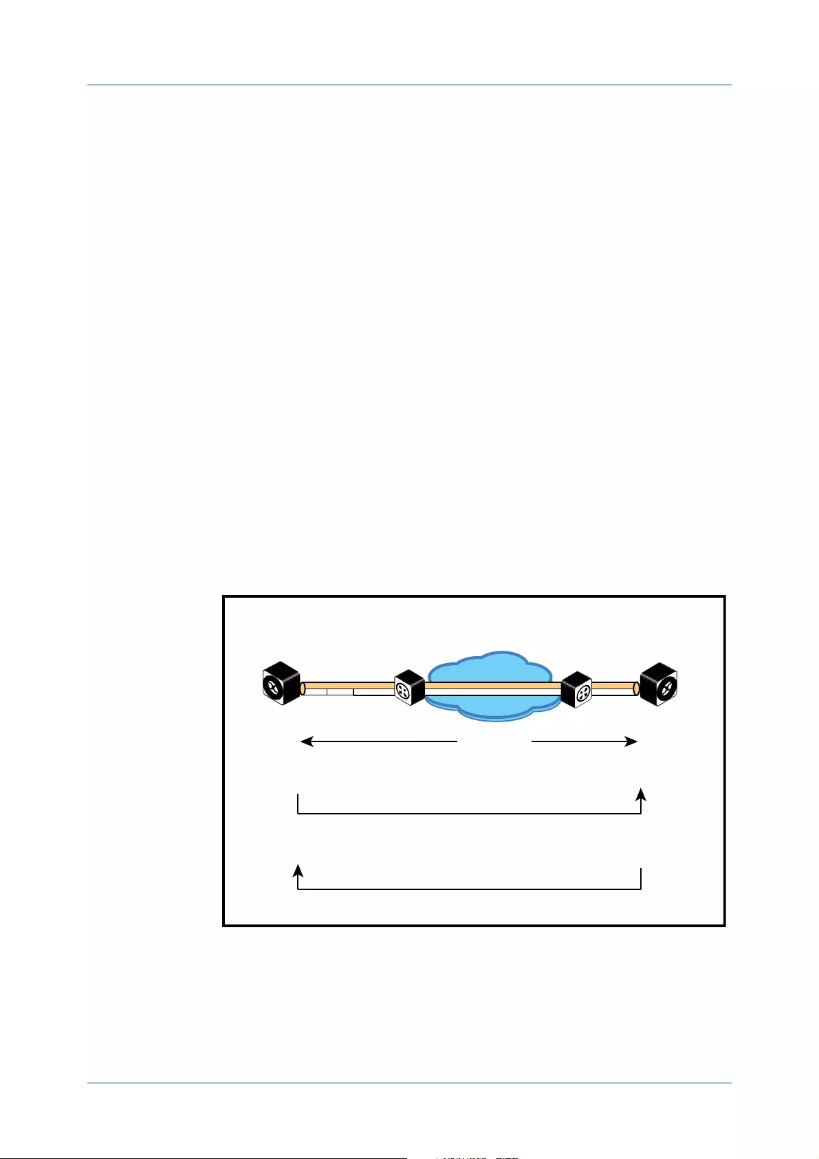
C613-50338-01 Rev A Command Reference for x530 Series 2958
AlliedWare Plus™ Operating System - Version 5.4.9-2.x
ALLIED TELESIS MANAGEMENT FRAMEWORK™ (AMF) COMMANDS
ATMF VIRTUAL-LINK
Configuration involves creating a local tunnel ID, a local IP address, a remote
tunnel ID and a remote IP address. A reciprocal configuration is also required on
the corresponding remote device. The local tunnel ID must be unique to the device
on which it is configured.
If an interface acquires its IP address dynamically then the local side of the tunnel
can be specified by using the interface’s name instead of using its IP address. When
using a dynamic local address the remote address of the other side of the
virtual-link must be configured with either:
• the IP address of the NAT device the dynamically configured interface is
behind, or
• 0.0.0.0, if the virtual-link is configured as a secure virtual-link.
For instructions on how to configure dynamic IP addresses on virtual-links, see the
AMF Feature Overview and Configuration Guide.
The tunneled link may operate via external (non AlliedWare Plus) routers in order
to provide wide area network connectivity. However in this configuration, the
routers perform a conventional router to router connection. The protocol
tunneling function is accomplished by the AMF nodes.
NOTE: AMF cannot achieve zero touch replacement of the remote device that
terminates the tunnel connection, because you must pre-configure the local IP address
and tunnel ID on that remote device.
Example 1 Use the following commands to create the tunnel shown in the figure below.
Figure 55-1: AMF virtual link example
Node_10(config)# atmf virtual-link id 1 ip 192.168.1.1
remote-id 2 remote-ip 192.168.2.1
Node_20(config)# atmf virtual-link id 2 ip 192.168.2.1
remote-id 1 remote-ip 192.168.1.1
IP Network
AMF
Local Site
(subnet 192.168.1.0)
atmf virtual-link ID and IP (Example1).eps
AMF virtual-link id ip remote-id remote-ip (Example)
AMF
Remote Site
(subnet 192.168.2.0)
Switch 1
AMF Node 10
Router 1 Router 2
192.168.1.1
Tunnel ID = 1
Tunnel remote ID = 2
192.168.2.1
Tunnel ID = 2
Tunnel remote ID = 1
Tunnelled Packet
UDP Header
IP Header
Switch 2
AMF Node 20
192.168.1.1
192.168.2.1

C613-50338-01 Rev A Command Reference for x530 Series 2959
AlliedWare Plus™ Operating System - Version 5.4.9-2.x
ALLIED TELESIS MANAGEMENT FRAMEWORK™ (AMF) COMMANDS
ATMF VIRTUAL-LINK
Example 2 To set up an area virtual link to a remote site (assuming IP connectivity between
the sites already), one site must run the following commands:
SiteA# configure terminal
SiteA(config)# atmf virtual-link id 5 ip 192.168.100.1
remote-id 10 remote-ip 192.168.200.1 remote-area SiteB-AREA
The second site must run the following commands:
SiteB# configure terminal
SiteB(config)# atmf virtual-link id 10 ip 192.168.200.1
remote-id 5 remote-ip 192.168.100.1 remote-area SiteA-AREA
Before you can apply the above atmf virtual-link command, you must configure
the area names SiteB-AREA and SiteA-AREA.
Related
Commands
atmf virtual-link protection
show atmf
show atmf links
show atmf virtual-links
Command
changes
Version 5.4.9-0.1: interface parameter added

C613-50338-01 Rev A Command Reference for x530 Series 2960
AlliedWare Plus™ Operating System - Version 5.4.9-2.x
ALLIED TELESIS MANAGEMENT FRAMEWORK™ (AMF) COMMANDS
ATMF VIRTUAL-LINK PROTECTION
atmf virtual-link protection
Overview Use this command to add protection to an existing AMF virtual-link. Secure AMF
virtual-links encapsulate the L2TPv3 frames of the virtual-link with IPsec.
Use the no variant of this command to remove protection from an AMF virtual-link.
Syntax atmf virtual-link id <1-4094> protection ipsec key [8]
<key-string>
no atmf virtual-link id <1-4094> protection
Default Protection is off by default.
Mode Global Configuration
Usage The following limitations need to be considered when creating secure virtual-links.
• Switch devices support a maximum of 20 downstream AMF nodes when
using a secure virtual-link as an uplink.
• When there are two or more AMF members behind a shared NAT device,
only one of the members will be able to use secure virtual-links.
• An AMF Multi-tenant environment supports a maximum cumulative total of
1200 secure virtual-links across all AMF containers.
Secure virtual-links are only supported on the following device listed in the table
below. There is also a limit to the number of links these devices support.
Parameter Description
id Specify the link ID.
<1-4094> Link ID in the range 1 to 4094,
protection Protection is on for this link.
ipsec Security provided using IPsec.
key Set the shared key.
8Specifies a string in an encrypted format instead of plain text. The
running config will display the new password as an encrypted
string even if password encryption is turned off.
<key-string> Specify the shared key for the link.

C613-50338-01 Rev A Command Reference for x530 Series 2961
AlliedWare Plus™ Operating System - Version 5.4.9-2.x
ALLIED TELESIS MANAGEMENT FRAMEWORK™ (AMF) COMMANDS
ATMF VIRTUAL-LINK PROTECTION
Example To create and configure a virtual link with protection first create the virtual-link:
Host-A# configure terminal
Host-A(config)# atmf virtual-link id 1 ip 192.168.1.1 remote-id
2 remote-ip 192.168.2.1
Enable protection on the virtual link:
Host-A(config)# atmf virtual-link id 1 protection ipsec key
securepassword
Repeat these steps on the other side of the link:
Host-B(config)# atmf virtual-link id 2 ip 192.168.2.1 remote-id
1 remote-ip 192.168.1.1
Host-B(config)# atmf virtual-link id 2 protection ipsec key
securepassword
Related
Commands
atmf virtual-link
show atmf
show atmf links
show atmf virtual-links
Command
changes
Version 5.4.9-0.1: command added
Device Virtual-link Limit
AMF Cloud/ VAA 300
AR4050S
AR3050S
AR2050V
AR2010V
60
x220
x230/x230L
x310
x510/x510L
IX5-28GPX
2

C613-50338-01 Rev A Command Reference for x530 Series 2962
AlliedWare Plus™ Operating System - Version 5.4.9-2.x
ALLIED TELESIS MANAGEMENT FRAMEWORK™ (AMF) COMMANDS
ATMF WORKING-SET
atmf working-set
Overview Use this command to execute commands across an individually listed set of AMF
nodes or across a named group of nodes.
Note that this command can only be run on a master node.
Use the no variant of this command to remove members or groups from the
current working-set.
Syntax atmf working-set {[<node-list>]|[group
{<group-list>|all|local|current}]}
no atmf working-set {[<node-list>]|[group <group-list>]}
Mode Privileged Exec
Usage You can put AMF nodes into groups by using the atmf group (membership)
command.
This command opens a session on multiple network devices. When you change the
working set to anything other than the local device, the prompt will change to the
AMF network name, followed by the size of the working set, shown in square
brackets. This command has to be run at privilege level 15.
In addition to the user defined groups, the following system assigned groups are
automatically created:
•Implicit Groups
– local: The originating node.
– current: All nodes that comprise the current working-set.
– all: All nodes in the AMF.
Parameter Description
<node-list> A comma delimited list (without spaces) of nodes to be included
in the working-set.
group The AMF group.
<group-list> A comma delimited list (without spaces) of groups to be included
in the working-set. Note that this can include either defined
groups, or any of the Automatic, or Implicit Groups shown earlier
in the bulleted list of groups.
all All nodes in the AMF.
local Local node
Running this command with the parameters group local will
return you to the local prompt and local node connectivity.
current Nodes in current list.
C613-50338-01 Rev A Command Reference for x530 Series 2963
AlliedWare Plus™ Operating System - Version 5.4.9-2.x
ALLIED TELESIS MANAGEMENT FRAMEWORK™ (AMF) COMMANDS
ATMF WORKING-SET
• Automatic Groups - These can be defined by hardware architecture, e.g.
x510, x610, x8100, AR3050S or AR4050S, or by certain AMF nodal
designations such as master.
Note that the Implicit Groups do not appear in show atmf group command output.
If a node is an AMF master it will be automatically added to the master group.
Example 1 To add all nodes in the AMF to the working-set, use the command:
node1# atmf working-set group all
NOTE: This command adds the implicit group “all” to the working set, where “all”
comprises all nodes in the AMF.
This command displays an output screen similar to the one shown below:
Example 2 To return to the local prompt, and connect to only the local node, use the
command:
ATMF_Network_Name[6]# atmf working-set group local
node1#
The following table describes the meaning of the prompts in this example.
=========================================
node1, node2, node3, node4, node5, node6:
==============================================
Working set join
ATMF_NETWORK_Name[6]#
Parameter Description
ATMF_Network_Name The name of the AMF network, as set by the atmf
network-name command.
[6] The number of nodes in the working-set.
node1 The name of the local node, as set by the hostname
command.

C613-50338-01 Rev A Command Reference for x530 Series 2964
AlliedWare Plus™ Operating System - Version 5.4.9-2.x
ALLIED TELESIS MANAGEMENT FRAMEWORK™ (AMF) COMMANDS
BRIDGE-GROUP
bridge-group
Overview Use this command to connect an AMF container to a bridge created on a Virtual
AMF Appliance (VAA) virtual machine. This allows the AMF container to connect to
a physical network.
An AMF container is an isolated instance of AlliedWare Plus with its own network
interfaces, configuration, and file system. The features available inside an AMF
container are a sub-set of the features available on the host VAA. These features
enable the AMF container to function as a uniquely identifiable AMF master and
allows for multiple tenants (up to 60) to run on a single VAA host. See the
AMF Feature Overview and Configuration Guide for more information on running
multiple tenants on a single VAA host.
Use the no variant of this command to remove a bridge-group from an AMF
container.
Syntax bridge-group <bridge-id>
no bridge-group
Mode AMF Container Configuration
Usage Each container has two virtual interfaces:
1) Interface eth0, used to connect to the AMF controller on the VAA host via an
AMF area-link, and configured using this area-link command.
2) Interface eth1, used to connect to the outside world using a bridged L2
network link, and configured using the bridge-group command.
Before using this command, a bridge must be created with the same bridge-id on
the VAA host using the bridge <bridge-id> command.
See the AMF Feature Overview and Configuration Guide for more information on
configuring the bridge.
Example To create a bridge group for AMF container “vac-wlg-1” and , use the commands:
awplus# configure terminal
awplus(config)# atmf container vac-wlg-1
awplus(config-atmf-container)# bridge-group 1
Related
Commands
atmf container
show atmf container
Command
changes
Version 5.4.7-0.1: command added
Parameter Description
<bridge-id> The ID of the bridge group to join, a number between 1 and 64.

C613-50338-01 Rev A Command Reference for x530 Series 2965
AlliedWare Plus™ Operating System - Version 5.4.9-2.x
ALLIED TELESIS MANAGEMENT FRAMEWORK™ (AMF) COMMANDS
CLEAR APPLICATION-PROXY THREAT-PROTECTION
clear application-proxy threat-protection
Overview Use this command to clear the threat protection for a specified address.
Syntax clear application-proxy threat-protection {<ip-address>|
<mac-address>|all}
Mode Privileged Exec
Example To clear the threat for 10.34.199.117, use the command:
awplus# clear application-proxy threat-protection 10.34.199.117
Related
Commands
application-proxy quarantine-vlan
application-proxy threat-protection
application-proxy threat-protection send-summary
service atmf-application-proxy
show application-proxy threat-protection
Command
changes
Version 5.4.7-2.2: command added
Parameter Description
<ip-address>The IPv4 address you wish to clear the threat for, in A.B.C.D format.
<mac-address>The MAC address you wish to clear the threat for, in
HHHH.HHHH.HHHH format.
all Clear the threat for all IPv4 and MAC addresses.

C613-50338-01 Rev A Command Reference for x530 Series 2966
AlliedWare Plus™ Operating System - Version 5.4.9-2.x
ALLIED TELESIS MANAGEMENT FRAMEWORK™ (AMF) COMMANDS
CLEAR ATMF LINKS
clear atmf links
Overview Use this command with no parameters to manually reset all the AMF links on a
device. You can optionally specify an interface or range of interfaces to reset the
links on.
Certain events or topology changes can cause AMF links to be incorrect or
outdated. Clearing the links forces AMF to relearn the information from
neighboring nodes and create a fresh, correct, view of the network.
Syntax clear atmf links [<interface-list>]
Mode Privileged Exec
Example To clear all AMF links on a device, use the following command:
awplus# clear atmf links
To clear all AMF links on port1.0.1 to port1.0.4 and static aggregator sa1, use the
following command:
awplus# clear atmf links port1.0.1-port1.0.4,sa1
Related
Commands
clear atmf links virtual
show atmf links
Command
changes
Version 5.4.8-2.1: command added
Parameter Description
<interface-list>The interfaces or ports to perform the reset on. An
interface-list can be:
• a switchport (e.g. port1.0.1)
• a static channel group (e.g. sa2)
• a dynamic (LACP) channel group (e.g. po2)
• a local port (e.g. of0)
• You can specify a continuous range of interfaces
separated by a hyphen, or a comma-separated list (e.g.
port1.0.1, port1.0.4-port1.0.18).
The specified interfaces must exist.
If this parameter is left out then all links of the specified type
will be reset on the device.

C613-50338-01 Rev A Command Reference for x530 Series 2967
AlliedWare Plus™ Operating System - Version 5.4.9-2.x
ALLIED TELESIS MANAGEMENT FRAMEWORK™ (AMF) COMMANDS
CLEAR ATMF LINKS VIRTUAL
clear atmf links virtual
Overview Use this command with no parameters to manually reset all the AMF virtual links
on a device. You can, optionally, specify a comma separated list of virtual links to
reset.
Certain events or topology changes can cause AMF links to be incorrect or
outdated. Clearing the links forces AMF to relearn the information from
neighboring nodes and create a fresh, correct view of the network.
Syntax clear atmf links virtual [<virtuallink-list>]
Mode Privileged Exec
Example To clear all AMF virtual links on a device, use the following command:
awplus# clear atmf links virtual
To clear AMF virtual links vlink11 and vlink21, use the following command:
awplus# clear atmf links virtual vlink11,vlink22
Related
Commands
clear atmf links
show atmf links
Command
changes
Version 5.4.8-2.1: command added
Parameter Description
<virtuallink-list>A single, or list, of AMF virtual link identifiers to reset. This
must be a comma separated list of links e.g. vlink1, vlink2,
vlink3. Specifying a link range e.g vlink1-vlink3 is not
supported.

C613-50338-01 Rev A Command Reference for x530 Series 2968
AlliedWare Plus™ Operating System - Version 5.4.9-2.x
ALLIED TELESIS MANAGEMENT FRAMEWORK™ (AMF) COMMANDS
CLEAR ATMF LINKS STATISTICS
clear atmf links statistics
Overview This command resets the values of all AMF link, port, and global statistics to zero.
Syntax clear atmf links statistics
Mode Privilege Exec
Example To reset the AMF link statistics values, use the command:
node_1# clear atmf links statistics
Related
Commands
show atmf links statistics

C613-50338-01 Rev A Command Reference for x530 Series 2969
AlliedWare Plus™ Operating System - Version 5.4.9-2.x
ALLIED TELESIS MANAGEMENT FRAMEWORK™ (AMF) COMMANDS
CLEAR ATMF RECOVERY-FILE
clear atmf recovery-file
Overview Use this command to delete all of a node’s recovery files. It deletes the recovery
files stored on:
•the local node,
•neighbor nodes, and
• external media (USB or SD card).
Syntax clear atmf recovery-file
Mode Privileged Exec
Usage AMF recovery files are created for nodes with special links. Special links include:
•virtual links,
• area links terminating on an AMF master, and
• area virtual links terminating on an AMF master.
An AMF node with one of these special links pushes its startup configuration to its
neighbors and to any attached external media. It then fetches and applies this
configuration at recovery time. This configuration enables it to contact the AMF
master and initiate a recovery.
Recovery files can become out of date if:
• a node’s neighbor is off line when changes are made to its configuration, or
• when a node no longer contains a special link.
Example To clear a node’s recovery files, use the command:
node1# clear atmf recovery-file
Output Figure 55-2: If AlliedWare Plus detects that a node contains a special link then
the following message is displayed
Related
Commands
show atmf recovery-file
Command
changes
Version 5.4.8-0.2: command added
node1#clear atmf recovery-file
% Warning: ATMF recovery files have been removed.
ATMF recovery may fail. Please save running-configuration.

C613-50338-01 Rev A Command Reference for x530 Series 2970
AlliedWare Plus™ Operating System - Version 5.4.9-2.x
ALLIED TELESIS MANAGEMENT FRAMEWORK™ (AMF) COMMANDS
CLEAR ATMF SECURE-MODE CERTIFICATES
clear atmf secure-mode certificates
Overview Use this command to remove all certificates from an AMF member or master. AMF
nodes will need to be re-authorized once this command has been run.
Syntax clear atmf secure-mode certificates
Mode Privileged Exec
Example To clear all certificates from an AMF node, use the command:
awplus# clear atmf secure-mode certificates
If this is the only master on the network you will see the following warning:
On an AMF member you will see the following message:
Related
Commands
atmf authorize
atmf secure-mode
show atmf authorization
show atmf secure-mode certificates
Command
changes
Version 5.4.7-0.3: command added
% Warning: This node is the only master in the network!
All the nodes will become isolated and refuse to join any ATMF
network. The certificates on all the isolated nodes must be
cleared before rejoining an ATMF network will be possible.
To clear certificates a reboot of the device is required.
Clear certificates and Reboot ? (y/n):
To clear certificates a reboot of the device is required.
Clear certificates and Reboot ? (y/n):

C613-50338-01 Rev A Command Reference for x530 Series 2971
AlliedWare Plus™ Operating System - Version 5.4.9-2.x
ALLIED TELESIS MANAGEMENT FRAMEWORK™ (AMF) COMMANDS
CLEAR ATMF SECURE-MODE STATISTICS
clear atmf secure-mode statistics
Overview Use this command to reset all secure mode statistics to 0.
Syntax clear atmf secure-mode statistics
Mode Privileged Exec
Example To reset the AMF secure mode statistics information, use the command:
awplus# clear atmf secure-mode statistic
Related
Commands
show atmf secure-mode
show atmf secure-mode statistics
Command
changes
Version 5.4.7-0.3: command added

C613-50338-01 Rev A Command Reference for x530 Series 2972
AlliedWare Plus™ Operating System - Version 5.4.9-2.x
ALLIED TELESIS MANAGEMENT FRAMEWORK™ (AMF) COMMANDS
CLONE (AMF-PROVISION)
clone (amf-provision)
Overview This command sets up a space on the backup media for use with a provisioned
node and copies into it almost all files and directories from a chosen backup or
provisioned node.
Alternatively, you can set up a new, unique provisioned node by using the
command create (amf-provision).
Syntax clone <source-nodename>
Mode AMF Provisioning
Usage This command is only available on master nodes in the AMF network.
When using this command it is important to be aware of the following:
•A copy of <media>:atmf/<atmf_name>/nodes/<source_node>/flash will be
made for the provisioned node and stored in the backup media.
•The directory <node_backup_dir>/flash/.config/ssh is excluded from the
copy.
• All contents of <root_backup_dir>/nodes/<nodename> will be deleted or
overwritten.
• Settings for the expected location of other provisioned nodes are excluded
from the copy.
The active and backup configuration files are automatically modified in the
following ways:
•The hostname command is modified to match the name of the provisioned
node.
•The stack virtual-chassis-id command is removed, if present.
Example To copy from the backup of ‘device2’ to create backup files for the new provisioned
node ‘device3’ use the following command:
device1# atmf provision node device3
device1(atmf-provision)# clone device2
Figure 55-3: Sample output from the clone command
Parameter Description
<source-nodename> The name of the node whose configuration is to be
copied for loading to the clone.
device1# atmf provision node device3
device1(atmf-provision)#clone device2
Copying...
Successful operation

C613-50338-01 Rev A Command Reference for x530 Series 2973
AlliedWare Plus™ Operating System - Version 5.4.9-2.x
ALLIED TELESIS MANAGEMENT FRAMEWORK™ (AMF) COMMANDS
CLONE (AMF-PROVISION)
To confirm that a new provisioned node has been cloned, use the command:
device1# show atmf backup
The output from this command is shown in the following figure, and shows the
details of the new provisioned node ‘device3’.
Figure 55-4: Sample output from the show atmf backup command
Related
commands
atmf provision (interface)
atmf provision node
configure boot config (amf-provision)
configure boot system (amf-provision)
copy (amf-provision)
create (amf-provision)
delete (amf-provision)
identity (amf-provision)
license-cert (amf-provision)
locate (amf-provision)
show atmf provision nodes
Command
changes
Version 5.4.9-0.1: syntax change due to new AMF provisioning mode
device1#show atmf backup
Scheduled Backup ...... Enabled
Schedule ............ 1 per day starting at 03:00
Next Backup Time .... 01 Oct 2018 03:00
Backup Bandwidth ...... Unlimited
Backup Media .......... USB (Total 7446.0MB, Free 7297.0MB)
Server Config .........
Synchronization ..... Unsynchronized
Last Run .......... -
1 .................. Unconfigured
2 .................. Unconfigured
Current Action ........ Idle
Started ............. -
Current Node ........ -
---------------------------------------------------------------
Node Name Date Time In ATMF On Media Status
---------------------------------------------------------------
device3 - - No Yes Prov
device1 30 Sep 2018 00:05:49 No Yes Good
device2 30 Sep 2018 00:05:44 Yes Yes Good

C613-50338-01 Rev A Command Reference for x530 Series 2974
AlliedWare Plus™ Operating System - Version 5.4.9-2.x
ALLIED TELESIS MANAGEMENT FRAMEWORK™ (AMF) COMMANDS
CONFIGURE BOOT CONFIG (AMF-PROVISION)
configure boot config (amf-provision)
Overview This command sets the configuration file to use during the next boot cycle. This
command can also set a backup configuration file to use if the main configuration
file cannot be accessed for an AMF provisioned node. To unset the boot
configuration or the backup boot configuration use the no boot command.
Syntax configure boot config [backup] <file-path|URL>
configure no boot config [backup]
Default No boot configuration files or backup configuration files are specified for the
provisioned node.
Mode AMF Provisioning
Usage When using this command to set a backup configuration file, the specified AMF
provisioned node must exist. The specified file must exist in the flash directory
created for the provisioned node in the AMF remote backup media.
Examples To set the configuration file ‘branch.cfg’ on the AMF provisioned node ‘node1’, use
the command:
MasterNodeName# atmf provision node node1
MasterNodeName(atmf-provision)# configure boot config
branch.cfg
To set the configuration file ‘backup.cfg’ as the backup to the main configuration
file on the AMF provisioned node ‘node1’, use the command:
MasterNodeName(atmf-provision)# configure boot config backup
usb:/atmf/amf_net/nodes/node1/config/backup.cfg
To unset the boot configuration, use the command:
MasterNodeName(atmf-provision)# configure no boot config
To unset the backup boot configuration, use the command:
MasterNodeName(atmf-provision)# configure no boot config backup
Related
commands
atmf provision (interface)
atmf provision node
clone (amf-provision)
configure boot system (amf-provision)
create (amf-provision)
Parameter Description
backup Specify that this is the backup configuration file.
<file-path|URL> The path or URL and name of the configuration file.

C613-50338-01 Rev A Command Reference for x530 Series 2975
AlliedWare Plus™ Operating System - Version 5.4.9-2.x
ALLIED TELESIS MANAGEMENT FRAMEWORK™ (AMF) COMMANDS
CONFIGURE BOOT CONFIG (AMF-PROVISION)
delete (amf-provision)
identity (amf-provision)
license-cert (amf-provision)
locate (amf-provision)
show atmf provision nodes
Command
changes
Version 5.4.9-0.1: syntax change due to new AMF provisioning mode

C613-50338-01 Rev A Command Reference for x530 Series 2976
AlliedWare Plus™ Operating System - Version 5.4.9-2.x
ALLIED TELESIS MANAGEMENT FRAMEWORK™ (AMF) COMMANDS
CONFIGURE BOOT SYSTEM (AMF-PROVISION)
configure boot system (amf-provision)
Overview This command sets the release file that will load onto a specified provisioned node
during the next boot cycle. This command can also set the backup release file to be
loaded for an AMF provisioned node. To unset the boot system release file or the
backup boot release file use the no boot command.
Use the no variant of this command to return to the default.
This command can only be run on AMF master nodes.
Syntax configure boot system [backup] <file-path|URL>
configure no boot system [backup]
Default No boot release file or backup release files are specified for the provisioned node.
Mode AMF Provisioning
Usage When using this command to set a backup release file, the specified AMF
provisioned node must exist. The specified file must exist in the flash directory
created for the provisioned node in the AMF remote backup media.
Examples To set the release file x930-5.4.9-0.1.rel on the AMF provisioned node ‘node1’, use
the command:
MasterNodeName# atmf provision node node1
MasterNodeName(atmf-provision)# configure boot system
x930-5.4.9-0.1.rel
To set the backup release file x930-5.4.8-2.5.rel as the backup to the main release
file on the AMF provisioned node ‘node1’, use the command:
MasterNodeName# atmf provision node node1
MasterNodeName(atmf-provision)# configure boot system backup
card:/atmf/amf_net/nodes/node1/flash/x930-5.4.8-2.5.rel
To unset the boot release, use the command:
MasterNodeName# atmf provision node node1
MasterNodeName(atmf-provision)# configure no boot system
To unset the backup boot release, use the command:
MasterNodeName# atmf provision node node1
MasterNodeName(atmf-provision)# configure no boot system backup
Related
commands
atmf provision (interface)
Parameter Description
<file-path|URL> The path or URL and name of the release file.

C613-50338-01 Rev A Command Reference for x530 Series 2977
AlliedWare Plus™ Operating System - Version 5.4.9-2.x
ALLIED TELESIS MANAGEMENT FRAMEWORK™ (AMF) COMMANDS
CONFIGURE BOOT SYSTEM (AMF-PROVISION)
atmf provision node
clone (amf-provision)
configure boot config (amf-provision)
create (amf-provision)
delete (amf-provision)
identity (amf-provision)
license-cert (amf-provision)
locate (amf-provision)
show atmf provision nodes
Command
changes
Version 5.4.9-0.1: syntax change due to new AMF provisioning mode

C613-50338-01 Rev A Command Reference for x530 Series 2978
AlliedWare Plus™ Operating System - Version 5.4.9-2.x
ALLIED TELESIS MANAGEMENT FRAMEWORK™ (AMF) COMMANDS
COPY (AMF-PROVISION)
copy (amf-provision)
Overview Use this command to copy configuration and release files for the node you are
provisioning.
For more information about using the copy command see copy (filename) in the
File and Configuration Management chapter.
Syntax copy [force] <source-name> <destination-name>
Mode AMF Provisioning
Example To copy a configuration file named current.cfg from Node_4’s Flash into the
future_node directory, and set that configuration file to load onto future_node,
use the following commands:
node_4# atmf provision node future_node
node_4(atmf-provision)# create
node_4(atmf-provision)# locate
node_4(atmf-provision)# copy flash:current.cfg
./future_node.cfg
node_4(atmf-provision)# configure boot config future_node.cfg
Related
commands
atmf provision (interface)
atmf provision node
clone (amf-provision)
create (amf-provision)
delete (amf-provision)
locate (amf-provision)
show atmf provision nodes
Command
changes
Version 5.4.9-2.1: command added
Parameter Description
force This parameter forces the copy command to overwrite the
destination file, if it already exists, without prompting the
user for confirmation.
<source-name> The filename and path of the source file. See the
Introduction of the File and Configuration Management
chapter for valid syntax.
<destination-name> The filename and path for the destination file. See
Introduction of the File and Configuration Management
chapter for valid syntax.

C613-50338-01 Rev A Command Reference for x530 Series 2979
AlliedWare Plus™ Operating System - Version 5.4.9-2.x
ALLIED TELESIS MANAGEMENT FRAMEWORK™ (AMF) COMMANDS
CREATE (AMF-PROVISION)
create (amf-provision)
Overview This command sets up an empty directory on the backup media for use with a
provisioned node. This directory can have configuration and release files copied to
it from existing devices. Alternatively, the configuration files can be created by the
user.
An alternative way to create a new provisioned node is with the command clone
(amf-provision).
This command can only run on AMF master nodes.
Syntax create
Mode AMF Provisioning
Usage This command is only available on master nodes in the AMF network.
A date and time is assigned to the new provisioning directory reflecting when this
command was executed. If there is a backup or provisioned node with the same
name on another AMF master then the most recent one will be used.
Example To create a new provisioned node named “device2” use the command:
device1# atmf provision node device2
device1(atmf-provision)# create
Running this command will create the following directories:
•<media>:atmf/<atmf_name>/nodes/<node>
•<media>:atmf/<atmf_name>/nodes/<node>/flash
To confirm the new node’s settings, use the command:
device1# show atmf backup
The output for the show atmf backup command is shown in the following figure,
and shows details for the new provisioned node ‘device2’.

C613-50338-01 Rev A Command Reference for x530 Series 2980
AlliedWare Plus™ Operating System - Version 5.4.9-2.x
ALLIED TELESIS MANAGEMENT FRAMEWORK™ (AMF) COMMANDS
CREATE (AMF-PROVISION)
Figure 55-5: Sample output from the show atmf backup command
For instructions on how to configure on a provisioned node, see the AMF Feature
Overview and Configuration Guide.
Related
commands
atmf provision (interface)
atmf provision node
clone (amf-provision)
copy (amf-provision)
configure boot config (amf-provision)
configure boot system (amf-provision)
delete (amf-provision)
identity (amf-provision)
license-cert (amf-provision)
locate (amf-provision)
show atmf provision nodes
Command
changes
Version 5.4.9-0.1: syntax change due to new AMF provisioning mode
device1#show atmf backup
Scheduled Backup ...... Enabled
Schedule ............ 1 per day starting at 03:00
Next Backup Time .... 01 Oct 2018 03:00
Backup Bandwidth ...... Unlimited
Backup Media .......... USB (Total 7446.0MB, Free 7315.2MB)
Server Config .........
Synchronization ..... Unsynchronized
Last Run .......... -
1 .................. Unconfigured
2 .................. Unconfigured
Current Action ........ Idle
Started ............. -
Current Node ........ -
---------------------------------------------------------------
Node Name Date Time In ATMF On Media Status
---------------------------------------------------------------
device2 - - No Yes Prov
device1 30 Sep 2018 00:05:49 No Yes Good

C613-50338-01 Rev A Command Reference for x530 Series 2981
AlliedWare Plus™ Operating System - Version 5.4.9-2.x
ALLIED TELESIS MANAGEMENT FRAMEWORK™ (AMF) COMMANDS
DEBUG ATMF
debug atmf
Overview This command enables the AMF debugging facilities, and displays information
that is relevant (only) to the current node. The detail of the debugging displayed
depends on the parameters specified.
If no additional parameters are specified, then the command output will display all
AMF debugging information, including link events, topology discovery messages
and all notable AMF events.
The no variant of this command disables either all AMF debugging information, or
only the particular information as selected by the command’s parameters.
Syntax debug atmf
[link|crosslink|arealink|database|neighbor|error|all]
no debug atmf
[link|crosslink|arealink|database|neighbor|error|all]
Default All debugging facilities are disabled.
Mode User Exec and Global Configuration
Usage If no additional parameters are specified, then the command output will display all
AMF debugging information, including link events, topology discovery messages
and all notable AMF events.
NOTE: An alias to the no variant of this command is undebug atmf on page 3110.
Examples To enable all AMF debugging, use the command:
node_1# debug atmf
To enable AMF uplink and downlink debugging, use the command:
node_1# debug atmf link
To enable AMF error debugging, use the command:
node_1# debug atmf error
Parameter Description
link Output displays debugging information relating to uplink or
downlink information.
crosslink Output displays all crosslink events.
arealink Output displays all arealink events.
database Output displays only notable database events.
neighbor Output displays only notable AMF neighbor events.
error Output displays AMF error events.
all Output displays all AMF events.


C613-50338-01 Rev A Command Reference for x530 Series 2983
AlliedWare Plus™ Operating System - Version 5.4.9-2.x
ALLIED TELESIS MANAGEMENT FRAMEWORK™ (AMF) COMMANDS
DEBUG ATMF PACKET
debug atmf packet
Overview This command configures AMF Packet debugging parameters. The debug only
displays information relevant to the current node. The command has following
parameters:
Syntax debug atmf packet [direction {rx|tx|both}] [level {1|2|3}]
[timeout <seconds>] [num-pkts <quantity>]
[filter {node <name>|interface <ifname>}
[pkt-type [1][2][3][4][5][6][7][8][9][10][11][12][13]]]
Simplified
Syntax
NOTE: You can combine the syntax components shown, but when doing so, you must
retain their original order.
Default Level 1, both Tx and Rx, a timeout of 60 seconds with no filters applied.
NOTE: An alias to the no variant of this command - undebug atmf - can be found
elsewhere in this chapter.
Mode User Exec and Global Configuration
Usage If no additional parameters are specified, then the command output will apply a
default selection of parameters shown below:
debug atmf packet [direction {rx|tx|both}]
[level {[1][2|3}]
[timeout <seconds>]
[num-pkts <quantity>]
debug atmf packet filter [node <name>]
[interface <ifname>]
[pkt-type
[1][2][3][4][5][6][7][8][9][10][11][12][13]]
Parameter Description
direction Sets debug to packet received, transmitted, or both
rx packets received by this node
tx Packets sent from this node
1AMF Packet Control header Information, Packet Sequence
Number. Enter 1 to select this level.
2AMF Detailed Packet Information. Enter 2 to select this level.
3AMF Packet HEX dump. Enter 3 to select this level.
timeout Sets the execution timeout for packet logging

C613-50338-01 Rev A Command Reference for x530 Series 2984
AlliedWare Plus™ Operating System - Version 5.4.9-2.x
ALLIED TELESIS MANAGEMENT FRAMEWORK™ (AMF) COMMANDS
DEBUG ATMF PACKET
Examples To set a packet debug on node 1 with level 1 and no timeout, use the command:
node_1# debug atmf packet direction tx timeout 0
To set a packet debug with level 3 and filter packets received from AMF node 1:
node_1# debug atmf packet direction tx level 3 filter node_1
To enable send and receive 500 packets only on vlink1 for packet types 1, 7, and 11,
use the command:
node_1# debug atmf packet num-pkts 500 filter interface vlink1
pkt-type 1 7 11
<seconds> Seconds
num-pkts Sets the number of packets to be dumped
<quantity> The actual number of packets
filter Sets debug to filter packets
node Sets the filter on packets for a particular Node
<name> The name of the remote node
interface Sets the filter to dump packets from an interface (portx.x.x) on the
local node
<ifname>Interface port or virtual-link
pkt-type Sets the filter on packets with a particular AMF packet type
1Crosslink Hello BPDU packet with crosslink links information. Enter
1 to select this packet type.
2Crosslink Hello BPDU packet with downlink domain information.
Enter 2 to select this packet type.
3Crosslink Hello BPDU packet with uplink information. Enter 3 to
select this packet type.
4Downlink and uplink hello BPDU packets. Enter 4 to select this
packet type.
5Non broadcast hello unicast packets. Enter 5 to select this packet
type.
6Stack hello unicast packets. Enter 6 to select this packet type.
7Database description. Enter 7 to select this packet type.
8DBE request. Enter 8 to select this packet type.
9DBE update. Enter 9 to select this packet type.
10 DBE bitmap update. Enter 10 to select this packet type.
11 DBE acknowledgment. Enter 11 to select this packet type.
12 Area Hello Packets. Enter 12 to select this packet type.
13 Gateway Hello Packets. Enter 13 to select this packet type.
Parameter Description

C613-50338-01 Rev A Command Reference for x530 Series 2985
AlliedWare Plus™ Operating System - Version 5.4.9-2.x
ALLIED TELESIS MANAGEMENT FRAMEWORK™ (AMF) COMMANDS
DEBUG ATMF PACKET
This example applies the debug atmf packet command and combines many of its
options:
node_1# debug atmf packet direction rx level 1 num-pkts 60
filter node x930 interface port1.0.1 pkt-type 4 7 10

C613-50338-01 Rev A Command Reference for x530 Series 2986
AlliedWare Plus™ Operating System - Version 5.4.9-2.x
ALLIED TELESIS MANAGEMENT FRAMEWORK™ (AMF) COMMANDS
DELETE (AMF-PROVISION)
delete (amf-provision)
Overview This command deletes files that have been created for loading onto a provisioned
node. It can only be run on master nodes.
Syntax delete
Mode AMF Provisioning
Usage This command is only available on master nodes in the AMF network. The
command will only work if the provisioned node specified in the command has
already been set up (although the device itself is still yet to be installed). Otherwise,
an error message is shown when the command is run.
You may want to use the delete command to delete a provisioned node that was
created in error or that is no longer needed.
This command cannot be used to delete backups created by the AMF backup
procedure. In this case, use the command atmf backup delete to delete the files.
NOTE: This command allows provisioned entries to be deleted even if they have been
referenced by the atmf provision (interface) command, so take care to only delete
unwanted entries.
Example To delete backup files for a provisioned node named device3 use the command:
device1# atmf provision node device3
device1(atmf-provision)# delete
To confirm that the backup files for provisioned node device3 have been deleted
use the command:
device1# show atmf backup
The output should show that the provisioned node device3 no longer exists in the
backup file, as shown in the figure below:

C613-50338-01 Rev A Command Reference for x530 Series 2987
AlliedWare Plus™ Operating System - Version 5.4.9-2.x
ALLIED TELESIS MANAGEMENT FRAMEWORK™ (AMF) COMMANDS
DELETE (AMF-PROVISION)
Figure 55-6: Sample output showing the show atmf backup command
Related
commands
atmf provision (interface)
atmf provision node
clone (amf-provision)
configure boot config (amf-provision)
configure boot system (amf-provision)
create (amf-provision)
identity (amf-provision)
license-cert (amf-provision)
locate (amf-provision)
show atmf provision nodes
Command
changes
Version 5.4.9-0.1: syntax change due to new AMF provisioning mode
device1#show atmf backup
Scheduled Backup ...... Enabled
Schedule ............ 1 per day starting at 03:00
Next Backup Time .... 01 Oct 2016 03:00
Backup Bandwidth ...... Unlimited
Backup Media .......... USB (Total 7446.0MB, Free 7297.0MB)
Server Config .........
Synchronization ..... Unsynchronized
Last Run .......... -
1 .................. Unconfigured
2 .................. Unconfigured
Current Action ........ Idle
Started ............. -
Current Node ........ -
---------------------------------------------------------------
Node Name Date Time In ATMF On Media Status
---------------------------------------------------------------
device1 30 Sep 2016 00:05:49 No Yes Good
device2 30 Sep 2016 00:05:44 Yes Yes Good

C613-50338-01 Rev A Command Reference for x530 Series 2988
AlliedWare Plus™ Operating System - Version 5.4.9-2.x
ALLIED TELESIS MANAGEMENT FRAMEWORK™ (AMF) COMMANDS
DISCOVERY
discovery
Overview Use this command to specify how AMF learns about guest nodes.
AMF nodes gather information about guest nodes by using one of two internally
defined discovery methods: static or dynamic.
With dynamic learning (the default method), AMF learns IP address and MAC
addresses of guest nodes from LLDP or DHCP snooping. Dynamic learning is only
supported when using IPv4. For IPv6, use static learning.
With dynamic learning, ensure that the command ip dhcp snooping
delete-by-linkdown is set.
With static learning, you use the switchport atmf-guestlink command to specify
the guest class name and IP address of the guest node attached to each individual
switch port. AMF then learns the MAC addresses of each of the guests of that class
from ARP or Neighbor discovery tables.
If you are using the static method, ensure that you have configured the
appropriate class type for each of your statically discovered guest nodes.
The no variant of this command returns the discovery method to dynamic.
Syntax discovery [static|dynamic]
no discovery
Default Dynamic.
Mode ATMF Guest Configuration Mode.
Usage This command is one of several modal commands that are configured and applied
for a specific guest-class (mode). Its settings are automatically applied to a
guest-node link by the switchport atmf-guestlink command.
NOTE: AMF guest nodes are not supported on ports using the OpenFlow protocol.
Example 1 To configure the discovery of the guest-class camera to operate statically, use the
following commands:
Node1# configure terminal
Node1(config)# atmf guest-class camera
Node1(config-guest)# discovery static
Parameter Description
static Statically assigned.
dynamic Learned from DCHCP Snooping or LLDP.

C613-50338-01 Rev A Command Reference for x530 Series 2989
AlliedWare Plus™ Operating System - Version 5.4.9-2.x
ALLIED TELESIS MANAGEMENT FRAMEWORK™ (AMF) COMMANDS
DISCOVERY
Example 2 To return the discovery method for the guest class TQ4600-1 to its default of
dynamic, use the following commands:
Node1# configure terminal
Node1(config)# atmf guest-class TQ4600-1
Node1(config-guest)# no discovery
Related
Commands
atmf guest-class
switchport atmf-guestlink
show atmf links guest
show atmf nodes

C613-50338-01 Rev A Command Reference for x530 Series 2990
AlliedWare Plus™ Operating System - Version 5.4.9-2.x
ALLIED TELESIS MANAGEMENT FRAMEWORK™ (AMF) COMMANDS
DESCRIPTION (AMF-CONTAINER)
description (amf-container)
Overview Use this command to set the description on an AMF container on a Virtual AMF
Appliance (VAA).
An AMF container is an isolated instance of AlliedWare Plus with its own network
interfaces, configuration, and file system. The features available inside an AMF
container are a sub-set of the features available on the host VAA. These features
enable the AMF container to function as a uniquely identifiable AMF master and
allows for multiple tenants (up to 60) to run on a single VAA host. See the
AMF Feature Overview and Configuration Guide for more information on running
multiple tenants on a single VAA host.
Use the no variant of this command to remove the description from an AMF
container.
Syntax description <description>
no description
Mode AMF Container Configuration
Example To set the description for AMF container “vac-wlg-1” to “Wellington area”, use the
commands:
awplus# configure terminal
awplus(config)# atmf container vac-wlg-1
awplus(config-atmf-container)# description Wellington area
To remove the description for AMF container “vac-wlg-1”, use the commands:
awplus# configure terminal
awplus(config)# atmf container vac-wlg-1
awplus(config-atmf-container)# no description
Related
Commands
atmf container
show atmf container
Command
changes
Version 5.4.7-0.1: command added
Parameter Description
<description> Enter up to 128 characters of text describing the AMF container.

C613-50338-01 Rev A Command Reference for x530 Series 2991
AlliedWare Plus™ Operating System - Version 5.4.9-2.x
ALLIED TELESIS MANAGEMENT FRAMEWORK™ (AMF) COMMANDS
ERASE FACTORY-DEFAULT
erase factory-default
Overview This command erases all data from NVS and all data from Flash except the
following:
• the boot release file (a .rel file) and its release setting file
• all license files
• the latest GUI release file
The device is then rebooted and returned to its factory default condition. The
device can then be used for AMF automatic node recovery.
Syntax erase factory-default
Mode Privileged Exec.
Usage This command is an alias to the atmf cleanup command.
Note that this command can only be used on standalone switches, not stacked
switches.
Example To erase data, use the command:
Node_1# erase factory-default
This command will erase all NVS, all flash contents except for
the boot release, a GUI resource file, and any license files,
and then reboot the switch. Continue? (y/n):y
Related
Commands
atmf cleanup

C613-50338-01 Rev A Command Reference for x530 Series 2992
AlliedWare Plus™ Operating System - Version 5.4.9-2.x
ALLIED TELESIS MANAGEMENT FRAMEWORK™ (AMF) COMMANDS
HTTP-ENABLE
http-enable
Overview This command is used to enable GUI access to a guest node. When http-enable is
configured the port number is set to its default of 80. If the guest node is using a
different port for HTTP, you can configure this using the port <PORTNO> attribute.
This command is used to inform the GUI that this device has an HTTP interface at
the specified port number so that a suitable URL can be provided to the user.
Use the no variant of this command to disable HTTP.
Syntax http-enable [port <port-number>]
no http-enable
Default http-enable is off.
If http-enable is selected without a port parameter the port number will default to
80.
Mode ATMF Guest Configuration Mode
Example 1 To enable HTTP access to a guest node on port 80 (the default), use the following
commands:
node1# conf t
node1(config)#atmf guest-class Camera
node1(config-atmf-guest)#http-enable
node1(config-atmf-guest)#
Example 2 To enable HTTP access to a guest node on port 400, use the following commands:
node1# conf t
node1(config)#atmf guest-class Camera
node1(config-atmf-guest)#http-enable port 400
node1(config-atmf-guest)#
Example 3 To disable HTTP access to a guest node, use the following commands:
node1# conf t
node1(config)#atmf guest-class Camera
node1(config-atmf-guest)#no http-enable
node1(config-atmf-guest)#
Parameter Description
port TCP port number.
<port-number>The port number to be configured.

C613-50338-01 Rev A Command Reference for x530 Series 2994
AlliedWare Plus™ Operating System - Version 5.4.9-2.x
ALLIED TELESIS MANAGEMENT FRAMEWORK™ (AMF) COMMANDS
IDENTITY (AMF-PROVISION)
identity (amf-provision)
Overview Use this command to create an identity token for provisioning an isolated AMF
node. An isolated node is an AMF member that is only connected to the rest of the
AMF network via a virtual-link.
This command allows these nodes, which have no AMF neighbors, to be identified
for provisioning purposes. They are identified using an identity token which is
based on either the next-hop MAC address of the provisioned node, or the serial
number of the device being provisioned. This identity token is stored on the AMF
master.
Use the no variant of this command to remove the identity token for a node.
Syntax identity mac-address <mac-address> prefix
<ip-address/prefix-length>
identity serial-number <serial-number> prefix
<ip-address/prefix-length>
no identity
Mode AMF Provisioning
Usage To provision an isolated node, first create a configuration for the node using the
create (amf-provision) and/or the clone (amf-provision) commands.
Then create an identity token for the provisioned node by either specifying its
next-hop MAC address or by specifying the serial number of the replacement
device. The advantage of using the next-hop MAC address is that any device,
regardless of its serial number, can be added to the network but using the serial
number maybe preferred in situations where the next-hop MAC address is not easy
to obtain.
The atmf recovery-server option must be enabled on the AMF master before
attempting to provision the device. This option allows the AMF master to process
recovery requests from isolated AMF nodes.
Parameter Description
mac-address Specify the next-hop MAC address of the device being
provisioned.
<mac-address>MAC address of the port the provisioned node is connected to,
in the format xxxx.xxxx.xxxx.
serial-number Specify the serial number of the device to be provisioned.
<serial-number>Serial number of the device that is being provisioned.
prefix IPv4 address, and prefix length, of the virtual-link interface on
the isolated node
<ip-address/
prefix-length>IPv4 address, and prefix length, in A.B.C.D/M format.

C613-50338-01 Rev A Command Reference for x530 Series 2995
AlliedWare Plus™ Operating System - Version 5.4.9-2.x
ALLIED TELESIS MANAGEMENT FRAMEWORK™ (AMF) COMMANDS
IDENTITY (AMF-PROVISION)
See the AMF Feature Overview and Configuration Guide for information on
preparing your network for recovering or provisioning isolated nodes.
Example To create a identity token on your AMF master for a device named “my-x930” with
serial number “A10064A172100008”, use the command:
awplus# atmf provision node my-x930
awplus(atmf-provision)# identity serial-number
A10064A172100008 prefix 192.168.2.25/24
To create a identity token on your AMF master for a device named “my-x930” with
next-hop MAC address ”0000.cd28.0880”, use the command:
awplus# atmf provision node my-x930
awplus(atmf-provision)# identity mac-address 0000.cd28.0880
prefix 192.168.2.25/24
To delete the identity token from your AMF master for a device named “my-x930”,
use the command:
awplus# atmf provision node my-x930
awplus(atmf-provision)# no identity
Related
Commands
atmf cleanup
atmf provision (interface)
atmf provision node
atmf recovery-server
atmf virtual-link
clone (amf-provision)
configure boot config (amf-provision)
configure boot system (amf-provision)
create (amf-provision)
delete (amf-provision)
license-cert (amf-provision)
locate (amf-provision)
show atmf provision nodes
Command
changes
Version 5.4.9-0.1: syntax change due to new AMF provisioning mode
Version 5.4.7-2.1: command added

C613-50338-01 Rev A Command Reference for x530 Series 2996
AlliedWare Plus™ Operating System - Version 5.4.9-2.x
ALLIED TELESIS MANAGEMENT FRAMEWORK™ (AMF) COMMANDS
LICENSE-CERT (AMF-PROVISION)
license-cert (amf-provision)
Overview This command is used to set up the license certificate for a provisioned node.
The certificate file usually has all the license details for the network, and can be
stored anywhere in the network. This command makes a hidden copy of the
certificate file and stores it in the space set up for the provisioned node on AMF
backup media.
For node provisioning, the new device has not yet been part of the AMF network,
so the user is unlikely to know its product ID or its MAC address. When such a
device joins the network, assuming that this command has been applied
successfully, the copy of the certificate file will be applied automatically to the
provisioned node.
Once the new device has been resurrected on the network and the certificate file
has been downloaded to the provisioned node, the hidden copy of the certificate
file is deleted from AMF backup media.
Use the no variant of this command to set it back to the default.
This command can only be run on AMF master nodes.
Syntax license-cert <file-path|URL>
no license-cert
Default No license certificate file is specified for the provisioned node.
Mode AMF Provisioning
Usage This command is only available on master nodes in the AMF network. It will only
operate if the provisioned node specified in the command has already been set up,
and if the license certification is present in the backup file. Otherwise, an error
message is shown when the command is run.
Example 1 To apply the license certificate ‘cert1.txt’ stored on a TFTP server for AMF
provisioned node “device2”, use the command:
device1# atmf provision node device2
device1(atmf-provision)# license-cert
tftp://192.168.1.1/cert1.txt
Example 2 To apply the license certificate ‘cert2.txt’ stored in the AMF master's flash directory
for AMF provisioned node ‘host2’, use the command:
device1# atmf provision node host2
device1(atmf-provision)# license-cert /cert2.txt
Parameter Description
<file-path|URL> The name of the certificate file. This can include the
file-path of the file.

C613-50338-01 Rev A Command Reference for x530 Series 2997
AlliedWare Plus™ Operating System - Version 5.4.9-2.x
ALLIED TELESIS MANAGEMENT FRAMEWORK™ (AMF) COMMANDS
LICENSE-CERT (AMF-PROVISION)
To confirm that the license certificate has been applied to the provisioned node,
use the command show atmf provision nodes. The output from this command is
shown below, and displays license certification details in the last line.
Figure 55-7: Sample output from the show atmf provision nodes command
Related
commands
atmf provision (interface)
atmf provision node
clone (amf-provision)
configure boot config (amf-provision)
configure boot system (amf-provision)
create (amf-provision)
delete (amf-provision)
identity (amf-provision)
locate (amf-provision)
show atmf provision nodes
Command
changes
Version 5.4.9-0.1: syntax change due to new AMF provisioning mode
device1#show atmf provision nodes
ATMF Provisioned Node Information:
Backup Media .............: SD (Total 3827.0MB, Free 3481.1MB)
Node Name : device2
Date & Time : 06-Oct-2016 & 23:25:44
Provision Path : card:/atmf/nodes
Boot configuration :
Current boot image : x510-5.4.6-1.4.rel (file exists)
Backup boot image : x510-5.4.6-1.3.rel (file exists)
Default boot config : flash:/default.cfg (file exists)
Current boot config : flash:/abc.cfg (file exists)
Backup boot config : flash:/xyz.cfg (file exists)
Software Licenses :
Repository file : ./.configs/.sw_v2.lic
: ./.configs/.swfeature.lic
Certificate file : card:/atmf/lok/nodes/awplus1/flash/.atmf-lic-cert

C613-50338-01 Rev A Command Reference for x530 Series 2998
AlliedWare Plus™ Operating System - Version 5.4.9-2.x
ALLIED TELESIS MANAGEMENT FRAMEWORK™ (AMF) COMMANDS
LOCATE (AMF-PROVISION)
locate (amf-provision)
Overview This command changes the present working directory to the directory of a
provisioned node. This makes it easier to edit files and create a unique provisioned
node in the backup.
This command can only be run on AMF master nodes.
NOTE: We advise that after running this command, you return to a known working
directory, typically flash.
Syntax locate
Mode AMF Provisioning
Example To change the working directory that happens to be on device1 to the directory of
provisioned node device2, use the following command:
device1# atmf provision node device2
device1[atmf-provision]# locate
The directory of the node device2 should now be the working directory. You can
use the command pwd to check this, as shown in the following figure.
Figure 55-8: Sample output from the pwd command
The output above shows that the working directory is now the flash of device2.
Related
commands
atmf provision (interface)
atmf provision node
clone (amf-provision)
configure boot config (amf-provision)
configure boot system (amf-provision)
copy (amf-provision)
create (amf-provision)
delete (amf-provision)
identity (amf-provision)
license-cert (amf-provision)
locate (amf-provision)
pwd
show atmf provision nodes
device2#pwd
card:/atmf/building_2/nodes/device2/flash

C613-50338-01 Rev A Command Reference for x530 Series 2999
AlliedWare Plus™ Operating System - Version 5.4.9-2.x
ALLIED TELESIS MANAGEMENT FRAMEWORK™ (AMF) COMMANDS
LOCATE (AMF-PROVISION)
Command
changes
Version 5.4.9-0.1: syntax change due to new AMF provisioning mode

C613-50338-01 Rev A Command Reference for x530 Series 3000
AlliedWare Plus™ Operating System - Version 5.4.9-2.x
ALLIED TELESIS MANAGEMENT FRAMEWORK™ (AMF) COMMANDS
LOG EVENT-HOST
log event-host
Overview Use this command to set up an external host to log AMF topology events through
Vista Manager. This command is run on the Master device.
Use the no variant of this command to disable log events through Vista Manager.
Syntax log event-host [<ipv4-addr>|<ipv6-addr>] atmf-topology-event
no log event-host [<ipv4-addr>|<ipv6-addr>] atmf-topology-event
Default Log events are disabled by default.
Mode Global Configuration
Usage Event hosts are set so syslog sends the messages out as they come.
Note that there is a difference between log event and log host messages:
• Log event messages are sent out as they come by syslog
• Log host messages are set to wait for a number of messages (20) to send
them out together for traffic optimization.
Example To enable Node 1 to log event messages from host IP address 192.0.2.31, use the
following commands:
Node1# configure terminal
Node1(config)# log event-host 192.0.2.31 atmf-topology-event
To disable Node 1 to log event messages from host IP address 192.0.2.31, use the
following commands:
Node1# configure terminal
Node1(config)# no log event-host 192.0.2.31 atmf-topology-event
Related
Commands
atmf topology-gui enable
Parameter Description
<ipv4-addr> ipv4 address of the event host
<ipv6-addr> ipv6 address of the event host

C613-50338-01 Rev A Command Reference for x530 Series 3001
AlliedWare Plus™ Operating System - Version 5.4.9-2.x
ALLIED TELESIS MANAGEMENT FRAMEWORK™ (AMF) COMMANDS
MODELTYPE
modeltype
Overview This command sets the expected model type of the guest node. The model type
will default to other if nothing is set.
Use the no variant of this command to reset the model type to other.
Syntax modeltype [alliedware|aw+|onvif|tq|other]
no modeltype
Default Default to other
Mode ATMF Guest Configuration Mode
Example 1 To assign the model type tq to the guest-class called ‘tq_device’, use the following
commands:
node1# conf t
node1(config)# atmf guest-class tq_device
node1(config-atmf-guest)# modeltype tq
node1(config-atmf-guest)# end
Example 2 To remove the model type tq from the guest-class called ‘tq_device’, and reset it
to the default of other, use the following commands:
node1# conf t
node1(config)# atmf guest-class tq_device
node1(config-atmf-guest)# no modeltype
node1(config-atmf-guest)# end
Related
Commands
atmf guest-class
switchport atmf-guestlink
show atmf links guest
Command
changes
Version 5.4.9-2.1: onvif parameter added
Parameter Description
alliedware A legacy Allied Telesis operating system.
aw+ The Allied Telesis AlliedWare Plus operating system.
onvif ONVIF (Open Network Video Interface Forum) Profile Q devices
tq An Allied Telesis TQ Series wireless access point.
other Used where the model type is outside the above definitions.

C613-50338-01 Rev A Command Reference for x530 Series 3002
AlliedWare Plus™ Operating System - Version 5.4.9-2.x
ALLIED TELESIS MANAGEMENT FRAMEWORK™ (AMF) COMMANDS
SERVICE ATMF-APPLICATION-PROXY
service atmf-application-proxy
Overview Use this command to enable the AMF Application Proxy service. This service
distributes messages across all AMF nodes.
Currently this is used for threat protection. When an AMF Security (AMF-Sec)
Controller detects a threat, it issues a request to block the address the threat
originated from. The AMF Application Proxy service distributes this message to all
AMF nodes. An AMF master accepts this block request and instructs the
subordinate AMF node to block the relevant device.
Use the no variant of this command to disable the AMF Application Proxy service.
Syntax service atmf-application-proxy
no service atmf-application-proxy
Default The AMF Application Proxy service is disabled by default.
Mode Global Configuration
Usage The AMF master maintains a list of all threats and will send this list to any AMF
node, or VCS member, when it boots and joins the AMF network.
In order for this to work the follow must be configured:
• the AMF Application Proxy service on all AMF nodes that need to receive the
messages.
• the Hypertext Transfer Protocol (HTTP) service on all nodes that are running
the AMF Application Proxy service (see service http).
Example To enable the AMF Application Proxy service, use the commands
awplus# configure terminal
awplus(config)# service atmf-application-proxy
To disable the AMF Application Proxy service, use the commands
awplus# configure terminal
awplus(config)# no service atmf-application-proxy
Related
Commands
application-proxy threat-protection
application-proxy whitelist server
clear application-proxy threat-protection
show application-proxy threat-protection
Command
changes
Version 5.4.7-2.2: command added

C613-50338-01 Rev A Command Reference for x530 Series 3003
AlliedWare Plus™ Operating System - Version 5.4.9-2.x
ALLIED TELESIS MANAGEMENT FRAMEWORK™ (AMF) COMMANDS
SHOW APPLICATION-PROXY THREAT-PROTECTION
show application-proxy threat-protection
Overview Use this command to list all the IP addresses blocked by the AMF Application Proxy
service. It also shows the global threat-detection configuration.
Syntax show application-proxy threat-protection [all]
Mode Privileged Exec
Example To list the addresses blocked by the AMF Application Proxy service, use the
command:
awplus# show application-proxy threat-protection
Output Figure 55-9: Example output from show application-proxy threat-protection
Related
Commands
application-proxy quarantine-vlan
application-proxy threat-protection
Parameter Description
all Include information for non-local blocks.
awplus#show application-proxy threat-protection
Quarantine Vlan : vlan200
Global IP-Filter : Enabled
IP-Filter Limit Exceeded : 0
Redirect-URL : http://my.dom/help.html
Client IP Interface MAC Address VLAN Action
--------------------------------------------------------------
10.34.199.110 - - - link-down
10.34.199.116 port1.0.3 001a.eb93.ec5d 1 drop
10.1.179.1 * * * ip-filter
...
Table 55-1: Parameters in the output from show application-proxy
threat-protection
Parameter Description
Quarantine Vlan The name of the quarantine VLAN.
Global IP-Filter The status of global IP filtering.
IP-Filter Limit
Exceeded The number of times an ACL failed to be installed
due to insufficient space.
Redirect-URL The URL a blocked user is redirected to.

C613-50338-01 Rev A Command Reference for x530 Series 3004
AlliedWare Plus™ Operating System - Version 5.4.9-2.x
ALLIED TELESIS MANAGEMENT FRAMEWORK™ (AMF) COMMANDS
SHOW APPLICATION-PROXY THREAT-PROTECTION
clear application-proxy threat-protection
service atmf-application-proxy
Command
changes
Version 5.4.7-2.2: command added

C613-50338-01 Rev A Command Reference for x530 Series 3005
AlliedWare Plus™ Operating System - Version 5.4.9-2.x
ALLIED TELESIS MANAGEMENT FRAMEWORK™ (AMF) COMMANDS
SHOW APPLICATION-PROXY WHITELIST INTERFACE
show application-proxy whitelist interface
Overview Use this command to display the status of port authentication on the specified
interface.
Syntax show application-proxy whitelist interface [<interface-list>]
Mode Privileged Exec
Example To display the port authentication information for all interfaces, use the command:
awplus# show application-proxy whitelist interface
To display the port authentication information for port1.0.4, use the command
awplus# show application-proxy whitelist interface port1.0.4
Parameter Description
<interface-list>The interfaces or ports to display information about. An
interface-list can be:
• a switchport (e.g. port1.0.4)
• a static channel group (e.g. sa2)
• a dynamic (LACP) channel group (e.g. po2)
• a continuous range of ports separated by a hyphen (e.g.
port1.0.1-1.0.4)
• a comma-separated list (e.g. port1.0.1,port1.0.3-1.0.4). Do
not mix port types in the same list.
The specified interface must exist.

C613-50338-01 Rev A Command Reference for x530 Series 3006
AlliedWare Plus™ Operating System - Version 5.4.9-2.x
ALLIED TELESIS MANAGEMENT FRAMEWORK™ (AMF) COMMANDS
SHOW APPLICATION-PROXY WHITELIST INTERFACE
Output Figure 55-10: Example output from show application-proxy whitelist interface
Related
Commands
application-proxy whitelist enable
application-proxy whitelist server
show application-proxy whitelist server
show application-proxy whitelist supplicant
Command
changes
Version 5.4.9-0.1: command added
awplus#sh application-proxy whitelist interface
Authentication Info for interface port1.0.1
portEnabled: false - portControl: Auto
portStatus: Unknown
reAuthenticate: disabled
reAuthPeriod: 3600
PAE: quietPeriod: 60 - maxReauthReq: 2 - txPeriod: 30
PAE: connectTimeout: 30
BE: suppTimeout: 30 - serverTimeout: 30
CD: adminControlledDirections: in
KT: keyTxEnabled: false
critical: disabled
guestVlan: disabled
guestVlanForwarding:
none
authFailVlan: disabled
dynamicVlanCreation: disabled
multiVlanSession: disabled
hostMode: single-host
dot1x: disabled
authMac: enabled
method: PAP
scheme: mac
reauthRelearning: disabled
authWeb: disabled
twoStepAuthentication:
configured: disabled
actual: disabled
supplicantMac: none
supplicantIpv4: none
Authentication Info for interface port1.0.2
...

C613-50338-01 Rev A Command Reference for x530 Series 3007
AlliedWare Plus™ Operating System - Version 5.4.9-2.x
ALLIED TELESIS MANAGEMENT FRAMEWORK™ (AMF) COMMANDS
SHOW APPLICATION-PROXY WHITELIST SERVER
show application-proxy whitelist server
Overview Use this command to display the external RADIUS server details for the
application-proxy whitelist feature.
Syntax show application-proxy whitelist server
Mode Privileged Exec
Example To display the external RADIUS server details for the application-proxy whitelist
feature, use the command:
awplus# show application-proxy whitelist server
Output Figure 55-11: Example output from show application-proxy whitelist server
Related
Commands
application-proxy whitelist enable
application-proxy whitelist server
show application-proxy whitelist interface
show application-proxy whitelist supplicant
Command
changes
Version 5.4.9-0.1: command added
awplus#show application-proxy whitelist server
Application Proxy Whitelist Details:
External Server Details:
IP: 192.168.1.10
Port: 1812
Proxy Details:
IP: 172.31.0.5
Status: Alive

C613-50338-01 Rev A Command Reference for x530 Series 3008
AlliedWare Plus™ Operating System - Version 5.4.9-2.x
ALLIED TELESIS MANAGEMENT FRAMEWORK™ (AMF) COMMANDS
SHOW APPLICATION-PROXY WHITELIST SUPPLICANT
show application-proxy whitelist supplicant
Overview Use this command to display the current configuration and status for each
supplicant attached to an application-proxy whitelist port.
Syntax show application-proxy whitelist supplicant [interface
<interface-list>|<mac-addr>|brief]
Mode Privileged Exec
Example To display the supplicant information for all ports, use the command:
awplus# show application-proxy whitelist supplicant
To display the supplicant information for port1.0.4, use the command:
awplus# show application-proxy whitelist supplicant interface
port1.0.4
Parameter Description
interface
<interface-list>The interfaces or ports to display information about. An
interface-list can be:
• a switchport (e.g. port1.0.4)
• a static channel group (e.g. sa2)
• a dynamic (LACP) channel group (e.g. po2)
• a continuous range of ports separated by a hyphen (e.g.
port1.0.1-1.0.4)
• a comma-separated list (e.g. port1.0.1,port1.0.3-1.0.4). Do
not mix port types in the same list.
The specified interface must exist.
<mac-addr>MAC (hardware) address of the supplicant.Entry format is
HHHH.HHHH.HHHH (hexadecimal)
brief Brief summary of the supplicant state.

C613-50338-01 Rev A Command Reference for x530 Series 3009
AlliedWare Plus™ Operating System - Version 5.4.9-2.x
ALLIED TELESIS MANAGEMENT FRAMEWORK™ (AMF) COMMANDS
SHOW APPLICATION-PROXY WHITELIST SUPPLICANT
Output Figure 55-12: Example output from show application-proxy whitelist
supplicant
Related
Commands
application-proxy whitelist enable
application-proxy whitelist server
show application-proxy whitelist interface
show application-proxy whitelist server
Command
changes
Version 5.4.9-0.1: command added
awplus#show application-proxy whitelist supplicant
Interface port1.0.4
authenticationMethod: dot1x/mac/web
Two-Step Authentication
firstMethod: mac
secondMethod: dot1x/web
totalSupplicantNum: 1
authorizedSupplicantNum: 1
macBasedAuthenticationSupplicantNum: 0
dot1xAuthenticationSupplicantNum: 0
webBasedAuthenticationSupplicantNum: 1
otherAuthenticationSupplicantNum: 0
Supplicant name: test
Supplicant address: 001c.233e.e15a
authenticationMethod: WEB-based Authentication
Two-Step Authentication:
firstAuthentication: Pass - Method: mac
secondAuthentication: Pass - Method: web
portStatus: Authorized - currentId: 1
abort:F fail:F start:F timeout:F success:T
PAE: state: Authenticated - portMode: Auto
PAE: reAuthCount: 0 - rxRespId: 0
PAE: quietPeriod: 60 - maxReauthReq: 2
BE: state: Idle - reqCount: 0 - idFromServer: 0
CD: adminControlledDirections: in operControlledDirections: in
CD: bridgeDetected: false
KR: rxKey: false
KT: keyAvailable: false - keyTxEnabled: false
RADIUS server group (auth): radius
RADIUS server (auth): 192.168.1.40
...

C613-50338-01 Rev A Command Reference for x530 Series 3010
AlliedWare Plus™ Operating System - Version 5.4.9-2.x
ALLIED TELESIS MANAGEMENT FRAMEWORK™ (AMF) COMMANDS
SHOW ATMF
show atmf
Overview Displays information about the current AMF node.
Syntax show atmf [summary|tech|nodes|session]
Default Only summary information is displayed.
Mode User Exec and Privileged Exec
Usage AMF uses internal VLANs to communicate between nodes about the state of the
AMF network. Two VLANs have been selected specifically for this purpose. Once
these have been assigned, they are reserved for AMF and cannot be used for other
purposes
For information on filtering and saving command output, see the “Getting Started
with AlliedWare Plus” Feature Overview and Configuration Guide.
Example 1 To show summary information on AMF node_1 use the following command:
node_1# show atmf summary
Example 2 To show information specific to AMF nodes use the following command:
node_1# show atmf nodes
Example 3 The show amf session command displays all CLI (Command Line Interface)
sessions for users that are currently logged in and running a CLI session.
Parameter Description
summary Displays summary information about the current AMF node.
tech Displays global AMF information.
nodes Displays a list of AMF nodes together with brief details.
session Displays information on an AMF session.
Table 56: Output from the show atmf summary command
node_1#show atmf summary
ATMF Summary Information:
ATMF Status : Enabled
Network Name : Test_network
Node Name : node_1
Role : Master
Restricted login : Disabled
Current ATMF Nodes : 3

C613-50338-01 Rev A Command Reference for x530 Series 3011
AlliedWare Plus™ Operating System - Version 5.4.9-2.x
ALLIED TELESIS MANAGEMENT FRAMEWORK™ (AMF) COMMANDS
SHOW ATMF
To display AMF active sessions, use the following command:
node_1# show atmf session
For example, in the output below, node_1 and node_5 have active users logged in.
Example 4 The AMF tech command collects all the AMF commands, and displays them. You
can use this command when you want to see an overview of the AMF network.
To display AMF technical information, use the following command:
node_1# show atmf tech
Table 57: Output from the show atmf session command
node_1#show atmf session
CLI Session Neighbors
Session ID : 73518
Node Name : node_1
PID : 7982
Link type : Broadcast-cli
MAC Address : 0000.0000.0000
Options : 0
Our bits : 0
Link State : Full
Domain Controller : 0
Backup Domain Controller : 0
Database Description Sequence Number : 00000000
First Adjacency : 1
Number Events : 0
DBE Retransmit Queue Length : 0
DBE Request List Length : 0
Session ID : 410804
Node Name : node_5
PID : 17588
Link type : Broadcast-cli
MAC Address : 001a.eb56.9020
Options : 0
Our bits : 0
Link State : Full
Domain Controller : 0
Backup Domain Controller : 0
Database Description Sequence Number : 00000000
First Adjacency : 1
Number Events : 0
DBE Retransmit Queue Length : 0
DBE Request List Length : 0

C613-50338-01 Rev A Command Reference for x530 Series 3012
AlliedWare Plus™ Operating System - Version 5.4.9-2.x
ALLIED TELESIS MANAGEMENT FRAMEWORK™ (AMF) COMMANDS
SHOW ATMF
Table 58: Output from the show atmf tech command
node_1#show atmf tech
ATMF Summary Information:
ATMF Status : Enabled
Network Name : ATMF_NET
Node Name : node_1
Role : Master
Current ATMF Nodes : 8
ATMF Technical information:
Network Name : ATMF_NET
Domain : node_1's domain
Node Depth : 0
Domain Flags : 0
Authentication Type : 0
MAC Address : 0014.2299.137d
Board ID : 287
Domain State : DomainController
Domain Controller : node_1
Backup Domain Controller : node2
Domain controller MAC : 0014.2299.137d
Parent Domain : -
Parent Domain Controller : -
Parent Domain Controller MAC : 0000.0000.0000
Number of Domain Events : 0
Crosslink Ports Blocking : 0
Uplink Ports Waiting on Sync : 0
Crosslink Sequence Number : 7
Domains Sequence Number : 28
Uplink Sequence Number : 2
Number of Crosslink Ports : 1
Number of Domain Nodes : 2
Number of Neighbors : 5
Number of Non Broadcast Neighbors : 3
Number of Link State Entries : 1
Number of Up Uplinks : 0
Number of Up Uplinks on This Node : 0
DBE Checksum : 84fc6
Number of DBE Entries : 0
Management Domain Ifindex : 4391
Management Domain VLAN : 4091
Management ifindex : 4392
Management VLAN : 4092
Table 59: Parameter definitions from the show atmf tech command
Parameter Definition
ATMF Status The Node’s AMF status, either Enabled or Disabled.
Network Name The AMF network that a particular node belongs to.

C613-50338-01 Rev A Command Reference for x530 Series 3013
AlliedWare Plus™ Operating System - Version 5.4.9-2.x
ALLIED TELESIS MANAGEMENT FRAMEWORK™ (AMF) COMMANDS
SHOW ATMF
Related
Commands
show atmf detail
Node Name The name assigned to a particular node.
Role The role configured for this AMF device, either Master or Member.
Current ATMF
Nodes The count of AMF nodes in an AMF Network.
Node Address An address used to access a remotely located node (.atmf).
Node ID A unique identifier assigned to a Node on an AMF network.
Node Depth The number of nodes in path from this node to level of the AMF root node. It can be
thought of as the vertical depth of the AMF network from a particular node to the
zero level of the AMF root node.
Domain State The state of Node in a Domain in AMF network as Controller/Backup.
Recovery State The AMF node recovery status. Indicates whether a node recovery is in progress on
this device - Auto, Manual, or None.
Management VLAN The VLAN created for traffic between Nodes of different domain (up/down links).
• VLAN ID - In this example VLAN 4092 is configured as the Management VLAN.
• Management Subnet - Network prefix for the subnet.
• Management IP Address - The IP address allocated for this traffic.
• Management Mask - The subnet mask used to create a subnet for this traffic
(255.255.128.0).
Domain VLAN The VLAN assigned for traffic between Nodes of same domain (crosslink).
• VLAN ID - In this example VLAN 4091 is configured as the domain VLAN.
• Domain Subnet. The subnet address used for this traffic.
• Domain IP Address. The IP address allocated for this traffic.
• Domain Mask. The subnet mask used to create a subnet for this traffic
(255.255.128.0).
Device Type The Product Series name.
ATMF Master Whether the node is an AMF master node for its area (‘Y‘ if it is and ‘N’ if it is not).
SC The device configuration, one of C - Chassis (SBx8100 Series), S - Stackable (VCS) or N
- Standalone.
Parent The node to which the current node has an active uplink.
Node Depth The number of nodes in the path from this node to the master node.
Table 59: Parameter definitions from the show atmf tech command (cont.)
Parameter Definition

C613-50338-01 Rev A Command Reference for x530 Series 3014
AlliedWare Plus™ Operating System - Version 5.4.9-2.x
ALLIED TELESIS MANAGEMENT FRAMEWORK™ (AMF) COMMANDS
SHOW ATMF AREA
show atmf area
Overview Use this command to display information about an AMF area. On AMF controllers,
this command displays all areas that the controller is aware of. On remote AMF
masters, this command displays the controller area and the remote local area. On
gateways, this command displays the controller area and remote master area.
Syntax show atmf area [detail] [<area-name>]
Mode Privileged Exec
Example 1 To show information about all areas, use the command:
controller-1# show atmf area
The following figure shows example output from running this command on a
controller.
The following figure shows example output from running this command on a
remote master.
Parameter Description
detail Displays detailed information
<area-name>Displays information about master and gateway nodes in the
specified area only.
Table 60: Example output from the show atmf area command on a Controller.
controller-1#show atmf area
ATMF Area Information:
* = Local area
Area Area Local Remote Remote Node
Name ID Gateway Gateway Master Count
----------------------------------------------------------------------------
* NZ 1 Reachable N/A N/A 3
Wellington 2 Reachable Reachable Auth OK 120
Canterbury 3 Reachable Reachable Auth Error -
SiteA-AREA 14 Unreachable Unreachable Unreachable -
Auckland 100 Reachable Reachable Auth Start -
Southland 120 Reachable Reachable Auth OK 54
Area count: 6 Area node count: 177

C613-50338-01 Rev A Command Reference for x530 Series 3015
AlliedWare Plus™ Operating System - Version 5.4.9-2.x
ALLIED TELESIS MANAGEMENT FRAMEWORK™ (AMF) COMMANDS
SHOW ATMF AREA
Table 61: Example output from the show atmf area command on a remote master.
Canterbury#show atmf area
ATMF Area Information:
* = Local area
Area Area Local Remote Remote Node
Name ID Gateway Gateway Master Count
----------------------------------------------------------------------------
NZ 1 Reachable N/A N/A -
* Canterbury 3 Reachable N/A N/A 40
Area count: 2 Local area node count: 40
Table 62: Parameter definitions from the show atmf area command
Parameter Definition
*Indicates the area of the device on which the command is being run.
Area Name The name of each area.
Area ID The ID of the area.
Local Gateway Whether the local gateway node is reachable or not.
Remote Gateway Whether the remote gateway node is reachable or not. This is one of the following:
• Reachable, if the link has been established.
• Unreachable, if a link to the remote area has not been established. This could
mean that a port or vlan is down, or that inconsistent VLANs have been configured
using the switchport atmf-arealink remote-area command.
• N/A for the area of the controller or remote master on which the command is
being run, because the gateway node on that device is local.
• Auth Start, which may indicate that the area names match on the controller and
remote master, but the IDs do not match.
• Auth Error, which indicates that the areas tried to authenticate but there is a
problem. For example, the passwords configured on the controller and remote
master may not match, or a password may be missing on the remote master.?
• Auth OK, which indicates that area authentication was successful and you can
now use the atmf select-area command.
Remote Master Whether the remote master node is reachable or not. This is N/A for the area of the
controller or remote master on which the command is being run, because the
master node on that device is local.
Node Count The number of nodes in the area.
Area Count The number of areas controlled by the controller.
Area Node Count The total number of nodes in the area.

C613-50338-01 Rev A Command Reference for x530 Series 3016
AlliedWare Plus™ Operating System - Version 5.4.9-2.x
ALLIED TELESIS MANAGEMENT FRAMEWORK™ (AMF) COMMANDS
SHOW ATMF AREA
Example 2 To show detailed information about the areas, use the command:
controller-1# show atmf area detail
The following figure shows example output from running this command.
Related
Commands
show atmf area summary
show atmf area nodes
show atmf area nodes-detail
Table 63: Output from the show atmf area detail command
controller-1#show atmf area detail
ATMF Area Detail Information:
Controller distance : 0
Controller Id : 21
Backup Available : FALSE
Area Id : 2
Gateway Node Name : controller-1
Gateway Node Id : 342
Gateway Ifindex : 6013
Masters Count : 1
Master Node Name : well-master (329)
Node Count : 2
Area Id : 3
Gateway Node Name : controller-1
Gateway Node Id : 342
Gateway Ifindex : 4511
Masters Count : 2
Master Node Name : cant1-master (15)
Master Node Name : cant2-master (454)
Node Count : 2
C613-50338-01 Rev A Command Reference for x530 Series 3017
AlliedWare Plus™ Operating System - Version 5.4.9-2.x
ALLIED TELESIS MANAGEMENT FRAMEWORK™ (AMF) COMMANDS
SHOW ATMF AREA GUESTS
show atmf area guests
Overview This command will display details of all guests that the controller is aware of.
Syntax show atmf area guests [<area-name> [<node-name>]]
Default n/a
Mode User Exec/Privileged Exec
Example 1 To display atmf area guest nodes on a controller, use the command,
GuestNode[1]#show atmf area guests
Output Figure 55-13: Example output from the show atmf area guests command
Parameter Description
<area-name> The area name for guest information
<node-name> The name of the node that connects to the guests.
main-building Area Guest Node Information:
Device MAC IP/IPv6
Type Address Parent Port Address
------------------------------------------------------------------------------
- 0008.5d10.7635 x230 1.0.3 192.168.5.4
AT-TQ4600 eccd.6df2.da60 wireless-node1 1.0.4 192.168.5.3
- 0800.239e.f1fe x230 1.0.4 192.168.4.8
AT-TQ4600 001a.eb3b.dc80 wireless-node2 1.0.7 192.168.4.12
main-building guest node count 4
GuestNode[1]#
Table 64: Parameters in the output from show atmf area guests command
Parameter Description
Device Type The device type as read from the guest node.
MAC Address The MAC address of the guest-node
Parent The device that directly connects to the guest-node
Port The port number on the parent node that connects to the guest
node.
IP/IPv6 The IP or IPv6 address of the guest node.


C613-50338-01 Rev A Command Reference for x530 Series 3019
AlliedWare Plus™ Operating System - Version 5.4.9-2.x
ALLIED TELESIS MANAGEMENT FRAMEWORK™ (AMF) COMMANDS
SHOW ATMF AREA GUESTS-DETAIL
show atmf area guests-detail
Overview This command displays the local and remote guest information from an AMF
controller.
Syntax show atmf area guests-detail [<area-name> [<node-name>]]
Default n/a.
Mode Privileged Exec
Example To display detailed information for all guest nodes attached to “node1”, which is
located within the area named “northern”, use the following command:
AMF_controller#show atmf area guests-detail northern node1
Output Figure 55-14: Example output from the show atmf guest detail command.
Parameter Description
<area-name>The name assigned to the AMF area. An area is an AMF network
that is under the control of an AMF Controller.
<node-name>The name assigned to the network node.
#show atmf guest detail
Node Name : Node1
Port Name : port1.0.5
Ifindex : 5005
Guest Description : tq4600
Device Type : AT-TQ4600
Configuration Mismatch : No
Backup Supported : Yes
MAC Address : eccd.6df2.da60
IP Address : 192.168.4.50
IPv6 Address : Not Set
HTTP Port : 80
Firmware Version :
Node Name : poe
Port Name : port1.0.6
Ifindex : 5006
Guest Description : tq3600
Device Type : AT-TQ2450
Configuration Mismatch : No
Backup Supported : Yes
MAC Address : 001a.eb3b.cb80
IP Address : 192.168.4.9
IPv6 Address : Not Set
HTTP Port : 80
Firmware Version :

C613-50338-01 Rev A Command Reference for x530 Series 3020
AlliedWare Plus™ Operating System - Version 5.4.9-2.x
ALLIED TELESIS MANAGEMENT FRAMEWORK™ (AMF) COMMANDS
SHOW ATMF AREA GUESTS-DETAIL
Related
Commands
show atmf area nodes-detail
show atmf area guests
Table 65: Parameters shown in the output of the show atmf guest detail
command
Parameter Description
Node Name The name of the guest’s parent node.
Port Name The port on the parent node that connects to the guest.
IFindex An internal index number that maps to the port number
on the parent node.
Guest Description A brief description of the guest node as manually entered
into the description (interface) command for the guest
node port on the parent node.
Device Type The device type as supplied by the guest node itself.
Backup Supported Indicates whether AMF supports backup of this guest
node.
MAC Address The MAC address of the guest node.
IP Address The IP address of the guest node.
IPv6 Address The IPv6 address of the guest node.
HTTP Port The HTTP port enables you to specify a port when
enabling http to allow a URL for the http user interface of
a Guest Node. This is determined by the http-enable
command.
Firmware Version The firmware version that the guest node is currently
running.
C613-50338-01 Rev A Command Reference for x530 Series 3021
AlliedWare Plus™ Operating System - Version 5.4.9-2.x
ALLIED TELESIS MANAGEMENT FRAMEWORK™ (AMF) COMMANDS
SHOW ATMF AREA NODES
show atmf area nodes
Overview Use this command to display summarized information about an AMF controller’s
remote nodes.
Note that this command can only be run from a controller node.
Syntax show atmf area nodes <area-name> [<node-name>]
Mode Privileged Exec
Usage If you do not limit the output to a single area or node, this command lists all remote
nodes that the controller is aware of. This can be a very large number of nodes.
Example To show summarized information for all the nodes in area ‘Wellington’, use the
command:
controller-1# show atmf area nodes Wellington
The following figure shows partial example output from running this command.
Parameter Description
<area-name>Displays information about nodes in the specified area.
<node-name>Displays information about the specified node.
Table 66: Output from the show atmf area nodes Wellington command
controller-1#show atmf area nodes Wellington
Wellington Area Node Information:
Node Device ATMF Node
Name Type Master SC Parent Depth
----------------------------------------------------------------------------
well-gate x230-18GP N N well-master 1
well-master AT-x930-28GPX Y N none 0
Wellington node count 2
...
Table 67: Parameter definitions from the show atmf area nodes command
Parameter Definition
Node Name The name assigned to a particular node.
Device Type The Product series name.

C613-50338-01 Rev A Command Reference for x530 Series 3022
AlliedWare Plus™ Operating System - Version 5.4.9-2.x
ALLIED TELESIS MANAGEMENT FRAMEWORK™ (AMF) COMMANDS
SHOW ATMF AREA NODES
Related
Commands
show atmf area
show atmf area nodes-detail
ATMF Master Whether the node is an AMF master node for its area (‘Y‘ if it is and ‘N’ if it is not).
SC The device configuration, one of C - Chassis (SBx8100 series), S - Stackable (VCS) or N
- Standalone.
Parent The node to which the current node has an active uplink.
Node Depth The number of nodes in the path from this node to the master node.
Table 67: Parameter definitions from the show atmf area nodes command (cont.)
Parameter Definition

C613-50338-01 Rev A Command Reference for x530 Series 3023
AlliedWare Plus™ Operating System - Version 5.4.9-2.x
ALLIED TELESIS MANAGEMENT FRAMEWORK™ (AMF) COMMANDS
SHOW ATMF AREA NODES-DETAIL
show atmf area nodes-detail
Overview Use this command to display detailed information about an AMF controller’s
remote nodes.
Note that this command can only be run from a controller node.
Syntax show atmf area nodes-detail <area-name> [<node-name>]
Mode Privileged Exec
Usage If you do not limit the output to a single area or node, this command displays
information about all remote nodes that the controller is aware of. This can be a
very large number of nodes.
Example To show information for all the nodes in area ‘Wellington’, use the command:
controller-1# show atmf area nodes-detail Wellington
The following figure shows partial example output from running this command.
Parameter Description
<area-name>Displays detailed information about nodes in the specified area.
<node-name>Displays detailed information about the specified node.
Table 68: Output from the show atmf area nodes-detail Wellington command
controller-1#show atmf area nodes-detail Wellington
Wellington Area Node Information:
Node name well-gate
Parent node name : well-master
Domain id : well-gate’s domain
Board type : 368
Distance to core : 1
Flags : 50
Extra flags : 0x00000006
MAC Address : 001a.eb56.9020
Node name well-master
Parent node name : none
Domain id : well-master’s domain
Board type : 333
Distance to core : 0
Flags : 51
Extra flags : 0x0000000c
MAC Address : eccd.6d3f.fef7
...

C613-50338-01 Rev A Command Reference for x530 Series 3024
AlliedWare Plus™ Operating System - Version 5.4.9-2.x
ALLIED TELESIS MANAGEMENT FRAMEWORK™ (AMF) COMMANDS
SHOW ATMF AREA NODES-DETAIL
Related
Commands
show atmf area
show atmf area nodes
Table 69: Parameter definitions from the show atmf area nodes-detail command
Parameter Definition
Node name The name assigned to a particular node.
Parent node name The node to which the current node has an active uplink.
Domain id The name of the domain the node belongs to.
Board type The Allied Telesis code number for the device.
Distance to core The number of nodes in the path from the current node to the master node in its
area.
Flags Internal AMF information
Extra flags Internal AMF information
MAC Address The MAC address of the current node

C613-50338-01 Rev A Command Reference for x530 Series 3025
AlliedWare Plus™ Operating System - Version 5.4.9-2.x
ALLIED TELESIS MANAGEMENT FRAMEWORK™ (AMF) COMMANDS
SHOW ATMF AREA SUMMARY
show atmf area summary
Overview Use this command to display a summary of IPv6 addresses used by AMF, for one or
all of the areas controlled by an AMF controller.
Syntax show atmf area summary [<area-name>]
Mode Privileged Exec
Example 1 To show a summary of IPv6 addresses used by AMF, for all of the areas controlled
by controller-1, use the command:
controller-1# show atmf area summary
The following figure shows example output from running this command.
Related
Commands
show atmf area
show atmf area nodes
show atmf area nodes-detail
Parameter Description
<area-name>Displays information for the specified area only.
Table 70: Output from the show atmf area summary command
controller-1#show atmf area summary
ATMF Area Summary Information:
Management Information
Local IPv6 Address : fd00:4154:4d46:1::15
Area Information
Area Name : NZ (Local)
Area ID : 1
Area Master IPv6 Address : -
Area Name : Wellington
Area ID : 2
Area Master IPv6 Address : fd00:4154:4d46:2::149
Area Name : Canterbury
Area ID : 3
Area Master IPv6 Address : fd00:4154:4d46:3::f
Area Name : Auckland
Area ID : 100
Area Master IPv6 Address : fd00:4154:4d46:64::17
Interface : vlink2000

C613-50338-01 Rev A Command Reference for x530 Series 3026
AlliedWare Plus™ Operating System - Version 5.4.9-2.x
ALLIED TELESIS MANAGEMENT FRAMEWORK™ (AMF) COMMANDS
SHOW ATMF AUTHORIZATION
show atmf authorization
Overview Use this command on an AMF master to display the authorization status of other
AMF members and masters on the network.
On an AMF controller this command will show the authorization status of remote
area AMF masters.
Syntax show atmf authorization {current|pending|provisional}
Mode Privileged Exec
Example To display all authorized AMF nodes on an AMF controller or AMF master, use the
command:
awplus# show atmf authorization current
To display AMF nodes which are requesting authorization on an AMF controller or
AMF master, use the command:
awplus# show atmf authorization pending
To display AMF nodes which have provisional authorization, use the command:
awplus# show atmf authorization provisional
Output Figure 55-15: Example output from show atmf authorization current
Parameter Description
current Show the status of all authorized nodes.
pending Show the status of unauthorized nodes in the pending queue.
These are nodes that enabled secure mode with atmf
secure-mode but have not yet been authorized with atmf
authorize.
provisional Show the status of provisionally authorized nodes. These are
nodes that have been provisioned with atmf authorize provision.
NZ Authorized Nodes:
Node Name Signer Expires
----------------------------------------------------------------
master_1 master_1 4 Mar 2017
area_1_node_1 master_1 4 Mar 2017
area_1_node_2 master_1 4 Mar 2017

C613-50338-01 Rev A Command Reference for x530 Series 3027
AlliedWare Plus™ Operating System - Version 5.4.9-2.x
ALLIED TELESIS MANAGEMENT FRAMEWORK™ (AMF) COMMANDS
SHOW ATMF AUTHORIZATION
Output Figure 55-16: Example output from show atmf authorization pending
Output Figure 55-17: Example output from show atmf authorization provisional
Table 55-1: Parameters in the output from show atmf authorization current
Parameter Description
Node Name AMF node name of the authorized node.
Signer Name of the AMF master that authorized the node.
Expires Expiry date of the authorization. Authorization expiry time
is set using atmf secure-mode certificate expiry.
Pending Authorizations:
NZ Requests:
Node Name Product Parent Node Interface
------------------------------------------------------------------
area_1_node_3 x230-18GP master_1 port1.2.9
area_1_node_4 x510-52GTX master_1 sa1
Table 55-2: Parameters in the output from show atmf authorization pending
Parameter Description
Node Name Name of the node that is requesting authorization.
Product Product name.
Parent Node Authorization authority of the requesting node.
Interface Interface that the authorization request came in on.
ATMF Provisional Authorization:
Area - Node Name Start Timeout
or MAC Address Interface Time Minutes
------------------------------------------------------------------
3333.4444.5555 5 Sep 2016 02:35:54 3
1111.2222.3333 5 Sep 2016 02:35:24 60
NZ - blue port1.0.3 5 Sep 2016 02:35:06 60

C613-50338-01 Rev A Command Reference for x530 Series 3028
AlliedWare Plus™ Operating System - Version 5.4.9-2.x
ALLIED TELESIS MANAGEMENT FRAMEWORK™ (AMF) COMMANDS
SHOW ATMF AUTHORIZATION
Related
Commands
atmf authorize
atmf authorize provision
atmf secure-mode
clear atmf secure-mode certificates
show atmf
show atmf secure-mode
show atmf secure-mode certificates
Command
changes
Version 5.4.7-0.3: command added
Table 55-3: Parameters in the output from show atmf authorization provisional
Parameter Description
Area - Node Name
or MAC Address MAC address or node name of the node that has been
provisionally authorized.
Interface Interface that the node has been provisioned on.
Start Time Time the node was provisioned.
Timeout Minutes Length of time from Start Time until the provisional
authorization expires.
C613-50338-01 Rev A Command Reference for x530 Series 3029
AlliedWare Plus™ Operating System - Version 5.4.9-2.x
ALLIED TELESIS MANAGEMENT FRAMEWORK™ (AMF) COMMANDS
SHOW ATMF BACKUP
show atmf backup
Overview This command displays information about AMF backup status for all the nodes in
an AMF network. It can only be run on AMF master and controller nodes.
Syntax show atmf backup
show atmf backup logs
show atmf backup server-status
show atmf backup synchronize [logs]
Mode Privileged Exec
Example 1 To display the AMF backup information, use the command:
node_1# show atmf backup
To display log messages to do with backups, use the command:
node_1# show atmf backup logs
Parameter Description
logs Displays detailed log information.
server-status Displays connectivity diagnostics information for each
configured remote file server.
synchronize Display the file server synchronization status
logs For each remote file server, display the logs for the last
synchronization
Table 55-4: Output from show atmf backup
Node_1# show atmf backup
ScheduledBackup ......Enabled
Schedule............1 per day starting at 03:00
Next Backup Time....04 May 2019 03:00
Backup Bandwidth .....Unlimited
Backup Media..........SD (Total 1974.0 MB, Free197.6MB)
Current Action........Starting manual backup
Started...............04 May 2019 10:08
CurrentNode...........atmf_testbox1
Backup Redundancy ....Enabled
Local media ........SD (Total 3788.0MB, Free 3679.5MB)
State ..............Active
Node Name Date Time In ATMF On Media Status
--------------------------------------------------------------------------------
atmf_testbox1 04 May 2019 09:58:59 Yes Yes In Progress
atmf_testbox2 04 May 2019 10:01:23 Yes Yes Good

C613-50338-01 Rev A Command Reference for x530 Series 3030
AlliedWare Plus™ Operating System - Version 5.4.9-2.x
ALLIED TELESIS MANAGEMENT FRAMEWORK™ (AMF) COMMANDS
SHOW ATMF BACKUP
Example 2 To display the AMF backup synchronization status, use the command:
node_1# show atmf backup synchronize
To display log messages to do with synchronization of backups, use the command:
node_1# show atmf backup synchronize logs
Example 3 To display the AMF backup information with the optional parameter
server-status, use the command:
Node_1# show atmf backup server-status
Table 55-5: Output from show atmf backup logs
Node_1#show atmf backup logs
Backup Redundancy ..... Enabled
Local media ......... SD (Total 3788.0MB, Free 1792.8MB)
State ............... Inactive (Remote file server is not available)
Log File Location: card:/atmf/ATMF/logs/rsync_<node name>.log
Node
Name Log Details
--------------------------------------------------------------------------------
atmf_testbox
2019/05/04 18:16:51 [9045] receiving file list
2019/05/04 18:16:51 [9047] .d..t.... flash/
2019/05/04 18:16:52 [9047] >f+++++++ flash/a.rel
Table 55-6: Output from show atmf backup synchronize
Node_1#show atmf backup synchronize
ATMF backup synchronization:
* = Active file server
Id Date Time Status
------------------------------------------------------------------
1 04 May 2016 22:25:57 Synchronized
* 2 - - Active
Table 55-7: Output from show atmf backup synchronize logs
Node_1#show atmf backup synchronize logs
Id Log Details
--------------------------------------------------------------------------------
1 2019/05/04 22:25:54 [8039] receiving file list
2019/05/04 22:25:54 [8039] >f..t.... backup_Box1.info
2019/05/04 22:25:54 [8039] sent 46 bytes received 39 bytes total size 40

C613-50338-01 Rev A Command Reference for x530 Series 3031
AlliedWare Plus™ Operating System - Version 5.4.9-2.x
ALLIED TELESIS MANAGEMENT FRAMEWORK™ (AMF) COMMANDS
SHOW ATMF BACKUP
Node1#sh atmf backup server-status
Id Last Check State
-------------------------------------
1 186 s File server ready
2 1 s SSH no route to host
Table 56: Parameter definitions from the show atmf backup command
Parameter Definition
Scheduled
Backup Indicates whether AMF backup scheduling is enabled or disabled.
Schedule Displays the configured backup schedule.
Next Backup Time Displays the date and time of the next scheduled.
Backup Media The current backup medium in use.
This will be one of USB, SD, or NONE.
Utilized and available memory (MB) will be indicated if backup media memory is
present.
Current Action The task that the AMF backup mechanism is currently performing. This will be a
combination of either (Idle, Starting, Doing, Stopping), or (manual, scheduled).
Started The date and time that the currently executing task was initiated in the format DD
MMM YYYY HH:MM
Current Node The name of the node that is currently being backed up.
Backup
Redundancy Whether backup redundancy is enabled or disabled.
Local media The local media to be used for backup redundancy; SD, USB, INTERNAL, or NONE,
and total and free memory available on the media.
State Whether SD or USB media is installed and available for backup redundancy. May be
Active (if backup redundancy is functional—requires both the local redundant
backup media and a remote server to be configured and available) or Inactive.
Node Name The name of the node that is storing backup data - on its backup media.
Date The data of the last backup in the format DD MMM YYYY.
Time The time of the last backup in the format HH:MM:SS.
In ATMF Whether the node shown is active in the AMF network, (Yes or No).
On Media Whether the node shown has a backup on the backup media (Yes or No).

C613-50338-01 Rev A Command Reference for x530 Series 3032
AlliedWare Plus™ Operating System - Version 5.4.9-2.x
ALLIED TELESIS MANAGEMENT FRAMEWORK™ (AMF) COMMANDS
SHOW ATMF BACKUP
For information on filtering and saving command output, see the “Getting Started
with AlliedWare Plus” Feature Overview and Configuration Guide.
Related
Commands
show atmf
atmf network-name
Status The output can contain one of four values:
• “-” meaning that the status file cannot be found or cannot be read.
• “Errors” meaning that there are issues - note that the backup may still be deemed
successful depending on the errors.
• “Stopped” meaning that the backup attempt was manually aborted.
• “Good” meaning that the backup was completed successfully.
• “In Progress” meaning that the backup is currently running on that node.
Log File
Location All backup attempts will generate a result log file in the identified directory based on
the node name. In the above example this would be:
card:/amf/office/logs/rsync_amf_testbox1.log.
Log Details The contents of the backup log file.
server-status Displays connectivity diagnostics information for each configured remove file server.
Table 56: Parameter definitions from the show atmf backup command (cont.)
Parameter Definition

C613-50338-01 Rev A Command Reference for x530 Series 3033
AlliedWare Plus™ Operating System - Version 5.4.9-2.x
ALLIED TELESIS MANAGEMENT FRAMEWORK™ (AMF) COMMANDS
SHOW ATMF BACKUP AREA
show atmf backup area
Overview Use this command to display backup status information for the master nodes in
one or more areas.
Note that this command is only available on AMF controllers.
Syntax show atmf backup area [<area-name> [<node-name>]] [logs]
Mode Privileged Exec
Example To show information about backups for an area, use the command:
controller-1# show atmf backup area
Parameter Description
logs Displays the logs for the last backup of each node.
<area-name>Displays information about nodes in the specified area.
<node-name>Displays information about the specified node.

C613-50338-01 Rev A Command Reference for x530 Series 3034
AlliedWare Plus™ Operating System - Version 5.4.9-2.x
ALLIED TELESIS MANAGEMENT FRAMEWORK™ (AMF) COMMANDS
SHOW ATMF BACKUP AREA
Related
Commands
atmf backup area-masters enable
show atmf area
show atmf area nodes-detail
switchport atmf-arealink remote-area
Table 57: Output from the show atmf backup area command
controller-1#show atmf backup area
Scheduled Backup ...... Enabled
Schedule ............ 12 per day starting at 14:30
Next Backup Time .... 15 Oct 2016 04:30
Backup Bandwidth ...... Unlimited
Backup Media .......... FILE SERVER 1 (Total 128886.5MB, Free 26234.2MB)
Server Config .........
* 1 .................. Configured (Mounted, Active)
Host .............. 10.37.74.1
Username .......... root
Path .............. /tftpboot/backups_from_controller-1
Port .............. -
2 .................. Configured (Unmounted)
Host .............. 10.37.142.1
Username .......... root
Path .............. -
Port .............. -
Current Action ........ Idle
Started ............. -
Current Node ........ -
Backup Redundancy ..... Enabled
Local media ......... USB (Total 7604.0MB, Free 7544.0MB)
State ............... Active
Area Name Node Name Id Date Time Status
----------------------------------------------------------------------------
Wellington camry 1 14 Oct 2016 02:30:22 Good
Canterbury corona 1 14 Oct 2016 02:30:23 Good
Canterbury Avensis 1 14 Oct 2016 02:30:22 Good
Auckland RAV4 1 14 Oct 2016 02:30:23 Good
Southland MR2 1 14 Oct 2016 02:30:24 Good

C613-50338-01 Rev A Command Reference for x530 Series 3035
AlliedWare Plus™ Operating System - Version 5.4.9-2.x
ALLIED TELESIS MANAGEMENT FRAMEWORK™ (AMF) COMMANDS
SHOW ATMF BACKUP GUEST
show atmf backup guest
Overview This command displays backup status information of guest nodes in an AMF
network.This command can only be run on a device configured as an AMF Master
and has an AMF guest license.
Syntax show atmf backup guest [<node-name> [<guest-port>]] [logs]
Mode User Exec/Privileged Exec
Example On the switch named x930-master, to display information about the AMF backup
guest status, use the command:
x930-master# show atmf backup guest
Output Figure 55-18: Example output from show atmf backup guest
Parameter Description
<node-name> The name of parent guest node
<guest-port> The port number on the parent node
x930-master#sh atmf backup guest
Guest Backup .......... Enabled
Scheduled Backup ...... Disabled
Schedule ............ 1 per day starting at 03:00
Next Backup Time .... 20 Jan 2016 03:00
Backup Bandwidth ...... Unlimited
Backup Media .......... FILE SERVER 2 (Total 655027.5MB,
Free 140191.5MB)
Server Config
1 .................. Configured (Mounted)
Host .............. 11.0.24.1
Username .......... bob
Path .............. guest-project
Port .............. -
* 2 .................. Configured (Mounted, Active)
Host .............. 11.0.24.1
Username .......... bob
Path .............. guest-project-second
Port.................-
Current Action .......Idle
Started ............. -
Current Node ........ -
Backup Redundancy ....Enabled
Local media ......... USB (Total 7376.0MB, Free 7264.1MB)
State ............... Active

C613-50338-01 Rev A Command Reference for x530 Series 3036
AlliedWare Plus™ Operating System - Version 5.4.9-2.x
ALLIED TELESIS MANAGEMENT FRAMEWORK™ (AMF) COMMANDS
SHOW ATMF BACKUP GUEST
Related
Commands
show atmf backup area
show atmf backup
show atmf links guest
show atmf nodes
show atmf backup guest
atmf backup guests delete
atmf backup guests enable
Parent Node Name Port Name Id Date Time Status
--------------------------------------------------------------------------------
x230 port1.0.4 2 19 Jan 2016 22:21:46 Good
1 19 Jan 2016 22:21:46 Good
USB 19 Jan 2016 22:21:46 Good
Table 55-1: Parameters in the output from show atmf backup guest
Parameter Description
Guest Backup The status of the guest node backup process
Scheduled Backup The timing configured for guest backups.
Schedule Displays the configured backup schedule.
Next Backup Time The time the next backup process will be initiated.
Backup Bandwidth The bandwidth limit applied to the backup data flow
measured in kilo Bytes /second. Note that unlimited
means there is no limit set specifically for the backup data
flow.
Backup Media Detail of the memory media used to store the backup files
and the current memory capacity available.
C613-50338-01 Rev A Command Reference for x530 Series 3037
AlliedWare Plus™ Operating System - Version 5.4.9-2.x
ALLIED TELESIS MANAGEMENT FRAMEWORK™ (AMF) COMMANDS
SHOW ATMF CONTAINER
show atmf container
Overview Use this command to display information about the AMF containers created on a
a Virtual AMF Appliance (VAA).
An AMF container is an isolated instance of AlliedWare Plus with its own network
interfaces, configuration, and file system. The features available inside an AMF
container are a sub-set of the features available on the host VAA. These features
enable the AMF container to function as a uniquely identifiable AMF master and
allows for multiple tenants (up to 60) to run on a single VAA host. See the
AMF Feature Overview and_Configuration Guide for more information on running
multiple tenants on a single VAA host.
Syntax show atmf container [detail] [<container-name>]
Mode Privileged Exec
Output Figure 55-19: Example output from show atmf container
Figure 55-20: Example output from show atmf container vac-wlg-1
Parameter Description
detail Show detailed information.
<container-name> The name of the AMF container you wish to display
information for.
awplus#show atmf container
ATMF Container Information:
Container Area Bridge State Memory CPU%
------------------------------------------------------------------
vac-wlg-1 wlg br1 running 70.3 MB 1.2
vac-akl-1 akl br2 stopped 0 bytes 0.0
vac-nsn-1 nsn br3 running 53.2 MB 0.7
Current ATMF Container count: 3
awplus#show atmf container vac-wlg-1
ATMF Container Information:
Container Area Bridge State Memory CPU%
------------------------------------------------------------------
vac-wlg-1 wlg br1 running 70.3 MB 1.2
Current ATMF Container count: 1

C613-50338-01 Rev A Command Reference for x530 Series 3038
AlliedWare Plus™ Operating System - Version 5.4.9-2.x
ALLIED TELESIS MANAGEMENT FRAMEWORK™ (AMF) COMMANDS
SHOW ATMF CONTAINER
Figure 55-21: Example output from show atmf container detail vac-wlg-1
Table 55-2: Parameters in the output from show atmf container
Parameter Description
Container Name of the AMF container.
Area Name of the area the container is in.
Bridge Name of the bridge connecting the container to the physical
network.
State Container state, running or stopped. This is set with the
state command.
Memory The amount of memory the container is using on the VAA
host.
CPU% The percentage of CPU time the container is using on the VAA,
at the time the show command is run.
awplus#show atmf container detail vac-wlg-1
ATMF Container Information:
Name: vac-wlg-1
State: RUNNING
PID: 980
IP: 172.31.0.1
IP: 192.168.0.2
IP: fd00:4154:4d46:3c::1
CPU use: 3.95 seconds
Memory use: 67.07 MiB
Memory use: 0 bytes
Link: vethP31UFA
TX bytes: 166.01 KiB
RX bytes: 141.44 KiB
Total bytes: 307.45 KiB
Link: vethYCT7BB
TX bytes: 674.27 KiB
RX bytes: 698.27 KiB
Total bytes: 1.34 MiB
Table 55-3: Parameters in the output from show atmf container detail
Parameter Description
Name Name of the AMF container.
State Container state, RUNNING or STOPPED. This is set with the
state command.

C613-50338-01 Rev A Command Reference for x530 Series 3039
AlliedWare Plus™ Operating System - Version 5.4.9-2.x
ALLIED TELESIS MANAGEMENT FRAMEWORK™ (AMF) COMMANDS
SHOW ATMF CONTAINER
Related
Commands
area-link
atmf area
atmf area password
atmf container
atmf container login
bridge-group
description (amf-container)
state
Command
changes
Version 5.4.7-0.1: command added
PID Internal container id.
IP This lists the IP addresses used by the container. These include
the eth1 IP address and the AMF management IP address.
CPU use The CPU usage of the container since it was enabled.
Memory use Container memory usage.
Link Each container has two links:
1 An AMF area-link, this connects the container to the AMF
controller and uses virtual interface eth0 on the AMF
container.
2 A bridged L2 network link, this connects the container to
the outside world and uses the virtual interface eth1 on the
AMF container.
See the AMF Feature Overview and Configuration_Guide for
more information on these links.
TX/RX bytes Bytes sent and received on a link.
Total bytes Total bytes transferred on a link.
Table 55-3: Parameters in the output from show atmf container detail (cont.)
Parameter Description

C613-50338-01 Rev A Command Reference for x530 Series 3040
AlliedWare Plus™ Operating System - Version 5.4.9-2.x
ALLIED TELESIS MANAGEMENT FRAMEWORK™ (AMF) COMMANDS
SHOW ATMF DETAIL
show atmf detail
Overview This command displays details about an AMF node. It can only be run on AMF
master and controller nodes.
Syntax show atmf detail
Mode Privileged Exec
Example 1 To display the AMF node1 information in detail, use the command:
controller-1# show atmf detail
A typical output screen from this command is shown below:
Parameter Description
detail Displays output in greater depth.
atmf-1#show atmf detail
ATMF Detail Information:
Network Name : Test_network
Network Mtu : 1300
Node Name : controller-1
Node Address : controller-1.atmf
Node ID : 342
Node Depth : 0
Domain State : BackupDomainController
Recovery State : None
Log Verbose Setting : Verbose
Management VLAN
VLAN ID : 4000
Management Subnet : 172.31.0.0
Management IP Address : 172.31.1.86
Management Mask : 255.255.128.0
Management IPv6 Address : fd00:4154:4d46:1::156
Management IPv6 Prefix Length : 64
Domain VLAN
VLAN ID : 4091
Domain Subnet : 172.31.128.0
Domain IP Address : 172.31.129.86
Domain Mask : 255.255.128.0

C613-50338-01 Rev A Command Reference for x530 Series 3041
AlliedWare Plus™ Operating System - Version 5.4.9-2.x
ALLIED TELESIS MANAGEMENT FRAMEWORK™ (AMF) COMMANDS
SHOW ATMF DETAIL
Table 56: Parameter definitions from the show atmf detail command
Parameter Definition
Network MTU The network MTU for the ATMF network.
Network Name The AMF network that a particular node belongs to.
Node Name The name assigned to a particular node.
Node Address An Address used to access a remotely located node. This is simply the Node Name
plus the dotted suffix atmf (.atmf).
Node ID A Unique identifier assigned to a Node on an AMF network.
Node Depth The number of nodes in path from this node to level of the AMF root node. It can be
thought of as the vertical depth of the AMF network from a particular node to the
zero level of the AMF root node.
Domain State The state of Node in a Domain in AMF network as Controller/Backup.
Recovery State The AMF node recovery status. Indicates whether a node recovery is in progress on
this device - Auto, Manual, or None.
Management VLAN The VLAN created for traffic between Nodes of different domain (up/down links).
• VLAN ID - In this example VLAN 4092 is configured as the Management VLAN.
• Management Subnet - Network prefix for the subnet.
• Management IP Address - The IP address allocated for this traffic.
• Management Mask - The subnet mask used to create a subnet for this traffic
(255.255.128.0).
Domain VLAN The VLAN assigned for traffic between Nodes of same domain (crosslink).
• VLAN ID - In this example VLAN 4091 is configured as the domain VLAN.
• Domain Subnet. The subnet address used for this traffic.
• Domain IP Address. The IP address allocated for this traffic.
• Domain Mask. The subnet mask used to create a subnet for this traffic
(255.255.128.0).
Node Depth The number of nodes in the path from this node to the Core domain.

C613-50338-01 Rev A Command Reference for x530 Series 3042
AlliedWare Plus™ Operating System - Version 5.4.9-2.x
ALLIED TELESIS MANAGEMENT FRAMEWORK™ (AMF) COMMANDS
SHOW ATMF GROUP
show atmf group
Overview This command can be used to display the group membership within to a particular
AMF node. It can also be used with the working-set command to display group
membership within a working set.
Each node in the AMF is automatically added to the group that is appropriate to its
hardware architecture, e.g. x510, x230. Nodes that are configured as masters are
automatically assigned to the master group.
You can create arbitrary groups of AMF members based on your own selection
criteria. You can then assign commands collectively to any of these groups.
Syntax show atmf group [user-defined|automatic]
Default All groups are displayed
Mode Privileged Exec
Example 1 To display group membership of node2, use the following command:
node2# show atmf group
A typical output screen from this command is shown below:
This screen shows that node2 contains the groups master and x510. Note that
although the node also contains the implicit groups, these do not appear in the
show output.
Example 2 The following commands (entered on node2) will display all the automatic groups
within the working set containing node1 and all nodes that have been pre-defined
to contain the sysadmin group:
First define the working-set:
node1# #atmf working-set node1 group sysadmin
A typical output screen from this command is shown below:
Parameter Description
user-defined User-defined-group information display.
automatic Automatic group information display.
ATMF group information
master, x510
node2#

C613-50338-01 Rev A Command Reference for x530 Series 3043
AlliedWare Plus™ Operating System - Version 5.4.9-2.x
ALLIED TELESIS MANAGEMENT FRAMEWORK™ (AMF) COMMANDS
SHOW ATMF GROUP
This confirms that the six nodes (node1 to node6) are now members of the
working-set and that these nodes reside within the AMF-NETWORK.
Note that to run this command, you must have previously entered the command
atmf working-set on page 2962. This can be seen from the network level prompt,
which in this case is AMF_NETWORK[6]#.
ATMF group information
master, poe, x8100
===============================================
node1, node2, node3, node4, node5, node6:
===============================================
ATMF group information
sysadmin, x8100
AMF_NETWORK[6]#
Table 57: Sample output from the show atmf group command for a working
set.
AMF_NETWORK[6]#show atmf group
===============================
node3, node4, node5, node6:
===============================
ATMF group information
edge_switches, x510
Table 58: Parameter definitions from the show atmf group command for a
working set
Parameter Definition
ATMF group information Displays a list of nodes and the groups that they
belong to, for example:
• master - Shows a common group name for Nodes
configured as AMF masters.
• Hardware Arch - Shows a group for all Nodes
sharing a common Hardware architecture, e.g.
x8100, x230, for example.
• User-defined - Arbitrary groups created by the
user for AMF nodes.

C613-50338-01 Rev A Command Reference for x530 Series 3044
AlliedWare Plus™ Operating System - Version 5.4.9-2.x
ALLIED TELESIS MANAGEMENT FRAMEWORK™ (AMF) COMMANDS
SHOW ATMF GROUP MEMBERS
show atmf group members
Overview This command will display all group memberships within an AMF working-set.
Each node in the AMF working set is automatically added to automatic groups
which are defined by hardware architecture, e.g. x510, x230. Nodes that are
configured as masters are automatically assigned to the master group. Users can
define arbitrary groupings of AMF members based on their own criteria, which can
be used to select groups of nodes.
Syntax show atmf group members [user-defined|automatic]
Mode Privileged Exec
Example To display group membership of all nodes in a working-set, use the command:
ATMF_NETWORK[9]# show atmf group members
Parameter Description
user-defined User defined group membership display.
automatic Automatic group membership display.
Table 59: Sample output from the show atmf group members command
ATMF Group membership
Automatic Total
Groups Members Members
----------------------------------------------------------------
master 1 Building_1
poe 1 HW_Team1
x510 3 SW_Team1 SW_Team2 SW_Team3
x930 1 HW_Team1
x8100 2 Building_1 Building_2
ATMF Group membership
User-defined Total
Groups Members Members
----------------------------------------------------------------
marketing 1 Bld1_Floor_1
software 3 SW_Team1 SW_Team2 SW_Team3

C613-50338-01 Rev A Command Reference for x530 Series 3045
AlliedWare Plus™ Operating System - Version 5.4.9-2.x
ALLIED TELESIS MANAGEMENT FRAMEWORK™ (AMF) COMMANDS
SHOW ATMF GROUP MEMBERS
Related
Commands
show atmf group
show atmf
atmf group (membership)
Table 60: Parameter definitions from the show atmf group members command
Parameter Definition
Automatic Groups Lists the Automatic Groups and their nodal
composition. The sample output shows AMF nodes
based on the same Hardware type or belonging to
the same Master group.
User-defined Groups Shows the grouping of AMF nodes in user defined
groups.
Total Members Shows the total number of members in each group.
Members Shows the list of AMF nodes in each group.

C613-50338-01 Rev A Command Reference for x530 Series 3046
AlliedWare Plus™ Operating System - Version 5.4.9-2.x
ALLIED TELESIS MANAGEMENT FRAMEWORK™ (AMF) COMMANDS
SHOW ATMF GUESTS
show atmf guests
Overview This command is available on any AMF master or controller in the network. It
displays a summary of the AMF guest nodes that exist in the AMF network,
including device type, parent node, and IP address.
Syntax show atmf guests
Mode User Exec/Privileged Exec
Usage Use this command to display all guest nodes in a network. If you want to see only
the guests attached to a single node, use the show atmf links guest command,
which shows information about the guest nodes and also about their link to their
parent node.
Example To display the AMF guest output, use the command:
awplus# show atmf guests
Output Figure 55-22: Example output from the show atmf guests command
master#show atmf guests
Guest Information:
Device Device Parent Guest IP/IPv6
Name Type Node Port Address
---------------------------------------------------------------------
node1-2.0.1 x600-24Ts node1 2.0.1 192.168.2.10
wireless-zone1 AT-TQ4600 node2 1.0.1 192.168.1.10
wireless-zone2 AT-TQ4600 node2 1.0.2 192.168.1.12
Current ATMF guest node count 3
Table 61: Parameters shown in the output of the show atmf guests command
Parameter Description
Device Name The name that is discovered from the device, or failing
that, a name that is auto-assigned by AMF. The
auto-assigned name consists of:
<parent node name>-<attached port number>
You can change this by configuring a description on the
port.
Device Type The product name of the guest node, which is discovered
from the device. If no device type can be discovered, this
shows the name of the AMF guest-class that has been
assigned to the guest node by the atmf guest-class
command.

C613-50338-01 Rev A Command Reference for x530 Series 3047
AlliedWare Plus™ Operating System - Version 5.4.9-2.x
ALLIED TELESIS MANAGEMENT FRAMEWORK™ (AMF) COMMANDS
SHOW ATMF GUESTS
Related
Commands
atmf guest-class
switchport atmf-guestlink
show atmf backup guest
show atmf links guest
Parent Node The name of the AMF node that directly connects to the
guest node.
Guest Port The port on the parent node that directly connects to the
guest node.
IP/IPv6 Address The address discovered from the node, or statically
configured on the parent node's attached port.
Table 61: Parameters shown in the output of the show atmf guests command
Parameter Description
C613-50338-01 Rev A Command Reference for x530 Series 3048
AlliedWare Plus™ Operating System - Version 5.4.9-2.x
ALLIED TELESIS MANAGEMENT FRAMEWORK™ (AMF) COMMANDS
SHOW ATMF GUESTS DETAIL
show atmf guests detail
Overview This command is available on any AMF master in the network. It displays details
about the AMF guest nodes that exist in the AMF network, such as device type, IP
address, MAC address etc.
Syntax show atmf guests detail [<node-name>] [<guest-port>]
Mode User Exec/Privileged Exec
Usage If you want to see only the guests attached to a single node, you can use either:
• this command and specify the node name, or
•show atmf links guest detail, which shows information about the guest
nodes and also about their link to their parent node.
Note that the parameters that are displayed depend on the guest node’s model.
Example To display the AMF guest output, use the command:
awplus# show atmf guests detail
Output Figure 55-23: Example output from show atmf guests detail
Parameter Description
<node-name> The name of the guest node’s parent.
<guest-port>The port name on the parent node.
master#show atmf guests detail
ATMF Guest Node Information:
Node Name : master
Port Name : port1.0.9
Ifindex : 5009
Guest Description : red-1.0.9
Device Type : x600-24Ts
Backup Supported : No
MAC Address : 0000.cd38.0c4d
IP Address : 192.168.1.5
IPv6 Address : Not Set
HTTP Port : 0
Firmware Version : 5.4.2-0.1

C613-50338-01 Rev A Command Reference for x530 Series 3049
AlliedWare Plus™ Operating System - Version 5.4.9-2.x
ALLIED TELESIS MANAGEMENT FRAMEWORK™ (AMF) COMMANDS
SHOW ATMF GUESTS DETAIL
Node Name : node1
Port Name : port1.0.13
Ifindex : 5013
Guest Description : node1-1.0.13
Device Type : AT-TQ4600
Backup Supported : Yes
MAC Address : eccd.6df2.daa0
IP Address : 192.168.5.6
IPv6 Address : Not Set
HTTP Port : 80
Firmware Version : 3.1.0 B01
Table 62: Parameters in the output from show atmf guests detail.
Parameter Description
Node Name The name of the parent node, which is the AMF node that
directly connects to the guest node.
Port Name The port on the parent node that connects to the guest.
IfIndex An internal index number that maps to the port number
on the parent node.
Guest Description A description that is discovered from the device, or failing
that, auto-assigned by AMF. The auto-assigned name
consists of:
<parent node name>-<attached port number>.
You can change this by configuring a description on the
port.
Device Type The product name of the guest node, which is discovered
from the device. If no device type can be discovered, this
shows the name of the AMF guest-class that has been
assigned to the guest node by the atmf guest-class
command.
Username The user name configured on the guest node.
Backup Supported Whether the guest node supports AMF backup
functionality.
MAC Address The MAC address of the guest node.
IP Address The IP address of the guest node.
IPv6 Address The IPv6 address of the guest node.
Firmware Version The version of the firmware operating on the guest node.
HTTP port The HTTP port as specified with the http-enable
command when defining a guest class. You can set this if
the guest node provides an HTTP user interface on a
non-standard port (any port other than port 80).


C613-50338-01 Rev A Command Reference for x530 Series 3051
AlliedWare Plus™ Operating System - Version 5.4.9-2.x
ALLIED TELESIS MANAGEMENT FRAMEWORK™ (AMF) COMMANDS
SHOW ATMF LINKS
show atmf links
Overview This command displays information about AMF links on a switch. The display
output contains link status state information.
Syntax show atmf links [brief]
Mode User Exec and Privileged Exec
Usage The show atmf links and show atmf links brief commands both produce a table
of summarized link information. For a more detailed view use the show atmf links
detail command.
This command does not show links that are configured on provisioned ports.
Example To display a brief summary of the AMF links, use the following command:
node-1# show atmf links brief
Figure 55-24: Example output from show atmf links brief
Parameter Description
brief A brief summary of AMF links, their configuration and status.
Example-core# show atmf links
ATMF Link Brief Information:
Local Link Link ATMF Adjacent Adjacent Link
Port Type Status State Node Ifindex State
----------------------------------------------------------------------------
1.0.10 Crosslink Down Init *crosslink1 - Blocking
1.0.14 Crosslink Down Init *crosslink2 - Blocking
1.0.1 Downlink Down Init - - Blocking
1.0.2 Downlink Up Full Node2 5001 Forwarding
1.0.8 Downlink Up Full downlink1 5001 Forwarding
* = Provisioned.
Table 55-1: Parameter in the output from show atmf links brief
Parameter Definition
Local Port Shows the local port on the selected node.
Link Type Shows link type as Uplink or Downlink (parent and child) or Cross-link (nodes in
same domain).
Link Status Shows the link status of the local port on the node as either Up or Down.

C613-50338-01 Rev A Command Reference for x530 Series 3052
AlliedWare Plus™ Operating System - Version 5.4.9-2.x
ALLIED TELESIS MANAGEMENT FRAMEWORK™ (AMF) COMMANDS
SHOW ATMF LINKS
For information on filtering and saving command output, see the “Getting Started
with AlliedWare_Plus” Feature Overview and Configuration Guide.
Related
Commands
no debug all
clear atmf links statistics
show atmf
show atmf links detail
show atmf links guest
show atmf links guest detail
show atmf links statistics
show atmf nodes
ATMF State Shows AMF state of the local port:
• Init - Link is down.
• Hold - Link transitioned to up state, but waiting for hold period to ensure link
is stable.
• Incompatible - Neighbor rejected the link because of inconsistency in AMF
configurations.
• OneWay - Link is up and has waited the hold down period and now
attempting to link to another unit in another domain.
• OneWaySim - Device is running in secure mode and link is up but waiting for
authorization from an AMF master.
• Full - Link hello packets are sent and received from its neighbor with its own
node id.
• Shutdown - Link has been shut down by user configuration.
Adjacent Node Shows the Adjacent AMF Node to the one being configured.
Adjacent IF Index Shows the IF index for the Adjacent AMF Node connected to the node being
configured.
Link State Shows the state of the AMF link. Valid states are either Forwarding or Blocking.
Table 55-1: Parameter in the output from show atmf links brief (cont.)
Parameter Definition

C613-50338-01 Rev A Command Reference for x530 Series 3053
AlliedWare Plus™ Operating System - Version 5.4.9-2.x
ALLIED TELESIS MANAGEMENT FRAMEWORK™ (AMF) COMMANDS
SHOW ATMF LINKS DETAIL
show atmf links detail
Overview This command displays detailed information on all the links configured in the AMF
network. It can only be run on AMF master and controller nodes.
Syntax show atmf links detail
Mode User Exec
Usage For summarized link information see the show atmf links command.
This command does not show links that are configured on provisioned ports.
Example To display the AMF link details use this command:
device1# show atmf links detail
The output from this command will display all the internal data held for AMF links.
The following example gives details of the links that are summarized in the
example in show atmf links.
Parameter Description
detail Detailed AMF links information.
Table 56: Sample output from the show atmf links detail command
device1# show atmf links detail
--------------------------------------------------------------------------------
Crosslink Ports Information
--------------------------------------------------------------------------------
Port : sa1
Ifindex : 4501
Port Status : Down
Port State : Init
Last event :
Port BPDU Receive Count : 0
Port : po10
Ifindex : 4610
Port Status : Up
Port State : Full
Last event : AdjNodeLSEPresent
Port BPDU Receive Count : 140
Adjacent Node Name : Building-B
Adjacent Ifindex : 4610
Adjacent MAC : eccd.6dd1.64d0
Port Last Message Response : 0

C613-50338-01 Rev A Command Reference for x530 Series 3054
AlliedWare Plus™ Operating System - Version 5.4.9-2.x
ALLIED TELESIS MANAGEMENT FRAMEWORK™ (AMF) COMMANDS
SHOW ATMF LINKS DETAIL
Port : po30
Ifindex : 4630
Port Status : Up
Port State : Full
Last event : AdjNodeLSEPresent
Port BPDU Receive Count : 132
Adjacent Node Name : Building-A
Adjacent Ifindex : 4630
Adjacent MAC : eccd.6daa.c861
Port Last Message Response : 0
Link State Entries:
Crosslink Ports Blocking : False
Node.Ifindex : Building-A.4630 - Example-core.4630
Transaction ID : 2 - 2
MAC Address : eccd.6daa.c861 - 0000.cd37.054b
Link State : Full - Full
Node.Ifindex : Building-B.4610 - Example-core.4610
Transaction ID : 2 - 2
MAC Address : eccd.6dd1.64d0 - 0000.cd37.054b
Link State : Full - Full
Domain Nodes Tree:
Node : Building-A
Links on Node : 1
Link 0 : Building-A.4630 - Example-core.4630
Forwarding State : Forwarding
Node : Building-B
Links on Node : 1
Link 0 : Building-B.4610 - Example-core.4610
Forwarding State : Forwarding
Node : Example-core
Links on Node : 2
Link 0 : Building-A.4630 - Example-core.4630
Forwarding State : Forwarding
Link 1 : Building-B.4610 - Example-core.4610
Forwarding State : Forwarding
Crosslink Transaction Entries:
Node : Building-B
Transaction ID : 2
Uplink Transaction ID : 6
Node : Building-A
Transaction ID : 2
Uplink Transaction ID : 6
Uplink Information:
Waiting for Sync : 0
Transaction ID : 6
Number of Links : 0
Number of Local Uplinks : 0
Table 56: Sample output from the show atmf links detail command (cont.)

C613-50338-01 Rev A Command Reference for x530 Series 3055
AlliedWare Plus™ Operating System - Version 5.4.9-2.x
ALLIED TELESIS MANAGEMENT FRAMEWORK™ (AMF) COMMANDS
SHOW ATMF LINKS DETAIL
Originating Node : Building-A
Domain : -'s domain
Node : Building-A
Ifindex : 0
Node Depth : 0
Transaction ID : 6
Flags : 32
Domain Controller : -
Domain Controller MAC : 0000.0000.0000
Originating Node : Building-B
Domain : -'s domain
Node : Building-B
Ifindex : 0
Node Depth : 0
Transaction ID : 6
Flags : 32
Domain Controller : -
Domain Controller MAC : 0000.0000.0000
Downlink Domain Information:
Domain : Dept-A's domain
Domain Controller : Dept-A
Domain Controller MAC : eccd.6d20.c1d9
Number of Links : 2
Number of Links Up : 2
Number of Links on This Node : 2
Links are Blocked : 0
Node Transaction List
Node : Building-B
Transaction ID : 8
Node : Building-A
Transaction ID : 8
Domain List
Domain : Dept-A's domain
Node : Example-core
Ifindex : 4621
Transaction ID : 8
Flags : 1
Domain : Dept-A's domain
Node : Example-core
Ifindex : 4622
Transaction ID : 8
Flags : 1
Table 56: Sample output from the show atmf links detail command (cont.)

C613-50338-01 Rev A Command Reference for x530 Series 3056
AlliedWare Plus™ Operating System - Version 5.4.9-2.x
ALLIED TELESIS MANAGEMENT FRAMEWORK™ (AMF) COMMANDS
SHOW ATMF LINKS DETAIL
Domain : Dorm-D's domain
Domain Controller : Dorm-D
Domain Controller MAC : 0000.cd37.082c
Number of Links : 2
Number of Links Up : 2
Number of Links on This Node : 2
Links are Blocked : 0
Node Transaction List
Node : Building-B
Transaction ID : 20
Node : Building-A
Transaction ID : 20
Domain List
Domain : Dorm-D's domain
Node : Building-A
Ifindex : 0
Transaction ID : 20
Flags : 32
Domain : Dorm-D's domain
Node : Building-B
Ifindex : 0
Transaction ID : 20
Flags : 32
Domain : Dorm-D's domain
Node : Example-core
Ifindex : 4510
Transaction ID : 20
Flags : 1
Domain : Dorm-D's domain
Node : Example-core
Ifindex : 4520
Transaction ID : 20
Flags : 1
Domain : Example-edge's domain
Domain Controller : Example-edge
Domain Controller MAC : 001a.eb93.7aa6
Number of Links : 1
Number of Links Up : 1
Number of Links on This Node : 0
Links are Blocked : 0
Node Transaction List
Node : Building-B
Transaction ID : 9
Node : Building-A
Transaction ID : 9
Table 56: Sample output from the show atmf links detail command (cont.)

C613-50338-01 Rev A Command Reference for x530 Series 3057
AlliedWare Plus™ Operating System - Version 5.4.9-2.x
ALLIED TELESIS MANAGEMENT FRAMEWORK™ (AMF) COMMANDS
SHOW ATMF LINKS DETAIL
Domain List
Domain : Example-edge's domain
Node : Building-A
Ifindex : 0
Transaction ID : 9
Flags : 32
Domain : Example-edge's domain
Node : Building-B
Ifindex : 5027
Transaction ID : 9
Flags : 1
----------------------------------------------------------------
Up/Downlink Ports Information
----------------------------------------------------------------
Port : sa10
Ifindex : 4510
Port Status : Up
Port State : Full
Last event : LinkComplete
Adjacent Node : Dorm-A
Adjacent Internal ID : 211
Adjacent Ifindex : 4510
Adjacent Board ID : 387
Adjacent MAC : eccd.6ddf.6cdf
Adjacent Domain Controller : Dorm-D
Adjacent Domain Controller MAC : 0000.cd37.082c
Port Forwarding State : Forwarding
Port BPDU Receive Count : 95
Port Sequence Number : 11
Port Adjacent Sequence Number : 7
Port Last Message Response : 0
Port : po21
Ifindex : 4621
Port Status : Up
Port State : Full
Last event : LinkComplete
Adjacent Node : Dept-A
Adjacent Internal ID : 29
Adjacent Ifindex : 4621
Adjacent Board ID : 340
Adjacent MAC : eccd.6d20.c1d9
Adjacent Domain Controller : Dept-A
Adjacent Domain Controller MAC : eccd.6d20.c1d9
Port Forwarding State : Forwarding
Port BPDU Receive Count : 96
Port Sequence Number : 8
Port Adjacent Sequence Number : 9
Port Last Message Response : 0
Special Link Present : FALSE
Table 56: Sample output from the show atmf links detail command (cont.)

C613-50338-01 Rev A Command Reference for x530 Series 3058
AlliedWare Plus™ Operating System - Version 5.4.9-2.x
ALLIED TELESIS MANAGEMENT FRAMEWORK™ (AMF) COMMANDS
SHOW ATMF LINKS DETAIL
Table 57: Parameter definitions from the show atmf links detail command output
Parameter Definition
Crosslink Ports
Information Show details of all Crosslink ports on this Node:
• Port - Name of the Port or static aggregation (sa<*>).
•Ifindex - Interface index for the crosslink port.
• VR ID - Virtual router id for the crosslink port.
• Port Status - Status of the local port on the Node as UP or DOWN.
• Port State - AMF State of the local port.
– Init - Link is down.
– Hold - Link transitioned to up state, but waiting for hold period to ensure
link is stable.
– Incompatible - Neighbor rejected the link because of inconsistency in
AMF configurations.
– OneWay - Link is up and has waited the hold down period and now
attempting to link to
– another unit in another domain
– Full - Link hello packets are sent and received from its neighbor with its
own node id.
– Shutdown - Link has been shut down by user configuration.
Port BPDU Receive Count - The number of AMF protocol PDU's received.
• Adjacent Node Name - The name of the adjacent node connected to this
node.
• Adjacent Ifindex - Adjacent AMF Node connected to this Node.
• Adjacent VR ID - Virtual router id of the adjacent node in the domain.
• Adjacent MAC - MAC address of the adjacent node in the domain.
• Port Last Message Response - Response from the remote neighbor to our
AMF last hello packet.
Link State Entries Shows all the link state database entries:
• Node.Ifindex - Shows adjacent Node names and Interface index.
• Transaction ID - Shows transaction id of the current crosslink transaction.
• MAC Address - Shows adjacent Node MAC addresses.
• Link State - Shows AMF states of adjacent nodes on the link.
Domain Nodes Tree Shows all the nodes in the domain:
• Node - Name of the node in the domain.
• Links on Node - Number of crosslinks on a vertex/node.
• Link no - Shows adjacent Node names and Interface index.
• Forwarding State - Shows state of AMF link Forwarding/Blocking.
Crosslink
Transaction Entries Shows all the transaction entries:
• Node - Name of the AMF node.
• Transaction ID - transaction id of the node.
• Uplink Transaction ID - transaction id of the remote node.

C613-50338-01 Rev A Command Reference for x530 Series 3059
AlliedWare Plus™ Operating System - Version 5.4.9-2.x
ALLIED TELESIS MANAGEMENT FRAMEWORK™ (AMF) COMMANDS
SHOW ATMF LINKS DETAIL
Uplink Information Show all uplink entries.
• Waiting for Sync - Flag if uplinks are currently waiting for synchronization.
• Transaction ID - Shows transaction id of the local node.
• Number of Links - Number of up downlinks in the domain.
• Number of Local Uplinks - Number of uplinks on this node to the parent
domain.
• Originating Node - Node originating the uplink information.
• Domain - Name of the parent uplink domain.
• Node - Name of the node in the parent domain, that is connected to the
current domain.
• Ifindex - Interface index of the parent node's link to the current domain.
• VR ID - Virtual router id of the parent node’s link to the current domain.
• Transaction ID - Transaction identifier for the neighbor in crosslink.
• Flags - Used in domain messages to exchange the state:
ATMF_DOMAIN_FLAG_DOWN = 0
ATMF_DOMAIN_FLAG_UP = 1
ATMF_DOMAIN_FLAG_BLOCK = 2
ATMF_DOMAIN_FLAG_NOT_PRESENT = 4
ATMF_DOMAIN_FLAG_NO_NODE = 8
ATMF_DOMAIN_FLAG_NOT_ACTIVE_PARENT = 16
ATMF_DOMAIN_FLAG_NOT_LINKS = 32
ATMF_DOMAIN_FLAG_NO_CONFIG = 64
• Domain Controller - Domain Controller in the uplink domain
• Domain Controller MAC - MAC address of Domain Controller in uplink
domain
Downlink Domain
Information Shows all the downlink entries:
• Domain - Name of the downlink domain.
• Domain Controller - Controller of the downlink domain.
• Domain Controller MAC - MAC address of the domain controller.
• Number of Links - Total number of links to this domain from the Node.
• Number of Links Up - Total number of links that are in UP state.
• Number of Links on This Node - Number of links terminating on this node.
• Links are Blocked - 0 links are not blocked to the domain. 1 All links are
blocked to the domain.
Table 57: Parameter definitions from the show atmf links detail command output (cont.)
Parameter Definition

C613-50338-01 Rev A Command Reference for x530 Series 3060
AlliedWare Plus™ Operating System - Version 5.4.9-2.x
ALLIED TELESIS MANAGEMENT FRAMEWORK™ (AMF) COMMANDS
SHOW ATMF LINKS DETAIL
For information on filtering and saving command output, see the “Getting Started
with AlliedWare Plus” Feature Overview and Configuration Guide.
Node Transaction
List List of transactions from this downlink domain node.
• Node - 0 links are not blocked to the domain. 1 All links are blocked to the
domain.
• Transaction ID - Transaction id for this node.
• Domain List: Shows list of nodes in the current domain and their links to the
downlink domain.:
• Domain - Domain name of the downlink node.
• Node - Name of the node in the current domain.
• Ifindex - Interface index for the link from the node to the downlink domain.
• Transaction ID - Transaction id of the node in the current domain.
• Flags - As mentioned above.
Up/Downlink Ports
Information Shows all the configured up and down link ports on this node:
• Port - Name of the local port.
•Ifindex - Interface index of the local port.
• VR ID - Virtual router id for the local port.
• Port Status - Shows status of the local port on the Node as UP/DOWN.
• Port State - AMF state of the local port.
• Adjacent Node - nodename of the adjacent node.
• Adjacent Internal ID - Unique node identifier of the remote node.
• Adjacent Ifindex - Interface index for the port of adjacent AMF node.
• Adjacent Board ID - Product identifier for the adjacent node.
• Adjacent VR ID - Virtual router id for the port on adjacent AMF node.
• Adjacent MAC - MAC address for the port on adjacent AMF node.
• Adjacent Domain Controller - nodename of the Domain controller for
Adjacent AMF node.
• Adjacent Domain Controller MAC - MAC address of the Domain controller for
Adjacent AMF node.
• Port Forwarding State - Local port forwarding state Forwarding or Blocking.
• Port BPDU Receive Count - count of AMF protocol PDU's received.
• Port Sequence Number - hello sequence number, incremented every time
the data in the hello packet changes.
• Port Adjacent Sequence Number - remote ends sequence number used to
check if we need to process this packet or just note it arrived.
• Port Last Message Response - response from the remote neighbor to our last
hello packet.
Table 57: Parameter definitions from the show atmf links detail command output (cont.)
Parameter Definition

C613-50338-01 Rev A Command Reference for x530 Series 3062
AlliedWare Plus™ Operating System - Version 5.4.9-2.x
ALLIED TELESIS MANAGEMENT FRAMEWORK™ (AMF) COMMANDS
SHOW ATMF LINKS GUEST
show atmf links guest
Overview This command displays information about guest nodes visible to an AMF device.
Syntax show atmf links guest [interface <interface-range>]
Default With no parameters specified this command will display its standard output for all
ports with guest nodes connected.
Mode User Exec/Privileged Exec
Usage Use this command to display the guest nodes connected to a single parent node.
If you want to see a list of all the guests in the AMF network, use show atmf guests.
Example 1 To display information about AMF guests that are connectible from node1, use the
command:
node1# show atmf links guest
Output Figure 55-25: Example output from show atmf links guest
Parameter Description
interface
<interface-range>Select a specific range of ports to display information about
guest nodes.
node1#sh atmf links guest
Guest Link Information:
DC = Discovery configuration
S = static D = dynamic
Local Guest Model MAC IP / IPv6
Port Class Type DC Address Address
---------------------------------------------------------------
1.0.1 - other D 0013.1a1e.4589 192.168.1.2
1.0.2 aastra-phone other D 0008.5d10.7635 192.168.1.3
1.0.3 cisco-phone2 other S - 192.168.2.1
1.0.4 panasonic... other D 0800.239e.f1fe 192.168.1.5
Table 55-1: Parameters in the output from show atmf links guest
Parameter Description
Local Port The port on the parent node that connects to the guest.
Guest Class The name of the ATMF guest-class that has been assigned
to the guest node by the atmf guest-class command.

C613-50338-01 Rev A Command Reference for x530 Series 3063
AlliedWare Plus™ Operating System - Version 5.4.9-2.x
ALLIED TELESIS MANAGEMENT FRAMEWORK™ (AMF) COMMANDS
SHOW ATMF LINKS GUEST
Related
Commands
atmf guest-class
discovery
http-enable
username
modeltype
switchport atmf-guestlink
show atmf backup guest
Model Type The model type of the guest node, as entered by the
modeltype command. Can be one of the following:
• alliedware
•aw+
•tq
•other
DC The discovery method as applied by the discovery
command. This can be either dynamic (D) or static (S).
MAC Address The MAC address of the guest node.
IP / IPv6 Address The IP address of the guest node.
Table 55-1: Parameters in the output from show atmf links guest (cont.)
Parameter Description

C613-50338-01 Rev A Command Reference for x530 Series 3064
AlliedWare Plus™ Operating System - Version 5.4.9-2.x
ALLIED TELESIS MANAGEMENT FRAMEWORK™ (AMF) COMMANDS
SHOW ATMF LINKS GUEST DETAIL
show atmf links guest detail
Overview This command displays detailed information about guest nodes visible to an AMF
device.
Syntax show atmf links guest detail [interface <interface-range>]
Mode User Exec/Privileged Exec
Usage Use this command to display the guest nodes connected to a single parent node.
If you want to see a list of all the guests in the AMF network, use show atmf guests
detail.
Note that the parameters that are displayed depend on the guest node’s model
and state.
Example To display detailed information about AMF guests, use the command:
node1# show atmf links guest detail
Output Figure 55-26: Example output from show atmf links guest detail
Parameter Description
interface
<interface-range>Select a specific range of ports to display information about
guest nodes.
node1#show atmf links guest detail
Detailed Guest Link Information:
Interface : port1.0.13
Link State : Down
Class Name : test
Model Type : Other
Discovery Method : Static
IP Address : 192.168.1.13
Node State : Down
Interface : port1.0.17
Link State : Full
Class Name : access
Model Type : TQ
Discovery Method : Dynamic
IP Address : 192.168.5.8
Username : manager
Node State : Full
Backup Supported : Yes
MAC address : 001a.ebad.ce60
Device Type : AT-TQ3400
Description : node1-1.0.17
Firmware Version : 3.2.1 A02

C613-50338-01 Rev A Command Reference for x530 Series 3065
AlliedWare Plus™ Operating System - Version 5.4.9-2.x
ALLIED TELESIS MANAGEMENT FRAMEWORK™ (AMF) COMMANDS
SHOW ATMF LINKS GUEST DETAIL
Table 55-2: Parameters in the output from show atmf links guest detail
Parameter Description
Interface The port on the parent node that connects to the guest.
Link State The state of the link to the guest node; one of:
• Down: The physical link is down.
• Up: The physical link has come up, but it is still during a
timeout period that is enforced to allow other links to
come up.
• Learn: The timeout period described above has
elapsed, and the link is now learning information from
the AMF guest node. You can see what information it is
learning from the “Node State” field below.
• Full: The node connected by this link has joined the
AMF network.
• Fail: The port is physically up but something has
prevented the guest node from joining the AMF
network.
Class Name The name of the ATMF guest-class that has been assigned
to the guest node by the atmf guest-class command.
Model Type The model type of the guest node, as entered by the
modeltype command. Can be one of the following:
• alliedware
•aw+
• onvif
•tq
•other
Discovery Method The discovery method as applied by the discovery
command. This can be either dynamic or static.
IP Address The IP address of the guest node.
Username The user name configured on the guest node.

C613-50338-01 Rev A Command Reference for x530 Series 3066
AlliedWare Plus™ Operating System - Version 5.4.9-2.x
ALLIED TELESIS MANAGEMENT FRAMEWORK™ (AMF) COMMANDS
SHOW ATMF LINKS GUEST DETAIL
Related
Commands
atmf guest-class
discovery
http-enable
Node state The state of the guest node; one of:
• Down: The initial state when a link to a guest node is
first configured. This is also the state if the physical link
goes down.
• Getting IP: The AMF device is in the process of retrieving
the IP address of the guest node.
• Getting Mac: The AMF device is in the process of
retrieving the MAC address of the guest node.
• Getting Info: The AMF device is in the process of
retrieving any other available information from the
guest (firmware version etc). The information available
depends on what device the guest node is.
•Full: The AMF device has retrieved all necessary
information and the guest node has joined the AMF
network. Once this state is reached, the Link State also
changes to “Full”.
• Failure: The physical link is up but the AMF member has
failed to retrieve enough information to allow the guest
node to join the AMF network.
Backup Supported Whether the guest node supports AMF backup
functionality.
MAC Address The MAC address of the guest node.
Device Type Model information for the guest node. This field shows the
model information that AMF retrieved from the guest
node. In contrast, the Model Type shows what a user
entered as the type of device they intended this guest
node to be.
Description By default, this is a concatenation of the guest node’s
parent node and the port to which it is attached. You can
change it by configuring a description on the port.
Serial Number The serial number of the guest node.
Firmware Name The name of the firmware operating on the guest node.
Firmware Version The version of the firmware operating on the guest node.
HTTP port The HTTP port as specified with the http-enable
command when defining a guest class. You can set this if
the guest node provides an HTTP user interface on a
non-standard port (any port other than port 80).
Table 55-2: Parameters in the output from show atmf links guest detail (cont.)
Parameter Description


C613-50338-01 Rev A Command Reference for x530 Series 3068
AlliedWare Plus™ Operating System - Version 5.4.9-2.x
ALLIED TELESIS MANAGEMENT FRAMEWORK™ (AMF) COMMANDS
SHOW ATMF LINKS STATISTICS
show atmf links statistics
Overview This command displays details of the AMF links configured on the device and also
displays statistics about the AMF packet exchanges between the devices.
It is also possible to display the AMF link configuration and packet exchange
statistics for a specified interface.
This command can only be run on AMF master and controller nodes
Syntax show atmf links statistics [interface [<port-number>]]
Mode User Exec
Example 1 To display AMF link statistics for the whole device, use the command:
device1# show atmf links statistics
Parameter Description
interface Specifies that the command applies to a specific interface
(port) or range of ports. Where both the interface and port
number are unspecified, full statistics (not just those relating to
ports will be displayed.
<port-number> Enter the port number for which statistics are required. A port
range, a static channel or LACP link can also be specified.
Where no port number is specified, statistics will be displayed
for all ports on the device.
Table 56: Sample output from the show atmf links statistics command
ATMF Statistics:
Receive Transmit
--------------------------------------------------------------------------------
Arealink Hello 318 327
Crosslink Hello 164 167
Crosslink Hello Domain 89 92
Crosslink Hello Uplink 86 88
Hello Link 0 0
Hello Neighbor 628 630
Hello Stack 0 0
Hello Gateway 1257 1257
Database Description 28 28
Database Request 8 6
Database Update 66 162
Database Update Bitmap 0 29
Database Acknowledge 144 51

C613-50338-01 Rev A Command Reference for x530 Series 3069
AlliedWare Plus™ Operating System - Version 5.4.9-2.x
ALLIED TELESIS MANAGEMENT FRAMEWORK™ (AMF) COMMANDS
SHOW ATMF LINKS STATISTICS
Example 2 To display the AMF links statistics on interface port1.0.4, use the command:
device1# show atmf links statistics interface port1.0.4
Transmit Fails 0 1
Discards 0 0
Total ATMF Packets 2788 2837
ATMF Database Statistics:
Database Entries 18
Database Full Ages 0
ATMF Virtual Link Statistics:
Virtual Receive Transmit
link Receive Dropped Transmit Dropped
--------------------------------------------------------------------------------
vlink2000 393 0 417 0
ATMF Packet Discards:
Type0 0 : Gateway hello msg received from unexpected neighbor
Type1 0 : Stack hello msg received from unexpected neighbor
Type2 0 : Discard TX update bitmap packet - bad checksum
Type3 0 : Discard TX update packet - neighbor not in correct state
Type4 0 : Discard update packet - bad checksum or type
Type5 0 : Discard update packet - neighbor not in correct state
Type6 0 : Discard update bitmap packet - bad checksum or type
Type7 0 : Incarnation is not possible with the data received
Type8 0 : Discard crosslink hello received - not correct state
Type9 0 : Discard crosslink domain hello received on non crosslink
Type10 0 : Discard crosslink domain hello - not in correct state
Type11 0 : Crosslink uplink hello received on non crosslink port
Type12 0 : Discard crosslink uplink hello - not in correct state
Type13 0 : Wrong network-name for this ATMF
Type14 0 : Packet received on port is too long
Type15 0 : Bad protocol version, received on port
Type16 0 : Bad packet checksum calculation
Type17 0 : Bad authentication type
Type18 0 : Bad simple password
Type19 0 : Unsupported authentication type
Type20 0 : Discard packet - unknown neighbor
Type21 0 : Discard packet - port is shutdown
Type22 0 : Non broadcast hello msg received from unexpected neighbor
Type23 0 : Arealink hello msg received on non arealink port
Type24 0 : Discard arealink hello packet - not in correct state
Type25 0 : Discard arealink hello packet - failed basic processing
Type26 0 : Discard unicast packet - MAC address does not match node
Type27 0 : AMF Master license node limit exceeded
Table 56: Sample output from the show atmf links statistics command (cont.)

C613-50338-01 Rev A Command Reference for x530 Series 3070
AlliedWare Plus™ Operating System - Version 5.4.9-2.x
ALLIED TELESIS MANAGEMENT FRAMEWORK™ (AMF) COMMANDS
SHOW ATMF LINKS STATISTICS
Figure 55-27: Sample output from the show atmf links statistics command for
interface port1.0.4
Figure 55-28: Parameter definitions from the show atmf links statistics
command output
For information on filtering and saving command output, see the “Getting Started
with AlliedWare Plus” Feature Overview and Configuration Guide.
Related
Commands
no debug all
clear atmf links statistics
show atmf
device1# show atmf links statistics interface port1.0.4
ATMF Port Statistics:
Transmit Receive
-----------------------------------------------------------------
port1.0.4 Crosslink Hello 231 232
port1.0.4 Crosslink Hello Domain 116 116
port1.0.4 Crosslink Hello Uplink 116 115
port1.0.4 Hello Link 0 0
port1.0.4 Arealink Hello 0 0
Parameter Definition
Receive Shows a count of AMF protocol packets received per message type.
Transmit Shows the number of AMF protocol packets transmitted per message type.
Database Entries Shows the number of AMF elements existing in the distributed database.
Database Full Ages Shows the number of times the entries aged in the database.
ATMF Packet
Discards Shows the number of discarded packets of each type.

C613-50338-01 Rev A Command Reference for x530 Series 3071
AlliedWare Plus™ Operating System - Version 5.4.9-2.x
ALLIED TELESIS MANAGEMENT FRAMEWORK™ (AMF) COMMANDS
SHOW ATMF NODES
show atmf nodes
Overview This command displays nodes currently configured within the AMF network.
Note that the output also tells you whether or not node map exchange is active.
Node map exchange improves the tracking of nodes joining and leaving an AMF
network. This improves the efficiency of AMF networks. Node map exchange is
only available if every node in your AMF network is running version 5.4.6-2.1 or
later. We recommend running the latest version on all nodes in your network, so
you receive the advantages of node map exchange and other improvements.
Syntax show atmf nodes [guest|all]
Mode Privileged Exec
Usage You can use this command to display one of three sets of nodes:
• all nodes except guest nodes, by specifying show atmf nodes
• all nodes including guest nodes, by specifying show atmf nodes all
• only guest nodes, by specifying show atmf nodes guest
Examples To display AMF information for all nodes except guest nodes, use the command:
node1# show atmf nodes
Parameter Description
guest Display only guest nodes in the AMF network.
all Display all nodes in the AMF network, including guest nodes.
Table 55-1: Sample output from show atmf nodes
node1#show atmf nodes guest
Node Information:
* = Local device
SC = Switch Configuration:
C = Chassis S = Stackable N = Standalone
Node Device ATMF Parent Node
Name Type Master SC Domain Depth
--------------------------------------------------------------------------------
* M1 x510-28GTX Y S none 0
N3 x230-18GP N N M1 1
N1 AR4050S N N M1 1
Node map exchange is active
Current ATMF node count 3

C613-50338-01 Rev A Command Reference for x530 Series 3072
AlliedWare Plus™ Operating System - Version 5.4.9-2.x
ALLIED TELESIS MANAGEMENT FRAMEWORK™ (AMF) COMMANDS
SHOW ATMF NODES
To display AMF information for all nodes, including guest nodes, use the
command:
node1# show atmf nodes all
To display AMF information for guest nodes only, use the command:
node1# show atmf nodes guest
Related
Commands
show atmf
show atmf area nodes
discovery
http-enable
show atmf backup guest
Table 56: Sample output from show atmf nodes all. In this example, not all nodes support node map
exchange, as shown by the message at the end
node1#show atmf nodes all
Node and Guest Information:
* = Local device
SC = Switch Configuration:
C = Chassis S = Stackable N = Standalone G = Guest
Node/Guest Device ATMF Parent Node
Name Type Master SC Domain Depth
--------------------------------------------------------------------------------
* M1 x510-28GTX Y S none 0
N3 x230-18GP N N M1 1
N1 AR4050S N N M1 1
N3-1.0.24 AT-TQ4600 N G N3 -
Node map exchange is inactive
Firmware on some nodes does not support node map exchange, eg AR4050S
Current ATMF node count 4 (guests 1)
Table 55-1: Sample output from show atmf nodes guest
node1#show atmf nodes guest
Guest Information:
Device MAC IP/IPv6
Name Address Parent Port Address
--------------------------------------------------------------------------------
aastra-... 0008.5d10.7635 Node-1 1.0.2 192.168.4.7
poe-1.0.1 0013.1a1e.4589 Node-1 1.0.1 192.168.4.6
ip-camera 0800.239e.f1fe Node-1 1.0.4 192.168.4.8
tq4600 eccd.6df2.da60 Node-1 1.0.5 192.168.4.50

C613-50338-01 Rev A Command Reference for x530 Series 3073
AlliedWare Plus™ Operating System - Version 5.4.9-2.x
ALLIED TELESIS MANAGEMENT FRAMEWORK™ (AMF) COMMANDS
SHOW ATMF PROVISION NODES
show atmf provision nodes
Overview This command displays information about each provisioned node with details
about date and time of creation, boot and configuration files available in the
backup, and license files present in the provisioned backup. This includes nodes
that have joined the network but are yet to run their first backup.
This command can only be run on AMF master and controller nodes.
Syntax show atmf provision nodes
Mode Privileged Exec
Usage This command will only work if provisioned nodes have already been set up.
Otherwise, an error message is shown when the command is run.
Example To show the details of all the provisioned nodes in the backup use the command:
NodeName# show atmf provision nodes
Figure 55-29: Sample output from the show atmf provision nodes command
Related
commands
atmf provision (interface)
atmf provision node
clone (amf-provision)
configure boot config (amf-provision)
configure boot system (amf-provision)
create (amf-provision)
device1#show atmf provision nodes
ATMF Provisioned Node Information:
Backup Media .............: SD (Total 3827.0MB, Free 3481.1MB)
Node Name : device2
Date& Time : 06-Oct-2016 & 23:25:44
Provision Path : card:/atmf/provision_nodes
Boot configuration :
Current boot image : x510-5.4.9-0.1.rel (file exists)
Backup boot image : x510-5.4.8-2.3.rel (file exists)
Default boot config : flash:/default.cfg (file exists)
Current boot config : flash:/abc.cfg (file exists)
Backup boot config : flash:/xyz.cfg (file exists)
Software Licenses :
Repository file : ./.configs/.sw_v2.lic
: ./.configs/.swfeature.lic
Certificate file : card:/atmf/nodes/awplus1/flash/.atmf-lic-cert


C613-50338-01 Rev A Command Reference for x530 Series 3075
AlliedWare Plus™ Operating System - Version 5.4.9-2.x
ALLIED TELESIS MANAGEMENT FRAMEWORK™ (AMF) COMMANDS
SHOW ATMF RECOVERY-FILE
show atmf recovery-file
Overview Use this command to display the recovery file information for an AMF node.
AMF recovery files are created for nodes with special links. Special links include:
•virtual links,
• area links terminating on an AMF master, and
• area virtual links terminating on an AMF master.
Syntax show atmf recovery-file
Mode Privileged Exec
Example To display recovery file information for an AMF node, use the command:
node1# show atmf recovery-file
Output Figure 55-30: Example output from show atmf recovery-file
Related
Commands
clear atmf recovery-file
show atmf backup
Command
changes
Version 5.4.8-0.2: command added
node1#show atmf recovery-file
ATMF Recovery File Info: Special Link Present
Location Date Time
USB storage device 30 Apr 2018 14:50:32
Master 30 Apr 2018 14:56:45
node1 30 Apr 2018 14:56:45
node3 30 Apr 2018 14:56:45

C613-50338-01 Rev A Command Reference for x530 Series 3076
AlliedWare Plus™ Operating System - Version 5.4.9-2.x
ALLIED TELESIS MANAGEMENT FRAMEWORK™ (AMF) COMMANDS
SHOW ATMF SECURE-MODE
show atmf secure-mode
Overview Use this command to display an overview of the secure mode status of an AMF
network.
Syntax show atmf secure-mode
Mode Privileged Exec
Example To display an overview of AMF secure mode on an AMF master or member node,
use the command:
awplus# show atmf secure-mode
Output Figure 55-31: Example output from show atmf secure-mode on an AMF master
Figure 55-32: Example output from show atmf secure-mode on an AMF node
ATMF Secure Mode:
Secure Mode Status : Enabled
Certificate Expiry : 180 Days
Certificates Total : 8
Certificates Revoked : 0
Certificates Rejected : 0
Certificates Active : 8
Provisional Authorization : 0
Pending Requests : 0
Trusted Master : master_1
Trusted Master : master_2
Key Fingerprint:
48:37:d9:a0:37:32:22:9b:5c:22:da:a2:62:49:a7:e5:a9:bc:12:88
ATMF Secure Mode:
Secure Mode Status : Enabled
Trusted Master : master_1
Trusted Master : master_2
Key Fingerprint:
93:f0:52:a9:74:8f:ae:ea:5b:e2:ee:62:cb:6b:21:22:5a:08:db:98

C613-50338-01 Rev A Command Reference for x530 Series 3077
AlliedWare Plus™ Operating System - Version 5.4.9-2.x
ALLIED TELESIS MANAGEMENT FRAMEWORK™ (AMF) COMMANDS
SHOW ATMF SECURE-MODE
Related
Commands
atmf authorize
atmf secure-mode
atmf secure-mode certificate expiry
show atmf authorization
show atmf secure-mode audit link
Command
changes
Version 5.4.7-0.3: command added
Table 55-2: Parameters in the output from show atmf secure-mode
Parameter Description
Secure Mode Status Shows the status of secure mode, Enabled or
Disabled.
Certificate Expiry Certificate expiry time. Set with atmf secure-mode
certificate expiry
Certificates Total Total number of certificates.
Certificates
Revoked Certificates that have been revoked by the AMF master.
Certificates
Rejected Certificates that have been rejected by the AMF master.
Certificates Active Certificates that are currently active.
Provisional
Authorization Number of nodes with provisional authorization. For
more information use the show atmf authorization
provisional command.
Pending Requests Number of nodes waiting for authorization on the AMF
master. For more information use the show atmf
authorization pending command.
Trusted Master List of trusted masters in the AMF area.
Key Fingerprint The AMF node’s key fingerprint.

C613-50338-01 Rev A Command Reference for x530 Series 3078
AlliedWare Plus™ Operating System - Version 5.4.9-2.x
ALLIED TELESIS MANAGEMENT FRAMEWORK™ (AMF) COMMANDS
SHOW ATMF SECURE-MODE AUDIT
show atmf secure-mode audit
Overview Use this command to detect security vulnerabilities on a node.
Syntax show atmf secure-mode audit
Mode Privileged Exec
Example To display AMF secure mode link audits for a node, use the command
awplus# show atmf secure-mode audit
Output Figure 55-33: Example output from show atmf secure-mode audit
Related
Commands
show atmf secure-mode
Command
changes
Version 5.4.7-0.3: command added
ATMF Secure Mode Audit:
Warning : The default username and password is enabled.
Good : SNMP V1 or V2 is disabled.
Warning : Telnet server is enabled.
Good : ATMF is enabled. Secure-Mode is on.
Good : ATMF Topology-GUI is disabled. No trustpoints configured.
ATMF Secure Mode Log Events:
-------------------------------------------------------------------------
2017 Feb 2 00:59:25 user.notice node1 ATMF[848]: Sec_Audit - ATMF Secure
Mode is enabled.
2017 Feb 2 01:30:00 user.notice node1 ATMF[848]: Sec_Audit - Established
secure connection to area_1_node_1 on interface vlink1.
Table 55-3: Parameters in the output from show atmf secure-mode audit link
Parameter Description
ATMF Secure Mode
Audit A list of security recommendations to secure the AMF
network. Items prefaced with Warning need to be fixed.
In the sample above the default username and password,
and telnet, should be disabled.
ATMF Secure Mode
Log Events A list of recorded secure mode log events.
C613-50338-01 Rev A Command Reference for x530 Series 3079
AlliedWare Plus™ Operating System - Version 5.4.9-2.x
ALLIED TELESIS MANAGEMENT FRAMEWORK™ (AMF) COMMANDS
SHOW ATMF SECURE-MODE AUDIT LINK
show atmf secure-mode audit link
Overview Use this command to detect security vulnerabilities by identifying devices that are
connected to a secure mode node that are not in secure mode or are not
authorized.
Syntax show atmf secure-mode audit link
Mode Privileged Exec
Example To display AMF secure mode link audits for a node, use the command
awplus# show atmf secure-mode audit link
Output Figure 55-34: Example output from show atmf secure-mode audit link
Related
Commands
show atmf
show atmf secure-mode
Command
changes
Version 5.4.7-0.3: command added
ATMF Secure Mode Audit Link:
* ATMF links connected to devices which are not authorized
or are not in secure-mode.
Port Link Type Discovered Node/Area Name
---------------------------------------------------------
vlink1 Downlink 16/02/2017 09:28:22 Member3
Table 55-4: Parameters in the output from show atmf secure-mode audit link
Parameter Description
Port Port name on local device.
Link Type Link type.
Discovered Date discovered
Node/Area Name Node or area name of remote device.
C613-50338-01 Rev A Command Reference for x530 Series 3080
AlliedWare Plus™ Operating System - Version 5.4.9-2.x
ALLIED TELESIS MANAGEMENT FRAMEWORK™ (AMF) COMMANDS
SHOW ATMF SECURE-MODE CERTIFICATES
show atmf secure-mode certificates
Overview Use this command to display the certificate status details when secure mode is
enabled on an AMF network.
Syntax show atmf secure-mode certificates [detail] [area <area-name>]
[node <node-name>]
Mode Privileged Exec
Example To display AMF secure mode certificates on a master or member node, use the
command:
awplus# show atmf secure-mode certificates
To display detailed information about AMF secure mode certificates for a node
named “area_2_node_1” in an area named “area-2”, use the command:
awplus# show atmf secure-mode certificates detail area area-2
node area_2_node_1
Output Figure 55-35: Example output from show atmf secure-mode certificates
Parameter Description
detail Display detailed certificate information.
area Specify an AMF area.
<area-name>The AMF area you want to see the certificate information for.
node Specify an AMF node.
<node-name>The AMF node you want to see information for.
Area-1 Certificates:
Node Name Signer Expires Status
------------------------------------------------------------------------------
area_1_node_1 master_1 11 Mar 2017
master_2 4 Mar 2017 Active
area_1_node_2 master_1 11 Mar 2017
master_2 4 Mar 2017 Revoked
Area-2 Certificates:
Node Name Signer Expires Status
------------------------------------------------------------------------------
area_2_node_1 master_1 18 Mar 2017 Active
area_2_node_2 master_1 18 Mar 2017 Rejected

C613-50338-01 Rev A Command Reference for x530 Series 3081
AlliedWare Plus™ Operating System - Version 5.4.9-2.x
ALLIED TELESIS MANAGEMENT FRAMEWORK™ (AMF) COMMANDS
SHOW ATMF SECURE-MODE CERTIFICATES
Output Figure 55-36: Example output from show atmf secure-mode certificates detail
area area-2 node area_2_node_1
Table 55-5: Parameters in the output from show atmf secure-mode certificates
Parameter Description
Node Name Name of AMF node the certificate was issued to.
Signer Name of AMF master that issued the certificate.
Expires Certificate expiry date.
Status The status column will display Active before a member
node is trusted, and can be accessed using AMF
commands. Valid statuses are Active, Revoked, and
Rejected.
Certificates Detail:
------------------------------------------------------------------------------
area_2_node_1 (area:area-2)
MAC Address : 0000.cd37.0003
Status : Active
Serial Number : A24SC8001
Product : x510-28GTX
Key Fingerprint : cd:b4:c9:cd:7b:87:6a:30:98:25:d7:3c:89:8e:cb:74:e8:91:56:9d
Flags : 00000011
Signer : master_1
Expiry Date : 18 Mar 2017 21:17:42
Table 55-6: Parameters in the output from show atmf secure-mode certificates
detail
Parameter Description
MAC Address MAC address of AMF node.
Status The device status will show Active if a member node is
trusted, and can be accessed using AMF commands. Valid
statuses are Active, Revoked, and Rejected.
Serial Number Device serial number.
Product Device product type.
Key Fingerprint AMF node key fingerprint.
Flags Internal AMF information.
Signer Name of AMF master that issued the certificate.
Expiry Date Certificate expiry date.

C613-50338-01 Rev A Command Reference for x530 Series 3082
AlliedWare Plus™ Operating System - Version 5.4.9-2.x
ALLIED TELESIS MANAGEMENT FRAMEWORK™ (AMF) COMMANDS
SHOW ATMF SECURE-MODE CERTIFICATES
Related
Commands
atmf authorize
atmf secure-mode
atmf secure-mode certificate expire
atmf secure-mode certificate renew
clear atmf secure-mode certificates
show atmf secure-mode sa
Command
changes
Version 5.4.7-0.3: command added
C613-50338-01 Rev A Command Reference for x530 Series 3083
AlliedWare Plus™ Operating System - Version 5.4.9-2.x
ALLIED TELESIS MANAGEMENT FRAMEWORK™ (AMF) COMMANDS
SHOW ATMF SECURE-MODE SA
show atmf secure-mode sa
Overview Use this command to display the security associations on the network. This is the
list of links and neighbors that are trusted.
Syntax show atmf secure-mode sa [detail] [link|neighbor|broadcast]
Mode Privileged Exec
Example To display an overview of AMF secure mode security associations on a master or
member node, use the command:
awplus# show atmf secure-mode sa
To display a detailed overview of AMF secure mode neighbor security associations
on a master or member node, use the command:
awplus# show atmf secure-mode sa detail neighbor
Output Figure 55-37: Example output from show atmf secure-mode sa
Parameter Description
detail Display detailed security association information.
link Display security associations for type links.
neighbor Display security associations for type neighbors.
broadcast Display security associations for type broadcast.
ATMF Security Associations:
Type State ID Details
--------------------------------------------------------------------------------
Neighbor Node Complete 175 master_1
Broadcast Complete 4095
CrossLink Complete 4501 sa1
AreaLink Cert Exchg 4511 sa11
Link Complete 6009 port1.2.9
AreaLink CA Exchg Init 6013 port1.2.13
AreaLink Cert Exchg 13001 port1.9.1
Link CA Exchg Init 16779521 vlink3
Neighbor Gateway Complete 83 master_2
Neighbor Gateway Complete 175 master_1
Neighbor Cntl-Master Complete 83 master_2
Neighbor Cntl-Master Complete 175 master_1

C613-50338-01 Rev A Command Reference for x530 Series 3084
AlliedWare Plus™ Operating System - Version 5.4.9-2.x
ALLIED TELESIS MANAGEMENT FRAMEWORK™ (AMF) COMMANDS
SHOW ATMF SECURE-MODE SA
Figure 55-38: Example output from show atmf secure-mode sa detail neighbor
Security Associations Detail:
--------------------------------------------------------------
Id : 175 (af)
Type : Neighbor Node
State : Complete
Remote MAC Address : eccd.6d82.6c16
Flags : 000003c0
Id : 83 (40000053)
Type : Neighbor Gateway
State : Complete
Remote MAC Address : 001a.eb54.e53b
Flags : 000003c0
Id : 175 (400000af)
Type : Neighbor Gateway
State : Complete
Remote MAC Address : eccd.6d82.6c16
Flags : 000003c0
Id : 83 (80000053)
Type : Neighbor Cntl-Master
State : Complete
Remote MAC Address : 001a.eb54.e53b
Flags : 000003c0
Id : 175 (800000af)
Type : Neighbor Cntl-Master
State : Complete
Remote MAC Address : eccd.6d82.6c16
Flags : 000003c0
Id : 321 (80000141)
Type : Neighbor Cntl-Master
State : Complete
Remote MAC Address : 0000.f427.93da
Flags : 000003c0

C613-50338-01 Rev A Command Reference for x530 Series 3085
AlliedWare Plus™ Operating System - Version 5.4.9-2.x
ALLIED TELESIS MANAGEMENT FRAMEWORK™ (AMF) COMMANDS
SHOW ATMF SECURE-MODE SA
Related
Commands
atmf secure-mode
show atmf secure-mode
show atmf secure-mode certificates
Command
changes
Version 5.4.7-0.3: command added
Table 55-7: Parameters in the output from show atmf secure-mode sa
Parameter Description
Type Security Association (SA) types:
•Link - SA for link
• CrossLink - SA for crosslink
• AreaLink - SA for area link
• Neighbor Node - SA for node neighbor relationship
• Neighbor Gateway - SA for gateway neighbor
relationship
• Neighbor Cntl-Master - SA for controller/master
neighbor relationship
• Broadcast - SA for working-set broadcast requests
State Current state of the Security Association. The state must
be Complete before a member node is trusted, and can
be accessed using AMF commands.
• CA Exchg Init - SA is ready to begin the SA exchange
process
• CA Exchg - SA is currently exchanging CAs
• Cert Exchg - SA is currently exchanging certificates
• Key Exchg - SA is currently exchanging ephemeral keys
• Complete - SA exchange has completed
ID Security Association ID.
• For Neighbor types this is the remote node ID.
• For Link types this is the local ifindex.
• For Broadcast type this is always 4095.
Details Human readable translation of ID.
• For Neighbor types this is the node name
• For Link types this is the interface name
Remote MAC Address MAC address of the remote partner of the security
association.
Flags Internal AMF information.

C613-50338-01 Rev A Command Reference for x530 Series 3086
AlliedWare Plus™ Operating System - Version 5.4.9-2.x
ALLIED TELESIS MANAGEMENT FRAMEWORK™ (AMF) COMMANDS
SHOW ATMF SECURE-MODE STATISTICS
show atmf secure-mode statistics
Overview Use this command to display AMF secure mode statistics. These statistics are from
when AMF secure mode was first enabled or the statistics were cleared with the
clear atmf secure-mode statistics command.
Syntax show atmf secure-mode statistics
Mode Privileged Exec
Example To display AMF secure mode statistics on a master or member node, use the
command:
awplus# show atmf secure-mode statistics
Output Figure 55-39: Example output from show atmf secure-mode statistics on an
AMF master.
ATMF Secure Mode Statistics:
Certificates:
New ............. 7 Expired .......... 0
Updated ......... 7 Deleted .......... 0
Revoked ......... 1 Renewed .......... 2
Rejected ........ 1 Re-authorized .... 1
Authorized ...... 0
Local Certificates:
Valid ........... 4 Invalid ......... 0
Certificates Validation:
Request Valid ..................................... 2
Request Invalid ................................... 0
Common Valid ...................................... 13
Common Invalid .................................... 0
Issuer Valid ...................................... 14
Issuer Invalid .................................... 0
Signature Verified ................................ 29
Signature Invalid ................................. 0
Signature Purpose Invalid ......................... 0
Signatures Signed ................................. 12
Master Certificates:
Re-issued ......................................... 3
Downgraded to member .............................. 0
Public key change ................................. 2
Invalid SA public key ............................. 0

C613-50338-01 Rev A Command Reference for x530 Series 3087
AlliedWare Plus™ Operating System - Version 5.4.9-2.x
ALLIED TELESIS MANAGEMENT FRAMEWORK™ (AMF) COMMANDS
SHOW ATMF SECURE-MODE STATISTICS
Output Figure 55-40: Example output from show atmf secure-mode statistics on an
AMF node.
Related
Commands
atmf authorize
atmf secure-mode
atmf secure-mode certificate renew
clear atmf secure-mode statistics
show atmf secure-mode
Command
changes
Version 5.4.7-0.3: command added
ATMF Secure Mode Statistics:
Local Certificates:
Valid ........... 3 Invalid ......... 0
Certificates Validation:
Request Valid ..................................... 0
Request Invalid ................................... 0
Common Valid ...................................... 0
Common Invalid .................................... 0
Issuer Valid ...................................... 12
Issuer Invalid .................................... 0
Signature Verified ................................ 12
Signature Invalid ................................. 3
Signature Purpose Invalid ......................... 0
Signatures Signed ................................. 0
Master Certificates:
Re-issued ......................................... 0
Downgraded to member .............................. 0
Public key change ................................. 2
Invalid SA public key ............................. 0

C613-50338-01 Rev A Command Reference for x530 Series 3088
AlliedWare Plus™ Operating System - Version 5.4.9-2.x
ALLIED TELESIS MANAGEMENT FRAMEWORK™ (AMF) COMMANDS
SHOW ATMF TECH
show atmf tech
Overview This command collects and displays all the AMF command output. The command
can thus be used to display a complete picture of an AMF network.
Syntax show atmf tech
Mode Privileged Exec
Example To display output for all AMF commands, use the command:
NodeName# show atmf tech
Table 56: Sample output from the show atmf tech command.
node1#show atmf tech
ATMF Summary Information:
ATMF Status : Enabled
Network Name : ATMF_NET
Node Name : node1
Role : Master
CurrentATMF Nodes : 8
ATMF Technical information:
Network Name : ATMF_NET
Domain : node1's domain
Node Depth : 0
Domain Flags : 0
Authentication Type : 0
MAC Address : 0014.2299.137d
Board ID : 287
Domain State : DomainController
Domain Controller : node1
Backup Domain Controller : node2
Domain controller MAC : 0014.2299.137d
Parent Domain : -
Parent Domain Controller : -
Parent Domain Controller MAC : 0000.0000.0000
Number of Domain Events : 0
Crosslink Ports Blocking : 0
Uplink Ports Waiting on Sync : 0

C613-50338-01 Rev A Command Reference for x530 Series 3089
AlliedWare Plus™ Operating System - Version 5.4.9-2.x
ALLIED TELESIS MANAGEMENT FRAMEWORK™ (AMF) COMMANDS
SHOW ATMF TECH
Crosslink Sequence Number : 7
Domains Sequence Number : 28
Uplink Sequence Number : 2
Number of Crosslink Ports : 1
Number of Domain Nodes : 2
Number of Neighbors : 5
Number of Non Broadcast Neighbors : 3
Number of Link State Entries : 1
Number of Up Uplinks : 0
Number of Up Uplinks on This Node : 0
DBE Checksum : 84fc6
Number of DBE Entries : 0
...
Table 56: Sample output from the show atmf tech command. (cont.)
Table 57: Parameter definitions from the show atmf tech command
Parameter Definition
ATMF Status Shows status of AMF feature on the Node as
Enabled/Disabled.
Network Name The name of the AMF network to which this node belongs.
Node Name The name assigned to the node within the AMF network.
Role The role configured on the device within the AMF - either master or member.
Current ATMF Nodes A count of the AMF nodes in the AMF network.
Node Address The identity of a node (in the format name.atmf) that enables its access it from a
remote location.
Node ID A unique identifier assigned to an AMF node.
Node Depth The number of nodes in the path from this node to the core domain.
Domain State A node’s state within an AMF Domain - either controller or backup.
Recovery State The AMF node recovery status. Indicates whether a node recovery is in progress
on this device - either Auto, Manual, or None.
Management VLAN The VLAN created for traffic between nodes of different domains (up/down
links).
VLAN ID - In this example VLAN 4092 is configured as the Management VLAN.
Management Subnet - the Network prefix for the subnet.
Management IP Address - the IP address allocated for this traffic.
Management Mask - the Netmask used to create a subnet for this traffic
255.255.128.0 (= prefix /17)

C613-50338-01 Rev A Command Reference for x530 Series 3090
AlliedWare Plus™ Operating System - Version 5.4.9-2.x
ALLIED TELESIS MANAGEMENT FRAMEWORK™ (AMF) COMMANDS
SHOW ATMF TECH
NOTE: The show atmf tech command can produce very large output. For this reason
only the most significant terms are defined in this table.
Domain VLAN The VLAN assigned for traffic between Nodes of same domain (crosslink).
VLAN ID - In this example VLAN 4091 is configured as the domain VLAN.
Domain Subnet - the Subnet address used for this traffic.
Domain IP Address - the IP address allocated for this traffic.
Domain Mask - the Netmask used to create a subnet for this traffic 255.255.128.0
(= prefix /17)
Device Type Shows the Product Series Name.
ATMF Master Indicates the node’s membership of the core domain (membership is indicated
by Y)
SC Shows switch configuration:
• C - Chassis (such as SBx8100 series)
•S - Stackable (VCS)
•N - Standalone
Parent A node that is connected to the present node’s uplink, i.e. one layer higher in the
hierarchy.
Node Depth Shows the number of nodes in path from the current node to the Core domain.
Table 57: Parameter definitions from the show atmf tech command (cont.)
Parameter Definition

C613-50338-01 Rev A Command Reference for x530 Series 3091
AlliedWare Plus™ Operating System - Version 5.4.9-2.x
ALLIED TELESIS MANAGEMENT FRAMEWORK™ (AMF) COMMANDS
SHOW ATMF VIRTUAL-LINKS
show atmf virtual-links
Overview This command displays a summary of all virtual links (L2TP tunnels) currently in the
running configuration.
Syntax show atmf virtual-links [macaddr]
Mode Privileged Exec
Example 1 To display AMF virtual links, use the command:
node_1# show atmf virtual-links
In the above example, a centrally located switch has the IP address space
192.0.2.x/24. It has two VLANs assigned the subnets 192.0.2.33 and 192.0.2.65
using the prefix /27. Each subnet connects to a virtual link. The first link has the IP
address 192.168.1.1 and has a Local ID of 1. The second has the IP address
192.168.2.1 and has the Local ID of 2.
Example 2 To display AMF virtual links’ MAC address information, use the command:
node_1# show atmf virtual-links macaddr
Parameter Description
macaddr Display the virtual AMF links’ MAC addresses.
Table 55-1: Example output from show atmf virtual-links
ATMF Link Remote Information:
Local Local Remote Tunnel Tunnel
Port ID IP ID IP Protect State
------------------------------------------------------------------------
vlink1 1 172.16.24.2 2 1.0.0.2 - Complete
vlink2 2 172.16.24.2* 10 172.16.24.3* ipsec Complete
vlink3 3 (eth0)* 1 1.2.3.4 - AcquireLocal
* = Dynamic Address.
Virtual Links Configured: 3

C613-50338-01 Rev A Command Reference for x530 Series 3092
AlliedWare Plus™ Operating System - Version 5.4.9-2.x
ALLIED TELESIS MANAGEMENT FRAMEWORK™ (AMF) COMMANDS
SHOW ATMF VIRTUAL-LINKS
Related
Commands
atmf virtual-link
Table 55-2: Example output from show atmf virtual-links macaddr
ATMF Link Remote Information:
ATMF Management Bridge Information:
Bridge: br-atmfmgmt
port no mac addr is local? ageing timer
1 00:00:cd:27:c2:07 yes 0.00
2 8e:c7:ae:81:7e:68 yes 0.00
2 00:00:cd:28:bf:e7 no 0.01
Table 55-3: Parameters in the output from show atmf virtual-links
Parameter Definition
vlink1 The tunnel named vlink1, equivalent to an L2TP tunnel.
Local ID The local ID of the virtual link. This matches the vlink<number>
State The operational state of the vlink (either Up or Down). This state is
always displayed once a vlink has been created.
mac addr AMF virtual links terminate on an internal soft bridge. The “show
atmf virtual-links macaddress” command displays MAC Address
information.
is local? Indicates whether the MAC displayed is for a local or a remote
device.
ageing timer Indicates the current aging state for each MAC address.

C613-50338-01 Rev A Command Reference for x530 Series 3093
AlliedWare Plus™ Operating System - Version 5.4.9-2.x
ALLIED TELESIS MANAGEMENT FRAMEWORK™ (AMF) COMMANDS
SHOW ATMF WORKING-SET
show atmf working-set
Overview This command displays the nodes that form the current AMF working-set.
Syntax show atmf working-set
Mode Privileged Exec
Example To show current members of the working-set, use the command:
ATMF_NETWORK[6]# show atmf working-set
Related
Commands
atmf working-set
show atmf
show atmf group
Table 56: Sample output from the show atmf working-set command.
ATMF Working Set Nodes:
node1, node2, node3, node4, node5, node6
Working set contains 6 nodes

C613-50338-01 Rev A Command Reference for x530 Series 3094
AlliedWare Plus™ Operating System - Version 5.4.9-2.x
ALLIED TELESIS MANAGEMENT FRAMEWORK™ (AMF) COMMANDS
SHOW DEBUGGING ATMF
show debugging atmf
Overview This command shows the debugging modes status for AMF.
Syntax show debugging atmf
Mode User Exec and Global Configuration
Example To display the AMF debugging status, use the command:
node_1# show debugging atmf
Related
Commands
debug atmf packet
Table 55-1: Sample output from the show debugging atmf command.
node1# show debugging atmf
ATMF debugging status:
ATMF arealink debugging is on
ATMF link debugging is on
ATMF crosslink debugging is on
ATMF database debugging is on
ATMF neighbor debugging is on
ATMF packet debugging is on
ATMF error debugging is on

C613-50338-01 Rev A Command Reference for x530 Series 3095
AlliedWare Plus™ Operating System - Version 5.4.9-2.x
ALLIED TELESIS MANAGEMENT FRAMEWORK™ (AMF) COMMANDS
SHOW DEBUGGING ATMF PACKET
show debugging atmf packet
Overview This command shows details of AMF Packet debug command settings.
Syntax show debugging atmf packet
Mode User Exec and Global Configuration
Example To display the AMF packet debugging status, use the command:
node_1# show debug atmf packet
Related
Commands
debug atmf
debug atmf packet
Table 55-2: Sample output from the show debugging atmf packet command.
ATMF packet debugging is on
=== ATMF Packet Debugging Parameters===
Node Name: x908
Port name: port1.1.1
Limit: 500 packets
Direction: TX
Info Level: Level 2
Packet Type Bitmap:
2. Crosslink Hello BPDU pkt with downlink domain info
3. Crosslink Hello BPDU pkt with uplink info
4. Down and up link Hello BPDU pkts
6. Stack hello unicast pkts
8. DBE request
9. DBE update
10. DBE bitmap update

C613-50338-01 Rev A Command Reference for x530 Series 3096
AlliedWare Plus™ Operating System - Version 5.4.9-2.x
ALLIED TELESIS MANAGEMENT FRAMEWORK™ (AMF) COMMANDS
SHOW RUNNING-CONFIG ATMF
show running-config atmf
Overview This command displays the running system information that is specific to AMF.
Syntax show running-config atmf
Mode User Exec and Global Configuration
Example To display the current configuration of AMF, use the following commands:
node_1# show running-config atmf
For information on filtering and saving command output, see the “Getting Started
with AlliedWare Plus” Feature Overview and Configuration Guide.
Related
Commands
show running-config
no debug all

C613-50338-01 Rev A Command Reference for x530 Series 3097
AlliedWare Plus™ Operating System - Version 5.4.9-2.x
ALLIED TELESIS MANAGEMENT FRAMEWORK™ (AMF) COMMANDS
STATE
state
Overview This command sets the running state of an AMF container on a Virtual AMF
Appliance (VAA).
An AMF container is an isolated instance of AlliedWare Plus with its own network
interfaces, configuration, and file system. The features available inside an AMF
container are a sub-set of the features available on the host VAA. These features
enable the AMF container to function as a uniquely identifiable AMF master and
allows for multiple tenants (up to 60) to run on a single VAA host. See the
AMF Feature Overview and Configuration Guide for more information on running
multiple tenants on a single VAA host.
Syntax state {enable|disable}
Default By default, state is disabled.
Mode AMF Container Configuration
Usage The first time the state enable command is executed on a container it assigns the
container to an area and configures it as an AMF master. This is achieved by
automatically adding the following configuration to the AMF container:
For this reason the state enable command should be run after the container has
been created with the atmf container command and an area-link configured with
the area-link command.
Once the start-up configuration has been saved from within the AMF container, all
further configuration changes need to be made manually.
Parameter Description
disable Stop the AMF container. The container’s state changes to
stopped.
enable Start the AMF container. The container’s state changes to
running.
atmf network-name <AMF network-name>
atmf master
atmf area <container area-name> <co ntainer area-id> local
atmf area <container area-name> password <container area-password>
atmf area <host area-name> <host area-id>
interface eth0
atmf-arealink remote-area <host area-name> vlan 4094

C613-50338-01 Rev A Command Reference for x530 Series 3098
AlliedWare Plus™ Operating System - Version 5.4.9-2.x
ALLIED TELESIS MANAGEMENT FRAMEWORK™ (AMF) COMMANDS
STATE
Example To start the AMF container “vac-wlg-1” use the commands:
awplus# configure terminal
awplus(config)# atmf container vac-wlg-1
awplus(config-atmf-container)# state enable
To stop the AMF container “vac-wlg-1” use the commands:
awplus# configure terminal
awplus(config)# atmf container vac-wlg-1
awplus(config-atmf-container)# state disable
Related
Commands
atmf container
show atmf container
Command
changes
Version 5.4.7-0.1: command added

C613-50338-01 Rev A Command Reference for x530 Series 3099
AlliedWare Plus™ Operating System - Version 5.4.9-2.x
ALLIED TELESIS MANAGEMENT FRAMEWORK™ (AMF) COMMANDS
SWITCHPORT ATMF-AGENTLINK
switchport atmf-agentlink
Overview Use this command to configure a link between this device and an x600 Series
switch, in order to integrate the x600 Series switch into your AMF network. The
x600 Series switch is called an “AMF agent”, and the link between the x600 and this
device is called an “agent link”.
The x600 Series switch must be running version 5.4.2-3.16 or later.
Use the no variant of this command to remove the agent link. If the x600 Series
switch is still connected to the switch port, it will no longer be part of the AMF
network.
Syntax switchport atmf-agentlink
no switchport atmf-agentlink
Default By default, no agent links exist and x600 Series switches are not visible to AMF
networks.
Mode Interface mode for a switch port. Note that the link between the x600 and the AMF
network must be a single link, not an aggregated link.
Usage The x600 Series switch provides the following information to the AMF node that it
is connected to:
•The MAC address
•The IPv4 address
•The IPv6 address
• The name/type of the device (Allied Telesis x600)
• The name of the current firmware
• The version of the current firmware
• The configuration name
AMF guestnode also makes most of this information available from x600 Series
switches, but requires configuration with DHCP and/or LLDP. AMF agent is simpler;
as soon the x600 is connected to an appropriately configured port of an AMF node,
it is immediately integrated into the AMF network.
To see information about the x600 Series switch, use the show atmf links guest
detail command.
Example To configure port1.0.1 as an agent link, use the commands:
awplus# configure terminal
awplus(config)# interface port1.0.1
awplus(config-if)# switchport atmf-agentlink
Related
Commands
show atmf links guest

C613-50338-01 Rev A Command Reference for x530 Series 3100
AlliedWare Plus™ Operating System - Version 5.4.9-2.x
ALLIED TELESIS MANAGEMENT FRAMEWORK™ (AMF) COMMANDS
SWITCHPORT ATMF-AREALINK REMOTE-AREA
switchport atmf-arealink remote-area
Overview This command enables you to configure a port or aggregator to be an AMF
arealink. AMF arealinks are designed to operate between two nodes in different
areas in an AMF network.
Use the no variant of this command to remove any AMF-arealink that may exist for
the selected port or aggregated link.
This command is only available on AMF controllers and master nodes.
Syntax switchport atmf-arealink remote-area <area-name> vlan <2-4094>
no switchport atmf-arealink
Default By default, no arealinks are configured
Mode Interface Configuration for a switchport, a static aggregator or a dynamic channel
group.
Usage Run this command on the port or aggregator at both ends of the link.
Each area must have the area-name configured, and the same area password must
exist on both ends of the link.
Running this command will automatically place the port or static aggregator into
trunk mode (i.e. switchport mode trunk) and will synchronize the area information
stored on the two nodes.
You can configure multiple arealinks between two area nodes, but only one
arealink at any time will be in use. All other arealinks will block information, to
prevent network storms.
For AMF links, we recommend not using VCStack ports that are configured as
network ports. During AMF recovery, these ports revert to their default state of
being VCStack ports, so AMF cannot use them for auto-recovery. We recommend
using standard network ports instead of VCStack ports for AMF links, so you can
take advantage of AMF recovery.
Example To make switchport port1.0.2 an arealink to the Auckland area on VLAN 6, use the
following commands
controller-1# configure terminal
controller-1(config)# interface port1.0.2
controller-1(config-if)# switchport atmf-arealink remote-area
Auckland vlan 6
Parameter Description
<area-name>The name of the remote area that the port is connecting to.
<2-4094>The VLAN ID for the link. This VLAN cannot be used for any other
purpose, and the same VLAN ID must be used at each end of the link.


C613-50338-01 Rev A Command Reference for x530 Series 3102
AlliedWare Plus™ Operating System - Version 5.4.9-2.x
ALLIED TELESIS MANAGEMENT FRAMEWORK™ (AMF) COMMANDS
SWITCHPORT ATMF-CROSSLINK
switchport atmf-crosslink
Overview This command configures the selected port, statically aggregated link or dynamic
channel group (LACP) to be an AMF crosslink. Running this command will
automatically place the port or aggregator into trunk mode (i.e. switchport mode
trunk).
The connection between two AMF masters must utilize a crosslink. Crosslinks are
used to carry the AMF control information between master nodes. Multiple
crosslinks can be configured between two master nodes, but only one crosslink
can be active at any particular time. All other crosslinks between masters will be
placed in the blocking state, in order to prevent broadcast storms.
Use the no variant of this command to remove any crosslink that may exist for the
selected port or aggregated link.
Syntax switchport atmf-crosslink
no switchport atmf-crosslink
Mode Interface Configuration for a switchport, a static aggregator or a dynamic channel
group.
Usage Crosslinks can be used anywhere within an AMF network. They have the effect of
separating the AMF network into separate domains.
Where this command is used, it is also good practice to use the switchport trunk
native vlan command with the parameter none selected. This is to prevent a
network storm on a topology of ring connected devices.
For AMF links, we recommend not using VCStack ports that are configured as
network ports. During AMF recovery, these ports revert to their default state of
being VCStack ports, so AMF cannot use them for auto-recovery. We recommend
using standard network ports instead of VCStack ports for AMF links, so you can
take advantage of AMF recovery.
Example 1 To make switchport port1.0.1 an AMF crosslink, use the following commands:
Node_1# configure terminal
Node_1(config)# interface port1.0.1
Node_1(config-if)# switchport atmf-crosslink
Example 2 This example is shown twice. Example 2A is the most basic command sequence.
Example 2B is a good practice equivalent that avoids problems such as broadcast
storms that can otherwise occur.
Example 2A To make static aggregator sa1 an AMF crosslink, use the following commands:
Node_1# configure terminal
Node_1(config)# interface sa1
Node_1(config-if)# switchport atmf-crosslink

C613-50338-01 Rev A Command Reference for x530 Series 3103
AlliedWare Plus™ Operating System - Version 5.4.9-2.x
ALLIED TELESIS MANAGEMENT FRAMEWORK™ (AMF) COMMANDS
SWITCHPORT ATMF-CROSSLINK
Example 2B To make static aggregator sa1 an AMF crosslink, use the following commands for
good practice:
Node_1# configure terminal
Node_1(config)# interface sa1
Node_1(config-if)# switchport atmf-crosslink
Node_1(config-if)# switchport trunk allowed vlan add 2
Node_1(config-if)# switchport trunk native vlan none
In this example VLAN 2 is assigned to the static aggregator, and the native VLAN
(VLAN 1) is explicitly excluded from the aggregated ports and the crosslink
assigned to it.
NOTE: The AMF management and domain VLANs are automatically added to the
aggregator and the crosslink.
Related
Commands
show atmf links statistics

C613-50338-01 Rev A Command Reference for x530 Series 3104
AlliedWare Plus™ Operating System - Version 5.4.9-2.x
ALLIED TELESIS MANAGEMENT FRAMEWORK™ (AMF) COMMANDS
SWITCHPORT ATMF-GUESTLINK
switchport atmf-guestlink
Overview Guest links are used to provide basic AMF functionality to non AMF capable
devices. Guest links can be configured for either a selected switch port or a range
of switch ports and use generic protocols to collect status and configuration
information that the guest devices make available.
Use the no variant of this command to remove the guest node functionality from
the selected port or ports.
NOTE: AMF guest nodes are not supported on ports using the OpenFlow protocol.
Syntax switchport atmf-guestlink [class <guest-class>] [ip <A.B.C.D>|
ipv6 <X:X::X:X>]
no switchport atmf-guestlink
Default No guest links are configured.
Mode Interface
Example 1 To configure switchport port1.0.1 to be a guest link, that will connect to a guest
node having a guest class of camera and an IPv4 address of 192.168.3.3, use the
following commands:
node1# configure terminal
node1(config)# int port1.0.1
node1(config-if)# switchport atmf-guestlink class camera ip
192.168.3.3
Example 2 To configure switchport port1.0.1 to be a guest link, which will connect to a guest
node having a guest class of phone and an IPv6 address of 2001:db8:21e:10d::5,
use the following commands:
node1# configure terminal
node1(config)# int port1.0.1
node1(config-if)# switchport atmf-guestlink class phone ipv6
2000:db8:21e:10d::5
Parameter Description
class Set a guest class
<guest-class>The name of the guest class.
ip Specifies that the address following will have an IPv4 format
<A.B.C.D>The guest node’s IP address in IPv4 format.
ipv6 Specifies that the address following will have an IPv6 format
<X:X::X:X>The guest node’s IP address in IPv6 format.

C613-50338-01 Rev A Command Reference for x530 Series 3105
AlliedWare Plus™ Operating System - Version 5.4.9-2.x
ALLIED TELESIS MANAGEMENT FRAMEWORK™ (AMF) COMMANDS
SWITCHPORT ATMF-GUESTLINK
Example 3 To configure switchport port1.0.1 to be a guest link, using the default model type
and learning method address, use the following commands:
node1# configure terminal
node1(config)# int port1.0.1
node1(config-if)# switchport atmf-guestlink
Example 4 To configure switchports port1.0.1 to port1.0.3 to be guest links, for the guest class
camera, use the following commands:
node1# configure terminal
node1(config)# int port1.0.1-port1.0.3
node1(config-if)# switchport atmf-guestlink class camera
Example 5 To remove the guest-link functionality from switchport port1.0.1, use the following
commands:
node1# configure terminal
node1(config)# int port1.0.1
node1(config-if)# no switchport atmf-guestlink
Related
Commands
atmf guest-class
discovery
http-enable
username
modeltype
show atmf links guest
show atmf guests

C613-50338-01 Rev A Command Reference for x530 Series 3106
AlliedWare Plus™ Operating System - Version 5.4.9-2.x
ALLIED TELESIS MANAGEMENT FRAMEWORK™ (AMF) COMMANDS
SWITCHPORT ATMF-LINK
switchport atmf-link
Overview This command enables you to configure a port or aggregator to be an AMF
up/down link. Running this command will automatically place the port or
aggregator into trunk mode. If the port was previously configured in access mode,
the configured access VLAN will be removed.
Use the no variant of this command to remove any AMF-link that may exist for the
selected port or aggregated link.
Syntax switchport atmf-link
no switchport atmf-link
Mode Interface Configuration for a switchport, a static aggregator or a dynamic channel
group.
Usage Up/down links and virtual links interconnect domains in a vertical hierarchy, with
the highest domain being the core domain. In effect, they form a tree of
interconnected AMF domains. This tree must be loop-free. Therefore, you must
configure your links so that no rings are formed only from up/down links and/or
virtual links.
Within each domain, cross-links between AMF nodes define those nodes as
siblings within the same domain. You can form rings by combining cross-links with
up/down links and/or virtual links, as long as each AMF domain links upwards to
only a single parent domain. Each domain may link downwards to multiple child
domains.
For AMF links, we recommend not using VCStack ports that are configured as
network ports. During AMF recovery, these ports revert to their default state of
being VCStack ports, so AMF cannot use them for auto-recovery. We recommend
using standard network ports instead of VCStack ports for AMF links, so you can
take advantage of AMF recovery.
Example To make switchport port1.0.1 an AMF up/down link, use the following commands:
Node_1# configure terminal
Node_1(config)# interface port1.0.1
Node_1(config-if)# switchport atmf-link
C613-50338-01 Rev A Command Reference for x530 Series 3107
AlliedWare Plus™ Operating System - Version 5.4.9-2.x
ALLIED TELESIS MANAGEMENT FRAMEWORK™ (AMF) COMMANDS
TYPE ATMF NODE
type atmf node
Overview This command configures a trigger to be activated at an AMF node join event or
leave event.
Syntax type atmf node {join|leave}
Mode Trigger Configuration
CAUTION: Only configure this trigger on one device because it is a network wide event.
Example 1 To configure trigger 5 to activate at an AMF node leave event, use the following
commands. In this example the command is entered on node-1:
node1(config)# trigger 5
node1(config-trigger) type atmf node leave
Example 2 The following commands will configure trigger 5 to activate if an AMF node join
event occurs on any node within the working set:
node1# atmf working-set group all
This command returns the following display:
Note that the running the above command changes the prompt from the name of
the local node, to the name of the AMF-Network followed, in square brackets, by
the number of member nodes in the working set.
AMF-Net[3]# conf t
AMF-Net[3](config)# trigger 5
AMF-Net[3](config-trigger)# type atmf node leave
AMF-Net[3](config-trigger)# description “E-mail on AMF Exit”
AMF-Net[3](config-trigger)# active
Enter the name of the script to run at the trigger event.
AMF-Net[3](config-trigger)# script 1 email_me.scp
AMF-Net[3](config-trigger)# end
Parameter Description
join AMF node join event.
leave AMF node leave event.
====================
node1, node2, node3:
====================
Working set join

C613-50338-01 Rev A Command Reference for x530 Series 3108
AlliedWare Plus™ Operating System - Version 5.4.9-2.x
ALLIED TELESIS MANAGEMENT FRAMEWORK™ (AMF) COMMANDS
TYPE ATMF NODE
Display the trigger configurations
AMF-Net[3]# show trigger
This command returns the following display:
Display the triggers configured on each of the nodes in the AMF Network.
AMF-Net[3]# show running-config trigger
This command returns the following display:
=======
node1:
========
TR# Type & Details Description Ac Te Tr Repeat #Scr Days/Date
-------------------------------------------------------------------------------
001 Periodic (2 min) Periodic Status Chk Y N Y Continuous 1 smtwtfs
005 ATMF node (leave) E-mail on ATMF Exit Y N Y Continuous 1 smtwtfs
-------------------------------------------------------------------------------
==============
Node2, Node3,
==============
TR# Type & Details Description Ac Te Tr Repeat #Scr Days/Date
-------------------------------------------------------------------------------
005 ATMF node (leave) E-mail on ATMF Exit Y N Y Continuous 1 smtwtfs
-------------------------------------------------------------------------------
========
Node1:
========
trigger 1
type periodic 2
script 1 atmf.scp
trigger 5
type atmf node leave
description “E-mail on ATMF Exit”
script 1 email_me.scp
!
============
Node2, Node3:
============
trigger 5
type atmf node leave
description “E-mail on ATMF Exit”
script 1 email_me.scp
!


C613-50338-01 Rev A Command Reference for x530 Series 3111
AlliedWare Plus™ Operating System - Version 5.4.9-2.x
ALLIED TELESIS MANAGEMENT FRAMEWORK™ (AMF) COMMANDS
USERNAME
username
Overview This command enables you to assign a username to a guest class. Guests may
require a username and possibly also a password. In its non-encypted form the
password must be between 1 and 32 characters and will allow spaces. In its
encrypted form the password must be between 1 to 64 characters and will allow
any character
Syntax username <NAME> password [8] <USERPASS>
no username
Default No usernames configured
Mode AMF Guest Configuration Mode
Example 1 To assign the user name reception and the password of secret to an AMF guest
node that has the guest class of phone1 use the following commands:
node1# conf t
node1(config)# amf guest-class phone1
node1(config-atmf-guest)# username reception password secret
node1(config-atmf-guest)# end
Example 2 To remove a guest node username and password for the user guest class phone1,
use the following commands:
node1# conf t
node1(config)# atmf guest-class phone1
node1(config-atmf-guest)# no username
node1(config-atmf-guest)# end
Related
Commands
show atmf links detail
atmf guest-class
switchport atmf-guestlink
Parameter Description
username Indicates that a user name is to follow
<NAME> User name of the guest node
password Indicates that a password (or specifier) is to follow.
8Specifier indicating that the following password is encrypted. It's
primary purpose is to differentiate between the configuration
input and the CLI input. You should not specify this for CLI input
<USERPASS>The password to be entered for the guest node.


56
C613-50338-01 Rev A Command Reference for x530 Series 3113
AlliedWare Plus™ Operating System - Version 5.4.9-2.x
Autonomous Wave
Control Commands
Introduction
Overview This chapter provides an alphabetical reference of commands used to configure
Autonomous Wave Control (AWC).
AWC is an advanced network technology that utilizes game theory to deliver
significant improvements in wireless network connectivity and performance. AWC
can automatically minimize coverage gaps and reduce Access Point (AP)
interference and respond to network configuration changes and bandwidth
demands from user devices.
You can configure AWC through the command line, or through the Device GUI.
For more information, see AWC Device GUI for the SBx908GEN 2 Switch Feature
Overview and Configuration Guide.
Command List •“airtime-fairness enable (wireless-ap-prof-radio)” on page 3118
•“antenna (wireless-ap-prof-radio)” on page 3120
•“ap” on page 3121
•“ap-profile (wireless)” on page 3122
•“ap-profile (wireless-ap)” on page 3123
•“authentication (wireless-sec-wep)” on page 3124
•“band” on page 3125
•“band-steering (wireless-network)” on page 3126
•“bandwidth (wireless-ap-prof-radio)” on page 3127
•“bcast-key-refresh-interval (wireless-sec-wpa-ent)” on page 3128
•“bcast-key-refresh-interval (wireless-sec-wpa-psnl)” on page 3129
•“captive-portal” on page 3130
•“cb-channel” on page 3131
•“channels (wireless-ap-prof-radio)” on page 3132

C613-50338-01 Rev A Command Reference for x530 Series 3114
AlliedWare Plus™ Operating System - Version 5.4.9-2.x
AUTONOMOUS WAVE CONTROL COMMANDS
•“channel-blanket” on page 3133
•“channel (wireless-ap-radio)” on page 3134
•“ciphers (wireless-sec-wpa-ent)” on page 3135
•“ciphers (wireless-sec-wpa-psnl)” on page 3136
•“control-vlan” on page 3137
•“country-code” on page 3138
•“day (wireless-task)” on page 3139
•“description (wireless-ap)” on page 3140
•“description (wireless-ap-prof)” on page 3141
•“description (wireless-mac-flt)” on page 3142
•“description (wireless-network)” on page 3143
•“description (wireless-task)” on page 3144
•“designated-ap” on page 3145
•“enable (wireless)” on page 3146
•“enable (wireless-ap)” on page 3147
•“enable (wireless-ap-prof-radio)” on page 3148
•“enable (wireless-network-cp)” on page 3149
•“enable (wireless-sec-wep)” on page 3150
•“enable (wireless-task)” on page 3151
•“enable (wireless-wds)” on page 3152
•“filter-entry” on page 3153
•“force-disable (wireless-ap-radio)” on page 3155
•“hide-ssid (wireless-network)” on page 3156
•“hwtype” on page 3157
•“index” on page 3159
•“initialization-button enable” on page 3160
•“ip-address (wireless-ap)” on page 3161
•“key” on page 3162
•“key (wireless-sec-wep)” on page 3163
•“key (wireless-sec-wpa-psnl)” on page 3165
•“led enable” on page 3166
•“length (wireless-sec-wep)” on page 3167
•“login username (wireless-ap)” on page 3168
•“
login-password (wireless-ap)” on page 3169
•“mac-address (wireless-ap)” on page 3170

C613-50338-01 Rev A Command Reference for x530 Series 3115
AlliedWare Plus™ Operating System - Version 5.4.9-2.x
AUTONOMOUS WAVE CONTROL COMMANDS
•“mac-auth password” on page 3171
•“mac-auth radius auth group (wireless-network)” on page 3172
•“mac-auth username” on page 3173
•“management address” on page 3175
•“management-frame-protection enable (wireless-sec-wpa-ent)” on page
3176
•“management-frame-protection enable (wireless-sec-wpa-psnl)” on page
3177
•“max-clients” on page 3178
•“mode (wireless-ap-prof-radio)” on page 3179
•“mode (wireless-network-cp)” on page 3181
•“network (wireless)” on page 3183
•“ntp designated-server” on page 3184
•“ntp designated-server enable” on page 3185
•“ntp designated-server period” on page 3186
•“outdoor” on page 3187
•“page-proxy-url” on page 3188
•“peer (wireless-wds)” on page 3190
•“power (wireless-ap-radio)” on page 3191
•“pre-authentication enable (wireless-sec-wpa-ent)” on page 3192
•“radio (wireless-ap)” on page 3193
•“radio (wireless-ap-profile)” on page 3194
•“radius auth group (wireless-network-cp)” on page 3195
•“radius auth group (wireless-sec-wpa-ent)” on page 3197
•“redirect-url” on page 3198
•“rogue-ap-detection enable (wireless)” on page 3200
•“security (wireless)” on page 3201
•“security (wireless-network)” on page 3203
•“security (wireless-wds)” on page 3204
•“session-keep” on page 3205
•“session-key-refresh-interval” on page 3206
•“show wireless” on page 3207
•“show wireless ap” on page 3208
•“show wireless ap capability” on page 3213
•“
show wireless ap client” on page 3215

C613-50338-01 Rev A Command Reference for x530 Series 3116
AlliedWare Plus™ Operating System - Version 5.4.9-2.x
AUTONOMOUS WAVE CONTROL COMMANDS
•“show wireless ap neighbors” on page 3216
•“show wireless ap power-channel” on page 3217
•“show wireless ap-profile” on page 3218
•“show wireless channel-blanket ap status” on page 3220
•“show wireless channel-blanket ap-profile status” on page 3221
•“show wireless country-code” on page 3222
•“show wireless network” on page 3223
•“show wireless power-channel calculate” on page 3225
•“show wireless security” on page 3226
•“show wireless task” on page 3228
•“show wireless wds” on page 3231
•“show wireless wireless-mac-filter” on page 3233
•“ssid (wireless-network)” on page 3235
•“station-isolation enable” on page 3236
•“station-isolation enable (wireless-ap-prof-radio)” on page 3237
•“task” on page 3238
•“time (wireless-task)” on page 3239
•“type (wireless-sec-wep)” on page 3240
•“type ap-configuration apply ap” on page 3241
•“type download ap (wireless-task)” on page 3242
•“type power-channel ap all” on page 3243
•“vap” on page 3244
•“vap network (wireless-ap-prof-radio)” on page 3246
•“versions (wireless-sec-wpa-ent)” on page 3247
•“versions (wireless-sec-wpa-psnl)” on page 3248
•“vlan (wireless-network)” on page 3249
•“wds” on page 3250
•“wds radio (wireless-ap)” on page 3251
•“web-auth radius auth group” on page 3252
•“wireless” on page 3253
•“wireless ap-configuration apply ap” on page 3254
•“wireless download ap url” on page 3255
•“
wireless export” on page 3257
•“wireless import” on page 3258
•“wireless power-channel ap all” on page 3259

C613-50338-01 Rev A Command Reference for x530 Series 3117
AlliedWare Plus™ Operating System - Version 5.4.9-2.x
AUTONOMOUS WAVE CONTROL COMMANDS
•“wireless reset ap” on page 3260
•“wireless-mac-filter (wireless)” on page 3261
•“wireless-mac-filter (wireless-ap-prof)” on page 3262
•“wireless-mac-filter enable” on page 3264

C613-50338-01 Rev A Command Reference for x530 Series 3118
AlliedWare Plus™ Operating System - Version 5.4.9-2.x
AUTONOMOUS WAVE CONTROL COMMANDS
AIRTIME-FAIRNESS ENABLE (WIRELESS-AP-PROF-RADIO)
airtime-fairness enable
(wireless-ap-prof-radio)
Overview Use this command to enable airtime-fairness for all wireless clients regardless of
speed.
Use the no variant of this command to disable airtime-fairness for all wireless
clients.
Syntax airtime-fairness enable
no airtime-fairness enable
Default Disabled.
Mode Wireless AP Profile Radio Configuration
Usage Airtime-fairness ensures that every client has equal access to air time, regardless of
client capability. Client capability includes the wireless standard 802.11 mode and
Radio Frequency (RF) link signal strength.
If two clients were each assigned a 10 Mbps bandwidth and sending equally sized
frames then they potentially could have unequal air time if their RF link
characteristics were different.
RF link characteristics are based upon the distance of the client from the Access
Point (AP). A client that is closer to the AP typically operates at a higher data rate
than a client farther from the AP. This is because the AP and client are deliberately
designed to adapt their transmission rates in order to maintain an optimal quality
of the RF link.
This behavior is normal between the AP and clients since the client devices are not
expected to remain at a constant or equal distance from the AP. This could mean
that one device is consuming more airtime than it is entitled to, even though that
device is not consuming more than its bandwidth limit.
Note: This command is valid on TQ series devices only.
Example To enable airtime-fairness for ‘radio 2’ on ‘ap-profile100’ use the following
commands:
awplus# configure terminal
awplus(config)# wireless
awplus(config-wireless)# ap-prof 100
awplus(config-wireless-ap-prof)# ap-prof 100
awplus(config-wireless-ap-prof-radio)# radio 2
awplus(config-wireless-ap-prof-radio)# airtime-fairness enable
Related
Commands
radio (wireless-ap-profile)

C613-50338-01 Rev A Command Reference for x530 Series 3119
AlliedWare Plus™ Operating System - Version 5.4.9-2.x
AUTONOMOUS WAVE CONTROL COMMANDS
AIRTIME-FAIRNESS ENABLE (WIRELESS-AP-PROF-RADIO)
Command
changes
Version 5.4.7-2.4: command added.

C613-50338-01 Rev A Command Reference for x530 Series 3120
AlliedWare Plus™ Operating System - Version 5.4.9-2.x
AUTONOMOUS WAVE CONTROL COMMANDS
ANTENNA (WIRELESS-AP-PROF-RADIO)
antenna (wireless-ap-prof-radio)
Overview Use the antenna command to set the antenna model for a wireless Access Point
(AP).
Use the no variant of this command to remove the designated antenna model for
a wireless AP.
Syntax antenna {an2458-10dp|an5158-16dp|an5158-19dp}
no antenna
Default Not set.
Mode Wireless AP Profile Radio Configuration
Example To configure an AP radio configuration to use the antenna model AN5158-19DP,
use the following commands:
awplus# configure terminal
awplus(config)# wireless
awplus(config-wireless)# ap-profile 100
awplus(config-wireless-ap)# hwtype tq single spec 11n
awplus(config-wireless-ap)# band 5
awplus(config-wireless-ap)# radio 1
awplus(config-wireless-ap-radio)# antenna an5158-19dp
Related
Commands
hwtype
band
radio (wireless-ap-profile)
Command
changes
Version 5.4.7-2.4: command added
Parameter Description
an2458-10dp Antenna model AN2458-10DP
an5158-16dp Antenna model AN5158-16DP
an5158-19dp Antenna model AN5158-19DP

C613-50338-01 Rev A Command Reference for x530 Series 3121
AlliedWare Plus™ Operating System - Version 5.4.9-2.x
AUTONOMOUS WAVE CONTROL COMMANDS
AP
ap
Overview Use this command to configure an Access Point (AP).
If the AP doesn’t already exist, then this command creates it.
Use the no variant of this command to remove an AP configuration.
Syntax ap <1-65535>
Default Not set.
Mode Wireless Configuration
Usage This command adds an AP configuration and enters the AP configuration mode.
Example To configure an AP with an ID of 10, use the following commands:
awplus# configure terminal
awplus(config)# wireless
awplus(config-wireless)# ap 10
Related
Commands
wireless
enable (wireless-ap)
description (wireless-ap)
ap-profile (wireless)
ip-address (wireless-ap)
mac-address (wireless-ap)
login username (wireless-ap)
login-password (wireless-ap)
wds radio (wireless-ap)
radio (wireless-ap-profile)
Command
changes
Version 5.4.7-2.4: command added.
Parameter Description
<1-65535>AP configuration ID number.

C613-50338-01 Rev A Command Reference for x530 Series 3122
AlliedWare Plus™ Operating System - Version 5.4.9-2.x
AUTONOMOUS WAVE CONTROL COMMANDS
AP-PROFILE (WIRELESS)
ap-profile (wireless)
Overview Use this command to configure an AP (Access Point) profile. If the AP profile
doesn’t already exist, then this command creates it.
Use the no variant of this command to delete an AP profile.
Syntax ap-profile <1-65535>
no ap-profile <1-65535>
Default Not set.
Mode Wireless Configuration
Example To configure an AP profile with the ID profile number of 10, use the following
commands:
awplus# configure terminal
awplus(config)# wireless
awplus(config-wireless)# ap-profile 10
To remove the AP profile 10, use the following commands:
awplus# configure terminal
awplus(config)# wireless
awplus(config-wireless)# no ap-profile 10
Related
Commands
show wireless ap-profile
description (wireless-ap-prof)
hwtype
outdoor
ntp designated-server
led enable
radio (wireless-ap-profile)
show wireless ap-profile
Command
changes
Version 5.4.7-2.4: command added
Parameter Description
<1-65535> The AP profile ID number.

C613-50338-01 Rev A Command Reference for x530 Series 3123
AlliedWare Plus™ Operating System - Version 5.4.9-2.x
AUTONOMOUS WAVE CONTROL COMMANDS
AP-PROFILE (WIRELESS-AP)
ap-profile (wireless-ap)
Overview Use this command to set an Access Point (AP) Profile to an AP.
Use the no variant of this command to delete an AP Profile.
Syntax ap-profile <1-65535>
no ap-profile
Default Not set.
Mode Wireless AP Configuration
Example To set AP Profile (ap-profile 100) to the AP 1configuration, use the following
commands:
awplus# configure terminal
awplus(config)# wireless
awplus(config-wireless)# ap 1
awplus(config-wireless-ap)# ap-profile 100
Related
Commands
ap
ap-profile (wireless)
show wireless ap
Command
changes
Version 5.4.7-2.4: command added.
Parameter Description
<1-65535>AP Profile configuration ID number.
C613-50338-01 Rev A Command Reference for x530 Series 3124
AlliedWare Plus™ Operating System - Version 5.4.9-2.x
AUTONOMOUS WAVE CONTROL COMMANDS
AUTHENTICATION (WIRELESS-SEC-WEP)
authentication (wireless-sec-wep)
Overview Use this command to enable or disable authentication on a wireless Access Point
(AP).
Syntax authentication {both|open-system|shared-key}
Default Open-system.
Mode Wireless Security WEP Configuration
Usage For MWS series devices, select either the open-system or shared-key parameter.
You can’t select the both parameter.
Example To configure WEP as the security authentication mode for clients, use the following
commands:
awplus# configure terminal
awplus(config)# wireless
awplus(config-wireless)# security 10 mode wep
awplus(config-wireless-sec-wep)# authentication shared-key
Related
Commands
security (wireless)
Command
changes
Version 5.4.7-2.4: command added.
Parameter Description
both Use both types of authentication: open-system and shared-key
authentication.
open-system No authentication.
shared-key WEP authentication.

C613-50338-01 Rev A Command Reference for x530 Series 3125
AlliedWare Plus™ Operating System - Version 5.4.9-2.x
AUTONOMOUS WAVE CONTROL COMMANDS
BAND
band
Overview Use this command to assign a frequency band to a single antenna wireless AP.
Use the no variant of this command to set the band to the default value of 2.
Syntax band {2|5}
no band
Default The default band is 2 (2.4GHz).
Mode Wireless AP Profile Configuration
Usage The command can only be used with single antenna APs.
Example To configure a 5GHz band for a single antenna AP, use the following commands:
awplus# configure terminal
awplus(config)# wireless
awplus(config-wireless)# ap-profile 2
awplus(config-wireless-ap-prof)# band 5
Related
Commands
ap-profile (wireless)
show wireless ap-profile
antenna (wireless-ap-prof-radio)
Command
changes
Version 5.4.7-2.4: command added
Parameter Description
22.4GHz band
55GHz band

C613-50338-01 Rev A Command Reference for x530 Series 3126
AlliedWare Plus™ Operating System - Version 5.4.9-2.x
AUTONOMOUS WAVE CONTROL COMMANDS
BAND-STEERING (WIRELESS-NETWORK)
band-steering (wireless-network)
Overview Use this command to enable band steering on a wireless Access Point (AP).
Use the no variant of this command to disable band steering.
Syntax band-steering
no band-steering
Default Disabled.
Mode Wireless Network Configuration
Usage Band Steering detects dual-band capable clients and steers them to the 5 GHz
frequency. This leaves the more crowded 2.4 GHz band available for legacy clients.
This helps improve end user experience by reducing channel utilization, especially
in high density environments
This command is not supported on the MWS series products.
Example To enable band steering, use the following commands:
awplus# configure terminal
awplus(config)# wireless
awplus(config-wireless)# network 20
awplus(config-wireless-network)# band-steering
Related
Commands
network (wireless)
show wireless network
Command
changes
Version 5.4.7-2.4: command added.
C613-50338-01 Rev A Command Reference for x530 Series 3127
AlliedWare Plus™ Operating System - Version 5.4.9-2.x
AUTONOMOUS WAVE CONTROL COMMANDS
BANDWIDTH (WIRELESS-AP-PROF-RADIO)
bandwidth (wireless-ap-prof-radio)
Overview Use this command to assign a bandwidth to an Access Point (AP).
Use the no variant of this command to revert to the default bandwidth.
Syntax bandwidth {20|40|80}
no bandwidth
Default The default bandwidth value varies according to the configured hardware and
radio type.
Mode Wireless AP Profile Radio Configuration
Example To assign a 40MHz bandwidth to AP-profile 100 for Radio 2, use the following
commands:
awplus# configure terminal
awplus(config)# wireless
awplus(config-wireless)# ap-profile 100
awplus(config-wireless-ap-prof)# radio 2
awplus(config-wireless-ap-prof-radio)# bandwidth 40
Related
Commands
ap-profile (wireless)
country-code
hwtype
outdoor
radio (wireless-ap-profile)
Command
changes
Version 5.4.7-2.4: command added.
Parameter Description
20 20MHz bandwidth
40 40MHz bandwidth
80 80MHz bandwidth

C613-50338-01 Rev A Command Reference for x530 Series 3128
AlliedWare Plus™ Operating System - Version 5.4.9-2.x
AUTONOMOUS WAVE CONTROL COMMANDS
BCAST-KEY-REFRESH-INTERVAL (WIRELESS-SEC-WPA-ENT)
bcast-key-refresh-interval
(wireless-sec-wpa-ent)
Overview Use this command to set the refresh interval for the broadcast key used in a
WPA-enterprise security configuration.
Use the no variant of this command to set the refresh interval for the broadcast key
to the default.
Syntax bcast-key-refresh-interval <0-86400>
no bcast-key-refresh-interval
Default The default refresh interval is 0 seconds.
Mode Wireless Security WPA-enterprise Configuration
Example To set 3600 seconds as the broadcast key refresh interval, use the following
commands:
awplus# configure terminal
awplus(config)# wireless
awplus(config-wireless)# security 210 mode wpa-enterprise
awplus(config-wireless-sec-wpa-ent)#
bcast-key-refresh-interval 3600
Related
Commands
security (wireless)
Command
changes
Version 5.4.7-2.4: command added
Parameter Description
<0-86400> The refresh interval in seconds
For the MWS series, the broadcast key refresh rate is <0, 30-3600>
seconds.

C613-50338-01 Rev A Command Reference for x530 Series 3129
AlliedWare Plus™ Operating System - Version 5.4.9-2.x
AUTONOMOUS WAVE CONTROL COMMANDS
BCAST-KEY-REFRESH-INTERVAL (WIRELESS-SEC-WPA-PSNL)
bcast-key-refresh-interval
(wireless-sec-wpa-psnl)
Overview Use this command to set the refresh interval for a broadcast (group) key used in a
WPA-personal security configuration.
Use the no variant of this command to set the refresh interval to the default value.
Syntax bcast-key-refresh-interval <0-86400>
no bcast-key-refresh-interval
Default The default value is 0.
Mode Wireless Security WPA-personal Configuration
Example To set the broadcast key refresh interval to 3600 seconds on a WPA-personal
security configuration, use the following commands:
awplus# configure terminal
awplus(config)# wireless
awplus(config-wireless)# security 110 mode wpa-personal
awplus(config-wireless-sec-wpa-psnl)#
bcast-key-refresh-interval 3600
Related
Commands
security (wireless)
Command
changes
Version 5.4.7-2.4: command added.
Parameter Description
<0-86400> The broadcast key refresh interval.
For the MWS series, the broadcast key refresh rate is <0, 30-3600>
seconds.

C613-50338-01 Rev A Command Reference for x530 Series 3130
AlliedWare Plus™ Operating System - Version 5.4.9-2.x
AUTONOMOUS WAVE CONTROL COMMANDS
CAPTIVE-PORTAL
captive-portal
Overview Use this command to add a captive portal (web authentication) configuration and
enter the captive portal configuration mode.
This setting is only valid for AT-TQ series wireless access points.
Use the no variant of this command to remove a captive portal configuration.
Syntax captive-portal
no captive-portal
Default Captive portal is not set.
Mode Wireless Network Configuration
Example To enter the captive portal configuration mode of network 20, use the following
commands:
awplus# configure terminal
awplus(config)# wireless
awplus(config-wireless)# network 20
awplus(config-wireless-network)# captive-portal
To reset all the captive portal configuration settings of network 20, use the
following commands:
awplus# configure terminal
awplus(config)# wireless
awplus(config-wireless)# network 20
awplus(config-wireless-network)# no captive-portal
Related
Commands
enable (wireless-network-cp)
mode (wireless-network-cp)
page-proxy-url
radius auth group (wireless-network-cp)
redirect-url
session-keep
Command
changes
Version 5.4.9-1.1: command added

C613-50338-01 Rev A Command Reference for x530 Series 3131
AlliedWare Plus™ Operating System - Version 5.4.9-2.x
AUTONOMOUS WAVE CONTROL COMMANDS
CB-CHANNEL
cb-channel
Overview Use this command to designate the fixed channel for channel blanket used by each
of the radios in an AP profile.
Use the no variant of this command to revert to the default channel setting.
Syntax cb-channel radio <1-3> channel <channel-number>
no cb-channel radio <1-3>
Default Not set. When the parameter is blank, an eligible channel is configured.
automatically.
Mode Wireless AP Profile Channel Blanket Configuration
Example To configure cb-channel 10 to radio1 and cb-channel 40 to radio2 on AP profile
100, use the following commands:
awplus# configure terminal
awplus(config)# wireless
awplus(config-wireless)# ap-profile 100
awplus(config-wireless-ap-prof)# channel-blanket
awplus(config-wireless-ap-prof)# cb-channel radio 1 channel 10
awplus(config-wireless-ap-prof)# cb-channel radio 2 channel 40
Related
Commands
show wireless ap-profile
channel-blanket
Command
changes
Version 5.4.9-1.1: command added
Parameter Description
<1-3> Select the radio interface number
to be a fixed channel.
<channel-number> Fixed channel number. Select the channel from the
eligible channels listed in the AP profile.

C613-50338-01 Rev A Command Reference for x530 Series 3132
AlliedWare Plus™ Operating System - Version 5.4.9-2.x
AUTONOMOUS WAVE CONTROL COMMANDS
CHANNELS (WIRELESS-AP-PROF-RADIO)
channels (wireless-ap-prof-radio)
Overview Use this command to set the channel that a wireless Access Point (AP) uses when
it is set to auto.
Use the no variant of this command to return the AP channel to its default.
Syntax channels <1-255>
no channels
Default The default channel varies with each type of AP, its country-code, and outdoor
settings.
Mode Wireless AP Profile Radio Configuration
Example To set the wireless AP radio channel, use the following commands:
awplus# configure terminal
awplus(config)# wireless
awplus(config-wireless)# ap-profile 100
awplus(config-wireless-ap-prof)# radio 1
awplus(config-wireless-ap-prof-radio)# channels 10
Related
Commands
radio (wireless-ap-profile)
hwtype
outdoor
country-code
Command
changes
Version 5.4.7-2.4: command added.
Parameter Description
<1-255> The channel number.

C613-50338-01 Rev A Command Reference for x530 Series 3133
AlliedWare Plus™ Operating System - Version 5.4.9-2.x
AUTONOMOUS WAVE CONTROL COMMANDS
CHANNEL-BLANKET
channel-blanket
Overview Use this command to enter the wireless-AP-profile-channel-blanket configuration
mode. Once in this mode, you can modify the channel blanket configuration
parameters for a wireless AP profile. A wireless AP profile defines the radio settings,
such as band and channel selection and the control VLAN. The AP profile names
the SSIDs to which it applies.
NOTE: The channel-blanket setting can only be used with AT-TQ5403 and AT-TQ5403e
APs. If this is set for other APs, you will not be able to manage those APs.
Use the no variant of this command to reset all parameters for channel blanket to
default.
Syntax channel-blanket
no channel-blanket
Default Not set
Mode Wireless AP Profile Configuration
Usage When the command is entered, if the "key" parameter is empty, the automatically
generated value is set.
Example To enter the channel blanket configuration mode for AP profile 2, enter the
commands:
awplus# configure terminal
awplus(config)# wireless
awplus(config-wireless)# ap profile 2
awplus(config-wireless-ap-prof)# channel-blanket
awplus(config-wireless-ap-prof-cb)#
To reset all the channel blanket parameters of AP profile 2, enter the commands:
awplus# configure terminal
awplus(config)# wireless
awplus(config-wireless)# ap profile 2
awplus(config-wireless-ap-prof)# no channel-blanket
Related
Commands
show wireless ap-profile
vap
Command
changes
Version 5.4.9-1.1: command added

C613-50338-01 Rev A Command Reference for x530 Series 3134
AlliedWare Plus™ Operating System - Version 5.4.9-2.x
AUTONOMOUS WAVE CONTROL COMMANDS
CHANNEL (WIRELESS-AP-RADIO)
channel (wireless-ap-radio)
Overview Use this command to configure a channel on an Access Point (AP). You can
configure an AP to automatically select a channel or use a fixed channel.
Use the no variant of this command to remove any configured channels and return
to the default value.
Syntax channel {auto|<1-255>}
no channel
Default The default is auto.
Mode Wireless AP Radio Configuration
Example To configure a fixed channel for an AP, use the following commands:
awplus# configure terminal
awplus(config)# wireless
awplus(config-wireless)# ap 100
awplus(config-wireless-ap)# radio 2
awplus(config-wireless-ap-radio)# channel 1
Related
Commands
ap-profile (wireless)
show wireless ap-profile
country-code
hwtype
outdoor
Command
changes
Version 5.4.7-2.4: command added.
Parameter Description
auto The channel is automatically selected.
<1-255>A list of fixed channels. The list is determined by the country-code.

C613-50338-01 Rev A Command Reference for x530 Series 3135
AlliedWare Plus™ Operating System - Version 5.4.9-2.x
AUTONOMOUS WAVE CONTROL COMMANDS
CIPHERS (WIRELESS-SEC-WPA-ENT)
ciphers (wireless-sec-wpa-ent)
Overview Use this command to set the cipher suite(s) used by WPA-personal security
configurations.The cipher suites available are: CCMP (AES) and TKIP.
Use the no variant of this command to set the default cipher suite used by
WPA-personal security configurations.
Syntax ciphers <cipher-list>
no ciphers
Default CCMP.
Mode Wireless Security WPA-enterprise Configuration
Usage For MWS series devices, a combination of versions and ciphers are supported as
follows:
• versions wpa2 and ciphers ccmp
• versions wpa, wpa2, and ciphers tkip and ccmp
Example To set both CCMP (AES) and TKIP as cipher suites on a security WPA-enterprise
configuration, use the following commands:
awplus# configure terminal
awplus(config)# wireless
awplus(config-wireless)# security 210 mode wpa-enterprise
awplus(config-wireless-sec-wpa-ent)# ciphers ccma tkip
Related
Commands
security (wireless)
Command
changes
Version 5.4.7-2.4: command added
Parameter Description
<cipher-list> The available cipher suite(s) in list format. The list can contain
either ccmp or tkip or both and can be in any order.

C613-50338-01 Rev A Command Reference for x530 Series 3136
AlliedWare Plus™ Operating System - Version 5.4.9-2.x
AUTONOMOUS WAVE CONTROL COMMANDS
CIPHERS (WIRELESS-SEC-WPA-PSNL)
ciphers (wireless-sec-wpa-psnl)
Overview Use this command to set the cipher suite(s) used by WPA-personal security
configurations.The cipher suites available are: CCMP (AES) and TKIP.
Use the no variant of this command to set the default cipher suite used by
WPA-personal security configurations.
Syntax ciphers <cipher-list>
no ciphers
Default ccmp.
Mode Wireless Security WPA-personal Configuration
Usage For MWS series devices, a combination of versions and ciphers are supported as
follows:
• versions wpa2 and ciphers ccmp
• versions wpa, wpa2, and ciphers tkip and ccmp
Example To configure WPA-personal to use both CCMP (AES) and TKIP as cipher suites in a
security configuration, use the following commands:
awplus# configure terminal
awplus(config)# wireless
awplus(config-wireless)# security 110 mode wpa-personal
awplus(config-wireless-sec-wpa-psnl)# ciphers ccmp tkip
Related
Commands
security (wireless)
Command
changes
Version 5.4.7-2.4: command added.
Parameter Description
<cipher-list> The available cipher suite(s) in list format. The list can contain
either ccmp or tkip or both and can be in any order.

C613-50338-01 Rev A Command Reference for x530 Series 3137
AlliedWare Plus™ Operating System - Version 5.4.9-2.x
AUTONOMOUS WAVE CONTROL COMMANDS
CONTROL-VLAN
control-vlan
Overview Use this command to create a control VLAN ID for a wireless AP belonging to
channel blanket.
Use the no variant of this command to clear an AP’s designated channel blanket
VLAN ID.
Syntax control-vlan <vlan-id>
no control-vlan
Default Not set
Mode Wireless AP Profile Channel Blanket Configuration
Example To set the channel blanket control VLAN for AP profile 100, use the following
commands:
awplus# configure terminal
awplus(config)# wireless
awplus(config-wireless)# ap-profile 100
awplus(config-wireless-ap-prof)# channel-blanket
awplus(config-wireless-ap-prof-cb)# control-vlan 10
Related
Commands
ap-profile (wireless-ap)
show wireless ap-profile
channel-blanket
Command
changes
Version 5.4.9-1.1: command added
Parameter Description
<vlan-id> The designated VLAN ID <1-4094> used on a wireless AP
belonging to channel blanket.

C613-50338-01 Rev A Command Reference for x530 Series 3138
AlliedWare Plus™ Operating System - Version 5.4.9-2.x
AUTONOMOUS WAVE CONTROL COMMANDS
COUNTRY-CODE
country-code
Overview Use this command to set the country code for an AP-profile.
Use the no variant of this command to revert back to the default country code for
the device’s region.
Syntax country code <code>
no country code
Default The default country code is ‘jp’ for Japan or ‘us’ for other regions.
Mode Wireless AP Profile Configuration
Usage To display a list of the country codes that can be applied, use the command show
wireless country-code
Note, applying a new country code will reset the following configuration for the
ap-profile and ap-radio modes:
• mode, bandwidth, and channel
Example To set the country code to ‘New Zealand’ for AP-profile 10, use the following
commands:
awplus# configure terminal
awplus(config)# wireless
awplus(config-wireless)# ap-profile 10
awplus(config-wireless-ap-prof)# country-code nz
Related
Commands
show wireless country-code
show wireless ap-profile
channel (wireless-ap-radio)
mode (wireless-ap-prof-radio)
bandwidth (wireless-ap-prof-radio)
Command
changes
Version 5.4.7-2.4: command added
Parameter Description
<code> A two letter code representing the country. Use the command
show wireless country-code to see the full list of country codes
available.

C613-50338-01 Rev A Command Reference for x530 Series 3139
AlliedWare Plus™ Operating System - Version 5.4.9-2.x
AUTONOMOUS WAVE CONTROL COMMANDS
DAY (WIRELESS-TASK)
day (wireless-task)
Overview Use this command to set a day or range of days to run a task.
You can use the time command along with the day command to more fully set the
task run time configuration.
Use the no variant of this command to remove the day set to run a task.
Syntax day {<day> <month> <year>|<daysofweek>|every-day}
no day
Default Not set.
Mode Wireless Task Configuration
Example To configure task 5 to run on the 22nd of September 2017, use the following
commands:
awplus# configure terminal
awplus(config)# wireless
awplus(config-wireless)# task 5
awplus(config-wireless-task)# day 22 Sep 2017
Related
Commands
task
show wireless task
time (wireless-task)
Command
changes
Version 5.4.7-2.4: command added.
Parameter Description
<day>The day set for the task. Select a number from1-31.
<month>The month to run the task. Enter the first three letters of the
month, for example Jan, Feb, Mar...
<year>The year to run the task. Select a year between <2000-2035>.
<daysofweek>The day or days of the week to run the task.
(sunday|monday|tuesday|wednesday|thursday|friday|saturday)
every-day Set the task to run on every day of the week.

C613-50338-01 Rev A Command Reference for x530 Series 3140
AlliedWare Plus™ Operating System - Version 5.4.9-2.x
AUTONOMOUS WAVE CONTROL COMMANDS
DESCRIPTION (WIRELESS-AP)
description (wireless-ap)
Overview Use this command to specify a description to identify an Access Point (AP).
Use the no variant of this command to remove the description of a selected AP.
Syntax description <description>
no description
Default Not set.
Mode Wireless AP Configuration
Example To specify a description for an AP, use the following commands:
awplus# configure terminal
awplus(config)# wireless
awplus(config-wireless)# ap 10
awplus(config-wireless-ap)# description AP10_MEETING_SPACE
Related
Commands
ap
show wireless ap
Command
changes
Version 5.4.7-2.4: command added.
Parameter Description
<description>Text to describe a specific AP.

C613-50338-01 Rev A Command Reference for x530 Series 3141
AlliedWare Plus™ Operating System - Version 5.4.9-2.x
AUTONOMOUS WAVE CONTROL COMMANDS
DESCRIPTION (WIRELESS-AP-PROF)
description (wireless-ap-prof)
Overview Use this command to configure an AP-profile description. You must be in the
config-wireless-ap-prof mode to use this command.
Use the no variant of this command to remove an AP-profile description.
Syntax description <description>
no description
Default Not set.
Mode Wireless AP Profile Configuration
Example To configure the description “PROF10” for an AP-profile, use the following
commands:
awplus# configure terminal
awplus(config)# wireless
awplus(config-wireless)# ap-profile 10
awplus(config-wireless-ap-prof)# description PROF10
Related
Commands
ap-profile (wireless)
show wireless ap-profile
Command
changes
Version 5.4.7-2.4: command added

C613-50338-01 Rev A Command Reference for x530 Series 3142
AlliedWare Plus™ Operating System - Version 5.4.9-2.x
AUTONOMOUS WAVE CONTROL COMMANDS
DESCRIPTION (WIRELESS-MAC-FLT)
description (wireless-mac-flt)
Overview Use this command to set the description of a wireless MAC filter.
Use the no variant of this command to remove the description.
Syntax description <description>
no description
Default No description set by default.
Mode Wireless MAC Filter Configuration
Example To set the description of MAC filter ’20’ to ‘mywhitelist’, use the following
commands:
awplus# configure terminal
awplus(config)# wireless
awplus(config-wireless)# wireless-mac-filter 20
awplus(config-wireless-mac-flt)# description mywhitelist
To remove the description from MAC filter ’20’, use the following commands:
awplus# configure terminal
awplus(config)# wireless
awplus(config-wireless)# wireless-mac-filter 20
awplus(config-wireless-mac-flt)# no description
Related
Commands
filter-entry
show wireless ap-profile
show wireless wireless-mac-filter
wireless export
wireless import
wireless-mac-filter (wireless)
wireless-mac-filter (wireless-ap-prof)
wireless-mac-filter enable
Command
changes
Version 5.4.8-2.1: command added
Parameter Description
<description>Text describing the wireless MAC filter.

C613-50338-01 Rev A Command Reference for x530 Series 3143
AlliedWare Plus™ Operating System - Version 5.4.9-2.x
AUTONOMOUS WAVE CONTROL COMMANDS
DESCRIPTION (WIRELESS-NETWORK)
description (wireless-network)
Overview Use this command to set a description for the wireless network.
Use the no variant of this command to remove a description for a wireless network.
Syntax description <description>
no description
Default Not set.
Mode Wireless Network Configuration
Example To set the description for a wireless network, use the following commands:
awplus# configure terminal
awplus(config)# wireless
awplus(config-wireless)# network 20
awplus(config-wireless-network)# description GUEST_NETWORK
Related
Commands
network (wireless)
show wireless network
Command
changes
Version 5.4.7-2.4: command added.
Parameter Description
<description> Set a description for a wireless network.

C613-50338-01 Rev A Command Reference for x530 Series 3144
AlliedWare Plus™ Operating System - Version 5.4.9-2.x
AUTONOMOUS WAVE CONTROL COMMANDS
DESCRIPTION (WIRELESS-TASK)
description (wireless-task)
Overview Use this command to set a description for a wireless task configuration.
Use the no variant of this command to remove a description for a wireless task
configuration.
Syntax description <description>
no description
Default Not set.
Mode Wireless Task Configuration
Example To set a description for the wireless task 5 configuration, use the following
commands:
awplus# configure terminal
awplus(config)# wireless
awplus(config-wireless)# task 5
awplus(config-wireless-task)# description PERIODIC_AWC_CALC
Related
Commands
task
show wireless task
Command
changes
Version 5.4.7-2.4: command added.
Parameter Description
<description>The description for a wireless task configuration.

C613-50338-01 Rev A Command Reference for x530 Series 3145
AlliedWare Plus™ Operating System - Version 5.4.9-2.x
AUTONOMOUS WAVE CONTROL COMMANDS
DESIGNATED-AP
designated-ap
Overview Use this command to designate an AP to determine the BSSID (or name) of a
channel blanket profile.
BSSIDs are used to describe sections of a wireless local area network. It recognizes
the AP because it has a unique physical MAC address, which creates the wireless
network.
This command configures the BSSID of the designated AP to be used as the BSSID
of the channel blanket.
Use the no variant of this command to remove a designated AP.
Syntax designated-ap <1-65535>
no designated-ap
Default Not set.
Mode Wireless AP Profile Channel Blanket Configuration
Usage If you do not designate an AP, the AP with the lowest ID is assigned automatically.
Example To designate AP 1001 on AP profile 100, use the following commands:
awplus# configure terminal
awplus(config)# wireless
awplus(config-wireless)# ap-profile 100
awplus(config-wireless-ap-prof)# channel-blanket
awplus(config-wireless-ap-prof-cb)# designated-ap 1001
Related
Commands
ap-profile (wireless-ap)
channel-blanket
radio (wireless-ap)
Command
changes
Version 5.4.9-1.1: command added
Parameter Description
<1-65535> The ID of the designated AP.

C613-50338-01 Rev A Command Reference for x530 Series 3146
AlliedWare Plus™ Operating System - Version 5.4.9-2.x
AUTONOMOUS WAVE CONTROL COMMANDS
ENABLE (WIRELESS)
enable (wireless)
Overview Use this command to enable Access Point (AP) management by Autonomous
Wave Control (AWC).
Use the no variant of this command to disable AP management by AWC.
Syntax enable
no enable
Default Disabled.
Mode Wireless Configuration
Usage You must use the enable command before you configure a management address.
Example To configure AP management by AWC, using an interface with the IP address
192.168.0.1, use the following commands:
awplus# configure terminal
awplus(config)# wireless
awplus(config-wireless)# enable
awplus(config-wireless)# management address 192.168.0.1
Related
Commands
management address
show wireless
Command
changes
Version 5.4.7-2.4: command added.

C613-50338-01 Rev A Command Reference for x530 Series 3147
AlliedWare Plus™ Operating System - Version 5.4.9-2.x
AUTONOMOUS WAVE CONTROL COMMANDS
ENABLE (WIRELESS-AP)
enable (wireless-ap)
Overview Use this command to enable a wireless Access Point (AP) configuration.
Use the no variant of this command to disable wireless AP configuration.
Syntax enable
no enable
Default Disabled.
Mode Wireless AP Configuration
Example To enable the configuration for AP 100, use the following commands:
awplus# configure terminal
awplus(config)# wireless
awplus(config-wireless)#ap 100
awplus(config-wireless-ap)#enable
Related
Commands
ap
show wireless ap
Command
changes
Version 5.4.7-2.4: command added.

C613-50338-01 Rev A Command Reference for x530 Series 3148
AlliedWare Plus™ Operating System - Version 5.4.9-2.x
AUTONOMOUS WAVE CONTROL COMMANDS
ENABLE (WIRELESS-AP-PROF-RADIO)
enable (wireless-ap-prof-radio)
Overview Use this command to enable a wireless Access Point (AP) profile radio
configuration.
Use the no variant of this command to disable a wireless AP profile radio
configuration.
Syntax enable
no enable
Default Disabled.
Mode Wireless AP Profile Radio Configuration
Example To enable an AP radio profile configuration, use the following commands:
awplus# configure terminal
awplus(config)# wireless
awplus(config-wireless)# ap-profile 100
awplus(config-wireless-ap-prof)# radio 1
awplus(config-wireless-ap-prof-radio)# enable
Related
Commands
radio (wireless-ap-profile)
Command
changes
Version 5.4.7-2.4: command added

C613-50338-01 Rev A Command Reference for x530 Series 3149
AlliedWare Plus™ Operating System - Version 5.4.9-2.x
AUTONOMOUS WAVE CONTROL COMMANDS
ENABLE (WIRELESS-NETWORK-CP)
enable (wireless-network-cp)
Overview Use this command to enable captive portal (web authentication) configuration on
the target network.
Use the no variant of this command to disable captive portal configuration on the
target network.
Syntax enable
no enable
Default Captive portal is not enabled.
Mode Wireless Network Configuration
Example To enable captive portal, use the following commands:
awplus# configure terminal
awplus(config)# wireless
awplus(config-wireless)# network 20
awplus(config-wireless-network)# captive-portal
awplus(config-wireless-network-cp)# enable
Related
Commands
captive-portal
enable (wireless-network-cp)
mode (wireless-network-cp)
page-proxy-url
radius auth group (wireless-network-cp)
redirect-url
session-keep
Command
changes
Version 5.4.9-1.1: command added

C613-50338-01 Rev A Command Reference for x530 Series 3150
AlliedWare Plus™ Operating System - Version 5.4.9-2.x
AUTONOMOUS WAVE CONTROL COMMANDS
ENABLE (WIRELESS-SEC-WEP)
enable (wireless-sec-wep)
Overview Use this command to enable a wireless WEP security configuration.
Use the no variant of this command to disable a wireless WEP security
configuration.
Syntax enable
no enable
Default Disabled.
Mode Wireless Security WEP Configuration
Example To enable a wireless security WEP configuration, use the following commands:
awplus# configure terminal
awplus(config)# wireless
awplus(config-wireless)# network 10 mode wep
awplus(config-wireless-sec-wep)# enable
Related
Commands
security (wireless)
Command
changes
Version 5.4.7-2.4: command added.

C613-50338-01 Rev A Command Reference for x530 Series 3151
AlliedWare Plus™ Operating System - Version 5.4.9-2.x
AUTONOMOUS WAVE CONTROL COMMANDS
ENABLE (WIRELESS-TASK)
enable (wireless-task)
Overview Use this command to enable a wireless task configuration.
Use the no variant of this command to disable a wireless task configuration.
Syntax enable
no enable
Default Not set.
Mode Wireless Task Configuration
Example To enable the wireless task 5 configuration, use the following commands:
awplus# configure terminal
awplus(config)# wireless
awplus(config-wireless)# task 5
awplus(config-wireless-task)# enable
Related
Commands
task
show wireless task
Command
changes
Version 5.4.7-2.4: command added.

C613-50338-01 Rev A Command Reference for x530 Series 3152
AlliedWare Plus™ Operating System - Version 5.4.9-2.x
AUTONOMOUS WAVE CONTROL COMMANDS
ENABLE (WIRELESS-WDS)
enable (wireless-wds)
Overview Use this command to enable a wireless WDS security configuration.
Use the no variant of this command to disable a wireless WDS security
configuration.
Syntax enable
no enable
Default Not set.
Mode Wireless WDS Configuration
Example To enable a wireless WDS configuration, use the following commands:
awplus# configure terminal
awplus(config)# wireless
awplus(config-wireless)# wds 10
awplus(config-wireless-wds)# enable
Related
Commands
wds
show wireless wds
Command
changes
Version 5.4.7-2.4 command added.

C613-50338-01 Rev A Command Reference for x530 Series 3153
AlliedWare Plus™ Operating System - Version 5.4.9-2.x
AUTONOMOUS WAVE CONTROL COMMANDS
FILTER-ENTRY
filter-entry
Overview Use this command to add a filter entry to a wireless MAC filter. You can optionally
include a description for the filter.
Use the no variant of this command to remove an entry from the MAC filter list.
Syntax filter-entry <mac-address> [description <description>]
no filter-entry <mac-address>
Mode Wireless MAC Filter Configuration
Example To add a filter entry to MAC filter ’20’, use the following commands:
awplus# configure terminal
awplus(config)# wireless
awplus(config-wireless)# wireless-mac-filter 20
awplus(config-wireless-mac-flt)# filter-entry
0000.cd28.0880.1234 description PC01
To remove a filter entry from MAC filter ’20’, use the following commands:
awplus# configure terminal
awplus(config)# wireless
awplus(config-wireless)# wireless-mac-filter 20
awplus(config-wireless-mac-flt)# no filter-entry
0000.cd28.0880.1234
Related
Commands
description (wireless-mac-flt)
show wireless ap-profile
show wireless wireless-mac-filter
wireless export
wireless import
wireless-mac-filter (wireless)
wireless-mac-filter (wireless-ap-prof)
wireless-mac-filter enable
Parameter Description
<mac-address>MAC address of the filter entry in hexadecimal format
HHHH.HHHH.HHHH.
description Set an optional description for the filter entry.
<description>Text describing the filter entry.

C613-50338-01 Rev A Command Reference for x530 Series 3154
AlliedWare Plus™ Operating System - Version 5.4.9-2.x
AUTONOMOUS WAVE CONTROL COMMANDS
FILTER-ENTRY
Command
changes
Version 5.4.8-2.1: command added

C613-50338-01 Rev A Command Reference for x530 Series 3155
AlliedWare Plus™ Operating System - Version 5.4.9-2.x
AUTONOMOUS WAVE CONTROL COMMANDS
FORCE-DISABLE (WIRELESS-AP-RADIO)
force-disable (wireless-ap-radio)
Overview Use this command to override and force the disabling of an Access Point (AP) radio
status.
Use the no variant of this command to stop overrides of an AP radio status.
Syntax force-disable
no force-disable
Default no force-disable (do not override the AP profile radio status).
Mode Wireless AP Radio Configuration
Example To force a disable of an AP radio status, use the following commands:
awplus# configure terminal
awplus(config)# wireless
awplus(config-wireless)# ap 100
awplus(config-wireless-ap)# radio 2
awplus(config-wireless-ap-radio)# force-disable
Related
Commands
show wireless ap-profile
radio (wireless-ap-profile)
Command
changes
Version 5.4.7-2.4: command added

C613-50338-01 Rev A Command Reference for x530 Series 3156
AlliedWare Plus™ Operating System - Version 5.4.9-2.x
AUTONOMOUS WAVE CONTROL COMMANDS
HIDE-SSID (WIRELESS-NETWORK)
hide-ssid (wireless-network)
Overview Use this command to hide the SSID for a selected wireless network.
Use the no variant of this command to stop hiding the SSID for a selected wireless
network.
Syntax hide ssid
no hide ssid
Default The default is Disabled, which means the SSID is included in the Access Point (AP)
beacon frames. For more information, see the Usage section below.
Mode Wireless Network Configuration
Usage The SSID differentiates one wireless network from another, so all APs and all
devices attempting to connect to a specific wireless network must use the same
SSID to enable effective roaming.
SSIDs are included in beacon frames.
A beacon frame is one of the management frames in the IEEE 802.11 standard.
Every compliant AP periodically sends beacon frames to advertise the presence of
an AP in an area, its capabilities, and some configuration and security information
to the client devices.
Example To hide the SSID for network 20, use the following commands:
awplus# configure terminal
awplus(config)# wireless
awplus(config-wireless)# network 20
awplus(config-wireless-network)# hide-ssid
Related
Commands
ssid (wireless-network)
network (wireless)
Command
changes
Version 5.4.7-2.4: command added.
C613-50338-01 Rev A Command Reference for x530 Series 3157
AlliedWare Plus™ Operating System - Version 5.4.9-2.x
AUTONOMOUS WAVE CONTROL COMMANDS
HWTYPE
hwtype
Overview Use this command to configure the hardware type used for a wireless AP profile.
Use the no variant of this command to revert the AP hardware type to the default.
Syntax hwtype <modelname>
hwtype tq {single|dual|triple} spec {11ac|11n}
hwtype tq dual spec {11ac|11n}
no hwtype
Parameter Description
<modelname>Set the model name. See the table below for a list of model names
and associated settings.
tq The hardware type used for the AT-TQ series
mws The hardware type used for the AT-MWS series
single Single antenna model. Only available for the AT-TQ series.
dual Dual antenna model.
spec Enable selection of support mode of the hardware type
11ac Support for 802.11ac mode.
11n Support for 802.11n mode.
Table 1: AP modelname parameters with applicable values
modelname series bands supported standard supported
at-tq5403
at-tqm5403
at-tq5403e
tq triple 11ac
at-tq4400
at-tq4400e
at-tq4600
at-tq1402
at-tqm1402
tq dual 11ac
at-tq2450
at-tq3400
at-tq3600
tq dual 11n
at-tq3200 tq single 11n
at-mws1750ap
at-mws2533ap mws dual 11ac
at-mws600ap mws dual 11n

C613-50338-01 Rev A Command Reference for x530 Series 3158
AlliedWare Plus™ Operating System - Version 5.4.9-2.x
AUTONOMOUS WAVE CONTROL COMMANDS
HWTYPE
Default hwtype tq dual spec 11ac.
Mode Wireless AP Profile Configuration
Usage This command may reset the following configuration commands for:
•antenna (AP profile)
•mode
•bandwidth
• channel
Example To configure the AP hardware type as an AT-TQ5403 (TQ series, triple antenna,
supported by 802.11ac), use the following commands:
awplus# configure terminal
awplus(config)# wireless
awplus(config-wireless)# ap-profile 2
awplus(config-wireless-ap-prof)# hwtype tq triple 11ac
To use the <modelname> parameter to configure the AP hardware type as an
AT-TQ5403 (TQ series, triple antenna, supported by 802.11ac), use the following
commands:
awplus# configure terminal
awplus(config)# wireless
awplus(config-wireless)# ap-profile 2
awplus(config-wireless-ap-prof)# hwtype at-tq5403
Related
Commands
ap-profile (wireless)
show wireless ap-profile
show wireless ap capability
channel (wireless-ap-radio)
antenna (wireless-ap-prof-radio)
bandwidth (wireless-ap-prof-radio)
channels (wireless-ap-prof-radio)
Command
changes
Version 5.4.7-2.4: command added
Version 5.4.9-1.1: <modelname> parameter added.

C613-50338-01 Rev A Command Reference for x530 Series 3159
AlliedWare Plus™ Operating System - Version 5.4.9-2.x
AUTONOMOUS WAVE CONTROL COMMANDS
INDEX
index
Overview Use this command to designate the key index number for WEP security.
Use the no variant of this command to use the default key index number for WEP
security.
Syntax index <1-4>
no index
Default The default key index number is set to 1.
Mode Wireless Security WEP Configuration
Example To assign key index number 3 for a WEP security configuration, use the following
commands:
awplus# configure terminal
awplus(config)# wireless
awplus(config-wireless)# network 10 mode wep
awplus(config-wireless-sec-wep)# index 3
Related
Commands
security (wireless))
key (wireless-sec-wep)
Command
changes
Version 5.4.7-2.4: command added.
Parameter Description
<1-4> The index number for the WEP security key.

C613-50338-01 Rev A Command Reference for x530 Series 3160
AlliedWare Plus™ Operating System - Version 5.4.9-2.x
AUTONOMOUS WAVE CONTROL COMMANDS
INITIALIZATION-BUTTON ENABLE
initialization-button enable
Overview Use this command to enable the initialization button on a wireless AP using the
selected AP profile.
Use the no variant of this command to disable the initialization button on a
wireless AP using the selected AP profile.
Syntax initialization-button enable
no initialization-button enable
Default Enabled.
Mode Wireless AP Profile Configuration
Usage This command effects only APs which have an initialization button.
Example To enable the initialization button on APs which use ap-profile 100, use the
following commands:
awplus# configure terminal
awplus(config)# wireless
awplus(config-wireless)# ap-profile 100
awplus(config-wireless-ap-prof)# initialization-button enable
Related
Commands
ap-profile (wireless)
show wireless ap-profile
Command
changes
Version 5.4.7-2.4: command added.

C613-50338-01 Rev A Command Reference for x530 Series 3161
AlliedWare Plus™ Operating System - Version 5.4.9-2.x
AUTONOMOUS WAVE CONTROL COMMANDS
IP-ADDRESS (WIRELESS-AP)
ip-address (wireless-ap)
Overview Use this command to specify the IP address of a wireless Access Point (AP).
Use the no variant of this command to remove the IP address of the selected
wireless AP.
Syntax ip-address <ip-address>
no ip-address
Default Not set.
Mode Wireless AP Configuration
Example To specify an IPv4 address for a wireless AP, use the following commands:
awplus# configure terminal
awplus(config)# wireless
awplus(config-wireless)# ap 100
awplus(config-wireless-ap)# ip address 192.168.0.100
Related
Commands
ap
show wireless ap
Command
changes
Version 5.4.7-2.4: command added.
Parameter Description
<ip-address> IPv4 address of the wireless AP.

C613-50338-01 Rev A Command Reference for x530 Series 3162
AlliedWare Plus™ Operating System - Version 5.4.9-2.x
AUTONOMOUS WAVE CONTROL COMMANDS
KEY
key
Overview Use this command to designate the shared secret key used on a wireless AP
belonging to channel blanket.
Use the no variant of this command to remove a designated key for a wireless AP
belonging to channel blanket.
Syntax key [encrypted] <key-string>
no key
Default Not set.
Mode Wireless AP Profile Channel Blanket Configuration
Usage When not set, a random shared key is automatically genererated.
Example To configure AP profile100, with a channel blanket key, use the following
commands:
awplus# configure terminal
awplus(config)# wireless
awplus(config-wireless)# ap-profile 100
awplus(config-wireless-ap-prof)# channel-blanket
awplus(config-wireless-ap-prof-cb)# key L51nJ6Cp/A-bwXx3
Related
Commands
ap-profile (wireless-ap)
show wireless ap-profile
channel-blanket
Command
changes
Version 5.4.9-1.1: command added
Parameter Description
encrypted This parameter is displayed in show running-config output to
indicate that it is displaying the password in encrypted form. You
should not enter encrypted on the CLI yourself.
<key-string> The usable key-string characters. They can be up to16 letters
using ASCII Printable excluding double-quote and single-quote.
C613-50338-01 Rev A Command Reference for x530 Series 3163
AlliedWare Plus™ Operating System - Version 5.4.9-2.x
AUTONOMOUS WAVE CONTROL COMMANDS
KEY (WIRELESS-SEC-WEP)
key (wireless-sec-wep)
Overview Use this command to set the key-string for a WEP security configuration.
Use the no variant of this command to remove a key-string for a WEP security
configuration.
Syntax key <1-4> [encrypted] <key-string>
no key <1-4>
Default Not set.
Mode Wireless Security WEP Configuration
Usage When using the key command, also use the type command to set the key-string
type to either ASCII or Hex, this will also set the character and bit number limits as
follows.
Example To assign the word ‘friend’ as the key-string at index 3 for a WEP security
configuration, use the following commands:
awplus# configure terminal
awplus(config)# wireless
awplus(config-wireless)# security 10 mode wep
awplus(config-wireless-sec-wep)# type ascii
awplus(config-wireless-sec-wep)# key 3 friend
Parameter Description
<1-4> The key’s index number. To configure the index number(s), use
the index command.
encrypted This parameter is displayed in show running-config output to
indicate that it is displaying the password in encrypted form. You
should not enter encrypted on the CLI yourself.
<key-string>The usable key-string characters, which depend on the key-string
type. Use the type command to configure the key-string
character type.
See the table in the usage section below for more information.
Type Number of bits Number of characters Case sensitive
ascii 64 5Yes
ascii 128 13 Yes
hex 64 10 No
hex 128 26 No


C613-50338-01 Rev A Command Reference for x530 Series 3165
AlliedWare Plus™ Operating System - Version 5.4.9-2.x
AUTONOMOUS WAVE CONTROL COMMANDS
KEY (WIRELESS-SEC-WPA-PSNL)
key (wireless-sec-wpa-psnl)
Overview Use this command to set a string as the shared secret key on a wireless security
WPA-personal configuration.
Use the no variant of this command to reset the shared key to the default.
Syntax key [encrypted] <key-string>
no key
Default Not set.
Mode Wireless Security WPA-personal Configuration
Example To set friend as the shared secret key for a WPA-personal configuration, use the
following commands:
awplus# configure terminal
awplus(config)# wireless
awplus(config-wireless)# security 110 mode wpa-personal
awplus(config-wireless-sec-wpa-psnl)# key friend
Related
Commands
security (wireless)
Command
changes
Version 5.4.7-2.4: command added.
Parameter Description
encrypted This parameter is displayed in show running-config output to
indicate that it is displaying the password in encrypted form. You
should not enter encrypted on the CLI yourself.
<key-string>The usable key-string characters for the configuration. You can
enter 8 to 63 ASCII characters which are case-sensitive.

C613-50338-01 Rev A Command Reference for x530 Series 3166
AlliedWare Plus™ Operating System - Version 5.4.9-2.x
AUTONOMOUS WAVE CONTROL COMMANDS
LED ENABLE
led enable
Overview Use this command to turn on the LED of a wireless AP using the selected AP profile.
Use the no variant of this command to disable the LED of a wireless AP using the
selected AP profile.
Syntax led enable
no led enable
Default Enabled.
Mode Wireless AP Profile Configuration
Example To turn off the LED of a wireless AP using ap-profile 100, use the following
commands:
awplus# configure terminal
awplus(config)# wireless
awplus(config-wireless)# ap-profile 100
awplus(config-wireless-ap-prof)# no led enable
Related
Commands
ap-profile (wireless)
show wireless ap-profile
Command
changes
Version 5.4.7-2.4: command added

C613-50338-01 Rev A Command Reference for x530 Series 3167
AlliedWare Plus™ Operating System - Version 5.4.9-2.x
AUTONOMOUS WAVE CONTROL COMMANDS
LENGTH (WIRELESS-SEC-WEP)
length (wireless-sec-wep)
Overview Use this command to set the key length for a WEP key on a wireless security WEP
configuration.
Use the no variant of this command to reset the key length for a WEP key to the
default value.
Syntax length {64|128}
no length
Default 128 bit.
Mode Wireless Security WEP Configuration
Example To configure 64 bit length as the key length for a WEP key on a wireless security
WEP configuration, use the following commands:
awplus# configure terminal
awplus(config)# wireless
awplus(config-wireless)# network 10 mode wep
awplus(config-wireless-sec-wep)# length 64
Related
Commands
security (wireless)
key (wireless-sec-wep)
Command
changes
Version 5.4.7-2.4: command added.
Parameter Description
64 Set 64 bit as the key length for a WEP key
128 Set 128 bit as the key length for a WEP key

C613-50338-01 Rev A Command Reference for x530 Series 3168
AlliedWare Plus™ Operating System - Version 5.4.9-2.x
AUTONOMOUS WAVE CONTROL COMMANDS
LOGIN USERNAME (WIRELESS-AP)
login username (wireless-ap)
Overview Use this command to specify a username and password for a wireless Access Point
(AP).
Use the no variant of this command to remove a username and password for a
wireless AP.
Syntax login username <username> password <password>
no login username
Default Not set.
Mode Wireless AP Configuration
Example To set the username manager and password friend for a wireless AP, use the
following commands:
awplus# configure terminal
awplus(config)# wireless
awplus(config-wireless)# ap 100
awplus(config-wireless-ap)# login username manager password
friend
Related
Commands
ap
show wireless ap
Command
changes
Version 5.4.7-2.4: command added.
Parameter Description
<username> The username for the selected AP.
<password> An alphanumeric string of characters used as the password for the
selected AP.

C613-50338-01 Rev A Command Reference for x530 Series 3169
AlliedWare Plus™ Operating System - Version 5.4.9-2.x
AUTONOMOUS WAVE CONTROL COMMANDS
LOGIN-PASSWORD (WIRELESS-AP)
login-password (wireless-ap)
Overview Use this command to set the login password for an Access Point (AP).
Use the no variant of this command to remove the login password for an AP.
Syntax login-password <password>
no login-password
Default Not set.
Mode Wireless AP Configuration
Example To configure a password for AP 100, use the following commands:
awplus# configure terminal
awplus(config)# wireless
awplus(config-wireless)# ap 100
awplus(config-wireless-ap)# login-password friend
Related
Commands
ap
show wireless ap
Command
changes
Version 5.4.7-2.4: command added.
Parameter Description
<password>An alphanumeric string of characters used as the password for the
selected AP.

C613-50338-01 Rev A Command Reference for x530 Series 3170
AlliedWare Plus™ Operating System - Version 5.4.9-2.x
AUTONOMOUS WAVE CONTROL COMMANDS
MAC-ADDRESS (WIRELESS-AP)
mac-address (wireless-ap)
Overview Use this command to specify the MAC address for a wireless Access Point (AP).
Use the no variant of this command to remove the MAC address of the selected
wireless AP.
Syntax mac-address <mac-address>
no mac-address
Default Not set.
Mode Wireless AP Configuration
Example To specify a MAC address for a wireless AP, use the following commands:
awplus# configure terminal
awplus(config)# wireless
awplus(config-wireless)# ap 100
awplus(config-wireless-ap)# mac-address 0000.5e00.5301
Related
Commands
ap
show wireless ap
Command
changes
Version 5.4.7-2.4: command added.
Parameter Description
<mac-address>The MAC address of the wireless AP in hexadecimal notation with
the format HHHH.HHHH.HHHH.

C613-50338-01 Rev A Command Reference for x530 Series 3171
AlliedWare Plus™ Operating System - Version 5.4.9-2.x
AUTONOMOUS WAVE CONTROL COMMANDS
MAC-AUTH PASSWORD
mac-auth password
Overview Use this command to change the password for MAC-based authentication.
Use the no variant of this command to return the password to its default.
Syntax mac-auth password <password>
no mac-auth password
Default By default the password is the MAC address of the supplicant.
Mode Wireless Network Configuration
Example To set the password for MAC authentication to be ‘SECRET’, use the following
commands:
awplus# configure terminal
awplus(config)# wireless
awplus(config-wireless)# network 20
awplus(config-wireless-network)# mac-auth password SECRET
To reset the password for MAC authentication to the default, use the following
commands:
awplus# configure terminal
awplus(config)# wireless
awplus(config-wireless)# network 20
awplus(config-wireless-network)# no mac-auth password
Related
Commands
enable (wireless-network-cp)
network (wireless)
mac-auth radius auth group (wireless-network)
mac-auth username
Command
changes
Version 5.4.9-2.1: command added
Parameter Description
<password>The new password. Passwords can be up to 64 characters in
length and can contain any printable characters except ?, "
(double quotes), and spaces.
C613-50338-01 Rev A Command Reference for x530 Series 3172
AlliedWare Plus™ Operating System - Version 5.4.9-2.x
AUTONOMOUS WAVE CONTROL COMMANDS
MAC-AUTH RADIUS AUTH GROUP (WIRELESS-NETWORK)
mac-auth radius auth group
(wireless-network)
Overview Use this command to enable MAC authentication of clients with a RADIUS group
in a wireless network.
Use the no variant of this command to disable MAC authentication with a RADIUS
group.
Syntax mac-auth radius auth group {radius|<group-name>}
no mac-auth radius auth group
Default Not set.
Mode Wireless Network.
Usage This command enables MAC authentication and designates a RADIUS server group
to authenticate clients on a wireless network. RADIUS server groups are defined
using the aaa group server command. RADIUS server groups can consist of
multiple server hosts, but this command only uses two servers.
Example To enable MAC authentication with a RADIUS server group, use the following
commands:
awplus# configure terminal
awplus(config)# wireless
awplus(config-wireless)# network 10
awplus(config-wireless-network)# mac-auth radius auth group
radius
Related
Commands
network (wireless)
Command
changes
Version 5.4.7-2.4: command added.
Parameter Description
radius Use a RADIUS group, which means all RADIUS servers.
<group-name>The RADIUS server group.
C613-50338-01 Rev A Command Reference for x530 Series 3173
AlliedWare Plus™ Operating System - Version 5.4.9-2.x
AUTONOMOUS WAVE CONTROL COMMANDS
MAC-AUTH USERNAME
mac-auth username
Overview Use this command to set the format of the MAC address in the username and
password field when a request for MAC-based authorization is sent to a RADIUS
server.
Use the no variant of this command to reset the format to the default of hyphen
and lower-case.
Syntax mac-auth username {hyphen|colon|unformatted}
{lower-case|upper-case}
no mac-auth username
Default Default format is hyphen lower-case.
Mode Wireless Network Configuration
Example To configure the format of the MAC address in the username and password field to
be colon and upper-case, use the following commands:
awplus# configure terminal
awplus(config)# wireless
awplus(config-wireless)# network 20
awplus(config-wireless-network)# mac-auth username colon
upper-case
To reset the format of the MAC address in the username and password field to the
default, use the following commands:
awplus# configure terminal
awplus(config)# wireless
awplus(config-wireless)# network 20
awplus(config-wireless-network)# no mac-auth username
Related
Commands
enable (wireless-network-cp)
mac-auth password
mac-auth radius auth group (wireless-network)
Parameter Description
hyphen The MAC address includes hyphens, e.g. xx-xx-xx-xx-xx-xx.
colon The MAC address includes colons, e.g. xx:xx:xx:xx:xx:xx.
unformatted The MAC address does not include hyphens or colons, e.g.
xxxxxxxxxxxx.
lower-case The MAC address uses lower-case characters (a-f).
upper-case The MAC address uses upper-case characters (A-F).


C613-50338-01 Rev A Command Reference for x530 Series 3175
AlliedWare Plus™ Operating System - Version 5.4.9-2.x
AUTONOMOUS WAVE CONTROL COMMANDS
MANAGEMENT ADDRESS
management address
Overview Use this command to configure a management address on the router for
transmitting Autonomous Wave Control (AWC) packets to Access Points (APs). The
management address must already exist on a device interface.
Use the no variant of this command to turn off AP management by AWC on the
management address.
Syntax managment address <ipv4-addr>
no management address
Default Not enabled.
Mode Wireless Configuration
Example To configure an AP management interface address, use the following commands:
awplus# configure terminal
awplus(config)# wireless
awplus(config-wireless)# management address 192.168.0.1
To remove an AP management interface address, use the following commands:
awplus# configure terminal
awplus(config)# wireless
awplus(config-wireless)# no management address
Related
Commands
enable (wireless)
Command
changes
Version 5.4.7-2.4: command added.
Parameter Description
<ipv4-addr>Set the IPv4 interface address used for AP management by AWC.
no Unset the IPv4 management address used for AP management by
AWC.

C613-50338-01 Rev A Command Reference for x530 Series 3176
AlliedWare Plus™ Operating System - Version 5.4.9-2.x
AUTONOMOUS WAVE CONTROL COMMANDS
MANAGEMENT-FRAME-PROTECTION ENABLE (WIRELESS-SEC-WPA-ENT)
management-frame-protection enable
(wireless-sec-wpa-ent)
Overview Use this command to enable management frame protection (MFP) in a
WPA-enterprise configuration.
MFP provides security for management messages passed between wireless Access
Points (APs) and client stations. MFP checks management messages for potential
security issues such as rogue devices and denial-of-service attacks.
Use the no variant of this command to disable MFP.
Syntax management-frame-protection enable
no management-frame-protection enable
Default Enabled.
Mode Wireless Security WPA-enterprise Configuration
Usage This command is supported on the following AT-TQ series devices: AT-TQ4400,
AT-TQ4400e, and AT-TQ4600 with dual-band 802.11ac. Other AT-TQ series and
MWS series devices do not support MFP.
Example To disable MFP, use the following commands:
awplus# configure terminal
awplus(config)# wireless
awplus(config-wireless)# security 110 mode wpa-enterprise
awplus(config-wireless-sec-wpa-psnl)# no
management-frame-protection enable
Related
Commands
security (wireless)
management-frame-protection enable (wireless-sec-wpa-psnl)
Command
changes
Version 5.4.7-2.4: command added.

C613-50338-01 Rev A Command Reference for x530 Series 3177
AlliedWare Plus™ Operating System - Version 5.4.9-2.x
AUTONOMOUS WAVE CONTROL COMMANDS
MANAGEMENT-FRAME-PROTECTION ENABLE (WIRELESS-SEC-WPA-PSNL)
management-frame-protection enable
(wireless-sec-wpa-psnl)
Overview Use this command to enable Management Frame Protection (MFP). MFP provides
security for management messages passed between wireless Access Points (APs)
and client stations. MFP checks management messages for potential security
issues such as rogue devices and denial-of-service attacks.
This parameter will be ignored when the version list includes wpa3 as WPA3
requires that MFP is enabled, see versions (wireless-sec-wpa-psnl).
Use the no variant of this command to disable MFP.
Syntax management-frame-protection enable
no management-frame-protection enable
Default Enabled.
Mode Wireless Security WPA-personal Configuration
Usage This command is supported on the following AT-TQ series devices: AT-TQ4400,
AT-TQ4400e, and AT-TQ4600 with dual-band 802.11ac. Other AT-TQ series and
MWS series devices do not support MFP.
Example To disable MFP, use the following commands:
awplus# configure terminal
awplus(config)# wireless
awplus(config-wireless)# security 100 mode wpa-personal
awplus(config-wireless-sec-wpa-psnl)# no
management-frame-protection enable
Related
Commands
security (wireless)
management-frame-protection enable (wireless-sec-wpa-ent)
Command
changes
Version 5.4.7-2.4: command added.

C613-50338-01 Rev A Command Reference for x530 Series 3178
AlliedWare Plus™ Operating System - Version 5.4.9-2.x
AUTONOMOUS WAVE CONTROL COMMANDS
MAX-CLIENTS
max-clients
Overview Use this command to set the number of clients able to connect to a wireless Access
Point (AP).
Use the no variant of this command to return the number of clients able to connect
to the default value.
Syntax max-clients <0-200>
no max-clients
Default 200.
Mode Wireless AP Profile Radio Configuration
Example To set the maximum number of clients that can connect to a wireless AP to 100, use
the following commands:
awplus# configure terminal
awplus(config)# wireless
awplus(config-wireless)# ap-profile 100
awplus(config-wireless-ap-prof)# radio 2
awplus(config-wireless-ap-prof-radio)# max-clients 100
Related
Commands
radio (wireless-ap-profile)
Command
changes
Version 5.4.7-2.4: command added.
Parameter Description
<0-200>The number of clients able to connect to the wireless AP.
Configuring the number 0 will disable all clients from connecting
to the selected AP.
For the MWS series, the range is: <0 -127> with a default of 127.
C613-50338-01 Rev A Command Reference for x530 Series 3179
AlliedWare Plus™ Operating System - Version 5.4.9-2.x
AUTONOMOUS WAVE CONTROL COMMANDS
MODE (WIRELESS-AP-PROF-RADIO)
mode (wireless-ap-prof-radio)
Overview Use this command to set the wireless standard and bandwidth mode used by
the Access Points (APs) in a secure wireless security configuration. The AP type or
model determines which mode to select.
Use the no variant of this command to set the mode to the default values specified
for an AP type.
Syntax mode {a|bg|a-n|bg-n|n-only-a|n-only-g|a-n-ac|n-ac}
no mode
Default The default values change with each antenna type and AP.
Mode Wireless AP Profile Radio Configuration
Example To configure the wireless mode a-n-ac for AP profile 100, radio 2, use the following
commands:
awplus# configure terminal
awplus(config)# wireless
awplus(config-wireless)# ap-profile 100
awplus(config-wireless-ap-prof)# radio 2
awplus(config-wireless-ap-prof-radio)# mode a-n-ac
Related
Commands
country-code
hwtype
radio (wireless-ap-profile)
Parameter Standard Description
a802.11a Bandwidth 54Mbps - 5GHz
bg 802.11bg Bandwidths 11 and 54Mbps- 2.4GHz.
a-n 802.11a/n Bandwidths 54 and 300 Mbps - 2.4GHz.
bg-n 802.11b/g/n Bandwidths 11, 54, and 300 Mbps - 2.4GHz
n-only-a 802.11n Bandwidth 300 Mbps using the 5GHz bandwidth
n-only-g 802.11n Bandwidth 300 Mbps using the 2.4GHz bandwidth
a-n-ac 802.11a/n/ac Dual-band: supporting simultaneous connections on both the
2.4 GHz and 5 GHz Wi-Fi bands.
802.11ac offers backward compatibility to 802.11b/g/n and
bandwidth rated up to 1300 Mbps on the 5 GHz band plus up
to 450 Mbps on 2.4 GHz.
n-ac 802.11n/ac Dual-band: Bandwidth 54, and 300Mbps using both the 2.4
and 5GHz frequencies.

C613-50338-01 Rev A Command Reference for x530 Series 3180
AlliedWare Plus™ Operating System - Version 5.4.9-2.x
AUTONOMOUS WAVE CONTROL COMMANDS
MODE (WIRELESS-AP-PROF-RADIO)
Command
changes
Version 5.4.7-2.4: command added.

C613-50338-01 Rev A Command Reference for x530 Series 3181
AlliedWare Plus™ Operating System - Version 5.4.9-2.x
AUTONOMOUS WAVE CONTROL COMMANDS
MODE (WIRELESS-NETWORK-CP)
mode (wireless-network-cp)
Overview Use this command to set the captive portal (web authentication) mode.
Use the no variant of this command to reset the captive portal mode to default.
Syntax mode {radius|click-through}
no mode
Default click-through
Mode Wireless Network Captive Portal Configuration
Usage Click-through is only valid for AT-TQ4400/4600/4400e, AT-TQ1402/5403/5403e,
and AT-TQm1402/5403 wireless access points.
Click-through is not supported on AT-TQ2450/3200/3400/3600 APs, set the mode
to radius (external RADIUS authentication) for these devices.
Example To set the captive portal authentication mode as RADIUS, use the following
commands:
awplus# configure terminal
awplus(config)# wireless
awplus(config-wireless)# network 20
awplus(config-wireless-network)# captive-portal
awplus(config-wireless-network-cp)# mode radius
Related
Commands
captive-portal
enable (wireless-network-cp)
mac-auth password
mac-auth username
mode (wireless-network-cp)
page-proxy-url
radius auth group (wireless-network-cp)
redirect-url
Parameter Description
radius The user name and password entered from the browser screen
are sent to the RADIUS server and a network connection is
permitted after successful authentication.
click-through By accepting the terms of service displayed on the browser screen
a network connection is allowed.


C613-50338-01 Rev A Command Reference for x530 Series 3183
AlliedWare Plus™ Operating System - Version 5.4.9-2.x
AUTONOMOUS WAVE CONTROL COMMANDS
NETWORK (WIRELESS)
network (wireless)
Overview Use this command to configure an Autonomous Wave Control (AWC) network.
If the network doesn’t exist, then this command creates it.
Use the no variant of this command to remove an AWC network.
Syntax network <1-65535>
Default Not set.
Mode Wireless Configuration
Usage This commands adds a network configuration and enters the network
configuration mode.
Example To configure an AWC network with an ID of 20, use the following commands:
awplus# configure terminal
awplus(config)# wireless
awplus(config-wireless)# network 20
Related
Commands
show wireless network
vap network (wireless-ap-prof-radio)
description (wireless-network)
vlan (wireless-network)
ssid (wireless-network)
hide-ssid (wireless-network)
band-steering (wireless-network)
security (wireless-network)
vap network (wireless-ap-prof-radio)
Command
changes
Version 5.4.7-2.4: command added.
Parameter Description
<1-65535> The network ID number

C613-50338-01 Rev A Command Reference for x530 Series 3184
AlliedWare Plus™ Operating System - Version 5.4.9-2.x
AUTONOMOUS WAVE CONTROL COMMANDS
NTP DESIGNATED-SERVER
ntp designated-server
Overview Use this command to designate the NTP server that a wireless Access point (AP)
refers to.
Use the no variant of this command to remove the configured IP address or
host-name of the NTP server.
Syntax ntp designated-server {ip <ip-address>|host <host-name>}
no ntp designated-server
Default Disabled.
Mode Wireless AP Profile Configuration
Usage This command sets the NTP server that a wireless AP refers to. If the NTP server is
disabled, then the AP will synchronize its time with the AWC router.
This is because the AP can not hold current time after a reboot because it does not
have a real-time clock.
Therefore, the NTP master must be configured on the AWC router.
Example To configure an NTP server with an IP address of 192.168.0.254 for ap-profile 100,
use the following commands:
awplus# configure terminal
awplus(config)# wireless
awplus(config-wireless)# ap-profile 100
awplus(config-wireless-ap-prof)# ntp designated-server
192.168.0.154
Related
Commands
ap-profile (wireless)
show wireless ap-profile
ntp designated-server period
Command
changes
Version 5.4.7-2.4: command added
Parameter Description
<ip-address>Specify the IP address of the NTP server, entered in the form
A.B.C.D for an IPv4 address.
<host-name>Specify the host-name for the NTP server

C613-50338-01 Rev A Command Reference for x530 Series 3185
AlliedWare Plus™ Operating System - Version 5.4.9-2.x
AUTONOMOUS WAVE CONTROL COMMANDS
NTP DESIGNATED-SERVER ENABLE
ntp designated-server enable
Overview Use this command to configure NTP on a wireless Access Point (AP).
Use the no variant of this command to disable the NTP feature on an AP.
Syntax ntp designated-server enable
no ntp designated-server enable
Default Enabled.
Mode Wireless AP Profile Configuration
Example To disable NTP for AP-profile 100, use the following commands:
awplus# configure terminal
awplus(config)# wireless
awplus(config-wireless)# ap-profile 100
awplus(config-wireless-ap-prof)# no ntp designated-server
enable
Related
Commands
ntp designated-server
Command
changes
Version 5.4.7-2.4: command added.

C613-50338-01 Rev A Command Reference for x530 Series 3186
AlliedWare Plus™ Operating System - Version 5.4.9-2.x
AUTONOMOUS WAVE CONTROL COMMANDS
NTP DESIGNATED-SERVER PERIOD
ntp designated-server period
Overview Use this command to set the time adjustment period for an NTP server. This is the
time adjustment period for a wireless AP using the selected AP profile.
Use the no variant of this command to reset the time adjustment period to the
default of 10 minutes.
Syntax ntp designated-server period <1-9999>
no ntp designated-server period
Default 10 minutes.
Mode Wireless AP Profile Configuration
Example To configure 30 minutes as the NTP server time adjustment period for ap-profile
100, use the following commands:
awplus# configure terminal
awplus(config)# wireless
awplus(config-wireless)# ap-profile 100
awplus(config-wireless-ap-prof)# ntp designated-server
192.168.0.254
awplus(config-wireless-ap-prof)# ntp designated-server period
30
Related
Commands
ap-profile (wireless)
show wireless ap-profile
ntp designated-server
Command
changes
Version 5.4.7-2.4: command added.
Parameter Description
<1-9999>The time adjustment period for the NTP server in minutes.

C613-50338-01 Rev A Command Reference for x530 Series 3187
AlliedWare Plus™ Operating System - Version 5.4.9-2.x
AUTONOMOUS WAVE CONTROL COMMANDS
OUTDOOR
outdoor
Overview Use this command to designate that a wireless AP is located outdoors.
Use the no variant of this command to designate when a wireless AP is not located
outdoors.
Syntax outdoor
no outdoor
Default No outdoor.
Mode Wireless AP Profile Configuration
Usage This command indicates whether the wireless AP is located outdoors, and selects
the mode and channel that corresponds to this. To configure a channel number,
use the channel command in wireless-ap-prof-radio mode. If you configure an
invalid channel number, an error message displays the valid channels that you may
select in your region.
The command is ignored when the AP is already configured using the hwtype
command.
Example To configure an AP to be located outdoors, use the following commands:
awplus# configure terminal
awplus(config)# wireless
awplus(config-wireless)# ap-profile 2
awplus(config-wireless-ap-prof)# outdoor
Related
Commands
ap-profile (wireless)
show wireless ap-profile
channel (wireless-ap-radio)
bandwidth (wireless-ap-prof-radio)
channel (wireless-ap-radio)
Command
changes
Version 5.4.7-2.4: command added

C613-50338-01 Rev A Command Reference for x530 Series 3188
AlliedWare Plus™ Operating System - Version 5.4.9-2.x
AUTONOMOUS WAVE CONTROL COMMANDS
PAGE-PROXY-URL
page-proxy-url
Overview Use this command in captive portal mode to set the location of the custom page
to display for web authentication. This page will be displayed instead of the
wireless access point’s built-in authentication or click-through page.
Use the no variant of this command to remove the URL pointing to the custom
web authentication page.
Syntax page-proxy-url <URL>
no page-proxy-url
Default No custom page is set by default.
Mode Wireless Network Captive Portal Configuration
Usage This setting is valid only for AT-TQ5403, AT-TQm5403, AT-TQ5403e, AT-TQ1402,
and AT-TQm1402 wireless access points.
Example To enable and set the web authentication proxy page, use the following
commands:
awplus# configure terminal
awplus(config)# wireless
awplus(config-wireless)# network 20
awplus(config-wireless-network)# captive-portal
awplus(config-wireless-network-cp)# page-proxy-url
http://www.mydomain.com/login_page
Related
Commands
captive-portal
enable (wireless-network-cp)
mac-auth password
mac-auth username
mode (wireless-network-cp)
page-proxy-url
radius auth group (wireless-network-cp)
redirect-url
session-keep
Parameter Description
<URL>URL of external web server (hostname or dotted IP notation).

C613-50338-01 Rev A Command Reference for x530 Series 3189
AlliedWare Plus™ Operating System - Version 5.4.9-2.x
AUTONOMOUS WAVE CONTROL COMMANDS
PAGE-PROXY-URL
Command
changes
Version 5.4.9-1.1: command added

C613-50338-01 Rev A Command Reference for x530 Series 3190
AlliedWare Plus™ Operating System - Version 5.4.9-2.x
AUTONOMOUS WAVE CONTROL COMMANDS
PEER (WIRELESS-WDS)
peer (wireless-wds)
Overview Use this command to add a pair of wireless Access Points (APs) to a WDS peer list.
Use the no variant of this command to remove a pair of wireless APs from a WDS
peer list.
Syntax peer ap <1-65535> radio <1-3> {ap <1-65535>|mac <mac-addr>}
radio <1-3>
no peer
Default There are no APs configured in a WDS peer list by default.
Mode Wireless WDS Configuration
Example To add a pair of wireless APs to a WDS peer list, use the following commands:
awplus# configure terminal
awplus(config)# wireless
awplus(config-wireless)# wds 10
awplus(config-wireless-wds)# peer ap 10 radio 1 ap 20 radio 1
Related
Commands
wds
show wireless wds
ap
Command
changes
Version 5.4.7-2.4: command added.
Parameter Description
ap Signifies that the first AP identifier follows.
<1-65535>The first AP identifier.
radio Select the radio interface of the first AP.
<1-3>Designate the radio interface for the first AP.
ap Signifies that the second AP identifier follows.
<1-65535>The second AP identifier.
mac Signifies that the MAC address of the second AP follows.
<mac-addr>The MAC address of the second AP.
Enter the address in the format <HHHH.HHHH.HHHH> where H is
a hexadecimal number.
radio Select the radio interface of the second AP.
<1-3>The radio interface for the second AP.

C613-50338-01 Rev A Command Reference for x530 Series 3191
AlliedWare Plus™ Operating System - Version 5.4.9-2.x
AUTONOMOUS WAVE CONTROL COMMANDS
POWER (WIRELESS-AP-RADIO)
power (wireless-ap-radio)
Overview Use this command to set the power level for client devices on a wireless Access
Point (AP).
Use the no variant of this command to return the power level to its default value.
Syntax power <1-100>
no power
Default A power level of 100% is the default.
Mode Wireless AP Radio Configuration
Example To set a power level of 30% for radio 2, use the following commands:
awplus# configure terminal
awplus(config)# wireless
awplus(config-wireless)# ap 100
awplus(config-wireless-ap)# radio 2
awplus(config-wireless-ap-radio)# power 30
Related
Commands
show wireless ap
radio (wireless-ap)
Command
changes
Version 5.4.7-2.4: command added
Parameter Description
<1-100>The percentage power level value.

C613-50338-01 Rev A Command Reference for x530 Series 3192
AlliedWare Plus™ Operating System - Version 5.4.9-2.x
AUTONOMOUS WAVE CONTROL COMMANDS
PRE-AUTHENTICATION ENABLE (WIRELESS-SEC-WPA-ENT)
pre-authentication enable
(wireless-sec-wpa-ent)
Overview Use this command to enable WPA-enterprise pre-authentication for Access Points
(APs) that have WPA2 clients.
Use the no variant of this command to disable WPA-enterprise pre-authentication.
Syntax pre-authentication enable
no pre-authentication enable
Default Enabled.
Mode Wireless Security WPA-enterprise Configuration
Usage Enable this option if the AP has WPA2 clients and you want the AP to share the
pre-authentication packets from the clients with other access points. If it is
enabled, this can speed up authentication for roaming clients who connect to
multiple access points. This option does not apply to WPA clients.
The MWS series of devices do not support pre-authentication, therefore, you
should disable this command on these devices.
Example To disable pre-authentication on a WPA-enterprise configuration, use the
following commands:
awplus# configure terminal
awplus(config)# wireless
awplus(config-wireless)# security 210 mode wpa-enterprise
awplus(config-wireless-sec-wpa-ent)# no pre-authentication
enable
Related
Commands
security (wireless)
Command
changes
Version 5.4.7-2.4: command added

C613-50338-01 Rev A Command Reference for x530 Series 3193
AlliedWare Plus™ Operating System - Version 5.4.9-2.x
AUTONOMOUS WAVE CONTROL COMMANDS
RADIO (WIRELESS-AP)
radio (wireless-ap)
Overview Use this command to enter wireless-ap-radio configuration mode.
Syntax radio <1-3>
Mode Wireless AP Configuration
Example To enter the AP Radio configuration mode, use the following commands:
awplus# configure terminal
awplus(config)# wireless
awplus(config-wireless)# ap 100
awplus(config-wireless-ap)# radio 2
awplus(config-wireless-ap-radio)#
Related
Commands
ap
show wireless ap
show wireless ap neighbors
show wireless ap client
description (wireless-ap)
power (wireless-ap-radio)
enable (wireless-ap)
Command
changes
Version 5.4.7-2.4: command added
Parameter Description
<1-3>The radio interface.

C613-50338-01 Rev A Command Reference for x530 Series 3194
AlliedWare Plus™ Operating System - Version 5.4.9-2.x
AUTONOMOUS WAVE CONTROL COMMANDS
RADIO (WIRELESS-AP-PROFILE)
radio (wireless-ap-profile)
Overview Use this command to enter AP profile radio configuration mode. Once in this
mode, you can create and modify the radio configuration parameters for an AP
profile.
Syntax radio <1-3>
Mode Wireless AP Profile Configuration
Example To enter the AP profile radio configuration mode for interface 1, use the following
commands:
awplus# configure terminal
awplus(config)# wireless
awplus(config-wireless)# ap-profile 2
awplus(config-wireless-ap-prof)# radio 1
awplus(config-wireless-ap-prof-radio)#
Related
Commands
ap-profile (wireless)
show wireless ap-profile
enable (wireless-ap-prof-radio)
antenna (wireless-ap-prof-radio)
mode (wireless-ap-prof-radio)
bandwidth (wireless-ap-prof-radio)
bandwidth (wireless-ap-prof-radio)
station-isolation enable (wireless-ap-prof-radio)
airtime-fairness enable (wireless-ap-prof-radio)
management-frame-protection enable (wireless-sec-wpa-psnl)
max-clients
channels (wireless-ap-prof-radio)
vap network (wireless-ap-prof-radio)
Command
changes
Version 5.4.7-2.4: command added.
Parameter Description
<1-3>The radio interface within the AP profile.

C613-50338-01 Rev A Command Reference for x530 Series 3195
AlliedWare Plus™ Operating System - Version 5.4.9-2.x
AUTONOMOUS WAVE CONTROL COMMANDS
RADIUS AUTH GROUP (WIRELESS-NETWORK-CP)
radius auth group (wireless-network-cp)
Overview Use this command to set the RADIUS server/s that wireless APs use for captive
portal (web authentication).
Use the no variant of this command to remove the RADIUS server/s used for
authentication.
Syntax radius auth group {radius|<groupname>}
no radius auth group {radius|<groupname>}
Default No RADIUS server set by default.
Mode Wireless Network Captive Portal Configuration
Usage This setting is only valid for TQ series APs. It has no effect on MWS series APs.
Example To use the RADIUS group ‘my_rad’ for captive portal authentication, use the
following commands:
awplus# configure terminal
awplus(config)# wireless
awplus(config-wireless)# network 20
awplus(config-wireless-network)# captive-portal
awplus(config-wireless-network-cp)# mode radius
awplus(config-wireless-network-cp)# radius auth group my_rad
Related
Commands
aaa group server radius
captive-portal
enable (wireless-network-cp)
mac-auth password
mac-auth username
mode (wireless-network-cp)
page-proxy-url
radius auth group (wireless-network-cp)
Parameter Description
radius Use a RADIUS server registered with the radius-server host
command.
<groupname>Use a RADIUS server that belongs to the specified server group.
Use a server group created with the aaa group server radius
command.


C613-50338-01 Rev A Command Reference for x530 Series 3197
AlliedWare Plus™ Operating System - Version 5.4.9-2.x
AUTONOMOUS WAVE CONTROL COMMANDS
RADIUS AUTH GROUP (WIRELESS-SEC-WPA-ENT)
radius auth group (wireless-sec-wpa-ent)
Overview Use this command to set the RADIUS server group used to authenticate clients in
a wireless WPA-enterprise.
Use the no variant of this command to set the RADIUS server group to the default.
Syntax radius auth group {radius|<group-name>}
no radius auth group
Default RADIUS (all RADIUS servers).
Mode Wireless Security WPA-enterprise Configuration
Example To set radius, which means all RADIUS servers, to authenticate a wireless
WPA-enterprise, use the following commands:
awplus# configure terminal
awplus(config)# wireless
awplus(config-wireless)# security 210 mode wpa-enterprise
awplus(config-wireless-sec-wpa-ent)# radius auth group radius
Related
Commands
security (wireless)
Command
changes
Version 5.4.7-2.4: command added
Parameter Description
radius Use all RADIUS servers.
<group-name>Server group name

C613-50338-01 Rev A Command Reference for x530 Series 3198
AlliedWare Plus™ Operating System - Version 5.4.9-2.x
AUTONOMOUS WAVE CONTROL COMMANDS
REDIRECT-URL
redirect-url
Overview Use this command to enable the redirect-url feature. After successful
authentication this feature redirects the web browser to the URL specified in the
command. If both session-keep and redirect-url are enabled, session-keep takes
precedence.
Use the no variant of this command to disable the redirect-url feature.
Syntax redirect-url <URL>
no redirect-url
Default Not set by default.
Mode Wireless Network Captive Portal Configuration
Usage This setting is valid only for TQ4400, TQ4600, TQ4400e, TQ1402, TQ5403, TQ5403e,
TQm1402, and TQm5403 APs. It has no effect on TQ2450, TQ3200, TQ3400, TQ3600
and MWS series APs.
Example To enable and set the redirect-url for captive portal authentication on network 20,
use the following commands:
awplus# configure terminal
awplus(config)# wireless
awplus(config-wireless)# network 20
awplus(config-wireless-network)# captive-portal
awplus(config-wireless-network-cp)# redirect-url
http://www.mydomain.com/welcome
Related
Commands
captive-portal
enable (wireless-network-cp)
mac-auth password
mac-auth username
mode (wireless-network-cp)
page-proxy-url
radius auth group (wireless-network-cp)
redirect-url
session-keep
Parameter Description
<URL>URL of page to redirect the user to (hostname or dotted IP
notation).

C613-50338-01 Rev A Command Reference for x530 Series 3199
AlliedWare Plus™ Operating System - Version 5.4.9-2.x
AUTONOMOUS WAVE CONTROL COMMANDS
REDIRECT-URL
Command
changes
Version 5.4.9-1.1: command added

C613-50338-01 Rev A Command Reference for x530 Series 3200
AlliedWare Plus™ Operating System - Version 5.4.9-2.x
AUTONOMOUS WAVE CONTROL COMMANDS
ROGUE-AP-DETECTION ENABLE (WIRELESS)
rogue-ap-detection enable (wireless)
Overview Use this command to enable rogue application detection.
Use the no variant of this command to disable rogue application detection.
Syntax rogue-ap-detection enable
no rogue-ap-detection enable
Default Disabled.
Mode Wireless Configuration
Example To enable rogue application detection, use the following commands:
awplus# configure terminal
awplus(config)# wireless
awplus(config-wireless)# rogue-ap-detection enable
Related
Commands
show wireless
Command
changes
Version 5.4.7-2.4 command added.

C613-50338-01 Rev A Command Reference for x530 Series 3201
AlliedWare Plus™ Operating System - Version 5.4.9-2.x
AUTONOMOUS WAVE CONTROL COMMANDS
SECURITY (WIRELESS)
security (wireless)
Overview Use this command to configure a wireless security instance. If the instance doesn’t
already exist, then this command creates it.
Use the no variant of this command to remove a wireless security instance.
Syntax security <1-65535> mode {wep|wpa-personal|wpa-enterprise}
no security <1-65535>
Default Not set.
Mode Wireless Configuration
Usage You create a wireless security instance by designating a security instance ID and
selecting a security mode. There are three types of security modes:
•WEP
•WPA-Personal
•WPA-Enterprise
Example To configure and enter the wireless security mode for WPA-Personal, use the
following commands:
awplus# configure terminal
awplus(config)# wireless
awplus(config-wireless)# network 10 mode wpa-personal
awplus(config-wireless-sec-wpa-psnl)#
Related
Commands
wireless
security (wireless-network)
enable (wireless-sec-wep)
Parameter Description
<1-65535>Wireless security instance identification number
mode Security mode
wep Security mode WEP. This assigns the configuration identifier
to config-wireless-sec-wep mode and enters the mode.
wpa-personal Security mode WPA-Personal. This assigns the configuration
identifier to config-wireless-sec-wpa-psnl mode and enters
the mode.
wpa-enterprise Security mode WPA-Enterprise. This assigns the configuration
identifier to config-wireless-sec-wpa-ent mode and enters
the mode.


C613-50338-01 Rev A Command Reference for x530 Series 3203
AlliedWare Plus™ Operating System - Version 5.4.9-2.x
AUTONOMOUS WAVE CONTROL COMMANDS
SECURITY (WIRELESS-NETWORK)
security (wireless-network)
Overview Use this command to designate a security configuration identifier for a wireless
security configuration.
Use the no variant of this command to remove a security configuration identifier.
Syntax security <1-65535>
no security
Default Not set.
Mode Wireless Network Configuration
Example To assign a security configuration identifier of 10 to wireless network 2, use the
following commands:
awplus# configure terminal
awplus(config)# wireless
awplus(config-wireless)# network 2
awplus(config-wireless-network)# security 10
Related
Commands
network (wireless)
show wireless network
Command
changes
Version 5.4.7-2.4: command added.
Parameter Description
<1-65535> The wireless security configuration identifier.

C613-50338-01 Rev A Command Reference for x530 Series 3204
AlliedWare Plus™ Operating System - Version 5.4.9-2.x
AUTONOMOUS WAVE CONTROL COMMANDS
SECURITY (WIRELESS-WDS)
security (wireless-wds)
Overview Use this command to set a wireless security configuration identifier to the WDS
configuration mode.
Use the no variant of this command to remove the WDS security configuration
identifier.
Syntax security <1-65535>
no security
Default Not set.
Mode Wireless WDS Configuration
Example To designate the wireless security configuration identifier to the WDS
configuration, use the following commands:
awplus# configure terminal
awplus(config)# wireless
awplus(config-wireless)# wds 10
awplus(config-wireless-wds)# security 2
Related
Commands
wds
show wireless wds
Command
changes
Version 5.4.7-2.4: command added
Parameter Description
<1-65535>The wireless security configuration identifier.

C613-50338-01 Rev A Command Reference for x530 Series 3205
AlliedWare Plus™ Operating System - Version 5.4.9-2.x
AUTONOMOUS WAVE CONTROL COMMANDS
SESSION-KEEP
session-keep
Overview Use this command to enable the session-keep feature. After successful
authentication this feature redirects the web browser back to the originally
requested URL. If both session-keep and redirect-url are enabled, session-keep
takes precedence.
Use the no variant of this command to disable the session-keep feature.
Syntax session-keep
no session-keep
Default Not set by default.
Mode Wireless Network Captive Portal Configuration
Usage This setting is valid only for TQ4400, TQ4600, TQ4400e, TQ1402, TQ5403, TQ5403e,
TQm1402, and TQm5403 APs. It has no effect on TQ2450, TQ3200, TQ3400, TQ3600
and MWS series APs.
Example To configure session-keep for captive portal authentication on network 20, use the
following commands:
awplus# configure terminal
awplus(config)# wireless
awplus(config-wireless)# network 20
awplus(config-wireless-network)# captive-portal
awplus(config-wireless-network-cp)# session-keep
Related
Commands
captive-portal
enable (wireless-network-cp)
mac-auth password
mac-auth username
mode (wireless-network-cp)
page-proxy-url
radius auth group (wireless-network-cp)
redirect-url
session-keep
Command
changes
Version 5.4.9-1.1: command added

C613-50338-01 Rev A Command Reference for x530 Series 3206
AlliedWare Plus™ Operating System - Version 5.4.9-2.x
AUTONOMOUS WAVE CONTROL COMMANDS
SESSION-KEY-REFRESH-INTERVAL
session-key-refresh-interval
Overview Use this command to set the refresh interval for the session key used in a
WPA-enterprise security configuration.
Use the no variant of this command to set the refresh interval to the default.
Syntax session-key-refresh-interval <0-86400>
no session-refresh-key-interval
Default The default refresh interval is 0 seconds.
Mode Wireless Security WPA-enterprise Configuration
Usage This command is for TQ series devices only.
Example To set 7200 seconds as the session key refresh rate, use the following commands:
awplus# configure terminal
awplus(config)# wireless
awplus(config-wireless)# security 210 mode wpa-enterprise
awplus(config-wireless-sec-wep-ent)#
session-key-refresh-interval 7200
Related
Commands
security (wireless)
Command
changes
Version 5.4.7-2.4: command added
Parameter Description
<0-86400>The refresh interval in seconds.

C613-50338-01 Rev A Command Reference for x530 Series 3207
AlliedWare Plus™ Operating System - Version 5.4.9-2.x
AUTONOMOUS WAVE CONTROL COMMANDS
SHOW WIRELESS
show wireless
Overview Use this command to show the overall status information for Autonomous Wave
Control (AWC).
Syntax show wireless
Mode Privileged Exec
Example To show the status of AWC on a device, use the command:
awplus# show wireless
Output Figure 56-1: Example output from show wireless
Related
Commands
management address
enable (wireless)
rogue-ap-detection enable (wireless)
Command
changes
Version 5.4.7-2.4: command added.
awplus#show wireless
Wireless Controller Mode ... Enable
Management IP Address ...... 192.168.8.30
Rogue AP Detection ......... Enable

C613-50338-01 Rev A Command Reference for x530 Series 3208
AlliedWare Plus™ Operating System - Version 5.4.9-2.x
AUTONOMOUS WAVE CONTROL COMMANDS
SHOW WIRELESS AP
show wireless ap
Overview Use this command to display the configuration and status of wireless Access Points
(APs).
Syntax show wireless ap {<ap-id-range>|all} [brief|status|detail]
Mode Privileged Exec
Example To display the status and configuration of wireless APs, use the following
commands:
awplus# show wireless ap
Output Figure 56-2: Example output from show wireless ap
Parameter Description
<ap-id-range>Display the configuration and status for a selected AP or range of
APs, <1-65535>.
all Display the configuration and status of APs.
brief Display the brief configuration details of APs.
status Display the status of APs.
detail Display the detailed status and device information of APs.
awplus#show wireless ap
AP ID 1:
Status ........................ Enable
Description ................... TQ4400
AP Profile .................... 3
IP Address .................... 150.87.20.13
MAC Address ................... 0000.5e00.5301
Login Username ................ manager
Login Password ................ friend
Radio 1:
Status ....................... Enable
Channel ...................... 1,6,11
Power ........................ 50

C613-50338-01 Rev A Command Reference for x530 Series 3209
AlliedWare Plus™ Operating System - Version 5.4.9-2.x
AUTONOMOUS WAVE CONTROL COMMANDS
SHOW WIRELESS AP
To display a brief (summary), use the following command:
awplus# show wireless ap brief
Figure 56-3: Example output from show wireless brief
Radio 2:
Status ....................... Enable
Channel ...................... Auto
Power ........................ AutoAP ID 2:
Status ........................ Enable
Description ................... TQ4200
AP Profile .................... 20
IP Address .................... 192.168.1.100
MAC Address ................... 0000.5e00.5312
Login Username ................ manager
Login Password ................ friend
Radio 1:
Status ....................... Disable
Channel ...................... auto
Power ........................ auto
Radio 2:
Status ....................... Enable
Channel ...................... 48
Power ........................ 60
AP ID 3:
Status ........................ Enable
Description ................... MWS600
AP Profile .................... 100
IP Address .................... 192.168.2.100
MAC Address ................... 0000.5e00.5344
Login Username ................ manager
Login Password ................ friend Radio 1:
Status ....................... Enable
Channel ...................... 1,6,12
Power ........................ 30
Radio 2:
Status ....................... Enable
Channel ...................... 52
Power ........................ 100
awplus#show wireless ap brief
ID Description Status Prof IP Address MAC Address
----- ----------- ------- ----- --------------- --------------
1 TQ4400 Enable 3 192.8.20.13 0000.5e00.5301
2 TQ4200 Enable 20 192.168.1.
2 MWS600 Enable 100 192.168.2.100 0000.5e00.5344
awplus#
Legends:
- ID ... ID of Access Point entry
- Model ... Description of Access Point
- Status ... Status of AP configuration
- IP Address ... IP Address of Access Point
- MAC Address ... MAC Address of Access Point

C613-50338-01 Rev A Command Reference for x530 Series 3210
AlliedWare Plus™ Operating System - Version 5.4.9-2.x
AUTONOMOUS WAVE CONTROL COMMANDS
SHOW WIRELESS AP
To display AP status, use the following command:
awplus# show wireless ap status
Figure 56-4: Example output from show wireless ap status
To display AP detail, use the following command:
awplus# show wireless ap detail
awplus#show wireless ap status
ID Model FW ver Manage rup Config c Clnt Uptime
----- ------------ ---------- ---------- ---------- -------------
1 AT-TQ3600 4.0.5.B99 Managd --- Succeed - 0 363248
2 AT-MWS2533AP V2.2.0 B07 Joined --- Failed - 0 0
3 AT-TQ3200 4.0.5.B01 Managd --- Succeed - 0 363500
awplus#
Legends:
- ID ... ID of Access Point entry
- Model ... Model name of Access Point
- FW ver ... Firmware version of Access Point
- Manage ... Management Status of Access Point
Managd: Managed
Discvd: Discovered
Joined: Joinded
Failed: Failed
Reboot: Rebooting
Update: Updating
- r ... Reboot Status
R: Requested
*: Rebooting
S: Succeeded
F: Failed
- u ... Update Status
R: Requested
*: Upgrading
S: Succeeded
F: Failed
- p ... Power-Channel Status
R: Requested
S: Succeeded
F: Failed
- Config ... Configuration Status
NotConfg: Not Configured
InProgrs: In Progress
Succeed : Succeeded
Failed : Failed
Unknown : Unknown
- c ... Configuration Apply Status
R: Requested
A: Applying
S: Succeeded
F: Failed
- Clnt ... Number of connected clients
- Uptime ... Uptime in seconds

C613-50338-01 Rev A Command Reference for x530 Series 3211
AlliedWare Plus™ Operating System - Version 5.4.9-2.x
AUTONOMOUS WAVE CONTROL COMMANDS
SHOW WIRELESS AP
Figure 56-5: Example output from show wireless ap detail
Related
Commands
enable (wireless-ap)
ap-profile (wireless)
description (wireless-ap)
ip-address (wireless-ap)
radio (wireless-ap-profile)
channels (wireless-ap-prof-radio)
login username (wireless-ap)
login-password (wireless-ap)
wds radio (wireless-ap)
description (wireless-ap)
awplus#show wireless ap detail
AP ID 1:
Description ...................
AP Profile .................... 1
IP Address .................... 192.168.1.231
MAC Address ................... 001a.eb95.1880
Model ......................... AT-TQ3600
Serial ........................ TQ3600G23EF608J
Firmware Version .............. 4.0.5.B99
Management Status ............. Joined
Configuration Status .......... In Progress (Modified)
Crash Log Status .............. -
Clients........................ 0
Sysup time..................... 0
Operational Status:
Reboot Status ................. -
Firmware Upgrade Status ....... -
Configuration Apply Status .... -
Auto Channel Power Status ..... -
AP ID 3:
Description ...................
AP Profile .................... 3
IP Address .................... 192.168.1.232
MAC Address ................... 001a.ebbd.e240
Model ......................... AT-TQ3200
Serial ........................ 000171R172200024A2
Firmware Version .............. 4.0.5.B01
Management Status ............. Managed
Configuration Status .......... Succeeded (Latest)
Crash Log Status .............. -
Clients........................ 0
Sysup time..................... 0
Operational Status:
Reboot Status ................. -
Firmware Upgrade Status ....... -
Configuration Apply Status .... -
Auto Channel Power Status ..... -

C613-50338-01 Rev A Command Reference for x530 Series 3212
AlliedWare Plus™ Operating System - Version 5.4.9-2.x
AUTONOMOUS WAVE CONTROL COMMANDS
SHOW WIRELESS AP
Command
changes
Version 5.4.7-2.4: command added.

C613-50338-01 Rev A Command Reference for x530 Series 3213
AlliedWare Plus™ Operating System - Version 5.4.9-2.x
AUTONOMOUS WAVE CONTROL COMMANDS
SHOW WIRELESS AP CAPABILITY
show wireless ap capability
Overview Use this command to display the configured specifications of a supported wireless
Access Point (AP).
Syntax show wireless ap capability
show wireless ap capability hwtype <modelname>
show wireless ap capability hwtype {tq|mws}
[single|dual|triple] [spec {11ac|11n}] [radio {1|2|3}] [country
<country-code>]
Mode User Exec and Privileged Exec
Parameter Description
hwtype To specify the display of a hardware type. When omitted, all
hardware types will be displayed.
<modelname>The model name of the wireless AP capabilities to be displayed.
See hwtype for a full list of model names.
tq Display hardware type AT-TQ series only.
mws Display hardware type AT-MWS series only.
single Display a single radio interface.
dual Display a dual radio interface.
spec To specify the display of an IEEE wireless networking standard
mode. When omitted, all modes are displayed.
11ac Display information for the 802.11ac mode only.
11n Display information for the 802.11n mode only.
radio To specify a radio bandwidth. When omitted, all radio bandwidths
are displayed.
1Display information for radio bandwidth 2.4GHz only.
2Display information for radio 2 bandwidth 5GHz only.
3Display information for radio 3 bandwidth 5GHz only.
country To specify the display for a country. When omitted, the default
country will be displayed.
<country-code>Display the specified country code. The default country code is ‘jp’
for Japan or ‘us’ for other regions.

C613-50338-01 Rev A Command Reference for x530 Series 3214
AlliedWare Plus™ Operating System - Version 5.4.9-2.x
AUTONOMOUS WAVE CONTROL COMMANDS
SHOW WIRELESS AP CAPABILITY
Output Figure 56-6: Example output from show wireless ap capability
Related
Commands
country-code
show wireless country-code
hwtype
Command
changes
Version 5.4.7-2.4: command added.
Version 5.4.9-1.1: <modelname> parameter added.
awplus#show wireless ap capability
Country: jp
Hwtype Radios Spec Band Radio Mode Bandwidths
------ ------ ---- ---- ----- -------- ----------
tq dual 11ac - 1 bg 20
*bg-n 20, 40
n-only-g 20, 40
2 a 20
*a-n-ac 20, 40, 80
n-ac 20, 40, 80
11n - 1 bg 20
*bg-n 20, 40
n-only-g 20, 40
2 a 20
*a-n 20, 40
n-only-a 20, 40
single 11n 2 1 bg 20
*bg-n 20, 40
n-only-g 20, 4
5 1 a 20
*a-n 20, 40
n-only-a 20, 40
mws dual 11ac - 1 bg 20
*bg-n 20, 40
n-only-g 20, 40
2 a 20
*n-ac 20, 40, 80
11n - 1 bg 20
*bg-n 20, 40
n-only-g 20, 40
2 a 20
*a-n 20, 40
n-only-a 20, 40
* means default configuration
C613-50338-01 Rev A Command Reference for x530 Series 3215
AlliedWare Plus™ Operating System - Version 5.4.9-2.x
AUTONOMOUS WAVE CONTROL COMMANDS
SHOW WIRELESS AP CLIENT
show wireless ap client
Overview Use this command to display the client information on a managed wireless Access
Point (AP).
Syntax show wireless ap [<ap-id-range>] client [radio <1-3>]
Mode User Exec and Privileged Exec
Example To display the wireless AP client settings, use the following commands:
awplus# show wireless ap client
Output Figure 56-7: Example output from show wireless ap client
Related
Commands
radio (wireless-ap)
Command
changes
Version 5.4.7-2.4: command added
Parameter Description
<ap-id-range> Display information for the selected Access Point, or range
<1-65535>.
radio Select a radio interface on the AP.
<1-3>Radio interface number.
awplus#show wireless ap client
IP Address Mac Address AP SSID Radio Ch Signal Age
--------------- -------------- --- ----------- ----- -- ------ --------------
192.168.10.100 1234.abcd.5678 1 4z9FbaEh2Vr 2 36 58 00d:00h:05m:21s
192.168.10.103 1234.abef.9876 3 prTnO44aN7H 1 12 11 05d:15h:13m:40s

C613-50338-01 Rev A Command Reference for x530 Series 3216
AlliedWare Plus™ Operating System - Version 5.4.9-2.x
AUTONOMOUS WAVE CONTROL COMMANDS
SHOW WIRELESS AP NEIGHBORS
show wireless ap neighbors
Overview Use this command to display the neighboring wireless Access Points (APs)
connected to a radio or range of radios. If no parameters are specified, then all
configurations are displayed.
Syntax show wireless ap [<ap-id-range>|all] neighbors [radio <1-3>]
Mode User Exec and Privileged Exec
Usage If the total number of AP neighbors in the system exceeds 12500, this command
will only show the first 12500 neighbors. You can specify the AP ID to see all
neighbors of each AP.
Example To display all wireless AP neighbors, use the following command:
awplus# show wireless ap neighbors
Output Figure 56-8: Example output from show wireless ap neighbors
Related
Commands
radio (wireless-ap)
Command
changes
Version 5.4.7-2.4: command added.
Version 5.4.8-1.1: display limited to 12500 neighbors
Parameter Description
<ap-id-range>Show the radio and wireless neighbors associated with an AP or
range of APs. To select a range, use the range format <1-65535>.
all Display the radio and neighbors for all APs.
radio Display the configured radio.
<1-3>Radio interface number.
awplus#show wireless ap neighbors
BSSID ESSID R Ch Sig AP Detected
-------------- ------------------------ - --- --- ----- -------------------
001a.ebab.ced0 meeting-space1 2 124 19 1 2017-09-07 07:27:11
001a.ebab.ced2 meeting-space2 2 124 19 1 2017-09-07 07:27:11
5001.d93a.e654 office 2 116 12 1 2017-09-07 07:25:08
1234.5610.0270 guest 2 124 9 1 2017-09-07 07:25:14
001a.eb84.5750 Demo 2 140 14 1 2017-09-07 07:10:08
001a.eb71.9594 Web 2 48 25 1 2017-09-07 06:55:06
001a.eb71.9595 test1 2 48 26 1 2017-09-07 06:55:06
104b.4683.46b7 test2 2 52 8 1 2017-09-07 06:37:03
001a.ebbe.d3b0 test3 2 36 66 1 2017-09-07 06:33:02

C613-50338-01 Rev A Command Reference for x530 Series 3217
AlliedWare Plus™ Operating System - Version 5.4.9-2.x
AUTONOMOUS WAVE CONTROL COMMANDS
SHOW WIRELESS AP POWER-CHANNEL
show wireless ap power-channel
Overview Use this command to display the currently configured status of an Access Point
(AP) power-channel. If the command parameters are omitted, then the status for
all APs will display.
Syntax show wireless ap [<ap-id-range>|all] power-channel
Mode User Exec and Privileged Exec
Example To display the currently configured power-channel status for APs, use the
command:
awplus# show wireless ap power-channel
Output Figure 56-9: Example output from show wireless ap power-channel
Related
Commands
type power-channel ap all
wireless power-channel ap all
show wireless power-channel calculate
Command
changes
Version 5.4.7-2.4: command added.
Parameter Description
<ap-id-range> Display the current power-channel status for a selected AP or
range of APs in the format <1-65535>
all Display the current power-channel status for all APs.
awplus#show wireless ap power-channel
AP MAC address Radio1 Radio2
----- -------------- ------------- -------------
1 001a.ebbc.0200 Ch:120 (100%) -

C613-50338-01 Rev A Command Reference for x530 Series 3218
AlliedWare Plus™ Operating System - Version 5.4.9-2.x
AUTONOMOUS WAVE CONTROL COMMANDS
SHOW WIRELESS AP-PROFILE
show wireless ap-profile
Overview Use this command to display the AP-profile configuration for Autonomous Wave
Control.
Syntax show wireless ap-profile [<ap-profile-id-range>] [brief]
Mode User Exec and Privileged Exec
Output Figure 56-10: Example output from show wireless ap-profile
Output Figure 56-11: Example output from show wireless ap-profile brief
Parameter Description
<ap-profile-id-range>Displays the AP-profile information for an ID range. The
ID range is <1-65535>.
brief Displays a brief summary of AP-profile configuration.
awplus#show wireless ap-profile
AP-PROFILE ID 1:
Description ................... TQ3200Z
Country-Code .................. JP
HWTYPE ........................ TQ
Band.......................... Single
Spec ......................... 11n
Band .......................... 5GHz
NTP Server .................... 192.168.1.100
NTP Server Period.............. 30
LED ........................... Enable
Initialization-button ......... Enable
Radio 1:
Status ....................... Disable
Mode ......................... bg-n
Bandwidth ....................
Station-Isolation ............ Disable
Airtime-Fairness ............. Disable
Max-Clients .................. 200
Channel ...................... 1-13
VAP .......................... None
Network ..................... None
awplus#show wireless ap-profile brief
ID Description HWTYPE Radio 1 Radio 2 Radio 3
----- ---------------- -------------- ------- ------- -------
1 TQ3200 tq-single-11n Disable Enable Disable
2 TQ4400e_out tq-dual-11ac Enable Enable Disable
3 MWS1750 mws-dual-11ac Disable Disable Disable

C613-50338-01 Rev A Command Reference for x530 Series 3219
AlliedWare Plus™ Operating System - Version 5.4.9-2.x
AUTONOMOUS WAVE CONTROL COMMANDS
SHOW WIRELESS AP-PROFILE
Related
Commands
ap-profile (wireless)
description (wireless-ap-prof)
country-code
hwtype
band
outdoor
ntp designated-server
led enable
initialization-button enable
radio (wireless-ap-profile)
Command
changes
Version 5.4.7-2.4: command added

C613-50338-01 Rev A Command Reference for x530 Series 3220
AlliedWare Plus™ Operating System - Version 5.4.9-2.x
AUTONOMOUS WAVE CONTROL COMMANDS
SHOW WIRELESS CHANNEL-BLANKET AP STATUS
show wireless channel-blanket ap status
Overview Use this command to display the channel blanket status for a single or range of
wireless APs. An AP whose AP ID is displayed as “-” is an AP that is not part of an
AWC Lite configuration. If an AP ID (or range) is not selected, then the status of all
APs will be displayed.
Syntax show wireless channel-blanket ap {<ap-idrange> | all} status
Mode Privileged Exec
Example To display the wireless channel blanket status for AP 100, use the command:
awplus# show wireless channel-blanket ap 100 status
Output Figure 56-12: Example output from show wireless channel-blanket ap status
Related
Commands
ap
channel-blanket
Command
changes
Version 5.4.9-1.1: command added
Parameter Description
<ap-idrange> The AP ID, or range of IDs <1-65535>.
all Display the channel blanket status of all APs
awplus#show wireless channel-blanket ap 100 status
AP: 100
Last Update Time: 2018-10-04 01:33:33
Number of CB member: 5
AP MAC Address
----- -----------------
11 001a.eb12.3456
12 001a.eb12.3457
13 001a.eb12.3458
14 001a.eb12.3459
- 001a.eb12.3460

C613-50338-01 Rev A Command Reference for x530 Series 3221
AlliedWare Plus™ Operating System - Version 5.4.9-2.x
AUTONOMOUS WAVE CONTROL COMMANDS
SHOW WIRELESS CHANNEL-BLANKET AP-PROFILE STATUS
show wireless channel-blanket ap-profile
status
Overview Use this command to display the channel blanket status of AP profiles. The
command displays the number of channel blanket APs configured and visible from
each AP to which the profile is assigned. An AP whose member is displayed as "-"
is an AP that is not part of the channel blanket. If an AP Profile (or range) is not
selected, then all APs profiles will be displayed.
Syntax show wireless channel-blanket ap-profile {<profile-id> | all}
status
Mode Privileged Exec
Example To display the wireless channel blanket status for APs belonging to AP profile 100,
use the following command:
awplus# show wireless channel-blanket ap-profile 100 status
Output Figure 56-13: Example output from show wireless channel-blanket ap-profile
Related
Commands
ap-profile (wireless-ap)
channel-blanket
Command
changes
Version 5.4.9-1.1: command added
Parameter Description
<profile-id> The AP Profile ID, or range of IDs <1-65535>.
all Display the status of all APs in the AP profile.
awplus#show wireless channel-blanket ap-profile 100 status
AP Profile: 100
AP Member TimeStamp
----- ------ -------------------
11 4 2018-10-04 01:33:33
12 4 2018-10-04 01:33:29
13 4 2018-10-04 01:18:20
14 4 2018-10-04 01:19:01
15 1 2018-10-03 12:46:26
16 -

C613-50338-01 Rev A Command Reference for x530 Series 3222
AlliedWare Plus™ Operating System - Version 5.4.9-2.x
AUTONOMOUS WAVE CONTROL COMMANDS
SHOW WIRELESS COUNTRY-CODE
show wireless country-code
Overview Use this command to display a list of country codes that can be used on an Access
Point (AP) Autonomous Wave Control (AWC) configuration.
Syntax show wireless county-code
Mode User Exec and Privileged Exec
Example To display the list of AWC country codes, use the command:
awplus# show wireless country-code
Output Figure 56-14: Example output extract from show wireless country-code
Related
Commands
show wireless ap capability
country-code
Command
changes
Version 5.4.7-2.4: command added.
awplus#show wireless country-code
Code Country
---- --------------------------------
AD Andorra
AE United Arab Emirates
AF Afghanistan
AG Antigua and Barbuda
AI Anguilla
AL Albania
AM Armenia
AN Netherlands Antilles
AO Angola
AR Argentina
AS American Somoa
AT Austria
AU Australia
AW Aruba
AZ Azerbaijan
......

C613-50338-01 Rev A Command Reference for x530 Series 3223
AlliedWare Plus™ Operating System - Version 5.4.9-2.x
AUTONOMOUS WAVE CONTROL COMMANDS
SHOW WIRELESS NETWORK
show wireless network
Overview Use this command to display the wireless network configuration for Autonomous
Wave Control (AWC).
If you use the brief parameter, a summary of the configuration will be displayed,
otherwise a detailed version is displayed.
Syntax show wireless network <network-id-range> [brief]
Mode Privileged Exec
Example To display the full wireless network configuration for AWC, use the command:
awplus# show wireless network
Output Figure 56-15: Example output from show wireless network
Parameter
Descripti
on
<network-id-range>Display the network configuration for a selected
network ID or network ID range <1-65535>.
brief Display a brief summary of the network configuration.
awplus#show wireless network
Network ID 1:
Description ................... Guest Network 1
Assigned VLAN ID .............. 20
SSID .......................... w3antgihm92ssbp2
Hide SSID ..................... Yes
Band-Steering ................. Disable
Security ID ................... 2
Security Mode ................ wpa-enterprisseNetwork ID 2:
Description ................... Default-2
Assigned VLAN ID .............. 10
SSID .......................... Akk3nq0xpE42
Hide SSID ..................... Yes
Band-Steering ................. Disable
Security ID ................... 2
Security Mode ................ wep
awplus#show wireless network brief
ID VLAN SSID Hide Sec ID
----- ---- ---------------- ----- ------
1 1 Guest Network Y 1
2 2 Default-2 - 2
3 10 Default-3 - 3
4 1 Default-4 - 4
5 1 Default-5 Y 5

C613-50338-01 Rev A Command Reference for x530 Series 3224
AlliedWare Plus™ Operating System - Version 5.4.9-2.x
AUTONOMOUS WAVE CONTROL COMMANDS
SHOW WIRELESS NETWORK
Related
Commands
network (wireless)
description (wireless-network)
vlan (wireless-network)
ssid (wireless-network)
band-steering (wireless-network)
security (wireless-network)
Command
changes
Version 5.4.7-2.4: command added.

C613-50338-01 Rev A Command Reference for x530 Series 3225
AlliedWare Plus™ Operating System - Version 5.4.9-2.x
AUTONOMOUS WAVE CONTROL COMMANDS
SHOW WIRELESS POWER-CHANNEL CALCULATE
show wireless power-channel calculate
Overview Use this command to display the result of the optimal power per channel as
calculated by Autonomous Wave Control (AWC).
Note: To see the currently assigned power per channel, use the command show
wireless ap power-channel.
Syntax show wireless power-channel calculate
Mode Privileged Exec
Example To display the optimal power for each channel as calculated by AWC, use the
following command:
awplus# show wireless power-channel calculate
Output Figure 56-16: Example output from show wireless power-channel calculate
Related
Commands
type power-channel ap all
show wireless ap power-channel
Command
changes
Version 5.4.7-2.4: command added.
awplus#show wireless power-channel calculate
Latest Calculated Time: 2017-07-05 12:01:19
Latest Applied Time : 2017-07-05 23:01:19AP
Radio1 ch Radio2 ch Radio1 PWR Radio2 PWR MAC address
----- --------- --------- ---------- ---------- --------------
1 4 - 80 - 1234.abcd.5678
2 1 52 50 66 1234.abef.9876
10 13 36 44 70 abcd.5678.1234
20 6 44 100 83 42d9.2a00.1ff4

C613-50338-01 Rev A Command Reference for x530 Series 3226
AlliedWare Plus™ Operating System - Version 5.4.9-2.x
AUTONOMOUS WAVE CONTROL COMMANDS
SHOW WIRELESS SECURITY
show wireless security
Overview Use this command to display the Autonomous Wave Control (AWC) security
configuration. If the brief parameter is specified, then a summary of the
configuration is displayed, otherwise the detailed configuration is displayed.
Syntax show wireless security [<security-id-range>] [brief]
Mode Privileged Exec
Examples To display a detailed AWC security configuration, use the following command:
awplus# show wireless security
Output Figure 56-17: Example output from show wireless security
To display a brief (summary) AWC security configuration, use the following
command:
awplus# show wireless security brief
Parameter Description
<security-id-range>Display the security configuration for a specified ID range.
Specify the ID range using the format <1-65535>
brief Display the brief summary of the security configuration.
awplus# show wireless security
Security ID 1:
Security Mode ................. wpa-personal
Key ........................... abcdetgh
Versions ...................... wpa wpa2
Ciphers ....................... ccmp tkip
Bcast Key Refresh Interval .... 0
Management Frame Protection ... Enable
Fast Roaming
Fast Transition .............. Disable
Over-the-DS .................. Disable
Mobility Domain .............. a1b2
RMK-R0 Key Lifetime ....... 10000
Reassociation Deadline ....... 1000
AES Key ......................
Radio Resource Management .... Disable
Wireless Network Management .. Disable
...

C613-50338-01 Rev A Command Reference for x530 Series 3227
AlliedWare Plus™ Operating System - Version 5.4.9-2.x
AUTONOMOUS WAVE CONTROL COMMANDS
SHOW WIRELESS SECURITY
Related
Commands
security (wireless-network)
Command
changes
Version 5.4.7-2.4: command added.
awplus# show wireless security brief
ID Mode Status Assigned Network Assigned WDS
----- -------- ------- ---------------- ------------
1 wep Enable 11,13,14,25,40.. 65535
2 wpa-psnl Enable 22-24 2
3 wpa-ent Disable - -
4 web Enable - -
5 mac Enable - -

C613-50338-01 Rev A Command Reference for x530 Series 3228
AlliedWare Plus™ Operating System - Version 5.4.9-2.x
AUTONOMOUS WAVE CONTROL COMMANDS
SHOW WIRELESS TASK
show wireless task
Overview Use this command to display the tasks associated with Autonomous Wave Control
(AWC).
Syntax show wireless task [<task-id-range>] [brief|status]
Mode User Exec and Privileged Exec
Usage An AWC task is a periodic or scheduled action to be taken, such as applying a
configuration to an Access Point (AP) on a specified date, or calculating optimal AP
power-channel usage and applying the results to all APs. See the task command
for more details.
Example To display the configured AWC tasks in detail, use the command:
awplus# show wireless task
Parameter Description
<task-id-range>Display the task information for a specific task ID or ID
range.
brief Display the task information in summary format.
status Display the task status information. For example the date
and time that the task will be performed next.

C613-50338-01 Rev A Command Reference for x530 Series 3229
AlliedWare Plus™ Operating System - Version 5.4.9-2.x
AUTONOMOUS WAVE CONTROL COMMANDS
SHOW WIRELESS TASK
Output Figure 56-18: Example output from show wireless task
Figure 56-19: Example output from show wireless task brief
awplus# show wireless task
Task ID 1: Enable
Description ................... task1
Time .......................... 10:00
Day ........................... Sun,Wed,Sat
Type .......................... Download
AP ........................... 2-5
URL ........................... http://allied-telesis.co.jp/hogehoge.img
Task ID 2: Enable
Description ................... task2
Time .......................... 9:00
Day ........................... Sun
Type .......................... AP Configuration Apply
AP ........................... 3,4Task ID 3: Enable
Description ................... task3
Time .......................... 12:00
Day ........................... every day
Type .......................... Power Channel-Calculate
AP ........................... AllTask ID 4: Enable
Description ................... task4
Time .......................... 04:00
Day ........................... Sat
Type .......................... Power Channel-Apply
AP ........................... All
awplus# show wireless task brief
ID Description Day Time Type AP
----- ---------------- ------- ----- -------------- -------
1 task1 S--W--S 10:00 download 2-5
2 task2 S------ 09:00 ap conf apply 3,7
3 task3 SMTWTFS 12:00 pwrchnl-calc All
4 task4 ------S 04:00 pwrchnl-apply All

C613-50338-01 Rev A Command Reference for x530 Series 3230
AlliedWare Plus™ Operating System - Version 5.4.9-2.x
AUTONOMOUS WAVE CONTROL COMMANDS
SHOW WIRELESS TASK
Figure 56-20: Example output from show wireless task status
Related
Commands
wds
enable (wireless-task)
description (wireless-task)
day (wireless-task)
time (wireless-task)
type download ap (wireless-task)
type power-channel ap all
Command
changes
Version 5.4.7-2.4: command added.
awplus# show wireless task status
Task ID 1: Enable
Description ................... task1
Applied AP .................... 2-5
Schedule
Day .......................... Sun,Wed,Sat
Time ......................... 10:00
Next Time ..................... 2017-07-09 10:00:00
Last Time .....................Task ID 2: Enable
Description ................... task2
Applied AP .................... 3,4
Schedule
Day .......................... Sun
Time ......................... 09:00
Next Time ..................... 2017-07-09 09:00:00
Last Time .....................Task ID 3: Enable
Description ................... task3
Applied AP .................... All
Schedule
Day .......................... every day
Time ......................... 12:00
Next Time ..................... 2017-07-06 12:00:00
Last Time ..................... 2017-07-05 12:01:19Task ID 4:
Enable
Description ................... task4
Applied AP .................... All
Schedule
Day .......................... Sat
Time ......................... 04:00
Next Time ..................... 2017-07-08 04:00:00
Last Time .....................

C613-50338-01 Rev A Command Reference for x530 Series 3231
AlliedWare Plus™ Operating System - Version 5.4.9-2.x
AUTONOMOUS WAVE CONTROL COMMANDS
SHOW WIRELESS WDS
show wireless wds
Overview Use this command to display the configuration of a Wireless Distribution System
(WDS) with Autonomous Wave Control. A WDS enables the wireless
interconnection of Access Points (APs) or Peers in an IEEE802.11 network.
Syntax show wireless wds [<wds-id-range>][brief]
Mode User Exec and Privileged Exec
Example To display the full detail of a WDS configuration for a wireless network, use the
following command:
awplus# show wireless wds
Output Figure 56-21: Example output from show wireless wds
Figure 56-22: Example output from show wireless wds brief
Parameter Description
<wds-id-range> Display the configured information for a specified ID or a
range of IDs. To display a range of WDS IDs, use the format
<1-65535>.
brief Display a brief summary of the WDS configuration.
awplus#show wireless wds
WDS ID 1: Enable
Peer 1st AP ................... 10
2nd AP ................... 11
Security ...................... 100
WDS ID 2: Enable
Peer AP1 ...................... 20
AP2 ...................... abcd.1234.6789
Security ...................... 100
WDS ID 3: Disable
Peer AP1 ...................... 30
AP2 ...................... 16
Security ...................... 200
awplus# show wireless wds brief
ID Status Peer 1st AP Peer 2nd AP Security
----- ------- -------------- -------------- --------
1 Enable 10 11 100
2 Enable 20 abcd.1234.6789 100
3 Disable 30 16 200


C613-50338-01 Rev A Command Reference for x530 Series 3233
AlliedWare Plus™ Operating System - Version 5.4.9-2.x
AUTONOMOUS WAVE CONTROL COMMANDS
SHOW WIRELESS WIRELESS-MAC-FILTER
show wireless wireless-mac-filter
Overview Use this command to display the wireless MAC filter configuration for Autonomous
Wave Control.
Syntax show wireless wireless-mac-filter [<mac-filter-range>|all]
[brief]
Mode Privileged Exec
Output Figure 56-23: Example output from show wireless-mac-filter
Related
Commands
description (wireless-mac-flt)
filter-entry
show wireless ap-profile
wireless export
wireless import
wireless-mac-filter (wireless)
wireless-mac-filter (wireless-ap-prof)
wireless-mac-filter enable
Parameter Description
<mac-filter-range><1-65535>
Display the information for a specified ID or range of IDs.
all Display the information for all MAC filters.
brief Display a brief summary of the information
awplus#show wireless wireless-mac-filter
WIRELESS MAC FILTER ID 100:
Description ................... Floor 1
Entries ....................... 3
Entries ....................... 2
MAC address Description
-------------- ----------------
1234.5678.abcd PC lab 1
0987.6543.abcd guest
abcd.9876.5432
WIRELESS MAC FILTER ID 200:
Description ...................
Entries ....................... 0

C613-50338-01 Rev A Command Reference for x530 Series 3234
AlliedWare Plus™ Operating System - Version 5.4.9-2.x
AUTONOMOUS WAVE CONTROL COMMANDS
SHOW WIRELESS WIRELESS-MAC-FILTER
Command
changes
Version 5.4.8-2.1: command added

C613-50338-01 Rev A Command Reference for x530 Series 3235
AlliedWare Plus™ Operating System - Version 5.4.9-2.x
AUTONOMOUS WAVE CONTROL COMMANDS
SSID (WIRELESS-NETWORK)
ssid (wireless-network)
Overview Use this command to configure the SSID (Service Set Identifier) for the wireless
network.
Syntax ssid <value>
Default Default- {NETWORKID}.
Except for the default Guest Network, the default SSID for each network is 'Default-'
followed by the unique Network ID.
Mode Wireless Network Configuration
Usage A network must be configured with an SSID of one or more alphanumeric
characters. The SSID can be modified, but cannot be deleted.
Example To configure a SSID name for a wireless network, use the following commands:
awplus# configure terminal
awplus(config)# wireless
awplus(config-wireless)# network 20
awplus(config-wireless-network)# ssid GUEST_NETWORK_1
Related
Commands
network (wireless)
show wireless network
Command
changes
Version 5.4.7-2.4: command added.
Parameter Description
<value>The unique alphanumeric description or name of the SSID. The
maximum character length is 32.

C613-50338-01 Rev A Command Reference for x530 Series 3236
AlliedWare Plus™ Operating System - Version 5.4.9-2.x
AUTONOMOUS WAVE CONTROL COMMANDS
STATION-ISOLATION ENABLE
station-isolation enable
Overview Use this command to enable to the station-isolation option on channel blanket for
a wireless AP profile. When station-isolation is enabled, the AP blocks
communication between wireless clients on the same virtual access point (VAP).
The AP still allows data traffic between its wireless clients and wired devices on the
network.
Use the no variant of this command to disable the station-isolation option.
Syntax station-isolation enable
no station-isolation enable
Default Disabled.
Mode Wireless AP Profile Channel Blanket Configuration
Example To enable station-isolation for channel blanket on AP profile 100, use the following
commands:
awplus# configure terminal
awplus(config)# wireless
awplus(config-wireless)# ap-profile 100
awplus(config-wireless-ap-prof)# channel-blanket
awplus(config-wireless-ap-prof-cb)# station-isolation enable
Related
Commands
ap-profile (wireless-ap)
show wireless ap-profile
channel-blanket
Command
changes
Version 5.4.9-1.1: command added

C613-50338-01 Rev A Command Reference for x530 Series 3237
AlliedWare Plus™ Operating System - Version 5.4.9-2.x
AUTONOMOUS WAVE CONTROL COMMANDS
STATION-ISOLATION ENABLE (WIRELESS-AP-PROF-RADIO)
station-isolation enable
(wireless-ap-prof-radio)
Overview Use this command to enable the station-isolation option. This option designates
whether to allow communication between wireless clients which are connected to
the same Virtual Access Point (VAP).
Use the no variant of this command to disable the station-isolation option on a
selected VAP.
Syntax station-isolation enable
no station-isolation enable
Default Disabled.
Mode Wireless AP Profile Radio Configuration
Example To enable the station-isolation option for radio 2 on ap-profile100, use the
following commands:
awplus# configure terminal
awplus(config)# wireless
awplus(config-wireless)# ap-profile 100
awplus(config-wireless-ap-prof)# radio 2
awplus(config-wireless-ap-prof-radio)# station-isolation
enable
Related
Commands
radio (wireless-ap-profile)
Command
changes
Version 5.4.7-2.4: command added.

C613-50338-01 Rev A Command Reference for x530 Series 3238
AlliedWare Plus™ Operating System - Version 5.4.9-2.x
AUTONOMOUS WAVE CONTROL COMMANDS
TASK
task
Overview Use this command to configure an Autonomous Wave Control (AWC) task.
If the task doesn’t exist, then this command creates it.
Use the no variant of this command to remove the task.
Syntax task <1-65535>
no task <1-65535>
Default Not set.
Mode Wireless Configuration
Usage A task is a configuration for a periodic or scheduled action to be taken. For
example, the task may be to run a configuration, start an AWC calculation, or
download AP firmware. Use commands such as description, time, and day to
configure the task actions.
Example To add a task with an ID of 10, use the following commands:
awplus# configure terminal
awplus(config)# wireless
awplus(config-wireless)# task 10
To remove task ID 10, use the following commands:
awplus# configure terminal
awplus(config)# wireless
awplus(config-wireless)# no task 10
Related
Commands
enable (wireless-task)
description (wireless-task)
time (wireless-task)
day (wireless-task)
type download ap (wireless-task)
type ap-configuration apply ap
type power-channel ap all
Command
changes
Version 5.4.7-2.4: command added
Parameter Description
<1-65535>Task ID number

C613-50338-01 Rev A Command Reference for x530 Series 3239
AlliedWare Plus™ Operating System - Version 5.4.9-2.x
AUTONOMOUS WAVE CONTROL COMMANDS
TIME (WIRELESS-TASK)
time (wireless-task)
Overview Use this command to set a time to run a task using the 24-hour format.
You can use the day command along with the time command to more fully set the
task run time configuration.
Use the no variant of this command to remove the time set to run a task.
Syntax time <HH:MM>
no time
Default Not set.
Mode Wireless Task Configuration
Example To set task 5 to run at 11:15 pm, use the following commands:
awplus# configure terminal
awplus(config)# wireless
awplus(config-wireless)# task 5
awplus(config-wireless-task)# time 23:15
Related
Commands
task
show wireless task
day (wireless-task)
Command
changes
Version 5.4.7-2.4: command added.
Parameter Description
<HH:MM>The time set to run a task in 24-hour time format.

C613-50338-01 Rev A Command Reference for x530 Series 3240
AlliedWare Plus™ Operating System - Version 5.4.9-2.x
AUTONOMOUS WAVE CONTROL COMMANDS
TYPE (WIRELESS-SEC-WEP)
type (wireless-sec-wep)
Overview Use this command to assign the key-string type for a wireless security WEP
configuration.
Use the no variant of this command to reset the assigned WEP key-string type to
the default.
Syntax type {ascii|hex}
no type
Default Hex.
Mode Wireless Security WEP Configuration
Example To configure ASCII as the key-string type for WEP for a wireless security WEP
configuration, use the following commands:
awplus# configure terminal
awplus(config)# wireless
awplus(config-wireless)# network 10 mode wep
awplus(config-wireless-sec-wep)# type ascii
Related
Commands
security (wireless)
Command
changes
Version 5.4.7-2.4: command added.
Parameter Description
ascii Use ASCII as the type for the WEP key
hex Use Hex as the type for the WEP key

C613-50338-01 Rev A Command Reference for x530 Series 3241
AlliedWare Plus™ Operating System - Version 5.4.9-2.x
AUTONOMOUS WAVE CONTROL COMMANDS
TYPE AP-CONFIGURATION APPLY AP
type ap-configuration apply ap
Overview Use this command to apply a task configuration type to a selected wireless Access
Point (AP) or range of wireless APs.
Syntax type ap-configuration apply ap {all|<ap-id-range>}
Default Not set.
Mode Wireless Task Configuration
Example To assign task 5 configuration to wireless AP ranges: 5-9 and 15-19, use the
following commands:
awplus# configure terminal
awplus(config)# wireless
awplus(config-wireless)# task 5
awplus(config-wireless-task)# type ap-configuration apply ap
5-9,15-19
Related
Commands
task
show wireless task
ap
type download ap (wireless-task)
Command
changes
Version 5.4.7-2.4: command added.
Parameter Description
all Apply the configuration to all APs.
<ap-id-range>Apply the configuration to a selected range of APs.

C613-50338-01 Rev A Command Reference for x530 Series 3242
AlliedWare Plus™ Operating System - Version 5.4.9-2.x
AUTONOMOUS WAVE CONTROL COMMANDS
TYPE DOWNLOAD AP (WIRELESS-TASK)
type download ap (wireless-task)
Overview Use this command to download and update wireless Access Point (AP) firmware.
The firmware must be stored on an HTTP server.
Syntax type download ap {all|<ap-id-range>} url <URL> [username
<user-name> password <password>]
Mode Wireless Task Configuration
Example To set a task to download new firmware from the IP address192.168.0.1 to a
wireless AP which is assigned ‘7’ as its identifier, use the following commands:
awplus# configure terminal
awplus(config)# wireless
awplus(config-wireless)# task 5
awplus(config-wireless-task)# type download ap 7 url
http://192.168.0.1/AT-TQ4600-4.0.3.b02.img
Related
Commands
task
show wireless task
ap
type ap-configuration apply ap
type power-channel ap all
Command
changes
Version 5.4.7-2.4: command added.
Parameter Description
all Run the task on all managed APs.
<ap-id-range>Run the task on the selected identifier.
<URL>The URL where the firmware is stored and can be downloaded
from.
<user-name>The username requiring authentication and access to the URL.
<password>The password requiring authentication and access to the URL.

C613-50338-01 Rev A Command Reference for x530 Series 3243
AlliedWare Plus™ Operating System - Version 5.4.9-2.x
AUTONOMOUS WAVE CONTROL COMMANDS
TYPE POWER-CHANNEL AP ALL
type power-channel ap all
Overview Use this command to calculate the power usage on wireless Access Point (AP)
channels and apply the results manually or automatically.
Syntax type power-channel ap all {calculate|apply|calculate-and-apply}
Default Not set.
Mode Wireless Task Configuration
Usage This command allows you to monitor how APs are being utilized at various times
and adjust AP power levels if required.
Example To calculate all AP power-channel usage and apply the results to all APs, use the
following commands:
awplus# configure terminal
awplus(config)# wireless
awplus(config-wireless)# task 5
awplus(config)# type power-channel ap all calculate-and-apply
Related
Commands
task
show wireless task
type download ap (wireless-task)
type ap-configuration apply ap
show wireless power-channel calculate
Command
changes
Version 5.4.7-2.4: command added.
Parameter Description
calculate Run the AWC power calculation on all APs.
apply Apply the latest AWC power calculation results to all
APs.
calculate-and-apply Run the AWC power calculation and apply the results
to all APs.
C613-50338-01 Rev A Command Reference for x530 Series 3244
AlliedWare Plus™ Operating System - Version 5.4.9-2.x
AUTONOMOUS WAVE CONTROL COMMANDS
VAP
vap
Overview Use this command to assign a network configuration ID to a Virtual Access Point
(VAP) on the radio.
Use the no variant of this command to remove a specific VAP configuration.
NOTE: The channel-blanket setting can only be used with AT-TQ5403 and AT-TQ5403e
APs. If this is set for other APs, you will not be able to manage those APs. Also, even if the
AP profile for AT-TQ5403 or AT-TQ5403e does not include the Channel Blanket setting,
those AT-TQ5403 or AT-TQ5403e will not be manageable.
Syntax vap <vap-id> network <network-id> [channel-blanket]
no vap <vap-id>
Default Not set.
Mode Wireless AP Profile Radio Configuration
Example To associate a network (ID 100) with the VAP 2, use the following commands:
awplus# configure terminal
awplus(config)# wireless
awplus(config-wireless)# ap 100
awplus(config-wireless-ap)# radio 2
awplus(config-wireless-ap-radio)# vap 2 network 100
To associate a network (ID 100) with the VAP 2 as channel blanket mode, use the
following commands:
awplus# configure terminal
awplus(config)# wireless
awplus(config-wireless)# ap 100
awplus(config-wireless-ap)# radio 2
awplus(config-wireless-ap-radio)# vap 2 network 100
channel-blanket
Related
Commands
network (wireless)
radio (wireless-ap-profile)
show wireless channel-blanket ap status
Parameter Description
<vap-id> Enter the VAP ID in the range of <0-7>
<network-id> Enter the network ID in the range of <1-65535>
channel-blanket Set the VAP to channel blanket mode


C613-50338-01 Rev A Command Reference for x530 Series 3246
AlliedWare Plus™ Operating System - Version 5.4.9-2.x
AUTONOMOUS WAVE CONTROL COMMANDS
VAP NETWORK (WIRELESS-AP-PROF-RADIO)
vap network (wireless-ap-prof-radio)
Overview Use this command to assign a network configuration ID to a Virtual Access Point
(VAP) on a radio.
Use the no variant of this command to remove the network configuration for a
VAP.
Syntax vap <0-7> network <1-65535>
no vap <0-7>
Default Not set.
Mode Wireless AP Profile Radio Configuration
Usage vap0 is the only VAP identification number valid on the MWS series.
Example To associate an AP with network (ID 100) to VAP 2, use the following commands:
awplus# configure terminal
awplus(config)# wireless
awplus(config-wireless)# ap-profile 100
awplus(config-wireless-ap-prof)# radio 2
awplus(config-wireless-ap-prof-radio)# vap 2 network 2
Related
Commands
radio (wireless-ap-profile)
network (wireless)
Command
changes
Version 5.4.7-2.4: command added.
Parameter Description
<0-7>VAP identification number
<1-65535>Network configuration of the designated VAP

C613-50338-01 Rev A Command Reference for x530 Series 3247
AlliedWare Plus™ Operating System - Version 5.4.9-2.x
AUTONOMOUS WAVE CONTROL COMMANDS
VERSIONS (WIRELESS-SEC-WPA-ENT)
versions (wireless-sec-wpa-ent)
Overview Use this command to set the WPA version used for a WPA-enterprise wireless
security configuration.
Use the no variant of this command to reset the designated version to the default.
Syntax versions <version-list>
no versions
Default wpa2.
Mode Wireless Security WPA-enterprise Configuration
Usage For MWS series devices, a combination of versions and ciphers are supported as
follows:
• versions WPA2 and ciphers CCMP
• versions WPA, WPA2, and ciphers TKIP and CCMP
WPA3 is only supported on TS5403 series devices.
Example To configure both WPA and WPA2 as WPA versions on a security configuration for
WPA-enterprise, use the following commands:
awplus# configure terminal
awplus(config)# wireless
awplus(config-wireless)# security 210 mode wpa-enterprise
awplus(config-wireless-sec-wpa-ent)# versions wpa wpa2
Related
Commands
security (wireless)
Command
changes
Version 5.4.7-2.4: command added.
Version 5.4.9-1.1: wpa3 parameter added.
Parameter Description
<version-list>The version list. You can use either wpa, wpa2, wpa3, or any
combination of the three in any order.

C613-50338-01 Rev A Command Reference for x530 Series 3248
AlliedWare Plus™ Operating System - Version 5.4.9-2.x
AUTONOMOUS WAVE CONTROL COMMANDS
VERSIONS (WIRELESS-SEC-WPA-PSNL)
versions (wireless-sec-wpa-psnl)
Overview Use this command to set the WPA version used for a WPA-personal wireless
security configuration.
Use the no variant of this command to reset the designated version to the default.
Syntax versions <version-list>
no versions
Default wpa2.
Mode Wireless Security WPA-personal Configuration
Usage For MWS series devices, a combination of versions and ciphers are supported as
follows:
• versions WPA2 and ciphers CCMP
• versions WPA, WPA2, and ciphers TKIP and CCMP
WPA3 is only supported on TS5403 series devices.
Example To configure both WPA and WPA2 as WPA versions on a security configuration for
WPA-personal, use the following commands:
awplus# configure terminal
awplus(config)# wireless
awplus(config-wireless)# security 110 mode wpa-personal
awplus(config-wireless-sec-wpa-psnl)# versions wpa wpa2
Related
Commands
security (wireless)
Command
changes
Version 5.4.7-2.4: command added.
Version 5.4.9-1.1: wpa3 parameter added.
Parameter Description
<version-list>The version list. You can use either wpa, wpa2, wpa3, or any
combination of the three in any order.

C613-50338-01 Rev A Command Reference for x530 Series 3249
AlliedWare Plus™ Operating System - Version 5.4.9-2.x
AUTONOMOUS WAVE CONTROL COMMANDS
VLAN (WIRELESS-NETWORK)
vlan (wireless-network)
Overview Use this command to configure the wireless VLAN that clients belong to.
Use the no variant of this command to reset the wireless VLAN to the default.
Syntax vlan <1-4094>
no vlan
Default VLAN1.
Mode Wireless Network Configuration
Example To configure a VLAN ID, use the following commands:
awplus# configure terminal
awplus(config)# wireless
awplus(config-wireless)# network 20
awplus(config-wireless-network)# vlan 100
To restore VLAN 20 to its default value, use the following commands:
awplus# configure terminal
awplus(config)# wireless
awplus(config-wireless)# network 20
awplus(config-wireless-network)# no vlan
Related
Commands
network (wireless)
show wireless network
Command
changes
Version 5.4.7-2.4: command added
Parameter Description
<1-4094> VLAN ID number.

C613-50338-01 Rev A Command Reference for x530 Series 3250
AlliedWare Plus™ Operating System - Version 5.4.9-2.x
AUTONOMOUS WAVE CONTROL COMMANDS
WDS
wds
Overview Use this command to add a Wireless Distribution System (WDS) configuration.
Use the no variant of this command to remove a WDS configuration.
Syntax wds <1-65535>
Default Not set.
Mode Wireless Configuration
Usage This command adds a WDS configuration and enters the configuration mode.
Example To add a WDS configuration for AWC, use the following commands:
awplus# configure terminal
awplus(config)# wireless
awplus(config-wireless)# wds 10
To remove a WDS configuration for AWC, use the following commands:
awplus# configure terminal
awplus(config)# wireless
awplus(config-wireless)# no wds 10
Related
Commands
show wireless wds
enable (wireless-wds)
peer (wireless-wds)
security (wireless-wds)
Command
changes
Version 5.4.7-2.4: command added.
Parameter Description
<1-65535> WDS configuration ID number.

C613-50338-01 Rev A Command Reference for x530 Series 3251
AlliedWare Plus™ Operating System - Version 5.4.9-2.x
AUTONOMOUS WAVE CONTROL COMMANDS
WDS RADIO (WIRELESS-AP)
wds radio (wireless-ap)
Overview Use this command to designate a radio interface for an Access Point (AP) in a
Wireless Distribution System (WDS) network.
Use the no variant of this command to remove a wireless radio interface.
Syntax wds radio <1-3>
no wds radio
Default Not set.
Mode Wireless AP Configuration
Example To configure ‘radio 2’ as the radio interface for a WDS connection, use the following
commands:
awplus# configure terminal
awplus(config)# wireless
awplus(config-wireless)# ap 100
awplus(config-wireless-ap)# wds radio 2
Related
Commands
ap
show wireless ap
Command
changes
Version 5.4.7-2.4: command added.
Parameter Description
<1-3> Designate a radio interface for the WDS connection.

C613-50338-01 Rev A Command Reference for x530 Series 3252
AlliedWare Plus™ Operating System - Version 5.4.9-2.x
AUTONOMOUS WAVE CONTROL COMMANDS
WEB-AUTH RADIUS AUTH GROUP
web-auth radius auth group
Overview Use this command to enable Web authentication of clients with a RADIUS group in
a wireless network.
Use the no variant of this command to disable Web authentication with a RADIUS
group.
Syntax web-auth radius auth group {radius|<group-name>}
no web-auth radius auth group
Default Not set.
Mode Wireless Network.
Usage This command enables Web authentication and designates a RADIUS server group
to authenticate clients on a wireless network. RADIUS server groups are defined
using the aaa group server command. RADIUS server groups can consist of
multiple server hosts, but this command only uses two servers.
Example To enable Web authentication with a RADIUS server group, use the following
commands:
awplus# configure terminal
awplus(config)# wireless
awplus(config-wireless)# network 10
awplus(config-wireless-network)# web-auth radius auth group
radius
Related
Commands
aaa group server
network (wireless)
Command
changes
Version 5.4.7-2.4: command added.
Parameter Description
radius Use a RADIUS group, which means all RADIUS servers.
<group-name>The RADIUS server group.

C613-50338-01 Rev A Command Reference for x530 Series 3253
AlliedWare Plus™ Operating System - Version 5.4.9-2.x
AUTONOMOUS WAVE CONTROL COMMANDS
WIRELESS
wireless
Overview Use this command to enter wireless configuration mode.
Use the no variant of this command to exit wireless configuration mode.
Syntax wireless
no wireless
Mode Global Configuration
Example To enter wireless configuration mode, use the following commands:
awplus# configure terminal
awplus(config)# wireless
awplus(config-wireless)#
Command
changes
Version 5.4.7-2.4: command added.

C613-50338-01 Rev A Command Reference for x530 Series 3254
AlliedWare Plus™ Operating System - Version 5.4.9-2.x
AUTONOMOUS WAVE CONTROL COMMANDS
WIRELESS AP-CONFIGURATION APPLY AP
wireless ap-configuration apply ap
Overview Use this command to apply a configuration to a single Access point (AP) or a range
of APs. The configuration must exist before you use this command.
Syntax wireless ap-configuration apply ap {all|<ap-idrange>}
Mode Privileged Exec
Example To apply a configuration to the AP range 1-10, use the command:
awplus# configure terminal
awplus(config)# wireless ap-configuration apply 1-10
To apply a configuration to all APs, use the command:
awplus# wireless ap-configuration apply ap all
Related
Commands
ap
Command
changes
Version 5.4.7-2.4: command added.
Parameter Description
all Apply the configuration to all APs.
<ap-idrange>Apply the configuration to a range of APs. The range format is
1-65535.
C613-50338-01 Rev A Command Reference for x530 Series 3255
AlliedWare Plus™ Operating System - Version 5.4.9-2.x
AUTONOMOUS WAVE CONTROL COMMANDS
WIRELESS DOWNLOAD AP URL
wireless download ap url
Overview Use this command to download Access Point (AP) firmware from a URL.
Syntax wireless download ap {all|<aprange>} url [username <user-name>
password <password>]
Default Not set.
Mode Privileged Exec
NOTE: AWC supports the following firmware version:
• TW series: v4.0.5B02
• MWS2533AP: v2.2.1, v2.2.3
• MWS600AP/MWS1750AP: v2.2.3
Example To download new firmware to all APs from the URL 192.168.0.1, use the following
commands:
awplus# configure terminal
awplus(config)# wireless
awplus(config-wireless)# wireless download ap all url
http://192.168.0.1/AT-TQ4600-4.0.3.n.b02.img
Related
Commands
show wireless ap
Parameter
Descript
ion
all All APs.
<aprange>A range of APs <1-65535>
username <user-name>The login username.
The username can contain:
• up to 255 characters.
• any printable ASCII characters (ASCII 32-126)
• special characters: backslash, double-quote or
space, but they should be escaped with a
backslash.
password <password>Passwords can be up to 64 characters in length
and can contain printable characters, except:
•?
• “(double quotes)
•space

C613-50338-01 Rev A Command Reference for x530 Series 3256
AlliedWare Plus™ Operating System - Version 5.4.9-2.x
AUTONOMOUS WAVE CONTROL COMMANDS
WIRELESS DOWNLOAD AP URL
Command
changes
Version 5.4.7-2.4: command added.

C613-50338-01 Rev A Command Reference for x530 Series 3257
AlliedWare Plus™ Operating System - Version 5.4.9-2.x
AUTONOMOUS WAVE CONTROL COMMANDS
WIRELESS EXPORT
wireless export
Overview Use this command to export MAC filter entries to a CSV file. If the specified file does
not exist, it will be created. If the file does exist then it will be overwritten with the
new data.
Syntax wireless export wireless-mac-filter <mac-filter-id> <url>
Mode Privileged Exec
Example To export MAC filter ‘20’ to a CSV file named ‘whitelist.csv’, use the following
command:
awplus# wireless export wireless-mac-filter 20
flash://whitelist.csv
Figure 56-24: Sample export file:
Related
Commands
description (wireless-mac-flt)
filter-entry
show wireless ap-profile
show wireless wireless-mac-filter
wireless import
wireless-mac-filter (wireless)
wireless-mac-filter (wireless-ap-prof)
wireless-mac-filter enable
Command
changes
Version 5.4.8-2.1: command added
Parameter Description
<mac-filter-id><1-65535>
The ID of the MAC filter to export.
<url>Path and filename of the export file.
"00:1a:eb:12:34:56","client1"
"00:1a:eb:12:34:57","client2"
"00:1a:eb:12:34:58","client3"
"00:1a:eb:12:34:59","client4"
"00:1a:eb:12:34:5a","client5"
C613-50338-01 Rev A Command Reference for x530 Series 3258
AlliedWare Plus™ Operating System - Version 5.4.9-2.x
AUTONOMOUS WAVE CONTROL COMMANDS
WIRELESS IMPORT
wireless import
Overview Use this command to import MAC filter entries from a CSV file. The imported
entries can either replace or be appended to the existing entries.
Syntax wireless import <url> wireless-mac-filter <mac-filter-id>
{add|replace}
Mode Privileged Exec
Example To add MAC filter entries from the file ‘whitelist.csv’ to MAC filter ‘20’, use the
following command:
awplus# wireless import flash://whitelist.csv
wireless-mac-filter 20 add
Figure 56-25: Sample import file:
Related
Commands
description (wireless-mac-flt)
filter-entry
show wireless ap-profile
show wireless wireless-mac-filter
wireless export
wireless-mac-filter (wireless)
wireless-mac-filter (wireless-ap-prof)
wireless-mac-filter enable
Command
changes
Version 5.4.8-2.1: command added
Parameter Description
<url>Path and filename of the import file.
<mac-filter-id><1-65535>
The ID of the MAC filter to import the entries to.
add Add the filter entries to the specified MAC filter
replace Overwrite the existing MAC filter with the imported entries.
"00:1a:eb:12:34:56","client1"
"00:1a:eb:12:34:57","client2"
"00:1a:eb:12:34:58","client3"
"00:1a:eb:12:34:59","client4"
"00:1a:eb:12:34:5a","client5"

C613-50338-01 Rev A Command Reference for x530 Series 3259
AlliedWare Plus™ Operating System - Version 5.4.9-2.x
AUTONOMOUS WAVE CONTROL COMMANDS
WIRELESS POWER-CHANNEL AP ALL
wireless power-channel ap all
Overview This command activates AWC to calculate the optimal power-channel levels for all
the Access Points (APs) in a wireless network. You can use this command to
calculate and apply the latest AWC calculation results to the APs automatically or
you can choose to apply them manually.
Syntax wireless power-channel ap all
{calculate|apply|calculate-and-apply}
Default Not set.
Mode Privileged Exec
Example To activate AWC to calculate the optimal power-channel levels for all APs, use the
following commands:
awplus# configure terminal
awplus(config)# wireless power-channel ap all calculate
To apply the latest optimal power-channel results manually to all APs, use the
following commands:
awplus# configure terminal
awplus(config)# wireless power-channel ap all apply
To activate AWC to calculate the optimal power-channel levels for all APs and then
automatically apply the results to the APs, use the following commands:
awplus# configure terminal
awplus(config)# wireless power-channel ap all
calculate-and-apply
Related
Commands
show wireless ap power-channel
Command
changes
Version 5.4.7-2.4: command added.
Parameter Description
calculate Use AWC to calculate the optimal power-channel levels for all APs.
apply Apply the latest AWC optimal power-channel level results to all
APs.
calculate-and
-apply Use AWC to calculate the optimal power-channel levels for all APs,
and apply the results to the APs.

C613-50338-01 Rev A Command Reference for x530 Series 3260
AlliedWare Plus™ Operating System - Version 5.4.9-2.x
AUTONOMOUS WAVE CONTROL COMMANDS
WIRELESS RESET AP
wireless reset ap
Overview Use this command to reset the current configuration applied to a wireless Access
Point (AP).
Syntax wireless reset ap {all|<aprange>}
Mode Privileged Exec
Example To reset the configuration for wireless APs in the range 1-10, use the following
commands:
awplus# configure terminal
awplus(config)# wireless reset ap 1-10
To reset the configuration for all wireless APs, use the following commands:
awplus# configure terminal
awplus(config)# wireless reset ap all
Related
Commands
ap
Command
changes
Version 5.4.7-2.4: command added.
Parameter Description
<aprange>Reset the range of APs in the format <1-65535>
all Reset all APs.

C613-50338-01 Rev A Command Reference for x530 Series 3261
AlliedWare Plus™ Operating System - Version 5.4.9-2.x
AUTONOMOUS WAVE CONTROL COMMANDS
WIRELESS-MAC-FILTER (WIRELESS)
wireless-mac-filter (wireless)
Overview Use this command to configure a wireless MAC filter. If the filter does not already
exist it will be created when you issue this command.
Use the no variant of this command to remove a wireless MAC filter.
Syntax wireless-mac-filter <mac-filter-id>
no wireless-mac-filter <mac-filter-id>
Default No MAC filters are set by default.
Mode Wireless Configuration
Example To add a MAC filter with ID ‘20’ and enter configuration mode for that filter, use the
following commands:
awplus# configure terminal
awplus(config)# wireless
awplus(config-wireless)# wireless-mac-filter 20
awplus(config-wireless-mac-flt)#
To remove a MAC filter with ID ‘20’, use the following commands:
awplus# configure terminal
awplus(config)# wireless
awplus(config-wireless)# no wireless-mac-filter 20
Related
Commands
description (wireless-mac-flt)
filter-entry
show wireless ap-profile
show wireless wireless-mac-filter
wireless export
wireless import
wireless-mac-filter (wireless-ap-prof)
wireless-mac-filter enable
Command
changes
Version 5.4.8-2.1: command added
Parameter Description
<mac-filter-id><1-65535>
Enter the ID of the MAC filter to assign to the AP profile.

C613-50338-01 Rev A Command Reference for x530 Series 3262
AlliedWare Plus™ Operating System - Version 5.4.9-2.x
AUTONOMOUS WAVE CONTROL COMMANDS
WIRELESS-MAC-FILTER (WIRELESS-AP-PROF)
wireless-mac-filter (wireless-ap-prof)
Overview Use this command to assign a MAC filter to a wireless AP profile. You can configure
the filter as a ‘whitelist’ or a ‘blacklist’. An AP profile can only have one MAC filter
assigned to it.
Use the no variant of this command to remove a MAC filter from an AP profile.
Syntax wireless-mac-filter {permit|deny} <mac-filter-id>
no wireless-mac-filter
Default No MAC filter assigned by default.
Mode Wireless AP Profile Configuration
Example To assign the MAC filter ‘20’ as a whitelist to wireless AP profile ‘1’, use the following
commands:
awplus# configure terminal
awplus(config)# wireless
awplus(config-wireless)# ap-profile 1
awplus(config-wireless-ap-prof)# wireless-mac-filter permit 20
To remove a MAC filter from wireless AP profile ‘1’, use the following commands:
awplus# configure terminal
awplus(config)# wireless
awplus(config-wireless)# ap-profile 1
awplus(config-wireless-ap-prof)# no wireless-mac-filter
Related
Commands
description (wireless-mac-flt)
filter-entry
show wireless ap-profile
show wireless wireless-mac-filter
wireless export
wireless import
wireless-mac-filter (wireless)
Parameter Description
permit Set the MAC filter as a whitelist.
deny Set the MAC filter as a blacklist.
<mac-filter-id><1-65535>
Enter the ID of the MAC filter to assign to the AP profile.


C613-50338-01 Rev A Command Reference for x530 Series 3264
AlliedWare Plus™ Operating System - Version 5.4.9-2.x
AUTONOMOUS WAVE CONTROL COMMANDS
WIRELESS-MAC-FILTER ENABLE
wireless-mac-filter enable
Overview Use this command to enable the MAC filter on a Virtual Access Point (VAP). It will
enable the MAC filter based on the filter entry set in the AP profile.
Use the no variant of this command to disable the AMC filter on a VAP.
Syntax wireless-mac-filter enable
no wireless-mac-filter enable
Default Disabled by default.
Mode Wireless Network Configuration
Example To enable wireless MAC filter on APs that use network 100, use the following
commands:
awplus# configure terminal
awplus(config)# wireless
awplus(config-wireless)# network 100
awplus(config-wireless-network)# wireless-mac-filter enable
To disable wireless MAC filter on APs that use network 100, use the following
commands:
awplus# configure terminal
awplus(config)# wireless
awplus(config-wireless)# network 100
awplus(config-wireless-network)# no wireless-mac-filter enable
Related
Commands
description (wireless-mac-flt)
filter-entry
show wireless ap-profile
show wireless wireless-mac-filter
wireless export
wireless import
wireless-mac-filter (wireless)
wireless-mac-filter (wireless-ap-prof)
Command
changes
Version 5.4.8-2.1: command added

57
C613-50338-01 Rev A Command Reference for x530 Series 3265
AlliedWare Plus™ Operating System - Version 5.4.9-2.x
Dynamic Host
Configuration
Protocol (DHCP)
Commands
Introduction
Overview This chapter provides an alphabetical reference for commands used to configure
DHCP.
For more information, see the DHCP Feature Overview and Configuration Guide,
which is available at the above link on alliedtelesis.com.
For information on filtering and saving command output, see the “Getting Started
with AlliedWare Plus” Feature Overview and Configuration Guide. This guide is
available at the above link on alliedtelesis.com.
Command List •“bootfile” on page 3267
•“clear ip dhcp binding” on page 3268
•“default-router” on page 3269
•“dns-server” on page 3270
•“domain-name” on page 3271
•“host (DHCP)” on page 3272
•“ip address dhcp” on page 3273
•“ip dhcp bootp ignore” on page 3275
•“ip dhcp leasequery enable” on page 3276
•“ip dhcp option” on page 3277
•“ip dhcp pool” on page 3279
•“ip dhcp-client default-route distance” on page 3280
•“ip dhcp-client request vendor-identifying-specific” on page 3282
•“ip dhcp-client vendor-identifying-class” on page 3283
•“ip dhcp-relay agent-option” on page 3284
•“ip dhcp-relay agent-option checking” on page 3286

C613-50338-01 Rev A Command Reference for x530 Series 3266
AlliedWare Plus™ Operating System - Version 5.4.9-2.x
DYNAMIC HOST CONFIGURATION PROTOCOL (DHCP) COMMANDS
•“ip dhcp-relay agent-option remote-id” on page 3287
•“ip dhcp-relay information policy” on page 3288
•“ip dhcp-relay maxhops” on page 3290
•“ip dhcp-relay max-message-length” on page 3291
•“ip dhcp-relay server-address” on page 3293
•“ip dhcp-relay use-client-side-address” on page 3295
•“lease” on page 3297
•“network (DHCP)” on page 3299
•“next-server” on page 3300
•“option” on page 3301
•“probe enable” on page 3303
•“probe packets” on page 3304
•“probe timeout” on page 3305
•“probe type” on page 3306
•“range” on page 3307
•“route” on page 3308
•“service dhcp-relay” on page 3309
•“service dhcp-server” on page 3310
•“short-lease-threshold” on page 3311
•“show counter dhcp-client” on page 3313
•“show counter dhcp-relay” on page 3314
•“show counter dhcp-server” on page 3318
•“show dhcp lease” on page 3320
•“show ip dhcp binding” on page 3321
•“show ip dhcp pool” on page 3323
•“show ip dhcp-relay” on page 3328
•“show ip dhcp server statistics” on page 3330
•“show ip dhcp server summary” on page 3332
•“subnet-mask” on page 3333

C613-50338-01 Rev A Command Reference for x530 Series 3267
AlliedWare Plus™ Operating System - Version 5.4.9-2.x
DYNAMIC HOST CONFIGURATION PROTOCOL (DHCP) COMMANDS
BOOTFILE
bootfile
Overview This command sets the boot filename for a DHCP server pool. This is the name of
the boot file that the client should use in its bootstrap process. It may need to
include a path.
The no variant of this command removes the boot filename from a DHCP server
pool.
Syntax bootfile <filename>
no bootfile
Mode DHCP Configuration
Example To configure the boot filename for a pool P2, use the command:
awplus# configure terminal
awplus(config)# ip dhcp pool P2
awplus(dhcp-config)# bootfile boot/main_boot.bt
Parameter Description
<filename> The boot file name.

C613-50338-01 Rev A Command Reference for x530 Series 3268
AlliedWare Plus™ Operating System - Version 5.4.9-2.x
DYNAMIC HOST CONFIGURATION PROTOCOL (DHCP) COMMANDS
CLEAR IP DHCP BINDING
clear ip dhcp binding
Overview This command clears either a specific lease binding or the lease bindings specified
by the command or DHCP server. The command will only take effect on
dynamically allocated bindings, not statically configured bindings.
Syntax clear ip dhcp binding {ip <ip-address>|mac
<mac-address>|all|pool <pool-name>|range <low-ip-address>
<high-ip-address>}
Mode User Exec and Privileged Exec
Usage A specific binding may be deleted by ip address or mac address, or several
bindings may be deleted at once using all, pool or range.
Note that if you specify to clear the ip or mac address of what is actually a static
DHCP binding, an error message is displayed. If all, pool or range are specified and
one or more static DHCP bindings exist within those addresses, any dynamic
entries within those addresses are cleared but any static entries are not cleared.
Examples To clear the specific IP address binding 192.168.1.1, use the command:
awplus# clear ip dhcp binding ip 192.168.1.1
To clear all dynamic DHCP entries, use the command:
awplus# clear ip dhcp binding all
Related
Commands
show ip dhcp binding
Parameter Description
ip <ip-address>IPv4 address of the DHCP client, in dotted decimal
notation in the format A.B.C.D.
mac <mac-address>MAC address of the DHCP client, in hexadecimal
notation in the format HHHH.HHHH.HHHH.
all All DHCP bindings.
pool <pool-name>Description used to identify DHCP server address
pool. Valid characters are any printable character. If
the name contains spaces then you must enclose
these in “quotation marks”.
range<low-ip-address>
<high-ip-address>IPv4 address range for DHCP clients, in dotted
decimal notation. The first IP address is the low end of
the range, the second IP address is the high end of the
range.

C613-50338-01 Rev A Command Reference for x530 Series 3269
AlliedWare Plus™ Operating System - Version 5.4.9-2.x
DYNAMIC HOST CONFIGURATION PROTOCOL (DHCP) COMMANDS
DEFAULT-ROUTER
default-router
Overview This command adds a default router to the DHCP address pool you are configuring.
You can use this command multiple times to create a list of default routers on the
client’s subnet. This sets the router details using the pre-defined option 3. Note
that if you add a user-defined option 3 using the option command, then you will
override any settings created with this command.
The no variant of this command removes either the specified default router, or all
default routers from the DHCP pool.
Syntax default-router <ip-address>
no default-router [<ip-address>]
Mode DHCP Configuration
Examples To add a router with an IP address 192.168.1.2 to the DHCP pool named P2, use the
following commands:
awplus# configure terminal
awplus(config)# ip dhcp pool P2
awplus(dhcp-config)# default-router 192.168.1.2
To remove a router with an IP address 192.168.1.2 to the DHCP pool named P2, use
the following commands:
awplus# configure terminal
awplus(config)# ip dhcp pool P2
awplus(dhcp-config)# no default-router 192.168.1.2
To remove all routers from the DHCP pool named P2, use the following commands:
awplus# configure terminal
awplus(config)# ip dhcp pool P2
awplus(dhcp-config)# no default-router
Parameter Description
<ip-address>IPv4 address of the default router, in dotted decimal notation.

C613-50338-01 Rev A Command Reference for x530 Series 3270
AlliedWare Plus™ Operating System - Version 5.4.9-2.x
DYNAMIC HOST CONFIGURATION PROTOCOL (DHCP) COMMANDS
DNS-SERVER
dns-server
Overview This command adds a Domain Name System (DNS) server to the DHCP address
pool you are configuring. You can use this command multiple times to create a list
of DNS name servers available to the client. This sets the DNS server details using
the pre-defined option 6.
Note that if you add a user-defined option 6 using the option command, then you
will override any settings created with this command.
The no variant of this command removes either the specified DNS server, or all DNS
servers from the DHCP pool.
Syntax dns-server <ip-address>
no dns-server [<ip-address>]
Mode DHCP Configuration
Examples To add the DNS server with the assigned IP address 192.168.1.1 to the DHCP pool
named P1, use the following commands:
awplus# configure terminal
awplus(config)# ip dhcp pool P2
awplus(dhcp-config)# dns-server 192.168.1.1
To remove the DNS server with the assigned IP address 192.168.1.1 from the DHCP
pool named P1, use the following commands:
awplus# configure terminal
awplus(config)# ip dhcp pool P2
awplus(dhcp-config)# no dns-server 192.168.1.1
To remove all DNS servers from the DHCP pool named P1, use the following
commands:
awplus# configure terminal
awplus(config)# ip dhcp pool P2
awplus(dhcp-config)# no dns-server
Related
Commands
default-router
option
service dhcp-server
show ip dhcp pool
subnet-mask
Parameter Description
<ip-address>IPv4 address of the DNS server, in dotted decimal notation.

C613-50338-01 Rev A Command Reference for x530 Series 3271
AlliedWare Plus™ Operating System - Version 5.4.9-2.x
DYNAMIC HOST CONFIGURATION PROTOCOL (DHCP) COMMANDS
DOMAIN-NAME
domain-name
Overview This command adds a domain name to the DHCP address pool you are
configuring. Use this command to specify the domain name that a client should
use when resolving host names using the Domain Name System. This sets the
domain name details using the pre-defined option 15.
Note that if you add a user-defined option 15 using the option command, then you
will override any settings created with this command.
The no variant of this command removes the domain name from the address pool.
Syntax domain-name <domain-name>
no domain-name
Mode DHCP Configuration
Examples To add the domain name Nerv_Office to DHCP pool P2, use the commands:
awplus# configure terminal
awplus(config)# ip dhcp pool P2
awplus(dhcp-config)# domain-name Nerv_Office
To remove the domain name Nerv_Office from DHCP pool P2, use the
commands:
awplus# configure terminal
awplus(config)# ip dhcp pool P2
awplus(dhcp-config)# no domain-name Nerv_Office
Related
Commands
default-router
dns-server
option
service dhcp-server
show ip dhcp pool
subnet-mask
Parameter Description
<domain-name>The domain name you wish to assign the DHCP pool. Valid
characters are any printable character. If the name contains
spaces then you must enclose it in “quotation marks”.
C613-50338-01 Rev A Command Reference for x530 Series 3272
AlliedWare Plus™ Operating System - Version 5.4.9-2.x
DYNAMIC HOST CONFIGURATION PROTOCOL (DHCP) COMMANDS
HOST (DHCP)
host (DHCP)
Overview This command adds a static host address to the DHCP address pool you are
configuring. The client with the matching MAC address is permanently assigned
this IP address. No other clients can request it.
The no variant of this command removes the specified host address from the
DHCP pool. Use the no host all command to remove all static host addresses from
the DHCP pool.
Syntax host <ip-address> <mac-address>
no host <ip-address>
no host all
Mode DHCP Configuration
Usage Note that a network/mask must be configured using a network command before
issuing a host command. Also note that a host address must match a network to
add a static host address.
Examples To add the host at 192.168.1.5 with the MAC address 000a.451d.6e34 to
DHCP pool 1, use the commands:
awplus# configure terminal
awplus(config)# ip dhcp pool 1
awplus(dhcp-config)# network 192.168.1.0/24
awplus(dhcp-config)# host 192.168.1.5 000a.451d.6e34
To remove the host at 192.168.1.5 with the MAC address 000a.451d.6e34
from DHCP pool 1, use the commands:
awplus# configure terminal
awplus(config)# ip dhcp pool 1
awplus(dhcp-config)# no host 192.168.1.5 000a.451d.6e34
Related
Commands
lease
range
show ip dhcp pool
Parameter Description
<ip-address> IPv4 address of the DHCP client, in dotted decimal notation in the format A.B.C.D
<mac-address> MAC address of the DHCP client, in hexadecimal notation in the format
HHHH.HHHH.HHHH
C613-50338-01 Rev A Command Reference for x530 Series 3273
AlliedWare Plus™ Operating System - Version 5.4.9-2.x
DYNAMIC HOST CONFIGURATION PROTOCOL (DHCP) COMMANDS
IP ADDRESS DHCP
ip address dhcp
Overview This command activates the DHCP client on the interface you are configuring. This
allows the interface to use the DHCP client to obtain its IP configuration details
from a DHCP server on its connected network.
The client-id and hostname parameters are identifiers that you may want to set in
order to interoperate with your existing DHCP infrastructure. If neither option is
needed, then the DHCP server uses the MAC address field of the request to identify
the host.
The DHCP client supports the following IP configuration options:
• Option 1 - the subnet mask for your device.
• Option 3 - a list of default routers.
• Option 6 - a list of DNS servers. This list appends the DNS servers set on your
device with the ip name-server command.
• Option 15 - a domain name used to resolve host names. This option replaces
the domain name set with the ip domain-name command. Your device
ignores this domain name if it has a domain list set using the ip domain-list
command.
• Option 51 - lease expiration time.
The no variant of this command stops the interface from obtaining IP
configuration details from a DHCP server.
Syntax ip address dhcp [client-id <interface>] [hostname <hostname>]
no ip address dhcp
Mode Interface Configuration for a VLAN interface.
Examples To set the interface vlan2 to use DHCP to obtain an IP address, use the commands:
awplus# configure terminal
awplus(config)# interface vlan2
awplus(config-if)# ip address dhcp
Parameter Description
client-id
<interface> The name of the interface you are activating the DHCP client on. If
you specify this, then the MAC address associated with the
specified interface is sent to the DHCP server in the optional
identifier field.
Default: no default
hostname
<hostname> The hostname for the DHCP client on this interface. Typically this
name is provided by the ISP.
Default: no default

C613-50338-01 Rev A Command Reference for x530 Series 3274
AlliedWare Plus™ Operating System - Version 5.4.9-2.x
DYNAMIC HOST CONFIGURATION PROTOCOL (DHCP) COMMANDS
IP ADDRESS DHCP
To stop the interface vlan2 from using DHCP to obtain its IP address, use the
commands:
awplus# configure terminal
awplus(config)# interface vlan2
awplus(config-if)# no ip address dhcp
Related
Commands
ip address (IP Addressing and Protocol)
show ip interface
show running-config

C613-50338-01 Rev A Command Reference for x530 Series 3275
AlliedWare Plus™ Operating System - Version 5.4.9-2.x
DYNAMIC HOST CONFIGURATION PROTOCOL (DHCP) COMMANDS
IP DHCP BOOTP IGNORE
ip dhcp bootp ignore
Overview This command configures the DHCP server to ignore any BOOTP requests it
receives. The DHCP server accepts BOOTP requests by default.
The no variant of this command configures the DHCP server to accept BOOTP
requests. This is the default setting.
Syntax ip dhcp bootp ignore
no ip dhcp bootp ignore
Mode Global Configuration
Examples To configure the DHCP server to ignore BOOTP requests, use the commands:
awplus# configure terminal
awplus(config)# ip dhcp bootp ignore
To configure the DHCP server to respond to BOOTP requests, use the commands:
awplus# configure terminal
awplus(config)# no ip dhcp bootp ignore
Related
Commands
show ip dhcp server summary

C613-50338-01 Rev A Command Reference for x530 Series 3276
AlliedWare Plus™ Operating System - Version 5.4.9-2.x
DYNAMIC HOST CONFIGURATION PROTOCOL (DHCP) COMMANDS
IP DHCP LEASEQUERY ENABLE
ip dhcp leasequery enable
Overview Use this command to enable the DHCP server to respond to DHCPLEASEQUERY
packets. Enabling the DHCP leasequery feature allows a DHCP Relay Agent to
obtain IP address information directly from the DHCP server using
DHCPLEASEQUERY messages.
Use the no variant of this command to disable the support of DHCPLEASEQUERY
packets.
For more information, see the DHCP Feature Overview and Configuration Guide.
Syntax ip dhcp leasequery enable
no ip dhcp leasequery enable
Default DHCP leasequery support is disabled by default.
Mode Global Configuration
Examples To enable DHCP leasequery support, use the commands:
awplus# configure terminal
awplus(config)# ip dhcp leasequery enable
To disable DHCP leasequery support, use the commands:
awplus# configure terminal
awplus(config)# no ip dhcp leasequery enable
Related
Commands
show counter dhcp-server
show ip dhcp server statistics
show ip dhcp server summary

C613-50338-01 Rev A Command Reference for x530 Series 3277
AlliedWare Plus™ Operating System - Version 5.4.9-2.x
DYNAMIC HOST CONFIGURATION PROTOCOL (DHCP) COMMANDS
IP DHCP OPTION
ip dhcp option
Overview This command creates a user-defined DHCP option. Options with the same
number as one of the pre-defined options override the standard option definition.
The pre-defined options use the option numbers 1, 3, 6, 15, and 51.
You can use this option when configuring a DHCP pool, by using the option
command.
The no variant of this command removes either the specified user-defined option,
or removes all user-defined options. This also automatically removes the
user-defined options from the associated DHCP address pools.
Syntax ip dhcp option <1-254> [name <option-name>] [<option-type>]
no ip dhcp option [<1-254>|<option-name>]
Mode Global Configuration
Parameter Description
<1-254> The option number of the option. Options with the same number
as one of the standard options overrides the standard option
definition.
<option-name> Option name used to identify the option. You cannot use a
number as the option name. Valid characters are any printable
character. If the name contains spaces then you must enclose it
in “quotation marks”.
Default: no default
<option-type> The option value. You must specify a value that is appropriate to
the option type:
asci An ASCII text string
hex A hexadecimal string. Valid characters are the
numbers 0–9 and letters a–f. Embedded spaces are
not valid. The string must be an even number of
characters, from 2 and 256 characters long.
ip An IPv4 address or mask that has the dotted decimal
A.B.C.D notation. To create a list of IP addresses, you
must add each IP address individually by using the
option command multiple times.
integer A number from 0 to 4294967295.
flag A value that either sets (to 1) or unsets (to 0) a flag:
true, on, or enabled will set the flag.
f alse, off or disabled will unset the flag.

C613-50338-01 Rev A Command Reference for x530 Series 3278
AlliedWare Plus™ Operating System - Version 5.4.9-2.x
DYNAMIC HOST CONFIGURATION PROTOCOL (DHCP) COMMANDS
IP DHCP OPTION
Examples To define a user-defined ASCII string option as option 66, without a name, use the
command:
awplus# configure terminal
awplus(config)# ip dhcp option 66 ascii
To define a user-defined hexadecimal string option as option 46, with the name
“tcpip-node-type”, use the commands:
awplus# configure terminal
awplus(config)# ip dhcp option 46 name tcpip-node-type hex
To define a user-defined IP address option as option 175, with the name
special-address, use the commands:
awplus# configure terminal
awplus(config)# ip dhcp option 175 name special-address ip
To remove the specific user-defined option with the option number 12, use the
commands:
awplus# configure terminal
awplus(config)# no ip dhcp option 12
To remove the specific user-defined option with the option name
perform-router-discovery, use the commands:
awplus# configure terminal
awplus(config)# no ip dhcp option perform-router-discovery
To remove all user-defined option definitions, use the commands:
awplus# configure terminal
awplus(config)# no ip dhcp option
Related
Commands
default-router
dns-server
domain-name
option
service dhcp-server
show ip dhcp server summary
subnet-mask

C613-50338-01 Rev A Command Reference for x530 Series 3279
AlliedWare Plus™ Operating System - Version 5.4.9-2.x
DYNAMIC HOST CONFIGURATION PROTOCOL (DHCP) COMMANDS
IP DHCP POOL
ip dhcp pool
Overview This command will enter the configuration mode for the pool name specified. If
the name specified is not associated with an existing pool, the device will create a
new pool with this name, then enter the configuration mode for the new pool.
Once you have entered the DHCP configuration mode, all commands executed
before the next exit command will apply to this pool.
You can create multiple DHCP pools on devices with multiple interfaces. This
allows the device to act as a DHCP server on multiple interfaces to distribute
different information to clients on the different networks.
The no variant of this command deletes the specific DHCP pool.
Syntax ip dhcp pool <pool-name>
no ip dhcp pool <pool-name>
Mode Global Configuration
Example To create the DHCP pool named P2 and enter DHCP Configuration mode, use the
commands:
awplus# configure terminal
awplus(config)# ip dhcp pool P2
awplus(dhcp-config)#
To delete the DHCP pool named P2, use the commands:
awplus# configure terminal
awplus(config)# no ip dhcp pool P2
Related
Commands
service dhcp-server
Parameter Description
<pool-name> Description used to identify this DHCP pool. Valid characters
are any printable character. If the name contains spaces then
you must enclose it in “quotation marks”.

C613-50338-01 Rev A Command Reference for x530 Series 3280
AlliedWare Plus™ Operating System - Version 5.4.9-2.x
DYNAMIC HOST CONFIGURATION PROTOCOL (DHCP) COMMANDS
IP DHCP-CLIENT DEFAULT-ROUTE DISTANCE
ip dhcp-client default-route distance
Overview Use this command to specify an alternative Administrative Distance (AD) for the
current default route (from DHCP) for an interface.
Use the no variant of this command to set the AD back to the default of 1.
Syntax ip dhcp-client default-route distance [<1-255>]
no ip dhcp-client default-route distance
Default 1
Mode Interface Configuration
Usage DHCP client interfaces can automatically add a default route with an AD of 1 into
the IP Routing Information Base (RIB).
Any pre-existing default route(s) via alternative interfaces (configured with a
higher AD) will no longer be selected as the preferred forwarding path for traffic
when the DHCP based default route is added to the IP routing table.
This can be problematic if the DHCP client is operating via an interface that is only
intended to be used for back-up interface redundancy purposes, such as a VLAN
containing a single switchport, or a 4G cellular interface on an AR-Series Firewall.
Use this command to set the AD of the default route (via a specific DHCP client
interface) to a non-default (higher cost) value, ensuring any pre-existing default
route(s) via any other interface(s) continue to be selected as the preferred
forwarding path for network traffic.
When the command is used, the static default route is deleted from the RIB, the
distance value of the route is modified to the configured distance value, then it is
reinstalled into the RIB.
Examples To configure vlan10 as a DHCP client and to set the AD for the default route added
by DHCP to 150, use the commands:
awplus# configure terminal
awplus(config)# interface vlan10
awplus(config-if)# ip address dhcp
awplus(config-if)# ip dhcp-client default-route distance 150
Parameter Description
<1-255> Administrative Distance (AD) from the range 1 though 255.

C613-50338-01 Rev A Command Reference for x530 Series 3281
AlliedWare Plus™ Operating System - Version 5.4.9-2.x
DYNAMIC HOST CONFIGURATION PROTOCOL (DHCP) COMMANDS
IP DHCP-CLIENT DEFAULT-ROUTE DISTANCE
To set the AD for the default route back to the default value of 1, use the
commands:
awplus# configure terminal
awplus(config)# interface vlan10
awplus(config-if)# no ip dhcp-client default-route distance
Related
Commands
show ip route
show ip route database
Command
changes
Version 5.4.7-0.2 Command added.

C613-50338-01 Rev A Command Reference for x530 Series 3282
AlliedWare Plus™ Operating System - Version 5.4.9-2.x
DYNAMIC HOST CONFIGURATION PROTOCOL (DHCP) COMMANDS
IP DHCP-CLIENT REQUEST VENDOR-IDENTIFYING-SPECIFIC
ip dhcp-client request
vendor-identifying-specific
Overview Use this command to add vendor-identifying vendor-specific information (option
125) requests to the DHCP discovery packets sent by an interface. This option,
along with option 124, can be used to send vendor specific information back to a
DHCP client.
See RFC3925 for more information on Vendor-Identifying Vendor Options for
DHCPv4.
Use the no variant of this command to remove the vendor-identifying-specific
request from an interface.
Syntax ip dhcp-client request vendor-identifying-specific
no ip dhcp-client request vendor-identifying-specific
Default The vendor-identifying-specific request is not configured by default.
Mode Interface Configuration
Usage The DHCP client must be activated on the interface, using the ip address dhcp
command, so that DHCP discovery packets are sent.
Example To add the vendor-identifying-specific request on vlan2, use the commands:
awplus# configure terminal
awplus(config)# interface vlan2
awplus(config-if)# ip dhcp-client request
vendor-identifying-specific
To remove the vendor-identifying-specific request on vlan2, use the commands:
awplus# configure terminal
awplus(config)# interface vlan2
awplus(config-if)# no ip dhcp-client request
vendor-identifying-specific
Related
Commands
ip address dhcp
ip dhcp-client vendor-identifying-class
Command
changes
Version 5.4.7-2.1: command added

C613-50338-01 Rev A Command Reference for x530 Series 3283
AlliedWare Plus™ Operating System - Version 5.4.9-2.x
DYNAMIC HOST CONFIGURATION PROTOCOL (DHCP) COMMANDS
IP DHCP-CLIENT VENDOR-IDENTIFYING-CLASS
ip dhcp-client vendor-identifying-class
Overview Use this command to add a vendor-identifying vendor class (option 124) to the
DHCP discovery packets sent by an interface. This option places the Allied Telesis
Enterprise number (207) into the discovery packet. Option 124, along with option
125, can be used to send vendor specific information back to a DHCP client.
See RFC3925 for more information on Vendor-Identifying Vendor Options for
DHCPv4.
Use the no variant of this command to remove the vendor-identifying-class from
an interface.
Syntax ip dhcp-client vendor-identifying-class
no ip dhcp-client vendor-identifying-class
Default The vendor-identifying-class is not configured by default.
Mode Interface Configuration
Usage The DHCP client must be activated on the interface, using the ip address dhcp
command, so that DHCP discovery packets are sent.
Example To remove the vendor-identifying-specific request on vlan2, use the commands:
awplus# configure terminal
awplus(config)# interface vlan2
awplus(config-if)# no ip dhcp-client vendor-identifying-class
Related
Commands
ip address dhcp
ip dhcp-client request vendor-identifying-specific
Command
changes
Version 5.4.7-2.1: command added

C613-50338-01 Rev A Command Reference for x530 Series 3284
AlliedWare Plus™ Operating System - Version 5.4.9-2.x
DYNAMIC HOST CONFIGURATION PROTOCOL (DHCP) COMMANDS
IP DHCP-RELAY AGENT-OPTION
ip dhcp-relay agent-option
Overview This command enables the DHCP Relay Agent to insert the DHCP Relay Agent
Information Option (Option 82) into the client-request packets that it relays to its
DHCP server. This allows the DHCP Relay Agent to pass on information to the
server about the network location of the client device. The DHCP Relay Agent strips
the DHCP Relay Agent Option 82 field out of the DHCP server’s response, so that
the DHCP client never sees this field.
When the DHCP Relay Agent appends its DHCP Relay Agent Option 82 data into
the packet, it first overwrites any pad options present; then if necessary, it increases
the packet length to accommodate the DHCP Relay Agent Option 82 data.
The no variant of this command stops the DHCP Relay Agent from appending the
Option 82 field onto DHCP requests before forwarding it to the server.
For DHCP Relay Agent and DHCP Relay Agent Option 82 introductory information,
see the DHCP Feature Overview and Configuration Guide.
NOTE: The DHCP-relay service might alter the content of the DHCP Relay Agent Option
82 field, if the commands ip dhcp-relay agent-option and ip dhcp-relay information
policy have been configured.
Syntax ip dhcp-relay agent-option
no ip dhcp-relay agent-option
Default DHCP Relay Agent Information Option (Option 82) insertion is disabled by default.
Mode Interface Configuration for a VLAN interface.
Usage Use this command to alter the DHCP Relay Agent Option 82 setting when your
device is the first hop for the DHCP client. To limit the maximum length of the
packet, use the ip dhcp-relay max-message-length command.
This command cannot be enabled if DHCP snooping is enabled on your device
(service dhcp-snooping command), and vice versa.
Examples To make the DHCP Relay Agent listening on vlan2 append the DHCP Relay Agent
Option 82 field, use the commands:
awplus# configure terminal
awplus(config)# interface vlan2
awplus(config-if)# ip dhcp-relay agent-option
To stop the DHCP Relay Agent from appending the DHCP Relay Agent Option 82
field on vlan2, use the commands:
awplus# configure terminal
awplus(config)# interface vlan2
awplus(config-if)# no ip dhcp-relay agent-option

C613-50338-01 Rev A Command Reference for x530 Series 3285
AlliedWare Plus™ Operating System - Version 5.4.9-2.x
DYNAMIC HOST CONFIGURATION PROTOCOL (DHCP) COMMANDS
IP DHCP-RELAY AGENT-OPTION
Related
Commands
ip dhcp-relay agent-option remote-id
ip dhcp-relay information policy
ip dhcp-relay max-message-length
service dhcp-relay

C613-50338-01 Rev A Command Reference for x530 Series 3286
AlliedWare Plus™ Operating System - Version 5.4.9-2.x
DYNAMIC HOST CONFIGURATION PROTOCOL (DHCP) COMMANDS
IP DHCP-RELAY AGENT-OPTION CHECKING
ip dhcp-relay agent-option checking
Overview This command enables the DHCP Relay Agent to check DHCP Relay Agent
Information Option (Option 82) information in response packets returned from
DHCP servers. If the information does not match the information it has for its own
client (downstream) interface then the DHCP Relay Agent drops the packet. Note
that ip dhcp-relay agent-option must be configured.
The DHCP Relay Agent Option 82 field is included in relayed client DHCP packets if:
• DHCP Relay Agent Option 82 is enabled (ip dhcp-relay agent-option), and
• DHCP Relay Agent is enabled on the device (service dhcp-relay)
For DHCP Relay Agent and DHCP Relay Agent Option 82 introductory information,
see the DHCP Feature Overview and Configuration Guide.
Syntax ip dhcp-relay agent-option checking
no ip dhcp-relay agent-option checking
Mode Interface Configuration for a VLAN interface.
Examples To make the DHCP Relay Agent listening on vlan2 check the DHCP Relay Agent
Information Option (Option 82) field, use the commands:
awplus# configure terminal
awplus(config)# interface vlan2
awplus(config-if)# ip dhcp-relay agent-option
awplus(config-if)# ip dhcp-relay agent-option checking
To stop the DHCP Relay Agent on vlan2 from checking the DHCP Relay Agent
Information Option (Option 82) field, use the commands:
awplus# configure terminal
awplus(config)# interface vlan2
awplus(config-if)# no ip dhcp-relay agent-option checking
Related
Commands
ip dhcp-relay agent-option
ip dhcp-relay agent-option remote-id
ip dhcp-relay information policy
service dhcp-relay

C613-50338-01 Rev A Command Reference for x530 Series 3287
AlliedWare Plus™ Operating System - Version 5.4.9-2.x
DYNAMIC HOST CONFIGURATION PROTOCOL (DHCP) COMMANDS
IP DHCP-RELAY AGENT-OPTION REMOTE-ID
ip dhcp-relay agent-option remote-id
Overview Use this command to specify the Remote ID sub-option of the DHCP Relay Agent
Option 82 field the DHCP Relay Agent inserts into clients’ request packets. The
Remote ID identifies the device that is inserting the DHCP Relay Agent Option 82
information. If a Remote ID is not specified, the Remote ID sub-option is set to the
device’s MAC address.
Use the no variant of this command to return the Remote ID for an interface.
For DHCP Relay Agent and DHCP Relay Agent Option 82 introductory information,
see the DHCP Feature Overview and Configuration Guide.
Syntax ip dhcp-relay agent-option remote-id <remote-id>
no ip dhcp-relay agent-option remote-id
Default The Remote ID is set to the device’s MAC address by default.
Mode Interface Configuration for a VLAN interface.
Usage The Remote ID sub-option is included in the DHCP Relay Agent Option 82 field of
relayed client DHCP packets if:
• DHCP Relay Agent Option 82 is enabled (ip dhcp-relay agent-option), and
• DHCP Relay Agent is enabled on the device (service dhcp-relay)
Examples To set the Remote ID to myid for client DHCP packets received on vlan1, use the
commands:
awplus# configure terminal
awplus(config)# interface vlan1
awplus(config-if)# ip dhcp-relay agent-option remote-id myid
To remove the Remote ID specified for vlan1, use the commands:
awplus# configure terminal
awplus(config)# interface vlan1
awplus(config-if)# no ip dhcp-relay agent-option remote-id
Related
Commands
ip dhcp-relay agent-option
ip dhcp-relay agent-option checking
show ip dhcp-relay
Parameter Description
<remote-id>An alphanumeric (ASCII) string, 1 to 63 characters in length.
Additional characters allowed are hyphen (-), underscore (_)
and hash (#). Spaces are not allowed.
C613-50338-01 Rev A Command Reference for x530 Series 3288
AlliedWare Plus™ Operating System - Version 5.4.9-2.x
DYNAMIC HOST CONFIGURATION PROTOCOL (DHCP) COMMANDS
IP DHCP-RELAY INFORMATION POLICY
ip dhcp-relay information policy
Overview This command sets the policy for how the DHCP relay deals with packets arriving
from the client that contain DHCP Relay Agent Option 82 information.
If the command ip dhcp-relay agent-option has not been configured, then this
command has no effect at all - no alteration is made to Option 82 information in
packets arriving from the client side.
However, if the command ip dhcp-relay agent-option has been configured, this
command modifies how the DHCP relay service deals with cases where the packet
arriving from the client side already contains DHCP Relay Agent Option 82
information.
This command sets the action that the DHCP relay should take when a received
DHCP client request contains DHCP Relay Agent Option 82 information.
By default, the DHCP Relay Agent replaces any existing DHCP Relay Agent Option
82 field with its own DHCP Relay Agent field. This is equivalent to the functionality
of the replace parameter.
The no variant of this command returns the policy to the default behavior - i.e.
replacing the existing DHCP Relay Agent Option 82 field.
For DHCP Relay Agent and DHCP Relay Agent Option 82 introductory information,
see the DHCP Feature Overview and Configuration Guide.
NOTE: The DHCP-relay service might alter the content of the DHCP Relay Agent Option
82 field, if the commands ip dhcp-relay agent-option and ip dhcp-relay information
policy have been configured.
Syntax ip dhcp-relay information policy {append|drop|keep|replace}
no ip dhcp-relay information policy
Mode Interface Configuration for a VLAN interface.
Parameter Description
append The DHCP Relay Agent appends the DHCP Relay Agent Option 82 field
of the packet with its own DHCP Relay Agent Option 82 details.
drop The DHCP Relay Agent discards the packet.
keep The DHCP Relay Agent forwards the packet without altering the DHCP
Relay Agent Option 82 field.
replace The DHCP Relay Agent replaces the existing DHCP Relay Agent details
in the DHCP Relay Agent Option 82 field with its own details before
forwarding the packet.

C613-50338-01 Rev A Command Reference for x530 Series 3289
AlliedWare Plus™ Operating System - Version 5.4.9-2.x
DYNAMIC HOST CONFIGURATION PROTOCOL (DHCP) COMMANDS
IP DHCP-RELAY INFORMATION POLICY
Examples To make the DHCP Relay Agent listening on vlan2 drop any client requests that
already contain DHCP Relay Agent Option 82 information, use the commands:
awplus# configure terminal
awplus(config)# interface vlan2
awplus(config-if)# ip dhcp-relay information policy drop
To reset the DHCP relay information policy to the default policy for interface vlan2,
use the commands:
awplus# configure terminal
awplus(config)# interface vlan2
awplus(config-if)# no ip dhcp-relay information policy
Related
Commands
ip dhcp-relay agent-option
ip dhcp-relay agent-option checking
service dhcp-server

C613-50338-01 Rev A Command Reference for x530 Series 3290
AlliedWare Plus™ Operating System - Version 5.4.9-2.x
DYNAMIC HOST CONFIGURATION PROTOCOL (DHCP) COMMANDS
IP DHCP-RELAY MAXHOPS
ip dhcp-relay maxhops
Overview This command sets the hop count threshold for discarding BOOTP messages.
When the hops field in a BOOTP message exceeds the threshold, the DHCP Relay
Agent discards the BOOTP message. The hop count threshold is set to 10 hops by
default.
Use the no variant of this command to reset the hop count to the default.
For DHCP Relay Agent and DHCP Relay Agent Option 82 introductory information,
see the DHCP Feature Overview and Configuration Guide.
Syntax ip dhcp-relay maxhops <1-255>
no ip dhcp-relay maxhops
Default The default hop count threshold is 10 hops.
Mode Interface Configuration for a VLAN interface.
Example To set the maximum number of hops to 5 for packets received on interface vlan2,
use the commands:
awplus# configure terminal
awplus(config)# interface vlan2
awplus(config-if)# ip dhcp-relay maxhops 5
Related
Commands
service dhcp-relay
Parameter Description
<1-255>The maximum hop count value.

C613-50338-01 Rev A Command Reference for x530 Series 3291
AlliedWare Plus™ Operating System - Version 5.4.9-2.x
DYNAMIC HOST CONFIGURATION PROTOCOL (DHCP) COMMANDS
IP DHCP-RELAY MAX-MESSAGE-LENGTH
ip dhcp-relay max-message-length
Overview This command applies when the device is acting as a DHCP Relay Agent and DHCP
Relay Agent Option 82 insertion is enabled. It sets the maximum DHCP message
length (in bytes) for the DHCP packet with its DHCP Relay Agent Option 82 data
inserted. From this value it calculates the maximum packet size that it will accept
at its input. Packets that arrive greater than this value will be dropped.
The no variant of this command sets the maximum message length to its default
of 1400 bytes.
For DHCP Relay Agent and DHCP Relay Agent Option 82 introductory information,
see the DHCP Feature Overview and Configuration Guide.
Syntax ip dhcp-relay max-message-length <548-1472>
no ip dhcp-relay max-message-length
Default The default is 1400 bytes.
Mode Interface Configuration for a VLAN interface.
Usage When a DHCP Relay Agent (that has DHCP Relay Agent Option 82 insertion
enabled) receives a request packet from a DHCP client, it will append the DHCP
Relay Agent Option 82 component data, and forward the packet to the DHCP
server. The DHCP client will sometimes issue packets containing pad option fields
that can be overwritten with Option 82 data.
Where there are insufficient pad option fields to contain all the DHCP Relay Agent
Option 82 data, the DHCP Relay Agent will increase the packet size to
accommodate the DHCP Relay Agent Option 82 data. If the new (increased) packet
size exceeds that defined by the maximum-message-length parameter, then the
DHCP Relay Agent will drop the packet.
NOTE: Before setting this command, you must first run the ip dhcp-relay agent-option
command. This will allow the DHCP Relay Agent Option 82 fields to be appended.
Example To set the maximum DHCP message length to 1200 bytes for packets arriving in
interface vlan2, use the commands:
awplus# configure terminal
awplus(config)# interface vlan2
awplus(config-if)# ip dhcp-relay max-message-length 1200
Parameter Description
<548-1472> The maximum DHCP message length (this is the message
header plus the inserted DHCP option fields in bytes).

C613-50338-01 Rev A Command Reference for x530 Series 3292
AlliedWare Plus™ Operating System - Version 5.4.9-2.x
DYNAMIC HOST CONFIGURATION PROTOCOL (DHCP) COMMANDS
IP DHCP-RELAY MAX-MESSAGE-LENGTH
To reset the maximum DHCP message length to the default of 1400 bytes for
packets arriving in interface vlan2, use the commands:
awplus# configure terminal
awplus(config)# interface vlan2
awplus(config-if)# no ip dhcp-relay max-message-length
Related
Commands
service dhcp-relay

C613-50338-01 Rev A Command Reference for x530 Series 3293
AlliedWare Plus™ Operating System - Version 5.4.9-2.x
DYNAMIC HOST CONFIGURATION PROTOCOL (DHCP) COMMANDS
IP DHCP-RELAY SERVER-ADDRESS
ip dhcp-relay server-address
Overview This command adds a DHCP server for the DHCP Relay Agent to forward client
DHCP packets to on a particular interface. You can add up to five DHCP servers on
each device interface that the DHCP Relay Agent is listening on.
The no variant of this command deletes the specified DHCP server from the list of
servers available to the DHCP relay agent.
The no ip dhcp-relay command removes all DHCP relay settings from the
interface.
For DHCP Relay Agent and DHCP Relay Agent Option 82 introductory information,
see the DHCP Feature Overview and Configuration Guide.
Syntax ip dhcp-relay server-address {<ipv4-address>|<ipv6-address>
<server-interface>}
no ip dhcp-relay server-address {<ipv4-address>|<ipv6-address>
<server-interface>}
no ip dhcp-relay
Mode Interface Configuration for a VLAN interface.
Usage For a DHCP server with an IPv6 address you must specify the interface for the DHCP
server. See examples below for configuration differences between IPv4 and IPv6
DHCP relay servers.
See also the service dhcp-relay command to enable the DHCP Relay Agent on your
device. The ip dhcp-relay server-address command defines a relay destination on
an interface on the device, needed by the DHCP Relay Agent to relay DHCP client
packets to a DHCP server.
Parameter Description
<ipv4-address>Specify the IPv4 address of the DHCP server for the DHCP
Relay Agent to forward client DHCP packets to, in dotted
decimal notation. The IPv4 address uses the format
A.B.C.D.
<ipv6-address>Specify the IPv6 address of the DHCPv6 server for the
DHCPv6 Relay Agent to forward client DHCP packets to, in
hexadecimal notation.
<server-interface>Specify the interface name of the DHCPv6 server. It is only
required for a DHCPv6 server with an IPv6 address.

C613-50338-01 Rev A Command Reference for x530 Series 3294
AlliedWare Plus™ Operating System - Version 5.4.9-2.x
DYNAMIC HOST CONFIGURATION PROTOCOL (DHCP) COMMANDS
IP DHCP-RELAY SERVER-ADDRESS
Examples To enable the DHCP Relay Agent to relay DHCP packets on interface vlan2 to the
DHCP server with the IPv4 address 192.0.2.200, use the commands:
awplus# configure terminal
awplus(config)# service dhcp-relay
awplus(config)# interface vlan2
awplus(config-if)# ip dhcp-relay server-address 192.0.2.200
To remove the DHCP server with the IPv4 address 192.0.2.200 from the list of
servers available to the DHCP Relay Agent on interface vlan2, use the commands:
awplus# configure terminal
awplus(config)# interface vlan2
awplus(config-if)# no ip dhcp-relay server-address 192.0.2.200
To enable the DHCP Relay Agent on your device to relay DHCP packets on interface
vlan10 to the DHCP server with the IPv6 address 2001:0db8:010d::1 on interface
vlan20, use the commands:
awplus# configure terminal
awplus(config)# service dhcp-relay
awplus(config)# interface vlan10
awplus(config-if)# ip dhcp-relay server-address
2001:0db8:010d::1 vlan20
To remove the DHCP server with the IPv6 address 2001:0db8:010d::1 on interface
vlan20 from the list of servers available to the DHCP Relay Agent on interface
vlan10, use the commands:
awplus# configure terminal
awplus(config)# interface vlan10
awplus(config-if)# no ip dhcp-relay server-address
2001:0db8:010d::1 vlan20
To disable DHCP relay on vlan2, use the commands:
awplus# configure terminal
awplus(config)# interface vlan2
awplus(config-if)# no ip dhcp-relay
Related
Commands
service dhcp-relay

C613-50338-01 Rev A Command Reference for x530 Series 3295
AlliedWare Plus™ Operating System - Version 5.4.9-2.x
DYNAMIC HOST CONFIGURATION PROTOCOL (DHCP) COMMANDS
IP DHCP-RELAY USE-CLIENT-SIDE-ADDRESS
ip dhcp-relay use-client-side-address
Overview Use this command to configure DHCP-Relay to use the client-side interface (that is
the interface receiving the DHCP client packets) IP address as the source address of
the relayed DHCP packets.
Use the no variant of this command to disable the use of the client-side interface
IP address as the source IP address for relayed DHCP packets.
Syntax ip dhcp-relay use-client-side-address
no ip dhcp-relay use-client-side-address
Default By default, the server-side interface IP address is used as the source IP address of
DHCP relayed packets.
Mode Global Configuration
Usage In most cases, there are filters placed between the DHCP relay and DHCP server
which only allow DHCP packets from the client subnet to the server and back. This
command allows you to configure the DHCP relay so that the relay will use the IP
address of the interface receiving clients DHCP requests to be used as the source
IP address of the relayed DHCP packets.
Example To configure the client-side IP address as the source IP address of DHCP relayed
packets, use the following commands:
awplus# configure terminal
awplus(config)# ip dhcp-relay use-client-side-address
Output Figure 57-1: Example output from show ip dhcp-relay
Note that the second line of the display output shows the status of the client-side
address being enabled as the source IP address.
Parameter Description
use-client-side-address Use the client side interface IP address as the
source IP address for relayed DHCP packets.

C613-50338-01 Rev A Command Reference for x530 Series 3296
AlliedWare Plus™ Operating System - Version 5.4.9-2.x
DYNAMIC HOST CONFIGURATION PROTOCOL (DHCP) COMMANDS
IP DHCP-RELAY USE-CLIENT-SIDE-ADDRESS
Related
Commands
ip dhcp-relay server-address
Command
changes
Version 5.4.9-0.7: command added
awplus#sh ip dhcp-relay
DHCP Relay Service is enabled
Use of client side address as source address is enabled
vlan2 is down, line protocol is down
Maximum hop count is 10
Maximum DHCP message length is 1400
Insertion of Relay Agent Option is disabled
Checking of Relay Agent Option is disabled
Insertion of Subscriber-ID auto-MAC is disabled
The Remote Id string for Relay Agent Option is 0000.0000.0000
Relay Information policy is to replace existing relay agent information
List of servers : 10.1.1.100

C613-50338-01 Rev A Command Reference for x530 Series 3297
AlliedWare Plus™ Operating System - Version 5.4.9-2.x
DYNAMIC HOST CONFIGURATION PROTOCOL (DHCP) COMMANDS
LEASE
lease
Overview This command sets the expiration time for a leased address for the DHCP address
pool you are configuring. The time set by the days, hours, minutes and seconds is
cumulative. The minimum total lease time that can be configured is 20 seconds.
The maximum total lease time that can be configured is 120 days.
Note that if you add a user-defined option 51 using the option command, then you
will override any settings created with this command. Option 51 specifies a lease
time of 1 day.
Use the infinite parameter to set the lease expiry time to infinite (leases never
expire).
Use the no variant of this command to return the lease expiration time back to the
default of one day.
Syntax lease <days> <hours> <minutes> [<seconds>]
lease infinite
no lease
Default The default lease time is 1 day.
Mode DHCP Configuration
Examples To set the lease expiration time for address pool P2 to 35 minutes, use the
commands:
awplus# configure terminal
awplus(config)# ip dhcp pool P2
awplus(dhcp-config)# lease 0 0 35
Parameter Description
<days>The number of days, from 0 to 120, that the lease expiry time is
configured for.
Default: 1
<hours>The number of hours, from 0 to 24, that the lease expiry time is
configured for.
Default: 0
<minutes>The number of minutes, from 0 to 60, the lease expiry time is configured
for.
Default: 0
<seconds>The number of seconds, from 0 to 60, the lease expiry time is configured
for.
infinite The lease never expires.

C613-50338-01 Rev A Command Reference for x530 Series 3298
AlliedWare Plus™ Operating System - Version 5.4.9-2.x
DYNAMIC HOST CONFIGURATION PROTOCOL (DHCP) COMMANDS
LEASE
To set the lease expiration time for the address pool Nerv_Office to 1 day, 5
hours, and 30 minutes, use the commands:
awplus# configure terminal
awplus(config)# ip dhcp pool Nerv_Office
awplus(dhcp-config)# lease 1 5 30
To set the lease expiration time for the address pool P3 to 20 seconds, use the
commands:
awplus# configure terminal
awplus(config)# ip dhcp pool P3
awplus(dhcp-config)# lease 0 0 0 20
To set the lease expiration time for the pool to never expire, use the command:
awplus(dhcp-config)# lease infinite
To return the lease expiration time to the default of one day, use the command:
awplus(dhcp-config)# no lease
Related
Commands
option
service dhcp-server
short-lease-threshold

C613-50338-01 Rev A Command Reference for x530 Series 3299
AlliedWare Plus™ Operating System - Version 5.4.9-2.x
DYNAMIC HOST CONFIGURATION PROTOCOL (DHCP) COMMANDS
NETWORK (DHCP)
network (DHCP)
Overview This command sets the network (subnet) that the DHCP address pool applies to.
The no variant of this command removes the network (subnet) from the DHCP
address pool.
Syntax network
{<ip-subnet-address/prefix-length>|<ip-subnet-address/mask>}
no network
Mode DHCP Configuration
Usage This command will fail if it would make existing ranges invalid. For example, if they
do not lie within the new network you are configuring.
The no variant of this command will fail if ranges still exist in the pool. You must
remove all ranges in the pool before issuing a no network command to remove a
network from the pool.
Examples To configure a network for the address pool P2, where the subnet is 192.0.2.5
and the mask is 255.255.255.0, use the commands:
awplus# configure terminal
awplus(config)# ip dhcp pool P2
awplus(dhcp-config)# network 192.0.2.5/24
or you can use dotted decimal notation instead of slash notation for the
subnet-mask:
awplus# configure terminal
awplus(config)# ip dhcp pool P2
awplus(dhcp-config)# network 192.0.2.5 255.255.255.0
Related
Commands
service dhcp-server
subnet-mask
Parameter Description
<ip-subnet-address/
prefix-length> The IPv4 subnet address in dotted decimal notation
followed by the prefix length in slash notation.
<ip-subnet-address/
mask> The IPv4 subnet address in dotted decimal notation
followed by the subnet mask in dotted decimal
notation.

C613-50338-01 Rev A Command Reference for x530 Series 3300
AlliedWare Plus™ Operating System - Version 5.4.9-2.x
DYNAMIC HOST CONFIGURATION PROTOCOL (DHCP) COMMANDS
NEXT-SERVER
next-server
Overview This command sets the next server address for a DHCP server pool. It is the address
of the next server that the client should use in its bootstrap process.
The no variant of this command removes the next server address from the DHCP
address pool.
Syntax next-server <ip-address>
no next-server
Mode DHCP Configuration
Example To set the next-server address for the address pool P2, use the commands:
awplus# configure terminal
awplus(config)# ip dhcp pool P2
awplus(dhcp-config)# next-server 192.0.2.2
Parameter Description
<ip-address> The server IP address, entered in dotted decimal notation.

C613-50338-01 Rev A Command Reference for x530 Series 3301
AlliedWare Plus™ Operating System - Version 5.4.9-2.x
DYNAMIC HOST CONFIGURATION PROTOCOL (DHCP) COMMANDS
OPTION
option
Overview This command adds a user-defined option to the DHCP address pool you are
configuring. For the hex, integer, and flag option types, if the option already
exists, the new option overwrites the existing option’s value. Options with an ip
type can hold a list of IP addresses or masks (i.e. entries that have the A.B.C.D
address format), so if the option already exists in the pool, then the new IP address
is added to the list of existing IP addresses.
Options with the same number as one of the pre-defined options override the
standard option definition. The pre-defined options use the option numbers 1, 3,
6, 15, and 51.
The no variant of this command removes the specified user-defined option from
the DHCP pool, or all user-defined options from the DHCP pool.
Syntax option [<1-254>|<option-name>] <option-value>
no option [<1-254>|<option-value>]
Mode DHCP Configuration
Parameter Description
<1-254> The option number of the option. Options with the same
number as one of the standard options overrides the standard
option definition.
<option-name> Option name associated with the option.
<option-value> The option value. You must specify a value that is appropriate
to the option type:
hex A hexadecimal string. Valid characters are the
numbers 0–9 and letters a–f. Embedded spaces
are not valid. The string must be an even
number of characters, from 2 and 256 characters
long.
ip An IPv4 address or mask that has the dotted
decimal A.B.C.D notation. To create a list of IP
addresses, you must add each IP address
individually using the option command multiple
times.
integer A number from 0 to 4294967295.
flag A value of either true, on, or enabled to set the
flag, or false, off or disabled to unset the flag.

C613-50338-01 Rev A Command Reference for x530 Series 3302
AlliedWare Plus™ Operating System - Version 5.4.9-2.x
DYNAMIC HOST CONFIGURATION PROTOCOL (DHCP) COMMANDS
OPTION
Examples To add the ASCII-type option named tftp-server-name to the pool P2 and
give the option the value server1, use the commands:
awplus# configure terminal
awplus(config)# ip dhcp pool P2
awplus(dhcp-config)# option tftp-server-name server1
To add the hex-type option named tcpip-node-type to the pool P2 and give
the option the value 08af, use the commands:
awplus# configure terminal
awplus(config)# ip dhcp pool P2
awplus(dhcp-config)# option tcpip-node-type 08af
To add multiple IP addresses for the ip-type option 175, use the command:
awplus(dhcp-config)# option 175 192.0.2.6
awplus(dhcp-config)# option 175 192.0.2.12
awplus(dhcp-config)# option 175 192.0.2.33
To add the option 179 to a pool, and give the option the value 123456, use the
command:
awplus(dhcp-config)# option 179 123456
To add a user-defined flag option with the name
perform-router-discovery, use the command:
awplus(dhcp-config)# option perform-router-discovery yes
To clear all user-defined options from a DHCP address pool, use the command:
awplus(dhcp-config)# no option
To clear a user-defined option, named tftp-server-name, use the command:
awplus(dhcp-config)# no option tftp-server-name
Related
Commands
dns-server
ip dhcp option
lease
service dhcp-server
show ip dhcp pool

C613-50338-01 Rev A Command Reference for x530 Series 3303
AlliedWare Plus™ Operating System - Version 5.4.9-2.x
DYNAMIC HOST CONFIGURATION PROTOCOL (DHCP) COMMANDS
PROBE ENABLE
probe enable
Overview Use this command to enable lease probing for a DHCP pool. Probing is used by the
DHCP server to check if an IP address it wants to lease to a client is already being
used by another host.
The no variant of this command disables probing for a DHCP pool.
Syntax probe enable
no probe enable
Default Probing is enabled by default.
Mode DHCP Pool Configuration
Examples To enable probing for pool P2, use the commands:
awplus# configure terminal
awplus(config)# ip dhcp pool P2
awplus(dhcp-config)# probe enable
To disable probing for pool P2, use the commands:
awplus# configure terminal
awplus(config)# ip dhcp pool P2
awplus(dhcp-config)# no probe enable
Related
Commands
ip dhcp pool
probe packets
probe timeout
probe type
show ip dhcp pool

C613-50338-01 Rev A Command Reference for x530 Series 3304
AlliedWare Plus™ Operating System - Version 5.4.9-2.x
DYNAMIC HOST CONFIGURATION PROTOCOL (DHCP) COMMANDS
PROBE PACKETS
probe packets
Overview Use this command to specify the number of packets sent for each lease probe.
Lease probing is configured on a per-DHCP pool basis. When set to 0 probing is
effectively disabled.
The no variant of this command sets the number of probe packets sent to the
default of 5.
Syntax probe packets <0-10>
no probe packets
Default The default is 5.
Mode DHCP Pool Configuration
Examples To set the number of probe packets to 2 for pool P2, use the commands:
awplus# configure terminal
awplus(config)# ip dhcp pool P2
awplus(dhcp-config)# probe packets 2
To set the number of probe packets to the default 5 for pool P2, use the
commands:
awplus# configure terminal
awplus(config)# ip dhcp pool P2
awplus(dhcp-config)# no probe packets
Related
Commands
probe enable
probe timeout
probe type
show ip dhcp pool
Parameter Description
<0-10>The number of probe packets sent.

C613-50338-01 Rev A Command Reference for x530 Series 3305
AlliedWare Plus™ Operating System - Version 5.4.9-2.x
DYNAMIC HOST CONFIGURATION PROTOCOL (DHCP) COMMANDS
PROBE TIMEOUT
probe timeout
Overview Use this command to set the timeout value in milliseconds that the server waits for
a response after each probe packet is sent. Lease probing is configured on a
per-DHCP pool basis.
The no variant of this command sets the probe timeout value to the default
setting, 200 milliseconds.
Syntax probe timeout <50-5000>
no probe timeout
Default The default timeout interval is 200 milliseconds.
Mode DHCP Pool Configuration
Examples To set the probe timeout value to 500 milliseconds for pool P2, use the commands:
awplus# configure terminal
awplus(config)# ip dhcp pool P2
awplus(dhcp-config)# probe timeout 500
To set the probe timeout value for pool P2 to the default, 200 milliseconds, use the
commands:
awplus# configure terminal
awplus(config)# ip dhcp pool P2
awplus(dhcp-config)# no probe timeout
Related
Commands
probe enable
probe packets
probe type
show ip dhcp pool
Parameter Description
<50-5000>Timeout interval in milliseconds.

C613-50338-01 Rev A Command Reference for x530 Series 3306
AlliedWare Plus™ Operating System - Version 5.4.9-2.x
DYNAMIC HOST CONFIGURATION PROTOCOL (DHCP) COMMANDS
PROBE TYPE
probe type
Overview Use this command to set the probe type for a DHCP pool. The probe type specifies
how the DHCP server checks whether an IP address is being used by other hosts,
referred to as lease probing. If arp is specified, the server sends an ARP request to
determine if an address is in use. If ping is specified, the server will send an ICMP
Echo Request (ping).
The no variant of this command sets the probe type to the default setting, ping.
Syntax probe type {arp|ping}
no probe type
Default The default probe type is ping.
Mode DHCP Pool Configuration
Examples To set the probe type to arp for the pool P2, use the commands:
awplus# configure terminal
awplus(config)# ip dhcp pool P2
awplus(dhcp-config)# probe type arp
To set the probe type for the pool P2 to the default, ping, use the commands:
awplus# configure terminal
awplus(config)# ip dhcp pool P2
awplus(dhcp-config)# no probe type
Related
Commands
ip dhcp pool
probe enable
probe packets
probe timeout
show ip dhcp pool
Parameter Description
arp Probe using ARP.
ping Probe using ping.

C613-50338-01 Rev A Command Reference for x530 Series 3307
AlliedWare Plus™ Operating System - Version 5.4.9-2.x
DYNAMIC HOST CONFIGURATION PROTOCOL (DHCP) COMMANDS
RANGE
range
Overview This command adds an address range to the DHCP address pool you are
configuring. The DHCP server responds to client requests received from the pool’s
network. It assigns an IP addresses within the specified range. The IP address range
must lie within the network. You can add multiple address ranges and individual IP
addresses for a DHCP pool by using this command multiple times.
The no variant of this command removes an address range from the DHCP pool.
Use the no range all command to remove all address ranges from the DHCP pool.
Syntax range <ip-address> [<ip-address>]
no range <ip-address> [<ip-address>]
no range all
Mode DHCP Configuration
Examples To add an address range of 192.0.2.5 to 192.0.2.16 to the pool
Nerv_Office, use the command:
awplus# configure terminal
awplus(config)# ip dhcp pool Nerv_Office
awplus(dhcp-config)# range 192.0.2.5 192.0.2.16
To add the individual IP address 192.0.2.2 to a pool, use the command:
awplus(dhcp-config)# range 192.0.2.2
To remove all address ranges from a pool, use the command:
awplus(dhcp-config)# no range all
Related
Commands
ip dhcp pool
service dhcp-server
show ip dhcp pool
Parameter Description
<ip-address> IPv4 address range for DHCP clients, in dotted decimal
notation. The first IP address is the low end of the range, the
second IP address is the high end. Specify only one IP address
to add an individual IP address to the address pool.
C613-50338-01 Rev A Command Reference for x530 Series 3308
AlliedWare Plus™ Operating System - Version 5.4.9-2.x
DYNAMIC HOST CONFIGURATION PROTOCOL (DHCP) COMMANDS
ROUTE
route
Overview This command allows the DHCP server to provide static routes to clients.
Syntax route A.B.C.D/M A.B.C.D {both|opt249|rfc3442}
Mode DHCP Configuration
Examples To distribute static routes for route 0.0.0.0/0 whose next hop is 192.16.1.1
to clients using both opt249 and rfc3442, use the command:
awplus# configure terminal
awplus(config)# ip dhcp pool pubic
awplus(dhcp-config)# route 0.0.0.0/0 192.16.1.1 both
Related
Commands
ip dhcp pool
Parameter Description
A.B.C.D/M Subnet for the route
A.B.C.D Next hop for the route
both opt249 and rft3442
opt249 Classless static route option for DHCP
rfc3442 Classless static route option for DHCP

C613-50338-01 Rev A Command Reference for x530 Series 3309
AlliedWare Plus™ Operating System - Version 5.4.9-2.x
DYNAMIC HOST CONFIGURATION PROTOCOL (DHCP) COMMANDS
SERVICE DHCP-RELAY
service dhcp-relay
Overview This command enables the DHCP Relay Agent on the device. However, on a given
IP interface, no DHCP forwarding takes place until at least one DHCP server is
specified to forward/relay all clients’ DHCP packets to.
The no variant of this command disables the DHCP Relay Agent on the device for
all interfaces.
Syntax service dhcp-relay
no service dhcp-relay
Mode Global Configuration
Usage A maximum number of 400 DHCP Relay Agents (one per interface) can be
configured on the device. Once this limit has been reached, any further attempts
to configure DHCP Relay Agents will not be successful.
Default The DHCP-relay service is enabled by default.
Examples To enable the DHCP relay global function, use the commands:
awplus# configure terminal
awplus(config)# service dhcp-relay
To disable the DHCP relay global function, use the commands:
awplus# configure terminal
awplus(config)# no service dhcp-relay
Related
Commands
ip dhcp-relay agent-option
ip dhcp-relay agent-option checking
ip dhcp-relay information policy
ip dhcp-relay maxhops
ip dhcp-relay server-address

C613-50338-01 Rev A Command Reference for x530 Series 3310
AlliedWare Plus™ Operating System - Version 5.4.9-2.x
DYNAMIC HOST CONFIGURATION PROTOCOL (DHCP) COMMANDS
SERVICE DHCP-SERVER
service dhcp-server
Overview This command enables the DHCP server on your device. The server then listens for
DHCP requests on all IP interfaces. It will not run if there are no IP interfaces
configured.
The no variant of this command disables the DHCP server.
Syntax service dhcp-server
no service dhcp-server
Mode Global Configuration
Example To enable the DHCP server, use the commands:
awplus# configure terminal
awplus(config)# service dhcp-server
Related
Commands
ip dhcp pool
show ip dhcp server summary
subnet-mask

C613-50338-01 Rev A Command Reference for x530 Series 3311
AlliedWare Plus™ Operating System - Version 5.4.9-2.x
DYNAMIC HOST CONFIGURATION PROTOCOL (DHCP) COMMANDS
SHORT-LEASE-THRESHOLD
short-lease-threshold
Overview Use this command to configure a short lease threshold.
Use the no variant of this command to return the short lease threshold to the
default of one minute.
Syntax short-lease-threshold <hours> <minutes>
no short-lease-threshold
Default 1 minute.
Mode DHCP Configuration
Usage DHCP leases need to be backed up in NVS so that when the DHCP server reboots
or goes through a power cycle it won't lose all the knowledge of these leases.
Some networks have a high number of mobile devices repeatedly requesting
DHCP leases every few seconds before their existing lease expires. This can happen
for example, when mobile devices move in and out of a Wi-Fi zone or when Wi-Fi
signal strength changes. This means the same IP address can have multiple lease
entries which can take up unnecessary backup file space.
The short-lease-threshold command allows you to configure the threshold for a
short lease, from 1 minute to 24 hours. Any lease less than the threshold is deemed
to be a short lease and will NOT be backed up to NVS.
This is useful if you have:
• limited backup file space, and
• you don’t need to restore leases after a device reboot or power cycle
Example To set the short lease threshold for address pool P2 to 40 minutes, use the
following commands:
awplus# configure terminal
awplus(config)# ip dhcp pool P2
awplus(dhcp-config)# short-lease-threshold 0 40
To set the short lease threshold for address pool Nerv_Office to 5 hours and 35
minutes, use the following commands:
awplus# configure terminal
awplus(config)# ip dhcp pool Nerv_Office
awplus(dhcp-config)# short-lease-threshold 5 35
Parameter Description
<hours> The number of hours, from 0 to 24.
<minutes> The number of minutes, from 0 to 60.

C613-50338-01 Rev A Command Reference for x530 Series 3312
AlliedWare Plus™ Operating System - Version 5.4.9-2.x
DYNAMIC HOST CONFIGURATION PROTOCOL (DHCP) COMMANDS
SHORT-LEASE-THRESHOLD
To return the short lease threshold to the default of one minute, use the following
commands:
awplus# configure terminal
awplus(config)# no short-lease-threshold
Related
Commands
lease
Command
changes
Version 5.4.8-2.1: command added

C613-50338-01 Rev A Command Reference for x530 Series 3313
AlliedWare Plus™ Operating System - Version 5.4.9-2.x
DYNAMIC HOST CONFIGURATION PROTOCOL (DHCP) COMMANDS
SHOW COUNTER DHCP-CLIENT
show counter dhcp-client
Overview This command shows counters for the DHCP client on your device.
For information on filtering and saving command output, see the “Getting Started
with AlliedWare Plus” Feature Overview and Configuration Guide.
Syntax show counter dhcp-client
Mode User Exec and Privileged Exec
Example To display the message counters for the DHCP client on your device, use the
command:
awplus# show counter dhcp-client
Output Figure 57-2: Example output from the show counter dhcp-client command
Related
Commands
ip address dhcp
show counter dhcp-client
DHCPDISCOVER out ......... 10
DHCPREQUEST out ......... 34
DHCPDECLINE out ......... 4
DHCPRELEASE out ......... 0
DHCPOFFER in ......... 22
DHCPACK in ......... 18
DHCPNAK in ......... 0
Table 1: Parameters in the output of the show counter dhcp-client command
Parameter Description
DHCPDISCOVER out The number of DHCP Discover messages sent by the client.
DHCPREQUEST out The number of DHCP Request messages sent by the client.
DHCPDECLINE out The number of DHCP Decline messages sent by the client.
DHCPRELEASE out The number of DHCP Release messages sent by the client.
DHCPOFFER in The number of DHCP Offer messages received by the client.
DHCPACK in The number of DHCP Acknowledgement messages received
by the client.
DHCPNAK in The number of DHCP Negative Acknowledgement
messages received by the client.
C613-50338-01 Rev A Command Reference for x530 Series 3314
AlliedWare Plus™ Operating System - Version 5.4.9-2.x
DYNAMIC HOST CONFIGURATION PROTOCOL (DHCP) COMMANDS
SHOW COUNTER DHCP-RELAY
show counter dhcp-relay
Overview This command shows counters for the DHCP Relay Agent on your device.
For information on filtering and saving command output, see the “Getting Started
with AlliedWare Plus” Feature Overview and Configuration Guide.
Syntax show counter dhcp-relay
Syntax (VRF-lite) show counter dhcp-relay [vrf <vrf-name>|global]
Mode User Exec and Privileged Exec
Examples To display counters for the DHCP Relay Agent on your device, use the following
command:
awplus# show counter dhcp-relay
Output Figure 57-3: Example output from the show counter dhcp-relay command
Parameter Description
vrf Display the output for a VRF instance
<vrf-name> The name of the specific VRF instance.
global Display the output for the Global VRF instance
awplus#show counter dhcp-relay
DHCP relay counters
Requests In ......... 4
Replies In ......... 4
Relayed To Server ......... 4
Relayed To Client ......... 4
Out To Server Failed ......... 0
Out To Client Failed ......... 0
Invalid hlen ......... 0
Bogus giaddr ......... 0
Corrupt Agent Option ......... 0
Missing Agent Option ......... 0
Bad Circuit ID ......... 0
Missing Circuit ID ......... 0
Bad Remote ID ......... 0
Missing Remote ID ......... 0
Option Insert Failed ......... 0
DHCPv6 Requests In ......... 0
DHCPv6 Replies In ......... 0
DHCPv6 Relayed to Server ......... 0
DHCPv6 Relayed to Client ......... 0

C613-50338-01 Rev A Command Reference for x530 Series 3315
AlliedWare Plus™ Operating System - Version 5.4.9-2.x
DYNAMIC HOST CONFIGURATION PROTOCOL (DHCP) COMMANDS
SHOW COUNTER DHCP-RELAY
Output (VRF-lite) Figure 57-4: Example output from the show counter dhcp-relay command for
VRF instance red
DHCP relay counters
[VRF red]
Requests In ...................... 4
Replies In ....................... 4
Relayed To Server ................ 4
Relayed To Client ................ 4
Out To Server Failed ............. 0
Out To Client Failed ............. 0
Invalid hlen ..................... 0
Bogus giaddr ..................... 0
Corrupt Agent Option ............. 0
Missing Agent Option ............. 0
Bad Circuit ID ................... 0
Missing Circuit ID ............... 0
Option Insert Failed ............. 0
Parameter Description
Requests In The number of DHCP Request messages received from
clients.
Replies In The number of DHCP Reply messages received from
servers.
Relayed To Server The number of DHCP Request messages relayed to servers.
Relayed To Client The number of DHCP Reply messages relayed to clients.
Out To Server
Failed The number of failures when attempting to send request
messages to servers. This is an internal debugging counter.
Out To Client
Failed The number of failures when attempting to send reply
messages to clients. This is an internal debugging counter.
Invalid hlen The number of incoming messages dropped due to an
invalid hlen field.
Bogus giaddr The number of incoming DHCP Reply messages dropped
due to the bogus giaddr field.
Corrupt Agent
Option The number of incoming DHCP Reply messages dropped
due to a corrupt relay agent information option field.
Note that Agent Option counters only increment on errors
occurring if the ip dhcp-relay agent-option command is
configured for an interface. Messages generating the
errors are only dropped if the ip dhcp-relay agent-option
checking command is configured on the interface as well
as the ip dhcp-relay agent-option command.

C613-50338-01 Rev A Command Reference for x530 Series 3316
AlliedWare Plus™ Operating System - Version 5.4.9-2.x
DYNAMIC HOST CONFIGURATION PROTOCOL (DHCP) COMMANDS
SHOW COUNTER DHCP-RELAY
Missing Agent
Option The number of incoming DHCP Reply messages dropped
due to a missing relay agent information option field.
Note that Agent Option counters only increment on errors
occurring if the ip dhcp-relay agent-option command is
configured for an interface. Messages generating the
errors are only dropped if the ip dhcp-relay agent-option
checking command is configured on the interface as well
as the ip dhcp-relay agent-option command.
Bad Circuit ID The number of incoming DHCP Reply messages dropped
due to a bad circuit ID.
Note that Agent Option counters only increment on errors
occurring if the ip dhcp-relay agent-option command is
configured for an interface. Messages generating the
errors are only dropped if the ip dhcp-relay agent-option
checking command is configured on the interface as well
as the ip dhcp-relay agent-option command
Missing Circuit
ID The number of incoming DHCP Reply messages dropped
due to a missing circuit ID.
Note that Agent Option counters only increment on errors
occurring if the ip dhcp-relay agent-option command is
configured for an interface. Messages generating the
errors are only dropped if the ip dhcp-relay agent-option
checking command is configured on the interface as well
as the ip dhcp-relay agent-option command
Bad Remote ID The number of incoming DHCP Reply messages dropped
due to a bad remote ID.
Note that Agent Option counters only increment on errors
occurring if the ip dhcp-relay agent-option command is
configured for an interface. Messages generating the
errors are only dropped if the ip dhcp-relay agent-option
checking command is configured on the interface as well
as the ip dhcp-relay agent-option command
Missing Remote ID The number of incoming DHCP Reply messages dropped
due to a missing remote ID.
Note that Agent Option counters only increment on errors
occurring if the ip dhcp-relay agent-option command is
configured for an interface. Messages generating the
errors are only dropped if the ip dhcp-relay agent-option
checking command is configured on the interface as well
as the ip dhcp-relay agent-option command
Parameter Description

C613-50338-01 Rev A Command Reference for x530 Series 3317
AlliedWare Plus™ Operating System - Version 5.4.9-2.x
DYNAMIC HOST CONFIGURATION PROTOCOL (DHCP) COMMANDS
SHOW COUNTER DHCP-RELAY
Option Insert
Failed The number of incoming DHCP Request messages
dropped due to an error adding the DHCP Relay Agent
information (option-82). This counter increments when:
• the DHCP Relay Agent is set to drop packets with the
DHCP Relay Agent Option 82 field already filled by
another DHCP Relay Agent. This policy is set with the ip
dhcp-relay information policy command.
• there is a packet error that stops the DHCP Relay Agent
from being able to append the packet with its DHCP
Relay Agent Information Option (Option 82) field.
Note that the following parameters are only used on the Global VRF instance when
DHCPv6 is running
DHCPv6 Requests
In The number of incoming DHCPv6 Request messages.
DHCPv6 Replies In The number of incoming DHCPv6 Reply messages.
DHCPv6 Relayed to
Server The number of DHCPv6 messages relayed to the server.
DHCPv6 Relayed to
Client The number of DHCPv6 messages relayed to the client.
Parameter Description

C613-50338-01 Rev A Command Reference for x530 Series 3318
AlliedWare Plus™ Operating System - Version 5.4.9-2.x
DYNAMIC HOST CONFIGURATION PROTOCOL (DHCP) COMMANDS
SHOW COUNTER DHCP-SERVER
show counter dhcp-server
Overview This command shows counters for the DHCP server on your device.
For information on filtering and saving command output, see the “Getting Started
with AlliedWare Plus” Feature Overview and Configuration Guide.
Syntax show counter dhcp-server
Mode User Exec and Privileged Exec
Example To display counters for the DHCP server on your device, use the command:
awplus# show counter dhcp-server
Output Figure 57-5: Example output from the show counter dhcp-server command
DHCP server counters
DHCPDISCOVER in ......... 20
DHCPREQUEST in ......... 12
DHCPDECLINE in ......... 1
DHCPRELEASE in ......... 0
DHCPINFORM in ......... 0
DHCPOFFER out ......... 8
DHCPACK out ......... 4
DHCPNAK out ......... 0
BOOTREQUEST in ......... 0
BOOTREPLY out ......... 0
Table 2: Parameters in the output of the show counter dhcp-server command
Parameter Description
DHCPDISCOVER
in The number of Discover messages received by the DHCP server.
DHCPREQUEST
in The number of Request messages received by the DHCP server.
DHCPDECLINE
in The number of Decline messages received by the DHCP server.
DHCPRELEASE
in The number of Release messages received by the DHCP server.
DHCPINFORM in The number of Inform messages received by the DHCP server.
DHCPOFFER out The number of Offer messages sent by the DHCP server.
DHCPACK out The number of Acknowledgement messages sent by the DHCP
server.

C613-50338-01 Rev A Command Reference for x530 Series 3319
AlliedWare Plus™ Operating System - Version 5.4.9-2.x
DYNAMIC HOST CONFIGURATION PROTOCOL (DHCP) COMMANDS
SHOW COUNTER DHCP-SERVER
Related
Commands
service dhcp-server
show ip dhcp binding
show ip dhcp server statistics
show ip dhcp pool
DHCPNAK out The number of Negative Acknowledgement messages sent by
the DHCP server. The server sends these after receiving a request
that it cannot fulfil because either there are no available IP
addresses in the related address pool, or the request has come
from a client that doesn’t fit the network setting for an address
pool.
BOOTREQUEST
in The number of bootp messages received by the DHCP server
from bootp clients.
BOOTREPLY out The number of bootp messages sent by the DHCP server to bootp
clients.
Table 2: Parameters in the output of the show counter dhcp-server command
Parameter Description

C613-50338-01 Rev A Command Reference for x530 Series 3320
AlliedWare Plus™ Operating System - Version 5.4.9-2.x
DYNAMIC HOST CONFIGURATION PROTOCOL (DHCP) COMMANDS
SHOW DHCP LEASE
show dhcp lease
Overview This command shows details about the leases that the DHCP client has acquired
from a DHCP server for interfaces on the device.
For information on filtering and saving command output, see “Controlling “show”
Command Output” in the “Getting Started with AlliedWare_Plus” Feature
Overview and Configuration Guide.
Syntax show dhcp lease [<interface>]
Mode User Exec and Privileged Exec
Example To show the current lease expiry times for all interfaces, use the command:
awplus# show dhcp lease
To show the current lease for vlan1, use the command:
awplus# show dhcp lease vlan1
Output Figure 57-6: Example output from the show dhcp lease vlan1 command
Related
Commands
ip address dhcp
Parameter Description
<interface> Interface name to display DHCP lease details for.
Interface vlan1
----------------------------------------------------------------
IP Address: 192.168.22.4
Expires: 13 Mar 2017 20:10:19
Renew: 13 Mar 2017 18:37:06
Rebind: 13 Mar 2017 19:49:29
Server:
Options:
subnet-mask 255.255.255.0
routers 19.18.2.100,12.16.2.17
dhcp-lease-time 3600
dhcp-message-type 5
domain-name-servers 192.168.100.50,19.88.200.33
dhcp-server-identifier 192.168.22.1
domain-name alliedtelesis.com

C613-50338-01 Rev A Command Reference for x530 Series 3321
AlliedWare Plus™ Operating System - Version 5.4.9-2.x
DYNAMIC HOST CONFIGURATION PROTOCOL (DHCP) COMMANDS
SHOW IP DHCP BINDING
show ip dhcp binding
Overview This command shows the lease bindings that the DHCP server has allocated
clients.
For information on filtering and saving command output, see the “Getting Started
with AlliedWare Plus” Feature Overview and Configuration Guide.
Syntax show ip dhcp binding [<ip-address>|<address-pool>]
Mode User Exec and Privileged Exec
Examples To display all leases for every client in all address pools, use the command:
awplus# show ip dhcp binding
To display the details for the leased IP address 172.16.2.16, use the command:
awplus# show ip dhcp binding 172.16.2.16
To display the leases from the address pool MyPool, use the command:
awplus# show ip dhcp binding MyPool
Output Figure 57-7: Example output from the show ip dhcp binding command
Parameter Description
<ip-address> IPv4 address of a leased IP address, in dotted decimal notation.
This displays the lease information for the specified IP address.
<address-pool> Name of an address pool. This displays the lease information
for all clients within the address pool.
Pool 30_2_network Network 172.16.2.0/24
DHCP Client Entries
IP Address ClientId Type Expiry
--------------------------------------------------------------------------------
172.16.2.100 0050.fc82.9ede Dynamic 21 Sep 2007 19:02:58
172.16.2.101 000e.a6ae.7c14 Static Infinite
172.16.2.102 000e.a6ae.7c4c Static Infinite
172.16.2.103 000e.a69a.ac91 Static Infinite
172.16.2.104 00e0.189d.5e41 Static Infinite
172.16.2.150 00e0.2b04.5800 Static Infinite
172.16.2.167 4444.4400.35c3 Dynamic 21 Sep 2007 14:58:41


C613-50338-01 Rev A Command Reference for x530 Series 3323
AlliedWare Plus™ Operating System - Version 5.4.9-2.x
DYNAMIC HOST CONFIGURATION PROTOCOL (DHCP) COMMANDS
SHOW IP DHCP POOL
show ip dhcp pool
Overview This command displays the configuration details and system usage of the DHCP
address pools configured on the device.
For information on filtering and saving command output, see the “Getting Started
with AlliedWare Plus” Feature Overview and Configuration Guide.
Syntax show ip dhcp pool [<address-pool>]
Mode User Exec and Privileged Exec
Example awplus# show ip dhcp pool
Output Figure 57-8: Example output from the show ip dhcp pool command
Parameter Description
<address-pool>Name of a specific address pool. This displays the
configuration of the specified address pool only.
Pool p1 :
network: 192.168.1.0/24
address ranges:
addr: 192.168.1.10 to 192.168.1.18
static host addresses:
addr: 192.168.1.12 MAC addr: 1111.2222.3333
lease <days:hours:minutes:seconds> <1:0:0:0>
subnet mask: 255.255.255.0 (pool's network mask)
Probe: Default Values
Status: Enabled [Enabled]
Type: ARP [Ping]
Packets: 2 [5]
Timeout: 200 msecs [200]
Dynamic addresses:
Total: 8
Leased: 2
Utilization: 25.0 %
Static host addresses:
Total: 1
Leased: 1

C613-50338-01 Rev A Command Reference for x530 Series 3324
AlliedWare Plus™ Operating System - Version 5.4.9-2.x
DYNAMIC HOST CONFIGURATION PROTOCOL (DHCP) COMMANDS
SHOW IP DHCP POOL
Figure 57-9: Example output from the show ip dhcp pool command with IP
address 192.168.1.12 assigned to a VLAN interface on the device:
Pool p1 :
network: 192.168.1.0/24
address ranges:
addr: 192.168.1.10 to 192.168.1.18
(interface addr 192.168.1.12 excluded)
(static host addr 192.168.1.12 excluded)
static host addresses:
addr: 192.168.1.12 MAC addr: 1111.2222.3333
(= interface addr, so excluded)
lease <days:hours:minutes:seconds> <1:0:0:0>
subnet mask: 255.255.255.0 (pool's network mask)
Probe: Default Values
Status: Enabled [Enabled]
Type: ARP [Ping]
Packets: 2 [5]
Timeout: 200 msecs [200]
Dynamic addresses:
Total: 8
Leased: 2
Utilization: 25.0 %
Static host addresses:
Total: 1
Leased: 1

C613-50338-01 Rev A Command Reference for x530 Series 3325
AlliedWare Plus™ Operating System - Version 5.4.9-2.x
DYNAMIC HOST CONFIGURATION PROTOCOL (DHCP) COMMANDS
SHOW IP DHCP POOL
Figure 57-10: Example output from the show ip dhcp pool command with a host
with MAC 0000.cd38.05f9 is registered as a static host by DHCP
Framed IP Lease feature from AUTHD:
Pool p1 :
network: 10.1.1.0/24
address ranges:
addr: 10.1.1.101 to 10.1.1.199
(static host addr 10.1.1.122 excluded)
(static host addr 10.1.1.111 excluded)
static host addresses:
addr: 10.1.1.122 MAC addr: 0000.1111.2222
addr: 10.1.1.111 MAC addr: 0000.cd38.05f9
Netmask : 255.255.255.0
Gateway : 10.1.1.1
Lease : 60 seconds
Added by AUTHD
lease <1:0:0:0>
subnet mask: 255.255.255.0 (pool's network mask)
Probe: Default Values
Status: Enabled [Enabled]
Type: Ping [Ping]
Packets: 5 [5]
Timeout: 200 msecs [200]
Dynamic addresses:
Total: 97
Leased: 1
Utilization: 1.0 %
Static host addresses:
Total: 2
Leased: 2
Table 3: Parameters in the output of the show ip dhcp pool command
Parameter Description
Pool Name of the pool.
network Subnet and mask length of the pool.
address ranges Individual IP addresses and address ranges
configured for the pool. The DHCP server can offer
clients an IP address from within the specified
ranges only.
Any of these addresses that match an interface
address on the device, or a static host address
configured in the pool, will be automatically
excluded from the range, and a message to this
effect will appear beneath the range entry.

C613-50338-01 Rev A Command Reference for x530 Series 3326
AlliedWare Plus™ Operating System - Version 5.4.9-2.x
DYNAMIC HOST CONFIGURATION PROTOCOL (DHCP) COMMANDS
SHOW IP DHCP POOL
static host addresses The static host addresses configured on the pool.
Each IP address is permanently assigned to the
client with the matching MAC address.
Any of these addresses that match an interface
address on the device will be automatically
excluded, and a message to this effect will appear
beneath the static host entry.
lease <days:hours:minutes> The lease duration for address allocated by this
pool.
domain The domain name sent by the pool to clients. This is
the domain name that the client should use when
resolving host names using DNS.
subnet mask The subnet mask sent by the pool to clients.
Probe - Status Whether lease probing is enabled or disabled.
Probe - Type The lease probe type configured. Either ping or ARP.
Probe - Packets The number of packets sent for each lease probe in
the range 0 to 10.
Probe - Timeout The timeout value in milliseconds to wait for a
response after each probe packet is sent. In the
range 50 to 5000.
dns servers The DNS server addresses sent to by the pool to
clients.
default-router(s) The default router addresses sent by the pool to
clients.
user-defined options The list of user-defined options sent by the pool to
clients.
Dynamic addresses- Total The total number of IP addresses that have been
configured in the pool for dynamic allocation to
DHCP clients.
Dynamic addresses- Leased The number of IP addresses in the pool that have
been dynamically allocated (leased) to DHCP
clients.
Dynamic addresses - Utilization The percentage of IP addresses in the pool that are
currently dynamically allocated to clients.
Static host addresses- Total The number of static IP addresses configured in the
pool for specific DHCP client hosts.
Static host addresses - Leased The number of static IP addresses assigned to
specific DHCP client hosts.
Table 3: Parameters in the output of the show ip dhcp pool command (cont.)
Parameter Description


C613-50338-01 Rev A Command Reference for x530 Series 3328
AlliedWare Plus™ Operating System - Version 5.4.9-2.x
DYNAMIC HOST CONFIGURATION PROTOCOL (DHCP) COMMANDS
SHOW IP DHCP-RELAY
show ip dhcp-relay
Overview This command shows the configuration of the DHCP Relay Agent on each
interface.
For information on filtering and saving command output, see the “Getting Started
with AlliedWare Plus” Feature Overview and Configuration Guide.
Syntax show ip dhcp-relay [interface <interface-name>]
Syntax (VRF-lite) show ip dhcp-relay [vrf <name>|global] [interface
<interface-name>]
Mode User Exec and Privileged Exec
Example To display the DHCP Relay Agent’s configuration on the interface vlan2, use the
command:
awplus# show ip dhcp-relay interface vlan2
Output Figure 57-11: Example output from the show ip dhcp-relay command
Parameter Description
<interface-name> Name of a specific interface. This displays the DHCP
configuration for the specified interface only.
vrf Apply this command to a VRF instance.
<vrf-name>The name of the VRF instance.
global The Global VRF instance.
DHCP Relay Service is enabled
vlan2 is up, line protocol is up
Maximum hop count is 10
Insertion of Relay Agent Option is disabled
Checking of Relay Agent Option is disabled
The Remote Id string for Relay Agent Option is 0000.cd28.074c
Relay information policy is to append new relay agent
information
List of servers : 192.168.1.200

C613-50338-01 Rev A Command Reference for x530 Series 3329
AlliedWare Plus™ Operating System - Version 5.4.9-2.x
DYNAMIC HOST CONFIGURATION PROTOCOL (DHCP) COMMANDS
SHOW IP DHCP-RELAY
Output (VRF-lite) Figure 57-12: Example output from the show ip dhcp-relay command applied
for VRF instance red
Related
Commands
ip dhcp-relay agent-option
ip dhcp-relay agent-option checking
ip dhcp-relay information policy
ip dhcp-relay maxhops
ip dhcp-relay server-address
DHCP Relay Service is enabled
[VRF: red]
vlan2 is up, line protocol is up
Maximum hop count is 10
Maximum DHCP message length is 1400
Insertion of Relay Agent Option is enabled
Checking of Relay Agent Option is disabled
The Remote Id string for Relay Agent Option is 0000.cd28.074c
Relay Information policy is to replace existing relay agent
information
List of servers : 192.168.1.3

C613-50338-01 Rev A Command Reference for x530 Series 3330
AlliedWare Plus™ Operating System - Version 5.4.9-2.x
DYNAMIC HOST CONFIGURATION PROTOCOL (DHCP) COMMANDS
SHOW IP DHCP SERVER STATISTICS
show ip dhcp server statistics
Overview This command shows statistics related to the DHCP server.
You can display the server counters using the show counter dhcp-server command
as well as with this command.
For information on filtering and saving command output, see the “Getting Started
with AlliedWare Plus” Feature Overview and Configuration Guide.
Syntax show ip dhcp server statistics
Mode User Exec and Privileged Exec
Example To display the server statistics, use the command:
awplus# show ip dhcp server statistics
Output Figure 57-13: Example output from the show ip dhcp server statistics
command
DHCP server counters
DHCPDISCOVER in ......... 20
DHCPREQUEST in ......... 12
DHCPDECLINE in ......... 1
DHCPRELEASE in ......... 0
DHCPINFORM in ......... 0
DHCPOFFER out ......... 8
DHCPACK out ......... 4
DHCPNAK out ......... 0
BOOTREQUEST in ......... 0
BOOTREPLY out ......... 0
DHCPLEASEQUERY in ....... 0
DHCPLEASEUNKNOWN out ....... 0
DHCPLEASEACTIVE out ....... 0
DHCPLEASEUNASSIGNED out ....... 0
Table 4: Parameters in the output of the show ip dhcp server statistics
command
Parameter Description
DHCPDISCOVER in The number of Discover messages received by the
DHCP server.
DHCPREQUEST in The number of Request messages received by the
DHCP server.
DHCPDECLINE in The number of Decline messages received by the
DHCP server.

C613-50338-01 Rev A Command Reference for x530 Series 3331
AlliedWare Plus™ Operating System - Version 5.4.9-2.x
DYNAMIC HOST CONFIGURATION PROTOCOL (DHCP) COMMANDS
SHOW IP DHCP SERVER STATISTICS
Related
Commands
show counter dhcp-server
service dhcp-server
show ip dhcp binding
show ip dhcp pool
DHCPRELEASE in The number of Release messages received by the
DHCP server.
DHCPINFORM in The number of Inform messages received by the
DHCP server.
DHCPOFFER out The number of Offer messages sent by the DHCP
server.
DHCPACK out The number of Acknowledgement messages sent
by the DHCP server.
DHCPNAK out The number of Negative Acknowledgement
messages sent by the DHCP server. The server
sends these after receiving a request that it cannot
fulfil because either there are no available IP
addresses in the related address pool, or the
request has come from a client that doesn’t fit the
network setting for an address pool.
BOOTREQUEST in The number of bootp messages received by the
DHCP server from bootp clients.
BOOTREPLY out The number of bootp messages sent by the DHCP
server to bootp clients.
DHCPLEASEQUERY in The number of Lease Query messages received by
the DHCP server from DHCP Relay Agents.
DHCPLEASEUNKNOWN out The number of Lease Unknown messages sent by
the DHCP server to DHCP Relay Agents.
DHCPLEASEACTIVE out The number of Lease Active messages sent by the
DHCP server to DHCP Relay Agents.
DHCPLEASEUNASSIGNED
out The number of Lease Unassigned messages sent by
the DHCP server to DHCP Relay Agents.
Table 4: Parameters in the output of the show ip dhcp server statistics
command (cont.)
Parameter Description

C613-50338-01 Rev A Command Reference for x530 Series 3332
AlliedWare Plus™ Operating System - Version 5.4.9-2.x
DYNAMIC HOST CONFIGURATION PROTOCOL (DHCP) COMMANDS
SHOW IP DHCP SERVER SUMMARY
show ip dhcp server summary
Overview This command shows the current configuration of the DHCP server. This includes:
• whether the DHCP server is enabled
• whether the DHCP server is configured to ignore BOOTP requests
• whether the DHCP server is configured to support DHCP lease queries
• the details of any user-defined options
• a list of the names of all DHCP address pools currently configured
This show command does not include any configuration details of the address
pools. You can display these using the show ip dhcp pool command.
For information on filtering and saving command output, see the “Getting Started
with AlliedWare Plus” Feature Overview and Configuration Guide.
Syntax show ip dhcp server summary
Mode User Exec and Privileged Exec
Example To display the current configuration of the DHCP server, use the command:
awplus# show ip dhcp server summary
Output Figure 57-14: Example output from the show ip dhcp server summary
command
Related
Commands
ip dhcp leasequery enable
ip dhcp pool
service dhcp-server
DHCP Server service is disabled
BOOTP ignore is disabled
DHCP leasequery support is disabled
Pool list: p2

C613-50338-01 Rev A Command Reference for x530 Series 3333
AlliedWare Plus™ Operating System - Version 5.4.9-2.x
DYNAMIC HOST CONFIGURATION PROTOCOL (DHCP) COMMANDS
SUBNET-MASK
subnet-mask
Overview This command sets the subnet mask option for a DHCP address pool you are
configuring. Use this command to specify the client’s subnet mask as defined in
RFC 950. This sets the subnet details using the pre-defined option 1. Note that if
you create a user-defined option 1 using the option command, then you will
override any settings created with this command. If you do not specify a subnet
mask using this command, then the pool’s network mask (specified using the
next-server command) is applied.
The no variant of this command removes a subnet mask option from a DHCP pool.
The pool reverts to using the pool’s network mask.
Syntax subnet-mask <mask>
no subnet-mask
Mode DHCP Configuration
Examples To set the subnet mask option to 255.255.255.0 for DHCP pool P2, use the
commands:
awplus# configure terminal
awplus(config)# ip dhcp pool P2
awplus(dhcp-config)# subnet-mask 255.255.255.0
To remove the subnet mask option from DHCP pool P2, use the commands:
awplus# configure terminal
awplus(config)# ip dhcp pool P2
awplus(dhcp-config)# no subnet-mask
Related
Commands
default-router
dns-server
domain-name
next-server
option
service dhcp-server
show ip dhcp pool
Parameter Description
<mask> Valid IPv4 subnet mask, in dotted decimal notation.

58
C613-50338-01 Rev A Command Reference for x530 Series 3334
AlliedWare Plus™ Operating System - Version 5.4.9-2.x
DHCP for IPv6
(DHCPv6)
Commands
Introduction
Overview This chapter provides an alphabetical reference for commands used to configure
DHCPv6. For more information, see the DHCPv6 Feature Overview and
Configuration Guide.
DHCPv6 is a network protocol used to configure IPv6 hosts with IPv6 addresses and
IPv6 prefixes for an IPv6 network. DHCPv6 is used instead of SLAAC (Stateless
Address Autoconfiguration) at sites where centralized management of IPv6 hosts
is needed. IPv6 routers require automatic configuration of IPv6 addresses and IPv6
prefixes.
DHCPv6 Prefix Delegation provides automatic configuration of IPv6 addresses and
IPv6 prefixes.
For information on filtering and saving command output, see the “Getting Started
with AlliedWare Plus” Feature Overview and Configuration Guide.
NOTE: The IPv6 addresses shown use the address space 2001:0db8::/32, defined in RFC
3849 for documentation purposes. These addresses should not be used for practical
networks (other than for testing purposes) nor should they appear on any public
network.
Command List •“address prefix” on page 3336
•“address range” on page 3338
•“clear counter ipv6 dhcp-client” on page 3340
•“clear counter ipv6 dhcp-server” on page 3341
•“clear ipv6 dhcp binding” on page 3342
•“clear ipv6 dhcp client” on page 3344
•“dns-server (DHCPv6)” on page 3345
•“domain-name (DHCPv6)” on page 3347
•“ip dhcp-relay agent-option” on page 3348

C613-50338-01 Rev A Command Reference for x530 Series 3335
AlliedWare Plus™ Operating System - Version 5.4.9-2.x
DHCP FOR IPV6 (DHCPV6) COMMANDS
•“ip dhcp-relay agent-option subscriber-id-auto-mac” on page 3350
•“ip dhcp-relay agent-option checking” on page 3351
•“ip dhcp-relay agent-option remote-id” on page 3352
•“ip dhcp-relay information policy” on page 3353
•“ip dhcp-relay maxhops” on page 3355
•“ip dhcp-relay max-message-length” on page 3356
•“ip dhcp-relay server-address” on page 3358
•“ipv6 address (DHCPv6 PD)” on page 3360
•“ipv6 address dhcp” on page 3362
•“ipv6 dhcp client pd” on page 3364
•“ipv6 dhcp option” on page 3366
•“ipv6 dhcp pool” on page 3368
•“ipv6 dhcp server” on page 3370
•“ipv6 local pool” on page 3371
•“ipv6 nd prefix (DHCPv6)” on page 3373
•“link-address” on page 3375
•“option (DHCPv6)” on page 3377
•“prefix-delegation pool” on page 3379
•“service dhcp-relay” on page 3381
•“show counter dhcp-relay” on page 3382
•“show counter ipv6 dhcp-client” on page 3386
•“show counter ipv6 dhcp-server” on page 3388
•“show ip dhcp-relay” on page 3390
•“show ipv6 dhcp” on page 3392
•“show ipv6 dhcp binding” on page 3393
•“show ipv6 dhcp interface” on page 3396
•“show ipv6 dhcp pool” on page 3398
•“sntp-address” on page 3400

C613-50338-01 Rev A Command Reference for x530 Series 3336
AlliedWare Plus™ Operating System - Version 5.4.9-2.x
DHCP FOR IPV6 (DHCPV6) COMMANDS
ADDRESS PREFIX
address prefix
Overview Use this command in DHCPv6 Configuration mode to specify an address prefix for
address assignment with DHCPv6 server pool configuration.
Use the no variant of this command to remove the address prefix from the DHCPv6
server pool.
Syntax address prefix <ipv6-prefix/prefix-length> [lifetime
{<valid-time>|infinite} {<preferred-time>|infinite}]
no address prefix <ipv6-prefix/prefix-length>
Mode DHCPv6 Configuration
Default The default valid lifetime is 2592000 seconds and the default preferred lifetime is
604800 seconds.
Usage This command creates a pool of prefixes from which addresses are assigned to
clients on request, and allocates a network prefix from which the DHCPv6 Server
leases addresses. This command is an alternative to using a range set using the
address range command.
The DHCPv6 Server selects an IPv6 address from the range available allocated by
the IPv6 prefix, randomly generating the suffix of the IPv6 address, with the
specified preferred and valid lifetime leases. Leased IPv6 address are found in the
Parameter Description
<ipv6-prefix/
prefix-length>Specify an IPv6 prefix and prefix length. The prefix length
indicates the length of the IPv6 prefix assigned to the pool.
The IPv6 address uses the format X:X::X:X/Prefix-Length. The
prefix-length is usually set between 0 and 64.
lifetime Specify a time period for the hosts to remember router
advertisements (RAs).
If you specify the optional lifetime parameter with this
command then you must also specify a valid-time and a
preferred-time value.
See the Usage notes below this parameter table for a
description of preferred and valid lifetimes and how these
determine deprecated or invalid IPv6 addresses upon expiry.
<valid-time>Specify a valid lifetime in seconds in the range
<5-315360000>.
The default valid lifetime is 2592000 seconds.
infinite Specify an infinite valid lifetime or an infinite preferred lifetime,
or both, when using this keyword.
<preferred-
time>Specify a preferred lifetime in seconds in the range
<5-315360000>.
The default preferred lifetime is 604800 seconds.

C613-50338-01 Rev A Command Reference for x530 Series 3337
AlliedWare Plus™ Operating System - Version 5.4.9-2.x
DHCP FOR IPV6 (DHCPV6) COMMANDS
ADDRESS PREFIX
DHCPv6 Server REPLY packet, which is located within the IANA (Identity
Association for Non-temporary Addresses) IA address field in the REPLY message.
Preferred IPv6 addresses or prefixes are available to interfaces for unrestricted use
and are deprecated when the preferred timer expires.
Deprecated IPv6 addresses and prefixes are available for use and are discouraged
but not forbidden. A deprecated address or prefix should not be used as a source
address or prefix, but packets sent from deprecated addresses or prefixes are
delivered as expected.
An IPv6 address or prefix becomes invalid and is not available to an interface when
the valid lifetime timer expires. Invalid addresses or prefixes should not appear as
the source or destination for a packet.
Examples To add IPv6 address prefix 2001:0db8:1::/48 for DHCPv6 server pool
configuration, use the following commands:
awplus# configure terminal
awplus(config)# ipv6 dhcp pool pool1
awplus(config-dhcp6)# address prefix 2001:0db8:1::/48
To remove a configured IPv6 address prefix for DHCPv6 server pool configuration,
use the following commands:
awplus# configure terminal
awplus(config)# ipv6 dhcp pool pool1
awplus(config-dhcp6)# no address prefix 2001:0db8:1::/48
Related
Commands
address range
ipv6 dhcp pool
Validation
Commands
show ipv6 dhcp binding
show ipv6 dhcp pool

C613-50338-01 Rev A Command Reference for x530 Series 3338
AlliedWare Plus™ Operating System - Version 5.4.9-2.x
DHCP FOR IPV6 (DHCPV6) COMMANDS
ADDRESS RANGE
address range
Overview Use this command in DHCPv6 Configuration mode to specify an address range for
address assignment with DHCPv6 server pool configuration.
Use the no variant of this command to remove an address range from the DHCPv6
server pool.
Syntax address range <first-ipv6-address>
<last-ipv6-address>[lifetime {<valid-time>|infinite}
{<preferred-time>|infinite}]
no address range <first-ipv6-address> <last-ipv6-address>
Default The default valid lifetime is 2592000 seconds and the default preferred lifetime is
604800 seconds.
Mode DHCPv6 Configuration
Usage Preferred IPv6 addresses or prefixes are available to interfaces for unrestricted use
and are deprecated when the preferred timer expires.
Deprecated IPv6 addresses and prefixes are available for use and are discouraged
but not forbidden. A deprecated address or prefix should not be used as a source
address or prefix, but packets sent from deprecated addresses or prefixes are
delivered as expected.
Parameter Description
<first-ipv6-
address>Specify the first IPv6 address of the IPv6 address range, in
hexadecimal notation in the format X:X::X:X.
<last-ipv6-
address>Specify the last IPv6 address of the IPv6 address range, in
hexadecimal notation in the format X:X::X:X.
lifetime Optional. Specify a time period for the hosts to remember
router advertisements (RAs).
If you specify this parameter then you must also specify a
valid-time and a preferred-time value.
See the Usage notes below this parameter table for a
description of preferred and valid lifetimes and how these
determine deprecated or invalid IPv6 addresses upon expiry.
<valid-time>Specify a valid lifetime in seconds in the range
<5-31536000>.
The default valid lifetime is 2592000 seconds.
infinite Specify an infinite valid lifetime or an infinite preferred
lifetime, or both, when using this keyword.
<preferred-time>Specify a preferred lifetime in seconds in the range
<5-31536000>.
The default preferred lifetime is 604800 seconds.

C613-50338-01 Rev A Command Reference for x530 Series 3339
AlliedWare Plus™ Operating System - Version 5.4.9-2.x
DHCP FOR IPV6 (DHCPV6) COMMANDS
ADDRESS RANGE
An IPv6 address or prefix becomes invalid and is not available to an interface when
the valid lifetime timer expires. Invalid addresses or prefixes should not appear as
the source or destination for a packet.
Examples To add the IPv6 address range 2001:0db8:1::1 to 2001:0db8:1fff::1 for
DHCPv6 server pool configuration, use the following commands:
awplus# configure terminal
awplus(config)# ipv6 dhcp pool pool1
awplus(config-dhcp6)# address range 2001:0db8:1::1
2001:0db8:1fff::1
To remove a configured IPv6 address range for DHCPv6 server pool configuration,
use the following commands:
awplus# configure terminal
awplus(config)# ipv6 dhcp pool pool1
awplus(config-dhcp6)# no address range
Related
Commands
address prefix
ipv6 dhcp pool
Validation
Commands
show ipv6 dhcp binding
show ipv6 dhcp pool

C613-50338-01 Rev A Command Reference for x530 Series 3340
AlliedWare Plus™ Operating System - Version 5.4.9-2.x
DHCP FOR IPV6 (DHCPV6) COMMANDS
CLEAR COUNTER IPV6 DHCP-CLIENT
clear counter ipv6 dhcp-client
Overview Use this command in Privileged Exec mode to clear DHCPv6 client counters.
Syntax clear counter ipv6 dhcp-client
Mode Privileged Exec
Example To clear DHCPv6 client counters, use the following command:
awplus# clear counter ipv6 dhcp-client
Related
Commands
show counter ipv6 dhcp-client

C613-50338-01 Rev A Command Reference for x530 Series 3341
AlliedWare Plus™ Operating System - Version 5.4.9-2.x
DHCP FOR IPV6 (DHCPV6) COMMANDS
CLEAR COUNTER IPV6 DHCP-SERVER
clear counter ipv6 dhcp-server
Overview Use this command in Privileged Exec mode to clear DHCPv6 server counters.
Syntax clear counter ipv6 dhcp-server
Mode Privileged Exec
Example To clear DHCPv6 server counters, use the following command:
awplus# clear counter ipv6 dhcp-server
Related
Commands
show counter ipv6 dhcp-server

C613-50338-01 Rev A Command Reference for x530 Series 3342
AlliedWare Plus™ Operating System - Version 5.4.9-2.x
DHCP FOR IPV6 (DHCPV6) COMMANDS
CLEAR IPV6 DHCP BINDING
clear ipv6 dhcp binding
Overview Use this command in Privileged Exec mode to clear either a specific lease binding
or the lease bindings as specified by the command parameters. The command will
only take effect on dynamically allocated bindings, not statically configured
bindings. This command clears binding entries on the DHCPv6 server binding
table.
Syntax clear ipv6 dhcp binding {ipv6 <prefix>|duid <DUID>|all|pool
<name>}
Mode Privileged Exec
Usage A specific binding may be deleted by ipv6 address or duid address, or several
bindings may be deleted at once using all or pool.
Note that if you specify to clear the ipv6 or duid address of what is actually a static
DHCPv6 binding, an error message is displayed. If all or pool are specified and one
or more static DHCPv6 bindings exist within those addresses, any dynamic entries
within those addresses are cleared but any static entries are not cleared.
The clear ipv6 dhcp binding command is used as a server function. A binding table
entry on the DHCPv6 server is automatically:
• Created whenever a prefix is delegated to a client from the configuration
pool.
• Updated when the client renews, rebinds, or confirms the prefix delegation.
• Deleted when the client releases all the prefixes in the binding, all prefix
lifetimes have expired, or when a user runs the clear ipv6 dhcp binding
command.
If the clear ipv6 dhcp binding command is used with the optional IPv6 address
parameter, only the binding for the specified client is deleted. If the clear ipv6
dhcp binding command is used without the optional IPv6 address parameter,
then all automatic client bindings are deleted from the DHCPv6 bindings table.
Parameter Description
ipv6 <prefix>Optional. Specify the IPv6 prefix of the DHCPv6 client, in
hexadecimal notation in the format X:X::X:X.
duid <DUID>Specify the DUID (DHCPv6 unique ID) of the DHCPv6 client.
all All DHCPv6 bindings.
pool <name>Description used to identify DHCPv6 server address pool.
Valid characters are any printable character. If the name
contains spaces then you must enclose these in “quotation
marks”.

C613-50338-01 Rev A Command Reference for x530 Series 3343
AlliedWare Plus™ Operating System - Version 5.4.9-2.x
DHCP FOR IPV6 (DHCPV6) COMMANDS
CLEAR IPV6 DHCP BINDING
Example To clear all dynamic DHCPv6 server binding entries, use the command:
awplus# clear ipv6 dhcp binding all
Output Figure 58-1: Example output from the clear ipv6 dhcp binding all command
Related
Commands
show ipv6 dhcp binding
awplus#clear ipv6 dhcp binding all
% Deleted 1 entries

C613-50338-01 Rev A Command Reference for x530 Series 3344
AlliedWare Plus™ Operating System - Version 5.4.9-2.x
DHCP FOR IPV6 (DHCPV6) COMMANDS
CLEAR IPV6 DHCP CLIENT
clear ipv6 dhcp client
Overview Use this command in Privileged Exec mode to restart a DHCPv6 client on an
interface.
Syntax clear ipv6 dhcp client <interface>
Mode Privileged Exec
Example To restart a DHCPv6 client on interface vlan1, use the following command:
awplus# clear ipv6 dhcp client vlan1
Related
Commands
show ipv6 dhcp binding
Parameter Description
<interface>Specify the interface name to restart a DHCPv6 client on.

C613-50338-01 Rev A Command Reference for x530 Series 3345
AlliedWare Plus™ Operating System - Version 5.4.9-2.x
DHCP FOR IPV6 (DHCPV6) COMMANDS
DNS-SERVER (DHCPV6)
dns-server (DHCPv6)
Overview Use this command to add a Domain Name System (DNS) server to the DHCPv6
address pool you are configuring. You can use this command multiple times to
create a list of DNS name servers available to the client. This sets the DNS server
details using the pre-defined option 6. Note that if you add a user-defined option
6 using the option (DHCPv6) command, then you will override any settings created
with this command.
Use the no variant of this command to remove either the specified DNS server or
all DNS servers from the DHCPv6 pool.
Syntax dns-server <ipv6-address>
no dns-server [<ipv6-address>]
Mode DHCPv6 Configuration
Examples To add the DNS server with the assigned IPv6 address
2001:0db8:3000:3000::32 to the DHCPv6 server pool named P2, use the
following commands:
awplus# configure terminal
awplus(config)# ipv6 dhcp pool P2
awplus(dhcpv6-config)# dns-server 2001:0db8:3000:3000::32
To remove the DNS server with the assigned IPv6 address
2001:0db8:3000:3000::32 from the DHCPv6 server pool named P2, use the
following commands:
awplus# configure terminal
awplus(config)# ipv6 dhcp pool P2
awplus(dhcpv6-config)# no dns-server 2001:0db8:3000:3000::32
To remove all DNS servers from the DHCPv6 server pool named P2, use the
following commands:
awplus# configure terminal
awplus(config)# ipv6 dhcp pool P2
awplus(dhcpv6-config)# no dns-server
Parameter Description
<ipv6-address>Specify an IPv6 address of the DNS server, in hexadecimal
notation in the format X:X::X:X. This parameter is required
when adding a DNS server to the DHCPv6 address pool. All
DNS servers are removed from the DHCPv6 pool if you enter
the no dns-server command without this parameter.


C613-50338-01 Rev A Command Reference for x530 Series 3347
AlliedWare Plus™ Operating System - Version 5.4.9-2.x
DHCP FOR IPV6 (DHCPV6) COMMANDS
DOMAIN-NAME (DHCPV6)
domain-name (DHCPv6)
Overview Use this command in DHCPv6 Configuration mode to add a domain name to the
DHCPv6 server address pool you are configuring.
Use the no variant of this command to remove a domain name from the address
pool.
Syntax domain-name <domain-name>
no domain-name
Mode DHCPv6 Configuration
Usage This command specifies the domain name that a client should use when resolving
host names using the Domain Name System, and sets the domain name details
using the pre- defined option 15. Note that if you add a user-defined option 15
using the option (DHCPv6) command, then you will override any settings created
with this command.
Examples To add the domain name Engineering to DHCPv6 server pool P2, use the
commands:
awplus# configure terminal
awplus(config)# ipv6 dhcp pool P2
awplus(dhcpv6-config)# domain-name Engineering
To remove the domain name Engineering from DHCPv6 server pool P2, use the
commands:
awplus# configure terminal
awplus(config)# ipv6 dhcp pool P2
awplus(dhcpv6-config)# no domain-name Engineering
Related
Commands
dns-server (DHCPv6)
option (DHCPv6)
show ipv6 dhcp pool
Parameter Description
<domain-name>Specify the domain name you wish to assign the DHCPv6
server address pool. Valid characters are printable characters.
If the name contains spaces then you must enclose it in
“quotation marks”.

C613-50338-01 Rev A Command Reference for x530 Series 3348
AlliedWare Plus™ Operating System - Version 5.4.9-2.x
DHCP FOR IPV6 (DHCPV6) COMMANDS
IP DHCP-RELAY AGENT-OPTION
ip dhcp-relay agent-option
Overview This command enables the DHCP Relay Agent to insert the DHCP Relay Agent
Information Option (Option 82) into the client-request packets that it relays to its
DHCP server. This allows the DHCP Relay Agent to pass on information to the
server about the network location of the client device. The DHCP Relay Agent strips
the DHCP Relay Agent Option 82 field out of the DHCP server’s response, so that
the DHCP client never sees this field.
When the DHCP Relay Agent appends its DHCP Relay Agent Option 82 data into
the packet, it first overwrites any pad options present; then if necessary, it increases
the packet length to accommodate the DHCP Relay Agent Option 82 data.
The no variant of this command stops the DHCP Relay Agent from appending the
Option 82 field onto DHCP requests before forwarding it to the server.
For DHCP Relay Agent and DHCP Relay Agent Option 82 introductory information,
see the DHCP Feature Overview and Configuration Guide.
NOTE: The DHCP-relay service might alter the content of the DHCP Relay Agent Option
82 field, if the commands ip dhcp-relay agent-option and ip dhcp-relay information
policy have been configured.
Syntax ip dhcp-relay agent-option
no ip dhcp-relay agent-option
Default DHCP Relay Agent Information Option (Option 82) insertion is disabled by default.
Mode Interface Configuration for a VLAN interface.
Usage Use this command to alter the DHCP Relay Agent Option 82 setting when your
device is the first hop for the DHCP client. To limit the maximum length of the
packet, use the ip dhcp-relay max-message-length command.
This command cannot be enabled if DHCP snooping is enabled on your device
(service dhcp-snooping command), and vice versa.
Examples To make the DHCP Relay Agent listening on vlan2 append the DHCP Relay Agent
Option 82 field, use the commands:
awplus# configure terminal
awplus(config)# interface vlan2
awplus(config-if)# ip dhcp-relay agent-option
To stop the DHCP Relay Agent from appending the DHCP Relay Agent Option 82
field on vlan2, use the commands:
awplus# configure terminal
awplus(config)# interface vlan2
awplus(config-if)# no ip dhcp-relay agent-option

C613-50338-01 Rev A Command Reference for x530 Series 3349
AlliedWare Plus™ Operating System - Version 5.4.9-2.x
DHCP FOR IPV6 (DHCPV6) COMMANDS
IP DHCP-RELAY AGENT-OPTION
Related
Commands
ip dhcp-relay agent-option remote-id
ip dhcp-relay information policy
ip dhcp-relay max-message-length
service dhcp-relay

C613-50338-01 Rev A Command Reference for x530 Series 3350
AlliedWare Plus™ Operating System - Version 5.4.9-2.x
DHCP FOR IPV6 (DHCPV6) COMMANDS
IP DHCP-RELAY AGENT-OPTION SUBSCRIBER-ID-AUTO-MAC
ip dhcp-relay agent-option
subscriber-id-auto-mac
Overview This command causes the relay agent to insert the requesting clients’ MAC address
into a subscriber ID field in the relay header. A suitably-configured server can then
use this subscriber ID option to assign the same IPv6 address to that requesting
client every time it requires an address.
Use the no form of this command to disable this feature.
Syntax ip dhcp-relay agent-option subscriber-id-auto-mac
no ip dhcp-relay agent-option subscriber-id-auto-mac
Default Disabled
Usage By default, DHCPv6 uses a DUID-LLT client identifier instead of a MAC address. This
is generated by the operating system when DHCP first starts. If the OS is reinstalled
the DUID-LLT can change, and any multiple operating systems on the machine will
all have different DUIDs.
Configuring the subscriber-id-auto-mac option causes the relay agent to insert the
requesting client’s MAC address into a subscriber ID field in the relay header. A
suitably-configured server can then use this subscriber ID to assign the same IPv6
address to that requesting client every time it connects.
The client must be in the same L2 network as the relay. If there are multiple relays
between the client and the server, only the first relay will add a subscriber ID
option.
Example To enable this feature on VLAN1, use the following commands:
awplus(config)#int vlan1
awplus(config-if)#ip dhcp-relay agent-option
subscriber-id-auto-mac
For an example of how to configure a relay agent and server, see the document
“How to use DHCPv6 to assign specific IPv6 addresses to specific devices”,
available from www.alliedtelesis.com.

C613-50338-01 Rev A Command Reference for x530 Series 3351
AlliedWare Plus™ Operating System - Version 5.4.9-2.x
DHCP FOR IPV6 (DHCPV6) COMMANDS
IP DHCP-RELAY AGENT-OPTION CHECKING
ip dhcp-relay agent-option checking
Overview This command enables the DHCP Relay Agent to check DHCP Relay Agent
Information Option (Option 82) information in response packets returned from
DHCP servers. If the information does not match the information it has for its own
client (downstream) interface then the DHCP Relay Agent drops the packet. Note
that ip dhcp-relay agent-option must be configured.
The DHCP Relay Agent Option 82 field is included in relayed client DHCP packets if:
• DHCP Relay Agent Option 82 is enabled (ip dhcp-relay agent-option), and
• DHCP Relay Agent is enabled on the device (service dhcp-relay)
For DHCP Relay Agent and DHCP Relay Agent Option 82 introductory information,
see the DHCP Feature Overview and Configuration Guide.
Syntax ip dhcp-relay agent-option checking
no ip dhcp-relay agent-option checking
Mode Interface Configuration for a VLAN interface.
Examples To make the DHCP Relay Agent listening on vlan2 check the DHCP Relay Agent
Information Option (Option 82) field, use the commands:
awplus# configure terminal
awplus(config)# interface vlan2
awplus(config-if)# ip dhcp-relay agent-option
awplus(config-if)# ip dhcp-relay agent-option checking
To stop the DHCP Relay Agent on vlan2 from checking the DHCP Relay Agent
Information Option (Option 82) field, use the commands:
awplus# configure terminal
awplus(config)# interface vlan2
awplus(config-if)# no ip dhcp-relay agent-option checking
Related
Commands
ip dhcp-relay agent-option
ip dhcp-relay agent-option remote-id
ip dhcp-relay information policy
service dhcp-relay

C613-50338-01 Rev A Command Reference for x530 Series 3352
AlliedWare Plus™ Operating System - Version 5.4.9-2.x
DHCP FOR IPV6 (DHCPV6) COMMANDS
IP DHCP-RELAY AGENT-OPTION REMOTE-ID
ip dhcp-relay agent-option remote-id
Overview Use this command to specify the Remote ID sub-option of the DHCP Relay Agent
Option 82 field the DHCP Relay Agent inserts into clients’ request packets. The
Remote ID identifies the device that is inserting the DHCP Relay Agent Option 82
information. If a Remote ID is not specified, the Remote ID sub-option is set to the
device’s MAC address.
Use the no variant of this command to return the Remote ID for an interface.
For DHCP Relay Agent and DHCP Relay Agent Option 82 introductory information,
see the DHCP Feature Overview and Configuration Guide.
Syntax ip dhcp-relay agent-option remote-id <remote-id>
no ip dhcp-relay agent-option remote-id
Default The Remote ID is set to the device’s MAC address by default.
Mode Interface Configuration for a VLAN interface.
Usage The Remote ID sub-option is included in the DHCP Relay Agent Option 82 field of
relayed client DHCP packets if:
• DHCP Relay Agent Option 82 is enabled (ip dhcp-relay agent-option), and
• DHCP Relay Agent is enabled on the device (service dhcp-relay)
Examples To set the Remote ID to myid for client DHCP packets received on vlan1, use the
commands:
awplus# configure terminal
awplus(config)# interface vlan1
awplus(config-if)# ip dhcp-relay agent-option remote-id myid
To remove the Remote ID specified for vlan1, use the commands:
awplus# configure terminal
awplus(config)# interface vlan1
awplus(config-if)# no ip dhcp-relay agent-option remote-id
Related
Commands
ip dhcp-relay agent-option
ip dhcp-relay agent-option checking
show ip dhcp-relay
Parameter Description
<remote-id>An alphanumeric (ASCII) string, 1 to 63 characters in length.
Additional characters allowed are hyphen (-), underscore (_)
and hash (#). Spaces are not allowed.

C613-50338-01 Rev A Command Reference for x530 Series 3353
AlliedWare Plus™ Operating System - Version 5.4.9-2.x
DHCP FOR IPV6 (DHCPV6) COMMANDS
IP DHCP-RELAY INFORMATION POLICY
ip dhcp-relay information policy
Overview This command sets the policy for how the DHCP relay deals with packets arriving
from the client that contain DHCP Relay Agent Option 82 information.
If the command ip dhcp-relay agent-option has not been configured, then this
command has no effect at all - no alteration is made to Option 82 information in
packets arriving from the client side.
However, if the command ip dhcp-relay agent-option has been configured, this
command modifies how the DHCP relay service deals with cases where the packet
arriving from the client side already contains DHCP Relay Agent Option 82
information.
This command sets the action that the DHCP relay should take when a received
DHCP client request contains DHCP Relay Agent Option 82 information.
By default, the DHCP Relay Agent replaces any existing DHCP Relay Agent Option
82 field with its own DHCP Relay Agent field. This is equivalent to the functionality
of the replace parameter.
The no variant of this command returns the policy to the default behavior - i.e.
replacing the existing DHCP Relay Agent Option 82 field.
For DHCP Relay Agent and DHCP Relay Agent Option 82 introductory information,
see the DHCP Feature Overview and Configuration Guide.
NOTE: The DHCP-relay service might alter the content of the DHCP Relay Agent Option
82 field, if the commands ip dhcp-relay agent-option and ip dhcp-relay information
policy have been configured.
Syntax ip dhcp-relay information policy {append|drop|keep|replace}
no ip dhcp-relay information policy
Mode Interface Configuration for a VLAN interface.
Parameter Description
append The DHCP Relay Agent appends the DHCP Relay Agent Option 82 field
of the packet with its own DHCP Relay Agent Option 82 details.
drop The DHCP Relay Agent discards the packet.
keep The DHCP Relay Agent forwards the packet without altering the DHCP
Relay Agent Option 82 field.
replace The DHCP Relay Agent replaces the existing DHCP Relay Agent details
in the DHCP Relay Agent Option 82 field with its own details before
forwarding the packet.

C613-50338-01 Rev A Command Reference for x530 Series 3354
AlliedWare Plus™ Operating System - Version 5.4.9-2.x
DHCP FOR IPV6 (DHCPV6) COMMANDS
IP DHCP-RELAY INFORMATION POLICY
Examples To make the DHCP Relay Agent listening on vlan2 drop any client requests that
already contain DHCP Relay Agent Option 82 information, use the commands:
awplus# configure terminal
awplus(config)# interface vlan2
awplus(config-if)# ip dhcp-relay information policy drop
To reset the DHCP relay information policy to the default policy for interface vlan2,
use the commands:
awplus# configure terminal
awplus(config)# interface vlan2
awplus(config-if)# no ip dhcp-relay information policy
Related
Commands
ip dhcp-relay agent-option
ip dhcp-relay agent-option checking
service dhcp-server

C613-50338-01 Rev A Command Reference for x530 Series 3355
AlliedWare Plus™ Operating System - Version 5.4.9-2.x
DHCP FOR IPV6 (DHCPV6) COMMANDS
IP DHCP-RELAY MAXHOPS
ip dhcp-relay maxhops
Overview This command sets the hop count threshold for discarding BOOTP messages.
When the hops field in a BOOTP message exceeds the threshold, the DHCP Relay
Agent discards the BOOTP message. The hop count threshold is set to 10 hops by
default.
Use the no variant of this command to reset the hop count to the default.
For DHCP Relay Agent and DHCP Relay Agent Option 82 introductory information,
see the DHCP Feature Overview and Configuration Guide.
Syntax ip dhcp-relay maxhops <1-255>
no ip dhcp-relay maxhops
Default The default hop count threshold is 10 hops.
Mode Interface Configuration for a VLAN interface.
Example To set the maximum number of hops to 5 for packets received on interface vlan2,
use the commands:
awplus# configure terminal
awplus(config)# interface vlan2
awplus(config-if)# ip dhcp-relay maxhops 5
Related
Commands
service dhcp-relay
Parameter Description
<1-255>The maximum hop count value.

C613-50338-01 Rev A Command Reference for x530 Series 3356
AlliedWare Plus™ Operating System - Version 5.4.9-2.x
DHCP FOR IPV6 (DHCPV6) COMMANDS
IP DHCP-RELAY MAX-MESSAGE-LENGTH
ip dhcp-relay max-message-length
Overview This command applies when the device is acting as a DHCP Relay Agent and DHCP
Relay Agent Option 82 insertion is enabled. It sets the maximum DHCP message
length (in bytes) for the DHCP packet with its DHCP Relay Agent Option 82 data
inserted. From this value it calculates the maximum packet size that it will accept
at its input. Packets that arrive greater than this value will be dropped.
The no variant of this command sets the maximum message length to its default
of 1400 bytes.
For DHCP Relay Agent and DHCP Relay Agent Option 82 introductory information,
see the DHCP Feature Overview and Configuration Guide.
Syntax ip dhcp-relay max-message-length <548-1472>
no ip dhcp-relay max-message-length
Default The default is 1400 bytes.
Mode Interface Configuration for a VLAN interface.
Usage When a DHCP Relay Agent (that has DHCP Relay Agent Option 82 insertion
enabled) receives a request packet from a DHCP client, it will append the DHCP
Relay Agent Option 82 component data, and forward the packet to the DHCP
server. The DHCP client will sometimes issue packets containing pad option fields
that can be overwritten with Option 82 data.
Where there are insufficient pad option fields to contain all the DHCP Relay Agent
Option 82 data, the DHCP Relay Agent will increase the packet size to
accommodate the DHCP Relay Agent Option 82 data. If the new (increased) packet
size exceeds that defined by the maximum-message-length parameter, then the
DHCP Relay Agent will drop the packet.
NOTE: Before setting this command, you must first run the ip dhcp-relay agent-option
command. This will allow the DHCP Relay Agent Option 82 fields to be appended.
Example To set the maximum DHCP message length to 1200 bytes for packets arriving in
interface vlan2, use the commands:
awplus# configure terminal
awplus(config)# interface vlan2
awplus(config-if)# ip dhcp-relay max-message-length 1200
Parameter Description
<548-1472> The maximum DHCP message length (this is the message
header plus the inserted DHCP option fields in bytes).

C613-50338-01 Rev A Command Reference for x530 Series 3357
AlliedWare Plus™ Operating System - Version 5.4.9-2.x
DHCP FOR IPV6 (DHCPV6) COMMANDS
IP DHCP-RELAY MAX-MESSAGE-LENGTH
To reset the maximum DHCP message length to the default of 1400 bytes for
packets arriving in interface vlan2, use the commands:
awplus# configure terminal
awplus(config)# interface vlan2
awplus(config-if)# no ip dhcp-relay max-message-length
Related
Commands
service dhcp-relay

C613-50338-01 Rev A Command Reference for x530 Series 3358
AlliedWare Plus™ Operating System - Version 5.4.9-2.x
DHCP FOR IPV6 (DHCPV6) COMMANDS
IP DHCP-RELAY SERVER-ADDRESS
ip dhcp-relay server-address
Overview This command adds a DHCP server for the DHCP Relay Agent to forward client
DHCP packets to on a particular interface. You can add up to five DHCP servers on
each device interface that the DHCP Relay Agent is listening on.
The no variant of this command deletes the specified DHCP server from the list of
servers available to the DHCP relay agent.
The no ip dhcp-relay command removes all DHCP relay settings from the
interface.
For DHCP Relay Agent and DHCP Relay Agent Option 82 introductory information,
see the DHCP Feature Overview and Configuration Guide.
Syntax ip dhcp-relay server-address {<ipv4-address>|<ipv6-address>
<server-interface>}
no ip dhcp-relay server-address {<ipv4-address>|<ipv6-address>
<server-interface>}
no ip dhcp-relay
Mode Interface Configuration for a VLAN interface.
Usage For a DHCP server with an IPv6 address you must specify the interface for the DHCP
server. See examples below for configuration differences between IPv4 and IPv6
DHCP relay servers.
See also the service dhcp-relay command to enable the DHCP Relay Agent on your
device. The ip dhcp-relay server-address command defines a relay destination on
an interface on the device, needed by the DHCP Relay Agent to relay DHCP client
packets to a DHCP server.
Parameter Description
<ipv4-address>Specify the IPv4 address of the DHCP server for the DHCP
Relay Agent to forward client DHCP packets to, in dotted
decimal notation. The IPv4 address uses the format
A.B.C.D.
<ipv6-address>Specify the IPv6 address of the DHCPv6 server for the
DHCPv6 Relay Agent to forward client DHCP packets to, in
hexadecimal notation.
<server-interface>Specify the interface name of the DHCPv6 server. It is only
required for a DHCPv6 server with an IPv6 address.

C613-50338-01 Rev A Command Reference for x530 Series 3359
AlliedWare Plus™ Operating System - Version 5.4.9-2.x
DHCP FOR IPV6 (DHCPV6) COMMANDS
IP DHCP-RELAY SERVER-ADDRESS
Examples To enable the DHCP Relay Agent to relay DHCP packets on interface vlan2 to the
DHCP server with the IPv4 address 192.0.2.200, use the commands:
awplus# configure terminal
awplus(config)# service dhcp-relay
awplus(config)# interface vlan2
awplus(config-if)# ip dhcp-relay server-address 192.0.2.200
To remove the DHCP server with the IPv4 address 192.0.2.200 from the list of
servers available to the DHCP Relay Agent on interface vlan2, use the commands:
awplus# configure terminal
awplus(config)# interface vlan2
awplus(config-if)# no ip dhcp-relay server-address 192.0.2.200
To enable the DHCP Relay Agent on your device to relay DHCP packets on interface
vlan10 to the DHCP server with the IPv6 address 2001:0db8:010d::1 on interface
vlan20, use the commands:
awplus# configure terminal
awplus(config)# service dhcp-relay
awplus(config)# interface vlan10
awplus(config-if)# ip dhcp-relay server-address
2001:0db8:010d::1 vlan20
To remove the DHCP server with the IPv6 address 2001:0db8:010d::1 on interface
vlan20 from the list of servers available to the DHCP Relay Agent on interface
vlan10, use the commands:
awplus# configure terminal
awplus(config)# interface vlan10
awplus(config-if)# no ip dhcp-relay server-address
2001:0db8:010d::1 vlan20
To disable DHCP relay on vlan2, use the commands:
awplus# configure terminal
awplus(config)# interface vlan2
awplus(config-if)# no ip dhcp-relay
Related
Commands
service dhcp-relay

C613-50338-01 Rev A Command Reference for x530 Series 3360
AlliedWare Plus™ Operating System - Version 5.4.9-2.x
DHCP FOR IPV6 (DHCPV6) COMMANDS
IPV6 ADDRESS (DHCPV6 PD)
ipv6 address (DHCPv6 PD)
Overview Use this command in Interface Configuration mode for a VLAN interface to append
an IPv6 address suffix to the IPv6 prefix provided by a DHCPv6 Prefix Delegation
(PD) server.
Use the no variant of this command to remove the IPv6 address assigned and
disable IPv6. Note that if no global addresses are left after removing the IPv6
address then IPv6 is disabled.
Syntax ipv6 address [<ipv6-prefix-name>] <ipv6-addr/prefix-length>
[eui64]
no ipv6 address [<ipv6-prefix-name>] <ipv6-addr/prefix-length>
[eui64]
Mode Interface Configuration for a VLAN interface.
Usage When specifying the eui64 parameter, the interface identifier of the IPv6 address
is derived from the MAC address of the device.
For more information about EUI64, see the IPv6 Feature Overview and
Configuration Guide.
Examples To configure a PD prefix named prefix1 on interface vlan1 and then add an IPv6
address, use the following commands. In this example, the prefix will be assigned
from the pool on the PD client. The host portion or suffix will be ::1 for the last 64
bits:
awplus# configure terminal
awplus(config)# interface vlan1
awplus(config-if)# ipv6 enable
awplus(config-if)# ipv6 dhcp client pd prefix1
awplus(config-if)# ipv6 address prefix1::1/64
Parameter Description
<ipv6-prefix-name> The IPv6 prefix name advertised on the router
advertisement message sent from the device.
The IPv6 prefix name is delegated from the DHCPv6
Server configured for DHCPv6 Prefix-Delegation.
<ipv6-addr/prefix-
length>Specifies the IPv6 address to be set, for example ::1/
64. The IPv6 address uses the format
X:X::X:X/Prefix-Length. The prefix-length is usually
set between 0 and 64.
[eui64] EUI-64 is a method of automatically deriving the
lower 64 bits of an IPv6 address, based on the
switch's MAC address.

C613-50338-01 Rev A Command Reference for x530 Series 3361
AlliedWare Plus™ Operating System - Version 5.4.9-2.x
DHCP FOR IPV6 (DHCPV6) COMMANDS
IPV6 ADDRESS (DHCPV6 PD)
To configure a PD prefix named prefix1 on interface vlan1 and then add an IPv6
address using EUI-64 identifiers, use the following commands. In this example, the
prefix will be assigned from the pool on the PD client. The host portion or suffix is
created from the EUI-64 identifier of the interface for the last 64 bits:
awplus# configure terminal
awplus(config)# interface vlan1
awplus(config-if)# ipv6 enable
awplus(config-if)# ipv6 dhcp client pd prefix1
awplus(config-if)# ipv6 address prefix1/64 eui64
To assign the IPv6 address 2001:0db8::a2/48 to the VLAN interface vlan2, use the
following commands:
awplus# configure terminal
awplus(config)# interface vlan2
awplus(config-if)# ipv6 address 2001:0db8::a2/48
To remove the IPv6 address 2001:0db8::a2/48 from the VLAN interface vlan2, use
the following commands:
awplus# configure terminal
awplus(config)# interface vlan2
awplus(config-if)# no ipv6 address 2001:0db8::a2/48
To assign the eui64 derived address in the prefix 2001:db8::/64 to VLAN interface
vlan2, use the following commands:
awplus# configure terminal
awplus(config)# interface vlan2
awplus(config-if)# ipv6 address 2001:0db8::/64 eui64
To remove the eui64 derived address in the prefix 2001:db8::/32 from VLAN
interface vlan2, use the following commands:
awplus# configure terminal
awplus(config)# interface vlan2
awplus(config-if)# no ipv6 address 2001:0db8::/64 eui64
Validation
Commands
show running-config
show ipv6 dhcp binding
show ipv6 interface brief
show ipv6 route
Related
Commands
ipv6 dhcp client pd
ipv6 dhcp pool
ipv6 local pool
ipv6 nd prefix (DHCPv6)
prefix-delegation pool

C613-50338-01 Rev A Command Reference for x530 Series 3362
AlliedWare Plus™ Operating System - Version 5.4.9-2.x
DHCP FOR IPV6 (DHCPV6) COMMANDS
IPV6 ADDRESS DHCP
ipv6 address dhcp
Overview Use this command to activate the DHCPv6 client on the interface that you are
configuring. This allows the interface to use the DHCPv6 client to obtain its IPv6
configuration details from a DHCPv6 server on its connected network.
The command also enables IPv6 on the interface, which creates an EUI-64 link-local
address as well as enabling RA processing and SLAAC.
Use the no variant of this command to stop the interface from obtaining IPv6
configuration details from a DHCPv6 server.
The DHCPv6 client supports the following IP configuration options:
• Option 1 - the subnet mask for your device.
• Option 3 - a list of default routers.
• Option 6 - a list of DNS servers. This list appends the DNS servers set on your
device with the dns-server (DHCPv6) command.
• Option 15 - a domain name used to resolve host names. This option replaces
any domain name that you have set with the domain-name (DHCPv6)
command.
• Option 51 - lease expiration time.
Syntax ipv6 address dhcp [default-route-to-server]
no ipv6 address dhcp
Usage Use the default-route-to-server option to allow the automatic configuration of a
default route to the DHCPv6 server. Note that this option is not enabled by default
when you enable the DHCP client on an interface.
Examples To set the interface vlan2 to use DHCPv6 to obtain an IPv6 address, use the
commands:
awplus# configure terminal
awplus(config)# interface vlan2
awplus(config-if)# ipv6 enable
awplus(config-if)# ipv6 address dhcp
To stop the interface vlan2 from using DHCPv6 to obtain its IPv6 address, use the
commands:
awplus# configure terminal
awplus(config)# interface vlan2
awplus(config-if)# no ipv6 address dhcp


C613-50338-01 Rev A Command Reference for x530 Series 3364
AlliedWare Plus™ Operating System - Version 5.4.9-2.x
DHCP FOR IPV6 (DHCPV6) COMMANDS
IPV6 DHCP CLIENT PD
ipv6 dhcp client pd
Overview Use this command in Interface Configuration mode to enable the DHCPv6 client
process and enable requests for prefix delegation through the interface that you
are configuring.
Use the no variant of this command to disable requests for prefix delegation. This
is the default setting.
For further information about DHCPv6 Prefix Delegation, which is used to
automate the process of assigning prefixes, see the DHCPv6 Feature Overview and
Configuration Guide.
Syntax ipv6 dhcp client pd <prefix-name> <default-route-to-server>
no ipv6 dhcp client pd
Mode Interface Configuration
Default Prefix delegation is disabled by default on an interface.
Usage Entering the ipv6 dhcp client pd command starts the DHCPv6 client process if not
already running, and enables requests for prefix delegation through the interface
on which the command is configured.
When prefix delegation is enabled and a prefix is acquired, the prefix is stored in
the IPv6 prefix pool with an internal name defined by the required <prefix-name>
placeholder parameter. The ipv6 address command can then refer to the prefixes
stored in the IPv6 prefix pool.
Examples To enable prefix delegation with the prefix name prefix-name on the VLAN
interface vlan2, use the following commands:
awplus# configure terminal
awplus(config)# interface vlan2
awplus(config-if)# ipv6 enable
awplus(config-if)# ipv6 dhcp client pd my-prefix-name
Parameter Description
<prefix-name>Specify an IPv6 general prefix name. Valid characters are any
printable character. If the name contains spaces then you
must enclose it in “quotation marks”.
<default-route-to
-server>Specify the default route to the DHCP server

C613-50338-01 Rev A Command Reference for x530 Series 3365
AlliedWare Plus™ Operating System - Version 5.4.9-2.x
DHCP FOR IPV6 (DHCPV6) COMMANDS
IPV6 DHCP CLIENT PD
To disable prefix delegation on the VLAN interface vlan2, use the following
commands:
awplus# configure terminal
awplus(config)# interface vlan2
awplus(config-if)# no ipv6 dhcp client pd
Related
Commands
ipv6 enable
clear ipv6 dhcp client
ipv6 address (DHCPv6 PD)
ipv6 nd prefix (DHCPv6)
show ipv6 dhcp binding
show ipv6 dhcp interface

C613-50338-01 Rev A Command Reference for x530 Series 3366
AlliedWare Plus™ Operating System - Version 5.4.9-2.x
DHCP FOR IPV6 (DHCPV6) COMMANDS
IPV6 DHCP OPTION
ipv6 dhcp option
Overview Use this command in Global Configuration mode to create a user-defined DHCPv6
option. You can then use this option when configuring a DHCPv6 server address
pool, by using the option (DHCPv6) command.
Options with the same number as one of the pre-defined options override the
standard option definition. The pre-defined options use the option numbers 1, 3,
6, 15, and 51.
Use the no variant of this command to remove either the specified user-defined
option. This also removes user-defined options from the associated DHCPv6 server
address pools.
Syntax ipv6 dhcp option <1-254> [name <option-name>] [<option-type>]
no ipv6 dhcp option <1-254>|<option-name>
Mode Global Configuration
Parameter Description
<1-254> The option number of the option. Options with the same number
as one of the standard options overrides the standard option
definition.
<option-name> Option name used to identify the option. You cannot use a
number as the option name. Valid characters are any printable
character. If the name contains spaces then you must enclose it
in “quotation marks”.
Default: no default
<option-type> The option value. You must specify a value that is appropriate to
the option type:
asci An ASCII text string
hex A hexadecimal string. Valid characters are the
numbers 0–9 and letters a–f. Embedded spaces are
not valid. The string must be an even number of
characters, from 2 and 256 characters long.
ipv6 An IPv6 address or prefix that has hexadecimal
notation in the format HHHH:HHHH::HHHH:HHHH.
To create a list of IPv6 addresses, you must add each
IPv6 address individually by using the option
command multiple times.
integer A number from 0 to 4294967295.
flag A value that either sets (to 1) or unsets (to 0) a flag:
true, on, or enabled will set the flag.
f alse, off or disabled will unset the flag.

C613-50338-01 Rev A Command Reference for x530 Series 3367
AlliedWare Plus™ Operating System - Version 5.4.9-2.x
DHCP FOR IPV6 (DHCPV6) COMMANDS
IPV6 DHCP OPTION
Examples To define a user-defined ASCII string option as option 66, without a name, use the
following commands:
awplus# configure terminal
awplus(config)# ipv6 dhcp option 66 ascii
To define a user-defined hexadecimal string option as option 46, with the name
“tcpip- node-type”, use the following commands:
awplus# configure terminal
awplus(config)# ipv6 dhcp option 46 name tcpip-node-type hex
To define a user-defined IP address option as option 175, with the name
special-address, use the following commands:
awplus# configure terminal
awplus(config)# ipv6 dhcp option 175 name special-address ip
To remove the specific user-defined option with the option number 12, use the
following commands:
awplus# configure terminal
awplus(config)# no ipv6 dhcp option 12
To remove the specific user-defined option with the option name
perform-router-discovery, use the following commands:
awplus# configure terminal
awplus(config)# no ipv6 dhcp option perform-router-discovery
Related
Commands
dns-server (DHCPv6)
domain-name (DHCPv6)
option (DHCPv6)
show ipv6 dhcp

C613-50338-01 Rev A Command Reference for x530 Series 3368
AlliedWare Plus™ Operating System - Version 5.4.9-2.x
DHCP FOR IPV6 (DHCPV6) COMMANDS
IPV6 DHCP POOL
ipv6 dhcp pool
Overview Use this command in Global Configuration mode to enter the DHCPv6
Configuration mode for the DHCPv6 server pool name as specified in the required
command parameter. If the name specified is not associated with an existing pool,
the device will create a new pool with this name, then enter the configuration
mode for the new pool.
Once you have entered the DHCPv6 configuration mode, all commands executed
before the next exit command will apply to this pool.
You can create multiple DHCPv6 server pools on devices with multiple interfaces.
This allows the device to act as a DHCPv6 server on multiple interfaces to distribute
different information to clients on the different networks.
Use the no variant of this command to delete the specific DHCPv6 pool.
Syntax ipv6 dhcp pool <DHCPv6-poolname>
no ipv6 dhcp pool <DHCPv6-poolname>
Mode Global Configuration
Usage All DHCPv6 prefix pool names must be unique. IPv6 prefix pools have a similar
function to IPv4 address pools. Contrary to IPv4, a block of IPv6 addresses (an IPv6
address prefix) are assigned and not single IPv6 addresses. IPv6 prefix pools are not
allowed to overlap.
Once a pool is configured, it cannot be changed. To change the configuration, you
must remove then recreate a IPv6 prefix pool. All IPv6 prefixes already allocated are
also freed.
Examples To create the DHCPv6 pool named P2 and enter DHCPv6 configuration mode, use
the following commands:
awplus# configure terminal
awplus(config)# ipv6 dhcp pool P2
awplus(config-dhcp6)#
To delete the DHCPv6 pool named P2, use the following commands:
awplus# configure terminal
awplus(config)# no ipv6 dhcp pool P2
Parameter Description
<DHCPv6-poolname> Description used to identify this DHCPv6 server pool. Valid
characters are any printable character. If the name contains
spaces then you must enclose it in “quotation marks”.


C613-50338-01 Rev A Command Reference for x530 Series 3370
AlliedWare Plus™ Operating System - Version 5.4.9-2.x
DHCP FOR IPV6 (DHCPV6) COMMANDS
IPV6 DHCP SERVER
ipv6 dhcp server
Overview Use this command in Interface Configuration mode to enable DHCPv6 server for
the current IPv6 configured interface to use the specified DHCPv6 server pool
name.
The DHCPv6 server service listens for DHCPv6 requests on the IPv6 configured
interface. The DHCPv6 server service does not run on interfaces without IPv6
configured on them.
Use the no variant of this command to disable the DHCPv6 server.
Syntax ipv6 dhcp-server [<DHCPv6-poolname>]
no ipv6 dhcp-server
Mode Interface Configuration
Usage The ipv6 dhcp server command enables the DHCPv6 service on a specified
interface using the pool for prefix delegation and configuration through the
specified interface.
Note that DHCPv6 client, DHCPv6 server and DHCPv6 relay are mutually exclusive
on an interface. When one of the DHCPv6 functions is enabled on an interface then
another DHCPv6 function cannot be enabled on the same interface.
Examples To enable the DHCPv6 server service and use the DHCPv6 pool named P2 on VLAN
interface vlan2, use the following commands:
awplus# configure terminal
awplus(config)# interface vlan2
awplus(config-if)# ipv6 dhcp server P2
To disable the DHCPv6 server on VLAN interface vlan2, use the following
commands:
awplus# configure terminal
awplus(config)# interface vlan2
awplus(config-if)# no ipv6 dhcp server
Related
Commands
ipv6 dhcp pool
show ipv6 dhcp binding
show ipv6 dhcp pool
Parameter Description
<DHCPv6-poolname> Specify a named DHCPv6 server pool as defined with the
ipv6 dhcp pool command. Valid characters are any
printable character. If the name contains spaces then you
must enclose it in “quotation marks”.

C613-50338-01 Rev A Command Reference for x530 Series 3371
AlliedWare Plus™ Operating System - Version 5.4.9-2.x
DHCP FOR IPV6 (DHCPV6) COMMANDS
IPV6 LOCAL POOL
ipv6 local pool
Overview Use this command in Global Configuration mode to configure a local DHCPv6
server prefix delegation pool specifying a poolname and a prefix/prefix length.
You can optionally exclude the locally assigned prefix from the pool with the
exclude-local-prefix keyword.
Use the no variant of this command to remove a local DHCPv6 server prefix
delegation pool specifying the poolname.
Syntax ipv6 local pool <DHCPv6-poolname> <delegated-prefix-name>
<ipv6-prefix/prefix-length> <assigned-length>
[exclude-local-prefix]
no ipv6 local pool
Default No DHCPv6 server prefix delegation pool is configured by default.
Mode Global Configuration
Usage All IPv6 prefix pool names must be unique. IPv6 prefix pools have a similar function
to IPv4 address pools. Contrary to IPv4, a block of IPv6 addresses (an IPv6 address
prefix) are assigned and not single IPv6 addresses. IPv6 prefix pools are not allowed
to overlap.
Parameter Description
<DHCPv6-poolname> Description used to identify this DHCPv6 server
pool. Valid characters are any printable character. If
the name contains spaces then you must enclose it
in “quotation marks”.
<delegated-prefix-
name> Description used to identify the delegated prefix
name from the parent PD (Prefix Delegation) server.
If the name contains spaces then you must enclose
it in “quotation marks”.
<ipv6-prefix/prefix-
length>Specify an IPv6 prefix and prefix length. The prefix
length indicates the length of the IPv6 prefix
assigned to the pool.
The IPv6 address uses the format
X:X::X:X/Prefix-Length. The prefix-length is usually
set between 0 and 64.
<assigned-length>Specify an IPv6 prefix length assigned to the user
from the pool in the range <1-128>. Note that the
value of the assigned-length parameter entered
cannot be less than or equal to the prefix-length
parameter value entered. An assigned length must
be longer than a prefix length.
exclude-local-prefix Specify this keyword to exclude the locally assigned
prefix from the pool.

C613-50338-01 Rev A Command Reference for x530 Series 3372
AlliedWare Plus™ Operating System - Version 5.4.9-2.x
DHCP FOR IPV6 (DHCPV6) COMMANDS
IPV6 LOCAL POOL
Once a pool is configured, it cannot be changed. To change the configuration, you
must remove then recreate a IPv6 prefix pool. All IPv6 prefixes already allocated are
also freed.
Examples To create a local DHCPv6 local pool named P2 with the IPv6 prefix and prefix length
2001:0db8::/32 with an assigned length of 64, use the following commands:
awplus# configure terminal
awplus(config)# ipv6 local pool P2 2001:0db8::/32 64
To remove a configured DHCPv6 local pool, use the following commands:
awplus# configure terminal
awplus(config)# no ipv6 local pool
Related
Commands
ipv6 dhcp pool
show ipv6 dhcp pool

C613-50338-01 Rev A Command Reference for x530 Series 3373
AlliedWare Plus™ Operating System - Version 5.4.9-2.x
DHCP FOR IPV6 (DHCPV6) COMMANDS
IPV6 ND PREFIX (DHCPV6)
ipv6 nd prefix (DHCPv6)
Overview Use this command to specify IPv6 RA (Router Advertisement) prefix information
generated from the DHCPv6 server for DHCPv6 prefix-delegation for a VLAN.
Use the no variant of this command to remove IPv6 RA prefix information from the
DHCPv6 Server for DHCPv6 Prefix-Delegation for the interface. Use the all
parameter with the no variant of this command to remove all prefix names and all
prefixes for an interface.
Syntax ipv6 nd prefix <ipv6-prefix-name>
<ipv6-prefix/length>{<valid-lifetime>|infinite}
{<preferred-lifetime>|infinite} {off-link|no-autoconfig}
no ipv6 nd prefix {<ipv6-prefix-name>|<ipv6-prefix/length>|all}
Parameter Description
<ipv6-prefix-
name> The IPv6 prefix name advertised on the router advertisement
message sent from the device.
The IPv6 prefix name is delegated from the DHCPv6 Server
configured for DHCPv6 Prefix-Delegation.
<ipv6-prefix/
length> The IPv6 prefix and prefix length advertised on the router
advertisement message sent from the device.
The IPv6 address prefix uses the format X:X::/prefix-length. The
prefix-length is usually set between 0 and 64.
<valid-
lifetime> The the period during which the specified IPv6 address prefix is
valid. This can be set to a value between 5 and 315360000 seconds.
Note that this period should be set to a value greater than that set
for the prefix preferred-lifetime. See the Usage notes after this
parameter table for a description of valid lifetime and how it
determines invalid IPv6 addresses upon expiry.
infinite Specifying this keyword instead of entering a value for the
<valid-lifetime> parameter applies an infinite valid lifetime.
<preferred-
lifetime> Specifies the IPv6 prefix preferred lifetime. This is the period during
which the IPv6 address prefix is considered current. Set this to a
value between 0 and 315360000 seconds.
Note that this period should be set to a value less than that set for
the prefix valid-lifetime. See the Usage notes after this parameter
table for a description of preferred lifetime and how it determines
deprecated IPv6 addresses upon expiry.
infinite Specifying this keyword instead of entering a value for the
<preferred-lifetime> parameter applies an infinite valid lifetime.
off-link Specify the IPv6 prefix off-link flag.
no-autoconfig Specify the IPv6 prefix no autoconfiguration flag. Setting this flag
indicates that the prefix is not to be used for autoconfiguration.
all Specify all prefix names and all prefixes are removed when used
with the no variant of this command.

C613-50338-01 Rev A Command Reference for x530 Series 3374
AlliedWare Plus™ Operating System - Version 5.4.9-2.x
DHCP FOR IPV6 (DHCPV6) COMMANDS
IPV6 ND PREFIX (DHCPV6)
Mode Interface Configuration for a VLAN interface.
Usage This command specifies the IPv6 prefix flags that are advertised by the router
advertisement message.
Preferred IPv6 addresses or prefixes are available to interfaces for unrestricted use
and are deprecated when the preferred timer expires.
Deprecated IPv6 addresses and prefixes are available for use and are discouraged
but not forbidden. A deprecated address or prefix should not be used as a source
address or prefix, but packets sent from deprecated addresses or prefixes are
delivered as expected.
An IPv6 address or prefix becomes invalid and is not available to an interface when
the valid lifetime timer expires. Invalid addresses or prefixes should not appear as
the source or destination for a packet.
Examples The following example configures the device to issue RAs (Router Advertisements)
on the VLAN interface vlan2, and advertises the DHCPv6 prefix name prefix1 and
the IPv6 address prefix of 2001:0db8::/32.
awplus# configure terminal
awplus(config)# interface vlan2
awplus(config-if)# ipv6 enable
awplus(config-if)# ipv6 dhcp client pd prefix1
awplus(config-if)# ipv6 nd prefix prefix1 2001:0db8::/32
The following example resets router advertisements on the VLAN interface vlan2,
so the address prefix of 2001:0db8::/32 is not advertised from the device.
awplus# configure terminal
awplus(config)# interface vlan2
awplus(config-if)# no ipv6 nd prefix 2001:0db8::/32
The following example removes all prefix names and prefixes from VLAN interface
vlan2:
awplus# configure terminal
awplus(config)# interface vlan2
awplus(config-if)# no ipv6 nd prefix all
Related
Commands
ipv6 address (DHCPv6 PD)
ipv6 dhcp client pd
ipv6 dhcp pool
ipv6 local pool
prefix-delegation pool
show ipv6 dhcp binding

C613-50338-01 Rev A Command Reference for x530 Series 3375
AlliedWare Plus™ Operating System - Version 5.4.9-2.x
DHCP FOR IPV6 (DHCPV6) COMMANDS
LINK-ADDRESS
link-address
Overview Use this command in DHCPv6 Configuration mode to specify a link-address prefix
within a DHCPv6 Server pool.
Note that you can only configure one link address per DHCPv6 pool. Configuring
another link address in the same DHCPv6 pool overwrites the previously
configured link address.
Use the no variant of this command to remove the link-address prefix from the
DHCPv6 Server pool.
Syntax link-address <ipv6-prefix/prefix-length>
no link-address
Default No DHCPv6 Server pool configuration link address prefix is configured by default.
Mode DHCPv6 Configuration
Usage Link addresses are configured in DHCPv6 Server address pools when there are
remote clients that communicate via intermediate relay(s).
RELAY-FORW and RELAY-REPL relay packets contain the requesting link address
source.
This command is used to match incoming requests from PD (Prefix Delegation)
clients (received via an intermediate relay) to a configured delegation pool.
When an address on the incoming interface of the DHCPv6 server or a link address
set in the incoming delegation request packet from the prefix delegation client
matches the link-address prefix configured in the delegation pool, the DHCPv6
server is able to match and use the appropriate delegation pool for relayed
delegation request messages.
If there is no match between incoming delegation request packets from the prefix
delegation client and the link-address prefix configured in the delegation pool, the
DHCPv6 Server does not delegate an IPv6 prefix to the requesting device.
The link address should be set to the network prefix where the prefix delegation
client resides. The prefix delegation server will also need a forwarding path (IPv6
route) back to the network prefix where the prefix delegation client resides.
For more information, see the DHCPv6 Feature Overview and Configuration Guide.
Parameter Description
<ipv6-prefix/
prefix-length>Specify an IPv6 prefix and prefix length. The prefix length
indicates the length of the IPv6 prefix assigned to the pool.
The IPv6 address uses the format X:X::X:X/Prefix-Length. The
prefix-length is usually set between 0 and 64.

C613-50338-01 Rev A Command Reference for x530 Series 3376
AlliedWare Plus™ Operating System - Version 5.4.9-2.x
DHCP FOR IPV6 (DHCPV6) COMMANDS
LINK-ADDRESS
Examples To configure the IPv6 prefix and prefix length 2001:0db8:1::/48 as the link address
for pool P2, use the following commands:
awplus# configure terminal
awplus(config)# ipv6 dhcp pool P2
awplus(config-dhcp6)# address prefix 2001:0db8:2::/48
awplus(config-dhcp6)# link-address 2001:0db8:1::/48
To remove the link address, use the commands:
awplus# configure terminal
awplus(config)# ipv6 dhcp pool P2
awplus(config-dhcp6)# no link-address
Related
Commands
ipv6 dhcp pool
show ipv6 dhcp pool

C613-50338-01 Rev A Command Reference for x530 Series 3377
AlliedWare Plus™ Operating System - Version 5.4.9-2.x
DHCP FOR IPV6 (DHCPV6) COMMANDS
OPTION (DHCPV6)
option (DHCPv6)
Overview Use this command in DHCPv6 Configuration mode to add a user-defined option to
the DHCPv6 prefix pool you are configuring. For the hex, integer, and flag option
types, if the option already exists, the new option overwrites the existing option’s
value.
Use the no variant of this command to remove the specified user-defined option
from the DHCPv6 server pool, or to remove all user-defined options from the
DHCPv6 server pool.
Syntax option [<1-254>|<option-name>] <option-value>
no option [<1-254>|<option-value>]
Mode DHCPv6 Configuration
Usage You must define a DHCPv6 option using the ipv6 dhcp option command before
using the option (DHCPv6) command.
Note that options with an ipv6 type can hold a list of IPv6 prefix (i.e. entries that
have theX:X::X:X address format), so if the option already exists in the pool,
then the new IP address is added to the list of existing IPv6 prefixes. Also note
options with the same number as one of the pre-defined options override the
standard option definition. The pre-defined options use the option numbers 1, 3,
6, 15, and 51.
Parameter Description
<1-254> The option number of the option. Options with the same
number as one of the standard options overrides the standard
option definition.
<option-name> Option name associated with the option.
<option-value> The option value. You must specify a value that is appropriate to
the option type:
hex A hexadecimal string. Valid characters are the
numbers 0–9 and letters a–f. Embedded spaces
are not valid. The string must be an even number
of characters, from 2 and 256 characters long.
ipv6 An IPv6 prefix that has the hexadecimal
X:X::X:X notation. To create a list of IPv6
prefixes, you must add each IPv6 prefix
individually using this command multiple times.
integer A number from 0 to 4294967295.
flag A value of either true, on, or enabled to set the
flag, or false, off or disabled to unset the flag.

C613-50338-01 Rev A Command Reference for x530 Series 3378
AlliedWare Plus™ Operating System - Version 5.4.9-2.x
DHCP FOR IPV6 (DHCPV6) COMMANDS
OPTION (DHCPV6)
Examples To add the IPv6 type option named sntp-server-addr to the pool P2 and give
the option the value ipv6, use the following commands:
awplus# configure terminal
awplus(config)# ipv6 dhcp option 22 name sntp_server_addr ipv6
awplus(config)# ipv6 dhcp pool P2
awplus(config-dhcp6)# option sntp_server_addr ipv6
To add the ASCII-type option named tftp-server-name to the pool P2 and
give the option the value server1, use the following commands:
awplus# configure terminal
awplus(config)# ipv6 dhcp pool P2
awplus(config-dhcp6)# option tftp-server-name server1
To add the hex-type option named tcpip-node-type to the pool P2and give
the option the value 08af, use the following commands:
awplus# configure terminal
awplus(config)# ipv6 dhcp pool P2
awplus(config-dhcp6)# option tcpip-node-type 08af
To add multiple IP addresses for the ip-type option 175, use the following
commands:
awplus(config-dhcp6)# option 175 2001:0db8:3001::/64
awplus(config-dhcp6)# option 175 2001:0db8:3002::/64
awplus(config-dhcp6)# option 175 2001:0db8:3003::/64
To add the option 179 to a pool, and give the option the value 123456, use the
following command:
awplus(config-dhcp6)# option 179 123456
To add a user-defined flag option with the name
perform-router-discovery, use the following command:
awplus(config-dhcp6)# option perform-router-discovery yes
To clear all user-defined options from a DHCP address pool, use the following
command:
awplus(config-dhcp6)# no option
To clear a user-defined option, named tftp-server-name, use the following
command:
awplus(config-dhcp6)# no option tftp-server-name
Related
Commands
dns-server (DHCPv6)
ipv6 dhcp option
ipv6 dhcp pool
show ipv6 dhcp pool

C613-50338-01 Rev A Command Reference for x530 Series 3379
AlliedWare Plus™ Operating System - Version 5.4.9-2.x
DHCP FOR IPV6 (DHCPV6) COMMANDS
PREFIX-DELEGATION POOL
prefix-delegation pool
Overview Use this command in DHCPv6 Configuration mode to add a DHCPv6 server
prefix-delegation pool entry to the current DHCPv6 pool configuration. You must
define a DHCPv6 server prefix-delegation pool using the ipv6 dhcp pool command
before using this command.
Use the no variant of this command to remove a DHCPv6 server prefix-delegation
pool from the current DHCPv6 pool configuration.
Syntax prefix-delegation pool <DHCPv6-poolname> [lifetime
{<valid-time>|infinite} {<preferred-time>|infinite}]
no prefix-delegation pool <DHCPv6-poolname>
Default No IPv6 local prefix pool is specified by default.
Mode DHCPv6 Configuration
Usage The DHCPv6 server assigns prefixes dynamically from an IPv6 local prefix pool,
which is configured using the ipv6 local pool command and is associated with a
DHCPv6 configuration pool using this command. When the server receives a prefix
request from a client, it attempts to obtain unassigned prefixes from the pool. After
the client releases the previously assigned prefixes, the server returns the prefixes
to the pool for reassignment.
Preferred IPv6 addresses or prefixes are available to interfaces for unrestricted use
and are deprecated when the preferred timer expires.
Deprecated IPv6 addresses and prefixes are available for use and are discouraged
but not forbidden. A deprecated address or prefix should not be used as a source
Parameter Description
<DHCPv6-poolname> Description used to identify this DHCPv6 server pool. Valid
characters are any printable character. If the name contains
spaces then you must enclose it in “quotation marks”.
lifetime Optional. Specify a time period for the hosts to remember
router advertisements (RAs). If you specify this parameter
then you must also specify a valid-time and a preferred-time
value.
See the Usage notes below this parameter table for a
description of preferred and valid lifetimes and how these
determine deprecated or invalid IPv6 addresses upon expiry.
<valid-time>Specify a valid lifetime in seconds in the range
<5-315360000>.
infinite Specify an infinite valid lifetime or an infinite preferred
lifetime, or both, when using this keyword.
<preferred-time>Specify a valid lifetime in seconds in the range
<5-315360000>.

C613-50338-01 Rev A Command Reference for x530 Series 3380
AlliedWare Plus™ Operating System - Version 5.4.9-2.x
DHCP FOR IPV6 (DHCPV6) COMMANDS
PREFIX-DELEGATION POOL
address or prefix, but packets sent from deprecated addresses or prefixes are
delivered as expected.
An IPv6 address or prefix becomes invalid and is not available to an interface when
the valid lifetime timer expires. Invalid addresses or prefixes should not appear as
the source or destination for a packet.
Example This example adds DHCPv6 Prefix Delegation pool pd_pool1 to DHCPv6 pool
pool1:
awplus# configure terminal
awplus(config)# ipv6 local pool pd_pool1 2001:0db8::/48 56
awplus(config)# ipv6 dhcp pool pool1
awplus(config-dhcp6)# prefix-delegation pool pd_pool1
Related
Commands
ipv6 dhcp pool
ipv6 local pool
show ipv6 dhcp pool

C613-50338-01 Rev A Command Reference for x530 Series 3381
AlliedWare Plus™ Operating System - Version 5.4.9-2.x
DHCP FOR IPV6 (DHCPV6) COMMANDS
SERVICE DHCP-RELAY
service dhcp-relay
Overview This command enables the DHCP Relay Agent on the device. However, on a given
IP interface, no DHCP forwarding takes place until at least one DHCP server is
specified to forward/relay all clients’ DHCP packets to.
The no variant of this command disables the DHCP Relay Agent on the device for
all interfaces.
Syntax service dhcp-relay
no service dhcp-relay
Mode Global Configuration
Usage A maximum number of 400 DHCP Relay Agents (one per interface) can be
configured on the device. Once this limit has been reached, any further attempts
to configure DHCP Relay Agents will not be successful.
Default The DHCP-relay service is enabled by default.
Examples To enable the DHCP relay global function, use the commands:
awplus# configure terminal
awplus(config)# service dhcp-relay
To disable the DHCP relay global function, use the commands:
awplus# configure terminal
awplus(config)# no service dhcp-relay
Related
Commands
ip dhcp-relay agent-option
ip dhcp-relay agent-option checking
ip dhcp-relay information policy
ip dhcp-relay maxhops
ip dhcp-relay server-address

C613-50338-01 Rev A Command Reference for x530 Series 3382
AlliedWare Plus™ Operating System - Version 5.4.9-2.x
DHCP FOR IPV6 (DHCPV6) COMMANDS
SHOW COUNTER DHCP-RELAY
show counter dhcp-relay
Overview This command shows counters for the DHCP Relay Agent on your device.
For information on filtering and saving command output, see the “Getting Started
with AlliedWare Plus” Feature Overview and Configuration Guide.
Syntax show counter dhcp-relay
Syntax (VRF-lite) show counter dhcp-relay [vrf <vrf-name>|global]
Mode User Exec and Privileged Exec
Examples To display counters for the DHCP Relay Agent on your device, use the following
command:
awplus# show counter dhcp-relay
Output Figure 58-2: Example output from the show counter dhcp-relay command
Parameter Description
vrf Display the output for a VRF instance
<vrf-name> The name of the specific VRF instance.
global Display the output for the Global VRF instance
awplus#show counter dhcp-relay
DHCP relay counters
Requests In ......... 4
Replies In ......... 4
Relayed To Server ......... 4
Relayed To Client ......... 4
Out To Server Failed ......... 0
Out To Client Failed ......... 0
Invalid hlen ......... 0
Bogus giaddr ......... 0
Corrupt Agent Option ......... 0
Missing Agent Option ......... 0
Bad Circuit ID ......... 0
Missing Circuit ID ......... 0
Bad Remote ID ......... 0
Missing Remote ID ......... 0
Option Insert Failed ......... 0
DHCPv6 Requests In ......... 0
DHCPv6 Replies In ......... 0
DHCPv6 Relayed to Server ......... 0
DHCPv6 Relayed to Client ......... 0

C613-50338-01 Rev A Command Reference for x530 Series 3383
AlliedWare Plus™ Operating System - Version 5.4.9-2.x
DHCP FOR IPV6 (DHCPV6) COMMANDS
SHOW COUNTER DHCP-RELAY
Output (VRF-lite) Figure 58-3: Example output from the show counter dhcp-relay command for
VRF instance red
DHCP relay counters
[VRF red]
Requests In ...................... 4
Replies In ....................... 4
Relayed To Server ................ 4
Relayed To Client ................ 4
Out To Server Failed ............. 0
Out To Client Failed ............. 0
Invalid hlen ..................... 0
Bogus giaddr ..................... 0
Corrupt Agent Option ............. 0
Missing Agent Option ............. 0
Bad Circuit ID ................... 0
Missing Circuit ID ............... 0
Option Insert Failed ............. 0
Parameter Description
Requests In The number of DHCP Request messages received from
clients.
Replies In The number of DHCP Reply messages received from
servers.
Relayed To Server The number of DHCP Request messages relayed to servers.
Relayed To Client The number of DHCP Reply messages relayed to clients.
Out To Server
Failed The number of failures when attempting to send request
messages to servers. This is an internal debugging counter.
Out To Client
Failed The number of failures when attempting to send reply
messages to clients. This is an internal debugging counter.
Invalid hlen The number of incoming messages dropped due to an
invalid hlen field.
Bogus giaddr The number of incoming DHCP Reply messages dropped
due to the bogus giaddr field.
Corrupt Agent
Option The number of incoming DHCP Reply messages dropped
due to a corrupt relay agent information option field.
Note that Agent Option counters only increment on errors
occurring if the ip dhcp-relay agent-option command is
configured for an interface. Messages generating the
errors are only dropped if the ip dhcp-relay agent-option
checking command is configured on the interface as well
as the ip dhcp-relay agent-option command.

C613-50338-01 Rev A Command Reference for x530 Series 3384
AlliedWare Plus™ Operating System - Version 5.4.9-2.x
DHCP FOR IPV6 (DHCPV6) COMMANDS
SHOW COUNTER DHCP-RELAY
Missing Agent
Option The number of incoming DHCP Reply messages dropped
due to a missing relay agent information option field.
Note that Agent Option counters only increment on errors
occurring if the ip dhcp-relay agent-option command is
configured for an interface. Messages generating the
errors are only dropped if the ip dhcp-relay agent-option
checking command is configured on the interface as well
as the ip dhcp-relay agent-option command.
Bad Circuit ID The number of incoming DHCP Reply messages dropped
due to a bad circuit ID.
Note that Agent Option counters only increment on errors
occurring if the ip dhcp-relay agent-option command is
configured for an interface. Messages generating the
errors are only dropped if the ip dhcp-relay agent-option
checking command is configured on the interface as well
as the ip dhcp-relay agent-option command
Missing Circuit
ID The number of incoming DHCP Reply messages dropped
due to a missing circuit ID.
Note that Agent Option counters only increment on errors
occurring if the ip dhcp-relay agent-option command is
configured for an interface. Messages generating the
errors are only dropped if the ip dhcp-relay agent-option
checking command is configured on the interface as well
as the ip dhcp-relay agent-option command
Bad Remote ID The number of incoming DHCP Reply messages dropped
due to a bad remote ID.
Note that Agent Option counters only increment on errors
occurring if the ip dhcp-relay agent-option command is
configured for an interface. Messages generating the
errors are only dropped if the ip dhcp-relay agent-option
checking command is configured on the interface as well
as the ip dhcp-relay agent-option command
Missing Remote ID The number of incoming DHCP Reply messages dropped
due to a missing remote ID.
Note that Agent Option counters only increment on errors
occurring if the ip dhcp-relay agent-option command is
configured for an interface. Messages generating the
errors are only dropped if the ip dhcp-relay agent-option
checking command is configured on the interface as well
as the ip dhcp-relay agent-option command
Parameter Description

C613-50338-01 Rev A Command Reference for x530 Series 3385
AlliedWare Plus™ Operating System - Version 5.4.9-2.x
DHCP FOR IPV6 (DHCPV6) COMMANDS
SHOW COUNTER DHCP-RELAY
Option Insert
Failed The number of incoming DHCP Request messages
dropped due to an error adding the DHCP Relay Agent
information (option-82). This counter increments when:
• the DHCP Relay Agent is set to drop packets with the
DHCP Relay Agent Option 82 field already filled by
another DHCP Relay Agent. This policy is set with the ip
dhcp-relay information policy command.
• there is a packet error that stops the DHCP Relay Agent
from being able to append the packet with its DHCP
Relay Agent Information Option (Option 82) field.
Note that the following parameters are only used on the Global VRF instance when
DHCPv6 is running
DHCPv6 Requests
In The number of incoming DHCPv6 Request messages.
DHCPv6 Replies In The number of incoming DHCPv6 Reply messages.
DHCPv6 Relayed to
Server The number of DHCPv6 messages relayed to the server.
DHCPv6 Relayed to
Client The number of DHCPv6 messages relayed to the client.
Parameter Description

C613-50338-01 Rev A Command Reference for x530 Series 3386
AlliedWare Plus™ Operating System - Version 5.4.9-2.x
DHCP FOR IPV6 (DHCPV6) COMMANDS
SHOW COUNTER IPV6 DHCP-CLIENT
show counter ipv6 dhcp-client
Overview Use this command in User Exec or Privilege Exec mode to show DHCPv6 client
counter information. See show counter ipv6 dhcp-server for DHCPv6 server
information.
For information on filtering and saving command output, see the “Getting Started
with AlliedWare Plus” Feature Overview and Configuration Guide.
Syntax show counter ipv6 dhcp-client
Mode User Exec and Privileged Exec
Example To display the DHCPv6 client counter information, use the command:
awplus# show counter ipv6 dhcp-client
Output Figure 58-4: Example output from the show counter ipv6 dhcp-client
command
awplus#show counter ipv6 dhcp-client
SOLICIT out ......... 20
ADVERTISE in ......... 12
REQUEST out ......... 1
CONFIRM out ......... 0
RENEW out ......... 0
REBIND out ......... 0
REPLY in ......... 0
RELEASE out ......... 0
DECLINE out ......... 0
INFORMATION-REQUEST out ......... 0
Table 1: Parameters in the output of the show counter ipv6 dhcp-client
command
Parameter Description
SOLICIT out Displays the count of SOLICIT messages sent by the DHCPv6
client.
ADVERTISE in Displays the count of ADVERTISE messages received by the
DHCPv6 client.
REQUEST out Displays the count of REQUEST messages sent by the DHCPv6
client.
CONFIRM out Displays the count of CONFIRM messages sent by the DHCPv6
client.
RENEW out Displays the count of RENEW messages sent by the DHCPv6
client.

C613-50338-01 Rev A Command Reference for x530 Series 3387
AlliedWare Plus™ Operating System - Version 5.4.9-2.x
DHCP FOR IPV6 (DHCPV6) COMMANDS
SHOW COUNTER IPV6 DHCP-CLIENT
Related
Commands
show counter ipv6 dhcp-server
REBIND out Displays the count of REBIND messages sent by the DHCPv6
client.
REPLY in Displays the count of REPLY messages received by the DHCPv6
client.
RELEASE out Displays the count of RELEASE messages sent by the DHCPv6
client.
DECLINE out Displays the count of DECLINE messages sent by the DHCPv6
client.
INFORMATION-
REQUEST out Displays the count of INFORMATION-REQUEST messages sent
by the DHCPv6 client.
Table 1: Parameters in the output of the show counter ipv6 dhcp-client
command (cont.)
Parameter Description

C613-50338-01 Rev A Command Reference for x530 Series 3388
AlliedWare Plus™ Operating System - Version 5.4.9-2.x
DHCP FOR IPV6 (DHCPV6) COMMANDS
SHOW COUNTER IPV6 DHCP-SERVER
show counter ipv6 dhcp-server
Overview Use this command in User Exec or Privileged Exec mode to show DHCPv6 server
counter information. See show counter ipv6 dhcp-client for DHCPv6 client
information.
For information on filtering and saving command output, see the “Getting Started
with AlliedWare Plus” Feature Overview and Configuration Guide.
Syntax show counter ipv6 dhcp-server
Mode User Exec and Privileged Exec
Example To display the DHCPv6 server counter information, use the command:
awplus# show counter ipv6 dhcp-server
Output Figure 58-5: Example output from the show counter ipv6 dhcp-server
command
awplus#show counter ipv6 dhcp-server
SOLICIT in ......... 20
ADVERTISE out ......... 12
REQUEST in ......... 1
CONFIRM in ......... 0
RENEW in ......... 0
REBIND in ......... 0
REPLY out ......... 0
RELEASE in ......... 0
DECLINE in ......... 0
INFORMATION-REQUEST in ......... 0
Table 2: Parameters in the output of the show counter ipv6 dhcp-server
command
Parameter Description
SOLICIT in Displays the count of SOLICIT messages received by the DHCPv6
server.
ADVERTISE out Displays the count of ADVERTISE messages sent by the DHCPv6
server.
REQUEST in Displays the count of REQUEST messages received by the
DHCPv6 server.
CONFIRM in Displays the count of CONFIRM messages received by the
DHCPv6 server.
RENEW in Displays the count of RENEW messages received by the DHCPv6
server.

C613-50338-01 Rev A Command Reference for x530 Series 3389
AlliedWare Plus™ Operating System - Version 5.4.9-2.x
DHCP FOR IPV6 (DHCPV6) COMMANDS
SHOW COUNTER IPV6 DHCP-SERVER
Related
Commands
show counter ipv6 dhcp-client
REBIND in Displays the count of REBIND messages received by the DHCPv6
server.
REPLY out Displays the count of REPLY messages sent by the DHCPv6
server.
RELEASE in Displays the count of RELEASE messages received by the
DHCPv6 server.
DECLINE in Displays the count of DECLINE messages received by the
DHCPv6 server.
INFORMATION-
REQUEST in Displays the count of INFORMATION-REQUEST messages
received by the DHCPv6 server
Table 2: Parameters in the output of the show counter ipv6 dhcp-server
command (cont.)
Parameter Description

C613-50338-01 Rev A Command Reference for x530 Series 3390
AlliedWare Plus™ Operating System - Version 5.4.9-2.x
DHCP FOR IPV6 (DHCPV6) COMMANDS
SHOW IP DHCP-RELAY
show ip dhcp-relay
Overview This command shows the configuration of the DHCP Relay Agent on each
interface.
For information on filtering and saving command output, see the “Getting Started
with AlliedWare Plus” Feature Overview and Configuration Guide.
Syntax show ip dhcp-relay [interface <interface-name>]
Syntax (VRF-lite) show ip dhcp-relay [vrf <name>|global] [interface
<interface-name>]
Mode User Exec and Privileged Exec
Example To display the DHCP Relay Agent’s configuration on the interface vlan2, use the
command:
awplus# show ip dhcp-relay interface vlan2
Output Figure 58-6: Example output from the show ip dhcp-relay command
Parameter Description
<interface-name> Name of a specific interface. This displays the DHCP
configuration for the specified interface only.
vrf Apply this command to a VRF instance.
<vrf-name>The name of the VRF instance.
global The Global VRF instance.
DHCP Relay Service is enabled
vlan2 is up, line protocol is up
Maximum hop count is 10
Insertion of Relay Agent Option is disabled
Checking of Relay Agent Option is disabled
The Remote Id string for Relay Agent Option is 0000.cd28.074c
Relay information policy is to append new relay agent
information
List of servers : 192.168.1.200

C613-50338-01 Rev A Command Reference for x530 Series 3391
AlliedWare Plus™ Operating System - Version 5.4.9-2.x
DHCP FOR IPV6 (DHCPV6) COMMANDS
SHOW IP DHCP-RELAY
Output (VRF-lite) Figure 58-7: Example output from the show ip dhcp-relay command applied
for VRF instance red
Related
Commands
ip dhcp-relay agent-option
ip dhcp-relay agent-option checking
ip dhcp-relay information policy
ip dhcp-relay maxhops
ip dhcp-relay server-address
DHCP Relay Service is enabled
[VRF: red]
vlan2 is up, line protocol is up
Maximum hop count is 10
Maximum DHCP message length is 1400
Insertion of Relay Agent Option is enabled
Checking of Relay Agent Option is disabled
The Remote Id string for Relay Agent Option is 0000.cd28.074c
Relay Information policy is to replace existing relay agent
information
List of servers : 192.168.1.3

C613-50338-01 Rev A Command Reference for x530 Series 3392
AlliedWare Plus™ Operating System - Version 5.4.9-2.x
DHCP FOR IPV6 (DHCPV6) COMMANDS
SHOW IPV6 DHCP
show ipv6 dhcp
Overview Use this command in User Exec or Privileged Exec mode to show the DHCPv6
unique identifier (DUID) configured on your device.
For information on filtering and saving command output, see the “Getting Started
with AlliedWare Plus” Feature Overview and Configuration Guide.
Syntax show ipv6 dhcp
Mode User Exec and Privileged Exec
Usage The DUID is based on the link-layer address for both DHCPv6 client and DHCPv6
server identifiers. The device uses the MAC address from the lowest interface
number for the DUID.
The DUID is used by a DHCPv6 client to obtain an IPv6 address from a DHCPv6
server. A DHCPv6 server compares the DUID with its database of DUIDs and sends
configuration data for an IPv6 address plus the preferred and valid lease time
values to a DHCPv6 client.
Example To display the DUID configured on your device, use the command:
awplus# show ipv6 dhcp
Output Figure 58-8: Example output from the show ipv6 dhcp command
Related
Commands
ipv6 address dhcp
awplus#show ipv6 dhcp
DHCPv6 Server DUID: 0001000117ab6876001577f7ba23

C613-50338-01 Rev A Command Reference for x530 Series 3393
AlliedWare Plus™ Operating System - Version 5.4.9-2.x
DHCP FOR IPV6 (DHCPV6) COMMANDS
SHOW IPV6 DHCP BINDING
show ipv6 dhcp binding
Overview Use this command in User Exec or Privileged Exec mode to show the IPv6 address
entries that the DHCPv6 server leases to DHCPv6 clients. Note that applying this
command with the optional summary keyword parameter displays the number of
addresses per pool, but not the address or prefix entries per pool.
For information on filtering and saving command output, see the “Getting Started
with AlliedWare Plus” Feature Overview and Configuration Guide.
Syntax show ipv6 dhcp binding [summary]
Mode User Exec and Privileged Exec
Example 1 To display the total DHCPv6 leasing address entries for all pools, use the command:
awplus# show ipv6 dhcp binding summary
Output Figure 58-9: Example output from the show ipv6 dhcp binding summary
command
Parameter Description
summary Optional. Specify the summary keyword to display summarized
information for DHCPv6 server leases to client nodes, displaying the
number of address entries per pool, not the addresses or prefixes.
awplus# show ipv6 dhcp binding summary
Pool Name Number of Leased Addresses
----------------------------------------------------
ia-na1 3
ia-pd1 5
Total in all Pools: 8
Table 3: Parameters in the output of the show ipv6 dhcp binding summary
command
Parameter Description
Pool Name Displays a list of all the pool names.
Number of
Leased
Addresses
Displays the number of leased address entries for the pool.
Total in all
Pools Displays the total number of leased address entries for all pools.

C613-50338-01 Rev A Command Reference for x530 Series 3394
AlliedWare Plus™ Operating System - Version 5.4.9-2.x
DHCP FOR IPV6 (DHCPV6) COMMANDS
SHOW IPV6 DHCP BINDING
Example 2 To display addresses, prefixes, and lifetimes for all DHCPv6 leasing entries by pool,
enter:
awplus# show ipv6 dhcp binding
Output Figure 58-10: Example output from the show ipv6 dhcp binding command
awplus#show ipv6 dhcp binding
Pool ia-na1
Address 2002:0:3c0::1
client IAID 77f7ba23, DUID 0001000117c4bbb4001577f7ba23
preferred lifetime 604800, valid lifetime 2592000
starts at 20 Aug 2012 18:38:29
expires at 19 Sep 2012 18:38:29
Pool ia-pd1
Prefix 2002:0:3c0::/42
client IAID 77f7ba23, DUID 0001000117c4bbb4001577f7ba23
preferred lifetime 604800, valid lifetime 2592000
starts at 20 Aug 2012 18:38:29
expires at 19 Sep 2012 18:38:29
Table 4: Parameters in the output of the show ipv6 dhcp binding command
Parameter Description
Address Address delegated to the indicated IAID and DUID.
See the IAID and DUID descriptions below for further information.
Prefix Prefix delegated to the indicated IAID and DUID.
See the IAID and DUID descriptions below for further information.
DUID DHCPv6 unique identifier (DUID) (see RFC 3315).
Each DHCPv6 client has as DUID. DHCPv6 servers use DUIDs to
identify clients for the association of IAs (Identity Associations) with
DHCPv6 clients. DHCPv6 clients use DUIDs to identify a DHCPv6
server.
IAID Identify Association Identifier (IAID) (see RFC 3315).
IAIDs are identifiers for IAs (Identity Associations), where an IA is a
collection of IPv6 addresses assigned to a DHCPv6 client. Each IA has
an associated IAD. Each DHCPv6 client may have more than one IA
assigned to it. Each IA holds one type of address.
preferred
lifetime The preferred lifetime setting in seconds for the specified IAID and
DUID. Preferred IPv6 addresses or prefixes are available to interfaces
for unrestricted use and are deprecated when the preferred timer
expires. Deprecated IPv6 addresses and prefixes are available for use
and are discouraged but not forbidden. A deprecated address or
prefix should not be used as a source address or prefix, but packets
sent from deprecated addresses or prefixes are delivered as expected.
valid
lifetime The valid lifetime setting in seconds for the specified IAID and DUID.
An IPv6 address or prefix becomes invalid and is not available to an
interface when the valid lifetime timer expires. Invalid addresses or
prefixes should not appear as the source or destination for a packet.

C613-50338-01 Rev A Command Reference for x530 Series 3395
AlliedWare Plus™ Operating System - Version 5.4.9-2.x
DHCP FOR IPV6 (DHCPV6) COMMANDS
SHOW IPV6 DHCP BINDING
Related
Commands
clear ipv6 dhcp binding
ipv6 dhcp pool
show ipv6 dhcp pool
starts at The date and time at which the valid lifetime expires.
expires at The date and time at which the valid lifetime expires.
Table 4: Parameters in the output of the show ipv6 dhcp binding command
Parameter Description

C613-50338-01 Rev A Command Reference for x530 Series 3396
AlliedWare Plus™ Operating System - Version 5.4.9-2.x
DHCP FOR IPV6 (DHCPV6) COMMANDS
SHOW IPV6 DHCP INTERFACE
show ipv6 dhcp interface
Overview Use this command in User Exec or Privileged Exec mode to display DHCPv6
information for a specified interface, or all interfaces when entered without the
interface parameter.
For information on filtering and saving command output, see the “Getting Started
with AlliedWare Plus” Feature Overview and Configuration Guide.
Syntax show ipv6 dhcp interface [<interface-name>]
Mode User Exec and Privileged Exec
Example1 To display DHCPv6 information for all interfaces DHCPv6 is configured on, use the
command:
awplus# show ipv6 dhcp interface
Output Figure 58-11: Example output from the show ipv6 dhcp interface command
Example 2 To display DHCPv6 information for interface vlan2, use the command:
awplus# show ipv6 dhcp interface vlan2
Parameter Description
<interface-name> Optional. Specify the name of the interface to show DHCPv6
information about. Omit this optional parameter to display
DHCPv6 information for all interfaces DHCPv6 is configured on.
awplus# show ipv6 dhcp interface
vlan1 is in client mode
Address 1001::3c0:1
preferred lifetime 9000, valid lifetime 5000
starts at 20 Jan 2012 09:21:35
expires at 20 Jan 2012 10:25:32
vlan2
is in client (Prefix-Delegation) mode
Prefix name pd1
prefix 2002:0:3c0::/42
preferred lifetime 604800, valid lifetime 2592000
starts at 20 Aug 2012 09:21:33
expires at 19 Sep 2012 09:21:33
vlan3 is in server mode
Using pool : pool-1; Preference:0
C613-50338-01 Rev A Command Reference for x530 Series 3397
AlliedWare Plus™ Operating System - Version 5.4.9-2.x
DHCP FOR IPV6 (DHCPV6) COMMANDS
SHOW IPV6 DHCP INTERFACE
Output Figure 58-12: Example output from the show ipv6 dhcp interface command for
a specific interface
Related
Commands
ipv6 dhcp client pd
awplus# show ipv6 dhcp interface vlan2
vlan2 is in client (Prefix-Delegation) mode
Prefix name pd1
prefix 2002:0:3c0::/42
preferred lifetime 604800, valid lifetime 2592000
starts at 20 Aug 2012 09:21:33
expires at 19 Sep 2012 09:21:33
Table 5: Parameters in the output of the show counter dhcp-client command
Parameter Description
<interface> is in
server/client/(Prefix-
Delegation) mode
Displays whether the specified interface is in server
or client mode and whether prefix-delegation is
applied to an interface.
Address Displays the address of the DHCPv6 server on the
interface.
Prefix name Displays the IPv6 general prefix pool name, where
prefixes are stored for the interface.
Using pool Displays the name of the pool used by the interface.
Preference Displays the preference value for the DHCPv6
server.
C613-50338-01 Rev A Command Reference for x530 Series 3398
AlliedWare Plus™ Operating System - Version 5.4.9-2.x
DHCP FOR IPV6 (DHCPV6) COMMANDS
SHOW IPV6 DHCP POOL
show ipv6 dhcp pool
Overview Use this command in User Exec or Privileged Exec mode to display the
configuration details and system usage of the DHCPv6 address pools configured
on the device.
For information on filtering and saving command output, see the “Getting Started
with AlliedWare Plus” Feature Overview and Configuration Guide.
Syntax show ipv6 dhcp pool [<DHCPv6-address-pool-name>]
Mode User Exec and Privileged Exec
Example awplus# show ipv6 dhcp pool
Output Figure 58-13: Example output from the show ipv6 dhcp pool command
Parameter Description
<DHCPv6-address-
pool-name>Name of a specific DHCPv6 address pool. This displays the
configuration of the specified DHCPv6 address pool only.
awplus# show ipv6 dhcp pool
DHCPv6 Pool: ia-na
Address Prefix : 1001::/64
Lifetime: 2592000(valid), 604800(preferred)
DNS Server: 2001::1
DNS Server: 2001::2
Domain Name: example.com
Domain Name: example.co.jp
SNTP Server: 2001::5
SNTP Server: 2001::6
Option Code : 150
Value: [ASCII] test-test
DHCPv6 Pool: ia-pd
PD Pool Name: pd1
Prefix : 2002::/38-42
Lifetime : 2592000(valid), 604800(preferred)
Table 6: Parameters in the output of the show ipv6dhcp pool command
Parameter Description
DHCPv6 Pool Name of the DHCPv6 pool.
Address Prefix Address prefix to the DHCPv6 pool.

C613-50338-01 Rev A Command Reference for x530 Series 3399
AlliedWare Plus™ Operating System - Version 5.4.9-2.x
DHCP FOR IPV6 (DHCPV6) COMMANDS
SHOW IPV6 DHCP POOL
Related
Commands
ipv6 dhcp pool
Address
Lifetime Valid and preferred lifetimes to the DHCPv6 pool.
Preferred IPv6 addresses or prefixes are available to interfaces
for unrestricted use and are deprecated when the preferred
timer expires.
Deprecated IPv6 addresses and prefixes are available for use
and are discouraged but not forbidden. A deprecated address
or prefix should not be used as a source address or prefix, but
packets sent from deprecated addresses or prefixes are
delivered as expected.
An IPv6 address or prefix becomes invalid and is not available to
an interface when the valid lifetime timer expires. Invalid
addresses or prefixes should not appear as the source or
destination for a packet.
DNS Server IPv6 address of the DNS Server
Domain name URL for the domain name.
SNTP Server IPv6 address of the SNTP (Simple Network Time Protocol)
Server.
Option Code DHCP Option code (see RFC 2132).
Option Value DHCP Option value type (see RFC 2132).
Table 6: Parameters in the output of the show ipv6dhcp pool command (cont.)
Parameter Description

C613-50338-01 Rev A Command Reference for x530 Series 3400
AlliedWare Plus™ Operating System - Version 5.4.9-2.x
DHCP FOR IPV6 (DHCPV6) COMMANDS
SNTP-ADDRESS
sntp-address
Overview Use this command in DHCPv6 Configuration mode to add an SNTP Server IPv6
address to a DHCPv6 Server pool.
Use the no variant of this command to remove an SNTP Server IPv6 address from a
DHCPv6 Server pool.
Syntax sntp-address <ipv6-address>
no sntp-address <ipv6-address>
Mode DHCPv6 Configuration
Examples The following example adds an SNTP Server IPv6 address of 2001:0db8::/32 to the
DHCPv6 pool named P2:
awplus# configure terminal
awplus(config)# ipv6 dhcp pool P2
awplus(config-dhcp6)# sntp-address 2001:0db8::/32
The following example removes an SNTP Server IPv6 address of 2001:0db8::/32 to
the DHCPv6 pool named P2:
awplus# configure terminal
awplus(config)# ipv6 dhcp pool P2
awplus(config-dhcp6)# no sntp-address 2001:0db8::/32
Related
Commands
dns-server (DHCPv6)
domain-name (DHCPv6)
option (DHCPv6)
show ipv6 dhcp pool
Parameter Description
<ipv6-address>Specify an SNTP Server IPv6 address, in hexadecimal notation
in the format X:X::X:X.

59
C613-50338-01 Rev A Command Reference for x530 Series 3401
AlliedWare Plus™ Operating System - Version 5.4.9-2.x
NTP Commands
Introduction
Overview This chapter provides an alphabetical reference for commands used to configure
the Network Time Protocol (NTP). For more information, see the NTP Feature
Overview and_Configuration Guide.
The device can act as an NTP client to receive time from one or more NTP servers,
and as an NTP server.
For information on filtering and saving command output, see the “Getting Started
with AlliedWare_Plus” Feature Overview and Configuration Guide.
Command List •“ntp access-group (deprecated)” on page 3403
•“ntp authenticate” on page 3404
•“ntp authentication-key” on page 3405
•“ntp broadcastdelay” on page 3406
•“ntp discard” on page 3407
•“ntp master” on page 3408
•“ntp peer” on page 3409
•“ntp rate-limit” on page 3411
•“ntp restrict” on page 3412
•“ntp server” on page 3414
•“ntp source” on page 3416
•“ntp trusted-key (deprecated)” on page 3418
•“show counter ntp (deprecated)” on page 3419
•“show ntp associations” on page 3420
•“show ntp counters” on page 3422
•“show ntp counters associations” on page 3423


C613-50338-01 Rev A Command Reference for x530 Series 3404
AlliedWare Plus™ Operating System - Version 5.4.9-2.x
NTP COMMANDS
NTP AUTHENTICATE
ntp authenticate
Overview This command enables NTP authentication. This allows NTP to authenticate the
associations with other systems for security purposes.
The no variant of this command disables NTP authentication.
Syntax ntp authenticate
no ntp authenticate
Mode Global Configuration
Examples To enable NTP authentication, use the commands:
awplus# configure terminal
awplus(config)# ntp authenticate
To disable NTP authentication, use the commands:
awplus# configure terminal
awplus(config)# no ntp authenticate

C613-50338-01 Rev A Command Reference for x530 Series 3405
AlliedWare Plus™ Operating System - Version 5.4.9-2.x
NTP COMMANDS
NTP AUTHENTICATION-KEY
ntp authentication-key
Overview This command defines each of the authentication keys. Each key has a key number,
a type (MD5 or SHA1), and a value.
The no variant of this disables the authentication key.
Syntax ntp authentication-key <keynumber> {md5|sha1} <key> [trusted]
no ntp authentication-key <keynumber>
Mode Global Configuration
Examples To define an MD5 authentication key number 134343 and a key value “mystring”,
use the commands:
awplus# configure terminal
awplus(config)# ntp authentication-key 134343 md5 mystring
To disable the authentication key number 134343 with the key value “mystring”,
use the commands:
awplus# configure terminal
awplus(config)# no ntp authentication-key 134343 md5 mystring
Parameter Description
<keynumber><1-4294967295> An identification number for the key.
md5 Define an MD5 key.
sha1 Define an SHA1 key.
<key>The authentication key. For SHA1, this is a 20 hexadecimal character
string. For MD5, this is a string of up to 31 ASCII characters.
trusted Add this key to the list of authentication keys that this server trusts.

C613-50338-01 Rev A Command Reference for x530 Series 3406
AlliedWare Plus™ Operating System - Version 5.4.9-2.x
NTP COMMANDS
NTP BROADCASTDELAY
ntp broadcastdelay
Overview Use this command to set the estimated round-trip delay for broadcast packets.
Use the no variant of this command to reset the round-trip delay for broadcast
packets to the default offset of 0 microseconds.
Syntax ntp broadcastdelay <delay>
no ntp broadcastdelay
Default 0 microsecond offset, which can only be applied with the no variant of this
command.
Mode Global Configuration
Examples To set the estimated round-trip delay to 23464 microseconds for broadcast
packets, use these commands:
awplus# configure terminal
awplus(config)# ntp broadcastdelay 23464
To reset the estimated round-trip delay for broadcast packets to the default setting
(0 microseconds), use these commands:
awplus# configure terminal
awplus(config)# no ntp broadcastdelay
Parameter Description
<delay> <1-999999> The broadcast delay in microseconds.

C613-50338-01 Rev A Command Reference for x530 Series 3407
AlliedWare Plus™ Operating System - Version 5.4.9-2.x
NTP COMMANDS
NTP DISCARD
ntp discard
Overview Use this command to limit the time between NTP packets on the host or hosts
specified by the command ntp restrict. Packets that arrive at greater frequency
than the limits are dropped or sent a kiss-of-death response.
Use the no variant of this command to return the limits to their default values.
Syntax ntp discard minimum <1-60>
ntp discard average <1-16>
no ntp discard minimum
no ntp discard average
Default Minimum: 2
Average: 3 (8 seconds)
Mode Global Configuration
Example To drop NTP packets from the 192.168.1.0/16 subnet if they arrive more frequently
than every 5 seconds, and also send kiss-of-death messages, use the commands:
awplus# configure terminal
awplus(config)# ntp discard minimum 5
awplus(config)# ntp restrict 192.168.1.0/16 limited kod
To silently drop all NTP packets if they arrive more frequently than once every 4
seconds on average (2 to the power of 2), use the commands:
awplus# configure terminal
awplus(config)# ntp discard average 2
awplus(config)# ntp restrict default-v4 limited
awplus(config)# ntp restrict default-v6 limited
Related
Commands
ntp restrict
Parameter Description
minimum <1-60> The minimum time between NTP packets, in seconds.
average <1-16> A value that determines the minimum average time
between NTP packets. The number of seconds is 2 to the
power of the specified value (e.g. if you specify 4, the
minimum average time is 16 seconds).

C613-50338-01 Rev A Command Reference for x530 Series 3408
AlliedWare Plus™ Operating System - Version 5.4.9-2.x
NTP COMMANDS
NTP MASTER
ntp master
Overview Use this command to make the device to be an authoritative NTP server, even if the
system is not synchronized to an outside time source.
Use the no variant of this command to stop the device being the designated NTP
server.
Syntax ntp master [<stratum>]
no ntp master
Mode Global Configuration
Usage The stratum levels define the distance from the reference clock and exist to
prevent cycles in the hierarchy. Stratum 1 is used to indicate time servers, which
are more accurate than Stratum 2 servers. For more information on the Network
Time Protocol go to: www.ntp.org
Examples To stop the device from being the designated NTP server, use the commands:
awplus# configure terminal
awplus(config)# no ntp master
To make the device the designated NTP server with stratum number 2, use the
commands:
awplus# configure terminal
awplus(config)# ntp master 2
Parameter Description
<stratum><1-15> The stratum number defines the configured level that is set
for this master within the NTP hierarchy. The default stratum number
is 12.

C613-50338-01 Rev A Command Reference for x530 Series 3409
AlliedWare Plus™ Operating System - Version 5.4.9-2.x
NTP COMMANDS
NTP PEER
ntp peer
Overview Use this command to configure an NTP peer association. An NTP association is a
peer association if this system is willing to either synchronize to the other system,
or allow the other system to synchronize to it.
Use the no variant of this command to remove the configured NTP peer
association.
Syntax ntp peer {<peeraddress>|<peername>}
ntp peer {<peeraddress>|<peername>} [prefer] [key <key>]
[version <version>]
no ntp peer {<peeraddress>|<peername>}
Mode Global Configuration
Examples See the following commands for options to configure NTP peer association, key
and NTP version for the peer with an IPv4 address of 192.0.2.23:
awplus# configure terminal
awplus(config)# ntp peer 192.0.2.23
awplus(config)# ntp peer 192.0.2.23 prefer
awplus(config)# ntp peer 192.0.2.23 prefer version 4
awplus(config)# ntp peer 192.0.2.23 prefer version 4 key 1234
awplus(config)# ntp peer 192.0.2.23 version 4 key 1234
awplus(config)# ntp peer 192.0.2.23 version 4
awplus(config)# ntp peer 192.0.2.23 key 1234
To remove an NTP peer association for this peer with an IPv4 address of
192.0.2.23, use the following commands:
awplus# configure terminal
awplus(config)# no ntp peer 192.0.2.23
Parameter Description
<peeraddress>Specify the IP address of the peer, entered in the form
A.B.C.D for an IPv4 address, or in the form X:X::X:X for an IPv6
address.
<peername>Specify the peer hostname. The peer hostname can resolve
to an IPv4 and an IPv6 address.
prefer Prefer this peer when possible.
key <key><1-4294967295>
Configure the peer authentication key.
version <version><1-4>
Configure for this NTP version.

C613-50338-01 Rev A Command Reference for x530 Series 3410
AlliedWare Plus™ Operating System - Version 5.4.9-2.x
NTP COMMANDS
NTP PEER
See the following commands for options to configure NTP peer association, key
and NTP version for the peer with an IPv6 address of 2001:0db8:010d::1:
awplus# configure terminal
awplus(config)# ntp peer 2001:0db8:010d::1
awplus(config)# ntp peer 2001:0db8:010d::1 prefer
awplus(config)# ntp peer 2001:0db8:010d::1 prefer version 4
awplus(config)# ntp peer 2001:0db8:010d::1 prefer version 4 key
1234
awplus(config)# ntp peer 2001:0db8:010d::1 version 4 key 1234
awplus(config)# ntp peer 2001:0db8:010d::1 version 4
awplus(config)# ntp peer 2001:0db8:010d::1 key 1234
To remove an NTP peer association for this peer with an IPv6 address of
2001:0db8:010d::1, use the following commands:
awplus# configure terminal
awplus(config)# no ntp peer 2001:0db8:010d::1
Related
Commands
ntp server
ntp source

C613-50338-01 Rev A Command Reference for x530 Series 3411
AlliedWare Plus™ Operating System - Version 5.4.9-2.x
NTP COMMANDS
NTP RATE-LIMIT
ntp rate-limit
Overview Use this command to enable NTP server response rate-limiting. Limiting NTP
server responses can reduce network traffic when occurrences such as
misconfigured or broken NTP clients poll the NTP server too frequently. Excessive
polling can lead to network overload.
Use the no variant of this command to remove the rate-limit configuration.
Syntax ntp rate-limit {interval<1-4096>|burst <1-255>|leak <2-16>}
no ntp rate-limit
Mode Global Configuration
Default Interval - 8 seconds.
Burst - 8 responses.
Leak - 4.
Example To configure an NTP rate-limiting interval of 30 seconds, use the following
commands:
awplus# configure terminal
awplus(config)# ntp rate-limit interval 30
Related
Commands
ntp restrict
Command
changes
Version 5.4.8-1.1: command added
Parameter Description
interval The minimum interval between responses configured in seconds.
The default interval is 8 seconds.
burst The maximum number of responses that can be sent in a burst,
temporarily exceeding the limit specified by the interval option.
The default burst is 8 responses.
leak The rate at which responses are randomly allowed even if the
limits specified by the interval and burst options are exceeded.
The default leak is 4, i.e. on average, every fourth request has a
response.
C613-50338-01 Rev A Command Reference for x530 Series 3412
AlliedWare Plus™ Operating System - Version 5.4.9-2.x
NTP COMMANDS
NTP RESTRICT
ntp restrict
Overview Use this command to configure a restriction (allow or deny) on NTP packets or NTP
functionality for a specific host/network or all hosts of a given IP family.
This means you can control host access to NTP service and NTP server status
queries.
Use the no variant of this command to remove a restriction from one or more
hosts.
Syntax ntp restrict
{default-v4|default-v6|<host-address>|<host-subnet>}
{allow|deny}
ntp restrict
{default-v4|default-v6|<host-address>|<host-subnet>} query
{allow|deny}
ntp restrict
{default-v4|default-v6|<host-address>|<host-subnet>} serve
{allow|deny}
no ntp restrict
{default-v4|default-v6|<host-address>|<host-subnet>}
Default By default, time service is allowed to all hosts, and NTP server status querying is
denied to all hosts.
Mode Global Configuration
Parameter Description
default-v4 Apply this restriction to all IPv4 hosts.
default-v6 Apply this restriction to all IPv6 hosts.
<host-address> Apply this restriction to the specified IPv4 or IPv6 host.
Enter an IPv4 address in the format A.B.C.D.
Enter an IPv6 address in the format X:X::X:X.
<host-subnet> Apply this restriction to the specified IPv4 subnet or IPv6 prefix.
Enter an IPv4 subnet in the format A.B.C.D/M.
Enter an IPv6 prefix in the format X:X::X:X/X.
query Control NTP server status queries to matching hosts.
serve Control NTP time service to matching hosts.
allow Allow the configured restriction.
deny Deny the configured restriction.

C613-50338-01 Rev A Command Reference for x530 Series 3413
AlliedWare Plus™ Operating System - Version 5.4.9-2.x
NTP COMMANDS
NTP RESTRICT
Example To prevent all IPv4 hosts from accessing a device for NTP service, use the
commands:
awplus# configure terminal
awplus(config)# ntp restrict default-v4 deny
To prevent the host 192.168.1.1 from accessing a device for NTP service, use the
commands:
awplus# configure terminal
awplus(config)# ntp restrict 198.168.1.1 deny
To allow all hosts in the 10.10.10.0/24 subnet to access a device for NTP server
status, use the commands:
awplus# configure terminal
awplus(config)# ntp restrict 10.10.10.0/24 query allow
Related
Commands
ntp rate-limit
Command
changes
Version 5.4.8-1.1: command added

C613-50338-01 Rev A Command Reference for x530 Series 3414
AlliedWare Plus™ Operating System - Version 5.4.9-2.x
NTP COMMANDS
NTP SERVER
ntp server
Overview Use this command to configure an NTP server. This means that this system will
synchronize to the other system, and not vice versa.
Use the no variant of this command to remove the configured NTP server.
Syntax ntp server {<serveraddress>|<servername>}
ntp server {<serveraddress>|<servername>} [prefer] [key <key>]
[version <version>]
no ntp server {<serveraddress>|<servername>}
Mode Global Configuration
Examples See the following commands for options to configure an NTP server association,
key and NTP version for the server with an IPv4 address of 192.0.1.23:
awplus# configure terminal
awplus(config)# ntp server 192.0.1.23
awplus(config)# ntp server 192.0.1.23 prefer
awplus(config)# ntp server 192.0.1.23 prefer version 4
awplus(config)# ntp server 192.0.1.23 prefer version 4 key 1234
awplus(config)# ntp server 192.0.1.23 version 4 key 1234
awplus(config)# ntp server 192.0.1.23 version 4
awplus(config)# ntp server 192.0.1.23 key 1234
To remove an NTP peer association for this peer with an IPv4 address of 192.0.1.23,
use the commands:
awplus# configure terminal
awplus(config)# no ntp server 192.0.1.23
Parameter Description
<serveraddress>Specify the IP address of the peer, entered in the form
A.B.C.D for an IPv4 address, or in the form X:X::X.X for
an IPv6 address.
<servername>Specify the server hostname. The server hostname can
resolve to an IPv4 and an IPv6 address.
prefer Prefer this server when possible.
key <key><1-4294967295>
Configure the server authentication key.
version <version><1-4>
Configure for this NTP version.

C613-50338-01 Rev A Command Reference for x530 Series 3415
AlliedWare Plus™ Operating System - Version 5.4.9-2.x
NTP COMMANDS
NTP SERVER
See the following commands for options to configure an NTP server association,
key and NTP version for the server with an IPv6 address of 2001:0db8:010e::2:
awplus# configure terminal
awplus(config)# ntp server 2001:0db8:010e::2
awplus(config)# ntp server 2001:0db8:010e::2 prefer
awplus(config)# ntp server 2001:0db8:010e::2 prefer version 4
awplus(config)# ntp server 2001:0db8:010e::2 prefer version 4
key 1234
awplus(config)# ntp server 2001:0db8:010e::2 version 4 key 1234
awplus(config)# ntp server 2001:0db8:010e::2 version 4
awplus(config)# ntp server 2001:0db8:010e::2 key 1234
To remove an NTP peer association for this peer with an IPv6 address of
2001:0db8:010e::2, use the commands:
awplus# configure terminal
awplus(config)# no ntp server 2001:0db8:010e::2
Related
Commands
ntp peer
ntp source

C613-50338-01 Rev A Command Reference for x530 Series 3416
AlliedWare Plus™ Operating System - Version 5.4.9-2.x
NTP COMMANDS
NTP SOURCE
ntp source
Overview Use this command to configure an IPv4 or an IPv6 address for the NTP source
interface. This command defines the socket used for NTP messages, and only
applies to NTP client behavior.
Note that you cannot use this command when using AMF (Allied Telesis
Management Framework) or VCStack.
Use the no variant of this command to remove the configured IPv4 or IPv6 address
from the NTP source interface.
Syntax ntp source <source-address>
no ntp source
Default An IP address is selected based on the most appropriate egress interface used to
reach the NTP peer if a configured NTP client source IP address is unavailable or
invalid.
Mode Global Configuration
Usage Adding an IPv4 or an IPv6 address allows you to select which source interface NTP
uses for peering. The IPv4 or IPv6 address configured using this command is
matched to the interface.
When selecting a source IP address to use for NTP messages to the peer, if the
configured NTP client source IP address is unavailable then default behavior will
apply, and an alternative source IP address is automatically selected. This IP
address is based on the most appropriate egress interface used to reach the NTP
peer. The configured NTP client source IP may be unavailable if the interface is
down, or an invalid IP address is configured that does not reside on the device.
Note that this command only applies to NTP client behavior. The egress interface
that the NTP messages use to reach the NTP server is determined by the ntp peer
and ntp server commands.
Note that you cannot use this command when using AMF (Allied Telesis
Management Framework).
Examples To configure the NTP source interface with the IPv4 address 192.0.2.23, enter the
commands:
awplus# configure terminal
awplus(config)# ntp source 192.0.2.23
Parameter Description
<source-address>Specify the IP address of the NTP source interface, entered
in the form A.B.C.D for an IPv4 address, or in the form
X:X::X.X for an IPv6 address.

C613-50338-01 Rev A Command Reference for x530 Series 3417
AlliedWare Plus™ Operating System - Version 5.4.9-2.x
NTP COMMANDS
NTP SOURCE
To configure the NTP source interface with the IPv6 address 2001:0db8:010e::2,
enter the commands:
awplus# configure terminal
awplus(config)# ntp source 2001:0db8:010e::2
To remove a configured address for the NTP source interface, use the following
commands:
awplus# configure terminal
awplus(config)# no ntp source
Related
Commands
ntp peer
ntp server

C613-50338-01 Rev A Command Reference for x530 Series 3418
AlliedWare Plus™ Operating System - Version 5.4.9-2.x
NTP COMMANDS
NTP TRUSTED-KEY (DEPRECATED)
ntp trusted-key (deprecated)
Overview This command has been deprecated in Software Version 5.4.6-1.1. Please use the
trusted parameter of the command ntp authentication-key instead.


C613-50338-01 Rev A Command Reference for x530 Series 3420
AlliedWare Plus™ Operating System - Version 5.4.9-2.x
NTP COMMANDS
SHOW NTP ASSOCIATIONS
show ntp associations
Overview Use this command to display the status of NTP associations.
Syntax show ntp associations
Mode User Exec and Privileged Exec
Example See the sample output of the show ntp associations command displaying the
status of NTP associations.
Table 59-1: Example output from show ntp associations
awplus#show ntp associations
remote refid st t when poll reach delay offset disp
-------------------------------------------------------------------------------
*server1.example.com
192.0.2.2 4 u 47 64 377 0.177 0.021 0.001
+192.168.1.10 10.32.16.80 5 u 46 64 377 0.241 -0.045 0.000
* system peer, # backup, + candidate, - outlier, x false ticker
Table 59-2: Parameters in the output from show ntp associations
Parameter Description
* system
peer The peer that NTP uses to calculate variables like the offset and root
dispersion of this AlliedWare Plus device. NTP passes these variables
to the clients using this AlliedWare Plus device.
# backup Peers that are usable, but are not among the first six peers sorted by
synchronization distance. These peers may not be used.
+
candidate Peers that the NTP algorithm has determined can be used, along
with the system peer, to discipline the clock (i.e. to set the time on
the AlliedWare Plus device).
- outlier Peers that are not used because their time is significantly different
from the other peers.
x false
ticker Peers that are not used because they are not consider trustworthy.
space Peers that are not used because they are, for example, unreachable.
remote The peer IP address
refid The IP address of the reference clock, or an abbreviation indicating
the type of clock (e.g. GPS indicates that the server uses GPS for the
reference clock). INIT indicates that the reference clock is initializing,
so it is not operational.

C613-50338-01 Rev A Command Reference for x530 Series 3421
AlliedWare Plus™ Operating System - Version 5.4.9-2.x
NTP COMMANDS
SHOW NTP ASSOCIATIONS
st The stratum, which is the number of hops between the server and
the accurate time source such as an atomic clock.
tType, one of:
u: unicast or manycast client
b: broadcast or multicast clientl: local reference clock
s: symmetric peer
A: manycast server
B: broadcast server
M: multicast server
when When last polled (seconds ago, h hours ago, or d days ago).
poll Time between NTP requests from the device to the server.
reach An indication of whether or not the NTP server is responding to
requests. 0 indicates there has never been a successful poll; 1
indicates that the last poll was successful; 3 indicates that the last
two polls were successful; 377 indicates that the last 8 polls were
successful.
delay The round trip communication delay to the remote peer or server, in
milliseconds.
offset The mean offset (phase) in the times reported between this local
host and the remote peer or server (root mean square, milliseconds).
disp The amount of clock error (in milliseconds) of the server due to clock
resolution, network congestion, etc.
Table 59-2: Parameters in the output from show ntp associations (cont.)
Parameter Description

C613-50338-01 Rev A Command Reference for x530 Series 3422
AlliedWare Plus™ Operating System - Version 5.4.9-2.x
NTP COMMANDS
SHOW NTP COUNTERS
show ntp counters
Overview This command displays packet counters for NTP.
Syntax show ntp counters
Mode Privileged Exec
Example To display counters for NTP use the command:
awplus# show ntp counters
Figure 59-1: Example output from show ntp counters
awplus#show ntp counters
Server Received 4
Server Dropped 0
Client Sent 90
Client Received 76
Client Valid Received 76
Table 59-3: Parameters in the output from show ntp counters
Parameter Description
Server
Received Number of NTP packets received from NTP clients.
Server Dropped Number of NTP packets received from NTP clients but dropped.
Client Sent Number of NTP packets sent to servers.
Client
Received Number of NTP packets received from servers
Client Valid
Received Number of valid NTP packets received from servers.

C613-50338-01 Rev A Command Reference for x530 Series 3423
AlliedWare Plus™ Operating System - Version 5.4.9-2.x
NTP COMMANDS
SHOW NTP COUNTERS ASSOCIATIONS
show ntp counters associations
Overview Use this command to display NTP packet counters for individual servers and peers.
Syntax show ntp counters associations
Mode Privileged Exec
Examples To display packet counters for each NTP server and peer that is associated with a
device, use the command:
awplus# show ntp counters associations
Output Figure 59-2: Example output from show ntp counters associations
Related
Commands
ntp discard
ntp restrict
awplus#show ntp counters associations
Peer 2001::1
sent: -
received: -
Peer 10.37.219.100
sent: 7
received: 7
Table 59-4: Parameters in the output from show ntp counters associations
Parameter Description
Peer An NTP peer or server that the device is associated with.
sent The number of NTP packets that this device sent to the
peer.
received The number of NTP packets that this device received from
the peer.

C613-50338-01 Rev A Command Reference for x530 Series 3424
AlliedWare Plus™ Operating System - Version 5.4.9-2.x
NTP COMMANDS
SHOW NTP STATUS
show ntp status
Overview Use this command to display the status of the Network Time Protocol (NTP).
Syntax show ntp status
Mode User Exec and Privileged Exec
Example To see information about NTP status, use the command:
awplus# show ntp status
For information about the output displayed by this command, see ntp.org.
Figure 59-3: Example output from show ntp status
awplus#show ntp status
Reference ID : C0A8010A (192.168.1.10)
Stratum : 4
Ref time (UTC) : Fri Jun 15 05:32:38 2018
System time : 0.000002004 seconds fast of NTP time
Last offset : -0.002578615 seconds
RMS offset : 0.000928071 seconds
Frequency : 5.099 ppm slow
Residual freq : -9.120 ppm
Skew : 17.486 ppm
Precision : -21 (0.000000477 seconds)
Root delay : 0.031749818 seconds
Root dispersion : 0.133974627 seconds
Update interval : 65.3 seconds
Leap status : Normal

60
C613-50338-01 Rev A Command Reference for x530 Series 3425
AlliedWare Plus™ Operating System - Version 5.4.9-2.x
SNMP Commands
Introduction
Overview This chapter provides an alphabetical reference for commands used to configure
SNMP. For more information, see:
•the Support for Allied Telesis Enterprise_MIBs in AlliedWare Plus, for
information about which MIB objects are supported.
•the SNMP Feature Overview and Configuration_Guide.
For information on filtering and saving command output, see the “Getting Started
with AlliedWare Plus” Feature Overview and Configuration Guide.
Command List •“alias (interface)” on page 3427
•“debug snmp” on page 3428
•“show counter snmp-server” on page 3429
•“show debugging snmp” on page 3433
•“show running-config snmp” on page 3434
•“show snmp-server” on page 3435
•“show snmp-server community” on page 3436
•“show snmp-server group” on page 3437
•“show snmp-server user” on page 3438
•“show snmp-server view” on page 3439
•“snmp trap link-status” on page 3440
•“snmp trap link-status suppress” on page 3441
•“snmp-server” on page 3443
•“snmp-server community” on page 3445
•“snmp-server contact” on page 3446
•“snmp-server enable trap” on page 3447

C613-50338-01 Rev A Command Reference for x530 Series 3426
AlliedWare Plus™ Operating System - Version 5.4.9-2.x
SNMP COMMANDS
•“snmp-server engineID local” on page 3450
•“snmp-server engineID local reset” on page 3452
•“snmp-server group” on page 3453
•“snmp-server host” on page 3455
•“snmp-server legacy-ifadminstatus” on page 3457
•“snmp-server location” on page 3458
•“snmp-server source-interface” on page 3459
•“snmp-server startup-trap-delay” on page 3460
•“snmp-server user” on page 3461
•“snmp-server view” on page 3464
•“undebug snmp” on page 3465

C613-50338-01 Rev A Command Reference for x530 Series 3427
AlliedWare Plus™ Operating System - Version 5.4.9-2.x
SNMP COMMANDS
ALIAS (INTERFACE)
alias (interface)
Overview Use this command to set an alias name for a port, as returned by the SNMP ifMIB in
OID 1.3.6.1.2.1.31.1.1.1.18.
Use the no variant of this command to remove an alias name from a port.
Syntax alias <ifAlias>
no alias
Default Not set.
Mode Interface Configuration
Usage The interface alias can also be set via SNMP.
Third-party management systems often use standard MIBs to access device
information. Network managers can specify an alias interface name to provide a
non-volatile way to access the interface.
Example To configure the alias interface name “uplink_a” for port1.0.1, use the following
commands:
awplus# configure terminal
awplus(config)# interface port1.0.1
awplus(config-if)# alias uplink_a
To remove an alias interface name from port1.0.1, use the following commands:
awplus# configure terminal
awplus(config)# interface port1.0.1
awplus(config-if)# no alias
Command
changes
Version 5.4.8-2.1: command added
Parameter Description
<ifAlias> 64 character name for an interface in a network management
system. All printable characters are valid.

C613-50338-01 Rev A Command Reference for x530 Series 3428
AlliedWare Plus™ Operating System - Version 5.4.9-2.x
SNMP COMMANDS
DEBUG SNMP
debug snmp
Overview This command enables SNMP debugging.
The no variant of this command disables SNMP debugging.
Syntax debug snmp
[all|detail|error-string|process|receive|send|xdump]
no debug snmp
[all|detail|error-string|process|receive|send|xdump]
Mode Privileged Exec and Global Configuration
Example To start SNMP debugging, use the command:
awplus# debug snmp
To start SNMP debugging, showing detailed SNMP debugging information, use
the command:
awplus# debug snmp detail
To start SNMP debugging, showing all SNMP debugging information, use the
command:
awplus# debug snmp all
Related
Commands
show debugging snmp
terminal monitor
undebug snmp
Parameter Description
all Enable or disable the display of all SNMP debugging information.
detail Enable or disable the display of detailed SNMP debugging
information.
error-string Enable or disable the display of debugging information for SNMP
error strings.
process Enable or disable the display of debugging information for
processed SNMP packets.
receive Enable or disable the display of debugging information for
received SNMP packets.
send Enable or disable the display of debugging information for sent
SNMP packets.
xdump Enable or disable the display of hexadecimal dump debugging
information for SNMP packets.

C613-50338-01 Rev A Command Reference for x530 Series 3429
AlliedWare Plus™ Operating System - Version 5.4.9-2.x
SNMP COMMANDS
SHOW COUNTER SNMP-SERVER
show counter snmp-server
Overview This command displays counters for SNMP messages received by the SNMP agent.
Syntax show counter snmp-server
Mode User Exec and Privileged Exec
Example To display the counters for the SNMP agent, use the command:
awplus# show counter snmp-server
Output Figure 60-1: Example output from the show counter snmp-server command
SNMP-SERVER counters
inPkts ......... 11
inBadVersions ......... 0
inBadCommunityNames ......... 0
inBadCommunityUses ......... 0
inASNParseErrs ......... 0
inTooBigs ......... 0
inNoSuchNames ......... 0
inBadValues ......... 0
inReadOnlys ......... 0
inGenErrs ......... 0
inTotalReqVars ......... 9
inTotalSetVars ......... 0
inGetRequests ......... 2
inGetNexts ......... 9
inSetRequests ......... 0
inGetResponses ......... 0
inTraps ......... 0
outPkts ......... 11
outTooBigs ......... 0
outNoSuchNames ......... 2
outBadValues ......... 0
outGenErrs ......... 0
outGetRequests ......... 0
outGetNexts ......... 0
outSetRequests ......... 0
outGetResponses ......... 11
outTraps ......... 0
UnSupportedSecLevels ......... 0
NotInTimeWindows ......... 0
UnknownUserNames ......... 0
UnknownEngineIDs ......... 0
WrongDigest ......... 0
DecryptionErrors ......... 0
UnknownSecModels ......... 0
InvalidMsgs ......... 0
UnknownPDUHandlers ......... 0

C613-50338-01 Rev A Command Reference for x530 Series 3430
AlliedWare Plus™ Operating System - Version 5.4.9-2.x
SNMP COMMANDS
SHOW COUNTER SNMP-SERVER
Table 1: Parameters in the output of the show counter snmp-server command
Parameter Meaning
inPkts The total number of SNMP messages received by the
SNMP agent.
inBadVersions The number of messages received by the SNMP agent
for an unsupported SNMP version. It drops these
messages.The SNMP agent on your device supports
versions 1, 2C, and 3.
inBadCommunityNames The number of messages received by the SNMP agent
with an unrecognized SNMP community name. It
drops these messages.
inBadCommunityUses The number of messages received by the SNMP agent
where the requested SNMP operation is not permitted
from SNMP managers using the SNMP community
named in the message.
inASNParseErrs The number of ASN.1 or BER errors that the SNMP
agent has encountered when decoding received SNMP
Messages.
inTooBigs The number of SNMP PDUs received by the SNMP
agent where the value of the error-status field is
‘tooBig'. This is sent by an SNMP manager to indicate
that an exception occurred when processing a request
from the agent.
inNoSuchNames The number of SNMP PDUs received by the SNMP
agent where the value of the error-status field is
‘noSuchName'. This is sent by an SNMP manager to
indicate that an exception occurred when processing a
request from the agent.
inBadValues The number of SNMP PDUs received by the SNMP
agent where the value of the error-status field is
‘badValue'. This is sent by an SNMP manager to indicate
that an exception occurred when processing a request
from the agent.
inReadOnlys The number of valid SNMP PDUs received by the SNMP
agent where the value of the error-status field is
‘readOnly'. The SNMP manager should not generate a
PDU which contains the value ‘readOnly' in the error-
status field. This indicates that there is an incorrect
implementations of the SNMP.
inGenErrs The number of SNMP PDUs received by the SNMP
agent where the value of the error-status field is
‘genErr'.

C613-50338-01 Rev A Command Reference for x530 Series 3431
AlliedWare Plus™ Operating System - Version 5.4.9-2.x
SNMP COMMANDS
SHOW COUNTER SNMP-SERVER
inTotalReqVars The number of MIB objects that the SNMP agent has
successfully retrieved after receiving valid SNMP
Get-Request and Get-Next PDUs.
inTotalSetVars The number of MIB objects that the SNMP agent has
successfully altered after receiving valid SNMP Set-
Request PDUs.
inGetRequests The number of SNMP Get-Request PDUs that the SNMP
agent has accepted and processed.
inGetNexts The number of SNMP Get-Next PDUs that the SNMP
agent has accepted and processed.
inSetRequests The number of SNMP Set-Request PDUs that the SNMP
agent has accepted and processed.
inGetResponses The number of SNMP Get-Response PDUs that the
SNMP agent has accepted and processed.
inTraps The number of SNMP Trap PDUs that the SNMP agent
has accepted and processed.
outPkts The number of SNMP Messages that the SNMP agent
has sent.
outTooBigs The number of SNMP PDUs that the SNMP agent has
generated with the value ‘tooBig’ in the error-status
field. This is sent to the SNMP manager to indicate that
an exception occurred when processing a request from
the manager.
outNoSuchNames The number of SNMP PDUs that the SNMP agent has
generated with the value `noSuchName' in the
error-status field. This is sent to the SNMP manager to
indicate that an exception occurred when processing a
request from the manager.
outBadValues The number of SNMP PDUs that the SNMP agent has
generated with the value ‘badValue’ in the error-status
field. This is sent to the SNMP manager to indicate that
an exception occurred when processing a request from
the manager.
outGenErrs The number of SNMP PDUs that the SNMP agent has
generated with the value ‘genErr' in the error-status
field. This is sent to the SNMP manager to indicate that
an exception occurred when processing a request from
the manager.
outGetRequests The number of SNMP Get-Request PDUs that the SNMP
agent has generated.
Table 1: Parameters in the output of the show counter snmp-server command
Parameter Meaning

C613-50338-01 Rev A Command Reference for x530 Series 3432
AlliedWare Plus™ Operating System - Version 5.4.9-2.x
SNMP COMMANDS
SHOW COUNTER SNMP-SERVER
Related
Commands
show snmp-server
outGetNexts The number of SNMP Get-Next PDUs that the SNMP
agent has generated.
outSetRequests The number of SNMP Set-Request PDUs that the SNMP
agent has generated.
outGetResponses The number of SNMP Get-Response PDUs that the
SNMP agent has generated.
outTraps The number of SNMP Trap PDUs that the SNMP agent
has generated.
UnSupportedSecLevel
sThe number of received packets that the SNMP agent
has dropped because they requested a securityLevel
unknown or not available to the SNMP agent.
NotInTimeWindows The number of received packets that the SNMP agent
has dropped because they appeared outside of the
authoritative SNMP agent’s window.
UnknownUserNames The number of received packets that the SNMP agent
has dropped because they referenced an unknown
user.
UnknownEngineIDs The number of received packets that the SNMP agent
has dropped because they referenced an unknown
snmpEngineID.
WrongDigest The number of received packets that the SNMP agent
has dropped because they didn't contain the expected
digest value.
DecryptionErrors The number of received packets that the SNMP agent
has dropped because they could not be decrypted.
UnknownSecModels The number of messages received that contain a
security model that is not supported by the server.
Valid for SNMPv3 messages only.
InvalidMsgs The number of messages received where the security
model is supported but the authentication fails. Valid
for SNMPv3 messages only.
UnknownPDUHandlers The number of times the SNMP handler has failed to
process a PDU. This is a system debugging counter.
Table 1: Parameters in the output of the show counter snmp-server command
Parameter Meaning

C613-50338-01 Rev A Command Reference for x530 Series 3433
AlliedWare Plus™ Operating System - Version 5.4.9-2.x
SNMP COMMANDS
SHOW DEBUGGING SNMP
show debugging snmp
Overview This command displays whether SNMP debugging is enabled or disabled.
Syntax show debugging snmp
Mode User Exec and Privileged Exec
Example To display the status of SNMP debugging, use the command:
awplus# show debugging snmp
Output Figure 60-2: Example output from the show debugging snmp command
Related
Commands
debug snmp
Snmp (SMUX) debugging status:
Snmp debugging is on

C613-50338-01 Rev A Command Reference for x530 Series 3434
AlliedWare Plus™ Operating System - Version 5.4.9-2.x
SNMP COMMANDS
SHOW RUNNING-CONFIG SNMP
show running-config snmp
Overview This command displays the current configuration of SNMP on your device.
Syntax show running-config snmp
Mode Privileged Exec
Example To display the current configuration of SNMP on your device, use the command:
awplus# show running-config snmp
Output Figure 60-3: Example output from the show running-config snmp command
Related
Commands
show snmp-server
snmp-server contact AlliedTelesis
snmp-server location Philippines
snmp-server group grou1 auth read view1 write view1 notify view1
snmp-server view view1 1 included
snmp-server community public
snmp-server user user1 group1 auth md5 password priv des
password

C613-50338-01 Rev A Command Reference for x530 Series 3435
AlliedWare Plus™ Operating System - Version 5.4.9-2.x
SNMP COMMANDS
SHOW SNMP-SERVER
show snmp-server
Overview This command displays the status and current configuration of the SNMP server.
Syntax show snmp-server
Mode Privileged Exec
Example To display the status of the SNMP server, use the command:
awplus# show snmp-server
Output Figure 60-4: Example output from the show snmp-server command
Related
Commands
debug snmp
show counter snmp-server
snmp-server
snmp-server engineID local
snmp-server engineID local reset
SNMP Server .......................... Enabled
IP Protocol .......................... IPv4
SNMPv3 Engine ID (configured name) ... Not set
SNMPv3 Engine ID (actual) ............ 0x80001f888021338e4747b8e607

C613-50338-01 Rev A Command Reference for x530 Series 3436
AlliedWare Plus™ Operating System - Version 5.4.9-2.x
SNMP COMMANDS
SHOW SNMP-SERVER COMMUNITY
show snmp-server community
Overview This command displays the SNMP server communities configured on the device.
SNMP communities are specific to v1 and v2c.
Syntax show snmp-server community
Mode Privileged Exec
Example To display the SNMP server communities, use the command:
awplus# show snmp-server community
Output Figure 60-5: Example output from the show snmp-server community
command
Related
Commands
show snmp-server
snmp-server community
SNMP community information:
Community Name ........... public
Access ................. Read-only
View ................... none

C613-50338-01 Rev A Command Reference for x530 Series 3437
AlliedWare Plus™ Operating System - Version 5.4.9-2.x
SNMP COMMANDS
SHOW SNMP-SERVER GROUP
show snmp-server group
Overview This command displays information about SNMP server groups. This command is
used with SNMP version 3 only.
Syntax show snmp-server group
Mode Privileged Exec
Example To display the SNMP groups configured on the device, use the command:
awplus# show snmp-server group
Output Figure 60-6: Example output from the show snmp-server group command
Related
Commands
show snmp-server
snmp-server group
SNMP group information:
Group name .............. guireadgroup
Security Level ........ priv
Read View ............. guiview
Write View ............ none
Notify View ........... none
Group name .............. guiwritegroup
Security Level ........ priv
Read View ............. none
Write View ............ guiview
Notify View ........... none

C613-50338-01 Rev A Command Reference for x530 Series 3438
AlliedWare Plus™ Operating System - Version 5.4.9-2.x
SNMP COMMANDS
SHOW SNMP-SERVER USER
show snmp-server user
Overview This command displays the SNMP server users and is used with SNMP version 3
only.
Syntax show snmp-server user
Mode Privileged Exec
Example To display the SNMP server users configured on the device, use the command:
awplus# show snmp-server user
Output Figure 60-7: Example output from the show snmp-server user command
Related
Commands
show snmp-server
snmp-server user
Name Group name Auth Privacy
------- ------------- ------- ----------
freddy guireadgroup none none

C613-50338-01 Rev A Command Reference for x530 Series 3439
AlliedWare Plus™ Operating System - Version 5.4.9-2.x
SNMP COMMANDS
SHOW SNMP-SERVER VIEW
show snmp-server view
Overview This command displays the SNMP server views and is used with SNMP version 3
only.
Syntax show snmp-server view
Mode Privileged Exec
Example To display the SNMP server views configured on the device, use the command:
awplus# show snmp-server view
Output Figure 60-8: Example output from the show snmp-server view command
Related
Commands
show snmp-server
snmp-server view
SNMP view information:
View Name ............... view1
OID .................... 1
Type ................... included

C613-50338-01 Rev A Command Reference for x530 Series 3440
AlliedWare Plus™ Operating System - Version 5.4.9-2.x
SNMP COMMANDS
SNMP TRAP LINK-STATUS
snmp trap link-status
Overview Use this command to enable SNMP to send link status notifications (traps) for the
interfaces when an interface goes up (linkUp) or down (linkDown).
Use the no variant of this command to disable the sending of link status
notifications.
Syntax snmp trap link-status [enterprise]
no snmp trap link-status
Default By default, link status notifications are disabled.
Mode Interface Configuration
Usage The link status notifications can be enabled for the following interface types:
• switch port (e.g. port1.0.1)
• VLAN (e.g. vlan2)
• static and dynamic link aggregation (e.g. sa2, po2)
To specify where notifications are sent, use the snmp-server host command. To
configure the device globally to send other notifications, use the snmp-server
enable trap command.
Examples To enable SNMP to send link status notifications for port1.0.1 to port1.0.3 use the
following commands:
awplus# configure terminal
awplus(config)# interface port1.0.1-port1.0.3
awplus(config-if)# snmp trap link-status
To disable the sending of link status notifications for port1.0.1, use the following
commands:
awplus# configure terminal
awplus(config)# interface port1.0.1
awplus(config-if)# no snmp trap link-status
Related
Commands
show interface
snmp trap link-status suppress
snmp-server enable trap
snmp-server host
Parameter Description
enterprise Send an Allied Telesis enterprise type of link trap.

C613-50338-01 Rev A Command Reference for x530 Series 3441
AlliedWare Plus™ Operating System - Version 5.4.9-2.x
SNMP COMMANDS
SNMP TRAP LINK-STATUS SUPPRESS
snmp trap link-status suppress
Overview Use this command to enable the suppression of link status notifications (traps) for
the interfaces beyond the specified threshold, in the specified interval.
Use the no variant of this command to disable the suppression of link status
notifications for the ports.
Syntax snmp trap link-status suppress {time {<1-60>|default}|threshold
{<1-20>|default}}
no snmp trap link-status suppress
Default By default, if link status notifications are enabled (they are enabled by default), the
suppression of link status notifications is enabled: notifications that exceed the
notification threshold (default 20) within the notification timer interval (default 60
seconds) are not sent.
Mode Interface Configuration
Usage An unstable network can generate many link status notifications. When
notification suppression is enabled, a suppression timer is started when the first
link status notification of a particular type (linkUp or linkDown) is sent for an
interface. If the threshold number of notifications of this type is sent before the
timer reaches the suppress time, any further notifications of this type generated for
the interface during the interval are not sent. At the end of the interval, the sending
of link status notifications resumes, until the threshold is reached in the next
interval.
Examples To suppress link status notifications for port1.0.1 to port1.0.3 after 10 notifications
in 40 seconds, use the following commands:
awplus# configure terminal
awplus(config)# interface port1.0.1-port1.0.3
awplus(config-if)# snmp trap link-status suppress time 40
threshold 10
Parameter Description
time Set the suppression timer for link status notifications.
<1-60>The suppress time in seconds.
default The default suppress time in seconds (60).
threshold Set the suppression threshold for link status notifications. This is the
number of link status notifications after which to suppress further
notifications within the suppression timer interval.
<1-20>The number of link status notifications.
default The default number of link status notifications (20).

C613-50338-01 Rev A Command Reference for x530 Series 3442
AlliedWare Plus™ Operating System - Version 5.4.9-2.x
SNMP COMMANDS
SNMP TRAP LINK-STATUS SUPPRESS
To stop suppressing link status notifications for port1.0.1, use the following
commands:
awplus# configure terminal
awplus(config)# interface port1.0.1
awplus(config-if)# no snmp trap link-status suppress
Related
Commands
show interface
snmp trap link-status

C613-50338-01 Rev A Command Reference for x530 Series 3443
AlliedWare Plus™ Operating System - Version 5.4.9-2.x
SNMP COMMANDS
SNMP-SERVER
snmp-server
Overview Use this command to enable the SNMP agent (server) on the device. The SNMP
agent receives and processes SNMP packets sent to the device, and generates
notifications (traps) that have been enabled by the snmp-server enable trap
command.
Use the no variant of this command to disable the SNMP agent on the device.
When SNMP is disabled, SNMP packets received by the device are discarded, and
no notifications are generated. This does not remove any existing SNMP
configuration.
Syntax snmp-server [ip|ipv6]
no snmp-server [ip|ipv6]
Default By default, the SNMP agent is enabled for both IPv4 and IPv6. If neither the ip
parameter nor the ipv6 parameter is specified for this command, then SNMP is
enabled or disabled for both IPv4 and IPv6.
Mode Global Configuration
Examples To enable SNMP on the device for both IPv4 and IPv6, use the commands:
awplus# configure terminal
awplus(config)# snmp-server
To enable the SNMP agent for IPv4 on the device, use the commands:
awplus# configure terminal
awplus(config)# snmp-server ip
To disable the SNMP agent for both IPv4 and IPv6 on the device, use the
commands:
awplus# configure terminal
awplus(config)# no snmp-server
To disable the SNMP agent for IPv4, use the commands:
awplus(config)# no snmp-server ipv4
Parameter Description
ip Enable or disable the SNMP agent for IPv4.
ipv6 Enable or disable the SNMP agent for IPv6.

C613-50338-01 Rev A Command Reference for x530 Series 3444
AlliedWare Plus™ Operating System - Version 5.4.9-2.x
SNMP COMMANDS
SNMP-SERVER
Related
Commands
show snmp-server
show snmp-server community
show snmp-server user
snmp-server community
snmp-server contact
snmp-server enable trap
snmp-server engineID local
snmp-server group
snmp-server host
snmp-server location
snmp-server view

C613-50338-01 Rev A Command Reference for x530 Series 3445
AlliedWare Plus™ Operating System - Version 5.4.9-2.x
SNMP COMMANDS
SNMP-SERVER COMMUNITY
snmp-server community
Overview This command creates an SNMP community, optionally setting the access mode
for the community. The default access mode is read only. If view is not specified,
the community allows access to all the MIB objects. The SNMP communities are
only valid for SNMPv1 and v2c and provide very limited security. Communities
should not be used when operating SNMPv3.
The no variant of this command removes an SNMP community. The specified
community must already exist on the device.
Syntax snmp-server community <community-name> {view
<view-name>|ro|rw|<access-list>}
no snmp-server community <community-name> [{view
<view-name>|<access-list>}]
Mode Global Configuration
Example The following command creates an SNMP community called “public” with read
only access to all MIB variables from any management station.
awplus# configure terminal
awplus(config)# snmp-server community public ro
The following command removes an SNMP community called “public”
awplus# configure terminal
awplus(config)# no snmp-server community public
Related
Commands
show snmp-server
show snmp-server community
snmp-server view
Parameter Description
<community-name> Community name. The community name is a case sensitive
string of up to 20 characters.
view Configure SNMP view. If view is not specified, the community
allows access to all the MIB objects.
<view-name> View name. The view name is a string up to 20 characters long
and is case sensitive.
ro Read-only community.
rw Read-write community.
<access-list> <1-99> Access list number.

C613-50338-01 Rev A Command Reference for x530 Series 3446
AlliedWare Plus™ Operating System - Version 5.4.9-2.x
SNMP COMMANDS
SNMP-SERVER CONTACT
snmp-server contact
Overview This command sets the contact information for the system. The contact name is:
• displayed in the output of the show system command
• stored in the MIB object sysContact
The no variant of this command removes the contact information from the system.
Syntax snmp-server contact <contact-info>
no snmp-server contact
Mode Global Configuration
Example To set the system contact information to “support@alliedtelesis.co.nz”, use the
command:
awplus# configure terminal
awplus(config)# snmp-server contact
support@alliedtelesis.co.nz
Related
Commands
show system
snmp-server location
snmp-server group
Parameter Description
<contact-info> The contact information for the system, from 0 to 255 characters
long. Valid characters are any printable character and spaces.

C613-50338-01 Rev A Command Reference for x530 Series 3447
AlliedWare Plus™ Operating System - Version 5.4.9-2.x
SNMP COMMANDS
SNMP-SERVER ENABLE TRAP
snmp-server enable trap
Overview Use this command to enable the switch to transmit the specified notifications
(traps).
Note that the Environmental Monitoring traps defined in the AT-ENVMONv2-MIB
are enabled by default.
Use the no variant of this command to disable the transmission of the specified
notifications.
Syntax snmp-server enable trap <trap-list>
no snmp-server enable trap <trap-list>
Depending on your device model, you can enable some or all of the traps in the
following table:
Parameter Description
atmf AMF traps.
atmflink AMF link traps.
atmfnode AMF node traps.
atmfrr AMF reboot-rolling traps.
auth Authentication failure.
bgp BGP traps.
chassis Chassis traps.
dhcpsnooping DHCP snooping and ARP security traps. These notifications must
also be set using the ip dhcp snooping violation command,
and/or the arp security violation arp security violation
command.
epsr EPSR traps.
g8032 G.8032 ERP traps.
lldp Link Layer Discovery Protocol (LLDP) traps. These notifications
must also be enabled using the lldp notifications command,
and/or the lldp med-notifications command.
loopprot Loop Protection traps.
mstp MSTP traps.
nsm NSM traps.
ospf OSPF traps.
pim PIM traps.
power-inline Power-inline traps (Power Ethernet MIB RFC 3621).
qsp QoS Storm Protection

C613-50338-01 Rev A Command Reference for x530 Series 3448
AlliedWare Plus™ Operating System - Version 5.4.9-2.x
SNMP COMMANDS
SNMP-SERVER ENABLE TRAP
Default By default, no notifications are generated.
Mode Global Configuration
Usage This command cannot be used to enable link status notifications globally. To
enable link status notifications for particular interfaces, use the snmp trap
link-status command.
To specify where notifications are sent, use the snmp-server host command.
Note that you can enable (or disable) multiple traps with a single command, by
specifying a space-separated list of traps.
Examples To enable the device to send a notification if an AMF node changes its status, use
the following commands:
awplus# configure terminal
awplus(config)# snmp-server enable trap atmfnode
To enable the device to send PoE related traps, use the following commands:
awplus# configure terminal
awplus(config)# snmp-server enable trap power-inline
To disable PoE traps being sent out by the device, use the following commands:
awplus# configure terminal
awplus(config)# no snmp-server enable power-inline
To enable the device to send MAC address Thrash Limiting traps, use the following
commands:
awplus# configure terminal
awplus(config)# snmp-server enable trap thrash-limit
To disable the device from sending MAC address Thrash Limiting traps, use the
following commands:
awplus# configure terminal
awplus(config)# no snmp-server enable trap thrash-limit
To enable the device to send OSPF and VRRP-related traps, use the following
commands:
awplus# configure terminal
awplus(config)# snmp-server enable trap ospf vrrp
rmon RMON traps.
thrash-limit MAC address Thrash Limiting traps.
vcs VCS traps.
vrrp Virtual Router Redundancy (VRRP) traps.
ufo Upstream Forwarding Only (UFO) traps.
Parameter Description

C613-50338-01 Rev A Command Reference for x530 Series 3449
AlliedWare Plus™ Operating System - Version 5.4.9-2.x
SNMP COMMANDS
SNMP-SERVER ENABLE TRAP
To disable OSPF traps being sent out by the device, use the following commands:
awplus# configure terminal
awplus(config)# no snmp-server enable trap ospf
Related
Commands
show snmp-server
show ip dhcp snooping
snmp trap link-status
snmp-server host
trap (g8032-switch)
private-vlan ufo trap
Command
changes
Version 5.4.7-2.1: ufo parameter added

C613-50338-01 Rev A Command Reference for x530 Series 3450
AlliedWare Plus™ Operating System - Version 5.4.9-2.x
SNMP COMMANDS
SNMP-SERVER ENGINEID LOCAL
snmp-server engineID local
Overview Use this command to configure the SNMPv3 engine ID. The SNMPv3 engine ID is
used to uniquely identify the SNMPv3 agent on a device when communicating
with SNMP management clients. Once an SNMPv3 engine ID is assigned, this
engine ID is permanently associated with the device until you change it.
Use the no variant of this command to set the user defined SNMPv3 engine ID to a
system generated pseudo-random value by resetting the SNMPv3 engine. The no
snmp-server engineID local command has the same effect as the snmp-server
engineID local default command.
Note that the snmp-server engineID local reset command is used to force the
system to generate a new engine ID when the current engine ID is also system
generated.
Syntax snmp-server engineID local {<engine-id>|default}
no snmp-server engineID local
Mode Global Configuration
Usage All devices must have a unique engine ID which is permanently set unless it is
configured by the user.
In a stacked environment, if the same engine ID was automatically generated for
all members of the stack, conflicts would occur if the stack was dismantled.
Therefore, each member of the stack will generate its own engine ID and the stack
master's ID is used when transmitting SNMPv3 packets. Should a master failover
occur, a different engine ID is transmitted. You can modify this behavior by
manually assigning all stack members the same engine ID using the snmp-server
engineID local command. However, should you decide to separate the stack and
use the devices individually, you must remember to change or remove this
configuration to prevent conflicts.
Example To set the SNMPv3 engine ID to 800000cf030000cd123456, use the following
commands:
awplus# configure terminal
awplus(config)# snmp-server engineID local
800000cf030000cd123456
Parameter Description
<engine-id> Specify SNMPv3 Engine ID value, a string of up to 27 characters.
default Set SNMPv3 engine ID to a system generated value by resetting the
SNMPv3 engine, provided the current engine ID is user defined. If the
current engine ID is system generated, use the snmp-server engineID
local reset command to force the system to generate a new engine
ID.

C613-50338-01 Rev A Command Reference for x530 Series 3451
AlliedWare Plus™ Operating System - Version 5.4.9-2.x
SNMP COMMANDS
SNMP-SERVER ENGINEID LOCAL
To set a user defined SNMPv3 engine ID back to a system generated value, use the
following commands:
awplus# configure terminal
awplus(config)# no snmp-server engineID local
Output The following example shows the engine ID values after configuration:
Related
Commands
show snmp-server
snmp-server engineID local reset
snmp-server group
awplus(config)#snmp-server engineid local asdgdfh231234d
awplus(config)#exit
awplus#show snmp-server
SNMP Server .......................... Enabled
IP Protocol .......................... IPv4
SNMPv3 Engine ID (configured name) ... asdgdfh231234d
SNMPv3 Engine ID (actual) ............ 0x80001f888029af52e149198483
awplus(config)#no snmp-server engineid local
awplus(config)#exit
awplus#show snmp-server
SNMP Server .......................... Enabled
IP Protocol .......................... IPv4
SNMPv3 Engine ID (configured name) ... Not set
SNMPv3 Engine ID (actual) ............ 0x80001f888029af52e149198483

C613-50338-01 Rev A Command Reference for x530 Series 3452
AlliedWare Plus™ Operating System - Version 5.4.9-2.x
SNMP COMMANDS
SNMP-SERVER ENGINEID LOCAL RESET
snmp-server engineID local reset
Overview Use this command to force the device to generate a new pseudo-random SNMPv3
engine ID by resetting the SNMPv3 engine. If the current engine ID is user defined,
use the snmp-server engineID local command to set SNMPv3 engine ID to a system
generated value.
Syntax snmp-server engineID local reset
Mode Global Configuration
Example To force the SNMPv3 engine ID to be reset to a system generated value, use the
commands:
awplus# configure terminal
awplus(config)# snmp-server engineID local reset
Related
Commands
snmp-server engineID local
show snmp-server

C613-50338-01 Rev A Command Reference for x530 Series 3453
AlliedWare Plus™ Operating System - Version 5.4.9-2.x
SNMP COMMANDS
SNMP-SERVER GROUP
snmp-server group
Overview This command is used with SNMP version 3 only, and adds an SNMP group,
optionally setting the security level and view access modes for the group. The
security and access views defined for the group represent the minimum required
of its users in order to gain access.
The no variant of this command deletes an SNMP group, and is used with SNMPv3
only. The group with the specified authentication/encryption parameters must
already exist.
Syntax snmp-server group <groupname> {auth|noauth|priv} [read
<readname>|write <writename>|notify <notifyname>]
no snmp-server group <groupname> {auth|noauth|priv}
Mode Global Configuration
Examples To add SNMP group, for ordinary users, user the following commands:
awplus# configure terminal
awplus(config)# snmp-server group usergroup noauth read
useraccess write useraccess
To delete SNMP group usergroup, use the following commands
awplus# configure terminal
awplus(config)# no snmp-server group usergroup noauth
Parameter Description
<groupname>Group name. The group name is a string up to 20 characters long
and is case sensitive.
auth Authentication.
noauth No authentication and no encryption.
priv Authentication and encryption.
read Configure read view.
<readname>Read view name.
write Configure write view.
<writename>Write view name. The view name is a string up to 20 characters long
and is case sensitive.
notify Configure notify view.
<notifyname>Notify view name. The view name is a string up to 20 characters
long and is case sensitive.


C613-50338-01 Rev A Command Reference for x530 Series 3455
AlliedWare Plus™ Operating System - Version 5.4.9-2.x
SNMP COMMANDS
SNMP-SERVER HOST
snmp-server host
Overview This command specifies an SNMP trap host destination to which Trap or Inform
messages generated by the device are sent.
For SNMP version 1 and 2c you must specify the community name parameter. For
SNMP version 3, specify the authentication/encryption parameters and the user
name. If the version is not specified, the default is SNMP version 1. Inform
messages can be sent instead of traps for SNMP version 2c and 3.
Use the no variant of this command to remove an SNMP trap host. The trap host
must already exist.
The trap host is uniquely identified by:
• host IP address (IPv4 or IPv6),
• inform or trap messages,
• community name (SNMPv1 or SNMP v2c) or the authentication/encryption
parameters and user name (SNMP v3).
Syntax snmp-server host {<ipv4-address>|<ipv6-address>} [traps]
[version 1] <community-name>]
snmp-server host {<ipv4-address>|<ipv6-address>}
[informs|traps] version 2c <community-name>
snmp-server host {<ipv4-address>|<ipv6-address>}
[informs|traps] version 3 {auth|noauth|priv} <user-name>
no snmp-server host {<ipv4-address>|<ipv6-address>} [traps]
[version 1] <community-name>
no snmp-server host {<ipv4-address>|<ipv6-address>}
[informs|traps] version 2c <community-name>
no snmp-server host {<ipv4-address>|<ipv6-address>}
[informs|traps] version 3 {auth|noauth|priv} <user-name>
Parameter Description
<ipv4-address> IPv4 trap host address in the format A.B.C.D, for example,
192.0.2.2.
<ipv6-address>IPv6 trap host address in the format x:x::x:x for example,
2001:db8::8a2e:7334.
informs Send Inform messages to this host.
traps Send Trap messages to this host (default).
version SNMP version to use for notification messages. Default:
version 1.
1Use SNMPv1(default).
2c Use SNMPv2c.
3Use SNMPv3.

C613-50338-01 Rev A Command Reference for x530 Series 3456
AlliedWare Plus™ Operating System - Version 5.4.9-2.x
SNMP COMMANDS
SNMP-SERVER HOST
Mode Global Configuration
Examples To configure the device to send generated traps to the IPv4 host destination
192.0.2.5 with the SNMPv2c community name public, use the following
command:
awplus# configure terminal
awplus(config)# snmp-server host version 2c public192.0.2.5
To configure the device to send generated traps to the IPv6 host destination
2001:db8::8a2e:7334 with the SNMPv2c community name private, use the
following command:
awplus# configure terminal
awplus(config)# snmp-server host version 2c
private2001:db8::8a2e:7334
To remove a configured trap host of 192.0.2.5 with the SNMPv2c community name
public, use the following command:
awplus# configure terminal
awplus(config)# no snmp-server host version 2c public192.0.2.5
Related
Commands
snmp trap link-status
snmp-server enable trap
snmp-server view
auth Authentication.
noauth No authentication.
priv Encryption.
<community-name>The SNMPv1 or SNMPv2c community name.
<user-name>SNMPv3 user name.
Parameter Description

C613-50338-01 Rev A Command Reference for x530 Series 3457
AlliedWare Plus™ Operating System - Version 5.4.9-2.x
SNMP COMMANDS
SNMP-SERVER LEGACY-IFADMINSTATUS
snmp-server legacy-ifadminstatus
Overview Use this command to set the ifAdminStatus to reflect the operational state of the
interface, rather than the administrative state.
The no variant of this command sets the ifAdminStatus to reflect the
administrative state of the interface.
Syntax snmp-server legacy-ifadminstatus
no snmp-server legacy-ifadminstatus
Default Legacy ifAdminStatus is turned off by default, so by default the SNMP
ifAdminStatus reflects the administrative state of the interface.
Mode Global Configuration
Usage Note that if you enable Legacy ifAdminStatus, the ifAdminStatus will report a link’s
status as Down when the link has been blocked by a process such as loop
protection.
Example To turn on Legacy ifAdminStatus, use the command:
awplus#snmp-server legacy-ifadminstatus
Related
Commands
show interface

C613-50338-01 Rev A Command Reference for x530 Series 3458
AlliedWare Plus™ Operating System - Version 5.4.9-2.x
SNMP COMMANDS
SNMP-SERVER LOCATION
snmp-server location
Overview This command sets the location of the system. The location is:
• displayed in the output of the show system command
• stored in the MIB object sysLocation
The no variant of this command removes the configured location from the system.
Syntax snmp-server location <location-name>
no snmp-server location
Mode Global Configuration
Example To set the location to “server room 523”, use the following commands:
awplus# configure terminal
awplus(config)# snmp-server location server room 523
Related
Commands
show snmp-server
show system
snmp-server contact
Parameter Description
<location-name>The location of the system, from 0 to 255 characters long. Valid
characters are any printable character and spaces.

C613-50338-01 Rev A Command Reference for x530 Series 3459
AlliedWare Plus™ Operating System - Version 5.4.9-2.x
SNMP COMMANDS
SNMP-SERVER SOURCE-INTERFACE
snmp-server source-interface
Overview Use this command to specify the originating interface for SNMP traps or informs.
An interface specified by this command must already have an IP address assigned
to it.
Use the no variant of this command to reset the interface to its default value (the
originating egress interface).
Syntax snmp-server source-interface {traps|informs} <interface-name>
no snmp-server source-interface {traps|informs}
Default By default, the source interface is the originating egress interface of the traps and
informs messages.
Mode Global Configuration
Usage An SNMP trap or inform message that is sent from an SNMP server carries the
notification IP address of its originating interface. Use this command to assign this
interface.
Example The following commands set vlan2 to be the interface whose IP address is used as
the originating address in SNMP informs packets.
awplus# configure terminal
awplus(config)# snmp-server source-interface informs vlan2
The following commands reset the originating source interface for SNMP trap
messages to be the default interface (the originating egress interface):
awplus# configure terminal
awplus(config)# no snmp-server source-interface traps
Validation
Commands
show running-config
Parameter Description
traps SNMP traps.
informs SNMP informs.
<interface-name>Interface name (must already have an IP address assigned).

C613-50338-01 Rev A Command Reference for x530 Series 3460
AlliedWare Plus™ Operating System - Version 5.4.9-2.x
SNMP COMMANDS
SNMP-SERVER STARTUP-TRAP-DELAY
snmp-server startup-trap-delay
Overview Use this command to set the time in seconds after following completion of the
device startup sequence before the device sends any SNMP traps (or SNMP
notifications).
Use the no variant of this command to restore the default startup delay of 30
seconds.
Syntax snmp-server startup-trap-delay <delay-time>
no snmp-server startup-trap-delay
Default The SNMP server trap delay time is 30 seconds. The no variant restores the default.
Mode Global Configuration
Example To delay the device sending SNMP traps until 60 seconds after device startup, use
the following commands:
awplus# configure terminal
awplus(config)# snmp-server startup-trap-delay 60
To restore the sending of SNMP traps to the default of 30 seconds after device
startup, use the following commands:
awplus# configure terminal
awplus(config)# no snmp-server startup-trap-delay
Validation
Commands
show snmp-server
Parameter Description
<delay-time>Specify an SNMP trap delay time in seconds in the range of 30
to 600 seconds.

C613-50338-01 Rev A Command Reference for x530 Series 3461
AlliedWare Plus™ Operating System - Version 5.4.9-2.x
SNMP COMMANDS
SNMP-SERVER USER
snmp-server user
Overview Use this command to create or move users as members of specified groups. This
command is used with SNMPv3 only.
The no variant of this command removes an SNMPv3 user. The specified user must
already exist.
Syntax snmp-server user <username> <groupname> [encrypted] [auth
{md5|sha} <auth-password>] [priv {des|aes} <privacy-password>]
no snmp-server user <username>
Mode Global Configuration
Usage Additionally this command provides the option of selecting an authentication
protocol and (where appropriate) an associated password. Similarly, options are
offered for selecting a privacy protocol and password.
• Note that each SNMP user must be configured on both the manager and
agent entities. Where passwords are used, these passwords must be the
same for both entities.
•Use the encrypted parameter when you want to enter already encrypted
passwords in encrypted form as displayed in the running and startup configs
stored on the device. For example, you may need to move a user from one
Parameter Description
<username>User name. The user name is a string up to 20 characters
long and is case sensitive.
<groupname>Group name. The group name is a string up to 20
characters long and is case sensitive.
encrypted Use the encrypted parameter when you want to enter
encrypted passwords.
auth Authentication protocol.
md5 MD5 Message Digest Algorithms.
sha SHA Secure Hash Algorithm.
<auth-password>Authentication password. The password is a string of 8 to
20 characters long and is case sensitive.
priv Privacy protocol.
des DES: Data Encryption Standard. DES is not available if you
enable crypto secure-mode.
aes AES: Advanced Encryption Standards.
<privacy-password>Privacy password. The password is a string of 8 to 20
characters long and is case sensitive.

C613-50338-01 Rev A Command Reference for x530 Series 3462
AlliedWare Plus™ Operating System - Version 5.4.9-2.x
SNMP COMMANDS
SNMP-SERVER USER
group to another group and keep the same passwords for the user instead
of removing the user to apply new passwords.
• User passwords are entered using plaintext without the encrypted
parameter and are encrypted according to the authentication and privacy
protocols selected.
• User passwords are viewed as encrypted passwords in running and startup
configs shown from show running-config and show startup-config
commands respectively. Copy and paste encrypted passwords from
running-configs or startup-configs to avoid entry errors.
Examples To add SNMP user authuser as a member of group “usergroup”, with
authentication protocol MD5, authentication password “Authpass”, privacy
protocol AES and privacy password “Privpass”, use the following commands:
awplus# configure terminal
awplus(config)# snmp-server user authuser usergroup auth md5
Authpass priv aes Privpass
Validate the user is assigned to the group using the show snmp-server user
command:
To enter existing SNMP user “authuser” with existing passwords as a member of
group “newusergroup” with authentication protocol MD5 with the encrypted
authentication password 0x1c74b9c22118291b0ce0cd883f8dab6b74, and privacy
protocol AES with the encrypted privacy password
0x0e0133db5453ebd03822b004eeacb6608f, use the following commands:
awplus# configure terminal
awplus(config)# snmp-server user authuser newusergroup
encrypted auth md5 0x1c74b9c22118291b0ce0cd883f8dab6b74 priv
aes 0x0e0133db5453ebd03822b004eeacb6608f
NOTE: Copy and paste the encrypted passwords from the running-config or the
startup-config displayed, using the show running-config and show startup- config
commands respectively, into the command line to avoid key stroke errors issuing this
command.
Validate the user has been moved from the first group using the show
snmp-server user command:
awplus#show snmp-server user
Name Group name Auth Privacy
------- ------------- ------- ----------
authuser usergroup md5 aes
awplus#show snmp-server user
Name Group name Auth Privacy
------- ------------- ------- ----------
authuser newusergroup md5 aes

C613-50338-01 Rev A Command Reference for x530 Series 3463
AlliedWare Plus™ Operating System - Version 5.4.9-2.x
SNMP COMMANDS
SNMP-SERVER USER
To delete SNMP user “authuser”, use the following commands:
awplus# configure terminal
awplus(config)# no snmp-server user authuser
Related
Commands
show snmp-server user
snmp-server view

C613-50338-01 Rev A Command Reference for x530 Series 3464
AlliedWare Plus™ Operating System - Version 5.4.9-2.x
SNMP COMMANDS
SNMP-SERVER VIEW
snmp-server view
Overview Use this command to create an SNMP view that specifies a sub-tree of the MIB.
Further sub-trees can then be added by specifying a new OID to an existing view.
Views can be used in SNMP communities or groups to control the remote
manager’s access.
NOTE: The object identifier must be specified in a sequence of integers separated by
decimal points.
The no variant of this command removes the specified view on the device. The
view must already exist.
Syntax snmp-server view <view-name> <mib-name> {included|excluded}
no snmp-server view <view-name>
Mode Global Configuration
Examples The following command creates a view called “loc” that includes the system
location MIB sub-tree.
awplus(config)# snmp-server view loc 1.3.6.1.2.1.1.6.0 included
To remove the view “loc” use the following command
awplus(config)# no snmp-server view loc
Related
Commands
show snmp-server view
snmp-server community
Parameter Description
<view-name>SNMP server view name.
The view name is a string up to 20 characters long and is case
sensitive.
<mib-name>Object identifier of the MIB.
included Include this OID in the view.
excluded Exclude this OID in the view.


61
C613-50338-01 Rev A Command Reference for x530 Series 3466
AlliedWare Plus™ Operating System - Version 5.4.9-2.x
LLDP Commands
Introduction
Overview LLDP and LLDP-MED can be configured using the commands in this chapter, or by
using SNMP with the LLDP-MIB and LLDP-EXT-DOT1-MIB (see the Support for
Allied Telesis Enterprise MIBs in AlliedWare Plus).
The Voice VLAN feature can be configured using commands in VLAN Commands
chapter.
For more information about LLDP, see the LLDP Feature Overview and
Configuration Guide.
LLDP can transmit a lot of data about the network. Typically, the network
information gathered using LLDP is transferred to a Network Management System
by SNMP. For security reasons, we recommend using SNMPv3 for this purpose (see
the SNMP Feature Overview and Configuration Guide).
LLDP operates over physical ports only. For example, it can be configured on switch
ports that belong to static or dynamic channel groups, but not on the channel
groups themselves.
Command List •“clear lldp statistics” on page 3468
•“clear lldp table” on page 3469
•“debug lldp” on page 3470
•“lldp faststart-count” on page 3472
•“lldp holdtime-multiplier” on page 3473
•“lldp management-address” on page 3474
•“lldp med-notifications” on page 3475
•“lldp med-tlv-select” on page 3476
•“lldp non-strict-med-tlv-order-check” on page 3479
•“lldp notification-interval” on page 3480
•“lldp notifications” on page 3481

C613-50338-01 Rev A Command Reference for x530 Series 3467
AlliedWare Plus™ Operating System - Version 5.4.9-2.x
LLDP COMMANDS
•“lldp port-number-type” on page 3482
•“lldp reinit” on page 3483
•“lldp run” on page 3484
•“lldp timer” on page 3485
•“lldp tlv-select” on page 3486
•“lldp transmit receive” on page 3488
•“lldp tx-delay” on page 3489
•“location civic-location configuration” on page 3490
•“location civic-location identifier” on page 3494
•“location civic-location-id” on page 3495
•“location coord-location configuration” on page 3496
•“location coord-location identifier” on page 3498
•“location coord-location-id” on page 3499
•“location elin-location” on page 3501
•“location elin-location-id” on page 3502
•“show debugging lldp” on page 3503
•“show lldp” on page 3505
•“show lldp interface” on page 3507
•“show lldp local-info” on page 3509
•“show lldp neighbors” on page 3514
•“show lldp neighbors detail” on page 3516
•“show lldp statistics” on page 3520
•“show lldp statistics interface” on page 3522
•“show location” on page 3524

C613-50338-01 Rev A Command Reference for x530 Series 3468
AlliedWare Plus™ Operating System - Version 5.4.9-2.x
LLDP COMMANDS
CLEAR LLDP STATISTICS
clear lldp statistics
Overview This command clears all LLDP statistics (packet and event counters) associated
with specified ports. If no port list is supplied, LLDP statistics for all ports are
cleared.
Syntax clear lldp statistics [interface <port-list>]
Mode Privileged Exec
Examples To clear the LLDP statistics on ports 1.0.1 and 1.0.6, use the command:
awplus# clear lldp statistics interface port1.0.1,port1.0.6
To clear all LLDP statistics for all ports, use the command:
awplus# clear lldp statistics
Related
Commands
show lldp statistics
show lldp statistics interface
Command
changes
Version 5.4.8-2.1: Command added to AR2050V, AR3050S, AR4050S
Parameter Description
<port-list>The ports for which the statistics are to be cleared.

C613-50338-01 Rev A Command Reference for x530 Series 3469
AlliedWare Plus™ Operating System - Version 5.4.9-2.x
LLDP COMMANDS
CLEAR LLDP TABLE
clear lldp table
Overview This command clears the table of LLDP information received from neighbors
through specified ports. If no port list is supplied, neighbor information is cleared
for all ports.
Syntax clear lldp table [interface <port-list>]
Mode Privileged Exec
Examples To clear the table of neighbor information received on ports 1.0.1 and 1.0.6, use the
command:
awplus# clear lldp table interface port1.0.1,port1.0.6
To clear the entire table of neighbor information received through all ports, use the
command:
awplus# clear lldp table
Related
Commands
show lldp neighbors
Parameter Description
<port-list> The ports for which the neighbor information table is to be cleared.

C613-50338-01 Rev A Command Reference for x530 Series 3470
AlliedWare Plus™ Operating System - Version 5.4.9-2.x
LLDP COMMANDS
DEBUG LLDP
debug lldp
Overview This command enables specific LLDP debug for specified ports. When LLDP
debugging is enabled, diagnostic messages are entered into the system log. If no
port list is supplied, the specified debugging is enabled for all ports.
The no variant of this command disables specific LLDP debug for specified ports. If
no port list is supplied, the specified debugging is disabled for all ports.
Syntax debug lldp {[rx][rxpkt][tx][txpkt]} [interface [<port-list>]]
debug lldp operation
no debug lldp {[rx][rxpkt][tx][txpkt]} [interface
[<port-list>]]
no debug lldp operation
no debug lldp all
Default By default no debug is enabled for any ports.
Mode Privileged Exec
Examples To enable debugging of LLDP receive on ports 1.0.1 and 1.0.6, use the command:
awplus# debug lldp rx interface port1.0.1,port1.0.6
To enable debugging of LLDP transmit with packet dump on all ports, use the
command:
awplus# debug lldp tx txpkt
To disable debugging of LLDP receive on ports 1.0.1 and 1.0.6, use the command:
awplus# no debug lldp rx interface port1.0.1,port1.0.6
To turn off all LLDP debugging on all ports, use the command:
awplus# no debug lldp all
Parameter Description
rx LLDP receive debug.
rxpkt Raw LLDPDUs received in hex format.
tx LLDP transmit debug.
txpkt Raw Tx LLDPDUs transmitted in hex format.
<port-list>The ports for which debug is to be configured.
operation Debug for LLDP internal operation on the switch.
all Disables all LLDP debugging for all ports.


C613-50338-01 Rev A Command Reference for x530 Series 3472
AlliedWare Plus™ Operating System - Version 5.4.9-2.x
LLDP COMMANDS
LLDP FASTSTART-COUNT
lldp faststart-count
Overview Use this command to set the fast start count for LLDP-MED. The fast start count
determines how many fast start advertisements LLDP sends from a port when it
starts sending LLDP-MED advertisements from the port, for instance, when it
detects a new LLDP-MED capable device.
The no variant of this command resets the LLDPD-MED fast start count to the
default (3).
Syntax lldp faststart-count <1-10>
no lldp faststart-count
Default The default fast start count is 3.
Mode Global Configuration
Examples To set the fast start count to 5, use the command:
awplus# configure terminal
awplus(config)# lldp faststart-count 5
To reset the fast start count to the default setting (3), use the command:
awplus# configure terminal
awplus(config)# no lldp faststart-count
Related
Commands
show lldp
Parameter Description
<1-10>The number of fast start advertisements to send.

C613-50338-01 Rev A Command Reference for x530 Series 3473
AlliedWare Plus™ Operating System - Version 5.4.9-2.x
LLDP COMMANDS
LLDP HOLDTIME-MULTIPLIER
lldp holdtime-multiplier
Overview This command sets the holdtime multiplier value. The transmit interval is
multiplied by the holdtime multiplier to give the Time To Live (TTL) value that is
advertised to neighbors.
The no variant of this command sets the multiplier back to its default.
Syntax lldp holdtime-multiplier <2-10>
no lldp holdtime-multiplier
Default The default holdtime multiplier value is 4.
Mode Global Configuration
Usage The Time-To-Live defines the period for which the information advertised to the
neighbor is valid. If the Time-To-Live expires before the neighbor receives another
update of the information, then the neighbor discards the information from its
database.
Examples To set the holdtime multiplier to 2, use the commands:
awplus# configure terminal
awplus(config)# lldp holdtime-multiplier 2
To set the holdtime multiplier back to its default, use the commands:
awplus# configure terminal
awplus(config)# no lldp holdtime-multiplier 2
Related
Commands
show lldp
Parameter Description
<2-10>The multiplier factor.

C613-50338-01 Rev A Command Reference for x530 Series 3474
AlliedWare Plus™ Operating System - Version 5.4.9-2.x
LLDP COMMANDS
LLDP MANAGEMENT-ADDRESS
lldp management-address
Overview This command sets the IPv4 address to be advertised to neighbors (in the
Management Address TLV) via the specified ports. This address will override the
default address for these ports.
The no variant of this command clears the user-configured management IP
address advertised to neighbors via the specified ports. The advertised address
reverts to the default.
Syntax lldp management-address <ipaddr>
no lldp management-address
Default The local loopback interface primary IPv4 address if set, else the primary IPv4
interface address of the lowest numbered VLAN the port belongs to, else the MAC
address of the device’s baseboard if no VLAN IP addresses are configured for the
port.
Mode Interface Configuration
Usage To see the management address that will be advertised, use the show lldp
interface command or show lldp local-info command.
Examples To set the management address advertised by port1.0.1 and port1.0.2, to be
192.168.1.6, use the commands:
awplus# configure terminal
awplus(config)# interface port1.0.1,port1.0.2
awplus(config-if)# lldp management-address 192.168.1.6
To clear the user-configured management address advertised by port1.0.1 and
port1.0.2, and revert to using the default address, use the commands:
awplus# configure terminal
awplus(config)# interface port1.0.1,port1.0.2
awplus(config-if)# no lldp management-address
Related
Commands
show lldp interface
show lldp local-info
Command
changes
Version 5.4.8-2.1: Command added to AR2050V, AR3050S, AR4050S
Parameter Description
<ipaddr>The IPv4 address to be advertised to neighbors, in dotted
decimal format. This must be one of the IP addresses already
configured on the device.

C613-50338-01 Rev A Command Reference for x530 Series 3475
AlliedWare Plus™ Operating System - Version 5.4.9-2.x
LLDP COMMANDS
LLDP MED-NOTIFICATIONS
lldp med-notifications
Overview Use this command to enable LLDP to send LLDP-MED Topology Change Detected
SNMP notifications relating to the specified ports. The switch sends an SNMP event
notification when a new LLDP-MED compliant IP Telephony device is connected to
or disconnected from a port on the switch.
Use the no variant of this command to disable the sending of LLDP-MED Topology
Change Detected notifications relating to the specified ports.
Syntax lldp med-notifications
no lldp med-notifications
Default The sending of LLDP-MED notifications is disabled by default.
Mode Interface Configuration
Examples To enable the sending of LLDP-MED Topology Change Detected notifications
relating to ports port1.0.1 and port1.0.2, use the commands:
awplus# configure terminal
awplus(config)# interface port1.0.1,port1.0.2
awplus(config-if)# lldp med-notifications
To disable the sending of LLDP-MED notifications relating to port1.0.1 and
port1.0.2, use the commands:
awplus# configure terminal
awplus(config)# interface port1.0.1,port1.0.2
awplus(config-if)# no lldp med-notifications
Related
Commands
lldp notification-interval
lldp notifications
snmp-server enable trap
show lldp interface
Command
changes
Version 5.4.8-2.1: Command added to AR2050V, AR3050S, AR4050S
C613-50338-01 Rev A Command Reference for x530 Series 3476
AlliedWare Plus™ Operating System - Version 5.4.9-2.x
LLDP COMMANDS
LLDP MED-TLV-SELECT
lldp med-tlv-select
Overview Use this command to enable LLDP-MED Organizationally Specific TLVs for
transmission in LLDP advertisements via the specified ports. The LLDP-MED
Capabilities TLV must be enabled before any of the other LLDP-MED
Organizationally Specific TLVs are enabled.
Use the no variant of this command to disable the specified LLDP-MED
Organizationally Specific TLVs for transmission in LLDP advertisements via these
ports. In order to disable the LLDP-MED Capabilities TLV, you must also disable the
rest of these TLVs. Disabling all these TLVs disables LLDP-MED advertisements.
Syntax lldp med-tlv-select [capabilities] [network-policy] [location]
[power-management-ext] [inventory-management]
lldp med-tlv-select all
no lldp med-tlv-select [capabilities] [network-policy]
[location] [power-management-ext] [inventory-management]
no lldp med-tlv-select all
Parameter Description
capabilities LLDP-MED Capabilities TLV. When this is enabled, the
MAC/PHY Configuration/Status TLV from IEEE 802.3
Organizationally Specific TLVs is also automatically
included in LLDP-MED advertisements, whether or not it
has been explicitly enabled by the lldp tlv-select
command.
network-policy Network Policy TLV. This TLV is transmitted if Voice VLAN
parameters have been configured using the commands:
•switchport voice dscp
•switchport voice vlan
•switchport voice vlan priority
location Location Identification TLV. This TLV is transmitted if
location information has been configured using the
commands:
•location elin-location-id
•location civic-location identifier
•location civic-location configuration
•location coord-location identifier
•location coord-location configuration
•location elin-location
power-management-ext Extended Power-via-MDI TLV. This TLV is transmitted if
the port is PoE capable, and PoE is enabled (power-inline
enable command).

C613-50338-01 Rev A Command Reference for x530 Series 3477
AlliedWare Plus™ Operating System - Version 5.4.9-2.x
LLDP COMMANDS
LLDP MED-TLV-SELECT
Default By default LLDP-MED Capabilities, Network Policy, Location Identification and
Extended Power-via-MDI TLVs are enabled. Therefore, if LLDP is enabled using the
lldp run command, by default LLDP-MED advertisements are transmitted on ports
that detect LLDP-MED neighbors connected to them.
Mode Interface Configuration
Usage LLDP-MED TLVs are only sent in advertisements via a port if there is an
LLDP-MED-capable device connected to it. To see whether there are LLDP-MED
capable devices connected to the ports, use the show lldp neighbors command.
Examples To enable inclusion of the Inventory TLV Set in advertisements transmitted via
port1.0.1 and port1.0.2, use the commands:
awplus# configure terminal
awplus(config)# interface port1.0.1,port1.0.2
awplus(config-if)# lldp med-tlv-select inventory-management
To exclude the Inventory TLV Set in advertisements transmitted via port1.0.1 and
port1.0.2, use the commands:
awplus# configure terminal
awplus(config)# interface port1.0.1,port1.0.2
awplus(config-if)# no lldp med-tlv-select inventory-management
To disable LLDP-MED advertisements transmitted via port1.0.1 and port1.0.2,
disable all these TLVs using the commands:
awplus# configure terminal
awplus(config)# interface port1.0.1,port1.0.2
awplus(config-if)# no lldp med-tlv-select all
inventory-management Inventory Management TLV Set, including the following
TLVs:
• Hardware Revision
• Firmware Revision
• Software Revision
• Serial Number
• Manufacturer Name
•Model Name
• Asset ID
all All LLDP-MED Organizationally Specific TLVs.
Parameter Description

C613-50338-01 Rev A Command Reference for x530 Series 3478
AlliedWare Plus™ Operating System - Version 5.4.9-2.x
LLDP COMMANDS
LLDP MED-TLV-SELECT
Related
Commands
lldp tlv-select
location elin-location-id
location civic-location identifier
location civic-location configuration
location coord-location identifier
location coord-location configuration
location elin-location
show lldp interface
switchport voice dscp
switchport voice vlan
switchport voice vlan priority
Command
changes
Version 5.4.8-2.1: Command added to AR2050V, AR3050S, AR4050S

C613-50338-01 Rev A Command Reference for x530 Series 3479
AlliedWare Plus™ Operating System - Version 5.4.9-2.x
LLDP COMMANDS
LLDP NON-STRICT-MED-TLV-ORDER-CHECK
lldp non-strict-med-tlv-order-check
Overview Use this command to enable non-strict order checking for LLDP-MED
advertisements it receives. That is, use this command to enable LLDP to receive
and store TLVs from LLDP-MED advertisements even if they do not use standard
TLV order.
Use the no variant of this command to disable non-strict order checking for
LLDP-MED advertisements, that is, to set strict TLV order checking, so that LLDP
discards any LLDP-MED TLVs that occur before the LLDP-MED Capabilities TLV in
an advertisement.
Syntax lldp non-strict-med-tlv-order-check
no lldp non-strict-med-tlv-order-check
Default By default TLV non-strict order checking for LLDP-MED advertisements is disabled.
That is, strict order checking is applied to LLDP-MED advertisements, according to
ANSI/TIA-1057, and LLDP-MED TLVs in non-standard order are discarded.
Mode Global Configuration
Usage The ANSI/TIA-1057 specifies standard order for TLVs in LLDP-MED advertisements,
and specifies that if LLDP receives LLDP advertisements with non-standard
LLDP-MED TLV order, the TLVs in non-standard order should be discarded. This
implementation of LLDP-MED follows the standard: it transmits TLVs in the
standard order, and by default discards LLDP-MED TLVs that occur before the
LLDP-MED Capabilities TLV in an advertisement. However, some implementations
of LLDP transmit LLDP-MED advertisements with non-standard TLV order. To
receive and store the data from these non-standard advertisements, enable
non-strict order checking for LLDP-MED advertisements using this command.
Examples To enable strict TLV order checking, use the commands:
awplus# configure terminal
awplus(config)# lldp tlv-order-check
To disable strict TLV order checking, use the commands:
awplus# configure terminal
awplus(config)# no lldp tlv-order-check
Related
Commands
show running-config lldp

C613-50338-01 Rev A Command Reference for x530 Series 3480
AlliedWare Plus™ Operating System - Version 5.4.9-2.x
LLDP COMMANDS
LLDP NOTIFICATION-INTERVAL
lldp notification-interval
Overview This command sets the notification interval. This is the minimum interval between
LLDP SNMP notifications (traps) of each kind (LLDP Remote Tables Change
Notification and LLDP-MED Topology Change Notification).
The no variant of this command sets the notification interval back to its default.
Syntax lldp notification-interval <5-3600>
no lldp notification-interval
Default The default notification interval is 5 seconds.
Mode Global Configuration
Examples To set the notification interval to 20 seconds, use the commands:
awplus# configure terminal
awplus(config)# lldp notification-interval 20
To set the notification interval back to its default, use the commands:
awplus# configure terminal
awplus(config)# no lldp notification-interval
Related
Commands
lldp notifications
show lldp
Parameter Description
<5-3600>The interval in seconds.

C613-50338-01 Rev A Command Reference for x530 Series 3481
AlliedWare Plus™ Operating System - Version 5.4.9-2.x
LLDP COMMANDS
LLDP NOTIFICATIONS
lldp notifications
Overview This command enables the sending of LLDP SNMP notifications (traps) relating to
specified ports.
The no variant of this command disables the sending of LLDP SNMP notifications
for specified ports.
Syntax lldp notifications
no lldp notifications
Default The sending of LLDP SNMP notifications is disabled by default.
Mode Interface Configuration
Examples To enable sending of LLDP SNMP notifications for ports 1.0.1 and 1.0.6, use the
commands:
awplus# configure terminal
awplus(config)# interface port1.0.1,port1.0.6
awplus(config-if)# lldp notifications
To disable sending of LLDP SNMP notifications for ports 1.0.1 and 1.0.6, use the
commands:
awplus# configure terminal
awplus(config)# interface port1.0.1,port1.0.6
awplus(config-if)# no lldp notifications
Related
Commands
lldp notification-interval
show lldp interface
snmp-server enable trap

C613-50338-01 Rev A Command Reference for x530 Series 3482
AlliedWare Plus™ Operating System - Version 5.4.9-2.x
LLDP COMMANDS
LLDP PORT-NUMBER-TYPE
lldp port-number-type
Overview This command sets the type of port identifier used to enumerate, that is to count,
the LLDP MIB local port entries. The LLDP MIB (IEEE Standard 802.1AB-2005,
Section 12, LLDP MIB Definitions.) requires the port number value to count LLDP
local port entries.
This command also enables you to optionally set an interface index to enumerate
the LLDP MIB local port entries, if required by your management system.
The no variant of this command resets the type of port identifier back to the
default setting (number).
Syntax lldp port-number-type [number|ifindex]
no lldp port-number-type
Default The default port identifier type is number. The no variant of this command sets the
port identifier type to the default.
Mode Global Configuration
Examples To set the type of port identifier used to enumerate LLDP MIB local port entries to
port numbers, use the commands:
awplus# configure terminal
awplus(config)# lldp port-number-type number
To set the type of port identifier used to enumerate LLDP MIB local port entries to
interface indexes, use the commands:
awplus# configure terminal
awplus(config)# lldp port-number-type ifindex
To reset the type of port identifier used to enumerate LLDP MIB local port entries
the default (port numbers), use the commands:
awplus# configure terminal
awplus(config)# no lldp port-number-type
Related
Commands
show lldp
Parameter Description
number Set the type of port identifier to a port number to enumerate the
LLDP MIB local port entries.
ifindex Set the type of port identifier to an interface index to enumerate the
LLDP MIB local port entries.

C613-50338-01 Rev A Command Reference for x530 Series 3483
AlliedWare Plus™ Operating System - Version 5.4.9-2.x
LLDP COMMANDS
LLDP REINIT
lldp reinit
Overview This command sets the value of the reinitialization delay. This is the minimum time
after disabling LLDP on a port before it can reinitialize.
The no variant of this command sets the reinitialization delay back to its default
setting.
Syntax lldp reinit <1-10>
no lldp reinit
Default The default reinitialization delay is 2 seconds.
Mode Global Configuration
Examples To set the reinitialization delay to 3 seconds, use the commands:
awplus# configure terminal
awplus(config)# lldp reinit 3
To set the reinitialization delay back to its default, use the commands:
awplus# configure terminal
awplus(config)# no lldp reinit
Related
Commands
show lldp
Parameter Description
<1-10>The delay in seconds.

C613-50338-01 Rev A Command Reference for x530 Series 3484
AlliedWare Plus™ Operating System - Version 5.4.9-2.x
LLDP COMMANDS
LLDP RUN
lldp run
Overview This command enables the operation of LLDP on the device.
The no variant of this command disables the operation of LLDP on the device. The
LLDP configuration remains unchanged.
Syntax lldp run
no lldp run
Default LLDP is disabled by default.
Mode Global Configuration
Examples To enable LLDP operation, use the commands:
awplus# configure terminal
awplus(config)# lldp run
To disable LLDP operation, use the commands:
awplus# configure terminal
awplus(config)# no lldp run
Related
Commands
show lldp

C613-50338-01 Rev A Command Reference for x530 Series 3485
AlliedWare Plus™ Operating System - Version 5.4.9-2.x
LLDP COMMANDS
LLDP TIMER
lldp timer
Overview This command sets the value of the transmit interval. This is the interval between
regular transmissions of LLDP advertisements.
The no variant of this command sets the transmit interval back to its default.
Syntax lldp timer <5-32768>
no lldp timer
Default The default transmit interval is 30 seconds.
Mode Global Configuration
Examples To set the transmit interval to 90 seconds, use the commands:
awplus# configure terminal
awplus(config)# lldp timer 90
To set the transmit interval back to its default, use the commands:
awplus# configure terminal
awplus(config)# no lldp timer
Related
Commands
lldp tx-delay
show lldp
Parameter Description
<5-32768>The transmit interval in seconds. The transmit interval must be at
least four times the transmission delay timer (lldp tx-delay
command).

C613-50338-01 Rev A Command Reference for x530 Series 3486
AlliedWare Plus™ Operating System - Version 5.4.9-2.x
LLDP COMMANDS
LLDP TLV-SELECT
lldp tlv-select
Overview This command enables one or more optional TLVs, or all TLVs, for transmission in
LLDP advertisements via the specified ports. The TLVs can be specified in any
order; they are placed in LLDP frames in a fixed order (as described in IEEE
802.1AB). The mandatory TLVs (Chassis ID, Port ID, Time To Live, End of LLDPDU)
are always included in LLDP advertisements.
In LLDP-MED advertisements the MAC/PHY Configuration/Status TLV will be
always be included regardless of whether it is selected by this command.
The no variant of this command disables the specified optional TLVs, or all optional
TLVs, for transmission in LLDP advertisements via the specified ports.
Syntax lldp tlv-select {[<tlv>]...}
lldp tlv-select all
no lldp tlv-select {[<tlv>]...}
no lldp tlv-select all
Default By default no optional TLVs are included in LLDP advertisements. The MAC/PHY
Configuration/Status TLV ( mac-phy-config) is included in LLDP-MED
advertisements whether or not it is selected by this command.
Mode Interface Configuration
Parameter Description
<tlv>The TLV to transmit in LLDP advertisements. One of
these keywords:
• port-description (specified by the description
(interface) command)
• system-name (specified by the hostname command)
• system-description
• system-capabilities
• management-address
•port-vlan
• port-and-protocol-vlans
•vlan-names
•protocol-ids
• mac-phy-config
• power-management (Power Via MDI TLV)
• link-aggregation
• max-frame-size
all All TLVs.

C613-50338-01 Rev A Command Reference for x530 Series 3487
AlliedWare Plus™ Operating System - Version 5.4.9-2.x
LLDP COMMANDS
LLDP TLV-SELECT
Examples To include the management-address and system-name TLVs in advertisements
transmitted via ports 1.0.1 and 1.0.6, use the commands:
awplus# configure terminal
awplus(config)# interface port1.0.1,port1.0.6
awplus(config-if)# lldp tlv-select management-address
system-name
To include all optional TLVs in advertisements transmitted via ports 1.0.1 and 1.0.6,
use the commands:
awplus# configure terminal
awplus(config)# interface port1.0.1,port1.0.6
awplus(config-if)# lldp tlv-select all
To exclude the management-address and system-name TLVs from advertisements
transmitted via ports 1.0.1 and 1.0.6, use the commands:
awplus# configure terminal
awplus(config)# interface port1.0.1,port1.0.6
awplus(config-if)# no lldp tlv-select management-address
system-name
To exclude all optional TLVs from advertisements transmitted via ports 1.0.1 and
1.0.6, use the commands:
awplus# configure terminal
awplus(config)# interface port1.0.1,port1.0.6
awplus(config-if)# no lldp tlv-select all
Related
Commands
description (interface)
hostname
lldp med-tlv-select
show lldp interface
show lldp local-info

C613-50338-01 Rev A Command Reference for x530 Series 3488
AlliedWare Plus™ Operating System - Version 5.4.9-2.x
LLDP COMMANDS
LLDP TRANSMIT RECEIVE
lldp transmit receive
Overview This command enables transmission and/or reception of LLDP advertisements to
or from neighbors through the specified ports.
The no variant of this command disables transmission and/or reception of LLDP
advertisements through specified ports.
Syntax lldp {[transmit] [receive]}
no lldp {[transmit] [receive]}
Default LLDP advertisement transmission and reception are enabled on all ports by
default.
Mode Interface Configuration
Examples To enable transmission of LLDP advertisements on port1.0.1 and port1.0.2, use the
commands:
awplus# configure terminal
awplus(config)# interface port1.0.1,port1.0.2
awplus(config-if)# lldp transmit
To enable LLDP advertisement transmission and reception on port1.0.1 and
port1.0.2, use the commands:
awplus# configure terminal
awplus(config)# interface port1.0.1,port1.0.2
awplus(config-if)# lldp transmit receive
To disable LLDP advertisement transmission and reception on port1.0.1 and
port1.0.2, use the commands:
awplus# configure terminal
awplus(config)# interface port1.0.1,port1.0.2
awplus(config-if)# no lldp transmit receive
Related
Commands
show lldp interface
Command
changes
Version 5.4.8-2.1: Command added to AR2050V, AR3050S, AR4050S
Parameter Description
transmit Enable or disable transmission of LLDP advertisements via this port
or ports.
receive Enable or disable reception of LLDP advertisements via this port or
ports.

C613-50338-01 Rev A Command Reference for x530 Series 3489
AlliedWare Plus™ Operating System - Version 5.4.9-2.x
LLDP COMMANDS
LLDP TX-DELAY
lldp tx-delay
Overview This command sets the value of the transmission delay timer. This is the minimum
time interval between transmitting LLDP advertisements due to a change in LLDP
local information.
The no variant of this command sets the transmission delay timer back to its
default setting.
Syntax lldp tx-delay <1-8192>
no lldp tx-delay
Default The default transmission delay timer is 2 seconds.
Mode Global Configuration
Examples To set the transmission delay timer to 12 seconds, use the commands:
awplus# configure terminal
awplus(config)# lldp tx-delay 12
To set the transmission delay timer back to its default, use the commands:
awplus# configure terminal
awplus(config)# no lldp tx-delay
Related
Commands
lldp timer
show lldp
Parameter Description
<1-8192>The transmission delay in seconds. The transmission delay cannot be
greater than a quarter of the transmit interval (lldp timer command).

C613-50338-01 Rev A Command Reference for x530 Series 3490
AlliedWare Plus™ Operating System - Version 5.4.9-2.x
LLDP COMMANDS
LOCATION CIVIC-LOCATION CONFIGURATION
location civic-location configuration
Overview Use these commands to configure a civic address location. The country parameter
must be specified first, and at least one of the other parameters must be
configured before the location can be assigned to a port.
Use the no variants of this command to delete civic address parameters from the
location.
Syntax country <country>
state <state>
no state
county <county>
no county
city <city>
no city
division <division>
no division
neighborhood <neighborhood>
no neighborhood
street-group <street-group>
no street-group
leading-street-direction <leading-street-direction>
no leading-street-direction
trailing-street-suffix <trailing-street-suffix>
no trailing-street-suffix
street-suffix <street-suffix>
no street-suffix
house-number <house-number>
no house-number
house-number-suffix <house-number-suffix>
no house-number-suffix
landmark <landmark>
no landmark
additional-information <additional-information>
no additional-information

C613-50338-01 Rev A Command Reference for x530 Series 3491
AlliedWare Plus™ Operating System - Version 5.4.9-2.x
LLDP COMMANDS
LOCATION CIVIC-LOCATION CONFIGURATION
Syntax (cont.) name <name>
no name
postalcode <postalcode>
no postalcode
building <building>
no building
unit <unit>
no unit
floor <floor>
no floor
room <room>
no room
place-type <place-type>
no place-type
postal-community-name <postal-community-name>
no postal-community-name
post-office-box <post-office-box>
no post-office-box
additional-code <additional-code>
no additional-code
seat <seat>
no seat
primary-road-name <primary-road-name>
no primary-road-name
road-section <road-section>
no road-section
branch-road-name <branch-road-name>
no branch-road-name
sub-branch-road-name <sub-branch-road-name>
no sub-branch-road-name
street-name-pre-modifier <street-name-pre-modifier>
no street-name-pre-modifier
streetname-post-modifier <streetname-post-modifier>
no streetname-post-modifier

C613-50338-01 Rev A Command Reference for x530 Series 3492
AlliedWare Plus™ Operating System - Version 5.4.9-2.x
LLDP COMMANDS
LOCATION CIVIC-LOCATION CONFIGURATION
Parameter Description
<country>Upper-case two-letter country code, as
specified in ISO 3166.
<state>State (Civic Address (CA) Type 1): national
subdivisions (state, canton, region).
<county>County (CA Type 2): County, parish, gun (JP),
district (IN).
<city>City (CA Type 3): city, township, shi (JP).
<division>City division (CA Type 4): City division, borough,
city district, ward, chou (JP).
<neighborhood>Neighborhood (CA Type 5): neighborhood,
block.
<street-group>Street group (CA Type 6): group of streets below
the neighborhood level.
<leading-street-
direction>Leading street direction (CA Type 16).
<trailing-street-suffix>Trailing street suffix (CA Type 17).
<street-suffix>Street suffix (CA Type 18): street suffix or type.
<house-number>House number (CA Type 19).
<house-number-suffix>House number suffix (CA Type 20).
<landmark>Landmark or vanity address (CA Type 21).
<additional-information>Additional location information (CA Type 22).
<name>Name (CA Type 23): residence and office
occupant.
<postal-code>Postal/zip code (CA Type 24).
<building>Building (CA Type 25): structure.
<unit>Unit (CA Type 26): apartment, suite.
<floor>Floor (CA Type 27).
<room>Room (CA Type 28).
<place-type>Type of place (CA Type 29).
<postal-community-name>Postal community name (CA Type 30).
<post-office-box>Post office box (P.O. Box) (CA Type 31).
<additional-code>Additional code (CA Type 32).
<seat>Seat (CA Type 33): seat (desk, cubicle,
workstation).
<primary-road-name>Primary road name (CA Type 34).
<road-section>Road section (CA Type 35).

C613-50338-01 Rev A Command Reference for x530 Series 3493
AlliedWare Plus™ Operating System - Version 5.4.9-2.x
LLDP COMMANDS
LOCATION CIVIC-LOCATION CONFIGURATION
Default By default no civic address location information is configured.
Mode Civic Address Location Configuration
Usage The country parameter must be configured before any other parameters can be
configured; this creates the location. The country parameter cannot be deleted.
One or more of the other parameters must be configured before the location can
be assigned to a port. The country parameter must be entered as an upper-case
two-letter country code, as specified in ISO 3166. All other parameters are entered
as alpha-numeric strings. Do not configure all the civic address parameters (this
would generate TLVs that are too long). Configure a subset of these
parameters—enough to consistently and precisely identify the location of the
device. If the location is to be used for Emergency Call Service (ECS), the particular
ECS application may have guidelines for configuring the civic address location. For
more information about civic address format, see the LLDP Feature Overview and
Configuration Guide.
To specify the civic address location, use the location civic-location identifier
command. To delete the civic address location, use the no variant of the location
civic-location identifier command. To assign the civic address location to
particular ports, so that it can be advertised in TLVs from those ports, use the
command location civic-location-id command.
Examples To configure civic address location 1 with location "27 Nazareth Avenue,
Christchurch, New Zealand" in civic-address format, use the commands:
awplus# configure terminal
awplus(config)# location civic-location identifier 1
awplus(config-civic)# country NZ
awplus(config-civic)# city Christchurch
awplus(config-civic)# primary-road-name Nazareth
awplus(config-civic)# street-suffix Avenue
awplus(config-civic)# house-number 27
Related
Commands
location civic-location-id
location civic-location identifier
show lldp local-info
show location
<branch-road-name>Branch road name (CA Type 36).
<sub-branch-road-name>Sub-branch road name (CA Type 37).
<street-name-pre-
modifier>Street name pre-modifier (CA Type 38).
<street-name-post-
modifier>Street name post-modifier (CA Type 39).
Parameter Description

C613-50338-01 Rev A Command Reference for x530 Series 3494
AlliedWare Plus™ Operating System - Version 5.4.9-2.x
LLDP COMMANDS
LOCATION CIVIC-LOCATION IDENTIFIER
location civic-location identifier
Overview Use this command to enter the Civic Address Location Configuration mode to
configure the specified location.
Use the no variant of this command to delete a civic address location. This also
removes the location from any ports it has been assigned to.
Syntax location civic-location identifier <civic-loc-id>
no location civic-location identifier <civic-loc-id>
Default By default there are no civic address locations.
Mode Global Configuration
Usage To configure the location information for this civic address location identifier, use
the location civic-location configuration command. To associate this civic location
identifier with particular ports, use the location elin-location-id command.
Up to 400 locations can be configured on the switch for each type of location
information, up to a total of 1200 locations.
Examples To enter Civic Address Location Configuration mode for the civic address location
with ID 1, use the commands:
awplus# configure terminal
awplus(config)# location civic-location identifier 1
awplus(config-civic)#
To delete the civic address location with ID 1, use the commands:
awplus# configure terminal
awplus(config)# no location civic-location identifier 1
Related
Commands
location civic-location-id
location civic-location configuration
show location
show running-config lldp
Parameter Description
<civic-loc-id>A unique civic address location ID, in the range 1 to 4095.

C613-50338-01 Rev A Command Reference for x530 Series 3495
AlliedWare Plus™ Operating System - Version 5.4.9-2.x
LLDP COMMANDS
LOCATION CIVIC-LOCATION-ID
location civic-location-id
Overview Use this command to assign a civic address location to the ports. The civic address
location must already exist. This replaces any previous assignment of civic address
location for the ports. Up to one location of each type can be assigned to a port.
Use the no variant of this command to remove a location identifier from the ports.
Syntax location civic-location-id <civic-loc-id>
no location civic-location-id [<civic-loc-id>]
Default By default no civic address location is assigned to ports.
Mode Interface Configuration
Usage The civic address location associated with a port can be transmitted in Location
Identification TLVs via the port.
Before using this command, create the location using the following commands:
•location civic-location identifier command
•location civic-location configuration command
If a civic-address location is deleted using the no variant of the location
civic-location identifier command, it is automatically removed from all ports.
Examples To assign the civic address location 1 to port1.0.1, use the commands:
awplus# configure terminal
awplus(config)# interface port1.0.1
awplus(config-if)# location civic-location-id 1
To remove a civic address location from port1.0.1, use the commands:
awplus# configure terminal
awplus(config)# interface port1.0.1
awplus(config-if)# no location civic-location-id
Related
Commands
lldp med-tlv-select
location civic-location identifier
location civic-location configuration
show location
Command
changes
Version 5.4.8-2.1: Command added to AR2050V, AR3050S, AR4050S
Parameter Description
<civic-loc-id>Civic address location ID, in the range 1 to 4095.

C613-50338-01 Rev A Command Reference for x530 Series 3496
AlliedWare Plus™ Operating System - Version 5.4.9-2.x
LLDP COMMANDS
LOCATION COORD-LOCATION CONFIGURATION
location coord-location configuration
Overview Use this command to configure a coordinate-based location. All parameters must
be configured before assigning this location identifier to a port.
Syntax latitude <latitude>
lat-resolution <lat-resolution>
longitude <longitude>
long-resolution <long-resolution>
altitude <altitude> {meters|floor}
alt-resolution <alt-resolution>
datum {wgs84|nad83-navd|nad83-mllw}
Default By default no coordinate location information is configured.
Mode Coordinate Configuration
Usage Latitude and longitude values are always stored internally, and advertised in the
Location Identification TLV, as 34-bit fixed-point binary numbers, with a 25-bit
fractional part, irrespective of the number of digits entered by the user. Likewise
Parameter Description
<lat-resolution>Latitude resolution, as a number of valid bits, in the range 0 to
34.
<latitude>Latitude value in degrees in the range -90.0 to 90.0
<long-
resolution>Longitude resolution, as a number of valid bits, in the range 0
to 34.
<longitude>Longitude value in degrees, in the range -180.0 to 180.0.
<alt-resolution>Altitude resolution, as a number of valid bits, in the range 0 to
30. A resolution of 0 can be used to indicate an unknown
value.
<altitude>Altitude value, in meters or floors.
meters The altitude value is in meters.
floors The altitude value is in floors.
datum The geodetic system (or datum) that the specified coordinate
values are based on.
wgs84 World Geodetic System 1984.
nad83-navd North American Datum 1983 - North American Vertical
Datum.
nad83-mllw North American Datum 1983 - Mean Lower Low Water vertical
datum.

C613-50338-01 Rev A Command Reference for x530 Series 3497
AlliedWare Plus™ Operating System - Version 5.4.9-2.x
LLDP COMMANDS
LOCATION COORD-LOCATION CONFIGURATION
altitude is stored as a 30- bit fixed point binary number, with an 8-bit fractional
part. Because the user-entered decimal values are stored as fixed point binary
numbers, they cannot always be represented exactly—the stored binary number
is converted to a decimal number for display in the output of the show location
command. For example, a user-entered latitude value of “2.77” degrees is
displayed as “2.7699999809265136718750000”.
The lat-resolution, long-resolution, and alt-resolution parameters allow the
user to specify the resolution of each coordinate element as the number of valid
bits in the internally-stored binary representation of the value. These resolution
values can be used by emergency services to define a search area.
To specify the coordinate identifier, use the location coord-location identifier
command. To remove coordinate information, delete the coordinate location by
using the no variant of that command. To associate the coordinate location with
particular ports, so that it can be advertised in TLVs from those ports, use the
location elin-location-id command.
Example To configure the location for the White House in Washington DC, which has the
coordinates based on the WGS84 datum of 38.89868 degrees North (with 22 bit
resolution), 77.03723 degrees West (with 22 bit resolution), and 15 meters height
(with 9 bit resolution), use the commands:
awplus# configure terminal
awplus(config)# location coord-location identifier 1
awplus(config-coord)# la-resolution 22
awplus(config-coord)# latitude 38.89868
awplus(config-coord)# lo-resolution 22
awplus(config-coord)# longitude -77.03723
awplus(config-coord)# alt-resolution 9
awplus(config-coord)# altitude 15 meters
awplus(config-coord)# datum wgs84
Related
Commands
location coord-location-id
location coord-location identifier
show lldp local-info
show location

C613-50338-01 Rev A Command Reference for x530 Series 3498
AlliedWare Plus™ Operating System - Version 5.4.9-2.x
LLDP COMMANDS
LOCATION COORD-LOCATION IDENTIFIER
location coord-location identifier
Overview Use this command to enter Coordinate Location Configuration mode for this
coordinate location.
Use the no variant of this command to delete a coordinate location. This also
removes the location from any ports it has been assigned to.
Syntax location coord-location identifier <coord-loc-id>
no location coord-location identifier <coord-loc-id>
Default By default there are no coordinate locations.
Mode Global Configuration
Usage Up to 400 locations can be configured on the switch for each type of location
information, up to a total of 1200 locations.
To configure this coordinate location, use the location coord-location
configuration command. To associate this coordinate location with particular
ports, so that it can be advertised in TLVs from those ports, use the location
coord-location-id command.
Examples To enter Coordinate Location Configuration mode to configure the coordinate
location with ID 1, use the commands:
awplus# configure terminal
awplus(config)# location coord-location identifier 1
awplus(config-coord)#
To delete coordinate location 1, use the commands:
awplus# configure terminal
awplus(config)# no location coord-location identifier 1
Related
Commands
location coord-location-id
location coord-location configuration
show lldp local-info
show location
Parameter Description
<coord-loc-id>A unique coordinate location identifier, in the range 1 to
4095.

C613-50338-01 Rev A Command Reference for x530 Series 3499
AlliedWare Plus™ Operating System - Version 5.4.9-2.x
LLDP COMMANDS
LOCATION COORD-LOCATION-ID
location coord-location-id
Overview Use this command to assign a coordinate location to the ports. The coordinate
location must already exist. This replaces any previous assignment of coordinate
location for the ports. Up to one location of each type can be assigned to a port.
Use the no variant of this command to remove a location from the ports.
Syntax location coord-location-id <coord-loc-id>
no location coord-location-id [<coord-loc-id>]
Default By default no coordinate location is assigned to ports.
Mode Interface Configuration
Usage The coordinate location associated with a port can be transmitted in Location
Identification TLVs via the port.
Before using this command, configure the location using the following
commands:
•location coord-location identifier command
•location coord-location configuration command
If a coordinate location is deleted using the no variant of the location
coord-location identifier command, it is automatically removed from all ports.
Examples To assign coordinate location 1 to port1.0.1, use the commands:
awplus# configure terminal
awplus(config)# interface port1.0.1
awplus(config-if)# location coord-location-id 1
To remove a coordinate location from port1.0.1, use the commands:
awplus# configure terminal
awplus(config)# interface port1.0.1
awplus(config-if)# no location coord-location-id
Related
Commands
lldp med-tlv-select
location coord-location identifier
location coord-location configuration
show location
Parameter Description
<coord-loc-id>Coordinate location ID, in the range 1 to 4095.

C613-50338-01 Rev A Command Reference for x530 Series 3500
AlliedWare Plus™ Operating System - Version 5.4.9-2.x
LLDP COMMANDS
LOCATION COORD-LOCATION-ID
Command
changes
Version 5.4.8-2.1: Command added to AR2050V, AR3050S, AR4050S

C613-50338-01 Rev A Command Reference for x530 Series 3501
AlliedWare Plus™ Operating System - Version 5.4.9-2.x
LLDP COMMANDS
LOCATION ELIN-LOCATION
location elin-location
Overview Use this command to create or modify an ELIN location.
Use the no variant of this command to delete an ELIN location, and remove it from
any ports it has been assigned to.
Syntax location elin-location <elin> identifier <elin-loc-id>
no location elin-location identifier <elin-loc-id>
Default By default there are no ELIN location identifiers.
Mode Global Configuration
Usage Up to 400 locations can be configured on the switch for each type of location
information, up to a total of 1200 locations.
To assign this ELIN location to particular ports, so that it can be advertised in TLVs
from those ports, use the location elin-location-id command.
Examples To create a new ELIN location with ID 1, and configure it with ELIN "1234567890",
use the commands:
awplus# configure terminal
awplus(config)# location elin-location 1234567890 identifier 1
To delete existing ELIN location with ID 1, use the commands:
awplus# configure terminal
awplus(config)# no location elin-location identifier 1
Related
Commands
location elin-location-id
show lldp local-info
show location
Parameter Description
<elin>Emergency Location Identification Number (ELIN) for
Emergency Call Service (ECS), in the range 10 to 25 digits long. In
North America, ELINs are typically 10 digits long.
<elin-loc-id>A unique ELIN location identifier, in the range 1 to 4095.

C613-50338-01 Rev A Command Reference for x530 Series 3502
AlliedWare Plus™ Operating System - Version 5.4.9-2.x
LLDP COMMANDS
LOCATION ELIN-LOCATION-ID
location elin-location-id
Overview Use this command to assign an ELIN location to the ports. The ELIN location must
already exist. This replaces any previous assignment of ELIN location for the ports.
Up to one location of each type can be assigned to a port.
Use the no variant of this command to remove a location identifier from the ports.
Syntax location elin-location-id <elin-loc-id>
no location elin-location-id [<elin-loc-id>]
Default By default no ELIN location is assigned to ports.
Mode Interface Configuration
Usage An ELIN location associated with a port can be transmitted in Location
Identification TLVs via the port.
Before using this command, configure the location using the location elin-location
command.
If an ELIN location is deleted using the no variant of one of the location
elin-location command, it is automatically removed from all ports.
Examples To assign ELIN location 1 to port1.0.1, use the commands:
awplus# configure terminal
awplus(config)# interface port1.0.1
awplus(config-if)# location elin-location-id 1
To remove ELIN location 1 from port1.0.1, use the commands:
awplus# configure terminal
awplus(config)# interface port1.0.1
awplus(config-if)# no location elin-location-id 1
Related
Commands
lldp med-tlv-select
location elin-location
show location
Command
changes
Version 5.4.8-2.1: Command added to AR2050V, AR3050S, AR4050S
Parameter Description
<elin-loc-id>ELIN location identifier, in the range 1 to 4095.
C613-50338-01 Rev A Command Reference for x530 Series 3503
AlliedWare Plus™ Operating System - Version 5.4.9-2.x
LLDP COMMANDS
SHOW DEBUGGING LLDP
show debugging lldp
Overview This command displays LLDP debug settings for specified ports. If no port list is
supplied, LLDP debug settings for all ports are displayed.
Syntax show debugging lldp [interface <port-list>]
Mode User Exec and Privileged Exec
Examples To display LLDP debug settings for all ports, use the command:
awplus# show debugging lldp
To display LLDP debug settings for ports 1.0.1 to 1.0.6, use the command:
awplus# show debugging lldp interface port1.0.1-1.0.6
Output Figure 61-1: Example output from the show debugging lldp command
Parameter Description
<port-list>The ports for which the LLDP debug settings are shown.
LLDP Debug settings:
Debugging for LLDP internal operation is on
Port Rx RxPkt Tx TxPkt
------------------------------------
1.0.1 Yes Yes No No
1.0.2 Yes No No No
1.0.3 No No No No
1.0.4 Yes Yes Yes No
1.0.5 Yes No Yes No
1.0.6 Yes Yes Yes Yes
Table 1: Parameters in the output of the show debugging lldp command
Parameter Description
Port Port name.
Rx Whether debugging of LLDP receive is enabled on the port.
RxPkt Whether debugging of LLDP receive packet dump is enabled on the
port.
Rx Whether debugging of LLDP transmit is enabled on the port.
RxPkt Whether debugging of LLDP transmit packet dump is enabled on the
port.


C613-50338-01 Rev A Command Reference for x530 Series 3505
AlliedWare Plus™ Operating System - Version 5.4.9-2.x
LLDP COMMANDS
SHOW LLDP
show lldp
Overview This command displays LLDP status and global configuration settings.
Syntax show lldp
Mode User Exec and Privileged Exec
Example To display LLDP status and global configuration settings, use the command:
awplus# show lldp
Output
Table 2: Example output from the show lldp command
awplus# show lldp
LLDP Global Configuration: [Default Values]
LLDP Status ............... Enabled [Disabled]
Notification Interval ..... 5 secs [5]
Tx Timer Interval ......... 30 secs [30]
Hold-time Multiplier ...... 4 [4]
(Computed TTL value ....... 120 secs)
Reinitialization Delay .... 2 secs [2]
Tx Delay .................. 2 secs [2]
Port Number Type........... Ifindex [Port-Number]
Fast Start Count .......... 5 [3]
LLDP Global Status:
Total Neighbor Count ...... 47
Neighbors table last updated 0 hrs 0 mins 43 secs ago
Table 3: Parameters in the output of the show lldp command
Parameter Description
LLDP Status Whether LLDP is enabled. Default is disabled.
Notification
Interval Minimum interval between LLDP notifications.
Tx Timer
Interval Transmit interval between regular transmissions of LLDP
advertisements.
Hold-time
Multiplier The holdtime multiplier. The transmit interval is multiplied
by the holdtime multiplier to give the Time To Live (TTL)
value that is advertised to neighbors.
Reinitialization
Delay The reinitialization delay. This is the minimum time after
disabling LLDP transmit on a port before it can reinitialize
again.

C613-50338-01 Rev A Command Reference for x530 Series 3506
AlliedWare Plus™ Operating System - Version 5.4.9-2.x
LLDP COMMANDS
SHOW LLDP
Related
Commands
show lldp interface
show running-config lldp
Tx Delay The transmission delay. This is the minimum time interval
between transmitting advertisements due to a change in
LLDP local information.
Port Number Type The type of port identifier used to enumerate LLDP MIB
local port entries, as set by the lldp port-number-type
command.
Fast Start Count The number of times fast start advertisements are sent for
LLDP-MED.
Total Neighbor
Count Number of LLDP neighbors discovered on all ports.
Neighbors table
last updated The time since the LLDP neighbor table was last updated.
Table 3: Parameters in the output of the show lldp command (cont.)
Parameter Description

C613-50338-01 Rev A Command Reference for x530 Series 3507
AlliedWare Plus™ Operating System - Version 5.4.9-2.x
LLDP COMMANDS
SHOW LLDP INTERFACE
show lldp interface
Overview This command displays LLDP configuration settings for specified ports. If no port
list is specified, LLDP configuration for all ports is displayed.
Syntax show lldp interface [<port-list>]
Mode User Exec and Privileged Exec
Examples To display LLDP configuration settings for ports 1.0.1 to 1.0.6, use the command:
awplus# show lldp interface port1.0.1-1.0.6
To display LLDP configuration settings for all ports, use the command:
awplus# show lldp interface
Output Figure 61-2: Example output from the show lldp interface command
Parameter Description
<port-list>The ports for which the LLDP configuration settings are to be shown.
awplus# show lldp interface port1.0.1-1.0.8
LLDP Port Status and Configuration:
* = LLDP is inactive on this port because it is a mirror analyser port
Notification Abbreviations:
RC = LLDP Remote Tables Change TC = LLDP-MED Topology Change
TLV Abbreviations:
Base: Pd = Port Description Sn = System Name
Sd = System Description Sc = System Capabilities
Ma = Management Address
802.1: Pv = Port VLAN ID Pp = Port And Protocol VLAN ID
Vn = VLAN Name Pi = Protocol Identity
802.3: Mp = MAC/PHY Config/Status Po = Power Via MDI (PoE)
La = Link Aggregation Mf = Maximum Frame Size
MED: Mc = LLDP-MED Capabilities Np = Network Policy
Lo = Location Identification Pe = Extended PoE In = Inventory
Optional TLVs Enabled for Tx
Port Rx/Tx Notif Management Addr Base 802.1 802.3 MED
-------------------------------------------------------------------------------
1.0.1 Rx Tx RC -- 192.168.100.123 PdSnSdScMa -------- -------- McNpLoPe--
*1.0.2 -- Tx RC -- 192.168.100.123 PdSnSdScMa -------- -------- McNpLoPe--
1.0.3 Rx Tx RC -- 192.168.100.123 Pd--SdScMa PvPpVnPi -------- McNpLoPe--
1.0.4 -- -- RC -- 192.168.100.123 PdSnSd--Ma -------- -------- McNpLoPe--
1.0.5 Rx Tx RC TC 192.168.100.123 PdSnSdScMa PvPpVnPi -------- McNpLoPe--
1.0.6 Rx Tx RC TC 192.168.100.123 Pd----ScMa -------- -------- McNpLoPe--
1.0.7 Rx Tx -- TC 192.168.100.123 PdSnSdScMa PvPpVnPi MpPoLaMf McNpLoPeIn
1.0.8 Rx Tx -- TC 192.168.1.1 PdSn--ScMa PvPpVnPi -------- McNp------

C613-50338-01 Rev A Command Reference for x530 Series 3508
AlliedWare Plus™ Operating System - Version 5.4.9-2.x
LLDP COMMANDS
SHOW LLDP INTERFACE
Related
Commands
show lldp
show running-config lldp
Table 4: Parameters in the output of the show lldp interface command
Parameter Description
Port Port name.
Rx Whether reception of LLDP advertisements is enabled on
the port.
Tx Whether transmission of LLDP advertisements is enabled
on the port.
Notif Whether sending SNMP notification for LLDP is enabled on
the port:
• RM = Remote Tables Change Notification
•TP = LLDP-MED Topology Change Notification
Management Addr Management address advertised to neighbors.
Base TLVs Enabled
for Tx List of optional Base TLVs enabled for transmission:
• Pd = Port Description
• Sn =System Name
• Sd = System Description
• Sc =System Capabilities
• Ma = Management Address
802.1 TLVs
Enabled for Tx List of optional 802.1 TLVs enabled for transmission:
•Pv = Port VLAN ID
• Pp = Port And Protocol VLAN ID
•Vn = VLAN Name
• Pi =Protocol Identity
802.3 TLVs
Enabled for Tx List of optional 802.3 TLVs enabled for transmission:
• Mp = MAC/PHY Configuration/Status
• Po = Power Via MDI (PoE)
• La = Link Aggregation
• Mf = Maximum Frame Size
MED TLVs Enabled
for Tx List of optional LLDP-MED TLVs enabled for transmission:
• Mc = LLDP-MED Capabilities
•Np = Network Policy
• Lo = Location Information,
• Pe = Extended Power-Via-MDI
• In = Inventory

C613-50338-01 Rev A Command Reference for x530 Series 3509
AlliedWare Plus™ Operating System - Version 5.4.9-2.x
LLDP COMMANDS
SHOW LLDP LOCAL-INFO
show lldp local-info
Overview This command displays local LLDP information that can be transmitted through
specified ports. If no port list is entered, local LLDP information for all ports is
displayed.
Syntax show lldp local-info [base] [dot1] [dot3] [med] [interface
<port-list>]
Mode User Exec and Privileged Exec
Usage Whether and which local information is transmitted in advertisements via a port
depends on:
• whether the port is set to transmit LLDP advertisements (lldp transmit
receive command)
• which TLVs it is configured to send (lldp tlv-select command, lldp
med-tlv-select command)
Examples To display local information transmitted via port 1.0.1, use the command:
awplus# show lldp local-info interface port1.0.1
To display local information transmitted via all ports, use the command:
awplus# show lldp local-info
Output Figure 61-3: Example output from show lldp local-info
Parameter Description
base Information for base TLVs.
dot1 Information for 802.1 TLVs.
dot3 Information for 802.3 TLVs.
med Information for LLDP-MED TLVs.
<port-list>The ports for which the local information is to be shown.
LLDP Local Information:
Local port1.0.1:
Chassis ID Type .................. MAC address
Chassis ID ....................... 0015.77c9.7453
Port ID Type ..................... Interface alias
Port ID .......................... port1.0.1
TTL .............................. 120
Port Description ................. [not configured]

C613-50338-01 Rev A Command Reference for x530 Series 3510
AlliedWare Plus™ Operating System - Version 5.4.9-2.x
LLDP COMMANDS
SHOW LLDP LOCAL-INFO
System Name ...................... awplus
System Description ............... Allied Telesis router/switch, AW+
v5.4.6
System Capabilities - Supported .. Bridge, Router
- Enabled .... Bridge, Router
Management Address ............... 192.168.1.6
Port VLAN ID (PVID) .............. 1
Port & Protocol VLAN - Supported . Yes
- Enabled ... No
- VIDs ...... 0
VLAN Names ....................... default
Protocol IDs ..................... 9000, 0026424203000000, 888e01, aaaa03,
88090101, 00540000e302, 0800, 0806, 86dd
MAC/PHY Auto-negotiation ......... Supported, Enabled
Advertised Capability ....... 1000BaseTFD, 100BaseTXFD, 100BaseTX,
10BaseTFD, 10BaseT
Operational MAU Type ........ 1000BaseTFD (30)
Power Via MDI (PoE) .............. Supported, Enabled
Port Class .................. PSE
Pair Control Ability ........ Disabled
Power Class ................. Unknown
Link Aggregation ................. Supported, Disabled
Maximum Frame Size ............... 1522
LLDP-MED Device Type ............. Network Connectivity
LLDP-MED Capabilities ............ LLDP-MED Capabilities, Network Policy,
Location Identification,
Extended Power - PSE, Inventory
Network Policy ................... [not configured]
Location Identification .......... Civic Address
Country Code ................ NZ
City ........................ Christchurch
Street Suffix ............... Avenue
House Number ................ 27
Primary Road Name ........... Nazareth
Location Identification .......... ELIN
ELIN ........................ 123456789012
LLDP-MED Device Type ............. Network Connectivity
LLDP-MED Capabilities ............ LLDP-MED Capabilities, Network Policy,
Location Identification,
Extended Power - PSE, Inventory
Extended Power Via MDI (PoE) ..... PSE
Power Source ................ Primary Power
Power Priority .............. Low
Power Value ................. 4.4 Watts
Inventory Management:
Hardware Revision ........... A-0
Firmware Revision ........... 1.1.0
Software Revision ........... v5.4.6
Serial Number ............... G1Q78900B
Manufacturer Name ........... Allied Telesis Inc.
Model Name .................. AT-x930-52GPX
Asset ID .................... [zero length]

C613-50338-01 Rev A Command Reference for x530 Series 3511
AlliedWare Plus™ Operating System - Version 5.4.9-2.x
LLDP COMMANDS
SHOW LLDP LOCAL-INFO
Table 61-1: Parameters in the output of show lldp local-info
Parameter Description
Chassis ID Type Type of the Chassis ID.
Chassis ID Chassis ID that uniquely identifies the local device.
Port ID Type Type of the Port ID.
Port ID Port ID of the local port through which advertisements
are sent.
TTL Number of seconds that the information advertised by
the local port remains valid.
Port Description Port description of the local port, as specified by the
description (interface) command.
System Name System name, as specified by the hostname command.
System Description System description.
System
Capabilities
(Supported)
Capabilities that the local port supports.
System
Capabilities
(Enabled)
Enabled capabilities on the local port.
Management
Addresses Management address associated with the local port. To
change this, use the lldp management-address
command.
Port VLAN ID (PVID) VLAN identifier associated with untagged or priority
tagged frames received via the local port.
Port & Protocol
VLAN (Supported) Whether Port & Protocol VLANs (PPV) is supported on
the local port.
Port & Protocol
VLAN (Enabled) Whether the port is in one or more Port & Protocol
VLANs.
Port & Protocol
VLAN (VIDs) List of identifiers for Port & Protocol VLANs that the port
is in.
VLAN Names List of VLAN names for VLANs that the local port is
assigned to.
Protocol IDs List of protocols that are accessible through the local
port.
MAC/PHY Auto-
negotiation Auto-negotiation support and current status of the 802.3
LAN on the local port.

C613-50338-01 Rev A Command Reference for x530 Series 3512
AlliedWare Plus™ Operating System - Version 5.4.9-2.x
LLDP COMMANDS
SHOW LLDP LOCAL-INFO
Power Via MDI (PoE) PoE-capability and current status on the local port.
Port Class Whether the device is a PSE (Power Sourcing Entity) or a
PD (Powered Device)
Pair Control
Ability Whether power pair selection can be controlled
Power Pairs Which power pairs are selected for power ("Signal Pairs"
or "Spare Pairs") if pair selection can be controlled
Power Class The power class of the PD device on the port (class 0, 1, 2,
3 or 4)
Link Aggregation Whether the link is capable of being aggregated and it is
currently in an aggregation.
Aggregated Port-ID Aggregated port identifier.
Maximum Frame Size The maximum frame size capability of the implemented
MAC and PHY.
LLDP-MED Device
Type LLDP-MED device type
LLDP-MED
Capabilities Capabilities LLDP-MED capabilities supported on the
local port.
Network Policy List of network policies configured on the local port.
VLAN ID VLAN identifier for the port for the specified application
type
Tagged Flag Whether the VLAN ID is to be used as tagged or
untagged
Layer-2 Priority: Layer 2 User Priority (in the range 0 to 7)
DSCP Value Diffserv codepoint (in the range 0 to 63)
Location
Identification Location configured on the local port.
Extended Power Via
MDI (PoE) PoE-capability and current status of the PoE parameters
for Extended Power-Via-MDI TLV on the local port.
Power Source The power source the switch currently uses; either
primary power or backup power.
Power Priority The power priority configured on the port; either critical,
high or low.
Table 61-1: Parameters in the output of show lldp local-info (cont.)
Parameter Description

C613-50338-01 Rev A Command Reference for x530 Series 3513
AlliedWare Plus™ Operating System - Version 5.4.9-2.x
LLDP COMMANDS
SHOW LLDP LOCAL-INFO
Related
Commands
description (interface)
hostname
lldp transmit receive
Power Value The total power the switch can source over a maximum
length cable to a PD device on the port. The value shows
the power value in Watts from the PD side.
Inventory
Management Inventory information for the device.
Table 61-1: Parameters in the output of show lldp local-info (cont.)
Parameter Description

C613-50338-01 Rev A Command Reference for x530 Series 3514
AlliedWare Plus™ Operating System - Version 5.4.9-2.x
LLDP COMMANDS
SHOW LLDP NEIGHBORS
show lldp neighbors
Overview This command displays a summary of information received from neighbors via
specified ports. If no port list is supplied, neighbor information for all ports is
displayed.
Syntax show lldp neighbors [interface <port-list>]
Mode User Exec and Privileged Exec
Examples To display neighbor information received via all ports, use the command:
awplus# show lldp neighbors
To display neighbor information received via ports 1.0.1 and 1.0.6 with LLDP-MED
configuration, use the command:
awplus# show lldp neighbors interface port1.0.1,port1.0.6
Output Figure 61-4: Example output from the show lldp neighbors command
Parameter Description
<port-list>The ports for which the neighbor information is to be shown.
LLDP Neighbor Information:
Total number of neighbors on these ports .... 4
System Capability Codes:
O = Other P = Repeater B = Bridge W = WLAN Access Point
R = Router T = Telephone C = DOCSIS Cable Device S = Station Only
LLDP-MED Device Type and Power Source Codes:
1 = Class I 3 = Class III PSE = PoE Both = PoE&Local Prim = Primary
2 = Class II N = Network Con. Locl = Local Unkn = Unknown Back = Backup
Local Neighbor Neighbor Neighbor System MED
Port Chassis ID Port ID Sys Name Cap. Ty Pwr
----------------------------------------------------------------------------------
1.0.1 002d.3044.7ba6 port1.0.2 awplus OPBWRTCS
1.0.1 0011.3109.e5c6 port1.0.3 AT-9924 switch/route... --B-R---
1.0.6 0000.10cf.8590 port3 AR-442S --B-R---
1.0.6 00ee.4352.df51 192.168.1.2 Jim’s desk phone --B--T-- 3 PSE

C613-50338-01 Rev A Command Reference for x530 Series 3515
AlliedWare Plus™ Operating System - Version 5.4.9-2.x
LLDP COMMANDS
SHOW LLDP NEIGHBORS
Related
Commands
show lldp neighbors detail
Table 62: Parameters in the output of the show lldp neighbors command
Parameter Description
Local Port Local port on which the neighbor information was
received.
Neighbor Chassis ID Chassis ID that uniquely identifies the neighbor.
Neighbor Port Name Port ID of the neighbor.
Neighbor Sys Name System name of the LLDP neighbor.
Neighbor Capability Capabilities that are supported and enabled on the
neighbor.
System Capability System Capabilities of the LLDP neighbor.
MED Device Type LLDP-MED Device class (Class I, II, III or Network
Connectivity)
MED Power Source LLDP-MED Power Source

C613-50338-01 Rev A Command Reference for x530 Series 3516
AlliedWare Plus™ Operating System - Version 5.4.9-2.x
LLDP COMMANDS
SHOW LLDP NEIGHBORS DETAIL
show lldp neighbors detail
Overview This command displays in detail the information received from neighbors via
specified ports. If no port list is supplied, detailed neighbor information for all ports
is displayed.
Syntax show lldp neighbors detail [base] [dot1] [dot3] [med] [interface
<port-list>]
Mode User Exec and Privileged Exec
Examples To display detailed neighbor information received via all ports, use the command:
awplus# show lldp neighbors detail
To display detailed neighbor information received via ports 1.0.1, use the
command:
awplus# show lldp neighbors detail interface port1.0.1
Parameter Description
base Information for base TLVs.
dot1 Information for 802.1 TLVs.
dot3 Information for 803.1 TLVs.
med Information for LLDP-MED TLVs.
<port-list>The ports for which the neighbor information is to be shown.

C613-50338-01 Rev A Command Reference for x530 Series 3517
AlliedWare Plus™ Operating System - Version 5.4.9-2.x
LLDP COMMANDS
SHOW LLDP NEIGHBORS DETAIL
Output Figure 61-5: Example output from the show lldp neighbors detail command
awplus#show lldp neighbors detail interface port1.0.1
LLDP Detailed Neighbor Information:
Local port1.0.1:
Neighbors table last updated 0 hrs 0 mins 40 secs ago
Chassis ID Type .................. MAC address
Chassis ID ....................... 0004.cd28.8754
Port ID Type ..................... Interface alias
Port ID .......................... port1.0.6
TTL .............................. 120 (secs)
Port Description ................. [zero length]
System Name ...................... awplus
System Description ............... Allied Telesis router/switch, AW+ v5.4.6
System Capabilities - Supported .. Bridge, Router
- Enabled .... Bridge, Router
Management Addresses ............. 0004.cd28.8754
Port VLAN ID (PVID) .............. 1
Port & Protocol VLAN - Supported . Yes
- Enabled ... Yes
- VIDs ...... 5
VLAN Names ....................... default, vlan5
Protocol IDs ..................... 9000, 0026424203000000, 888e01, 8100,
88090101, 00540000e302, 0800, 0806, 86dd
MAC/PHY Auto-negotiation ......... Supported, Enabled
Advertised Capability ....... 1000BaseTFD, 100BaseTXFD, 100BaseTX,
10BaseTFD, 10BaseT
Operational MAU Type ........ 1000BaseTFD (30)
Power Via MDI (PoE) .............. [not advertised]
Link Aggregation ................. Supported, Disabled
Maximum Frame Size ............... 1522 (Octets)
LLDP-MED Device Type ............. Network Connectivity
LLDP-MED Capabilities ............ LLDP-MED Capabilities, Network Policy,
Location Identification,
Extended Power - PSE, Inventory
Network Policy ................... [not advertised]
Location Identification .......... [not advertised]
Extended Power Via MDI (PoE) ..... PD
Power Source ............ PSE
Power Priority .......... High
Power Value ............. 4.4 Watts
Inventory Management:
Hardware Revision ....... X1-0
Firmware Revision ....... 1.1.0
Software Revision ....... v5.4.6
Serial Number ........... M1NB73008
Manufacturer Name ....... Allied Telesis Inc.
Model Name .............. x230-28GP
Asset ID ................ [zero length]

C613-50338-01 Rev A Command Reference for x530 Series 3518
AlliedWare Plus™ Operating System - Version 5.4.9-2.x
LLDP COMMANDS
SHOW LLDP NEIGHBORS DETAIL
Table 63: Parameters in the output of the show lldp neighbors detail command
Parameter Description
Chassis ID Type Type of the Chassis ID.
Chassis ID Chassis ID that uniquely identifies the
neighbor.
Port ID Type Type of the Port ID.
Port ID Port ID of the neighbor.
TTL Number of seconds that the information
advertised by the neighbor remains valid.
Port Description Port description of the neighbor’s port.
System Name Neighbor’s system name.
System Description Neighbor’s system description.
System Capabilities
(Supported) Capabilities that the neighbor supports.
System Capabilities
(Enabled) Capabilities that are enabled on the
neighbor.
Management Addresses List of neighbor’s management addresses.
Port VLAN ID (PVID) VLAN identifier associated with untagged or
priority tagged frames for the neighbor port.
Port & Protocol VLAN
(Supported) Whether Port & Protocol VLAN is supported
on the LLDP neighbor.
Port & Protocol VLAN
(Enabled) Whether Port & Protocol VLAN is enabled on
the LLDP neighbor.
Port & Protocol VLAN (VIDs) List of Port & Protocol VLAN identifiers.
VLAN Names List of names of VLANs that the neighbor’s
port belongs to.
Protocol IDs List of protocols that are accessible through
the neighbor’s port.
MAC/PHY Auto-negotiation Auto-negotiation configuration and status
Power Via MDI (PoE) PoE configuration and status of 802.3 Power-
Via-MDI TLV
Link Aggregation Link aggregation information

C613-50338-01 Rev A Command Reference for x530 Series 3519
AlliedWare Plus™ Operating System - Version 5.4.9-2.x
LLDP COMMANDS
SHOW LLDP NEIGHBORS DETAIL
Related
Commands
show lldp neighbors
Maximum Frame Size The maximum frame size capability
LLDP-MED Device Type LLDP-MED Device type
LLDP-MED Capabilities LLDP-MED capabilities supported
Network Policy List of network policies
Location Identification Location information
Extended Power Via MDI
(PoE) PoE-capability and current status
Inventory Management Inventory information
Table 63: Parameters in the output of the show lldp neighbors detail command
(cont.)
Parameter Description

C613-50338-01 Rev A Command Reference for x530 Series 3520
AlliedWare Plus™ Operating System - Version 5.4.9-2.x
LLDP COMMANDS
SHOW LLDP STATISTICS
show lldp statistics
Overview This command displays the global LLDP statistics (packet and event counters).
Syntax show lldp statistics
Mode User Exec and Privileged Exec
Example To display global LLDP statistics information, use the command:
awplus# show lldp statistics
Output
Table 64: Example output from the show lldp statistics command
awplus# show lldp statistics
Global LLDP Packet and Event counters:
Frames: Out ................... 345
In .................... 423
In Errored ............ 0
In Dropped ............ 0
TLVs: Unrecognized .......... 0
Discarded ............. 0
Neighbors: New Entries ........... 20
Deleted Entries ....... 20
Dropped Entries ....... 0
Entry Age-outs ........ 20
Table 65: Parameters in the output of the show lldp statistics command
Parameter Description
Frames Out Number of LLDPDU frames transmitted.
Frames In Number of LLDPDU frames received.
Frames In Errored Number of invalid LLDPDU frames received.
Frames In Dropped Number of LLDPDU frames received and discarded for any
reason.
TLVs
Unrecognized Number of LLDP TLVs received that are not recognized but
the TLV type is in the range of reserved TLV types.
TLVs Discarded Number of LLDP TLVs discarded for any reason.
Neighbors New
Entries Number of times the information advertised by neighbors
has been inserted into the neighbor table.

C613-50338-01 Rev A Command Reference for x530 Series 3521
AlliedWare Plus™ Operating System - Version 5.4.9-2.x
LLDP COMMANDS
SHOW LLDP STATISTICS
Related
Commands
clear lldp statistics
show lldp statistics interface
Neighbors
Deleted Entries Number of times the information advertised by neighbors
has been removed from the neighbor table.
Neighbors
Dropped Entries Number of times the information advertised by neighbors
could not be entered into the neighbor table because of
insufficient resources.
Neighbors Entry
Age-outs Entries Number of times the information advertised by neighbors
has been removed from the neighbor table because the
information TTL interval has expired.
Table 65: Parameters in the output of the show lldp statistics command (cont.)
Parameter Description

C613-50338-01 Rev A Command Reference for x530 Series 3522
AlliedWare Plus™ Operating System - Version 5.4.9-2.x
LLDP COMMANDS
SHOW LLDP STATISTICS INTERFACE
show lldp statistics interface
Overview This command displays the LLDP statistics (packet and event counters) for
specified ports. If no port list is supplied, LLDP statistics for all ports are displayed.
Syntax show lldp statistics interface [<port-list>]
Mode User Exec and Privileged Exec
Examples To display LLDP statistics information for all ports, use the command:
awplus# show lldp statistics interface
To display LLDP statistics information for ports 1.0.1 and 1.0.6, use the command:
awplus# show lldp statistics interface port1.0.1,port1.0.6
Output
Parameter Description
<port-list>The ports for which the statistics are to be shown.
Table 66: Example output from the show lldp statistics interface command
awplus# show lldp statistics interface port1.0.1,port1.0.6
LLDP Packet and Event Counters:
port1.0.1
Frames: Out ................... 27
In .................... 22
In Errored ............ 0
In Dropped ............ 0
TLVs: Unrecognized .......... 0
Discarded ............. 0
Neighbors: New Entries ........... 3
Deleted Entries ....... 0
Dropped Entries ....... 0
Entry Age-outs ........ 0
port1.0.6
Frames: Out ................... 15
In .................... 18
In Errored ............ 0
In Dropped ............ 0
TLVs: Unrecognized .......... 0
Discarded ............. 0
Neighbors: New Entries ........... 1
Deleted Entries ....... 0
Dropped Entries ....... 0
Entry Age-outs ........ 0

C613-50338-01 Rev A Command Reference for x530 Series 3523
AlliedWare Plus™ Operating System - Version 5.4.9-2.x
LLDP COMMANDS
SHOW LLDP STATISTICS INTERFACE
Related
Commands
clear lldp statistics
show lldp statistics
Table 67: Parameters in the output of the show lldp statistics interface
command
Parameter Description
Frames Out Number of LLDPDU frames transmitted.
Frames In Number of LLDPDU frames received.
Frames In
Errored Number of invalid LLDPDU frames received.
Frames In
Dropped Number of LLDPDU frames received and discarded for any
reason.
TLVs
Unrecognized Number of LLDP TLVs received that are not recognized but
the TLV type is in the range of reserved TLV types.
TLVs Discarded Number of LLDP TLVs discarded for any reason.
Neighbors New
Entries Number of times the information advertised by neighbors
has been inserted into the neighbor table.
Neighbors
Deleted Entries Number of times the information advertised by neighbors
has been removed from the neighbor table.
Neighbors
Dropped Entries Number of times the information advertised by neighbors
could not be entered into the neighbor table because of
insufficient resources.
Neighbors Entry
Age-outs Entries Number of times the information advertised by neighbors
has been removed from the neighbor table because the
information TTL interval has expired.

C613-50338-01 Rev A Command Reference for x530 Series 3524
AlliedWare Plus™ Operating System - Version 5.4.9-2.x
LLDP COMMANDS
SHOW LOCATION
show location
Overview Use this command to display selected location information configured on the
switch.
Syntax show location {civic-location|coord-location|elin-location}
show location {civic-location|coord-location|elin-location}
identifier {<civic-loc-id>|<coord-loc-id>|<elin-loc-id>}
show location {civic-location|coord-location|elin-location}
interface <port-list>
Mode User Exec and Privileged Exec
Examples To display a civic address location configured on port1.0.1, use the command:
awplus# show location civic-location interface port1.0.1
To display coordinate location information configured on the identifier 1, use the
command:
awplus# show location coord-location identifier 1
Parameter Description
civic-location Display civic location information.
coord-location Display coordinate location information.
elin-location Display ELIN (Emergency Location Identifier Number)
information.
<civic-loc-id>Civic address location identifier, in the range 1 to 4095.
<coord-loc-id>Coordinate location identifier, in the range 1 to 4095.
<elin-loc-id>ELIN location identifier, in the range 1 to 4095.
<port-list>Ports to display information about.
Table 68: Example output from the show location command
awplus# show location civic-location interface port1.0.1
Port ID Element Type Element Value
----------------------------------------------------------------
1.0.1 1 Country NZ
City Christchurch
Street-suffix Avenue
House-number 27
Primary-road-name Nazareth

C613-50338-01 Rev A Command Reference for x530 Series 3525
AlliedWare Plus™ Operating System - Version 5.4.9-2.x
LLDP COMMANDS
SHOW LOCATION
The coordinate location information displayed may differ from the information
entered because it is stored in binary format. For more information, see the
location coord-location configuration command.
To display all ELIN location information configured on the switch, use the
command:
awplus# show location elin-location
Related
Commands
location elin-location-id
location civic-location identifier
location civic-location configuration
location coord-location identifier
location coord-location configuration
location elin-location
Command
changes
Version 5.4.8-2.1: Command added to AR2050V, AR3050S, AR4050S
Table 69: Example output from the show location command
awplus# show location coord-location identifier 1
ID Element Type Element Value
--------------------------------------------------------------------
1 Latitude Resolution 15 bits
Latitude 38.8986481130123138427734375 degrees
Longitude Resolution 15 bits
Longitude 130.2323232293128967285156250 degrees
Altitude Resolution 10 bits
Altitude 2.50000000 meters
Map Datum WGS 84
Table 70: Example output from the show location elin-location command
awplus# show location elin-location
ID ELIN
-----------------------------------
1 1234567890
2 5432154321

62
C613-50338-01 Rev A Command Reference for x530 Series 3526
AlliedWare Plus™ Operating System - Version 5.4.9-2.x
Mail (SMTP)
Commands
Introduction
Overview This chapter provides an alphabetical reference for commands used to configure
mail. The mail feature uses Simple Mail Transfer Protocol (SMTP) to transfer mail
from an internal email client operating within the AlliedWare Plus device. This
feature is typically used to email event notifications to an external email server
from the AlliedWare Plus device.
For information on using the mail feature, see the Mail (SMTP) Feature Overview
and Configuration Guide.
Command List •“debug mail” on page 3527
•“delete mail” on page 3528
•“mail” on page 3529
•“mail from” on page 3531
•“mail smtpserver” on page 3532
•“mail smtpserver authentication” on page 3533
•“mail smtpserver port” on page 3535
•“show counter mail” on page 3537
•“show mail” on page 3538
•“undebug mail” on page 3539

C613-50338-01 Rev A Command Reference for x530 Series 3527
AlliedWare Plus™ Operating System - Version 5.4.9-2.x
MAIL (SMTP) COMMANDS
DEBUG MAIL
debug mail
Overview This command turns on debugging for sending emails.
The no variant of this command turns off debugging for sending emails.
Syntax debug mail
no debug mail
Mode Privileged Exec
Examples To turn on debugging for sending emails, use the command:
awplus# debug mail
To turn off debugging for sending emails, use the command:
awplus# no debug mail
Related
Commands
delete mail
mail
mail from
mail smtpserver
show counter mail
show mail
undebug mail

C613-50338-01 Rev A Command Reference for x530 Series 3528
AlliedWare Plus™ Operating System - Version 5.4.9-2.x
MAIL (SMTP) COMMANDS
DELETE MAIL
delete mail
Overview This command deletes mail from the queue.
You need the mail-id from the show mail command output to delete specific
emails, or use the all parameter to clear all messages in the queue completely.
Syntax delete mail [mail-id <mail-id>|all]
Mode Privileged Exec
Examples To delete the unique mail item “20060912142356.1234” from the queue, use the
command:
awplus# delete mail 20060912142356.1234
To delete all mail from the queue, use the command:
awplus# delete mail all
Related
Commands
debug mail
mail
mail from
mail smtpserver
show mail
Parameter Description
mail-id Deletes a single mail from the mail queue.
<mail-id> A unique mail ID number. Use the show mail
command to display this for an item of mail.
all Delete all the mail in the queue.
C613-50338-01 Rev A Command Reference for x530 Series 3529
AlliedWare Plus™ Operating System - Version 5.4.9-2.x
MAIL (SMTP) COMMANDS
MAIL
mail
Overview This command sends an email using the SMTP protocol. If you specify a file the text
inside the file is sent in the message body.
If you do not specify the to, file, or subject parameters, the CLI prompts you for the
missing information.
Before you can send mail using this command, you must specify the sending email
address using the mail from command and a mail server using the mail smtpserver
command.
Syntax mail [to <to>] [subject <subject>] [file <filename>]
Mode Privileged Exec
Usage When you use the mail command you can use parameter substitutions in the
subject field. The following table lists the parameters that can be substituted and
their descriptions:
NOTE: If no local time is configured, it will use UTC.
Parameter Description
to The email recipient.
<to>Email address.
subject Description of the subject of this email. Use quote marks when the
subject text contains spaces.
<subject>String.
file File to insert as text into the message body.
<filename>String.
Parameter Description
<%N>When this parameter is specified, the %N is replaced by the
host name of your device.
<%S>When this parameter is specified, the %S is replaced by the
serial number of your device.
<%D>
<%L>
<%T>
When any of these parameters is specified, they are replaced
by the current date and time (local time) on your device.
<%U>When this parameter is specified, the %U is replaced by the
current date and time (UTC time) on your device.

C613-50338-01 Rev A Command Reference for x530 Series 3530
AlliedWare Plus™ Operating System - Version 5.4.9-2.x
MAIL (SMTP) COMMANDS
MAIL
Examples To send an email to “admin@example.com” with the subject “test email” and with
the message body inserted from the file “test.conf”, use the command:
awplus# mail to admin@example.com subject "test email" filename
test.conf
To send an email using parameter substitutions for the host name, serial number
and date, use the commands:
awplus# mail to admin@example.com subject "Sending email from
Hostname:%N Serial Number:%S Date:%T"
Related
Commands
debug mail
delete mail
mail from
mail smtpserver
mail smtpserver authentication
mail smtpserver port
show counter mail
show mail

C613-50338-01 Rev A Command Reference for x530 Series 3531
AlliedWare Plus™ Operating System - Version 5.4.9-2.x
MAIL (SMTP) COMMANDS
MAIL FROM
mail from
Overview This command sets an email address as the sender. You must specify a sending
email address with this command before you can send email.
Use the no variant of this command to remove the “mail from” address.
Syntax mail from <from>
no mail from
Mode Global Configuration
Example To set up your email address as the sender “kaji@nerv.com”, use the command:
awplus(config)# mail from kaji@nerv.com
Related
Commands
debug mail
delete mail
mail
mail smtpserver
show counter mail
show mail
undebug mail
Parameter Description
<from>The email address that the mail is sent from (also known as the
hostname).

C613-50338-01 Rev A Command Reference for x530 Series 3532
AlliedWare Plus™ Operating System - Version 5.4.9-2.x
MAIL (SMTP) COMMANDS
MAIL SMTPSERVER
mail smtpserver
Overview This command specifies the IP address or domain name of the SMTP server that
your device sends email to. You must specify a mail server with this command
before you can send email.
Use the no variant of this command to remove the configured mail server.
Syntax mail smtpserver {<ip-address>|<name>}
no mail smtpserver
Mode Global Configuration
Usage If you specify the server by specifying its domain name, you must also ensure that
the DNS client on your device is enabled. It is enabled by default but if it has been
disabled, you can re-enable it by using the ip domain-lookup command.
Examples To specify a mail server at “192.168.0.1”, use the command:
awplus(config)# mail smtpserver 192.168.0.1
To specify a mail server that has a host name of “smtp.example.com”, use the
command:
awplus(config)# mail smtpserver smtp.example.com
To remove the configured mail server, use the command:
awplus(config)# no mail smtpserver
Related
Commands
debug mail
delete mail
mail
mail from
show counter mail
show mail
Parameter Description
<ip-address>Internet Protocol (IP) address for the mail server.
<name>Domain name (FQDN) for the mail server (also known as the host
name).

C613-50338-01 Rev A Command Reference for x530 Series 3533
AlliedWare Plus™ Operating System - Version 5.4.9-2.x
MAIL (SMTP) COMMANDS
MAIL SMTPSERVER AUTHENTICATION
mail smtpserver authentication
Overview Use this command to configure SMTP mail server authentication.
Use the no variant of this command to remove the configured SMTP mail server
authentication.
Syntax mail smtpserver authentication {crammd5|login|plain} username
<username> password [8] <password>
no mail smtpserver authentication
Default No authentication option is set by default.
Mode Global Configuration
Usage You cannot change the IP address or Domain Name of the SMTP server if
authentication is configured. If you attempt to change it when authentication is
configured, the following error message is displayed:
% Error: authentication configuration still exists
Examples To configure the SMTP mail server authentication to crammd5, use the commands:
awplus# configure terminal
awplus(config)# mail smtpserver authentication crammd5 username
admin password unguessablePassword
To remove SMTP mail server authentication, use the commands:
awplus# configure terminal
awplus(config)# no mail smtpserver authentication
Parameter Description
crammd5 This is a Challenge Request Authentication Mechanism based on
the HMAC-MD5 mechanism and is the most secure option.
login A BASE64 encryption method
plain A BASE64 encryption method
<username> Registered user name
8The registered user password is presented in an already
encrypted format. This is how the running configuration stores
the plain text password and is not for general use.
<password> Registered user password

C613-50338-01 Rev A Command Reference for x530 Series 3534
AlliedWare Plus™ Operating System - Version 5.4.9-2.x
MAIL (SMTP) COMMANDS
MAIL SMTPSERVER AUTHENTICATION
Output Figure 62-1: Example output from show mail:
Related
Commands
debug mail
delete mail
mail
mail from
mail smtpserver
mail smtpserver port
show counter mail
show mail
Command
changes
Version 5.4.8-1.1: command added
awplus#show mail
Mail Settings
------------------------------------------------------------
State : Alive
SMTP Server : 1.2.3.4
Host Name : admin@example.com
Authentication : crammd5
Username : admin
Debug : Disabled
awplus#show running-config
!
mail smtpserver authentication plain username admin password 8
aF0a9pkjbmXGfl6TlSk/GakeIK5tMYN6LqMYT8Ia2qw=
!

C613-50338-01 Rev A Command Reference for x530 Series 3535
AlliedWare Plus™ Operating System - Version 5.4.9-2.x
MAIL (SMTP) COMMANDS
MAIL SMTPSERVER PORT
mail smtpserver port
Overview Use this command to configure the SMTP mail client/server communication port.
Use the no variant of this command to remove the configured port and set it back
to the default port 25.
Syntax mail smtpserver port <port>
no mail smtpserver port
Default Port 25 is the default port.
Mode Global Configuration
Examples To configure the mail server communication over port 587, use the commands:
awplus# configure terminal
awplus(config)# mail smtpserver port 587
To remove the configured port and set it back to the default port 25, use the
commands:
awplus# configure terminal
awplus(config)# no mail smtpserver port
Output Figure 62-2: Example output from show mail:
Related
Commands
debug mail
delete mail
mail
Parameter Description
<port> Port number from the range 1 to 65535
awplus#show mail
Mail Settings
------------------------------------------------------------
State : Alive
SMTP Server : 10.24.165.4
Host Name : admin@example.com
Authentication : plain
Username : admin
Port : 587
Debug : Disabled
awplus#show running-config
!
mail smtpserver port 587
!


C613-50338-01 Rev A Command Reference for x530 Series 3537
AlliedWare Plus™ Operating System - Version 5.4.9-2.x
MAIL (SMTP) COMMANDS
SHOW COUNTER MAIL
show counter mail
Overview This command displays the mail counters.
Syntax show counter mail
Mode User Exec and Privileged Exec
Example To show the emails in the queue use the command:
awplus# show counter mail
Output Figure 62-3: Example output from the show counter mail command
Related
Commands
debug mail
delete mail
mail
mail from
show mail
Mail Client (SMTP) counters
Mails Sent ......... 2
Mails Sent Fails ......... 1
Table 1: Parameters in the output of the show counter mail command
Parameter Description
Mails Sent The number of emails sent successfully since the last device
restart.
Mails Sent Fails The number of emails the device failed to send since the last
device restart.

C613-50338-01 Rev A Command Reference for x530 Series 3538
AlliedWare Plus™ Operating System - Version 5.4.9-2.x
MAIL (SMTP) COMMANDS
SHOW MAIL
show mail
Overview This command displays the emails in the queue.
Syntax show mail
Mode Privileged Exec
Example To display the emails in the queue use the command:
awplus# show mail
Output Figure 62-4: Example output from the show mail command:
Related
Commands
delete mail
mail
mail from
mail smtpserver
show counter mail
undebug mail
awplus#show mail
Mail Settings
------------------------------------------------------------
State : Alive
SMTP Server : example.net
Host Name : test@example.com
Debug : Enabled
Messages
------------------------------------------------------------
To : rei@nerv.com
Subject : The WAN is down
Message-ID : 20180615121150.8663
To : rei@nerv.com
Subject : WAN is not connecting in the lab
Message-ID : 20180614142502.19308
To : rei@nerv.com
Subject : The LAN is not functioning
Message-ID : 20180614141911.29709


63
C613-50338-01 Rev A Command Reference for x530 Series 3540
AlliedWare Plus™ Operating System - Version 5.4.9-2.x
RMON Commands
Introduction
Overview This chapter provides an alphabetical reference for commands used to configure
Remote Monitoring (RMON).
For an introduction to RMON and an RMON configuration example, see the RMON
Feature Overview and Configuration Guide.
RMON is disabled by default in AlliedWare Plus™. No RMON alarms or events are
configured.
For information on filtering and saving command output, see the “Getting Started
with AlliedWare Plus” Feature Overview and Configuration Guide.
Command List •“rmon alarm” on page 3541
•“rmon collection history” on page 3543
•“rmon collection stats” on page 3544
•“rmon event” on page 3545
•“show rmon alarm” on page 3546
•“show rmon event” on page 3547
•“show rmon history” on page 3549
•“show rmon statistics” on page 3551
C613-50338-01 Rev A Command Reference for x530 Series 3541
AlliedWare Plus™ Operating System - Version 5.4.9-2.x
RMON COMMANDS
RMON ALARM
rmon alarm
Overview Use this command to configure an RMON alarm to monitor the value of an SNMP
object, and to trigger specified events when the monitored object crosses
specified thresholds.
To specify the action taken when the alarm is triggered, use the event index of an
event defined by the rmon event command.
Use the no variant of this command to remove the alarm configuration.
NOTE: Only alarms for switch port interfaces, not for VLAN interfaces, can be
configured.
Syntax rmon alarm <alarm-index> <oid> interval <1-2147483647>
{delta|absolute} rising-threshold <1-2147483647> event
<rising-event-index> falling-threshold <1-2147483647> event
<falling-event-index> alarmstartup [1|2|3] [owner <owner>]
no rmon alarm <alarm-index>
Parameter Description
<alarm-index><1-65535> Alarm entry index value.
<oid>The variable SNMP MIB Object Identifier (OID) name
to be monitored, in the format
etherStatsEntry.<field>.<stats-index>.
For example, etherStatsEntry.5.22 is the OID for the
etherStatsPkts field in the etherStatsEntry table for
the interface defined by the <stats-index> 22 in the
rmon collection stats command.
interval
<1-2147483647>Polling interval in seconds.
delta The RMON MIB alarmSampleType: the change in the
monitored MIB object value between the beginning
and end of the polling interval.
absolute The RMON MIB alarmSampleType: the value of the
monitored MIB object.
rising-threshold
<1-2147483647>Rising threshold value of the alarm entry in seconds.
<rising-event-index><1-65535> The event to be triggered when the
monitored object value reaches the rising threshold
value. This is an event index of an event specified by
the rmon event command.
falling-threshold
<1-2147483647>Falling threshold value of the alarm entry in seconds.
<falling-event-index><1-65535> The event to be triggered when the
monitored object value reaches the falling threshold
value. This is an event index of an event specified by
the rmon event command.

C613-50338-01 Rev A Command Reference for x530 Series 3542
AlliedWare Plus™ Operating System - Version 5.4.9-2.x
RMON COMMANDS
RMON ALARM
Default By default, there are no alarms.
Mode Global Configuration
Usage RMON alarms have a rising and falling threshold. Once the alarm monitoring is
operating, you cannot have a falling alarm unless there has been a rising alarm and
vice versa.
However, when you start RMON alarm monitoring, an alarm must be generated
without the other type of alarm having first been triggered. The alarmstartup
parameter allows this. It is used to say whether RMON can generate a rising alarm
(1), a falling alarm (2) or either alarm (3) as the first alarm.
Note that the SNMP MIB Object Identifier (OID) indicated in the command syntax
with <oid> must be specified as a dotted decimal value with the form
etherStatsEntry.<field>.<stats-index>, for example, etherStatsEntry.22.5.
Example To configure an alarm to monitor the change per minute in the etherStatsPkt value
for interface 22 (defined by stats-index 22 in the rmon collection stats command),
to trigger event 2 (defined by the rmon event command) when it reaches the rising
threshold 400, and to trigger event 3 when it reaches the falling threshold 200, and
identify this alarm as belonging to Maria, use the commands:
awplus# configure terminal
awplus(config)# rmon alarm 229 etherStatsEntry.22.5 interval 60
delta rising-threshold 400 event 2 falling-threshold 200 event
3 alarmstartup 3 owner maria
Related
Commands
rmon collection stats
rmon event
alarmstartup {1|2|3} Whether RMON can trigger a falling alarm (1), a rising
alarm (2) or either (3) when you first start monitoring.
See the Usage section for more information.
The default is setting 3 (either).
owner <owner>Arbitrary owner name to identify the alarm entry.
Parameter Description
C613-50338-01 Rev A Command Reference for x530 Series 3543
AlliedWare Plus™ Operating System - Version 5.4.9-2.x
RMON COMMANDS
RMON COLLECTION HISTORY
rmon collection history
Overview Use this command to create a history statistics control group to store a specified
number of snapshots (buckets) of the standard RMON statistics for the switch port,
and to collect these statistics at specified intervals. If there is sufficient memory
available, then the device will allocate memory for storing the set of buckets that
comprise this history control.
Use the no variant of this command to remove the specified history control
configuration.
NOTE: Only a history for switch port interfaces, not for VLAN interfaces, can be
collected.
Syntax rmon collection history <history-index> [buckets <1-65535>]
[interval <1-3600>] [owner <owner>]
no rmon collection history <history-index>
Default The default interval is 1800 seconds and the default buckets is 50 buckets.
Mode Interface Configuration
Example To create a history statistics control group with ID 200 to store 500 snapshots with
an interval of 600 seconds, use the commands:
awplus# configure terminal
awplus(config)# interface port1.0.2
awplus(config-if)# rmon collection history 200 buckets 500
interval 600 owner herbert
To disable the history statistics control group, use the commands:
awplus# configure terminal
awplus(config)# interface port1.0.2
awplus(config-if)# no rmon collection history 200
Parameter Description
<history-index><1-65535> A unique RMON history control entry index
value.
buckets <1-65535>Number of requested buckets to store snapshots. Default
50 buckets.
interval <1-3600>Polling interval in seconds. Default 1800 second polling
interval.
owner <owner>Owner name to identify the entry.

C613-50338-01 Rev A Command Reference for x530 Series 3544
AlliedWare Plus™ Operating System - Version 5.4.9-2.x
RMON COMMANDS
RMON COLLECTION STATS
rmon collection stats
Overview Use this command to enable the collection of RMON statistics on a switch port, and
assign an index number by which to access these collected statistics.
Use the no variant of this command to stop collecting RMON statistics on this
switch port.
NOTE: Only statistics for switch port interfaces, not for VLAN interfaces, can be
collected.
Syntax rmon collection stats <collection-index> [owner <owner>]
no rmon collection stats <collection-index>
Default RMON statistics are not enabled by default.
Mode Interface Configuration
Example To enable the collection of RMON statistics with a statistics index of 200, use the
commands:
awplus# configure terminal
awplus(config)# interface port1.0.2
awplus(config-if)# rmon collection stats 200 owner myrtle
To to stop collecting RMON statistics, use the commands:
awplus# configure terminal
awplus(config)# interface port1.0.2
awplus(config-if)# no rmon collection stats 200
Parameter Description
<collection-index> <1-65535> Give this collection of statistics an index
number to uniquely identify it. This is the index to use to
access the statistics collected for this switch port.
owner <owner>An arbitrary owner name to identify this statistics
collection entry.

C613-50338-01 Rev A Command Reference for x530 Series 3545
AlliedWare Plus™ Operating System - Version 5.4.9-2.x
RMON COMMANDS
RMON EVENT
rmon event
Overview Use this command to create an event definition for a log or a trap or both. The
event index for this event can then be referred to by the rmon alarm command.
Use the no variant of this command to remove the event definition.
NOTE: Only the events for switch port interfaces, not for VLAN interfaces, can be
collected.
Syntax rmon event <event-index> [description <description>|owner
<owner>| trap <trap>]
rmon event <event-index> [log [description <description>|owner
<owner>|trap <trap>] ]
rmon event <event-index> [log trap [description
<description>|owner <owner] ]
no rmon event <event-index>
Default No event is configured by default.
Mode Global Configuration
Example To create an event definition for a log with an index of 299, use this command:
awplus# configure terminal
awplus(config)# rmon event 299 log description cond3 owner
alfred
To to remove the event definition, use the command:
awplus# configure terminal
awplus(config)# no rmon event 299
Related
Commands
rmon alarm
Parameter Description
<event-index> <1-65535> Unique event entry index value.
log Log event type.
trap Trap event type.
log trap Log and trap event type.
description<description>Event entry description.
owner <owner>Owner name to identify the entry.

C613-50338-01 Rev A Command Reference for x530 Series 3546
AlliedWare Plus™ Operating System - Version 5.4.9-2.x
RMON COMMANDS
SHOW RMON ALARM
show rmon alarm
Overview Use this command to display the alarms and threshold configured for the RMON
probe.
NOTE: Only the alarms for switch port interfaces, not for VLAN interfaces, can be
shown.
Syntax show rmon alarm
Mode User Exec and Privileged Exec
Example To display the alarms and threshold, use this command:
awplus# show rmon alarm
Related
Commands
rmon alarm

C613-50338-01 Rev A Command Reference for x530 Series 3547
AlliedWare Plus™ Operating System - Version 5.4.9-2.x
RMON COMMANDS
SHOW RMON EVENT
show rmon event
Overview Use this command to display the events configured for the RMON probe.
NOTE: Only the events for switch port interfaces, not for VLAN interfaces, can be shown.
Syntax show rmon event
Mode User Exec and Privileged Exec
Output Figure 63-1: Example output from the show rmon event command
NOTE: The following etherStats counters are not currently available for Layer 3
interfaces:
• etherStatsBroadcastPkts
• etherStatsCRCAlignErrors
• etherStatsUndersizePkts
•etherStatsOversizePkts
• etherStatsFragments
• etherStatsJabbers
• etherStatsCollisions
• etherStatsPkts64Octets
• etherStatsPkts65to127Octets
• etherStatsPkts128to255Octets
• etherStatsPkts256to511Octets
• etherStatsPkts512to1023Octets
• etherStatsPkts1024to1518Octets
awplus#sh rmon event
event Index = 787
Description TRAP
Event type log & trap
Event community name gopher
Last Time Sent = 0
Owner RMON_SNMP
event Index = 990
Description TRAP
Event type trap
Event community name teabo
Last Time Sent = 0
Owner RMON_SNMP


C613-50338-01 Rev A Command Reference for x530 Series 3549
AlliedWare Plus™ Operating System - Version 5.4.9-2.x
RMON COMMANDS
SHOW RMON HISTORY
show rmon history
Overview Use this command to display the parameters specified on all the currently defined
RMON history collections on the device.
NOTE: Only the history for switch port interfaces, not for VLAN interfaces, can be
shown.
Syntax show rmon history
Mode User Exec and Privileged Exec
Output Figure 63-2: Example output from the show rmon history command
NOTE: The following etherStats counters are not currently available for Layer 3
interfaces:
• etherStatsBroadcastPkts
• etherStatsCRCAlignErrors
• etherStatsUndersizePkts
•etherStatsOversizePkts
• etherStatsFragments
• etherStatsJabbers
• etherStatsCollisions
• etherStatsPkts64Octets
• etherStatsPkts65to127Octets
• etherStatsPkts128to255Octets
• etherStatsPkts256to511Octets
• etherStatsPkts512to1023Octets
awplus#sh rmon history
history index = 56
data source ifindex = 4501
buckets requested = 34
buckets granted = 34
Interval = 2000
Owner Andrew
history index = 458
data source ifindex = 5004
buckets requested = 400
buckets granted = 400
Interval = 1500
Owner trev
========================================================

C613-50338-01 Rev A Command Reference for x530 Series 3550
AlliedWare Plus™ Operating System - Version 5.4.9-2.x
RMON COMMANDS
SHOW RMON HISTORY
• etherStatsPkts1024to1518Octets
Example To display the parameters specified on all the currently defined RMON history
collections, us the commands:
awplus# show rmon history
Related
Commands
rmon collection history

C613-50338-01 Rev A Command Reference for x530 Series 3551
AlliedWare Plus™ Operating System - Version 5.4.9-2.x
RMON COMMANDS
SHOW RMON STATISTICS
show rmon statistics
Overview Use this command to display the current values of the statistics for all the RMON
statistics collections currently defined on the device.
NOTE: Only statistics for switch port interfaces, not for VLAN interfaces, can be shown.
Syntax show rmon statistics
Mode User Exec and Privileged Exec
Example To display the current values of the statistics for all the RMON statistics collections,
us the commands:
awplus# show rmon statistics
Output Figure 63-3: Example output from the show rmon statistics command
NOTE: The following etherStats counters are not currently available for Layer 3
interfaces:
• etherStatsBroadcastPkts
• etherStatsCRCAlignErrors
• etherStatsUndersizePkts
•etherStatsOversizePkts
• etherStatsFragments
• etherStatsJabbers
• etherStatsCollisions
• etherStatsPkts64Octets
• etherStatsPkts65to127Octets
• etherStatsPkts128to255Octets
• etherStatsPkts256to511Octets
• etherStatsPkts512to1023Octets
awplus#show rmon statistics
rmon collection index 45
stats->ifindex = 4501
input packets 1279340, bytes 85858960, dropped 00, multicast packets 1272100
output packets 7306090, bytes 268724, multicast packets 7305660 broadcast
packets 290
rmon collection index 679
stats->ifindex = 5013
input packets 00, bytes 00, dropped 00, multicast packets 00
output packets 8554550, bytes 26777324, multicast packets 8546690 broadcast
packets 7720


64
C613-50338-01 Rev A Command Reference for x530 Series 3553
AlliedWare Plus™ Operating System - Version 5.4.9-2.x
Secure Shell (SSH)
Commands
Introduction
Overview This chapter provides an alphabetical reference for commands used to configure
Secure Shell (SSH). For more information, see the SSH Feature Overview and
Configuration Guide.
Command List •“banner login (SSH)” on page 3555
•“clear ssh” on page 3556
•“crypto key destroy hostkey” on page 3557
•“crypto key destroy userkey” on page 3558
•“crypto key generate hostkey” on page 3559
•“crypto key generate userkey” on page 3561
•“crypto key pubkey-chain knownhosts” on page 3562
•“crypto key pubkey-chain userkey” on page 3564
•“debug ssh client” on page 3566
•“debug ssh server” on page 3567
•“service ssh” on page 3568
•“show banner login” on page 3570
•“show crypto key hostkey” on page 3571
•“show crypto key pubkey-chain knownhosts” on page 3573
•“show crypto key pubkey-chain userkey” on page 3575
•“show crypto key userkey” on page 3576
•“show running-config ssh” on page 3577
•“show ssh” on page 3579
•“show ssh client” on page 3581

C613-50338-01 Rev A Command Reference for x530 Series 3554
AlliedWare Plus™ Operating System - Version 5.4.9-2.x
SECURE SHELL (SSH) COMMANDS
•“show ssh server” on page 3582
•“show ssh server allow-users” on page 3584
•“show ssh server deny-users” on page 3585
•“ssh” on page 3586
•“ssh client” on page 3589
•“ssh server” on page 3591
•“ssh server allow-users” on page 3593
•“ssh server authentication” on page 3595
•“ssh server deny-users” on page 3597
•“ssh server max-auth-tries” on page 3599
•“ssh server resolve-host” on page 3600
•“ssh server scp” on page 3601
•“ssh server sftp” on page 3602
•“undebug ssh client” on page 3603
•“undebug ssh server” on page 3604

C613-50338-01 Rev A Command Reference for x530 Series 3555
AlliedWare Plus™ Operating System - Version 5.4.9-2.x
SECURE SHELL (SSH) COMMANDS
BANNER LOGIN (SSH)
banner login (SSH)
Overview This command configures a login banner on the SSH server. This displays a
message on the remote terminal of the SSH client before the login prompt. SSH
client version 1 does not support this banner.
To add a banner, first enter the command banner login, and hit [Enter]. Write your
message. You can use any character and spaces. Use Ctrl+D at the end of your
message to save the text and re-enter the normal command line mode.
The banner message is preserved if the device restarts.
The no variant of this command deletes the login banner from the device.
Syntax banner login
no banner login
Default No banner is defined by default.
Mode Global Configuration
Examples To set a login banner message, use the commands:
awplus# configure terminal
awplus(config)# banner login
The screen will prompt you to enter the message:
Type CNTL/D to finish.
... banner message comes here ...
Enter the message. Use Ctrl+D to finish, like this:
^D
awplus(config)#
To remove the login banner message, use the commands:
awplus# configure terminal
awplus(config)# no banner login
Related
Commands
show banner login

C613-50338-01 Rev A Command Reference for x530 Series 3556
AlliedWare Plus™ Operating System - Version 5.4.9-2.x
SECURE SHELL (SSH) COMMANDS
CLEAR SSH
clear ssh
Overview This command deletes Secure Shell sessions currently active on the device. This
includes both incoming and outgoing sessions. The deleted sessions are closed.
You can only delete an SSH session if you are a system manager or the user who
initiated the session. If all is specified then all active SSH sessions are deleted.
Syntax clear ssh {<1-65535>|all}
Mode Privileged Exec
Examples To stop the current SSH session 123, use the command:
awplus# clear ssh 123
To stop all SSH sessions active on the device, use the command:
awplus# clear ssh all
Related
Commands
service ssh
ssh
Parameters Description
<1-65535>Specify a session ID in the range 1 to 65535 to delete a specific session.
all Delete all SSH sessions.

C613-50338-01 Rev A Command Reference for x530 Series 3557
AlliedWare Plus™ Operating System - Version 5.4.9-2.x
SECURE SHELL (SSH) COMMANDS
CRYPTO KEY DESTROY HOSTKEY
crypto key destroy hostkey
Overview This command deletes the existing public and private keys of the SSH server.
When you enable the SSH server, the server automatically generates an SSHv2 host
key pair (public and private keys), using RSA with 1024-bit key generation. If you
need a key with different parameters than this, you can use the crypto key
generate hostkey command to generate that key before you enable the SSH
server.
Syntax crypto key destroy hostkey {dsa|ecdsa|rsa|rsa1}
Mode Global Configuration
Example To destroy the RSA host key used for SSH version 2 connections, use the
commands:
awplus# configure terminal
awplus(config)# crypto key destroy hostkey rsa
Related
Commands
crypto key generate hostkey
service ssh
Parameters Description
dsa Deletes the existing DSA public and private keys.
ecdsa Deletes the existing ECDSA public and private keys.
rsa Deletes the existing RSA public and private keys configured for SSH
version 2 connections.
rsa1 Deletes the existing RSA public and private keys configured for SSH
version 1 connections.

C613-50338-01 Rev A Command Reference for x530 Series 3558
AlliedWare Plus™ Operating System - Version 5.4.9-2.x
SECURE SHELL (SSH) COMMANDS
CRYPTO KEY DESTROY USERKEY
crypto key destroy userkey
Overview This command destroys the existing public and private keys of an SSH user
configured on the device.
Syntax crypto key destroy userkey <username> {dsa|rsa|rsa1}
Mode Global Configuration
Example To destroy the RSA user key for the SSH user remoteuser, use the commands:
awplus# configure terminal
awplus(config)# crypto key destroy userkey remoteuser rsa
Related
Commands
crypto key generate hostkey
show ssh
show crypto key hostkey
Parameters Description
<username>Name of the user whose userkey you are destroying. The username
must begin with a letter. Valid characters are all numbers, letters, and
the underscore, hyphen and full stop symbols.
dsa Deletes the existing DSA userkey.
rsa Deletes the existing RSA userkey configured for SSH version 2
connections.
rsa1 Deletes the existing RSA userkey for SSH version 1 connections.

C613-50338-01 Rev A Command Reference for x530 Series 3559
AlliedWare Plus™ Operating System - Version 5.4.9-2.x
SECURE SHELL (SSH) COMMANDS
CRYPTO KEY GENERATE HOSTKEY
crypto key generate hostkey
Overview This command generates public and private keys for the SSH server.
When you enable the SSH server, the server automatically generates an SSHv2 host
key pair (public and private keys), using RSA with 1024-bit key generation.
If you need a key with different parameters than this, you can use this command to
generate that key before you enable the SSH server. If a host key exists with the
same cryptography algorithm, this command replaces the old host key with the
new key.
This command is not saved in the device configuration. However, the device saves
the keys generated by this command in the non-volatile memory.
Syntax crypto key generate hostkey {dsa} [<768-1024>]
crypto key generate hostkey {rsa|rsa1} [<768-32768>]
crypto key generate hostkey {ecdsa} [<256|384>]
Default The default key length for RSA and DSA is 1024 bits.
The default key size for ECDSA is 256 bits.
Mode Global Configuration
Examples To generate an RSA host key for SSH version 2 connections that is 2048 bits in
length, use the commands:
awplus# configure terminal
awplus(config)# crypto key generate hostkey rsa 2048
To generate a DSA host key, use the commands:
awplus# configure terminal
awplus(config)# crypto key generate dsa
Parameters Description
dsa Creates a DSA hostkey. Both SSH version 1 and 2 connections can
use the DSA hostkey.
rsa Creates an RSA hostkey for SSH version 2 connections.
rsa1 Creates an RSA hostkey for SSH version 1 connections.
ecdsa Creates an ECDSA hostkey. Both SSH version 1 and 2 connections
can use the ECDSA hostkey.
<768-32768>The length in bits of the generated key. The default is 1024 bits.
<256|384>The ECDSA key size in bits. The default is 256, but it can be set to
384.

C613-50338-01 Rev A Command Reference for x530 Series 3560
AlliedWare Plus™ Operating System - Version 5.4.9-2.x
SECURE SHELL (SSH) COMMANDS
CRYPTO KEY GENERATE HOSTKEY
To generate an ECDSA host key with an elliptic curve size of 384 bits, use the
commands:
awplus# configure terminal
awplus(config)# crypto key generate ecdsa 384
Related
Commands
crypto key destroy hostkey
service ssh
show crypto key hostkey

C613-50338-01 Rev A Command Reference for x530 Series 3561
AlliedWare Plus™ Operating System - Version 5.4.9-2.x
SECURE SHELL (SSH) COMMANDS
CRYPTO KEY GENERATE USERKEY
crypto key generate userkey
Overview This command generates public and private keys for an SSH user using either an
RSA or DSA cryptography algorithm. To use public key authentication, copy the
public key of the user onto the remote SSH server.
This command is not saved in the device configuration. However, the device saves
the keys generated by this command in the non-volatile memory.
Syntax crypto key generate userkey <username> {dsa} [<768-1024>]
crypto key generate userkey <username> {rsa|rsa1} [<768-32768>]
crypto key generate userkey <username> {ecdsa} [<256|384>]
Mode Global Configuration
Examples To generate a 2048-bits RSA user key for SSH version 2 connections for the user
“bob”, use the commands:
awplus# configure terminal
awplus(config)# crypto key generate userkey bob rsa 2048
To generate a DSA user key for the user “lapo”, use the commands:
awplus# configure terminal
awplus(config)# crypto key generate userkey lapo dsa
Related
Commands
crypto key pubkey-chain userkey
show crypto key userkey
Parameters Description
<username>Name of the user that the user key is generated for. The username
must begin with a letter. Valid characters are all numbers, letters, and
the underscore, hyphen and full stop symbols.
dsa Creates a DSA userkey. Both SSH version 1 and 2 connections can use
a key created with this command.
rsa Creates an RSA userkey for SSH version 2 connections.
rsa1 Creates an RSA userkey for SSH version 1 connections.
ecdsa Creates an ECDSA hostkey. Both SSH version 1 and 2 connections can
use the ECDSA hostkey.
<768-32768>The length in bits of the generated key. The default is 1024 bits.
<256|384>The ECDSA key size in bits. The default is 256, but it can be set to 384.

C613-50338-01 Rev A Command Reference for x530 Series 3562
AlliedWare Plus™ Operating System - Version 5.4.9-2.x
SECURE SHELL (SSH) COMMANDS
CRYPTO KEY PUBKEY-CHAIN KNOWNHOSTS
crypto key pubkey-chain knownhosts
Overview This command adds a public key of the specified SSH server to the known host
database on your device. The SSH client on your device uses this public key to
verify the remote SSH server.
The key is retrieved from the server. Before adding a key to this database, check
that the key sent to you is correct.
If the server’s key changes, or if your SSH client does not have the public key of the
remote SSH server, then your SSH client will inform you that the public key of the
server is unknown or altered.
The no variant of this command deletes the public key of the specified SSH server
from the known host database on your device.
Syntax crypto key pubkey-chain knownhosts [ip|ipv6] <hostname>
[rsa|dsa|rsa1]
no crypto key pubkey-chain knownhosts <1-65535>
Syntax (VRF-lite) crypto key pubkey-chain knownhosts [vrf <vrf-name>]
[ip|ipv6] <hostname> [rsa|dsa|rsa1]
no crypto key pubkey-chain knownhosts [vrf <vrf-name>]
<1-65535>
Default If no cryptography algorithm is specified, then rsa is used as the default
cryptography algorithm.
Mode Privilege Exec
Parameter Description
vrf Apply this command to the specified VRF instance.
<vrf-name>The VRF instance name
ip Keyword used prior to specifying an IPv4 address
ipv6 Keyword used prior to specifying an IPv6 address
<hostname> IPv4/IPv6 address or hostname of a remote server in the
format a.b.c.d for an IPv4 address, or in the format
x:x::x:x for an IPv6 address.
rsa Specify the RSA public key of the server to be added to the
known host database.
dsa Specify the DSA public key of the server to be added to the
known host database.
rsa1 Specify the SSHv1 public key of the server to be added to the
know host database.
<1-65535>Specify a key identifier when removing a key using the no
parameter.

C613-50338-01 Rev A Command Reference for x530 Series 3563
AlliedWare Plus™ Operating System - Version 5.4.9-2.x
SECURE SHELL (SSH) COMMANDS
CRYPTO KEY PUBKEY-CHAIN KNOWNHOSTS
Usage This command adds a public key of the specified SSH server to the known host
database on the device. The key is retrieved from the server. The remote SSH server
is verified by using this public key. The user is requested to check the key is correct
before adding it to the database.
If the remote server’s host key is changed, or if the device does not have the public
key of the remote server, then SSH clients will inform the user that the public key
of the server is altered or unknown.
Examples To add the RSA host key of the remote SSH host IPv4 address 192.0.2.11 to the
known host database, use the command:
awplus# crypto key pubkey-chain knownhosts 192.0.2.11
To delete the second entry in the known host database, use the command:
awplus# no crypto key pubkey-chain knownhosts 2
Examples
(VRF-lite)
To add the RSA host key of the remote SSH host IPv4 address 192.0.2.11 in VRF
red to the known host database, use the command:
awplus# crypto key pubkey-chain knownhosts vrf red 192.0.2.11
To delete the second entry in the known host database in VRF red, use the
command:
awplus# no crypto key pubkey-chain knownhosts vrf red 2
Validation
Commands
show crypto key pubkey-chain knownhosts

C613-50338-01 Rev A Command Reference for x530 Series 3564
AlliedWare Plus™ Operating System - Version 5.4.9-2.x
SECURE SHELL (SSH) COMMANDS
CRYPTO KEY PUBKEY-CHAIN USERKEY
crypto key pubkey-chain userkey
Overview This command adds a public key for an SSH user on the SSH server. This allows the
SSH server to support public key authentication for the SSH user. When
configured, the SSH user can access the SSH server without providing a password
from the remote host.
The no variant of this command removes a public key for the specified SSH user
that has been added to the public key chain. When a SSH user’s public key is
removed, the SSH user can no longer login using public key authentication.
Syntax crypto key pubkey-chain userkey <username> [<filename>]
no crypto key pubkey-chain userkey <username> <1-65535>
Mode Global Configuration
Usage You should import the public key file from the client node. The device can read the
data from a file on the flash or user terminal.
Or you can add a key as text into the terminal. To add a key as text into the terminal,
first enter the command crypto key pubkey-chain userkey <username>, and hit
[Enter]. Enter the key as text. Note that the key you enter as text must be a valid SSH
RSA key, not random ASCII text. Use [Ctrl]+D after entering it to save the text and
re-enter the normal command line mode.
Note you can generate a valid SSH RSA key on the device first using the crypto key
generate host rsa command. View the SSH RSA key generated on the device using
the show crypto hostkey rsa command. Copy and paste the displayed SSH RSA
key after entering the crypto key pubkey-chain userkey <username> command.
Use [Ctrl]+D after entering it to save it.
Parameters Description
<username> Name of the user that the SSH server associates the key with. The
username must begin with a letter. Valid characters are all numbers,
letters, and the underscore, hyphen and full stop symbols.
Default: no default
<filename> Filename of a key saved in flash. Valid characters are any printable
character. You can add a key as a hexadecimal string directly into the
terminal if you do not specify a filename.
<1-65535>The key ID number of the user’s key. Specify the key ID to delete a key.

C613-50338-01 Rev A Command Reference for x530 Series 3565
AlliedWare Plus™ Operating System - Version 5.4.9-2.x
SECURE SHELL (SSH) COMMANDS
CRYPTO KEY PUBKEY-CHAIN USERKEY
Examples To generate a valid SSH RSA key on the device and add the key, use the following
commands:
awplus# configure terminal
awplus(config)# crypto key generate host rsa
awplus(config)# exit
awplus# show crypto key hostkey
rsaAAAAB3NzaC1yc2EAAAABIwAAAIEAr1s7SokW5aW2fcOw1TStpb9J20bWluh
nUC768EoWhyPW6FZ2t5360O5M29EpKBmGqlkQaz5V0mU9IQe66+5YyD4UxOKSD
tTI+7jtjDcoGWHb2u4sFwRpXwJZcgYrXW16+6NvNbk+h+c/pqGDijj4SvfZZfe
ITzvvyZW4/I4pbN8=
awplus# configure terminal
awplus(config)# crypto key pubkey-chain userkey joeType CNTL/D
to
finish:AAAAB3NzaC1yc2EAAAABIwAAAIEAr1s7SokW5aW2fcOw1TStpb9J20b
WluhnUC768EoWhyPW6FZ2t5360O5M29EpKBmGqlkQaz5V0mU9IQe66+5YyD4Ux
OKSDtTI+7jtjDcoGWHb2u4sFwRpXwJZcgYrXW16+6NvNbk+h+c/pqGDijj4Svf
ZZfeITzvvyZW4/I4pbN8=control-D
awplus(config)#
To add a public key for the user graydon from the file key.pub, use the
commands:
awplus# configure terminal
awplus(config)# crypto key pubkey-chain userkey graydon key.pub
To add a public key for the user tamara from the terminal, use the commands:
awplus# configure terminal
awplus(config)# crypto key pubkey-chain userkey tamara
and enter the key. Use Ctrl+D to finish.
To remove the first key entry from the public key chain of the user john, use the
commands:
awplus# configure terminal
awplus(config)# no crypto key pubkey-chain userkey john 1
Related
Commands
show crypto key pubkey-chain userkey

C613-50338-01 Rev A Command Reference for x530 Series 3566
AlliedWare Plus™ Operating System - Version 5.4.9-2.x
SECURE SHELL (SSH) COMMANDS
DEBUG SSH CLIENT
debug ssh client
Overview This command enables the SSH client debugging facility. When enabled, any SSH,
SCP and SFTP client sessions send diagnostic messages to the login terminal.
The no variant of this command disables the SSH client debugging facility. This
stops the SSH client from generating diagnostic debugging message.
Syntax debug ssh client [brief|full]
no debug ssh client
Default SSH client debugging is disabled by default.
Mode Privileged Exec and Global Configuration
Examples To start SSH client debugging, use the command:
awplus# debug ssh client
To start SSH client debugging with extended output, use the command:
awplus# debug ssh client full
To disable SSH client debugging, use the command:
awplus# no debug ssh client
Related
Commands
debug ssh server
show ssh client
undebug ssh client
Parameter Description
brief Enables brief debug mode.
full Enables full debug mode.

C613-50338-01 Rev A Command Reference for x530 Series 3567
AlliedWare Plus™ Operating System - Version 5.4.9-2.x
SECURE SHELL (SSH) COMMANDS
DEBUG SSH SERVER
debug ssh server
Overview This command enables the SSH server debugging facility. When enabled, the SSH
server sends diagnostic messages to the system log. To display the debugging
messages on the terminal, use the terminal monitor command.
The no variant of this command disables the SSH server debugging facility. This
stops the SSH server from generating diagnostic debugging messages.
Syntax debug ssh server [brief|full]
no debug ssh server
Default SSH server debugging is disabled by default.
Mode Privileged Exec and Global Configuration
Examples To start SSH server debugging, use the command:
awplus# debug ssh server
To start SSH server debugging with extended output, use the command:
awplus# debug ssh server full
To disable SSH server debugging, use the command:
awplus# no debug ssh server
Related
Commands
debug ssh client
show ssh server
undebug ssh server
Parameter Description
brief Enables brief debug mode.
full Enables full debug mode.

C613-50338-01 Rev A Command Reference for x530 Series 3568
AlliedWare Plus™ Operating System - Version 5.4.9-2.x
SECURE SHELL (SSH) COMMANDS
SERVICE SSH
service ssh
Overview Use this command to enable the Secure Shell server on the device. Once enabled,
connections coming from SSH clients are accepted.
When you enable the SSH server, the server automatically generates an SSHv2 host
key pair (public and private keys), using RSA with 1024-bit key generation (except
for switches in Secure Mode, which use ECDSA with a curve length of 384). If you
need a key with different parameters than this, you can use the crypto key
generate hostkey command to generate that key before you enable the SSH
server.
Use the no variant of this command disables the Secure Shell server. When the
Secure Shell server is disabled, connections from SSH, SCP, and SFTP clients are not
accepted. This command does not affect existing SSH sessions. To terminate
existing sessions, use the clear ssh command.
Syntax service ssh [ip|ipv6]
no service ssh [ip|ipv6]
Default The Secure Shell server is disabled by default. Both IPv4 and IPv6 Secure Shell
server are enabled when you issue service ssh without specifying the optional ip
or ipv6 parameters.
By default, the server supports both SSH version 2 and SSH version 1, except when
in Secure Mode (see the crypto secure-mode command). SSH version 1 is not
available in Secure Mode.
Mode Global Configuration
Examples To enable both the IPv4 and the IPv6 Secure Shell server, use the commands:
awplus# configure terminal
awplus(config)# service ssh
To enable the IPv4 Secure Shell server only, use the commands:
awplus# configure terminal
awplus(config)# service ssh ip
To enable the IPv6 Secure Shell server only, use the commands:
awplus# configure terminal
awplus(config)# service ssh ipv6
To disable both the IPv4 and the IPv6 Secure Shell server, use the commands:
awplus# configure terminal
awplus(config)# no service ssh
To disable the IPv4 Secure Shell server only, use the commands:
awplus# configure terminal
awplus(config)# no service ssh ip

C613-50338-01 Rev A Command Reference for x530 Series 3569
AlliedWare Plus™ Operating System - Version 5.4.9-2.x
SECURE SHELL (SSH) COMMANDS
SERVICE SSH
To disable the IPv6 Secure Shell server only, use the commands:
awplus# configure terminal
awplus(config)# no service ssh ipv6
Related
Commands
crypto key generate hostkey
show running-config ssh
show ssh server
ssh server allow-users
ssh server deny-users

C613-50338-01 Rev A Command Reference for x530 Series 3570
AlliedWare Plus™ Operating System - Version 5.4.9-2.x
SECURE SHELL (SSH) COMMANDS
SHOW BANNER LOGIN
show banner login
Overview This command displays the banner message configured on the device. The banner
message is displayed to the remote user before user authentication starts.
Syntax show banner login
Mode User Exec, Privileged Exec, Global Configuration, Interface Configuration, Line
Configuration
Example To display the current login banner message, use the command:
awplus# show banner login
Related
Commands
banner login (SSH)
C613-50338-01 Rev A Command Reference for x530 Series 3571
AlliedWare Plus™ Operating System - Version 5.4.9-2.x
SECURE SHELL (SSH) COMMANDS
SHOW CRYPTO KEY HOSTKEY
show crypto key hostkey
Overview This command displays the public keys generated on the device for the SSH server.
When you enable the SSH server, the server automatically generates an SSHv2 host
key pair (public and private keys), using RSA with 1024-bit key generation. If you
need a key with different parameters than this, you can use the crypto key
generate hostkey command to generate that key before you enable the SSH
server.
The private key remains on the device secretly. The public key is copied to SSH
clients to identify the server. This command displays the public key.
Syntax show crypto key hostkey [dsa|ecdsa|rsa|rsa1]
Mode User Exec, Privileged Exec and Global Configuration
Examples To show the public keys generated on the device for SSH server, use the command:
awplus# show crypto key hostkey
To display the RSA public key of the SSH server, use the command:
awplus# show crypto key hostkey rsa
Output Figure 64-1: Example output from the show crypto key hostkey command
Parameter Description
dsa Displays the DSA algorithm public key. Both SSH version 1 and 2
connections can use the DSA hostkey
ecdsa Displays the ECDSA algorithm public key. Both SSH version 1 and 2
connections can use the ECDSA hostkey.
rsa Displays the RSA algorithm public key for SSH version 2 connections.
rsa1 Displays the RSA algorithm public key for SSH version 1 connections.
Type Bits Fingerprint
-----------------------------------------------------------
rsa 2058 4e:7d:1d:00:75:79:c5:cb:c8:58:2e:f9:29:9c:1f:48
dsa 1024 fa:72:3d:78:35:14:cb:9a:1d:ca:1c:83:2c:7d:08:43
rsa1 1024 e2:1c:c8:8b:d8:6e:19:c8:f4:ec:00:a2:71:4e:85:8b

C613-50338-01 Rev A Command Reference for x530 Series 3572
AlliedWare Plus™ Operating System - Version 5.4.9-2.x
SECURE SHELL (SSH) COMMANDS
SHOW CRYPTO KEY HOSTKEY
Related
Commands
crypto key destroy hostkey
crypto key generate hostkey
Table 1: Parameters in output of the show crypto key hostkey command
Parameter Description
Type Algorithm used to generate the key.
Bits Length in bits of the key.
Fingerprint Checksum value for the public key.

C613-50338-01 Rev A Command Reference for x530 Series 3573
AlliedWare Plus™ Operating System - Version 5.4.9-2.x
SECURE SHELL (SSH) COMMANDS
SHOW CRYPTO KEY PUBKEY-CHAIN KNOWNHOSTS
show crypto key pubkey-chain knownhosts
Overview This command displays the list of public keys maintained in the known host
database on the device.
Syntax show crypto key pubkey-chain knownhosts [<1-65535>]
Syntax (VRF-lite) show crypto key pubkey-chain knownhosts [vrf <vrf-name>|global]
[<1-65535>]
Default Display all keys.
Mode User Exec, Privileged Exec and Global Configuration
When VRF-lite is configured:
•If vrf is specified, this command displays the known host database from the
specified VRF instance.
•If global is specified, this command displays the known host database from
the global routing environment.
•If neither vrf nor global is specified, this command displays the known host
database from the global routing environment and each configured VRF.
For more information about VRF, see the VRF Lite Feature Overview and
Configuration Guide.
Examples To display public keys of known SSH servers, use the command:
awplus# show crypto key pubkey-chain knownhosts
To display the key data of the first entry in the known host data, use the command:
awplus# show crypto key pubkey-chain knownhosts 1
Parameter Description
global When VRF-lite is configured, apply the command to the global
routing and forwarding table.
vrf Apply the command to the specified VRF instance.
<vrf-name> The name of the VRF instance.
<1-65535>Key identifier for a specific key. Displays the public key of the entry if
specified.
C613-50338-01 Rev A Command Reference for x530 Series 3574
AlliedWare Plus™ Operating System - Version 5.4.9-2.x
SECURE SHELL (SSH) COMMANDS
SHOW CRYPTO KEY PUBKEY-CHAIN KNOWNHOSTS
Output Figure 64-2: Example output from the show crypto key public-chain
knownhosts command
Related
Commands
crypto key pubkey-chain knownhosts
No Hostname Type Fingerprint
-------------------------------------------------------------------------
1 172.16.23.1 rsa c8:33:b1:fe:6f:d3:8c:81:4e:f7:2a:aa:a5:be:df:18
2 172.16.23.10 rsa c4:79:86:65:ee:a0:1d:a5:6a:e8:fd:1d:d3:4e:37:bd
3 5ffe:1053:ac21:ff00:0101:bcdf:ffff:0001
rsa1 af:4e:b4:a2:26:24:6d:65:20:32:d9:6f:32:06:ba:57
Table 2: Parameters in the output of the show crypto key public-chain
knownhosts command
Parameter Description
No Number ID of the key.
Hostname Host name of the known SSH server.
Type The algorithm used to generate the key.
Fingerprint Checksum value for the public key.

C613-50338-01 Rev A Command Reference for x530 Series 3575
AlliedWare Plus™ Operating System - Version 5.4.9-2.x
SECURE SHELL (SSH) COMMANDS
SHOW CRYPTO KEY PUBKEY-CHAIN USERKEY
show crypto key pubkey-chain userkey
Overview This command displays the public keys registered with the SSH server for SSH
users. These keys allow remote users to access the device using public key
authentication. By using public key authentication, users can access the SSH server
without providing password.
Syntax show crypto key pubkey-chain userkey <username> [<1-65535>]
Default Display all keys.
Mode User Exec, Privileged Exec and Global Configuration
Example To display the public keys for the user manager that are registered with the SSH
server, use the command:
awplus# show crypto key pubkey-chain userkey manager
Output Figure 64-3: Example output from the show crypto key public-chain userkey
command
Related
Commands
crypto key pubkey-chain userkey
Parameter Description
<username> User name of the remote SSH user whose keys you wish to display.
The username must begin with a letter. Valid characters are all
numbers, letters, and the underscore, hyphen and full stop symbols.
<1-65535>Key identifier for a specific key.
No Type Bits Fingerprint
----------------------------------------------------------------
1 dsa 1024 2b:cc:df:a8:f8:2e:8f:a4:a5:4f:32:ea:67:29:78:fd
2 rsa 2048 6a:ba:22:84:c1:26:42:57:2c:d7:85:c8:06:32:49:0e
Table 3: Parameters in the output of the show crypto key userkey command
Parameter Description
No Number ID of the key.
Type The algorithm used to generate the key.
Bits Length in bits of the key.
Fingerprint Checksum value for the key.
C613-50338-01 Rev A Command Reference for x530 Series 3576
AlliedWare Plus™ Operating System - Version 5.4.9-2.x
SECURE SHELL (SSH) COMMANDS
SHOW CRYPTO KEY USERKEY
show crypto key userkey
Overview This command displays the public keys created on this device for the specified SSH
user.
Syntax show crypto key userkey <username> [dsa|rsa|rsa1]
Mode User Exec, Privileged Exec and Global Configuration
Examples To show the public key generated for the user, use the command:
awplus# show crypto key userkey manager
To store the RSA public key generated for the user manager to the file “user.pub”,
use the command:
awplus# show crypto key userkey manager rsa > manager-rsa.pub
Output Figure 64-4: Example output from the show crypto key userkey command
Related
Commands
crypto key generate userkey
Parameter Description
<username>User name of the local SSH user whose keys you wish to display. The
username must begin with a letter. Valid characters are all numbers,
letters, and the underscore, hyphen and full stop symbols.
dsa Displays the DSA public key.
rsa Displays the RSA public key used for SSH version 2 connections.
rsa1 Displays the RSA key used for SSH version 1 connections.
Type Bits Fingerprint
-------------------------------------------------------------
rsa 2048 e8:d6:1b:c0:f4:b6:e6:7d:02:2e:a9:d4:a1:ca:3b:11
rsa1 1024 12:25:60:95:64:08:8e:a1:8c:3c:45:1b:44:b9:33:9b
Table 4: Parameters in the output of the show crypto key userkey command
Parameter Description
Type The algorithm used to generate the key.
Bits Length in bits of the key.
Fingerprint Checksum value for the key.

C613-50338-01 Rev A Command Reference for x530 Series 3577
AlliedWare Plus™ Operating System - Version 5.4.9-2.x
SECURE SHELL (SSH) COMMANDS
SHOW RUNNING-CONFIG SSH
show running-config ssh
Overview This command displays the current running configuration of Secure Shell (SSH).
Syntax show running-config ssh
Mode Privileged Exec and Global Configuration
Example To display the current configuration of SSH, use the command:
awplus# show running-config ssh
Output Figure 64-5: Example output from the show running-config ssh command
!
ssh server session-timeout 600
ssh server login-timeout 30
ssh server allow-users manager 192.168.1.*
ssh server allow-users john
ssh server deny-user john*.a-company.com
ssh server
Table 5: Parameters in the output of the show running-config ssh command
Parameter Description
ssh server SSH server is enabled.
ssh server v2 SSH server is enabled and only support SSHv2.
ssh server<port> SSH server is enabled and listening on the
specified TCP port.
no ssh server scp SCP service is disabled.
no ssh server sftp SFTP service is disabled.
ssh server
session-timeout Configure the server session timeout.
ssh server login-timeout Configure the server login timeout.
ssh server max-startups Configure the maximum number of concurrent
sessions waiting authentication.
no ssh server
authentication password Password authentication is disabled.
no ssh server
authentication publickey Public key authentication is disabled.

C613-50338-01 Rev A Command Reference for x530 Series 3578
AlliedWare Plus™ Operating System - Version 5.4.9-2.x
SECURE SHELL (SSH) COMMANDS
SHOW RUNNING-CONFIG SSH
Related
Commands
service ssh
show ssh server
ssh server allow-users Add the user (and hostname) to the allow list.
ssh server deny-users Add the user (and hostname) to the deny list.
Table 5: Parameters in the output of the show running-config ssh command
Parameter Description
C613-50338-01 Rev A Command Reference for x530 Series 3579
AlliedWare Plus™ Operating System - Version 5.4.9-2.x
SECURE SHELL (SSH) COMMANDS
SHOW SSH
show ssh
Overview This command displays the active SSH sessions on the device, both incoming and
outgoing.
Syntax show ssh
Mode User Exec, Privileged Exec and Global Configuration
Example To display the current SSH sessions on the device, use the command:
awplus# show ssh
Output Figure 64-6: Example output from the show ssh command
Secure Shell Sessions:
ID Type Mode Peer Host Username State Filename
----------------------------------------------------------------
414 ssh server 172.16.23.1 root open
456 ssh client 172.16.23.10 manager user-auth
459 scp client 172.16.23.12 root download example.awd
463 ssh client 5ffe:33fe:5632:ffbb:bc35:ddee:0101:ac51
manager user-auth
Table 6: Parameters in the output of the show ssh command
Parameter Description
ID Unique identifier for each SSH session.
Type Session type; either SSH, SCP, or SFTP.
Mode Whether the device is acting as an SSH client (client) or SSH server
(server) for the specified session.
Peer Host The hostname or IP address of the remote server or client.
Username Login user name of the server.

C613-50338-01 Rev A Command Reference for x530 Series 3580
AlliedWare Plus™ Operating System - Version 5.4.9-2.x
SECURE SHELL (SSH) COMMANDS
SHOW SSH
Related
Commands
clear ssh
State The current state of the SSH session. One of:
connecting The device is looking for a remote server.
connected The device is connected to the remote server.
accepted The device has accepted a new session.
host-auth host-to-host authentication is in progress.
user-auth User authentication is in progress.
authenticated User authentication is complete.
open The session is in progress.
download The user is downloading a file from the
device.
upload The user is uploading a file from the device.
closing The user is terminating the session.
closed The session is closed.
Filename Local filename of the file that the user is downloading or uploading.
Table 6: Parameters in the output of the show ssh command (cont.)
Parameter Description

C613-50338-01 Rev A Command Reference for x530 Series 3581
AlliedWare Plus™ Operating System - Version 5.4.9-2.x
SECURE SHELL (SSH) COMMANDS
SHOW SSH CLIENT
show ssh client
Overview This command displays the current configuration of the Secure Shell client.
Syntax show ssh client
Mode User Exec, Privileged Exec and Global Configuration
Example To display the current configuration for SSH clients on the login shell, use the
command:
awplus# show ssh client
Output Figure 64-7: Example output from the show ssh client command
Related
Commands
show ssh server
Secure Shell Client Configuration
----------------------------------------------------------------
Port : 22
Version : 2,1
Connect Timeout : 30 seconds
Session Timeout : 0 (off)
Debug : NONE
Table 7: Parameters in the output of the show ssh client command
Parameter Description
Port SSH server TCP port where the SSH client connects to. The default
is port 22.
Version SSH server version; either “1”, “2” or “2,1”.
Connect
Timeout Time in seconds that the SSH client waits for an SSH session to
establish. If the value is 0, the connection is terminated when it
reaches the TCP timeout.
Debug Whether debugging is active on the client.
C613-50338-01 Rev A Command Reference for x530 Series 3582
AlliedWare Plus™ Operating System - Version 5.4.9-2.x
SECURE SHELL (SSH) COMMANDS
SHOW SSH SERVER
show ssh server
Overview This command displays the current configuration of the Secure Shell server.
Note that changes to the SSH configuration affects only new SSH sessions coming
from remote hosts, and does not affect existing sessions.
Syntax show ssh server
Mode User Exec, Privileged Exec and Global Configuration
Example To display the current configuration of the Secure Shell server, use the command:
awplus# show ssh server
Output Figure 64-8: Example output from the show ssh server command
Secure Shell Server Configuration
----------------------------------------------------------------
SSH Server : Enabled
Port : 22
Version : 2
Services : scp, sftp
User Authentication : publickey, password
Resolve Hosts : Disabled
Session Timeout : 0 (Off)
Login Timeout : 60 seconds
Maximum Authentication Tries : 6
Maximum Startups : 10
Debug : NONE
Table 8: Parameters in the output of the show ssh server command
Parameter Description
SSH Server Whether the Secure Shell server is enabled or disabled.
Port TCP port where the Secure Shell server listens for
connections. The default is port 22.
Version SSH server version; either “1”, “2” or “2,1”.
Services List of the available Secure Shell service; one or more of
SHELL, SCP or SFTP.
Authentication List of available authentication methods.
Login Timeout Time (in seconds) that the SSH server will wait the SSH
session to establish. If the value is 0, the client login will be
terminated when TCP timeout reaches.

C613-50338-01 Rev A Command Reference for x530 Series 3583
AlliedWare Plus™ Operating System - Version 5.4.9-2.x
SECURE SHELL (SSH) COMMANDS
SHOW SSH SERVER
Related
Commands
show ssh
show ssh client
Idle Timeout Time (in seconds) that the SSH server will wait to receive data
from the SSH client. The server disconnects if this timer limit
is reached. If set at 0, the idle timer remains off.
Maximum
Startups The maximum number of concurrent connections that are
waiting authentication. The default is 10.
Debug Whether debugging is active on the server.
Table 8: Parameters in the output of the show ssh server command (cont.)
Parameter Description

C613-50338-01 Rev A Command Reference for x530 Series 3584
AlliedWare Plus™ Operating System - Version 5.4.9-2.x
SECURE SHELL (SSH) COMMANDS
SHOW SSH SERVER ALLOW-USERS
show ssh server allow-users
Overview This command displays the user entries in the allow list of the SSH server.
Syntax show ssh server allow-users
Mode User Exec, Privileged Exec and Global Configuration
Example To display the user entries in the allow list of the SSH server, use the command:
awplus# show ssh server allow-users
Output Figure 64-9: Example output from the show ssh server allow-users command
Related
Commands
ssh server allow-users
ssh server deny-users
Username Remote Hostname (pattern)
----------------- ------------------------- -------
awplus 192.168.*
john
manager *.alliedtelesis.com
Table 9: Parameters in the output of the show ssh server allow-users command
Parameter Description
Username User name that is allowed to access the SSH server.
Remote Hostname
(pattern) IP address or hostname pattern of the remote client. The user
is allowed requests from a host that matches this pattern. If no
hostname is specified, the user is allowed from all hosts.

C613-50338-01 Rev A Command Reference for x530 Series 3585
AlliedWare Plus™ Operating System - Version 5.4.9-2.x
SECURE SHELL (SSH) COMMANDS
SHOW SSH SERVER DENY-USERS
show ssh server deny-users
Overview This command displays the user entries in the deny list of the SSH server. The user
in the deny list is rejected to access the SSH server. If a user is not included in the
access list of the SSH server, the user is also rejected.
Syntax show ssh server deny-users
Mode User Exec, Privileged Exec and Global Configuration
Example To display the user entries in the deny list of the SSH server, use the command:
awplus# show ssh server deny-users
Output Figure 64-10: Example output from the show ssh server deny-users command
Related
Commands
ssh server allow-users
ssh server deny-users
Username Remote Hostname (pattern)
----------------- ------------------------- -------
john *.b-company.com
manager 192.168.2.*
Table 10: Parameters in the output of the show ssh server deny-user command
Parameter Description
Username The user that this rule applies to.
Remote
Hostname
(pattern)
IP address or hostname pattern of the remote client. The user is
denied requests from a host that matches this pattern. If no
hostname is specified, the user is denied from all hosts.
C613-50338-01 Rev A Command Reference for x530 Series 3586
AlliedWare Plus™ Operating System - Version 5.4.9-2.x
SECURE SHELL (SSH) COMMANDS
SSH
ssh
Overview Use this command to initiate a Secure Shell connection to a remote SSH server.
If the server requests a password to login, you need to type in the correct password
at the “Password:” prompt.
An SSH client identifies the remote SSH server by its public key registered on the
client device. If the server identification is changed, server verification fails. If the
public key of the server has been changed, the public key of the server must be
explicitly added to the known host database.
NOTE: A hostname specified with SSH cannot begin with a hyphen (-) character.
Syntax ssh [ip|ipv6] [user <username>|port <1-65535>|version {1|2}]
<remote-device> [<command>]
Syntax in secure
mode ssh [cipher {aes128-cbc|aes256-cbc}] [hmac {hmac-sha2-256}]
[public-key {ecdsa-sha2-nistp256|ecdsa-sha2-nistp384}] [key
exchange {ecdh-sha2-nistp256|ecdh-sha2-nistp384}] [ip|ipv6]
[user <username>|port <1-65535>|version {1|2}] <remote-device>
[<command>]
Syntax (VRF-lite) If the platform supports multicast for VRFs then specifying a VRF name the
command will take effect on that VRF and not specifying a VRF will do it for the
global VRF.
ssh vrf <vrf-name> [ip|ipv6] [user <username>|port
<1-65535>|version {1|2}] <remote-device> [<command>]
Parameter Description
cipher The supported cipher name.
Select either: aes128-cbc or aes256-cbc.
hmac The supported hmac name: hmac-sha2-256
public-key The supported public-key name.
Select either:
ecdsa-sha2-nistp256 or ecdsa-sha2-nistp384
key-exchange The supported key-exchange name.
Select either:
ecdsa-sha2-nistp256 or ecdsa-sha2-nistp384
vrf Apply the command to the specified VRF instance.
<vrf-name>The name of the VRF instance.
ip Specify IPv4 SSH.
ipv6 Specify IPv6 SSH.

C613-50338-01 Rev A Command Reference for x530 Series 3587
AlliedWare Plus™ Operating System - Version 5.4.9-2.x
SECURE SHELL (SSH) COMMANDS
SSH
Mode User Exec and Privileged Exec
Usage This command contains some additional security parameters (cipher, hmac,
public-key, and key exchange). To access these parameters you must enable
Secure Mode on the device by using the command: crypto secure-mode.
awplus(config)# crypto secure-mode
Examples To login to the remote SSH server at 192.0.2.5, use the command:
awplus# ssh ip 192.0.2.5
To login to the remote SSH server at 192.0.2.5 as user “manager”, use the
command:
awplus# ssh ip user manager 192.0.2.5
To login to the remote SSH server at 192.0.2.5 that is listening on TCP port 2000, use
the command:
awplus# ssh port 2000 192.0.2.5
To login to the remote SSH server with “example_host” using an IPv6 session, use
the command:
awplus# ssh ipv6 example_host
user Login user. If user is specified, the username is used for login
to the remote SSH server when user authentication is
required. Otherwise the current user name is used.
<username>User name to login on the remote server.
port SSH server port. If port is specified, the SSH client connects to
the remote SSH server with the specified TCP port. Other-
wise, the client port configured by “ssh client” command or
the default TCP port (22) is used.
<1-65535>TCP port.
version SSH client version. If version is specified, the SSH client
supports only the specified SSH version. By default, SSH client
uses SSHv2 first. If the server does not support SSHv2, it will
try SSHv1. The default version can be configured by “ssh
client” command.
1Use SSH version 1.
2Use SSH version 2.
<remote-device>IPv4/IPv6 address or hostname of a remote server. The
address is in the format A.B.C.D for an IPv4 address, or in the
format X:X::X:X for an IPv6 address. Note that a hostname
specified with SSH cannot begin with a hyphen (-) character.
<command> A command to execute on the remote server. If a command is
specified, the command is executed on the remote SSH server
and the session is disconnected when the remote command
finishes.
Parameter Description

C613-50338-01 Rev A Command Reference for x530 Series 3588
AlliedWare Plus™ Operating System - Version 5.4.9-2.x
SECURE SHELL (SSH) COMMANDS
SSH
To run the cmd command on the remote SSH server at 192.0.2.5, use the
command:
awplus# ssh ip 192.0.2.5 cmd
Example
(VRF-lite)
To login to the remote SSH server at 192.168.1.1 on VRF “red”, use the command:
awplus# ssh vrf red 192.168.1.1
Related
Commands
crypto key generate userkey
crypto secure-mode
crypto key pubkey-chain knownhosts
debug ssh client
ssh client
Command
changes
Version 5.4.6-2.1: VRF-lite support added for AR-Series devices.
Version 5.4.8-1.2: secure mode syntax added for x220, x930, x550, XS900MX.
Version 5.4.8-2.1: secure mode syntax added for x950, SBx908 GEN2.
C613-50338-01 Rev A Command Reference for x530 Series 3589
AlliedWare Plus™ Operating System - Version 5.4.9-2.x
SECURE SHELL (SSH) COMMANDS
SSH CLIENT
ssh client
Overview This command modifies the default configuration parameters of the Secure Shell
(SSH) client. The configuration is used for any SSH client on the device to connect
to remote SSH servers. Any parameters specified on SSH client explicitly override
the default configuration parameters.
The change affects the current user shell only. When the user exits the login
session, the configuration does not persist. This command does not affect existing
SSH sessions.
The no variant of this command resets configuration parameters of the Secure
Shell (SSH) client changed by the ssh client command, and restores the defaults.
This command does not affect the existing SSH sessions.
Syntax ssh client {port <1-65535>|version {1|2}|session-timeout
<0-3600>|connect-timeout <1-600>}
no ssh client {port|version|session-timeout|connect-timeout}
Parameter Description
port The default TCP port of the remote SSH server. If an SSH client
specifies an explicit port of the server, it overrides the default TCP
port.
Default: 22
<1-65535>TCP port number.
version The SSH version used by the client for SSH sessions.
The SSH client supports both version 2 and version 1
Default: version 2
Note: SSH version 2 is the default SSH version. SSH client supports
SSH version 1 if SSH version 2 is not configured using a ssh version
command.
1SSH clients on the device supports SSH version 1
only.
2SSH clients on the device supports SSH version 2
only
session-
timeout The global session timeout for SSH sessions. If the session timer
lapses since the last time an SSH client received data from the
remote server, the session is terminated. If the value is 0, then the
client does not terminate the session. Instead, the connection is
terminated when it reaches the TCP timeout.
Default: 0 (session timer remains off)
<0-3600>Timeout in seconds.

C613-50338-01 Rev A Command Reference for x530 Series 3590
AlliedWare Plus™ Operating System - Version 5.4.9-2.x
SECURE SHELL (SSH) COMMANDS
SSH CLIENT
Mode Privileged Exec
Examples To configure the default TCP port for SSH clients to 2200, and the session timer to
10 minutes, use the command:
awplus# ssh client port 2200 session-timeout 600
To configure the connect timeout of SSH client to 10 seconds, use the command:
awplus# ssh client connect-timeout 10
To restore the connect timeout to its default, use the command:
awplus# no ssh client connect-timeout
Related
Commands
show ssh client
ssh
connect-
timeout The maximum time period that an SSH session can take to become
established. The SSH client terminates the SSH session if this timeout
expires and the session is still not established.
Default: 30
<1-600>Timeout in seconds.
Parameter Description

C613-50338-01 Rev A Command Reference for x530 Series 3591
AlliedWare Plus™ Operating System - Version 5.4.9-2.x
SECURE SHELL (SSH) COMMANDS
SSH SERVER
ssh server
Overview Use this command to modify the configuration of the SSH server. Changing these
parameters affects new SSH sessions connecting to the device.
Use the no variant of this command to restore the configuration of a specified
parameter to its default. The change affects the SSH server immediately if the
server is running. Otherwise, the configuration is used when the server starts.
To enable the SSH server, use the service ssh command.
By default, the server supports both SSH version 2 and SSH version 1, except when
in Secure Mode (see the crypto secure-mode command). SSH version 1 is not
available in Secure Mode.
Syntax ssh server {[v1v2|v2only]|<1-65535>}
ssh server {[session-timeout <0-3600>] [login-timeout <1-600>]
[max-startups <1-128>]}
no ssh server {[session-timeout] [login-timeout]
[max-startups]}
Parameter Description
v1v2 Supports both SSHv2 and SSHv1client connections.
Default: v1v2
v2only Supports SSHv2 client connections only.
<1-65535>The TCP port number that the server listens to for incoming SSH
sessions.
Default: 22
session-
timeout The maximum time period that the server waits before deciding that a
session is inactive and should be terminated. The server considers the
session inactive when it has not received any data from the client, and
when the client does not respond to keep alive messages.
Default: 0 (session timer remains off).
<0-3600>Timeout in seconds.
login-
timeout The maximum time period the server waits before disconnecting an
unauthenticated client.
Default: 60
<1-600>Timeout in seconds.
max-
startups The maximum number of concurrent unauthenticated connections
the server accepts. When the number of SSH connections awaiting
authentication reaches the limit, the server drops any additional
connections until authentication succeeds or the login timer expires
for a connection.
Default: 10
<1-128>Number of sessions.

C613-50338-01 Rev A Command Reference for x530 Series 3592
AlliedWare Plus™ Operating System - Version 5.4.9-2.x
SECURE SHELL (SSH) COMMANDS
SSH SERVER
Mode Global Configuration
Examples To configure the session timer of SSH server to 10 minutes (600 seconds), use the
commands:
awplus# configure terminal
awplus(config)# ssh server login-timeout 600
To configure the login timeout of SSH server to 30 seconds, use the commands:
awplus# configure terminal
awplus(config)# ssh server login-timeout 30
To limit the number of SSH client connections waiting for authentication from SSH
server to 3, use the commands:
awplus# configure terminal
awplus(config)# ssh server max-startups 3
To set max-startups parameters of SSH server to the default configuration, use the
commands:
awplus# configure terminal
awplus(config)# no ssh server max-startups
To support the Secure Shell server with TCP port 2200, use the commands:
awplus# configure terminal
awplus(config)# ssh server 2200
To force the Secure Shell server to support SSHv2 only, use the commands:
awplus# configure terminal
awplus(config)# ssh server v2only
To support both SSHv2 and SSHv1, use the commands:
awplus# configure terminal
awplus(config)# ssh server v1v2
Related
Commands
show ssh server
ssh client

C613-50338-01 Rev A Command Reference for x530 Series 3593
AlliedWare Plus™ Operating System - Version 5.4.9-2.x
SECURE SHELL (SSH) COMMANDS
SSH SERVER ALLOW-USERS
ssh server allow-users
Overview This command adds a username pattern to the allow list of the SSH server. If the
user of an incoming SSH session matches the pattern, the session is accepted.
When there are no registered users in the server’s database of allowed users, the
SSH server does not accept SSH sessions even when enabled.
SSH server also maintains the deny list. The server checks the user in the deny list
first. If a user is listed in the deny list, then the user access is denied even if the user
is listed in the allow list.
The no variant of this command deletes a username pattern from the allow list of
the SSH server. To delete an entry from the allow list, the username and hostname
pattern should match exactly with the existing entry.
Syntax ssh server allow-users <username-pattern> [<hostname-pattern>]
no ssh server allow-users <username-pattern>
[<hostname-pattern>]
Mode Global Configuration
Examples To allow the user john to create an SSH session from any host, use the commands:
awplus# configure terminal
awplus(config)# ssh server allow-users john
To allow the user john to create an SSH session from a range of IP address (from
192.168.1.1 to 192.168.1.255), use the commands:
awplus# configure terminal
awplus(config)# ssh server allow-users john 192.168.1.*
To allow the user john to create a SSH session from a-company.com domain,
use the commands:
awplus# configure terminal
awplus(config)# ssh server allow-users john *.a-company.com
Parameter Description
<username-pattern> The username pattern that users can match to. An asterisk
acts as a wildcard character that matches any string of
characters.
<hostname-pattern>The host name pattern that hosts can match to. If specified,
the server allows the user to connect only from hosts
matching the pattern. An asterisk acts as a wildcard
character that matches any string of characters.

C613-50338-01 Rev A Command Reference for x530 Series 3594
AlliedWare Plus™ Operating System - Version 5.4.9-2.x
SECURE SHELL (SSH) COMMANDS
SSH SERVER ALLOW-USERS
To delete the existing user entry john 192.168.1.* in the allow list, use the
commands:
awplus# configure terminal
awplus(config)# no ssh server allow-users john 192.168.1.*
Related
Commands
show running-config ssh
show ssh server allow-users
ssh server deny-users
C613-50338-01 Rev A Command Reference for x530 Series 3595
AlliedWare Plus™ Operating System - Version 5.4.9-2.x
SECURE SHELL (SSH) COMMANDS
SSH SERVER AUTHENTICATION
ssh server authentication
Overview This command enables RSA public-key or password user authentication for SSH
Server. Apply the password keyword with the ssh server authentication
command to enable password authentication for users. Apply the publickey
keyword with the ssh server authentication command to enable RSA public-key
authentication for users.
Use the no variant of this command to disable RSA public-key or password user
authentication for SSH Server. Apply the password keyword with the no ssh
authentication command to disable password authentication for users. Apply the
required publickey keyword with the no ssh authentication command to disable
RSA public-key authentication for users.
Syntax ssh server authentication {password|publickey}
no ssh server authentication {password|publickey}
Default Both RSA public-key authentication and password authentication are enabled by
default.
Mode Global Configuration
Usage For password authentication to authenticate a user, password authentication for a
user must be registered in the local user database or on an external RADIUS server,
before using the ssh server authentication password command.
For RSA public-key authentication to authenticate a user, a public key must be
added for the user, before using the ssh server authentication publickey
command.
Examples To enable password authentication for users connecting through SSH, use the
commands:
awplus# configure terminal
awplus(config)# ssh server authentication password
To enable publickey authentication for users connecting through SSH, use the
commands:
awplus# configure terminal
awplus(config)# ssh server authentication publickey
Parameter Description
password Specifies user password authentication for SSH server.
publickey Specifies user publickey authentication for SSH server.

C613-50338-01 Rev A Command Reference for x530 Series 3596
AlliedWare Plus™ Operating System - Version 5.4.9-2.x
SECURE SHELL (SSH) COMMANDS
SSH SERVER AUTHENTICATION
To disable password authentication for users connecting through SSH, use the
commands:
awplus# configure terminal
awplus(config)# no ssh server authentication password
To disable publickey authentication for users connecting through SSH, use the
commands:
awplus# configure terminal
awplus(config)# no ssh server authentication publickey
Related
Commands
crypto key pubkey-chain userkey
service ssh
show ssh server

C613-50338-01 Rev A Command Reference for x530 Series 3597
AlliedWare Plus™ Operating System - Version 5.4.9-2.x
SECURE SHELL (SSH) COMMANDS
SSH SERVER DENY-USERS
ssh server deny-users
Overview This command adds a username pattern to the deny list of the SSH server. If the
user of an incoming SSH session matches the pattern, the session is rejected.
SSH server also maintains the allow list. The server checks the user in the deny list
first. If a user is listed in the deny list, then the user access is denied even if the user
is listed in the allow list.
If a hostname pattern is specified, the user is denied from the hosts matching the
pattern.
The no variant of this command deletes a username pattern from the deny list of
the SSH server. To delete an entry from the deny list, the username and hostname
pattern should match exactly with the existing entry.
Syntax ssh server deny-users <username-pattern> [<hostname-pattern>]
no ssh server deny-users <username-pattern>
[<hostname-pattern>]
Mode Global Configuration
Examples To deny the user john to access SSH login from any host, use the commands:
awplus# configure terminal
awplus(config)# ssh server deny-users john
To deny the user john to access SSH login from a range of IP address (from
192.168.2.1 to 192.168.2.255), use the commands:
awplus# configure terminal
awplus(config)# ssh server deny-users john 192.168.2.*
To deny the user john to access SSH login from b-company.com domain, use
the commands:
awplus# configure terminal
awplus(config)# ssh server deny-users john*.b-company.com
Parameter Description
<username-pattern> The username pattern that users can match to. The
username must begin with a letter. Valid characters are all
numbers, letters, and the underscore, hyphen, full stop and
asterisk symbols. An asterisk acts as a wildcard character
that matches any string of characters.
<hostname-pattern> The host name pattern that hosts can match to. If specified,
the server denies the user only when they connect from
hosts matching the pattern. An asterisk acts as a wildcard
character that matches any string of characters.

C613-50338-01 Rev A Command Reference for x530 Series 3598
AlliedWare Plus™ Operating System - Version 5.4.9-2.x
SECURE SHELL (SSH) COMMANDS
SSH SERVER DENY-USERS
To delete the existing user entry john 192.168.2.* in the deny list, use the
commands:
awplus# configure terminal
awplus(config)# no ssh server deny-users john 192.168.2.*
Related
Commands
show running-config ssh
show ssh server deny-users
ssh server allow-users

C613-50338-01 Rev A Command Reference for x530 Series 3599
AlliedWare Plus™ Operating System - Version 5.4.9-2.x
SECURE SHELL (SSH) COMMANDS
SSH SERVER MAX-AUTH-TRIES
ssh server max-auth-tries
Overview Use this command to specify the maximum number of SSH authentication
attempts that the device will allow.
Use the no variant of this command to return the maximum number of attempts
to its default value of 6.
Syntax ssh server max-auth-tries <1-32>
no ssh server max-auth-tries
Default 6 attempts
Mode Global Configuration
Usage By default, users must wait one second after a failed login attempt before trying
again. You can increase this gap by using the command aaa login fail-delay.
Example To set the maximum number of SSH authentication attempts to 3, use the
commands:
awplus# configure terminal
awplus(config)# ssh server max-auth-tries 3
Related
Commands
show ssh server
Parameter Description
<1-32> Maximum number of SSH authentication attempts the device will
allow.

C613-50338-01 Rev A Command Reference for x530 Series 3600
AlliedWare Plus™ Operating System - Version 5.4.9-2.x
SECURE SHELL (SSH) COMMANDS
SSH SERVER RESOLVE-HOST
ssh server resolve-host
Overview This command enables resolving an IP address from a host name using a DNS
server for client host authentication.
The no variant of this command disables this feature.
Syntax ssh server resolve-hosts
no ssh server resolve-hosts
Default This feature is disabled by default.
Mode Global Configuration
Usage Your device has a DNS Client that is enabled automatically when you add a DNS
server to your device. Use the ip name-server command to add a DNS server to the
list of servers that the device queries.
Example To resolve a host name using a DNS server, use the commands:
awplus# configure terminal
awplus(config)# ssh server resolve-hosts
Related
Commands
ip name-server
show ssh server
ssh server allow-users
ssh server deny-users

C613-50338-01 Rev A Command Reference for x530 Series 3601
AlliedWare Plus™ Operating System - Version 5.4.9-2.x
SECURE SHELL (SSH) COMMANDS
SSH SERVER SCP
ssh server scp
Overview This command enables the Secure Copy (SCP) service on the SSH server. Once
enabled, the server accepts SCP requests from remote clients.
You must enable the SSH server as well as this service before the device accepts
SCP connections. The SCP service is enabled by default as soon as the SSH server is
enabled.
The no variant of this command disables the SCP service on the SSH server. Once
disabled, SCP requests from remote clients are rejected.
Syntax ssh server scp
no ssh server scp
Mode Global Configuration
Examples To enable the SCP service, use the commands:
awplus# configure terminal
awplus(config)# ssh server scp
To disable the SCP service, use the commands:
awplus# configure terminal
awplus(config)# no ssh server scp
Related
Commands
show running-config ssh
show ssh server

C613-50338-01 Rev A Command Reference for x530 Series 3602
AlliedWare Plus™ Operating System - Version 5.4.9-2.x
SECURE SHELL (SSH) COMMANDS
SSH SERVER SFTP
ssh server sftp
Overview This command enables the Secure FTP (SFTP) service on the SSH server. Once
enabled, the server accepts SFTP requests from remote clients.
You must enable the SSH server as well as this service before the device accepts
SFTP connections. The SFTP service is enabled by default as soon as the SSH server
is enabled. If the SSH server is disabled, SFTP service is unavailable.
The no variant of this command disables SFTP service on the SSH server. Once
disabled, SFTP requests from remote clients are rejected.
Syntax ssh server sftp
no ssh server sftp
Mode Global Configuration
Examples To enable the SFTP service, use the commands:
awplus# configure terminal
awplus(config)# ssh server sftp
To disable the SFTP service, use the commands:
awplus# configure terminal
awplus(config)# no ssh server sftp
Related
Commands
show running-config ssh
show ssh server


65
C613-50338-01 Rev A Command Reference for x530 Series 3605
AlliedWare Plus™ Operating System - Version 5.4.9-2.x
Trigger Commands
Introduction
Overview This chapter provides an alphabetical reference for commands used to configure
Triggers. For more information, see the Triggers Feature Overview and
Configuration Guide.
For information on filtering and saving command output, see the “Getting Started
with AlliedWare Plus” Feature Overview and Configuration Guide.
Command List •“active (trigger)” on page 3607
•“day” on page 3608
•“debug trigger” on page 3610
•“description (trigger)” on page 3611
•“repeat” on page 3612
•“script” on page 3613
•“show debugging trigger” on page 3615
•“show running-config trigger” on page 3616
•“show trigger” on page 3617
•“test” on page 3622
•“time (trigger)” on page 3623
•“trap” on page 3625
•“trigger” on page 3626
•“trigger activate” on page 3627
•“type atmf node” on page 3628
•“type cpu” on page 3631
•“type interface” on page 3632
•“type linkmon-probe” on page 3633

C613-50338-01 Rev A Command Reference for x530 Series 3606
AlliedWare Plus™ Operating System - Version 5.4.9-2.x
TRIGGER COMMANDS
•“type log” on page 3635
•“type memory” on page 3636
•“type periodic” on page 3637
•“type ping-poll” on page 3638
•“type reboot” on page 3639
•“type stack disabled-master” on page 3640
•“type stack link” on page 3641
•“type stack master-fail” on page 3642
•“type stack member” on page 3643
•“type time” on page 3644
•“type usb” on page 3645
•“undebug trigger” on page 3646

C613-50338-01 Rev A Command Reference for x530 Series 3607
AlliedWare Plus™ Operating System - Version 5.4.9-2.x
TRIGGER COMMANDS
ACTIVE (TRIGGER)
active (trigger)
Overview This command enables a trigger. This allows the trigger to activate when its trigger
conditions are met.
The no variant of this command disables a trigger. While in this state the trigger
cannot activate when its trigger conditions are met.
Syntax active
no active
Default Active, which means that triggers are enabled by default
Mode Trigger Configuration
Usage Configure a trigger first before you use this command to activate it.
For information about configuring a trigger, see the Triggers_Feature Overview
and Configuration Guide.
Examples To enable trigger 172, so that it can activate when its trigger conditions are met,
use the commands:
awplus# configure terminal
awplus(config)# trigger 172
awplus(config-trigger)# active
To disable trigger 182, preventing it from activating when its trigger conditions are
met, use the commands:
awplus# configure terminal
awplus(config)# trigger 182
awplus(config-trigger)# no active
Related
Commands
show trigger
trigger
trigger activate
C613-50338-01 Rev A Command Reference for x530 Series 3608
AlliedWare Plus™ Operating System - Version 5.4.9-2.x
TRIGGER COMMANDS
DAY
day
Overview This command specifies the days or date that the trigger can activate on. You can
specify one of:
• A specific date
• A specific day of the week
• A list of days of the week
• A day of any month of any year
• A day of a specific month in any year
•Every day
By default, the trigger can activate on any day.
Syntax day every-day
day <1-31>
day <1-31> <month>
day <1-31> <month> <year>
day <weekday>
Default every-day, so by default, the trigger can activate on any day.
Mode Trigger Configuration
Usage For example trigger configurations that use the day command, see “Restrict
Internet Access” and “Turn off Power to Port LEDs” in the Triggers Feature
Overview and Configuration Guide.
Parameter Description
every-day Sets the trigger so that it can activate on any day.
<1-31>Day of the month the trigger is permitted to activate on.
<month>Sets the month that the trigger is permitted to activate on. Valid
keywords are: january, february, march, april, may, june, july,
august, september, october, november, and december.
<year>Sets the year that the trigger is permitted to activate in, between
2000 and 2035.
<weekday>Sets the days of the week that the trigger can activate on. You can
specify one or more week days in a space separated list. Valid
keywords are: monday, tuesday, wednesday, thursday, friday,
saturday, and sunday.

C613-50338-01 Rev A Command Reference for x530 Series 3609
AlliedWare Plus™ Operating System - Version 5.4.9-2.x
TRIGGER COMMANDS
DAY
Examples To permit trigger 55 to activate on the 1 June 2019, use the commands:
awplus# configure terminal
awplus(config)# trigger 55
awplus(config-trigger)# day 1 jun 2019
To permit trigger 12 to activate on Mondays, Wednesdays and Fridays, use the
commands:
awplus# configure terminal
awplus(config)# trigger 12
awplus(config-trigger)# day monday wednesday friday
To permit trigger 17 to activate on the 5th day of any month, in any year, use the
commands:
awplus# configure terminal
awplus(config)# trigger 17
awplus(config-trigger)# day 5
To permit trigger 6 to activate on the 20th day of September, in any year, use the
commands:
awplus# configure terminal
awplus(config)# trigger 6
awplus(config-trigger)# day 20 september
To permit trigger 14 to activate on the 1st day of each month, in any year, at
11.00am, use the commands:
awplus# configure terminal
awplus(config)# trigger 14
awplus(config-trigger)# day 1
awplus(config-trigger)# type time 11:00
Related
Commands
show trigger
type time
trigger
Command
changes
Version 5.4.8-2.1: day of the month functionality added

C613-50338-01 Rev A Command Reference for x530 Series 3610
AlliedWare Plus™ Operating System - Version 5.4.9-2.x
TRIGGER COMMANDS
DEBUG TRIGGER
debug trigger
Overview This command enables trigger debugging. This generates detailed messages
about how your device is processing the trigger commands and activating the
triggers.
The no variant of this command disables trigger debugging.
Syntax debug trigger
no debug trigger
Mode Privilege Exec
Examples To start trigger debugging, use the command:
awplus# debug trigger
To stop trigger debugging, use the command:
awplus# no trigger
Related
Commands
show debugging trigger
show trigger
test
trigger
undebug trigger

C613-50338-01 Rev A Command Reference for x530 Series 3611
AlliedWare Plus™ Operating System - Version 5.4.9-2.x
TRIGGER COMMANDS
DESCRIPTION (TRIGGER)
description (trigger)
Overview This command adds an optional description to help you identify the trigger. This
description is displayed in show command outputs and log messages.
The no variant of this command removes a trigger’s description. The show
command outputs and log messages stop displaying a description for this trigger.
Syntax description <description>
no description
Mode Trigger Configuration
Examples To give trigger 240 the description daily status report, use the commands:
awplus# configure terminal
awplus(config)# trigger 240
awplus(config-trigger)# description daily status report
To remove the description from trigger 36, use the commands:
awplus# configure terminal
awplus(config)# trigger 36
awplus(config-trigger)# no description
Related
Commands
show trigger
test
trigger
Parameter Description
<description> A word or phrase that uniquely identifies this trigger or its purpose.
Valid characters are any printable character and spaces, up to a
maximum of 40 characters.

C613-50338-01 Rev A Command Reference for x530 Series 3612
AlliedWare Plus™ Operating System - Version 5.4.9-2.x
TRIGGER COMMANDS
REPEAT
repeat
Overview This command specifies the number of times that a trigger is permitted to activate.
This allows you to specify whether you want the trigger to activate:
• only the first time that the trigger conditions are met
• a limited number of times that the trigger conditions are met
• an unlimited number of times
Once the trigger has reached the limit set with this command, the trigger remains
in your configuration but cannot be activated. Use the repeat command again to
reset the trigger so that it is activated when its trigger conditions are met.
By default, triggers can activate an unlimited number of times. To reset a trigger to
this default, specify either yes or forever.
Syntax repeat {forever|no|once|yes|<1-4294967294>}
Mode Trigger Configuration
Examples To allow trigger 21 to activate only once, use the commands:
awplus# configure terminal
awplus(config)# trigger 21
awplus(config-trigger)# repeat no
To allow trigger 22 to activate an unlimited number of times whenever its trigger
conditions are met, use the commands:
awplus# configure terminal
awplus(config)# trigger 22
awplus(config-trigger)# repeat forever
To allow trigger 23 to activate only the first 10 times the conditions are met, use
the commands:
awplus# configure terminal
awplus(config)# trigger 23
awplus(config-trigger)# repeat 10
Related
Commands
show trigger
trigger
Parameter Description
yes|forever The trigger repeats indefinitely, or until disabled.
no|once The trigger activates only once.
<1-4292967294> The trigger repeats the specified number of times.

C613-50338-01 Rev A Command Reference for x530 Series 3613
AlliedWare Plus™ Operating System - Version 5.4.9-2.x
TRIGGER COMMANDS
SCRIPT
script
Overview This command specifies one or more scripts that are to be run when the trigger
activates. You can add up to five scripts to a single trigger.
The sequence in which the trigger runs the scripts is specified by the number you
set before the name of the script file. One script is executed completely before the
next script begins.
Scripts may be either ASH shell scripts, indicated by a . sh filename extension suffix,
or AlliedWare Plus™ scripts, indicated by a . scp filename extension suffix.
AlliedWare Plus™ scripts only need to be readable.
The no variant of this command removes one or more scripts from the trigger’s
script list. The scripts are identified by either their name, or by specifying their
position in the script list. The all parameter removes all scripts from the trigger.
Syntax script <1-5> {<filename>}
no script {<1-5>|<filename>|all}
Mode Trigger Configuration
Examples To configure trigger 71 to run the script flash:/cpu_trig.sh in position 3 when the
trigger activates, use the commands:
awplus# configure terminal
awplus(config)# trigger 71
awplus(config-trigger)# script 3 flash:/cpu_trig.sh
To configure trigger 99 to run the scripts flash:reconfig.scp, flash:cpu_trig.sh
and flash:email.scp in positions 2, 3 and 5 when the trigger activates, use the
following commands:
awplus# configure terminal
awplus(config)# trigger 99
awplus(config-trigger)# script 2 flash:/reconfig.scp 3
flash:/cpu_trig.sh 5 flash:/email.scp
To remove the scripts 1, 3 and 4 from trigger 71’s script list, use the commands:
awplus# configure terminal
awplus(config)# trigger 71
awplus(config-trigger)# no script 1 3 4
Parameter Description
<1-5>The position of the script in execution sequence. The trigger runs the
lowest numbered script first.
<filename>The path to the script file.

C613-50338-01 Rev A Command Reference for x530 Series 3614
AlliedWare Plus™ Operating System - Version 5.4.9-2.x
TRIGGER COMMANDS
SCRIPT
To remove the script flash:/cpu_trig.sh from trigger 71’s script list, use the
commands:
awplus# configure terminal
awplus(config)# trigger 71
awplus(config-trigger)# no script flash:/cpu_trig.sh
To remove all the scripts from trigger 71’s script list, use the commands:
awplus# configure terminal
awplus(config)# trigger 71
awplus(config-trigger)# no script all
Related
Commands
show trigger
trigger

C613-50338-01 Rev A Command Reference for x530 Series 3615
AlliedWare Plus™ Operating System - Version 5.4.9-2.x
TRIGGER COMMANDS
SHOW DEBUGGING TRIGGER
show debugging trigger
Overview This command displays the current status for trigger utility debugging. Use this
command to show when trigger debugging has been turned on or off from the
debug trigger command.
Syntax show debugging trigger
Mode User Exec and Privileged Exec
Example To display the current configuration of trigger debugging, use the command:
awplus# show debugging trigger
Output Figure 65-1: Example output from the show debugging trigger command
Related
Commands
debug trigger
awplus#debug trigger
awplus#show debugging trigger
Trigger debugging status:
Trigger debugging is on
awplus#no debug trigger
awplus#show debugging trigger
Trigger debugging status:
Trigger debugging is off

C613-50338-01 Rev A Command Reference for x530 Series 3616
AlliedWare Plus™ Operating System - Version 5.4.9-2.x
TRIGGER COMMANDS
SHOW RUNNING-CONFIG TRIGGER
show running-config trigger
Overview This command displays the current running configuration of the trigger utility.
Syntax show running-config trigger
Mode Privileged Exec
Example To display the current configuration of the trigger utility, use the command:
awplus# show running-config trigger
Related
Commands
show trigger
C613-50338-01 Rev A Command Reference for x530 Series 3617
AlliedWare Plus™ Operating System - Version 5.4.9-2.x
TRIGGER COMMANDS
SHOW TRIGGER
show trigger
Overview This command displays configuration and diagnostic information about the
triggers configured on the device. Specify the show trigger command without
any options to display a summary of the configuration of all triggers.
Syntax show trigger [<1-250>|counter|full]
Mode Privileged Exec
Example To get summary information about all triggers, use the following command:
awplus# show trigger
Parameter Description
<1-250>Displays detailed information about a specific trigger, identified by its
trigger ID.
counter Displays statistical information about all triggers.
full Displays detailed information about all triggers.
Table 65-1: Example output from show trigger
awplus#show trigger
TR# Type & Details Name Ac Te Repeat #Scr Days/Date
-------------------------------------------------------------------------
001 CPU (80% any) Busy CPU Y N 5 1 smtwtfs
005 Periodic (30 min) Regular status check Y N Continuous 1 -mtwtf-
007 Memory (85% up) High mem usage Y N 8 1 smtwtfs
011 Time (00:01) Weekend access Y N Continuous 1 ------s
013 Reboot Y N Continuous 2 smtwtfs
017 Interface (vlan1 .. Change config for... Y N Once 1 2-apr-2008
019 Ping-poll (5 up) Connection to svr1 Y N Continuous 1 smtwtfs
-------------------------------------------------------------------------
Table 65-2: Parameters in the output of show trigger
Parameter Description
TR# Trigger identifier (ID).
Type &
Details The trigger type, followed by the trigger details in brackets.
Name Descriptive name of the trigger configured with the description
(trigger) command.
Ac Whether the trigger is active (Y), or inactive (N).

C613-50338-01 Rev A Command Reference for x530 Series 3618
AlliedWare Plus™ Operating System - Version 5.4.9-2.x
TRIGGER COMMANDS
SHOW TRIGGER
To display detailed information about trigger 3, use the command:
awplus# show trigger 3
Figure 65-2: Example output from show trigger for a specific trigger
To display detailed information about all triggers, use the command:
awplus# show trigger full
Te Whether the trigger is in test mode (Y) or not (N).
Repeat Whether the trigger repeats continuously, and if not, the configured
repeat count for the trigger. To see the number of times a trigger has
activated, use the show trigger <1-250> command.
#Scr Number of scripts associated with the trigger.
Days/Date Days or date when the trigger may be activated. For the days options,
the days are shown as a seven character string representing Sunday to
Saturday. A hyphen indicates days when the trigger cannot be
activated.
awplus#show trigger 1
Trigger Configuration Details
------------------------------------------------------------
Trigger ..................... 1
Name ........................ display cpu usage when pass 80%
Type and details ............ CPU (80% up)
Days ........................ smtwtfs
Active ...................... Yes
Test ........................ No
Trap ........................ Yes
Repeat ...................... Continuous
Modified .................... Fri Feb 3 17:18:44 2017
Number of activations ....... 0
Last activation ............. not activated
Number of scripts ........... 1
1. shocpu.scp
2.
3.
4.
5.
------------------------------------------------------------
Table 65-2: Parameters in the output of show trigger (cont.)
Parameter Description

C613-50338-01 Rev A Command Reference for x530 Series 3619
AlliedWare Plus™ Operating System - Version 5.4.9-2.x
TRIGGER COMMANDS
SHOW TRIGGER
Table 65-3: Example output from show trigger full
awplus#show trigger full
Trigger Configuration Details
------------------------------------------------------------
Trigger ..................... 1
Name ........................ Busy CPU
Type and details ............ CPU (80% up)
Days ........................ smtwtfs
Active ...................... Yes
Test ........................ No
Trap ........................ Yes
Repeat ...................... Continuous
Modified .................... Fri Feb 3 17:05:16 2017
Number of activations ....... 0
Last activation ............. not activated
Number of scripts ........... 2
1. flash:/cpu_alert.sh
2. flash:/reconfig.scp
3.
4.
5.
Trigger ..................... 5
Name ........................ Regular status check
Type and details ............ Periodic (30 min)
Days ........................ smtwtfs
Active ...................... Yes
Test ........................ No
Trap ........................ Yes
Repeat ...................... 5 (2)
Modified .................... Fri Feb 3 17:18:44 2017
Number of activations ....... 0
Last activation ............. Fri Feb 10 18:00:00 2017
Number of scripts ........... 1
1. flash:/stat_check.scp
2.
3.
4.
5.
------------------------------------------------------------
Table 66: Parameters in the output of show trigger full and show trigger for a
specific trigger
Parameter Description
Trigger The ID of the trigger.
Name Descriptive name of the trigger.
Type and
details The trigger type and its activation conditions.
Days The days on which the trigger is permitted to activate.

C613-50338-01 Rev A Command Reference for x530 Series 3620
AlliedWare Plus™ Operating System - Version 5.4.9-2.x
TRIGGER COMMANDS
SHOW TRIGGER
To display counter information about all triggers use the command:
awplus# show trigger counter
Figure 65-3: Example output from show trigger counter
Date The date on which the trigger is permitted to activate. Only
displayed if configured, in which case it replaces “Days”.
Active Whether or not the trigger is permitted to activate.
Test Whether or not the trigger is operating in diagnostic mode.
Trap Whether or not the trigger is enabled to send SNMP traps.
Repeat Whether the trigger repeats an unlimited number of times
(Continuous) or for a set number of times. When the trigger can
repeat only a set number of times, then the number of times
the trigger has been activated is displayed in brackets.
Modified The date and time of the last time that the trigger was modified.
Number of
activations Number of times the trigger has been activated since the last
restart of the device.
Last
activation The date and time of the last time that the trigger was
activated.
Number of
scripts How many scripts are associated with the trigger, followed by
the names of the script files in the order in which they run.
awplus# show trigger counter
Trigger Module Counters
-------------------------------------------------------
Trigger activations 4
Last trigger activated 55
Time triggers activated today 0
Periodic triggers activated today 0
Interface triggers activated today 1
CPU triggers activated today 2
Memory triggers activated today 1
Reboot triggers activated today 0
Ping-poll triggers activated today 0
USB event triggers activated today 0
Stack master fail triggers activated today 0
Stack member triggers activated today 0
Stack link triggers activated today 0
ATMF node triggers activated today 0
Log triggers activated today 0
-------------------------------------------------------
Table 66: Parameters in the output of show trigger full and show trigger for a
specific trigger (cont.)
Parameter Description


C613-50338-01 Rev A Command Reference for x530 Series 3622
AlliedWare Plus™ Operating System - Version 5.4.9-2.x
TRIGGER COMMANDS
TEST
test
Overview This command puts the trigger into a diagnostic mode. In this mode the trigger
may activate but when it does it will not run any of the trigger’s scripts. A log
message will be generated to indicate when the trigger has been activated.
The no variant of this command takes the trigger out of diagnostic mode, restoring
normal operation. When the trigger activates the scripts associated with the
trigger will be run, as normal.
Syntax test
no test
Mode Trigger Configuration
Usage Configure a trigger first before you use this command to diagnose it. For
information about configuring a trigger, see the Triggers_Feature Overview and
Configuration Guide.
Examples To put trigger 5 into diagnostic mode, where no scripts will be run when the trigger
activates, use the commands:
awplus# configure terminal
awplus(config)# trigger 5
awplus(config-trigger)# test
To take trigger 205 out of diagnostic mode, restoring normal operation, use the
commands:
awplus# configure terminal
awplus(config)# trigger 205
awplus(config-trigger)# no test
Related
Commands
show trigger
trigger

C613-50338-01 Rev A Command Reference for x530 Series 3623
AlliedWare Plus™ Operating System - Version 5.4.9-2.x
TRIGGER COMMANDS
TIME (TRIGGER)
time (trigger)
Overview This command specifies the time of day when the trigger is permitted to activate.
The after parameter specifies the start of a time period that extends to midnight
during which trigger may activate. By default the value of this parameter is
00:00:00 (am); that is, the trigger may activate at any time. The before parameter
specifies the end of a time period beginning at midnight during which the trigger
may activate. By default the value of this parameter is 23:59:59; that is, the trigger
may activate at any time. If the value specified for before is later than the value
specified for after, a time period from “ after ” to “ before ” is defined, during which
the trigger may activate. This command is not applicable to time triggers ( type
time).
The following figure illustrates how the before and after parameters operate.
Syntax time {[after <hh:mm:ss>] [before <hh:mm:ss>]}
Mode Trigger Configuration
00:00 06:00 12:00 18:00 00:00
00:00 06:00 12:00 18:00 00:00
00:00 06:00 12:00 18:00 00:00
00:00 06:00 12:00 18:00 00:00
BEFORE=08:00
AFTER=18:00
AFTER=18:00 BEFORE=08:00
AFTER=08:00 BEFORE=18:00
Period when trigger may activate.Key:
Period when trigger may not activate.
TRG_02
Parameter Description
after<hh:mm:ss>The earliest time of day when the trigger may be activated.
before<hh:mm:ss>The latest time of day when the trigger may be activated.

C613-50338-01 Rev A Command Reference for x530 Series 3624
AlliedWare Plus™ Operating System - Version 5.4.9-2.x
TRIGGER COMMANDS
TIME (TRIGGER)
Usage For example trigger configurations that use the time (trigger) command, see
“Restrict Internet Access” and “Turn off Power to Port LEDs” in the Triggers Feature
Overview and Configuration Guide.
Examples To allow trigger 63 to activate between midnight and 10:30am, use the
commands:
awplus# configure terminal
awplus(config)# trigger 63
awplus(config-trigger)# time before 10:30:00
To allow trigger 64 to activate between 3:45pm and midnight, use the commands:
awplus# configure terminal
awplus(config)# trigger 64
awplus(config-trigger)# time after 15:45:00
To allow trigger 65 to activate between 10:30am and 8:15pm, use the commands:
awplus# configure terminal
awplus(config)# trigger 65
awplus(config-trigger)# time after 10:30:00 before 20:15:00
Related
Commands
show trigger
trigger

C613-50338-01 Rev A Command Reference for x530 Series 3625
AlliedWare Plus™ Operating System - Version 5.4.9-2.x
TRIGGER COMMANDS
TRAP
trap
Overview This command enables the specified trigger to send SNMP traps.
Use the no variant of this command to disable the sending of SNMP traps from the
specified trigger.
Syntax trap
no trap
Default SNMP traps are enabled by default for all defined triggers.
Mode Trigger Configuration
Usage You must configure SNMP before using traps with triggers. For more information,
see:
•Support for Allied Telesis Enterprise_MIBs_in_AlliedWare Plus, for
information about which MIB objects are supported.
•the SNMP Feature Overview and Configuration_Guide.
•the SNMP Commands chapter.
Since SNMP traps are enabled by default for all defined triggers, a common usage
will be for the no variant of this command to disable SNMP traps from a specified
trap if the trap is only periodic. Refer in particular to AT-TRIGGER-MIB in the
Support for Allied Telesis Enterprise_MIBs_in AlliedWare Plus for further
information about the relevant SNMP MIB.
Examples To enable SNMP traps to be sent from trigger 5, use the commands:
awplus# configure terminal
awplus(config)# trigger 5
awplus(config-trigger)# trap
To disable SNMP traps being sent from trigger 205, use the commands:
awplus# configure terminal
awplus(config)# trigger 205
awplus(config-trigger)# no trap
Related
Commands
trigger
show trigger

C613-50338-01 Rev A Command Reference for x530 Series 3626
AlliedWare Plus™ Operating System - Version 5.4.9-2.x
TRIGGER COMMANDS
TRIGGER
trigger
Overview This command is used to access the Trigger Configuration mode for the specified
trigger. Once Trigger Configuration mode has been entered the trigger type
information can be configured and the trigger scripts and other operational
parameters can be specified. At a minimum the trigger type information must be
specified before the trigger can become active.
The no variant of this command removes a specified trigger and all configuration
associated with it.
Syntax trigger <1-250>
no trigger <1-250>
Mode Global Configuration
Examples To enter trigger configuration mode for trigger 12, use the commands:
awplus# configure terminal
awplus(config)# trigger 12
To completely remove all configuration associated with trigger 12, use the
commands:
awplus# configure terminal
awplus(config)# no trigger 12
Related
Commands
show trigger
trigger activate
Parameter Description
<1-250>A trigger ID.

C613-50338-01 Rev A Command Reference for x530 Series 3627
AlliedWare Plus™ Operating System - Version 5.4.9-2.x
TRIGGER COMMANDS
TRIGGER ACTIVATE
trigger activate
Overview This command is used to manually activate a specified trigger from the Privileged
Exec mode, which has been configured with the trigger command from the Global
Configuration mode.
Syntax trigger activate <1-250>
Mode Privileged Exec
Usage This command manually activates a trigger without the normal trigger conditions
being met.
The trigger is activated even if it has been configured as inactive by using the
command no active. The scripts associated with the trigger will be executed even
if the trigger is in the diagnostic test mode.
Triggers activated manually do not have their repeat counts decremented or their
'last triggered' time updated, and do not result in updates to the '[type] triggers
today' counters.
Example To manually activate trigger 12 use the command:
awplus# trigger activate 12
Related
Commands
active (trigger)
show trigger
trigger
Parameter Description
<1-250>A trigger ID.

C613-50338-01 Rev A Command Reference for x530 Series 3628
AlliedWare Plus™ Operating System - Version 5.4.9-2.x
TRIGGER COMMANDS
TYPE ATMF NODE
type atmf node
Overview This command configures a trigger to be activated at an AMF node join event or
leave event.
Syntax type atmf node {join|leave}
Mode Trigger Configuration
CAUTION: Only configure this trigger on one device because it is a network wide
event.
Example 1 To configure trigger 5 to activate at an AMF node leave event, use the following
commands. In this example the command is entered on node-1:
node1(config)# trigger 5
node1(config-trigger) type atmf node leave
Example 2 The following commands will configure trigger 5 to activate if an AMF node join
event occurs on any node within the working set:
node1# atmf working-set group all
This command returns the following display:
Note that the running the above command changes the prompt from the name of
the local node, to the name of the AMF-Network followed, in square brackets, by
the number of member nodes in the working set.
AMF-Net[3]# conf t
AMF-Net[3](config)# trigger 5
AMF-Net[3](config-trigger)# type atmf node leave
AMF-Net[3](config-trigger)# description “E-mail on AMF Exit”
AMF-Net[3](config-trigger)# active
Parameter Description
join AMF node join event.
leave AMF node leave event.
====================
node1, node2, node3:
====================
Working set join

C613-50338-01 Rev A Command Reference for x530 Series 3629
AlliedWare Plus™ Operating System - Version 5.4.9-2.x
TRIGGER COMMANDS
TYPE ATMF NODE
Enter the name of the script to run at the trigger event.
AMF-Net[3](config-trigger)# script 1 email_me.scp
AMF-Net[3](config-trigger)# end
Display the trigger configurations
AMF-Net[3]# show trigger
This command returns the following display:
Display the triggers configured on each of the nodes in the AMF Network.
AMF-Net[3]# show running-config trigger
This command returns the following display:
=======
node1:
=======
TR# Type & Details Description Ac Te Tr Repeat #Scr Days/Date
-------------------------------------------------------------------------------
001 Periodic (2 min) Periodic Status Chk Y N Y Continuous 1 smtwtfs
005 ATMF node (leave) E-mail on ATMF Exit Y N Y Continuous 1 smtwtfs
-------------------------------------------------------------------------------
==============
Node2, Node3,
==============
TR# Type & Details Description Ac Te Tr Repeat #Scr Days/Date
-------------------------------------------------------------------------------
005 ATMF node (leave) E-mail on ATMF Exit Y N Y Continuous 1 smtwtfs
-------------------------------------------------------------------------------

C613-50338-01 Rev A Command Reference for x530 Series 3630
AlliedWare Plus™ Operating System - Version 5.4.9-2.x
TRIGGER COMMANDS
TYPE ATMF NODE
Related
Commands
show trigger
========
Node1:
========
trigger 1
type periodic 2
script 1 atmf.scp
trigger 5
type atmf node leave
description “E-mail on ATMF Exit”
script 1 email_me.scp
!
============
Node2, Node3:
============
trigger 5
type atmf node leave
description “E-mail on ATMF Exit”
script 1 email_me.scp
!

C613-50338-01 Rev A Command Reference for x530 Series 3631
AlliedWare Plus™ Operating System - Version 5.4.9-2.x
TRIGGER COMMANDS
TYPE CPU
type cpu
Overview This command configures a trigger to activate based on CPU usage level. Selecting
the up option causes the trigger to activate when the CPU usage exceeds the
specified usage level. Selecting the down option causes the trigger to activate
when CPU usage drops below the specified usage level. Selecting any causes the
trigger to activate in both situations. The default is any.
Syntax type cpu <1-100> [up|down|any]
Mode Trigger Configuration
Usage For an example trigger configuration that uses the type cpu command, see
“Capture Unusual CPU and RAM Activity” in the Triggers Feature Overview and
Configuration Guide.
Examples To configure trigger 28 to be a CPU trigger that activates when CPU usage exceeds
80% use the following commands:
awplus# configure terminal
awplus(config)# trigger 28
awplus(config-trigger)# type cpu 80 up
To configure trigger 5 to be a CPU trigger that activates when CPU usage either
rises above or drops below 65%, use the following commands:
awplus# configure terminal
awplus(config)# trigger 5
awplus(config-trigger)# type cpu 65
or
awplus# configure terminal
awplus(config)# trigger 5
awplus(config-trigger)# type cpu 65 any
Related
Commands
show trigger
trigger
Parameter Description
<1-100> The percentage of CPU usage at which to trigger.
up Activate when CPU usage exceeds the specified level.
down Activate when CPU usage drops below the specified level
any Activate when CPU usage passes the specified level in either
direction

C613-50338-01 Rev A Command Reference for x530 Series 3632
AlliedWare Plus™ Operating System - Version 5.4.9-2.x
TRIGGER COMMANDS
TYPE INTERFACE
type interface
Overview This command configures a trigger to activate based on the link status of an
interface. The trigger can be activated when the interface becomes operational by
using the up option, or when the interface closes by using the down option. The
trigger can also be configured to activate when either one of these events occurs
by using the any option.
Syntax type interface <interface> [up|down|any]
Mode Trigger Configuration
Example To configure trigger 19 to be an interface trigger that activates when port1.0.2
becomes operational, use the following commands:
awplus# configure terminal
awplus(config)# trigger 19
awplus(config-trigger)# type interface port1.0.2 up
Related
Commands
show trigger
trigger
Parameter Description
<interface>Interface name. This can be the name of a device port, an
eth-management port, or a VLAN.
up Activate when interface becomes operational.
down Activate when the interface closes.
any Activate when any interface link status event occurs.

C613-50338-01 Rev A Command Reference for x530 Series 3633
AlliedWare Plus™ Operating System - Version 5.4.9-2.x
TRIGGER COMMANDS
TYPE LINKMON-PROBE
type linkmon-probe
Overview Use this command to create a trigger that will run a script when a Link Health
Monitoring probe reports that a link becomes “good”, “bad”, or “unreachable”.
Syntax type linkmon-probe <probename> <profilename>
{good|bad|unreachable|any}
Mode Trigger Configuration
Example When the Link Health Monitoring probes sent to the “test-probe” destination no
longer meet the performance profile “test-profile” the link will be deemed “bad”.
To create a trigger that will run a script when a Link Health Monitoring probe is
deemed “bad”, use the following commands:
awplus# trigger 1
awplus(config)# script 1 link-bad.scp
awplus(config)# type linkmon-probe test-probe test-profile bad
To create a trigger that will run a script when the link is deemed “good” again, use
the following commands:
awplus# trigger 2
awplus(config)# script 1 link-good.scp
awplus(config)# type linkmon-probe test-probe test-profile good
Related
Commands
trigger
Parameter Description
<probename> The name of the Link Health Monitoring probe that will be used
for executing the trigger.
<profilename> The name of the Link Health Monitoring performance profile that
will be used for determine if the Link Health Monitoring probe is
good, bad, or unreachable.
good If the Link Health Monitoring probe becomes 'good' according to
the Link Health Monitoring performance profile then the trigger
will be executed.
bad If the Link Health Monitoring probe goes 'bad' according to the
Link Health Monitoring performance profile then the trigger will
be executed.
unreachable If the Link Health Monitoring probe becomes 'unreachable'
according to the Link Health Monitoring performance profile then
the trigger will be executed.
any If the Link Health Monitoring probe changes state according to
the Link Health Monitoring performance profile then the trigger
will be executed.

C613-50338-01 Rev A Command Reference for x530 Series 3634
AlliedWare Plus™ Operating System - Version 5.4.9-2.x
TRIGGER COMMANDS
TYPE LINKMON-PROBE
Command
changes
Version 5.4.8-1.1: command added

C613-50338-01 Rev A Command Reference for x530 Series 3635
AlliedWare Plus™ Operating System - Version 5.4.9-2.x
TRIGGER COMMANDS
TYPE LOG
type log
Overview Use this command to configure a trigger to activate based on the content of log
messages matching a string or regular expression.
Syntax type log <log-message-string>
Default There is no type or log message string set by default.
Mode Trigger Configuration
Usage Log type triggers fully support regular expressions using PCRE (Perl-Compatible
Regular Expression) syntax.
Only log messages of severity level notice or higher can activate a trigger.
Note that any command executed by the script will generate a log message with
level notice, and will include ‘[SCRIPT]’ before the command string. Therefore, if
something in the script matches the configured log message trigger string, it will
retrigger indefinitely.
Example To configure trigger 6 to activate when a log message of level notice or higher
indicates that any port has ‘failed’, use the commands:
awplus# configure terminal
awplus(config)# trigger 6
awplus(config-trigger)# type log port.+ failed
Related
Commands
show trigger
trigger
Command
changes
Version 5.4.7-2.1: command added
Parameter Description
<log-message-string> A string or a regular expression (PCRE) to match a log
message or part of a log message.

C613-50338-01 Rev A Command Reference for x530 Series 3636
AlliedWare Plus™ Operating System - Version 5.4.9-2.x
TRIGGER COMMANDS
TYPE MEMORY
type memory
Overview This command configures a trigger to activate based on RAM usage level. Selecting
the up option causes the trigger to activate when memory usage exceeds the
specified level. Selecting the down option causes the trigger to activate when
memory usage drops below the specified level. Selecting any causes the trigger to
activate in both situations. The default is any.
Syntax type memory <1-100> [up|down|any]
Mode Trigger Configuration
Examples To configure trigger 12 to be a memory trigger that activates when memory usage
exceeds 50% use the following commands:
awplus# configure terminal
awplus(config)# trigger 12
awplus(config-trigger)# type memory 50 up
To configure trigger 40 to be a memory trigger that activates when memory usage
either rises above or drops below 65%, use the following commands:
awplus# configure terminal
awplus(config)# trigger 40
awplus(config-trigger)# type memory 65
or
awplus# configure terminal
awplus(config)# trigger 40
awplus(config-trigger)# type memory 65 any
Related
Commands
show trigger
trigger
Parameter Description
<1-100>The percentage of memory usage at which to trigger.
up Activate when memory usage exceeds the specified level.
down Activate when memory usage drops below the specified level.
any Activate when memory usage passes the specified level in either
direction.

C613-50338-01 Rev A Command Reference for x530 Series 3637
AlliedWare Plus™ Operating System - Version 5.4.9-2.x
TRIGGER COMMANDS
TYPE PERIODIC
type periodic
Overview This command configures a trigger to be activated at regular intervals. The time
period between activations is specified in minutes.
Syntax type periodic <1-1440>
Mode Trigger Configuration
Usage A combined limit of 10 triggers of the type periodic and time can be configured. If
you attempt to add more than 10 triggers the following error message is displayed:
For an example trigger configuration that uses the type periodic command, see
“See Daily Statistics” in the Triggers_Feature Overview and Configuration Guide.
Example To configure trigger 44 to activate periodically at 10 minute intervals use the
following commands:
awplus# configure terminal
awplus(config)# trigger 44
awplus(config-trigger)# type periodic 10
Related
Commands
show trigger
trigger
Parameter Description
<1-1440>The number of minutes between activations.
% Cannot configure more than 10 triggers with the type time or
periodic

C613-50338-01 Rev A Command Reference for x530 Series 3638
AlliedWare Plus™ Operating System - Version 5.4.9-2.x
TRIGGER COMMANDS
TYPE PING-POLL
type ping-poll
Overview This command configures a trigger that activates when Ping Polling identifies that
a target device’s status has changed. This allows you to run a configuration script
when a device becomes reachable or unreachable.
Syntax type ping-poll <1-100> {up|down}
Mode Trigger Configuration
Example To configure trigger 106 to activate when ping poll 12 detects that its target
device is now unreachable, use the following commands:
awplus# configure terminal
awplus(config)# trigger 106
awplus(config-trigger)# type ping-poll 12 down
Related
Commands
show trigger
trigger
Parameter Description
<1-100>The ping poll ID.
up The trigger activates when ping polling detects that the target is
reachable.
down The trigger activates when ping polling detects that the target is
unreachable.

C613-50338-01 Rev A Command Reference for x530 Series 3639
AlliedWare Plus™ Operating System - Version 5.4.9-2.x
TRIGGER COMMANDS
TYPE REBOOT
type reboot
Overview This command configures a trigger that activates when your device is rebooted.
Syntax type reboot
Mode Trigger Configuration
Example To configure trigger 32 to activate when your device reboots, use the following
commands:
awplus# configure terminal
awplus(config)# trigger 32
awplus(config-trigger)# type reboot
Related
Commands
show trigger
trigger

C613-50338-01 Rev A Command Reference for x530 Series 3640
AlliedWare Plus™ Operating System - Version 5.4.9-2.x
TRIGGER COMMANDS
TYPE STACK DISABLED-MASTER
type stack disabled-master
Overview This command (configured to the stack) configures a trigger to activate on a stack
member if it becomes the disabled master.
A disabled master has the same configuration as the active master, but has all its
links shutdown.
Although this command could activate any trigger script, the intention here is that
the script will reactivate the links from their previously shutdown state, to enable
the user to manage the device. An appropriate trigger script must already exist
that will apply the shutdown command on the deactivated links.
CAUTION: It is important that any ports that are configured as trunked ports across
master and stack members are disabled at their stack member termination when
operating in the fallback configuration. Otherwise, the trunked ports will not function
correctly on the device that is connected downstream.
If the stack virtual-mac command is enabled, the stack uses a virtual MAC address.
The stack will always use this MAC address and the new elected master will still
retain the originally configured virtual MAC address. If the stack virtual-mac
command is disabled, the stack will use the MAC address of the current master. If
the stack master fails, the stack MAC address changes to reflect the new master's
MAC address. For more information about virtual MAC addresses, see the VCStack
Feature Overview and Configuration Guide.
Syntax type stack disabled-master
Mode Trigger Configuration
Examples To configure trigger 82 to activate on a device if it becomes the disabled master,
use the following commands. These commands enter the Trigger Configuration
mode for trigger 82, specify the trigger type, and then specify the script to run.
awplus# configure terminal
awplus(config)# trigger 82
awplus(config-trigger)# type stack disabled master
awplus(config-trigger)# script 1 flash:/disabled.scp
awplus(config-trigger)# exit
Related
Commands
stack disabled-master-monitoring
trigger
type stack master-fail
type stack member
type stack link

C613-50338-01 Rev A Command Reference for x530 Series 3641
AlliedWare Plus™ Operating System - Version 5.4.9-2.x
TRIGGER COMMANDS
TYPE STACK LINK
type stack link
Overview This command (configured to the stack) initiates the action of a pre-configured
trigger to occur when a stacking link is either activated or deactivated.
Syntax type stack link {up|down}
Mode Trigger Configuration
Example To configure trigger 86 to activate when the stack link down event occurs, use the
commands:
awplus# configure terminal
awplus(config)# trigger 86
awplus(config-trigger)# type stack link down
Related
Commands
show trigger
trigger
type stack master-fail
Parameter Description
up Stack link up event
down Stack link down event

C613-50338-01 Rev A Command Reference for x530 Series 3642
AlliedWare Plus™ Operating System - Version 5.4.9-2.x
TRIGGER COMMANDS
TYPE STACK MASTER-FAIL
type stack master-fail
Overview This command (configured to the stack) initiates the action of a pre-configured
trigger to occur when the stack enters the fail-over state.
Syntax type stack master-fail
Mode Trigger Configuration
Example To configure trigger 86 to activate when stack master fail-over event occurs, use
the commands:
awplus# configure terminal
awplus(config)# trigger 86
awplus(config-trigger)# type stack master-fail
Related
Commands
stack disabled-master-monitoring
trigger
type stack disabled-master
type stack member
type stack link

C613-50338-01 Rev A Command Reference for x530 Series 3643
AlliedWare Plus™ Operating System - Version 5.4.9-2.x
TRIGGER COMMANDS
TYPE STACK MEMBER
type stack member
Overview This command (configured to the stack) initiates the action of a pre-configured
trigger to occur when a device either joins or leaves the stack.
Syntax type stack member {join|leave}
Mode Trigger Configuration
Example To configure a pre-configured trigger number 86 to activate when a new device
joins the stack.
Note that the number 86 has no particular significance: you can assign any
(previously created) numbered trigger.
awplus# configure terminal
awplus(config)# trigger 86
awplus(config-trigger)# type stack member join
Related
Commands
trigger
type stack master-fail
type stack link
Parameter Description
join Neighbor join event
leave Neighbor leave event

C613-50338-01 Rev A Command Reference for x530 Series 3644
AlliedWare Plus™ Operating System - Version 5.4.9-2.x
TRIGGER COMMANDS
TYPE TIME
type time
Overview This command configures a trigger that activates at a specified time of day.
Syntax type time <hh:mm>
Mode Trigger Configuration
Usage A combined limit of 10 triggers of the type time and type periodic can be
configured. If you attempt to add more than 10 triggers the following error
message is displayed:
Example To configure trigger 86 to activate at 15:53, use the following commands:
awplus# configure terminal
awplus(config)# trigger 86
awplus(config-trigger)# type time 15:53
Related
Commands
show trigger
trigger
Parameter Description
<hh:mm>The time to activate the trigger.
% Cannot configure more than 10 triggers with the type time or
periodic

C613-50338-01 Rev A Command Reference for x530 Series 3645
AlliedWare Plus™ Operating System - Version 5.4.9-2.x
TRIGGER COMMANDS
TYPE USB
type usb
Overview Use this command to configure a trigger that activates on either the removal or the
insertion of a USB storage device.
Syntax type usb {in|out}
Mode Trigger Configuration
Usage USB triggers cannot execute script files from a USB storage device.
Examples To configure trigger 1 to activate on the insertion of a USB storage device, use the
commands:
awplus# configure terminal
awplus(config)# trigger 1
awplus(config-trigger)# type usb in
Related
Commands
trigger
show running-config trigger
show trigger
Parameter Description
in Trigger activates on insertion of a USB storage device.
out Trigger activates on removal of a USB storage device.

66
C613-50338-01 Rev A Command Reference for x530 Series 3647
AlliedWare Plus™ Operating System - Version 5.4.9-2.x
Ping-Polling
Commands
Introduction
Overview This chapter provides an alphabetical reference for commands used to configure
Ping Polling. For more information, see the Ping Polling Feature Overview and
Configuration Guide.
For information on filtering and saving command output, see the “Getting Started
with AlliedWare Plus” Feature Overview and Configuration Guide.
Command List •“active (ping-polling)” on page 3649
•“clear ping-poll” on page 3650
•“critical-interval” on page 3651
•“debug ping-poll” on page 3652
Table 66-1: The following table lists the default values when configuring a ping
poll
Default Value
Critical-interval 1 second
Description No description
Fail-count 5
Length 32 bytes
Normal-interval 30 seconds
Sample-size 5
Source-ip The IP address of the interface from which the ping packets are
transmitted
Time-out 1 second
Up-count 30

C613-50338-01 Rev A Command Reference for x530 Series 3648
AlliedWare Plus™ Operating System - Version 5.4.9-2.x
PING-POLLING COMMANDS
•“description (ping-polling)” on page 3653
•“fail-count” on page 3654
•“ip (ping-polling)” on page 3655
•“length (ping-poll data)” on page 3656
•“normal-interval” on page 3657
•“ping-poll” on page 3658
•“sample-size” on page 3659
•“show counter ping-poll” on page 3661
•“show ping-poll” on page 3663
•“source-ip” on page 3667
•“timeout (ping polling)” on page 3669
•“up-count” on page 3670
•“undebug ping-poll” on page 3671

C613-50338-01 Rev A Command Reference for x530 Series 3649
AlliedWare Plus™ Operating System - Version 5.4.9-2.x
PING-POLLING COMMANDS
ACTIVE (PING-POLLING)
active (ping-polling)
Overview This command enables a ping-poll instance. The polling instance sends ICMP echo
requests to the device with the IP address specified by the ip (ping-polling)
command.
By default, polling instances are disabled. When a polling instance is enabled, it
assumes that the device it is polling is unreachable.
The no variant of this command disables a ping-poll instance. The polling instance
no longer sends ICMP echo requests to the polled device. This also resets all
counters for this polling instance.
Syntax active
no active
Mode Ping-Polling Configuration
Examples To activate the ping-poll instance 43, use the commands:
awplus# configure terminal
awplus(config)# ping-poll 43
awplus(config-ping-poll)# active
To disable the ping-poll instance 43 and reset its counters, use the commands:
awplus# configure terminal
awplus(config)# ping-poll 43
awplus(config-ping-poll)# no active
Related
Commands
debug ping-poll
ip (ping-polling)
ping-poll
show ping-poll

C613-50338-01 Rev A Command Reference for x530 Series 3650
AlliedWare Plus™ Operating System - Version 5.4.9-2.x
PING-POLLING COMMANDS
CLEAR PING-POLL
clear ping-poll
Overview This command resets the specified ping poll, or all ping poll instances. This clears
the ping counters, and changes the status of polled devices to unreachable. The
polling instance changes to the polling frequency specified with the
critical-interval command. The device status changes to reachable once the device
responses have reached the up-count.
Syntax clear ping-poll {<1-100>|all}
Mode Privileged Exec
Examples To reset the ping poll instance 12, use the command:
awplus# clear ping-poll 12
To reset all ping poll instances, use the command:
awplus# clear ping-poll all
Related
Commands
active (ping-polling)
ping-poll
show ping-poll
Parameter Description
<1-100>A ping poll ID number. The specified ping poll instance has its
counters cleared, and the status of the device it polls is
changed to unreachable.
all Clears the counters and changes the device status of all polling
instances.

C613-50338-01 Rev A Command Reference for x530 Series 3651
AlliedWare Plus™ Operating System - Version 5.4.9-2.x
PING-POLLING COMMANDS
CRITICAL-INTERVAL
critical-interval
Overview This command specifies the time period in seconds between pings when the
polling instance has not received a reply to at least one ping, and when the device
is unreachable.
This command enables the device to quickly observe changes in state, and should
be set to a much lower value than the normal-interval command.
The no variant of this command sets the critical interval to the default of one
second.
Syntax critical-interval <1-65536>
no critical-interval
Default The default is 1 second.
Mode Ping-Polling Configuration
Examples To set the critical interval to 2 seconds for the ping-polling instance 99, use the
commands:
awplus# configure terminal
awplus(config)# ping-poll 99
awplus(config-ping-poll)# critical-interval 2
To reset the critical interval to the default of one second for the ping-polling
instance 99, use the commands:
awplus# configure terminal
awplus(config)# ping-poll 99
awplus(config-ping-poll)# no critical-interval
Related
Commands
fail-count
normal-interval
sample-size
show ping-poll
timeout (ping polling)
up-count
Parameter Description
<1-65536>Time in seconds between pings, when the device has failed to
a ping, or the device is unreachable.

C613-50338-01 Rev A Command Reference for x530 Series 3652
AlliedWare Plus™ Operating System - Version 5.4.9-2.x
PING-POLLING COMMANDS
DEBUG PING-POLL
debug ping-poll
Overview This command enables ping poll debugging for the specified ping-poll instance.
This generates detailed messages about ping execution.
The no variant of this command disables ping-poll debugging for the specified
ping-poll.
Syntax debug ping-poll <1-100>
no debug ping-poll {<1-100>|all}
Mode Privileged Exec
Examples To enable debugging for ping-poll instance 88, use the command:
awplus# debug ping-poll 88
To disable all ping poll debugging, use the command:
awplus# no debug ping-poll all
To disable debugging for ping-poll instance 88, use the command:
awplus# no debug ping-poll 88
Related
Commands
active (ping-polling)
clear ping-poll
ping-poll
show ping-poll
undebug ping-poll
Parameter Description
<1-100>A unique ping poll ID number.
all Turn off all ping-poll debugging.

C613-50338-01 Rev A Command Reference for x530 Series 3653
AlliedWare Plus™ Operating System - Version 5.4.9-2.x
PING-POLLING COMMANDS
DESCRIPTION (PING-POLLING)
description (ping-polling)
Overview This command specifies a string to describe the ping-polling instance. This allows
the ping-polling instance to be recognized easily in show commands. Setting this
command is optional.
By default ping-poll instances do not have a description.
Use the no variant of this command to delete the description set.
Syntax description <description>
no description
Mode Ping-Polling Configuration
Examples To add the text “Primary Gateway” to describe the ping-poll instance 45, use the
commands:
awplus# configure terminal
awplus(config)# ping-poll 45
awplus(config-ping-poll)# description Primary Gateway
To delete the description set for the ping-poll instance 45, use the commands:
awplus# configure terminal
awplus(config)# ping-poll 45
awplus(config-ping-poll)# no description
Related
Commands
ping-poll
show ping-poll
Parameter Description
<description> The description of the target. Valid characters are any printable
character and spaces. There is no maximum character length.

C613-50338-01 Rev A Command Reference for x530 Series 3654
AlliedWare Plus™ Operating System - Version 5.4.9-2.x
PING-POLLING COMMANDS
FAIL-COUNT
fail-count
Overview This command specifies the number of pings that must be unanswered, within the
total number of pings specified by the sample-size command, for the ping-polling
instance to consider the device unreachable.
If the number set by the sample-size command and the fail-count commands are
the same, then the unanswered pings must be consecutive. If the number set by
the sample-size command is greater than the number set by the fail-count
command, then a device that does not always reply to pings may be declared
unreachable.
The no variant of this command resets the fail count to the default.
Syntax fail-count <1-100>
no fail-count
Default The default is 5.
Mode Ping-Polling Configuration
Examples To specify the number of pings that must fail within the sample size to determine
that a device is unreachable for ping-polling instance 45, use the commands:
awplus# configure terminal
awplus(config)# ping-poll 45
awplus(config-ping-poll)# fail-count 5
To reset the fail-count to its default of 5 for ping-polling instance 45, use the
commands:
awplus# configure terminal
awplus(config)# ping-poll 45
awplus(config-ping-poll)# no fail-count
Related
Commands
critical-interval
normal-interval
ping-poll
sample-size
show ping-poll
timeout (ping polling)
up-count
Parameter Description
<1-100>The number of pings within the sample size that a reachable device
must fail to respond to before it is classified as unreachable.

C613-50338-01 Rev A Command Reference for x530 Series 3655
AlliedWare Plus™ Operating System - Version 5.4.9-2.x
PING-POLLING COMMANDS
IP (PING-POLLING)
ip (ping-polling)
Overview This command specifies the IPv4 address of the device you are polling.
Syntax ip {<ip-address>|<ipv6-address>}
Mode Ping-Polling Configuration
Examples To set ping-poll instance 5 to poll the device with the IP address 192.168.0.1,
use the commands:
awplus# configure terminal
awplus(config)# ping-poll 5
awplus(config-ping-poll)# ip 192.168.0.1
To set ping-poll instance 10 to poll the device with the IPv6 address 2001:db8::,
use the commands:
awplus# configure terminal
awplus(config)# ping-poll 10
awplus(config-ping-poll)# ip 2001:db8::
Related
Commands
ping-poll
source-ip
show ping-poll
Parameter Description
<ip-address>An IPv4 address in dotted decimal notation A.B.C.D
<ipv6-address> An IPv6 address in hexadecimal notation X:X::X:X
C613-50338-01 Rev A Command Reference for x530 Series 3656
AlliedWare Plus™ Operating System - Version 5.4.9-2.x
PING-POLLING COMMANDS
LENGTH (PING-POLL DATA)
length (ping-poll data)
Overview This command specifies the number of data bytes to include in the data portion of
the ping packet. This allows you to set the ping packets to a larger size if you find
that larger packet types in your network are not reaching the polled device, while
smaller packets are getting through. This encourages the polling instance to
change the device’s status to unreachable when the network is dropping packets
of the size you are interested in.
The no variant of this command resets the data bytes to the default of 32 bytes.
Syntax length <4-1500>
no length
Default The default is 32.
Mode Ping-Polling Configuration
Examples To specify that ping-poll instance 12 sends ping packet with a data portion of 56
bytes, use the commands:
awplus# configure terminal
awplus(config)# ping-poll 12
awplus(config-ping-poll)# length 56
To reset the number of data bytes in the ping packet to the default of 32 bytes for
ping- poll instance 3, use the commands:
awplus# configure terminal
awplus(config)# ping-poll 12
awplus(config-ping-poll)# length
Related
Commands
ping-poll
show ping-poll
Parameter Description
<4-1500>The number of data bytes to include in the data portion of the ping
packet.

C613-50338-01 Rev A Command Reference for x530 Series 3657
AlliedWare Plus™ Operating System - Version 5.4.9-2.x
PING-POLLING COMMANDS
NORMAL-INTERVAL
normal-interval
Overview This command specifies the time period between pings when the device is
reachable.
The no variant of this command resets the time period to the default of 30 seconds.
Syntax normal-interval <1-65536>
no normal-interval
Default The default is 30 seconds.
Mode Ping-Polling Configuration
Examples To specify a time period of 60 seconds between pings when the device is reachable
for ping-poll instance 45, use the commands:
awplus# configure terminal
awplus(config)# ping-poll 45
awplus(config-ping-poll)# normal-interval 60
To reset the interval to the default of 30 seconds for ping-poll instance 45, use the
commands:
awplus# configure terminal
awplus(config)# ping-poll 45
awplus(config-ping-poll)# no normal-interval
Related
Commands
critical-interval
fail-count
ping-poll
sample-size
show ping-poll
timeout (ping polling)
up-count
Parameter Description
<1-65536>Time in seconds between pings when the target is reachable.

C613-50338-01 Rev A Command Reference for x530 Series 3658
AlliedWare Plus™ Operating System - Version 5.4.9-2.x
PING-POLLING COMMANDS
PING-POLL
ping-poll
Overview This command enters the ping-poll configuration mode. If a ping-poll exists with
the specified number, then this command enters its configuration mode. If
no-ping poll exists with the specified number, then this command creates a new
ping poll with this ID number.
To configure a ping-poll, create a ping poll using this command, and use the ip
(ping-polling) command to specify the device you want the polling instance to
poll. It is not necessary to specify any further commands unless you want to
change a command’s default.
The no variant of this command deletes the specified ping poll.
Syntax ping-poll <1-100>
no ping-poll <1-100>
Mode Global Configuration
Examples To create ping-poll instance 3 and enter ping-poll configuration mode, use the
commands:
awplus# configure terminal
awplus(config)# ping-poll 3
awplus(config-ping-poll)#
To delete ping-poll instance 3, use the commands:
awplus# configure terminal
awplus(config)# no ping-poll 3
Related
Commands
active (ping-polling)
clear ping-poll
debug ping-poll
description (ping-polling)
ip (ping-polling)
length (ping-poll data)
show ping-poll
source-ip
Parameter Description
<1-100>A unique ping poll ID number.

C613-50338-01 Rev A Command Reference for x530 Series 3659
AlliedWare Plus™ Operating System - Version 5.4.9-2.x
PING-POLLING COMMANDS
SAMPLE-SIZE
sample-size
Overview This command sets the total number of pings that the polling instance inspects
when determining whether a device is unreachable. If the number of pings
specified by the fail-count command go unanswered within the inspected
sample, then the device is declared unreachable.
If the numbers set in this command and fail-count command are the same, the
unanswered pings must be consecutive. If the number set by this command is
greater than that set with the fail-count command, a device that does not always
reply to pings may be declared unreachable.
You cannot set this command’s value lower than the fail-count value.
The polling instance uses the number of pings specified by the up-count
command to determine when a device is reachable.
The no variant of this command resets this command to the default.
Syntax sample-size <1-100>
no sample size
Default The default is 5.
Mode Ping-Polling Configuration
Examples To set the sample-size to 50 for ping-poll instance 43, use the commands:
awplus# configure terminal
awplus(config)# ping-poll 43
awplus(config-ping-poll)# sample-size 50
To reset sample-size to the default of 5 for ping-poll instance 43, use the
commands:
awplus# configure terminal
awplus(config)# ping-poll 43
awplus(config-ping-poll)# no sample-size
Parameter Description
<1-100>Number of pings that determines critical and up counts.


C613-50338-01 Rev A Command Reference for x530 Series 3661
AlliedWare Plus™ Operating System - Version 5.4.9-2.x
PING-POLLING COMMANDS
SHOW COUNTER PING-POLL
show counter ping-poll
Overview This command displays the counters for ping polling.
Syntax show counter ping-poll [<1-100>]
Mode User Exec and Privileged Exec
Output Figure 66-1: Example output from the show counter ping-poll command
Parameter Description
<1-100>A unique ping poll ID number. This displays the counters for the specified
ping poll only. If you do not specify a ping poll, then this command
displays counters for all ping polls.
Ping-polling counters
Ping-poll: 1
PingsSent ......... 15
PingsFailedUpState ......... 0
PingsFailedDownState ......... 0
ErrorSendingPing ......... 2
CurrentUpCount ......... 13
CurrentFailCount ......... 0
UpStateEntered ......... 0
DownStateEntered ......... 0
Ping-poll: 2
PingsSent ......... 15
PingsFailedUpState ......... 0
PingsFailedDownState ......... 0
ErrorSendingPing ......... 2
CurrentUpCount ......... 13
CurrentFailCount ......... 0
UpStateEntered ......... 0
DownStateEntered ......... 0
Ping-poll: 5
PingsSent ......... 13
PingsFailedUpState ......... 0
PingsFailedDownState ......... 2
ErrorSendingPing ......... 2
CurrentUpCount ......... 9
CurrentFailCount ......... 0
UpStateEntered ......... 0
DownStateEntered ......... 0

C613-50338-01 Rev A Command Reference for x530 Series 3662
AlliedWare Plus™ Operating System - Version 5.4.9-2.x
PING-POLLING COMMANDS
SHOW COUNTER PING-POLL
Example To display counters for the polling instances, use the command:
awplus# show counter ping-poll
Related
Commands
debug ping-poll
ping-poll
show ping-poll
Table 67: Parameters in output of the show counter ping-poll command
Parameter Description
Ping-poll The ID number of the polling instance.
PingsSent The total number of pings generated by the polling
instance.
PingsFailedUpState The number of unanswered pings while the target
device is in the Up state. This is a cumulative counter
for multiple occurrences of the Up state.
PingsFailedDownState Number of unanswered pings while the target device
is in the Down state. This is a cumulative counter for
multiple occurrences of the Down state.
ErrorSendingPing The number of pings that were not successfully sent to
the target device.
This error can occur when your device does not have a
route to the destination.
CurrentUpCount The current number of sequential ping replies.
CurrentFailCount The number of ping requests that have not received a
ping reply in the current sample-size window.
UpStateEntered Number of times the target device has entered the Up
state.
DownStateEntered Number of times the target device has entered the
Down state.

C613-50338-01 Rev A Command Reference for x530 Series 3663
AlliedWare Plus™ Operating System - Version 5.4.9-2.x
PING-POLLING COMMANDS
SHOW PING-POLL
show ping-poll
Overview This command displays the settings and status of ping polls.
Syntax show ping-poll [<1-100>|state {up|down}] [brief]
Mode User Exec and Privileged Exec
Output Figure 66-2: Example output from the show ping-poll brief command
Parameter Description
<1-100>Displays settings and status for the specified polling instance.
state Displays polling instances based on whether the device they are
polling is currently reachable or unreachable.
up Displays polling instance where the device state is
reachable.
down Displays polling instances where the device state is
unreachable.
brief Displays a summary of the state of ping polls, and the devices they
are polling.
Ping Poll Configuration
----------------------------------------------------------
Id Enabled State Destination
----------------------------------------------------------
1 Yes Down 192.168.0.1
2 Yes Up 192.168.0.100
Table 68: Parameters in output of the show ping-poll brief command
Parameter Meaning
Id The ID number of the polling instance, set when creating the polling
instance with the ping-poll command.
Enabled Whether the polling instance is enabled or disabled.

C613-50338-01 Rev A Command Reference for x530 Series 3664
AlliedWare Plus™ Operating System - Version 5.4.9-2.x
PING-POLLING COMMANDS
SHOW PING-POLL
Figure 66-3: Example output from the show ping-poll command
State The current status of the device being polled:
Up The device is reachable.
Down The device is unreachable.
Critical
Up The device is reachable but recently the polling
instance has not received some ping replies, so the
polled device may be going down.
Critical
Down The device is unreachable but the polling instance
received a reply to the last ping packet, so the
polled device may be coming back up.
Destinatio
nThe IP address of the polled device, set with the ip (ping-polling)
command.
Ping Poll Configuration
----------------------------------------------------------
Poll 1:
Description : Primary Gateway
Destination IP address : 192.168.0.1
Status : Down
Enabled : Yes
Source IP address : 192.168.0.10
Critical interval : 1
Normal interval : 30
Fail count : 10
Up count : 5
Sample size : 50
Length : 32
Timeout : 1
Debugging : Enabled
Table 68: Parameters in output of the show ping-poll brief command (cont.)
Parameter Meaning

C613-50338-01 Rev A Command Reference for x530 Series 3665
AlliedWare Plus™ Operating System - Version 5.4.9-2.x
PING-POLLING COMMANDS
SHOW PING-POLL
Poll 2:
Description : Secondary Gateway
Destination IP address : 192.168.0.100
Status : Up
Enabled : Yes
Source IP address : Default
Critical interval : 5
Normal interval : 60
Fail count : 20
Up count : 30
Sample size : 100
Length : 56
Timeout : 2
Debugging : Enabled
Table 69: Parameters in output of the show ping-poll command
Parameter Description
Description Optional description set for the polling instance with the
description (ping-polling) command.
Destination
IP address The IP address of the polled device, set with the ip (ping-polling)
command.
Status The current status of the device being polled:
Up The device is reachable.
Down The device is unreachable.
Critic
a l Up The device is reachable but recently the polling
instance has not received some ping replies, so the
polled device may be going down.
Critic
a l
Down
The device is unreachable but the polling instance
received a reply to the last ping packet, so the
polled device may be coming back up.
Enabled Whether the polling instance is enabled or disabled. The active
(ping-polling) and active (ping-polling) commands enable and
disable a polling instance.
Source IP
address The source IP address sent in the ping packets. This is set using
the source-ip command.
Critical
interval The time period in seconds between pings when the polling
instance has not received a reply to at least one ping, and when
the device is unreachable. This is set with the critical-interval
command.
Normal
interval The time period between pings when the device is reachable.
This is set with the normal-interval command.

C613-50338-01 Rev A Command Reference for x530 Series 3666
AlliedWare Plus™ Operating System - Version 5.4.9-2.x
PING-POLLING COMMANDS
SHOW PING-POLL
Examples To display the ping poll settings and the status of all the polls, use the command:
awplus# show ping-poll
To display a summary of the ping poll settings, use the command:
awplus# show ping-poll brief
To display the settings for ping poll 6, use the command:
awplus# show ping-poll 6
To display a summary of the state of ping poll 6, use the command:
awplus# show ping-poll 6 brief
To display the settings of ping polls that have reachable devices, use the
command:
awplus# show ping-poll state up
To display a summary of ping polls that have unreachable devices, use the
command:
awplus# show ping-poll state down brief
Related
Commands
debug ping-poll
ping-poll
Fail count The number of pings that must be unanswered, within the total
number of pings specified by the sample-size command, for the
polling instance to consider the device unreachable. This is set
using the fail-count command.
Up count The number of consecutive pings that the polling instance must
receive a reply to before classifying the device reachable again.
This is set using the up-count command.
Sample size The total number of pings that the polling instance inspects
when determining whether a device is unreachable. This is set
using the sample-size command.
Length The number of data bytes to include in the data portion of the
ping packet. This is set using the length (ping-poll data)
command.
Timeout The time in seconds that the polling instance waits for a
response to a ping packet. This is set using the timeout (ping
polling) command.
Debugging Indicates whether ping polling debugging is Enabled or
Disabled.
This is set using the debug ping-poll command.
Table 69: Parameters in output of the show ping-poll command (cont.)
Parameter Description

C613-50338-01 Rev A Command Reference for x530 Series 3667
AlliedWare Plus™ Operating System - Version 5.4.9-2.x
PING-POLLING COMMANDS
SOURCE-IP
source-ip
Overview This command specifies the source IP address to use in ping packets.
By default, the polling instance uses the address of the interface through which it
transmits the ping packets. It uses the device’s local interface IP address when it is
set. Otherwise, the IP address of the interface through which it transmits the ping
packets is used.
The no variant of this command resets the source IP in the packets to the device’s
local interface IP address.
Syntax source-ip {<ip-address>|<ipv6-address>}
no source-ip
Mode Ping-Polling Configuration
Examples To configure the ping-polling instance 43 to use the source IP address
192.168.0.1 in ping packets, use the commands:
awplus# configure terminal
awplus(config)# ping-poll 43
awplus(config-ping-poll)# source-ip 192.168.0.1
To configure the ping-polling instance 43 to use the source IPv6 address
2001:db8:: in ping packets, use the commands:
awplus# configure terminal
awplus(config)# ping-poll 43
awplus(config-ping-poll)# source-ip 2001:db8::
To reset the source IP address to the device’s local interface IP address for ping-poll
instance 43, use the commands:
awplus# configure terminal
awplus(config)# ping-poll 43
awplus(config-ping-poll)# no source-ip
Parameter Description
<ip-address>An IPv4 address in dotted decimal notation A.B.C.D
<ipv6-address> An IPv6 address in hexadecimal notation X:X::X:X


C613-50338-01 Rev A Command Reference for x530 Series 3669
AlliedWare Plus™ Operating System - Version 5.4.9-2.x
PING-POLLING COMMANDS
TIMEOUT (PING POLLING)
timeout (ping polling)
Overview This command specifies the time in seconds that the polling instance waits for a
response to a ping packet. You may find a higher time-out useful in networks
where ping packets have a low priority.
The no variant of this command resets the set time out to the default of one
second.
Syntax timeout <1-30>
no timeout
Default The default is 1 second.
Mode Ping-Polling Configuration
Examples To specify the timeout as 5 seconds for ping-poll instance 43, use the commands:
awplus# configure terminal
awplus(config)# ping-poll 43
awplus(config-ping-poll)# timeout 5
To reset the timeout to its default of 1 second for ping-poll instance 43, use the
commands:
awplus# configure terminal
awplus(config)# ping-poll 43
awplus(config-ping-poll)# no timeout
Related
Commands
critical-interval
fail-count
normal-interval
ping-poll
sample-size
show ping-poll
up-count
Parameter Description
<1-30>Length of time, in seconds, that the polling instance waits for a
response from the polled device.

C613-50338-01 Rev A Command Reference for x530 Series 3670
AlliedWare Plus™ Operating System - Version 5.4.9-2.x
PING-POLLING COMMANDS
UP-COUNT
up-count
Overview This command sets the number of consecutive pings that the polling instance
must receive a reply to before classifying the device reachable again.
The no variant of this command resets the up count to the default of 30.
Syntax up-count <1-100>
no up-count
Default The default is 30.
Mode Ping-Polling Configuration
Examples To set the upcount to 5 consecutive pings for ping-polling instance 45, use the
commands:
awplus# configure terminal
awplus(config)# ping-poll 45
awplus(config-ping-poll)# up-count 5
To reset the upcount to the default value of 30 consecutive pings for ping-polling
instance 45, use the commands:
awplus# configure terminal
awplus(config)# ping-poll 45
awplus(config-ping-poll)# no up-count
Related
Commands
critical-interval
fail-count
normal-interval
ping-poll
sample-size
show ping-poll
timeout (ping polling)
Parameter Description
<1-100>Number of replied pings before an unreachable device is classified as
reachable.


67
C613-50338-01 Rev A Command Reference for x530 Series 3672
AlliedWare Plus™ Operating System - Version 5.4.9-2.x
sFlow Commands
Introduction
Overview This chapter provides an alphabetical reference for sFlow commands.
Command List •“debug sflow” on page 3673
•“debug sflow agent” on page 3674
•“sflow agent” on page 3675
•“sflow collector” on page 3677
•“sflow collector max-datagram-size” on page 3679
•“sflow enable” on page 3680
•“sflow max-header-size” on page 3681
•“sflow polling-interval” on page 3683
•“sflow sampling-rate” on page 3684
•“show debugging sflow” on page 3685
•“show running-config sflow” on page 3687
•“show sflow” on page 3688
•“show sflow interface” on page 3690
•“undebug sflow” on page 3691

C613-50338-01 Rev A Command Reference for x530 Series 3673
AlliedWare Plus™ Operating System - Version 5.4.9-2.x
SFLOW COMMANDS
DEBUG SFLOW
debug sflow
Overview This command enables sFlow® debug message logging, for sFlow sampling and
polling activity on the specified ports. If no ports are specified, sampling and/or
polling debug messages are enabled for all ports.
The no variant of this command disables sFlow sampling and or polling debug
message logging on the ports selected. If no ports are specified, sampling and/or
polling debug messages are disabled on all ports.
Syntax debug sflow [interface <port-list>] [sampling][polling]
no debug sflow [interface <port-list>] [sampling][polling]
Default The sFlow sampling and or polling debug is disabled.
Mode Privileged Exec
Examples To enable sFlow debug message logging for polling and sampling on port1.0.1
and port1.0.7, use the commands:
awplus# debug sflow interface port1.0.1,port1.0.7 sampling
polling
To enable logging and polling of sFlow debug messages for polling and sampling
on all ports, use the command:
awplus# debug sflow sampling polling
Related
Commands
show debugging sflow
no debug all
Parameter Description
interface Interface information.
<port-list> The ports for which sFlow debug is to be enabled. The ports to
display information about. The port list can be:
• a switch port (e.g. port1.0.12)
• a continuous range of ports separated by a hyphen, e.g.
port1.0.1-1.0.24
• a comma-separated list of ports and port ranges, e.g.
port1.0.1,port1.0.1-1.0.24.
sampling Debug sFlow sampling for the specified port(s).
polling Debug sFlow polling for the specified port(s).

C613-50338-01 Rev A Command Reference for x530 Series 3674
AlliedWare Plus™ Operating System - Version 5.4.9-2.x
SFLOW COMMANDS
DEBUG SFLOW AGENT
debug sflow agent
Overview This command enables sFlow® debug message logging that is not specific to
particular ports. For example, sending an sFlow datagram to the collector.
The no variant of this command applies the command default.
Syntax debug sflow agent
no debug sflow agent
Default The sFlow agent debug message logging (that is not port specific) is disabled.
Mode Privileged Exec
Example To enable logging of sFlow agent debug messages, use the following command:
awplus# debug sflow agent
Related
Commands
show debugging sflow
debug sflow

C613-50338-01 Rev A Command Reference for x530 Series 3675
AlliedWare Plus™ Operating System - Version 5.4.9-2.x
SFLOW COMMANDS
SFLOW AGENT
sflow agent
Overview This command sets the sFlow® agent IP address on the switch. This address is
inserted into every sFlow datagram sent from the sFlow agent switch to the sFlow
collector device. The sFlow collector can then uses this address to uniquely identify
and to access the switch, such as for SNMP. We therefore recommend that you
change this address as little as possible.
Although the agent address can be set to any valid IPv4 or IPv6 address; we
recommended that you set the sFlow® agent IP address to be the local address
that is configured on the switch. For information on local addresses and how to set
them up, see the interface (to configure) command. This ensures that the sFlow
collector can maintain connectivity to the switch irrespective of the addition or
deletion of VLAN interfaces (each of which will have its own specific IP address).
Note that sFlow is rendered inactive whenever the agent address is not set.
The no variant of this command applies its default setting to remove a configured
address.
Syntax sflow agent {ip <ip-address>|ipv6 <ipv6-address>}
no sflow agent {ip|ipv6}
Default The sFlow agent address is unset.
Mode Global Configuration
Examples To set the sFlow agent (IPv4) address to 192.0.2.23, use the command:
awplus# configure terminal
awplus(config)# sflow agent ip 192.0.2.23
To remove the sFlow agent (IPv4) address, use the command:
awplus# configure terminal
awplus(config)# no sflow agent ip
To set the sFlow agent (IPv6) address to 2001:0db8::1, use the command:
awplus# configure terminal
awplus(config)# sflow agent ipv6 2001:0db8::1
To remove the sFlow agent (IPv6) address, use the command:
awplus# configure terminal
awplus(config)# no sflow agent ipv6
Parameter Description
<ip-address>The IPv4 address of the switch that is acting as the sFlow agent.
<ipv6-address>The IPv6 address of the switch that is acting as the sFlow agent.
The IPv6 address uses the format X:X::X:X.


C613-50338-01 Rev A Command Reference for x530 Series 3677
AlliedWare Plus™ Operating System - Version 5.4.9-2.x
SFLOW COMMANDS
SFLOW COLLECTOR
sflow collector
Overview This command sets the sFlow® agent's collector IP address and/or UDP port. This is
the destination IP address and UDP port, for sFlow datagrams sent from the sFlow
agent. The IP address can be any valid IPv4 or IPv6 address. Note that sFlow is
rendered inactive whenever the collector address is set to 0.0.0.0 (for IPv4) or ::
(for IPv6).
The no variant of this command returns the IP address and UDP port values to their
defaults, which will result in sFlow being deactivated.
Syntax sflow collector {[ip <ip-address>|ipv6 <ipv6-address>]|[port
<1-65535>]}
no sflow collector {[ip|ipv6]|[port]}
Default The collector address is 0.0.0.0 (which renders sFlow inactive), and the UDP
port is 6343.
Mode Global Configuration
Examples To set the sFlow collector address to 1920.2.25 and UDP port to 9000, use the
command:
awplus# configure terminal
awplus(config)# sflow collector ip 192.0.2.25 port 9000
To remove the sFlow collector IPv4 address and leave the UDP port unchanged,
use the command:
awplus# configure terminal
awplus(config)# no sflow collector ip
To remove the sFlow collector IPv4 address and to remove the UDP port, use the
command:
awplus# configure terminal
awplus(config)# no sflow collector ip port
Parameter Description
<ip-address>IPv4 address of the remote sFlow collector.
<ipv6-address>IPv6 address of remote sFlow collector.
The IPv6 address uses the format X:X::X:X.
port Destination UDP port for sFlow datagrams sent to the
collector.
<1-65535>UDP port number (default: 6343).

C613-50338-01 Rev A Command Reference for x530 Series 3678
AlliedWare Plus™ Operating System - Version 5.4.9-2.x
SFLOW COMMANDS
SFLOW COLLECTOR
To set the sFlow collector address to 2001:0db8::1 and leave the UDP port
unchanged, use the command:
awplus# configure terminal
awplus(config)# sflow collector ipv6 2001:0db8::1
To remove the sFlow collector IPv6 address and leave the UDP port unchanged,
use the command:
awplus# configure terminal
awplus(config)# no sflow collector ipv6
To remove the sFlow collector IPv6 address and to remove the UDP port, use the
command:
awplus# configure terminal
awplus(config)# no sflow collector ipv6 port
Related
Commands
show running-config sflow
show sflow

C613-50338-01 Rev A Command Reference for x530 Series 3679
AlliedWare Plus™ Operating System - Version 5.4.9-2.x
SFLOW COMMANDS
SFLOW COLLECTOR MAX-DATAGRAM-SIZE
sflow collector max-datagram-size
Overview This command sets the maximum size of the sFlow® datagrams sent to the
collector.
The no variant of this command resets the maximum-datagram-size to the default.
Syntax sflow collector max-datagram-size <200-1500>
no sflow collector max-datagram-size
Default 1400 bytes
Mode Global Configuration
Example To set the maximum datagram size to 1200, use the command:
awplus# configure terminal
awplus(config)# sflow collector max-datagram-size 1200
Related
Commands
show running-config sflow
show sflow
Parameter Description
<200-1500>The maximum number of bytes that can be sent in an sFlow
datagram sent from the agent to the collector.

C613-50338-01 Rev A Command Reference for x530 Series 3680
AlliedWare Plus™ Operating System - Version 5.4.9-2.x
SFLOW COMMANDS
SFLOW ENABLE
sflow enable
Overview This command enables sFlow® globally on the switch.
The no variant of this command disables sFlow globally on the switch.
Note that enabling sFlow does not automatically set its operational status to
active. To activate sFlow the following conditions need to be met:
•sFlow is enabled.
• The sFlow agent address is set.
• The sFlow collector address is set to a valid (non zero) IPv4 or IPv6 address.
• Polling or sampling is enabled on the ports to be sampled or polled.
Syntax sflow enable
no sflow enable
Default sFlow is disabled globally on the switch.
Mode Global Configuration
Example To enable sFlow operation, use the command:
awplus# configure terminal
awplus(config)# sflow enable
Related
Commands
show running-config sflow
show sflow

C613-50338-01 Rev A Command Reference for x530 Series 3681
AlliedWare Plus™ Operating System - Version 5.4.9-2.x
SFLOW COMMANDS
SFLOW MAX-HEADER-SIZE
sflow max-header-size
Overview This command sets the maximum header size of the Ethernet frames sampled on
a specified port. The maximum header size is measured in bytes, referenced from
the first byte of the Ethernet destination address and excludes the Ethernet FCS
fields.
If a sampled Ethernet frame is longer than the maximum header size set by this
command, then the frame will be truncated to the first N bytes before being placed
in the sFlow datagram, where N is the maximum header size set by this command.
The no variant of this command resets the max-header-size to its default.
Syntax sflow max-header-size <14-200>
no sflow max-header-size
Default The max-header-size is 128 bytes.
Mode Interface Configuration
Usage The header size is measured from the first byte of the Ethernet frame MAC
Destination Address.
• For an environment using standard TCP IPv4 over Ethernet frames, consider
the following basic protocol structure:
Ethernet header (including the 4 byte 802.1Q header component) = 18 bytes
IPv4 header = 24 bytes
TCP header = 24 bytes
Total = 66 bytes
CAUTION: For IPv4, any data existing between 66 bytes and the value set by this
command will be included in the sFlow packet samples. For example, with the
default of 128 applied, up to 128-66=62 bytes of user data could be included in
the sFlow datagram samples sent between the Agent and the Collector.
For more information, see the sFlow Feature Overview and Configuration
Guide.
Parameter Description
<14-200>The maximum number of header bytes to be sampled.

C613-50338-01 Rev A Command Reference for x530 Series 3682
AlliedWare Plus™ Operating System - Version 5.4.9-2.x
SFLOW COMMANDS
SFLOW MAX-HEADER-SIZE
• A similar consideration can be made for an environment using TCP IPv6 over
Ethernet:
Ethernet header (including the 4 byte 802.1Q header component) = 18 bytes
IPv6 header = 40 bytes
TCP header = 24 bytes
Total = 82 bytes
CAUTION: For IPv6, any data existing between 82 bytes and the value set by this
command will be included in the sFlow packet samples. For example, with the
default of 128 applied, up to 128-82=46 bytes of user data could be included in
the sFlow datagram samples sent between the Agent and the Collector.
Note that the agent-to-collector datagrams contain their own UDP headers, which
are outside this calculation.
Example To set the maximum header size to 160 bytes for ports 1.0.1 and 1.0.7, use the
commands:
awplus# configure terminal
awplus(config)# interface port1.0.1,port1.0.7
awplus(config-if)# sflow max-header-size 160
Related
Commands
show running-config sflow
show sflow interface
sflow max-header-size

C613-50338-01 Rev A Command Reference for x530 Series 3683
AlliedWare Plus™ Operating System - Version 5.4.9-2.x
SFLOW COMMANDS
SFLOW POLLING-INTERVAL
sflow polling-interval
Overview This command sets the sFlow® counter polling interval (in seconds) for the
specified ports. A value of 0 disables polling. A counter sample is taken every N
seconds where N is the value set by this command.
The no variant of this command applies the default.
Syntax sflow polling-interval {0|<1-16777215>}
no sflow polling-interval
Default The polling-interval is 0 (polling disabled).
Mode Interface Configuration
Example To set the polling interval to 60 seconds for ports 1.0.1 and 1.0.7, use the following
commands:
awplus# configure terminal
awplus(config)# interface port1.0.1,port1.0.7
awplus(config-if)# sflow polling-interval 60
Related
Commands
show running-config sflow
show sflow interface
Parameter Description
0Disable polling (the default).
<1-16777215>The polling interval in seconds.

C613-50338-01 Rev A Command Reference for x530 Series 3684
AlliedWare Plus™ Operating System - Version 5.4.9-2.x
SFLOW COMMANDS
SFLOW SAMPLING-RATE
sflow sampling-rate
Overview This command sets the mean sFlow® sampling rate for the specified ports.
Sampling occurs every N frames (on average), where N is the rate value set via this
command. The sampling rate applies to ingress and egress frames independently.
For example, a value of 1000 will sample one frame in every 1000 frames received,
i.e. one in every 1000 frames sent from the specified port. A value of 0 disables
sampling on the specified port(s).
The no variant of this command applies the default.
Syntax sflow sampling-rate <50-2147483647>
no sflow sampling-rate
Default The sampling-rate is 0 (sampling disabled).
Mode Interface Configuration
Example To set the sampling rate to 500 for port1.0.1 and port1.0.3, use the commands:
awplus# configure terminal
awplus(config)# interface port1.0.1,port1.0.3
awplus(config-if)# sflow sampling-rate 500
Related
Commands
show running-config sflow
show sflow interface
Parameter Description
<50-2147483647>The sampling rate N, measured in Ethernet frames.

C613-50338-01 Rev A Command Reference for x530 Series 3685
AlliedWare Plus™ Operating System - Version 5.4.9-2.x
SFLOW COMMANDS
SHOW DEBUGGING SFLOW
show debugging sflow
Overview This command displays sFlow® debug settings for agent operation, and for
sampling and polling on specific interface ports. If no interface ports are specified,
sampling and polling will be applied to all ports.
Syntax show debugging sflow [interface <port-list>]
Mode User Exec and Privileged Exec
Example To display sFlow debug settings on the agent, and for sampling and polling on
ports 1.0.1 to 1.0.9, use the command:
awplus# show debugging sflow interface port1.0.1-1.0.9
Output Figure 67-1: Sample obtained for an sFlow agent
To display sFlow debug settings for all ports, use the command:
awplus# show debugging sflow
Parameter Description
interface The interface information.
<port-list> The ports for which the sFlow debug settings are to be shown.
The ports to display information about. The port list can be:
• a switch port (e.g. port1.0.6)
• a continuous range of ports separated by a hyphen, e.g.
port1.0.1-1.0.6
• a comma-separated list of ports and port ranges, e.g.
port1.0.1,port1.0.3-1.0.6.
awplus# show debugging sflow interface port1.0.1-1.0.9
sFlow Agent Debug: Enabled
Sampling Polling
Port Debug Debug
-------------------------------
1.0.1 Enabled Enabled
1.0.2 Enabled -
1.0.3 - -
1.0.4 - -
1.0.5 - -
1.0.6 - Enabled
1.0.7 - -
1.0.8 - Enabled
1.0.9 - Enabled


C613-50338-01 Rev A Command Reference for x530 Series 3687
AlliedWare Plus™ Operating System - Version 5.4.9-2.x
SFLOW COMMANDS
SHOW RUNNING-CONFIG SFLOW
show running-config sflow
Overview This command displays the running system information specific to the sFlow
feature.
Syntax show running-config sflow
Mode Privileged Exec and Global Configuration
Example To display the sFlow running configuration information, use the command:
awplus# show running-config sflow
Output Figure 67-2: Example output from the show running-config sflow command
Related
Commands
show running-config
awplus#sh run sflow
!
sflow agent ip 192.0.2.33
sflow collector ip 192.0.2.65
sflow collector max-datagram-size 1200
sflow enable
!
interface port1.0.11-port1.0.22
sflow sampling-rate 512

C613-50338-01 Rev A Command Reference for x530 Series 3688
AlliedWare Plus™ Operating System - Version 5.4.9-2.x
SFLOW COMMANDS
SHOW SFLOW
show sflow
Overview This command displays non-port-specific sFlow agent configuration and
operational status.
Syntax show sflow
Mode Privileged Exec
Example To display sFlow configuration and operational status, use the command:
awplus# show sflow
Output
Table 1: Example output from the show sflow command
sFlow Agent Configuration: Default Values
sFlow Admin Status ........ Disabled [Disabled]
sFlow Agent Address ....... [not set] [not set]
Collector Address ......... 0.0.0.0 [0.0.0.0]
Collector UDP Port ........ 6343 [6343]
Tx Max Datagram Size ...... 1200 [1400]
sFlow Agent Status:
Polling/sampling/Tx ....... Inactive because:
- sFlow is disabled
- Agent Addr is not set
- Collector Addr is 0.0.0.0
- Polling & sampling disabled
on all ports
Table 2: Parameters in the output of the show sflow command
Output Parameter Description
sFlow Admin
Status Whether sFlow agent operation is administratively
enabled.
sFlow Agent
Address The sFlow agent IPv4 or IPv6 address for the device. sFlow
is rendered inactive whenever the agent address is not set.
Collector Address The IPv4 or IPv6 collector address to which sFlow
datagrams are sent. sFlow is rendered inactive whenever
the collector address is set to 0.0.0.0 or 0:0::0.0.
Collector UDP
Port The UDP port on the collector to which sFlow datagrams
are sent.

C613-50338-01 Rev A Command Reference for x530 Series 3689
AlliedWare Plus™ Operating System - Version 5.4.9-2.x
SFLOW COMMANDS
SHOW SFLOW
Related
Commands
show running-config sflow
show sflow interface
Tx Max Datagram
Size The maximum size of the sFlow datagrams sent to the
collector.
Polling/sampling/
Tx Whether sFlow sampling and/or polling (and hence sFlow
datagram transmission) are active. If inactive the reasons
are listed.
Table 2: Parameters in the output of the show sflow command (cont.)
Output Parameter Description

C613-50338-01 Rev A Command Reference for x530 Series 3690
AlliedWare Plus™ Operating System - Version 5.4.9-2.x
SFLOW COMMANDS
SHOW SFLOW INTERFACE
show sflow interface
Overview This command displays sFlow agent sampling and polling configuration for
specified ports.
Syntax show sflow interface <ifrange>
Mode Privileged Exec
Parameter Description
<ifrange>The interface range.
