Table of Contents
- Safety
- General Information
- Installation
- Mechanical Connections
- Electrical Connections
APC ACRC301H User Manual
Displayed below is the user manual for ACRC301H by APC which is a product in the Computer Cooling System Parts & Accessories category. This manual has pages.
Related Manuals
Installation Manual
InRow™ Chilled Water Air Conditioners
InRow™ RC
ACRC301S, ACRC301H
990-4705B-001
Publication Date: November 2017

Schneider Electric IT Corporation Legal Disclaimer
The information presented in this manual is not warranted by the Schneider Electric IT Corporation to be
authoritative, error free, or complete. This publication is not meant to be a substitute for a detailed operational
and site specific development plan. Therefore, Schneider Electric IT Corporation assumes no liability for
damages, violations of codes, improper installation, system failures, or any other problems that could arise
based on the use of this Publication.
The information contained in this Publication is provided as is and has been prepared solely for the purpose of
evaluating data center design and construction. This Publication has been compiled in good faith by Schneider
Electric IT Corporation. However, no representation is made or warranty given, either express or implied, as to
the completeness or accuracy of the information this Publication contains.
IN NO EVENT SHALL SCHNEIDER ELECTRIC IT CORPORATION, OR ANY PARENT, AFFILIATE OR
SUBSIDIARY COMPANY OF SCHNEIDER ELECTRIC IT CORPORATION OR THEIR RESPECTIVE
OFFICERS, DIRECTORS, OR EMPLOYEES BE LIABLE FOR ANY DIRECT, INDIRECT, CONSEQUENTIAL,
PUNITIVE, SPECIAL, OR INCIDENTAL DAMAGES (INCLUDING, WITHOUT LIMITATION, DAMAGES FOR
LOSS OF BUSINESS, CONTRACT, REVENUE, DATA, INFORMATION, OR BUSINESS INTERRUPTION)
RESULTING FROM, ARISING OUT, OR IN CONNECTION WITH THE USE OF, OR INABILITY TO USE THIS
PUBLICATION OR THE CONTENT, EVEN IF SCHNEIDER ELECTRIC IT CORPORATION HAS BEEN
EXPRESSLY ADVISED OF THE POSSIBILITY OF SUCH DAMAGES. SCHNEIDER ELECTRIC IT
CORPORATION RESERVES THE RIGHT TO MAKE CHANGES OR UPDATES WITH RESPECT TO OR IN
THE CONTENT OF THE PUBLICATION OR THE FORMAT THEREOF AT ANY TIME WITHOUT NOTICE.
Copyright, intellectual, and all other proprietary rights in the content (including but not limited to software, audio,
video, text, and photographs) rests with Schneider Electric IT Corporation or its licensors. All rights in the
content not expressly granted herein are reserved. No rights of any kind are licensed or assigned or shall
otherwise pass to persons accessing this information.
This Publication shall not be for resale in whole or in part.

Table of Contents
InRow Chilled Water Air Conditioners Installation Manual 3
Safety.................................................................................7
Important Safety Information . . . . . . . . . . . . . . . . . . . . . . . . . . . . . . . . . 7
General Information...........................................................8
Inspecting the Cooling Unit. . . . . . . . . . . . . . . . . . . . . . . . . . . . . . . . . . . 8
Storing the Cooling Unit Before Installation . . . . . . . . . . . . . . . . . . . . . . 8
Moving the Cooling Unit . . . . . . . . . . . . . . . . . . . . . . . . . . . . . . . . . . . . . 8
Model Identification. . . . . . . . . . . . . . . . . . . . . . . . . . . . . . . . . . . . . . . . . 9
Inventory. . . . . . . . . . . . . . . . . . . . . . . . . . . . . . . . . . . . . . . . . . . . . . . . 10
Package contents—ACRC301S . . . . . . . . . . . . . . . . . . . . . . . 10
Package contents—ACRC301H . . . . . . . . . . . . . . . . . . . . . . . 11
Component Identification . . . . . . . . . . . . . . . . . . . . . . . . . . . . . . . . . . . 12
External components—ACRC301S . . . . . . . . . . . . . . . . . . . . 12
External components—ACRC301H . . . . . . . . . . . . . . . . . . . . 13
Internal components—ACRC301S . . . . . . . . . . . . . . . . . . . . . 14
Internal components—ACRC301H . . . . . . . . . . . . . . . . . . . . . 15
User interface connection panel—ACRC301S . . . . . . . . . . . . 16
User interface connection panel—ACRC301H . . . . . . . . . . . . 17
Display interface . . . . . . . . . . . . . . . . . . . . . . . . . . . . . . . . . . . 18
Location, Power, and Water Considerations . . . . . . . . . . . . . . . . . . . . 19
Room preparation . . . . . . . . . . . . . . . . . . . . . . . . . . . . . . . . . . 19
Incoming power supply requirements . . . . . . . . . . . . . . . . . . . 19
Chilled water temperature requirements . . . . . . . . . . . . . . . . . 19
Cooling unit location . . . . . . . . . . . . . . . . . . . . . . . . . . . . . . . . 19
Piping Diagrams . . . . . . . . . . . . . . . . . . . . . . . . . . . . . . . . . . . . . . . . . . 20
With Cooling Distribution Unit (CDU) . . . . . . . . . . . . . . . . . . . 20
Without CDU . . . . . . . . . . . . . . . . . . . . . . . . . . . . . . . . . . . . . . 21
Internal piping diagram—ACRC301S . . . . . . . . . . . . . . . . . . . 22
Internal piping diagram—ACRC301H . . . . . . . . . . . . . . . . . . . 23
Piping and electrical access locations—ACRC301S . . . . . . . 24
Piping and electrical access locations—ACRC301H . . . . . . . 26
Weights and dimensions . . . . . . . . . . . . . . . . . . . . . . . . . . . . . 28
Installation........................................................................29
How to Remove Cover Panels . . . . . . . . . . . . . . . . . . . . . . . . . . . . . . . 30

4InRow Chilled Water Air Conditioners Installation Manual
Positioning the Cooling Unit. . . . . . . . . . . . . . . . . . . . . . . . . . . . . . . . . 31
Service access . . . . . . . . . . . . . . . . . . . . . . . . . . . . . . . . . . . . 31
Leveling . . . . . . . . . . . . . . . . . . . . . . . . . . . . . . . . . . . . . . . . . . 31
Stabilizing the Cooling Unit . . . . . . . . . . . . . . . . . . . . . . . . . . . . . . . . . 32
Bolt-down kit . . . . . . . . . . . . . . . . . . . . . . . . . . . . . . . . . . . . . . 32
Joining the InRow RC to a NetShelter™ enclosure . . . . . . . . 33
Mechanical Connections..................................................34
Piping . . . . . . . . . . . . . . . . . . . . . . . . . . . . . . . . . . . . . . . . . . . . . . . . . . 35
Water . . . . . . . . . . . . . . . . . . . . . . . . . . . . . . . . . . . . . . . . . . . . . . . . . . 35
Layout and Piping Considerations . . . . . . . . . . . . . . . . . . . . . . . . . . . . 35
Insulation . . . . . . . . . . . . . . . . . . . . . . . . . . . . . . . . . . . . . . . . . . . . . . . 35
Supply and Return Piping . . . . . . . . . . . . . . . . . . . . . . . . . . . . . . . . . . 36
Main Water Connections . . . . . . . . . . . . . . . . . . . . . . . . . . . . . . . . . . . 39
Top piping system diagram . . . . . . . . . . . . . . . . . . . . . . . . . . . 39
Insulation . . . . . . . . . . . . . . . . . . . . . . . . . . . . . . . . . . . . . . . . . 40
Condensate pump and drain line—ACRC301S . . . . . . . . . . . 41
Additional Equipment . . . . . . . . . . . . . . . . . . . . . . . . . . . . . . . . . . . . . . 43
Chiller . . . . . . . . . . . . . . . . . . . . . . . . . . . . . . . . . . . . . . . . . . . 43
CDU . . . . . . . . . . . . . . . . . . . . . . . . . . . . . . . . . . . . . . . . . . . . . 43
Filling and Purging . . . . . . . . . . . . . . . . . . . . . . . . . . . . . . . . . . . . . . . . 44
Electrical Connections .....................................................46
Communication Connections . . . . . . . . . . . . . . . . . . . . . . . . . . . . . . . . 48
Interface connection . . . . . . . . . . . . . . . . . . . . . . . . . . . . . . . . 48
A-Link ports . . . . . . . . . . . . . . . . . . . . . . . . . . . . . . . . . . . . . . . 49
Network port . . . . . . . . . . . . . . . . . . . . . . . . . . . . . . . . . . . . . . 50
Modbus . . . . . . . . . . . . . . . . . . . . . . . . . . . . . . . . . . . . . . . . . . 51
Modbus configuration—DIP switch SW503 . . . . . . . . . . . . . . . 51
Output relays and standby input . . . . . . . . . . . . . . . . . . . . . . . 52
Leak detector—optional . . . . . . . . . . . . . . . . . . . . . . . . . . . . . 54
Temperature sensor . . . . . . . . . . . . . . . . . . . . . . . . . . . . . . . . 54
Temperature and humidity sensor—ACRC301H . . . . . . . . . . 56

5InRow Chilled Water Air Conditioners Installation Manual
Power Connections . . . . . . . . . . . . . . . . . . . . . . . . . . . . . . . . . . . . . . . 58
Top configuration—ACRC301S . . . . . . . . . . . . . . . . . . . . . . . 58
Bottom configuration (optional)—ACRC301S . . . . . . . . . . . . . 59
Top configuration—ACRC301H . . . . . . . . . . . . . . . . . . . . . . . 60
Bottom configuration—ACRC301H . . . . . . . . . . . . . . . . . . . . . 61
Primary and secondary power feeds . . . . . . . . . . . . . . . . . . . . 62

7InRow Chilled Water Air Conditioners Installation Manual
Safety
Important Safety Information
Read the instructions carefully to become familiar with the equipment before trying to install, operate, service,
or maintain it. The following special messages may appear throughout this manual or on the equipment to warn
of potential hazards or to call attention to information that clarifies or simplifies a procedure.
The addition of this symbol to a Danger or Warning safety label indicates that an electrical hazard
exists which will result in personal injury if the instructions are not followed.
This is the safety alert symbol. It is used to alert you to potential personal injury hazards. Obey all
safety messages that follow this symbol to avoid possible injury or death.
DANGER
DANGER indicates an imminently hazardous situation which, if not avoided, will result in death
or serious injury.
WARNING
WARNING indicates a potentially hazardous situation which, if not avoided, can result in death
or serious injury.
CAUTION
CAUTION indicates a potentially hazardous situation which, if not avoided, can result in minor
or moderate injury.
NOTICE
NOTICE addresses practices not related to physical injury including certain environmental
hazards, potential damage or loss of data.
InRow Chilled Water Air Conditioners Installation Manual8
General Information
Inspecting the Cooling Unit
Inspect for missing components. All shipped loose components are identified in the “Inventory” on page 10 of
this manual. Ensure each item is present before accepting delivery of the unit.
Filing a claim. If damage has occurred, or if shipped loose parts are missing, report it immediately to the
delivering carrier. Failure to do so will result in replacement parts and repairs being billed to the customer.
In case of shipping damage, do not operate the cooling unit. Keep all packaging for inspection by the shipping
company and contact Schneider Electric IT Corp.
Storing the Cooling Unit Before Installation
If the cooling unit will not be installed immediately, store it in a safe place, protected from the weather.
Moving the Cooling Unit
The recommended tools for moving the equipment while it is still on the pallet include the following:
NOTICE
WEATHER DAMAGE
Leaving the cooling unit uncovered and exposed to possible damage from the
environment will void the factory warranty.
Failure to follow these instructions can result in equipment damage.
WARNING
HEAVY EQUIPMENT - TIP HAZARD
• Ensure the lifting equipment has sufficient capacity for the load.
• The equipment can be rolled to its final location using its casters if the floor is smooth
and clean.
• Be sure to use two people to move the equipment.
Failure to follow these instructions can result in injury or equipment damage.
Pallet Jack Forklift
9InRow Chilled Water Air Conditioners Installation Manual
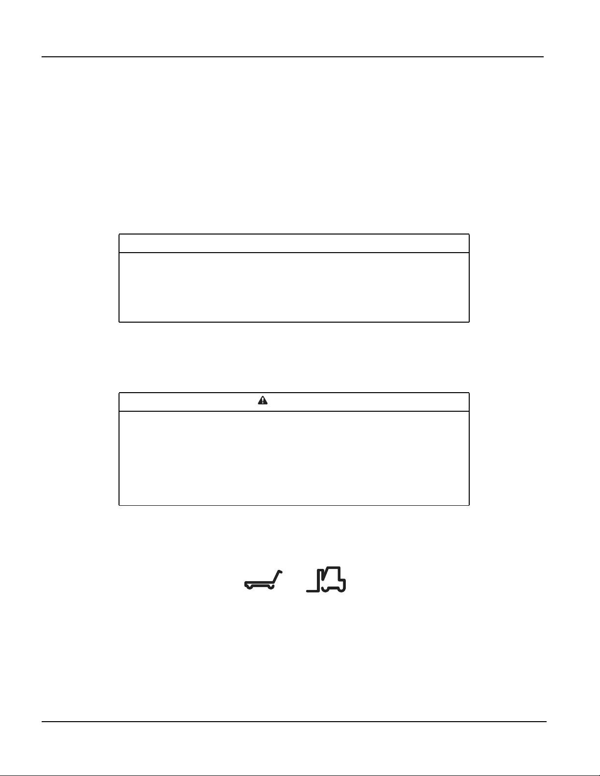
Model Identification
The model number can be found on the outside of
the shipping crate and on the name plate located on
the rear of the cooling unit as shown. Use the table
below to verify that the equipment is the correct type
and voltage.
Model Width Range
of Capacity Voltage Phase Frequency Power
Connection
ACRC301S 300 mm Up to 45 kW 100–240V 1 50/60 Hz NEMA L5-20P/
IEC 309-16A
ACRC301H 300 mm Up to 60 kW 208–230V 1 50/60 Hz HARDWIRED
na4402a
NAME PLATE
REAR
InRow Chilled Water Air Conditioners Installation Manual10
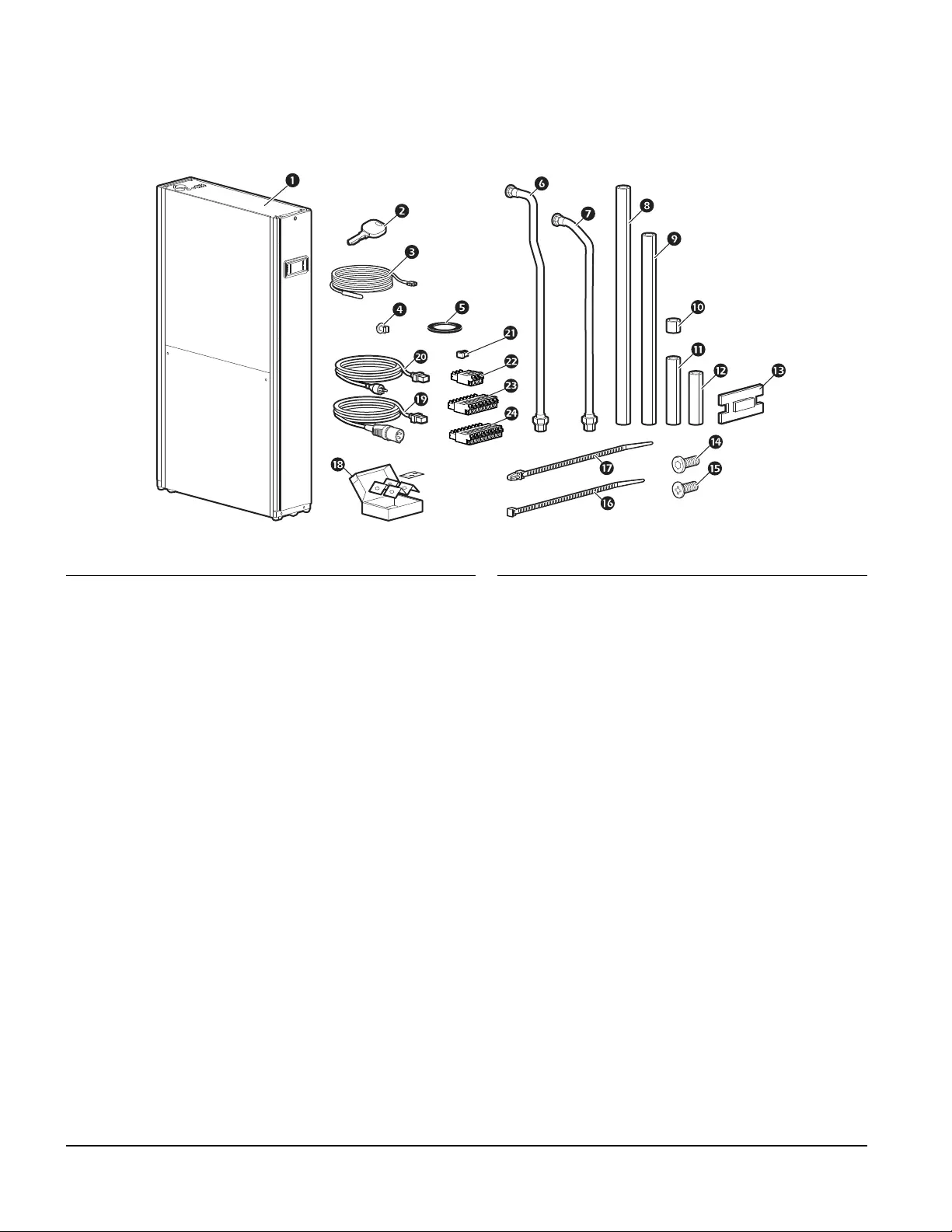
Inventory
Package contents—ACRC301S
Item Description Quantity Item Description Quantity
InRow RC—ACRC301S 1 Insulation, bracket 2
Front and rear panel key 2 TORX screw 4
Remote temperature probe 1 Phillips screw, black 4
Remote temperature probe clip 3 Wire tie 3
Pipe gasket 4 Barb-type wire tie 3
Pipe, outlet 1 Bolt down kit 1
Pipe, inlet 1 Power cord,
IEC 309-16A to C19
2
Insulation, outlet pipe (above clamp) 1 Power cord,
NEMA L5-20P to C19
2
Insulation, inlet pipe (above clamp) 1 Terminator 1
Insulation, union 2 Terminal plug, 3-position 2
Insulation, outlet pipe (below clamp) 1 Connector, 8-tab 1
Insulation, inlet pipe (below clamp) 1 Connector, 9-tab 1
na4465a
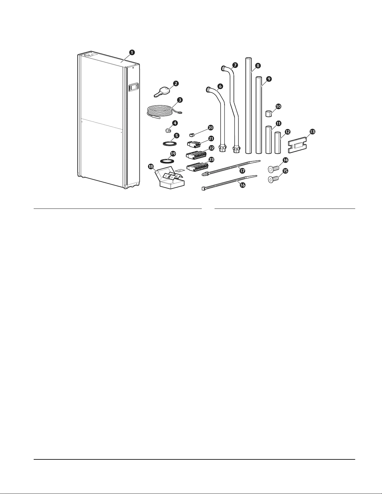
11InRow Chilled Water Air Conditioners Installation Manual
Package contents—ACRC301H
Item Description Quantity Item Description Quantity
InRow RC—ACRC301H 1 Insulation, clamp 2
Front and rear panel key 2 TORX screw 4
Remote temperature probe 1 Phillips screw, black 4
Remote temperature probe clip 3 Wire tie 3
Pipe gasket, unit pipes 2 Barb-type wire tie 3
Pipe, inlet 1 Bolt down kit 1
Pipe, outlet 1 Pipe gasket, client
connections
2
Insulation, outlet pipe (above clamp) 1 Terminator 1
Insulation, inlet pipe (above clamp) 1 Terminal plug, 3-position 2
Insulation, pipe unions 2 Connector, 8-tab 1
Insulation, inlet pipe (below clamp) 1 Connector, 9-tab 1
Insulation, outlet pipe (below clamp) 1
na4398a
InRow Chilled Water Air Conditioners Installation Manual12
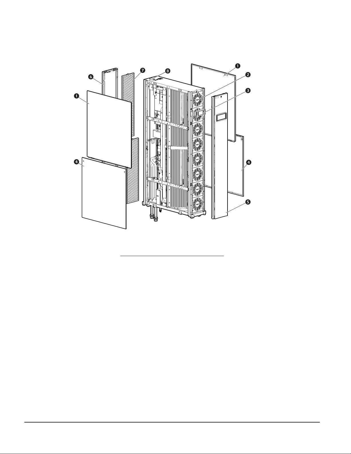
Component Identification
External components—ACRC301S
Item Description
Upper side panels
Fans
Display interface
Lower side panels
Front panel
Rear panel
Air filters
Upper piping installation holes
na4303a
13InRow Chilled Water Air Conditioners Installation Manual
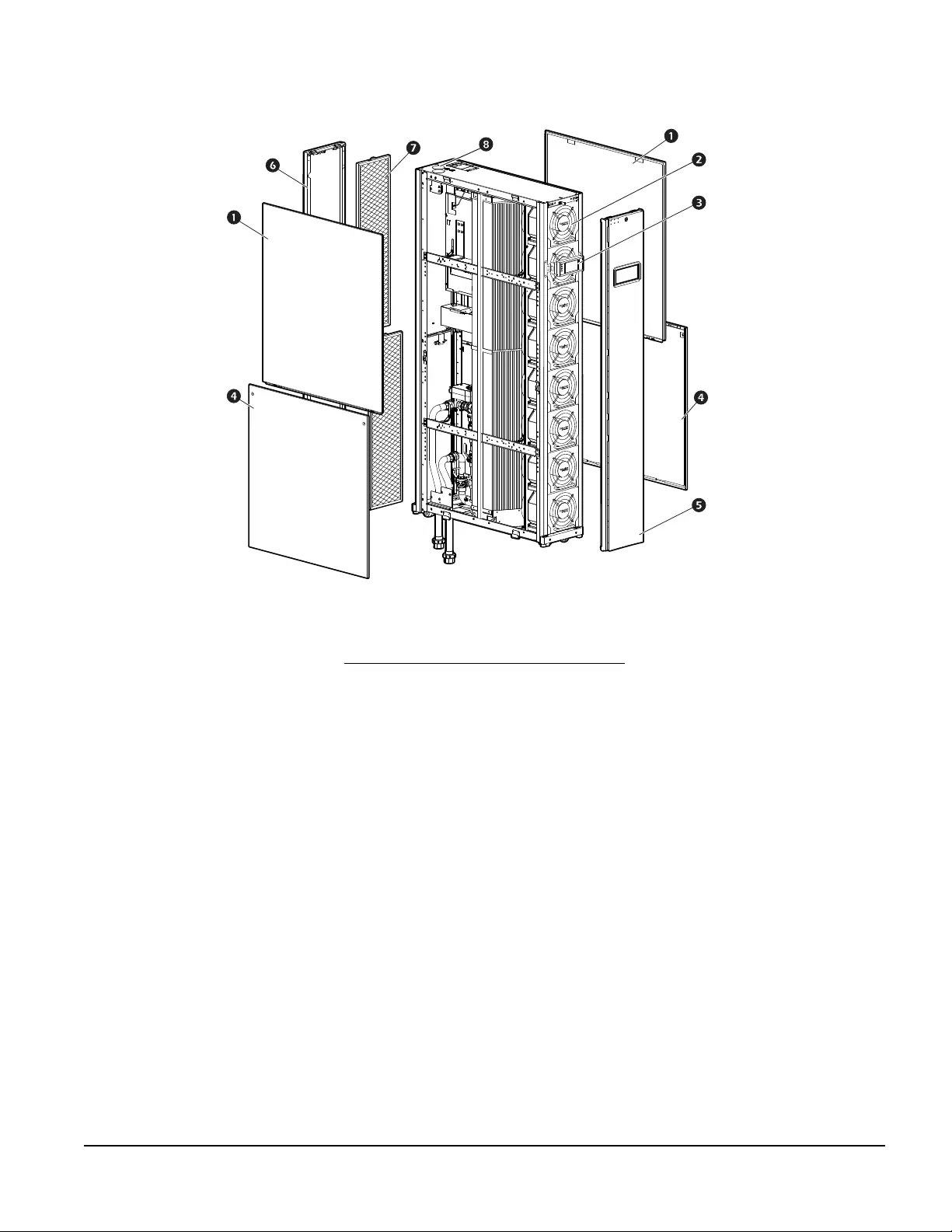
External components—ACRC301H
Item Description
Upper side panels
Fans
Display interface
Lower side panels
Front panel
Rear panel
Air filters
Upper piping installation holes
na4345a
InRow Chilled Water Air Conditioners Installation Manual14
Internal components—ACRC301S
Item Description Item Description
Fan Inlet shutoff valve (1 in.)
Supply air temperature sensor, top Pipe connection, water inlet
Coil Pipe connection, water outlet
Condensate drain pan, top Schrader valve (outlet water pressure test)
Supply air temperature sensor, bottom 3-way actuator valve
Condensate drain pan, bottom Flow meter
Drain valve Auto-transfer switch (ATS) box
Condensate drain pan float switch Electrical box
Condensate pump Return air temperature sensors
Return air temperature sensor, bottom Power cord connections, top
Schrader valve (inlet water pressure test) Rack joining brackets
2-way–(3/4-in.) bypass shut-off valve Schrader valve (air purging)
na4397a
15InRow Chilled Water Air Conditioners Installation Manual
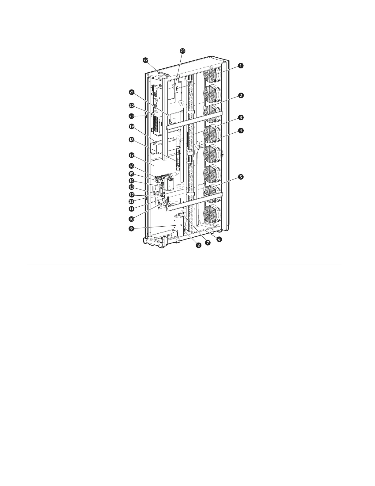
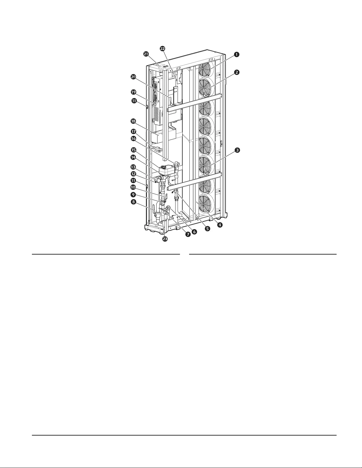
Internal components—ACRC301H
Item Description Item Description
Fan Pipe connection, water outlet
Supply air temperature sensor, top Return air temperature sensor, bottom
Supply air temperature sensor, bottom 3-way valve actuator
Coil Top pipe connection for optional recirculation
pump
Flow meter Humidity sensor
Bottom pipe connection for optional
recirculation pump
Auto transfer switch (ATS) box
Drain valve Electrical box
Inlet shutoff valve (1 1/4-in.) Return air temperature sensor, top
Pipe connection, water inlet Junction box, top position
2-way valve (1-in.) bypass shut-off Schrader valve (air purging)
Rack joining brackets Schrader valve (inlet water pressure test)
Schrader valve (outlet water pressure test)
na4333a
InRow Chilled Water Air Conditioners Installation Manual16
User interface connection panel—ACRC301S
Item Description
Upper electrical box cover
User interface connection panel
Control module cover
na4335a
17InRow Chilled Water Air Conditioners Installation Manual
User interface connection panel—ACRC301H
Item Description
Upper electrical box cover
User interface connection panel
Control module cover
na5053a
InRow Chilled Water Air Conditioners Installation Manual18
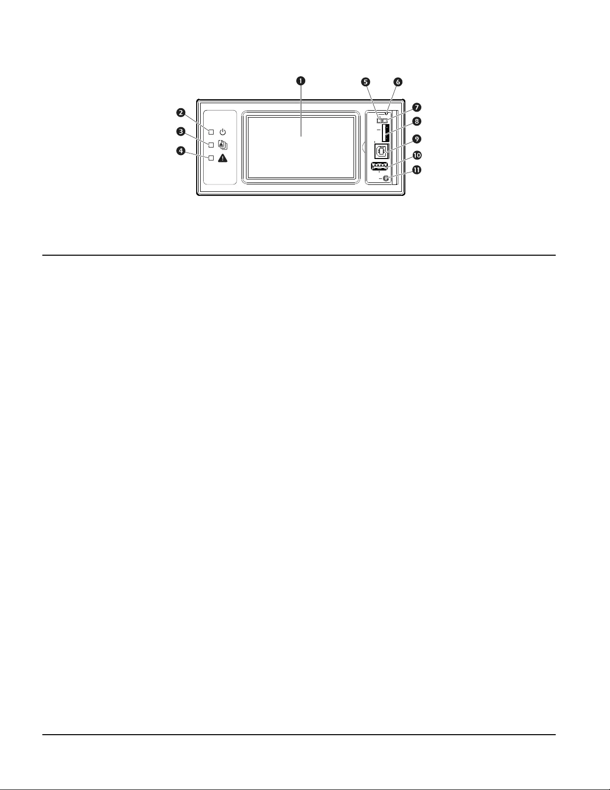
Display interface
Item Description Function
LCD display 4.3-in. touch-screen color display.
Power LED The cooling unit is powered when the LED is illuminated. Unit
firmware is updating when LED is blinking.
Check Log LED When this LED is illuminated, a new entry has been made to the
event log.
Alarm LED Displays current alarm condition of unit.
Status LED Displays current network management card status.
Display Reset button Resets the display microprocessor. This has no effect on the air
conditioner controller.
Link-RX/TX (10/100) LED Displays current network link status.
Micro SD card slot Memory card expansion slot.
Service port USB-B port used only by service personnel.
USB-A port Supports firmware upgrades.
Serial Configuration port Connects the display to a local computer to configure initial network
settings or access the command line interface (CLI).
Display
Reset
Micro
SD
Service
Port
USB
Console
10/100
na4820a

19InRow Chilled Water Air Conditioners Installation Manual
Location, Power, and Water Considerations
Room preparation
During the design of the data center, consider ease of entry for the equipment, floor loading factors, and
accessibility to piping and wiring.
Seal the room with a vapor barrier to minimize moisture infiltration. (Polyethylene film is recommended for
ceiling and wall applications.) Apply rubber- or plastic-based paints to concrete walls and floors.
Insulate the room to minimize the influence of exterior heat loads. Use the minimum required amount of fresh
air for make up to comply with local and national codes and regulations. Fresh air imposes extreme load
variation on the cooling equipment from summer to winter and causes increased operating costs.
The cooling unit is designed as a sensible cooling air conditioning unit for in-row use in data centers. The
cooling unit does not have humidification or dehumidification control. Room humidity must be within acceptable
operating conditions before starting the cooling unit. If operated in spaces where the humidity is in the
unacceptable operating conditions section of the Operating Guidelines chart (see the InRow RC Operation and
Maintenance manual), the cooling unit condenses excess water vapor from the air. For units that contain
condensate pumps, this condition will exceed the pumps pumping capacity, causing the cooling unit to send an
alarm and shut down to avoid overflowing the condensate pan. The condensate pump will run until the fluid
level in the pan is reduced, and the alarm is automatically reset. The cooling unit self-regulates in this manner
until normal operating conditions are present.
Incoming power supply requirements
See the name plate on the unit to determine the maximum possible current draw of the cooling unit. Provide
either a single outlet circuit or a Power Distribution Unit (PDU) with sufficient capacity to handle all loads. Do not
plug two InRow RC units into the same branch circuit or PDU.
The cooling unit must be grounded. Electrical service must conform to national and local electrical codes and
regulations.
Chilled water temperature requirements
For ACRC301H units, the chilled water temperature needs to be higher than the dew point of the room. If the
dew point is too high, an optional dew point control pump is available for installation in ACRC301H units. The
InRow RC units are not designed for precision humidity control for the IT environment.
Cooling unit location
Refer to the floor layout drawing for the exact placement of the cooling unit in the row of IT equipment. This
layout drawing can be found in the Configure To Order (CTO) report or the engineering specification drawings
provided by the Consulting Engineer.
Due to potentially high noise levels during peak loads, the InRow RC is not intended to be used in an occupied
office environment. It is recommended that ear protection be worn if prolonged exposure to the high noise level
is expected.
Model Chilled Water Temperature Range
ACRC301S 5–15°C (41–59°F)
ACRC301H 10–22°C (50–72°F)
InRow Chilled Water Air Conditioners Installation Manual20
Piping Diagrams
NOTE: Install isolation shutoff valves and particulate strainers in the supply line between the chiller and the
CDU. If the system is to be set up as an isolated loop - a chiller and pipe layout, dedicated only to supplying
InRow RC units and no other cooling unit - the strainer may be placed in the piping circuit before the pump.
NOTE: Thoroughly flush the system to remove all debris and process chemicals.
NOTE: Top or bottom entry can be chosen individually for each type of connection, i.e., power, condensate
drain (ACRC301S), chilled-water supply, and chilled-water return. Top piping configurations have the same
valves and strainers as bottom piping configurations.
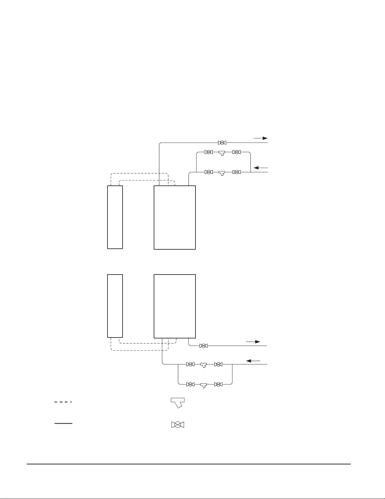
With Cooling Distribution Unit (CDU)
A CDU is only used with ACRC301S units.
Flex hose or copper tubing Strainer with 20 mesh screen with opening
size of 865 micron, (field installed)
Copper tubing Isolation shutoff valve (field-installed)
INROW RC
TOP PIPING
CONFIGURATION
BOTTOM PIPING
CONFIGURATION
CDU
CDU
TO
CUSTOMER
SUPPLIED
CHILLER
SUPPORTS UP
TO 12 UNITS
TO
CUSTOMER
SUPPLIED
CHILLER
INROW RC
21InRow Chilled Water Air Conditioners Installation Manual
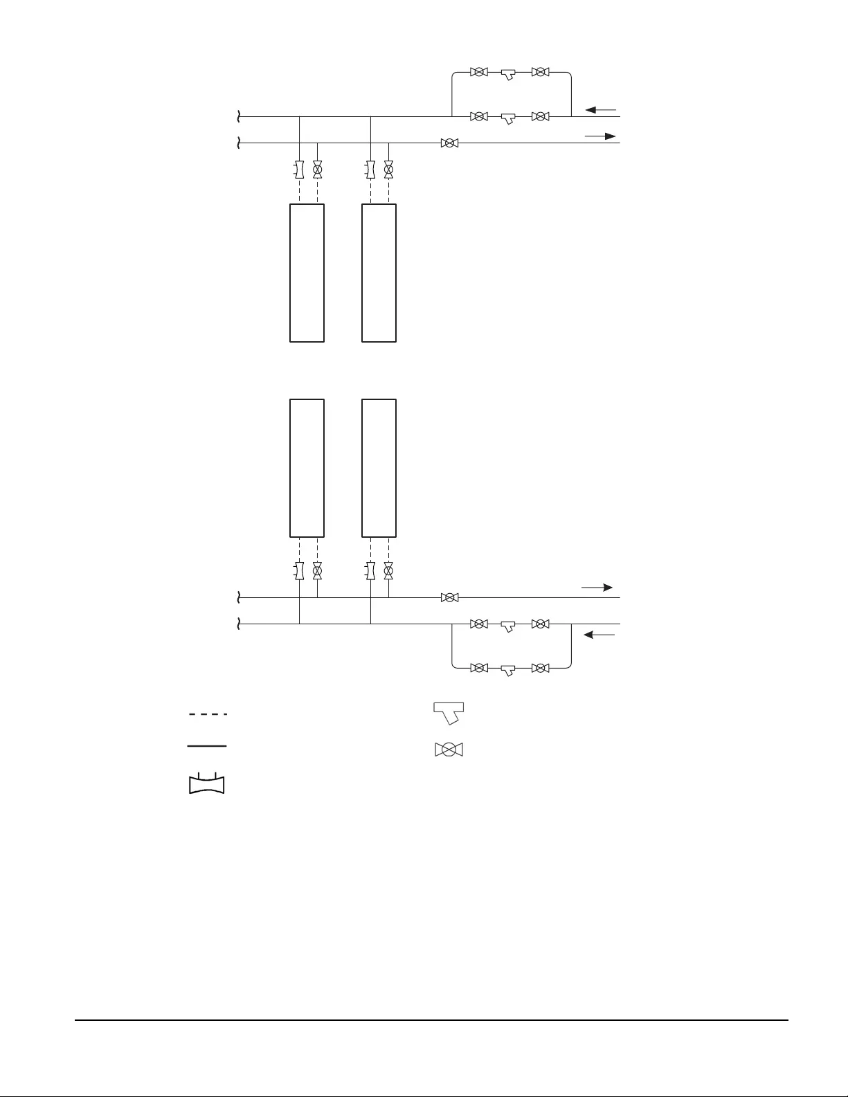
Without CDU
Flex hose or copper Strainer with 20 mesh screen
(field installed)
Copper tubing Shutoff valve (field-installed)
Circuit setter
TOP PIPING
INROW RC
TO
CUSTOMER
SUPPLIED
CHILLER
TO
CUSTOMER
SUPPLIED
CHILLER
BOTTOM PIPING
InRow Chilled Water Air Conditioners Installation Manual22
Internal piping diagram—ACRC301S
Item Description Item Description
Outlet water union (top piping option) Outlet water union (bottom piping option)
Inlet water union (top piping option) Inlet water union (bottom piping option)
3-way actuator control valve—1 1/4 in. Drain valve
Flow meter Condensate pump
Bypass shutoff ball valve—3/4 in. Bottom condensate pan
Inlet shutoff valve—1 in. Top condensate pan
Condensate drain Coil
na4343a
23InRow Chilled Water Air Conditioners Installation Manual
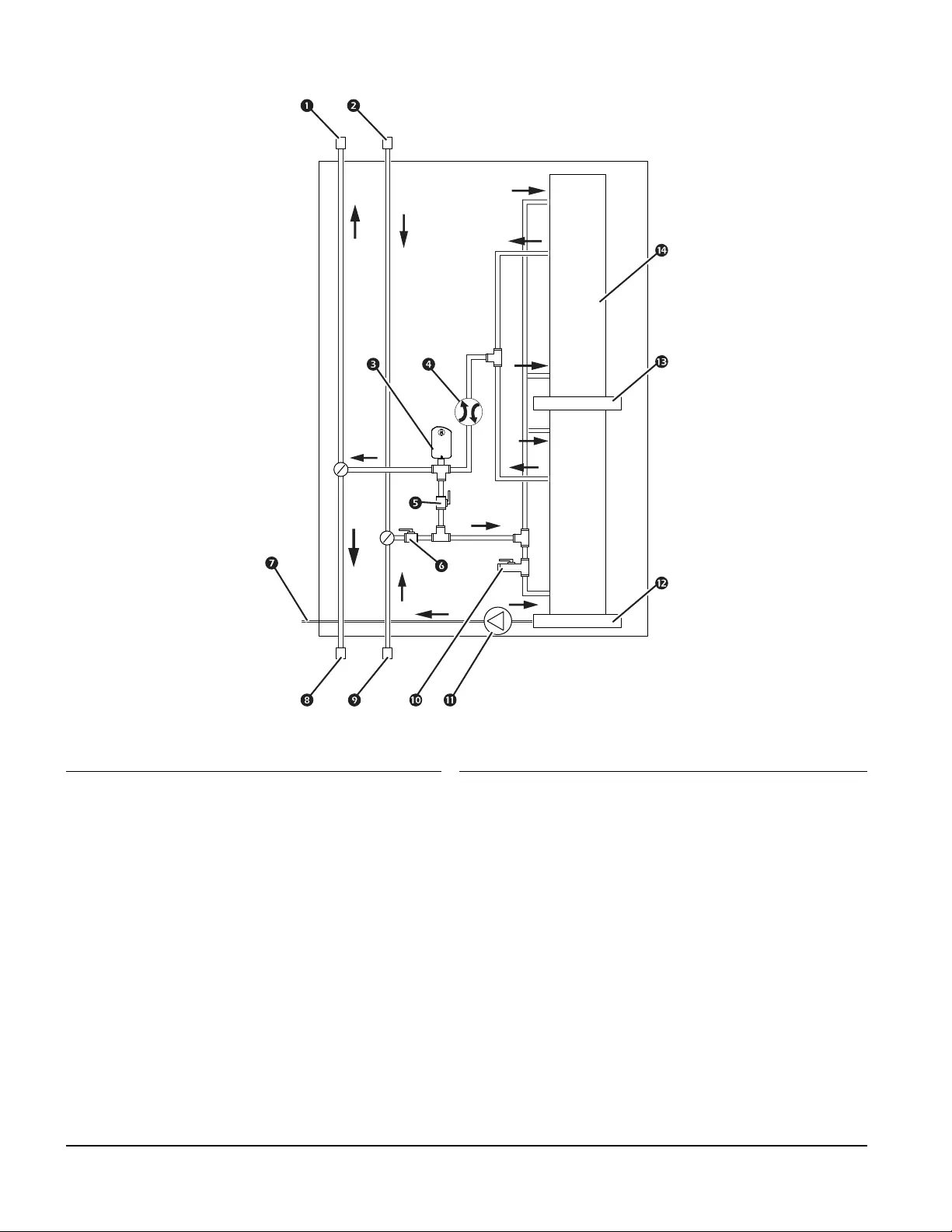
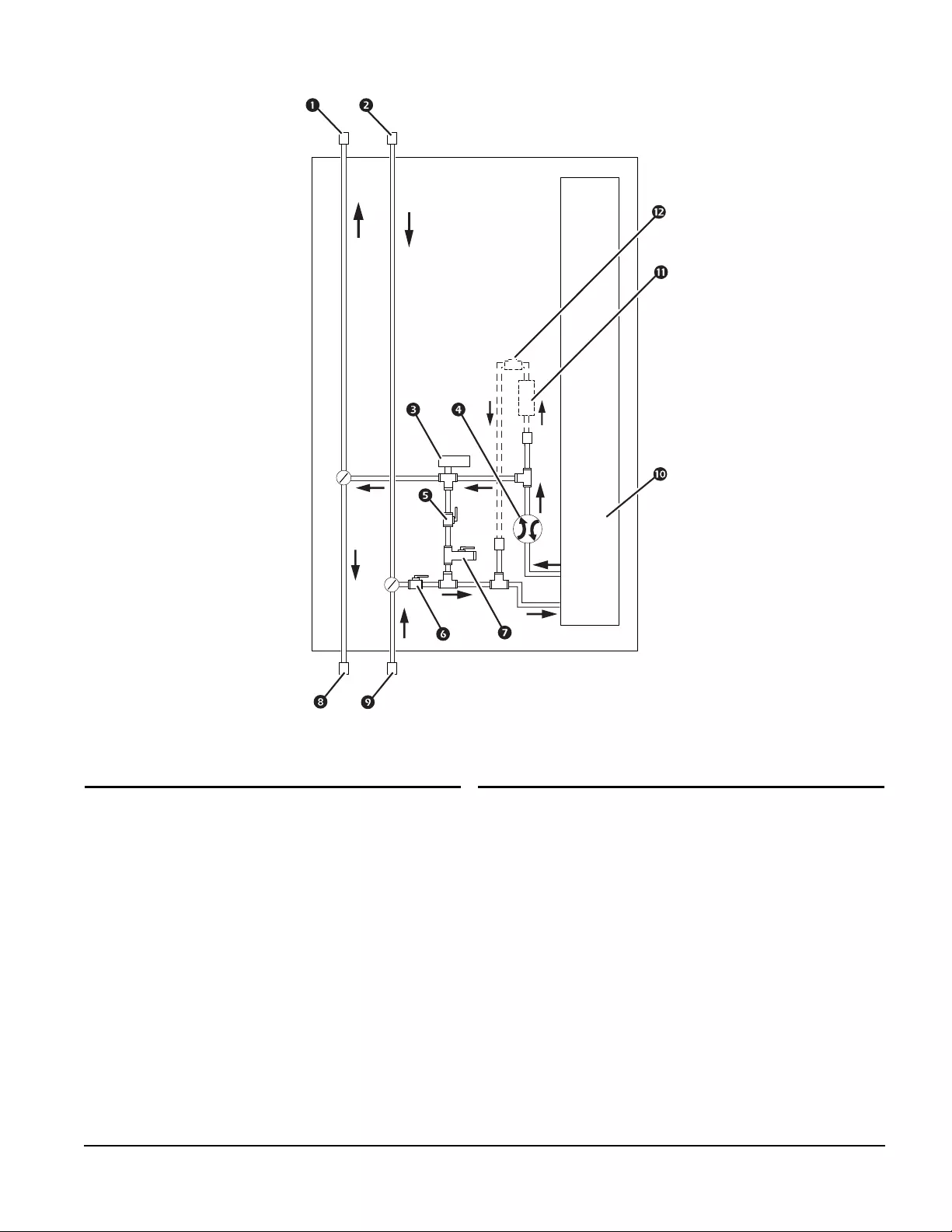
Internal piping diagram—ACRC301H
Item Description Item Description
Outlet water union (top piping option) Outlet water union (bottom piping option)
Inlet water union (top piping option) Inlet water union (bottom piping option)
3-way actuator control valve—1 1/4 in. Coil
Flow meter Circulation pump (optional)
Bypass shutoff valve—1 in. Circulation pump check valve (optional)
Inlet shutoff valve—1 1/4 in.
Drain valve
na4358a
InRow Chilled Water Air Conditioners Installation Manual24
Piping and electrical access locations—ACRC301S
na4353a
56 (2.22)
110 (4.35)
116 (4.55)
204 (8.02)
97 (3.83)
145 (5.72)
147 (5.80)
180 (7.10)
199 (7.85)
240 (9.46)
174 (6.84)
157 (6.20)
90 (3.54)
184 (7.26)
53 (2.08)
161 (6.34)
189 (7.43)
83 (3.27)
110 (4.31)
BOTTOM
(LOOKING UP)
TOP
* Dimensions are shown in mm (in.).
25InRow Chilled Water Air Conditioners Installation Manual
Item Description
Power connections
Condensate line—0.25 in. ID/0.38 in. OD
1-in. NPT female return pipe (outlet)
1-in. NPT female supply pipe (inlet)
Low voltage input wiring.
na4463a
TOP BOTTOM
LOOKING UP
InRow Chilled Water Air Conditioners Installation Manual26
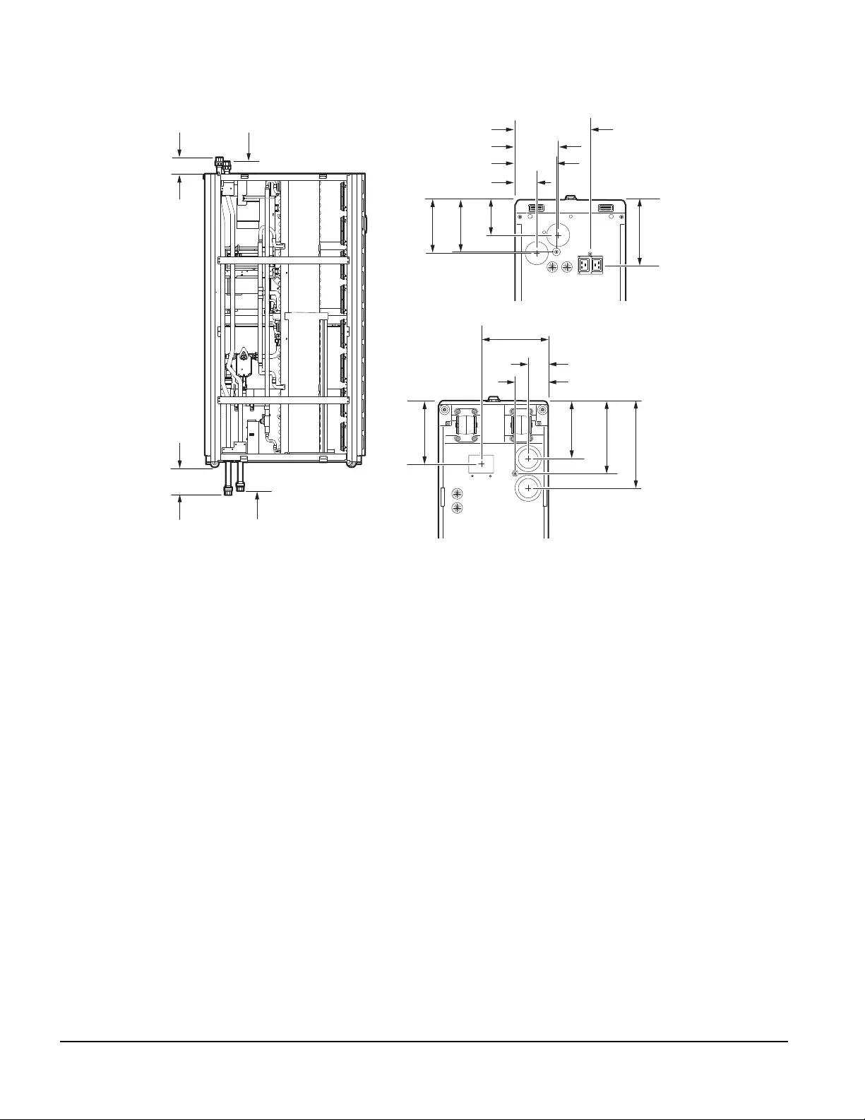
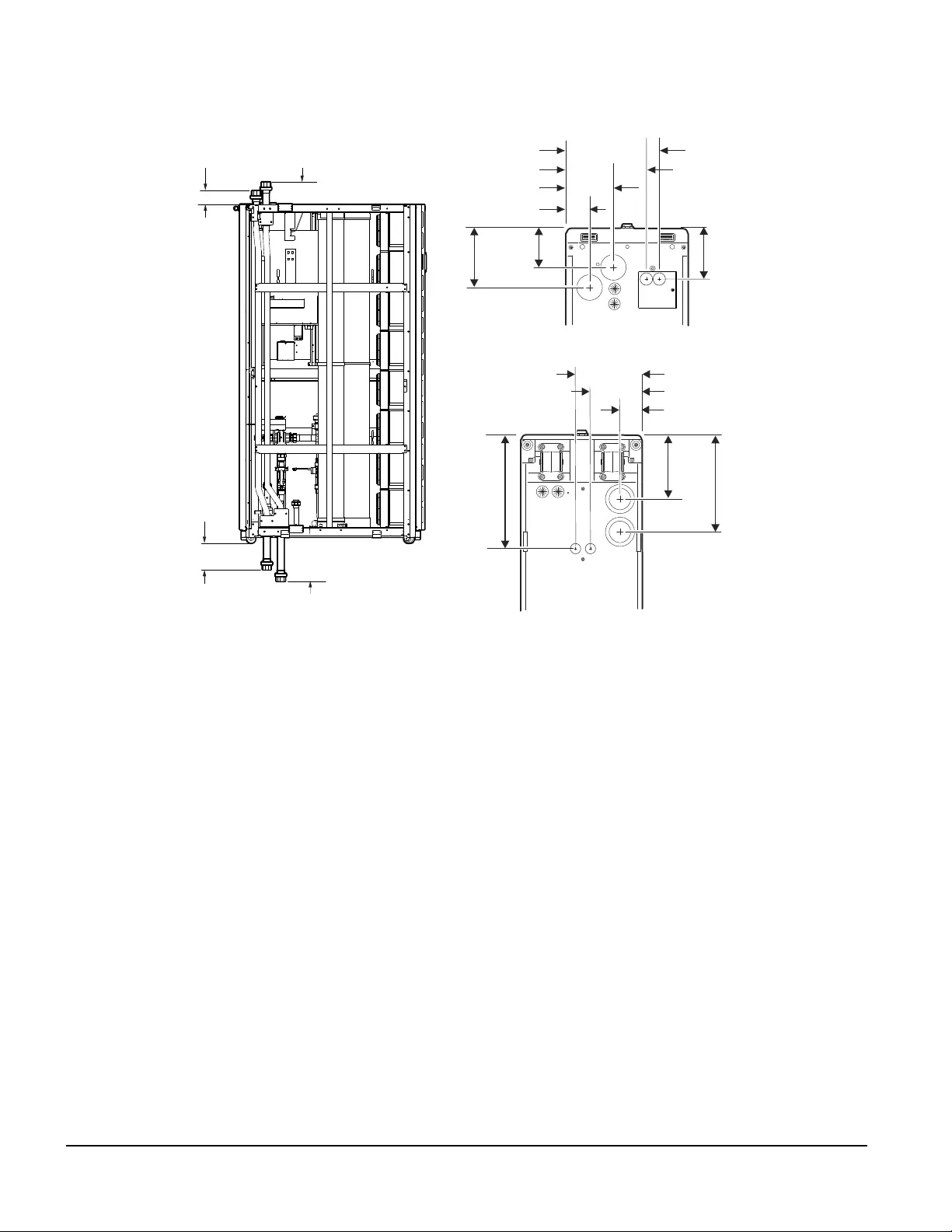
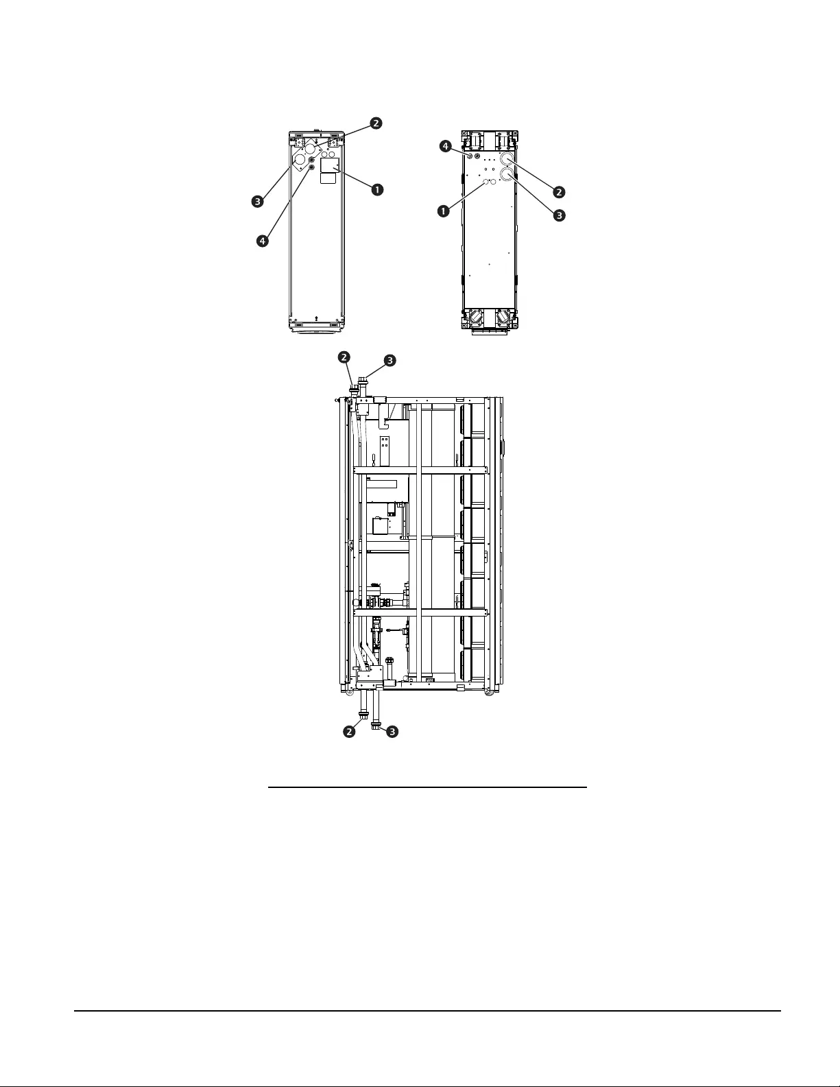
Piping and electrical access locations—ACRC301H
* Dimensions are shown in mm (in).
na4334a
158 (6.23)
280 (11.02)
130 (5.12)
170 (6.69)
56 (2.22)
240 (9.46)
81 (3.19) 132 (5.21)
156 (6.14)
224 (8.82)
126 (4.95)
61 (2.38)
116 (4.55)
193 (7.60)
233 (9.17)
97 (3.83)
152 (6.00)
BOTTOM
(LOOKING UP)
TOP
27InRow Chilled Water Air Conditioners Installation Manual
Item Description
Power connections
1 1/4-in. NPT female return pipe (outlet)
1 1/4-in. NPT female supply pipe (inlet)
Low voltage input wiring
na4464a
TOP BOTTOM
LOOKING UP
InRow Chilled Water Air Conditioners Installation Manual28
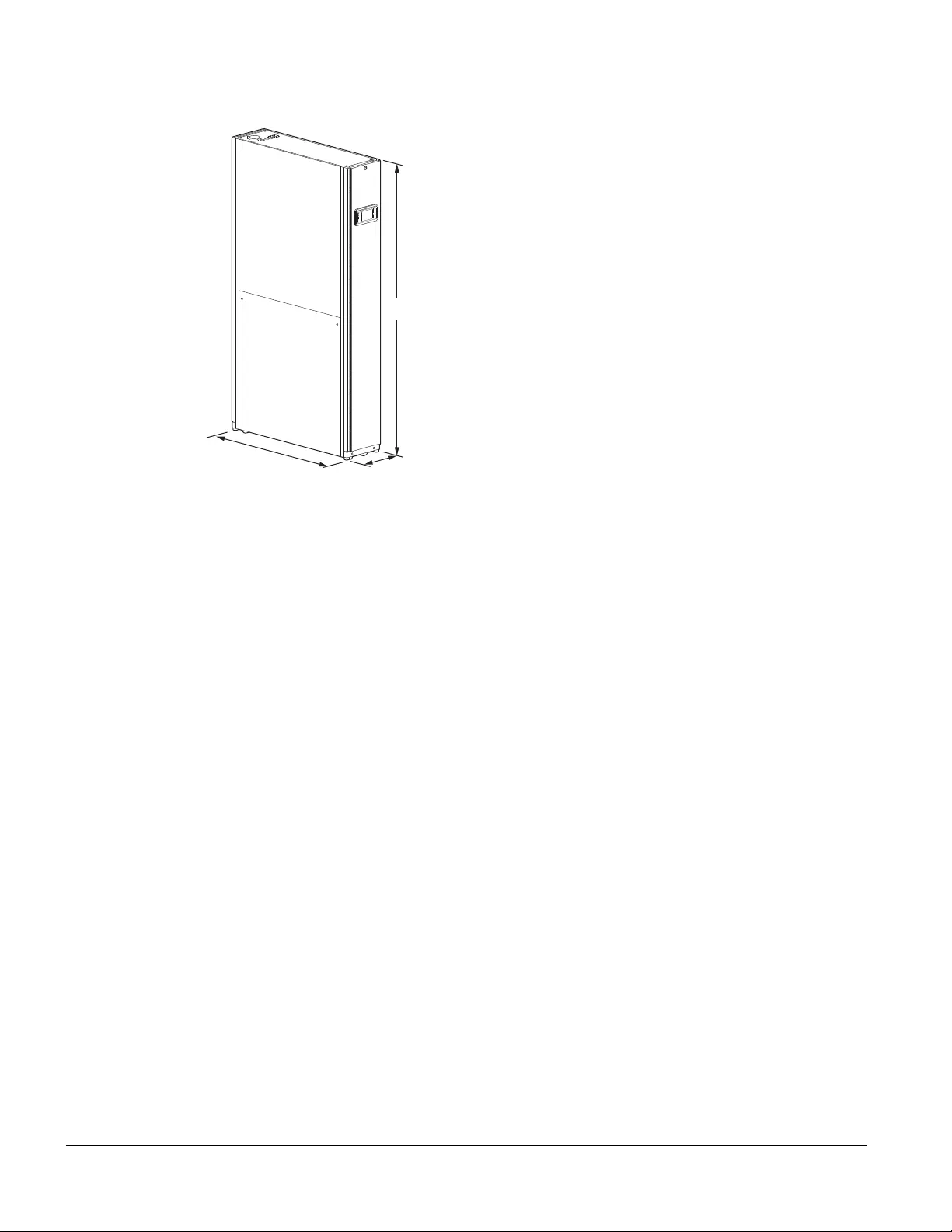
Weights and dimensions
na4339a
1095 (43.11)
300 (11.80)
1991 (78.39)
* Dimensions are shown in mm (in.).
Net weight (cooling unit only)
ACRC301S = 184 kg (406 lb)
ACRC301H = 210 kg (463 lb)
Operating weight (cooling unit only)
ACRC301S = 192 kg (423 lb)
ACRC301H = 220 kg (485 lb)
29InRow Chilled Water Air Conditioners Installation Manual
Installation
DANGER
HAZARD OF ELECTRIC SHOCK, EXPLOSION, OR ARC FLASH
Turn off all power supplying this equipment before working on the equipment. All electrical
work must be performed by qualified personnel. Practice Lockout/Tagout procedures. Do
not wear jewelry when working with electrical equipment.
Failure to follow these instructions will result in death or serious injury.
WARNING
MOVING PARTS HAZARD
• Do not open doors and panels if the equipment is operating
Failure to follow these instructions can result in death, serious injury, or
equipment damage.
WARNING
HAZARD TO EQUIPMENT OR PERSONNEL
All work must be performed by Schneider Electric qualified personnel.
Failure to follow these instructions can result in death, serious injury, or
equipment damage.
WARNING
TIP HAZARD
• Use two or more people at all times to move or turn this equipment.
• Always push, pull, or turn while facing the front and rear of this equipment - never push,
pull, or turn while facing the sides of the equipment.
• Slowly move this equipment across uneven surfaces or door thresholds.
• Lower leveling feet to the floor when this equipment is stationary.
• Lower the leveling feet and attach joining brackets to adjacent racks when the equipment
is in its final location.
Failure to follow these instructions can result in death, serious injury, or
equipment damage.
InRow Chilled Water Air Conditioners Installation Manual30
IMPORTANT: Before proceeding with the installation of the cooling unit, install the optional pump kit
(ACRC301H) or upper piping kits. These optional items must be installed before placing the unit in-row.
Refer to the documentation that is supplied with other equipment for instructions on how to install
that equipment.
IMPORTANT: Ensure the unit is stable before installing any optional kits. When installing upper piping kits,
make sure the electrical box wiring remains as is and do not hit the air temperature sensors with the piping.
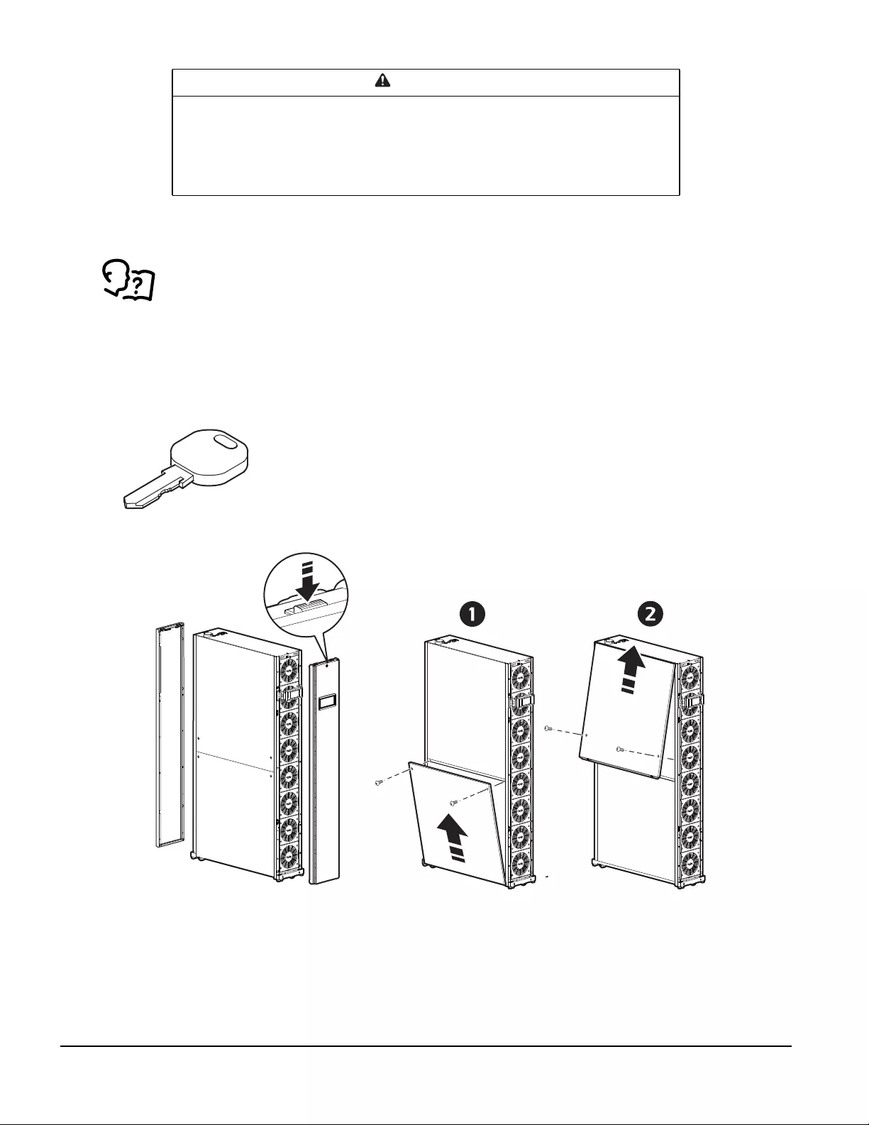
How to Remove Cover Panels
The front and rear panels must first be unlocked before they can be removed.
Two keys are provided with the unit.
CAUTION
UNPROTECTED PARTS
Be careful when placing doors when removed from the equipment. Spring latches are
easily damaged.
Failure to follow these instructions can result in equipment damage.
na4336a
31InRow Chilled Water Air Conditioners Installation Manual
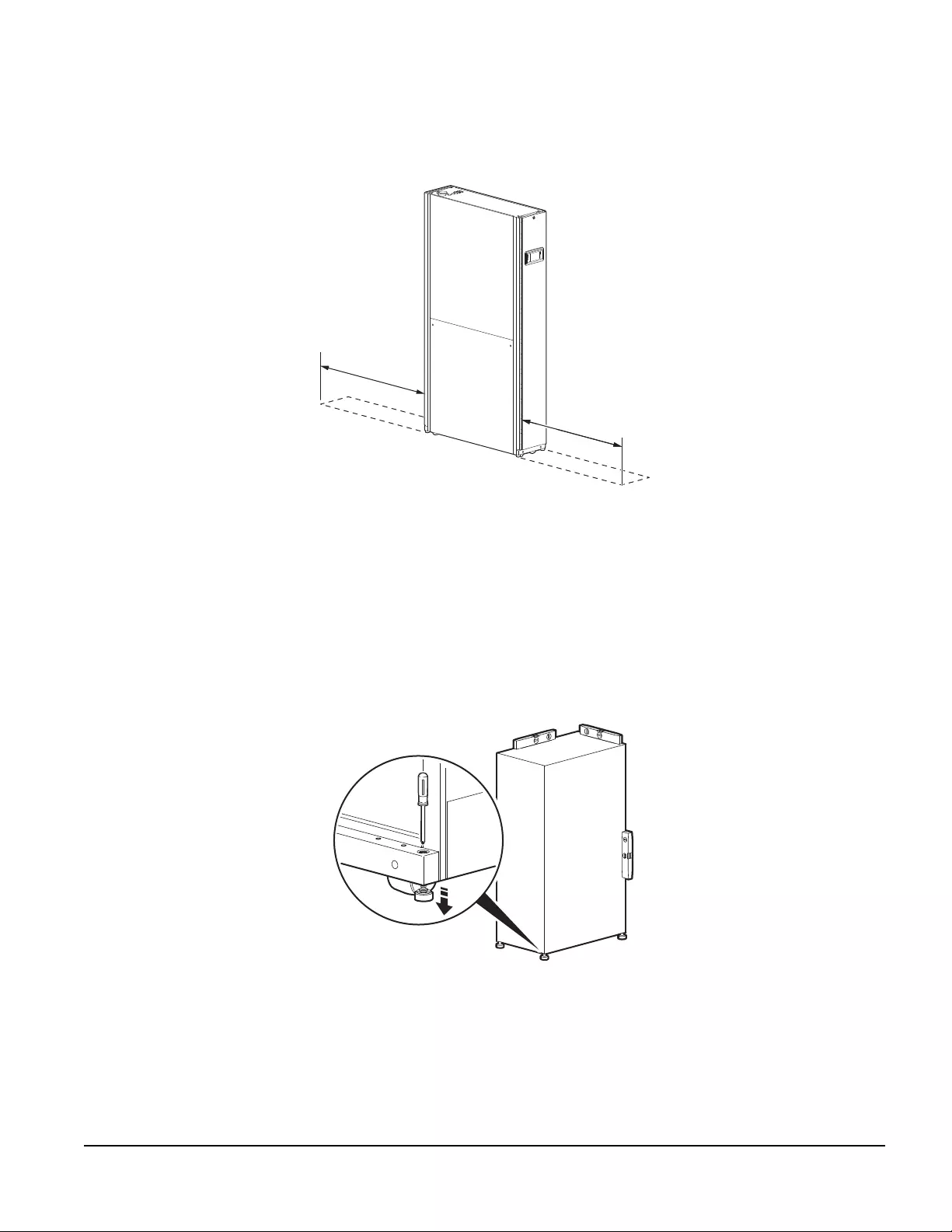
Positioning the Cooling Unit
Service access
An area of 1143 mm (45 in.) of clear floor space in front and 914.4 mm (36 in.) in the rear of the cooling units
are required for service.
Leveling
The leveling feet provide a stable base if the floor is uneven but cannot compensate for a badly sloped surface.
Once the cooling unit is in its intended location, use a screwdriver to turn each leveling foot until it makes
contact with the floor. Adjust each foot until the cooling unit is level and plumb.
The casters and leveling feet can be removed to allow the cooling unit to rest directly on the floor.
NOTE: Front and rear panels will need to be removed to access the leveling screw.
1143 (45)
914.4 (36)
na4340a
* Dimensions are shown in mm (in).
na1572b
InRow Chilled Water Air Conditioners Installation Manual32
Stabilizing the Cooling Unit
Bolt-down kit
To prevent the cooling unit from moving (if it is not joined with an enclosure), use the included bolt-down kit
(AR7701). Follow the installation instructions included with the kit.
DANGER
HAZARD OF ELECTRIC SHOCK, EXPLOSION, OR ARC FLASH
Turn off all power supplying this equipment before working on the equipment. All electrical
work must be performed by qualified personnel. Practice Lockout/Tagout procedures. Do
not wear jewelry when working with electrical equipment.
Failure to follow these instructions will result in death or serious injury.
WARNING
TIP HAZARD
• Use two or more people at all times to move or turn this equipment.
• Always push, pull, or turn while facing the front and rear of this equipment - never push,
pull, or turn while facing the sides of the equipment.
• Slowly move this equipment across uneven surfaces or door thresholds.
• Lower leveling feet to the floor when this equipment is stationary.
• Lower the leveling feet and attach joining brackets to adjacent racks when the equipment
is in its final location.
Failure to follow these instructions can result in death, serious injury, or
equipment damage.
33InRow Chilled Water Air Conditioners Installation Manual
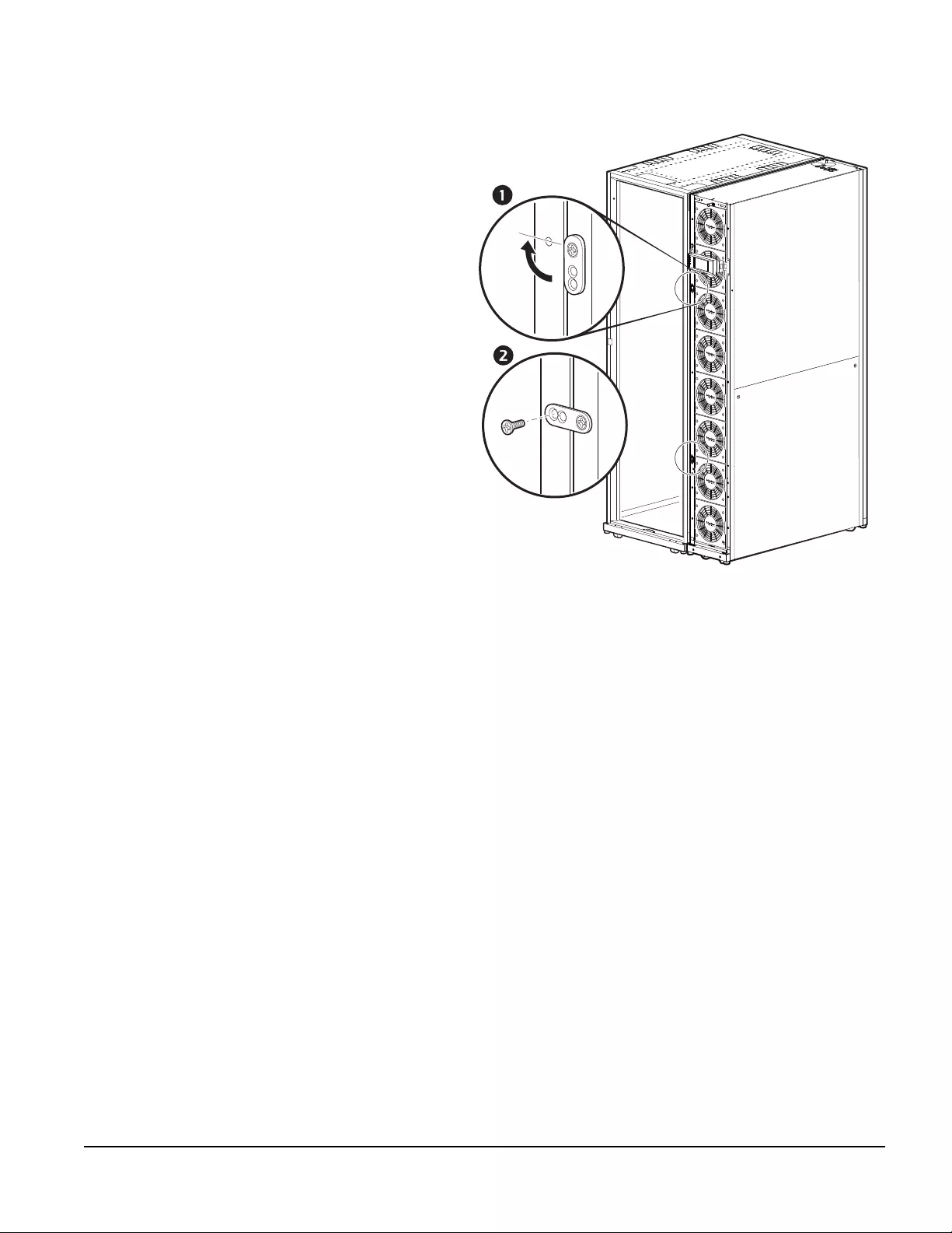
Joining the InRow RC to a NetShelter™ enclosure
For NetShelter SX enclosures:
Joining brackets are installed on the unit, two in
the front and two on the rear. Each bracket is
designed to accommodate both 24-in. or 600-
mm enclosure spacing.
To install a joining bracket:
1. Loosen the attachment screw.
2. Rotate the brackets 90°.
3. Install a provided Phillips screw (M5
screw) through the bracket and into the
adjoining enclosure.
4. Re-tighten the attachment screw.
na4354a
90°
InRow Chilled Water Air Conditioners Installation Manual34
Mechanical Connections
DANGER
HAZARD OF ELECTRIC SHOCK, EXPLOSION, OR ARC FLASH
Turn off all power supplying this equipment before working on the equipment. All electrical
work must be performed by licensed electricians. Practice Lockout/Tagout procedures.
Do not wear jewelry when working with electrical equipment.
Failure to follow these instructions will result in death or serious injury.
WARNING
TIP HAZARD
• Use two or more people at all times to move or turn this equipment.
• Always push, pull, or turn while facing the front and rear of this equipment - never push,
pull, or turn while facing the sides of the equipment.
• Slowly move this equipment across uneven surfaces or door thresholds.
• Lower leveling feet to the floor when this equipment is stationary.
• Lower the leveling feet and attach joining brackets to adjacent racks when the equipment
is in its final location.
Failure to follow these instructions can result in death, serious injury, or
equipment damage.

35InRow Chilled Water Air Conditioners Installation Manual
Piping
Ensure that coolant water quality complies with local water quality standards or at least with the guidelines
below.
Water
Install shutoff valves for routine service and emergency isolation of the cooling unit. When a CDU is not used, it
is recommended that you install circuit setters to regulate the chilled water flow for each InRow RC air
conditioner. Refer to the piping diagram in this document.
Layout and Piping Considerations
Fluid pipes are not allowed directly above electrical cooling units and must be kept separate from any electrical
runs or wiring. All fluid piping must be installed above the aisles as shown in the diagram below. If any piping
makes a turn, or must be routed over electrical equipment, there must be a drip tray under the pipe that will
protect the equipment from condensation and leaks.
Insulation
Insulate water lines to protect personnel, protect components from condensate, and to minimize condensation.
See “Insulation” on page 40 for insulation locations.
Cooling Water Quality Guidelines for APC Cooling Units
1 ppm = 1 mg/kg = 1 mg/l, CFU - colony forming unit
Water Characteristics Range Water Characteristics Range
Alkalinity (HCO3-)
Hydrogen Carbonate 70 – 300 ppm Hardness as CaCO330 – 200 ppm
Alkalinity / Sulfate: HCO3- /SO42- >1.0 Hydrogen Sulfide (H2S) < 0.05 ppm
Aluminum (Al) < 0.2 ppm Iron (Fe) < 0.2 ppm
Ammonia (NH3) < 2 ppm Magnesium (Mg) < 50 ppm
Ammonium (NH4) < 2 ppm Manganese (Mn) < 0.1 ppm
Bacteria: aerobic < 1000 CFU/ml Molybdenates (MoO42-) < 30 ppm
anaerobic < 1000 CFU/ml Nitrate (NO3) < 100 ppm
heterotrophic colony count < 100,000 CFU/ml Oil and grease < 1 ppm
legionella species < 10 CFU/ml Oxygen < 0.02 ppm
sulfate reducing < 10 CFU/ml Particles: size < 25 microns
pseudomonas < 10 CFU/100 ml weight < 10 ppm
Calcium (Ca) < 50 ppm pH: Acid-Alkaline balance 7 – 9
Carbon Dioxide (CO2): free
(aggressive) < 5 ppm Phosphate (PO43-) < 10 ppm
Carbon acid, free < 20 ppm Potassium (K) < 10 ppm
Chloride (Cl-) < 300 ppm Sodium (Na) < 10 ppm
Chlorine, free (CL2) < 1 ppm Softness: [Ca2+, Mg2+]/[HCO3-] > 0.5
Copper (Cu) < 1.0 ppm Silica (SiO2) Silicon Dioxide < 50 ppm
Electrical conductivity 50 – 500 μS/cm Sulfate (SO42-) < 50 ppm
Sulfide (S2-) 0 ppm
InRow Chilled Water Air Conditioners Installation Manual36
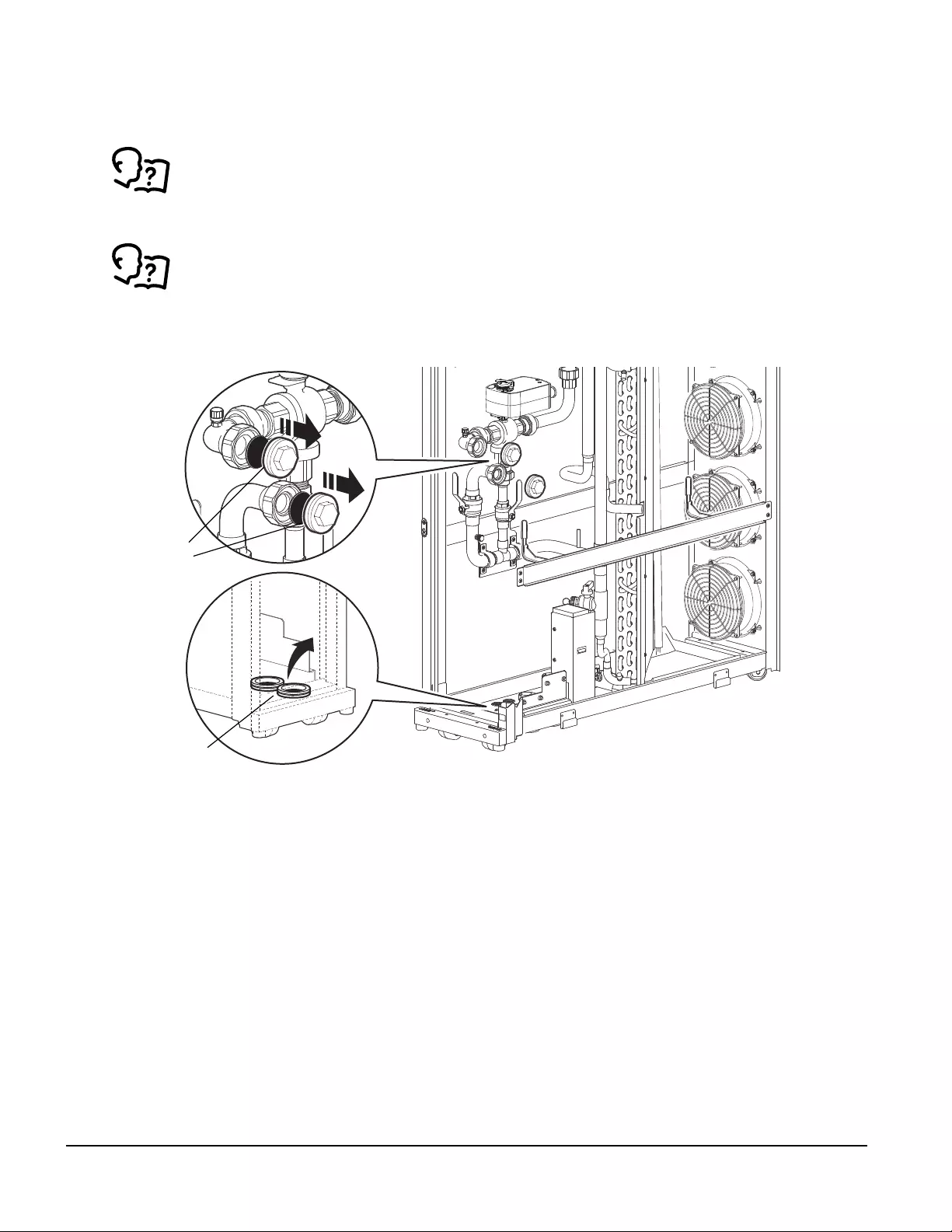
Supply and Return Piping
NOTE: This section covers a bottom piping configuration only. The ACRC301S model is shown in the
illustrations; the process will be the same for ACRC301H units.
IMPORTANT: Before installing pipes, use the Schrader valves to discharge gas from the unit.For
Schrader valve locations, see “Internal components—ACRC301S” on page 14 or “Internal
components—ACRC301H” on page 15.
For upper piping configurations, refer to the instructions that come with the upper piping kit.
1. Remove the pipe connection caps and grommets from the bottom pipe connections.
2. Place the lower piping insulation on the pipes.
na4369a
CAPS
GROMMETS
37InRow Chilled Water Air Conditioners Installation Manual
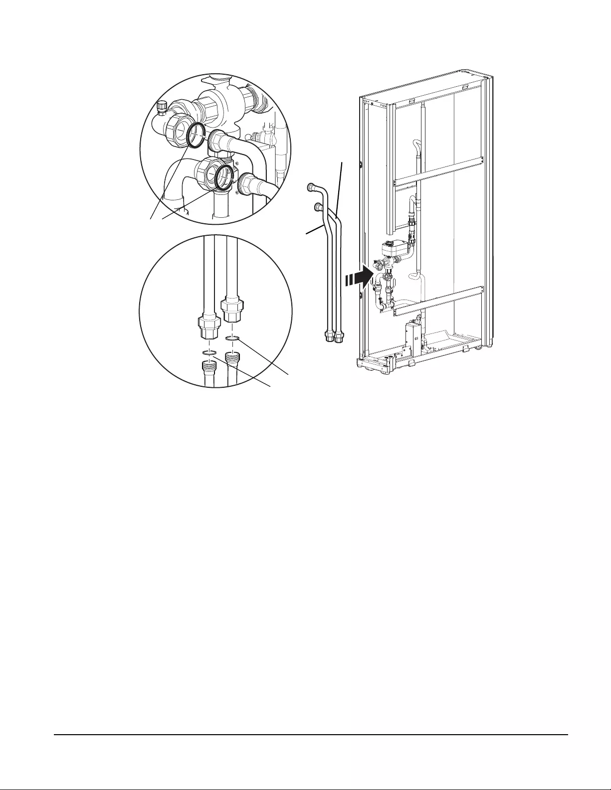
3. Install the provided pipe gaskets and piping. Tighten connections to 40 N*m (29 ft/lbs).
NOTE: Install the inlet pipe first..
na4370a
GASKETS
GASKETS
INLET PIPE
OUTLET
PIPE
InRow Chilled Water Air Conditioners Installation Manual38
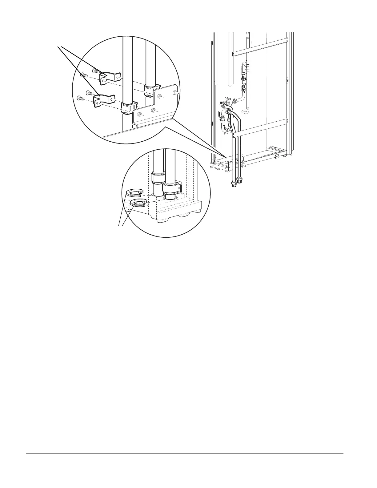
4. Install lower pipe clamps and re-install the grommets around the pipes.
5. Install the insulation around the pipe clamps.
na4375a
GROMMETS
PIPE CLAMPS
39InRow Chilled Water Air Conditioners Installation Manual
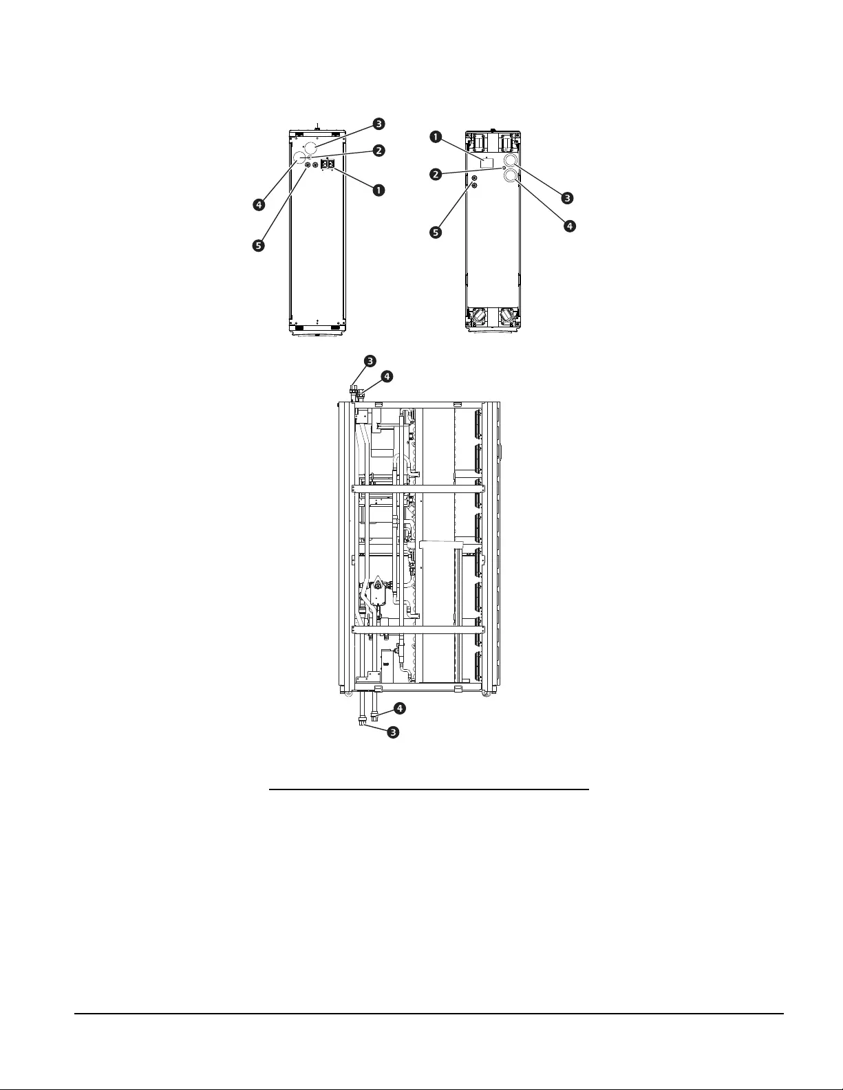
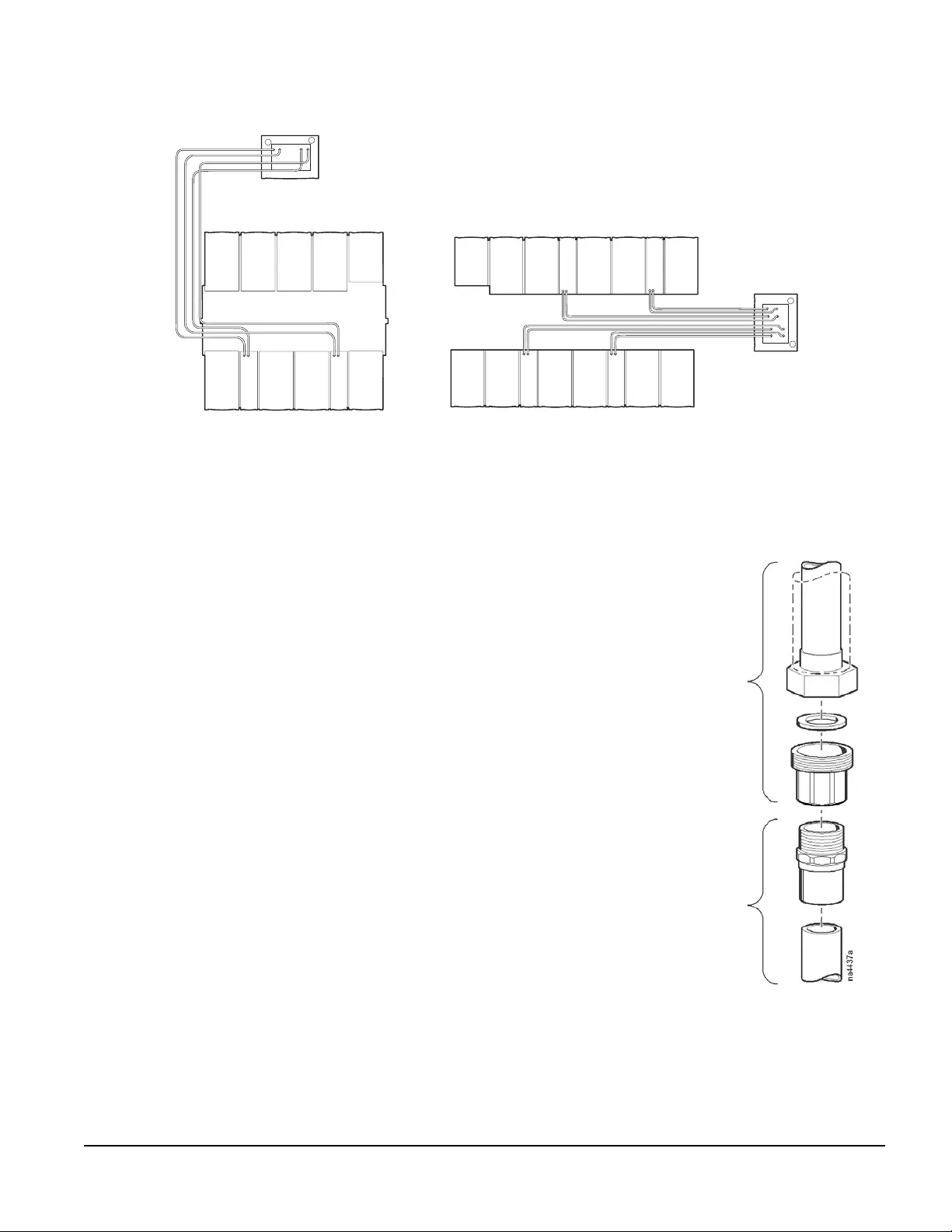
Main Water Connections
Top piping system diagram
1. Route all piping to the cooling unit. Be sure to follow all
local and national codes.
NOTE: Circuit setters are recommended to regulate the
flow of chilled water to each cooling unit. When a CDU is
used in conjunction with the cooling unit, circuit setters are
not required as the CDU provides the flow-regulating
function.
NOTE: The figure shows field piping installation with a
field-supplied PEX fitting. Rigid pipe fittings are handled
similarly.
2. Make the connection on the entering and exiting water
lines:
– Use thread sealant and thread sealing tape in
accordance with local and national codes.
– Use two properly-sized open end wrenches to tighten
the connections.
na4352a
InRow
Aisle Containment
UNIT PIPING
FIELD PIPING
BOTTOM PIPING
SHOWN
InRow Chilled Water Air Conditioners Installation Manual40
Insulation
Use only approved insulation (closed cell elastomeric insulation with sealing seams). Insulation should be 9.52
mm (3/8 in.) wall thickness. All horizontal insulation sections must be installed with seams facing up. Each
section of insulation must be glued to the adjacent section. Any insulation sections that must be fitted around
piping support clamps (other than supplied clamps) must be glued together to prevent condensation.
See “Package contents—ACRC301S” on page 10 and “Package contents—ACRC301H” on
page 11 for locations of insulation pieces.
na4466a
ACRC301H SHOWN
41InRow Chilled Water Air Conditioners Installation Manual
Condensate pump and drain line—ACRC301S
The condensate pump is factory-wired, piped internally to the lower condensate pan, and is capable of moving
liquid a maximum of 15.2 m (50 ft), including a maximum lift of 4.9 m (16 ft).
NOTE: Sufficient drain line is supplied to route the drain to the outside of the cooling unit. To route the drain
line to a remote drain, an additional drain line may need to be provided.
An on-board condensate high-level float switch is wired into the InRow RC controller for local and remote alarm
capabilities.
NOTE: Comply with all local codes when installing the condensate drain line to the proper drain system.
To route the pump drain line:
1. Remove the drain line from the side of the unit.
2. Route the drain line through the top or bottom of the unit. Use the provided rubber grommets.
3. Secure the drain line with tie wraps.
CAUTION
CONDENSATE DAMAGE
• Do not exceed the lift or the run length of the drain system.
• To prevent equipment damage from condensate, do not leave the condensate drain line
coiled inside the cooling unit. Route the condensate drain line out the top or bottom of the
cooling unit before operation.
Failure to follow these instructions can result in equipment damage.
na4438a
InRow Chilled Water Air Conditioners Installation Manual42
CONDENSATE
PUMP
DRAIN LINE
DRAIN LINE
TOP PIPING BOTTOM PIPING
GROMMET
TIE-WRAP
(SQUARE-
HEAD)
GROMMET
43InRow Chilled Water Air Conditioners Installation Manual
Additional Equipment
Chiller
There are three types of chillers to which the cooling unit can be connected:
• APC size-matched chiller/thermal storage system
• Building chilled-water system
• Existing dedicated chiller
See the chiller documentation: (installation, operation, and maintenance manuals) for proper
installation procedures.
CDU
See the CDU Installation Manual for proper installation procedures.
InRow Chilled Water Air Conditioners Installation Manual44
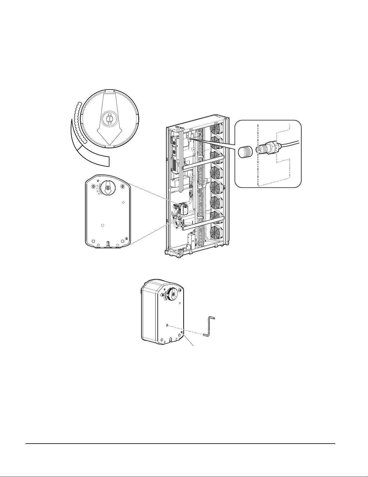
Filling and Purging
When the installation of the piping is complete, begin the filling process.
1. Open all isolation valves and allow water to flow through the cooling unit.
2. In ACRC301S and ACRC301H units, manually rotate the chilled water control valve stem to the fully
open position.
NOTE: To manually reposition a spring-return actuator from a locked position, turn the crank 1/8 of a
turn to the right, then remove the crank to release.
a. Insert the attached crank into the hole located on the front of the actuator.
b. Rotate the crank in the direction indicated on the label until the valve is in the required position.
c. Hold the crank in place and, using a Phillips screwdriver, turn the rotation lock button in the
direction indicated on the label.
d. Hold the screwdriver in place, remove the crank, then remove the screwdriver.
3. Open the cap of the Schrader valve and slightly press the needle.
4. Close the cap of the Schrader valve when water begins flowing out of the vent.
na4337b
0%
50
100
SCHRADER VALVE
(AIR VENT)
ACRC301S SHOWN
na4494a
ROTATION LOCK BUTTON

45InRow Chilled Water Air Conditioners Installation Manual
At the water supply:
1. Open all valves (no greater than 108l/m [28.5 gpm] for ACRC301S units and 144 l/m [38 gpm] for
ACRC301H units), allowing the water supply to reach the highest possible flow to the cooling unit for 45
seconds.
2. Close the valves to a 3.8–11.4 l/m (1–3 gpm) flow for 60 seconds.
3. Open the valves to maximum flow for another 45 seconds.
4. Balance the system to provide the designed flow rate to all cooling units.
InRow Chilled Water Air Conditioners Installation Manual46
Electrical Connections
The following electrical connections are required in the field:
• Primary and secondary feeds
• A-Link
• Network Management
• Rack inlet temperature sensor
• Communication (building management system)
See the electrical schematic (located on the lid of the electrical box) for all electrical connections.
See the InRow RC name plate for voltage and current requirements.
A power disconnect is required to isolate each InRow RC unit for maintenance and service.
All low-voltage connections, including data and control connections, must be made with properly insulated
wires. The low-voltage connections must have 300-V minimum insulation.
NOTE: Single phase service is required. Electrical service must conform to national and local electrical codes.
The InRow RC unit is grounded through the power cord.
DANGER
HAZARD OF ELECTRIC SHOCK, EXPLOSION, OR ARC FLASH
Turn off all power supplying this equipment before working on the equipment. All electrical
work must be performed by qualified personnel. Practice Lockout/Tagout procedures. Do
not wear jewelry when working with electrical equipment.
Failure to follow these instructions will result in death or serious injury.
WARNING
ELECTRICAL HAZARD
• Electrical service must conform to local and national electrical codes and regulations.
• The equipment must be grounded.
Failure to follow these instructions can result in death, serious injury, or
equipment damage.
47InRow Chilled Water Air Conditioners Installation Manual
Before making any electrical connections, the shipping bracket must be removed from the electrical box.
na4495a
InRow Chilled Water Air Conditioners Installation Manual48
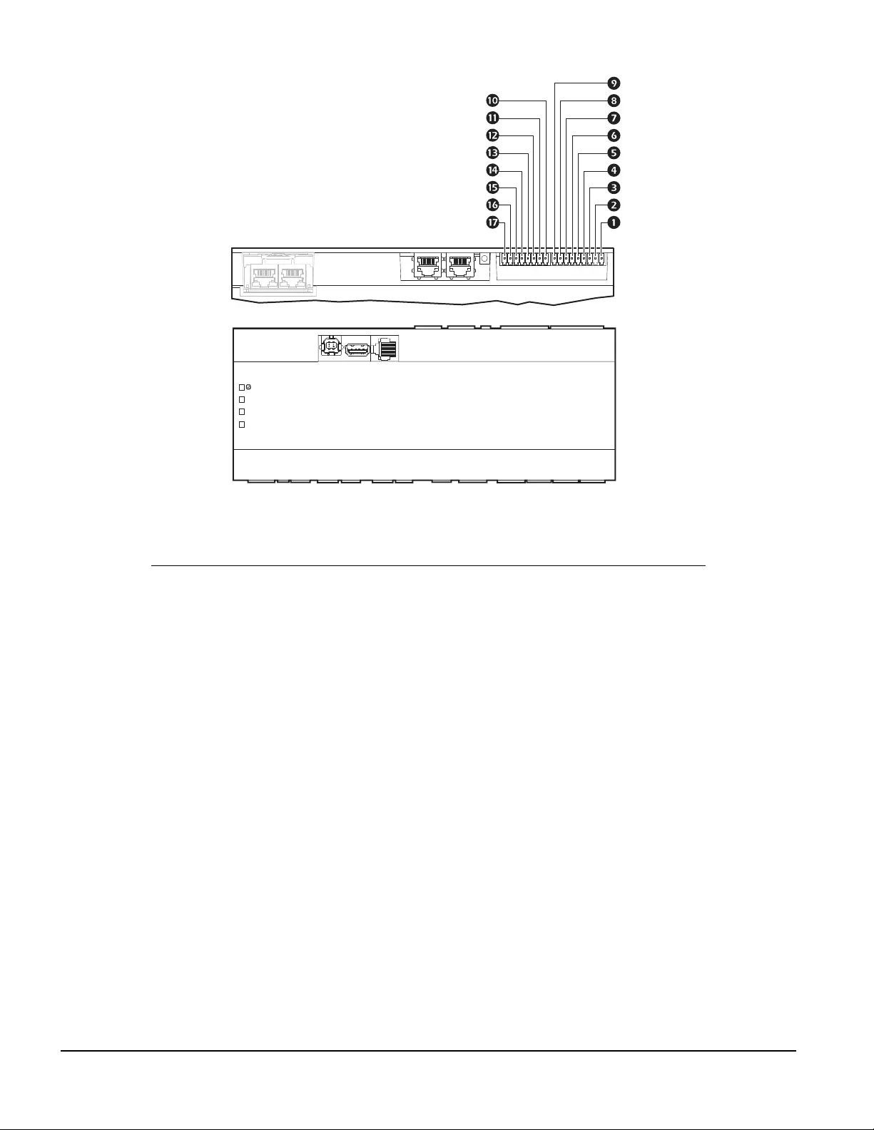
Communication Connections
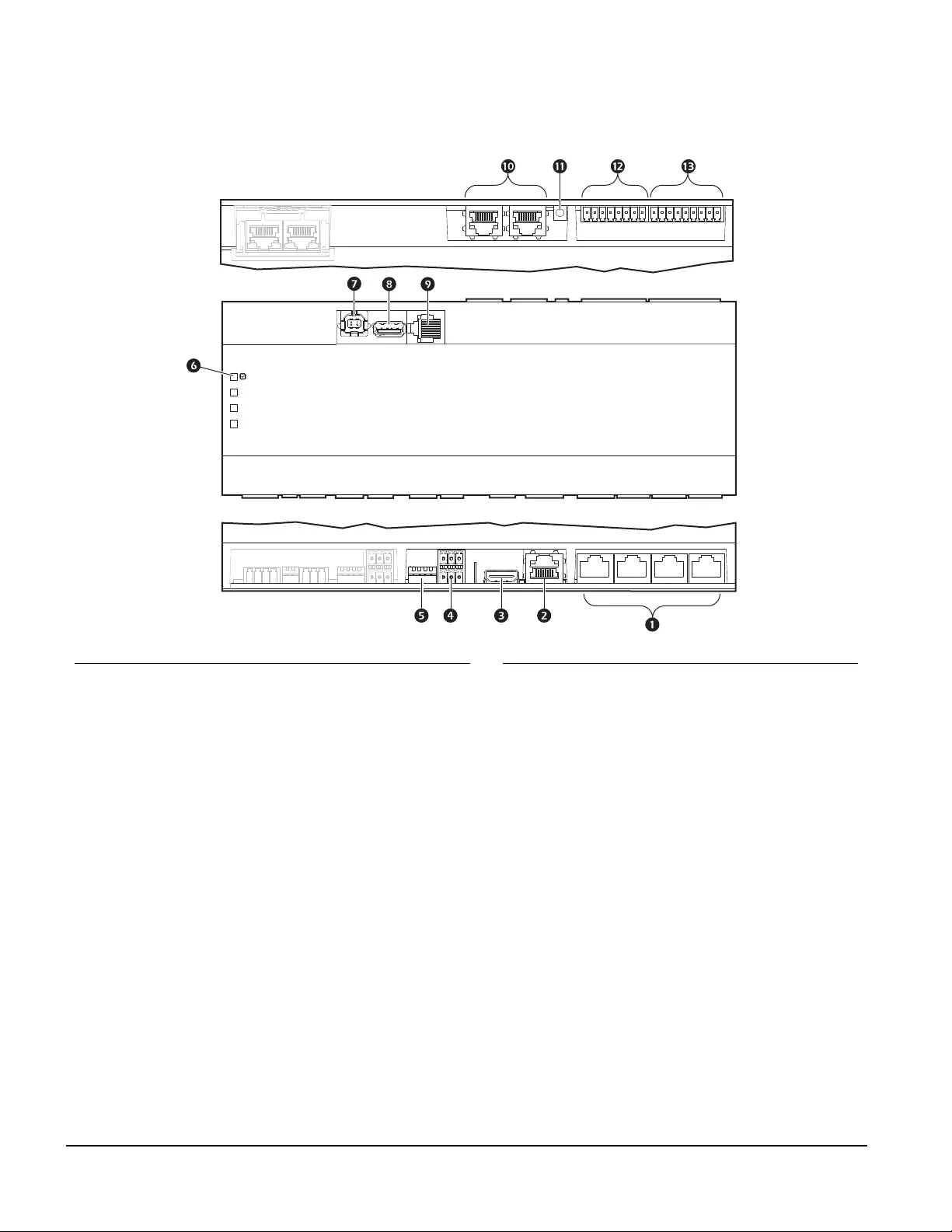
Interface connection
Item Description Item Description
Universal sensor ports USB host port
Network connection Serial port
Touchscreen display connection A-Link port
ModBus connection Reset button
ModBus configuration switches Output relay 4/standby input
Processor status LED Output relay 1–3
USB device port
P514
P513
P512
P511
SW1
P501
P502
P503
SW501
SW502
P504
P505
P506
P507
P508
P509
P510
SW503
na4434a
49InRow Chilled Water Air Conditioners Installation Manual
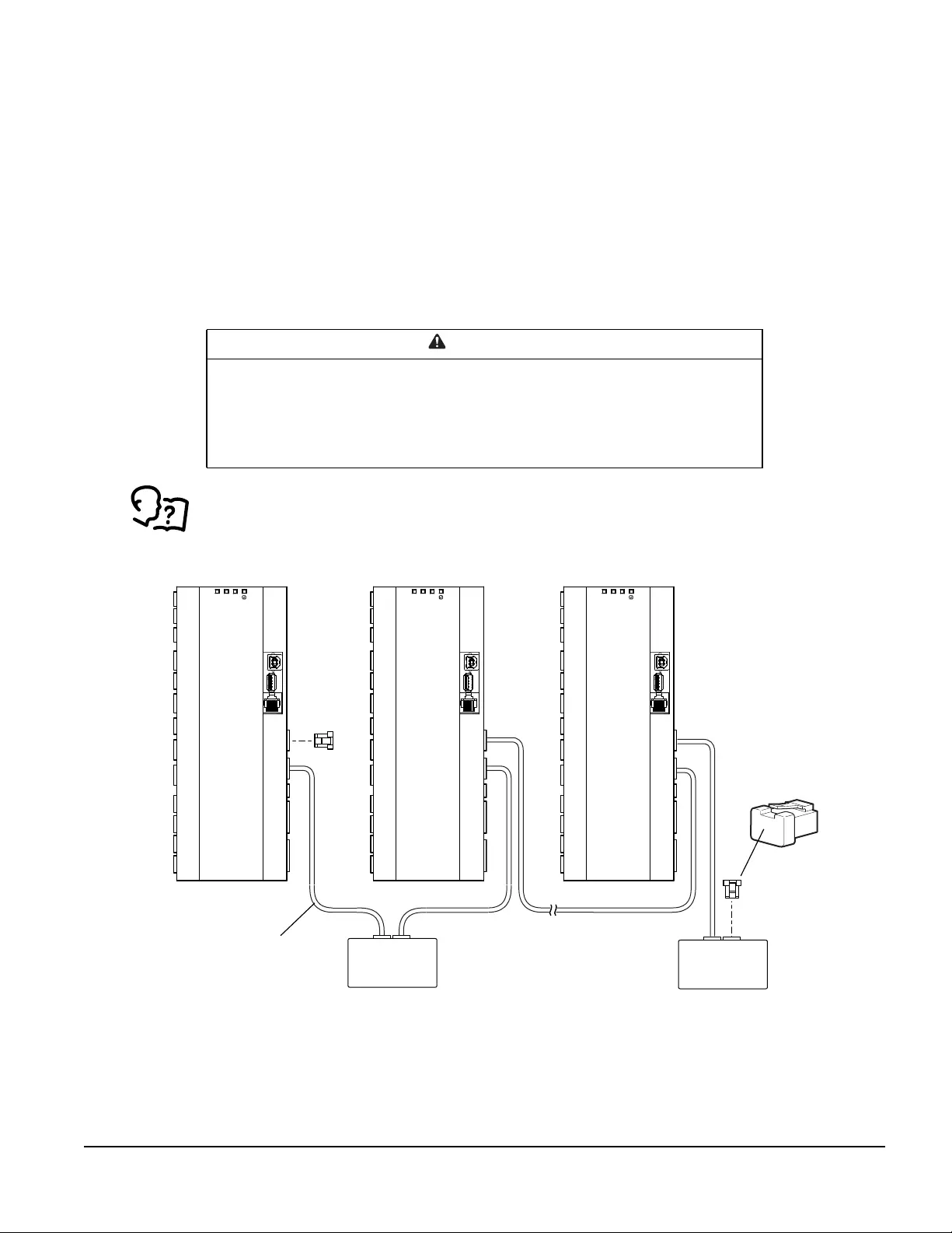
A-Link ports
NOTE: All input and output connections should be wired as Class 2 circuits.
The A-Link bus connection allows a maximum group of twelve InRow ACRC units (ACRC301H or ACRC301S)
to communicate with one another.
To enable the InRow RC ACRC301x to function as a group, link them together using a standard pin-out CAT-5
cable with RJ-45 connectors. The A-Link bus must be terminated at the first and last unit installed in the group.
See example below. An A-Link terminator is supplied with each unit.
NOTE: The maximum wire length for the entire group must not exceed 305 m (1,000 ft).
Active Flow Controllers (AFC): If AFC units are installed in the row, they are connected to the A-Link bus as
shown.
See the AFC installation manual for more information.
CAUTION
CAT 5 PINOUT
Devices connected on the A-Link ports should use a standard pin-out (1-1, 2-2, 3-3, 4-4,
5-5, 6-6, 7-7, 8-8) CAT5 cable only.
Failure to follow these instructions can result in equipment damage.
P514
P513
P512
P511
SW1
P501
P502
P503
SW501
SW502
P504
P505
P506
P507
P508
P509
P510
SW503
P514
P513
P512
P511
SW1
P501
P502
P503
SW501
SW502
P504
P505
P506
P507
P508
P509
P510
SW503
P514
P513
P512
P511
SW1
P501
P502
P503
SW501
SW502
P504
P505
P506
P507
P508
P509
P510
SW503
FIRST INROW RC SECOND INROW RC LAST INROW RC
AFC
(OPTIONAL)
A-LINK
CABLE
RJ-45
TERMINATOR
AFC
(OPTIONAL)
InRow Chilled Water Air Conditioners Installation Manual50
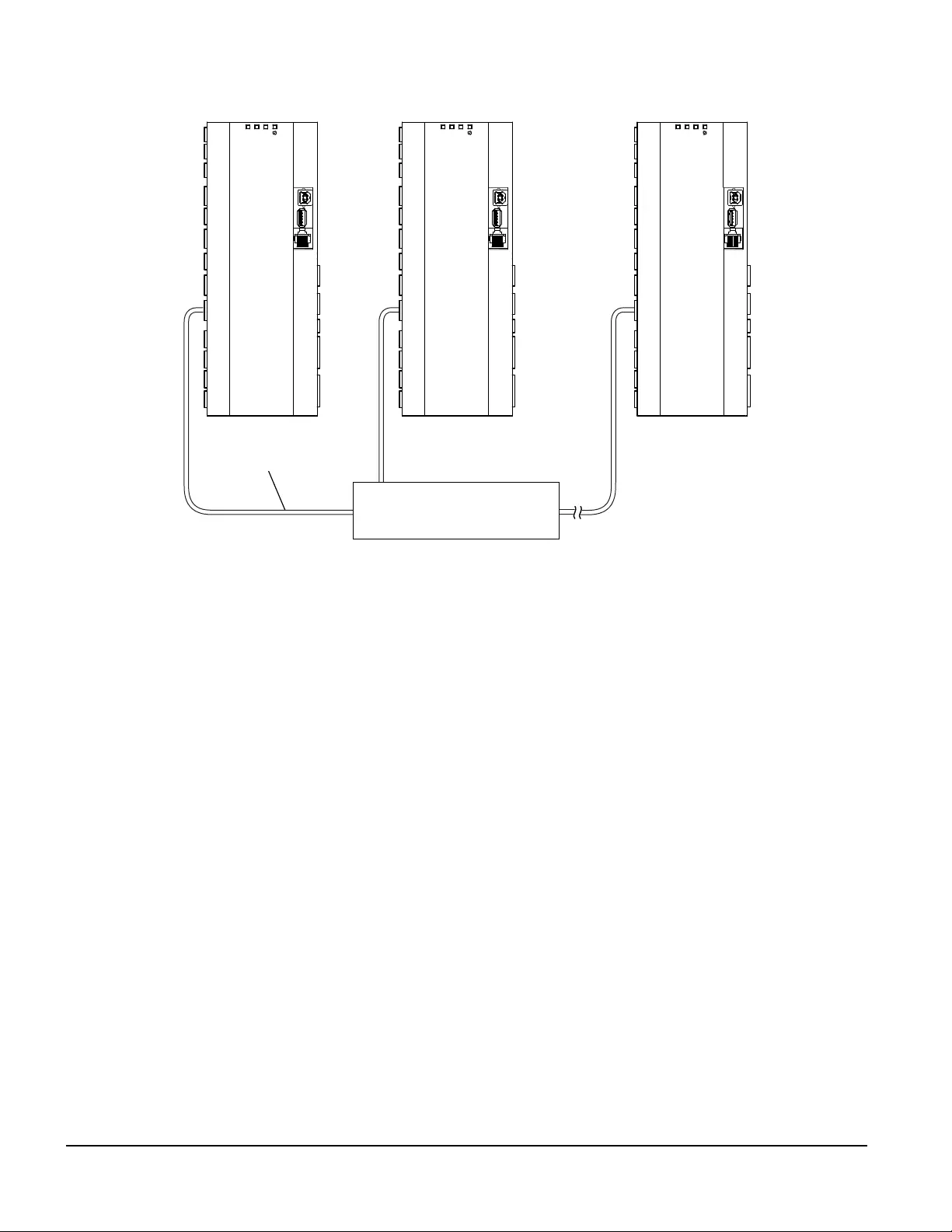
Network port
na4401a
P514
P513
P512
P511
SW1
P501
P502
P503
SW501
SW502
P504
P505
P506
P507
P508
P509
P510
SW503
P514
P513
P512
P511
SW1
P501
P502
P503
SW501
SW502
P504
P505
P506
P507
P508
P509
P510
SW503
P514
P513
P512
P511
SW1
P501
P502
P503
SW501
SW502
P504
P505
P506
P507
P508
P509
P510
SW503
SWITCH/HUB
FIRST INROW RC SECOND INROW RC LAST INROW RC
LAN CABLE
(10/100 BASE-T)
51InRow Chilled Water Air Conditioners Installation Manual
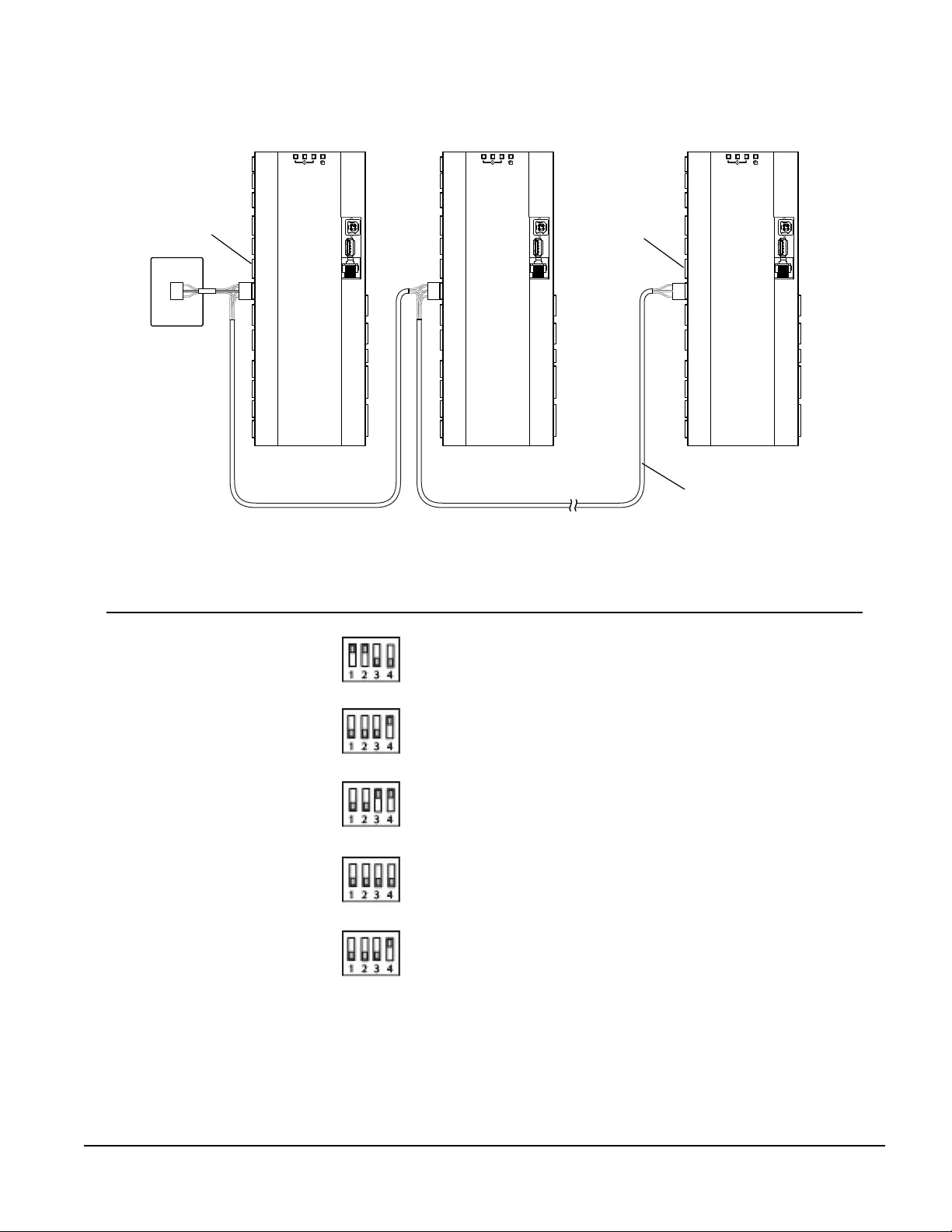
Modbus
Modbus configuration—DIP switch SW503
Position Status Dip Switches Mode
1 and 2 Open (up) 4-wire Modbus (needs TXD0-, TXD1+, RXD0-, RXD0+, and
COM connected to Modbus master)
1 and 2 Closed (down) 2-wire Modbus (needs TXD0-, TXD1+, and COM, or RXD0,
RXD0+, and COM)
3 and 4 Open (up) 2-wire or 4-wire Modbus (no termination)
3 and 4 Closed (down) 4-wire Modbus (termination enabled)
3 Closed (down)
2-wire Modbus (termination enabled, position 4 must remain
in the Open (up) position in 2-wire mode, or double
termination will occur)
na4402a
P514
P513
P512
P511
SW1
P501
P502
P503
SW501
SW502
P504
P505
P506
P507
P508
P509
P510
SW503
P514
P513
P512
P511
SW1
P501
P502
P503
SW501
SW502
P504
P505
P506
P507
P508
P509
P510
SW503
P514
P513
P512
P511
SW1
P501
P502
P503
SW501
SW502
P504
P505
P506
P507
P508
P509
P510
SW503
MODBUS
MASTER
FIRST INROW RC SECOND INROW RC LAST INROW RC
MODBUS CABLE
(RS-485)
DIP
SWITCH
DIP
SWITCH
InRow Chilled Water Air Conditioners Installation Manual52
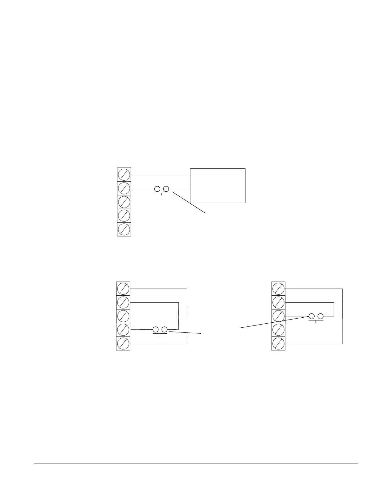
Output relays and standby input
Item Name Description
Output relay 1 N.O. Normally Open contact
Output relay 1 COM Common contact
Output relay 1 N.C. Normally Closed contact
Output relay 2 N.O. Normally Open contact
Output relay 2 COM Common contact
Output relay 2 N.C. Normally Closed contact
Output relay 3 N.O. Normally Open contact
Output relay 3 COM Common contact
Output relay 3 N.C. Normally Closed contact
Output relay 4 N.O. Normally Open contact
Output relay 4 COM Common contact
Output relay 4 N.C. Normally Closed contact
Ground Ground reference, typically connected to the negative
connection of Standby Input, when using the 12 VDC or
24 VDC power supply.
12VDC Standby input 12 VDC supply current limited to 20 mA
24VDC Standby input 24 VDC supply current limited to 20 mA
Standby Input + Positive connection used for Standby Input
Standby Input – Negative connection used for Standby Input. Typically
connected to ground.
na4400a
P514
P513
P512
P511
SW1
P501
P502
P503
SW501
SW502
P504
P505
P506
P507
P508
P509
P510
SW503
53InRow Chilled Water Air Conditioners Installation Manual
OUTPUT RELAYS
Four output relays connections are available. These relays can be configured, through the user interface, to
various alarms detecting normal or abnormal conditions
Output relays are Form C type, having a Normally Open (N.O.), Normally Closed (N.C.), and Common (COM)
contacts.
NOTE: Output Relays are rated at 24 VDC, 0.6 A maximum.
STANDBY INPUT
Standby input allows the InRow cooling unit to be remotely placed in Standby mode. Standby mode is
configured through the user interface and can be set as a normally “active” or “not active” input.
NOTE: Standby Input is rated at 12/24-V AC or DC. If using field supplied voltage, the Standby Input consumes
10 mA maximum at 24 VDC.
:
na4478a
SD-
SD+
24V_SD
12V_SD
GND
SD-
SD+
24V_SD
12V_SD
GND
SD-
SD+
24V_SD
12V_SD
GND
EXTERNAL POWER SUPPLY
24-V POWER SUPPLY12-V POWER SUPPLY
STANDBY
12–30 V AC/DC
STANDBY
12–30 V AC/DC STANDBY
12–30 V AC/DC
NOT USED
NOT USED
NOT USED
NOT USED
NOT USED
N.O. OR N.C.
CONTACTS*
N.O. OR N.C.
CONTACTS*
*Normally open contacts shown.
12–30 V AC/DC
POWER SUPPLY
InRow Chilled Water Air Conditioners Installation Manual54
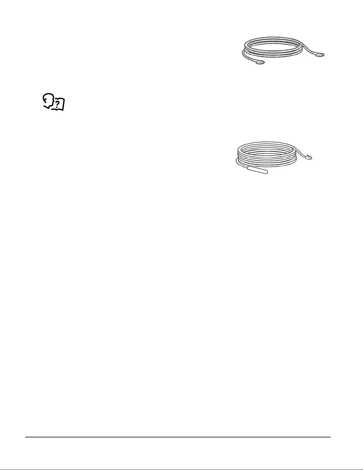
Leak detector—optional
The leak rope detector (NBES0308) connects to the Universal Sensor
Port connection using the supplied cable in the leak detector kit. Route
the leak detector cable through one of the low voltage wiring openings.
NOTE: The total length of the rope leak sensor can be extended up to 24.4 m (80 ft) using a Rope Leak Sensor
Extension kit (NBES0309).
See the documentation supplied with the kit for installation information.
Temperature sensor
The remote temperature sensor (AP9335T) monitors the room
temperature surrounding the cooling unit, ensuring the area is
being cooled at the correct temperature.
Location considerations
IMPORTANT: Different locations of the remote temperature sensors can result in different operational behavior
of the cooling unit. The optimal position of the temperature sensors will vary from installation to installation, but
should be located in an active rack air flow stream to allow accurate readings. It is not recommended to place
remote sensors in front of areas with little or no active rack air flow (e.g., in front of blanking panels).
Servers most likely to have insufficient cooling air or inadequately cooled air due to the recirculation of hot air
from the hot aisle include the following:
• Servers positioned at the top of a rack
• Servers positioned at any height in the last rack at an open end of a row
• Servers positioned behind flow-impairing obstacles such as building elements
• Servers positioned in a bank of high-density racks
• Servers positioned next to racks with Air Removal Units (ARU)
• Servers positioned very far from or very close to the cooling unit
55InRow Chilled Water Air Conditioners Installation Manual
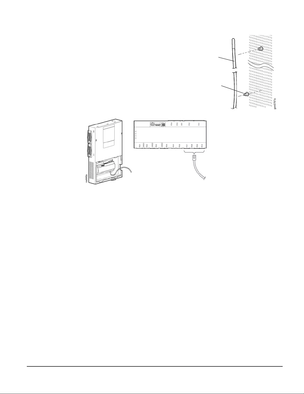
Installation
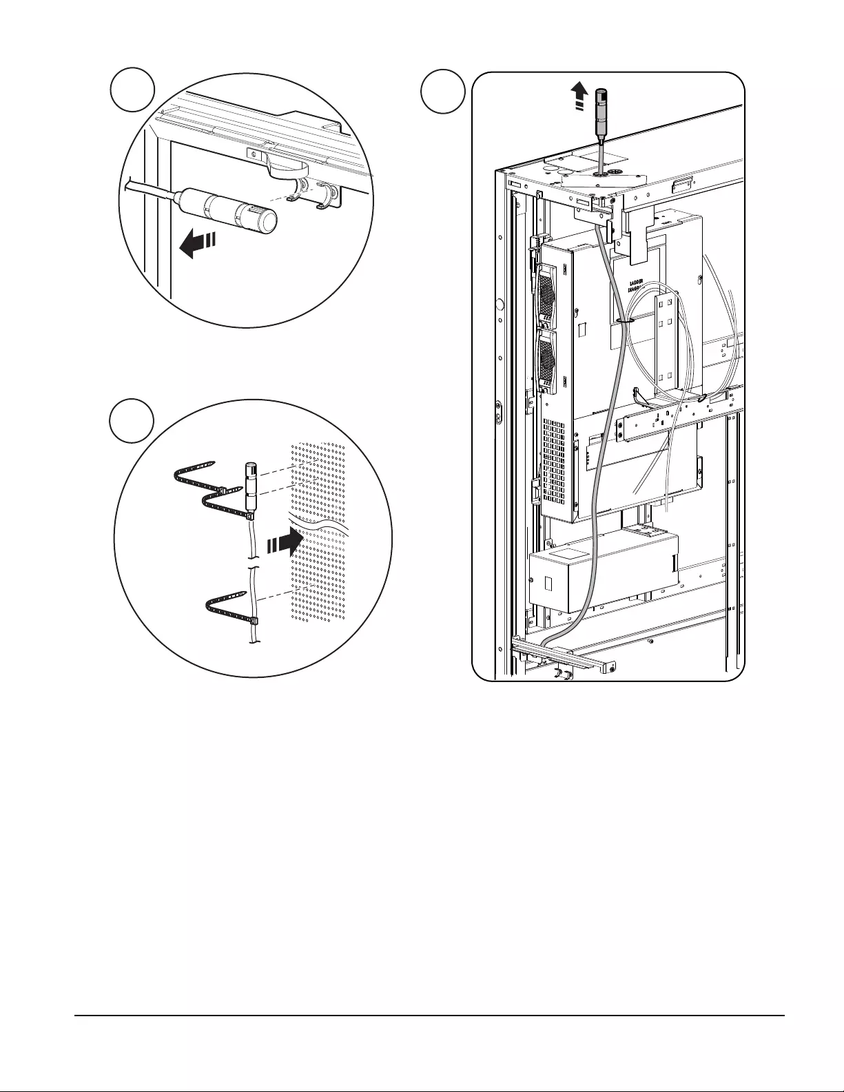
NOTE: For proper operation, the temperature sensor must be installed as shown below.
1. Route the rack temperature sensor cable through a
low voltage wiring opening on the top or bottom of
the cooling unit, then through the top or bottom of
the adjacent server enclosure.
2. Using the provided wire clips, secure the
temperature sensor cable to the inside of the front
door of an adjacent server enclosure.
3. Connect the RJ-45 connector to the controller as
shown. WIRE CLIP
TEMPERATURE
SENSOR
InRow Chilled Water Air Conditioners Installation Manual56
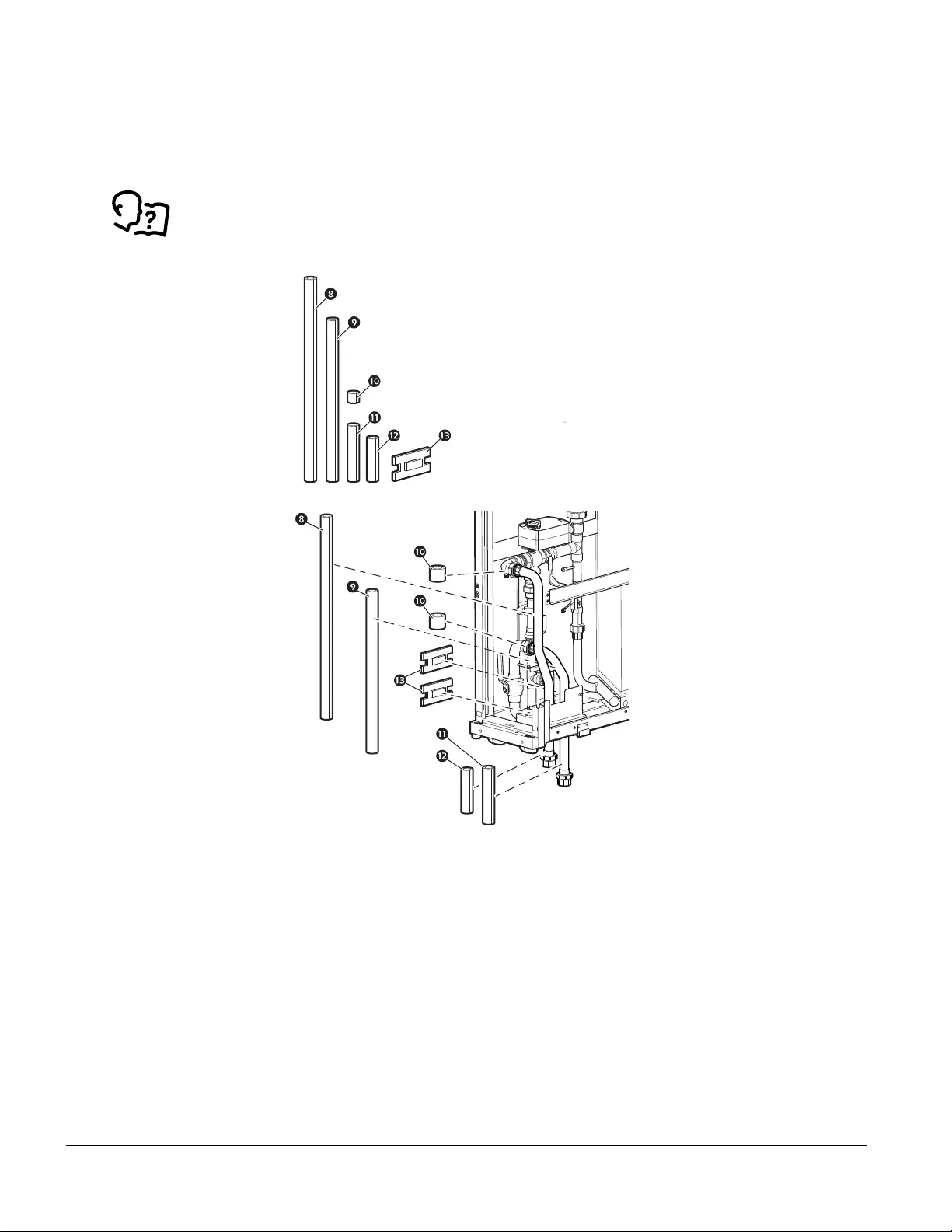
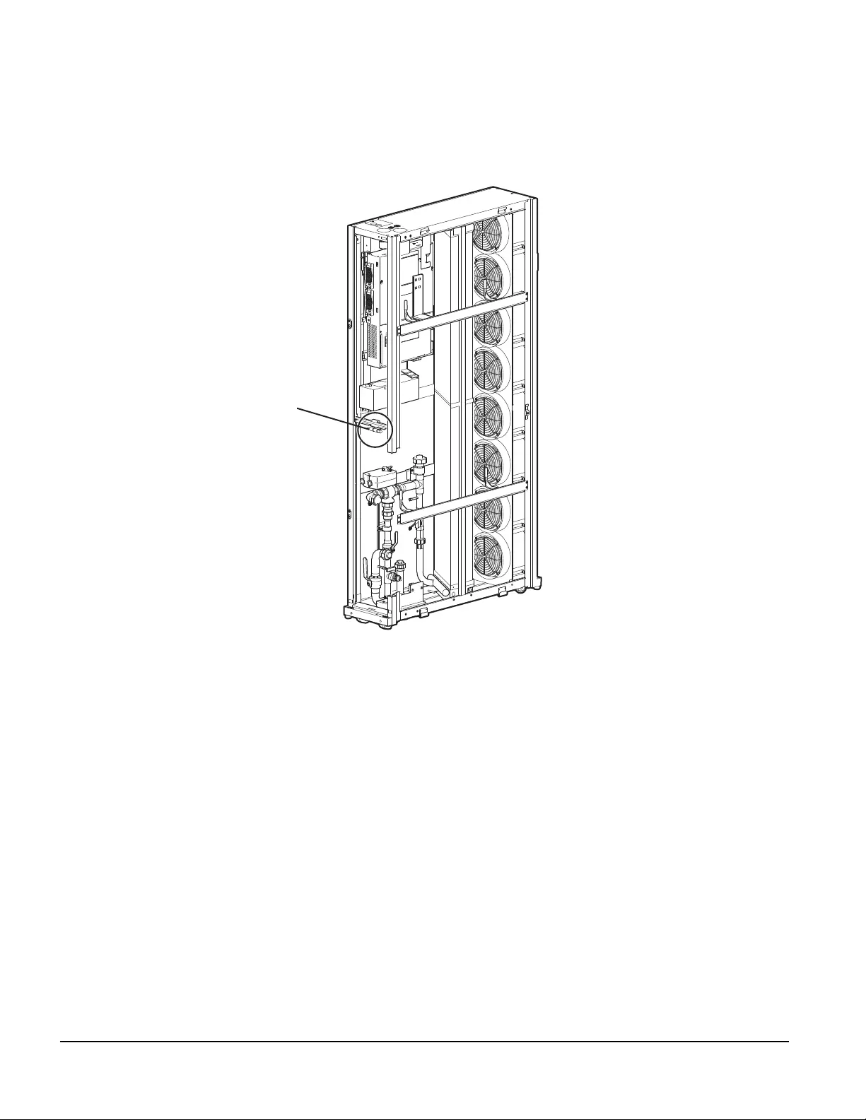
Temperature and humidity sensor—ACRC301H
Installation considerations: The temperature and humidity sensor located in the middle of the rear of the
ACRC301H cooling unit is used to calculate the dew point. It is recommended to relocate the sensor to the front
of a rack in the cold aisle (rack air inlet side). It is not recommended to place the sensor in front of areas with
little to no active rack air flow.
NOTE: The sensor will still operate properly if it is not relocated; however, the readings will not be as accurate.
na6664a
SENSOR
LOCATION
57InRow Chilled Water Air Conditioners Installation Manual
Installation
na6530a
1
na6531a
2
3
na6532a
RACK AIR
INLET
SIDE
InRow Chilled Water Air Conditioners Installation Manual58
Power Connections
Power cords may be connected at the top of the cooling unit (standard) or at the bottom (optional).
Top configuration—ACRC301S
Plug the power cords (supplied) into the electrical outlet located at the top of
the cooling unit.
na4383a
59InRow Chilled Water Air Conditioners Installation Manual
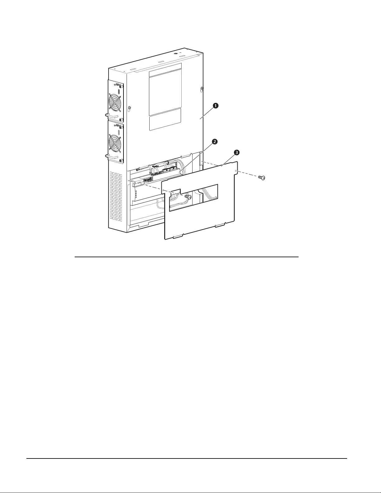
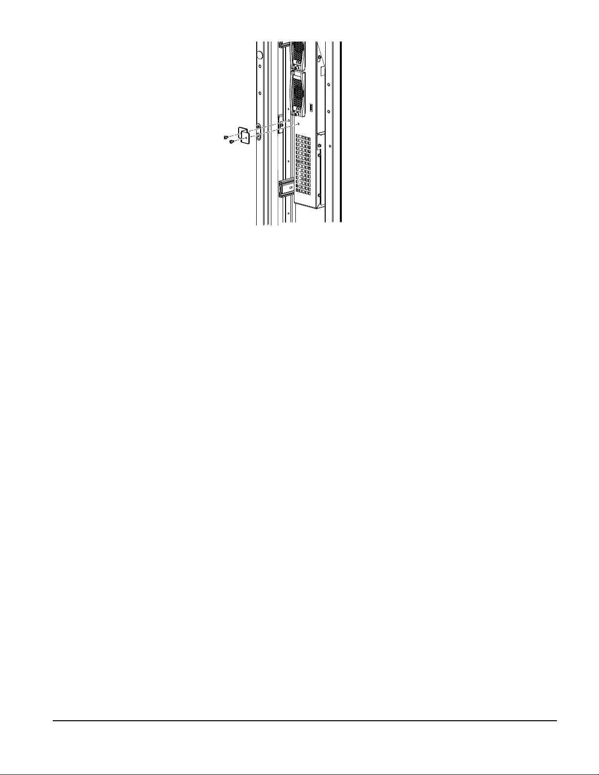
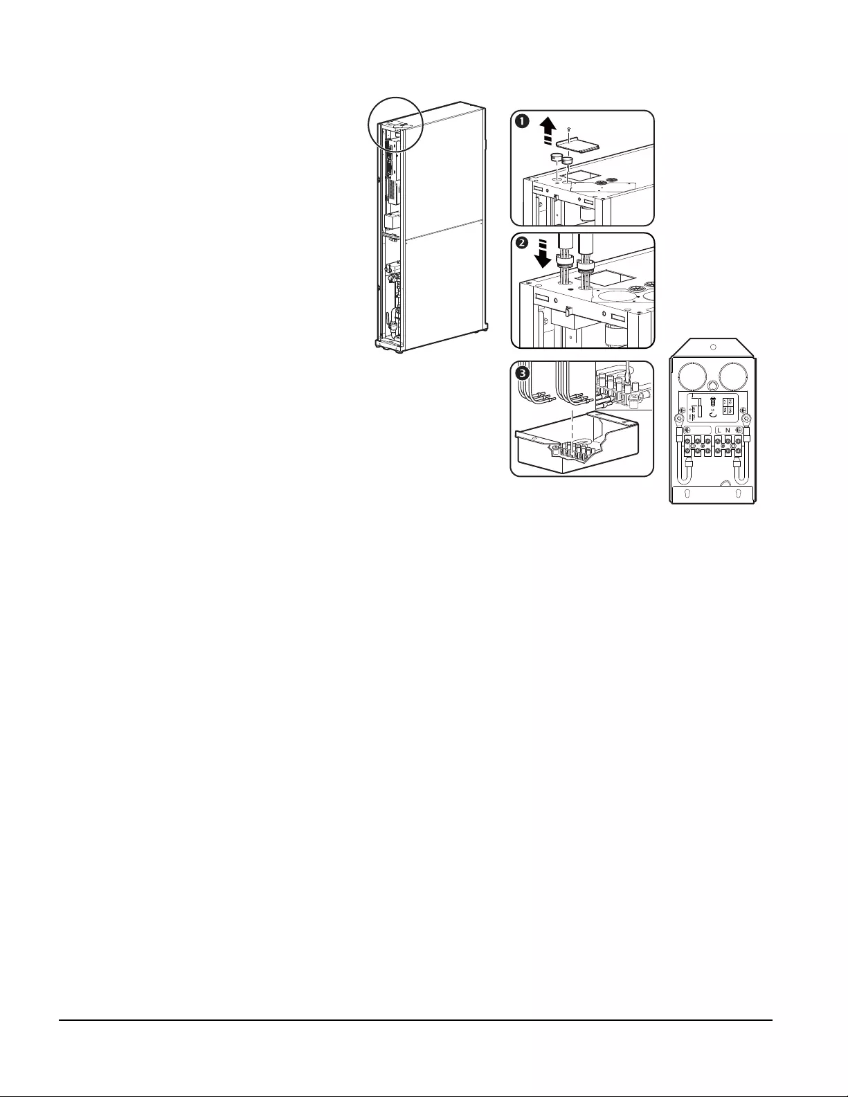
Bottom configuration (optional)—ACRC301S
1. Remove the cover plate located at the bottom
of the cooling unit. The screw attaching the
cover plate will be used to attach the junction
box to the bottom of the unit.
2. Remove the junction box from the top of the
unit.
3. Remove the cover from the junction box.
4. Relocate the junction box from the top of the
cooling unit to the bottom and replace the
junction box cover.
5. Plug the power cords (supplied) into the
electrical outlets.
NOTE: Left outlet is secondary power supply;
right outlet is the primary power supply (when
viewing from the rear of the unit).
6. Place the cover plate on the top of the unit.
na4394a
InRow Chilled Water Air Conditioners Installation Manual60
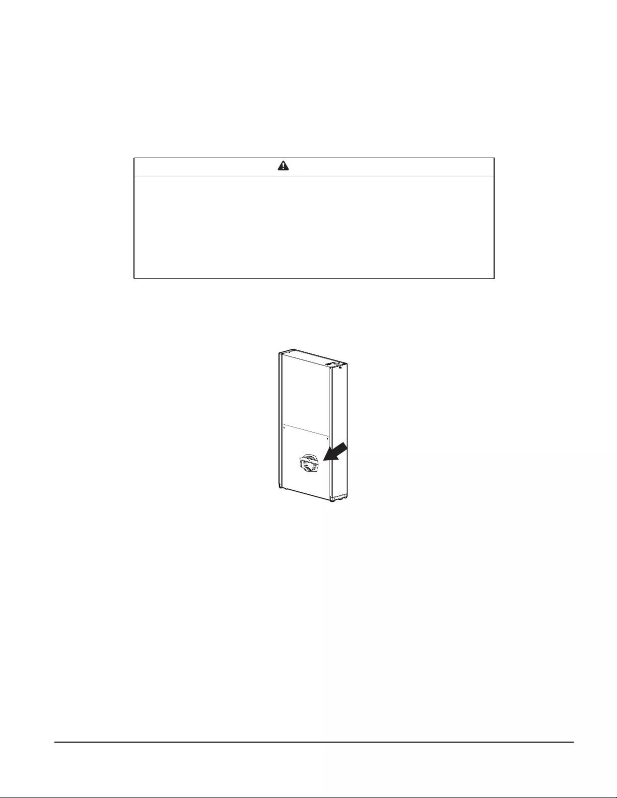
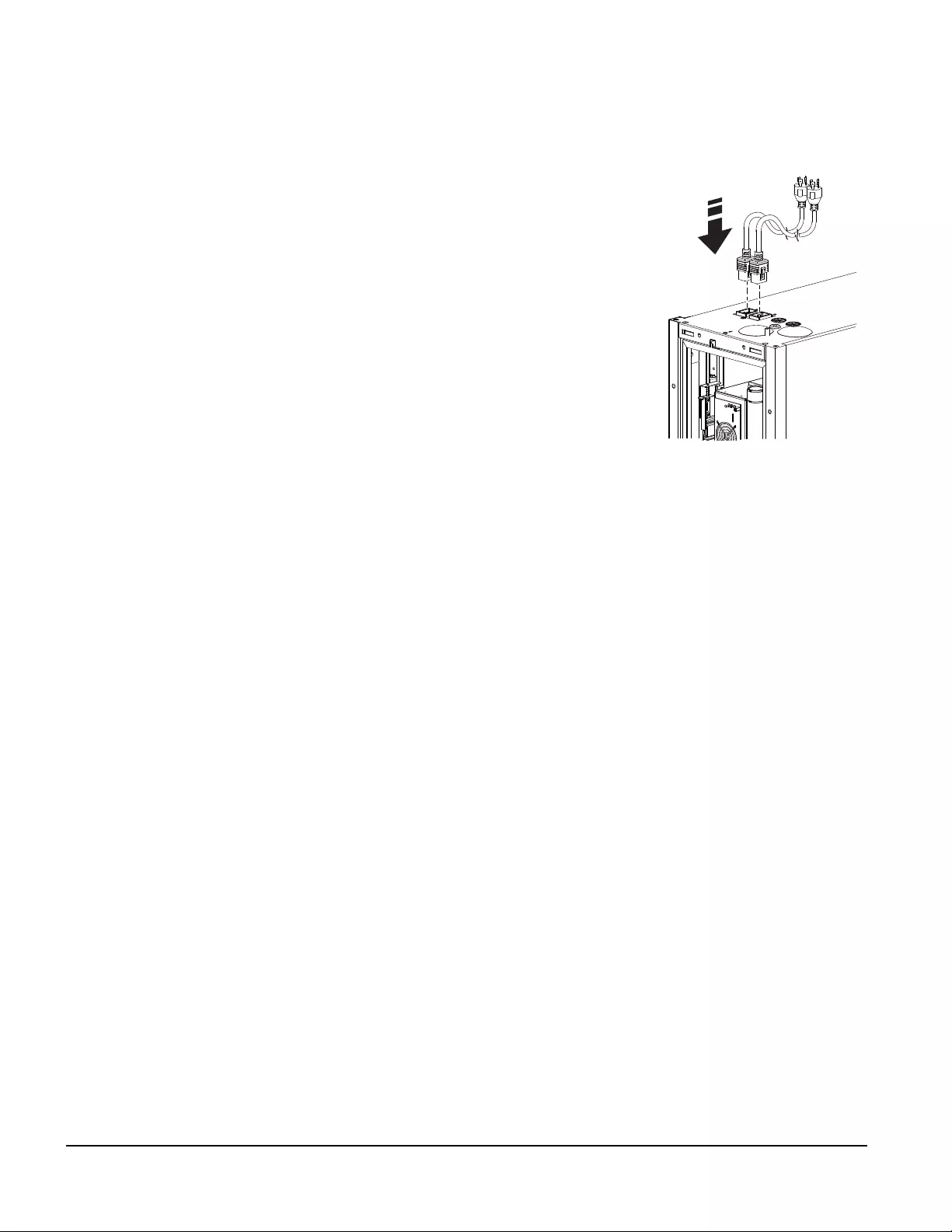
Top configuration—ACRC301H
1. Remove the cover plate and hole
plugs from the top of the unit.
2. Route the power connections
through the holes in the top of the
unit.
3. Plug-in the connections.
NL
n
a
4
3
42
a
61InRow Chilled Water Air Conditioners Installation Manual
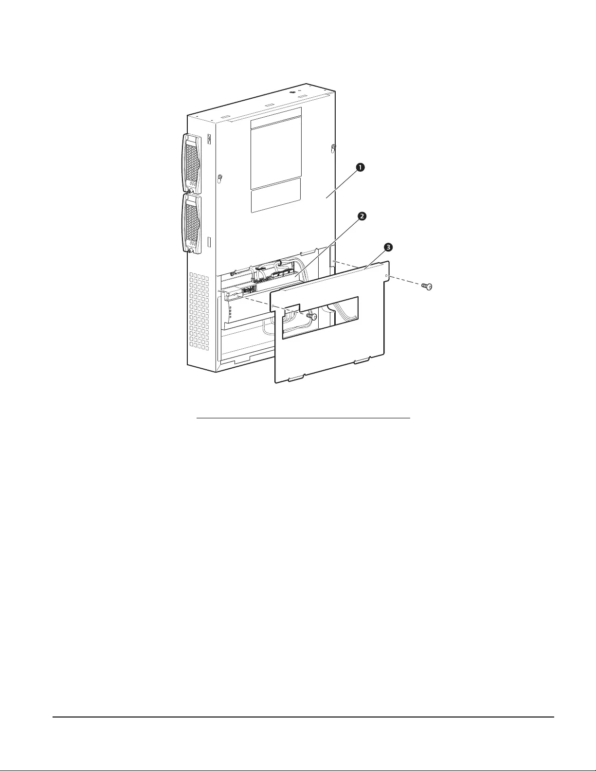
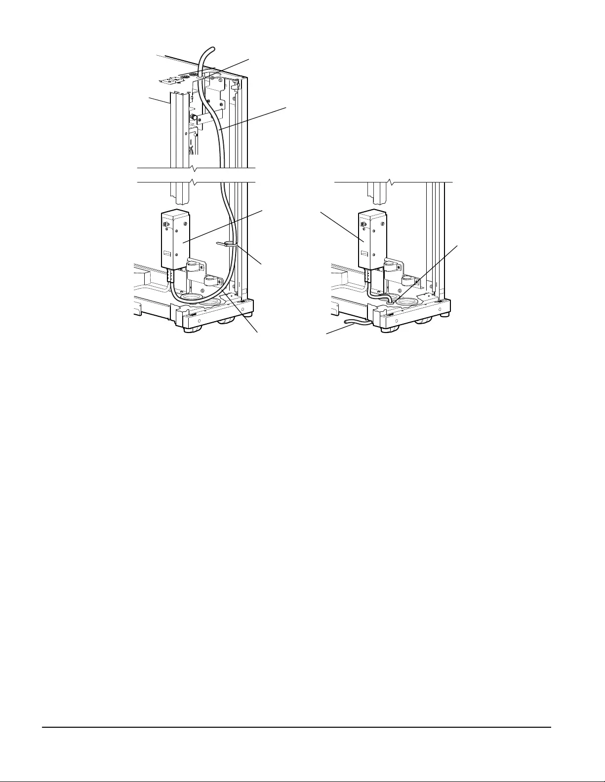
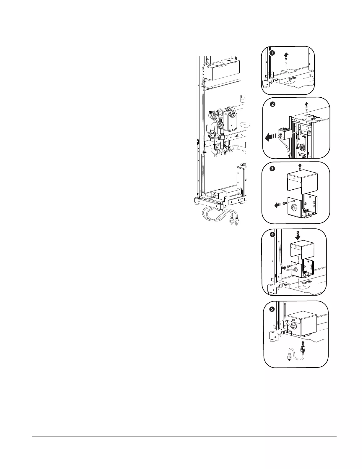
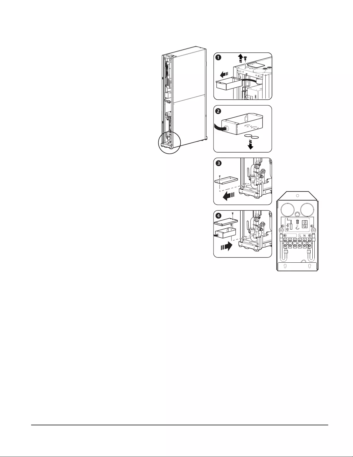
Bottom configuration—ACRC301H
1. Remove the screw that fastens
the box to the top of the unit. Cut
and remove wire ties as needed
to allow the power cord to be
repositioned for bottom power
feed connection.
2. Remove the plugs from the holes
in the bottom of the junction
connection box.
3. Remove the cover plate located
at the bottom of the cooling unit.
The screw attaching the cover
plate will be used to attach the
junction box to the bottom of the
unit.
4. Attach the junction box to the
bottom of the unit. Attach the
cover plate to the top of the
junction box.
5. Route the power connections
through the bottom of the unit.
na4342b
NL

InRow Chilled Water Air Conditioners Installation Manual62
Primary and secondary power feeds
The equipment is capable of receiving power through one of two separate feeds: primary feed or secondary
feed. Use the display interface to configure the unit to receive power through the primary feed, the secondary
feed, or both). The equipment receives power through the primary feed regardless of whether the secondary
feed is receiving power. If power is removed from the primary feed, the secondary feed takes over and supplies
power to the equipment (if a secondary feed is connected).
Connect the primary feed and secondary feed input cables to individual, breaker-controlled branch circuits or to
PDUs backed by separate Uninterruptible Power Supplies (UPS).
NOTE: The primary and secondary feeds must not use the same branch circuit, PDU, or UPS.
For more information on configuring power input feeds, see the InRow Chilled Water Air
Conditioners Operation and Maintenance Manual.

63InRow Chilled Water Air Conditioners Installation Manual


Worldwide Customer Support
Customer support for this or any other product is available at no charge in any of the following ways:
• Visit the Schneider Electric Web site to access documents in the Schneider Electric Knowledge Base
and to submit customer support requests.
–www.schneider-electric.com (Corporate Headquarters)
Connect to localized Schneider Electric Web sites for specific countries, each of which provides
customer support information.
–www.schneider-electric.com/support/
Global support searching Schneider Electric Knowledge Base and using e-support.
• Contact the Schneider Electric Customer Support Center by telephone or e-mail.
– Local, country-specific centers: go to www.schneider-electric.com > Support > Operations
around the world for contact information.
For information on how to obtain local customer support, contact the representative or other distributors
from whom you purchased your product.
As standards, specifications, and designs change from time to time, please ask for confirmation of the information given in this publication.
All trademarks owned by Schneider Electric Industries SAS or its affiliated companies.
11/2017
990-4705B-001