Table of Contents
- NetShelter WX Low-profile Cabinet
- Product Overview
- Important Safety Instructions — SAVE THESE INSTRUCTIONS
- Component Identification
- Configuration Options
- Equipment Installation
- Cabinet Installation
- Maintenance
- Specifications
- Five-year Factory Warranty
- Radio Frequency Interference
APC AR106V User Manual
Displayed below is the user manual for AR106V by APC which is a product in the Rack Cabinets category. This manual has pages.
Related Manuals
NetShelter WX Low-profile Cabinet
Installation and Customization Manual
990-6229-001
Release date 10/2019

Legal Information
The Schneider Electric brand and any trademarks of Schneider Electric SE and its
subsidiaries referred to in this guide are the property of Schneider Electric SE or its
subsidiaries. All other brands may be trademarks of their respective owners.
This guide and its content are protected under applicable copyright laws and
furnished for informational use only. No part of this guide may be reproduced or
transmitted in any form or by any means (electronic, mechanical, photocopying,
recording, or otherwise), for any purpose, without the prior written permission of
Schneider Electric.
Schneider Electric does not grant any right or license for commercial use of the
guide or its content, except for a non-exclusive and personal license to consult it on
an "as is" basis. Schneider Electric products and equipment should be installed,
operated, serviced, and maintained only by qualified personnel.
As standards, specifications, and designs change from time to time, information
contained in this guide may be subject to change without notice.
To the extent permitted by applicable law, no responsibility or liability is assumed
by Schneider Electric and its subsidiaries for any errors or omissions in the
informational content of this material or consequences arising out of or resulting
from the use of the information contained herein.
APC, the APC logo, NetShelter, and EcoStruxure are trademarks of Schneider
Electric SE or its subsidiaries. All other brands may be trademarks of their
respective owners.

Table of Contents
Product Overview........................................................................................5
Important Safety Instructions — SAVE THESE
INSTRUCTIONS.........................................................................................6
Safety Information for the 6U Cabinet...........................................................7
Labels on the Cabinet .................................................................................8
Component Identification...........................................................................9
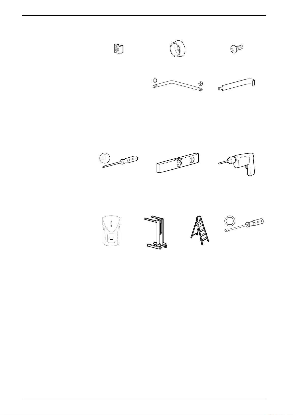
Hardware Bag ..........................................................................................10
Tools (Not Provided) .................................................................................10
Configuration Options .............................................................................. 11
Front and Rear Panels .............................................................................. 11
Mounting Bracket ..................................................................................... 11
Side Panels..............................................................................................12
Cable Access ...........................................................................................12
Open Brush Strips for Cable Access ..........................................................13
Equipment Installation..............................................................................14
Identify One (1) U-space ...........................................................................14
Install a Cage Nut .....................................................................................14
Remove a Cage Nut .................................................................................14
Install Equipment on the Mounting Flanges.................................................15
UPS Installation ..................................................................................15
Server Installation ...............................................................................17
Other Compatible Equipment...............................................................17
Additional Options for Cable Management ...........................................18
Universal Accessory Bracket .....................................................................18
Additional Options (not included) ...............................................................19
NetBotz Camera Pod 165 (NBPD0165) ................................................19
NetBotz Door Switch Sensor (NBES0313) ............................................19
Cabinet Installation ...................................................................................20
Mount the Cabinet to a Wall.......................................................................20
Floor Mount..............................................................................................22
Ground the Cabinet ..................................................................................23
Maintenance ..............................................................................................24
Replace the Fan Module ..........................................................................24
Replace the Filter .....................................................................................24
Additional Options: EcoStruxure Asset Advisor ...........................................25
Specifications ............................................................................................26
Five-year Factory Warranty.....................................................................27
Terms of Warranty ....................................................................................27
Non-transferable Warranty ........................................................................27
Exclusions ...............................................................................................27
Warranty Claims.......................................................................................28
Radio Frequency Interference ................................................................29
990-6229-001 3


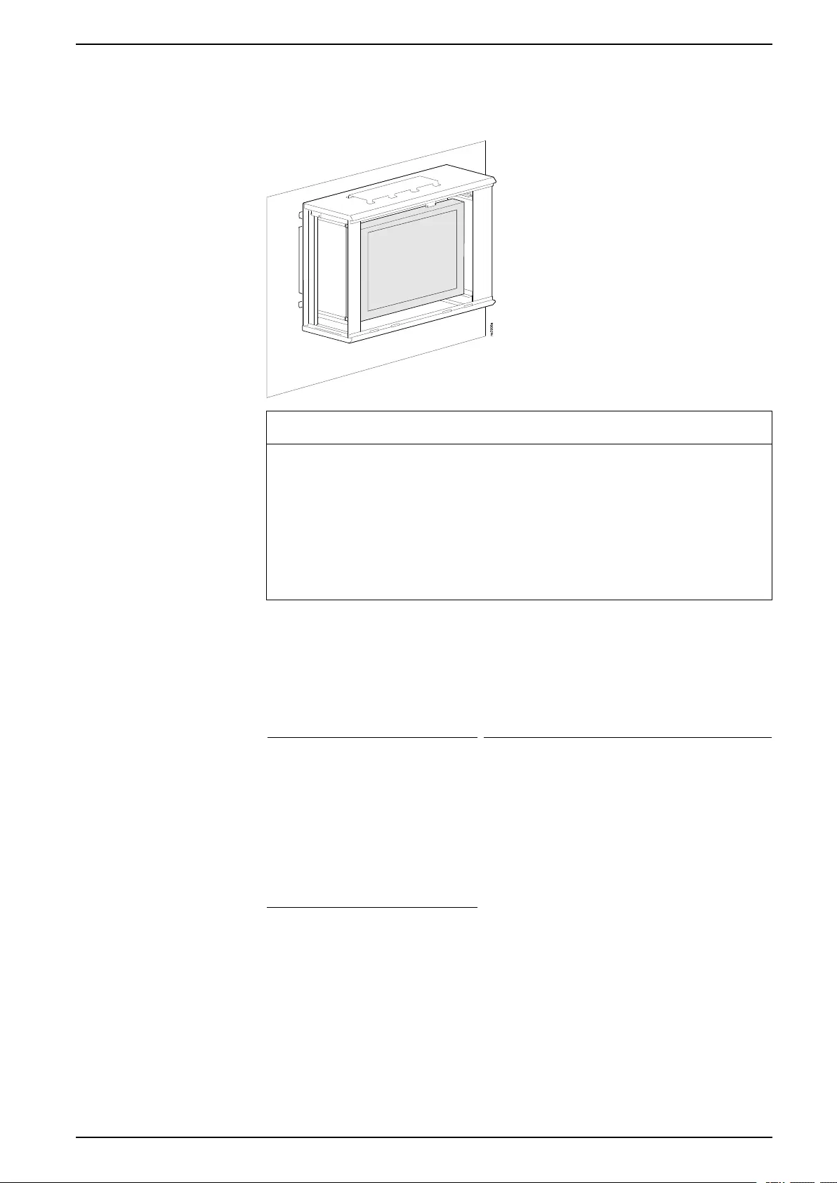
Product Overview
Product Overview
The APC by Schneider Electric NetShelter™WX Low-profile cabinet provides
storage for industry-standard (EIA/ECA-310) 482 mm (19 in) rack-mount
hardware, including voice, data, networking, and networking equipment
Model Mounting
Width
Mounting
Depth
Mounting
Height
External
Width*
External
Depth
External
Height
AR106V
(cabinet with
120 V fan)
6U†762 mm
(30 in)
482 mm
(19 in)
351.75
mm
(13.85 in)
978.2 mm
(38.5 in)
649.5 mm
(25.6 in)
AR106VI
(cabinet with
230 V fan)
†One U= 44 mm (1.75 in)
*Includes16.75 mm (0.65 in) mounting bracket
This unit has the following features:
• Black, perforated front panel with filter for ventilation.
• Rear with fans for ventilation.
• Large side panels for access to equipment.
• Locks on all panels.
• Fixed front and rear mounting flanges with square cage nut holes.
990-6229-001 5
Important Safety Instructions — SAVE THESE
INSTRUCTIONS
Important Safety Instructions — SAVE THESE
INSTRUCTIONS
Read these instructions carefully and look at the equipment to become familiar
with it before trying to install, operate, service or maintain it. The following safety
messages may appear throughout this manual or on the equipment to warn of
potential hazards or to call attention to information that clarifies or simplifies a
procedure.
The addition of this symbol to a “Danger” or “Warning” safety
message indicates that an electrical hazard exists which will
result in personal injury if the instructions are not followed.
This is the safety alert symbol. It is used to alert you to potential
personal injury hazards. Obey all safety messages with this
symbol to avoid possible injury or death.
DANGER
DANGER indicates a hazardous situation which, if not avoided, will result in
death or serious injury.
Failure to follow these instructions will result in death or serious injury.
WARNING
WARNING indicates a hazardous situation which, if not avoided, could result
in death or serious injury.
Failure to follow these instructions can result in death, serious injury, or
equipment damage.
CAUTION
CAUTION indicates a hazardous situation which, if not avoided, could result in
minor or moderate injury.
Failure to follow these instructions can result in injury or equipment
damage.
NOTICE
NOTICE is used to address practices not related to physical injury. The safety
alert symbol shall not be used with this type of safety message.
Failure to follow these instructions can result in equipment damage.
Please Note
Electrical equipment should only be installed, operated, serviced, and maintained
by qualified personnel. No responsibility is assumed by APC by Schneider Electric
for any consequences arising out of the use of this material.
A qualified person is one who has skills and knowledge related to the construction,
installation, and operation of electrical equipment and has received safety training
to recognize and avoid the hazards involved.
6 990-6229-001
Important Safety Instructions — SAVE THESE
INSTRUCTIONS
Safety Information for the 6U Cabinet
DANGER
HAZARD OF ELECTRIC SHOCK
• Power supplied to the cabinet must be a dedicated branch circuit with
ground.
• The cabinet must be connected to the building Common Bonding Network
(CBN).
Failure to follow these instructions will result in death or serious injury.
WARNING
HEAVY EQUIPMENT HAZARD
• Installation must be performed by qualified personnel.
• Use at least two (2) people to move the cabinet.
Failure to follow these instructions can result in death, serious injury, or
equipment damage.
NOTICE
RISK OF EQUIPMENT DAMAGE
Ensure your fan is connected to a power source appropriate for its voltage.
Check the Specifications, page 26.
Failure to follow these instructions can result in equipment damage.
990-6229-001 7
Important Safety Instructions — SAVE THESE
INSTRUCTIONS
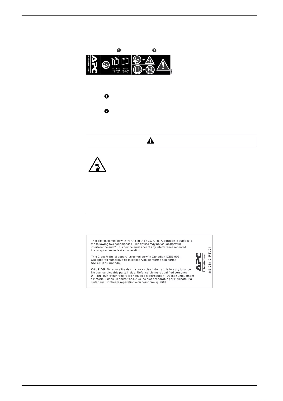
Labels on the Cabinet
Weight Rating
The weight rating label shown above can be found on the cabinet, and serves to
communicate the following information:
Section :Weight capacity. The cabinet can be mounted on a wall or casters
loaded with up to 113 kg (250 lb) of equipment.
Section :Generic Tip Hazard.
Falling Equipment Hazard
WARNING
UNSECURED EQUIPMENT FALLING HAZARD
• Enclosure wall mount requires reinstallation of all four (4) T30 bolts.
• Enclosure is designed to support loads only with all four (4) mounting bolts
installed. Failure to follow these instructions can result in death or serious
injury.
Failure to follow these instructions can result in death, serious injury, or
equipment damage.
FCC
8 990-6229-001
Component Identification
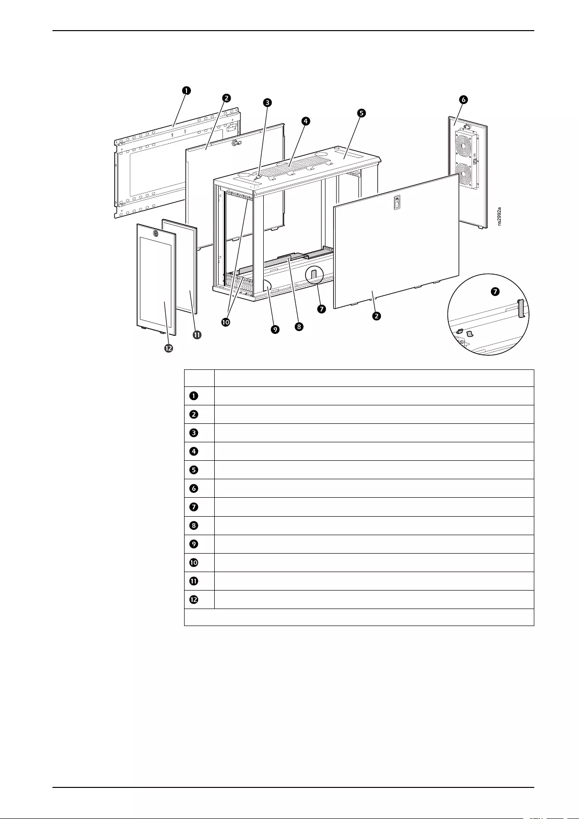
Component Identification
Item Description
Mounting bracket
Removable, lockable side panels
Key
Universal accessories bracket
Cabinet frame
Removable, lockable rear panel with fan
Reserved for future use
UPS mounting bracket
Hardware bag
Top and bottom mounting flanges
Removable filter
Removable, lockable front panel
Not shown: Fan power cord, IEC C-13 to NEMA 5-15
990-6229-001 9
Configuration Options
Configuration Options
Before you install the cabinet, plan the location and arrangement of components
within the cabinet based on the available space.
Front and Rear Panels
You can swap the front and rear panels to reverse the direction of the cabinet.
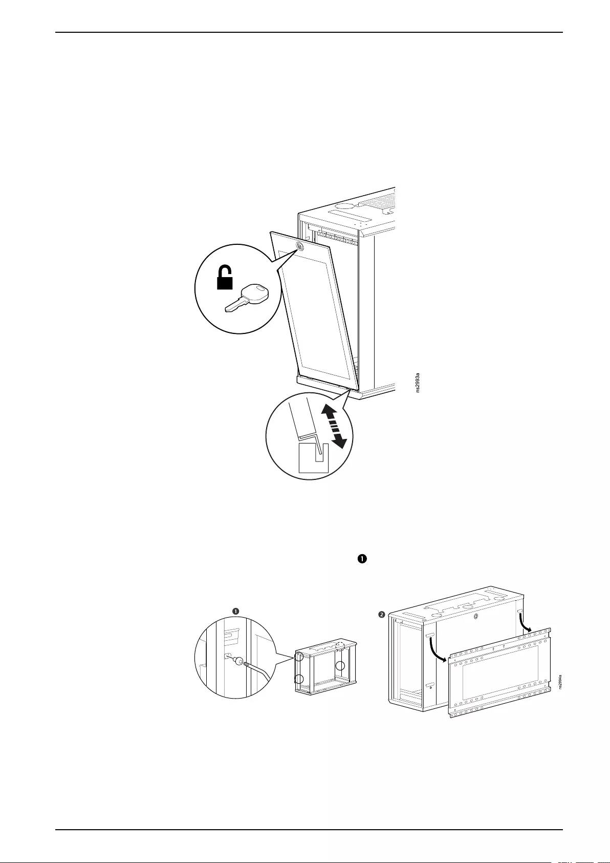
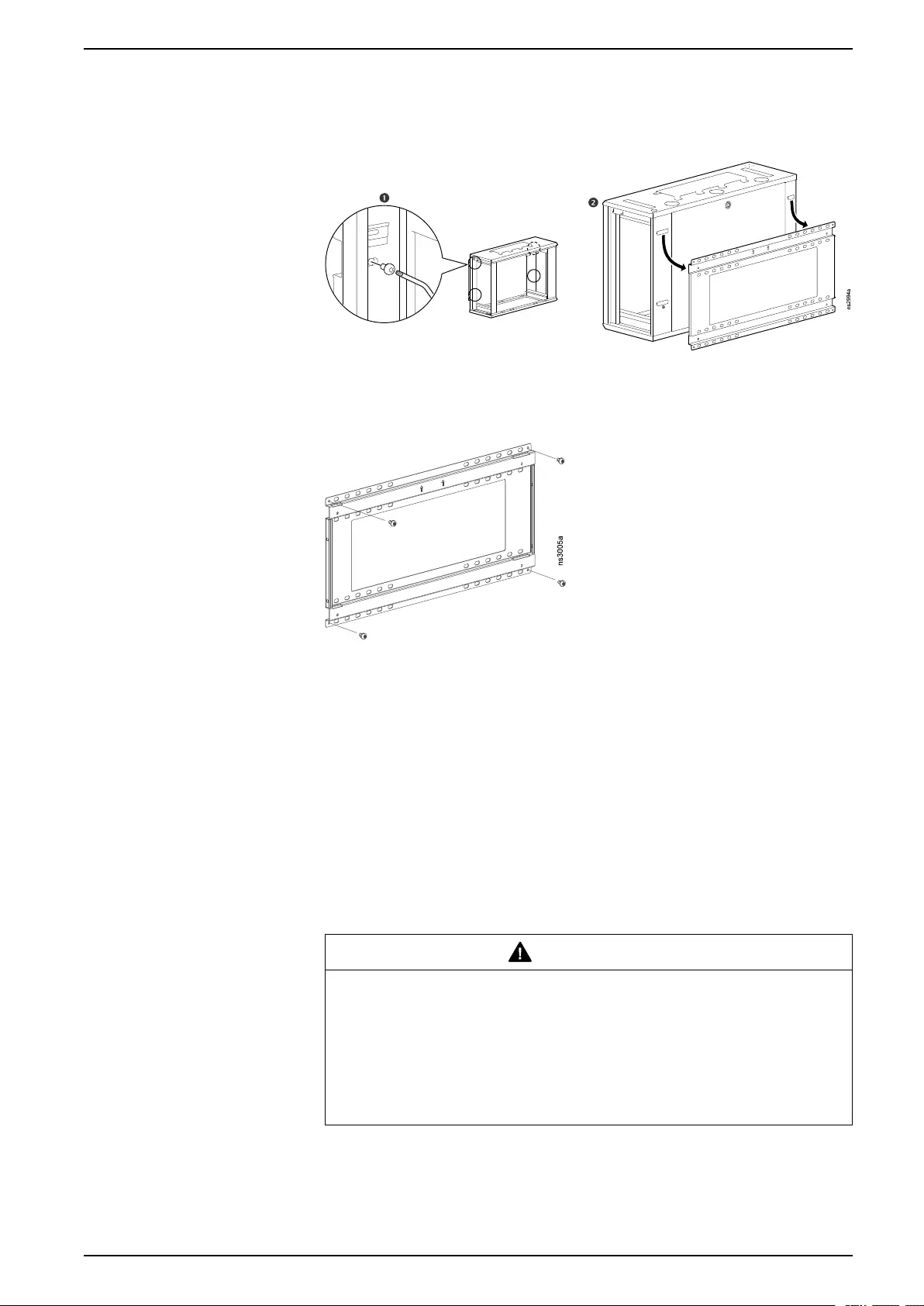
Mounting Bracket
You must remove the front and rear panels to remove or install the mounting
bracket. As you remove the screws ( ), hold the bracket to prevent it from falling.
Save the screws for wall-mounting.
990-6229-001 11
Configuration Options
Side Panels
To remove the side panel closest to the wall, you must first remove the mounting
bracket.
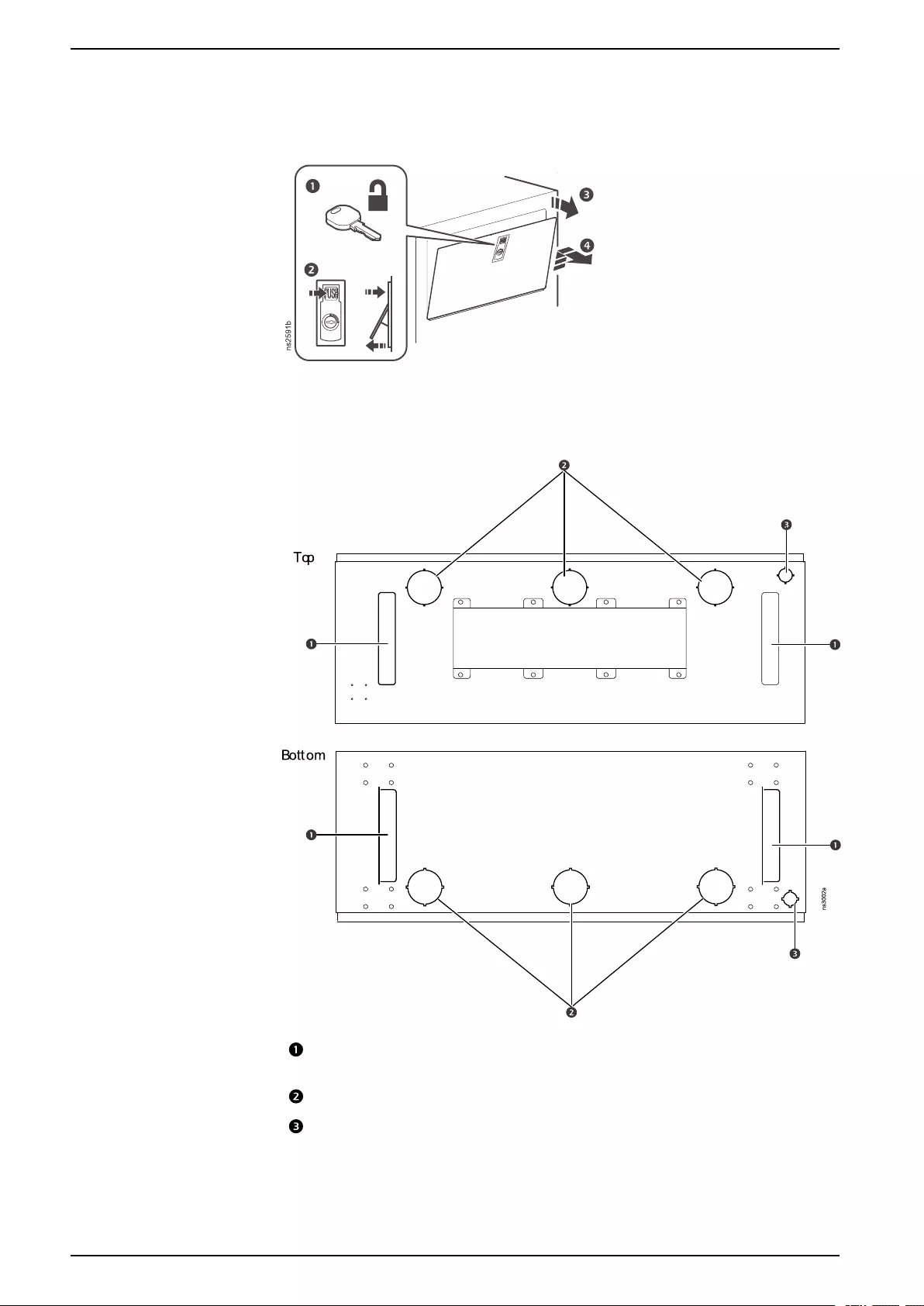
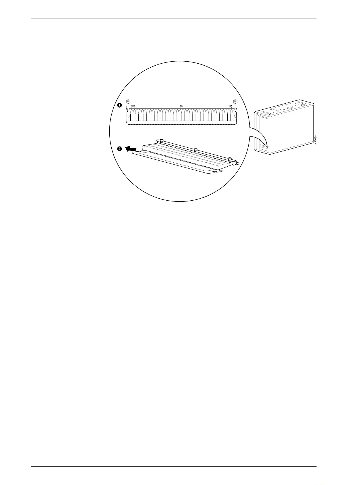
Cable Access
Brush strips, 201 x 44 mm (8 x 2 in). See Open Brush Strips for Cable
Access, page 13.
Knockouts for CAT5 or CAT6 cables, 70 mm (2.76 in)
Conduit knockouts, 28 mm (1.1 in)
12 990-6229-001
Equipment Installation
Equipment Installation
NOTE: Before installing the equipment, remove any desired knockouts or
brush strips (Cable Access, page 12) and install the casters if desired (Floor
Mount, page 22).
For specific information on how to mount equipment in the cabinet, see the
installation instructions supplied with the equipment. You can use the provided
M6 x 16 Phillips slot screws and cage nuts to mount equipment on the square
holes in the mounting flanges.
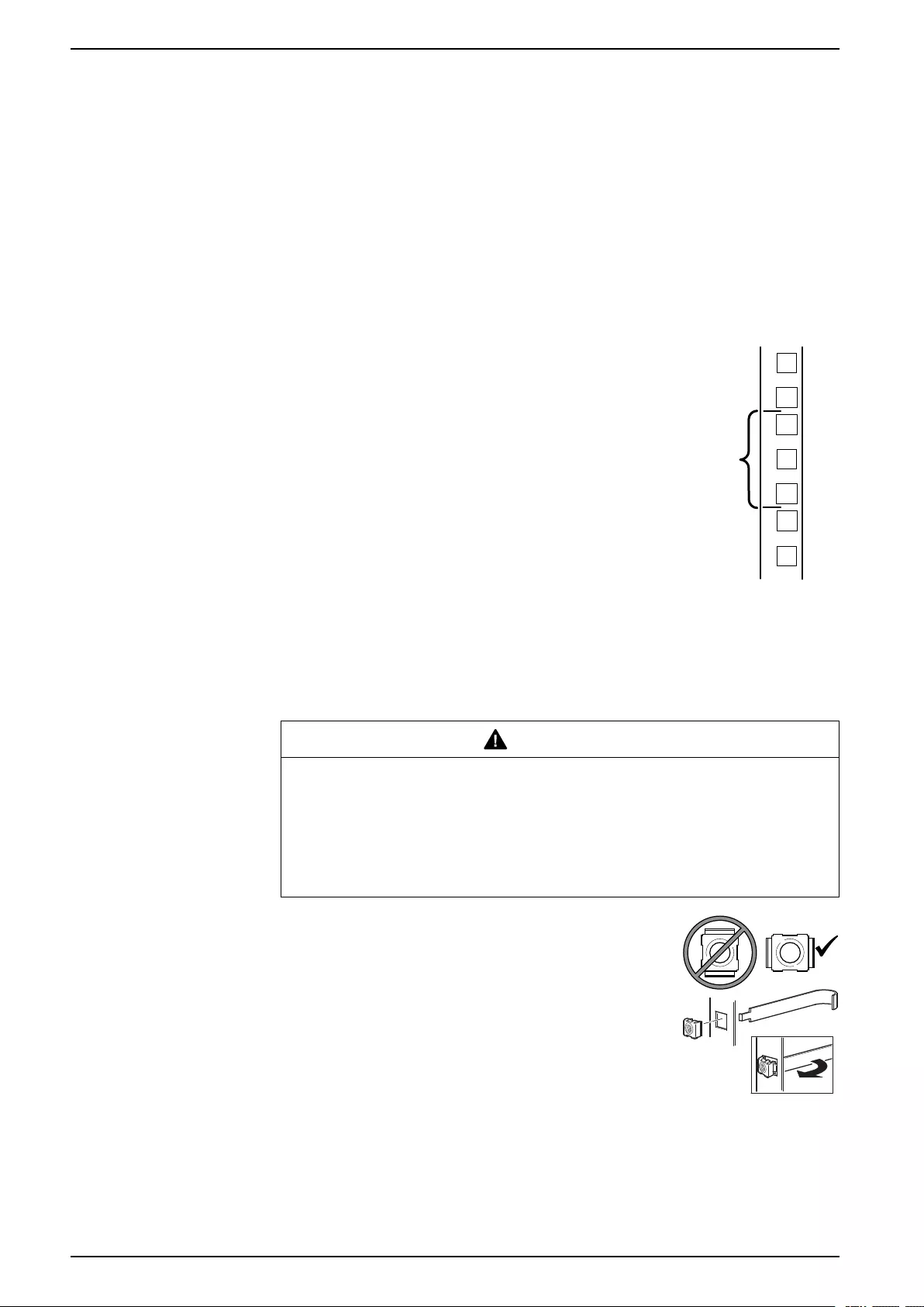
Identify One (1) U-space
To install rack-mount equipment, locate the top and bottom of a
U-space on the mounting flanges. Every third hole on the
mounting flanges of a NetShelter enclosure is numbered to
indicate the middle of a U-space. A U-space consists of one of
these numbered holes and one hole directly above and below it,
as shown.
1U
7
6
5
ns0014a
Install a Cage Nut
APC by Schneider Electric offers a cage nut hardware kit (AR8100) for use with
square holes.
CAUTION
FALLING EQUIPMENT HAZARD
Install cage nuts horizontally, with the tabs engaging the left and right sides of
the square hole. Do NOT install cage nuts vertically with the tabs engaging the
top and bottom of the square hole.
Failure to follow these instructions can result in injury or equipment
damage.
1. Install the cage nuts on the interior of the vertical
mounting flange. Insert the cage nut into the square
hole by hooking one (1) ear of the cage nut assembly
through the far side of the hole.
2. Place the cage nut tool on the other side of the cage
nut and pull to snap it into position.
ns1768a
gen0188a
Remove a Cage Nut
1. Remove any attached screw.
2. Grasp the cage nut and squeeze the sides to release it from the square hole.
14 990-6229-001
Equipment Installation
Install Equipment on the Mounting Flanges
1. Review the installation instructions from the equipment manufacturer.
2. Turn the cabinet on its side.
3. Locate the top and bottom U-space on the mounting flanges. (See Identify
One (1) U-space, page 14.)
4. If you use cage nuts, install the cage nuts on the interior of the mounting
flanges (see Install a Cage Nut, page 14). Then install the equipment.
NOTE: Read UPS Installation, page 15 before installing a UPS. Read Server
Installation, page 17 before installing a server.
UPS Installation
If you have an Uninterruptible Power Supply (UPS), it is recommended that you
mount the UPS first, in U-space one (1) (closest to the wall and mounting bracket).
You can use the included UPS bracket to mount a 2U UPS and fit additional
equipment behind the UPS in the rear of the cabinet. Mount the UPS with the
battery at the bottom of the cabinet.
CAUTION
BATTERY LEAK HAZARD
Mounting a UPS in the wrong orientation can prevent proper ventilation and
cause overheating or battery leakage. Mount compatible APC by Schneider
Electric UPS models with the display at the top of the cabinet and the battery at
the bottom of the cabinet. If you install a third-party UPS in the cabinet, check
with the manufacturer to ensure that the UPS can be safely mounted in the
vertical orientation required by the cabinet.
Failure to follow these instructions can result in injury or equipment
damage.
NOTICE
RISK OF EQUIPMENT DAMAGE
• If you intend to re-ship the cabinet with a UPS installed, ensure the UPS
bracket will keep the UPS secure while the cabinet is on its side and that the
UPS can tolerate the shipping orientation.
• Disconnect the battery before reshipment. Follow all national and
international shipping requirements.
Failure to follow these instructions can result in equipment damage.
990-6229-001 15
Equipment Installation
Compatible UPS Models
The following UPS models are compatible with the Low-profile WX Cabinet by
APC by Schneider Electric.
Lead Acid UPS Models Lithium Ion UPS Models
Rating Model Rating Model
750 VA SMX750-NMC 500 VA SCL500RMI1UNC
SMX750NC SCL500RMI1UC
SMX750I SCL500RM1UNC
1 kVA SMT1000RMI2UC SCL500RM1UC
SMT1000RMI2U 750 VA SMTL750RMI2UNC
SMT1000RM2UC SMTL750RMI2UC
SMT1000RM2U SMTL750RM2UC
SMX1000I 1 kVA SMTL1000RMI2UNC
SMX1000 SMTL1000RMI2UC
SRT1000RMXLA SMTL1000RM2UNC
SRT1000RMXLA-NC SRTL1000RMXLI-NC
SRT1000RMXLI SRTL1000RMXLI
SRT1000RMXLI-NC 1.5 kVA SMTL1500RMI3UNC
1.5 kVA SMT1500RMI2UNC SMTL1500RMI3UC
SMT1500RMI2UC SMTL1500RM3UC
SMT1500RMI2U SRTL1500RMXLI-NC
SMT1500RM2UNC SRTL1500RMXLI
SMT1500RM2UC
SMT1500RM2U
SMT1500R2-NMC
SMX1500RMI2UNC
SMX1500RMI2U
SMX1500RM2UNC
SMX1500RM2U
SRT1500RMXLA
SRT1500RMXLA-NC
SRT1500RMXLI
SRT1500RMXLI-NC
Ground the UPS
Follow the grounding guidelines for your UPS model. There are four(4) grounding
points available with 7 mm nuts pre-installed.
16 990-6229-001
Equipment Installation
Server Installation
Install the server in U-space six (6) (farthest from the wall and mounting bracket)
with the access panel facing outward to allow easy access for maintenance.
NOTICE
RISK OF EQUIPMENT DAMAGE
• Check with the manufacturer to ensure that the server can safely operate in
the vertical orientation required by the cabinet.
• If you intend to re-pack and ship the cabinet with a server installed, ensure
the server bracket will keep the server secure while the cabinet is on its side
and that the server can tolerate the shipping orientation (with the server
access panel facing the ground).
Failure to follow these instructions can result in equipment damage.
Other Compatible Equipment
The following equipment is compatible with the Low-profile WX Cabinet by APC by
Schneider Electric. Other equipment may work but has not been validated.
NetBotz Appliances Rack Power Distribution Units
Rack Monitor 250 (NBRK0250) Switched PDU, 1U, 15A, 100/120V,
(8) 5-15 outlets (AP7900B)
Rack Monitor 570 (NBRK0570) Switched PDU, 1U, 12A/208V, 10A/230V,
(8) C13 outlets (AP7920B)
Rack Monitor 750 (NBRK0750) Metered PDU, 1U, 15A, 100/120V,
(8) 5-15 outlets (AP7800B)
Miscellaneous Accessories
Metered PDU, 1U, 12A/208V, 10A/230V,
(8) C13 outlets (AP7820B)
Airflow management blanking
panel kit, 1U (AR8136BLK)
Basic PDU, 1U, 15A, 120V,
(10) 5-15 outlets (AP9562)
NOTE: See the installation manual for your NetBotz appliance to determine
which NetBotz accessories are compatible.
990-6229-001 17
Equipment Installation
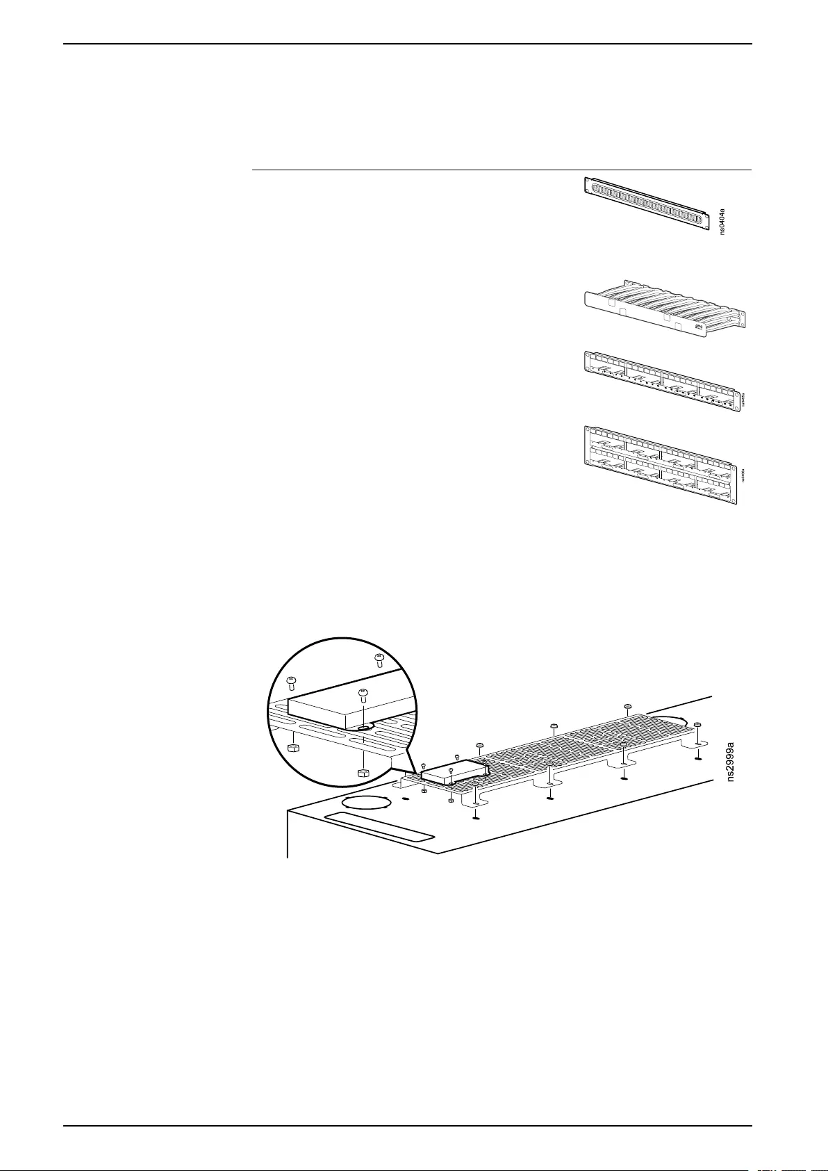
Additional Options for Cable Management
The following cable management accessories (not included) are compatible with
the Low-profile WX Cabinet.
Accessory Description
Horizontal cable
manager with brush
strip, 1U (AR8429 )
19 in, 1U cable pass-
through assists with
containing air in the
cabinet and providing an
aesthetic solution for
cable routing.
Horizontal cable
manager, 1U x 4 in
(AR8602A)
Routes cables on the front
or back of the 19 in EIA
cabinet.
Data distribution
panel, 1U (AR8451)
Holds four (4) data
distribution cables, for a
total of 24 ports.
Data distribution
panel, 2U (AR8452)
Holds eight (8) data
distribution cables, for a
total of 48 ports.
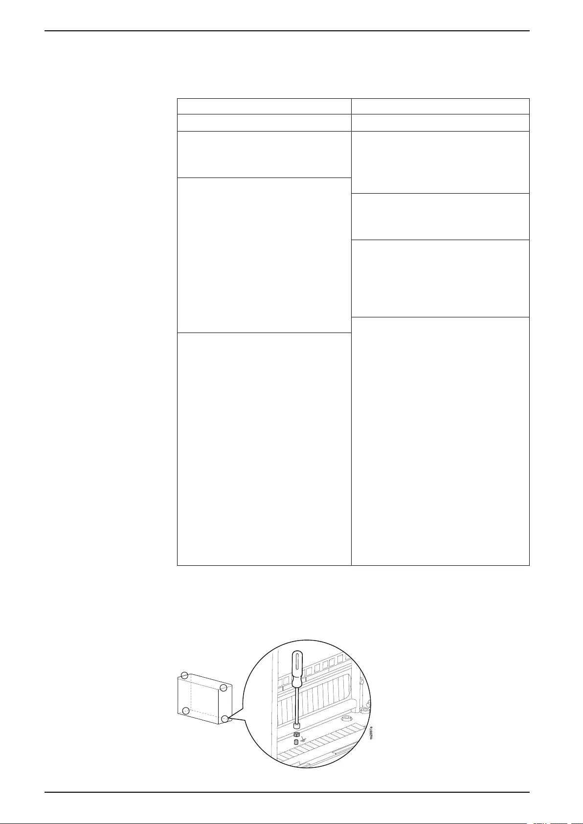
Universal Accessory Bracket
You can install additional sensors or networking equipment on the Universal
Accessory bracket.
18 990-6229-001
Equipment Installation
Additional Options (not included)
The following accessories are available on www.apc.com. Installation instructions
are provided for each accessory. Check your NetBotz appliance documentation to
ensure that any NetBotz accessories are compatible with your appliance.
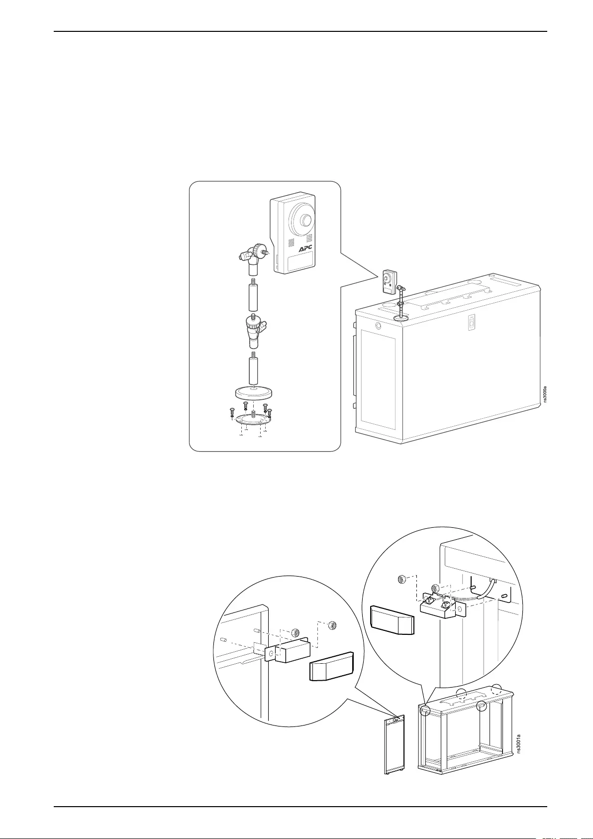
NetBotz Camera Pod 165 (NBPD0165)
The top of the cabinet has four (4) holes that can be used to install a NetBotz
Camera Pod 165. Use the pre-installed #6-32 x 5/16 screws and washers.
NetBotz Door Switch Sensor (NBES0313)
The cabinet has four (4) locations for NetBotz door switch sensors with matching
installation locations on each panel.
990-6229-001 19
Cabinet Installation
Cabinet Installation
WARNING
HEAVY EQUIPMENT HAZARD
• Installation must be performed by qualified personnel.
• Use at least two (2) people to lift the cabinet and follow site-specific
requirements for lifting.
• Follow local and national building codes when installing the cabinet.
Failure to follow these instructions can result in death, serious injury, or
equipment damage.
NOTE: The cabinet is intended only for indoor environments. See
Specifications, page 26 for environmental requirements.
NOTE: See Specifications, page 26 for the weight of the cabinet and its
maximum weight capacity.
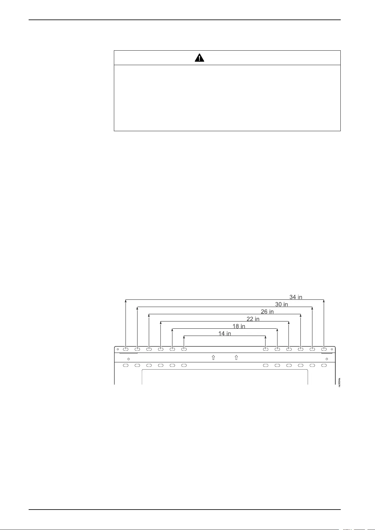
Mount the Cabinet to a Wall
NOTE: Install equipment before mounting the cabinet to a wall. See
Equipment Installation, page 14.
The holes on the mounting bracket will accommodate up to a 10 mm (3/8 in) bolt.
The centers of adjacent holes are 51 mm (2 in) apart, and the centers of the
middle holes are 356 mm (14 in) apart. The bracket can be mounted on studs with
standard 16 in (406 mm) centers or 24 in (610 mm) centers.
Unless mounting on concrete or cinder block, you must mount the bracket on at
least two (2) studs, centered to the best of your ability. Secure the bracket with at
least four (4) fasteners. Follow local and national building codes, and ensure your
mounting surface and fasteners can support the weight of the loaded cabinet and
all attached equipment.
You will need the following items (not provided):
• stud finder (only needed for mounting on studs)
• four (4) drywall screws (only needed for temporary bracket mounting in step
3)
• level
• at least four (4) fastener and four (4) washers appropriate for your wall type
• cordless drill and appropriate drill bit
• material lift (recommended)
20 990-6229-001
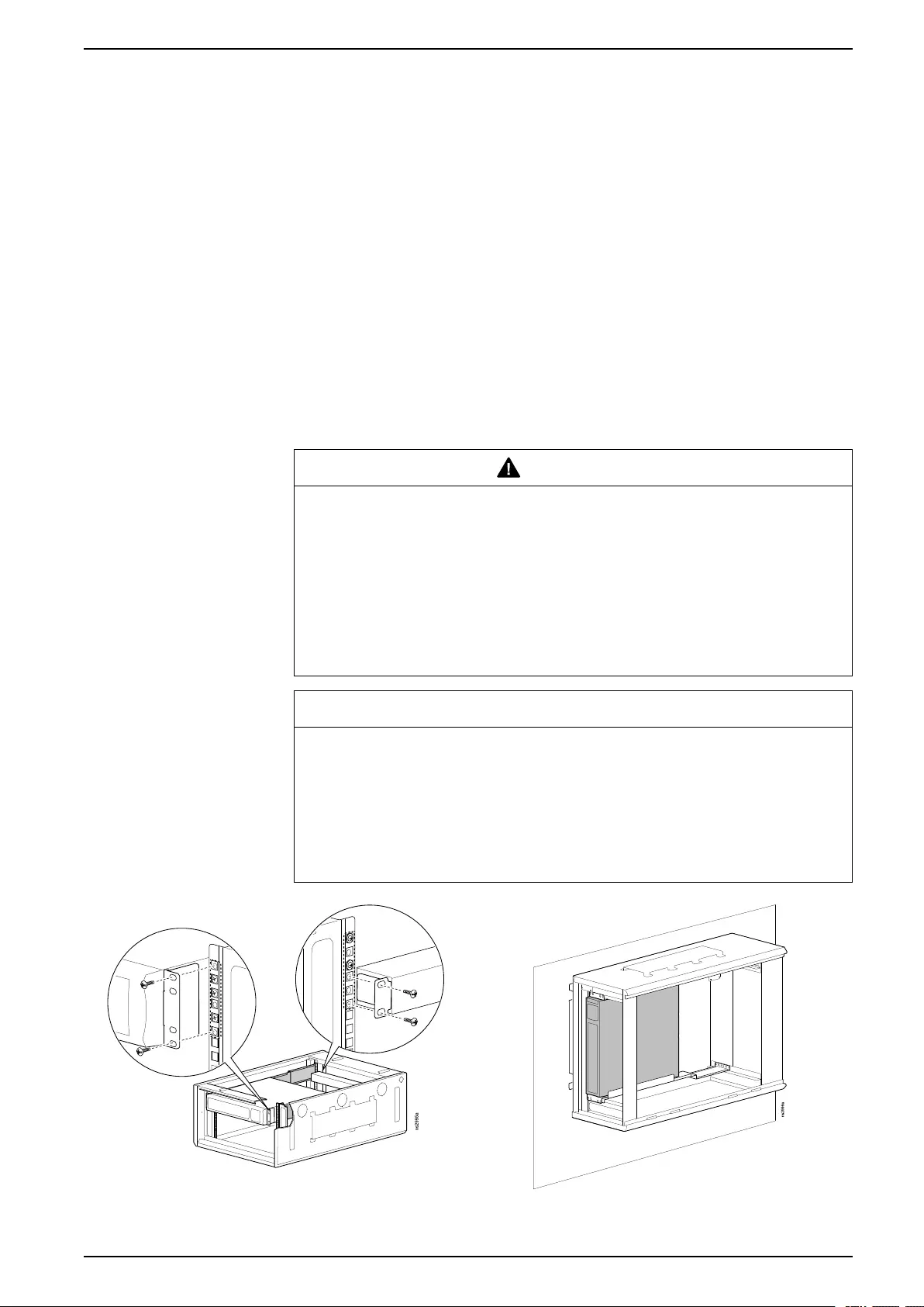
Cabinet Installation
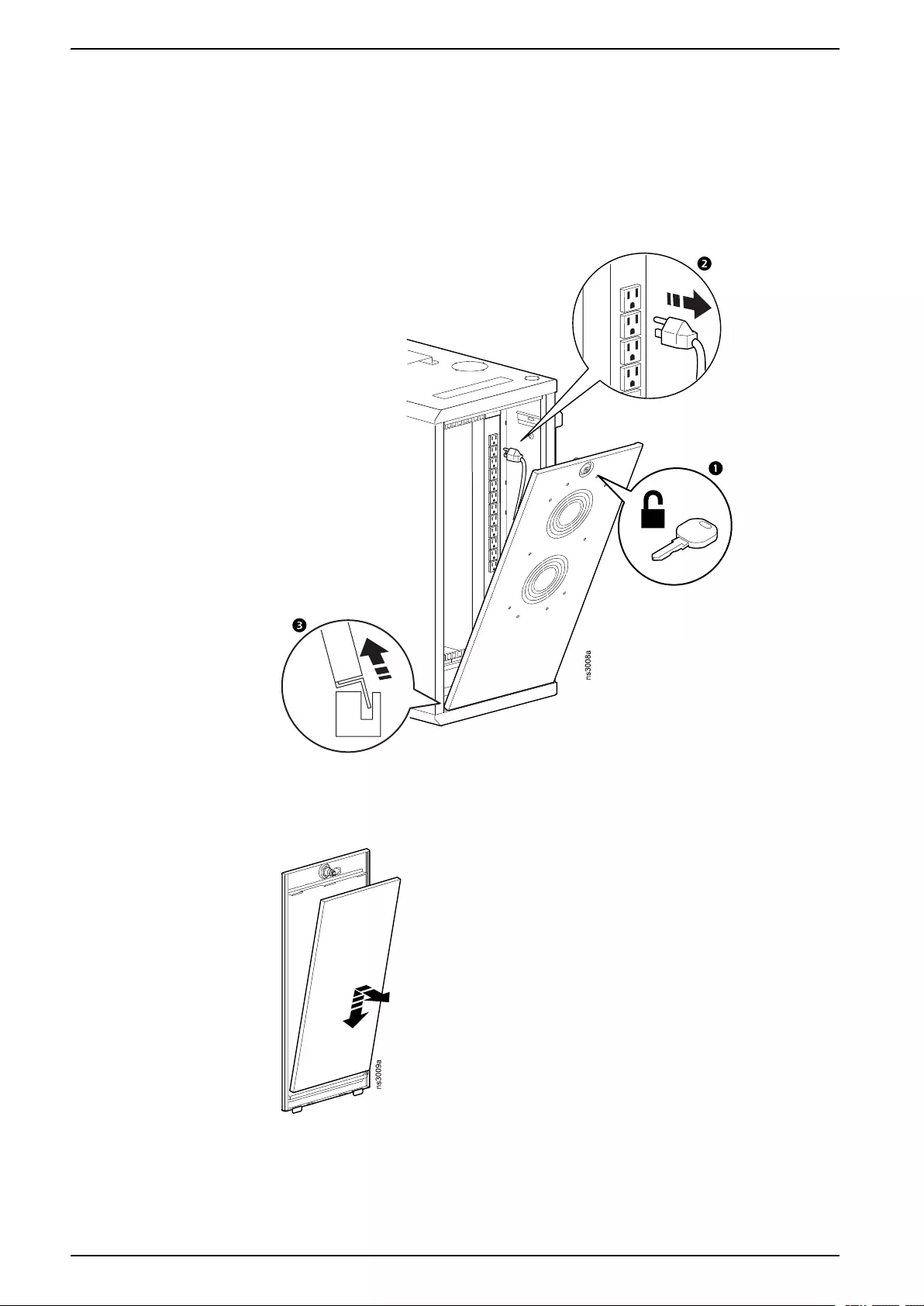
1. Remove the front and rear panels (see Front and Rear Panels, page 11).
2. Use two (2) people to remove the mounting bracket. While one person holds
the bracket, let the other person remove the four (4) T30 TORX screws (keep
the screws). Then remove the bracket.
3. NOTE: Skip this step for concrete or cinder block.Use a stud finder to locate
and mark at least two (2) wall studs. Hold the bracket to the wall so that four
(4) fastener holes are aligned with the studs. Ensure the bracket is
horizontally level and install two (2) drywall screws as shown.
NOTE: The drywall screws will hold the bracket in position while you
secure the bracket so that it can bear the weight of the cabinet. Do not put
any weight on the bracket at this time.
4. Drill at least four (4) pilot holes where fastener holes in the bracket align with
the wall studs.
5. Screw the appropriate fastener for your wall-type into each pilot hole. Leave
about 13 mm (1/2 in) of each fastener out of the wall. When all four (4)
fasteners are in place, tighten them to secure the bracket against the wall.
6. Hang the cabinet by all four (4) tabs on the mounting bracket. It is
recommended that you use a material lift or other lifting device to lift the
cabinet up to the mounting bracket, then use at least two (2) people to guide
the cabinet onto the bracket.
7. Re-install the four (4) T30 TORX screws to secure the cabinet to the
mounting bracket.
WARNING
UNSECURED EQUIPMENT FALLING HAZARD
• Enclosure wall mount requires reinstallation of all four (4) T30 bolts.
• Enclosure is designed to support loads only with all four (4) mounting
bolts installed. Failure to follow these instructions can result in death or
serious injury.
Failure to follow these instructions can result in death, serious injury,
or equipment damage.
8. Re-attach and lock the front and rear panels. (See Front and Rear Panels,
page 11).
990-6229-001 21
Cabinet Installation
Floor Mount
CAUTION
TIP HAZARD
The cabinet can be tipped. Exercise caution around a standing cabinet.
Failure to follow these instructions can result in injury or equipment
damage.
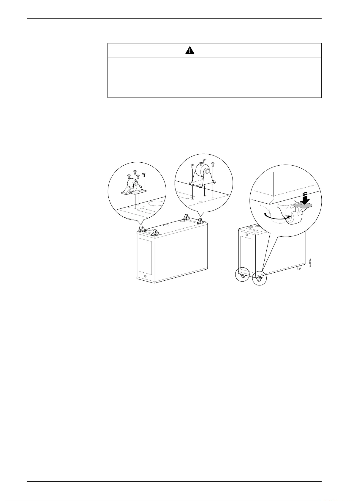
The cabinet can be set on the floor or mounted on the APC by Schneider Electric
caster kit (AR8741, not included).
The bottom of the cabinet has four (4) sets of holes for the casters. The caster kit
comes with two (2) swivel casters for the front of the cabinet, and two (2) fixed
casters for the rear of the cabinet. Ensure the screws are tight and fully seated.
Lock the swivel casters once the cabinet is in place.
NOTE: Do not install casters on a loaded cabinet.
22 990-6229-001
Cabinet Installation
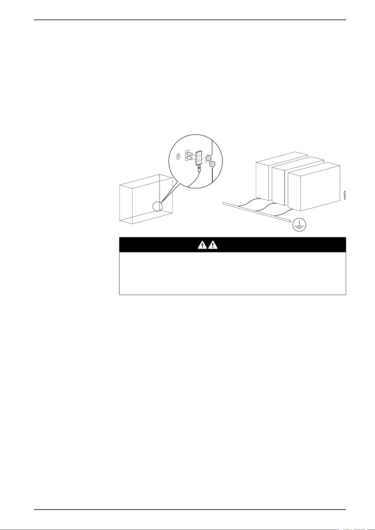
Ground the Cabinet
The front and rear doors are grounded with grounding clips.
Each cabinet should be grounded directly to the building ground using the
grounding points at the rear of the cabinet (grounding hardware not provided).
• Use a Common Bonding Network Jumper kit (for example, Listed [KDER]
Panduit RGCBNJ660PY or equivalent).
• Use the M6 nuts pre-installed on the grounding points to secure the Jumper
Kit. Torque the nuts to 6.9 N•m (60 lb-in). (You do not need the screws
included in the Jumper Kit.)
• Do not ground one cabinet to another cabinet in a cascading style. Ground
each cabinet directly to the building ground.
DANGER
HAZARD OF ELECTRIC SHOCK
The cabinet must be connected to the building Common Bonding Network
(CBN).
Failure to follow these instructions will result in death or serious injury.
990-6229-001 23

Maintenance
Additional Options: EcoStruxure Asset Advisor
EcoStruxure Asset Advisor is a cloud-based monitoring service that provides the
following benefits:
• 24/7 remote monitoring and smart alarms for the provided by Schneider
Electric Connected Services Hub
• The ability to resolve issues through an online chat or over the phone call with
experts from the Connected Services Hub
• Incident tracking and data analysis to help your equipment run more
efficiently
• Access to the EcoStruxure IT mobile application for your smart phone
You can purchase EcoStruxure Asset Advisor offers for individual devices on
www.apc.com. For example:
Parts Covered Part Number Description
1-phase UPS up to 10 kVA WADV1PEAA One (1) Year EcoStruxure
Asset Advisor Service for your
UPS
WUPG1PEAA-UG-01 Add one (1) Year EcoStruxure
Asset Advisor to an existing
firmware purchase or service
plan
990-6229-001 25

Specifications
Specifications
AR106VI
50 Hz
AR106V
60 Hz
Electrical (fan module)
Rated input voltage 230 VAC 115 VAC
Rated input current 1 A 1 A
Input connection C13 C13
Physical
Dimensions (H x W x D) 649.5 x 351.75 x 978.2 mm ( 25.6 x 13.85 x 38.5 in)
NOTE: Width includes 16.75 mm (0.65 in) mounting bracket.
Maximum equipment depth 762 mm (30 in)
Cabinet weight (empty) 34 kg (75 lb)
Maximum equipment weight 113 kg (250 lb)
Ventilation (front door) 79.6 % open area
Airflow (fan module) 220 cubic feet (6 cubic meters ) per minute at 0 static pressure
Filter ratings MERV 5, G3
Environmental
Temperature (fan)
Operating
Storage
-10 C (14 F) – 70 C (158 F)
-40 C (-40 F) – 70 C (158 F)
Compliance
UL/cUL UL2416
CAN/CSA
60950–1
UL2416
CAN/CSA
60950–1
CE 2014/35/EU —
EMC compliance
FCC —47 CFR Part 15 Class A
26 990-6229-001

Five-year Factory Warranty
Five-year Factory Warranty
The limited warranty provided by APC by Schneider Electric in this Statement of
Limited Factory Warranty applies only to products you purchase for your
commercial or industrial use in the ordinary course of your business.
Terms of Warranty
APC by Schneider Electric warrants its products to be free from defects in
materials and workmanship for a period of five years from the date of purchase.
The obligation of APC by Schneider Electric under this warranty is limited to
repairing or replacing, at its sole discretion, any such defective products. This
warranty does not apply to equipment that has been damaged by accident,
negligence, or misapplication or has been altered or modified in any way. Repair
or replacement of a defective product or part thereof does not extend the original
warranty period. Any parts furnished under this warranty may be new or factory-
remanufactured.
Non-transferable Warranty
This warranty extends only to the original purchaser who must have properly
registered the product. The product may be registered atwww.apc.com.
Exclusions
APC by Schneider Electric shall not be liable under the warranty if its testing and
examination disclose that the alleged defect in the product does not exist or was
caused by end user’s or any third person’s misuse, negligence, improper
installation or testing. Further, APC by Schneider Electric shall not be liable under
the warranty for unauthorized attempts to repair or modify wrong or inadequate
electrical voltage or connection, inappropriate on-site operation conditions,
corrosive atmosphere, repair, installation, start-up by non-APC by Schneider
Electric designated personnel, a change in location or operating use, exposure to
the elements, Acts of God, fire, theft, or installation contrary to APC by Schneider
Electric recommendations or specifications or in any event if the APC by
Schneider Electric serial number has been altered, defaced, or removed, or any
other cause beyond the range of the intended use.
THERE ARE NO WARRANTIES, EXPRESS OR IMPLIED, BY OPERATION OF
LAW OR OTHERWISE, OF PRODUCTS SOLD, SERVICED OR FURNISHED
UNDER THIS AGREEMENT OR IN CONNECTION HEREWITH. APC BY
SCHNEIDER ELECTRIC DISCLAIMS ALL IMPLIED WARRANTIES OF
MERCHANTABILITY, SATISFACTION AND FITNESS FOR A PARTICULAR
PURPOSE. APC BY SCHNEIDER ELECTRIC EXPRESS WARRANTIES WILL
NOT BE ENLARGED, DIMINISHED, OR AFFECTED BY AND NO OBLIGATION
OR LIABILITY WILL ARISE OUT OF, APC BY SCHNEIDER ELECTRIC
RENDERING OF TECHNICAL OR OTHER ADVICE OR SERVICE IN
CONNECTION WITH THE PRODUCTS. THE FOREGOING WARRANTIES AND
REMEDIES ARE EXCLUSIVE AND IN LIEU OF ALL OTHER WARRANTIES
AND REMEDIES. THE WARRANTIES SET FORTH ABOVE CONSTITUTE APC
BY SCHNEIDER ELECTRIC’S SOLE LIABILITY AND PURCHASER'S
EXCLUSIVE REMEDY FOR ANY BREACH OF SUCH WARRANTIES. APC BY
SCHNEIDER ELECTRIC WARRANTIES EXTEND ONLY TO PURCHASER AND
ARE NOT EXTENDED TO ANY THIRD PARTIES.
IN NO EVENT SHALL APC BY SCHNEIDER ELECTRIC, ITS OFFICERS,
DIRECTORS, AFFILIATES OR EMPLOYEES BE LIABLE FOR ANY FORM OF
INDIRECT, SPECIAL, CONSEQUENTIAL OR PUNITIVE DAMAGES, ARISING
OUT OF THE USE, SERVICE OR INSTALLATION, OF THE PRODUCTS,
WHETHER SUCH DAMAGES ARISE IN CONTRACT OR TORT,
990-6229-001 27

Five-year Factory Warranty
IRRESPECTIVE OF FAULT, NEGLIGENCE OR STRICT LIABILITY OR
WHETHER APC BY SCHNEIDER ELECTRIC HAS BEEN ADVISED IN
ADVANCE OF THE POSSIBLY OF SUCH DAMAGES. SPECIFICALLY, APC BY
SCHNEIDER ELECTRIC IS NOT LIABLE FOR ANY COSTS, SUCH AS LOST
PROFITS OR REVENUE, LOSS OF EQUIPMENT, LOSS OF USE OF
EQUIPMENT, LOSS OF SOFTWARE, LOSS OF DATA, COSTS OF
SUBSTITUENTS, CLAIMS BY THIRD PARTIES, OR OTHERWISE.
NO SALESMAN, EMPLOYEE OR AGENT OF APC BY SCHNEIDER ELECTRIC
IS AUTHORIZED TO ADD TO OR VARY THE TERMS OF THIS WARRANTY.
WARRANTY TERMS MAY BE MODIFIED, IF AT ALL, ONLY IN WRITING
SIGNED BY AN APC BY SCHNEIDER ELECTRIC OFFICER AND LEGAL
DEPARTMENT.
Warranty Claims
Customers with warranty claims issues may access the customer support network
through the Support page, www.apc.com/support. Select your country from the
country selection pull-down menu at the top of the Web page. Select the Support
tab to obtain contact information for customer support in your region.
28 990-6229-001

Radio Frequency Interference
Radio Frequency Interference
USA—FCC
This equipment has been tested and found to comply with the limits for a Class A
digital device, pursuant to part 15 of the FCC Rules. These limits are designed to
provide reasonable protection against harmful interference when the equipment is
operated in a commercial environment. This equipment generates, uses, and can
radiate radio frequency energy and, if not installed and used in accordance with
this user manual, may cause harmful interference to radio communications.
Operation of this equipment in a residential area is likely to cause harmful
interference. The user will bear sole responsibility for correcting such interference.
Canada—ICES
This Class A digital apparatus complies with Canadian ICES-003.
Cet appareil numérique de la classe A est conforme à la norme NMB-003 du
Canada.
Japan — VCCI
This is a Class A product based on the standard of the Voluntary Control Council
for Interference by Information Technology Equipment (VCCI). If this equipment is
used in a domestic environment, radio disturbance may occur, in which case, the
user may be required to take corrective actions.
この装置は、情報処理装置等電波障害自主規制協議会(VCCI)の基準 に基づくク
ラス A情報技術装置です。この装置を家庭環境で使用すると、電波 妨害を引き起こ
すことがあります。この場合には、使用者が適切な対策を講ず るように要求されること
があります。
European Union
This product has been tested and found to comply with the limits for Class A
Information Technology Equipment according to CISPR 32/European Standard
EN 55032. The limits for Class A equipment were derived for commercial and
industrial environments to provide a reasonable protection against interference
with licensed communication equipment.
Attention: This is a Class A product. In a domestic environment this product may
cause radio interference in which case the user may be required to take adequate
measures.
990-6229-001 29


APC by Schneider Electric
132 West Fairgrounds Rd
West Kingston, RI 02892
USA
www.apc.com
As standards, specifications, and design change from time to time,
please ask for confirmation of the information given in this publication.
© 2019 – APC by Schneider Electric. All rights reserved.
990-6229-001