APC AR3157W User Manual
Displayed below is the user manual for AR3157W by APC which is a product in the Rack Cabinets category. This manual has pages.
Related Manuals

Page 1 7/30/2019
APC by Schneider Electric
NetShelter™ SX Cabinet
THIS GUIDE SPECIFICATION IS WRITTEN IN ACCORDANCE WITH THE CONSTRUCTION SPECIFICATIONS INSTITUTE (CSI) MASTERFORMAT.
THIS SECTION MUST BE CAREFULLY REVIEWED AND EDITED BY THE ARCHITECT OR THE ENGINEER TO MEET THE REQUIREMENTS OF THE
PROJECT. COORDINATE THIS SECTION WITH OTHER SPECIFICATION SECTIONS IN THE PROJECT MANUAL AND WITH THE DRAWINGS.
WHERE REFERENCE IS MADE THROUGHOUT THIS SECTION TO “PROVIDE”, “INSTALL”, “SUBMIT”, ETC., IT SHALL MEAN THAT THE
CONTRACTOR, SUBCONTRACTOR, OR CONTRACTOR OF LOWER TIER SHALL “PROVIDE”, “INSTALL”, SUBMIT”, ETC., UNLESS OTHERWISE
INDICATED.
THIS SECTION IS WRITTEN TO INCLUDE THE 2004 MASTERFORMAT AND THE 1995 MASTERFORMAT VERSIONS. WHERE APPLICABLE, THESE
ITEMS ARE BRACKETED AND, IN EACH CASE, UNLESS OTHERWISE INDICATED, THE FIRST CHOICE APPLIES TO THE 2004 MASTERFORMAT
AND THE SECOND CHOICE APPLIES TO THE 1995 MASTERFORMAT.
SECTION [27 11 16]
COMMUNICATIONS CABINETS
PART 1 - GENERAL
1.1 SUMMARY
A. Provide design and engineering, labor, material, equipment, related services, and supervision required,
including, but not limited to, manufacturing, fabrication, erection, and installation as required for the
complete performance of the work, and as herein specified.
B. The work specified includes, but shall not be limited to, requirements for cabinets, in data centers,
computer rooms, communications equipment rooms and edge applications.
C. Included in this section are the minimum composition requirements and installation methods for NetShelter
SX Cabinets.
1.2 QUALITY ASSURANCE
A. All cable and equipment shall be installed in a neat and workmanlike manner. All methods of construction
that are not specifically described or indicated in the contract documents shall be subject to the control
and approval of the Owner or Owner Representative. Equipment and materials shall be of the quality and
manufacture indicated. Where “approved equal” is stated, equipment shall be equivalent in every way to
that of the equipment specified and subject to approval.
B. Strictly adhere to all Building Industry Consulting Service International (BICSI), Electronic Industries
Alliance (EIA) and Telecommunications Industry Association (TIA) recommended installation practices
when installing communications/data cabling.
C. Material and work specified herein shall comply with the applicable requirements of the following
standards and regulations:
1. TIA – 569-B Commercial Building Standard for Telecommunications Pathways and Spaces, 2004
2. ANSI/ TIA – 568-C Commercial Building Telecommunications Cabling Standard, 2009
3. ANSI/ NECA/BICSI 568-2006 – Standard for Installing Commercial Building Telecommunications
Cabling
4. TIA – 606-A Administration Standard for Commercial Telecommunications Infrastructure, 2007
5. ANSI-J-STD – 607-A Joint Standard for Commercial Building Grounding (Earthing) and Bonding
Requirements for Telecommunications, 2002
6. ANSI/TIA-942 Telecommunications Infrastructure Standard for Data Centers, 2005
7. NFPA 70 – National Electric Code, 2008

Page 2 7/30/2019
1.3 SUBMITTALS
A. Provide product data for the following:
1. Manufacturer’s data sheets/cut sheets, specifications and installation instructions for all products
(submit with bid).
1.4 DELIVERY, STORAGE, AND HANDLING
A. Deliver materials to the Project site in supplier’s or manufacturer’s original wrappings and containers, labeled
with supplier’s or manufacturer’s name, material or product brand name, and lot number, if any.
1. The unit shall be shipped fully assembled as one orderable SKU.
2. The unit shall ship on a wooden pallet. Optional packaging shall be available for shipping cabinets with
600lbs to 3,500lbs of installed equipment, model dependent.
3. The unit shall be bolted to the wooden pallet for stability during shipment.
4. The unit shall be protected by corrugated corners, which are stretch-wrapped to limit damage during
handling.
B. The unit shall have unpacking instructions including manufacturer’s contact information for customer
support.
The customer shall store materials in their original, undamaged packages and containers, inside a
well-ventilated area protected from weather, moisture, soiling, extreme temperatures, and humidity.
1. The manufacturer shall offer an inside-delivery shipping option which includes reasonable delivery to
the inside of a customer’s building and removal and disposal of shipping material and packaging
2. The 42U unit shall roll through a standard 2 meter or seven (7) foot office doorway.
1.5 PROJECT CONDITIONS
A. Environmental Requirements: Do not install equipment until space is enclosed and weatherproof, wet work
in space is completed and nominally dry, work above ceilings is complete, and ambient temperature and
humidity conditions are and will be continuously maintained at values near those indicated for final
occupancy.
1.6 WARRANTY
A. The manufacturer shall warrant the unit to be free from defects in materials and workmanship for a
minimum period of five years (two years in Japan) from the date of purchase. The manufacturer’s
obligation under this warranty shall be to repair or replace the unit, at its own sole option. This warranty
shall not apply to equipment that has been damaged by accident, negligence, or misapplication or has
been altered or modified in any way.
B. The manufacturer shall warrant all accessories and options to be free from defects in materials and
workmanship for a minimum period of two years from the date of purchase (Japan only). The
manufacturer’s obligation under this warranty shall be to repair or replace the equipment, at its own sole
option. This warranty shall not apply to equipment that has been damaged by accident, negligence, or
misapplication or has been altered or modified in any way.
PART 2 – PRODUCT
2.1 MANUFACTURER
A. Product specified is “NetShelter SX” Cabinet as manufactured by Schneider Electric. Items specified are to
establish a standard of quality for design, function, materials, and appearance.
Page 3 7/30/2019
2.2 DESIGN REQUIREMENTS
A. Equipment cabinets to store computer, data storage and networking equipment in the data centers, computer
rooms, equipment rooms and for edge applications. Each cabinet shall be designed to provide a secure,
managed environment for server and networking equipment. Cabinets shall be designed to accommodate
power and cable management accessories that keep network and power cables separate and organized.
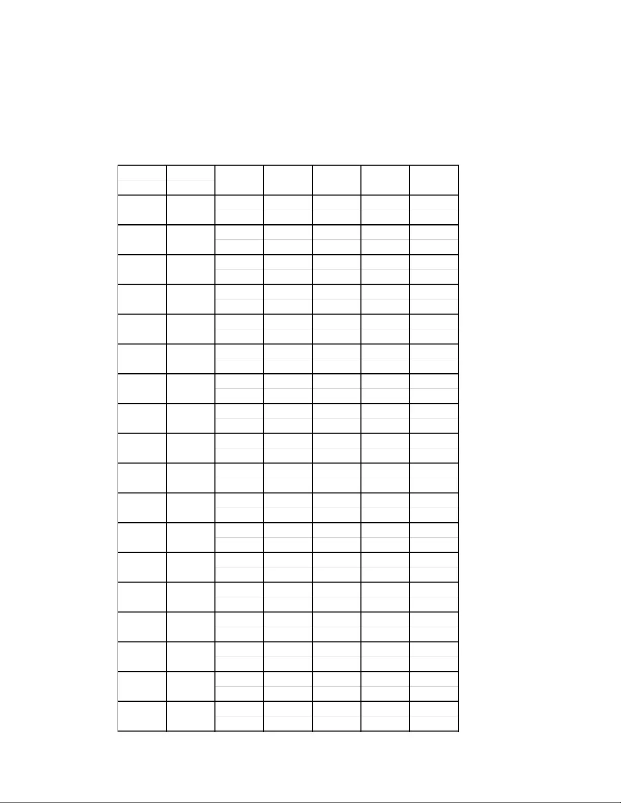
Physical Specifications:
1. Cabinet dimensions, equipment mounting compatibility and weight load ratings:
Internal
Height EIA-310
1991mm 600mm 1070mm 1700 kg 1022 kg
(78.40”) (23.62”) (42.13”) (3750lbs) (2250lbs)
1991mm 750mm 1070mm 1700 kg 1022 kg
(78.40”) (29.53”) (42.13”) (3750lbs) (2250lbs)
1991mm 800mm 1070mm 1700 kg 1022 kg
(78.40”) (31.50”) (42.13”) (3750lbs) (2250lbs)
1991mm 600mm 1200mm 1700 kg 1022 kg
(78.40”) (23.62”) (47.24”) (3750lbs) (2250lbs)
1991mm 750mm 1200mm 1700 kg 1022 kg
(78.40”) (29.53”) (47.24” (3750lbs) (2250lbs)
1991mm 800mm 1200mm 1700 kg 1022 kg
(78.40”) (31.50”) (47.24” (3750lbs) (2250lbs)
2124mm 600mm 1070mm 1700 kg 1022 kg
(83.62”) (23.62”) (42.13”) (3750lbs) (2250lbs)
2124mm 750mm 1070mm 1700 kg 1022 kg
(83.62”) (29.53”) (42.13”) (3750lbs) (2250lbs)
2124mm 800mm 1070mm 1700 kg 1022 kg
(83.62”) (29.53”) (42.13”) (3750lbs) (2250lbs)
2124mm 600mm 1200mm 1700 kg 1022 kg
(83.62”) (23.62”) (47.24”) (3750lbs) (2250lbs)
2124mm 750mm 1200mm 1700 kg 1022 kg
(83.62”) (29.53”) (47.24” (3750lbs) (2250lbs)
2124mm 800mm 1200mm 1700 kg 1022 kg
(83.62”) (29.53”) (47.24” (3750lbs) (2250lbs)
2258mm 600mm 1070mm 1700 kg 1022 kg
(88.90”) (23.62”) (42.13”) (3750lbs) (2250lbs)
2258mm 750mm 1070mm 1700 kg 1022 kg
(88.90”) (29.53”) (42.13”) (3750lbs) (2250lbs)
2258mm 800mm 1070mm 1700 kg 1022 kg
(88.90”) (31.50”) (42.13”) (3750lbs) (2250lbs)
2258mm 600mm 1200mm 1700 kg 1022 kg
(88.90”) (23.62”) (47.24” (3750lbs) (2250lbs)
2258mm 750mm 1200mm 1700 kg 1022 kg
(88.90”) (29.53”) (47.24” (3750lbs) (2250lbs)
2258mm 800mm 1200mm 1700 kg 1022 kg
(88.90”) (31.50”) (47.24” (3750lbs) (2250lbs)
42U
19”
45U
19”
45U
19”
42U
19”
42U
19”
42U
19”
42U
19”
42U
19”
45U
External
Height
External
Width
External
Depth
Static
Rating
Dynamic
Rating
19”
45U
19”
45U
19”
45U
19”
48U
19”
48U
19”
48U
19”
48U
19”
48U
19”
48U
19”
Page 4 7/30/2019
2. The 42U unit shall have exterior maximum height to allow passage through a standard 2 Meter or 7 Ft.
(84 in) doorway without tipping.
3. The 42U, 45U, 48U and 52U units shall support a static load (weight supported by the casters and
leveling feet) of at least 1,700 kg. (3,750 lb) total installed equipment weight.
4. The 42U, 45U, 48U and 52U units shall support a rolling load (rolling on the casters) of at least 1,022
kg. (2,250 lb) total installed equipment weight.
5. The units (42U, 45U, 48U and 52U) shall ship with a perforated front door, perforated split rear doors,
four (4) half-height side panels, toolless roof, two (2) vertical frame posts, four (4) adjustable vertical
mounting rails, minimum of two (2) and maximum of four (4) vertical PDU mount cable organizers, four
(4) leveling feet and four (4) casters, baying and grounding hardware pre-installed by the manufacturer.
B. Material Requirements
1. All weight bearing components shall be constructed from steel with a thickness no less than 0.9mm (20
gauge).
2. All sheet metal parts shall be painted using a powder coat paint process.
3. Plastic materials shall meet or exceed Underwriters Laboratory’s UL94 standard HB rating.
4. All interior components of the cabinets shall not have electroplated zinc coating to minimize zinc
whiskers near active equipment.
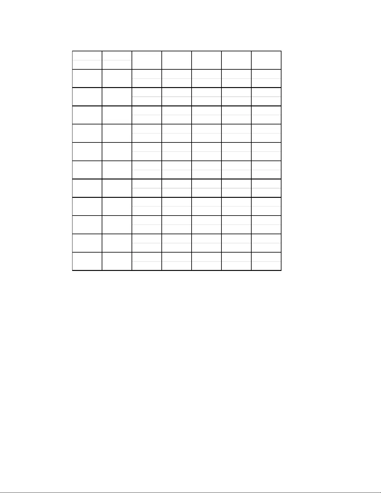
Internal
Height EIA-310
2436 mm 600mm 1070mm 1700 kg 1022 kg
(95.91”) (23.62”) (42.13”) (3750lbs) (2250lbs)
2437 mm 750mm 1070mm 1700 kg 1022 kg
(95.91”) (29.53”) (42.13”) (3750lbs) (2250lbs)
2438 mm 800mm 1070mm 1700 kg 1022 kg
(95.91”) (31.50”) (42.13”) (3750lbs) (2250lbs)
2439 mm 600mm 1200mm 1700 kg 1022 kg
(95.91”) (23.62”) (47.24” (3750lbs) (2250lbs)
2440 mm 750mm 1200mm 1700 kg 1022 kg
(95.91”) (29.53”) (47.24” (3750lbs) (2250lbs)
2441 mm 800mm 1200mm 1700 kg 1022 kg
(95.91”) (31.50”) (47.24” (3750lbs) (2250lbs)
1198mm 600mm 1070mm 1363 kg 1022 kg
(47.19”) (23.62”) (42.13”) (3000lbs) (2250)lbs
925mm 600mm 900mm 408 kg 408 kg
(36.42”) (23.62”) (35.42”) (900lbs) (900lbs)
925mm 600mm 1070mm 408 kg 408 kg
(36.42”) (23.62”) (42.13”) (900lbs) (900lbs)
658mm 600mm 900mm 272 kg 272 kg
(25.91”) (23.62”) (35.42”) (600lbs) (600lbs)
658mm 600mm 1070mm 272 kg 272 kg
(25.91”) (23.62”) (42.13”) (600lbs) (600lbs)
12U
19”
18U
19”
18U
19”
12U
19”
52U
19”
52U
19”
24U
19”
52U
19”
52U
19”
52U
19”
52U
19”
Static
Rating
Dynamic
Rating
External
Height
External
Width
External
Depth

Page 5 7/30/2019
C. Access and Installation:
1. The unit shall provide 42U, 45U, 48U or 52U of equipment vertical mounting space (42U-52U units).
2. The vertical mounting rails shall be easily adjustable to allow different mounting depths.
a. Each vertical mounting rail shall be marked on both sides with lines showing the top and bottom of
each U and the number U space next to the middle hole. Each U consists of three square holes
and is 1.75 inches (44.45 mm) high.
3. The unit shall include M6 caged nuts, bolts and cup washers, and caged nut tool for the mounting of
equipment inside the unit.
4. Both the front and rear doors shall be designed with lift-off hinges allowing for quick and easy
detachment without the use of tools.
a. The front and rear doors shall open a minimum of 120 degrees to allow easy access to the interior.
b. The front door of the unit shall be reversible so that it can be mounted on either side.
c. Split rear doors are provided for increased service clearance.
d. The front door of the unit shall be capable of being installed on the rear of the unit and the rear
doors shall be capable of being installed on the front of the unit.
5. The unit shall include half-height side panels that are removed without tools using easy finger latches
for fast access to cabling and equipment.
a. The side panels on the unit shall double as privacy panels when the units are bayed together.
b. Side panels shall be flush with the frame so the overall width of the unit does not change with the
side panels installed.
c. Baying brackets must provide two sets of mounting holes for standard cabinet spacing of 24” or
600mm.
6. Grounding:
a. All cabinet components such as doors, side panels, roofs, etc. shall be bonded directly to the
frame.
b. Grounding points shall be provided on the cabinet’s frame to externally bond each unit to the
building ground.
Page 6 7/30/2019
2.3 VENTILATION
A. The unit shall have ventilated front and rear doors to provide adequate airflow
required by the major server manufacturers.
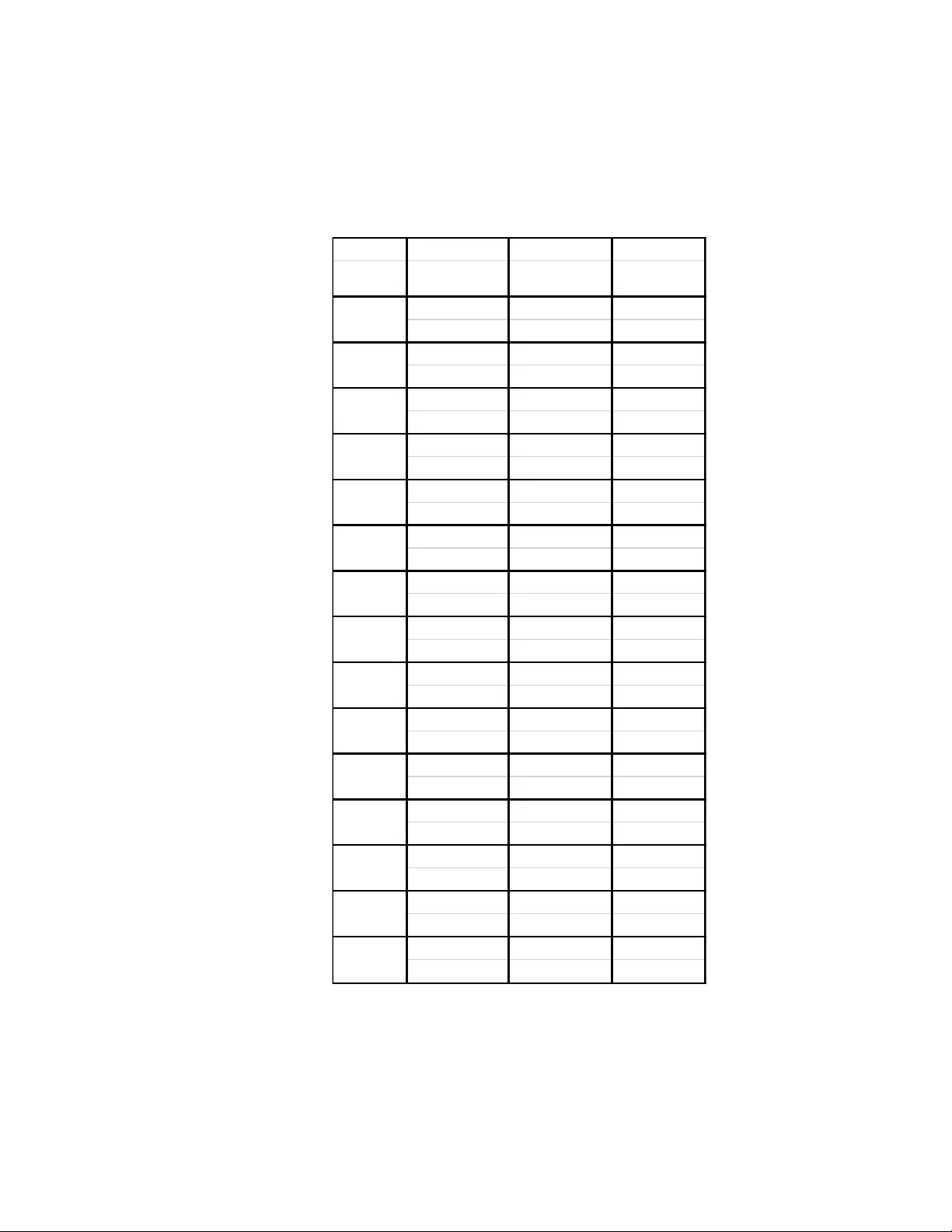
B. The unit shall have a minimum total ventilation area for the front door and split rear
doors as specified in the table below:
Internal External Perforated Perforated
Height Width Front Door Rear Doors
600mm 5930 cm26689 cm2
(23.62”) (919 in2) (1036 in2)
750mm 7889 cm28669 cm2
(29.53”) (1222 in2) (1343 in2)
800mm 8571cm29346 cm2
(31.50”) (1328 in2) (1449 in2)
600mm 6348 cm27154 cm2
(23.62”) (984 in2) (1109 in2)
750mm 8470 cm29290 cm2
(29.53”) (1313 in2) (1440 in2)
800mm 9174 cm210009 cm2
(31.50”) (1422 in2) (1552 in2)
600mm 6758 cm27626 cm2
(23.62”) (1047 in2) (1182 in2)
750mm 9004 cm29892 cm2
(29.53”) (1395 in2) (1533 in2)
800mm 9779 cm210663 cm2
(31.50”) (1516 in2) (1653 in2)
600mm 7362 cm2 8233 cm2
(23.62”) (1141 in2) (1276 in2)
750mm 9819 cm210689 cm2
(29.53”) (1522 in2) (1657 in2)
800mm 10638 cm211507 cm2
(31.50”) (1649 in2) (1784 in2)
600mm 3458 cm23759 cm2
(23.62”) (536 in2) (583 in2)
600mm 2622 cm22939 cm2
(23.62”) ( 406 in2) ( 455 in2)
600mm 1787 cm21996 cm2
(23.62”) ( 277 in2) ( 309 in2)
18U
12U
52U
52U
48U
48U
24U
52U
48U
45U
42U
42U
42U
45U
45U
Page 7 7/30/2019
C. The unit shall provide the means to mount optional cooling accessories for high-density applications.
D. The manufacturer shall offer an optional toolless blanking panel kit to prevent the recirculation of hot exhaust
air.
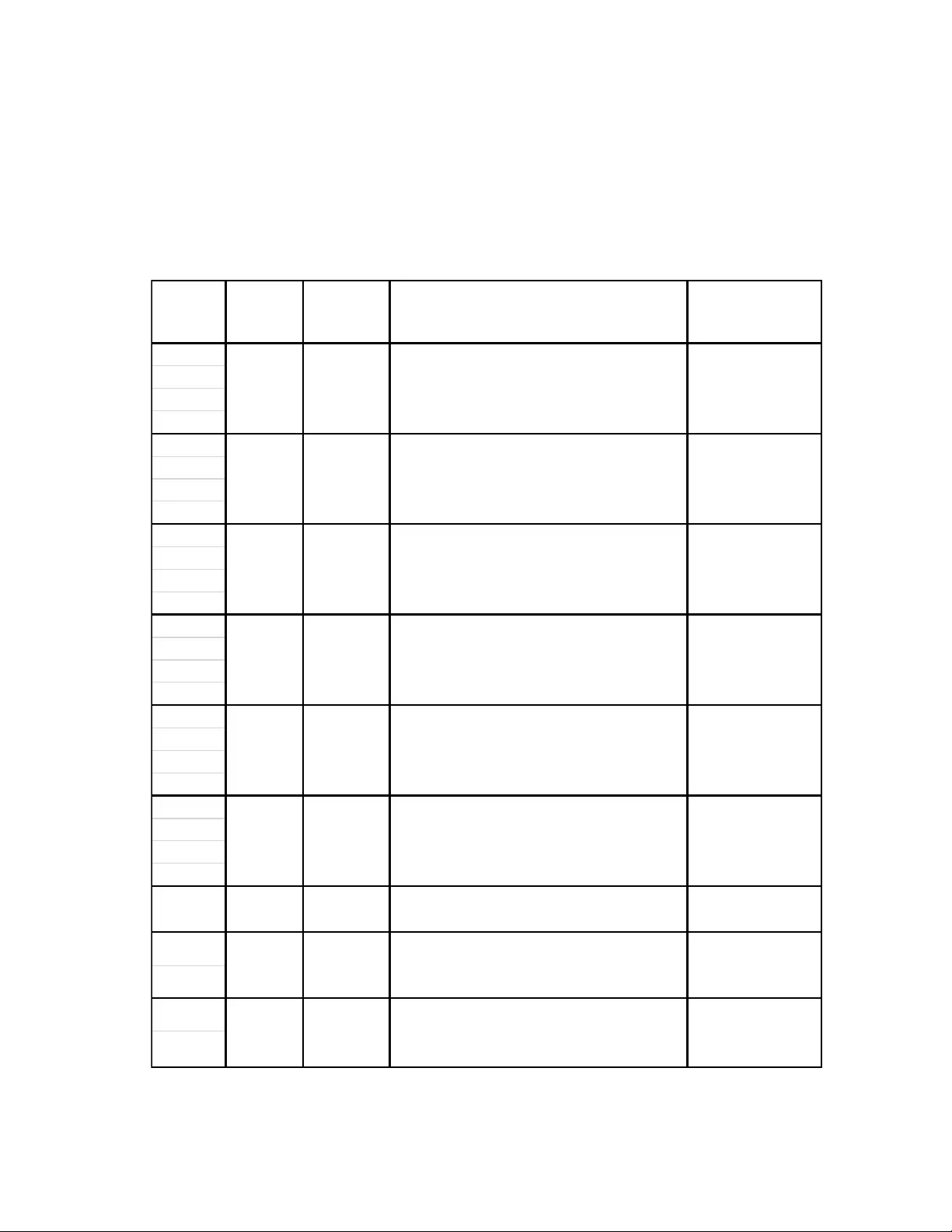
2.4 CABLE ACCESS
A. Top cable management openings provided in the cabinet roof.
42U
45U
48U
52U
42U
45U
48U
52U
42U
45U
48U
52U
42U
45U
48U
52U
42U
45U
48U
52U
42U
45U
48U
52U
12U
18U
12U
18U
600mm
(23.62")
900mm
(35.42")
600mm
(23.62")
1070mm
(42.13")
Internal
Height
External
Width
External
Depth
600mm
(23.62")
1070mm
(42.13")
750mm
(29.53")
1070mm
(42.13")
800mm
(31.50")
1070mm
(42.13")
24U
Three 60mm (2.36”) Diameter Circular
Openings
567mm (22.31”) x
892mm (35.10”)
Two 75mm (2.96”) x 164mm (6.44”), One
240mm (9.45”) x 92mm (3.61”), and Five
171mm (6.75”) x 54mm (2.14”) Rectangular
Openings
767mm (30.19”) x
892mm (35.10”)
Two 66mm (2.60”) x 252mm (9.93”) and nine
171mm (6.75”) x 54mm (2.14”) Rectangular
Openings
567mm (22.32”) x
1023mm (40.28”)
Two 66mm (2.60”) x 252mm (9.93”) and nine
171mm (6.75”) x 54mm (2.14”) Rectangular
Openings
600mm
(23.62")
1200mm
(47.24")
750mm
(29.53")
1200mm
(47.24")
800mm
(31.50")
1200mm
(47.24")
600mm
(23.62")
1070mm
(42.13")
Openings Located on Roof
Opening with Roof
Removed
Two 75mm (2.96”) x 164mm (6.44”), One
240mm (9.45”) x 92mm (3.61”), and Five
171mm (6.75”) x 54mm (2.14”) Rectangular
Openings
567mm (22.31”) x
892mm(35.10”)
Two 75mm (2.96”) x 164mm (6.44”), One
240mm (9.45”) x 92mm (3.61”), and Five
171mm (6.75”) x 54mm (2.14”) Rectangular
Openings
717mm (28.20”) x
892mm (35.10”)
Two 60mm (2.36”) Diameter Circular Openings
and One 171mm (6.75”) x 54mm (2.14”)
Rectangular Opening
567mm (22.31”) x
892mm(35.10”)
Two 60mm (2.36”) Diameter Circular Openings
and One 171mm (6.75”) x 54mm (2.14”)
Rectangular Opening
567mm (22.31”) x
722mm(28.43”)
716mm (28.20”) x
1023mm (40.28”)
Two 66mm (2.60”) x 252mm (9.93”) and nine
171mm (6.75”) x 54mm (2.14”) Rectangular
Openings
767mm (30.19”) x
1023mm (40.28”)
Page 8 7/30/2019
B. Cable opening edges shall be protected with plastic grommets or radiused edges.
C. Bottom cable management opening provided in the cabinet base:
D. Side cable management opening shall be provided in the cabinet base. A minimum of two and maximum of
four vertical PDU mount cable organizers shall be offered.
2.5 ENVIRONMENTAL
A. The unit shall have a minimum of IP 20 rating for protection against touch, ingress of foreign bodies, and
ingress of water.
B. Manufacturer must certify products are RoHS and China RoHS compliant.
C. The cabinet shall both protect the user from mechanical hazards and generally meet the requirements
(stability, mechanical strength, aperture sizes, etc.) as defined in IEC 60950 Third Edition.
2.6 SECURITY
A. The unit shall include a front door lock, rear door lock and four (4) side panel locks. All six (6) locks shall be
configured to use the same key. Two copies of the key shall be included.
1. Replacement key lock cylinders from the handle manufacturer shall be available to provide a minimum
of 220 unique key combinations on the front and rear doors.
B. The manufacturer shall provide optional products and accessories to allow the cabinet environment to be
monitored for temperature, humidity, and electronic pass key door access.
C. The unit shall have mounting provisions for optional door alarm switches to monitor access to the cabinet
doors.
600mm
(23.62")
600mm
(23.62")
750mm
(29.53")
900mm
(35.42")
1070mm
(42.13")
1070mm
(42.13")
567mm (22.31”) x 661mm (26.02”)
42U/45U/48U/52U
767mm (30.19”) x 962mm (37.87”)
42U/45U/48U/52U
767mm (30.19”) x 831mm (32.71”)
42U/45U/48U/52U
567mm (22.32”) x 962mm (37.87”)
42U/45U/48U/52U
717mm (28.23”) x 962mm (37.87”)
800mm
(31.50")
600mm
(23.62")
750mm
(29.53")
800mm
(31.50")
1070mm
(42.13")
1200mm
(47.24")
1200mm
(47.24")
1200mm
(47.24")
Main Base Opening
12/18U
12U/18U/24U/42U/45U/
48U/52U
567mm (22.31”) x 831mm (32.71”)
42U/45U/48U/52U
717mm (28.25”) x 832mm (32.74”)
Internal
Height
External
Width
External
Depth

Page 9 7/30/2019
2.7 STABILIZATION
A. The unit shall ship with provisions for stabilization in the field using the pallet mounting brackets.
B. The manufacturer shall offer an optional stabilizer kit that can be attached to the cabinet frame. The frame
can then be bolted to the floor.
C. The manufacturer shall offer an optional bolt down kits, consisting of brackets and mounting hardware that
attach to the cabinet frame and which must be anchored to the sub-floor for compliance with the International
Building Code (IBC).
D. The manufacturer shall supply structural calculations by a professionally registered engineer showing
compliance with the IBC for floor anchoring.
E. The unit shall have four (4) adjustable leveling feet to help provide a stable base in the event of an uneven
floor surface and to prevent rolling.
2.8 OPTIONAL ACCESSORIES
A. The manufacturer shall offer the following optional accessories as required to accommodate customer
requirements.
1. RM LCD Monitor/Keyboard drawer: The manufacturer shall offer a 1U high, rack-mounted LCD
monitor/keyboard drawer to maximize space in a data center environment.
2. Cooling: The manufacturer shall offer roof-mounted fan trays, door mounted fan trays, monitoring
devices, and stand alone cooling units for maintaining a cool environment.
3. Rack Power Distribution Units: The manufacturer shall offer a variety of single-phase and three-phase
rack mount power distribution units with current monitoring outlet switching, and remote management
capabilities.
4. Cable Management: The manufacturer shall offer a variety of cable management accessories to neatly
organize the routing of data and power cables within the cabinet.
5. Shelving: The manufacturer shall offer as optional accessories various fixed and sliding shelves with
the ability to support up to 250 lbs of non-rack mount equipment.
6. Uninterruptible Power Supplies: The manufacturer shall offer various rack mounted uninterruptible
power supplies (UPS), with user-replaceable and hot-swappable batteries, and with extended runtime
options available
PART 3- EXECUTION
3.1 EXAMINATION
A. Verification of Conditions: Examine areas and conditions under which the work is to be installed, and notify
the Contractor in writing, with a copy to the Owner and the Architect/Engineer, of any conditions detrimental
to the proper and timely completion of the work. Do not proceed with the work until unsatisfactory conditions
have been corrected. Beginning the work shall indicate acceptance of the areas and conditions as
satisfactory by the Installer.

Page 10 7/30/2019
3.2 INSTALLATION
A. NetShelter SX Equipment Cabinets
1. Provide all components of the cabinet system (including any optional accessories).
2. Install and adjust to position all cabinet components including accessories. Install vertical cable
managers, power distribution and equipment-mounting rails, using the manufacturer’s installation
instructions prior to baying and/or placing the cabinet for attachment to the building and before
installing any rack-mount equipment into the cabinet. Shelves, horizontal cable managers and filler
panels, if used, may be installed after the cabinet is placed.
3. When attached to the structural floor, the installer shall provide installation hardware.
4. When used in a multi-cabinet bay, cabinets shall be attached side-by-side using included baying kits
according to the manufacturer’s instructions.
5. Attach overhead ladder rack or cable tray to the ceiling or the top of the cabinet. The ladder
rack/cable tray shall be positioned so that it does not interfere with the hot air exhaust through the
cabinet’s top panel.
Note: Seismic installations require additional bracing of cabinets and overhead cable runways to the
building structure as advised by and certified by a licensed structural engineer.
6. Cabinets shall be securely bonded to a common ground. Attach a bonding conductor sized as defined
in J-STD-607-A and as defined by local code or the authority having jurisdiction (AHJ) between the
common ground and the cabinet. Attach the bonding conductor to the cabinet using a ground terminal
block according to the manufacturer’s installation instructions. The installer shall provide the bonding
conductor and other necessary hardware required to make the connections between the cabinet and
the common ground.
3.3 FIELD QUALITY CONTROL
A. MANUFACTURER FIELD SERVICE
1. Replacement parts: Parts shall be available through the worldwide service organization 24 hours a
day, 7 days a week, and 365 days a year.
END OF SECTION