Table of Contents
- Important Safety Instructions
- Package Contents
- Connect Battery
- Install PowerChute™ Personal Edition Software
- Connect the Equipment
- Operation
- Alarms and Detected System Errors
- Status Indicators
- Troubleshooting
- Specifications
- Replacement Battery
- Warranty
- APC by Schneider Electric Customer Support
- FCC Radio Frequency Class B Warning
- User Manual Back-UPS™ Pro Gaming UPS BGM1500/BGM1500B
APC BGM1500B User Manual
Displayed below is the user manual for BGM1500B by APC which is a product in the Uninterruptible Power Supplies (UPSs) category. This manual has pages.
Related Manuals
Important Safety Instructions
Inspect the package contents upon receipt. Notify the carrier and dealer if there
is any damage.
SAVE THESE INSTRUCTIONS - This manual contains important instructions that
should be followed during installation and maintenance of the UPS and batteries.
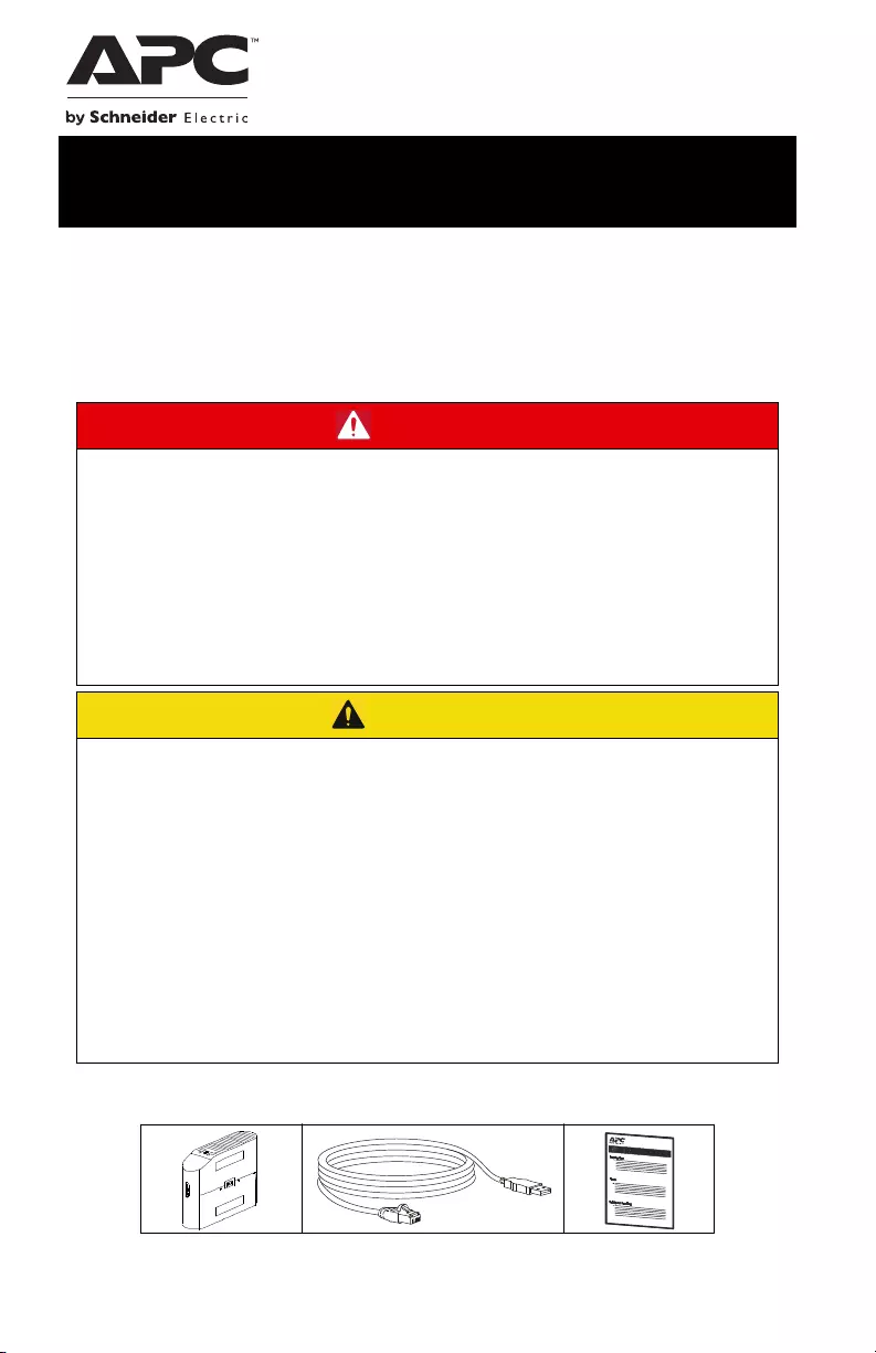
Package Contents
DANGER
RISK OF ELECTRIC SHOCK, EXPLOSION, OR ARC FLASH
• This UPS is intended for indoor use only.
• Do not operate this UPS in direct sunlight, in contact with fluids, or where
there is excessive dust or humidity.
• Be sure the air vents on the UPS are not blocked. Allow adequate space for
proper ventilation.
• Connect the UPS power cable directly to a wall outlet.
Failure to follow these instructions can result in minor or moderate
injury and equipment damage.
CAUTION
RISK OF HYDROGEN SULPHIDE GAS AND EXCESSIVE SMOKE
• Replace the battery at least every 5 years or at the end of its service life,
whichever is earlier.
• Replace the battery immediately when the UPS indicates battery
replacement is necessary.
• Replace batteries with the same number and type of batteries as originally
installed in the equipment.
• Replace the battery immediately when the UPS indicates a battery over-
temperature condition, or when there is evidence of electrolyte leakage.
Power off the UPS, unplug it from the AC input, and disconnect the batteries.
Do not operate the UPS until the batteries have been replaced.
Failure to follow these instructions can result in minor or moderate
injury and equipment damage.
User Manual Back-UPS™ Pro Gaming UPS
BGM1500/BGM1500B
Back-UPS Pro Gaming UPS 1500 VA2
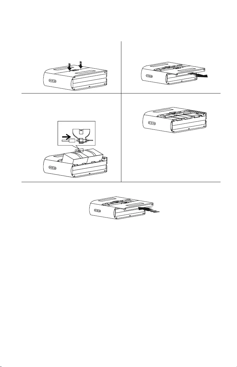
Connect Battery
The UPS is shipped with the battery disconnected.
Install PowerChute™ Personal Edition Software
Use PowerChute Personal Edition software to configure the UPS settings. During a
power outage, PowerChute will save any open files on your computer and shut it
down. When power is restored, it will restart the computer.
NOTE: PowerChute is only compatible with a Windows operating system. If you are
using Mac OSX, use the native shutdown feature to protect your system. See the
documentation provided with your computer.
Installation
Use the USB Data Port Cable supplied with the Back-UPS to connect the data port on
the Back-UPS to the USB port on your computer. Download PowerChute™ Personal
Edition Software from www.apc.com/pcpe. Select the appropriate operating system
and follow directions to download the software.
Lay the UPS with the battery door facing
up. The arrows point to the locking tabs
of the battery compartment.
Press the tabs downwards and pull the
battery door away from the unit to access
the battery modules.
Using the handles on both sides of the
battery, lift the battery 30 degrees upward
to expose the battery connector. Connect
the red wire as shown above.
Push the battery into the unit
Align the side rails on the cover with the rails on the UPS and slide the cover till it locks
in position.
RE D +
Connect Batter y
Back-UPS Pro Gaming UPS 1500 VA 3
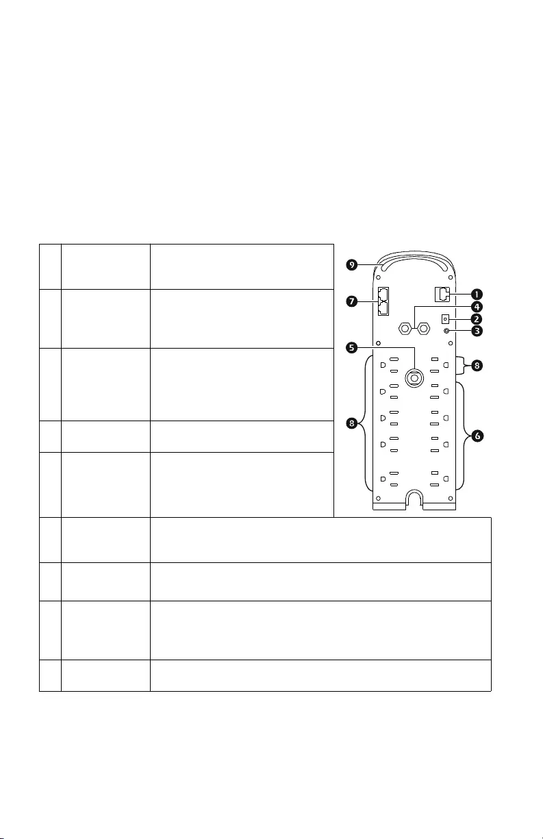
Connect the Equipment
Battery Backup and Surge Protected outlets
When the Back-UPS is receiving input power, the Battery Backup with Surge
Protection outlets will supply power to connected equipment. During a power outage
or other AC problems, the Battery Backup outlets receive power for a limited time
from the Back-UPS. Connect Gaming PC, Console, router and Monitor to these
outlets so you could stay on line during power outage.
Connect equipment such as External Hard Drive, Television or other peripherals that
do not need battery backup power to the Surge Protection Only outlets. These outlets
provide full-time protection from surges even if the Back-UPS is turned off.
USB and Serial
Data Port
To use PowerChute Personal
Edition, connect the supplied USB
communication cable
Ground Screw Connect the ground lead from an
additional surge suppression device
such as a stand-alone data line surge
protector.
Building
Wiring Fault
Indicator
If this illuminated, there is a
problem with the wiring in the
building. Contact an electrician
immediately and do not use the
Back-UPS.
Coaxial Ports with
Surge Protection
Connect a cable modem or other
equipment with coaxial jacks.
Circuit breaker
Reset Button
Use to reset the system after an
overload condition has tripped the
circuit breaker interrupt current
flow.
Surge Protected
Outlets
These outlets provide full-time protection from surges, even if the
Back-UPS is off. Connect equipment such as printers and scanners
that do not require battery backup protection.
In/Out Ethernet
Surge Protected
Ports
Use an Ethernet cable to connect a cable modem to the in port, and
connect a computer to the OUT port.
Battery Backup
Outlets with
Surge Protection
During a power outage or other AC problems, the Battery Backup
receive power for a limited time from the Back-UPS. Connect
essential equipment such as Gaming PC, Console, Router or other
gaming gear into these outlets.
Rear LEDs The Rear LEDs provide 12-color ambient lights to help you add/
remove loads from outlets.
Back-UPS Pro Gaming UPS 1500 VA4
Operation
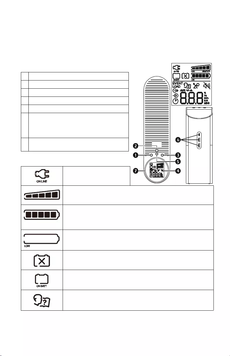
Top Bezel Buttons and Display Interface
Use the four buttons on the front panel of the Back-UPS and the display interface to
configure the Back-UPS.
Front Panel
Display Icons
INFORMATION button
POWER ON/OFF button
MUTE button
Display interface
LED button
USB charging ports: The 3 USB ports
provide a total of 15W of DC power, and will
provide power even when the UPS is on
battery.
Reactor Circle: Provides 12-color ambient
lights.
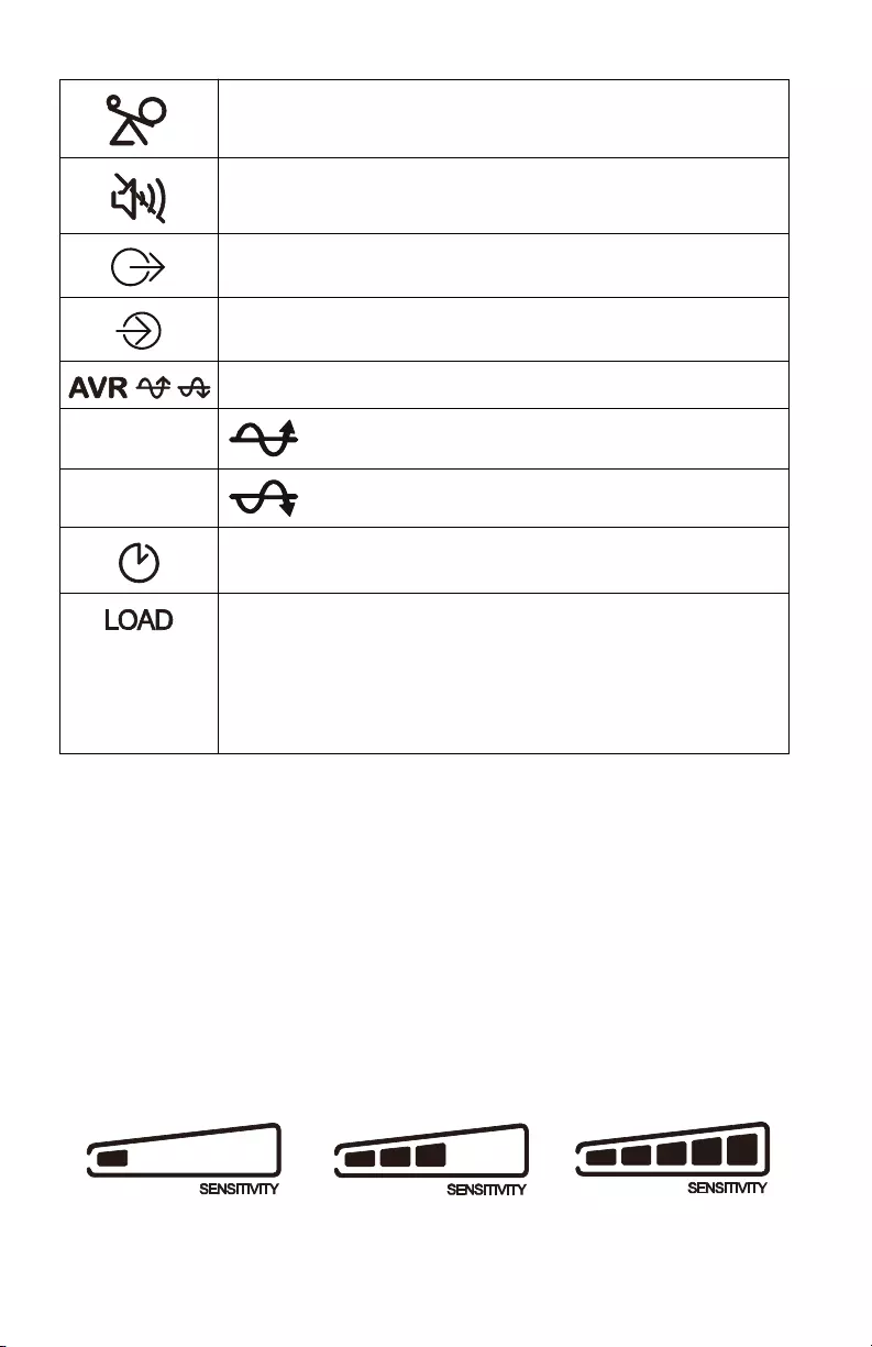
On Line: The Back-UPS is
supplying conditioned Utility
power to connected equipment
Load Capacity: The approximate load capacity percentage is indicated
by the number of load bar sections illuminated. Each bar represents
approx 20% of load capacity.
Battery Capacity: The battery charge level is indicated by the number
of bar sections illuminated. When all five bar sections are illuminated,
it indicates that the battery is fully charged. When only one bar section
is illuminated, it indicates the battery charge is nearing depletion.
Low Battery: When the battery charge is completely depleted and the
UPS is nearing shutdown, the indicator will flash accompanied by a
continuous beep.
Replace Battery: The battery is nearing the end of its useful life and
should be replaced immediately.
On Battery: The UPS is supplying battery power to the connected
equipment. The UPS will emit an audible beep once in every 10
seconds.
System Error Detected: A system error has been detected. The system
error number will be displayed on the display interface. Refer
“Detected system errors” on page 6, for details.
Back-UPS Pro Gaming UPS 1500 VA 5
Unit sensitivity
The higher the sensitivity, the more often the Back-UPS switches to battery power.
Adjust the sensitivity of the Back-UPS to control when the UPS will switch over to
battery power;
1. Turn off the Back-UPS while connected to a wall outlet.
2. Press and hold the INFORMATION button for six seconds. The Load
capacity icon will flash on and off, indicating that the Back-UPS is in
programming mode.
3. Press INFORMATION button to navigate through the menu options. Stop at
selected sensitivity.
Overload: The connected equipment is drawing more power than the
rated capacity of the UPS.
Mute: An illuminated line through the icon indicates that the audible
alarm is disabled.
Out: Output voltage, frequency
In: Input voltage, frequency
Automatic Voltage Regulation:
When illuminated, the Back-UPS is compensating for low
input voltage.
When illuminated, the Back-UPS is compensating for high
input voltage.
Estimated Runtime: Indicates the remaining runtime (in minutes) in
on-battery mode.
Load: The total load in watts (W) or percentage (%) used by the
devices indicates the remaining runtime (in minutes) in on-battery
mode.
Event: The number of events that shows up on the LCD screen are the
number of power disturbances that your UPS has detected. These
disturbances can be any of the following: blackout, under/over voltage,
total harmonic distortion, surge, spike, etc.
Generator Sensitivity Default Sensitive Loads

Back-UPS Pro Gaming UPS 1500 VA6
Alarms and Detected System Errors
Audible indicators
Detected system errors
If the UPS system does not operate correctly, use the table below to resolve the
problem.
Low sensitivity Medium sensitivity (Default) High sensitivity
78-150 Vac 88-147 Vac 88-144 Vac
Gaming UPS will change to
battery mode only when input
voltage is extremely low or
high. Not recommended for
computer or gaming console
loads.
This is default sensitivity
setting and is recommend for
Gaming PC and Gaming
consoles.
The connected equipment is
sensitive to voltage
fluctuations.
Overload Beep every 0.5 second
Low battery Beep every 0.5 second
Overcharge Beep every 1.5 seconds
Battery replacement Beep every 2 seconds
Battery mode Beep every 30 seconds
Internal error detected Continuous beep
F01 Overload fault Turn the Gaming UPS off. Disconnect non-essential
equipment from the Battery Backup outlets and then
turn Gaming UPS on.
F02 Output short Turn the Gaming UPS off. Disconnect all equipment
from the Battery Backup outlets and then turn Gaming
UPS on. Reconnect equipment one item at a time. If
the system error is detected again, disconnect the last
connected equipment as it is in an inoperable
condition.
F05 Over Charge Voltage Contact APC by Schneider Electric support
F06 Relay Welding Contact APC by Schneider Electric support
F07 Over Temperature or NTC
disconnected
Contact APC by Schneider Electric support
F08 Fan lock error detected. Contact APC by Schneider Electric support
F12 Battery mode output high. Contact APC by Schneider Electric support
F13 Battery mode output low Contact APC by Schneider Electric support
F28 Low battery voltage Replace the battery. If the detected error still occurs
after battery is replaced, contact APC by Schneider
Electric Support
Back-UPS Pro Gaming UPS 1500 VA 7
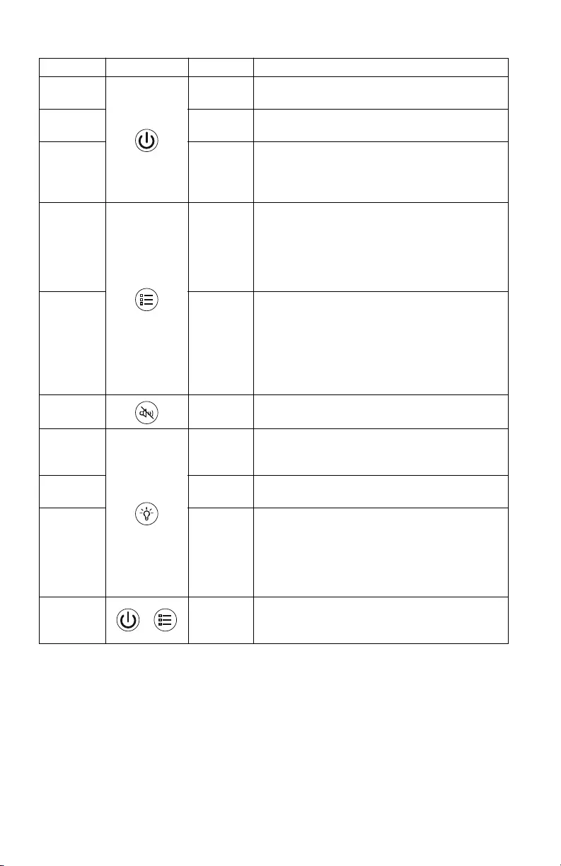
Function Button Timing Description
Power On 2 seconds Press and hold the POWER ON/OFF button to turn
on UPS.
Power Off 2 seconds Press and hold the POWER ON/OFF button to turn
off UPS.
Self-Test
mode
6 seconds Press and hold the POWER ON/OFF button for
6 seconds (buzzer will beep when 6 seconds
pass) to go into Self-Test mode when UPS is in
Line mode or AVR mode.
UPS
Information
0.2 seconds Press the INFORMATION button to display UPS
information. The information will cycle from
Event counter → Runtime → Load watt →
Load VA → Load percentage → Output
voltage → Output frequency → Input voltage
→ LCD off.
Sensitivity 6 seconds When the UPS is powered off, press and hold the
INFORMATION button, the Load Capacity icon
will blink, indicating that the UPS is in
programming mode. Use the INFORMATION
button to scroll through Low, Medium, and High.
Stop at selected sensitivity for 5 seconds. The
UPS will beep confirming the selection.
Mute 2 seconds Press and hold the MUTE button to enable or
disable the audible alarms.
LED Color 0.2 seconds Click to LED button to select LED Color (There
are twelve colors to choose from). The front and
rear LED will be synced in color.
Previous
LED Color
2 seconds Press and hold the LED button (till a beep is heard
after 2 seconds) to select previous LED Color
Turn on/off
the LED
lights
6 seconds Press and hold the LED button to turn on/off the
LED lights (buzzer will beep when after 6
seconds pass). The status will cycle through:
Front and rear LED on → Front LED on, rear
LED off → Front LED off, Rear LED on →
Front LED and rear LED off
Event Reset 0.2 seconds When the Event screen is visible, press and hold
INFORMATION button, then press POWER ON/OFF
button to clear the detected event counter.

Back-UPS Pro Gaming UPS 1500 VA8
Status Indicators
Unit Status Description
Standby When the unit is plugged into the AC outlet but is turned off, LCD will
display battery capacity, input voltage and mute icon. LED ring will be in
customized color. In standby mode, the connected equipment will not be
protected.
UPS is
turning on
All LEDs will light up and the colors will slowly cycle among all available
colors. The process should take about 10 seconds.
Equipment
is plugged in
The Reactor circle will show the load percentage. The Rear LEDs do not
change. Rear LEDs will return to idle state after 10 seconds.
Equipment
is unplugged
The Reactor circle will show the load percentage. Rear LEDs do not change.
Rear LEDs will return to idle state after 10 seconds.
Idle State This animation occurs after 10s of inactivity.
This occurs every time except when UPS has detected a system error.
Rear LED doesn't change (keeps custom/default color).
Idle state color is defined by the custom color that user selects (default white).
LED illumination in idle state is always at 60% intensity.
Press a
button
The LCD will be lit. The unit will switch to idle state after 10 seconds of
inactivity.
Power
Outage (unit
goes on
battery)
The Reactor circle will light up to show the runtime percentage, and the
displayed percentage will reduce as the runtime reduces. The reactor circle
color will be green and blinking if battery life is above 50%, orange and
pulsing when battery life is between 20% and 50%, red and flashing when
battery life is under 20%.
Low Battery When the unit is on battery and the battery capacity is low (i.e. when the unit
continuously beeps) the reactor circles that is still on will turn red and pulsing
- regardless of the color you have selected. The back-light will match this
functionality - but only when lighting is enabled.
Overload The reactor circle lights up in red. It will remain in this state until the unit is
no longer overloaded.
Dead
Battery
The reactor circle lights up in red. It will remain in this state until the battery
is charged or replaced
Building
Wiring Fault
The reactor circle lights up in red and pulsing. It will remain in this state until
the building wiring fault is no longer detected
Power Surge All LEDs light up in your chosen color
Rear LED has same behavior as reactor circle.
Power Dip
LCD
Information
LCD will cycle through different information when INFORMATION button is
pressed. The information will be cycle from Event counter → Runtime →
Load watt → Load VA → Load percentage → Output voltage →
Output frequency → Input voltage → LCD off.
When Runtime is displayed, the Reactor circle color will be green and
blinking if battery life is above 50%, orange and pulsing when battery life is
between 20% and 50%, red and flashing when battery life is under 20%
When Load percentage is displayed, the LED ring color will be green.

Back-UPS Pro Gaming UPS 1500 VA 9
Troubleshooting
Problem Possible Cause Corrective Action
Back-UPS will
not switch on
The Back-UPS is not
connected to utility power.
Be sure that the Back-UPS is securely
connected to a utility outlet.
The circuit breaker has
tripped.
Disconnect non-essential equipment
from the Back-UPS. Reset the circuit
breaker. Reconnect equipment one item
at a time. If the circuit breaker trips
again, disconnect the device that caused
the circuit breaker to trip.
The internal battery is not
connected.
Connect the battery.
The input voltage is out of
range.
Adjust the transfer voltage and
sensitivity range.
The Back-UPS
does not provide
power during a
utility power
outage.
Be sure that essential
equipment is not plugged
into a surge only outlet.
Disconnect equipment from the surge
only outlet and re-connect to a Battery
Backup outlet.
The Back-UPS is
operating on
battery power,
while connected
to utility power.
Plug is not inserted fully into
the wall outlet, the wall outlet
is no longer receiving utility
power, the circuit breaker has
tripped.
Be sure that the plug is fully inserted
into the wall outlet. Be sure that the wall
outlet is receiving utility power by
checking it with another device.
Reset the circuit breaker
The Back-UPS is performing
an automatic self-test.
No action is necessary.
The input voltage is out of
range, the frequency is out of
range, or the waveform is
distorted.
Adjust the transfer voltage and
sensitivity range.
The Back-UPS
does not provide
the expected
amount of
backup time.
Battery Backup outlets may
be fully or improperly
loaded.
Disconnect non-essential equipment
from the Battery Backup outlets and
connect the equipment to surge outlets.
The battery was recently
discharged due to a power
outage and has not fully
recharged.
Charge the battery for 16 hours.
The battery has reached the
end of its useful life.
Replace the battery.
The Replace
Battery indicator
is illuminated.
The battery has reached the
end of its useful life.
Replace the battery immediately
The Overload
indicator is
illuminated.
The equipment connected to
the Back-UPS is drawing
more power than the
Back-UPS can provide.
Disconnect non-essential equipment
from the Battery Backup outlets and
connect the equipment to surge outlets.

Back-UPS Pro Gaming UPS 1500 VA10
The System
Error Detected
indicator is
illuminated, all
the front panel
indicators are
flashing.
An internal error has been
detected.
Determine the detected system error by
matching the detected error number
displayed on the LCD with the
corresponding detected system error
number in “Detected system errors” on
page 6.
Contact APC by Schneider Electric
support.
Mobile phone is
not getting
charged through
the USB port.
The UPS is in Stand-by
mode.
Be sure that the UPS is in On-battery
mode or On-line mode.
Charging cable connector is
not fully inserted into the
USB port.
Be sure that the charging cable
connector is securely inserted into the
USB port.
Charging cable is damaged. Replace the charging cable. If problem
persists even after the charging cable is
replaced, contact APC by Schneider
Electric support.
Mobile phone charging
standard not compatible.
Try charging another mobile phone
which is compliant with USB charging
standard BC1.2. If the problem persists
with this mobile phone also, contact
APC by Schneider Electric support.
An Internal error has been
detected.
Contact APC by Schneider Electric
support.
Problem Possible Cause Corrective Action

Back-UPS Pro Gaming UPS 1500 VA 11
Specifications
Replacement Battery
The battery typically lasts for 3 to 5 years, a shorter period if subjected to frequent
outages or elevated temperatures. Contact APC support for battery replacement parts.
Battery replacement parts for BGM1500 and BGM1500B is APCRBC163.
Delaying the replacement of batteries may corrode the batteries in the cartridge.
Recycle spent battery cartridges.
Warranty
The standard warranty is three (3) years from the date of purchase. Schneider Electric
IT (SEIT) standard procedure is to replace the original unit with a factory
reconditioned unit. Customers who must have the original unit back due to the
assignment of asset tags and set depreciation schedules must declare such a need at
first contact with an SEIT Technical Support representative. SEIT will ship the
replacement unit once the defective unit has been received by the repair department,
or cross ship upon the receipt of a valid credit card number. The customer pays for
shipping the unit to SEIT. SEIT pays ground freight transportation costs to ship the
replacement unit to the customer.
Gaming UPS 1500 VA
Rating 1500 VA
Maximum Load 900 W
Nominal Input Voltage 120 V
Online Input Voltage Range 88 - 147 V
Automatic Voltage Regulation Boost by +15.7% when input voltage drops below limit
Trim by -13.6% when input voltage exceeds limit
Frequency Range 60 Hz ± 3 Hz
USB charging port Type C*1, Type A*2 (15 W in total)
Typical Recharge Time 16 hours
Transfer Time 8ms (Typical), 10ms (Max)
Operating Temperature 32 to 104 °C (0 ~ 40 °C)
Storage Temperature 23 to 113 °C (-15 to 40 °C)
Unit Dimensions 16.0 ×4.1 ×11.4 in (408 ×105 ×291 mm)
Unit Weight 25.3 lb (11.5 kg)
Color BGM1500 - White; BGM1500B - Black
Interface USB
On-Battery Runtime Go to: http://www.apc.com/
International Protection Code IP20

© 2021 APC by Schneider Electric. APC, the APC logo, PowerChute and Back-UPS
are owned by Schneider Electric Industries S.A.S., or their affiliated companies.
All other trademarks are property of their respective owners.
EN 990-6266B
03/2021
APC by Schneider Electric Customer Support
Select models are ENERGY STAR® qualified.
For more information on your specific model visit the APC
by Schneider Electric web site, www.apc.com.
FCC Radio Frequency Class B Warning
This equipment has been tested and found to comply with the limits for a Class B
digital device, pursuant to part 15 of the FCC Rules. These limits are designed to
provide reasonable protection against harmful interference in a residential
installation. This equipment generates, uses and can radiate radio frequency energy
and, if not installed and used in accordance with the instructions, may cause harmful
interference to radio communications. However, there is no guarantee that
interference will not occur in a particular installation. If this equipment does cause
harmful interference to radio or television reception, which can be determined by
turning the equipment off and on, the user is encouraged to try to correct the
interference by one or more of the following measures:
• Reorient or relocate the receiving antenna.
• Increase the separation between the equipment and receiver.
• Connect the equipment into an outlet on a circuit different from that to
which the receiver is connected.
• Consult the dealer or an experienced radio/TV technician for help.
Internet http://www.apc.com/support
Toll Free 18001030011/18004194272
E-mail indiainfo@apc.com