APC C25B User Manual
Displayed below is the user manual for C25B by APC which is a product in the Uninterruptible Power Supplies (UPSs) category. This manual has pages.
Related Manuals
General Information
The APC™ AV C-Type Power Filters C20B/C25B protect high performance
audio and video system equipment from damage due to power surges, spikes,
and lightning strikes.
Safety Electrical Hazard : For indoor use only.
• Risk o f elec tri c sh o ck. Do not plug into another relocatable power
tap.
• C o n tai n s a lwa y s on rec ep ta cl es. To reduce t h e r isk of e lectric
shock , disconn ect th e filter from the power s ource before servi cing the
equipment.
• Overloading. Do not overl oad the wall outlet where this device is
being connected. Do not overload th is device . Ensure the total load to
this device does not exceed that which is listed in the Specif ica tions
section of this manual.
• Power. Ensure this de vice is conn ec ted to a properly grounde d AC
power source. Further ensure the device is plugged into a sourc e
providing the required 120 Vac. Do not use a plug ada pter whic h
defea ts the ground pin of the AC plug.
• Placement. Install the filter on a flat surface. Do not install this
device on any unstea dy surface. Do not install this dev ice on any heat
source.
• W ate r and Moisture. Do not use this product near any source of
water, or in an environment where the re lative humidi ty m ay exceed
95% (non-con densing).
• Polarization. This device has a pola r ized AC line plug hav ing one
grounding pin. T h is plug will only fit into the wall outlet in one
orientation. This is a safety feature. Do not remove the round
grounding pin.
Installat ion and Operat ion
C-Type Power Filter C20B/C25B

C-Type Power Filter C20B/C25B 2
• System Ground Terminal. The filter provide s for th e connecti on of
gr ounding wire s from all of your equipment to a central terminal lug .
This ground connection elimi nates ground loop problem s; tie al l
com ponent groun ds to this scre w to brea k any pos s ible gro und loops
tha t can cau se an au d ib l e no i se.
• Servicing. There are no us er -servi ceab le com ponents within thi s devi ce.
Rem oval of th e cover f r om t his device may pres ent a sh ock hazard, and/
or void the warranty.
• D ama g e R equ ir in g S erv ic e . If any type of damage occurs to this
device, immediate ly disconnect it from the wall outle t. Notify APC
Technical Support or Customer Service at once.
• CAUTION: Do not install this device if there is not at least 10 meters
(30 feet ) or more of wire be tween the elect r ical outlet and the ele ctrical
se rvice panel.
C-Type Power Filter C20B/C25B 3
Product Overview
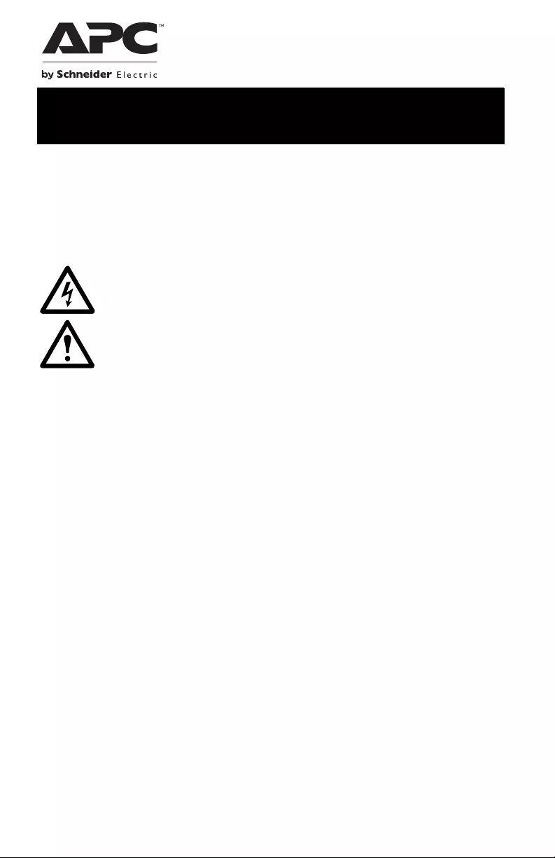
Front panel
C20B
1Overload LED
2 Pr otection O N LED
3Bu ild i ng Wi ri n g O K LED
C25B
1Overload LED 4Controlled ON LED
2Building Wi ring OK LED 5Master Enable LED
3 Pr otect ion ON LED 6Switched ON LED
av037b
Overload
Protection ON
Building Wiring OK
av037c
Overload
Protection ON
Building Wiring OK Master EnableControlled ON Switched ON
C-Type Power Filter C20B/C25B4
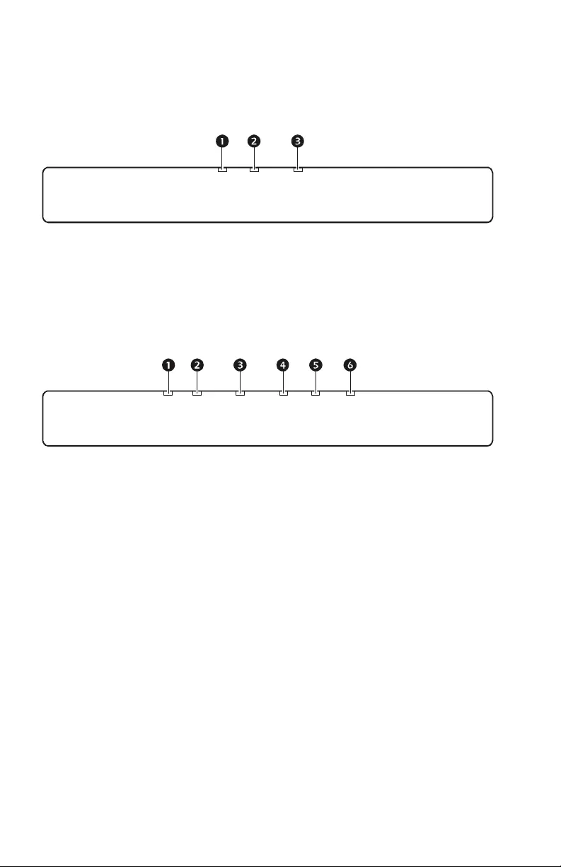
Rear panel
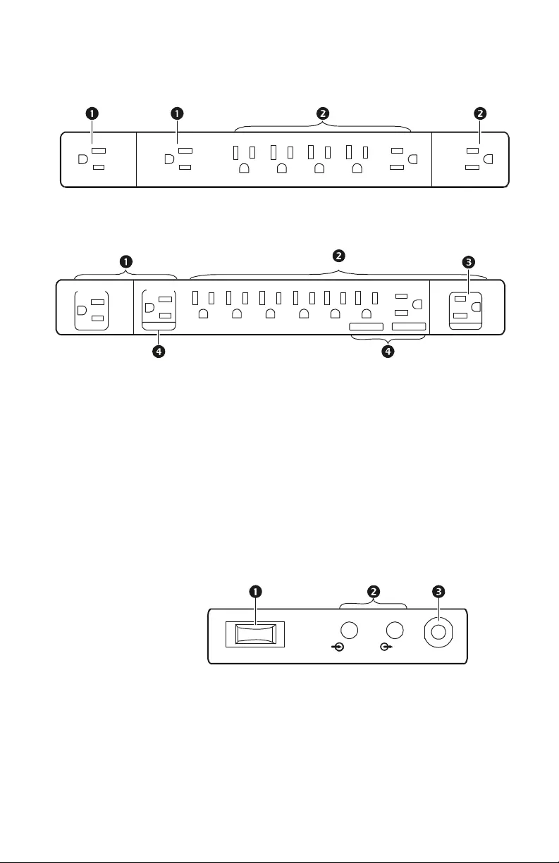
Left side panel
C20B
C25B
1Hig h C u rre n t Fi lt er outle ts
2Digi tal Filter o utlets
3Mast er outlet
4Controlled outlets
C20B and C25B models
1Power switch/Circuit
breaker
2Coaxial connectors
3AC power input
av036b
av036a
CONTROLLED CONTROLLED
MASTER
CONTROLLED
High Curr en t
Filter
Digital Filter Outlets
High Curr en t
Filter
IN
OUT
av
038a
RESET
C-Type Power Filter C20B/C25B 5
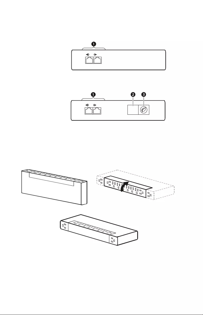
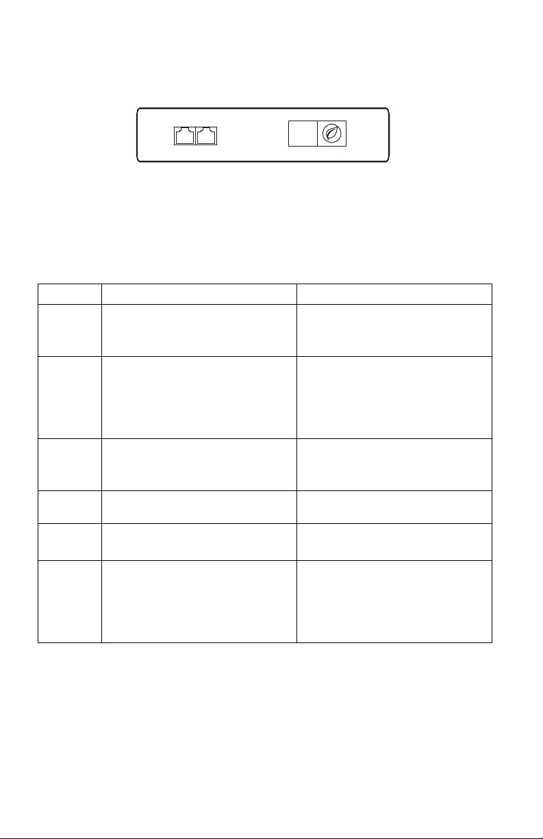
Right side panel
Installation
Rotate the outlet bank to change the orientation of the outlets. Refer to the
diagrams below.
When rotating the outlet bank be careful not to pinch fin gers.
Connect to AC Power
Connect the power cable to an AC outlet . If the filter is functi oning prope rly,
the P rotection ON L ED w ill illu min ate .
C20B
1Telephone port
2LED DIMMER
button
3MASTER ENABLE
button
C25B
IN OUT
TELEPHONE
av039a
IN OUT
TELEPHONE
av039b
DIMMER
av0
40
c
av040a
av0
40b

C-Type Power Filter C20B/C25B6
When connected to AC power the filter will provide protection for connec ted
com ponents if it is turned on or off.
Connect Components to Power Filter
Digital Filter and High Curre n t Fil ter ou tlets
Before connec ting com ponents to the fil ter, determ ine which com ponents will
utilize the Digital Filter and the High Current Filter outlets. Connect
com ponents to the appropriate outlet s.
Digital outlet s. The Digita l outlets filter input AC power to provide protection
for se nsitive devices such as a CD or Blu-Ray player, a DVR, Television or
CATV/SAT.
High Current outlets. The High Curre nt outl et s fil ter in put AC power for high
current devices such as subwoofers and amplifiers.
Power Saving Mast er and Controlled outlets: C25B model only
The fi lter is equipped with power saving outl ets that conserve electricity.
Configure the fil ter to recognize a Maste r device, such as a televisi on, a
computer or an A/V recei ver, and Cont rolled peripheral devices, such as
amp lifiers, DVD playe rs, or sub-woofe rs. When the Mast er device goes into
Standby or Hibernation mode, or is turned off, the Controlled device will be
tur n ed of f.
1. Before c onnectin g components to the filter, det erm ine which
com ponents will utilize the Master and Controlled outlets.
– Connect a master device such as a TV to the Master ou tlet.
– Connect pe ripheral devices such as amplifiers , DVD players , or
sub-woofers to the Controlled outle ts.
2. Conne ct components to the outlets on the rear panel of the filter.
3. Configure the filter to recognize the master outlet. Refer t o “Configure
Mas ter and Cont rolled out lets: C25B model only” on page 8.
C-Type Power Filter C20B/C25B 7
Operation
Right panel buttons: C25B model only
LED Dimmer. Use to adjust the brightness of the LEDs .
Master E nable /Disab le. P ush to enable or disable the Power Saving
fe at u re . W h en en ab l ed , th e Master Enable LED w il l illumin ate .
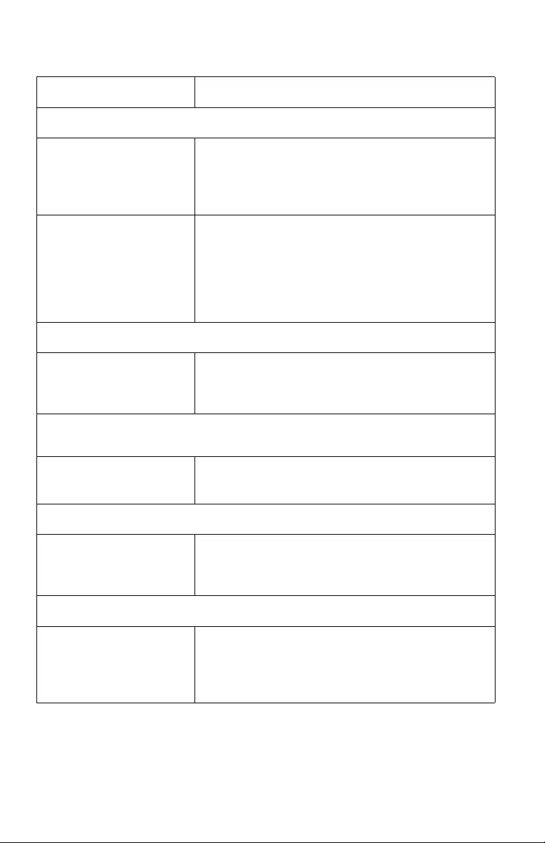
Front panel LEDs
LED Illuminated Not Illuminated
Overload The filter is experiencing an overload
conditi on. Disconnec t nonessential
components.
The filt er is f uncti oning properly.
Protection
ON
The filter is pr otect ing all connected
equipment. The filter is not providi ng pow er
protection.
See “Trou bleshooting” on page 9 and
contact A PC Technical Support
immediately.
Building
Wiring
OK
The filter is fu nctioning properly. There is a problem with the bu ildi ng
wiring.
Contact a qualified electrician.
Master
Enable The Power Savi ng feat ure is enabled. The Pow er Saving feature is dis abled.
Controlled
ON Powe r is bei ng supplied to the
Co ntro ll ed out l ets. Pow er is not being supplied to the
Controlled outlets.
Switched
ON
The AC power is within acceptable
range. The input volt age from AC power is
o utside th e acceptab le range and the
filt er has disco nnected from A C
power to protect the connected
equipment.
av039c
DIMMER

C-Type Power Filter C20B/C25B8
Configure Power Filter
Tu rn the filter On or Off
Use the Power s w itch to turn th e filter on or off.
Configure the brightness of the LEDs: C25B model only
To adjust the brightness of the LEDs, use the LED DIMMER button.
Configure Master and Controlled outlets: C25B model only
Enable and Disable the Power Saving featur e. Us e the MASTER ENABLE
button to enable or disable the feature.
Setting the threshold. The amount of powe r used by a device in Sle ep or
Standby mode varies between devic es . It may be necessary to adjust the
threshold at which the Master outlet signals the Controlled outlets to shut
down.
1. Be sure a master device is connected to the Master outlet. The filter
should be in Sleep or Sta ndby mode or turned off.
2. P ush and hol d the MASTER ENABLE but ton until the Master Enable LED
on the front panel flashes three tim es . The filte r will recognize th e
threshold level of the master device and save this as the new threshold
setting.
C-Type Power Filter C20B/C25B 9
Troubleshooting
Problem and Possible Cause Solution
The power fi lter will n ot turn on
There i s no inpu t p ow er, or
insufficie n t inpu t power from
the w al l outlet .
Us e a vo ltm eter to c hec k th e outpu t of th e wal l o utlet . Use a
device that is known to work properly to check the outlet.
Note: Th e filt er will n ot tur n on if th e inp ut AC po w e r is
out of the acceptable range.
A ci rcui t breaker has been
tripped. Check the bu ilding ci rcuit breakers and the fil ter’s circuit
b reaker. Reset the breaker on the fil ter wit h the POWER
sw itch. If it trips again, unplug one of t he comp onents
p lugged into the fi lter and reset the breaker.
Note: If th e b reake r is tripp ed ag ain afte r trying th is
solution, contact APC Technical Support.
Power is not supplied to some of the outlets.
P o w e r to the Con trolled
outlets has intentionally been
turn e d off .
Di sable the Po w er Saving feature using the MASTER
ENABLE butt on or tur n the master device on.
The Contr olled outlet s are not supplying po w er, even though the master devi ce is not
in sleep mode.
The Master Outlet threshold
ma y be incorrectly set. Refer to “Setting the thre shold” on pag e 8.
Th e filter is on, but none of the LEDs are illuminated.
T he LED DIMMER butto n
n eeds to be adjus ted. Push the LED DIMMER but ton several time s. The LEDs
sho ul d illu m in a te . If they do no t illum in a te , co nt a ct AP C
Technical Support.
The Overload LED is illuminated
T he filter is ov erloade d . Po w er off th e filter and reduce the load by disconnect ing
one or more components from the filter . When the load is
below the capacity of the filter, power on the unit again, the
LE D will extingui sh.

C-Type Power Filter C20B/C25B10
Th e Bu ild i n g Wiri n g O K LE D is illu minat ed
• The wall out let polari ty is
reversed.
• The neutral wire is
overloaded.
• The ea rth ground is not
connected at the wall outlet.
Contact an ele c trici a n to inspect the buil d ing wiring.
WARNING: Do not o perate th e filter if any of the se
co nd ition s ex ist. The filter may no t be pr o vi di n g su rge
protection.
Proble m an d P ossible Cause Solution
C-Type Power Filter C20B/C25B 11
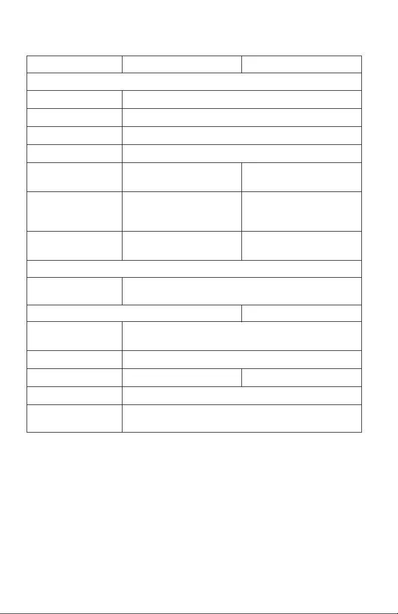
Specifications
Contact APC Technical Support
For technical s upport, go to the APC Web site, www.apc.com.
C20B C25B
Input/Output
Inpu t/Out put Voltage Nominal 120 V
Input/Output Current 15 A
Frequency 50/60 Hz
Rece ptacl e Types NEMA 5-15R
Number of Outlet
Receptacles 810
Dimen sions (HxWxL) 4.5 cm x 13.6 cm x 37.8 cm
(1.77 in x 5.35 in x 14. 928
in)
4.5 cm x 13.8 cm x 43.6 cm
(1.77 in x 5.43 in x 17.17 in)
Power Cord 1.8 m (6 ft. ) right angle
NEMA 5-15P 2.4 m (8 ft. ) right angle
NE M A 5-15 P
AC Surge Performance
EMI/RFI Filtering 50 dB: 150 KHz ~ 1 MHz
40 dB: 1 MHz ~ 30 MHz
Envi ronmental Performance Specifi cations
Operating
temperature 0º – 40ºC (32º – 104 ºF)
Storage temperature -15º – 45ºC (5º – 1 13º F)
Net weight 1.5 kg (3.3 lbs) 1.9 kg (4.2 lbs)
Relative Humidity 0 – 95% non-condensing
Safety Agency
Approval UL1449, UL1363, cETLus listed
FCC Part 15 Class B

C-Type Power Filter C20B/C25B12
Warranty
APC warrants the C20B and the C25B to be free from defects in materials and
workmanship under normal use and serv ice for the lifetime of the ori ginal
purcha s er. APC warra nts the removable flashlight to be free from defects in
materi als and workman ship under normal use and servi ce for one year fro m the
date of purchase. APC’s obligation under this warranty is limited to repairing
or repla cing, at its sole option, any s uch de fective products . To obtain service
under warranty you must obtain a Re turned Mat erial Authorizati on (RMA)
numbe r from APC or an APC Service Center with transportation charges
prepaid and must be accompanied by a brief description of the problem and
pr oof of date and place of purc hase. This warranty applies only to the original
purchaser.
FCC Information
This equipment compli es with FCC rules and the requirements adopted by the
ACTA. On the bottom of this equipment is a label that contains, among other
information, a product identifier in the format US:AAAEQ##TXXXX. If
requested , this number must be provi ded to the telephone com pany.
Applicable connector jack Universal Service Order Code s (“USOC”) for the
Equipment is RJ11C.
A plug and ja ck us ed to connect this equipmen t to the premises wir ing and
telephone network must comply with the applicable FCC rules and
requirements adopted by the ACTA. A compliant telephone cord and modular
plug is provided with thi s product. It is designe d to be c onnected to a
com pat ibl e modu lar jack tha t i s al so compl ia nt. S ee i ns tal lati on i nstr ucti ons for
details.
The REN is us ed to determine the number of devices that may be connected to
a telephone line. Excessive RENs on a telephone line may result in th e devices
not ringing in response to an incoming call . In most but not all areas, the sum
of RENs shou ld not exceed five (5. 0). To be certain of the number of devices
that may be connected to a line, as determined by the total RENs, contact the
local telephone com pany. F or products approved after Ju ly 23, 2001, the RE N
for this produ ct is part of the pr oduct identifier that has the format
US:AAAEQ##TXXXX. The digi ts repre sented by ## are the REN without a
decimal point (e.g., 03 is a REN of 0.3).
If this equipment causes harm to the telephone network, the telephone
com pany will not ify you in advance that temporary di scontinuance of service
may be required. But if advance notice isn't practical, the telephone company
will notify the custom er as soon as poss ible. Also , you will be advised of your
right to file a complaint with th e FCC if you belie ve it is nec es sary.

© 2013 APC by Schnei der El ectric. APC, and the AP C logo are owned by Schnei der
El ectric Industries S.A.S., or their a f filiated compani es . All other trademarks are
pro per ty of their res pective owners. 990-4512E
12/2013
The telephone company may make changes in its facilitie s, equipment ,
operations or procedures that could affect the operation of the equipment. If
this happens the telephone company will provide advance notice in order for
you to make necessary modifications to maintain uninterrupted service.
If trouble is experienced with this equipment, for repair or warranty
information, please contact US Service Center at www.apc.com. If the
equipment is causing harm to the telephone network, the telephone company
may reque st that you disconne ct the equipment unti l the probl em is res olved.
Co nnection to party line ser v ice is su bject to state tariffs. Conta ct the sta te
public utility commission, publ ic service commiss ion or corporation
commi ssion for infor mation.
If your home has specially wired alarm e quipment connected to the telephone
line, ensu re the insta llat ion of this equipment doe s n ot disable your alarm
equipment. If you have quest ions about what will disable alarm equi pment,
consult your telephone company or a qualified installer.
