APC CP27U13SC3-F User Manual
Displayed below is the user manual for CP27U13SC3-F by APC which is a product in the UPS Accessories category. This manual has pages.
Related Manuals
990-2366C 04/2016
Broadband PowerShield
®
CP27U Models
User Manual


1
Chapter 1: General Information
The PowerShield® provides a power source for broadband telephony,
Fiber-to-the-Home/Premise (FTTH/P), and other direct current (DC) equipment/applications.
Safety
This manual contains important instructions that should be followed during installation and
maintenance of the APC equipment and batteries. It is intended for APC customers that set up,
install, relocate, or maintain APC equipment.
Changes and modifications to this unit not expressly approve d by APC could void the
warranty. Failure to observe this warning may result in serious injury, death, or damage to the
equipment.
Electrical Warn ings
Do not work alone under hazardous conditions.
Servicing the PowerShield may require the removal of protective covers, as well as connected utility
power. Use extreme caution during these procedures.
Check that the power cord(s), plug(s), and sockets are in good condition.
Replacement of fuses or other parts must be with identical types and ratings. Substitution of
nonidentical parts may cause safety and fire hazards.
Battery Warning
Danger of explosion if the battery is incorrectly connected or replaced. Use only APC replacement
batteries.
Unpacking
Inspect the unit upon receipt. Notify the shipping carrier or product supplier if there is damage.
The packaging is recyclable; save it for reuse or dispose of it properly.
Check the package contents. The package contains the enclosure, the battery (to be installed), one
power cord, and the product documentation.

2
Specifications
General
Model
Number Input Output Maximum
Signal
Voltage
Maximum
Signal
Current
Battery
Type
CP27U13 100-240 V
50/60 Hz 1.0 A
27 W
13 VDC
12VDC nominal
30 V 5 mA 12 V, 7.2 AHr
Spill-Proof,
Maintenance Free,
Sealed Lead Acid
Environmental
Operating Temperature -4º F to 122º F (-20º C to 50º C)
Operating Humidity 5 to 95% noncondensing within enclosure
Maximum Operating Elevat ion 10,000 ft (3,000 m)
Maximum Storage Elevation 50,000 ft (15,000 m)
Storage Temperature -4º F to 122º F (-20º C to 50º C)
Battery lifetime is reduced with prolonged storage in
high temperatures (>25º C).
Physical
Height x Width x Depth
PowerShield 7.5 x 9.5 x 3 in (19 x 24 x 7.6 cm)
PowerShield carton 13.5 x 13.5 x 4.5 in (34 x 34 x 11 cm)
Weight
PowerShield 7.15 lbs (3.25 kg)
PowerShield with package materials 9 lbs (4 kg)
3
Chapter 2: Installation
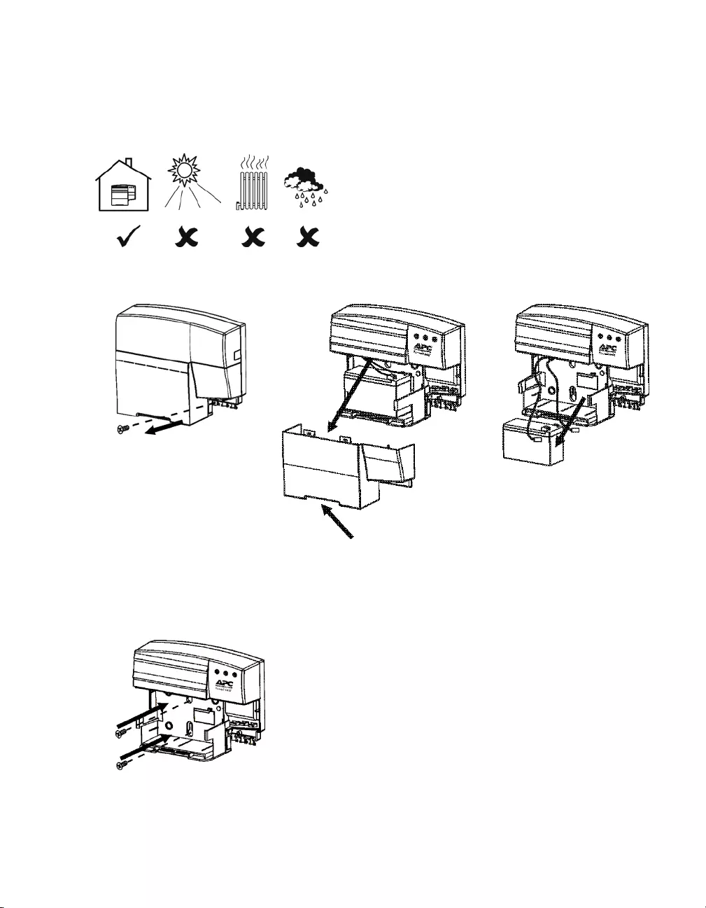
Enclosure Installation
Install the PowerShield in a protected area that is free
of excessive dust and has adequate airflow.
Do not operate the PowerShield where the temperature
and humidity are outside the specified limits. See
Specifications.
Use screws that are
appropriate for the weight of
this unit and the mounting
surface material. See
Specifications.
Battery Cover Release Tabs
Indoor Use Only
4
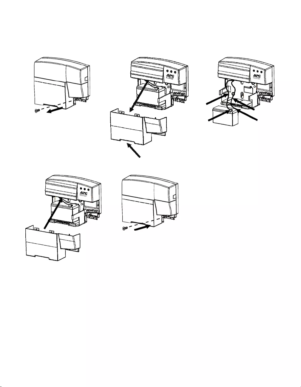
Battery Installation
Battery Cover Release Tabs
Red
Cable Black
Cable
Negative
Terminal
Positiv e
Terminal
5
Connect Equipment and Power
The PowerShield battery charges when it is connected to utility power. The battery charges fully
during the first eight hours of normal operation. Do not expect full battery run capability during this
initial charge period.
1. Connect the PowerShield to the application equipment (example: FTTH/P Optical Network
Terminal) via the seven-pin output connector, using the appropriate cable (must be ordered
separately). See www.apc.com for a list of available output cables.
2. Plug the PowerShield power cord into the utility power cord inlet and then into the wall outlet.
Do not overload the wall outlet or circuit.
Cold Start Feature: Upon installation of a charged battery, power will immediately be applied to
the unit even when utility power is not present.
Attention: To disconnect from utility power, remove the plug from the wall outlet.
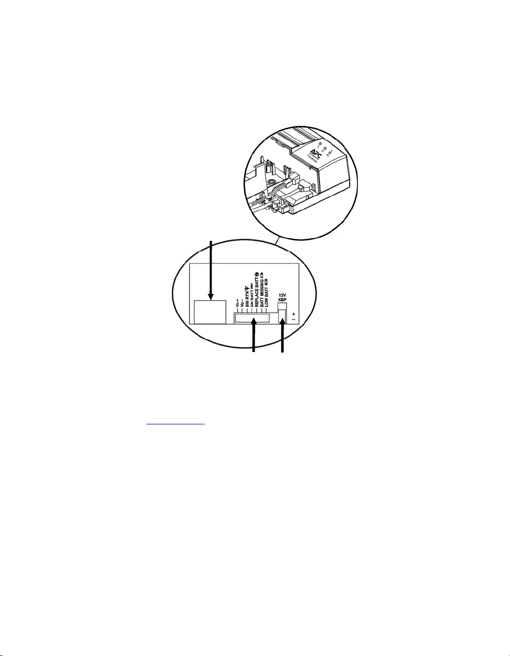
Optional Runtime Extension
The runtime may be extended by adding the external battery CP20B12BP.
Output Power and
Communication
Signals
Utility Power
Cord Inlet
Optional Runtime
Extension Connector
6
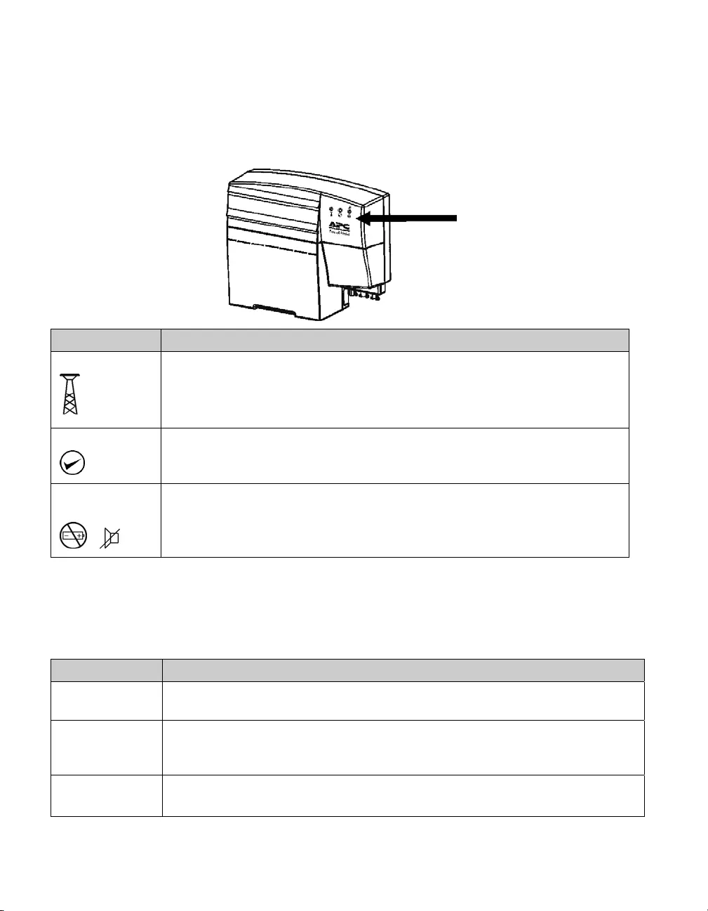
Chapter 3: Operation
Status Indicators and Features
Fron t Pa nel
Indicator Description
Utility
Solid green indicates the unit is on utility power.
Solid yellow indicates that utility power is not present and the unit is on battery
power.
Flashing green LED indicates the unit is fast charging.
Output
Green indicates the unit is working properly and DC output power is provided
by the battery or the utility power.
Replace Battery/
Alarm Silence
/
Red indicates that the battery must be replaced or that the battery is
disconnected. See Battery Replacement.
Pressing this button will silence the audible alarm. See Alarm Silence Butto n.
Automatic Self-Test
The unit automatically performs a self-test 31 hours after initial installation. Following this, a battery
self-test will occur every 30 days. See Alarm Silence Button for manual self-test information.
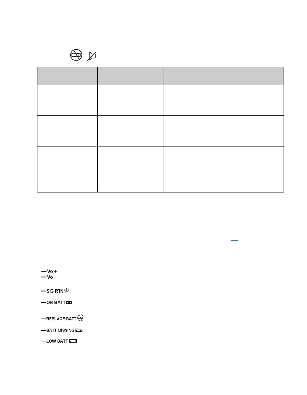
Audible Alarm
Explanation Description
On
Battery
Four beeps in four seconds will be emitted one time only. This alarm will sound
when the utility power is lost and the unit goes on battery power.
Low
Battery
Voltage
Every five minutes, four beeps in four seconds will be emitted. This alarm will
sound when operating on battery and the battery voltage has dropped below
threshold, indicating that less than 20% of available runtime remains.
Replace Battery Every fifteen minutes, there will be a quarter-second beep when the battery fails
the automatic self-test.
Statu s
Indicators
7
Alarm Silence Button
The audible alarms may be silenced by utilizing the dual function Replace Battery/Alarm Silence
LED/button /.
Function Button Operation
(Press and hold for:) Description
Replace Battery
Temporarily
Enable/Disable
<4 seconds If the alarm has been silenced, the unit will
emit one quick beep.
If the alarm has been enabled, two quick
beeps will be emitted.
Replace Battery
Permanently
Enable/Disable
8-12 seconds If the alarm has been silenced, the unit will
emit one quick beep.
If the alarm has been enabled, two quick
beeps will be emitted.
Battery Self-Test
Enable/Disable
4-8 seconds If the self-test has been enabled, three beeps
will be emitted.
If the self-test cannot be enabled, a single
beep will be emitted.*
If the battery self-test has been canceled, the
unit will emit four beeps.
*A battery self-test cannot be enabled unless the following conditions have been met.
1. Battery has been charged for at least 31 hours.
2. The unit has been on utility power for more than 12 hours.
3. Temperature is between 0 and 50°C.
Output Power and Communication Signals
The PowerShield communication signals are isolated from its internal circuitry via by open collector
opto-coupled transistors. The connection labeled “Signal Return” is a common return point for all
communication signals. In the typical application, the attached equipment digital ground connects to
Signal Return, and pull-up resistors turn the open collector signals into logic levels.
+Voltage output
Voltage output
Signal return.
Low when operating from utility line. Open when operating from
battery.
Low when battery is charged. Open when battery fails the Self-Test.
Low when battery is present. Open when battery is missing.
Low when battery is near full charge capacity. Open when operating
from a battery with less than 20% of available runtime remaining.
8
Chapter 4: Maintenance, Service, Contact Information, and
Warranty
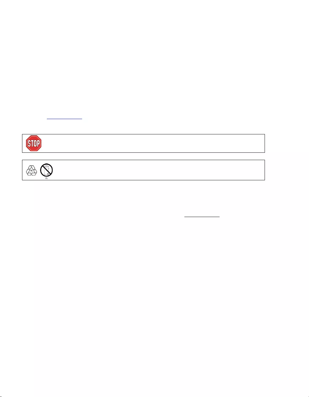
Battery Replacement
This unit has an easy to replace battery. Battery replacement can be performed while the unit and
connected equipment are operating.
During a self-test, battery removal and replacement are not recommended. For self-test disabling, see
Alarm Silence Button.
Replace the used battery with APC replacement battery RBC2. See your dealer or refer to the APC
Web site, www.apc.com, for information on replacement batteries.
For battery replacement, see Battery Installation.
Once the battery is disconnected, the connected equipment is not protected
from power outages.
Be sure to deliver used batteries to a recycling facility found on the Used
Battery Return Facilities li st included w ith RBC2.
Service
If the unit requires service, do not return it to the dealer. Follow these steps:
1. Contact APC Customer Support through the APC web site at www.apc.com.
a) Note the product model number, the serial number, and the date of purchase.
b) Call APC Customer Support and a technician will attempt to solve it over the phone. If this
is not possible, the technician will issue a Returned Material Authorization Number
(RMA#).
c) If the product is under warranty, repairs are free. If not, there is a repair charge.
d) Service procedures and returns may vary internationally. Refer to the APC web site for
country specific instructions.
2. Pack the unit properly to avoid damage in transit. Never use Styrofoam beads for packaging.
Damage sustained in transit is not covered under warranty.
3. Before shipping, always disconnect all battery modules.
4. Write the RMA# provided by Customer Support on the outside of the package.
5. Return the unit by insured, prepaid carrier to the address provided by Customer Support.

9
Limited Factory Warranty
Schneider Electric IT Corporation (SEIT), warrants its products to be free from defects in materials and
workmanship for a period of two (2) years from the date of purchase. The SEIT obligation under this
warranty is limited to repairing or replacing, at its sole discretion, any such defective products. Repair or
replacement of a defective product or parts thereof does not extend the original warranty period.
This warranty applies only to the original purchaser who must have properly registered the product
within 10 days of purchase. Products may be registered online at warranty.apc.com.
SEIT shall not be liable under the warranty if its testing and examination disclose that the alleged defect
in the product does not exist or was caused by end user or any third person misuse, negligence, improper
installation, testing, operation or use of the product contrary to SEIT recommendations or specifications.
Further, SEIT shall not be liable for defects resulting from: 1) unauthorized attempts to repair or modify
the product, 2) incorrect or inadequate electrical voltage or connection, 3) inappropriate on site operation
conditions, 4) Acts of God, 5) exposure to the elements, or 6) theft. In no event shall SEIT have any
liability under this warranty for any product where the serial number has been altered, defaced, or
removed.
EXCEPT AS SET FORTH ABOVE, THERE ARE NO WARRANTIES , EXPRESS OR
IMPLIED, BY OPERATION OF LAW OR OTHERWISE, APPLICABLE TO PRODUCTS
SOLD, SERVICED OR FURNIS HED UNDER THIS AGREEMENT OR IN CONNECTION
HEREWITH.
SEIT DISCLAIM S ALL IMPLIED WARRANTIES OF M ERCHANTABILITY,
SATISFACTION AND FITNE S S FOR A PARTICULAR PURPOSE.
SEIT EXPRESS WARRANTIES WILL NOT BE ENLARGED, DIMINISHED, OR AFFECTED
BY AND NO OB LIGATION OR LIABILITY WILL ARISE OUT OF, SEIT RENDERING OF
TECHNICAL OR OTHER ADVICE OR SERVICE IN CONNECTION WITH THE
PRODUCTS.
THE FOREGOING WARRANTIES AND REMEDIES ARE EXCLUSI VE AND IN LIEU OF
ALL OTHER WARRANTIES AND REMEDIES. THE WARRANTIES SET FORTH AB OVE
CONSTITUTE SEIT SOLE LIAB ILITY AND PURCHASER EXCLUSIVE REMEDY FOR ANY
BREACH OF SUCH WARRANTIES . SEIT WARRANTIES EXTEND ONLY TO ORIGINAL
PURCHASER AND ARE NOT EXTENDED TO ANY THIRD PARTIES.
IN NO EVENT SHALL SEIT, ITS OFFICERS, DIRECTORS, AFFILIATES OR EMPLOYEES
BE LIABLE FOR ANY FORM OF INDIRECT, SPECIAL, CONS EQUENTIAL OR PUNITIVE
DAMAGES, ARIS ING OUT OF THE USE, SERVICE OR INSTALLATION OF THE
PRODUCTS, WHETHER SUCH DAMAGES ARISE IN CONTRACT OR TORT,
IRRESPECTIVE OF FAULT, NEGLIGENCE OR STRICT LIABILITY OR WHET HER S E IT
HAS BEEN ADVISED IN ADVANCE OF THE POS SIBILITY OF SUCH DAMAGES.
SPECIFICALLY, SEIT IS NOT LIABLE FOR ANY COSTS, SUCH AS LOST PROFITS OR
REVENUE, WHETHER DIRECT OR INDIRECT, LOS S OF EQUIPMENT, LOSS OF USE OF
EQUIPMENT, LOS S OF SOFTWARE, LOSS OF DATA, COSTS OF SUBSTITUANTS,
CLAIMS BY THIRD PARTIES , OR OTHERWISE.

10
NOTHING IN THIS LIMITED WARRANTY SHALL SEEK TO EXCLUDE OR LIMIT SEIT
LIABILITY FOR DEATH OR PERS ONAL INJURY RESULTING FROM ITS NEGLIGENCE
OR ITS FRAUDULENT MISREPRESENTATION OF TO THE EXTENT THAT IT CANNOT
BE EXCLUDED OR LIMITED BY APPLICABLE LAW.
To obtain service under warranty you must obtain a Returned Material Authorization (RMA) number
from customer support. Customers with warranty claims issues may access the SEIT worldwide
customer support network through the APC web site: www.apc.com. Select your country from the
country selection drop down menu. Open the Support tab at the top of the web page to obtain
information for customer support in your region. Products must be returned with transportation charges
prepaid and must be accompanied by a brief description of the problem encountered and proof of date
and place of purchase.
APC™ by Schneider Electric
Worldwi de Customer Support
Customer support for this or any other APC™ by Schneider Electric product is available at no charge
in any of the following ways:
• Visit the APC by Schneider Electric web site, www.apc.com to access documents in the APC
Knowledge Base and to submit customer support requests.
– www.apc.com (Corporate Headquarters)
Connect to localized APC by Schneider Electric web site for specific countries, each of
which provides customer support information.
– www.apc.com/support/
Global support searching APC Knowledge Base and using e-support.
• Contact the APC by Schneider Electric Customer Support Center by telephone or e-mail.
– Local, country specific centers: go to www.apc.com/support/contact for contact
information.
– For information on how to obtain local customer support, contact the APC by Schneider
Electric representative or other distributor from whom you purchased your APC by
Schneider Electric product.
© 2016 APC by Schneider Electric. APC, the APC logo are owned by Schneider Electric Industries S.A.S. or
their affiliated companies. All other trademarks are property of their respective owners.