Table of Contents
APC E3MBPAR60K200H User Manual
Displayed below is the user manual for E3MBPAR60K200H by APC which is a product in the UPS Accessories category. This manual has pages.
Related Manuals
Easy UPS 3M
Parallel Maintenance Bypass Panel
Installation
E3MBPAR60K200H
09/2019
www.schneider-electric.com

Legal Information
The Schneider Electric brand and any trademarks of Schneider Electric SE and its
subsidiaries referred to in this guide are the property of Schneider Electric SE or its
subsidiaries. All other brands may be trademarks of their respective owners.
This guide and its content are protected under applicable copyright laws and
furnished for informational use only. No part of this guide may be reproduced or
transmitted in any form or by any means (electronic, mechanical, photocopying,
recording, or otherwise), for any purpose, without the prior written permission of
Schneider Electric.
Schneider Electric does not grant any right or license for commercial use of the guide
or its content, except for a non-exclusive and personal license to consult it on an "as
is" basis. Schneider Electric products and equipment should be installed, operated,
serviced, and maintained only by qualified personnel.
As standards, specifications, and designs change from time to time, information
contained in this guide may be subject to change without notice.
To the extent permitted by applicable law, no responsibility or liability is assumed by
Schneider Electric and its subsidiaries for any errors or omissions in the informational
content of this material or consequences arising out of or resulting from the use of the
information contained herein.
Go to http://www.productinfo.schneider-electric.com/portals/ui/easyups3m/ for
translations.
Rendez-vous sur http://www.productinfo.schneider-electric.com/portals/ui/
easyups3m/ pour accéder aux traductions.
Vaya a http://www.productinfo.schneider-electric.com/portals/ui/easyups3m/ para
obtener las traducciones.
Gehe zu http://www.productinfo.schneider-electric.com/portals/ui/easyups3m/ für
Übersetzungen.
Vai a http://www.productinfo.schneider-electric.com/portals/ui/easyups3m/ per le
traduzioni.
Vá para http://www.productinfo.schneider-electric.com/portals/ui/easyups3m/ para
obter as traduções.
Перейдите по ссылке http://www.productinfo.schneider-electric.com/portals/ui/
easyups3m/ для просмотра переводов.
前往 http://www.productinfo.schneider-electric.com/portals/ui/easyups3m/ 查看译
文。
前往 http://www.productinfo.schneider-electric.com/portals/ui/easyups3m/ 查看譯
文。

Parallel Maintenance Bypass Panel
Table of Contents
Important Safety Instructions — SAVE THESE
INSTRUCTIONS.........................................................................................5
Electromagnetic Compatibility .....................................................................6
Safety Precautions .....................................................................................6
Electrical Safety....................................................................................8
Overview of UPS System with Parallel Maintenance Bypass
Panel...........................................................................................................10
Specifications ............................................................................................12
Recommended Cable Sizes ......................................................................12
Recommended Upstream Protection..........................................................13
Recommended Bolt and Lug Sizes ............................................................13
Torque Specifications................................................................................14
Parallel Maintenance Bypass Panel Weights and Dimensions......................14
Clearance ................................................................................................14
Environment.............................................................................................14
Installation Procedure ..............................................................................15
Mount the Parallel Maintenance Bypass Panel to the Wall ...........................15
Prepare the Parallel Maintenance Bypass Panel for Cables .........................16
Connect the Power Cables........................................................................18
Connect the Signal Cables ........................................................................18
990-5994A-001 3

Important Safety Instructions — SAVE THESE
INSTRUCTIONS Parallel Maintenance Bypass Panel
Important Safety Instructions — SAVE THESE
INSTRUCTIONS
Read these instructions carefully and look at the equipment to become familiar
with it before trying to install, operate, service or maintain it. The following safety
messages may appear throughout this manual or on the equipment to warn of
potential hazards or to call attention to information that clarifies or simplifies a
procedure.
The addition of this symbol to a “Danger” or “Warning” safety
message indicates that an electrical hazard exists which will result in
personal injury if the instructions are not followed.
This is the safety alert symbol. It is used to alert you to potential
personal injury hazards. Obey all safety messages with this symbol
to avoid possible injury or death.
DANGER
DANGER indicates a hazardous situation which, if not avoided, will result in
death or serious injury.
Failure to follow these instructions will result in death or serious injury.
WARNING
WARNING indicates a hazardous situation which, if not avoided, could result
in death or serious injury.
Failure to follow these instructions can result in death, serious injury, or
equipment damage.
CAUTION
CAUTION indicates a hazardous situation which, if not avoided, could result in
minor or moderate injury.
Failure to follow these instructions can result in injury or equipment
damage.
NOTICE
NOTICE is used to address practices not related to physical injury. The safety
alert symbol shall not be used with this type of safety message.
Failure to follow these instructions can result in equipment damage.
Please Note
Electrical equipment should only be installed, operated, serviced, and maintained
by qualified personnel. No responsibility is assumed by Schneider Electric for any
consequences arising out of the use of this material.
A qualified person is one who has skills and knowledge related to the construction,
installation, and operation of electrical equipment and has received safety training
to recognize and avoid the hazards involved.
990-5994A-001 5
Parallel Maintenance Bypass Panel
Important Safety Instructions — SAVE THESE
INSTRUCTIONS
Electromagnetic Compatibility
NOTICE
RISK OF ELECTROMAGNETIC DISTURBANCE
This is a product Category C3 according to IEC 62040-2. This is a product for
commercial and industrial applications in the second environment - installation
restrictions or additional measures may be needed to prevent disturbances. The
second environment includes all commercial, light industry, and industrial
locations other than residential, commercial, and light industrial premises
directly connected without intermediate transformer to a public low-voltage
mains supply. The installation and cabling must follow the electromagnetic
compatibility rules, e.g.:
• the segregation of cables,
• the use of shielded or special cables when relevant,
• the use of grounded metallic cable tray and supports.
Failure to follow these instructions can result in equipment damage.
Safety Precautions
DANGER
HAZARD OF ELECTRIC SHOCK, EXPLOSION, OR ARC FLASH
Read all instructions in the installation manual before installing or working on
this product.
Failure to follow these instructions will result in death or serious injury.
DANGER
HAZARD OF ELECTRIC SHOCK, EXPLOSION, OR ARC FLASH
Do not install the product until all construction work has been completed and the
installation room has been cleaned.
Failure to follow these instructions will result in death or serious injury.
DANGER
HAZARD OF ELECTRIC SHOCK, EXPLOSION, OR ARC FLASH
The product must be installed according to the specifications and requirements
as defined by Schneider Electric. It concerns in particular the external and
internal protections (upstream breakers, battery breakers, cabling, etc.) and
environmental requirements. No responsibility is assumed by Schneider Electric
if these requirements are not respected.
Failure to follow these instructions will result in death or serious injury.
6 990-5994A-001
Important Safety Instructions — SAVE THESE
INSTRUCTIONS Parallel Maintenance Bypass Panel
DANGER
HAZARD OF ELECTRIC SHOCK, EXPLOSION, OR ARC FLASH
The UPS system must be installed according to local and national regulations.
Install the UPS according to:
• IEC 60364 (including 60364–4–41- protection against electric shock, 60364–
4–42 - protection against thermal effect, and 60364–4–43 - protection
against overcurrent), or
• NEC NFPA 70, or
• Canadian Electrical Code (C22.1, Part 1)
depending on which one of the standards apply in your local area.
Failure to follow these instructions will result in death or serious injury.
DANGER
HAZARD OF ELECTRIC SHOCK, EXPLOSION, OR ARC FLASH
• Install the product in a temperature controlled indoor environment free of
conductive contaminants and humidity.
• Install the product on a non-flammable, level and solid surface (e.g.
concrete) that can support the weight of the system.
Failure to follow these instructions will result in death or serious injury.
DANGER
HAZARD OF ELECTRIC SHOCK, EXPLOSION, OR ARC FLASH
The product is not designed for and must therefore not be installed in the
following unusual operating environments:
• Damaging fumes
• Explosive mixtures of dust or gases, corrosive gases, or conductive or
radiant heat from other sources
• Moisture, abrasive dust, steam or in an excessively damp environment
• Fungus, insects, vermin
• Salt-laden air or contaminated cooling refrigerant
• Pollution degree higher than 2 according to IEC 60664-1
• Exposure to abnormal vibrations, shocks, and tilting
• Exposure to direct sunlight, heat sources, or strong electromagnetic fields
Failure to follow these instructions will result in death or serious injury.
DANGER
HAZARD OF ELECTRIC SHOCK, EXPLOSION, OR ARC FLASH
Do not drill or cut holes for cables or conduits with the gland plates installed and
do not drill or cut holes in close proximity to the UPS.
Failure to follow these instructions will result in death or serious injury.
WARNING
HAZARD OF ARC FLASH
Do not make mechanical changes to the product (including removal of cabinet
parts or drilling/cutting of holes) that are not described in the installation manual.
Failure to follow these instructions can result in death, serious injury, or
equipment damage.
990-5994A-001 7
Parallel Maintenance Bypass Panel
Important Safety Instructions — SAVE THESE
INSTRUCTIONS
NOTICE
RISK OF OVERHEATING
Respect the space requirements around the product and do not cover the
ventilation openings when the product is in operation.
Failure to follow these instructions can result in equipment damage.
Electrical Safety
DANGER
HAZARD OF ELECTRIC SHOCK, EXPLOSION, OR ARC FLASH
• Electrical equipment must be installed, operated, serviced, and maintained
only by qualified personnel.
• Apply appropriate personal protective equipment (PPE) and follow safe
electrical work practices.
• Turn off all power supplying the UPS system before working on or inside the
equipment.
• Before working on the UPS system, check for hazardous voltage between all
terminals including the protective earth.
• The UPS contains an internal energy source. Hazardous voltage can be
present even when disconnected from the mains supply. Before installing or
servicing the UPS system, ensure that the units are OFF and that mains and
batteries are disconnected. Wait five minutes before opening the UPS to
allow the capacitors to discharge.
• The UPS must be properly earthed/grounded and due to a high leakage
current, the earthing/grounding conductor must be connected first.
Failure to follow these instructions will result in death or serious injury.
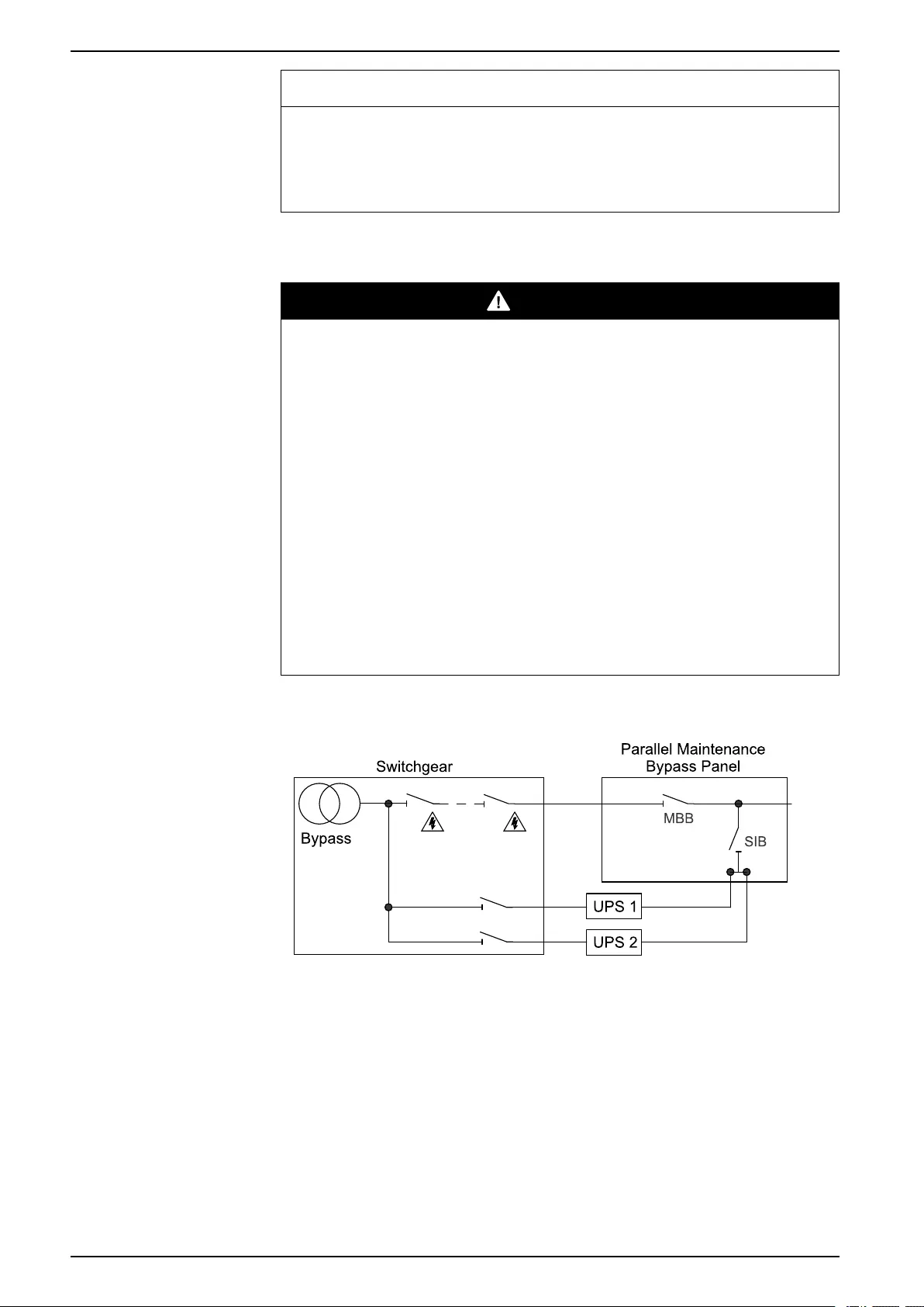
Distribution-Related Backfeed
The upstream disconnection switchgear must be suitable for disconnection
purposes. Before working on the upstream supply, the MBB must be locked in the
open position using the built-in lockout function.
When installing the parallel maintenance bypass panel, warning labels must be
posted on the load side of all upstream disconnection devices. The labels must be
supplied by the user, displaying the following text (or equivalent in a language
which is acceptable in the country in which the UPS system is installed):
8 990-5994A-001

Parallel Maintenance Bypass Panel
Overview of UPS System with Parallel Maintenance Bypass
Panel
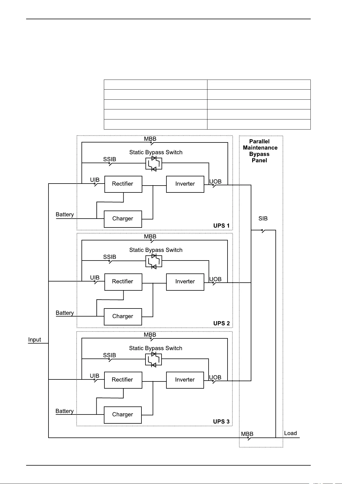
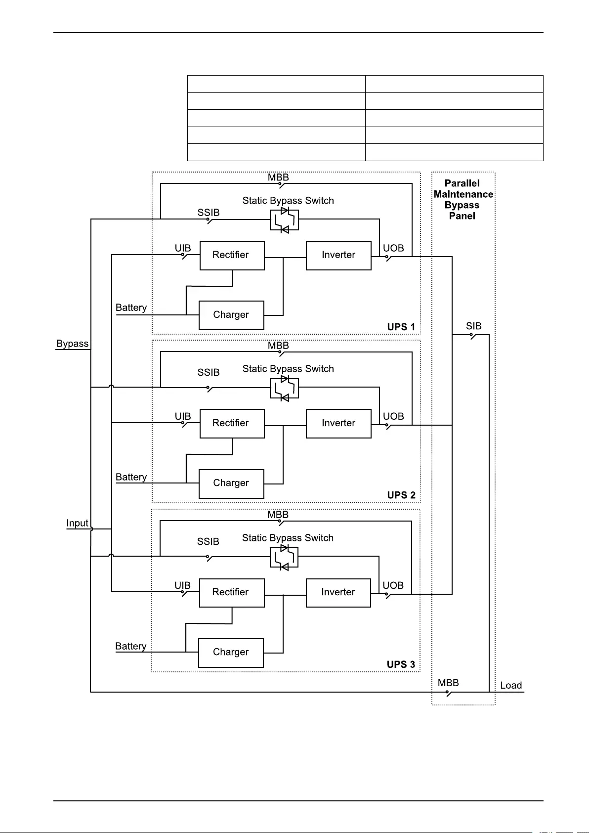
Overview of UPS System with Parallel Maintenance
Bypass Panel
Single Mains Systems
UIB Unit input breaker
SSIB Static switch input breaker
UOB Unit output breaker
MBB Maintenance bypass breaker
SIB System isolation breaker
10 990-5994A-001

Parallel Maintenance Bypass Panel Specifications
Specifications
NOTICE
HAZARD OF EQUIPMENT DAMAGE
Refer to the UPS installation manual for detailed specifications for the UPS
system.
Failure to follow these instructions can result in equipment damage.
Recommended Cable Sizes
DANGER
HAZARD OF ELECTRIC SHOCK, EXPLOSION, OR ARC FLASH
All wiring must comply with all applicable national and/or electrical codes. The
maximum allowable cable size is 185 mm².
Failure to follow these instructions will result in death or serious injury.
Cable sizes in this manual are based on table B.52.5 of IEC 60364-5-52 with the
following assertions:
• 90 °C conductors
• An ambient temperature of 30 °C
• Use of copper conductors
• Installation method C
PE size is based on table 54.2 of IEC 60364-4-54.
If the ambient temperature is greater than 30 °C, larger conductors are to be used
in accordance with the correction factors of the IEC.
NOTE: Refer to the UPS installation manual for UPS input cable sizes.
Cable 3+0 Parallel Capacity 2+0 Parallel Capacity
2+1 Parallel Redundant
1+0 Single
1+1 Parallel Redundant
Per
Phase
(mm²)
Neutral
(mm²)
PE
(mm²)
Per
Phase
(mm²)
Neutral
(mm²)
PE
(mm²)
Per
Phase
(mm²)
Neutral
(mm²)
PE
(mm²)
60 kVA UPS output 25 2x25 16 25 2x25 16 25 2x25 16
Input (single mains)/
bypass (dual mains)
2x70 4x70 70 95 2x95 50 25 2x25 16
Load 2x70 4x70 70 95 2x95 50 25 2x25 16
80 kVA UPS output 50 2x50 25 50 2x50 25 50 2x50 25
Input (single mains)/
bypass (dual mains)
2x95 4x95 95 120 2x120 70 50 2x50 25
Load 2x95 4x95 95 120 2x120 70 50 2x50 25
100 kVA UPS output 70 2x70 35 70 2x70 35 70 2x70 35
Input (single mains)/
bypass (dual mains)
4x50 4x95 120 2x70 4x70 70 70 2x70 35
Load 4x50 4x95 120 2x70 2x150 or
4x70
70 70 2x70 35
120 kVA UPS output 95 2x70 50 95 2x70 50 95 2x70 50
Input (single mains)/
bypass (dual mains)
4x70 4x95 150 2x95 4x70 95 95 120 or
2x70
50
12 990-5994A-001

Specifications Parallel Maintenance Bypass Panel
Cable 3+0 Parallel Capacity 2+0 Parallel Capacity
2+1 Parallel Redundant
1+0 Single
1+1 Parallel Redundant
Per
Phase
(mm²)
Neutral
(mm²)
PE
(mm²)
Per
Phase
(mm²)
Neutral
(mm²)
PE
(mm²)
Per
Phase
(mm²)
Neutral
(mm²)
PE
(mm²)
Load 4x70 4x95 150 2x95 2x150 or
4x70
95 95 120 or
2x70
50
160 kVA UPS output –––120 120 70 120 120 70
Input (single mains)/
bypass (dual mains)
–––4x50 4x70 120 120 120 70
Load –––2x120 or
4x50
2x150 or
4x70
120 120 120 70
200 kVA UPS output –––2x70 2x70 70 2x70 2x70 70
Input (single mains)/
bypass (dual mains)
–––4x70 4x70 185 150 or
2x70
150 or
2x70
70
Load –––2x185 or
4x70
2x185 or
4x70
185 150 or
2x70
150 or
2x70
70
Recommended Upstream Protection
3+0 Parallel Capacity 2+0 Parallel Capacity
2+1 Parallel Redundant
1+0 Single
1+1 Parallel Redundant
Breaker Io Ir Isd Tr Breaker Io Ir Isd Tr Breaker Io Ir Isd Tr
60 kVA NSX400N
mic2.3
320 320 1.5-
10
–NSX250N
mic2.3
200 200 1.5-
10
–NSX100N
TM100D
–100 – –
80 kVA NSX400N
mic2.3
400 400 1.5-
10
–NSX400N
mic2.3
280 280 1.5-
10
–NSX160N
TM160D
–144 – –
100 kVA NSX630N
mic2.3
500 500 1.5-
10
–NSX400N
mic2.3
320 320 1.5-
10
–NSX160N
TM160D
–160 – –
120 kVA NSX630N
mic2.3
500 500 1.5-
10
–NSX400N
mic2.3
400 400 1.5-
10
–NSX250N
mic2.3
250 250 1.5-
10
–
160 kVA – – – – – NSX630N
mic2.3
500 500 1.5-
10
–NSX400N
mic2.3
320 320 1.5-
10
–
200 kVA – – – – – NSX630N
mic2.3
630 630 1.5-
10
–NSX400N
mic2.3
400 400 1.5-
10
–
Recommended Bolt and Lug Sizes
Cable Size Terminal Bolt Diameter Cable Lug Type
16 mm² M10 KST TLK16-10
25 mm² M10 KST TLK25-10
35 mm² M10 KST TLK35-10
50 mm² M10 KST TLK50-10
70 mm² M10 KST TLK70-10
95 mm² M10 KST TLK95-10
120 mm² M10 KST TLK120-10
150 mm² M10 KST TLK150-10
185 mm² M10 KST TLK185-10
990-5994A-001 13
Parallel Maintenance Bypass Panel Specifications
Torque Specifications
Bolt Size Torque
M10 30 Nm
Parallel Maintenance Bypass Panel Weights and Dimensions
Weight kg Height mm Width mm Depth mm
Parallel maintenance
bypass panel
E3MBPAR60K200H
62 1000 700 320
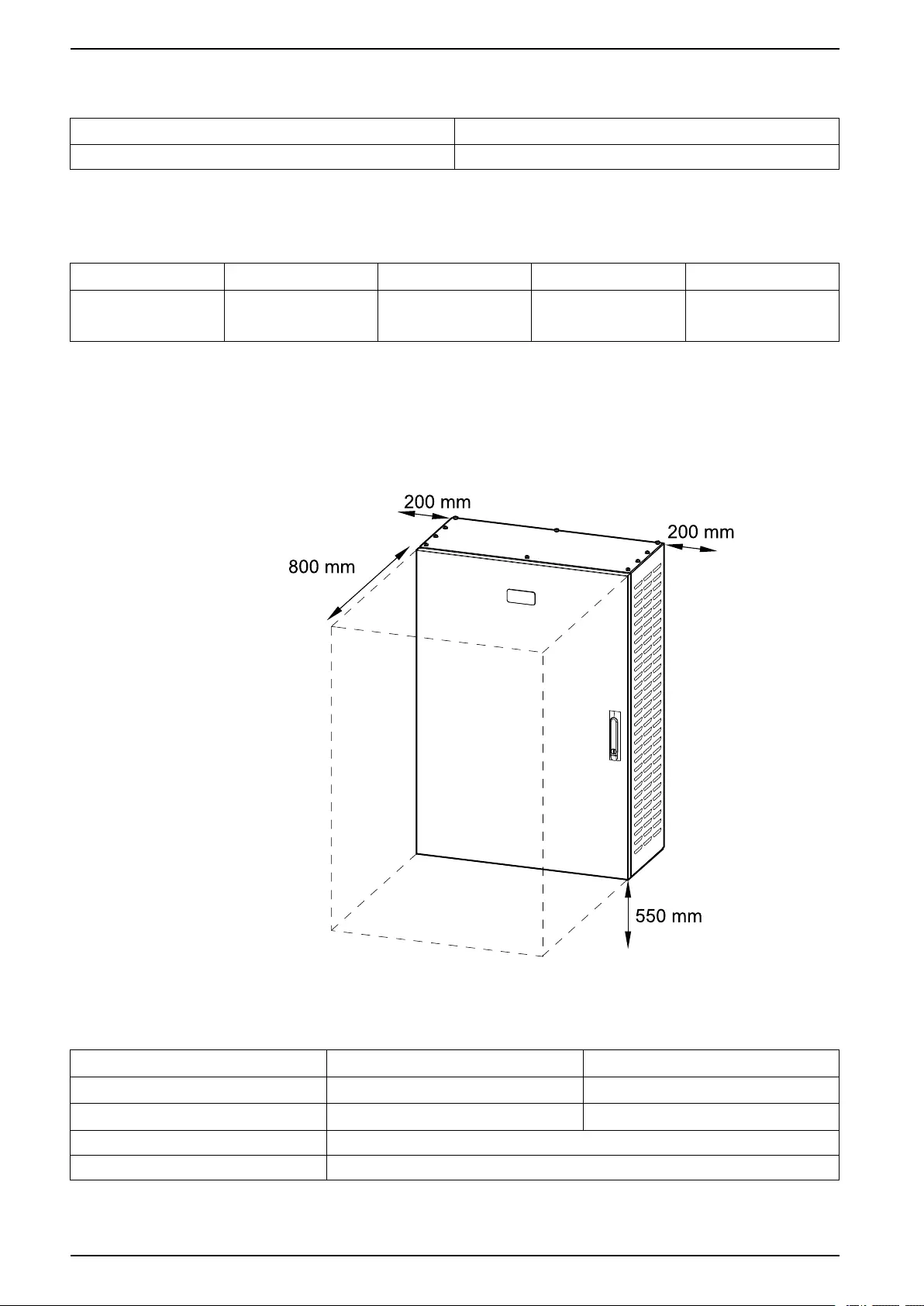
Clearance
NOTE: Clearance dimensions are published for airflow and service access
only. Consult with the local safety codes and standards for additional
requirements in your local area.
Environment
Operating Storage
Temperature 0 °C to 40 °C -25 °C to 55 °C
Relative humidity 0 – 95% non-condensing 0 – 95% non-condensing
Protection class IP20
Color RAL 9003
14 990-5994A-001
Installation Procedure Parallel Maintenance Bypass Panel
Installation Procedure
1. Mount the Parallel Maintenance Bypass Panel to the Wall, page 15.
2. Prepare the Parallel Maintenance Bypass Panel for Cables, page 16.
3. Connect the Power Cables, page 18.
4. Connect the Signal Cables, page 18.
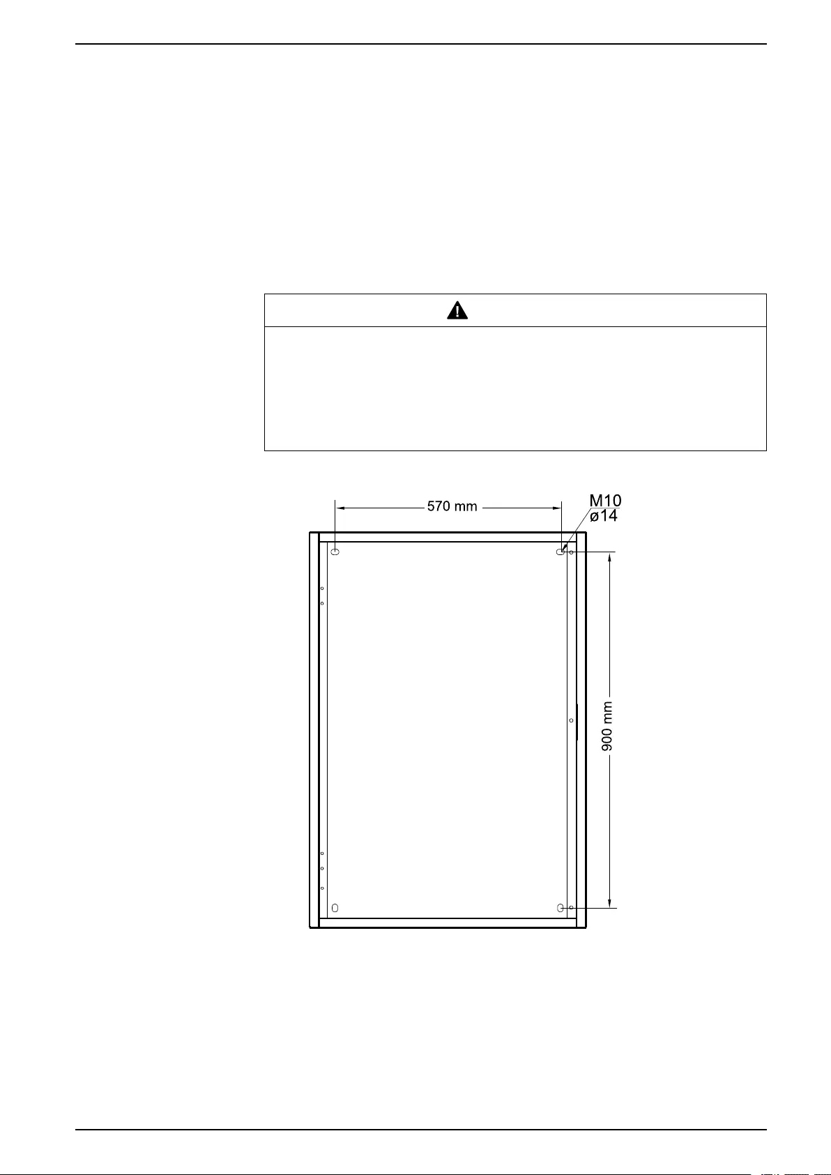
Mount the Parallel Maintenance Bypass Panel to the Wall
CAUTION
RISK OF INJURY OR EQUIPMENT DAMAGE
• Mount the maintenance bypass panel to a wall or a rack that is structurally
sound and able to support the weight of the unit.
• Use appropriate hardware for the wall/rack type.
Failure to follow these instructions can result in injury or equipment
damage.
1. Measure and mark the four mounting hole locations on the wall.
2. Drill holes in each of the four marked locations and mount the anchor bolts.
990-5994A-001 15
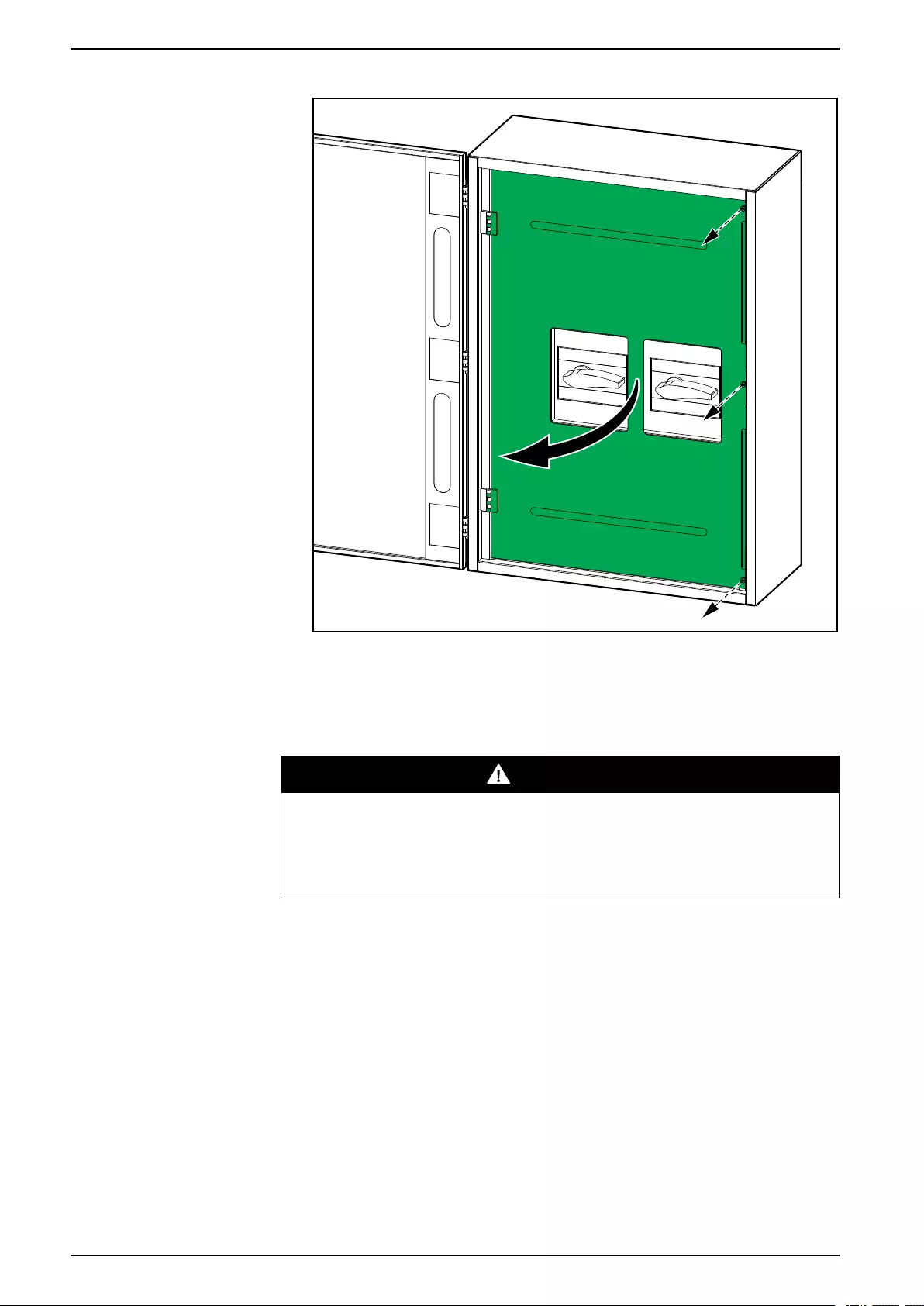
Parallel Maintenance Bypass Panel Installation Procedure
3. Remove the screws and open the inner door.
4. Mount the parallel maintenance bypass panel to the wall.
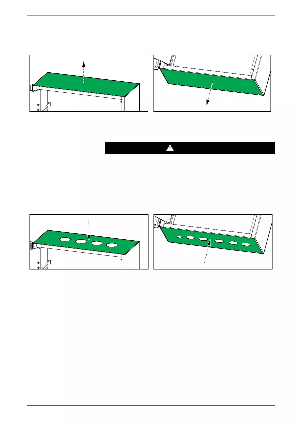
Prepare the Parallel Maintenance Bypass Panel for Cables
DANGER
HAZARD OF ELECTRIC SHOCK, EXPLOSION, OR ARC FLASH
Do not drill or punch holes with the gland plates installed and do not drill or
punch holes in close proximity to the parallel maintenance bypass panel.
Failure to follow these instructions will result in death or serious injury.
16 990-5994A-001
Installation Procedure Parallel Maintenance Bypass Panel
1. Remove the top and bottom gland plates.
Top of Parallel Maintenance Bypass Panel Bottom of Parallel Maintenance Bypass Panel
2. Drill or punch holes for cables or grommets in the gland plates.
3. Install grommets (if applicable) and refit the gland plates.
DANGER
HAZARD OF ELECTRIC SHOCK, EXPLOSION, OR ARC FLASH
Ensure that there are no sharp edges that can damage the cables.
Failure to follow these instructions will result in death or serious
injury.
Top of Parallel Maintenance Bypass Panel Bottom of Parallel Maintenance Bypass Panel
990-5994A-001 17
Parallel Maintenance Bypass Panel Installation Procedure
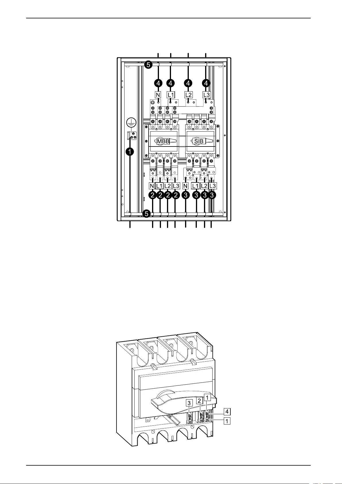
Connect the Power Cables
1. Connect the PE cable to the PE busbar.
2. Connect the input/bypass cables to the maintenance bypass switch MBB.
3. Connect the UPS output cables to the system isolation breaker SIB.
4. Connect the load cables.
5. Fasten the cables with cable ties to the cable reliefs.
Connect the Signal Cables
NOTE: Route the signal cables separately from the power cables.
1. Remove the plastic cover of the maintenance bypass switch MBB to get
access to the AUX switches.
18 990-5994A-001
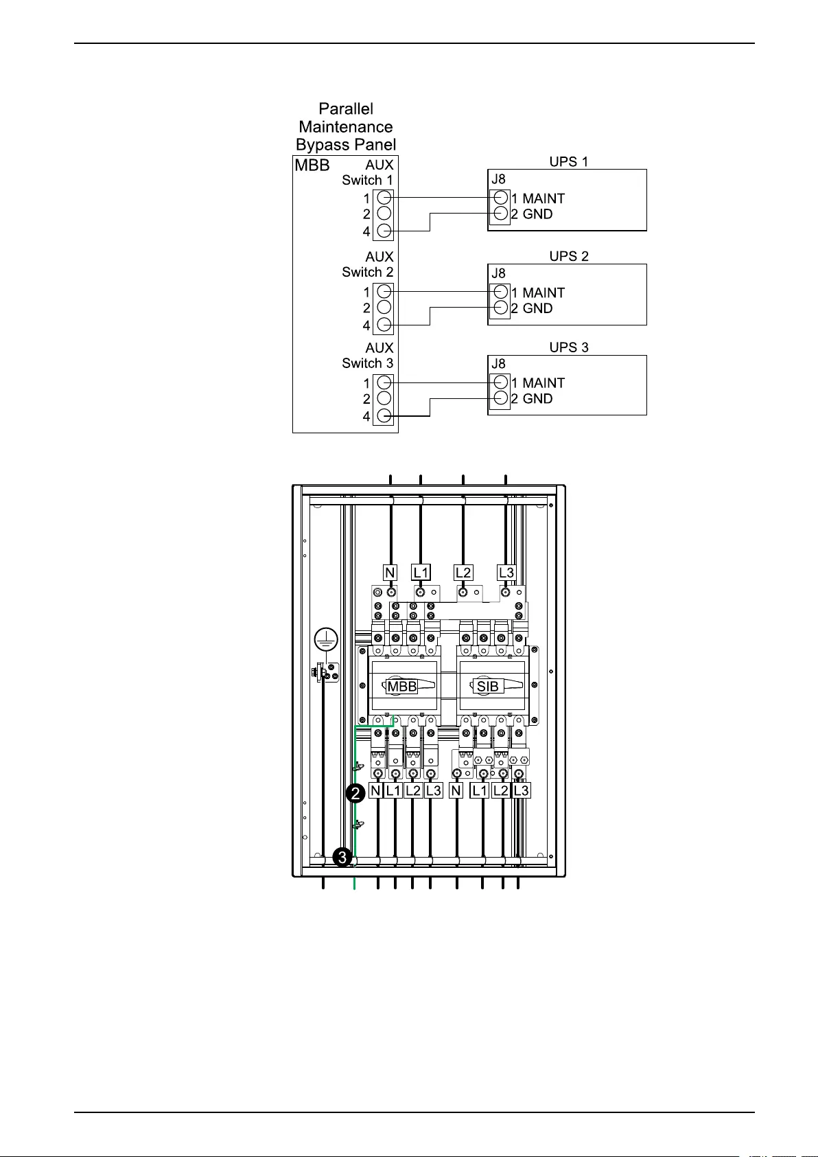
Installation Procedure Parallel Maintenance Bypass Panel
2. Connect signal cables (not supplied) from the three AUX switches in the
maintenance bypass switch MBB to the UPSs.
3. Fasten the signal cables to the cable reliefs.
4. Close the inner door and fasten with screws.
5. Close the front door.
990-5994A-001 19

Schneider Electric
35 rue Joseph Monier
92500 Rueil Malmaison
France
+ 33 (0) 1 41 29 70 00
*990-5994A-001*
As standards, specifications, and design change from time to time,
please ask for confirmation of the information given in this publication.
© 2019 – 2019 Schneider Electric. All rights reserved.
990-5994A-001