Table of Contents
- Easy UPS 3M
- Important Safety Instructions — SAVE THESE INSTRUCTIONS
- Specifications
- Input Specifications
- Bypass Specifications
- Output Specifications
- Battery Specifications
- Recommended Upstream Protection
- Recommended Cable Sizes
- Recommended Bolts and Cable Lugs
- Torque Specifications
- Requirements for a Third Party Battery Solution
- UPS Weights and Dimensions
- UPS Shipping Weights and Dimensions
- Clearance
- Environmental
- Overview
- Receiving
- Prepare System for TNC Earthing
- Connect the Power Cables
- Communication Interfaces
- Backfeed Protection
APC E3MOPT001 User Manual
Displayed below is the user manual for E3MOPT001 by APC which is a product in the UPS Accessories category. This manual has pages.
Related Manuals
Easy UPS 3M
For External Batteries
Installation
60–100 kVA 400 V
09/2019
www.schneider-electric.com

Legal Information
The Schneider Electric brand and any trademarks of Schneider Electric SE and its
subsidiaries referred to in this guide are the property of Schneider Electric SE or its
subsidiaries. All other brands may be trademarks of their respective owners.
This guide and its content are protected under applicable copyright laws and
furnished for informational use only. No part of this guide may be reproduced or
transmitted in any form or by any means (electronic, mechanical, photocopying,
recording, or otherwise), for any purpose, without the prior written permission of
Schneider Electric.
Schneider Electric does not grant any right or license for commercial use of the guide
or its content, except for a non-exclusive and personal license to consult it on an "as
is" basis. Schneider Electric products and equipment should be installed, operated,
serviced, and maintained only by qualified personnel.
As standards, specifications, and designs change from time to time, information
contained in this guide may be subject to change without notice.
To the extent permitted by applicable law, no responsibility or liability is assumed by
Schneider Electric and its subsidiaries for any errors or omissions in the informational
content of this material or consequences arising out of or resulting from the use of the
information contained herein.
Go to http://www.productinfo.schneider-electric.com/portals/ui/easyups3m/ for
translations.
Rendez-vous sur http://www.productinfo.schneider-electric.com/portals/ui/
easyups3m/ pour accéder aux traductions.
Vaya a http://www.productinfo.schneider-electric.com/portals/ui/easyups3m/ para
obtener las traducciones.
Gehe zu http://www.productinfo.schneider-electric.com/portals/ui/easyups3m/ für
Übersetzungen.
Vai a http://www.productinfo.schneider-electric.com/portals/ui/easyups3m/ per le
traduzioni.
Vá para http://www.productinfo.schneider-electric.com/portals/ui/easyups3m/ para
obter as traduções.
Перейдите по ссылке http://www.productinfo.schneider-electric.com/portals/ui/
easyups3m/ для просмотра переводов.
前往 http://www.productinfo.schneider-electric.com/portals/ui/easyups3m/ 查看译
文。
前往 http://www.productinfo.schneider-electric.com/portals/ui/easyups3m/ 查看譯
文。

For External Batteries
Table of Contents
Important Safety Instructions — SAVE THESE
INSTRUCTIONS.........................................................................................5
Electromagnetic Compatibility .....................................................................6
Safety Precautions .....................................................................................6
Electrical Safety....................................................................................8
Battery Safety.......................................................................................9
Specifications ............................................................................................ 11
Input Specifications .................................................................................. 11
Bypass Specifications ............................................................................... 11
Output Specifications................................................................................ 11
Battery Specifications ...............................................................................12
Recommended Upstream Protection..........................................................12
Recommended Cable Sizes ......................................................................13
Recommended Bolts and Cable Lugs ........................................................14
Torque Specifications................................................................................14
Requirements for a Third Party Battery Solution..........................................14
Third Party Battery Breaker Requirements............................................14
Guidance for Organizing Battery Cables ...............................................15
UPS Weights and Dimensions...................................................................15
UPS Shipping Weights and Dimensions .....................................................15
Clearance ................................................................................................16
Environmental..........................................................................................16
Heat Dissipation .................................................................................17
Overview ....................................................................................................18
Overview of Single UPS............................................................................18
Overview of 1+1 Redundant Parallel System with Common Battery
Bank........................................................................................................19
Overview of Parallel System......................................................................19
Location of Breakers.................................................................................21
Receiving ...................................................................................................22
Remove the UPS from the Pallet................................................................22
Prepare System for TNC Earthing..........................................................25
Connect the Power Cables......................................................................26
Communication Interfaces.......................................................................28
Input Contacts and Output Relays..............................................................29
Connect the Signal Cables in Parallel Systems ...........................................31
Backfeed Protection .................................................................................32
990-5992C-001 3

Important Safety Instructions — SAVE THESE
INSTRUCTIONS For External Batteries
Important Safety Instructions — SAVE THESE
INSTRUCTIONS
Read these instructions carefully and look at the equipment to become familiar
with it before trying to install, operate, service or maintain it. The following safety
messages may appear throughout this manual or on the equipment to warn of
potential hazards or to call attention to information that clarifies or simplifies a
procedure.
The addition of this symbol to a “Danger” or “Warning” safety
message indicates that an electrical hazard exists which will result in
personal injury if the instructions are not followed.
This is the safety alert symbol. It is used to alert you to potential
personal injury hazards. Obey all safety messages with this symbol
to avoid possible injury or death.
DANGER
DANGER indicates a hazardous situation which, if not avoided, will result in
death or serious injury.
Failure to follow these instructions will result in death or serious injury.
WARNING
WARNING indicates a hazardous situation which, if not avoided, could result
in death or serious injury.
Failure to follow these instructions can result in death, serious injury, or
equipment damage.
CAUTION
CAUTION indicates a hazardous situation which, if not avoided, could result in
minor or moderate injury.
Failure to follow these instructions can result in injury or equipment
damage.
NOTICE
NOTICE is used to address practices not related to physical injury. The safety
alert symbol shall not be used with this type of safety message.
Failure to follow these instructions can result in equipment damage.
Please Note
Electrical equipment should only be installed, operated, serviced, and maintained
by qualified personnel. No responsibility is assumed by Schneider Electric for any
consequences arising out of the use of this material.
A qualified person is one who has skills and knowledge related to the construction,
installation, and operation of electrical equipment and has received safety training
to recognize and avoid the hazards involved.
990-5992C-001 5
For External Batteries
Important Safety Instructions — SAVE THESE
INSTRUCTIONS
Electromagnetic Compatibility
NOTICE
RISK OF ELECTROMAGNETIC DISTURBANCE
This is a product Category C3 according to IEC 62040-2. This is a product for
commercial and industrial applications in the second environment - installation
restrictions or additional measures may be needed to prevent disturbances. The
second environment includes all commercial, light industry, and industrial
locations other than residential, commercial, and light industrial premises
directly connected without intermediate transformer to a public low-voltage
mains supply. The installation and cabling must follow the electromagnetic
compatibility rules, e.g.:
• the segregation of cables,
• the use of shielded or special cables when relevant,
• the use of grounded metallic cable tray and supports.
Failure to follow these instructions can result in equipment damage.
Safety Precautions
DANGER
HAZARD OF ELECTRIC SHOCK, EXPLOSION, OR ARC FLASH
All safety instructions in this document must be read, understood and followed.
Failure to follow these instructions will result in death or serious injury.
DANGER
HAZARD OF ELECTRIC SHOCK, EXPLOSION, OR ARC FLASH
Read all instructions in the Installation Manual before installing or working on
this UPS system.
Failure to follow these instructions will result in death or serious injury.
DANGER
HAZARD OF ELECTRIC SHOCK, EXPLOSION, OR ARC FLASH
Do not install the UPS system until all construction work has been completed
and the installation room has been cleaned.
Failure to follow these instructions will result in death or serious injury.
DANGER
HAZARD OF ELECTRIC SHOCK, EXPLOSION, OR ARC FLASH
• The product must be installed according to the specifications and
requirements as defined by Schneider Electric. It concerns in particular the
external and internal protections (upstream breakers, battery breakers,
cabling, etc.) and environmental requirements. No responsibility is assumed
by Schneider Electric if these requirements are not respected.
• After the UPS system has been electrically wired, do not start up the system.
Start-up must only be performed by Schneider Electric.
Failure to follow these instructions will result in death or serious injury.
6 990-5992C-001

Important Safety Instructions — SAVE THESE
INSTRUCTIONS For External Batteries
DANGER
HAZARD OF ELECTRIC SHOCK, EXPLOSION, OR ARC FLASH
The UPS system must be installed according to local and national regulations.
Install the UPS according to:
• IEC 60364 (including 60364–4–41- protection against electric shock, 60364–
4–42 - protection against thermal effect, and 60364–4–43 - protection
against overcurrent), or
• NEC NFPA 70, or
• Canadian Electrical Code (C22.1, Part 1)
depending on which one of the standards apply in your local area.
Failure to follow these instructions will result in death or serious injury.
DANGER
HAZARD OF ELECTRIC SHOCK, EXPLOSION, OR ARC FLASH
• Install the UPS system in a temperature controlled indoor environment free
of conductive contaminants and humidity.
• Install the UPS system on a non-flammable, level and solid surface (e.g.
concrete) that can support the weight of the system.
Failure to follow these instructions will result in death or serious injury.
DANGER
HAZARD OF ELECTRIC SHOCK, EXPLOSION, OR ARC FLASH
The UPS is not designed for and must therefore not be installed in the following
unusual operating environments:
• Damaging fumes
• Explosive mixtures of dust or gases, corrosive gases, or conductive or
radiant heat from other sources
• Moisture, abrasive dust, steam or in an excessively damp environment
• Fungus, insects, vermin
• Salt-laden air or contaminated cooling refrigerant
• Pollution degree higher than 2 according to IEC 60664-1
• Exposure to abnormal vibrations, shocks, and tilting
• Exposure to direct sunlight, heat sources, or strong electromagnetic fields
Failure to follow these instructions will result in death or serious injury.
DANGER
HAZARD OF ELECTRIC SHOCK, EXPLOSION, OR ARC FLASH
Do not drill or cut holes for cables or conduits with the gland plates installed and
do not drill or cut holes in close proximity to the UPS.
Failure to follow these instructions will result in death or serious injury.
WARNING
HAZARD OF ARC FLASH
Do not make mechanical changes to the product (including removal of cabinet
parts or drilling/cutting of holes) that are not described in the Installation Manual.
Failure to follow these instructions can result in death, serious injury, or
equipment damage.
990-5992C-001 7
For External Batteries
Important Safety Instructions — SAVE THESE
INSTRUCTIONS
NOTICE
RISK OF OVERHEATING
Respect the space requirements around the UPS system and do not cover the
product’s ventilation openings when the UPS system is in operation.
Failure to follow these instructions can result in equipment damage.
NOTICE
RISK OF EQUIPMENT DAMAGE
Do not connect the UPS output to regenerative load systems including
photovoltaic systems and speed drives.
Failure to follow these instructions can result in equipment damage.
Electrical Safety
DANGER
HAZARD OF ELECTRIC SHOCK, EXPLOSION, OR ARC FLASH
• Electrical equipment must be installed, operated, serviced, and maintained
only by qualified personnel.
• Apply appropriate personal protective equipment (PPE) and follow safe
electrical work practices.
• Turn off all power supplying the UPS system before working on or inside the
equipment.
• Before working on the UPS system, check for hazardous voltage between all
terminals including the protective earth.
• The UPS contains an internal energy source. Hazardous voltage can be
present even when disconnected from the mains supply. Before installing or
servicing the UPS system, ensure that the units are OFF and that mains and
batteries are disconnected. Wait five minutes before opening the UPS to
allow the capacitors to discharge.
• A disconnection device (e.g. disconnection circuit breaker or switch) must be
installed to enable isolation of the system from upstream power sources in
accordance with local regulations. The disconnection device must be easily
accessible and visible.
• The UPS must be properly earthed/grounded and due to a high leakage
current, the earthing/grounding conductor must be connected first.
Failure to follow these instructions will result in death or serious injury.
DANGER
HAZARD OF ELECTRIC SHOCK, EXPLOSION, OR ARC FLASH
In systems where backfeed protection is not part of the standard design, an
automatic isolation device (backfeed protection option or other device meeting
the requirements of IEC/EN 62040–1 or UL1778 5th Edition – depending on
which of the two standards apply to your local area) must be installed to prevent
hazardous voltage or energy at the input terminals of the isolation device. The
device must open within 15 seconds after the upstream power supply fails and
must be rated according to the specifications.
Failure to follow these instructions will result in death or serious injury.
When the UPS input is connected through external isolators that, when opened,
isolate the neutral or when the automatic backfeed isolation is provided external to
the equipment or is connected to an IT power distribution system, a label must be
fitted at the UPS input terminals, and on all primary power isolators installed
8 990-5992C-001

Important Safety Instructions — SAVE THESE
INSTRUCTIONS For External Batteries
remote from the UPS area and on external access points between such isolators
and the UPS, by the user, displaying the following text (or equivalent in a language
which is acceptable in the country in which the UPS system is installed):
DANGER
HAZARD OF ELECTRIC SHOCK, EXPLOSION, OR ARC FLASH
Risk of Voltage Backfeed. Before working on this circuit: Isolate the UPS and
check for hazardous voltage between all terminals including the protective
earth.
Failure to follow these instructions will result in death or serious injury.
Battery Safety
DANGER
HAZARD OF ELECTRIC SHOCK, EXPLOSION, OR ARC FLASH
• Battery circuit breakers must be installed according to the specifications and
requirements as defined by Schneider Electric.
• Servicing of batteries must only be performed or supervised by qualified
personnel knowledgeable of batteries and the required precautions. Keep
unqualified personnel away from batteries.
• Disconnect charging source prior to connecting or disconnecting battery
terminals.
• Do not dispose of batteries in a fire as they can explode.
• Do not open, alter, or mutilate batteries. Released electrolyte is harmful to
the skin and eyes. It may be toxic.
Failure to follow these instructions will result in death or serious injury.
DANGER
HAZARD OF ELECTRIC SHOCK, EXPLOSION, OR ARC FLASH
Batteries can present a risk of electric shock and high short-circuit current. The
following precautions must be observed when working on batteries
• Remove watches, rings, or other metal objects.
• Use tools with insulated handles.
• Wear protective glasses, gloves and boots.
• Do not lay tools or metal parts on top of batteries.
• Disconnect the charging source prior to connecting or disconnecting battery
terminals.
• Determine if the battery is inadvertently grounded. If inadvertently grounded,
remove source from ground. Contact with any part of a grounded battery can
result in electric shock. The likelihood of such shock can be reduced if such
grounds are removed during installation and maintenance (applicable to
equipment and remote battery supplies not having a grounded supply
circuit).
Failure to follow these instructions will result in death or serious injury.
DANGER
HAZARD OF ELECTRIC SHOCK, EXPLOSION, OR ARC FLASH
When replacing batteries, always replace with the same type and number of
batteries or battery packs.
Failure to follow these instructions will result in death or serious injury.
990-5992C-001 9

For External Batteries
Important Safety Instructions — SAVE THESE
INSTRUCTIONS
NOTICE
RISK OF EQUIPMENT DAMAGE
• Wait until the system is ready to be powered up before installing batteries in
the system. The time duration from battery installation until the UPS system
is powered up must not exceed 72 hours or 3 days.
• Batteries must not be stored more than six months due to the requirement of
recharging. If the UPS system remains de-energized for a long period,
Schneider Electric recommends that you energize the UPS system for a
period of 24 hours at least once every month. This charges the batteries,
thus avoiding irreversible damage.
Failure to follow these instructions can result in equipment damage.
10 990-5992C-001

Specifications For External Batteries
Specifications
Input Specifications
60 kVA 80 kVA 100 kVA
Voltage (V) 380 400 415 380 400 415 380 400 415
Connections L1, L2, L3, N, PE
Input voltage range (V) 342–477 at full load1
Frequency range (Hz) 40–70
Nominal input current (A) 96 91 88 128 122 117 160 152 146
Maximum input current (A) 109 104 100 154 146 141 186 177 170
Input current limitation (A) 155 206 258
Total harmonic distortion (THDI) <3% for linear loads
Input power factor > 0.99
Maximum short circuit rating 10 kA RMS
Protection Fuse
Ramp-in 7 seconds
Bypass Specifications
60 kVA 80 kVA 100 kVA
Voltage (V) 380 400 415 380 400 415 380 400 415
Connections L1, L2, L3, N, PE
Overload capacity 110% for 60 minutes
130% for 10 minutes
130–150% for 1 minute
Minimum bypass voltage (V) 266 280 291 266 280 291 266 280 291
Maximum bypass voltage (V) 475 480 477 475 480 477 475 480 477
Frequency (Hz) 50 or 60
Frequency range (%) ±1, ±2, ±4, ±5, ±10. Default is ±10 (user selectable).
Nominal bypass current (A) 91 87 83 122 115 111 152 144 139
Maximum short circuit rating 10 kA RMS
Output Specifications
60 kVA 80 kVA 100 kVA
Voltage (V) 380 400 415 380 400 415 380 400 415
Connections L1, L2, L3, N, PE
Overload capacity2110% for 60 minutes
125% for 10 minutes
150% for 1 minute
Output voltage regulation ± 1%
990-5992C-001 11
1. 150–342 V with a linear derating of the load to 30%.
2. At 30 °C.

For External Batteries Specifications
60 kVA 80 kVA 100 kVA
Voltage (V) 380 400 415 380 400 415 380 400 415
Dynamic load response 20 milliseconds
Output power factor 1.0
Nominal output current (A) 91 87 83 122 115 111 152 144 139
Total harmonic distortion (THDU) <3% at 100% linear load
<5% at 100% non-linear load
Output frequency (Hz) 50 or 60
Slew rate (Hz/sec) Programmable: 0.5 to 2.0. Default is 0.5
Output performance classification (according to IEC/ EN62040-3) VFI-SS–111
Load power factor 0.5 leading to 0.5 lagging without derating
Battery Specifications
60 kVA 80 kVA 100 kVA
Charging power in % of output power 1–20% 1–30% 1–24%
Maximum charging power (W) 12000 24000 24000
Nominal battery voltage (32–50 blocks3) (VDC) ± 192 to ± 300
Nominal float voltage (32–50 blocks3) (VDC) ± 215.5 to ± 337.5
End of discharge voltage (32–50 blocks) (VDC) ± 153.6 to ± 240
Battery current at full load and nominal battery voltage (36–50 blocks) (A) 147–105 196–140 245–175
Battery current at full load and minimum battery voltage (36–50 blocks)
(A)
185–132 246–176 308–221
Temperature compensation (per cell)4Programmable from 0–7 mV. Default is 0 mV
Ripple current < 5% C10
Recommended Upstream Protection
NOTE: For local directives which require 4–pole circuit breakers: If neutral
conductor is expected to carry a high current, due to line-neutral non-linear
load, the circuit breaker must be rated according to expected neutral current.
60 kW 80 kW 100 kW
Input Bypass Input Bypass Input Bypass
Breaker type Compact
NSX160F
TM125D
(LV430631)
Compact
NSX100F
TM100D
(LV429630)
Compact
NSX160F
TM160D
(LV430630)
Compact
NSX160F
TM160D
(LV430630)
Compact
NSX250F
TM200D
(LV431631)
Compact
NSX160F
TM160D
(LV430630)
In setting 125 100 160 160 200 160
Ir setting 125 100 160 144 200 160
Im setting 800 (fixed) 800 (fixed) 1250 (fixed) 1250 (fixed) 1000 1250 (fixed)
12 990-5992C-001
3. 32–34 blocks are only possible when the load is <90%.
4. If the temperature is above 28 °C. If the temperature is below 28 °C, no compensation is needed.

Specifications For External Batteries
Recommended Cable Sizes
DANGER
HAZARD OF ELECTRIC SHOCK, EXPLOSION, OR ARC FLASH
All wiring must comply with all applicable national and/or electrical codes. The
maximum allowable cable size is 70 mm².
Failure to follow these instructions will result in death or serious injury.
Cable sizes in this manual are based on table B.52.5 of IEC 60364–5–52 with the
following assertions:
• 90 °C conductors
• An ambient temperature of 30 °C
• Use of copper conductors
• Installation method C
PE size is based on table 54.2 of IEC 60364–4–54.
If the ambient temperature is greater than 30 °C, larger conductors are to be used
in accordance with the correction factors of the IEC.
60 kVA UPS
Cable Size per Phase (mm²) Neutral5Cable Size (mm²) PE Cable Size (mm²)
Input 35 2x25 16
Bypass 25 16
Output 25 2x25 16
Battery 50 50 25
80 kVA UPS
Cable Size per Phase (mm²) Neutral5Cable Size (mm²) PE Cable Size (mm²)
Input 50 2x50 25
Bypass 50 25
Output 50 2x50 25
Battery 2x50 2x50 50
100 kVA UPS
Cable Size per Phase (mm²) Neutral5Cable Size (mm²) PE Cable Size (mm²)
Input 70 2x70 35
Bypass 70 35
Output 70 2x70 35
Battery 2x70 2x70 70
990-5992C-001 13
5. Neutral conductor is sized to handle 1.73 times phase current in case of high harmonic content from non-linear loads. If non or less
harmonic currents are expected, neutral conductor can be sized accordingly but not less than the phase conductor.
For External Batteries Specifications
Recommended Bolts and Cable Lugs
Cable Size (mm²) Bolt Size Cable Lug Type
16 M8 KST TLK16-8
25 M8 KST TLK25-8
35 M8 KST TLK35-8
50 M8 KST TLK50-8
70 M8 KST TL70-8
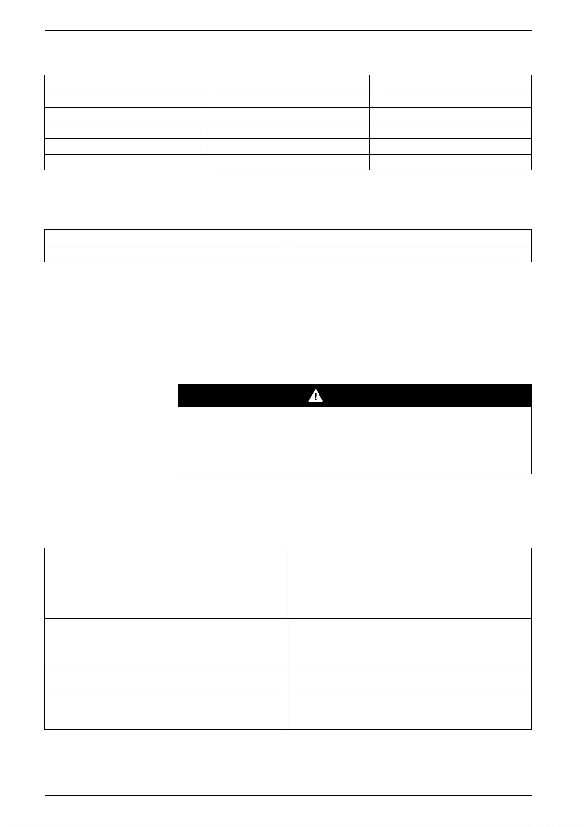
Torque Specifications
Bolt Size Torque
M8 17.5 Nm
Requirements for a Third Party Battery Solution
Battery breaker boxes from Schneider Electric are recommended for the battery
interface. Please contact Schneider Electric for more information.
Third Party Battery Breaker Requirements
DANGER
HAZARD OF ELECTRIC SHOCK, EXPLOSION, OR ARC FLASH
All selected battery breakers must be equipped with instantaneous trip
functionality with an undervoltage release coil or a shunt trip release coil.
Failure to follow these instructions will result in death or serious injury.
NOTE: There are more factors to consider when selecting a battery breaker
than the requirements listed below. Please contact Schneider Electric for more
information.
Design Requirements for Battery Breaker
Battery breaker rated DC voltage > Normal battery
voltage
The normal voltage of the battery configuration is
defined as the highest nominal occurring battery
voltage. This can be equivalent to the float voltage
which may be defined as number of battery blocks x
number of cells x cell float voltage. Ex: 32 blocks of 6
cells of 2.27 = 435 VDC.
Battery breaker rated DC current > Rated discharge
battery current
This current is controlled by the UPS and must include
maximum discharge current. This will typically be the
current at the end of discharge (minimum operation
DC voltage or in overload condition or a combination).
DC landings Three DC landings for DC-cables are required.
AUX switches for monitoring One AUX switch must be installed in each battery
breaker and connected to the UPS. The UPS can
monitor one battery breaker.
14 990-5992C-001
Specifications For External Batteries
Design Requirements for Battery Breaker (Continued)
Short-circuit breaking capability The short-circuit breaking capability must be higher
than the short-circuit DC current of the (largest)
battery configuration.
Minimum trip current The minimum short-circuit current to trip the battery
breaker must match the (smallest) battery
configuration, to make the breaker trip in case of a
short circuit, up to the end of its life time.
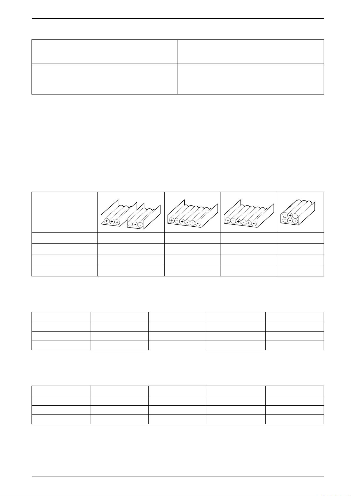
Guidance for Organizing Battery Cables
NOTE: For 3rd party batteries, use only high rate batteries for UPS
applications.
NOTE: When the battery bank is placed remotely, the organizing of the cables
is important to reduce voltage drop and inductance. The distance between the
battery bank and the UPS must not exceed 200 m (656 ft). Contact Schneider
Electric for installations with a longer distance.
NOTE: To minimize the risk of electromagnetic radiation, it is highly
recommended to follow the below guidance and to use grounded metallic tray
supports.
Cable Length
<30 m Not recommended Acceptable Recommended Recommended
31–75 m Not recommended Not recommended Acceptable Recommended
76–150 m Not recommended Not recommended Acceptable Recommended
151–200 m Not recommended Not recommended Not recommended Recommended
UPS Weights and Dimensions
UPS Weight kg Height mm Width mm Depth mm
60 kVA 109 915 360 850
80 kVA 140 915 360 850
100 kVA 145 915 360 850
UPS Shipping Weights and Dimensions
UPS Weight kg Height mm Width mm Depth mm
60 kVA 133 1140 475 965
80 kVA 164 1140 475 965
100 kVA 169 1140 475 965
990-5992C-001 15
For External Batteries Specifications
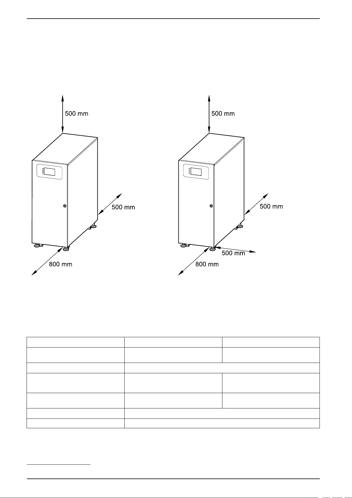
Clearance
NOTE: Clearance dimensions are published for airflow and service access
only. Consult with the local safety codes and standards for additional
requirements in your local area.
Option A
NOTE: If the UPS is installed without side access,
the length of the cables connected to the UPS
must allow for rolling out the UPS.
Option B
Environmental
Operation Storage
Temperature 0 °C to 40 °C -15 °C to 40 °C for systems with batteries
-25 °C to 55 °C for systems without batteries
Relative humidity 0–95% non-condensing
Elevation derating according to
IEC 62040–3
Power derating factor:
0–1500 m: 1.000
1500–2000 m: 0.975
< 15000 m above sea level (or in an
environment with equivalent air pressure)
Audible noise <65 dBA at full load and an ambient
temperature of 30 °C6
Protection class IP20 (dust filter as standard)
Color RAL 9003
16 990-5992C-001
6. According to ISO 3746.

Overview For External Batteries
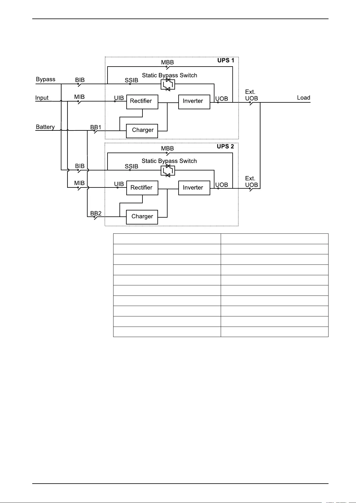
Overview of 1+1 Redundant Parallel System with Common
Battery Bank
MIB Mains input breaker
BIB Bypass input breaker
UIB Unit input breaker
SSIB Static switch input breaker
UOB Unit output breaker
Ext. UOB External unit output breaker
MBB Maintenance bypass breaker
Ext. MBB External maintenance bypass breaker
BB1 Battery breaker 1
BB2 Battery breaker 2
Overview of Parallel System
NOTE: In parallel systems with an external maintenance bypass breaker Ext.
MBB, the maintenance bypass breakers MBB must be padlocked in the open
position.
990-5992C-001 19
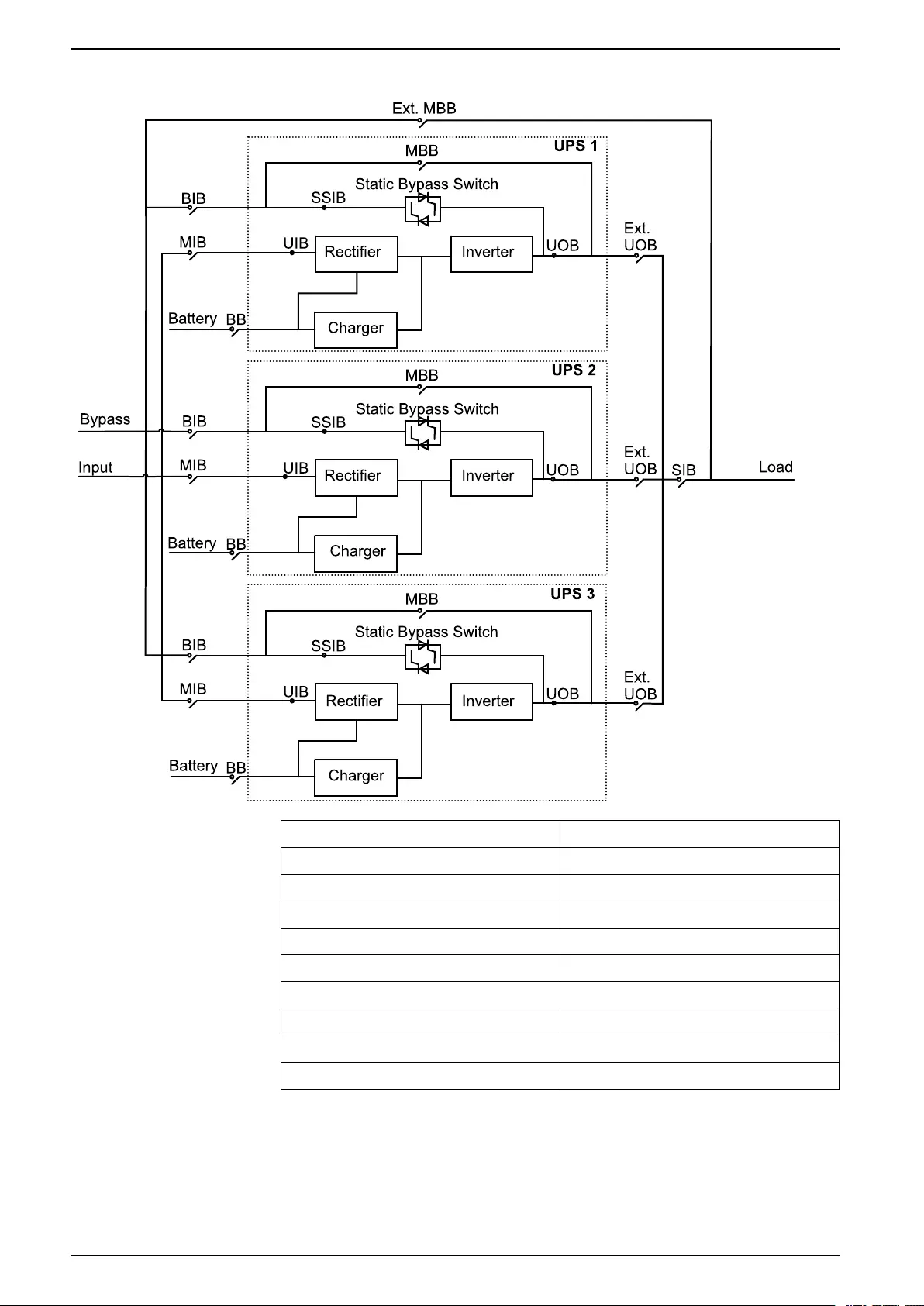
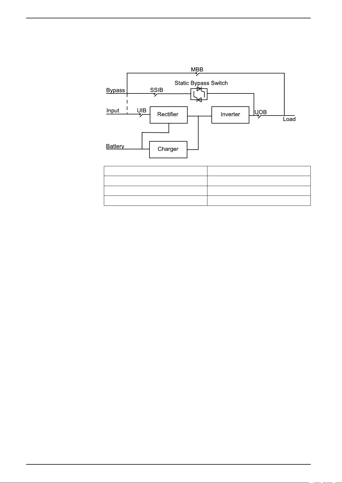
For External Batteries Overview
UPSs for External Batteries
MIB Mains input breaker
BIB Bypass input breaker
UIB Unit input breaker
SSIB Static switch input breaker
UOB Unit output breaker
Ext. UOB External unit output breaker
MBB Maintenance bypass breaker
Ext. MBB External maintenance bypass breaker
SIB System isolation breaker
BB Battery breaker
20 990-5992C-001

For External Batteries Receiving
Receiving
External Inspection
When the shipment arrives, inspect the shipping material for any signs of damage
or mishandling. Do not attempt to install the system if a damage is apparent. If any
damage is noted, contact Schneider Electric and file a damage claim with the
shipping agency within 24 hours.
Compare the components of the shipment with the bill of lading. Report any
missing items to the carrier and to Schneider Electric immediately.
Verify that labelled units match the order confirmation.
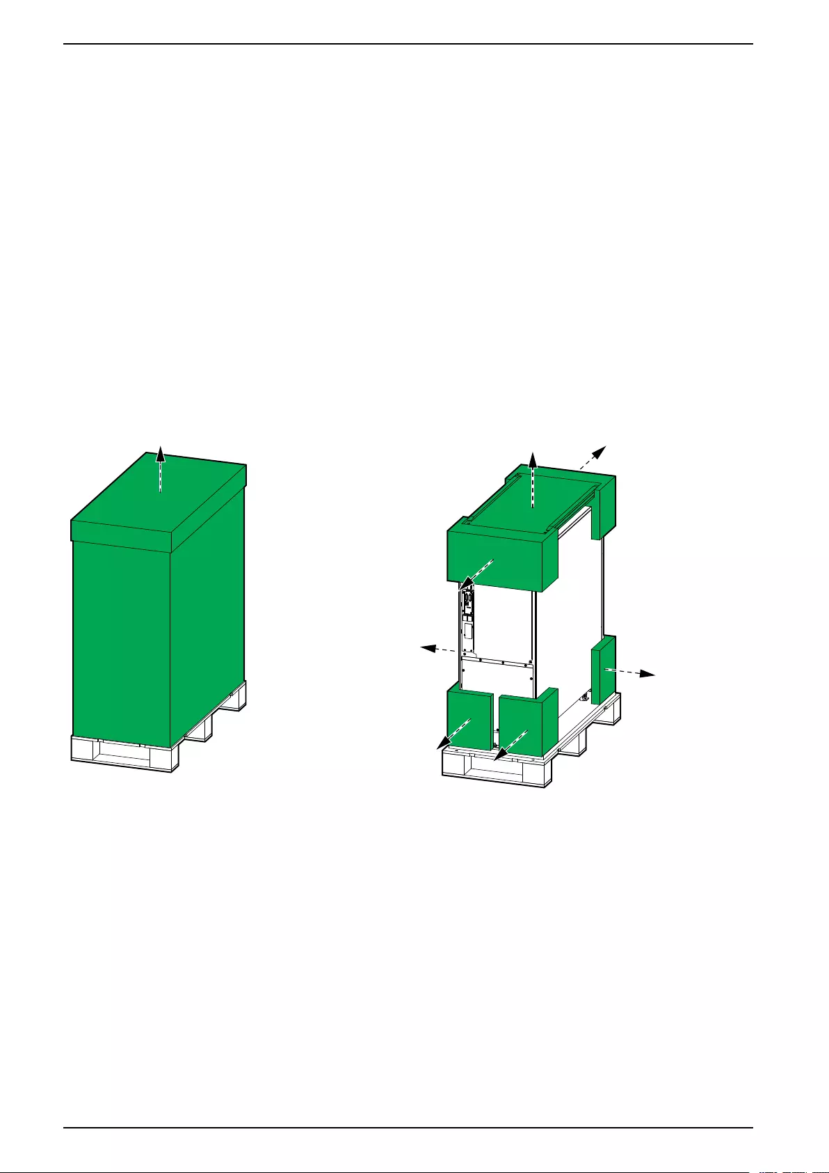
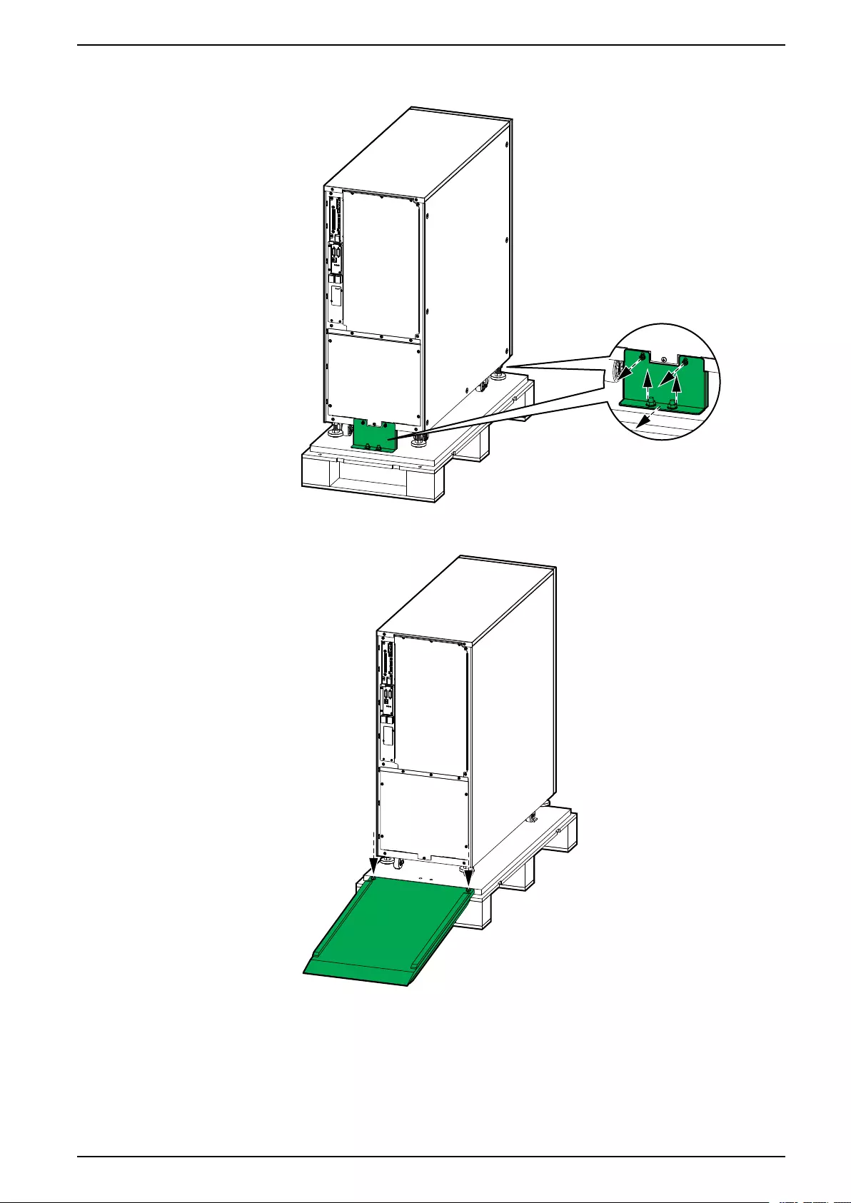
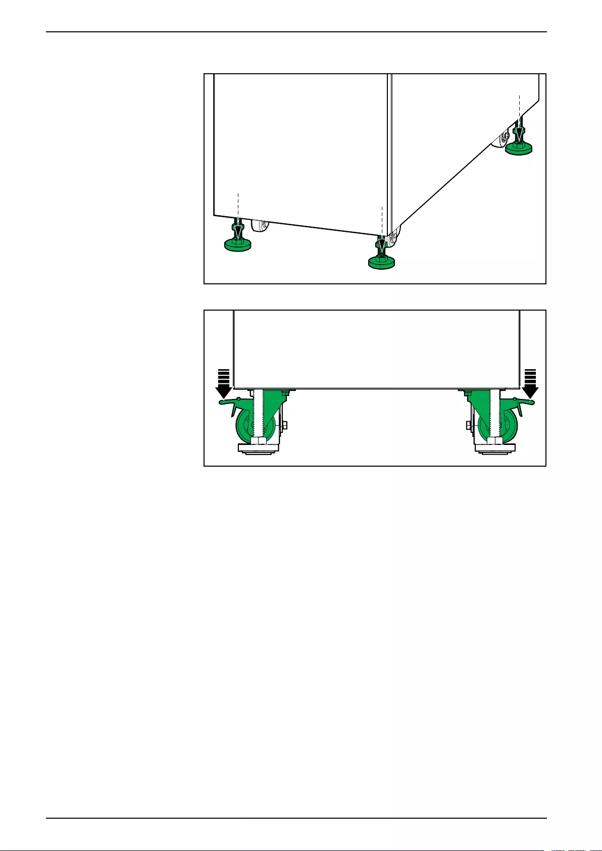
Remove the UPS from the Pallet
1. Move the UPS to the final installation area using a forklift.
2. Remove the shipping materials and the ramp from the UPS.
22 990-5992C-001
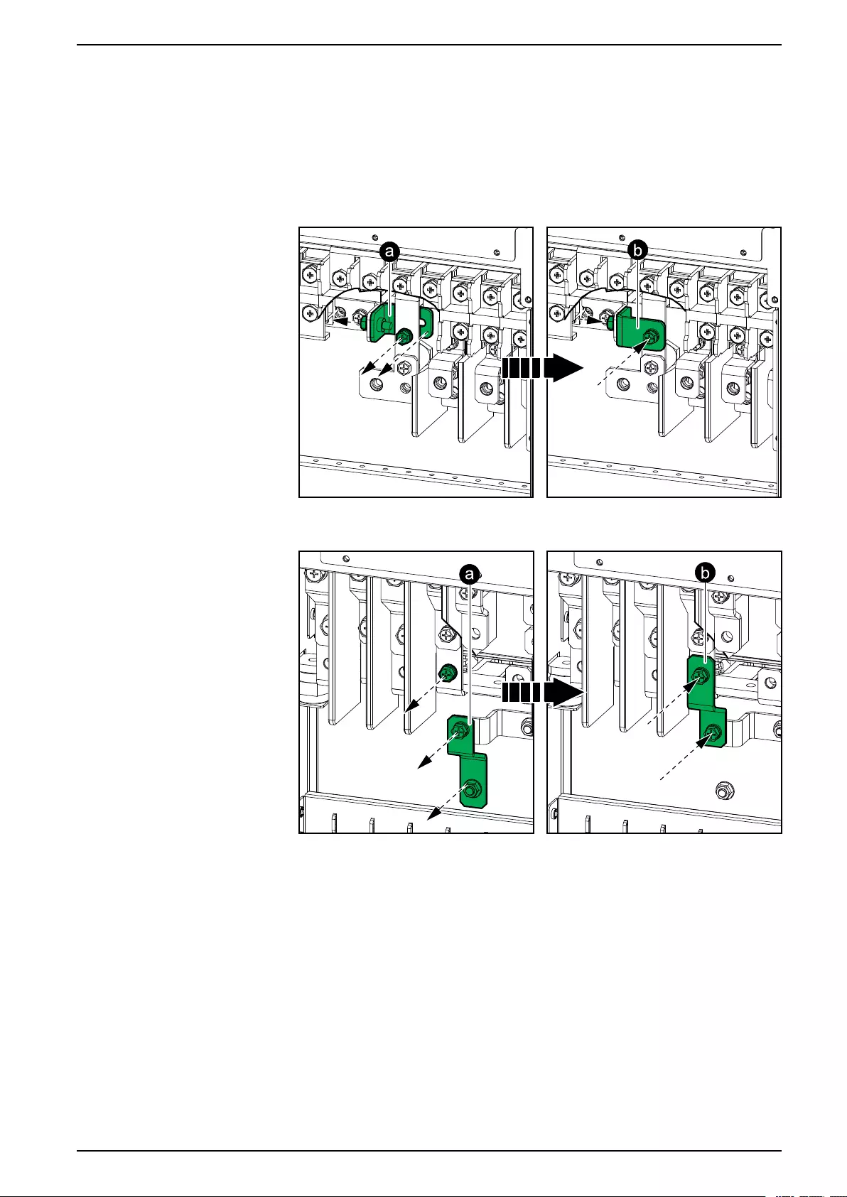
Prepare System for TNC Earthing For External Batteries
Prepare System for TNC Earthing
NOTE: This procedure is only applicable to TNC earthing systems.
1. Rotate the busbar from the original position (a) to the position (b) to create a
connection between the PE busbar and the neutral busbar.
60–80 kVA UPS
100 kVA UPS
990-5992C-001 25
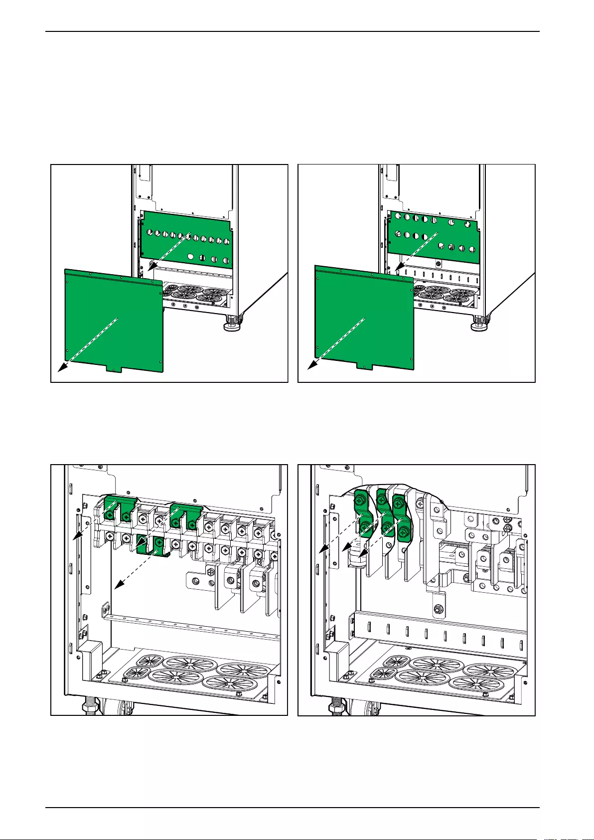
For External Batteries Connect the Power Cables
Connect the Power Cables
1. Ensure that all breakers are in the OFF (open) position.
2. Remove the two indicated plates from the bottom of the UPS.
Rear View of the 60–80 kVA UPS Rear View of the 100 kVA UPS
3. In dual mains systems, remove the three single mains brackets.
Rear View of the 60–80 kVA UPS Rear View of the 100 kVA UPS
4. Route the power cables through the bottom of the UPS.
26 990-5992C-001
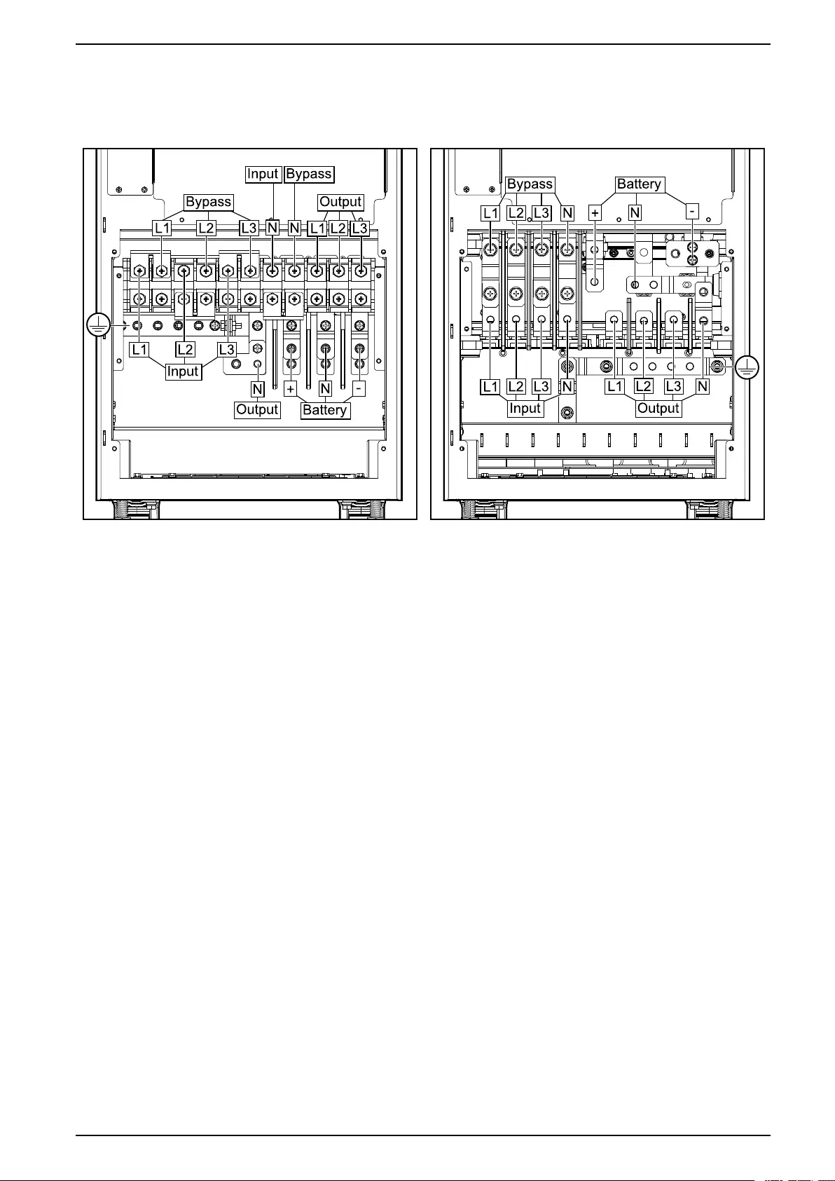
Connect the Power Cables For External Batteries
5. Connect the PE cable to the PE terminal.
Rear View of the 60–80 kVA UPS Rear View of the 100 kVA UPS
6. Connect the input, output, and bypass (if applicable) cables.
7. Connect the battery cables.
8. Fasten the cables to the cable relief in the bottom of the UPS.
9. Reinstall the two plates in the bottom of the UPS.
990-5992C-001 27
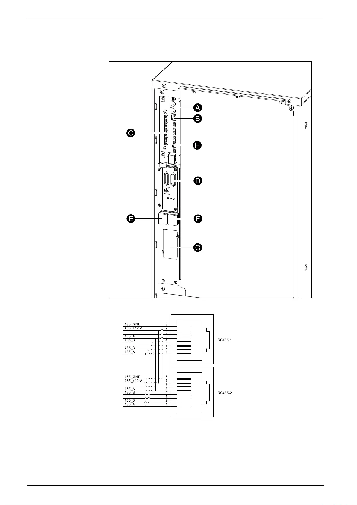
Communication Interfaces For External Batteries
H. CAN_R: CAN termination resistor
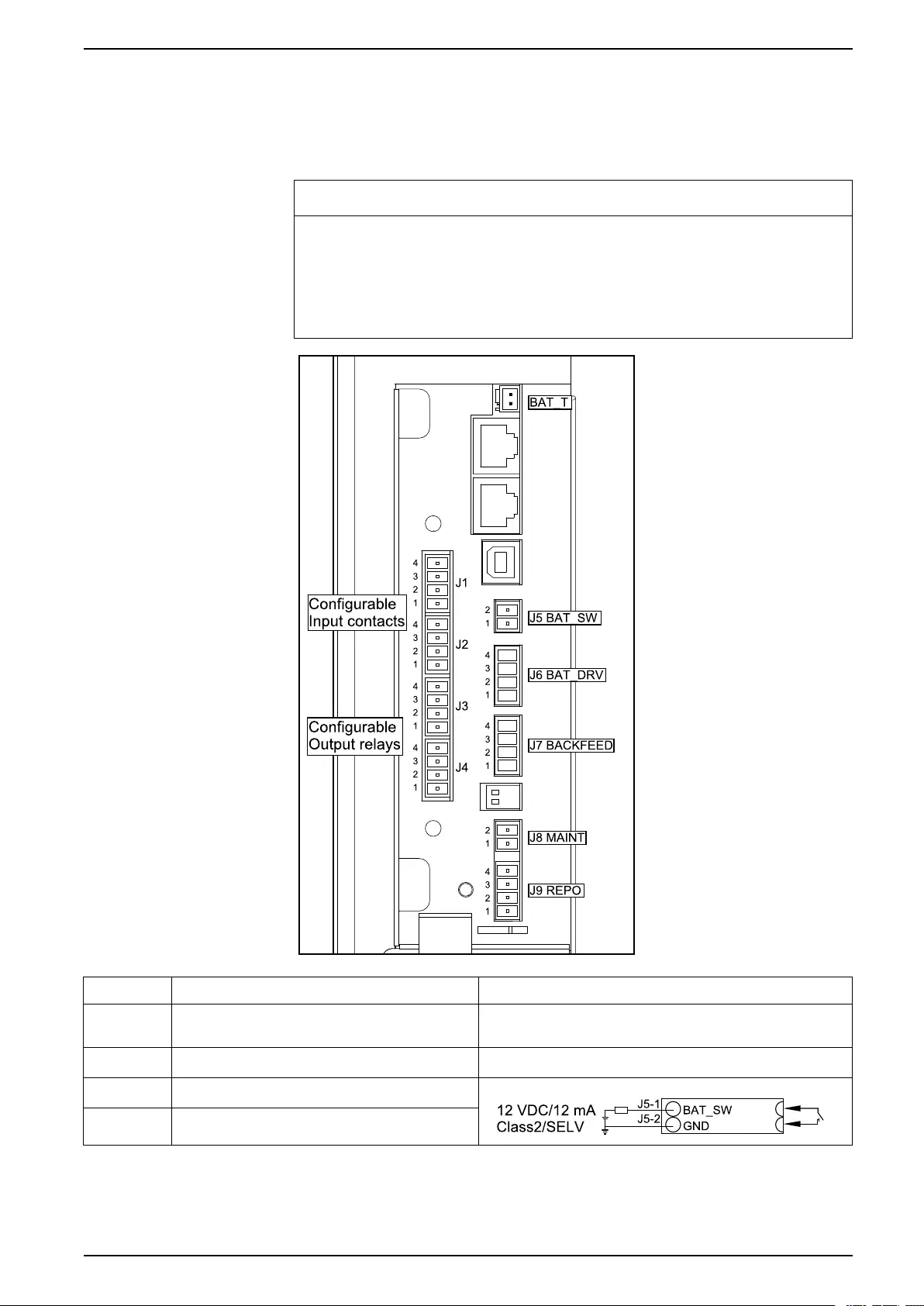
Input Contacts and Output Relays
NOTICE
RISK OF EQUIPMENT DAMAGE
The battery breaker contact drive J6–1 and J6–2 can provide a maximum of +24
VDC 400 mA to the undervoltage release coil or shunt trip release coil. If this
value is exceeded it can damage the UPS.
Failure to follow these instructions can result in equipment damage.
Terminal Function
BAT_T–1 Input contact for battery temperature
sensor
BAT_T–2 Signal ground
J5–1 Auxiliary contact for battery breaker
J5–2 Signal ground
990-5992C-001 29
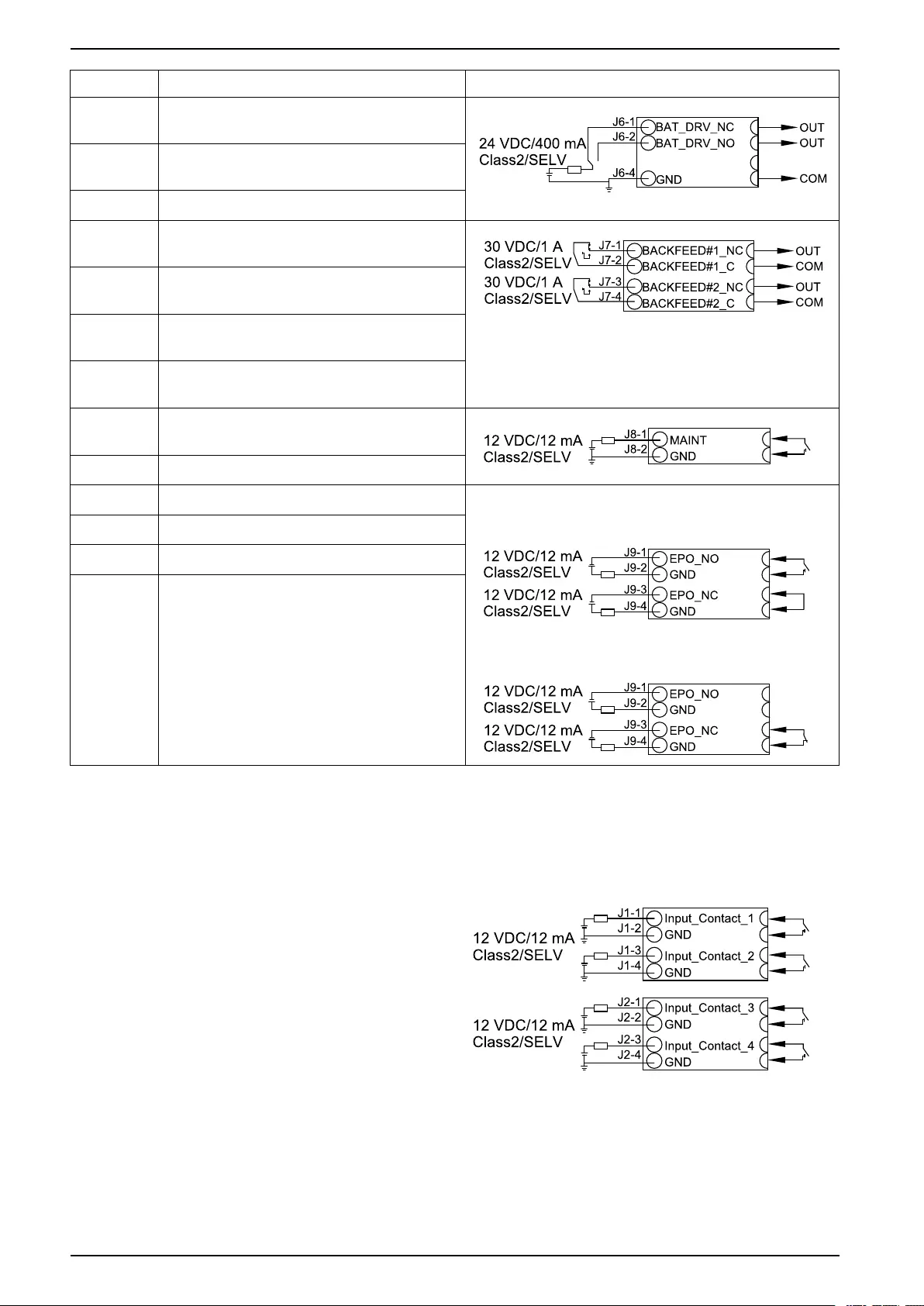
For External Batteries Communication Interfaces
Terminal Function
J6–1 Normally closed output contact for battery
breaker trip
J6–2 Normally open output contact for battery
breaker trip
J6–4 Signal ground
J7–1 Backfeed 1 output relay pin 1 (normally
closed (NC) as default)
J7–2 Backfeed 1 output relay pin 2 (normally
closed (NC) as default)
J7–3 Backfeed 2 output relay pin 1 (normally
closed (NC) as default)
J7–4 Backfeed 2 output relay pin 2 (normally
closed (NC) as default)
J8–1 Auxiliary contact for external maintenance
bypass breaker
J8–2 Signal ground
J9–1 Normally open EPO contact
NO configuration
NC configuration
J9–2 Signal ground
J9–3 Normally closed EPO contact
J9–4 Signal ground
Configurable Input Contacts
The four configurable input contacts can be configured from the display with the
following functions:
• Disable
• INV ON
• INV OFF
• Battery alarm
• Genset enable
• Custom alarm 3
• Custom alarm 4
• Disable ECO
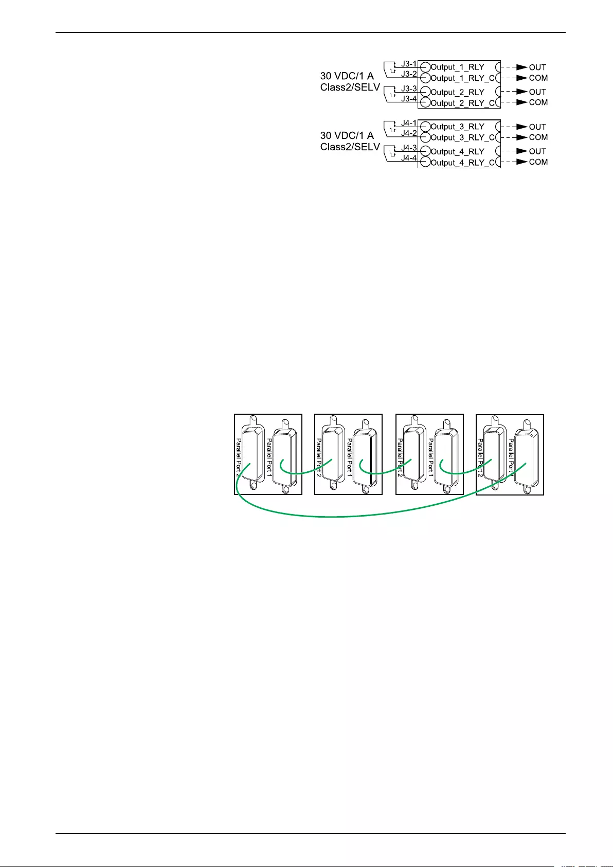
Configurable Output Relays
The four configurable output contacts can be configured from the display with the
following functions:
30 990-5992C-001
Communication Interfaces For External Batteries
• Disable
• Common alarm
• Normal operation
• Battery operation
• Static bypass operation
• Output overload
• Fan inoperable
• Battery alarm
• Battery disconnected
• Battery voltage low
• Input out of tolerance
• Bypass out of tolerance
• EPO activated
• Maintenance mode
• Parallel lost
Connect the Signal Cables in Parallel Systems
1. Connect the optional parallel cables between all the UPSs of the parallel
system.
NOTE: See Communication Interfaces, page 28 for location of parallel
ports.
2. Verify the setting of the CAN_R (for location of CAN_R see Communication
Interfaces, page 28).
– For parallel systems with ≤ 4 parallel UPSs, CAN_R of all UPSs must be in
ON position.
– For parallel systems with ≥ 5 parallel UPSs, CAN_R of all UPSs must be in
OFF position.
990-5992C-001 31

For External Batteries Backfeed Protection
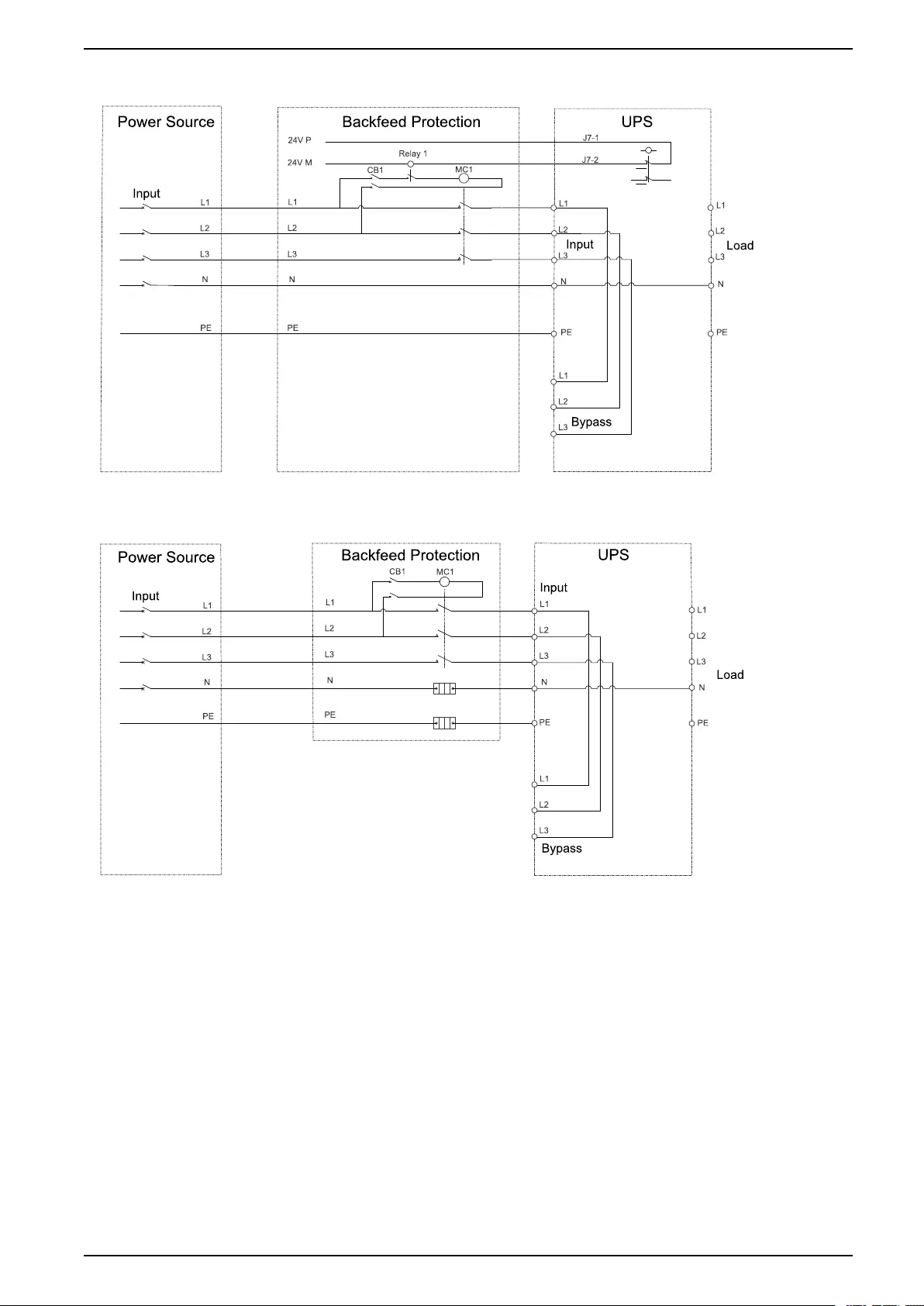
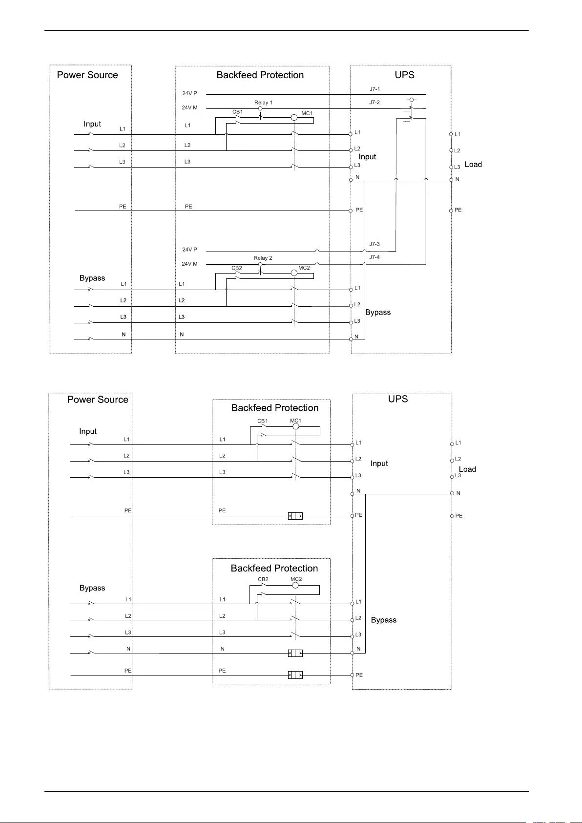
Backfeed Protection
DANGER
HAZARD OF ELECTRIC SHOCK, EXPLOSION, OR ARC FLASH
In systems where backfeed protection is not part of the standard design, an
automatic isolation device (backfeed protection option or other device meeting
the requirements of IEC/EN 62040–1) must be installed to prevent hazardous
voltage or energy at the input terminals of the isolation device. The device must
open within 15 seconds after the upstream power supply fails and must be rated
according to the specifications.
Failure to follow these instructions will result in death or serious injury.
When the UPS input is connected through external isolators that, when opened,
isolate the neutral or when the automatic backfeed isolation is provided external to
the equipment or is connected to an IT power distribution system, a label must be
fitted at the UPS input terminals, and on all primary power isolators installed
remote from the UPS area and on external access points between such isolators
and the UPS, by the user, displaying the following text (or equivalent in a language
which is acceptable in the country in which the UPS system is installed):
DANGER
HAZARD OF ELECTRIC SHOCK, EXPLOSION, OR ARC FLASH
Risk of Voltage Backfeed. Before working on this circuit: Isolate the UPS and
check for hazardous voltage between all terminals including the protective
earth.
Failure to follow these instructions will result in death or serious injury.
An additional external isolation device must be installed in the UPS system. A
contactor can be used for this purpose. In the shown examples, the isolation
device is a contactor (marked with a MC1 for single mains systems and marked
with a MC1 and MC2 for dual mains systems).
The isolation device must be able to withstand the electrical characteristics as
described in Specifications, page 11.
NOTE: The 24 V source should be generated from the switchgear input
source in single mains configurations and from both the switchgear input and
bypass source in dual mains configurations.
32 990-5992C-001


Schneider Electric
35 rue Joseph Monier
92500 Rueil Malmaison
France
+ 33 (0) 1 41 29 70 00
*990-5992C-001*
As standards, specifications, and design change from time to time,
please ask for confirmation of the information given in this publication.
© 2019 – 2019 Schneider Electric. All rights reserved.
990-5992C-001