Table of Contents
- Easy UPS 3M
- Important Safety Instructions — SAVE THESE INSTRUCTIONS
- Overview
- Operation Modes
- Operation Procedures
- View System Status Information
- Start Up a Single UPS in Normal Mode
- Transfer a Single UPS from Normal Mode to Static Bypass Mode
- Transfer a Single UPS from Static Bypass Mode to Normal Mode
- Transfer a Single UPS from Normal Mode to Maintenance Bypass Mode
- Transfer a Single UPS from Maintenance Bypass Mode to Normal Mode
- Transfer a Parallel System from Normal Mode to Maintenance Bypass Mode
- Transfer a Parallel System from Maintenance Bypass Mode to Normal Mode
- Isolate a Single UPS from the Parallel System
- Start Up and Add a UPS to a Running Parallel System
- Configuration
- Default Settings
- Set the Display Language
- Configure the Display Settings
- Configure the Network Settings
- Change the Display Password
- Set the Date and Time
- Configure the UPS Settings
- Configure the Output Settings
- Configure the Battery Settings
- Configure the Input Contacts and Output Relays
- Configure Life Cycle Monitoring
- Enable/Disable Buzzer
- Maintenance
- Troubleshooting
- Tom side
- Tom side
APC E3MUPS80KHB1S User Manual
Displayed below is the user manual for E3MUPS80KHB1S by APC which is a product in the Uninterruptible Power Supplies (UPSs) category. This manual has pages.
Related Manuals
Easy UPS 3M
60-200 kVA
Operation
09/2019
www.schneider-electric.com

Legal Information
The Schneider Electric brand and any trademarks of Schneider Electric SE and its
subsidiaries referred to in this guide are the property of Schneider Electric SE or its
subsidiaries. All other brands may be trademarks of their respective owners.
This guide and its content are protected under applicable copyright laws and
furnished for informational use only. No part of this guide may be reproduced or
transmitted in any form or by any means (electronic, mechanical, photocopying,
recording, or otherwise), for any purpose, without the prior written permission of
Schneider Electric.
Schneider Electric does not grant any right or license for commercial use of the guide
or its content, except for a non-exclusive and personal license to consult it on an "as
is" basis. Schneider Electric products and equipment should be installed, operated,
serviced, and maintained only by qualified personnel.
As standards, specifications, and designs change from time to time, information
contained in this guide may be subject to change without notice.
To the extent permitted by applicable law, no responsibility or liability is assumed by
Schneider Electric and its subsidiaries for any errors or omissions in the informational
content of this material or consequences arising out of or resulting from the use of the
information contained herein.
Go to http://www.productinfo.schneider-electric.com/portals/ui/easyups3m/ for
translations.
Rendez-vous sur http://www.productinfo.schneider-electric.com/portals/ui/
easyups3m/ pour accéder aux traductions.
Vaya a http://www.productinfo.schneider-electric.com/portals/ui/easyups3m/ para
obtener las traducciones.
Gehe zu http://www.productinfo.schneider-electric.com/portals/ui/easyups3m/ für
Übersetzungen.
Vai a http://www.productinfo.schneider-electric.com/portals/ui/easyups3m/ per le
traduzioni.
Vá para http://www.productinfo.schneider-electric.com/portals/ui/easyups3m/ para
obter as traduções.
Перейдите по ссылке http://www.productinfo.schneider-electric.com/portals/ui/
easyups3m/ для просмотра переводов.
前往 http://www.productinfo.schneider-electric.com/portals/ui/easyups3m/ 查看译
文。
前往 http://www.productinfo.schneider-electric.com/portals/ui/easyups3m/ 查看譯
文。

60-200 kVA
Table of Contents
Important Safety Instructions — SAVE THESE
INSTRUCTIONS.........................................................................................5
Electromagnetic Compatibility .....................................................................6
Safety Precautions .....................................................................................6
Overview ......................................................................................................7
User Interface ............................................................................................7
Status LEDs .........................................................................................7
EPO ..........................................................................................................7
Display Menu Tree......................................................................................8
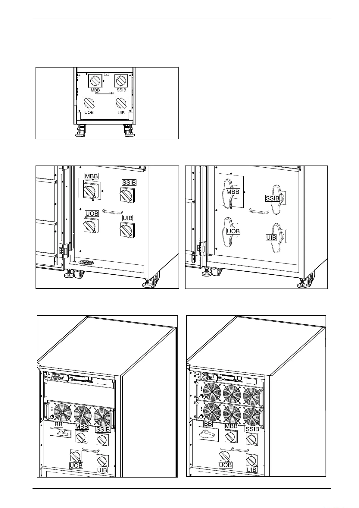
Location of Breakers...................................................................................9
Overview of Single UPS............................................................................10
Overview of 1+1 Redundant Parallel System with Common Battery
Bank........................................................................................................ 11
Overview of Parallel System ...................................................................... 11
Operation Modes ......................................................................................14
Operation Procedures..............................................................................18
View System Status Information ................................................................18
Start Up a Single UPS in Normal Mode ......................................................18
Transfer a Single UPS from Normal Mode to Static Bypass Mode.................19
Transfer a Single UPS from Static Bypass Mode to Normal Mode.................19
Transfer a Single UPS from Normal Mode to Maintenance Bypass
Mode.......................................................................................................20
Transfer a Single UPS from Maintenance Bypass Mode to Normal
Mode.......................................................................................................20
Transfer a Parallel System from Normal Mode to Maintenance Bypass
Mode.......................................................................................................21
Transfer a Parallel System from Maintenance Bypass Mode to Normal
Mode.......................................................................................................22
Isolate a Single UPS from the Parallel System ............................................22
Start Up and Add a UPS to a Running Parallel System ................................23
Configuration .............................................................................................25
Default Settings........................................................................................25
Set the Display Language .........................................................................26
Configure the Display Settings...................................................................27
Configure the Network Settings .................................................................27
Change the Display Password...................................................................28
Set the Date and Time ..............................................................................28
Configure the UPS Settings.......................................................................29
Configure the Output Settings....................................................................29
Configure the Battery Settings ...................................................................30
Configure the Input Contacts and Output Relays.........................................31
Configure Life Cycle Monitoring .................................................................33
Enable/Disable Buzzer..............................................................................34
Maintenance ..............................................................................................35
Parts Replacement ...................................................................................35
Determine if you need a Replacement Part ...........................................35
Replace the Air Filter ................................................................................35
990-5995B-001 3

60-200 kVA
Replace a Battery String ...........................................................................36
Troubleshooting ........................................................................................39
View the Active Alarms..............................................................................39
Clear Alarm..............................................................................................39
View the Log ............................................................................................39
Calibrate the Display.................................................................................40
4 990-5995B-001
Important Safety Instructions — SAVE THESE
INSTRUCTIONS 60-200 kVA
Important Safety Instructions — SAVE THESE
INSTRUCTIONS
Read these instructions carefully and look at the equipment to become familiar
with it before trying to install, operate, service or maintain it. The following safety
messages may appear throughout this manual or on the equipment to warn of
potential hazards or to call attention to information that clarifies or simplifies a
procedure.
The addition of this symbol to a “Danger” or “Warning” safety
message indicates that an electrical hazard exists which will result in
personal injury if the instructions are not followed.
This is the safety alert symbol. It is used to alert you to potential
personal injury hazards. Obey all safety messages with this symbol
to avoid possible injury or death.
DANGER
DANGER indicates a hazardous situation which, if not avoided, will result in
death or serious injury.
Failure to follow these instructions will result in death or serious injury.
WARNING
WARNING indicates a hazardous situation which, if not avoided, could result
in death or serious injury.
Failure to follow these instructions can result in death, serious injury, or
equipment damage.
CAUTION
CAUTION indicates a hazardous situation which, if not avoided, could result in
minor or moderate injury.
Failure to follow these instructions can result in injury or equipment
damage.
NOTICE
NOTICE is used to address practices not related to physical injury. The safety
alert symbol shall not be used with this type of safety message.
Failure to follow these instructions can result in equipment damage.
Please Note
Electrical equipment should only be installed, operated, serviced, and maintained
by qualified personnel. No responsibility is assumed by Schneider Electric for any
consequences arising out of the use of this material.
A qualified person is one who has skills and knowledge related to the construction,
installation, and operation of electrical equipment and has received safety training
to recognize and avoid the hazards involved.
990-5995B-001 5
60-200 kVA
Important Safety Instructions — SAVE THESE
INSTRUCTIONS
Electromagnetic Compatibility
NOTICE
RISK OF ELECTROMAGNETIC DISTURBANCE
This is a product Category C3 according to IEC 62040-2. This is a product for
commercial and industrial applications in the second environment - installation
restrictions or additional measures may be needed to prevent disturbances. The
second environment includes all commercial, light industry, and industrial
locations other than residential, commercial, and light industrial premises
directly connected without intermediate transformer to a public low-voltage
mains supply. The installation and cabling must follow the electromagnetic
compatibility rules, e.g.:
• the segregation of cables,
• the use of shielded or special cables when relevant,
• the use of grounded metallic cable tray and supports.
Failure to follow these instructions can result in equipment damage.
Safety Precautions
DANGER
HAZARD OF ELECTRICAL SHOCK, EXPLOSION OR ARC FLASH
All safety instructions in this document must be read, understood and followed.
Failure to follow these instructions will result in death or serious injury.
DANGER
HAZARD OF ELECTRICAL SHOCK, EXPLOSION OR ARC FLASH
After the UPS system has been electrically wired, do not start up the system.
Start-up must only be performed by Schneider Electric.
Failure to follow these instructions will result in death or serious injury.
6 990-5995B-001
Overview 60-200 kVA
Overview
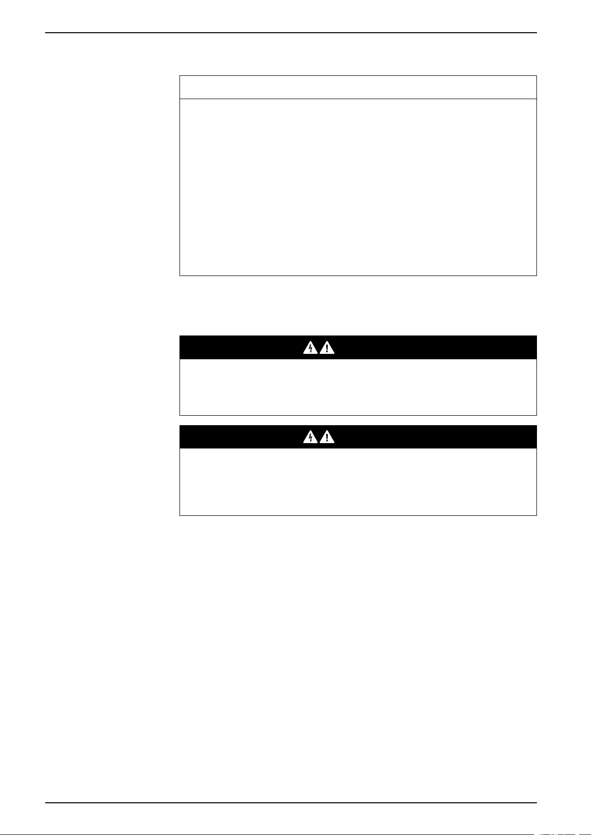
User Interface
Status LEDs
LED State Description
ALARM Steady red Critical alarm
Flashing red Warning alarm
Off No alarm condition
BYPASS Steady yellow The load is supplied by the bypass source
Flashing yellow There is an alarm condition on the bypass source
Off The load is not supplied by the bypass source
BATTERY Steady yellow The load is supplied by the battery source
Flashing yellow The battery source is unavailable
Off The load is not supplied by the battery source
INVERTER Steady green Inverter on
Off Inverter off
EPO
Only use the EPO button in case of emergency.
It can be configured wether, when the EPO button is pressed, the UPS should:
• turn off the rectifier, inverter, charger, and static bypass and stop supplying
the load immediately, or
• transfer to static bypass mode and keep supplying the load.
DANGER
HAZARD OF ELECTRIC SHOCK, EXPLOSION, OR ARC FLASH
The UPS control circuit will remain active after the EPO has been pushed if
mains is available.
Failure to follow these instructions will result in death or serious injury.
990-5995B-001 7

60-200 kVA Overview
Display Menu Tree
•Status
◦Input
◦Output
◦Battery
◦Bypass
◦Status information
•Alarms
◦Active alarms
◦Enable buzzer/Disable buzzer
◦Log
•Settings
◦General settings
–Language settings
–Display settings
–Network
–Password settings
–Date and time
–UPS information
◦Advanced settings
–System settings
–Output settings
–Bypass settings
–Parallel settings
–Battery settings
–Contacts and relays
•Service
◦Battery self-test
◦Export data to USB
◦Display calibration
◦LCM settings
•Control
◦Inverter ON/OFF
◦Clear alarm(s)
◦Self-test
•About
8 990-5995B-001
Overview 60-200 kVA
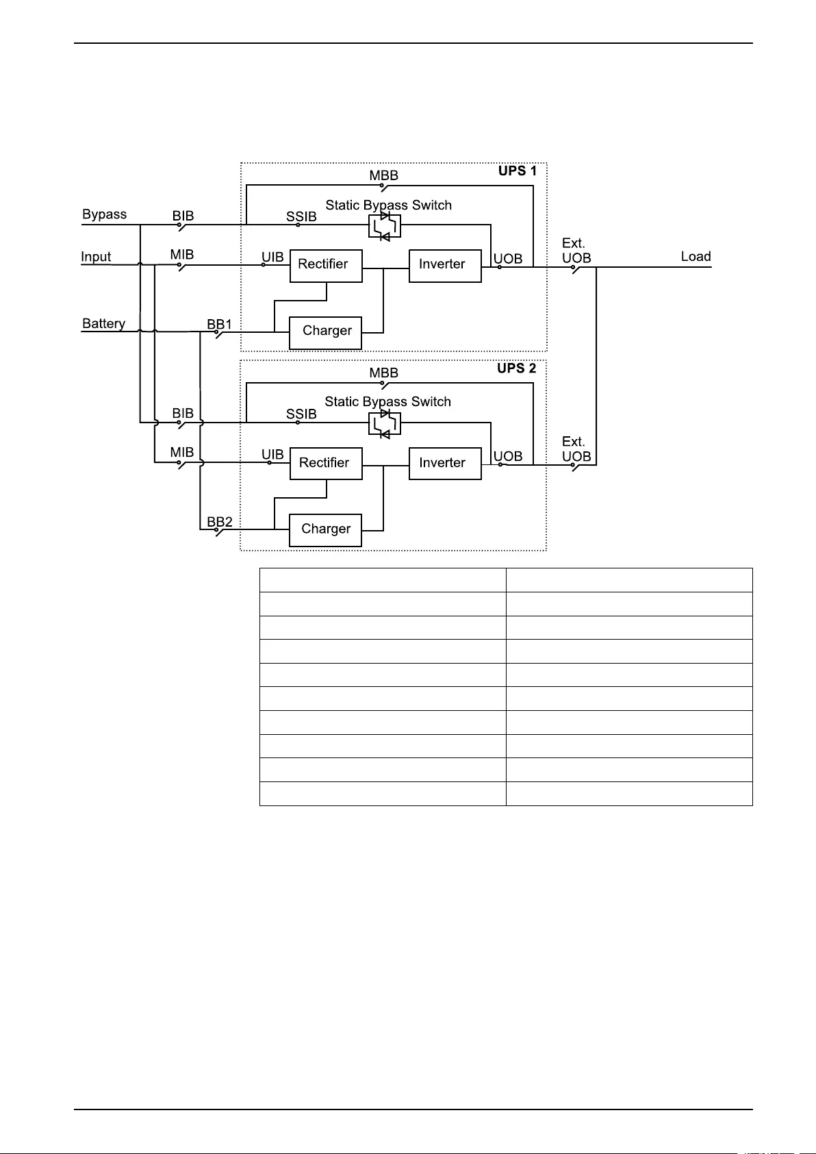
Overview of 1+1 Redundant Parallel System with Common
Battery Bank
NOTE: Common battery banks are not supported in systems with internal
batteries.
MIB Mains input breaker
BIB Bypass input breaker
UIB Unit input breaker
SSIB Static switch input breaker
UOB Unit output breaker
Ext. UOB External unit output breaker
MBB Maintenance bypass breaker
Ext. MBB External maintenance bypass breaker
BB1 Battery breaker 1
BB2 Battery breaker 2
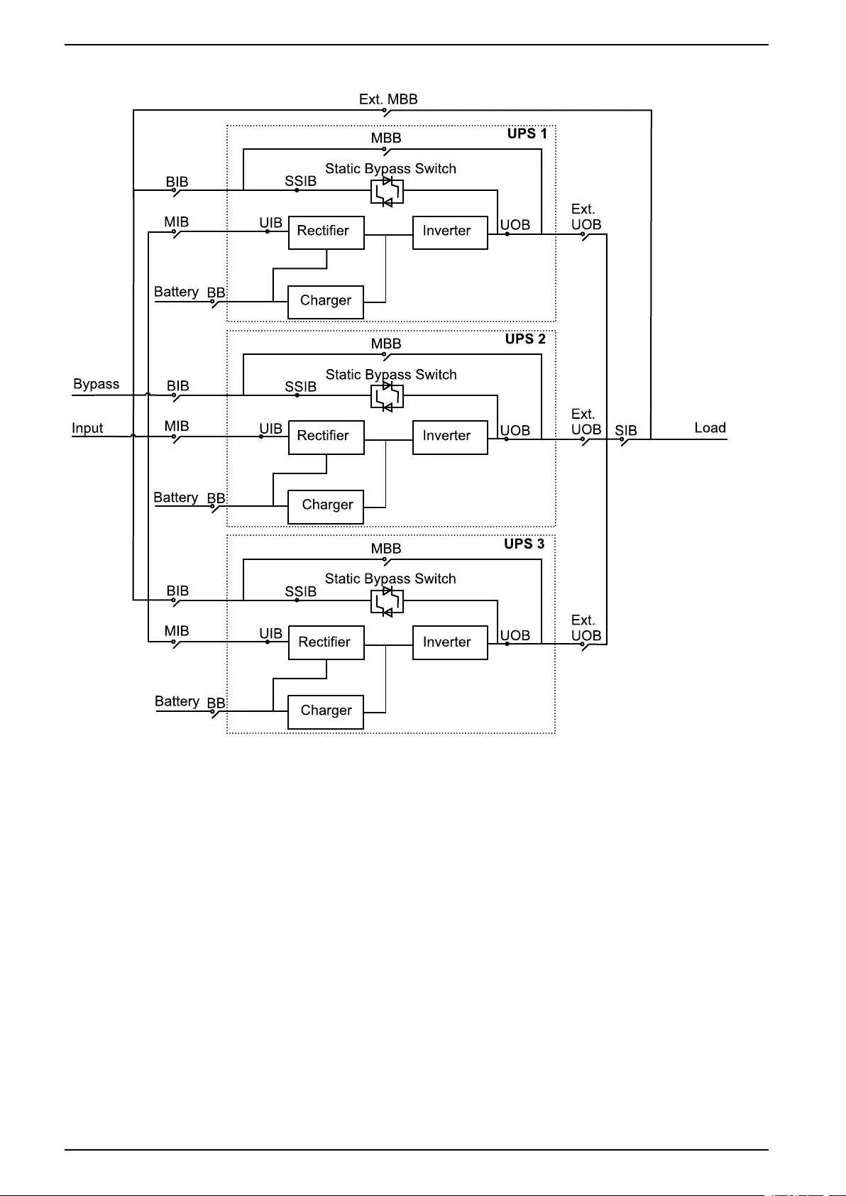
Overview of Parallel System
NOTE: In parallel systems with an external maintenance bypass breaker Ext.
MBB, the maintenance bypass breakers MBB must be padlocked in the open
position.
990-5995B-001 11
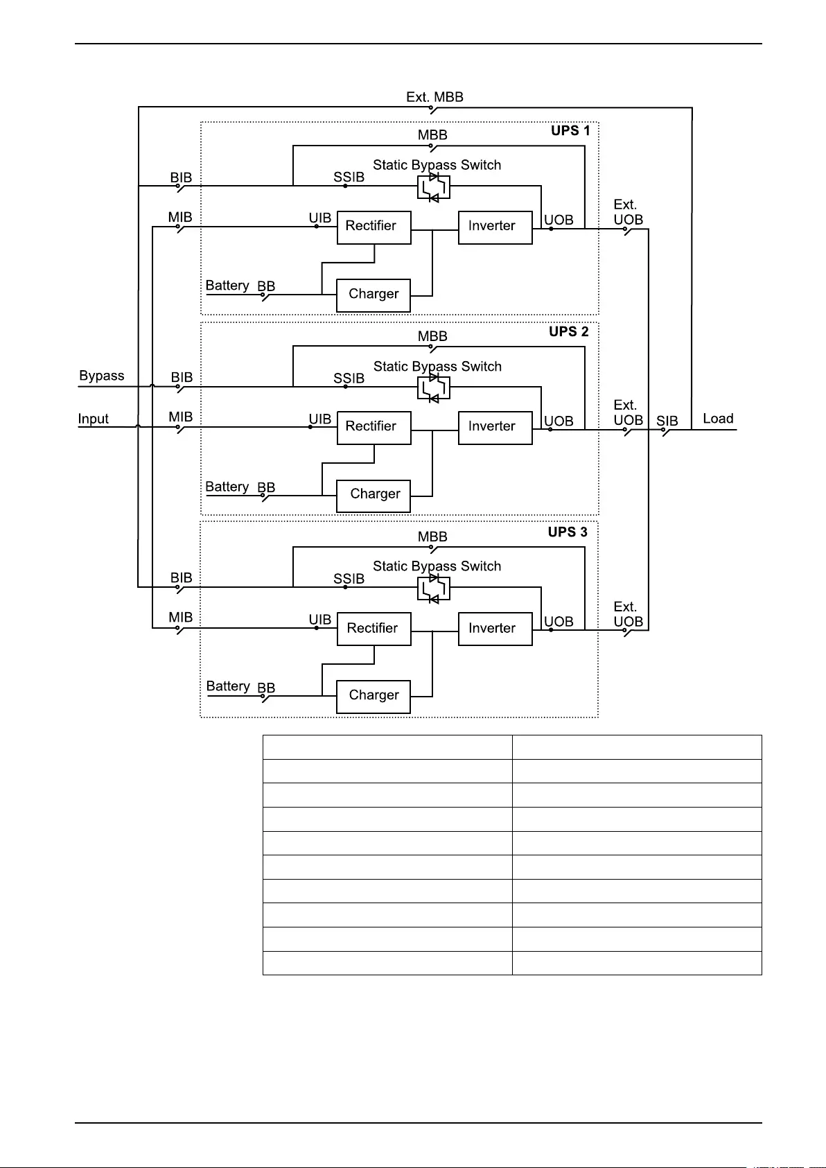
Overview 60-200 kVA
UPSs for Internal Batteries
MIB Mains input breaker
BIB Bypass input breaker
UIB Unit input breaker
SSIB Static switch input breaker
UOB Unit output breaker
Ext. UOB External unit output breaker
MBB Maintenance bypass breaker
Ext. MBB External maintenance bypass breaker
SIB System isolation breaker
BB Battery breaker
990-5995B-001 13
60-200 kVA Operation Modes
Operation Modes
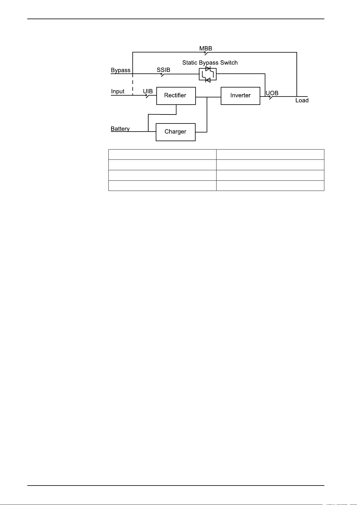
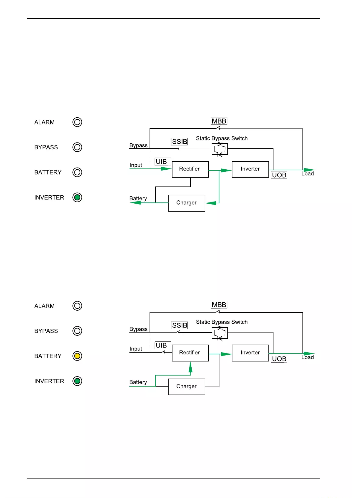
Normal Mode
The UPS provides power to the connected load from mains. The UPS converts
mains to conditioned power for the connected load while recharging the batteries
(float or boost charge).
LED Status Power Flow
Battery Mode
The UPS transfers to battery mode if the mains supply fails. The UPS provides
power to the connected load from the connected batteries for a finite period. When
the mains supply returns, the UPS transfers back to normal mode.
LED Status Power Flow
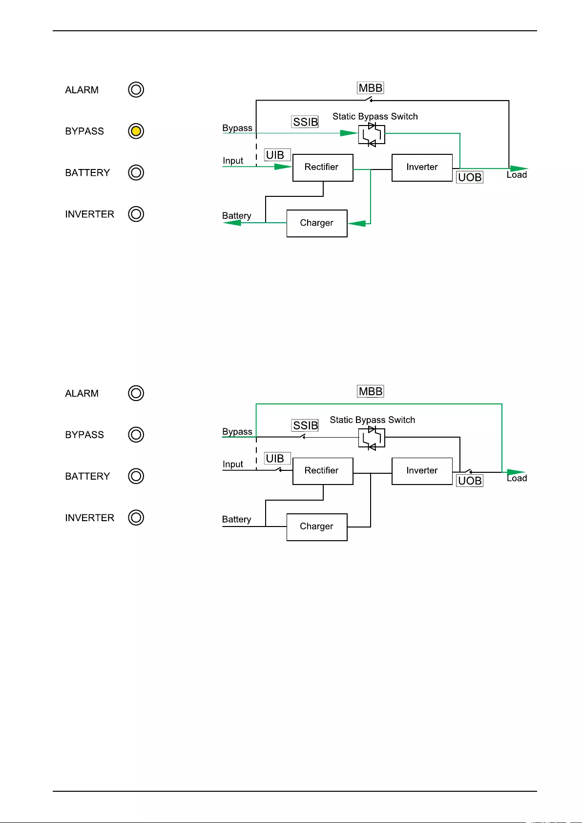
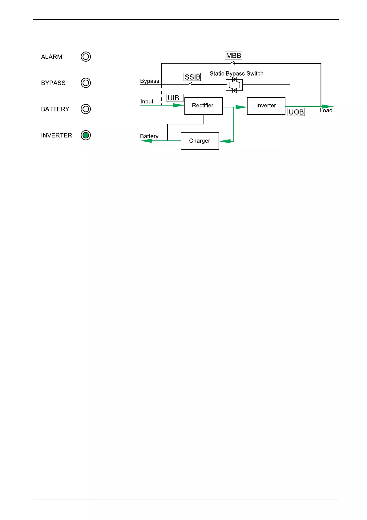
Static Bypass Mode
The UPS supplies the load with power from the bypass source. If the conditions
for normal or battery mode are not met, the load will be transferred from the
inverter to the bypass source with no interruption in power to the load.
14 990-5995B-001
Operation Modes 60-200 kVA
LED Status Power Flow
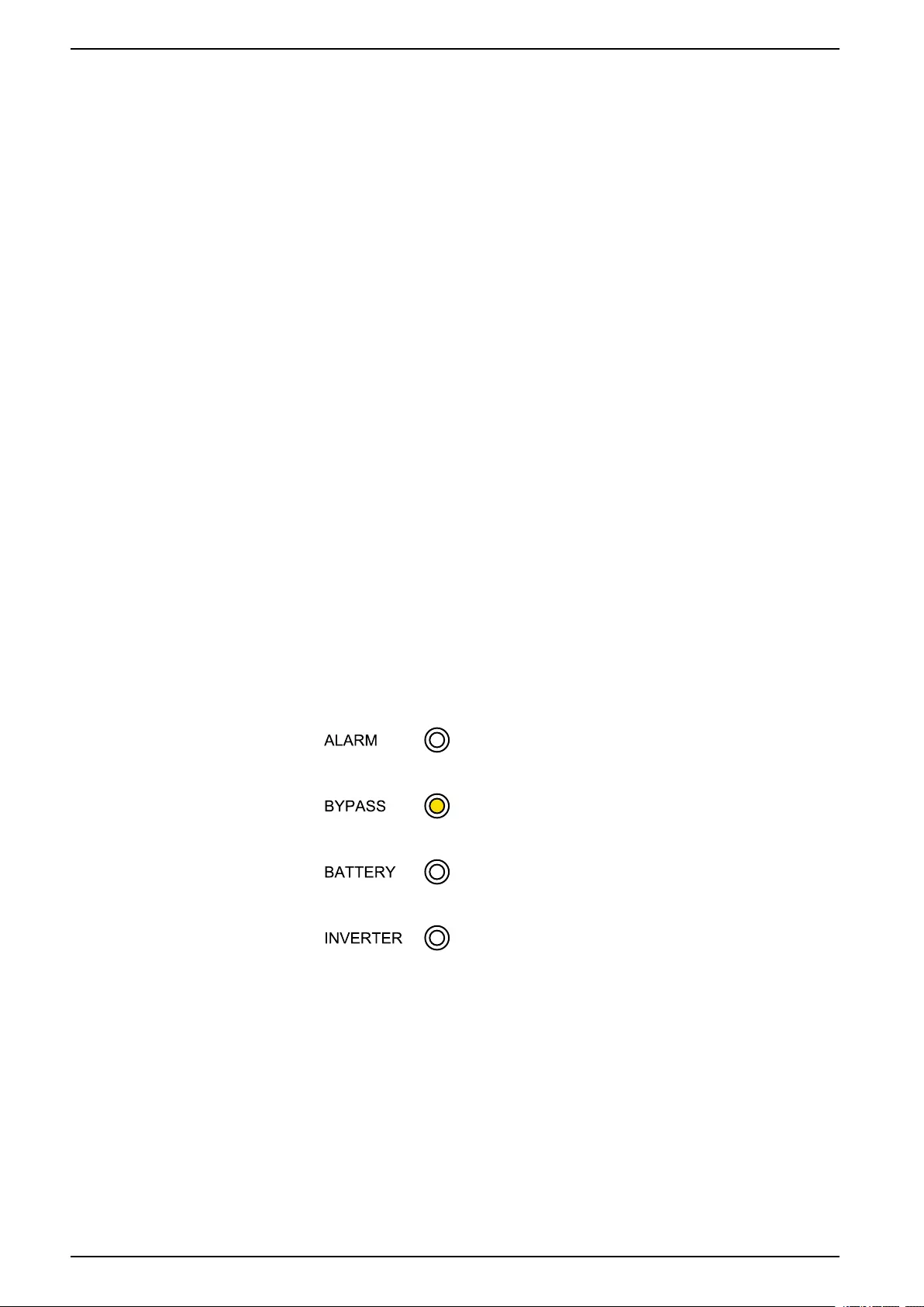
Maintenance Bypass Mode
In maintenance bypass mode, the mains is sent via the (external) maintenance
bypass breaker (MBB) to the load. Battery backup is not available in maintenance
bypass mode.
LED Status Power Flow
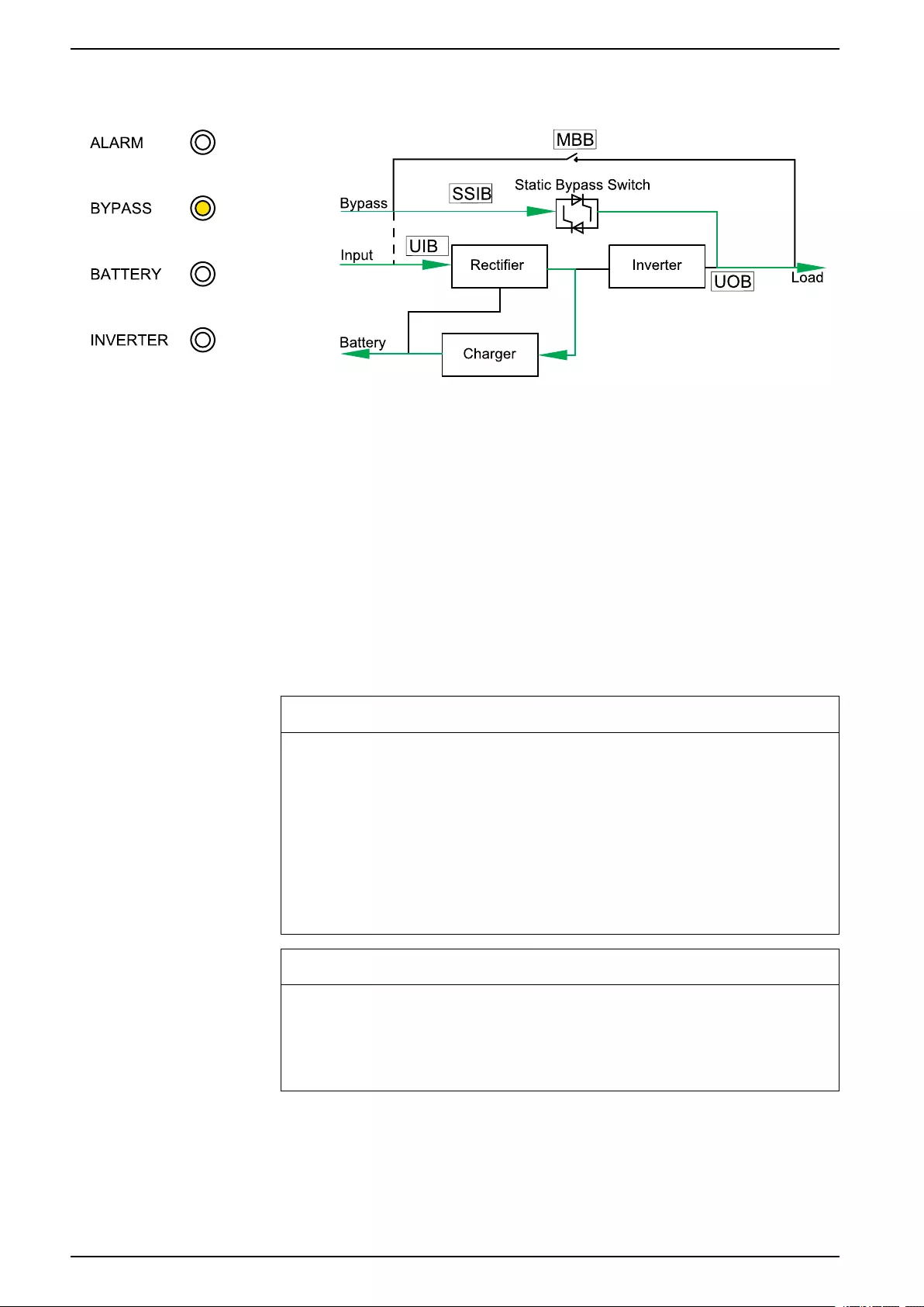
ECO Mode
In ECO mode the UPS is configured to use static bypass mode as the preferred
operation mode under predefined circumstances. The inverter is in standby in
ECO mode and in case of interruption to the mains, the UPS transfers to battery
mode and the load is supplied from the inverter.
990-5995B-001 15
60-200 kVA Operation Modes
LED Status Power Flow
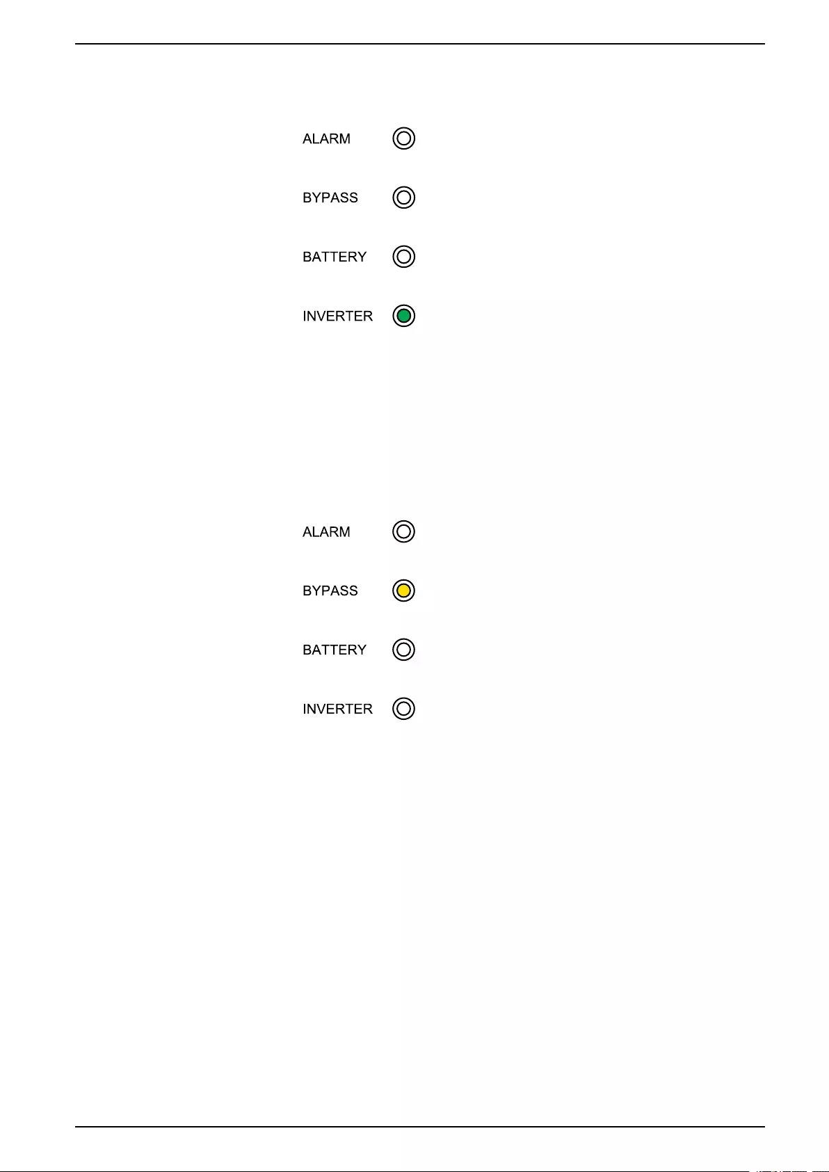
Autostart Mode
When autostart is enabled, the UPS automatically restarts the inverter and bypass
when the mains returns. By default autostart is enabled.
NOTE: If autostart is disabled, the inverter and bypass will not restart
automatically when the mains return.
Frequency Converter Mode
In frequency converter mode, the UPS presents a stable output frequency (at 50
or 60 Hz) and the static bypass switch is not available.
NOTICE
RISK OF EQUIPMENT DAMAGE OR LOAD DROP
In frequency converter mode the UPS cannot run in static bypass or
maintenance bypass mode. Before turning the UPS into frequency converter
mode, you must contact a Schneider Electric-certified partner to make sure
• the static switch input breaker SSIB and the maintenance bypass breaker
MBB are in the OFF (opened) position (Schneider Electric strongly
recommends to lock these with a padlock available from Schneider Electric)
• no cables are connected to the bypass terminals
Failure to follow these instructions can result in equipment damage.
NOTICE
RISK OF LOAD DROP
When the unit output breaker UOB is opened while the UPS is in frequency
converter mode, the load will not be transferred, but will be dropped.
Failure to follow these instructions can result in equipment damage.
16 990-5995B-001
60-200 kVA Operation Procedures
Operation Procedures
View System Status Information
1. From the home screen of the display select Status.
2. You can now select to view status information for:
–Input
–Output
–Battery
–Bypass
–Status information
Start Up a Single UPS in Normal Mode
NOTE: When the UPS starts up, any stored settings will be used.
1. Check that all breakers are in the OFF (open) position.
2. Turn the static switch input breaker SSIB to the ON (closed) position.
The display turns on and the Home screen is shown.
3. Turn the unit output breaker UOB to the ON (closed) position.
Wait approximately 30 seconds until the bypass LED turns steady yellow. The
UPS starts up in static bypass mode.
4. Turn the unit input breaker UIB to the ON (closed) position.
The rectifier ramps up. When the rectifier is ready, the inverter starts up and
synchronizes with bypass.
The LEDs on the user interface show as follows:
18 990-5995B-001
Operation Procedures 60-200 kVA
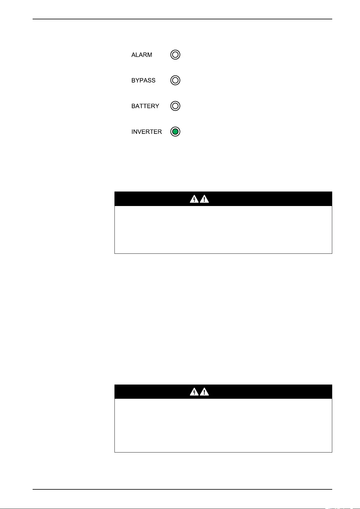
5. Wait approximately 20 seconds until inverter LED turns steady green, the
UPS transfers automatically from static bypass mode to normal mode.
The LEDs on the user interface show as follows:
Transfer a Single UPS from Normal Mode to Static Bypass Mode
1. From the home screen on the display select Control > Inverter OFF.
The UPS transfers from normal to static bypass mode without an interruption
to the load.
The LEDs on the user interface show as follows:
Transfer a Single UPS from Static Bypass Mode to Normal Mode
NOTE: The UPS will normally transfer automatically from static bypass to
normal mode. This procedure can be used to manually transfer to normally
mode if the bypass frequency or voltage is above the specified limits.
990-5995B-001 19
60-200 kVA Operation Procedures
1. From the home screen of the display select Control > Inverter ON.
The LEDs on the user interface show as follows:
Transfer a Single UPS from Normal Mode to Maintenance Bypass
Mode
1. From the home screen on the display select Control > Inverter OFF.
2. Turn the maintenance bypass breaker MBB to the ON (closed) position.
The load is now supplied via the maintenance bypass breaker.
3. Turn the battery breaker(s) BB to the OFF (open) position.
4. Turn the unit input breaker UIB to the OFF (open) position.
5. Turn the static switch input breaker SSIB to the OFF (open) position.
6. Turn the unit output breaker UOB to the OFF (open) position.
DANGER
HAZARD OF ELECTRIC SHOCK, EXPLOSION, OR ARC FLASH
• Wait at least 5 minutes before removing the cover of the UPS after the
display has turned off to allow for the capacitors to fully discharge.
• Always measure for hazardous voltages on all terminals before working on
the UPS.
Failure to follow these instructions will result in death or serious injury.
Transfer a Single UPS from Maintenance Bypass Mode to Normal
Mode
1. Check that all breakers except maintenance bypass breaker MBB are in the
OFF (open) position.
2. Turn the static switch input breaker SSIB to the ON (closed) position.
The display turns on and the Home screen is shown.
3. Turn the unit output breaker UOB to the ON (closed) position.
The UPS starts up in static bypass mode.
4. Turn the unit input breaker UIB to the ON (closed) position.
The rectifier ramps up.
5. Turn the battery breaker(s) BB to the ON (closed) position.
20 990-5995B-001
Operation Procedures 60-200 kVA
6. Turn the maintenance bypass breaker MBB to the OFF (open) position.
The UPS automatically transfers to normal mode.
Transfer a Parallel System from Normal Mode to Maintenance
Bypass Mode
DANGER
HAZARD OF ELECTRIC SHOCK, EXPLOSION, OR ARC FLASH
To completely isolate the UPSs, all upstream breakers (mains input breakers
MIB, bypass input breakers BIB, and system isolation breaker SIB) must be in
the OFF (open) position.
Failure to follow these instructions will result in death or serious injury.
1. From the home screen on the display select Control > Inverter OFF >
Parallel OFF.
All UPSs will turn to static bypass mode.
2. Turn the external maintenance bypass breaker Ext. MBB to the ON (closed)
position.
The load is now supplied via the external maintenance bypass breaker.
3. Turn the battery breakers BB of all UPSs to the OFF (open) position.
4. Turn the mains input breakers MIB and the bypass input breakers BIB of all
UPSs to the OFF (open) position if available.
5. Turn the unit input breakers UIB and the static switch input breakers SSIB of
all UPSs to the OFF (open) position.
6. Turn the unit output breakers UOB of all UPSs and the system isolation
breaker SIB to OFF (open) position.
DANGER
HAZARD OF ELECTRIC SHOCK, EXPLOSION, OR ARC FLASH
• Wait at least 5 minutes before removing the cover of the UPS after the
display has turned off to allow for the capacitors to fully discharge.
• Always measure for hazardous voltages on all terminals before working on
the UPS.
Failure to follow these instructions will result in death or serious injury.
990-5995B-001 21
60-200 kVA Operation Procedures
Transfer a Parallel System from Maintenance Bypass Mode to
Normal Mode
1. Check that:
a. All upstream breakers (mains input breakers MIB, bypass input breakers
BIB, and system isolation breaker SIB) are in the OFF (open) position.
b. All UPS breakers (unit input breakers UIB, static switch input breakers
SSIB, and unit output breakers UOB) and the external unit output
breakers Ext. UOB are in the ON (closed) position.
c. The battery breakers BB are in the OFF (open) position.
2. Turn the system isolation breaker SIB and the unit output breakers UOB of all
UPSs to ON (closed) position.
3. Turn the bypass input breakers BIB and the static switch input breakers of all
UPSs to the ON (closed) position.
Wait approximately 20 seconds until the bypass LEDs turn yellow.
4. Turn the external maintenance bypass breaker Ext. MBB to the OFF (open)
position.
5. Turn the mains input breakers MIB and the unit input breakers UIB of all
UPSs to the ON (closed) position.
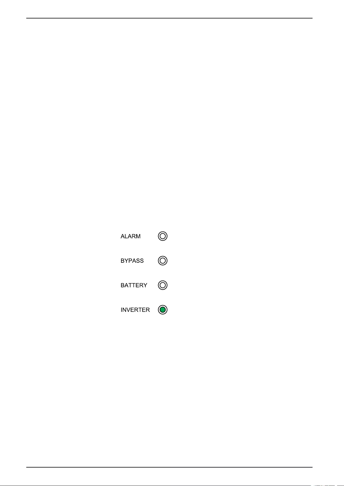
When the inverter LED turns steady green, the parallel system automatically
transfers from static bypass to normal mode.
6. Turn the battery breakers of all UPSs to the ON (closed) position.
The LEDs on the user interfaces show as follows:
The parallel system is now in normal mode.
Isolate a Single UPS from the Parallel System
Use this procedure to shut down one UPS in a running parallel system.
NOTE: Before initiating this procedure, ensure that the remaining UPS units
can supply the load.
1. Turn the static switch input breaker SSIB of the UPS to the OFF (open)
position.
2. From the home screen on the display select Control > Inverter OFF > Single
OFF.
3. Turn the battery breaker(s) BB of the UPS to the OFF (open) position.
4. Turn the mains input breaker MIB of the UPS to the OFF (open) position.
5. Turn the bypass input breaker BIB of the UPS to the OFF (open) position.
22 990-5995B-001
Operation Procedures 60-200 kVA
6. Turn the external unit output breaker Ext. UOB of the UPS to the OFF (open)
position.
DANGER
HAZARD OF ELECTRIC SHOCK, EXPLOSION, OR ARC FLASH
• Wait at least 5 minutes before removing the cover of the UPS after the
display has turned off to allow for the capacitors to fully discharge.
• Always measure for hazardous voltages on all terminals before working on
the UPS.
Failure to follow these instructions will result in death or serious injury.
Start Up and Add a UPS to a Running Parallel System
Use this procedure to start up a UPS and add it to a running parallel system.
IMPORTANT: Before a UPS can be added to a parallel system, the parallel
system must be configured by Schneider Electric.
DANGER
HAZARD OF ELECTRIC SHOCK, EXPLOSION, OR ARC FLASH
Ensure that the external unit output breaker Ext. UOB, the mains input breaker
MIB, and the bypass input breaker BIB for the UPS are in the OFF (open)
position before connecting power cables to the UPS.
Failure to follow these instructions will result in death or serious injury.
1. On the new UPS check that:
a. All UPS breakers (unit input breaker UIB, static switch input breaker
SSIB, and unit output breaker UOB) and the external unit output breaker
Ext. UOB are in the OFF (open) position.
b. The battery breaker(s) BB are in the OFF (open) position.
2. Turn the external unit output breaker Ext. UOB of the UPS to the ON (closed)
position.
3. Turn the mains input breaker MIB and the bypass input breaker BIB of the
UPS to the ON (closed) position.
4. Turn the unit input breaker UIB, the static switch input breaker SSIB, and the
unit output breaker UOB of the UPS to the ON (closed) position.
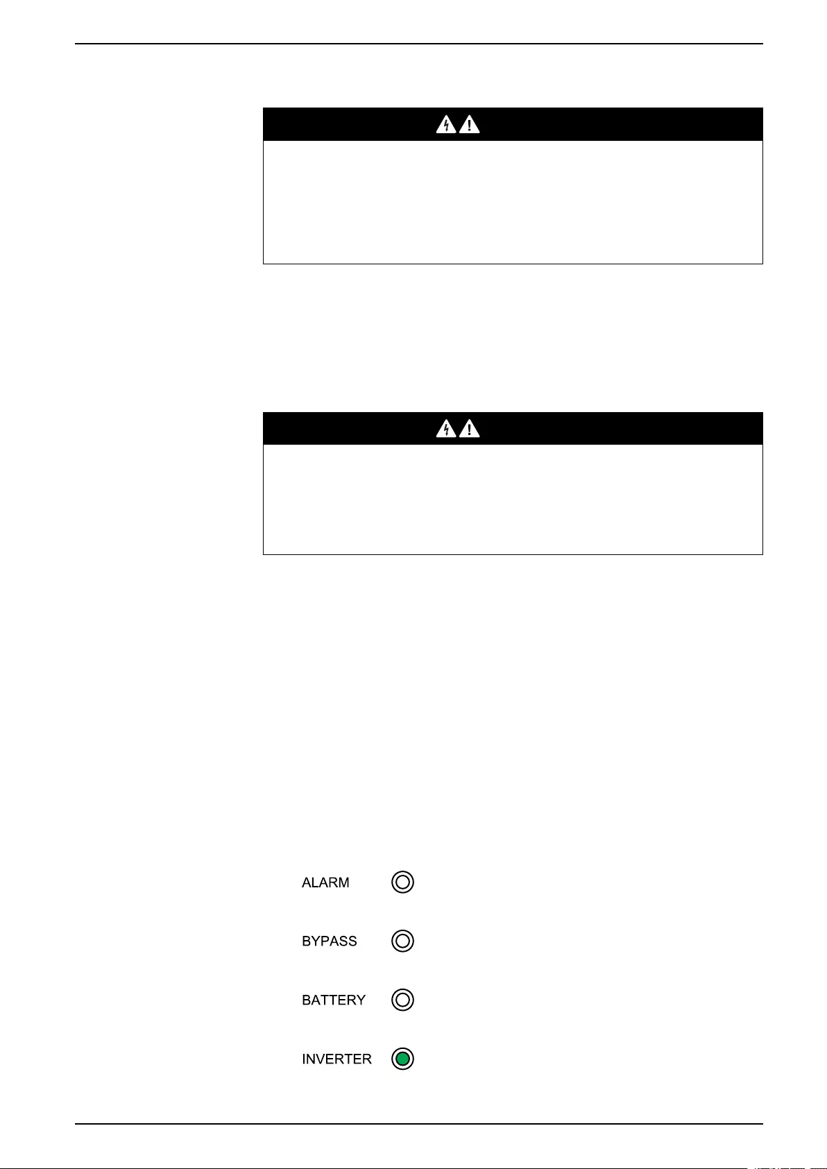
When the inverter LED turns steady green, the UPS has joined the running
parallel system.
The LEDs on the user interface show as follows:
990-5995B-001 23


Configuration 60-200 kVA
Configuration
Default Settings
Setting Default Value Available Settings
UPS for External Batteries UPSs for Internal Batteries
Display brightness 63 63 1-63
Backlight timeout (sec) 60 60 10-255
Device ID 1 1 1-255
Baud rate 9600 9600 2400, 4800, 9600, 14400,
19200
Password timeout (minutes) 3 3 0-120
Date 2015-01-01 2015-01-01
Time 00:00:00 00:00:00
Operation mode Single mode Single mode Single mode,ECO mode,
Parallel mode,Parallel ECO
mode
Autostart Enable Enable Enable,Disable
Self-aging load rate (%) 60 60 18-100
Frequency converter mode Disable Disable Disable,Enable
LBS operation LBS disabled LBS disabled LBS disabled,LBS master,
LBS slave
Transfer delay (sec) 1 1 0- 20
Par. transfer delay (sec) 10 10 0 -200
EPO transfers to bypass Disable Disable Disable,Enable
Output frequency (Hz) 50 50 50, 60
Output voltage (V) 400 400 380, 400, 415
Output volt. compensation
(%)
0.0 0.0 -5.0, -4.5, -4.0, -3.5, -3.0, -2.5,
-2.0, -1.5, -1.0, -0.5, 0.0, 0.5,
1.0, 1.5, 2.0, 2.5, 3.0, 3.5, 4.0,
4.5, 5.0
Min. bypass RMS voltage (V) -10 -10 -10, -15, -20, -30
Max. bypass RMS voltage (V) 10 10 10, 15, 20, 25
Bypass frequency range (%) 10 10 1, 2, 4, 5, 10
Output slew rate (Hz/sec) 0.5 0.5 0.5-2.0
Use bypass ON with
overheated SCR
Disable Disable Disable,Enable
Allowed transfers to bypass 10 10 3-10
Parallel ID 1 1 1-6
Number of parallel UPSs 2 2 2-6
Number of par. redundant
UPSs
0 0 0, 1, 2,3, 4, 5
Number of battery strings 1 3 1-8
Battery blocks per string 32 40 32, 34, 36, 38, 40, 42, 44, 46,
48, 50
Battery block capacity (Ah) 7 7 7-2000
Periodic boost charge (M) 0 0 0-24
Maximum charge current 0.1 0.1 0.05-0.15
990-5995B-001 25

60-200 kVA Configuration
Setting Default Value Available Settings
UPS for External Batteries UPSs for Internal Batteries
Float voltage (V) 2.25 2.25 2.20-2.29
Boost voltage (V) 2.30 2.30 2.30-2.40
Boost charge duration
(minutes)
240 240 0-999
Float temp. compensation 0.000 0.000 0.000-0.007
Boost charge Disable Disable Enable,Disable
Alarm for no battery
connected
Enable Enable Enable,Disable
Common battery bank No No Yes,No
External batt. breaker status Enable Enable Disable,Enable
Battery breaker trip Enable Enable Disable,Enable
Backfeed on bypass Enable Enable Disable,Enable
External MBB status Disable Disable Disable,Enable
OUT 01 Disable Disable Disable,Common alarm,In
normal operation,On battery,
Static bypass,Maintenance
bypass,Output overload,Fan
inoperable,Battery
inoperable,Battery
disconnected,Battery voltage
low,Input out of tol.,Bypass
out of tol.,EPO active
OUT 02 Disable Disable
OUT 03 Disable Disable
OUT 04 Disable Disable
IN 01 Disable Disable Disable,INV ON,INV OFF,
Battery inoperable,Genset
on,Custom alarm 3,Custom
alarm 4,Disable ECO,Force
INV OFF
IN 02 Disable Disable
IN 03 Disable Disable
IN 04 Disable Disable
Self-test settings Disable auto self-test Disable auto self-test Disable auto self-test,self-
test every month,self-test
every day
Self-test every 0 Day 0 hour 0 minute 0 Day 0 hour 0 minute
Self-test type Customize Customize 10 seconds,10 minutes,EOD,
-10%,Customize
Air filter check (months) 3 3 0, 3, 4, 5, 12
Air filter counter (days) 0 0
Set the Display Language
1. From the home screen of the display select Settings > General settings >
Language settings.
2. Select your preferred language.
3. Tap Save settings.
26 990-5995B-001
Configuration 60-200 kVA
Configure the Display Settings
1. From the home screen of the display select Settings > General settings >
Display settings.
2. Set the Display brightness by choosing a value between 1 and 63.
3. Set the Backlight timeout (sec) by choosing a value between 10 and 255.
4. Tap Save settings.
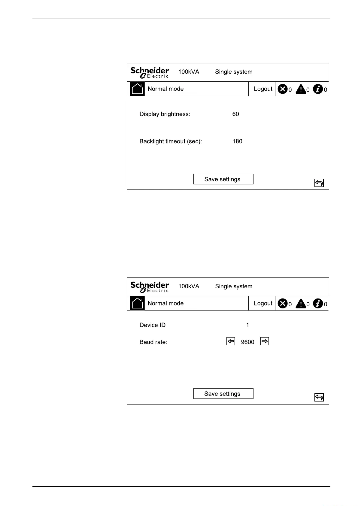
Configure the Network Settings
1. From the home screen of the display select Settings > General settings >
Network.
2. Set the Baud rate for communication using the left and right arrows. Choose
between 2400, 4800, 9600, 14400, and 19200.
3. Tap Save settings.
990-5995B-001 27
60-200 kVA Configuration
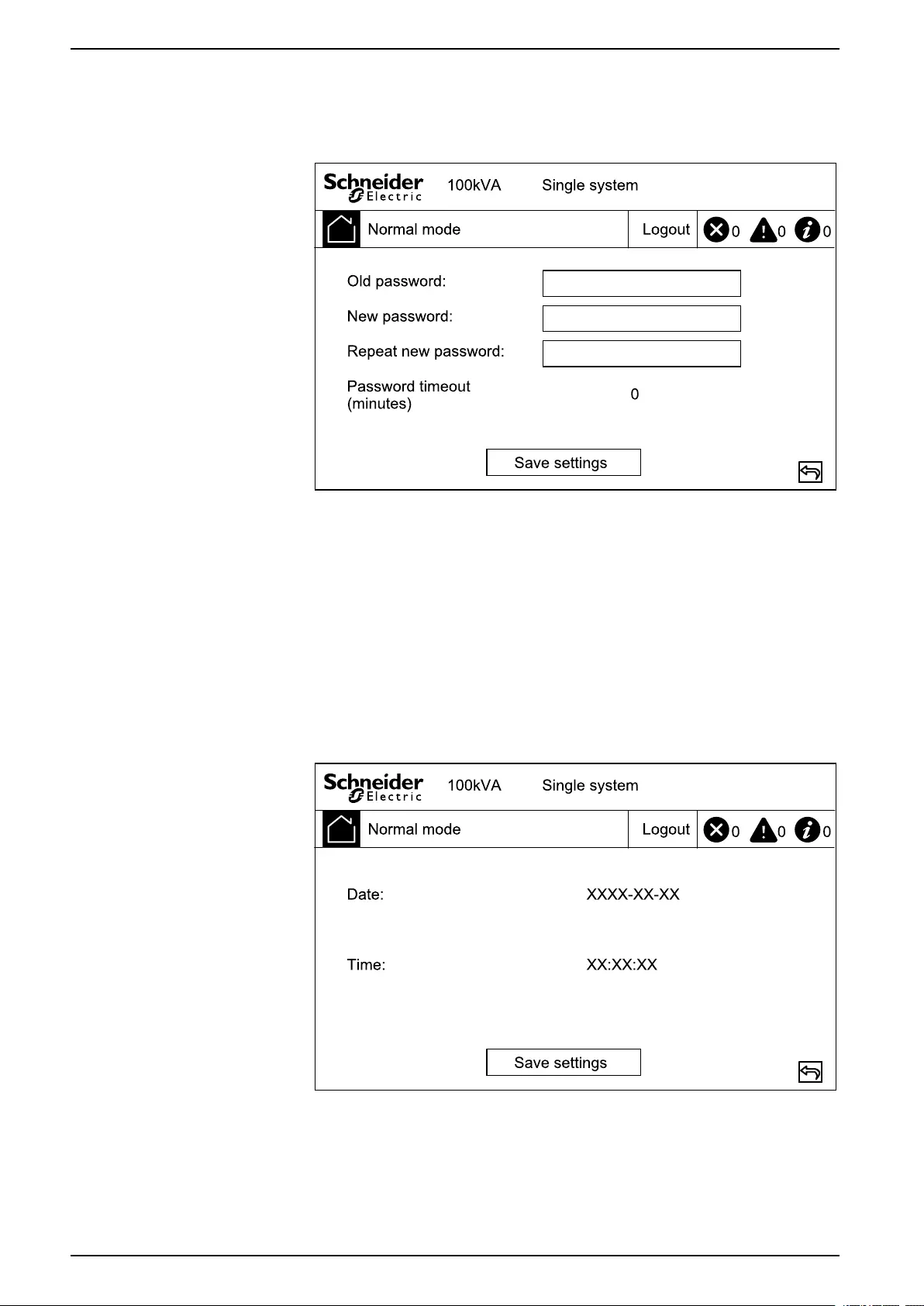
Change the Display Password
1. From the home screen of the display select Settings > General settings >
Password settings.
2. Type in Old password.
3. Type in New password and Confirm new password.
4. Set the time in minutes for automatic log out of the display after inactivity.
Choose a value between 0 and 120.
5. Tap Save settings.
Set the Date and Time
1. From the home screen of the display select Settings > General settings >
Date and time.
2. Set the Date using the keypad.
3. Set the Time using the keypad.
4. Tap Save settings.
28 990-5995B-001
Configuration 60-200 kVA
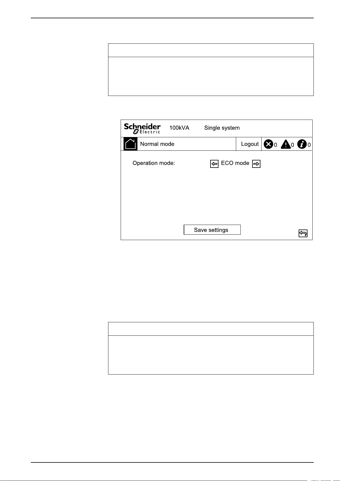
Configure the UPS Settings
NOTICE
RISK OF EQUIPMENT DAMAGE
Only trained personnel following the required training must make modifications
to the UPS system parameters.
Failure to follow these instructions can result in equipment damage.
1. From the home screen of the display select Settings > Advanced settings >
System settings.
2. Set the System mode. Choose between:
– Choose ECO mode to use static bypass mode as the preferred operation
mode.
– Choose Single mode for a single UPS.
3. Tap Save settings.
Configure the Output Settings
NOTICE
RISK OF EQUIPMENT DAMAGE
Only trained personnel following the required training must make modifications
to the UPS system parameters.
Failure to follow these instructions can result in equipment damage.
990-5995B-001 29
60-200 kVA Configuration
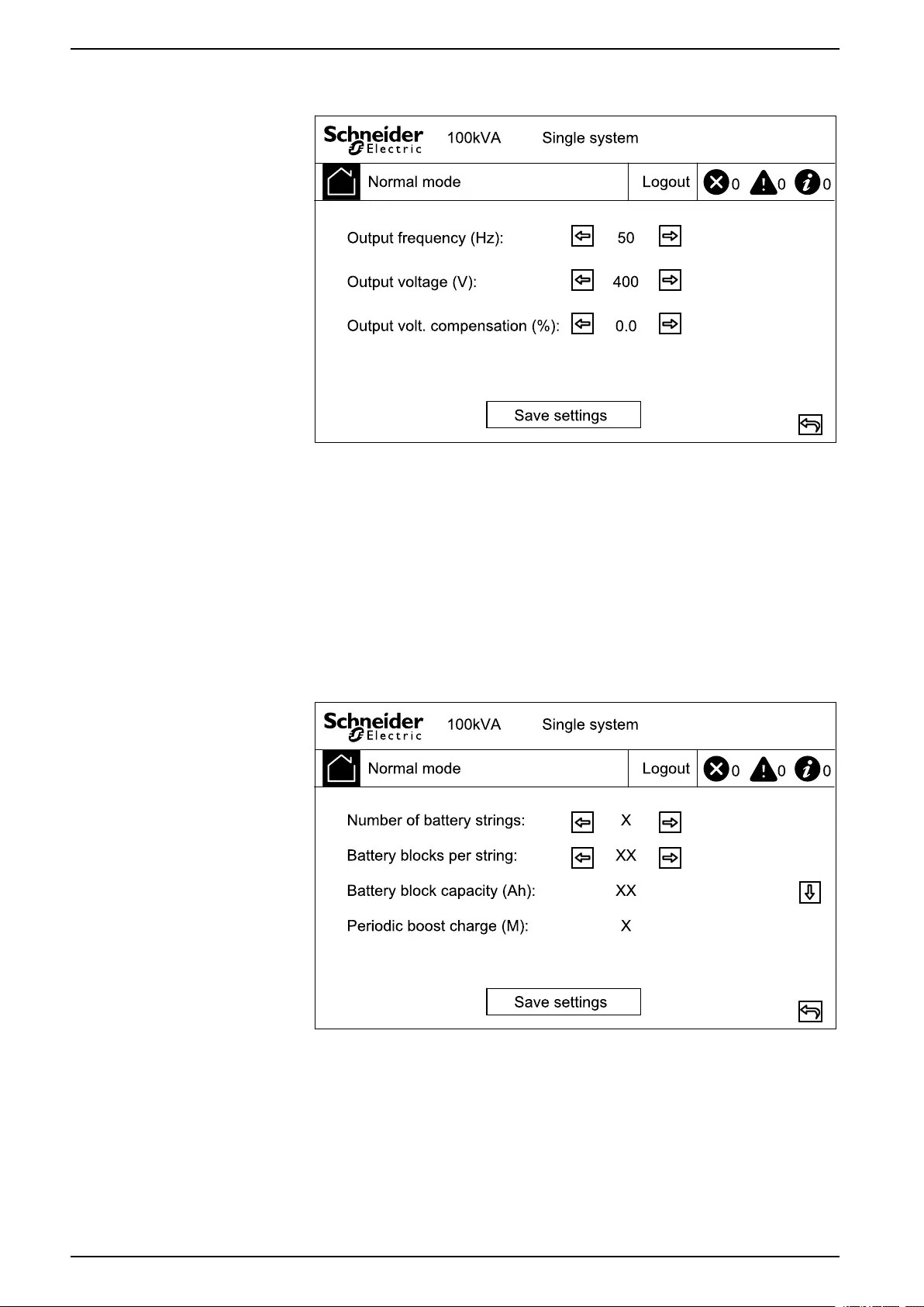
1. From the home screen of the display select Settings > Advanced settings >
Output settings.
2. Set the Output frequency (Hz). Choose between 50 and 60 Hz.
3. Set the Output voltage (V). Choose between 380, 400, and 415 V.
4. Set the output voltage compensation (%). Choose a value between –5 and 5.
5. Tap Save settings.
Configure the Battery Settings
1. From the home screen of the display select Settings > Advanced settings >
Battery settings and configure the following settings.
a. Number of battery strings: Set the number of battery strings in the
battery solution.
b. Battery blocks per string: Set the number of battery blocks in one
battery string.
c. Battery block capacity (Ah): Set the rated capacity of the battery block.
d. Periodic boost charge (M): Set the interval in months for changing from
float charge to boost charge.
30 990-5995B-001
Configuration 60-200 kVA
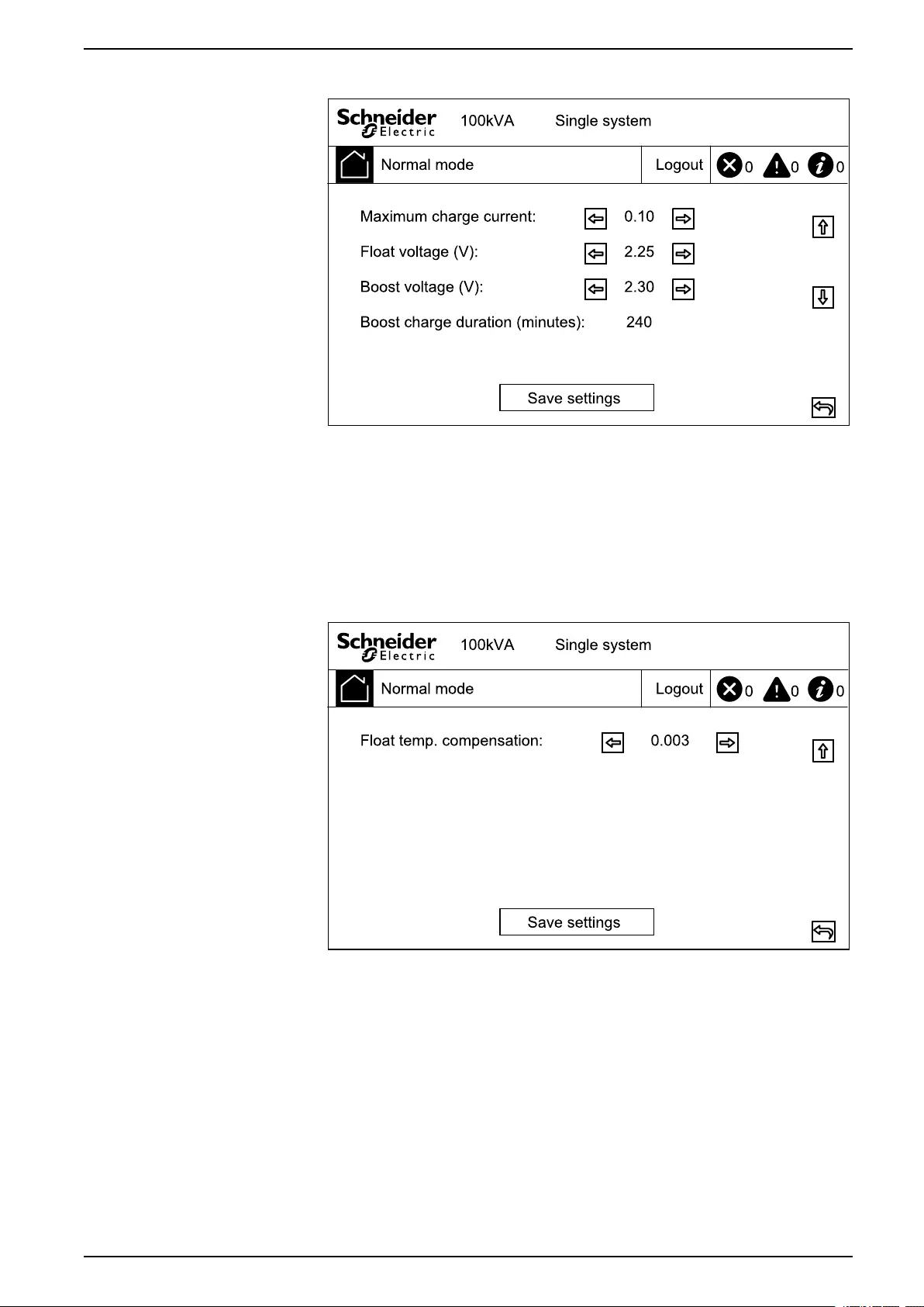
2. Tap arrow down and complete the following settings:
a. Maximum charge current: Choose a value between 0.05 and 0.15 C.
b. Float voltage (V): Choose a value between 2.20 and 2.29
c. Boost voltage (V): Set the upper limit for the boost charge voltage of a
battery cell. Choose a value between 2.30 and 2.40.
d. Boost charge duration (minutes): Set the duration of the boost charge.
Choose a value between 0 and 999 minutes.
3. Tap arrow down and complete the following setting:
a. Float temp. compensation: Choose a value between 0.000 and 0.007
V/°C per cell.
4. Tap Save settings.
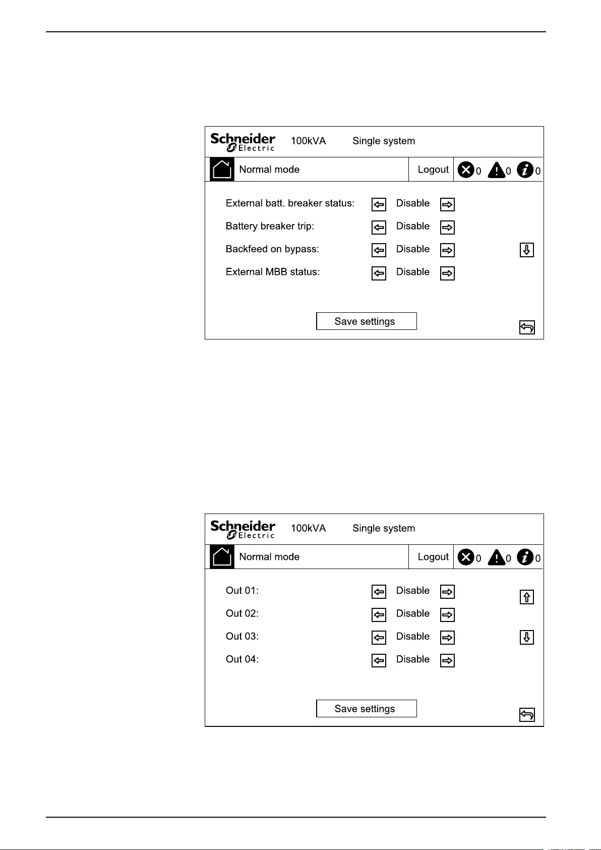
Configure the Input Contacts and Output Relays
1. From the home screen of the display select Settings > Advanced settings >
Contacts and relays.
990-5995B-001 31
60-200 kVA Configuration
2. Enable or Disable the following features:
•External batt. breaker status
•Battery breaker trip
•Backfeed on bypass
•External MBB status
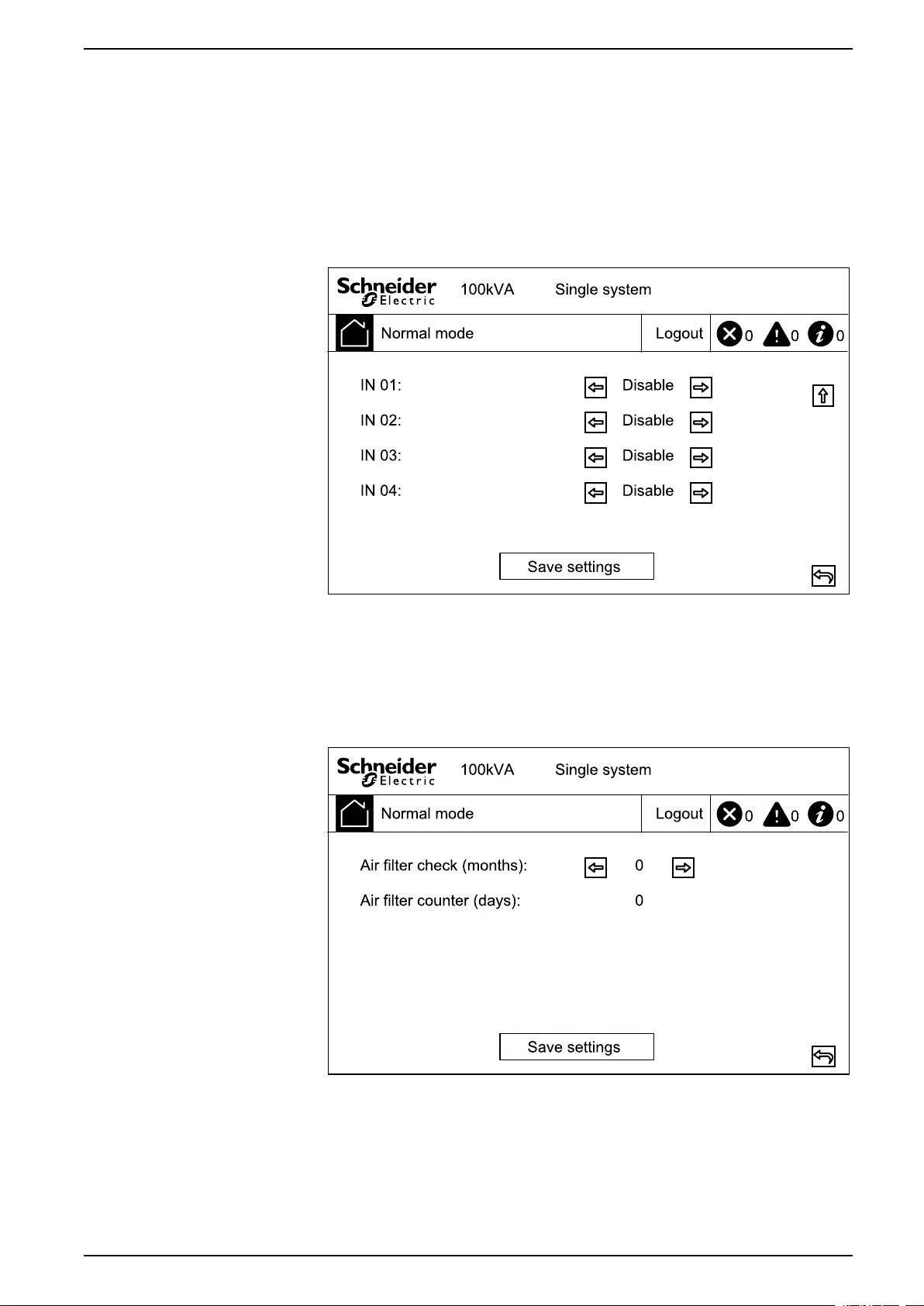
3. Tap arrow down and set the function for each of the configurable output
relays. Choose between:
•Disable
•Common alarm
•In normal operation
•On battery
•Static bypass
•Maintenance bypass
•Output overload
•Fan inoperable
•Battery inoperable
•Battery disconnected
•Battery voltage low
•Input out of tol.
•Bypass out of tol.
•EPO active
32 990-5995B-001
Configuration 60-200 kVA
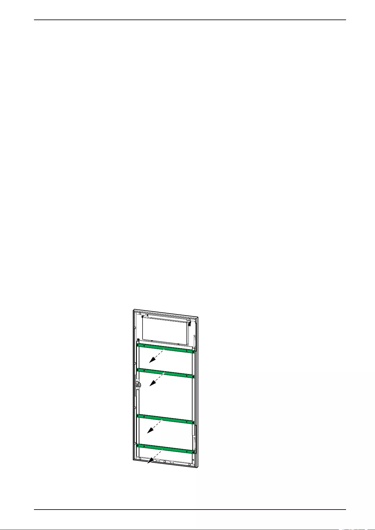
4. Tap arrow down and set the function for each of the configurable input
contacts. Choose between:
•Disable
•INV ON
•INV OFF
•Battery inoperable
•Genset on
•Custom alarm 3
•Custom alarm 4
•Disable ECO
•Force INV OFF
5. Tap Save settings.
Configure Life Cycle Monitoring
1. From the home screen of the display select Service > LCM settings.
2. Set the time in months between air filter checks. The system will generate a
Check air filter message when it is time to check the air filters.
3. Tap Save settings.
990-5995B-001 33

Maintenance 60-200 kVA
Maintenance
Parts Replacement
Determine if you need a Replacement Part
To determine if you need a replacement part, contact Schneider Electric and
follow the procedure below so that the representative can assist you promptly:
1. In the event of an alarm condition, scroll through the alarm lists, record the
information, and provide it to the representative.
2. Write down the serial number of the unit so that you will have it easily
accessible when you contact Schneider Electric.
3. If possible, call Schneider Electric from a telephone that is within reach of the
display so that you can gather and report additional information to the
representative.
4. Be prepared to provide a detailed description of the problem. A representative
will help you solve the problem over the telephone, if possible, or will assign a
return material authorization (RMA) number to you. If a module is returned to
Schneider Electric, this RMA number must be clearly printed on the outside of
the package.
5. If the unit is within the warranty period and has been started up by Schneider
Electric, repairs or replacements will be performed free of charge. If it is not
within the warranty period, there will be a charge.
6. If the unit is covered by a Schneider Electric service contract, have the
contract available to provide information to the representative.
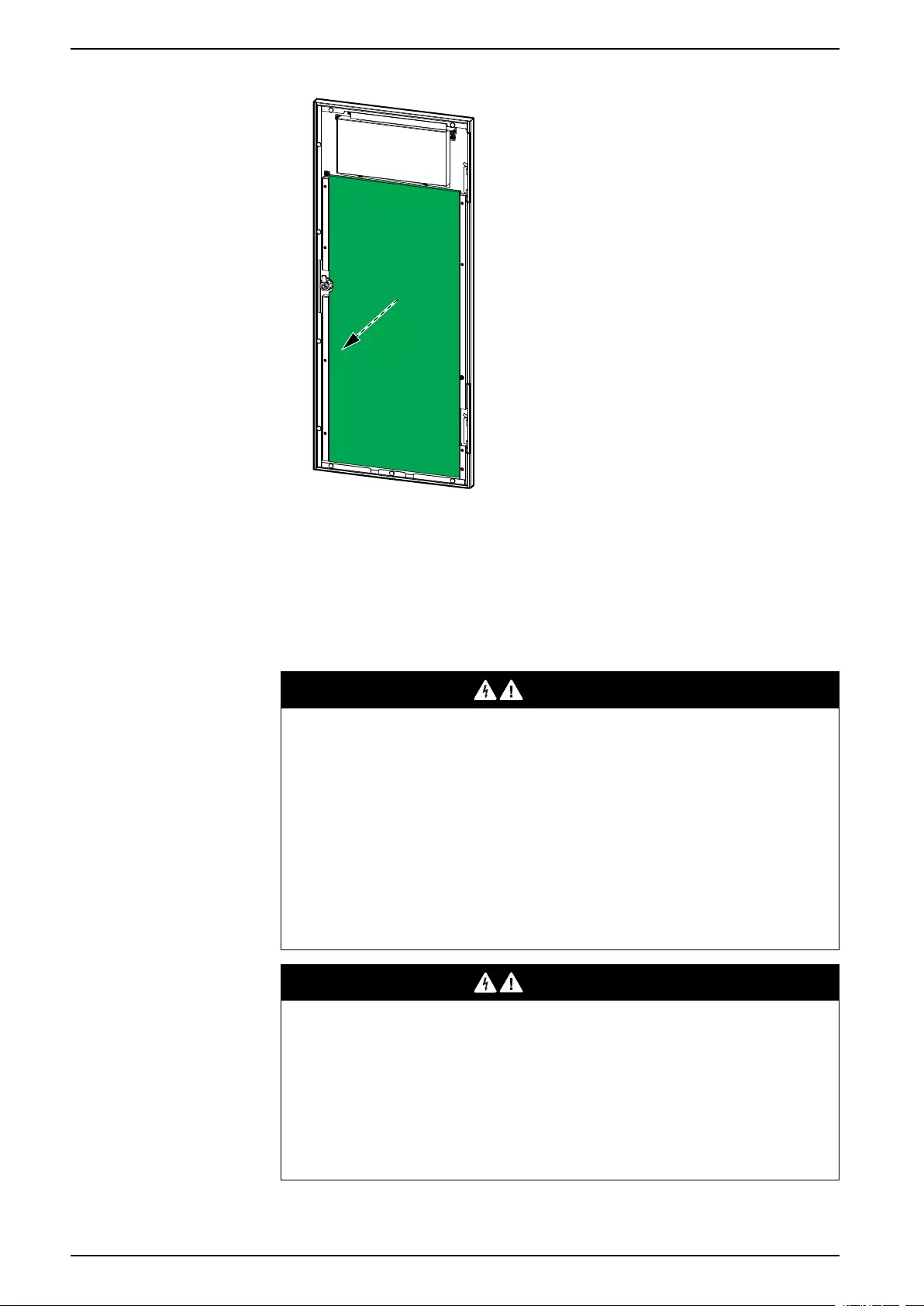
Replace the Air Filter
1. Open the front door of the UPS.
2. Loosen the screws and remove the metal brackets.
990-5995B-001 35
60-200 kVA Maintenance
3. Replace the dust filter.
4. Reinstall the metal brackets and fasten with the screws.
5. Close the front door.
6. Reset the air filter counter in the display.
Replace a Battery String
DANGER
HAZARD OF ELECTRIC SHOCK, EXPLOSION, OR ARC FLASH
Batteries can present a risk of electric shock and high short-circuit current. The
following precautions must be observed when working on batteries
• Remove watches, rings, or other metal objects.
• Use tools with insulated handles.
• Wear protective glasses, gloves and boots.
• Do not lay tools or metal parts on top of batteries.
• Set the battery breaker BB to the open (OFF) position before starting this
procedure.
Failure to follow these instructions will result in death or serious injury.
DANGER
HAZARD OF ELECTRIC SHOCK, EXPLOSION, OR ARC FLASH
• Servicing of batteries must only be performed or supervised by qualified
personnel knowledgeable of batteries and the required precautions. Keep
unqualified personnel away from batteries.
• Do not dispose of batteries in a fire as they can explode.
• Do not open, alter, or mutilate batteries. Released electrolyte is harmful to
the skin and eyes. It may be toxic.
Failure to follow these instructions will result in death or serious injury.
36 990-5995B-001
Maintenance 60-200 kVA
WARNING
RISK OF EQUIPMENT DAMAGE
• When replacing battery modules, always replace with the same battery
module and always replace the entire battery string (four battery modules).
• Batteries must not be stored more than six months due to the requirement of
recharging.
Failure to follow these instructions can result in death, serious injury, or
equipment damage.
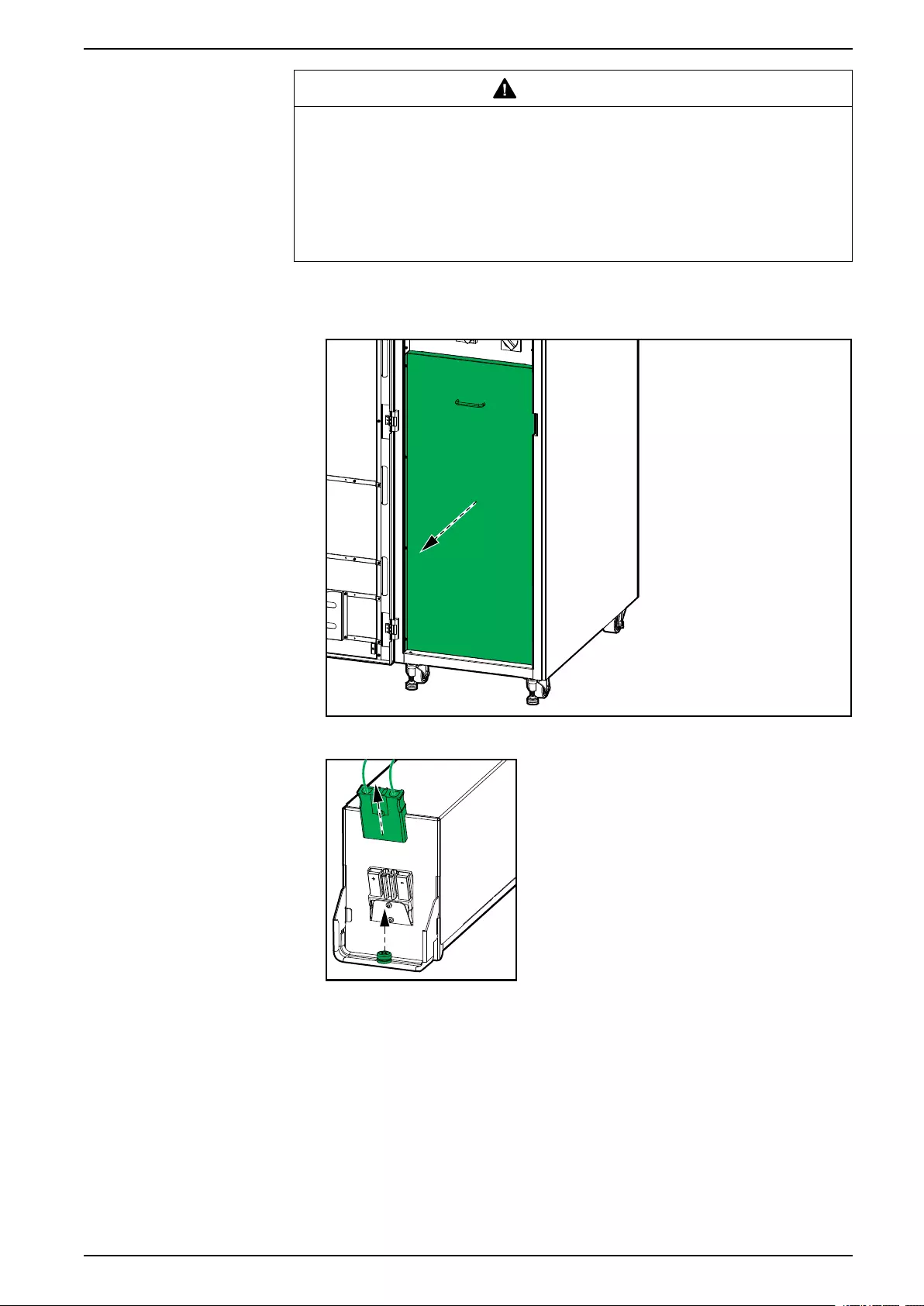
1. Set the battery breaker BB to the open (OFF) position.
2. Remove the plate in front of the battery modules.
3. Disconnect the power terminal from the front of the battery module.
4. Remove the screw from the battery module handle and lift the handle
upwards.
990-5995B-001 37
60-200 kVA Maintenance
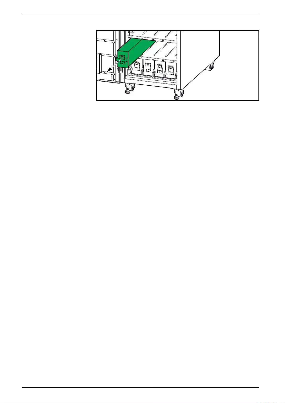
5. Pull the battery module carefully out of the slot.
6. Repeat for all battery modules in the battery string. One row is one battery
string.
7. Push the replacement battery modules into the UPS.
8. Lower the handles on the battery modules and fasten to the shelf with the
screws.
9. Connect the power terminals to the front of the battery modules.
10. Reinstall the plate in front of the battery modules.
11. Set the battery breaker BB to the closed (ON) position.
38 990-5995B-001
Troubleshooting 60-200 kVA
Troubleshooting
View the Active Alarms
1. From the home screen of the display select Alarm(s) > Active alarm(s).
2. You can browse through the list of active alarms using the arrows.
Clear Alarm
1. Select Control > Clear Alarm(s) to clear the alarm list.
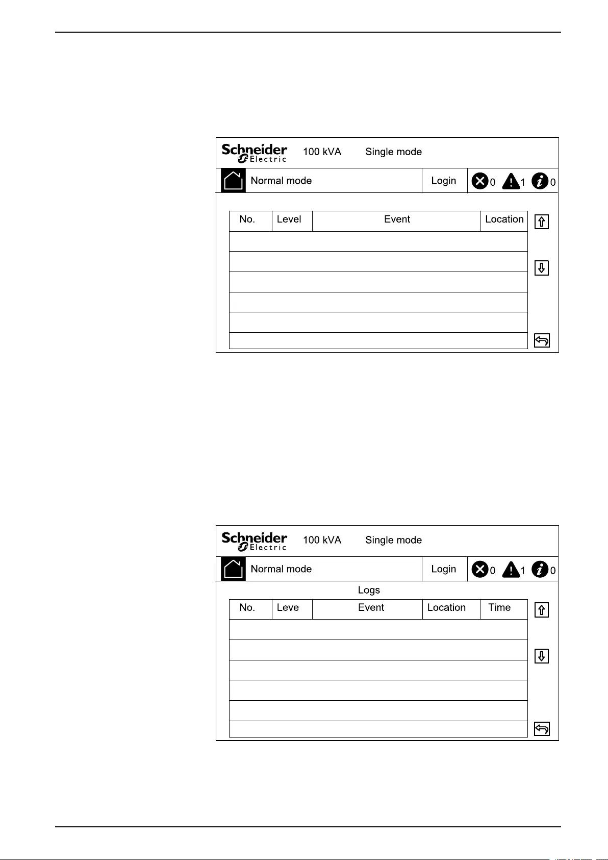
View the Log
1. From the home screen of the display select Alarm(s) > Log.
2. You can browse through the list of events using the arrows.
990-5995B-001 39


Schneider Electric
35 rue Joseph Monier
92500 Rueil Malmaison
France
+ 33 (0) 1 41 29 70 00
*990-5995B-001*
As standards, specifications, and design change from time to time,
please ask for confirmation of the information given in this publication.
© 2019 – 2019 Schneider Electric. All rights reserved.
990-5995B-001