Table of Contents
APC E3SBPSU10K20F User Manual
Displayed below is the user manual for E3SBPSU10K20F by APC which is a product in the Maintenance Bypass Panels (MBPs) category. This manual has pages.
Related Manuals
Easy UPS 3S
Maintenance Bypass Panels
Installation
For 10-40 kVA 208 V UPS
E3SBPSU10K20F, E3SBPSU30K40F
12/2020
www.se.com

Legal Information
The Schneider Electric brand and any trademarks of Schneider Electric SE and its
subsidiaries referred to in this guide are the property of Schneider Electric SE or its
subsidiaries. All other brands may be trademarks of their respective owners.
This guide and its content are protected under applicable copyright laws and
furnished for informational use only. No part of this guide may be reproduced or
transmitted in any form or by any means (electronic, mechanical, photocopying,
recording, or otherwise), for any purpose, without the prior written permission of
Schneider Electric.
Schneider Electric does not grant any right or license for commercial use of the guide
or its content, except for a non-exclusive and personal license to consult it on an "as
is" basis. Schneider Electric products and equipment should be installed, operated,
serviced, and maintained only by qualified personnel.
As standards, specifications, and designs change from time to time, information
contained in this guide may be subject to change without notice.
To the extent permitted by applicable law, no responsibility or liability is assumed by
Schneider Electric and its subsidiaries for any errors or omissions in the informational
content of this material or consequences arising out of or resulting from the use of the
information contained herein.
Go to https://www.productinfo.schneider-electric.com/easyups3s_ul/ for translations.
Rendez-vous sur https://www.productinfo.schneider-electric.com/easyups3s_ul/ pour
accéder aux traductions.
Vaya a https://www.productinfo.schneider-electric.com/easyups3s_ul/ para obtener
las traducciones.
Vá para https://www.productinfo.schneider-electric.com/easyups3s_ul/ para obter as
traduções.

Maintenance Bypass Panels
Table of Contents
Important Safety Instructions — SAVE THESE
INSTRUCTIONS.........................................................................................5
FCC Statement ..........................................................................................6
Safety Precautions .....................................................................................6
Electrical Safety....................................................................................7
Specifications ..............................................................................................9
Torque Specifications................................................................................10
Maintenance Bypass Panel Weights and Dimensions..................................10
Clearance ................................................................................................10
Environment............................................................................................. 11
Installation Procedure ..............................................................................12
Mount the Maintenance Bypass Panel to the Wall .......................................12
Prepare the Maintenance Bypass Panel for Cables .....................................14
Connect the Power Cables........................................................................15
Connect the Signal Cables ........................................................................16
Install the Kirkkey kit E3SOPT015 in E3SBPSU10K20F ..............................18
Install the Kirkkey kit E3SOPT015 in E3SBPSU30K40F ..............................18
990-6426-001 3

Important Safety Instructions — SAVE THESE
INSTRUCTIONS Maintenance Bypass Panels
Important Safety Instructions — SAVE THESE
INSTRUCTIONS
Read these instructions carefully and look at the equipment to become familiar
with it before trying to install, operate, service or maintain it. The following safety
messages may appear throughout this manual or on the equipment to warn of
potential hazards or to call attention to information that clarifies or simplifies a
procedure.
The addition of this symbol to a “Danger” or “Warning” safety
message indicates that an electrical hazard exists which will result in
personal injury if the instructions are not followed.
This is the safety alert symbol. It is used to alert you to potential
personal injury hazards. Obey all safety messages with this symbol
to avoid possible injury or death.
DANGER
DANGER indicates a hazardous situation which, if not avoided, will result in
death or serious injury.
Failure to follow these instructions will result in death or serious injury.
WARNING
WARNING indicates a hazardous situation which, if not avoided, could result
in death or serious injury.
Failure to follow these instructions can result in death, serious injury, or
equipment damage.
CAUTION
CAUTION indicates a hazardous situation which, if not avoided, could result in
minor or moderate injury.
Failure to follow these instructions can result in injury or equipment
damage.
NOTICE
NOTICE is used to address practices not related to physical injury. The safety
alert symbol shall not be used with this type of safety message.
Failure to follow these instructions can result in equipment damage.
Please Note
Electrical equipment should only be installed, operated, serviced, and maintained
by qualified personnel. No responsibility is assumed by Schneider Electric for any
consequences arising out of the use of this material.
A qualified person is one who has skills and knowledge related to the construction,
installation, and operation of electrical equipment and has received safety training
to recognize and avoid the hazards involved.
990-6426-001 5
Maintenance Bypass Panels
Important Safety Instructions — SAVE THESE
INSTRUCTIONS
FCC Statement
NOTE: This equipment has been tested and found to comply with the limits for
a Class A digital device, pursuant to Part 15 of the FCC Rules. These limits
are designed to provide reasonable protection against harmful interference
when the equipment is operated in a commercial environment. This equipment
generates, uses, and can radiate radio frequency energy and, if not installed
and used in accordance with the instruction manual, may cause harmful
interference to radio communications. Operation of this equipment in a
residential area is likely to cause harmful interference in which case the user
will be required to correct the interference at his own expense.
Any changes or modifications not expressly approved by the party responsible for
compliance could void the user’s authority to operate the equipment.
Safety Precautions
DANGER
HAZARD OF ELECTRIC SHOCK, EXPLOSION, OR ARC FLASH
Read all instructions in the installation manual before installing or working on
this product.
Failure to follow these instructions will result in death or serious injury.
DANGER
HAZARD OF ELECTRIC SHOCK, EXPLOSION, OR ARC FLASH
Do not install the product until all construction work has been completed and the
installation room has been cleaned.
Failure to follow these instructions will result in death or serious injury.
DANGER
HAZARD OF ELECTRIC SHOCK, EXPLOSION, OR ARC FLASH
The product must be installed according to the specifications and requirements
as defined by Schneider Electric. It concerns in particular the external and
internal protections (upstream breakers, battery breakers, cabling, etc.) and
environmental requirements. No responsibility is assumed by Schneider Electric
if these requirements are not respected.
Failure to follow these instructions will result in death or serious injury.
DANGER
HAZARD OF ELECTRIC SHOCK, EXPLOSION, OR ARC FLASH
The UPS system must be installed according to local and national regulations.
Install the UPS according to:
• IEC 60364 (including 60364–4–41- protection against electric shock, 60364–
4–42 - protection against thermal effect, and 60364–4–43 - protection
against overcurrent), or
• NEC NFPA 70, or
• Canadian Electrical Code (C22.1, Part 1)
depending on which one of the standards apply in your local area.
Failure to follow these instructions will result in death or serious injury.
6 990-6426-001
Important Safety Instructions — SAVE THESE
INSTRUCTIONS Maintenance Bypass Panels
DANGER
HAZARD OF ELECTRIC SHOCK, EXPLOSION, OR ARC FLASH
• Install the product in a temperature controlled indoor environment free of
conductive contaminants and humidity.
• Install the product on a non-flammable, level and solid surface (e.g.
concrete) that can support the weight of the system.
Failure to follow these instructions will result in death or serious injury.
DANGER
HAZARD OF ELECTRIC SHOCK, EXPLOSION, OR ARC FLASH
The product is not designed for and must therefore not be installed in the
following unusual operating environments:
• Damaging fumes
• Explosive mixtures of dust or gases, corrosive gases, or conductive or
radiant heat from other sources
• Moisture, abrasive dust, steam or in an excessively damp environment
• Fungus, insects, vermin
• Salt-laden air or contaminated cooling refrigerant
• Pollution degree higher than 2 according to IEC 60664-1
• Exposure to abnormal vibrations, shocks, and tilting
• Exposure to direct sunlight, heat sources, or strong electromagnetic fields
Failure to follow these instructions will result in death or serious injury.
DANGER
HAZARD OF ELECTRIC SHOCK, EXPLOSION, OR ARC FLASH
Do not drill or cut holes for cables or conduits with the gland plates installed and
do not drill or cut holes in close proximity to the UPS.
Failure to follow these instructions will result in death or serious injury.
WARNING
HAZARD OF ARC FLASH
Do not make mechanical changes to the product (including removal of cabinet
parts or drilling/cutting of holes) that are not described in the installation manual.
Failure to follow these instructions can result in death, serious injury, or
equipment damage.
NOTICE
RISK OF OVERHEATING
Respect the space requirements around the product and do not cover the
ventilation openings when the product is in operation.
Failure to follow these instructions can result in equipment damage.
Electrical Safety
This manual contains important safety instructions that should be followed during
the installation and maintenance of the UPS system.
990-6426-001 7
Maintenance Bypass Panels
Important Safety Instructions — SAVE THESE
INSTRUCTIONS
DANGER
HAZARD OF ELECTRIC SHOCK, EXPLOSION, OR ARC FLASH
• Electrical equipment must be installed, operated, serviced, and maintained
only by qualified personnel.
• Apply appropriate personal protective equipment (PPE) and follow safe
electrical work practices.
• Disconnection devices for AC and DC must be provided by others, be readily
accessible, and the function of the disconnect device marked for its function.
• Turn off all power supplying the UPS system before working on or inside the
equipment.
• Before working on the UPS system, check for hazardous voltage between all
terminals including the protective earth.
• The UPS contains an internal energy source. Hazardous voltage can be
present even when disconnected from the mains supply. Before installing or
servicing the UPS system, ensure that the units are OFF and that mains and
batteries are disconnected. Wait five minutes before opening the UPS to
allow the capacitors to discharge.
• The UPS must be properly earthed/grounded and due to a high leakage
current, the earthing/grounding conductor must be connected first.
Failure to follow these instructions will result in death or serious injury.
When the UPS input is connected through external isolators that, when opened,
isolate the neutral or when the automatic backfeed isolation is provided external to
the equipment or is connected to an IT power distribution system, a label must be
fitted at the UPS input terminals, and on all primary power isolators installed
remotely from the UPS area and on external access points between such isolators
and the UPS, by the user, displaying the following text (or equivalent in a language
which is acceptable in the country in which the UPS system is installed):
DANGER
HAZARD OF ELECTRIC SHOCK, EXPLOSION, OR ARC FLASH
Risk of voltage backfeed. Before working on this circuit: Isolate the UPS and
check for hazardous voltage between all terminals including the protective
earth.
Failure to follow these instructions will result in death or serious injury.
8 990-6426-001

Specifications Maintenance Bypass Panels
Specifications
Maximum Input Short-Circuit Withstand
The maximum input short-circuit withstand for the maintenance bypass panel is 10
kA RMS symmetrical.
Trip Settings for E3SBPSU10K20F
UIB/SSIB MBB and UOB
UPS rating Breaker Ir Im Breaker Ir Im
10 kVA BGF36100 100 A fixed 1000 A fixed BGF46125 125 A fixed 1000 A fixed
15 kVA BGF36100 100 A fixed 1000 A fixed BGF46125 125 A fixed 1000 A fixed
20 kVA BGF36100 100 A fixed 1000 A fixed BGF46125 125 A fixed 1000 A fixed
Trip Settings for E3SBPSU30K40F
UIB/SSIB MBB and UOB
UPS
rating
Breaker Ir Im(li) Tr Breaker Ir Im(li) Tr N
30 kVA HGF36150C 150 A
fixed
1250 A –LJF46250CU31X 100 A 1.5-12 0.5-16 4P 3D
40 kVA HGF36150C 150 A
fixed
1250 A –LJF46250CU31X 150 A 1.5-12 0.5-16 4P 3D
Recommended Upstream Protection
UPS rating Connection Breaker Im
10 kVA Input BDF36045 400 A fixed
Bypass BDF36035 400 A fixed
15 kVA Input BGF36070 640 A fixed
Bypass BGF36060 640 A fixed
20 kVA Input BGF36090 1000 A fixed
Bypass BGF36070 640 A fixed
30 kVA Input HGF36110C 1250 A
Bypass HGF36090C 1250 A
40 kVA Input HJF36150C 1250 A
Bypass HJF36125C 1250 A
Recommended Cable Sizes and Cable Lugs
NOTE: Please refer to the UPS installation manual for recommended cables
sizes and recommended cable lugs.
990-6426-001 9
Maintenance Bypass Panels Specifications
Torque Specifications
Bolt size Torque
M6 on busbar 5 Nm (3.69 lb-ft / 44.3 lb-in)
M8 on busbar 17.5 Nm (12.91 lb-ft / 154.9 lb-in)
M10 on busbar 30 Nm (22 lb-ft / 194.7 lb-in)
5/32 in on breaker 9 Nm (6.64 lb-ft / 79.7 lb-in)
M10 on breaker 50 Nm (36.88 lb-ft/ 442.5 lb-in)
Maintenance Bypass Panel Weights and Dimensions
Weight kg (lbs) Height mm (in) Width mm (in) Depth mm (in)
E3SBPSU10K20F 30 (66) 600 (23.62) 550 (21.65) 260 (10.24)
E3SBPSU30K40F 65 (143) 900 (35.43) 800 (31.50) 320 (12.60)
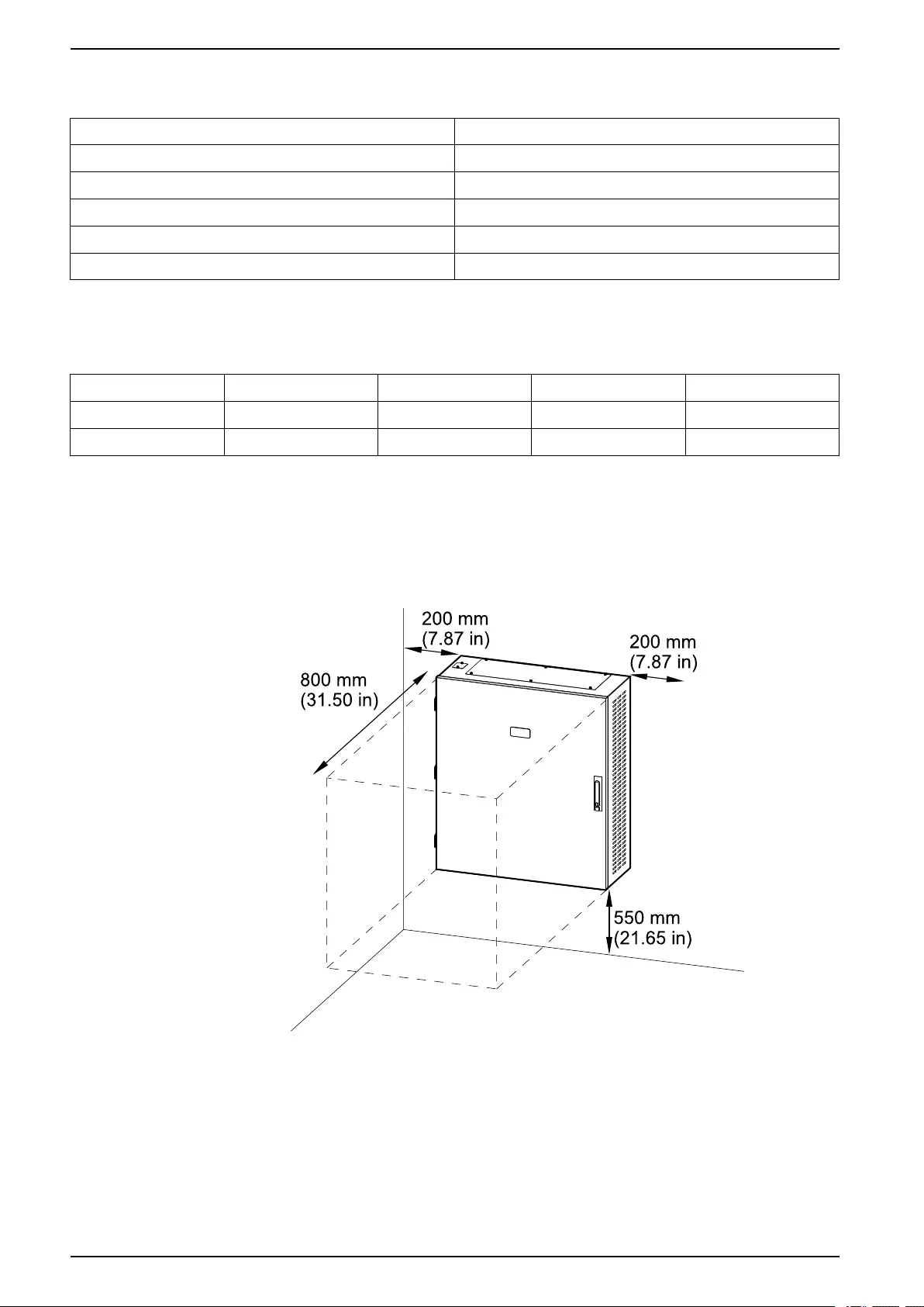
Clearance
NOTE: Clearance dimensions are published for airflow and service access
only. Consult with the local safety codes and standards for additional
requirements in your local area.
10 990-6426-001

Specifications Maintenance Bypass Panels
Environment
Operating Storage
Temperature 0 °C to 40 °C (32 °F to 104 °F ) -25 °C to 55 °C (-13 °F to 131 °F)
Relative humidity 0-95% non-condensing 0-95% non-condensing
Elevation 0-2000 m (0-6561 feet)
Protection class IP20
Color RAL 9003, gloss level 85%
990-6426-001 11
Maintenance Bypass Panels Installation Procedure
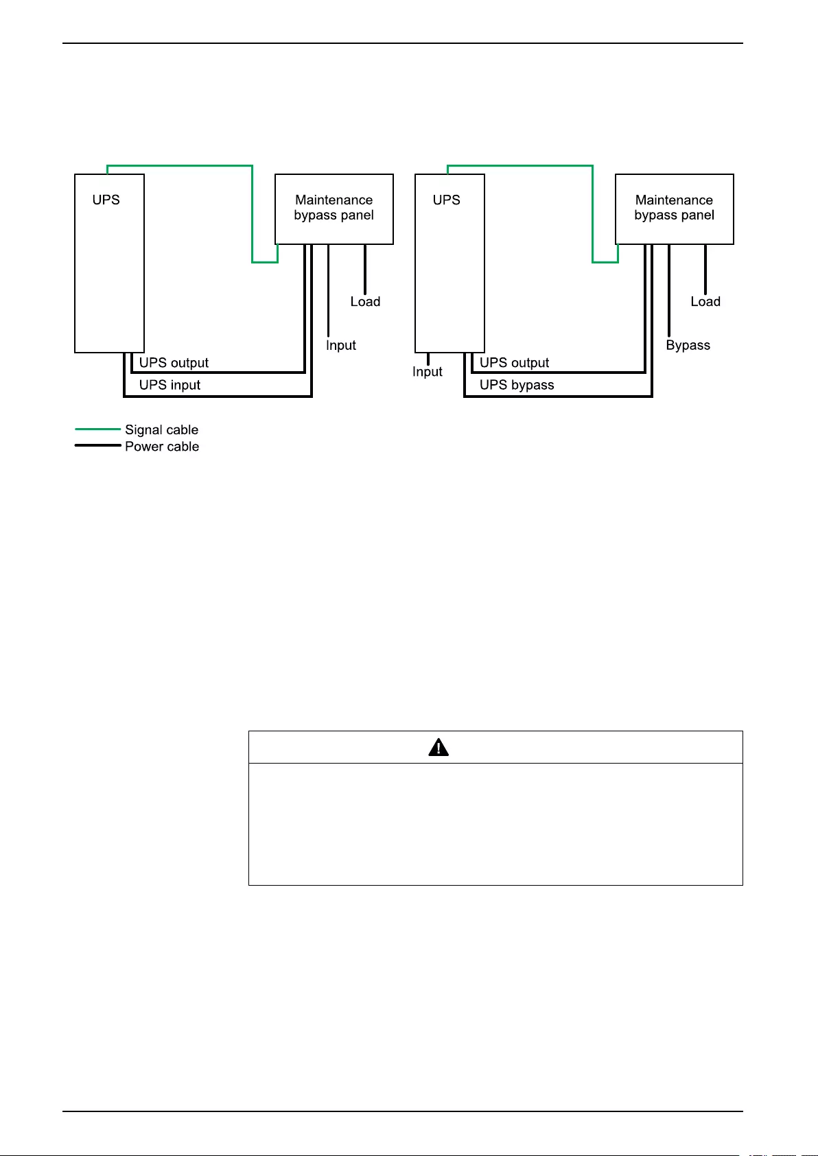
Installation Procedure
Single Mains System Dual Mains System
1. Mount the Maintenance Bypass Panel to the Wall, page 12.
2. Prepare the Maintenance Bypass Panel for Cables, page 14.
3. Connect the Power Cables, page 15.
4. Connect the Signal Cables, page 16.
5. Optional: Install the kirkkey kit E3SOPT015:
–Install the Kirkkey kit E3SOPT015 in E3SBPSU10K20F, page 18.
–Install the Kirkkey kit E3SOPT015 in E3SBPSU30K40F, page 18.
Mount the Maintenance Bypass Panel to the Wall
CAUTION
RISK OF INJURY OR EQUIPMENT DAMAGE
• Mount the maintenance bypass panel to a wall or a rack that is structurally
sound and able to support the weight of the unit.
• Use appropriate hardware for the wall/rack type.
Failure to follow these instructions can result in injury or equipment
damage.
12 990-6426-001
Installation Procedure Maintenance Bypass Panels
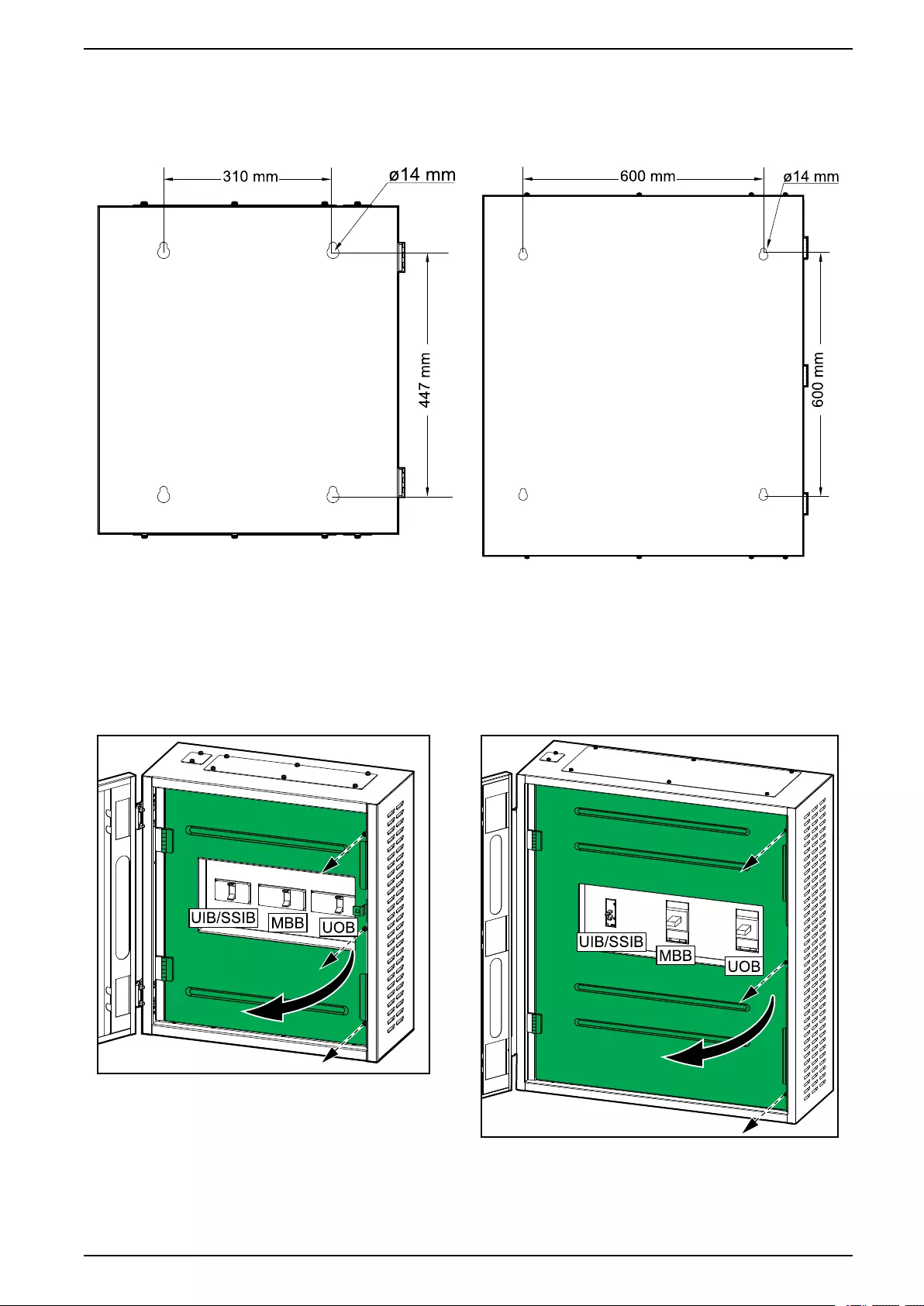
1. Measure and mark the four mounting hole locations on the wall.
E3SBPSU10K20F E3SBPSU30K40F
2. Drill holes in each of the four marked locations and mount the anchor bolts.
3. Remove the screws and open the inner door in the maintenance bypass
panel.
E3SBPSU10K20F E3SBPSU30K40F
4. Lift the maintenance bypass panel, position it against the wall and line it up
with the four anchor bolts. Mount the maintenance bypass panel to the wall.
990-6426-001 13
Maintenance Bypass Panels Installation Procedure
Prepare the Maintenance Bypass Panel for Cables
DANGER
HAZARD OF ELECTRIC SHOCK, EXPLOSION, OR ARC FLASH
Do not drill or punch holes with the gland plates installed and do not drill or
punch holes in close proximity to the parallel maintenance bypass panel.
Failure to follow these instructions will result in death or serious injury.
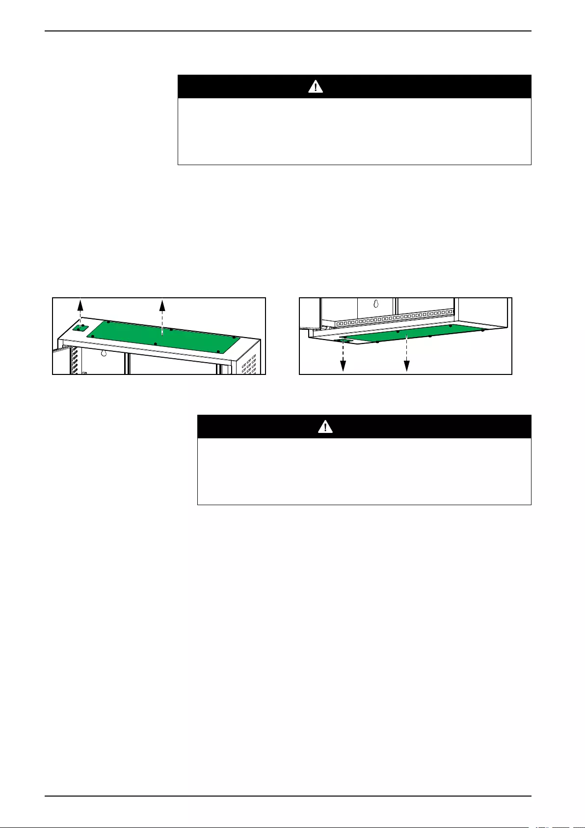
1. Prepare the maintenance bypass panel for power and signal cables:
a. Loosen the six bolts from the top AND bottom gland plates for power
cables and remove the gland plates.
b. Loosen the two bolts from the top OR bottom gland plate for signal
cables and remove the gland plate.
Top of Maintenance Bypass Panel Bottom of Maintenance Bypass Panel
2. Drill or punch holes for cables/conduits.
DANGER
HAZARD OF ELECTRIC SHOCK, EXPLOSION, OR ARC FLASH
Ensure that there are no sharp edges that can damage the cables.
Failure to follow these instructions will result in death or serious
injury.
3. Install conduits (if applicable) and reinstall the gland plates.
14 990-6426-001
Installation Procedure Maintenance Bypass Panels
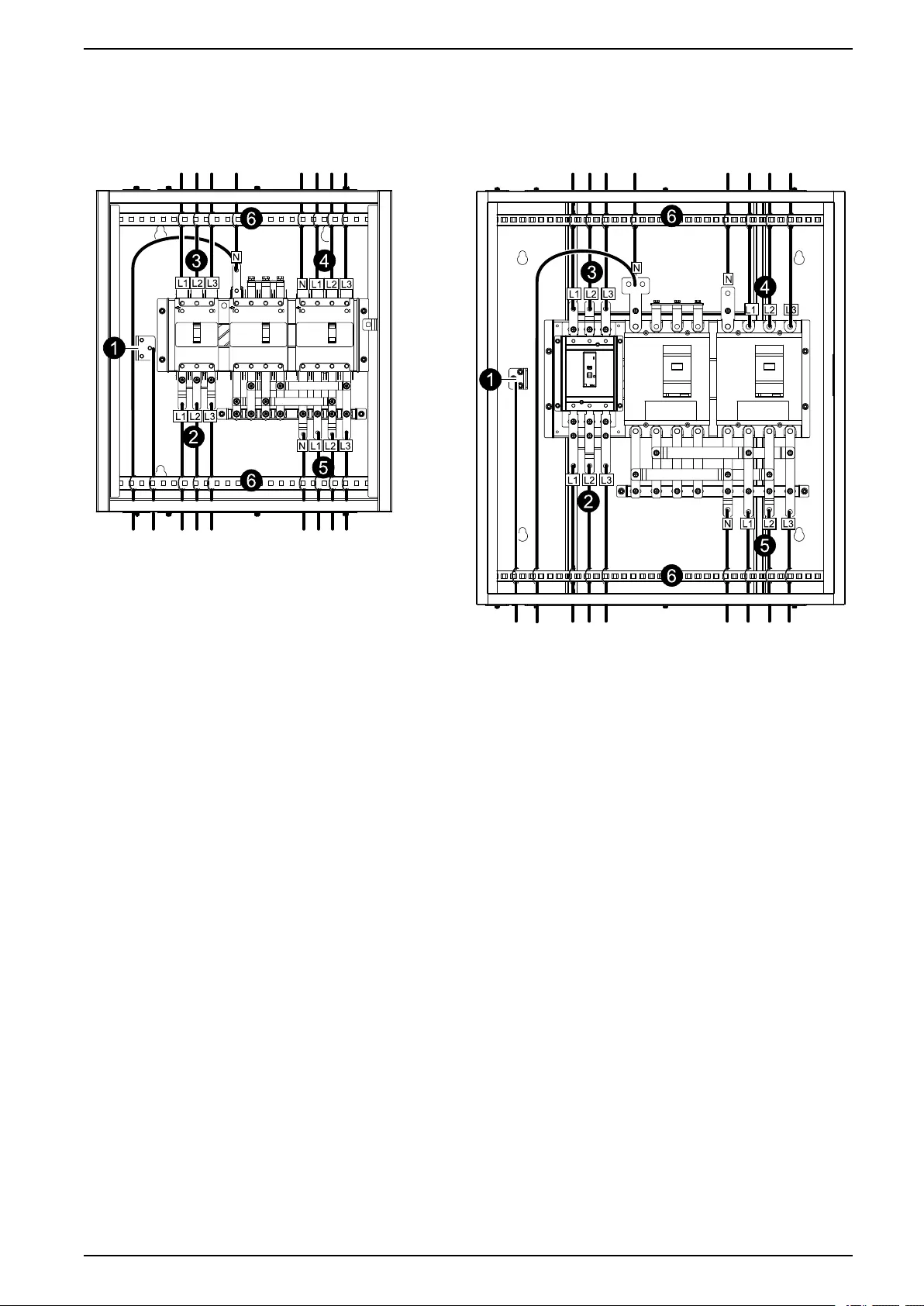
Connect the Power Cables
E3SBPSU10K20F E3SBPSU30K40F
1. Connect the ground cable.
2. Perform one of the following:
– For single mains: Connect the input cables to the unit input breaker (UIB).
– For dual mains: Connect the bypass cables to the static switch input
breaker (SSIB).
3. Perform one of the following:
– For single mains: Connect the UPS input cables to the unit input breaker
(UIB).
– For dual mains: Connect the UPS bypass cables to the static switch input
breaker (SSIB).
4. Connect the UPS output cables to the unit output breaker (UOB).
5. Connect the load cables.
6. Fasten the cables with cable ties to the cable reliefs as shown.
990-6426-001 15
Maintenance Bypass Panels Installation Procedure
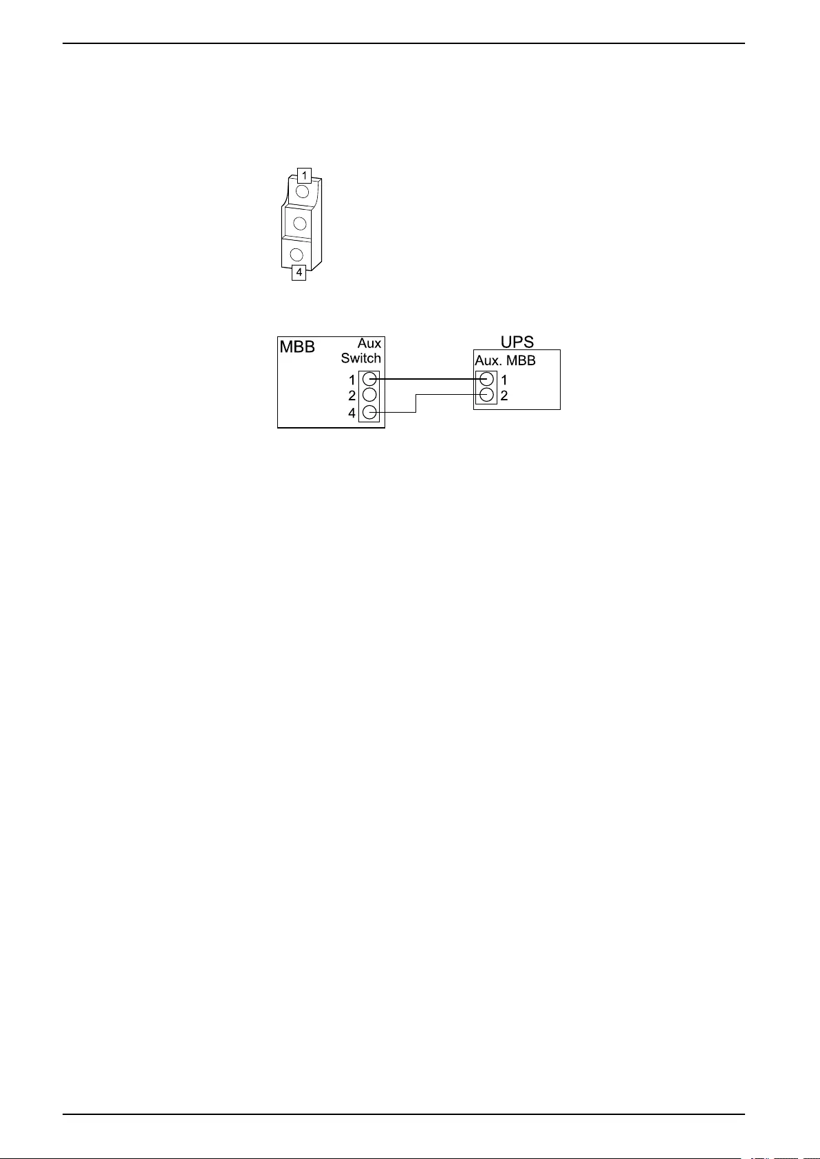
Connect the Signal Cables
NOTE: Route the signal cables separately from the power cables.
1. Remove the plastic cover of the maintenance bypass breaker MBB to get
access to the auxiliary switch.
2. Connect signal cables 22 AWG (not supplied) between the maintenance
bypass breaker MBB and the UPS.
16 990-6426-001
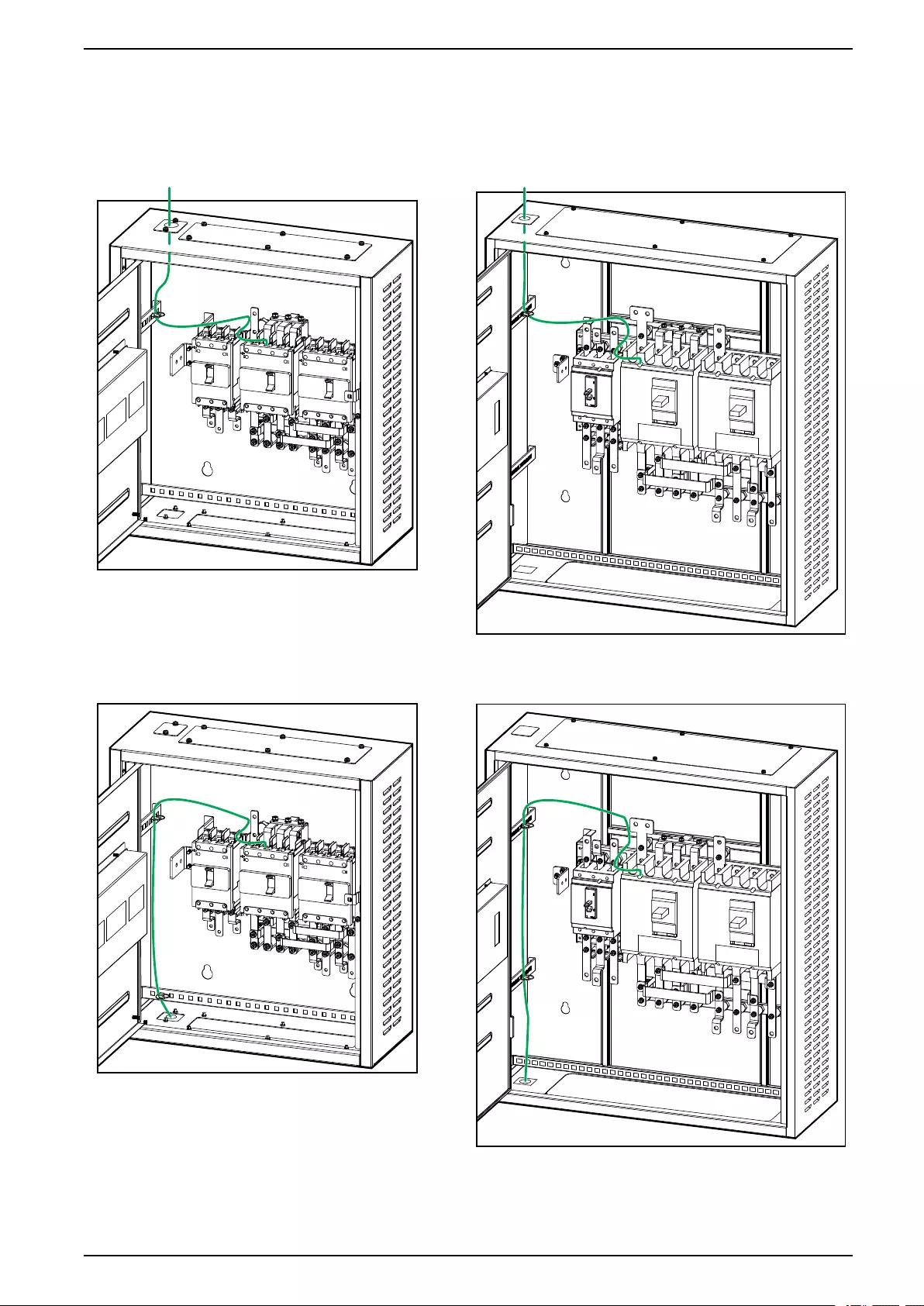
Installation Procedure Maintenance Bypass Panels
3. Route the signal cables through the top or bottom of the maintenance bypass
panel and fasten the signal cables to the cables reliefs.
E3SBPSU10K20F – Top Cable Entry E3SBPSU30K40F – Top Cable Entry
E3SBPSU10K20F – Bottom Cable Entry E3SBPSU30K40F – Bottom Cable Entry
990-6426-001 17
Maintenance Bypass Panels Installation Procedure
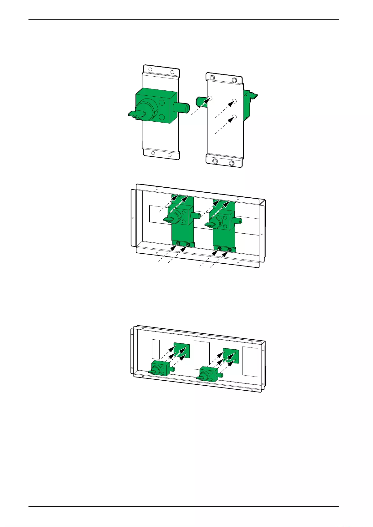
Install the Kirkkey kit E3SOPT015 in E3SBPSU10K20F
1. Place the kirkkeys on the front of the two brackets and fasten from the rear
side of the brackets.
2. Install the two brackets on the breaker cover.
Install the Kirkkey kit E3SOPT015 in E3SBPSU30K40F
1. Place the plate and kirkkeys on the front of the breaker cover and fasten with
four screws from the rear side of the cover.
18 990-6426-001


Printed in:
Schneider Electric
35 rue Joseph Monier
92500 Rueil Malmaison - France
+ 33 (0) 1 41 29 70 00
Schneider Electric
35 rue Joseph Monier
92500 Rueil Malmaison
France
+ 33 (0) 1 41 29 70 00
*990-6426-001*
As standards, specifications, and design change from time to time,
please ask for confirmation of the information given in this publication.
© 2020 – 2020 Schneider Electric. All rights reserved.
990-6426-001