Table of Contents
APC E3SUPS10K3IB User Manual
Displayed below is the user manual for E3SUPS10K3IB by APC which is a product in the Uninterruptible Power Supplies (UPSs) category. This manual has pages.
Related Manuals
Easy UPS 3S with Internal Batteries
10–30 kVA 3:1
Installation
E3SUPS10K3IB, E3SUPS10K3IB1, E3SUPS10K3IB2, E3SUPS15K3IB, E3SUPS15K3IB1,
E3SUPS15K3IB2, E3SUPS20K3IB, E3SUPS20K3IB1, E3SUPS20K3IB2, E3SUPS30K3IB,
E3SUPS30K3IB1, E3SUPS30K3IB2
11/2019
www.schneider-electric.com

Legal Information
The Schneider Electric brand and any trademarks of Schneider Electric SE and its
subsidiaries referred to in this guide are the property of Schneider Electric SE or its
subsidiaries. All other brands may be trademarks of their respective owners.
This guide and its content are protected under applicable copyright laws and
furnished for informational use only. No part of this guide may be reproduced or
transmitted in any form or by any means (electronic, mechanical, photocopying,
recording, or otherwise), for any purpose, without the prior written permission of
Schneider Electric.
Schneider Electric does not grant any right or license for commercial use of the guide
or its content, except for a non-exclusive and personal license to consult it on an "as
is" basis. Schneider Electric products and equipment should be installed, operated,
serviced, and maintained only by qualified personnel.
As standards, specifications, and designs change from time to time, information
contained in this guide may be subject to change without notice.
To the extent permitted by applicable law, no responsibility or liability is assumed by
Schneider Electric and its subsidiaries for any errors or omissions in the informational
content of this material or consequences arising out of or resulting from the use of the
information contained herein.
Go to http://www.productinfo.schneider-electric.com/portals/ui/easyups3s/ for
translations.
Rendez-vous sur http://www.productinfo.schneider-electric.com/portals/ui/
easyups3s/ pour accéder aux traductions.
Vaya a http://www.productinfo.schneider-electric.com/portals/ui/easyups3s/ para
obtener las traducciones.
Gehe zu http://www.productinfo.schneider-electric.com/portals/ui/easyups3s/ für
Übersetzungen.
Vai a http://www.productinfo.schneider-electric.com/portals/ui/easyups3s/ per le
traduzioni.
Vá para http://www.productinfo.schneider-electric.com/portals/ui/easyups3s/ para
obter as traduções.
Перейдите по ссылке http://www.productinfo.schneider-electric.com/portals/ui/
easyups3s/ для просмотра переводов.
前往 http://www.productinfo.schneider-electric.com/portals/ui/easyups3s/ 查看译文。
前往 http://www.productinfo.schneider-electric.com/portals/ui/easyups3s/ 查看譯文。

10–30 kVA 3:1
Table of Contents
Important Safety Instructions — SAVE THESE
INSTRUCTIONS.........................................................................................5
Electromagnetic Compatibility .....................................................................6
Safety Precautions .....................................................................................6
Electrical Safety....................................................................................8
Battery Safety.......................................................................................9
Specifications ............................................................................................ 11
Input Specifications .................................................................................. 11
Bypass Specifications............................................................................... 11
Output Specifications................................................................................12
Battery Specifications ...............................................................................12
Required Upstream and Downstream Protection and Cable Sizes................12
Recommended Bolts and Cable Lugs ........................................................14
Torque Specifications................................................................................14
Weights and Dimensions...........................................................................14
Shipping Weights and Dimensions.............................................................14
Clearance ................................................................................................15
Environmental..........................................................................................15
Overview ....................................................................................................16
Overview of Single UPS............................................................................16
Overview of 1+1 Redundant Parallel System with Common Battery
Bank........................................................................................................17
Overview of Parallel System......................................................................17
Receiving ...................................................................................................19
Remove the UPS from the Pallet................................................................19
Connect the Power Cables......................................................................22
Connect the Power Cables in the 10–15 kVA UPS.......................................22
Connect the Power Cables in the 20 kVA UPS ............................................24
Connect the Power Cables in the 30 kVA UPS ............................................26
Communication Interfaces.......................................................................28
Input Contacts and Output Relays..............................................................30
Connect the Signal Cables in Parallel Systems ...........................................31
Backfeed Protection .................................................................................32
Install Batteries in the UPS......................................................................35
Installation Checklist.................................................................................37
990-91189C–001 3

Important Safety Instructions — SAVE THESE
INSTRUCTIONS 10–30 kVA 3:1
Important Safety Instructions — SAVE THESE
INSTRUCTIONS
Read these instructions carefully and look at the equipment to become familiar
with it before trying to install, operate, service or maintain it. The following safety
messages may appear throughout this manual or on the equipment to warn of
potential hazards or to call attention to information that clarifies or simplifies a
procedure.
The addition of this symbol to a “Danger” or “Warning” safety
message indicates that an electrical hazard exists which will result in
personal injury if the instructions are not followed.
This is the safety alert symbol. It is used to alert you to potential
personal injury hazards. Obey all safety messages with this symbol
to avoid possible injury or death.
DANGER
DANGER indicates a hazardous situation which, if not avoided, will result in
death or serious injury.
Failure to follow these instructions will result in death or serious injury.
WARNING
WARNING indicates a hazardous situation which, if not avoided, could result
in death or serious injury.
Failure to follow these instructions can result in death, serious injury, or
equipment damage.
CAUTION
CAUTION indicates a hazardous situation which, if not avoided, could result in
minor or moderate injury.
Failure to follow these instructions can result in injury or equipment
damage.
NOTICE
NOTICE is used to address practices not related to physical injury. The safety
alert symbol shall not be used with this type of safety message.
Failure to follow these instructions can result in equipment damage.
Please Note
Electrical equipment should only be installed, operated, serviced, and maintained
by qualified personnel. No responsibility is assumed by Schneider Electric for any
consequences arising out of the use of this material.
A qualified person is one who has skills and knowledge related to the construction,
installation, and operation of electrical equipment and has received safety training
to recognize and avoid the hazards involved.
990-91189C–001 5
10–30 kVA 3:1
Important Safety Instructions — SAVE THESE
INSTRUCTIONS
Electromagnetic Compatibility
NOTICE
RISK OF ELECTROMAGNETIC DISTURBANCE
This is a product Category C3 according to IEC 62040-2. This is a product for
commercial and industrial applications in the second environment - installation
restrictions or additional measures may be needed to prevent disturbances. The
second environment includes all commercial, light industry, and industrial
locations other than residential, commercial, and light industrial premises
directly connected without intermediate transformer to a public low-voltage
mains supply. The installation and cabling must follow the electromagnetic
compatibility rules, e.g.:
• the segregation of cables,
• the use of shielded or special cables when relevant,
• the use of grounded metallic cable tray and supports.
Failure to follow these instructions can result in equipment damage.
Safety Precautions
DANGER
HAZARD OF ELECTRIC SHOCK, EXPLOSION, OR ARC FLASH
All safety instructions in this document must be read, understood and followed.
Failure to follow these instructions will result in death or serious injury.
DANGER
HAZARD OF ELECTRIC SHOCK, EXPLOSION, OR ARC FLASH
Read all instructions in the Installation Manual before installing or working on
this UPS system.
Failure to follow these instructions will result in death or serious injury.
DANGER
HAZARD OF ELECTRIC SHOCK, EXPLOSION, OR ARC FLASH
Do not install the UPS system until all construction work has been completed
and the installation room has been cleaned.
Failure to follow these instructions will result in death or serious injury.
DANGER
HAZARD OF ELECTRIC SHOCK, EXPLOSION, OR ARC FLASH
• The product must be installed according to the specifications and
requirements as defined by Schneider Electric. It concerns in particular the
external and internal protections (upstream breakers, battery breakers,
cabling, etc.) and environmental requirements. No responsibility is assumed
by Schneider Electric if these requirements are not respected.
• After the UPS system has been electrically wired, do not start up the system.
Start-up must only be performed by Schneider Electric.
Failure to follow these instructions will result in death or serious injury.
6 990-91189C–001

Important Safety Instructions — SAVE THESE
INSTRUCTIONS 10–30 kVA 3:1
DANGER
HAZARD OF ELECTRIC SHOCK, EXPLOSION, OR ARC FLASH
The UPS system must be installed according to local and national regulations.
Install the UPS according to:
• IEC 60364 (including 60364–4–41- protection against electric shock, 60364–
4–42 - protection against thermal effect, and 60364–4–43 - protection
against overcurrent), or
• NEC NFPA 70, or
• Canadian Electrical Code (C22.1, Part 1)
depending on which one of the standards apply in your local area.
Failure to follow these instructions will result in death or serious injury.
DANGER
HAZARD OF ELECTRIC SHOCK, EXPLOSION, OR ARC FLASH
• Install the UPS system in a temperature controlled indoor environment free
of conductive contaminants and humidity.
• Install the UPS system on a non-flammable, level and solid surface (e.g.
concrete) that can support the weight of the system.
Failure to follow these instructions will result in death or serious injury.
DANGER
HAZARD OF ELECTRIC SHOCK, EXPLOSION, OR ARC FLASH
The UPS is not designed for and must therefore not be installed in the following
unusual operating environments:
• Damaging fumes
• Explosive mixtures of dust or gases, corrosive gases, or conductive or
radiant heat from other sources
• Moisture, abrasive dust, steam or in an excessively damp environment
• Fungus, insects, vermin
• Salt-laden air or contaminated cooling refrigerant
• Pollution degree higher than 2 according to IEC 60664-1
• Exposure to abnormal vibrations, shocks, and tilting
• Exposure to direct sunlight, heat sources, or strong electromagnetic fields
Failure to follow these instructions will result in death or serious injury.
DANGER
HAZARD OF ELECTRIC SHOCK, EXPLOSION, OR ARC FLASH
Do not drill or cut holes for cables or conduits with the gland plates installed and
do not drill or cut holes in close proximity to the UPS.
Failure to follow these instructions will result in death or serious injury.
WARNING
HAZARD OF ARC FLASH
Do not make mechanical changes to the product (including removal of cabinet
parts or drilling/cutting of holes) that are not described in the Installation Manual.
Failure to follow these instructions can result in death, serious injury, or
equipment damage.
990-91189C–001 7

10–30 kVA 3:1
Important Safety Instructions — SAVE THESE
INSTRUCTIONS
NOTICE
RISK OF OVERHEATING
Respect the space requirements around the UPS system and do not cover the
product’s ventilation openings when the UPS system is in operation.
Failure to follow these instructions can result in equipment damage.
NOTICE
RISK OF EQUIPMENT DAMAGE
Do not connect the UPS output to regenerative load systems including
photovoltaic systems and speed drives.
Failure to follow these instructions can result in equipment damage.
Electrical Safety
DANGER
HAZARD OF ELECTRIC SHOCK, EXPLOSION OR ARC FLASH
• Electrical equipment must be installed, operated, serviced, and maintained
only by qualified personnel.
• The UPS system must be installed in a room with restricted access (qualified
personnel only).
• Apply appropriate personal protective equipment (PPE) and follow safe
electrical work practices.
• Turn off all power supplying the UPS system before working on or inside the
equipment.
• Before working on the UPS system, check for hazardous voltage between all
terminals including the protective earth.
• The UPS contains an internal energy source. Hazardous voltage can be
present even when disconnected from the utility/mains supply. Before
installing or servicing the UPS system, ensure that the units are OFF and
that utility/mains and batteries are disconnected. Wait five minutes before
opening the UPS to allow the capacitors to discharge.
• A disconnection device (e.g. disconnection circuit breaker or switch) must be
installed to enable isolation of the system from upstream power sources in
accordance with local regulations. This disconnection device must be easily
accessible and visible.
• The UPS must be properly earthed/grounded and due to a high leakage
current, the earthing/grounding conductor must be connected first.
Failure to follow these instructions will result in death or serious injury.
DANGER
HAZARD OF ELECTRIC SHOCK, EXPLOSION, OR ARC FLASH
In systems where backfeed protection is not part of the standard design, an
automatic isolation device (backfeed protection option or other device meeting
the requirements of IEC/EN 62040–1 or UL1778 5th Edition – depending on
which of the two standards apply to your local area) must be installed to prevent
hazardous voltage or energy at the input terminals of the isolation device. The
device must open within 15 seconds after the upstream power supply fails and
must be rated according to the specifications.
Failure to follow these instructions will result in death or serious injury.
8 990-91189C–001

Important Safety Instructions — SAVE THESE
INSTRUCTIONS 10–30 kVA 3:1
When the UPS input is connected through external isolators that, when opened,
isolate the neutral or when the automatic backfeed isolation is provided external to
the equipment or is connected to an IT power distribution system, a label must be
fitted at the UPS input terminals, and on all primary power isolators installed
remote from the UPS area and on external access points between such isolators
and the UPS, by the user, displaying the following text (or equivalent in a language
which is acceptable in the country in which the UPS system is installed):
DANGER
HAZARD OF ELECTRIC SHOCK, EXPLOSION, OR ARC FLASH
Risk of Voltage Backfeed. Before working on this circuit: Isolate the UPS and
check for hazardous voltage between all terminals including the protective
earth.
Failure to follow these instructions will result in death or serious injury.
Battery Safety
DANGER
HAZARD OF ELECTRIC SHOCK, EXPLOSION, OR ARC FLASH
• Battery circuit breakers must be installed according to the specifications and
requirements as defined by Schneider Electric.
• Servicing of batteries must only be performed or supervised by qualified
personnel knowledgeable of batteries and the required precautions. Keep
unqualified personnel away from batteries.
• Disconnect charging source prior to connecting or disconnecting battery
terminals.
• Do not dispose of batteries in a fire as they can explode.
• Do not open, alter, or mutilate batteries. Released electrolyte is harmful to
the skin and eyes. It may be toxic.
Failure to follow these instructions will result in death or serious injury.
DANGER
HAZARD OF ELECTRIC SHOCK, EXPLOSION, OR ARC FLASH
Batteries can present a risk of electric shock and high short-circuit current. The
following precautions must be observed when working on batteries
• Remove watches, rings, or other metal objects.
• Use tools with insulated handles.
• Wear protective glasses, gloves and boots.
• Do not lay tools or metal parts on top of batteries.
• Disconnect the charging source prior to connecting or disconnecting battery
terminals.
• Determine if the battery is inadvertently grounded. If inadvertently grounded,
remove source from ground. Contact with any part of a grounded battery can
result in electric shock. The likelihood of such shock can be reduced if such
grounds are removed during installation and maintenance (applicable to
equipment and remote battery supplies not having a grounded supply
circuit).
Failure to follow these instructions will result in death or serious injury.
990-91189C–001 9

10–30 kVA 3:1
Important Safety Instructions — SAVE THESE
INSTRUCTIONS
DANGER
HAZARD OF ELECTRIC SHOCK, EXPLOSION, OR ARC FLASH
When replacing batteries, always replace with the same type and number of
batteries or battery packs.
Failure to follow these instructions will result in death or serious injury.
NOTICE
RISK OF EQUIPMENT DAMAGE
• Wait until the system is ready to be powered up before installing batteries in
the system. The time duration from battery installation until the UPS system
is powered up must not exceed 72 hours or 3 days.
• Batteries must not be stored more than six months due to the requirement of
recharging. If the UPS system remains de-energized for a long period,
Schneider Electric recommends that you energize the UPS system for a
period of 24 hours at least once every month. This charges the batteries,
thus avoiding irreversible damage.
Failure to follow these instructions can result in equipment damage.
10 990-91189C–001

Specifications 10–30 kVA 3:1
Specifications
Input Specifications
10 kVA 15 kVA 20 kVA 30 kVA
Voltage (V) 380 400 415 380 400 415 380 400 415 380 400 415
Connections L1, L2, L3, N, PE
Input voltage range (V) 304–477
Frequency range (Hz) 45–65
Nominal input current (A) 16 15 15 24 23 22 32 31 30 48 46 44
Maximum input current (A) 19 18 18 29 28 26 38 37 36 58 55 53
Input current limitation (A) 22 20 20 33 31 30 44 42 41 65 63 60
Total harmonic distortion (THDI) <4% for 10 kVA UPS
<5% for 15–30 kVA UPS
Input power factor > 0.99
Maximum input shortcircuit withstand Icc=10 kA
Protection Circuit breaker and fuse Switch and fuse
Ramp-in 15 seconds
Bypass Specifications
10 kVA 15 kVA 20 kVA 30 kVA
Voltage (V) 220 230 240 220 230 240 220 230 240 220 230 240
Connections L, N, PE
Overload capacity 125% continuous
125–130% for 10 minutes
130–150% for 1 minute
>150% for 300 milliseconds
Minimum bypass voltage (V) 176 184 192 176 184 192 176 184 192 176 184 192
Maximum bypass voltage (V) 253 264 276 253 264 276 253 264 276 253 264 276
Frequency (Hz) 50 or 60
Nominal bypass current (A) 46 43 42 69 66 63 91 87 84 137 131 125
Maximum input short circuit withstand Icc=10 kA
990-91189C–001 11

10–30 kVA 3:1 Specifications
Output Specifications
10 kVA 15 kVA 20 kVA 30 kVA
Voltage (V) 220 230 240 220 230 240 220 230 240 220 230 240
Connections L, N, PE
Overload capacity 110% for 60 minutes
125% for 10 minutes
150% for 1 minute
>150% for less than 200 milliseconds
Output voltage tolerance ± 1%
Dynamic load response 40 milliseconds
Output power factor 1.0 1.01
Nominal output current (A) 46 43 42 69 66 63 91 87 84 137 131 125
Total harmonic distortion (THDU) <3% at 100% linear load
<5.5% at 100% non-linear load
Output frequency (Hz) 50 or 60
Slew rate (Hz/sec) Programmable: 0.1 to 5.0. Default is 2.0.
Output performance classification (according to
EN62040–3)
VFI-SS–111
Battery Specifications
10 kVA 15 kVA 20 kVA 30 kVA
Charging power Programmable from 1% to 20% of UPS capacity. Default is 10%.
Maximum charging power (W) 2000 3000 4000 6000
Nominal battery voltage (VDC) ± 240
Nominal float voltage (VDC) ± 270
End of discharge voltage (full load) (VDC) ± 198
End of discharge voltage (no load) (VDC) ± 210
Battery current at full load and nominal battery
voltage (A)
22 33 44 66
Battery current at full load and minimum battery
voltage (A)
27 40 54 81
Temperature compensation (per cell) Programmable from 0–5 mV. Default is 3 mV.
Ripple current < 5% C10
Required Upstream and Downstream Protection and Cable Sizes
NOTE: Overcurrent protection must be provided by others.
Cable sizes in this manual are based on:
• Single core cables type U1000 R02V
• Specific to AC cables: Maximum length 70 m with a line voltage drop <3%
installed on perforated cable trays, XLPE-type insulation, single layer trefoil
formation, THDI between 15% and 33% , 35 °C at 400 V grouped in four
touching cables
• Specific to DC cables: Maximum length 15 m with a line voltage drop <1%
12 990-91189C–001
1. When ambient temperature is below 30 °C. When the ambient temperature is above 30 °C, the power factor is 0.9.

Specifications 10–30 kVA 3:1
NOTE: If neutral conductor is expected to carry a high current, due to line-
neutral non-linear load, the circuit breaker must be rated according to
expected neutral current.
10 kVA UPS
Breaker type Cable Size per Phase
(mm2)
PE Cable Size (mm2)
Input – single mains
Input – dual mains
iC65H-C-50A / C60H-C-50A
iC65H-C-20A / C60H-C-20A
16
6
6
Bypass iC65H-C-50A / C60H-C-50A 16 6
Output C65N-B-2P-25A/
C60N-B-2P-25A
16 6
15 kVA UPS
Breaker type Cable Size per Phase
(mm2)
PE Cable Size (mm2)
Input – single mains
Input – dual mains
C120H-C-80A / NSX100F TM80C 80A
iC65H-C-32A / C60H-C-32A
25
6
6
Bypass C120H-C-80A / NSX100F TM80C 80A 25 6
Output C65N-B-2P-25A/
C60N-B-2P-25A
25 6
20 kVA UPS
Breaker type Cable Size per Phase
(mm2)
PE Cable Size (mm2)
Input – single mains
Input – dual mains
C120H-C-100A / NSX100F TM100C 100A
iC65H-C-40A / C60H-C-40A
35
10
10
Bypass C120H-C-100A / NSX100F TM100C 100A 35 10
Output C65N-B-2P-32A/
C60N-B-2P-32A
35 10
30 kVA UPS
Breaker type Cable Size per Phase
(mm2)
PE Cable Size (mm2)
Input – single mains
Input – dual mains
Compact NSX160F TM160C 160A
iC65H-C-63A / C60H-C-63A / C120H-C-63A
50
16
16
Bypass Compact NSX160F TM160C 160A 50 16
Output C65N-B-2P-50A/
C60N-B-2P-50A
50 16
990-91189C–001 13

10–30 kVA 3:1 Specifications
Recommended Bolts and Cable Lugs
Cable Size (mm²) Bolt Size Cable Lug Type
6 M5 KST TLK6-5
8 M5 KST RNBS8-5
10 M6 KST TLK10-6
16 M6 KST TLK16-6
25 M6 KST DRNB6-25
35 M6 KST TLK35-6
50 M8 KST TLK50-8
Torque Specifications
Bolt Size Torque
M5 4 Nm
M6 5 Nm
M8 12 Nm
Weights and Dimensions
UPS Weight kg Height mm Width mm Depth mm
10 kVA 3:1 UPS with
internal batteries
13021400 380 907
15 kVA 3:1 UPS with
internal batteries
13021400 380 907
20 kVA 3:1 UPS with
internal batteries
15021400 380 907
30 kVA 3:1 UPS with
internal batteries
18521400 500 996
Battery 27 157 107 760
Shipping Weights and Dimensions
UPS Weight kg Height mm Width mm Depth mm
10 kVA 3:1 UPS with
internal batteries
14521640 563 1014
15 kVA 3:1 UPS with
internal batteries
14521640 563 1014
20 kVA 3:1 UPS with
internal batteries
15821640 563 1014
30 kVA 3:1 UPS with
internal batteries
18521640 683 1114
Battery 28 180 140 820
14 990-91189C–001
2. Weight without batteries.

Specifications 10–30 kVA 3:1
Clearance
NOTE: Clearance dimensions are published for airflow and service access
only. Consult with the local safety codes and standards for additional
requirements in your local area.
NOTE: If the UPS is installed without side access, the length of the cables
connected to the UPS must allow for rolling out the UPS.
UPS with Internal Batteries
Option A Option B
Environmental
Operation Storage
Temperature 0 °C to 40 °C3-15 °C to 40 °C for systems with batteries
-25 °C to 55 °C for systems without batteries
Relative humidity 0–95% non-condensing
Elevation derating according to
IEC 62040–3
1000 m: 1.000
1500 m: 0.975
2000 m: 0.950
< 15000 m above sea level (or in an
environment with equivalent air pressure)
Audible noise 10–20 kVA: <60 dBA at full load
30–40 kVA: <63 dBA at full load
Protection class IP20 (dust filter as standard)
Color RAL 9003
990-91189C–001 15
3. The optimal operation temperature for batteries is 20 °C to 25 °C
Overview 10–30 kVA 3:1
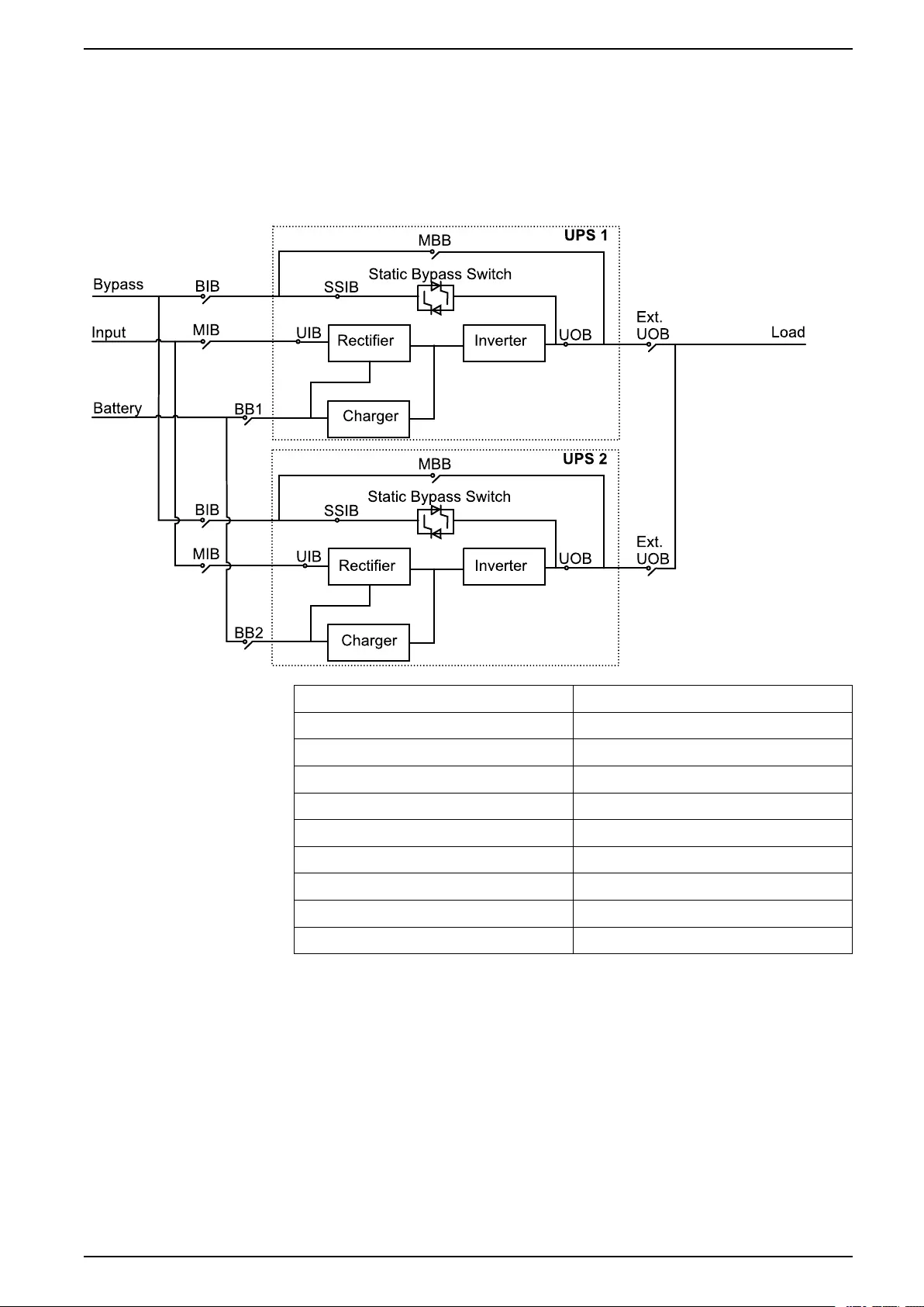
Overview of 1+1 Redundant Parallel System with Common
Battery Bank
NOTE: For UPS with internal batteries, the batteries must be removed and the
internal battery breaker (BB) must be opened.
NOTE: Common battery banks are not supported in systems with internal
batteries.
MIB Mains input breaker
BIB Bypass input breaker
UIB Unit input breaker
SSIB Static switch input breaker
UOB Unit output breaker
Ext. UOB External unit output breaker
MBB Maintenance bypass breaker
Ext. MBB External maintenance bypass breaker
BB1 Battery breaker 1
BB2 Battery breaker 2
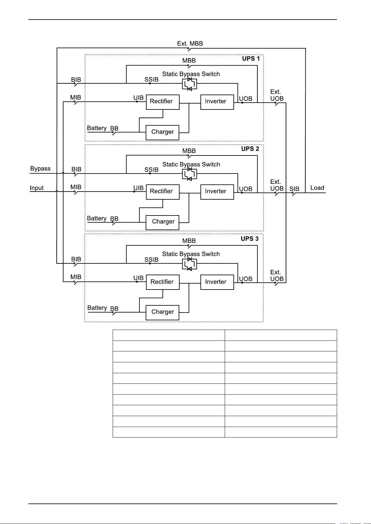
Overview of Parallel System
NOTE: In parallel systems with an external maintenance bypass breaker Ext.
MBB, the maintenance bypass breakers MBB must be padlocked in the open
position.
990-91189C–001 17
10–30 kVA 3:1 Overview
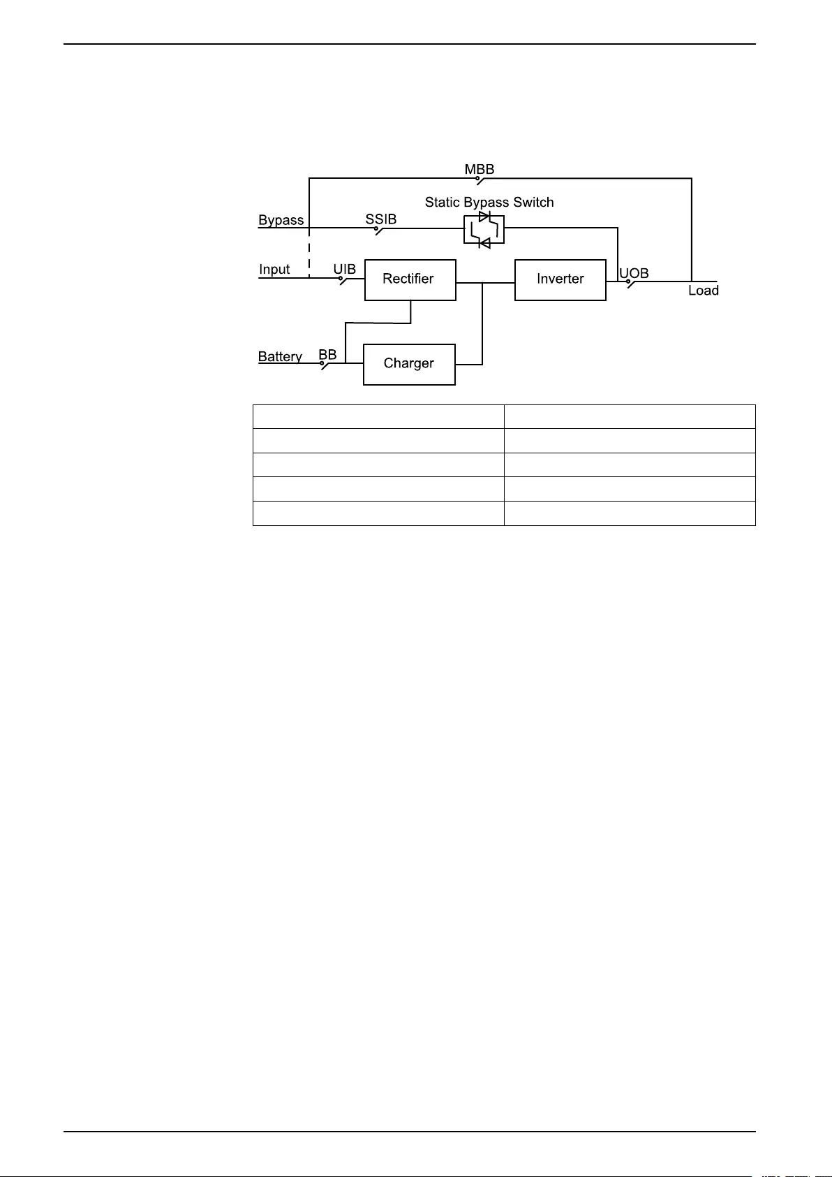
UPSs for Internal Batteries
MIB Mains input breaker
BIB Bypass input breaker
UIB Unit input breaker
SSIB Static switch input breaker
UOB Unit output breaker
Ext. UOB External unit output breaker
MBB Maintenance bypass breaker
Ext. MBB External maintenance bypass breaker
SIB System isolation breaker
BB Battery breaker
18 990-91189C–001
Receiving 10–30 kVA 3:1
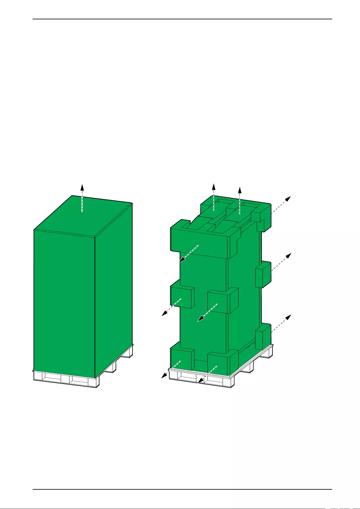
Receiving
External Inspection
When the shipment arrives, inspect the shipping material for any signs of damage
or mishandling. Do not attempt to install the system if a damage is apparent. If any
damage is noted, contact Schneider Electric and file a damage claim with the
shipping agency within 24 hours.
Compare the components of the shipment with the bill of lading. Report any
missing items to the carrier and to Schneider Electric immediately.
Verify that labelled units match the order confirmation.
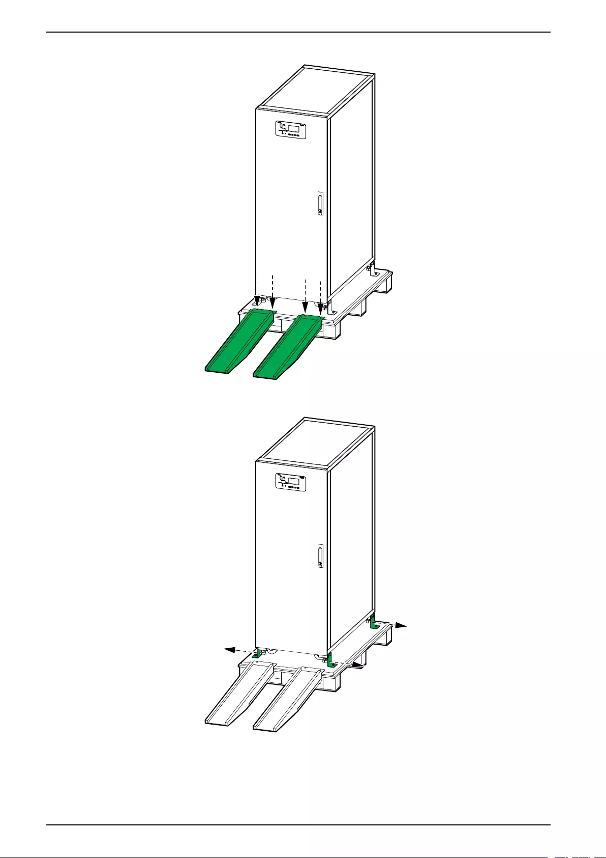
Remove the UPS from the Pallet
1. Move the UPS to the final installation area using a forklift.
2. Remove the shipping materials and the ramp from the UPS.
990-91189C–001 19


10–30 kVA 3:1 Connect the Power Cables
Connect the Power Cables
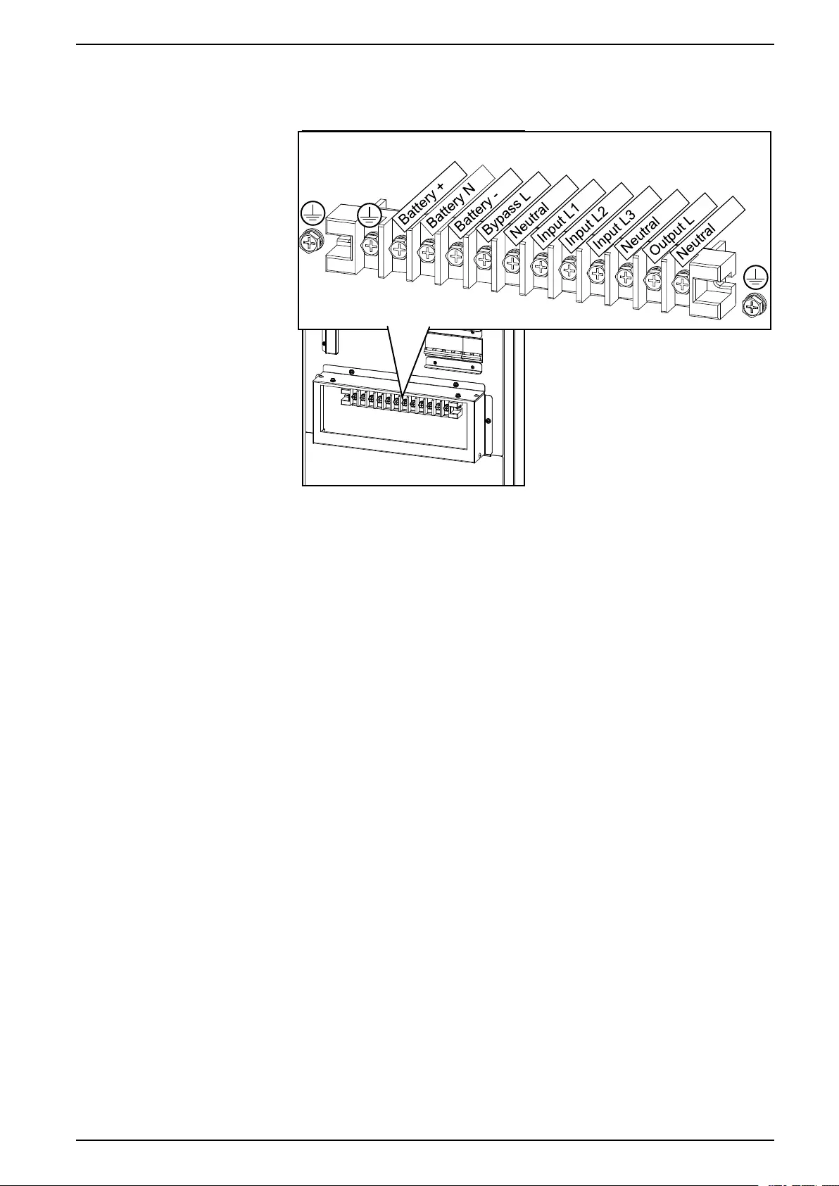
Connect the Power Cables in the 10–15 kVA UPS
1. Ensure that all breakers are in the OFF (open) position.
2. Remove the conduit box cover.
Rear View of the 10–15 kVA UPS
3. In dual mains systems, remove the single mains cable.
Rear View of the 10–15 kVA UPS
4. Route the power cables through the bottom of the conduit box.
22 990-91189C–001
Connect the Power Cables 10–30 kVA 3:1
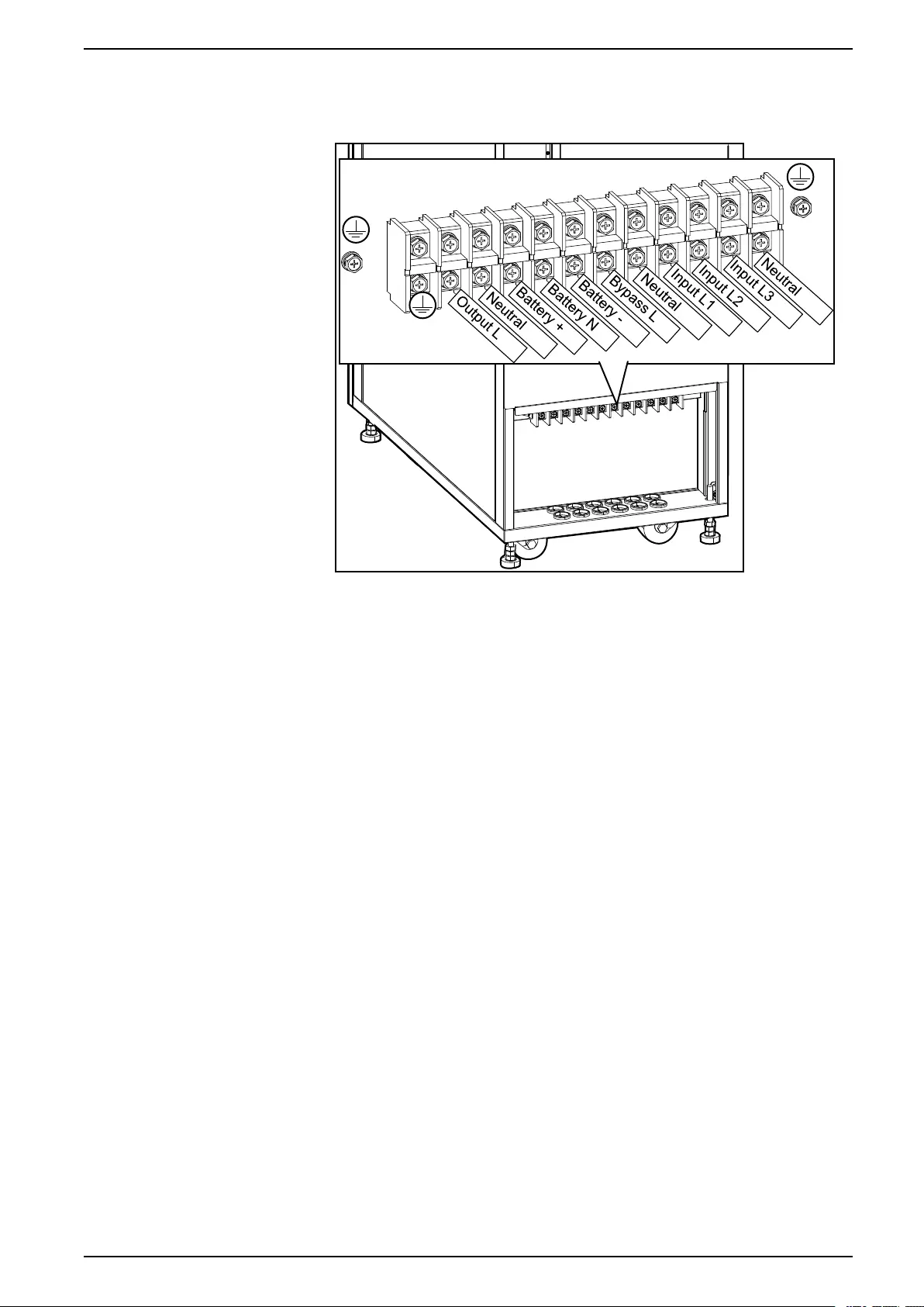
5. Connect the PE cable to the PE terminal.
Rear View of the 10–15 kVA UPS
6. Connect the input cables, output cables, and bypass cables (if applicable).
7. Connect the battery cables if the UPS should have external batteries for
extended runtime.
NOTE: Ensure that the type and number of blocks are the same as the
internal batteries.
8. Reinstall the conduit box cover.
990-91189C–001 23
10–30 kVA 3:1 Connect the Power Cables
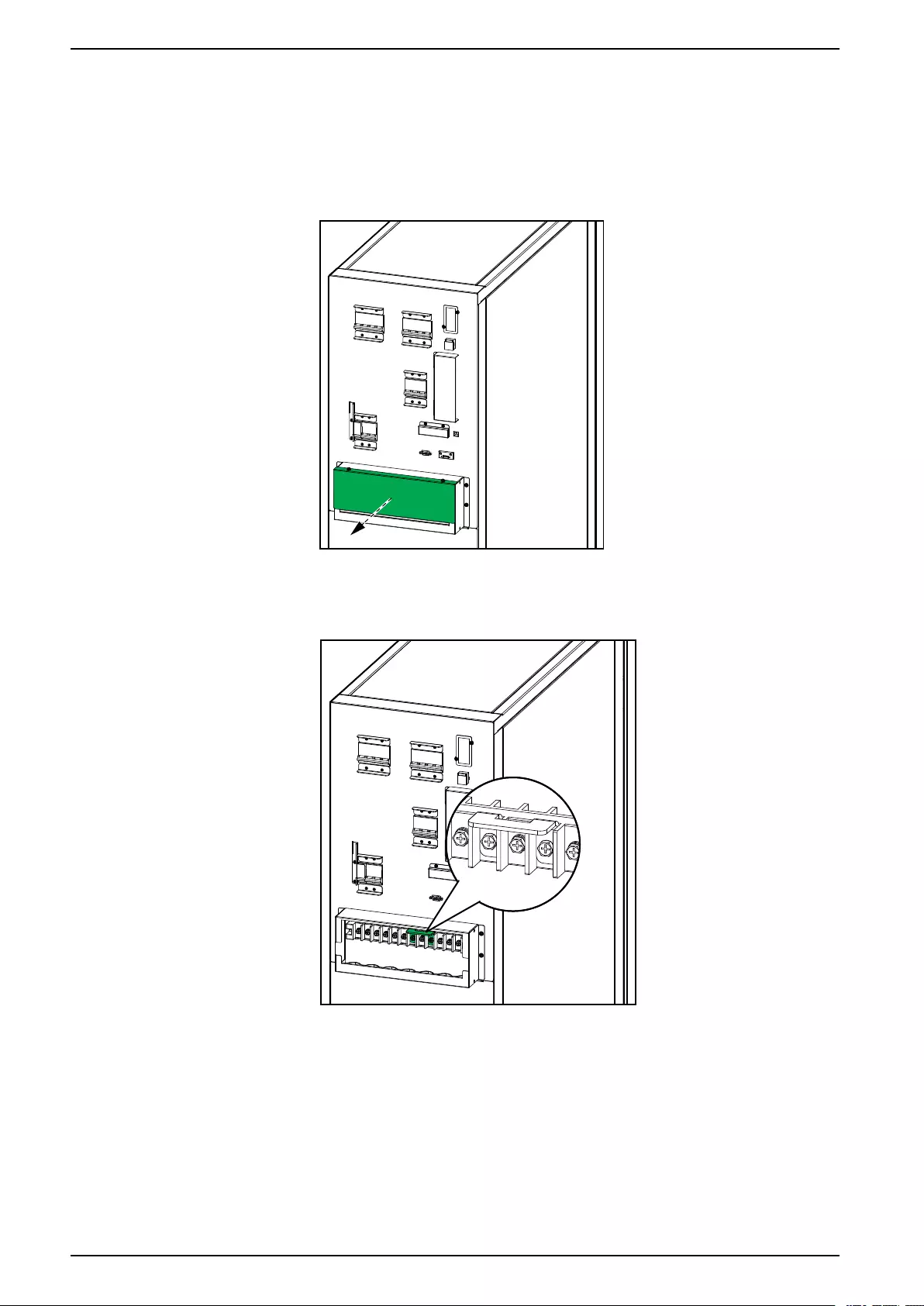
Connect the Power Cables in the 20 kVA UPS
1. Ensure that all breakers are in the OFF (open) position.
2. Remove the conduit box cover.
Rear View of the 20 kVA UPS
3. In dual mains systems, remove the single mains bracket.
Rear View of the 20 kVA UPS
4. Route the power cables through the bottom of the conduit box.
24 990-91189C–001
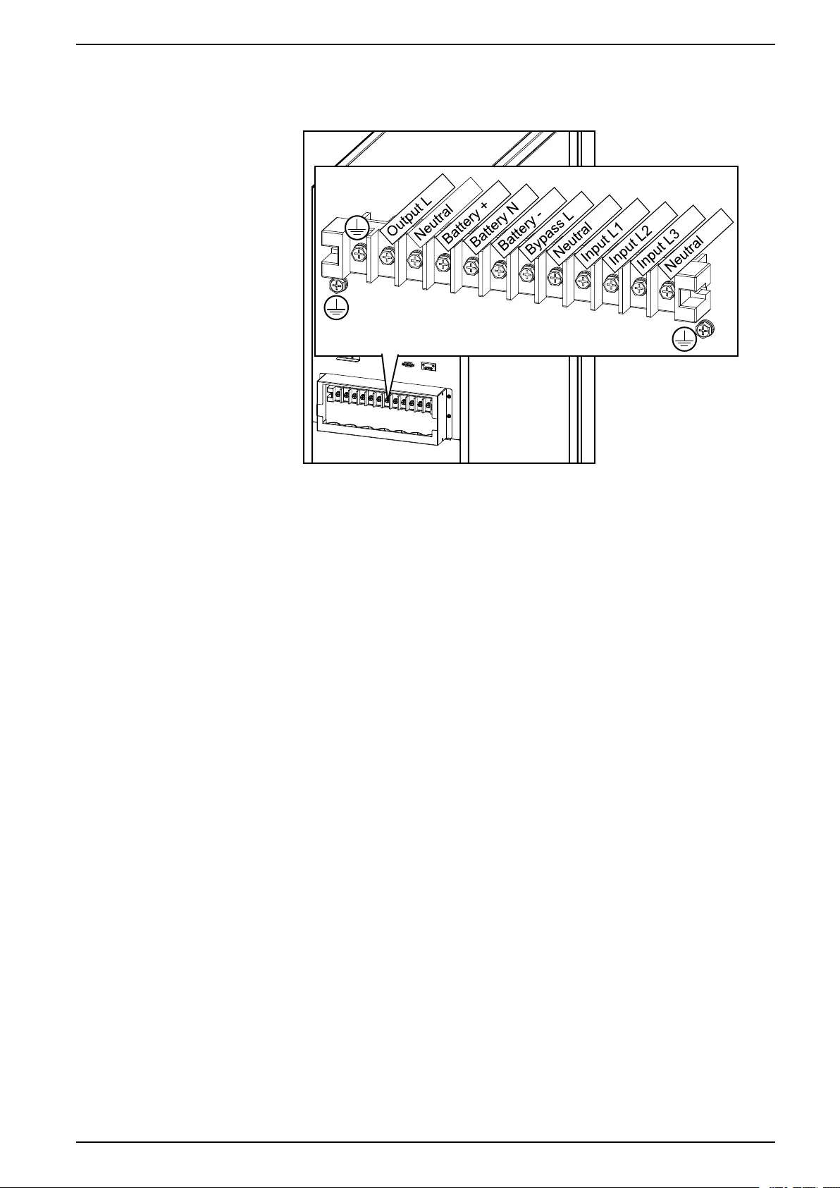
Connect the Power Cables 10–30 kVA 3:1
5. Connect the PE cable to the PE terminal.
Rear View of the 20 kVA UPS
6. Connect the input cables, output cables, and bypass cables (if applicable).
7. Connect the battery cables if the UPS should have external batteries for
extended runtime.
NOTE: Ensure that the type and number of blocks are the same as the
internal batteries.
8. Reinstall the conduit box cover.
990-91189C–001 25
10–30 kVA 3:1 Connect the Power Cables
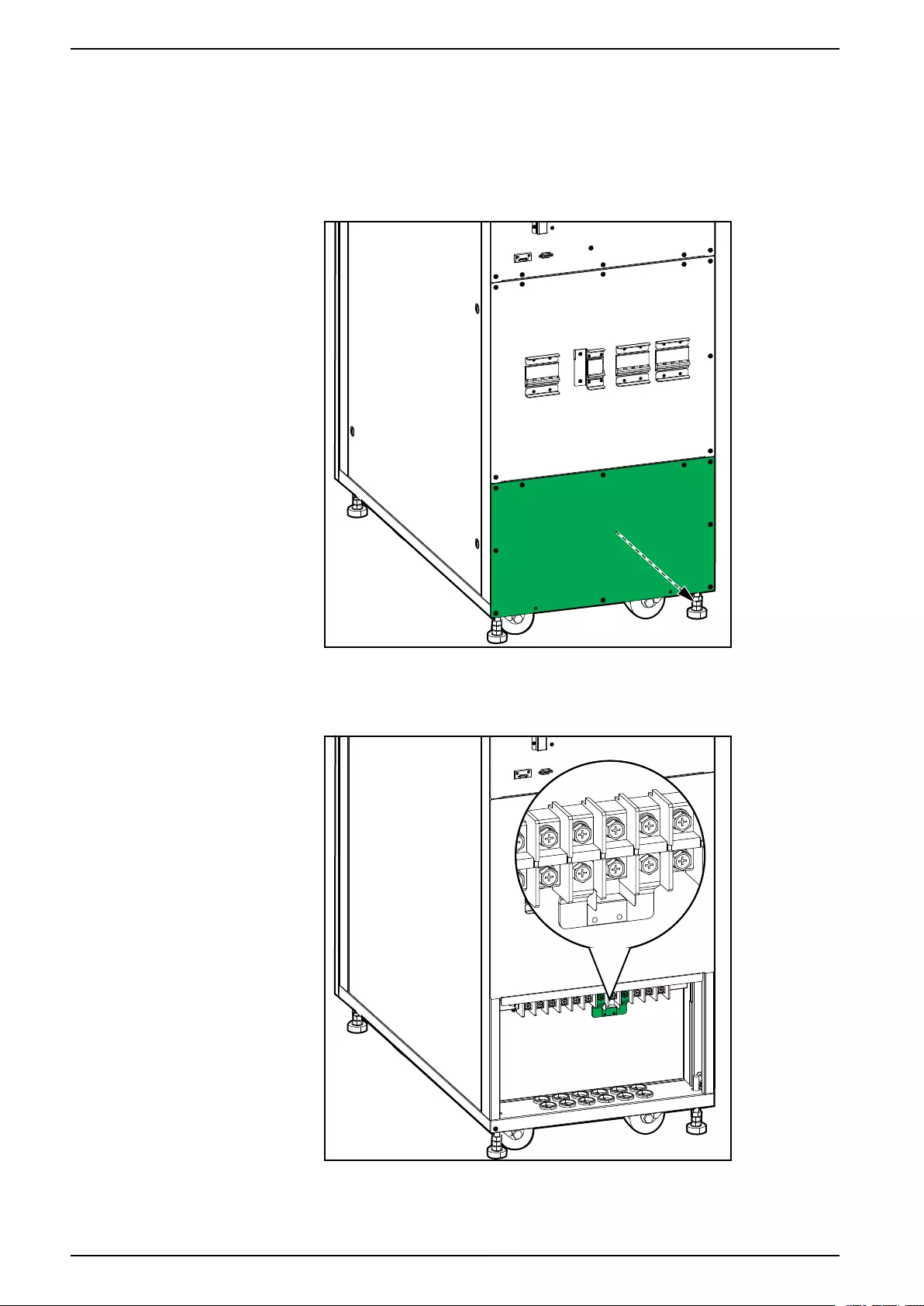
Connect the Power Cables in the 30 kVA UPS
1. Ensure that all breakers are in the OFF (open) position.
2. Remove the lower plate.
Rear View of the 30 kVA UPS
3. In dual mains systems, remove the single mains bracket.
Rear View of the 30 kVA UPS
4. Route the power cables through the bottom of the UPS.
26 990-91189C–001
Connect the Power Cables 10–30 kVA 3:1
5. Connect the PE cable to the PE busbar.
Rear View of the 30 kVA UPS
6. Connect the input cables, output cables, and bypass cables (if applicable).
7. Connect the battery cables if the UPS should have external batteries for
extended runtime.
NOTE: Ensure that the type and number of blocks are the same as the
internal batteries.
8. Reinstall the lower plate.
990-91189C–001 27
10–30 kVA 3:1 Communication Interfaces
Communication Interfaces
NOTE: Route the signal cables separately from the power cables.
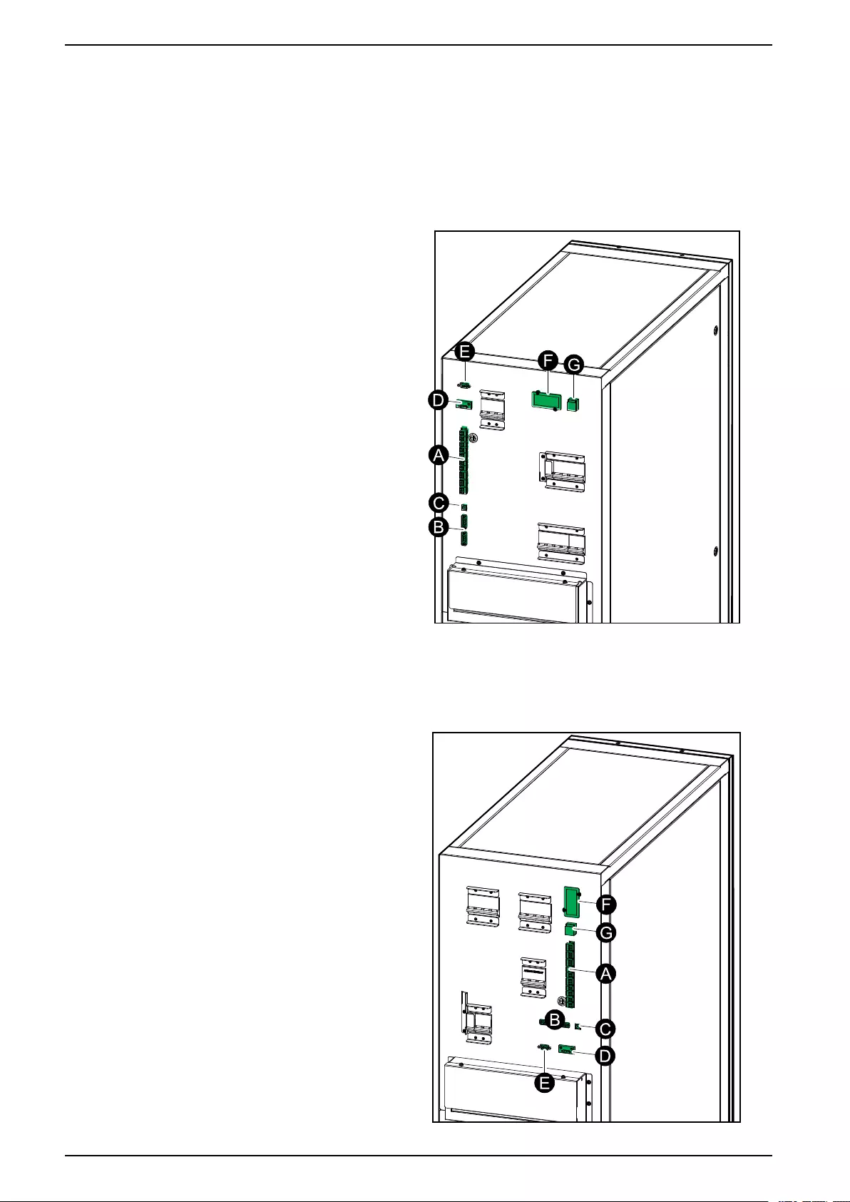
10–15 kVA UPS
A. Dry contacts
B. Parallel ports
C. USB (for service)
D. RS485
E. RS232 (for service)
F. Slot for optional SNMP
G. Cold start (optional)
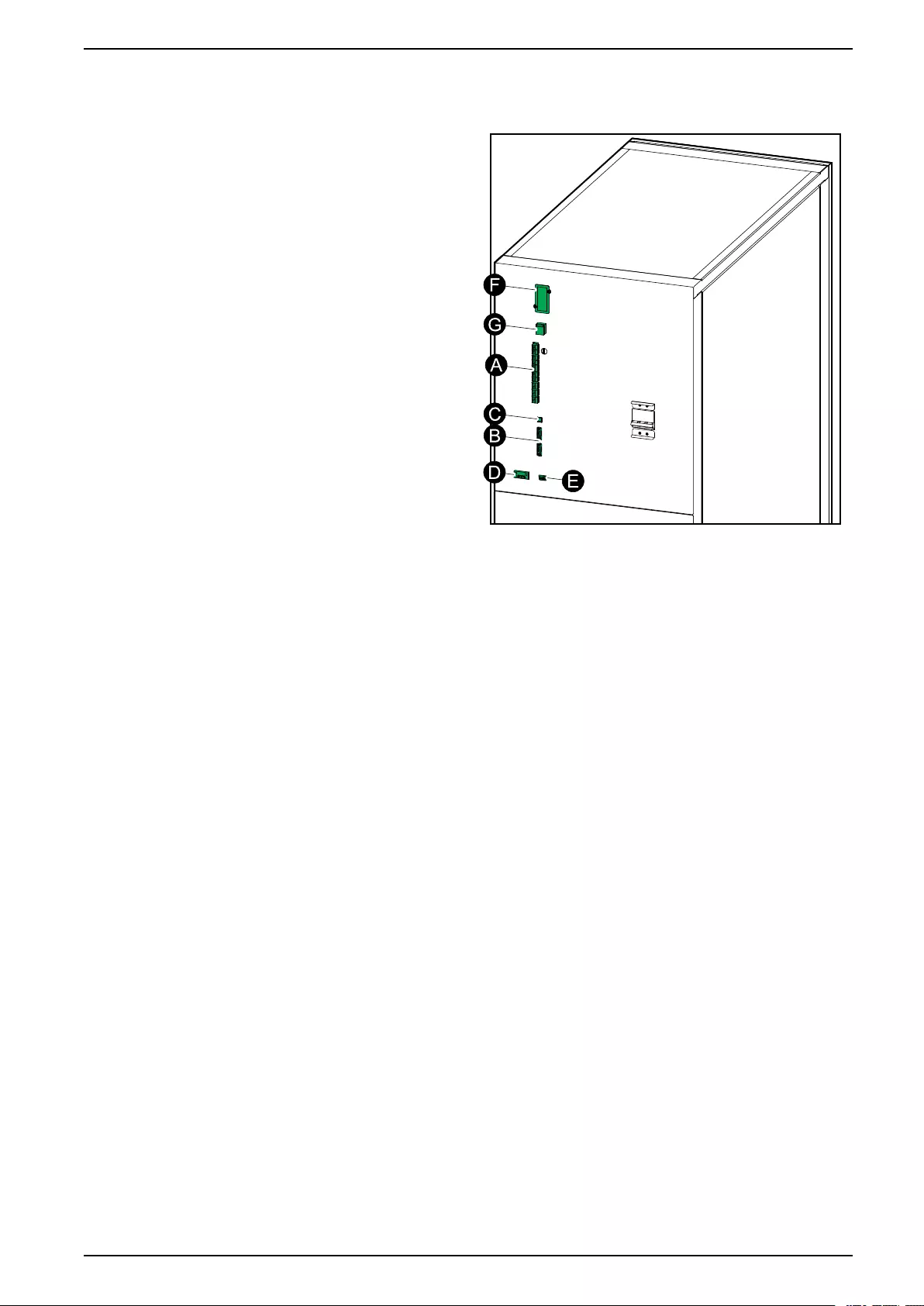
20 kVA UPS
A. Dry contacts
B. Parallel ports
C. USB (for service)
D. RS485
E. RS232 (for service)
F. Slot for optional SNMP
G. Cold start (optional)
28 990-91189C–001
10–30 kVA 3:1 Communication Interfaces
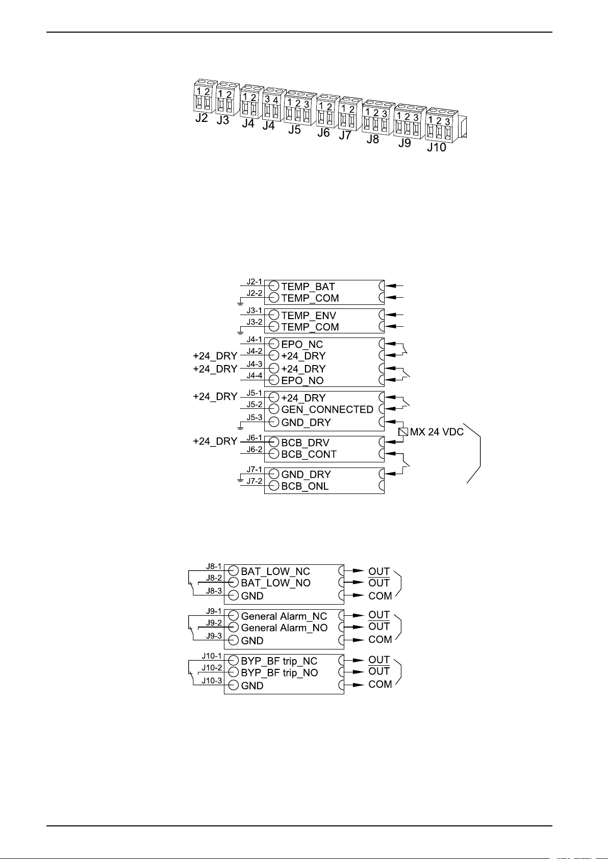
Input Contacts and Output Relays
Input Contacts
NOTE: J2 is reserved for the internal battery temperature sensor which is
installed from factory.
Input connections are considered Class 2/SELV.
Input Contacts for UPSs with Batteries
Output Relays
Output relay connection: Maximum 3A/240 VAC.
30 990-91189C–001


10–30 kVA 3:1 Backfeed Protection
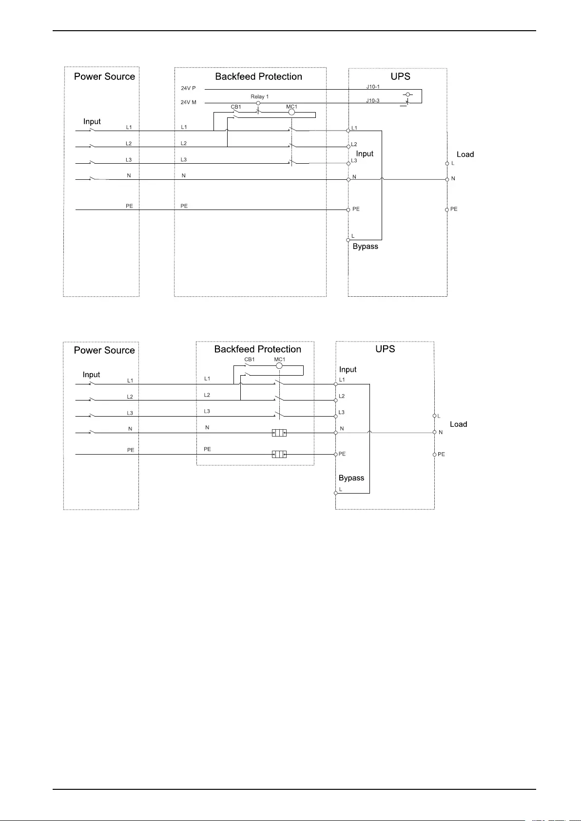
Backfeed Protection
DANGER
HAZARD OF ELECTRIC SHOCK, EXPLOSION, OR ARC FLASH
In systems where backfeed protection is not part of the standard design, an
automatic isolation device (backfeed protection option or other device meeting
the requirements of IEC/EN 62040–1) must be installed to prevent hazardous
voltage or energy at the input terminals of the isolation device. The device must
open within 15 seconds after the upstream power supply fails and must be rated
according to the specifications.
Failure to follow these instructions will result in death or serious injury.
When the UPS input is connected through external isolators that, when opened,
isolate the neutral or when the automatic backfeed isolation is provided external to
the equipment or is connected to an IT power distribution system, a label must be
fitted at the UPS input terminals, and on all primary power isolators installed
remote from the UPS area and on external access points between such isolators
and the UPS, by the user, displaying the following text (or equivalent in a language
which is acceptable in the country in which the UPS system is installed):
DANGER
HAZARD OF ELECTRIC SHOCK, EXPLOSION, OR ARC FLASH
Risk of Voltage Backfeed. Before working on this circuit: Isolate the UPS and
check for hazardous voltage between all terminals including the protective
earth.
Failure to follow these instructions will result in death or serious injury.
An additional external isolation device must be installed in the UPS system. A
magnetic contactor or a circuit breaker with UVR (Under Voltage Release)
functionality can be used for this purpose. In the shown examples, the isolation
device is a magnetic contactor (marked with a MC1 for single mains systems and
marked with a MC1 and MC2 for dual mains systems).
The isolation device must be able to withstand the electrical characteristics as
described in Input Specifications, page 11.
NOTE: The 24 V source should be generated from the input source in single
mains configurations and from the both the input and bypass source in dual
mains configurations.
32 990-91189C–001

Install Batteries in the UPS 10–30 kVA 3:1
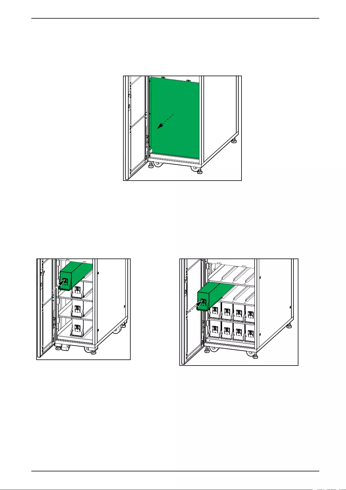
Install Batteries in the UPS
1. Remove the plate in front of the battery shelves.
Front View of the 30 kVA UPS
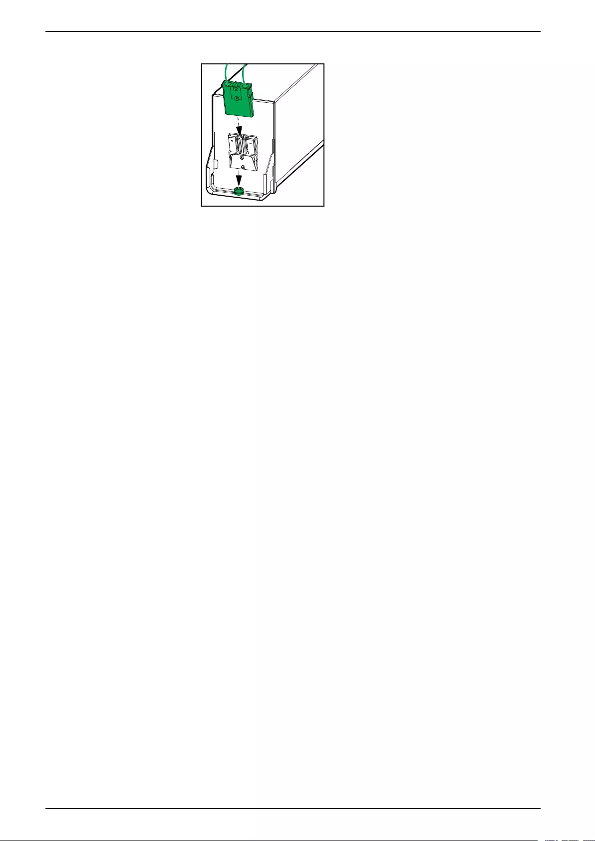
2. Install the batteries one string at a time and from the bottom and up.
NOTE: For 10–20 kVA UPSs the battery strings are vertical and for 30
kVA UPSs the battery strings are horizontal. If the 10–20 kVA UPS
contains one battery string, the batteries should be placed in the middle. If
the 10–20 kVA UPS contains two battery strings, the batteries should be
installed in the left and right sides.
Front View of the 10–20 kVA UPS Front View of the 30 kVA UPS
990-91189C–001 35

Installation Checklist 10–30 kVA 3:1
Installation Checklist
• The UPS and batteries are free of damage.
• The UPS has been installed in a temperature controlled indoor environment
free of conductive contaminants.
• The UPS has been installed on a non-flammable, level and solid surface that
can support the weight of the cabinet.
• Upstream protection is installed according to Required Upstream and
Downstream Protection and Cable Sizes, page 12 and local regulations.
• Power cables have been connected according to the procedures in this
manual.
• Signal cables have been connected according to the procedures in this
manual.
• Battery cables have been connected according to the procedures in this
manual.
• All protection covers have been installed.
990-91189C–001 37


Schneider Electric
35 rue Joseph Monier
92500 Rueil Malmaison
France
+ 33 (0) 1 41 29 70 00
*990-91189C-001*
As standards, specifications, and design change from time to time,
please ask for confirmation of the information given in this publication.
© 2018 – 2019 Schneider Electric. All rights reserved.
990-91189C–001