APC EVP1000 User Manual
Displayed below is the user manual for EVP1000 by APC which is a product in the Rack Accessories category. This manual has pages.
Related Manuals
990-91506 10/2021
© 2021 Schneider Electric. All rights reserved.
Worldwide Customer Support
Customer support and warranty information is available at
www.se.com
Emergency Ventilation Kit
Installation
EVP1000
Receiving
Inspect the Equipment
Carefully inspect the shipment for visible signs of damage. If you detect shipping
damage, contact your shipping company immediately and Schneider Electric Customer
Support at www.se.com.
Storage
The kit components should be stored indoors and out of the weather. Do not allow the
components to be exposed to the elements.
Unpacking
Each kit contains the parts for the installation of two (2) Emergency Ventilation Kits to
two (2) Air Containment Adapter doors. The kits can be installed on a front or rear door.
1. Open and unpack the kit boxes. Use a box cutter (not provided) to open
the boxes.
2. Check the contents against the Inventory list on this page.
3. Confirm the contents of the boxes are complete.
Recycle or dispose of the packaging materials appropriately.
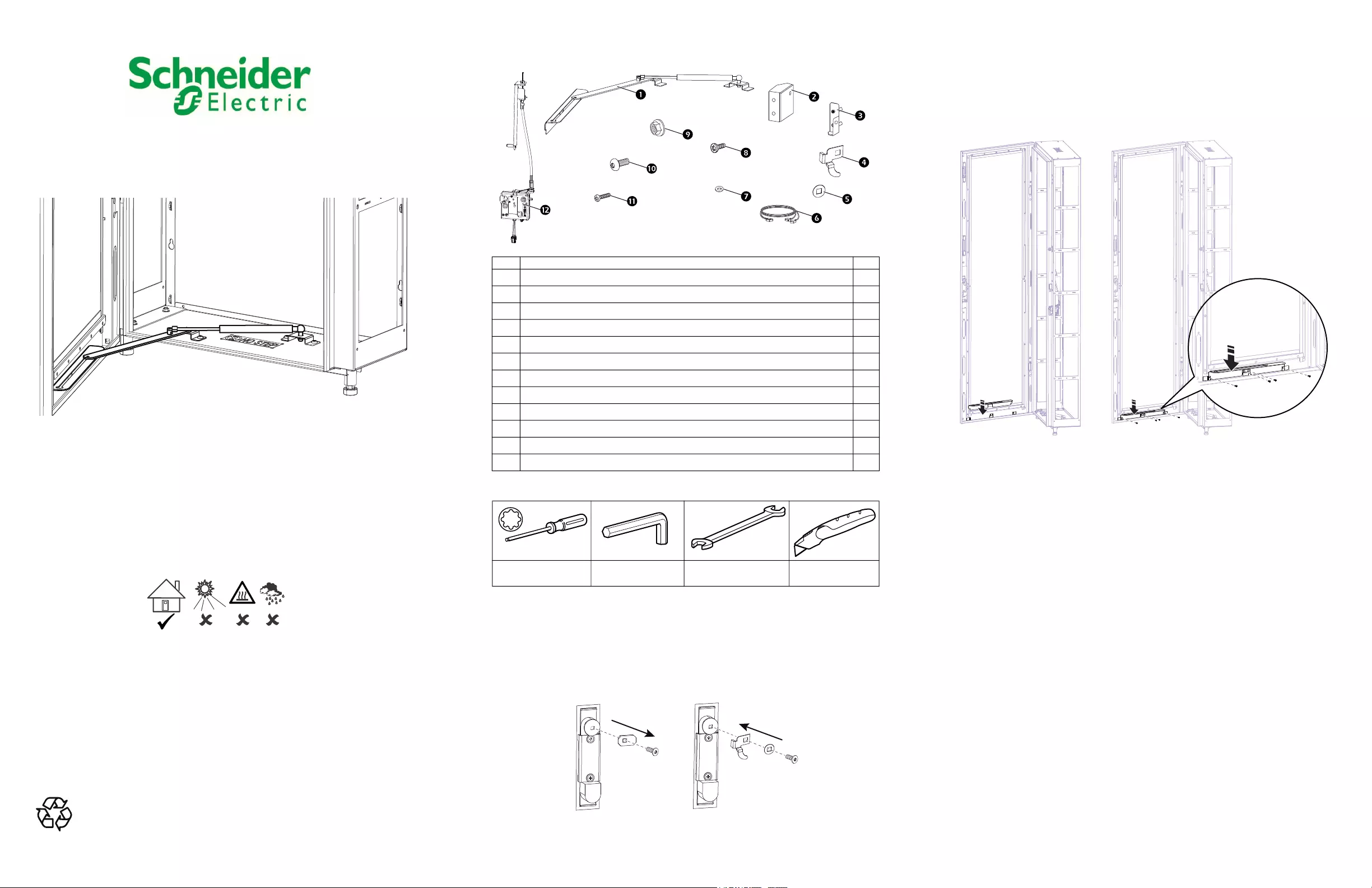
Inventory
Tools Required (not provided)
Install the Door Lock Components
Remove the screw and latch cam from the Air Containment adapter door handle.
Save the screw to install the latch cam from the kit.
Install the latch cam and spacer from the kit using the screw saved when the door
handle latch cam was removed.
Item Description Qty
Door opener assembly 2
Interior bracket for electronic lock assembly 2
Exterior bracket for electronic lock assembly 2
Latch cam (electronic lock assembly) for door handle 2
Latch cam spacer (electronic lock assembly) for door handle 2
Power and signal cable for electronic lock assembly 1
Spacer for electronic lock assembly 4
M4 x 8 pan head T20 screw 8
M6 flanged head hex nut 8
M6 x 12 pan head T30 screw 8
M5 x 16 hex screw 4
Electronic lock assembly 2
T20 and T30 Torx
head screwdrivers
Allen wrench 10-mm wrench Box cutter
ns3391a
ns3398a
Install the Door Opener Assembly
Install the door opener plate to the door
1. Insert the opener plate into the three (3) clips on the bottom of the door.
2. Secure the plate in position behind the clips with four (4) M4 x 8 pan head T20 screws
included in the kit. Use a T20 screwdriver (not provided).
ns3396a
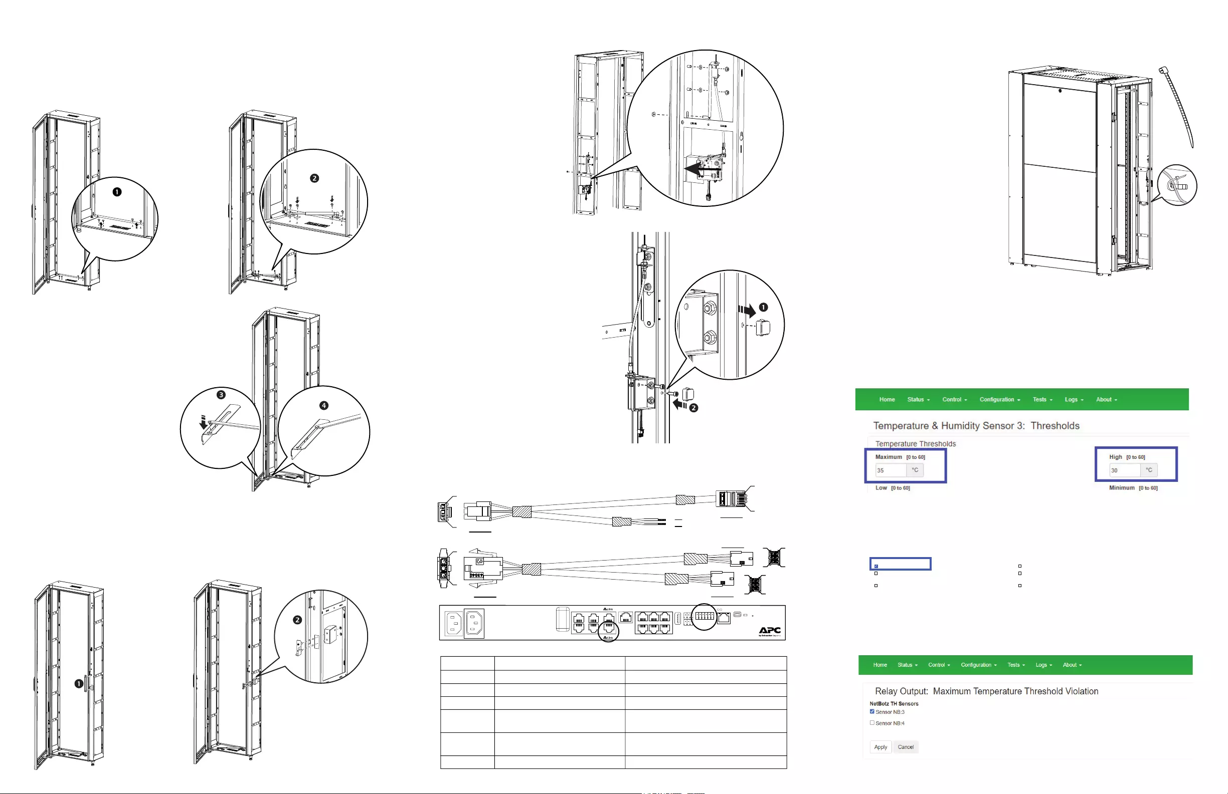
Install the opener bracket assembly to the floor of the Air
Containment frame
1. Remove the four (4) hole plugs from the floor of the Air Containment Adapter frame.
2. Install the opener bracket assembly with four (4) M6 x 12 pan head T30 screws
included in the kit. Use a T30 screwdriver (not provided) to tighten the screws.
3. Install the pin on the end of the
extension arm of the bracket
assembly into the large hole in the
opener plate on the door.
NOTE: The pin will fit through either
hole and can accommodate
installation or removal of the pin.
4. The pin should slide smoothly in
the channel between the large hole
and smaller hole in the opener plate.
NOTE: The door of the Air
Containment adapter has a normal
opening range of 130 degrees. With
the door opener bracket of the
Emergency Ventilation Kit installed,
the opening range is 70 degrees.
Remove the pin on the extension
arm from the door plate to open the
door to its full range.
Install the Electronic Locking Assembly
1. Remove the cover plate on the Air Containment Adapter frame.
2. Install the interior and exterior brackets from the kit with two (2) M6 flanged hex nuts
from the kit. Use a 10-mm wrench (not provided) to tighten the hex nuts..
ns3404a
ns3405a
ns3397a
ns3399a
ns3393a
3. Install the body of the
electronic locking assembly
through the rectangular
opening on the frame next to
the interior and exterior
brackets.
4. Secure the bracket to the
frame with the two (2)
spacers from the kit to the
frame with two (2) M6
flanged hex nuts also from
the kit. Use a 10-mm wrench
(not provided) to tighten the
hex nuts.
5. Remove the hole plug from the Air
Containment adapter frame.
6. Secure the body of the electronic
lock to the interior bracket and the Air
Containment adapter frame with two
(2) M5 x 15 hex screws (included)
using an Allen wrench (not provided).
Cable Configuration
Make the cable connections as shown in the table.
Connector PIN Definition Connection
CONN1 P1: GND, P3: 24VDC Connect to CONN3
CONN3 P1: GND, P3: 24VDC Connect to CONN1
CONN2 P4, P5: GND; P3, P6: 24 VDC Connect to the NetBotz A-Link port
CONN4 P1: GND; P2: 24VDC Power; PIN3:
24VDC Control Signal
Connect to the cable on the electronic lock
body installed on the rear door.
CONN5 P1: GND; P2: 24VDC Power; PIN3:
24VDC Control Signal
Connect to the cable on the electronic lock
body installed on the front door.
T1; T2 T1: GND; T2: 24VDC Connect to the NetBotz Relay Output port
ns3403a
View from rear of
Air Containment Frame
ns3401a
P1
P3
P3
P1
P6 P3
P4 P1
CONN 3
CONN 4
CONN 5 P6 P3
P4 P1
CONN 1
CONN 2
T1
T2
P1
P8
NetBotz Rack Monitor 250
123
56
4
Sensors
Reset
USB Power
Console
Port
Voltage
Output Relay
Output
Com
RxD
1+ 0-
Beacon
Door #1 Door #2
Handle #1 Handle #2
Wireless
Ch
Gnd
1+ 0-
TxD
+
24 +
12 G
N
D
N
OC
O
M
N
C
10/100
99xx
Modbus
ns3408a
Connect the Cable
1. Connect the cable to the connector
at the bottom of the electronic locking
assembly body.
2. Connect the other end of the cable
to the NetBotz appliance in your
Easy Rack.
3. Secure the cable to the frame with
zip ties (not provided).
Configure the NetBotz
The cold aisle temperature maximum threshold initiates the Emergency Ventilation
system causing the electronic lock to release and allowing the doors to open.
1. Log in to the NetBotz Web UI (see the NetBotz user manual for information).
2. Navigate to the Configuration > Temperature & Humidity Sensors page. Select
the cold aisle sensor. Set the Maximum Threshold value to 35°C (default) and the High
Value to 30°C (default). Click the Apply button to save the settings.
3. Navigate to the Control > Relay Output page. Select Maximum Threshold Violation
in the Alarm Mapping section. Click the Apply button to save your changes.
4. Click on Maximum Threshold Violation to go to the Configuration page. Click on the
checkbox of the cold aisle TH Sensor to select it. Click the Apply button to save the
selection.
NetBotz
ns3402a
Maximum Threshold Violation
Maximum Threshold Violation
High Threshold Violation
Low Threshold Violation
Low Threshold Violation
Minimum Threshold Violation
Alarm Mapping
Temperature Alarms
Humidity Alarms
Select one or more alarms that will turn the relay on, if activated. To customize the reporting sensors, click on the alarm name. When any of the selected sensors are in an
alarmed state, the output relay will be triggered to switch states.
An asterisk* indicates that not all available sensors are selected.