Table of Contents
- Galaxy VS
- Important Safety Instructions — SAVE THESE INSTRUCTIONS
- Specifications
- Installation Procedure
- Mount the Maintenance Bypass Panel to the Wall
- Prepare the Maintenance Bypass Panel for Cables
- Remove the Neutral Jumper (Option)
- Connect the Power Cables
- Connect the Signal Cables for Single System
- Connect the Signal Cables for Simplified 1+1 Parallel System
- Add Translated Safety Labels to Your Product
- Final Installation
- Blank Page
- Blank Page
APC GVSBPSU10K20H User Manual
Displayed below is the user manual for GVSBPSU10K20H by APC which is a product in the UPS Accessories category. This manual has pages.
Related Manuals
Galaxy VS
Wall-Mounted Maintenance Bypass Panel
Installation
GVSBPSU10K20H, GVSBPSU20K60H, GVSBPSU80K120H
6/2019
www.schneider-electric.com

Legal Information
The Schneider Electric brand and any trademarks of Schneider Electric SE and its
subsidiaries referred to in this guide are the property of Schneider Electric SE or its
subsidiaries. All other brands may be trademarks of their respective owners.
This guide and its content are protected under applicable copyright laws and
furnished for informational use only. No part of this guide may be reproduced or
transmitted in any form or by any means (electronic, mechanical, photocopying,
recording, or otherwise), for any purpose, without the prior written permission of
Schneider Electric.
Schneider Electric does not grant any right or license for commercial use of the guide
or its content, except for a non-exclusive and personal license to consult it on an "as
is" basis. Schneider Electric products and equipment should be installed, operated,
serviced, and maintained only by qualified personnel.
As standards, specifications, and designs change from time to time, information
contained in this guide may be subject to change without notice.
To the extent permitted by applicable law, no responsibility or liability is assumed by
Schneider Electric and its subsidiaries for any errors or omissions in the informational
content of this material or consequences arising out of or resulting from the use of the
information contained herein.
Go to
https://www.productinfo.schneider-electric.com/portals/ui/galaxyvs_iec/
or scan the QR code above for digital experience and translated manuals.

Wall-Mounted Maintenance Bypass Panel
Table of Contents
Important Safety Instructions — SAVE THESE
INSTRUCTIONS.........................................................................................5
Electromagnetic Compatibility .....................................................................6
Safety Precautions .....................................................................................6
Additional Safety Precautions After Installation........................................8
Electrical Safety....................................................................................8
Specifications ..............................................................................................9
Recommended Upstream Protection............................................................9
Recommended Cable Sizes ........................................................................9
Torque Specifications..................................................................................9
Maintenance Bypass Panel Weights and Dimensions....................................9
Clearance ................................................................................................10
Environment.............................................................................................10
One Line Diagrams................................................................................... 11
Installation Procedure ..............................................................................13
Mount the Maintenance Bypass Panel to the Wall ..............................14
Prepare the Maintenance Bypass Panel for Cables............................16
Remove the Neutral Jumper (Option)....................................................17
Connect the Power Cables......................................................................18
Connect the Signal Cables for Single System......................................21
Connect the Signal Cables for Simplified 1+1 Parallel
System........................................................................................................24
Add Translated Safety Labels to Your Product.....................................31
Final Installation ........................................................................................32
990-5912B-001 3

Important Safety Instructions — SAVE THESE
INSTRUCTIONS Wall-Mounted Maintenance Bypass Panel
Important Safety Instructions — SAVE THESE
INSTRUCTIONS
Read these instructions carefully and look at the equipment to become familiar
with it before trying to install, operate, service or maintain it. The following safety
messages may appear throughout this manual or on the equipment to warn of
potential hazards or to call attention to information that clarifies or simplifies a
procedure.
The addition of this symbol to a “Danger” or “Warning” safety
message indicates that an electrical hazard exists which will result in
personal injury if the instructions are not followed.
This is the safety alert symbol. It is used to alert you to potential
personal injury hazards. Obey all safety messages with this symbol
to avoid possible injury or death.
DANGER
DANGER indicates a hazardous situation which, if not avoided, will result in
death or serious injury.
Failure to follow these instructions will result in death or serious injury.
WARNING
WARNING indicates a hazardous situation which, if not avoided, could result
in death or serious injury.
Failure to follow these instructions can result in death, serious injury, or
equipment damage.
CAUTION
CAUTION indicates a hazardous situation which, if not avoided, could result in
minor or moderate injury.
Failure to follow these instructions can result in injury or equipment
damage.
NOTICE
NOTICE is used to address practices not related to physical injury. The safety
alert symbol shall not be used with this type of safety message.
Failure to follow these instructions can result in equipment damage.
Please Note
Electrical equipment should only be installed, operated, serviced, and maintained
by qualified personnel. No responsibility is assumed by Schneider Electric for any
consequences arising out of the use of this material.
A qualified person is one who has skills and knowledge related to the construction,
installation, and operation of electrical equipment and has received safety training
to recognize and avoid the hazards involved.
990-5912B-001 5
Wall-Mounted Maintenance Bypass Panel
Important Safety Instructions — SAVE THESE
INSTRUCTIONS
Electromagnetic Compatibility
NOTICE
RISK OF ELECTROMAGNETIC DISTURBANCE
This is a product category C2 UPS product. In a residential environment, this
product may cause radio inference, in which case the user may be required to
take additional measures.
Failure to follow these instructions can result in equipment damage.
Safety Precautions
DANGER
HAZARD OF ELECTRIC SHOCK, EXPLOSION, OR ARC FLASH
Read all instructions in the installation manual before installing or working on
this product.
Failure to follow these instructions will result in death or serious injury.
DANGER
HAZARD OF ELECTRIC SHOCK, EXPLOSION, OR ARC FLASH
Do not install the product until all construction work has been completed and the
installation room has been cleaned.
Failure to follow these instructions will result in death or serious injury.
DANGER
HAZARD OF ELECTRIC SHOCK, EXPLOSION, OR ARC FLASH
The product must be installed according to the specifications and requirements
as defined by Schneider Electric. It concerns in particular the external and
internal protections (upstream breakers, battery breakers, cabling, etc.) and
environmental requirements. No responsibility is assumed by Schneider Electric
if these requirements are not respected.
Failure to follow these instructions will result in death or serious injury.
DANGER
HAZARD OF ELECTRIC SHOCK, EXPLOSION, OR ARC FLASH
The UPS system must be installed according to local and national regulations.
Install the UPS according to:
• IEC 60364 (including 60364–4–41- protection against electric shock, 60364–
4–42 - protection against thermal effect, and 60364–4–43 - protection
against overcurrent), or
• NEC NFPA 70, or
• Canadian Electrical Code (C22.1, Part 1)
depending on which one of the standards apply in your local area.
Failure to follow these instructions will result in death or serious injury.
6 990-5912B-001
Important Safety Instructions — SAVE THESE
INSTRUCTIONS Wall-Mounted Maintenance Bypass Panel
DANGER
HAZARD OF ELECTRIC SHOCK, EXPLOSION, OR ARC FLASH
• Install the product in a temperature controlled indoor environment free of
conductive contaminants and humidity.
• Install the product on a non-flammable, level and solid surface (e.g.
concrete) that can support the weight of the system.
Failure to follow these instructions will result in death or serious injury.
DANGER
HAZARD OF ELECTRIC SHOCK, EXPLOSION, OR ARC FLASH
The product is not designed for and must therefore not be installed in the
following unusual operating environments:
• Damaging fumes
• Explosive mixtures of dust or gases, corrosive gases, or conductive or
radiant heat from other sources
• Moisture, abrasive dust, steam or in an excessively damp environment
• Fungus, insects, vermin
• Salt-laden air or contaminated cooling refrigerant
• Pollution degree higher than 2 according to IEC 60664-1
• Exposure to abnormal vibrations, shocks, and tilting
• Exposure to direct sunlight, heat sources, or strong electromagnetic fields
Failure to follow these instructions will result in death or serious injury.
DANGER
HAZARD OF ELECTRIC SHOCK, EXPLOSION, OR ARC FLASH
Do not drill or cut holes for cables or conduits with the gland plates installed and
do not drill or cut holes in close proximity to the UPS.
Failure to follow these instructions will result in death or serious injury.
WARNING
HAZARD OF ARC FLASH
Do not make mechanical changes to the product (including removal of cabinet
parts or drilling/cutting of holes) that are not described in the installation manual.
Failure to follow these instructions can result in death, serious injury, or
equipment damage.
NOTICE
RISK OF OVERHEATING
Respect the space requirements around the product and do not cover the
ventilation openings when the product is in operation.
Failure to follow these instructions can result in equipment damage.
990-5912B-001 7
Wall-Mounted Maintenance Bypass Panel
Important Safety Instructions — SAVE THESE
INSTRUCTIONS
Additional Safety Precautions After Installation
DANGER
HAZARD OF ELECTRIC SHOCK, EXPLOSION, OR ARC FLASH
Do not install the UPS system until all construction work has been completed
and the installation room has been cleaned. If additional construction work is
needed in the installation room after this product has been installed, turn off the
product and cover the product with the protective packaging bag the product
was delivered in.
Failure to follow these instructions will result in death or serious injury.
Electrical Safety
This manual contains important safety instructions that should be followed during
the installation and maintenance of the UPS system.
DANGER
HAZARD OF ELECTRIC SHOCK, EXPLOSION, OR ARC FLASH
• Electrical equipment must be installed, operated, serviced, and maintained
only by qualified personnel.
• Apply appropriate personal protective equipment (PPE) and follow safe
electrical work practices.
• Disconnection devices for AC and DC must be provided by others, be readily
accessible, and the function of the disconnect device marked for its function.
• Turn off all power supplying the UPS system before working on or inside the
equipment.
• Before working on the UPS system, check for hazardous voltage between all
terminals including the protective earth.
• The UPS contains an internal energy source. Hazardous voltage can be
present even when disconnected from the mains supply. Before installing or
servicing the UPS system, ensure that the units are OFF and that mains and
batteries are disconnected. Wait five minutes before opening the UPS to
allow the capacitors to discharge.
• The UPS must be properly earthed/grounded and due to a high leakage
current, the earthing/grounding conductor must be connected first.
Failure to follow these instructions will result in death or serious injury.
When the UPS input is connected through external isolators that, when opened,
isolate the neutral or when the automatic backfeed isolation is provided external to
the equipment or is connected to an IT power distribution system, a label must be
fitted at the UPS input terminals, and on all primary power isolators installed
remotely from the UPS area and on external access points between such isolators
and the UPS, by the user, displaying the following text (or equivalent in a language
which is acceptable in the country in which the UPS system is installed):
DANGER
HAZARD OF ELECTRIC SHOCK, EXPLOSION, OR ARC FLASH
Risk of voltage backfeed. Before working on this circuit: Isolate the UPS and
check for hazardous voltage between all terminals including the protective
earth.
Failure to follow these instructions will result in death or serious injury.
8 990-5912B-001
Specifications Wall-Mounted Maintenance Bypass Panel
Specifications
NOTE: Maximum short circuit rating: 10 kA RMS symmetrical.
NOTE: GVSBPSU80K120H can support a load of up to 120 kW/kVA as long
as the neutral current (250 A) is not exceeded:
• at 380 V, the maximum neutral current capability is reached with a 95 kVA
non-linear load.
• at 400 V, the maximum neutral current capability is reached with a 100
kVA non-linear load.
Recommended Upstream Protection
Refer to the UPS installation manual for recommended upstream protection.
Recommended Cable Sizes
DANGER
HAZARD OF ELECTRIC SHOCK, EXPLOSION, OR ARC FLASH
All wiring must comply with all applicable national and/or electrical codes. The
maximum allowable cable size is 16 mm2for GVSBPSU10K20H, 70 mm2for
GVSBPSU20K60H, and 150 mm2for GVSBPSU80K120H.
Failure to follow these instructions will result in death or serious injury.
NOTE: Aluminum cables are not supported in a 80-100 kW simplified 1+1
parallel systems.
Refer to the UPS installation manual for recommended cable sizes.
Torque Specifications
Bolt size Torque
M4 1.7 Nm
M5 2.2 Nm
M6 5 Nm
M8 17.5 Nm
M10 30 Nm
Maintenance Bypass Panel Weights and Dimensions
Commercial reference Weight kg Height mm Width mm Depth mm
GVSBPSU10K20H 12 450 400 150
GVSBPSU20K60H 25 600 550 220
GVSBPSU80K120H 40 800 600 280
990-5912B-001 9
Wall-Mounted Maintenance Bypass Panel Specifications
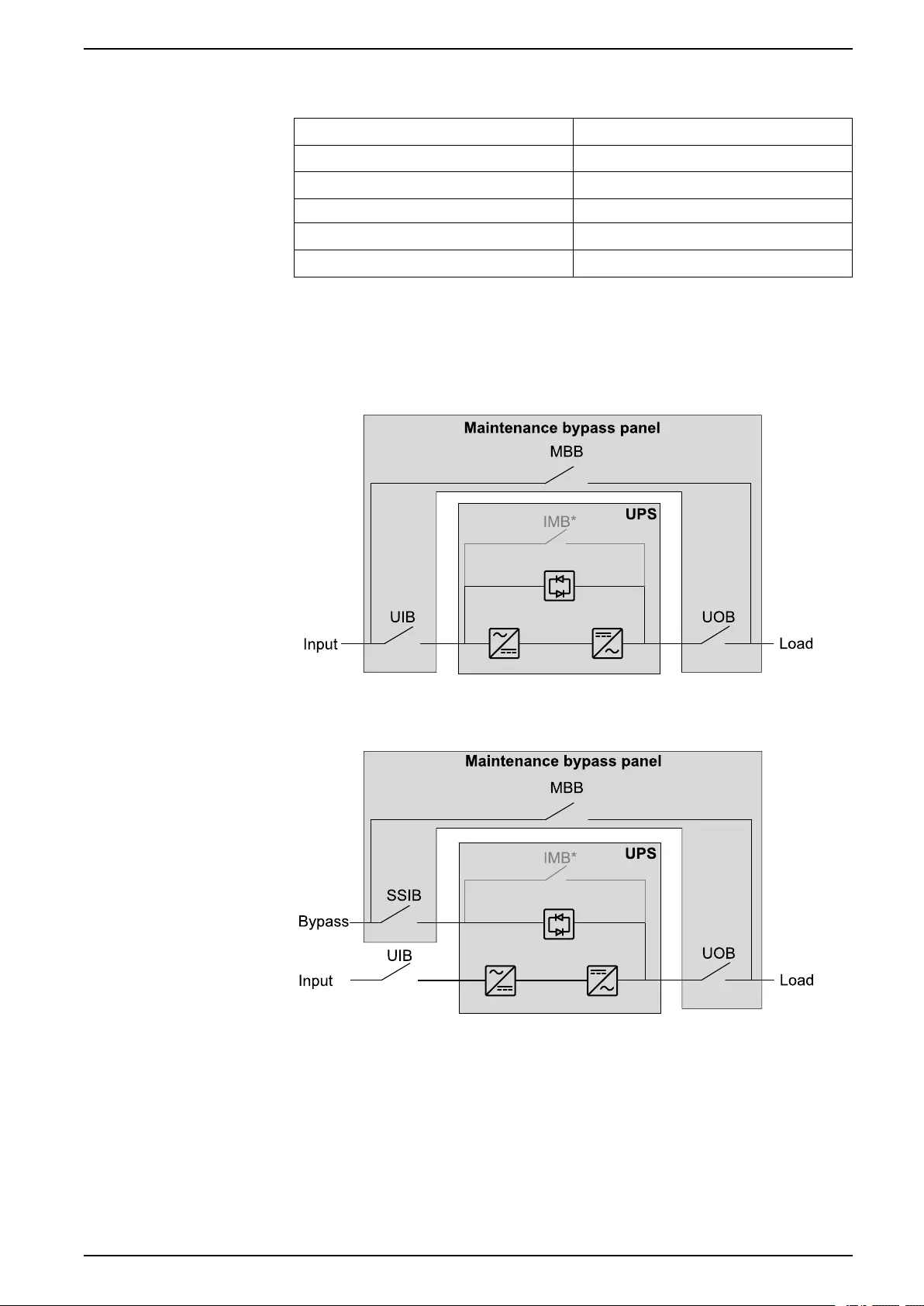
Clearance
NOTE: Clearance dimensions are published for airflow and service access
only. Consult with the local safety codes and standards for additional
requirements in your local area.
Environment
Operating Storage
Temperature 0 °C to 40 °C -25 °C to 55 °C
Relative humidity 0 – 95% non-condensing 0 – 95% non-condensing
Elevation 0-3000 m
Protection class IP20
Color RAL 9003, gloss level 85%
10 990-5912B-001
Specifications Wall-Mounted Maintenance Bypass Panel
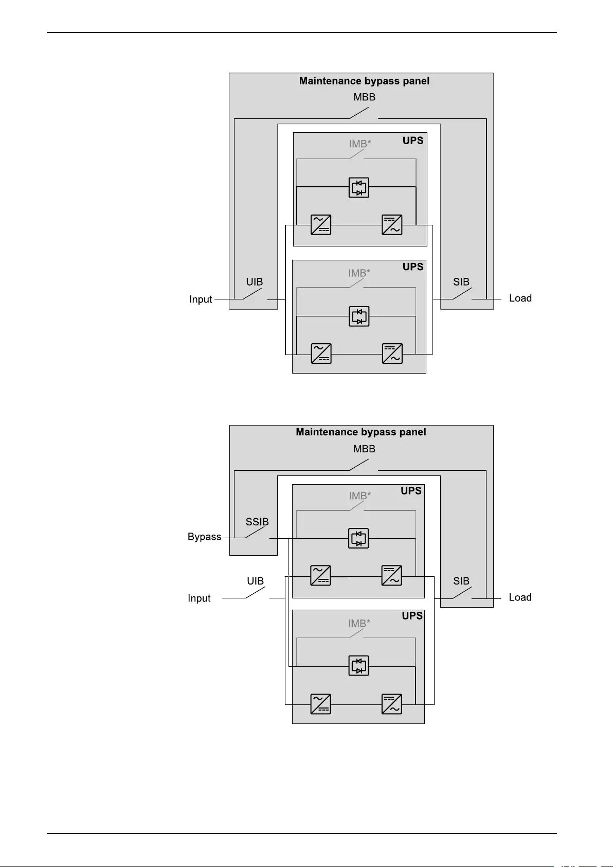
One Line Diagrams
UIB Unit input breaker
SSIB Static switch input breaker
MBB Maintenance bypass breaker
IMB Internal maintenance breaker
UOB Unit output breaker
SIB System isolation breaker
NOTE: The internal maintenance breaker IMB* in the UPS cannot be used in
a system with an maintenance bypass panel and the internal maintenance
breaker IMB* must be padlocked in the open position.
Single System – Single Mains
Single System – Dual Mains
990-5912B-001 11
Installation Procedure Wall-Mounted Maintenance Bypass Panel
Installation Procedure
Single System – Single Mains
Simplified 1+1 Parallel System – Single Mains
Single System – Dual Mains
Simplified 1+1 Parallel System – Dual Mains
1. Mount the Maintenance Bypass Panel to the Wall, page 14.
2. Prepare the Maintenance Bypass Panel for Cables, page 16.
3. Only in countries where required: Remove the Neutral Jumper (Option), page
17.
4. Connect the Power Cables, page 18.
5. Do one of the following:
–Connect the Signal Cables for Single System, page 21, or
–Connect the Signal Cables for Simplified 1+1 Parallel System, page 24.
6. Add Translated Safety Labels to Your Product, page 31.
7. Final Installation, page 32.
990-5912B-001 13
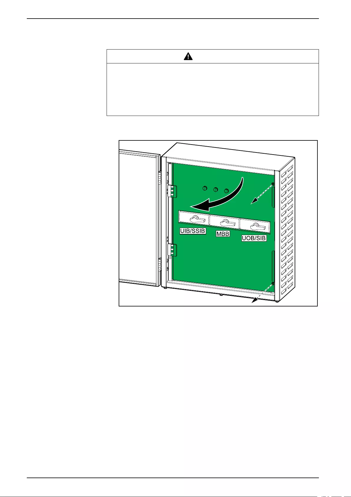
Wall-Mounted Maintenance Bypass Panel Mount the Maintenance Bypass Panel to the Wall
Mount the Maintenance Bypass Panel to the Wall
CAUTION
RISK OF INJURY OR EQUIPMENT DAMAGE
• Mount the maintenance bypass panel to a wall or a rack that is structurally
sound and able to support the weight of the unit.
• Use appropriate hardware for the wall/rack type.
Failure to follow these instructions can result in injury or equipment
damage.
1. Remove the screws and open the inner door in the maintenance bypass
panel.
14 990-5912B-001
Mount the Maintenance Bypass Panel to the Wall Wall-Mounted Maintenance Bypass Panel
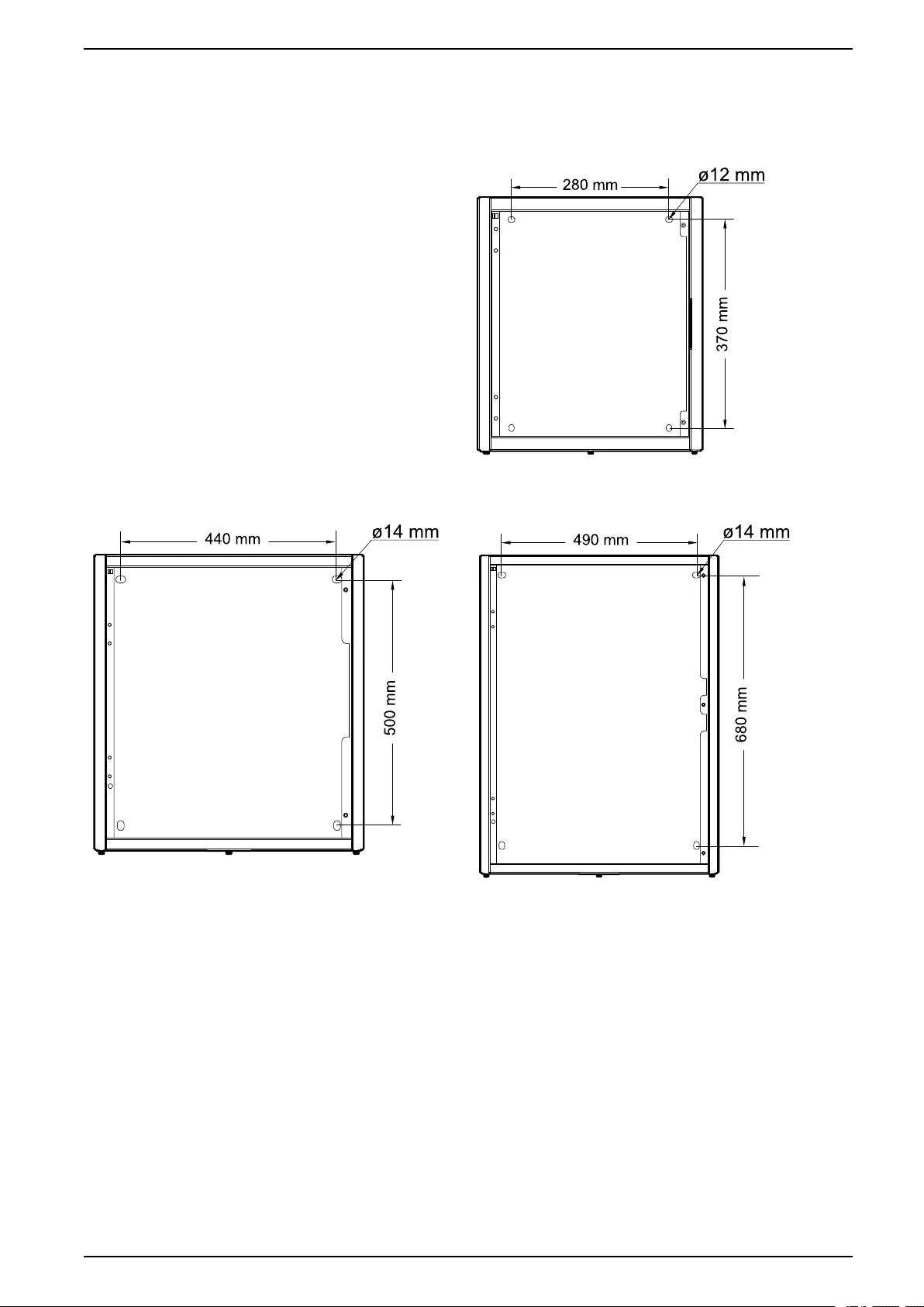
2. Measure and mark the four mounting hole locations on the wall.
GVSBPSU10K20H
GVSBPSU20K60H GVSBPSU80K120H
3. Drill holes in the four marked locations and mount the anchor bolts.
4. Mount the maintenance bypass panel to the wall.
990-5912B-001 15
Wall-Mounted Maintenance Bypass Panel Prepare the Maintenance Bypass Panel for Cables
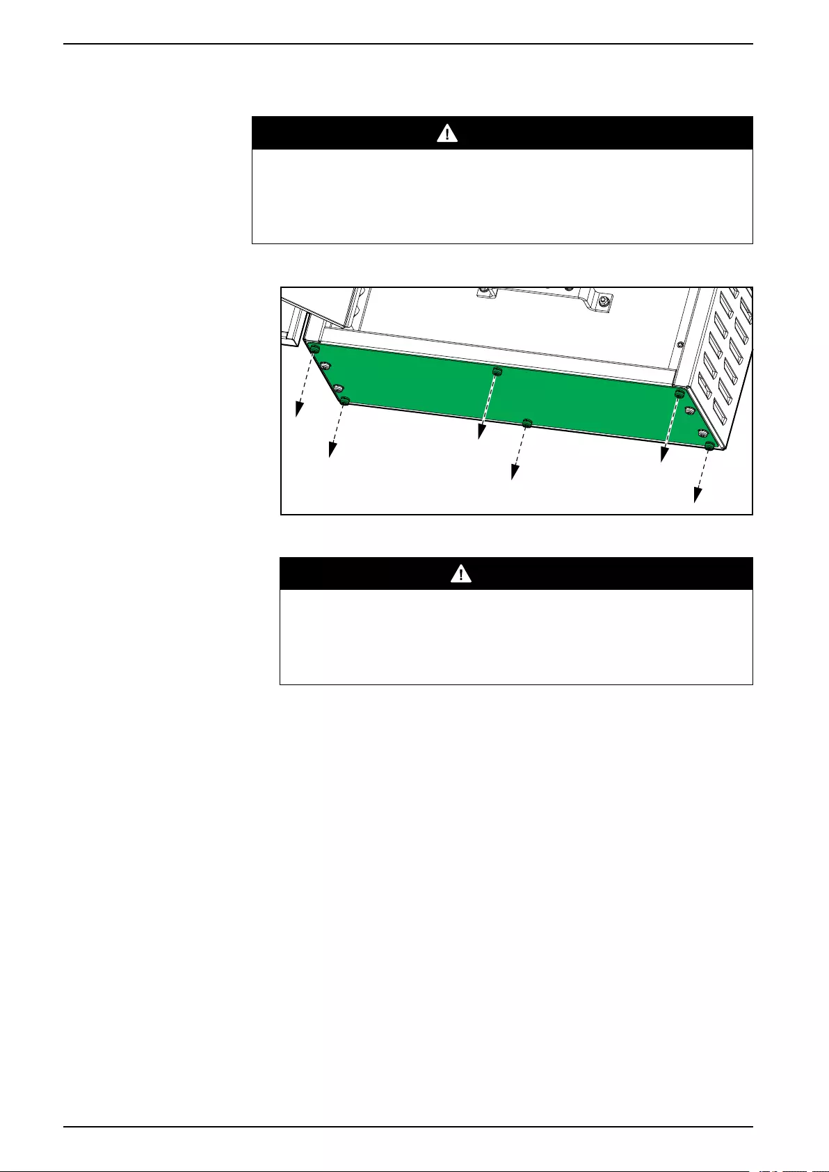
Prepare the Maintenance Bypass Panel for Cables
DANGER
HAZARD OF ELECTRIC SHOCK, EXPLOSION, OR ARC FLASH
Do not drill or punch holes with the gland plates installed and do not drill or
punch holes in close proximity to the maintenance bypass cabinet.
Failure to follow these instructions will result in death or serious injury.
1. Loosen the six bolts from the bottom gland plate and remove the gland plate.
2. Drill or punch holes for cables or grommets.
DANGER
HAZARD OF ELECTRIC SHOCK, EXPLOSION, OR ARC FLASH
Ensure that there are no sharp edges that can damage the cables.
Failure to follow these instructions will result in death or serious
injury.
3. Install grommets (if applicable) and reinstall the gland plate(s).
16 990-5912B-001
Remove the Neutral Jumper (Option) Wall-Mounted Maintenance Bypass Panel
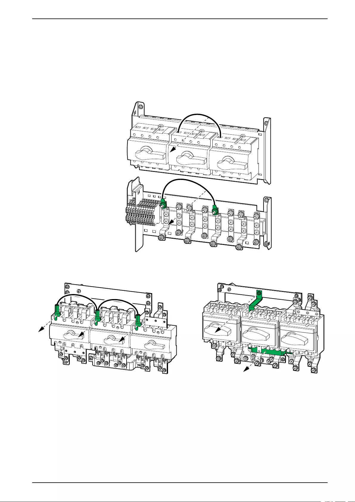
Remove the Neutral Jumper (Option)
NOTE: The neutral jumper makes a bolted connection of the neutral so that
the neutral is not disconnected when the 4-pole breakers are opened. Only
remove the neutral jumpers if this is a local requirement.
1. Remove the neutral jumpers from the breakers.
GVSBPSU10K20H
GVSBPSU20K60H GVSBPSU80K120H
990-5912B-001 17

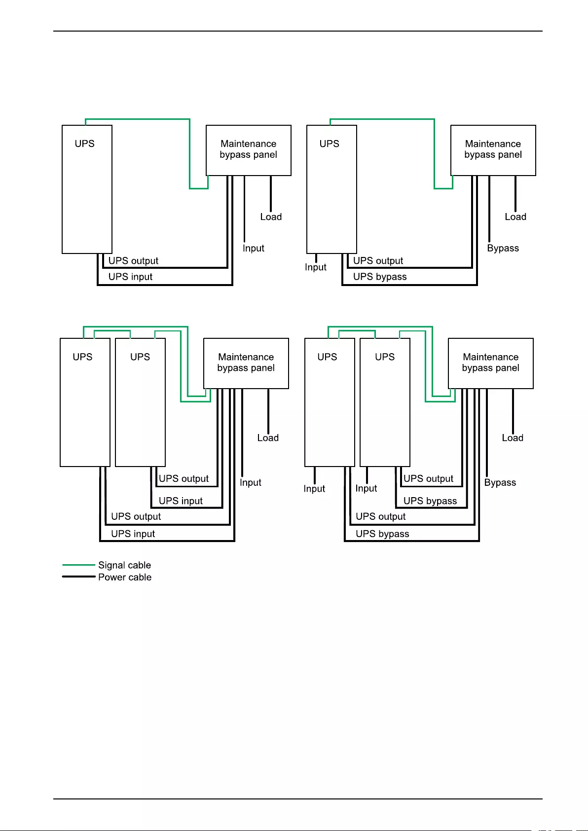
Wall-Mounted Maintenance Bypass Panel Connect the Power Cables
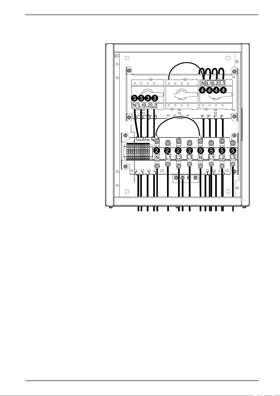
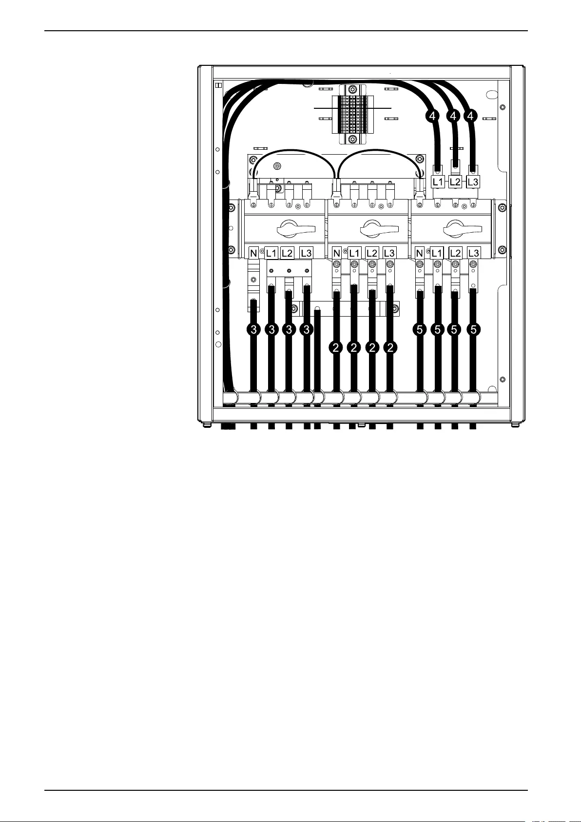
Connect the Power Cables
NOTE: For a simplified 1+1 parallel system, install the power cables from the
two UPSs on the front and rear side of the busbar using the same bolt.
1. Connect the PE cables to the PE busbar.
GVSBPSU10K20H
GVSBPSU20K60H and GVSBPSU80K120H
2. Do one of the following:
–For single mains: Connect the input cables from utility/mains.
–For dual mains: Connect the bypass cables from utility/mains.
3. Do one of the following:
–For single mains: Connect the UPS input cables.
–For dual mains: Connect the UPS bypass cables.
4. Connect the UPS output cables.
18 990-5912B-001
Connect the Signal Cables for Single System Wall-Mounted Maintenance Bypass Panel
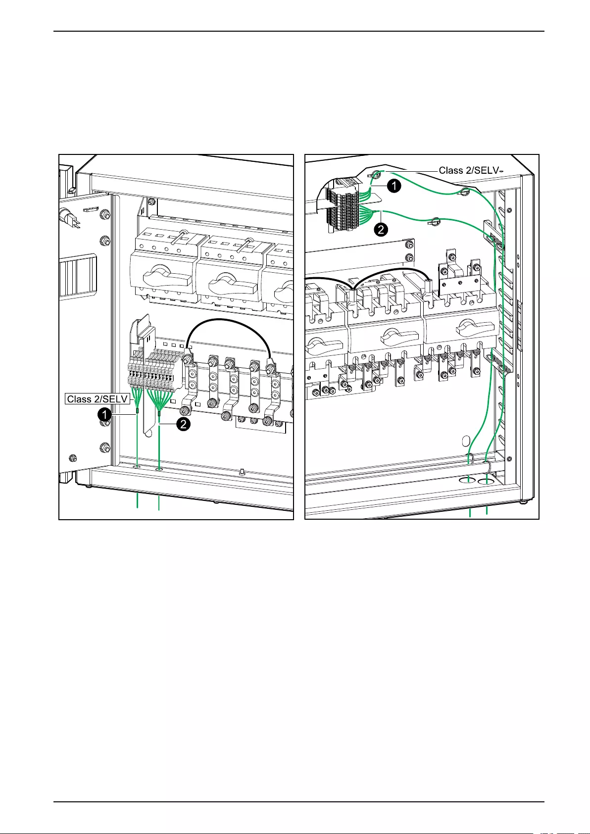
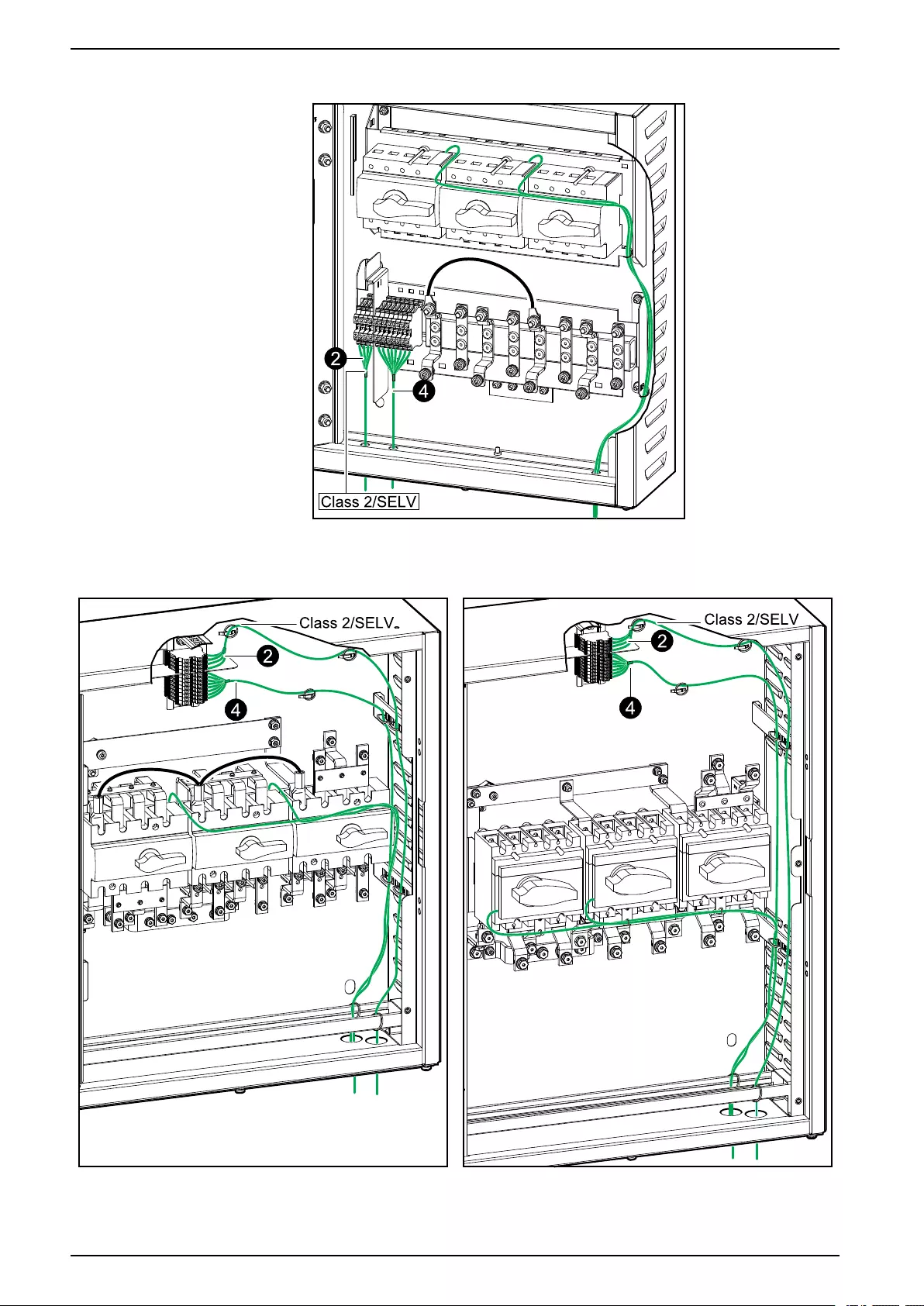
Connect the Signal Cables for Single System
NOTE: Route the signal cables separately from the power cables and route
the Class 2/SELV cables separately from the non-Class 2/non-SELV cables.
GVSBPSU10K20H GVSBPSU20K60H and GVSBPSU80K120H
990-5912B-001 21
Wall-Mounted Maintenance Bypass Panel Connect the Signal Cables for Single System
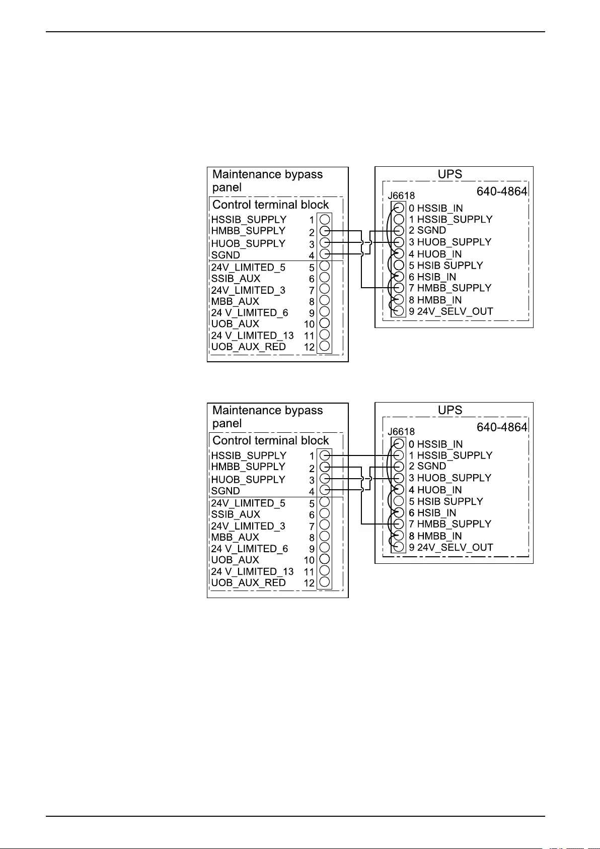
1. Connect the Class 2/SELV signal cables for the breaker indicator lights from
the control terminal block in the maintenance bypass panel to the UPS as per
your configuration.
NOTE: The breaker indicator light circuit is considered Class 2/SELV.
Class 2/SELV circuits must be isolated from the primary circuitry. Do not
connect any circuit to the breaker indicator light terminals unless it can be
confirmed that the circuit is Class 2/SELV.
Single System – Single Mains
Single System – Dual mains
22 990-5912B-001
Connect the Signal Cables for Single System Wall-Mounted Maintenance Bypass Panel
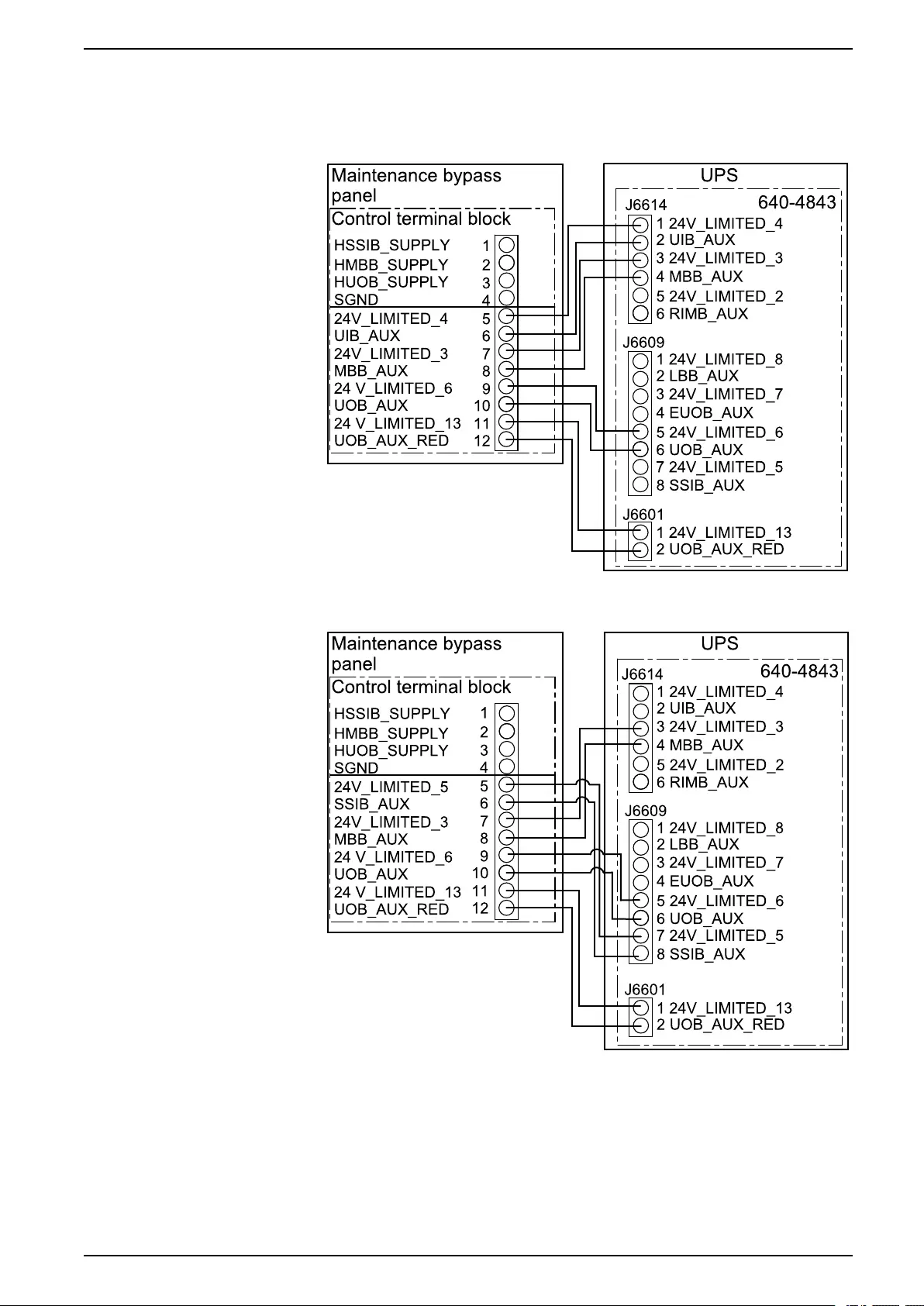
2. Connect the non-Class 2/non-SELV signal cables from the control terminal
block in the maintenance bypass panel to the UPS as per your configuration.
Single System – Single Mains
Single System – Dual Mains
3. Pull up the slack in the signal cables and fasten the signal cables to the cable
reliefs.
990-5912B-001 23

Wall-Mounted Maintenance Bypass Panel Connect the Signal Cables for Simplified 1+1 Parallel System
Connect the Signal Cables for Simplified 1+1 Parallel
System
NOTE: The breaker indicator lights are supplied by UPS 1 and will only work
while UPS 1 is powered.
NOTE: The AUX switches are in optional parallel installation kit GVSOPT006
provided with the UPS.
NOTE: Route the signal cables separately from the power cables and route
the Class 2/SELV cables separately from the non-Class 2/non-SELV cables.
24 990-5912B-001
Connect the Signal Cables for Simplified 1+1 Parallel System Wall-Mounted Maintenance Bypass Panel
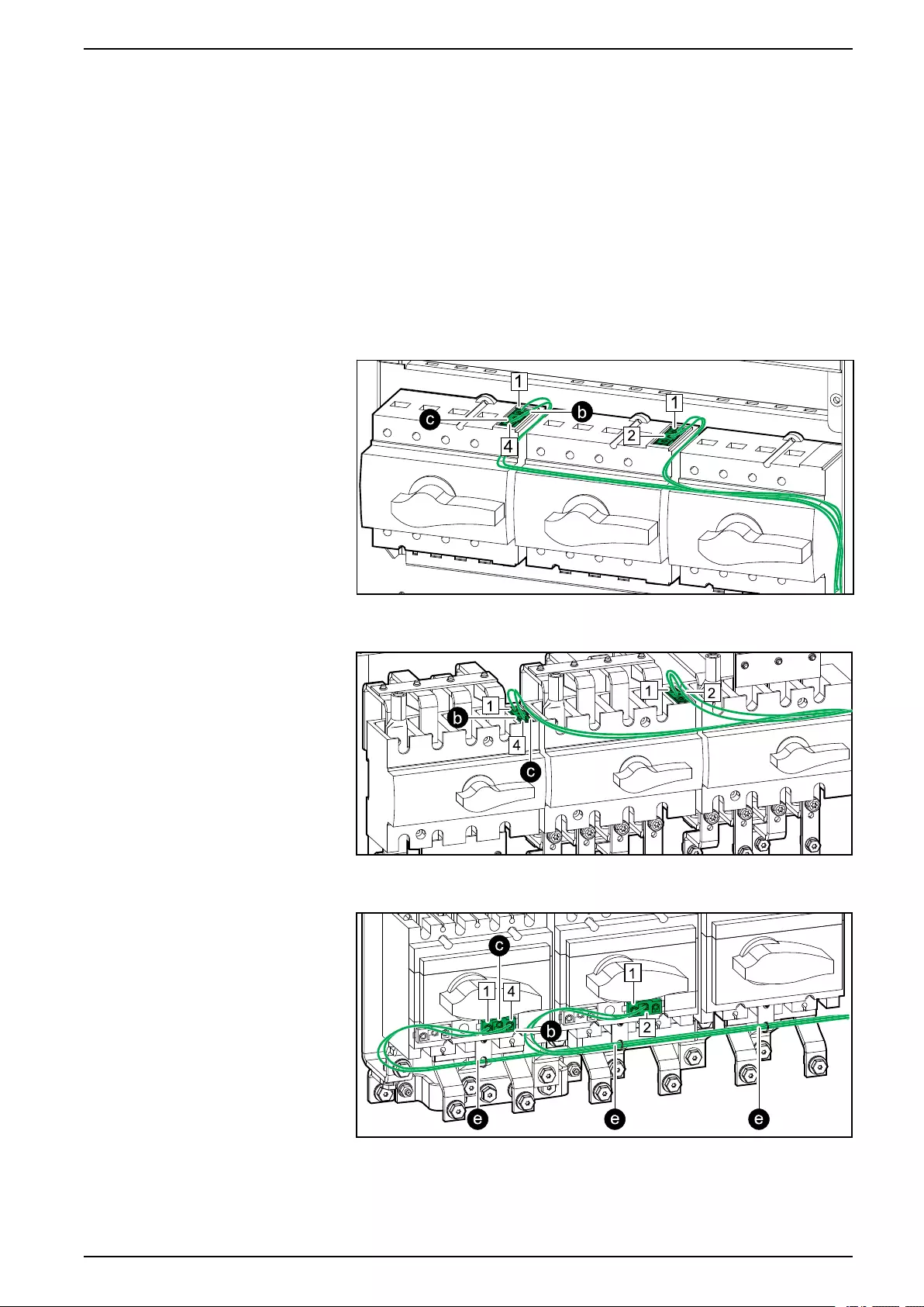
1. Install an AUX switch in the unit input breaker UIB/static switch input breaker
SSIB and the maintenance bypass breaker MBB.
a. Remove the AUX switch cover on the UIB/SSIB and MBB breaker.
b. Install the AUX switch from kit GVSOPT006 in the UIB/SSIB and MBB
breaker.
c. Connect the non-Class 2/non-SELV signal cables to the AUX switch in
the UIB/SSIB and MBB breaker.
d. Reinstall the AUX switch cover on the UIB/SSIB and MBB breaker.
e. Only for GVSBPSU80K120H: Fasten the signal cables to the plastic
tabs to ensure correct separation from the busbars.
GVSBPSU10K20H
GVSBPSU20K60H
GVSBPSU80K120H
990-5912B-001 25
Wall-Mounted Maintenance Bypass Panel Connect the Signal Cables for Simplified 1+1 Parallel System
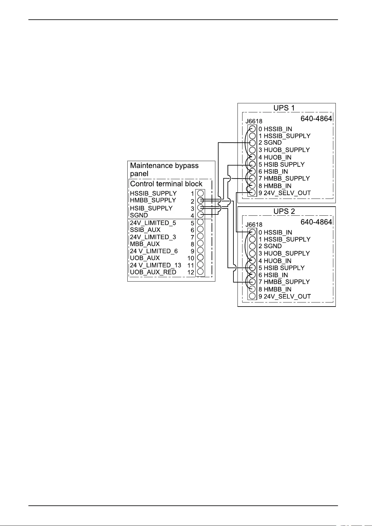
2. Connect the Class 2/SELV signal cables for the breaker indicator lights from
the control terminal block in the maintenance bypass panel to the UPSs as
per your configuration.
NOTE: The breaker indicator light circuit is considered Class 2/SELV.
Class 2/SELV circuits must be isolated from the primary circuitry. Do not
connect any circuit to the breaker indicator light terminals unless it can be
confirmed that the circuit is Class 2/SELV.
Simplified 1+1 Parallel System – Single Mains
26 990-5912B-001
Connect the Signal Cables for Simplified 1+1 Parallel System Wall-Mounted Maintenance Bypass Panel
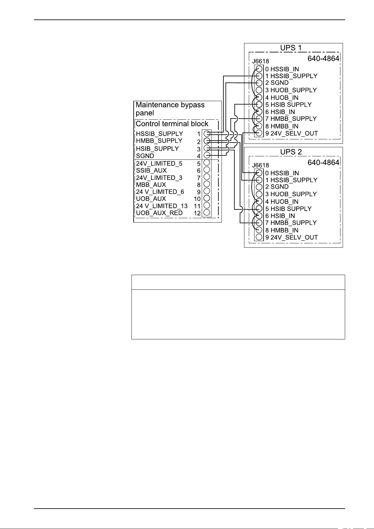
Simplified 1+1 Parallel System – Dual mains
3. On UPS 2: Cut the preinstalled jumper between pins 8 and 9 on the terminal
connector for J6618 on board 640-4864.
NOTICE
RISK OF INCORRECT EQUIPMENT BEHAVIOR
Cut the preinstalled jumper between pins 8 and 9 on terminal J6618 on
board 640-4864 on UPS 2. The 24 V_SELV_OUT cannot be supplied from
both UPSs.
Failure to follow these instructions can result in equipment damage.
990-5912B-001 27
Wall-Mounted Maintenance Bypass Panel Connect the Signal Cables for Simplified 1+1 Parallel System
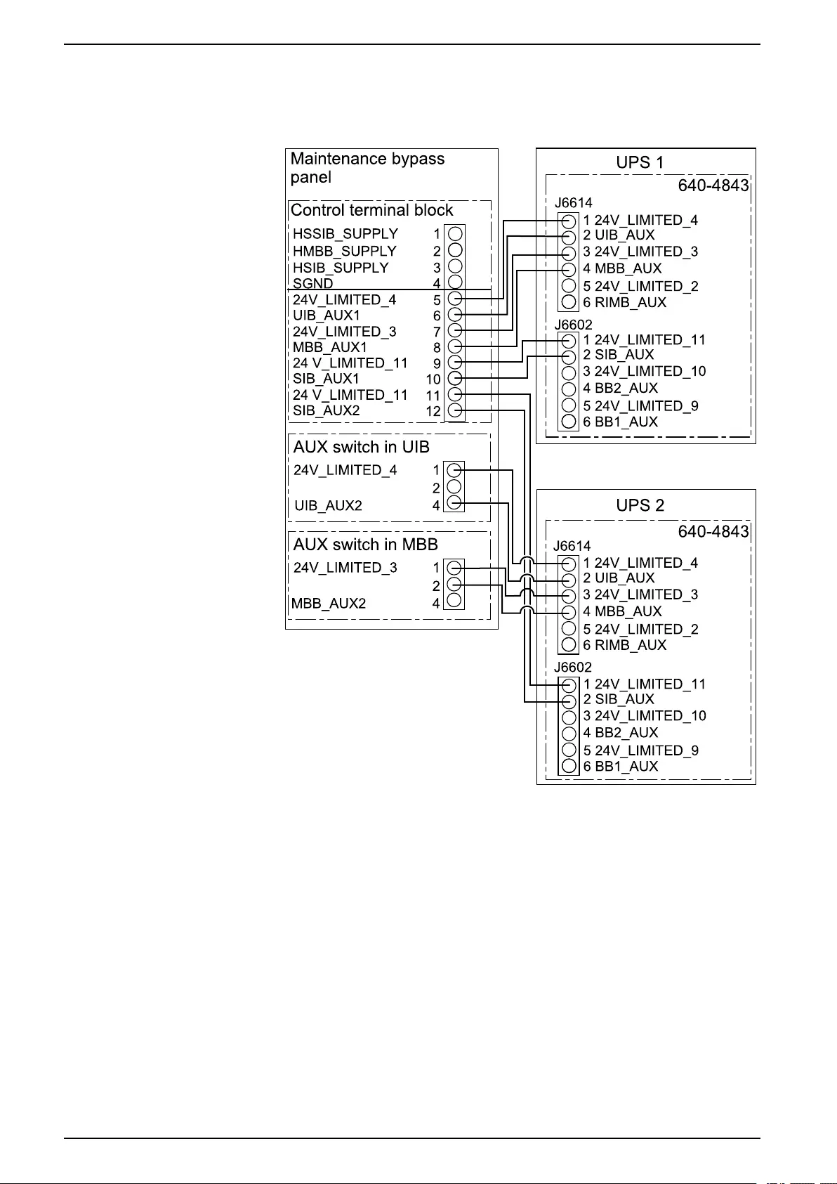
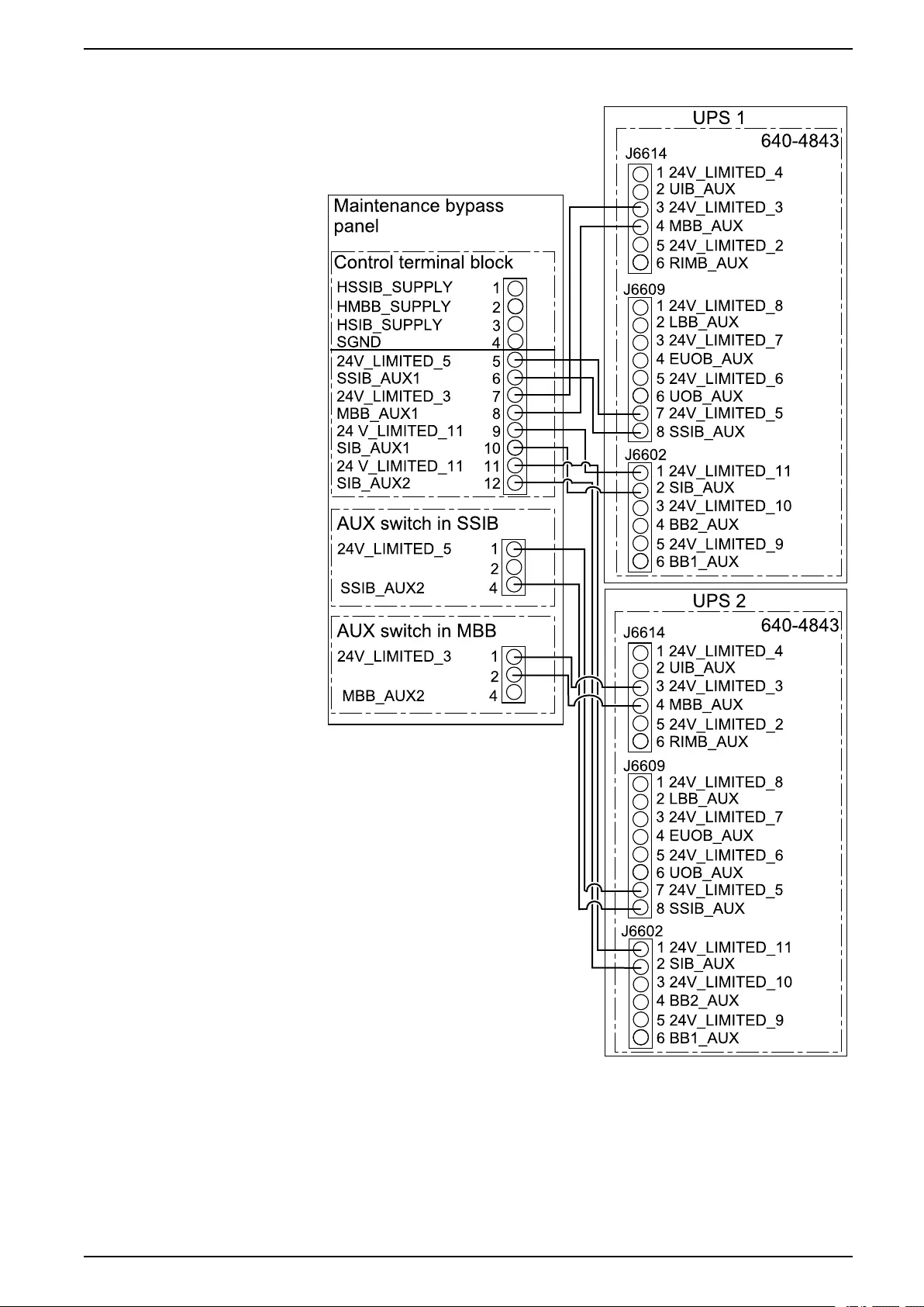
4. Connect the non-Class 2/non-SELV signal cables from the control terminal
block in the maintenance bypass panel to the UPSs as per your configuration.
Simplified 1+1 Parallel System – Single Mains
28 990-5912B-001

Add Translated Safety Labels to Your Product Wall-Mounted Maintenance Bypass Panel
Add Translated Safety Labels to Your Product
The safety labels on your product are in English and French. Sheets with
translated safety labels are provided with your product.
1. Find the sheets with translated safety labels provided with your product.
2. Check which 885-XXX numbers are on the sheet with translated safety
labels.
3. Locate the safety labels on your product that match the translated safety
labels on the sheet – look for the 885-XXX numbers.
4. Add the replacement safety label in your preferred language to your product
on top of the existing French safety label.
990-5912B-001 31
Wall-Mounted Maintenance Bypass Panel Final Installation
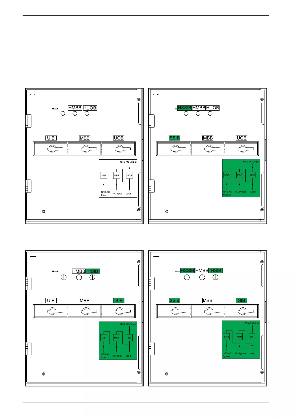
Final Installation
1. Close the inner door and fasten it with the screws.
2. Add labels to the breaker indicator lamps, the breakers, and the diagram label
according to your system. The labels are provided with this manual.
Labels in Single System – Single Mains Labels in Single System – Dual Mains
Labels in Simplified 1+1 Parallel System – Single
Mains
Labels in Simplified 1+1 Parallel System – Dual
Mains
32 990-5912B-001


Schneider Electric
35 rue Joseph Monier
92500 Rueil Malmaison
France
+ 33 (0) 1 41 29 70 00
*990-5912B-001*
As standards, specifications, and design change from time to time,
please ask for confirmation of the information given in this publication.
© 2018 – 2019 Schneider Electric. All rights reserved.
990-5912B-001