Table of Contents
APC GVSCBC10A2 User Manual
Displayed below is the user manual for GVSCBC10A2 by APC which is a product in the UPS Accessories category. This manual has pages.
Related Manuals
Galaxy VS
Classic Battery Cabinet
Installation
GVSCBC7A, GVSCBC7B, GVSCBC7C, GVSCBC10A2, GVSCBC10B2
10/2019
www.schneider-electric.com

Legal Information
The Schneider Electric brand and any trademarks of Schneider Electric SE and its
subsidiaries referred to in this guide are the property of Schneider Electric SE or its
subsidiaries. All other brands may be trademarks of their respective owners.
This guide and its content are protected under applicable copyright laws and
furnished for informational use only. No part of this guide may be reproduced or
transmitted in any form or by any means (electronic, mechanical, photocopying,
recording, or otherwise), for any purpose, without the prior written permission of
Schneider Electric.
Schneider Electric does not grant any right or license for commercial use of the guide
or its content, except for a non-exclusive and personal license to consult it on an "as
is" basis. Schneider Electric products and equipment should be installed, operated,
serviced, and maintained only by qualified personnel.
As standards, specifications, and designs change from time to time, information
contained in this guide may be subject to change without notice.
To the extent permitted by applicable law, no responsibility or liability is assumed by
Schneider Electric and its subsidiaries for any errors or omissions in the informational
content of this material or consequences arising out of or resulting from the use of the
information contained herein.
Go to
https://www.productinfo.schneider-electric.com/portals/ui/galaxyvs_iec/
or scan the QR code above for digital experience and translated manuals.

Classic Battery Cabinet
Table of Contents
Important Safety Instructions — SAVE THESE
INSTRUCTIONS.........................................................................................5
Safety Precautions .....................................................................................6
Electrical Safety....................................................................................8
Battery Safety.......................................................................................9
Specifications ............................................................................................ 11
Classic Battery Cabinet Specifications ....................................................... 11
Trip Settings.............................................................................................12
Recommended Cable Sizes ......................................................................14
Torque Specifications................................................................................16
Environment.............................................................................................16
Clearance ................................................................................................16
Classic Battery Cabinet Weights and Dimensions .......................................17
Installation Procedure ..............................................................................18
Receiving ...................................................................................................19
Unpack the Cabinet ..................................................................................19
Prepare for Cables....................................................................................21
Connect the Signal Cables......................................................................22
Connect the Power Cables......................................................................25
Add Translated Safety Labels to Your Product.....................................28
Final Installation ........................................................................................29
990-5913B-001 3

Important Safety Instructions — SAVE THESE
INSTRUCTIONS Classic Battery Cabinet
Important Safety Instructions — SAVE THESE
INSTRUCTIONS
Read these instructions carefully and look at the equipment to become familiar
with it before trying to install, operate, service or maintain it. The following safety
messages may appear throughout this manual or on the equipment to warn of
potential hazards or to call attention to information that clarifies or simplifies a
procedure.
The addition of this symbol to a “Danger” or “Warning” safety
message indicates that an electrical hazard exists which will result in
personal injury if the instructions are not followed.
This is the safety alert symbol. It is used to alert you to potential
personal injury hazards. Obey all safety messages with this symbol
to avoid possible injury or death.
DANGER
DANGER indicates a hazardous situation which, if not avoided, will result in
death or serious injury.
Failure to follow these instructions will result in death or serious injury.
WARNING
WARNING indicates a hazardous situation which, if not avoided, could result
in death or serious injury.
Failure to follow these instructions can result in death, serious injury, or
equipment damage.
CAUTION
CAUTION indicates a hazardous situation which, if not avoided, could result in
minor or moderate injury.
Failure to follow these instructions can result in injury or equipment
damage.
NOTICE
NOTICE is used to address practices not related to physical injury. The safety
alert symbol shall not be used with this type of safety message.
Failure to follow these instructions can result in equipment damage.
Please Note
Electrical equipment should only be installed, operated, serviced, and maintained
by qualified personnel. No responsibility is assumed by Schneider Electric for any
consequences arising out of the use of this material.
A qualified person is one who has skills and knowledge related to the construction,
installation, and operation of electrical equipment and has received safety training
to recognize and avoid the hazards involved.
990-5913B-001 5
Classic Battery Cabinet
Important Safety Instructions — SAVE THESE
INSTRUCTIONS
Safety Precautions
DANGER
HAZARD OF ELECTRIC SHOCK, EXPLOSION, OR ARC FLASH
Read all instructions in the installation manual before installing or working on
this product.
Failure to follow these instructions will result in death or serious injury.
DANGER
HAZARD OF ELECTRIC SHOCK, EXPLOSION, OR ARC FLASH
Do not install the product until all construction work has been completed and the
installation room has been cleaned.
Failure to follow these instructions will result in death or serious injury.
DANGER
HAZARD OF ELECTRIC SHOCK, EXPLOSION, OR ARC FLASH
The product must be installed according to the specifications and requirements
as defined by Schneider Electric. It concerns in particular the external and
internal protections (upstream breakers, battery breakers, cabling, etc.) and
environmental requirements. No responsibility is assumed by Schneider Electric
if these requirements are not respected.
Failure to follow these instructions will result in death or serious injury.
DANGER
HAZARD OF ELECTRIC SHOCK, EXPLOSION, OR ARC FLASH
The UPS system must be installed according to local and national regulations.
Install the UPS according to:
• IEC 60364 (including 60364–4–41- protection against electric shock, 60364–
4–42 - protection against thermal effect, and 60364–4–43 - protection
against overcurrent), or
• NEC NFPA 70, or
• Canadian Electrical Code (C22.1, Part 1)
depending on which one of the standards apply in your local area.
Failure to follow these instructions will result in death or serious injury.
DANGER
HAZARD OF ELECTRIC SHOCK, EXPLOSION, OR ARC FLASH
• Install the product in a temperature controlled indoor environment free of
conductive contaminants and humidity.
• Install the product on a non-flammable, level and solid surface (e.g.
concrete) that can support the weight of the system.
Failure to follow these instructions will result in death or serious injury.
6 990-5913B-001
Important Safety Instructions — SAVE THESE
INSTRUCTIONS Classic Battery Cabinet
DANGER
HAZARD OF ELECTRIC SHOCK, EXPLOSION, OR ARC FLASH
The product is not designed for and must therefore not be installed in the
following unusual operating environments:
• Damaging fumes
• Explosive mixtures of dust or gases, corrosive gases, or conductive or
radiant heat from other sources
• Moisture, abrasive dust, steam or in an excessively damp environment
• Fungus, insects, vermin
• Salt-laden air or contaminated cooling refrigerant
• Pollution degree higher than 2 according to IEC 60664-1
• Exposure to abnormal vibrations, shocks, and tilting
• Exposure to direct sunlight, heat sources, or strong electromagnetic fields
Failure to follow these instructions will result in death or serious injury.
DANGER
HAZARD OF ELECTRIC SHOCK, EXPLOSION, OR ARC FLASH
Do not drill or cut holes for cables or conduits with the gland plates installed and
do not drill or cut holes in close proximity to the UPS.
Failure to follow these instructions will result in death or serious injury.
WARNING
HAZARD OF ARC FLASH
Do not make mechanical changes to the product (including removal of cabinet
parts or drilling/cutting of holes) that are not described in the installation manual.
Failure to follow these instructions can result in death, serious injury, or
equipment damage.
NOTICE
RISK OF OVERHEATING
Respect the space requirements around the product and do not cover the
ventilation openings when the product is in operation.
Failure to follow these instructions can result in equipment damage.
990-5913B-001 7
Classic Battery Cabinet
Important Safety Instructions — SAVE THESE
INSTRUCTIONS
Electrical Safety
DANGER
HAZARD OF ELECTRIC SHOCK, EXPLOSION, OR ARC FLASH
• Electrical equipment must be installed, operated, serviced, and maintained
only by qualified personnel.
• Apply appropriate personal protective equipment (PPE) and follow safe
electrical work practices.
• Turn off all power supplying the UPS system before working on or inside the
equipment.
• Before working on the UPS system, check for hazardous voltage between all
terminals including the protective earth.
• The UPS contains an internal energy source. Hazardous voltage can be
present even when disconnected from the mains supply. Before installing or
servicing the UPS system, ensure that the units are OFF and that mains and
batteries are disconnected. Wait five minutes before opening the UPS to
allow the capacitors to discharge.
• The UPS must be properly earthed/grounded and due to a high leakage
current, the earthing/grounding conductor must be connected first.
Failure to follow these instructions will result in death or serious injury.
DANGER
HAZARD OF ELECTRIC SHOCK, EXPLOSION, OR ARC FLASH
In systems where backfeed protection is not part of the standard design, an
automatic isolation device (backfeed protection option or other device meeting
the requirements of IEC/EN 62040–1 or UL1778 5th Edition – depending on
which of the two standards apply to your local area) must be installed to prevent
hazardous voltage or energy at the input terminals of the isolation device. The
device must open within 15 seconds after the upstream power supply fails and
must be rated according to the specifications.
Failure to follow these instructions will result in death or serious injury.
When the UPS input is connected through external isolators that, when opened,
isolate the neutral or when the automatic backfeed isolation is provided external to
the equipment or is connected to an IT power distribution system, a label must be
fitted at the UPS input terminals, and on all primary power isolators installed
remote from the UPS area and on external access points between such isolators
and the UPS, by the user, displaying the following text (or equivalent in a language
which is acceptable in the country in which the UPS system is installed):
DANGER
HAZARD OF ELECTRIC SHOCK, EXPLOSION, OR ARC FLASH
Risk of Voltage Backfeed. Before working on this circuit: Isolate the UPS and
check for hazardous voltage between all terminals including the protective
earth.
Failure to follow these instructions will result in death or serious injury.
8 990-5913B-001
Important Safety Instructions — SAVE THESE
INSTRUCTIONS Classic Battery Cabinet
Battery Safety
DANGER
HAZARD OF ELECTRIC SHOCK, EXPLOSION OR ARC FLASH
• Battery circuit breakers must be installed according to the specifications and
requirements as defined by Schneider Electric.
• Servicing of batteries must only be performed or supervised by qualified
personnel knowledgeable of batteries and the required precautions. Keep
unqualified personnel away from batteries.
• Disconnect charging source prior to connecting or disconnecting battery
terminals.
• Do not dispose of batteries in a fire as they can explode.
• Do not open, alter, or mutilate batteries. Released electrolyte is harmful to
the skin and eyes. It may be toxic.
Failure to follow these instructions will result in death or serious injury.
DANGER
HAZARD OF ELECTRIC SHOCK, EXPLOSION, OR ARC FLASH
Batteries can present a risk of electric shock and high short-circuit current. The
following precautions must be observed when working on batteries
• Remove watches, rings, or other metal objects.
• Use tools with insulated handles.
• Wear protective glasses, gloves and boots.
• Do not lay tools or metal parts on top of batteries.
• Disconnect the charging source prior to connecting or disconnecting battery
terminals.
• Determine if the battery is inadvertently grounded. If inadvertently grounded,
remove source from ground. Contact with any part of a grounded battery can
result in electric shock. The likelihood of such shock can be reduced if such
grounds are removed during installation and maintenance (applicable to
equipment and remote battery supplies not having a grounded supply
circuit).
Failure to follow these instructions will result in death or serious injury.
DANGER
HAZARD OF ELECTRIC SHOCK, EXPLOSION, OR ARC FLASH
When replacing batteries, always replace with the same type and number of
batteries or battery packs. Refer to the label in the classic battery cabinet for
information on batteries in your system.
Failure to follow these instructions will result in death or serious injury.
990-5913B-001 9

Classic Battery Cabinet
Important Safety Instructions — SAVE THESE
INSTRUCTIONS
CAUTION
RISK OF EQUIPMENT DAMAGE
• Wait until the system is ready to be powered up before installing batteries in
the system. The time duration from battery installation until the UPS system
is powered up must not exceed 72 hours or 3 days.
• Batteries must not be stored more than six months due to the requirement of
recharging. If the UPS system remains de-energized for a long period, we
recommend that you energize the UPS system for a period of 24 hours at
least once every month. This charges the batteries, thus avoiding
irreversible damage.
Failure to follow these instructions can result in injury or equipment
damage.
10 990-5913B-001
Specifications Classic Battery Cabinet
Specifications
NOTICE
HAZARD OF EQUIPMENT DAMAGE
Refer to the UPS installation manual for detailed specifications for the UPS
system.
Failure to follow these instructions can result in equipment damage.
Classic Battery Cabinet Specifications
DANGER
HAZARD OF ELECTRIC SHOCK, EXPLOSION OR ARC FLASH
The classic battery cabinet must only be used with the Galaxy VS UPS.
Failure to follow these instructions will result in death or serious injury.
NOTE: Up to two classic battery cabinets can be connected to the Galaxy VS
UPS.
Commercial reference Battery type Number of battery blocks
GVSCBC7A SWL750 48
GVSCBC7B SWL1100 44
GVSCBC7C XP12V1800 36
GVSCBC10A2 XP12V1800 48
GVSCBC10B2 XP12V3000 40
990-5913B-001 11
Classic Battery Cabinet Specifications
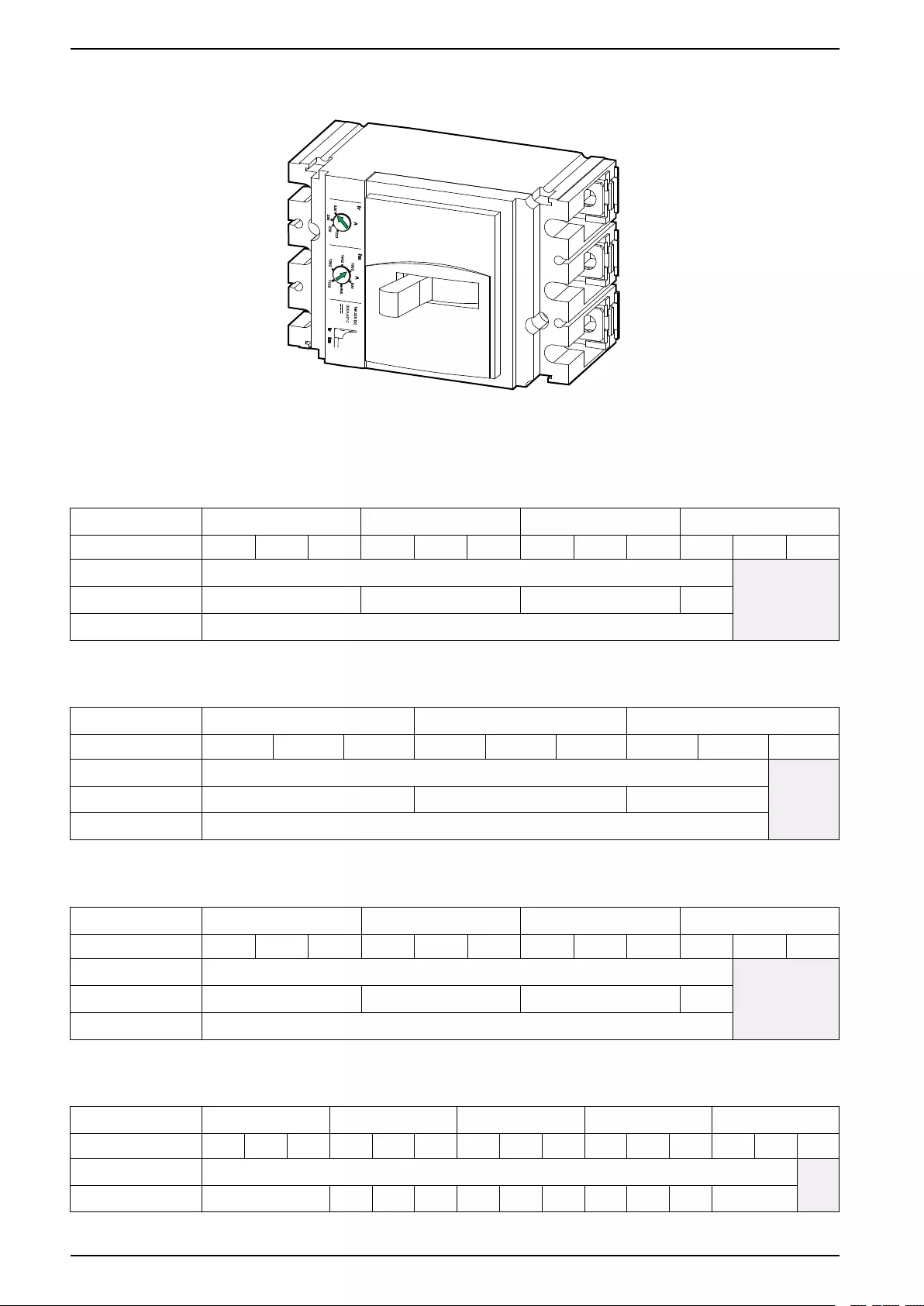
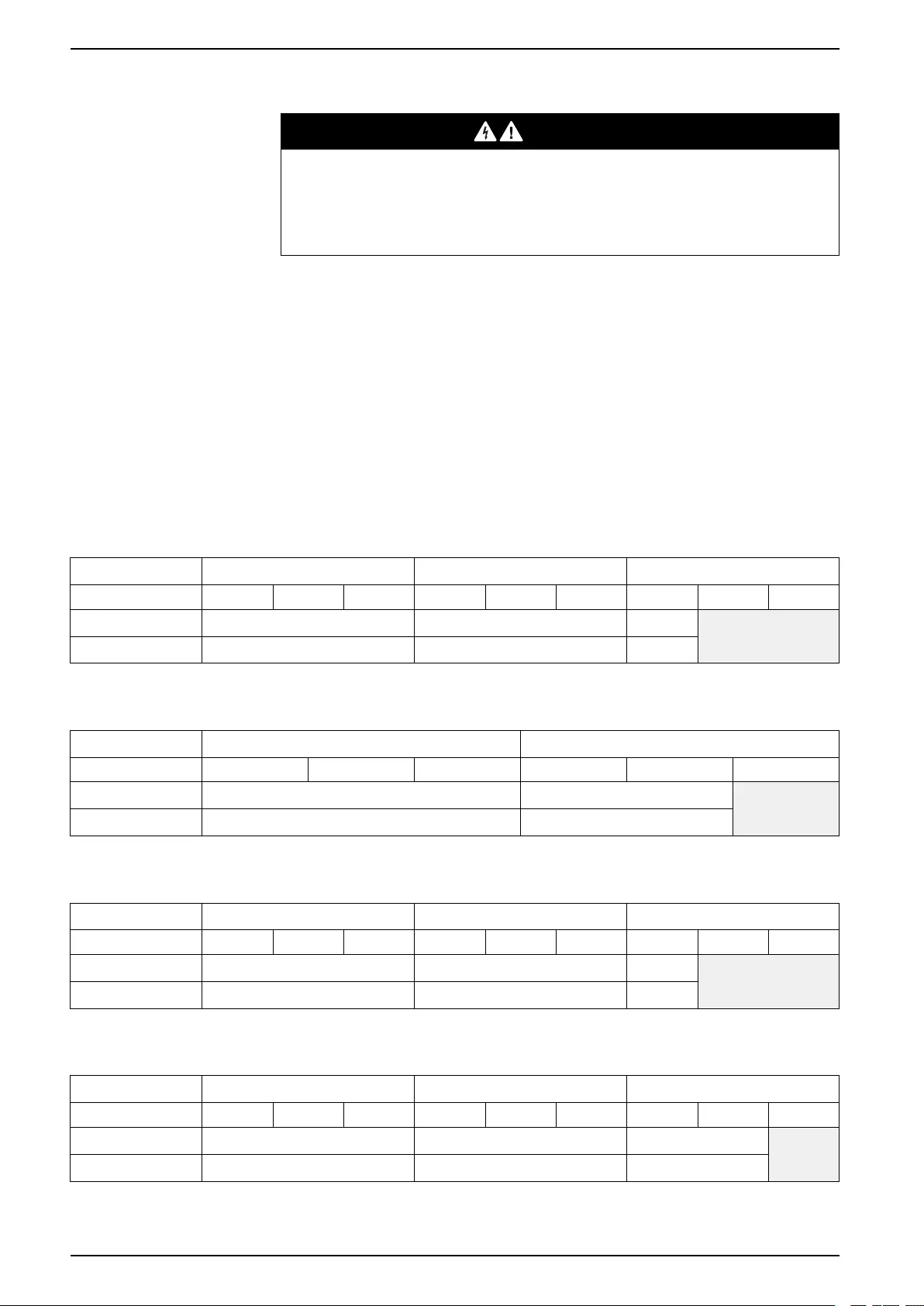
Trip Settings
Trip settings must be controlled during installation. Set the trip settings according
to the relevant table below.
GVSCBC7A
UPS rating 20 kW 30 kW 40-50 kW 60 kW
Power factor 0.8 0.9 1 0.8 0.9 1 0.8 0.9 1 0.8 0.9 1
Breaker type NSX100SDC (LV438018) + TM80G (LV430080) NA
Ir setting 56 72 80 80
Im setting 250 (fixed)
GVSCBC7B
UPS rating 20-50 kW 60 kW 80 kW
Power factor 0.8 0.9 1 0.8 0.9 1 0.8 0.9 1
Breaker type NSX250SDC (LV438218) + TM200G (LV430088) NA
Ir setting 140 160 160
Im setting 530 (fixed)
GVSCBC7C
UPS rating 20-50 kW 60 kW 80 kW 100 kW
Power factor 0.8 0.9 1 0.8 0.9 1 0.8 0.9 1 0.8 0.9 1
Breaker type NSX250SDC (LV438218) + TM250G (LV430089) NA
Ir setting 175 200 250 250
Im setting 625 (fixed)
GVSCBC10A2
UPS rating 20-60 kW 80 kW 100 kW 120 kW 150 kW
Power factor 0.8 0.9 1 0.8 0.9 1 0.8 0.9 1 0.8 0.9 1 0.8 0.9 1
Breaker type NSX250SDC (LV438218) + TM250G (LV430089) NA
Ir setting 175 175 175 200 200 225 225 225 250 250 250
12 990-5913B-001

Specifications Classic Battery Cabinet
UPS rating 20-60 kW 80 kW 100 kW 120 kW 150 kW
Power factor 0.8 0.9 1 0.8 0.9 1 0.8 0.9 1 0.8 0.9 1 0.8 0.9 1
Im setting 625 (fixed)
GVSCBC10B2
UPS rating 20-80 kW 100 kW 120 kW 150 kW
Power factor 0.8 0.9 1 0.8 0.9 1 0.8 0.9 1 0.8 0.9 1
Breaker type NSX320S TM-DC (LV438276)
Ir setting 224 224 256 288 288 320 320
Im setting 800 (fixed)
990-5913B-001 13
Classic Battery Cabinet Specifications
Recommended Cable Sizes
DANGER
HAZARD OF ELECTRIC SHOCK, EXPLOSION, OR ARC FLASH
All wiring must comply with all applicable national and/or electrical codes. The
maximum allowable cable size is 95 mm2.
Failure to follow these instructions will result in death or serious injury.
Cable sizes in this manual are based on table B.52.3 (52–C2) of IEC 60364–5–52
with the following assertions:
• 90 °C conductors
• An ambient temperature of 30 °C
• Use of copper conductors
• Installation method C
Protective Earth (PE) cables are sized in accordance with table 54.3 of IEC
60364-4-54, Article 543.
If the ambient temperature is greater than 30 °C, larger conductors are to be
selected in accordance with the correction factors of the IEC.
GVSCBC7A
UPS rating 20-30 kW 40-50 kW 60 kW
Power factor 0.8 0.9 1 0.8 0.9 1 0.8 0.9 1
DC+/DC- (mm2) 10 16 16 NA
DC PE (mm2) 10 10 10
GVSCBC7B
UPS rating 20-60 kW 80 kW
Power factor 0.8 0.9 1 0.8 0.9 1
DC+/DC- (mm2) 35 35 NA
DC PE (mm2) 16 16
GVSCBC7C
UPS rating 20-60 kW 80 kW 100 kW
Power factor 0.8 0.9 1 0.8 0.9 1 0.8 0.9 1
DC+/DC- (mm2) 50 70 70 NA
DC PE (mm2) 25 35 35
GVSCBC10A2
UPS rating 20-80 kW 100-120 kW 150 kW
Power factor 0.8 0.9 1 0.8 0.9 1 0.8 0.9 1
DC+/DC- (mm2) 50 70 70 NA
DC PE (mm2) 25 35 35
14 990-5913B-001

Classic Battery Cabinet Specifications
Torque Specifications
Bolt size Torque
M4 1.7 Nm
M5 2.2 Nm
M6 5 Nm
M8 17.5 Nm
M10 30 Nm
Environment
Operating Storage
Temperature 0 °C to 40 °C -15 °C to 40 °C
Relative humidity 0-95% non-condensing 10-80% non-condensing
Elevation 0-1000 m
Protection class IP20
Color RAL 9003, gloss level 85%
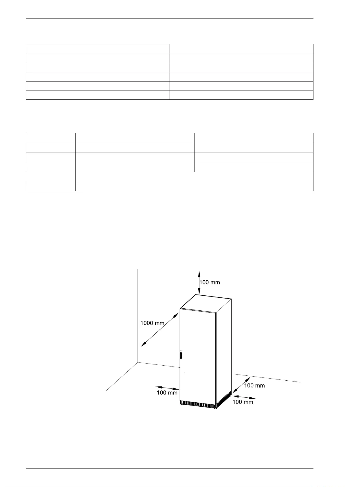
Clearance
NOTE: Clearance dimensions are published for airflow and service access
only. Consult with the local safety codes and standards for additional
requirements in your local area.
NOTE: The room should be ventilated to prevent the concentration of the
dihydrogen generated by the battery cabinet. Recommended minimum
airflow: 2.41 m3/h.
16 990-5913B-001

Classic Battery Cabinet Installation Procedure
Installation Procedure
NOTE: The distance between the battery bank and the UPS must not exceed
200 m. Contact Schneider Electric for installations with a longer distance.
1. Unpack the Cabinet, page 19.
2. Prepare for Cables, page 21.
3. Connect the Signal Cables, page 22.
4. Connect the Power Cables, page 25.
5. Add Translated Safety Labels to Your Product, page 28.
6. Final Installation, page 29.
18 990-5913B-001
Receiving Classic Battery Cabinet
Receiving
External Inspection
When the shipment arrives, inspect the shipping material for any signs of damage
or mishandling. Check tilt and impact indicators. Do not attempt to install the
system if a damage is apparent. If any damage is noted, contact Schneider
Electric and file a damage claim with the shipping agency within 24 hours.
Compare the components of the shipment with the bill of lading. Report any
missing items to the carrier and to Schneider Electric immediately.
Verify that labelled units match the order confirmation.
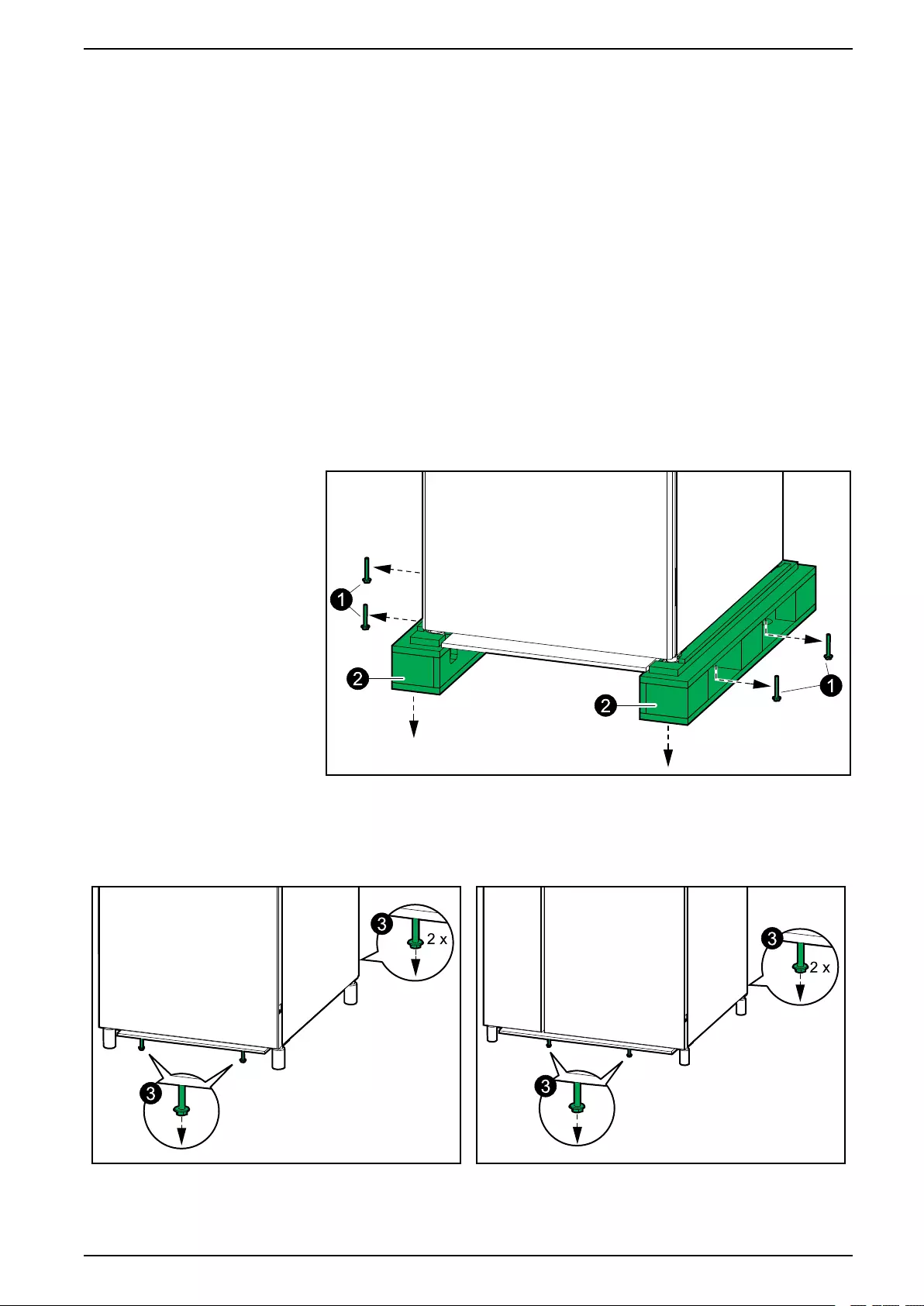
Unpack the Cabinet
1. Remove the indicated bolts.
2. Lift up the cabinet with a forklift and remove the pallet parts.
3. Lower the cabinet to the floor and remove the indicated bolts.
GVSCBC7A, GVSCBC7B, GVSCBC7C GVSCBC10A2, GVSCBC10B2
990-5913B-001 19

Prepare for Cables Classic Battery Cabinet
Prepare for Cables
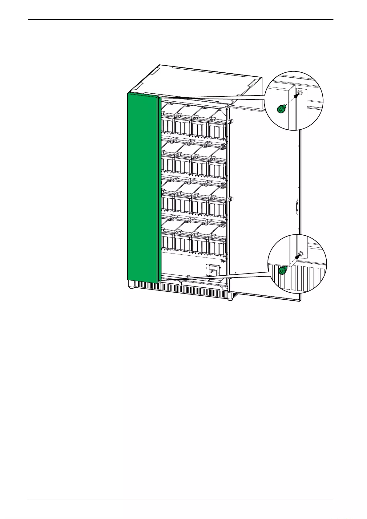
1. Open the door(s). On GVSCBC10A2 and GVSCBC10B2, remove two screws
to open the left door.
2. Lockout/Tagout the battery breaker.
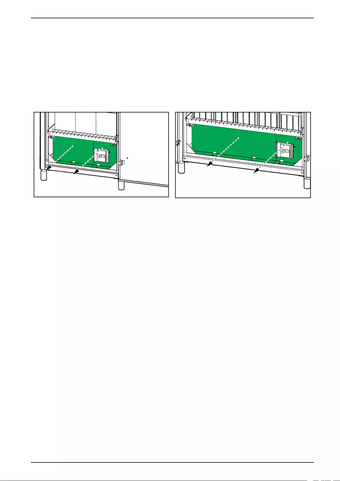
3. Remove the breaker protection plates.
GVSCBC7A, GVSCBC7B, GVSCBC7C GVSCBC10A2, GVSCBC10B2
4. Remove the kit with copper bars/cables from the classic battery cabinet. Save
for interconnection of the batteries – see Connect the Power Cables, page 25.
990-5913B-001 21
Classic Battery Cabinet Connect the Signal Cables
Connect the Signal Cables
NOTE: Route the signal cables separately from the power cables to ensure
sufficient isolation.
NOTE: Use double isolated signal cables. The signal cables must have a
minimum rating of 600 V.
1. Install the temperature sensor provided with the UPS in the top of the classic
battery cabinet.
WARNING
HAZARD OF FIRE
Position the temperature sensor as described to ensure correct
temperature measurements.
Failure to follow these instructions can result in death, serious injury,
or equipment damage.
GVSCBC7A, GVSCBC7B, GVSCBC7C GVSCBC10A2, GVSCBC10B2
22 990-5913B-001
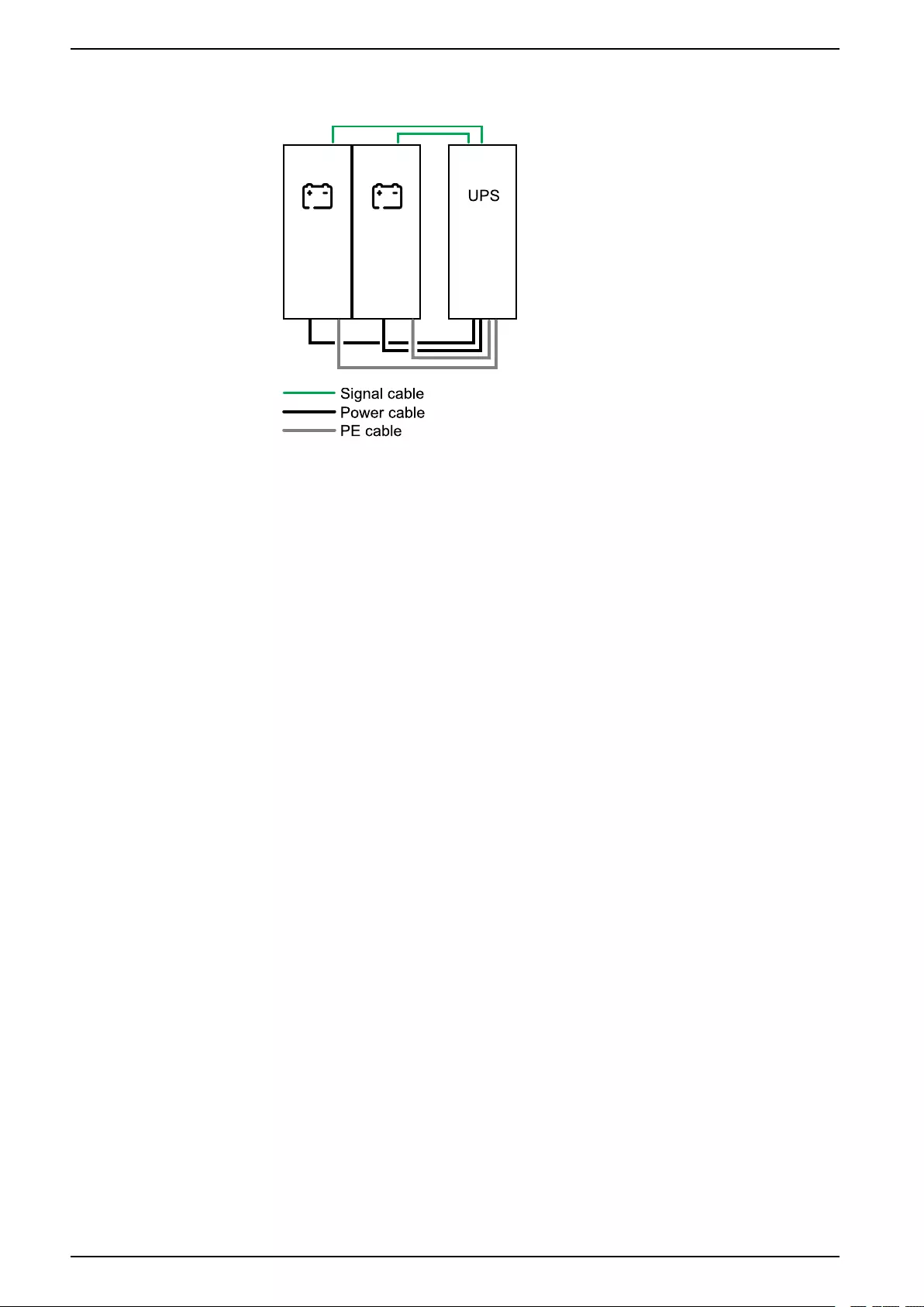
Connect the Signal Cables Classic Battery Cabinet
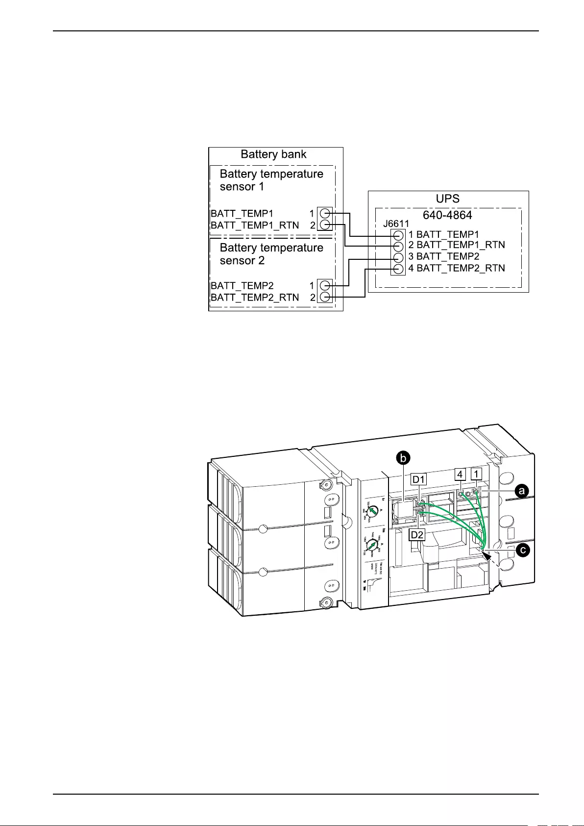
2. Route the battery temperature sensor cables through the bottom of the
classic battery cabinet to the UPS and connect as shown.
NOTE: One temperature sensor is provided with the UPS. Contact
Schneider Electric if you want to buy an additional temperature sensor
(0J-0M-1160).
NOTE: The battery temperature sensor cables are considered Class 2
and SELV. Class 2 and SELV circuits must be double isolated from the
primary circuitry.
3. Remove the cover on the battery breaker.
4. Connect the signal cables to the battery breaker:
a. Connect the signal cables to the AUX switch.
b. Connect the signal cables to the undervoltage trip coil.
c. Route the signal cables out through the lower opening of the battery
breaker.
990-5913B-001 23
Classic Battery Cabinet Connect the Signal Cables
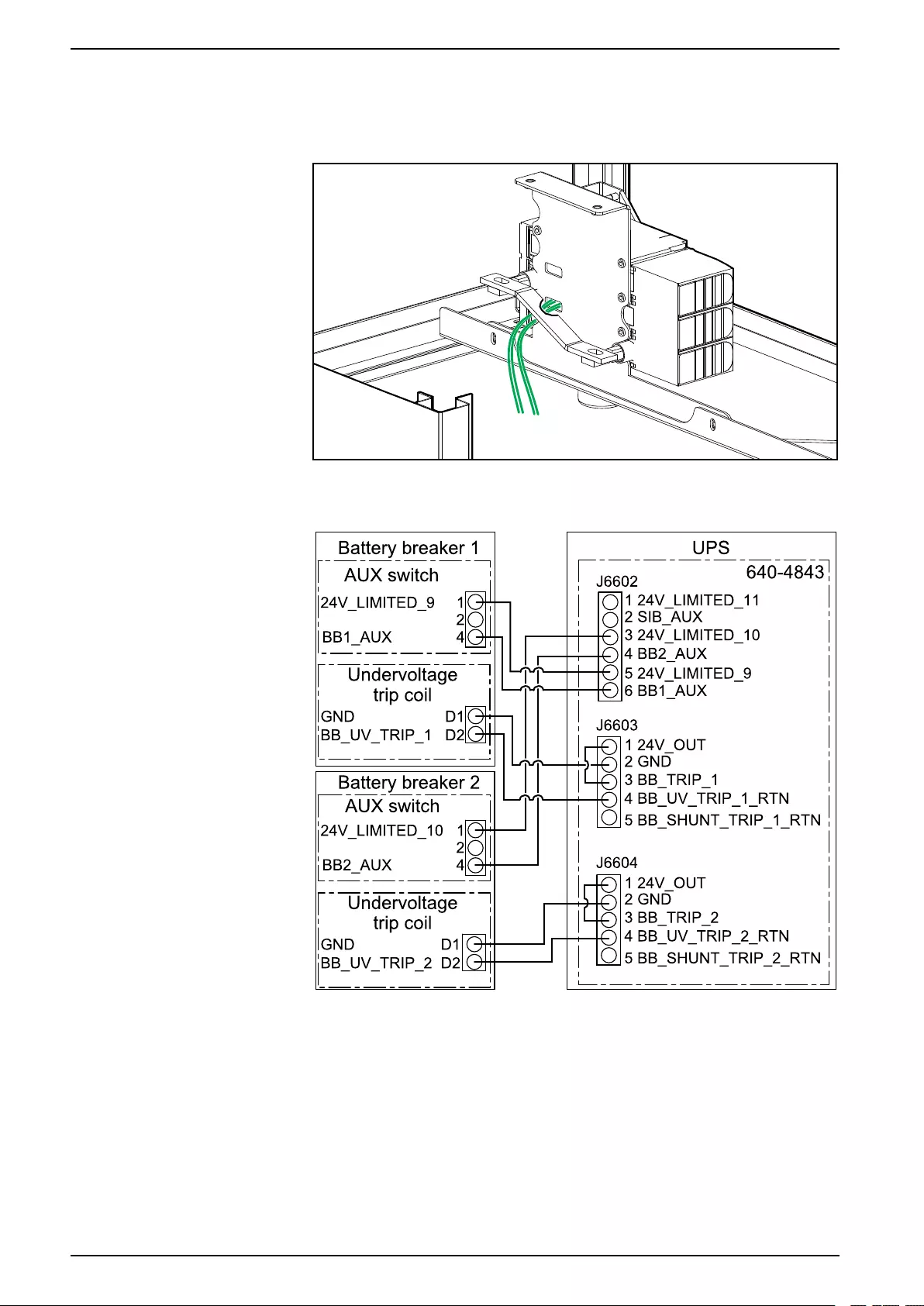
5. Route the signal cables from behind the battery breaker and out through the
bottom of the classic battery cabinet.
Rear View of the Battery Breaker
6. Reinstall the cover on the battery breaker.
7. Connect the signal cables in the UPS as shown.
24 990-5913B-001
Connect the Power Cables Classic Battery Cabinet
Connect the Power Cables
DANGER
HAZARD OF ELECTRIC SHOCK, EXPLOSION, OR ARC FLASH
Perform a total power off of the UPS before connecting the DC cables and
battery cables to the classic battery cabinet.
Failure to follow these instructions will result in death or serious injury.
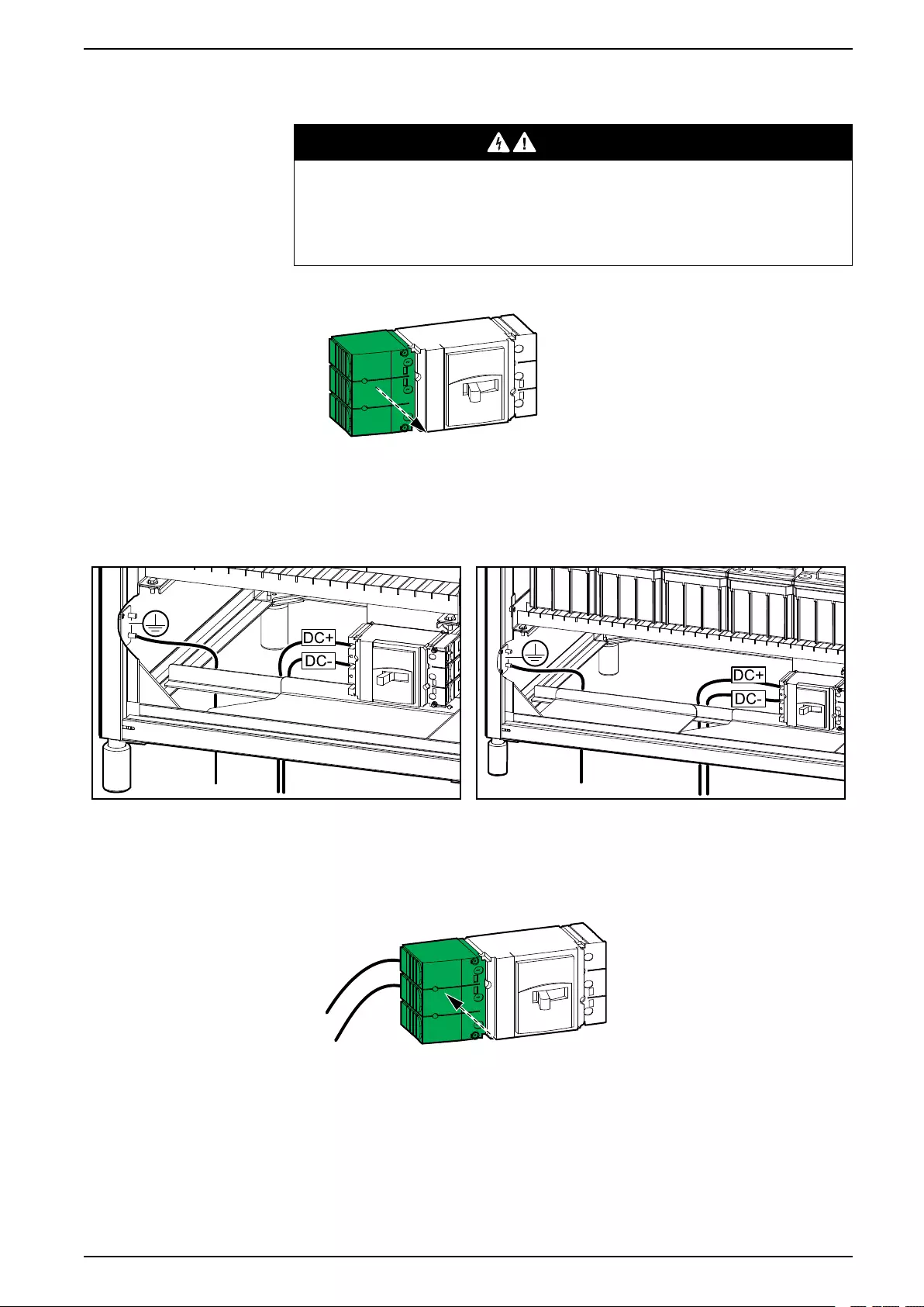
1. Remove the terminal cover from the left side of the battery breaker.
2. Route the PE cable through the bottom of the classic battery cabinet and
connect the PE cable.
GVSCBC7A, GVSCBC7B, GVSCBC7C GVSCBC10A2, GVSCBC10B2
3. Route the DC cables through the bottom of the classic battery cabinet and
connect the DC cables (DC+, DC-). Use lock washers (not provided) when
connecting the DC cables.
4. Reinstall the terminal cover on the left side of the battery breaker.
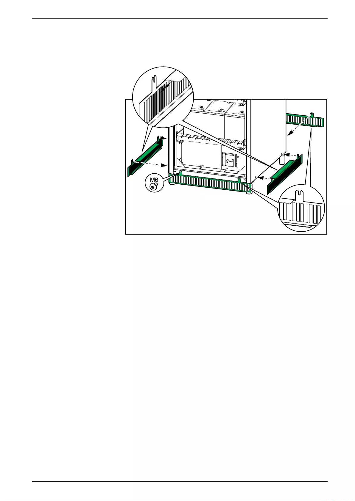
5. Reinstall the breaker protection plates.
990-5913B-001 25

Classic Battery Cabinet Connect the Power Cables
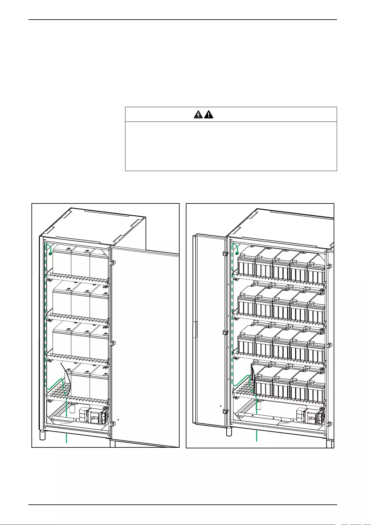
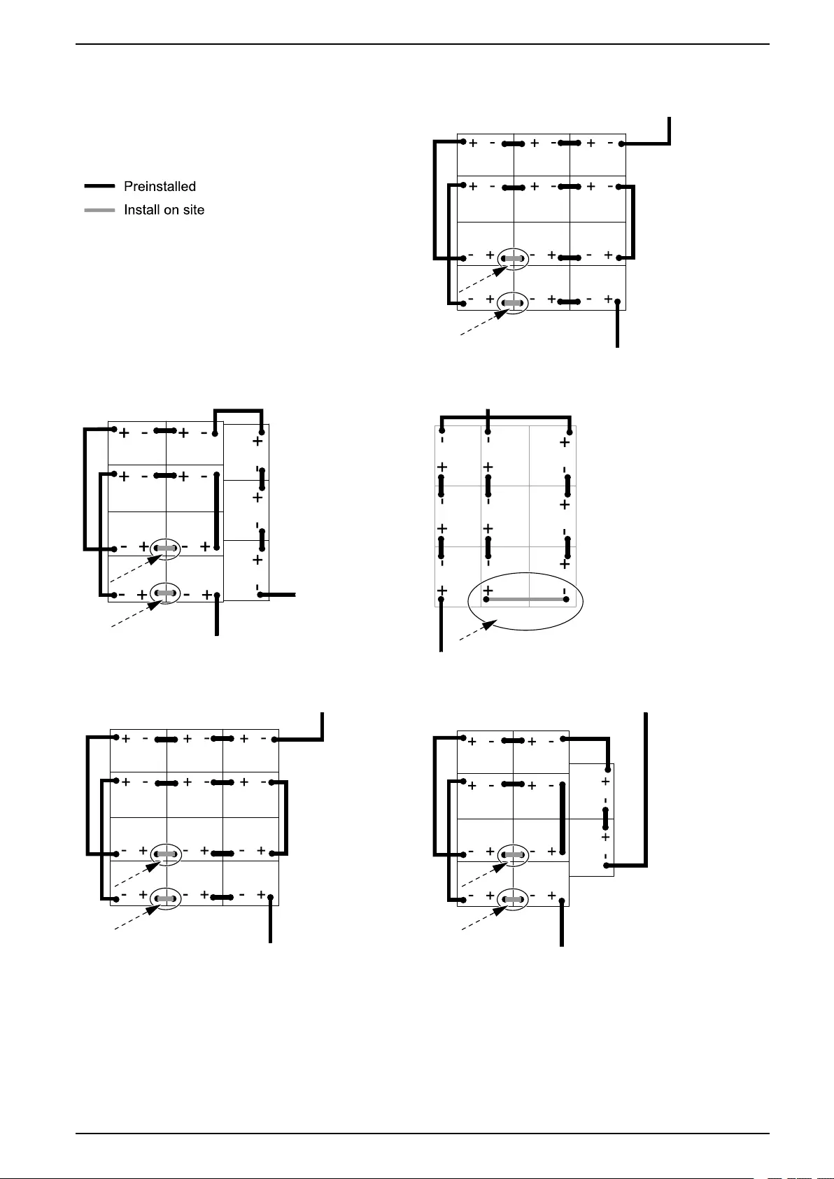
6. Interconnect the batteries on each shelf with the provided copper bars or
cables as shown. Each shelf is connected the same way. Follow the diagram
that matches your classic battery cabinet configuration.
DANGER
HAZARD OF ELECTRIC SHOCK, EXPLOSION, OR ARC FLASH
Batteries can present a risk of electric shock and high short-circuit current.
The following precautions must be observed when working on batteries
• Remove watches, rings, or other metal objects.
• Use tools with insulated handles.
• Wear protective glasses, gloves and boots.
• Do not lay tools or metal parts on top of batteries.
• Disconnect the charging source prior to connecting or disconnecting
battery terminals.
• Determine if the battery is inadvertently grounded. If inadvertently
grounded, remove source from ground. Contact with any part of a
grounded battery can result in electric shock. The likelihood of such
shock can be reduced if such grounds are removed during installation
and maintenance (applicable to equipment and remote battery supplies
not having a grounded supply circuit).
Failure to follow these instructions will result in death or serious
injury.
26 990-5913B-001

Classic Battery Cabinet Add Translated Safety Labels to Your Product
Add Translated Safety Labels to Your Product
The safety labels on your product are in English and French. Sheets with
translated safety labels are provided with your product.
1. Find the sheets with translated safety labels provided with your product.
2. Check which 885-XXX numbers are on the sheet with translated safety
labels.
3. Locate the safety labels on your product that match the translated safety
labels on the sheet – look for the 885-XXX numbers.
4. Add the replacement safety label in your preferred language to your product
on top of the existing French safety label.
28 990-5913B-001


Schneider Electric
35 rue Joseph Monier
92500 Rueil Malmaison
France
+ 33 (0) 1 41 29 70 00
*990-5913B-001*
As standards, specifications, and design change from time to time,
please ask for confirmation of the information given in this publication.
© 2018 – 2019 Schneider Electric. All rights reserved.
990-5913B-001