Table of Contents
- Galaxy VS
- Important Safety Instructions — SAVE THESE INSTRUCTIONS
- Specifications
- Single System Overview
- Parallel System Overview
- Overview of Installation Kits
- Installation Procedure for Single Systems
- Installation Procedure for Parallel Systems
- Prepare for Installation
- Install the Power Module(s)
- Install the Seismic Anchoring (Option)
- Prepare the UPS for TN-C/480 V Solid-Grounded System
- Connect the Power Cables
- Connect the Power Cables with NEMA 2 Hole Plates
- Connect the Signal Cables
- Connect the Signal Cables from a Modular Battery Cabinet
- Connect the Signal Cables from Switchgear and Third-Party Auxiliary Products
- Connect the IMB Signal Cables in a Simplified 1+1 Parallel System
- Connect the PBUS Cables
- Connect the External Communication Cables
- Add Translated Safety Labels to Your Product
- Final Installation
APC GVSUPS100KRHS User Manual
Displayed below is the user manual for GVSUPS100KRHS by APC which is a product in the Uninterruptible Power Supplies (UPSs) category. This manual has pages.
Related Manuals
Galaxy VS
UPS for External Batteries
Installation
20-150 kW 400/480 V
10-75 kW 208 V
Latest updates are available on the Schneider Electric website
6/2021
www.schneider-electric.com

Legal Information
The Schneider Electric brand and any trademarks of Schneider Electric SE and its
subsidiaries referred to in this guide are the property of Schneider Electric SE or its
subsidiaries. All other brands may be trademarks of their respective owners.
This guide and its content are protected under applicable copyright laws and
furnished for informational use only. No part of this guide may be reproduced or
transmitted in any form or by any means (electronic, mechanical, photocopying,
recording, or otherwise), for any purpose, without the prior written permission of
Schneider Electric.
Schneider Electric does not grant any right or license for commercial use of the guide
or its content, except for a non-exclusive and personal license to consult it on an "as
is" basis. Schneider Electric products and equipment should be installed, operated,
serviced, and maintained only by qualified personnel.
As standards, specifications, and designs change from time to time, information
contained in this guide may be subject to change without notice.
To the extent permitted by applicable law, no responsibility or liability is assumed by
Schneider Electric and its subsidiaries for any errors or omissions in the informational
content of this material or consequences arising out of or resulting from the use of the
information contained herein.
Go to
IEC: https://www.productinfo.schneider-electric.com/portals/ui/galaxyvs_iec/ or
UL: https://www.productinfo.schneider-electric.com/portals/ui/galaxyvs_ul/
or scan the QR code above for digital experience and translated manuals.

UPS for External Batteries
Table of Contents
Important Safety Instructions — SAVE THESE
INSTRUCTIONS.........................................................................................5
FCC Statement ..........................................................................................6
Electromagnetic Compatibility .....................................................................6
Safety Precautions .....................................................................................6
Electrical Safety .........................................................................................9
Battery Safety ............................................................................................9
Symbols Used.......................................................................................... 11
ENERGY STAR Qualification.....................................................................13
Specifications ............................................................................................14
Specifications for 400 V Systems ............................................................... 14
Input Specifications 400 V ...................................................................14
Bypass Specifications 400 V................................................................15
Output Specifications 400 V.................................................................16
Battery Specifications 400 V ................................................................17
Recommended Cable Sizes 400 V .......................................................18
Recommended Upstream Protection 400 V ..........................................20
Specifications for 480 V Systems ............................................................... 21
Input Specifications 480 V ...................................................................21
Bypass Specifications 480 V................................................................22
Output Specifications 480 V.................................................................23
Battery Specifications 480 V ................................................................24
Recommended Cable Sizes 480 V .......................................................25
Recommended Upstream Protection 480 V ..........................................27
Specifications for 208 V Systems ............................................................... 28
Input Specifications 208 V ...................................................................28
Bypass Specifications 208 V................................................................29
Output Specifications 208 V.................................................................30
Battery Specifications 208 V ................................................................31
Recommended Cable Sizes 208 V .......................................................32
Recommended Upstream Protection 208 V ..........................................34
Recommended Bolt and Lug Sizes ............................................................36
Torque Specifications................................................................................37
Requirements for a Third Party Battery Solution..........................................38
Third Party Battery Breaker Requirements ............................................ 38
Guidance for Organizing Battery Cables ...............................................39
Environment.............................................................................................39
UPS Weights and Dimensions...................................................................40
Clearance ................................................................................................41
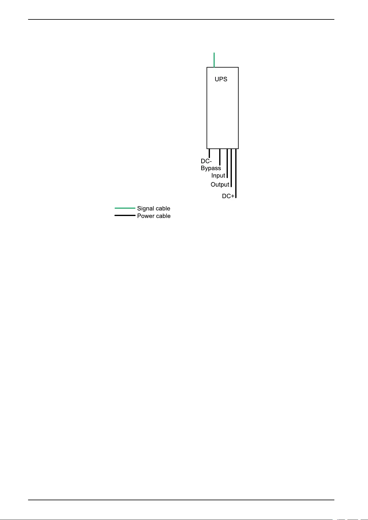
Single System Overview..........................................................................42
Parallel System Overview........................................................................43
Overview of Installation Kits ....................................................................46
Optional Seismic Kit GVSOPT002 .............................................................47
Optional NEMA 2 Hole Kit GVSOPT005 .....................................................47
Optional Parallel Kit GVSOPT006 ..............................................................48
Optional Kit GVSOPT030..........................................................................49
Installation Procedure for Single Systems ............................................50
990-91111F-001 3

UPS for External Batteries
Installation Procedure for Parallel Systems ..........................................51
Prepare for Installation.............................................................................52
Install the Power Module(s).....................................................................56
Install the Seismic Anchoring (Option) ..................................................57
Prepare the UPS for TN-C/480 V Solid-Grounded System................58
Connect the Power Cables......................................................................59
Connect the Power Cables with NEMA 2 Hole Plates ........................63
Connect the Signal Cables......................................................................67
Connect the Signal Cables from a Modular Battery Cabinet..............69
Connect the Signal Cables from Switchgear and Third-Party
Auxiliary Products .....................................................................................71
Connect the IMB Signal Cables in a Simplified 1+1 Parallel
System........................................................................................................75
Connect the PBUS Cables ......................................................................79
Connect the External Communication Cables......................................80
Connect the Modbus Cables .....................................................................81
Add Translated Safety Labels to Your Product.....................................82
Final Installation ........................................................................................83
4 990-91111F-001
Important Safety Instructions — SAVE THESE
INSTRUCTIONS UPS for External Batteries
Important Safety Instructions — SAVE THESE
INSTRUCTIONS
Read these instructions carefully and look at the equipment to become familiar
with it before trying to install, operate, service or maintain it. The following safety
messages may appear throughout this manual or on the equipment to warn of
potential hazards or to call attention to information that clarifies or simplifies a
procedure.
The addition of this symbol to a “Danger” or “Warning” safety
message indicates that an electrical hazard exists which will result in
personal injury if the instructions are not followed.
This is the safety alert symbol. It is used to alert you to potential
personal injury hazards. Obey all safety messages with this symbol
to avoid possible injury or death.
DANGER
DANGER indicates a hazardous situation which, if not avoided, will result in
death or serious injury.
Failure to follow these instructions will result in death or serious injury.
WARNING
WARNING indicates a hazardous situation which, if not avoided, could result
in death or serious injury.
Failure to follow these instructions can result in death, serious injury, or
equipment damage.
CAUTION
CAUTION indicates a hazardous situation which, if not avoided, could result in
minor or moderate injury.
Failure to follow these instructions can result in injury or equipment
damage.
NOTICE
NOTICE is used to address practices not related to physical injury. The safety
alert symbol shall not be used with this type of safety message.
Failure to follow these instructions can result in equipment damage.
Please Note
Electrical equipment should only be installed, operated, serviced, and maintained
by qualified personnel. No responsibility is assumed by Schneider Electric for any
consequences arising out of the use of this material.
A qualified person is one who has skills and knowledge related to the construction,
installation, and operation of electrical equipment and has received safety training
to recognize and avoid the hazards involved.
990-91111F-001 5
UPS for External Batteries
Important Safety Instructions — SAVE THESE
INSTRUCTIONS
FCC Statement
NOTE: This equipment has been tested and found to comply with the limits for
a Class A digital device, pursuant to Part 15 of the FCC Rules. These limits
are designed to provide reasonable protection against harmful interference
when the equipment is operated in a commercial environment. This equipment
generates, uses, and can radiate radio frequency energy and, if not installed
and used in accordance with the instruction manual, may cause harmful
interference to radio communications. Operation of this equipment in a
residential area is likely to cause harmful interference in which case the user
will be required to correct the interference at his own expense.
Any changes or modifications not expressly approved by the party responsible for
compliance could void the user’s authority to operate the equipment.
Electromagnetic Compatibility
NOTICE
RISK OF ELECTROMAGNETIC DISTURBANCE
This is a product category C2 UPS product. In a residential environment, this
product may cause radio inference, in which case the user may be required to
take additional measures.
Failure to follow these instructions can result in equipment damage.
Safety Precautions
DANGER
HAZARD OF ELECTRIC SHOCK, EXPLOSION, OR ARC FLASH
All safety instructions in this document must be read, understood and followed.
Failure to follow these instructions will result in death or serious injury.
DANGER
HAZARD OF ELECTRIC SHOCK, EXPLOSION, OR ARC FLASH
Read all instructions in the installation manual before installing or working on
this UPS system.
Failure to follow these instructions will result in death or serious injury.
DANGER
HAZARD OF ELECTRIC SHOCK, EXPLOSION, OR ARC FLASH
Do not install the UPS system until all construction work has been completed
and the installation room has been cleaned. If additional construction work is
needed in the installation room after the UPS has been installed, turn off the
UPS and cover the UPS with the protective packaging bag the UPS was
delivered in.
Failure to follow these instructions will result in death or serious injury.
6 990-91111F-001

Important Safety Instructions — SAVE THESE
INSTRUCTIONS UPS for External Batteries
DANGER
HAZARD OF ELECTRIC SHOCK, EXPLOSION, OR ARC FLASH
• The product must be installed according to the specifications and
requirements as defined by Schneider Electric. It concerns in particular the
external and internal protections (upstream breakers, battery breakers,
cabling, etc.) and environmental requirements. No responsibility is assumed
by Schneider Electric if these requirements are not respected.
• After the UPS system has been electrically wired, do not start up the system.
Start-up must only be performed by Schneider Electric.
Failure to follow these instructions will result in death or serious injury.
DANGER
HAZARD OF ELECTRIC SHOCK, EXPLOSION, OR ARC FLASH
The UPS system must be installed according to local and national regulations.
Install the UPS according to:
• IEC 60364 (including 60364-4-41– protection against electric shock, 60364-
4-42 – protection against thermal effect, and 60364-4-43 – protection against
overcurrent), or
• NEC NFPA 70, or
• Canadian Electrical Code (C22.1, Part 1)
depending on which one of the standards apply in your local area.
Failure to follow these instructions will result in death or serious injury.
DANGER
HAZARD OF ELECTRIC SHOCK, EXPLOSION, OR ARC FLASH
• Install the UPS system in a temperature controlled indoor environment free
of conductive contaminants and humidity.
• Install the UPS system on a non-flammable, level and solid surface (e.g.
concrete) that can support the weight of the system.
Failure to follow these instructions will result in death or serious injury.
DANGER
HAZARD OF ELECTRIC SHOCK, EXPLOSION, OR ARC FLASH
The UPS is not designed for and must therefore not be installed in the following
unusual operating environments:
• Damaging fumes
• Explosive mixtures of dust or gases, corrosive gases, or conductive or
radiant heat from other sources
• Moisture, abrasive dust, steam or in an excessively damp environment
• Fungus, insects, vermin
• Salt-laden air or contaminated cooling refrigerant
• Pollution degree higher than 2 according to IEC 60664-1
• Exposure to abnormal vibrations, shocks, and tilting
• Exposure to direct sunlight, heat sources, or strong electromagnetic fields
Failure to follow these instructions will result in death or serious injury.
990-91111F-001 7
UPS for External Batteries
Important Safety Instructions — SAVE THESE
INSTRUCTIONS
DANGER
HAZARD OF ELECTRIC SHOCK, EXPLOSION, OR ARC FLASH
Do not drill or cut holes for cables or conduits with the gland plates installed and
do not drill or cut holes in close proximity to the UPS.
Failure to follow these instructions will result in death or serious injury.
WARNING
HAZARD OF ARC FLASH
Do not make mechanical changes to the product (including removal of cabinet
parts or drilling/cutting of holes) that are not described in the installation manual.
Failure to follow these instructions can result in death, serious injury, or
equipment damage.
NOTICE
RISK OF OVERHEATING
Respect the space requirements around the UPS system and do not cover the
UPS ventilation openings when the UPS system is in operation.
Failure to follow these instructions can result in equipment damage.
NOTICE
RISK OF EQUIPMENT DAMAGE
Do not connect the UPS output to regenerative load systems including
photovoltaic systems and speed drives.
Failure to follow these instructions can result in equipment damage.
8 990-91111F-001

Important Safety Instructions — SAVE THESE
INSTRUCTIONS UPS for External Batteries
Electrical Safety
DANGER
HAZARD OF ELECTRIC SHOCK, EXPLOSION OR ARC FLASH
• Electrical equipment must be installed, operated, serviced, and maintained
only by qualified personnel.
• Apply appropriate personal protective equipment (PPE) and follow safe
electrical work practices.
• Turn off all power supplying the UPS system before working on or inside the
equipment.
• Before working on the UPS system, check for hazardous voltage between all
terminals including the protective earth.
• The UPS contains an internal energy source. Hazardous voltage can be
present even when disconnected from the utility/mains supply. Before
installing or servicing the UPS system, ensure that the units are OFF and
that utility/mains and batteries are disconnected. Wait five minutes before
opening the UPS to allow the capacitors to discharge.
• A disconnection device (e.g. disconnection circuit breaker or switch) must be
installed to enable isolation of the system from upstream power sources in
accordance with local regulations. This disconnection device must be easily
accessible and visible.
• The UPS must be properly earthed/grounded and due to a high leakage
current, the earthing/grounding conductor must be connected first.
Failure to follow these instructions will result in death or serious injury.
Battery Safety
DANGER
HAZARD OF ELECTRIC SHOCK, EXPLOSION, OR ARC FLASH
• Battery circuit breakers must be installed according to the specifications and
requirements as defined by Schneider Electric.
• Servicing of batteries must only be performed or supervised by qualified
personnel knowledgeable of batteries and the required precautions. Keep
unqualified personnel away from batteries.
• Disconnect charging source prior to connecting or disconnecting battery
terminals.
• Do not dispose of batteries in a fire as they can explode.
• Do not open, alter, or mutilate batteries. Released electrolyte is harmful to
the skin and eyes. It may be toxic.
Failure to follow these instructions will result in death or serious injury.
990-91111F-001 9

UPS for External Batteries
Important Safety Instructions — SAVE THESE
INSTRUCTIONS
DANGER
HAZARD OF ELECTRIC SHOCK, EXPLOSION, OR ARC FLASH
Batteries can present a risk of electric shock and high short-circuit current. The
following precautions must be observed when working on batteries
• Remove watches, rings, or other metal objects.
• Use tools with insulated handles.
• Wear protective glasses, gloves and boots.
• Do not lay tools or metal parts on top of batteries.
• Disconnect the charging source prior to connecting or disconnecting battery
terminals.
• Determine if the battery is inadvertently grounded. If inadvertently grounded,
remove source from ground. Contact with any part of a grounded battery can
result in electric shock. The likelihood of such shock can be reduced if such
grounds are removed during installation and maintenance (applicable to
equipment and remote battery supplies not having a grounded supply
circuit).
Failure to follow these instructions will result in death or serious injury.
DANGER
HAZARD OF ELECTRIC SHOCK, EXPLOSION, OR ARC FLASH
When replacing batteries, always replace with the same type and number of
batteries or battery packs.
Failure to follow these instructions will result in death or serious injury.
CAUTION
RISK OF EQUIPMENT DAMAGE
• Mount the batteries in the UPS system, but do not connect the batteries until
the UPS system is ready to be powered up. The time duration from battery
connection until the UPS system is powered up must not exceed 72 hours or
3 days.
• Batteries must not be stored more than six months due to the requirement of
recharging. If the UPS system remains de-energized for a long period, we
recommend that you energize the UPS system for a period of 24 hours at
least once every month. This charges the batteries, thus avoiding
irreversible damage.
Failure to follow these instructions can result in injury or equipment
damage.
10 990-91111F-001
Important Safety Instructions — SAVE THESE
INSTRUCTIONS UPS for External Batteries
Symbols Used
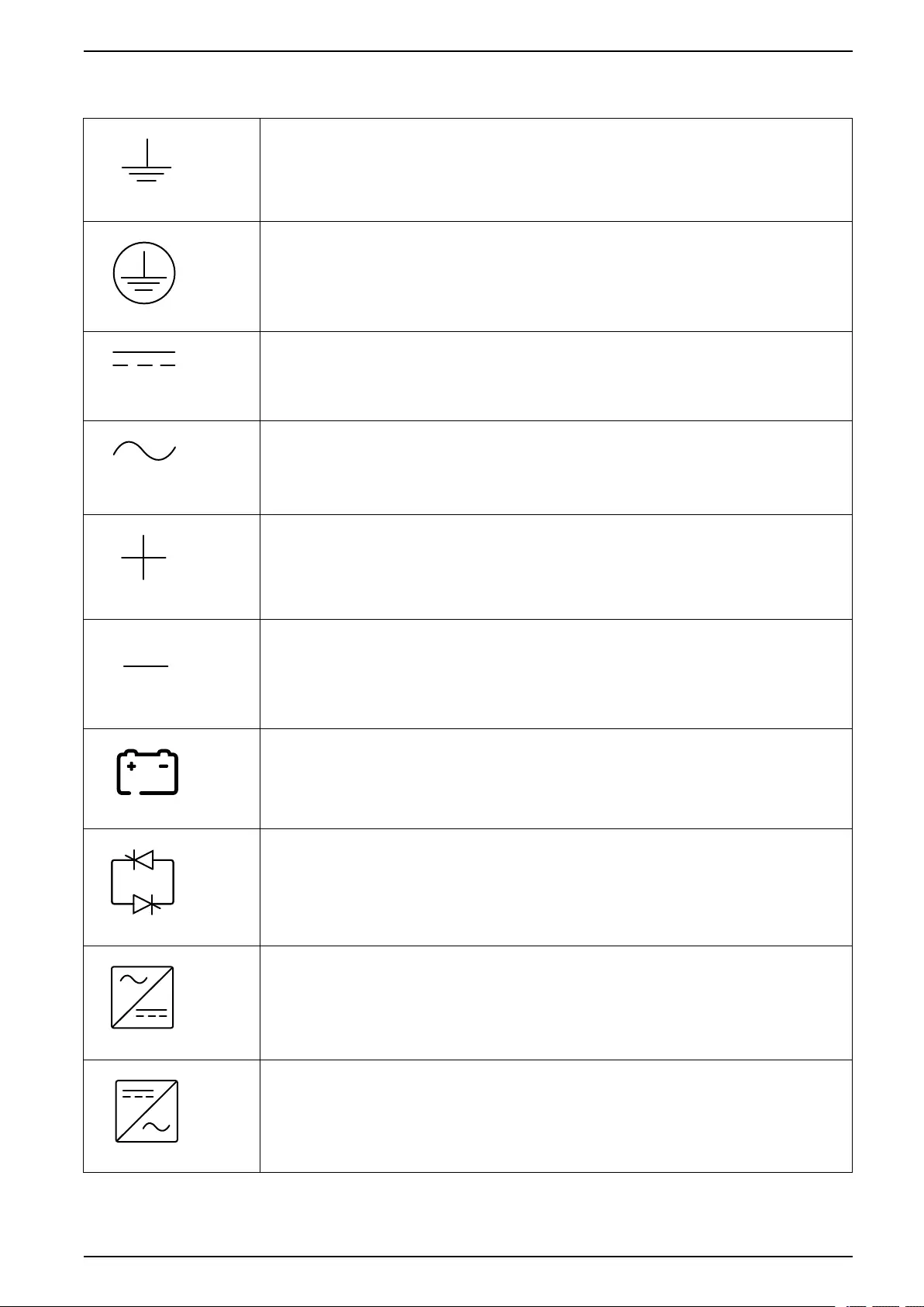
Earthing/ground symbol.
Protective earth (PE)/equipment grounding conductor (EGC) symbol.
Direct current (DC) symbol.
Alternating current (AC) symbol.
Positive polarity symbol. It is used to identify the positive terminal(s) of equipment
which is used with, or generates direct current.
Negative polarity symbol. It is used to identify the negative terminal(s) of equipment
which is used with, or generates direct current.
Battery symbol.
Static switch symbol. It is used to indicate switches that are designed to connect or
disconnect the load to or from the supply respectively without the existence of
moving parts.
AC/DC converter (rectifier) symbol. It is used to identify an AC/DC converter
(rectifier) and, in case of plug-in devices, to identify the relevant receptacles.
DC/AC converter (inverter) symbol. It is used to identify an DC/AC converter
(inverter) and, in case of plug-in devices, to identify the relevant receptacles.
990-91111F-001 11
UPS for External Batteries
Important Safety Instructions — SAVE THESE
INSTRUCTIONS
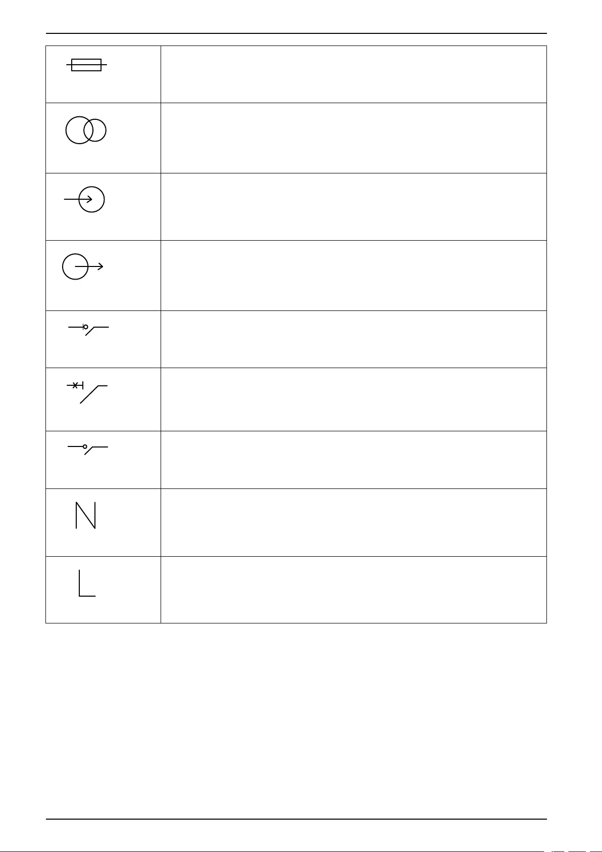
Fuse symbol. It is used to identify fuse boxes or their locations.
Transformer symbol.
Input symbol. It is used to identify an input terminal when it is necessary to
distinguish between inputs and outputs.
Output symbol. It is used to identify an output terminal when it is necessary to
distinguish between inputs and outputs.
Switch disconnector symbol. It is used to identify the disconnecting device in the form
of switch that protects the equipment from short circuit or heavy load current. It opens
the circuits once the current flow crosses its maximum limit.
Circuit breaker symbol. It is used to identify the disconnecting device in the form of
circuit breaker that protects the equipment from short circuit or heavy load current. It
opens the circuits once the current flow crosses its maximum limit.
Disconnection device symbol. It is used to identify the disconnecting device in the
form of circuit breaker or switch that protects the equipment from short circuit or
heavy load current. It opens the circuits once the current flow crosses its maximum
limit.
Neutral symbol. It is used to identify the neutral conductors or their locations.
Phase conductor symbol. It is used to identify the phase conductors or their
locations.
12 990-91111F-001


UPS for External Batteries Specifications
Specifications
Specifications for 400 V Systems
Input Specifications 400 V
UPS rating 20 kW 30 kW 40 kW 50 kW 60 kW 80 kW 100 kW 120 kW 150 kW
Voltage (V) 380/400/415
Connections 4-wire (L1, L2, L3, N, PE) WYE (single mains)
3-wire (L1, L2, L3, PE) WYE (dual mains)1 2
Input voltage range
(V)
380 V: 331-437
400 V: 340-460
415 V: 353-477
Frequency range
(Hz)
40-70
Nominal input
current (A)
32/30/29 47/45/43 63/60/58 79/75/72 95/90/87 126/120/
116
158/150/
144
189/180/
173
237/225/
217
Maximum input
current (A)
38/36/35 57/54/52 76/72/69 91/90/87 114/108/
104
151/144/
139
182/180/
173
227/216/
208
273/270/
260
Input current
limitation (A)
39/37/36 59/56/54 78/74/72 91/91/90 117/111/
107
156/148/
143
182/182/
179
234/222/
214
273/273/
268
Input power factor 0.99 for load greater than 50%
0.95 for load greater than 25%
Total harmonic
distortion (THDI)
<5% at
100%
load
<3% at 100% load
Maximum short
circuit rating
65 kA RMS
Protection Built-in backfeed protection and fuses
Ramp-in Programmable and adaptive 1-40 seconds
NOTE: For a UPS with N+1 power module, the input power factor is 0.99 at
100% load and the total harmonic distortion (THDI) is <6% at full linear load
(symmetrical).
14 990-91111F-001
1. TN and TT power distribution systems are supported. Corner (line) grounding is not supported.
2. Only for dual mains system with upstream 4-pole breakers: Install an N connection with the input cables (L1, L2, L3, N, PE). Refer to
earthing schematics for TN-S dual mains 4-pole circuit breaker.

Specifications UPS for External Batteries
Bypass Specifications 400 V
UPS rating 20 kW 30 kW 40 kW 50 kW 60 kW 80 kW 100 kW 120 kW 150 kW
Voltage (V) 380/400/415
Connections 4-wire (L1, L2, L3, N, PE) WYE
Bypass voltage
range (V)
380 V: 342-418
400 V: 360-440
415 V: 374-457
Frequency range
(Hz)
50/60 ± 1, 50/60 ± 3, 50/60 ± 10 (user selectable)
Nominal bypass
current (A)
31/29/28 46/44/42 61/58/56 77/73/70 92/87/84 123/117/
112
153/146/
141
184/175/
169
230/219/
211
Nominal neutral
current (A)3
53/50/48 79/75/72 105/100/
96
131/125/
120
158/150/
144
210/200/
193
263/250/
241
263/250/
241
263/250/
241
Maximum short
circuit rating
65 kA RMS
Protection Built-in backfeed protection and fuses
Internal fuse specifications: Rated 400 A, prearcing 33 kA2s
Built-in backfeed
protection and fuses
Internal fuse
specifications: Rated
550 A, prearcing 52
kA2s
990-91111F-001 15
3. Harmonic currents in neutral are only considered to be 1.73 x nominal up till 100 kW. Above 100 kW only resistive load is considered.

UPS for External Batteries Specifications
Output Specifications 400 V
UPS rating 20 kW 30 kW 40 kW 50 kW 60 kW 80 kW 100 kW 120 kW 150 kW
Voltage (V) 380/400/415
Connections 4-wire (L1, L2, L3, N, PE)
Output voltage
regulation
Symmetrical load ± 1%
Asymmetrical load ± 3%
Overload capacity 150% for 1 minute (in normal operation)
125% for 10 minutes (in normal operation)
125% for 1 minute (in battery operation)
110% continuous (bypass operation)
1000% for 100 milliseconds (bypass operation)
Dynamic load
response
± 5% after 2 milliseconds
± 1% after 50 milliseconds
Output power factor 1
Nominal output
current (A)
30/29/28 46/43/42 61/58/56 76/72/70 91/87/83 122/115/
111
152/144/
139
182/173/
167
228/217/
209
Frequency regulation
(Hz)
50/60 Hz bypass synchronized – 50/60 Hz ± 0.1% free-running
Synchronized slew
rate (Hz/sec)
Programmable to 0.25, 0.5, 1, 2, 4, 6
Output performance
classification
(according to IEC
62040-3:2021)
VFI-SS-11
Total harmonic
distortion (THDU)
<1% for linear load
<5% for non-linear load
Load crest factor 2.5
Load power factor From 0.7 leading to 0.7 lagging without any derating
16 990-91111F-001

Specifications UPS for External Batteries
Battery Specifications 400 V
DANGER
HAZARD OF ELECTRIC SHOCK, EXPLOSION, OR ARC FLASH
• Protection of the energy storage device: An overcurrent protective device
must be located in close proximity to the energy storage device.
• Trip delay must be set to zero on all battery breakers.
Failure to follow these instructions will result in death or serious injury.
UPS rating 20 kW 30 kW 40 kW 50 kW 60 kW 80 kW 100 kW 120 kW 150 kW
Charging power in %
of output power at 0-
40% load4
80%
Charging power in %
of output power at
100% load
20%5
Maximum charging
power (at 0-40%
load) (kW)4
16 24 32 40 48 64 80 96 120
Maximum charging
power (at 100%
load) (kW)
4 6 8 10 12 16 20 24 30
Nominal battery
voltage (VDC)
32-48 blocks: 384-576 40-48
blocks:
480-576
35-48
blocks:
420-576
32-48
blocks:
384-576
40-48 blocks: 480-576
Nominal float voltage
(VDC)
32-48 blocks: 436-654 40-48
blocks:
545-654
35-48
blocks:
477-654
32-48
blocks:
436-654
40-48 blocks: 545-654
Maximum boost
voltage (VDC)
720 for 48 blocks
Temperature
compensation (per
cell)
-3.3mV/°C, for T ≥ 25 °C – 0mV/°C, for T < 25 °C
End of discharge
voltage (full load)
(VDC)
32 blocks: 307 40
blocks:
384
35 blocks:
336
32
blocks:
307
40 blocks: 384
Battery current at full
load and nominal
battery voltage (A)6
54 81 109 109 130 174 217 260 326
Battery current at full
load and minimum
battery voltage (A)6
68 102 136 136 163 217 271 326 407
Ripple current < 5% C20 (5 minute runtime)
Battery test Manual/automatic (selectable)
Maximum short
circuit rating
10 kA
990-91111F-001 17
4. Values based on 48 blocks.
5. At 380 V only 15% for 50 kW, 100 kW, and 150 kW.
6. Values based on 20-40 kW: 32 blocks; 50-150 kW: 40 blocks.

UPS for External Batteries Specifications
Recommended Cable Sizes 400 V
DANGER
HAZARD OF ELECTRIC SHOCK, EXPLOSION, OR ARC FLASH
All wiring must comply with all applicable national and/or electrical codes. The
maximum allowable cable size is 150 mm2.
Failure to follow these instructions will result in death or serious injury.
The maximum number of cable connections per busbar: Two on input/output/
bypass busbars; Four on DC+/DC- busbars; Six on N/PE busbars.
NOTE: Overcurrent protection is to be provided by others.
Cable sizes in this manual are based on table B.52.3 and table B.52.5 of IEC
60364-5-52 with the following assertions:
• 90 °C conductors
• An ambient temperature of 30 °C
• Use of copper or aluminum conductors
• Installation method C
PE cable size is based on table 54.2 of IEC 60364-4-54.
If the ambient temperature is greater than 30 °C, larger conductors are to be
selected in accordance with the correction factors of the IEC.
NOTE: Recommended cable sizes and maximum allowable cable size may
vary for the auxiliary products. Not all auxiliary products support aluminum
cables. Refer to the installation manual provided with the auxiliary product.
NOTE: The DC cable sizes given here are recommendations – Always follow
the specific instructions in the battery solution documentation for DC cable
sizes and DC PE cable sizes and ensure that the DC cable sizes match the
battery breaker rating.
NOTE: Neutral conductor is sized to handle 1.73 times phase current in case
of high harmonic content from non-linear loads. If non or less harmonic
currents are expected, neutral conductor can be sized accordingly but not less
than the phase conductor.
Copper
UPS rating 20 kW 30 kW 40 kW 50 kW 60 kW 80 kW 100 kW 120 kW 150 kW
Input phases (mm2) 6 10 16 25 35 50 70 95 120
Input PE (mm2) 6 10 16 16 16 25 35 50 70
Bypass/output
phases (mm2)
6 6 10 16 25 35 50 70 95
Bypass PE/output
PE (mm2)
6 6 10 16 16 16 25 35 50
Neutral (mm2) 10 16 25 35 50 70 95 95 95
DC+/DC- (mm2)710 25 35 35 50 70 95 95 120
DC PE (mm2) 10 16 16 16 25 35 50 50 70
Aluminum
UPS rating 20 kW 30 kW 40 kW 50 kW 60 kW 80 kW 100 kW 120 kW 150 kW
Input phases (mm2) 6 16 25 35 50 70 95 120 150
Input PE (mm2) 6 16 16 16 25 35 50 70 95
Bypass/output
phases (mm2)
6 10 16 25 35 50 70 95 150
18 990-91111F-001
7. 20-40 kW: DC cables are sized according to 32 blocks. 50-100 kW: DC cables are sized according to 40 blocks.

Specifications UPS for External Batteries
Aluminum (Continued)
UPS rating 20 kW 30 kW 40 kW 50 kW 60 kW 80 kW 100 kW 120 kW 150 kW
Bypass PE/output
PE (mm2)
6 10 16 16 16 25 35 50 95
Neutral (mm2) 10 25 35 50 70 95 2 x 70 2 x 70 2 x 70
DC+/DC- (mm2)816 35 50 50 70 95 2 x 70 2 x 70 2 x 95
DC PE (mm2) 16 16 25 25 35 50 70 70 95
990-91111F-001 19
8. 20-40 kW: DC cables are sized according to 32 blocks. 50-100 kW: DC cables are sized according to 40 blocks.

UPS for External Batteries Specifications
Recommended Upstream Protection 400 V
DANGER
HAZARD OF ELECTRIC SHOCK, EXPLOSION, OR ARC FLASH
• For parallel systems, instantaneous override (Ii) values must not be set
higher than 1250 A. Place the label 885-92556 adjacent to the upstream
circuit breaker to inform about the hazard.
• For UPS rating 20-120 kW: In parallel systems with three or more UPSs, a
circuit breaker must be installed on the output of each UPS. The unit output
breaker (UOB) instantaneous override (Ii) values must not be set higher than
1250 A.
• For UPS rating 150 kW: In parallel systems with two or more UPSs, a circuit
breaker must be installed on the output of each UPS. The unit output
breaker (UOB) instantaneous override (Ii) values must not be set higher than
1250 A.
Failure to follow these instructions will result in death or serious injury.
NOTE: For local directives which require 4-pole circuit breakers: If neutral
conductor is expected to carry a high current, due to line-neutral non-linear
load, the circuit breaker must be rated according to expected neutral current.
NOTE: For the scalable UPS (GVSUPS50K150HS), always size the upstream
protection for a UPS rating of 150 kW.
UPS rating 20 kW 30 kW 40 kW
Input Bypass Input Bypass Input Bypass
Breaker type NSX100H
TM40D
(LV429674)
NSX100H
TM32D
(LV429675)
NSX100H
TM63D
(LV429672)
NSX100H
TM50D
(LV429673)
NSX100H
TM80D
(LV429671)
NSX100H
TM63D
(LV429672)
In 40 32 63 50 80 63
Ir 40 32 63 50 80 63
Im 500 (fixed) 400 (fixed) 500 (fixed) 500 (fixed) 640 (fixed) 500 (fixed)
UPS rating 50 kW 60 kW 80 kW 100 kW
Input Bypass Input Bypass Input Bypass Input Bypass
Breaker type NSX100H
TM100D
(LV429670)
NSX100H
TM80D
(LV429671)
NSX160H
TM125D
(LV430671)
NSX100H
TM100D
(LV429670)
NSX160H
TM160D
(LV430670)
NSX160H
TM125D
(LV430671)
NSX250H
TM200D
(LV431671)
NSX160H
TM160D
(LV430670)
In 100 80 125 100 160 125 200 160
Ir 100 80 125 100 160 125 200 160
Im 800 (fixed) 640 (fixed) 1250
(fixed)
800 (fixed) 1250
(fixed)
1250
(fixed)
≤6 x In 1250
(fixed)
UPS rating 120 kW 150 kW
Input Bypass Input Bypass
Breaker type NSX250H TM250D
(LV431670)
NSX250H TM200
(LV431671)
NSX400H Mic.L5
(LV432701)
NSX250H TM250
(LV431670)
In/Io 250 200 280 250
Ir 250 200 —250
tr — — 0.5 —
Im/Isd ≤5 x In ≤6 x In 10 ≤5 x In
tsd — — 0—
li — — ≤4.5 x In —
20 990-91111F-001

Specifications UPS for External Batteries
Specifications for 480 V Systems
The supply for input and bypass must be solid-grounded WYE transformers. Delta
input supply for either input or bypass is not permitted.
The UPS system must be installed as a separately derived system. Leakage
currents will occur in the bonding jumper and the technical/system earth.
Input Specifications 480 V
UPS rating 20 kW 30 kW 40 kW 50 kW 60 kW 80 kW 100 kW 120 kW 150 kW
Connections 3-wire (L1, L2, L3, G) WYE or 4-wire (L1, L2, L3, N, G) WYE (single mains)
3-wire (L1, L2, L3, G) WYE (dual mains)
Input voltage range
(V)
408-552
Frequency range
(Hz)
40-70
Nominal input
current (A)
25 37 50 62 74 99 124 149 186
Maximum input
current (A)
30 45 60 74 89 119 149 179 223
Input current
limitation (A)
31 47 62 77 93 124 154 185 231
Input power factor 0.99 for load greater than 50%
0.95 for load greater than 25%
Total harmonic
distortion (THDI)
<5% at 100% load <3% at
100%
load
<5% at 100% load <3% at
100%
load
<5% at
100%
load
<3% at
100%
load
Maximum short
circuit rating
65 kA RMS
Protection Built-in backfeed protection and fuses
Ramp-in Programmable and adaptive 1-40 seconds
NOTE: For a UPS with N+1 power module, the input power factor is 0.99 at
100% load and the total harmonic distortion (THDI) is <6% at full linear load
(symmetrical).
990-91111F-001 21

UPS for External Batteries Specifications
Bypass Specifications 480 V
UPS rating 20 kW 30 kW 40 kW 50 kW 60 kW 80 kW 100 kW 120 kW 150 kW
Connections 3-wire (L1, L2, L3, G) WYE or 4-wire (L1, L2, L3, N, G) WYE
Bypass voltage
range (V)
432-528
Frequency range
(Hz)
50/60 ± 1, 50/60 ± 3, 50/60 ± 10 (user selectable)
Nominal bypass
current (A)
24 36 49 61 73 97 121 146 182
Nominal neutral
current (A)9
42 62 83 104 125 166 208 208 208
Maximum short
circuit rating
65 kA RMS
Protection Built-in backfeed protection and fuses
Internal fuse specifications: Rated 400 A, prearcing 33 kA2s
Built-in backfeed
protection and fuses
Internal fuse
specifications: Rated
550 A, prearcing 52
kA2s
22 990-91111F-001
9. Harmonic currents in neutral are only considered to be 1.73 x nominal up till 100 kW. Above 100 kW only resistive load is considered.

Specifications UPS for External Batteries
Output Specifications 480 V
NOTE: The number of output connections must match the number of input
wires in a single mains system or bypass wires in a dual mains system.
UPS rating 20 kW 30 kW 40 kW 50 kW 60 kW 80 kW 100 kW 120 kW 150 kW
Connections 3-wire (L1, L2, L3, G, GEC10) or 4-wire (L1, L2, L3, N, G)
Output voltage
regulation
Symmetrical load ± 1%
Asymmetrical load ± 3%
Overload capacity 150% for 1 minute (in normal operation)
125% for 10 minutes (in normal operation)
125% for 1 minute (in battery operation)
125% continuous (bypass operation)
1000% for 100 milliseconds (bypass operation)
Dynamic load
response
± 5% after 2 milliseconds
± 1% after 50 milliseconds
Output power factor 1
Nominal output
current (A)
24 36 48 60 72 96 120 144 180
Frequency regulation
(Hz)
50/60 Hz bypass synchronized – 50/60 Hz ± 0.1% free-running
Synchronized slew
rate (Hz/sec)
Programmable to 0.25, 0.5, 1, 2, 4, 6
Total harmonic
distortion (THDU)
<1% for linear load
<5% for non-linear load
Load crest factor 2.5
Load power factor From 0.7 leading to 0.7 lagging without any derating
990-91111F-001 23
10. Per NEC 250.30.

UPS for External Batteries Specifications
Battery Specifications 480 V
DANGER
HAZARD OF ELECTRIC SHOCK, EXPLOSION, OR ARC FLASH
• Protection of the energy storage device: An overcurrent protective device
must be located in close proximity to the energy storage device.
• Trip delay must be set to zero on all battery breakers.
Failure to follow these instructions will result in death or serious injury.
UPS rating 20 kW 30 kW 40 kW 50 kW 60 kW 80 kW 100 kW 120 kW 150 kW
Charging power in %
of output power at 0-
40% load11
80%
Charging power in %
of output power at
100% load
20%
Maximum charging
power (at 0-40%
load) (kW)11
16 24 32 40 48 64 80 96 120
Maximum charging
power (at 100%
load) (kW)
4 6 8 10 12 16 20 24 30
Nominal battery
voltage (VDC)
32-48 blocks: 384-576 40-48
blocks:
480-576
35-48
blocks:
420-576
32-48
blocks:
384-576
40-48 blocks: 480-576
Nominal float voltage
(VDC)
32-48 blocks: 436-654 40-48
blocks:
545-654
35-48
blocks:
477-654
32-48
blocks:
436-654
40-48 blocks: 545-654
Maximum boost
voltage (VDC)
720 for 48 blocks
Temperature
compensation (per
cell)
-3.3mV/°C, for T ≥ 25 °C – 0mV/°C, for T < 25 °C
End of discharge
voltage (full load)
(VDC)
32 blocks: 307 40
blocks:
384
35 blocks:
336
32
blocks:
307
40 blocks: 384
Battery current at full
load and nominal
battery voltage (A)12
54 81 108 108 130 173 216 260 326
Battery current at full
load and minimum
battery voltage (A)12
68 101 135 135 162 216 270 325 406
Ripple current < 5% C20 (5 minute runtime)
Battery test Manual/automatic (selectable)
Maximum short
circuit rating
10 kA
24 990-91111F-001
11. Values based on 48 blocks.
12. Values based on 20-40 kW: 32 blocks; 50-150 kW: 40 blocks.

Specifications UPS for External Batteries
Recommended Cable Sizes 480 V
DANGER
HAZARD OF ELECTRIC SHOCK, EXPLOSION, OR ARC FLASH
All wiring must comply with all applicable national and/or electrical codes. The
maximum allowable cable size is 300 kcmil.
Failure to follow these instructions will result in death or serious injury.
The maximum number of cable connections per busbar: Two on input/output/
bypass busbars; Four on DC+/DC- busbars; Six on N/G busbars.
NOTE: Overcurrent protection is to be provided by others.
Cable sizes in this manual are based on Table 310.15 (B)(16) of the National
Electrical Code (NEC) with the following assertions:
• 90 °C (194 °F) conductors (75 °C (167 °F) termination)
• An ambient temperature of 30 °C (86 °F)
• Use of copper or aluminum conductors
If the ambient temperature is greater than 30 °C (86 °F), larger conductors are to
be selected in accordance with the correction factors of the NEC.
Equipment grounding conductors (EGC) are sized in accordance with NEC Article
250.122 and Table 250.122.
NOTE: Recommended cable sizes and maximum allowable cable size may
vary for the auxiliary products. Not all auxiliary products support aluminum
cables. Refer to the installation manual provided with the auxiliary product.
NOTE: The DC cable sizes given here are recommendations – Always follow
the specific instructions in the battery solution documentation for DC cable
sizes and DC EGC cable sizes and ensure that the DC cable sizes match the
battery breaker rating.
NOTE: Neutral conductor is sized to handle 1.73 times phase current in case
of high harmonic content from non-linear loads. If non or less harmonic
currents are expected, neutral conductor can be sized accordingly but not less
than the phase conductor.
Copper
UPS rating 20 kW 30 kW 40 kW 50 kW 60 kW 80 kW 100 kW 120 kW 150 kW
Input phases (AWG/
kcmil)
8 6 4 3 1 2/0 3/0 4/0 300
Input EGC (AWG/
kcmil)
10 8 8 6 6 6 4 4 4
Bypass/output
phases (AWG/kcmil)
10 8 6 4 3 1 2/0 3/0 4/0
Bypass EGC/output
EGC (AWG/kcmil)
10 10 8 8 8 6 6 6 4
Neutral (AWG/kcmil) 6 4 2 1/0 2/0 4/0 2 x 1/0 2 x 1/0 2 x 1/0
DC+/DC-(AWG/
kcmil)13
4 2 1/0 1/0 2/0 4/0 2 x 1/0 2 x 3/0 2 x 4/0
DC EGC (AWG/
kcmil)
8 6 6 6 6 4 4 3 2
990-91111F-001 25
13. 20-40 kW: DC cables are sized according to 32 blocks. 50-100 kW: DC cables are sized according to 40 blocks.

UPS for External Batteries Specifications
Aluminum
UPS rating 20 kW 30 kW 40 kW 50 kW 60 kW 80 kW 100 kW 120 kW 150 kW
Input phases (AWG/
kcmil)
6 4 2 1 1/0 3/0 250 300 2 x 3/0
Input EGC (AWG/
kcmil)
6 6 6 4 4 4 2 2 2 x 2
Bypass/output
phases (AWG/kcmil)
6 6 4 2 1 2/0 3/0 250 300
Bypass EGC/output
EGC (AWG/kcmil)
6 6 6 6 6 4 4 4 2
Neutral (AWG/kcmil) 4 2 1/0 2/0 4/0 2 x 1/0 2 x 2/0 2 x 250 2 x 2/0
DC+/DC-(AWG/
kcmil)14
3 1/0 2/0 2/0 4/0 2 x 1/0 2 x 3/0 1 2 x 250
DC EGC (AWG/
kcmil)
6 4 4 4 4 2 2 2 x 1 2 x 1/0
NOTE: For DC EGC aluminum cables used in parallel conduits, EGC must be
full-sized in order to prevent overload or burnout of cables.
NOTE: 80% rated circuit breakers for UIB, UOB, MBB, SSIB.
26 990-91111F-001
14. 20-40 kW: DC cables are sized according to 32 blocks. 50-100 kW: DC cables are sized according to 40 blocks.
Specifications UPS for External Batteries
Recommended Upstream Protection 480 V
DANGER
HAZARD OF ELECTRIC SHOCK, EXPLOSION, OR ARC FLASH
• For parallel systems, instantaneous override (Ii) values must not be set
higher than 1250 A. Place the label 885-92556 adjacent to the upstream
circuit breaker to inform about the hazard.
• For UPS rating 20-120 kW: In parallel systems with three or more UPSs, a
circuit breaker must be installed on the output of each UPS. The unit output
breaker (UOB) instantaneous override (Ii) values must not be set higher than
1250 A.
• For UPS rating 150 kW: In parallel systems with two or more UPSs, a circuit
breaker must be installed on the output of each UPS. The unit output
breaker (UOB) instantaneous override (Ii) values must not be set higher than
1250 A.
Failure to follow these instructions will result in death or serious injury.
CAUTION
HAZARD OF FIRE
• Connect only to a circuit with the below specifications.
• Connect to a circuit provided with a 250 A branch circuit overcurrent
protection maximum in accordance with the National Electrical Code, ANSI/
NFPA70, and the Canadian Electrical Code, Part I, C22.1.
Failure to follow these instructions can result in injury or equipment
damage.
NOTE: For the scalable UPS (GVSUPS50K150GS), always size the upstream
protection for a UPS rating of 150 kW.
NOTE: Overcurrent protection is to be provided by others and marked with its
function.
UPS rating 20 kW 30 kW 40 kW 50 kW
Input Bypass Input Bypass Input Bypass Input Bypass
Breaker type HJF36100U31X
Ir 40 35 60 50 80 70 100 80
tr @ 6 Ir 0.5-16
li (x In) ≤8
UPS rating 60 kW 80 kW 100 kW
Input Bypass Input Bypass Input Bypass
Breaker type HJF36150U31X HJF36100U31X JJF36250U31X HJF36150U31X JJF36250U31X
Ir 125 100 175 125 200 175
tr @ 6 Ir 0.5-16
li (x In) ≤10 ≤12 ≤5 ≤8 ≤5
UPS rating 120 kW 150 kW
Input Bypass Input Bypass
Breaker type JJF36250CU31X JJF36250CU31X LJF36400U31X JJF36250U31X
Ir 250 200 300 250
tr @ 6 Ir 0.5-16
li (x In) ≤5 ≤3 ≤5
990-91111F-001 27

UPS for External Batteries Specifications
Specifications for 208 V Systems
Input Specifications 208 V
UPS rating 10 kW 15 kW 20 kW 25 kW 30 kW 40 kW 50 kW 60 kW 75 kW
Voltage (V) 200/208/220
Connections 4-wire (L1, L2, L3, N, G) WYE (single mains)
3-wire (L1, L2, L3, G) WYE (dual mains)
Input voltage range
(V)
200 V: 170-230
208 V: 177-239
220 V: 187-253
Frequency range
(Hz)
40-70
Nominal input
current (A)
31/30/28 47/45/42 62/60/56 78/75/71 93/90/85 124/119/
113
155/149/
141
186/179/
169
233/224/
212
Maximum input
current (A)
37/36/34 56/54/51 74/72/68 91/90/85 112/107/
102
149/143/
135
182/179/
169
223/215/
203
273/269/
254
Input current
limitation (A)
39/37/35 58/55/52 77/74/70 91/91/87 115/110/
104
153/147/
139
182/182/
174
229/220/
208
273/273/
260
Input power factor 0.99 for load greater than 50%
0.95 for load greater than 25%
Total harmonic
distortion (THDI)
<5% at
100%
load
<3% at 100% load <5% at
100%
load
<3% at
100%
load
Maximum short
circuit rating
65 kA RMS
Protection Built-in backfeed protection and fuses
Ramp-in Programmable and adaptive 1-40 seconds
NOTE: For a UPS with N+1 power module, the input power factor is 0.99 at
100% load and the total harmonic distortion (THDI) is <6% at full linear load
(symmetrical).
28 990-91111F-001

Specifications UPS for External Batteries
Bypass Specifications 208 V
UPS rating 10 kW 15 kW 20 kW 25 kW 30 kW 40 kW 50 kW 60 kW 75 kW
Voltage (V) 200/208/220
Connections 4-wire (L1, L2, L3, N, G) WYE
Bypass voltage
range (V)
200 V: 180-220
208 V: 187-229
220 V: 198-242
Frequency range
(Hz)
50/60 ± 1, 50/60 ± 3, 50/60 ± 10 (user selectable)
Nominal bypass
current (A)
29/28/27 44/42/40 58/56/53 73/70/66 87/84/80 117/112/
106
146/140/
133
175/168/
159
219/210/
199
Nominal neutral
current (A)15
50/48/45 75/72/68 100/96/91 125/120/
114
150/144/
136
200/192/
182
250/240/
227
250/240/
227
250/240/
227
Maximum short
circuit rating
65 kA RMS
Protection Built-in backfeed protection and fuses
Internal fuse specifications: Rated 400 A, prearcing 33 kA2s
Built-in backfeed
protection and fuses
Internal fuse
specifications: Rated
550 A, prearcing 52
kA2s
990-91111F-001 29
15. Harmonic currents in neutral are only considered to be 1.73 x nominal up till 50 kW. Above 50 kW only resistive load is considered.

UPS for External Batteries Specifications
Output Specifications 208 V
UPS rating 10 kW 15 kW 20 kW 25 kW 30 kW 40 kW 50 kW 60 kW 75 kW
Voltage (V) 200/208/220
Connections 4-wire (L1, L2, L3, N, G)
Output voltage
regulation
Symmetrical load ± 1%
Asymmetrical load ± 3%
Overload capacity 150% for 1 minute (in normal operation)
125% for 10 minutes (in normal operation)
125% for 1 minute (in battery operation)
125% continuous (bypass operation)
1000% for 100 milliseconds (bypass operation)
Dynamic load
response
± 5% after 2 milliseconds
± 1% after 50 milliseconds
Output power factor 1
Nominal output
current (A)
29/28/26 43/42/39 58/56/52 73/70/66 87/83/79 115/111/
105
144/139/
131
173/167/
157
217/208/
197
Frequency regulation
(Hz)
50/60 Hz bypass synchronized – 50/60 Hz ± 0.1% free-running
Synchronized slew
rate (Hz/sec)
Programmable to 0.25, 0.5, 1, 2, 4, 6
Total harmonic
distortion (THDU)
<2%
Load crest factor 2.5
Load power factor From 0.7 leading to 0.7 lagging without any derating
30 990-91111F-001

Specifications UPS for External Batteries
Battery Specifications 208 V
DANGER
HAZARD OF ELECTRIC SHOCK, EXPLOSION, OR ARC FLASH
• Protection of the energy storage device: An overcurrent protective device
must be located in close proximity to the energy storage device.
• Trip delay must be set to zero on all battery breakers.
Failure to follow these instructions will result in death or serious injury.
UPS rating 10 kW 15 kW 20 kW 25 kW 30 kW 40 kW 50 kW 60 kW 75 kW
Charging power in %
of output power at 0-
40% load16
80%
Charging power in %
of output power at
100% load
20%
Maximum charging
power (at 0-40%
load) (kW)16
8 12 16 20 24 32 40 48 60
Maximum charging
power (at 100%
load) (kW)
2 3 4 5 6 8 10 12 15
Nominal battery
voltage (VDC)
32-40 blocks: 384-480
Nominal float voltage
(VDC)
32-40 blocks: 436-545
Maximum boost
voltage (VDC)
600 for 40 blocks
Temperature
compensation (per
cell)
-3.3mV/°C, for T ≥ 25 °C – 0mV/°C, for T < 25 °C
End of discharge
voltage (full load)
(VDC)
32 blocks: 307
Battery current at full
load and nominal
battery voltage (A)17
27 41 55 68 82 109 136 164 205
Battery current at full
load and minimum
battery voltage (A)17
34 51 68 85 102 136 170 204 254
Ripple current < 5% C20 (5 minute runtime)
Battery test Manual/automatic (selectable)
Maximum short
circuit rating
10 kA
990-91111F-001 31
16. Values based on 40 blocks.
17. Values based on 32 blocks.

UPS for External Batteries Specifications
Recommended Cable Sizes 208 V
DANGER
HAZARD OF ELECTRIC SHOCK, EXPLOSION, OR ARC FLASH
All wiring must comply with all applicable national and/or electrical codes. The
maximum allowable cable size is 300 kcmil.
Failure to follow these instructions will result in death or serious injury.
The maximum number of cable connections per busbar: Two on input/output/
bypass busbars; Four on DC+/DC- busbars; Six on N/G busbars.
NOTE: Overcurrent protection is to be provided by others.
Cable sizes in this manual are based on Table 310.15 (B)(16) of the National
Electrical Code (NEC) with the following assertions:
• 90 °C (194 °F) conductors (75 °C (167 °F) termination)
• An ambient temperature of 30 °C (86 °F)
• Use of copper or aluminum conductors
If the ambient temperature is greater than 30 °C (86 °F), larger conductors are to
be selected in accordance with the correction factors of the NEC.
Equipment grounding conductors (EGC) are sized in accordance with NEC Article
250.122 and Table 250.122.
NOTE: Recommended cable sizes and maximum allowable cable size may
vary for the auxiliary products. Not all auxiliary products support aluminum
cables. Refer to the installation manual provided with the auxiliary product.
NOTE: The DC cable sizes given here are recommendations – Always follow
the specific instructions in the battery solution documentation for DC cable
sizes and DC EGC cable sizes and ensure that the DC cable sizes match the
battery breaker rating.
NOTE: Neutral conductor is sized to handle 1.73 times phase current in case
of high harmonic content from non-linear loads. If non or less harmonic
currents are expected, neutral conductor can be sized accordingly but not less
than the phase conductor.
Copper
UPS rating 10 kW 15 kW 20 kW 25 kW 30 kW 40 kW 50 kW 60 kW 75 kW
Input phases (AWG/
kcmil)
8 4 3 2 1/0 3/0 4/0 300 2 x 2/0
Input EGC (AWG/
kcmil)
10 8 8 6 6 6 4 4 3
Bypass/output
phases (AWG/kcmil)
8 6 4 3 2 1/0 3/0 4/0 300
Bypass EGC/output
EGC (AWG/kcmil)
10 10 8 8 6 6 6 4 4
Neutral (AWG/kcmil) 6 3 1 2/0 3/0 2 x 1/0 2 x 2/0 2 x 2/0 2 x 2/0
DC+/DC-(AWG/
kcmil)
10 6 4 4 2 1/0 2/0 4/0 250
DC EGC (AWG/
kcmil)
10 10 8 8 6 6 6 4 4
Aluminum
UPS rating 10 kW 15 kW 20 kW 25 kW 30 kW 40 kW 50 kW 60 kW 75 kW
Input phases (AWG/
kcmil)
6 3 1 1/0 3/0 250 300 2 x 3/0 4/0
Input EGC (AWG/
kcmil)
6 6 6 4 4 4 2 2 x 2 1
32 990-91111F-001

Specifications UPS for External Batteries
Aluminum (Continued)
UPS rating 10 kW 15 kW 20 kW 25 kW 30 kW 40 kW 50 kW 60 kW 75 kW
Bypass/output
phases (AWG/kcmil)
6 4 3 1 1/0 3/0 250 300 2 x 3/0
Bypass EGC/output
EGC (AWG/kcmil)
6 6 6 6 4 4 4 2 2
Neutral (AWG/kcmil) 4 1 2/0 4/0 2 x 1/0 2 x 2/0 2 x 4/0 2 x 4/0 2 x 4/0
DC+/DC-(AWG/
kcmil)
8 4 3 2 1/0 3/0 4/0 250 2 x 3/0
DC EGC (AWG/
kcmil)
6 6 6 6 4 4 4 2 2
NOTE: For DC EGC aluminum cables used in parallel conduits, EGC must be
full-sized in order to prevent overload or burnout of cables.
NOTE: 80% rated circuit breakers for UIB, UOB, MBB, SSIB.
990-91111F-001 33
UPS for External Batteries Specifications
Recommended Upstream Protection 208 V
DANGER
HAZARD OF ELECTRIC SHOCK, EXPLOSION, OR ARC FLASH
• For parallel systems, instantaneous override (Ii) values must not be set
higher than 1250 A. Place the label 885-92556 adjacent to the upstream
circuit breaker to inform about the hazard.
• For UPS rating 10-60 kW: In parallel systems with three or more UPSs, a
circuit breaker must be installed on the output of each UPS. The unit output
breaker (UOB) instantaneous override (Ii) values must not be set higher than
1250 A.
• For UPS rating 75 kW: In parallel systems with two or more UPSs, a circuit
breaker must be installed on the output of each UPS. The unit output
breaker (UOB) instantaneous override (Ii) values must not be set higher than
1250 A.
Failure to follow these instructions will result in death or serious injury.
CAUTION
HAZARD OF FIRE
• Connect only to a circuit with the below specifications.
• Connect to a circuit provided with a 250 A branch circuit overcurrent
protection maximum in accordance with the National Electrical Code, ANSI/
NFPA70, and the Canadian Electrical Code, Part I, C22.1.
Failure to follow these instructions can result in injury or equipment
damage.
NOTE: For the scalable UPS (GVSUPS25K75FS), always size the upstream
protection for a UPS rating of 75 kW.
NOTE: Overcurrent protection is to be provided by others and marked with its
function.
UPS rating 10 kW 15 kW 20 kW 25 kW
Input Bypass Input Bypass Input Bypass Input Bypass
Breaker type HJF36100U31X HJF36150-
U31X
HJF36100-
U31X
Ir 50 40 80 60 100 80 125 100
tr @ 6 Ir 0.5-16
li (x In) ≤8 ≤5 ≤8
UPS rating 30 kW 40 kW 50 kW
Input Bypass Input Bypass Input Bypass
Breaker type HJF36150U31X JJF36250U31X HJF36150U31X JJF36250U31X
Ir 150 110 200 150 250 200
tr @ 6 Ir 0.5-16
li (x In) ≤10 ≤12 ≤5 ≤8 ≤5
UPS rating 60 kW 75 kW
Input Bypass Input Bypass
Breaker type LJF36400U31X JJF36250U31X LJF36400U31X LJF36400U31X
Ir 300 225 350 300
34 990-91111F-001


UPS for External Batteries Specifications
Recommended Bolt and Lug Sizes
NOTICE
RISK OF EQUIPMENT DAMAGE
Use only UL approved compression cable lugs.
Failure to follow these instructions can result in equipment damage.
Copper — One Hole Cable Lugs
Cable size Bolt size Cable lug type Crimping tool Die
10 AWG M8 x 25 mm LCA10-56-L NA NA
8 AWG M8 x 25 mm LCA8-56-L CT-720 CD-720-1 Red P21
6 AWG M8 x 25 mm LCA6-56-L CT-720 CD-720-1 Blue P24
4 AWG M8 x 25 mm LCA4-56-L CT-720 CD-720-1 Gray P29
3 AWG M8 x 25 mm LCA4-56-L CT-720 CD-720-1 Gray P29
2 AWG M8 x 25 mm LCA2-56-Q CT-720 CD-720-1 Brown P33
1 AWG M8 x 25 mm LCA1-56-E CT-720 CD-720-2 Green P37
1/0 AWG M8 x 25 mm LCA1/0-56-X CT-720 CD-720-2 Pink P42
2/0 AWG M8 x 25 mm LCA2/0-56-X CT-720 CD-720-2 Black P45
3/0 AWG M8 x 25 mm LCA3/0-56-X CT-720 CD-720-2 Orange P50
4/0 AWG M8 x 25 mm LCA4/0-56-X CT-720 CD-720-3 Purple P54
250 kcmil M8 x 25 mm LCA250-56-X CT-720 CD-720-3 Yellow P62
300 kcmil M8 x 25 mm LCA300-56-X CT-720 CD-720-4 White P66
Copper — Two Hole Cable Lugs
Cable size Bolt size Cable lug type Crimping tool Die
6 AWG M8 x 25 mm LCC6-12-L CT-930 CD-920-6 Blue P24
4 AWG M8 x 25 mm
LCC4-12-L CT-930 CD-920-4 Gray P29
3 AWG M8 x 25 mm
2 AWG M8 x 25 mm LCC2-12-Q CT-930 CD-920-2 Brown P33
1 AWG M8 x 25 mm LCC1-12-E CT-930 CD-920-1 Green P37
1/0 AWG M8 x 25 mm LCC1/0-12-X CT-930 CD-920-1/0 Pink P42
2/0 AWG M8 x 25 mm LCC2/0-12-X CT-930 CD-920-2/0 Black P45
3/0 AWG M8 x 25 mm LCC3/0-12-X CT-930 CD-920-3/0 Orange P50
4/0 AWG M8 x 25 mm LCC4/0-12-X CT-930 CD-920-4/0 Purple P54
250 kcmil M8 x 25 mm LCC250-12-X CT-930 CD-920-250 Yellow P62
300 kcmil M8 x 25 mm LCC300-12-X CT-930 CD-920-300 White P66
Aluminum — One Hole Cable Lugs
Cable size Bolt size Cable lug type Crimping tool Die
6 AWG M8 x 25 mm LAA6-56-X CT-720 CD-720-1 Gray P29
4 AWG M8 x 25 mm LAA4-56-X CT-720 CD-720-2 Green P37
3 AWG M8 x 25 mm LAA3-56-X CT-720 CD-720-2 Green P37
2 AWG M8 x 25 mm LAA2-56-X CT-720 CD-720-2 Pink P42
1 AWG M8 x 25 mm LAA1-56-X CT-720 CD-720-2 Gold P45
1/0 AWG M8 x 25 mm LAA1/0-56-X CT-720 CD-720-2 Tan P50
36 990-91111F-001

Specifications UPS for External Batteries
Aluminum — One Hole Cable Lugs (Continued)
Cable size Bolt size Cable lug type Crimping tool Die
2/0 AWG M8 x 25 mm LAA2/0-56-5 CT-720 CD-720-3 Olive P54
3/0 AWG M8 x 25 mm LAA3/0-56-5 CT-720 CD-720-3 Ruby P60
4/0 AWG M8 x 25 mm LAA4/0-56-5 CT-720 CD-720-4 White P66
250 kcmil M8 x 25 mm LAA250-56-5 CT-720 CD-720-5 Red P71
300 kcmil M8 x 25 mm LAA300-56-5 CT-720 CD-720-6 Blue P76
Aluminum — Two Hole Cable Lugs
Cable size Bolt size Cable lug type Crimping tool Die
2/0 AWG M8 x 25 mm LAB2/0-12-5 CT-720 CD-720-3 Olive P54
3/0 AWG M8 x 25 mm LAB3/0-12-5 CT-720 CD-720-3 Ruby P60
4/0 AWG M8 x 25 mm LAB4/0-12-5 CT-720 CD-720-4 White P66
250 kcmil M8 x 25 mm LAB250-12-2 CT-720 CD-720-5 Red P71
300 kcmil M8 x 25 mm LAB300-12-2 CT-720 CD-720-6 Blue P76
Torque Specifications
Bolt size Torque
M4 1.7 Nm (1.25 lb-ft / 15 lb-in)
M5 2.2 Nm (1.62 lb-ft / 19.5 lb-in)
M6 5 Nm (3.69 lb-ft / 44.3 lb-in)
M8 17.5 Nm (12.91 lb-ft / 154.9 lb-in)
M10 30 Nm (22 lb-ft / 194.7 lb-in)
M12 50 Nm (36.87 lb-ft / 442.5 lb-in)
990-91111F-001 37

UPS for External Batteries Specifications
Requirements for a Third Party Battery Solution
Battery breaker boxes from Schneider Electric are recommended for the battery
interface. Please contact Schneider Electric for more information.
Third Party Battery Breaker Requirements
DANGER
HAZARD OF ELECTRIC SHOCK, EXPLOSION, OR ARC FLASH
All selected battery breakers must be equipped with instantaneous trip
functionality with an undervoltage release coil or a shunt trip release coil.
Failure to follow these instructions will result in death or serious injury.
NOTE: There are more factors to consider when selecting a battery breaker
than the requirements listed below. Please contact Schneider Electric for more
information.
Design Requirements for Battery Breaker
Battery breaker rated DC voltage > Normal battery
voltage
The normal voltage of the battery configuration is
defined as the highest nominal occurring battery
voltage. This can be equivalent to the float voltage
which may be defined as number of battery blocks x
number of cells x cell float voltage.
Battery breaker rated DC current > Rated discharge
battery current
This current is controlled by the UPS and must include
maximum discharge current. This will typically be the
current at the end of discharge (minimum operation
DC voltage or in overload condition or a combination).
DC landings Two DC landings for DC cables are required.
AUX switches for monitoring One AUX switch must be installed in each battery
breaker and connected to the UPS. The UPS can
monitor up to two battery breakers.
Short-circuit breaking capability The short-circuit breaking capability must be higher
than the short-circuit DC current of the (largest)
battery configuration.
Minimum trip current The minimum short-circuit current to trip the battery
breaker must match the (smallest) battery
configuration, to make the breaker trip in case of a
short circuit, up to the end of its life time.
38 990-91111F-001
Specifications UPS for External Batteries
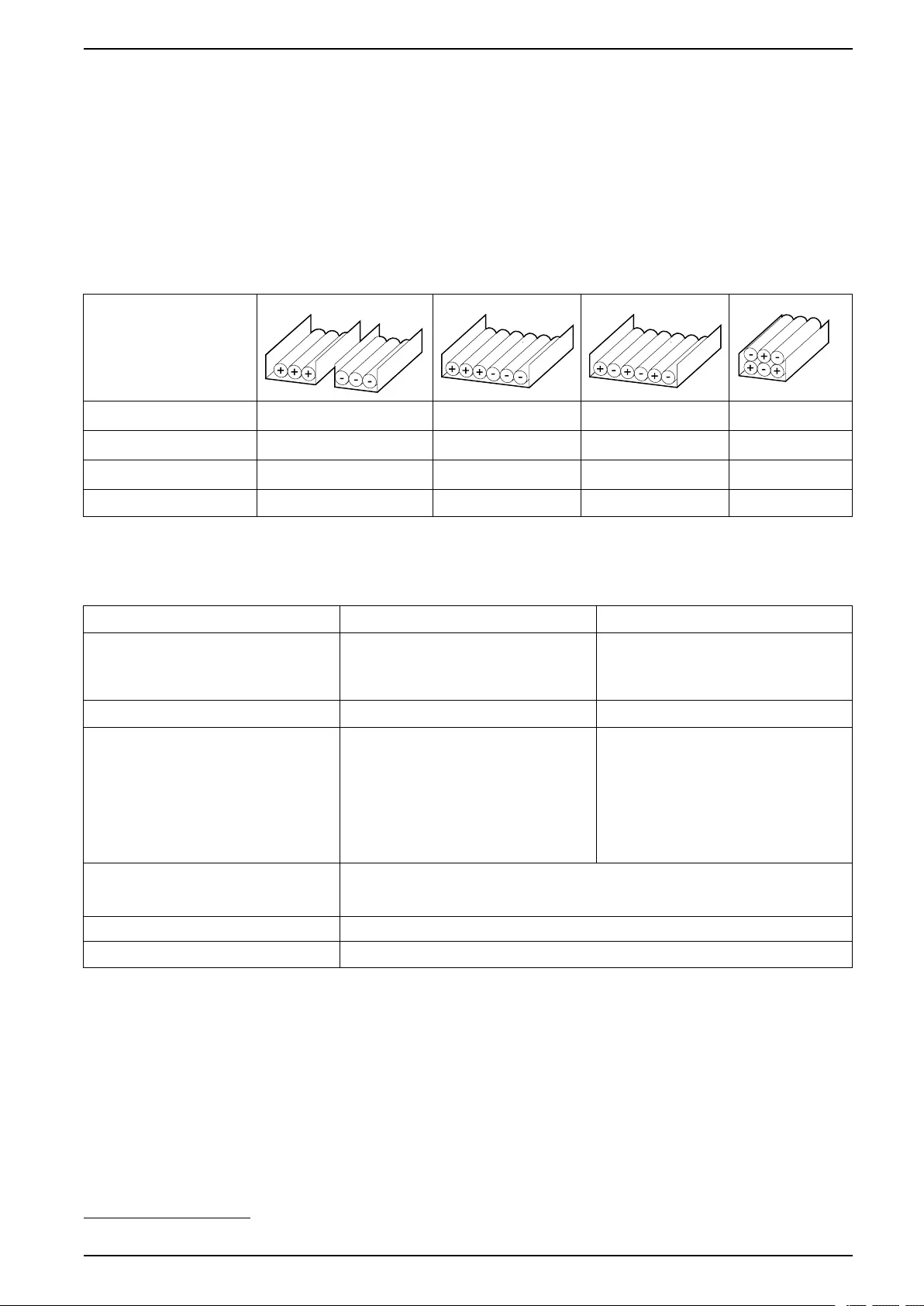
Guidance for Organizing Battery Cables
NOTE: For 3rd party batteries, use only high rate batteries for UPS
applications.
NOTE: When the battery bank is placed remotely, the organizing of the cables
is important to reduce voltage drop and inductance. The distance between the
battery bank and the UPS must not exceed 200 m (656 ft). Contact Schneider
Electric for installations with a longer distance.
NOTE: To minimize the risk of electromagnetic radiation, it is highly
recommended to follow the below guidance and to use grounded metallic tray
supports.
Cable Length
<30 m Not recommended Acceptable Recommended Recommended
31–75 m Not recommended Not recommended Acceptable Recommended
76–150 m Not recommended Not recommended Acceptable Recommended
151–200 m Not recommended Not recommended Not recommended Recommended
Environment
Operating Storage
Temperature 0 °C to 50 °C (32 °F to 122 °F) with load
derating above 40 °C (104 °F).18
-15 °C to 40 °C (5 °F to 104 °F) for systems
with batteries.
-25 °C to 55 °C (-13 °F to 131 °F) for
systems without batteries.
Relative humidity 0-95% non-condensing 10-80% non-condensing
Elevation Designed for operation in 0-3000 m (0-
10000 feet) elevation.
Derating required from 1000-3000 m (3300-
10000 feet):
Up to 1000 m (3300 feet): 1.000
Up to 1500 m (5000 feet) : 0.975
Up to 2000 m (6600 feet): 0.950
Up to 2500 m (8300 feet): 0.925
Up to 3000 m (10000 feet): 0.900
Audible noise one meter (three feet) from
unit
400 V: 60 dB at 70% load, 68 dB at 100% load
480 V: 57 dB at 70% load, 64 dB at 100% load
208 V: 60 dB at 70% load, 68 dB at 100% load
Protection class IP21
Color RAL 9003, gloss level 85%
990-91111F-001 39
18. For temperatures between 40 °C (104 °F) and 50 °C (122 °F), derate the load power rating with 2.5% per °C.

UPS for External Batteries Specifications
UPS Weights and Dimensions
Weight kg (lbs) Height mm (in) Width mm (in) Depth mm (in)
20-50 kW UPS 400 V 206 (454) 1485 (58.46) 521 (20.51) 847 (33.35)
20-50 kW UPS with N+1
power module 400 V
250 (551) 1485 (58.46) 521 (20.51) 847 (33.35)
60 kW UPS 400 V 238 (525) 1485 (58.46) 521 (20.51) 847 (33.35)
60-100 kW UPS with N
+1 power module 400 V
290 (639) 1485 (58.46) 521 (20.51) 847 (33.35)
80-100 kW UPS 400 V 250 (551) 1485 (58.46) 521 (20.51) 847 (33.35)
120 kW UPS 400 V 278 (613) 1485 (58.46) 521 (20.51) 847 (33.35)
150 kW UPS 400 V 290 (639) 1485 (58.46) 521 (20.51) 847 (33.35)
20-50 kW UPS 480 V 206 (454) 1485 (58.46) 521 (20.51) 847 (33.35)
20-50 kW UPS with N+1
power module 480 V
250 (551) 1485 (58.46) 521 (20.51) 847 (33.35)
60 kW UPS 480 V 238 (525) 1485 (58.46) 521 (20.51) 847 (33.35)
60-100 kW UPS with N
+1 power module 480 V
290 (639) 1485 (58.46) 521 (20.51) 847 (33.35)
80-100 kW UPS 480 V 250 (551) 1485 (58.46) 521 (20.51) 847 (33.35)
120 kW UPS 480 V 278 (613) 1485 (58.46) 521 (20.51) 847 (33.35)
150 kW UPS 480 V 290 (639) 1485 (58.46) 521 (20.51) 847 (33.35)
10-25 kW UPS 208 V 206 (454) 1485 (58.46) 521 (20.51) 847 (33.35)
10-25 kW UPS with N+1
power module 208 V
250 (551) 1485 (58.46) 521 (20.51) 847 (33.35)
30 kW UPS 208 V 238 (525) 1485 (58.46) 521 (20.51) 847 (33.35)
30-50 kW UPS with N+1
power module 208 V
290 (639) 1485 (58.46) 521 (20.51) 847 (33.35)
40-50 kW UPS 208 V 250 (551) 1485 (58.46) 521 (20.51) 847 (33.35)
60 kW UPS 208 V 278 (613) 1485 (58.46) 521 (20.51) 847 (33.35)
75 kW UPS 208 V 290 (639) 1485 (58.46) 521 (20.51) 847 (33.35)
40 990-91111F-001
Specifications UPS for External Batteries
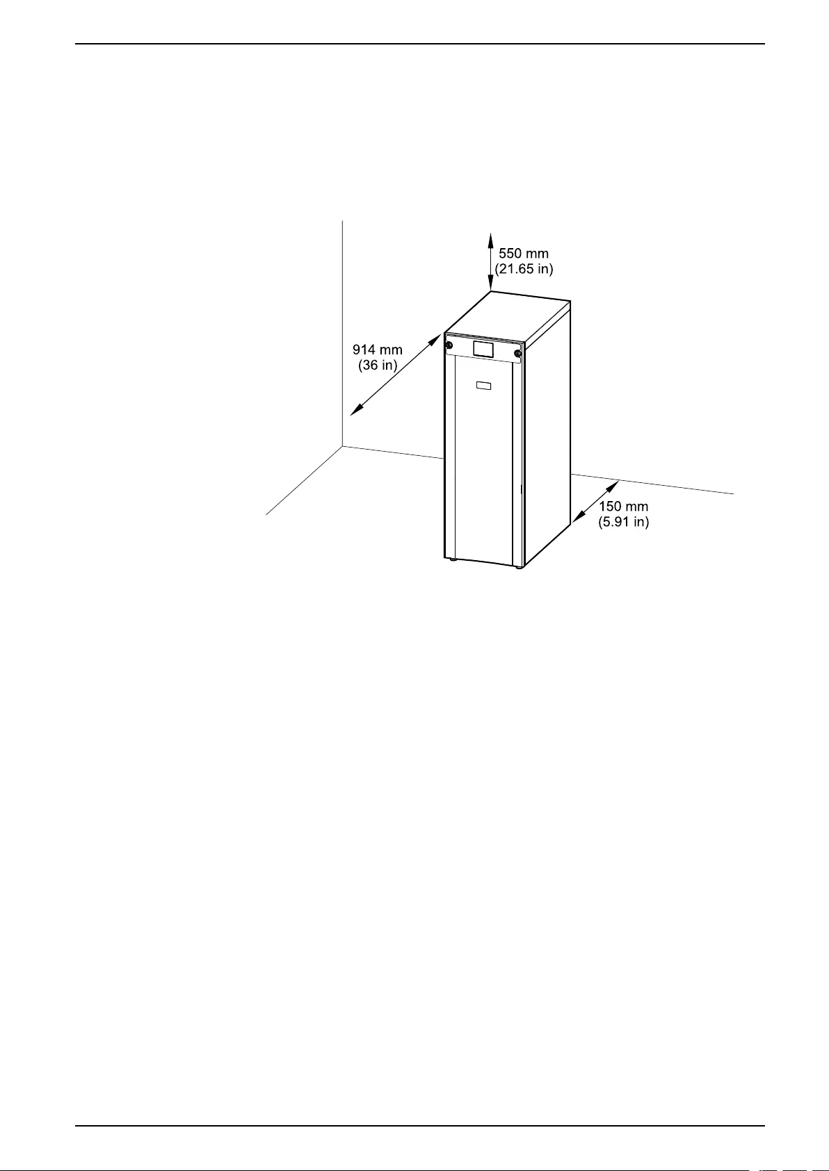
Clearance
NOTE: Clearance dimensions are published for airflow and service access
only. Consult with the local safety codes and standards for additional
requirements in your local area.
NOTE: The required minimum rear clearance is 150 mm (5.91 in).
Front View of the UPS
990-91111F-001 41
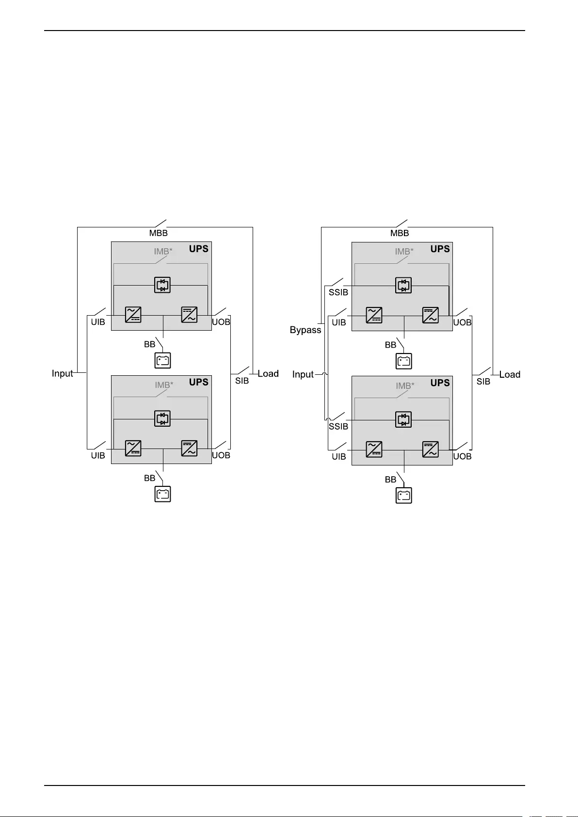
Parallel System Overview UPS for External Batteries
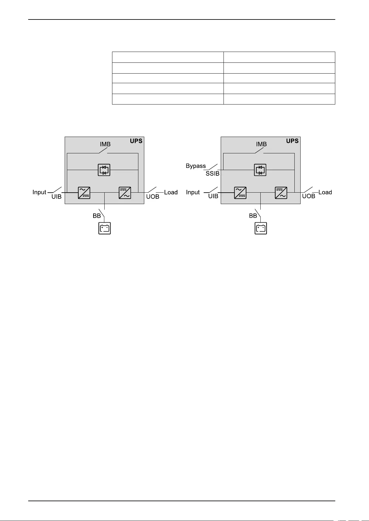
Parallel System Overview
UIB Unit input breaker
SSIB Static switch input breaker
IMB Internal maintenance breaker
UOB Unit output breaker
SIB System isolation breaker
BB Battery breaker
MBB External maintenance bypass breaker
Simplified 1+1 Parallel System
Galaxy VS can support 2 UPSs in a simplified 1+1 parallel system for redundancy
with shared unit input breaker UIB and static switch input breaker SSIB.
Simplified 1+1 Parallel System – Single Mains Simplified 1+1 Parallel System – Dual Mains
990-91111F-001 43
UPS for External Batteries Parallel System Overview
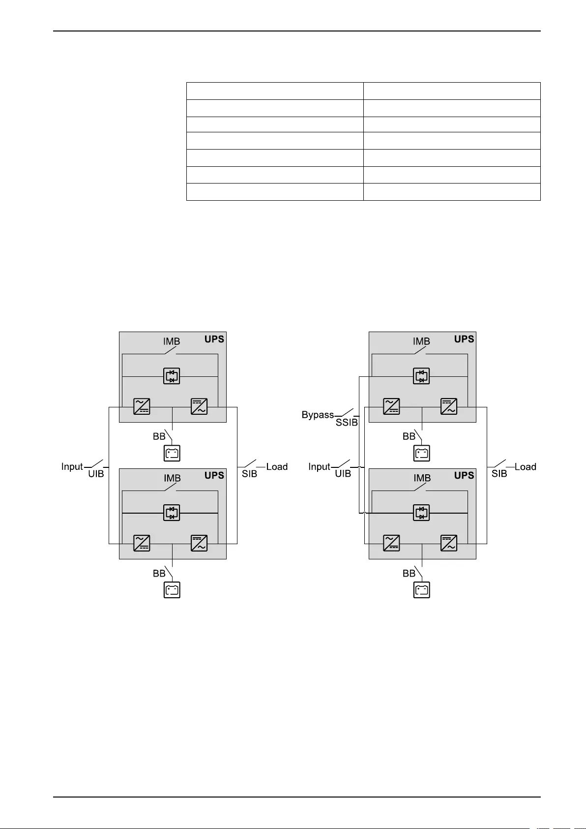
Parallel System with Individual Unit Input Breaker UIB and Static
Switch Input Breaker SSIB
Galaxy VS can support up to 4 UPSs in parallel for capacity and up to 3+1 UPSs
in parallel for redundancy with individual unit input breaker UIB and static switch
input breaker SSIB.
NOTE: The internal maintenance breaker IMB can only be used in a simplified
1+1 parallel system. In any other parallel system, an external maintenance
bypass breaker MBB must be provided and the internal maintenance breaker
IMB* must be padlocked in the open position.
Parallel System – Single Mains Parallel System – Dual Mains
44 990-91111F-001
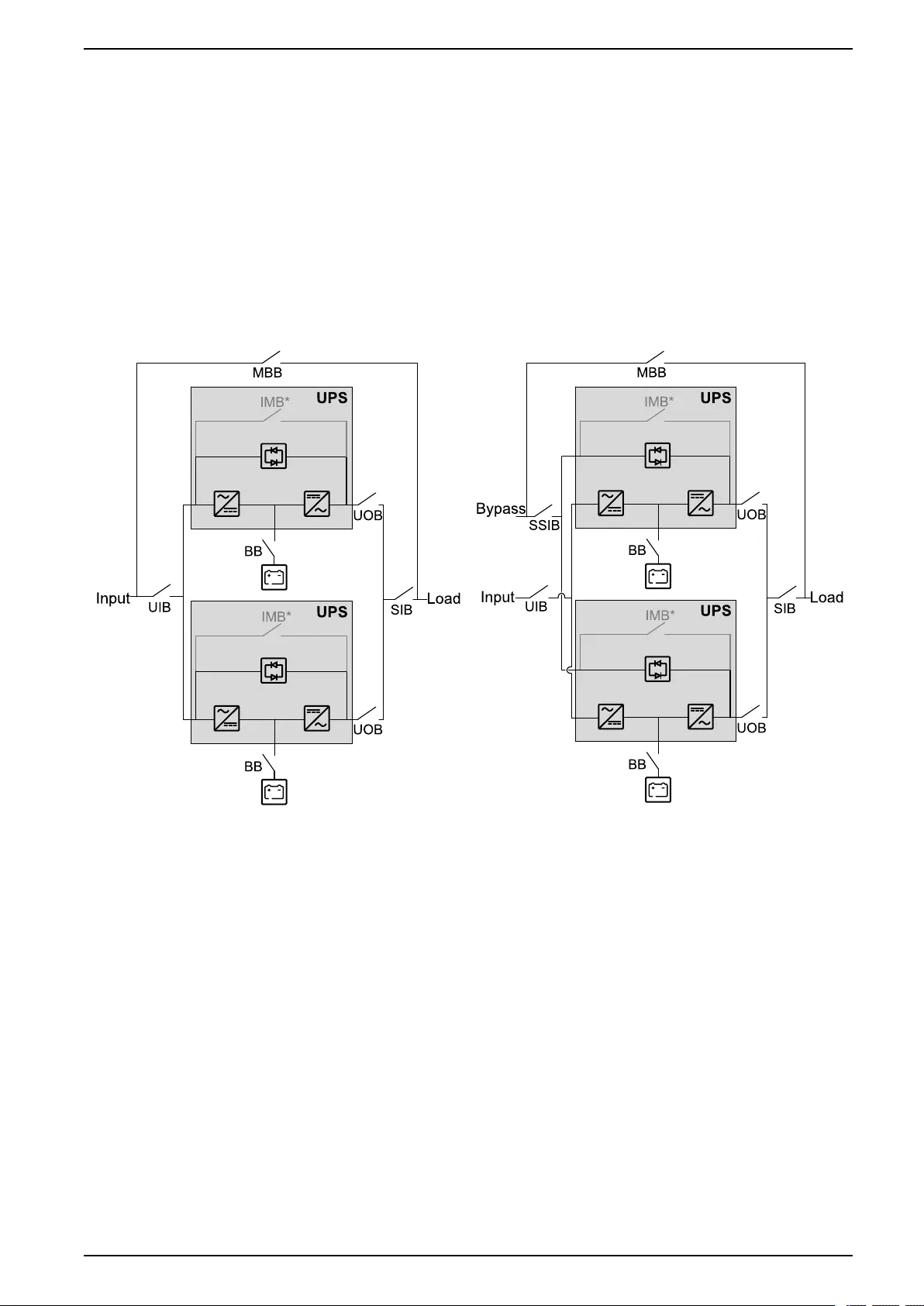
Parallel System Overview UPS for External Batteries
Parallel System with Shared Unit Input Breaker UIB and Static
Switch Input Breaker SSIB
Galaxy VS can support up to 4 UPSs in parallel for capacity and up to 3+1 UPSs
in parallel for redundancy with shared unit input breaker UIB and static switch
input breaker SSIB.
NOTE: The internal maintenance breaker IMB can only be used in a simplified
1+1 parallel system. In any other parallel system, an external maintenance
bypass breaker MBB must be provided and the internal maintenance breaker
IMB* must be padlocked in the open position.
Parallel System – Single Mains Parallel System – Dual Mains
990-91111F-001 45
UPS for External Batteries Overview of Installation Kits
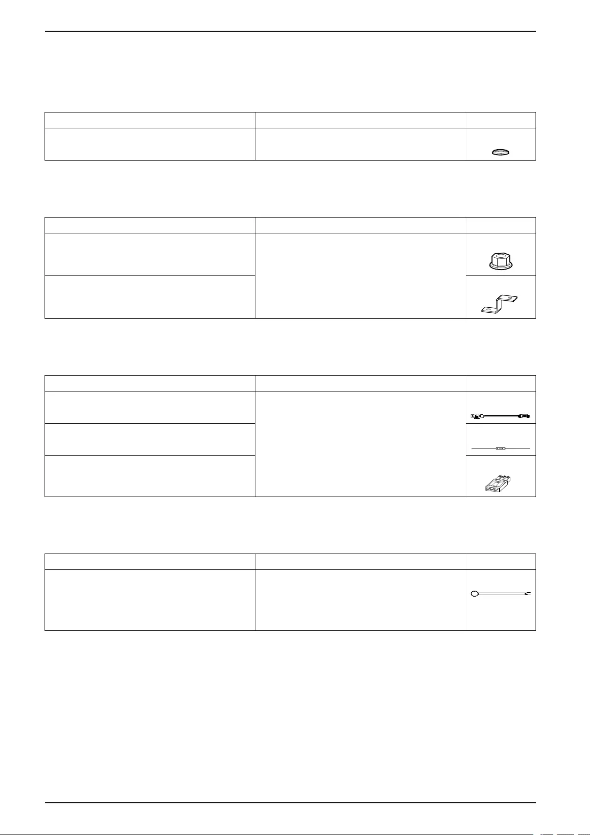
Overview of Installation Kits
Installation Kit 0M-100883
Part Used in Number of units
Spring washer Connect the Power Cables, page 59. 40
Installation Kit 0M-100917
Part Used in Number of units
M8 nut with washer Prepare the UPS for TN-C/480 V Solid-Grounded
System, page 58.
2
Bonding busbar 1
Installation Kit 0M-88357
Part Used in Number of units
USB cable Connect the Modbus Cables, page 81. 1
150 Ohm resistor 10
Terminal connector 2
Installation Kit 0J-0M-1160
Part Used in Number of units
Temperature sensor For third-party battery solution, see Connect the Signal
Cables from Switchgear and Third-Party Auxiliary
Products, page 71.
Refer to the installation manual for your specific battery
solution for information on how to install and connect the
temperature sensor.
1
46 990-91111F-001
Overview of Installation Kits UPS for External Batteries
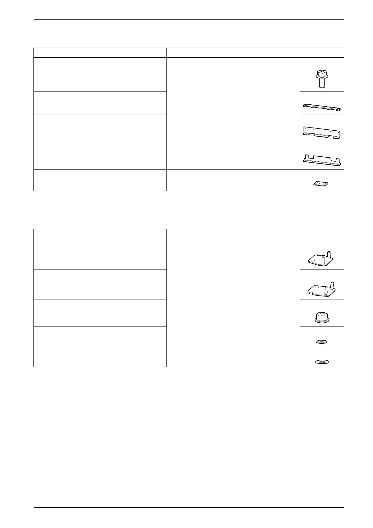
Optional Seismic Kit GVSOPT002
Part Used in Number of units
M8 x 20 mm bolt with washer Install the Seismic Anchoring (Option), page 57 and Final
Installation, page 83.
12
Rear anchor 1
Rear anchoring bracket 1
Front anchoring bracket 1
Rear connection plate Used for installation with an adjacent product. Follow
instructions in the installation manual for the adjacent
product.
1
Optional NEMA 2 Hole Kit GVSOPT005
Part Used in Number of units
NEMA 2 hole plate (output, DC+, N) Connect the Power Cables with NEMA 2 Hole Plates,
page 63.
7
NEMA 2 hole plate (input, bypass, DC-) 8
M8 nut with washer 30
Spring washer 30
M8x24 mm flat washer 60
990-91111F-001 47

UPS for External Batteries Overview of Installation Kits
Optional Parallel Kit GVSOPT006
Part Used in Number of units
PBUS1 cable 0W6268 Connect the PBUS Cables, page 79. 1
PBUS2 cable 0W6267 1
AUX switch Connect the IMB Signal Cables in a Simplified 1+1
Parallel System, page 75.
2
This kit contains parts for use with other UPS models which are not relevant for this installation.
48 990-91111F-001
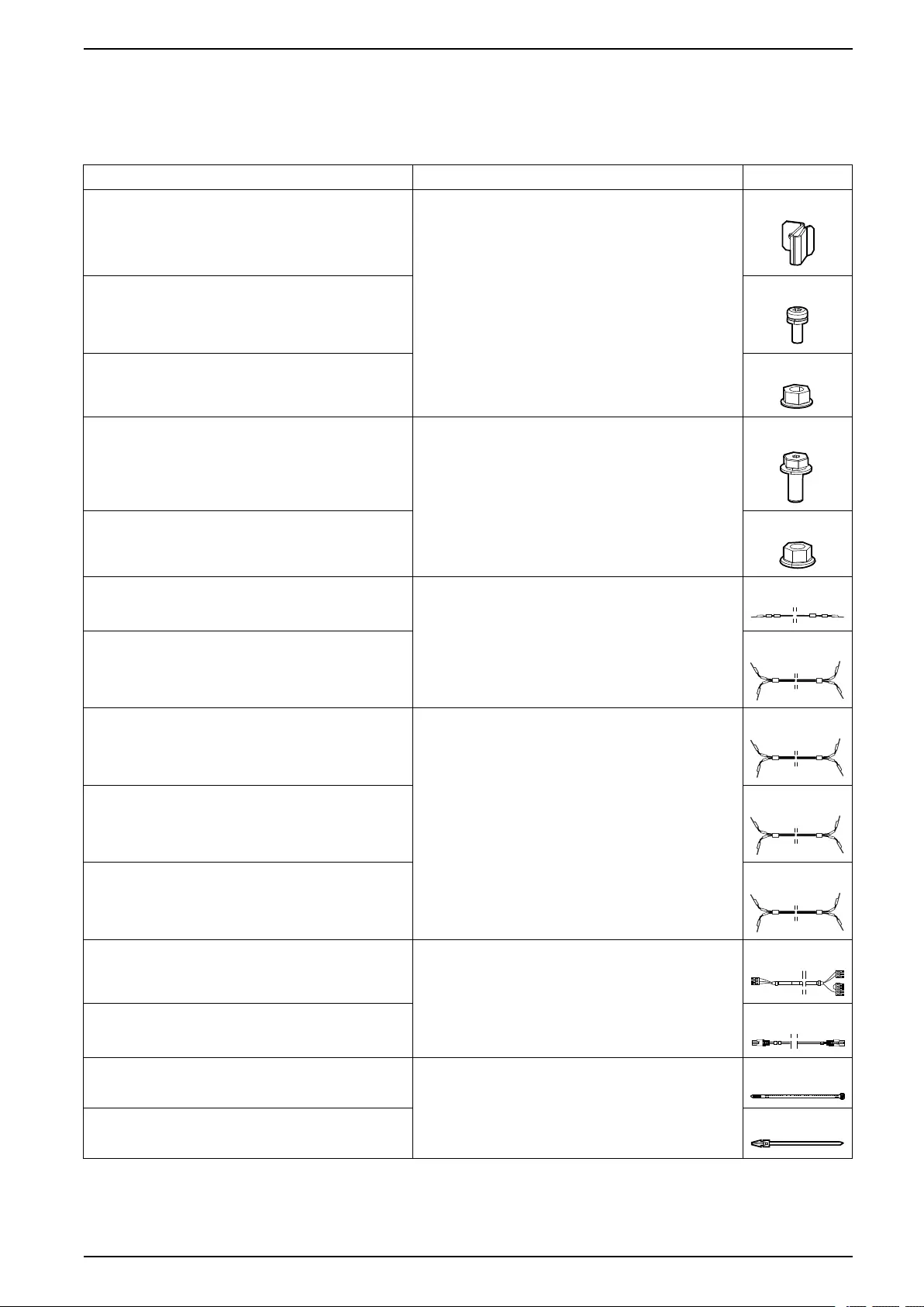
Overview of Installation Kits UPS for External Batteries
Optional Kit GVSOPT030
Only for installation with adjacent modular battery cabinet(s). Follow the modular
battery cabinet installation manual.
Part Used in Number of units
Interconnection clamp For interconnection. 3
M6 x 16 mm screw with washer 3
M6 nut with washer 3
M8 x 25 mm bolt with washer For power cable connection. 9
M8 nut with washer 9
PE cable 0W13065 (for modular battery cabinet 1) For power cable connection for modular battery cabinet 1. 1
DC cable 0W13071 (for modular battery cabinet 1) 1
DC cable 0W13066 (for modular battery cabinet 2) Only for power cable connection for modular battery
cabinet 2,3,4 for a UPS rated over 50 kW.
For a UPS rated for maximum 50 kW, use the provided
DC cables.
1
DC cable 0W13068 (for modular battery cabinet 3) 1
DC cable 0W13067 (for modular battery cabinet 4) 1
Signal cable 0W13070 For signal cable connection for modular battery cabinet 1. 1
Signal cable 0W13069 1
Cable tie For power cable fastening. 18
Cable tie 30
990-91111F-001 49
UPS for External Batteries Installation Procedure for Single Systems
Installation Procedure for Single Systems
1. Prepare for Installation, page 52.
2. For UPS without preinstalled power modules:Install the Power Module(s),
page 56.
3. Install the Seismic Anchoring (Option), page 57.
4. Only for TN-C/480 V solid-grounded earthing system (no neutral connection):
Prepare the UPS for TN-C/480 V Solid-Grounded System, page 58.
5. Perform one of the following:
–Connect the Power Cables, page 59, or
–Connect the Power Cables with NEMA 2 Hole Plates, page 63.
6. Connect the Signal Cables, page 67.
7. Connect the Signal Cables from a Modular Battery Cabinet, page 69.
8. Connect the Signal Cables from Switchgear and Third-Party Auxiliary
Products, page 71.
9. Connect the External Communication Cables, page 80.
10. Add Translated Safety Labels to Your Product, page 82.
11. Final Installation, page 83.
50 990-91111F-001
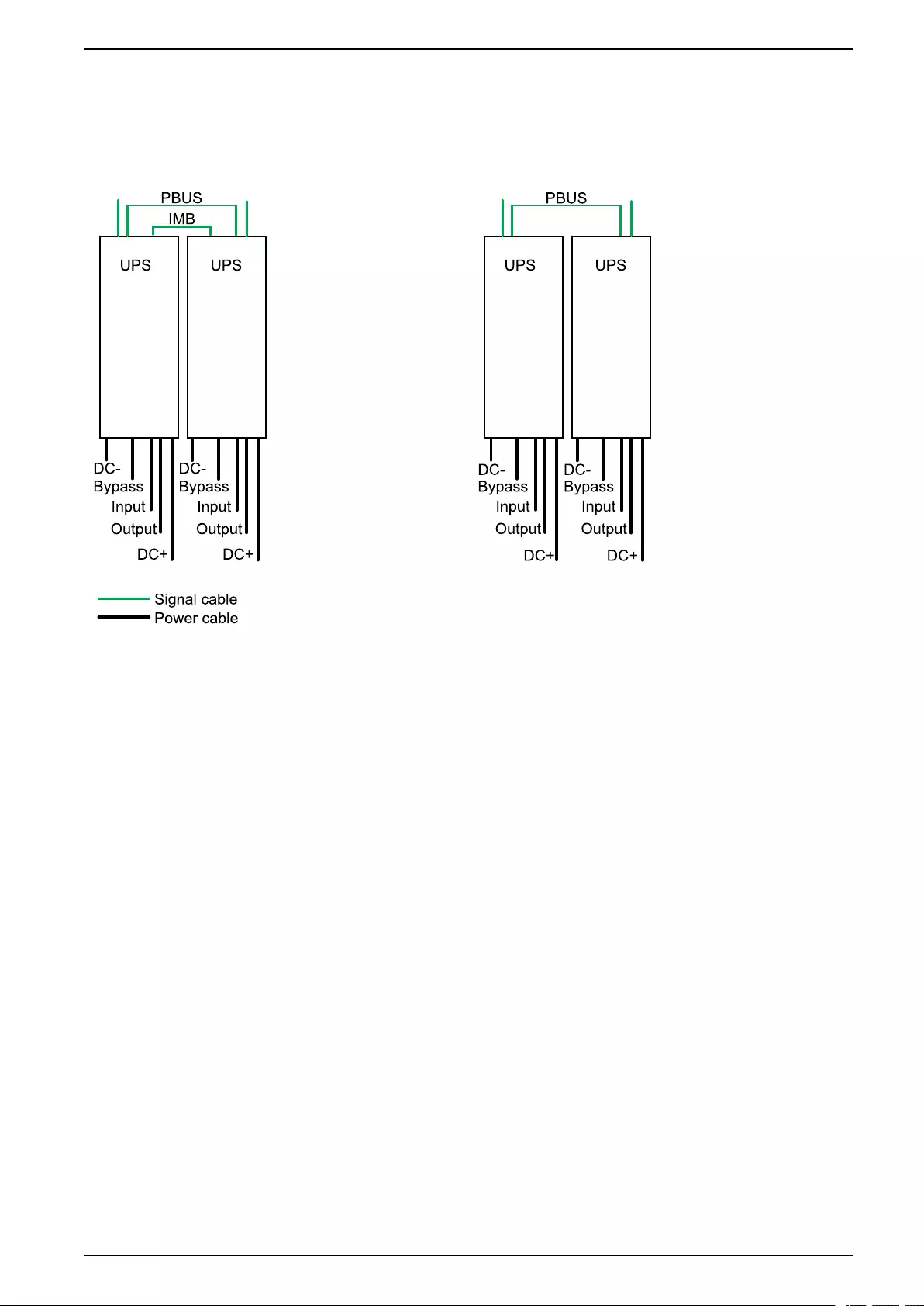
Installation Procedure for Parallel Systems UPS for External Batteries
Installation Procedure for Parallel Systems
Simplified 1+1 Parallel System Parallel System
1. Prepare for Installation, page 52.
2. For UPS without preinstalled power modules:Install the Power Module(s),
page 56.
3. Install the Seismic Anchoring (Option), page 57.
4. Only for TN-C/480 V solid-grounded earthing system (no neutral connection):
Prepare the UPS for TN-C/480 V Solid-Grounded System, page 58.
5. Perform one of the following:
–Connect the Power Cables, page 59, or
–Connect the Power Cables with NEMA 2 Hole Plates, page 63.
6. Connect the Signal Cables, page 67.
7. Connect the Signal Cables from a Modular Battery Cabinet, page 69.
8. Connect the Signal Cables from Switchgear and Third-Party Auxiliary
Products, page 71.
9. Perform one of the following:
–For simplified 1+1 parallel system:Connect the IMB Signal Cables in a
Simplified 1+1 Parallel System, page 75.
–For parallel system: Install a padlock on the internal maintenance
breaker IMB in the open position on all UPSs in the parallel system.
10. Connect the PBUS Cables, page 79.
11. Connect the External Communication Cables, page 80.
12. Add Translated Safety Labels to Your Product, page 82.
13. Final Installation, page 83.
990-91111F-001 51
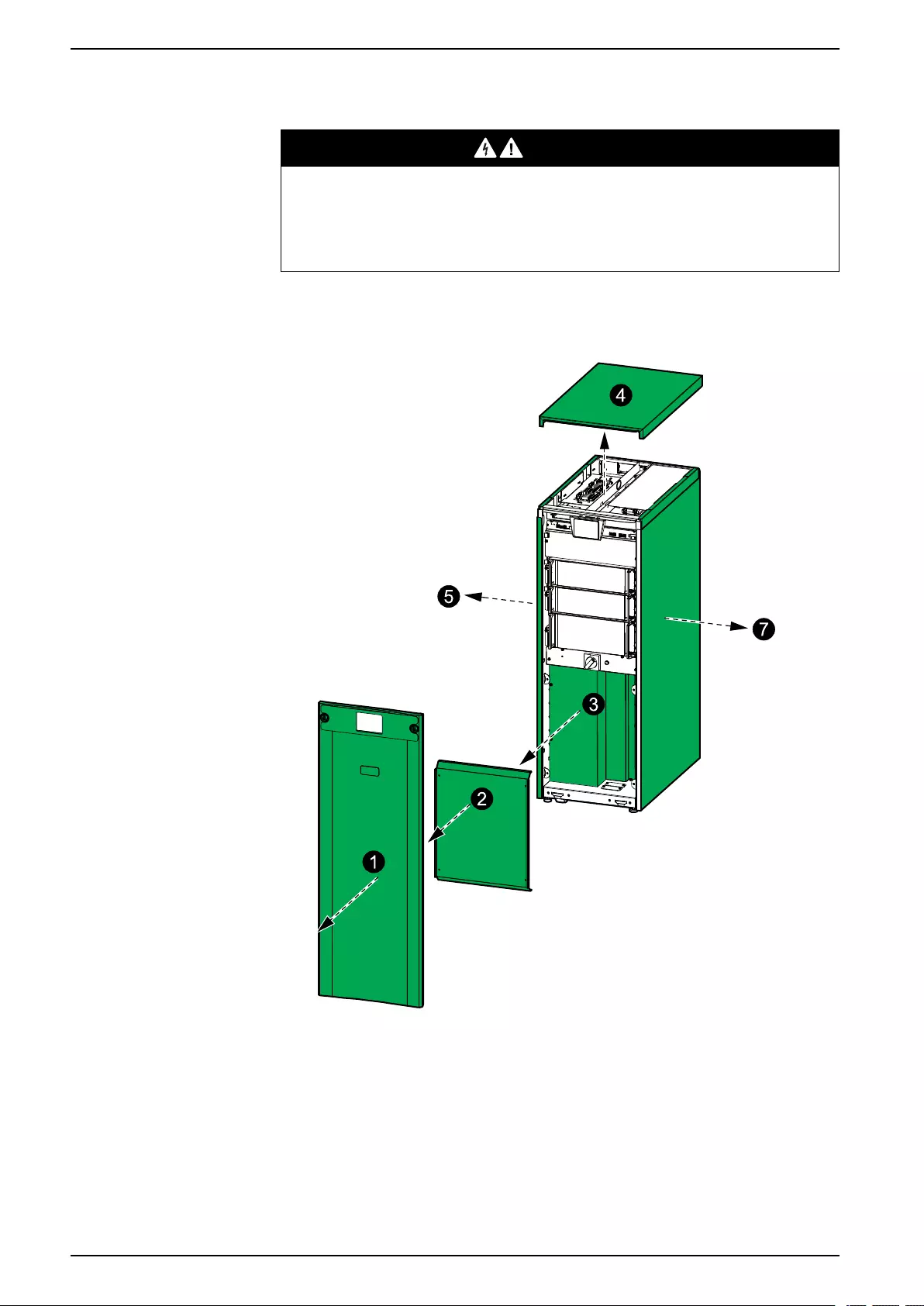
UPS for External Batteries Prepare for Installation
Prepare for Installation
DANGER
HAZARD OF ELECTRIC SHOCK, EXPLOSION, OR ARC FLASH
Do not drill or punch holes for cables or conduits with the gland plate installed
and do not drill or punch holes in close proximity to the UPS.
Failure to follow these instructions will result in death or serious injury.
NOTE: Route the signal cables separately from the power cables and route
the Class 2/SELV cables separately from the non-Class 2/non-SELV cables.
1. Remove the front panel.
2. Remove the lower front plate.
3. Remove the transparent cover.
4. Remove the top cover:
a. Remove the screws and tilt the front of the top cover upwards.
b. Slide the top cover towards the rear to remove it. Tabs in the rear of the
top cover must disconnect from the slots in the rear of the UPS.
5. For installation with adjacent battery cabinet: Remove the left side panel.
52 990-91111F-001
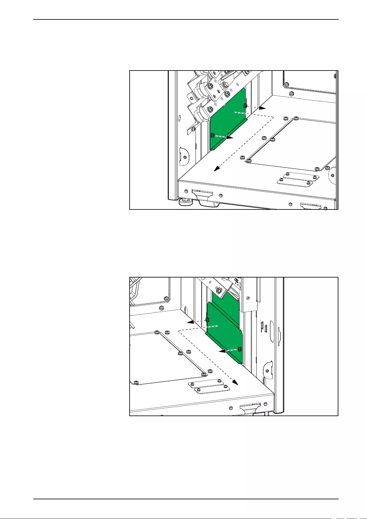
Prepare for Installation UPS for External Batteries
6. For installation with adjacent battery cabinet: Remove the lower left side
plate for internal DC cabling between the UPS and the adjacent battery
cabinet.
Front View of the UPS
7. For installation with maintenance bypass cabinet: Remove the right side
panel. The side panel will be reinstalled on the maintenance bypass cabinet.
8. For installation with maintenance bypass cabinet: Remove the lower right
side plate for internal power cabling between the UPS and the maintenance
bypass cabinet.
Front View of the UPS
990-91111F-001 53
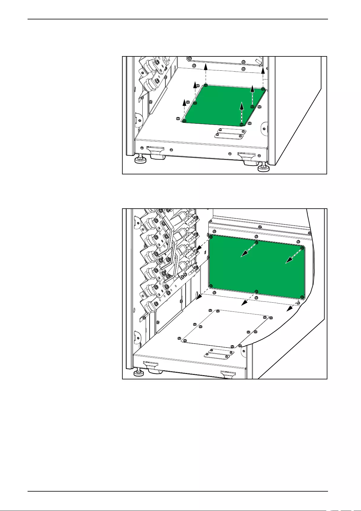
UPS for External Batteries Prepare for Installation
9. For bottom cable entry: Remove the gland plate in the bottom of the UPS.
Front View of the UPS
10. For rear cable entry: Remove the gland plate in the rear of the UPS.
Front View of the UPS
11. Drill/punch holes for power cables/conduits in the gland plate. Install conduits
(not provided), if applicable.
12. Install the gland plate in the bottom or rear of the UPS.
54 990-91111F-001
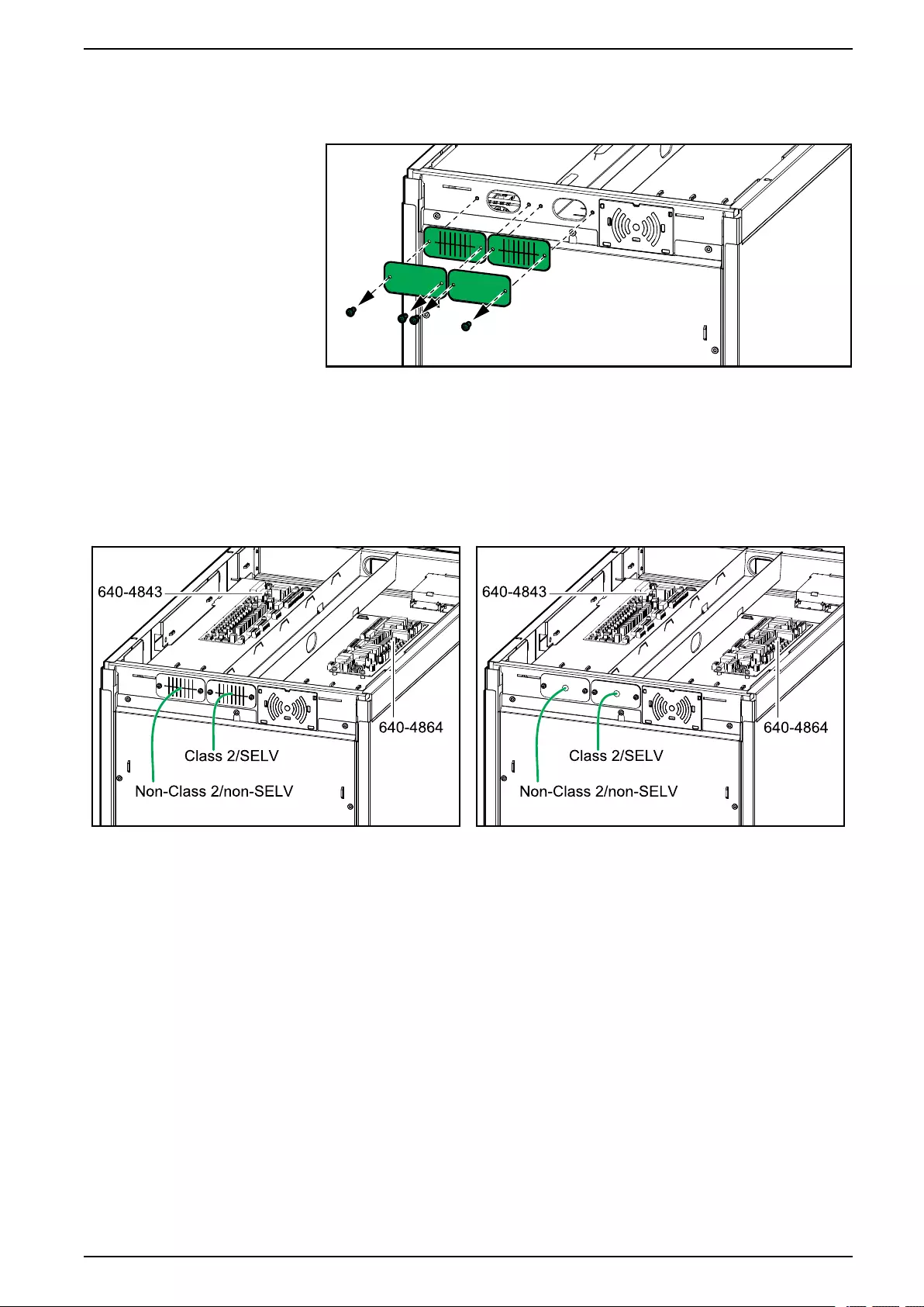
Prepare for Installation UPS for External Batteries
13. Remove the rear gland plates and the rear brush plates from the UPS.
Rear View of the UPS
14. Perform one of the following:
–For installation without conduits: Reinstall the brush plates.
–For installation with conduits: Drill a hole in the gland plates for
conduits, install conduits, and reinstall the gland plates.
Rear View of the UPS without Conduits Rear View of the UPS with Conduits
15. Route the non-Class 2/non-SELV signal cables through the left rear brush/
gland plate and into the left side of the UPS.
16. Route the external cables that connect to the controller box through the right
rear brush/gland plate and through the cable channel to the front of the UPS.
17. Route the Class 2/SELV signal cables through the right rear brush/gland plate
and into the right side of the UPS.
990-91111F-001 55
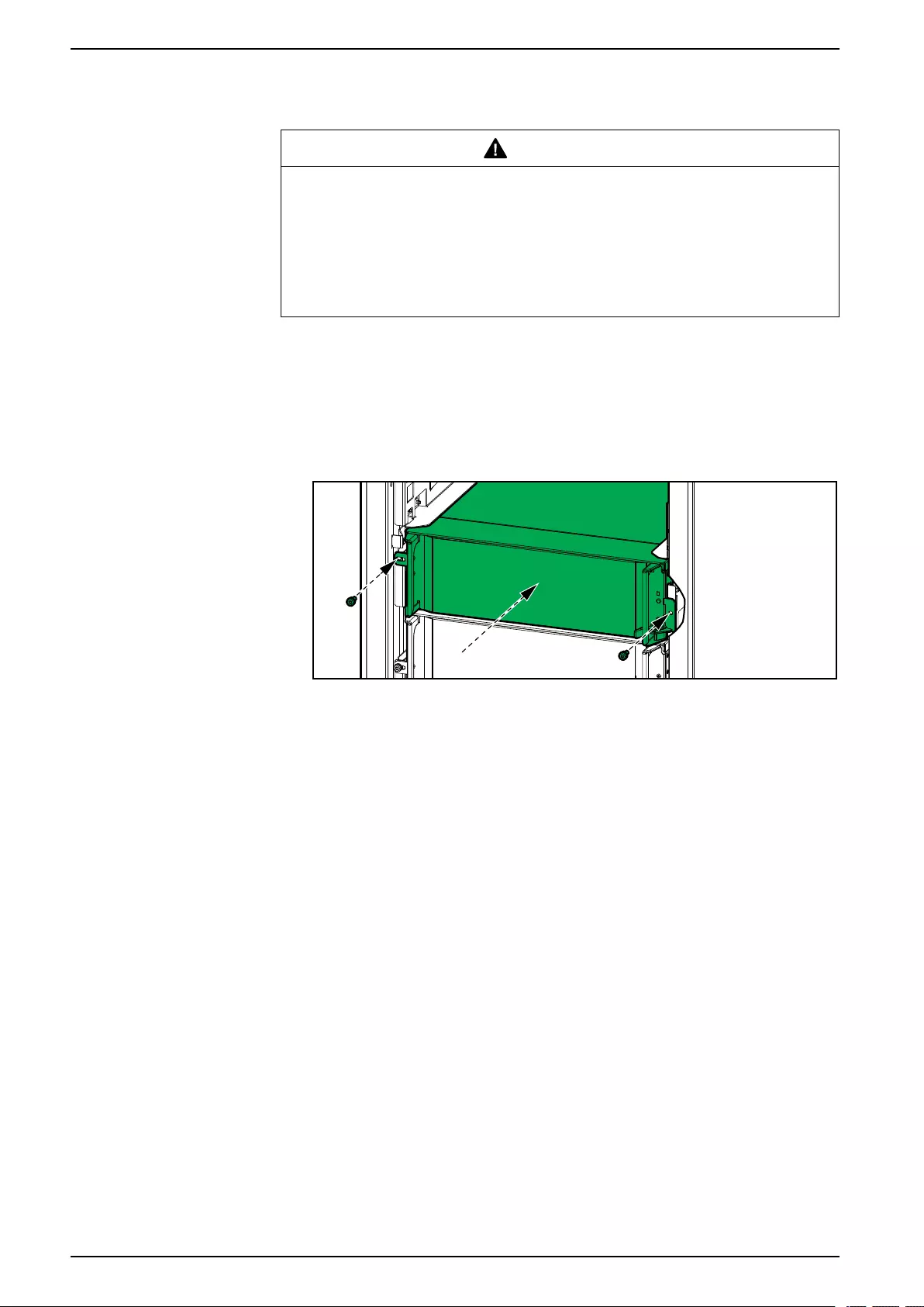
UPS for External Batteries Install the Power Module(s)
Install the Power Module(s)
CAUTION
HEAVY LOAD
Power modules are heavy and require two persons to lift.
• 20 kW power module weighs 25 kg (55 lbs).
• 50 kW power module weighs 38 kg (84 lbs).
Failure to follow these instructions can result in injury or equipment
damage.
NOTE: Always install power modules starting with the bottom position and
upwards.
1. Remove the screw in each side of the empty power module slot. Remove filler
plate, if present.
2. Push the power module into the slot.
3. Reinstall the screw in each side of the slot.
56 990-91111F-001
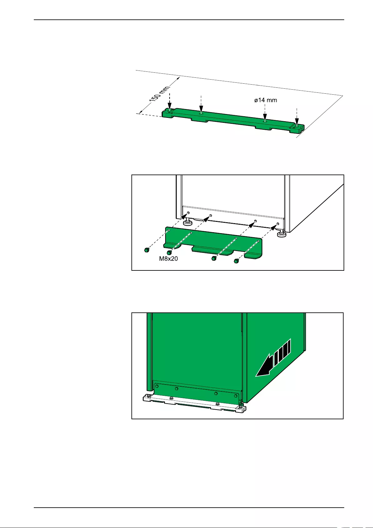
Install the Seismic Anchoring (Option) UPS for External Batteries
Install the Seismic Anchoring (Option)
1. Mount the rear anchor(s) to the floor. Use appropriate hardware for the floor
type – the hole diameter in the rear anchor is ø14 mm.
2. Install the rear anchoring bracket on the UPS with the provided M8 bolts.
Rear View of the UPS
3. Push the UPS into position so the rear anchoring bracket connects to the rear
anchor. The front anchoring bracket is installed in the final installation steps.
Rear View of the UPS
990-91111F-001 57
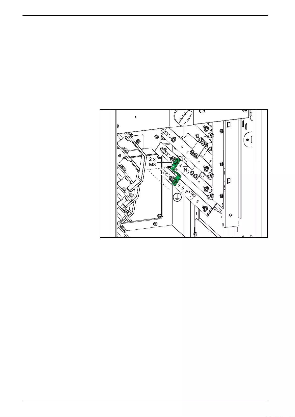
UPS for External Batteries Prepare the UPS for TN-C/480 V Solid-Grounded System
Prepare the UPS for TN-C/480 V Solid-Grounded
System
NOTE: The UPS is preconfigured for TNS earthing system.
NOTE: 480 V solid-grounded system (no neutral connection) using a bonding
busbar will result in a higher leakage current.
1. Only for TN-C/480 V solid-grounded system (no neutral connection):
Install the supplied bonding busbar.
Front View of the UPS – TN-C/480 V Solid-Grounded System (No Neutral
Connection)
58 990-91111F-001

Connect the Power Cables UPS for External Batteries
Connect the Power Cables
DANGER
HAZARD OF ELECTRIC SHOCK, EXPLOSION, OR ARC FLASH
In single mains systems where power cables are split due to the cable size
restriction, use the bypass busbars for the second input cable set. There is not
enough space to land two input cable sets on the input busbars due to the
single mains jumper busbars.
Failure to follow these instructions will result in death or serious injury.
NOTICE
RISK OF EQUIPMENT DAMAGE
To ensure correct load sharing in bypass operation in a parallel system:
• All bypass cables must be the same length for all UPSs.
• All output cables must be the same length for all UPSs.
• All input cables must be the same length for all UPSs (only required in single
mains system).
Failure to follow these instructions can result in equipment damage.
1. Only for 480 V solid-grounded systems (no neutral cable connection):
a. Remove the RFI bracket. Save the two screws.
b. Remove the screw in the left side and save it.
c. Install the RFI bracket in the left side with the three screws.
Front View of the UPS
990-91111F-001 59
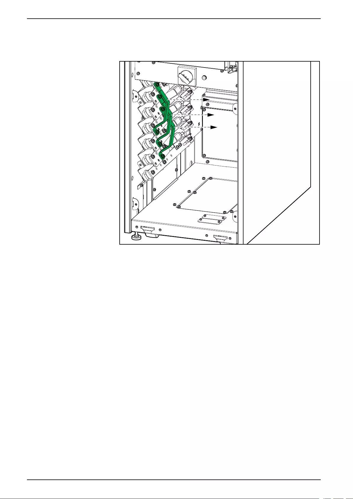
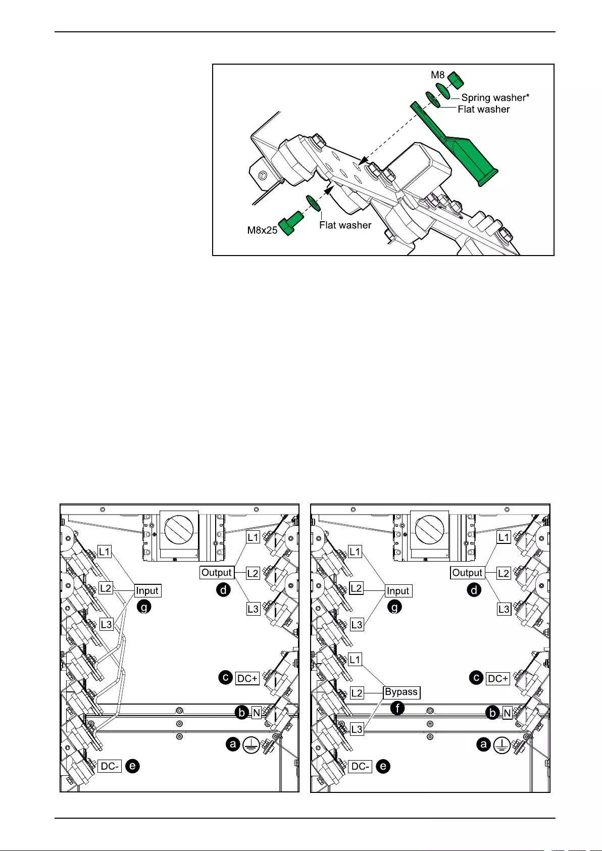
Connect the Power Cables UPS for External Batteries
3. Connect the power cables as shown in the described order:
*Provided in kit.
a. Connect the equipment grounding conductor/PE cables.
b. Connect the N cables. Connect battery midpoint (if present in battery
solution).
c. Connect the DC+ cables.
d. Connect the output cables.
e. Connect the DC- cables.
f. Only for dual mains system: Connect the bypass cables.
g. Connect the input cables.
NOTE: Ensure to connect the input cables to the correct input
busbars in the top left side of the UPS.
Front View of the UPS – Single Mains System Front View of the UPS – Dual Mains System
990-91111F-001 61

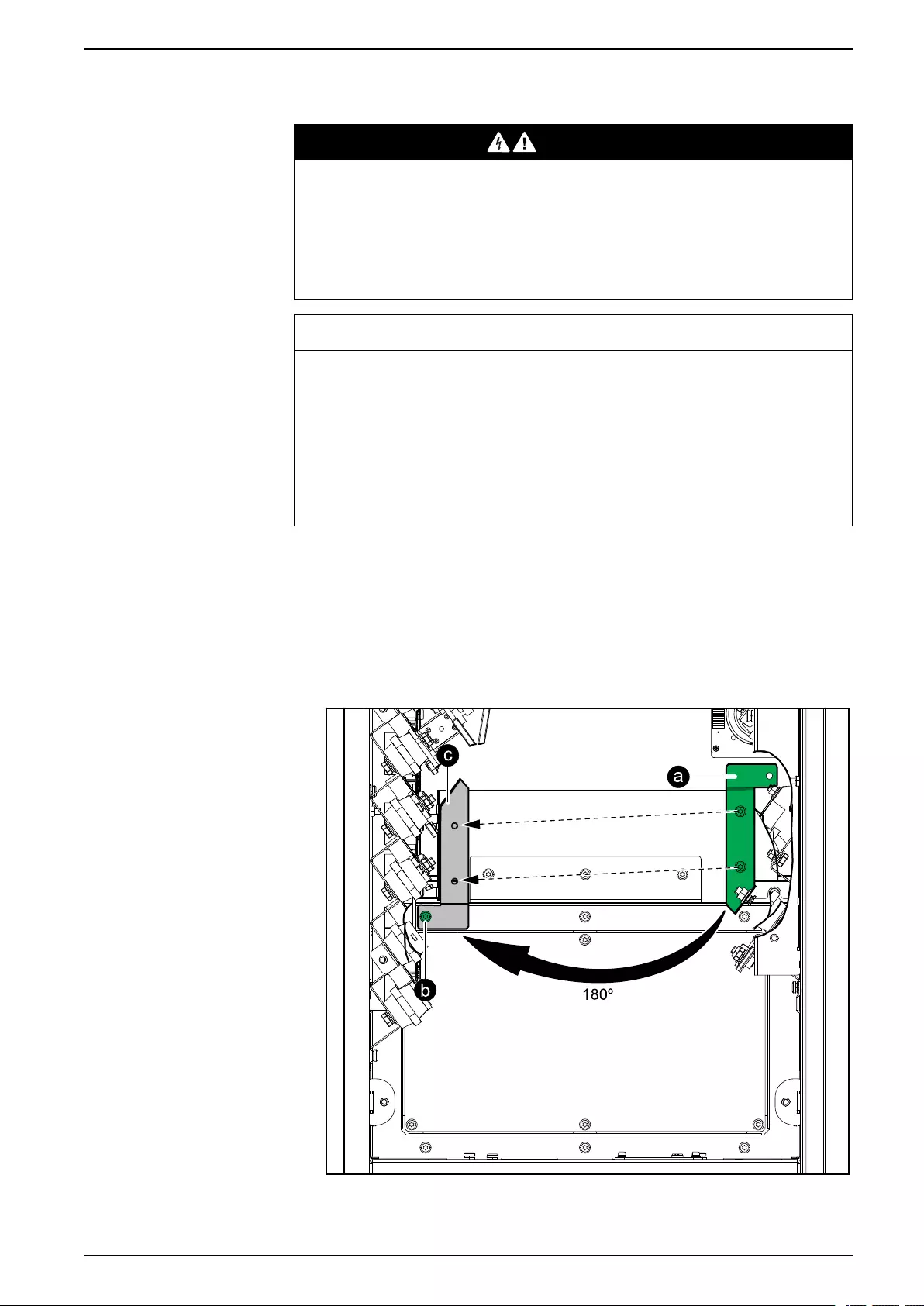
Connect the Power Cables with NEMA 2 Hole Plates UPS for External Batteries
Connect the Power Cables with NEMA 2 Hole Plates
DANGER
HAZARD OF ELECTRIC SHOCK, EXPLOSION, OR ARC FLASH
In single mains systems where power cables are split due to the cable size
restriction, use the bypass busbars for the second input cable set. There is not
enough space to land two input cable sets on the input busbars due to the
single mains jumper busbars.
Failure to follow these instructions will result in death or serious injury.
NOTICE
RISK OF EQUIPMENT DAMAGE
To ensure correct load sharing in bypass operation in a parallel system:
• All bypass cables must be the same length for all UPSs.
• All output cables must be the same length for all UPSs.
• All input cables must be the same length for all UPSs (only required in single
mains system).
Failure to follow these instructions can result in equipment damage.
1. Only for 480 V solid-grounded systems (no neutral cable connection):
a. Remove the RFI bracket. Save the two screws.
b. Remove the screw in the left side and save it.
c. Install the RFI bracket in the left side with the three screws.
Front View of the UPS
990-91111F-001 63
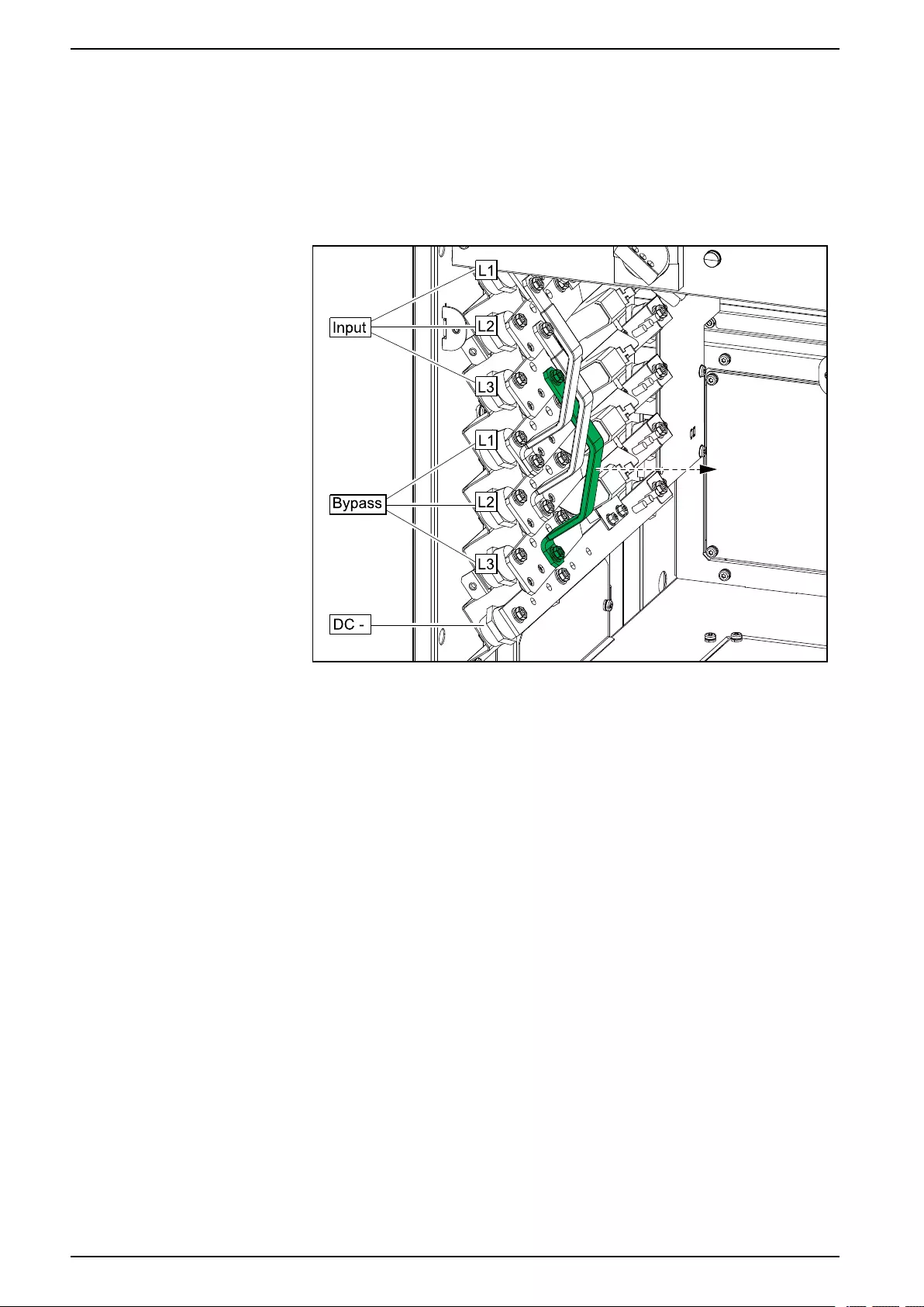
UPS for External Batteries Connect the Power Cables with NEMA 2 Hole Plates
2. Perform one of the following:
–Only for single mains system: Remove the indicated L3 jumper busbar
in the left side of the UPS. Save the L3 jumper busbar for reinstallation
later.
–Only for dual mains system: Remove the three single mains jumper
busbars in the left side of the UPS.
Front View of the UPS
64 990-91111F-001
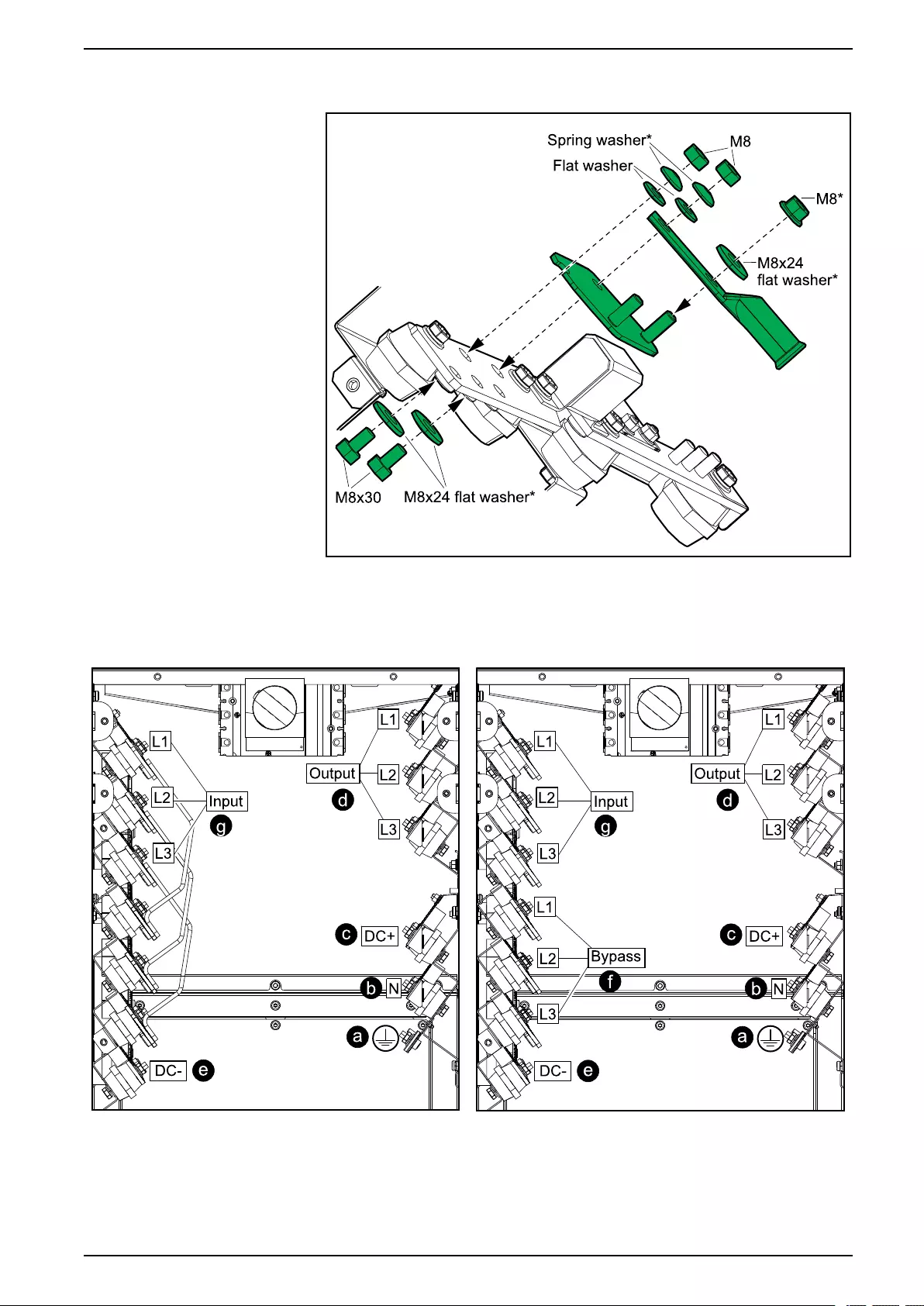
Connect the Power Cables with NEMA 2 Hole Plates UPS for External Batteries
3. Install the NEMA 2 hole plates and connect the power cables as shown in the
described order:
*Provided in kit.
Front View of the UPS — Single Mains System Front View of the UPS — Dual Mains System
a. Connect the equipment grounding conductor/PE cables.
b. Connect the N cables. Connect battery midpoint (if present in battery
solution).
c. Connect the DC+ cables.
990-91111F-001 65
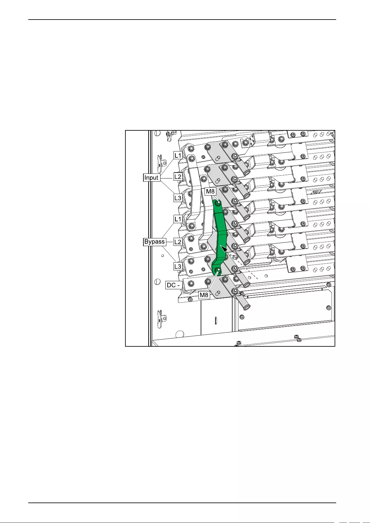
UPS for External Batteries Connect the Power Cables with NEMA 2 Hole Plates
d. Connect the output cables.
e. Connect the DC- cables.
f. Only for dual mains system: Connect the bypass cables.
g. Connect the input cables.
NOTE: Ensure to connect the input cables to the correct input busbars in
the top left side of the UPS.
4. Only for single mains system: Reinstall the L3 jumper busbar in its original
position with two M8 nuts.
Front Right View of the UPS
66 990-91111F-001
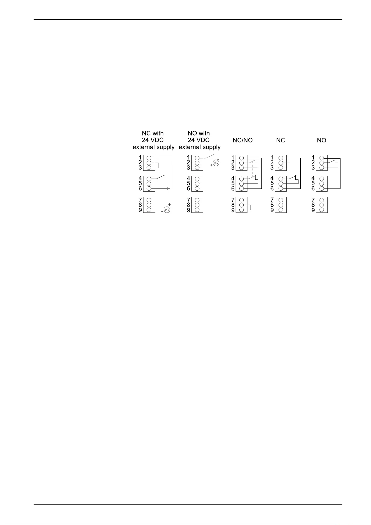
Connect the Signal Cables UPS for External Batteries
Connect the Signal Cables
NOTE: Route the signal cables separately from the power cables and route
the Class 2/SELV cables separately from the non-Class 2/non-SELV cables.
1. Connect the Class 2/SELV signal cables from the building EPO to board 640–
4864 terminal J6600 in the UPS according to one of the options below.
The EPO circuit is considered Class 2/SELV. Class 2/SELV circuits must be
isolated from the primary circuitry. Do not connect any circuit to the EPO
terminal block unless it can be confirmed that the circuit is Class 2/SELV.
EPO Configurations (640–4864 terminal J6600, 1–9)
The EPO input supports 24 VDC.
NOTE: The default setting for the EPO activation is to turn off the inverter.
If you want the EPO activation to transfer the UPS into forced static
bypass operation instead, please contact Schneider Electric.
2. Connect the Class 2/SELV signal cables from the auxiliary products to board
640–4864 in the UPS. Follow the instructions in the auxiliary product
manuals.
990-91111F-001 67
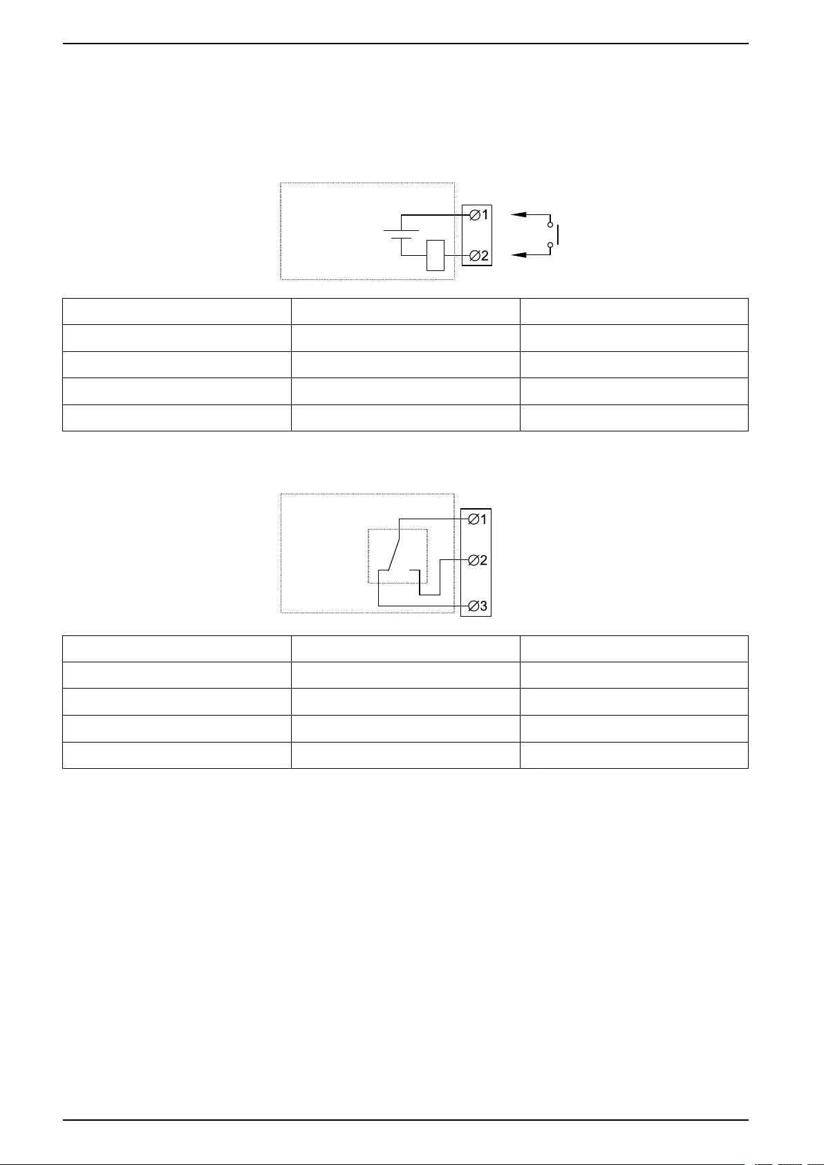
UPS for External Batteries Connect the Signal Cables
3. Connect the Class 2/SELV signal cables to the input contacts and output
relays on board 640–4864 in the UPS.
Do not connect any circuit to the input contacts unless it can be confirmed
that the circuit is Class 2/SELV.
The input contacts support 24 VDC 10 mA. All circuits connected must have
the same 0 V reference.
Name Description Location
IN _1 (input contact 1) Configurable input contact 640-4864 terminal J6616, 1–2
IN _2 (input contact 2) Configurable input contact 640-4864 terminal J6616, 3–4
IN _3 (input contact 3) Configurable input contact 640-4864 terminal J6616, 5–6
IN _4 (input contact 4) Configurable input contact 640-4864 terminal J6616, 7–8
The output relays support 24 VAC/VDC 1 A. All external circuitry must be
fused with maximum 1 A fast acting fuses.
Name Description Location
OUT _1 (output relay 1) Configurable output relay 640–4864 terminal J6617, 1–3
OUT _2 (output relay 2) Configurable output relay 640–4864 terminal J6617, 4–6
OUT _3 (output relay 3) Configurable output relay 640–4864 terminal J6617, 7–9
OUT _4 (output relay 4) Configurable output relay 640–4864 terminal J6617, 10–12
4. Connect the non-Class 2/non-SELV signal cables from the auxiliary products
to board 640–4843 in the UPS. Follow the instructions in the auxiliary product
manuals.
68 990-91111F-001

Connect the Signal Cables from a Modular Battery Cabinet UPS for External Batteries
Connect the Signal Cables from a Modular Battery
Cabinet
For installation with adjacent modular battery cabinet, use the signal cables
provided in optional installation kit GVSOPT030. For installation with remote
modular battery cabinets, signal cables are not provided. Follow the modular
battery cabinet installation manual to prepare for installation.
1. For a remote modular battery cabinet: Route the signal cables from
modular battery cabinet 1 through the rear of the UPS.
2. For an adjacent modular battery cabinet: Route the signal cables from
modular battery cabinet 1 to the UPS as shown.
a. Route the signal cables from modular battery cabinet 1 into the UPS
through the opening.
b. Route the signal cables up through the cable channel in the UPS.
Front View of Adjacent Modular Battery Cabinet 1 and the UPS
990-91111F-001 69
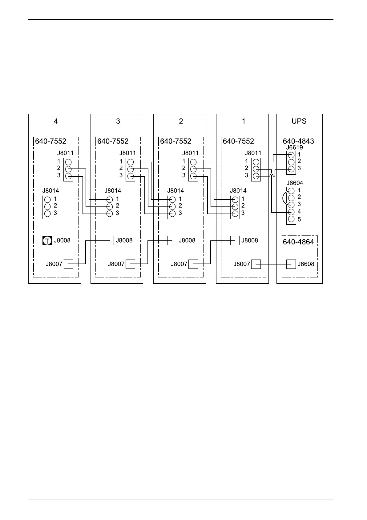
UPS for External Batteries Connect the Signal Cables from a Modular Battery Cabinet
3. Connect the signal cables from modular battery cabinet 1 to the UPS:
a. Mount a termination plug in J8008 on board 640-7552 in the last modular
battery cabinet (T).
b. Connect the signal cable from J8011 on board 640-7552 in modular
battery cabinet 1 to J6619 and J6604 on board 640-4843 in the UPS.
c. Connect the signal cable from J8007 on board 640-7552 in modular
battery cabinet 1 to J6608 on board 640-4864 in the UPS.
Signal Cable Connections between Four Modular Battery Cabinets and the UPS
70 990-91111F-001
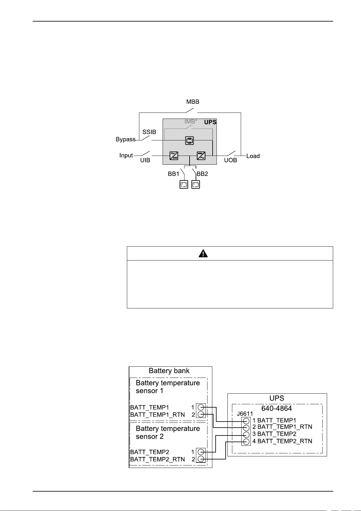
Connect the Signal Cables from Switchgear and Third-Party
Auxiliary Products UPS for External Batteries
Connect the Signal Cables from Switchgear and
Third-Party Auxiliary Products
NOTE: Route the signal cables separately from the power cables and route
the Class 2/SELV cables separately from the non-Class 2/non-SELV cables.
Example of Single System with Third-Party Switchgear
NOTE: The internal maintenance breaker IMB* cannot be used in a system
with an external maintenance bypass breaker MBB and the internal
maintenance breaker IMB* must be padlocked in the open position.
1. Install the temperature sensor provided with the UPS in the battery solution.
In battery cabinets, install the temperature sensor in the top corner of the
battery cabinet.
WARNING
HAZARD OF FIRE
Position the temperature sensor as described to ensure correct
temperature measurements.
Failure to follow these instructions can result in death, serious injury,
or equipment damage.
2. Route the battery temperature sensor cables from the battery solution to the
UPS and connect on board 640-4864 in the top of the UPS as shown.
NOTE: One temperature sensor is provided with the UPS. Contact
Schneider Electric if you want to buy an additional temperature sensor.
NOTE: The battery temperature sensor cables are considered Class 2/
SELV. Class 2/SELV circuits must be isolated from the primary circuitry.
990-91111F-001 71
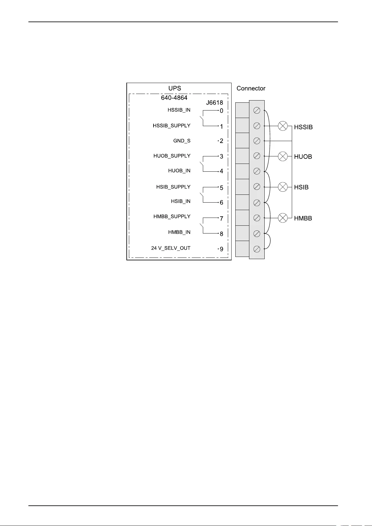
UPS for External Batteries
Connect the Signal Cables from Switchgear and Third-Party
Auxiliary Products
3. Connect signal cables from the breaker indicator lights in your switchgear to
board 640-4864 terminal J6618 in the top of the UPS. If an external supply is
used, remove jumper from J6618 pin 8 and 9.
NOTE: The breaker indicator light circuit is considered Class 2/SELV.
Class 2/SELV circuits must be isolated from the primary circuitry. Do not
connect any circuit to the breaker indicator light terminals unless it can be
confirmed that the circuit is Class 2/SELV.
72 990-91111F-001
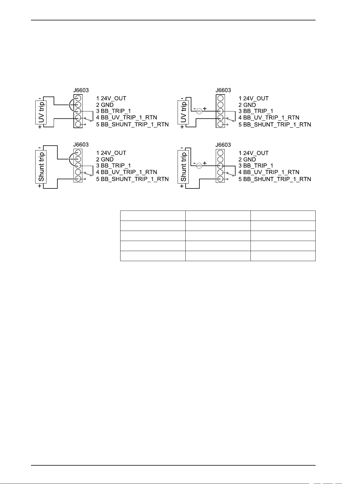
Connect the Signal Cables from Switchgear and Third-Party
Auxiliary Products UPS for External Batteries
4. Connect the signal cables from battery breaker 1 in your battery solution for
shunt trip or undervoltage (UV) trip connection to board 640-4843 terminal
J6603. Follow the illustration for connection with internal or external 24 VDC
supply.
Battery Breaker Trip Connection with Internal 24
VDC Supply
Battery Breaker Trip Connection with External 24
VDC Supply
Supported Shunt
Current (A) Time (ms) Temperature
1.6 Continuous 20 °C (68 °F)
10 1300 20 °C (68 °F)
20 200 20 °C (68 °F)
30 60 20 °C (68 °F)
5. Connect the signal cables from battery breaker 2 (if present) in your battery
solution for shunt trip or undervoltage (UV) trip connection to board 640-4843
terminal J6604. The connection principle is the same as for battery breaker 1.
990-91111F-001 73
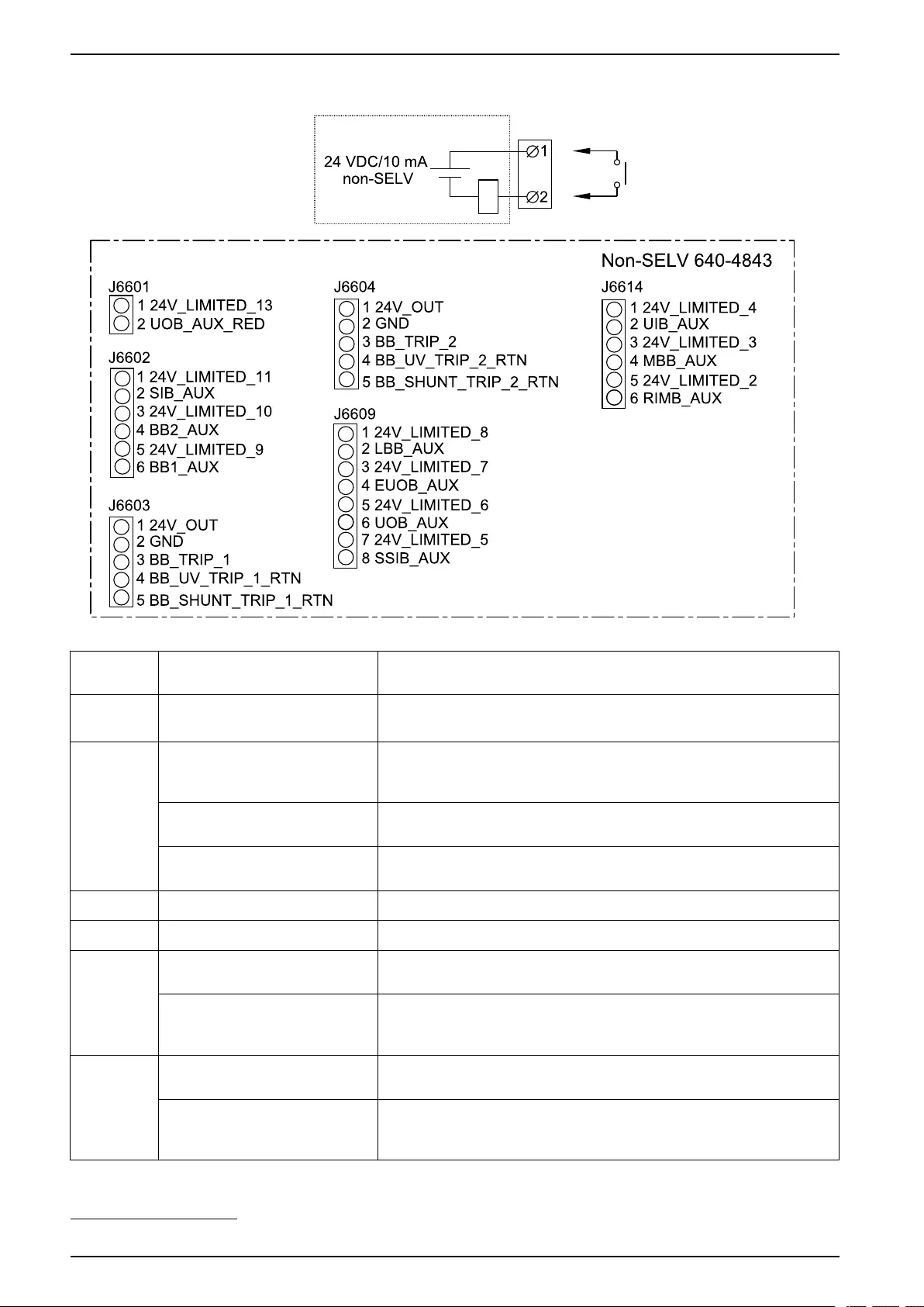
UPS for External Batteries
Connect the Signal Cables from Switchgear and Third-Party
Auxiliary Products
6. Connect signal cables from AUX switches in your switchgear to board 640-
4843 in the top of the UPS.
Terminal
number
Function Connection
J6601 UOB_RED (redundant AUX
switch in unit output breaker)
Connect to redundant AUX switch in unit output breaker UOB.
J6602 SIB (system isolation
breaker)
Connect to normally open (NO) AUX switch in system isolation
breaker SIB for parallel system. SIB must contain an AUX switch
for each connected UPS.
BB2 (battery breaker 2) Connect to normally open (NO) AUX switch in battery breaker
number 219
BB1 (battery breaker 1) Connect to normally open (NO) AUX switch in battery breaker
number 119
J6603 BB1_TRIP (battery breaker 1) Connect to shunt trip or UV trip in battery breaker number 119
J6604 BB2_TRIP (battery breaker 2) Connect to shunt trip or UV trip in battery breaker number 219
J6609 UOB (unit output breaker) Connect to normally open (NO) AUX switch in unit output breaker
UOB.
SSIB (static switch input
breaker)
Connect to normally open (NO) AUX switch in static switch input
breaker SSIB. SSIB must contain an AUX switch for each
connected UPS.
J6614 UIB (unit input breaker) Connect to normally open (NO) AUX switch in unit input breaker
UIB. UIB must contain an AUX switch for each connected UPS.
MBB (maintenance bypass
breaker)
Connect to normally closed (NC) AUX switch in maintenance
bypass breaker MBB. MBB must contain an AUX switch for each
connected UPS.
74 990-91111F-001
19. The UPS can connect to and monitor up to two battery breakers.
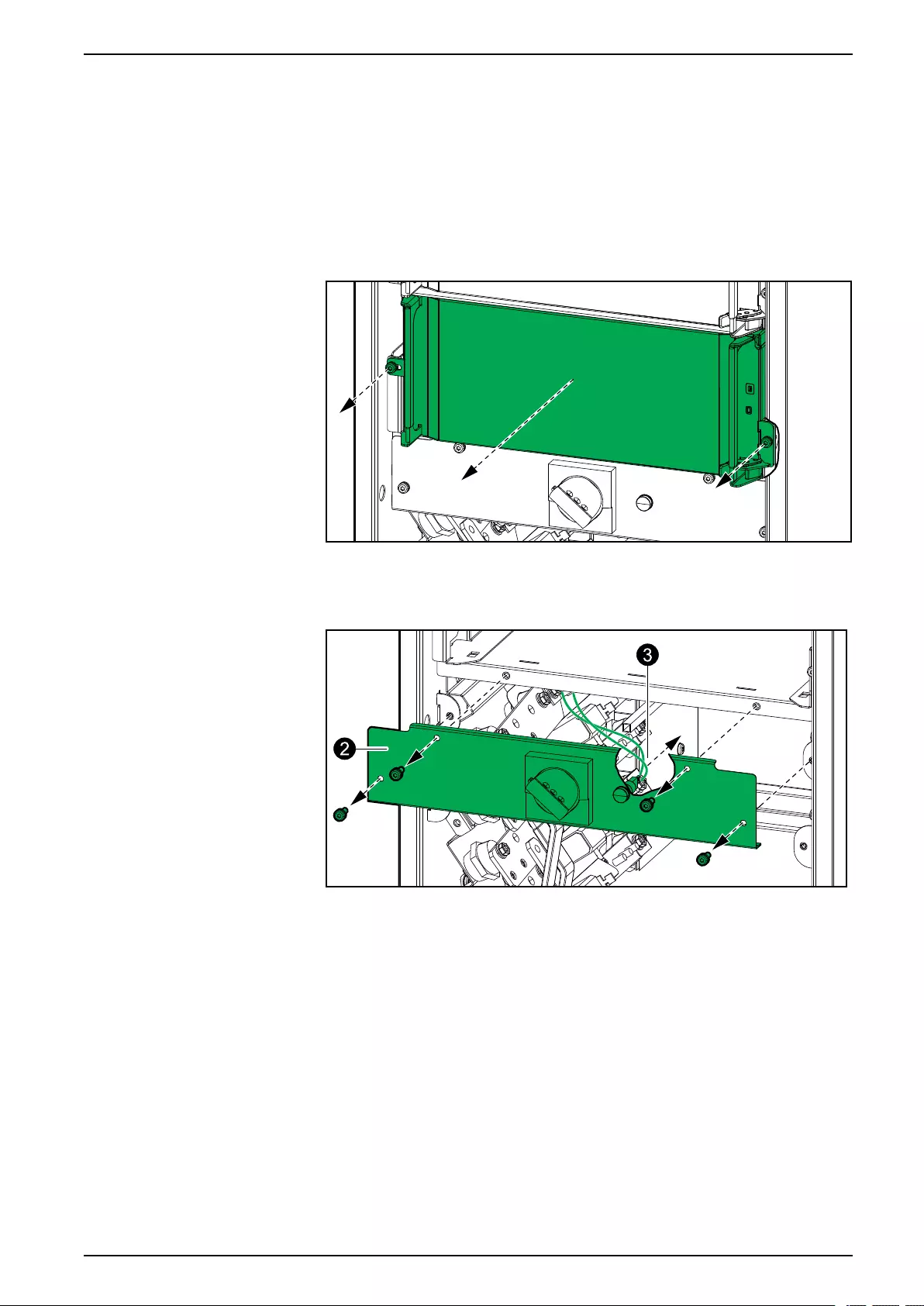
Connect the IMB Signal Cables in a Simplified 1+1 Parallel
System UPS for External Batteries
Connect the IMB Signal Cables in a Simplified 1+1
Parallel System
NOTE: Route the signal cables separately from the power cables to ensure
sufficient isolation.
1. Remove the static switch module from both UPSs.
Front View of the UPS
2. Remove the cover from both UPSs.
Front View of the UPS
3. Disconnect the signal cables from the internal maintenance breaker IMB
indicator light on both UPSs.
990-91111F-001 75
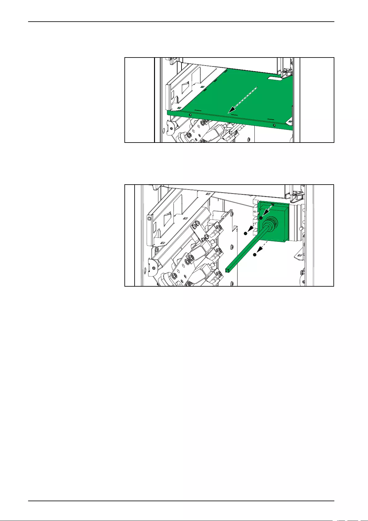
UPS for External Batteries
Connect the IMB Signal Cables in a Simplified 1+1 Parallel
System
4. Remove the shelf from both UPSs.
Front View of the UPS
5. Remove the front cover from the internal maintenance breaker IMB on both
UPSs.
Front View of the UPS
6. Install an additional AUX switch (provided) in the OF2 position in the internal
maintenance breaker IMB on both UPSs.
76 990-91111F-001
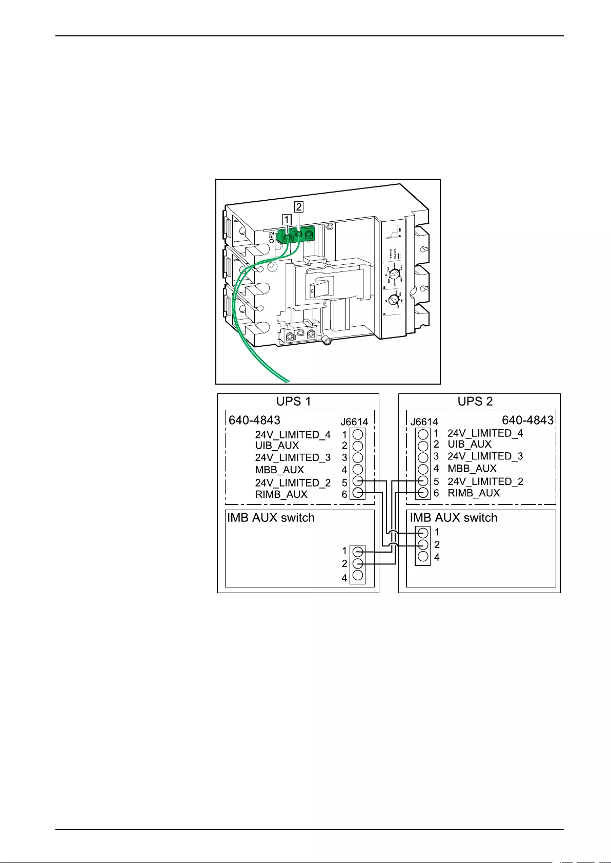
Connect the IMB Signal Cables in a Simplified 1+1 Parallel
System UPS for External Batteries
7. Connect the non-Class 2/non-SELV signal cables between the two UPSs:
a. Connect the non-Class 2/non-SELV signal cables (not provided) from the
AUX switch terminal 1 and 2 in the internal maintenance breaker IMB in
UPS 1 to J6614-5 and J6614-6 on board 640-4843 in UPS 2 as shown.
b. Connect the non-Class 2/non-SELV signal cables (not provided) from the
AUX switch terminal 1 and 2 in the internal maintenance breaker IMB in
UPS 2 to J6614-5 and J6614-6 on board 640-4843 in UPS 1 as shown.
Front View of Internal Maintenance Breaker IMB
990-91111F-001 77
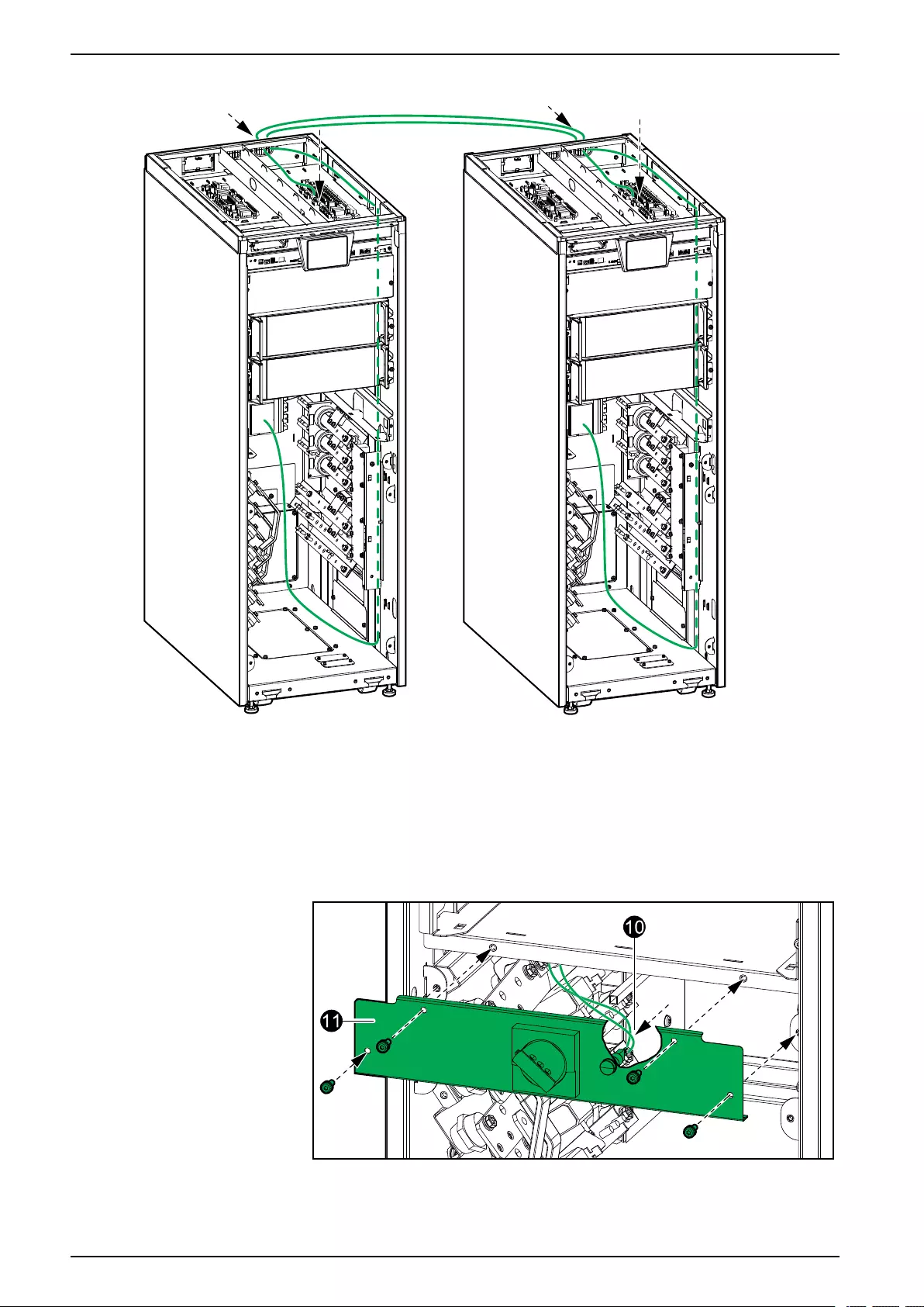
UPS for External Batteries
Connect the IMB Signal Cables in a Simplified 1+1 Parallel
System
Front View of Simplified 1+1 Parallel System
8. Reinstall the front cover on the internal maintenance breaker IMB on both
UPSs.
9. Reinstall the shelf on both UPSs.
10. Reconnect the signal cables from the internal maintenance breaker IMB to
the indicator light on both UPSs.
Front View of the UPS
11. Reinstall the cover on both UPSs.
12. Reinstall the static switch module on both UPSs.
78 990-91111F-001
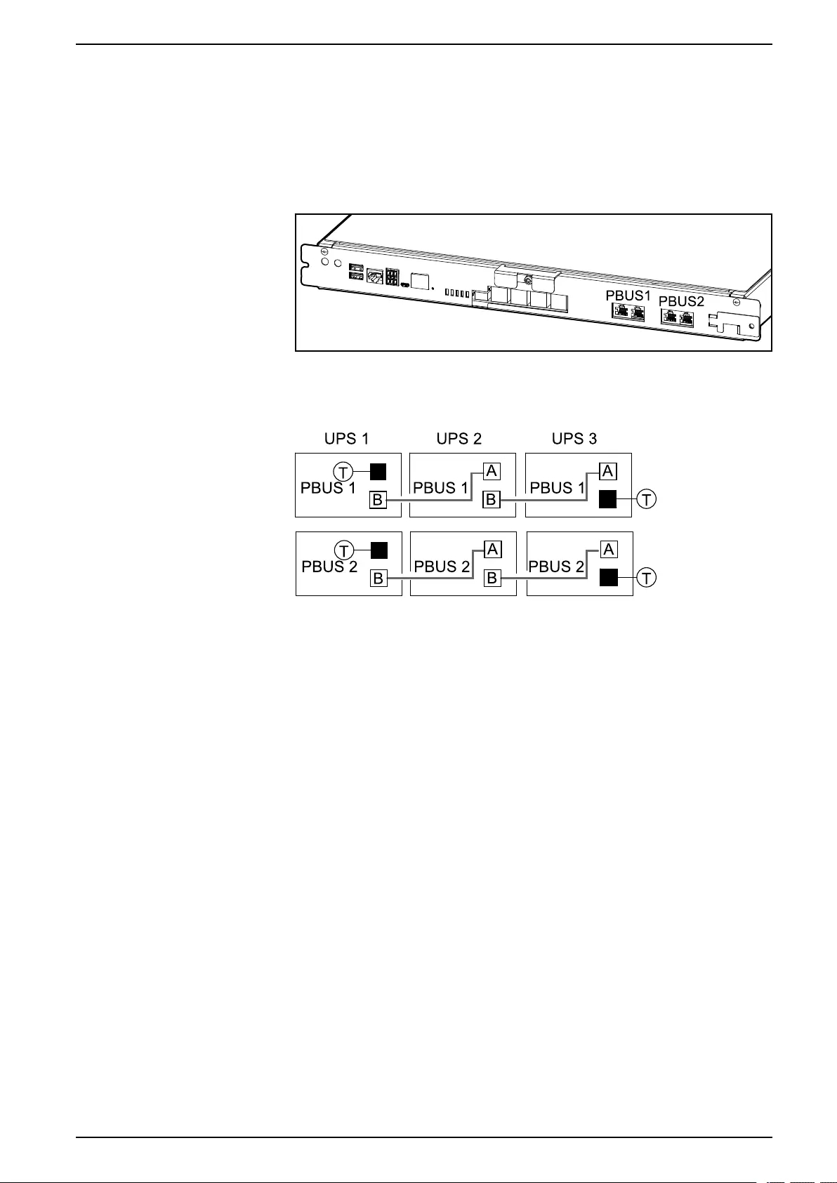
Connect the PBUS Cables UPS for External Batteries
Connect the PBUS Cables
1. Connect the provided PBUS 1 (white) and PBUS 2 (red) cables to the PBUS
ports in the UPS controller boxes. Route the PBUS cables through the cable
channel in the UPSs.
Front View of Controller Box
2. Mount termination plugs (T) in the unused connectors.
Example of System with Three UPSs in Parallel
990-91111F-001 79

UPS for External Batteries Connect the External Communication Cables
Connect the External Communication Cables
1. Connect the external communication cables to the ports in the UPS controller
box.
Front View of the Controller Box
A. Universal I/O port for built-in network management card.
B. Modbus port for built-in network management card.
C. Network port for built-in network management card. Use a shielded
network cable.
NOTE: Check that you are connecting to the correct port to avoid network
communication conflicts.
80 990-91111F-001
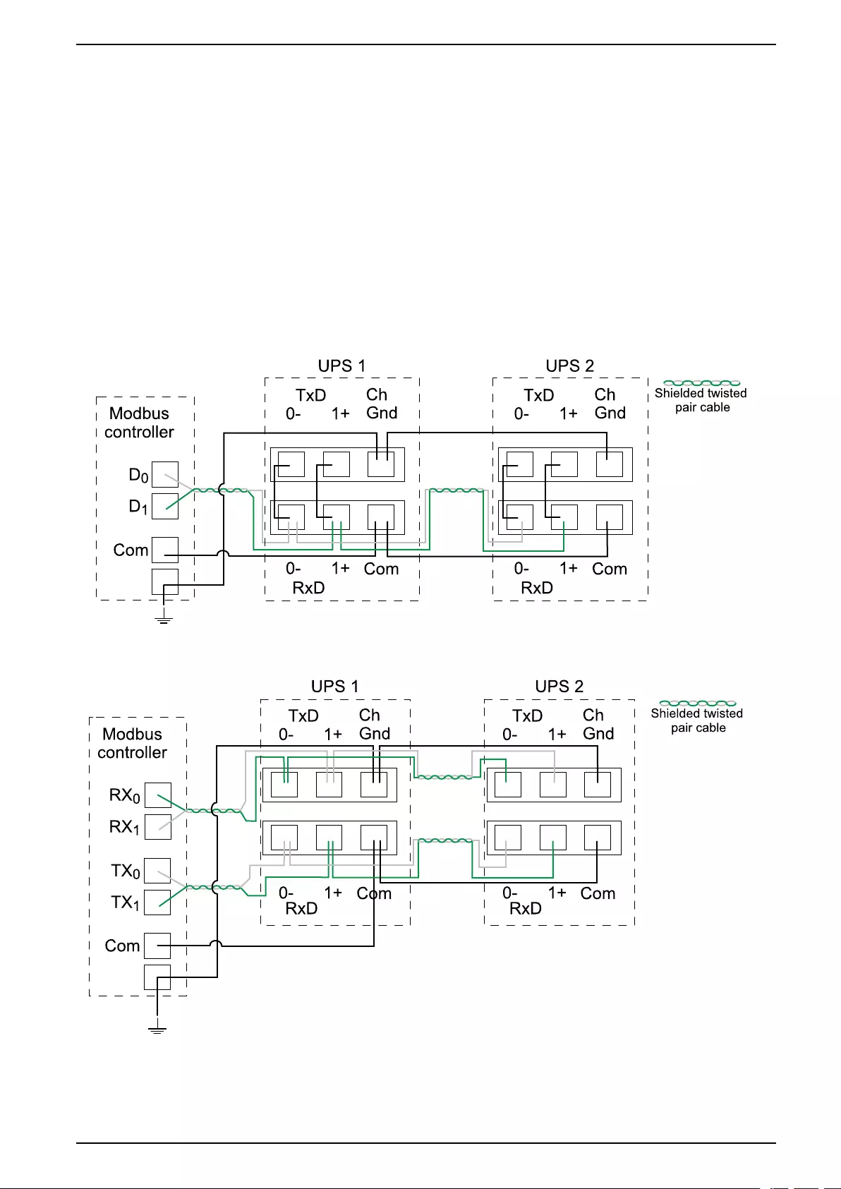
Connect the External Communication Cables UPS for External Batteries
Connect the Modbus Cables
1. Connect the Modbus cables to the UPS(s). Use either 2-wire or 4-wire
connection.
• Shielded twisted pair cables must be used for Modbus connections. The
shield connection to the ground must be as short as possible (ideally
below 1 cm). The cable shield must be connected to the Ch Gnd pin on
each device.
• Wiring should be done in accordance with local wiring codes.
• Route signal cables separately from power cables to ensure sufficient
isolation.
• The Modbus port is galvanically isolated with the Com pin as ground
reference.
Example: 2-Wire Connection with Two UPSs
Example: 4-Wire Connection with Two UPSs
2. Install 150 Ohm termination resistors at each end of each bus if the buses are
very long and operate at high data rates. Busses under 610 meters (2000
feet) at 9600 baud or under 305 meters (1000 feet) at 19.200 baud should not
require termination resistors.
990-91111F-001 81

UPS for External Batteries Add Translated Safety Labels to Your Product
Add Translated Safety Labels to Your Product
The safety labels on your product are in English and French. Sheets with
translated safety labels are provided with your product.
1. Find the sheets with translated safety labels provided with your product.
2. Check which 885-XXX numbers are on the sheet with translated safety
labels.
3. Locate the safety labels on your product that match the translated safety
labels on the sheet – look for the 885-XXX numbers.
4. Add the replacement safety label in your preferred language to your product
on top of the existing French safety label.
82 990-91111F-001
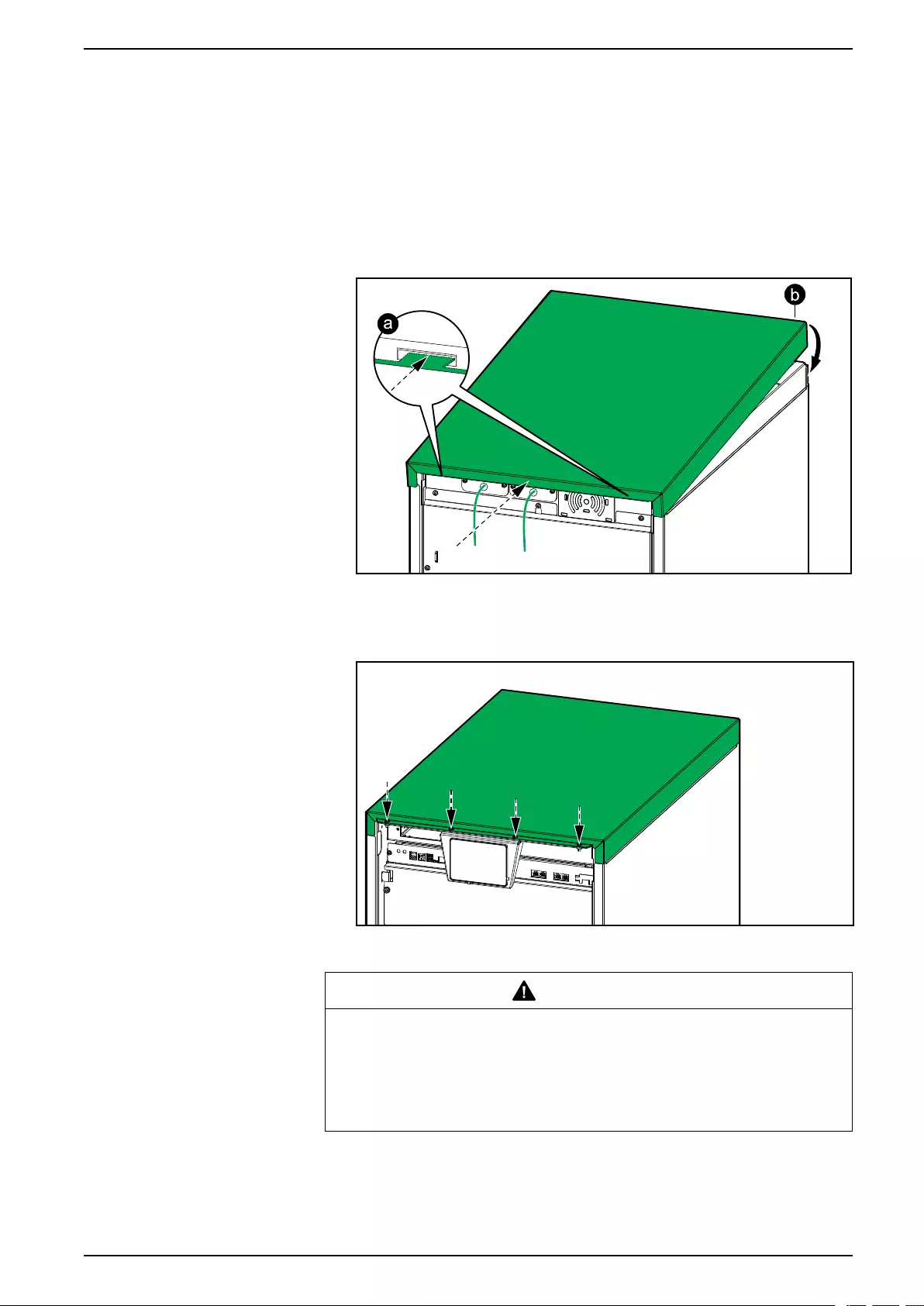
Final Installation UPS for External Batteries
Final Installation
1. Reinstall the top cover:
a. Tilt the top cover and slide it onto the UPS from the rear. Tabs in the rear
of the top cover must connect to the slots in the rear of the UPS.
b. Push the top cover down in the front.
Rear View of the UPS
c. Reinstall the screws.
Front View of the UPS
2. Check the fastening of the cable lugs.
CAUTION
RISK OF EQUIPMENT DAMAGE
Check the fastening of the cable lugs. If the cable lugs move due to pulling
on cables, the bolt can become loose.
Failure to follow these instructions can result in injury or equipment
damage.
990-91111F-001 83
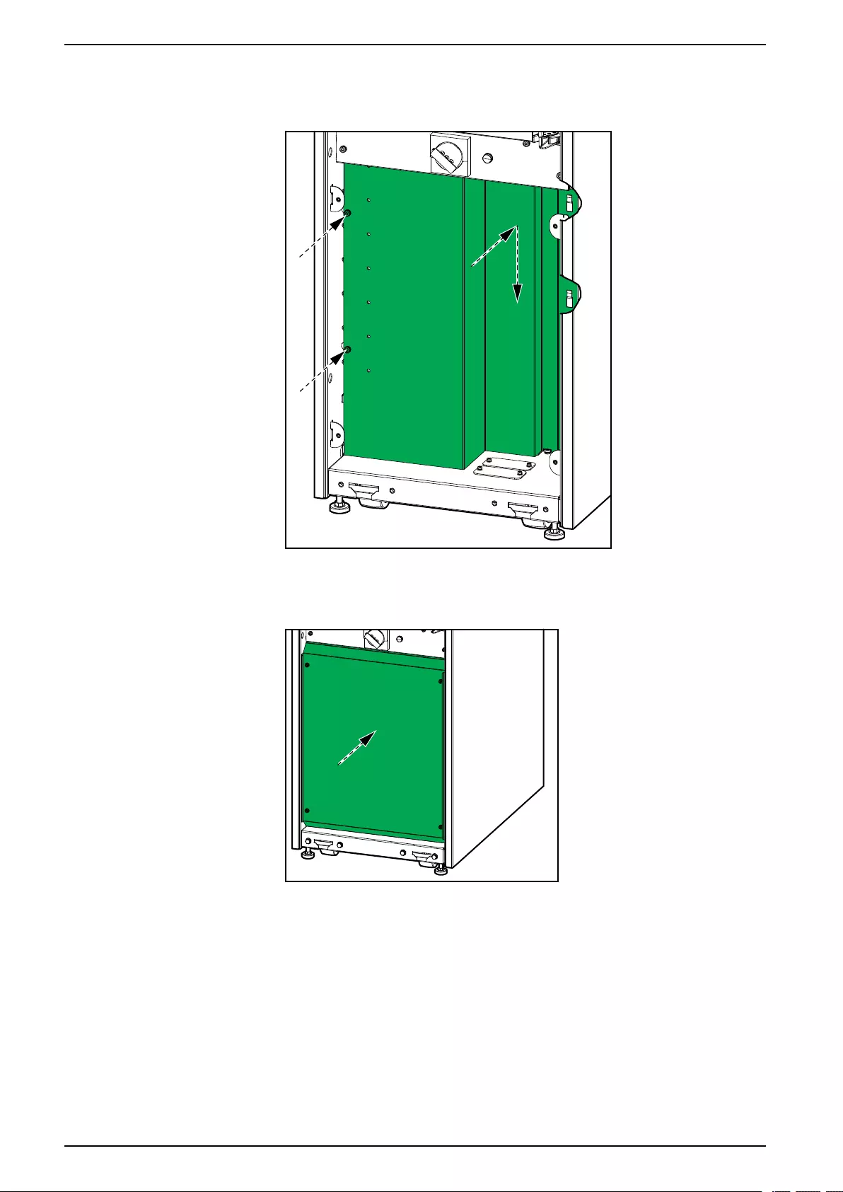
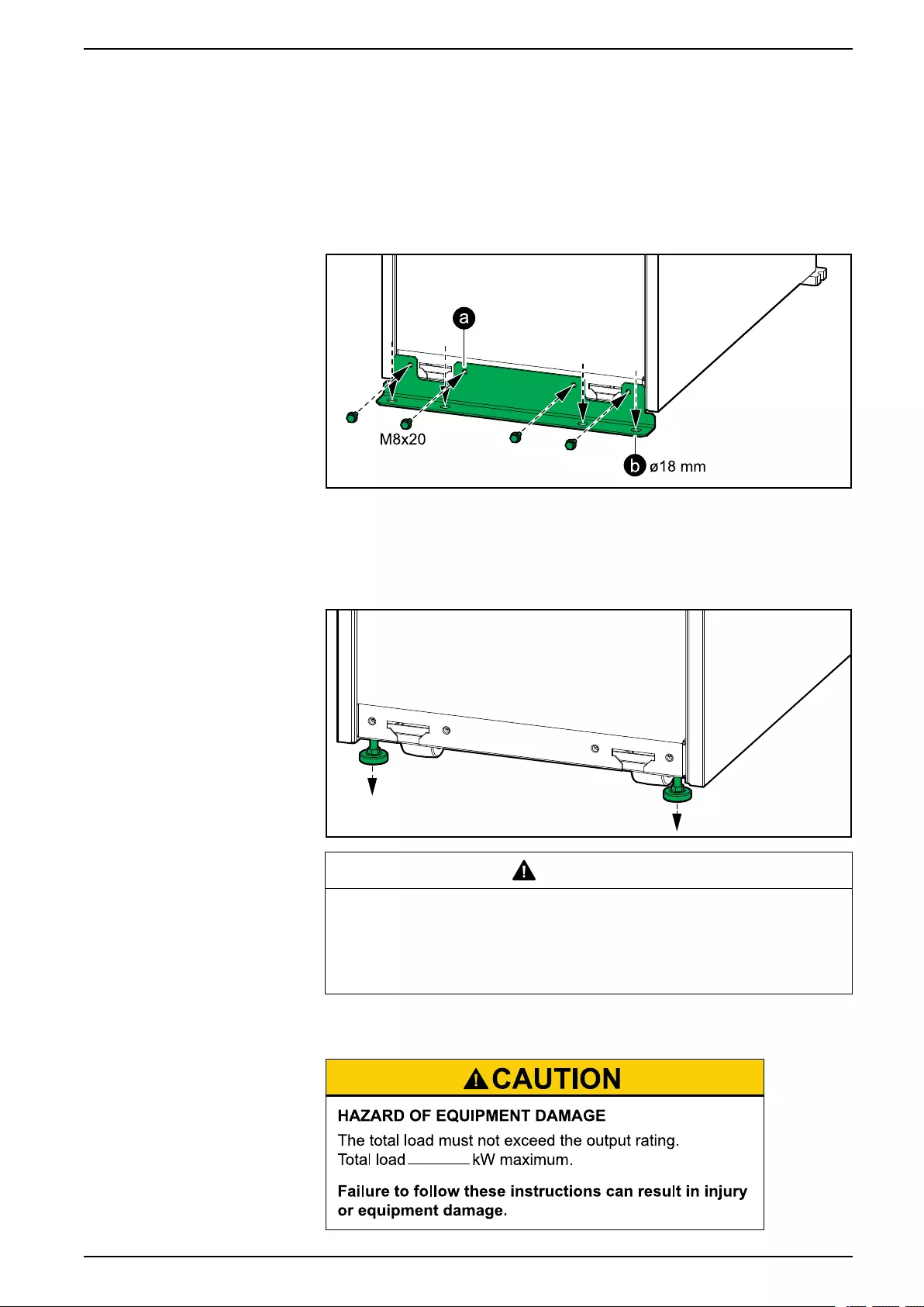
Final Installation UPS for External Batteries
5. Only for seismic anchoring:
a. Install the seismic front anchoring bracket on the UPS with the provided
M8 bolts.
b. Mount the seismic front anchoring bracket on the UPS to the floor. Use
appropriate hardware for the floor type – the hole diameter in the front
anchoring bracket is ø18 mm.
Front View of the UPS
6. Lower the front and rear leveling feet on the UPS with a wrench until they
connect with the floor. Use a bubble-leveler to check that the UPS is level.
This step is not necessary for a UPS with seismic anchoring.
Front View of the UPS
CAUTION
TIP HAZARD
Do not move the cabinet after the leveling feet have been lowered.
Failure to follow these instructions can result in injury or equipment
damage.
7. Only for UL 924 and CSA C22.2 NO. 141-15 solutions: Fill out the label on
the lower front plate with the UPS output rating in kW.
990-91111F-001 85
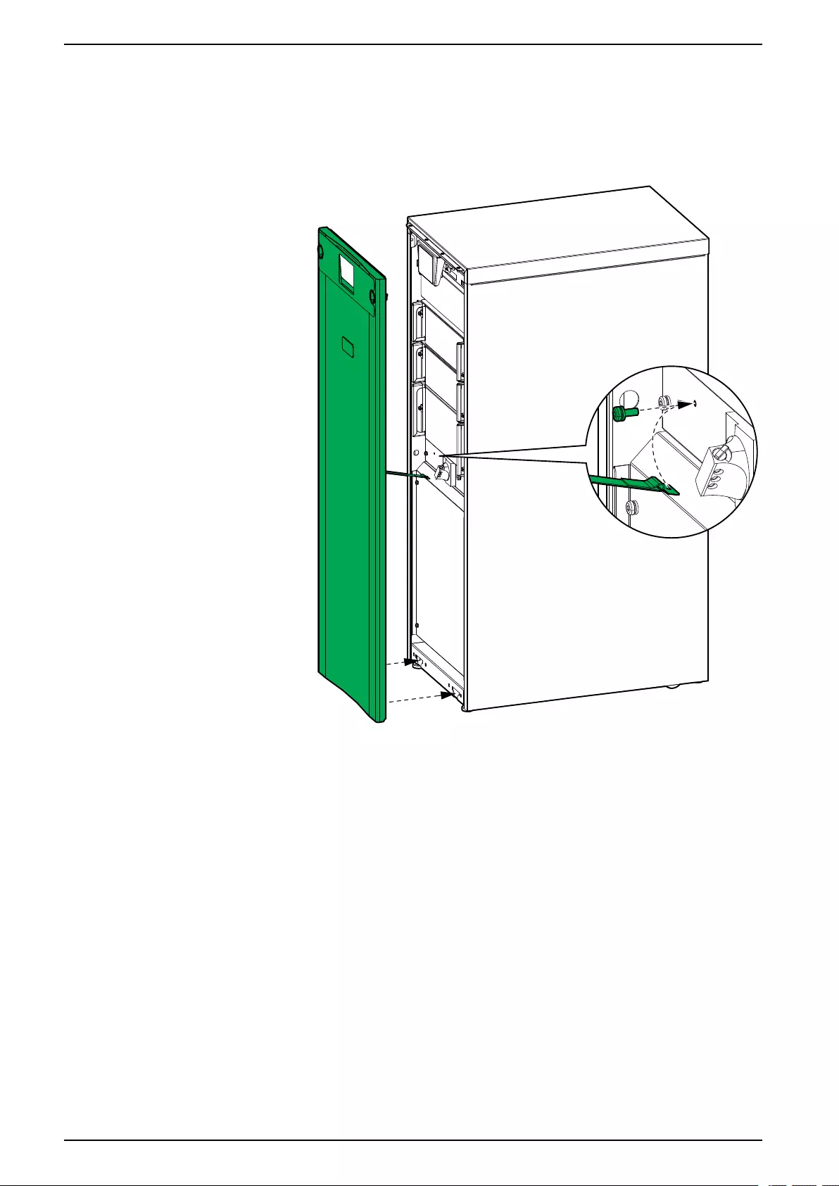


Schneider Electric
35 rue Joseph Monier
92500 Rueil Malmaison
France
+ 33 (0) 1 41 29 70 00
*990-91111F-001*
As standards, specifications, and design change from time to time,
please ask for confirmation of the information given in this publication.
© 2018 – 2021 Schneider Electric. All rights reserved.
990-91111F-001