Table of Contents
- Galaxy VS
- Important Safety Instructions — SAVE THESE INSTRUCTIONS
- Single System Overview
- Parallel System Overview
- Overview of User Interface
- Operation Modes
- Configuration
- Configure the UPS Input
- Configure the Output
- Configure the Battery Solution
- Configure High Efficiency Mode
- Configure the Breakers
- Configure the Input Contacts
- Configure the Output Relays
- Configure the Network
- Configure the Modbus
- Set the UPS Name
- Set the Date and Time
- Configure the Display Preferences
- Configure the Air Filter Reminder
- Save the UPS Settings on a USB Device
- Restore the UPS Settings from a USB Device
- Set the Display Language
- Change the Password
- Operation Procedures
- Start Up the UPS System from Off Mode
- Transfer the UPS from Normal Operation to Static Bypass Operation
- Transfer the UPS from Static Bypass Operation to Normal Operation
- Turn the Inverter OFF
- Turn the Inverter ON
- Set the Charger Mode
- Shut Down the UPS System into Maintenance Bypass Operation
- Start Up the UPS System from Maintenance Bypass Operation
- Access a Configured Network Management Interface
- View the Logs
- View the System Status Information
- Tests
- Maintenance
- Troubleshooting
APC GVSUPS60KHS User Manual
Displayed below is the user manual for GVSUPS60KHS by APC which is a product in the Uninterruptible Power Supplies (UPSs) category. This manual has pages.
Related Manuals
Galaxy VS
UPS
Operation
5/2019
www.schneider-electric.com

Legal Information
The Schneider Electric brand and any trademarks of Schneider Electric SE and its
subsidiaries referred to in this guide are the property of Schneider Electric SE or its
subsidiaries. All other brands may be trademarks of their respective owners.
This guide and its content are protected under applicable copyright laws and
furnished for informational use only. No part of this guide may be reproduced or
transmitted in any form or by any means (electronic, mechanical, photocopying,
recording, or otherwise), for any purpose, without the prior written permission of
Schneider Electric.
Schneider Electric does not grant any right or license for commercial use of the guide
or its content, except for a non-exclusive and personal license to consult it on an "as
is" basis. Schneider Electric products and equipment should be installed, operated,
serviced, and maintained only by qualified personnel.
As standards, specifications, and designs change from time to time, information
contained in this guide may be subject to change without notice.
To the extent permitted by applicable law, no responsibility or liability is assumed by
Schneider Electric and its subsidiaries for any errors or omissions in the informational
content of this material or consequences arising out of or resulting from the use of the
information contained herein.
Go to
IEC: https://www.productinfo.schneider-electric.com/portals/ui/galaxyvs_iec/ or
UL: https://www.productinfo.schneider-electric.com/portals/ui/galaxyvs_ul/
or scan the QR code above for digital experience and translated manuals.

UPS
Table of Contents
Important Safety Instructions — SAVE THESE
INSTRUCTIONS.........................................................................................5
FCC Statement ..........................................................................................6
Electromagnetic Compatibility .....................................................................6
Safety Precautions .....................................................................................6
Single System Overview............................................................................7
Parallel System Overview..........................................................................8
Overview of User Interface......................................................................11
Display ....................................................................................................11
Menu Tree..........................................................................................14
Controller Section.....................................................................................15
Operation Modes ......................................................................................16
UPS Modes..............................................................................................16
System Modes .........................................................................................18
Configuration .............................................................................................20
Configure the UPS Input ...........................................................................20
Configure the Output.................................................................................21
Output Transformer Voltage Compensation ..........................................22
Configure the Battery Solution ...................................................................23
Configure High Efficiency Mode.................................................................26
Configure the Breakers .............................................................................27
Configure the Input Contacts .....................................................................28
Configure the Output Relays .....................................................................29
Configure the Network ..............................................................................31
Configure the Modbus...............................................................................32
Set the UPS Name ...................................................................................33
Set the Date and Time ..............................................................................33
Configure the Display Preferences.............................................................33
Configure the Air Filter Reminder ...............................................................34
Save the UPS Settings on a USB Device....................................................34
Restore the UPS Settings from a USB Device.............................................35
Set the Display Language .........................................................................35
Change the Password...............................................................................36
Operation Procedures..............................................................................37
Start Up the UPS System from Off Mode ....................................................37
Transfer the UPS from Normal Operation to Static Bypass
Operation.................................................................................................37
Transfer the UPS from Static Bypass Operation to Normal
Operation.................................................................................................37
Turn the Inverter OFF ...............................................................................37
Turn the Inverter ON .................................................................................37
Set the Charger Mode...............................................................................38
Shut Down the UPS System into Maintenance Bypass Operation.................38
Start Up the UPS System from Maintenance Bypass Operation ...................38
Access a Configured Network Management Interface..................................38
Enable HTTP/HTTPS Protocols ...........................................................39
Enable SNMP Protocols ......................................................................39
990-5910B-001 3

UPS
View the Logs...........................................................................................40
View the System Status Information...........................................................41
View the Modular Battery Status ..........................................................44
Tests............................................................................................................45
Start a Runtime Calibration Test.................................................................45
Stop a Runtime Calibration Test.................................................................46
Start a Battery Test ...................................................................................46
Stop a Battery Test ...................................................................................46
Maintenance ..............................................................................................47
Replace the Air Filter ................................................................................47
Determine if you need a Replacement Part.................................................48
Find the Serial Numbers......................................................................48
Return Parts to Schneider Electric .............................................................49
Troubleshooting ........................................................................................50
Status LED Lighting per UPS Operation Mode ............................................50
Export UPS Report to a USB Device ..........................................................51
4 990-5910B-001
Important Safety Instructions — SAVE THESE
INSTRUCTIONS UPS
Important Safety Instructions — SAVE THESE
INSTRUCTIONS
Read these instructions carefully and look at the equipment to become familiar
with it before trying to install, operate, service or maintain it. The following safety
messages may appear throughout this manual or on the equipment to warn of
potential hazards or to call attention to information that clarifies or simplifies a
procedure.
The addition of this symbol to a “Danger” or “Warning” safety
message indicates that an electrical hazard exists which will result in
personal injury if the instructions are not followed.
This is the safety alert symbol. It is used to alert you to potential
personal injury hazards. Obey all safety messages with this symbol
to avoid possible injury or death.
DANGER
DANGER indicates a hazardous situation which, if not avoided, will result in
death or serious injury.
Failure to follow these instructions will result in death or serious injury.
WARNING
WARNING indicates a hazardous situation which, if not avoided, could result
in death or serious injury.
Failure to follow these instructions can result in death, serious injury, or
equipment damage.
CAUTION
CAUTION indicates a hazardous situation which, if not avoided, could result in
minor or moderate injury.
Failure to follow these instructions can result in injury or equipment
damage.
NOTICE
NOTICE is used to address practices not related to physical injury. The safety
alert symbol shall not be used with this type of safety message.
Failure to follow these instructions can result in equipment damage.
Please Note
Electrical equipment should only be installed, operated, serviced, and maintained
by qualified personnel. No responsibility is assumed by Schneider Electric for any
consequences arising out of the use of this material.
A qualified person is one who has skills and knowledge related to the construction,
installation, and operation of electrical equipment and has received safety training
to recognize and avoid the hazards involved.
990-5910B-001 5
UPS Important Safety Instructions — SAVE THESE
INSTRUCTIONS
FCC Statement
NOTE: This equipment has been tested and found to comply with the limits for
a Class A digital device, pursuant to Part 15 of the FCC Rules. These limits
are designed to provide reasonable protection against harmful interference
when the equipment is operated in a commercial environment. This equipment
generates, uses, and can radiate radio frequency energy and, if not installed
and used in accordance with the instruction manual, may cause harmful
interference to radio communications. Operation of this equipment in a
residential area is likely to cause harmful interference in which case the user
will be required to correct the interference at his own expense.
Any changes or modifications not expressly approved by the party responsible for
compliance could void the user’s authority to operate the equipment.
Electromagnetic Compatibility
NOTICE
RISK OF ELECTROMAGNETIC DISTURBANCE
This is a product category C2 UPS product. In a residential environment, this
product may cause radio inference, in which case the user may be required to
take additional measures.
Failure to follow these instructions can result in equipment damage.
Safety Precautions
DANGER
HAZARD OF ELECTRICAL SHOCK, EXPLOSION OR ARC FLASH
All safety instructions in this document must be read, understood and followed.
Failure to follow these instructions will result in death or serious injury.
DANGER
HAZARD OF ELECTRICAL SHOCK, EXPLOSION OR ARC FLASH
After the UPS system has been electrically wired, do not start up the system.
Start-up must only be performed by Schneider Electric.
Failure to follow these instructions will result in death or serious injury.
6 990-5910B-001
Single System Overview UPS
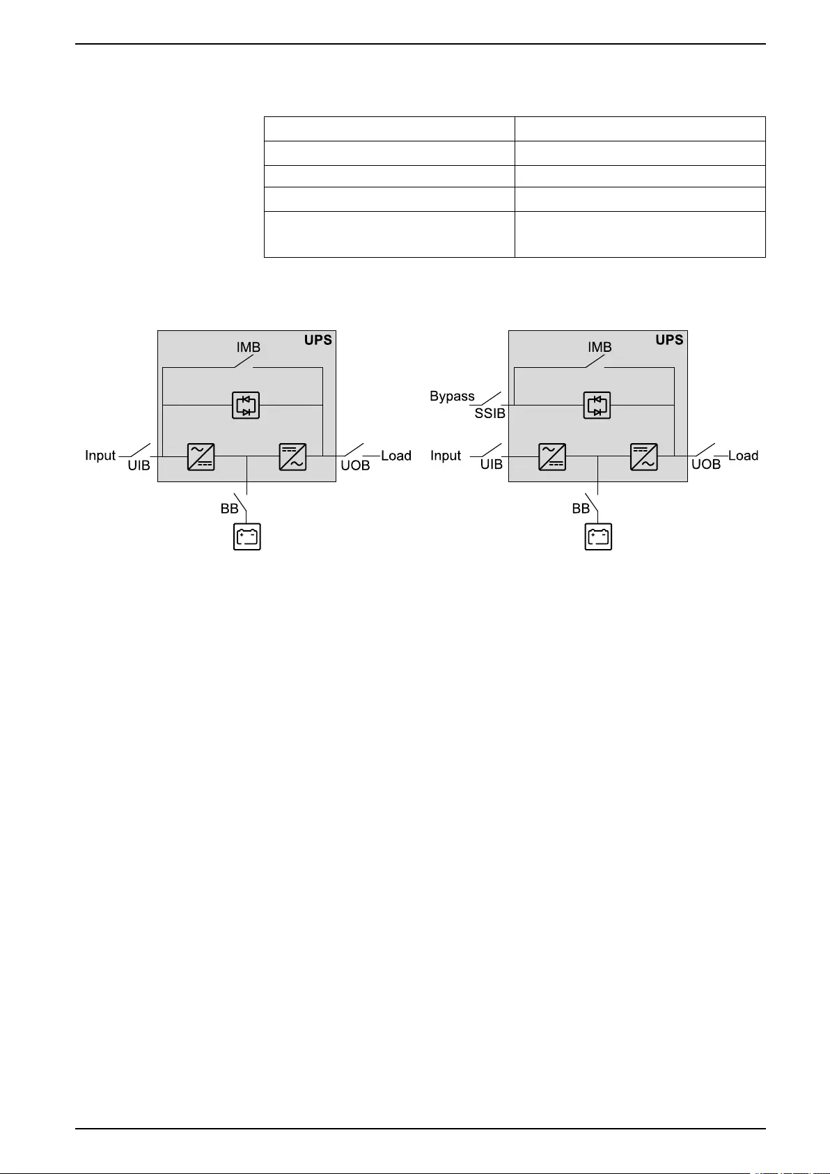
Single System Overview
UIB Unit input breaker
SSIB Static switch input breaker
IMB Internal maintenance breaker
UOB Unit output breaker
BB Battery breaker. A UPS for internal batteries will
contain a battery breaker for the internal
batteries.
Single System – Single Mains Single System – Dual Mains
990-5910B-001 7
UPS Parallel System Overview
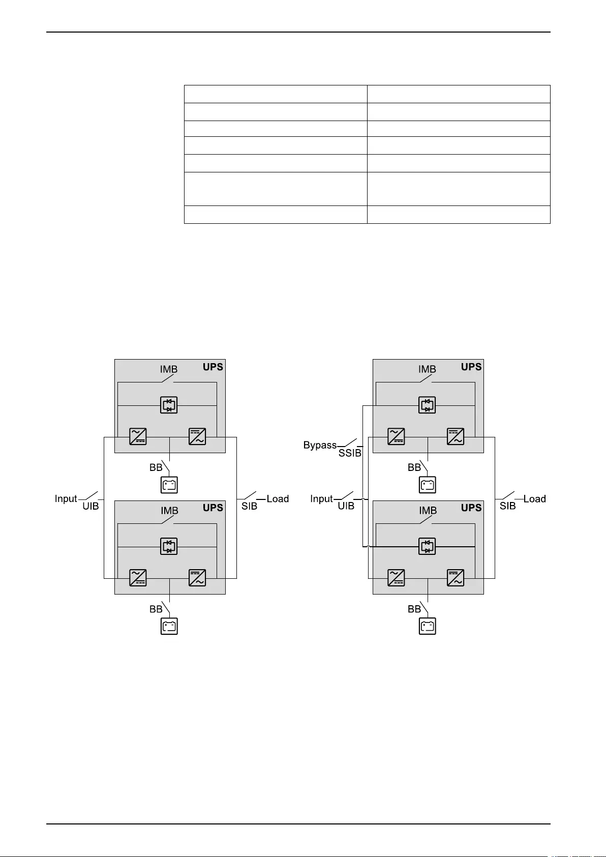
Parallel System Overview
UIB Unit input breaker
SSIB Static switch input breaker
IMB Internal maintenance breaker
UOB Unit output breaker
SIB System isolation breaker
BB Battery breaker. A UPS for internal batteries will
contain a battery breaker for the internal
batteries.
MBB External maintenance bypass breaker
Simplified 1+1 Parallel System
Galaxy VS can support 2 UPSs in a simplified 1+1 parallel system for redundancy
with shared unit input breaker UIB and static switch input breaker SSIB.
Simplified 1+1 Parallel System – Single Mains Simplified 1+1 Parallel System – Dual Mains
8 990-5910B-001
Parallel System Overview UPS
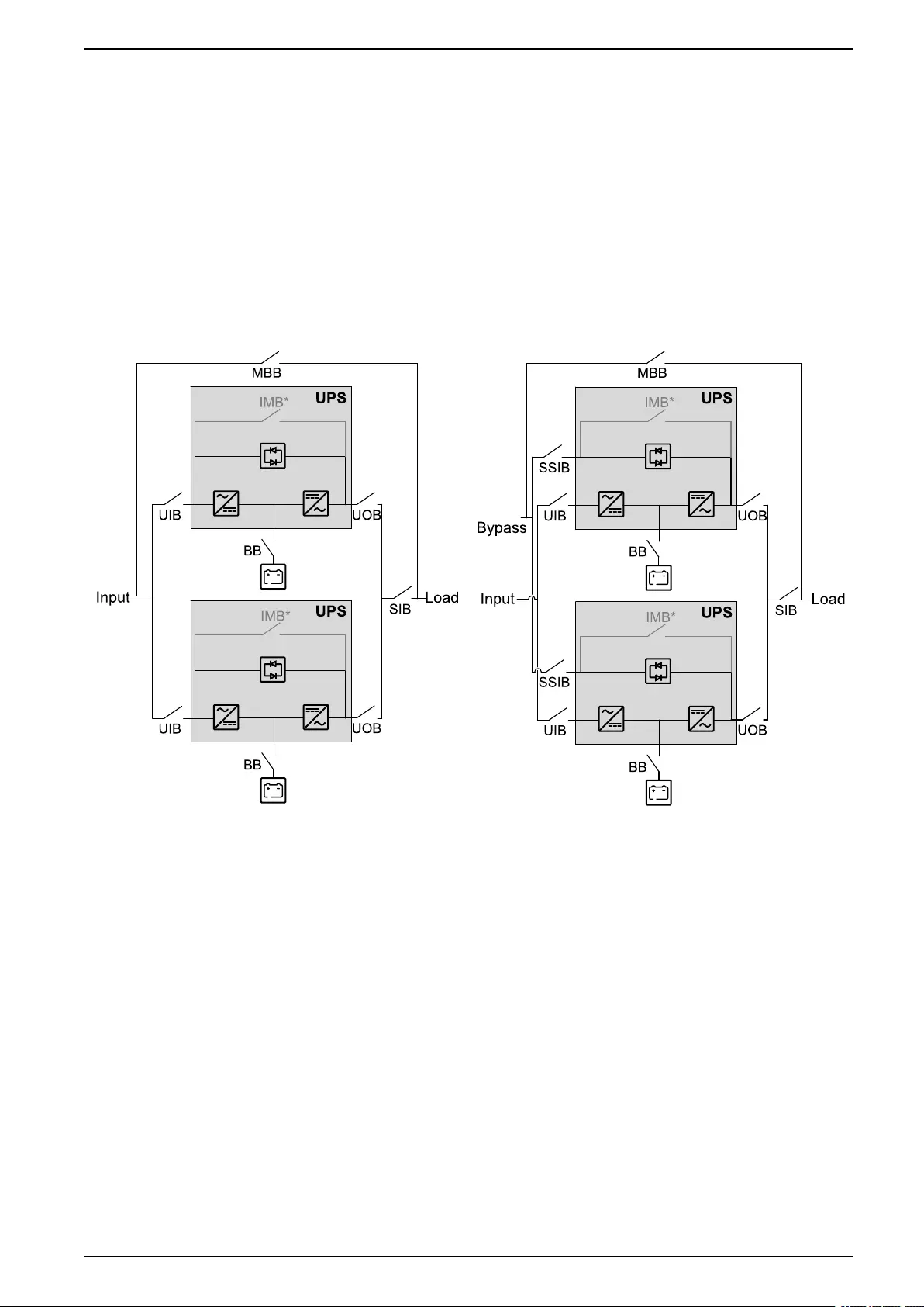
Parallel System with Individual Unit Input Breaker UIB and Static
Switch Input Breaker SSIB
Galaxy VS can support up to 3 UPSs in parallel for capacity and up to 3+1 UPSs
in parallel for redundancy with individual unit input breaker UIB and static switch
input breaker SSIB.
NOTE: The internal maintenance breaker IMB can only be used in a simplified
1+1 parallel system. In any other parallel system, an external maintenance
bypass breaker MBB must be provided and the internal maintenance breaker
IMB* must be padlocked in the open position.
Parallel System – Single Mains Parallel System – Dual Mains
990-5910B-001 9
UPS Parallel System Overview
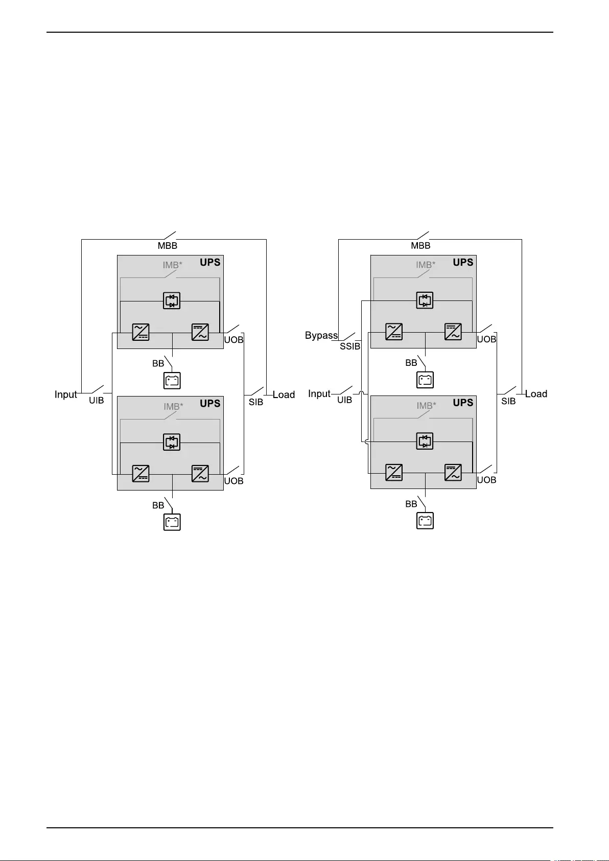
Parallel System with Shared Unit Input Breaker UIB and Static
Switch Input Breaker SSIB
Galaxy VS can support up to 3 UPSs in parallel for capacity and up to 3+1 UPSs
in parallel for redundancy with shared unit input breaker UIB and static switch
input breaker SSIB.
NOTE: The internal maintenance breaker IMB can only be used in a simplified
1+1 parallel system. In any other parallel system, an external maintenance
bypass breaker MBB must be provided and the internal maintenance breaker
IMB* must be padlocked in the open position.
Parallel System – Single Mains Parallel System – Dual Mains
10 990-5910B-001
Overview of User Interface UPS
Overview of User Interface
Display
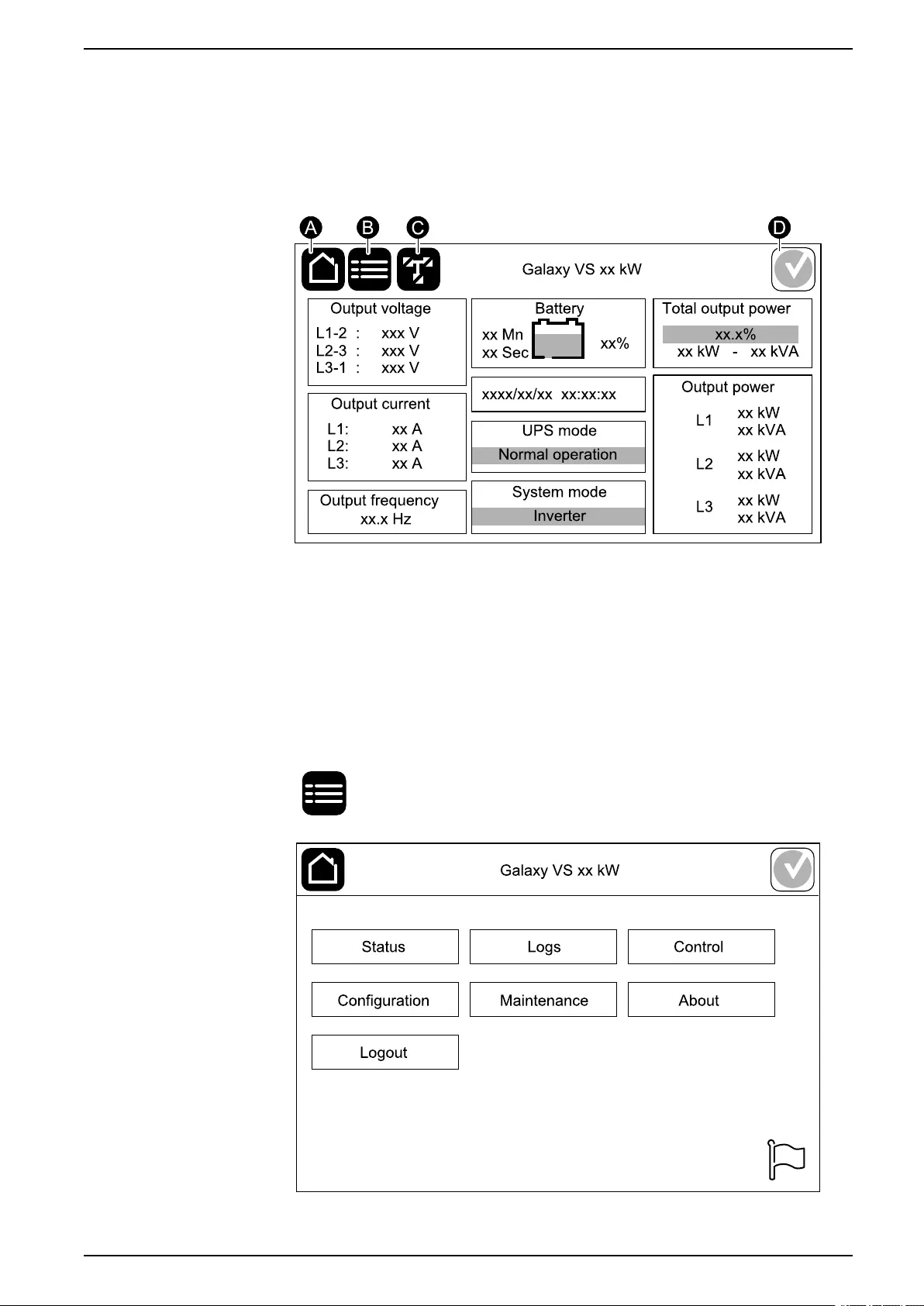
Overview of the Home Screen
A. Home button - tap here on any screen to return to the home screen.
B. Main menu button - tap here to access the menus.
C. Mimic diagram button - tap here to access the mimic diagram.
D. Alarm status symbol - tap here to access the active alarms log.
You can tap on the output or battery fields on the home screen to go directly to the
detailed measurement pages.
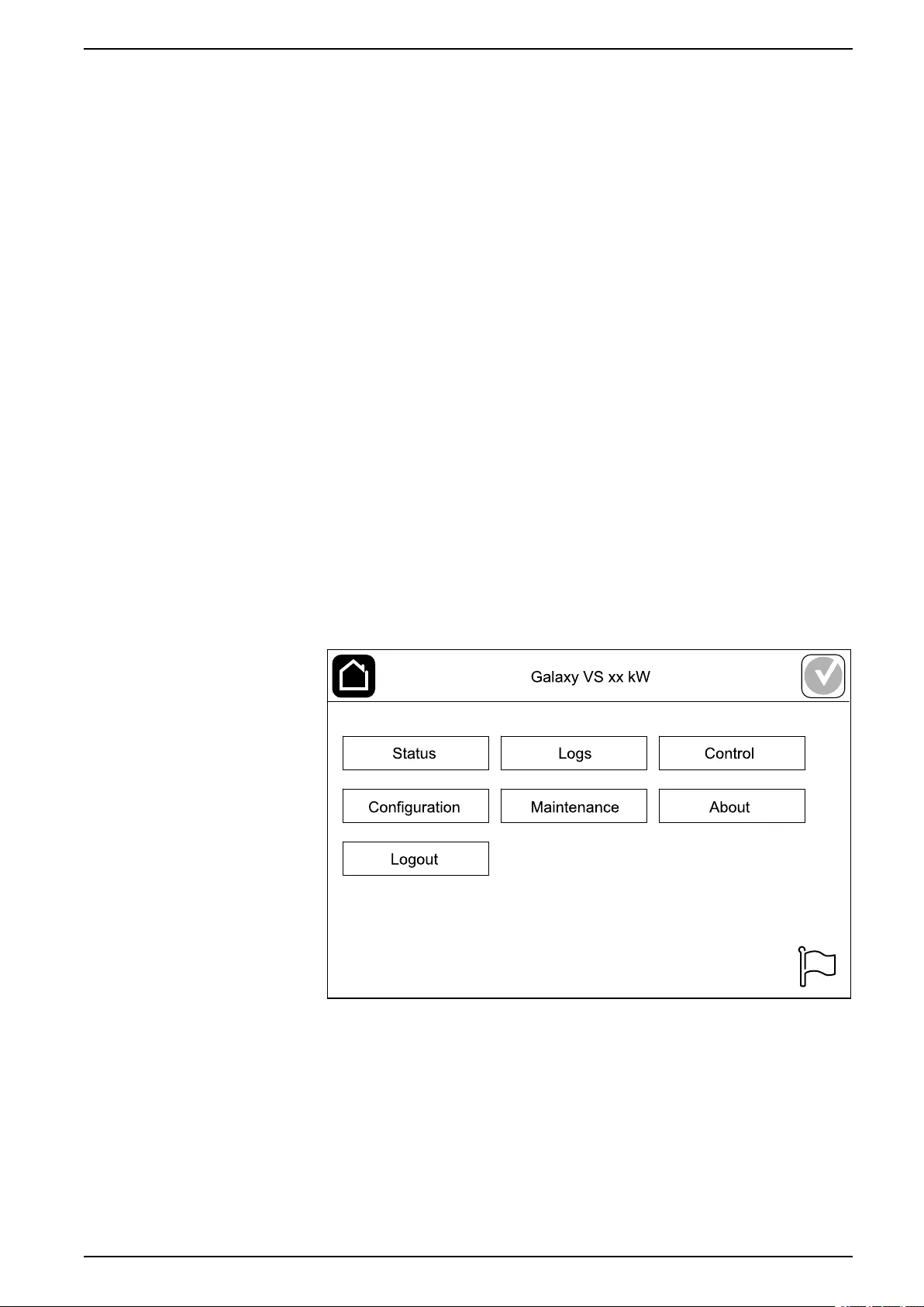
Main Menu
Tap the main menu button on the home screen to access the menus.
990-5910B-001 11
UPS Overview of User Interface
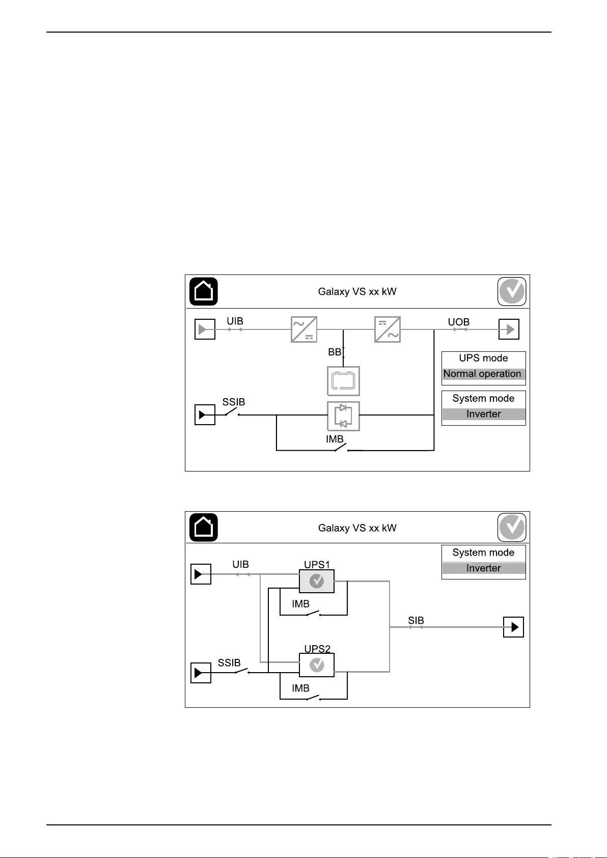
Mimic Diagram
The mimic diagram will adapt to your system configuration – the mimic diagrams
shown here are just examples.
The green power line (gray in illustration) in the mimic diagram shows the power
flow through the UPS system. Active modules (inverter, rectifier, battery, static
bypass switch, etc.) are framed in green and inactive modules are framed in black.
Modules framed in red are inoperable or in an alarm condition.
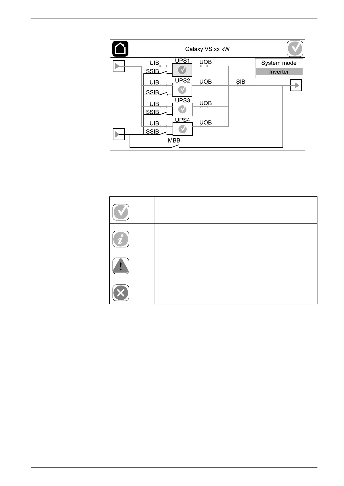
In mimic diagrams for parallel systems, tap on the gray UPS to see the mimic
diagram on UPS level.
NOTE: The mimic diagram only shows one battery breaker BB even if more
battery breakers have been connected and configured for monitoring. If one or
more of the monitored battery breakers are in the closed position, the BB on
the mimic diagram will show as closed. If all of the monitored battery breakers
are in the open position, the BB on the mimic diagram will show as open.
Example of Single UPS System – Dual Mains
Example of Simplified 1+1 Parallel System – Dual Mains
12 990-5910B-001
Overview of User Interface UPS
Example of Parallel System – Dual Mains
Alarm Status Symbol
The alarm status symbol (gray in illustration) in the top right corner of the display
changes depending on the alarm status of the UPS system.
Green: No alarms present in the UPS system.
Blue: Informational alarm(s) present in the UPS system. Tap
the alarm status symbol to open the active alarms log.
Yellow: Warning alarm(s) present in the UPS system. Tap the
alarm status symbol to open the active alarms log.
Red: Critical alarm(s) present in the UPS system. Tap the
alarm status symbol to open the active alarms log.
990-5910B-001 13

UPS Overview of User Interface
Menu Tree
Tap the main menu button on the home screen to access the menus.
•Status
◦Input
◦Output
◦Bypass
◦Battery
◦Temperature
◦Parallel
•Logs
•Control1
◦Operation mode
◦Inverter
◦Charger
◦Guided sequences
•Configuration1
◦UPS
◦Output
◦Battery
◦High efficiency
◦Breakers
◦Contacts and relays
◦Network
◦Modbus
◦General
◦Reminder
◦Save/restore
◦Update status
•Maintenance
◦Buzzer
◦Status LEDs
◦Breaker lamp
◦Battery1
◦Runtime calibration1
◦Battery replacement1
◦UPS report
•About
•Logout
• Flag button – See Set the Display Language, page 35.
Some menus contain more submenus than described in this manual. These
submenus are grayed out and are only for use by Schneider Electric to avoid
unwanted load impacts. Other menu items can also be grayed out if they are not
relevant for this particular UPS system.
14 990-5910B-001
1. This menu requires administrator login to access.
Overview of User Interface UPS
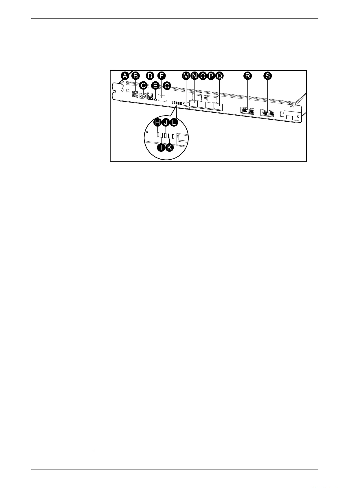
Controller Section
NOTE: Remove the front panel to access the controller section.
Front View of the Controller Section
A. Inverter ON/OFF buttons
B. USB ports2
C. Universal I/O2
D. Modbus port2
E. USB Micro-B port2
F. Network port2
G. Reset button2
H. Input status LED3
I. Inverter status LED3
J. Output status LED3
K. Bypass status LED3
L. Battery status LED3
M. Display power supply
N. Display port
O. Service port (only for service)
P. For future use
Q. For future use
R. PBUS 1
S. PBUS 2
990-5910B-001 15
2. Built-in network management card.
3. See Status LED Lighting per UPS Operation Mode, page 50.

UPS Operation Modes
Operation Modes
The Galaxy UPS has two different levels of operation modes:
•UPS mode: The operation mode of the individual UPS. See UPS Modes,
page 16.
•System mode: The operation mode of the complete UPS system that
supplies the load. See System Modes, page 18.
UPS Modes
Normal Operation
In normal operation, the UPS supports the load with conditioned power.
Battery Operation
If the utility/mains supply fails, the UPS transfers to battery operation and supports
the load with conditioned power from the DC source.
Requested Static Bypass Operation
The UPS can be transferred to requested static bypass operation following a
command from the display. During requested static bypass operation, the load is
supplied from the bypass source. If a fault is detected, the UPS will transfer to
normal operation or forced static bypass operation. If there is an interruption to the
utility/mains supply during requested static bypass operation, the UPS will transfer
to battery operation.
Forced Static Bypass Operation
The UPS is in forced static bypass operation following a command from the UPS
or because the user has pressed the inverter OFF button on the UPS. During
forced static bypass operation, the load is supplied from the bypass source.
NOTE: The batteries are not available as an alternate power source while the
UPS is in forced static bypass operation.
Internal Maintenance Bypass Operation via the Internal Maintenance Breaker IMB
When the internal maintenance breaker IMB is closed, the UPS transfers to
internal maintenance bypass operation. The load is supplied with unconditioned
power from the bypass source. Service and replacement can be performed on
power modules, the static bypass switch module, and on the controller box during
internal maintenance bypass operation via the internal maintenance breaker IMB.
The internal maintenance breaker IMB can only be used in single systems and in
simplified 1+1 parallel systems with no external maintenance bypass breaker.
NOTE: The batteries are not available as an alternate power source while the
UPS is in internal maintenance bypass operation.
External Maintenance Bypass Operation via the Maintenance Bypass Breaker MBB
When the maintenance bypass breaker MBB is closed in the external
maintenance bypass panel/cabinet or third party switchgear, the UPS transfers to
external maintenance bypass operation. The load is supplied with unconditioned
power from the bypass source. Service and replacement can be performed on the
entire UPS during external maintenance bypass operation via the maintenance
bypass breaker MBB.
16 990-5910B-001

Operation Modes UPS
NOTE: The batteries are not available as an alternate power source while the
UPS is in external maintenance bypass operation.
Static Bypass Standby Operation
Static bypass standby is only applicable to an individual UPS in a parallel system.
The UPS enters static bypass standby operation if the UPS is prevented from
entering forced static bypass operation and the other UPSs of the parallel system
can support the load. In static bypass standby the output of the specific UPS is
OFF. The UPS automatically transfers to the preferred operation mode when
possible.
NOTE: If the other UPSs cannot support the load, the parallel system
transfers to forced static bypass operation. The UPS in static bypass standby
operation will then transfer to forced static bypass operation.
Battery Test
The UPS is in battery test mode when the UPS is performing a battery self-test or
a runtime calibration.
NOTE: The battery test will be aborted if the utility/mains supply is interrupted
or if a critical alarm is present and the UPS will return to normal operation
upon return of utility/mains.
ECO Mode
ECO mode allows the UPS to be configured to use requested static bypass, with
the load supplied through the bypass, as the preferred operation mode under
predefined circumstances. If a fault is detected (bypass voltage out of tolerance,
output voltage out of tolerance, etc), the UPS will immediately transfer to normal
operation or forced static bypass. The main advantage of ECO mode is a
reduction in the consumption of electrical power. In case of interruption to the
utility/mains supply, the UPS transfers to battery operation for an uninterrupted
supply of the load. The batteries are charged when the UPS is in ECO mode.
NOTE: When changes to ECO mode settings are made on one UPS in a
parallel system, the settings are shared to all UPSs in the parallel system.
ECOnversion Mode
ECOnversion allows the UPS to supply the active part of the load through the
static bypass. The inverter is kept running in parallel with the bypass source and
supplies the reactive part of the load. The input power factor of the UPS is,
regardless of the load power factor, maintained close to unity as the reactive part
of the load is significantly reduced in the UPS input current. In case of an
interruption to the utility/mains supply, the inverter immediately maintains the
output voltage so that breaks or drops during the transfer from ECOnversion mode
are practically eliminated. The batteries are charged when the UPS is in
ECOnversion mode.
NOTE: When changes to ECOnversion mode settings are made on one UPS
in a parallel system, the settings are shared to all UPSs in the parallel system.
OFF Mode
The UPS is not supplying the load with power. The batteries are charged and the
display is on.
990-5910B-001 17

UPS Operation Modes
System Modes
The system mode indicates the output status of the complete UPS system
including the surrounding switchgear and indicates which source supplies the
load.
Inverter Operation
In inverter operation the load is supplied by the inverters. The UPS mode can be
in either normal or battery operation when the system operation mode is inverter
operation.
Requested Static Bypass Operation
When the system is in requested static bypass operation, the load is supplied from
the bypass source. If a fault is detected, the system will transfer to inverter
operation or forced static bypass operation.
Forced Static Bypass Operation
The system is in forced static bypass operation following a command from the
UPS system or because the user has pressed the inverter OFF button on the
UPSs. During forced static bypass operation, the load is supplied directly by the
bypass source with unconditioned power.
NOTE: The batteries are not available as an alternate power source while the
system is in forced static bypass operation.
Maintenance Bypass Operation
In maintenance bypass operation, the load is supplied directly by the bypass
source with unconditioned power.
NOTE: The batteries are not available as an alternate power source in
maintenance bypass operation.
ECO Mode
ECO mode allows the system to be configured to use requested static bypass
operation, with the load supplied through the bypass, as the preferred operation
mode under predefined circumstances. The main advantage of ECO mode is a
reduction in the consumption of electrical power. In case of interruption to the
utility/mains supply, the UPS transfers to inverter operation for an uninterrupted
supply of the load.
NOTE: When changes to ECO mode settings are made on one UPS in a
parallel system, the settings are shared to all UPSs in the parallel system.
ECOnversion Mode
ECOnversion allows the system to supply the active part of the load through the
bypass. The inverter is kept running in parallel with the bypass source and
supplies the reactive part of the load. The input power factor of the UPS is,
regardless of the load power factor, maintained close to unity as the reactive part
of the load is significantly reduced in the UPS input current. In case of an
interruption to the utility/mains supply, the inverter immediately maintains the
output voltage so that breaks or drops during the transfer from ECOnversion mode
are practically eliminated.
NOTE: When changes to ECOnversion mode settings are made on one UPS
in a parallel system, the settings are shared to all UPSs in the parallel system.
18 990-5910B-001

UPS Configuration
Configuration
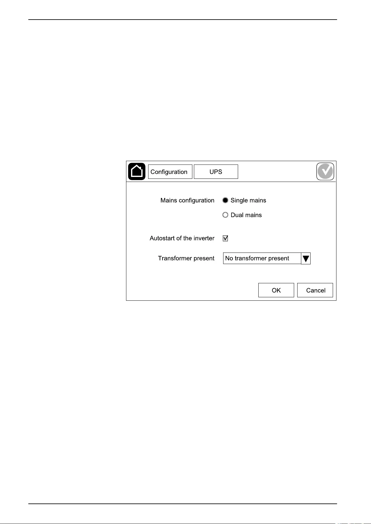
Configure the UPS Input
NOTE: This configuration is mandatory for correct UPS operation.
1. Tap Configuration > UPS.
a. Set the Mains configuration to Single mains or Dual mains.
b. Select Autostart of the inverter if you want to enable this function.
NOTE: When Autostart of the inverter has been enabled, the
inverter will start up automatically when input voltage returns, after a
shutdown due to drained battery.
c. Set Transformer present to No transformer present,Input
transformer, or Output transformer.
2. Tap OK to save your settings.
20 990-5910B-001

Configuration UPS
Configure the Output
NOTE: This configuration is mandatory for correct UPS operation.
1. Tap Configuration > Output.
a. Set the AC voltage ph-ph to 200VAC,208VAC,220VAC,380VAC,
400VAC,415VAC, or 480VAC depending on your configuration. (Not all
voltages are available in all regions.)
b. Set the Frequency to 50Hz ±1.0,50Hz ±3.0,50Hz ±10.0,60Hz ±1.0,
60Hz ±3.0, or 60Hz ±10.0 depending on your configuration.
c. Tap OK to save your settings and tap the arrow symbol to go to the next
page.
990-5910B-001 21
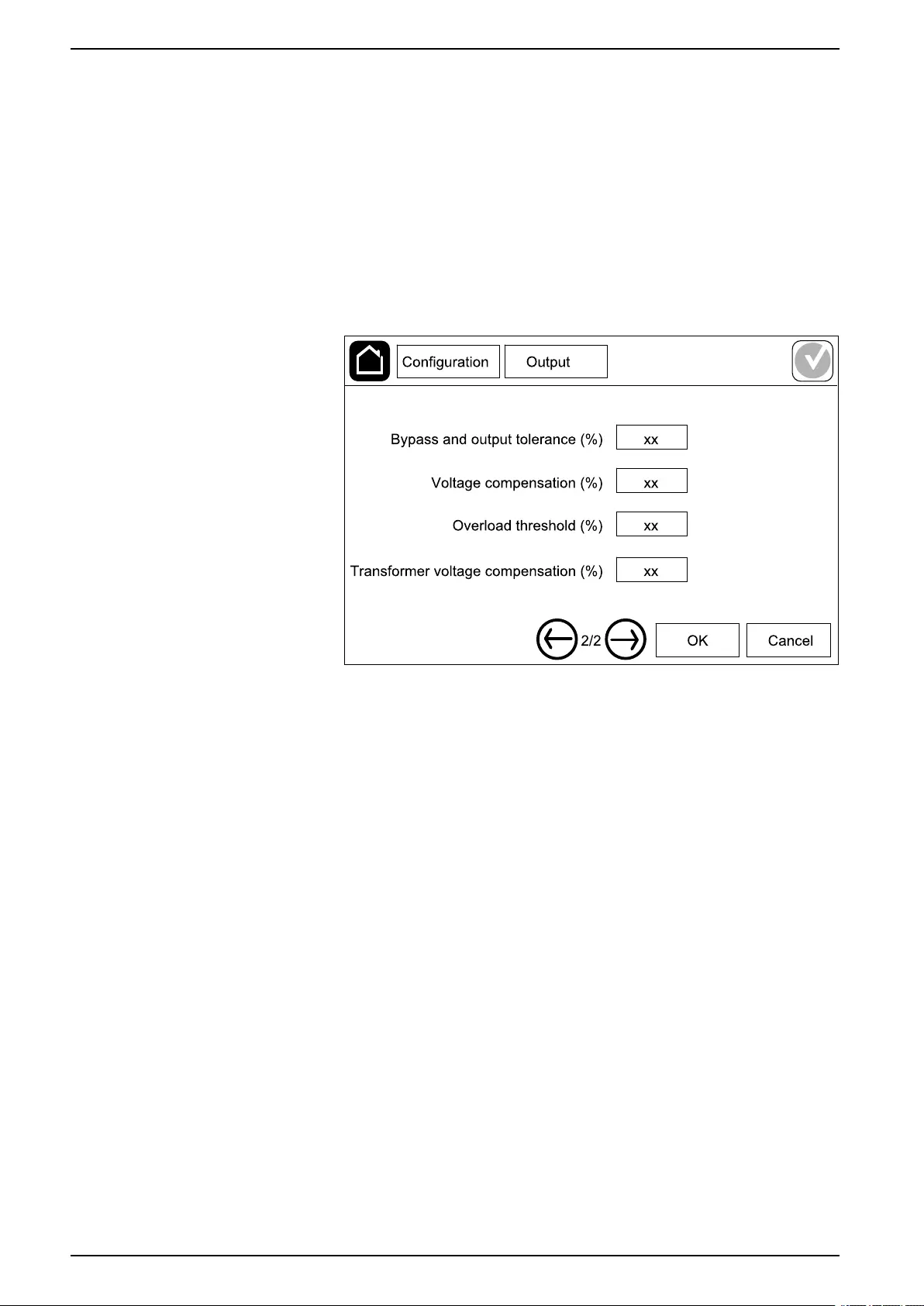
UPS Configuration
d. Set the Bypass and output tolerance (%). The bypass and output
tolerance range is +3% to +10%, default is +10%.
e. Set the Voltage compensation (%). The output voltage of the UPS can
be adjusted up to ±3% to compensate for different cable lengths.
f. Set the Overload threshold (%). The overload range is 0% to 100%,
default is 75%.
g. Set the Transformer voltage compensation (%). The transformer
voltage compensation range is 0% to 3%, default is 0%. See Output
Transformer Voltage Compensation, page 22 for more details and
Configure the UPS Input, page 20 for configuring that an output
transformer is present.
h. Tap OK to save your settings.
Output Transformer Voltage Compensation
It is possible to compensate for an output transformer and balance the output
voltage drop. The output transformer voltage compensation works without having
the UPS to measure the voltage on the secondary side of the transformer.
At 0% load you must measure the voltage on the secondary side of the
transformer, and the output voltage of the UPS is then manually adjusted via a
setting to offset compensation if necessary. Then load must be applied on the
UPS. You must measure the voltage on the secondary side of the transformer
again, and the output voltage of the UPS must be adjusted via a setting to
compensate for the voltage drop in the transformer. The voltage compensation
required at the specific load is used to make an automatic linear output voltage
adjustment on the UPS according to the output load percentage.
22 990-5910B-001
Configuration UPS
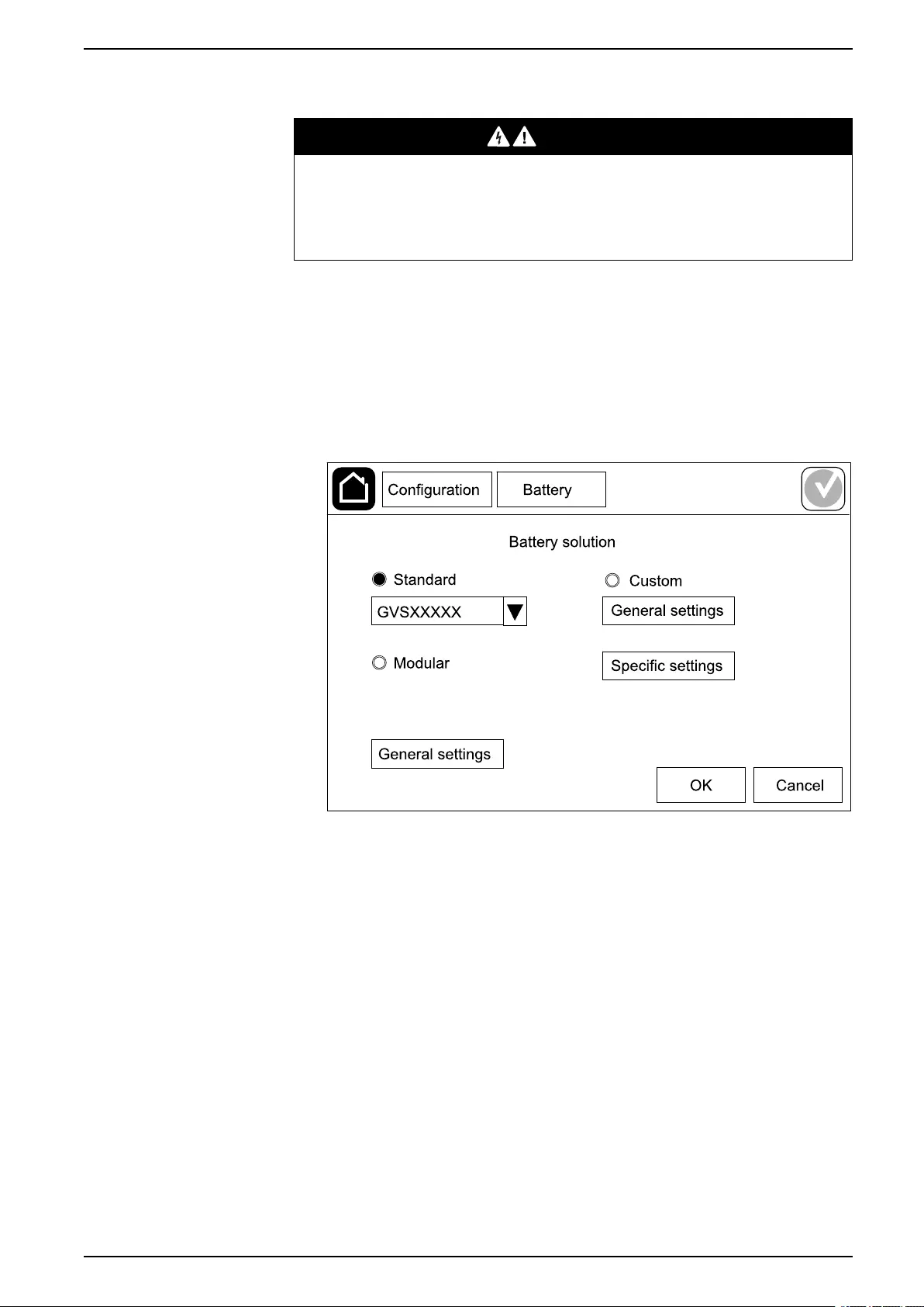
Configure the Battery Solution
DANGER
HAZARD OF ELECTRICAL SHOCK, EXPLOSION, OR ARC FLASH
Battery settings must only be entered by qualified personnel knowledgeable of
batteries, battery configuration, and the required precautions.
Failure to follow these instructions will result in death or serious injury.
1. Tap Configuration > Battery.
2. Select your battery solution type:
a. Select Standard if you have a standard Galaxy VS battery solution and
choose the commercial reference for your specific battery configuration
from the drop-down list.
b. Select Modular if you have a modular Galaxy VS battery solution.
c. Select Custom if you have a custom battery solution.
990-5910B-001 23

UPS Configuration
3. Tap General settings and set up the following parameters:
NOTE: On each page, tap OK to save your settings and tap the arrow
symbol to go to the next page. Only the first three settings are available
for modular battery solutions.
Number of battery cabinets connected to the
battery breaker/Number of modular battery
cabinets
Set the number of battery cabinets connected to each
battery breaker/Set the number of modular battery
cabinets connected to the UPS.
Low runtime warning (sec) Set the threshold for remaining runtime in seconds
that will activate the low runtime warning.
Charge capacity (%) Set the maximum charge capacity in percentage of
the UPS nominal power rating.
Minimum threshold (°C) Set the minimum acceptable battery temperature in
Celsius or Fahrenheit. Temperatures below this
threshold will activate an alarm.
Maximum threshold (°C) Set the maximum acceptable battery temperature in
Celsius or Fahrenheit. Temperatures above this
threshold will activate an alarm.
Charger autoboost mode Select to enable charger autoboost mode. This
function will automatically transfer the charger to
boost charger mode after the system has been in
battery operation.
Cyclic charge mode Select to enable cyclic charge mode.
During a cyclic charge, the system cycles between
periods of float charging and resting. This function will
continuously maintain the battery charge status
without stressing the batteries by conducting a
permanent float charging.
Test interval every Set how often the UPS should run a battery test.
Test day of the week Set on which day of the week the battery test should
run.
Test start time (hh:mm) Set which time of day the battery test should run.
24 990-5910B-001

Configuration UPS
4. Only for custom battery solution: Tap Specific settings and set up the
following parameters:
NOTE: On each page, tap OK to save your settings and tap the arrow
symbol to go to the next page.
Battery type Select the battery type.
Battery midpoint connected Select if a battery midpoint is connected.
Disable temperature monitoring Select to disable battery temperature monitoring.
Battery capacity per block (Ah) Set the battery capacity per battery block in ampere
hours for the battery bank connected to each battery
breaker.
Number of parallel battery strings Set the number of battery strings connected in parallel
for the battery bank connected to each battery
breaker.
Number of battery blocks per string Set the number of battery blocks per battery string.
Number of battery cells per block Set the number of battery cells in a battery block.
DC voltage per battery cell (V) Set the charging voltage per battery cell for Float
charging.
Float charging is the basic charging function available
on all types of batteries and automatically initiated by
the charger.
Set the charging voltage per battery cell for Boost
charging.
Boost charging makes it possible to conduct a fast
charging in order to quickly restore a discharged
battery.
Set the charging voltage per battery cell for
Equalization charging.
Equalization charging is used when equalizing
skewed open cell batteries. This is the charging
method available using the highest possible charging
voltage level. When equalization charging is
conducted, water is evaporated from the open cell
batteries which must be replaced when charging is
completed.
Charge duration (sec) Set the duration in seconds of the charge for Boost
charging and Equalization charging.
DC shutdown voltage per battery cell (V) Set the voltage level per battery cell for when the
battery must be shut down.
Nominal temperature (°C)/Nominal temperature (°
F)
Set the nominal temperature in Celsius or Fahrenheit.
Charge current rate Set the charge current rate.
Allow boost charge Select to allow boost charge of the batteries.
Boost charging makes it possible to conduct a fast
charging in order to quickly restore a discharged
battery.
990-5910B-001 25

UPS Configuration
Allow battery deep discharge Select to allow deep discharge of the batteries when
the UPS is in battery operation. This function allows to
discharge the batteries to an even lower voltage level
than the normally recommended value. Note that this
may damage the batteries.
Enable battery automatic disconnect Select to enable automatic disconnection of the
batteries. When the UPS system is left with output off
and no ability to charge the batteries, this function will
trip the battery breakers to avoid battery deep
discharge after a period of:
• Two weeks.
• 10 minutes with the battery cell voltage below the
low battery shutdown level.
Configure High Efficiency Mode
1. Tap Configuration > High efficiency.
2. Select the High efficiency mode:Disable,ECO mode, or ECOnversion.
NOTE: Contact Schneider Electric to enable ECO mode.
3. Select ECOnversion harmonics compensator, if relevant.
4. Select the High efficiency schedule:Active on schedule,Always active,
or Never active.
a. For Active on schedule, tap Schedule and set up and enable the
schedule(s) as needed.
26 990-5910B-001
Configuration UPS
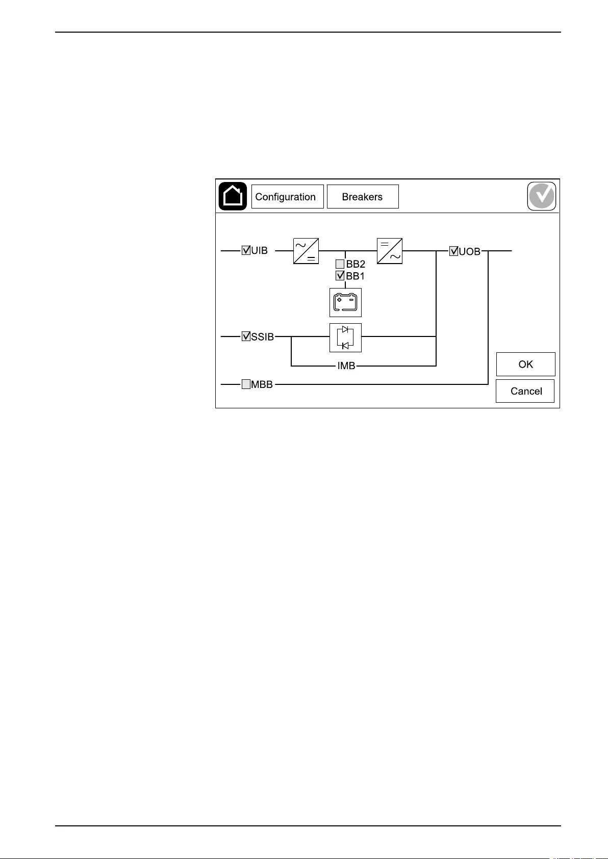
Configure the Breakers
NOTE: This configuration is mandatory for correct UPS operation.
1. Tap Configuration > Breakers.
2. Tap the different breakers in the mimic diagram to configure which breakers
are present in the UPS system. Square with a √ means that the breaker is
present, empty square means that the breaker is not present, grayed out
square means that the breaker is automatically configured in your UPS
system.
NOTE: The UPS can monitor up to two battery breakers in a standard
battery solution. The UPS can monitor up to four battery breakers in a
modular battery solution – this is configured automatically by the UPS.
The mimic diagram only shows one battery breaker BB even if more
battery breakers have been connected and configured for monitoring. If
one or more of the monitored battery breakers are in the closed position,
the BB on the mimic diagram will show as closed. If all of the monitored
battery breakers are in the open position, the BB on the mimic diagram
will show as open.
3. Tap OK to save your settings.
990-5910B-001 27
UPS Configuration
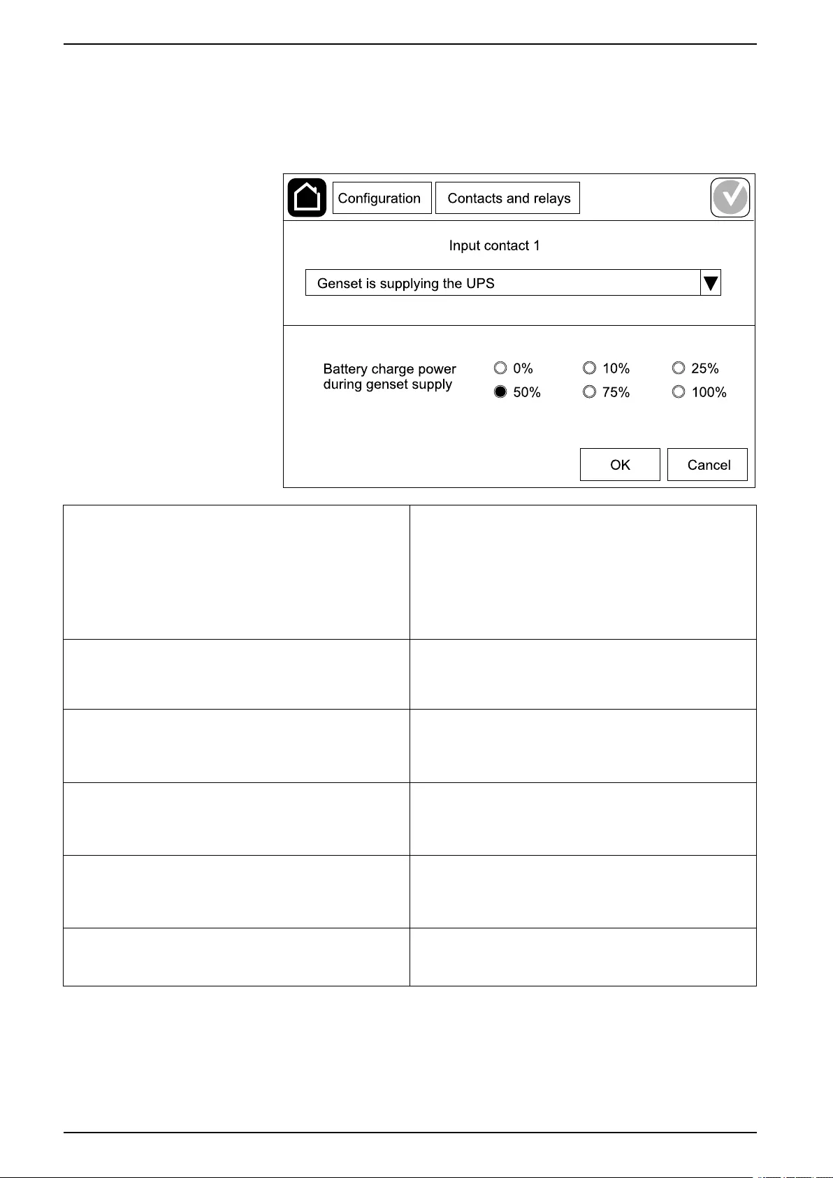
Configure the Input Contacts
1. Tap Configuration > Contacts and relays and select the input contact that
you want to configure.
2. Select a function from the drop-down list for the selected input contact:
None: No action assigned to this input contact. Genset is supplying the UPS: Input to indicate that
the UPS is being supplied by a generator. You must
also select the reduction in battery charge current
while the UPS is being supplied by a generator. Set
Battery charge power during genset supply to 0%
(no battery charging), 10%,25%,50%,75%, or 100%
(full battery charging). Battery charge power during
genset supply is only selectable for this function.
Ground fault: Input to indicate that a ground fault is
present. Battery room ventilation is inoperable: Input to
indicate that the battery room ventilation is inoperable.
When the input is active, the battery charger will turn
OFF.
User-defined 1: General purpose input. External battery monitoring detected a fault: Input
to indicate that the external battery monitoring has
detected a fault. When the input is active, the UPS will
post an alarm (no other action).
User-defined 2: General purpose input. High efficiency mode is disabled: If this input is
activated, the UPS is prevented from entering high
efficiency mode (ECO mode and ECOnversion mode)
or will exit any active high efficiency mode.
External energy storage monitoring detected a
minor fault: Input to indicate that the external energy
storage monitoring has detected a minor fault.
External signal turns charger off: If this input is
activated, the charger will turn OFF on a signal from
external equipment, e.g. on a signal from the external
energy storage.
External energy storage monitoring detected a
major fault: Input to indicate that the external energy
storage monitoring has detected a major fault.
Transformer temperature is too high: Input to
indicate that there is a high temperature alarm for the
transformer.
3. Tap OK to save your settings.
28 990-5910B-001
Configuration UPS
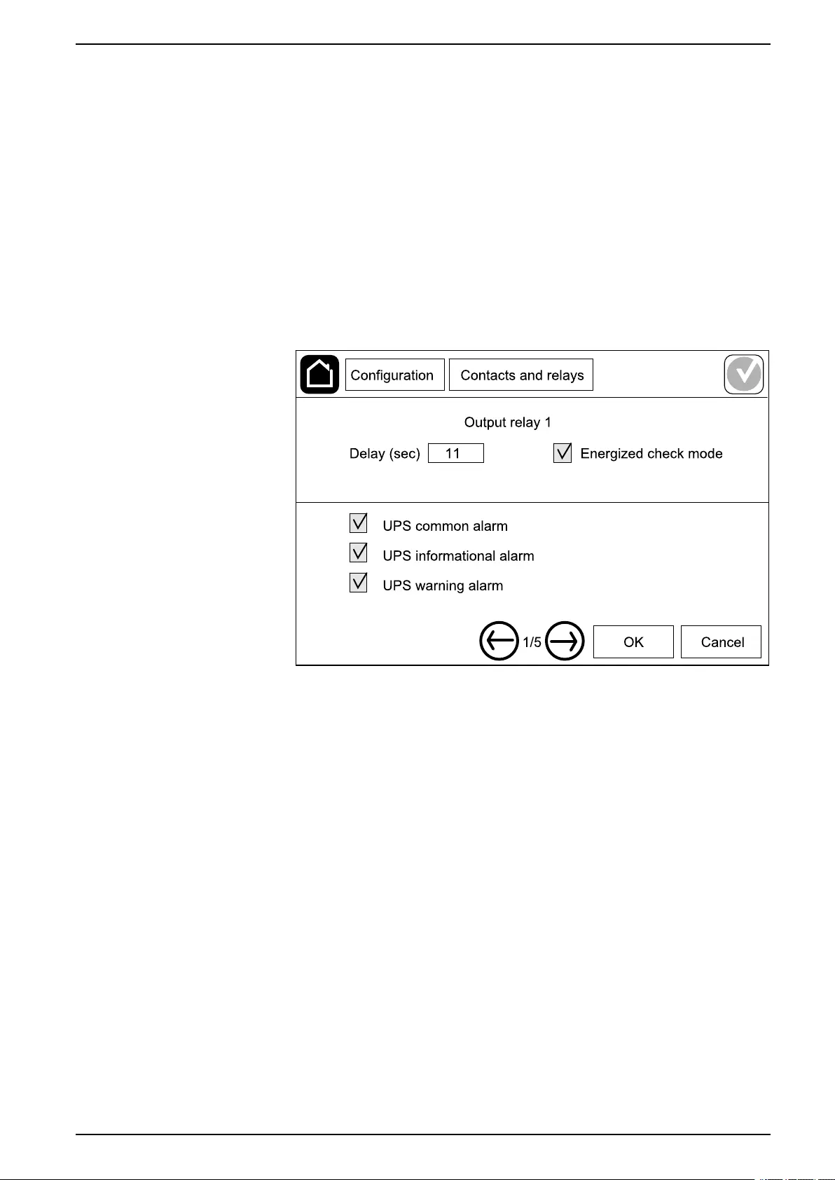
Configure the Output Relays
1. Tap Configuration > Contacts and relays and select the output relay that
you want to configure.
2. Set the Delay (sec).
3. Select to enable or disable Energized check mode.
– When Energized check mode is enabled the output relay is ON. If a
signal is received or the power supply to the output relay is lost, the circuit
will open and the output relay will be deactivated.
– When Energized check mode is disabled the output relay is OFF. If a
signal is received, the circuit will close and the output relay will be
activated.
4. Select the function(s) you want to assign to the output relay. On each page,
tap OK to save your settings and tap the arrow symbol to go to the next page.
990-5910B-001 29

UPS Configuration
NOTE: It is possible to assign several functions to the same output relay.
UPS common alarm: The output is triggered when
any alarm is present for the UPS. UPS in maintenance mode: The output is triggered
when the unit output breaker UOB has been opened
which transfers the UPS to maintenance mode. The
UPS is not supplying the load.
UPS informational alarm: The output is triggered
when an information alarm is present for the UPS. External fault: The output is triggered the UPS
detects an external fault.
UPS warning alarm: The output is triggered when a
warning alarm is present for the UPS. Fan inoperable: The output is triggered when one or
more fans are inoperable.
UPS critical alarm: The output is triggered when a
critical alarm is present for the UPS. Battery voltage low: The output is triggered when the
battery voltage is below the threshold.
System common alarm: The output is triggered
when any alarm is present for the system. Battery is not working correctly: The output is
triggered when the batteries are not working correctly.
System informational alarm: The output is triggered
when an information alarm is present for the system. Battery is disconnected: The output is triggered
when the batteries have been disconnected or the
battery breaker(s) are open.
System warning alarm: The output is triggered when
a warning alarm is present for the system. Inverter overload: The output is triggered when there
is an overload condition, while the UPS is in inverter
operation.
System critical alarm: The output is triggered when a
critical alarm is present for the system. Output overload: The output is triggered when there
is an overload condition, while the UPS is in inverter
operation or bypass operation.
UPS in normal operation: The output is triggered
when the UPS is in normal operation. Input out of tolerance: The output is triggered when
the input is out of tolerance.
UPS in battery operation: The output is triggered
when the UPS is in battery operation. Bypass out of tolerance: The output is triggered
when the bypass is out of tolerance.
UPS in static bypass operation: The output is
triggered when the UPS is in forced static bypass
operation or requested static bypass operation.
EPO active: The output is triggered when the EPO
has been activated.
UPS in maintenance bypass operation: The output
is triggered when the UPS is in internal maintenance
bypass operation or external maintenance bypass
operation.
5. Tap OK to save your settings.
30 990-5910B-001
Configuration UPS
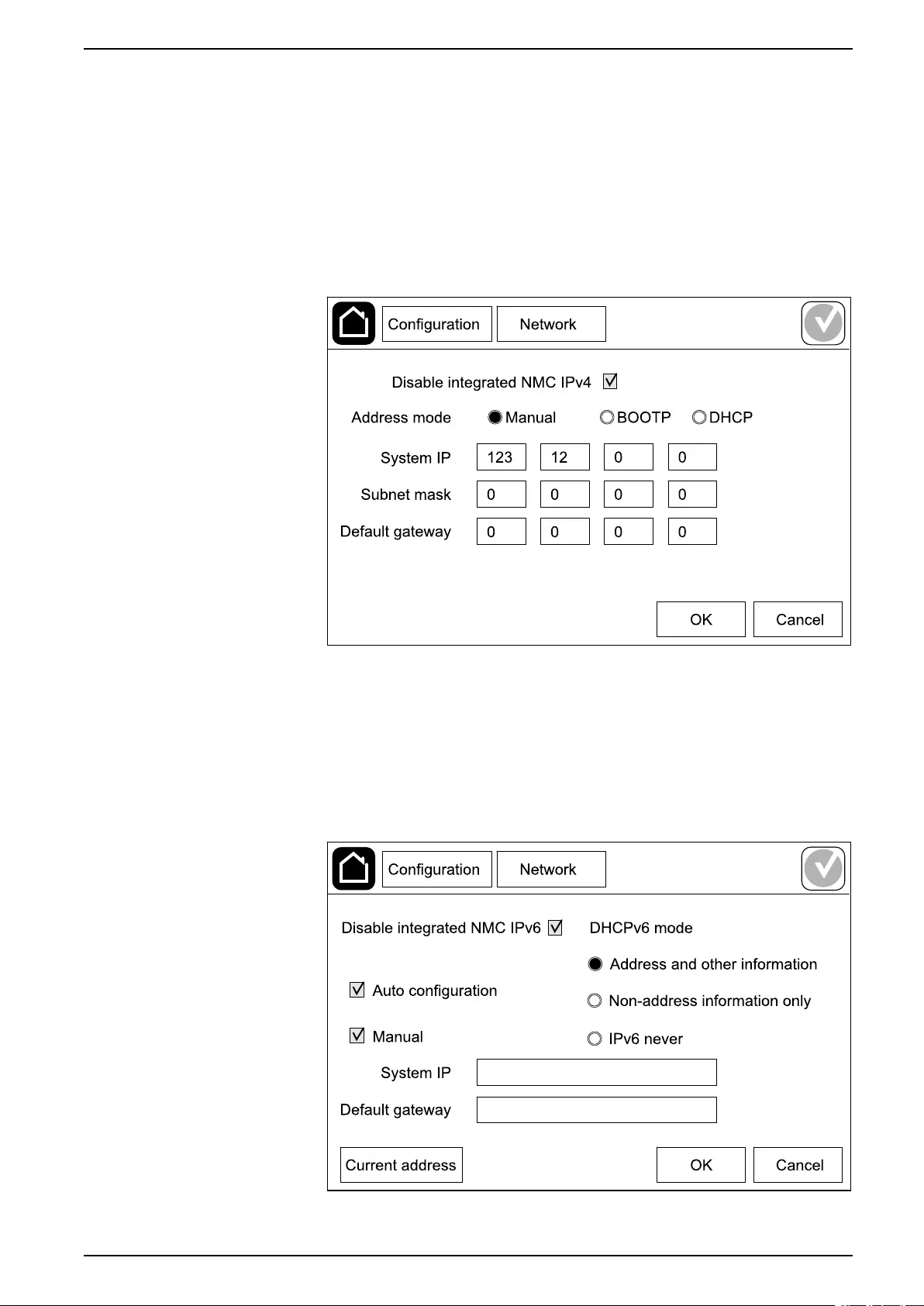
Configure the Network
The network can be configured for the integrated network management card
(NMC).
1. Tap Configuration > Network > Integrated NMC IPv4.
a. Set the Address mode to Manual,BOOTP, or DCHP.
b. You can also disable the network by selecting Disable integrated NMC
IPv4.
c. Tap OK to save your settings.
2. Tap Configuration > Network > Integrated NMC IPv6.
a. Set the DHCPV6 mode to Address and other information,Non-
address information only, or IPv6 never.
b. Select Auto configuration or Manual.
c. You can also disable the network by selecting Disable integrated NMC
IPv6
d. Tap OK to save your settings.
990-5910B-001 31
UPS Configuration
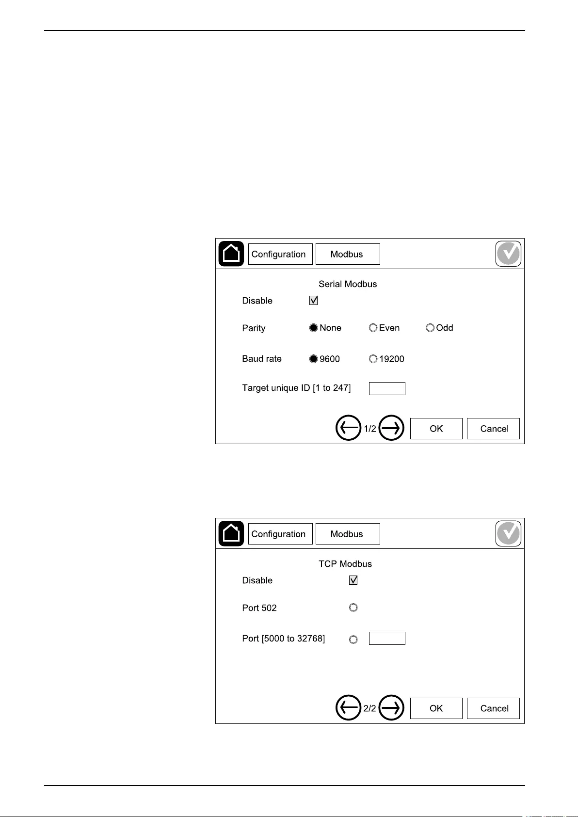
Configure the Modbus
The Modbus can be configured for the integrated network management card
(NMC).
1. Tap Configuration > Modbus > Integrated NMC Modbus.
a. Enable or disable Serial Modbus.
b. Set the Parity to None,Even, or Odd.
c. Set the Baud rate to 9600 or 19200.
d. Set the Target unique ID to a number between 1 and 247.
NOTE: Every device on the bus must have exactly the same settings
except the device address Target unique ID, which must be unique
for every device. No two devices on the bus can have the same
address.
e. Tap OK to save your settings and tap the arrow symbol to go to the next
page.
f. Enable or disable TCP Modbus.
g. Select Port 502 or Port [5000 to 32768].
h. Tap OK to save your settings.
32 990-5910B-001

Configuration UPS
Set the UPS Name
1. Tap Configuration > General > UPS name.
2. Set the UPS name.
3. Tap OK to save your settings.
Set the Date and Time
1. Tap Configuration > General > Date and time.
2. Set the Year,Month,Day,Hour,Minute, and Second.
3. Tap OK to save your settings.
Configure the Display Preferences
1. Tap Configuration > General > Display.
a. Set the temperature unit to Celsius or Fahrenheit.
b. Tap the - or + to set the display brightness.
c. Set the Alarm sound to Enable or Disable. This will enable/mute all
alarm sounds.
d. Set the Touch screen sound to Enable or Disable. This will enable/
mute all display sounds (excluding alarm sounds).
990-5910B-001 33
UPS Configuration
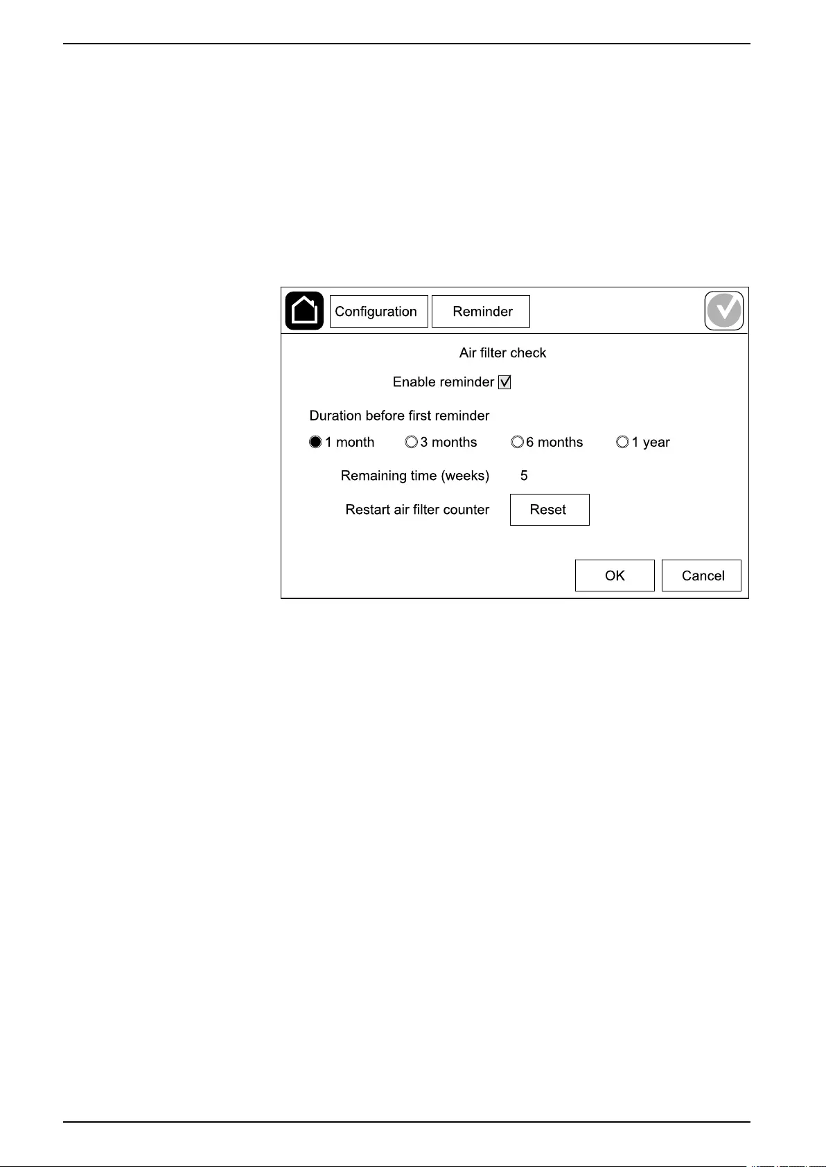
Configure the Air Filter Reminder
When the air filter has been replaced, reset the air filter reminder.
1. Tap Configuration > Reminder.
a. Select Enable reminder to get reminders about replacing the air filter.
b. Select the reminder interval: 1 month,3 months,6 months, or 1 year
based on the installation room environment.
Under Remaining time (weeks) you can see how much service life the
air filter in use has left.
c. Tap Reset to reset the air filter service life counter.
2. Tap OK to save your settings.
Save the UPS Settings on a USB Device
NOTE: The UPS can only accept settings that were originally saved from the
same UPS. Settings saved from other UPSs can not be reused.
1. Tap Configuration > Save/restore.
2. Open the front panel.
3. Insert your USB device in USB port 1 on the UPS.
4. Tap Save to save the present UPS settings on the USB device.
NOTE: Do not remove the USB device until the save process has
finished.
34 990-5910B-001
Configuration UPS
Restore the UPS Settings from a USB Device
NOTE: The UPS can only accept settings that were originally saved from the
same UPS. Settings saved from other UPSs cannot be reused.
Settings can only be restored when the UPS is in maintenance bypass
operation or off mode.
NOTE: Do not open the unit input breaker UIB at the end of the shutdown
sequence as this will turn off the power to the display.
1. Tap Control > Guided sequences > Shut down UPS system or Control >
Guided sequences > Shut down a UPS in a parallel system, and follow
the steps which appear on the display.
2. Select Configuration > Save/restore.
3. Open the front panel.
4. Insert your USB device in one of the USB ports on the UPS.
5. Tap Restore to implement saved UPS settings from the USB device. Wait for
the controller to reboot automatically.
NOTE: Do not remove the USB device until the restore process has
finished.
6. Select Control > Guided sequences > Start up UPS system or Control >
Guided sequences > Start up a UPS in a parallel system, and follow the
steps which appear on the display.
Set the Display Language
1. Tap the flag symbol in the bottom right corner.
2. Tap your language.
990-5910B-001 35


Operation Procedures UPS
Operation Procedures
Start Up the UPS System from Off Mode
NOTE: Use this procedure to start up a UPS from Off mode with no supplied
load. If you are starting up the UPS with load supplied via MBB or IMB, please
follow the procedure described in Start Up the UPS System from Maintenance
Bypass Operation, page 38.
1. Close the unit input breaker UIB.
The display turns on. The rebooting sequence lasts approximately 3 minutes.
2. Close the static switch input breaker SSIB (if present).
3. Close the battery breakers (if present).
4. Close the unit output breaker UOB.
5. Close the system input breaker SIB (if present).
6. Turn on the inverter by pressing the inverter ON button on the controller box
or by following Turn the Inverter ON, page 37.
Transfer the UPS from Normal Operation to Static Bypass
Operation
1. Select Control > Operation mode > Transfer to bypass operation.
2. Tap OK on the confirmation screen.
Transfer the UPS from Static Bypass Operation to Normal
Operation
1. Select Control > Operation mode > Transfer to normal operation.
2. Tap OK on the confirmation screen.
Turn the Inverter OFF
IMPORTANT: This will turn off the supply to the load.
1. Select Control > Inverter > Inverter off.
2. Tap OK on the confirmation screen.
Turn the Inverter ON
1. Select Control > Inverter > Inverter on.
2. Tap OK on the confirmation screen.
990-5910B-001 37

UPS Operation Procedures
Set the Charger Mode
1. Tap Control > Charger.
2. Tap Float,Boost, or Equalization.
3. Tap OK on the confirmation screen.
Shut Down the UPS System into Maintenance Bypass Operation
NOTE: Only operate a breaker when the associated breaker indicator lamp is
illuminated.
1. Tap Control > Guided sequences > Shut down UPS system or Control >
Guided sequences > Shut down a UPS in a parallel system, and follow
the steps which appear on the display.
Start Up the UPS System from Maintenance Bypass Operation
NOTE: Only operate a breaker when the associated breaker indicator lamp is
illuminated.
1. If open, close the unit input breaker UIB.
The display turns on. The rebooting sequence lasts approximately 3 minutes.
2. Select Control > Guided sequences > Start up UPS system or Control >
Guided sequences > Start up a UPS in a parallel system, and follow the
steps which appear on the display.
Access a Configured Network Management Interface
The network management card web interface is compatible with:
Windows® operating systems:
• Microsoft® Internet Explorer® (IE) 10.x or higher, with compatibility view
turned on.
• The latest release of Microsoft Edge
All operating systems:
• The latest releases of Mozilla® Firefox® or Google® Chrome®
The below procedure describes how to access the network management interface
from a web interface. If enabled, it is also possible to use the following interfaces:
• SSH
• SNMP
• FTP
• SFTP
NOTE: Please visit www.schneider-electric.com to view the Security
Deployment Guidelines and Security Handbook for the product.
The network management card supports NTP connection for synchronization of
time. Ensure that only one network management interface in the entire UPS
system (single or parallel) is set to synchronize time.
You can use either of the following protocols when you use the web interface:
• The HTTP protocol (disabled by default), which provides authentication by
user name and Pin but no encryption.
• The HTTPS protocol (enabled by default), which provides extra security
through Secure Socket Layer (SSL); encrypts user names, Pin, and data
38 990-5910B-001

Operation Procedures UPS
being transmitted; and authenticates network management cards by means
of digital certificates.
See Enable HTTP/HTTPS Protocols, page 39.
By default, SNMP protocols are disabled on the network management card to
avoid cybersecurity risks. SNMP protocols must be enabled to use the monitoring
functions of the network management card, or to connect to EcoStruxure IT
Gateway or StruxureWare Data Center Expert. You can enable and use either of
these SNMP protocols:
• SNMPv1, which provides minimal security. If using this protocol, Schneider
Electric recommends customizing the access control parameters to enhance
security.
• SNMPv3, which provides extra security through both encryption and
authentication. Schneider Electric recommends using this protocol for better
security and customizing the access control parameters.
See Enable SNMP Protocols, page 39.
Enable HTTP/HTTPS Protocols
1. Access the network management interface by its IP address (or its DNS
name, if a DNS name is configured).
2. Enter the user name and password. The default user name and password is
apc. You will be prompted to change this password on the first login.
3. To enable or disable the HTTP or HTTPS protocol, go to Configuration >
Network > Web > Access, select the protocol, set the parameters, and click
on Apply.
Enable SNMP Protocols
1. Access the network management interface by its IP address (or its DNS
name, if a DNS name is configured).
2. Enter the user name and password. The default user name and password is
apc. You will be prompted to change this password on the first login.
3. To enable SNMPv1 protocol:
a. Go to Configuration > Network > SNMPv1 > Access, select Enable
and click on Apply
b. Go to Configuration > Network > SNMPv1 > Access Control and set
up the parameters.
4. To enable SNMPv3 protocol:
a. Go to Configuration > Network > SNMPv3 > Access, select Enable
and click on Apply.
b. Go to Configuration > Network > SNMPv3 > Access Control and set
up the parameters.
c. Go to Configuration > Network > SNMPv3 > User Profiles and set up
the parameters.
NOTE: The SNMPv1 or SNMPv3 settings must match your settings on the
EcoStruxure IT Gateway or StruxureWare Data Center Expert for the network
management card 4 to communicate correctly with EcoStruxure IT Gateway or
StruxureWare Data Center Expert.
990-5910B-001 39
UPS Operation Procedures
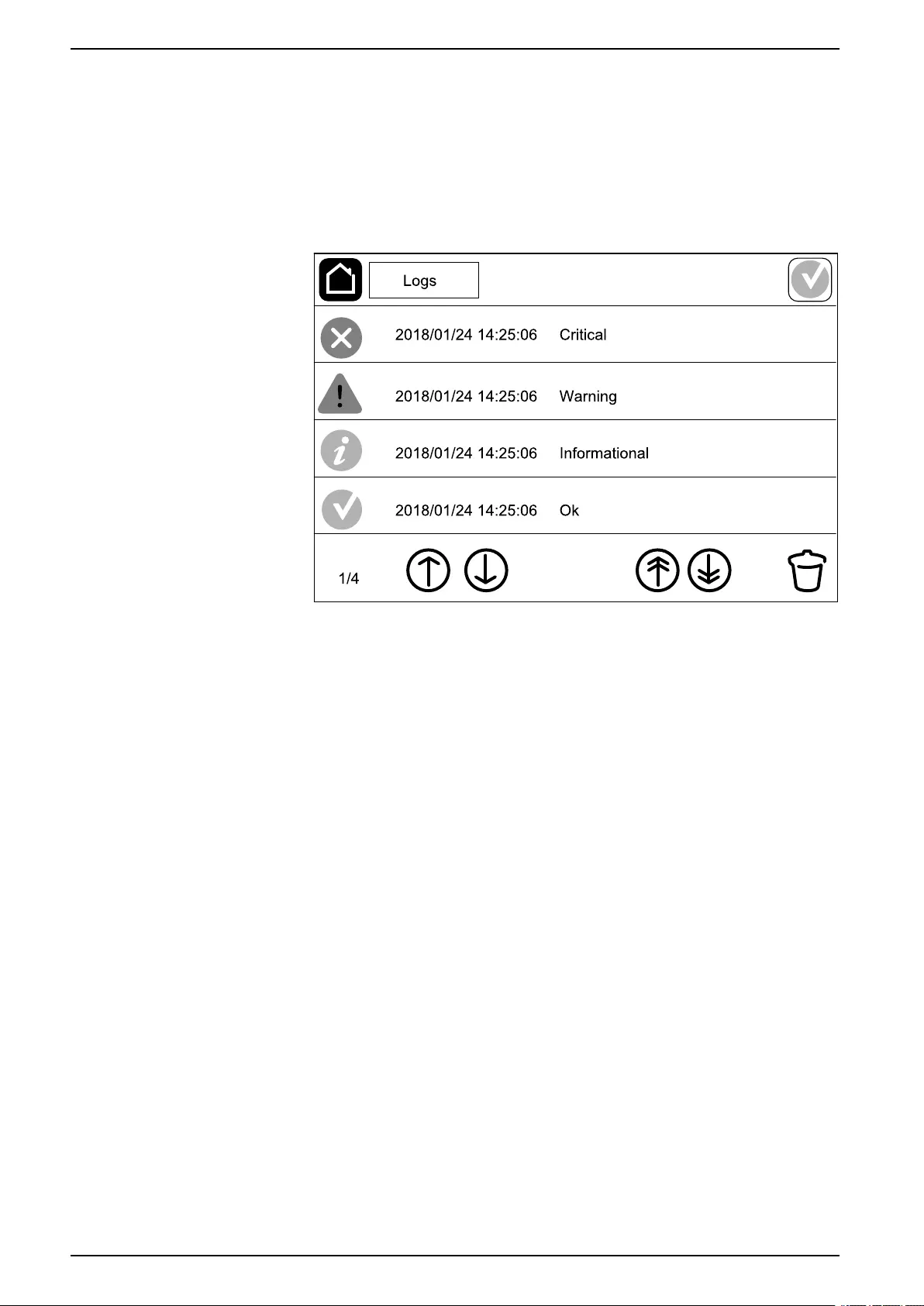
View the Logs
1. Tap Logs. The log shows the lastest 100 events with the newest events at the
top of the list.
a. Tap the arrow buttons to go to the next or previous page.
b. Tap the double arrow buttons to go the first or last page.
c. Tap the recycle bin button to delete all events stored in the log.
40 990-5910B-001

Operation Procedures UPS
View the System Status Information
1. Tap Status.
a. Tap Input,Output,Bypass,Battery,Temperature, or Parallel to see
the status.
Input
Voltage ph-ph (phase-to-phase) The present phase-to-phase input voltage.
Current The present input current from the AC utility power source per phase in
amperes (A).
Frequency The present input frequency in hertz (Hz).
Voltage ph-N (phase-to-neutral)4The present phase-to-neutral input voltage in volts (V).
Total power The present total active power input (for all three phases) in kW.
Power The present active power (or real power) input for each phase in
kilowatts (kW). Active power is the portion of power flow that, averaged
over a complete cycle of the AC waveform, results in net transfer of
energy in one direction.
Peak current The input peak current in amperes (A)
Power factor The ratio of the active power to apparent power.
Energy The total energy consumption since the time of installation.
Output
Voltage ph-ph (phase-to-phase) The phase-to-phase output voltage at the inverter in volts (V).
Current The present output current for each phase in amperes (A).
Frequency The present output frequency in hertz (Hz).
Voltage ph-N (phase-to-neutral)4The phase-to-neutral output voltage at the inverter in volts (V).
Load The percentage of the UPS capacity presently used across all phases.
The load percentage for the highest phase load is displayed.
Neutral current4The present output neutral current in amperes (A).
Total power The present active total output power (for all three phases) in kilowatts
(kW).
Power The present active power (or real power) output for each phase in
kilowatts (kW). Active power is the portion of power flow that, averaged
over a complete cycle of the AC waveform, results in net transfer of
energy in one direction.
Peak current The output peak current in amperes (A).
Power factor The present output power factor for each phase. Power factor is the ratio
of active power to apparent power.
Energy The total energy supplied since the time of installation.
Crest factor The present output crest factor for each phase. The output crest factor is
the ratio of the peak value of the output current to the RMS (root mean
square) value.
990-5910B-001 41
4. Only applicable in systems with neutral connection.

UPS Operation Procedures
Bypass
Voltage ph-ph (phase-to-phase)5The present phase-to-phase bypass voltage (V).
Current The present bypass current for each phase, in amperes (A).
Frequency The present bypass frequency in hertz (Hz).
Voltage ph-N (phase-to-neutral) The present phase-to-neutral bypass voltage (V).
Total power The present total active bypass power (for all three phases) in kilowatts
(kW).
Power The present active bypass power for each phase in kilowatts (kW).
Active power is the time average of the instantaneous product of voltage
and current.
Peak current The bypass peak current in amperes (A).
Power factor The present bypass power factor for each phase. Power factor is the
ratio of active power to apparent power.
Battery
Measurements The present DC power being drawn from the battery, in kilowatts (kW).
The present battery voltage (VDC).
The present battery current in amperes (A). A positive current indicates
that the battery is charging; a negative current indicates that the battery
is discharging.
Battery temperature from the connected temperature sensors in Celsius
or Fahrenheit.
Battery The amount of time before the batteries reach the low-voltage shutdown
level. Also shows charge level of the battery as a percentage of full
charge capacity.
The present battery charge (Ah).
Configuration Shows battery type. For a modular battery, tap the Details button in this
field to see the modular battery details. See View the Modular Battery
Status, page 44.
Status The general condition of the charger.
Mode The operation mode of the charger (Off,Float,Boost,Equalization,
Cyclic,Test).
Charging capacity The maximum charge capacity in percentage of the UPS nominal power
rating.
Temperature
Ambient temperature Ambient temperature in Celsius or Fahrenheit.
Battery temperature Battery temperature in Celsius or Fahrenheit from the connected
temperature sensors.
Parallel
Input current The present input current from the input source per phase in amperes
(A).
Bypass current The present bypass current from the bypass source per phase in
amperes (A).
42 990-5910B-001
5. Only applicable in systems with neutral connection.

Operation Procedures UPS
Parallel (Continued)
Total output power The total output power of the parallel UPS system showing the total load
percentage and the total output power in kW and kVA for the parallel
system.
Output current The present output current for each phase in amperes (A).
Number of redundant UPSs The number of redundant UPSs present.
Redundancy setting The configured redundancy setting.
990-5910B-001 43
UPS Operation Procedures
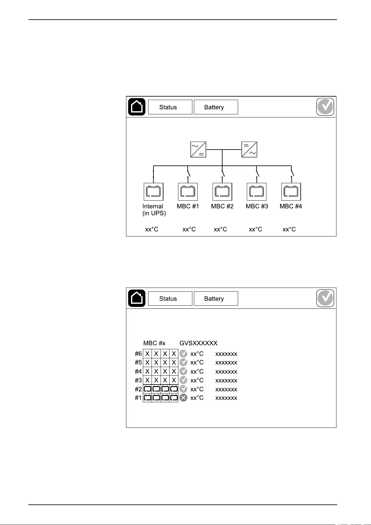
View the Modular Battery Status
1. Select Status > Battery > Details. An overview of the modular battery
solution is shown. You can see the battery breaker status for each modular
battery cabinet and for the modular batteries inside the UPS (only available
for UPS models for internal batteries). If the battery symbol is red, it means
that an alarm exists for modular batteries in the modular battery cabinet or in
the UPS. The temperature shown on this screen is the highest battery string
temperature measured in the modular battery cabinet/UPS.
2. Tap the battery symbol named Internal (in UPS) (only present for UPS
models for internal batteries) to see the information for modular batteries in
the UPS or tap the battery symbol named MBC # x to see the information for
modular battery cabinet x. You will then be able to see details for each battery
string such as number of installed battery modules, alarm presence,
temperature for each battery string, and battery module type.
44 990-5910B-001

Tests UPS
Tests
The UPS system can perform the following tests to ensure correct performance of
the system:
•Buzzer
•Status LEDs
•Breaker lamp
•Runtime calibration
•Battery
Tap the menu button on the home screen and select Maintenance and Buzzer, or
Status LEDs, or Breaker lamp to start the test of these functions. See Start a
Runtime Calibration Test, page 45 and Start a Battery Test, page 46 for details
and requirements for these tests.
Start a Runtime Calibration Test
This feature is used for calibrating the estimated remaining battery runtime value.
In this test, the UPS transfers to battery operation and the batteries are
discharged to the low DC warning level. Based on the elapsed time and
information about the load, the battery capacity can be calculated and the
estimated runtime calibrated.
Schneider Electric recommends performing a runtime calibration test at start-up,
when batteries are replaced, or when changes are made to the battery solution.
NOTICE
RISK OF EQUIPMENT DAMAGE
• During a runtime calibration test, the batteries are reduced to a very low
capacity and are therefore not capable of supporting the load in case of an
input power failure.
• Batteries will be discharged to 10% capacity and this will result in a short
battery runtime after the calibration until they are fully recharged.
• Repeated battery testing or calibration can affect the service life of the
battery.
Failure to follow these instructions can result in equipment damage.
Prerequisites:
• Batteries must be 100% charged.
• The load percentage must be at least 10% and must not change more than
20% during test. Example: If the load percentage is 30% at the start of the
test, the test will abort if the load percentage drops below 24% or rises above
36% during the test.
• The bypass supply must be available.
• The operation mode must be normal operation, ECOnversion, or ECO mode.
• The system operation mode must be inverter, ECOnversion, or ECO mode.
1. Tap the menu button on the home screen.
2. Select Maintenance > Runtime calibration > Start calibration.
3. Tap OK on the confirmation screen.
990-5910B-001 45

UPS Tests
Stop a Runtime Calibration Test
1. Tap the menu button on the home screen.
2. Select Maintenance > Runtime calibration > Stop calibration.
3. Tap OK on the confirmation screen.
Start a Battery Test
Prerequisites:
• The batteries must be more than 50% charged.
• The runtime available must be more than 4 minutes.
• The operation mode must be normal operation, ECOnversion, or ECO mode.
• The system operation mode must be inverter, ECOnversion, or ECO mode.
This feature performs a number of tests on the batteries, such as fuse-blown
check and weak battery detection. The test will discharge the batteries and use
about 10% of the total runtime capacity. Example: If you have 10 minutes of
runtime, the test will run for 1 minute. The Battery can be scheduled to run
automatically in different time intervals (from weekly and up to once a year). See
Configure the Battery Solution, page 23.
1. Tap the menu button on the home screen.
2. Select Maintenance > Battery > Start test.
3. Tap OK on the confirmation screen.
Stop a Battery Test
1. Tap the menu button on the home screen.
2. Select Maintenance > Battery > Stop test.
3. Tap OK on the confirmation screen.
46 990-5910B-001
Maintenance UPS
Maintenance
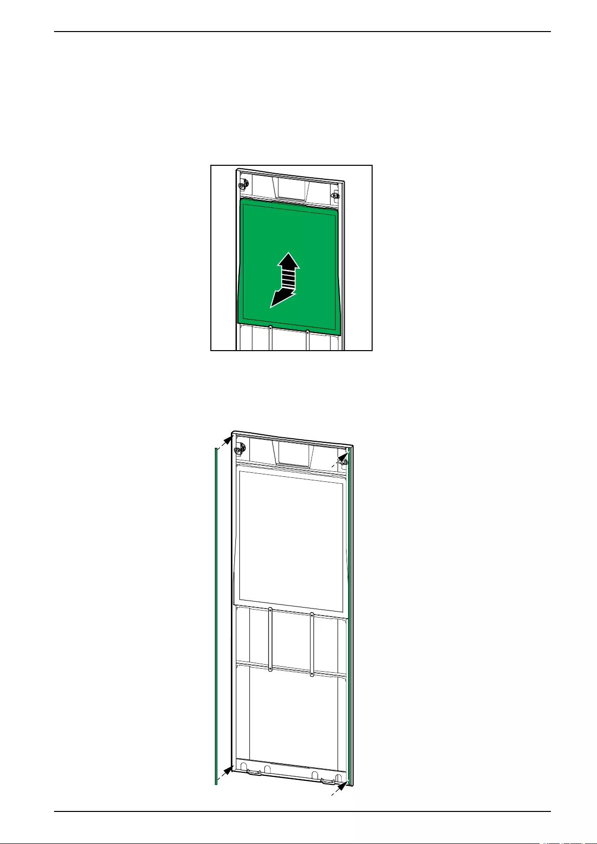
Replace the Air Filter
1. Open the front panel of the UPS.
2. Remove the air filter by pushing it upwards until you can ease it over the two
metal grips in the bottom and pull it out.
3. Hold the new air filter by the sides and insert the air filter by pushing it
upwards into the door frame until you can ease it in over the two metal grips.
4. Mount the two provided rubber gaskets on each side of the door as close to
the edge of the door frame as possible. Replace the rubber gaskets as
needed on the next replacement of the air filter.
990-5910B-001 47
UPS Maintenance
5. Close the front panel of the UPS.
6. Restart the air filter counter, see Configure the Air Filter Reminder, page 34.
Determine if you need a Replacement Part
To determine if you need a replacement part, contact Schneider Electric and
follow the procedure below so that the representative can assist you promptly:
1. In the event of an alarm condition, scroll through the alarm lists, record the
information, and provide it to the representative.
2. Write down the serial number of the unit so that you will have it easily
accessible when you contact Schneider Electric.
3. If possible, call Schneider Electric from a telephone that is within reach of the
display so that you can gather and report additional information to the
representative.
4. Be prepared to provide a detailed description of the problem. A representative
will help you solve the problem over the telephone, if possible, or will assign a
return material authorization (RMA) number to you. If a module is returned to
Schneider Electric, this RMA number must be clearly printed on the outside of
the package.
5. If the unit is within the warranty period and has been started up by Schneider
Electric, repairs or replacements will be performed free of charge. If it is not
within the warranty period, there will be a charge.
6. If the unit is covered by a Schneider Electric service contract, have the
contract available to provide information to the representative.
Find the Serial Numbers
1. Tap the menu button on the home screen.
2. Tap About.
3. Note down the serial number of the UPS cabinet and have it ready for
customer support.
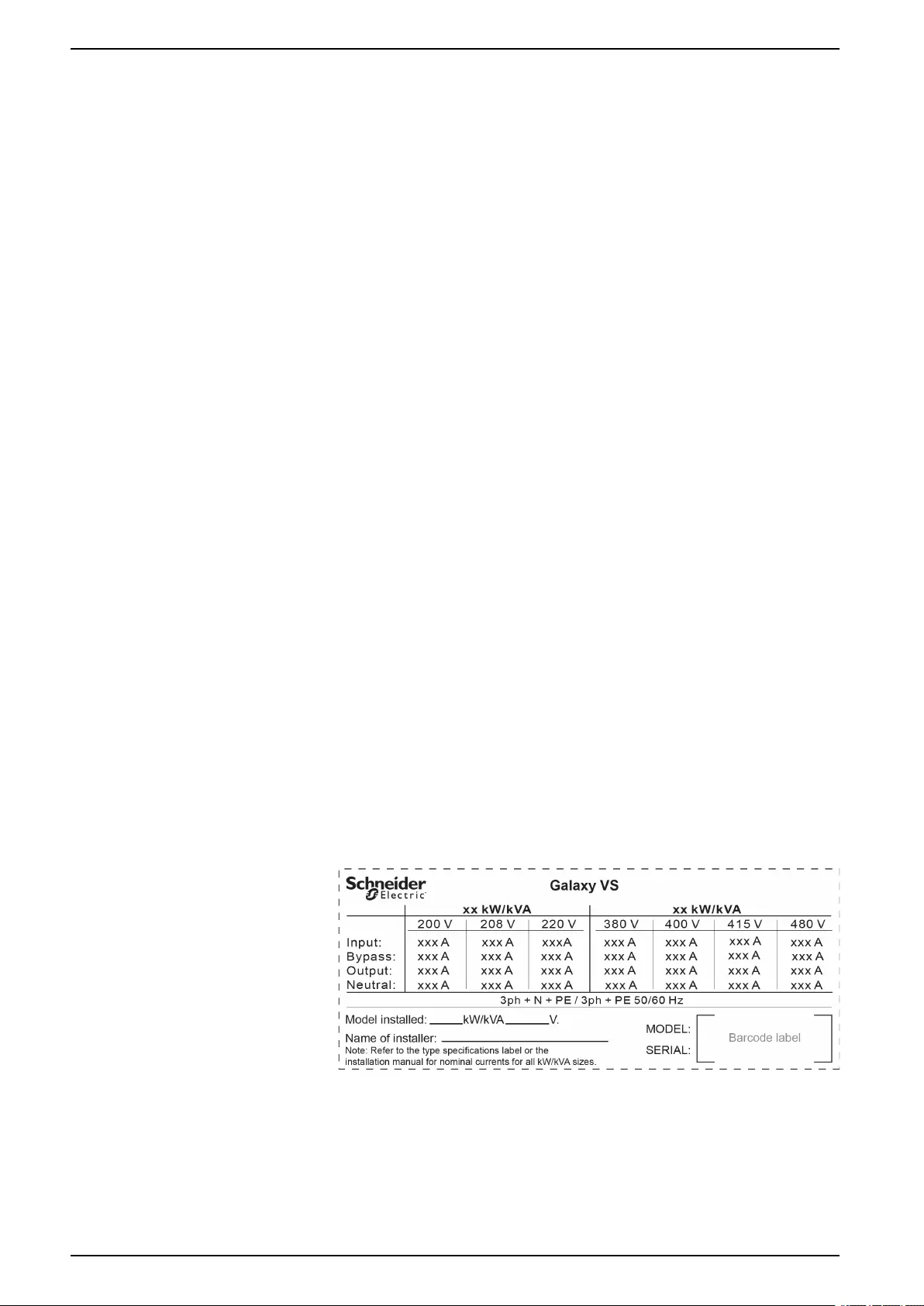
NOTE: If the display is not available, remove the front panel to find the
UPS serial number on the name plate label under SERIAL:.
Example of Name Plate Label for UPS
4. Tap the arrow to go to the next pages and note down the serial numbers of
the display and the network management card(s) and have them ready for
customer support.
48 990-5910B-001

Maintenance UPS
Return Parts to Schneider Electric
To return an inoperable part to Schneider Electric, contact Schneider Electric
customer support to obtain an RMA number.
Pack the part in the original shipping materials, and return it by insured, prepaid
carrier. The customer support representative will provide the destination address.
If you no longer have the original shipping materials, ask the representative about
obtaining a new set.
• Pack the part properly to avoid damage in transit. Never use styrofoam beads
or other loose packaging materials when shipping a part. The part may settle
in transit and become damaged.
• Enclose a letter in the package with your name, RMA number, address, a
copy of the sales receipt, description of the problem, a phone number, and a
confirmation for payment (if necessary).
NOTE: Damages sustained in transit are not covered under warranty.
990-5910B-001 49
UPS Troubleshooting
Troubleshooting
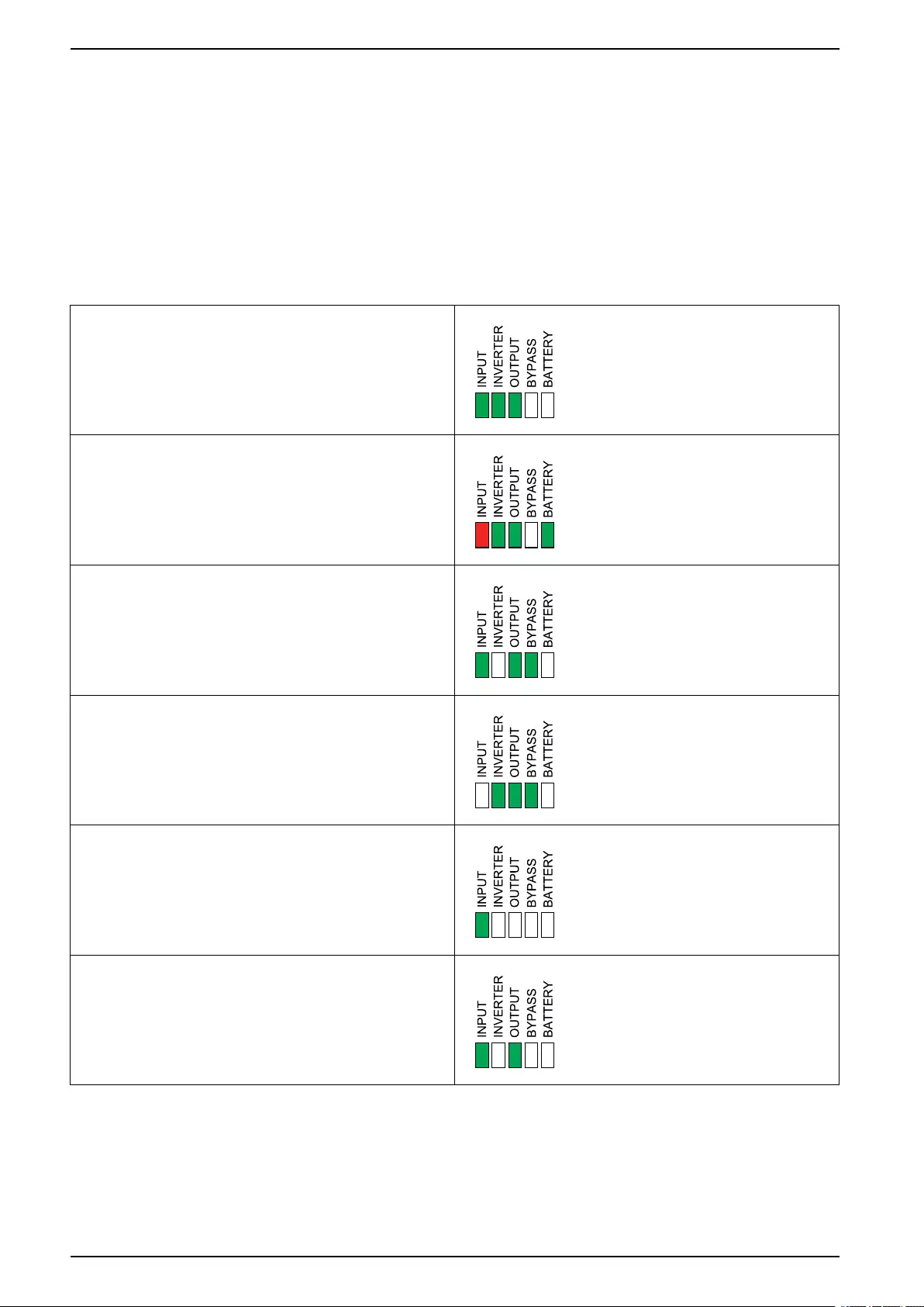
Status LED Lighting per UPS Operation Mode
If the display becomes inoperable, you can see the UPS operation mode via the
status LEDs behind the front panel.
• Green LED means function active.
• Off LED means function inactive.
• Red LED means function inoperable or in alarm condition.
Normal operation
Battery operation
Requested static bypass operation
Forced static bypass operation
ECO mode
ECOnversion mode
Off mode
Static bypass standby operation
50 990-5910B-001

Troubleshooting UPS
Export UPS Report to a USB Device
1. Select Maintenance > UPS report.
2. Open the front panel.
3. Insert your USB device in the USB port on the UPS.
4. Tap Export.
NOTE: Do not remove the USB device until the export process has
finished.
5. Send the UPS report to Schneider Electric customer support.
990-5910B-001 51

Schneider Electric
35 rue Joseph Monier
92500 Rueil Malmaison
France
+ 33 (0) 1 41 29 70 00
*990-5910B-001*
As standards, specifications, and design change from time to time,
please ask for confirmation of the information given in this publication.
© 2018 – 2019 Schneider Electric. All rights reserved.
990-5910B-001