Table of Contents
- Galaxy VX
- Important Safety Instructions — SAVE THESE INSTRUCTIONS
- Overview of UPS User Interface
- Operation Modes
- UPS Display
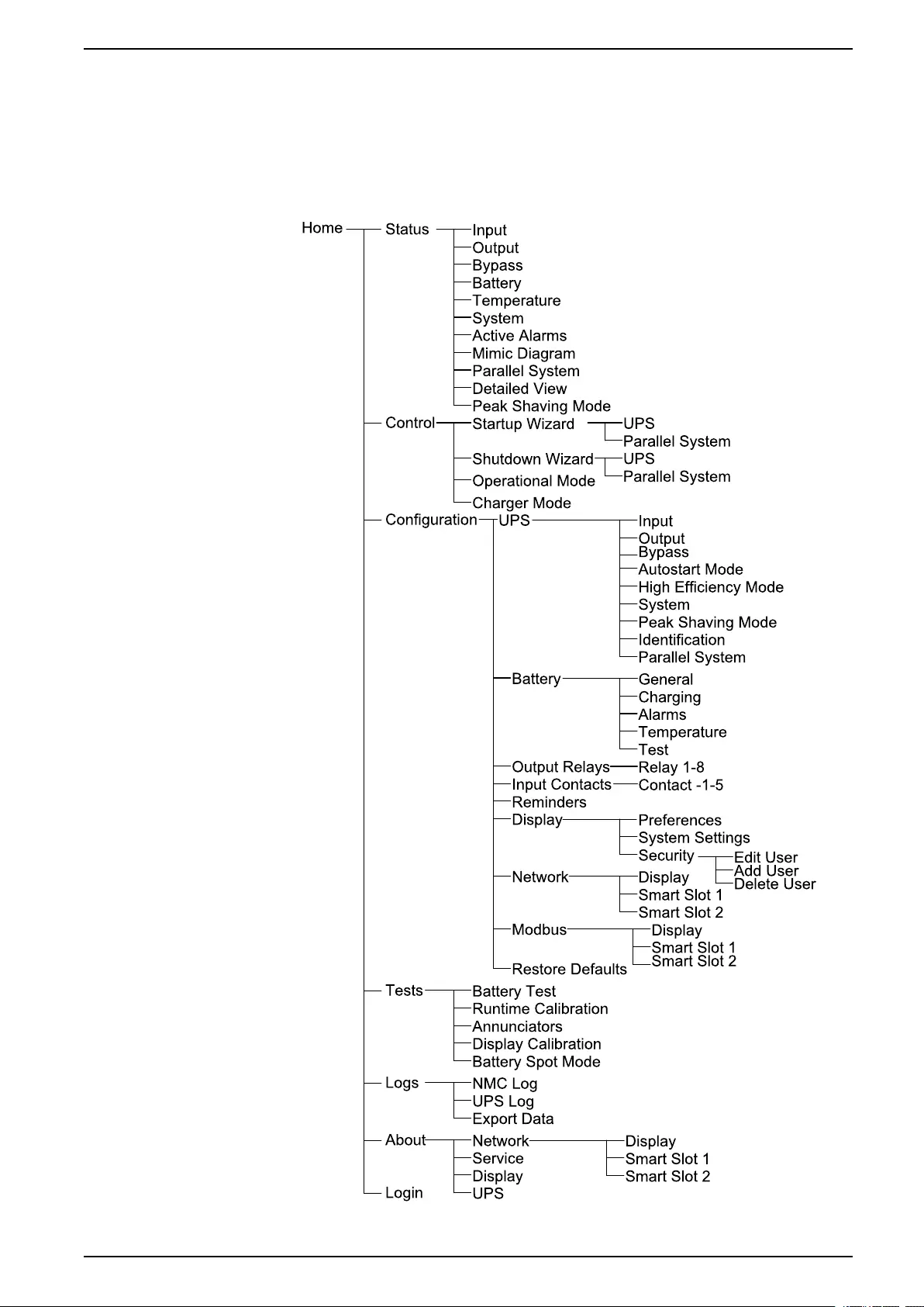
- UPS Display Menu Tree
- Configuration from the UPS Display
- Disable Password Request
- Add a New User or Edit an Existing User
- Delete a User
- Configure the Display Preferences
- Configure the Display Settings
- Configure the UPS Output Voltage Compensation
- Configure High Efficiency Mode
- Enable Peak Shaving Mode
- Set the UPS Identification
- Configure the Input Contacts
- Configure the Output Relays
- Configure Reminder Settings
- Configure Battery Alarm Threshold
- Configure Automatic Battery Test
- Configure the Network
- Configure the Modbus
- Restore Default Configuration
- Operation Procedures from the UPS Display
- Access Password-Protected Screens
- View the System Status Information
- Start Up Single System from Maintenance Bypass Operation
- Shut Down Single System from Normal to Maintenance Bypass Operation
- Transfer UPS from Normal to Requested Static Bypass Operation
- Transfer UPS from Requested Static Bypass Operation to Normal Operation
- Start Up Parallel System from Maintenance Bypass Operation
- Shut Down Parallel System from Normal to Maintenance Bypass Operation
- Start Up and Add UPS to a Running Parallel System
- Isolate this Single UPS from the Parallel System
- Start-Up System Operating as Frequency Converters
- Shut Down System Operating as Frequency Converters
- Start a Boost Charge of the Batteries
- Access a Configured Network Management Interface
- Troubleshooting from the UPS
- Tests
- 10” System Bypass Display
- 10” System Bypass Display Menu Tree (Option)
- Configuration from the 10” System Bypass Display (Option)
- Operation Procedures from the 10” System Bypass Display (Option)
- Access Password-Protected Screens
- View the Parallel System Status
- View System Bypass Status
- View UPS Status Information
- Transfer the Parallel System from Normal to Requested Static Bypass Operation
- Transfer the Parallel System from Requested Static Bypass to Normal Operation
- Connect to the 10” System Bypass Display Remotely
- Troubleshooting from the 10” System Bypass Display (Option)
- Maintenance
- Troubleshooting
APC GVX1250K1250GS User Manual
Displayed below is the user manual for GVX1250K1250GS by APC which is a product in the Uninterruptible Power Supplies (UPSs) category. This manual has pages.
Related Manuals
Galaxy VX
UPS System
Operation
04/2020
www.schneider-electric.com

Legal Information
The Schneider Electric brand and any trademarks of Schneider Electric SE and its
subsidiaries referred to in this guide are the property of Schneider Electric SE or its
subsidiaries. All other brands may be trademarks of their respective owners.
This guide and its content are protected under applicable copyright laws and
furnished for informational use only. No part of this guide may be reproduced or
transmitted in any form or by any means (electronic, mechanical, photocopying,
recording, or otherwise), for any purpose, without the prior written permission of
Schneider Electric.
Schneider Electric does not grant any right or license for commercial use of the guide
or its content, except for a non-exclusive and personal license to consult it on an "as
is" basis. Schneider Electric products and equipment should be installed, operated,
serviced, and maintained only by qualified personnel.
As standards, specifications, and designs change from time to time, information
contained in this guide may be subject to change without notice.
To the extent permitted by applicable law, no responsibility or liability is assumed by
Schneider Electric and its subsidiaries for any errors or omissions in the informational
content of this material or consequences arising out of or resulting from the use of the
information contained herein.

UPS System
Table of Contents
Important Safety Instructions — SAVE THESE
INSTRUCTIONS.........................................................................................5
FCC Statement ..........................................................................................6
Safety Precautions .....................................................................................6
Overview of UPS User Interface...............................................................7
Overview of Mimic Diagram.........................................................................8
Overview of Status LEDs.............................................................................8
Display Symbols.........................................................................................9
Operation Modes ......................................................................................10
UPS Operation Modes ..............................................................................10
System Operation Modes..........................................................................13
Frequency Converter Mode.......................................................................14
UPS Display...............................................................................................15
UPS Display Menu Tree............................................................................15
Configuration from the UPS Display ...........................................................16
Disable Password Request..................................................................16
Add a New User or Edit an Existing User ..............................................16
Delete a User .....................................................................................17
Configure the Display Preferences .......................................................17
Configure the Display Settings .............................................................18
Configure the UPS Output Voltage Compensation.................................18
Configure High Efficiency Mode ...........................................................19
Enable Peak Shaving Mode.................................................................20
Set the UPS Identification....................................................................21
Configure the Input Contacts ...............................................................22
Configure the Output Relays................................................................23
Configure Reminder Settings ...............................................................24
Configure Battery Alarm Threshold.......................................................25
Configure Automatic Battery Test .........................................................25
Configure the Network.........................................................................26
Configure the Modbus .........................................................................28
Restore Default Configuration..............................................................28
Operation Procedures from the UPS Display ..............................................29
Access Password-Protected Screens ...................................................29
View the System Status Information .....................................................29
Start Up Single System from Maintenance Bypass Operation.................33
Shut Down Single System from Normal to Maintenance Bypass
Operation...........................................................................................34
Transfer UPS from Normal to Requested Static Bypass
Operation...........................................................................................35
Transfer UPS from Requested Static Bypass Operation to Normal
Operation...........................................................................................35
Start Up Parallel System from Maintenance Bypass Operation ............... 36
Shut Down Parallel System from Normal to Maintenance Bypass
Operation...........................................................................................36
Start Up and Add UPS to a Running Parallel System .............................37
Isolate this Single UPS from the Parallel System ...................................37
990-5452H-001 3

UPS System
Start-Up System Operating as Frequency Converters............................38
Shut Down System Operating as Frequency Converters ........................ 38
Start a Boost Charge of the Batteries....................................................38
Access a Configured Network Management Interface ............................39
Troubleshooting from the UPS ...................................................................40
Troubleshooting via the Mimic Diagram LEDs .......................................40
Reboot the Display..............................................................................41
Logs ..................................................................................................41
View the Active Alarms........................................................................44
Tests .......................................................................................................50
Perform a Battery Test.........................................................................50
Perform a Runtime Calibration .............................................................51
Perform a Battery SPoT Mode Test ......................................................51
Perform an Annunciators Test ..............................................................52
Calibrate the Display ...........................................................................52
10” System Bypass Display.....................................................................53
10” System Bypass Display Menu Tree (Option) .........................................53
Configuration from the 10” System Bypass Display (Option) ........................53
Configure the Display Settings .............................................................53
Change the User Password .................................................................54
Change the System Names .................................................................55
Configure the Output Distribution Breakers ...........................................56
Operation Procedures from the 10” System Bypass Display (Option)............56
Access Password-Protected Screens ...................................................56
View the Parallel System Status...........................................................56
View System Bypass Status ................................................................58
View UPS Status Information ...............................................................58
Transfer the Parallel System from Normal to Requested Static
Bypass Operation ...............................................................................61
Transfer the Parallel System from Requested Static Bypass to
Normal Operation ...............................................................................62
Connect to the 10” System Bypass Display Remotely ............................62
Troubleshooting from the 10” System Bypass Display (Option).....................62
View the Display Log...........................................................................62
View the Parallel System Log...............................................................63
View the Active Alarms........................................................................64
Maintenance ..............................................................................................65
Replace the Top Filter ...............................................................................65
Replace the Three Bottom Filters...............................................................65
Troubleshooting ........................................................................................67
Determine if you need a Replacement Part.................................................67
Find the Serial Numbers ......................................................................67
Return Parts to Schneider Electric .............................................................67
4 990-5452H-001
Important Safety Instructions — SAVE THESE
INSTRUCTIONS UPS System
Important Safety Instructions — SAVE THESE
INSTRUCTIONS
Read these instructions carefully and look at the equipment to become familiar
with it before trying to install, operate, service or maintain it. The following safety
messages may appear throughout this manual or on the equipment to warn of
potential hazards or to call attention to information that clarifies or simplifies a
procedure.
The addition of this symbol to a “Danger” or “Warning” safety
message indicates that an electrical hazard exists which will result in
personal injury if the instructions are not followed.
This is the safety alert symbol. It is used to alert you to potential
personal injury hazards. Obey all safety messages with this symbol
to avoid possible injury or death.
DANGER
DANGER indicates a hazardous situation which, if not avoided, will result in
death or serious injury.
Failure to follow these instructions will result in death or serious injury.
WARNING
WARNING indicates a hazardous situation which, if not avoided, could result
in death or serious injury.
Failure to follow these instructions can result in death, serious injury, or
equipment damage.
CAUTION
CAUTION indicates a hazardous situation which, if not avoided, could result in
minor or moderate injury.
Failure to follow these instructions can result in injury or equipment
damage.
NOTICE
NOTICE is used to address practices not related to physical injury. The safety
alert symbol shall not be used with this type of safety message.
Failure to follow these instructions can result in equipment damage.
Please Note
Electrical equipment should only be installed, operated, serviced, and maintained
by qualified personnel. No responsibility is assumed by Schneider Electric for any
consequences arising out of the use of this material.
A qualified person is one who has skills and knowledge related to the construction,
installation, and operation of electrical equipment and has received safety training
to recognize and avoid the hazards involved.
990-5452H-001 5
UPS System
Important Safety Instructions — SAVE THESE
INSTRUCTIONS
FCC Statement
NOTE: This equipment has been tested and found to comply with the limits for
a Class A digital device, pursuant to Part 15 of the FCC Rules. These limits
are designed to provide reasonable protection against harmful interference
when the equipment is operated in a commercial environment. This equipment
generates, uses, and can radiate radio frequency energy and, if not installed
and used in accordance with the instruction manual, may cause harmful
interference to radio communications. Operation of this equipment in a
residential area is likely to cause harmful interference in which case the user
will be required to correct the interference at his own expense.
Any changes or modifications not expressly approved by the party responsible for
compliance could void the user’s authority to operate the equipment.
Safety Precautions
DANGER
HAZARD OF ELECTRICAL SHOCK, EXPLOSION OR ARC FLASH
All safety instructions in this document must be read, understood and followed.
Failure to follow these instructions will result in death or serious injury.
DANGER
HAZARD OF ELECTRICAL SHOCK, EXPLOSION OR ARC FLASH
After the UPS system has been electrically wired, do not start up the system.
Start-up must only be performed by Schneider Electric.
Failure to follow these instructions will result in death or serious injury.
6 990-5452H-001

Overview of UPS User Interface UPS System
Overview of UPS User Interface
The user interface consists of:
A. Display interface
B. Status LEDs
C. Mimic diagram
D. Inverter ON button
E. Inverter OFF button
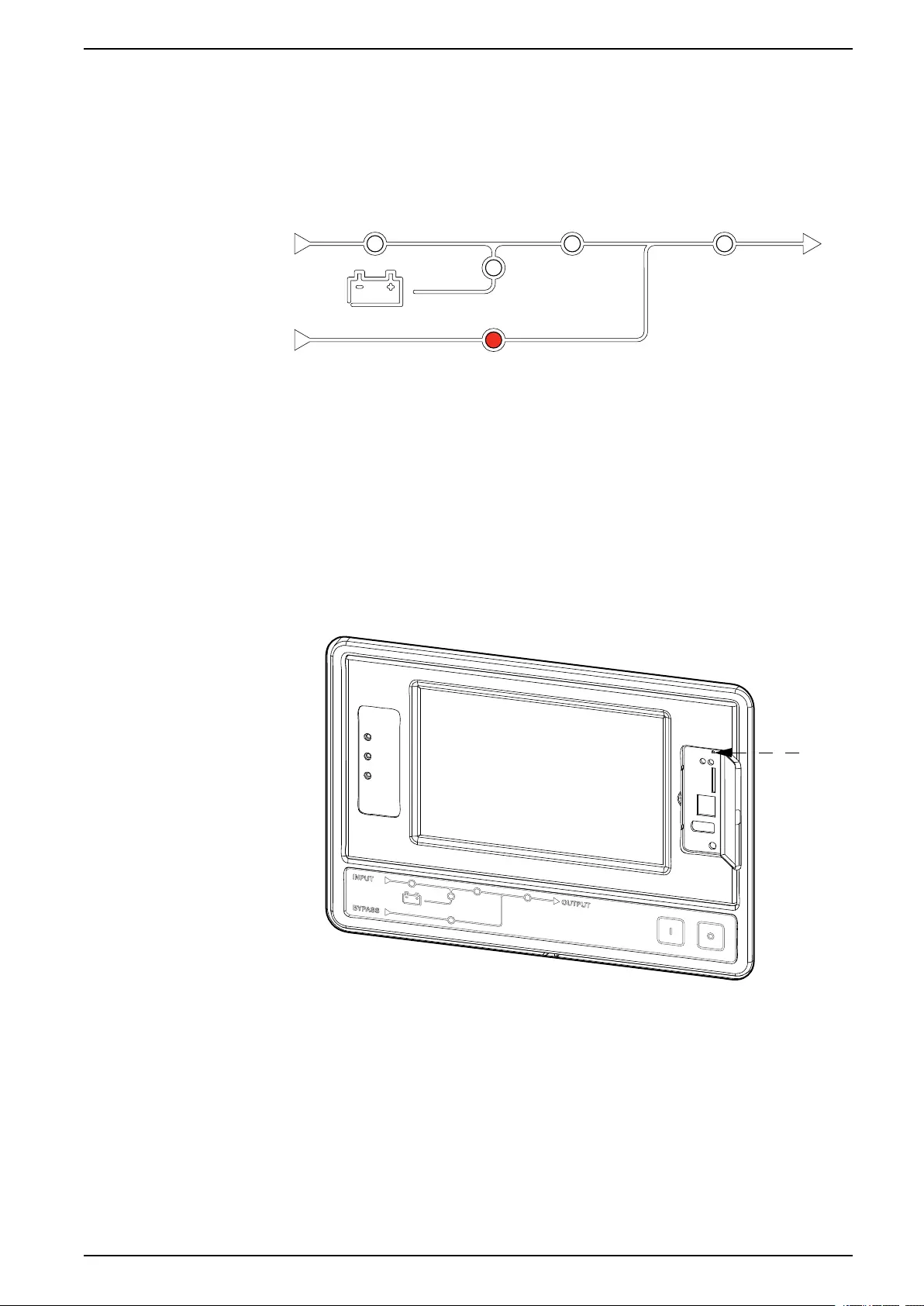
F. USB port for export of logs
G. Display reset button
H. Network connection LED:
• Solid green: The system has valid TCP/IP settings.
See Configure the Network, page 26.
• Flashing green: The system does not have valid TCP/IP settings.
• Solid orange: The display is inoperable. Contact Schneider Electric.
• Flashing orange: The system is making BOOTP requests.
See Configure the Network, page 26.
• Alternately flashing green and orange: If the LED is alternately flashing
slowly, the system is making DHCP requests.
See Configure the Network, page 26.
If the LED is alternately flashing rapidly, the system is starting up.
• Off: The display is not receiving input power or the display is inoperable.
I. LED for indication of network connection type:
• Solid green: The system is connected to a network operating at 10
Megabits per second (Mbps).
• Flashing green: The system is receiving or transmitting data packets at 10
Megabits per second (Mbps).
• Solid orange: The system is connected to a network operating at 100
Megabits per second (Mbps).
• Flashing orange: The system is receiving or transmitting data packets at
100 Megabits per second (Mbps).
• Off: One or more of the following exists: The display is not receiving input
power, the cable that connects the system to the network is disconnected,
the device that connects the system to the network is turned off, or the
display is inoperable. Check the connections and if the LED remains off,
contact Schneider Electric.
J. Slots reserved for service.
990-5452H-001 7
UPS System Overview of UPS User Interface
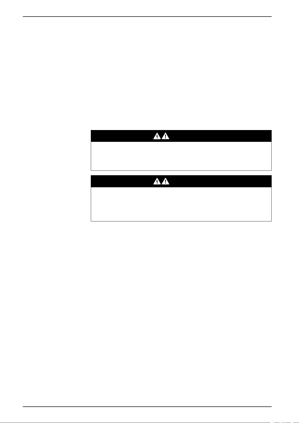
Overview of Mimic Diagram
The mimic diagram shows the power flow through the UPS system, and the status
of the main functions.
Each LED can be in one of the below three states:
Green The corresponding function is active and OK
Red The corresponding function is not working
properly
Off The corresponding function is not active
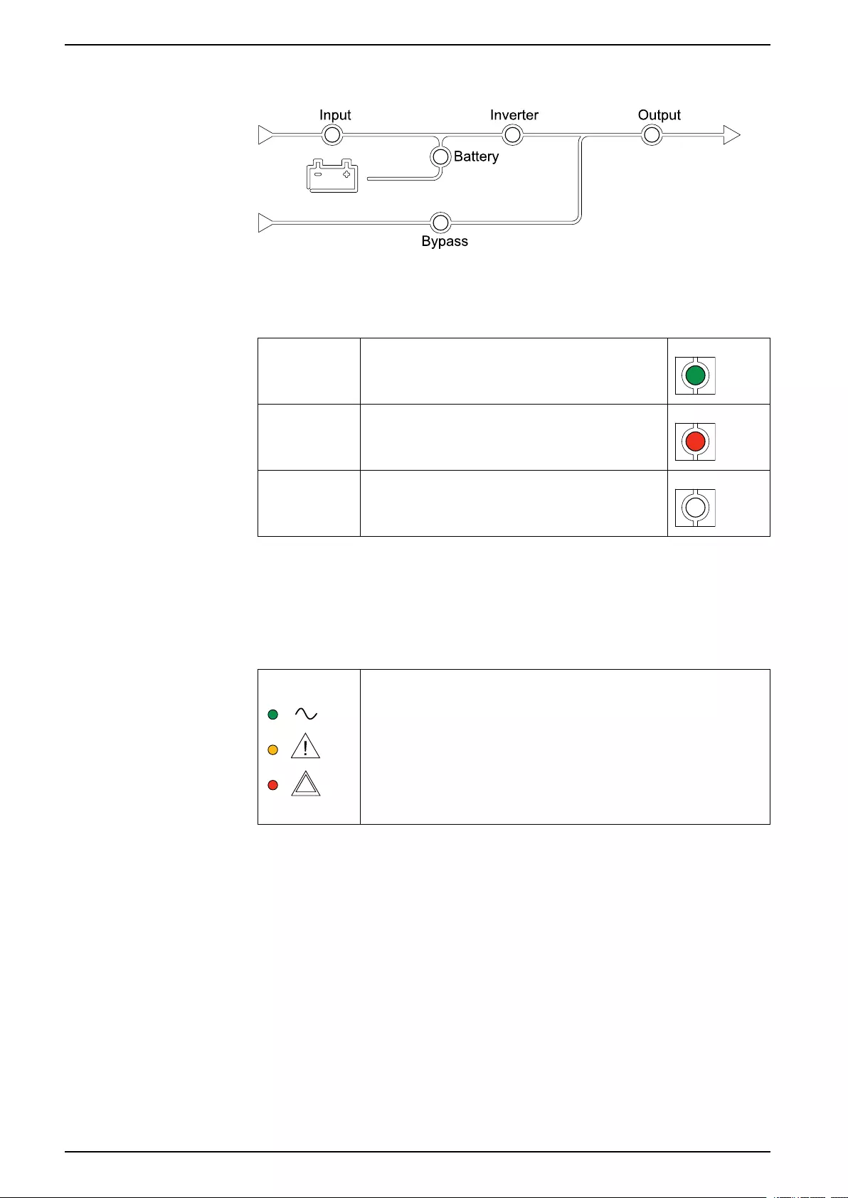
Overview of Status LEDs
The status LEDs placed next to the display interface shows the current status of
the UPS system:
• Green: The load is protected
• Green + Orange: The load is protected, but the system
reports an alarm at warning level
• Orange + Red: The load is unprotected and the system
reports an alarm at warning level and an alarm at critical
level
• Red: The load is unprotected and the system reports an
alarm at critical level
8 990-5452H-001
Overview of UPS User Interface UPS System
Display Symbols
Symbol Description
The locked home button appears when the system is locked by a
password protection. Tap this button to go to the home screen of
the display.
The unlocked home button appears when the system has been
unlocked using the password. Tap this button to go to the home
screen of the display.
Tap the OK button to confirm your selections and exit the current
screen.
Tap the ESC button to cancel your changes and exit the current
screen.
Tap the filter button to set up the filters for your logs.
Tap the recycle bin button to clear the log.
990-5452H-001 9
UPS System Operation Modes
Operation Modes
The Galaxy UPS has two different levels of operation mode:
• UPS Operation Mode: The operation mode of the operated UPS. See UPS
Operation Modes, page 10.
• System Operation Mode: The operation mode of the complete UPS system.
See System Operation Modes, page 13.
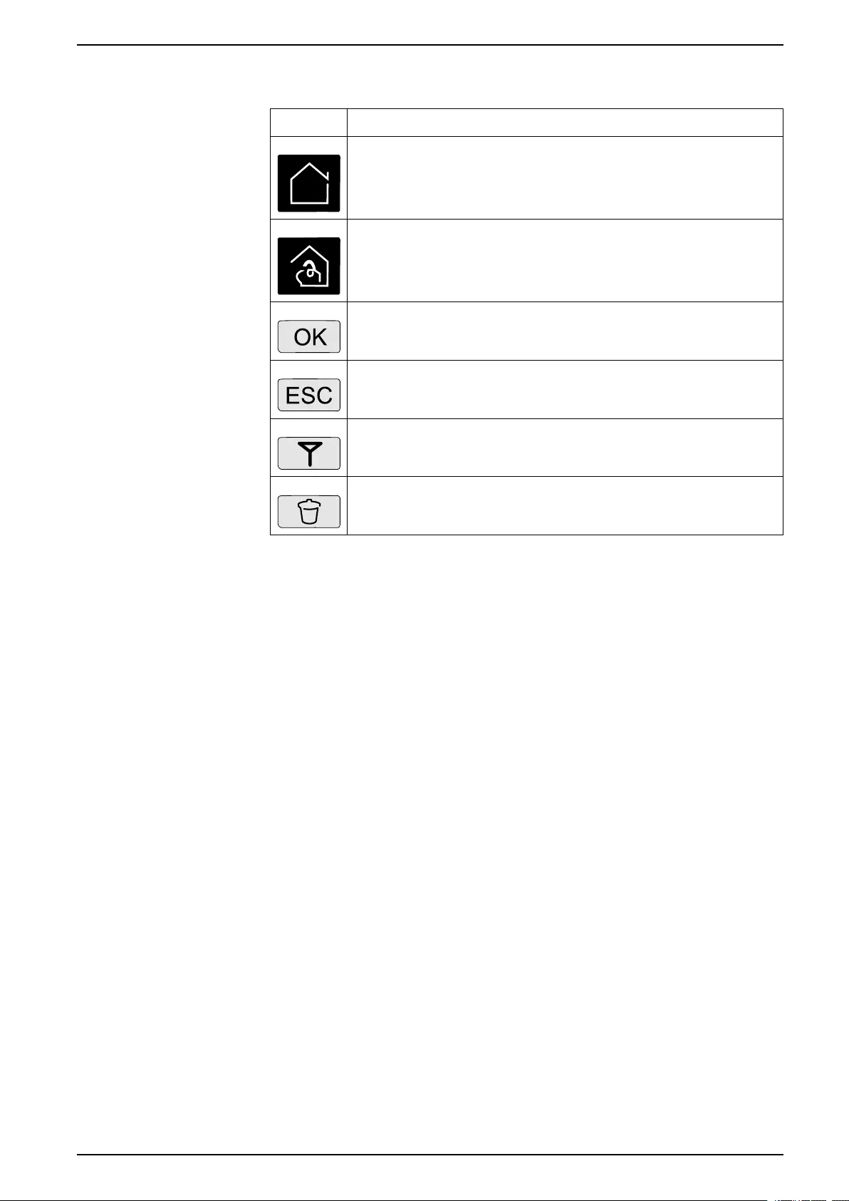
UPS Operation Modes
Normal
During normal operation, the UPS supports the load with conditioned power. While
the UPS is in normal operation, the input, inverter, and load LEDs are green, and
the battery and bypass LEDs are off.
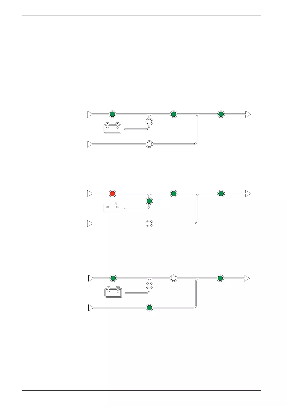
Battery
If the utility/mains supply fails, the UPS transfers to battery operation and supports
the load with conditioned power from the DC source. While the UPS system is in
battery operation, the battery, inverter, and load LEDs are green, the bypass LED
is off and the input LED is red.
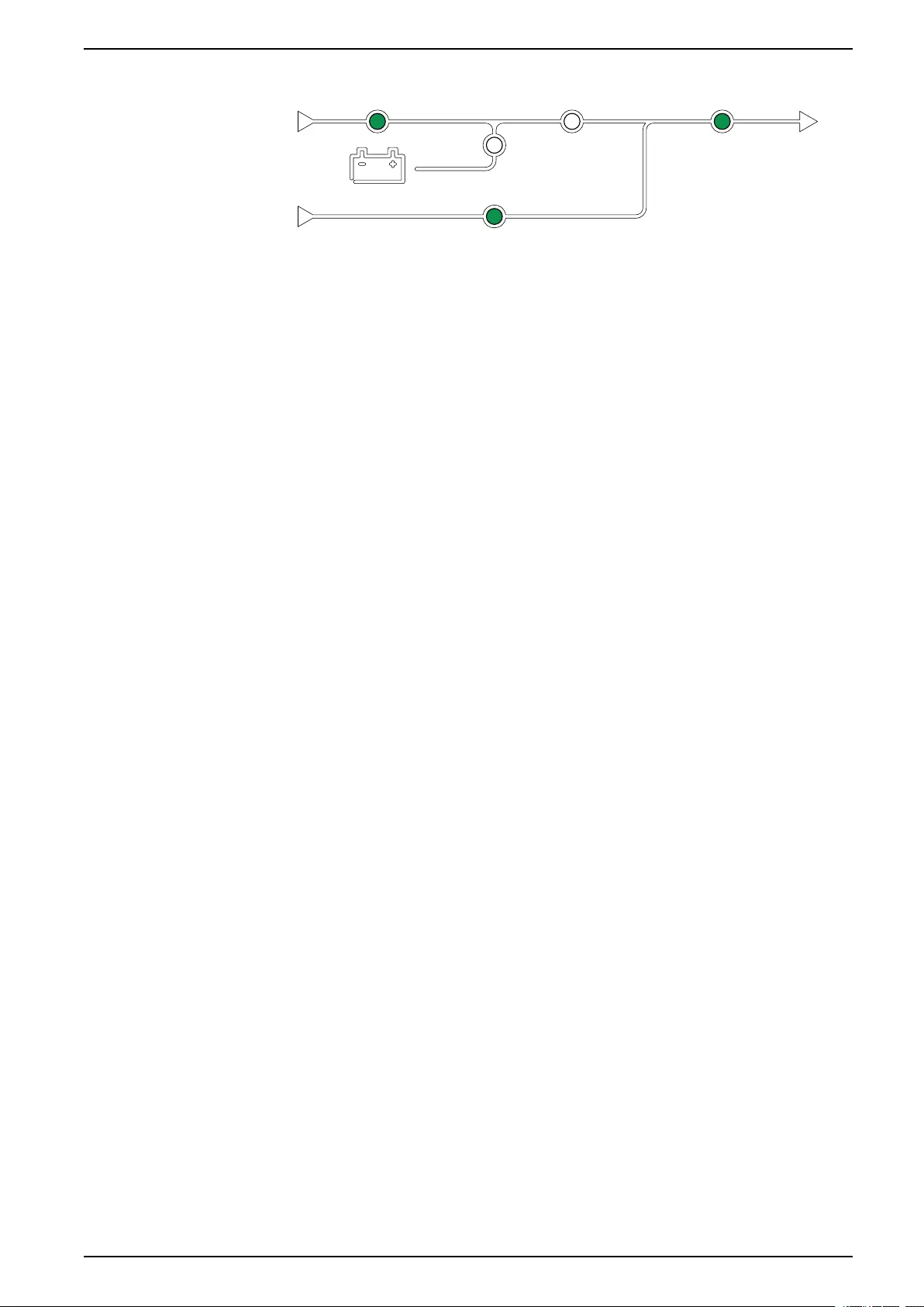
Requested Static Bypass
The UPS can be transferred to requested static bypass following a command from
the display. During static bypass operation, the load is supplied from the bypass
source. If a fault is detected, the UPS will transfer to normal operation or forced
static bypass operation. If there is an interruption to the utility/mains power supply
during requested static bypass operation, the system will transfer to battery
operation.
During requested static bypass, the input, bypass and output LEDs are green and
the battery and inverter LEDs are off.
10 990-5452H-001
Operation Modes UPS System
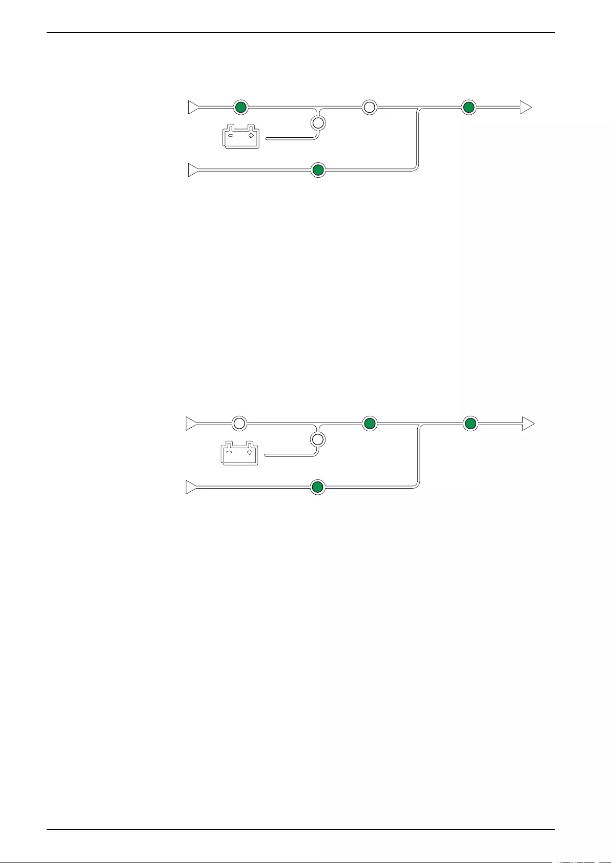
Forced Static Bypass
The UPS is in forced static bypass following a command from the UPS system or
because the user has pressed the inverter OFF button on the UPS. During forced
static bypass operation, the load is supplied directly by the bypass source.
During forced static bypass, the input, bypass and output LEDs are green and the
battery and inverter LEDs are off or red if an alarm is present.
NOTE: The batteries are not available as an alternate power source while the
UPS is in forced static bypass operation.
Maintenance Bypass Operation
When the Maintenance Bypass Breaker (MBB) is closed, the UPS system enters
maintenance bypass operation. The load is supplied with unconditioned power
from the bypass input.
NOTE: The batteries are not available as an alternate power source while the
UPS is in maintenance bypass operation.
Static Bypass Standby
NOTE: Static bypass standby is only applicable to an individual UPS in a
parallel system.
The UPS enters static bypass standby if the UPS is prevented from entering
forced static bypass and the other UPS units of the parallel system can support
the load.
In static bypass standby the output of the specific UPS is off.
The UPS automatically changes to the preferred operation mode when possible.
NOTE: If the other UPS units cannot support the load, the parallel system
enters forced static bypass. The UPS in static bypass standby will then
transfer to forced static bypass.
Inverter Standby
NOTE: Inverter standby is only applicable to an individual UPS in a parallel
system.
The UPS enters inverter standby if there is an interruption to the utility/mains
supply of one UPS and the other UPS units of the parallel system can support the
load with the configured redundancy level maintained. This is to avoid that the
batteries are being drained in situations where it is not necessary.
Battery Test
The UPS is in battery test mode when the UPS is performing a battery self-test or
a runtime calibration.
NOTE: The battery test will be aborted if the utility/mains supply is interrupted
or a critical alarm is present and will return to normal operation upon return of
utility/mains.
990-5452H-001 11
UPS System Operation Modes
ECO Mode
NOTE: ECO mode must be enabled by a Schneider Electric field service
engineer.
ECO mode allows the UPS to be configured to use requested static bypass, with
the load supplied through the bypass, as the preferred operation mode under
predefined circumstances.
If a fault is detected (bypass voltage out of tolerance, output voltage out of
tolerance, etc), the UPS will immediately change to normal operation or forced
static bypass.
The main advantage of ECO mode is a reduction in the consumption of electrical
power.
In case of interruption to the utility/mains supply, the UPS transfers to inverter
operation for a continuous supply of the load.
The batteries are charged when the UPS is in ECO mode.
NOTE: When changes to ECO mode settings are made on one UPS in a
parallel system, the settings are shared to all UPSs in the parallel system.
ECOnversion Mode
ECOnversion allows the system to supply the active part of the load through the
static bypass. The inverter is kept running in parallel with the bypass source and
supplies the reactive part of the load.
The input power factor of the UPS is, regardless of the load power factor,
maintained close to unity as the reactive part of the load is significantly reduced in
the UPS input current.
In case of an interruption to the utility/mains supply, the inverter immediately
maintains the output voltage so that breaks or drops during the transfer from
ECOnversion mode are practically eliminated.
The batteries are charged when the UPS is in ECOnversion mode.
NOTE: When changes to ECOnversion settings are made on one UPS in a
parallel system, the settings are shared to all UPSs in the parallel system.
Self-test
After start-up of the UPS system, the UPS will perform an automatic self-test. The
status and progress of the self-test are indicated by the flashing LEDs on the
mimic diagram.
When the self-test has been passed, the LEDs will indicate the operation mode of
the UPS system.
NOTE: If an LED continues to flash after completion of the self-test, please
call Schneider Electric.
12 990-5452H-001

Operation Modes UPS System
Off
When the UPS is in off, the UPS does not supply the connected load with power.
System Operation Modes
The system operation mode indicates the current output status of the complete
UPS system and which source that supplies the load.
Inverter
In inverter operation the load is supplied by the inverters. The UPS mode can be
in either normal or battery operation when the system operation mode is inverter
operation.
Requested Static Bypass
When the system is in requested static bypass, the load is supplied from the
bypass source. If a fault is detected, the system will transfer to inverter operation
or forced static bypass operation.
Forced Static Bypass
The system is in forced static bypass following a command from the UPS system
or because the user has pressed the inverter OFF button on the UPS units. During
static bypass operation, the load is supplied directly by the bypass source.
NOTE: The batteries are not available as an alternate power source while the
system is in forced static bypass operation.
Maintenance Bypass
In maintenance bypass operation, the load is supplied by unconditioned power
from the bypass input via the maintenance bypass breaker.
NOTE: The batteries are not available as an alternate power source in
maintenance bypass operation.
ECO Mode
NOTE: ECO mode must be enabled by a Schneider Electric field service
engineer.
ECO Mode allows the system to be configured to use requested static bypass,
with the load supplied through the bypass, as the preferred operation mode under
predefined circumstances.
The main advantage of ECO mode is a reduction in the consumption of electrical
power.
In case of interruption to the utility/mains supply, the UPS transfers to inverter
operation for a continuous supply of the load.
ECOnversion Mode
ECOnversion allows the system to supply the active part of the load through the
bypass. The inverter is kept running in parallel with the bypass source and
supplies the reactive part of the load.
The input power factor of the UPS is, regardless of the load power factor,
maintained close to unity as the reactive part of the load is significantly reduced in
the UPS input current.
990-5452H-001 13

UPS System Operation Modes
In case of an interruption to the utility/mains supply, the inverter immediately
maintains the output voltage so that breaks or drops during the transfer from
ECOnversion mode are practically eliminated. The behaviour is the same for all
UPSs in the parallel system.
Off
When the system operation mode is off, the UPS system does not supply the
connected load with power.
Frequency Converter Mode
In frequency converter mode the UPS is able to convert the frequency of the input
source to a different frequency on the UPS output.
NOTE: Frequency converter mode must be configured by Schneider Electric
during service configuration.
The possible input/output frequencies are 50/50 Hz, 50/60 Hz, 60/50 Hz and 60/60
Hz. This is set under output frequency.
When the UPS is configured as frequency converter static bypass is not available:
• Transfer to static bypass is disabled
• Alarms and events related to the static bypass switch and the bypass source
are disabled (not shown)
• References to the static bypass switch and the MBB are removed from the
mimic diagram in the display and UPS Tuner
• Guided sequences are changed to support startup and shutdown of the UPS
with no bypass available
It is possible to run battery self-test and battery runtime calibration even when
there is no bypass available.
NOTE: In frequency converter mode the capacitor lifetime is reduced by 40%.
14 990-5452H-001
UPS System UPS Display
Configuration from the UPS Display
Disable Password Request
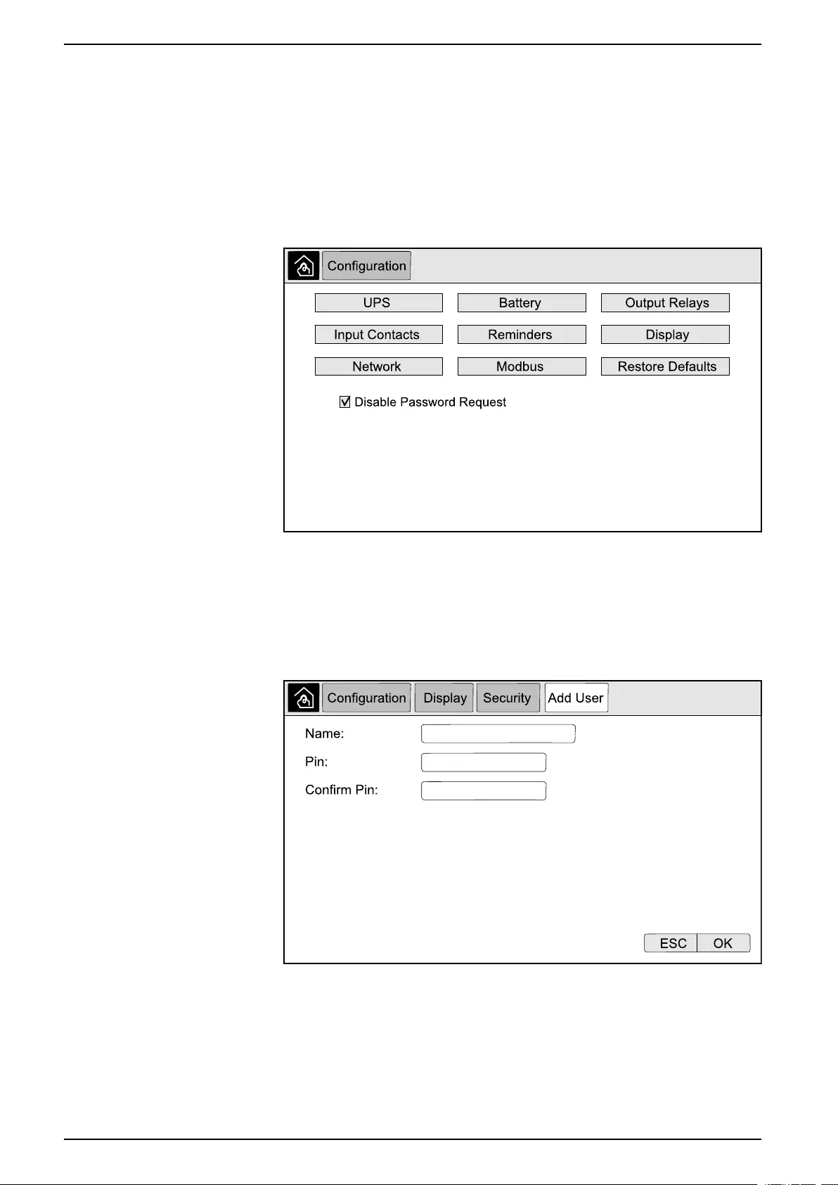
1. From the home screen on the display select Configuration.
2. Select Disable Password Request.
NOTE: When Disable Password Request has been enabled, it is no
longer required to enter the password when configuring or operating the
UPS. However when changing this setting, the password is required.
Add a New User or Edit an Existing User
1. From the home screen on the display select Configuration > Display >
Security.
2. Select Add User to add a new user or select Edit User to edit an existing
user of the system.
3. In the Name field, type in the name of the user. Complete with Enter.
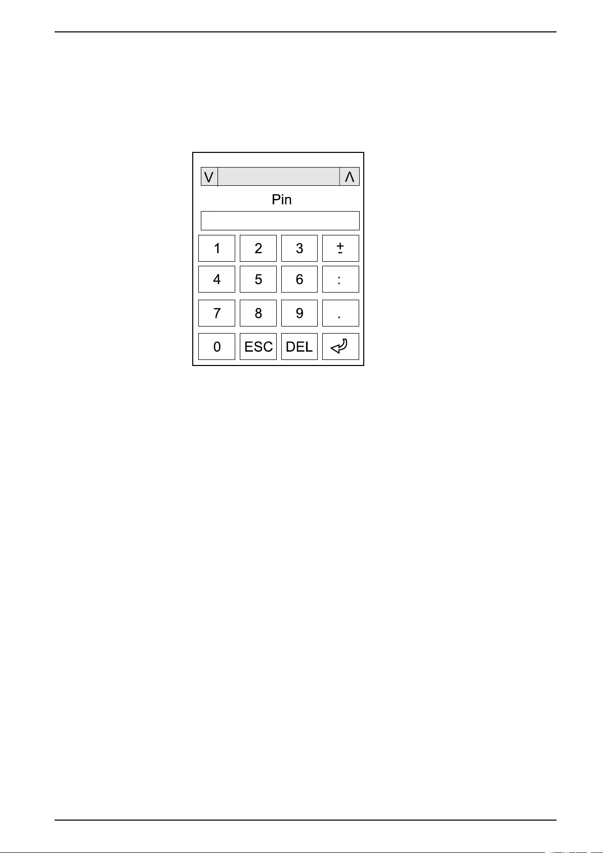
4. In the Pin field, type in a pin code for the user. Complete with Enter.
5. In the Confirm Pin field, retype the pin code of the user. Complete with
Enter.
6. Tap OK to save your settings.
16 990-5452H-001
UPS Display UPS System
Delete a User
1. From the home screen on the display select Configuration > Display >
Security > Delete User.
2. Browse to the user that you wish to delete using the up and down arrows and
tap OK.
3. Tap Yes to confirm deletion of an existing user of the system.
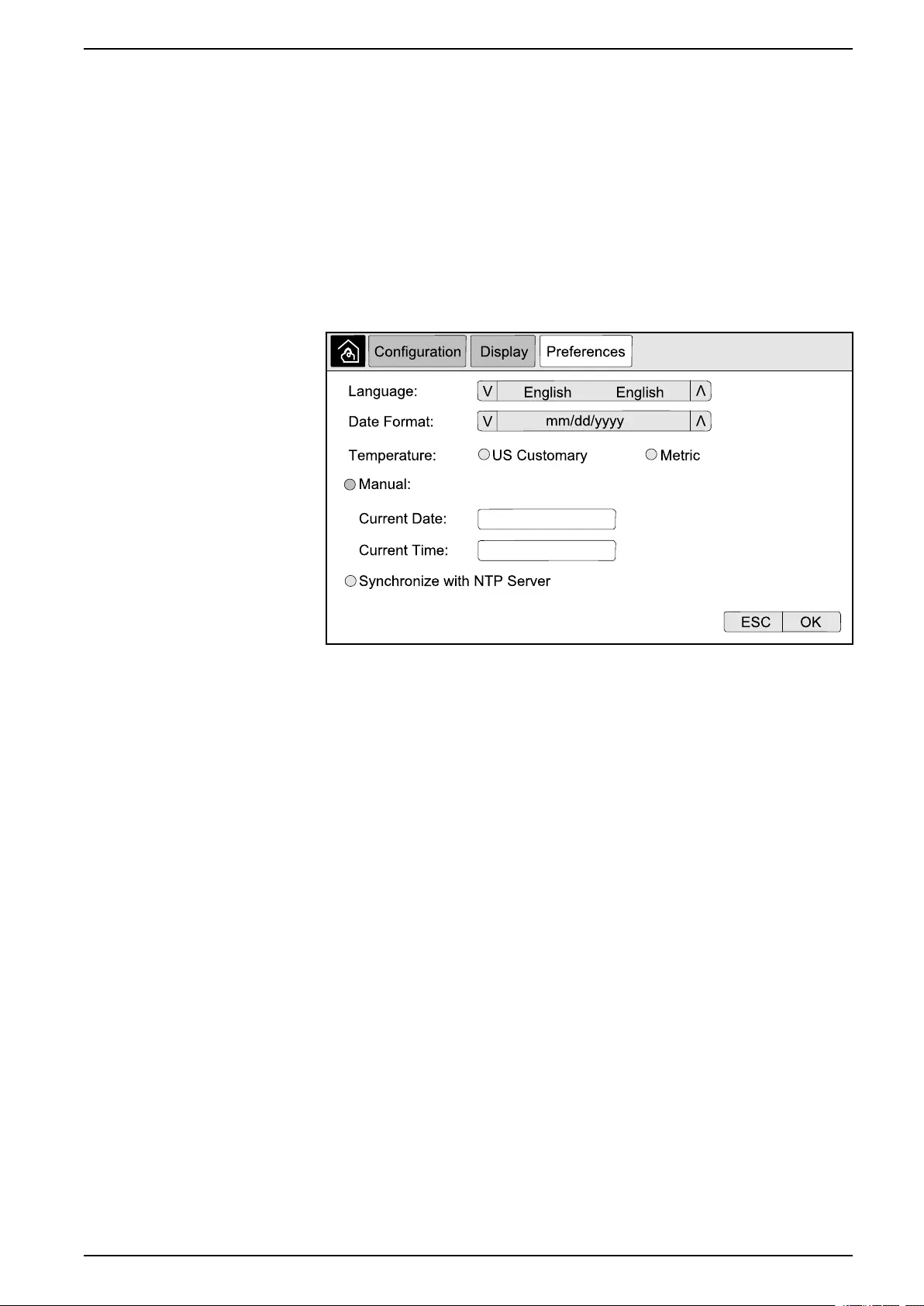
Configure the Display Preferences
1. From the home screen on the display select Configuration > Display >
Preferences.
2. Select the preferred language using the up and down arrows.
3. Select the preferred date format using the up and down arrows.
4. Select the preferred temperature units: US Customary (°Fahrenheit) or
Metric (°Celsius).
5. Set the current date and time using one of the below two methods:
– Set the date and time manually on the display by selecting Manual and
typing the actual date and time and completing with Enter.
– Set the date and time automatically by selecting Synchronize with NTP
server (Network Time Protocol server).
NOTE: NTP server settings can be configured in the network
management interface via the Web, command line, or config file.
6. Tap OK to save your settings.
990-5452H-001 17
UPS System UPS Display
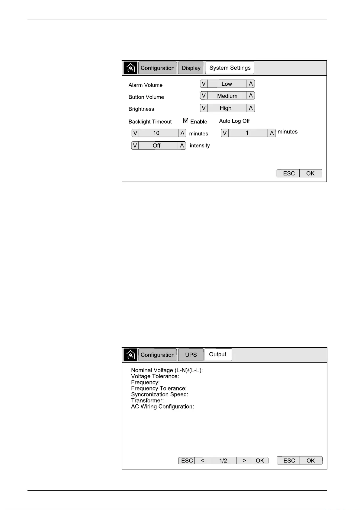
Configure the Display Settings
1. From the home screen on the display select Configuration > Display >
System Settings.
2. Set the Alarm Volume. Choose between: Off,Low,Medium, and High.
3. Set the Button Volume. Choose between: Off,Low,Medium, and High.
4. Set the Brightness of the display. Choose between: Low,Medium, and
High.
5. Enable or disable Backlight Timeout. If you wish to enable backlight timeout,
set the time limit in minutes for enabling backlight timeout. Choose between:
60,30,10,5, and 1.
6. Set the intensity of the backlight. Choose between: Off,Very Low,Low, and
Medium.
7. Set the time limit in minutes for automatic log off. Choose between: 60,30,
10,5, and 1.
8. Tap OK to save your settings.
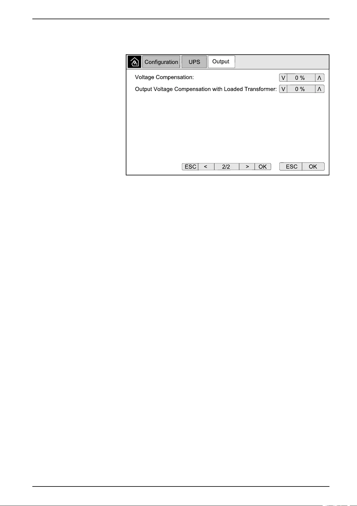
Configure the UPS Output Voltage Compensation
1. From the home screen on the display select Configuration > UPS > Output.
2. Tap arrow to the right to go to the next output configuration screen.
18 990-5452H-001
UPS Display UPS System
3. Under Voltage Compensation select the preferred voltage compensation for
your system. Choose between –3%,–2%,–1%,0%,1%,2%, or 3%.
NOTE: This setting is shared between all UPSs in a parallel system.
4. Under Output Voltage Compensation with Loaded Transformer select the
preferred output voltage compensation to compensate for load dependent
transformer voltage drop. Choose between 0%,1%,2%, or 3%.
NOTE: This setting must be identical for all UPSs in a parallel system.
NOTE: When this setting is set to 0%, the output transformer voltage
compensation is disabled.
5. Tap OK to confirm your setting.
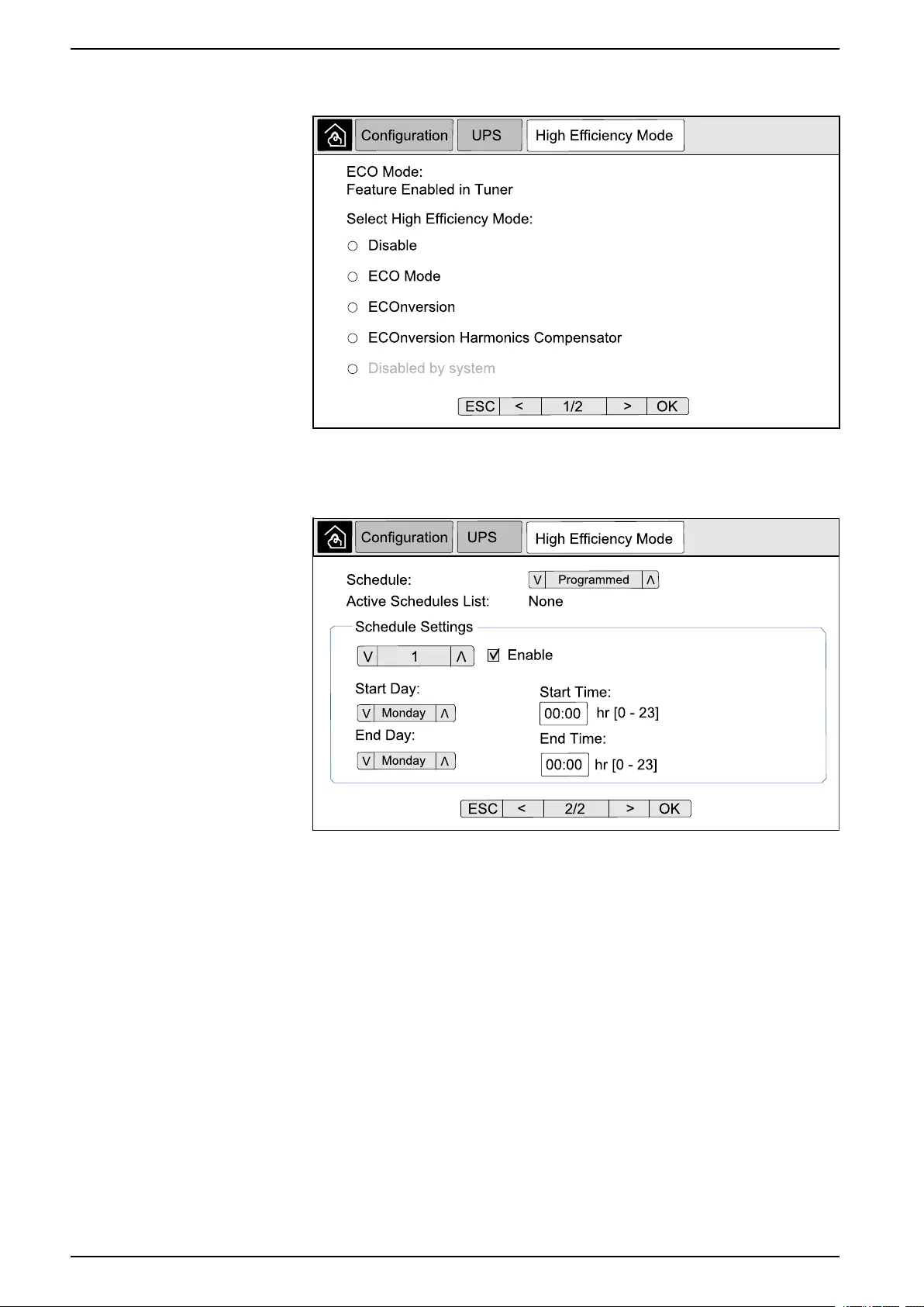
Configure High Efficiency Mode
NOTE: ECO Mode must be enabled by Schneider Electric during service
configuration to make this selection available.
The UPS returns to high efficiency mode after 10 seconds under normal operating
conditions. If an unstable mains forces the UPS to exit high efficiency mode more
than one to ten times (this setting must be configured by Schneider Electric) within
24 hours, the UPS will disable high efficiency mode. An informational alarm will be
generated, and Disabled by system will be shown on the screen Configuration
> UPS > High Efficiency Mode. High efficiency must then be manually
reactivated.
990-5452H-001 19
UPS System UPS Display
1. From the home screen on the display select Configuration > UPS > High
Efficiency Mode and configure the following settings:
a. Select High Efficiency Mode: Choose between Disable,ECO Mode,
ECOnversion, and ECOnversion Harmonics Compensator.
2. Tap >and configure the schedule settings:
a. Schedule: Select when the system should enter the selected
ECOnversion or ECO mode. Choose between Always,Programmed
and Never.
b. Active Schedules List: If you chose Programmed above, select
Enable and set the time and date for when the system should enter the
selected ECOnversion or ECO mode.
3. Tap OK to confirm your settings.
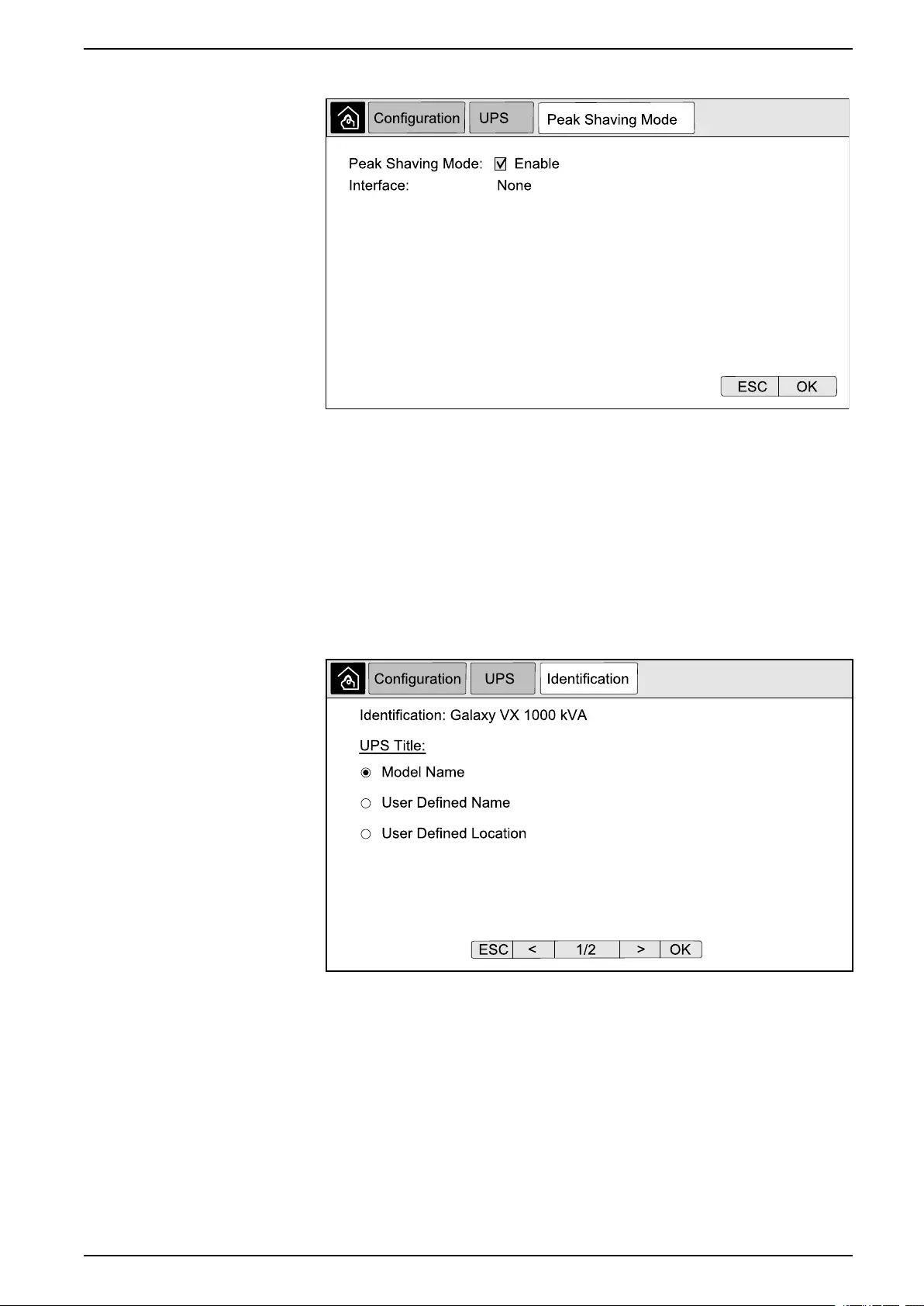
Enable Peak Shaving Mode
Peak shaving mode allows the UPS to reduce peak power consumed from the
utility/mains supply.
NOTE: Peak shaving mode must be enabled locally by Schneider Electric
during service configuration to make this selection available, but it must be
controlled via a remote software application. Contact Schneider Electric for
more details.
1. From the home screen on the display select Configuration > UPS > Peak
Shaving Mode.
20 990-5452H-001
UPS Display UPS System
2. Select Enable to enable peak shaving mode.
3. Tap OK to confirm your settings.
Set the UPS Identification
NOTE: User Defined Name and User Defined Location must be configured
via the network management interface. For more information see Access a
Configured Network Management Interface, page 39.
1. From the home screen on the display select Configuration > UPS >
Identification.
2. Select to have the UPS identified via Model Name,User Defined Name or
User Defined Location.
3. Tap arrow to the right to go to the next configuration screen.
990-5452H-001 21
UPS System UPS Display
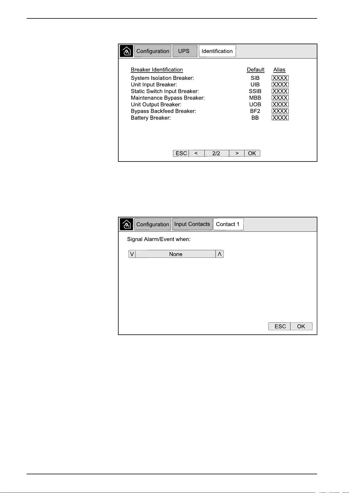
4. Tap the text box and type a name for the individual breakers or keep the
default settings. The alias is limited to four characters.
5. Tap OK to confirm your settings.
Configure the Input Contacts
1. On the display select Configuration > Input Contacts and select the input
contact that you wish to configure.
22 990-5452H-001
UPS Display UPS System
2. Choose between the below options:
Custom Input 1: General purpose input. External Battery Monitoring Detected Fault: Input to indicate that
the external battery monitor has detected a fault.
Custom Input 2: General purpose input. Battery Room Ventilation Inoperable: Input to indicate that the
battery room ventilation is inoperable. When the input is active, the
battery charger will turn off.
Ground fault: Input to indicate that a ground fault is present. Supplied By Genset: Input to indicate that the UPS is running on
generator. The battery charge current will be reduced to the value
set by Schneider Electric during start-up.
Inhibit Transfer from Static Bypass: When this input is active, and
the system enters requested static bypass or forced static bypass,
the system will be locked in static bypass as long as the input is
active.
External energy storage: minor alarm: Input to indicate that the
external energy storage monitor reports a minor alarm.
External energy storage: major alarm: Input to indicate that the
external energy storage monitor reports a major alarm.
Force the Charger to Turn Off: Input that forces the charger to turn
off.
Flywheel inoperable: Input to indicate that the flywheel is
inoperable.
Disable High Efficiency Mode: Input to disable the use of high
efficiency mode
Request bypass operation: Input that will transfer the UPS into
requested static bypass operation if the conditions for a transfer are
met.
Force battery operation: Input that will force a transfer to battery
operation.
3. Tap OK to save your settings.
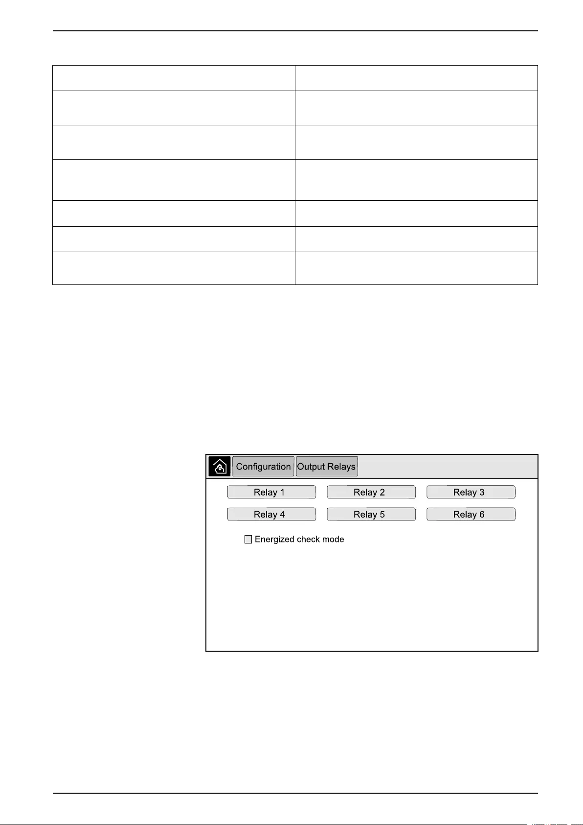
Configure the Output Relays
1. On the display select Configuration > Output Relays.
2. Select to enable or disable Energized check mode.
– When Energized check mode is enabled the output relays are ON. If a
signal is received or the power supply to the relay is lost, the circuit will
open and the relay will be deactivated.
– When Energized check mode is disabled the output relays are OFF. If a
signal is received, the circuit will close and the relay will be activated.
3. Select the output relay that you wish to configure.
990-5452H-001 23
UPS System UPS Display
4. Select the function that you wish to use the specific output relay for from the
list below:
Common Alarm: The output is triggered when any alarm is
present.
Normal Operation: The output is triggered when the UPS is
running in normal operation.
Battery Operation1: The output is triggered when the UPS is
running in battery operation.
Maintenance Bypass2: The output is triggered when the UPS is
running in maintenance bypass operation.
Static Bypass1: The output is triggered when the UPS is running in
forced static bypass operation or requested static bypass operation.
High Efficiency Mode: The output is triggered when the UPS is
running in ECOnversion or ECO mode.
Output Overload: The input is triggered when there is an overload
condition.
Fan Inoperable: The output is triggered when one or more fans are
inoperable.
Battery is not Working Correctly1: The output is triggered when
the batteries are not working correctly.
Battery Disconnected1: The output is triggered when the batteries
have been disconnected or the battery breaker(s) are open.
Battery Voltage Low1: The output is triggered when the battery
voltage is below the threshold.
Input Out of Tolerance: The output is triggered when the input is
out of tolerance.
Bypass Out of Tolerance2: The output is triggered when the
bypass is out of tolerance.
UPS Warning: The output is triggered when a warning alarm is
present.
UPS Critical: The output is triggered when a critical alarm is
present.
Parallel Redundancy Lost: The output is triggered when the
specified redundancy has been lost.
External Fault: The output is triggered when a fault external to the
UPS is present.
UPS Maintenance Mode: The output is triggered when the unit
output breaker (UOB) is open.
System Warning: The output is triggered when a warning alarm is
present in a parallel system.
System Critical: The output is triggered when a critical alarm is
present in a parallel system.
System Common Alarm: The output is triggered when any alarm
is present in a parallel system.
Emergency power off activated: The output is triggered when the
EPO has been activated.
Transfer to static bypass disabled UPS informational alarm: The output is triggered when an
information alarm is present.
System informational alarm: The output is triggered when an
information alarm is present in a parallel system.
5. Set the delay in seconds for the specific output to activate. Select a value
between 0 and 60 seconds.
6. Tap OK to save your settings.
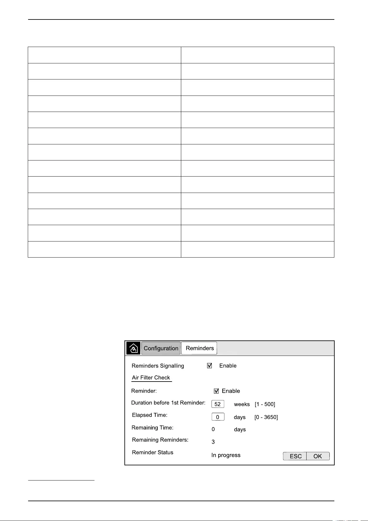
Configure Reminder Settings
When the air filters have been replaced, the reminders settings must be updated.
1. From the home screen on the display select Configuration > Reminders.
24 990-5452H-001
1. Not available when operating as a frequency converter without batteries.
2. Not available when operating as a frequency converter.
UPS Display UPS System
2. Configure the following settings:
a. Reminders Signalling: Select Enable to enable the display of all
reminders.
b. Reminder: Select Enable to enable the display of reminders for air filter
replacement.
c. Duration before 1st Reminder: Set the time in weeks before the first
reminder is shown.
d. Elapsed Time: Manually set the number of days that the air filters have
been used.
3. Tap OK to confirm your settings.
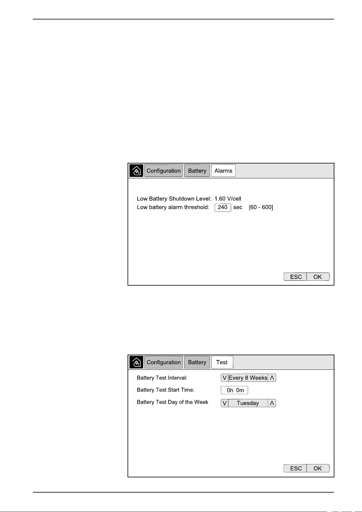
Configure Battery Alarm Threshold
1. From the home screen on the display select Configuration > Battery >
Alarms.
2. Select your preferred battery alarm threshold in seconds. Select a value
between 60 and 6000 seconds and complete with Enter.
3. Tap OK to confirm your setting.
Configure Automatic Battery Test
1. From the home screen on the display select Configuration > Battery > Test.
990-5452H-001 25
UPS System UPS Display
2. Set your preferred settings for the automatic battery test:
a. Battery Test Interval: Select your preferred interval for battery tests.
Choose between: Never,Every 52 Weeks,Every 26 Weeks,Every 12
Weeks,Every 8 Weeks,Every 4 weeks,Every 2 Weeks, or Once a
Week.
NOTE: If you run battery tests too frequently it can reduce the lifetime
of the batteries.
b. Battery Test Start Time: Select the time of the day in 24 hour format that
the test should take place and complete with Enter.
c. Battery Test Day of the Week: Select the day of the week that the test
should take place and complete with Enter.
3. When all settings have been completed, tap OK to confirm your settings.
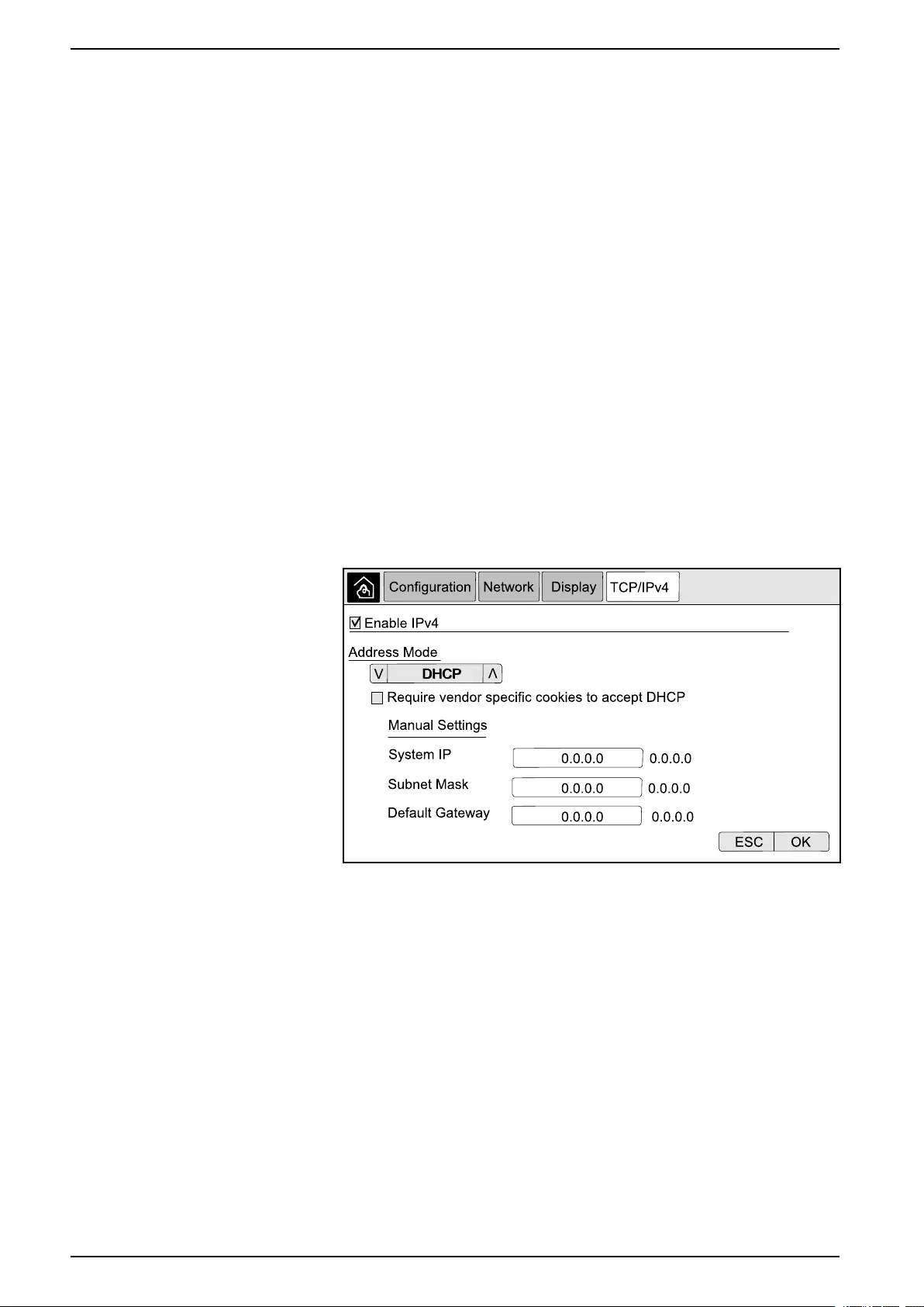
Configure the Network
The network can be configured for the display and for the cards in Smart Slot 1
and Smart Slot 2.
1. From the home screen on the display select Configuration > Network and
select either Display,Smart Slot 1, or Smart Slot 2 if present.
2. Configure the following settings:
a. TCP/IPv4:Enable IPv4 (if applicable), and select the Address Mode
(Manual,DCHP, or BOOTP).
26 990-5452H-001
UPS Display UPS System
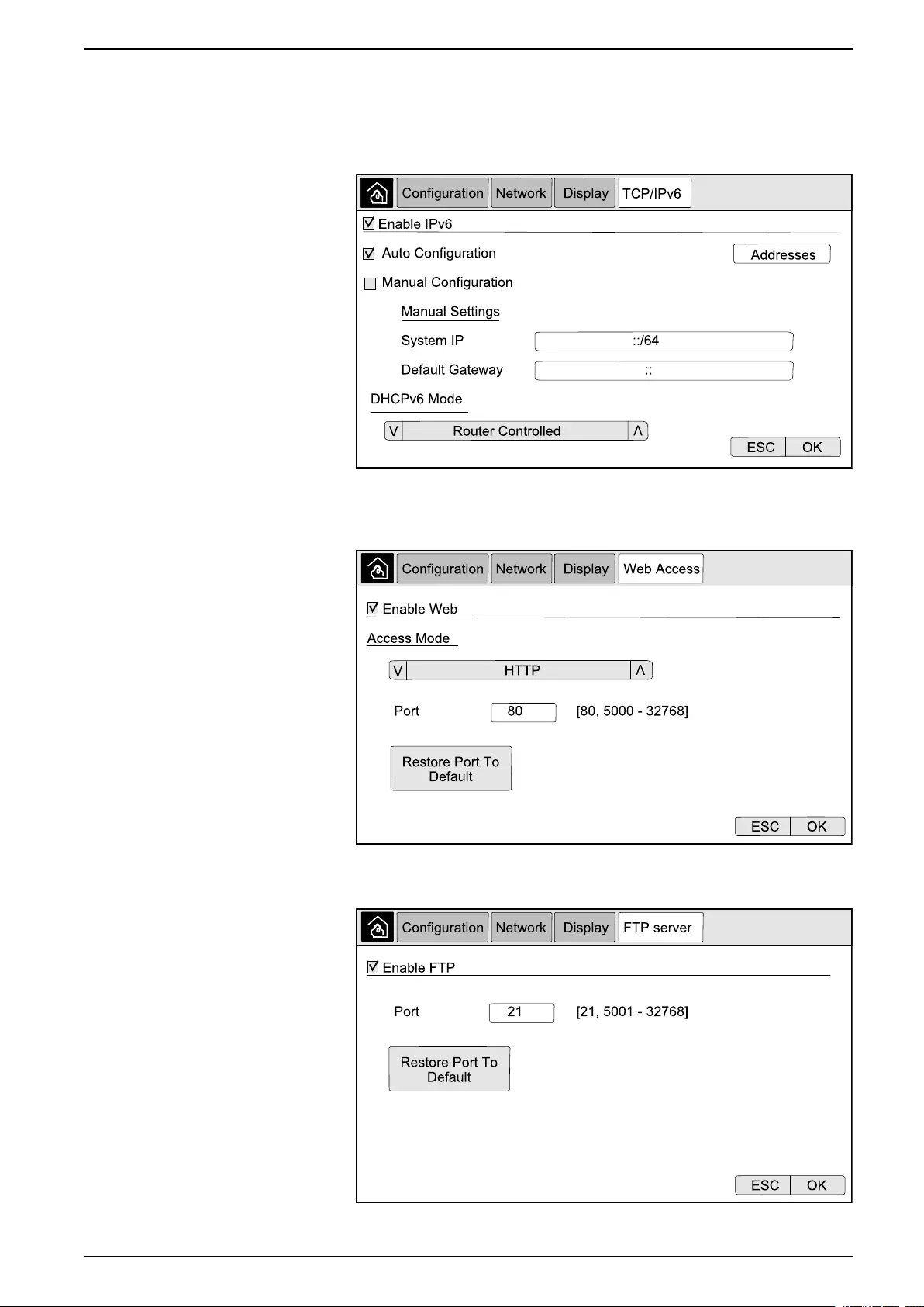
b. TCP/IPv6:Enable IPv6 (if applicable), select Auto Configuration or
Manual Configuration, and select the DHCPv6 Mode (Router
controlled,Non-Address Information Only,Never, or Address and
Other Information).
NOTE: Tap Addresses to see all valid IPv6 addresses.
c. Web Access:Enable Web (if applicable) and select the Access Mode
(HTTP or HTTPS).
NOTE: Not available for Smart Slots.
d. FTP server:Enable FTP (if applicable).
NOTE: Not available for Smart Slots.
990-5452H-001 27
UPS System UPS Display
Configure the Modbus
The modbus can be configured for the display and for the cards in Smart Slot 1
and Smart Slot 2.
NOTE: Only the display and optional Network Management Card AP9635 can
be used for serial modbus.
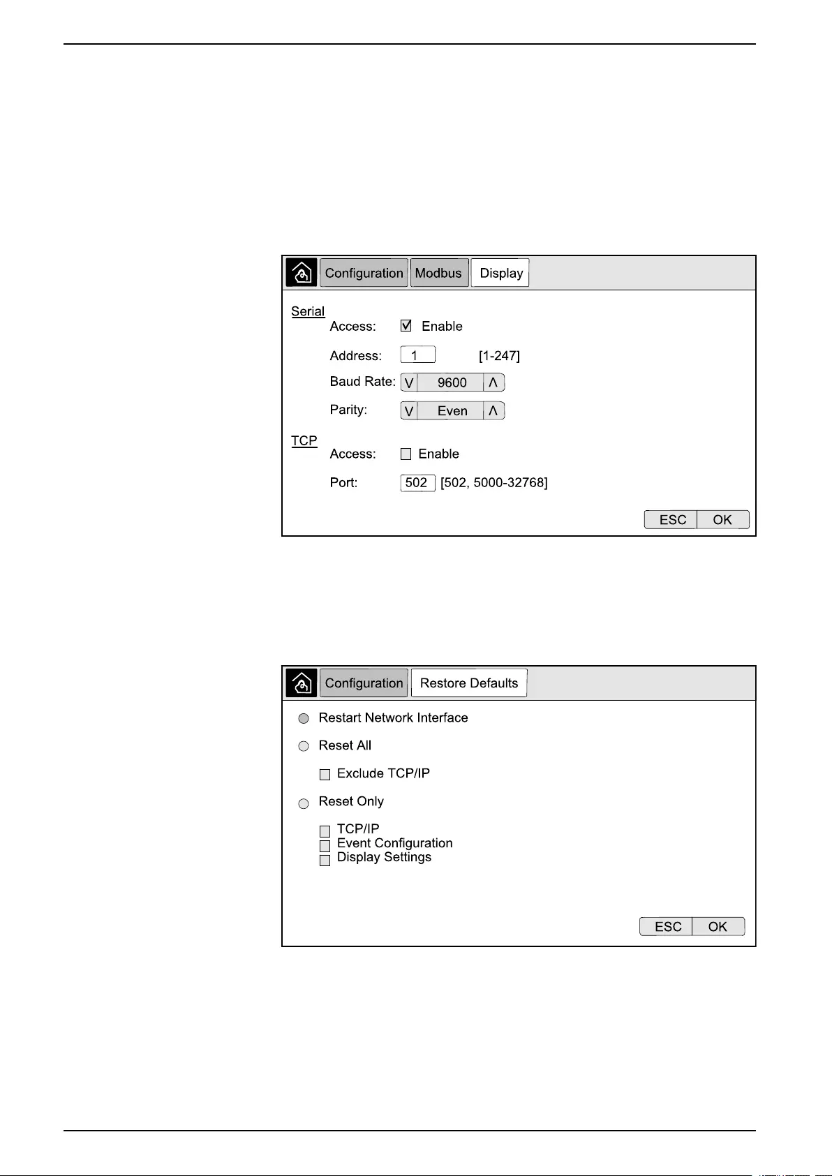
1. From the home screen on the display select Configuration > Modbus and
select either Display,Smart Slot 1, or Smart Slot 2.
2. Configure the modbus by enabling Serial or TCP access, and adding the
needed values.
3. Tap OK to confirm your settings.
Restore Default Configuration
1. From the home screen on the display select Configuration > Restore
Defaults.
2. Select one of the below options:
–Restart Network Interface: Select this option to restart network interface.
–Reset All: Select this option to reset all settings to default. You can select
to leave out the TCP/IP settings from the reset procedure.
–Reset Only: Select this option if you only wish to reset parts of the settings
to default values. You can select to reset the following settings: TCP/IP,
Event Configuration, and Display Settings.
28 990-5452H-001
UPS Display UPS System
3. When you have made your selection, tap OK to reset the selected settings to
default.
Operation Procedures from the UPS Display
Access Password-Protected Screens
1. When prompted for the password, select your username.
2. Type in the pin code for your username.
NOTE: The default pin code is 1234.
3. Change the password. For more information see Change the User Password,
page 54.
View the System Status Information
NOTE: The display does not show real time data, and a comparison between
the display and an external power analyzer will not show the same data.
Please allow for a tolerance of ± 1% for voltages, ± 3% for power, and ± 3% for
currents.
1. From the home screen on the display select Status.
990-5452H-001 29

UPS System UPS Display
2. Select the area for which you wish to see the status. Choose between:
Input
Voltage (phase-to-neutral)3The present phase-to-neutral input voltage in volts (V).
Current The present input current from the AC utility power source per phase in amperes (A).
Maximum RMS Current The maximum current for the latest 30 days.
Apparent Power The present apparent power input for each phase in kVA. Apparent power is the product of
RMS (root mean square) volts and RMS amperes.
Active Power The present active power (or real power) input for each phase in kilowatts (kW). Active
power is the portion of power flow that, averaged over a complete cycle of the AC
waveform, results in net transfer of energy in one direction.
Power Factor The ratio of the active power to apparent power.
Voltage (phase-to-phase) The present phase-to-phase input voltage.
Total Apparent Power The present total apparent power input (for all three phases) in kVA.
Total Active Power The present total active power input (for all three phases) in kW.
Frequency The present input frequency in hertz (Hz).
Energy The total energy consumption since the time of installation or since the number was reset.
Output
Voltage (phase-to-neutral)3The phase-to-neutral output voltage at the inverter in volts (V).
Current The present output current for each phase in amperes (A).
Maximum RMS Current The maximum current for the latest 30 days.
Apparent Power The present apparent power output for each phase in kVA. Apparent power is the product
of RMS (root mean square) volts and RMS amperes.
Active Power The present active power (or real power) output for each phase in kilowatts (kW). Active
power is the portion of power flow that, averaged over a complete cycle of the AC
waveform, results in net transfer of energy in one direction.
Power Factor The present output power factor for each phase. Power factor is the ratio of active power to
apparent power.
Current Crest Factor The present output crest factor for each phase. The output crest factor is the ratio of the
peak value of the output current to the RMS (root mean square) value.
Current THD The THD (total harmonic distortion) for each phase, as a percentage, for the present
output current.
Voltage (phase-to-phase) The phase-to-phase output voltage at the inverter in volts (V).
Total Apparent Power The present apparent power output for each phase in thousands of Volt-Amps (kVA).
Apparent power is the product of RMS (root mean square) volts and RMS amperes.
Total Active Power The present total active output power (for all three phases) in kilowatts (kW).
Load The percentage of the UPS capacity presently used across all phases. The load
percentage for the highest phase load is displayed.
Neutral Current3The present output neutral current in amperes (A).
Frequency The present output frequency in hertz (Hz).
Inverter Status The general condition of the inverter.
PFC Status The general condition of the PFC.
Energy The total energy supplied since the time of installation or since the value was reset.
Bypass
Voltage (phase-to-neutral)3The present phase-to-neutral bypass voltage (V).
Current The present bypass current for each phase, in amperes (A).
30 990-5452H-001
3. Only applicable in systems with neutral connection.

UPS Display UPS System
Bypass (Continued)
Maximum RMS Current The maximum current for the latest 30 days.
Apparent Power The present apparent bypass power for each phase in kVA. Apparent power is the product
of RMS (root mean square) volts and RMS amperes.
Active Power The present active bypass power for each phase in kilowatts (kW). Active power is the time
average of the instantaneous product of voltage and current.
Power Factor The present bypass power factor for each phase. Power factor is the ratio of active power
to apparent power.
Voltage (phase-to-phase) The present phase-to-phase bypass voltage (V).
Total Apparent Power The present total apparent bypass power (for all three phases) in thousands of Volt-Amps
(kVA).
Total Active Power The present total active bypass power (for all three phases) in kilowatts (kW).
Frequency The present bypass frequency in hertz (Hz).
Battery
Voltage The present battery voltage.
Current The present battery current in amperes (A).
A positive current indicates that the battery is charging; a negative current indicates that
the battery is discharging.
Power The present DC power being drawn from the battery, in kilowatts (kW).
Estimated Charge Level The present battery charge, as a percentage of full charge capacity.
Estimated Charge Time The estimated time, in minutes, until the batteries reach 100% charge.
Runtime Remaining The amount of time in hours and minutes before the batteries reach the low-voltage
shutdown level.
Charger Mode The operation mode of the charger (Off, Float, Boost, Equalization, Cyclic, Test).
Battery Status The general condition of the battery.
Charger Status The general condition of the charger.
Total Battery Capacity The total capacity available from the available batteries.
Temperature The highest battery temperature from the connected temperature sensors.
Temperature
Ambient Temperature Ambient temperature in degrees Celsius or Fahrenheit for the I/O cabinet and each power
cabinet.
System
Output Voltage The phase-to-phase output voltage at the inverter in volts (V).
Output Current The present output current for each phase in amperes (A).
Output Frequency The present output frequency in hertz (Hz).
Runtime Remaining The amount of time in hours and minutes before the batteries reach the low-voltage
shutdown level.
System Time The time of the UPS system.
UPS Operation Mode The operation mode of the operated UPS.
System Operation Mode The operation mode of the complete UPS system.
Total Output Power The apparent and active power (or real power) output for each phase.
990-5452H-001 31
UPS System UPS Display
System (Continued)
Overload Timer4The time in seconds before the UPS changes to forced static bypass due to an overload
condition on the system.
NOTE: The system can be in an overload condition even though the Total Output
Power is below 100% if the load is not equally shared between the three phases.
Output Power The phase-to-phase apparent and active power (or real power) output for each phase.
Parallel System
Input Current The present phase-to-phase input current in amperes (A).
Output Current The present phase-to-phase output current in amperes (A).
Bypass Current The present phase-to-phase bypass current in amperes (A).
Parallel UPS Number The parallel UPS number of the operated UPS.
Parallel system redundancy The redundancy for the parallel system.
Number of Parallel Units The total number of UPSs in the parallel system.
Parallel Units The numbers of all UPSs in the parallel system.
Output Total Apparent Power The present total apparent output power (for all three phases) in thousands of Volt-Amps
(kVA).
Output Total Load The percentage of the UPS system capacity presently used across all phases. The load
percentage for the highest phase load is displayed.
Active Alarms
Active Alarms For more information on active alarms, go to View the Active Alarms, page 44.
Mimic Diagram
Mimic Diagram The mimic diagram shows the current status of the main parts of the UPS system: power
sources, converters, bypass static switch and breakers, and it shows the power flow
through the system.
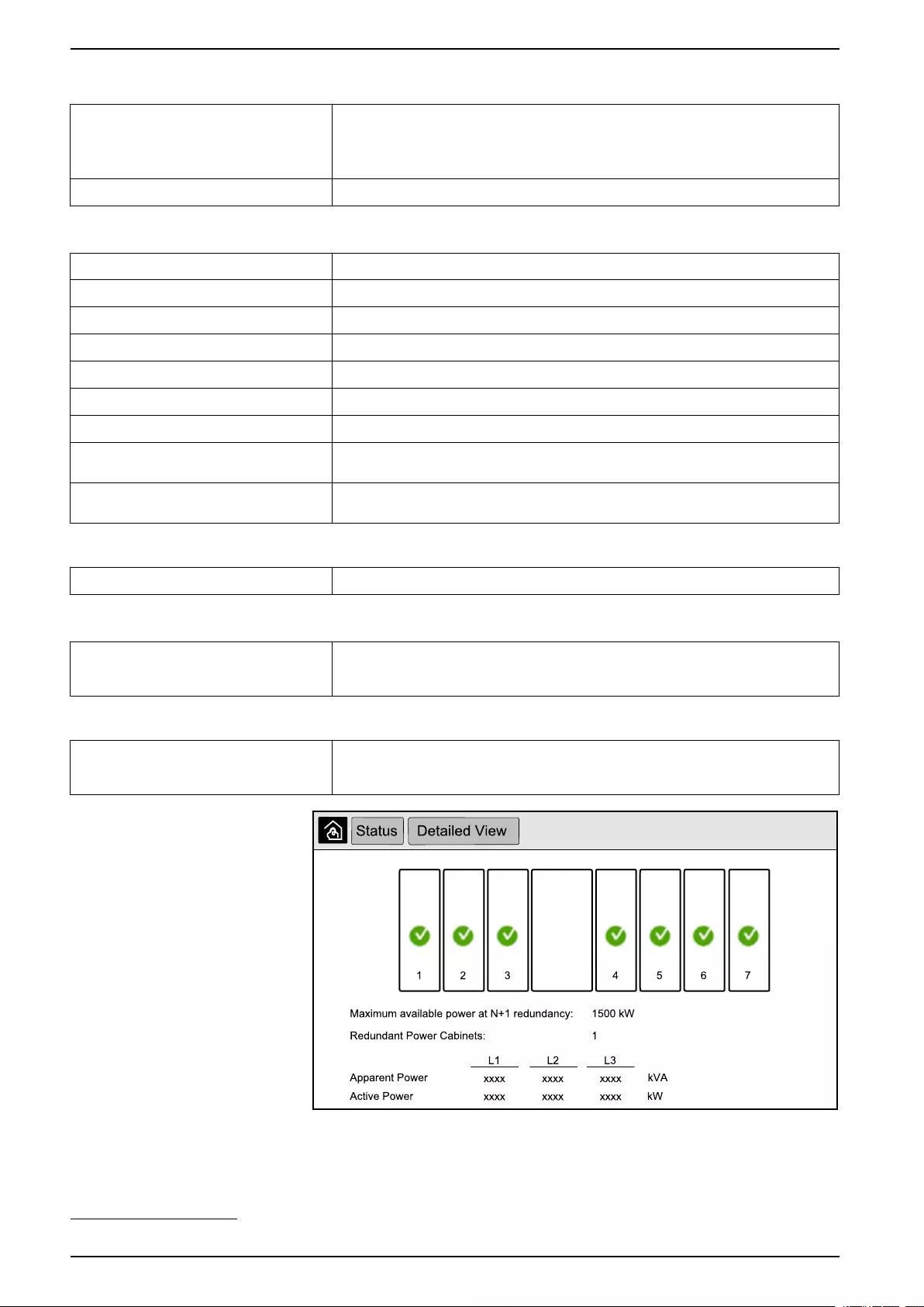
Detailed View
Detailed view The detailed view shows the system with a status icon on each individual power cabinet
and the actual number of redundant power cabinets. The detailed view also shows the
apparent power and active power per phase.
32 990-5452H-001
4. The overload timer is only visible when it is active.
UPS Display UPS System
Symbols on the Detailed View Screen
Indicates that the power cabinet is operational and working correctly
Indicates that there is an informational alarm.
Indicates that the power cabinet redundancy has been lost and/or an alarm of severity level Warning is present in the
power cabinet. The power cabinet is still operational.
Indicates that the power cabinet is inoperable due to a critical event. The customer alarm Power cabinet inoperable
is also displayed.
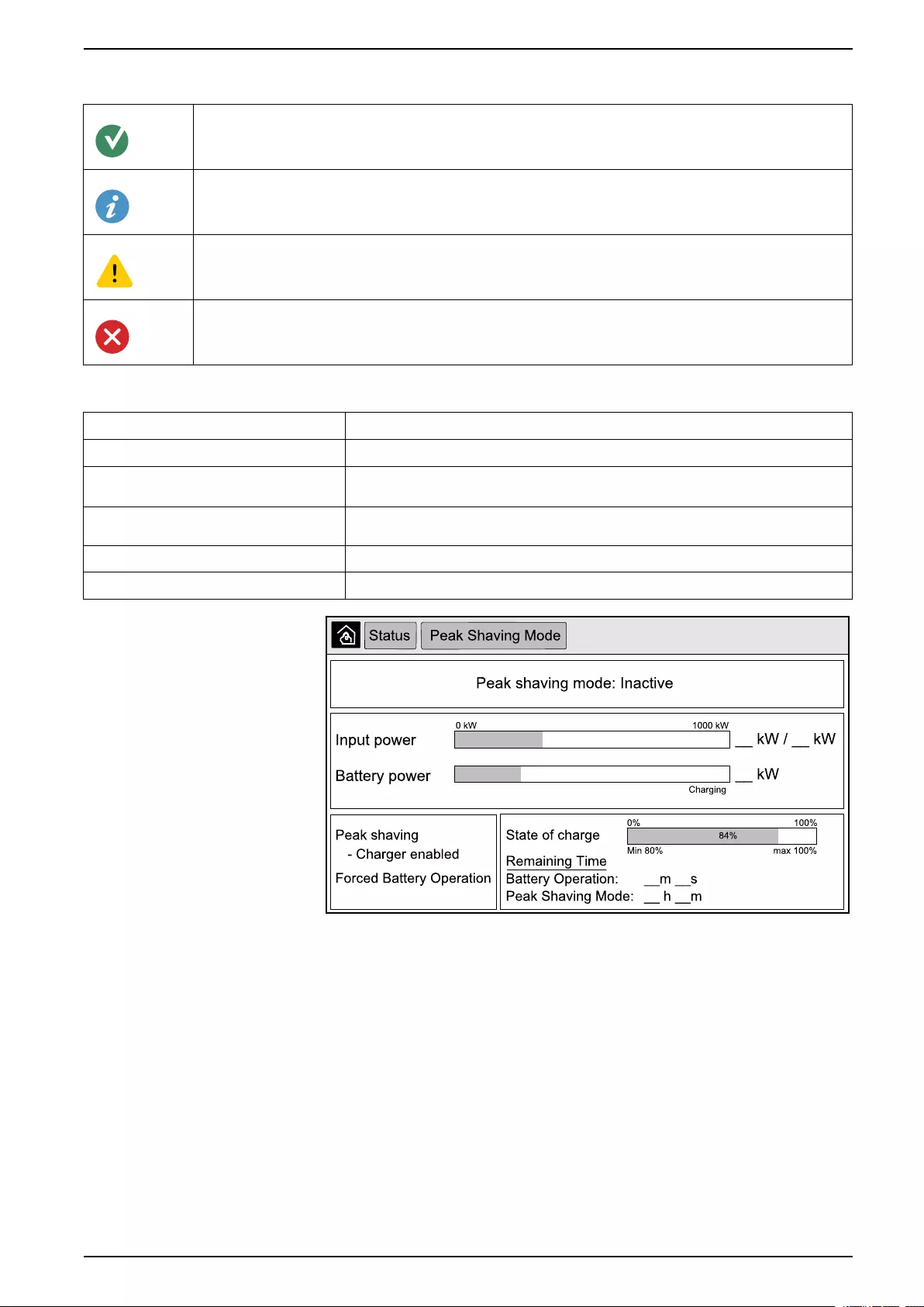
Peak Shaving Mode
Peak shaving mode The status of the peak shaving mode — Active or Inactive
Input power The present input power (kW).
Battery power The present battery power (kW). The bar is green when the batteries are charging and
yellow when the batteries are discharging.
Peak shaving Indicates if the charger is enabled or disabled and if forced battery operation is enabled
or disabled.
State of charge The current charge status of the batteries.
Remaining time The remaining time in battery operation and peak shaving mode.
3. Tap the home button to exit the screens and return to the home screen.
Start Up Single System from Maintenance Bypass Operation
Use this procedure to start up a single system from maintenance bypass operation
with the load supplied through the MBB and all other breakers open.
NOTE: Only operate a breaker when the associated breaker LED is green.
1. Close the unit input breaker UIB.
This will power up the display interface after approximately 30 seconds.
2. From the home screen on the display, select Control > Startup Wizard.
Select Startup from Maintenance Bypass and follow the steps which
appear on the screen.
The following is a generic start-up procedure. Always follow the steps of the
Startup Wizard which are specific to your system.
990-5452H-001 33

UPS System UPS Display
3. Close the static switch input breaker SSIB.
4. Close the backfeed protection switch (BF2) if it is open.
5. Close the battery breakers in your specific battery solution.
6. Initiate transfer to static bypass by tapping the Transfer Load to static
bypass button on the display interface.
In systems with kirk-keys, the key is released from the solenoid key release
unit.
If the UPS system does not transfer to requested static bypass, go to Status
> Active Alarms to see if there are active alarms that prevent the UPS
system from transferring to static bypass.
7. In systems with kirk-keys, insert the key in the lock on the unit output breaker
UOB and turn to unlock.
8. Close the unit output breaker UOB.
9. Open the maintenance bypass breaker MBB.
The system automatically transfers to normal operation.
10. In systems with kirk-keys, turn the key in the lock of the maintenance bypass
breaker MBB to lock open.
The key is released.
11. In systems with kirk-keys, insert the key in the solenoid key release unit and
turn to capture the key.
Shut Down Single System from Normal to Maintenance Bypass Operation
Use this procedure to shut down a single system to maintenance bypass
operation with the load supplied through the MBB.
NOTE: Only operate a breaker when the associated breaker LED is green.
1. From the home screen on the display, select Control > Shutdown Wizard.
Select Shutdown ending in Maintenance Bypass and follow the steps
which appear on the screen.
NOTE: The following is a generic shutdown procedure. Always follow the
steps of the Shutdown Wizard which are specific to your system.
2. Initiate transfer to static bypass by tapping the Transfer Load to static
bypass button on the display interface.
In systems with kirk-keys, the key is released from the solenoid key release
unit.
If the UPS system does not transfer to requested static bypass, go to Status
> Active Alarms to see if there are active alarms that prevent the UPS
system from transferring to static bypass.
3. In systems with kirk-keys, insert the key in the lock on the maintenance
bypass breaker MBB and turn to unlock.
4. Close the maintenance bypass breaker MBB.
In systems with kirk-keys, the key is held in the lock.
5. Open the unit output breaker UOB.
6. In systems with kirk-keys, turn the key in the lock on the unit output breaker
UOB to lock open.
The key is released.
7. In systems with kirk-keys, insert the key in the solenoid key release unit and
turn to capture the key.
8. Open the static switch input breaker SSIB.
34 990-5452H-001
UPS Display UPS System
9. Initiate transfer to forced static bypass by tapping the Inverter OFF button on
the front of the UPS system.
10. Open the battery breakers in your specific battery solution.
11. Open the unit input breaker UIB.
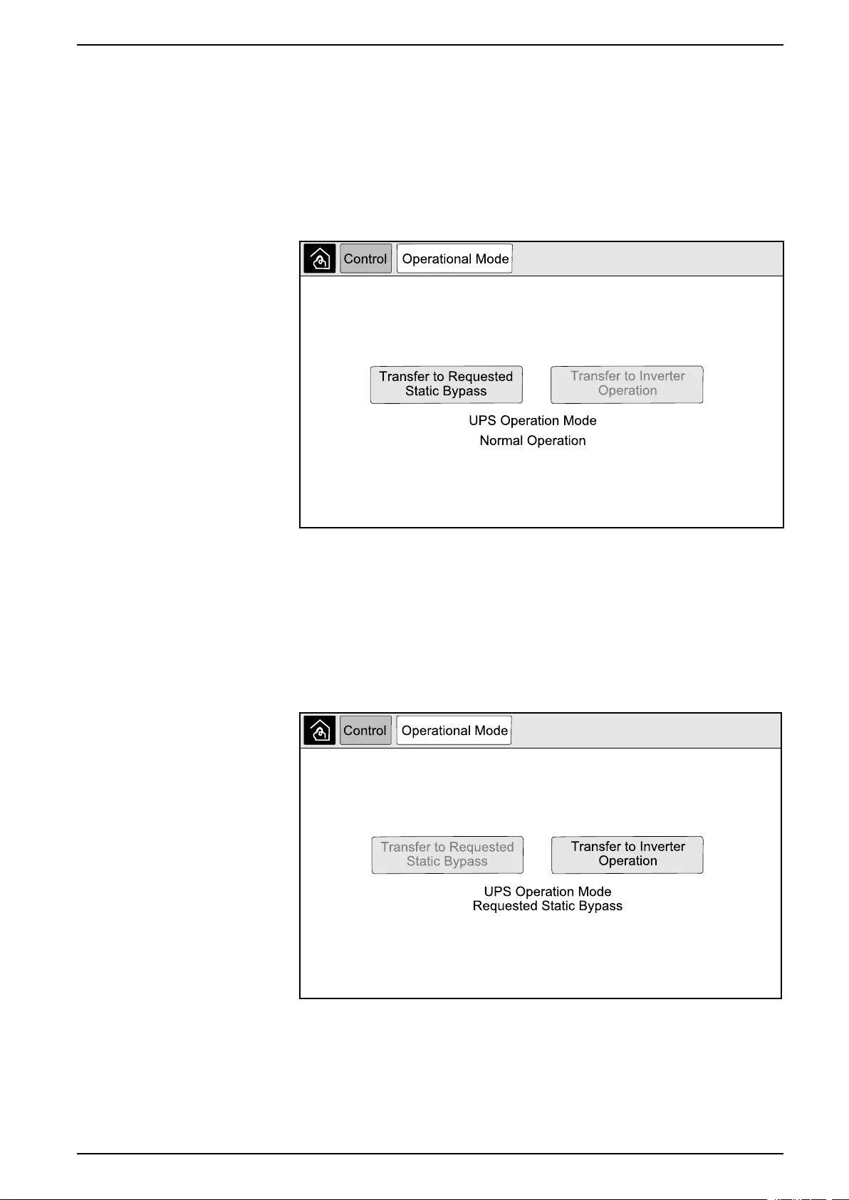
Transfer UPS from Normal to Requested Static Bypass Operation
1. From the home screen on the display select Control > Operational Mode.
2. Tap the Transfer to Requested Static Bypass button.
NOTE: If the conditions for performing a transfer are not met, the button
will be grayed out.
3. Verify that the UPS Operation Mode changes to Requested Static Bypass.
Transfer UPS from Requested Static Bypass Operation to Normal Operation
1. From the home screen on the display select Control > Operational Mode.
2. Tap the Transfer to Inverter Operation button.
NOTE: If the conditions for performing a transfer are not met, the button
will be grayed out.
3. Verify that the UPS Operation Mode changes to Normal Operation.
990-5452H-001 35

UPS System UPS Display
Start Up Parallel System from Maintenance Bypass Operation
Use this procedure to start up a parallel system from maintenance bypass
operation with the load supplied through the MBB and all other breakers open.
NOTE: Only operate a breaker when the associated breaker LED is green.
1. Close the unit input breaker UIB.
This will power up the display interface after approximately 30 seconds.
2. From the home screen on the display, select Control > Startup Wizard.
Select Startup from Maintenance Bypass and follow the steps which
appear on the screen.
NOTE: The following is a generic start-up procedure. Always follow the
steps of the Startup Wizard which are specific to your system.
3. Close the static switch input breaker SSIB.
4. Close the backfeed protection switch (BF2) if it is open.
5. Close the battery breakers in your specific battery solution.
6. Initiate transfer to static bypass by tapping the Transfer Load to static
bypass button on the display interface.
In systems with kirk-keys, the key is released from the solenoid key release
unit.
If the UPS system does not transfer to static bypass, go to Status > Active
Alarms to see if there are active alarms that prevent the UPS system from
transferring to static bypass.
7. Close the unit output breaker UOB.
8. Repeat steps 1 to 7 for the remaining UPS units in the parallel system before
continuing.
9. In systems with kirk-keys, insert the key from the solenoid key release unit in
the lock on the system isolation breaker SIB and turn to unlock.
10. Close the system isolation breaker SIB.
11. Open the maintenance bypass breaker MBB.
The system automatically transfers to normal operation.
12. In systems with kirk-keys, turn the key in the lock of the maintenance bypass
breaker MBB to lock open.
The key is released.
13. In systems with kirk-keys, insert the key in the solenoid key release unit and
turn to capture the key.
Shut Down Parallel System from Normal to Maintenance Bypass Operation
Use this procedure to shut down a parallel system to maintenance bypass
operation with the load supplied through the MBB.
NOTE: Only operate a breaker when the associated breaker LED is green.
1. From the home screen on the display, select Control > Shutdown Wizard.
Select Shutdown ending in Maintenance Bypass and follow the steps
which appear on the screen.
NOTE: The following is a generic shutdown procedure. Always follow the
steps of the Shutdown Wizard which are specific to your system.
36 990-5452H-001

UPS Display UPS System
2. Initiate transfer to static bypass by tapping the Transfer Load to static
bypass button on the display interface.
In systems with kirk-keys, the key is released from the solenoid key release
unit in the system bypass cabinet.
If the UPS system does not transfer to requested static bypass, go to Status
> Active Alarms to see if there are active alarms that prevent the UPS
system from transferring to static bypass.
3. Close the maintenance bypass breaker MBB.
In systems with kirk-keys, the key is held in the lock.
4. Open the system isolation breaker SIB.
5. In systems with kirk-keys, turn the key in the lock on the system isolation
breaker SIB to lock open.
The key is released.
6. In systems with kirk-keys, insert the key in the solenoid key release unit and
turn to capture the key.
7. Perform the following steps for each UPS unit in the parallel system:
a. Open the unit output breaker UOB.
b. Open the static switch input breaker SSIB.
c. Initiate transfer to forced static bypass by tapping the Inverter OFF button
on the front of the UPS system.
d. Open the battery breakers in your specific battery solution.
e. Open the unit input breaker UIB.
Start Up and Add UPS to a Running Parallel System
Use this procedure to start up a UPS and add it to a running parallel system.
NOTE: Only operate a breaker when the associated breaker LED is green.
1. Close the unit input breaker UIB.
This will power up the display interface after approximately 30 seconds.
2. From the home screen on the display, select Control > Startup Wizard.
Select Startup UPS into a parallel system and follow the steps which
appear on the screen.
NOTE: The following is a generic start-up procedure. Always follow the
steps of the Startup Wizard which are specific to your system.
3. Close the static switch input breaker SSIB.
4. Close the backfeed protection switch (BF2) if it is open.
5. Close the battery breakers in your specific battery solution.
6. Close the unit output breaker UOB.
7. Turn the inverter on by tapping the Inverter ON button on the front of the UPS.
Isolate this Single UPS from the Parallel System
Use this procedure to shut down one UPS in a running parallel system.
NOTE: Before initiating this procedure, ensure that the remaining UPS units
can supply the load.
NOTE: Only operate a breaker when the associated breaker LED is green.
990-5452H-001 37

UPS System UPS Display
1. From the home screen on the display, select Control > Shutdown Wizard.
Select Shut down UPS in a parallel system and follow the steps which
appear on the screen.
NOTE: The following is a generic shutdown procedure. Always follow the
steps of the Shutdown Wizard which are specific to your system.
2. Turn off the UPS by pressing the Inverter OFF key on the front of the UPS.
3. Open the unit output breaker UOB.
4. Open the static switch input breaker SSIB.
5. Open the battery breakers in your specific battery solution.
6. Open the unit input breaker UIB.
Start-Up System Operating as Frequency Converters
Use this procedure to start up a single system, a parallel system working as
frequency converters, or to start up a single frequency converter and add it into a
running parallel system working as frequency converters.
NOTE: Only operate a breaker when the associated breaker LED is green.
1. Close the unit input breaker UIB.
This will power up the display interface after approximately 30 seconds.
2. From the home screen on the display, select Control > Startup Wizard.
Select Startup from Off Operation and follow the steps which appear on the
screen.
NOTE: The following is a generic startup procedure. Always follow the
steps of the Startup Wizard which are specific to your system.
3. Close the battery breakers (if present).
4. Close the unit output breaker UOB.
5. Close the system isolation breaker SIB.
6. Tap Turn Inverter On on the display interface.
Shut Down System Operating as Frequency Converters
Use this procedure to shut down a single system, a parallel system operating as
frequency converters.
NOTE: Only operate a breaker when the associated breaker LED is green.
1. From the home screen on the display, select Control > Shutdown Wizard.
Select Shutdown ending in Off Operation and follow the steps which
appear on the screen.
NOTE: The following is a generic shutdown procedure. Always follow the
steps of the Shutdown Wizard which are specific to your system.
2. Open the unit output breaker UOB.
3. Open battery breakers (if present).
4. Open the unit input breaker UIB.
5. Repeat steps 1 to 4 on each Galaxy VX in the parallel system.
6. Open the system isolation breaker (if present).
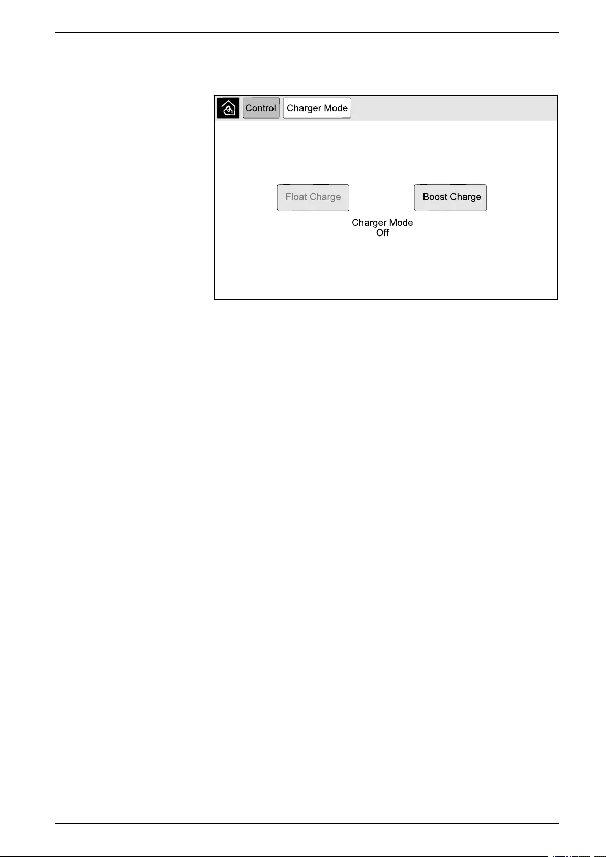
Start a Boost Charge of the Batteries
Boost charge gives the possibility of doing a fast recharge of a discharged battery.
38 990-5452H-001
UPS Display UPS System
NOTE: Boost charge must be enabled by Schneider Electric during start-up
for this option to be available.
1. From the home screen on the display select Control > Charger Mode.
2. Select Boost Charge to initiate a single boost charge of the batteries.
The UPS system starts boost charging the batteries.
To stop the boost charge and go back to float charge, select Float Charge.
Access a Configured Network Management Interface
The below procedure describes how to access the network management interface
from a web interface. It is also possible to use the following interfaces:
• Telnet and SSH
• SNMP
• FTP
• SCP
NOTE: Ensure that only one network management interface in the entire
system is set to synchronize time.
Use Microsoft Internet Explorer®7.x or higher on Windows operating systems only
or Mozilla®Firefox®3.0.6 or higher on all operating systems to access the web
interface of the network management interface. Other commonly available
browsers may work but have not been fully tested.
You can use either of the following protocols when you use the web interface:
• The HTTP protocol, which provides authentication by user name and Pin but
no encryption.
• The HTTPS protocol, which provides extra security through Secure Socket
Layer (SSL); encrypts user names, Pin, and data being transmitted; and
authenticates Network Management Cards by means of digital certificates.
1. Access the network management interface by its IP address (or its DNS
name, if a DNS name is configured).
2. Enter the user name and password.
3. To enable or disable the HTTP or HTTPS protocol, use the Network menu on
the Administration tab, and select the Access option under the Web
heading on the left navigation menu.
990-5452H-001 39
UPS System UPS Display
Troubleshooting from the UPS
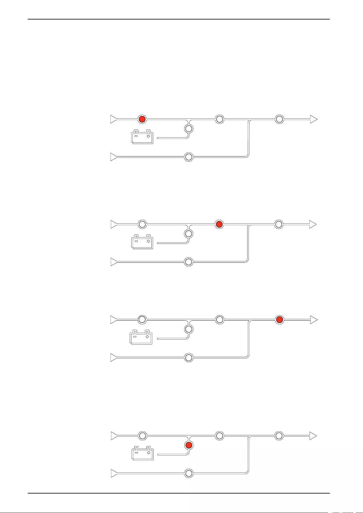
Troubleshooting via the Mimic Diagram LEDs
The mimic diagram shows the status of the main functions and the energy flow
supplying the load. The different LEDs are either green, red or turned off
depending on the status of the system functions. In this section it is listed what a
red LED on the mimic diagram is indicating to help troubleshooting.
Input LED
If the input LED is red, it can be caused by the following:
• UIB is open
• Input out of tolerance (waveform-, voltage-, or frequency out of tolerance)
Inverter LED
If the inverter LED is red, it can be caused by the following:
• Inverter inoperable
Load LED
If the load LED is red, it can be caused by the following:
• UOB is open
• SIB is open
• Output voltage out of tolerance
Battery LED
40 990-5452H-001
UPS Display UPS System
If the Battery LED is red, it can be caused by the following:
• Critical battery alarm active
• Charger inoperable
• Battery breaker disconnected
Bypass LED
If the bypass LED is red, it can be caused by the following:
• SSIB is open
• Static bypass switch inoperable
• Bypass out of tolerance
• BF2 is open
Reboot the Display
NOTE: A reboot of the display does not impact the settings made.
1. Open the shutter door on the front right side of the display.
2. Press the reboot button with a pointed object like a pen or a paper clip.
The display is rebooted.
Logs
There are two types of logs:
• NMC Log: Contains information about the display and network activities.
• UPS Log: Contains information about the system status and operation
modes.
990-5452H-001 41
UPS System UPS Display
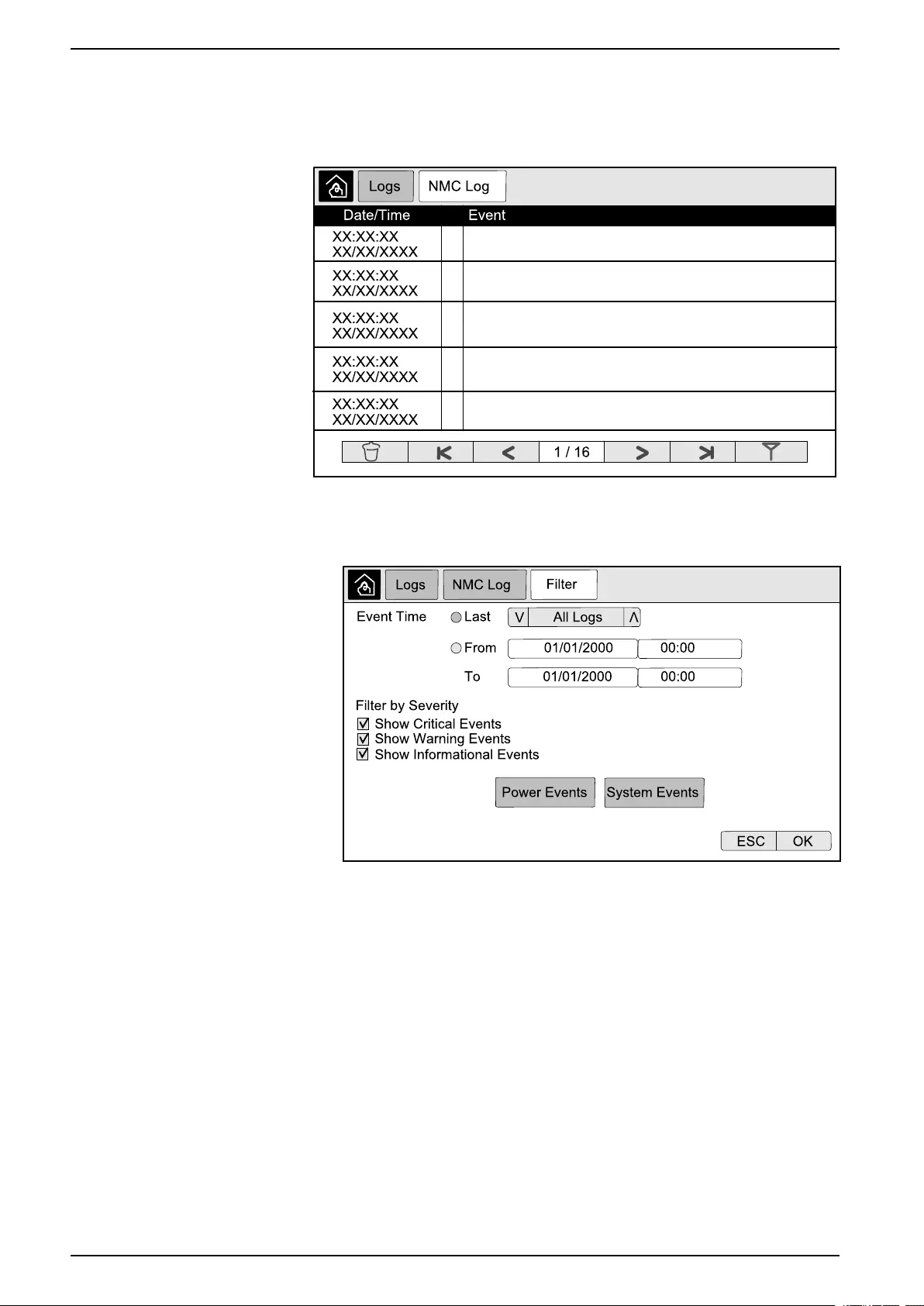
View the NMC Log
1. From the home screen on the display select Logs > NMC Log.
2. You can browse through the list of the events using the arrows.
3. You can now perform the following operations in the event log:
a. Tap the filter button to filter the events. Different filter settings are
available, including:
Filters for Power Events:Communication,Device,Output,Input,
Battery,UPS Operation Mode,Parallel System,Reminders,
Switchgear, and/or RFC 1628 MIB.
Filters for System Events:Mass Configuration and/or Security.
b. Tap the recycle bin button to clear the event log and select Yes to
confirm.
4. Tap the home button to exit the log.
42 990-5452H-001
UPS Display UPS System
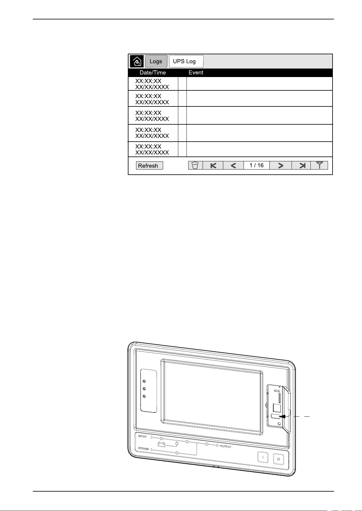
View the UPS Log
1. From the home screen on the display select Logs > UPS Log.
2. You can now browse through the list of the UPS events using the arrows.
3. You can perform the following operations in the UPS log:
a. Tap the filter button to filter the events. Different filter settings are
available, including:
Filters for Power Events:Communication,Device,Output,Input,
Battery,UPS Operation Mode,Parallel System,Reminders,
Switchgear, and/or RFC 1628 MIB.
Filters for System events:Mass Configuration and/or Security.
b. Tap the recycle bin button to clear the UPS log and select Yes to confirm.
4. Tap the home button to exit the log.
Export Data from Logs
The exported log can only be used by Schneider Electric customer support for
analysis.
1. From the home screen on the display select Logs > Export Data.
2. Insert a USB device in the USB port located on the front of the display.
990-5452H-001 43

UPS System UPS Display
3. Tap the Start Data Export button.
When the download is complete, the following message will be shown on the
screen: Data Exported Successfully. Remove USB device.
4. Remove the USB device and tap the home button to exit the screen.
5. The exported data on the USB device can now be sent to Schneider Electric
support for analyzing.
View the Active Alarms
When there is an active alarm in the system, a symbol indicating the alarm level is
shown in the top right corner of the screen and the buzzer is active.
1. From the home screen on the display select Status > Active Alarms.
Tapping the display will also silence the buzzer temporarily without login. By
logging in and tapping the display, the buzzer will be silenced permanently.
2. You can now browse through the list of active alarms using the left and right
arrows.
3. Tap the Refresh button to update the list with the latest active alarms.
Alarm Levels
There are three alarm levels:
• Critical: Take immediate action and call Schneider Electric.
• Warning: The load remains supported, but action must be taken. Call
Schneider Electric.
• Informational: No immediate action required. Check the cause of the alarm as
soon as possible.
Alarm Messages
Alarm/
Event
Severity Display Text Description Corrective Action Text
Alarm Warning Abnormal state at input contact
zone A
An abnormal state exists for
integrated Environmental Monitor
input contact zone A.
Please check the environment
Alarm Warning Abnormal state at input contact
zone B
An abnormal state exists for
integrated Environmental Monitor
input contact zone B.
Please check the environment
Alarm Warning Air Filter technical check
recommended
The air filters need to be checked
as preventive maintenance is
recommended.
The Air Filters may need to be
replaced.
Alarm Warning Ambient temperature high Ambient temperature is high.
Alarm Warning Ambient temperature out of
tolerance
The ambient temperature out of
tolerance.
Alarm Warning Batteries are discharging The load is drawing more power
than the UPS can draw from the
input, causing the UPS to draw
power from the batteries.
Alarm Warning Battery breaker BB1 open Battery breaker BB1 is open.
Alarm Warning Battery breaker BB2 open Battery breaker BB2 is open.
Alarm Warning Battery breaker BB3 open Battery breaker BB3 open.
Alarm Warning Battery breaker BB4 open Battery breaker BB4 open.
Alarm Warning Battery capacity is below minimum
acceptable level
The battery capacity is below the
minimum acceptable value
according to UPS power rating.
Risk of battery damage.
Change battery configuration and/
or add larger capacity battery
44 990-5452H-001

UPS Display UPS System
Alarm/
Event
Severity Display Text Description Corrective Action Text
Event Informational Battery breakers tripped To prevent the batteries deep
discharging, the battery breakers
have been tripped by the system.
Close the battery breakers
manually.
Alarm Warning Battery condition is poor Battery capacity is lower than
50%.
Batteries should be replaced.
Alarm Warning Battery condition is weak Battery capacity is between 50%
to 75%.
Alarm Warning Battery is below minimum
acceptable runtime
The battery runtime is below
configured minimum acceptable
value.
Alarm Critical Battery is not working correctly A battery is not working correctly. Please contact Schneider Electric.
Alarm Warning Battery room ventilation
inoperable
Input relay indicates that the
battery room ventilation is not
working correctly.
Alarm Warning Bypass backfeed breaker (BF2)
open
Bypass backfeed breaker (BF2) is
open, and the UPS is prevented
from running in normal operation.
Alarm Warning Breaker MBB closed Maintenance bypass breaker MBB
is closed, feeding the load with
unprotected power from bypass.
Alarm Warning Breaker SIB open System isolation breaker SIB is
open, and system cannot feed the
load.
Alarm Warning Breaker SSIB open Bypass static switch input breaker
SSIB is open, making static
bypass operation unavailable.
Alarm Warning Breaker UIB open Unit input breaker UIB is open,
and the UPS is prevented from
running in normal operation.
Alarm Warning Breaker UOB open Unit output breaker UOB is open,
and UPS cannot feed the load.
Alarm Warning Bypass frequency out of tolerance Bypass input frequency is out of
tolerance.
Check bypass input frequency
and bypass input frequency
setting.
Alarm Warning Bypass phase missing Bypass input is missing a phase. Check bypass input. Please
contact Schneider Electric.
Alarm Warning Bypass phase sequence incorrect The phase rotation on bypass
input is incorrect.
Check bypass input. Please
contact Schneider Electric.
Alarm Warning Bypass voltage out of tolerance Bypass input voltage is out of
tolerance and UPS is prevented
from going into requested bypass
mode.
Alarm Warning Charge power is reduced The battery charge power has
been reduced.
The input for this functionality was
activated, or the input current has
reached the maximum limit.
Please contact Schneider Electric.
Alarm Warning Communication cable termination
missing or damaged
One or more communication cable
terminators is/are missing or
damaged.
Alarm Warning Confirm redundancy lost and/or
transfer to Forced Static Bypass
One or more communication cable
terminators is/are missing or
damaged.
Alarm Warning Confirm Turn Load Off Off button has been pushed while
inverter is on and with no bypass
available. User must confirm that
the UPS turns off the power to the
load.
Confirm turn off either via display
or by pushing the off button again.
Alarm Informational Customer Input 1 activated Customer input relay 1 is
activated.
Alarm Informational Customer Input 2 activated Customer input relay 2 is
activated.
990-5452H-001 45

UPS System UPS Display
Alarm/
Event
Severity Display Text Description Corrective Action Text
Alarm Warning Delayed transfer from battery to
normal operation
The delayed transfer from battery
to normal operation is active.
Alarm Warning Display communication is lost Main Controller is unable to
communicate with the display.
Please contact Schneider Electric.
Alarm Warning Display firmware incompatibility
detected
The firmware of the display is
detected as incompatible with the
rest of the system.
Perform a firmware update.
Alarm Critical EPO Switch Activated An emergency power off (EPO)
switch is activated.
Deactivate the Emergency Power
Off switch.
Alarm Warning External battery monitoring
detected fault
Input relay indicates external
battery monitoring detected fault
Alarm Critical External charger off command:
activated
Input relay for charger off is
activated.
Please contact Schneider Electric.
Alarm Critical External energy storage
monitoring: major alarm
Input relay indicates external
energy storage monitoring has
detected a major alarm.
Please contact Schneider Electric.
Alarm Warning External energy storage
monitoring: minor alarm
Input relay indicates external
energy storage monitoring has
detected a minor alarm
Please contact Schneider Electric.
Alarm Warning External sync frequency out of
tolerance
External sync frequency is out of
tolerance.
Check external sync frequency.
Alarm Warning External sync phase missing External sync is missing a phase. Check External sync.
Alarm Warning External sync phase sequence
incorrect
The phase rotation on external
sync is incorrect.
Please contact Schneider Electric.
Alarm Warning External sync temporarily disabled External sync has been
temporarily disabled because
UPS cannot lock and syncronize
to the external sync source.
Check external sync
Alarm Warning External sync voltage out of
tolerance
External sync voltage is out of
tolerance and UPS is prevented
from going into external sync
mode.
Alarm Critical Fan inoperable UPS has one or more inoperable
fans. Fan redundancy is lost.
Alarm Critical Firmware update - Incorrect UPS
operation mode
The UPS is no longer in the
correct operation mode during
firmware update. Risk of load
drop.
Transfer UPS to maintenance
bypass.
Alarm Warning Firmware versions in parallel UPS
units are not identical
The firmware versions in parallel
UPS units are not identical.
Firmware update all UPS units in
the parallel system to the same
version
Alarm Critical Flywheel inoperable Input relay indicates that the
flywheel is not working correctly.
Alarm Informational Forced battery operation activated Forced battery operation has been
activated by user.
Alarm Critical General parallel system event The parallel system is not
configured correctly or is not
working correctly.
Please contact Schneider Electric.
Alarm Informational Genset is supplying the UPS Input relay indicates that a genset
is supplying the UPS.
Alarm Warning Ground fault detected Input relay indicates that a ground
fault has been detected.
Please contact Schneider Electric.
Alarm Warning High Battery Temperature Level The battery temperature is above
the Alarm setting.
Check the battery temperature. A
high temperature may decrease
the battery lifetime.
Alarm Informational High Efficiency Mode disabled High efficiency mode is disabled
from an input relay.
Alarm Informational High efficiency mode has been
disabled by the system
High Efficiency Mode is disabled
by the system as the maximum
number of transitions has been
exceeded.
Enable high efficiency mode
again, or disable it permanently.
46 990-5452H-001

UPS Display UPS System
Alarm/
Event
Severity Display Text Description Corrective Action Text
Alarm Informational High efficiency mode is disabled
due to bypass UTHD is above
configured limit
High efficiency mode is disabled
due to bypass UTHD is above
configured limit.
Alarm Warning High humidity threshold violation
at remote sensor
A high humidity threshold violation
exists for integrated
Environmental Monitor sensor.
Please check the environment.
Alarm Warning High temperature threshold
violation at remote sensor
A high temperature threshold
violation exists for integrated
Environmental Monitor sensor.
Please check the environment.
Alarm Warning Incorrect UPS configuration
detected
Incorrect UPS configuration
detected.
Alarm Warning Input frequency out of tolerance Mains input frequency is out of
tolerance.
Check input frequency and input
frequency setting.
Alarm Warning Input phase missing Input is missing a phase. Check input. Please contact
Schneider Electric.
Alarm Warning Input phase sequence incorrect The phase rotation on input is
incorrect.
Check input. Please contact
Schneider Electric.
Alarm Warning Input voltage out of tolerance Mains input voltage is out of
tolerance.
Alarm Warning Inverter is Off due to a request by
the user
The inverter is off due to a request
by the user.
Alarm Warning Inverter output is not in phase with
bypass input
The UPS inverter output is not in
phase with the bypass input.
Alarm Warning Li-Ion AC Supply Breaker BMS:
B1/BMS:B2 open
One or both Li-Ion BMS AC
Supply Breakers are open.
Alarm Warning Lost communication to remote
sensor
Lost the local network
management interface-to-
integrated Environmental Monitor.
Please check the environment.
Alarm Warning Lost parallel redundancy The load exceeds limit for an N+x
UPS in redundancy (x is the
configurable parallel redundancy).
Reduce the load on the system.
Alarm Warning Low Battery Temperature Level The battery temperature is below
the Alarm setting.
Alarm Warning Low humidity threshold violation at
remote sensor
A low humidity threshold violation
exists for integrated
Environmental Monitor sensor.
Please check the environment.
Alarm Warning Low temperature threshold
violation at remote sensor
A low temperature threshold
violation exists for integrated
Environmental Monitor sensor.
Please check the environment.
Alarm Warning Magelis 10 inch display firmware
incompatibility detected
The firmware of the Magelis 10
inch display is detected as
incompatible with the rest of the
system.
Perform a firmware update.
Alarm Warning Maintenance bypass breaker
(MBB) closed
Maintenance bypass breaker
(MBB) is closed, feeding the load
with unprotected power from
bypass.
Alarm Warning Maximum humidity threshold
violation at remote sensor
A maximum humidity threshold
violation exists for integrated
Environmental Monitor sensor.
Please check the environment.
Alarm Warning Maximum temperature threshold
violation at remote sensor
A maximum temperature
threshold violation exists for
integrated Environmental Monitor
sensor.
Please check the environment.
Alarm Informational Mega Tie is activated Dry contact input indicates that
Mega Tie is activated.
Alarm Warning Minimum humidity threshold
violation at remote sensor
A minimum humidity threshold
violation exists for integrated
Environmental Monitor sensor.
Please check the environment.
Alarm Warning Minimum temperature threshold
violation at remote sensor
A minimum temperature threshold
violation exists for integrated
Environmental Monitor sensor.
Please check the environment.
990-5452H-001 47

UPS System UPS Display
Alarm/
Event
Severity Display Text Description Corrective Action Text
Alarm Warning Modular battery breaker open Modular battery breaker is open.
Alarm Warning Modular battery cabinet is not
working correctly
Modular battery cabinet is not
working correctly.
Check battery cabinet. Please
contact Schneider Electric.
Alarm Warning NMC 1 firmware incompatibility
detected
The firmware of the NMC in Smart
Slot 1 is detected as incompatible
with the rest of the system.
Perform a firmware update.
Alarm Warning NMC 2 firmware incompatibility
detected
The firmware of the NMC in Smart
Slot 2 is detected as incompatible
with the rest of the system.
Perform a firmware update.
Alarm Warning Not enough UPS units ready to
turn on inverter
One or more parallel UPS units
have been requested to turn on
inverter, but not enough UPS units
are ready for system to enter
inverter on operation.
Turn on inverter of more UPS
units and/or check the setting
"Minimum Number of UPS
Required to Supply Load".
Alarm Warning Output frequency out of tolerance Output frequency is out of
tolerance.
Check output frequency and
output frequency setting.
Alarm Warning Output voltage out of tolerance The output voltage is out of
tolerance.
Alarm Warning Overload on installation The load exceeds 100% of rated
installation capacity.
Reduce load on system.
Alarm Warning Overload on UPS due to high
ambient temperature
The load exceeds the rated
capacity when running with high
ambient temperature.
Reduce load on system or
ambient temperature.
Alarm Warning Overload on UPS present. Load
below continuous overload
threshold
Reduce load on system or check
for output short circuit.
The load exceeds 100% of rated
capacity. Load is below the
Continuous Overload threshold.
Alarm Warning Overload or short circuit on UPS Reduce load on system or check
for output short circuit.
The load exceeds 100% of rated
capacity or there is a short circuit
on the output.
Alarm Warning Parallel communication lost on
PBUS cable 1
PBUS cable 1 may be damaged. Replace parallel Cable 1.
Alarm Warning Parallel communication lost on
PBUS cable 2
PBUS cable 2 may be damaged. Replace parallel Cable 2.
Alarm Warning Parallel mixed operation mode One or more parallel UPS units
are operating in battery operation,
while others are operating in
normal operation.
Alarm Warning Parallel unit not present Main Controller is unable to
communicate with parallel UPS X.
The UPS might have been
powered down or communication
cables may be damaged.
Alarm Warning Power cabinet inoperable Power cabinet is inoperable. Please contact Schneider Electric.
Alarm Warning Power cabinet mixed operation
mode
One or more power cabinets are
operating in battery operation,
while others are operating in
normal operation.
Alarm Warning Power cabinet redundancy lost The configured power cabinet
redundancy is lost, either because
the output load is too high, or
because there are not enough
power cabinets available.
Reduce the load on the system.
Alarm Critical Power cabinet surveillance
internal event detected
Power Cabinet Surveillance
detected an internal event.
Please contact Schneider Electric.
Alarm Warning Requested Bypass command
from input contact activated
Requested Bypass command
from input contact activated.
Alarm Critical Restricted air flow Restricted air flow. This could be caused by a
clogged air filter or other obstacle
blocking air flow.
Alarm Warning RTC backup battery is discharged The RTC backup battery is
discharged or the time is not set
correctly.
48 990-5452H-001

UPS Display UPS System
Alarm/
Event
Severity Display Text Description Corrective Action Text
Alarm Critical Self-test - Did not pass Self-test did not complete
correctly.
Check event log and active alarms
for more details.
Alarm Warning Startup recommended The product has been running
overtime without startup.
Please contact Schneider Electric
for secure startup.
Alarm Critical Static bypass switch inoperable Static bypass switch is inoperable.
UPS is prevented from going into
static bypass operation.
Please contact Schneider Electric.
Alarm Warning Static bypass switch warning The static bypass switch needs a
technical check but is still fully
operational.
Please contact Schneider Electric.
Alarm Critical Surveillance detected fault Surveillance detected fault. Please contact Schneider Electric.
Alarm Warning Synchronization unavailable -
system is freerunning
The UPS is unable to synchronize
to the bypass input, external
source or parallel system.
Alarm Warning System isolation breaker (SIB)
open
System isolation breaker (SIB) is
open, and system cannot feed the
load.
Alarm Critical System locked in bypass
operation
The system is locked in bypass
operation.
The system has toggled between
inverter operation and bypass
operation more than 10 times
within 1 minute. Please activate
on button to transfer back to
normal operation.
Alarm Critical System operation mode - Forced
Static Bypass
The system is in bypass in
response to a critical event or an
inverter off request.
Alarm Warning System operation mode -
Maintenance Bypass
The system load is supplied
through Maintenance Bypass
Breaker (MBB).
Alarm Critical System operation mode - Off The system output power is turned
off.
Alarm Warning System operation mode -
Requested Static Bypass
The system is in bypass in
response to the UPS front-panel
or a user-initiated software
command, typically for
maintenance.
Alarm Critical System operation mode - Static
Bypass Standby
The system is in static bypass
standby operation in response to a
critical event or an inverter off
request.
Alarm Warning Technical Check recommended The product and its batteries need
to be checked as preventive
maintenance is recommended.
Please contact Schneider Electric.
Alarm Warning Transfer from battery to normal
operation delay activated
Input relay indicates that the
transfer from battery to normal
operation delay is activated.
Alarm Warning Unit input breaker (UIB) open Unit input breaker (UIB) is open,
and the UPS is prevented from
running in normal operation
Alarm Warning Unit output breaker (UOB) aux
wiring not correct
Unit output breaker (UOB) aux
wiring is not correct.
Please check UOB aux wiring.
Both circuits must connect to a
normally open switch.
Alarm Warning Unit output breaker (UOB) open Unit output breaker (UOB) is
open, and UPS cannot feed the
load.
Alarm Warning UPS locked in static bypass mode
is activated
Input relay for UPS locked in static
bypass mode is activated.
Alarm Critical UPS configuration incorrect UPS is configured incorrectly. Please contact Schneider Electric.
Alarm Warning UPS operation mode - Battery On battery power in response to
an input power problem.
Alarm Informational UPS operation mode - Battery
Test
On battery power in response to a
test of the performance of the
batteries.
990-5452H-001 49

UPS System UPS Display
Alarm/
Event
Severity Display Text Description Corrective Action Text
Alarm Critical UPS operation mode - Forced
Static Bypass
The UPS is in bypass in response
to a critical event or an inverter off
request.
Alarm Informational UPS operation mode - Initialize The UPS is initializing.
Alarm Informational UPS operation mode - Inverter
Standby
The UPS is ready to enter battery
operation but awaits permission
from the system. UPS output is
off.
Alarm Warning UPS operation mode -
Maintenance Bypass
The UPS load is supplied through
Maintenance Bypass Breaker
(MBB).
Alarm Critical UPS operation mode - Off The output power is turned off.
Alarm Warning UPS operation mode - Requested
Static Bypass
The UPS is in bypass in response
to the UPS front-panel or a user-
initiated software command,
typically for maintenance.
Alarm
Warning UPS operation mode - Static
Bypass Standby
The UPS is ready to enter static
bypass but awaits permission from
the system. UPS output is off.
Alarm
Critical UPS settings reset to default Unit settings has been reset to
default. The UPS is locked in off
operation until settings are
confirmed.
Please contact Schneider Electric.
Alarm Warning Warranty expiring soon The product is reaching the end of
warranty.
Please contact Schneider Electric.
Tests
The UPS system can perform the following tests to ensure correct performance of
the system:
•Battery Test
•Runtime Calibration
•Battery SPoT Mode
•Annunciators
•Display Calibration
Perform a Battery Test
Prerequisites:
• The batteries must be more than 50% charged.
• The runtime available must be more than 4 minutes.
• The operation mode must be normal operation, ECOnversion, or ECO mode.
• The system operation mode must be normal, ECOnversion, or ECO mode.
This feature performs a number of tests on the batteries, such as fuse-blown
check, weak battery detection. The test will discharge the battery, and use about
10% of the total capacity. Meaning if you have 10 minutes of runtime, the test will
run for 1 minute. The Battery Test can be set up to run automatically in different
time intervals (from weekly and up to once a year).
1. From the home screen on the display select Tests > Battery Test.
2. Tap the Start Battery Self-Test button.
NOTE: If you wish to manually stop the battery self-test, tap the Abort
Battery Self-Test button.
50 990-5452H-001

UPS Display UPS System
Perform a Runtime Calibration
This feature is used for calibrating the estimated remaining battery runtime value.
In this test the UPS transfers to battery operation and the batteries are discharged
to the low DC warning level. Based on the elapsed time and information about the
load, the battery capacity can be calculated and the estimated runtime calibrated.
Schneider Electric recommends performing battery runtime calibration at start-up,
when batteries are replaced, or when changes are made to the battery cabinets.
NOTICE
RISK OF EQUIPMENT DAMAGE
• During a runtime calibration the batteries will be at a very low level and
therefore not capable of supporting your system load in case of a input
power failure.
• Batteries will be discharged to 10% capacity and this will result in a low
battery runtime after the calibration.
• Repeated battery testing or calibration can affect the lifetime of the battery.
Failure to follow these instructions can result in equipment damage.
Prerequisites:
• Batteries must be 100% charged.
• The load percentage must be at least 10% and must not change more than
20% during test.
• The bypass supply must be available.
• The operation mode must be normal operation, ECOnversion, or ECO mode.
• The system operation mode must be inverter, ECOnversion, or ECO mode.
1. From the home screen on the display select Tests > Runtime Calibration.
2. Tap the Start Runtime Calibration button.
NOTE: If you wish to manually stop the runtime calibration, tap the Abort
Runtime Calibration button.
Perform a Battery SPoT Mode Test
NOTE: Battery SPoT Mode test is only legal in some countries/ares. Please
refer to local/national legislation.
Prerequisites:
• The unit output breaker UOB must be open
• The UPS operation mode must be requested static bypass
• The battery breaker(s) BB must be closed
• There must be no detected surveillance faults
• The static switch input breaker SSIB must be closed
• The output voltage and frequency must be within predefined limits
This feature performs a battery discharge test without the need for a load bank.
During the battery SPoT mode test, the inverter is turned ON while the UPS is in
requested static bypass. During the test, the UPS performs a battery runtime
calibration test and adjusts the estimated runtime accordingly.
The output power can be manually adjusted from 0 to 100% load to be as closed
as possible to the operating conditions.
The battery SPoT mode test stops when the battery voltage has reached its
shutdown level, or when the predefined discharge level has been reached.
NOTE: Battery SPoT Mode must be enabled by Schneider Electric during
service configuration to make battery SPoT mode available.
990-5452H-001 51
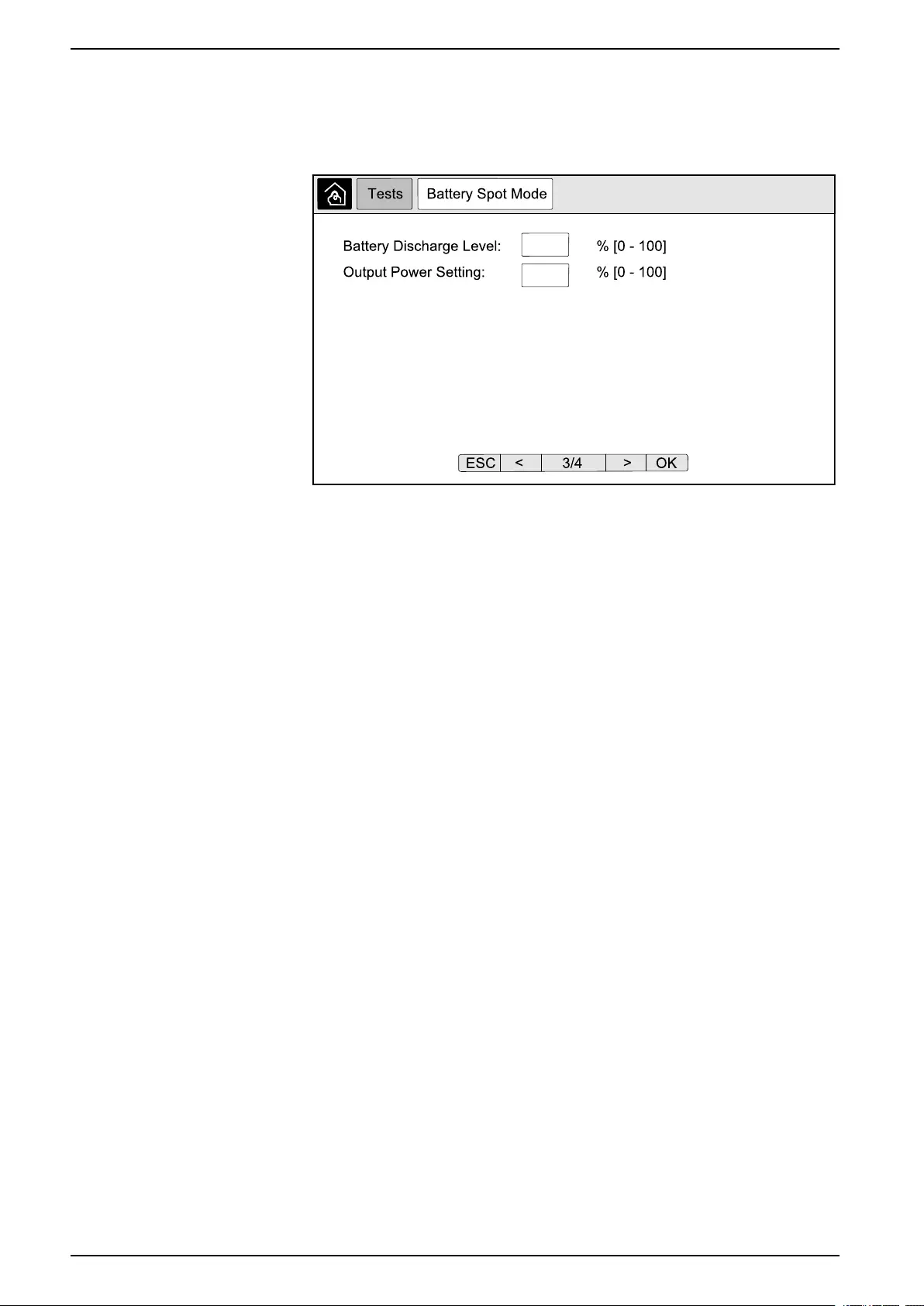
UPS System UPS Display
1. From the home screen on the display select Tests > Battery SPoT Mode.
2. Go through the Battery SPoT Mode screens and verify that the prerequisites
for performing a test is met.
3. Set the battery discharge level and the output power level.
4. Tap the Start Battery SPoT Mode button.
NOTE: If you wish to manually stop the battery SPoT mode test, tap the
Abort Battery SPoT Mode button.
Perform an Annunciators Test
1. From the home screen on the display select Tests > Annunciators.
2. Tap the Start button to initiate the test.
During the annunciators test the LEDs on the display and the mimic diagram
and the audible alarm are tested.
Calibrate the Display
From the home screen on the display select Tests > Display Calibration and
then select the calibration you want to perform.
•Calibrate: Tests and adjusts the touch screen target sensitivity.
•Calibration Check: Checks the calibration adjustments.
52 990-5452H-001
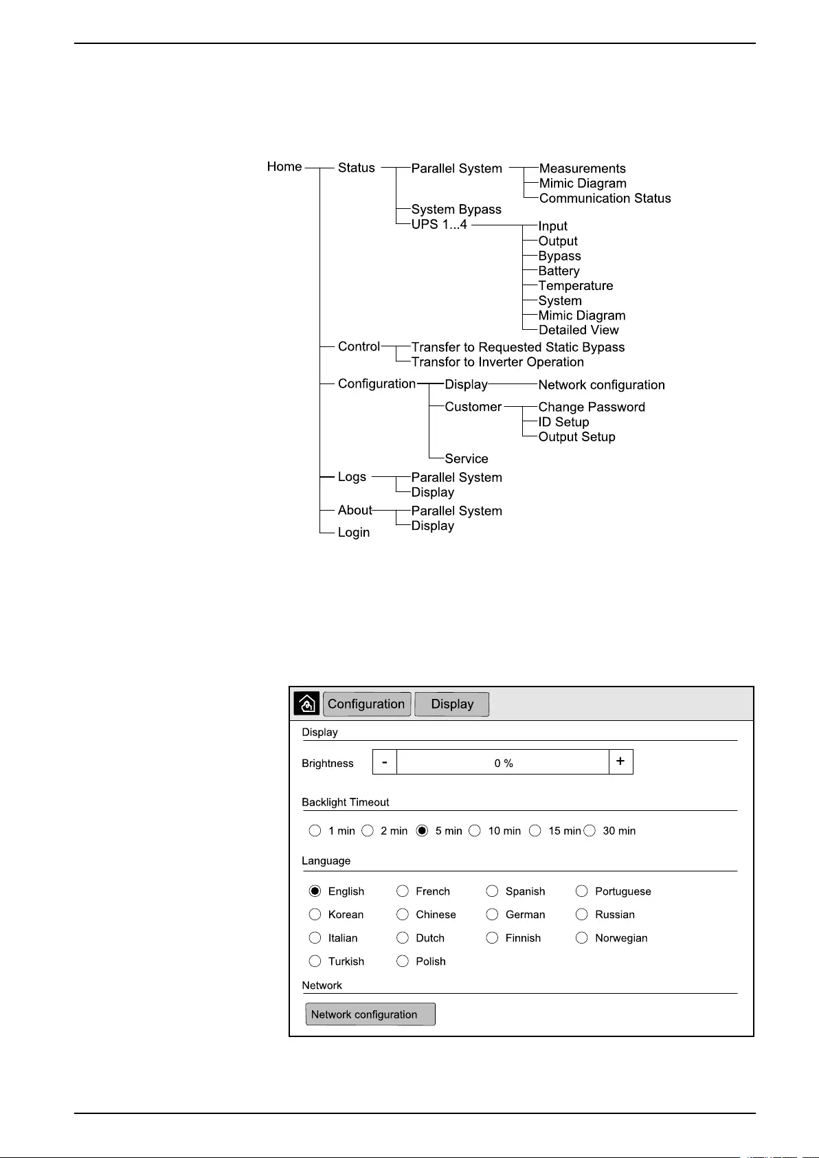
10” System Bypass Display UPS System
10” System Bypass Display
10” System Bypass Display Menu Tree (Option)
Configuration from the 10” System Bypass Display (Option)
Configure the Display Settings
1. From the home screen on the display select Configuration > Display.
2. Set the brightness of the display via the Brightness indicator. Tap +to
increase the brightness and tap –to decrease the brightness.
990-5452H-001 53
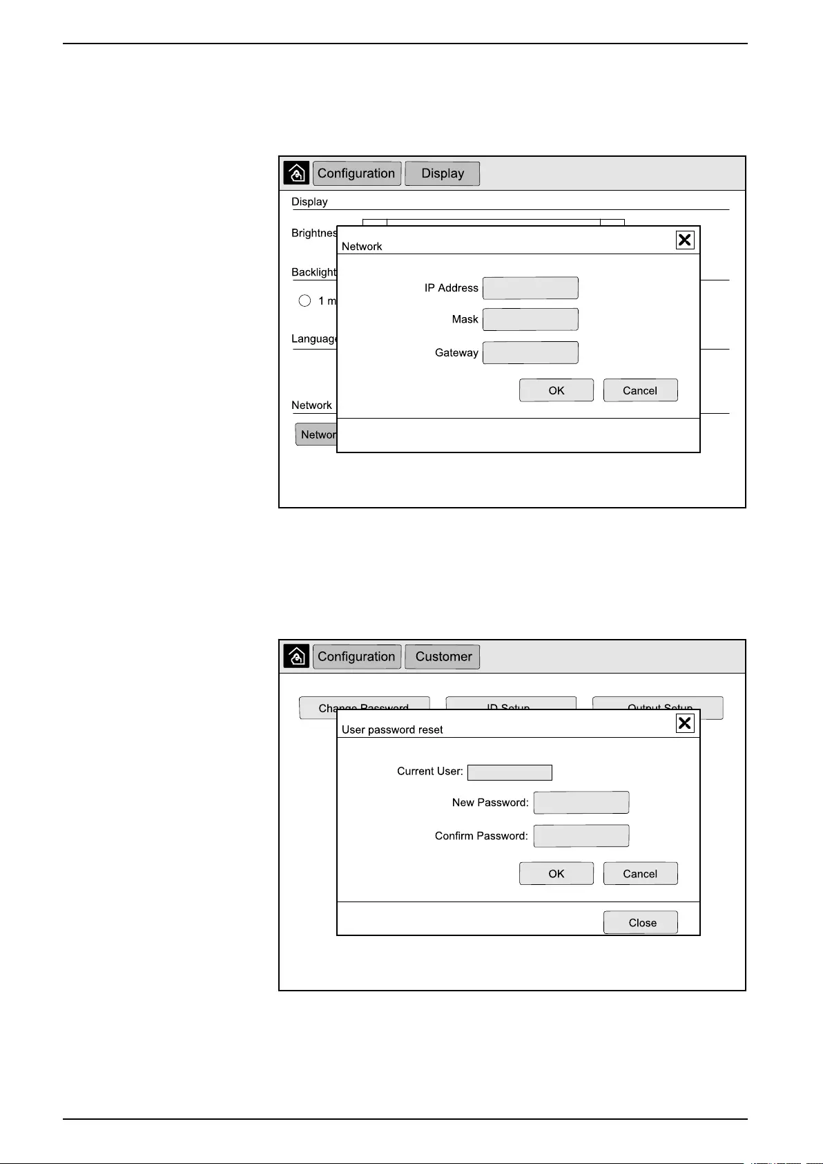
UPS System 10” System Bypass Display
3. Set the backlight timeout. Choose between 1,2,5,10,15, or 30 minutes.
4. Set the language of the display.
5. Configure the network by tapping the Network configuration button and
typing in the IP Address,Mask, and Gateway. Complete with OK.
6. Tap the home button to exit the configuration screen.
Change the User Password
1. From the home screen on the display select Configuration > Customer >
Change Password.
2. Type in New Password and Confirm Password and complete with OK.
3. Tap Close or the Xbutton to exit the User password reset pop-up screen.
4. Tap the home button to exit the configuration screen.
54 990-5452H-001
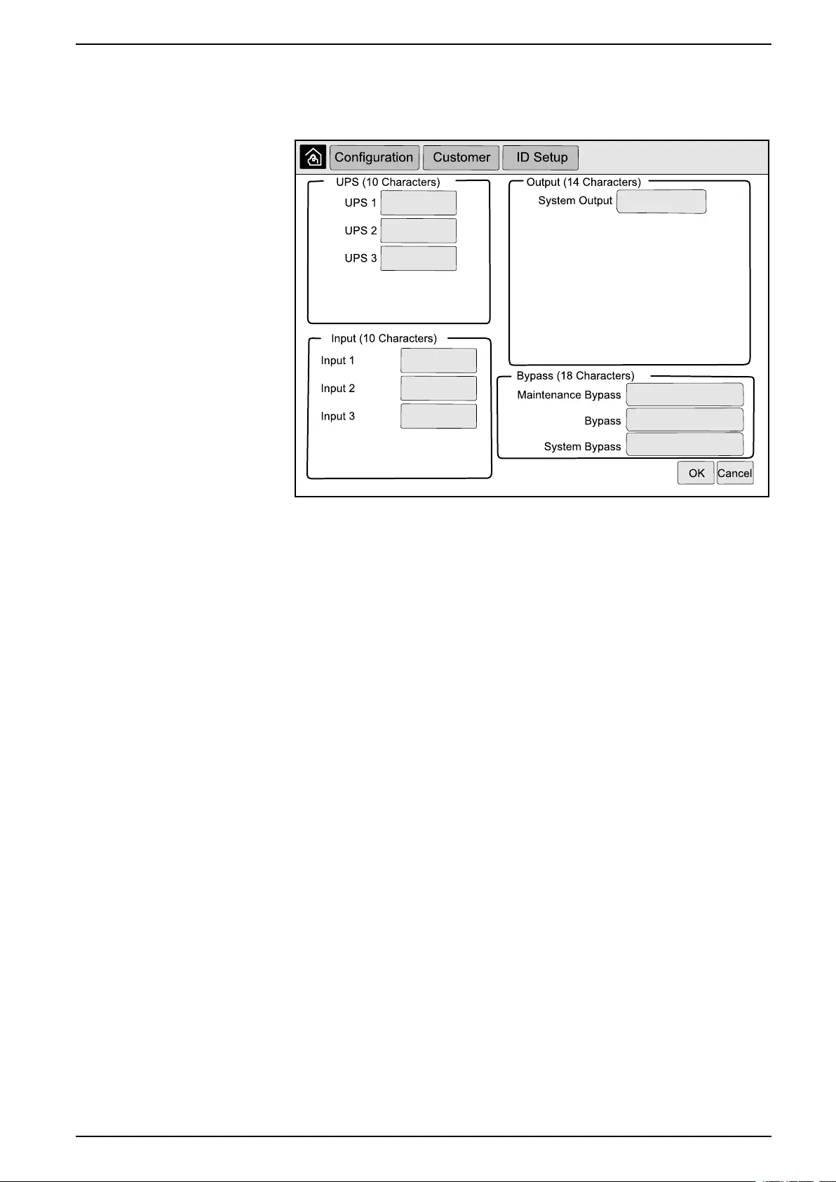
10” System Bypass Display UPS System
Change the System Names
1. From the home screen on the display select Configuration > Customer > ID
Setup.
2. The following names can be changed.
• UPS
• Input
• System Output
• Maintenance Bypass
• Bypass
• System Bypass
3. Tap OK to confirm your settings.
4. Tap the home button to exit the configuration screen.
990-5452H-001 55
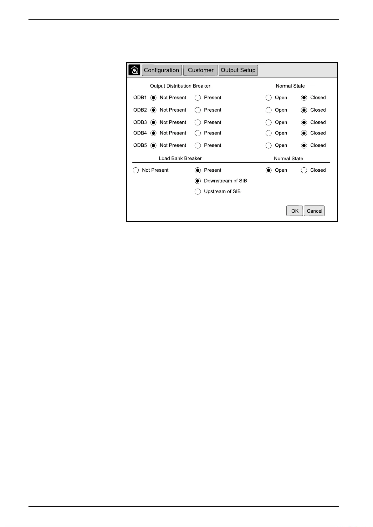
UPS System 10” System Bypass Display
Configure the Output Distribution Breakers
1. From the home screen on the display select Configuration > Customer >
Output Setup.
2. Select Present for the output distribution breakers that are available in the
parallel system.
3. Select Present for the Load Bank Breaker if it is part of the parallel system
and indicate whether the load bank breaker is Upstream of SIB or
Downstream of SIB.
4. Tap OK to confirm your settings.
5. Tap the home button to exit the configuration screen.
Operation Procedures from the 10” System Bypass Display
(Option)
Access Password-Protected Screens
NOTE: The default administrator username/password are admin/admin.
Change the password after logging in the first time, and change the password
regularly.
NOTE: The default user username/password are config/config.
1. When prompted for the password, tap the Username field to access the
keyboard.
2. Tap the username field, type in your username, and tap Enter.
3. Tap the Password field, type in your password, and tap Enter.
4. Tap Login.
5. Tap Close or the Xbutton to exit the Login pop-up screen.
View the Parallel System Status
1. From the home screen on the display select Status > Parallel System.
56 990-5452H-001
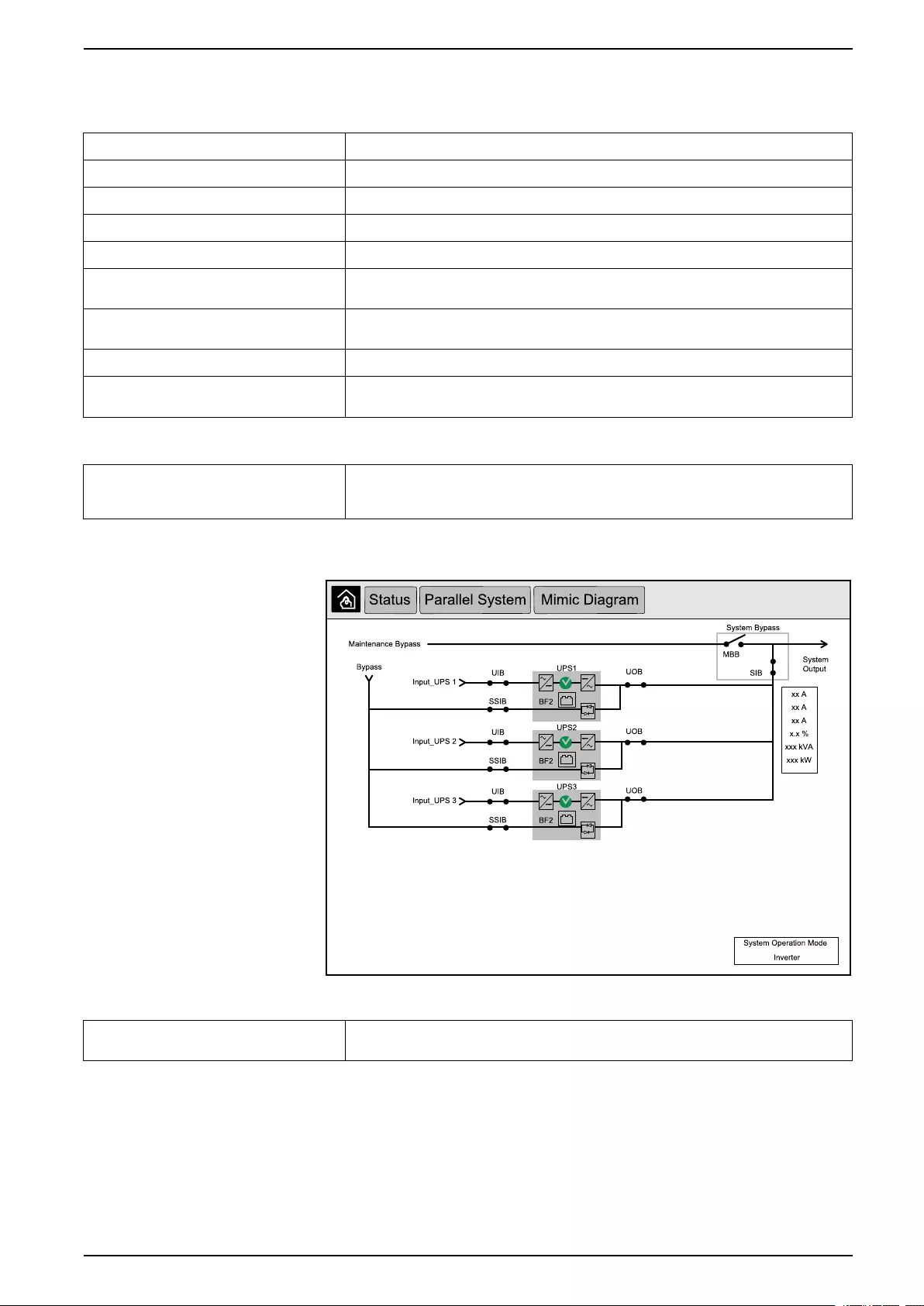
10” System Bypass Display UPS System
2. Select the area for which you wish to see the status. Choose between:
Measurements
Input Current (A) The present phase-to-phase input current in amperes (A).
Output Current (A) The present phase-to-phase output current in amperes (A).
Bypass Current (A) The present phase-to-phase bypass current in amperes (A).
Number of Parallel UPS The total number of UPSs in the parallel system.
Number of Redundant UPS The redundancy for the parallel system.
Number of Redundant Power Cabinets
per UPS
The number of redundant power cabinets in each UPS.
Output Total Apparent Power (kVA) The present total apparent output power (for all three phases) in thousands of Volt-Amps
(kVA).
Output Total Active Power (kW) The present total active output power (for all three phases) in kilowatts (kW).
Output Total Load (%) The percentage of the UPS system capacity presently used across all phases. The load
percentage for the highest phase load is displayed.
Mimic Diagram
Mimic Diagram The mimic diagram shows the current status of the main parts of the UPS system: power
sources, converters, bypass static switch and breakers, and it shows the power flow
through the system.
NOTE: You can click the UPS or the system bypass to get a more
detailed mimic diagram.
Communication Status
Communication Status The communication status diagram shows the communication status between the display
and the UPSs of the parallel system.
990-5452H-001 57
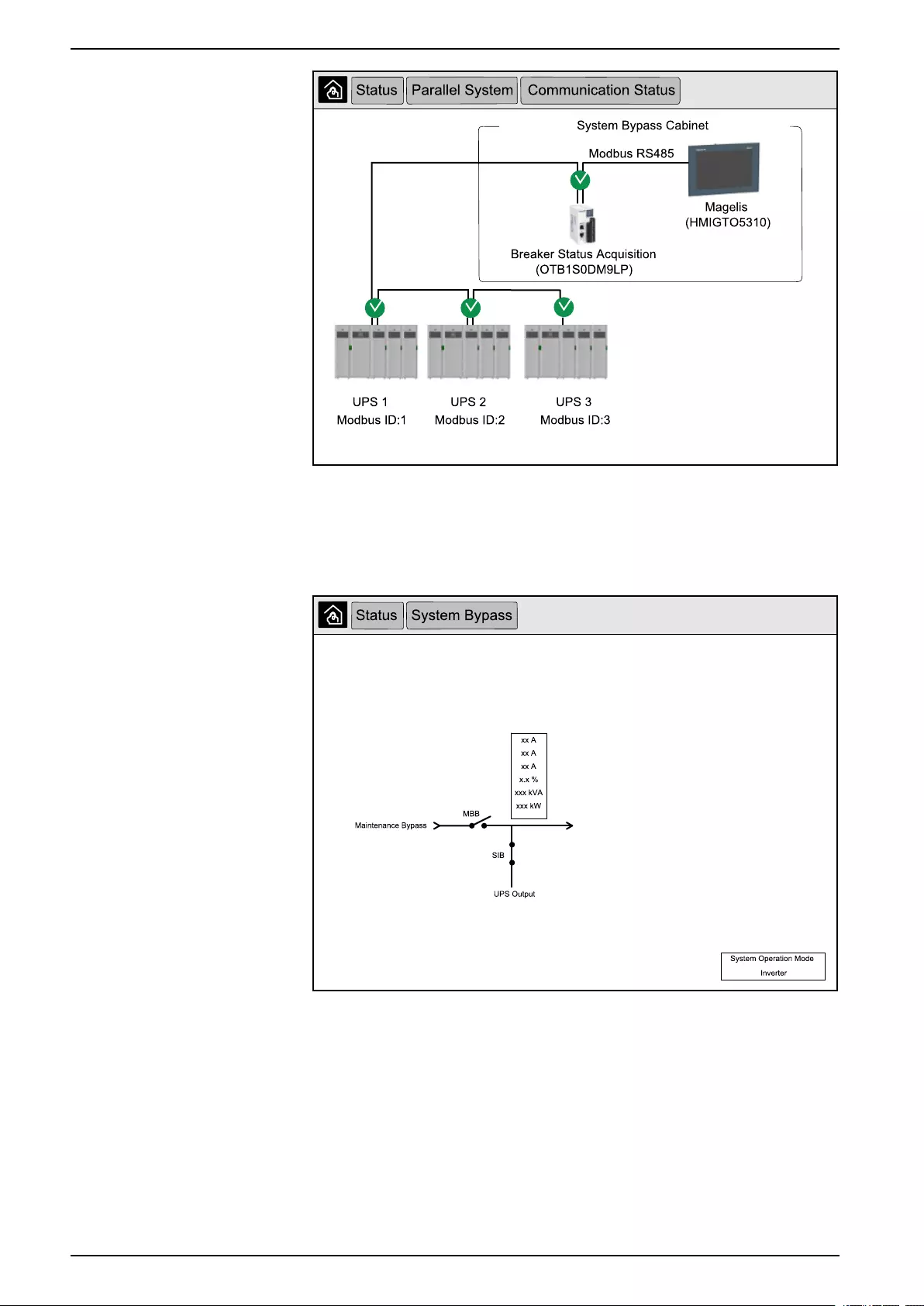
UPS System 10” System Bypass Display
3. Tap the home button to exit the screens and return to the home screen.
View System Bypass Status
1. From the home screen on the display select Status > System Bypass.
2. Tap the home button to exit the screens and return to the home screen.
View UPS Status Information
1. From the home screen on the display select Status > UPS X.
58 990-5452H-001

10” System Bypass Display UPS System
2. Select the area for which you wish to see the status. Choose between:
Input
Voltage (V) phase-to-neutral5The present phase-to-neutral input voltage in volts (V).
Current (A) The present input current from the AC utility power source per phase in amperes (A).
Peak RMS Current (A) The maximum current for the latest 30 days.
Apparent Power (kVA) The present apparent input power for each phase in kVA. Apparent power is the product of
RMS (root mean square) volts and RMS amperes.
Active Power (kW) The present active input power (or real power) for each phase in kilowatts (kW). Active
power is the portion of power flow that, averaged over a complete cycle of the AC
waveform, results in net transfer of energy in one direction.
Power Factor The ratio of the active power to apparent power.
Voltage (V) phase-to-phase The present phase-to-phase input voltage.
Total Apparent Power (kVA) The present total apparent input power (for all three phases) in kVA.
Total Active Power (kW) The present total active input power (for all three phases) in kW.
Frequency (Hz) The present input frequency in hertz (Hz).
Energy (kWh) The total energy consumption since the time of installation or since the number was reset.
Output
Voltage (V) phase-to-neutral5The phase-to-neutral output voltage at the inverter in volts (V).
Current (A) The present output current for each phase in amperes (A).
Peak RMS Current (A) The maximum current for the latest 30 days.
Apparent Power (kVA) The present apparent output power for each phase in kVA. Apparent power is the product
of RMS (root mean square) volts and RMS amperes.
Active Power (kW) The present active output power (or real power) for each phase in kilowatts (kW). Active
power is the portion of power flow that, averaged over a complete cycle of the AC
waveform, results in net transfer of energy in one direction.
Power Factor The present output power factor for each phase. Power factor is the ratio of active power to
apparent power.
Current Crest Factor The present output crest factor for each phase. The output crest factor is the ratio of the
peak value of the output current to the RMS (root mean square) value.
Current THD (%) The THD (total harmonic distortion) for each phase, as a percentage, for the present
output current.
Voltage (V) phase-to-phase The phase-to-phase output voltage at the inverter in volts (V).
Total Apparent Power (kVA) The present apparent output power for each phase in thousands of Volt-Amps (kVA).
Apparent power is the product of RMS (root mean square) volts and RMS amperes.
Total Active Power (kW) The present total active output power (for all three phases) in kilowatts (kW).
Load (%) The percentage of the UPS capacity presently used across all phases. The load
percentage for the highest phase load is displayed.
Neutral Current (A)1The present output neutral current in amperes (A).
Frequency (Hz) The present output frequency in hertz (Hz).
Inverter Status The general condition of the inverter.
PFC Status The general condition of the PFC.
Energy (kWh) The total energy supplied since the time of installation or since the value was reset.
Bypass
Voltage (V) phase-to-neutral5The present phase-to-neutral bypass voltage (V).
Current (A) The present bypass current for each phase, in amperes (A).
990-5452H-001 59
5. Only applicable in systems with neutral connection.

UPS System 10” System Bypass Display
Bypass (Continued)
Peak RMS Current (A) The maximum current for the latest 30 days.
Apparent Power (kVA) The present apparent bypass power for each phase in kVA. Apparent power is the product
of RMS (root mean square) volts and RMS amperes.
Active Power (kW) The present active bypass power for each phase in kilowatts (kW). Active power is the time
average of the instantaneous product of voltage and current.
Power Factor The present bypass power factor for each phase. Power factor is the ratio of active power
to apparent power.
Voltage (V) phase-to-phase The present phase-to-phase bypass voltage (V).
Total Apparent Power (kVA) The present total apparent bypass power (for all three phases) in thousands of Volt-Amps
(kVA).
Total Active Power (kW) The present total active bypass power (for all three phases) in kilowatts (kW).
Frequency (Hz) The present bypass frequency in hertz (Hz).
Battery
Voltage (V) The present battery voltage.
Current (A) The present battery current in amperes (A).
A positive current indicates that the battery is charging; a negative current indicates that
the battery is discharging.
Power (kW) The present DC power being drawn from the battery, in kilowatts (kW).
Estimated Charge Level (%) The present battery charge, as a percentage of full charge capacity.
Estimated Charge Time (h:mn) The estimated time, in minutes, until the batteries reach 100% charge.
Runtime Remaining (h:mn) The amount of time in hours and minutes before the batteries reach the low-voltage
shutdown level.
Charger Mode The operation mode of the charger (Off, Float, Boost, Equalization, Cyclic, Test).
Battery Status The general condition of the battery.
Charger Status The general condition of the charger.
Total Battery Capacity (Ah) The total capacity available from the available batteries.
Battery Temperature C° The highest battery temperature from the connected temperature sensors.
Temperature
Temperature Ambient temperature in degrees Celsius or Fahrenheit for the I/O cabinet and each power
cabinet.
System
Output Voltage The phase-to-phase output voltage at the inverter in volts (V).
Output Current The present output current for each phase in amperes (A).
Output Frequency The present output frequency in hertz (Hz).
Runtime Remaining The amount of time in hours and minutes before the batteries reach the low-voltage
shutdown level.
System Time The time of the UPS system.
UPS Operation Mode The operation mode of the operated UPS.
System Operation Mode The operation mode of the complete UPS system.
Total Output Power The apparent and active power (or real power) output for each phase.
Output Power The phase-to-phase apparent and active output power (or real power) for each phase.
60 990-5452H-001
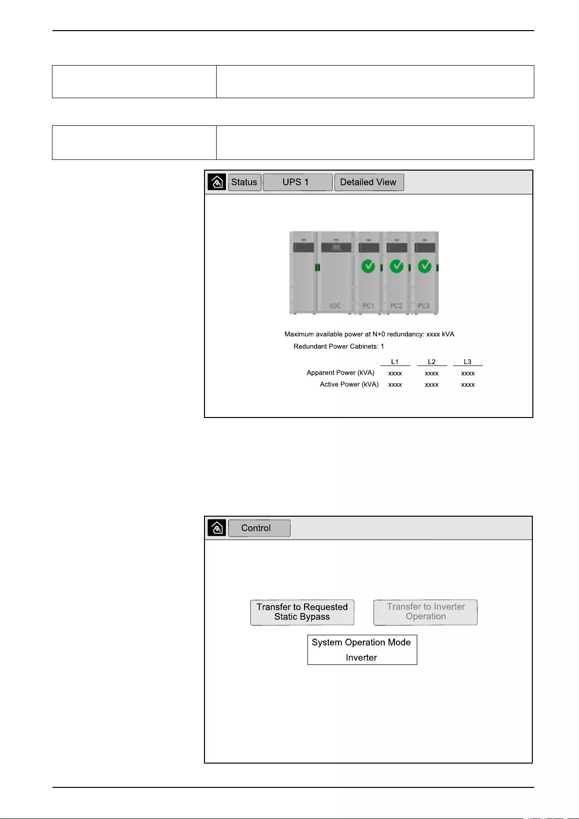
10” System Bypass Display UPS System
Mimic Diagram
Mimic Diagram The mimic diagram shows the current status of the main parts of the UPS: power sources,
converters, bypass static switch and breakers, and it shows the power flow through the
UPS.
Detailed View
Detailed view The detailed view shows the system with a status icon on each individual power cabinet
and the actual number of redundant power cabinets. The detailed view also shows the
apparent power and active power per phase.
3. Tap the home button to exit the screens and return to the home screen.
Transfer the Parallel System from Normal to Requested Static Bypass Operation
Please note that only the administrator can change operation mode.
1. From the home screen on the display select Control.
990-5452H-001 61
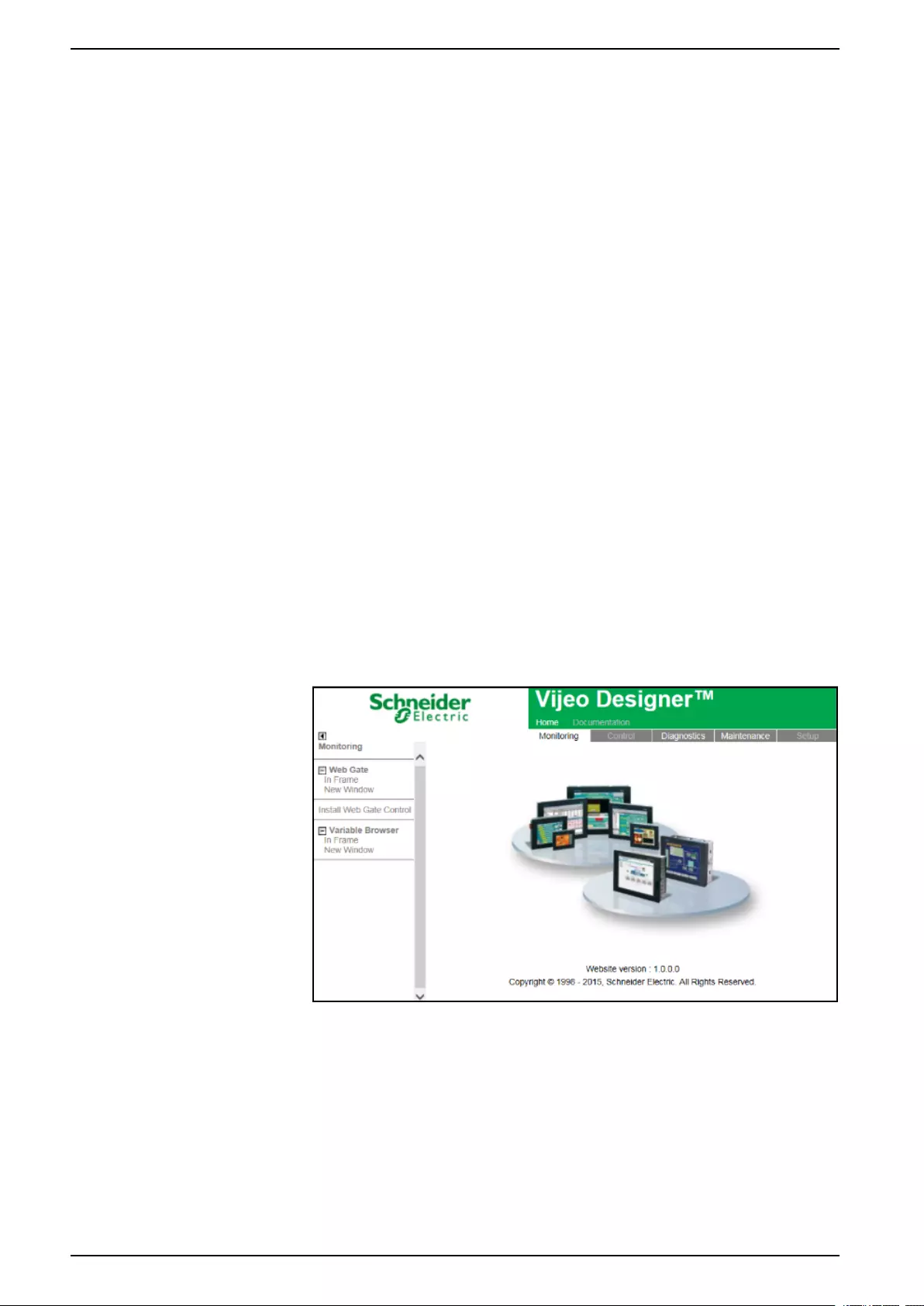
UPS System 10” System Bypass Display
2. Tap the Transfer to Requested Static Bypass button.
NOTE: If the conditions for performing the transfer are not met, the button
will be grayed out.
3. Verify that the System Operation Mode changes to Requested Static
Bypass.
Transfer the Parallel System from Requested Static Bypass to Normal Operation
Please note that only the administrator can change operation mode.
1. From the home screen on the display select Control.
2. Tap the Transfer to Inverter Operation button.
NOTE: If the conditions for performing the transfer are not met, the button
will be grayed out.
3. Verify that the System Operation Mode changes to Inverter.
Connect to the 10” System Bypass Display Remotely
1. In Internet Explorer 10 or newer, type in the IP address of the display. If you
want to disable this feature, ensure that the IP address of the display is left
blank.
2. If requested, follow Active X installation instructions.
3. Select the Monitoring tab and then select Web Gate > New Window in the
left pane.
You now have access to the status and log information of the parallel system.
4. Log in with your username and password. Please ensure that you change
your password before using the remote feature in order to secure your
connection. It is recommended to change your password regularly.
Troubleshooting from the 10” System Bypass Display (Option)
View the Display Log
NOTE: This log is only related to the display operation and not to the operation
of the UPS system.
62 990-5452H-001
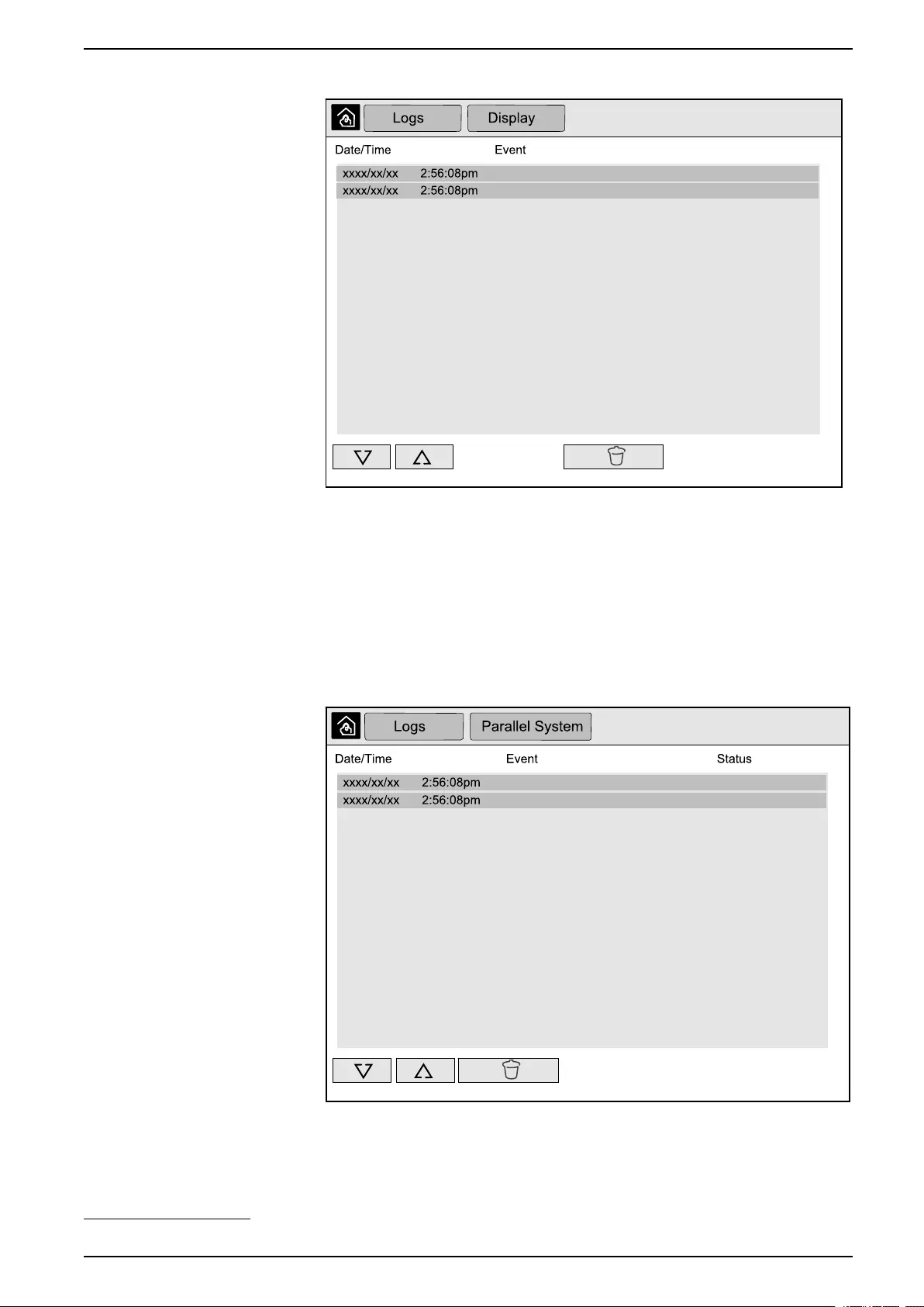
10” System Bypass Display UPS System
1. From the home screen on the display select Logs > Display.
2. You can perform the following operations in the log:
a. Tap the arrows to browse through the list of events.
b. Tap the recycle bin button to clear the log.6
3. Tap the home button to exit the log.
View the Parallel System Log
1. From the home screen on the display select Logs > Parallel System.
2. You can perform the following operations in the log:
a. Tap the arrows to browse through the list of events.
b. Tap the recycle bin button to clear the log.6
990-5452H-001 63
6. This action is only available to the administrator.
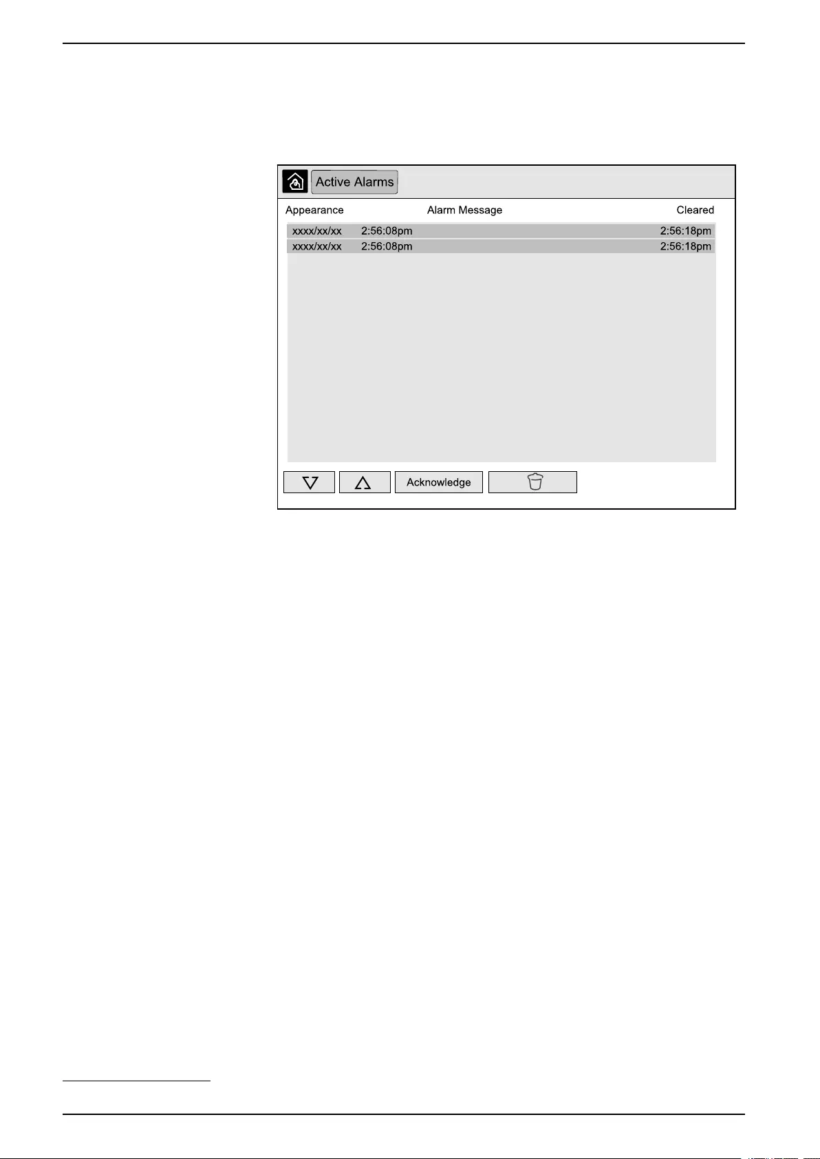
UPS System 10” System Bypass Display
3. Tap the home button to exit the log.
View the Active Alarms
1. Tap the symbol in the top right corner of the screen.
2. You can perform the following operations on the Active Alarms screen:
a. Tap the arrows to browse through the list of active alarms.
The active alarms are colored according to the alarm level:
• Green: No active alarms present
• Blue: Informational alarm present
• Yellow: Warning alarm present
• Red: Critical alarm present
b. Tap the recycle bin button to clear the active alarms list.7
c. Tap the Acknowledge button to stop the flashing of the active alarms.
3. Tap the home button to exit the active alarms list.
64 990-5452H-001
7. This action is only available to the administrator.
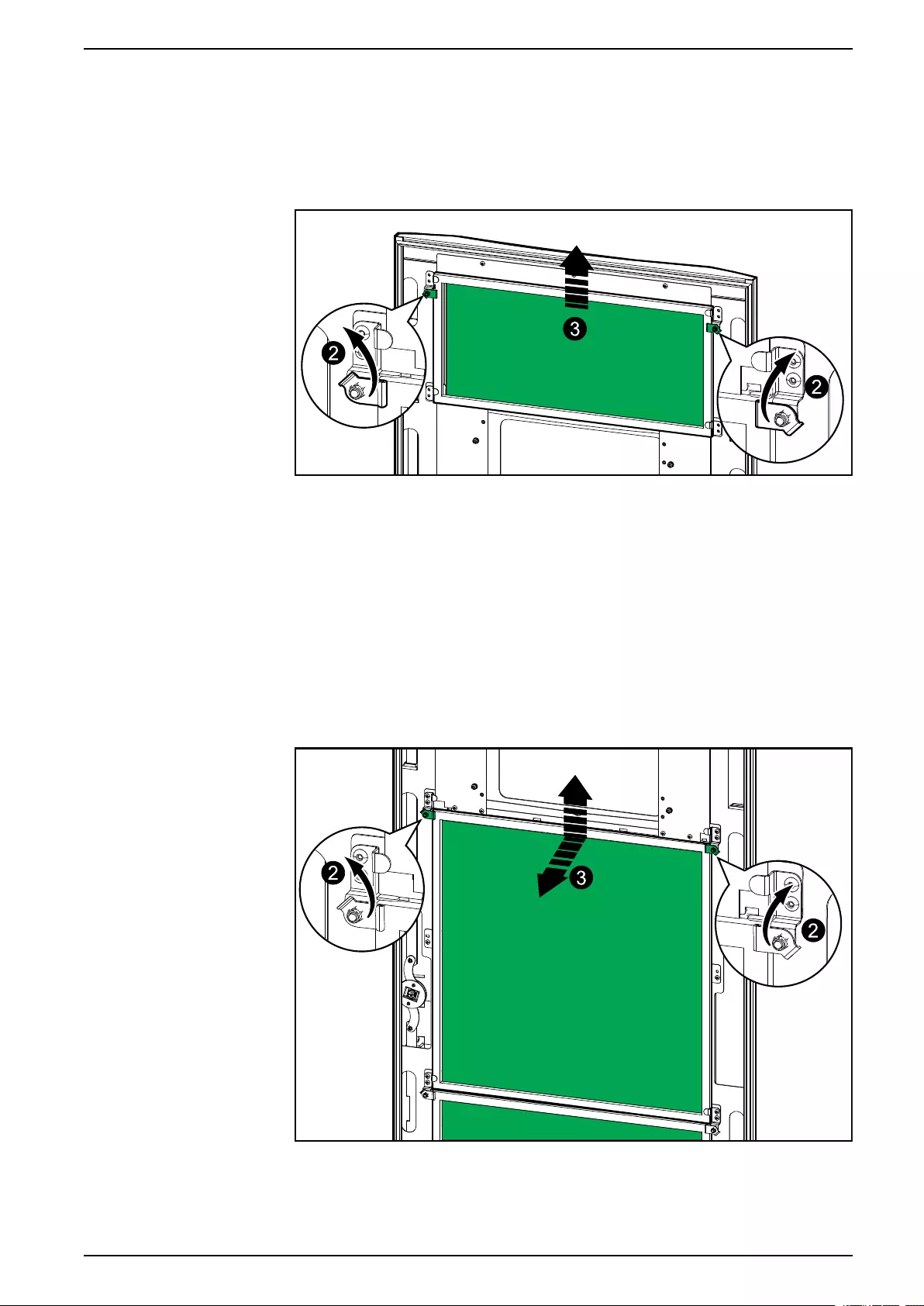
Maintenance UPS System
Maintenance
Replace the Top Filter
Rear View of the Front Door
1. Open the front door of the cabinet.
2. Turn the filter locks to release the filter.
3. Lift up the filter.
4. Take the replacement filter from the installation kit and install the new filter.
5. Turn the filter locks to fasten the filter.
Replace the Three Bottom Filters
Rear View of the Front Door
1. Open the front door of the cabinet.
2. Turn the filter locks to release the filters.
3. Tilt the filters out and lift them up.
990-5452H-001 65


Troubleshooting UPS System
Troubleshooting
Determine if you need a Replacement Part
To determine if you need a replacement part, contact Schneider Electric and
follow the procedure below so that the representative can assist you promptly:
1. In the event of an alarm condition, scroll through the alarm lists, record the
information, and provide it to the representative.
2. Write down the serial number of the unit so that you will have it easily
accessible when you contact Schneider Electric.
3. If possible, call Schneider Electric from a telephone that is within reach of the
display so that you can gather and report additional information to the
representative.
4. Be prepared to provide a detailed description of the problem. A representative
will help you solve the problem over the telephone, if possible, or will assign a
return material authorization (RMA) number to you. If a module is returned to
Schneider Electric, this RMA number must be clearly printed on the outside of
the package.
5. If the unit is within the warranty period and has been started up by Schneider
Electric, repairs or replacements will be performed free of charge. If it is not
within the warranty period, there will be a charge.
6. If the unit is covered by a Schneider Electric service contract, have the
contract available to provide information to the representative.
Find the Serial Numbers
NOTE: If the display is not available, the serial number can also be found on a
label in each specific cabinet.
1. From the home screen on the display interface select About > UPS.
2. On the first page note down the serial number of the I/O cabinet and have it
ready for customer support.
3. Press the arrow to go to the next page and note down the serial numbers of
the power cabinets and have them ready for customer support.
Return Parts to Schneider Electric
To return an inoperable part to Schneider Electric, contact Schneider Electric
customer support to obtain an RMA number.
Pack the part in the original shipping materials, and return it by insured, prepaid
carrier. The customer support representative will provide the destination address.
If you no longer have the original shipping materials, ask the representative about
obtaining a new set.
• Pack the part properly to avoid damage in transit. Never use styrofoam beads
or other loose packaging materials when shipping a part. The part may settle
in transit and become damaged.
• Enclose a letter in the package with your name, RMA number, address, a
copy of the sales receipt, description of the problem, a phone number, and a
confirmation for payment (if necessary).
NOTE: Damages sustained in transit are not covered under warranty.
990-5452H-001 67

Schneider Electric
35 rue Joseph Monier
92500 Rueil Malmaison
France
+ 33 (0) 1 41 29 70 00
*990-5452H-001*
As standards, specifications, and design change from time to time,
please ask for confirmation of the information given in this publication.
© 2016 – 2020 Schneider Electric. All rights reserved.
990-5452H-001