Table of Contents
- Galaxy VX
- Important Safety Instructions — SAVE THESE INSTRUCTIONS
- Specifications for 380, 400, 415, and 440 V Systems
- Specifications for 480 V Systems
- Specifications
- Overview of Configurations
- Overview of Supplied Installation Kits
- Installation Procedure
- Mechanical Installation
- Connect the Power Cables
- Prepare the I/O Cabinet for Power Cables in Top Cable Entry Systems
- Prepare the I/O Cabinet for Power Cables in Bottom Cable Entry Systems
- Install the Single Utility/Mains Installation Kit 0H-9161
- Connect the Power Cables in a 380 V, 400 V, 415, and 440 V System
- Connect the Power Cables in a 480 V System
- Mount the Front Anchoring Brackets
- Connect the Signal Cables
- Prepare for Signal Cables
- Connect the Signal Cables between the I/O Cabinet and the Power Cabinets
- Connect the Signal Cables between the I/O Cabinet and the Switchgear
- Connect the Signal Cables for Battery Solutions
- Connect the Emergency Power Off (EPO)
- Connect External Synchronization
- Connect Equipment to Input Contacts and Output Relays
- Connect the PBUS Cables between Parallel UPS Units
- External Communication
- Final Mechanical Assembly
- Tom side
- Tom side
APC GVX1250K1500HS User Manual
Displayed below is the user manual for GVX1250K1500HS by APC which is a product in the Uninterruptible Power Supplies (UPSs) category. This manual has pages.
Related Manuals
Galaxy VX
UPS with 1500 kW I/O Cabinet
Installation
380 V, 400 V, 415 V, 440 V, and 480 V
1100 kW/kVA and 1100 kW/kVA N+1
500 kW/kVA, 750 kW/kVA, and 1000 kW/kVA Expandable to 1250 kW/kVA, 1250 kW/kVA,
1250 kW/kVA, 1250 kW/kVA N+1
500 kW/kVA, 750 kW/kVA, 1000 kW/kVA, and 1250 kW/kVA Expandable to 1500 kW/kVA,
1500 kW/kVA, 1500 kW/kVA N+1
10/2019
www.schneider-electric.com

Legal Information
The Schneider Electric brand and any trademarks of Schneider Electric SE and its
subsidiaries referred to in this guide are the property of Schneider Electric SE or its
subsidiaries. All other brands may be trademarks of their respective owners.
This guide and its content are protected under applicable copyright laws and
furnished for informational use only. No part of this guide may be reproduced or
transmitted in any form or by any means (electronic, mechanical, photocopying,
recording, or otherwise), for any purpose, without the prior written permission of
Schneider Electric.
Schneider Electric does not grant any right or license for commercial use of the guide
or its content, except for a non-exclusive and personal license to consult it on an "as
is" basis. Schneider Electric products and equipment should be installed, operated,
serviced, and maintained only by qualified personnel.
As standards, specifications, and designs change from time to time, information
contained in this guide may be subject to change without notice.
To the extent permitted by applicable law, no responsibility or liability is assumed by
Schneider Electric and its subsidiaries for any errors or omissions in the informational
content of this material or consequences arising out of or resulting from the use of the
information contained herein.

UPS with 1500 kW I/O Cabinet
Table of Contents
Important Safety Instructions — SAVE THESE
INSTRUCTIONS.........................................................................................5
FCC Statement ..........................................................................................6
Electromagnetic Compatibility .....................................................................6
Safety Precautions .....................................................................................6
Electrical Safety....................................................................................8
Battery Safety.......................................................................................9
Specifications for 380, 400, 415, and 440 V Systems......................... 11
Specifications for 500 kW UPS .................................................................. 11
Specifications for 750 kW UPS ..................................................................13
Specifications for 1000 kW UPS ................................................................15
Specifications for 1100 kW UPS.................................................................17
Specifications for 1250 kW UPS ................................................................19
Specifications for 1500 kW UPS ................................................................21
Recommended Upstream Protection and Cable Sizes.................................23
Specifications for 480 V Systems ...........................................................25
Input Specifications ..................................................................................25
Bypass Specifications...............................................................................25
Output Specifications................................................................................26
Battery Specifications ...............................................................................26
Recommended Breaker and Cable Sizes ...................................................27
Recommended Bolt and Lug Sizes for Copper Cables.................................28
Recommended Bolt and Lug Sizes for Aluminium Cables ............................28
Heat Dissipation .......................................................................................28
Specifications ............................................................................................30
Torque Specifications................................................................................30
Environment.............................................................................................30
Weights and Dimensions for UPSs with 1500 kW I/O Cabinet ......................31
Clearance for UPSs with 1500 kW I/O Cabinet............................................31
Guidance for Organizing Battery Cables.....................................................31
Overview of Configurations .....................................................................33
Overview of UPSs with 1500 kW I/O Cabinet – Single Utility/Mains...............33
Overview of UPSs with 1500 kW I/O Cabinet – Dual Utility/Mains .................34
Overview of Supplied Installation Kits....................................................35
Installation Kits Shipped with the I/O Cabinet ..............................................35
Installation Kits Shipped with the Power Cabinet .........................................41
Installation Procedure ..............................................................................43
Mechanical Installation.............................................................................44
Remove the Cabinets from the Pallet .........................................................44
Mount the Rear Anchoring Brackets ...........................................................51
Position the Cabinets................................................................................52
Install the Busbars between the I/O Cabinet and the Power Cabinets ...........71
Install the Busbars between the Power Cabinets .........................................77
Connect the Power Cables......................................................................80
Prepare the I/O Cabinet for Power Cables in Top Cable Entry
Systems ..................................................................................................80
990-5783E-001 3

UPS with 1500 kW I/O Cabinet
Prepare the I/O Cabinet for Power Cables in Bottom Cable Entry
Systems ..................................................................................................81
Install the Single Utility/Mains Installation Kit 0H-9161 .................................82
Connect the Power Cables in a 380 V, 400 V, 415, and 440 V
System ....................................................................................................83
Connect the Power Cables in a 480 V System ............................................85
Mount the Front Anchoring Brackets ..........................................................86
Connect the Signal Cables......................................................................88
Prepare for Signal Cables .........................................................................88
Connect the Signal Cables between the I/O Cabinet and the Power
Cabinets ..................................................................................................92
Connect the Signal Cables between the I/O Cabinet and the
Switchgear...............................................................................................98
Connect the Signal Cables for Battery Solutions .........................................98
Connect the Signal Cables between the I/O Cabinet and the Classic
Battery Cabinets .................................................................................98
Connect Signal Cables between the I/O Cabinet and the Battery
Breaker Cabinet................................................................................100
Connect the Emergency Power Off (EPO) ................................................ 100
Connect External Synchronization ........................................................... 100
Basic UPS Synchronization to a Fixed Voltage Source......................... 101
Dual UPS Synchronization with a Floating Synchronization
Master .............................................................................................102
Fixed Parallel Synchronization Master ................................................ 103
Connect Equipment to Input Contacts and Output Relays .......................... 103
Overview of Input Contacts and Output Relays.................................... 103
Connect the PBUS Cables between Parallel UPS Units............................. 105
External Communication .........................................................................106
Connect the Modbus Cables..............................................................107
Final Mechanical Assembly................................................................... 110
Final Mechanical Assembly of the I/O Cabinet .......................................... 110
Final Mechanical Assembly of the Power Cabinets.................................... 113
4 990-5783E-001
Important Safety Instructions — SAVE THESE
INSTRUCTIONS UPS with 1500 kW I/O Cabinet
Important Safety Instructions — SAVE THESE
INSTRUCTIONS
Read these instructions carefully and look at the equipment to become familiar
with it before trying to install, operate, service or maintain it. The following safety
messages may appear throughout this manual or on the equipment to warn of
potential hazards or to call attention to information that clarifies or simplifies a
procedure.
The addition of this symbol to a “Danger” or “Warning” safety
message indicates that an electrical hazard exists which will result in
personal injury if the instructions are not followed.
This is the safety alert symbol. It is used to alert you to potential
personal injury hazards. Obey all safety messages with this symbol
to avoid possible injury or death.
DANGER
DANGER indicates a hazardous situation which, if not avoided, will result in
death or serious injury.
Failure to follow these instructions will result in death or serious injury.
WARNING
WARNING indicates a hazardous situation which, if not avoided, could result
in death or serious injury.
Failure to follow these instructions can result in death, serious injury, or
equipment damage.
CAUTION
CAUTION indicates a hazardous situation which, if not avoided, could result in
minor or moderate injury.
Failure to follow these instructions can result in injury or equipment
damage.
NOTICE
NOTICE is used to address practices not related to physical injury. The safety
alert symbol shall not be used with this type of safety message.
Failure to follow these instructions can result in equipment damage.
Please Note
Electrical equipment should only be installed, operated, serviced, and maintained
by qualified personnel. No responsibility is assumed by Schneider Electric for any
consequences arising out of the use of this material.
A qualified person is one who has skills and knowledge related to the construction,
installation, and operation of electrical equipment and has received safety training
to recognize and avoid the hazards involved.
990-5783E-001 5
UPS with 1500 kW I/O Cabinet
Important Safety Instructions — SAVE THESE
INSTRUCTIONS
FCC Statement
NOTE: This equipment has been tested and found to comply with the limits for
a Class A digital device, pursuant to Part 15 of the FCC Rules. These limits
are designed to provide reasonable protection against harmful interference
when the equipment is operated in a commercial environment. This equipment
generates, uses, and can radiate radio frequency energy and, if not installed
and used in accordance with the instruction manual, may cause harmful
interference to radio communications. Operation of this equipment in a
residential area is likely to cause harmful interference in which case the user
will be required to correct the interference at his own expense.
Any changes or modifications not expressly approved by the party responsible for
compliance could void the user’s authority to operate the equipment.
Electromagnetic Compatibility
NOTICE
RISK OF ELECTROMAGNETIC DISTURBANCE
This is a product Category C3 according to IEC 62040-2. This is a product for
commercial and industrial applications in the second environment - installation
restrictions or additional measures may be needed to prevent disturbances. The
second environment includes all commercial, light industry, and industrial
locations other than residential, commercial, and light industrial premises
directly connected without intermediate transformer to a public low-voltage
mains supply. The installation and cabling must follow the electromagnetic
compatibility rules, e.g.:
• the segregation of cables,
• the use of shielded or special cables when relevant,
• the use of grounded metallic cable tray and supports.
Failure to follow these instructions can result in equipment damage.
Safety Precautions
DANGER
HAZARD OF ELECTRIC SHOCK, EXPLOSION, OR ARC FLASH
All safety instructions in this document must be read, understood and followed.
Failure to follow these instructions will result in death or serious injury.
DANGER
HAZARD OF ELECTRIC SHOCK, EXPLOSION, OR ARC FLASH
Read all instructions in the Installation Manual before installing or working on
this UPS system.
Failure to follow these instructions will result in death or serious injury.
6 990-5783E-001

Important Safety Instructions — SAVE THESE
INSTRUCTIONS UPS with 1500 kW I/O Cabinet
DANGER
HAZARD OF ELECTRIC SHOCK, EXPLOSION, OR ARC FLASH
Do not install the UPS system until all construction work has been completed
and the installation room has been cleaned.
Failure to follow these instructions will result in death or serious injury.
DANGER
HAZARD OF ELECTRIC SHOCK, EXPLOSION, OR ARC FLASH
• The product must be installed according to the specifications and
requirements as defined by Schneider Electric. It concerns in particular the
external and internal protections (upstream breakers, battery breakers,
cabling, etc.) and environmental requirements. No responsibility is assumed
by Schneider Electric if these requirements are not respected.
• After the UPS system has been electrically wired, do not start up the system.
Start-up must only be performed by Schneider Electric.
Failure to follow these instructions will result in death or serious injury.
DANGER
HAZARD OF ELECTRIC SHOCK, EXPLOSION, OR ARC FLASH
The UPS system must be installed according to local and national regulations.
Install the UPS according to:
• IEC 60364 (including 60364–4–41- protection against electric shock, 60364–
4–42 - protection against thermal effect, and 60364–4–43 - protection
against overcurrent), or
• NEC NFPA 70, or
• Canadian Electrical Code (C22.1, Part 1)
depending on which one of the standards apply in your local area.
Failure to follow these instructions will result in death or serious injury.
DANGER
HAZARD OF ELECTRIC SHOCK, EXPLOSION, OR ARC FLASH
• Install the UPS system in a temperature controlled indoor environment free
of conductive contaminants and humidity.
• Install the UPS system on a non-flammable, level and solid surface (e.g.
concrete) that can support the weight of the system.
Failure to follow these instructions will result in death or serious injury.
990-5783E-001 7
UPS with 1500 kW I/O Cabinet
Important Safety Instructions — SAVE THESE
INSTRUCTIONS
DANGER
HAZARD OF ELECTRIC SHOCK, EXPLOSION, OR ARC FLASH
The UPS is not designed for and must therefore not be installed in the following
unusual operating environments:
• Damaging fumes
• Explosive mixtures of dust or gases, corrosive gases, or conductive or
radiant heat from other sources
• Moisture, abrasive dust, steam or in an excessively damp environment
• Fungus, insects, vermin
• Salt-laden air or contaminated cooling refrigerant
• Pollution degree higher than 2 according to IEC 60664-1
• Exposure to abnormal vibrations, shocks, and tilting
• Exposure to direct sunlight, heat sources, or strong electromagnetic fields
Failure to follow these instructions will result in death or serious injury.
DANGER
HAZARD OF ELECTRIC SHOCK, EXPLOSION, OR ARC FLASH
Do not drill or cut holes for cables or conduits with the gland plates installed and
do not drill or cut holes in close proximity to the UPS.
Failure to follow these instructions will result in death or serious injury.
WARNING
HAZARD OF ARC FLASH
Do not make mechanical changes to the product (including removal of cabinet
parts or drilling/cutting of holes) that are not described in the Installation Manual.
Failure to follow these instructions can result in death, serious injury, or
equipment damage.
NOTICE
RISK OF OVERHEATING
Respect the space requirements around the UPS system and do not cover the
product’s ventilation openings when the UPS system is in operation.
Failure to follow these instructions can result in equipment damage.
NOTICE
RISK OF EQUIPMENT DAMAGE
Do not connect the UPS output to regenerative load systems including
photovoltaic systems and speed drives.
Failure to follow these instructions can result in equipment damage.
Electrical Safety
This manual contains important safety instructions that should be followed during
the installation and maintenance of the UPS system.
8 990-5783E-001

Important Safety Instructions — SAVE THESE
INSTRUCTIONS UPS with 1500 kW I/O Cabinet
DANGER
HAZARD OF ELECTRIC SHOCK, EXPLOSION, OR ARC FLASH
• Electrical equipment must be installed, operated, serviced, and maintained
only by qualified personnel.
• Apply appropriate personal protective equipment (PPE) and follow safe
electrical work practices.
• Disconnection devices for AC and DC must be provided by others, be readily
accessible, and the function of the disconnect device marked for its function.
• Turn off all power supplying the UPS system before working on or inside the
equipment.
• Before working on the UPS system, check for hazardous voltage between all
terminals including the protective earth.
• The UPS contains an internal energy source. Hazardous voltage can be
present even when disconnected from the mains supply. Before installing or
servicing the UPS system, ensure that the units are OFF and that mains and
batteries are disconnected. Wait five minutes before opening the UPS to
allow the capacitors to discharge.
• The UPS must be properly earthed/grounded and due to a high leakage
current, the earthing/grounding conductor must be connected first.
Failure to follow these instructions will result in death or serious injury.
When the UPS input is connected through external isolators that, when opened,
isolate the neutral or when the automatic backfeed isolation is provided external to
the equipment or is connected to an IT power distribution system, a label must be
fitted at the UPS input terminals, and on all primary power isolators installed
remotely from the UPS area and on external access points between such isolators
and the UPS, by the user, displaying the following text (or equivalent in a language
which is acceptable in the country in which the UPS system is installed):
DANGER
HAZARD OF ELECTRIC SHOCK, EXPLOSION, OR ARC FLASH
Risk of voltage backfeed. Before working on this circuit: Isolate the UPS and
check for hazardous voltage between all terminals including the protective
earth.
Failure to follow these instructions will result in death or serious injury.
Battery Safety
DANGER
HAZARD OF ELECTRIC SHOCK, EXPLOSION, OR ARC FLASH
• Battery circuit breakers must be installed according to the specifications and
requirements as defined by Schneider Electric.
• Servicing of batteries must only be performed or supervised by qualified
personnel knowledgeable of batteries and the required precautions. Keep
unqualified personnel away from batteries.
• Disconnect charging source prior to connecting or disconnecting battery
terminals.
• Do not dispose of batteries in a fire as they can explode.
• Do not open, alter, or mutilate batteries. Released electrolyte is harmful to
the skin and eyes. It may be toxic.
Failure to follow these instructions will result in death or serious injury.
990-5783E-001 9

UPS with 1500 kW I/O Cabinet
Important Safety Instructions — SAVE THESE
INSTRUCTIONS
DANGER
HAZARD OF ELECTRIC SHOCK, EXPLOSION, OR ARC FLASH
Batteries can present a risk of electric shock and high short-circuit current. The
following precautions must be observed when working on batteries
• Remove watches, rings, or other metal objects.
• Use tools with insulated handles.
• Wear protective glasses, gloves and boots.
• Do not lay tools or metal parts on top of batteries.
• Disconnect the charging source prior to connecting or disconnecting battery
terminals.
• Determine if the battery is inadvertently grounded. If inadvertently grounded,
remove source from ground. Contact with any part of a grounded battery can
result in electric shock. The likelihood of such shock can be reduced if such
grounds are removed during installation and maintenance (applicable to
equipment and remote battery supplies not having a grounded supply
circuit).
Failure to follow these instructions will result in death or serious injury.
DANGER
HAZARD OF ELECTRIC SHOCK, EXPLOSION, OR ARC FLASH
When replacing batteries, always replace with the same type and number of
batteries or battery packs.
Failure to follow these instructions will result in death or serious injury.
NOTICE
RISK OF EQUIPMENT DAMAGE
• Wait until the system is ready to be powered up before installing batteries in
the system. The time duration from battery installation until the UPS system
is powered up must not exceed 72 hours or 3 days.
• Batteries must not be stored more than six months due to the requirement of
recharging. If the UPS system remains de-energized for a long period,
Schneider Electric recommends that you energize the UPS system for a
period of 24 hours at least once every month. This charges the batteries,
thus avoiding irreversible damage.
Failure to follow these instructions can result in equipment damage.
10 990-5783E-001

Specifications for 380, 400, 415, and 440 V Systems UPS with 1500 kW I/O Cabinet
Specifications for 380, 400, 415, and 440 V Systems
Specifications for 500 kW UPS
Voltage (V) 380 400 415 440 480
Connections 3–wire (L1, L2, L3, PE)1
Input voltage range (V)2340-456 340-480 353-498 374-528 408-576
Frequency (Hz) 40 – 70
Nominal input current (A) 800 760 731 685 633
Maximum input current (A)3886 851 819 767 725
Input current limitation (A) 890 832 760
Total harmonic distortion (THDI) <3% at 100% load
<4% at 50% load
<9% at 25% load
Input power factor 0.99 at >40% load
0.98 at >20% load
0.97 at >10% load
Protection Contactors
Ramp-in Adaptive 1 – 40 secs
Connections 4–wire (L1, L2, L3, N, PE) or 3–wire (L1, L2, L3, PE)1
Bypass voltage range (V) 342-418 360-440 374-457 396-484 432-528
Frequency (Hz) 50 or 60
Frequency range (Hz) Programmable: +/-0.1, +/-3, +/-10. Default is +/-3.
Nominal bypass current (A) 767 729 703 663 606
Maximum short circuit rating 100 kA RMS4
Thyristor I²t (kA*s²) 72205for systems with 1000 kW I/O cabinet
162455for systems with 1500 kW I/O cabinet
BF2 magnetic trip 39 kA
Protection Molded switch with trip for backfeed protection
Connections 4–wire (L1, L2, L3, N, PE) or 3–wire (L1, L2, L3, PE)
Overload capacity 150% for 1 minute (normal operation)
125% for 10 minutes (normal operation)
115% for 1 minute (battery operation)
110% continuous (bypass operation)
1000% for 100 milliseconds (bypass operation)
Output voltage tolerance Balanced load: +/- 1%
Unbalanced load: +/- 3%
Dynamic load response +/- 5% after 2 ms
+/- 1% after 50 ms
Output power factor 1
Nominal output current (A) 760 722 696 656 601
Total harmonic distortion (THDU) <2% at 100% linear load
<3% at 100% non–linear load
Output frequency (Hz) 50/60 (synchronized to bypass), 50/60 Hz +/-0.1% (free-running)
Slew rate (Hz/sec) Programmable: 0.25, 0.5, 1, 2, 4, 6
990-5783E-001 11
1. TN, TT, and IT power distribution systems are supported. Corner (line) grounding is not supported.
2. The system can operate at 600 V for 1 minute.
3. At nominal input voltage and full charge.
4. Conditioned by the internal molded switch with a 90 kA peak magnetic trip
5. If this value is exceeded, the thyristors can short.

UPS with 1500 kW I/O Cabinet Specifications for 380, 400, 415, and 440 V Systems
Voltage (V) 380 400 415 440 480
Output performance classification (according
to IEC/ EN62040-3)
Double-conversion: VFI-SS-111
Load crest factor Up to 3 (THDU < 5%)
Load power factor 0.7 leading to 0.5 lagging without derating
Charging power in % of output power 35% at ≤ 80% load
12% at 100% load
Maximum charging power (kW) 60 at 100% load
175 at <80% load
Nominal battery voltage (VDC) 480
Nominal float voltage (VDC) 546
End of discharge voltage (full load) (VDC) 384
End of discharge voltage (no load) (VDC) 420
Battery current at full load and nominal battery
voltage (A)
1090 1090 1090 1090 1090
Battery current at full load and minimum
battery voltage (A)
1362 1362 1362 1362 1362
Maximum battery backup time Unlimited
Temperature compensation (per cell) -3.3 mV per °C for T ≥ 25 °C
0 mV per °C for T < 25 °C
Ripple current < 5% C20 (5 minutes backup time)
Battery test Manual/automatic (selectable)
Deep discharge protection Yes
Recharge according to battery temperature Yes
Heat Dissipation (BTU/hr) for 500 kW UPS
Normal Operation ECO Mode
Load 380 V 400 V 415 V 440 V 380 V 400 V 415 V 440 V
25% 17309 16387 16387 16387 5618 5618 5618 6056
50% 32774 30938 30938 31396 7747 7747 7747 7747
75% 53313 50542 50542 50542 11620 11620 11620 10969
100% 86017 82260 82260 75723 13758 13758 13758 13758
ECOnversion Battery Operation
Load 380 V 400 V 415 V 440 V 380 V 400 V 415 V 440 V
25% 6495 6495 6495 7155 18234 18234 18234 18234
50% 7747 7747 7747 7747 31855 31855 31855 31855
75% 11620 11620 11620 10969 53313 53313 53313 53313
100% 15493 13758 13758 13758 78519 78519 78519 78519
12 990-5783E-001

Specifications for 380, 400, 415, and 440 V Systems UPS with 1500 kW I/O Cabinet
Specifications for 750 kW UPS
Voltage (V) 380 400 415 440 480
Connections 3–wire (L1, L2, L3, PE)6
Input voltage range (V)7340-456 340-480 353-498 374-528 408-576
Frequency (Hz) 40 – 70
Nominal input current (A) 1201 1139 1097 1029 950
Maximum input current (A)81328 1276 1229 1153 1092
Input current limitation (A) 1335 1248 1140
Total harmonic distortion (THDI) <3% at 100% load
<4% at 50% load
<9% at 25% load
Input power factor 0.99 at >40% load
0.98 at >20% load
0.97 at >10% load
Protection Contactors
Ramp-in Adaptive 1 – 40 secs
Connections 4–wire (L1, L2, L3, N, PE) or 3–wire (L1, L2, L3, PE)6
Bypass voltage range (V) 342-418 360-440 374-457 396-484 432-528
Frequency (Hz) 50 or 60
Frequency range (Hz) Programmable: +/-0.1, +/-3, +/-10. Default is +/-3.
Nominal bypass current (A) 1151 1093 1054 994 909
Maximum short circuit rating 100 kA RMS9
Thyristor I²t (kA*s²) 722010 for systems with 1000 kW I/O cabinet
1624510 for systems with 1500 kW I/O cabinet
BF2 magnetic trip 39 kA
Protection Molded switch with trip for backfeed protection
Connections 4–wire (L1, L2, L3, N, PE) or 3–wire (L1, L2, L3, PE)
Overload capacity 150% for 1 minute (normal operation)
125% for 10 minutes (normal operation)
115% for 1 minute (battery operation)
110% continuous (bypass operation)
1000% for 100 milliseconds (bypass operation)
Output voltage tolerance Balanced load: +/- 1%
Unbalanced load: +/- 3%
Dynamic load response +/- 5% after 2 ms
+/- 1% after 50 ms
Output power factor 1
Nominal output current (A) 1140 1083 1043 984 902
Total harmonic distortion (THDU) <2% at 100% linear load
<3% at 100% non–linear load
Output frequency (Hz) 50/60 (synchronized to bypass), 50/60 Hz +/-0.1% (free-running)
Slew rate (Hz/sec) Programmable: 0.25, 0.5, 1, 2, 4, 6
Output performance classification (according
to IEC/ EN62040-3)
Double-conversion: VFI-SS-111
Load crest factor Up to 3 (THDU < 5%)
990-5783E-001 13
6. TN, TT, and IT power distribution systems are supported. Corner (line) grounding is not supported.
7. The system can operate at 600 V for 1 minute.
8. At nominal input voltage and full charge.
9. Conditioned by the internal molded switch with a 90 kA peak magnetic trip
10. If this value is exceeded, the thyristors can short.

UPS with 1500 kW I/O Cabinet Specifications for 380, 400, 415, and 440 V Systems
Voltage (V) 380 400 415 440 480
Load power factor 0.7 leading to 0.5 lagging without derating
Charging power in % of output power 35% at ≤ 80% load
12% at 100% load
Maximum charging power (kW) 90 at 100% load
262 at <80% load
Nominal battery voltage (VDC) 480
Nominal float voltage (VDC) 546
End of discharge voltage (full load) (VDC) 384
End of discharge voltage (no load) (VDC) 420
Battery current at full load and nominal battery
voltage (A)
1634 1634 1634 1634 1634
Battery current at full load and minimum
battery voltage (A)
2043 2043 2043 2043 2043
Maximum battery backup time Unlimited
Temperature compensation (per cell) -3.3 mV per °C for T ≥ 25 °C
0 mV per °C for T < 25 °C
Ripple current < 5% C20 (5 minutes backup time)
Battery test Manual/automatic (selectable)
Deep discharge protection Yes
Recharge according to battery temperature Yes
Heat Dissipation (BTU/hr) for 750 kW UPS
Normal Operation ECO Mode
Load 380 V 400 V 415 V 440 V 380 V 400 V 415 V 440 V
25% 26656 25271 25271 25271 9084 9084 9084 9413
50% 51926 49160 49160 47782 12924 12924 12924 12272
75% 86236 82053 82053 77888 17430 17430 17430 16453
100% 134684 129025 129025 117778 23240 23240 23240 21938
ECOnversion Battery Operation
Load 380 V 400 V 415 V 440 V 380 V 400 V 415 V 440 V
25% 9742 9742 9742 10733 27351 27351 27351 27351
50% 12924 12924 12924 12924 47782 47782 47782 47782
75% 17430 17430 17430 16453 79969 79969 79969 79969
100% 23240 23240 23240 21938 117778 117778 117778 117778
14 990-5783E-001

Specifications for 380, 400, 415, and 440 V Systems UPS with 1500 kW I/O Cabinet
Specifications for 1000 kW UPS
Voltage (V) 380 400 415 440 480
Connections 3–wire (L1, L2, L3, PE)11
Input voltage range (V)12 340-456 340-480 353-498 374-528 408-576
Frequency (Hz) 40 – 70
Nominal input current (A) 1601 1519 1463 1370 1266
Maximum input current (A)13 1771 1702 1638 1534 1456
Input current limitation (A) 1780 1664 1520
Total harmonic distortion (THDI) <3% at 100% load
<4% at 50% load
<9% at 25% load
Input power factor 0.99 at >40% load
0.98 at >20% load
0.97 at >10% load
Protection Contactors
Ramp-in Adaptive 1 – 40 secs
Connections 4–wire (L1, L2, L3, N, PE) or 3–wire (L1, L2, L3, PE)11
Bypass voltage range (V) 342-418 360-440 374-457 396-484 432-528
Frequency (Hz) 50 or 60
Frequency range (Hz) Programmable: +/-0.1, +/-3, +/-10. Default is +/-3.
Nominal bypass current (A) 1535 1458 1405 1325 1211
Maximum short circuit rating 100 kA RMS14
Thyristor I²t (kA*s²) 722015 for systems with 1000 kW I/O cabinet
1624515 for systems with 1500 kW I/O cabinet
BF2 magnetic trip 39 kA
Protection Molded switch with trip for backfeed protection
Connections 4–wire (L1, L2, L3, N, PE) or 3–wire (L1, L2, L3, PE)
Overload capacity 150% for 1 minute (normal operation)
125% for 10 minutes (normal operation)
115% for 1 minute (battery operation)
110% continuous (bypass operation)
1000% for 100 milliseconds (bypass operation)
Output voltage tolerance Balanced load: +/- 1%
Unbalanced load: +/- 3%
Dynamic load response +/- 5% after 2 ms
+/- 1% after 50 ms
Output power factor 1
Nominal output current (A) 1519 1443 1391 1312 1203
Total harmonic distortion (THDU) <2% at 100% linear load
<3% at 100% non–linear load
Output frequency (Hz) 50/60 (synchronized to bypass), 50/60 Hz +/-0.1% (free-running)
Slew rate (Hz/sec) Programmable: 0.25, 0.5, 1, 2, 4, 6
Output performance classification (according
to IEC/ EN62040-3)
Double-conversion: VFI-SS-111
Load crest factor Up to 3 (THDU < 5%)
990-5783E-001 15
11. TN, TT, and IT power distribution systems are supported. Corner (line) grounding is not supported.
12. The system can operate at 600 V for 1 minute.
13. At nominal input voltage and full charge.
14. Conditioned by the internal molded switch with a 90 kA peak magnetic trip
15. If this value is exceeded, the thyristors can short.

UPS with 1500 kW I/O Cabinet Specifications for 380, 400, 415, and 440 V Systems
Voltage (V) 380 400 415 440 480
Load power factor 0.7 leading to 0.5 lagging without derating
Charging power in % of output power 35% at ≤ 80% load
12% at 100% load
Maximum charging power (kW) 120 at 100% load
350 at <80% load
Nominal battery voltage (VDC) 480
Nominal float voltage (VDC) 546
End of discharge voltage (full load) (VDC) 384
End of discharge voltage (no load) (VDC) 420
Battery current at full load and nominal battery
voltage (A)
2179 2179 2179 2179 2179
Battery current at full load and minimum
battery voltage (A)
2724 2724 2724 2724 2724
Maximum battery backup time Unlimited
Temperature compensation (per cell) -3.3 mV per °C for T ≥ 25 °C
0 mV per °C for T < 25 °C
Ripple current < 5% C20 (5 minutes backup time)
Battery test Manual/automatic (selectable)
Deep discharge protection Yes
Recharge according to battery temperature Yes
Heat Dissipation (BTU/hr) for 1000 kW UPS
Normal Operation ECO Mode
Load 380 V 400 V 415 V 440 V 380 V 400 V 415 V 440 V
25% 36468 34617 34617 33888 12112 12112 12112 12112
50% 71083 67389 67389 60137 17232 17232 17232 16362
75% 123390 117778 117778 98514 23240 23240 23240 21938
100% 187156 179579 179579 149141 30987 30987 30987 29251
ECOnversion Battery Operation
Load 380 V 400 V 415 V 440 V 380 V 400 V 415 V 440 V
25% 13334 13334 13334 14313 36468 35819 36468 36468
50% 17254 17254 17254 16956 63710 62976 63710 63710
75% 24358 24358 24358 22496 106625 104128 106625 106625
100% 31342 31342 31342 29428 157038 156664 157038 157038
16 990-5783E-001

Specifications for 380, 400, 415, and 440 V Systems UPS with 1500 kW I/O Cabinet
Specifications for 1100 kW UPS
Voltage (V) 380 400 415 440 480
Connections 3–wire (L1, L2, L3, PE)16
Input voltage range (V)17 340-456 340-480 353-498 374-528 408-576
Frequency (Hz) 40 – 70
Nominal input current (A) 1761 1671 1609 1510 1393
Maximum input current (A)18 1948 1872 1802 1691 1602
Input current limitation (A) 1958 1830 1672
Total harmonic distortion (THDI) <3% at 100% load
<4% at 50% load
<9% at 25% load
Input power factor 0.99 at >40% load
0.98 at >20% load
0.97 at >10% load
Protection Contactors
Ramp-in Adaptive 1 – 40 secs
Connections 4–wire (L1, L2, L3, N, PE) or 3–wire (L1, L2, L3, PE)16
Bypass voltage range (V) 342-418 360-440 374-457 396-484 432-528
Frequency (Hz) 50 or 60
Frequency range (Hz) Programmable: +/-0.1, +/-3, +/-10. Default is +/-3.
Nominal bypass current (A) 1688 1604 1546 1458 1332
Maximum short circuit rating 100 kA RMS19
Thyristor I²t (kA*s²) 722020 for systems with 1000 kW I/O cabinet
1624520 for systems with 1500 kW I/O cabinet
BF2 magnetic trip 39 kA
Protection Molded switch with trip for backfeed protection
Connections 4–wire (L1, L2, L3, N, PE) or 3–wire (L1, L2, L3, PE)
Overload capacity 150% for 1 minute (normal operation)
125% for 10 minutes (normal operation)
115% for 1 minute (battery operation)
110% continuous (bypass operation)
1000% for 100 milliseconds (bypass operation)
Output voltage tolerance Balanced load: +/- 1%
Unbalanced load: +/- 3%
Dynamic load response +/- 5% after 2 ms
+/- 1% after 50 ms
Output power factor 1
Nominal output current (A) 1671 1588 1530 1443 1323
Total harmonic distortion (THDU) <2% at 100% linear load
<3% at 100% non–linear load
Output frequency (Hz) 50/60 (synchronized to bypass), 50/60 Hz +/-0.1% (free-running)
Slew rate (Hz/sec) Programmable: 0.25, 0.5, 1, 2, 4, 6
Output performance classification (according
to IEC/ EN62040-3)
Double-conversion: VFI-SS-111
Load crest factor Up to 3 (THDU < 5%)
990-5783E-001 17
16. TN, TT, and IT power distribution systems are supported. Corner (line) grounding is not supported.
17. The system can operate at 600 V for 1 minute.
18. At nominal input voltage and full charge.
19. Conditioned by the internal molded switch with a 90 kA peak magnetic trip
20. If this value is exceeded, the thyristors can short.

UPS with 1500 kW I/O Cabinet Specifications for 380, 400, 415, and 440 V Systems
Voltage (V) 380 400 415 440 480
Load power factor 0.7 leading to 0.5 lagging without derating
Charging power in % of output power 35% at ≤ 80% load
12% at 100% load
Maximum charging power (kW) 132 at 100% load
385 at <80% load
Nominal battery voltage (VDC) 480
Nominal float voltage (VDC) 546
End of discharge voltage (full load) (VDC) 384
End of discharge voltage (no load) (VDC) 420
Battery current at full load and nominal battery
voltage (A)
2397
Battery current at full load and minimum
battery voltage (A)
2996
Maximum battery backup time Unlimited
Temperature compensation (per cell) -3.3 mV per °C for T ≥ 25 °C
0 mV per °C for T < 25 °C
Ripple current < 5% C20 (5 minutes backup time)
Battery test Manual/automatic (selectable)
Deep discharge protection Yes
Recharge according to battery temperature Yes
Heat Dissipation (BTU/hr) for 1100 kW UPS
Normal Operation ECO Mode
Load 380 V 400 V 415 V 440 V 380 V 400 V 415 V 440 V
25% 44213 42160 42160 42160 11396 11396 11396 11877
50% 78192 74128 74128 70080 17043 17043 17043 16088
75% 108153 102095 102095 100584 22701 22701 22701 21271
100% 152315 144204 144204 150284 26458 26458 26458 26458
ECOnversion Battery Operation
Load 380 V 400 V 415 V 440 V 380 V 400 V 415 V 440 V
25% 13701 13701 13701 15272 40115 40115 40115 40115
50% 17067 17067 17067 17683 70080 70080 70080 70080
75% 23928 23928 23928 22957 117288 117288 117288 117288
100% 30658 30658 30658 28556 172741 172741 172741 172741
18 990-5783E-001

Specifications for 380, 400, 415, and 440 V Systems UPS with 1500 kW I/O Cabinet
Specifications for 1250 kW UPS
Voltage (V) 380 400 415 440
Connections 3–wire (L1, L2, L3, PE)21
Input voltage range (V)22 340-456 340-480 353-498 374-528
Frequency (Hz) 40 – 70
Nominal input current (A) 2001 1899 1828 1716
Maximum input current (A)23 2214 2127 2048 1922
Input current limitation (A) 2225 2080
Total harmonic distortion (THDI) <3% at 100% load
<4% at 50% load
<9% at 25% load
Input power factor 0.99 at >40% load
0.98 at >20% load
0.97 at >10% load
Protection Contactors
Ramp-in Adaptive 1 – 40 secs
Connections 4–wire (L1, L2, L3, N, PE) or 3–wire (L1, L2, L3, PE)21
Bypass voltage range (V) 342-418 360-440 374-457 396-484
Frequency (Hz) 50 or 60
Frequency range (Hz) Programmable: +/-0.1, +/-3, +/-10. Default is +/-3.
Nominal bypass current (A) 1918 1822 1757 1657
Maximum short circuit rating 100 kA RMS24
Thyristor I²t (kA*s²) 1624525
BF2 magnetic trip 39 kA
Protection Molded switch with trip for backfeed protection
Connections 4–wire (L1, L2, L3, N, PE) or 3–wire (L1, L2, L3, PE)
Overload capacity 150% for 1 minute (normal operation)
125% for 10 minutes (normal operation)
115% for 1 minute (battery operation)
110% continuous (bypass operation)
1000% for 100 milliseconds (bypass operation)
Output voltage tolerance Balanced load: +/- 1%
Unbalanced load: +/- 3%
Dynamic load response +/- 5% after 2 ms
+/- 1% after 50 ms
Output power factor 1
Nominal output current (A) 1899 1804 1739 1640
Total harmonic distortion (THDU) <2% at 100% linear load
<3% at 100% non–linear load
Output frequency (Hz) 50/60 (synchronized to bypass), 50/60 Hz +/-0.1% (free-running)
Slew rate (Hz/sec) Programmable: 0.25, 0.5, 1, 2, 4, 6
Output performance classification (according to IEC/
EN62040-3)
Double-conversion: VFI-SS-111
Load crest factor Up to 3 (THDU < 5%)
Load power factor 0.7 leading to 0.5 lagging without derating
990-5783E-001 19
21. TN, TT, and IT power distribution systems with no earthed line conductors are supported.
22. The system can operate at 600 V for 1 minute.
23. At nominal input voltage and full charge.
24. Conditioned by the internal molded switch with a 90 kA peak magnetic trip
25. If this value is exceeded, the thyristors can short.

UPS with 1500 kW I/O Cabinet Specifications for 380, 400, 415, and 440 V Systems
Voltage (V) 380 400 415 440
Charging power in % of output power 35% at ≤ 80% load
12% at 100% load
Maximum charging power (kW) 150 at 100% load
437 at <80% load
Nominal battery voltage (VDC) 480
Nominal float voltage (VDC) 546
End of discharge voltage (full load) (VDC) 384
End of discharge voltage (no load) (VDC) 420
Battery current at full load and nominal battery
voltage (A)
2724 2724 2724 2724
Battery current at full load and minimum battery
voltage (A)
3405 3405 3405 3405
Maximum battery backup time 1 hour
Temperature compensation (per cell) -3.3 mV per °C for T ≥ 25 °C
0 mV per °C for T < 25 °C
Ripple current < 5% C20 (5 minutes backup time)
Battery test Manual/automatic (selectable)
Deep discharge protection Yes
Recharge according to battery temperature Yes
Heat Dissipation (BTU/hr) for 1250 kW UPS
Normal Operation ECO Mode
Load 380 V 400 V 415 V 440 V 380 V 400 V 415 V 440 V
25% 44427 42118 42118 42118 12950 12950 12950 13497
50% 86543 81934 81934 78490 19367 19367 19367 18282
75% 147223 140237 140237 129814 25796 25796 25796 24172
100% 224474 215042 215042 196297 30065 30065 30065 30065
ECOnversion Battery Operation
Load 380 V 400 V 415 V 440 V 380 V 400 V 415 V 440 V
25% 15569 15569 15569 17156 45585 45585 45585 45585
50% 19394 19394 19394 19721 79637 79637 79637 79637
75% 27191 27191 27191 25681 133281 133281 133281 133281
100% 34838 34838 34838 32451 196297 196297 196297 196297
20 990-5783E-001

Specifications for 380, 400, 415, and 440 V Systems UPS with 1500 kW I/O Cabinet
Specifications for 1500 kW UPS
Voltage (V) 380 400 415 440
Connections 3–wire (L1, L2, L3, PE)26
Input voltage range (V)27 340-456 340-480 353-498 374-528
Frequency (Hz) 40 – 70
Nominal input current (A) 2401 2279 2194 2059
Maximum input current (A)28 2657 2552 2457 2306
Input current limitation (A) 2670 2496
Total harmonic distortion (THDI) <3% at 100% load
<4% at 50% load
<9% at 25% load
Input power factor 0.99 at >40% load
0.98 at >20% load
0.97 at >10% load
Protection Contactors
Ramp-in Adaptive 1 – 40 secs
Connections 4–wire (L1, L2, L3, N, PE) or 3–wire (L1, L2, L3, PE)26
Bypass voltage range (V) 342-418 360-440 374-457 396-484
Frequency (Hz) 50 or 60
Frequency range (Hz) Programmable: +/-0.1, +/-3, +/-10. Default is +/-3.
Nominal bypass current (A) 2302 2187 2108 1988
Maximum short circuit rating 100 kA RMS29
Thyristor I²t (kA*s²) 1624530
BF2 magnetic trip 39 kA
Protection Molded switch with trip for backfeed protection
Connections 4–wire (L1, L2, L3, N, PE) or 3–wire (L1, L2, L3, PE)
Overload capacity 150% for 1 minute (normal operation)
125% for 10 minutes (normal operation)
115% for 1 minute (battery operation)
110% continuous (bypass operation)
1000% for 100 milliseconds (bypass operation)
Output voltage tolerance Balanced load: +/- 1%
Unbalanced load: +/- 3%
Dynamic load response +/- 5% after 2 ms
+/- 1% after 50 ms
Output power factor 1
Nominal output current (A) 2279 2165 2087 1968
Total harmonic distortion (THDU) <2% at 100% linear load
<3% at 100% non–linear load
Output frequency (Hz) 50/60 (synchronized to bypass), 50/60 Hz +/-0.1% (free-running)
Slew rate (Hz/sec) Programmable: 0.25, 0.5, 1, 2, 4, 6
Output performance classification (according to IEC/
EN62040-3)
Double-conversion: VFI-SS-111
Load crest factor Up to 3 (THDU < 5%)
Load power factor 0.7 leading to 0.5 lagging without derating
990-5783E-001 21
26. TN, TT, and IT power distribution systems with no earthed line conductors are supported.
27. The system can operate at 600 V for 1 minute.
28. At nominal input voltage and full charge.
29. Conditioned by the internal molded switch with a 90 kA peak magnetic trip
30. If this value is exceeded, the thyristors can short.

UPS with 1500 kW I/O Cabinet Specifications for 380, 400, 415, and 440 V Systems
Voltage (V) 380 400 415 440
Charging power in % of output power 35% at ≤ 80% load
12% at 100% load
Maximum charging power (kW) 180 at 100% load
525 at < 80% load
Nominal battery voltage (VDC) 480
Nominal float voltage (VDC) 546
End of discharge voltage (full load) (VDC) 384
End of discharge voltage (no load) (VDC) 420
Battery current at full load and nominal battery
voltage (A)
3269 3269 3269 3269
Battery current at full load and minimum battery
voltage (A)
4086 4086 4086 4086
Maximum battery backup time 1 hour
Temperature compensation (per cell) -3.3 mV per °C for T ≥ 25 °C
0 mV per °C for T < 25 °C
Ripple current < 5% C20 (5 minutes backup time)
Battery test Manual/automatic (selectable)
Deep discharge protection Yes
Recharge according to battery temperature Yes
Heat Dissipation (BTU/hr) for 1500 kW UPS
Normal Operation ECO Mode
Load 380 V 400 V 415 V 440 V 380 V 400 V 415 V 440 V
25% 53313 50542 50542 50680 15540 15540 15540 16131
50% 103851 98321 98321 91275 23240 23240 23240 21626
75% 176667 168285 168285 151832 30956 30956 30956 28889
100% 269368 258050 258050 234549 36079 36079 36079 37428
ECOnversion Battery Operation
Load 380 V 400 V 415 V 440 V 380 V 400 V 415 V 440 V
25% 18683 18683 18683 17234 54702 51372 54702 54702
50% 23273 23273 23273 20325 95564 95014 95564 95564
75% 32629 32629 32629 26436 159938 159521 159938 159938
100% 41806 41806 41806 35819 235556 236677 235556 235556
22 990-5783E-001

Specifications for 380, 400, 415, and 440 V Systems UPS with 1500 kW I/O Cabinet
Recommended Upstream Protection and Cable Sizes
DANGER
HAZARD OF ELECTRIC SHOCK, EXPLOSION, OR ARC FLASH
A readily accessible breaker is required for upstream protection. Maximum fault
current disconnection time: 46 seconds at 200% input.
Failure to follow these instructions will result in death or serious injury.
NOTE: Overcurrent protection is to be provided by others.
Cable sizes in this manual are based on table B.52.12 and B.52.13 of IEC 60364–
5–52 with the following assertions:
• 90 °C conductors
• An ambient temperature of 30 °C
• Use of copper or aluminium conductors
• Installation method F4 for DC cables and installation method F5 for AC
cables, corrected for single layer in perforated cable tray.
PE cables are sized in accordance with IEC 60364-5-54 table 54.2 Minimum
cross-sectional area of protective conductors.
NOTE: Alwasy consider the PE size according to the complete electrical
installation.
If the ambient temperature is greater than 30 °C, larger conductors are to be
selected in accordance with the correction factors of the IEC.
Recommended Upstream Protection and Cable Sizes for 1100 kW UPS
Maximum OCPD (A) Conductors per Phase Copper/
Aluminium (mm²)
PE Conductor (mm²)
380 V 400 V 415 V 440 V 380 V 400 V 415 V 440 V 380 V 400 V 415 V 440 V
Input 200031 200031 200031 200032 5x240/
6x240
5x240/
6x240
5x240/
6x240
5x185/
6x240
3x240/
3x240
3x240/
3x240
3x240/
3x240
3x185/
3x240
Bypass 200033 200033 160031 160032 4x240/
6x240
4x240/
6x240
4x185/
5x240
4x185/
5x240
2x240/
3x240
2x240/
3x240
2x185
3x240
2x185/
3x240
Output 200033 200033 160031 160032 4x240/
6x240
4x240/
6x240
4x185/
5x240
4x185/
5x240
2x240/
3x240
2x240/
3x240
2x185
3x240
2x185/
3x240
Battery 4000 4000 4000 4000 6x240/
8x240
6x240/
8x240
6x240/
8x240
6x240/
8x240
3x240/
4x240
3x240/
4x240
3x240/
4x240
3x240/
4x240
Recommended Upstream Protection and Cable Sizes for 1250 kW UPS
Maximum OCPD (A) Conductors per Phase Copper/
Aluminium (mm²)
PE Conductor (mm²)
380 V 400 V 415 V 440 V 380 V 400 V 415 V 440 V 380 V 400 V 415 V 440 V
Input 250033 250033 250033 250033 5x240/
7x240
5x240/
7x240
5x240/
7x240
5x240/
7x240
3x240/
4x240
3x240/
4x240
3x240/
4x240
3x240/
4x240
Bypass 200031 200032 200033 200033 5x240/
6x240
5x185/
6x240
4x240/
6x240
4x240/
6x240
3x240/
3x240
3x185/
3x240
2x240/
3x240
2x240/
3x240
Output 200031 200032 200033 200033 5x240/
6x240
5x185/
6x240
4x240/
6x240
4x240/
6x240
3x240/
3x240
3x185/
3x240
2x240/
3x240
2x240/
3x240
Battery 4000 4000 4000 4000 7x240/
9x240
7x240/
9x240
7x240/
9x240
7x240/
9x240
4x240/
5x240
4x240/
5x240
4x240/
5x240
4x240/
5x240
990-5783E-001 23
31. Long-time setting (Ir) = 0.98.
32. Long-time setting (Ir) = 0.95.
33. Long-time setting (Ir) = 0.9.

UPS with 1500 kW I/O Cabinet Specifications for 380, 400, 415, and 440 V Systems
Recommended Upstream Protection and Cable Sizes for 1500 kW UPS
Maximum OCPD (A) Conductors per Phase Copper/
Aluminium (mm²)
PE Conductor (mm²)
380 V 400 V 415 V 440 V 380 V 400 V 415 V 440 V 380 V 400 V 415 V 440 V
Input 320034 320034 320034 250035 7x240/
9x240
7x240/
9x240
7x240/
9x240
6x240/
8x240
4x240/
5x240
4x240/
5x240
4x240/
5x240
3x240/
4x240
Bypass 250036 250034 250034 200035 6x240/
7x240
5x240/
7x240
5x240/
7x240
5x240/
6x240
3x240/
4x240
3x240/
4x240
3x240/
4x240
3x240/
3x240
Output 250036 250034 250034 200035 6x240/
7x240
5x240/
7x240
5x240/
7x240
5x240/
6x240
3x240/
4x240
3x240/
4x240
3x240/
4x240
3x240/
3x240
Battery 4000 4000 4000 4000 8x240/
10x240
8x240/
10x240
8x240/
10x240
8x240/
10x240
4x240/
5x240
4x240/
5x240
4x240/
5x240
4x240/
5x240
24 990-5783E-001
34. Long-time setting (Ir) = 0.9.
35. Long-time setting (Ir) = 1.0.
36. Long-time setting (Ir) = 0.95.

Specifications for 480 V Systems UPS with 1500 kW I/O Cabinet
Specifications for 480 V Systems
Input Specifications
500 kW 750 kW 1000 kW 1100 kW 1250 kW 1500 kW
Connections L1, L2, L3 + G37
Nominal input voltage (V) 480
Input voltage range (V)38 408-576
Frequency range (Hz) 40 – 70
Nominal input current (A) 633 950 1266 1393 1583 1899
Maximum input current (A)
39 728 1092 1456 1602 1820 2184
Input current limitation (A) 760 1140 1520 1672 1900 2280
Total harmonic distortion
(THDI)
<3% at 100% load
<4% at 50% load
<9% at 25% load
Input power factor 0.99 at >40% load
0.98 at >20% load
0.97 at >10% load
Maximum short circuit
rating
100 kA RMS
Protection Contactors
Ramp-in Adaptive 1 – 40 secs
Bypass Specifications
500 kW 750 kW 1000 kW 1100 kW 1250 kW 1500 kW
Connections L1, L2, L3 + G
Nominal bypass voltage (V) 480
Bypass voltage range (V) 432-528
Frequency (Hz) 50 or 60
Frequency range (Hz) Programmable: +/-0.1, +/-3, +/-10. Default is +/-3.
Nominal bypass current (A) 606 909 1211 1332 1514 1817
Maximum short circuit
rating
100 kA RMS40
Thyristor I^2t 16245
BF2 magnetic trip 39 kA
Protection Molded switch for backfeed protection
990-5783E-001 25
37. TN, TT, and IT power distribution systems are supported. Corner (line) grounding is not supported.
38. The system can operate at 600 V for 1 minute.
39. At nominal input voltage and full charge.
40. Conditioned by the internal molded switch with a 90 kA peak magnetic trip

UPS with 1500 kW I/O Cabinet Specifications for 480 V Systems
Output Specifications
500 kW 750 kW 1000 kW 1100 kW 1250 kW 1500 kW
Nominal output voltage (V) 480
Connections L1, L2, L3 + G
Overload capacity 150% for 1 minute (normal operation)
125% for 10 minutes (normal operation)
115% for 1 minute (battery operation)
125% continuous (bypass operation)
1000% for 100 milliseconds (bypass operation)
Output voltage regulation Balanced load: +/- 1%
Unbalanced load: +/- 3%
Dynamic load response +/- 5% after 2 ms
+/- 1% after 50 ms
Output power factor 1
Nominal output current (A) 601 902 1203 1323 1504 1804
Total harmonic distortion
(THDU)
<2% at 100% linear load
<3% at 100% non–linear load
Output frequency (Hz) 50/60 (synchronized to bypass)
50/60 Hz +/-0.1% (free-running)
Slew rate (Hz/sec) Programmable: 0.25, 0.5, 1, 2, 4, 6
Output performance
classification (according to
IEC/ EN62040-3)
Double-conversion: VFI-SS-111
Load crest factor Up to 3 (THDU < 5%)
Load power factor 0.7 leading to 0.5 lagging without derating
Battery Specifications
NOTE: Refer to the battery manufacturer’s manual for information on
installation and maintenance.
500 kW 750 kW 1000 kW 1100 kW 1250 kW 1500 kW
Charging power in % of
output power
40% at ≤ 80% load
15% at 100% load
Maximum charging power
(kW)
75 at 100%
load
200 at 80%
load
112.5 at 100%
load
300 at 80%
load
150 at 100%
load
400 at <80%
load
165 at 100%
load
440 at <80%
load
187.5 at 100%
load
500 at <80%
load
225 at 100%
load
600 at <80%
load
Nominal battery voltage
(VDC)
480
Nominal float voltage
(VDC)
546
End of discharge voltage
(full load) (VDC)
384
End of discharge voltage
(full load) (VDC)
420
Battery current at full load
and nominal battery voltage
(A)
1090 1634 2179 2397 2724 3269
Battery current at full load
and minimum battery
voltage (A)
1362 2043 2724 2996 3405 4086
Temperature compensation
(per cell)
-3.3 mV per °C for T ≥ 25 °C
0 mV per °C for T < 25 °C
Ripple current < 5% C20 (5 minutes backup time)
26 990-5783E-001
Specifications for 480 V Systems UPS with 1500 kW I/O Cabinet
500 kW 750 kW 1000 kW 1100 kW 1250 kW 1500 kW
Battery test Manual/automatic (selectable)
Deep discharge protection Yes
Recharge according to
battery temperature
Yes
Recommended Breaker and Cable Sizes
CAUTION
HAZARD OF FIRE
• Connect only to a circuit with the below specifications.
• Connect only to a circuit provided with a 2500 A branch circuit overcurrent
protection maximum in accordance with the National Electrical Code, ANSI/
NFPA70, and the Canadian Electrical Code, Part I, C22.1.
Failure to follow these instructions can result in injury or equipment
damage.
NOTE: Overcurrent protection is to be provided by others and marked with its
function.
NOTE: All wiring must comply with all applicable national and/or electrical
codes (National Electrical Code, ANSI/NFPA 70).
Cable sizes in this manual are based on Table 310.15 of the National Electrical
Code 2014 (NEC) with the following assertions:
• 90 °C conductors (THHN) for 75 °C termination
• Not more than three current carrying conductors in each conduit
• An ambient temperature of 30 °C
• Use of copper or aluminium conductors
• 100% rated breakers
• Nominal operating conditions
If the ambient room temperature is greater than 30 °C, use larger or additional
parallel conductors in accordance with the correction factors of the NEC. The
maximum allowable conductor size is 600 kcmil.
Equipment Grounding Conductors (EGC) are sized in accordance with NEC
Article 250.122 and Table 250.122 “Minimum size equipment conductor for
grounding equipment.
NOTE: Always consider the EGC size according to the complete electrical
installation.
1100 kW
Maximum OCPD (A) Conductors per Phase Copper/
Aluminium (kcmil)
Equipment Grounding Conductor
Copper/Aluminium41
Input 200042 5x500 / 6x500 250 kcmil/ 400 kcmil
Bypass 160042 4x500 / 5x500 4/0 AWG / 350 kcmil
Output 160042 4x500 / 5x500 4/0 AWG / 350 kcmil
Battery 300043 8x500 / 9x600 400 kcmil / 600 kcmil
990-5783E-001 27
41. If the conductors are run in conduits, there must be one conductor in each conduit.
42. Long-time setting (Ir) = 0.9
43. Long-time setting (Ir) = 1.0

UPS with 1500 kW I/O Cabinet Specifications for 480 V Systems
1250 kW 1500 kW
Maximum
OCPD (A)
Conductors per
Phase Copper/
Aluminium
(kcmil)
Equipment
Grounding
Conductor
Copper/
Aluminium44
Maximum
OCPD (A)
Conductors per
Phase Copper/
Aluminium
(kcmil)
Equipment
Grounding
Conductor
Copper/
Aluminium44
Input 200045 5x600/
6x600
250 kcmil/
400 kcmil
250045 6x600/
8x600
350 kcmil/
400 kcmil
Bypass 160045 4x600/
5x600
4/0 AWG/
350 kcmil
200045 5x600/
6x600
250 kcmil/
350 kcmil
Output 160045 4x600/
5x600
4/0 AWG/
350 kcmil
200045 5x600/
6x600
250 kcmil/
350
Battery 400046 9x600/
11x600
500 kcmil/
750 kcmil
500046 11x600/
14x600
700 kcmil/
–
Recommended Bolt and Lug Sizes for Copper Cables
Cable Size Terminal Bolt Diameter Cable Lug Type Crimping Tool Die
1/0 AWG M12 x 35 mm LCCF1/0–12–X CT930 CD-920–2/0 Black P45
2/0 AWG M12 x 35 mm LCCF2/0–12–X CT930 CD-920–3/0 Orange P50
3/0 AWG M12 x 35 mm LCCF3/0–12–X CT930 CD-920–4/0 Purple P54
250 kcmil M12 x 35 mm LCCF250–12–X CT-940CH/CT-2940 CD-920–300 White P66
300 kcmil M12 x 35 mm LCCF300–12–6 CT-940CH/CT-2940 CD-920–350 Red P71
400 kcmil M12 x 35 mm LCCF400–12–6 CT-940CH/CT-2940 CD-920–500 Brown P87
500 kcmil M12 x 35 mm LCCF500–12–6 CT-940CH/CT-2940 CD-920–500A Pink P99
600 kcmil M12 x 40 mm LCCF600–12–6 CT-940CH/CT-2940 CD-920–750 Black P106
Recommended Bolt and Lug Sizes for Aluminium Cables
Cable Size Terminal Bolt Diameter Cable Lug Type Crimping Tool Die
2/0 AWG M12 x 40 mm LAB2/0-12-5 CT930 Olive P54
3/0 AWG M12 x 40 mm LAB3/0-12-5 CT930 Ruby P60
250 kcmil M12 x 40 mm LAB250-12-5 CT930 Red P71
300 kcmil M12 x 40 mm LAB300-12-2 CT930 Blue P76
400 kcmil M12 x 40 mm LAB400-12-2 CT930 Green P94
500 kcmil M12 x 40 mm LAB500-12-2 CT930 Pink P99
600 kcmil M12 x 40 mm LAB600-12-2 CT930 Black P106
Heat Dissipation
Heat Dissipation (BTU/hr) for a 500 kW UPS
Load Normal Operation ECO Mode ECOnversion Battery Operation
25% 18698 6495 7818 18234
50% 31855 7747 7747 31855
28 990-5783E-001
44. If the conductors are run in conduits, there must be one conductor in each conduit
45. Long-time setting (Ir) = 1.0
46. Long-time setting (Ir) = 0.9

Specifications for 480 V Systems UPS with 1500 kW I/O Cabinet
Load Normal Operation ECO Mode ECOnversion Battery Operation
75% 50542 10319 10319 53313
100% 69234 13758 13758 78519
Heat Dissipation (BTU/hr) for a 750 kW UPS
Load Normal Operation ECO Mode ECOnversion Battery Operation
25% load 27351 9742 11727 27351
50% load 46407 11620 12924 47782
75% load 73741 15478 15478 79969
100% load 106625 20637 20637 117778
Heat Dissipation (BTU/hr) for a 1000 kW UPS
Load Normal Operation ECO Mode ECOnversion Battery Operation
25% 36468 12112 15294 36468
50% 61876 15493 16657 63710
75% 95564 20637 20637 106625
100% 145873 27516 27516 157038
Heat Dissipation (BTU/hr) for a 1100 kW UPS
Load Normal Operation ECO Mode ECOnversion Battery Operation
25% 35040 12359 16849 40115
50% 66050 15134 18298 70080
75% 99075 19843 21986 117288
100% 156383 26458 26458 172741
Heat Dissipation (BTU/hr) for a 1250 kW UPS
Load Normal Operation ECO Mode ECOnversion Battery Operation
25% 44427 14044 18748 45585
50% 75057 17198 20047 79637
75% 119455 22549 24172 133281
100% 177708 30065 30065 196297
Heat Dissipation (BTU/hr) for a 1500 kW UPS
Load Normal Operation ECO Mode ECOnversion Battery Operation
25% 53313 16853 22054 54285
50% 92813 23240 23129 96666
75% 147481 27059 27059 154530
100% 213250 36079 36079 229962
990-5783E-001 29

UPS with 1500 kW I/O Cabinet Specifications
Specifications
Torque Specifications
Bolt size Torque
M6 5 Nm (3.69 lb-ft)
M8 17.5 Nm (12.91 lb-ft)
M10 30 Nm (22 lb-ft)
M12 50 Nm (36.87 lb-ft)
Environment
Operating Storage
Temperature 0 °C to 40 °C ( 32 °F to 104 °F )
0 °C to 50 °C ( 32 °F to 122 °F ) when
derated to 75% power47
-15 °C to 40 °C (5 °F to 104 °F) for systems
with batteries
-25 °C to 55 °C (-13 °F to 131 °F) for
systems without batteries
Relative humidity 0 – 95% non-condensing 0 – 95% non-condensing
Altitude derating according to ANSI C57.96–
199948
1000 m (3300 ft): 1.000
1500 m (5000 ft): 0.975
2000 m (6600 ft): 0.950
2500 m (8300 ft): 0.925
3000 m (10000 ft): 0.900
0 – 15000 m (0 – 50000 ft)
Audible noise one meter (three feet) from
surface
62 dB at 70% load
69.5 dB at 100% load for 400 V systems
68 dB at 100% load for 480 V systems
Protection class IP20
Color RAL 9003 white
30 990-5783E-001
47. For temperatures between 40 °C and 50 °C, the load power rating must be derated with 2.5% per °C of rated output power. Above 40 °C
the minimum input voltage is 340 V, and from 380 V to 340 V, the charge power must be linearly derated from 12% to 1%.
48. Maximum operation altitude is 3000 m (10000 ft).
Specifications UPS with 1500 kW I/O Cabinet
Weights and Dimensions for UPSs with 1500 kW I/O Cabinet
Part Number Parts Weight kg (lbs) Height mm (in) Width mm (in) Depth mm (in)
GVX500K1250HS
GVX500K1500HS
In total
– Power cabinets
– I/O cabinet
1956 (4312)
2x540 (2x1190)
876 (1931)
1970 (77.6) 3200 (126.0)
2x600 (2x23.6)
2000 (78.7)
900 (35.4)
GVX750K1250HS
GVX750K1500HS
In total
– Power cabinets
– I/O cabinet
2496 (5503)
3x540 (3x1190)
876 (1931)
1970 (77.6) 3800 (149.6)
3x600 (3x23.6)
2000 (78.7)
900 (35.4)
GVX1000K1250HS
GVX1000K1500HS
In total
– Power cabinets
– I/O cabinet
3036 (6693)
4x540 (4x1190)
876 (1931)
1970 (77.6) 4400 (173.2)
4x600 (4x23.6)
2000 (78.7)
900 (35.4)
GVX1250K1250HS
GVX1250K1500HS
In total
– Power cabinets
– I/O cabinet
3576 (7884)
5x540 (5x1190)
876 (1931)
1970 (77.6) 5000 (196.9)
5x600 (5x23.6)
2000 (78.7)
900 (35.4)
GVX1500K1250HS
GVX1500K1500HS
In total
– Power cabinets
– I/O cabinet
4116 (9074)
6x540 (6x1190)
876 (1931)
1970 (77.6) 5600 (220.5)
6x600 (6x23.6)
2000 (78.7)
900 (35.4)
GVX1750K1500HS In total
– Power cabinets
– I/O cabinet
4656 (10265)
7x540 (7x1190)
876 (1931)
1970 (77.6) 6200 (244.1)
7x600 (7x23.6)
2000 (78.7)
900 (35.4)
Clearance for UPSs with 1500 kW I/O Cabinet
NOTE: Clearance dimensions are published for airflow and service access
only. Consult with the local safety codes and standards for additional
requirements in your local area.
NOTE: The UPS system can be placed up against a wall with no requirement
for rear or side access.
Front View
Guidance for Organizing Battery Cables
NOTE: For 3rd party batteries, use only high rate batteries for UPS
applications.
990-5783E-001 31
UPS with 1500 kW I/O Cabinet Specifications
NOTE: When the battery bank is placed remotely, the organizing of the cables
is important to reduce voltage drop and inductance. The distance between the
battery bank and the UPS must not exceed 200 m (656 ft). Contact Schneider
Electric for installations with a longer distance.
NOTE: To minimize the risk of electromagnetic radiation, it is highly
recommended to follow the below guidance and to use grounded metallic tray
supports.
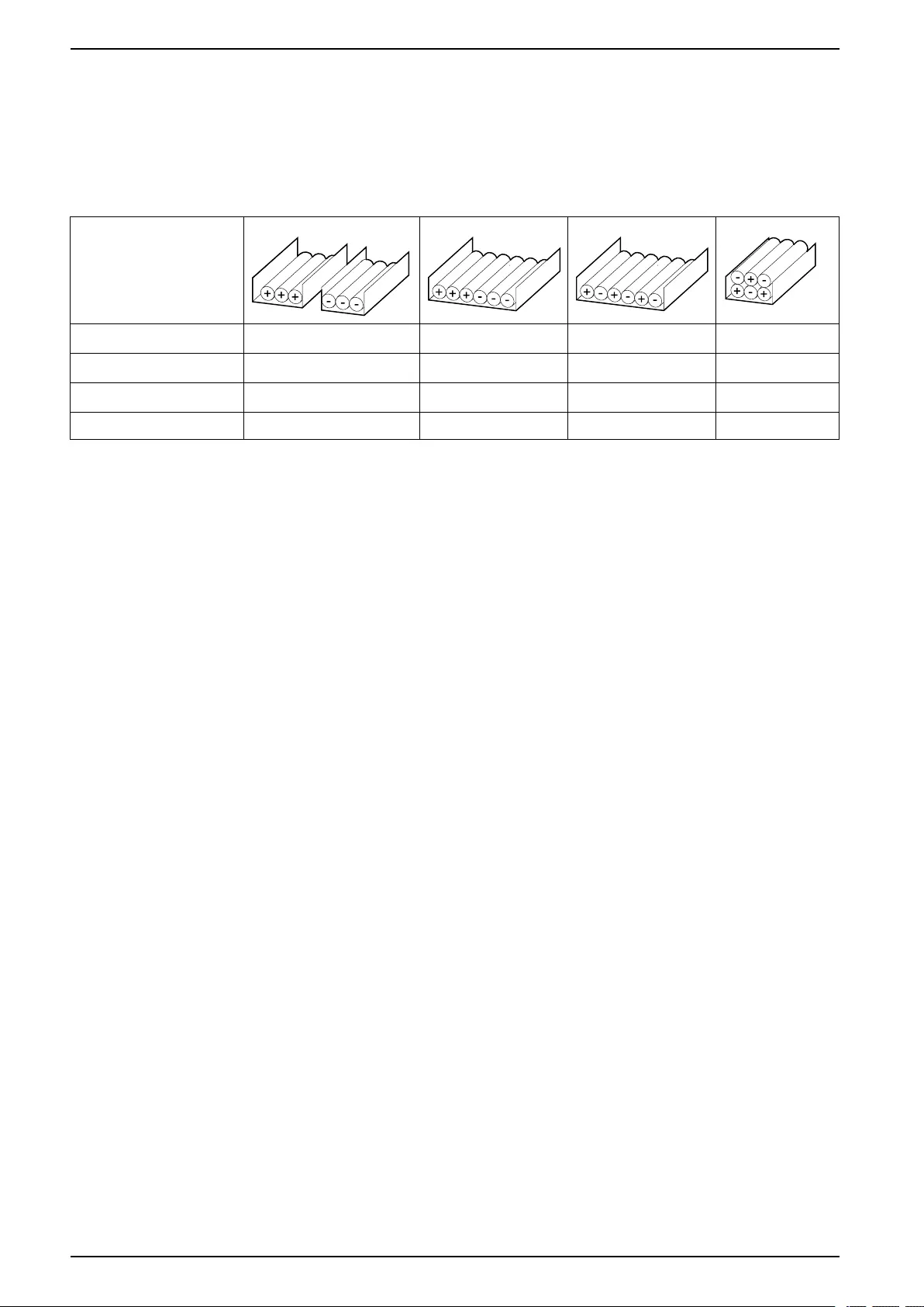
Cable Length
<30 m Not recommended Acceptable Recommended Recommended
31–75 m Not recommended Not recommended Acceptable Recommended
76–150 m Not recommended Not recommended Acceptable Recommended
151–200 m Not recommended Not recommended Not recommended Recommended
32 990-5783E-001
Overview of Configurations UPS with 1500 kW I/O Cabinet
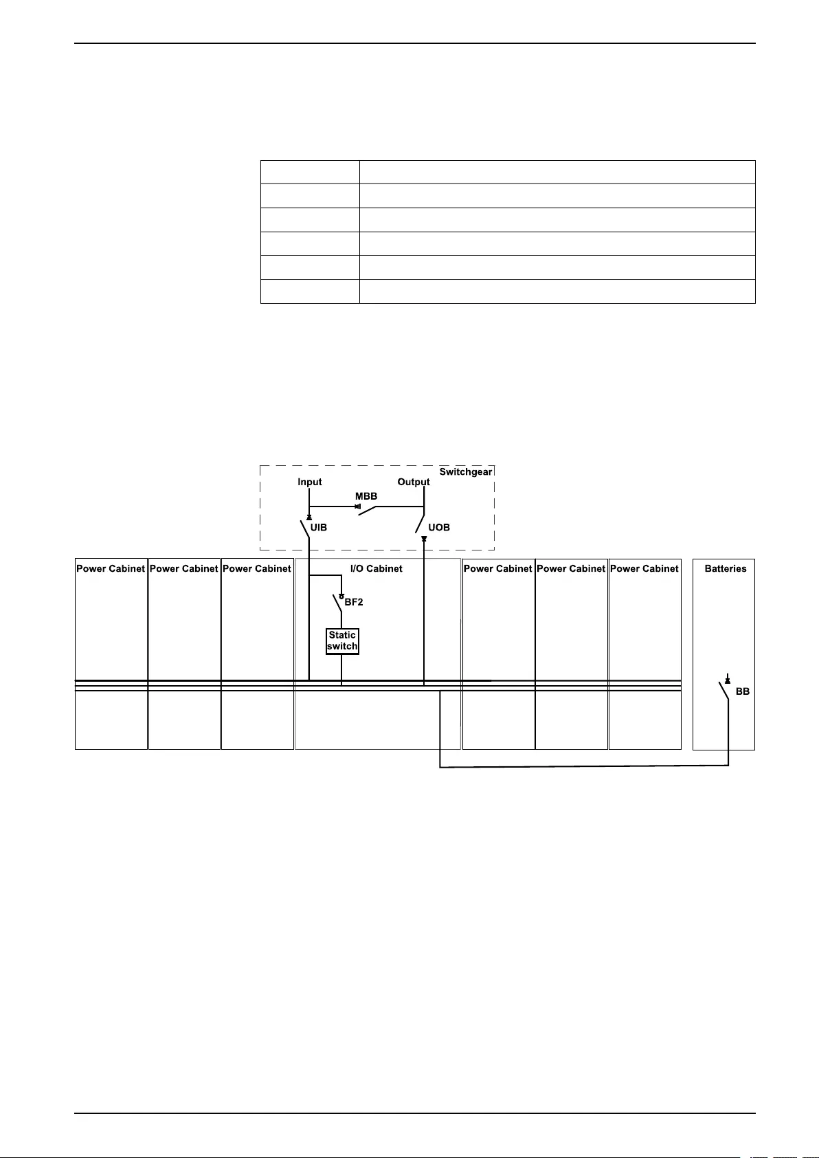
Overview of Configurations
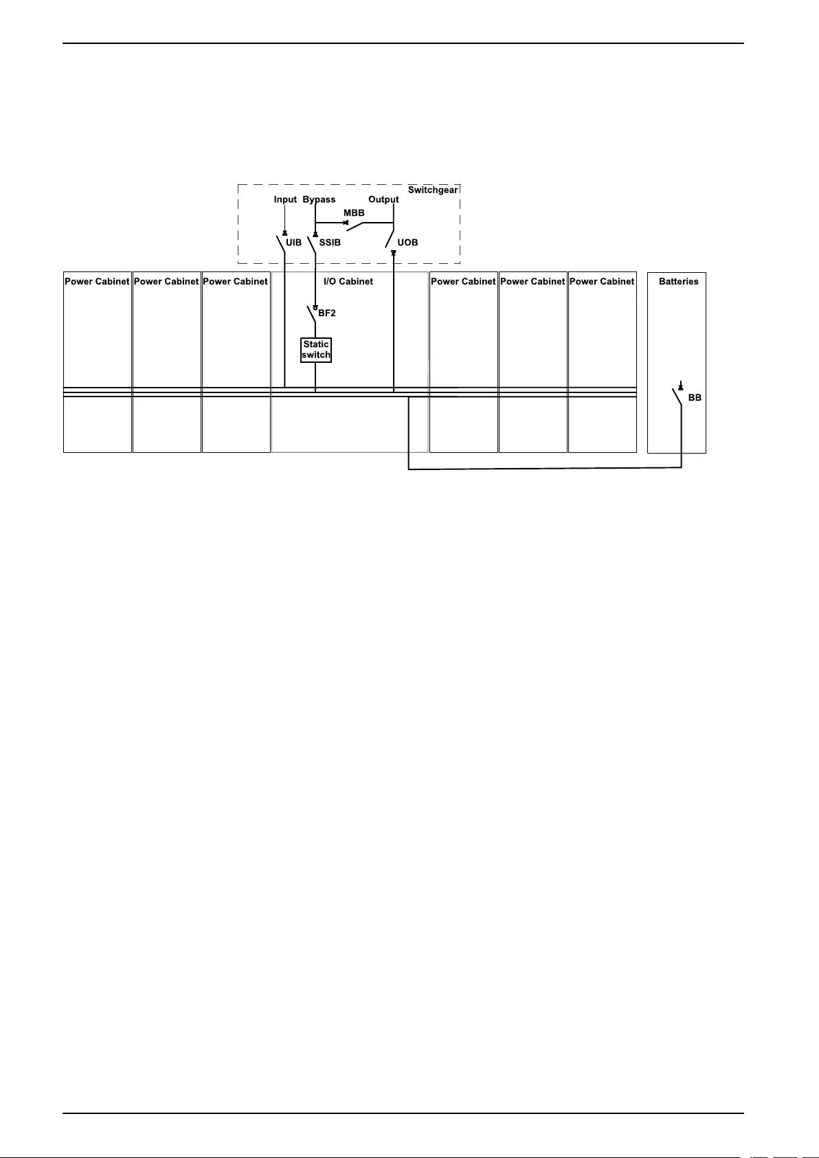
Breakers in the System
UIB Unit input breaker
SSIB Static switch input breaker
BB Battery breaker
MBB Maintenance bypass breaker
UOB Unit output breaker
BF2 Backfeed protection switch
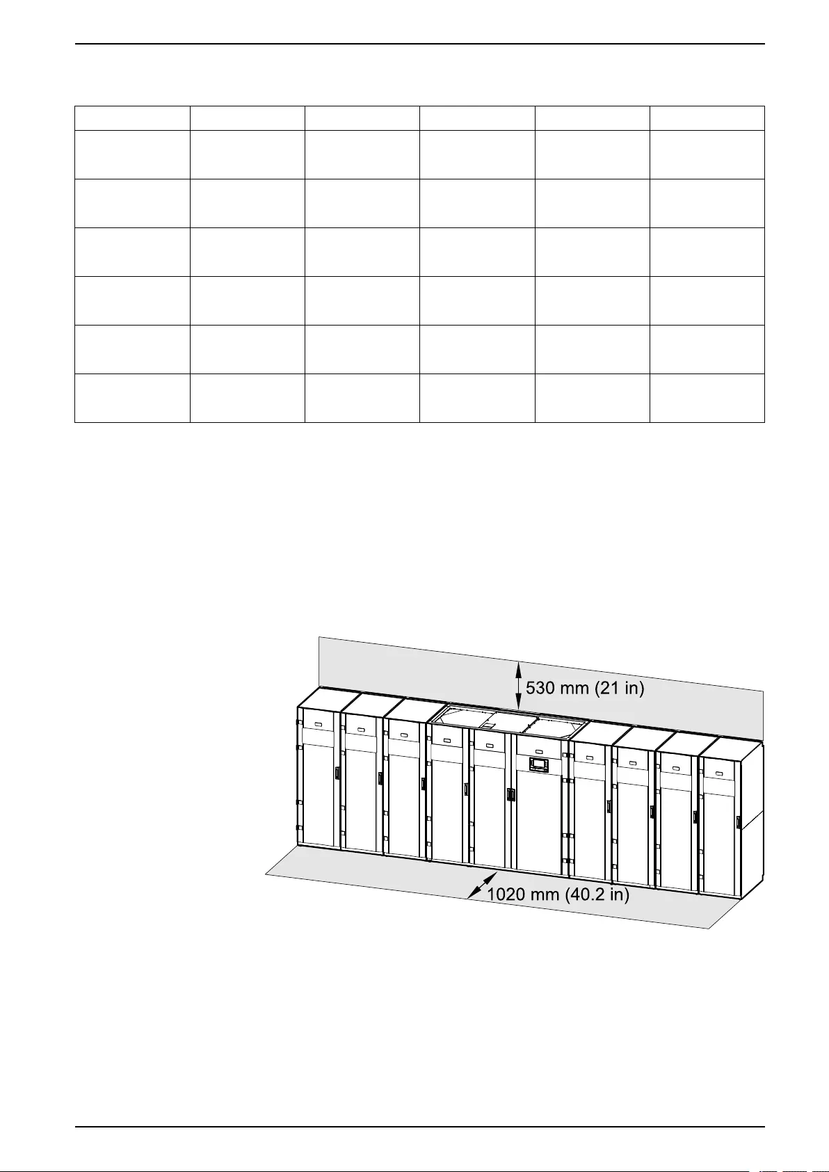
Overview of UPSs with 1500 kW I/O Cabinet – Single Utility/Mains
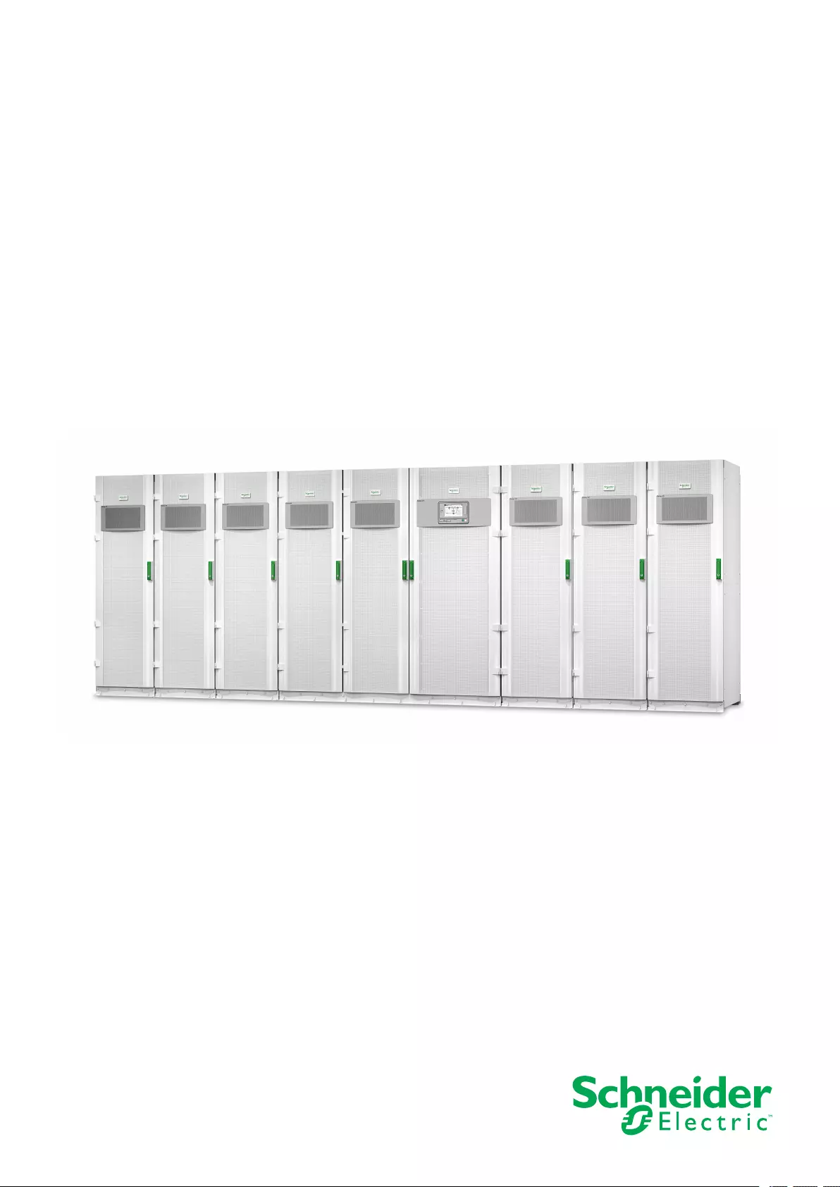
The illustration shows a 1500 kW UPS. The principle is the same for the other
UPSs with the 1500 kW I/O cabinet.
Galaxy VX 1500 kW UPS
990-5783E-001 33
Overview of Supplied Installation Kits UPS with 1500 kW I/O Cabinet
Overview of Supplied Installation Kits
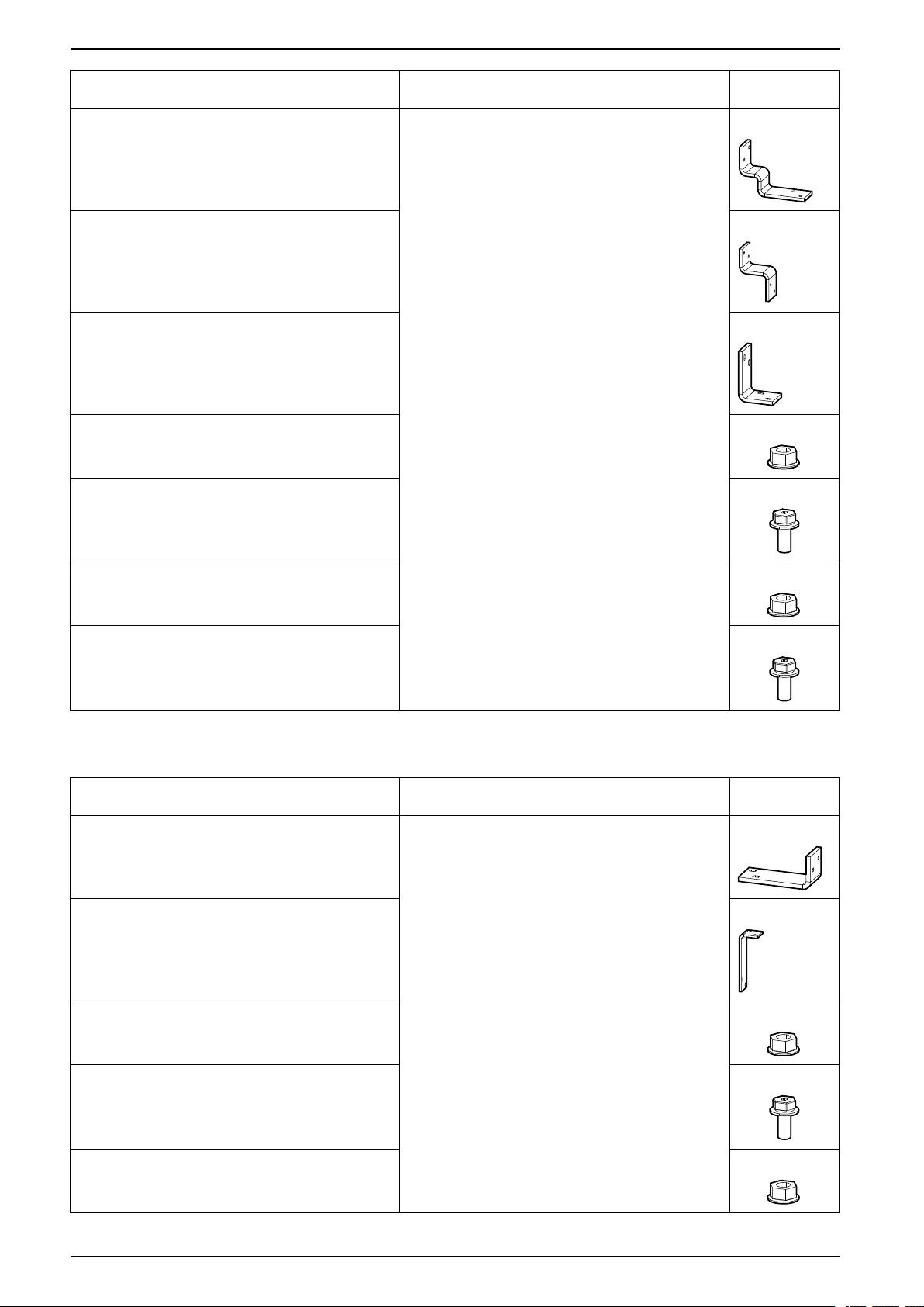
Installation Kits Shipped with the I/O Cabinet
Installation Kit 0M-816661
Part Used in Number of units
Jack Remove the Cabinets from the Pallet, page 44 1
Floor protection plate 1
Hexagonal socket for drilling machine 1
Installation Kit 0M-821667
NOTE: The rear anchoring bracket is shipped on the pallet.
Part Used in Number of units
Rear anchoring bracket Mount the Rear Anchoring Brackets, page 51 1
Installation Kit 0H-9101
Part Used in Number of
Units
Angle for left side of the rear anchoring bracket 870–
30411
Mount the Rear Anchoring Brackets, page 51 1
Angle for right side of the rear anchoring bracket 870–
30412
1
M8 x 20 hexagonal torx with washer 8
1 mm leveling shims 30
Temperature sensor 0M-1160 Connect the Signal Cables between the I/O Cabinet and
the Classic Battery Cabinets, page 98
2
990-5783E-001 35
UPS with 1500 kW I/O Cabinet Overview of Supplied Installation Kits
Part Used in Number of
Units
Terminator for modbus Connect the Modbus Cables, page 107 2
Cable ties for signal cables Connect the Signal Cables, page 88 50
EMC cover left 0M-82316 Position the Cabinets, page 52 1
EMC cover right 0M-98993 1
M6 nut with washer 22
Installation Kit 0H-9097
Part Used in Number of
Units
Battery + interconnection busbar 880–90655 between I/O
cabinet and power cabinet to the right
Install the Busbars between the I/O Cabinet and the
Power Cabinets, page 71
1
Output interconnection busbars 880–90654 between I/O
cabinet and power cabinet to the right
3
Neutral interconnection busbar 880–5538 between I/O
cabinet and power cabinet to the right
1
M10 nut with washer 8
M10 x 40 hexagonal torx with washer 2
M8 x 40 hexagonal torx with washer 10
36 990-5783E-001
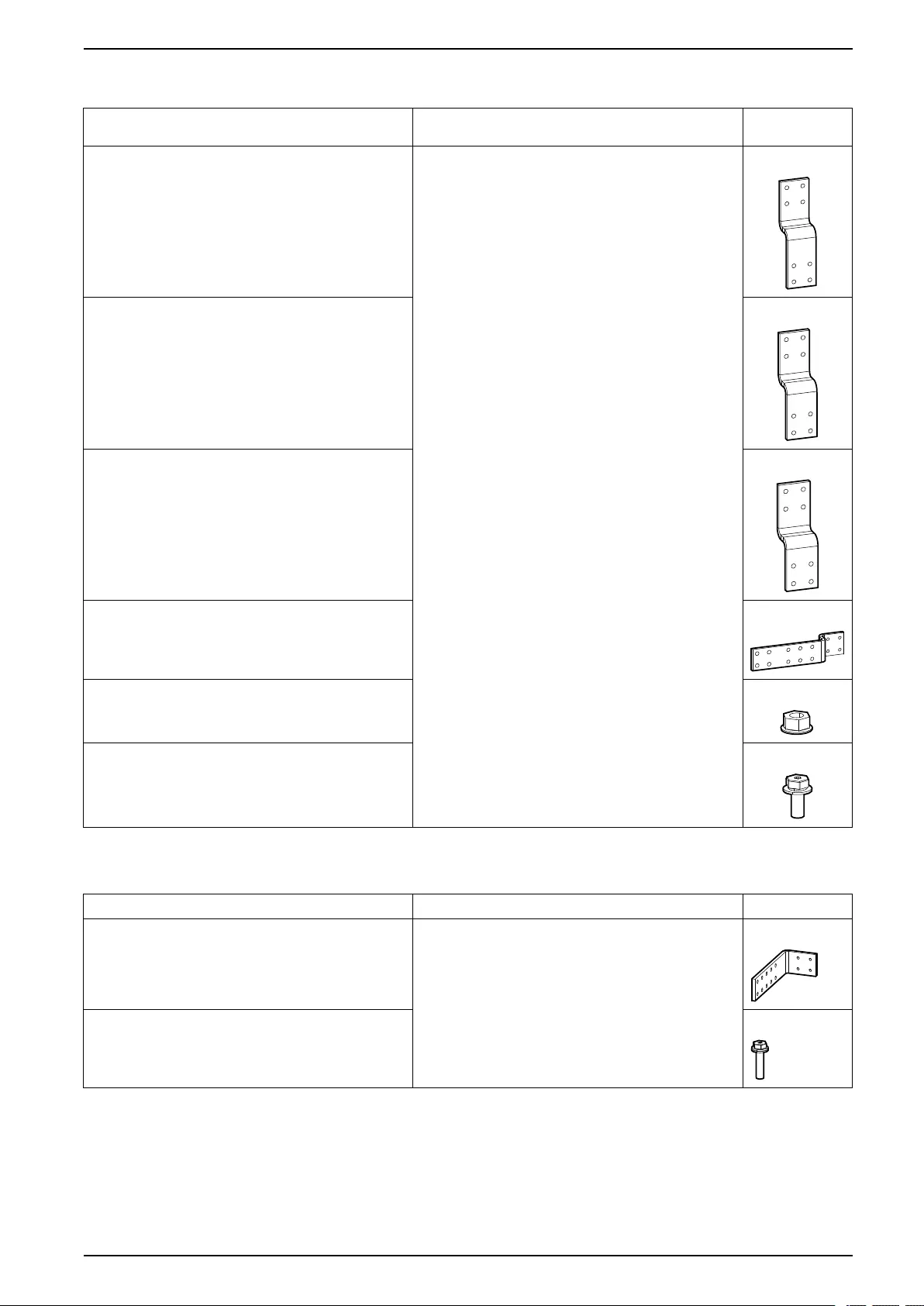
Overview of Supplied Installation Kits UPS with 1500 kW I/O Cabinet
Installation Kit 0H-9128
Part Used in Number of
Units
Grounding interconnection busbar 880–99029 between I/
O cabinet and power cabinet to the right
Install the Busbars between the I/O Cabinet and the
Power Cabinets, page 71
1
Battery - interconnection busbar 880–90658 between I/O
cabinet and power cabinet to the right
1
Input interconnection busbars 880–90657 between I/O
cabinet and power cabinet to the right
3
Neutral interconnection busbar 880–9614 between I/O
cabinet and power cabinet to the right
1
M10 nut with washer 8
M10 x 40 hexagonal torx with washer 2
M8 x 40 hexagonal torx with washer 18
M6 nuts with washer 3
Installation Kit 0H-9096
Part Used in Number of
Units
Grounding interconnection busbar 880–5662 between I/O
cabinet and power cabinet to the left
Install the Busbars between the I/O Cabinet and the
Power Cabinets, page 71
1
Battery + interconnection busbar 880–5503 between I/O
cabinet and power cabinet to the left
1
Neutral interconnection busbar 880–5507 between I/O
cabinet and power cabinet to the left
1
990-5783E-001 37
UPS with 1500 kW I/O Cabinet Overview of Supplied Installation Kits
Part Used in Number of
Units
First battery - interconnection busbar 880–5496 between
I/O cabinet and power cabinet to the left
1
First layer input interconnection busbars 880–5502
between I/O cabinet and power cabinet to the left
3
Second battery - interconnection busbar 880–5495
between I/O cabinet and power cabinet to the left
1
M10 nut with washer 2
M10 x 40 hexagonal torx with washer 10
M8 nut with washer 4
M8 x 40 hexagonal torx with washer 18
Installation Kit 0H-9129
Part Used in Number of
Units
Output interconnection busbars 880–9569 between I/O
cabinet and power cabinet to the left
Install the Busbars between the I/O Cabinet and the
Power Cabinets, page 71
3
Second layer input interconnection busbars 880–90650
between I/O cabinet and power cabinet to the left
3
M10 nut with washer 6
M8 x 40 hexagonal torx with washer 12
M6 nuts with washer 3
38 990-5783E-001
Overview of Supplied Installation Kits UPS with 1500 kW I/O Cabinet
Installation Kit 0H-9161 for Single Mains
Part Used in Number of
Units
Vertical single mains busbar 880–99058 for L1 Install the Single Utility/Mains Installation Kit 0H-9161,
page 82
1
Vertical single mains busbar 880–99059 for L2 1
Vertical single mains busbar 880–99057 for L3 1
Horizontal single mains busbars 880–99060 3
M10 nut with washer 24
M10 x 60 hexagonal torx with washer 36
Installation Kit 0H-1102
Part Used in Number of units
Neutral busbar 880–5501 Connect the Power Cables in a 380 V, 400 V, 415, and
440 V System, page 83
1
M8 x 35 hexagonal torx with washer 4
990-5783E-001 39
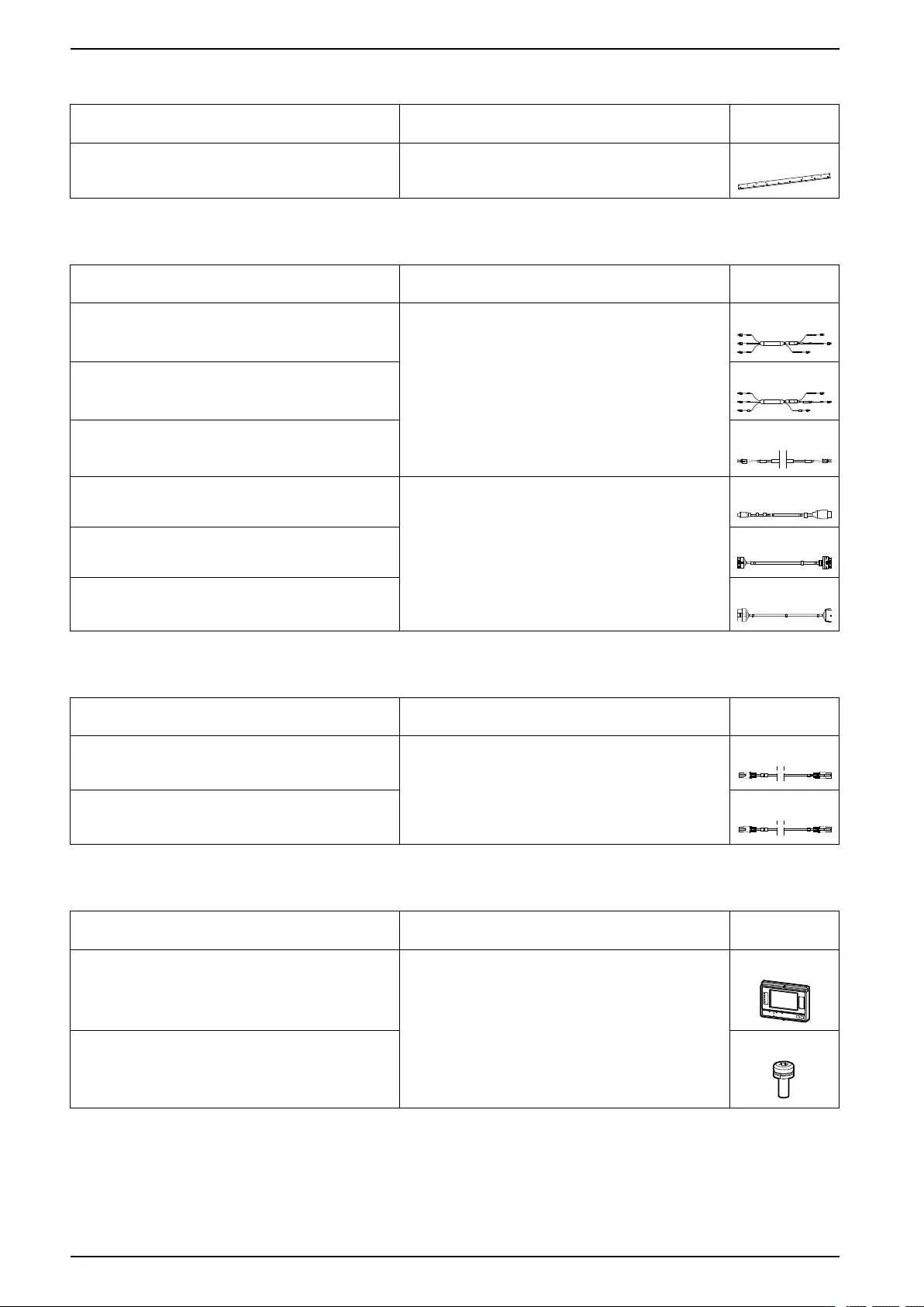
UPS with 1500 kW I/O Cabinet Overview of Supplied Installation Kits
Installation Kit 0M-99259
Part Used in Number of
Units
Front anchoring bracket for I/O cabinet Mount the Front Anchoring Brackets, page 86 1
Installation Kit 0H-1074
Part Used in Number of
Units
Optical fiber cable 0W7819 Connect the Signal Cables between the I/O Cabinet and
the Power Cabinets, page 92
1
Optical fiber cable 0W7822 1
Optical fiber cable 0W7827 1
Display cable 0W7853 Do not install. Installation must be performed by
Schneider Electric.
1
Display cable 0W7858 1
Display cable 0W7859 1
Installation Kit 0H-0889
Part Used in Number of
Units
PBUS 1 cable 0W7995 Connect the PBUS Cables between Parallel UPS Units,
page 105
1
PBUS 2 cable 0W7996 1
Installation Kit 0M-92449
Part Used in Number of
Units
Display Do not install. Installation must be performed by
Schneider Electric.
1
M4x10 torx screw with washer 4
40 990-5783E-001
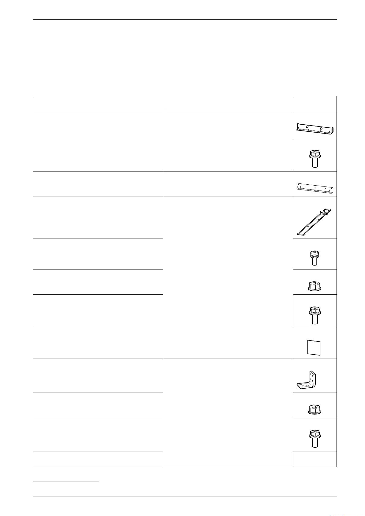
Overview of Supplied Installation Kits UPS with 1500 kW I/O Cabinet
Installation Kits Shipped with the Power Cabinet
Installation Kit 0H-0440, 0H-9162, or 0H-9102
NOTE: The part number of the installation kit depends on the power cabinet
version.
NOTE: These installation kit parts are shipped in the packaging of the power
cabinet.
Part Used in Number of
Units
Rear anchoring bracket for power cabinet 0M-818242 Mount the Rear Anchoring Brackets, page 51 1
M8 x 20 hexagonal torx with washer 2
Front anchoring bracket for power cabinet 0M-816684 Mount the Front Anchoring Brackets, page 86 1
Long top baying bracket 0M-821220 Position the Cabinets, page 52 1
M6 x 16 torx screw with washer 15
M10 nut with washer 24
M10 x 35 hexagonal torx with washer 12
1 mm leveling shims 10
Ground interconnection busbar 880–5259 or 880–
9902749 from power cabinet to power cabinet
Install the Busbars between the Power Cabinets, page 77 1
M8 nut with washer 4
M8 x 35 mm hexagonal torx with washer 4
Interconnection busbar 880-10146 or 880–972049 from
power cabinet to power cabinet (neutral)
1
990-5783E-001 41
49. The part number is dependant on the power cabinet version.

UPS with 1500 kW I/O Cabinet Overview of Supplied Installation Kits
Part Used in Number of
Units
Interconnection busbar 0M-140035 power cabinet to
power cabinet (battery +)
1
Interconnection busbar 0M-97886 power cabinet to power
cabinet (output)
3
Interconnection busbar 0M-819336 power cabinet to
power cabinet (battery -)
1
Interconnection busbar 0M-97885 power cabinet to power
cabinet (input)
3
42 990-5783E-001
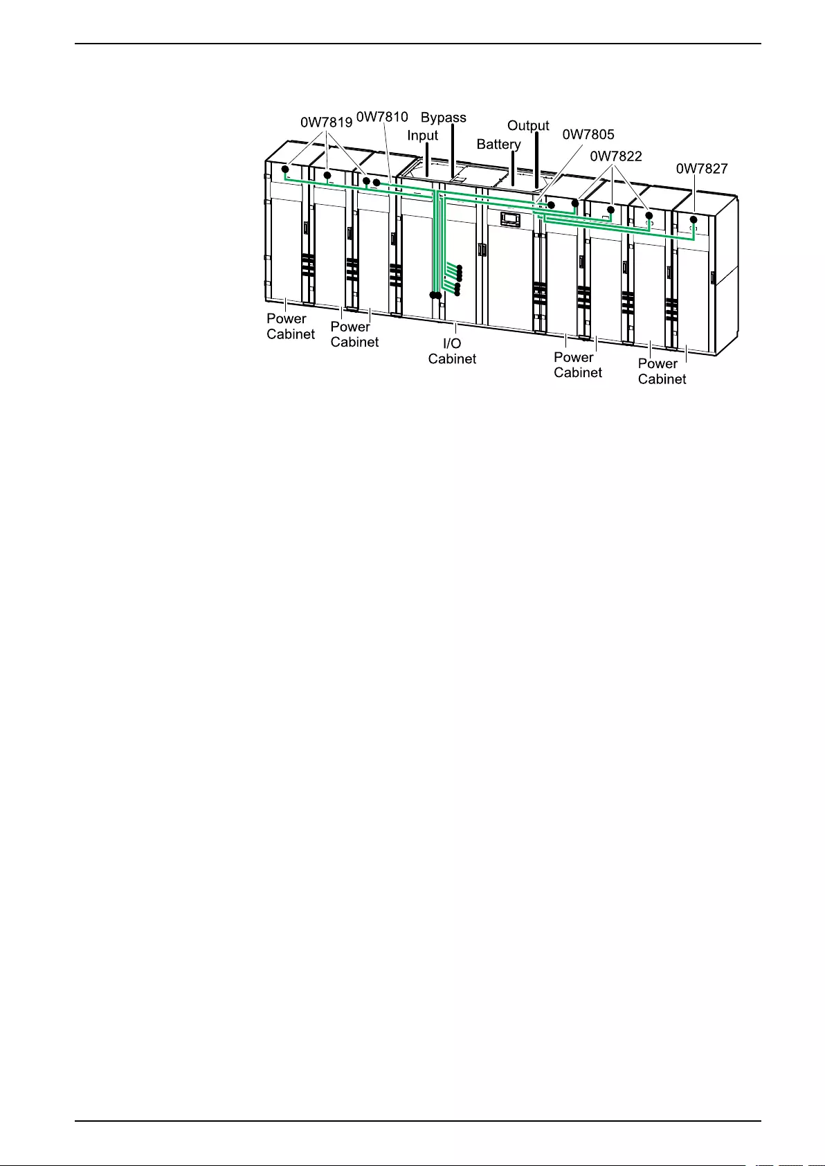
Installation Procedure UPS with 1500 kW I/O Cabinet
Installation Procedure
1. Remove the Cabinets from the Pallet, page 44.
2. Mount the Rear Anchoring Brackets, page 51.
3. Position the Cabinets, page 52.
4. Install the Busbars between the I/O Cabinet and the Power Cabinets, page
71.
5. Install the Busbars between the Power Cabinets, page 77.
6. Prepare the I/O cabinet for power cables. Follow one of the procedures:
–Prepare the I/O Cabinet for Power Cables in Top Cable Entry Systems,
page 80.
–Prepare the I/O Cabinet for Power Cables in Bottom Cable Entry Systems,
page 81.
7. In single mains systems only: Install the Single Utility/Mains Installation Kit
0H-9161, page 82.
8. Connect the power cables. Follow one of the procedures:
–Connect the Power Cables in a 380 V, 400 V, 415, and 440 V System,
page 83.
–Connect the Power Cables in a 480 V System, page 85.
9. Mount the Front Anchoring Brackets, page 86.
10. Prepare for Signal Cables, page 88.
11. Connect the Signal Cables between the I/O Cabinet and the Power Cabinets,
page 92.
12. Connect the Signal Cables between the I/O Cabinet and the Switchgear,
page 98.
13. Connect the Signal Cables for Battery Solutions, page 98.
14. Connect the Emergency Power Off (EPO), page 100.
15. Option: Connect External Synchronization, page 100.
16. Option: Connect Equipment to Input Contacts and Output Relays, page 103.
17. Option: Connect the PBUS Cables between Parallel UPS Units, page 105.
18. Option: Connect the Modbus Cables, page 107.
19. Final Mechanical Assembly, page 110.
990-5783E-001 43

UPS with 1500 kW I/O Cabinet Mechanical Installation
Mechanical Installation
Remove the Cabinets from the Pallet
NOTICE
RISK OF EQUIPMENT DAMAGE
Ensure that you have sufficient free space around the cabinets for the removal
of the middle pallet part. The 1500 kW I/O cabinet requires 1.5 m (59 in) free
space on the right or left side of the cabinet.
Failure to follow these instructions can result in equipment damage.
NOTICE
RISK OF EQUIPMENT DAMAGE
Ensure that the floor is level and can support the weight of the jack when it
carries the cabinet.
Failure to follow these instructions can result in equipment damage.
NOTICE
RISK OF EQUIPMENT DAMAGE
Be careful not to damage the cabinets when using the jack.
Failure to follow these instructions can result in equipment damage.
NOTE: The procedure shows the removal of the power cabinet when the
procedures are identical.
1. Take the installation kit 0M-816661 shipped with the I/O cabinet. Use the jack
and the floor protection plate in the kit for all cabinets in this procedure.
44 990-5783E-001
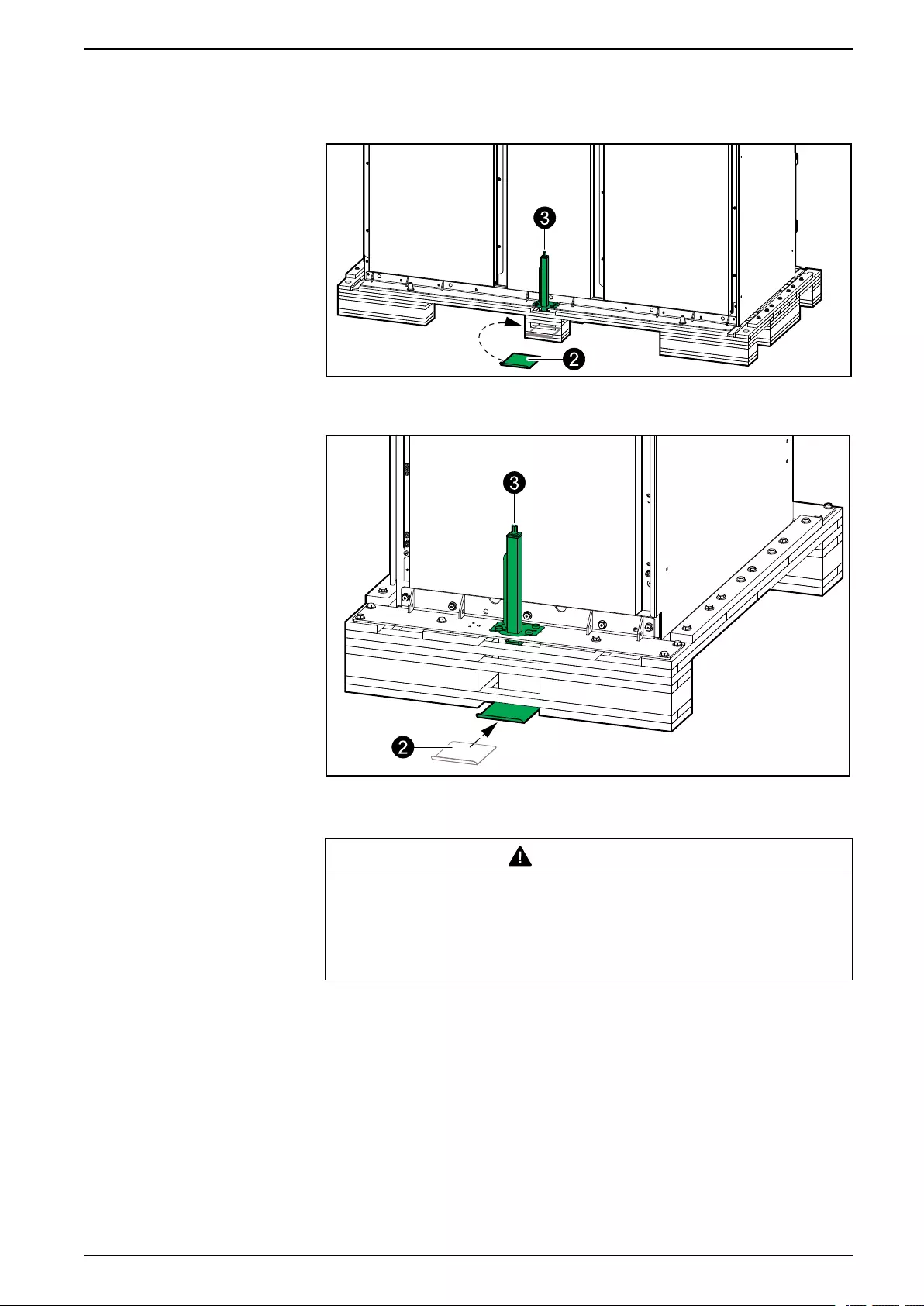
Mechanical Installation UPS with 1500 kW I/O Cabinet
2. Place the floor protection plate under the pallet on the rear of the cabinet.
Rear View of the 1500 kW I/O Cabinet
Rear View of the Power Cabinet
3. Place the jack from the installation kit in the hole in the transport bracket on
the rear of the cabinet.
WARNING
HAZARD OF TILTING
Do not use a jack in the front and rear transport bracket at the same time.
Failure to follow these instructions can result in death, serious injury,
or equipment damage.
990-5783E-001 45
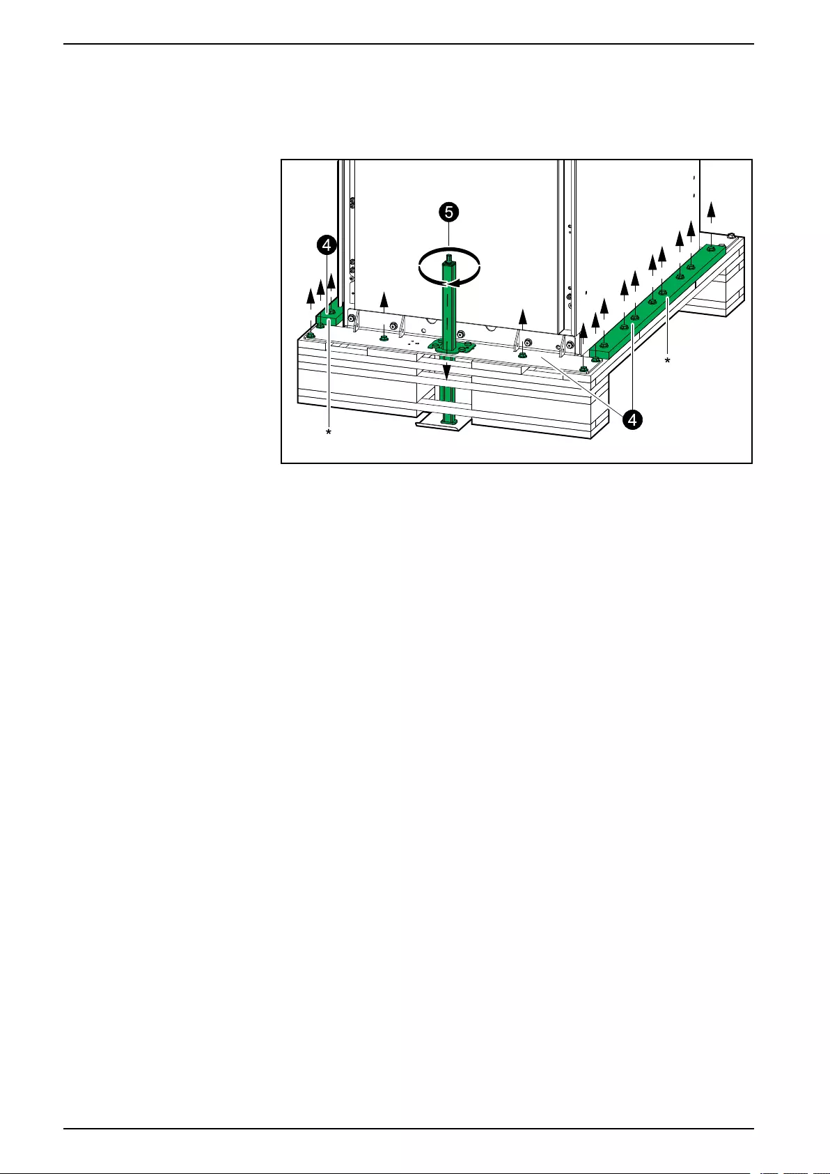
UPS with 1500 kW I/O Cabinet Mechanical Installation
4. Loosen and remove the bolts from the rear transport bracket and from the
middle pallet part. Remove the pallet parts marked with * and save for step 8
for the I/O cabinet.
Rear View of the Power Cabinet
5. Use a drilling machine with the provided hexagonal socket to activate the
jack, slide it into position in the bracket, and to make contact with the floor
protection plate.
NOTE: Reduce the drill torque to minimum to prevent kickback.
6. Use the jack to lift the pallet to the top position.
46 990-5783E-001

Mechanical Installation UPS with 1500 kW I/O Cabinet
7. Remove the rear and middle pallet parts.
WARNING
HAZARD OF SERIOUS INJURY
Do not put your hands or feet under the cabinet while removing the pallet
parts.
Failure to follow these instructions can result in death, serious injury,
or equipment damage.
Rear View of the Power Cabinet
8. Place support under the metal bracket:
– For the power cabinets, flip over the wooden part and place it under the
transportation bracket as a support.
– For the I/O cabinet, place the pallet parts from step 4 as a support.
990-5783E-001 47
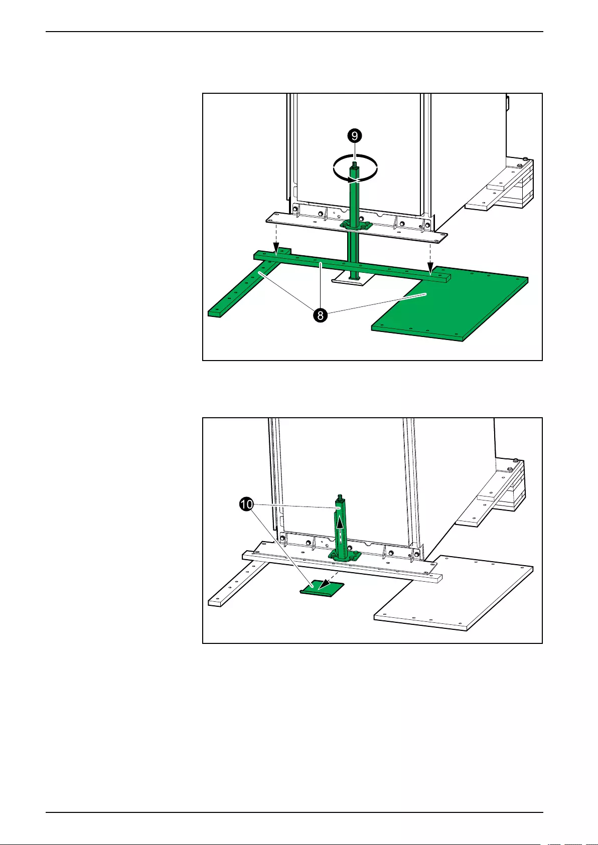
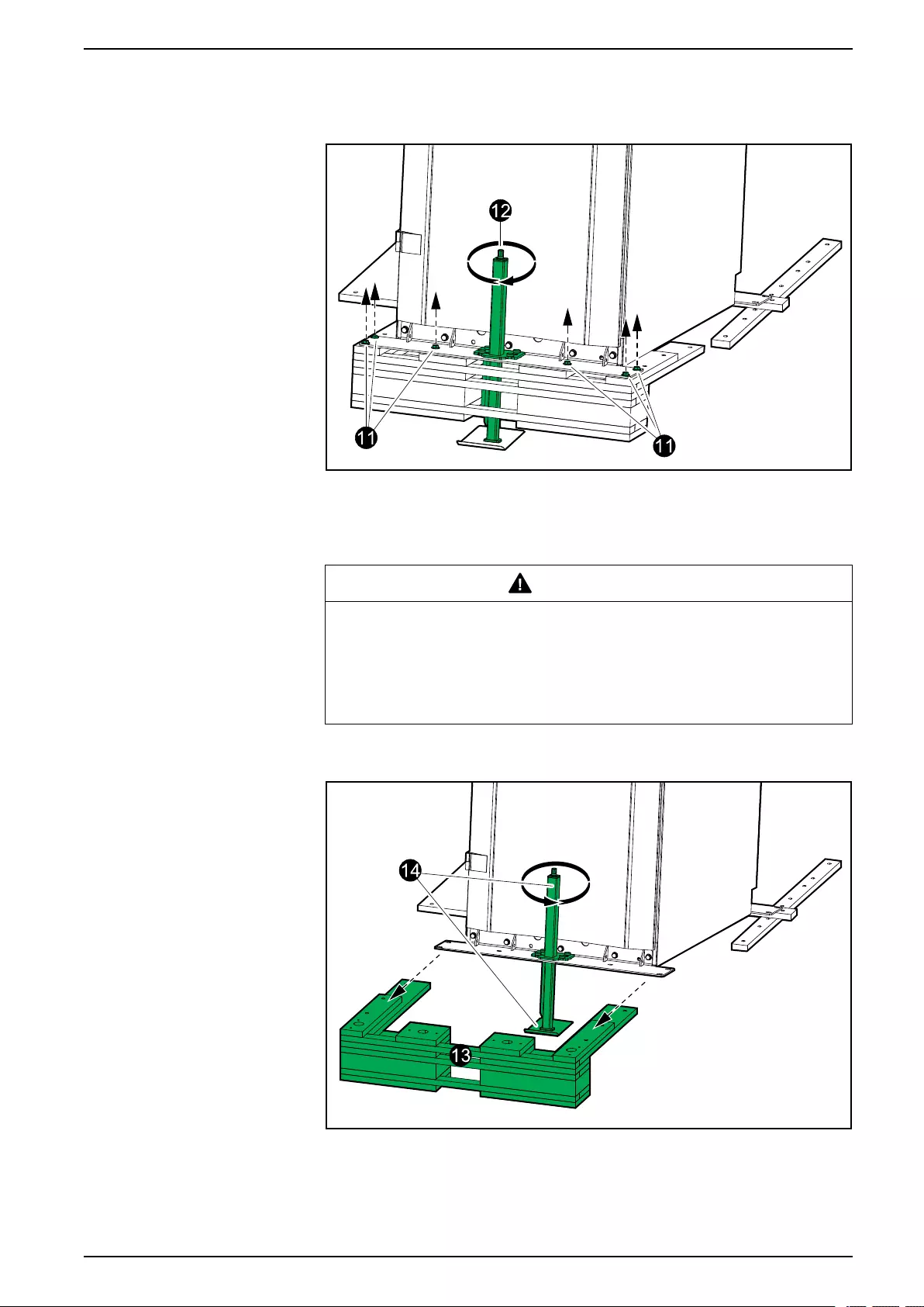
Mechanical Installation UPS with 1500 kW I/O Cabinet
11. Loosen and remove the bolts from the front transport bracket.
Front View of the Power Cabinet
12. Use a drilling machine with the provided hexagonal socket to activate the
jack, slide it into position in the bracket, and to lift the pallet to the top position.
13. Remove the front pallet parts.
WARNING
HAZARD OF SERIOUS INJURY
Do not put your hands or feet under the cabinet while removing the wooden
plate.
Failure to follow these instructions can result in death, serious injury,
or equipment damage.
Front View of the Power Cabinet
14. Use the jack to lower the cabinet onto the floor until the wheels connect with
the floor. Remove the jack and the floor protection plate.
990-5783E-001 49
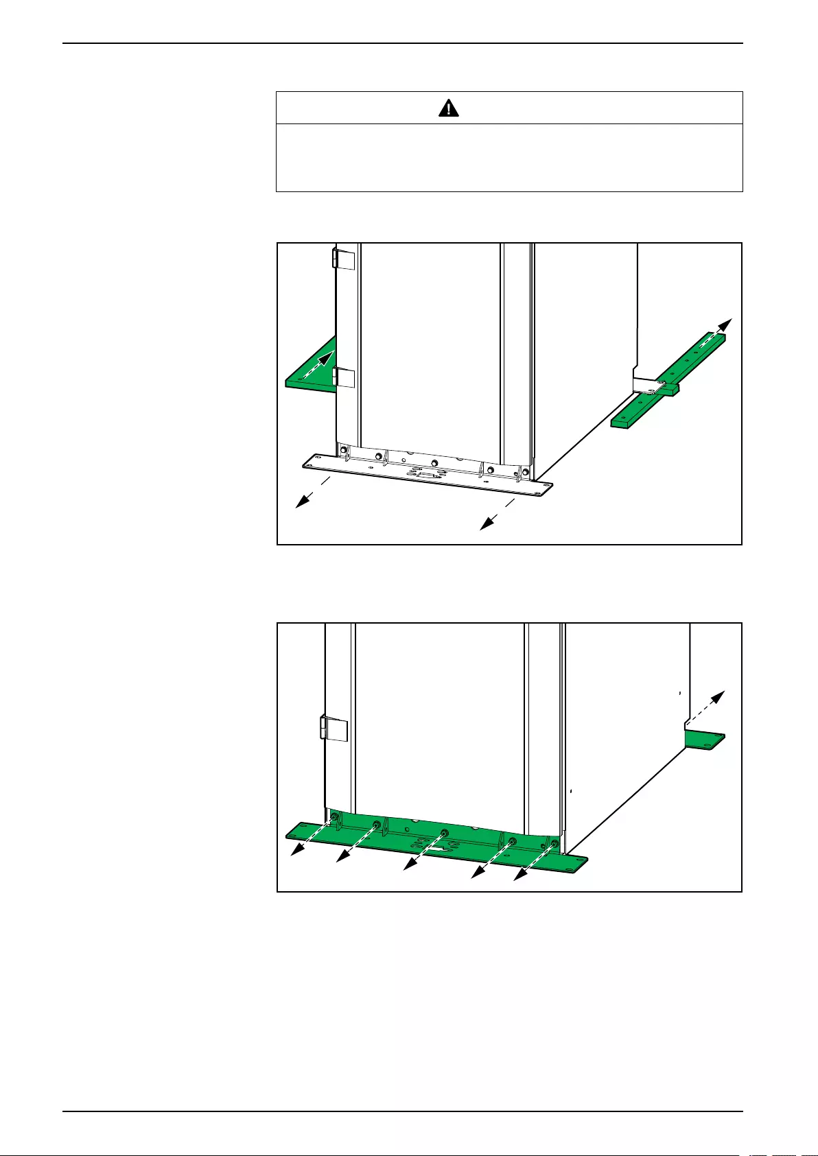
UPS with 1500 kW I/O Cabinet Mechanical Installation
15. Wheel the cabinet away and remove the remaining pallet parts.
WARNING
HAZARD OF TILTING
Be alert to uneven floors and doorsteps when moving the cabinet on its
wheels to avoid overbalancing and tipping the cabinet.
Front View of the Power Cabinet
16. Remove the front and rear transportation brackets.
Front View of the Power Cabinet
The cabinet can now be moved on the built-in wheels to the installation area.
50 990-5783E-001
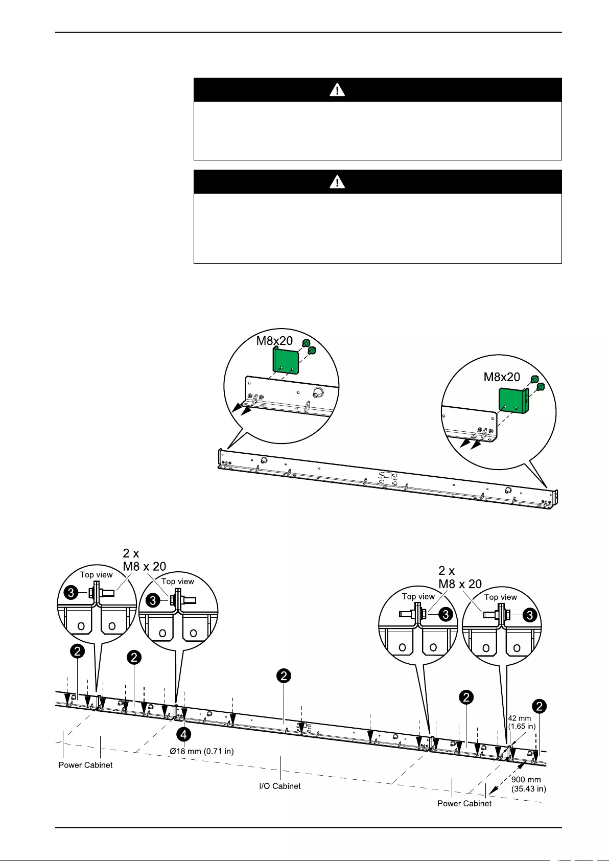
Mechanical Installation UPS with 1500 kW I/O Cabinet
Mount the Rear Anchoring Brackets
DANGER
HAZARD OF TILTING
All rear and front anchoring brackets must be installed.
Failure to follow these instructions will result in death or serious injury.
DANGER
HAZARD OF ELECTRIC SHOCK, EXPLOSION, OR ARC FLASH
Leave the UPS system covered while making anchoring holes to prevent dust or
other conductive particles from entering the system.
Failure to follow these instructions will result in death or serious injury.
1. Use the rear anchoring bracket that was attached to the rear of the I/O
cabinet pallet. Fasten the two plates from the installation kit 0H-9101 to the
rear anchoring bracket of the I/O cabinet with M8 bolts. Note the direction of
the plates.
2. Place the rear anchoring brackets for the I/O cabinet and the power cabinets
in the final installation area.
990-5783E-001 51
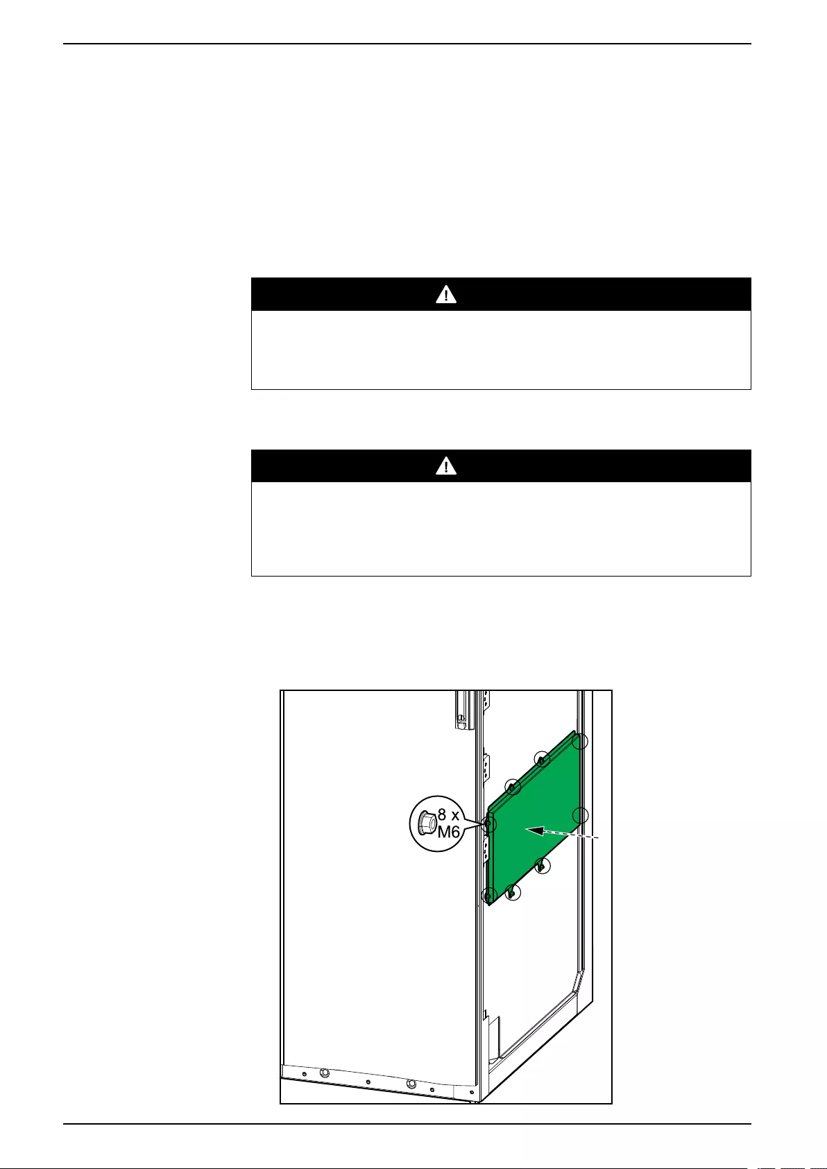
UPS with 1500 kW I/O Cabinet Mechanical Installation
3. Interconnect the rear anchoring brackets using the provided screws and bolts.
4. Mark the hole locations.
5. Drill anchoring holes according to the national and local requirements.
6. Mount the rear anchoring brackets to the floor. Bolts are not supplied.
7. Use a bubble-leveler to ensure that the rear anchoring brackets are level. Use
the provided leveling shims if necessary.
Position the Cabinets
DANGER
HAZARD OF ELECTRIC SHOCK, EXPLOSION, OR ARC FLASH
Do not step/walk on top of the cabinets.
Failure to follow these instructions will result in death or serious injury.
NOTE: The cabinets must be moved to the final installation area individually
and cannot be moved after they have been interconnected.
DANGER
HAZARD OF ELECTRIC SHOCK, EXPLOSION, OR ARC FLASH
A minimum of one power cabinet and a maximum of four power cabinets must
be placed on each side of the I/O cabinet.
Failure to follow these instructions will result in death or serious injury.
1. Install the interconnection cover 0M-98993 from the installation kit 0H-9101
on the right side (front view) of the right-most power cabinet and fasten with
the M6 nuts.
Front View of the Power Cabinet
52 990-5783E-001
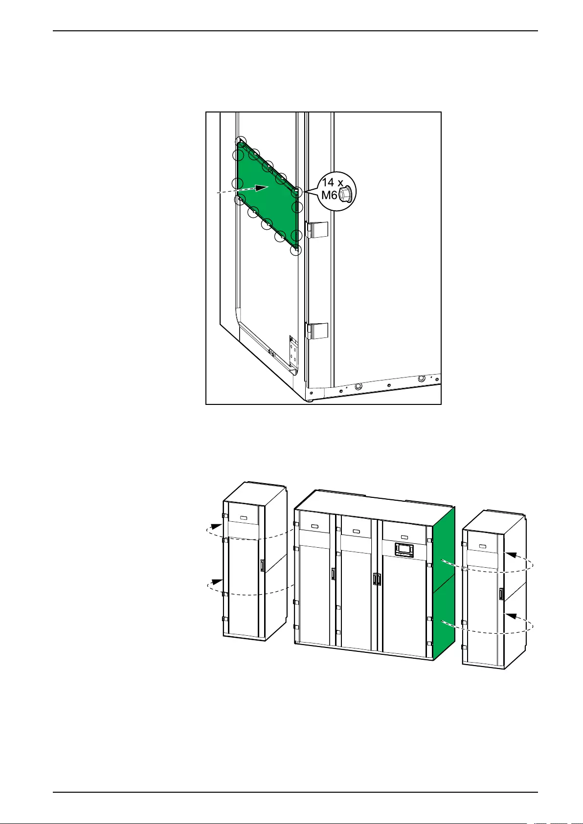
Mechanical Installation UPS with 1500 kW I/O Cabinet
2. Install the interconnection cover 0M-82316 from the installation kit 0H-9101
on the left side (front view) of the left-most power cabinet and fasten with the
M6 nuts.
Front View of the Power Cabinet
3. Remove the side panels from the I/O cabinet and install them on the left side
of the left-most power cabinet and on the right side of the right-most power
cabinet.
Front View of the UPS
990-5783E-001 53
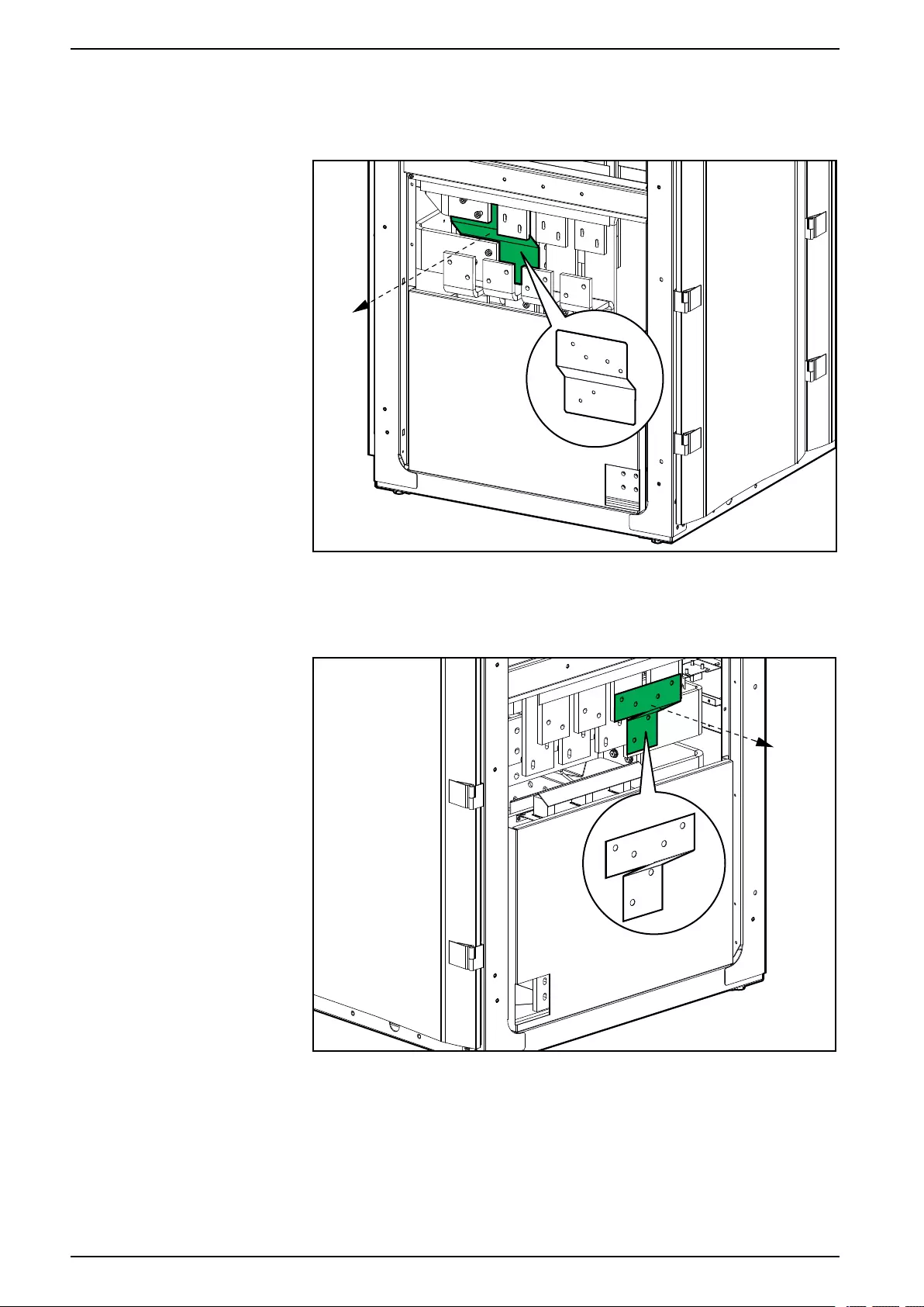
UPS with 1500 kW I/O Cabinet Mechanical Installation
4. Remove and dispose of the indicated transport bracket from the left side of
the I/O cabinet.
Front View of the I/O Cabinet
5. Remove and dispose of the indicated transport bracket from the right side of
the I/O cabinet.
Front View of the I/O Cabinet
54 990-5783E-001
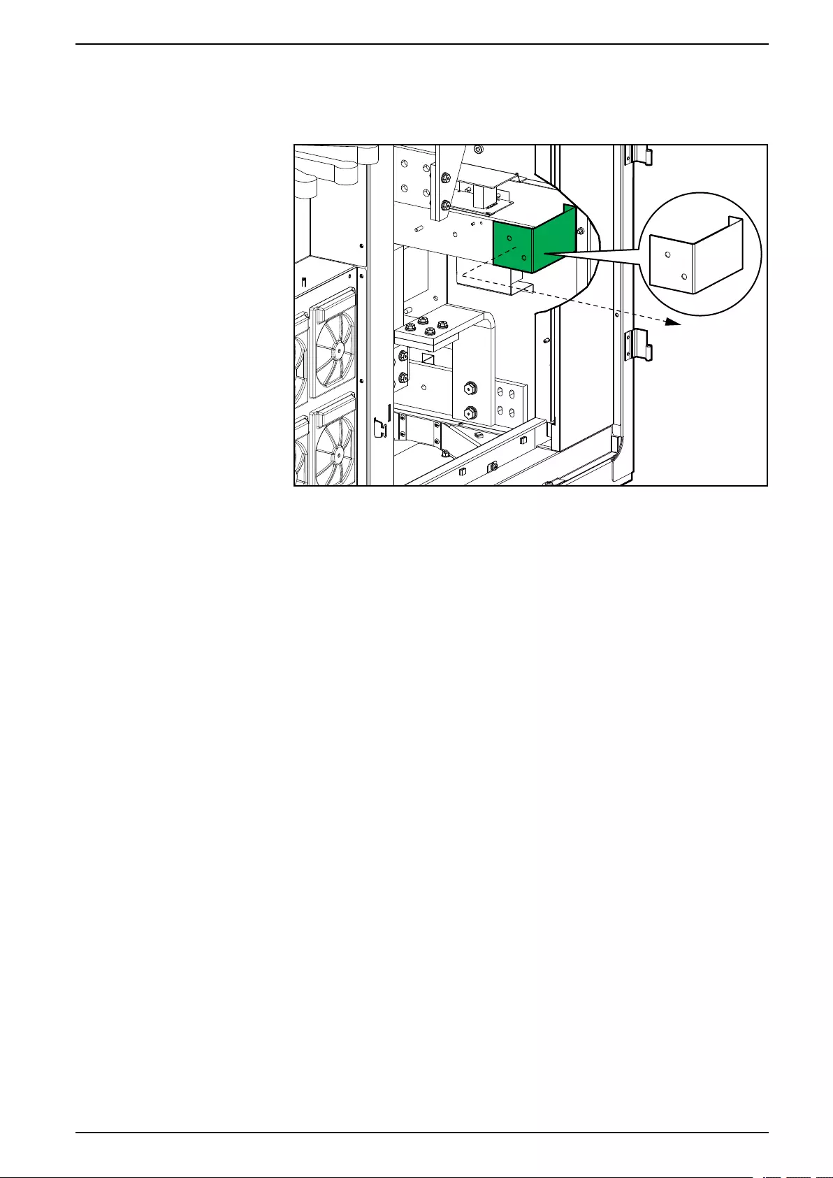

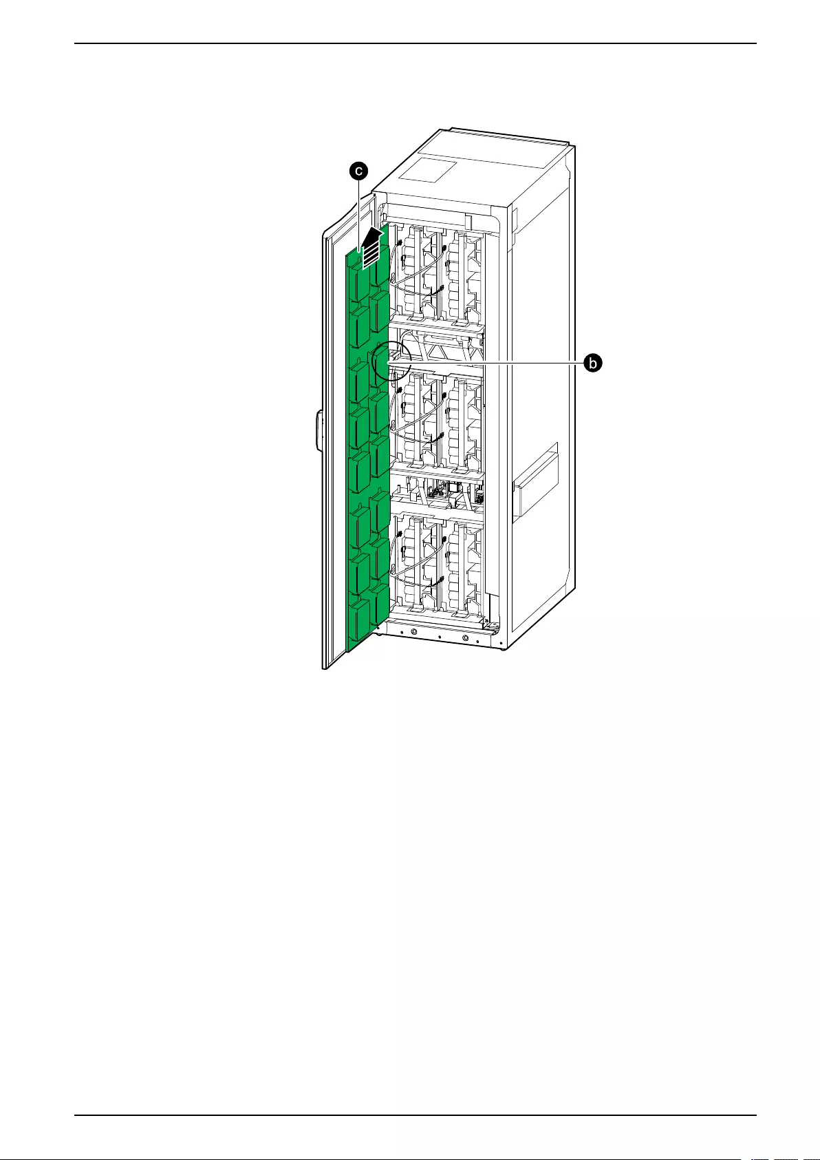
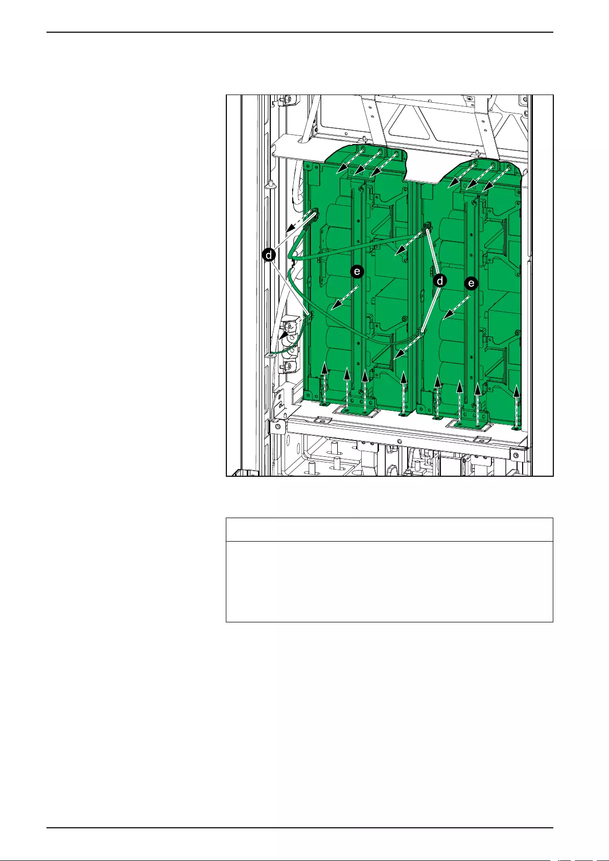
UPS with 1500 kW I/O Cabinet Mechanical Installation
d. Disconnect the two cables from each of the two middle power blocks.
Front View of the Power Cabinet
e. Loosen the screws and pull out the middle power blocks. Be careful not
to damage the cables.
NOTICE
RISK OF EQUIPMENT DAMAGE
Cover the power blocks while removed from the power cabinet to avoid
dust in the power blocks.
Failure to follow these instructions can result in equipment
damage.
58 990-5783E-001
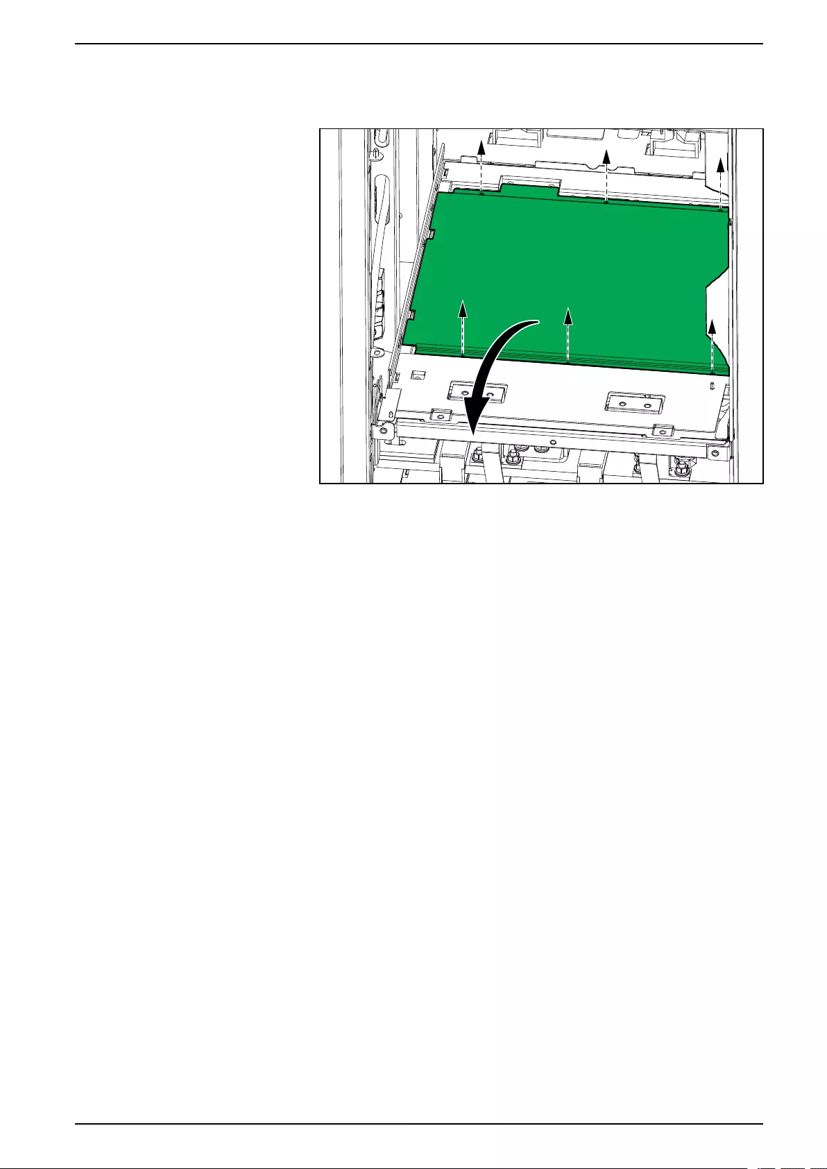
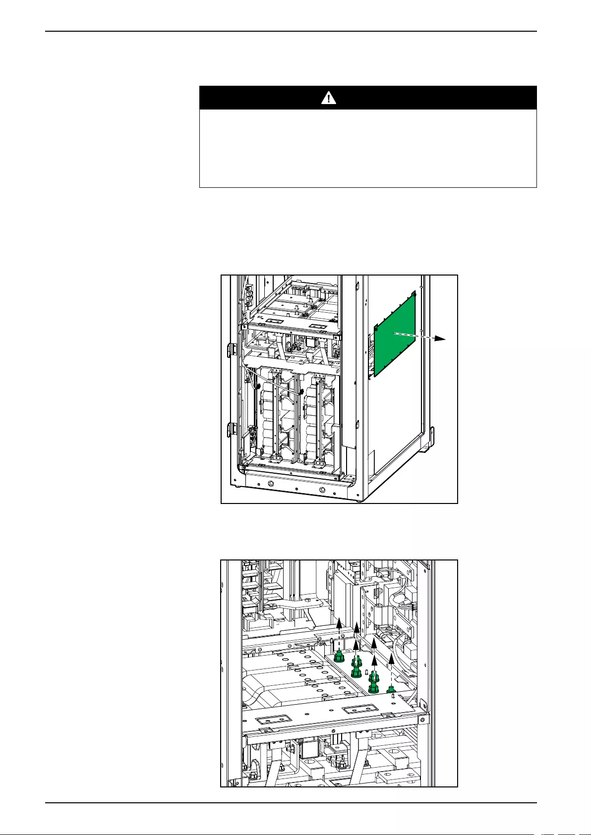
UPS with 1500 kW I/O Cabinet Mechanical Installation
8. Perform the following steps (a to c) on all power cabinets to remove the EMC
plate except the power cabinets that will be installed at the end of the
row.
DANGER
HAZARD OF ELECTRICAL SHOCK, EXPLOSION, OR ARC FLASH
Do not perform the steps a to c on the power cabinets that will be installed
at the end of the row.
Failure to follow these instructions will result in death or serious
injury.
NOTE: The EMC plate is not part of all power cabinet versions. Check
your specific power cabinets.
a. Remove the indicated cover from the right side and dispose of the cover.
Front View of the Power Cabinet
b. Loosen and remove the eight bolts from the inside of the power cabinet.
Front View of the Power Cabinet
60 990-5783E-001
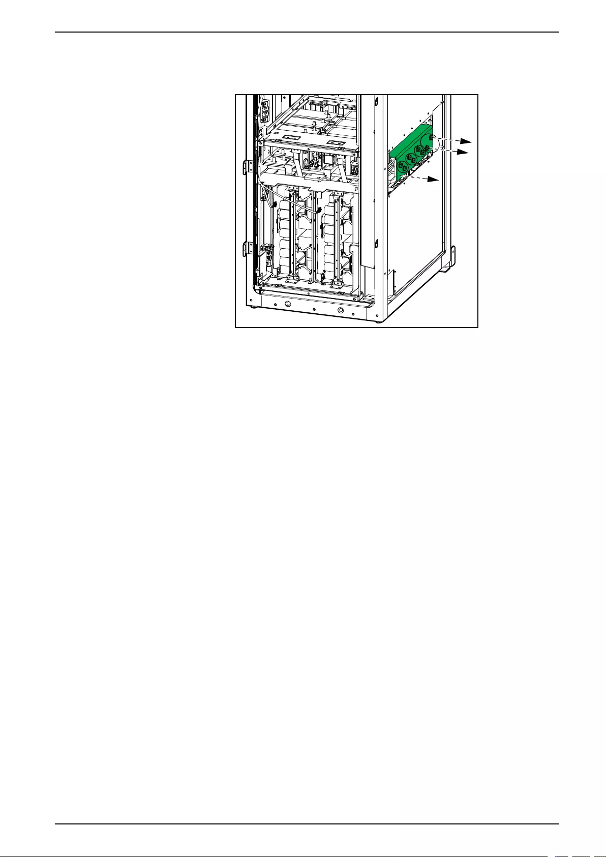
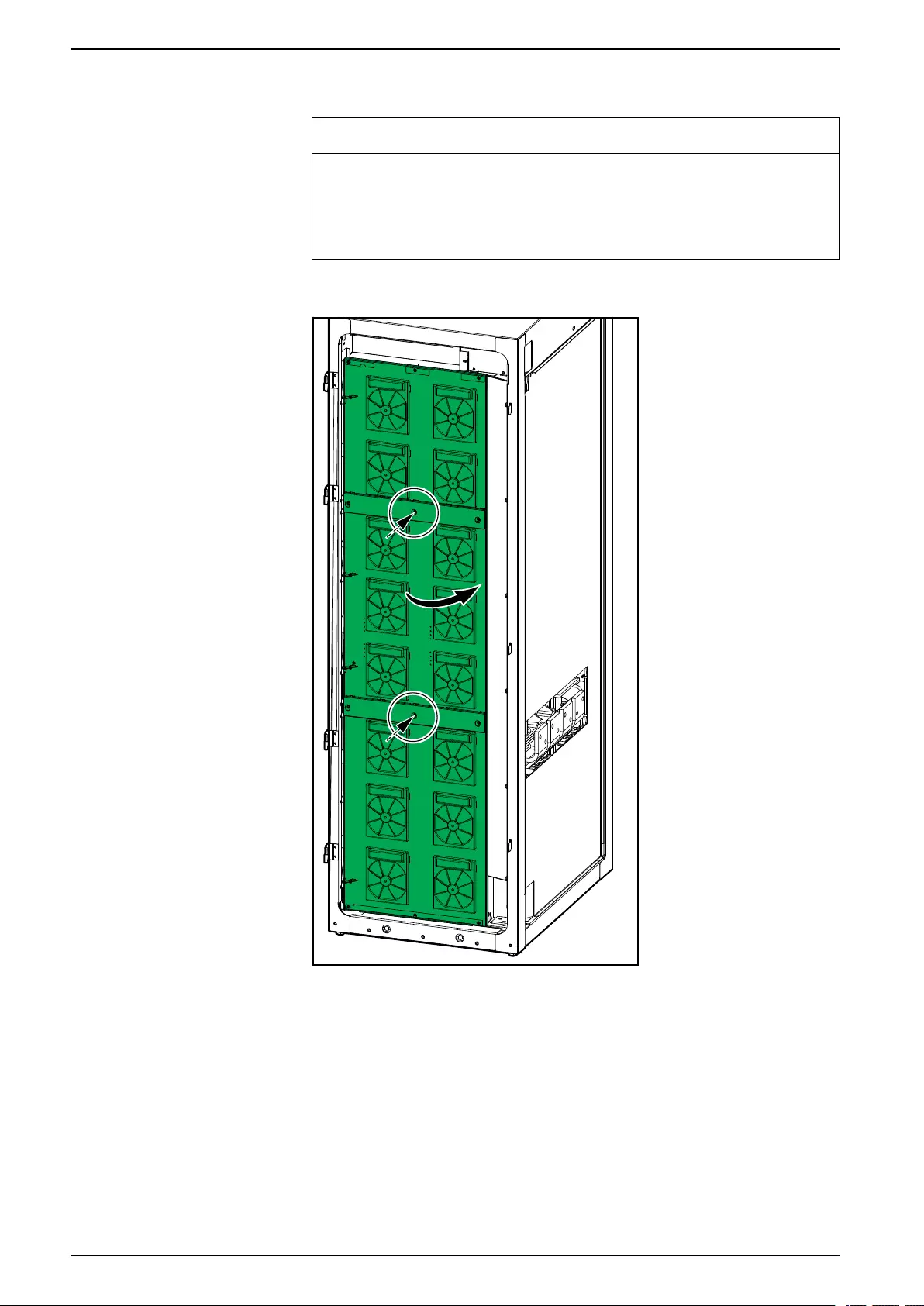
UPS with 1500 kW I/O Cabinet Mechanical Installation
9. Reinstall the fan doors temporarily on all power cabinets and fasten with two
screws.
NOTICE
RISK OF EQUIPMENT DAMAGE
The fan doors must be installed to avoid damaging the signal cables when
pushing the power cabinets into position.
Failure to follow these instructions can result in equipment damage.
Front View of the Power Cabinet
10. Open the left and right front doors of the I/O cabinet.
62 990-5783E-001
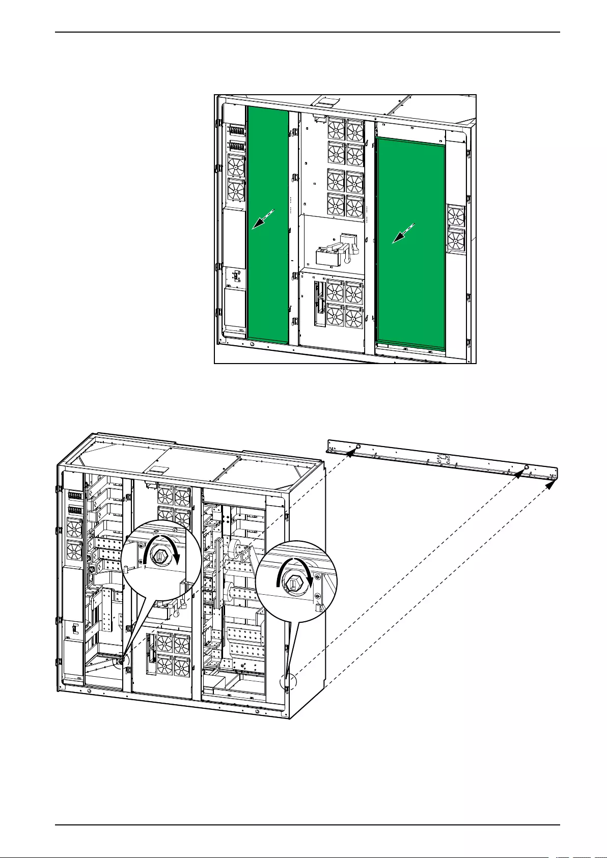
Mechanical Installation UPS with 1500 kW I/O Cabinet
11. Remove the two metal plates from the I/O cabinet.
Front View of the I/O Cabinet
12. Push the I/O cabinet into position against the rear anchoring bracket – the I/O
cabinet will connect to the conic outcroppings on the rear anchoring bracket.
Front View of the I/O Cabinet
990-5783E-001 63
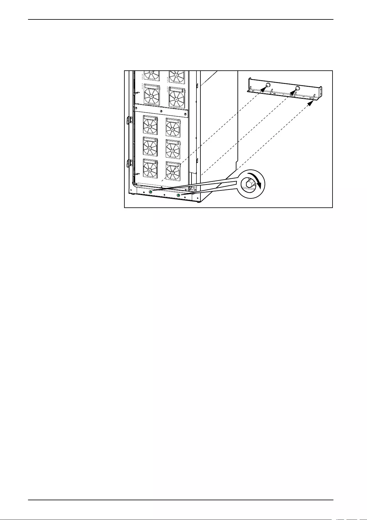
UPS with 1500 kW I/O Cabinet Mechanical Installation
13. Push the power cabinets into position against the rear anchoring brackets –
the power cabinets will connect to the conic outcroppings on the rear
anchoring brackets.
Front View of the Power Cabinet
14. Fasten the cabinets to the rear anchoring brackets by tightening the bolts on
the front of the cabinets. Torque to 50 Nm (36.87 lb-ft).
64 990-5783E-001
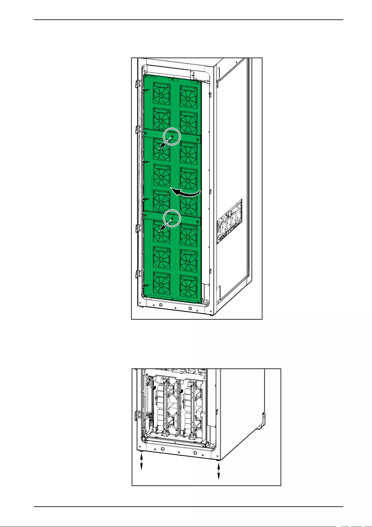
Mechanical Installation UPS with 1500 kW I/O Cabinet
15. Remove the fan doors of the power cabinets.
Front View of the Power Cabinet
16. Lower the two front feet on all cabinets until they connect with the floor – use
a bubble-leveler to ensure that the cabinets are level. Use the provided
levelling shims if necessary.
Front View of the Power Cabinet
990-5783E-001 65

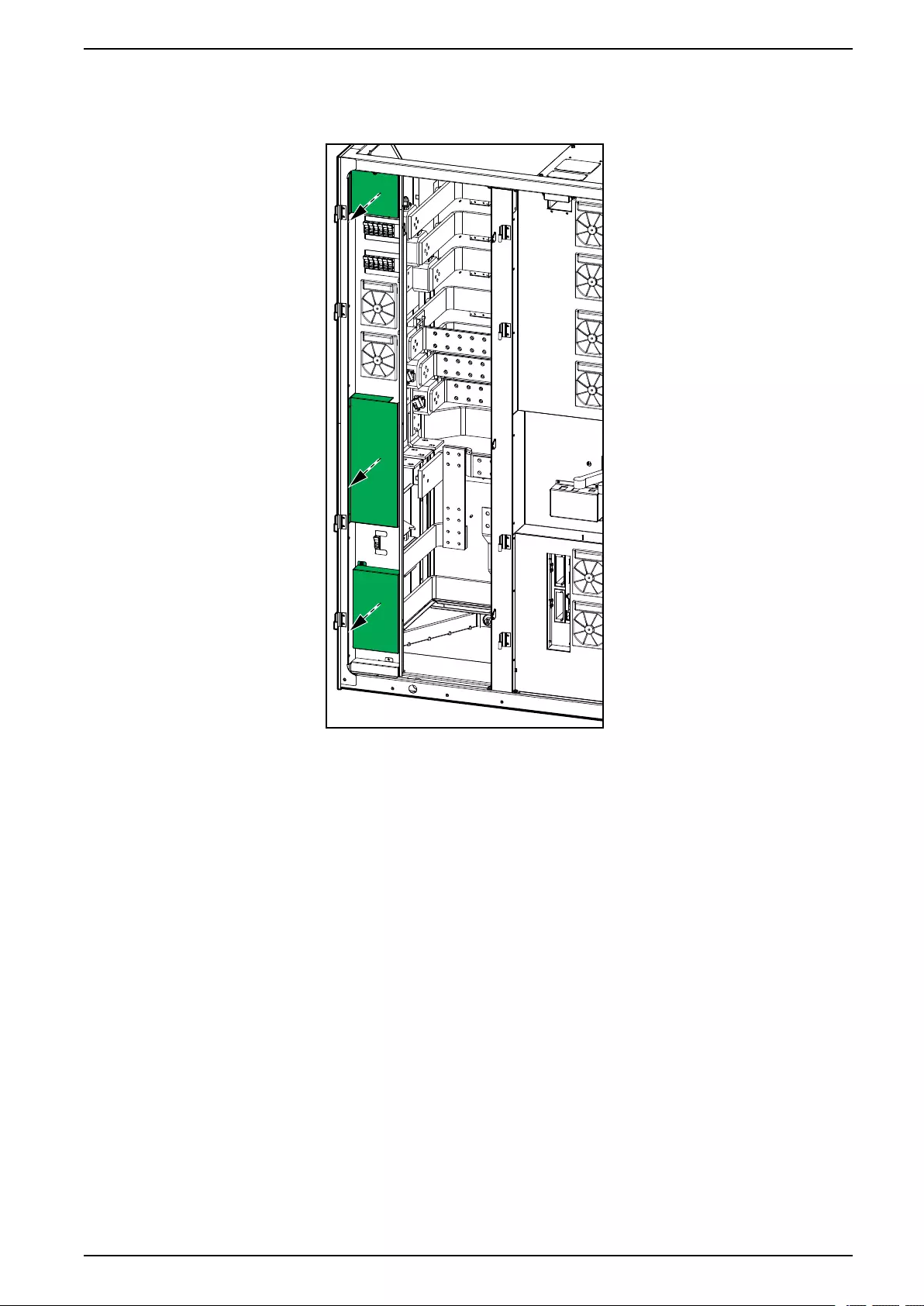
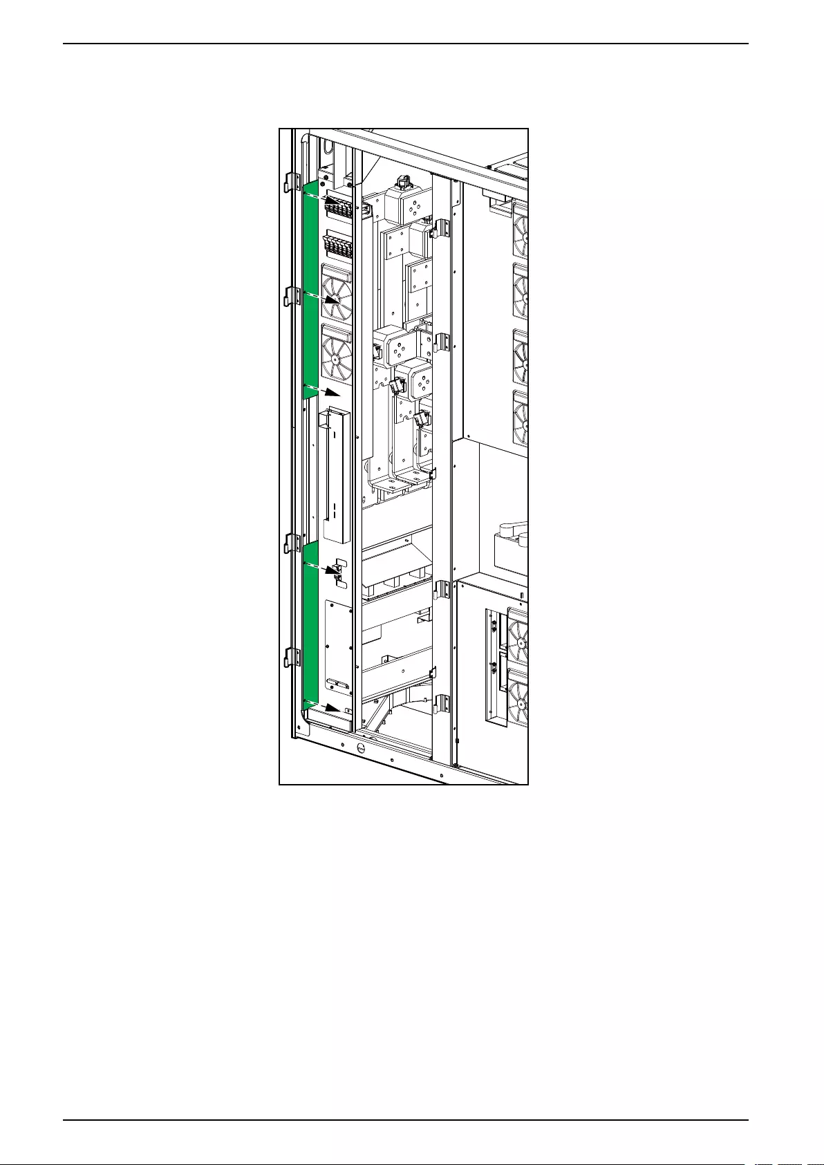
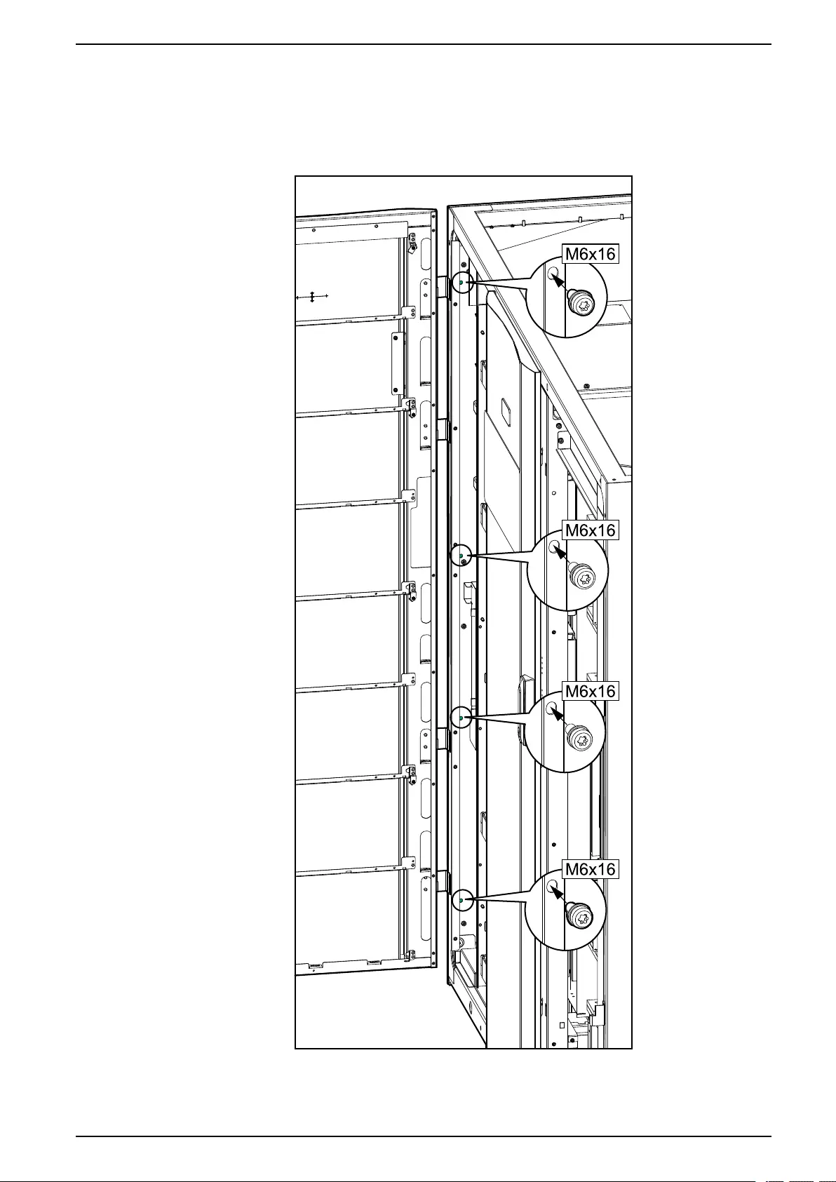
Mechanical Installation UPS with 1500 kW I/O Cabinet
20. Mount the M6 screws from the installation kit from right to left in the four
marked locations between the I/O cabinet and the power cabinet placed to
the left of the I/O cabinet.
From the Power Cabinet on the Left Side of the I/O Cabinet to the I/O
Cabinet
990-5783E-001 69
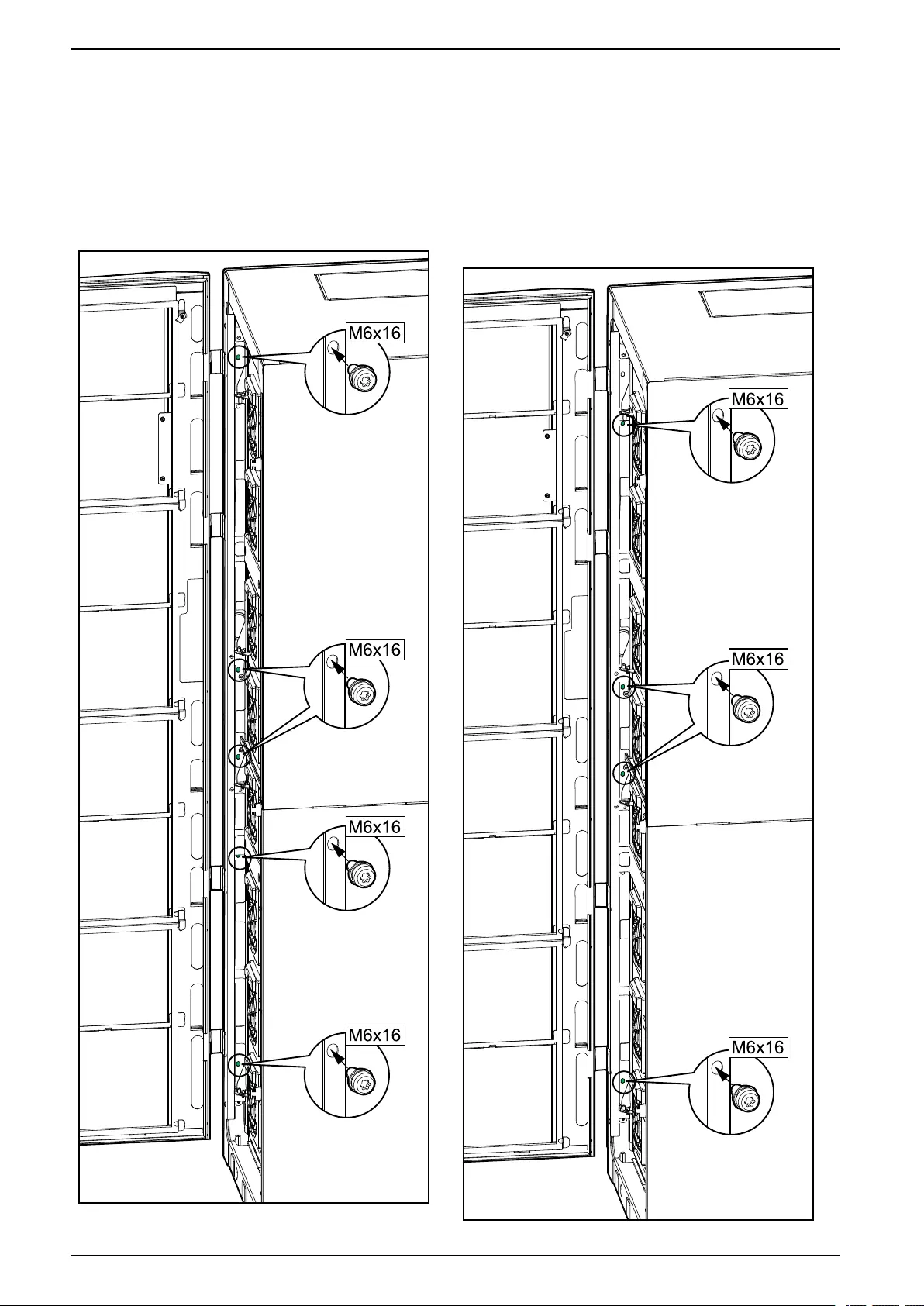
UPS with 1500 kW I/O Cabinet Mechanical Installation
21. Mount the M6 screws from the installation kit from right to left to tighten the
cabinets together:
• in the five marked positions between the power cabinets.
• in the four marked positions between the I/O cabinet and the power
cabinet on the right side of the I/O cabinet.
From the Power Cabinet to the Power Cabinet From the Power Cabinet on the Right Side of the I/
O Cabinet to the I/O Cabinet
70 990-5783E-001
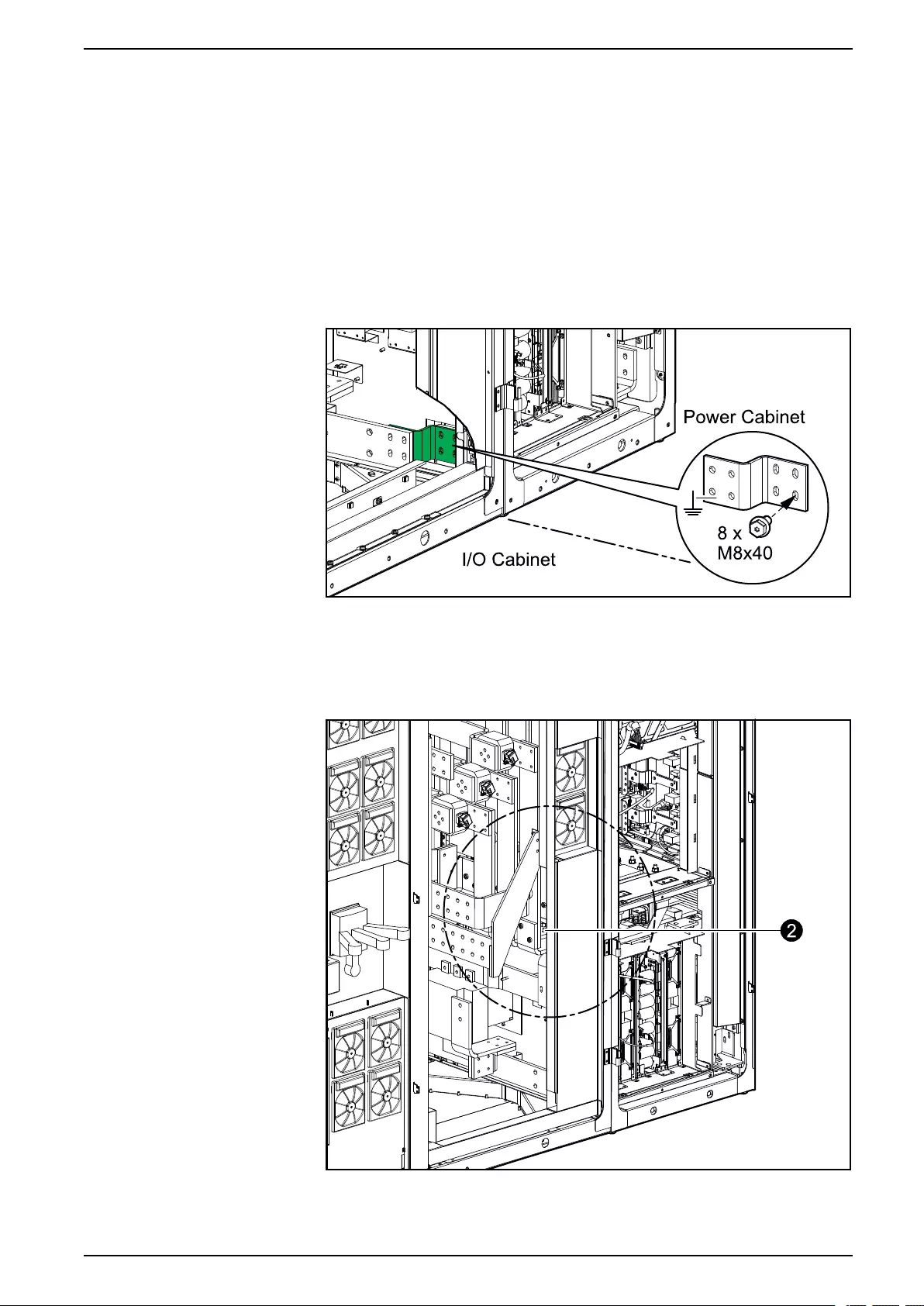
Mechanical Installation UPS with 1500 kW I/O Cabinet
Install the Busbars between the I/O Cabinet and the Power
Cabinets
1. Install the grounding busbar 880–99029 from the installation kit 0H–9128
between the I/O cabinet and the power cabinet placed to the right of the I/O
cabinet.
NOTE: If the grounding busbar 880-99029 is not compatible with the
power cabinet placed to the right of the I/O cabinet, the busbar kit 0J-
0446 with flexible busbars must be used for the grounding connection
instead of the grounding busbar. Contact Schneider Electric.
Front View of the I/O Cabinet and the Power Cabinet
2. Install the interconnection busbars from the installation kit 0H–9128 and 0H–
9097 between the I/O cabinet and the power cabinet placed to the right of the
I/O cabinet.
Front View of the I/O Cabinet and the Power Cabinet
990-5783E-001 71
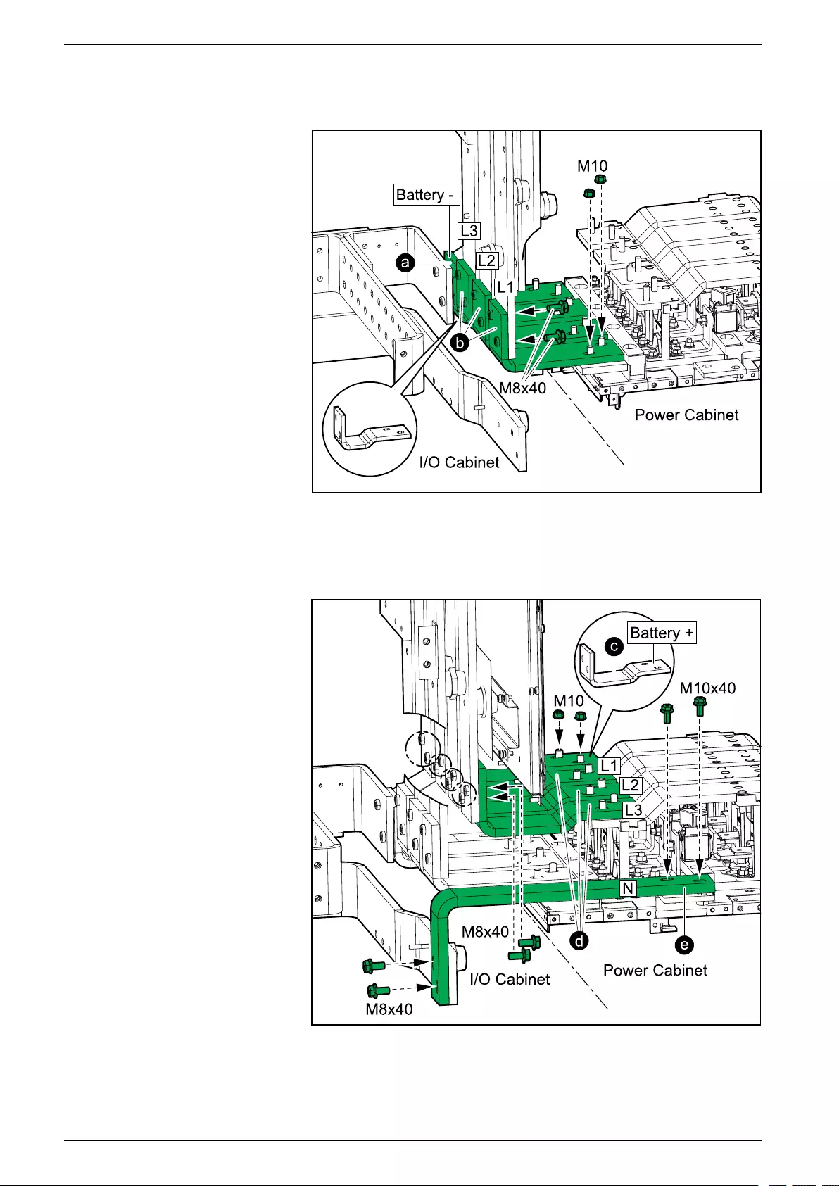
UPS with 1500 kW I/O Cabinet Mechanical Installation
a. Install the battery– interconnection busbar 880–90658.
Front View of Busbar Connections
b. Install the three input interconnection busbars 880–90657.
c. Install the battery+ interconnection busbar 880–90655.
Front View of Busbar Connections
d. Install the three output interconnection busbars 880–90654.
e. Install the neutral interconnection busbar 880–9614 or 880–553850.
72 990-5783E-001
50. The part number to use is dependent on your power cabinet version.

Mechanical Installation UPS with 1500 kW I/O Cabinet
f. Connect the signal cables connected to the boards to the three input
interconnection busbars and fasten with the three M6 nuts from the
installation kit 0H-9128.
Front View of the Right Side of the I/O Cabinet
3. Install the grounding busbar 880-5662 from the installation kit 0H-9096
between the I/O cabinet and the power cabinet placed to the left of the I/O
cabinet.
NOTE: If the grounding busbar 880-5662 is not compatible with the power
cabinet placed to the left of the I/O cabinet, the busbar kit 0J-0446 with
flexible busbars must be used for the grounding connection instead of the
grounding busbar. Contact Schneider Electric.
Front View of the Power Cabinet and the I/O Cabinet
990-5783E-001 73
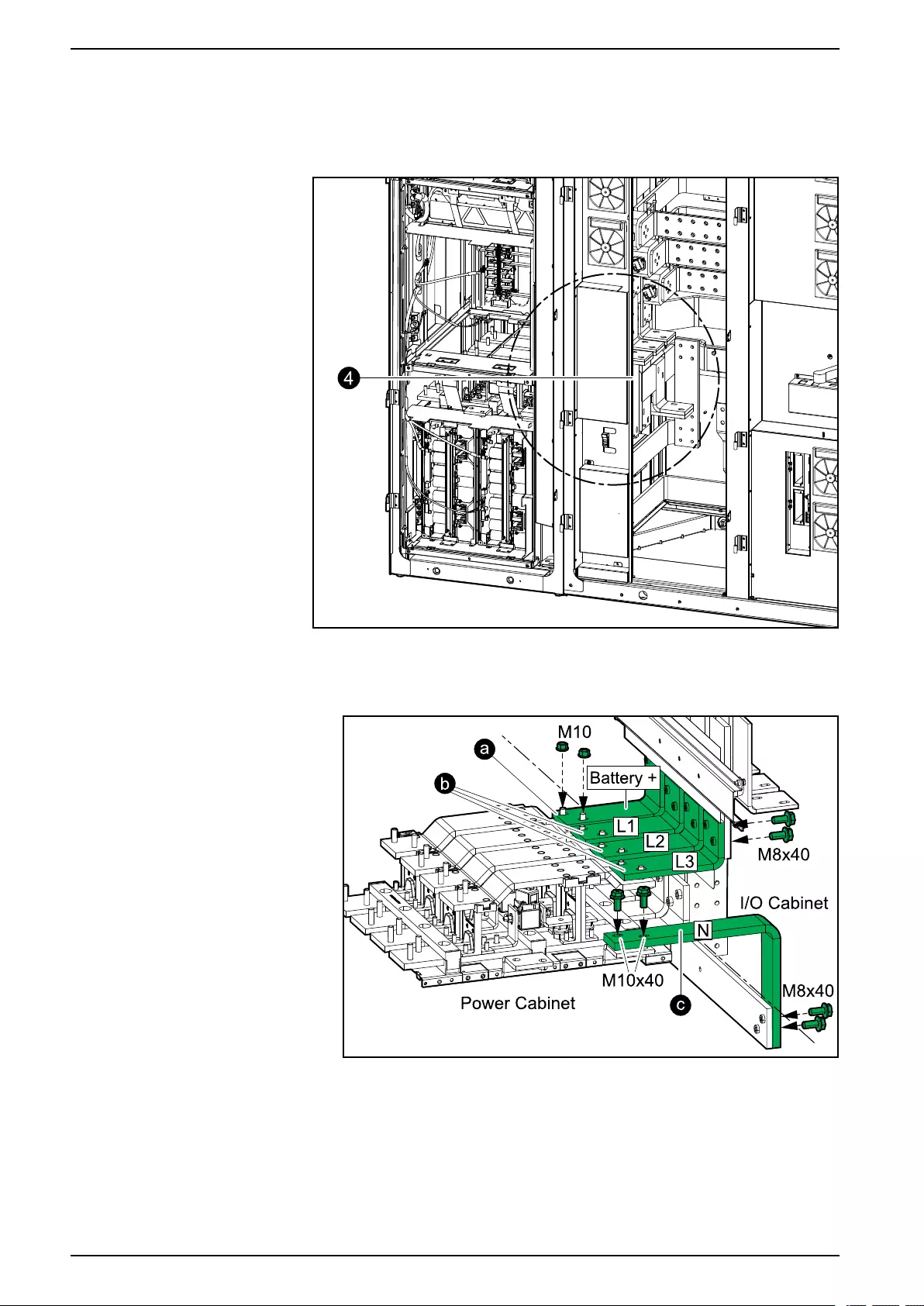
UPS with 1500 kW I/O Cabinet Mechanical Installation
4. Install the interconnection busbars from the installation kit 0H-9096 and 0H-
9129 between the I/O cabinet and the power cabinet placed to the left of the I/
O cabinet.
Front View of the Power Cabinet and the I/O Cabinet
a. Install the battery+ interconnection busbar 880–5503.
Front View of Busbar Connections
b. Install the three output interconnection busbars 880–9569.
c. Install the neutral interconnection busbar 880–5507.
74 990-5783E-001
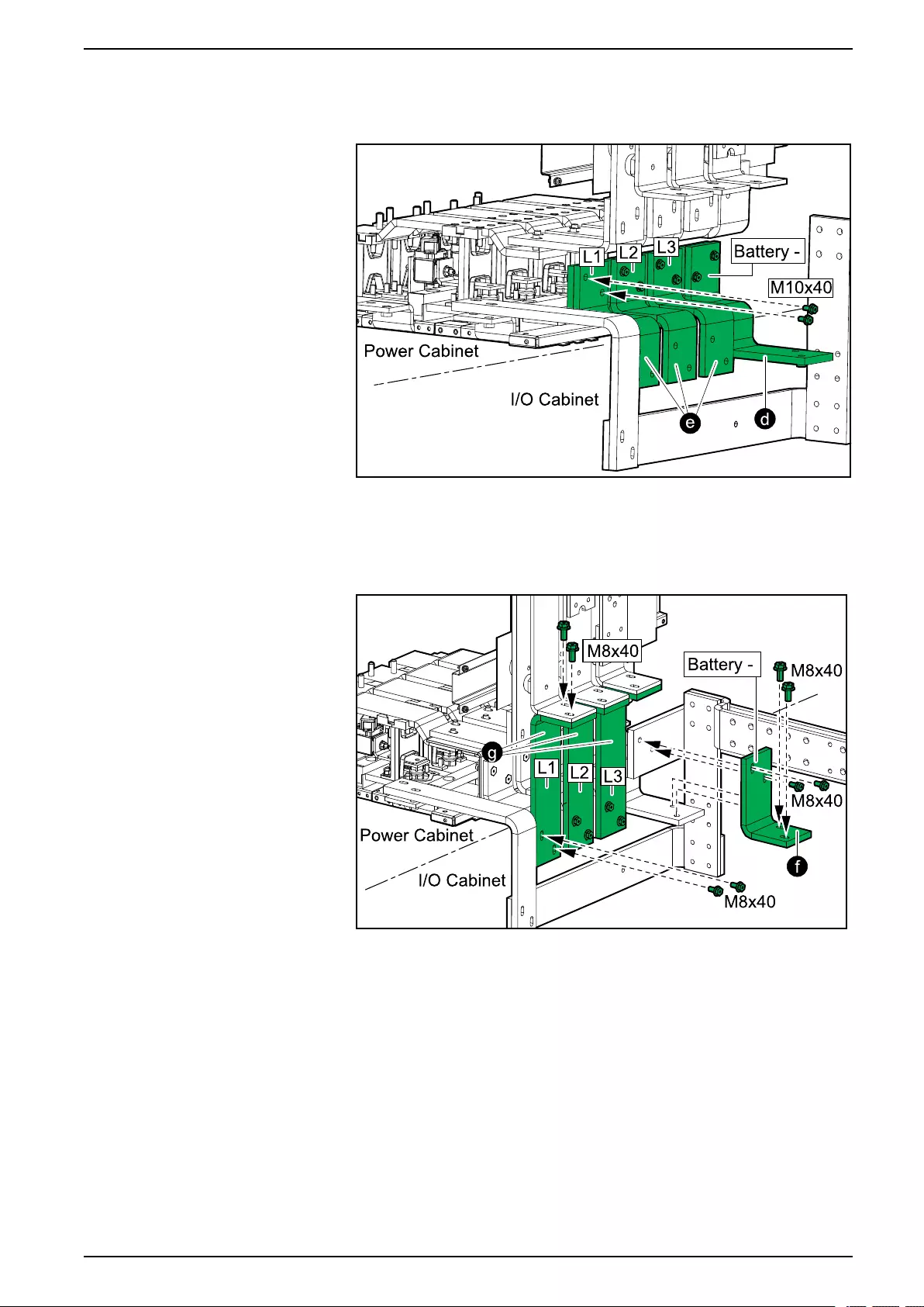
Mechanical Installation UPS with 1500 kW I/O Cabinet
d. Install the first battery– interconnection busbar 880–5496.
Front View of Busbar Connections
e. Install the first layer of three input interconnection busbars 880–5502.
f. Install the second battery– interconnection busbar 880–5495.
Front View of Busbar Connections
g. Install the second layer of three input interconnection busbars 880–
90650.
990-5783E-001 75

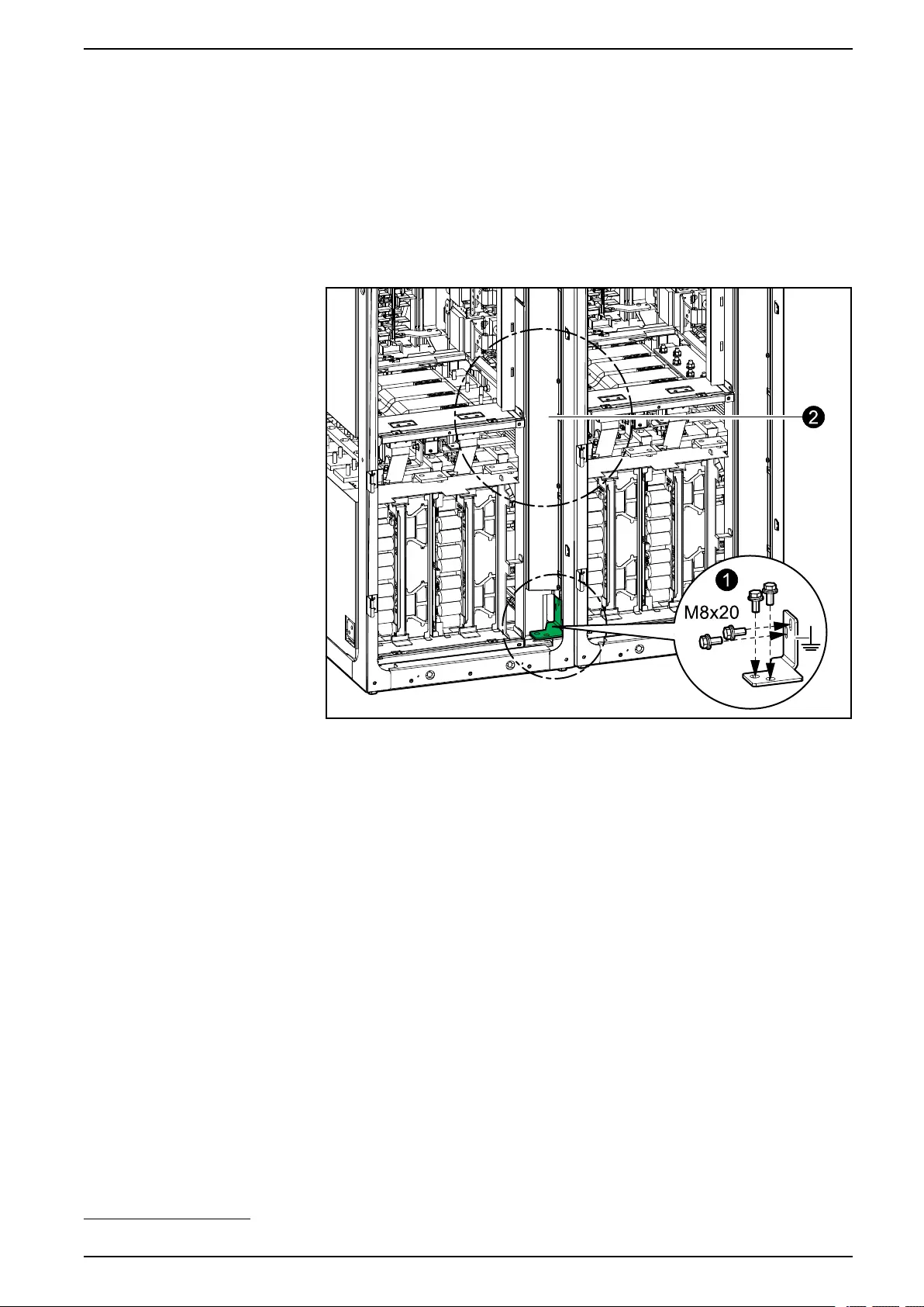
Mechanical Installation UPS with 1500 kW I/O Cabinet
Install the Busbars between the Power Cabinets
1. Install the grounding busbars 880-5259 or 880-9902751 from the installation
kit 0H-0440, 0H-9162, or 0H-910251 between all power cabinets.
NOTE: If your system contains different power cabinet versions, the
busbar kit 0J-0446 with flexible busbars must be used for the grounding
connection between the power cabinets instead of the grounding busbar.
Contact Schneider Electric.
Front View of Two Power Cabinets with grounding Busbar 880–5259
990-5783E-001 77
51. The part number is dependent on the power cabinet version.
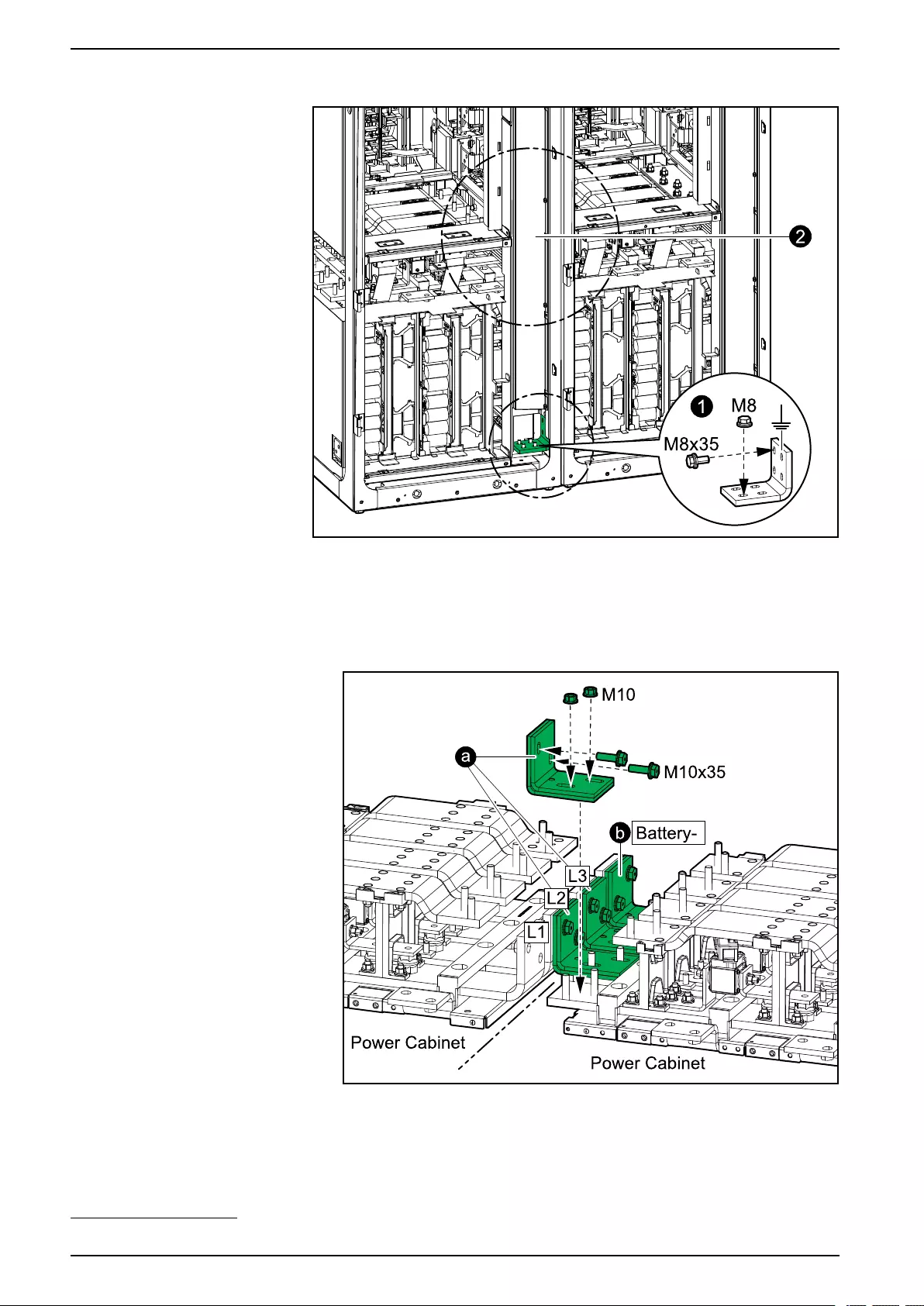
UPS with 1500 kW I/O Cabinet Mechanical Installation
Front View of Two Power Cabinets with grounding Busbar 880-99027
2. Install the interconnection busbars from the installation kit 0H-0440, 0H-9162,
or 0H-910252 between all power cabinets.
a. Install the three input interconnection busbars 0M-97885.
Front View of the Busbar Connections
b. Install the battery – interconnection busbar 0M-819336.
78 990-5783E-001
52. The part number is dependent on the power cabinet version.
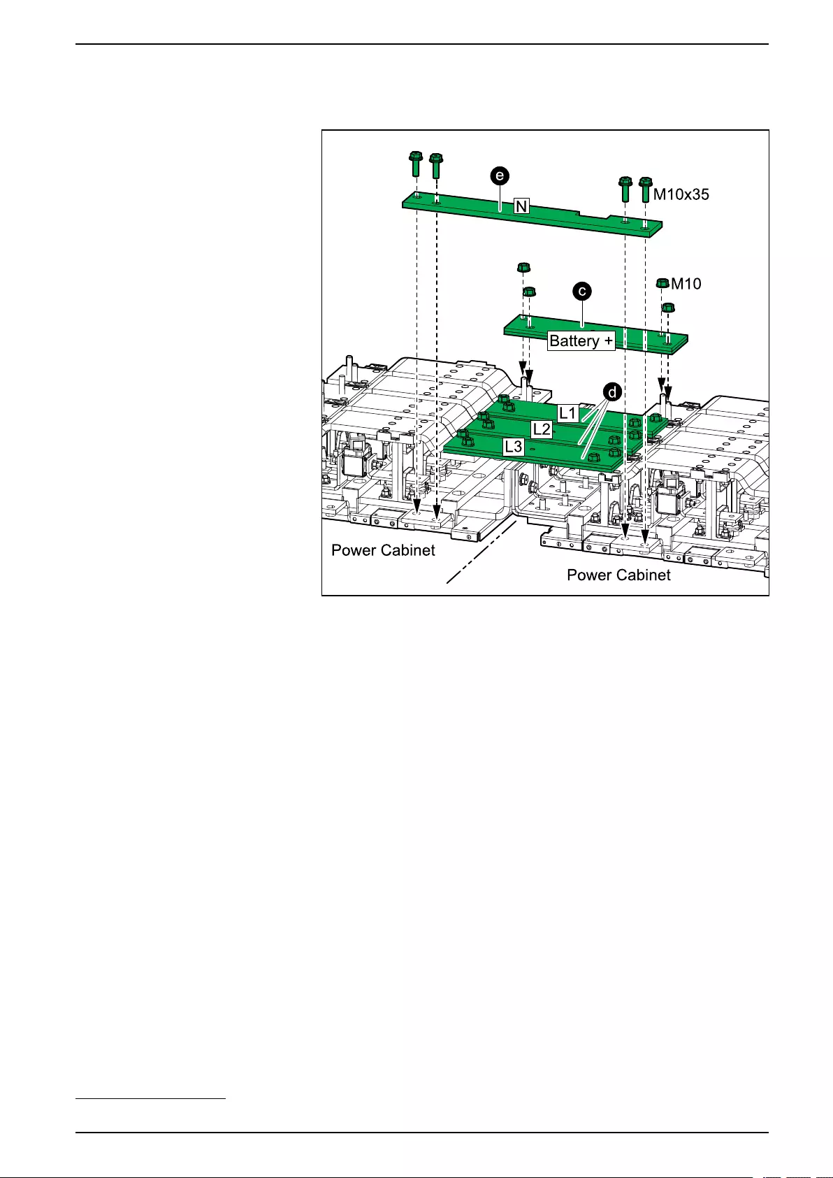
Mechanical Installation UPS with 1500 kW I/O Cabinet
c. Install the battery + interconnection busbar 0M-140035.
Front View of Busbar Connections
d. Install the output interconnection busbars 0M-97886.
e. Install the neutral interconnection busbar 880-10146 or 880-972053.
990-5783E-001 79
53. The part number is dependent on the power cabinet version.
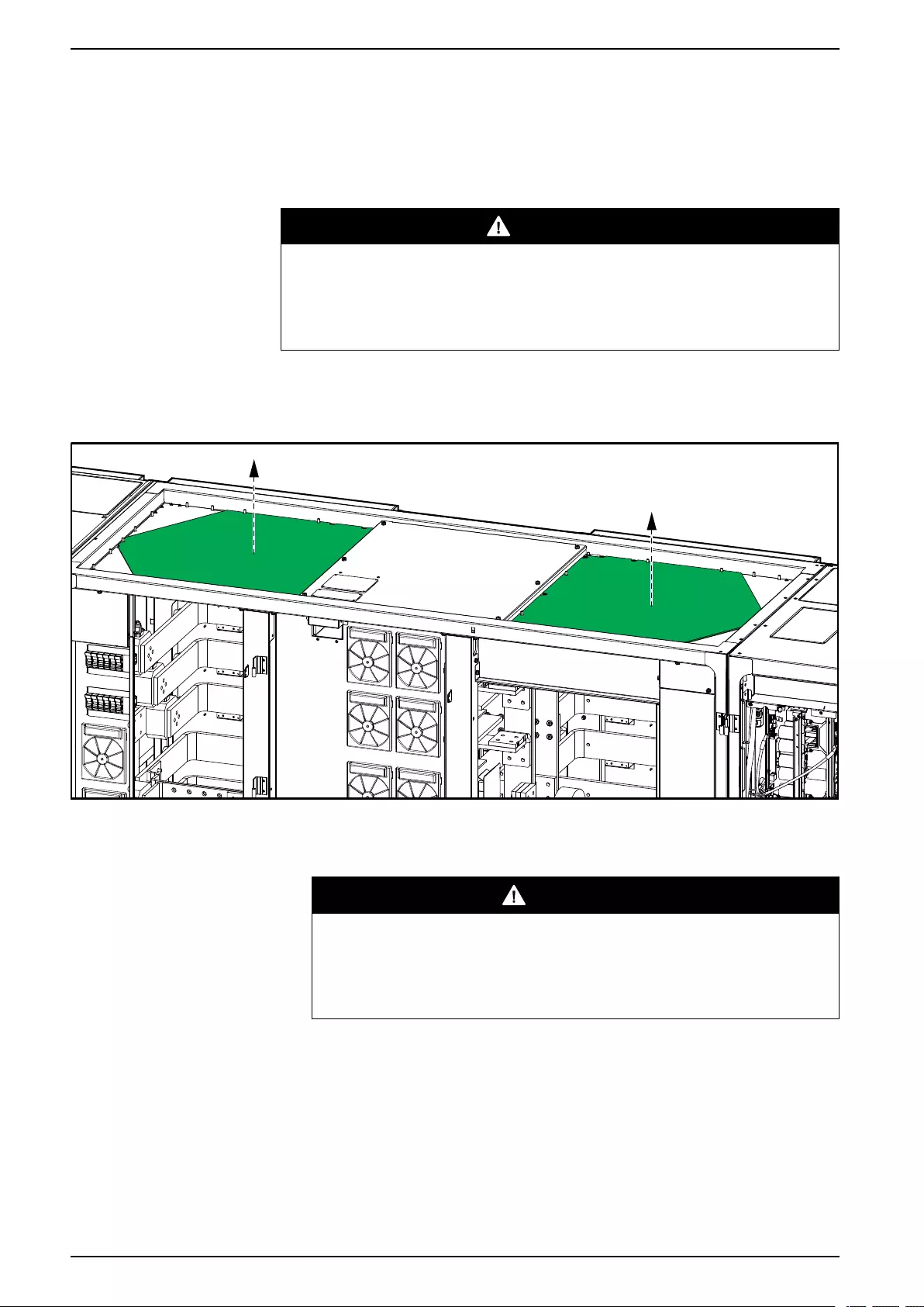
UPS with 1500 kW I/O Cabinet Connect the Power Cables
Connect the Power Cables
Prepare the I/O Cabinet for Power Cables in Top Cable Entry
Systems
DANGER
HAZARD OF ELECTRIC SHOCK, EXPLOSION, OR ARC FLASH
Do not drill/punch holes for cables or conduits with the gland plates installed
and do not drill/punch holes in close proximity to the UPS.
Failure to follow these instructions will result in death or serious injury.
1. Loosen the bolts and remove the gland plates from the top of the I/O cabinet.
Front View of the I/O Cabinet
2. Drill or cut holes for cables/conduits in the top gland plate.
3. Install conduits and reinstall the top gland plate.
DANGER
HAZARD OF ELECTRIC SHOCK, EXPLOSION, OR ARC FLASH
Ensure that there are no sharp edges that can damage the cables.
Failure to follow these instructions will result in death or serious
injury.
80 990-5783E-001
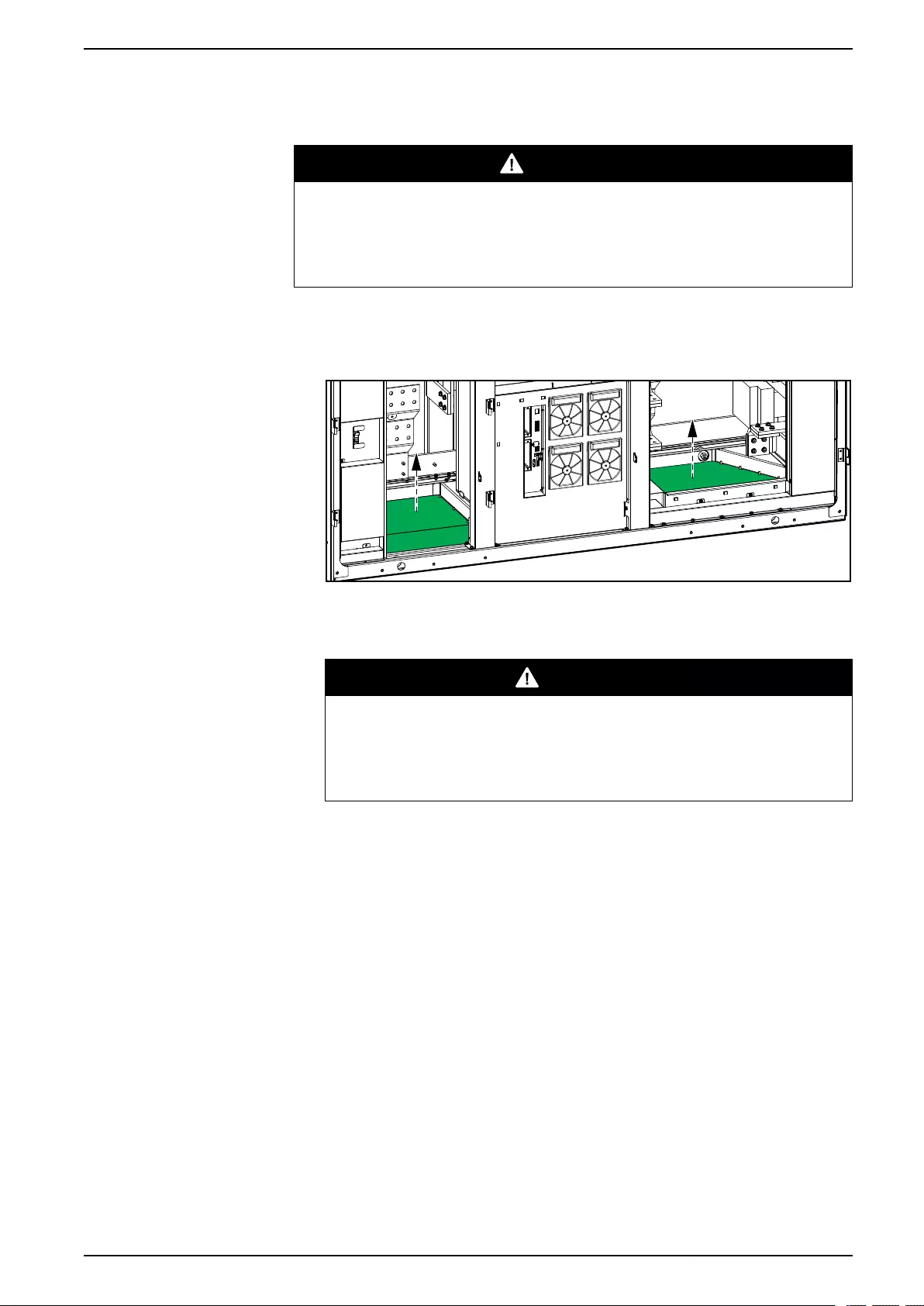
Connect the Power Cables UPS with 1500 kW I/O Cabinet
Prepare the I/O Cabinet for Power Cables in Bottom Cable Entry
Systems
DANGER
HAZARD OF ELECTRIC SHOCK, EXPLOSION, OR ARC FLASH
Do not drill/punch holes for cables or conduits with the gland plates installed
and do not drill/punch holes in close proximity to the UPS.
Failure to follow these instructions will result in death or serious injury.
1. Loosen the bolts and remove the gland plates in the bottom of the I/O cabinet.
Front View of the I/O Cabinet
2. Drill or cut holes for cables/conduits in the bottom gland plate.
3. Install conduits and reinstall the bottom gland plate.
DANGER
HAZARD OF ELECTRIC SHOCK, EXPLOSION, OR ARC FLASH
Ensure that there are no sharp edges that can damage the cables.
Failure to follow these instructions will result in death or serious
injury.
990-5783E-001 81
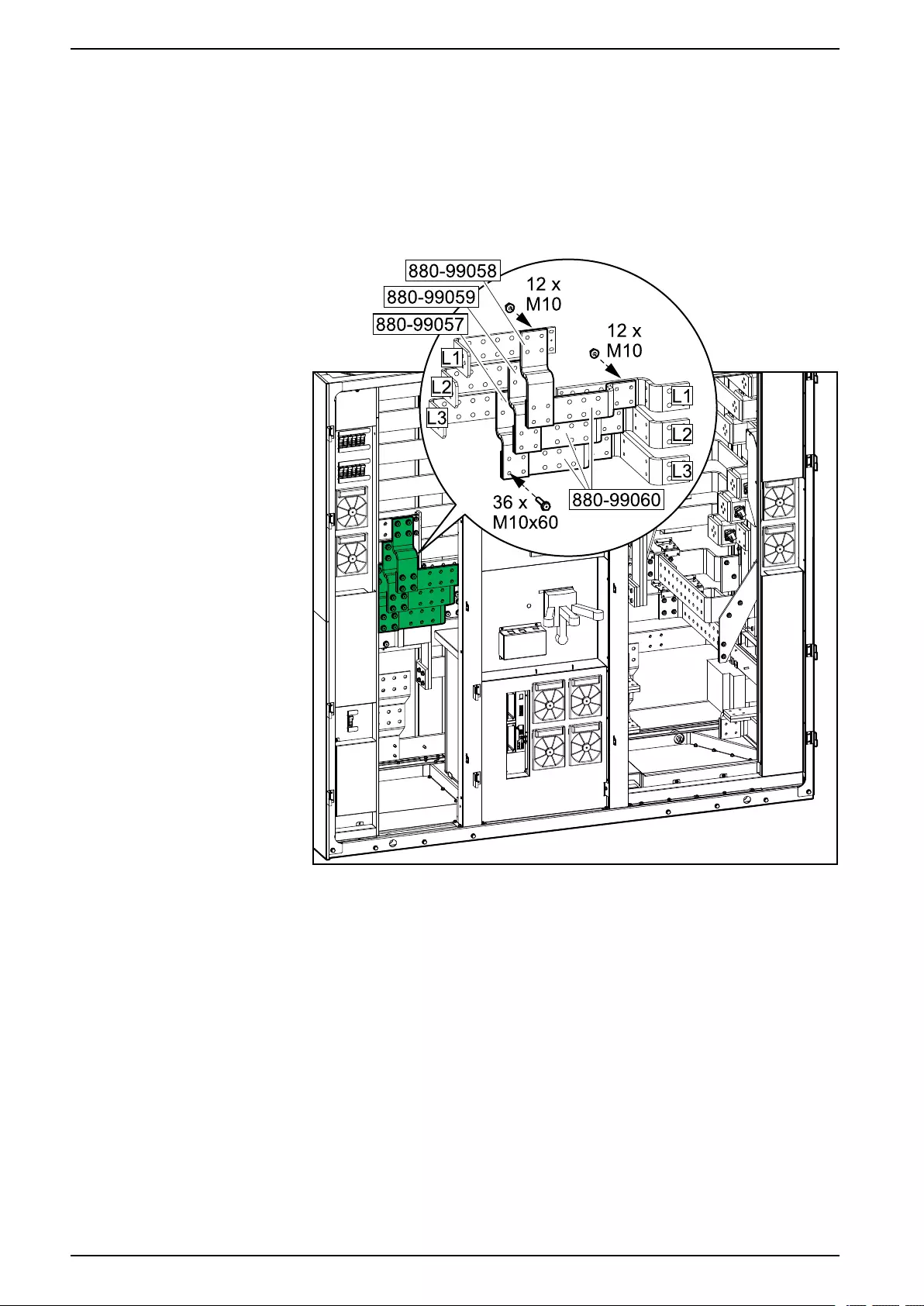
UPS with 1500 kW I/O Cabinet Connect the Power Cables
Install the Single Utility/Mains Installation Kit 0H-9161
NOTE: This procedure is only applicable to single utility/mains systems.
1. Install the single utility/mains installation kit 0H-9161 between the input and
bypass busbars. Connect L1 to L1, L2 to L2, and L3 to L3.
NOTE: Two busbars are required for each connection.
Front View of the I/O Cabinet
82 990-5783E-001
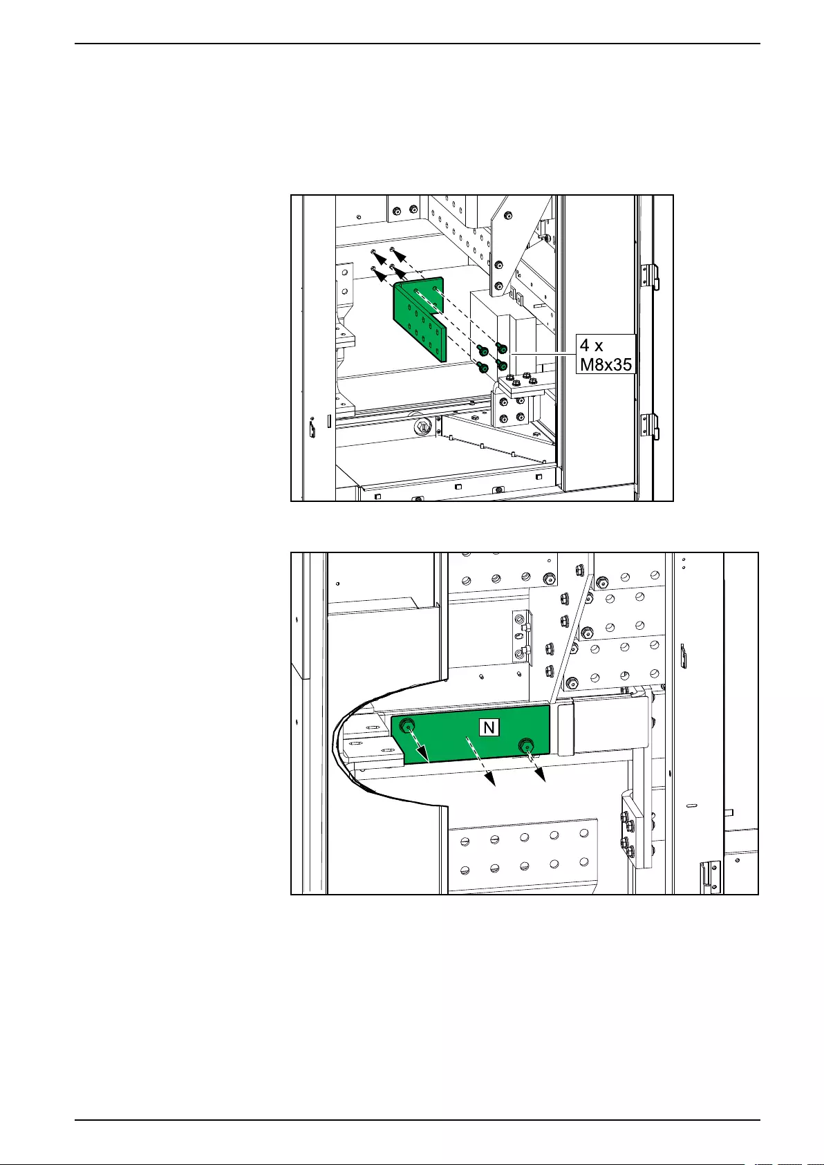
Connect the Power Cables UPS with 1500 kW I/O Cabinet
Connect the Power Cables in a 380 V, 400 V, 415, and 440 V
System
1. Install the N busbar 880–5501 from the installation kit 0H-1102.
Front View of the I/O Cabinet
2. In installations with neutral connection only, remove the lexan plate from the
N busbar.
990-5783E-001 83
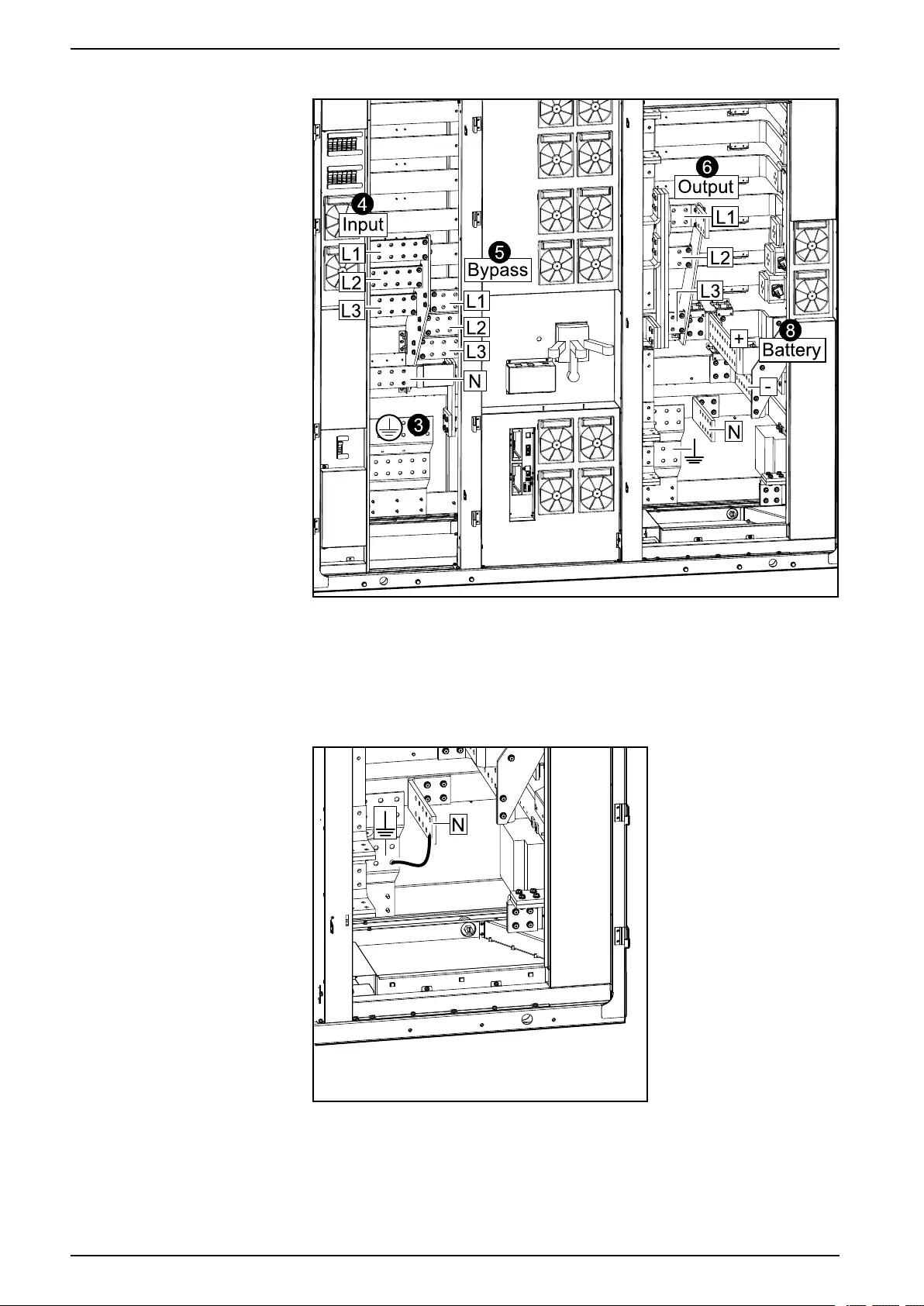
UPS with 1500 kW I/O Cabinet Connect the Power Cables
3. Connect the equipment earthing conductor/PE to the PE busbar.
4. Connect the input cables.
5. Only applicable to dual mains systems: Connect the bypass cables.
6. Connect the output cables.
7. Only applicable to TNC systems: Install jumper cables (not provided) between
the N busbar and the earthing terminal.
84 990-5783E-001
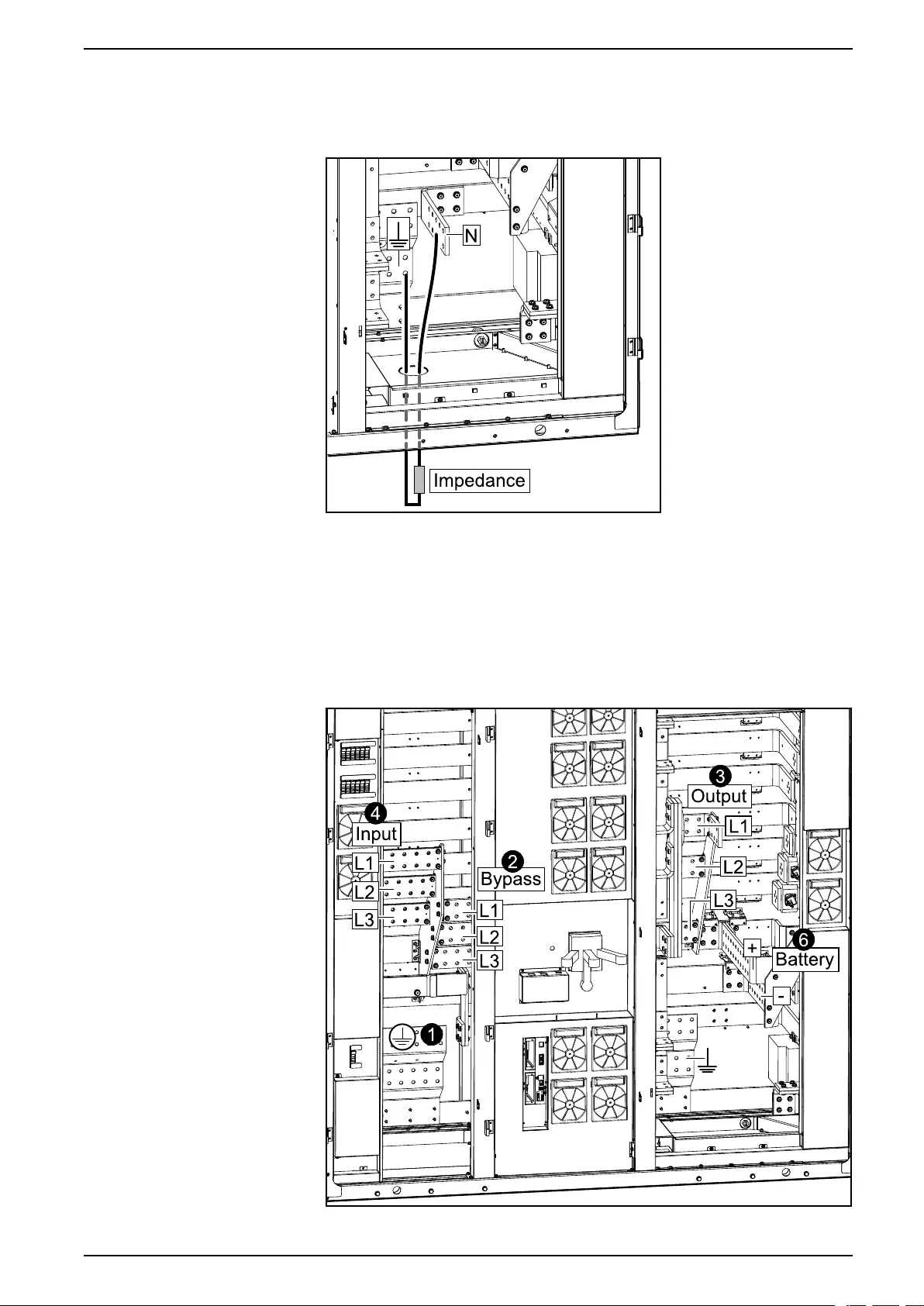
Connect the Power Cables UPS with 1500 kW I/O Cabinet
8. Only applicable to 4–wire systems: In an IT system, connect an external
impedance between the N busbar and the earthing terminal.
NOTE: For IT systems, the installation must include a earth-fault detection
circuitry.
9. Connect the battery cables to the battery + and battery – terminals.
Connect the Power Cables in a 480 V System
The grounding electrode conductor must be installed per NEC 250.30 and sized
per NEC 250.66.
1. Connect the equipment grounding conductor/PE to the PE busbar.
990-5783E-001 85
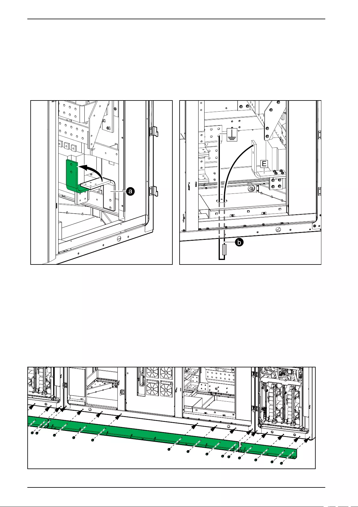
UPS with 1500 kW I/O Cabinet Connect the Power Cables
2. Only applicable to dual mains systems: Connect the bypass cables.
3. Connect the output cables.
4. Connect the input cables.
5. For high impedance grounding systems only:
NOTE: For high impedance grounding systems, the installation must
include a ground-fault detection circuitry.
a. Rotate the jumper busbar so it does not create a connection.
b. Connect an external impedance between the “E” terminal and the
equipment grounding conductor according to NEC 2014 article 250.36.
6. Connect the battery cables to the battery + and battery – terminals.
Mount the Front Anchoring Brackets
1. Fasten the front anchoring brackets to the front of the cabinets using the
provided bolts.
86 990-5783E-001

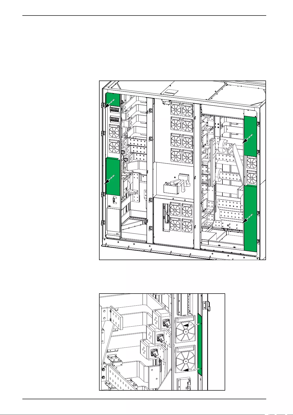
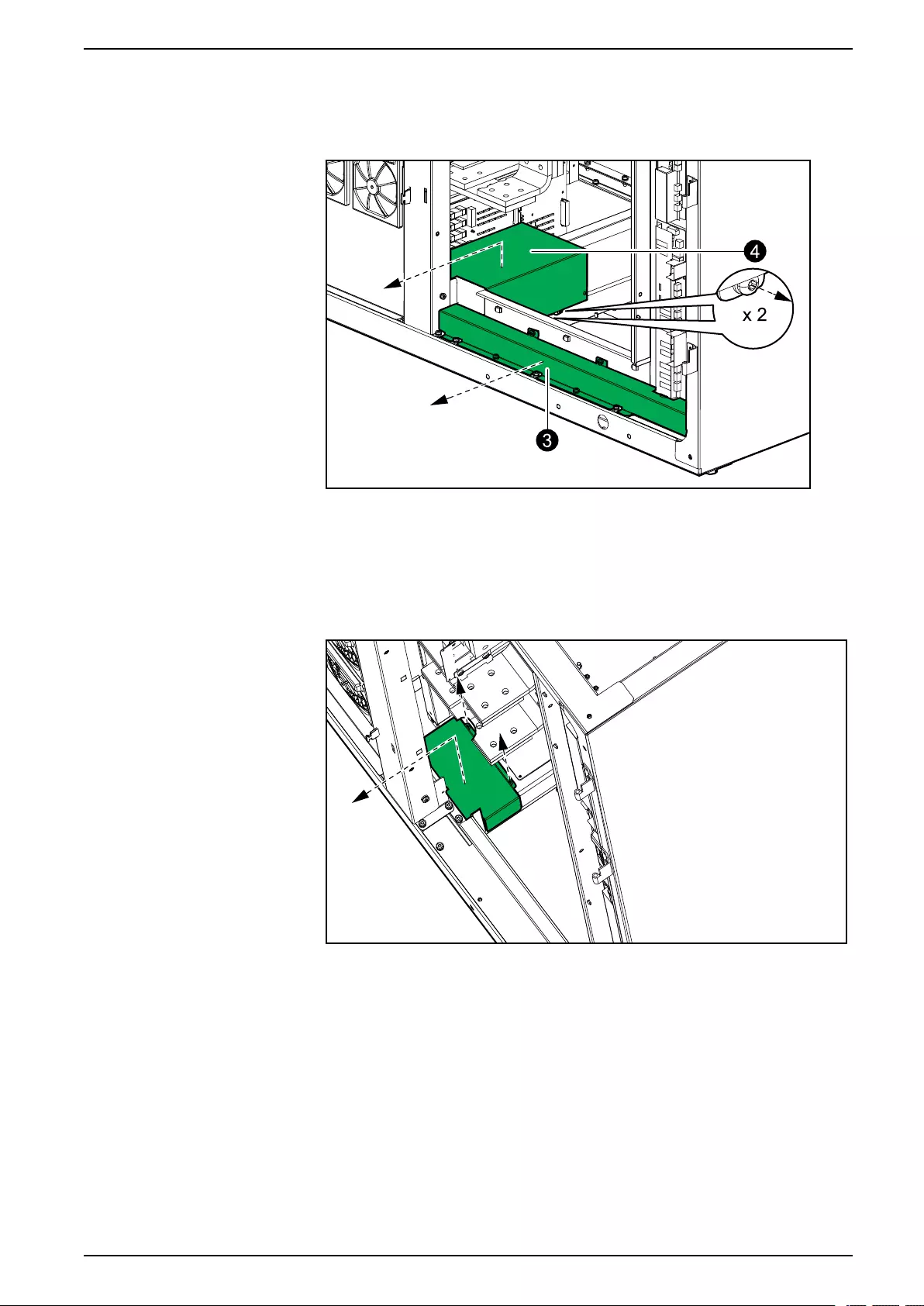
Connect the Signal Cables UPS with 1500 kW I/O Cabinet
3. For bottom cable entry only: remove the plate in front of the cable channel for
non-Class 2/non-SELV cables.
Front View of the I/O Cabinet
4. For bottom cable entry only: loosen the two screws on the right side of the
box and remove the box.
5. For bottom cable entry only: loosen the two screws behind the box and lift out
the box.
Front View of the I/O Cabinet
990-5783E-001 89
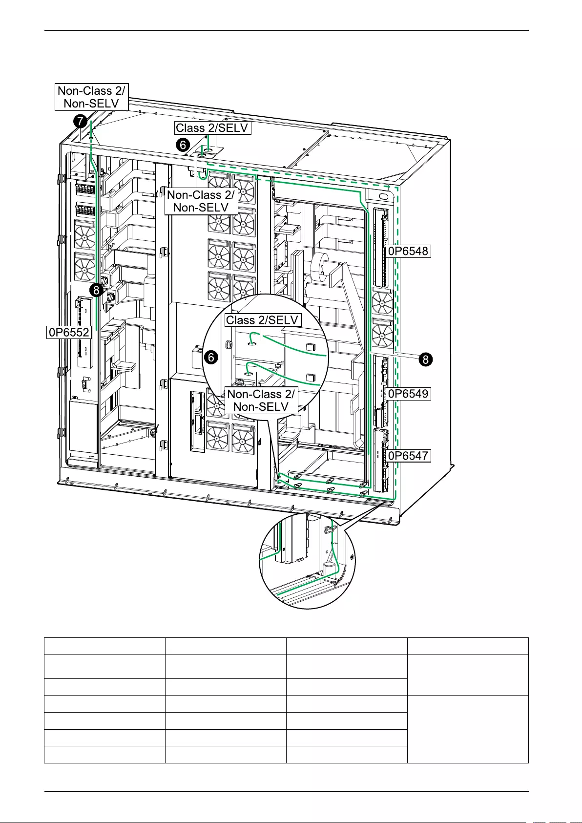
UPS with 1500 kW I/O Cabinet Connect the Signal Cables
6. Remove the two gland plates from either the top or the bottom of the I/O
cabinet and drill holes for the applicable Class 2/SELV and non-Class 2/non-
SELV cables in the table below. Install conduits and reinstall the plates.
Class 2/SELV
Board Terminal Description See
0P6548 J5502–J5506, J5508, J5510–
J5512
Input contacts Connect Equipment to Input
Contacts and Output Relays,
page 103
0P6548 J5520–J5525, J5528 Output relays
0P6548 J5527 Kirk key control Connect the Signal Cables
between the I/O Cabinet and the
Switchgear, page 98
0P6548 J5514 UOB lamp contol
0P6548 J5515 MBB lamp control
0P6548 J5516 SIB lamp control
90 990-5783E-001

Connect the Signal Cables UPS with 1500 kW I/O Cabinet
Class 2/SELV (Continued)
Board Terminal Description See
0P6548 J5517 SSIB lamp control
0P6548 J5509 UOB 2
0P6547 J4931–J4932 24 V SELV supply
0P6547 J4936–J4938 EPO Connect the Emergency Power
Off (EPO), page 100
0P3643 PBUS 1 and PBUS 2 PBUS Connect the PBUS Cables
between Parallel UPS Units,
page 105
0P6502 Modbus Connect the Modbus Cables,
page 107
Non-Class 2/Non-SELV
Board Terminal Description See
0P6548 J4939–J494154 Output relays Connect Equipment to Input
Contacts and Output Relays,
page 103
0P6549 J5607 MBB Connect the Signal Cables
between the I/O Cabinet and the
Switchgear, page 98
0P6549 J5608 SIB
0P6549 J5620 SSIB
0P6549 J5621 UOB
0P6549 J5622 UIB
0P6549 J5611–J5613 External synchronization Connect External
Synchronization, page 100
0P6548 J5529 Battery temperature sensor 1 Connect the Signal Cables for
Battery Solutions, page 98
0P6549 J5609 Battery breaker 1
0P6549 J5610 Battery breaker 2
0P6547 J4942–J4943 24 V supply 1
0P6547 J4929–J4930 24 V supply 2
0P6547 J4923 DC shunt trip 1
0P6547 J4924 DC shunt trip 2
7. In installations with three or four battery banks, remove the top gland plate in
the left corner of the I/O cabinet and drill holes for the applicable non-Class 2/
non-SELV cables below. Install conduits and reinstall the plates.
Non-Class 2/Non-SELV
Board Terminal Description See
0P6552 J9019 Battery breaker 3 Connect the Signal Cables for
Battery Solutions, page 98
0P6552 J9020 Battery breaker 4
0P6552 J9021 Battery temperature sensor 2
0P6552 J9022–J9023 24 V supply 3
0P6552 J9024–J9025 24 V supply 4
8. Route the cables through the top or bottom and to the boards as shown on
the illustration.
990-5783E-001 91
54. These output relays can also be Class 2/SELV but the three output relays must have identical reference.
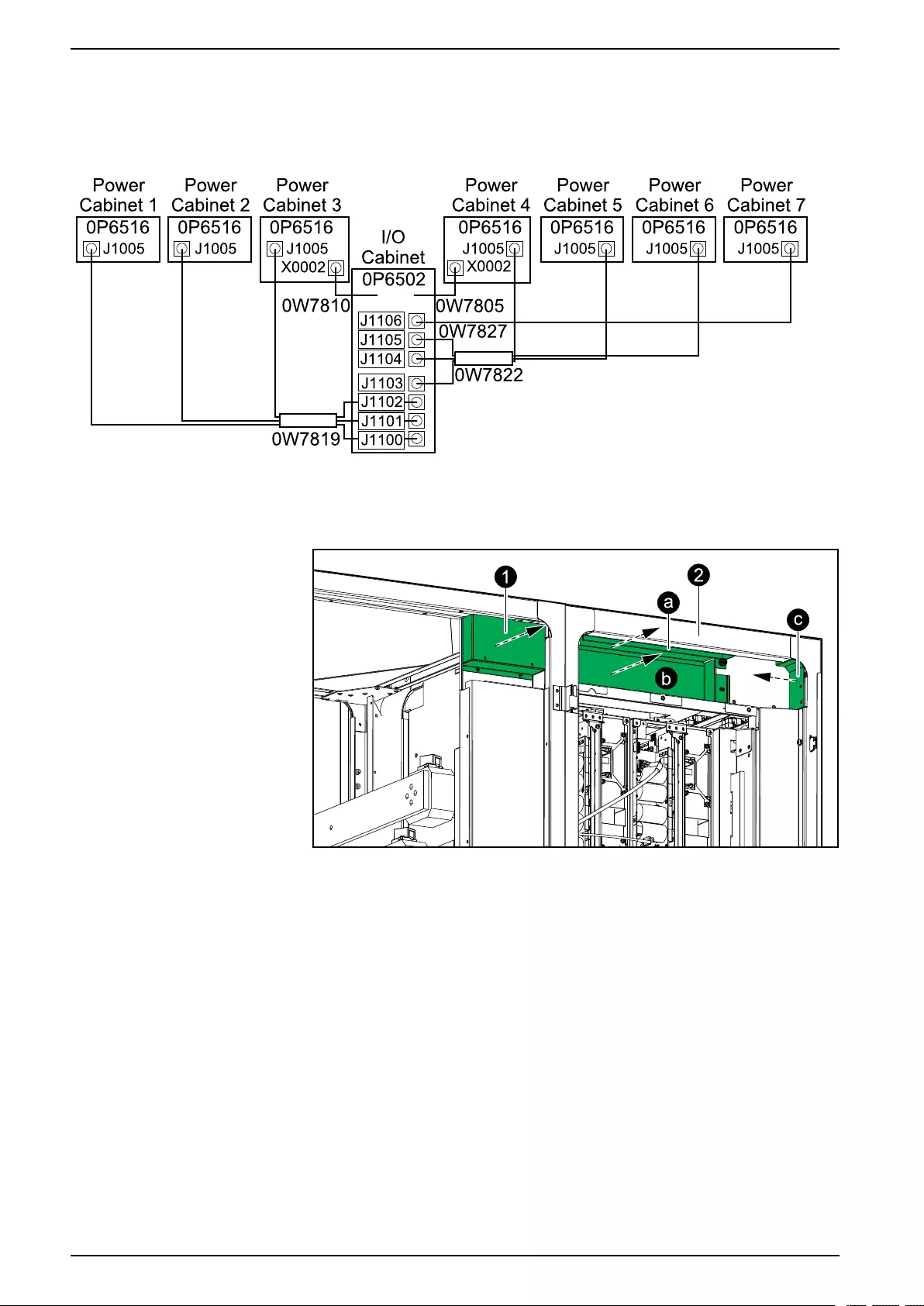
UPS with 1500 kW I/O Cabinet Connect the Signal Cables
Connect the Signal Cables between the I/O Cabinet and the Power
Cabinets
Overview of Signal Cables between the Power Cabinets and the I/O Cabinet
1. Remove the plate in the upper right corner of the I/O cabinet.
I/O Cabinet and One Power Cabinet
2. Remove the three plates (a-c) on all power cabinets.
3. Remove and dispose of all 0W11379 signal cables connected to the X0002
terminals of all power cabinets.
92 990-5783E-001
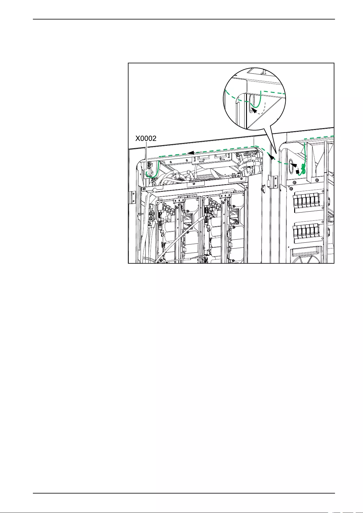
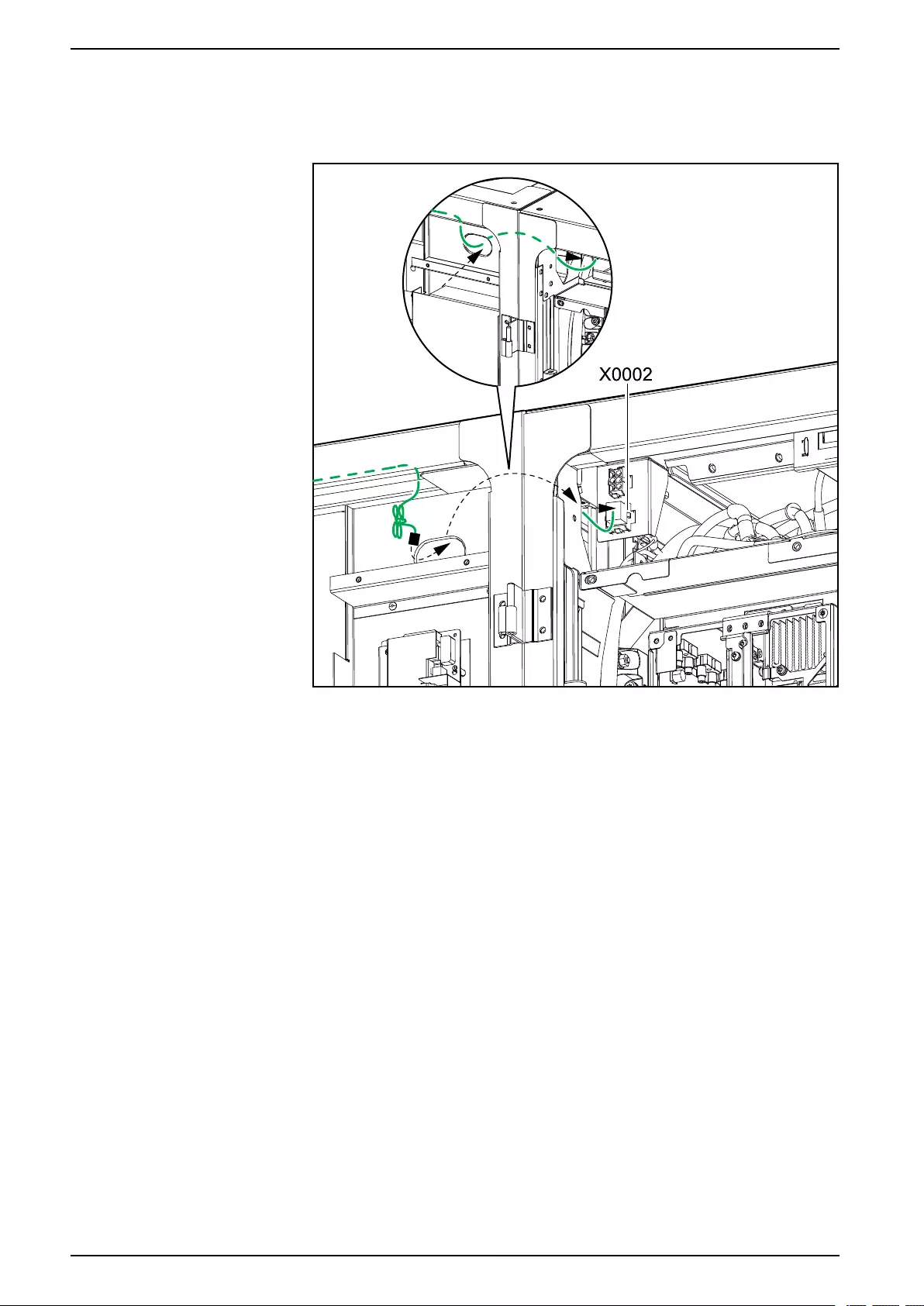
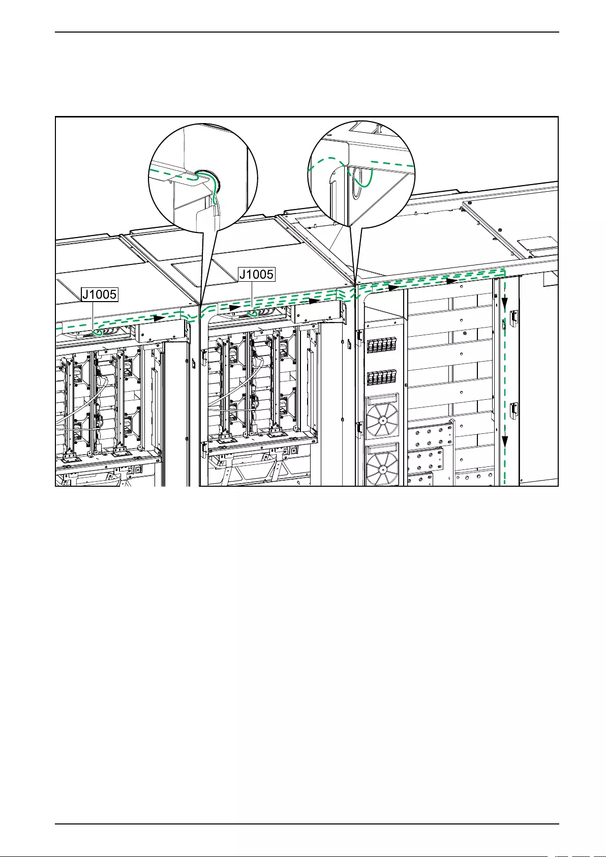
Connect the Signal Cables UPS with 1500 kW I/O Cabinet
6. Connect the signal cable 0W7819 to 0P6516 terminal J1005 in power
cabinets 1–3 (on the left side of the I/O cabinet). Route the cable into the I/O
cabinet as shown on the illustration and fasten the cable.
Two Power Cabinets and the I/O Cabinet
990-5783E-001 95
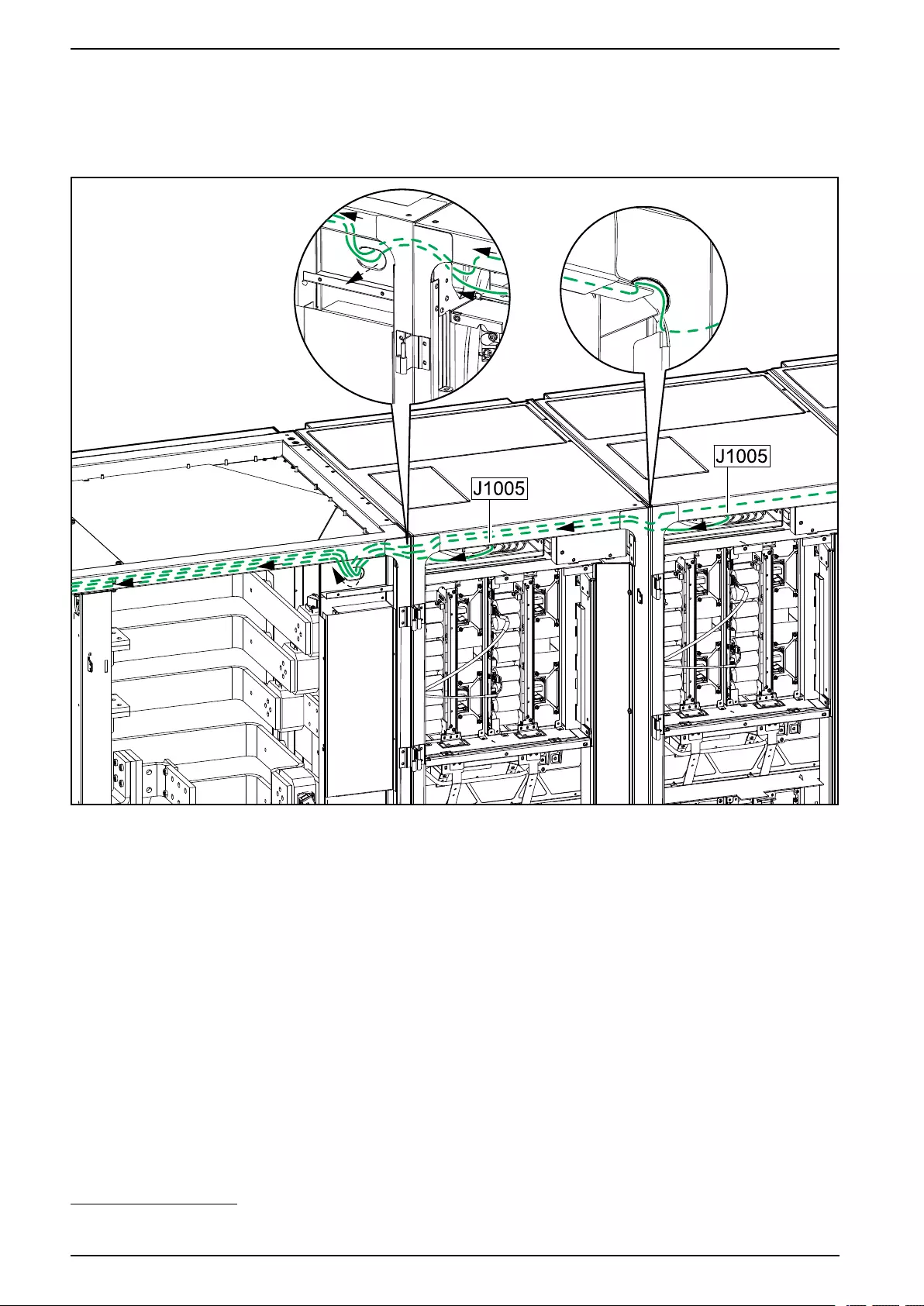
UPS with 1500 kW I/O Cabinet Connect the Signal Cables
7. Connect the signal cable 0W7822 to 0P6516 terminal J1005 in power
cabinets 4–655 (on the right side of the I/O cabinet). Route the cable into the I/
O cabinet as shown on the illustration and fasten the cable.
I/O Cabinet and Two Power Cabinets
8. In redundant systems only, connect the signal cable 0W7827 to 0P6516
terminal J1005 in power cabinet 7. Route the cable as shown above and
fasten the cable.
96 990-5783E-001
55. The cable must always be connected to power cabinet 4 (placed to the right of the I/O cabinet). Connect to power cabinet 5 and 6 if
available.
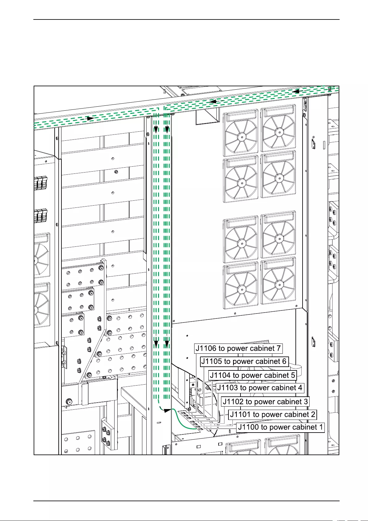
Connect the Signal Cables UPS with 1500 kW I/O Cabinet
9. Connect the signal cables 0W7819, 0W7822, and 0W7827 to 0P6502
terminals J1100 to J1106 in the I/O cabinet.
NOTE:
• J1104 only connected in systems with five or more power cabinets.
• J1105 only connected in systems with six or more power cabinets.
• J1106 only connected in systems with seven power cabinets.
990-5783E-001 97
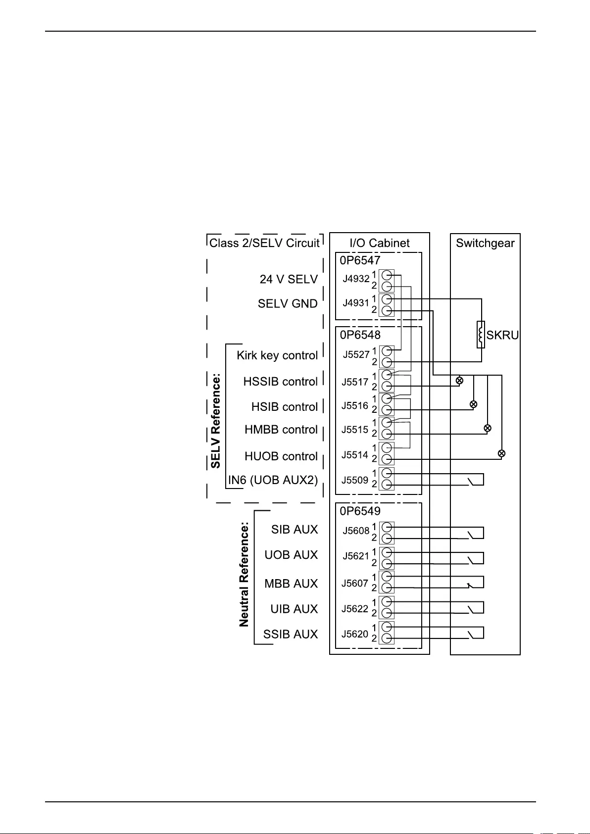
UPS with 1500 kW I/O Cabinet Connect the Signal Cables
Connect the Signal Cables between the I/O Cabinet and the
Switchgear
1. Route the cables from the switchgear through the top or bottom of the I/O
cabinet and to the boards as shown in Prepare for Signal Cables, page 88.
Class 2/SELV circuits must be separated from other cables as indicated on
the illustrations.
2. Connect the below signal cables between the I/O cabinet and the switchgear.
NOTE: The unit output breaker UOB must include two separated auxiliary
switches.
NOTE: The solenoid key release unit (SKRU) is only applicable to 480 V
systems.
All circuits connected must have the same 0 V reference.
Connect the Signal Cables for Battery Solutions
Connect the Signal Cables between the I/O Cabinet and the Classic Battery Cabinets
NOTE: The illustration below shows a system with four battery banks each
consisting of one classic battery cabinet. Connect signal cables according to
the number of classic battery cabinets in your installation.
98 990-5783E-001
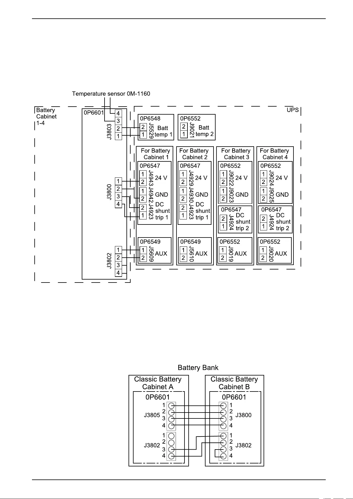
Connect the Signal Cables UPS with 1500 kW I/O Cabinet
NOTE: If you have two classic battery cabinets in your battery bank, see
Connect the Signal Cables between Two Classic Battery Cabinets in One
Battery Bank, page 99 for information on how to connect signal cables
between two classic battery cabinets in one battery bank.
1. Route the signal cables from the battery banks through the top or bottom of
the I/O cabinet to the boards.
2. Connect the signal cables between the I/O cabinet and the classic battery
cabinets.
Connect the Signal Cables between Two Classic Battery
Cabinets in One Battery Bank
NOTE: The procedure is identical for all battery banks with two classic battery
cabinets.
1. Remove the jumper between J3802 pin 3 and 4 in classic battery cabinet A.
2. Connect the signal cables between classic battery cabinet A and classic
battery cabinet B.
990-5783E-001 99
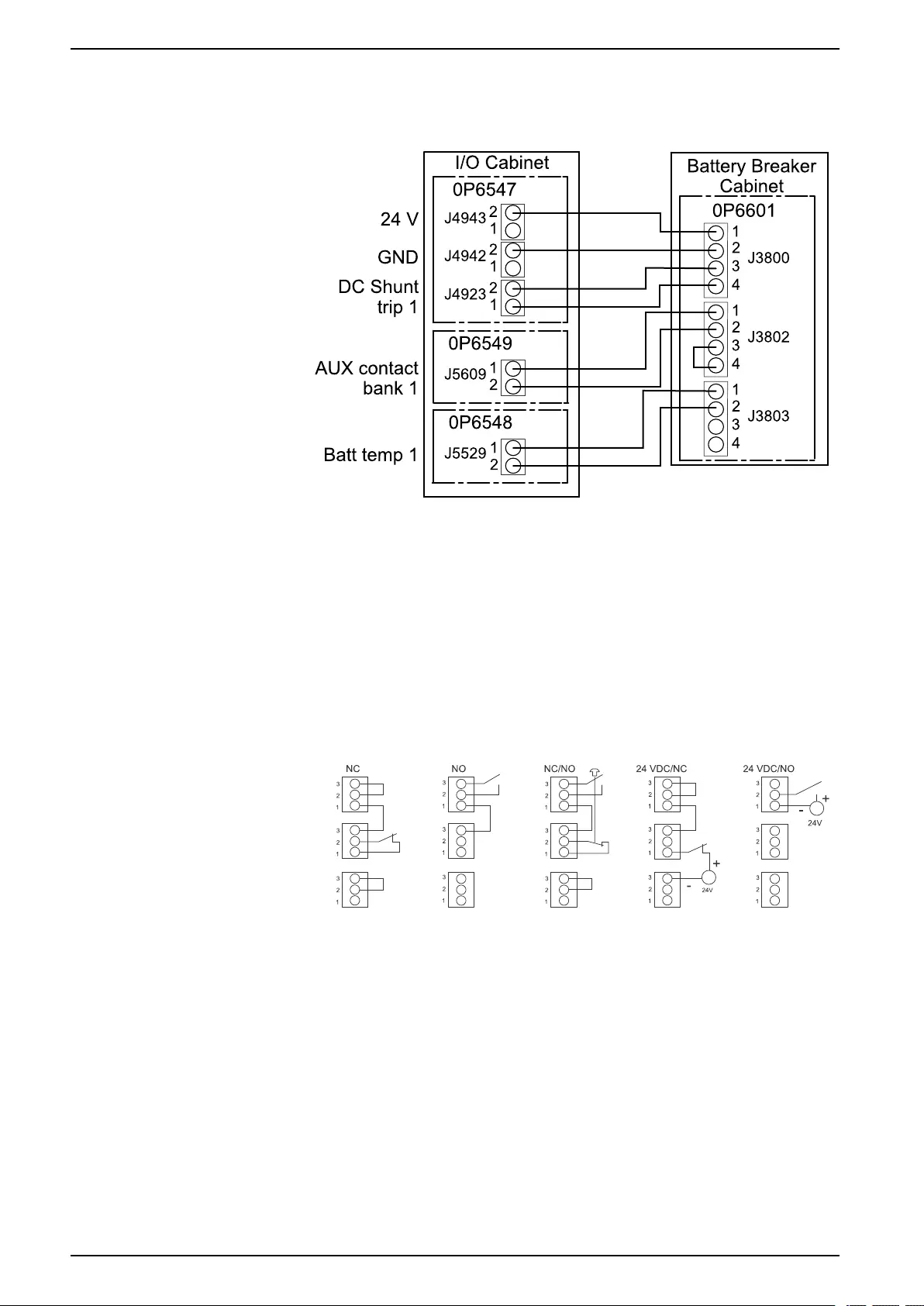
UPS with 1500 kW I/O Cabinet Connect the Signal Cables
Connect Signal Cables between the I/O Cabinet and the Battery Breaker Cabinet
1. Connect the below signal cables between the I/O cabinet and the battery
breaker cabinet.
Connect the Emergency Power Off (EPO)
Do not connect any circuit to the EPO terminal block unless it can be confirmed
that the circuit is Class 2/SELV.
All circuits connected must have the same 0 V reference.
1. Route the cables from your EPO through the top or bottom of the I/O cabinet
and to the EPO terminals J4936–J4938 on 0P6547 as shown in Prepare for
Signal Cables, page 88.
2. Connect the building EPO according to one of the options below.
Connect External Synchronization
The signal cables must have a minimum rating of 600 V.
1. Route the external synchronization cables through the top or bottom of the I/O
cabinet to 0P6549 as shown in Prepare for Signal Cables, page 88.
100 990-5783E-001
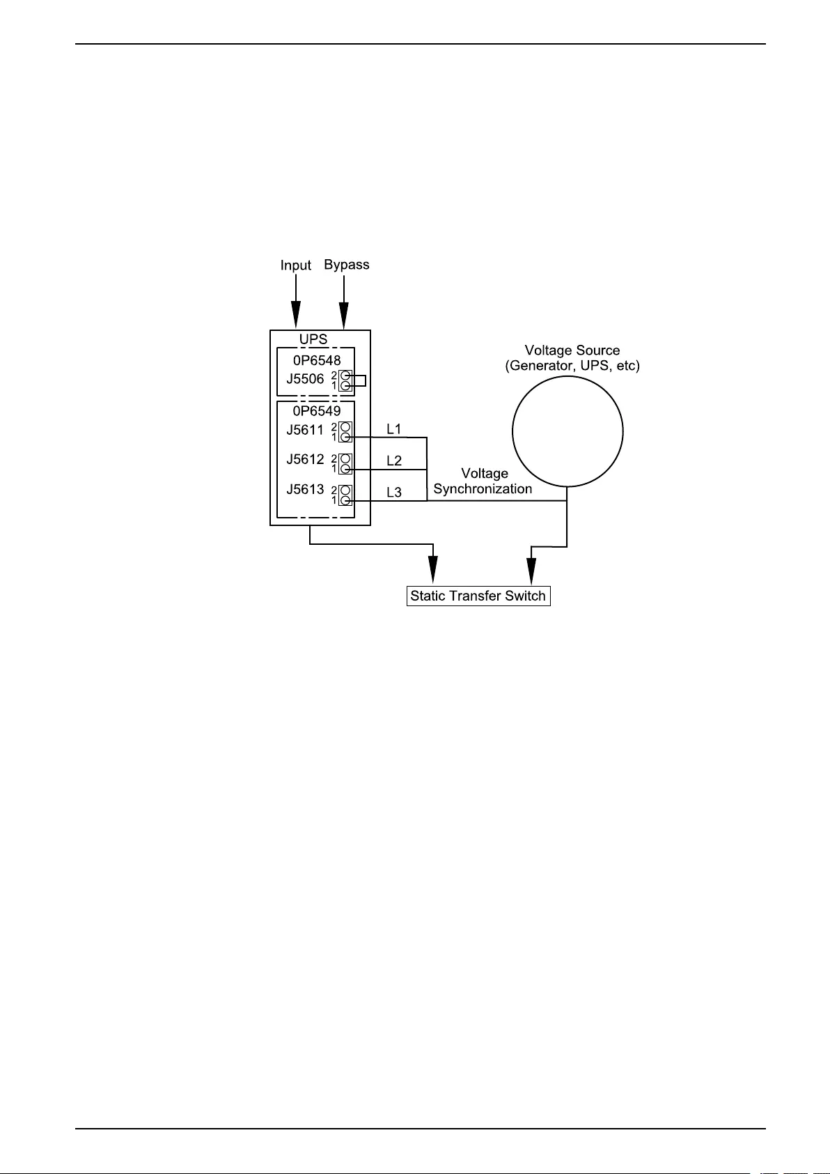
Connect the Signal Cables UPS with 1500 kW I/O Cabinet
2. Connect the three phases:
NOTE: The phases from the synchronization source must be protected by
a fuse of maximum 0.5 A.
a. Connect L1 to J5611 on 0P6549.
b. Connect L2 to J5612 on 0P6549.
c. Connect L3 to J5613 on 0P6549.
Basic UPS Synchronization to a Fixed Voltage Source
990-5783E-001 101
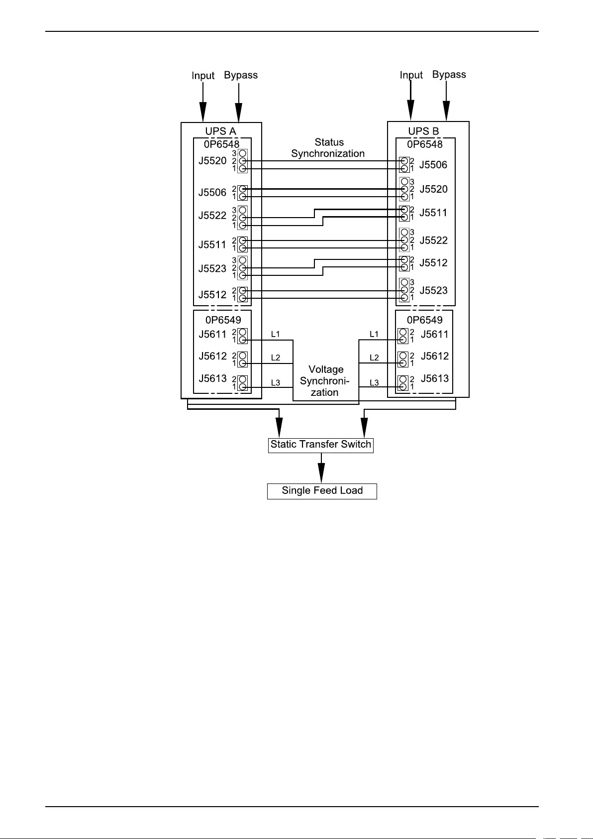
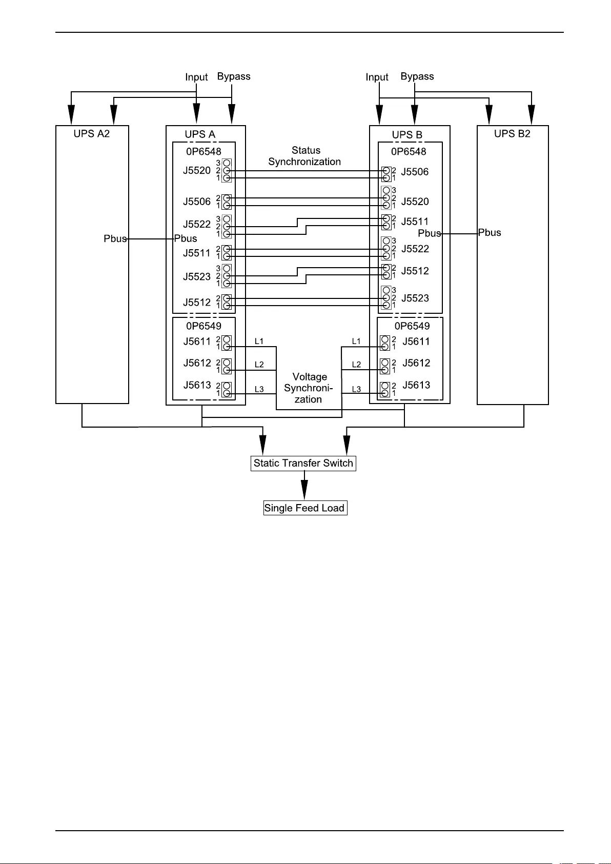
Connect the Signal Cables UPS with 1500 kW I/O Cabinet
Fixed Parallel Synchronization Master
Connect Equipment to Input Contacts and Output Relays
1. Route the cables from your contacts/relays through the top or bottom of the I/
O cabinet and to the boards in the right side of the I/O cabinet as shown in
Prepare for Signal Cables, page 88.
2. Connect your equipment to the input contacts and/or output relays.
Overview of Input Contacts and Output Relays
Input Contacts
Do not connect any circuit to the input contacts unless it can be confirmed that the
circuit is Class 2/SELV.
All circuits connected must have the same 0 V reference.
990-5783E-001 103

UPS with 1500 kW I/O Cabinet Connect the Signal Cables
The switch SW5500 on 0P6548 is used to select between internal SELV supply for
inputs (standard setting) and external supply56. If external supply is selected, the
supply must be connected to J5530.
Name Description Location
IN 1 (Contact 1) Configurable input contact 0P6548 terminal J550257
IN 2 (Contact 2) Configurable input contact 0P6548 terminal J550357
IN 3 (Contact 3) Configurable input contact 0P6548 terminal J550457
IN 4 (Contact 4) Configurable input contact 0P6548 terminal J550557
IN 5 (Contact 5) Configurable input contact 0P6548 terminal J551057
IN 6 UOB redundant AUX contact 0P6548 terminal J550957
IN 7 Transformer temperature switch 0P6548 terminal J550857
IN 8 External bonding contact 0P6548 terminal J550757
IN 9 Forced external synchronization input 0P6548 terminal J550657
IN 10 External synchronization requested 0P6548 terminal J551157
IN 11 Use static bypass standby 0P6548 terminal J551257
IN 14 MegaTie 0P6552 terminal J902757
Output Relays
NOTE: Maximum 250 VAC 5 A must be connected to the output relays.
All external circuitry must be fused with maximum 5 A fast acting fuses.
Name Description Location
OUT 1 (Relay 1) Configurable output relay 0P6547 terminal J4939
OUT 2 (Relay 2) Configurable output relay 0P6547 terminal J4940
OUT 3 (Relay 3) Configurable output relay 0P6547 terminal J4941
OUT 4 Forced external synchronization output 0P6548 terminal J552057
OUT 5 MegaTie 0P6548 terminal J552157
OUT 6 External synchronization requested output 0P6548 terminal J552257
OUT 7 UPS in inverter ON 0P6548 terminal J552357
OUT 8 (Relay 4) Configurable output relay 0P6548 terminal J552457
104 990-5783E-001
56. An external supply is useful in parallel systems where inputs are connected between different UPSs. This is to have a common reference
and to avoid cross currents.
57. Class 2/SELV wiring
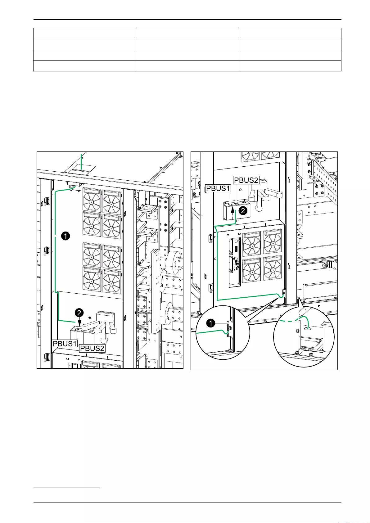
Connect the Signal Cables UPS with 1500 kW I/O Cabinet
Name Description Location
OUT 9 (Relay 5) Configurable output relay 0P6548 terminal J552558
OUT 10 (Relay 6) Configurable output relay 0P6548 terminal J552858
OUT 14 Bonding contactor 0P6552 terminal J902958
NOTE: Refer to the operation manual for configuration options.
Connect the PBUS Cables between Parallel UPS Units
Front View of the I/O Cabinet in Top Cable Entry
Systems
Front View of the I/O Cabinet in Bottom Cable
Entry Systems
1. Route the PBUS cables from the installation kit 0H–0889 through either the
top or the bottom of the I/O cabinet.
990-5783E-001 105
58. Class 2/SELV wiring

UPS with 1500 kW I/O Cabinet Connect the Signal Cables
2. Connect the PBUS cables between the I/O cabinets of the parallel system
according to the diagram below.
NOTE: The PBUS 1 cables are white and the PBUS 2 cables are red.
NOTE: The total length of the PBUS cables must not exceed 60 m (197
ft).
Example of System with Three UPSs in Parallel
External Communication
The following interfaces are supported:
A. Two smart slots for optional network management cards (AP9630, AP9631,
AP9635CH).
NOTE: If the input dry contact AP9810 is connected to AP9631 or
AP9635CH, the total length of cables for connected equipment must not
exceed 30 m (98 ft). Use the plate for shielding.
B. Modbus and modbus dip switch settings.
C. Network/ethernet.
Front View of the I/O Cabinet
106 990-5783E-001
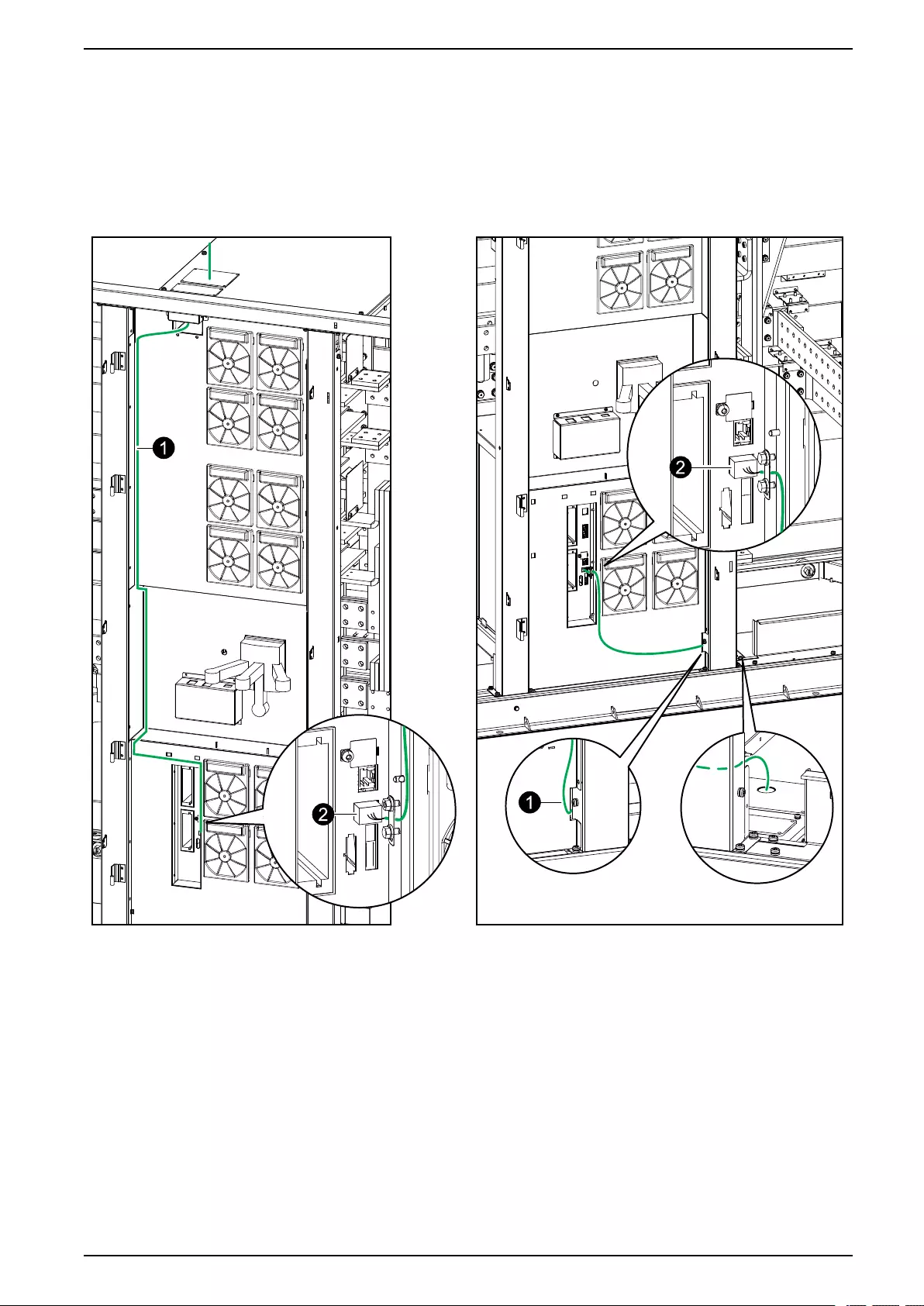
Connect the Signal Cables UPS with 1500 kW I/O Cabinet
Connect the Modbus Cables
NOTE: Terminators for modbus connection is provided in the installation kit
0H-9101.
Front View of the I/O Cabinet in Top Cable Entry
Systems
Front View of the I/O Cabinet in Bottom Cable
Entry Systems
1. Route the cables as shown on the illustrations.
990-5783E-001 107
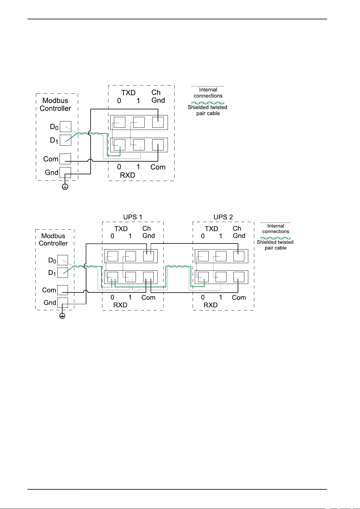
UPS with 1500 kW I/O Cabinet Connect the Signal Cables
2. Connect the modbus cables. Use either 2–wire or 4–wire connection. Shield
the cables as shown.
NOTE: Shielded cables must be used for modbus connections. The
shield connection to the ground must be as short as possible (ideally
below 1 cm).
2–Wire Connection with One UPS
Example: 2–Wire Connection with Two UPSs
108 990-5783E-001

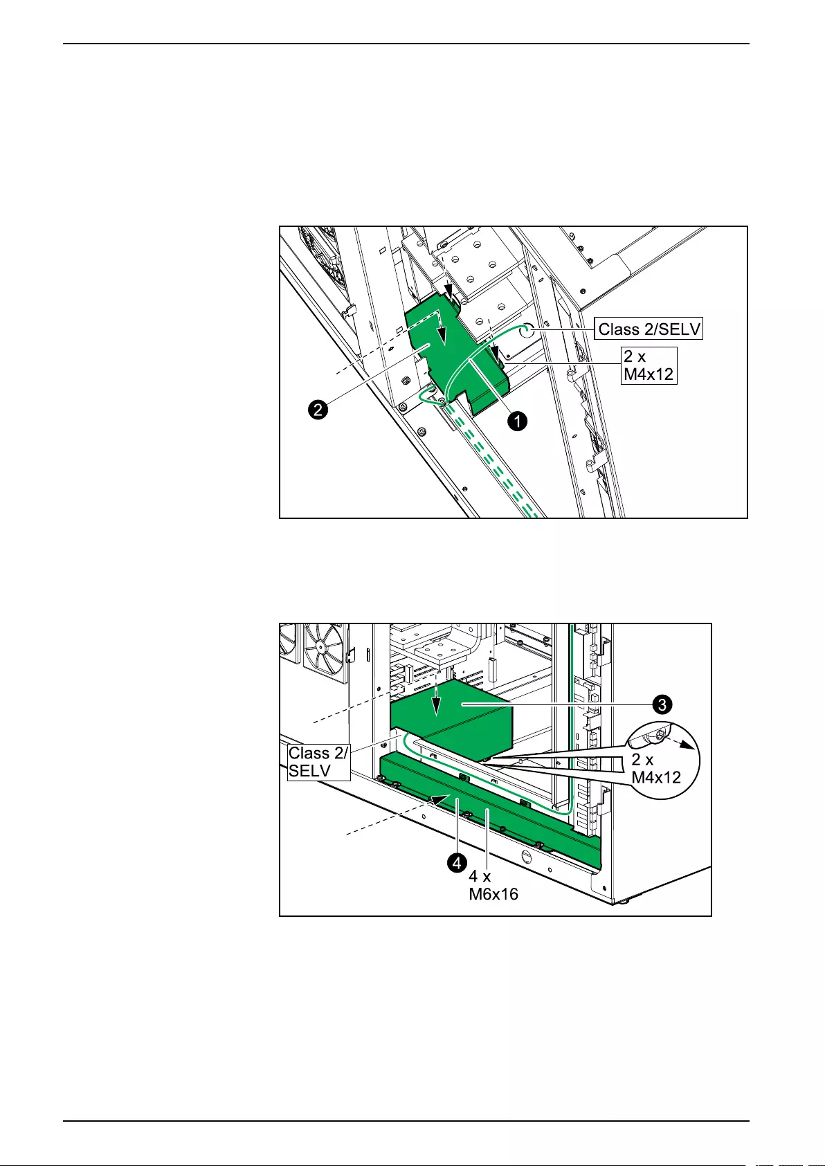
UPS with 1500 kW I/O Cabinet Final Mechanical Assembly
Final Mechanical Assembly
Final Mechanical Assembly of the I/O Cabinet
1. Lift up the Class 2/SELV cables.
Front View of the I/O Cabinet
2. Reinstall the indicated box over the non-Class 2/non-SELV cables.
3. Reinstall the indicated box over Class 2/SELV cables.
Front View of the I/O Cabinet
4. Reinstall the plate over the cable channel for non-Class 2/non-SELV cables.
110 990-5783E-001
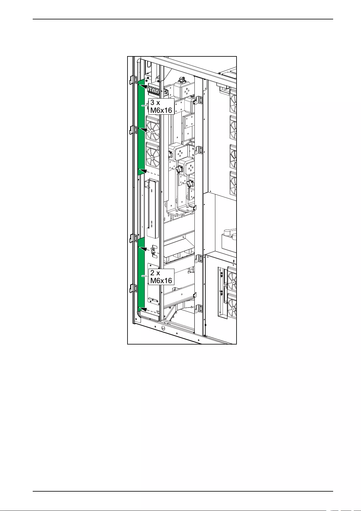
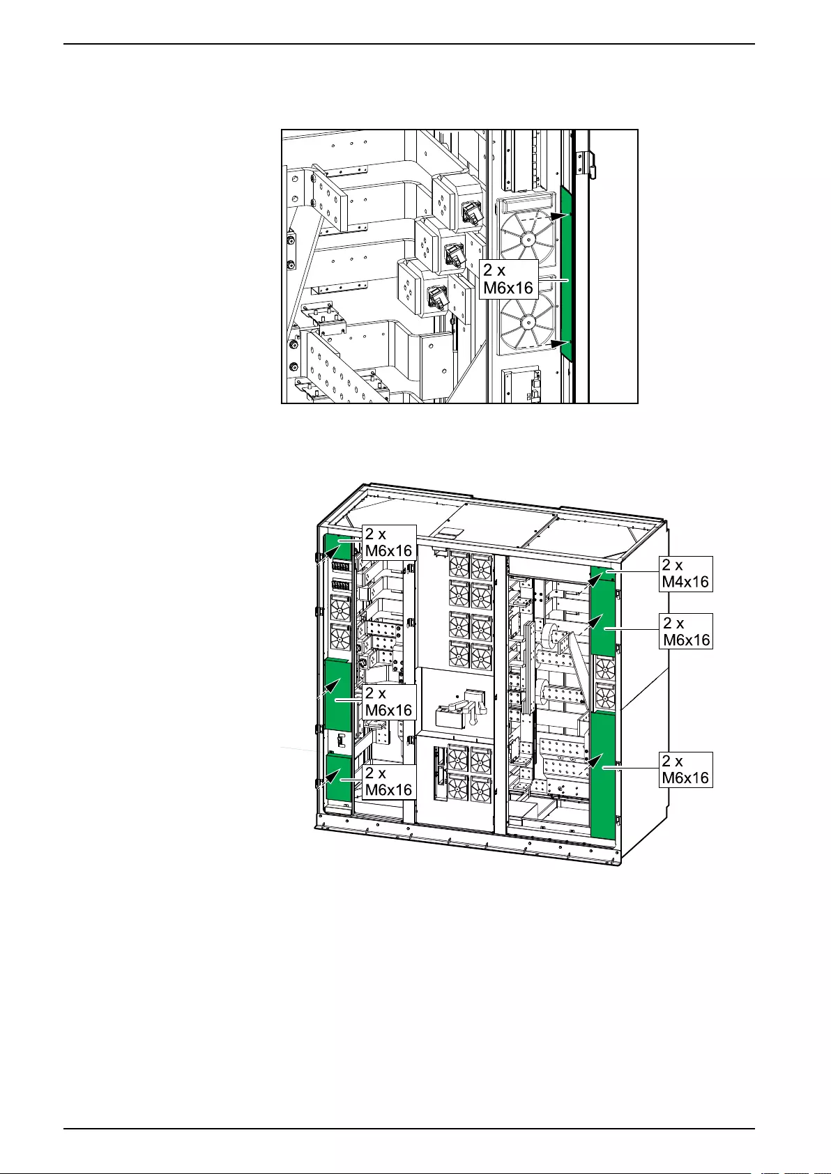
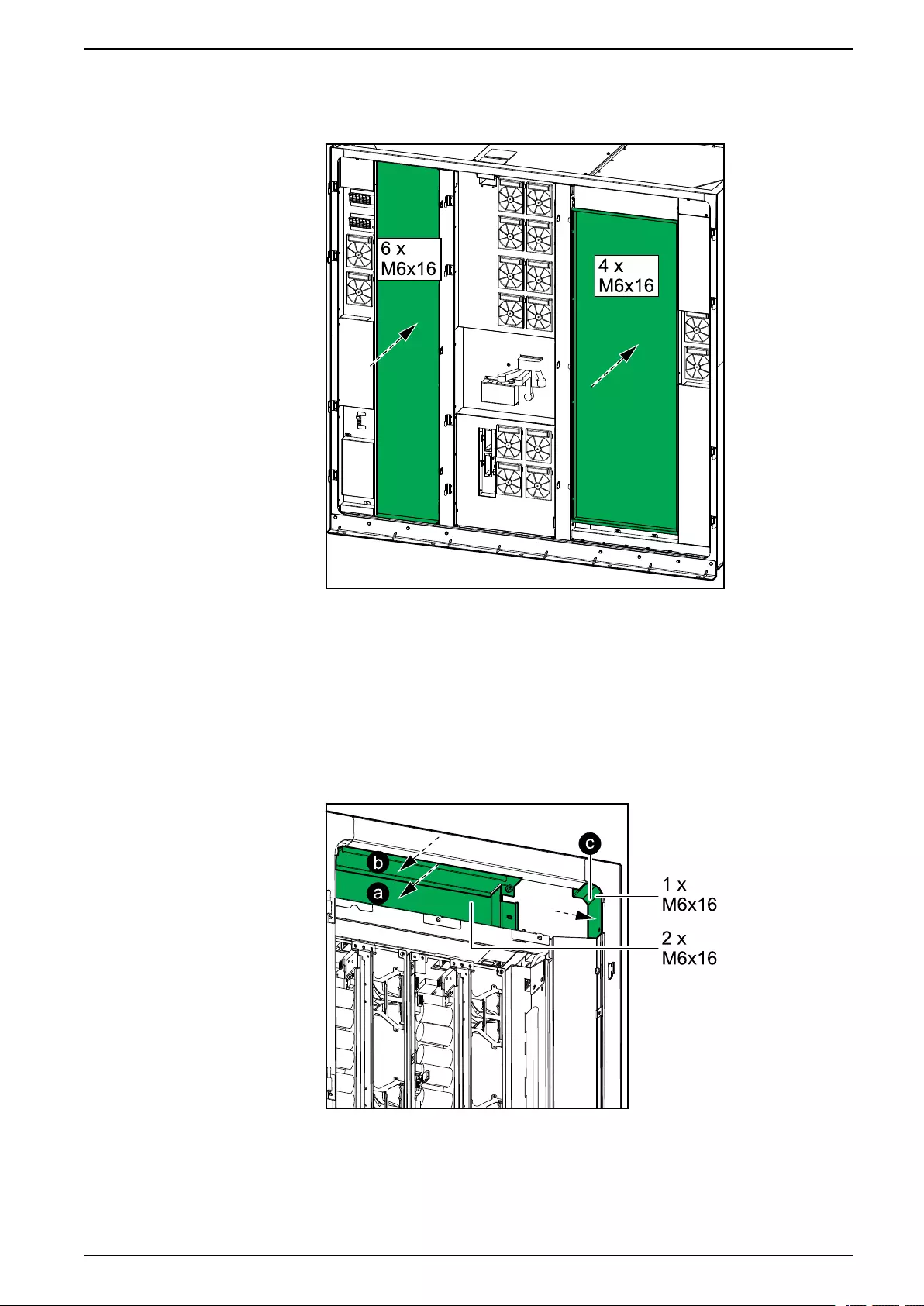
Final Mechanical Assembly UPS with 1500 kW I/O Cabinet
8. Reinstall the two metal plates.
Front View of the I/O Cabinet
9. Close the front doors.
Final Mechanical Assembly of the Power Cabinets
1. Reinstall the three plates in the top of each of the power cabinets in
chronological order (a-c).
Front View of the Power Cabinet
990-5783E-001 113
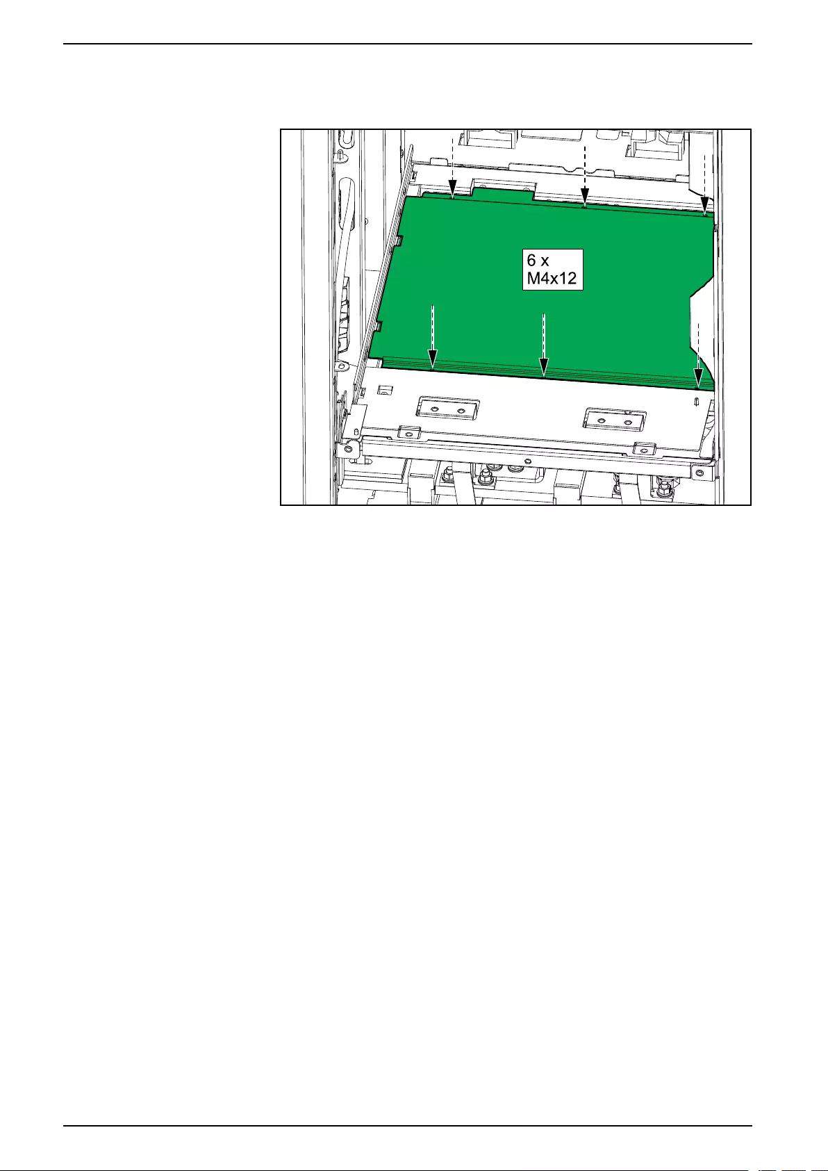
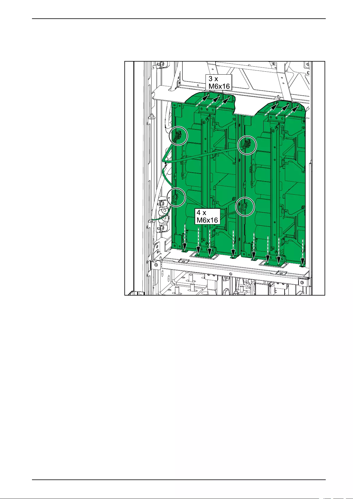

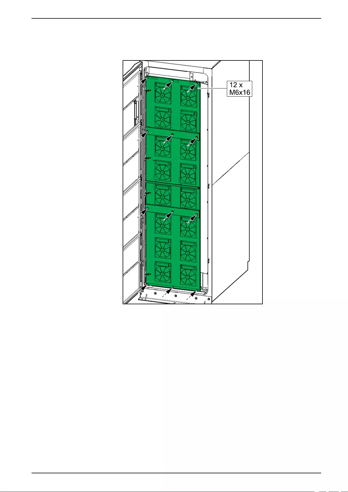


Schneider Electric
35 rue Joseph Monier
92500 Rueil Malmaison
France
+ 33 (0) 1 41 29 70 00
*990-5783E-001*
As standards, specifications, and design change from time to time,
please ask for confirmation of the information given in this publication.
© 2016 – 2019 Schneider Electric. All rights reserved.
990-5783E-001