Table of Contents
- Safety
- General Information
- Unit Overview
- Component Identification
- Dimensions and Weights
- Diagrams
- Installation
- Unit Connections
- Charging the Refrigeration System
- Worldwide Customer Support
APC MRA0221I User Manual
Displayed below is the user manual for MRA0221I by APC which is a product in the Split-System Air Conditioners category. This manual has pages.
Related Manuals
Uniflair™SP
Uniflair™UCF, MRA
Installation Manual
990-91229A-001
06MM0368@00B0110
Release Date: 05/2019
www.schneider-electric.com

Legal Information
The Schneider Electric brand and any trademarks of Schneider Electric SE and its
subsidiaries referred to in this guide are the property of Schneider Electric SE or its
subsidiaries. All other brands may be trademarks of their respective owners.
This guide and its content are protected under applicable copyright laws and
furnished for informational use only. No part of this guide may be reproduced or
transmitted in any form or by any means (electronic, mechanical, photocopying,
recording, or otherwise), for any purpose, without the prior written permission of
Schneider Electric.
Schneider Electric does not grant any right or license for commercial use of the guide
or its content, except for a non-exclusive and personal license to consult it on an "as
is" basis. Schneider Electric products and equipment should be installed, operated,
serviced, and maintained only by qualified personnel.
As standards, specifications, and designs change from time to time, information
contained in this guide may be subject to change without notice.
To the extent permitted by applicable law, no responsibility or liability is assumed by
Schneider Electric and its subsidiaries for any errors or omissions in the informational
content of this material or consequences arising out of or resulting from the use of the
information contained herein.

Uniflair™UCF, MRA
Table of Contents
Safety............................................................................................................5
Important Safety Instructions — SAVE THESE INSTRUCTIONS....................5
Safety During Installation ............................................................................6
Symbols on Unit or Packaging ...............................................................7
Intended Use........................................................................................7
General Information....................................................................................8
Document Overview ...................................................................................8
Save These Instructions ........................................................................8
Manual Updates ...................................................................................8
Cross-Reference Symbol Used in This Manual........................................8
Documentation Included with the Unit.....................................................9
Compliance................................................................................................9
Receiving and Inspecting the Cooling Unit..................................................10
Filing a Claim......................................................................................10
Storing the Cooling Unit Before Installation ................................................. 11
Moving the Unit ........................................................................................ 11
Equipment Disposal..................................................................................12
Waste Electrical and Electronic Equipment (WEEE) Disposal.................12
Radio Frequency Interference ...................................................................12
California Proposition 65—Warning Statement for California
Residents ................................................................................................12
Equipment Guidelines...............................................................................13
Working Conditions and Environmental Limits.......................................13
Unit Overview ............................................................................................14
Model Nomenclature.................................................................................14
Indoor Units........................................................................................14
Outdoor Units .....................................................................................14
Nameplate Example .................................................................................15
Component Identification.........................................................................16
Inventory..................................................................................................16
UCF0341I and UCF0481I ....................................................................16
MRA0221I..........................................................................................17
MRA0611D.........................................................................................18
External Components ...............................................................................19
Indoor Units........................................................................................19
Outdoor Units .....................................................................................20
Internal Components ................................................................................22
Indoor Units........................................................................................22
Outdoor Units .....................................................................................24
Electrical Panels.......................................................................................26
Indoor Units........................................................................................26
Outdoor Units .....................................................................................26
Display Interface.......................................................................................28
Alarm LED..........................................................................................28
Status LED.........................................................................................29
Link-RX/TX (10/100) LED ....................................................................29
Dimensions and Weights .........................................................................30
990-91229A-001 / 06MM0368@00B0110 3

Uniflair™UCF, MRA
Indoor Units .............................................................................................30
Outdoor Units...........................................................................................31
Piping and Electrical Access Locations.......................................................33
Indoor Units........................................................................................33
Outdoor Units .....................................................................................35
Service Clearance ....................................................................................37
Diagrams....................................................................................................38
Refrigeration Piping Diagram.....................................................................38
Installation..................................................................................................39
Site Preparation .......................................................................................39
Positioning Units.................................................................................39
External Air Free-Cooling–UCF Units ...................................................40
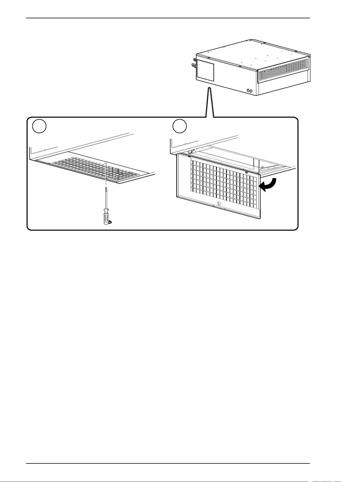
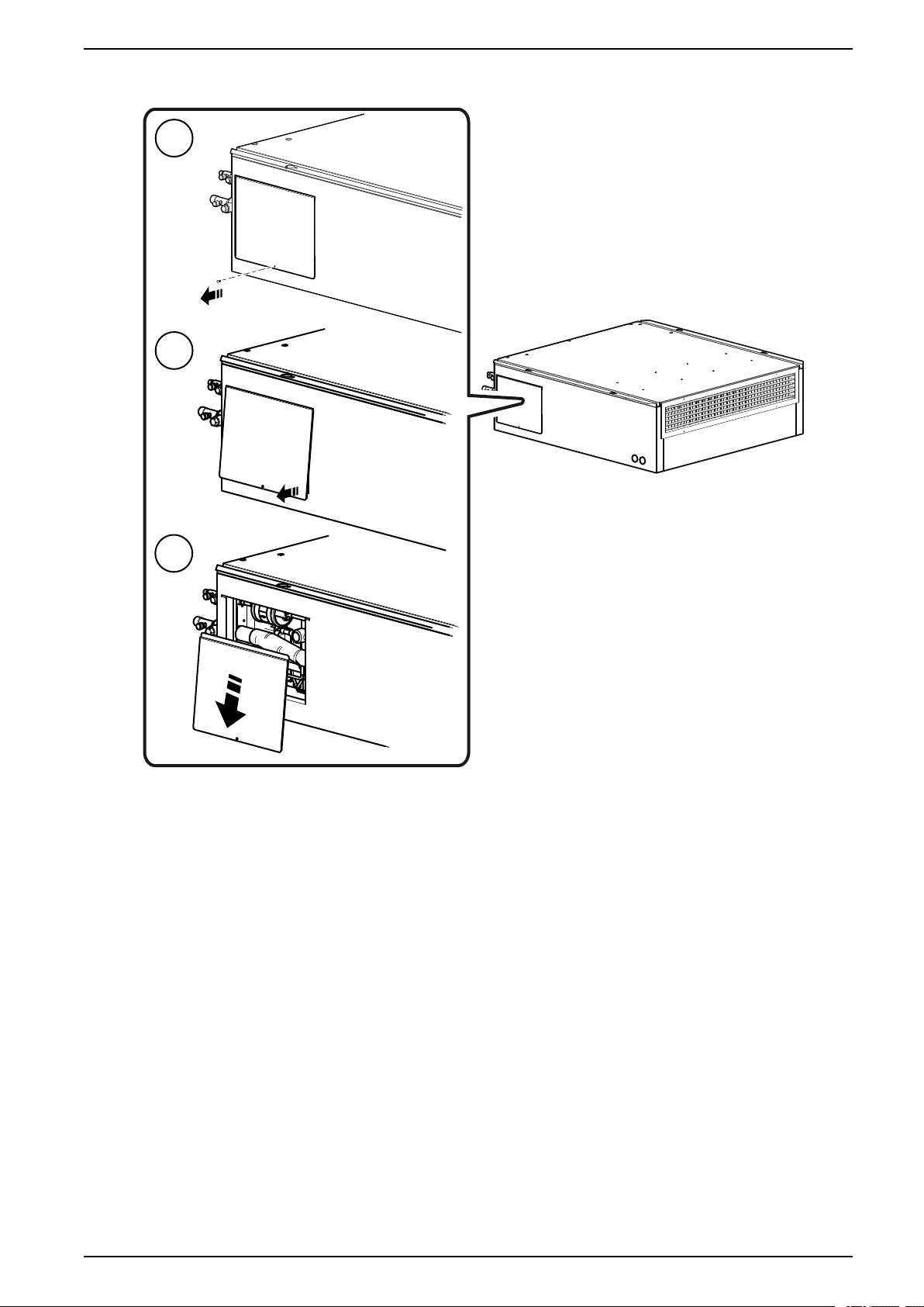
Panel Removal.........................................................................................41
Indoor Units........................................................................................41
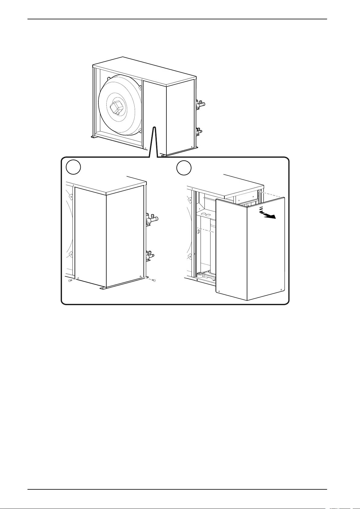
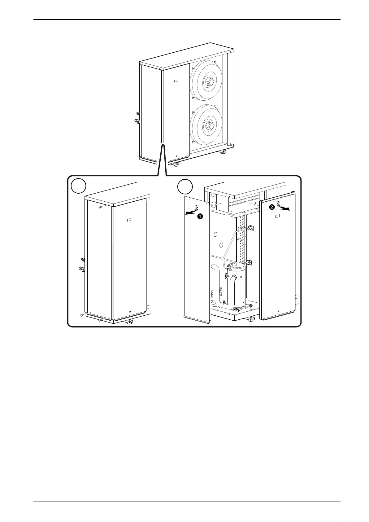
Outdoor Units .....................................................................................44
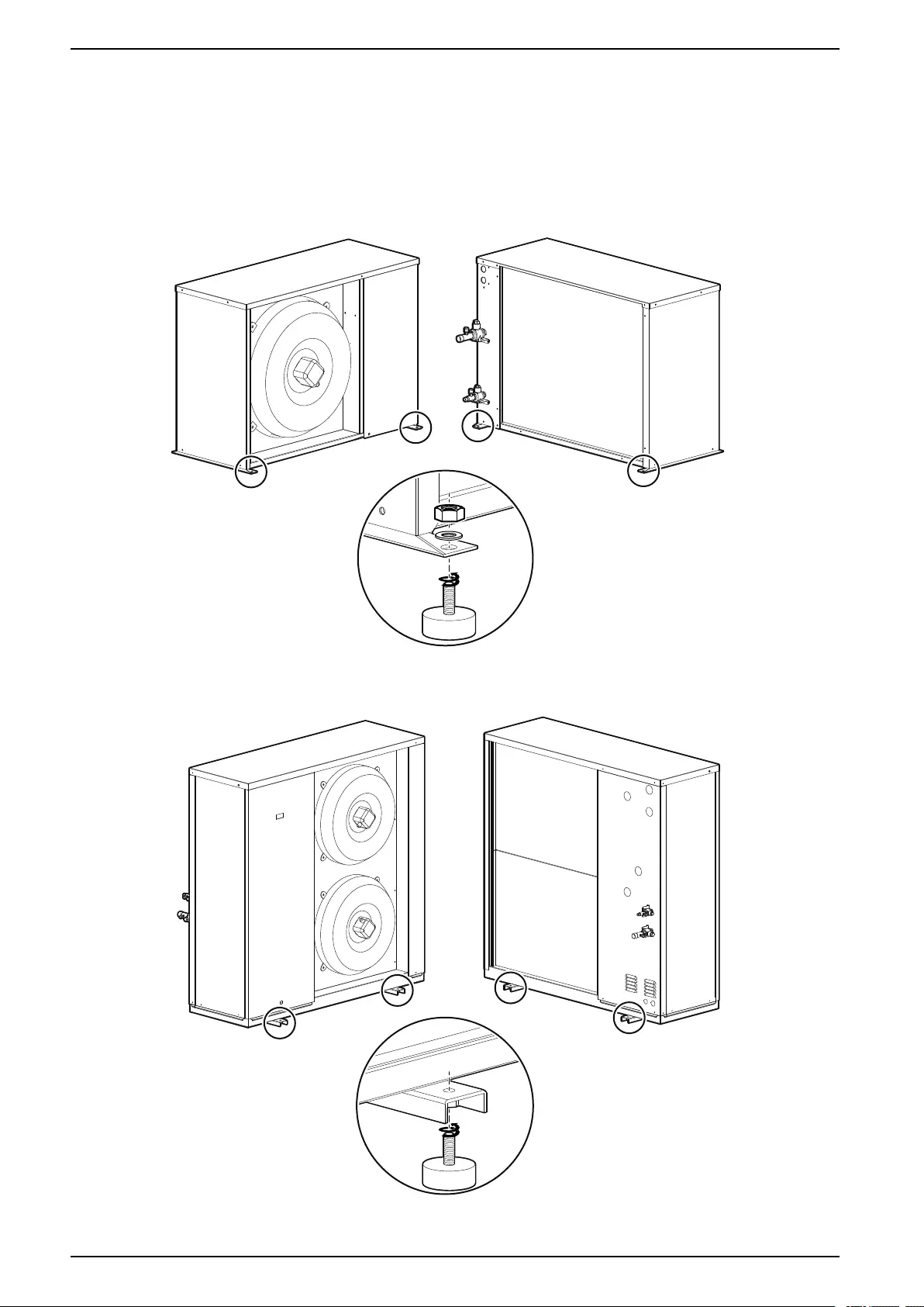
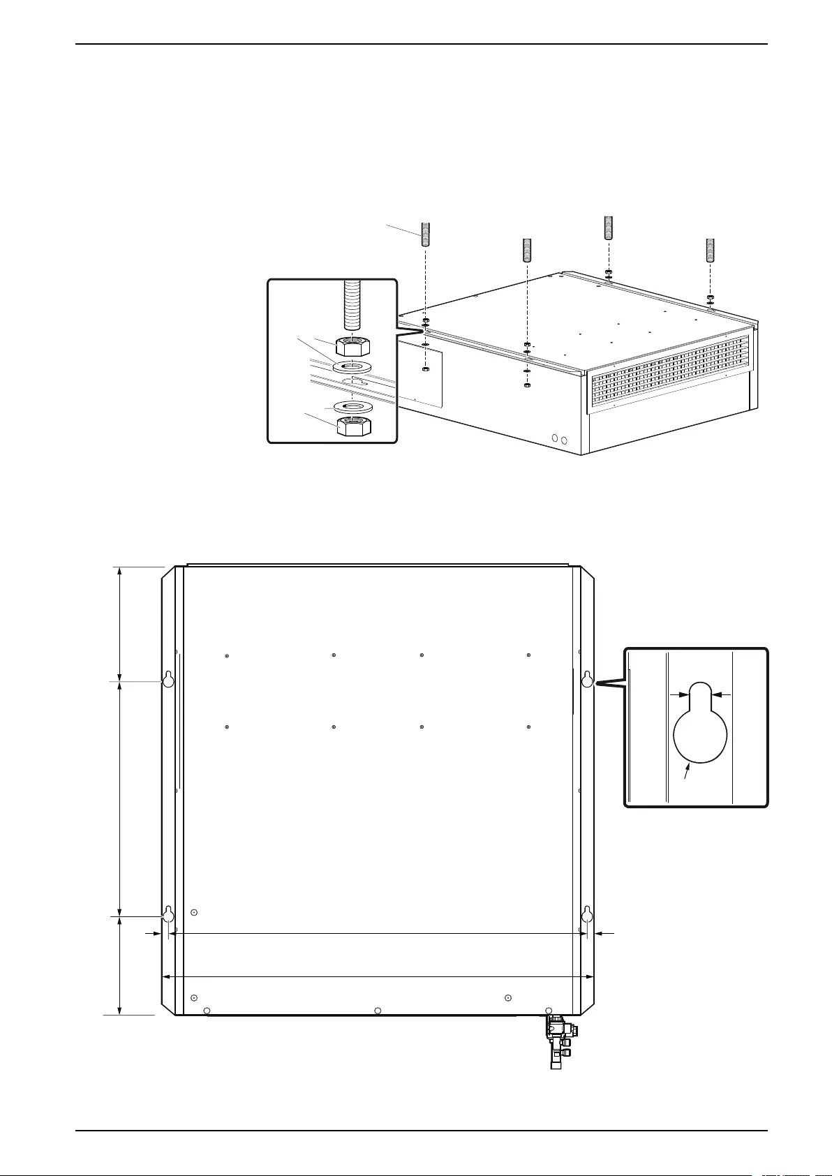
Placing the Outdoor Unit ...........................................................................46
Attaching the Mounting Feet ................................................................46
Unit Connections.......................................................................................47
Mechanical Connections ...........................................................................47
Mounting the Indoor Unit to the Ceiling .................................................47
Installing the Display Interface .............................................................48
Connecting the Condensate Drain........................................................49
Refrigerant Piping ...............................................................................50
Connect Refrigerant Lines ...................................................................52
Electrical Connections ..............................................................................55
Power Supply .....................................................................................55
Electrical Data..........................................................................................57
Indoor Units........................................................................................57
Outdoor Units .....................................................................................57
Communication Connections ...............................................................58
Temperature Sensor ...........................................................................63
Charging the Refrigeration System........................................................64
Calculating R410A Charge ........................................................................64
Charging the Equipment............................................................................65
Compressor Oil Charge ............................................................................66
Oil Charging Procedure.......................................................................66
R410A Refrigerant Charging Charts...........................................................66
Thermostatic Expansion Valve Adjustment .................................................69
Worldwide Customer Support .................................................................71
4 990-91229A-001 / 06MM0368@00B0110
Safety Uniflair™UCF, MRA
Safety
Important Safety Instructions — SAVE THESE INSTRUCTIONS
Read these instructions carefully and look at the equipment to become familiar
with it before trying to install, operate, service or maintain it. The following safety
messages may appear throughout this manual or on the equipment to warn of
potential hazards or to call attention to information that clarifies or simplifies a
procedure.
The addition of this symbol to a “Danger” or “Warning” safety
message indicates that an electrical hazard exists which will
result in personal injury if the instructions are not followed.
This is the safety alert symbol. It is used to alert you to potential
personal injury hazards. Obey all safety messages with this
symbol to avoid possible injury or death.
DANGER
DANGER indicates a hazardous situation which, if not avoided, will result in
death or serious injury.
Failure to follow these instructions will result in death or serious injury.
WARNING
WARNING indicates a hazardous situation which, if not avoided, could result
in death or serious injury.
Failure to follow these instructions can result in death, serious injury, or
equipment damage.
CAUTION
CAUTION indicates a hazardous situation which, if not avoided, could result in
minor or moderate injury.
Failure to follow these instructions can result in injury or equipment
damage.
NOTICE
NOTICE is used to address practices not related to physical injury. The safety
alert symbol shall not be used with this type of safety message.
Failure to follow these instructions can result in equipment damage.
Please Note
Electrical equipment should only be installed, operated, serviced, and maintained
by qualified personnel. No responsibility is assumed by Schneider Electric for any
consequences arising out of the use of this material.
A qualified person is one who has skills and knowledge related to the construction,
installation, and operation of electrical equipment and has received safety training
to recognize and avoid the hazards involved.
990-91229A-001 / 06MM0368@00B0110 5
Uniflair™UCF, MRA Safety
Safety During Installation
DANGER
HAZARD OF ELECTRIC SHOCK, EXPLOSION, OR ARC FLASH
• Apply appropriate personal protective equipment (PPE) and follow safe
electrical work practices.
• This equipment must be installed and serviced by qualified personnel only.
• Turn off all power supplying this equipment before working on or inside the
equipment.
• Replace all devices, doors, and covers before turning on power to this
equipment.
Failure to follow these instructions will result in death or serious injury.
WARNING
HAZARD FROM MOVING PARTS
Keep hands, clothing, and jewelry away from moving parts. Check the
equipment for foreign objects before closing the doors and starting the
equipment.
Failure to follow these instructions can result in death, serious injury, or
equipment damage.
WARNING
DAMAGE TO EQUIPMENT OR PERSONNEL
• The equipment is heavy. For safety purposes, adequate personnel must be
present when moving this item.
• The load must always be solidly anchored to the bearing element of the
lifting equipment and means of transport.
• No one should be near the suspended load, nor in the working area of the
crane, forklift, truck, or any other lifting equipment or means of transport.
Failure to follow these instructions can result in death, serious injury, or
equipment damage.
CAUTION
HAZARD FROM UNPROTECTED OUTPUT
Apply circuit protection to all outputs.
Failure to follow these instructions can result in injury or equipment
damage.
NOTICE
STATIC ELECTRICITY HAZARD
Circuit boards contained within this unit are sensitive to static electricity. Use
one or more electrostatic-discharge devices while handling the board.
Failure to follow these instructions can result in equipment damage.
6 990-91229A-001 / 06MM0368@00B0110
Safety Uniflair™UCF, MRA
NOTICE
DAMAGE FROM EXPOSURE
Leaving the equipment uncovered and exposed to possible damage from the
environment will void the factory warranty.
Failure to follow these instructions can result in equipment damage.
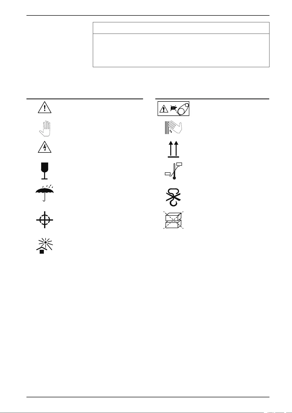
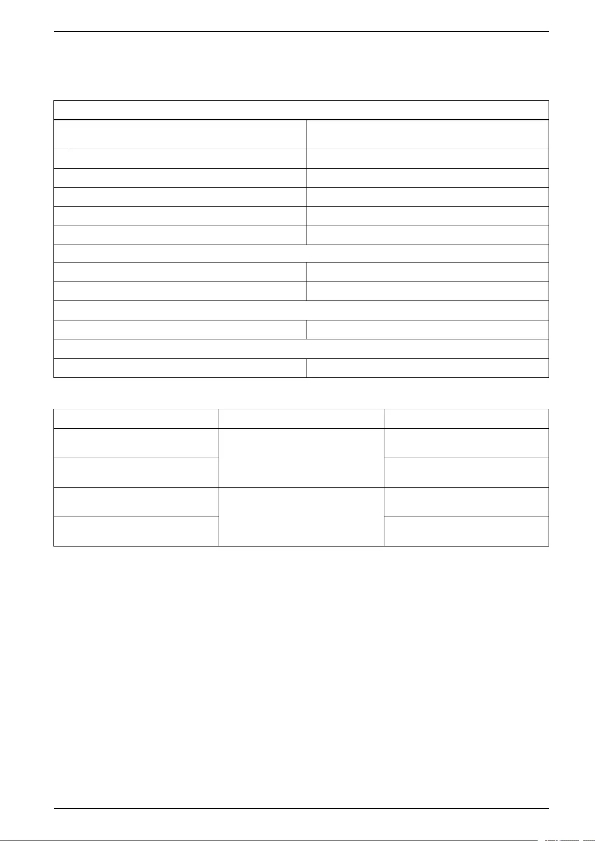
Symbols on Unit or Packaging
Symbol Meaning Symbol Meaning
Danger Moving parts
Important notice Sharp surface
High voltage: Risk of electric shock
This side up: Shows the correct
orientation of the packed unit
Fragile: Handle unit with care Temperature limits: The packed
unit must be stored in a place
within the indicated limits
Keep dry: The packed unit must be
stored in a dry place
Do not use hooks: Do not lift
packed unit with hooks
Center of gravity: Shows the
center of gravity of the packed unit
Do not stack: The packed units
must not be stacked
Keep away from the heat: The unit
must be stored away from heat
sources
Intended Use
The cooling units provide air conditioning within the limits and methods described
in this manual. This equipment must be installed and applied in accordance with
the instructions provided. No modifications may be made to the units or their parts
without explicit written consent from Schneider Electric. Any mechanical or
electrical modification voids factory warranty.
990-91229A-001 / 06MM0368@00B0110 7
Uniflair™UCF, MRA General Information
General Information
Document Overview
The Uniflair SP cooling unit is a precision unit used to control environments for
telecom rooms, internet hubs, and data processing centers.
This manual describes Unisplit air-cooled, direct expansion air conditioning units.
It supplies general information, safety instructions, unit transportation, and
necessary information on how to install the units.
Save These Instructions
This manual contains important instructions that must be followed during the
installation of this equipment.
Manual Updates
Schneider Electric™policy is one of continuous technological innovation and the
company reserves the right to amend any data herein without prior notice. The
images shown in this manual are for descriptive purposes only and they may differ
from specific models that are selected.
NOTE: Unit images and component identification information are examples
only. The final configuration of the unit may change according to the different
options.
Check for updates to this manual on the Schneider Electric Web site,
www.schneider-electric.com/support. Select the Download Documents and
Software link under the Support tab and enter the manual part number or SKU
for your equipment in the search field. See the back cover of this manual for the
part number.
Cross-Reference Symbol Used in This Manual
See another section of this document or another document for more
information on this subject.
8 990-91229A-001 / 06MM0368@00B0110

General Information Uniflair™UCF, MRA
Documentation Included with the Unit
Every Uniflair SP cooling unit is delivered with the following documentation
enclosed:
•Uniflair SP Operation and Maintenance Manual
•Uniflair SP Installation Manual
• Refrigeration circuit diagrams
• Electrical diagrams
• List of spare parts
• Conditions of Warranty
Compliance
These units are intended for installation in a non-public location with restricted
access, and with installation, use, and maintenance performed by professionally
trained personnel.
The manufacturer declares that this product is compliant with the following
standards:
• UL 1995
• CSA 22.2 No. 236-11
• FCC Part 15 Subpart B
• CSA ICES-003 Issue 5
The appliance operates safely in the areas of application for which it was
intended, provided its installation, commissioning, and maintenance are
performed in compliance with the documentation for the unit and with the labels
affixed to the unit.
It is necessary to install a supply disconnect on the fixed wiring located near the
unit to provide the safety shutdown and disconnection of the power supply. Follow
local and national codes and regulations.
The installed mains power disconnect must do the following:
• Isolate the electrical equipment from the supply and have one OFF and one
ON position.
• Be provided with a means for locking the device in the OFF (isolated) position
with Lockout Tagout
• Have a breaking capacity sufficient to interrupt the rated current (see rated
parameter on the unit nameplate or Technical Specifications)
• Be easily accessible and located between 0.6 m (2 ft) and 1.9 m (6 ft) above
where the service personnel stands to service the unit
After unit installation, it is necessary to evaluate the fault-loop impedance and
automatic protection coordination.
990-91229A-001 / 06MM0368@00B0110 9
Uniflair™UCF, MRA General Information
Receiving and Inspecting the Cooling Unit
NOTICE
DAMAGE TO EQUIPMENT
The indoor unit is shipped upside down. Use extreme caution when turning the
unit right side up taking care to not bend the flanges.
Failure to follow these instructions can result in equipment damage.
The cooling unit is packaged in a wooden crate or anchored to a pallet and
covered with transparent film.
Upon delivery, check to make sure the unit is intact and immediately notify the
carrier in writing of any damage that can be attributed to careless or improper
transportation. Check for any damage on the area upon which the display
interface is mounted.
In case of shipping damage, do not operate the cooling unit. Keep all packaging
for inspection by the shipping company and contact Schneider Electric
Corporation.
Filing a Claim
If damage is identified on receipt of the equipment, note the damage on the bill of
lading and file a damage claim with the shipping company. Contact Schneider
Electric Worldwide Customer Support at one of the numbers listed on the Web
page on the back page of this manual for information on how to file a claim with
the shipping company. The shipping claim must be filed at the receiving end of the
delivery.
NOTE: In case of shipping damage, do not operate the equipment. Keep all
packaging for inspection by the shipping company and contact Schneider
Electric.
10 990-91229A-001 / 06MM0368@00B0110
General Information Uniflair™UCF, MRA
Storing the Cooling Unit Before Installation
NOTICE
DAMAGE FROM EXPOSURE
Leaving the equipment uncovered and exposed to possible damage from the
environment will void the factory warranty.
Failure to follow these instructions can result in equipment damage.
If storing the unit for a period of time, the following procedures must be followed:
• The storage area must be dry (<85% R.H.) and protected against minimum
storage temperatures –23°C (–10°F) and extreme storage temperatures 50°C
(122°F).
• The unit should remain in its original packaging if stored for long periods of
time.
Moving the Unit
WARNING
DAMAGE TO EQUIPMENT OR PERSONNEL
• The equipment is heavy. For safety purposes, adequate personnel must be
present when moving this item.
• The load must always be solidly anchored to the bearing element of the
lifting equipment and means of transport.
• No one should be near the suspended load, nor in the working area of the
crane, forklift, truck, or any other lifting equipment or means of transport.
Failure to follow these instructions can result in death, serious injury, or
equipment damage.
Lifting and transporting the units must be carried out by qualified personnel as
described in this manual.
Use all relevant safety standards to prevent any possible damage to people or
objects.
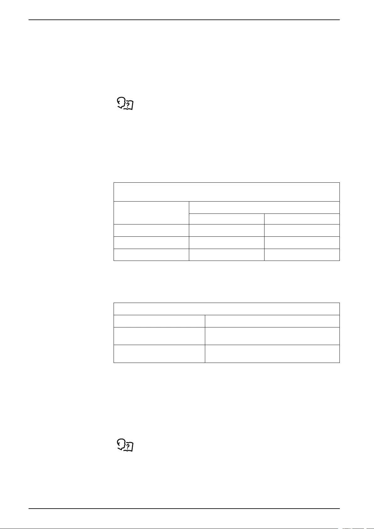
Indoor Unit
The cooling unit is packaged in a wooden crate or anchored to a pallet and
covered with transparent film. The recommended tools for moving and installing
the equipment include the following:
Forklift Pallet Jack
Outdoor Unit
The condensing unit is packaged in a wooden crate. The recommended tools for
moving and installing the equipment include the following:
Pallet Jack Forklift Crane
990-91229A-001 / 06MM0368@00B0110 11
Uniflair™UCF, MRA General Information
Equipment Disposal
Waste Electrical and Electronic Equipment (WEEE) Disposal
Schneider Electric products comply with international directives on
the Restriction of Hazardous Substances (RoHS) in electronic and
electrical equipment and the disposal of Waste Electrical and
Electronic Equipment (WEEE). Dispose of any waste electronic or
electrical equipment with the appropriate recycling center. Contact
Schneider Electric for assistance.
Radio Frequency Interference
The SKUs UCF0341I, UCF0481I, MRA0221I, and MRA0611D comply with part 15
of the FCC Rules. Operation is subject to the following two conditions:
1. These devices may not cause harmful interference.
2. These devices must accept any interference received, including interference
that may cause undesired operation.
Any changes or modifications not expressly approved by the party responsible for
compliance could void the user’s authority to operate the equipment.
California Proposition 65—Warning Statement for California
Residents
WARNING: This product can expose you to chemicals including lead and lead
compounds, that are known to the State of California to cause cancer and birth
defects or other reproductive harm. For more information go to
www.P65Warnings.ca.gov.
12 990-91229A-001 / 06MM0368@00B0110
General Information Uniflair™UCF, MRA
Equipment Guidelines
Working Conditions and Environmental Limits
Limit Working Conditions
Power supply 208 V, 1 Ph, 60 Hz
230 V, 1 Ph, 60 Hz
Voltage input tolerance ±10%*
Voltage imbalance Maximum 3% for 3-phase units
Frequency input tolerance—continuously ±0.5 Hz
Frequency input tolerance—short time ±1 Hz
Maximum altitude 2000 m (6562 ft)
Room Conditions
Temperature 18°C to 40°C (64.4°F to 104°F)
Humidity Relative humidity: 30 to 70%RH
DX Operational Conditions
Temperature –23°C to 46°C (–10°F to 115°F)
Storage Temperature
Temperature –23°C to 50°C (–10°F to 122°F)
*MRA0221I is only -5%/+10%
Unit Assembly Power Supply
UCF0341I Indoor 208 V, 1 Ph, 60Hz
230 V, 1 Ph, 60Hz
UCF0481I 208 V, 1 Ph, 60Hz
230 V, 1 Ph, 60Hz
MRA0221I Outdoor 208 V, 1 Ph, 60Hz
230 V, 1 Ph, 60Hz
MRA0611D 208 V, 3 Ph, 60Hz
230 V, 3 Ph, 60Hz
990-91229A-001 / 06MM0368@00B0110 13
Uniflair™UCF, MRA Unit Overview
Unit Overview
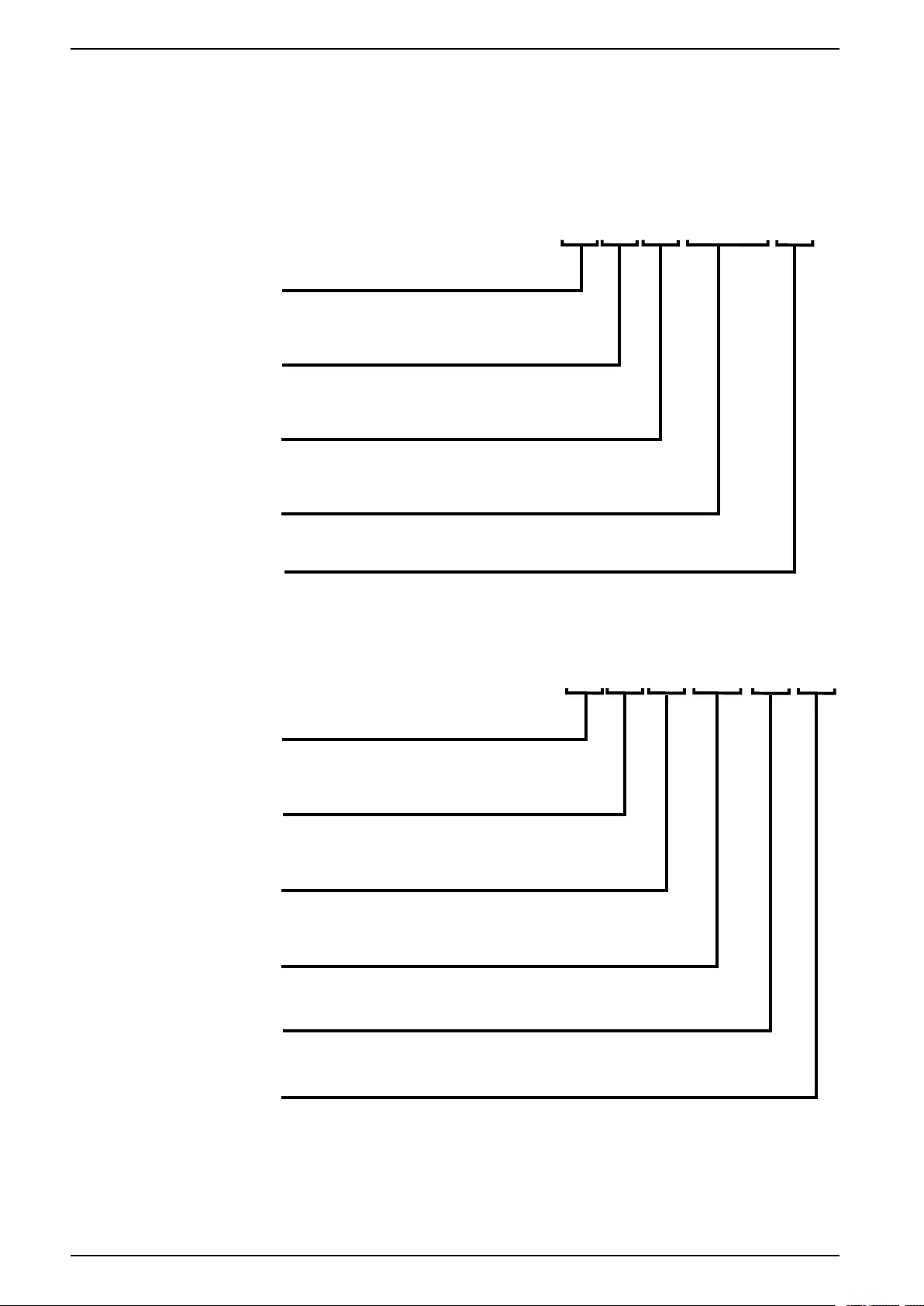
Model Nomenclature
Indoor Units
U C F
na4524c
I
XXXX
IDENTIFYING PREFIX
UNIT TYPE
C = CEILING-MOUNTED UNIT
FUNCTION MODE
F = FREE COOLING (OPTIONAL)
MODEL NUMBER
VOLTAGE
I = 208/230 V/1 Ph/60 Hz
0341, 0481
Outdoor Units
M R A
na4523b
022
1 I
IDENTIFYING PREFIX
COMPRESSOR TYPE
R = HERMETIC ROTARY SCROLL
FUNCTION MODE
A = MECHANICAL COOLING
MODEL NUMBER
NUMBER OF COMPRESSORS
VOLTAGE
I = 208/230 V/1 Ph/60 Hz
D = 208/230 V/3 Ph/60 Hz
M = MONOBLOCK
022, 061
14 990-91229A-001 / 06MM0368@00B0110

Unit Overview Uniflair™UCF, MRA
Nameplate Example
The units can be identified by the nameplate, which is located in the electrical
panel of the cooling unit. The model and any accessories that are installed are
indicated by an ‘X’ in the corresponding box. The nameplate contains the following
information:
• Model and series number of the unit
• Power supply type
• Power absorbed by the unit and individual components
• Current absorbed by the unit and individual components
• The setpoints of the air pressure switches
• Setpoints for the regulation and safety devices
Indoor Unit
UCF0341I
R410A
ELECTRICAL RATING:
MODEL/SKU:
208/230 VAC, 1~, 60 Hz
MCA: 15 AMPS
MOP: 15 AMPS
REFRIGERANT:
650 / 44.8
DESIGN PRESSURE:
Contains fluorinated greenhouse gases covered by the Kyoto protocol.
Foam blown with fluorinated greenhouse gases.
PSIG/Bar Low,High Side
TAAD056 3X3A
REMOTE AIR-COOLED CONDENSER
FAN: FLA 1.5 H.P. 0.23 QTY. 2
DESIGNED UNIT CHARGE: 10 / 0.28 oz/kg
SERIAL NO.
FACTORY CHARGE: Nitrogen
10 / 0.68 PSIG/Bar
FLA: 3.0 AMPS
4009332
Certification
ID
EXAMPLE
EXAMPLE
R410AR410A
AC, 1~, 60 Hz
AC, 1~, 60 Hz
AMPS
AMPS
REFRIGERANTREFRIGERANT
:
:
DESIGN PRESSURE
DESIGN PRESSURE
::
AN:
AN:
FLA
FLA
1.51.5
H.
H.
P
P
..
0.23
0.23
DESIGNED UNI
DESIGNED UNI
NO.
NO.
R
R
YY
RR
R
CHARGE
CHARGE
:
:
10 / 0.68
10 / 0.68
4009332
4009332
na7076a
Outdoor Unit
MRA0221I
R410A
ELECTRICAL RATING:
MODEL/SKU:
208-230 VAC, 1~, 60 Hz
MCA: 19.6 AMPS
MOP: 30.0 AMPS
REFRIGERANT
DESIGN PRESSURE
Contains fluorinated greenhouse gases covered by the Kyoto protocol.
Foam blown with fluorinated greenhouse gases.
TAAD056 4X3A
OUTDOOR USE (UTILISATION À L’EXTÉRIEUR)
COMPRESSOR: RLA 12.8 LRA 64
FAN: FLA 3.6 H.P. 0.46 QTY. 1
SYSTEM CHARGE: _________________________________ oz/kg
SERIAL NO.
FACTORY CHARGE:
FLA: 16.4 AMPS
Nitrogen
10 / 0.68 PSIG/Bar
650 / 44.8 PSIG/Bar Low,High Side
DESIGNED UNIT CHARGE: 81.0 / 2.29 oz/kg
4009332
Certification
ID
EXAMPLE
R410A
R410A
AMPS
AMPS
REFRIGERANT
REFRIGERANT
DESIGN PRESSURE
DESIGN PRESSURE
OUTDOOR USE (UTILIS
OUTDOOR USE (UTILIS
RLA
RLA
12.8
12.8
LRALRA
64
64
F
F
AN:
AN:
F
FF
FLA
FLA
3.6
3.6
H.
H.
P
P
NO.NO.
TT
OO
RR
Y
Y
R
R
R
CHARGE:
CHARGE:
10 / 0.68
10 / 0.68
na7077a
990-91229A-001 / 06MM0368@00B0110 15
Component Identification Uniflair™UCF, MRA
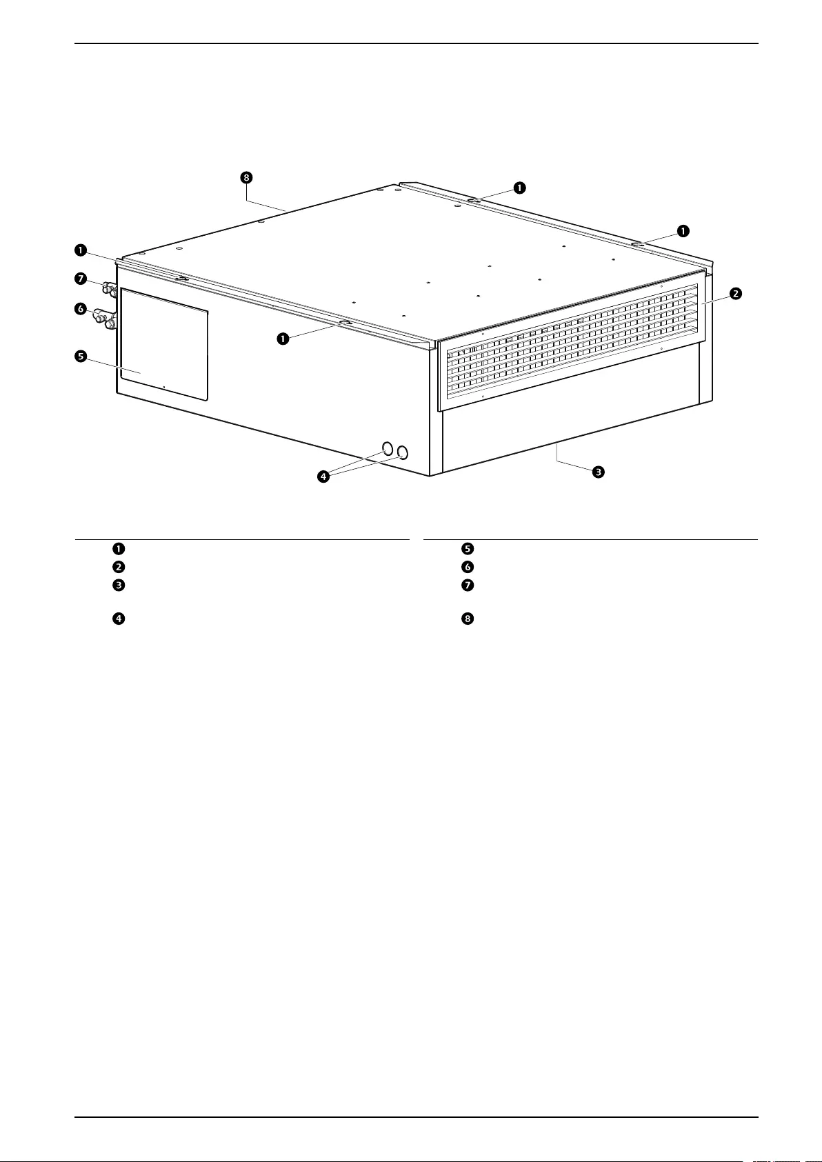
External Components
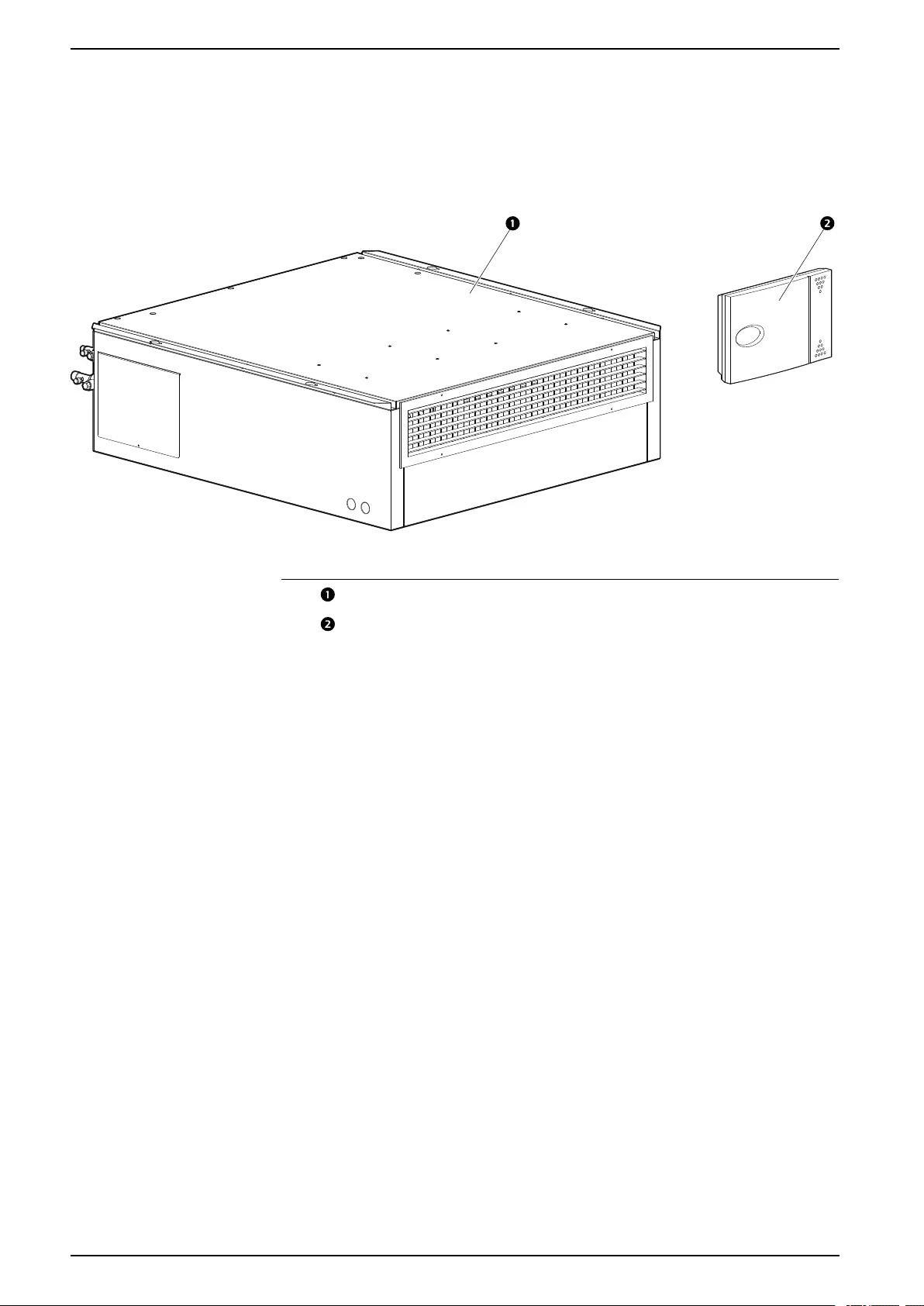
Indoor Units
UCF0341I and UCF0481I
na7062a
NOTE: Model shown is UCF0341I.
Item Description Item Description
Mounting holes Service panel
Fan protection grille Suction line service valve
Electrical panel cover (on bottom of
unit)
Liquid line service valve
Low-voltage conduit knock-out
panels*
Damper connection cover panel (on
rear of unit)
* High-voltage conduit knock-out panels are located on the opposite side.
990-91229A-001 / 06MM0368@00B0110 19
Uniflair™UCF, MRA Component Identification
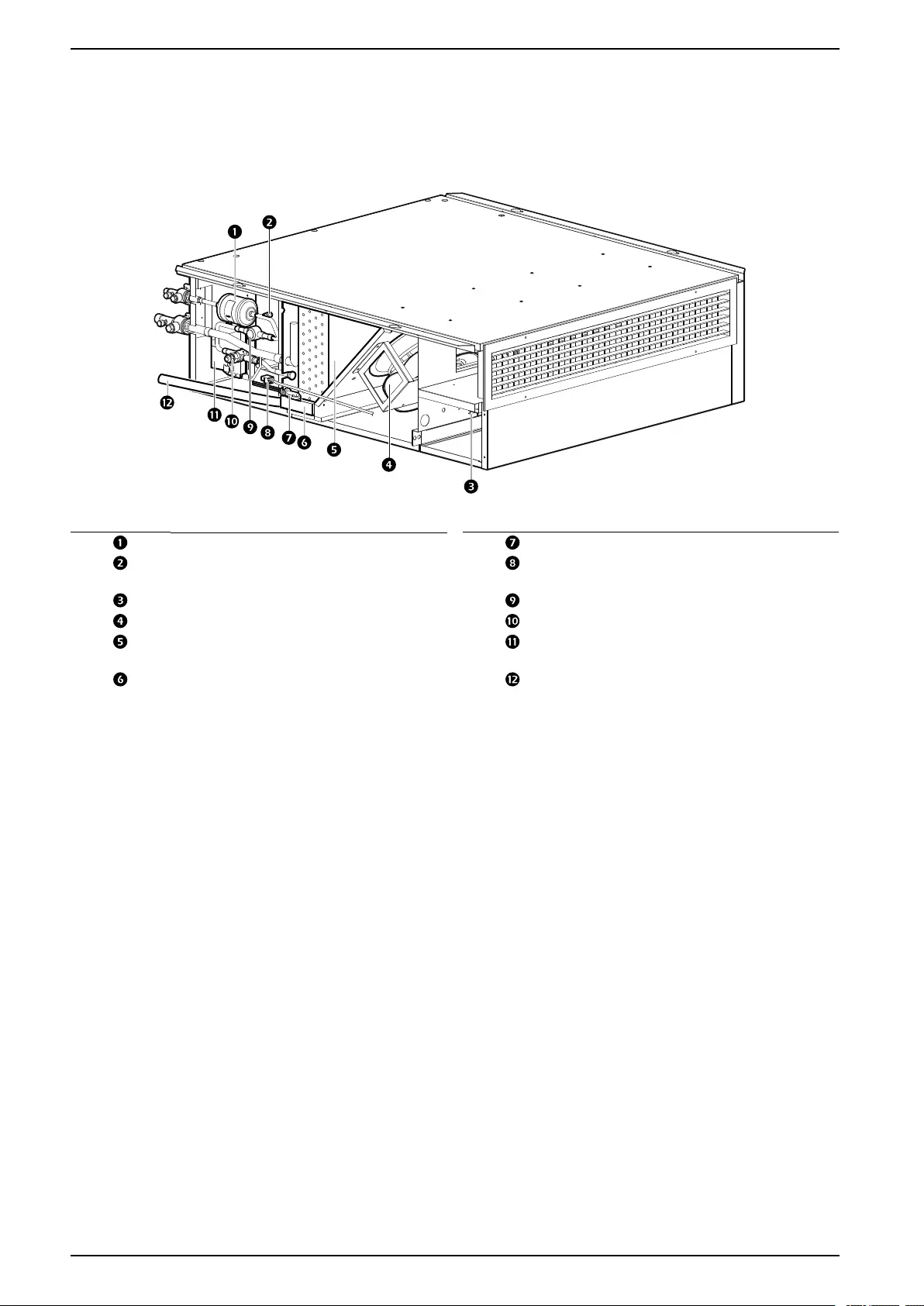
Internal Components
Indoor Units
UCF0341I
na7066a
Item Description Item Description
Filter drier Float switch
Service port Direct Air Economizer damper
actuator connection (optional)
Electrical panel (facing bottom of unit) Sight glass
Evaporative fans Thermostatic expansion valve (TXV)
Evaporative coil Motorized free-cooling damper
actuator (optional with damper kit)
Condensate drain pan Condensate drain hose
22 990-91229A-001 / 06MM0368@00B0110
Component Identification Uniflair™UCF, MRA
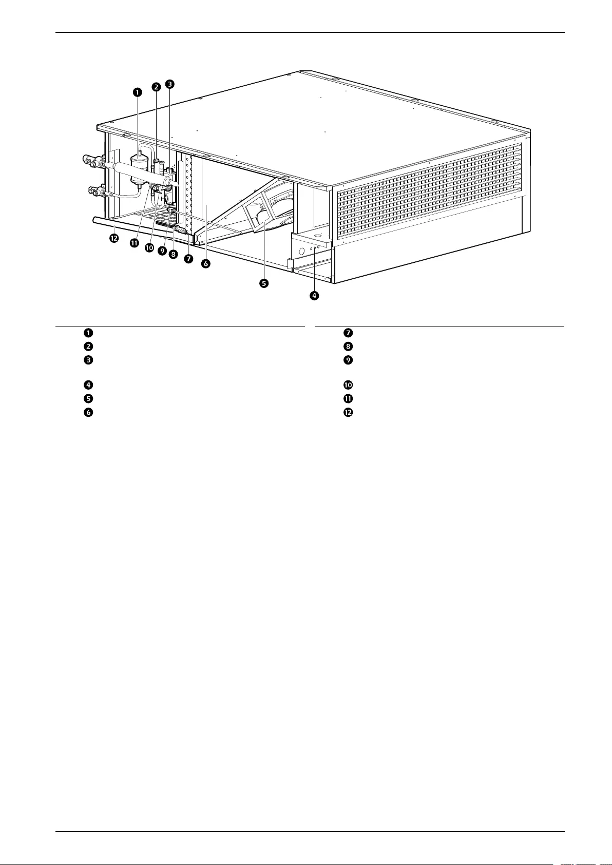
UCF0481I
na7096a
Item Description Item Description
Filter drier Condensate drain pan
Service port Float switch
Motorized free-cooling damper
actuator (optional with damper kit)
Direct Air Economizer damper
actuator connection (optional)
Electrical panel (facing bottom of unit) Thermostatic expansion valve (TXV)
Evaporative fans Sight glass
Evaporative coil Condensate drain hose
990-91229A-001 / 06MM0368@00B0110 23
Uniflair™UCF, MRA Component Identification
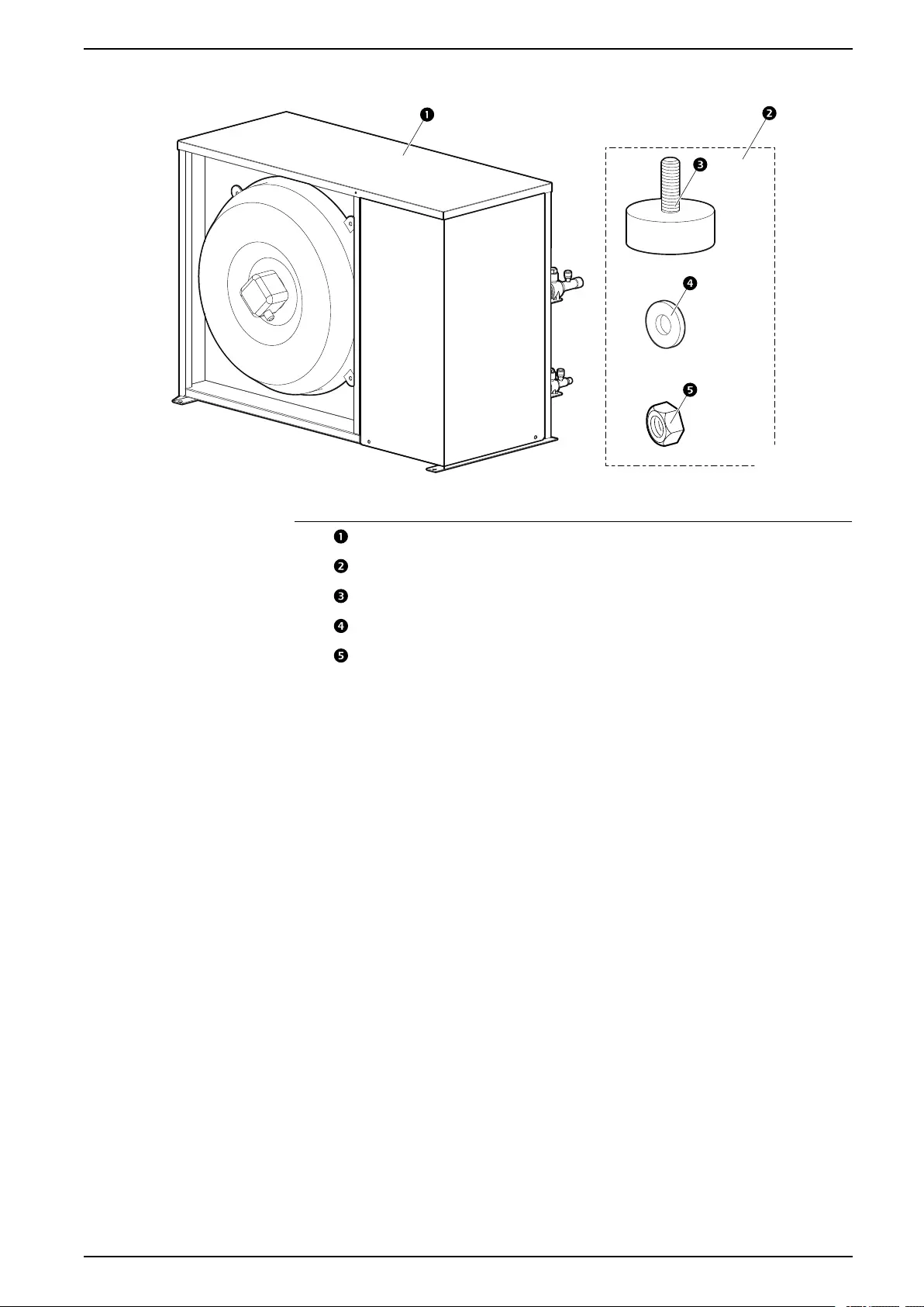
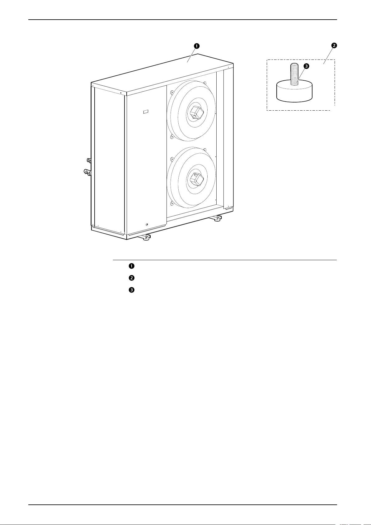
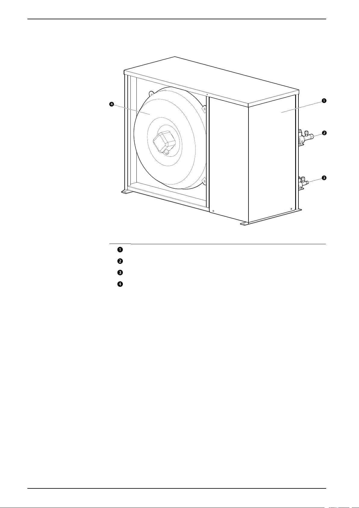
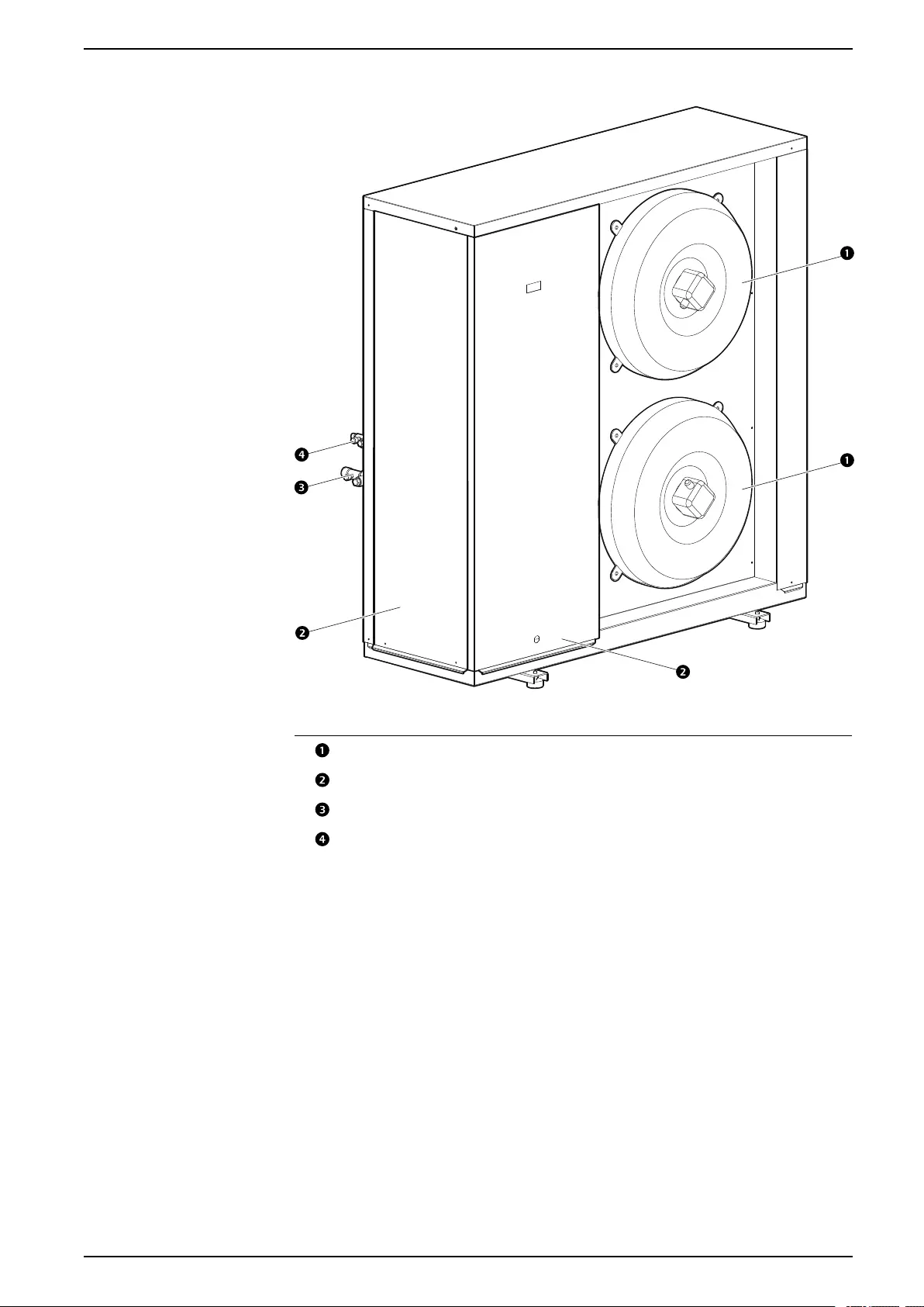
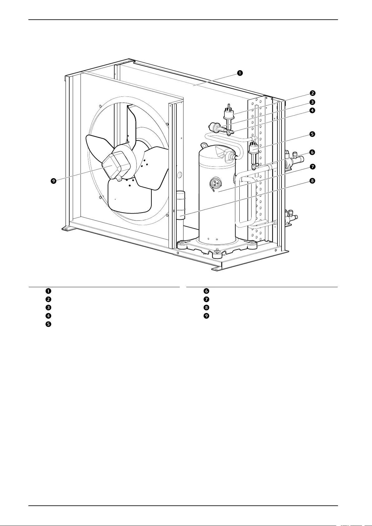
Outdoor Units
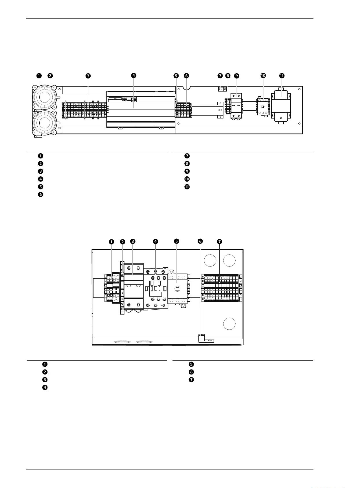
MRA0221I
na7067a
Item Description Item Description
Condensing coil Suction service port
High-pressure switch Scroll compressor
Pressure transducer Capacitor
Discharge service port Condensing fan
Low-pressure switch
NOTE: Crankcase heater and compressor blanket are not shown.
24 990-91229A-001 / 06MM0368@00B0110
Uniflair™UCF, MRA Component Identification
Electrical Panels
Indoor Units
UCF0341I, UCF0481I
na7052a
PE
L1
L2
1313
0
24
24
1601
1311
1312
1314
1502
1511
0213
0214
CHG
0210
0219
0220
0221
CHG
0204
0215
CHG
24VDC
5057
5059
24
24
0
0
CHG
CHG
CHG
24
CHG
DGND
F2
T1
Q1
F1
PE
TB2F2
PLC1
TB3
PFS
FS
TB1
Item Description Item Description
Clogged filter pressure switch (PFS) Ground (PE)
Air flow pressure switch (FS) Terminal block (TB1)
Terminal block (TB3) Fuse (F1)
J5 controller (PLC1) Internal power disconnect switch (Q1)
Fuse (F2) Transformer (T1)
Terminal block (TB2)
Outdoor Units
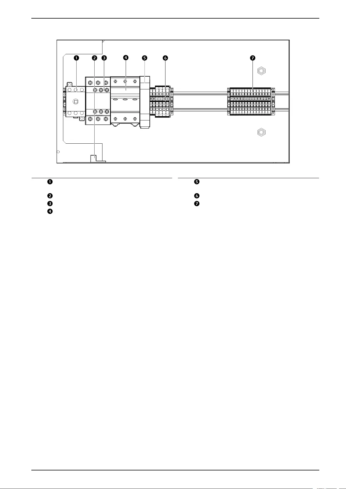
MRA0221I
na7053a
0
24
24
1601
1312
1314
1311
1511
1502
0214
0213
PE
PE
PE
L1
L2
Q1
F1
PE
TB02
K2
TB01
K1
Item Description Item Description
Terminal block (TB01) Internal power disconnect switch (Q1)
Voltage presence relay (K2) Ground (PE)
Fuse (F1) Terminal block (TB02)
Compressor contactor (K1)
26 990-91229A-001 / 06MM0368@00B0110
Component Identification Uniflair™UCF, MRA
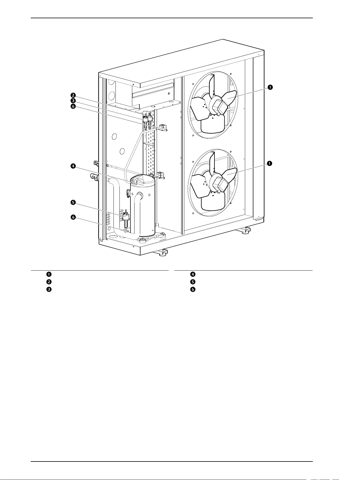
MRA0611D
L1
L1
L2
L2
0
24
24
1601
1312
1314
1311
1511
1511
1502
1502
0214
0213
PE
PE
PE
Q1
F1
PE
TB02
TB01
K1
K2
na7054a
Item Description Item Description
Internal power disconnect switch (Q1) Voltage presence relay/3-phase
monitor (K2)
Ground (PE) Terminal block (TB01)
Compressor contactor (K1) Terminal block (TB02)
Fuse (F1)
990-91229A-001 / 06MM0368@00B0110 27
Uniflair™UCF, MRA Component Identification
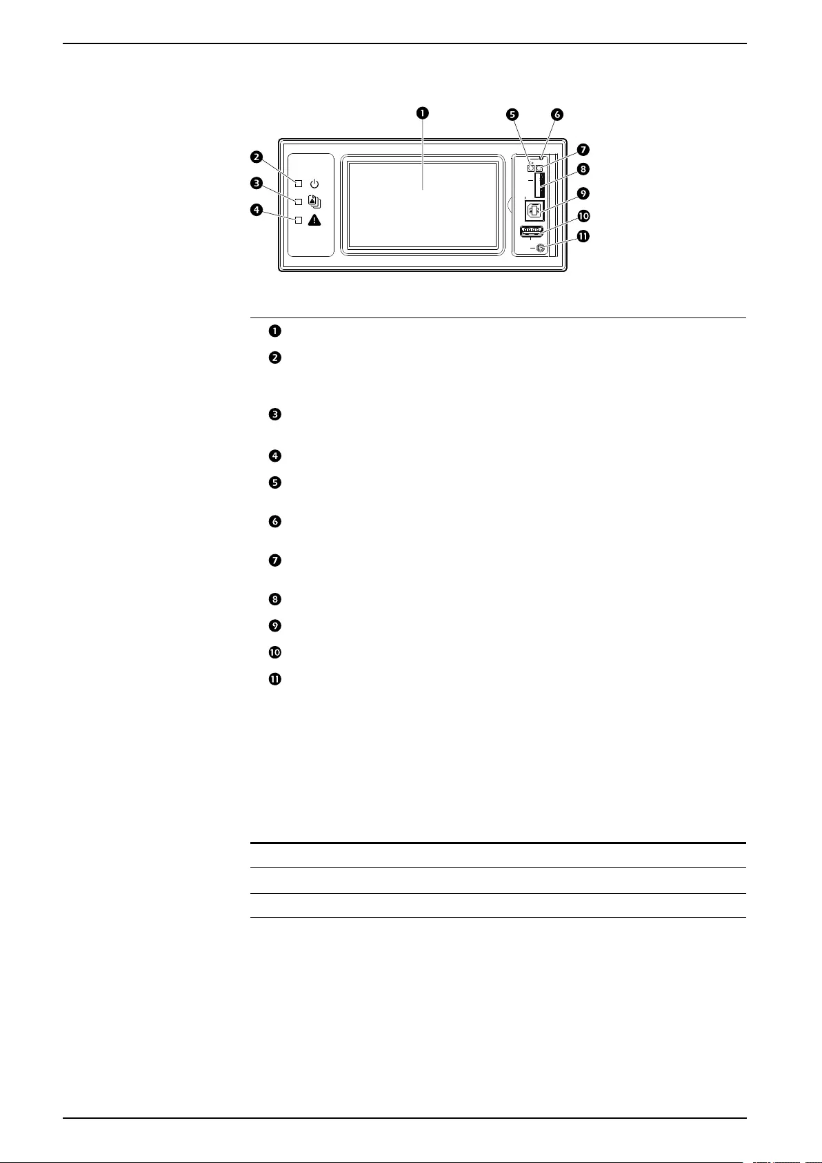
Display Interface
Display
Reset
Micro
SD
Service
Port
USB
Console
10/100
na4820a
Item Description Function
LCD Display 4.3-inch touch-screen color display
Power LED The cooling unit is powered when the LED is
illuminated. Unit firmware is updating when
LED is blinking.
Check Log LED When this LED is illuminated, a new entry has
been made to the event log.
Alarm LED Displays current alarm condition of unit.
Status LED Displays current network management card
status.
Display Reset button Resets the display microprocessor. This has
no effect on the air conditioner controller.
Link-RX/TX (10/100)
LED
Displays current network link status.
Micro SD card slot Memory card expansion slot.
Service port USB-B port used only by service personnel.
USB-A port Supports firmware upgrades.
Serial Configuration
port
Connects the display to a local computer to
configure initial network settings or access the
command line interface (CLI).
Alarm LED
This LED indicates active alarms on the display.
Condition Description
Off No alarm
Solid yellow Warning alarm
Solid red Critical alarm
28 990-91229A-001 / 06MM0368@00B0110
Component Identification Uniflair™UCF, MRA
Status LED
This LED indicates the status of the display.
Condition Description
Off One of the following situations exist:
• The display is not receiving input
power.
• The display is not operating
properly. It may need to be
repaired or replaced. Contact
Schneider Electric Customer
Support.
Solid green The display has valid TCP/IP settings.
Solid orange A hardware malfunction has been
detected in the display. Contact
Schneider Electric Customer Support.
Flashing green The display does not have valid TCP/
IP settings.
Flashing orange The display is making BOOTP
requests.
Alternately flashing green and orange If the LED is flashing slowly, the
display is making DHCP requests. If
the LED is flashing rapidy, the display
is starting up.
Link-RX/TX (10/100) LED
This LED indicates the network status of the display.
Condition Description
Off One or more of the following situations exist:
• The display is not receiving input power.
• The cable or device that connects the cooling unit
to the network is disconnected or not functioning
properly.
• The display itself is not operating properly. It may
need to be repaired or replaced. Contact
Schneider Electric Customer Support.
Solid green The display is connected to a network operating at 10
megabits per second (Mbps).
Solid orange The display is connected to a network operating at 100
Mbps.
Flashing green The display is receiving or transmitting at 10 Mbps.
Flashing orange The display is receiving data packets at 100 Mbps.
990-91229A-001 / 06MM0368@00B0110 29
Uniflair™UCF, MRA Dimensions and Weights
Dimensions and Weights
Indoor Units
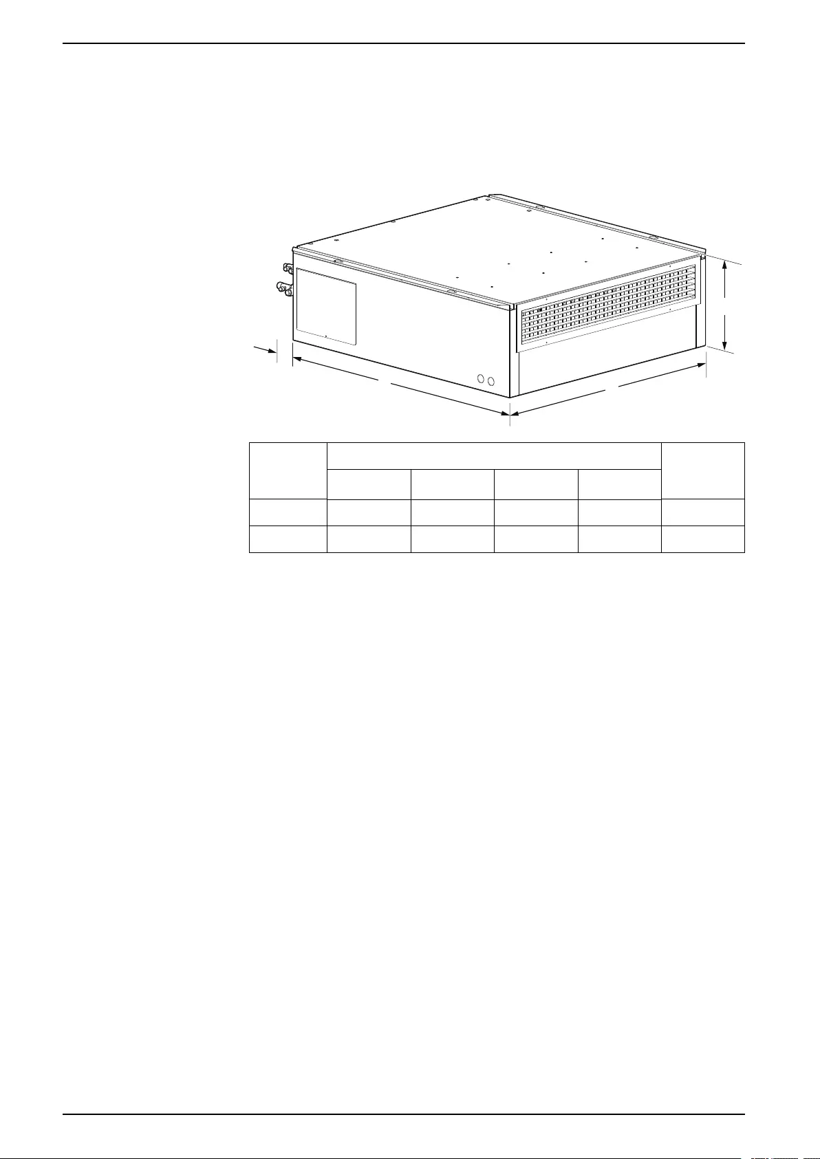
UCF0341I, UCF0481I
A
B
C
D
na7055a
Model Dimensions – mm (in.) Net
Weight –
kg (lb)
A B CD
UCF0341I 950 (37.4) 1050 (41.3) 330 (13.0) 125 (4.9) 75 (165.4)
UCF0481I 1150 (45.3) 1300 (51.2) 411 (16.2) 124 (4.8) 146 (321.9)
30 990-91229A-001 / 06MM0368@00B0110
Dimensions and Weights Uniflair™UCF, MRA
Piping and Electrical Access Locations
Indoor Units
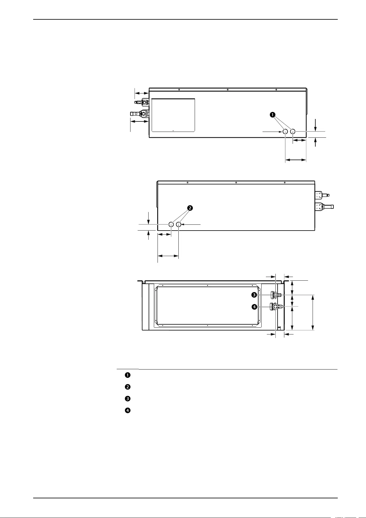
UCF0341I
140.0
(5.5)
158.3
(6.2)
235.0
(9.3)
58.0 (2.3)
40.0 (1.6)
90.0
(3.5)
40.0 (1.6)
140.0
(5.5)
90.0
(3.5)
125.0
(4.9)
95.5
(3.8)
56.6 (2.2)
95.0 (3.7)
76.7
(3.0)
na7058a
Ø28 (Ø1.1)
Ø28 (Ø1.1)
LEFT SIDE
RIGHT SIDE
REAR VIEW
NOTE: Dimensions shown in mm (in.).
Item Description
Low-voltage conduit knock-out panel
High-voltage conduit knock-out panel
Liquid line
Gas line
990-91229A-001 / 06MM0368@00B0110 33
Uniflair™UCF, MRA Dimensions and Weights
UCF0481I
140.0 (5.5)
95.5 (3.8)
124.0 (4.9)
118.0 (4.6)
120.0 (4.7)
173.0 (6.8)
58.0 (2.3)
56.6 (2.2)
371.0
(14.6)
40.0 (1.6)
90.0
(3.5)
371.0
(14.6)
40.0 (1.6) 90.0
(3.5)
140.0 (5.5)
LEFT SIDE
RIGHT SIDE
REAR VIEW
Ø28 (Ø1.1)
Ø28 (Ø1.1)
na7059a
NOTE: Dimensions shown in mm (in.).
Item Description
Low-voltage conduit knock-out panel
High-voltage conduit knock-out panel
Gas line
Liquid line
34 990-91229A-001 / 06MM0368@00B0110
Dimensions and Weights Uniflair™UCF, MRA
Outdoor Units
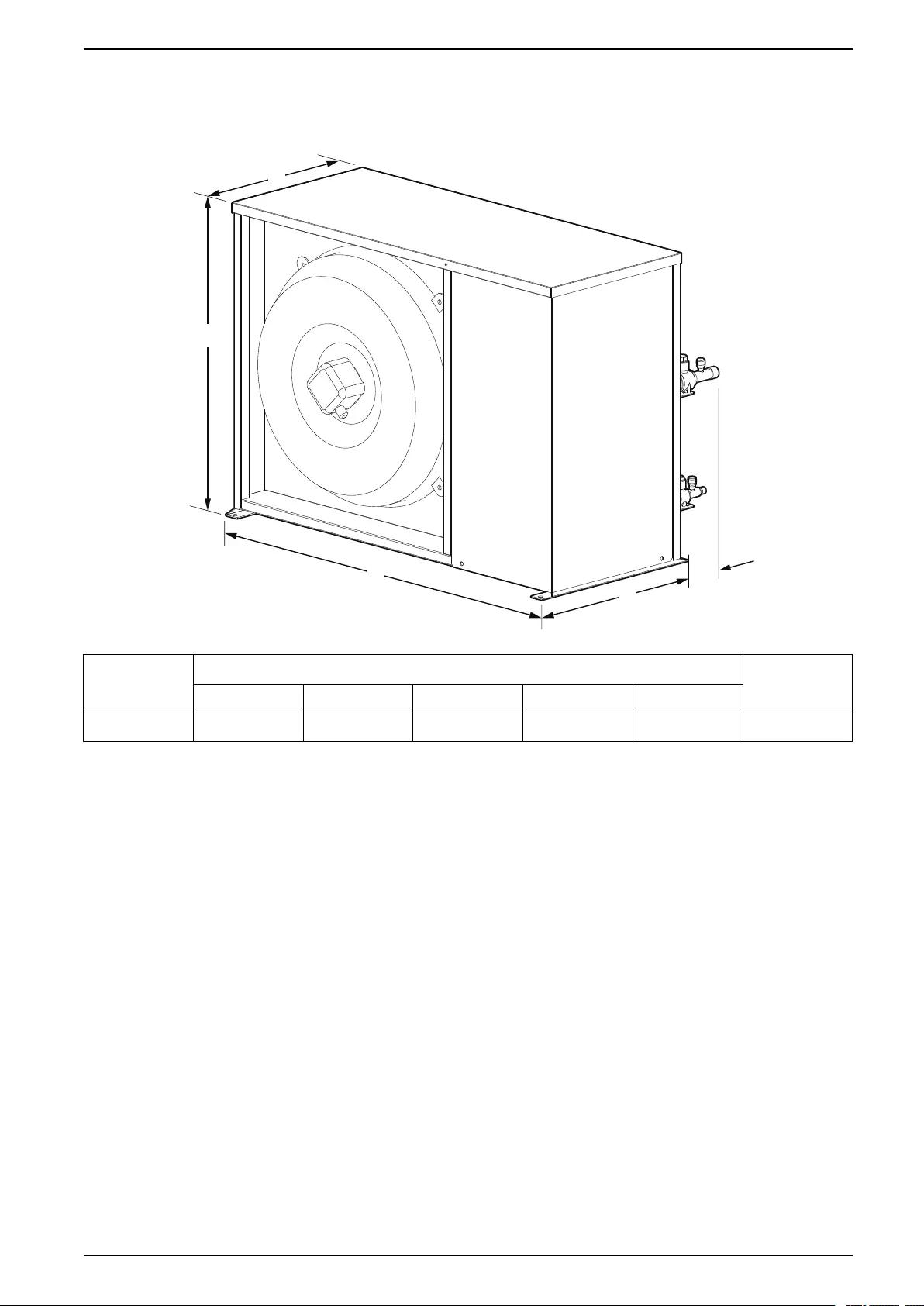
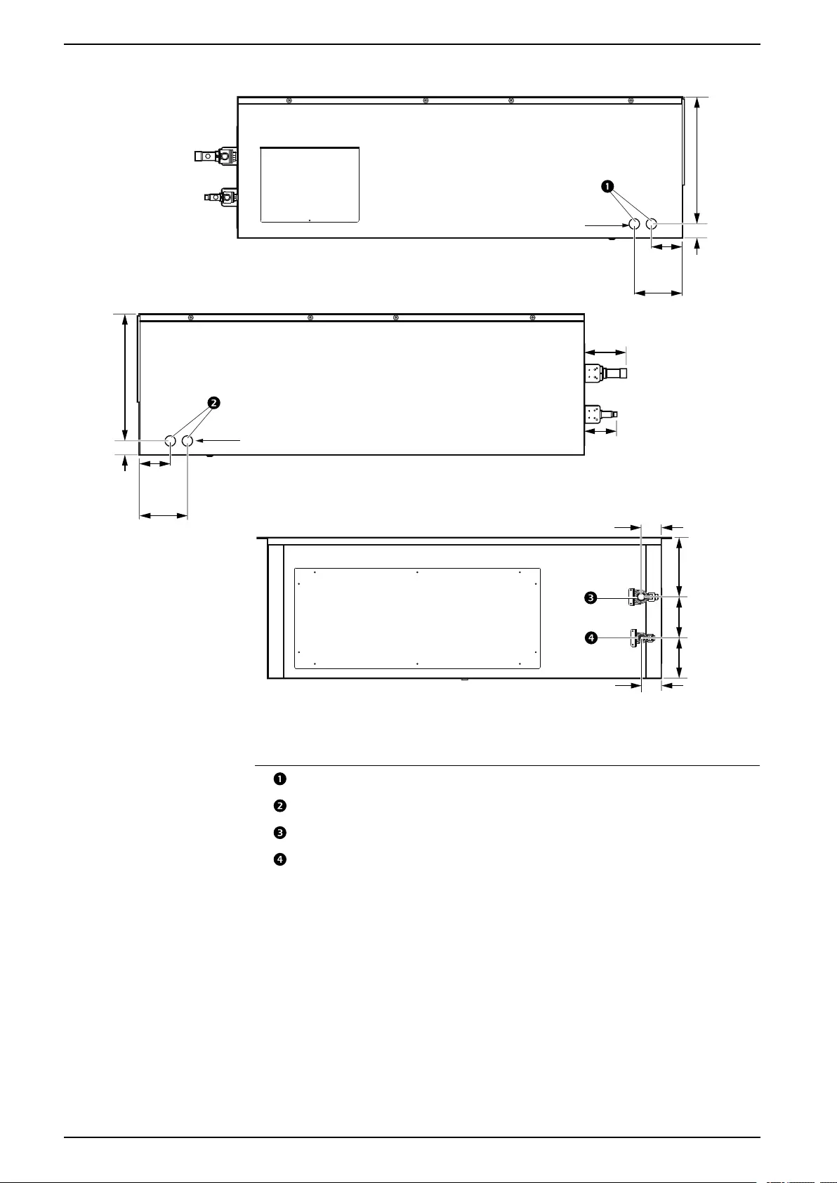
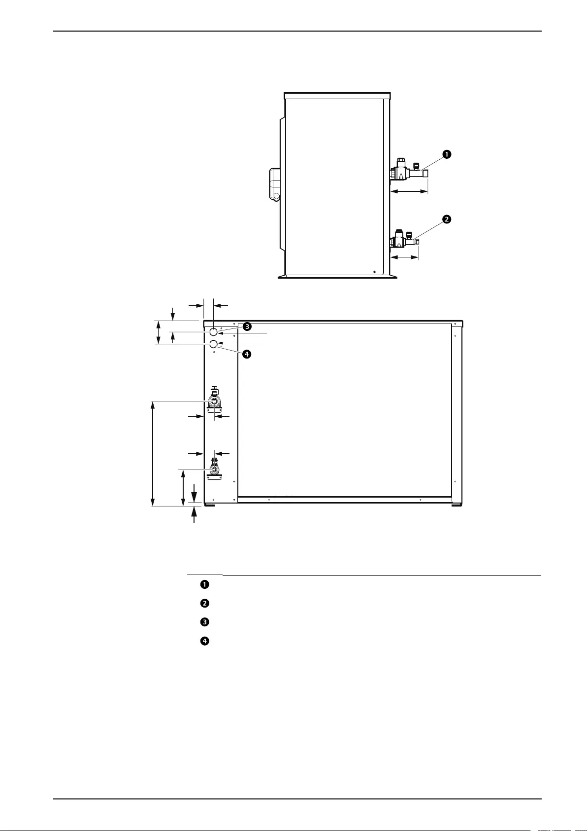
MRA0221I
REAR
95.5 (3.7)
30.0 (1.2)
37.0 (1.5)
77.0
(3.0)
10.1 (0.4)
119.1
(4.7)
345.1
(13.6)
125.0 (4.9)
33.0
(1.3)
33.0
(1.3)
Ø22.5 (Ø0.9)
Ø22.5 (Ø0.9)
na7060a
NOTE: Dimensions shown in mm (in.).
Item Description
Gas line
Liquid line
High–voltage conduit knock-out panel
Low–voltage conduit knock-out panel
990-91229A-001 / 06MM0368@00B0110 35
Uniflair™UCF, MRA Dimensions and Weights
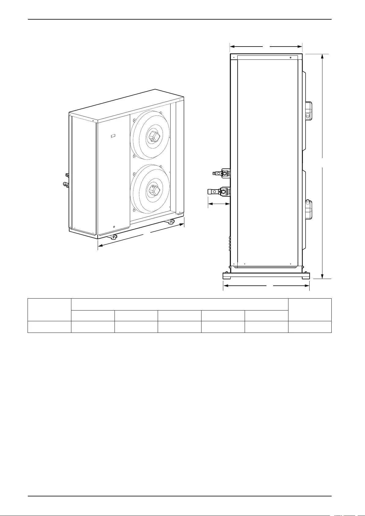
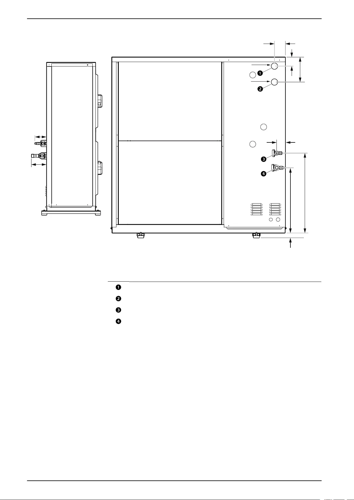
MRA0611D
na7061a
59.0 (2.3)
451.5 (17.8)
553.0 (21.8)
33.0 (1.3)
75.0 (3.0)
62.5 (2.5)
172.5
(6.8)
95.5
(3.8)
124.0
(4.9)
Ø42.0 (Ø1.7)
Ø42.0 (Ø1.7)
NOTE: Dimensions shown in mm (in.).
Item Description
High–voltage conduit knock-out panel
Low–voltage conduit knock-out panel
Liquid line
Gas line
36 990-91229A-001 / 06MM0368@00B0110
Dimensions and Weights Uniflair™UCF, MRA
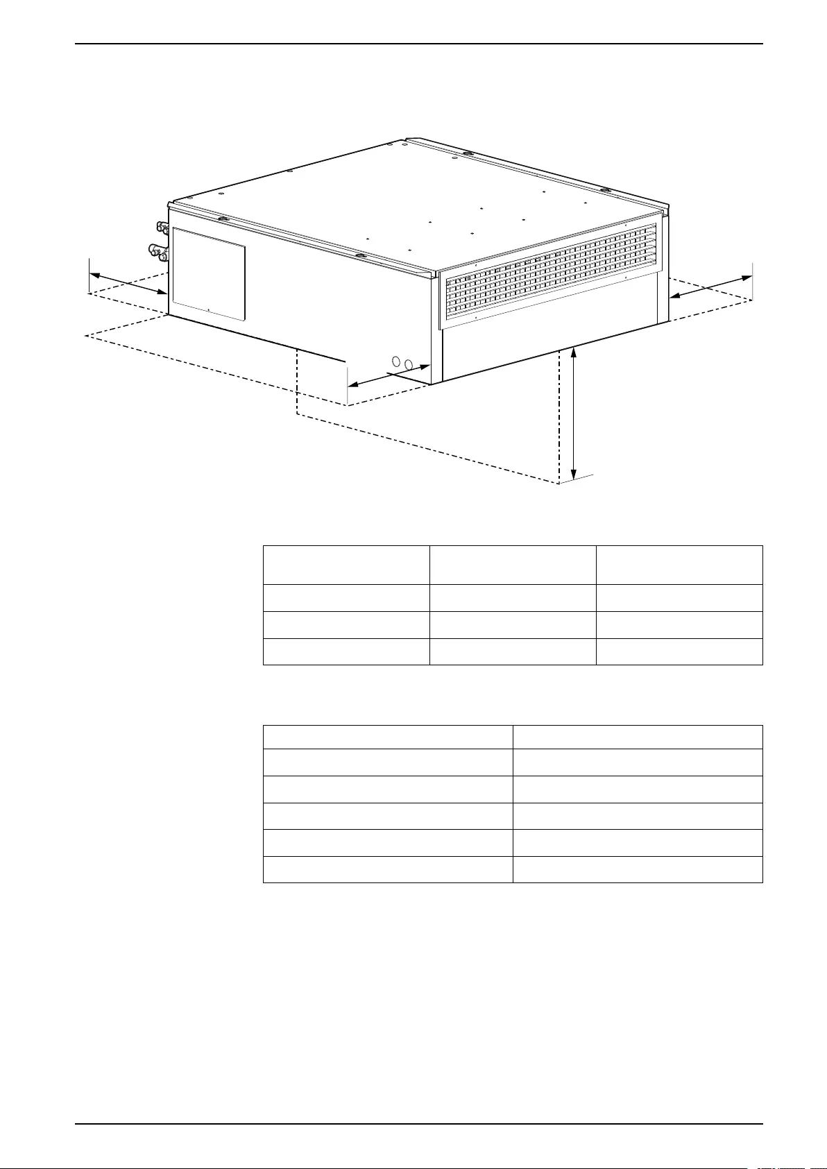
Service Clearance
Indoor Units
914 mm
(36 in.)
457 mm
(18 in.)
457 mm
(18 in.)
304 mm
(12 in.)
na7065a
Routine service and maintenance is performed from below the unit. Consider
service accessibility when planning equipment positioning in the data center.
Location Minimum Clearance Recommended
Clearance
Rear of unit 304 mm (12 in.) —
Sides of unit 457 mm (18 in.) 914 mm (36 in.)
Below unit 914 mm (36 in.) 1981.2 mm (78 in.)
Outdoor Units
Location Recommended Clearance
Rear of unit 152 mm (6 in.)
Top of unit 304 mm (12 in.)
Front of unit 914 mm (36 in.)
Service side of unit 508 mm (20 in.)
Non-service side of unit 152 mm (6 in.)
990-91229A-001 / 06MM0368@00B0110 37
Uniflair™UCF, MRA Diagrams
Diagrams
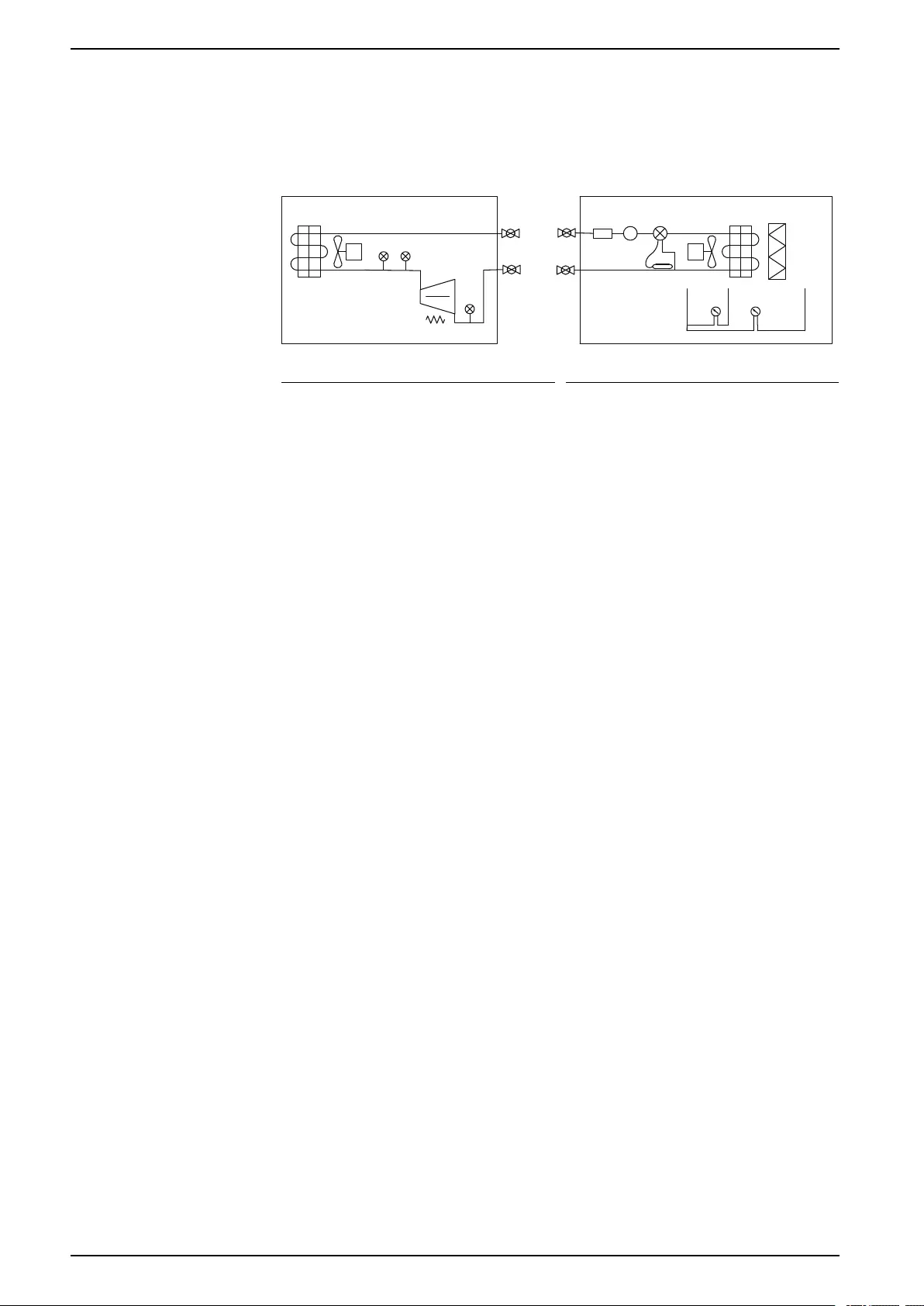
Refrigeration Piping Diagram
na7207a
OUTDOOR UNIT (MRA UNITS) INDOOR UNIT (UCF UNITS)
VS HPS PT
LPS
CCH
LIQUID
SV
SUCTION
SV
FD SG TXV
FS
AF
DP1 DP2
Item Description Item Description
FS Fixed speed fan AF Air filter
VS Variable speed fan FD Filter drier
PT Pressure transducer
(variable speed fan
control)
SG Sight glass
HPS High pressure switch,
manual reset
TXV Thermostatic expansion
valve
LPS Low pressure switch, auto
reset
DP1 Air pressure sensor, indoor
fan flow
CCH Crankcase heater DP2 Air pressure sensor, air
filter
SV Service valve, ball type
38 990-91229A-001 / 06MM0368@00B0110
Installation Uniflair™UCF, MRA
Installation
Site Preparation
WARNING
HAZARD FROM MOVING PARTS
Keep hands, clothing, and jewelry away from moving parts. Check the
equipment for foreign objects before closing the doors and starting the
equipment.
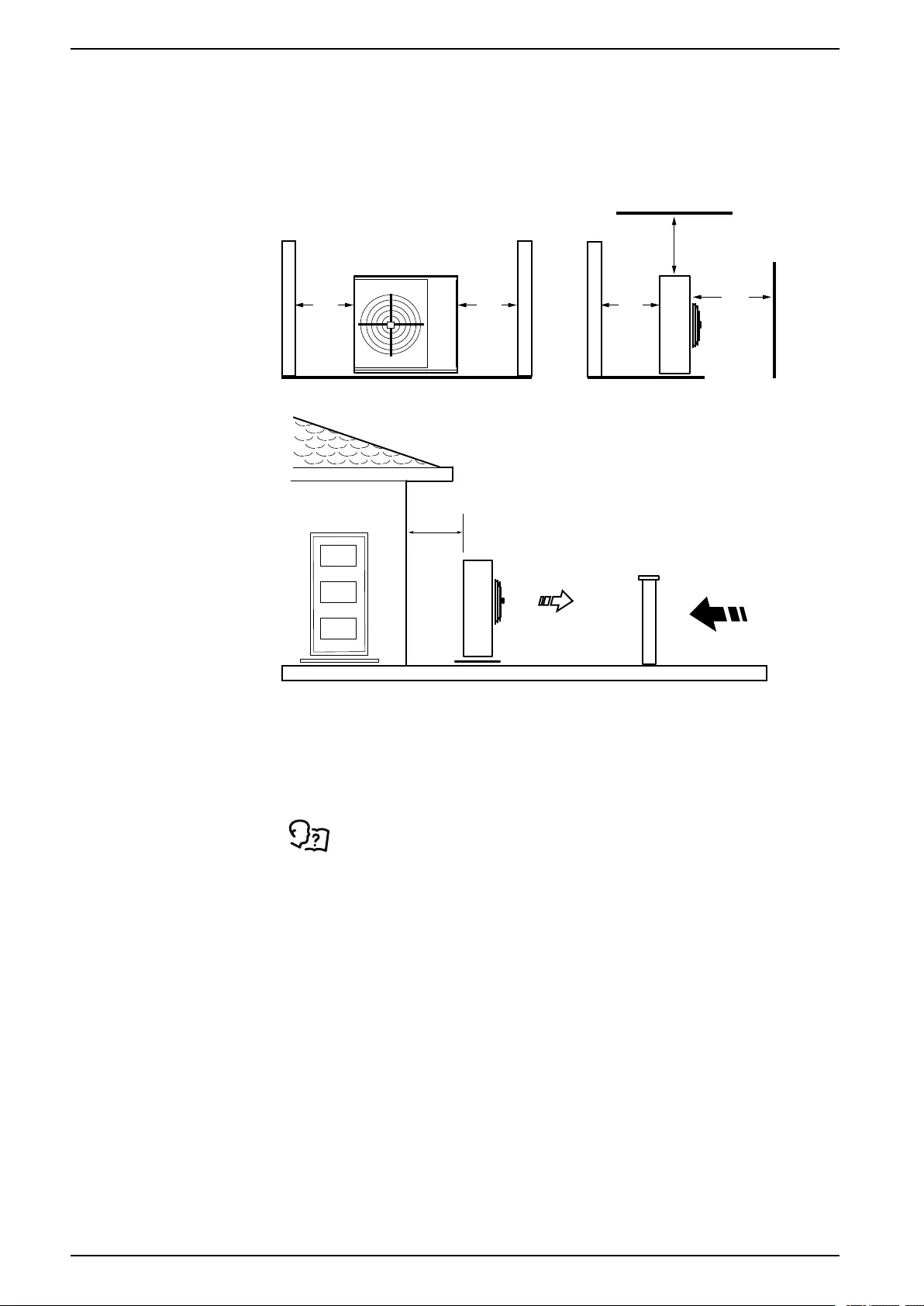
Failure to follow these instructions can result in death, serious injury, or
equipment damage.
NOTICE
EQUIPMENT DAMAGE RISK
Install the unit in an area that is protected from adverse conditions.
Failure to follow these instructions can result in equipment damage.
NOTICE
WATER DAMAGE
Installing the unit on an uneven surface may result in overflow spilling from the
condensate tray.
Failure to follow these instructions can result in equipment damage.
Positioning Units
Internal Units (UCF)
NOTICE
EQUIPMENT DAMAGE RISK
Install the unit in an area that is protected from adverse conditions.
Failure to follow these instructions can result in equipment damage.
UCF units must be attached to (or suspended from) the ceiling of the room by the
side flanges; check that the ceiling is strong enough to support the weight of the
unit.
When installing the unit, check that it is level.
The ceiling mount must be installed in accordance with local, regional, and
national codes, and this Installation Manual.
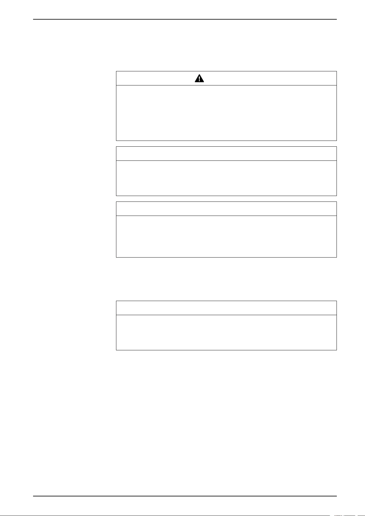
External Units (MRA)
This is an outdoor unit. Protect the unit from water flowing from drains or gutters.
Do not expose the unit to air containing flammable or greasy substances.
Do not obstruct intake airflow from the fans and through the condensing coil. Free
airflow ensures efficiency of the unit and prevents compressor safety devices from
ending unit operation.
990-91229A-001 / 06MM0368@00B0110 39
Uniflair™UCF, MRA Installation
Never direct the air-discharge side (the fan side) toward a wall. If the installation
location is windy, install the unit in a sheltered position; the wind could obstruct the
airflow through the cooling coil or make it excessive. If this is not possible, take
adequate wind-protection measures.
Check that the load capacity of the surface under the unit is sufficient to support its
weight.
na6340a
152
(6)
152
(6)
508
(20)
914
(36)
304 (12)
NOTE: Dimensions are in mm (in.)
na6341a
150
(6)
NOTE: Dimensions are in mm (in.)
External Air Free-Cooling–UCF Units
UCF units have the option to be converted for use with a free-cooling kit.
See the Damper Kit Installation Instructions for the requirements.
These free-cooling units have a butterfly damper that introduces external air when
the outside temperature is low enough to dissipate the thermal load in the air-
conditioned room.
40 990-91229A-001 / 06MM0368@00B0110
Unit Connections Uniflair™UCF, MRA
Unit Connections
Mechanical Connections
Mounting the Indoor Unit to the Ceiling
FIELD
SUPPLIED
FIELD
SUPPLIED
CUSTOMER SUPPLIED
MOUNTING SUPPORTS
na7094a
NOTE: Framing systems may also be used to suspend the unit.
Dimensions for Mounting Holes–UCF0341
na7074a
REAR
FRONT
230.0
(9.1)
550.0
(21.7)
270.0
(10.6)
980 (38.6)
1010 (39.8)
15.0
(0.6)
15.0
(0.6)
Ø25 (Ø1.0)
10.0
(0.4)
990-91229A-001 / 06MM0368@00B0110 47

Uniflair™UCF, MRA Unit Connections
Dimensions for Mounting Holes–UCF0481
1180.0 (46.5)
1210.0 (47.6)
15.0
(0.6)
15.0
(0.6)
220.0
(8.7)
450.0
(17.7)
450.0
(17.7)
180.0
(7.1)
Ø25 (Ø1.0)
10.0
(0.4)
na7075a
REAR
FRONT
Installing the Display Interface
NOTE: The display interface is not for use with external power supply.
See the installation instructions packed with the display interface.
48 990-91229A-001 / 06MM0368@00B0110
Unit Connections Uniflair™UCF, MRA
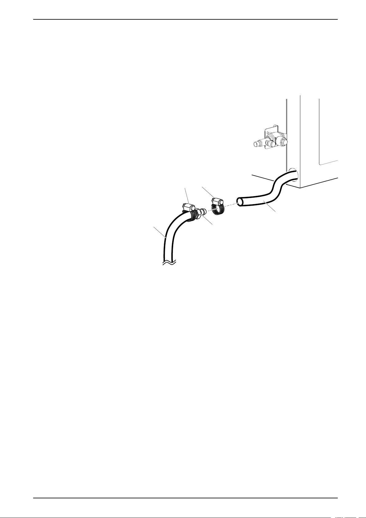
Connecting the Condensate Drain
Condensation drains from the drain pan under the coil through a Ø18 mm (ID)
flexible hose to the rear of the indoor unit. Use a 3/4 in. or 7/8 in. diameter hose
barb fitting and hose clamp (both field supplied) to connect the drain line under the
refrigerant service valves. Horizontal sections of the condensate drain lines should
have a slope of 6.4 mm (1/4 in.) to 12.7 mm (1/2 in.) per 0.3 m (1 ft). Vertical
sections of gravity drains should include an S- or P-trap at the top of the riser. Size
gravity drain piping for a maximum capacity of 100 lb/hr (12 gph).
na7090a
Ø18-MM (ID)
UNIT CONDENSATE
DRAIN HOSE
3/4-IN. OR 7/8-IN.
BARBED HOSE
CONNECTION
(FIELD SUPPLIED)
HOSE CLAMP
(FIELD SUPPLIED)
CUSTOMER
DRAIN HOSE
(FIELD SUPPLIED)
These units only support the use of an external condensate pump. If a condensate
pump is required for the application, a field-supplied unit may be installed in the
condensate drainage piping system. The pump should have its own water
reservoir located below the condensate drain pan of the unit and should be
independently mounted and supported. Do not attach the pump to the exterior
sheet metal of the indoor UCF units. The piping between the UCF unit and the
pump should maintain the gravity drain system requirements noted above.
990-91229A-001 / 06MM0368@00B0110 49
Uniflair™UCF, MRA Unit Connections
Refrigerant Piping
The indoor and outdoor units must only be connected and installed as a matched
set. Systems may not be mixed with equipment from other manufacturers or
aftermarket components except as detailed in these instructions. Install all
refrigerant lines in accordance with these instructions and applicable industry
guidelines. All refrigerant piping must comply with local, regional, and national
codes and regulations.
Before installation of the equipment piping, create a piping plan based on the
installation location, equipment elevations, and actual distances between the
equipment. Calculate an equivalent length based on the actual length of the run,
including valves and fittings. Construct all piping runs from hard-drawn, Type ACR
or Type L copper piping rated for HVAC/R service in accordance with ASTM B280.
Make all refrigerant lines as short and direct as possible. All pipe fittings should
have long-radius bends to minimize the line-set pressure drop. Piping should be
properly supported and isolated from structural surfaces using vibration clamps.
All horizontal lines must be sloped in the direction of flow. Suction lines must be
pitched downward at a minimum of 4 mm per m (1/2 in. per 10 ft) in the direction of
flow to aid in oil return. Suction lines must be insulated for their entire length.
Insulation should have a 13 mm (1/2 in.) wall thickness or at a minimum, have an
R-value of 3 (ft2*°F*hr/Btu). When possible, place piping supports on the exterior
of the piping insulation.
Piping Connection Sizes
Model Liquid Line Suction Line
UCF0341I
MRA0221I
3/8 in. ODF 3/4 in. ODF
UCF0481I
MRA0611D
3/8 in. ODF 7/8 in. ODF
For equipment installed with the evaporator above the condenser, if the
compressor is expected to operate at ambient conditions below freezing, the
system must include inverted piping loops to protect the compressor from liquid
flood-back during off cycles. The bottom of the inverted piping loops must be at
least 25 mm (1 in.) above the top of the evaporator coil. Other system setups may
also require inverted piping loops: the following sections provide more information
for these configurations.
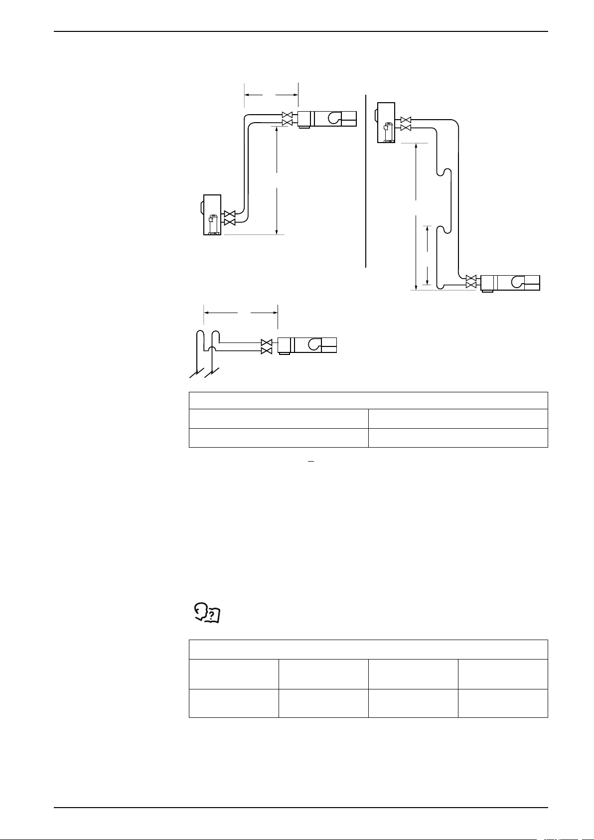
Piping between the indoor and outdoor units should minimize any elevation
changes between the units. Depending upon installation type, the maximum
recommended elevation between units is shown in the image below with the
recommendations listed in the table.
50 990-91229A-001 / 06MM0368@00B0110
Unit Connections Uniflair™UCF, MRA
na7091a
L
L
H1
H2
h
WHEN L ≥ 14 m (45 ft)
MRA UNIT
MRA
UNIT
UCF UNIT
UCF UNIT
EVAPORATOR
ABOVE
CONDENSER
CONDENSER
ABOVE
EVAPORATOR
UCF UNIT
Maximum Recommended Unit Elevations
Evaporator above Condenser Condenser above Evaporator
4.7 m (15.5 ft)* 13.7 m (45 ft)**
*For applications where L > 13.7 m (45 ft) and the actual piping length is 19.8 m
(65 ft) or longer, the liquid and suction risers should include inverted piping
loops to protect the compressor from liquid flood-back during off cycles.
Additionally, the suction piping loop should contain a P-trap for oil control.
**For applications that exceed 4.8 m (16 ft) of elevation, one oil trap should be
included in the riser for every 4.5 m (15 ft) of elevation. All risers should include
a P-trap at the base of the riser.
See the tables below for the recommended piping sizes that can be used for most
applications assuming a maximum differences in elevation of up to 8.5 m (28 ft).
Suction risers should also conform to the unit connection size of the suction line.
See the Piping Connection Sizes table.
Minimum Interconnecting Suction Pipe Sizes
Equivalent
Length
0-12 m
(0-40 ft)
12.4-22.8 m
(41-75 ft)
23.2-30.4 m
(76-100 ft)
UCF0341I
MRA0221I
3/4 in. ACR 7/8 in. ACR 7/8 in. ACR*
* Applications with significant elevation between units may require horizontal
sections to be increased to 1 1/8 in. ACR
990-91229A-001 / 06MM0368@00B0110 51
Uniflair™UCF, MRA Unit Connections
Minimum Interconnecting Suction Pipe Sizes
Equivalent
Length
0-6.0 m
(0-20 ft)
6.4-22.8 m
(21-75 ft)
23.2-30.4 m
(76-100 ft)
UCF0481I
MRA0611D
3/4 in. ACR 7/8 in. ACR 1 1/8 in. ACR
Applications of 22.8 m (75 ft) or less use 3/8 in. ACR for liquid lines.
NOTE: Install all piping in accordance with applicable industry guidelines as
well as local and national codes and regulations.
Consult with your installation contractor for the following conditions:
• Elevations greater than 8.5 m (28 ft)
• Refrigerant piping noise is a concern
Connect Refrigerant Lines
NOTICE
COMPLIANCE REQUIREMENT
Install all refrigerant lines in accordance with these instructions and applicable
industry guidelines. All refrigerant piping must comply with local, regional, and
national codes and regulations.
Failure to follow these instructions can result in equipment damage.
See Refrigerant Piping, page 50 for more information.
Before making the piping connections, dry fit the piping section together and verify
that the actual piping constructed meets the piping plan layout and applicable
sections of this manual. Then prepare the units and piping for joining. Only use
joining techniques approved for HVAC/R service and that meet or exceed the
rated, high-side pressure of the equipment. For equipment using R-410A
refrigerant, the high–side pressure is typically rated for 4481.6 kPa (650 psig).
See the equipment nameplate for the pressure requirement.
Construct refrigerant piping systems to minimize the contamination of the
refrigeration system during the brazing process.
When brazing copper piping joints, always do the following:
• Use a dry nitrogen gas (or other inert gas) to purge the air from the piping
system.
• Use a high silver content BCuP brazing material (15% is recommended).
• Properly clean, prepare, and deburr each joint.
• If a flux is used, always ensure that it is matched for the brazing material,
application, and temperature of the joint. Do not over-apply flux to the joint.
Always clean excess flux from both the interior and exterior of the joint after
brazing.
NOTE: For field-installed copper refrigeration lines, failure to use a nitrogen
purge during brazing voids the compressor warranty. A properly applied
nitrogen purge at 1-2 cfm prevents the formation of copper oxides (black
scale) inside the piping during brazing operations. Always maintain the flow of
the nitrogen purging gas while the joint is cooling. Allow the purge gas to
continue until the joint has reached the ambient temperature.
52 990-91229A-001 / 06MM0368@00B0110

Unit Connections Uniflair™UCF, MRA
Before brazing any joints near the equipment or at the service valves, always
protect the equipment from the brazing operation. Remove the service valve caps
(1) and valve cores (2) to protect the seals that can be removed. Use a heat-sink
compound or wet rags to protect the internal seals of the ball valve that cannot be
removed. Additionally, place heat shields on the equipment to protect the exterior
panels and paint coating from flame damage.
Pressure Testing
1. After all piping joints have been made, and cooled if they were brazed,
pressure test the piping with nitrogen to ensure that all joints are secure.
2. Pressurize both lines to a minimum of 1723.7 kPa (250 psig) and isolate for at
least 15 minutes.
The line-set should not lose any pressure during this time.
3. If the system passes the initial pressure test, increase the pressure in each
pipe to its specific design pressure.
4. Allow the system to hold the nitrogen charge for at least another 30 minutes.
5. While this pressure testing is being conducted, inspect all joints and fittings in
the system for leaks with a soap and water solution.
The system pressure should not change.
6. If any leaks are present, isolate the line with the leak, and repair the leak.
7. Perform the pressure testing again after all repairs have been made.
8. If a leak is present and cannot be located with a soap and water solution,
remove the nitrogen charge and perform a helium leak test using a quality
instrument.
9. Once the leak has been located, repair it, and perform the nitrogen pressure
test again.
10. Once the line-set has passed the pressure test, install remaining piping
insulation and supports as necessary.
Initial Evacuation, Line-Set
1. When the piping system construction has been completed, evacuate the line-
set to less than 1000 microns.
Use a vacuum gauge to perform this measurement, a standard refrigeration
gauge set is not accurate enough for this operation.
2. Install the vacuum gauge on the opposite end of the equipment line-set from
the vacuum pump.
Only use high quality equipment and hoses that are rated for vacuum
operations.
NOTE: Test the equipment independently of the line-set for its ability to
hold a vacuum before installing it on the line-set.
3. Once the line-set has been evacuated to below 1000 microns, isolate the line-
set from the vacuum pump and allow the line-set to hold a vacuum for at least
10 minutes.
The vacuum micron level may increase slightly once it is isolated from the
pump. This is normal.
4. As long as the reading stabilizes at or below 2500 microns, proceed to the
next step.
If a leak is present, or if an excessive amount of condensibles are in the line-
set, the vacuum micron level may not stabilize on any micron reading within
20 minutes and may even quickly return to atmospheric pressure.
If this is the case, inspect the line-set with a helium leak tester.
5. If a leak is present, find and repair the leak.
6. Perform the pressure testing and evacuation of the line-set again.
990-91229A-001 / 06MM0368@00B0110 53
Uniflair™UCF, MRA Unit Connections
Final Evacuation, System
If the line-set stabilizes on a micron reading of less than 2500 and holds this
reading steady for more than 10 minutes, open the equipment service valves.
These split systems have been dehydrated at the factory and are shipped with a
68.9 kPa (10 psig) holding charge of nitrogen.
1. Open the valves in the following order:
• Open both valves on the indoor unit.
• Open the suction valve on the outdoor unit.
• Open the liquid service valve on the outdoor unit.
This opening procedure prevents oil that is trapped on the pressure side of
the compressor scroll plate from being blown into the system.
2. Bleed the system pressure down to 6.9 kPa (1 psig) with a gauge set, and
restart the vacuum pump.
3. Evacuate the system to 350 microns.
4. Once 350 microns has been attained, isolate the system from the vacuum
pump and allow it to hold a vacuum for at least 10 minutes.
5. The system should stabilize on a value of 1000 microns or less before the
equipment can be charged with refrigerant.
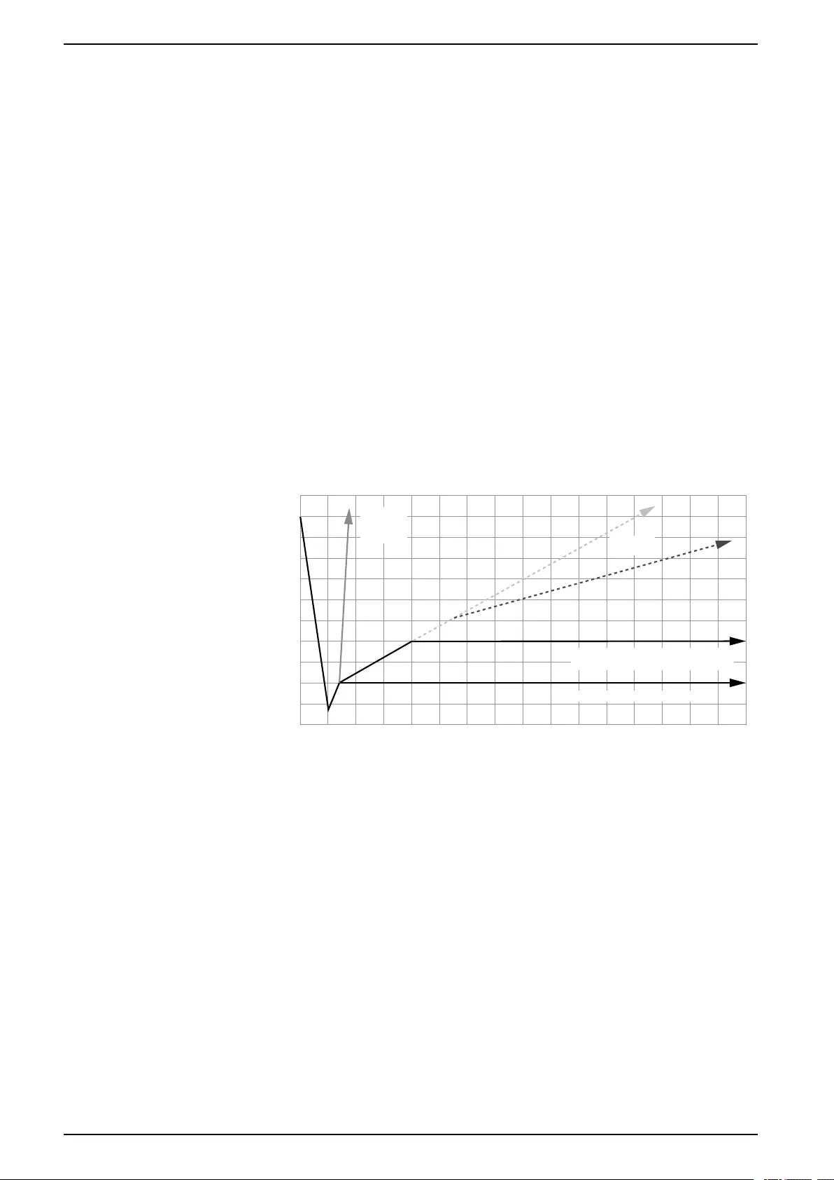
6. See the chart below for examples of different conditions that may be
encountered during the final evacuation.
-1 0 1 2 3 4 5 6 7 8 9 10 11 12 13 14 15
0
500
1000
1500
5500
5000
4500
4000
3500
3000
2500
2000
VACUUM (MICRONS)
TIME (MINUTES)
LARGE
LEAKS
PRESENT LEAKS
PRESENT
GOOD VACUUM, CONDENSIBLES
PRESENT—WET SYSTEM
TIGHT VACUUM—DRY SYSTEM
na7210a
54 990-91229A-001 / 06MM0368@00B0110
Unit Connections Uniflair™UCF, MRA
Electrical Connections
WARNING
ELECTRICAL HAZARD
• Electrical service must conform to local and national electrical codes and
regulations.
• The equipment must be grounded.
Failure to follow these instructions can result in death, serious injury, or
equipment damage.
WARNING
ELECTRICAL HAZARD
Ensure that all electrical connections are unplugged before you introduce water
into the unit.
Failure to follow these instructions can result in death, serious injury, or
equipment damage.
WARNING
SHARP EDGES
When using power tools be sure to read and follow the rules that come with that
tool.
Failure to follow these instructions can result in death, serious injury, or
equipment damage.
NOTICE
HAZARD FROM SHARP EDGES
• Edges of the knock-out panel may be sharp.
• Use a grommet, bushing, or other protective covering for the section of
power cable routed through the knock-out panel.
Failure to follow these instructions can result in equipment damage.
Power Supply
NOTICE
EQUIPMENT DAMAGE
Power supply cables must conform to local and national electrical codes and
regulations.
Failure to follow these instructions can result in equipment damage.
Power supply cables are field supplied and must be sized by the installer.
The power cable must be selected according to the following conditions:
• The length and type of laying
• The maximum current absorbed by the conditioning unit
Power Connections
1. Check that the mains voltage and frequency correspond to those of the unit.
Compare them with the nameplate inside the electric panel.
990-91229A-001 / 06MM0368@00B0110 55
Uniflair™UCF, MRA Unit Connections
The power cables (and the control circuit cables) can pass through the pre-
drilled holes on the unit.
2. Open the door of the electrical panel and perform connections as indicated in
the wiring diagram attached to the documentation of the unit.
3. Tighten the screws.
See the installation drawings included with the unit for more
information.
Indoor Units
Q1
L1
L2
TO GROUND
UCF0341I
UCF0481I
11 5
na7092a
Outdoor Units
Q1 Q1
L1 L2 L1 L2
L3
TO GROUND
TO GROUND
MRA0221I MRA0611D
2626
4
na7093a
56 990-91229A-001 / 06MM0368@00B0110
Unit Connections Uniflair™UCF, MRA
Electrical Data
Indoor Units
Overall Unit
Model UCF0341I UCF0481I
Voltage 208 V, 1 Ph, 60 Hz
230 V, 1 Ph, 60 Hz
FLA (A) 3.0 4.5
MCA (A) 4.5 6.4
MOP (A) 15 15
FLA: Full Load Amps
MCA: Minimum Circuit Amps
MOP: Maximum Overcurrent Protection
Fans
Model UCF0341I UCF0481I
Quantity 2 3
FLA (A) 1.5 1.5
FLA: Full Load Amps
Outdoor Units
Overall Unit
Model MRA0221I MRA0611D
Voltage 208 V, 1 Ph, 60 Hz
230 V, 1 Ph, 60 Hz
208 V, 3 Ph, 60 Hz
230 V, 3 Ph, 60 Hz
FLA (A) 16.4 23.1
MCA (A) 19.6 27.0
MOP (A) 30.0 40.0
FLA: Full Load Amps
MCA: Minimum Circuit Amps
MOP: Maximum Overcurrent Protection
Compressor
Model MRA0221I MRA0611D
Quantity 1 1
LRA (A) 64.0 110.0
RLA (A) 12.8 15.9
LRA: Locked Rotor Amps
RLA: Rated Load Amps
990-91229A-001 / 06MM0368@00B0110 57
Uniflair™UCF, MRA Unit Connections
Axial Fans
Model MRA0221I MRA0611D
Quantity 1 2
FLA (A) 3.6 3.6
FLA: Full Load Amps
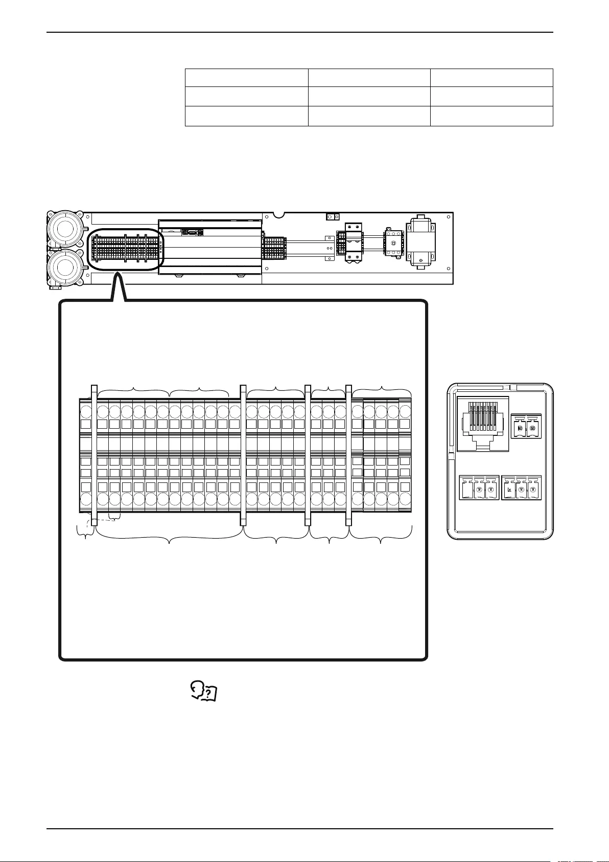
Communication Connections
`
PE
L1
L2
1313
0
24
24
1601
1311
1312
1314
1502
1511
0213
0214
CHG
0210
0219
0220
0221
CHG
0204
0215
CHG
24VDC
5057
5059
24
24
0
0
CHG
CHG
CHG
24
CHG
DGND
F2
T1
Q1
F1
PE
TB2F2
PLC1
TB3
PFS
FS
TB1
na7089a
SMOKE/FIRE
SENSOR INPUT
CONDENSING UNIT
CONNECTIONS
(TO TB02 IN
OUTDOOR UNIT)
OUTDOOR
TEMPERATURE/HUMIDITY
SENSOR
REMOTE
TEMPERATURE
SENSOR
REMOTE DISPLAY
CONNECTIONS
6 CONDUCTOR,
18 AWG,
300 V MINIMUM
(CONTROL)
4 CONDUCTOR,
18 AWG,
300 V MINIMUM,
SHIELDED WITH DRAIN
(ANALOG)
2 CONDUCTOR,
18–22 AWG,
SHIELDED WITH DRAIN
(ANALOG)
4 CONDUCTOR,
18–22 AWG,
300 V MINIMUM,
SHIELDED WITH DRAIN
2 PAIR, 18–22 AWG,
SHIELDED WITH DRAIN,
120 OHM
CHARACTERISTIC
IMPEDANCE
CONNECTIONS ON
REMOTE DISPLAY
24VDC
CANL
CANH
D0-
D1+
COM
– +
J2
J4 MODBUS J5 CANBUS
J3
1313
0
24
24
1601
1311
1312
1314
1502
1511
0213
0214
CHG
0210
0219
0220
0221
CHG
0204
0215
CHG
24VDC
5057
5059
CHG
DGND
TB3
See the electrical schematics for more information.
58 990-91229A-001 / 06MM0368@00B0110
Unit Connections Uniflair™UCF, MRA
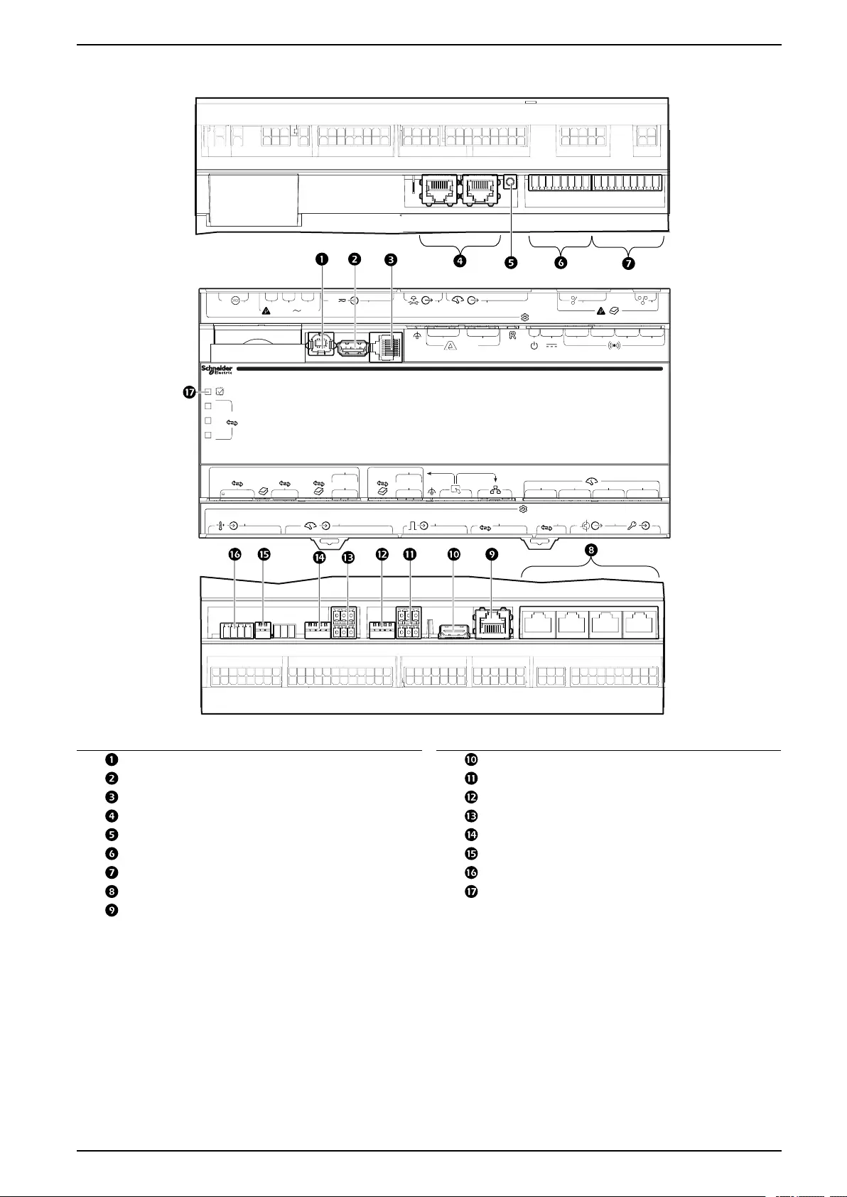
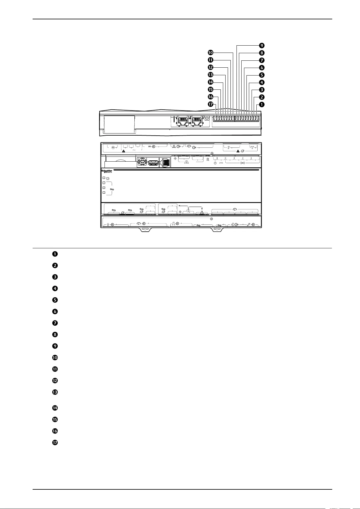
Interface Connections
J15
J9
24V
J10 J11 J12
100-240V
J13
24V
J14 J16 J17
123
NC COM NONC COM NONC COM NO
4
24V 12V 0V
– +
21 – Link
21
3 4
(1)
(2)
(3)
RS485
RS485 (1)
FIELDBUS
CAN
CANH CANL 0V D0- D1+ 0V
RS485 (2)
2W/4W D0- D1+ 0V
D0- D1+ 0V
TX
RX
RS485 (3)
2W/4W D0- D1+ 0V
D0- D1+ 0V
TX
RX
MODBUS NETWORK
12 3 4
J6
J5J4 CAN
RS485
J3J2J1
na6256b
Item Description Item Description
USB device port Touch screen display connection
USB host port Modbus connection
Serial port Modbus configuration switches
A-Link ports Fieldbus Modbus connection
Reset button Fieldbus Modbus configuration switches
Output relay 4/standby input Fieldbus CANbus configuration switches
Output relay 1–3 Fieldbus CANbus connection
Universal sensor ports Processor status LED
Network connection
990-91229A-001 / 06MM0368@00B0110 59
Uniflair™UCF, MRA Unit Connections
A-Link Ports
NOTICE
CAT 5 PINOUT
Devices connected on the A-Link ports should use a standard pin-out (1-1, 2-2,
3-3, 4-4, 5-5, 6-6, 7-7, 8-8) CAT5 cable only.
Failure to follow these instructions can result in equipment damage.
NOTE: All input and output connections should be wired as Class 2 circuits.
The A-Link bus connection allows a maximum group of twelve units to
communicate with one another.
To enable the units to function as a group, link them together using a standard pin-
out CAT-5 cable with RJ-45 connectors. The A-Link bus must be terminated at the
first and last unit installed in the group. See example below. An A-Link terminator
is supplied with the unit.
NOTE: The maximum wire length for the entire group must not exceed 305 m
(1,000 ft).
60 990-91229A-001 / 06MM0368@00B0110
Unit Connections Uniflair™UCF, MRA
Output Relays and Standby Input
na4400c
Item Name Description
Output relay 1 N.O. Normally Open contact
Output relay 1 COM Common contact
Output relay 1 N.C. Normally Closed contact
Output relay 2 N.O. Normally Open contact
Output relay 2 COM Common contact
Output relay 2 N.C. Normally Closed contact
Output relay 3 N.O. Normally Open contact
Output relay 3 COM Common contact
Output relay 3 N.C. Normally Closed contact
Output relay 4 N.O. Normally Open contact
Output relay 4 COM Common contact
Output relay 4 N.C. Normally Closed contact
Ground Ground reference, typically connected to the negative connection of
Standby Input, when using the 12 VDC or 24 VDC power supply.
12 VDC Standby input 12 VDC supply current limited to 20 mA
24 VDC Standby input 24 VDC supply current limited to 20 mA
Standby Input + Positive connection used for Standby Input
Standby Input – Negative connection used for Standby Input. Typically connected to
ground.
990-91229A-001 / 06MM0368@00B0110 61
Uniflair™UCF, MRA Unit Connections
Output Relays
Four output relays connections are available. These relays can be configured,
through the user interface, to various alarms detecting normal or abnormal
conditions.
Output relays are Form C type, having a Normally Open (N.O.), Normally Closed
(N.C.), and Common (COM) contacts.
NOTE: Output Relays are rated at 24 VDC, 0.6 A maximum.
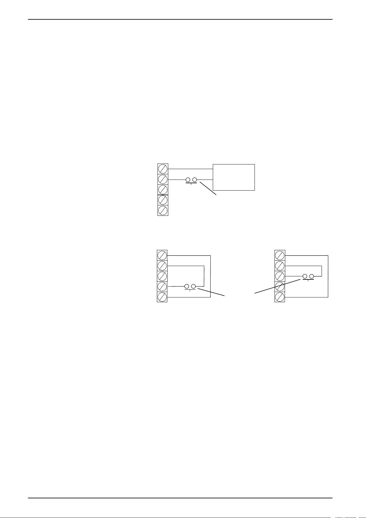
Standby Input
Standby input allows the cooling unit to be remotely placed in Standby mode.
Standby mode is configured through the user interface and can be set as a
normally “active” or “not active” input.
NOTE: Standby Input is rated at 12/24-V AC DC. If using field supplied
voltage, the Standby Input consumes 10 mA maximum at 24 VDC.
na4478a
EXTERNAL POWER SUPPLY
STANDBY
12-30 V AC/DC
SD–
SD+
24V_SD
12V_SD
GND
NOT USED
NOT USED
NOT USED
12–30V AC/DC
POWER SUPPLY
N.O. OR N.C.
CONTACTS
12V POWER SUPPLY 24V POWER SUPPLY
STANDBY
12-30 V AC/DC
STANDBY
12-30 V AC/DC
N.O. OR N.C.
CONTACTS
SD–
SD+
24V_SD
12V_SD
GND
SD–
SD+
24V_SD
12V_SD
GND
NOT USED
NOT USED
*Normally open contacts shown.
62 990-91229A-001 / 06MM0368@00B0110
Unit Connections Uniflair™UCF, MRA
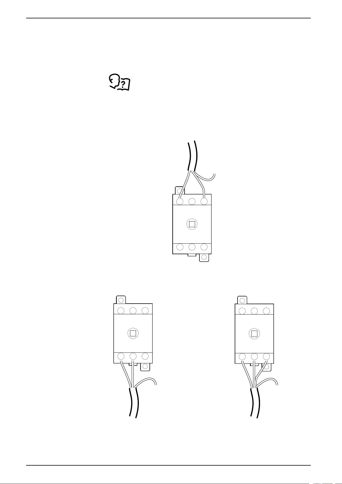
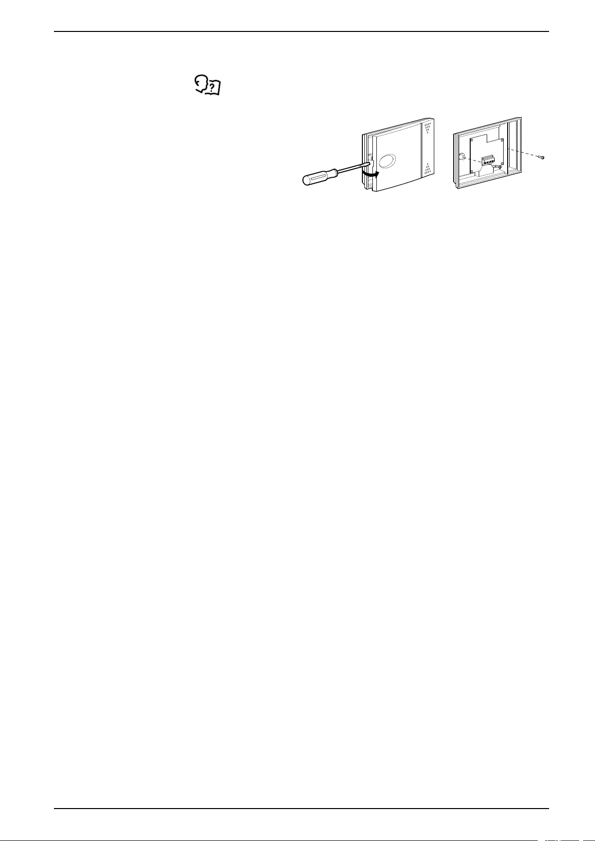
Temperature Sensor
See unit wiring diagrams for more information.
1. Insert a
screwdriver in the
slot and release
the front cover of
the sensor.
2. Remove the lid
and fasten the
screws inside the
sensor to the
mounting
location.
3. Connect the
shielded cable to
the two terminals
on the sensor,
using the
electrical diagram
in the unit as
reference.
na4730a
990-91229A-001 / 06MM0368@00B0110 63
Uniflair™UCF, MRA Charging the Refrigeration System
Charging the Refrigeration System
Calculating R410A Charge
To calculate the initial charge requirement of the equipment, see the piping plan
layout for the actual lengths of the equipment line-set.
See Refrigerant Piping, page 50 for more information.
Verify that the actual piping matches the planned layout. If necessary, measure
the actual lengths of piping used for traps and loops to get the total pipe length.
Using the table below, find the installed liquid and suction line sizes and look up
the R410A multiplier for your application. The table provides the amount of
R410A, in ounces per foot for different combinations of suction and liquid line
sizes (ACR tubing only). Multiply the value in the table by the length of the line-set
to provide the total ounces of R410A for the line-set.
Line-Set Charge Adjustment, Initial Charge,
Ounces of R410A/Foot (Grams of R410A/Centimeter)
Liquid Line Size
Suction Line Size 3/8 in. ACR 1/2 in. ACR
3/4 in. ACR 14.0 g (0.62 oz) N/A
7/8 in. ACR 18.7 g (0.66 oz) 32.3 g (1.14 oz)
1-1/8 in. ACR 20.9 g (0.74 oz) 34.5 g (1.22 oz)
Charge amount is based on the actual line-set length.
Look up the equipment charge in the table. A standard line-set is sized to the
service valve sizes of the equipment.
Initial R410A Charge Weight Calculation
Unit Indoor and Outdoor Units Only Charge
UCF0341I
MRA0221I
2.5 kg (5 lb 10 oz)
UCF0481I
MRA0611D
4.9 kg (10 lb 15 oz)
NOTE: Always verify the equipment charge amount listed on the nameplates.
If the nameplate charge differs from that listed in these instructions, use the
nameplate value.
Add the “Indoor and Outdoor Units Only” charge amount to the calculated line-set
charge. This is the initial charge for the equipment before start-up.
Total charge = Outdoor Equipment charge + Indoor Equipment charge + Line-set
charge
See R410A Refrigerant Charging Charts, page 66.
64 990-91229A-001 / 06MM0368@00B0110
Charging the Refrigeration System Uniflair™UCF, MRA
Charging the Equipment
WARNING
HAZARD TO EQUIPMENT OR PERSONNEL
All work must be performed by Schneider Electric qualified personnel.
Failure to follow these instructions can result in death, serious injury, or
equipment damage.
CAUTION
HAZARD OF HIGH PRESSURE REFRIGERANT OR EQUIPMENT DAMAGE
• Use R410A refrigerant only.
• The unit display should be used to obtain pressure readings.
Failure to follow these instructions can result in injury or equipment
damage.
NOTICE
DAMAGE TO EQUIPMENT OR PERSONNEL
POE oil is highly hygroscopic and can attract more moisture from surroundings
and the atmosphere. Do not use any POE oil that has been left in an unsealed
or improperly sealed container for any length of time. This could lead to
problems with the equipment or lead to acid formation in the equipment.
Failure to follow these instructions can result in equipment damage.
Before installing the initial refrigerant charge always complete a system
evacuation.
See Connect Refrigerant Lines, page 52 for more information.
When first commissioning a system, weight in the calculated, initial refrigerant
charge before equipment start-up. If a POE oil charge is also required, charge the
oil before equipment startup. Charge with oil through any of the service ports on
the discharge line located in the outdoor unit. Always use a high quality POE oil
approved for use by the compressor manufacturer. These units should use
Copeland Ultra 32-3MAF, Copeland Ultra22 CC, or an approved equivalent.
See Calculating R-410A Charge, page 64 for details on calculating the
initial charge amount.
After the initial refrigerant and oil charge (if necessary) has been weighted in, the
equipment may be started if all other install steps are completed. Always verify the
equipment charge upon startup with the charging chart provided in these
instructions. If the equipment does not meet the charging chart requirements,
adjust the equipment charge in accordance with the instructions on the charging
chart.
990-91229A-001 / 06MM0368@00B0110 65
Uniflair™UCF, MRA Charging the Refrigeration System
Compressor Oil Charge
Oil Charging Procedure
NOTICE
DAMAGE TO EQUIPMENT
Do not charge the compressor with too much oil: compressor damage could
result. The only way to drain oil from the compressor is to remove the
compressor from the equipment. The following system damage could also
occur:
• Failure of valves and pistons due to oil slugging.
• Excessive oil carryover.
• Loss of evaporator performance due to oil level build-up in the low-pressure
side of the system.
Failure to follow these instructions can result in equipment damage.
Calculating POE Oil Charge
If the total R410A refrigerant charge for the system exceeds 9 kg (20 lb), use the
chart to determine the appropriate POE oil charge required.
Final System
R410A Charge
9–11 kg
(20–25 lb)
11–13 kg
(25–30 lb)
13–16 kg
(30–35 lb)
POE Oil Addition
Requirements
0.02 kg (1 oz) 0.06 kg (2 oz) 0.08 kg (3 oz)
R410A Refrigerant Charging Charts
CAUTION
HAZARD OF HIGH PRESSURE REFRIGERANT OR EQUIPMENT DAMAGE
• Use R410A refrigerant only.
• Contents are under pressure: use caution when releasing pressure in the
system or refilling.
• Charging and maintaining the refrigeration circuit must only be performed by
qualified personnel.
Failure to follow these instructions can result in injury or equipment
damage.
The equipment comes factory supplied with a dry nitrogen holding charge.
The unit charging charts shown below are only intended to be used with the listed
indoor and outdoor equipment matches as shown in the titles of the charts
(MRA0611D and UCF0481I) and (MRA0221I and UCF0341I) and should not be
used for any other equipment.
The charging charts are only intended for final verification of the unit charge.
When first commissioning a unit during installation, always weigh in the proper
equipment charge to the listed nameplate value plus the proper line-set
adjustment.
See the previous sections of this Installation Manual for additional
details.
66 990-91229A-001 / 06MM0368@00B0110
Charging the Refrigeration System Uniflair™UCF, MRA
Do not operate a compressor system that has a serious undercharge condition for
more than 60 seconds.
Ensure that the TXV in the indoor unit has been properly adjusted prior to starting
the unit.
See Thermostatic Expansion Valve Adjustment, page 69.
Before using the charging charts below, ensure that the compressor circuit is
energized and operating stably. If the system has not been running or requires the
technician to start it up, allow the equipment to operate for at least 10 minutes
before using the charts for charge adjustment.
These charts are valid for a wide variety of indoor and outdoor temperature ranges
and unit loads however, for best results, the ambient temperature should be in the
range of 15.5; 37.7°C (60–100°F) with the outdoor fan(s) operating at 100% and
the indoor unit return air temperature should be between 21.1–26.6°C (70–80°F)
with the rated IT air flow rate.
Do not allow the outdoor unit fans to vary their speed when using these charts to
inspect the charge. Use the maintenance menu commands to lock the outdoor
fans to 100% speed, evaporator fan speed set to the rated IT air flow rate of the
unit, and the compressor ON for the duration of the inspection and charge
adjustment period.
If the installed equipment is operating with an extreme under-voltage condition, do
not use these charts for charge adjustment until after the under-voltage condition
has been corrected. Ensure the required clearances for proper operation are
satisfied, the condenser coil is clean, and the condenser fan is operating at full
load.
How to Use R410A Refrigerant Charging Charts
1. Use quality instruments, measure the liquid line pressure and temperature at
the outdoor unit service port.
2. Find the measured liquid pressure on the bottom axis and follow it up to the
equipment charging line.
3. Read the corresponding liquid temperature from the charging chart and
compare to the measured value.
4. If the measured temperature value is larger than the chart value, add charge
to the equipment. If less, remove charge from the equipment.
5. After charge adjustment, collect new measurements and repeat steps 1–4 as
necessary.
6. Adjust the equipment charge until the measured values are either on the line
or that the measured liquid line temperature is no more than 0.6°C (1.0°F)
lower than the chart value for the measured liquid pressure.
7. Record the final refrigerant system charge in the service documentation for
future reference.
When using these charts to inspect a system that has been in operation for some
time, follow these guidelines:
• If the measured liquid temperature is more than 1.1°C (2.0°F) higher than the
chart value for the measured liquid pressure, inspect the system for leaks.
• When repairing system leaks, always use a dry nitrogen or other inert gas to
protect the system piping.
• Always replace the refrigerant filter-drier when repairing refrigerant piping
systems or exposing the piping system to moist air.
• Once all repairs are complete, perform a pressure test on the system, then
evacuate the system to 350-500 microns and weight in the proper refrigerant
charge based on the unit nameplate and line-set adjustment.
990-91229A-001 / 06MM0368@00B0110 67
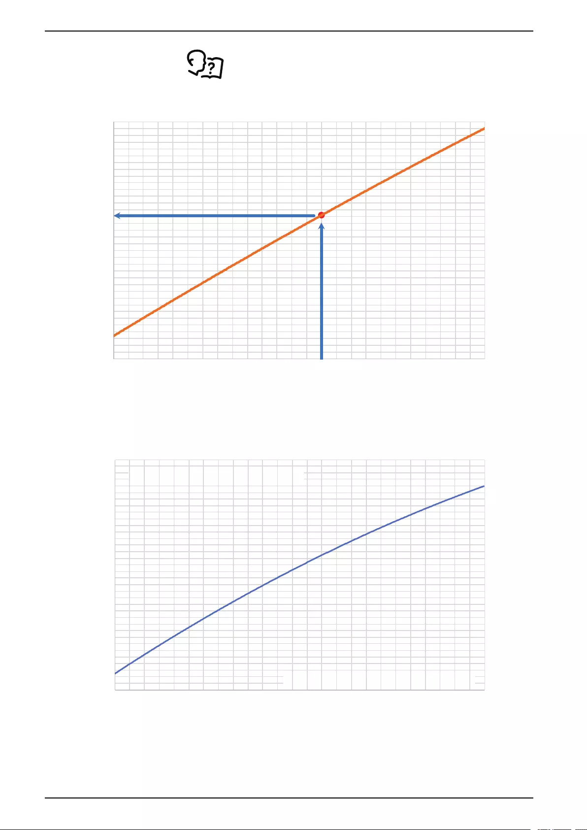
Uniflair™UCF, MRA Charging the Refrigeration System
See the installation instructions included with the unit before use.
50
52
54
56
58
60
62
64
66
68
70
72
74
76
78
80
82
84
86
88
90
92
94
96
98
100
102
104
106
108
110
112
114
116
118
120
200 210 220 230 240 250 260 270 280 290 300 310 320 330 340 350 360 370 380 390 400 410 420 430 440 450
LIQUID TEMP (°F)
LIQUID PRESSURE (PSIG)
LIQUID DATA CHARGING CHART EXAMPLE
na7047a
R410A Refrigerant Charging Chart for MRA0221I and UCF0341I
50
52
54
56
58
60
62
64
66
68
70
72
74
76
78
80
82
84
86
88
90
92
94
96
98
100
102
104
106
108
110
112
114
116
118
120
200 210 220 230 240 250 260 270 280 290 300 310 320 330 340 350 360 370 380 390 400 410 420 430 440 450
MRA0221 AND UCF0341
LIQUID TEMP (°F)
LIQUID PRESSURE (PSIG)
ADD CHARGE WHEN ABOVE LINE
REMOVE CHARGE WHEN BELOW LINE
na7046a
68 990-91229A-001 / 06MM0368@00B0110
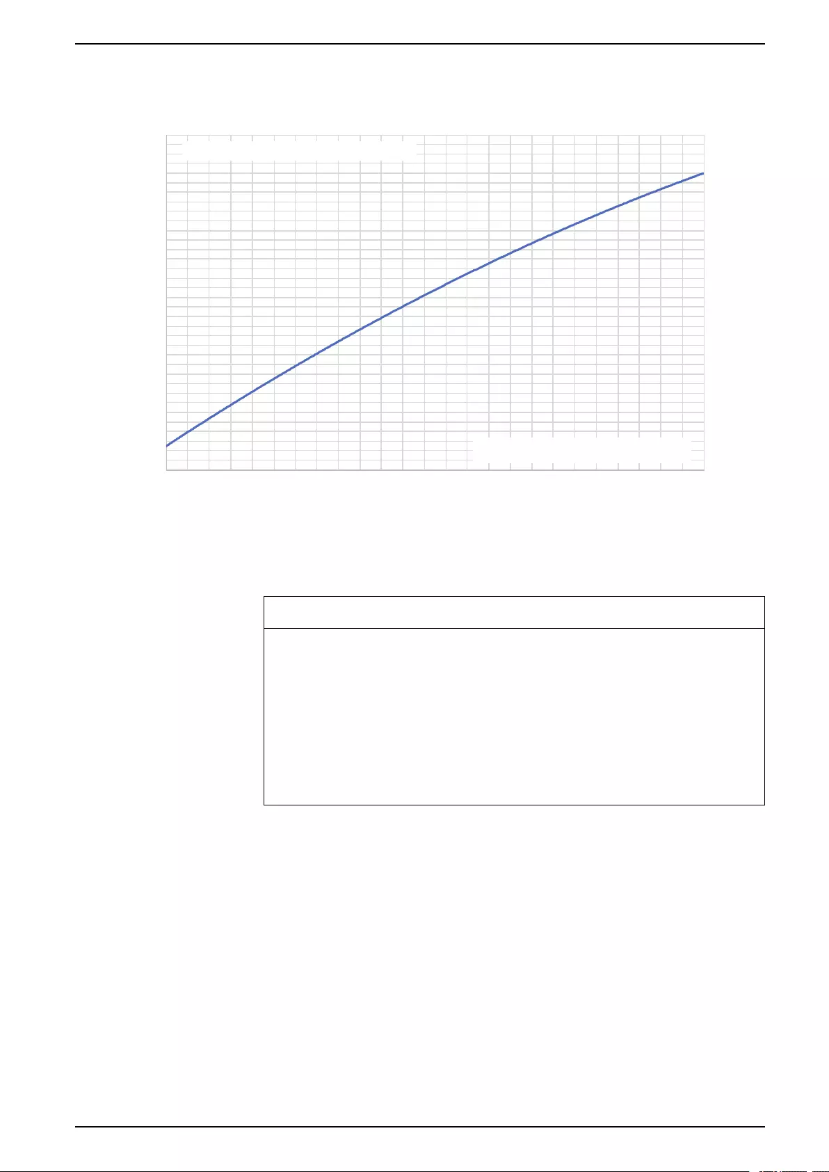
Charging the Refrigeration System Uniflair™UCF, MRA
R410A Refrigerant Charging Chart for MRA0611D and UCF0481I
50
52
54
56
58
60
62
64
66
68
70
72
74
76
78
80
82
84
86
88
90
92
94
96
98
100
102
104
106
108
110
112
114
116
118
120
200 210 220 230 240 250 260 270 280 290 300 310 320 330 340 350 360 370 380 390 400 410 420 430 440 450
MRA0611 AND UCF0481
LIQUID PRESSURE (PSIG)
ADD CHARGE WHEN ABOVE LINE
REMOVE CHARGE WHEN BELOW LINE
LIQUID TEMP (°F)
na7045a
Thermostatic Expansion Valve Adjustment
NOTICE
DAMAGE TO THERMOSTATIC EXPANSION VALVE
• Always read through the entire set of instructions and warnings provided
before starting the task.
• Always use a backup wrench on the TXV packing nut when removing or
installing the adjustment stem cap.
• Never apply excess torque to the adjustment stem of the TXV. Only a light
pressure is required to make an adjustment to the TXV setting. If the stem
does not turn under a light pressure, the adjustment has reached its stop.
Failure to follow these instructions can result in equipment damage.
The equipment has been provided with adjustable, balanced port, thermostatic
expansion valves (TXVs). These valves come factory-supplied with the
adjustment stem positioned near the middle of their travel and are required to be
adjusted to the proper position for each unit before start-up.
990-91229A-001 / 06MM0368@00B0110 69
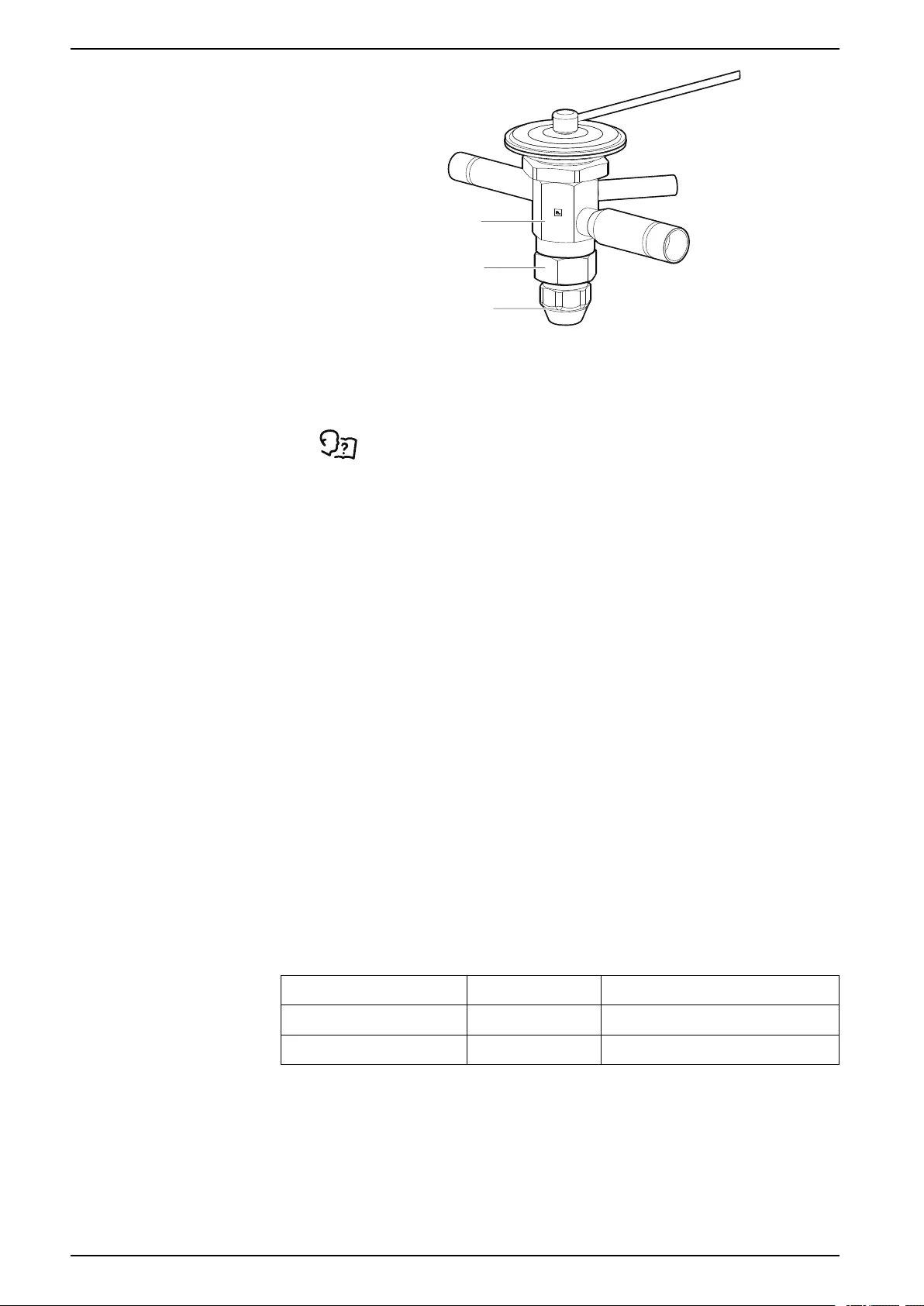
Uniflair™UCF, MRA Charging the Refrigeration System
TXV BODY
TXV PACKING
GLAND NUT
TXV ADJUSTMENT
STEM CAP
na7208a
The table provides information on the proper setpoint for the TXV for each unit.
1. To apply the initial adjustment to the valve, open the lower access door and
remove the service panel.
See Indoor Units, page 41 for more information.
2. Place a back-up wrench onto the TXV packing nut and remove the
adjustment stem cap.
3. Once exposed, open the TXV fully by turning the adjustment stem (as viewed
when looking at the stem) until the end-stop has been reached.
4. Count the number of full revolutions that is required to open the valve to the
stop.
5. If desired, mark one of the four corners on the adjustment stem with a
permanent marker and use it as a reference for the adjustment.
NOTE: As a general rule a TXV has approximately 9 full turns of
adjustment from full closed to full open. The manufacturer sets the air
pressure near the center of their adjustment but that is not necessarily the
exact halfway point of the available travel.
6. Once the valve has been adjusted to the full open position, close the valve by
turning to the right by the number of full turns noted in the table for the
applicable unit.
7. Once complete, replace the adjustment cap back onto the TXV and thread by
hand until hand tight.
8. Place the backup wrench on the packing nut, and tighten the adjustment cap
by turning it 60 degrees past hand-tight.
Do not over-tighten the cap.
9. Record the TXV adjustment setting used on the inside of the side access
panel.
10. Close the unit access doors and replace the access panels.
Unit TXV Initial Setting*
UCF0341I BBIZE-1.5-GA 3.5 turns closed from full open
UCF0481I BBIZE-3-GA 0.5 turns closed from full open
*1 turn = 360 degrees
70 990-91229A-001 / 06MM0368@00B0110

Worldwide Customer Support Uniflair™UCF, MRA
Worldwide Customer Support
Customer support for this or any other product is available at no charge in any of
the following ways:
• Visit the Schneider Electric Web site to access documents in the Schneider
Electric Knowledge Base and to submit customer support requests.
-www.schneider-electric.com (Corporate Headquarters)
Connect to localized Schneider Electric Web sites for specific countries, each
of which provides customer support information.
-www.schneider-electric.com/support/
Global support searching Schneider Electric Knowledge Base and using
esupport.
• Contact the Schneider Electric Customer Support Center by telephone or e-
mail.
Local, country-specific centers: go to www.schneider-electric.com/support/
contactwww.schneider-electric.com > Support > Operations around
the world for contact information.
For information on how to obtain local customer support, contact the
representative or other distributors from whom you purchased your product.
990-91229A-001 / 06MM0368@00B0110 71

Schneider Electric
35 rue Joseph Monier
92500 Rueil Malmaison
France
+ 33 (0) 1 41 29 70 00
www.schneider-electric.com
As standards, specifications, and design change from time to time,
please ask for confirmation of the information given in this publication.
© 2018 – 2019 Schneider Electric. All rights reserved.
990-91229A-001 / 06MM0368@00B0110