Table of Contents
APC Smart-UPS User Manual
Displayed below is the user manual for Smart-UPS by APC which is a product in the Uninterruptible Power Supplies (UPSs) category. This manual has pages.
Related Manuals

Operation Manual
Smart-UPS™
Uninterruptible Power Supply
Rack -Mount 1U
1200/1500 VA
100/120/230 Vac

1Smar t- UPS 1200 VA 100 Vac Rack-Mount 1U / 1500 VA 120/230 Vac Rack-Mount 1U
Product Description
The APC™ by Schneider Electric Smart-UPS™ is a high performance uninterruptible power supply
(UPS). The UPS provides protection for electronic equipment from utility power blackouts, brownouts,
sags, and sur ges, small utility power fluctuations and large disturbances. The UPS also provides batte ry
backup power for connected equipment until utility power returns to safe levels or the batterie s are fully
discharged.
This user manual is available on the enclosed CD and on the APC by Schneider Elect ricWeb site,
www.apc.com.
Important Safety Messages
The addition of thi s sym bol to a Caution product safet y label indicates tha t a haz ard exist s that can
result in injury and product damage if t he ins tructions are not followe d.
The following safety messages may appear throughout this manual to warn of potential hazards.
Saf ety and General Information
Inspect the package co ntents upon receipt. Notify th e carrier and dealer if there is any
damage.
Read the Safety Guide supplied with this unit before installing the UPS.
• Adhere to all national and local electrical codes.
• This UPS is intended for indoor use only.
• Do not operate this UPS in direct sunlight, in c ontact with fluids, or where there is excessive dus t
or humidity.
• Be sure the air vents on the UPS are not blocked. Allow adequate space for proper ventilation.
• The battery typically lasts for three to five years. Environmental factors impact battery life .
Elevated ambient t empera tures, poor quality uti lity power, and f requent short duration di scharge s
will shorten battery lif e.
• Connect the UPS power cable dire ctly to a wall outlet. Do not use surge protectors or extension
cords.
• The batteries are heavy. Remove the batteries prior to installing the UPS in a rack.
CAUTION
CAUTION i ndicates a potentially hazardous situation which, if not av oided, ca n res ult in equipment damage and minor or
modera te injury.
CAUTION
CAUTION indicates a potentially hazardous situation which, if not avoide d, can result in equi pmen t da ma ge.

Smart-UPS 1200 VA 100 Vac Rack-Mount 1U / 1500 VA 120/230 Vac Rack-Mount 1U 2
Specifications
For additional speci fications, refe r to the APC by Schneid er Electric Web site at www.apc.com.
Weight
Specifications
UPS + Bat tery P a ck Batt ery Pa ck
24 kg (53 lb) 10.5 kg (23 lb)
Temperature
Operating 0° to 40° C (32° to 104° F)
Storage -15° to 45° C (5° to 1 13° F)
charge UPS batte r y eve r y s ix mon ths
Maximum
Elevation
Operating 3,000 m (10,000 ft)
Storage 15,000 m (50,000 ft)
Humidity 0% to 95 % rel ative humidity,
non-condensing 0° to 40° C (32° to 104° F)
Battery
Mai n tenance free, sealed lea d acid
UPS model Replacement Battery Pack
SMT1200RMJ1U
SMT1500RM1U
SMT1500RMI1U
APCRBC88J
APCRBC88
APCRBC88
Rep lac e us ed ba tt er i es w it h APC by Sch n eider El ectric app r ov e d bat te r ies.
To order a repla cement battery go to the APC by Schne ider E lectric Web s ite, www.apc.c om.
Always recycle used batteries.
For in formation on recycling a use d b attery, refer to th e Batt er y Disposal I n form ation sheet
included with the replacement battery .
3Smar t- UPS 1200 VA 100 Vac Rack-Mount 1U / 1500 VA 120/230 Vac Rack-Mount 1U
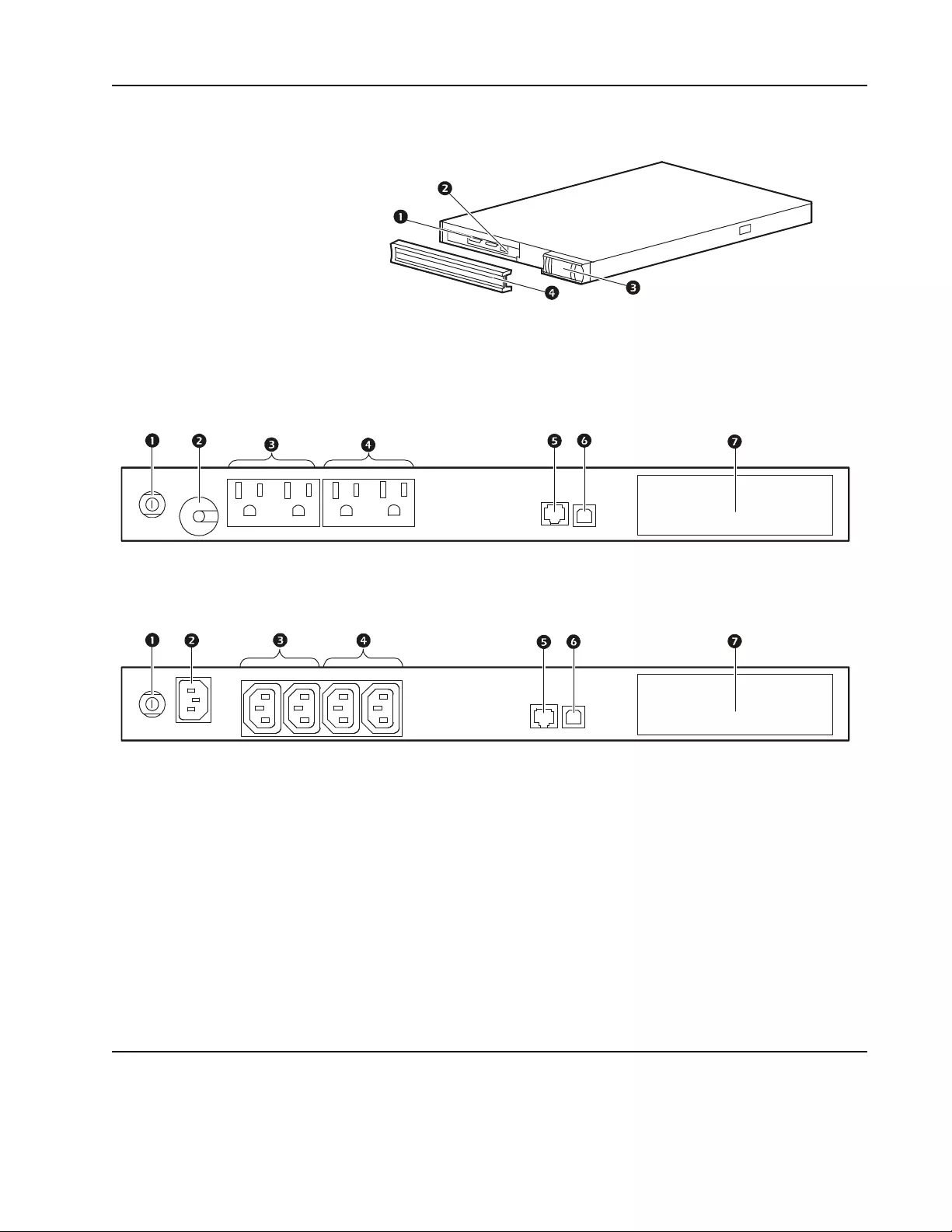
Product Overview
Front panel features
Rear panel features
Installation
For UPS installation information, refe r to the Smart-UPS 1200/1500 VA 100/120/230 Vac
Rack-Mount 1U Inst al lation Gu ide tha t is incl uded with t he UPS. The I nstall ation Guide is also avai lable
on the Documentation CD included with the UPS and on the APC by S chneider Electric Web site,
www.apc.com.
1Battery
2Battery connector
3Display interface
4Bezel
1200/1500 VA 100/120 Vac
1500 VA 230 Vac
1Circuit breaker/Overload protection
2UPS input
3Controlled outlet gr oup 1
4Controlled outlet gr oup 2
5RJ45 connector - seria l UPS monitoring port
6USB port
7SmartSlot for optional accessory card
su0697a
su0699bsu0699c
Smart-UPS 1200 VA 100 Vac Rack-Mount 1U / 1500 VA 120/230 Vac Rack-Mount 1U 4
Operation
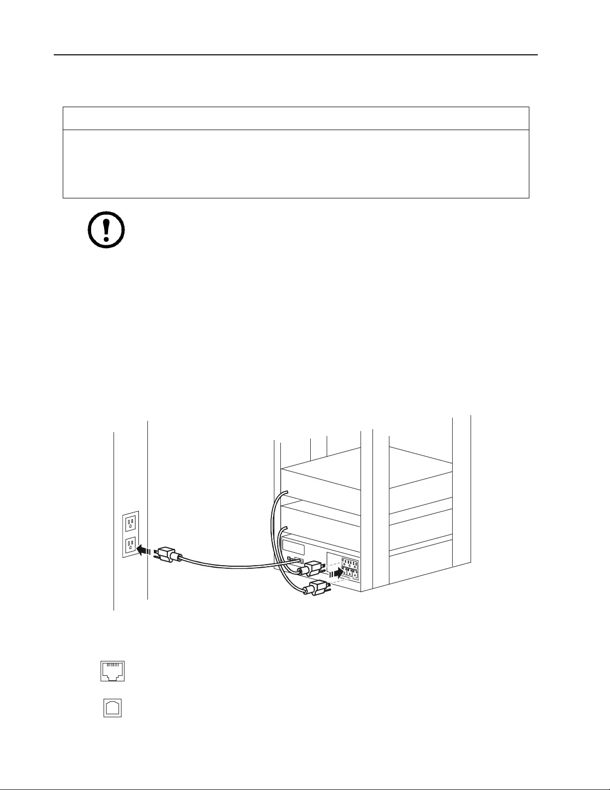
Connect Equipment
Note: The UPS will charge to 90% capacity in the fir st three hour s of normal operation. Do
not expect full battery runtime capabi lit y du ring this initial charge per iod.
1. Connect equipment to the outle ts on the rear panel of the UPS.
2. Connect the UPS to the building utility powe r. Connect the UPS to a two pole, three wire,
grounded so urce onl y.
3. To use the UPS as a MASTER ON/OFF switch, turn on equipment tha t is connected to the UPS.
4. To tur n on the UPS a nd all co nnected equipment press the ON/OFF button on the front panel of the
UPS.
5. Refer to “Switched Outlet Groups” on page 10 for information on switched outlet group
configuration.
Outlet type and location may vary.
Rear panel features
CAUTION
RISK OF EQUIPMENT DAMAGE
• Adhere to a ll local and national ele ctrical codes.
• W iring shoul d be pe rformed by qualified electrician.
• Always connect the UPS to a grounded outlet.
Failure to follow these instructions can res ult in equipme nt damage
Serial port: Connect a computer to use power manag ement software.
USB port: Conn ec t a computer to use power mana gement software.
su0628a
5Smar t- UPS 1200 VA 100 Vac Rack-Mount 1U / 1500 VA 120/230 Vac Rack-Mount 1U
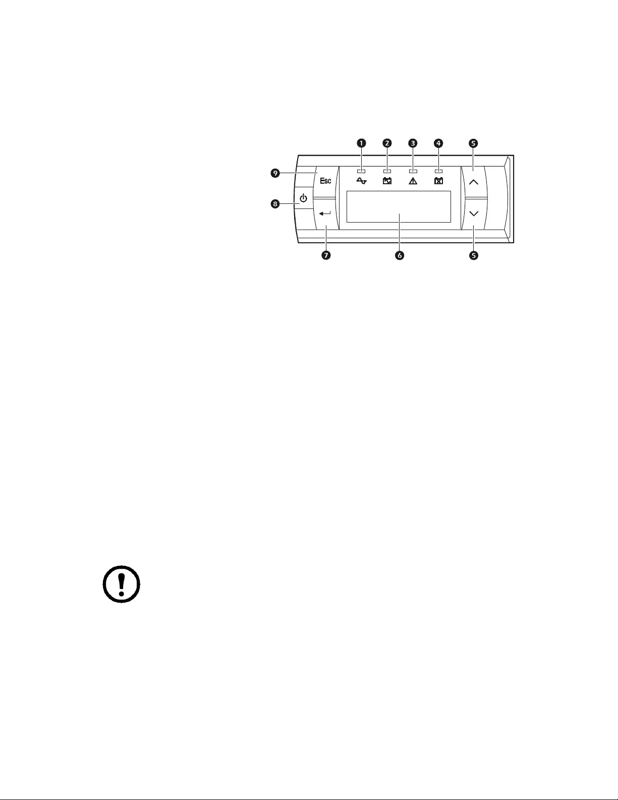
Display Panel
Overview
Display interface operation
Press either the ESC or ENTER buttons to acces s the main menu.
Use the UP/DOWN ar row buttons to scroll through menu options.
Press ENTER to view sub menus. Scr oll through the list of options. Press ENTER to select an option .
Press ESCAPE to exit a sub menu and return to a main menu.
Menu overview
The display interface has Standard and Advanced menu screens. The pref erenc e for Standard or
Advanced menu options i s made during initial installation and can be changed at any time using the
Configuration menu.
Standard menus are the most commonly used menus. The default sc reen shows Load and Battery
Capacity bar graphs.
The Advanced menus include more status information and additional sub menus. The default screen
shows scrolling status information.
Note: Actual menu scree ns may differ by model and firmware revision.
1Online LED
2On Battery LED
3Fault LE D
4Replace Battery LED
5UP/DOWN arrow buttons
6Display scre en
7ENTER button
8UPS ON/OFF button
9ESCAPE button
su0701a

Smart-UPS 1200 VA 100 Vac Rack-Mount 1U / 1500 VA 120/230 Vac Rack-Mount 1U 6
Main Menu Display Description Standard Option Advanc ed Op tion
Status
* Advanc ed menu Statu s
items displayed as
scrolling information
Operating m ode* x x
Efficiency x x
Load power (W)* x x
Load power (VA)* x x
Load amperage x
Load energy meter x
Batt er y cha r ge st ate% x x
Battery runtime* x x
Battery voltage x x
Battery temperature x
Input voltage and frequency* x x
Output voltage and frequency* x x
La st t r ansfer reason* x x
La st UP S self test result x x
Outlet group status* x
NMC IP address (if app licable) x
Control UPS control x
Outlet Group control x
Configuration Language x x
Output voltage setting (if applicable) x
Power qu ality x x
Menu type x x
Au dibl e al arms x x
Display mode x x
Sensitivity x
Low volta ge transfer points x
High voltage transfer points x
Low batter y warnin g thr es hold x
Automatic self test interval x
Battery install date x x
Reset energy meter x
Enter se t-up wizard x
Perform firmware update
(UPS output must be off) x
Reset to factory defaults x x
Outlet group configuration x
NMC configuration (if applicable) x
Test & Diagnostics UPS self test x x
UPS alarms test x x
UPS calibration test x x

7Smar t- UPS 1200 VA 100 Vac Rack-Mount 1U / 1500 VA 120/230 Vac Rack-Mount 1U
Logs Last 10 transfer events (if applicable) x
Last 10 fault events ( if app licable) x
About Model id entific ation x x
Part number x x
Serial number x x
UPS manufacture date x x
Replace battery part number x x
Battery insta ll date x x
Replace b atte ry date x x
UPS firm ware re vision x x
NMC Information - part/serial/v ersion
numbers/m anu factu re da te/MA C
addres s/ firmware revision
(if applicable)
x
Main Menu Display Description Standard Option Advanced Option

Smart-UPS 1200 VA 100 Vac Rack-Mount 1U / 1500 VA 120/230 Vac Rack-Mount 1U 8
Configuration
UPS Settings
Start up settings
At initial start up use the Setup Wizard to configure the following settings.
Function Factory Default Options Description
Language
English • English
•French
•German
• Spanish
• Italian
•Portuguese
• Japanese
The language for the display interface.
Lan guage options will vary by model.
Outpu t Voltage
230 Vac models only
230 Va c • 220 Vac
• 230 Vac
• 240 Vac
UPS output must be off to configure this setting.
Local Power Quality
Good • Good
•Fair
• Poor
Select the desired utility input power quality.
• Good: The UPS will go on battery power more
of ten to provide the cleanest power supply to
connected equipm ent.
• F ai r : Th e U P S w ill tol e r a te so me volta g e
fluctuations before switching to battery power.
• Poor: The UPS will tolerate more voltage
f luctuati ons and will go on batter y power le ss
often.
The Powe r Qu al ity setting will autom atically
change the high and low transfer points and the
transfer sensitivity setting.
Menu Type Standard • Standard
• Advanced The Advanced menus includ e al l para meters. The
Standard me nus display a limited set of menus and
options.
Date UPS manufacture date
+ 90 days mm-yyyy At initial start up, enter the c urrent date.

9Smar t- UPS 1200 VA 100 Vac Rack-Mount 1U / 1500 VA 120/230 Vac Rack-Mount 1U
General settings
Configure these settings at any time, using the display interf ace or Power Chute™ software.
Function Factory Default Option s Description
High Transfe r
Point
100 V ac models: 108
Vac
120 V ac models: 127
Vac
230 V ac models: 253
Vac
100 Vac models:
108-114 Va c
120 Vac models:
127-136 Vac
230 Vac models:
242-276 Vac
To av oid unnece ssary battery us age, the high and
low transfer points can be adjusted.
• Set the tra nsfer po int hig her if the A C voltag e is
chronically high.
• Set the transf er point lower if the AC volta ge is
chronically low.
When the Power Qu a l ity sett ing is changed the
high and lo w transfer point s wi ll automatic al ly be
adjusted.
230 Vac models only: The transfer point options
will cha nge based on the output voltage setti ng.
Low Tra nsfer
Point
100 Vac models :
92 Vac
120 Vac models:
106 Vac
230 Vac models:
207 Vac
100 Vac models:
86-92 Vac
120 Vac models:
97-106 Vac
230 Vac models:
186-216 Vac
Tran sfe r S ens it i v it y
Normal • Normal
• Reduced
•Low
Set th e se nsiti vit y t o a le vel tha t is a ppropr iate for
the connecte d equipment.
• Normal: The UPS will go on battery power
more often to provide the clea nest power supply
to t h e connecte d eq uipment.
• Reduce d : The UP S w il l to l er ate some vo l tag e
fluctuation s be fore sw itching to battery power.
• Low: The UPS will tolerate mor e voltage
fluctuations and will go on battery power less
often.
When the Power Qu a l ity sett ing is changed the
tr ansfer se nsitivity wil l automatically be
adjusted.
Low Runtime
Warning 120 sec Value set in seconds The UPS will emit a n audible alarm when the
remaining runtim e has rea ched this leve l.
Date of Last Battery
Replacement Dat e s et a t fac tory Reset t his date when the battery modul e is r eplaced.
Audible Alarm On • On
•Off T he UP S wil l mu te all au d ibl e ala rms if thi s is set
to Off or when any of the display buttons are
pressed.
Display Mode
Auto Dim • Always On
• Auto Dim
• Auto Off
• The display interface rem ains continuously
illuminated.
• The d ispla y inte rface i ll uminatio n wil l di minish
after two minutes of inactivity.
• T h e disp la y int er f a ce ill um ina ti o n wi ll
extinguish after two minutes of inactivity.
Auto Self-Test
Interval
On start up and 14
days after each
self-test.
• Last test + 14 days
• Last test + 7 days
• Start up+ 14 days
• Start up + 7 days
• On sta r t up only
•Never
The in terva l at wh i ch th e UP S wil l ex e c ute a
self-test.
The batteries must be c h arged to at l east 70%
cap aci ty to p erfo r m a self-test.
“Start up” on these menus refers to any time the
UPS is turne d on.
Reset to
Factory Default No • Yes
•No Restore the UPS fa ctory default settin gs.

Smart-UPS 1200 VA 100 Vac Rack-Mount 1U / 1500 VA 120/230 Vac Rack-Mount 1U 10
Switched Outlet Groups
Overview
The UPS has two Switched Outlet Groups. Each can be configur ed to independently per form the
following actions:
• Turn of f: Disconnect from power immedia tely and restart only with a manual command.
• Turn on: Connect to powe r im mediate ly.
• Shutdown: Disconnect power, and automaticall y reap ply power when utility power b ecomes
available.
• Reboot: Shut down and restart.
• Turn on or off in a speci fied sequence.
• Automatically turn off or shut down when various conditions occur.
Note: If the Switched Outlet Groups are not configur ed, all of the outlets on the unit will
provide battery backup powe r.
Confi gure the Switched O utlet Groups
1. Connect equipment to the Switched Outl et Groups.
– Nonessentia l equipment that sh ould s hut o ff qui ckly in the event o f a power outage to cons erve
battery runtime can be added to a short power off delay.
– If equipment has dependent peripherals t hat must re start or shut down in a specific order, suc h
as an e thernet switch that must restart before a conne cted server, connect the devices to
separate groups.
– Equipment that needs to reboot independently from other equipment should be added to a
separate group.
2. Use the Configurat ion menus to conf igure how the Switched Outl et Group will react in the e vent
of a power outage.

11Smart-UPS 1200 VA 100 Vac Rack-Mount 1U / 1500 VA 120/230 Vac Rack-Mount 1U
Customize Switched Outlet Groups
Use the Configuration menu to change the Switched Ou tlet Group settings.
Function Factory Default Options D escription
Turn On Delay 0 sec Set the value in
seconds The am ount of time the UPS or Switched Outlet
Group will wait betwe en re ceiving the com mand to
t u r n o n and th e actual startup.
Turn Off Delay 90 sec Set the value in
seconds The amount of time that the UPS or Switched Outlet
Group will wait betwe en re ceiving the com mand to
turn off and the actua l shut down.
Reboot Duration 8 sec Set the value in
seconds The amount of time that the UPS or Switched Outlet
Group must rem ain off before it will restart.
Minimum Return
Run Time 0 sec Set the value in
seconds The amount of battery runt ime that must be av ailable
before the UPS or Switched Outlet Group will turn
on.
Load Sh ed Time
On Battery Disabled • Enable
• Disable When the unit switches to battery power, the UPS can
disconnect power to the Switched Outlet Group to
sa ve runtime.
Load Sh ed Time
On Battery 1800 se c Set the value in
seconds The amount of time the Switche d Outlet Group will
continue func tion after the UPS begins operating on
battery.
Load Sh ed
Runtime Remain
Disabled • Enable
• Disable When the battery runtime falls below the specified
v alue, t h e Switch ed Outlet Group will turn o ff.
Load Sh ed
Runtime Remain 120 se c Set the value in
seconds Remaining runtime required for the outlets to stay on.
Load Shed on
Overload Disabled • Enable
• Disable In the event of an overload (greater than 100%
o utput), the Switched Ou tlet Group will imm ediately
t u r n o ff to con serve p o w er for criti cal loads. T h e
Swi tched Outlet Group will only tur n on again wit h a
manua l comman d.

Smart-UPS 1200 VA 100 Vac Rack-Mount 1U / 1500 VA 120/230 Vac Rack-Mount 1U 12
Troubleshooting
Proble m and Pos sib le Cause S olution
The UPS will not turn on or there is no output
The UPS has not been turned on. Press the ON button once to tur n on the UPS.
The UPS is not connected to utility power. Ensure that the power cab le is securely connected to the unit and to the utility
power supply.
The input circuit breaker has tripped. Reduce the load to the UPS, disconnect nonessential equipment and reset the
cir cuit breaker.
The unit shows very low or no input utility
voltage. Check the utility pow er supply to the UPS by plug ging in a table lamp . If the light
is very dim, check the utility voltage.
There is an internal UPS fault. Do not attempt to use the UPS. Unplug the UPS and have it serviced imm ediately.
The UPS is operatin g on ba ttery, while conn ected to utility p ower
The input circuit breaker has tripped. Reduce the load to the UPS, disconnect nonessential equipment and reset the
cir cuit breaker.
There is very high, very low, or distorted
input line voltage. Move t he UPS t o a diffe rent out let on a differ en t cir cu i t. Tes t th e input volt a ge w it h
the utility voltage display. If acceptable to the connected equipment, red uce the
UPS sensitivity.
The UPS is beeping
The UPS is in normal operation. None. The UPS is protecting the connected equipment.
UPS does not provide expected backup time
The UPS battery is weak due to a recent
outage or is near the end of its service life . Charge the battery. Batteries require recharging after extended outages and wear
ou t fa ste r whe n put i nt o s ervi c e of te n or whe n ope r at e d at el e va t ed te mper a t ur es . I f
the battery is near the e n d of its service life, consider replacing the b atte ry even if
the replace battery in dicator is not yet illuminated.
The UPS is experiencing an overload
condition. Check the UPS load display. Unplug unnecessary equipment, such as printers.
Display interface LEDs flash sequentially
The UPS has been shut down remotely
through software or an optional accessory
card.
None. The UPS will restart automatically when AC power returns.
The Fault LED is illuminated, the UPS displays a fault messa ge and emits a constant beeping
Internal UPS fault. Do not attempt to use the UPS. Turn the UPS off a nd have it service d immediately.
The replace battery LED is illuminated
The battery has a we ak charge . Allow the batte ry to recharge for at least four hours. Then, p erform a Self-Test. If
the problem p ers ists after recharging, replace th e battery.
The replacement battery is not properly
connected. Ensure that the battery connector is securely connected.

13Smart-UPS 1200 VA 100 Vac Rack-Mount 1U / 1500 VA 120/230 Vac Rack-Mount 1U
Service
If the unit requires service, do not return it to the dealer. Follow these steps:
1. R eview the Troubleshooting section of the manual to eliminate common problems.
2. I f the problem persists, contac t APC by Schneider Electric Customer Support through the APC
by Schneider Electric Web site, www.apc.com.
a. Note the model number and seria l number and the date of purchase. The model and seri al
numbers are loc ated on the rea r panel of the unit and are available t hrough the LC D di splay
on select model s.
b. Call APC by Schneider Electric Customer Support and a technician will attempt to solve
the problem over the phone. If this is not possible, the technic ian will issue a Returned
Material Authoriza tion Number (R MA#).
c. If the unit is under warranty, the repairs are free.
d. Service procedur es and retur ns may vary internationally. Refer to the APC by Schneider
Electric Web site for country specific instructions.
3. Pack the unit in the original packaging whene ver possible to avoid damage in transit. Never use
foam beads for packaging. Damage s ustained in trans it is not covered under warranty.
a. Always DISCONNECT THE UPS BATTERIES before shipping. The United States
Department of Transportation (DOT), and the Internation al Air Transpor t
Association (IATA) regulations requir e that UPS batteries be disconnected before
shipping. The internal batteries may remain in the UPS.
b. External Batter y Pack products are deenergized when disconnected from the associa te d
UPS product. I t is not necessary to disco nnect the internal batt eries for shipping. Not all
units utilize an exter nal battery pack.
4. Write the RM A# provided by Customer S upport on the outside of the package.
5. Retur n the uni t by insured, prepaid carr ier to the address provided by Customer Support.
Transport the unit
1. S hut down and disconnect all connected equipment.
2. Disc onnect the unit from utility power.
3. Disc onnect all internal and exte rnal batterie s (if applicable).
4. Foll ow the shipping instru ctions outline d in the Service section of this manual.

Smart-UPS 1200 VA 100 Vac Rack-Mount 1U / 1500 VA 120/230 Vac Rack-Mount 1U 14
Two Year Limited Factory Warranty
Schneider Elect ric IT Corporation (S EIT), warrants its products to be free from defects in mate rials and
workmanship for a period of three (3) years excluding the batteries, which are warranted for two (2) year from the
date of purchase. The SEIT obligation under this warranty is limited to repairing or replacing, at its own sole
option, any such defectiv e products. Repair or rep lacement of a defective product or parts thereof does not extend
the original warranty period.
This warranty applies only to t he original purcha ser who must have properly regis tered the product within 10 day s
of purchase. Products may be registered online at warranty.apc.com.
SEIT shall not be liable under the war r anty if its tes ting and examination dis close that the alleged defect in the
pr oduct does not exis t or was caused by end us er’s or any th ird person’s misus e, negligence, improper in stallation,
testing, operation or use of the produc t contrary to SEIT’s recommendations or specifi ca tions. Furt her, SEIT shall
not be liable for defects resulting from: 1) unauthorized attempts to repair or modify the product, 2) incorrect or
inadequate ele ctrical v oltage or connection, 3) ina ppropriate on site operation conditions, 4) Acts of God, 5)
exposure to the elements, or 6) theft. In no event shall SEIT have any liability under this w arranty for any product
where th e s erial number has been altered, defaced, or remov ed.
EXCEPT AS SET FOR TH ABOVE, THERE ARE NO WARRANTIES, EXPRESS OR IMPLIED, BY
OPERATION OF LAW OR OTHERWISE, APPLICABLE TO PRODUCTS SOLD, SERVICED OR
FURNISHED UNDE R THIS AGREEMENT OR IN CONNECTION HEREWITH.
SEIT DISCLAIMS ALL IMPLIED WARRANTIES OF MERCHANTABILITY, SATISFACTION AND
FITNESS FOR A PARTICULAR PURPOSE.
SEIT EXPRESS WARRANTIES WILL NOT BE ENLARGED, DIMINISHED, OR AFFECTED BY AND
NO OBLIG ATION OR LIABILITY WILL ARISE OUT OF, SEIT’S RENDERING OF TECHNICAL OR
OTHER ADVICE OR SERVICE IN CONNE CTION WITH T HE PRODUCTS.
THE FOREGOING WARRANTIES AND REMEDIES ARE EXCLUSIVE AND IN LIEU OF ALL
OTHER WARRANTIES AND REMEDIES. THE WARRANT IES SET FORTH ABOVE CONSTITUTE
SEIT’S SOLE LIABILITY AND PURCHASER’S EXCLUSIVE REMEDY FOR ANY BREACH OF SUCH
WARRANT IES. SEIT WARRANTIES EXTEND ONLY TO ORIGINAL PURCHASER AND ARE NOT
EXTENDED T O ANY THIRD PARTIES.
IN NO EVEN T SHALL SEIT, ITS OFFICER S, DIRECTORS, AFF ILIATES OR EMPLOYEES BE
LIABLE FOR ANY FORM OF INDIRECT, S PECIAL, CONSEQUENTIAL OR PUNITIVE DAMAG ES,
ARI SING OUT OF THE U SE, SE RVI C E OR INSTALLATION OF THE PRODUCTS, WHETHER SUCH
DAMAGES ARISE IN CONTRACT OR TORT, IRRESPECTIVE OF FAULT, NEGLIGENCE OR
STRICT LIABILITY OR WHETHER SEIT HAS BEEN ADVISED IN ADVANCE OF THE POSSIBILITY
OF SUCH DAMAGES. SPECIFICALLY, SEIT I S NOT LIABLE FOR ANY COSTS, SUCH AS LO ST
PROFITS OR REVENUE, WHETHER DIRECT OR INDIRECT, LOSS OF EQUIPMENT, LOSS OF USE
OF EQUIPMENT, LOSS OF SOFTWARE, LOSS OF DATA, COSTS OF SUBSTITUANTS, CLAIMS BY
THIRD PARTIES, OR OTHERWISE.
NOTHING IN THIS LIMITED WARRANTY SHALL SEEK T O EXCLUDE OR LIMIT SEIT’S
LIABILITY FO R DEATH OR PERSONAL INJURY RESULTING FRO M ITS NEGLIGENCE OR ITS
FRAUDULENT MISREPRESENTATION OF TO THE EXTENT THAT IT CANNOT BE EXCLUDED
OR LIMITED BY APPLICABLE LAW.
To obtain service under warranty you must obtain a Returned Ma terial Authorization (RMA) num ber from
cus tom er support. Cus tom ers with wa rranty claims is sues may access th e SEIT wor ldwide customer s upport
network through the SEIT Web site: www.apc.com. Select your count ry from t he co untry sele ction drop down
men u. Open the Support tab at the top of the web page to obtain i nform ation for custom er support in your re gion.
Products must be returned with transportation charges prepai d and must b e ac companied by a brief des cription of
the problem encountered and proof of date and pl ac e of purc has e.


03/2013EN 990-4324D
APC by Schneider Electric
Worldwide Customer Support
Customer support for this or any othe r APC by Schneider Electric product is available at no char ge in any of
the following ways:
• Visit the APC by Schneide r Electric Web site to acces s documen ts in the APC by Schneider Electric
Knowledge Base and to submit customer support requests.
–www.apc.com (Corporate Headquarters)
Connect to localized APC by S chneider Electric Web sites for specific countries, each of which
provides customer support inform ation.
–www.apc.com/support/
Global support searching APC by Schneide r El ectric Knowledge Base and usi ng e-support.
• Contact the APC by Schnei der Electric Customer Support Center by telephone or e-mail.
– Local, country-specific centers: go to www.apc.com/support/contact for conta ct in formation.
– For information on how to obtain local customer support, contact the APC by Schneider Electric
representative or other distributors from whom you purchased your APC by Schneider Electric
product.
Select models are ENERGY STAR® qualified .
For more informa tion go to www.apc.com/ si te/recycle/index.cf m /energy-efficiency/e nergy-star/
© 2013 APC by Schneider Electric. APC, the APC logo, Smart-UPS and PowerChute are owned by
Schneider Electric Indus tries S. A.S., or their affiliated co mpanie s. A l l other tra d emar k s are p rop er ty of their
respective owner s.