APC Smart-UPS User Manual
Displayed below is the user manual for Smart-UPS by APC which is a product in the Uninterruptible Power Supplies (UPSs) category. This manual has pages.
Related Manuals

User Manual
Smart-UPSTM C
Uninterruptible Power Supply
SRC250
SRC450
110/120/230 Vac
Tower/Rack-Mount 1U

990-1852D, 10/2014
Smart-UPSTM C
Uninterruptible Power Supply
250/450 VA
110/120/230 Vac
Tower/Rack-M ount 1U
English
1
Introduction
The APCTM by Schneider Electric Smart-UPSTM Uninterruptib le Power Supply (UPS) is designed to
prevent blackouts, brownouts, sags, and surges from reaching your equipment. The uninterruptible
power supply (UPS) filters small utility line fluctuations and isolates your equipment from large
disturbances by internally disconnecting from the utility li ne. The UPS pro vides continuous power
from its internal battery until the utility line returns to safe levels or the battery is fully discharged.
1: INSTALLATION
Unpack
Attention: Read the safety instruction sheet before installation.
Inspect the UPS upon receipt. Notify the carrier and dealer if there is damage.
The packaging is recyclable; save it for reuse or dispose of it properly.
Check the package contents:
Attention: The UP S comes with ba t tery disconnected.
UPS
UPS literature kit containing:
Product documenta tion, safety and warra nty informat i on
Docu mentation CD
PowerChuteTM Business Edition CD
Serial communication cable
Rack- mou nt i ng har d wa re
230 V models: Two jumper cables
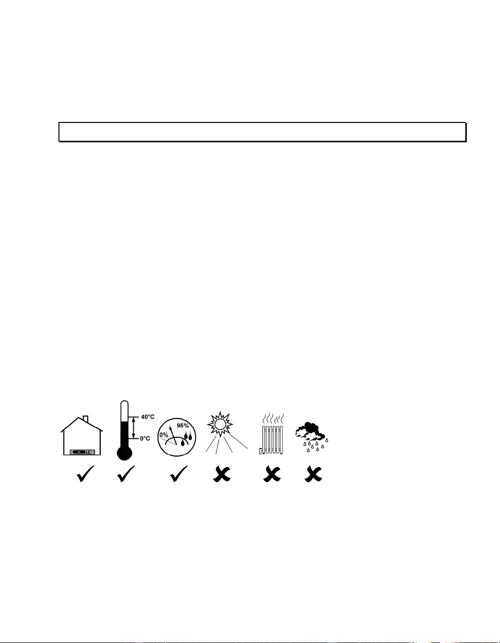
Position the UPS
2
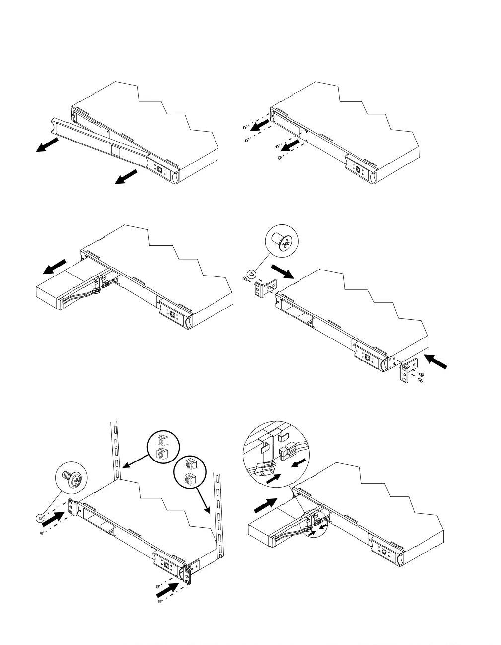
Rack-Mounting
n o
p q Two-post rack-mounting: Utilize the bracket
holes that are offset 6.25”.
r Secure clip nuts to the rack, and attach
brackets with provided screws. s
3
t u
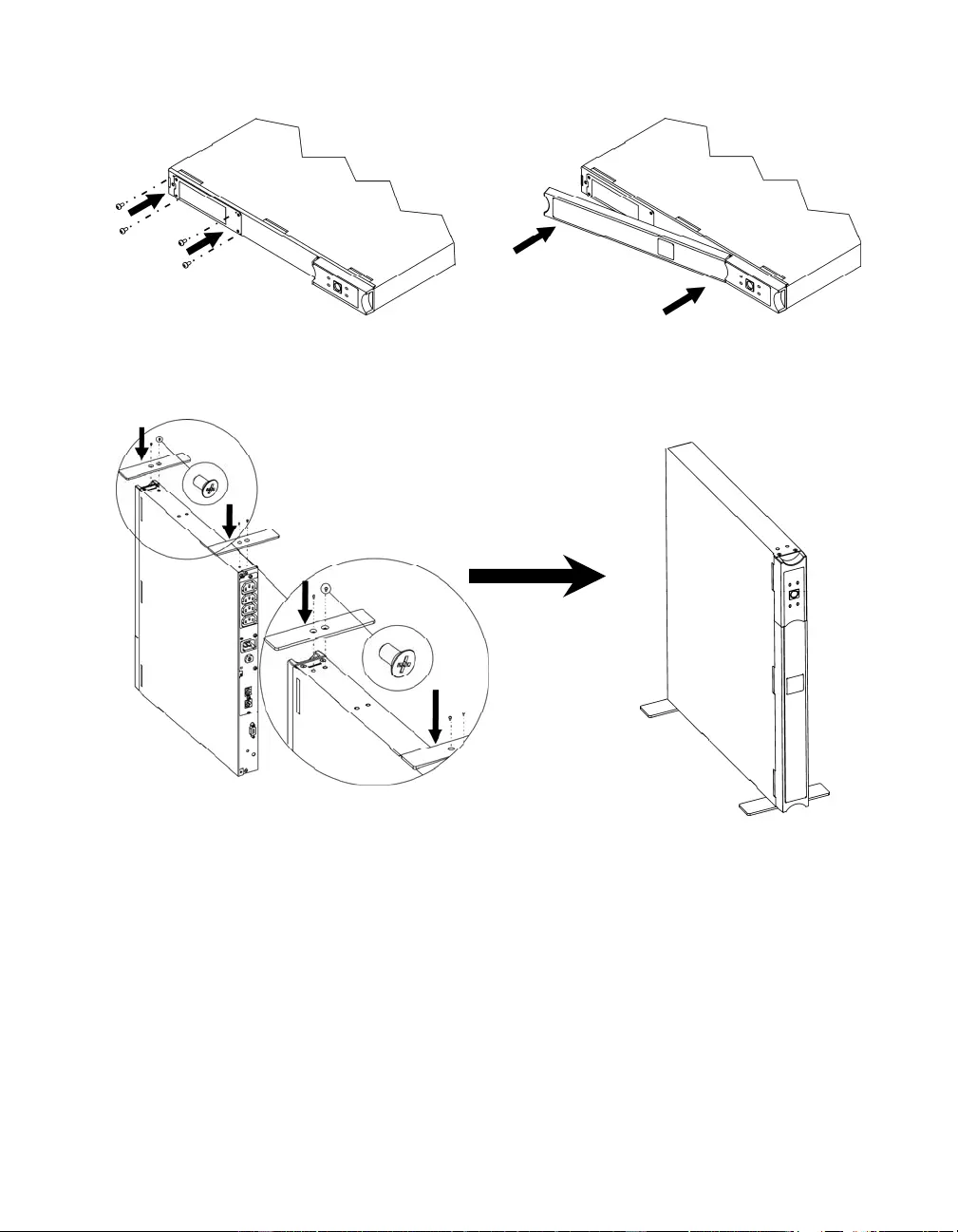
Tower Configuration
Attention: Connect the battery before tower setup by referring to applicable steps in
Rack-Mounting.

4
Wall Mounting
Attention: Connect the battery before mounting by referring to applicable steps in
Rack-Mounting.
To avoid a safety hazard, do not mount the unit on the wall with the bezel facing downwards,
or with t he display panel at the bot t om.
n
o Note: Whenever possible, attach two screws into wall studs. If st ud mounting is not po ssible, use
an expandable wall anchor. Hardware is not includ ed; .25” x 2” l ag bo lts are recommended. M ount
the UPS in either of the displayed positions.
Display
Panel
5
2: START UP
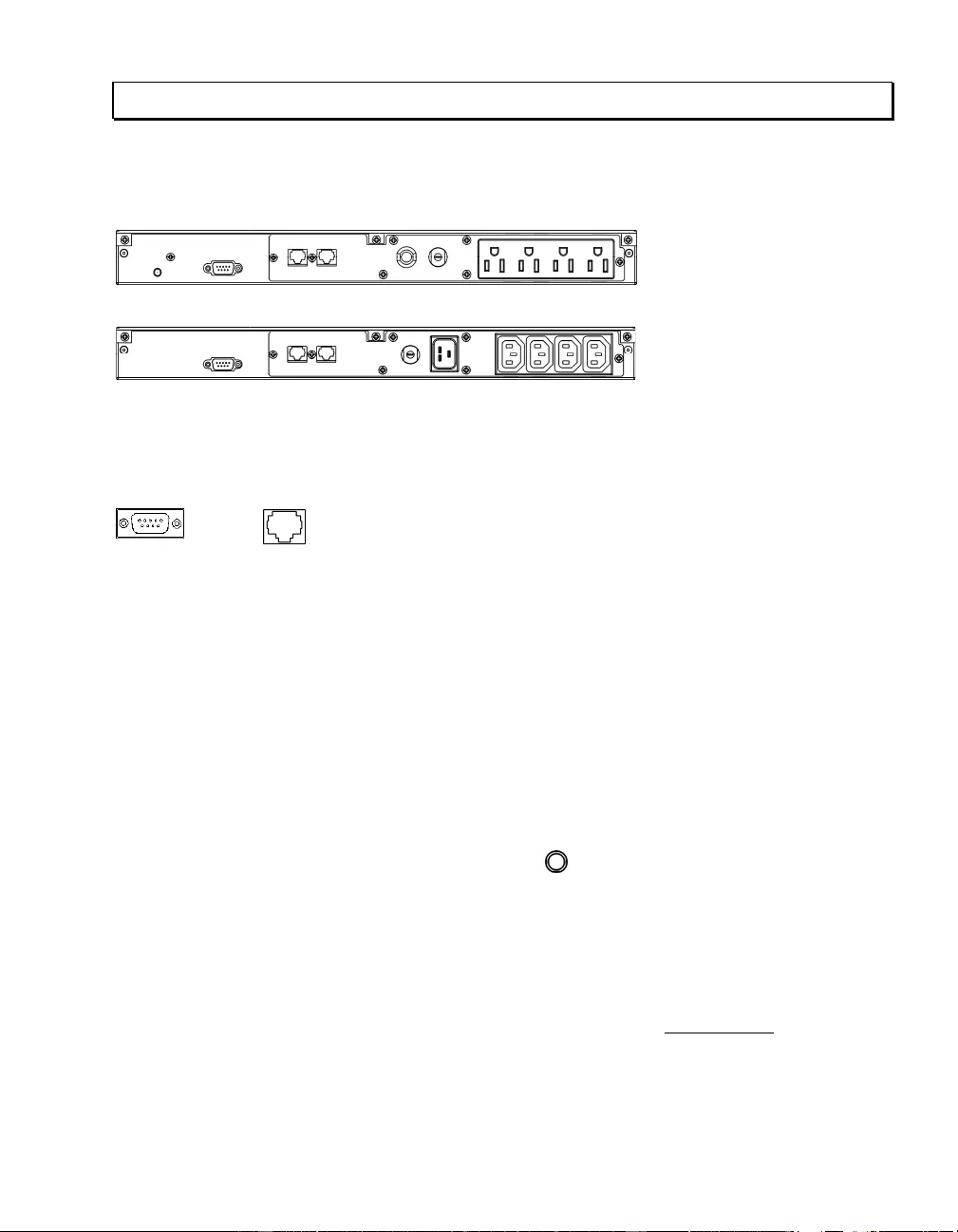
Connect Equipment to the UPS
Rear Panels
110/120 V:
230 V:
Note: A laser printer draws significantly more power than other types of equipment and may over-
load the UPS.
Connect the UP S to the Network (if Applicable )
Serial Port
Telephone/ Network Surge Suppression Ports
Use only interface kits approved by APC by Schneider Electric.
Use only the supplied cable to connect to the Serial Port. A standard serial interface cable is incompatible
with the UPS.
The UPS features optional telephone/network surge suppression. Connect a single line telephone or a 10
Base-T/ 100 Base-Tx network cable into the RJ-45/RJ-11 telephone/network surge protection IN jack on
the back of the UPS. Use the telephone cable (not supplied) or network cabling (not supplied) to connect
the OUT jack to a fax modem or network port.
Start the UPS
1. Plug the UPS into a two-pole, three-wire, grounded receptacle only. Avoid using extension
cords. 110/120 V models: The power cord is attached to the UPS; the input plug is a
NEMA 5-15P. 230 V models: The power cord set is supplied in the UPS literature kit.
2. 110/120 V models: Check the site wiring fault LED located on the rear panel. It will be
illuminated if the UPS is plug ged into an i mproperly wired utility po wer outlet
(see Troubleshooting).
3. Turn on all connected equipment. (This allows the UPS to be used as a master on/off switch.)
4. Press the button on the front pa nel to p ower the UPS.
Note: The battery charges fully dur i ng t he first four hour s of nor mal operat ion. Do no t expe ct
full battery run capability during this initial charge period. Refer to www.apc.com for battery
runtime charts.
5. For optimal computer system pro tectio n, install PowerChute Business Edition management
software to fully configure UPS shutdown and alarm settings.
6
3: OPERATION
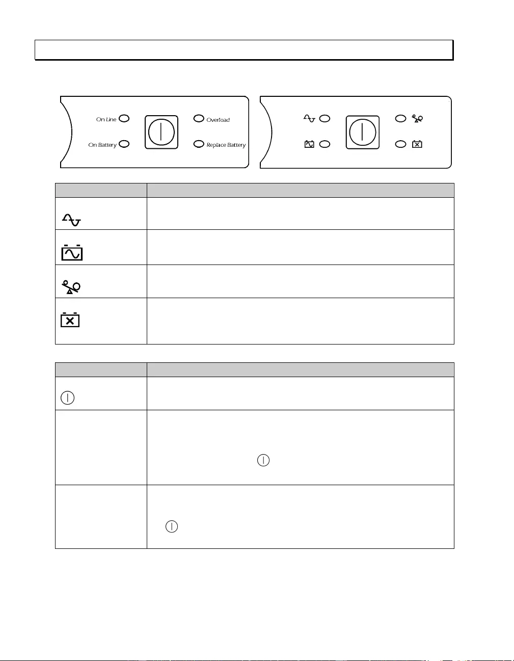
Front Display Panel
110/120 V 230 V
INDICATOR DESCRIPTION
On Line
The UPS is supplying utility power to the connected equipment.
On Battery
The UPS is supplying battery power to the connected eq uipment.
Overload
The connected loads are drawing more than th e UPS power rating.
Replace Battery
The battery must be repl aced.
FEATURE FUNCTION
Power Button
Press this button to turn the UPS on or off. Read on for additional capabilities.
Self-Test Automatic: The UP S performs a self-test au t omatically when t urned on, and
every two weeks thereafter (b y default). During the self-test, the UPS briefly
operates the connected equipment on battery.
Manual: Press and hold the button for a few seconds to initiate the self-test.
Cold Start To supply battery power to the UPS and connected equipment in the absence of
utility voltage (see Troubleshooting), press the front display panel button for
one second and release. The UPS will beep briefly and go quiet. Press and hold
the button again, but for approximately three seconds. The unit will emit a
sustained beep. Release the bu tton duri ng this beep.

7
4: USER CONFIGURABLE ITEMS
NOTE: SETTINGS ARE ADJUSTED THROUGH POWERCHUTE SOFTWARE
FUNCTION FACTORY
DEFAULT USER SELECTABLE
CHOICES DESCRIPTION
Automatic
Self-Test Every 14 days
(336 hours) Every 7 days
(168 hou rs),
Every 14 days
(336 hou rs),
On Startup Only,
No Self-Test
Set the interval at which the UPS will
execute a self-test.
UPS ID UPS_IDE N Up to ei ght charac-
ters (alphanumeric) Uniquely identify the UPS, (i.e. server
name or location) for network
management purposes.
Date of Last
Battery
Replacement
Manu facture Date mm/dd/yy Reset this date when you replace the
battery module.
Minimum Capa city
Before Return from
Shutdown
0 percen t 0, 15, 50, 90 percent Specify the percentage to which
batteries will be charged following a
low battery shutdown before powering
connected equ ip ment .
Voltage Sensitivity
The UPS det ect s
and reacts t o line
voltage distortions
by transferring to
battery operation to
protect conn ected
equipment.
High High sensitivity,
Medium sensitivity,
Low sensitivity
Note: In situations of poor power
quality, the UPS may frequently
transfer to battery operation. If the
connected equ ipment can operate
normally under such conditions,
reduce the sensitivity setting to
conserve batter y capacity and service
life.
Alarm Delay After
Line Fail 5 seconds 5 second delay,
30 second delay,
At low battery
conditio n,
No alarm
Set the delay to avoid alarms for minor
power glitches.
Shutdown Delay 60 seconds 60, 180, 300, 600
seconds Set the interval between the time when
the UPS receives a shu tdown
command and the actual shutdown.

8
NOTE: SETTINGS ARE ADJUSTED THROUGH POWERCHUTE SOFTWARE
FUNCTION FACTORY
DEFAULT USER SELECTABLE
CHOICES DESCRIPTION
Low Battery
Warning
2 minutes
PowerChute
Business Edition
software provides
automatic,
unatten ded
shutdown wh en
approximately 2
minutes of battery
operated runtime
remains.
2, 5, 7, 10 minutes
Times are
approximate.
The UPS will beep when 2 minutes of
battery runtime remains.
Change the low battery warning
interval setting to the time that the
operating system or system software
requires to safely shut down.
Synchronized
Turn-on Delay 0 seconds 0, 60, 180, 300
seconds Specify the time the UPS will wait
after the return of utility power before
turn-on to avoid branch circuit
overload.
High Transfer
Point 110/120 V mo del:
127 Vac
230 V model:
253 Vac
110/120 V mo del:
127, 130, 133,
136 Vac
230 V model:
253 , 257, 261,
265 Vac
Set the high transfer point higher to
avoid unnecessary battery usage when
the utility voltage is usually high and
the co nnected equipment i s specified
to operate with input voltages this
high.
Low Tr an sfer P o i nt 110/120 V mo del:
106 Vac
230 V model:
208 Vac
110/120 V mo del:
97, 100, 103,
106 Vac
230 V model:
196 , 200, 204,
208 Vac
Set the low transfer point lower when
the utility voltage is usually low and
the co nnected equipment i s specified
to operate with input voltages this low.

9
5: STORA GE AND MAINTENANCE
Storage
Store th e UPS covered in a cool, dry locat ion, with the batt ery fully ch arged.
At -15° to +30°C (+5 to +86° F), charge the UPS battery every six mont hs.
At + 30° to +45° C (+86 to +113° F), charge the UPS battery every th ree months.
Battery Replacement
The UPS batt ery life differs based on usage and environment. Consider repl acing the batt ery every three years.
This UP S h as an easy to replace, hot swapp able battery. Replacemen t is a safe procedure, isol ated from
electrical hazards. You may leave the UPS an d connected equip ment on during the replacement p r ocedure. See
your dealer or contact APC by Schneider Electric, (see Contact Information) for information on replacement
batteries.
Note: Upon bat tery disconn e ction, equipment is not protected from power out a ges.
For battery replacement instruction, refer to applicabl e st eps in Rack-Mounting.
Be sure to deliver the spent battery to a recycling facility or ship it to APC by Schneider
Electric in the repl acement battery packin g material.

10
6: TROUBLESHOOTING
Use the chart below to solve minor UP S installat ion and operation problems. Refer to www.apc.com
with complex UPS problems, and for battery runtime charts.
PROBLEM AND/OR POSSIBLE
CAUSE SOLUTION
UPS WILL NOT TURN ON
UPS not connected to utility
power supply. Check that the power cord from the UPS to the utility power supply is
securel y connected at both ends.
Batter y not conn ected proper-
ly. Check that battery connector is engaged.
Very low or no utility voltage. Check the utility power supply to the UPS by plugging in a table lamp. If the
light is very dim, have the utility voltage checked.
UPS WILL NOT TURN OFF
Internal UPS fault. Do not attempt to use the UPS. Unplug the UPS, unplug the battery
connector, an d have it serviced immediately.
UPS BEEPS OCCASIONALLY
Normal operati ng UPS beeps
when running on battery. None. Th e UPS is prot ecting the connect ed equipment from occasional
utility power irregularities.
UPS IS NOT PROVIDING EXPECTE D BACKUP TIME
The UPS battery is weak due
to a recent outage o r is near
the end of the service l ife.
Charge the battery. Batteries require recharging after extended outages, and
wear faster when freq uentl y pu t in to service o r when operated at elevated
temperatures. If the bat tery is near the end of the service life, con si der
replacing even if the replace battery LED is not yet illuminated.
ON-LINE AND OVERLOAD LEDS ARE FLASHING ALTERNATELY
The UPS was shut down
throug h PowerChute . None. The UPS will restart when utility power returns.
ALL LEDS ARE FLASHING OR ON-LINE AND ON-BATTERY LEDS ARE FL A SHING
Internal UPS fault. The UPS
has shut down. Do not attempt to use the UPS. Turn off the UPS, unplug the battery, and
have it servi ced immediately.
ALL LEDS ARE OFF AND THE UPS IS PLUGGED INTO A WALL OUTLET
The UPS is shut down or the
battery is discharged from an
extended outage.
None. The UPS will return to normal operation when the power is restored
and the battery has a sufficient charge.

11
PROBLEM AND/OR POSSIBLE
CAUSE SOLUTION
THE OVERLOAD LED IS ILLUMINATED AND THE UPS EMITS A SUST AINED ALARM TONE
The UPS is overloaded. Th e
connected equ ip ment is
drawing more VA than the
UPS can sustain.
The connected equipment exceeds the specified “maximum lo ad.”
The alarm remains on until the overload i s removed. Disconnect
nonessential equipment from the UPS to eliminate the overload.
The UPS continues to supply power as long as it is on-line and the circuit
breaker does not trip; the UPS will not provide power from batteries in the
event of a utility voltage interruption.
If a continuous overload occurs while the UPS is on battery, the unit turns
off output in order to protect the UPS from possible damage.
THE REPLACE BATTERY LED IS ILLUMINATED
Weak battery. Allow the battery to recharge for 24 hours. Then, perform a self-test. If the
problem persist s after recharging, replace the batt ery.
Failure of a battery self-test. The UPS emits sh ort beeps for one minu t e and th e replace batt ery LED
illuminates. The UPS repeats the alarm every five hours. Perform the
self-test procedure after the battery has charged for 24 hours to confirm the
replace battery condition. The alarm stops and the LED clears if the battery
passes the self-test.
THE SITE WIRING FAULT LED ON THE REAR PANEL IS IL L UMINATED (110/120 V MODEL ON LY)
The UPS is plugged into an
improperly wired utility power
outlet.
Wiring faults detected include missing ground, hot neutral polarity reversal,
and overloaded neutral circuit.
Contact a qualified el ectrician t o correct the building wiring.
THE INP UT CIRCUIT BREAKER HAS T R IPPED
The UPS is overloaded. Th e
plunger on the circuit breaker
has popped out.
Reduce the load on the UPS by unplugging equipment. Press in the plunger
on the circuit breaker.
UPS OPERATES ON BATTERY ALTHOUGH UTILITY VOLTAGE EXISTS
The UPS input circuit breaker
has tripped. To reduce the load on the UPS, unplug equipment and press in the plunger
on the circuit breaker.
The line voltage is very high,
low or distorted. Move the UPS to a different outlet on a different circuit, as inexpensive fuel
powered gen erators may dist ort the vo ltage. If accep table to the connected
equipment, reduce t he UPS sensitivity (see User Configurable Items).
ON-LINE LED
There is no illumination. The UPS is running on battery, or it must be turned on.
The LED is blinking. The UPS is running an internal self-test.

12
7: TRA N SP ORT AND SERVICE
Transport
1. Shut down and disconnect all connected equipment.
2. Disconnect the unit fro m utility power.
3. Disconnect all internal and external batteries (if applicable).
4. Follow the shipping instructions outlined in the Service section of this manual.
Service
If the unit requires service, do not return it to the dealer. Follow these steps:
1. Revie w the Troubleshooting section of the manual to eliminate common problems.
2. If the problem persists, contact APC by Schneider Electric Customer Support through
the APC by Schneider Electric web site, www.apc.com.
a. Note the model number and serial number and the date of purchase. The
model and serial numbers are located on the rear panel of the unit and
are available through the LCD display on select models.
b. Call Customer Support and a technician will attempt to solve the
problem over the phone. If this is not possible, the technician will issue a
Returned Material Authorization Number (RMA#).
c. If the unit is under warranty, the repairs are free.
d. Service procedures and returns may vary internationally. Refer to the
APC by Schneider Electric web site, www.apc.com for country specific
instructions.
3. Pack the unit properly to avoid damage in transit. Never use foam beads for
pac kaging. Damage susta ined in transit is not covered under warranty.
a. Note: When shipping within the United States, or to the United
States always DISCONNECT ONE UPS BATTERY before shipping
in compliance with U.S. Department of Transportation (DOT) and
IATA regulations. The internal batteries may remain in the UPS.
b. Batteries may remain connected in the XBP during shipment. Not all
units utilize XLBPs.
4. Write the RMA# provided by Customer Support on the outside of the package.
5. Return the unit by insured, prepaid carrier to the address provided by Customer
Support.

13
8: LIMITED FACTORY WARRANTY
Schneider Electric IT Corporation (SEIT), warrants its products to be free from defects in materials and workmanship for a
period of two (2) years from the date of purcha se. The SE IT obligation under this warranty is lim ited to repairing or replacing,
at its own sole option, any such defective products. Repair or replacement of a defective product or parts thereof does not
extend the original warranty period.
This warranty appli es only to t he original purchas er who must ha ve properl y regist ered the product within 10 days of
purchase. Products may be registered online at warranty.apc.com.
SEIT shall not be li able under the warranty if its test ing and examin ation disclose t hat the alleged defect in the pr oduct does
not exist or was caused by end user or any third person misuse, negligence, improper insta llation, test ing, operation or use of
the pr oduct c ontrary to SEIT recommendations or specifications. Further, SEIT sh all not be liable for defect s result ing from:
1) unauthorized attempts to repair or modify the product, 2) incorrect or inadequate electrical voltage or connection, 3)
inappropriate on site operation conditions, 4) Acts of God, 5) exposure to the elements, or 6) theft. In no event shall SEIT have
any liability under this warranty for any product where the serial number has been altered, defaced, or removed.
EXCEPT AS SET FORTH ABOVE, THERE ARE NO WARRANTIES, EXPRESS OR IMPLIED, BY OPERATION
OF LAW OR OTHERWISE, APPLICABLE TO PRODUCTS SOLD, SERVICED OR FURNISHED UNDER THIS
AGREEMENT OR IN CONNECTION HERE WITH.
SEIT DISCLAIMS ALL IMPLIED WARRANTIES OF MERCHANTAB I LITY, SATISFACTION AND FITNE SS
FOR A PARTICULAR PURPOSE.
SEIT EXPRESS WARRANTIES WILL NOT BE ENLARGED, DIMINISHED, OR AFFECTED BY AND NO
OBLIGATION OR LIABILITY WILL ARISE OUT OF, SEIT RENDERING OF TECHNICAL OR OTHER
ADVICE OR SERVICE IN CONNECTION WITH THE PRODUCTS.
THE FORE GOING WARRANTIES AND REMEDIES ARE EXCLUSIVE AND IN LIEU OF ALL OTHER
WARRANTIES AND REMEDIES. THE WARRANTIES SET FORTH ABOVE CONSTITUTE SEIT SOLE
LIABILITY AND PURCHASER EXCLUSIVE REMEDY FOR ANY BREACH OF SUCH WARRANTIES. SEIT
WARRANTIES EXTEND ONLY TO ORIGINAL PURCHASER AND ARE NOT EXTENDED TO ANY THIRD
PARTIES.
IN NO EVENT SHALL SEIT, ITS OFFICERS, DIRECTORS, AFFILIATES OR EMPLOYEES BE LIABLE FOR
ANY FORM OF INDIRECT, SPECIAL, CONSEQUENTIAL OR PUNITIVE DAMAGES, ARISING OUT OF THE
USE, SERVICE OR INSTALLATION OF THE PRODUCTS, WHETHER SUCH DAMAGES ARISE IN
CONTRACT OR TORT, IRRE SPECTIVE OF FAULT, NEGLIGENCE OR STRICT LIABILIT Y OR WHETHER
SEIT HAS BEEN ADVISED IN ADVANCE OF THE POSSIBILITY OF SUCH DAMAGES. SPECIFICALLY, SEIT
IS NOT LIABLE FOR ANY COSTS, SUCH AS LOST PROFITS OR REVENUE, WHETHER DIRECT OR
INDIRECT, LOSS OF EQUIPMENT, LOSS OF USE OF EQUIPMENT, LOSS OF SOFTWARE, LOSS OF DATA,
COSTS OF SUBSTITUANTS, CLAIMS BY THIRD PARTIES, OR OTHERWISE.
NOTHING IN THIS LIMITED WARRANTY SHALL SEEK TO EXCLUDE OR LIMIT SEIT LIABILITY FOR
DEATH OR PERSONAL INJURY RESULT ING FROM ITS NEGLIGENCE OR ITS FRAUDULENT
MISREPRESENTATION OF TO THE EXTENT TH AT IT CANNOT BE EXCLUDE D OR LIMITED BY
APPLICABLE LAW.
To obta in service und er warranty you must obta in a Return ed Material Authorization (RMA) numb er from cus tomer support.
Customers with warranty claims issues may access the SEIT worldwide customer support network through the APC web site:
www.apc.com. Select your country from the country selection drop down menu. Open the Support tab at the top of the web
page to obtain informa tion for customer support in your region. Products must be ret urned wi th transportation char ges prepaid
and must be accompanied by a brief description of the problem encountered and proof of date and place of purchase.


08/2014
EN 990-1852D
APC by Schneider Electric
Worldwide Cus t omer Support
Customer support for this or any other APC by Schneider Electric product is
available at no charge in any of the following ways:
• Visit the APC by Schneider Electric web site, www.apc.com to access
documents in the APC Knowledge Base and to submit customer support
requests.
–www.apc.com (Corporate Headquarters)
Connect to localized APC by Schneider Electric web site for specific
countries, each of which provides customer support information.
–www.apc.com/support/
Global support searching APC Knowledge Base and using e-support.
• Contact the APC by Schneider Electric Customer Support Center by
telephone or e-mail.
– Local, c ountry s pec if ic cent er s: go to www.apc.com/support/contact for
contact information.
– For information on how to obtain local customer support, contact the
APC by Schneider Electr ic repr esent ative or other distribut or fro m whom
you purchased your APC by Schneider Electric product.
© 2014 APC by Schneider Electric. Smart-UPS and PowerChute are owned by Schneider Electric
Industries S.A.S. or their affiliated companies. All other trademarks are property of their respective
owners.