Table of Contents
- Overview
- Product Description
- Important Safety Messages
- Safety and General Information
- Specifications
- Product Overview
- Rear panel features 2200 VA and 3000 VA models Installation
- Operation
- Connect Equipment
- Display Panel
- Configuration
- UPS Settings
- Main Outlet Group and Controlled Outlet Group
- Emergency Power Off
- Troubleshooting
- Service
- Two Year Limited Factory Warranty
APC Smart-UPS User Manual
Displayed below is the user manual for Smart-UPS by APC which is a product in the Uninterruptible Power Supplies (UPSs) category. This manual has pages.
Related Manuals

Operation Manual
Smart-UPS™
Un inte rr upt i ble P o w er Sup p ly
Tower
750/1000/1500/2200/3000 VA
100/120/230 Vac
500 VA
100 Vac

1Smar t- UPS 750/1000/1500/ 2200/3000 VA 100/120/ 230 Vac / 50 0 VA 100 Vac Tower
Overview
Produc t Description
The A PC ™ by Schneider Electric Smart-UPS™ i s a high performance uninterruptible power supply (UPS). The UPS
provides protection for electronic equipment from utility power blackouts, brownouts, sags, and surges, small utility
power fluctua tions a nd large disturbances. The UP S also pro vides battery backup powe r for connected equipment until
utility power re turns to safe lev els or the batter ies are fully discharged.
This us er manual is av ailable on the enclosed CD and on the APC by Sch neider Electric Web site, www.ap c.com.
Important Safety Messages
Rea d the instructions careful ly to become famili ar with t he equipment be fore trying to install, operate, servic e or
mai ntain it. The following special messa ges may appear throughout this ma nual or o n the equipment to warn of
potential hazards or to call attention to inform ation that cla r ifies or simplifies a procedure.
The addit ion of t his sy mbol to a Caution product safety label indicates that a haz ard exists that can result in
injury and product damage if the instructions are not followed.
The fol lowing safety messages may appear throughout this manual to warn of potential hazards.
Safety an d General Information
Inspect the package contents upon receipt. Notify the carrier and dealer if there is any
damage.
Read the Safety Guide supplied with this unit before installing the UPS.
• Adhere to all national an d local electrical c odes .
• This UPS is intended for indoor use only.
• Do not operate this UPS in direct sunlight, in contact with fluids, or where there is excessive dust or hum idity.
• Be sure the air vents on the UPS are not blocke d. Al low adequate spa ce f or proper ve ntilation.
• The battery t ypically lasts for two to fiv e years. Environme ntal factors impact batter y life. Elevated ambient
temperatures, poor quality utility power, and frequent short duration discharges will shorten battery life.
• Connect the UPS power cable directly to a wall outlet. Do not use surge protectors or extension cords.
• The equipment is heavy. Always practice safe li fting techni ques adequate for the weight of the equipment.
• The model and serial numbers are located on a small, rear panel la bel. For some mod els, an additional la bel i s
located on the chassis under the front bezel.
• A lway s re cy cl e u sed ba t te ri e s.
• Rec y cle the pack age materials o r save th em for reu se.
CAUTION
CAUTION indicates a potentially hazardou s situation which, if not avoided, can result in equipment damage and minor or moderate injury.
CAUTION
CAUTION indicates a potentially hazardous situation which, if not avoided, ca n res ult in equipment damag e.

Smart-UPS 750/1000/1500/2200/3000 VA 100/ 120/230 Vac / 500 VA 100 Vac Towe r2
Specifications
For additional specifications, refer to the APC by Schneider Electric Web site at www.apc.com.
Environmental
Temperature Operating 0° to 40° C (32° to 104° F)
Storage -15° to 45° C (5° to 113° F)
charge UPS battery ev ery six months
Maximum
Elevation Operating 3,000 m (10,00 0 ft)
Storage 15,000 m (50,000 ft)
Humidity 0% to 95% relative humidity, non-conde nsing
3Smar t- UPS 750/1000/1500/ 2200/3000 VA 100/120/ 230 Vac / 50 0 VA 100 Vac Tower
Product Overview
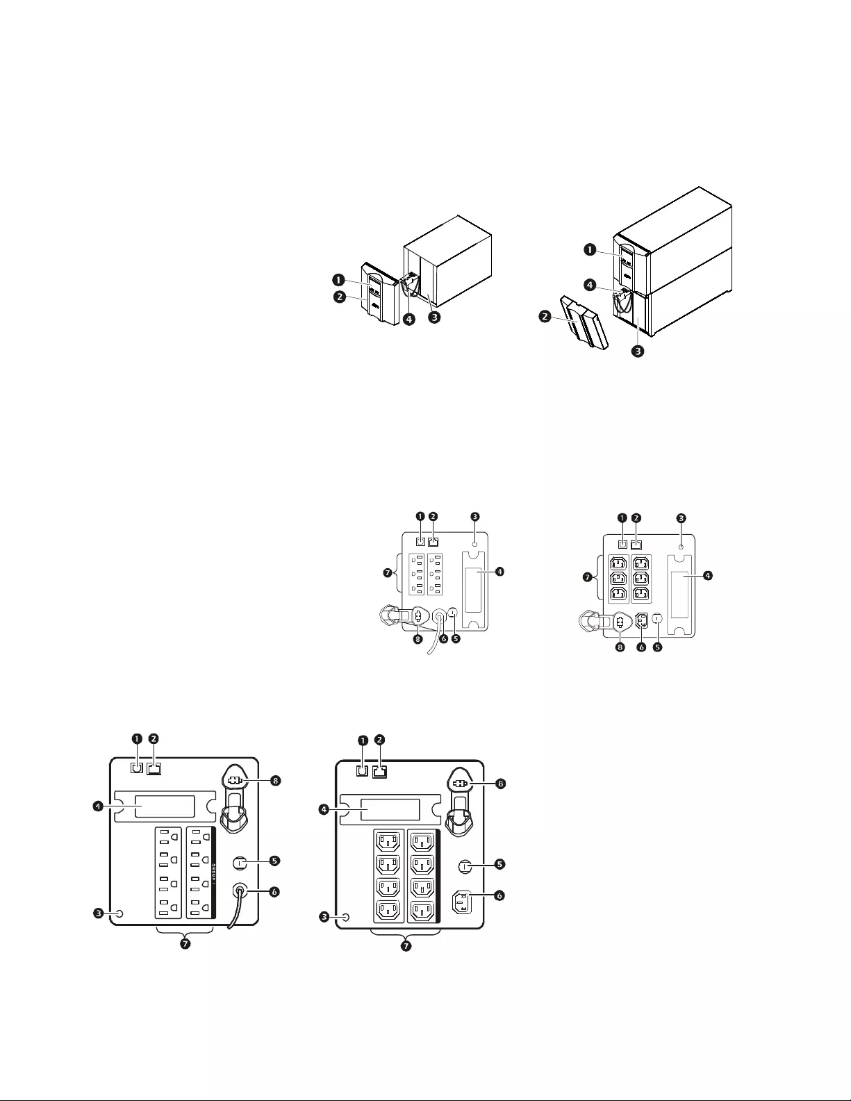
Front panel features
Rear panel features 500 VA to 1500 VA models
1Display interface 500/750/1000/1500 VA 2200/3000 VA
2Bezel
3Battery
4Internal battery connector
1USB port 500/750 VA 100 Vac
750 VA 120 Vac 750 VA 230 Vac
2Serial port
3Chass is ground screw
4SmartSlot
5Cir cuit breaker
6UPS input
7Outlets
8Interna l or external battery conne ctor
1000/1500 VA 100 Vac
1000/1500 VA 120 Vac 1000/1500 VA 230 Vac
su0453a
su0452a
su0326b
su
0327b
GROUP 1
su0325c
GROUP 1
su0328c
Smart-UPS 750/1000/1500/2200/3000 VA 100/ 120/230 Vac / 500 VA 100 Vac Towe r4
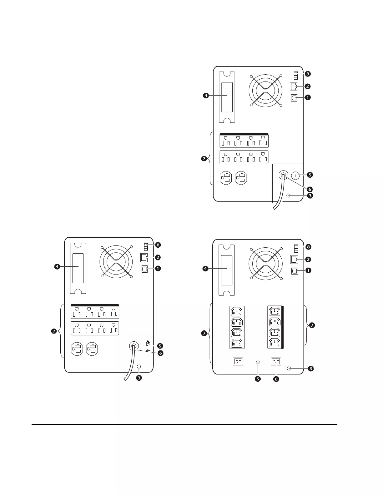
Rear panel features 2200 VA and 3000 VA models
Installation
For UPS inst allation inform ation, refer to the Smart-UPS I ns tallati on Guide 750/1000/1500/2200/3000 VA 100/120/
230 Vac, 500 VA 100 Vac Tower, that i s included with the UPS. The Installation guide is also available on the
Documentation CD included wi th the UPS and on the APC by Schneider Electric Web site, www.apc.com.
2200 VA 120 Vac
1USB Port
2Serial port
3Chassis ground screw
4SmartSlot
5Circuit breaker
6UPS input
7Outlets
8EPO connector
2200/3000 VA 100 Vac
3000 VA 120 Vac 2200/3000 VA 230 Vac
G R O U P 1
su0351b
G R O U P 1
su0330a
su0329b
GROUP 1
5Smar t- UPS 750/1000/1500/ 2200/3000 VA 100/120/ 230 Vac / 50 0 VA 100 Vac Tower
Operation
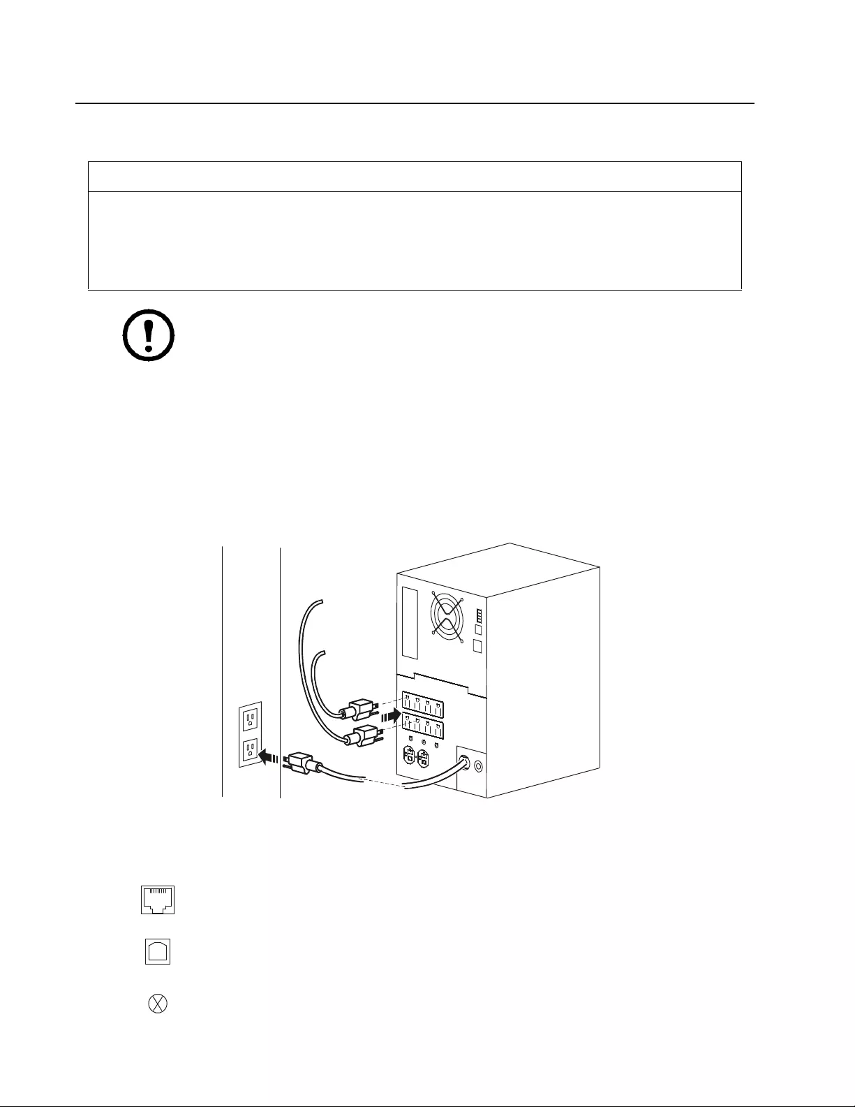
Connect Equipment
Note: The 2200/3000 VA 100 Vac model UPS will charge to 90% capacity in the first four and a half
hours of norm al ope ration.
All other models will ch arge to 90% capacity in the first three hours of normal operation
Do not expect full battery runtime capabili ty during this initial charge period.
1. Connect equipm ent to the outlets on the rear panel of the UPS.
2. Connect the UPS to the building utility power.
Always connect the UPS to a two pole, three wire, grounded source.
3. To us e th e UPS as a master ON/OFF switch, turn on all the equipment that i s connected to th e UPS.
4. Press the ON/OFF button on the front panel of the UPS to turn on the UPS and all connected equipment.
See “Main Outlet Group and Controlled Outlet Group” on page 10 for information on how to configure the outlet
groups.
Rear Panel Features
CAUTION
RISK OF EQUIPMENT DAMAGE
• Adhere to al l local and national electrical codes.
• W iring should be performed by qualified ele ctricia n.
• Always connec t the UPS to a grounded outlet.
Failure to follow these instructions can result in equipment damage
Serial port: Connect to a computer to use power management software.
USB port : Connect to a computer to use power management software.
Note: Serial and USB communication can not be used sim ultaneously.
Gr ound Screw: The UPS featur e s a ground sc rew for connecting the ground leads
on transient voltage devices. Prior to connecting a ground le ad, disconne ct the UPS
from utility power.
su0441a
Smart-UPS 750/1000/1500/2200/3000 VA 100/ 120/230 Vac / 500 VA 100 Vac Towe r6
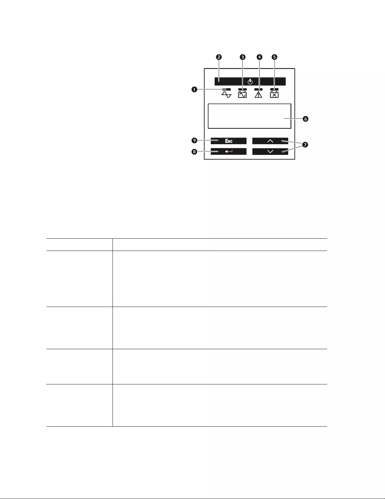
Display Panel
Using the display interface
Use the UP/DOWN arrow buttons to scroll through the main menu options. Press ENTER to view the
submenus under each main menu option. Press ESCAPE t o ex it a s u bmenu and return to a main menu.
Standard menus
The Standard menus are the most commonly used menus .
1Online LED
2UPS ON/OFF key
3On Battery LED
4Site Wiring Fault LED
5Replace Battery LED
6Display interface
7UP/DOWN arrow keys
8ENTER key
9ESCAPE key
Menu General Functions
Status
View UPS information:
• Operating Mode
• Efficiency
• Load Power
• Load VA
• Battery Charge state
• Estimated Runtime
•Battery Temp
• Input
• Output
• Last Tr ansfe r
• Last UPS Self Tes t
Configuration
Configure UPS settings:
• Language
• Local Power Quality: Good, Fair, Poor
• Men u Ty pe : Sta nda rd or Ad van ced
•Audible Alarm
• Displ ay (Auto Dim, Auto Off, Always On)
• Battery I nstall Date
• Reset t o Factory D efault
Test & Diags
Perform UPS te sts and diagnostic functions :
• UPS Self Test
• UPS Alarms Test
• Calibration Test
About
View UPS information:
• UPS Model
• UPS Part No.
• UPS Serial No.
• UPS Manufacture Date
• Battery Part No .
• Battery I nstall Date
• Replace Battery by
• UPS Firmware 1
su0343a
A
PC b
y
Schneider
Electric

7Smar t- UPS 750/1000/1500/ 2200/3000 VA 100/120/ 230 Vac / 50 0 VA 100 Vac Tower
Advanced menus
The Advan ce d men us provide additional opti ons for the UPS and are available only if the display int erface i s
configured to use the Advanced menus.
Menu Ge ner a l Func tions
Status
Vi ew detailed UPS informat ion:
• Operating Mode
• Efficiency
• Load Power
• Load VA
• Load Amps
• Load Energy
• Battery Charge state
• Estimated Runtime
• Ba tte ry Volta g e
•Battery Temp
• Input
•Output
• Last Tr ansfe r
• Last UPS Self Tes t
• Outlet Group 1 (if Controlled Outlet is available)
• NMC IP Address (if NMC is available)
Configuration
Configure advanced U PS settings:
• Language
• Lo cal Power Quality
• Men u Ty pe
•Audible Alarm
• Display (Auto Dim, Auto Off, Always On)
• Sensitivity
• Low T ran sfer
• High Transfer
• Low Battery Warning
• Auto Sel f Test
• Battery I nstall Date
• Reset Energy Meter
• Enter Setup Wizard
• Firmware Update (standby mode)
• Reset t o Factory Default
• Config Mai n Group Out lets
• Config Group 1 Outlets (if Controlled Outlet is
available)
• Config NMC (if NMC is availa ble )
Control Control the Main and Switched Outlet Group to turn on, turn off, shutdown, or reboot.
Test & Diags
Perform UPS test and diagnostic functions:
• UPS Self Test
• UPS Alarms Test
• Ca lib rat io n Test
Log View the eve n t and error log s for informatio n about UPS events and fau lts that have o ccurr ed.
About
View UPS information:
• UPS Model
• UPS Part No.
• UPS Serial No .
• UPS Manu facture Date
• Ba tte ry Pa rt No .
• Ba tte ry In st all Date
• Replace Battery by
• UPS Firmware 1
• UPS Firmware 2
• UPS Firmware 3
• UPS Firmware 4
• NMC Model No.*
• NMC Serial No.*
• NMC Hardware Version*
•NMC Manufacture Date*
•NMC MAC Address*
• SmartSlot FW 1*
• SmartSlot FW 2*
• SmartSlot FW 3*
*If NMC is available

Smart-UPS 750/1000/1500/2200/3000 VA 100/ 120/230 Vac / 500 VA 100 Vac Towe r8
Configuration
UPS Settings
Start up Settings
Configure these settings at initial start up, using the display interface. As an alternative, configuration can be
performed using PowerChute™ software.
Note: During start up, use the display interface to configure thes e settings. If nothing is selected, the
unit will use the default settings.
General Settings
Configure t hese sett ings at any time. Us e the display int erface or PowerChu te software.
Function Factory Default Options Description
Language English
•English
• French*
•German*
• Spanish*
• Italian*
• Portuguese*
• Japanese*
The language for the dis pla y interface.
*Language options will vary by model.
Local Power
Quality Good
• Good
•Fair
•Poor
Select t he quality of input utility power.
• If Good is selected, the un it wi ll go on battery power
more oft en to provide the cl eanest powe r sup ply to the
connected equipment.
• If Poor is selected, the UPS will tolerate more
fluct ua tions i n p ower and w ill g o on ba tt ery p ower l ess
often.
I f un s ure of t h e lo cal po w er qu a lity, sel ect G oo d .
Menu Type Standard Standard or
Advanced
The Standard menus displ ay a limited set of menus
and options. The advance d me nus include all
parameters.
Function Factory Default Options Description
Hi gh Transfer Point
100 Vac:
108 Vac 108 Vac - 114 Vac To avoid unnecessa ry battery usage, set the transfer
po int higher if the utilit y voltage is chronically high and
the connected e quipment is known t o wo rk under this
condition. The P o w e r Q u ality setting will
auto m a tica ll y ch ang e thi s se ttin g .
Note: Use the A dvanced Menus to configure thi s
setting.
120 Vac:
127 Vac 127 Vac - 136 Vac
230 Vac:
253 Vac 253 Vac - 265 Vac

9Smar t- UPS 750/1000/1500/ 2200/3000 VA 100/120/ 230 Vac / 50 0 VA 100 Vac Tower
Low Transfer Point
100 Vac:
92 Vac 86 Vac - 92 Vac Set the transfer point lower if the utility voltage is
chronically low and the connect ed equipm ent can
tolerate this condition.This setting may also be adjusted
using the power quality set ting.
Note: Use t he A dvanc ed M enus to co nfigure this
setting.
120 Vac:
106 Vac 97 Vac - 106 Vac
230 Vac:
208 Vac 196 Vac -208 Vac
Nominal Output
Voltage
100 Vac N/A
230 Vac mode ls only: S et t he nomi nal output voltage of
the UPS to standby mode.
120 Vac N/A
230 Vac • 220 Vac
• 230 Vac
• 240 Vac
Transfer Sensitivity Normal Normal, Reduced, Low
Select the level of sensitivity to power events that the
UPS will tolerate.
•Normal: The UPS will go on ba ttery power more
o ften to provid e the cleanes t pow er su pply to the
connected equipment.
•Low: The UPS will tolerate more fluctuations in
po w er and will g o on battery power less ofte n.
If the conne cted load is sens itive to pow er disturb ances,
set th e sen si tiv ity to N or mal.
Low Batte ry Warning 120 s ec Set the value in seconds T he UPS wi ll em it a n au dib le alarm w he n the r emai ni ng
runtime has reached this level.
Date of Last Battery
Replacement Date set at factory Reset this date when the battery module is replaced.
Audible Alarm On On/Off T he UPS will mute all audible alarms if this is set to Off
o r when the display keys are press ed.
Battery
Se lf-Test Interval
Setting
On st art up and every
14 days since the last
test
•Never
• Start up only
• Frequency of test
(every 7 to 14 d ays)
T h e inte rval at which the UPS will execute a
self-test.
Re se t to Facto ry
Default N o Yes/No Restore the UPS factory default settings.
Function Factory Default Options Description

Smart-UPS 750/1000/1500/2200/3000 VA 100/ 120/230 Vac / 500 VA 100 Vac Towe r10
Main Outlet Group and Controlle d Outlet Group
Overview
The Main Outlet Group and the Controlled Outle t Group can be configured to independen tly turn off,
turn on, s hut down, and reboot connected equipment. (These features ar e not a vailable on the 50 0 VA or 750 VA
units.)
The Main and Controlled Out let Groups can be conf igured to do th e following:
• Turn off: Disconnect from power immediately and res tart only with a manual command.
• Turn on: Co nnect to power immediately.
• Shutdown: Di sconn ect power i n sequ ence, and automati cally rea pply po wer in seque nce when ut ility power
becomes available.
• Reboot: Shut down and restart.
In addition, the Main Outlet Group and the Controll ed Outlet Group can be configured to do the following:
• Turn on or off in a specified sequence
• Automatically turn off or shut down when va rious conditions occur
Note: If the Main and Controlle d Outlet Groups ar e not c onfigured, al l of the outl ets on the unit will still provide
batte ry backup power.
Using the Main and Controlled Outlet Groups
The Main Out let Group function s as a master switch. It will tu rn on first when power is applied, a nd shut down last
when there is a power out age and battery runt im e has been exhaust ed.
The Main Outlet Group must be turned on for the Controlled Outlet Group to turn on.
1. Connect critical equipment to the Main Outlet Group .
2. Connect peripheral e quipment to th e Controlled Out let Group.
– Non es sential equipment that should shut down quickly in the event of a power outage c an be added to a
short power off delay, to conserve ba ttery runtime.
– Equipment that has depe ndent peripherals that must rest art or shut down in a specifi c orde r should be
connected to a separate outlet group.
– Equipment that needs to reboot independently from other equipment should be added to a s eparate
outlet group.
3. Use the Configuration menus to set reaction of the Controlled Outlet Group in the event of a power
outage.

11Smart-UPS 750/1000/1500/2200/3000 VA 100/120/230 Vac / 500 VA 100 Vac Tower
Customize the Main and Controlled Outlet Groups
Use the Configuration menus to change t he Main Outlet Group and the Controlled Outlet Group se ttings.
Network Management Card Settings
These settings are available only on units that have a Network Management C ard (NMC) and are s et at the fac tory.
These settings can onl y be modified usin g an ext ernal inte rface, such as the NMC Web interface.
• NMC IP Address Mode
• NMC IP Address
• NMC Subnet Mask
• NMC Default Gate way
Function Factory Default Options Description
Name String
Outlet Group Outlet Group 1 Edit these names using an external interface, such as the Network
Management Card Web interface.
UPS Name String UPS Outlets
Turn On Delay 0 sec Se t the val ue in
seconds
The amount of tim e the UPS o r a Co ntro lle d Outlet
Group will wait be tween receiving t he c ommand to
turn on and the actual s tartup.
Turn Off Delay • 0 sec U P S Ou tlet s
• 90 sec Controlled
Outlet Groups
Se t the val ue in
seconds
The amount of tim e the UPS o r a Co ntro lle d Outlet
Group will wait be tween receiving t he c ommand to
turn off and the actual shut down.
Reboot Du rati on 8 sec Se t the val ue in
seconds The amou nt of t ime th e U PS o r a Cont r o lled Outlet
Group m us t rema in off before it will restar t.
Minimum Return
Time 0 sec Set the value in
seconds
The amount of battery runt ime tha t must be avail ab le
before the UPS or a Co ntrolled Outlet Group will
turn on after a shutdown.
Load Shed On
Battery Disabled
• Enable
• Disable When the uni t swi tches to battery power, the UPS
will dis connect power to the C o n tr o ll ed Ou tlet
Group to save battery runtim e.
Co nf igure this delay time, use the LOAD SHED TIME
WHEN ON BATTERY se tting .
Load Shed Time
when On B att e ry 1800 sec Se t the val ue in
seconds The amount of time the outlets will function on
battery power before they will turn off.
Load Shed On
Runtime Disabled
• Enable
• Disable When t h e batter y r untime falls below the specified
value, the Controlled Outlet Group will turn off.
Co nf igure this time using the LOAD SHED RUNTIME
REMAINING setting.
Load Shed On
Runtime
Remaining 120 sec Se t the val ue in
seconds When the r emaining runtime reaches this level, the
Controlled Outlet Group will tu rn off.
Load Shed on
Overload Disabled
• Disabled
• Enabled In the event of an over load (gr eate r t h an 107%
output), the Controlled Outlet Group will
immedi ately turn of f to conserve power for critical
l oads . Th e Co n tro lle d Ou t let Grou p will only turn on
aga in w it h a man ua l co m m an d .
Smart-UPS 750/1000/1500/2200/3000 VA 100/ 120/230 Vac / 500 VA 100 Vac Towe r12
Emergency Power Off
Overview
The Emergency Power Off (E P O) option, is a safety feature th at will immediate ly di sconnect all connected
equipment from utility power. The UPS will immediately shut down and will not switch to battery power.
Adhere to all national and local electrical codes. Wiring must be performed by a qualified electrician.
Connect each UPS to the EPO switch. In configurations where mult iple units are connected in parallel, each UPS
must be connected to the EPO switch.
The UPS mu st be restarted for p o wer t o ret u rn t o co nnecte d equ i p ment. Press the ON/OFF key on the front panel of
the UPS.
Adhere t o a ll loca l an d n ati o n a l el ec t ri ca l code s . Al l wiring must be perf o rm ed by a q ua l if i ed elec t ri ci an.
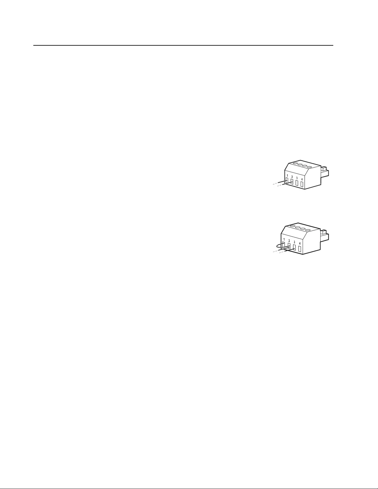
Normally open contacts
1. If the EPO swit ch or relay c ontact s are norm ally op en, inse rt the wi res from th e
switch or contacts at pins 1 and 2 of the EPO te rmi nal b lock. Use 16-28 AWG
wire.
2. Secure the wires by tightening the screws.
If the contacts are closed, the UPS will turn OFF and power will be removed from the load.
Normally closed contacts
1. If t he E PO switch or relay contacts are normally c los ed, insert the wires from
the swit ch or co ntacts at pins 2 and 3 of the EPO terminal block . Use 16-28
AWG wire.
2. Insert a wire jumper between pins 1 and 2. Secure the wires by tightening the
three scre ws at positions 1, 2, and 3.
If the contacts are opened, the UPS will turn OFF and power will be removed from the load.
Note: Pin 1 is the power sourc e for the EPO ci rcuit, it provides a few milliampere of 24 V power.
If the normally closed (NC) EPO configuration is us ed, the EPO switch or rel ay should be rated for “dry” circ uit
application s, the ra ting should be for low voltage and low current appli cations . Th is n ormally impli es the contacts
are gold-plated.
The E PO interface is a Safety Extra Low Voltage (SELV) circuit. Connect the EP O interface only to other SELV
circuits. The EPO interface monitors circuits that have no determined voltage potential. SELV circuits are
controlled by a switch or relay properly isolated from utility power. To avoid damage to the UPS, do not connect
the EPO interface to any circuit other than a SELV circuit.
Use one of the following cable ty pes to connect the UPS to the EPO swi tch.
• CL2: Cla ss 2 ca ble for general use.
• CL2P: Pl enum ca ble for use in ducts , pl enums, and other spaces used for en vironmenta l air.
• CL2R: Riser cable for use in a vertical r un in a floor- to-floor shaft.
• CLEX: Lim ited use cable for use in dwellings and for us e in ra ce ways .
• Insta llation in Canada: Use only CSA certified, type EL C, (e xtra-low voltage control cable).
• Insta llation in countries other than Canada and the USA: Use standard low voltage cable in accordance with
national and loca l r egulations.
Note: The EPO function is available only for 2200/3000VA models.
gen0887a
gen0888a

13Smart-UPS 750/1000/1500/2200/3000 VA 100/120/230 Vac / 500 VA 100 Vac Tower
Troubleshooting
Problem and Possible Cause Solution
The UPS will n ot turn on o r there is no ou tput
The unit has not been turned on. Pre ss the O N key once to turn on the UPS.
Th e U PS is not con n e ct ed t o utilit y po w e r. Be sure the powe r cable is securely connected to the unit a nd to the utilit y pow er
supply.
The input circuit breaker has tripped. Reduce the load on the U PS. Disconnect nonessential equipmen t and reset the circuit
breaker.
The unit show s very low or no input utility
voltage. Check the utility pow er sup ply t o the UPS by plugging in a table la m p. If the li ght is
very dim, check the utility vo ltage.
The battery connector plug is not
securel y connected. Be sure that all batte ry conne ctions are secure.
There is an internal UPS fault. Do not attempt to use the UPS. Unplug the UPS and have it serviced immediately.
The UPS is operating o n battery, wh ile connected to ut ility po wer
The input circuit breaker has tripped. Reduce the load on the U PS. Disconnect nonessential equipmen t and reset the circuit
breaker.
There is very hi gh, very low, or
distorted input line volta ge.
Move th e UPS to a dif f ere nt outl et on a di f fere nt ci rcui t. Test the i nput vol tage w ith t he
utility vol tage display. If acceptable to the c onnected equipm ent, reduce the U PS
sensitivity.
UPS is emits intermittent beeps
The UPS is operating normally. None. The UPS is protecting the connected equipment.
UPS does no t provide expected ba ckup time
Th e U PS ba tt ery is weak due to a
recent power outage or is near the end
of its service life.
Charge the battery. Batteries require recharging after extended outages a nd w ear out
faster whe n put into service often or when operated at elevated t emperatures. If th e
battery is near the end of its s ervice life, consider replacing the battery even if the
rep lace battery indicat or has no t illuminated.
The UPS is experiencing an overload
condition. Chec k the UPS load display. Unplug unne cessary equipment, such as printers.
Display interface LEDs flash sequentially
The UPS has been shut down remotely
through so ftware or an optional access ory
card.
None. The UPS will restart automat ically when util ity power is restored.
The Fault L E D is illuminat ed
The UPS displays a fault m essage and emits a constant beeping sound
Inter na l U P S fault. Do no t at te m p t to use the UP S . Turn th e U P S o ff an d hav e it se rvi ce d im med iate l y.
The Replace Battery LE D is illuminated and the UPS beeps for o ne min ute every five hours
The battery has a weak charge. Allow the battery to recharge for at least four hours. Then, perform a self-test. If the
pro blem persists after recharging, repla ce the ba ttery.
The Replace Battery LED is flashing and the UPS beeps once every 2 seconds
The r eplaceme n t battery is not
properly connec ted. Be sur e that the batt ery con nector is secure ly connected.
The UP S displays a site wiring fa ult message
Wiring faults det ected includ e
missing ground, hot-neutral,
po larity r evers al, and overloaded
neutra l circuit.
If the UPS ind ic at es a site wiri ng fault , ha ve a quali fi ed elec tr icia n insp ect th e buildi ng
wiring. (A pplicable for 120 V units only.)

Smart-UPS 750/1000/1500/2200/3000 VA 100/ 120/230 Vac / 500 VA 100 Vac Towe r14
Service
If th e un it re q ui re s se r vi ce , d o no t retur n it to t he d e al er. Fol lo w t he se st eps:
1. Review the Troubleshooting section of t h e manual to eliminat e co mmon probl ems.
2. If the proble m pe rsi sts, conta ct APC by Schneider Electric Cust ome r S upport through the APC by
Schneider Electric Web site, www.apc.com.
a. Note the model number and serial number and the date of purchase. The model and serial
numbers ar e located on the r ear panel of the unit and are availabl e through the LCD displ ay
on select mode ls.
b. Call APC by Schne ide r Elec tric Customer Suppor t and a technic ian wi ll attempt to solve
the problem over the phone. If this is not possible, the technic ian wi ll issue a Returned
Material Authoriza tion Number (RMA#).
c. If the unit is under warranty, the repairs are free.
d. Service procedures and returns may vary int erna tionally. Refe r to the APC by Schneider
Electric We b site for country specific instructions.
3. Pack the uni t in the original packaging whenever poss ible to avoid da ma ge in tr ansit. Never use fo am
beads for packaging. Dam age sustained in transit is not covered under warranty.
a. Always DISCONNECT THE UPS BATTERIES before shipping. The United States
Department of Transportation (DOT), and the Internation al Air Transport
Association (IATA) r egulations require that UPS batteries be disconnected before
shipping. The inter nal batteries may remain in the UPS.
b. External Battery Pa ck products are deenergized when discon necte d from th e associated
UPS product. I t is not necessary to disco nnect the internal batt eries for shipping. Not all
units utilize an exter nal battery pack.
4. W r ite the RMA# provided by Customer S upport on the outs ide of the package.
5. Return the unit by insured, prepaid carrier to the address provided by Customer Support.
Transport the unit
1. Shut down and dis connect all connected equipment.
2. Discon nec t the unit from utility power.
3. Disconn ect al l in ternal and ex ternal batteries (if applicab le).
4. Follow the shipping instructions outlined in the Service section of this manu al.

15Smart-UPS 750/1000/1500/2200/3000 VA 100/120/230 Vac / 500 VA 100 Vac Tower
Two Year Limited Factory Warr anty
Schneider Electri c IT Corporation (SEIT ), warrants its pr oducts to be free from defects in material s and
workmanshi p for a period of three (3) yea r s excludi ng the bat teries, which are wa rranted for two (2) ye ars from the
date of purchase. The SEIT obli gation under this warranty is limited to repa iring or replacing, at its own sole
option, any such defective products. Repair or replacement of a defective product or parts thereof does not extend
the original warranty period.
This warra nty applies only to the original purchaser who must have properly registered the product within 10 days
of purchase. Products may be reg is tered online at warranty.apc.com .
SEIT shall n ot be liable und er the warranty if its tes ting and exa mi nation dis close that the alleged defect in the
product does n ot exist or was caused by end us er’s or any third person’s misuse, negligenc e, improper installati on,
testing, operat ion or use of the product c ontrary to SEIT’s recommenda tions or specifications. Further, SEIT shall
not be liable for d efe cts result ing from: 1) unauth orized attem pts to repair or modif y the product, 2) incorre ct o r
inadequate electrical voltage or connec tion, 3) inappropriate on si te operation conditions, 4) Acts of God, 5)
exposure to th e elements , o r 6) the f t. In no event shall S EIT have any liabili ty under this warranty for any product
where the se rial number has been altered, defac ed, or removed.
EXCEPT AS SET FORTH ABOVE, THERE ARE NO WARRANTIES, EXPRESS OR IMPLIED, BY
OPERATION OF LAW OR OTHER WISE, APPLICABLE TO PRODUCTS SOLD, SERVICED OR
FURNISHED UNDER THIS AGREEMENT OR IN CONNECTION HEREWITH.
SEIT DISCLAIMS ALL IMPLIED WARRANTIES OF MERCHANTABILITY, SAT ISFACTION AND
FITNESS FOR A PARTICULAR PURPOSE.
SEIT EXPRESS WA RRANTIES WILL NOT BE ENL ARG ED, DIMINISHED, OR AFFECTED BY AND
NO OBLIGATION OR LIABILITY WILL ARISE OUT OF, SEIT’ S RENDERING OF TECHNICAL OR
OTHER ADVICE OR SERVICE IN CONNE CTION WITH THE P RODU CTS.
THE FOREGOING WARRANTIES AND REMEDIES ARE EXCLUSIVE AND IN LIEU OF ALL
OTHER WARRANTIES AND REMEDIES. THE WARRANTIES SET FORTH ABOVE CONSTITUT E
SEIT’S SOL E LIABILITY AND PURCHASER’S EXCLUSIVE REMEDY FOR ANY BREACH OF SUCH
WARRANTIES. SEIT WARRANTIES EXTEND ONLY TO ORIGINAL PURCHASER AND ARE NOT
EXTENDE D TO ANY THIRD PARTIES.
IN NO EVENT SHALL SEIT, ITS O FFICERS, DIRECTORS, AFFILIATES OR EMPLOYEES BE
LIABLE FOR ANY FORM OF INDIRECT, SPEC IAL, CONSEQ U ENTIAL OR PUNI TIVE DAMAGES ,
ARISING OUT OF THE USE, SER VICE OR INSTALLATION OF THE PRODUCTS, WHETHER SUCH
DAMAGES ARISE IN CONTRACT OR TORT, IRRESPECTIVE OF FAULT, NEGLIGENCE OR
STRICT LIABILITY OR WHETHER SEIT HAS BEEN ADVISED IN ADVANCE OF THE POSSIBILITY
OF SUCH DAMA GES. SPECIFICALLY, SEIT IS NOT LIABLE FOR ANY COSTS, SUCH AS LOST
PROFITS OR REVENUE, WHETHER DIRECT OR INDIRECT, LOSS OF EQUIPMENT, LOSS OF USE
OF EQUIPME NT, LOSS OF SOFTWARE , LOSS OF DATA, COSTS OF SUBSTITUANTS, CLAIMS BY
THIRD PAR TIES, OR OTHERWISE.
NOT HING IN TH IS LIMITED WARRAN TY SHALL SEEK TO EXCLUD E OR LIMIT SEIT’S
LIABILITY FOR DEATH OR PERSONAL INJURY RESULTING FROM ITS NEGLIGENCE OR ITS
FRAUDULENT MISREPRESENTATION OF TO THE EXTENT THAT IT CANNOT BE EXCLUDED
OR LIMITED BY APPLICA BLE LAW.
To obtain service under warranty you must obtain a Returned Material Authorization (RMA) number from
customer support. Customers with warranty claims issues may access the SEIT worldwide customer support
network through the SEIT Web site: www.apc.com. Select your country from the country selec tion drop down
menu. Open the Support tab at the top of the web page to obtain information for customer support in your region.
Produc ts must be r eturned with tra ns portation c harges prepaid and must be accompanied by a brief descri ption of
the problem encountered and proof of date and place of purchase.

03/2013EN 990-3534D
APC by Schneider Electric
Worldwide Customer Support
Customer support for this or any othe r APC by Schneider Electric product is available at no char ge in any of
the following ways:
• Visit the APC by Schneider Electric Web site to acces s documents in the APC by Schne ider Electric
Knowledge Base and to submit customer support reque sts.
–www.apc.com (Corpor ate Headquarters)
Connect to localized APC by S chneider Electric Web sites for specific countries, each of which
provides customer support inform ation.
–www.apc.com/support/
Global sup port s ear ching APC by Schneide r El ectric Knowledge Base and using e-support.
• Contact t he APC by Schneider Electric Customer Suppor t Center by telephone or e-mail.
– Local, country specific centers: go to www.apc.com/support/contact for contact information.
– For information on how to obtain local customer support, contact the APC by Schneider Electric
representative or other distributors from whom you purchased your APC by Schneider Electric
product.
Select models are ENERGY STAR® qualified.
Fo r mor e in f o rm ati on go to w w w.a p c. com/ s i te/r e cycl e/i nd ex .c fm/e n e rgy - eff i ci en cy /ene rg y - star /
© 2013 APC by Schneider Electric. APC, the APC logo and APC, the APC logo, Smart-UPS and
PowerChute are owne d by Schneider Electric Indus tries S.A.S. or their affili ated compani es. All other
trade mar ks are pr operty of their respective owners.