APC Smart-UPS User Manual
Displayed below is the user manual for Smart-UPS by APC which is a product in the Uninterruptible Power Supplies (UPSs) category. This manual has pages.
Related Manuals
Installation and Operation
Smart-UPS™SURTA
Uninterruptible Power Supply
1500XL/1500RMXL2U/1500XLJ
2200XL/2200RMXL2U
100/120 Vac
Tower/Rack-Mount 2U
su0541a

Smart-UPS™
SURTA1500XL
SURTA1500RMXL2U
SURTA1500XLJ
SURTA2200XL
SURTA2200RMXL2U
100/120 Vac
Tower/Ra ck-Mount 2U
English

SURTA 1500XL/1500XLJ/2200XL Series 100/120 Vac Tower/Ra ck-M oun t 2U2
Product Description
The APC™ by Schneider Electric Smart-UPS™ SURTA1500XL/2200XL is a high performance uninterruptible
power supply (UPS). The UPS provides protection for electronic equipment from utility power blackouts,
brownouts, sags, surges, small utility power fluctuations and large disturbances. The UPS also provides battery
backup power for connected equipment until utility power returns to safe levels or the batteries are fully
discharged.
This user manual is available on the enclosed Documentation CD and on the APC by Schneider Electric web site,
www.apc.com.
Package Contents
Accessories
Install accessories prior to co nn ecting pow er to the UPS
Refer to the APC by Schneider Electric web site, www.apc.com for available accessories.
Optional accesso ries
• External battery pack (XLBP)
• USB communication cables
• Network Management Card (NMC)
Important Safety Messages
Read the instructions carefully to become familiar with the equipment before trying to install, operate, service or
maintain it. The following special messages may appear throughout this manual or on the equipment to warn of
potential hazards or to call attention to information that clarifies or simplifies a procedure.
The addition of this symbol to a Danger or Warning product safety label indicates that an
electrical hazard exists that will result in death, serious injury and product damage if the
instructions are not followed.
The addition of this symbol to a Warning or Caution product safety label indicates that a hazard
exists that can result in injury and product damage if the instructions are not followed.
All m odels 120 Vac models
• UPS • PowerChute™ utility CD
• Front bezel • USB communication cable
• Serial communication cable
• Literature kit containing:
–Product docu mentati on
–Docu ment at ion CD
–Safety Guide
–Warranty information

3SURTA 1500XL/1500XLJ/2200XL Series 100/120 Vac Tower/Rack -Mount 2U
Safety and General Information
Inspect the package contents upon receipt.
Notify the carrier and dealer if there is any damage.
Read the instructions carefully to become familiar with the equipment before trying to install, operate, service or maintain
it. The following special messages may appear throug hout this manual or on the equipment to warn of potential hazards or
to call attention to information that clarifies or simplifies a procedure.
• Adhere to all national and local electrical codes.
• All wiring must be performed by a qualified electrician.
• Changes and modifications to this unit no t expressly approved by APC could void the warranty.
• This UPS is intended for indoor use only.
• Do not operate this unit in direct sunlight, in contact with fluids, or where there is excessive dust or
humidity.
• Be sure the air vents on the UPS are not blocked. Allow adequate space for proper ventilation.
• For a UPS with a factory installed power cord, connect the UPS power cable directly to a wall outlet. Do not
use surge protectors or extension cords.
• The battery typically lasts for two to five years. Environmental factors impact battery life. Elevated ambient
temperatures, poor quality utility power, and frequent short duration discharges will shorten battery life.
• The equipment is heavy. Always practice safe lifting techniques adequate for the weight of the equipment.
• The batteries are heavy. Remove the batteries before installing the UPS and external battery packs (XLBPs),
in a rack.
• Always install XLBPs at the bottom in rack-mount configurations. The UPS must be installed above the
XLBPs.
• Always install peripheral equipment above the UPS in rack-mount configurations.
Deenergizin g safety
The UPS contains internal batteries and may present a shock hazard even when disconnected from the branch
circuit (mains). Before installing or servicing the equipment check that the:
• input circuit breaker is in the OFF position.
• internal UPS the batteries are removed.
• XLBP battery modules are disconnected.
Electrical safety
• For models with a hardwired input, the connection to the branch circuit (mains) must be performed by a
qualified electrician.
• 230 V models only: In order to maintain compliance with the EMC directive for products sold in Europe,
output cords attached to the UPS must not exceed 10 meters in length.
• The protective earth conductor for the UPS carries the leakage current from the load devices (computer
equipment). An insulated ground conductor is to be installed as part of the branch circuit that supplies th e
UPS. The conductor must have the same size and insulation material as the grounded and ungrounded
branch circuit supply conductors. The conductor will typically be green and with or without a yellow stripe.
• The UPS input ground conductor must be properly bonded to protect ive earth at the service panel.
• If the UPS input power is supplied by a separately derived system, the ground conductor must be properly
bonded at the supply transformer or motor generator set.

SURTA 1500XL/1500XLJ/2200XL Series 100/120 Vac Tower/Ra ck-M oun t 2U4
Battery safety
• Before installing or replacing the batteries, remove jewelry such as wristwatches and rings.
High short circuit current through conductive materials could cause severe burns.
• Do not dispose of batteries by burning them. The batteries may explode.
• Do not open or mutilate batteries. Released electrolyte is harmful to the skin and eyes, and may be toxic.
Hardwire sa fety
• Verify that all branch circuit (mains) and low voltage (control) circuits are deenergized, and locked out
before installing cables or making connections, whether in the junction box or to the UPS.
• Wiring by a qualified electrician is required.
• Check national and local codes before wiring.
• Strain relief is required for all hardwiring (not supplied).
• All openings that allow access to UPS hardwire terminals must be covered. Failure to do so may result in
personal injury or equipment damage.
• Select wire size and connectors according to national and local codes.
General information
• The UPS will recognize as many as 10 external battery packs connected to the UPS. However there is no
limit to the number of XLBPs th at can be used with the UPS.
Note: For each XLBP added, increased recharge time will be required.
• The model and serial numbers are located on a small, rear panel label. For some models, an addit ional label
is located on the chassis under the front bezel.
• Always recycle used batteries.
• Recycle the package materials or save them fo r reuse.
FCC St atement for Class A product s
This equipment has been tested and found to comply with the limits for a Class A digital device,
pursuant to part 15 of the FCC Rules. These limits are intended to provide reasonable protection against
harmful interference when the equipment is operated in a commercial environment. This equipment
generates, uses, and can radiate radio frequency energy and, if not installed and used in accordance with
the inst ruction manual, may cause harmful interference to radio communications. Operation of this
equipment in a residential area is likely to cause harmful interference in which case the user will be
required to correct the interference at his own expense.
5SURTA 1500XL/1500XLJ/2200XL Series 100/120 Vac Tower/Rack -Mount 2U
Product Overview
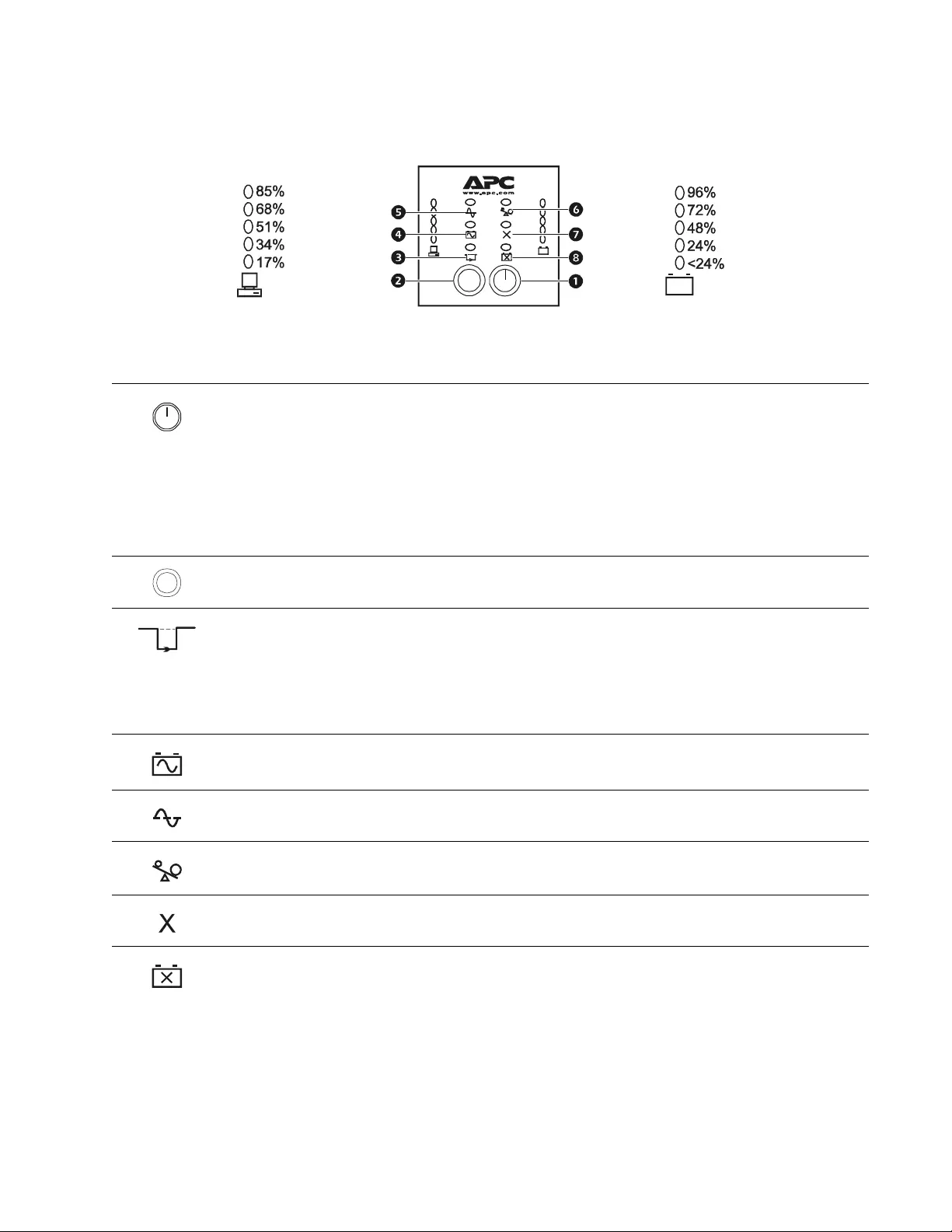
Front disp l ay panel
Button or
LED Description
The ON button: has three functions.
Press this button to turn on the UPS.
Press this button to initiate a Cold St art. Cold Start is not a normal cond ition. When there is
no utility power and UPS is off, press and hold this button to resto re pow e r to UPS. UPS
will emit two beeps. During second beep, release the button.
Press this button to initiate a Self-Test.
Automatic: The UPS performs a self-test automatically when turned on, and every two
weeks there after by default. During self-test, UPS briefly operates on battery power.
Manual: Press and hold ON button for a few seconds to initiate self-test.
The Off button: This button is used to switch UPS o ff.
The Bypass LED illuminate s indicating that the UPS is in byp ass mode. Utility power is sen t
directly to connected equipment during bypass mode operation. Bypass mode operation is the
result of an internal UPS fault, an overload condition or a selection made through NMC or
PowerChute software.
Battery operation is not available wh ile the UPS is in bypass mode.
Refer to “Troubleshooting” on page 10 in this manual.
The On Battery LED illuminates indicating that th e UPS is supplying battery power to
connected equipment.
The On Line LED illuminates when the UPS is drawin g utility power and performing double
conversion to supply power to connected equipment.
The Overload LED illuminates indicating that th e UPS is ex periencing an overload condition.
Refer to “Troubleshooting” on page 10 in this manual.
The Fault LED illuminates indicating that the UPS detects an internal fault.
Refer to “Troubleshooting” on page 10 in this manual.
The Battery Fault LED illuminates indicating that one or more batteries are disconnected or
must be replaced.
Refer to “Troubleshooting” on page 10 in this manual.
su0311b
Test
Battery Charge
Load
Test
SURTA 1500XL/1500XLJ/2200XL Series 100/120 Vac Tower/Ra ck-M oun t 2U6
Front Display Panel
Feature Description
The UPS has a diagnostic feature that indicat es ut ility voltage.
The UPS starts a self-test as part of this procedure. The self-test does not affect voltage
display.
Press and hold the ON button to view utility voltage bar graph indicator. As so on as the On
Line LED starts flashing indicating a self-test is in progress, the five LED Battery Charge
indicator to the right of the display panel will show utility input voltage.
Refer to diagram for voltage reading.
Values are not lis ted on the UPS.
Indicators on the UPS show the voltage is between the displayed value on list an d the n e xt
higher value.
Refer to “Troubleshooting” on page 10 in this manual.
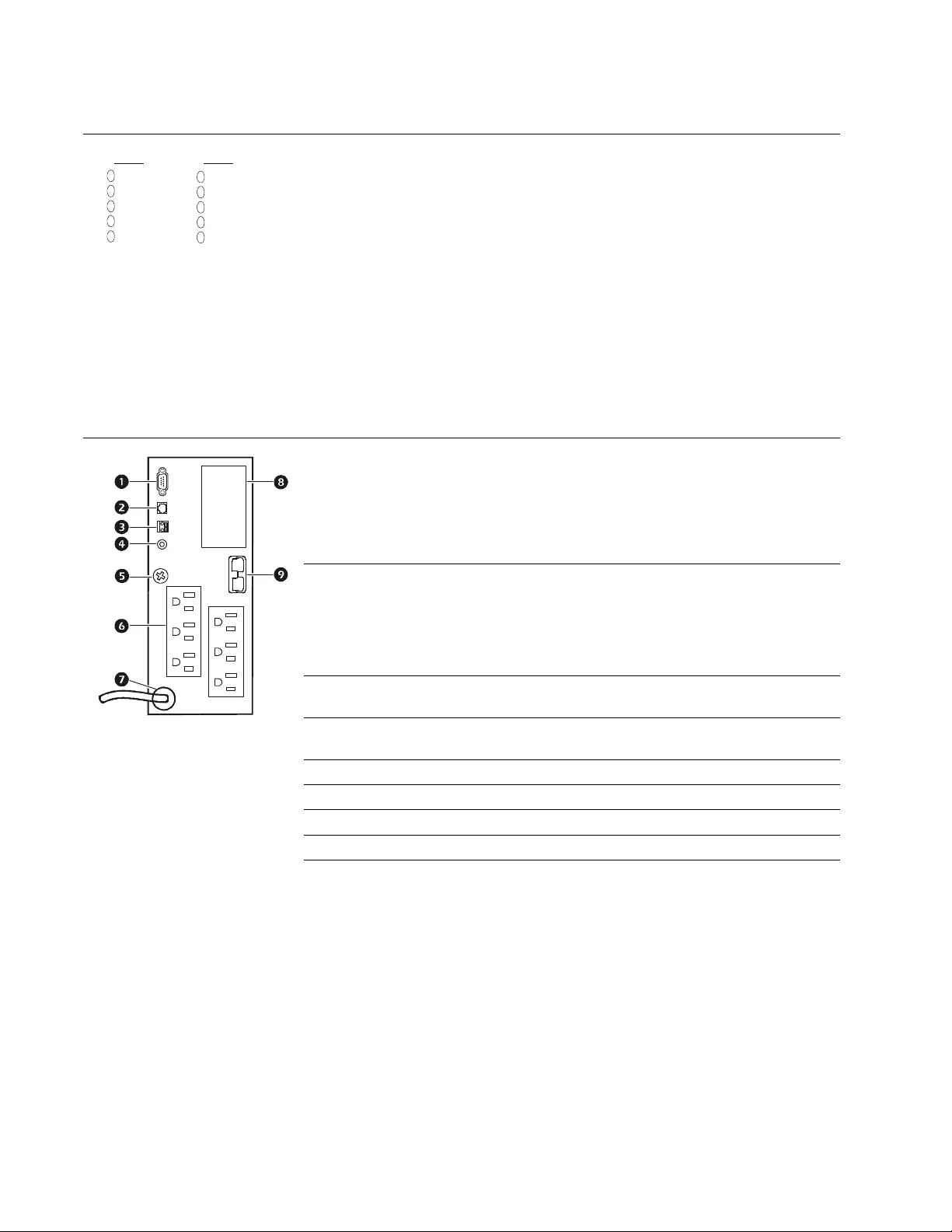
Rear panel
SERIAL COM-se ri al communi cat ion port for:
Power management software
Interface kits
Use only interface kits supplied or approved by APC. Any other serial
interface cable will be incompatible with UPS connecto r.
Serial and USB communication ports cannot be used simultaneously.
USB COM-USB communi cat ion port
120 Vac models: USB communication cable
100 Vac models: USB communication cables and software are available as
accessories.
Contact APC at www.apc.com for purchase information.
Emergency Power Off (EPO) terminal allows the user to connect the UPS to a
central EPO system.
SITE WIRING FAULT indicator-the LED illuminates when the UPS detects a
building wiring fault.
GND-The UPS features a chassis ground screw located on the UPS rear panel.
Outlets for connecting electronic equipment.
UPS power cable for connecting to utility power.
SmartSlot for optional NMC or PowerChute accessories.
External battery pack connector. The UPS will support up to 10 XLBPs.
118.0
100V
108.7
99.3
90.0
80.6
138.2
120V
128.8
119.5
110.1
100.8
suo0523a

7SURTA 1500XL/1500XLJ/2200XL Series 100/120 Vac Tower/Rack -Mount 2U
Specifications
Installation
Rack-Mount and St ack Configurations
Tower Config uration
External Battery Pack(s)
Refer to the user manual supplied with the external battery pack for installation instructions.
Temperature Operating 0° to 40° C (32° to 104° F) This unit is intended for indoor use only.
Select a location sturdy enough to handle
the weight.
Do not operate UPS where there is
excessive dust or temperature or humidity
are outside specified limits.
This unit has side air vents. Allow
adequate space for proper ventilation.
Environmental factors impact battery life.
High temperatures, poor utility power , and
frequent, short duration discharges will
shorten battery life.
Storage -15° to 45° C (5° to 113° F)
charge UPS battery every six months
Maximum
Elevation Operating 3,000 m (10,000 ft)
Storage 15,000 m (50,000 ft)
Humidity 0% to 95% relative humidity, non-condensing
NOTICE
RISK OF EQUIPMENT DAMAGE
• Adhere to all national and local electrical codes.
• Wiring should be performed by a qualified electrician.
• Always connect the UPS to a grounded outlet.
• The equipment is heavy. Always practice safe lifting techniques adequate for the weight of the equipment.
• Always connect ground wires between the UPS and the external battery packs.
• Refer to the XLBP user manual for details.
Failure to follow these instructions can result in equipment damage
NOTICE
RISK OF EQUIPMENT DAMAGE
• Refer to the installation guide supplied with the rail kit for rack-mount configuratio n instru ctions.
Failure to follow these instructions can result in equipment damage
NOTICE
RISK OF EQUIPMENT DAMAGE
• The UPS is shipped with stabilizer brackets installed. Do not remove the s tabilizer brackets when the UPS is to be
operated in tower configuration.
Failure to follow these instructions can result in equipment damage
SURTA 1500XL/1500XLJ/2200XL Series 100/120 Vac Tower/Ra ck-M oun t 2U8
Operation
Connect equipment to the UPS
1. Connect equipment to UPS. Do not use extension cords, plug equipment directly into the UPS outlets.
2. If applicable, connect equipment to the serial or USB ports.
3. Add optional accessories to the SmartSlot.
4. For additional system security, install PowerChute software. Refer to the PowerChute Utility CD for
instructions.
5. External battery packs pr ovide extended runtime during power outages. Refer to the APC by Schne ider
Electric web site, www.apc.com for external battery pack purchase information. Refer to the external
battery pack user manual for installation instructions.
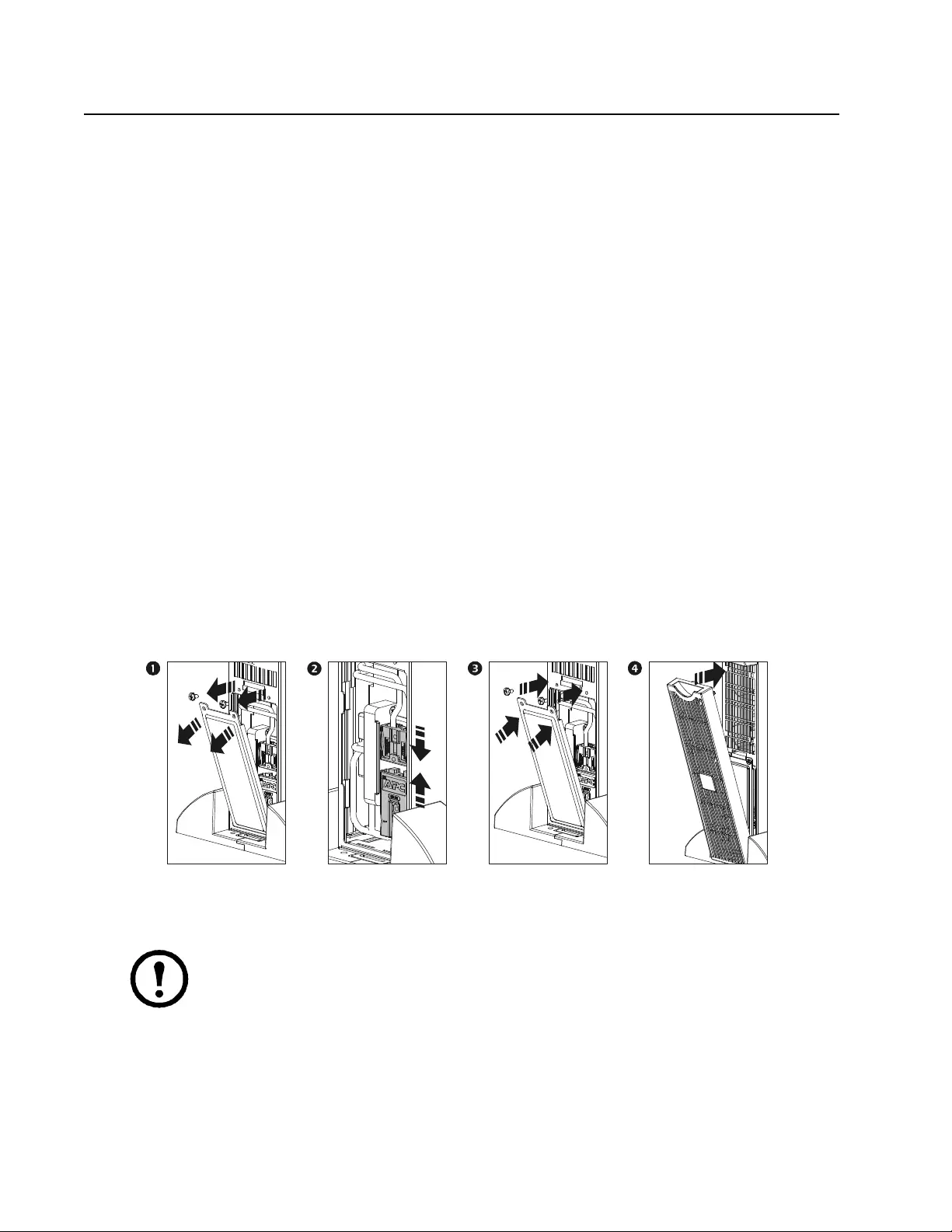
Connect the Internal Battery and
Install the Bezel
The UPS is shipped with the internal battery disconnected.
1. Remove the battery compartment cover.
2. Remove the warning label and protective sticker from the battery connector. Place the sticker on the back
of the battery compartment cover for re-use.
3. Snap the battery connectors together.
4. Reinstall the battery cover.
5. Install the front bezel.
Connect Power and Start the UPS
The UPS will charge to 90% capacity in the first four hours of normal operation. Do not expect full
battery run capability during this initial charge period.
1. Connect the UPS to the building utility power. Connect the UPS into a two-pole, three-wire, grounded
receptacle.
2. Press the On button the front display panel of the UPS to apply power to the unit and all connected
equipment.
3. To use UPS as a master on/off switch turn on all the equipment that is connected to the UPS.
4. Configure the Network Management card (NMC), if installed. Refer to NMC documentation for
instructions.
su0072b

9SURTA 1500XL/1500XLJ/2200XL Series 100/120 Vac Tower/Rack -Mount 2U
Configuration
UPS Settings
Configure t he settings using PowerChute software, a network management card or terminal mode.
Function Factory Default Options Description
Automatic
Self-Test On startup and every
14 days (336 hours)
there after
• On startup and every
7 days (168 hours)
there after
• On startup and every 14
days
(336 hours) there after
• On startup only
• No self-test
Set the interval at which the UPS will
execute self-tests.
UPS ID UPS_IDEN Use a maximum of eight
alphanumeric characters to
define a name for the UPS.
Uniquely identify the UPS, i.e. server name
or location for network manage ment
purposes.
Date of Last
Battery
Replacement
Manufacture
Date mm/dd/yy Reset this date when the battery mod ul e is
replaced.
Minimum Capac ity
Before Return from
Shutdown
0 percent • 0%
•15%
•30%
•60%
•75%
•90%
Specify the percentage to which batteries
will be charged following a low-battery
shutdown, before sending power to
connected equipment.
Alarm Delay
Control Enable • Enable
•Mute • Disable Specify the delay between an event and the
alarm to avoid alarms for insignificant
events.
Shutdown Delay 90 seconds • 0 sec
•90 sec
•180 sec
•270 sec
•360 sec
•450 sec
•540 sec
•630 sec
Specify the delay between the UPS
shutdown command and the actual
shutdown.
Duration of
Low Battery
Warning
2 minutes • 2 min
•5 min
•8 min
•11 min
•14 min
•17 min
•20 min
•23 min
Specify the number of minutes before
system shutdow n, after the low batt ery
warning.
Synchronized
Tu rn-on Delay 0 seconds • 0 sec
•60 sec
•120 sec
•180 sec
•240 sec
•300 sec
•360 sec
•420 sec
Specify the delay between the return of
utility power and the UPS turns on. Set the
interval to avoid a branch circuit overload
condition.
High Bypass Points 100 Vac models
110 Vac
•107 Vac
•110 Vac
•113 Vac
•116 Vac
•119 Vac
•122 Vac
•125 Vac
•128 Vac
Maximum voltage that the UPS will pass to
connected equipmen t during internal byp ass
operation.
120 Vac models
133 Vac
•127 Vac
•130 Vac
•133 Vac
•136 Vac
•139 Vac
•142 Vac
•145 Vac
•148 Vac

SURTA 1500XL/1500XLJ/2200XL Series 100/120 Vac Tower/Ra ck-M oun t 2U10
Emergency Power Off (EPO)
The Emergency Power Off (EPO) option is a safety feature that will immediately remove power to all connected
equipment. When EPO button is pushed, all connected equipment will immediately turn off and will not switch to
battery power.
Adhere to all national and local electrical codes. Wiring must be performed by a qualified electrician.
The switch should be connected in a normally open switch contact. External voltage is not required; the switch is
driven by 12 V internal supply. In closed condition, 2 mA of current are drawn.
The EPO switch is internally powered by the UPS for use with non-powered switch circuit breakers.
Connect the EPO
The EPO interface is a Safety Extra Low Voltage (SELV) circuit. Connect it only to other SELV circuits. The
EPO interface monitors circuits that have no determined voltage potential. Such closure circuits may be
provided by a switch or relay properly isolated fro m the utility. To avoid damage to the UPS, do not connect
the EPO interface to any circuit other than a closure type circuit.
Use one of the following cable types to connect the UPS to the EPO switch.
• CL2: Class 2 cable for general use.
• CL2P: Plenum cable for use in ducts, plenums, and other spaces used fo r environmental air.
• CL2R: Riser cable for use in a vertical run in a floor-to-floor shaft.
• CLEX: Limited use cable for use in dwellings and for use in raceways.
• For installation in Canada: Use only CSA certified, type ELC, (extra-low voltage control cable).
• For installation in other countries: Use standard low-voltage cable in accordance with national and local
regulations.
Low Bypass Points 100 Vac models
78 Vac
•78 Vac
•80 Vac
•82 Vac
•84 Vac
•86 Vac
•88 Vac
•90 Vac
•92 Vac
Minimum voltage that th e UPS will pass to
connected equipment during internal byp ass
operation.
120 Vac models
86 Vac
•86 Vac
•88 Vac
•90 Vac
•92 Vac
•94 Vac
•96 Vac
•98 Vac
•100 Vac
Output Frequency Automatic sel ect ion
between:
50 ± 3 Hz
60 ± 3 Hz
Automatic
50 ± 0.1 Hz
50 ± 3Hz
60 ± 0.1 Hz
60 ± 3 Hz
Specify the UPS output frequency.
Whenever possible the output frequency
should track the input frequency.
Number of Battery
Packs 1 Number of connected battery
packs Defines the number of connected battery
packs for proper runtime prediction.
1=internal battery module
2=one external battery pack
3=two external battery packs
The EPO connector is located on the rear panel of the UPS.
1. Strip insulation from one end of each wire to be used for connecting EPO.
2. Insert a screwdriver into the slot above the terminal to be wired. Insert stripped wire into
terminal. Remove screwdriver to secure wire in terminal. Repeat for each terminal.
Function Factory Default Options Description

11SURTA 1500XL/1500XLJ/2200XL Series 100/120 Vac Tower/Rack-Mount 2U
TERMINAL MODE TO
CONFIGURE UPS PARAMETERS
Terminal Mode is a menu driven interface that enables configuration of the UPS by users not wishing to use
PowerChute software or an optional Network Management Card.
Connect the serial cable to the serial com connector on the back of the UPS.
If PowerChute software is not installed do not perform steps 1, 2, 8 and 9.
1. For Windows users: STOP the PowerChute Server using the following steps:
– From the Desktop, go to St art => Settings => Control Panel => Administrative Tools => Servic es.
– Select APC PowerChute Server - right click the mouse and select Stop.
2. For Linux users: STOP the PowerChute Server using the followi ng steps:
– Change directory to /etc/init.d.
– Initiate the command . /PowerChute stop.
3. Open a terminal program. Example: HyperTerminal
– From the Desktop, go to Start => Prog rams => Accessories => Communication =>HyperTerminal.
4. Double-click on the HyperTerminal icon.
– Follow the prompts to choose a name and sel ect an icon. Disregard the message, "...must install a
modem," if it is displayed. Click OK.
– Select the COM port that is connected to your UPS. The port settings are:
• bits per second - 2400
• data - bits 8
• parit y - none
• stop bit - 1
• flow control - none
–Press
ENTER
5. Press 1 to modify the UPS parameters.
6. Follow the prompts.
7. Exit the terminal prog ram.
8. For Windows users: START the PowerChute Server using the following steps:
– From the Desktop, go to St art => Settings => Control Panel => Administrative Tools => Servic es.
– Select APC PowerChute Server - right click the mouse and select Start.
9. For Linux users: START the PowerChute Server using the following steps:
– Change directory to /etc/init.d.
– Initiate the command ./PowerChute start.

SURTA 1500XL/1500XLJ/2200XL Series 100/120 Vac Tower/Ra ck-M oun t 2U12
Troubleshooting
Problem and Possible Cause Solution
The UPS will not turn on or there is no output
The unit has not been turned on. Press the ON button once to turn on the UPS.
The UPS is not connected to utility
power. Ensure that the power cable is securely connected to the utility power supply.
The input circuit breaker has tripped. Reduce the load to the UPS, disconnect nonessential equipment and reset the
circuit breaker.
The unit shows very low or no input
utility voltage. Check the utility power supply to the UPS by plugging in a table lamp. If the
light is very dim, check the utility voltage.
The battery connectors are not
securely connected. Ensure that all battery connections are secure.
The UPS will not turn off
The unit has not been turned off. Press the OFF button once to turn off the UPS.
There is an internal UPS fault. Do not attempt to use the UPS. Disconnect the UPS from utility and battery
power. Have the UPS serviced immediately.
UPS beeps occasionally
The UPS is in normal operation. None. The UPS is protecting the connected equipment.
Press the ON butto n to silen ce the alarm.
The UPS is operating on battery, while connected to input utility power
The input circuit breaker has tripped. Reduce the load to the UPS, disconnect nonessential equipment and reset the
circuit breaker.
There is very high, very low, or
distorted input line voltage. Move the UPS to a dif ferent outlet on a differ ent circuit. Test the input voltage
with the utility voltage disp lay.
A connected generator is an
inappropriate size. XLJ models do not support the use of a generator.
Check the UPS and generator specifications for compatibility.
UPS does not provide expected backup time
The UPS battery is weak due to a
recent outage or is near the end of its
service life.
Charge the battery. Batteries require recharging after extended outages and
wear out faster when put into service often or when operated at elevated
temperatures. If the battery is n ear the end of its service life, con sider replacing
the battery even if the Replace Battery LED indicator is not yet illuminated.
A UPS overload condition has occurr ed. Check the UPS Load indicator. Disconnect nonessential equipment.
Site Wiring Fault indicator is illuminated
The UPS is connected to an improperly
wired utility outlet. Wiring faults detected include miss i ng gro und , hot-neu tr al polari ty reversal
and overloaded neutral circuit.
Do not attempt to use the UPS. Disconnect the UPS from utilit y and battery
power. Contact a qualified electrician to correct the building wiring.
All indicators are off and the UPS is connect ed to utility service
The UPS has been shut down or the
batteries are discharged from extended
usage.
None. The UPS will restart automatically when utility power returns and
configuration criteria have been met.

13SURTA 1500XL/1500XLJ/2200XL Series 100/120 Vac Tower/Rack-Mount 2U
All indicators flash sequentially
The UPS has been shut down remotely
through software or an optional accessory
card.
None. The UPS will restart automatically when utility power returns.
All indicators are illuminated and the UPS emits a constant beeping sound
The UPS detects an internal fault. Do not attempt to use the UPS. Disconnect the UPS from utili ty and battery
power. Have the UPS serviced immediately.
Battery Fault indicator is illuminated
The Battery Fault LED flashes and a
short beep is emitted every two seconds
to indicate the battery is disconnected.
Check that the battery connectors are fully engaged.
Weak battery. Allow battery to recharge for 24 hours and perform a self-test. If the problem
persists after recharging, replace battery.
Failure of a battery self-test: Battery
Fault LED illuminates and the UPS
emits short beeps for one minute. The
UPS repeats the alarm every five hours.
Allow battery to recharge for 24 hours. Perform the self-test procedure to
confirm the replace battery condition. The alarm stops and the LED clears if
the battery passes the self-test.
If battery fails again, it must be replaced. The connected equipment is
unaffected.
Byp ass indicator is illuminated
By pass mode ha s bee n turned on through
an accessory. If bypass mode has been selected, ignore the LED.
Overload indicator is illuminated and the UPS emits a sustained alarm tone
A UPS overload condition exists. Disconnect nonessential equipment from UPS to eliminate overload condition.
Bypass and Overload indicators are illuminated and the UPS emits a sustained alarm tone
A UPS overload condition has occurr ed. Connected equipment exceeds specified “maximum load” as defined in
Specifications on APC by Sch neider Electric web si t e, www.apc.com.
The alarm remains on until the overload is rem oved. Disconnect nonessential
equipment from UPS to eliminate overload condition.
The UPS continues to supply power as long as it is on line and the circuit
breaker does not trip. The UPS will not provide power from batteries in the
event of a utility voltage interruption.
Fau lt indicator is il luminated
An internal UPS fault has occurred. Do not attempt to use UPS. Tu rn UPS off and have it serviced immediately.
Refer to APC by Schneider Electric web site, www.apc.com.
Bypass and Fault indicators are illuminated and the UPS emits a sustained alarm tone
The UPS has auto matically switched to
Bypass mode. Bypass mode operation
is the result of an internal UPS fault or
an overload condition while operating
on utility power.
In the event an internal UPS fault occurs, Do Not attempt to use UPS. Turn
UPS of f and have it serviced immediately. Refer to APC by Schneider Electric
web site, www.apc.com.
Problem and Possible Cause Solution

SURTA 1500XL/1500XLJ/2200XL Series 100/120 Vac Tower/Ra ck-M oun t 2U14
Maintenance and Transport
Battery replacement
This UPS has a replaceable, hot-swappable battery module. Replacement is a safe procedure, isolated from
electrical hazards. Leave the UPS and connected load on during the replacement procedure.
Once the battery modules have been disconnected the connected equipment is not protected from
power outages.
When the battery modules have been replaced the LED on the display interface will prompt the user to
enter a new battery replacement date.
Refer to the appropriate replacement battery user manual for installation instructions. See your dealer or contact
APC by Schneider Electric at www.apc.com for information on replacement batteries.
Be sure to deliver spent batteries to a recycling facility or ship to APC by Schneider Electric in the
replacement battery packing material.
Prepare the UPS for transport
1. Shut down and disconnect all connected equipment.
2. Disconnect the unit from utility power.
3. Disconnect all internal and extern al batteries (if applicable).
4. Follow th e shipping instructions outlined in the Service section of this manual.
Fault and Overload indicators are illuminated and the UPS emits a sustained alarm tone
The UPS is not sending power to
connected equipment. Connected equipment exceeds specified “maximum load” as defined in
Specifications on APC by Schnei der Electri c web site, www.apc.com.
The alarm remains on until the overload is removed. Disconnect nonessential
equipment from UPS to eliminate overload condition.
The UPS will not provide power fro m batteries in the event o f a utility voltage
interruption.
There is no utility power
There is no utility power and the
UPS is off. Use the Cold Start feature to sup ply power to con nected equipment from UPS
battery(s).
Press and hold t he ON button. There will be a short beep followed by a longer
beep. Release the button during second beep.
Diagnostic utility voltage feature
All five LEDs are illuminated. The line voltage is extremely high and should be checked by an electrician.
There is no LED illumination. The line voltage is extremely low and should be checked by an electrician.
On Line indicator
There is no LED illumination. The UPS is running on battery, or it must be turned on.
The LED is blinking. The UPS is running an internal self-test.
Problem and Possible Cause Solution

15SURTA 1500XL/1500XLJ/2200XL Series 100/120 Vac Tower/Rack-Mount 2U
Service
If the unit requires service, do not return it to the dealer. Follow these steps:
1. Review the Troubleshooting section of the manual to eliminate co mmo n problems.
2. If the problem persists, contact APC by Schneider Electric Customer Support through the APC by
Schneider Electric web site, www.apc.com.
a. Note the model number and serial number and the date of purchase. The model and serial
numbers ar e lo cated o n the r ear pan el o f the un it and are ava ilabl e thr ough the LCD dis play
on select models .
b. Call Customer Support and a tec hnician will attempt to solve the problem over the phone. If
this is not possible, the technician will issue a Returned Material Authorization Number
(RMA#).
c. If the unit is under warranty, the repairs are free.
d. Service procedures and returns may vary internationally. Refer to the APC by Schneider
Electric web site, www.apc.com for country specific instructions.
3. Pack the unit properly to avoid damage in transit. Never use foam beads for packaging. Damage sustained
in transit is not covered under warranty.
a. Note: When shipping within the United States, or to the United States always
DISCONNECT ONE UPS BATTERY before shipping in compliance with U.S.
Department o f Transpor tation ( DOT) and IATA r egul ations . The in tern al b atter ies m ay
remain in the UPS.
b. Batteries may remain connected in the XBP during shipment. Not all units utilize XLBPs.
4. Writ e the RMA# provided by Customer Support on the outside of the package.
5. Return the unit by insured, prepaid carrier to the address provided by Customer Support.

SURTA 1500XL/1500XLJ/2200XL Series 100/120 Vac Tower/Ra ck-M oun t 2U16
Limited Warranty
Schneider Electric IT Corporation (SEIT), warrants its products to be free from defects in materials and
workmanship for a period of two (2) years from the date of purchase. The SEIT obligation under this warranty is
limited to repairing or replacing, at its own sole option, any such defective products. Repair or replacement of a
defective product or parts thereof does not extend the original warranty period.
This warranty applies only to the original purchaser who must have properly registered the product within 10 days
of purchase. Products may be registered online at warranty.apc.com.
SEIT shall not be liable under the warranty if its testing and examination disclose that th e alleged defect in the
product does not exist or was caused by end user or any third person misuse, negligence, improper installation,
testing, operation or use of the product contrary to SEIT recommendations or specifications. Further, SEIT shall
not be liable for defects resulting from: 1) unauthorized attempts to repair or modify the product, 2) incorrect or
inadequate electrical voltage or connection, 3) inappropriate on site operation conditions, 4) Acts of God, 5)
exposure to the elements, or 6) theft. In no event shall SEIT have any liability under this warranty for any product
where the serial number has been altered, defaced, or removed.
EXCEPT AS SET FORTH AB OVE, THERE ARE NO WARRANTIES, EXPRESS OR IMPLIED, BY
OPERATION OF LAW OR OTHERWISE, APPLICABLE TO PRODUCTS SOLD, SERVICED OR
FURNISHED UNDER THIS AGREEMENT OR IN CONNECTION HEREWITH. SEIT DIS C LAIMS
ALL IMPLIED WARRANTIES OF MERCHANTABILITY, SATISFACTION A ND FITNESS FOR A
PARTICULAR PURPOSE.
SEIT EXPRESS WARRANTIES WILL NOT BE ENL ARGED, DIMINIS HED , OR AFFECTED BY AND
NO OBLIGATION OR LIABILIT Y WILL ARISE OUT OF, SEIT RENDE RING OF TEC HN ICAL OR
OTHER ADVICE OR SERVICE IN CONNECTIO N WITH THE PRODUCTS.
THE FOREGOING WARRAN TIES AND REMEDIES ARE EXCLUSIVE AND IN LIEU OF ALL
OTHER WARRANTIES AND REMEDIES. THE WARRANTIES SET FORTH ABOVE CONSTITUTE
SEIT SOLE LIABILITY AND PURCHASER EXCL USIVE REMEDY FOR ANY BREACH OF SUCH
WARRANTIES . SEIT WARRANTIES EXTEND ONLY TO ORIGINAL PURCHASER AND ARE NOT
EXTENDED TO ANY THIRD PARTIES.
IN NO EVENT SHALL SEIT, ITS OFFICERS , DI RECTORS, AFFILIATES OR EMPLOYEES BE
LIABLE FOR ANY FORM OF INDIRECT, SPECIAL, CONSEQUENTIAL OR PUNITIVE DAMAGES,
ARISING OUT OF THE USE, SERVICE OR INSTALLATION OF THE PRODUCTS, WHETHER SUCH
DAMAGES ARISE IN CONTRACT OR TORT, IRRESPECTIVE OF FAULT, NEGLIGE NCE OR
STRICT LIABILITY OR WHETHER SEIT HAS BEEN ADVISED IN ADVANCE OF THE
POSSIBILITY OF SUCH DAM AGES. SPECIFICALLY, SE IT IS NOT LIABLE FOR ANY COSTS,
SUCH AS LOST PROFITS OR RE VENUE, WHETHER DIRECT OR INDIRECT, LOSS OF
EQUIP MENT, L OSS OF U SE OF EQUIPMENT, LOSS OF SOFTWARE, LOSS OF DATA, COSTS OF
SUBSTITUANTS, CLAIMS BY THIRD PART IES, OR OTHERWISE.
NOTHING IN THIS LIMITED WARRANTY SHALL SEEK TO EXCLUDE OR LIMIT SEIT LIABILITY
FOR DEAT H OR PER SONAL INJURY RESULTI NG FROM IT S NEGLIGENCE OR ITS
FRAUDULENT MISREPRESENTATION OF TO THE EXTENT THAT IT CANNOT BE EXCLUDED
OR LIMITED BY APPLICABLE LAW.
To obtain service under warranty you must obtain a Returned Material Authorization (RMA) number from
customer support. Customers with warranty claims issues may access the SEIT worldwide customer support
network through the APC web site: www.apc.com. Select your country from the country selection drop down
menu. Open the Support tab at the top of the web page to obtain information for customer support in your region.
Products must be returned with transportation charges prepaid and must be accompanied by a brief description of
the problem encountered and proof of date and place of purchase.

4/2015990-3622A
APC by Schn eider Electric
Worldwide Customer Support
Customer support for this or any other APC by Schneider Electric product is available at no charge in any of
the following ways:
• Visit the APC by Schneider Electric web site, www.apc.com to access documents in the APC
Knowledge Base and to submit customer support requests.
–www.apc.com (Corporate Headquarters)
Connect to localized APC by Schneider Electric web site for specific countries, each of which
provides customer support information.
–www.apc.com/support/
Global support sear ching APC Knowledge Base and using e-support.
• Contact the APC by Schneider Electric Customer Support Center by telephone or e-mail.
– Local, country specific centers: go to www.apc.com/support/contact fo r cont act in formation.
– For information on how to obtain local customer support, contact the APC by Schneider Electric
representative or other distributor from whom you purchased your APC by Schneider Electric
product.
© 2015 APC by Schneider Electric. Smart-UPS and PowerChute are owned by Schneider Electric Industries S.A.S. or their affiliated
companies. All ot her trademarks are property of their respective owne rs.