APC Smart-UPS User Manual
Displayed below is the user manual for Smart-UPS by APC which is a product in the Uninterruptible Power Supplies (UPSs) category. This manual has pages.
Related Manuals

EN 990-1853E 08/2014
Smart-UPSTM C
Uninterruptible Power Supply
420/620 VA
110/120/230 Vac
Tower
English

1
Introduction
The APC
™
by Schneider Electric Smart-UPS
™
product name is a high perfor mance uninterrup tible
power supply (UPS). The UPS provides pro tectio n for electronic equipment from utility power
blackouts, brownouts, sags, surges, small utilit y power fluctuations and large disturbances. The UPS
also provides battery backup power for connected equipment until utility power returns to safe levels
or the batteries are fully discharged.
This user manual is available on the enclosed CD and on the APC by Schneider Electric web site,
www.apc.com.
1: INSTALLATION
Unpack
Attention: Read the safety instruction sheet before installation.
Inspect the UPS upon receipt. Notify the carrier and dealer if there is damage.
The packaging is recyclable; save it for reuse or dispose of it properly.
Check the package contents:
Attention: The UPS comes with ba ttery disconnected.
UPS
UPS literature kit containing:
Pr oduct d ocume ntation, safe ty and warranty information
Documentation CD
PowerChute
TM
CD
Serial communication cable
230 V models: Two jumper cables
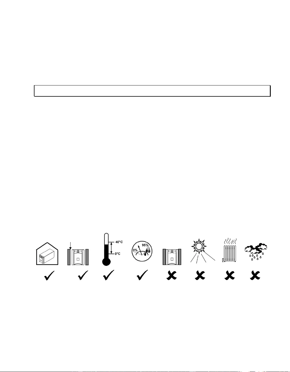
Position the UPS
1 in (2.5 cm)
2
2: START UP
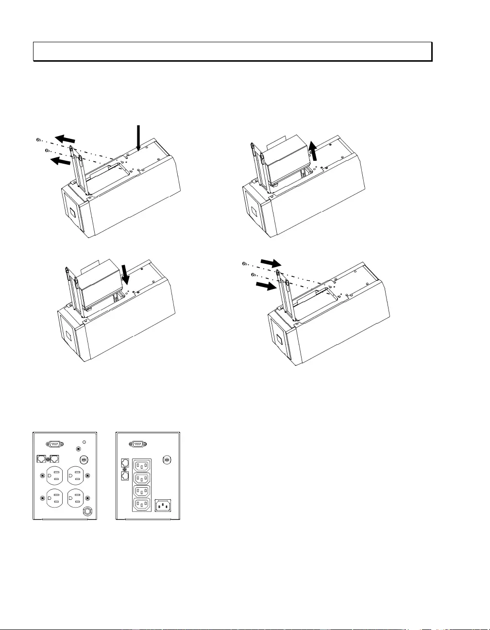
Connect the Battery
n o Connect black wire to battery. (Red wire
is already connected.) Note: Small sparks at
the point of battery connection are normal.
p q
Connect Equipment to the UPS
Rear Panels
110/120 V: 230 V:
230 V models: The top off white outlet
provides surge protection only. Equipment
plugged into this 500 VA outlet should
require surge protection, but should not
require power during a utility power failure.
The lower three outlets provide battery
backup protection, as well as protection from
surges.
Note: A laser printer draws significa ntl y
more power than other types of equipment
and may overload the UPS.
Bottom of unit

3
Connect the UPS to the Network (if Applicable)
Network Connectors
Serial Port
Telephone/Network
Surge Suppression Ports
Use only inter face kits approved by APC by Schneider Electric.
Use only the supplied cable to connect to the Serial Port. A standard serial interface cable is
incompatible with the UPS.
The UPS features optional telephone/network surge suppression. Connect a single line telephone or a
10 Base-T/ 100 Base-Tx network cable into the RJ-45/RJ-11 telephone/network surge protection IN
jack on the back of the UPS. Use a telephone cable (not supplied) or network cabling (not supplied)
to connect the OUT jack to a fax modem or network port.
Start the UPS
1. Plug the UPS into a two pole, three wire, grounded receptacle only. Avoid using extension
cords.
110/120 V models: The power cord is attached to the UPS. The input plug is a NEMA 5-15P.
230 V models: The power cord set is supplied in the UPS literature kit. Attention: Upon utility
power connection, the top outlet is immediately powered; the bottom three outlets are
powered after the UPS performs the self-test.
2. 110/120 V models: Check the site wiring fault LED located on the rear panel. It will be
illuminated if the UPS is plugged into an improperly wired utility power outlet
(see Troubleshooting).
3. Turn on all connected equipment. To use the UPS as a master on/off switch, be sure all
connected equipment is on.
4. Press the button on the front panel to po wer the UPS.
Note: The batt ery charges fu lly during the first fo ur hours of normal oper ation. Do not expect
full battery run capability during this initial charge period. Refer to www.apc.com for battery
runtimes.
5. For optimal computer system protection, install PowerChute management software to fully con-
figure UPS shutdown and alarm settings.
4
3: OPERATION
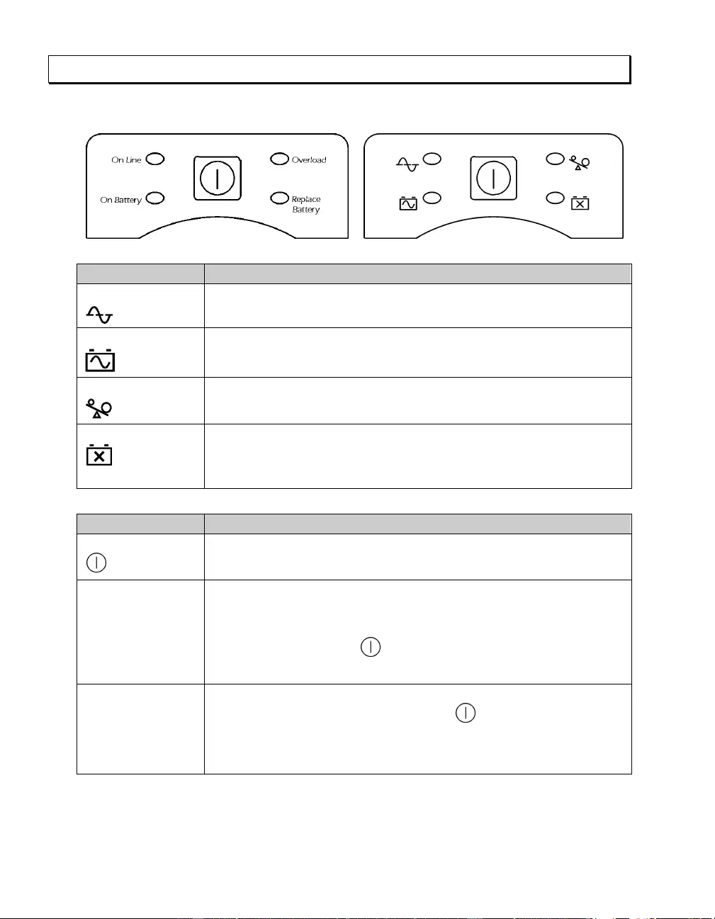
Front Display Panel
110/120 V 230 V
I
NDICATOR
D
ESCRIPTION
On Line
The UPS is supplying utility power to the connected equipment.
On Battery
The UPS is supplying bat tery power to the co nnected equipment.
Overload
The connected loads are drawing more than t he UPS power rating.
Replace Battery
The battery must be replaced .
F
EATURE
F
UNCTION
Power Button
Press this button to turn the UPS on or off. (Read on for additional capabilities.)
Self-Test Automatic: The UP S performs a self-test automatically when turned on, and
every two weeks thereafter (by default). During the self-test, t he UPS briefly
operates the connected equipment on battery.
Manual: P ress and hold the button for a few seconds to initiate the
self-test.
Cold Start Supp l y battery power to the UPS and connected equipment in the absence of
utility voltage (see Troubleshooting). Press the button for one second and
release. The UPS will beep briefly and go quiet. Press and hold the button again,
but for approximately three seconds. The unit will emit a sustained beep.
Release the button during this beep.

5
4: USER CONFIGURABLE ITEMS
NOTE: SETTINGS ARE ADJUSTED THROUGH POWERCHUTE SOFTWARE
FUNCTION FACTORY
DEFAULT USER SELECTABLE
CHOICES DESCRIPTION
Automatic
Self-Test Every 14 days
(336 hours) Every 7 days
(168 hours),
Every 14 days
(336 hours),
On Startup Only,
No Self-Test
Set the interval at which the UPS will
execute a self-test.
UPS ID UPS_IDEN Up to eight
characters
(alphanumeric)
Uniquely identify the UPS, (i.e. server
name or location) for network
management purposes.
Date of Last
Battery
Replacement
Manu facture Date mm/dd/yy Reset th is date when you replace the
battery module.
Minimum Capacity
Before Return from
Shutdown
0 percen t 0, 15, 50, 90 percent Specify the percentage to whi ch
batteries will be charged following a
low battery shutdown before powering
connected equipment.
Voltage Sensitivity
The UPS det ect s
and reacts t o line
voltage distortions
by transferring to
battery operation to
protect connected
equipment.
High High sensitivity,
Medium sensitivity,
Low sensitivity
Note: In situations of poor power
quality, the UPS may frequently
transfer to battery operation. If the
connected equipment can operate
normally under such conditions,
reduce the sensitivity setting to
conserve battery capacity and service
life.
Alarm Delay After
Line Fail 5 seconds 5 second delay,
30 second delay,
At low battery
conditio n,
No alarm
Set the delay to avoid alarms for minor
power glitches.
Shutdown Delay 60 seconds 60, 180, 300, 600
seconds Set the interval between the time when
the UPS receives a shutdown
command and the actual shutdown.

6
NOTE: SETTINGS ARE ADJUSTED THROUGH POWERCHUTE SOFTWARE
FUNCTION FACTORY
DEFAULT USER SELECTABLE
CHOICES DESCRIPTION
Low Battery
Warning
2 minutes
PowerChute
Business Edition
software provides
automatic,
unatten ded
shut dow n w he n
approximately 2
minutes of battery
operated runtime
remains.
2, 5, 7, 10 minutes
(Times are
approximate.)
The UPS will beep when 2 minutes of
battery runtime remains.
Change the low battery warning
interval setting to the time that the
operating system or system software
requires to safely shut down.
Synchronized
Turn-on Delay 0 seconds 0, 60, 180, 300
seconds Specify the time the UPS will wait
after the return of utility power before
turn-on (to avoid branch circuit
overload).
High Transfer
Point 110/120 V mo del:
127 Vac
230 V model:
253 Vac
110/120 V mo del:
127, 130, 133,
136 Vac
230 V model:
253 , 257, 261,
265 Vac
Set the high transfer point higher to
avoid unnecessary battery usage when
the utility voltage is usually high and
the co nnected equi pment is specified
to operate with input voltages this
high.
Low Tr an sfer P oint 110/120 V mo del:
106 Vac
230 V model:
208 Vac
110/120 V mo del:
97, 100, 103, 106
Vac
230 V model:
196 , 200, 204,
208 Vac
Set the low transfer point lower when
the utility voltage is usually low and
the co nnected equi pment is specified
to operate with input voltages this low.
7
5: STORAGE AND MAINTENANCE
Storage
Store the UPS covered in a cool, dry location, with the battery fully charged.
At -15° to +30° C (+ 5° to +86° F), charge the UPS battery every six months.
At +30° to +4 5 ° C (+86° to +113° F), charge the UPS battery every three months.
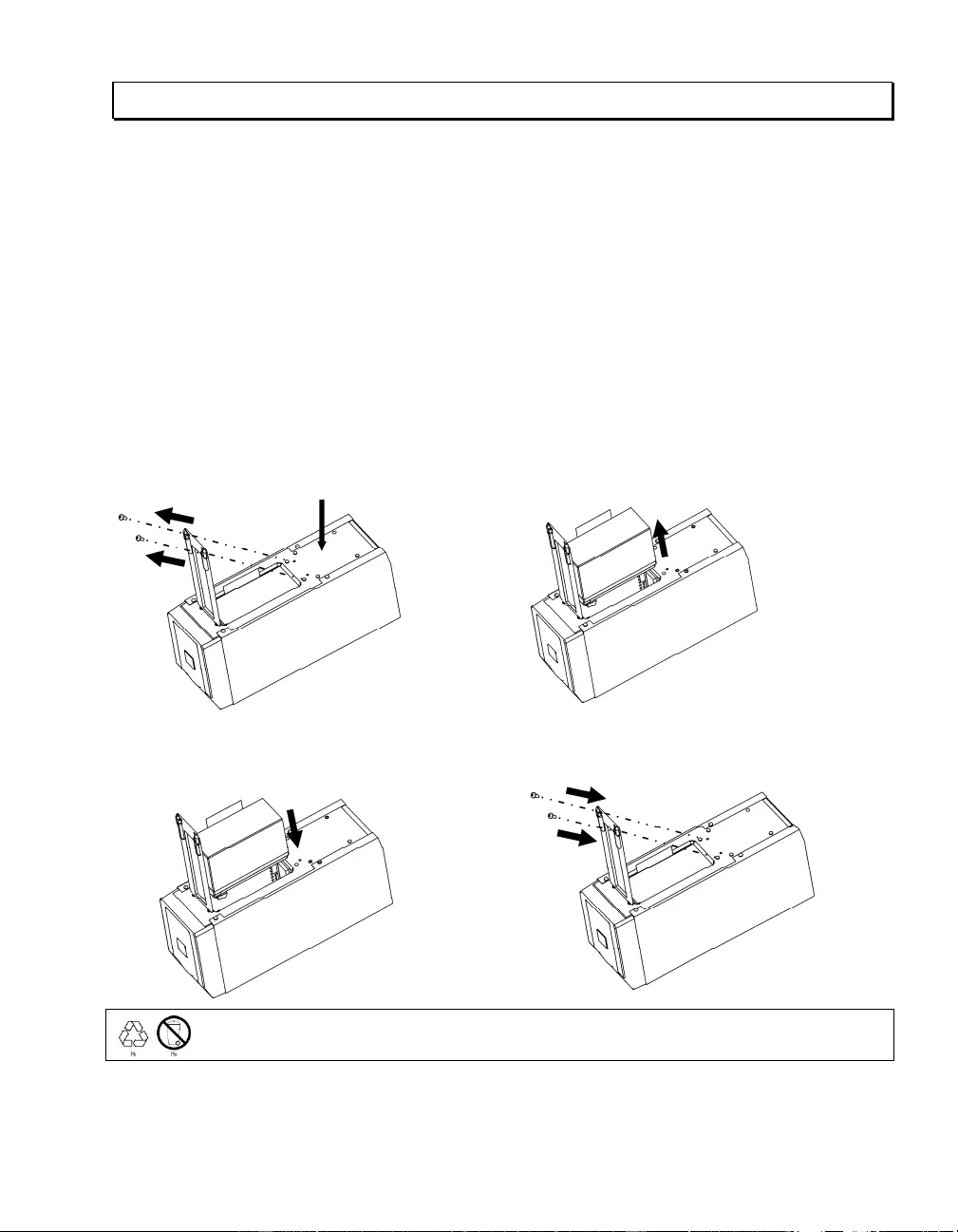
Battery Replacement
The UPS battery life differs based on usage and environment. Consider replacing the battery every
three years.
This UPS has an easy to replace, hot-swappable battery. Replacement is a safe procedure, isolated
from electrical hazards. You may leave the UPS and connected equipment on during the replacement
procedure. See your dealer or contact APC by Schneider Electric (see Contact Information) for
information on replacement batteries.
Note: Upon battery disconnection, equipment is not protected from power outa ges
.
n oDisconnect the battery wires.
p Connect the new battery by matching red and
black wires and connectors. Note: Small sparks at
the point of battery connection are normal.
q
Be sure to deliver the spent battery to a recycling facility or ship it to
APC by Schneider
Electric
in the rep l acement battery packing material.
Bottom of unit

8
6: TROUBLESHOOTING, TRANSPORT, AND SERVICE
Use the chart below to solve minor UP S installat ion and operation problems. Refer to www.apc.com
with complex UPS problems, and for battery runtime charts.
PROBLEM AND/OR POSSIBLE
CAUSE SOLUTION
UPS WILL NOT TURN ON
UPS not connected to utility
power supply. Check that the power cord from the UPS to the utility power supply is
securel y connected at both ends.
Batter y no t connected
properly. Check that battery is properly connected.
Very low or no utility voltage. Check the utility power supply to the UPS by plugging in a table lamp. If the
light is very dim, have the utility voltage checked.
UPS WILL NOT TURN OFF
Internal UPS fault. Do not attempt to use the UPS. Unplug the UPS, unplug the battery, and
have it servi ced immediately.
UPS BEEPS OCCASIONALLY
Normal operati ng UPS beeps
when running on battery. None. Th e UPS is protecti ng the connected equipment from occasional
utility power irregularities.
UPS IS NOT PROVIDING EXPECTED BACKUP TIME
The UPS battery is weak due
to a recent outage or i s near
the end of the service life.
Charge the battery. Batteries require recharging after extended outages, and
wear faster when freq uently put in to service or when operated at elevated
temperatures. If the battery is near the end of the service life, consider
replacing even if the replace battery LED is not yet illuminated.
ON-LINE AND OVERLOAD LEDS ARE FLASHING ALTERNATELY
The UPS was shut down
throug h PowerChute . None. The UPS will restart when utility power returns.
ALL LEDS ARE FLASHING OR ON-LINE AND ON-BATTERY LEDS ARE F L ASHING
Internal UPS fault. The UPS
has shut down. Do not attempt to use the UPS. Turn off the UPS , disconnect th e battery, and
have it servi ced immediately.
ALL LEDS ARE OFF AND THE UPS IS PLUGGED INTO A WALL OUTLET
The UPS is shut down or the
battery is discharged from an
extended outage.
None. The UPS will return to normal operation when the power is restored
and the battery has a sufficient charge.

9
PROBLEM AND/OR POSSIBLE
CAUSE SOLUTION
THE OVERLOAD LED IS ILLUMINATED AND THE UPS EMITS A SUST AINED ALARM TONE
The UPS is overloaded. The
connected equipment is
drawing more VA than the
UPS can sustain.
The connected equi pment exceeds t he specified “maximum load. ”
The alarm remains on until the overload is removed. Disconnect
nonessential equipment from the UPS to eliminate the overload.
The UPS continues to supply power as long as it is online and the circuit
breaker does not trip; the UPS will not provide power from batteries in the
event of a utility voltage interruption.
If a continuous overload occu rs while the UPS is on battery, the unit turns
off output in order to protect the UPS from possible damage.
THE REPLACE BATTERY LED IS ILLUMINATED
Weak battery. Allow the battery to recharge for 24 hours. Then, perform a self-test. If the
problem persist s after recharging, replace the b attery.
Failure of a battery self-test. The UPS emits sh ort beeps for one minute and the replace battery LED
illuminates. The UPS repeats the alarm every five hours. Perform the
self-test procedure after the battery has charged for 24 hours to confirm the
replace battery condition. The alarm stops and the LED clears if the battery
passes the self-test.
THE SITE WIRING FAULT LED ON THE REAR PANEL IS ILLUMINATED (110/120 V M OD EL ONLY)
The UPS is plugged into an
improperly wired utility power
outlet.
Wiring faults detected include missing ground, hot-n eutral polarity reversal,
and overloaded neutral circuit.
Contact a qualified electri cian to correct the buildin g wiring.
THE INP UT CIRCUIT BREAKER HAS TR IPPED
The UPS is overloaded. The
plunger on the circuit breaker
has popped out.
Reduce the load on the UPS by unplugging equipment. Press in the plunger
on the circuit breaker.
UPS OPERATES ON BATTERY ALTHOUGH UTILITY VOLTAGE EXIS T S
The UPS input circuit breaker
has tripped. To reduce the load on the UPS, unplug equipment and press in the plunger
on the circuit breaker.
The line voltage is very high,
low or distorted. Move the UPS to a different outlet on a different circuit, as inexpensive fuel
powered gen erators may disto rt the voltage. If acc eptable to the connected
equipment, reduce th e UPS sensitivity (see User Configurable Items).
ON-LINE LED
There is no illumination. The UPS is running on battery, or it must be turned on.
The LED is blinking. The UPS is running an internal self-test.

10
Transport
1 . Shut down and disconnect all connected equipment.
2 . Disconnect the unit from utility power.
3 . Disconnect all internal and external batteries (if applicable).
4 . Follow the shipping instructions outlined in the Service section of this manual.
Service
If the unit requires service, do not return it to the dealer. Follow these steps:
1 . Revie w the Troubleshooting section of the manual to eliminate common problems.
2 . If the problem persists, contact APC by Schneider Electric Customer Support through
the APC by Schneider Electric web site, www.apc.com.
a. Note the model number and serial number and the date of purchase. The
model and serial numbers are located on the rear panel of the unit and
are available through the LCD display on select models.
b. Call Customer Support and a technician will attempt to solve the
problem over the phone. If this is not possible, the technician will issue a
Returned Material Authorization Number (RMA#).
c. If the unit is under warranty, the repairs are free.
d. Service procedures and returns may vary internationally. Refer to the
APC by Schneider Electric web site, www.apc.com for country specific
instructions.
3 . Pack the unit properly to avoid damage in transit. Never use foam beads for
pac kaging. D ama ge sustained in tra nsit is not covered under wa rranty.
a. Note: When shipping within the United States, or to the United
States always DISCONNECT ONE UPS BATTERY before shipping
in compliance with U.S. Department of Transportation (DOT) and
IATA regulations. The internal batteries may remain in the UPS.
b. Batteries may remain connected in the XBP during shipment. Not all
units utilize XLBPs.
4 . Write the RMA# provided by Customer Support on the outside of the package.
5 . Return the unit by insured, prepaid carrier to the address provided by Customer
Support.

11
7: LIMITED FACTORY WARRANTY
Schneider Electric IT Corporation (SEIT), warrants its products to be free from defects in materials and workmanship
for a period of two (2) years from the date of purchas e. The SEIT obliga tion under this warran ty is limit ed to repairing
or replacing, at its own sole option, any such defective products. Repair or replacement of a defective product or parts
th er eof does no t extend the original war r anty period.
This warranty applies on ly to the original pur chaser who must ha ve properly registered the pr oduct within 10 days of
purchase. Products may be registered online at warranty.apc.com.
SEIT shall not be liable under the warranty if its tes ting and examination disclose tha t the alleged defect in the pr oduct
does not exist or was caused by end user or any third person misuse, negligence, improper installation, testing,
operation or use of the product contrary to SEIT recommendations or specifications. Further, SEIT shall not be liable
for defects resulting from: 1) unauth orized attempts t o repair or modi fy the product, 2) in correct or inadequat e
electrical voltage or c o nnection, 3) inappropria te on site operation conditi ons, 4) Acts of God, 5) exposure to the
elements, or 6) thef t. In no event shall SEIT have any liability under this warra nty for any product where the serial
number has been altered, defaced, or removed.
EXCEPT AS SET FORT H ABOVE, THERE ARE NO WARRANTIES, E XPRE SS OR IMPL IED, BY
OPERATION OF LAW OR OTHERWISE, APPLICABLE TO PRODUCTS SOLD, SERVICED OR
FURNISHED UNDER THIS AGREEMENT OR IN CONNECTION HEREWITH.
SEIT DISCLAIMS ALL IMPLIED WARRANTIES OF MERCHANTAB ILITY, SATISFACTION AND
FITNESS FOR A PARTICULAR PURPOSE.
SEIT EXPRESS WARRANTIES WILL NOT BE ENLARGED, DIMINISHED, OR AFFECTED BY AND NO
OBLIGATION OR LIABILITY WILL ARISE OUT OF, SEIT RENDERING OF TECHNICAL OR OTHER
ADVICE OR SERVICE IN CONNECTION WITH THE PRODUCTS.
THE FORE GOING WARRANTIES AND REMEDIES ARE EXCLUSIVE AND IN LIEU OF ALL OTHER
WARRANTIES AND REMEDIES. THE WARRANTIES SET FORTH ABOVE CONSTITUTE SEIT SOLE
LIABILIT Y AND P URCHASER EXCLUSIVE RE MEDY FOR ANY BREACH OF SUCH WARRANTIES.
SEIT WARRANTIES EXTEND ONLY TO ORIGINAL PURCHASER AND ARE NOT EXTENDED TO
ANY THIRD PARTIES.
IN NO EVENT SHALL SEIT, ITS OFFICERS, DIRECTORS, AFFILIATES OR EMPLOYEES BE LIAB LE
FOR ANY FORM OF INDIRECT, SPECIAL, CONSEQUENTIAL OR PUNITIVE DAMAGES, ARISING
OUT OF THE USE, SERVICE OR INSTALLATION OF THE PRODUCTS, WHETHER SUCH DAMAGES
ARISE IN CONTRACT OR TORT, IRRESPECTIVE OF FAULT, NEGLIGENCE OR STRICT LIABILITY
OR WHETHER SEIT HAS BEEN ADVISED IN ADVANCE OF THE POSSIBILITY OF SUCH DAMAGES.
SPECIFICALLY, SEIT IS NOT LIABLE FOR ANY COSTS, SUCH AS LOST PROFITS OR REVENUE,
WHETHER DIRECT OR INDIRECT, LOSS OF EQUIPMENT, LOSS OF USE OF EQUIPMENT, LOSS OF
SOFTWARE, LOSS OF DATA, COSTS OF SUBSTITUANTS, CLAIMS BY THIRD PARTIES, OR
OTHERWISE.
NOTHING IN THIS LIMITED WARRANTY SHALL SEEK TO EXCLUDE OR LIMIT SEIT LIABILITY
FOR DEATH OR PERSONAL INJURY RESUL TING FROM ITS NEGLIGENCE OR ITS FRAUDULENT
MISREPRESENTATION OF TO THE EXTENT THAT IT CANNOT BE EXCLUDED OR LIMITED BY
APPLICABLE LAW.
To obta in service under warran ty you must obtain a Returned Material Authorization (RMA) number from customer
support. Customers with warranty claims issues may access the SEIT worldwide customer support network through
the APC web site: www.apc.com. Select your country from the country selection drop down menu. Open the Support
tab at the top of the web page t o obtain information for customer support in your region. Products must be returned
with transportation charges prepaid and must be accompanied by a brief description of the problem encountered and
proof of date and place of purchase.