Table of Contents
APC SMTL750RM2UC User Manual
Displayed below is the user manual for SMTL750RM2UC by APC which is a product in the Uninterruptible Power Supplies (UPSs) category. This manual has pages.
Related Manuals
Operation Manual
Smart-UPS™
Uninterruptible Power Supply
750/1000/1500 VA
Short-depth Rack-Mount
with Lithium-ion batteries
120 Vac

Smart-UPS SMTL750/1000/1500 120 Vac Short-depth Rack-Mount 1
Important Safety Messages
SAVE THESE INSTRUCTIONS - This manual contains important instructions that should be followed during
installation and maintenance of the UPS and batteries.
Read the instructions carefully and look at the equipment to become familiar with the device before trying to
install, operate, service or maintain it. The following special messages may appear throughout this bulletin or on
the equipment to warn of potential hazards or to call attention to information that clarifies or simplifies a procedure.
The addition of this symbol to either a “Danger” or “Warning” safety label indicates that an electrical
hazard exists which will result in personal injury if the instructions are not followed.
This is the safety alert symbol. It is used to alert you to potential personal injury hazards. Obey all
safety messages that follow this symbol to avoid possible injury or death.
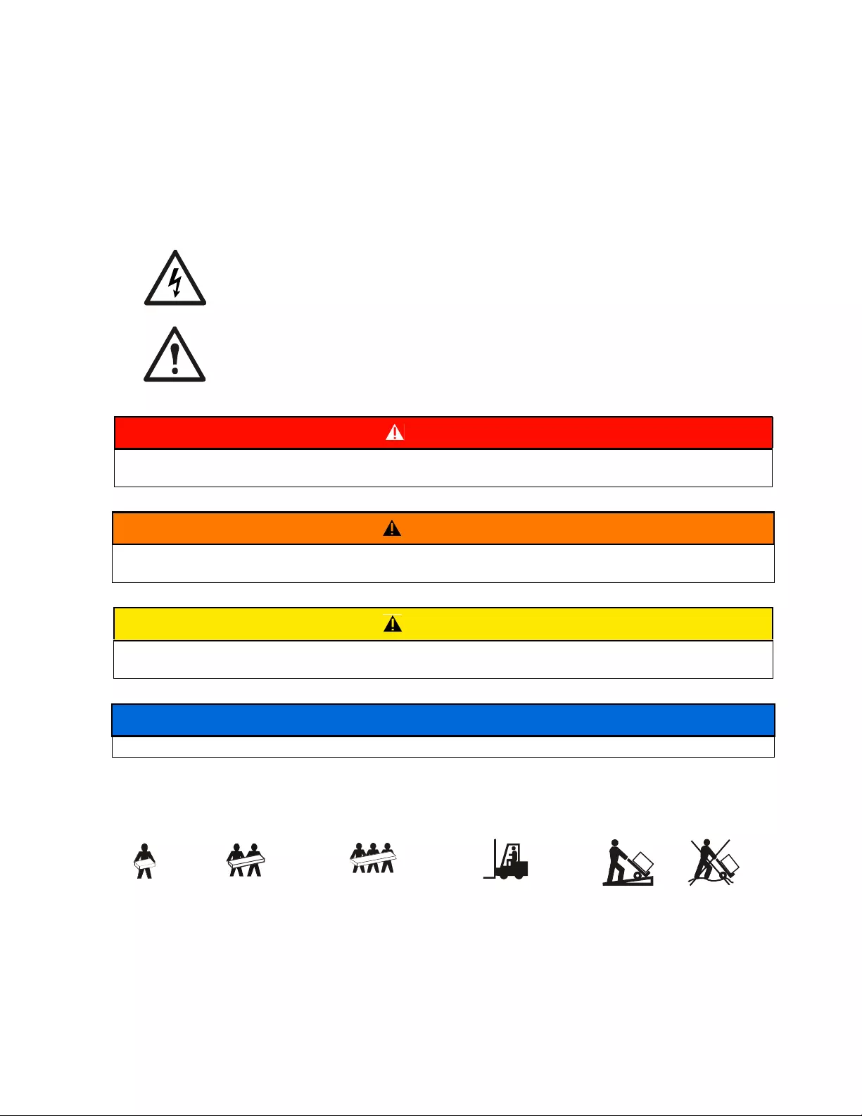
Product Handling Guidelines
DANGER
DANGER indicates a hazardous situation which, if not avoided, will result in death or serious
injury.
WARNING
WARNING indicates a hazardous situation which, if not avoided, could result in death or serious
injury.
CAUTION
CAUTION indicates a hazardous situation which, if not avoided, could result in minor or moderate
injury.
NOTICE
NOTICE is used to address practices not related to physical injury.
<18 kg
<40 lb
18-32 kg
40-70 lb
32-55 kg
70-120 lb
>55 kg
>120 lb

Smart-UPS SMTL750/1000/1500 120 Vac Short-depth Rack-Mount2
Safety and General Information
Inspect the package contents upon receipt. Notify the carrier and dealer if there is any damage.
General safety
• Adhere to all national and local electrical codes.
• All wiring must be performed by a qualified electrician.
• Changes and modifications to this unit not expressly approved by APC by Schneider Electric could
void the warranty.
• This UPS is intended for indoor use only.
• Do not operate this unit in direct sunlight, in contact with fluids, or where there is excessive dust or
humidity.
• Be sure the air vents on the UPS are not blocked. Allow adequate space for proper ventilation.
• For a UPS with a factory installed power cord, connect the UPS power cable directly to a wall outlet. Do not
use surge protectors or extension cords.
• The equipment is heavy. Always practice safe lifting techniques adequate for the weight of the equipment.
Deenergizing safety
The UPS contains internal batteries and may present a shock hazard even when disconnected from the branch
circuit (mains). Before installing or servicing the equipment check that the:
• Input circuit breaker is in the OFF position.
• Internal UPS batteries are removed.
Electrical safety
• Use tools with insulated handles.
• Do not handle any metallic connector before power has been disconnected.
• For models with a hardwired input, the connection to the branch circuit (mains) must be performed by a
qualified electrician.
• 230 V models only: In order to maintain compliance with the EMC directive for products sold in Europe,
output cords attached to the UPS must not exceed 10 meters in length.
• The protective earth conductor for the UPS carries the leakage current from the load devices (computer
equipment). An insulated ground conductor is to be installed as part of the branch circuit that supplies the
UPS. The conductor must have the same size and insulation material as the grounded and ungrounded
branch circuit supply conductors. The conductor will typically be green, with or without a yellow stripe.
• Leakage current for a pluggable, Type A UPS may exceed 3.5 mA when a separate ground terminal is used.
• The UPS input ground conductor must be properly bonded to protective earth at the service panel.
• If the UPS input power is supplied by a separately derived system, the ground conductor must be properly
bonded at the supply transformer or motor generator set.

Smart-UPS SMTL750/1000/1500 120 Vac Short-depth Rack-Mount 3
Battery safety
• The battery typically lasts for five to ten years. Environmental factors impact battery life. Elevated ambient
temperatures, poor quality utility power, and frequent short duration discharges will shorten battery life.
• For longest battery performance, the ambient temperature should be maintained between 68° and 77°F (20°
and 25°C).
• Replace the UPS immediately if the unit indicates battery replacement is necessary.
• Replace the UPS once the batteries have reached the end of their service life even if the UPS has not
indicated that battery replacement is necessary.
• The batteries are user replaceable. Under normal operating conditions, there is no need for replacement. If
attempting to replace batteries,
• Use only APC by Schneider Electric battery modules.
• Do not use third-party batteries as replacements.
• Replace with the same number and type of batteries as originally installed in the equipment.
• APC by Schneider Electric uses Lithium Ion batteries. Under normal use and handling, there is no contact
with the internal components of the battery.
• Do not drive nails into the battery pack.
• Do not strike the battery pack with a hammer.
• Do not stand on the battery pack.
• Do not short circuit battery pack.
• Do not place or use the battery pack near heat or fire.
• Do not use a dropped, damaged or deformed battery pack.
• Do not use the battery pack to power other equipment.
• CAUTION: Before installing or replacing the batteries, remove conductive jewelry such as chains, wrist
watches and rings. High energy through conductive materials could cause severe burns.
• CAUTION: Do not dispose of battery pack in a fire. The batteries may explode.
• CAUTION: Do not open or tamper with the battery enclosure. Doing so will expose the cell terminals
which pose an energy hazard.
General information
• The model and serial numbers are located on a small label on the rear panel. For some models, an additional
label is located on the chassis under the front bezel.
• Always recycle used batteries.
• Recycle the package materials or save them for reuse.
WARNING
RISK OF CHEMICAL HAZARD AND EXCESSIVE HEAT
• Replace the battery at least every 10 years.
• Replace the battery immediately when the UPS indicates battery replacement is necessary.
• Replace battery at the end of its service life.
• Replace batteries with the same number and type of batteries as originally installed in the equipment.
• Replace the battery immediately when the UPS indicates a battery over-temperature condition or UPS
internal over-temperature. Power off the UPS, unplug it from the AC input, and disconnect the batteries.
Do not operate the UPS until the batteries have been replaced.
Failure to follow these instructions can result in death or serious injury.
Smart-UPS SMTL750/1000/1500 120 Vac Short-depth Rack-Mount4
FCC Class A radio frequency warning
This equipment has been tested and found to comply with the limits for a Class A digital device, pursuant to part 15
of the FCC Rules. These limits are intended to provide reasonable protection against harmful interference when the
equipment is operated in a commercial environment. This equipment generates, uses, and can radiate radio
frequency energy and, if not installed and used in accordance with the instruction manual, may cause harmful
interference to radio communications. Operation of this equipment in a residential area is likely to cause harmful
interference in which case the user will be required to correct the interference at his own expense.
WARNING: This is a category C2 UPS product. In a residential environment, this product may cause radio
interference, in which case the user may be required to take additional measures.
Specifications
For additional specifications, refer to the APC Web site at www.apc.com.
Environmental specifications
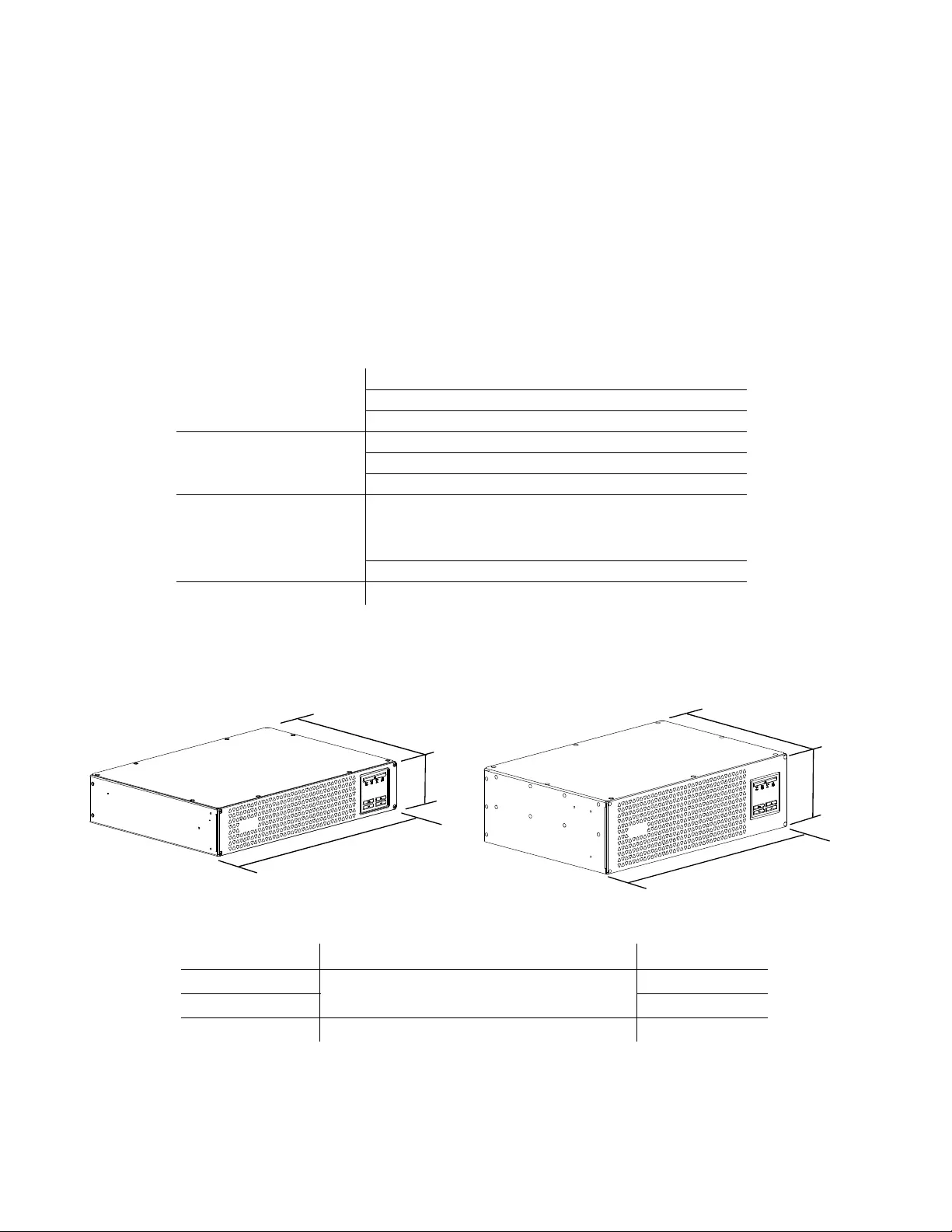
Dimensions and weights
Temperature
Operating 0° to 40° C (32° to 104° F)
Storage -40° to 35° C (-40° to 95° F)
Transporting -40° to 80° C (-40° to 176° F)
Maximum Elevation
Operating 10,000 ft. (3,048 m)
Storage 25,000 ft. (7,620 m)
Transporting 50,000 ft. (15,240m)
Shelf Life Storage
Limited by battery state of charge.
If initial state of charge is 100%,
batteries must be recharged when
storage time exceeds 12 months.
Transporting 2 weeks maximum
Humidity 0% to 95% relative humidity, non-condensing
SMTL750RM2UC / SMTL1000RM2UC Rack-Mount SMTL1500RM3UC Rack-Mount
D
H
W
su1038a
D
H
W
su1026a
Model Dimensions (in/mm) H x W x D Weights (lb / kg)
SMTL750RM2UC 3.4 x 17.25 x 12.52 in (86.35 x 438.15 x 318.1 mm) 34 / 15.4
SMTL1000TM2UC 36 / 16.3
SMTL1500RM3UC 5.14 x 17.25 x 11.89 in (130.6 x 438.15 x 302 mm) 43 / 19.5
Smart-UPS SMTL750/1000/1500 120 Vac Short-depth Rack-Mount 5
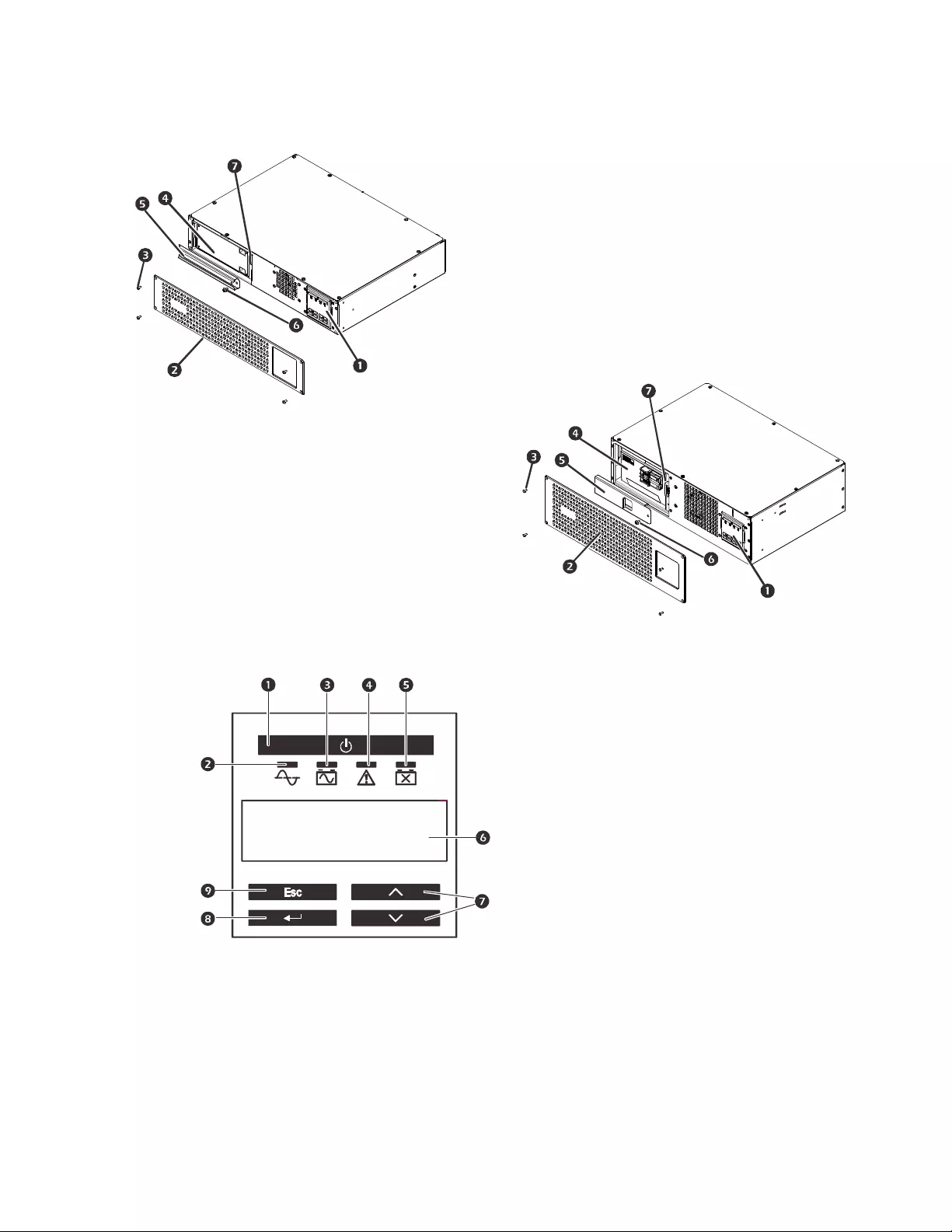
Product Overview
Front panel display features
SMTL750RM2UC and SMTL1000RM2UC
Display (more information below)
Bezel
Bezel Screws
Battery
Battery Door
Battery Door Screw
Battery Connector
SMTL1500RM3UC Rack-Mount
UPS ON/OFF
Online LED
On Battery LED
Error Detected LED
Replace Battery LED
Multi-lingual display screen
UP/DOWN Selection arrows
ENTER
ESCAPE
su1039ba
su1024b
su0343f
APC By Schneider
Electric
Smart-UPS SMTL750/1000/1500 120 Vac Short-depth Rack-Mount6
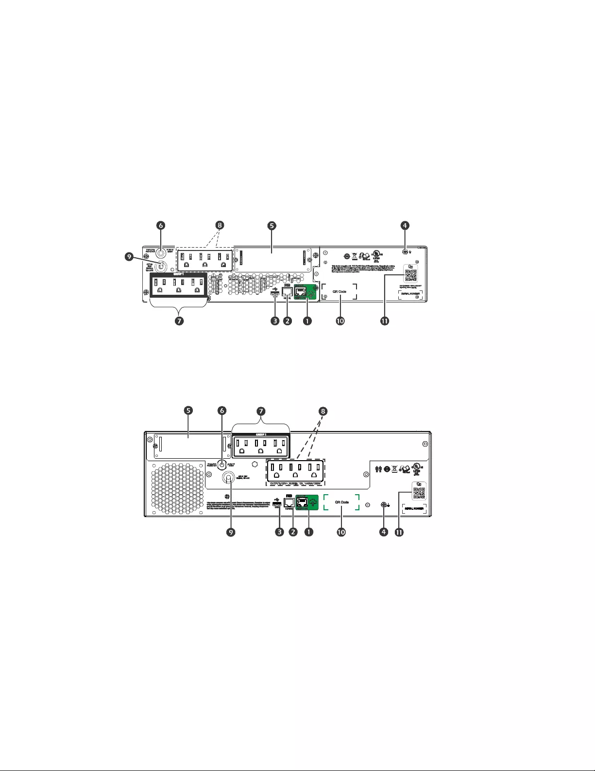
Rear panel features
SMTL750RM2UC and SMTL1000RM2UC
SMTL1500RM3UC
APC™ SmartConnect port
Serial port
USB port
Chassis ground connection screw
Smart Slot
Input circuit breaker
Controlled outlet group
Outlets
UPS input power cord
Link and data for SmartConnect setup
Link to on line users manual
su1035a
su1025b
Smart-UPS SMTL750/1000/1500 120 Vac Short-depth Rack-Mount 7
Installation
For UPS installation information, refer to the Installation Guide included with the UPS.
Placement
The UPS is intended for IT environments. Avoid placement where there is excessive dust and humidity. Note that
temperature in excess of 25o C may have an adverse effect on battery and UPS life. All vents on the side or rear of
the UPS should be free of obstructions.
The UPS is heavy. The UPS should be placed near the bottom of the rack.
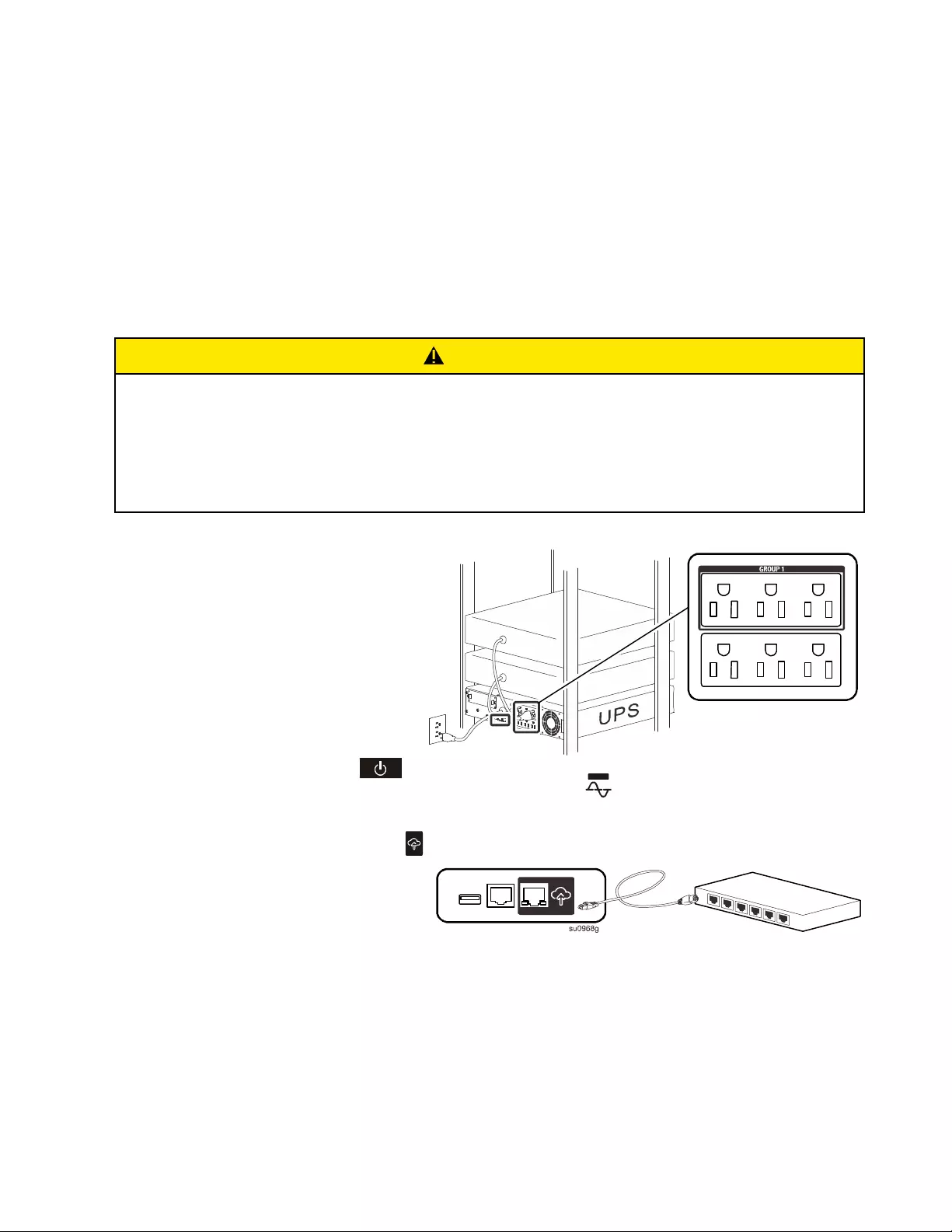
Connect to equipment and AC input power
The UPS will charge the battery to 90% capacity in the first three hours of normal operation.
Do not expect full battery runtime capability during this initial charge period.
1. Connect the battery. (see Installation
Guide)
2. Connect equipment to the outlets in
the rear of the UPS. Some models are
equipped with controlled outlet
groups. Refer to the “Configuration”
section of this manual for further
instructions on the use of controlled
outlet groups.
3. Connect the UPS input to AC power.
Once power is connected the display
will be active.
4. Press the main power button
on the UPS display to turn on the UPS output. The On-line LED will light green when the output is on.
SmartConnect
Connect the APC™ SmartConnect port
to your nearest network switch using the
cable provided.
APC SmartConnect allows you to monitor
the health and status of your UPS from any
device connected to the Internet. Visit
www.smartconnect.apc.com to learn more.
Log onto www.smartconnect.apc.com or scan the SmartConnect QR code to launch the registration process. The
website includes instructions to setup your online account, activate your warranty and begin monitoring your UPS
remotely.
By connecting this product to the Internet using the APC SmartConnect port, you are agreeing to APC
SmartConnect Terms of Use, as found at www.smartconnect.apc.com. Schneider Electric Data Privacy Policy can
also be found at www.smartconnect.apc.com.
CAUTION
RISK OF INJURY OR DAMAGE TO EQUIPMENT
• Adhere to all local and national electrical codes.
• Wiring should be performed by a qualified electrician.
• Always connect the UPS to a grounded outlet.
Failure to follow these instructions can result in injury or equipment damage.
su0968f
LINK/ACT
NETWORK
Smart-UPS SMTL750/1000/1500 120 Vac Short-depth Rack-Mount8
Start up settings
When the UPS is powered on for the first time the LCD screen displays the Setup Wizard and asks a number of
basic set-up questions. They can be answered simply by using the arrow and enter keys on the
display. Configuration can also be performed using PowerChute™ software.
Note: If the start up settings asked by the Setup Wizard are not selected completely, turning on UPS output is
inhibited. The Setup Wizard will disappear from the display if the start up settings remain idle for 2 minutes.
Pressing the MAIN ON/OFF button on the front panel will relaunch the Setup Wizard and allow completion of the
start up settings.
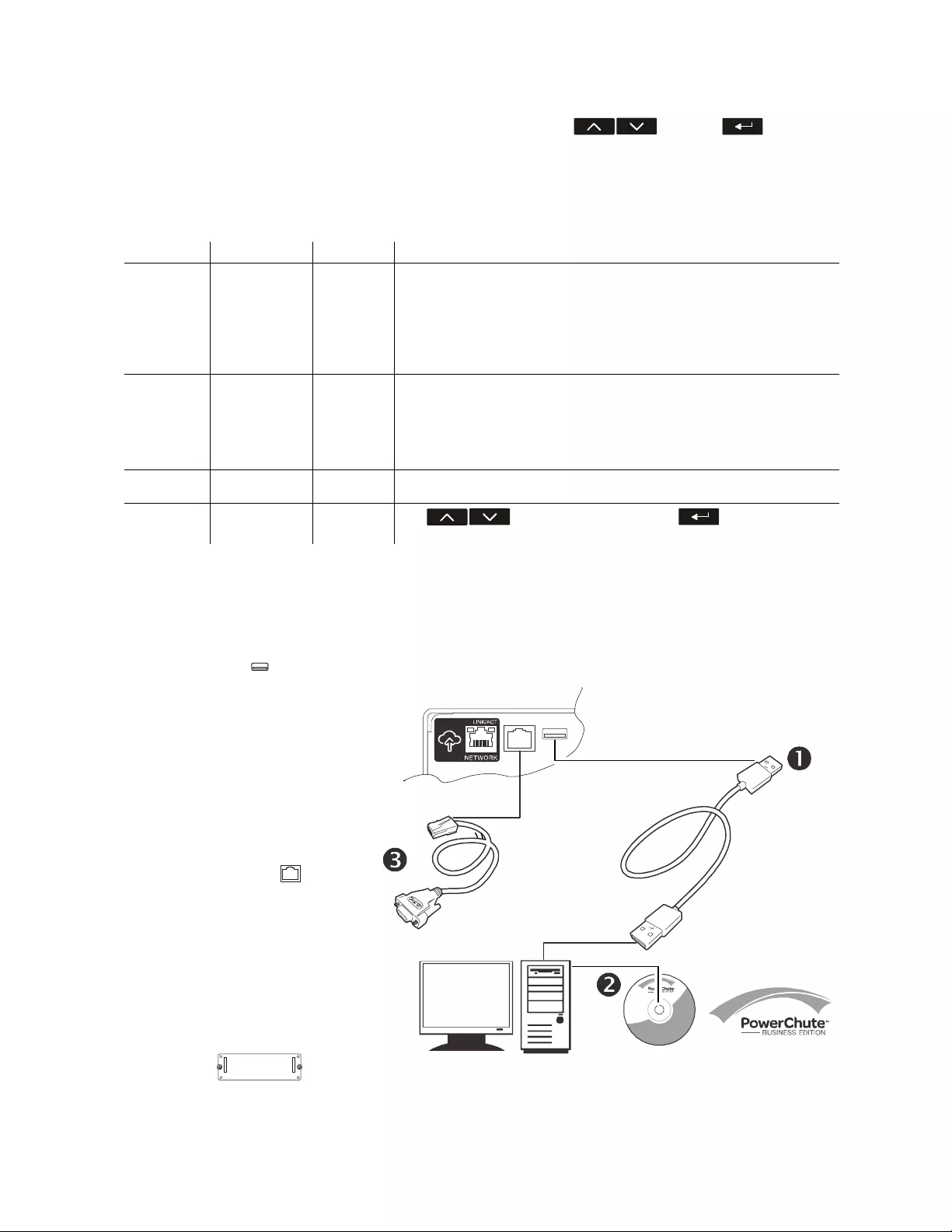
Connect and install management software
Smart-UPS is provided with PowerChute management software for unattended operating system shutdown, UPS
monitoring, UPS control and energy reporting. The following diagram is a representation of a typical server
installation.
Function Factory Default Options Description
Language English English
French*
German*
Spanish*
Italian*
Portuguese*
Japanese*
The language for the display interface.
*Language options will vary by model.
Local Power
Quality
Good Good
Fair
Poor
Select the quality of input AC power.
• If Good is selected, the unit will go on battery power more often to
provide the cleanest power supply to the connected equipment.
• If Poor is selected, the UPS will tolerate more fluctuations in power and
will go on battery power less often.
If unsure of the local power quality, select Good.
Menu Type Standard Standard
Advanced
The standard menu displays the most commonly required menus for most
users. The advanced menus include all parameters.
Today’s Date Manufacture
date Use to change the date, and the to use the date
displayed.
1 . Connect the USB cable from the
rear of the UPS to the
protected device such as a server.
2 . For a server or other device with
an operating system, load the
PowerChute CD and follow the
on-screen set-up instructions.
PowerChute provides for graceful
shutdown in the event of an
extended power outage and is a
powerful management interface
on the local network.
3 . A built-in serial port is also
available for additional
communication options with an
optional serial cable. For more
detailed information on supported
protocols and options refer to
application note #181 at
www.apc.com.
4 . Even more management options
are available via the built-in
Smartslot.
Refer to www.apc.com for more
information.
OR
Smart-UPS SMTL750/1000/1500 120 Vac Short-depth Rack-Mount 9
Operation
Using the display
These Smart-UPS models are equipped with an intuitive and configurable LCD display. This display complements
the software interface as they convey similar information and either may be used to configure the UPS settings.
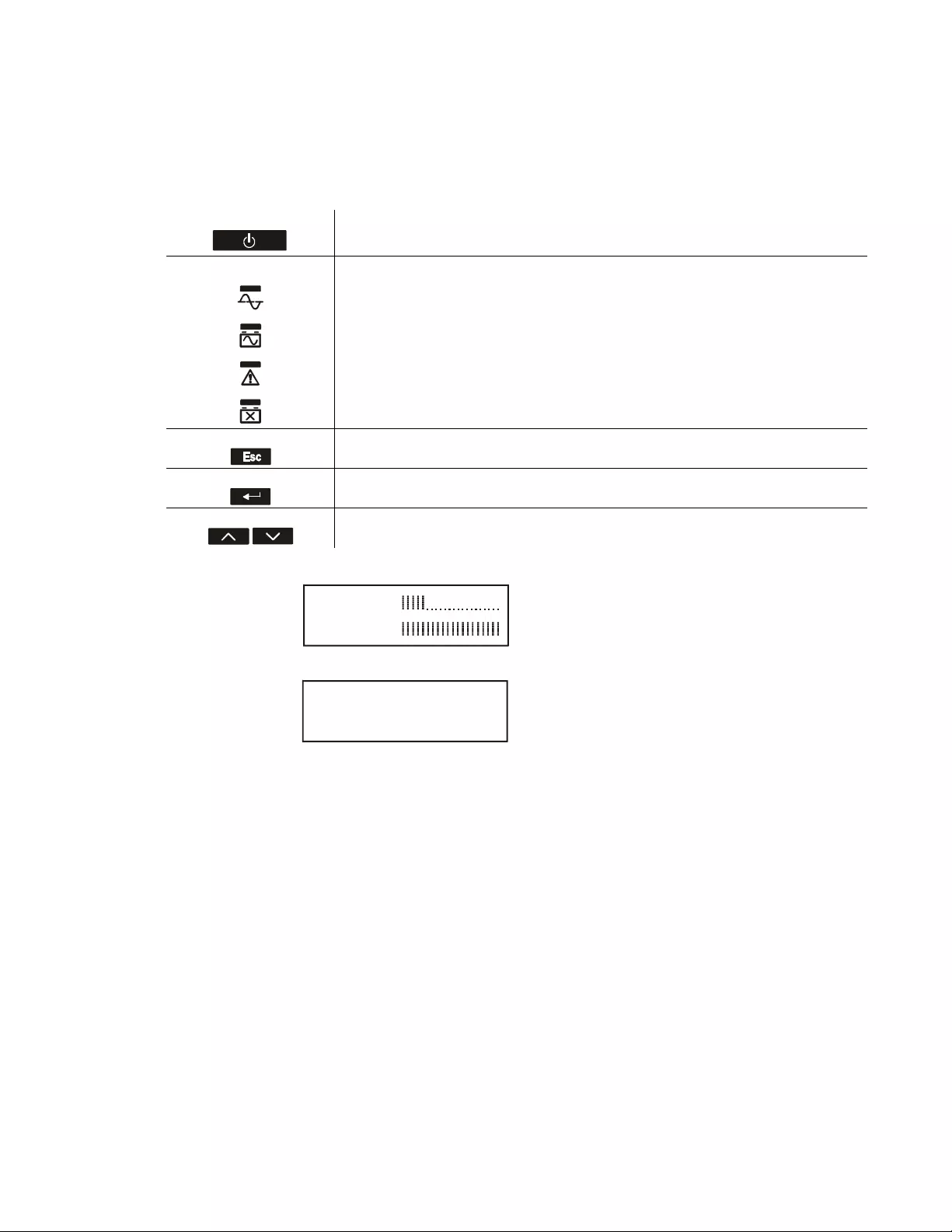
The display consists of the following keys and indicators:
The display has two status screen/menu options – standard and advanced.
Note: The standard menu is the default setting and does not contain all of the menus and attributes of the advanced
menu. The advanced menu automatically scrolls through multiple screens.
Main on/off This button is used to turn the UPS output power on and off.
Quick status LEDs
The online indicator illuminates green when UPS output is turned on and operating on
AC power.
The on-battery battery indicator illuminates orange and the unit will continue to emit a
series of short beeps indicating that the UPS is operating on battery power.
The error detected LED will illuminate red if the unit detects an error condition. The
display screen may also indicate an error message or code.
The replace battery indicator illuminates red when the UPS battery does not pass self test
and requires replacement.
Escape The escape key always returns the display to the previous screen. It is used to exit the
various display menus.
Return The return key is used to confirm a selection and/or enter a menu.
Up/down selection arrows The arrows are used to navigate through each menu selection.
Standard Menu Display
Default setting with fixed status
screen and fewer menus
Advanced Menu Display
Optional setting with
automatically scrolling status
screen and additional menus
su0983a
Load: 18%
Batt: 100%
su0984a
On Utility
Efficiency: 98%

Smart-UPS SMTL750/1000/1500 120 Vac Short-depth Rack-Mount10
Standard menus
The Standard menus are the most commonly used menus. The following is a list of some items displayed in this
menu mode.
Advanced menus
The Advanced menus provide additional options for the UPS and are available only if the display interface is
configured to use the Advanced menus.
Menu General Functions
Status View UPS information:
• Operating Mode
• Efficiency
• Load Power
• Load VA
• Battery Charge state
• Estimated Runtime
• Battery Temp
• Input
• Output
• SmartConnect
• Probe 1, Probe 2, when NMC and sensor probes
are installed
Configuration Configure UPS settings:
• Language
• Green Mode
• Local Power Quality: Good, Fair, Poor
• Menu Type: Standard or Advanced
• Audible Alarm
• Display (Auto Dim, Auto Off, Always On)
• Reset to Factory Default
• SmartConnect Control
• Install FW?
Test & Diags Perform UPS tests and diagnostic functions:
• UPS Self Test
• UPS Alarms Test
About View UPS information:
• UPS Model
• UPS Part No.
• UPS Serial No.
• UPS Manufacture Date
•Battery Part No.
• Battery Install Date
• Replace Battery by
• Running UPS FW
• Available UPS FW
• UPS MAC
• UPS IP Address
• UPS Product Key
• SmartSlot Card (if installed)
Menu General Functions
Status View detailed UPS information:
• Operating Mode
• Efficiency
• Load Power
• Load VA
• Load Amps
• Load Energy
• Battery Charge State
• Estimated Runtime
• Battery Voltage
• Battery Temp
• Input
• Output
• Outlet Groups
• SmartConnect
• Probe 1, Probe 2, when NMC and sensor probes
are installed
Control Control the Main and Controlled Outlet Group to turn on, turn off, shutdown, or reboot:
• UPS Control
• Outlet Group Control
Configuration Configure advanced UPS settings:
• Language
• Green Mode
• Local Power Quality
• Menu Type
• Audible Alarm
•Display
• Sensitivity
•Low Transfer
• High Transfer
• Auto Self Test
• Reset Energy Meter
• Enter Setup Wizard
• Reset to Factory Defaults
• Site Wiring Fault
• Modbus
• Modbus Address
• Config Main Group Outlets
• Config Group Outlets
• ModBus Settings
• SmartConnect Control
• Install FW? (only available if a firmware update is
available)
• NMC IP Address Settings (if NMC is available)

Smart-UPS SMTL750/1000/1500 120 Vac Short-depth Rack-Mount 11
Tes t & Diag Perform UPS tests and diagnostics functions:
• UPS Self Test
• UPS Alarms Test
Logs View the error log for information about UPS errors that have occurred.
About View UPS information:
• UPS Model
• UPS Part No.
• UPS Serial No.
• UPS Manufacture Date
• Battery Part No.
• Battery Install Date
• Replace Battery by
• Running UPS FW
•Available UPS FW
• UPS MAC
• UPS IP Address
• UPS Product Key
• SmartSlot Card (if installed)
Menu General Functions

Smart-UPS SMTL750/1000/1500 120 Vac Short-depth Rack-Mount12
Configuration
General configuration settings
Configuration settings may be changed at any time using the LCD interface or PowerChute software. This table
provides a brief description of the general settings.
Function Factory Default Options Description
High Transfer 127 Vac 127 Vac - 136 Vac To avoid unnecessary battery usage, set the transfer point
higher if the AC voltage is chronically high and the connected
equipment is known to work under this condition. The Power
Quality setting will automatically change this setting.
Note: Use the Advanced Menus to configure this setting.
Low Transfer 106 Vac 97 Vac - 106 Vac Set the transfer point lower if the AC voltage is chronically low
and the connected equipment can tolerate this condition. This
setting may also be adjusted using the power quality setting.
Note: Use the Advanced Menus to configure this setting.
Sensitivity Normal • Normal
• Reduced
•Low
Select the level of sensitivity to power events that the UPS will
tolerate.
• Normal: The UPS will go on battery power more often to
provide the cleanest power supply to the connected
equipment.
• Low: The UPS will tolerate more fluctuations in power and
will go on battery power less often.
If the connected load is sensitive to power disturbances, set the
sensitivity to Normal.
Date of Last Battery
Replacement
Date set at factory. User will be prompted to update this when the battery module is replaced.
Display Auto Off • Auto Off
• Auto Dim
•Always On
The UPS can be configured to change the LCD brightness
when the interface has not been used for 4 minutes.
• Auto Off: The LCD turns off. This is used as the default to
extend LCD lifetime.
• Auto Dim: The LCD switches to a lower brightness.
• Always On: The LCD is always at the lower brightness and
does not change due to inactivity.
Audible Alarm On • On
•Off
The UPS will mute all audible alarms if this is set to Off or
when the display buttons are pressed while there is an audible
alarm.
Auto Self Test On start-up and
every 14 days since
the last test
•Never
• Start-up only
• Frequency of test
(every 7 to 14 days)
The interval at which the UPS will execute a self-test.
Reset to Factory
Default
No Yes/No Restore the UPS factory default settings.
Site Wiring Fault Enable Enable/Disable/
Can Ack
Set the Site Wiring Fault detection to Enable, Disable or User
Can Acknowledge
Green Mode Enable • Enable
•Disable
This will enable or disable Green Mode function. Green Mode
conserves energy while the UPS is operating on line.
SmartConnect
Control
Disable • Enable
•Disable
This will permit remote configuration changes.
Install FW? Don’t Install • Next off (Updates
the UPS Firmware
next time that the
UPS is turned off)
• Now (Updates the
UPS firmware
immediately without
interrupting
operations)
• Don't Install
Firmware update: this only appears when new firmware
is available in the flash memory of the UPS and is ready
to be installed

Smart-UPS SMTL750/1000/1500 120 Vac Short-depth Rack-Mount 13
Outlet group configuration settings
The Main Outlet Group and the Controlled Outlet Group can be configured to independently turn off, turn on, shut
down, or reboot connected equipment.
• Turn off: Disconnect from power immediately and connect only with a manual command.
• Turn on: Connect to power immediately.
• Shutdown: Disconnect from power and automatically connect when AC power becomes available.
• Reboot: Disconnect from power, wait for a specified amount of time, then connect to power.
In addition, the Main Outlet Group and the Controlled Outlet Group can be configured to do the following:
• Turn on or off in a specified sequence.
• Automatically turn off or shut down when various conditions occur.
Note: If the Main and Controlled Outlet Groups are not configured, all of the outlets on the unit will still provide
battery back-up power.
Note: The Main Outlet Group must be turned on for the Controlled Outlet Group to turn on.
Function Factory Default Options Description
Name String
Outlet Group
Outlet Group 1 Edit these names using an external interface, such as the Network Management
Card Web interface.
UPS Name String UPS Outlets
Turn On Delay 0 sec Set the value in
seconds
The amount of time the UPS or the Outlet Group will wait
between receiving the command to turn on and the actual
startup.
Turn Off Delay • 0 sec (Main
Outlet Group)
• 90 sec
(Controlled
Outlet Groups)
Set the value in
seconds
The amount of time the Outlet Group will wait between
receiving the command to turn off and the actual shut down.
Reboot Duration 8 sec Set the value in
seconds
The amount of time that the Outlet Group must remain off
before it will restart.
Minimum Return
Time
0 sec Set the value in
seconds
The amount of battery runtime that must be available before
the Outlet Group will turn on.
Load Shed On
Battery
Disabled • Shutdown with
Delay
• Shutdown
immediately
• Turn off
immediately
• Turn off with delay
•Disabled
When the unit switches to battery power, the UPS can
disconnect power to the Controlled Outlet Group to save
runtime.
To configure this delay time, use the LOAD SHED TIME
WHEN ON BATTERY setting.
Load Shed Time
when On Battery
Disabled Set the value in
seconds
The amount of time the UPS will keep the Outlet Group on
when operating on battery.
When the battery runtime falls below the specified value,
the Outlet Group will turn off.
Configure this time using the LOAD SHED RUNTIME
REMAINING setting.
Load Shed On
Runtime
Disabled • Shutdown with
delay
• Shutdown
immediately
• Turn off
immediately
• Turn off with delay
•Disabled
Load Shed On
Runtime
Remaining
Disabled Set the value in
seconds
When the remaining runtime reaches this level, the Outlet
Group will turn off.
Load Shed on
Overload
Disabled • Disabled
• Enabled
In the event of an overload (greater than 100% output
power), the Outlet Group will immediately turn off to
conserve power for critical loads. The Outlet Group will
only turn on again with a manual command.

Smart-UPS SMTL750/1000/1500 120 Vac Short-depth Rack-Mount14
Modbus settings
Setting Factory Default Options Description
Slave ID 1 1- 223 Sets the Modbus slave address of UPS
Ser+USB Disable • Enable
•Disable
Enables or disables UPS Modbus protocol over serial and
USB ports
TCP Settings
• TCP Protocols Disable • Disable
•Read-Only
• Read-Write
Enables or disables UPS Modbus TCP/IP protocol
provided by the embedded SmartConnect port.
•Disable: Disables UPS Modbus TCP/IP protocol
•Read-Only: Modbus master over TCP/IP protocol is
only allowed to get UPS status.
•Read-Write: Modbus master over TCP/IP protocol is
allowed to get UPS status and control the UPS.
The port number of UPS Modbus TCP/IP protocol is fixed
at 502.
TCP Settings
• Master IP Addr 000.000.000.000 A valid IPv4 address Specifies the IPv4 address of the Modbus master.
The Master IP Addr when set as 000.000.000.000 will
allow connection of external Modbus master with any IP
address. When not set as 000.000.000.000, only the
Modbus master with the specified IP address is allowed to
connect to the UPS.
Example: Master IP Address is set to 192.168.0.10, only
Modbus master with IP address 192.168.0.10 could
connect to the UPS.

Smart-UPS SMTL750/1000/1500 120 Vac Short-depth Rack-Mount 15
UPS IP Address settings
Setting Factory Default Options Description
UPS IP Address
Mode
DHCP • DHCP
• Manual
Selects the IP address configuration mode of UPS embedded
SmartConnect port:
•DHCP: UPS will automatically configure its IPv4 address
via DHCP protocol.
•Manual: Manually assigns a static IPv4 address to UPS
IP Address 000.000.000.000 A valid IPv4
address
This is the IPv4 address assigned to the embedded
SmartConnect port.
When DHCP IP address mode is selected, it will display the
UPS IPv4 address assigned by DHCP server.
When Manual IP address mode is selected, you need to
manually specify a static IPv4 address.
Subnet Mask 000.000.000.000 A valid IPv4
subnet mask
Assigns the subnet mask of the network where UPS IPv4
address belongs.
When DHCP IP address mode is selected, it will display the
subnet mask assigned by DHCP server.
When Manual IP address mode is selected, you need to
manually specify the subnet mask of the network where the
specified static IPv4 address belongs.
Default Gateway 000.000.000.000 A valid IPv4
address
This is the IPv4 address of the host from where the UPS sends
data to another network or Internet.
When DHCP IP address mode is selected, it will display the
default gateway assigned by DHCP server.
When Manual IP address mode is selected, you need to
manually specify the IPv4 address of default gateway.
DNS Server 1 000.000.000.000 A valid IPv4
address
The IPv4 address of first domain name server (DNS) the UPS
uses to resolve host names to IPv4 addresses.
When DHCP IP address mode is selected, it will display the
IPv4 address of the first DNS server assigned by DHCP server.
When Manual IP address mode is selected, you need to
manually specify the IPv4 address of the first DNS server.
DNS Server 2 000.000.000.000 A valid IPv4
address
The IPv4 address of second domain name server (DNS) the
UPS uses to resolve host names to IPv4 addresses (only when
UPS fails to resolve IP address through first domain name
server). This setting is optional.
When DHCP IP address mode is selected, it will display the
IPv4 address of the second DNS server assigned by DHCP
server.
When Manual IP address mode is selected, you can manually
specify the IPv4 address of the second DNS server or leave it as
000.000.000.000.

Smart-UPS SMTL750/1000/1500 120 Vac Short-depth Rack-Mount16
Troubleshooting
Problem and Possible Cause Solution
The UPS will not turn on or there is no output.
The unit has not been turned on. Press the ON key once to turn on the UPS.
The UPS is not connected to AC power. Be sure the power cable is securely connected to the unit and to the AC
power supply.
The input circuit breaker has tripped. Reduce the load on the UPS. Disconnect nonessential equipment and reset
the circuit breaker.
The unit shows very low or no input AC voltage. Contact a qualified electrician to correct wiring issue.
The battery connector plug is not securely connected. Be sure that all battery connections are secure.
There is an internal UPS error detected. Do not attempt to use the UPS. Turn off the UPS and unplug it from AC.
Contact APC by Schneider Electric Customer Support for assistance.
If the UPS is not connected to AC Power, then there
will be up to a 1-minute delay between the initial
connection of the battery and the UPS being ready to
start
Wait 1 minute before pressing the ON key, or connect the UPS to AC
power to eliminate the delay.
The UPS is operating on battery, while connected to input AC power.
The input circuit breaker has tripped. Reduce the load on the UPS. Disconnect nonessential equipment and reset
the circuit breaker.
There is very high, very low, or distorted input line
voltage.
Move the UPS to a different outlet on a different circuit. Test the input
voltage with the AC voltage display. If acceptable to the connected
equipment, reduce the UPS sensitivity.
UPS is emitting intermittent beeps.
The UPS is operating normally. None. The UPS is protecting the connected equipment.
UPS does not provide expected backup time.
The UPS battery is weak due to a recent power
outage or is near the end of its service life.
Charge the battery. Batteries require recharging after extended outages and
wear out faster when put into service often or when operated at elevated
temperatures. If the battery is near the end of its service life, consider
replacing the battery even if the replace battery indicator has not
illuminated.
The UPS is experiencing an overload condition. Check the UPS load display. Unplug unnecessary equipment, such as
printers.
Display interface LEDs flash sequentially.
The UPS has been shut down remotely through
software or an optional accessory card.
None. The UPS will restart automatically when AC power is restored.
The Error LED is illuminated. The UPS displays an error message and emits a constant beeping sound.
Internal UPS error detected. Do not attempt to use the UPS. Turn the UPS off and contact APC by
Schneider Electric Customer Support immediately.
The Replace Battery icon is illuminated and the UPS beeps for one minute every five hours.
The battery has a weak charge. Allow the battery to recharge for at least four hours. Then, perform a self-
test. If the problem persists after recharging, replace the battery.
The Replace Battery icon is flashing and the UPS beeps once every 2 seconds.
The battery is not properly connected. Be sure that the battery connector is securely connected.
The UPS displays a site wiring error message.
Wiring errors detected include missing ground, hot-
neutral polarity reversal, and overloaded neutral
circuit.
If the UPS indicates a site wiring error, have a qualified electrician inspect
the building wiring. (Applicable to 120 V units only.)

Smart-UPS SMTL750/1000/1500 120 Vac Short-depth Rack-Mount 17
Limited Factory Warranty
Schneider Electric IT Corporation (SEIT), warrants this product to be free from defects in materials and
workmanship for a period of five(5) years from the date of purchase. The SEIT obligation under this warranty is
limited to repairing or replacing, at its own sole option, any such defective products. Repair or replacement of a
defective product or parts thereof does not extend the original warranty period.
This warranty applies only to the original purchaser who must have properly registered the product within 10 days
of purchase. Products may be registered online at warranty.apc.com.
SEIT shall not be liable under the warranty if its testing and examination disclose that the alleged defect in the
product does not exist or was caused by end user’s or any third person’s misuse, negligence, improper installation,
testing, operation or use of the product contrary to SEIT’s recommendations or specifications. Further, SEIT shall
not be liable for defects resulting from: 1) unauthorized attempts to repair or modify the product, 2) incorrect or
inadequate electrical voltage or connection, 3) inappropriate on site operation conditions, 4) Acts of God, 5)
exposure to the elements, or 6) theft. In no event shall SEIT have any liability under this warranty for any product
where the serial number has been altered, defaced, or removed.
EXCEPT AS SET FORTH ABOVE, THERE ARE NO WARRANTIES, EXPRESS OR IMPLIED, BY
OPERATION OF LAW OR OTHERWISE, APPLICABLE TO PRODUCTS SOLD, SERVICED OR
FURNISHED UNDER THIS AGREEMENT OR IN CONNECTION HEREWITH.
SEIT DISCLAIMS ALL IMPLIED WARRANTIES OF MERCHANTABILITY, SATISFACTION AND
FITNESS FOR A PARTICULAR PURPOSE.
SEIT EXPRESS WARRANTIES WILL NOT BE ENLARGED, DIMINISHED, OR AFFECTED BY AND NO
OBLIGATION OR LIABILITY WILL ARISE OUT OF, SEIT’S RENDERING OF TECHNICAL OR OTHER
ADVICE OR SERVICE IN CONNECTION WITH THE PRODUCTS.
THE FOREGOING WARRANTIES AND REMEDIES ARE EXCLUSIVE AND IN LIEU OF ALL OTHER
WARRANTIES AND REMEDIES. THE WARRANTIES SET FORTH ABOVE CONSTITUTE SEIT’S SOLE
LIABILITY AND PURCHASER’S EXCLUSIVE REMEDY FOR ANY BREACH OF SUCH WARRANTIES.
SEIT WARRANTIES EXTEND ONLY TO ORIGINAL PURCHASER AND ARE NOT EXTENDED TO ANY
THIRD PARTIES.
IN NO EVENT SHALL SEIT, ITS OFFICERS, DIRECTORS, AFFILIATES OR EMPLOYEES BE LIABLE
FOR ANY FORM OF INDIRECT, SPECIAL, CONSEQUENTIAL OR PUNITIVE DAMAGES, ARISING OUT
OF THE USE, SERVICE OR INSTALLATION OF THE PRODUCTS, WHETHER SUCH DAMAGES ARISE
IN CONTRACT OR TORT, IRRESPECTIVE OF FAULT, NEGLIGENCE OR STRICT LIABILITY OR
WHETHER SEIT HAS BEEN ADVISED IN ADVANCE OF THE POSSIBILITY OF SUCH DAMAGES.
SPECIFICALLY, SEIT IS NOT LIABLE FOR ANY COSTS, SUCH AS LOST PROFITS OR REVENUE,
WHETHER DIRECT OR INDIRECT, LOSS OF EQUIPMENT, LOSS OF USE OF EQUIPMENT, LOSS OF
SOFTWARE, LOSS OF DATA, COSTS OF SUBSTITUANTS, CLAIMS BY THIRD PARTIES, OR
OTHERWISE.
NOTHING IN THIS LIMITED WARRANTY SHALL SEEK TO EXCLUDE OR LIMIT SEIT’S LIABILITY
FOR DEATH OR PERSONAL INJURY RESULTING FROM ITS NEGLIGENCE OR ITS FRAUDULENT
MISREPRESENTATION OF TO THE EXTENT THAT IT CANNOT BE EXCLUDED OR LIMITED BY
APPLICABLE LAW.
To obtain service under warranty you must obtain a Returned Material Authorization (RMA) number from
customer support. Customers with warranty claims issues may access the SEIT worldwide customer support
network through the SEIT Web site: www.apc.com. Select your country from the country selection drop down
menu. Open the Support tab at the top of the web page to obtain information for customer support in your region.
Products must be returned with transportation charges prepaid and must be accompanied by a brief description of
the problem encountered and proof of date and place of purchase.

Smart-UPS SMTL750/1000/1500 120 Vac Short-depth Rack-Mount18
Transport the Unit
1. Shut down and disconnect all equipment.
2. Disconnect the unit from utility power.
3. Disconnect batteries.
4. Follow the shipping instructions outlined in the Service section of this manual.
Service
If the unit requires service, do not return it to the dealer. Follow these steps:
1. Review the Troubleshooting section of the manual to eliminate common problems.
2. If the problem persists, visit www.apc.com for APC by Schneider Electric Customer Support contact information.
a. Note the model number and serial number and the date of purchase. The model and serial numbers
are located on the rear panel of the unit and are available through the LCD interface on select
models.
b. Call APC by Schneider Electric Customer Support and a technician will attempt to solve the
problem over the phone. If this is not possible, the technician will issue a Returned Material
Authorization Number (RMA#).
c. If the unit is under warranty, it will be repaired or replaced at no cost.
d. Service procedures and returns may vary internationally. Refer to the APC web site for country
specific instructions.
3. Pack the unit properly to avoid damage in transit. Never use foam beads for packaging. Damage sustained in
transit is not covered under warranty.
4. Before shipping, always disconnect all battery modules.
5. Write the RMA# provided by Customer Support on the outside of the package.
6. Return the unit by insured, prepaid carrier to the address provided by Customer Support.


02/2019EN 990-91081B
APC by Schneider Electric
Worldwide Customer Support
Customer support for this or any other APC by Schneider Electric product is available at no charge in any of the
following ways:
• Visit the APC by Schneider Electric web site to access documents in the APC by Schneider Electric
Knowledge Base and to submit customer support requests.
–www.apc.com (Corporate Headquarters)
Connect to localized APC by Schneider Electric web sites for specific countries, each of which
provides customer support information.
• Contact the APC by Schneider Electric Customer Support Center by telephone or e-mail.
– Local, country specific centers: go to www.apc.com/support/contact for contact information.
– For information on how to obtain local customer support, contact the APC by Schneider Electric
representative or other distributor from whom you purchased your APC by Schneider Electric product.
© 2019 APC by Schneider Electric. APC, the APC logo and APC, the APC logo, Smart-UPS, SmartConnect
and PowerChute are owned by Schneider Electric Industries S.A.S. or their affiliated companies. All other
trademarks are property of their respective owners.