APC SMX750INC User Manual
Displayed below is the user manual for SMX750INC by APC which is a product in the Uninterruptible Power Supplies (UPSs) category. This manual has pages.
Related Manuals
Installation Guide Smart-UPS™ X
750/1000/1500 VA Rack-Mount 2U
Important Safety Messages
Read the instructions carefully to become familiar with the equipment before trying to install, operate, service
or maintain it. The following special messages ma y appear throughout this manual or on the equipment to
warn of potential hazards or to call attention to information that clarifies or simplifies a procedure.
The additio n of this symbo l to a Caution p roduct safe ty label ind icates tha t a hazard exists
that can result in injury and product damage if the instructions are not followed.
The following safety messages may appear throughout this manual to warn of potential
hazards.
Safety and General Information
Inspect the p ackage contents upon receipt. Notify the carrier and dealer if there is any
damage.
Read the Safety Guide supplied with this unit before installing the UPS.
• Adhere to all local and national electrical codes.
• This UPS is intended for indoor use only.
• Do not operate this UPS in direct sunlight, in contact with fluids, or where there is excessive dust or
humidity.
• Be sure the air vents on the UPS are not blocked. Allow adequate space for proper ventilation.
• The battery typically lasts for two to five years. Environmental factors impact battery life. Elevated
ambient temperatures, poor quality util ity power, and frequent short duration discharges will shorten
battery life.
• Connect the UPS power cable directly to a wall outlet. Do not use surge protectors or extension cords.
CAUTION
CAUTION indicates a potentially hazardous situation which, if not avoided, can result in equipme nt damage and minor or
moderate injury.
CAUTION
CAUTION indicates a potentially hazardous situation which, if not avoided, can result in equipment damage.
Installation Smart-UPS X 750/1000/1500 VA 120/230 Vac Rack-Mount 2U2
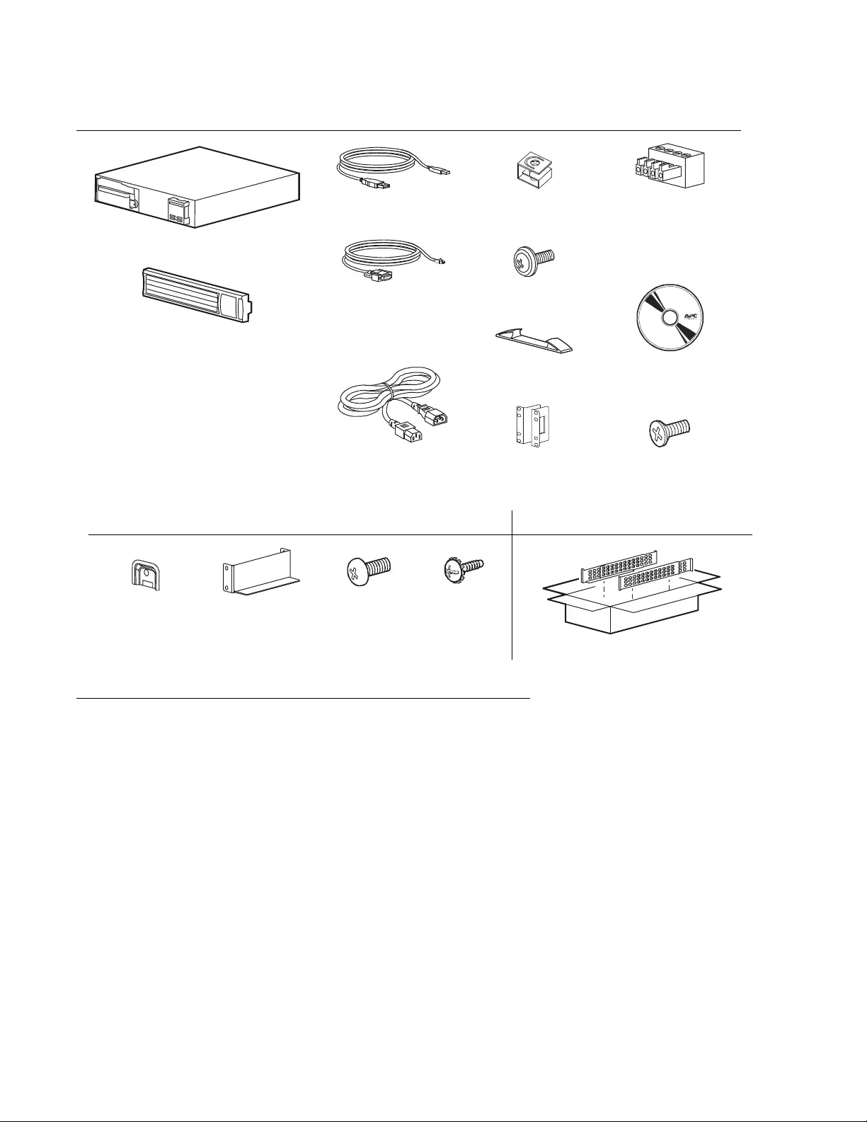
Inventory
All models
(1)
(1)
(1)
(2)
230 Vac models
(4)
(4)
(2)
(1 pair)
Rack-Mount brackets
(1)
(2)
(4)
(1)
750/1000 VA models 1500 VA models
(2) (2) (4) (2)
(1 pair)
Models with pr ei nstalled network cards
Installation Smart-UPS X 750/1000/1500 VA 120/230 Vac Rack-Mount 2U 3
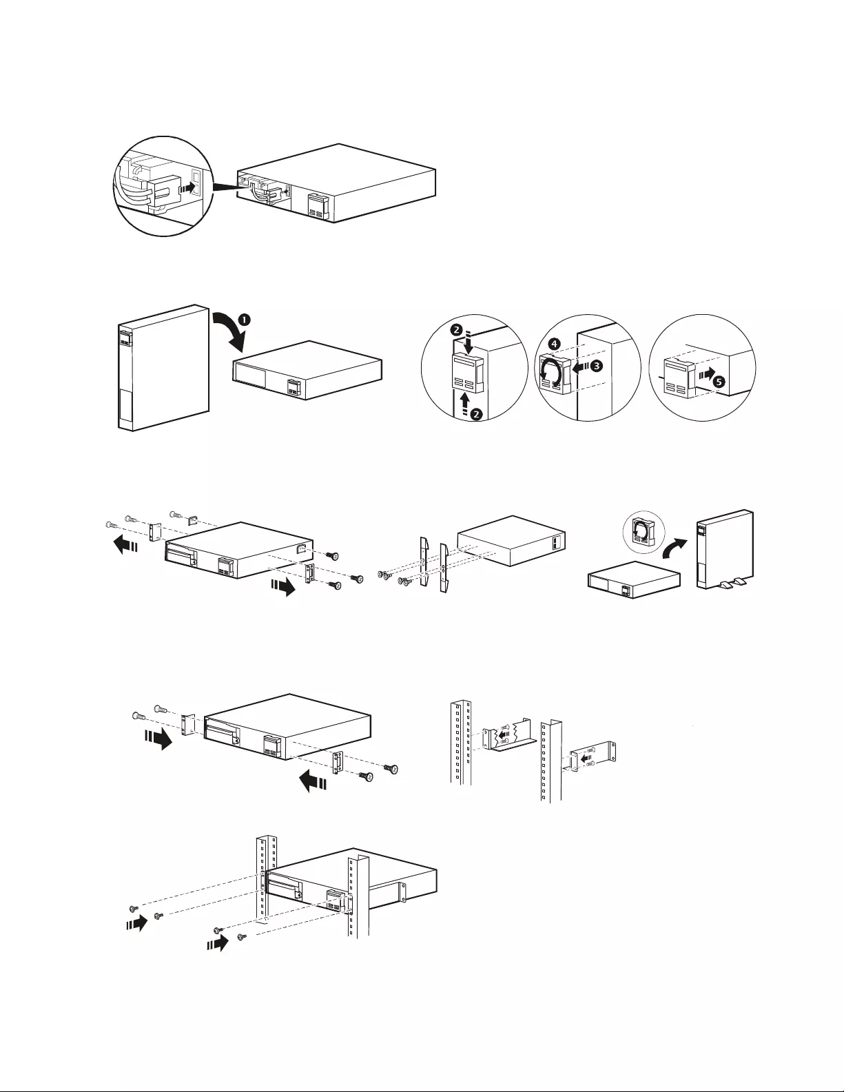
Installation
Connect the battery
Tower to rack-mount conversion 750/1000 VA
Rack-mount to tow er conversion 15 00 VA
Two post rack
Front moun t installation 750/1000 VA
123
12
3
su0320a
su0331a
su0332
su0336a
su00335a
su0337a
su0322a
su0356a
su0324a
Installation Smart-UPS X 750/1000/1500 VA 120/230 Vac Rack-Mount 2U4
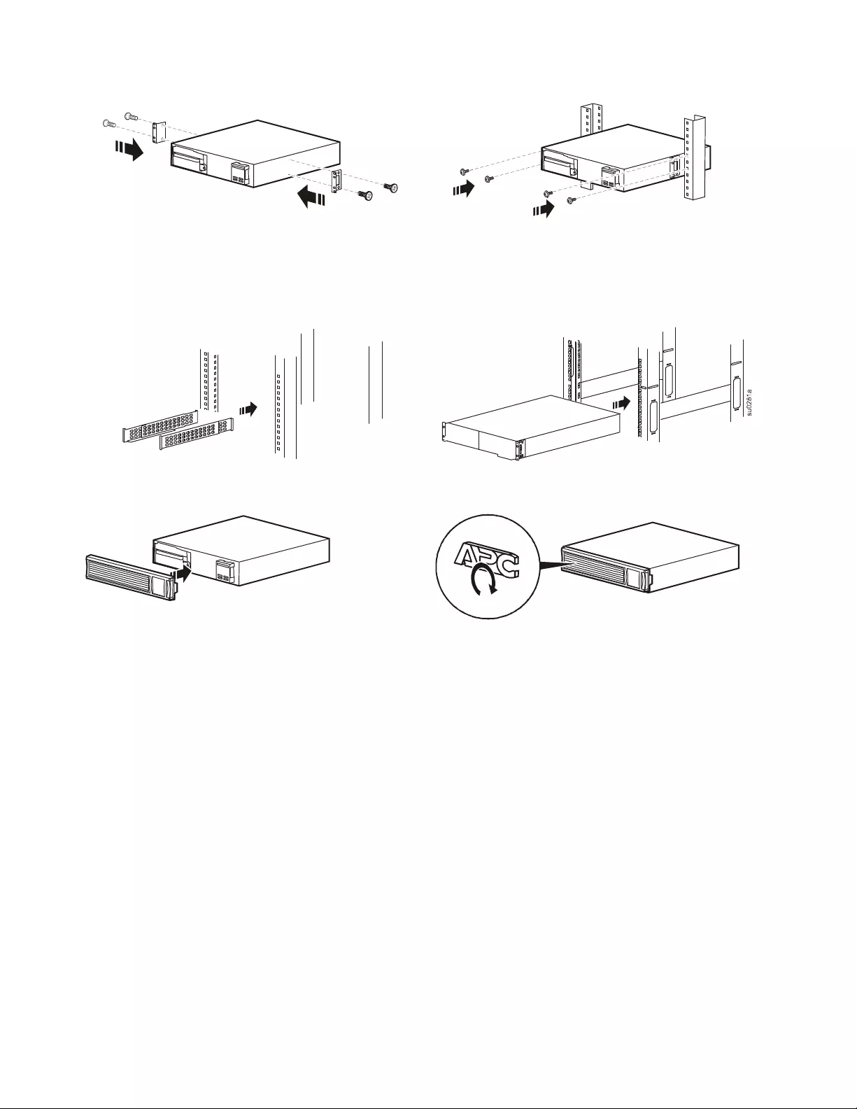
Center mount 750/10 00/1500 VA
Four post rack installation 1500 VA
Use the APC Four Post Rail Kit (included with 1500 VA models only.)
Install the bezel and rotate the logo
12
12
su0321a
su0323a
su0440a
su0357a
su0442a
Installation Smart-UPS X 750/1000/1500 VA 120/230 Vac Rack-Mount 2U 5
Start Up and Configuration
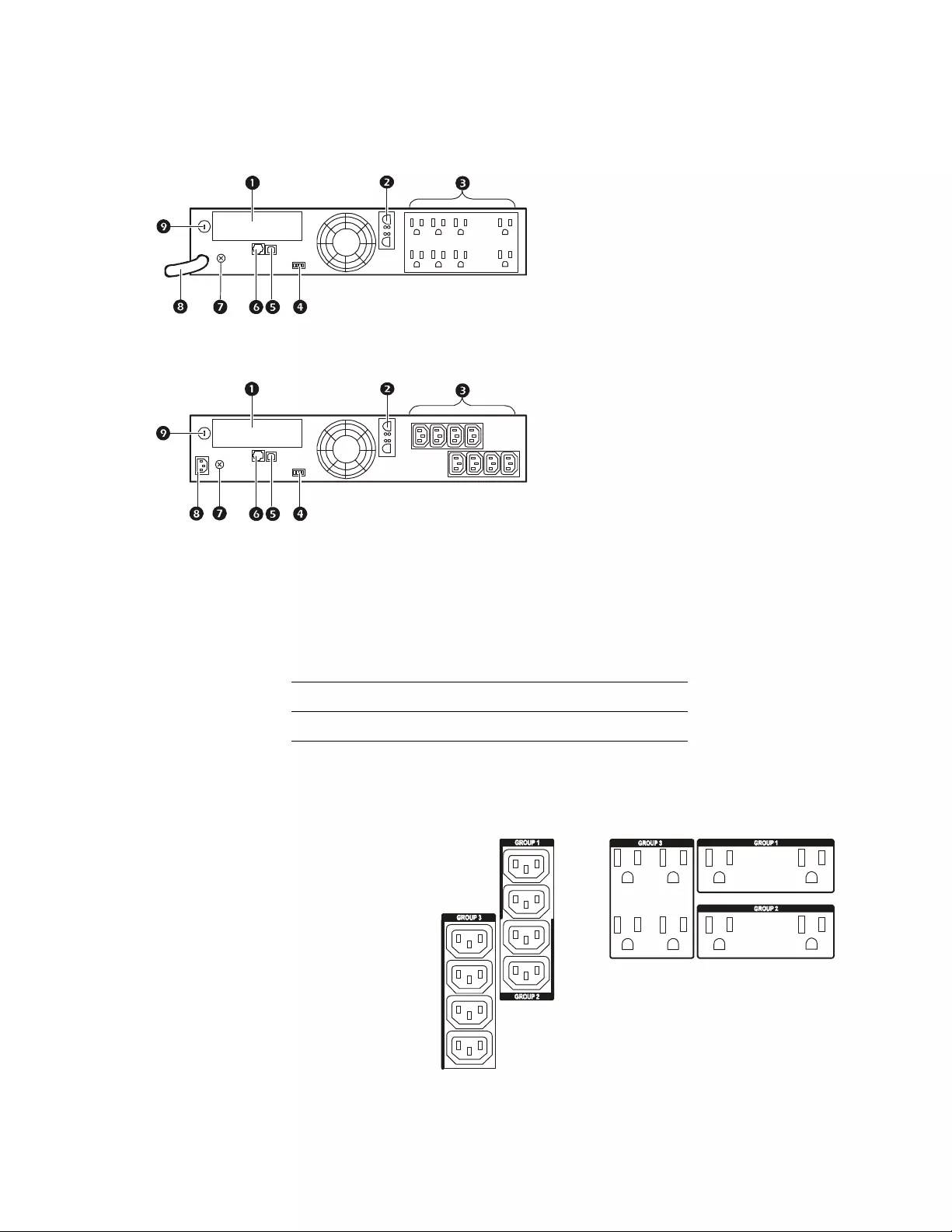
Overview
Controllable outlet groups
The outlets on the UPS are configured into groups. To configure the controlled outlet features, navigate
to: Main Menu > Control > Outlet1 Control.
120 Vac 1SmartSlot
2External battery pack connector
3Outlets
4EPO connector
5USB port
6Serial port
7Chassis ground screw
8UPS input
230 Vac 9Circuit breaker
SKU Contr ol lable Outlet Grou p
750 VA 1
1000 VA 1 & 2
1500 VA 1, 2, & 3
230 V 1500 VA 120 V 1500 VA
Examples of switched outlet groups
su0340a
su0341a
su0358
a
su0359a
© 2015 APC by Schneider El ectric. APC, the APC logo and Smart-UPS are o wned by Schneid er Electric
Industries S.A.S ., or t hei r affiliated companies. All ot her trademar ks are property of thei r respective
owners.
EN 990-3527D -0 02
04/2013
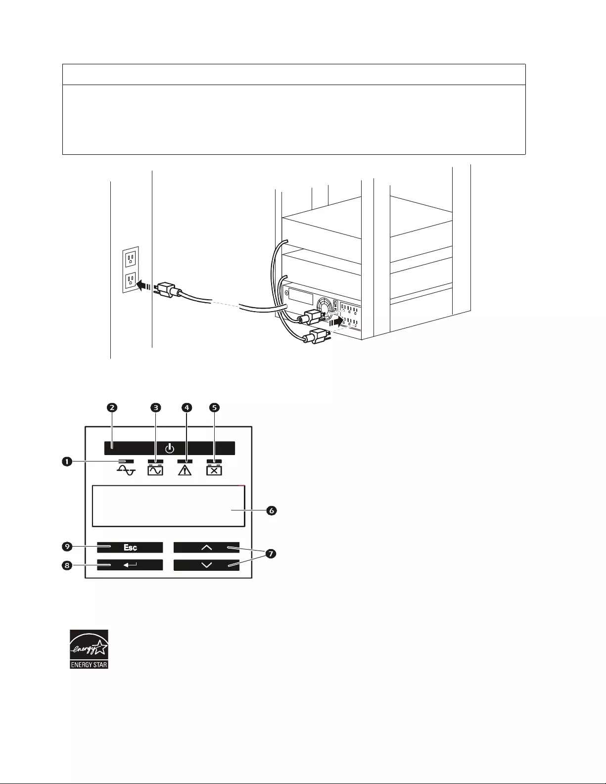
Electrical connections
Display Interface
Select models are ENERGY STAR® qualified.
For more information go to www.apc.com/site/recycle/index.cfm/energy-efficiency/energy-star/
CAUTION
RISK OF EQ U I PM EN T DA MAGE
• Adhere to all local and national electrical codes.
• Wiring should be performed by qualified electrician.
• Always connect the UPS to a grounded outlet.
Failu re to fo llow t hese instructions can resul t in equipment dam age
1Online LED
2UPS ON/OFF key
3On Battery LED
4Site Wiring Fault LED
5Replace Battery LED
6Display interface
7UP/DOWN arrow keys
8ENTER key
9ESC key
su0439a
su0343a
APC By Schn eider
Electric