Table of Contents
- Product Description
- General Information
- Important Safety Messages
- Safety and General Information
- Product Overview
- Specifications
- Front Panel Features
- Rear Panel Features
- Operation
- Connect Equipment
- Turn the UPS On/Off
- UPS Display Interface
- Configuration
- UPS Settings
- Controllable Outlet Groups
- Emergency Power Off
- Network Management Interface (For NC models only)
- Introduction
- IP Address Configuration
- Related Documents
- Smart Battery Management
- Troubleshooting
- Transport
- Service
- Limited Factory Warranty
APC SRT3000XLI User Manual
Displayed below is the user manual for SRT3000XLI by APC which is a product in the Uninterruptible Power Supplies (UPSs) category. This manual has pages.
Related Manuals

Operation Manual
Smart-UPS™ On - Line SR T
Uninterruptible Power Supply
SRT2200XLI
SRT2200RMXLI
SRT2200RMXLI-NC
SRT3000XLI
SRT3000RMXLI
SRT3000RMXLI-NC
SRT3000XLT
SRT3000RMXLT
SRT3000RMXLT-NC
SRT3000XLW-IEC
SRT3000RMXLW-IEC
208/220/230/240 Vac
Tower/Rack -Mount 2U

1Smart-UPS On-Line SRT2200/SRT 3000 Tower/Rack-Mount 2U
Product Description
The A PC by Schneider Electric Smart-UPS™ On-Line SRT is a high performance uninterruptible power supply
(UPS). The UPS helps to provide protection for electronic equipment from uti lity power blackouts, brownouts,
sags, surges, s mall utility power fluctuations and large disturbances . The UPS also provides battery backup power
for connec ted equipm ent until utility power returns to acceptable levels or the batteries are com pletely discharged.
This user manual is available on the enclosed Documentation CD and on the APC by Schneider Electric web site,
www.apc.com.
General Information
Important Safe ty Messages
Read t he instru cti ons carefully to bec om e familiar with the equipment be fore attempting to install, operate, s ervice
or maintain the UPS. The following special messages may appear throughout this manual or on the equipment to
warn of potent ial hazards or to cal l at tention to information that clarifies or simpl ifies a procedure.
The addition of this symbol to a Danger or Warning pr oduct safety label indi cates that a n electric al
hazard exists which will result in personal injury if the instructions are not followed.
The addition of this symbol to a Warning or Caution product safety label indicate s that a hazard exists
that can res ult in injury and pr oduct damage if the instruct ions are not fol lowed.
WARNING
WARNING indi cates a potent ial ly hazardous sit uation which, if not avoided, can result i n death or serious injury.
CAUTION
CAUTION indicates a potentially hazar dous situat ion which, if not avoided, can re s u lt in minor or m oderate injury.
NOTICE
NOTICE used to ad dress practices not related to phy sical injury. The safety al ert sym bol is not used wit h this signal word.

Smart-UPS On-Line SRT2200/SRT3000 Tow er/ R ack-Mount 2U2
Saf ety and General Information
• Adhere to a ll national and loc al electric al codes.
• All wiring m us t be pe rformed by a qualified el ec trician.
• Changes and modi fications to this unit not expressly a pproved by APC could void the warranty.
• This UPS is intended for indoor use only.
• Do not operate this UPS in dire ct sunlight, in contact with f luids, or where there is excess ive dust or
humidity.
• Be sure the air vents on the UPS are not bloc ked. Allow adequate space for proper ventilat ion.
• For a UPS with a factory installed power cord, connect the UPS power cable directly to a wall outlet. Do not
use s u rge pr o t ec to r s or ex t en si on co r d s.
• The batte ry ty pic ally la sts for two to five years. En viron mental fa ctors impact bat tery li fe. Elevate d ambient
temperatures, poor quality utility power, and frequent sh ort duration dis charges will short en battery life.
• Replace the batte ry immediately when the UPS indi cates battery repla cement is nece ssary.
• The equipment is he avy . Alw ays pract i ce saf e lifting tec h n i ques adeq u ate for the w eight of th e eq uipment.
• The batte ries are he avy. Re move the b atter ie s befor e ins talli ng t he UPS and e xte rnal ba ttery packs (XLBPs),
in a ra ck .
• Always ins tall XLBPs at the bottom in rack-mount configurati ons. The UPS must be installed above the
XLBPs.
• Always ins tall peripheral equipment above the UPS in rack-mount configurati ons.
• Additional safety in fo rmation can be fo und in the Safety Guide s upplied with this unit.
Dee nergizing safety
The UPS contains internal batteries and may present a shock hazard even when disconnected from the branch
circui t (m ains). Before ins tal ling or servi cing the equipment check that the:
• inp ut circu it br eaker is in the OFF position.
• in ter nal U P S th e bat ter ies ar e r em o v e d.
• XLBP batte r y m odules are disc onnected .
Electrical safety
• For models with a hardwi red input, the connection to the br anc h circuit (main s) mus t be pe rformed by a
qualif ied electrici an.
• Have a proper grounding for input s ocket for the models with pluggable power cords.
• 230 V models only: In order to maint ain com pliance with the EMC dire ctive for products sold in Eu rope,
output cords attached to the UPS must not exc eed 10 meters in length.
Battery safety
• Before installing or replacing the ba tteries, remove jewelry such as wr is twatches and ri ngs.
High sh ort circuit c urrent through con ductive mate rials could cause severe burns.
• Do not dispose of b atterie s by burning them. Th e bat teries may explode.
• Do not open or mut ilate bat teries. Released electrolyte is harmful to the s kin and eyes, an d may be toxic.

3Smart-UPS On-Line SRT2200/SRT 3000 Tower/Rack-Mount 2U
General information
• The UPS will recognize as many as 10 external batter y pac ks conne cted to the UPS.
Note: For each XLBP added, increased recharge time will be required.
• The model and serial num bers are locate d on a small, re ar panel label. F or some m odels, an a dditio nal labe l
is located on the chassis under the fro nt bez el.
• Always re cycle used batteries.
• Recycle the package materials or save them for reuse.
FCC Class A radio frequency warning
This equi pment has been te ste d and found to comply with t he limits for a Cla ss A di gital device , pursu ant to pa rt 15
of the FCC Rule s. T hese limit s are int ended t o provi de reasona ble prote ctio n aga inst harm ful in terferenc e when the
equipment is operated in a commercial environ me nt. This eq uipm ent generates, uses, and can radiate radio
frequency energy and, if not insta lled and used in accordance with the instruction manual, may cause harm ful
interference to radio communications. Op eration of this equipment in a re sidential area is likely to cause harmful
interference in which case the user will be required to correct the interference at his own expense.
Smart-UPS On-Line SRT2200/SRT3000 Tow er/ R ack-Mount 2U4
Product Overview
Specifications
For additional specifications refer to the APC by Schneider El ec tric web site, www.apc.com.
Environmental
Physical
Temperature Operating 0º to 40º C (32º to 104º F)
Storage -1 5º to 45º C (5º to 11 3º F)
Elevation Operating 0 - 3,000 m (0 - 10,0 00 ft)
Storage 0 - 15,000 m (50,000 ft)
Humidity 0% to 95% relative humidity, non-condensing
Protection Class I P 20 rating
Note: Charge the battery modules every six months during storage.
Environmental factors impact battery life . Elevated ambient temperatures, high humidity, poor quality mains power, and
frequent sh ort duration discharges will shorten battery life.
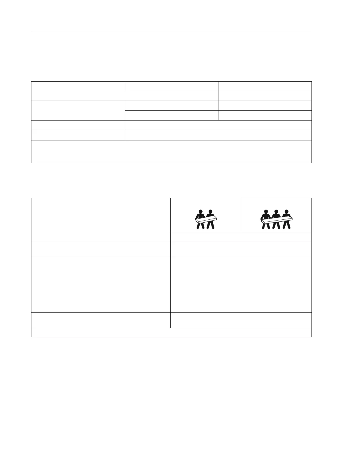
SRT2200XLI /S RT2200RMXLI/SRT2200RMXLI-NC model
The UPS is heavy. Follow all lifting gu idelines.
Lif t ing guidelines 18 - 32 kg (40 - 70 lb) 32 - 55 kg (70 - 120 lb)
Unit weight batte ries included, without packagin g 25 kg (55 lb)
Unit weight batte ries included, with packagi ng Rack-Mount models : 34 kg (75 lb)
Tower m o dels: 31 k g ( 68 lb )
Unit dimensions without packaging
Height x Width x Depth Rack-Mount models:
85 (2U) mm x 432 mm x 560mm
3.35 (2U) in x 17 in x 22 in
Tower models:
85 (2U) mm x 432 mm x 585mm
3.35 (2U) in x 17 in x 23 in
Unit dimensions with packaging
Height x Width x Depth 245 mm x 600 mm x 810 mm
9.7 in x 23.6 in x 31.9 in
The model a nd serial numbers a re on a small label loc ated on the rear pane l.
5Smart-UPS On-Line SRT2200/SRT 3000 Tower/Rack-Mount 2U
Battery
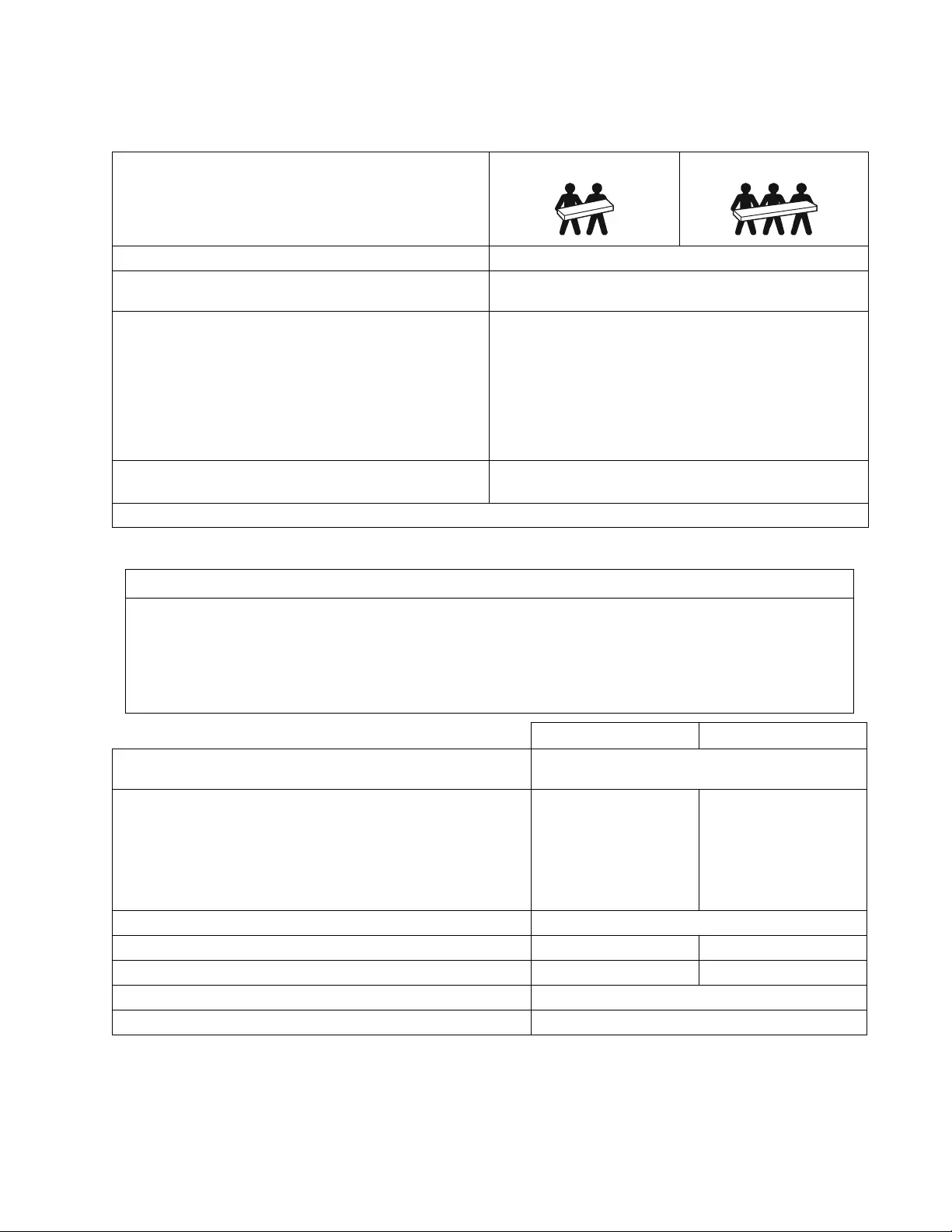
SRT3000XLI/SRT3000RMXLI/SRT3000RMXLI-NC/SRT3000XLT/SRT3000RMXLT/SRT3000RMXLT-NC/
SRT3000XLW -IEC/SRT3000RMXLW-I EC model
The UPS is heavy. Follow all lifting gu idelines.
Lif t ing guidelines 18 - 32 kg (40 - 70 lb) 32 - 55 kg ( 70 - 120 lb)
Unit weight batte ries included, without packagin g 31 kg (69 lb)
Unit weight batte ries included, with packagi ng Rack-Mount models : 40 kg (88 lb)
Tower models: 37 kg (81 lb)
Unit dimensions without packaging
Height x Width x Depth Rack-Mount models:
85 (2U) mm x 432 mm x 611mm
3.35 (2U) in x 17 in x 24 in
Tower models:
85 (2U) mm x 432 mm x 636mm
3.35 (2U) in x 17 in x 25 in
Unit dimensions with packaging
Height x Width x Depth 245 mm x 600 mm x 870 mm
9.7 in x 23.6 in x 34.3 in
The model a nd serial numbers a re on a small label loc ated on the rear pane l.
NOTICE
RISK OF EQUIPMENT DAMAGE
• Replace the battery at least every 5 years.
• Replace the battery immediately when the UPS indicates battery replacement is necessary.
Failure to follow these instructions can result in equipment dama ge
SRT2200 models S RT3000 models
Battery type Sealed, maintenance-free, Valve Regulated
Lead-Acid battery
Rep l acem e nt ba tt ery module
This UPS has s wappable bat tery modules.
Refer to the appropriate rep lacement battery user manual for
ins tallation instructions.
Contac t your dealer or go the APC by Schneider Elec tric web site,
www.apc.com for informa tion on replacement batteries.
APCRBC141 APCRBC152
Number of battery modules 1 batte r y module
Voltage for each battery module 72 VDC 96 VDC
Total battery voltage for the UPS 72 VDC 96 VDC
Ah rating 5 Ah per batter y mod ule
XL B P ca bl e len g t h 500 mm (19.7 in)
Smart-UPS On-Line SRT2200/SRT3000 Tow er/ R ack-Mount 2U6
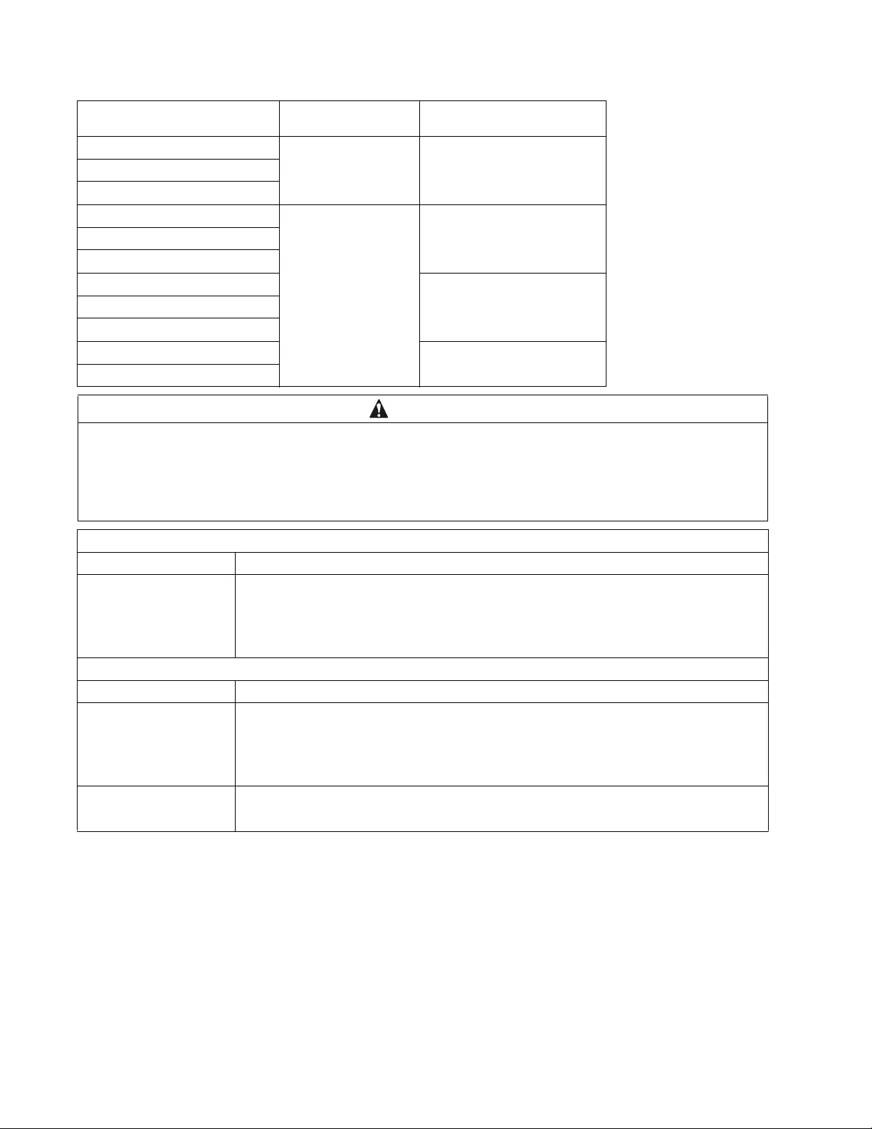
Electrical
Models Rating Building Circuit B reake r
(CB) Current Rating
SRT2200XLI 2200 VA / 1980 W 16 A
SRT2200RMXLI
SRT2200RMXLI-NC
SRT3000XLI 3000 VA / 2700 W 20 A
SRT3000RMXLI
SRT3000RMXLI-NC
SRT3000XLT 20 A* / 2 pole
SRT3000RMXLT
SRT3000RMXLT-NC
SRT3000XLW-IEC 20 A IEC; 20 A UL* / 2 pole
SRT3000RMXLW-IEC
CAUTION
RISK OF FIRE, RISK OF DAMAGE TO EQUIPMENT OR PERSONNEL
* Connect the UPS models onl y to a circuit provided wi th recomm ended maximu m b ranch cir cuit overcurrent pr otection in
accordance with the National Electrical Code, ANSI/NFPA 70 and the Canadian Electrical Code, Part I, C22.1.
F ail ure to follow these instructions can re sult in fire , equi pment damage and mino r or m oderate injury.
Output
Output Frequency 50 Hz / 60 Hz
Nominal Output Voltage SRT2200XL I/SRT2200RMXLI/SRT2200RMXLI-NC/SRT3000XLI/SRT3000RMXLI/
SRT3000RMXLI-NC: 220 V, 230 V, 240 V
SRT3000XLT/SRT3000RMXLT/S RT3000 RMXLT- NC: 208 V, 240 V
SRT3000XLW-IEC/SRT3000RMXLW -IEC: 208V, 220V, 230V, 240V
Input
Input Frequency 40 Hz - 70 Hz
Nominal Input Voltage SRT2200XL I/SRT2200RMXLI/SRT2200RMXLI-NC/SRT3000XLI/SRT3000RMXLI/
SRT3000RMXLI-NC: 220 V, 230 V, 240 V
SRT3000XLT/SRT3000RMXLT/S RT3000 RMXLT- NC: 208 V, 240 V
SRT3000XLW-IEC/SRT3000RMXLW -IEC: 208V, 220V, 230V, 240V
Input current rating SRT2200 m odels : 13 A
SRT3000 models: 16 A
7Smart-UPS On-Line SRT2200/SRT 3000 Tower/Rack-Mount 2U
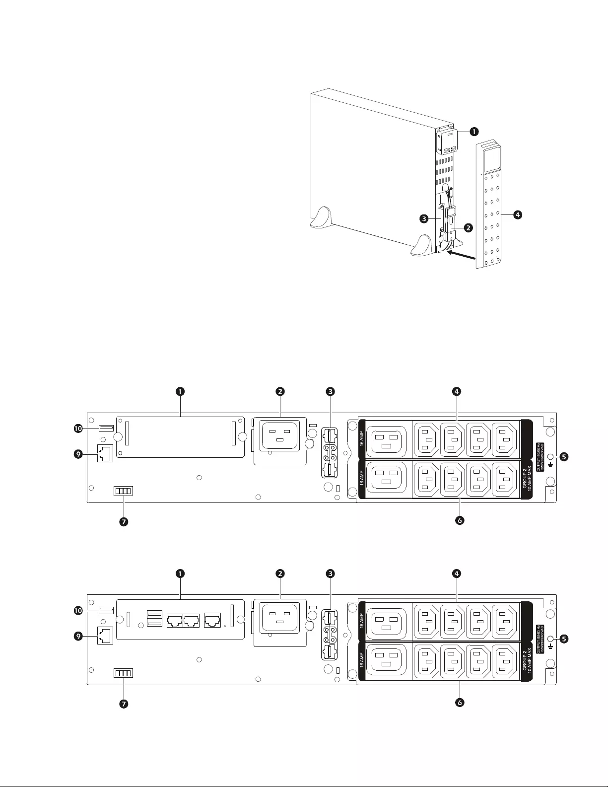
Front Panel Feat ures
Rear Pane l Features
Note: Refe r to the table “Key to identify rear panel features” on page 8, that provides a key to the callout numbers for
the rear panel graphics depicted in this manual.
Display interface panel
UPS battery connectors
Battery modul e
Bezel
SRT2200XLI/SRT2200RMXLI/SRT3000XLI/SRT3000RMXLI
SRT2200RMXLI-NC/SRT3000RMXLI-NC
suo0860a
GROUP 1
10 AMP MAX
suo0882a
GROUP 1
10 AMP MAX
suo0882b
Smart-UPS On-Line SRT2200/SRT3000 Tow er/ R ack-Mount 2U8
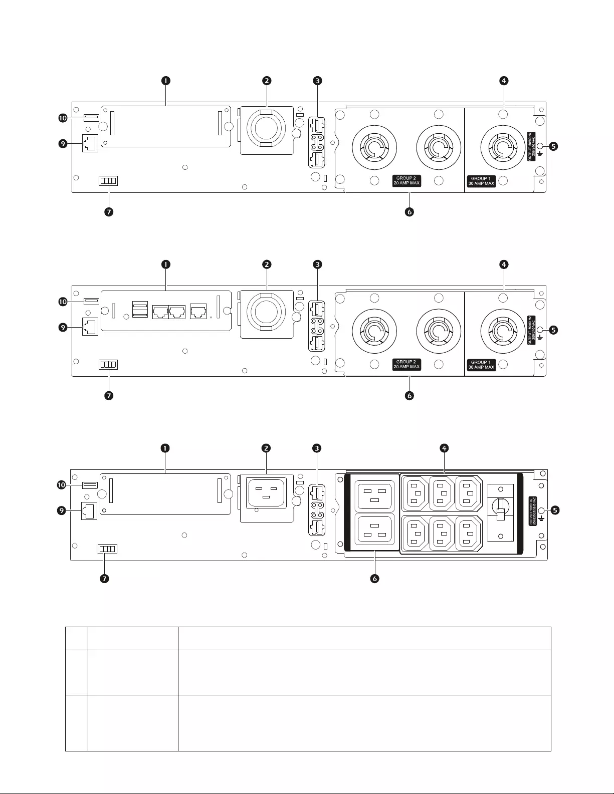
Key to identify rear panel features
SRT3000XLT/SRT3000RMXLT
SRT3000RMXLT-NC
SRT3000XLW-IEC/SRT3000RMXLW-IEC
SmartSlot The SmartSlot can be used to connect opti onal management acces sories.
AC input
p ower ca b l e o r
hardwire input box
SRT3000XLT, SRT3000RMXLT , SRT3000RMXLT-NC model s h ave fa ctory in stal led input
power cables.
External battery
power and
communication
connector
Use the external battery cable on the XLBP to connect the UPS and XLBP.
XLBPs provide extended runtime during power outages. T he UPS will automatic ally
recognize up to 10 external battery packs.
suo0883a
suo0883b
suo0884a
OVERLOAD
PROTECTO R
GROUP 2 MAX: 16 AMP IEC; 20 AMP UL
GROUP 1 MAX: 10 AMP IEC; 15 AMP UL

9Smart-UPS On-Line SRT2200/SRT 3000 Tower/Rack-Mount 2U
Controllable
outlet group 1 Con nect el ectronic devic es to these outlets.
Chassis ground
screws T he UPS and XLBPs have ground screws for connecting the ground leads. Prior to
connecting a ground lead, disconnect the UPS from mains power.
Controllable
outlet group 2 Con nect el ectronic devic es to these outlets.
EP O t e r min a l The Emergency Power Off (EPO) terminal allo ws the user to connect the UPS to a central
EPO system.
Serial Com Th e Serial Co m po r t is us ed to co mmunicate with t h e UPS.
Use only interface kits supplied or approved by APC by Schneider Electric. Any other
serial i nterface ca ble will be i ncompatible with th e UPS connecto r.
USB port The USB port is used to connect either a server for native operat ing s ystem
co mmunications, or f o r softwa r e to communi cate with the UPS.
Note: Serial and USB communication should not be us ed simultaneously. Use either the
Serial Com or the USB por t.

Smart-UPS On-Line SRT2200/SRT3000 Tow er/ R ack-Mount 2U10
Operation
Connect Equipment
Note: The UPS batteries will charge to 90% capacity in the first three hours of normal operation. Do not expect full
battery runtime capability during this initial charge period.
1. Connect the internal battery module. See Installation manual for details .
2. Connect equipm ent to the outlets on the rear panel of the UPS.
Refer to “Contro llable Outlet Groups” on page 19.
3. Connect the UPS to the building utility power.
Tu rn the UPS On/Off
The first tim e the UPS is tur ned on the Setup Wizard screen will run. Follow the prom pts to configure UPS settings.
Refer to “Configuration” on page 14.
To turn on the UPS and all connected equipment, press the POWER ON/OFF button on the dis play panel . F ollow the
prompts to either turn the UPS on immediately or after a delay, then press OK.
NOTE: When there is no input power and the UPS is off, the cold sta rt feature can be use d to turn on the UPS and
connected equipment using battery power.
To perform a cold start press the POWER ON/OFF button.
The display panel will illuminate and the POWER ON/OFF button will illuminate red.
To turn on the output power pres s the POWER ON/OFF button aga in. Select the prompt Turn ON with NO AC and press
OK.
To turn output power off, pres s the POWER ON/OFF button . Fol low th e prompts t o eithe r tur n the UPS of f i mmediat ely or
after a delay, then press OK.
NOTE: Once the UPS output power has been tu rned of f and the AC input ha s been removed, the UPS will continue to
use the bat tery for int ernal power fo r 10 min utes. To remove power comp letel y press the POWER ON/OFF butt on. Fol low
the prompt to selec t Internal Power Off, then press OK.
CAUTION
DAMAGE TO EQUIPMENT OR PERSONNEL
• Disconnect the mains input circuit breaker befor e installi ng or servic ing the UPS or connected equipm ent.
• Disconnect int ernal and external batterie s befor e instal ling or servicing the UPS or connected equipment .
• The UPS contains inte rnal and exter nal batt eries that may present a shock hazar d even when disconnected from th e
mains.
• UPS AC hardwired and pluggable outlets may be energi zed by rem ote or automatic control at any ti m e.
• Disconnect equipment from the UPS before se rvi cing any equip me nt.
Failure to follow these instructions can result in equipment damage and m inor or moderate injury.
11Smart -UPS On-Line SRT2200/S RT3000 Tow er/Rack-Mount 2U
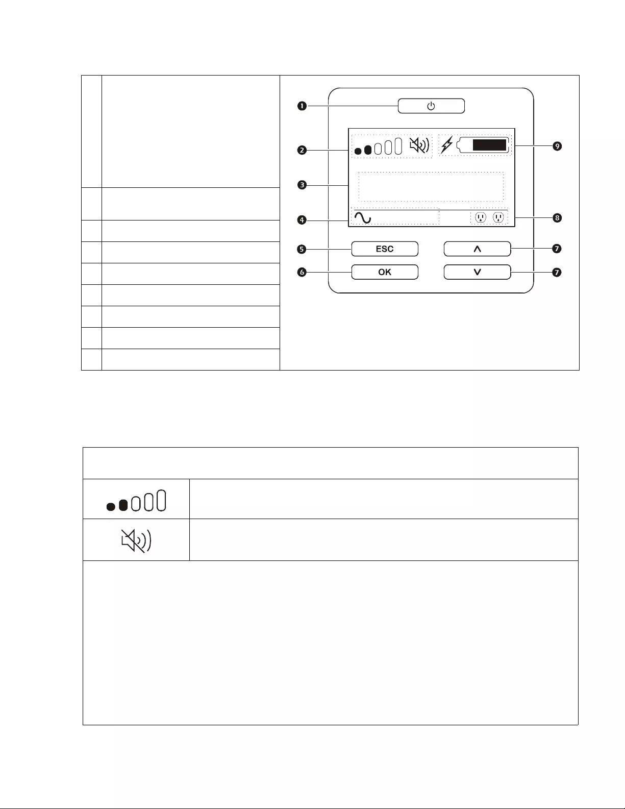
UPS Display Interface
UPS Display Interface operation
Use the UP/DOWN bu ttons to scroll through the options. Press the OK button to accept t he selected opt ion. P r es s the ESC
button to return to the previous menu.
.
POWER ON/OFF button
Button illumination indications:
-No illuminat ion, the UPS and the output
power are off
-White illum ination, the UPS and the
output power are on
-Red illumination, the UPS is on and the
output power is off
Load icon
Disable/mute audible alarm icon
UPS status information
O peration mode i cons
ESCAPE button
OK button
UP/DOWN buttons
Controll ab le outlet group status icons
Battery status icons
The i cons on th e L CD display interface screen may vary depending on the installed firmware versions and specific UPS
models.
Load icon: The approximate load capacity percentage is indicated by the number of load bar
sections illuminated. Each bar represents 16% of th e load capacit y.
Mute icon: Ind ica tes th e audible alarm is disabled /mute .
UPS Status Information
The status information field provides key information on the status of the UPS.
The Standard menu will allow the user to select one of the five screens lis ted below. Use the UP/DOWN buttons to scroll
thr ough the screens.
The Advanced menu will s croll through the five screens autom atically.
• Input Voltage
• Output Voltag e
• Output Frequency
•Load
• Runtime
In the ca se of a UPS event, status updates will be displayed defining the even t or condition that has occurred.
The display screen illuminates amber to indicate a Message and red to indicate an Alert depending on the severity of the
event or condition.
su0870b
Output
230.0
v
LOAD
On-Line
12
LOAD

Smart-UPS On-Line SRT2200/SRT3000 Tow er/ R ack-Mount 2U12
Opera tio n Mode Icons
On-Line mode: The UPS is supplying conditione d mains power to c onnected equipment.
Bypass mode: The UPS is in Bypass mode and the connected equipment will receive mains
power as long as the input voltage and frequency are within the configured limits.
Green mode: When in Green mode mains power is sent directly to the load.
I n the event of a mains power outage, there will be an interruption in power to the loa d of up to
10 m s w hil e the U P S s w it ches to On-Line or Battery mode.
When enabling Green mode consideration should be given to devices that may be sensitive to
power fl uctuations.
Indicates a UPS alert that requires attention.
UPS S tatus Icon
Battery mode: The UPS is supplying bat tery power to conne cted equipment.
The UPS has det ected an intern al fa ult with the bat tery. Follow the in st ructions on the screen.
The UPS has detected a critical fault with the battery. The battery is at the end of its life and has
to be re placed.
Controllable Outlet Group Icons
Contr o llable Out let Group Power Ava ilable: The number next to the icon identifies the
spe cific outlet groups that have avail able power.
Fl as hing icon indicates the outlet group is turning from OFF to ON with de lay.
Controllable Outlet Group Power Not Available: The number next to the ic on identifies
spe cific outlet groups that do not have avail able power.
Fl as hing icon indicates the outlet gr oup is turning from ON to OFF with delay.
Battery Status Icons
Batte ry Charg e St atu s : Indicates the battery charge status.
Battery Charge In Progress: Indicates the battery is charging.
X
13Smart -UPS On-Line SRT2200/S RT3000 Tow er/Rack-Mount 2U
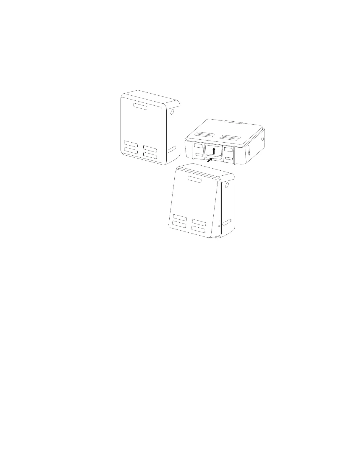
LCD display interface angle adjustment
The angle of the LCD display inte rface can be adjusted for ease in viewing the dis played messages.
1. Remove the front bezel.
2. Locate the button on the bottom of the display interface panel.
3. Press the button and slide the bottom of the LCD display interface screen out. An audible cl ick will be
heard when th e screen reaches the maxim um angle.
Menu overview
The UPS Dis pla y I nt er fac e ha s Standard and Advanced menu screens. The preference for Standard or Advanced
menu sel ections is made during init ial installation and ca n be changed at any time through the Configuration
menu.
The Standard menus include the most commonly used options.
The Advanced menus provide additional options.
Note: Actua l menu s cre ens may diffe r by model and f irm ware version.
su0926a

UPS Menu Overview
Mai n Menu
Status
Control
Configuration
Test And Diagnost ics
Log
About
Accessory***
Smart Slot – Probe 1 Temperature
Smart Slot - Probe 1 Humidity
Smart Slot – Probe 2 Temperature
Smart Slot - Probe 2 Humidity
Config Menu
UPS
Battery
Ou tl e t s
Communication
Display
Status Menu***
UPS
Battery
Ac cessory
Control Menu**
UPS
Bypass Control
Outlet Group 1*
Outlet Group 2*
Clear Alarms
Test and Diag nostics Menu
UPS Self Tes t
Runtime Test
Alarm Test - Short
Alarm Test - Continuous
Log
Event Log
Battery
RBC Health
RBC Summary – Installed MMYY, Replace MM YY
Internal RBC ’s , Battery Pa cks, Ex ter nal RBC ’ s
Charge %, Runtime
Temperature, V olta ge
Internal Pack – Temperature
Internal Pack – Health
External Pack – Temp erature
External Pack - Health
UPS**
Efficiency
Output Power - Watts, VA,Load %
Output - Voltage, Frequency, Current
Energy Usage
Battery - Charge %, Runtime
Input Voltage, Frequency
Self Test
Runtime Test
Alert status - Site Wiring Fault
-
UPS
Outlet Group 1**
Turn On Immediately
Turn On With Delay
Turn Of f Immediately
Turn Off With Delay
Reboot Immediately
Reboot With Delay
Shutdown Immediately
Shutdown W ith Delay
Outlet Group 2**
Turn On Immediately
Turn On With Delay
Turn Of f Immediately
Turn Off With Delay
Reboot Immediately
Reboot With Delay
Shutdown Immediately
Shutdown W ith Delay
Bypass Co ntrol**
Go into Bypass
Go out of Bypass
Clear Alarms**
No Alarms Exist
UPS**
T u rn On Immediately
Turn On With Delay
Turn Of f Immediately
Turn Off With Delay
Reboot Immediately
Reboot With Delay
Shutdown Immediately
Shutdown W ith Delay
Outlets
Main Outlet
Outlet Group 1
Outlet Group 2
Display
Language
Audible Alarm – D isable , Enable
LCD Backlight – A lways On, Auto Dim, Auto Off
LCD Setti ngs- Color, Brightness, Contrast
Menu type - Stan dard / Advanced
T i me***
UPS**
Green Mode - Enable / Disable
Output Setting - Lower Volt, Upper Volt
Output Setting – Accept able Frequency
B ypass S ett in gs - Lower Vol t, Uppe r Volt
Bypass Setti ngs – Frequency
Battery Settings – Low Runtime Warning
Self Test Schedule
Alert Setting - Site Wiring Fault
PDU model- Standard, SRT012
De fau lt S e tting
Energy Meter*
Output Setting – Frequency Slew Rate
Battery
Install Date
Replace Notific a tion
Replace Battery Alar m
Communication
SmartSlot- IP Add r ess M ode, IPv4 Address
Modbus*- Enable / Disable, A ddress
UPS***
UPS Hardware - Pa rt No.
PDU Hardware
UPS Hardware - Se ri a l No.
UPS Hardware - Manufacture Date
UPS Firmware – Revison
UPS – DSP Firmware
UPS – Comm Firmware
UPS Tim e
Accessor y***
Smart Slot - Serial No.
Smart Slot - Part No.
Sm a r t S lot - Fi rmw a re
Smart S lot - MAC Address
Smart S lot – IPv4 A ddress
About Men u
UPS
Battery
***
Accessory
Battery
Part Number
RB C Summary - Ins t alled MMYY, Rep lace MMY Y
Batter y – Firmware
Batter y – Part No.
Menus are subject to change depending on the installed firmware version
Options displayed will vary
Opt i ons dis played wi ll v ary based on c onnecte d ac c es s ories .
* Av ailable on t he Advanc ed M enu Screens
** based on UPS st ate.
***
Smart-UPS On-Line SRT2200/SRT3000 Tow er/ R ack-Mount 2U14
Configuration
UPS Settings
There are three ways to select UPS configuration options.
1. T h e f ir st time th e U P S is tu r n ed o n th e Setup Wizard screen will open. On each menu screen select the
desired settings. Pres s OK after each UPS setting is sel ected.
Note: The UPS will not turn on until all of the settings have been co nfigured.
2. M ain Menu/Configuration /UPS/Default Setting. Th is sc r een al lo w s th e us e r to re set th e UPS to f acto r y
defa ult settings. Press OK after the UPS s etting is s electe d .
Refer to “Config uration” on page 14 and “UPS Menu Overview” .
3. Configure se ttings using an external int erfa ce, such as the Network Management Web interface.
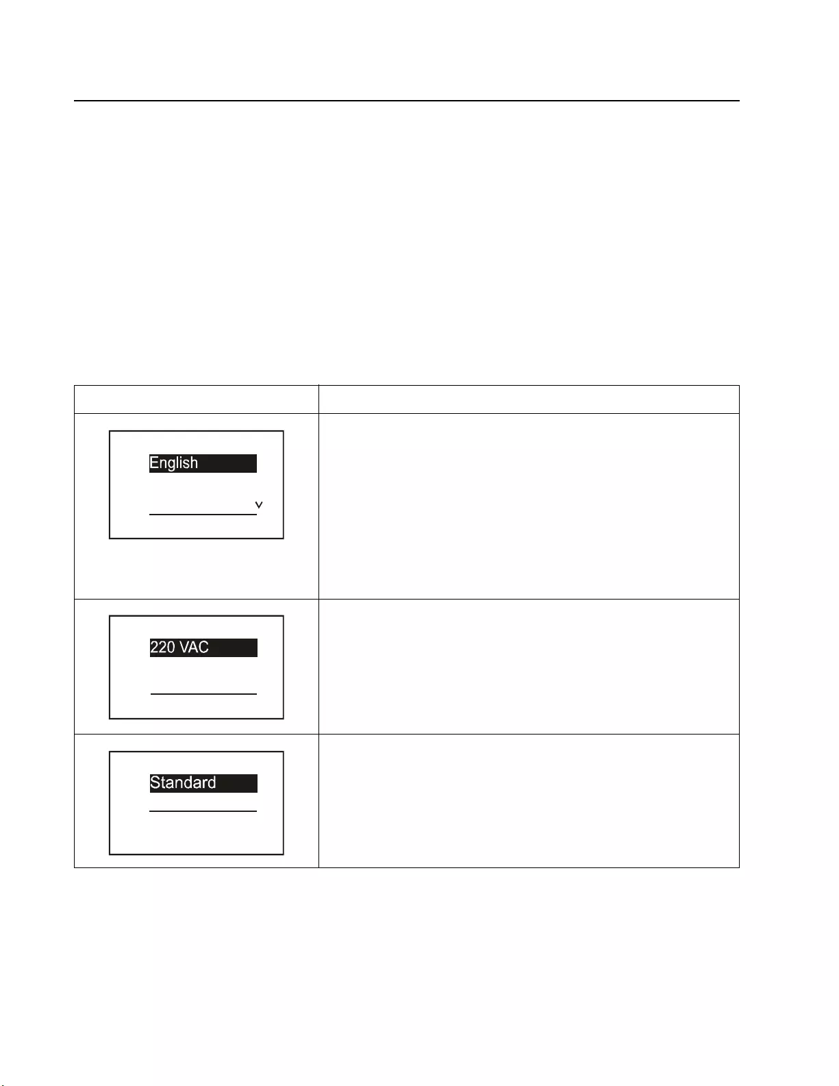
Startup configuration
Function Description
Sel ect the language required fo r the di splay interface.
Language options will vary by m odel and firmware version.
Options:
• English
•Francais
• Italiano
•Deutsch
• Espanol
• Portugues
• Russian
Select the output voltage.
Options will vary by model.
Options:
• 208 Vac
• 220 Vac
• 230 Vac
• 240 Vac
The Standard menu opt ions are the most commonly used options.
The Advanced menu options will be use d by IT professionals who need
detailed con f iguration and reporting inform ation.
Language
Francais
Italiano
Setup W izard
V
oltage AC Setting
230 VAC
240 VAC
Setup W izard
Menu Type
Advanced
Setup W izard

15Smart -UPS On-Line SRT2200/S RT3000 Tow er/Rack-Mount 2U
General settings
Configure these settings at any tim e, using the display interface, or the Network Management Web Interface.
Param et ers Defa ult Value Options Desc ription
Config
Menu
UPS
Green Mode Disabled Disable
Enable
Di sable or enabl e Green mode operation
AC Setting NA
( see description)
XLW models: 208 V,
220 V, 230 V, 240 V
XLI models: 220 V,
230 V, 240 V
XLT models: 208 V,
240 V
Set the output voltage for the UPS. This setting can
on ly b e changed wh en the UPS output is off.
These settings m ay vary dependin g on the UPS
model.
De f ault Value:
The value se lected by th e us er during initial
startup. Reset to factory default does not
ch ange the sele cted va lu e.
Output
Lower
Acceptable
Voltage
1 84 V for 208 V outpu t
1 98 V for 220 V outpu t
2 07 V for 230 V outpu t
2 16 V for 240 V outpu t
208 V - 169 to 184 V
220 V - 186 to 198 V
230 V - 195 to 207 V
240 V - 204 to 216 V
If the UPS input volta ge is between the lower
acceptable voltage and the higher acceptable
vol tage , th e U P S will op e ra te in Green mode when
enabled.
If the output vol tage go es outs ide th e accept able
range the UPS will switch from Green mode to
On-Line mode or to Battery mode.
Output
Upper
Acceptable
Voltage
2 20 V for 208 V outpu t
2 42 V for 220 V outpu t
2 53 V for 230 V outpu t
2 64 V for 240 V outpu t
208 V - 220 to 235 V
220 V - 242 to 253 V
230 V - 253 to 265 V
240V - 264 to 270 V
Output
Frequency Auto 50/60 ± 3Hz Auto 50/60 ± 3 Hz
50 ± 0.1 Hz
50 ± 3.0 Hz
60 ± 0.1 Hz
60 ± 3.0 Hz
S et the output frequen cy for th e U PS.
Output
Frequency
Slew Rate
1 Hz/S ec 0. 5 H z/ Sec
1 Hz/S ec
2 Hz/S ec
4 Hz/S ec
S elect the rate of change for output frequency in
He rtz per second.
Bypass
Lower
Acceptable
Voltage
160 V 208 V - 160 to 184 V
220 V - 160 to 198 V
230 V - 160 to 207 V
240V - 160 to 216 V If the UPS input volta ge is between the lower
acceptable voltage and the higher acceptable
voltage, the UPS can enter Bypass mode wh en
enabled.
Bypass
Upper
Acceptable
Voltage
2 50 V for 208 V outpu t
2 55 V for 220 V outpu t
2 65 V for 230 V outpu t
2 70 V for 240 V outpu t
208 V - 220 to 250 V
220 V - 242 to 264 V
230 V - 253 to 270 V
240 V - 264 to 270 V
Bypass
Setting
Acceptable
Frequency
Wider Frequency
4 7 - 63 H z • Wider Frequency
47 - 63 Hz
• Use Output
Frequency Setting
The settin g Wide r Freq uency, enables Bypass
mode operation for an input frequenc y range of
47-63 Hz.
Low
Runtime
Alert
150 secon ds 0 to 1800 seconds The U PS w ill emit an audible alarm whe n the
rem aining runtime has reached this threshold.
Self Test
Schedule Startup + ever y 14
days since last test • Never
•Startup
• Startup + 7 days
• Startup + 14 days
Th is is the inte rval at w h ich th e U PS w ill execute a
Self Test.

Smart-UPS On-Line SRT2200/SRT3000 Tow er/ R ack-Mount 2U16
Config
Menu
UPS
Site Wiring
Fault
(For XLI and
XLW models
only)
Disable • Disable
•User Can
Acknowledge
• Enable
Allows the user to configure the beha vior of
the UPS in response to the site wiring fault
ale rt which is ge nerat ed due t o wrong i nput AC
mains connection with input phase and neutral
reversed.
Disable: The UPS never indicates site wiring
fault to the use r.
User Can Acknowledge: UPS alerts t h e u ser
about site wiring fault, when detected. The
alert is active till the user acknowledges it by
pressi ng OK.
Enable: UPS alerts the user about site wiring
fault, when detected. The alert can not be res et
until the site wiring fault is correc ted.
PDU Model St a n d a r d SRT011 a n d S RT012
for XLT and XLW
models
SRT012 for XLI
models
Select th e P D U model insta lled in th e U PS for
proper operation of the PDU.
See the user documentation for the PDU
mode ls SRT011and SRT012 for details.
Default
Setting No Yes/No Allows th e user t o resto re the UPS factor y defaul t
settings.
Reset Energy
Meter No Yes/No The En er gy Met er store s i nform ati on on UPS output
energy usage.
Th e R eset feature allo w s the user to reset the
Energy Meter to 0 kWh.
Config
Menu
Battery
Instal l Date Battery In stallati o n
Date Month-Year Enter the i nstallation date of the RBCs .
Replacement
Notification
Time
180 days 0 -360 days To set the Near End of Life audible alarm, select
the number of days before the estimated battery end
of life.
When this da te is r eached the UPS w ill emit an
audible alarm an d a message wi ll appear on the
d isplay interface scree n .
Example: Using the default value, the Nea r End of
Life audible alarm will occur 180 days befor e the
estimated end of life date.
Replacement
Battery
Alarm Time
14 days 0-180 day s The Near End of Life au d i ble al ar m can be
mut ed. Ent er the numb er of days between the
time a Near End of Life audib le alar m is
acknowledge d and the next Near End of Life
aud ib l e al ar m o cc u rs .
Param et ers Defa ult Value Options Desc ription

17Smart -UPS On-Line SRT2200/S RT3000 Tow er/Rack-Mount 2U
Config
Menu
Display
Language English English
Francais
Italiano
Deutsch
Espanol
Portugues
Russian
S elect the language required for the display
interface.
Language options w ill vary by model and firmware
version.
Audible
alarm Enable • Disable
• Enable When audible alarms are disabled, the U PS w ill
n ever emi t an audi ble alarm .
LCD
Back Light Auto Dim Always On
Auto Dim
Auto Off
To con ser ve en erg y, t he LCD b ack lig ht il lum inati on
d im s or turn s of f w h en no events are active.
Full display interface illumination returns when the
UPS c hanges status as a result of an e vent or when
any button on the display interfa ce is pressed.
LCD Setting Optimal Values Color
Brightness
Contrast
Adjust t he brightness and contrast individually for
each LCD back light color.
Menu Type User Choice Standard
Advanced The Standard menus include the most commonly
us e d op ti o ns .
The Advanced menu options inc lude al l par ameter s.
Time UTC time DD-MMM-YYYY
HH:MM:SS am/pm Scroll through the fields to set the time.
Config
Menu
Outlets
Power On
Delay 0 seconds 0-1800 se conds S elect the am ount of time the co ntrollable outlet
groups will wait between receiving the command to
turn on and actual startup.
Power Off
Delay 90 seconds 0-32767 seconds S elect the am ount of time the co ntrollable outlet
groups will wait between receiving the command to
shutdown and actual shutdown.
Reboot
Duration 8 seconds 4-300 seconds Select the a m ount of time the controllable outlet
g roups wi ll rem ain off befo re the U PS will restart.
Minimum
Return
Runtime
0 seconds 0-32767 seconds Select the amount of battery runtime that must be
available before the controllable outlet groups will
turn on using battery power, after a shutdown.
Loadshed
Tim e O n
Battery
Disable Disable
Enable To conserve battery po w er the U PS can disconne ct
power from controllable outlet groups not in use.
To co nfigure the disconne ct d elay time for t his
feature use th e Loadshed Time On Battery setting.
Loadshed
Tim e O n
Battery
5 seconds 5-32767 seconds S elect the amount of t im e the controllable outlet
groups wi ll be allowed to function on battery pow er
before shutdown.
Loadshed On
Runtime Disable Disable
Enable To conserve battery po w er the U PS can disconne ct
power from controllable outlet groups when the
Loadshed Runtime thres ho l d is rea ch e d.
Loadshed
Runtime 0 seconds 0 -3600 seconds When the sel ected runtime threshold is rea ched the
UPS will shutdown the controllable outlet groups.
Loadshed
Overload Disable Disable
Enable To conserv e energy in the event of an overload
cond it ion gre at er tha n 105 % outp ut , the co nt roll abl e
o utlet groups will immediately turn off. The
contro llable outlet groups wi ll o nly turn on again
wi th a manua l restart command once the overload
condition has been corrected.
Param et ers Defa ult Value Options Desc ription

Smart-UPS On-Line SRT2200/SRT3000 Tow er/ R ack-Mount 2U18
Config
Menu
Network
Manage
(for NC
models
only)
IP Address
Mode Manual, DHCP,
BOOTP
Refer to the Ne twork Mana gem ent Utility CD.
IP Ad dress P rogram I P, Subnet,
Gateway
Param et ers Defa ult Value Options Desc ription

19Smart -UPS On-Line SRT2200/S RT3000 Tow er/Rack-Mount 2U
Controllable Outlet Groups
Controllable Outlet Groups provide battery backup power to connected equipment.
Overview
The controllable outlet groups can be configured using the Advanced menu options.
Refer to “Gener al se ttings” on page 15.
The controllable outlet groups can be configured to independently turn off, turn on, shutdown, switch to sleep
mode, and reboot connected equipment.
• Turn Off: Disconne ct output power to connected equipment either immedia tely usin g the Turn Off
Immediately feature or after a configured delay using the Turn Off With Delay feature.
NOTE: Controllable outlet gr oups can be turned on only using the Turn On feature.
• Turn On: Connect output power to conne cted equi pme nt either im me diately using the Turn On
Immediately feature or after a configured delay using the Turn On With Delay feature.
• Shutdown: Disconnects the powe r to conne cted equip ment either im mediately or af ter a configured del ay.
Equipment recon nec ts after a configured delay when mains power becomes ava ilable and ot her c onfigured
conditions are met.
Each controllable outlet group can be configured separately to al low power sequencing for equipment
connected to any cont rollable outlet group.
• Reboot: Disconnect the power to connected eq uipm en t either imm ediately o r af ter a configured d elay.
Reconnect equipm ent after a configured delay when either mains or ba ttery power bec omes available and
other configured conditions are met.
Each cont roll able outl et group can be configure d se parate ly to allow power seque ncing for load s connecte d
to any controlla ble outlet group.
• Sleep: This mode is a reboot with an extended duration where a outlet(s) remain turned off.
Disc onnect the power to connected equipment either immediately o r after a configured delay. Reconnect
equipment after a configured delay when either mains or battery power becomes available and other
configured conditions are met.
Each controllable outlet group can be configured separately to al low power sequencing for equipment
connected to any cont rollable outlet group.
To configure Sl eep mode us e an ex ternal interface, such as the Net work Management Web interface.
• Automa tically turn off or shutdown when certa in condi tio ns occ ur , ba sed on use r con figu rations set us ing
the Config Menu Outle ts menus. Refer to “Confi guration” on page 14
Connect controllable outlet groups
• Connect critical equipment to one controllable outl et gr oup.
• Connect peripheral equipment to the other controlla ble outlet gr oups.
– To conse r ve ba ttery runtime during a power outage, nonessential equipment can be configured to shut
down. Us e Loads hed Time on Battery Enable /Disable and Loadshe d Time on Battery Setting
defined in the General Settings section. Refer to “Gen eral settings” on page 15.
– If equipm ent has depende nt per iphera ls that must rest art or shut down in a specifi c seque nce, suc h as an
ethe rnet switch that must resta rt before a connected server can be restarted, connect the devi ces to
different outlet groups. Each controllable outlet gr oup can be configured independent ly of the other
groups.
• Use the Configuration menus to configur e how the controllabl e outlet groups will react in the event of a
power outage.
Smart-UPS On-Line SRT2200/SRT3000 Tow er/ R ack-Mount 2U20
Emergency Power Off
Overview
The E mergency Power Off (EPO) option is a feature that will immediately disconnect all connected equipment
from mains power. The UPS will im mediately shut down and will not s witch to battery power.
Connect each UPS to the EPO switch. If multiple units are to be controlled with an EPO switch, each UPS must be
c o nn ected s ep ara tely to th e E P O sw i tc h.
The UPS must be restarted for power to return to connected equi pment. Press the ON/OFF button on the front panel
of the UPS.
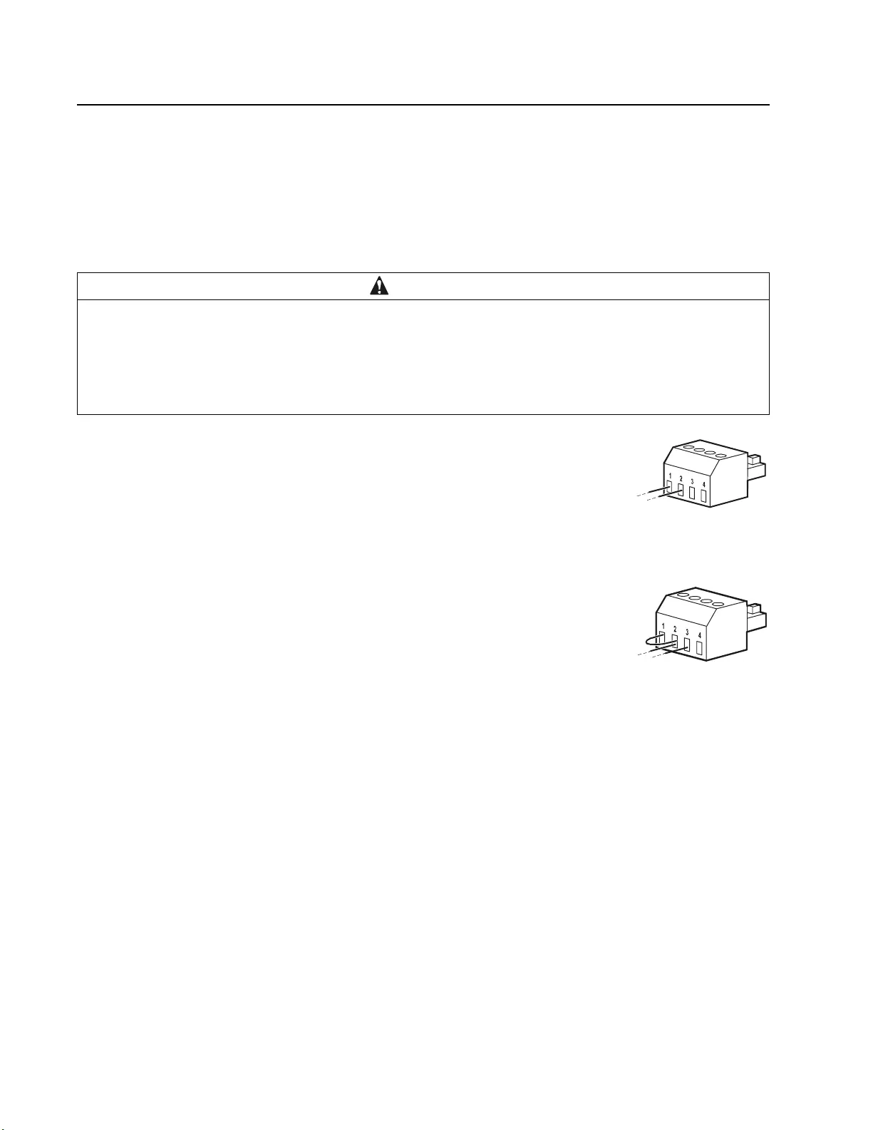
Normally open contacts
1. If the EPO switch or relay contacts are normally open, insert the wires from the
switch or contacts at pins 1 and 2 of the EPO te rmi nal block. Use 16-28 AWG
wire.
2. Secure the wires by tightening the screws.
If the contacts are closed, the UPS will turn OFF and power will be removed from the load.
Normally closed contacts
1. If the EPO switch or relay contacts are normally closed, insert the wires from the
switch or contacts at pins 2 and 3 of the EPO te rmi nal block. Use 16-28 AWG
wire.
2. Insert a wire jumper between pins 1 and 2. Secure the wires by tightening the
three scre ws at positions 1, 2, and 3.
If the contacts are opened, the UPS will turn OFF and power will be removed from the load.
Note: Pin 1 is the power source for the EPO circuit, it provides a few milliam pere of 24 V power.
If the normally closed (NC) EPO configuration is used, the EPO swit ch or relay should be rated for “dry” circ uit
application s, the rating should be for low voltage and low curre nt applica tions. This normally impli es the contacts
are gold plated.
The E PO interface is a Safety Extra Low Voltage (SELV) circuit. Connect the EPO interface only to other SELV
circuits. The EPO interface monitors circuits that have no determined voltage potential. SELV circuits are
controlled by a switch or relay properly isolated from mains power. To avoid damage to the UPS, do not connect
the EPO interface to any circuit other than a SELV circuit.
Use one of the following cable ty pes to connect the UPS to the EPO swi tch.
• CL2: Clas s 2 cable for general use.
• CL2P: Ple num cable for use in ducts, plenums, and other spaces used for environm ental air.
• CL2R: Riser cable for use in a vertical run in a floor to floor shaft.
• CLEX: Lim ited use cable for use in dw ellings and for use in raceways.
• Installation i n C anada: Use only CSA cer tified, type EL C, (extra low voltage control cable).
• Installation i n countries other than Canada and the USA: Use s tandard low vol tage cable in accor dance wi th national
and local regulations.
CAUTION
RISK OF DAMAGE TO EQUIPMENT OR PERSONNEL
• Adhere to all national and local electrical codes.
• Wir ing mus t be per formed by a quali fi ed electrician.
• Always connect the UPS to a grounded outlet.
Failur e to fol low these instr uctions can resul t in equi pm ent damage and minor or moderate injury.

21Smart -UPS On-Line SRT2200/S RT3000 Tow er/Rack-Mount 2U
Network Management Interface
(For NC models only)
Introduction
The UPS has a network port and co ns ole port that can be us ed to access the Network Management Interf ace. Refer
to the Network Management Card utility CD suppl ied wi th this product.
IP Addres s Configuration
The default TCP/IP confi guration setting DHCP, ass umes that a properly configured DHCP server is availabl e to
provide TCP/IP s ettings to the Netw ork Mana gement Interfa ce .
If the Network Management Interface obtains an IPv4 address from a DHCP server, us e the display interface
menus About/Accessory, to se e the address.
To setup a static IPv4 address use the display interfac e Config menu. Set the IP address Subnet Mask and Gateway
from the Config menu.
See the User’s G uide on the Network Management Card Utility CD for user information about the Network
Manageme nt Interface and for set up instruct ions.
Related Documents
The Netwo rk Management Card Utility CD contains the following documentation:
• UPS Network Manage ment Card 2 Use r’s Guide
• Network Mana gement Card Upgrade Utilit ies
• Security Handbook
• PowerNet Management Information Base (MIB) Refere nce Guide

Smart-UPS On-Line SRT2200/SRT3000 Tow er/ R ack-Mount 2U22
Smart Battery Management
Definitions
• Battery Module: A string of battery cells arranged to produce a battery assembly with a connector.
• Replaceable Ba ttery Cartridge (RBC): An APC battery cartridge co nsisting of o ne ba ttery module .
Replacement RBCs can be orde red from the APC by Schneider Electric web site, www.apc.com.
• Smart Ex ternal Bat t ery Pack (XLBP): An enclosu re that contai n s R BC( s) and battery manage ment
electronics.
• User Interface (U I): Any interface by which a user can interact with the system. This may include a UPS
dis play interfa ce , a network manage ment interfac e or PowerC hute™ Network Shutdown soft ware .
NOT E: Do not use a battery th at is not APC approved.
The system will n o t detect th e presence of a non APC ap proved batte ry a nd may a dversely a ffec t the
operation of the system.
Use of a no n AP C appro v ed ba t tery w ill vo id t he ma n ufact urer w a rr a n t y.
Features
Smart Battery Management provides the following feature s:
• Moni tor s and in f orms the user of the health o f eac h RBC.
• Monitors and shows on the UPS Dis play Interfa ce scr een, the date for the end of useful life for each RBC.
• The UPS emits an audible alarm and shows a message on the UPS Display Interface screen to indicate the
es tim ated battery end of life. On the UPS Display Interface screen the u ser ca n se t the number of days
before the audible alarm is heard and the message appears on the UPS Display Interfa ce sc ree n.
• Automatically detects the addition or removal of XLBPs and RBCs.
• Monitors the internal temperature of each XLBP and automatically adjusts the battery charging.
Maintenance
• RBC maintenance: The APC RBC uses sealed, maintenance-free, Valve Regulated Lead-Acid batteries
and does not require maintenance.
• Ru nti m e Tes t (Ca l ibra t io n ) : This should be performed anytime the ste ady st ate load is chan ged
significantly, for example a new server is adde d to or rem oved f rom the UPS load.
• Bat tery health monitoring: The batte ry ener gy out put and vol ta ge are monit ored to a sses s the heal th of t he
installed batteries when the UPS is operating on battery.
Battery health monitoring is done during a UPS Self Test, a Runtime Calibr ation Test, and when the UPS
is operating on battery power.
The UPS can be configured to per f orm periodic, automatic Self Tests.
End of useful life
• Near e nd of life notification: A mes sage will appear on the UPS display interface screen when each RBC
is approaching the end of its useful li fe. For configura tion detai ls refe r to Rep la c em ent Not if i ca t ion Tim e
and Replacement Battery Alarm Time.
The e stimated replaceme nt date for eac h RBC is avail able through the UI.
• Needs replacement notification: The UPS display interface scre en shows when RBC replac ement i s
required. The RBC must be repl ac ed as soon as pos sible.
Whe n an RBC r equires re placement, the UPS display interfac e may recommend that additional RBCs be
replaced if th ey will soon reach the end of their usef ul life.
CAUTION: Continued operation after end of useful life notification may cause damage to the batteries.
• Recycling: Remove the RBC from t he XLBP. Recycl e the RBC. Do not disassemble an RBC.

23Smart -UPS On-Line SRT2200/S RT3000 Tow er/Rack-Mount 2U
Rep l ac e th e RB C in a UPS
An RBC should only be disconnected or removed from the UPS temporarily as part of the battery
replacement procedure .
• Disco nnect the con nected bat tery module in the UPS. Slide the RBC out of the UPS.
• Sli d e the new RBC into the UPS and connect the battery module to the UPS.
• Securely connect the bat t ery module. Press th e b att er y connecto r in to the UPS until it is f irmly conne cted.
A batte r y that is not prop erly connected will cause erratic UPS operation, abnormal alert messages and
connected equipment may not rece ive battery power duri ng power outages.
• After installing the RBC, the UPS disp lay interface may pr omp t the user to verify the status of the re placed
battery module. If the battery module is new, respond YES. If the batte ry module is not new, respond NO.
Recommended actions after installing new RBC
• Verify that the UPS is connected to input power and the output power is turned on. See “Operation” on
page 10 for instructions.
• Perform a UPS Self Test.
• Verify on the UPS display interfa ce t h at t h e in stallation dates for t he re placed RBC is se t to the current date.
The installa tion dates can be changed manually on the UPS display interface.
For config urat ion details refer to Battery Install Date in the “General settings” on page 15 of this manual.
• Allow the system to charge for 24 hours to ensure full runtim e capability.
XLBP installation and replacement
Ref er to the Ext ernal Battery Pa ck I n stallation Gu ide for installation and replace ment instruct ions.

Smart-UPS On-Line SRT2200/SRT3000 Tow er/ R ack-Mount 2U24
Troubleshooting
Use the table below to solve minor installation and operation pr oblems.
Refer to the APC by Schneider Electri c web site, www.apc.com for assist ance with complex UPS pr oble ms.
The UPS features firmware that can be upgraded.
Go to the APC by Schneider Electric web site, www.apc.com/Support, or contact your local Customer Care
Center for more information.
Problem and Possible Cause Solution
UPS is not turning on or there is no output
The UPS is not connected to m ains
power. Be sure the power cab le is securely connected to the mains power supply.
The UPS display interf ac e scre en shows
very low or no mains power. Check the mains power supply to ver ify acceptable power quality.
There is an internal UPS aler t or
message. The UPS Display Interface screen will show a message to identify the alert or
message and corrective action.
UPS emits an audi ble alarm
Normal UP S operation when runni ng on
ba tt e r y po w er. The UPS is operating on batte ry power.
Refer to the status of the UPS as shown on the UPS Display Interface scre en.
Press any key to mut e all audible alarms.
The U PS emi t s an aud i bl e al arm and ha s
a red or amber back light on the UPS
Dis pla y Interface screen.
The UPS has detected a fault.
Refer to the display int erface screen for informat ion.
UPS does not provide expected backup time
The UPS batteries are weak due to a
recent power outage or they are near the
end of service life.
Charge the batteries. Batteries require recharging after extended outages and
wear out faster when put into service often or when operated at elevated
temperatures. If the batteries are near the end of service life, consider
replacing the batteries ev en if the Replace Batter y message is no t displayed.
The UPS is experiencing an overload
condition. Th e connec ted equipmen t exceeds the sp ecified maximu m load. Refer to the
APC by Schneider Electric web site, www.apc.com for product
specifications.
The UPS will em it a s ustained audible alarm u ntil the overload condition is
corrected.
Discon nec t nonessent ial equipment from the UPS to correc t the overloa d
condition.

25Smart -UPS On-Line SRT2200/S RT3000 Tow er/Rack-Mount 2U
UPS operates on battery power while connected to mains power
The input circuit breaker has tripped. Reduce the load on the UPS. Disconnect nonessential equipment and reset
the circuit breaker. Check the circuit breaker rating for the connected
equipment.
Th e r e i s very high, very l ow, or di s to rted
input line voltage. Navigat e to the UPS Display Interface screen that shows input v oltage.
Verify that the input voltage is w ithin specified operating lim its.
If no input voltage is indicated on the UPS Display Interface scre en, contact
Customer Support through the APC by Schneider Electric web site,
www.apc.com.
The UPS Displ ay Inter fac e screen sh ow s
the messa ge Wai ting for Minimum
Runtime.
The UPS has been conf igured to opera te for a spe cified period of runtime.
The setting can be changed through the Config/UPS menus.
UPS Display Interface Status screen shows Overload and the UPS emits a sustained audible alarm
The UPS is experiencing an overload
condition. The connected equipment exceeds the maximum load rating for the UPS.
The UPS will em it a s ustained audible alarm u ntil the overload condition is
corrected.
Discon nec t nonessent ial equipment from the UPS to correc t the overloa d
condition.
UPS Dis play Int erface Status screen shows UPS is operating in Bypass mode
The UPS received a command to operate
in Bypass mode No action is required.
The UPS has au tomatica lly switch ed to
Bypass mode due to an internal UPS
alert or message.
The UPS Display Interface screen will show a message to identify the alert or
de tect ed er r o r and co r r ect i ve act ion .
UPS Display Interface is re d or amber and shows an alert or message
The UPS emits a sustained audible alarm
The UPS has det ec ted a problem during
norm al operation. Follow the in str u ctions on th e UPS Display In terface screen .
Press any key to mut e all audible alarms.
The UPS Displ ay Inter fac e screen sh ow s
the messa ge D i sconn ec t ed Ba t t e ry.Be sure the battery cables are securely connected.
Perform a UPS Self Test to be sure the UPS detects all c onnected batteries.
To perform a UPS Self Test use the UP S Display Int erface menu option Test
and Diagn ostics.
The UPS Displ ay Inter fac e screen sh ow s
the messa ge R e plac e B att e ry.Rep lac e all of the batteries. Contact APC by Schneider Electric cus tom er
support.
Problem and Possible Cause Solution
Smart-UPS On-Line SRT2200/SRT3000 Tow er/ R ack-Mount 2U26
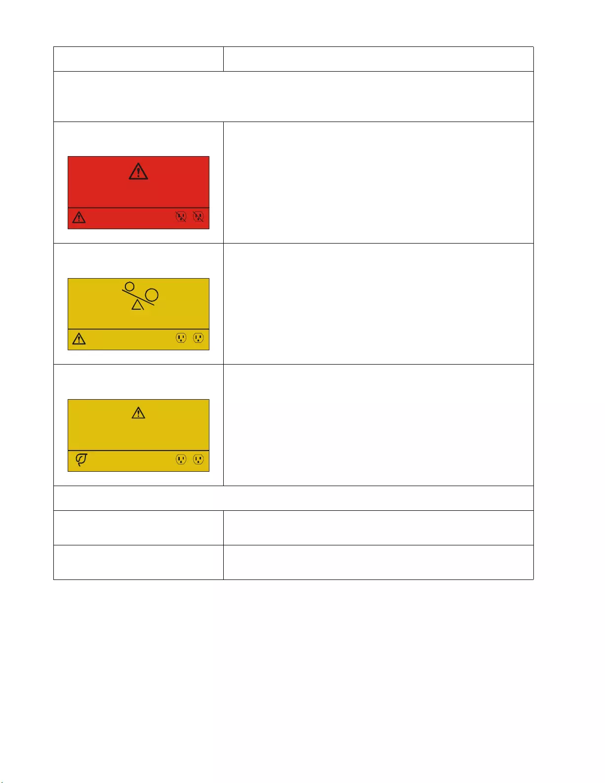
Th e UPS display tu rns red or amber, displays an alert mess age, and emits a sustain ed au d ible alarm.
Red il lumination indicates a UPS ala rm that requi res im m ediate attention.
Amber illumination in dica tes a UPS alar m that requires atte ntion.
There is an internal UPS aler t or
message. Do not attem pt to use the UPS. Turn the UPS off and have it serviced
immediately.
The UPS is experiencing an overload
condition. Reduce the lo ad on the UPS. Disconnect nonessenti al equipment.
The UPS has detected a Site W iring
Fault. Correct the building site wiring fault or ignore this message. See Config
Menu UPS in “G eneral settings” on page 15.
The Replace Battery alert is displayed
The battery has a weak char ge. Allo w the bat tery to recharge for at leas t four hours. Then, perform a
UPS Self Test. If the problem persists after recharging, replace the battery.
The replacement battery is not properly
connected. Be sure the battery cable is securely connected.
Problem and Possible Cause Solution
1/1
Power Sy s Error - 00100
Contact Customer Support
Outpu t Of f
12
1/1
Outpu t Over load
Bypass
12
1/1
Site Wiring Fault
Press OK to Clear Alarm
Online Green
12

27Smart -UPS On-Line SRT2200/S RT3000 Tow er/Rack-Mount 2U
Transport
1. Shut down and dis connect all connected equipment.
2. Discon nect the unit from mains power.
3. Discon nec t all intern al a nd external batteries ( if applicable).
4. Follow the shipping instructions outlined in the Service section of this manual.
Service
If the unit requires service, do not return it to the dealer. Follow these steps:
1. Review the Troubleshooting section of th e manual to eliminat e co mmon probl ems.
2. If the proble m pe rsi sts, conta ct APC by Schn eider Electric Customer S upport through the APC by
Schneider Electri c web s ite, www.apc.com.
a. Note the model number and serial number and the date of purchase . Th e model and serial numbers
are loc ated on the rear panel of the unit and are availabl e through the LCD display on select m odels.
b. Call Customer Support. A technician will attempt to solve the problem over the ph one. If this is not
possible, the tec hnician will issue a Returned Material Authorization Number (RMA#).
c. If the unit is under warranty, the repa ir s are free .
d. Ser vice procedures and returns may vary int erna tionally. For country sp ec ific inst ructions
refer to the APC by Schne ider Electric web site, www.apc.com.
3. Pack the unit properly to avoi d damage in tra nsit. Never use foam beads for pac kaging.
Damage sustained in transit is not cov ered under warranty.
Note: Before shipping, always disconnect battery modules in a UPS or external battery pack.
T h e di sc o nn e cted in te r n al b at t er i es may re m ain in si d e th e UPS o r ext e rn al ba tt er y pa ck .
4. W r ite the RMA# provided by Customer S upport on the outs ide of the package.
5. Return the unit by insured, prepaid carrier to the address provided by Customer Support.

Smart-UPS On-Line SRT2200/SRT3000 Tow er/ R ack-Mount 2U28
Limited Factory Warranty
Schneider Electri c IT Corporation (SEIT ), warrants its pr oducts to be free from defects in material s and
workmanship for a period of three (3) years excluding the batter ie s, which ar e warranted fo r two (2) years from the
date of purchase. The SEIT obli gation under this warranty is limited to repa iring or replacing, at its own sole
option, any such defective products. Repair or replacement of a defective product or part thereof does not extend
the original warranty period.
This warra nty applies only to the original purchaser who mus t have properly r egistered the product within 10 days
of purchase. Products may be reg is tered online at warranty.apc.com.
SEIT shall not be liable und er the warranty if its testing and exa mi nation dis close that the alleged defect in the
product does not exist or was cause d by end user or any third pers on misuse, negligenc e, impr oper installation,
test ing, o perati on or use o f the product contra ry t o SEIT r ecommen dation s of s pecif icati ons. Furthe r , SE IT s hall no t
be liab le for defects resul ting from: 1) unauthorized attempts to repair or modify the product, 2) incorrect or
inadequate electrical voltage or connec tion, 3) inappropriate on site op eration cond itions, 4) Acts of God, 5)
expos ure to the el ements, or 6) theft. In no event shall SEIT have any liabili ty under this warranty for any product
where the serial number has been altered, defac ed, or removed.
EXCEPT AS SET FORTH ABOVE, THERE ARE NO WARRANT IES, EXPRESS OR IMPLIED, BY
OPERATION OF LAW OR OTHERWISE, APPLICABLE TO PRODUCTS SOLD, SERVI CED OR
FURNISHED UNDER THIS AGREEMENT OR IN CONNECTION HEREWITH.
SEIT DISCLAIMS ALL IMPLIED WARRANTIES OF MERCHANTABILITY, SATISFACTION AND
FITNESS FOR A PAR TICULAR PURPOSE.
SEIT EXPRESS WARRANT IES WILL NOT BE ENLARG ED , DI MINISHED, OR AFFECTED BY AND
NO OBLIGATION OR LIABILITY WILL ARISE OUT OF, SEIT RENDERING OF TECHNICAL OR
OTHER ADVICE OR SERVICE IN CONNE CTION WITH THE P RODU CTS.
THE FOREGOING WARRANTIES AND REMEDIES ARE EXCLUSIVE AND IN LIEU OF ALL
OTHER WARRANTIES AND REMEDIES. THE WARRANTIES SET FORTH ABOVE CONSTITUTE
SEIT’S SOLE LIABILITY AND PURCHASER EXCLUSIVE REMEDY FOR ANY BREACH OF SUCH
WARRANTIES. SEIT WARRANTIES EXTEND ONLY TO ORIGINAL PURCHASER AND ARE NOT
EXTENDE D TO ANY THIRD PARTIES.
IN NO EVENT SHALL SEIT, ITS OFF ICERS, DIRECTORS, AFFILIATES OR EM PLOYE ES BE
LIABLE FOR ANY FORM OF INDIRECT, SP EC IAL, CONSEQ U EN TIAL OR PUNITIVE DAMAGES ,
ARISI N G OUT OF THE USE, SERVICE OR INSTALLATIO N OF THE PRO DUCTS, W HETHER SUCH
DAMAGES ARISE IN CONTRACT OR TORT, IRRESPECTIVE OF FAULT, NEGLIGENCE OR
STRICT LIABILITY OR WHETHER SEIT HAS BEEN ADVISED IN ADVANCE OF THE POSSIBILITY
OF SUCH DAMA GES. SPECIFICALLY, SE IT IS NOT LIABLE FOR ANY COSTS, SUCH AS LOST
PROFITS OR REVENUE, WHETHER DIRECT OR INDIRECT , LOSS OF EQUIPMENT , LOSS OF USE
OF EQUIPME NT, LOSS OF SOFTWARE, LOSS OF DATA, COSTS OF SUBSTITUANTS, CLAIMS BY
THIRD PARTIES, OR OTHERWISE.
NOTHING IN THIS LIMITED WARRANTY SHALL SEEK TO EXCLUDE OR LIMIT SEIT LIABILITY
FOR DEATH OR PERSONAL INJURY RESULTING FROM ITS NEGLIGENCE OR ITS
FRAUDULENT MISREPRESENTATION OF T O THE EXTENT THAT IT CANNOT BE EXCLUDED
OR LIMITED BY APPLICA BLE LAW.
To obtain service under warranty you must obtain a Returned Material Authorization (RMA) number from
customer support. Customers with warranty claims issues may access the SEIT worldwide customer support
network through the APC by Schneider Electric web site: www.apc.com. Select your country from the country
selection drop down menu. Open the Support tab at the top of the web page to obtain information for cust omer
support in your region . Produc ts must b e returned with tran sporta tion cha rges prepai d and must be accom panied by
a brief descriptio n of the problem encountered and proof of date and plac e of purchase.


5/2016EN 990-5269B
APC by Schneider Electric
Worldwide Customer Support
Customer support for this or any othe r APC by Schneider Ele ctric product is available at no charge in any of
the following ways:
• Visit the APC by Schneider Electric web site to access documents in the APC by Schneider Electric
Knowledge Base and to submit customer support requests.
–www.apc.com (Corporate Headquarters)
Connect to localized APC by S chneider Electric web sites for specific countries, each of which
provides customer support inform ation.
–www.apc.com/support/
Global support sear ching APC by Schneider Electr ic Knowledge Base and usi ng e-support.
• Contact the APC by Schneider Electric Customer Support Center by telepho ne or e-mail.
– Local, country specific cent ers: go to www.apc.com/support/contact for con tact informati on.
– For information on how to obtain local customer support, contact the APC by Schneider Electric
representative or other distributor from whom you purchased your APC by Schne ider Electric
product.
© 2016 APC by Schneider Electric. APC, the APC log o, and Smart-UPS are owned by Schneider Electric
I ndus tries S.A.S . or their affi liated companies. All othe r trademarks are property of their respec tive owners.