Table of Contents
- Installation Guide Smart-UPS™On-Line SRT5K/6K Tower/Rack-Mount 3U/4U
- Safety Messages
- Safety and General Information
- Package Contents
- Specifications
- Remove Battery Modules
- Rack-Mount Installation
- Tower Installation
- Rear Panel Features
- Wiring Specifications
- Hardwire the UPS
- UPS Configuration
- UPS Display Interface
APC SRT6KRMXLT-IEC User Manual
Displayed below is the user manual for SRT6KRMXLT-IEC by APC which is a product in the Uninterruptible Power Supplies (UPSs) category. This manual has pages.
Related Manuals
Installation Guide Smart-UPS™On-Line
SRT5K/6K Tower/Rack-Mount 3U/4U
Safety Messages
Read the instructions carefully to become familiar with the equipment before attempting to install, operate, service or
maintain the UPS. The following special messages may appear throughout this manual or on the equipment to warn of
po t en t ial haza r d s or to cal l at tenti o n to in fo r m at i on th a t cl ar i fi e s or sim p l ifies a proc ed u r e.
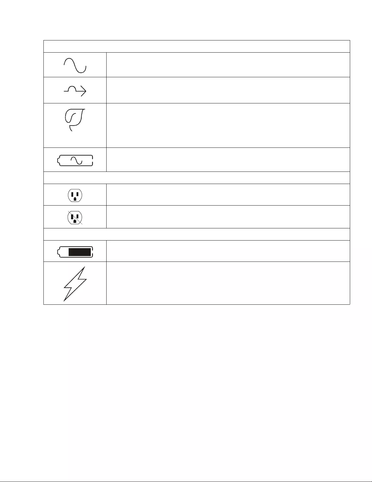
The addition of this symbol to a Dan ger or War ning product safet y label indicates that an ele ctrical haza rd
exists which will re sul t in personal injury if the instru ctions are not fol lowed.
The addition of this symbol to a Warning o r Caution pro duct sa fety label indicates that a haza rd exists that
can result in injury and product damage if the instructions are not followed.
Information
Safety and General Information
• Adhere to all nationa l and local electric al c odes.
• All wiring must be performed by a qualified electrician.
• Changes and modifications to this unit not expressly approved by APC could void the warranty.
• This UPS is intended for in door u se only.
• Do not operate th is UPS in direct sun light, in contact with flu id s, or where there is excessive dust or hum id ity.
• Be sure the air vents on the UPS are not blocke d. Allow adequate space for pro per ventilatio n.
• For a UPS w it h a f a ctor y i ns ta l led po we r c ord, c onne ct th e UPS p o wer ca bl e dir e ctl y to a wall out le t . Do not us e s urge
protectors or extension cords.
• The battery typically lasts for two to five years. Envi ro nmental factors imp act battery life. Ele v ated ambient
temperatures, po or quality mains power, and frequent short duration disc harges will shorten batte ry lif e.
• The equipment is he avy. Always practice safe lifting techn ique s adeq uate f or the we ight of th e equipment.
• Th e batterie s are heavy. Remov e the batteries before installing the UPS and e xternal battery pac ks (XLBPs), in a rack.
• Always install XLBPs at the bottom in rack-mount configurations. The UPS must be installed above the XLBPs.
• Always install peripheral equipment above the UPS in rack-m ount configurations.
• Additional safety information ca n be fo u nd in the Saf ety Guid e s upplied with this unit.
WARNING
WARNING indicat es a potentially hazardous situation which, if not avoided, can result in death or seri ous injury.
CAUTION
CAUTION indicates a potentially hazardous situation wh ich, if not avoided, can re s u lt in minor or m oderate injury.
NOTICE
NOTICE used to addr ess practices not rel ated to physical injury. The safety alert symb ol i s not used with this si gnal word.

Smart-UPS On-L ine SRT5K/ 6K Tow er/ R ack-Mount 3U/4U2
Dee nergizing safety
The UPS contains internal batteries and may present a shock hazard even when disconnected from the branch circuit (mains).
Before installing or servicing the equipme n t verify the following:
• Mains c ircuit breaker is in the OFF position
• Internal UPS the batteries are rem oved
• XLBP ba ttery modules are disconnected
Electrical safety
• For models with a hardwire d input, the connection to the branch circuit (mains) must be performed by a qualified
electrician.
• 230 V mod els onl y: I n or de r to m ai nta i n com pl iance with t he E MC dire cti v e f or pr oduc ts s ol d in E ur ope , out p ut cord s
attached to the UPS must not exceed 10 m eters in le ngth.
• The protective earth conductor for the UPS carries the leakage current from the load devices (computer equipment).
An insulated ground conductor is to be installed as part of the branch circuit that supplies the UPS. The conductor
must have the same size and insulation material as the grounded and ungrounded branch circuit supply conductors.
The conductor will typically be green and with or without a yellow stripe.
• The UPS input ground conductor must be prope rly bonded to protective eart h at the service panel.
If the UPS input power is s upplied by a separat ely derived system, the ground conductor must be properly
bonded at the supply transformer or motor genera tor set.
Battery safety
• Before installing or replac ing the batteries, remove jewelry such as wristwatc h es and rings.
High short circuit current through conductive materials could cause severe burns.
• Do not dispose of ba tteries by burning them. The batteries may explode.
• Do not open or mutilate ba tterie s. Released electrolyte is harmful to the skin and eye s, and may be to xic.
Hardwi re safety
• Verify that all branch circuit ( mains) and low voltage (control) circuits are deenergized, and locked out before
installing cables or making connections, whether in the junction box or to the UPS.
• Wiring by a qualified electric ian is re q uir ed.
• Check national and local codes be fore wiring.
• Strain relief is re quired for all hardw i rin g.
• All openings that allow ac cess to UPS hard wire terminals must be covere d. Failur e to do so may result in personal
injury or equipment damage.
• Select wire size and connectors according to national and local codes.
General information
• The UPS will recognize as ma ny as 10 ex terna l batter y packs co nne cted to the UPS. However there is no limit to the
number of XLBPs that can be used with the UPS.
Note: For each X LBP a d ded, increased recharge time w ill be required.
• The model a nd serial numbe rs a re located on a small, rear panel label. For some models, an additional label is located
on the chassis under the front bezel.
• Always recycle us ed batteries .
• Recycle the package materials or save them f or reuse.
FCC Class A radio frequency warning
This equipment has been tested and found to comply with the limits for a Class A digital device, pursuant to part 15 of the FCC Rules.
These limits are intended to provide reasonable protection against harmful interference when the equipment is operated in a commercial
environment. This equipment generates, uses, and can radiate radio frequency energy and, if not installed and used in accordance with
the instruction manual, may cause harmful interference to radio communications. Operation of this equipment in a residential area is
likely to cause harmful interference in which case the user will be required to correct the interference at his own expense.
Smart-UPS On-Line SRT5K/6K Tower/Rack-Mount 3U/4U 3
Package Contents
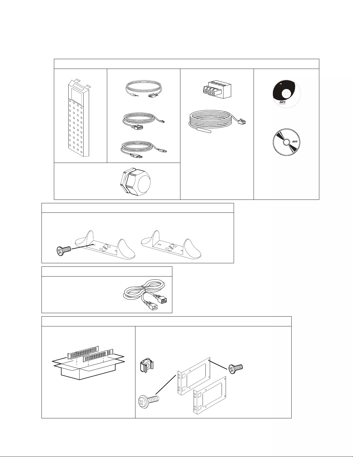
Inspect the contents upon receipt. Notify the carrier and dealer if the unit is damaged.
Included with all models
Front bezel Consol e to DB9 ca ble
RJ45 to DB9 cable
USB cable
EPO Terminal block
Temperature sensor probe
User Documentation CD.
Network Management
Ut ility CD
S tra in relie f
• Qty 1 for SRT5KXLI,
SRT5KHW mode ls
• Qty 2 for 6K models
In cl ude d w ith To w er and SRT5 KR MX LW-HW models only
• 2 pa ir s stabil ize r br acke ts
• 4 flat head screws to secure tower stabilizer brackets to the UPS
Included with XLI/XLT-IEC models only
2 output power cords:
1.2 m in length
2 m in lengt h
Included with Rack-Mount mod els only
Rail Kit with instr uctions and h ardware
for insta lling rails in a rack. • 1 pair rac k-mount brackets
• 8 flat head screws to secure rack -mount brackets to the UPS
• 4 ornamenta l s cre ws to secure rack-mount brackets to the rails
• 2 cage nuts
User Documentation
su04
34a
x4
x8
x2
Smart-UPS On-L ine SRT5K/ 6K Tow er/ R ack-Mount 3U/4U4
Specifications
For additiona l specifi cations refer to t he A PC web site, www.apc.com.
Environmental
Physical
Temperature Operating 0º to 40º C (32º to 104º F)
Storage -15º to 45º C (5º to 113º F)
Maximum Elevati on Operating 0 - 3,000 m (0 - 10,000 ft)
Storage 0 - 15,000 m (50,000 ft)
Humidity 0% to 95% relati ve hum idity, non-co ndensing
Protection Class IP 20 rat ing
Note: Charge the battery modules every six months during storage.
Environ menta l fact ors impac t batt ery l ife . Eleva ted ambie nt t emperat ures, high humidity, poor qua li ty mains power ,
and fre quent short duration discharges will shorten battery life.
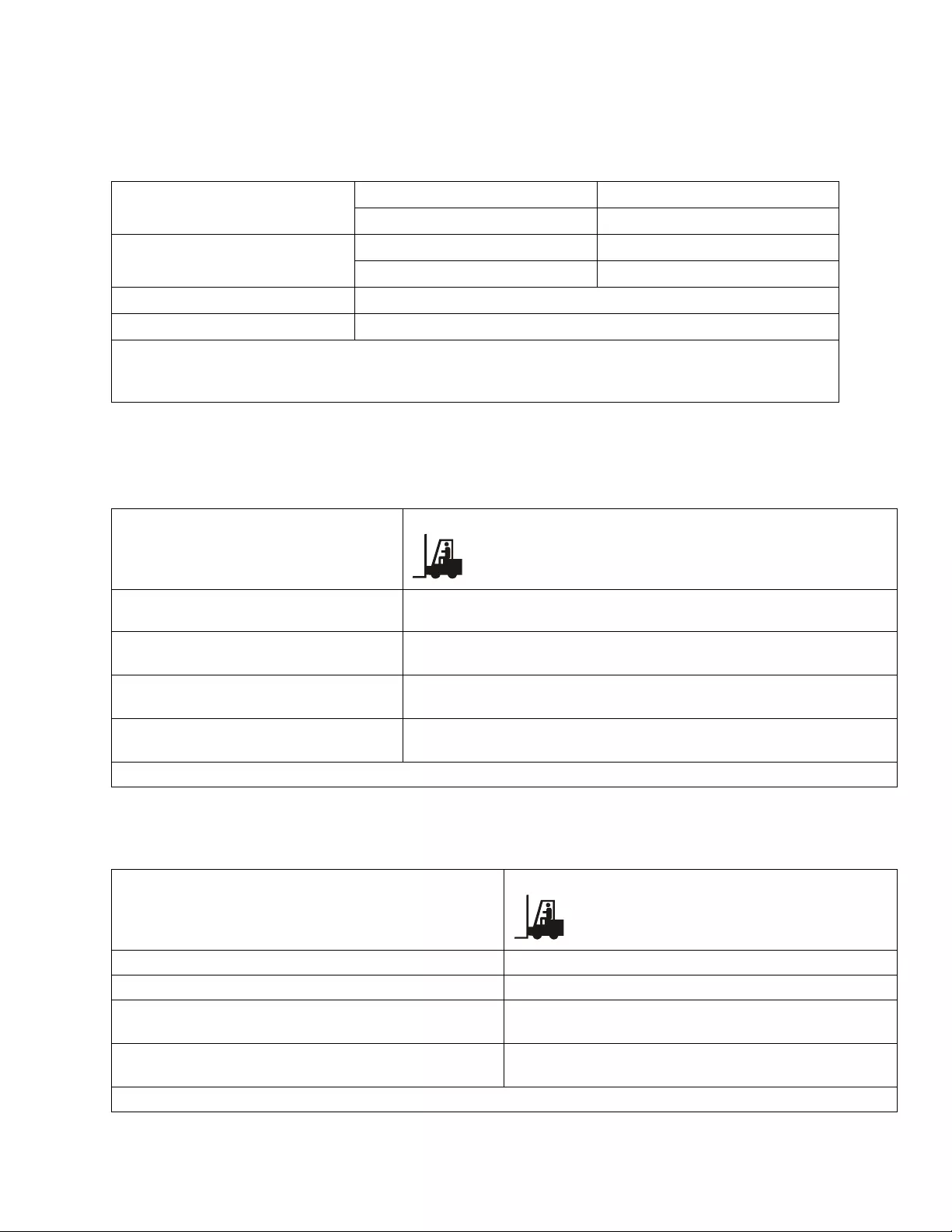
SRT5K model
The U PS is hea vy. Follow all lifting guidelines.
Lif t ing guidelines >55 kg (>120 lb)
Unit weight batt erie s included, without
packaging 54.6 kg (120 lb)
Unit weight batt eries included, with
packaging Rack-Mount models: 63.6 kg (140 lb)
Tower models : 67 kg (147 .4 lb)
Unit dimensions without packaging
Height x Width x Depth 130 mm x 432 mm x 719.4 mm
5 in x 17 in x 28.3 in
Unit dimensions with packaging
Height x Width x Depth 330 mm x 610 mm x 960 mm
13 in x 24 in x 37.8 in
The model and serial numbers are on a small labe l located on the rear panel.
SRT6K model
The U PS is hea vy. Follow all lifting guidelines.
Lif t ing guidelines >55 kg (>12 0 lb)
Unit weight batteries included, without packaging 60 kg (132 lb)
Unit weight batteries included, with packaging 67 kg (147.4 lb)
Unit dimensions without packaging
Height x Width x Depth 174 mm x 432 mm x 719.4 mm
6.9 in x 17 in x 28.3 in
Unit dimensions with packaging
Height x Width x Depth 370 mm x 610 mm x 960 mm
14.6 in x 24 in x 37. 8 in
The model and serial numbers are on a small labe l located on the rear panel.
Smart-UPS On-Line SRT5K/6K Tower/Rack-Mount 3U/4U 5
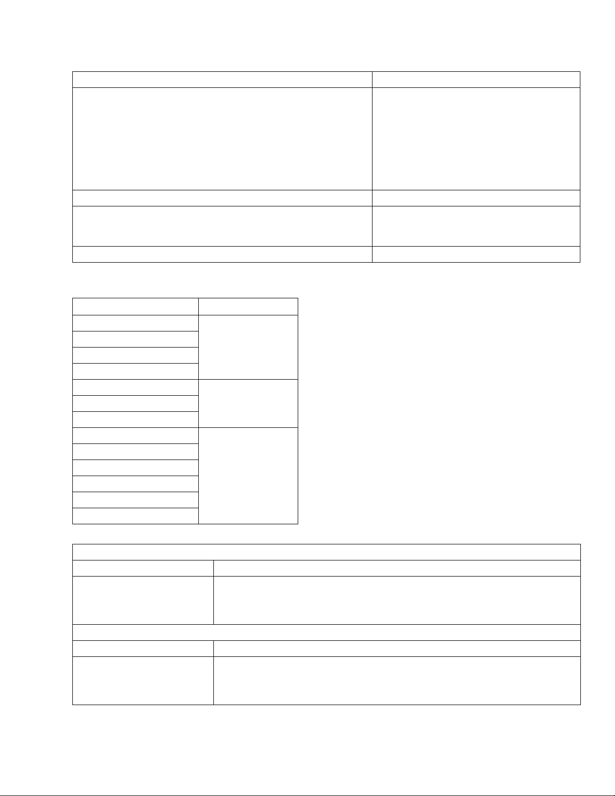
Battery
Electrical
Battery type Mainte nance fre e, le ak proof, sealed, le ad acid
Rep l acem e nt ba tt ery m odule
This UPS has hot swappable batte ry mo dules. Replacement is a s afe
procedure, is olated from e lectrical haza rds.
Refer to the appropriate replacement battery user manual for installation
instructions.
Contact your dealer or go the APC web si te, www.apc.com for
information on replacement ba tteries.
APCRBC140
Number of battery modu les 2 battery modules
Volt age for each ba ttery modul e
Total voltage for the UPS
Ah rating
96 V
192 V
5.1 Ah per battery module
XL B P ca bl e leng t h 500 mm (19.7 in)
Models Rating
SRT5KXLT
5 kVA/4.25 kW
SRT5KRMXLT
SRT5KXLT-IEC
SRT5KRMXLT-IEC
SRT5KXLI
5 kVA/4.5 kWSRT5KRMXLI
SRT5KRMXLW-HW
SRT6KXLT
6 kVA/6 kW
SRT6KRMXLT
SRT6KXLT-IEC
SRT6KRMXLT-IEC
SRT6KXLI
SRT6KRMXLI
Output
Output Fr equency 50 Hz/60 Hz ± 3 Hz
Nominal O utput Voltage SRT 5KRMXLW-HW: 208V, 220V, 230V, 240V
SRT 5K/6KXLI, SRT5K/6KRMXLI: 220V, 230V, 240V
SRT5K/6KXLT/XLT-IEC, SRT 5K/6KRMXLT/XLT-IEC: 208V, 240V
Input
Input Frequency 40 HZ/70 Hz ± 3 Hz
Nominal Input Volt age SRT5KRMXLW-HW: 2 08 V, 220 V, 230 V, 240 V
SRT5K/6KXLI, SRT5K/6KR MXLI: 220 V, 230 V, 240 V
SRT5K/6KXLT/XLT-IEC, SRT5K/6KRMXLT/XLT-IEC: 208 V, 240 V

Smart-UPS On-L ine SRT5K/ 6K Tow er/ R ack-Mount 3U/4U6
Remove Battery Modules
Use the battery module ha ndle to lift and slide the battery modules out of the UPS.
CAUTION
DAMAGE TO EQUIPMENT OR PERSONNEL
• The equipment i s heavy. Each battery module weighs 17 kg (37 lb).
• Always practice safe lifting techni ques ad equate for the weight of th e equipment.
• Remove t he batter y modules before installing the UPS.
• Use th e batt ery mod ule ha ndle to slide the batte ry modules in or out of the UPS.
• Do not use the bat tery modul e handle to lif t or carry the battery modu le.
Failure to fol low the se instruc ti ons can result in equipment damage and minor or moderate injury.
su0841c
su0842c
su0843a
su0844a
Smart-UPS On-Line SRT5K/6K Tower/Rack-Mount 3U/4U 7
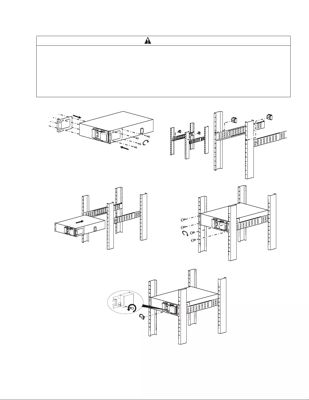
Rack-Mount Insta llation
Refer to the Rail Kit I nsta ll at ion G ui d e f or in st r u ction s on ra il in s t al lation.
CAUTION
DAMAGE TO EQUIPMENT OR PERSONNEL
• The equipme nt i s heavy. Alway s practice safe lifting techniques adequate for the wei ght of the equipment.
• Always use the recommended num ber of screws to secure brackets to the UPS.
• Always use the recommended num ber of screws and cage nuts to secure the UPS t o the rack.
• Always install the UPS at the bottom of t he rack.
• Always install the XLBP below t he UPS in the rack.
Failure to follow these instructions can result i n equi pment dam age and minor or moderate injury
su0853d
su0940a
su0854b
su0
855c
su0855d
Smart-UPS On-L ine SRT5K/ 6K Tow er/ R ack-Mount 3U/4U8
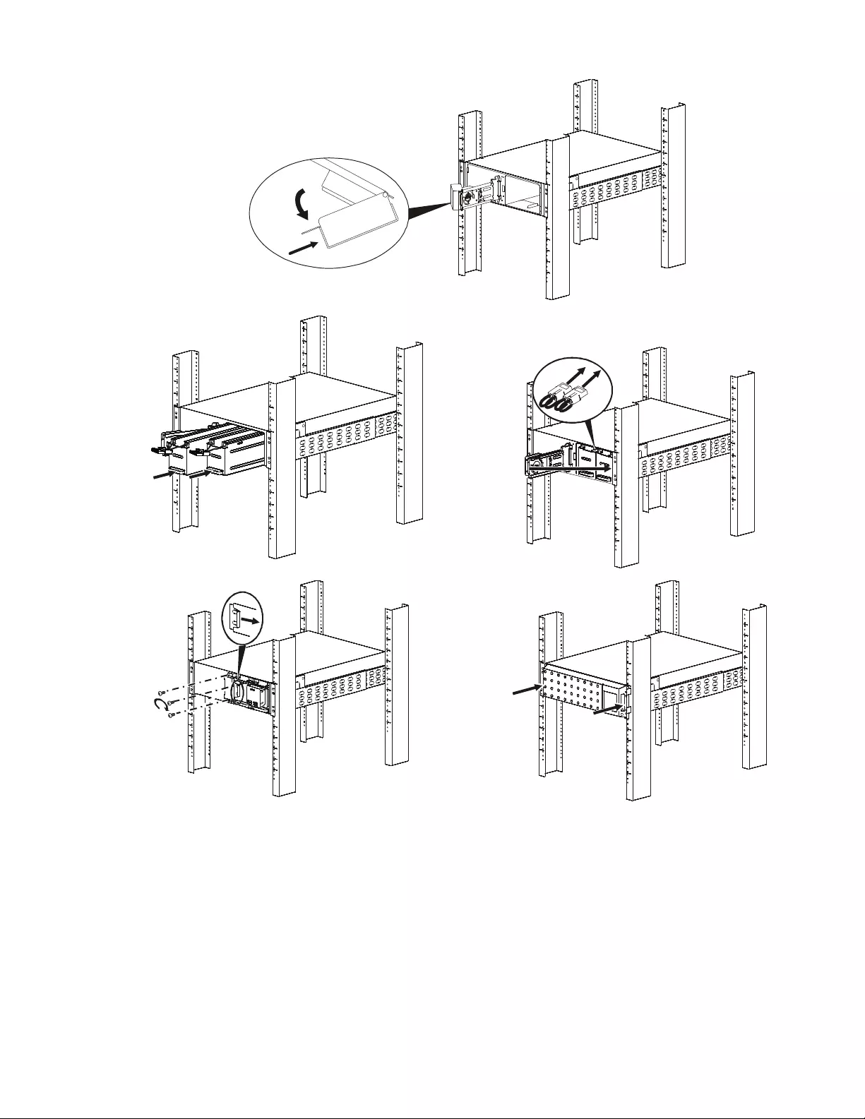
After the UPS is hardwired to branch circ uit mai ns
complete steps 8-10.
su0955a
su0856a
su0857a
su0858a
su0859a
Smart-UPS On-Line SRT5K/6K Tower/Rack-Mount 3U/4U 9
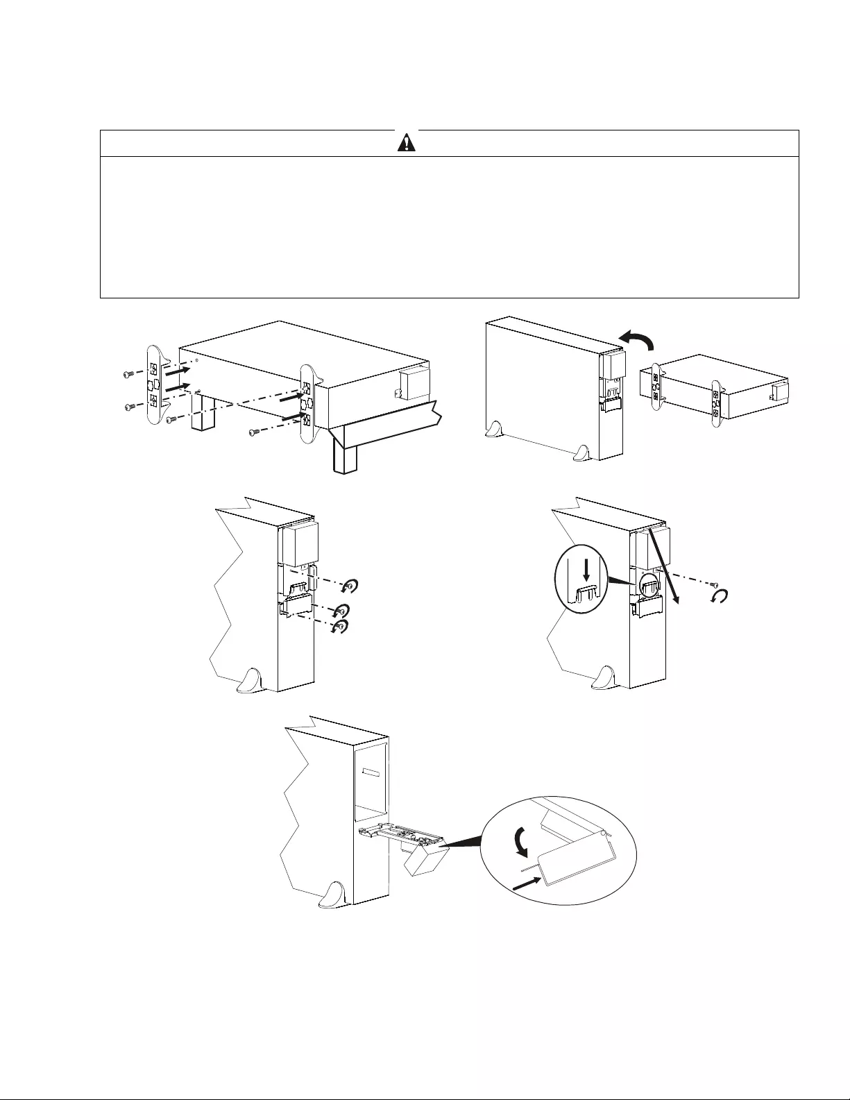
Tower Inst allation
CAUTION
DAMAGE TO EQUIPMENT OR PERSONNEL
• The equipme nt i s heavy. Each battery module weighs 17 kg (37 lb).
• Always pr actice safe lifting techniques adequate for t he we ight of the equi pm ent.
• Remove the battery modules befor e installi ng the UPS.
• Use the batt ery module handle to slide the battery modules in or out of the UPS.
• Do not use the battery module handle to l ift or carr y the battery module.
Failure to follow these instructions can result i n equi pment dam age and minor or moderate injury
su0845d
su0846c
su0847b
su0850c
su0848c
Smart-UPS On-L ine SRT5K/ 6K Tow er/ R ack-Mount 3U/4U10
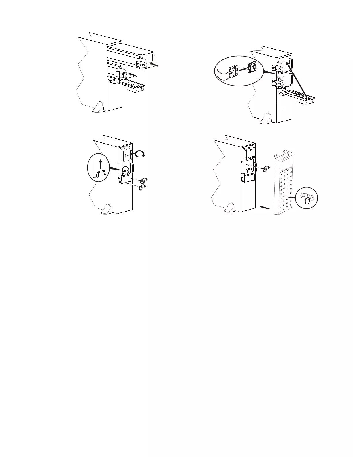
After the UPS is hardwired to branch circuit mains
complete ste ps 7 - 9.
su0848a
su0849a
su0851c
su0852a
Smart-UPS On-Line SRT5K/6K Tower/Rack-Mount 3U/4U 11
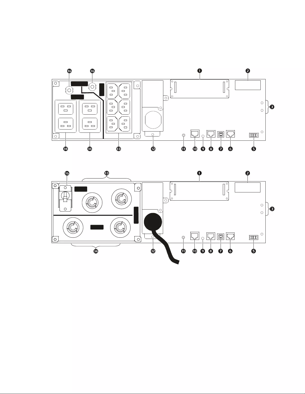
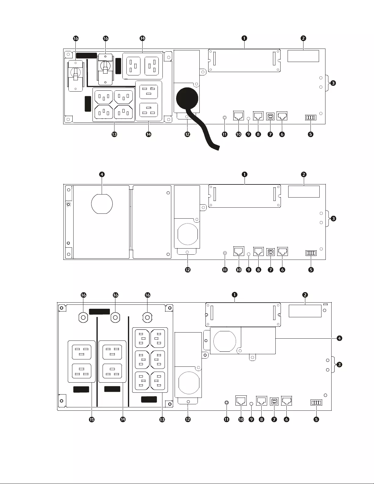
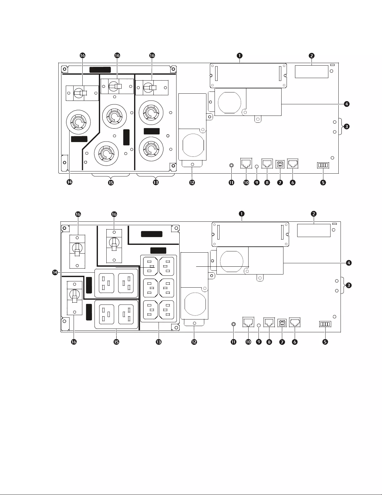
Rear Pane l Features
Note: Refer to the table “ K ey to identify rear pan el features” on page 14, that provides a key to th e callout numbers for
the rear panel graphics depicted in this manua l.
SRT5KXLI/SRT5KRMXLI
SRT5KXLT/SRT5KRMXLT
su0878a
GROUP 1
10 AM P MA X
GROUP 2
16 AMP MAX
Output: 50/60 Hz
220/230/240 VAC
su0879a
GROUP 1
20 AMP MAX
GROUP 2
30 AMP MAX
Output: 50/60 Hz
208//240 VAC
Smart-UPS On-L ine SRT5K/ 6K Tow er/ R ack-Mount 3U/4U12
SRT5KXLT-IEC/SRT5KRMXLT-IEC
SRT5KRMXLW-HW
SRT6KXLI/SRT6KRMXLI
su0880a
Output: 50/60 Hz
208/240 VAC
GROUP 1
15 A M P MA X
GROUP 2
20 AMP MAX
su0881a
su0882a
GROUP 1
10 AMP MAX
GROUP 2
16 AMP MAX
Output: 50/60 Hz
220/230/240 VAC
GROUP 3
16 AMP MAX
Smart-UPS On-Line SRT5K/6K Tower/Rack-Mount 3U/4U 13
SRT6KXLT/SRT6KRMXLT
SRT6KXLT-IEC/SRT6KRMXLT-IEC
su0883a
GROUP 2
30 AMP MAX
Output: 50/60 Hz
208/240 VAC
GROUP 1
20 AMP MAX
GROUP 3
30 AMP MAX
su0884a
GROUP 1
15 AMP MAX
GROUP 2
20 AMP MAX
Output: 50/60 Hz
208/240 VAC
GROUP 3
20 AMP MAX

Smart-UPS On-L ine SRT5K/ 6K Tow er/ R ack-Mount 3U/4U14
Key to identify rear panel features
SmartSlot The SmartSlot can be used to conne ct optional managem ent access ories.
External battery
power and
communication
connector
Use the ext er nal battery cab le on the XL BP to connect the UP S and XLBP.
XLBPs prov ide extended runtime during power outages. The UPS will automatically recognize
up to 10 externa l batter y pac ks.
Chassi s ground
screws The UPS and X LBPs have ground scre ws for connecting the ground leads. Prior to connecting a
ground lead, disconnec t the UPS from ma ins power.
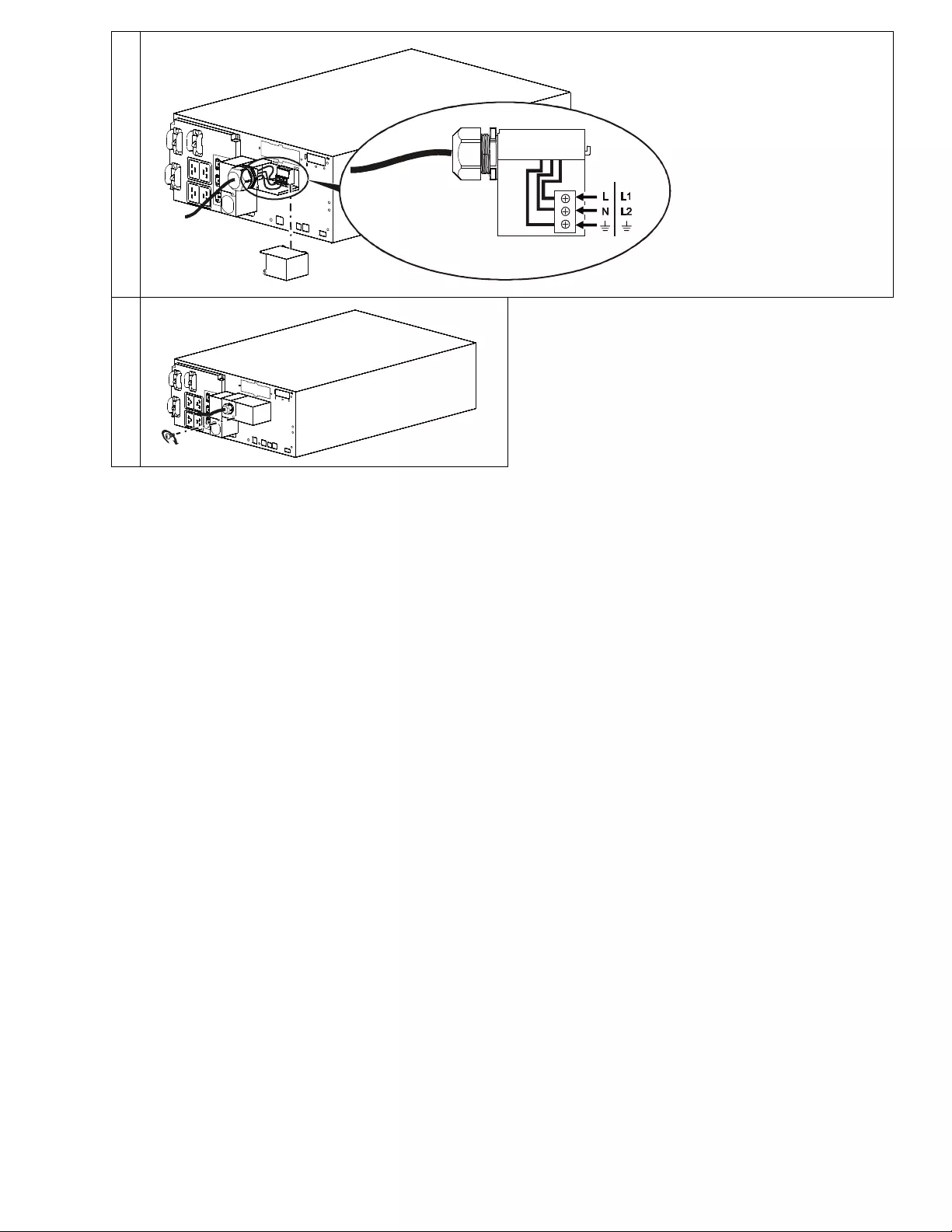
Hardwire output
box SRT5KRMXLW -HW, SRT6KXLI, SRT6KRMXLI, SRT6KXLT, SRT6KRMXLT,
SRT 6KXLT-IEC, SRT6KRMXLT-IEC models are equipped with a hardwire output box.
Refer to “Wiring Specifica tions” on page 15 for hardwire specific ations.
Remo ve the knockouts. Use Snap-In strain reliefs (supplied).
EPO terminal The Emergency P ower Off (EPO) terminal al lows the user to connec t the UPS to a central EPO
system.
Serial Com Th e Se r ia l Co m por t is u sed to c o mm u n i cate wi th th e U PS .
Use only interface kits supplied or approved by APC by Schneider E lectric. Any other seri al
in t er face cab l e w ill b e incom p a tib l e w it h t he U PS co n ne ct o r.
USB port The USB port is used to connect either a ser ver for nati ve ope rating system communi cati ons, or
for software to communicate with the UPS.
Note: Serial and USB communication should not be used simultane ousl y. Use either the Serial
Com or the USB port .
Univ ersa l I/O port Use to connect:
• Temperature s ensor AP9335T (s upplied)
• Temperature/humidity sensor AP9335TH (not supplied)
• Relay input/output connector AP9810 (not supplied), supports two input contacts and one
output relay
Console port Use th e Console port t o configure the ne twork manageme nt features .
Network port Use the Ne twork port to connect the UPS to the network.
Reset button Use th e Reset butt on to restart th e Network Management In terface.
Note: A restart of the Network Ma nagement Interface does not affect UPS operati on.
AC input
power cable or
hardwire input
box
• SRT5KXLT, SRT5KRMXLT, SRT5KXLT-IEC, SRT5KRMXLT-IEC models have factory
installed input power cabl es .
• All other models are equipped with a hardwire input box.
Refer to “Wiring Specifica tions” on page 15.
Rem ove the knockout s. Use Snap-In strain reliefs (supplied).
Controllable
outl et gr ou p 1 Connect electronic devices to these outlets.
Controllable
outl et gr ou p 2 Connect electronic devices to these outlets.
Controllable
outl et gr ou p 3 Connect electronic devices to these outlets.
Cir cuit breaker In the event an overloa d condition occurs, disconnect nonessential equipment.
Then r eset th e circui t b r eaker.
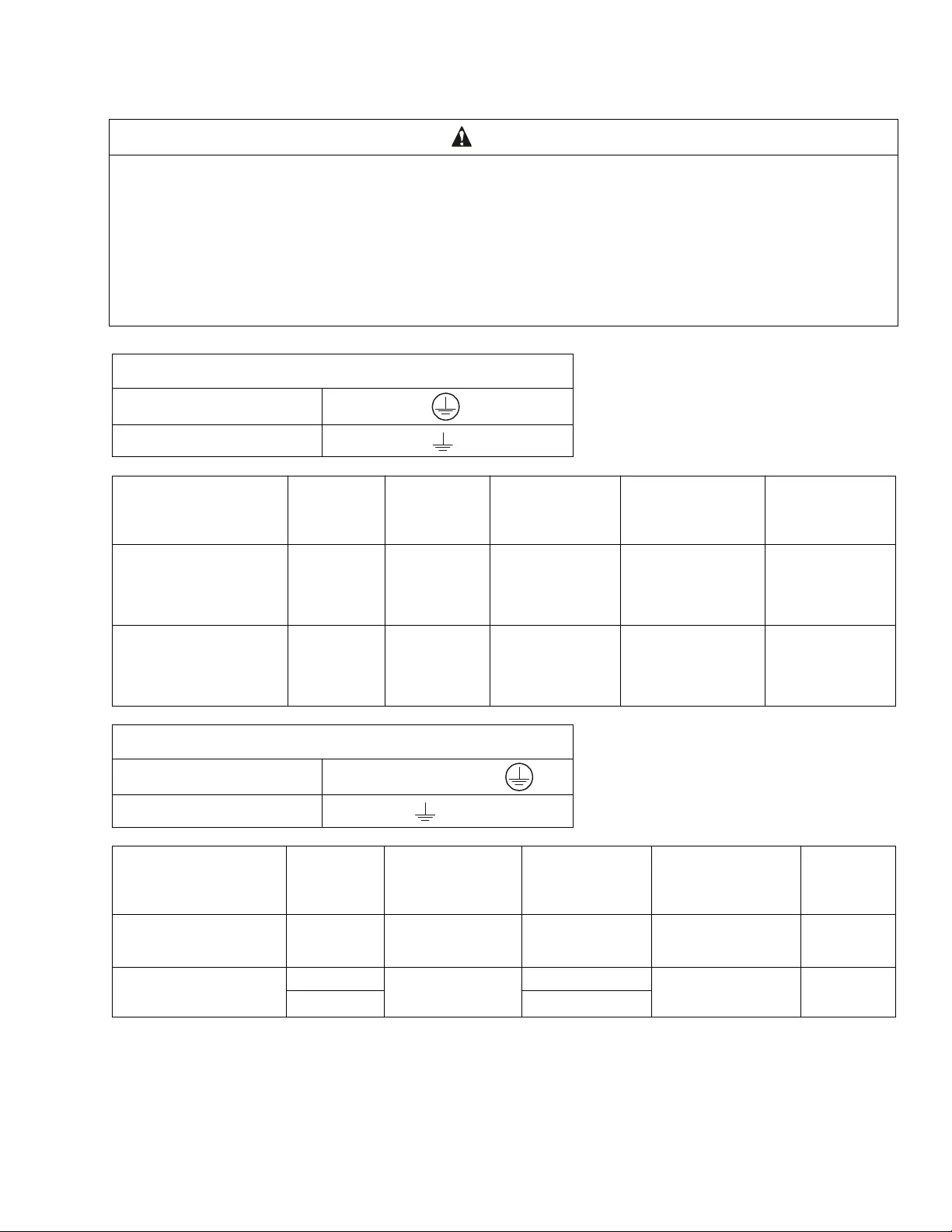
Smart-UPS On-Line SRT5K/6K Tower/Rack-Mount 3U/4U 15
Wiring Specifications
CAUTION
DAMAGE TO EQUIPMENT OR PE RSONNEL
• Adhere to all nati onal and local electrical codes.
• Wiring shoul d be performed by a quali fied electrician.
• Use Snap-In strain reliefs provided with the unit.
• The UPS must be wired into a branch ci rcuit, equipped with a circ uit breaker rated as specified in the tables below.
• Act ual wire size must comp ly wi th required amp capac ity and national and local electrica l codes.
• Rec om me nded input ter minal scr ew tor que: 16 lbf-in (2 Nm).
Failure to follow these instructions can result in equipment damage and minor or moderate injury
SRT5K /6K X LT /SRT5K/6K XLT- I EC m o del s
Input connections Wire to L1, L2,
Output connecti ons Wire to L1, L2,
System Wiring Voltage Current full
load, nominal External inpu t
circuit breaker,
(typical)
Wire size,
typical
SRT5KXLT
SRT5KRMXLT
SRT5KXLT-IEC
SRT5KRMXLT-IEC
Input
Output 208/240 Vac 24 A 30 A/2-pole L6-30
(provided with the
UPS)
SRT6KXLT
SRT6KRMXLT
SRT6KXLT-IEC
SRT6KRMXLT-IEC
Input
Output 208/240 Vac 33 A
29 A 50 A/2-pole 6 AWG
SRT5KXLI/SRT6KXLI models
Input conne ctions Si ngle phas e: Wi re to L , N,
Output connecti ons Wire to L, N
System Wiring Voltage Current full
load, nominal External input
circui t breaker,
(typical)
Wire size,
typical
SRT5KXLI
SRT5KRMXLI
Input
Output 220/230/240 Vac 24 A 40 A/2- pole 6 mm2
SRT6KXLI
SRT6KRMXLI Input 220/230/240 Vac 32 A 50 A/2-pole 10 mm2
Output 28 A
Smart-UPS On-L ine SRT5K/ 6K Tow er/ R ack-Mount 3U/4U16
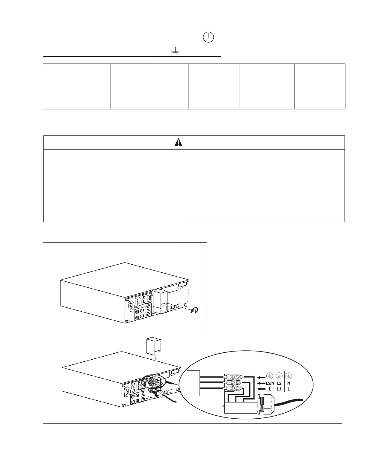
Hardwire the UPS
Input hardwiring
SRT5KRMXLW-HW
Input connections Single phase: Wire to L, L2/N,
Output connections Wire to L1, L2/N
System Wiring Voltage Current full
load, nominal External inpu t
circui t breaker,
(typical)
Wire size ,
typical
SRT5KRMXLW-HW Input
Output
208/220/
230/240 Vac
26 A
24 A 40 A/2-pole 6 mm2
(8 AWG)
CAUTION
DAMAGE TO EQUIPMENT OR PERSONNEL
• Disconnect the mains input circuit breaker before installing or servicing the UPS or connected equipm ent.
• Disconnect internal and ext ernal batteries be for e installing or servicing the UPS or connected equipment.
• The UPS contains internal and external batteri es t hat may presen t a shock h azard even when disconnected fr om the mains.
• UPS AC hardwired and pl uggable outlets m ay be energized by remote or automat ic cont rol at any time.
• Disconnect equipment fr om the UPS befo re ser vicing any equipment.
• Do not use the UPS as a safety disconnect.
• Use Snap- In st rain reli efs provided with the unit .
Failure to follow these instructions can result in equipment damage and minor or moderate injury
SRT 5K/6K models Rem ove the 35 mm (1.38 in) knockout panels.
UPS
Smart-UPS On-Line SRT5K/6K Tower/Rack-Mount 3U/4U 17
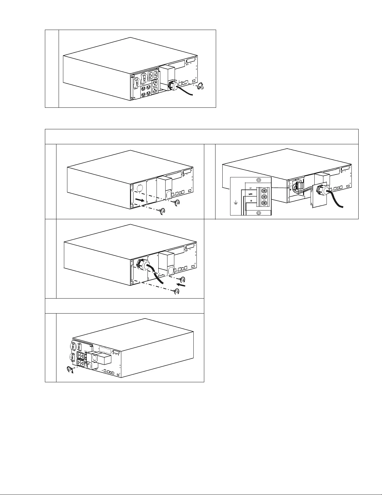
Output hardwiring
SRT5KRM XLW- HW models
SRT6K models Remove the 38.1 mm (1.5 in) knockout panels.
su0862a
su0863a
x2
su0864a
L1
L2/N
su0865a
x2
su086
6a
Smart-UPS On-L ine SRT5K/ 6K Tow er/ R ack-Mount 3U/4U18
UPS Configuration
Connect Emergency Pow er Off feature
For instructions on how to connect the Emergency Power Of f (EPO) swit ch, refer to the Operation and Mai ntenance
manual on the User Documentation CD (supplied).
Configure controllable outlet groups
The out lets on the UPS ar e gro uped. To co nfigu re t he cont rolled o utl et feature s, use the Advanced menus on t he d ispla y
interface and navigate to: Main Menu > Configuration > Outlets > Outlet Gr oup.
su0867a
su0868a
Smart-UPS On-Line SRT5K/6K Tower/Rack-Mount 3U/4U 19
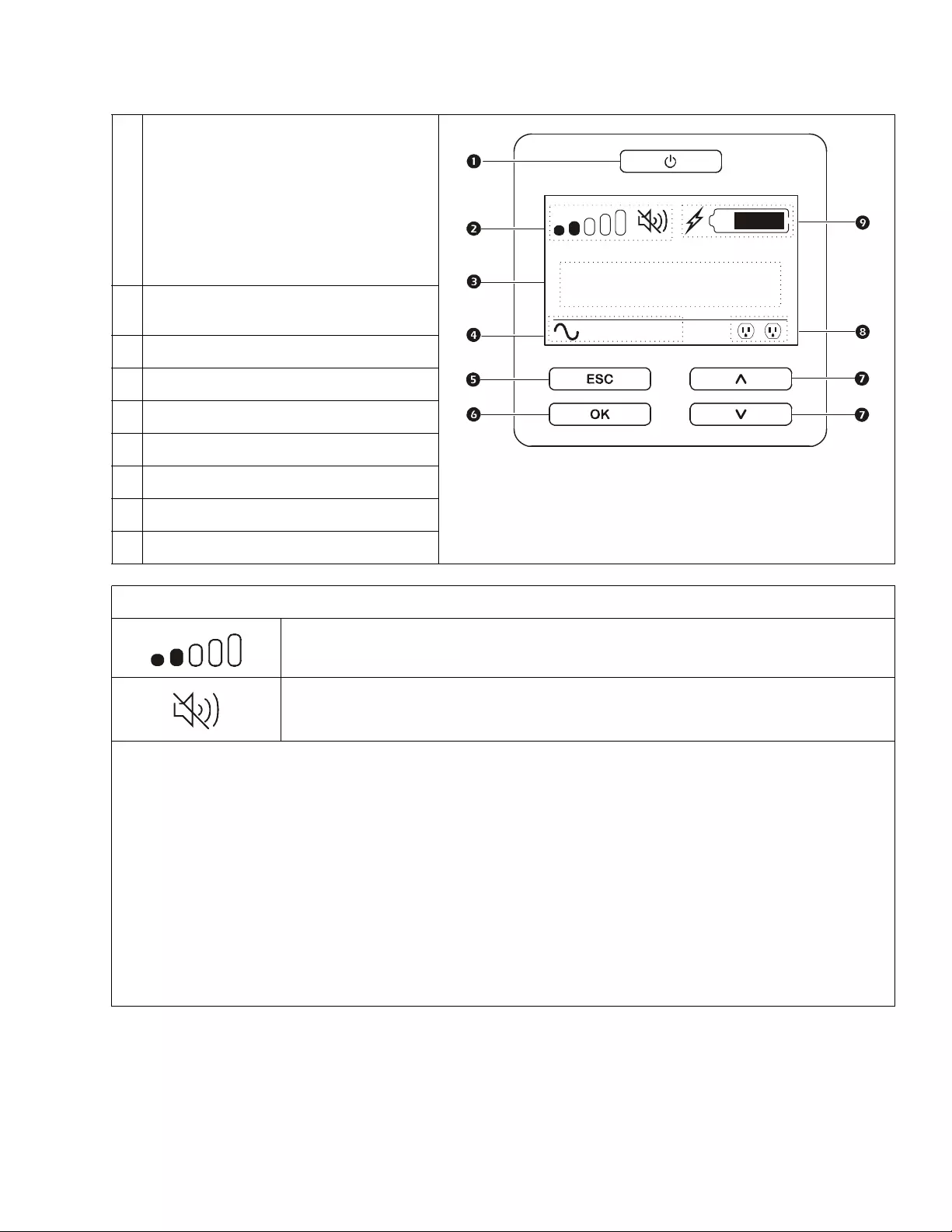
UPS Display Interface
POWER ON/OFF button
Button illumination indications:
-No illumination, the UPS and the output
power are off
-White illumination, the UPS and the ou tput
power are on
-Red illumination, the UPS is on and the
output power is off
Load ic on
Disable/mute audible alarm icon
UPS status information
Operation mode ic ons
ESCAPE but ton
OK button
UP/DOWN buttons
Controllable outlet group status icons
Battery status icons
The icons on the LCD displ ay interfac e s cre en may vary depending on the insta lled firmware version.
Load icon: The approxima te load capa city percentage is in dicated by the number of load bar
se ctions illuminated. Eac h bar re pres ents 16% of the load capacit y.
Mute icon: I n d icates th e au dibl e alarm is disabled/mu t e.
UPS S tatu s Information
The sta tus information field provides key information on the status of the UPS.
The Standard menu w ill allo w the us e r to s el ect o n e of th e f o ll owin g sc r eens .
The Advanced menu will scroll through the following five screens.
Input Voltage
Output Voltage
Output Fre quency
Load
Runtime
In the case of a UPS event, status updates will be displayed defining the event or condition that has occurred.
The displ ay sc reen il lumina tes yellow t o indica te a Warning and red to indi cate an Alert de pendin g on th e seve rity of t he even t
or condition.
su0870b
Output
230.0
v
LOAD
On-Line
12
LOAD
Smart-UPS On-L ine SRT5K/ 6K Tow er/ R ack-Mount 3U/4U20
Display interface oper ation
Use the UP/DOWN buttons to sc r o ll through the options. Press the OK button to accept the selected option. Press the
ESC button to return to the previous menu.
Menu overview
The display int erfac e h as Standar d and Advanced menu screens. The preference for Sta nda rd or Advanced menu
selections is made during initial installation and can be changed at any time through the Configuration menu.
The Standard m enus include the most commonly used options.
The Advanced menus provide additional options.
Note: Ac tual menu screens may differ by model and firmware version.
Refer to the UPS Operation Manual f or menu configura tion details .
Operation Mode Icons
On-Line mode: The UPS is s upplying conditioned mains power to connecte d equipment.
By pass mo de : Th e UPS is in Bypass mode and the conne cted e quip ment will re ceiv e mai ns power
as long as the input voltage and freque ncy are within the configured li mits.
Green mode: When in Green mode mains power is sent directly t o the load.
In the event of a mains power outage, the re will be an interruption in power to the load of
up to 8 m s wh il e the UPS swi tc h es to On-Line mode.
Wh en en abling Green mode conside ration should be giv en to devices that may be sensitive to
power fluctuations .
Battery mode: The UPS is supplyin g battery po wer to connected equipm ent.
Controllable Outlet Group Icons
Controllable Outlet Group P o wer Available : The number next to the icon identifies the specific
outlet groups tha t have available power.
Controllable Outlet Group Power Not A vailable: The numb er ne xt to t he i con i den tifi es s pec if ic
outlet groups that do not have available power .
Battery Status Icons
Battery Charge Status: Indicate s t h e b attery char g e st atus.
Battery Charge In Progress: Indicates the battery is charging.
Smart-UPS On-Line SRT5K/6K Tower/Rack-Mount 3U/4U 21
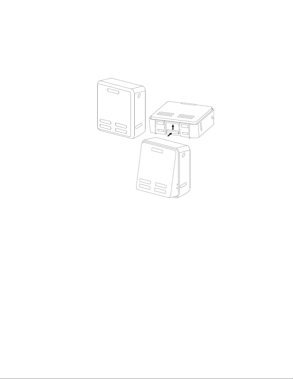
LCD display interface angle adjustment
The angle of the LCD display i nterface can be adjusted for ease in vi ewing t he displayed mes sages .
1. Remove the front bezel .
2. Locate the butt on on the bo ttom of the displa y interface panel.
3. Press the button and sl ide t he bottom of the LCD display interface screen out. An audible click will be heard
4. when the screen reaches the maximum an gl e.
su0926a

Customer support and w arranty information a re a vailable on the APC web site , www.apc.com.
© 2015 APC by Schneider Electric. APC, the APC logo, Smart-UPS and PowerChute are owned by
Sch n eider Electric Ind ustri e s S .A .S . or their affili at ed co m p an ies. Al l othe r tr ad e m arks ar e prope rty of
their respective owners. EN 990-509 0C
7/2015
Select models are ENERGY STAR® qualified.
For more in form ation go to www.apc.com/ si te/recycle/i ndex.cfm/ener gy-effi ciency/e nergy-sta r/