APC SUVTEFBAT10K40H User Manual
Displayed below is the user manual for SUVTEFBAT10K40H by APC which is a product in the UPS Battery Cabinets category. This manual has pages.
Related Manuals
990-3602-001 7/2009
*990-3602-001*
Installation
MGETM GalaxyTM 3500 and Smart-UPS® VT
Enclosure for Batteries and Enclosure for
Transformer 400 V
IMPORTANT SAFETY INSTRUCTIONS
- SAVE THESE INSTRUCTIONS
Warning: ALL safety instructions in the Safety Sheet
(990-2940) must be read, understood and followed when
instal ling the UPS syste m. Failur e to d o so c ould r esul t in
equipment damage, serious injury, or death.
Caution: All electrical power and power control wiring
must be install ed by a qua lified electri cian, and must comp ly
with local and national regulations for maximum power
rating.
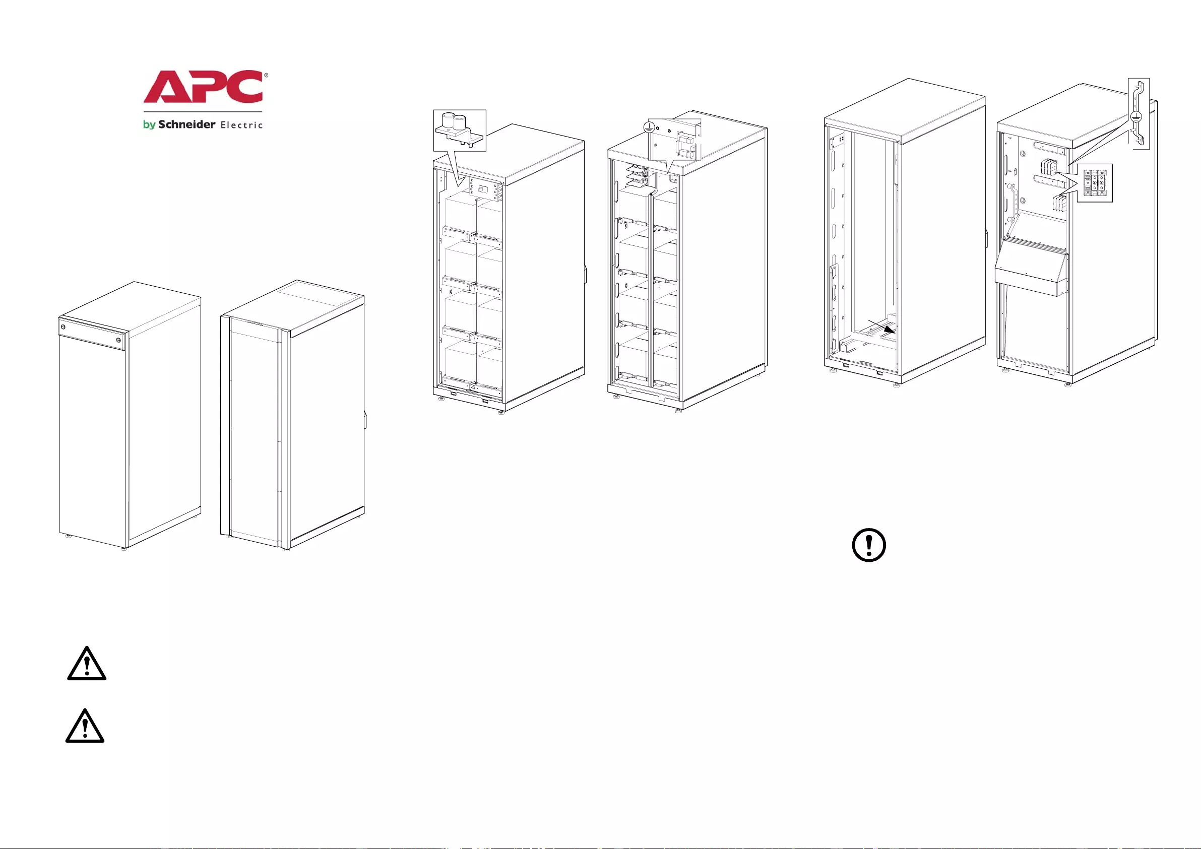
Product Overview
Enclosure for batteries
The enclosure can contain up to 32 batteries - 16 batteries on the
positive (right) side and 16 batteries on the negative (left) side. The
enclosure holds eight battery trays and four batteries each. The
maximum battery size is 197 mm x 165 mm x 175 mm.
Enclosure for Transformer
Site Planning
Note: Refer to the UPS Receiving and Unpacking sheet
(990-2940 for MGE Galaxy 3500 and 990-1747 for Smart-
UPS VT) to dete rmine th e space requir ements. Consul t local
codes for any additional requirements. Ideally, install the
enclosure in a location close to the UPS.
Galaxy 3500
Enclosure for Batteries
Enclosure for Transformer
Smart-UPS VT
Enclosure for Batteries
Enclosure for Transformer
Battery (customer-provided -
shown for reference only)
Battery output terminals
Battery tray Protective Earth/Ground
DC disconnect Communication board
Neutral
Rear viewFront view
N
PE/G
Unistruts Input terminal block
Neutra l busbar Output terminal block
PE/ground busbar
Front view Rear view
PE/G
N
;
2
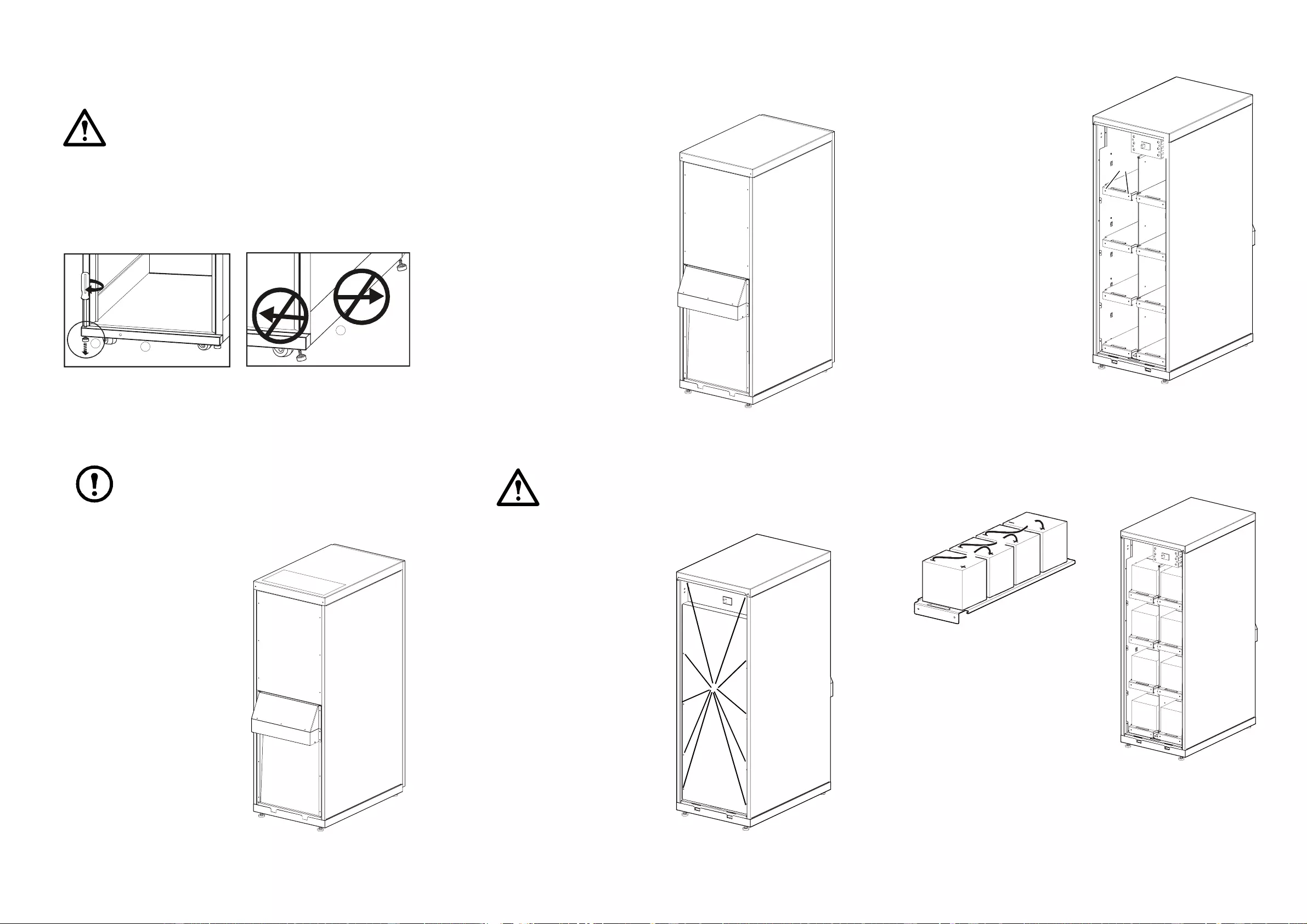
Level the Enclosures
Warning: The system must be installed on a level floor.
The leveling feet will stabilize the enclosure, but will not
account for a badly leveled floor.
Prepa r e for Cab les
Top cable entry
Note: Top cable entry is only applicable to Smart-UPS VT
enclosure for batteries.
Remove the upper rear cover.
Remove the top cover.
Make holes for cables/grommets.
Re-install the top cover.
Bottom cable entry through the I/O box
(optional)
Remove the upper rear cover.
Remove the top cover of the I/O
box.
Remove the bottom cover of the
I/O box (this one will not be
reinstalled).
Route the cables through the I/O
box to the cable conn ect io n area.
Re-inst all t he top cover of the I/O
box.
Install and Connect Batteries
Caution: Ins tall the batteries fro m the botto m and work
your way up.
Rem ove the fr ont door.
Remove the inner front door by
loosening the ten screws.
Loosen the two screws from
each battery tray and remove
the battery trays.
Install four batteries on each
battery tray.
Connect wires between the four batteries on the tray (negative to
positive).
Re-inst all the tra ys with the batteries installed and secu re wit h the two
screws.
Use a screwdriver to lower the
four leveling feet.
Ensure that the enclosure is
level.
Do not move the enclo sure aft er
the leveling feet have been
lowered.
Rear view
Rear view
Front view
Front view
+
N
-
+
N
-
Front view
3
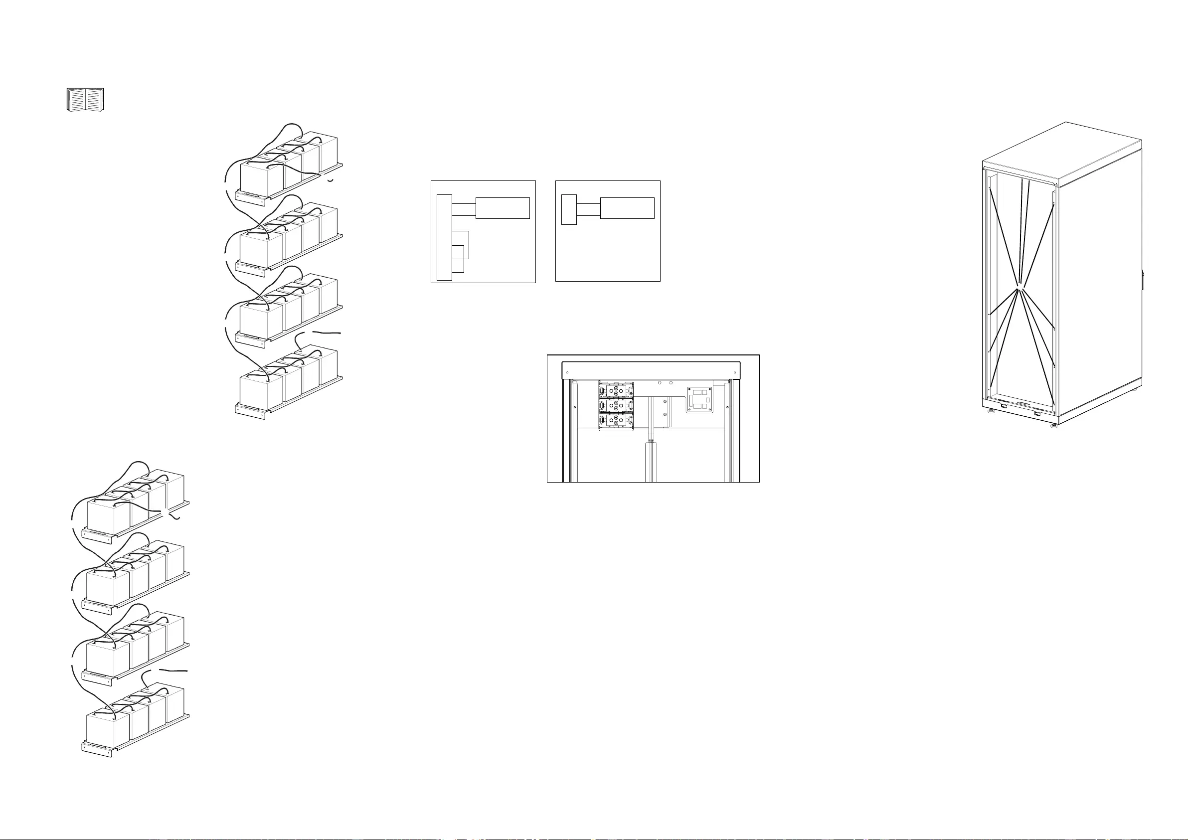
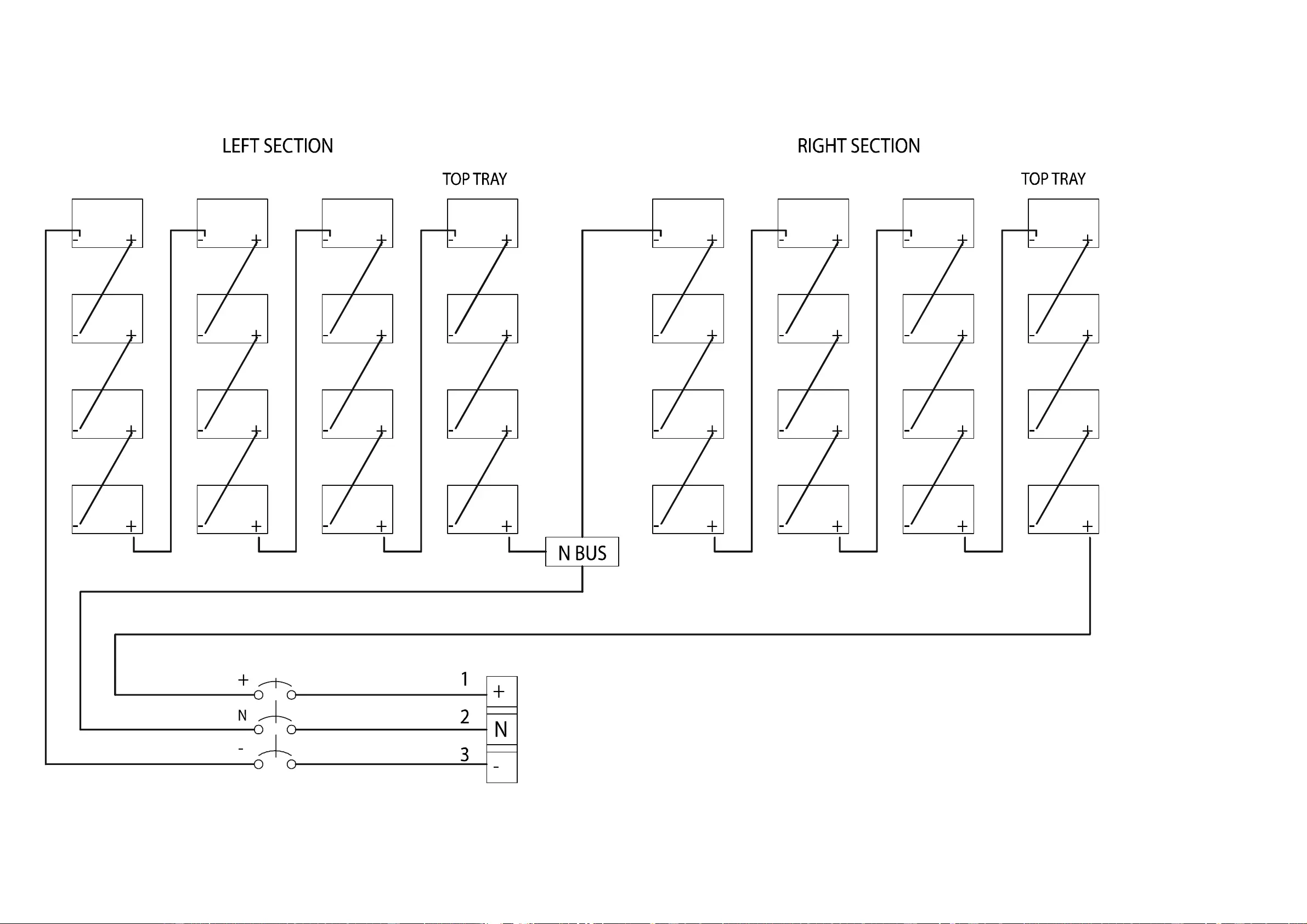
Connect the Positive Bus
See “Battery Enclosure Wiring” for more information.
Connect wire from the battery
breaker + and connect it to the
right top tray.
Connect wire from the top tray
to the sec ond tray.
Connect wire from the second
tray to the third tray.
Connect wire from the third tray
to the bot tom tray.
Connect wire from the back (-)
of the bottom tray to the
midpoint/neutral busbar in the
top of the enclosure.
Connect wire from the midpoint/
neutal busbar to the midpoint/
neutral of the battery breaker.
Connect the Negative Bus
Connec t wire from the
midpoint/neutral busbar to
the + on t he fi rst batt ery from
the fron t at the left top tr ay.
Connect wire from the top
tray to the second tray.
Connect wire from the
second tray to the third tray.
Connect wire from the
third tray to the bottom tray.
Connect wire from the
back of t he botto m tray t o the
battery breaker -.
Connect the EPO to the UPS and the Battery Enclosure
Connect the EPO (Emergency Power Off) to J108 in the UPS and to
J203 in the Battery Enclosure by guiding the cable through conduits as
describe d on the previ ous page .
Connect the EPO by using this configuration:
Connect battery cables between the Enclosure
for batteries and the UPS
Connect battery
cables from the
battery ter m in al
block (+, N, -) to
the (+, N, -) batter y
cable landings in
the UPS.
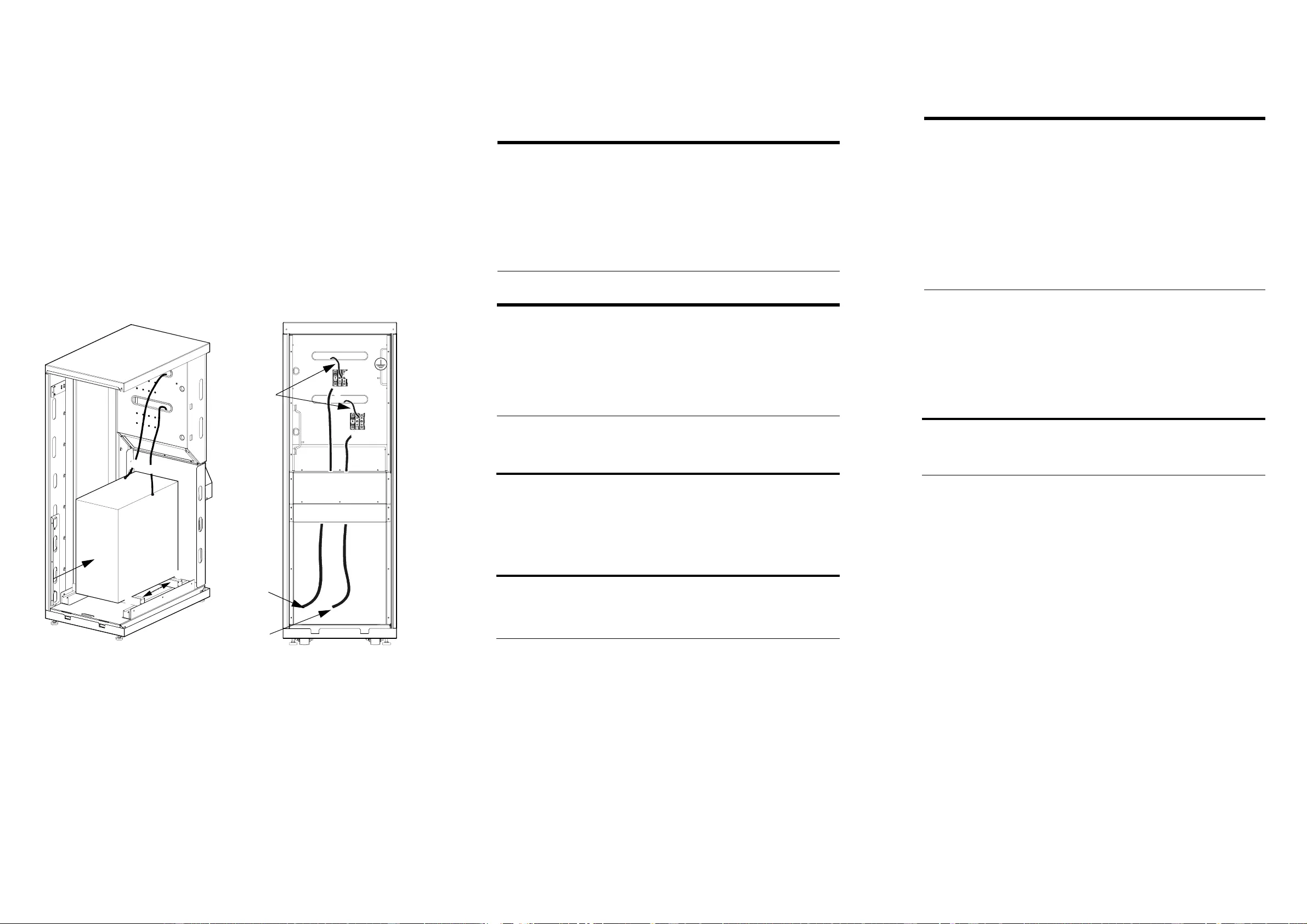
Install and Connect Transformer
Remove the front door.
Remove the inner front door
by loosening the ten screws.
Right side
of enclosure
To midpoint/
neutral busba
r
T o batt ery
breaker +
Left side
of enclosure
To battery
breaker -
To midpoint/
neutral busbar
+24 V Normally open
1
2
J203
EPO circuit
XR Conn Board EPO is activated when an
external 24 VDC, 1500 mA
is supplied on pin 1 with
reference to pin 2
1
2
3
4
5
6
J108
EPO circuit
UPS
Rear view of the Enclosure for Batteries
+
N
-Front view
4
Install the transformer on the four unistruts (two unistruts are
stationary and two are adjustible) and secure using the four M8 spring
nuts.
Connect cables from the transformer input to the top of the input
terminal block and the ground and neutral busbars.
Connect cables from the transformer output to the top of the output
terminal block and the ground and neutral busbars.
Connect cables ( L1, L2, L3, N, G) fro m the mains supply to the bot tom
of the input terminal block and the ground and neutral busbars.
Connect cables (L1, L2, L3, N, G) from the bottom of the output
terminal block and the ground and neutral busbars to the UPS input
terminals.
Specifications
Battery requirements
Recommended batteries.
Maximum total battery weight is 500 kg.
M6 torque 12 Nm.
Transf orm er re qui re m en ts
Maximum overall recommended dimensions for customer-provided
transformer are (WxDxH) 400 x 500 x 600 mm.
Maximum tran sformer mounti ng dimensio ns are (WxD) 305 x 410 mm
and maximum transformer weight is 863 kg.
Hardware provided is 4 x M8.
M8 torque 24 Nm.
Contact Information
For local, country-specific centers: go to www.apc.com/support/
contact.
Front view
Rear view
PE/G
N
Mains
From
transformer
Output
Input
L1,L2,L3
Output
L1,L2,L3
Physical Battery Transformer
Dimensions
(H × W × D) 1487 × 523 ×837 mm 1487 × 523 ×837 mm
Shipping dimensions
(H × W × D) 1664 × 724 ×1105 mm 1664 × 724 ×1105 mm
Weight 259.5 kg 146.5 kg
Shipping weight 294 kg 181 kg
Environmental
Operating environment Indoor use only, protect from water and
conductive contaminates
Operating temperature 0° to 40°C
Recommendation for
batteries 15° to 25°C
Humidity 0 to 95%, non-condensing
Electrical 10-40 kVA
Nom voltage (VDC) +/- 194
INom discharge187.9
IMax discharge2110.1
End Voltage (VDC) +/- 154
1 Nominal battery discharge current based on rated load and nominal battery
voltage.
2 Maximum battery discharge current based on rated load at the end of the
discharge.
Manufacturer Model
OTP 6FM24
OTP 6FM38
Yuasa NP7-12
Yuasa NP24-12
Yuasa NP38-12
Panasonic LC-X1224
Panasonic LC-X1238
Electrical 40 kVA/32 kW
380 V 400 V 415 V
Max. input current (A) 57.4 54.6 52.6
Max. output current (A) 60.8 57.7 55.6
5
Appendix
Battery Enclosure Wiring