Table of Contents
APC SUVTPF15KB4H User Manual
Displayed below is the user manual for SUVTPF15KB4H by APC which is a product in the Uninterruptible Power Supplies (UPSs) category. This manual has pages.
Related Manuals
Smart-UPS™VT™
10-40kVA
380/400/415,200/208/220V
Operation


TableofContents
AboutthisManual..........................................................................................................1
Howtondupdates....................................................................................................1
Safety....................................................................................................................................2
Overview..............................................................................................................................3
UserInterface................................................................................................................3
DisplayInterface..........................................................................................................4
MenuTree...........................................................................................................................5
Operation............................................................................................................................7
Modes..............................................................................................................................7
NormalOperation......................................................................................................7
BatteryOperation......................................................................................................7
InternalBypassOperation........................................................................................7
ExternalMaintenanceBypassOperation...................................................................7
OptionalParallelOperation........................................................................................7
SingleSystemwithoutExternalBypassPanel....................................................8
TurnintoInternalBypass...........................................................................................8
TurnintoNormalOperation.......................................................................................9
PerformaTotalPowerOff..........................................................................................10
PerformaRestart.......................................................................................................11
SingleSystemwithExternalBypassPanel..........................................................12
TurnintoExternalMaintenanceBypass....................................................................12
TurnintoNormalOperationfromExternalMaintenanceBypass...............................13
PerformaTotalPowerOff..........................................................................................14
PerformaRestart.......................................................................................................14
ParallelSystem.............................................................................................................15
TurnintoExternalMaintenanceBypass....................................................................15
TurnintoNormalOperationfromExternalMaintenanceBypass...............................16
PerformaTotalPowerOff..........................................................................................17
PerformaRestart.......................................................................................................17
IsolateoneUPSinaParallelSystem.........................................................................18
TurntheIsolatedUPSintoNormalOperation............................................................18
SingleandParallelSystems.....................................................................................19
TurnLoadoff/onviatheDisplayInterface.................................................................19
TurnLoadOff–DisconnecttheUPSOutputtotheLoadEquipment........................19
TurnLoadOn–ConnecttheUPSOutputtotheLoadEquipment.............................20
ViewtheStatusScreens............................................................................................20
ViewLogging.............................................................................................................22
ViewStatistics...........................................................................................................23
UsetheDiagsScreen................................................................................................24
990–2282E-001Smart-UPS™VT™10-40kV A380/400/415,200/208/220Vi

Conguration....................................................................................................................25
Settings...........................................................................................................................25
ChangetheClock,theAlarmThresholds,andtheDustFilterStatus........................25
Clock.........................................................................................................................26
DustFilter..................................................................................................................27
AlarmThresholds......................................................................................................28
ChangetheBeeperSetup,theContrast,andtheLanguage......................................29
Maintenance......................................................................................................................30
PartsReplacement......................................................................................................30
DetermineifyouNeedaReplacementPart...............................................................30
ReturnPartstoAPC..................................................................................................30
RemovetheFrontPanel............................................................................................31
InstalltheFrontPanel................................................................................................32
StoretheBatteriesandtheUPSSystem....................................................................32
ReplaceaNetworkManagementCard.......................................................................34
Install/replaceaDustFilter.......................................................................................35
ReplaceaBatteryModule..........................................................................................37
Troubleshooting..............................................................................................................42
StatusandAlarmMessages.....................................................................................42
DisplayMessages......................................................................................................42
iiSmart-UPS™VT™10-40kV A380/400/415,200/208/220V990–2282E-001

AboutthisManual
ThismanualisintendedfortheuseroftheSmart-UPS®VTseries.Itreferstoimportantsafetywarnings
andinstructions,givesanintroductiontothedisplayinterface,andprovidesinformationonoperation,load
connection,partsreplacement,troubleshooting,totalpoweroffandrestart.
Note:MainlygraphicsofSmart-UPSVTproductswithbuilt-inbatteriesareshowninthis
manual,butthemanualisintendedforusersofoneormoreunitswithintheSmart-UPSVT
series.Mostillustrationsshow523mmenclosuresbutapplytobothenclosuresizes.Any
differencesbetweentheenclosuresizeswillbeaddressedinthemanual.
Howtondupdates
Youcancheckforupdatestothismanualonwww.apc.com.Lookforthelatestletterrevision(A,
Betc.)ofthemanual.
990–2282E-001Smart-UPS™VT™10-40kV A380/400/415,200/208/220V1

Safety
WARNING:AllsafetyinstructionsintheSafetySheet(990-2822)mustberead,
understoodandfollowedpriortohandling/usingthesystem.Failuretodosocould
resultinequipmentdamage,seriousinjury,ordeath.
WARNING:Forsafetyreasons,onlyqualiedpersonnelisallowedtoperformthe
proceduresdescribedunder“Operation“and“Maintenance“.
2Smart-UPS™VT™10-40kV A380/400/415,200/208/220V990–2282E-001
Overview
UserInterface
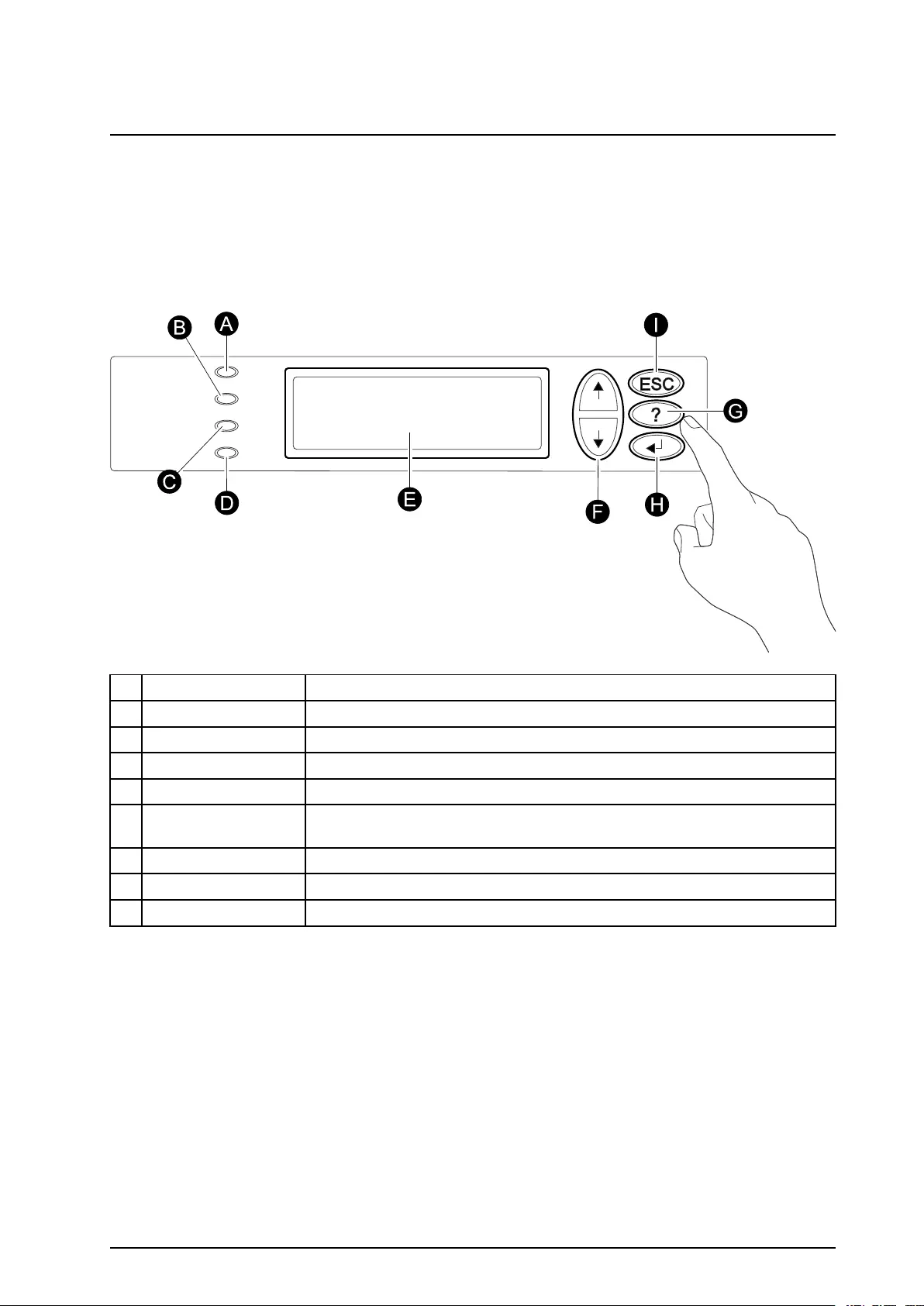
ThefourLEDstotheleftofthedisplayindicatetheoperationalstatusoftheUPS.Thevenavigation
keystotherightareusedtoselectandopenmenuitems,toaccessinformation,changesystemparameters,
andtogetcontext-sensitivehelp.
ALOADONWhenthegreenLEDislit,theUPSprovidespowertotheloadequipment.
BONBA TTWhentheyellowLEDislit,powerowsfromthebatteriestotheload.
CBYPASSWhentheyellowLEDislit,powertotheloadissuppliedthroughbypass.
DFAULTWhentheredLEDislit,afaultconditionexists.
ELCDSCREENDisplaysalarms,statusdata,instructionalhelp,andcongurationitems.
FUPANDDOWN
NA VIGA TIONKEYS
Usedtoscrollthroughandselectmenuitems.
GHELPKEYOpenscontext-sensitivehelp.
HENTERKEYOpensmenuitemsandconrmschangestothesystemparameters.
IESCKEYReturnstothepreviousscreendisplayed.
990–2282E-001Smart-UPS™VT™10-40kV A380/400/415,200/208/220V3
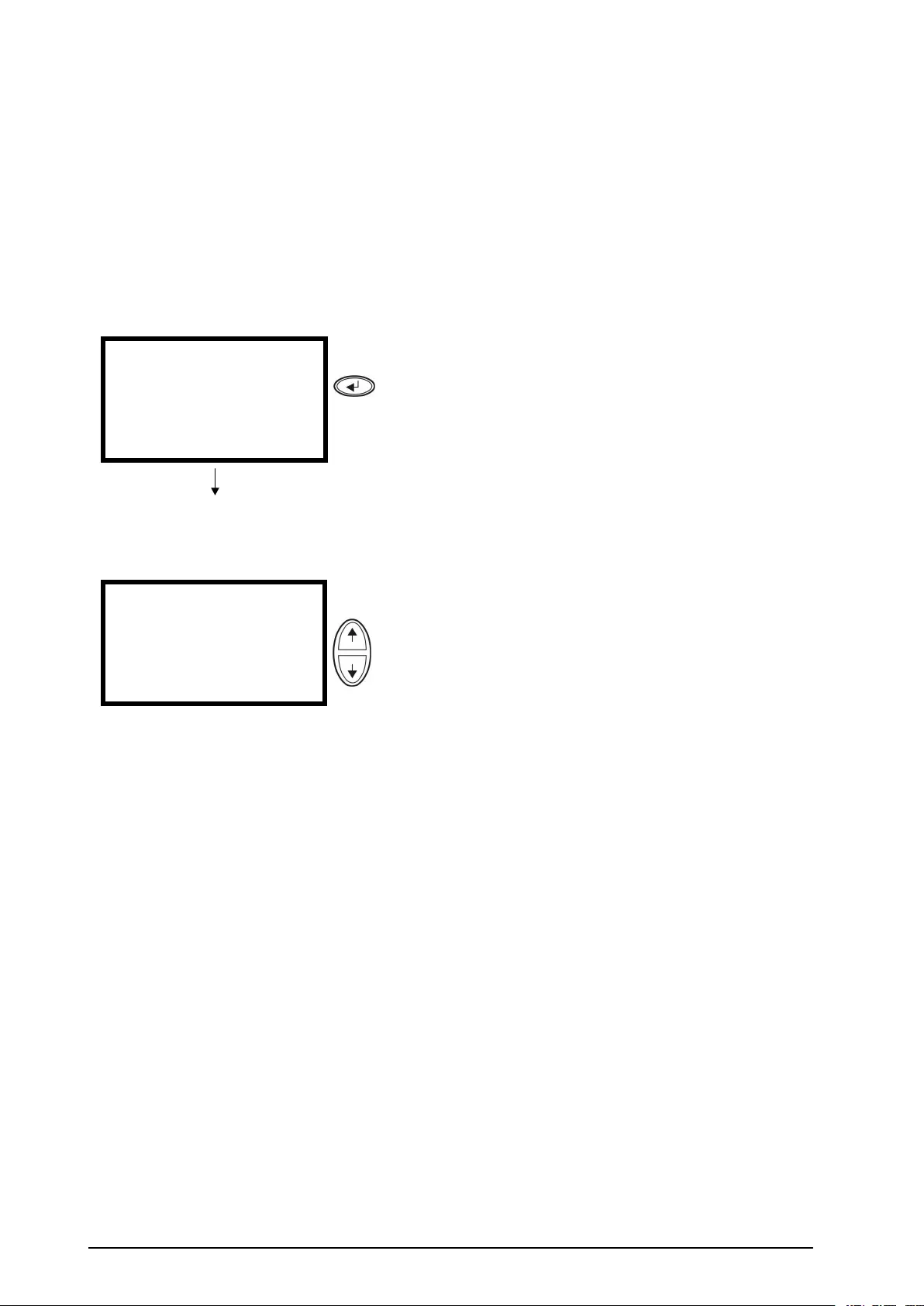
DisplayInterface
TheOverviewScreenisthemainentrancestotheuserfunctionsofthedisplayinterface.TheUP/DOWN
navigationkeystakeyoufromonescreentoanother.
TheENTERkeytakesyoufromtheOverviewScreentotheMainScreen.
FromtheMainScreenitispossibletocommand,congure,andmonitorthesystemthroughthesubmenu
screens:Control,Status,Setup,LCM,Logging,Display,Diags,andHelp(see“MenuTree“).The
selectorarrow(→)iscontrolledbytheUP/DOWNnavigationkeys.Thearrowmarkstheitemyou
mayopenbypressingENTER.
OverviewScreen
Chrgxxx%
Loadxxx%
xxxVinxxxVoutxxHz
Runtime:xxhrxxmin
Press
MainScreen
→ControlLogging
StatusDisplay
SetupDiags
LCMHelp
Press
4Smart-UPS™VT™10-40kV A380/400/415,200/208/220V990–2282E-001

MenuTree
Caution:Thedisplayprovidesaccesstomorefunctionsthandescribedinthismanual.
ThosefunctionsshouldnotbeaccessedwithouttheassistanceofAPCCustomerSupportin
ordertoavoidunwantedloadimpacts.ForAPCWorld-WideCustomerSupport,referto
thebackcoverofthismanual.Ifyoubyaccidentgobeyondthefunctionsdescribed,press
ESCtoreturntopreviousscreens.
990–2282E-001Smart-UPS™VT™10-40kV A380/400/415,200/208/220V5

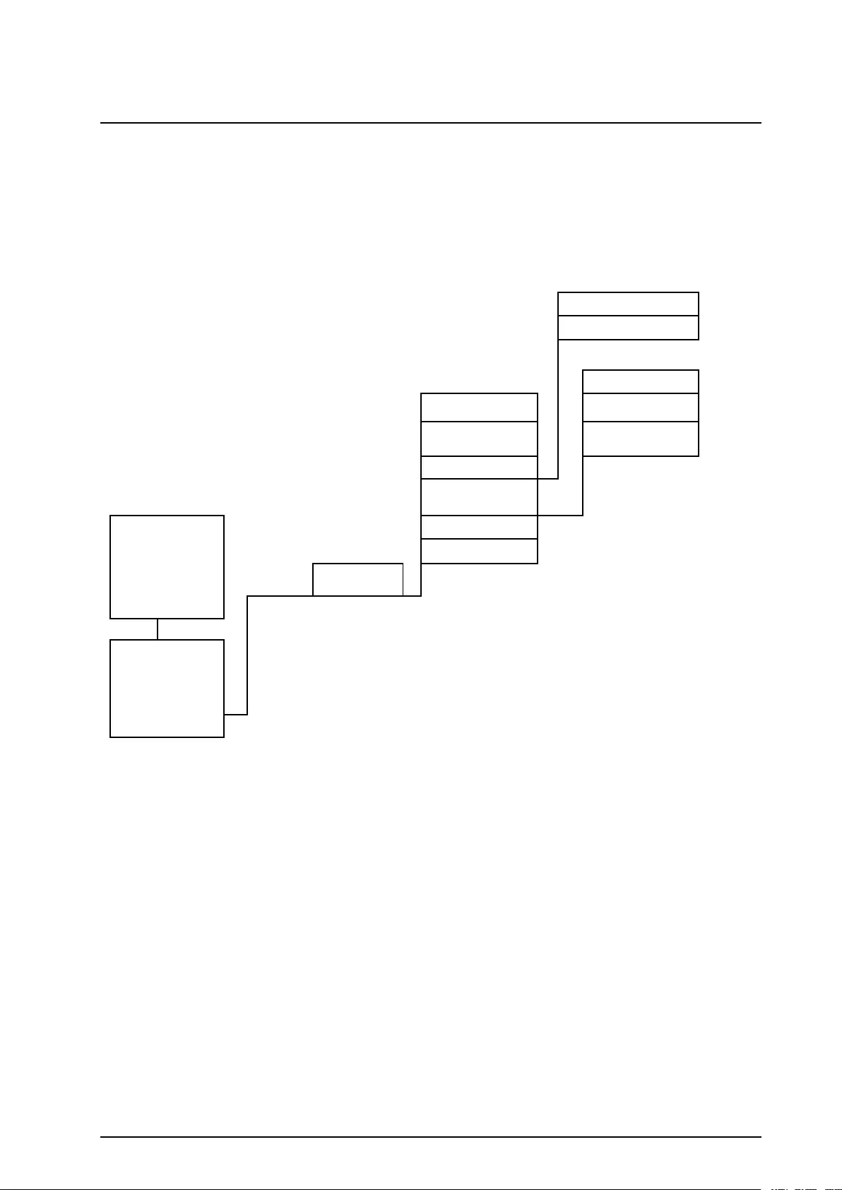
Themenutreeprovidesaquickoverviewofthefunctionsandviewsyoumayaccess.
ControlTurnLoadOff/On
UPSinto/outofBypass
StatusVinVbypV outDustlter
linlbyploutResetdust
lter
kW&kV A
FrequenciesLoad
Load&Bat&RuntimeShutdownRuntime
BatAmpHr/UPSTempDefaultPar.
redund.
AlarmThresholdsSystem
OverviewScreenParallelstatusAlarms
Clock
Other
SetupSettings
Chrgxxx%
Loadxxx%
xxxVinxxxV out
xxHz
Runtime:xxhr
LCMAlarmsPending
LCMContactInfo
LCMAlarmSettings
LCMLifeCycleMonitoring
Control
Status
Setup
LCM
Logging
Display
Diags
Help
MainMenu
ScreenViewLogLanguage
ViewStatisticsContrast
LoggingLoggingMenuBeep.
Setup
Display
FW
DisplayDisplaySetup
Int.mechByp.SW
DiagsFaultsandDiagnosticsQ3ExternalBypSW
SystemInformationStatusfromMBP
SwitchStatus
RawStatusData
Onanyscreen
andanyline,press?
Help
forcontext
sensitivehelp
6Smart-UPS™VT™10-40kV A380/400/415,200/208/220V990–2282E-001

Operation
WARNING:Forsafetyreasons,onlyqualiedpersonnelisallowedtoperformthe
operationproceduresdescribedinthischapter.
Modes
TheUPShasdifferentoperationmodes.IftheinstallationincludesaMaintenanceBypassPanel(MBP),
anexternalmaintenancebypassoperationmodewillalsobeavailable.
NormalOperation
TheUPSconvertsutility/mainspowertoconditionedpowerfortheconnectedload.
BatteryOperation
TheUPSprovidespowertotheconnectedloadfromitsinternaland(ifavailable)externalbatteriesfor
aniteperiod.TheUPStransferstobatteryoperationifthesupplyofutility/mainspowerfails,oris
outsidethepre-denedlimits.
InternalBypassOperation
Internalbypasskeepstheloadsuppliedwithutility/mainspowerduringmaintenanceoftheUPSpower
sections.Ininternalbypassoperation,utility/mainspowerissentdirectlytotheconnectedloadbypassing
allinternalUPSfunctionsandlters.Batteryback-upisnotavailableininternalbypassoperationeven
thoughthebatteriesareinplace.
ExternalMaintenanceBypassOperation
TheUPScanbeconnectedtoanoptionalexternalMBP .Whenactivated,thispanelbypassestheentire
UPSenclosure,feedingutility/mainspowerdirectlytotheload.AnactivatedexternalMBPcompletely
isolatestheUPSandallowsmaintenancetobeperformed.AnexternalMBPismandatoryiftheUPS
isrunninginparallel.
OptionalParallelOperation
TheconnectedloadispoweredbymultipleUPSunitstoincreasesystemredundancyortoincreasepower.
Theinternalmechanicalbypassleverisnotavailable.
990–2282E-001Smart-UPS™VT™10-40kV A380/400/415,200/208/220V7
SingleSystemwithoutExternalBypassPanel
WARNING:Forsafetyreasons,onlyqualiedpersonnelisallowedtoperformthe
operationproceduresdescribedinthischapter.
TurnintoInternalBypass
WARNING:Inbypassoperationthebatteriesarestillpowered.Ifatotalpower
offisrequired,theloadmustbeoff,andthebatteriesmustbepulledouttothered
disconnectline,seethesection“PerformaTotalPowerOff“.
Caution:TheloadisnotprotectedbytheUPSandthepowerisnotconditionedwhenthe
internalmechanicalbypassleverisactivated
Note:Thisprocedureisnotapplicabletoparallelsystemsastheinternalmechanicalbypass
leverisunavailable.
1.IftheUPSisrunningandcontrollablethrough
thedisplay,carryoutsteps2-5.Ifnot,go
directlytostep6.
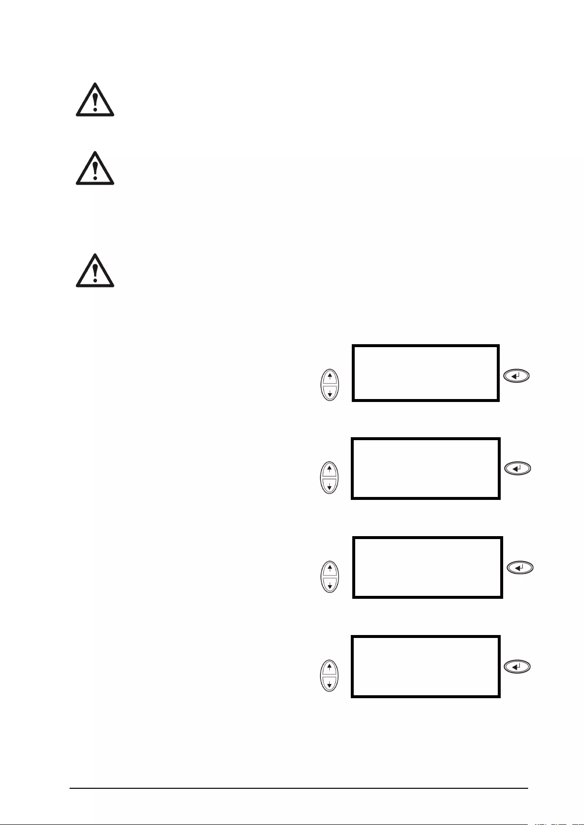
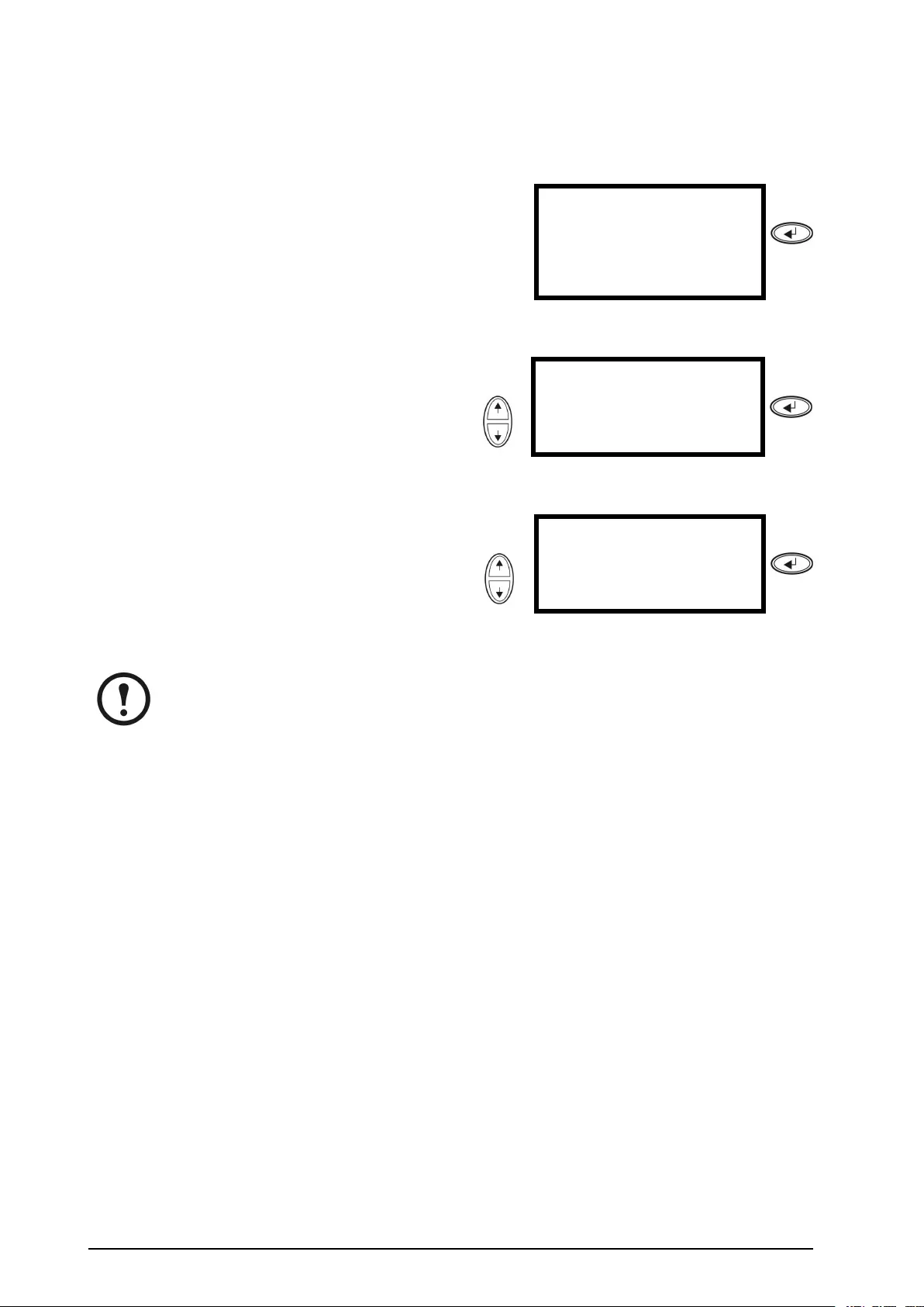
2.FromtheOverviewScreen,pressENTER.
UseChrgxxx%
Loadxxx%
xxxVinxxxVoutxxHz
Runtime:xxhrxxmin
Press
3.GotoControlbyusingtheUP/DOWN
navigationkeysandpressENTER.
Use→ControlLogging
StatusDisplay
SetupDiags
LCMHelp
Press
4.GotoUPSintoBypassbyusingtheUP/DOWN
navigationkeysandpressENTER.Use→UPSintoBypass
DoSelftest
SimulatePowerFail
StartRuntimeCal
Press
8Smart-UPS™VT™10-40kV A380/400/415,200/208/220V990–2282E-001
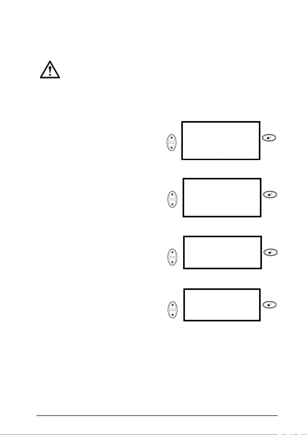
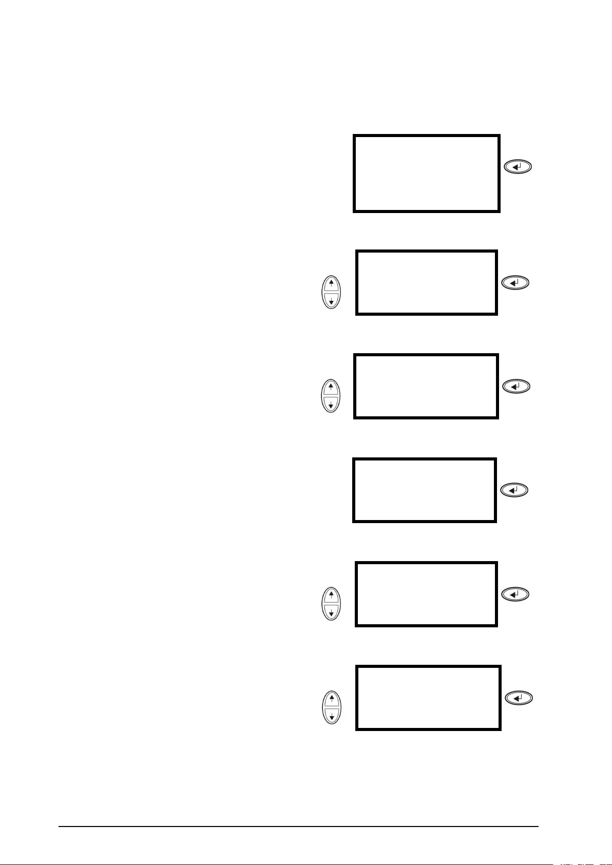
5.GotoYES,UPSintoBypassbyusingthe
UP/DOWNnavigationkeysandpressENTER.UseConfirm:
UPSintoBypass
NO,ABORT
→YES,UPSintoBypass
Press
6.CheckthattheUPSisinbypass.Thegreen
(LOADON)andtheyellow(BYPASS)LEDs
areilluminated.
WARNING:Forsafetyreasons,
onlyqualiedpersonnelisallowed
toperformthefollowingsteps.
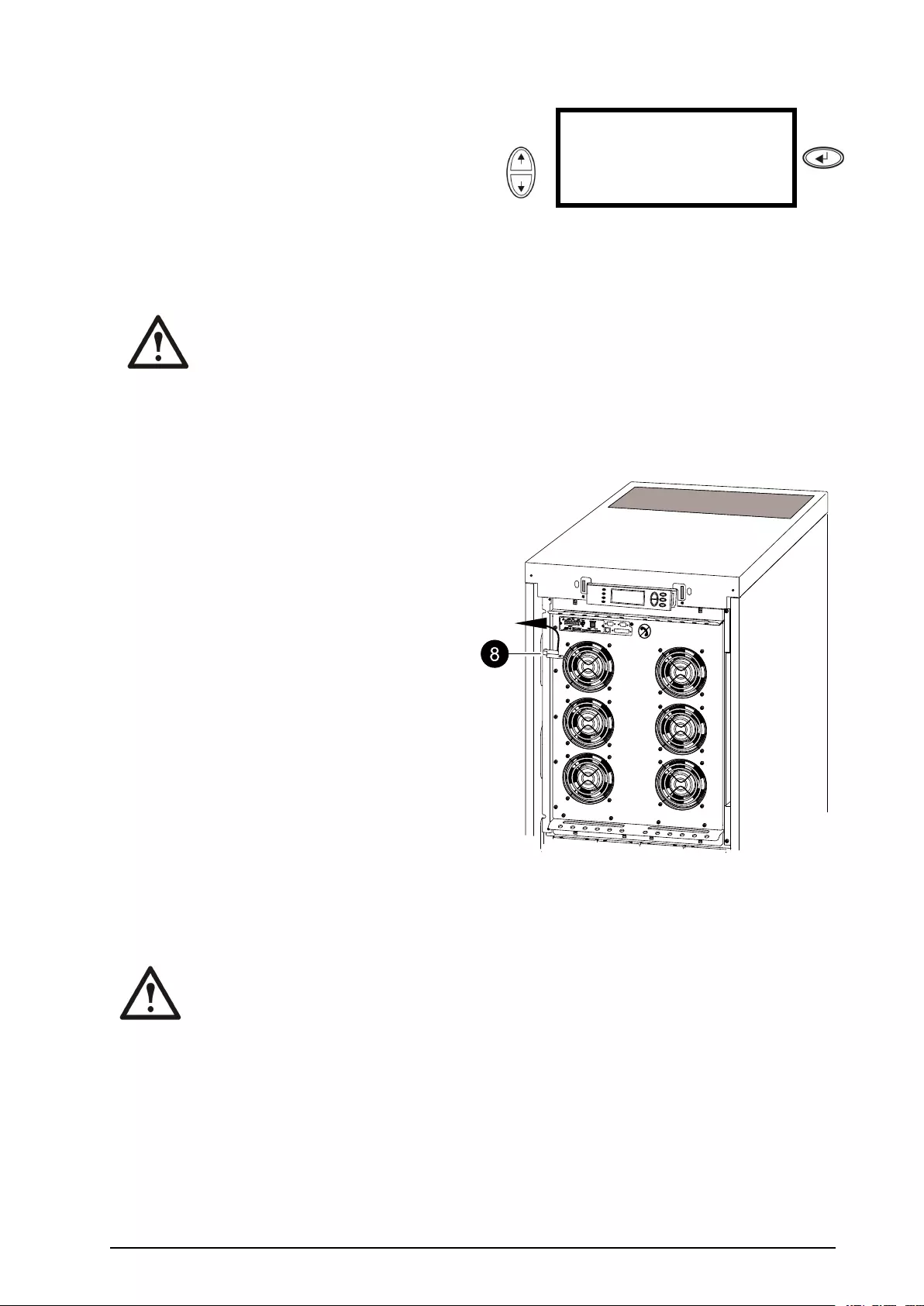
7.RemovethefrontpanelfromtheUPS(see
“RemovetheFrontPanel“).
8.Turntheinternalmechanicalbypasslever
upwardstoactivateit.Theloadwillnowbe
supporteddirectlybyutility/mainspower.
9.Reinstallthefrontpanel.
TurnintoNormalOperation
Caution:NeverattempttoswitchbacktheUPSintonormaloperationtillyouhaveveried
thattherearenointernalUPSfaults.
1.CheckthattheUPSisinbypass.Thegreen(LOADON)andtheyellow(BYPASS)LEDsare
illuminated.
2.Turnthemechanicalbypassleverdownwardsintoahorizontalpositiontodeactivatetheinternal
bypassoperation.
3.IftheUPShasnotreturnedtonormaloperation:PressESCtoreturntothepreviousmenusand
turnoutofbypassfromthedisplayviaControl>UPSoutofbypass>Y es,UPSoutofbypass.
990–2282E-001Smart-UPS™VT™10-40kV A380/400/415,200/208/220V9
4.CheckthattheUPSisinnormaloperation.Theyellow(BYPASS)LEDturnsoffandthegreen
(LOADON)LEDremainsilluminated.
PerformaTotalPowerOff
Note:InordertocarryoutthisproceduretheloadsupportedbytheUPSmustbeturnedoff.
10/100Base-T
Probe
AP9619NetworkManagementCardEM
Reset
Output Pwr Zone
10/100
ON
OFF
3
4
5
6
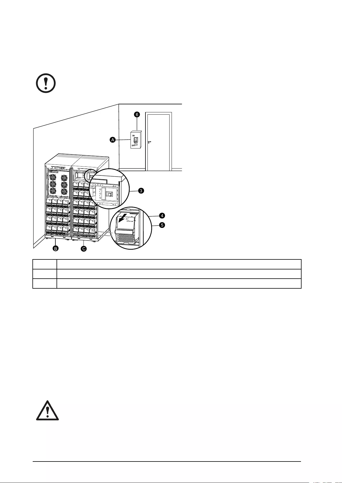
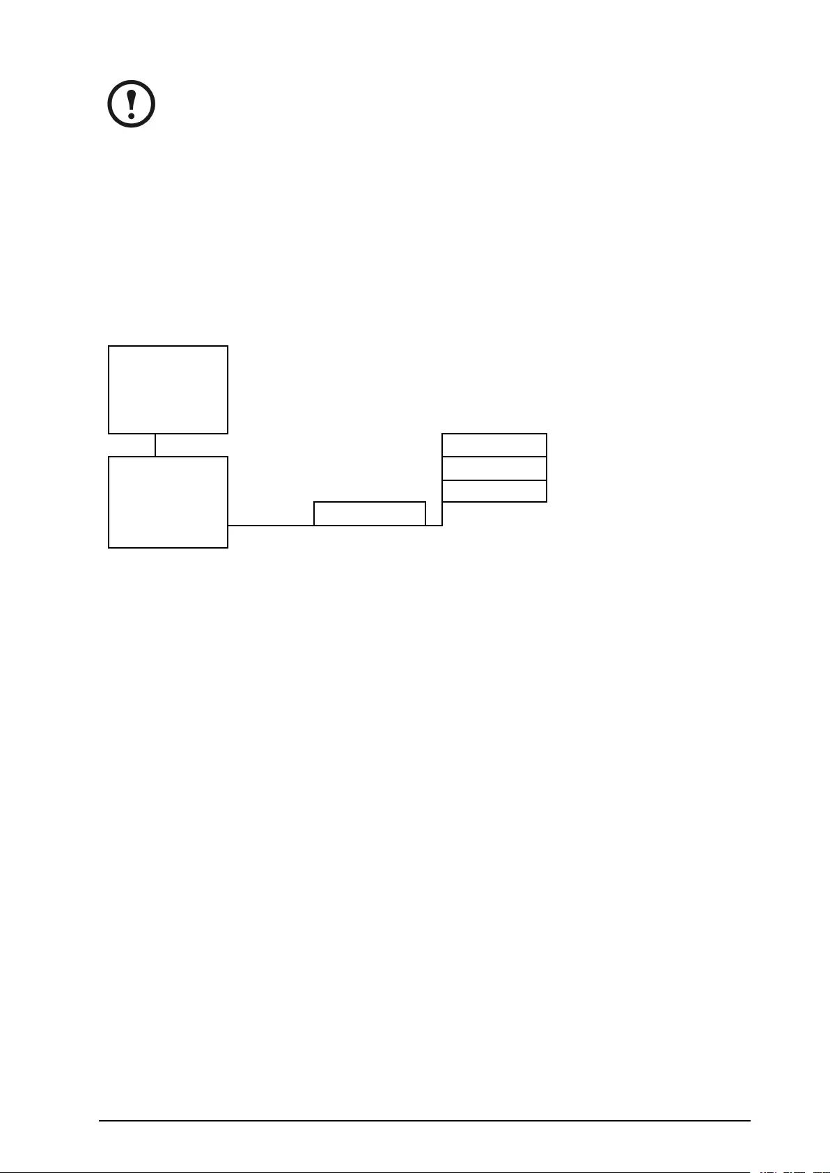
AB
BC
AMainsbreaker
BUPS
CXREnclosure
1.CheckthattheloadwhichissupportedbytheUPSisturnedOFF.
2.FromtheUPS:TurnloadOFFfromthedisplayviaControl>TurnLoadOff>Yes,Turn
LoadOff.
3.FromtheXREnclosure(s)(ifavailable):SettheDCdisconnectswitch(es)topositionOFF.
4.FromtheUPS:Disconnectthebatteries(ifavailable)bypullingthemouttothereddisconnect
lineshownoneachbatteryunit.
5.FromtheXREnclosure(s)(ifavailable):Disconnectthebatteriesbypullingthemouttothered
disconnectlineshownoneachbatteryunit.
6.Settheutility/mainsbreakertopositionOFForLOCKED-OUT.IftheUPShasdualutility/mains
supply,setbothsuppliestopositionOFForLOCKED-OUT.
WARNING:Thelockoutproceduresattheutility/mainsbreakermustbefollowed.
Ifnecessary,installapadlock.
10Smart-UPS™VT™10-40kV A380/400/415,200/208/220V990–2282E-001

Note:FordetailsonhowtoremoveBatteryLocks(ifavailable)(seethesection“Replacea
BatteryModule“andhereunder“RemoveandInstallBatteryLocks“).
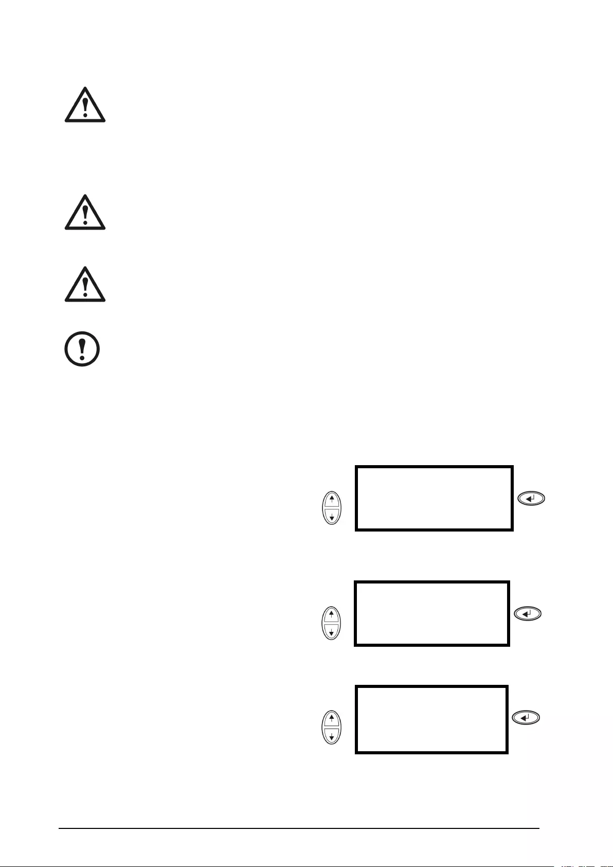
PerformaRestart
WARNING:Onlyqualiedpersonnelfamiliarwiththeconstructionandtheequipment
mayrestarttheUPS.
1.Settheutility/mainsbreakertopositionON.2.IfyourinstallationincludesanXRBattery
EnclosurewithaDCdisconnectswitch,setthe
DCdisconnectswitchtopositionON.
Note:Waitapproximately30
secondsforthesystemtobootup
andcarryoutaselftest.
Aftersystemboot-up,thedisplaywillautomatically
askyoutoconrm/selectvoltageandfrequencyas
showninthefollowing.
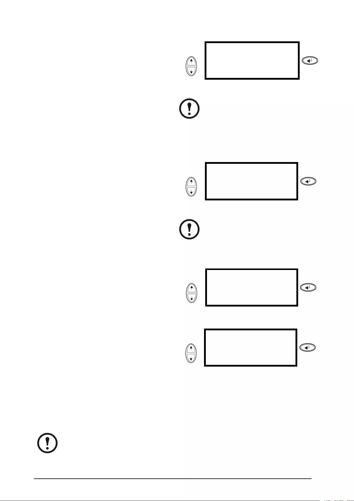
Voltageconrmation.Atrestart,thedisplaywill
promptyouthroughthefollowingscreens:
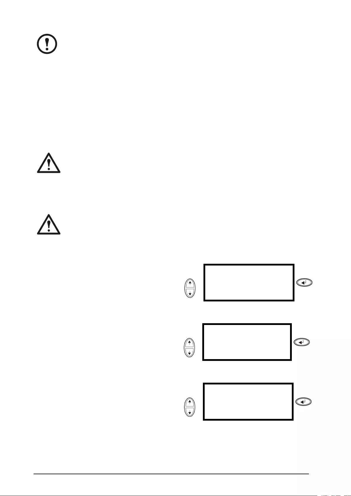
3.WhentheConrmVoltagepromptappearson
thescreen,gotothedesiredvoltageusingthe
UP/DOWNnavigationkeysandpressENTER.UseConfirmVoltage
Use400V
→Yes,use400V
No,selectanother
Press
4.WhenthepromptApplyloadappears,goto
YesusingtheUP/DOWNnavigationkeysand
pressENTERifyouwanttheUPStoprovidea
loadoutputnow.(IfyoudonotwantaUPSload
outputatthispoint,gotoNo).
Use
Applyload
→Yes
No
Press
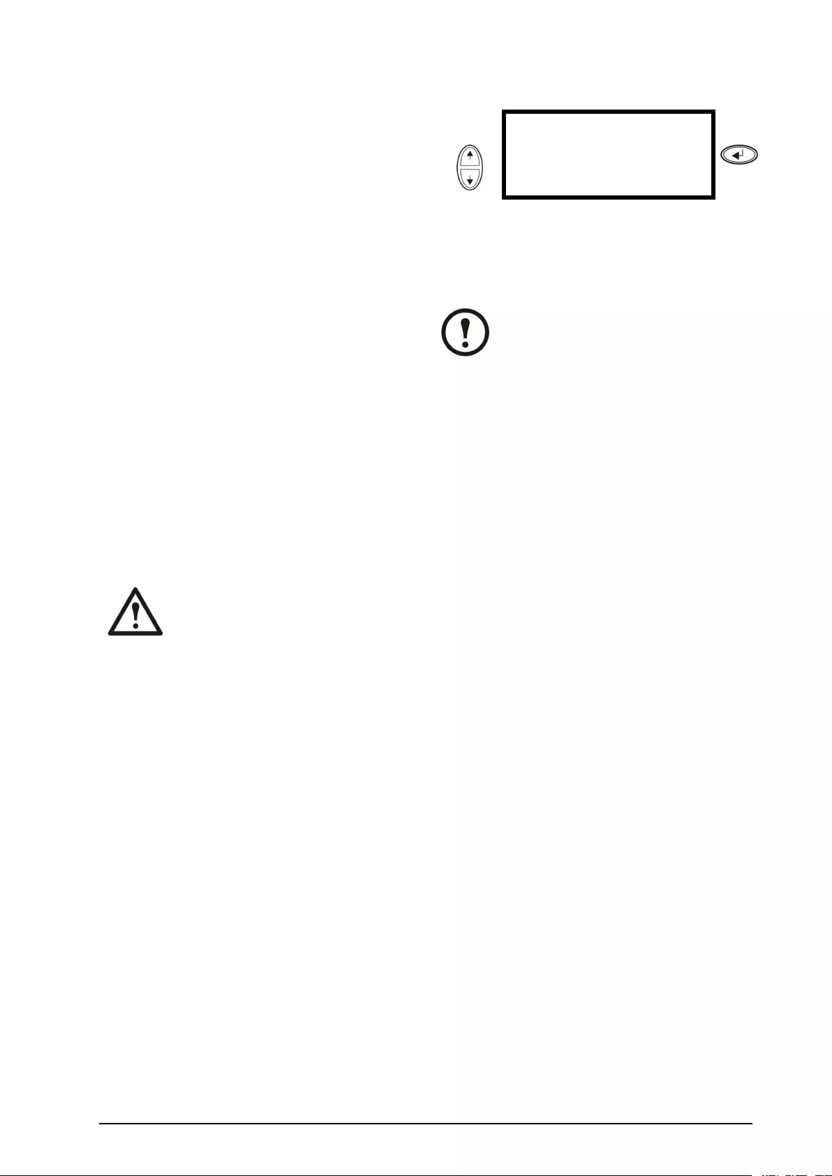
5.Thegreen(LOADON)LEDisnowlit.Press
ESCtwotimesandthedisplaywillreturntothe
OverviewScreen.UseChrgxxx%
Loadxxx%
xxxVinxxxVoutxxHz
Runtime:xxhrxxmin
Press
Note:TheUPSisnowreadytosupporttheload.
990–2282E-001Smart-UPS™VT™10-40kV A380/400/415,200/208/220V11
Note:
Theauto-detectiononfrequencyhasbeenimprovedinrmwareversion5.1andhigherfor
theSmart-UPSVTsingleunits(withparallelcapability).Auto-detectiononfrequencyisan
optionintheSetupmenu(inalignmentwiththevalues50Hzand60Hz)butalsoafeature
wherebyasingleUPSsystemdetectstheinputfrequencyinasystemstart-up.
IftheUPSsystemduringastart-updetectsaninputfrequencydifferentfromwhatisalready
set,thentheuserwillbeaskedtochoosethedetectedfrequency.Thesystemwillnotchange
frequencybyitself.Forsafetyreasons,theinputfrequencycanonlybechangedbytheuser.
Theauto-detectiononfrequency-featureisonlyapplicableinasinglesystemstart-up.Ifa
problemoccurscallAPCCustomerSupport(seethebackcoverofthismanual).
SingleSystemwithExternalBypassPanel
WARNING:Forsafetyreasons,onlyqualiedpersonnelisallowedtoperformthe
operationproceduresdescribedinthischapter.
TurnintoExternalMaintenanceBypass
WARNING:Inbypassoperationthebatteriesarestillpowered.Ifatotalpower
offisrequired,theloadmustbeoff,andthebatteriesmustbepulledouttothered
disconnectline(see“PerformaTotalPowerOff“inthischapter).
1.FromtheOverviewScreen,pressENTER.
UseChrgxxx%
Loadxxx%
xxxVinxxxVoutxxHz
Runtime:xxhrxxmin
Press
2.GotoControlbyusingtheUP/DOWN
navigationkeysandpressENTER.Use→ControlLogging
StatusDisplay
SetupDiags
LCMHelp
Press
3.GotoUPSintoBypassbyusingtheUP/DOWN
navigationkeysandpressENTER.Use→UPSintoBypass
DoSelftest
SimulatePowerFail
StartRuntimeCal
Press
12Smart-UPS™VT™10-40kV A380/400/415,200/208/220V990–2282E-001
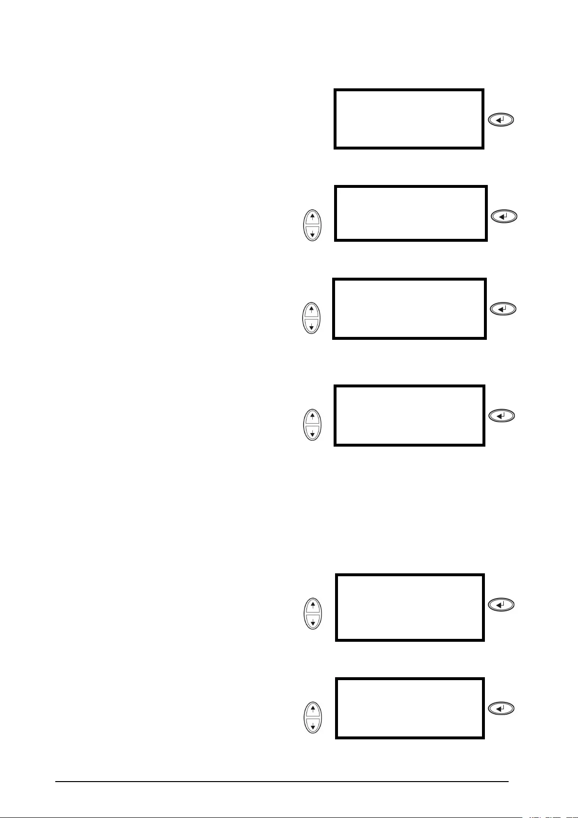
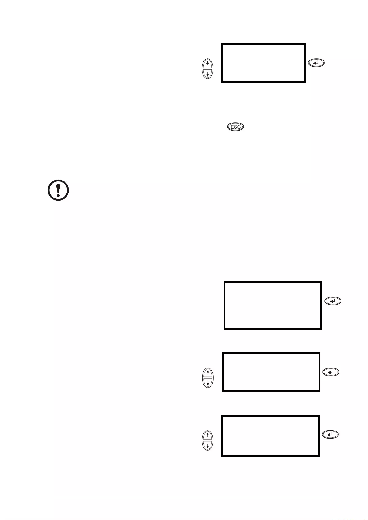
4.GotoY es,UPSintoBypassbyusingthe
UP/DOWNnavigationkeysandpressENTER.
UseConfirm:
UPSintoBypass
NO,ABORT
→YES,UPSintoBypass
Press
5.FromtheexternalMaintenanceBypassPanel
(MBP):Turnthebypassswitch(Q3)toposition
“|”(ON).
6.FromtheexternalMBP:Turntheoutputswitch
(Q2)toposition“O”(OFF).Nowtheloadisnot
supportedbytheUPS.
Note:Note!Ifyouneedtoturnthe
UPScompletelyOFF,proceedwith
steps7–11.
7.IfyouneedtoturntheUPScompletelyOFF:
FromtheexternalMBP:Turntheinputswitch
(Q1)toposition“O”(OFF).
8.FromtheXREnclosure(s)(ifavailable):Setthe
DCdisconnectswitch(es)topositionOFF.
9.FromtheUPS:Disconnectthebatteries(if
available)bypullingthemouttothered
disconnectlineshownoneachbatteryunit.
10.FromtheXREnclosure(s)(ifavailable):
Disconnectthebatteriesbypullingthemoutto
thereddisconnectlineshownoneachbattery
unit.
TurnintoNormalOperationfromExternalMaintenanceBypass
Caution:NeverattempttoswitchbacktheUPSintonormaloperationtillyouhaveveried
thattherearenointernalUPSfaults.
1.IftheUPShasbeencompletelyturnedOFF,proceedwithsteps2–10.IftheUPShasnotbeen
completelyturnedOFF,proceedwithsteps6–10.
2.FromtheXREnclosure(s)(ifavailable):Connectthebatteriesbypushingthemin.
3.FromtheUPS:Connectthebatteries(ifavailable)bypushingthemin.
4.FromtheXREnclosure(s)(ifavailable):SettheDCdisconnectswitch(es)topositionON.
5.FromtheXREnclosure(s)(ifavailable):SettheDCdisconnectswitch(es)topositionON.
6.FromtheexternalMBP:Turntheoutputswitch(Q2)toposition“|”(ON).Nowtheloadis
supportedbytheUPS.
7.FromtheUPS:Checkthattheyellow(BYPASS)LEDisilluminatedandthegreen(LOADON)
LEDisilluminated.
8.FromtheexternalMBP:Turnthebypassswitch(Q3)toposition“O”(OFF).
9.IftheUPShasnotreturnedtonormal:FromtheUPS:Turnoutofbypassfromthedisplayvia
Control>UPSoutofbypass>Y es,UPSoutofbypass.
10.FromtheUPS:CheckthattheUPSisinnormaloperation.Theyellow(BYPASS)LEDturnsoff
andthegreen(LOADON)LEDremainsilluminated.
990–2282E-001Smart-UPS™VT™10-40kV A380/400/415,200/208/220V13

PerformaTotalPowerOff
Note:InordertocarryoutthisproceduretheloadsupportedbytheUPSmustbeturnedoff.
1.CheckthattheloadwhichissupportedbytheUPSisturnedOFF.
2.FromtheUPS:TurnloadOFFfromthedisplayviaControl>TurnLoadOff>Yes,Turn
LoadOff.
3.FromtheexternalMBP:Turntheoutputswitch(Q2)toposition“O”(OFF).
4.FromtheexternalMBP:Turntheinputswitch(Q1)toposition“O”(OFF).
5.FromtheXREnclosure(s)(ifavailable):SettheDCdisconnectswitchtopositionOFF.
6.FromtheUPS:Disconnectthebatteries(ifavailable)bypullingthemouttothereddisconnect
lineshownoneachbatteryunit.
7.FromtheXREnclosure(s)(ifavailable):Disconnectthebatteriesbypullingthemouttothered
disconnectlineshownoneachbatteryunit.
PerformaRestart
Note:Onlyqualiedpersonnelfamiliarwiththeconstructionandtheequipmentmayrestart
theUPS.
1.FromtheXREnclosure(s)(ifavailable):Connectthebatteriesbypushingthemin.
2.FromtheUPS:Connectthebatteries(ifavailable)bypushingthemin.
3.FromtheXREnclosure(s)(ifavailable):SettheDCdisconnectswitch(es)topositionON.
4.FromtheexternalMBP:Turntheinputswitch(Q1)toposition“|”(ON).
5.FromtheexternalMBP:Turntheoutputswitch(Q2)toposition“|”(ON).
6.FromtheUPS:TurnloadONfromthedisplayviaControl>TurnLoadOn>Y es,Turn
LoadOn.
7.CheckthattheloadisON.
Note:TheUPSisnowreadytosupporttheload.
Note:Theauto-detectiononfrequencyhasbeenimprovedinrmwareversion5.1and
higherfortheSmart-UPSVTsingleunits(withparallelcapability).Auto-detectionon
frequencyisanoptionintheSetupmenu(inalignmentwiththevalues50Hzand60Hz)but
alsoafeaturewherebyasingleUPSsystemdetectstheinputfrequencyinasystemstart-up.
IftheUPSsystemduringastart-updetectsaninputfrequencydifferentfromwhatisalready
set,thentheuserwillbeaskedtochoosethedetectedfrequency.Thesystemwillnotchange
frequencybyitself.Forsafetyreasons,theinputfrequencycanonlybechangedbytheuser.
Theauto-detectiononfrequency-featureisonlyapplicableinasinglesystemstart-up.Ifa
problemoccurscallAPCCustomerSupport(seethebackcoverofthismanual).
14Smart-UPS™VT™10-40kV A380/400/415,200/208/220V990–2282E-001
ParallelSystem
WARNING:Forsafetyreasons,onlyqualiedpersonnelisallowedtoperformthe
operationproceduresdescribedinthischapter.
WARNING:ParallelOperationisnotavailablewhenthesystemissetupfor3–wire
operation,whichonlyappliestoJapanesesystems.
TurnintoExternalMaintenanceBypass
WARNING:Inbypassoperationthebatteriesarestillcharged.Ifatotalpoweroffis
required,theloadmustbeoffandthebatteriesmustbepulledouttothereddisconnect
line(see“PerformaTotalPowerOff“inthischapter).
1.FromtheOverviewScreen,pressENTER.
UseChrgxxx%
Loadxxx%
xxxVinxxxVoutxxHz
Runtime:xxhrxxmin
Press
2.GotoControlbyusingtheUP/DOWN
navigationkeysandpressENTER.Use→ControlLogging
StatusDisplay
SetupDiags
LCMHelp
Press
3.GotoUPSintoBypassbyusingtheUP/DOWN
navigationkeysandpressENTER.Use→UPSintoBypass
DoSelftest
SimulatePowerFail
StartRuntimeCal
Press
4.GotoYES,UPSintoBypassbyusingthe
UP/DOWNnavigationkeysandpressENTER.UseConfirm:
UPSintoBypass
NO,ABORT
→YES,UPSintoBypass
Press
5.FromtheUPS:CheckthatallUPSunitsare
inbypassoneachofthedisplays.Theyellow
bypassLEDisilluminatedoneachUPSunit.
6.FromtheexternalMaintenanceBypassPanel
(MBP):Checkthatthebypasslampindicator
(H3)isilluminatedatQ3.
990–2282E-001Smart-UPS™VT™10-40kV A380/400/415,200/208/220V15

7.FromtheexternalMBP:Turnthebypassswitch
(Q3)toposition“|”(ON).
8.FromtheexternalMBP:Checkthatthelamp
indicatoroftheoutputisolationbreaker(H4)at
Q4isilluminated.
9.FromtheexternalMBP:Turntheoutput
isolationbreaker(Q4)toposition“O”(OFF).
TheUPSisnowinexternalmaintenancebypass
withthebatteriesstillpowered.Note!Ifyou
needtoturntheUPSunitscompletelyOFF,
proceedwithsteps11–18.
Note:Note!Ifyouneedtoturnthe
UPSunitscompletelyOFF,proceed
withsteps11–18.
10.FromtheUPS:TurnOFFeachUPSunitfrom
thedisplayviaControl>TurnLoadOff>Y es,
TurnLoadOff.
11.FromtheexternalMBP:Checkthatallthe
outputlamps(H2a,H2b,H2c)forQ2are
illuminated.
12.FromtheexternalMBP:Turnalloutput
switches(Q2)toposition“O”(OFF).
13.FromtheexternalMBP:turnallinputswitches
(Q5)(ifavailable)toposition“O”(OFF).
14.FromtheexternalMBP:Turnallinputswitches
(Q1)toposition“O”(OFF).
15.FromtheXREnclosure(s)(ifavailable):Set
theDCdisconnectswitch(es)topositionOFF.
16.FromtheUPS:Disconnectthebatteries(if
available)bypullingthemouttothered
disconnectlineshownoneachbatteryunit.
17.FromtheXREnclosure(s)(ifavailable):
Disconnectthebatteriesbypullingthemoutto
thereddisconnectlineshownoneachbattery
unit.
18.De-energizeallUPSinputs.
TurnintoNormalOperationfromExternalMaintenanceBypass
Caution:NeverattempttoturntheUPSintonormaloperationtillyouhaveveriedthat
therearenointernalUPSfaults.
1.IftheUPSunitshavebeencompletelyturnedOFF,proceedwithsteps2–16.IftheUPSunits
havenotbeencompletelyturnedOFF,proceedwithstep13–16.
2.FromtheUPS:Connectthebatteries(ifavailable)ineachUPSbypushingthemin.
3.FromtheXREnclosure(s)(ifavailable):ConnectthebatteriesineachUPSbypushingthemin.
4.FromtheXREnclosure(s)(ifavailable):SettheDCdisconnectswitch(es)topositionON.
5.FromtheexternalMBP:Turnallinputswitches(Q1)toposition“|”(ON).
6.FromtheexternalMBP:Checkthatallthebypassinputlamps(H5)atQ5(ifavailable)are
illuminated.
7.FromtheexternalMBP:Turnallbypassinputswitches(Q5)(ifavailable)toposition“|”(ON).
8.FromtheexternalMBP:Checkthatalltheoutputlamps(H2)forQ2areilluminated.
9.FromtheexternalMBP:Turnalloutputswitches(Q2)toposition“|”(ON).Thelampindicatorof
theoutputisolationbreaker(Q4)isstillilluminated.
10.FromtheUPS:TurnONallUPSunitsfromeachdisplayviaControl>TurnLoadON>Yes,
TurnLoadON.ThegreenonlineLEDsareilluminatedoneachUPSunit.
16Smart-UPS™VT™10-40kV A380/400/415,200/208/220V990–2282E-001

11.FromtheexternalMBP:Checkthatalltheoutputlamps(H2)forQ2arenotilluminatedandthat
allthebypassinputlamps(H5)atQ5(ifavailable)arenotilluminated.
12.FromtheUPS:TurntheUPSunitsintobypassfromoneUPSdisplayviaControl>UPSinto
bypass>Yes,UPSintobypass.CheckthattheUPSunitsareinbypass.Thegreen(LOADON)
andtheyellow(BYPASS)LEDsareilluminated.
13.FromtheexternalMBP:Checkthatthelampindicatoroftheoutputisolationbreaker(Q4)
isilluminated.
14.FromtheexternalMBP:Turntheoutputisolationbreaker(Q4)toposition“|”(ON).Nowthe
lampsH3+H4areilluminated.
15.FromtheexternalMBP:Turnthebypassswitch(Q3)toposition“O”(OFF).Thelampindicator
oftheoutputisolationbreaker(H4)forQ4isnotilluminated,butthebypasslamp(H3)forQ3
isilluminated,untiltheUPSisrunninginnormaloperation.
16.FromtheUPS:TurntheUPSunitsoutofbypassfromthedisplayviaControl>UPSoutof
bypass>Y es,UPSoutofbypass.
PerformaTotalPowerOff
Note:InordertocarryoutthisproceduretheloadsupportedbytheUPSmustbeturnedoff.
1.CheckthattheloadwhichissupportedbytheUPSisturnedOFF.
2.FromtheUPS:TurnloadOFFfromeachoftheUPSdisplaysviaControl>TurnLoadOff>
Yes,TurnLoadOff.
3.FromtheexternalMBP:Turntheoutputisolationbreaker(Q4)toposition“O”(OFF).
4.FromtheexternalMBP:Turnalloutputswitches(Q2)toposition“O”(OFF).
5.FromtheexternalMBP:Turnallinputswitches(Q1)toposition“O”(OFF)
6.FromtheXREnclosure(s)(ifavailable):SettheDCdisconnectswitch(es)topositionOFF.
7.FromtheexternalMBP:Turnallbypassinputswitches(Q5)(ifavailable)toposition“O”(OFF).
8.FromtheUPS:DisconnectthebatteriesintheUPSunitsbypullingthemouttothereddisconnect
lineshownonbeachbatteryunit.
9.FromtheXREnclosure(s)(ifavailable):DisconnectthebatteriesontheUPSunitsbypulling
themouttothereddisconnectlineshownoneachbatteryunit.
10.De-energizeallUPSinputs.
PerformaRestart
WARNING:Onlyqualiedpersonnelfamiliarwiththeconstructionandtheequipment
mayrestarttheUPSsystem.
1.FromtheXREnclosure(s)(ifavailable):Connectthebatteriesbypushingthemin.
2.FromtheUPS:Connectthebatteries(ifavailable)bypushingthemin.
3.FromtheXREnclosure(s)(ifavailable):SettheDCdisconnectswitch(es)topositionON.
4.FromtheexternalMBP:Turnallinputswitches(Q1)toposition“|(ON).
5.FromtheexternalMBP:Turnallbypassinputswitches(Q5)(ifavailable)toposition“|”(ON).
6.FromtheexternalMBP:Turnalloutputswitches(Q2)toposition“|”(ON).
7.FromtheexternalMBP:Turntheoutputisolationbreaker(Q4)toposition“|”(ON).
990–2282E-001Smart-UPS™VT™10-40kV A380/400/415,200/208/220V17

8.FromtheUPS:TurnloadONfromthedisplayofeachUPSviaControl>T urnLoadOn>
Yes,TurnLoadOn.
9.CheckthattheloadisON.
Note:TheUPSsystemisnowreadytosupporttheload.
IsolateoneUPSinaParallelSystem
1.FromtheUPS:FromtheMainscreenselectStatusandscrolldowntoStatusofactual
redundancy:n+inordertocheckthattheremainingUPS(s)willbeabletosupporttheload
whenoneUPSisisolated.
2.FromtheUPS:TurnloadOFF(fromthedisplayontheUPStobeisolated)viaControl>T urn
LoadOff>Y es,TurnLoadOff.
3.FromtheexternalMBP:Checkthattheoutputlamp(H2)forQ2(oftheUPStobeisolated)
isilluminated.
4.FromtheexternalMBP:Turntheoutputswitch(Q2)(oftheUPStobeisolated)toposition
“O”(OFF).
5.FromtheexternalMBP:Checkthatthebypassinputlamp(H5)atQ5(ifavailable)isilluminated.
6.FromtheexternalMBP:Turnthebypassinputswitch(Q5)(ifavailable)toposition“O”(OFF).
7.FromtheexternalMBP:Turntheinputswitch(Q1)(oftheUPStobeisolated)toposition“O”
(OFF).
8.FromtheXREnclosure(s)(ifavailable):SettheDCdisconnectswitch(es)topositionOFF.
9.FromtheUPS:Disconnectthebatteries(ifavailable)intheUPStobeisolatedbypullingthemout
tothereddisconnectlineshownoneachbatteryunit.
10.FromtheXREnclosure(s)(ifavailable):Disconnectthebatteriesbypullingthemouttothered
disconnectlineshownoneachbatteryunit.
TurntheIsolatedUPSintoNormalOperation
1.FromtheXREnclosure(s)(ifavailable):Connectthebatteriesbypushingthemin.
2.FromtheUPS:Connectthebatteries(ifavailable)bypushingthemin.
3.FromtheXREnclosure(s)(ifavailable):SettheDCdisconnectswitch(es)topositionON.
4.FromtheexternalMBP:Turntheinputswitch(Q1)(oftheUPStobeturnedintonormal
operation)toposition“|”(ON).
5.FromtheexternalMBP:Checkthatthebypassinputlamp(H5)atQ5(ifavailable)isilluminated.
6.FromtheexternalMBP:Turnthebypassinputswitch(Q5)(ifavailable)toposition“|”(ON).
7.FromtheexternalMBP:Checkthattheoutputlamp(H2)forQ2(oftheUPStobeturnedinto
normaloperation)isilluminated.
8.FromtheexternalMBP:Turntheoutputswitch(Q2)(oftheUPStobeturnedintonormal
operation)toposition“|”(ON).
9.FromtheUPS:TurnloadON(fromthedisplayontheUPStobeturnedintonormaloperation)via
Control>TurnLoadon>Yes,turnLoadon.
10.FromtheUPS:PressESCtwotimestogetbacktotheOverviewScreen.
11.FromtheUPS:OneachOverviewScreen,checkthattheloadpercentageoftheUPSunits
isapproximatelythesame.
18Smart-UPS™VT™10-40kV A380/400/415,200/208/220V990–2282E-001
SingleandParallelSystems
TurnLoadoff/onviatheDisplayInterface
WARNING:Warning:DisconnectingtheUPSoutputtotheloaddoesNOTde-energize
theUPS!Alwaysfollowthetotalpoweroffprocedureintherespectivechaptersifyou
needtode-energizetheUPSinemergencysituations.
TurnLoadOff–DisconnecttheUPSOutputtotheLoadEquipment
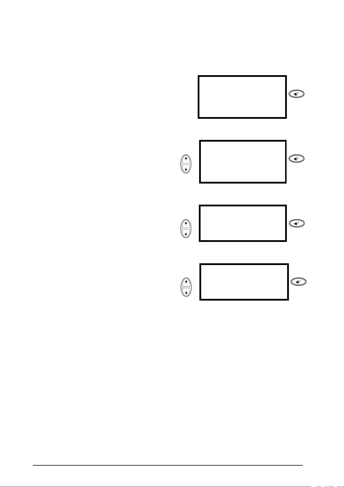
1.FromtheOverviewScreen,pressENTER.
Use
Chrgxxx%
Loadxxx%
xxxVinxxxVoutxxHz
Runtime:xxhrxxmin
Press
2.GotoControlbyusingtheUP/DOWN
navigationkeysandpressENTER.Use
→ControlLogging
StatusDisplay
SetupDiags
LCMHelp
Press
3.GotoTurnLoadOFFbyusingtheUP/DOWN
navigationkeysandpressENTER.Use→TurnLoadOffPress
4.GotoYES,TurnLoadOFFbyusingthe
UP/DOWNnavigationkeysandpressENTER.UseConfirm:
TurnLoadOFF
NO,ABORT
→YES,TurnLoadOFF
Press
5.IftheUPSisrunninginparalleloperationthis
proceduremustbecarriedoutoneachUPS.
990–2282E-001Smart-UPS™VT™10-40kV A380/400/415,200/208/220V19
TurnLoadOn–ConnecttheUPSOutputtotheLoadEquipment
1.FromtheOverviewScreen,pressENTER.
Chrgxxx%
Loadxxx%
xxxVinxxxVoutxxHz
Runtime:xxhrxxmin
Press
2.GotoControlbyusingtheUP/DOWN
navigationkeysandpressENTER.Use→ControlLogging
StatusDisplay
SetupDiags
LCMHelp
Press
3.GotoY es,TurnLoadONbyusingthe
UP/DOWNnavigationkeysandpressENTER.Use→TurnLoadOnPress
4.GotoTurnLoadONbyusingtheUP/DOWN
navigationkeysandpressENTER.
UseConfirm:
TurnLoadOFF
NO,ABORT
→YES,TurnLoadON
Press
5.IftheUPSisrunninginparalleloperationthis
proceduremustbecarriedoutoneachUPS.
ViewtheStatusScreens
1.FromtheOverviewScreen,pressENTER.
Use
Chrgxxx%
Loadxxx%
xxxVinxxxVoutxxHz
Runtime:xxhrxxmin
Press
2.GotoStatusbyusingtheUP/DOWN
navigationkeysandpressENTER.UseControlLogging
→StatusDisplay
SetupDiags
LCMHelp
Press
20Smart-UPS™VT™10-40kV A380/400/415,200/208/220V990–2282E-001

3.UsetheUP/DOWNkeystogothroughthe
belowparametersandpresstheESCkeyto
returntothepreviousmenus.
ViewParameters
V oltageonallphasesUtility/mainsvoltage(V),bypassvoltage(V),and
outputvoltage(V)foreachphase.
CurrentonallphasesUtility/mainscurrent(A),bypasscurrent(A),andoutput
current(A)foreachphase.
kV AandkWApparentpower(kV A)andrealpower(kW)generated
bytheUPSandtheconnectedload.
FrequenciesUtility/mainsfrequency,bypassfrequency,andoutput
frequencyinHertz(Hz).
LoadandbatteriesLoad:PercentageoftheloadinrelationtothetotalUPS
capacity.
BatV oltageShowseitherthepositiveornegativehalfofthebattery
voltage(thelowervalueofthetwowillappear).
BatCapPercentagechargeonthebatteriesinrelationtothetotal
batterycapacity.
Runtime:Thepredictedruntimeatthepresentload.
BatteriesBatAmpHr:Batterycapacity,includingbothexternal
andinternalbatteries.UPSTemp:Thehighestexternal
batterytemperature.
AlarmthresholdsLoad:Analarmwillbesetwhentheloadisabovethe
thresholdlevel.
Runtime:Analarmwillbesetwhentheruntimeis
belowthethresholdlevel.
ParallelStatusLocalUPSisslave/master:
#ofUPSsOK:IndicatesthenumberofparallelUPS
unitsthatisOK
#ofUPSsfail:IndicatesthenumberofparallelUPS
thathasfailed.
ParloadStatusKV AandKW:Totalapparentpower(kV A)andreal
power(kW)generatedbytheparallelUPSunitsandthe
connectedload.
Parredundancy:n+1,analarmwillbesetifthe
redundancylevelisbelowthethresholdlevel.
ParallelOperationModeTheparalleloperationmodecanbeoff,loadon,
requestedbypass,inbypassduetofaultormaintenance.
990–2282E-001Smart-UPS™VT™10-40kV A380/400/415,200/208/220V21
ViewLogging
Viewthe100mostrecentUPSlogevents,andviewtheloggeddetailsoftheevents,suchasdate,timeof
occurrence,andeventnumber.
1.FromtheOverviewScreen,pressENTER.
Chrgxxx%
Loadxxx%
xxxVinxxxVoutxxHz
Runtime:xxhrxxmin
Press
2.GotoLoggingbyusingtheUP/DOWN
navigationkeysandpressENTER.Use
Control→Logging
StatusDisplay
SetupDiags
LCMHelp
Press
3.GotoViewLogbyusingtheUP/DOWN
navigationkeysandpressENTER.Use
→Viewlog
Clearlog
Viewstatistics
Press
4.GotoOnLinebyusingtheUP/DOWN
navigationkeysandpressENTER.Use
24-Sep15:06:48#15
MainsoutofRange
→OnLine
Press
LoggingScreen(example)
5.Thetoplinestatesdate,time,andeventnumber.
Lines2,3,and4arepartoftheeventlist.To
viewtheentirelist:UsetheUP/DOWNkeysto
gothroughthelogeventsandpressENTERto
getadetaileddescriptionofaparticularevent.
22Smart-UPS™VT™10-40kV A380/400/415,200/208/220V990–2282E-001

ViewStatistics
Viewthestatisticsontheoperationmodechanges,theinvertertime,andthedurationofbatteryoperation.
1.FromtheOverviewScreen,pressENTER.
Chrgxxx%
Loadxxx%
xxxVinxxxVoutxxHz
Runtime:xxhrxxmin
Press
2.GotoLoggingbyusingtheUP/DOWN
navigationkeysandpressENTER.UseControl→Logging
StatusDisplay
SetupDiags
LCMHelp
Press
3.GotoViewStatisticsbyusingtheUP/DOWN
navigationkeysandpressENTER.
Use
Viewlog
Clearlog
→Viewstatistics
Press
990–2282E-001Smart-UPS™VT™10-40kV A380/400/415,200/208/220V23
UsetheDiagsScreen
Viewtroubleshootinginformation
1.FromtheOverviewScreen,pressENTER.
Chrgxxx%
Loadxxx%
xxxVinxxxVoutxxHz
Runtime:xxhrxxmin
Press
2.GotoDiagsbyusingtheUP/DOWNnavigation
keysandpressENTER.UseControlLogging
StatusDisplay
Setup→Diags
LCMHelp
Press
3.GotoFault&Diagnosticsbyusingthe
UP/DOWNnavigationkeysandpressENTER.Use→Fault&Diagnostics
SystemInformation
Switchstatus
RawStatusData
Press
Note:FormoredetailsontheFaultandDiagnosticsscreens,seethesection
“Troubleshooting“.
24Smart-UPS™VT™10-40kV A380/400/415,200/208/220V990–2282E-001
Conguration
Settings
ChangetheClock,theAlarmThresholds,andtheDustFilterStatus
Dustlter
Resetdustlter
Load
ShutdownRuntime
DefaultPar.redund.
System
Overview
ScreenAlarms
Clock
Other
SetupSettings
Chrgxxx%
Loadxxx%
xxxVinxxxV out
xxHz
Runtimexxhr
Control
Status
Setup
LCM
Logging
Display
Diags
Help
MainMenuScreen
990–2282E-001Smart-UPS™VT™10-40kV A380/400/415,200/208/220V25
Clock
TheClockmenuchangesthedateandtheclocksettingsandittime-stampseventsintheeventlog.To
avoidinaccuracies,changetheclock-settingatdaylight-savingtime.
1.FromtheOverviewScreen,pressENTER.
Chrgxxx%
Loadxxx%
xxxVinxxxVoutxxHz
Runtime:xxhrxxmin
Press
2.GotoSetupbyusingtheUP/DOWNnavigation
keysandpressENTER.UseControlLogging
StatusDisplay
→SetupDiags
LCMHelp
Press
3.GotoClockbyusingtheUP/DOWNnavigation
keysandpressENTER.UseSettings:
ShutdownAlarms
Default→Clock
SystemOther
Press
4.PressENTER.
→Date:24-Sep-2010
Time:13:45:51
Press
5.Thedayisnowactive.UsetheUP/DOWN
navigationkeystosetthedateandpress
ENTER.Use
→Date:24-Sep-2010
Time:13:28:00
Press
6.Themonthisnowactive.UsetheUP/DOWN
navigationkeystosetthemonth,pressENTER
anddothesametosettheyear,andpress
ENTER.
Use
→Date:24-Sep-2010
Time:13:28:00
Press
26Smart-UPS™VT™10-40kV A380/400/415,200/208/220V990–2282E-001
7.PresstheDOWNnavigationkeytoactivatethe
Timeline.Use
Date:24-Sep-2010
→Time:13:28:00
Press
8.TheproceduretochangetheTimefeaturesis
thesameasdescribedfordate,month,andyear.Press
DustFilter
Note:WhenadustlterisinstalledforthersttimeorwhenaUPSisinstalledwithfactory
pre-installeddustlter,thenthedustltersurveillanceshouldbeenabled.Theparameters
areHigh,Medium,orLow.AHighparameterselectionisforheavydustenvironments
andwillprompttheusertoreplacethedustlterafter90days.AMediumparameter
selectionwillprompttheusertoreplacethedustlterafter120daysandaLowparameter
selectionwillprompttheusertoreplacethedustlterafter150days.Apre-warningwill
appearvedaysbeforetheltermustbereplaced.Ifalterneedsreplacement,(whenthe
existinglterislledwithdustandanalarmhasbeeninitiated)thenyoumustreplacethe
lterandmakesurethattheResetdustltersettingissettoY es.Firmwareupgradeor
enablingthedustltersurveillanceisnotapplicableforUPSmodelswhichdonothavethe
capabilityofrunninginparallel.
1.FromtheOverviewScreen,pressENTER.
Chrgxxx%
Loadxxx%
xxxVinxxxVoutxxHz
Runtime:xxhrxxmin
Press
2.GotoSetupbyusingtheUP/DOWNnavigation
keysandpressENTER.UseControlLogging
StatusDisplay
→SetupDiags
LCMHelp
Press
3.GotoSystembyusingtheUP/DOWN
navigationkeysandpressENTER.UseSettings:
ShutdownAlarms
DefaultClock
→SystemOther
Press
990–2282E-001Smart-UPS™VT™10-40kV A380/400/415,200/208/220V27
4.GotoDustlterbyusingtheUP/DOWN
navigationkeysandpressENTER.UseUPS#:xx↑
#ofUPSs:x0x
MBPboard:xx
→DustfilterOff↓
Press
Note:Thedefaultsetting
ofthedustlteralarmis
“off”.Bychoosingoneofthe
threeparameters(“High”,
“Medium”,or“Low”)thedust
ltersurveillanceisautomatically
turnedon.
5.GotoDustlter:High,Medium,LoworOff
byusingtheUP/DOWNnavigationkeysand
pressENTER.UseUPS#:xx↑
#ofUPSs:xx
MBPboard:xx
→DustfilterHigh↓
Press
Note:Thedustltersurveillance
mustberesetaftereverydustlter
replacementinorderfortheUPS
systemtoknowwhenthelter
needstobereplacedagain.
6.Resetthedustltersurveillance:Carryoutsteps
1–3aboveandthenproceedwiththebelow
steps.
7.GotoResetdustlbyusingtheUP/DOWN
navigationkeysandpressENTER.
Use
→Resetdustfil:No↑
Press
8.GotoResetdustl:Y esbyusingthe
UP/DOWNnavigationkeys,andpress
ENTER.Note!ThemenuwillfallbacktoNo
afterafewseconds.Nowtheltertimerisreset.
Use
↕Resetdustfil:Yes↑
Press
AlarmThresholds
TheprocedureforchangingtheAlarmthresholdsisthesameasdescribedundertheClockchanges.
Beawareofthebelownotes.
Note:Iftheloadlevelexceedsthepre-programmedthreshold,theUPSwilldisplaya
warning.
28Smart-UPS™VT™10-40kV A380/400/415,200/208/220V990–2282E-001
Note:Redundancy:Thestateofredundancythatwilltriggeranalarm.Choicesare:
•N+0–Thepowerrequirementexceedstheredundancylimit:Redundancyisnotavailable.
•N+1–Thepowerrequirementdoesnotutilizethelastunit:Redundancyisavailable.
•N+2–Thepowerrequirementdoesnotutilizethelasttwounits:Redundancyisavailable.
•N+3–Thepowerrequirementdoesnotutilizethelastthreeunits:Redundancyis
available.
ChangetheBeeperSetup,theContrast,andtheLanguage
OverviewScreen
Chrgxxx%
Loadxxx%
xxxVinxxxV out
xxHz
Runtimexxhr
Beepersetup
Contrast
Language
DisplayDisplaysetup
Control
Status
Setup
LCM
Logging
Display
Diags
Help
MainMenuScreen
WorkyourwaythroughthemenuscreensandmakeyourchangeswiththeUP/DOWNandthe
ENTERkeysasdescribedfortheClockandtheAlarmsintheSettingsmenu.
TheBeepersetup
IntheBeepersetupyoucanchoosebetweenthefollowingoptions:
•Never:Ifyouselectthissetting,thebeeperwillbeactiveatinternalUPSerrorsonly.
•PwrFail+30:Ifyouselectthissetting,thebeeperwillbeactiveatinternalUPSerrorsandat
utility/mainsorbypasserrors.Thebeeperwillonlysoundifthefaulthasbeenpresentformore
than30seconds.
•PwrFail:Ifyouselectthissetting,thebeeperwillbeactiveatinternalUPSerrorsandatutility/mains
orbypasserrors.Thebeeperwillsoundimmediatelywhentheerrorisoccurring.
•LOWBATT:Ifyouselectthissetting,thebeeperwillbeactiveatinternalUPSerrorsatutility/mains
orbypasserrors,atpowerfailures,andatalowbatterylevel(iftheUPSrunsinbatteryoperation).
990–2282E-001Smart-UPS™VT™10-40kV A380/400/415,200/208/220V29

Maintenance
WARNING:Forsafetyreasons,onlyqualiedpersonnelisallowedtoperformthe
replacementproceduresdescribedinthischapter.
PartsReplacement
DetermineifyouNeedaReplacementPart
Todetermineifyouneedareplacementpart,contactAPCCustomerSupportandfollowtheprocedure
belowsothattheAPCCustomerSupportrepresentativecanassistyoupromptly:
1.Intheeventofamodulefailure,thedisplayinterfacemayshowadditional“faultlist”screens.
Pressanykeytoscrollthroughthesefaultlists,recordtheinformation,andprovideittothe
representative.
2.Writedowntheserialnumberoftheunitsothatyouwillhaveiteasilyaccessiblewhenyou
contactAPCCustomerSupport.
3.Ifpossible,callAPCCustomerSupportfromatelephonethatiswithinreachoftheUPSdisplay
interfacesothatyoucangatherandreportadditionalinformationtotherepresentative.
4.Bepreparedtoprovideadetaileddescriptionoftheproblem.Arepresentativewillhelpyousolve
theproblemoverthetelephone,ifpossible,orwillassignaReturnMaterialAuthorization(RMA)
numbertoyou.IfamoduleisreturnedtoAPC,thisRMAnumbermustbeclearlyprintedon
theoutsideofthepackage.
5.Iftheunitiswithinthewarrantyperiod,repairsorreplacementswillbeperformedfreeofcharge.
Ifitisnotwithinthewarrantyperiod,therewillbeacharge.
6.IftheunitiscoveredbyanAPCservicecontract,havethecontractavailabletoprovide
informationtotherepresentative.
ReturnPartstoAPC
CallAPCCustomerSupporttoobtainanRMAnumber.
ToreturnafailedmoduletoAPC,packthemoduleintheoriginalshippingmaterials,andreturnitby
insured,prepaidcarrier.TheAPCCustomerSupportrepresentativewillprovidethedestinationaddress.If
younolongerhavetheoriginalshippingmaterials,asktherepresentativeaboutobtaininganewset.Pack
themoduleproperlytoavoiddamageintransit.Neverusestyrofoambeadsorotherloosepackaging
materialswhenshippingamodule,asthemodulemaysettleintransitandbecomedamaged.Enclose
aletterinthepackagewithyourname,RMAnumber,address,acopyofthesalesreceipt,descriptionof
theproblem,aphonenumber,andacheckaspayment(ifnecessary).
Note:Damagessustainedintransitarenotcoveredunderwarranty.
30Smart-UPS™VT™10-40kV A380/400/415,200/208/220V990–2282E-001
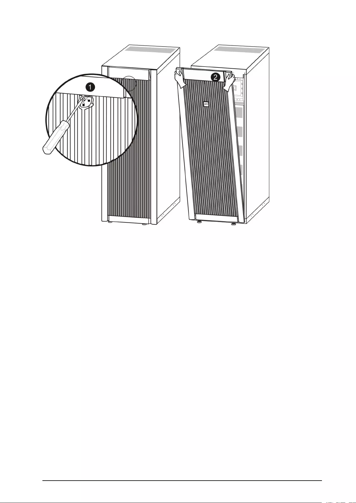
RemovetheFrontPanel
1.Turnthescrewtotherighttotheunlockedposition.
2.PullthetopofthefrontpanelawayfromtheUPS.
3.Liftthefrontpanelfreeofthetwoslotsatthebottomoftheenclosure.
4.Liftthebatterycompartmentcoverfreeofthetwoslotsatthebottomoftheenclosure(only
applicableinJapanesecongurations).
990–2282E-001Smart-UPS™VT™10-40kV A380/400/415,200/208/220V31
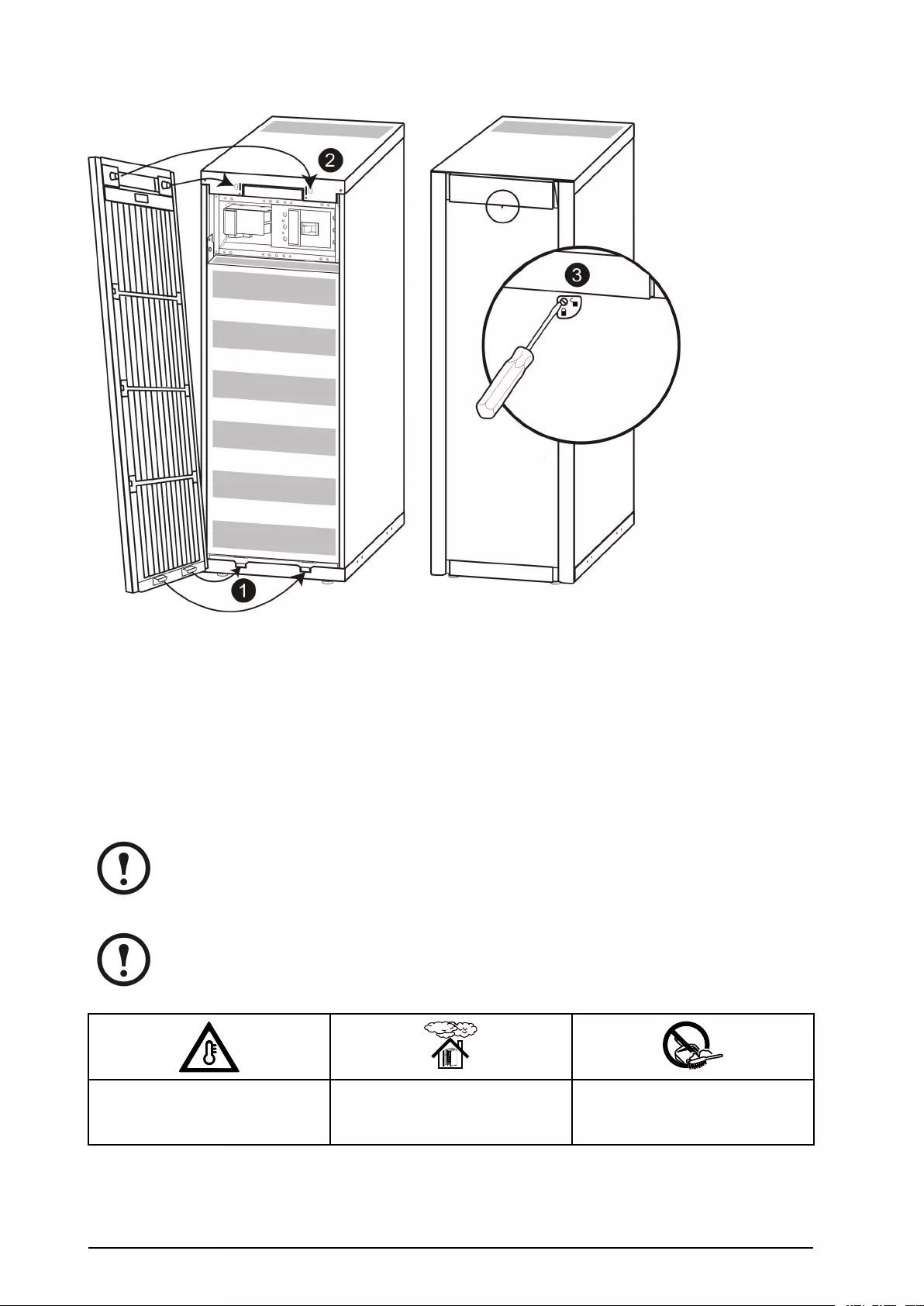
InstalltheFrontPanel
1.Reinstallthefrontpanelbyinsertingthetwotapsatthebottomofthefrontpanel.(ForJapanese
congurations,youmustrstreinstallthebatterycompartmentcoverintothetwoslotsatthe
bottomoftheenclosure).
2.Pushthefrontpanelforwarduntilitengagesthelockingdevicesatthetopoftheenclosure.
3.Useascrewdrivertosetthelockmechanismtothelockedposition.
StoretheBatteriesandtheUPSSystem
Note:Thebatterymodulesmustbestoredindoorsandwiththeirprotectivepackagingstill
inplace.
Note:Storedbatteriesshouldberechargedatregularintervals,dependingonthestorage
temperature:
Ambienttemperature:
-15°Cto40°C/
5°Fto104°F
RelativeHumidity:
0-95%Non-condensing
Storageplacefreefromvibration,
conductivedust,directsunlight,and
moisture.
32Smart-UPS™VT™10-40kV A380/400/415,200/208/220V990–2282E-001
StorageTemperatureRechargeInterval
-15°to20°C/5°Fto68°F9months
20°to30°C/68°Fto86°F6months
30°to40°C/86°Fto104°F3months
Caution:Donotstorethebatteriesformorethan12months.
StoretheDustFilter
Ambienttemperature:
4°Cto32°C/
40°Fto90°F
RelativeHumidity:
40%–90%Non-condensing
User-ReplaceableParts(onlyQualiedPersonnel)
PartAPCPartNos.
BatteryModuleSYBT4
NetworkManagementCardwithtemperaturesensorAP9631
Dustlterkitforlow,narrow(352mm)UPSenclosures
(10,15,and20kV A)
SUVTOPT012
Dustlterkitforlow,wide(523mm)UPSenclosures
(30and40kV A)
SUVTOPT013
Note:APCrecommendsthatawholebatterymodule(fourbatteries)isreplacedatthesame
timetoensureoptimalruntime.However,itisonlynecessarytoreplacetwobatteriesatthe
sametime.See“DirectionsforReplacement“.
990–2282E-001Smart-UPS™VT™10-40kV A380/400/415,200/208/220V33
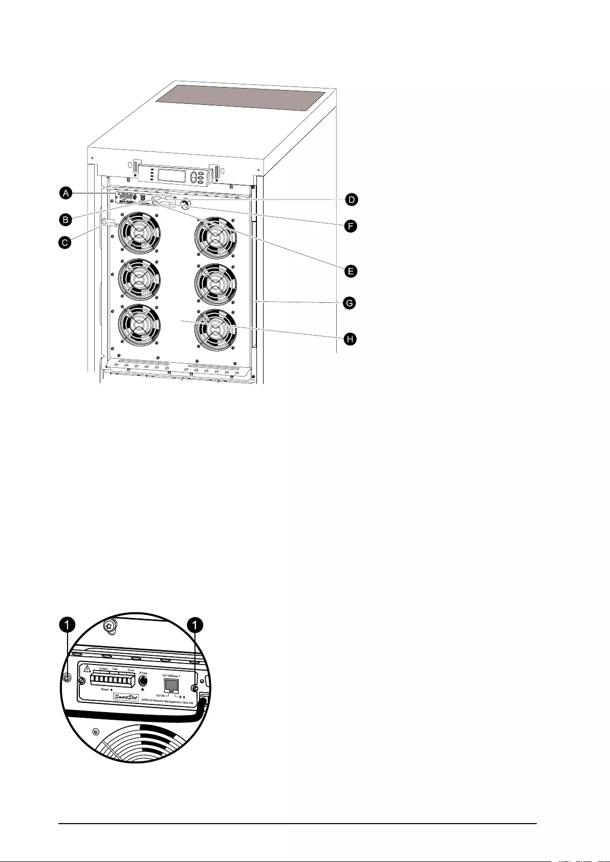
UserInterface(Front)
A.NetworkManagementCardwithtemperaturesensor:usedforremotesystemcontroland
monitoring,e-mailnoticationsetc.Forcongurationanduse,refertotheseparateusermanual:
NetworkManagementCardwithEnvironmentalMonitor–shippedwiththeUPS.
B.Computer-interfaceportfortheconnectionofcomputerswithAPCPowerchute®software.
C.Internalmechanicalbypasslever:usedtobypasstheupstreamutility/mainspoweraroundtheUPS
tosupporttheloaddirectly=internalbypassoperation.Notapplicableinparallelsystems.
D.Serviceport(forAPCmaintenancepersonnelonly).
E.Displayportfortheconnectionofdisplaycommunicationcable.
F.Paralleloperationport.
G.Documentationstorage.
H.Powermodule.
ReplaceaNetworkManagementCard
10/100Base-T
Probe
AP9619NetworkManagementCardEM
!
Reset
Output Pwr Zone
10/100
6
1
16
1
1
1.LoosenthetwoTorxscrews(oneoneachsideofthecard).
2.Carefullypulloutthecard.
34Smart-UPS™VT™10-40kV A380/400/415,200/208/220V990–2282E-001

3.Installthenewcard.
4.ReattachthetwoTorxscrews.
Install/replaceaDustFilter
Note:DustltersareonlyavailableforthetwolowSmart-UPSVTversionswithout
batteries.
Note:Onlygraphicsofthelowandwide(523mm)Smart-UPSVTenclosureareshown,but
theproceduresapplytobothenclosuresizes.
WARNING:OnlytrainedpersonnelfamiliarwiththeconstructionoftheUPSmay
installandremoveadustlter.
Caution:Thedustltermustbeinstalledinthefrontpanelbykeepingthefrontpanel
onalevelledoor.
Note:Donotreusethelterbycleaningthedustinthelter.
Note:Fornon-parallelversions(forwhichdustltersurveillanceisinapplicable)the
dustltermustbecheckedperiodicallyandiftheltershowsvisiblehighsignsofdust
accumulation,itmustbereplaced.
990–2282E-001Smart-UPS™VT™10-40kV A380/400/415,200/208/220V35
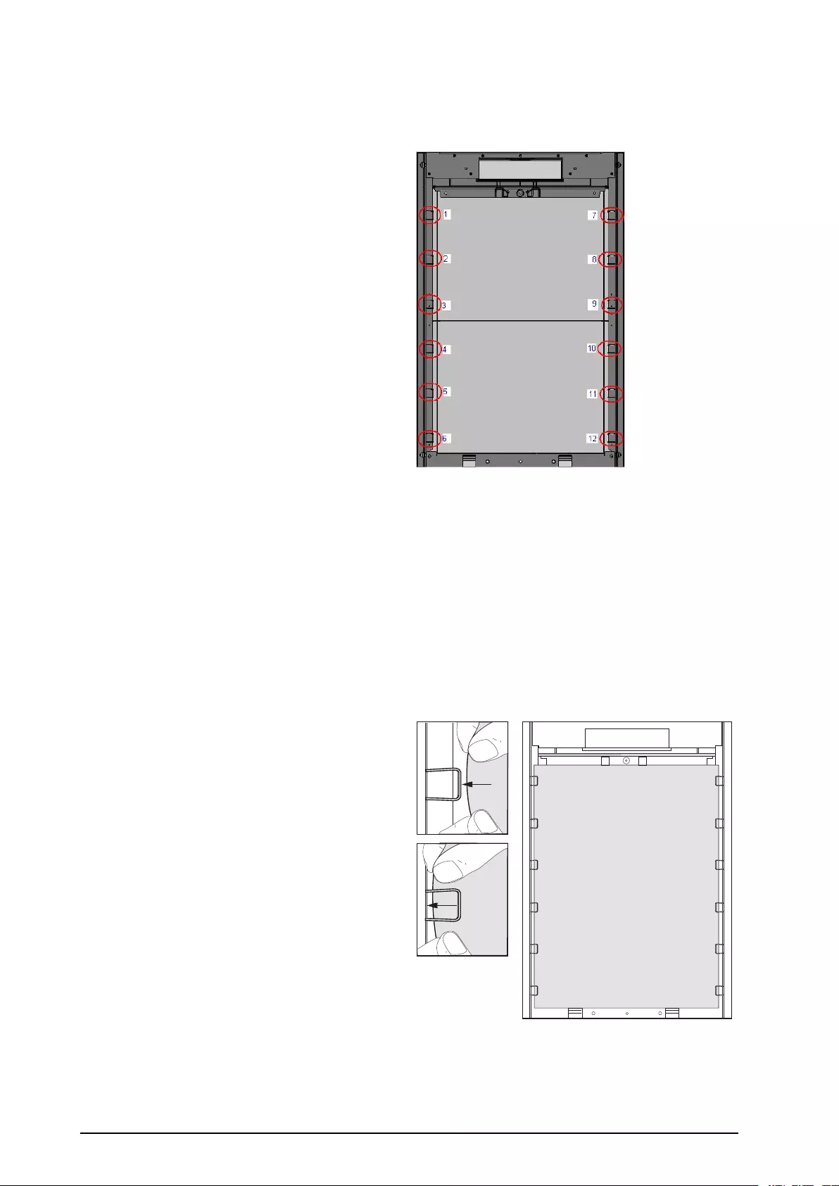
Installation–InsertFilterClips
1.Removethefrontpanel.See“Removethe
FrontPanel“.
2.Opentheairlterkitandinsert12clipsinthe
locationsshowninthedrawing.
Installation–InsertDustFilter
1.Removethefrontpanel.See“Removethe
FrontPanel“.
2.Removethedustonthefrontpanelbyusinga
brushorairblower.Whilecleaningthefront
panel,keepthefrontpanelawayfromtheUPS.
3.Insertlterclipsifnotalreadydoneatthispoint.
See“Installation–InsertFilterClips“step2.
4.Pressandslidethelterundereachclipstarting
fromthetopandworkingyourwaydown.
000000000000
000000
000000
000000
000000
000000000000
000000
000000
000000
000000
5.Installthefrontpanel.See“InstalltheFront
Panel“.
6.Enablethedustltersurveillance.See“Dust
Filter“.
36Smart-UPS™VT™10-40kV A380/400/415,200/208/220V990–2282E-001
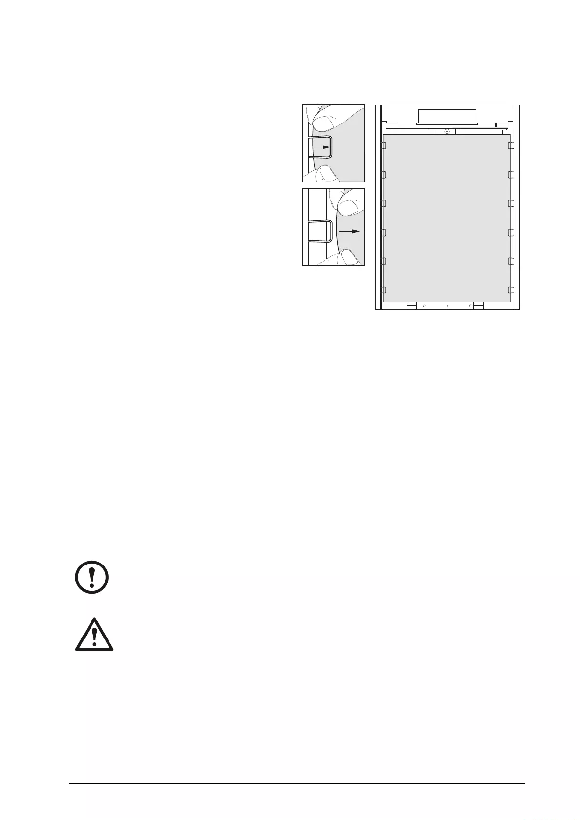
Replacement–ReplaceDustFilter
1.Removethefrontpanel.See“Removethe
FrontPanel“.
2.Removethelterbyslidingitoutunderthe
clips.Keeptheclipsattachedtotheenclosure.
000000000000
000000
000000
000000
000000
000000000000
000000
000000
000000
000000
3.Removethedustonthefrontpanelbyusinga
brushorairblower.Whilecleaningthefront
panel,keepthefrontpanelawayfromtheUPS.
4.Takethenewdustlterfromthekit.
5.Insertthenewdustlter.See“Installation–
InsertDustFilter“,fromstep2.
6.Installthefrontpanel.See“InstalltheFront
Panel“.
7.Resetthedustltersurveillance.See“Dust
Filter“,fromstep6.
8.Disposetheoldlterappropriately.
ReplaceaBatteryModule
Generalsafetypriortobatterymodulereplacement
Note:Whenreplacingbatterymodules,replacewithsamepartnumber.
Caution:Batteriesmustbereplacedbyqualiedpersonnelonly.
990–2282E-001Smart-UPS™VT™10-40kV A380/400/415,200/208/220V37
Caution:
Servicingofbatteriesshouldbeperformedorsupervisedbypersonnelknowledgeableof
batteriesandtherequiredprecautions.Keepunauthorizedpersonnelawayfrombatteries.
Donotdisposeofbatteryorbatteriesinare.Thebatterymayexplode.
Donotopenormultilatethebatteryorbatteries.Releasedelectrolyteisharmfultotheskin
andeyes.Itmaybetoxic.
Abatterycanpresentariskofelectricalshockandhighshortcircuitcurrent.Thefollowing
precautionsshouldbeobservedwhenworkingonbatteries:
•Removewatches,rings,orothermetalobjects.
•Usetoolswithinsulatedhandles.
•Wearrubberglovesandboots.
•Donotlaytoolsormetalpartsontopofbatteries.
•Disconnectchargingsourcepriortoconnectingordisconnectingbatteryterminals.
Caution:Usetwopeopletoliftcomponentsweighingbetween18–32kg/40–70lb.
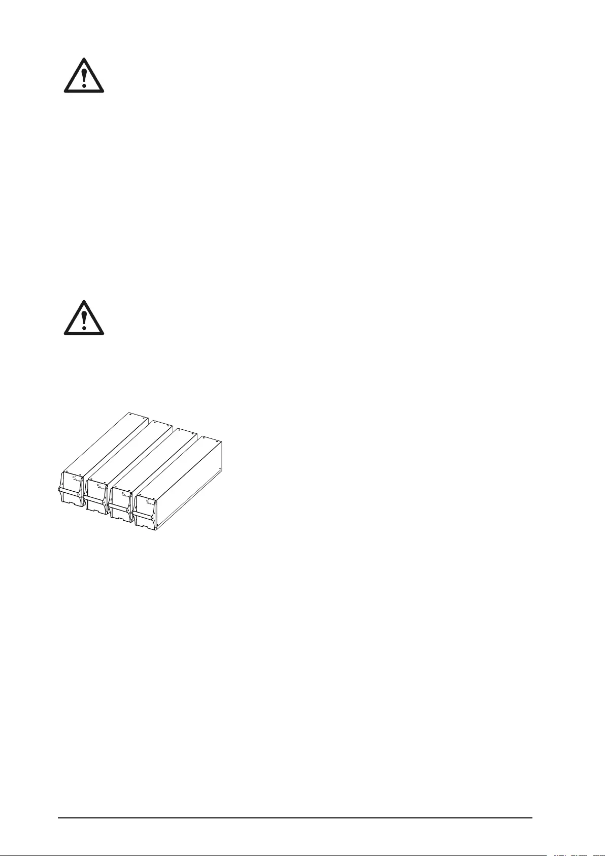
BatteryModule
Onebatterymoduleconsistsoffourbatteryunits(shippingintheenclosures).
Model:
Serial:
BATTERY UNIT
Model:
Serial:
BATTERY UNIT
Model:
Serial:
BATTERY UNIT
Model:
Serial:
BATTERY UNIT
4x24kg/4x53lbs
RemoveandInstallBatteryLocks
Ifyoursystemisequippedwithbatterylocks,followthebelowproceduretoremovethebatterylocks.
38Smart-UPS™VT™10-40kV A380/400/415,200/208/220V990–2282E-001
1.RemovetheM6screwattachingthebatterylock
totheshelf.
6
1
1
6
1
2
2.Pushthebatterylocktotheleft,pushitupwards
andremove.
3.Usethereverseprocedurefortheinstallationof
batterylocks.
BatteryReplacement
Caution:Batteriesmustbereplacedbyqualiedpersonnelonly“ReplaceaBattery
Module“.
DirectionsforReplacement
APCrecommendsthatawholebatterymodule(fourbatteries)isreplacedatthesametimetoensure
optimalruntime(seeExample1).However,itisonlynecessarytoreplacetwobatteriesatthesametime
accordingtoExample2and3inthebelowtables.
523mm/(20in)
Enclosure
ColumnAColumnBColumnCColumnD
Example1NewNewNewNew
Example2NewNewOldOld
Example3OldOldNewNew
352mm/(14in)EnclosureColumnAColumnB
NewNew
Example1
NewNew
NewNew
Example2
OldOld
OldOld Example3
NewNew
Followthebelowproceduresifyouneedtochangeoraddabatterymodule,e.g.ifyoureceiveadisplay
messagereportingabadbattery,orifyouneedtoaddbatteriesforincreasedruntime.
990–2282E-001Smart-UPS™VT™10-40kV A380/400/415,200/208/220V39
Model:
Serial:
BATTERY UNIT
Model:
Serial:
BATTERY UNIT
Model:
Serial:
BATTERY UNIT
Model:
Serial:
BATTERY UNIT
Model:
Serial:
BATTERY UNIT
Model:
Serial:
BATTERYUNIT
Model:
Serial:
BATTERY UNIT
Model:
Serial:
BATTERY UNIT
Model:
Serial:
BATTERY UNIT
Model:
Serial:
BATTERYUNIT
Model:
Serial:
BATTERY UNIT
Model:
Serial:
BATTERYUNIT
Model:
Serial:
BATTERYUNIT
Model:
Serial:
BATTERY UNIT
Model:
Serial:
BATTERY UNIT
Model:
Serial:
BATTERY UNIT
Model:
Serial:
BATTERY UNIT
Model:
Serial:
BATTERY UNIT
Model:
Serial:
BATTERY UNIT
Model:
Serial:
BATTERY UNIT
Model:
Serial:
BATTERY UNIT
Model:
Serial:
BATTERY UNIT
Model:
Serial:
BATTERYUNIT
Model:
Serial:
BATTERY UNIT
Model:
Serial:
BATTERYUNIT
Model:
Serial:
BATTERYUNIT
Model:
Serial:
BATTERYUNIT
Model:
Serial:
BATTERY UNIT
Model:
Serial:
BATTERY UNIT
Model:
Serial:
BATTERY UNIT
Model:
Serial:
BATTERY UNIT
Model:
Serial:
BATTERYUNIT
Model:
Serial:
BATTERY UNIT
Model:
Serial:
BATTERY UNIT
Model:
Serial:
BATTERY UNIT
10/100Base-T
Probe
AP9619NetworkManagementCardEM
!
Reset
Output Pwr Zone
10/100
Model:
Serial:
BATTERY UNIT
Model:
Serial:
BATTERYUNIT
Model:
Serial:
BATTERY UNIT
Model:
Serial:
BATTERY UNIT
Model:
Serial:
BATTERY UNIT
6
1
1
6
1
2
6
1
3
6
1
1
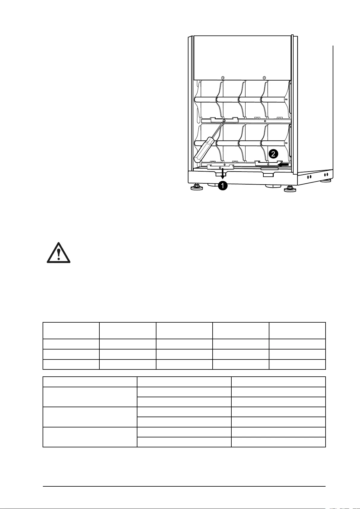
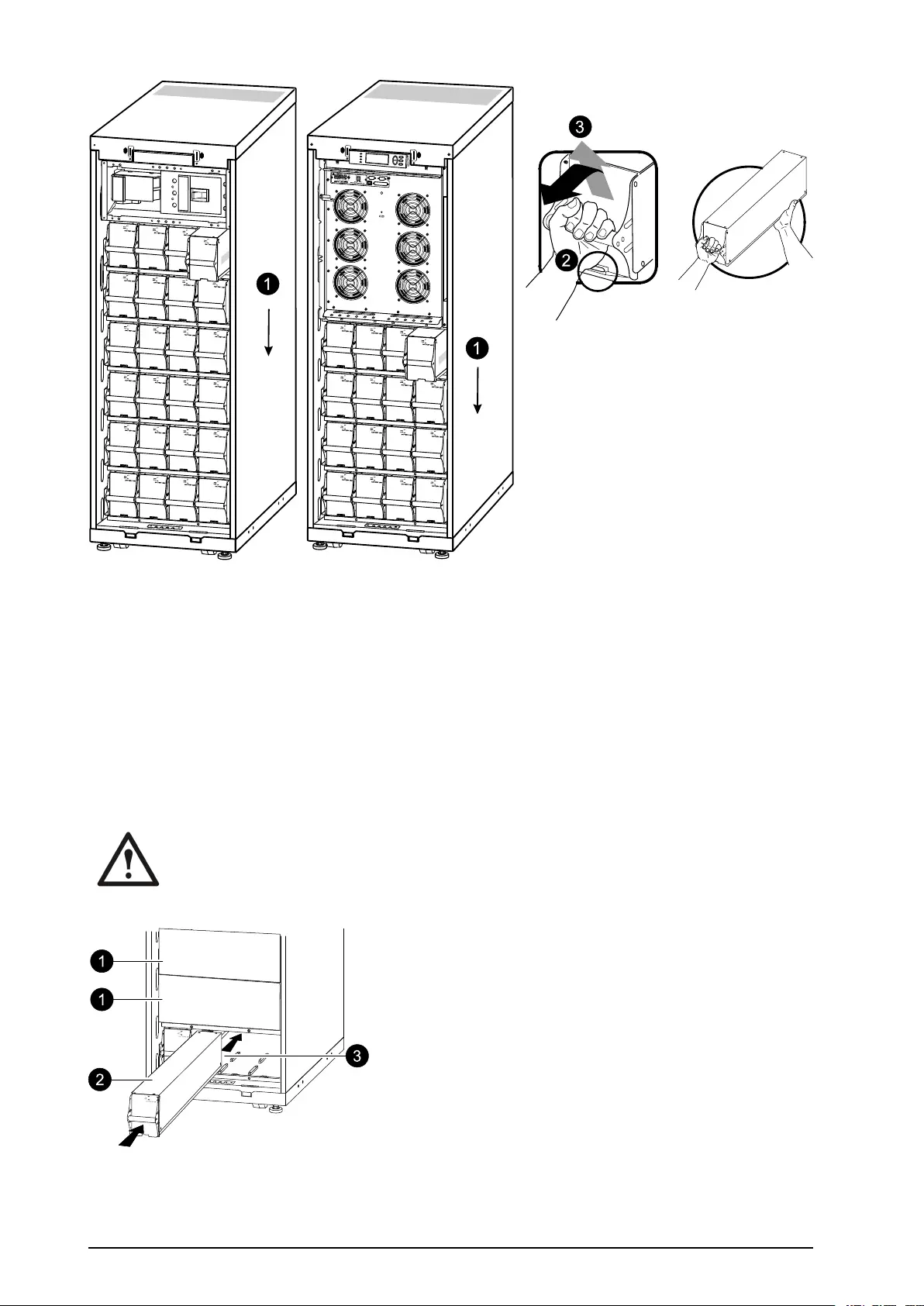
1.Whenremovingbatterymodules,startfromthehighestlevelandworkdown.
2.Holdingthebatteryhandle,gentlypushthebatteryupwardsandpullithalfwayoutofthe
enclosure.Alockmechanismpreventsitfrombeingpulledallthewayout.
3.Toreleasethebatteryfromthelockmechanism,gentlypushthebatteryupwardsagainandpullit
out,whileanotherpersonsupportsthebattery.
Installation
Ifadditionalbatteriesareneededforextraruntime,orifyouinstallbatteryreplacementmodules,be
awareofthefollowing:
Caution:DonotinstallbatterymodulesintheUPSuntilyouarereadytopowerupthe
system.Disregardingthiscautioncanresultinadeepdischargeofthebatteriesandcause
permanentdamage.ThetimebetweenbatteryinstallationandpoweringuptheUPSshould
notexceed72hours/threedays.
1.Removepossibleblindplateinfrontofpossibleemptybatteryshelves(savethescrewsforlater
use).
40Smart-UPS™VT™10-40kV A380/400/415,200/208/220V990–2282E-001

2.Installthebatterymoduleinthelowestavailablebay(fouracrossin523mm/(20in)UPSversions,
twoacrossin352mm/(14in)UPSversions).
3.PositionthebatteryunittoslideinbetweenthegroovesandpushitcompletelyintotheUPS
toensureconnection.
Note:Ifaproblemisreported,ensurethatthemodulesinquestionarecorrectlyinstalled.If
theproblempersists,seethesection“Troubleshooting”onpage35.
Note:Allowfora24-hourrechargingperiodofthebatteriesaftersystemstart-up.
990–2282E-001Smart-UPS™VT™10-40kV A380/400/415,200/208/220V41

Troubleshooting
StatusandAlarmMessages
ThissectionliststhestatusandalarmmessagesthattheUPSmightdisplay.Themessagesare
listedinalphabeticalorder,andasuggestedcorrectiveactionislistedwitheachalarmmessage
tohelpyoutroubleshootproblems.
DisplayMessages
DisplayMessageMeaningCorrectiveAction
AutomaticSelfTestStarted.TheUPShasstarted
pre-programmedbatterytest.
Nocorrectiveactionisnecessary.
ABusCommunicationFault.Communicationfaultdetectedon
theABus.
CheckABuswiring.Ifthisdoesnot
helpcontactAPC.
ABusTerminationFault.ABusterminationismissing.Checkifterminationispresent.If
thisdoesnothelpcontactAPC.
BattTemperatureExceededUpper
Limit.
Thetemperatureofoneormore
batteryunitshasexceededthe
systemspecications.
ContactAPCCustomerSupport(see
thebackcover).
Batteryover-voltagewarning.Thebatteryvoltageistoohighand
thechargerhasbeendeactivated.
ContactAPCCustomerSupport(see
thebackcover).
BypassNotAvailableInput
Freq/V oltOutOfRange.
Thefrequencyorvoltageisoutof
acceptablerangeforbypass.This
messageoccurswhentheUPS
isonline,andindicatesthatthe
bypassmodemaynotbeavailable
ifrequired.
Correcttheinputvoltagetoprovide
anacceptablevoltageorfrequency.
BatteryDischarged.TheUPSisinbatteryoperationand
thebatterychargeislow.Note:
Runtimeislimitedinduration.
Nocorrectiveactionisnecessary.
Shutdownthesystemandtheload
equipmentorrestoreincoming
voltage.
EmergencyPSUFault.TheredundantEmergencyPower
SupplyUnit(PSU)isnotworking.
TheUPSwillcontinuetowork
normally,butthePSUshouldbe
replaced.
ContactAPCCustomerSupport(see
thebackcover).
EPOActivated.TheEmergencyPowerOffswitch
hasbeenactivated.
DeactivatetheEmergencyPower
Offswitch.
Fanfault.Afanhasfailed.ContactAPCCustomerSupport(see
thebackcover).
Int.Mech.BypassSwitchClosed.Theinternalmechanicalswitchgear
isclosed.
Nocorrectiveactionnecessary.The
UPSisininternalmechanicalbypass
operation.
Int.Mech.BypassSwitchOpen.Theinternalmechanicalswitchgear
isOFF.
Nocorrectiveactionisnecessary.
Low-Battery.TheUPSisinbatteryoperationand
thebatterychargeislow.Note:
Runtimeislimitedinduration.
Shutdownthesystemandtheload
equipmentorrestoreincoming
voltage.
LoadIsNoLongerAboveAlarm
Threshold.
Theloadpreviouslyexceededthe
alarmthresholdandthesituationhas
beencorrectedeitherbecausethe
loaddecreasedorthethresholdwas
increased.
Nocorrectiveactionisnecessary.
42Smart-UPS™VT™10-40kV A380/400/415,200/208/220V990–2282E-001

DisplayMessageMeaningCorrectiveAction
LoadPowerIsAboveAlarm
Threshold.
Theloadhasexceededthe
user-speciedloadalarmthreshold.
Option1:Usethedisplayinterface
toraisethealarmthreshold.
Option2:Reducetheload.
MainsNotAvailable.Input
Freq/V oltOutofRange.
Thefrequencyorvoltageisout
ofacceptablerangefornormal
operation.
Correcttheinputvoltagetoprovide
acceptablevoltageorfrequency.
MinimumRuntimeRestored.Thesystemruntimedroppedbelow
theconguredminimumandhas
beenrestored.AdditionalBattery
Moduleswereinstalled,theexisting
BatteryModuleswererecharged,the
loadwasreduced,orthethreshold
wasdecreased.
Nocorrectiveactionisnecessary.
NoBatteriesAreConnected.Nobatterypowerisavailable.Checkthatthebatteriesareinserted
properly.
NoMasterisPresentintheParallel
System.
Noparallelmasterispresent.The
parallelsystemwillnotbeableto
functionproperly.
ContactAPCCustomerSupport(see
thebackcover).
NumberofBatteryModules
Decreased.
Oneormorebatterymoduleswere
removed.
Nocorrectiveactionisnecessary.
NumberofBatteryModules
Increased.
Oneormorebatterymoduleswere
added.
Nocorrectiveactionisnecessary.
OverloadonaParallelUnit.Oneormoresystemshasoverload.
Notethattheentireparallelsystem
willnotbeabletoreturnfrom
bypass.
Nocorrectiveactionisnecessary.
OrderStartupCheck.TheUPSsystemhasbeenonfor
vedays.
ContactAPCCustomerSupportto
verifytheinstallation(seetheback
cover).
OrderTechCheck.TheUPSsystemhasbeenonfor
fouryears.Atechnicalcheckis
recommended.
ContactAPCCustomerSupport(see
thebackcover).
PBusCommunicationFaulton
Cable1.
Communicationfaultdetectedon
PBus1.
CheckPBus1wiring.
IfthisdoesnothelpcontactAPC.
PBusCommunicationFaulton
Cable2.
Communicationfaultdetectedon
PBus2.
CheckPBus2wiring.
IfthisdoesnothelpcontactAPC.
PBusTerminationFaultonCable1.PBus1terminationismissing.Checkifterminationispresent.If
thisdoesnothelpcontactAPC.
PBusTerminationFaultonCable2.PBus2terminationismissing.Checkifterminationispresent.If
thisdoesnothelpcontactAPC.
ParallelCongurationFault.Theparallelsystemhasnotbeen
conguredcorrect.
ContactAPCCustomerSupport(see
thebackcover).
ParallelRedundancyRestored.Theparallelredundancyhasbeen
restored.
Nocorrectiveactionisnecessary.
ParallelRedundancyisbelowAlarm
Threshold
Theloadhasexceededtheuser
speciedloadalarmthreshold.
Option1:Usethedisplayinterface
toraisethealarmthreshold
Option2:Reducetheload.Parallel
redundancyisnowrestored.
ReplaceBatt(s).OneormoreBatteryModulesneed
replacement(onlyapplicablewith
internalbatteries).
Seethesection“Parts
Replacement“forprocedures.
990–2282E-001Smart-UPS™VT™10-40kV A380/400/415,200/208/220V43

DisplayMessageMeaningCorrectiveAction
RuntimeIsBelowAlarmThreshold.Thepredictedruntimeislowerthan
theuser-speciedminimumruntime
alarmthreshold.Eitherthebattery
capacityhasdecreased,ortheload
hasincreased.
Option1:Allowthebatterymodules
torecharge.
Option2:Ifpossible,increasethe
numberofbatterymodules.
Option3:Reducetheload.
Option4:Decreasethealarm
threshold.
ContactAPCCustomerSupport(see
thebackcover)
ShutdownDueToLowBattery.TheUPSwasinBatteryOperation
andshutdowntheloadwhenno
morebatterypowerwasavailable.
Nocorrectiveactionisnecessary.
Note:Iftheproblemreoccurs,
considerincreasingthebattery
capacity.
SiteWiringFault.Wrongphaserotationontheinput
side.TheUPSwillcontinueto
supplyconditionedpowerfrombatt.
Anelectricianshouldcheckthatthe
UPShasbeenwiredproperly.
StaticBypassSwitchFault.TheStaticBypassSwitchhasfailed.ContactAPCCustomerSupport(see
thebackcover).
SystemFailureDetectedby
Surveillance.
Thesystemhasdetectedaninternal
error.
Checkforotheralarmsandcontact
APCcustomersupportifthe
problempersists.
SystemStartUpConguration
Failed.
Systemcongurationerror.Unable
todeterminesystemvoltageand/or
enclosuresize.
Checkforotheralarmsandcontact
APCcustomersupportifthe
problempersists.
SystemNotSynchronizedtoBypass.Thesystemcannotsynchronize
tobypass.Themodemaynotbe
available.
Option1:Decreasetheinput
frequencysensitivity.
ContactAPCCustomerSupport(see
thebackcover)
Option2:Correctthebypass
inputvoltagetoprovideacceptable
voltageorfrequency.
Thedustltermustbechanged
immediately.
-Replacethedustlter.
Thedustltermustbechanged
soon.
-Bepreparedtochangethedustlter
soon.
UPSInBypassDueToFault.TheUPShastransferredtoBypass
Modebecauseafaulthasoccurred.
ContactAPCCustomerSupport(see
thebackcover).
UPSInBypassDueToOverload.Theloadexceededthepower
capacity.TheUPShasswitchedto
BypassMode.
Decreasetheload.
UPSIsOverloaded.Theloadexceededthesystempower
capacity.
Option1:Decreasetheload.
Option2:Checktheloaddistribution
onthe3phasesviathedisplay.Ifthe
loadisunevenlydistributed,adjust
theloaddistribution.
WarrantyExpiring.Thewarrantyexpiresinthree
months.
ContactAPCCustomerSupport(see
thebackcover).
WeakBatt(s)Detected.Reduced
Runtime.
Oneormoreweakbatteriesdetected.Replacetheweakbatteries.
XRBatteryFuseBlown.XRBatteryFuseblown.Runtimeis
lowerthanexpected.
ReplacetheblownfuseinXR
Enclosure(onlyapplicableif
yourinstallationincludesanXR
Enclosure).
44Smart-UPS™VT™10-40kV A380/400/415,200/208/220V990–2282E-001


WorldwideCustomerSupport
Customersupportforthisoranyotherproductisavailableatnocharge:
•ContacttheCustomerSupportCenterbytelephoneore-mail.Forlocal,country-speciccenters:
gotowww.apc.com/support/contactforcontactinformation.
©APCbySchneiderElectric.APCandtheAPClogoareownedbySchneiderElectricIndustries
S.A.S.,AmericanPowerConversionCorporation,ortheirafliatedcompanies.Allothertrademarks
arepropertyoftheirrespectiveowners.
990–2282E-00102/2011