Table of Contents
APC SYBT9-B6LL User Manual
Displayed below is the user manual for SYBT9-B6LL by APC which is a product in the UPS Batteries category. This manual has pages.
Related Manuals
Symmetra™ PX
250/500 kW 400/480 V
Receiving and Unpacking
2/2019
www.schneider-electric.com

Legal Information
The Schneider Electric brand and any registered trademarks of Schneider Electric
Industries SAS referred to in this guide are the sole property of Schneider Electric SA
and its subsidiaries. They may not be used for any purpose without the owner's
permission, given in writing. This guide and its content are protected, within the
meaning of the French intellectual property code (Code de la propriété intellectuelle
français, referred to hereafter as "the Code"), under the laws of copyright covering
texts, drawings and models, as well as by trademark law. You agree not to reproduce,
other than for your own personal, noncommercial use as defined in the Code, all or
part of this guide on any medium whatsoever without Schneider Electric's permission,
given in writing. You also agree not to establish any hypertext links to this guide or its
content. Schneider Electric does not grant any right or license for the personal and
noncommercial use of the guide or its content, except for a non-exclusive license to
consult it on an "as is" basis, at your own risk. All other rights are reserved.
Electrical equipment should be installed, operated, serviced, and maintained only by
qualified personnel. No responsibility is assumed by Schneider Electric for any
consequences arising out of the use of this material.
As standards, specifications, and designs change from time to time, please ask for
confirmation of the information given in this publication.

250/500 kW 400/480 V
Table of Contents
Important Safety Instructions — SAVE THESE
INSTRUCTIONS...................................................................5
Safety Precautions ...............................................................6
Storage Conditions...............................................................7
Shipping Weights and Dimensions ....................................8
Receiving ...............................................................................9
Moving to Installation Site .................................................10
Unpack the Cabinets.......................................................... 11
Find the Documentation ....................................................14
990-2749D-001 3

Important Safety Instructions — SAVE THESE
INSTRUCTIONS 250/500 kW 400/480 V
Important Safety Instructions — SAVE THESE
INSTRUCTIONS
Read these instructions carefully and look at the equipment to become familiar with it
before trying to install, operate, service or maintain it. The following safety messages
may appear throughout this manual or on the equipment to warn of potential hazards
or to call attention to information that clarifies or simplifies a procedure.
The addition of this symbol to a “Danger” or “Warning” safety message
indicates that an electrical hazard exists which will result in personal
injury if the instructions are not followed.
This is the safety alert symbol. It is used to alert you to potential
personal injury hazards. Obey all safety messages with this symbol to
avoid possible injury or death.
DANGER
DANGER indicates a hazardous situation which, if not avoided, will result in death
or serious injury.
Failure to follow these instructions will result in death or serious injury.
WARNING
WARNING indicates a hazardous situation which, if not avoided, could result in
death or serious injury.
Failure to follow these instructions can result in death, serious injury, or
equipment damage.
CAUTION
CAUTION indicates a hazardous situation which, if not avoided, could result in
minor or moderate injury.
Failure to follow these instructions can result in injury or equipment damage.
990-2749D-001 5
250/500 kW 400/480 V
Important Safety Instructions — SAVE THESE
INSTRUCTIONS
NOTICE
NOTICE is used to address practices not related to physical injury. The safety alert
symbol shall not be used with this type of safety message.
Failure to follow these instructions can result in equipment damage.
Please Note
Electrical equipment should only be installed, operated, serviced, and maintained by
qualified personnel. No responsibility is assumed by Schneider Electric for any
consequences arising out of the use of this material.
A qualified person is one who has skills and knowledge related to the construction,
installation, and operation of electrical equipment and has received safety training to
recognize and avoid the hazards involved.
Safety Precautions
WARNING
HAZARD OF ELECTRIC SHOCK, EXPLOSION, OR ARC FLASH
• Do not unpack the units before the time of installation.
• Cover the units and store the units in a temperature controlled indoor
environment free of conductive contaminants and humidity, where the units are
protected from moisture until the time of start-up. Moisture inside the cabinet can
create hazardous short circuits.
Failure to follow these instructions can result in death, serious injury, or
equipment damage.
6 990-2749D-001
Important Safety Instructions — SAVE THESE
INSTRUCTIONS 250/500 kW 400/480 V
NOTICE
RISK OF EQUIPMENT DAMAGE
• Wait until the system is ready to be powered up before installing batteries in the
system. The time duration from battery installation until the UPS system is
powered up must not exceed 72 hours or 3 days.
• Batteries must not be stored more than six months due to the requirement of
recharging. If the UPS system remains de-energized for a long period, Schneider
Electric recommends that you energize the UPS system for a period of 24 hours
at least once every month. This charges the batteries, thus avoiding irreversible
damage.
Failure to follow these instructions can result in equipment damage.
Storage Conditions
Storage temperature:
-15 °C to 40 °C (5 °F to 104 °F) for
systems with batteries
-25 °C to 55 °C (-13 °F to 131 °F) for
systems without batteries
Relative humidity:
0–95% Non-condensing
Altitude:
0–15000 m (0–50000 ft)
990-2749D-001 7

250/500 kW 400/480 V Shipping Weights and Dimensions
Shipping Weights and Dimensions
Modules Weight
kg (lbs)
Height
mm (in)
Width
mm (in)
Depth
mm (in)
Power module
(SYPM25KD)
48 (106) 285 (11.22) 585 (23.03) 935 (36.81)
Battery unit (SYBTU2-
PLP, SYBTU2-PLPLL)
27 (60) 178 (7.08) 108 (4.25) 610 (24)
Static bypass switch
250kVA (SYSW250KD)
105 (231) 930 (36.61) 780 (30.71) 915 (36.02)
Static bypass switch
500kVA (SYSW500KD)
134 (295) 930 (36.61) 780 (30.71) 915 (36.02)
Cabinets Weight
kg (lbs)
Height
mm (in)
Width
mm (in)
Depth
mm (in)
I/O cabinet
(SYIOF500KD)
375 (827) 2135 (84.06) 745 (29.33) 1210 (47.64)
I/O cabinet with
maintenance bypass
(SYIOF500KMBR)
752 (1658) 2150 (84.65) 1120 (44.09) 1270 (50)
Power module cabinet
(SYPF250KD)
280 (617) 2135 (84.06) 750 (29.53) 1210 (47.64)
Battery cabinet
(SYBFXR8)
431 (950) 2150 (84.65) 1120 (44.09) 1270 (50)
Bottom feed cabinet
(SYBFF)
186 (410) 2135 (84.06) 745 (29.33) 1210 (47.64)
Battery side car (SYBSC) 185 (408) 2150 (84.65) 745 (29.33) 1210 (47.64)
Battery breaker cabinet
(SYBBE, SYBBE-UL)
365 (805) 2135 (84.06) 750 (29.53) 1210 (47.64)
8 990-2749D-001

Receiving 250/500 kW 400/480 V
Receiving
External Inspection
When the shipment arrives, inspect the shipping material for any signs of damage or
mishandling. Check tilt and impact indicators. Do not attempt to install the system if a
damage is apparent. If any damage is noted, contact Schneider Electric and file a
damage claim with the shipping agency within 24 hours.
Compare the components of the shipment with the bill of lading. Report any missing
items to the carrier and to Schneider Electric immediately.
Verify that labelled units match the order confirmation.
990-2749D-001 9

250/500 kW 400/480 V Moving to Installation Site
Moving to Installation Site
NOTICE
RISK OF EQUIPMENT DAMAGE
Do not tip the cabinets more than 45 degrees.
Failure to follow these instructions can result in equipment damage.
If the height of the cabinets exceed the height of the doorway, remove the cabinet from
the pallet before moving the cabinet to the installation site.
If the width of the I/O cabinet with maintenance bypass 1003 mm (39.47 in) exceeds
the width of the doorway, unpack the cabinet and remove the front door of the
maintenance bypass. This reduces the width to 982.7 mm (38.67 in). The
maintenance bypass can also be separated from the I/O cabinet. Contact Schneider
Electric for more information.
10 990-2749D-001
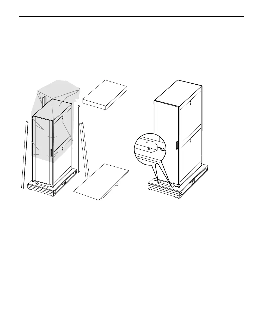
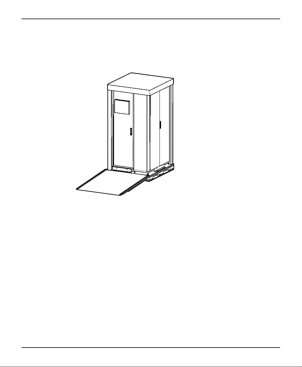
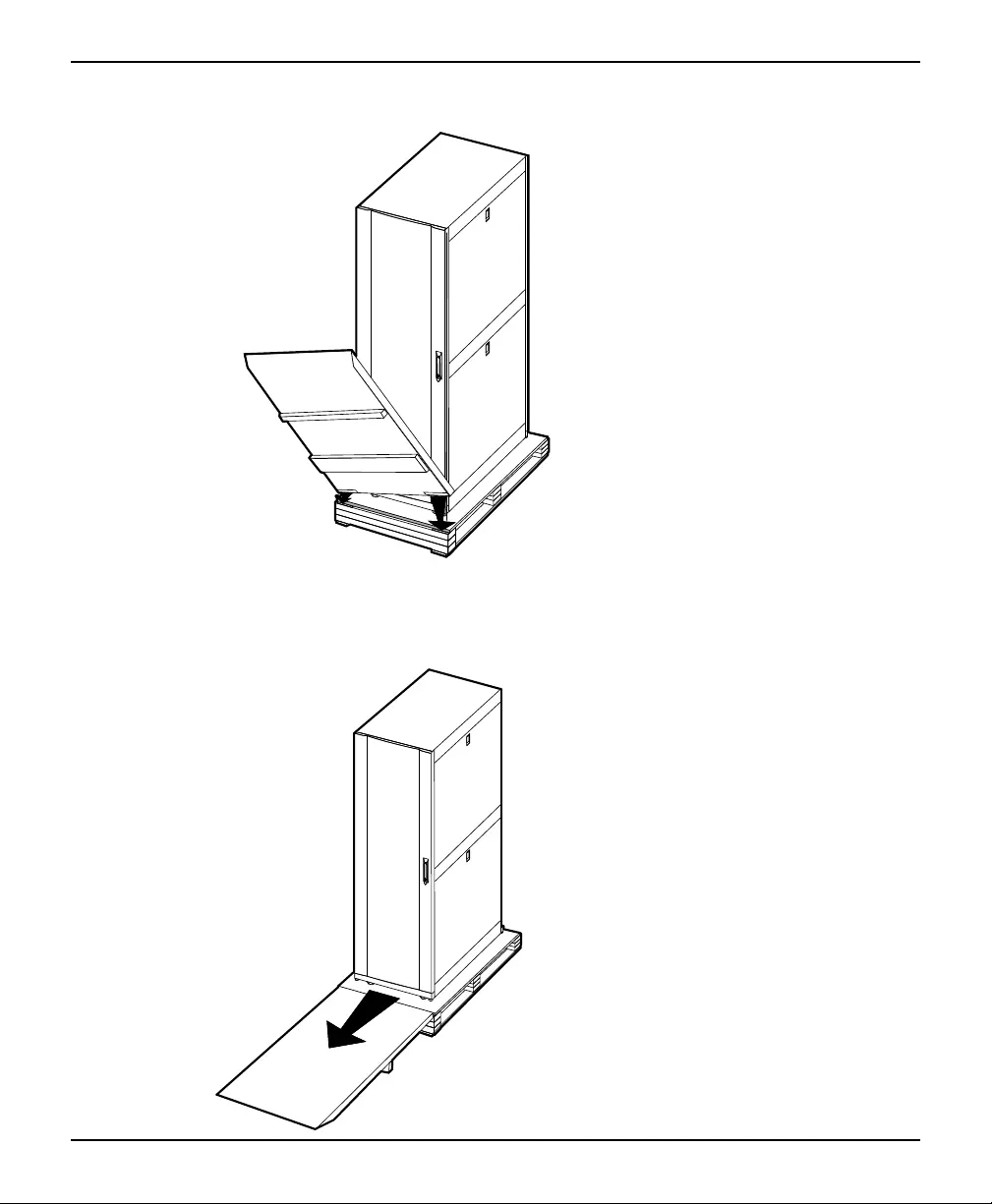
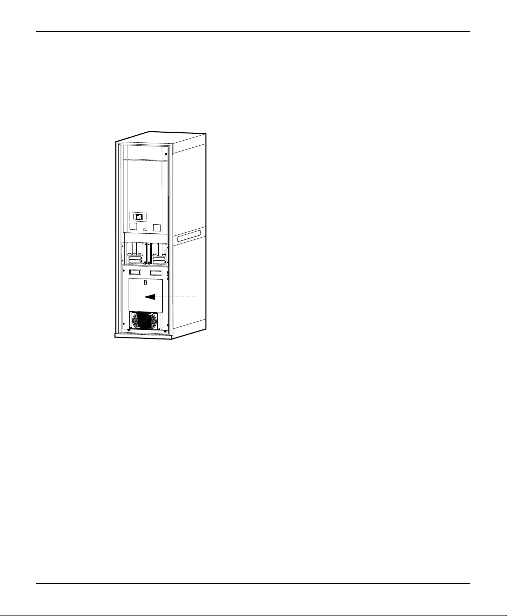
250/500 kW 400/480 V Unpack the Cabinets
3. Connect the ramp to the pallet:
– For the I/O cabinet with maintenance bypass: Let the two taps on the ramp
slide into the holes on the front of the pallet.
Front View of the Cabinet
– For the other cabinets: Align the hook-and-loop tape strips on the ramp with
the tape strips on the pallet
12 990-2749D-001


Schneider Electric
35 rue Joseph Monier
92500 Rueil Malmaison
France
+ 33 (0) 1 41 29 70 00
*990-2749D-001*
As standards, specifications, and design change from time to
time, please ask for confirmation of the information given in
this publication.
© 2008 – 2019 Schneider Electric. All rights reserved.
990-2749D-001