Table of Contents
APC SYWMBP96K160H2 User Manual
Displayed below is the user manual for SYWMBP96K160H2 by APC which is a product in the Uninterruptible Power Supplies (UPSs) category. This manual has pages.
Related Manuals
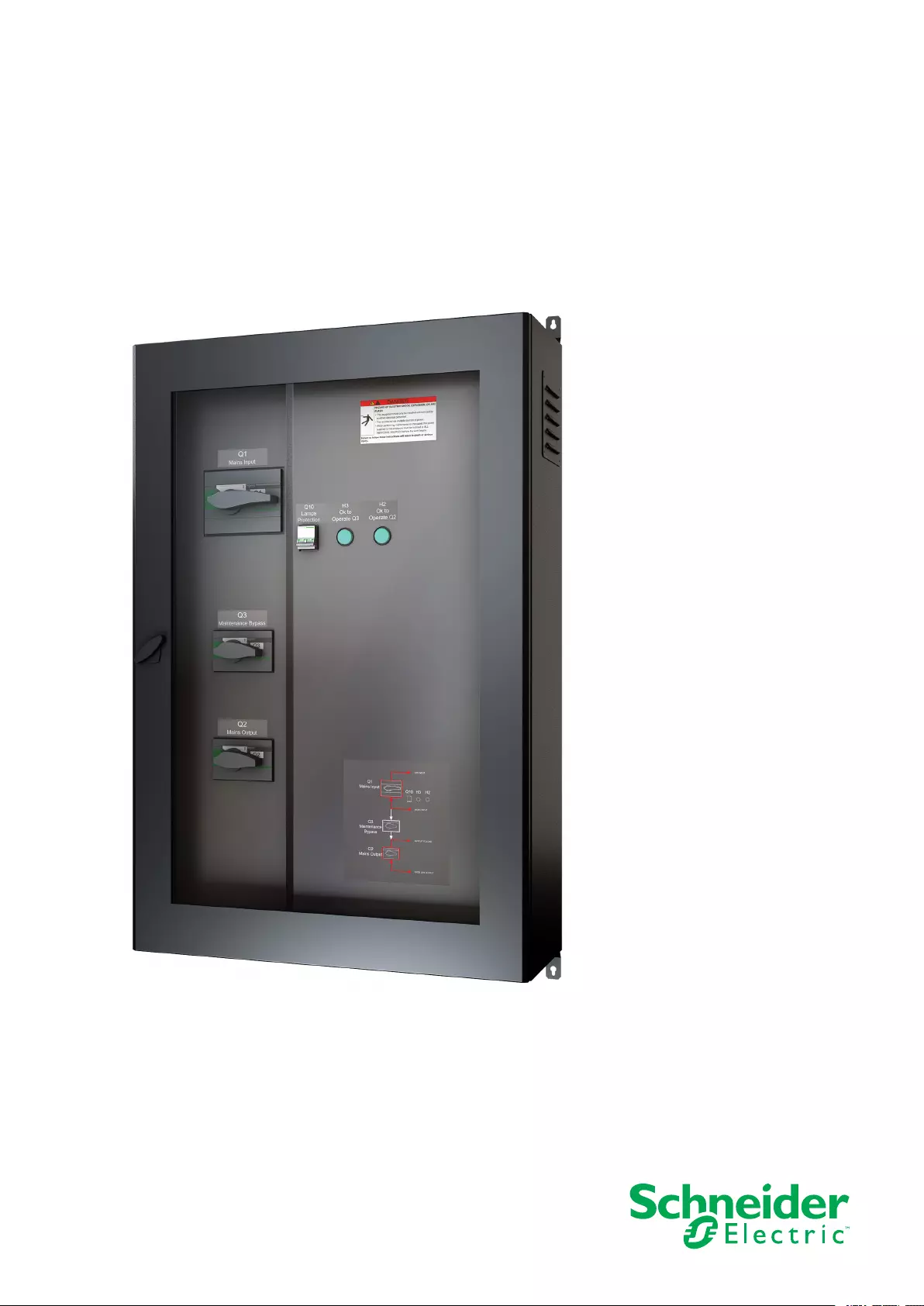
Symmetra™ PX 160
Maintenance Bypass Enclosure
Installation
05/2014
www.schneider-electric.com

Legal Information
The Schneider Electric brand and any registered trademarks of Schneider Electric
Industries SAS referred to in this guide are the sole property of Schneider Electric
SA and its subsidiaries. They may not be used for any purpose without the owner's
permission, given in writing. This guide and its content are protected, within the
meaning of the French intellectual property code (Code de la propriété
intellectuelle français, referred to hereafter as "the Code"), under the laws of
copyright covering texts, drawings and models, as well as by trademark law. You
agree not to reproduce, other than for your own personal, noncommercial use as
defined in the Code, all or part of this guide on any medium whatsoever without
Schneider Electric's permission, given in writing. You also agree not to establish
any hypertext links to this guide or its content. Schneider Electric does not grant
any right or license for the personal and noncommercial use of the guide or its
content, except for a non-exclusive license to consult it on an "as is" basis, at your
own risk. All other rights are reserved.
Electrical equipment should be installed, operated, serviced, and maintained only
by qualified personnel. No responsibility is assumed by Schneider Electric for any
consequences arising out of the use of this material.
As standards, specifications, and designs change from time to time, please ask for
confirmation of the information given in this publication.

Maintenance Bypass Enclosure
Table of Contents
Important Safety Information.....................................................................1
Safety Precautions .....................................................................................2
Electrical Safety....................................................................................4
Specifications ..............................................................................................6
Product Overview........................................................................................8
Installation..................................................................................................10
Prepare for Cables ...................................................................................10
Mount the Maintenance Bypass Enclosure to the Wall ................................. 11
Connect the Power Cables........................................................................ 11
Connect the Communication Cables ..........................................................13
Diagram...................................................................................................13
990–4907A-001 i

Maintenance Bypass Enclosure
ii 990–4907A-001
Important Safety Information Maintenance Bypass Enclosure
Important Safety Information
Read these instructions carefully and look at the equipment to become familiar with
it before trying to install, operate, service or maintain it. The following safety
messages may appear throughout this manual or on the equipment to warn of
potential hazards or to call attention to information that clarifies or simplifies a
procedure.
The addition of this symbol to a “Danger” or “Warning” safety
message indicates that an electrical hazard exists which will result in
personal injury if the instructions are not followed.
This is the safety alert symbol. It is used to alert you to potential
personal injury hazards. Obey all safety messages with this symbol
to avoid possible injury or death.
DANGER
DANGER indicates a hazardous situation which, if not avoided, will result in
death or serious injury.
Failure to follow these instructions will result in death or serious injury.
WARNING
WARNING indicates a hazardous situation which, if not avoided, could result in
death or serious injury.
Failure to follow these instructions can result in death, serious injury, or
equipment damage.
CAUTION
CAUTION indicates a hazardous situation which, if not avoided, could result in
minor or moderate injury.
Failure to follow these instructions can result in injury or equipment
damage.
NOTICE
NOTICE is used to address practices not related to physical injury. The safety
alert symbol shall not be used with this type of safety message.
Failure to follow these instructions can result in equipment damage.
Please Note
Electrical equipment should only be installed, operated, serviced, and maintained
by qualified personnel. No responsibility is assumed by Schneider Electric for any
consequences arising out of the use of this material.
990–4907A-001 1
Maintenance Bypass Enclosure Important Safety Information
A qualified person is one who has skills and knowledge related to the construction,
installation, and operation of electrical equipment and has received safety training
to recognize and avoid the hazards involved.
Safety Precautions
DANGER
HAZARD OF ELECTRIC SHOCK, EXPLOSION OR ARC FLASH
All safety instructions in this document must be read, understood and followed.
Failure to follow these instructions will result in death or serious injury.
DANGER
HAZARD OF ELECTRIC SHOCK, EXPLOSION OR ARC FLASH
Read all instructions in the Installation Manual before installing or working on this
UPS system.
Failure to follow these instructions will result in death or serious injury.
DANGER
HAZARD OF ELECTRIC SHOCK, EXPLOSION OR ARC FLASH
Do not install the UPS system until all construction work has been completed
and the installation room has been cleaned.
Failure to follow these instructions will result in death or serious injury.
DANGER
HAZARD OF ELECTRIC SHOCK, EXPLOSION OR ARC FLASH
• The product must be installed according to the specifications and
requirements as defined by Schneider Electric. It concerns in particular the
external and internal protections (upstream circuit breakers, battery circuit
breakers, cabling, etc.) and environmental requirements. No responsibility is
assumed by Schneider Electric if these requirements are not respected.
• After the UPS system has been electrically wired, do not start up the system.
Startup must only be performed by Schneider Electric.
Failure to follow these instructions will result in death or serious injury.
2 990–4907A-001

Important Safety Information Maintenance Bypass Enclosure
DANGER
HAZARD OF ELECTRIC SHOCK, EXPLOSION OR ARC FLASH
The UPS System must be installed according to local and national regulations.
Install the UPS according to:
• IEC 60364 (including 60364–4–41- protection against electric shock, 60364–
4–42 - protection against thermal effect, and 60364–4–43 - protection against
overcurrent), or
• NEC NFPA 70
depending on which one of the standards apply in your local area.
Failure to follow these instructions will result in death or serious injury.
DANGER
HAZARD OF ELECTRIC SHOCK, EXPLOSION OR ARC FLASH
• Install the UPS system in a temperature controlled environment free of
conductive contaminants and humidity.
• Install the UPS system on a non-inflammable, level and solid surface (e.g.
concrete) that can support the weight of the system.
Failure to follow these instructions will result in death or serious injury.
DANGER
HAZARD OF ELECTRIC SHOCK, EXPLOSION OR ARC FLASH
The UPS is not designed for and must therefore not be installed in the following
unusual operating environments:
• Damaging fumes
• Explosive mixtures of dust or gases, corrosive gases, or conductive or radiant
heat from other sources
• Moisture, abrasive dust, steam or in an excessively damp environment
• Fungus, insects, vermin
• Salt-laden air or contaminated cooling refrigerant
• Pollution degree higher than 2 according to IEC 60664-1
• Exposure to abnormal vibrations, shocks, and tilting
• Exposure to direct sunlight, heat sources, or strong electromagnetic fields
Failure to follow these instructions will result in death or serious injury.
DANGER
HAZARD OF ELECTRIC SHOCK, EXPLOSION, OR ARC FLASH
Do not drill/punch holes for cables or conduits with the gland plates installed and
do not drill/punch in close proximity to the UPS.
Failure to follow these instructions will result in death or serious injury.
990–4907A-001 3
Maintenance Bypass Enclosure Important Safety Information
WARNING
HAZARD OF ARC FLASH
Do not make mechanical changes to the product (including removal of cabinet
parts or drilling/cutting of holes) that are not described in the Installation Manual.
Failure to follow these instructions can result in death, serious injury, or
equipment damage.
WARNING
HAZARD OF OVERHEATING
Respect the space requirements around the UPS system and do not cover the
product’s ventilation openings when the UPS system is in operation.
Failure to follow these instructions can result in death, serious injury, or
equipment damage.
WARNING
HAZARD OF EQUIPMENT DAMAGE
Do not connect the UPS output to regenerative load systems including
photovoltaic systems and speed drives.
Failure to follow these instructions can result in death, serious injury, or
equipment damage.
Electrical Safety
DANGER
HAZARD OF ELECTRIC SHOCK, EXPLOSION OR ARC FLASH
• Electrical equipment must be installed, operated, serviced, and maintained
only by qualified personnel.
• The UPS system must be installed in a room with restricted access (qualified
personnel only).
• Apply appropriate personal protective equipment (PPE) and follow safe
electrical work practices.
• Turn off all power supplying the UPS system before working on or inside the
equipment.
• Before working on the UPS system, check for hazardous voltage between all
terminals including the protective earth.
• The UPS contains an internal energy source. Hazardous voltage can be
present even when disconnected from the mains supply. Before installing or
servicing the UPS system, ensure that the units are OFF and that mains and
batteries are disconnected. Wait five minutes before opening the UPS to
allow the capacitors to discharge.
• A disconnection device (e.g. disconnection circuit breaker or switch) must be
installed to enable isolation of the system from upstream power sources in
accordance with local regulations. This disconnection device must be easily
accessible and visible.
• The UPS must be properly earthed/grounded and due to a high leakage
current, the earthing/grounding conductor must be connected first.
Failure to follow these instructions will result in death or serious injury.
4 990–4907A-001

Important Safety Information Maintenance Bypass Enclosure
DANGER
HAZARD OF ELECTRIC SHOCK, EXPLOSION, OR ARC FLASH
In systems where backfeed protection is not part of the standard design, an
automatic isolation device (backfeed protection option or other device meeting
the requirements of IEC/EN 62040–1 or UL1778 4th Edition – depending on
which of the two standards apply to your local area) must be installed to prevent
hazardous voltage or energy at the input terminals of the isolation device. The
device must open within 15 seconds after the upstream power supply fails and
must be rated according to the specifications.
Failure to follow these instructions will result in death or serious injury.
When the UPS input is connected through external isolators that, when opened,
isolate the neutral or when the automatic backfeed isolation is provided external to
the equipment or is connected to an IT power distribution system, a label must be
fitted at the UPS input terminals, and on all primary power isolators installed
remote from the UPS area and on external access points between such isolators
and the UPS, by the user, displaying the following text (or equivalent in a language
which is acceptable in the country in which the UPS system is installed):
DANGER
HAZARD OF ELECTRIC SHOCK, EXPLOSION, OR ARC FLASH
Risk of Voltage Backfeed. Before working on this circuit: Isolate the UPS and
check for hazardous voltage between all terminals including the protective earth.
Failure to follow these instructions will result in death or serious injury.
990–4907A-001 5

Maintenance Bypass Enclosure Specifications
Specifications
Electrical
UPS rating 96 kVA 160 kVA
Input voltage
(V)
380 400 415 380 400 415
Nominal input
current (A)
154 146 141 256 243 234
Maximum
rated input
current (340
V input )(A)
169 160 155 281 267 258
Input
frequency
(Hz)
50/60
Maximum
short-circuit
withstand
(kA) Icc
Rated conditional short-circuit current Icc: 30 kA symmetrical rms
Rated peak withstand current Ipk: 63 kA
Device: NSX400F Mic2.3 3P 320 A setting (manufacturer: Schneider Electric) for 160 kVA, or
NSX250F TMD200 3P (manufacturer: Schneider Electric) for 96 kVA
Maximum
short-circuit
withstand
(kA) Icw
Rated short-time withstand current Icw: 13 kA symmetrical rms
Rated peak withstand current Ipk: 26 kA
Short-circuit withstand time: 3 cycles
Switch Sizes
Mains input switch Q1 (A) 400
UPS output switch Q2 (A) 250
Maintenance bypass switch Q3 (A) 250
Upstream Protection
NOTICE
For a maximum short-circuit withstand higher than 13 kA, it is mandatory to
install a circuit breaker (NSX250F TMD200 3P or NSX400F Mic2.3 3P 320 A
setting) upstream of the maintenance bypass enclosure.
Failure to follow these instructions can result in equipment damage.
UPS rating Required protection Max input current
96 kVA NSX250F TMD200 3P 169 A
160 kVA NSX400F Mic2.3 3P 320 A setting 281 A
6 990–4907A-001

Specifications Maintenance Bypass Enclosure
Recommended Cable Sizes
NOTE: Use only copper conductors with a minimum rating for 90 °C.
NOTE: 30 ℃ambient temperature, IEC standard 60364-5-52, Table A.52-4 (52-
C3), "C" method of installation. If the ambient room temperature is higher than 30
℃, larger conductors are to be selected in accordance with the correction factors
of the IEC.
UPS rating 96 kVA UPS 160 kVA UPS
Input cable (L1, L2, L3, N, PE)
(mm2)
70 120
Output cable (L1, L2, L3, N, PE)
(mm2)
50 95
Maintenance bypass to UPS input
cable (mm2)
70 120
UPS output to maintenance bypass
cable (mm2)
50 95
Weights and Dimensions
Weight (kg) Height (mm) Width (mm) Depth (mm)
Without packaging 90 1200 800 300
With packaging 105 1230 830 350
Environmental
Storage Operation
Temperature -25 °C to 55 °C 0 °C to 40 °C
Relative humidity 0 to 95% non-condensing
Elevation 0 to 15000 m 0 to 3000 m
Protection class IP20
Color Black
Torque
Torque (Nm) Screws
Mains input terminal block 23 M8 X 25 MSC HXG STL
Mains input to UPS terminal block 23 M8 X 25 MSC HXG STL
UPS output terminal block 23 M8 X 25 MSC HXG STL
System output terminal block 23 M8 X 25 MSC HXG STL
990–4907A-001 7
Maintenance Bypass Enclosure Product Overview
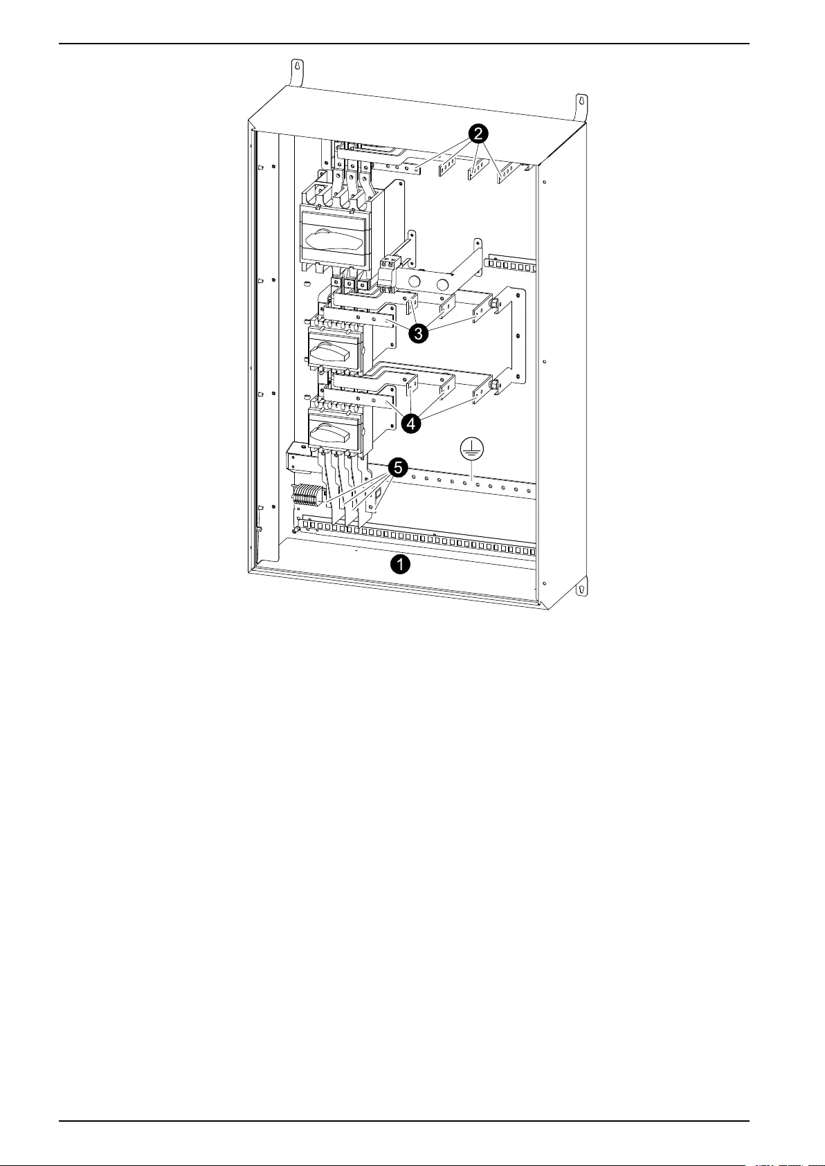
Product Overview
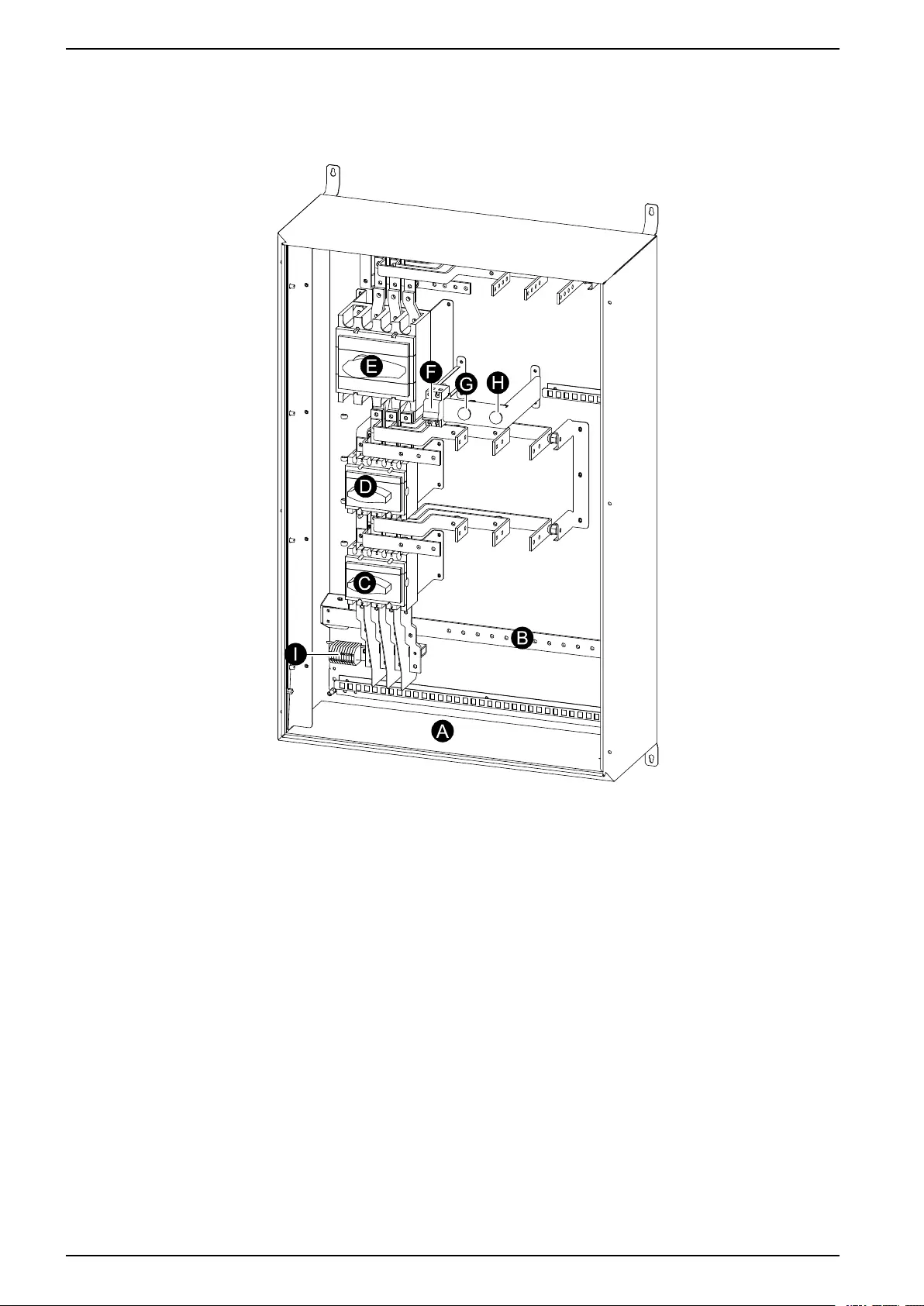
Front view (interior)
A. Cable entry
B. PE busbar
C. Q2 – UPS output switch
D. Q3 – Maintenance bypass switch
E. Q1 – Mains input switch
F. Q10 – LED protection breaker
G. LED H3 – OK to operate Q3 when light is ON
H. LED H2 – OK to operate Q2 when light is ON
I. Terminal block – signal connection to UPS
Site Planning
NOTE: Select a location for the maintenance bypass enclosure which provides
easy access to all breakers and internal components.
NOTE: Select a wall that is structurally sound and able to support the size and
weight of the maintenance bypass enclosure.
8 990–4907A-001
Product Overview Maintenance Bypass Enclosure
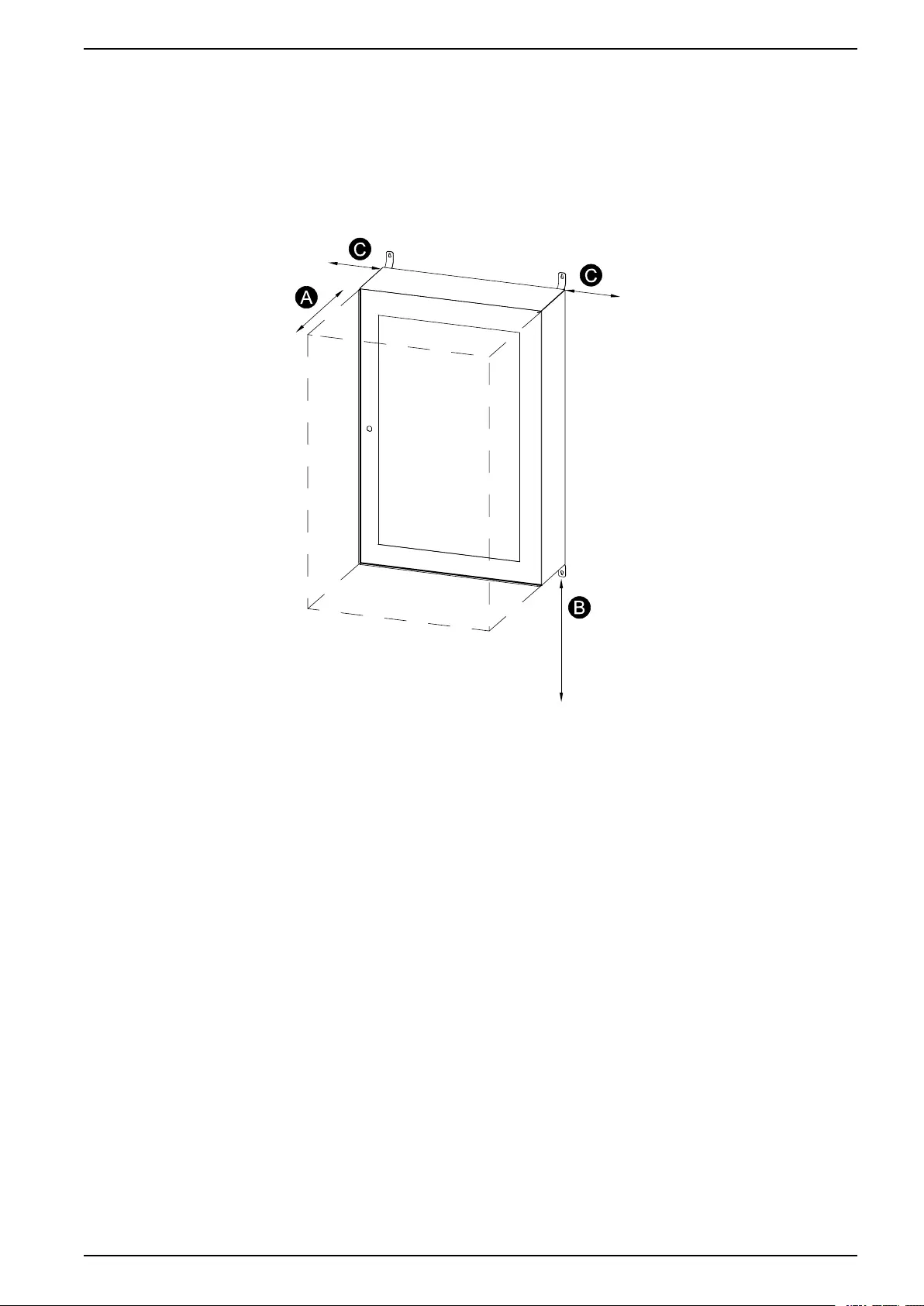
Clearance
Follow the listed clearance requirements and consult local codes for any additional
requirements.
The best location for the maintenance bypass enclosure is close to the UPS.
Front view
A. Minimum front clearance: 650 mm
B. Minimum enclosure–to–floor clearance: 600 mm
C. Minimum side clearance: 100 mm
990–4907A-001 9
Maintenance Bypass Enclosure Installation
Installation
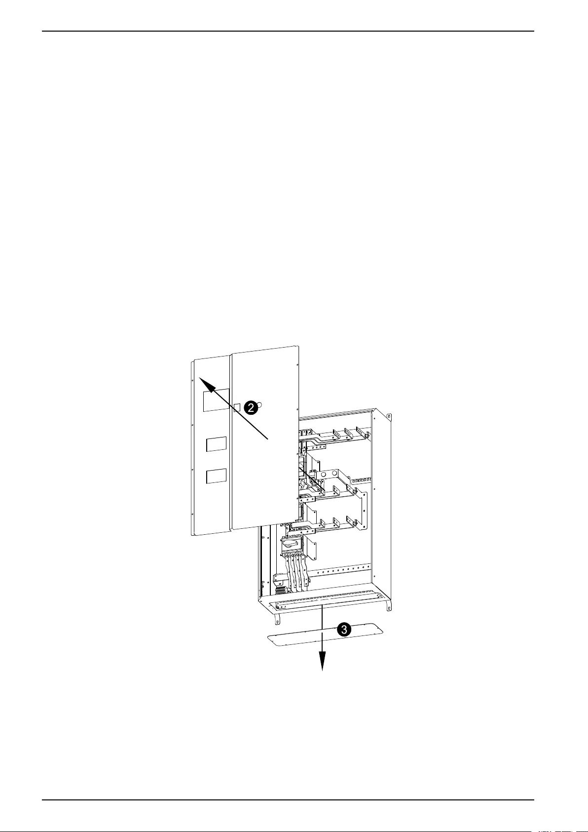
Prepare for Cables
NOTE: All power cables must be connected on site. External power cables are not
supplied with the maintenance bypass enclosure.
NOTE: Schneider Electric recommends to create the necessary holes for cable
access before mounting the maintenance bypass enclosure to the wall.
NOTE: The size of the holes and glands must be adapted to fit the size of the
cables.
1. Open the front door of the enclosure.
2. Remove the front panel.
3. Remove the bottom plate.
4. Drill holes for cables in the bottom plate. Make sure that the hole locations
correspond to the connector locations in the enclosure.
5. Reinstall the bottom plate.
Front view
10 990–4907A-001
Installation Maintenance Bypass Enclosure
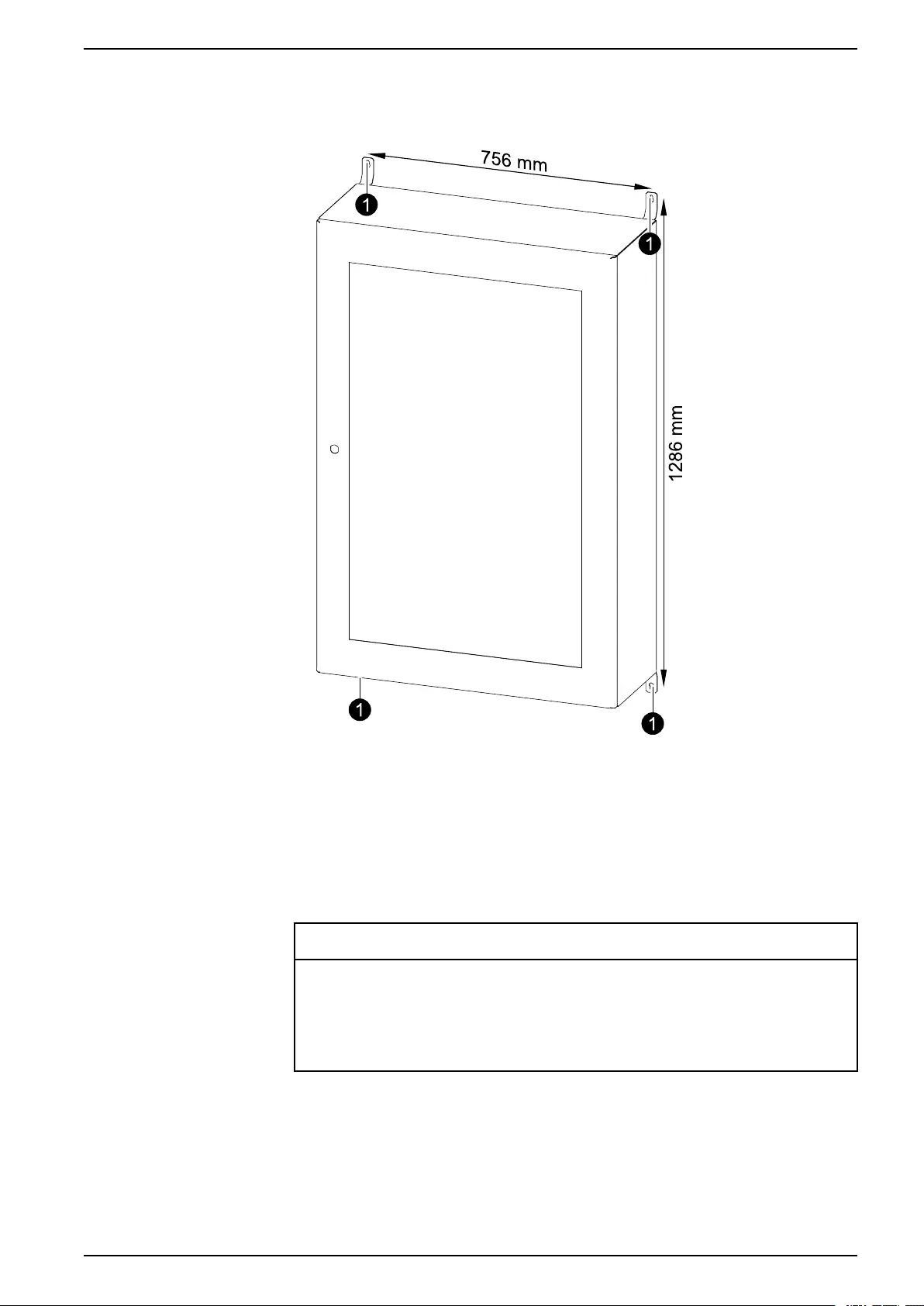
Mount the Maintenance Bypass Enclosure to the Wall
1. Measure and mark the four mounting hole locations on the wall.
2. Drill holes in each of the four marked locations and mount the anchor bolts.
3. Lift the maintenance bypass enclosure, position it against the backing and line it
up with the four holes/anchor bolts. Secure the enclosure with the four bolts and
flat washers.
Connect the Power Cables
NOTICE
For a maximum short-circuit withstand higher than 13 kA, it is mandatory to
install a circuit breaker (NSX250F TMD200 3P or NSX400F Mic2.3 3P 320 A
setting) upstream of the maintenance bypass enclosure.
Failure to follow these instructions can result in equipment damage.
990–4907A-001 11
Maintenance Bypass Enclosure Installation
1. Route the cables through the holes in the bottom plate of the maintenance
bypass enclosure.
2. Connect the UPS input cables (L1, L2, L3, N) to the UPS input terminals and
the PE cable to the PE bar.
3. Connect the AC input cables (L1, L2, L3, N) to the AC input terminal block and
the PE cable to the PE bar.
4. Connect the system output cables from the UPS (L1, L2, L3, N) to the system
output terminals and the PE cable to the PE bar.
5. Connect the UPS output cables (L1, L2, L3, N) to the UPS output terminals and
the PE cable to the PE bar.
12 990–4907A-001
Installation Maintenance Bypass Enclosure
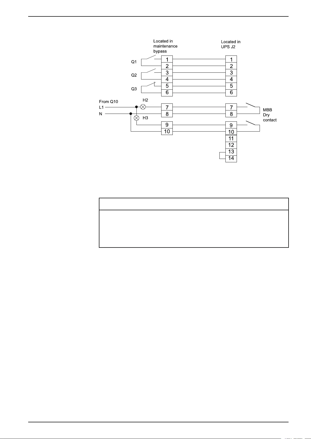
Connect the Communication Cables
Located in
maintenanc e
bypass
Located in
UPS J2
Q1
Q2
Q3
From Q10
L1
H2
H3
NMBB
Dry
contact
1
2
3
4
5
6
1
2
3
4
5
6
7
87
8
9
10
11
12
13
14
9
10
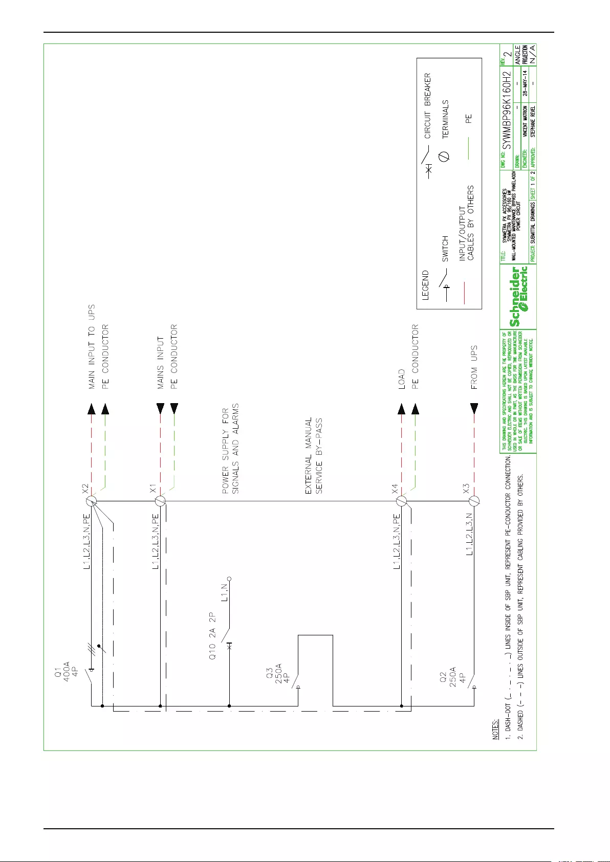
Diagram
NOTICE
For a maximum short-circuit withstand higher than 13 kA, it is mandatory to
install a circuit breaker (NSX250F TMD200 3P or NSX400F Mic2.3 3P 320 A
setting) upstream of the maintenance bypass enclosure.
Failure to follow these instructions can result in equipment damage.
990–4907A-001 13


Schneider Electric
35 rue Joseph Monier
92500 Rueil Malmason
France
+ 33 (0) 1 41 29 70 00
www.schneider-electric.com
As standards, specifications, and design change from
time to time, please ask for confirmation of the
information given in this publication.
© 2013 – 2014 Schneider Electric. All rights reserved.
990–4907A-001