Table of Contents
APC W0M-7054 User Manual
Displayed below is the user manual for W0M-7054 by APC which is a product in the Computer Cooling System Parts & Accessories category. This manual has pages.
Related Manuals
ARU Fan Module (W0M-7054)—
Replacement Procedure
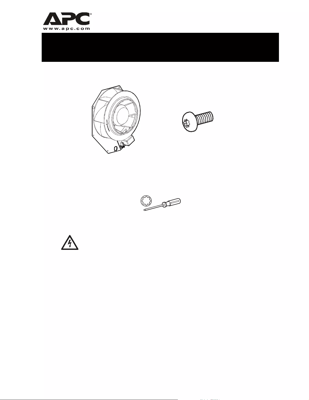
Inventory
Required tools
This procedure must be performed by trained APC service personnel.
Fan module (1) M4 x 8 mm Torx™ thread-forming screws
(5)
20-IP Torx screwdriver
Electrical
Hazard
2 ARU Fan Module (W0M-7054) — Replacement Procedure
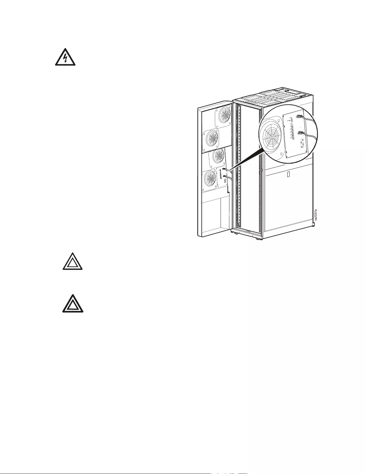
Install the fan module
The Air Removal Unit (ARU) has multiple power sources. Ensure that all power sources are
disconnected before performing any maintenance.
1. Turn off ARU fans through the display interface:
Menu>Set Points>Master Control>Off.
2. Open the ARU and unplug all power cords from
the electronics module.
When installing thread-forming screws, take care not to cross-thread them. Do not
over-tighten the screws.
The fans will still spin after power is removed. Wait for the fans to come to a
complete stop before removing finger guards.
Electrical
Hazard
Caution
Warnin
g
ARU Fan Module (W0M-7054) — Replacement Procedure 3
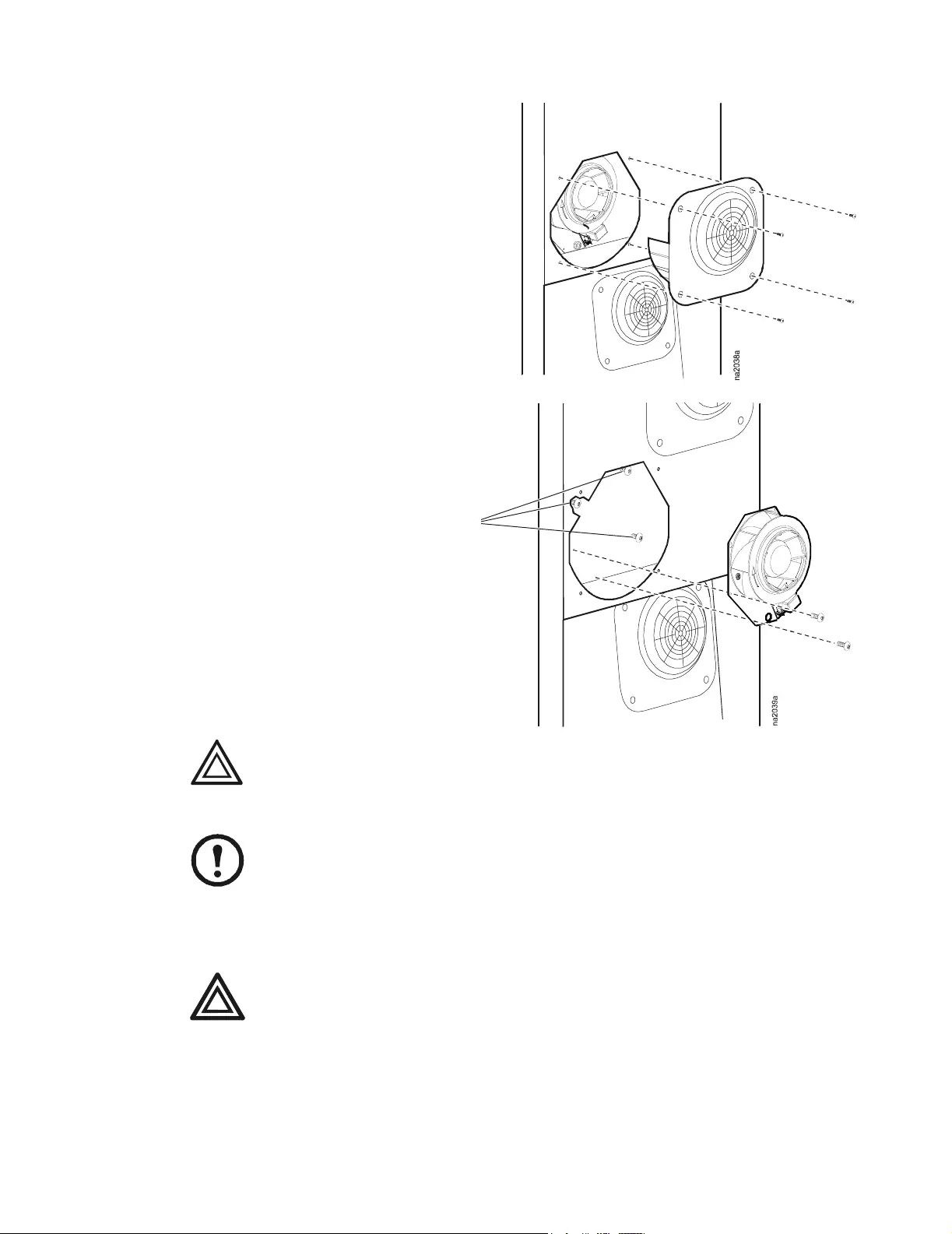
3. Remove four screws. Remove the finger
guard. Save the screws for later use.
4. Unplug the two connectors from the fan
module.
5. Loosen the three screws in
slotted holes as shown.
6. Remove the two remaining
screws. Remove the fan
module.
When installing
thread-forming screws, take care not to cross-thread them. Do not over-tighten the
screws.
Spare screws are included with this kit in case the original fasteners are lost or damaged.
7. Install the new fan module by reversing steps 1 through 6.
Remove fasteners or any other items that may have fallen inside the ARU. Loose
objects can be picked up by fans and cause damage to equipment or personal injury.
8. Reconnect power to the electronics module panel.
9. Turn on unit to verify proper operation.
Loosen
these
screws.
Caution
Note
Warnin
g
*990-2875-001*
Customer support for this or any other APC product is available at no charge in any of the following ways:
• Visit the APC Web site to access documents in the APC Knowledge Base and to submit customer support requests.
–www.apc.com (Corporate Headquarters)
Connect to localized APC Web sites for specific countries, each of which provides customer support information.
–www.apc.com/support/
Global support searching APC Knowledge Base and using e-support.
• Contact an APC Customer Support center by telephone or e-mail.
– Regional centers:
– Local, country-specific centers: go to www.apc.com/support/contact for contact information.
Contact the APC representative or other distributor from whom you purchased your APC product for information on how
to obtain local customer support.
Direct InfraStruXure Customer Support
Line (1)(877)537-0607 (toll free)
APC headquarters U.S., Canada (1)(800)800-4272 (toll free)
Latin America (1)(401)789-5735 (USA)
Europe, Middle East, Africa (353)(91)702000 (Ireland)
Japan (0) 35434-2021
Australia, New Zealand, South Pacific
area (61) (2) 9955 9366 (Australia)
Entire contents copyright 2006 American Power Conversion Corporation. All rights reserved.
Reproduction in whole or in part without permission is prohibited. APC, the APC logo, and
InfraStruXure are trademarks of American Power Conversion Corporation. All other trademarks,
product names, and corporate names are the property of their respective owners and are used for
informational purposes only.
03/2006990-2875-001