Table of Contents
- 1. This manual...
- 2. Hazard symbols
- 2.1 Levels of danger and signal words
- 2.2 Symbols and depictions used
- 2.3 Glossary - definition
- 3. Included in delivery
- 4. General view
- 5. Product description
- 6. Technical specifications
- 7. Safety instructions
- 7.1 Intended use
- 7.2 Improper use
- 7.3 Required expert knowledge of the installer
- 8. Safety instructions for the electrical connection
- 8.1 Important information prior to the electrical connection and mounting
- 8.2 Electrical connection and mounting
- 9. Commissioning
- 9.1 Manual setting of the load type
- 9.2 Setting the dimming range
- 9.3 Switching the minimum brightness function on and off
- 9.4 Overload protection - conduct in the event of an overload
- 10. Operation with an external button
- 11. DuoFern device (logging on / logging off)
- 11.1 Logging on DuoFern devices
- 11.2 Logging off DuoFern devices
- 12. Deleting all settings
- 13. Simplified EU declaration of conformity
- 14. Warranty terms and conditions
RADEMACHER 35140462 User Manual
Displayed below is the user manual for 35140462 by RADEMACHER which is a product in the Dimmers category. This manual has pages.
Related Manuals
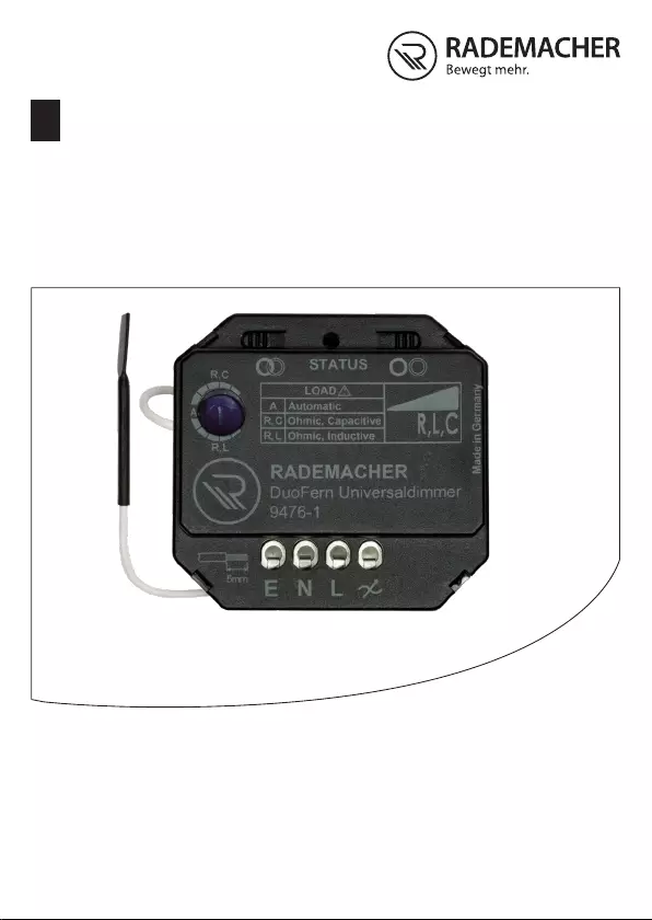
VBD 672-2 (03.18)
EN
DuoFern
Universal Dimmer
Translation of the original Installation and Commissioning Manual
Item no. 3514 04 62

2
EN
i
Contents
1. This manual... .................................................................. 3
2. Hazard symbols .............................................................. 4
2.1 Levels of danger and signal words ................................4
2.2 Symbols and depictions used ........................................5
2.3 Glossary - denition .......................................................5
3. Included in delivery ........................................................ 6
4. General view ................................................................... 6
5. Product description ........................................................ 7
6. Technical specications .............................................. 10
7. Safety instructions ....................................................... 12
7.1 Intended use ................................................................13
7.2 Improper use ...............................................................14
7.3 Required expert knowledge of the installer .................14
8. Safety instructions for the electrical connection ...... 15
8.1 Important information prior to the
electrical connection and mounting .............................17
8.2 Electrical connection and mounting .............................18
9. Commissioning ............................................................. 19
9.1 Manual setting of the load type ....................................19
9.2 Setting the dimming range ...........................................22
9.3 Switching the minimum brightness
function on and o .......................................................23
9.4 Overload protection - conduct in the
event of an overload ....................................................24
10. Operation with an external button .............................. 25
11. DuoFern device (logging on / logging o) ................. 27
11.1 Logging on DuoFern devices .......................................28
11.2 Logging o DuoFern devices ....................................... 29
12. Deleting all settings ...................................................... 30
13. Simplied EU declaration of conformity .................... 30
14. Warranty terms and conditions ................................... 31

3
EN
i
1. This manual...
...describe how to install, connect, commission and operate
the DuoFern Universal Dimmer.
How to use this manual
◆Before you begin, please read this manual through com-
pletely and follow all the safety instructions.
◆Please also read the instruction manual of the respec-
tive connected light source.
◆This manual is part of the product. Please store it in an
easily accessible place.
◆When passing the DuoFern Universal Dimmer on to a
third party, this manual must be passed on as well.
◆Damage resulting from non-compliance with these in-
structions and safety instructions will void the warranty.
We assume no liability for any consequential damage.
4
EN
i
2. Hazard symbols
Danger of fatal electric shock
Danger area / dangerous situation
2.1 Levels of danger and signal words
i
DANGER!
This hazard will lead to serious injury or death if not
avoided.
WARNING!
This hazard may result in serious injury or death if not
avoided.
CAUTION!
This hazard may result in minor or moderate injury if not
avoided.
ATTENTION!
This hazard may lead to property damage.
5
EN
2.2 Symbols and depictions used
Depiction Description
1. Procedures
2.
◆ Lists
1) or a) Lists
i
Further useful
information
Please read the respective manual.
i
2.3 Glossary - denition
DuoFern
◆RADEMACHER radio technology for controlling com-
patible products.
HomePilot®
◆The HomePilot® is a central controller unit for
RADEMACHER radio products.
i
6
EN
3. Included in delivery
1 x DuoFern Universal Dimmer 9476-1
1 x installation and commissioning manual
After unpacking please check and compare...
... the contents of the package with those specied above.
i
i
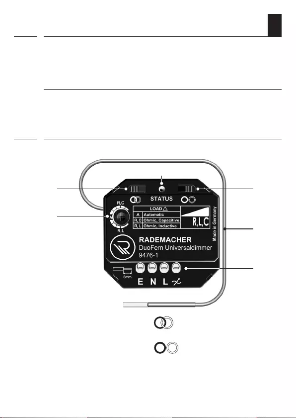
4. General view
1) DuoFern log-on button
2) Status LED
3) DuoFern log-o button
4) Antenna
5) Connecting terminals
6) Setting dial
1)
2)
3)
5)
4)
6)
7
EN
5. Product description
The DuoFern Universal Dimmer is a radio-capable actuator
for dimming 230 V dimmable light sources. As a ush-mounted
device with a low installation height, the dimmer can be tted
into a standard ush-mounted box.
Automatic load detection
The DuoFern Universal Dimmer has automatic detection of
the connected load type (R, L and C) and is therefore suitable
for almost all dimmable light sources. The required dimmer
mode is set automatically depending on the connected load.
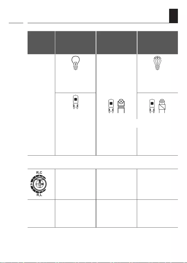
The following light sources can be connected
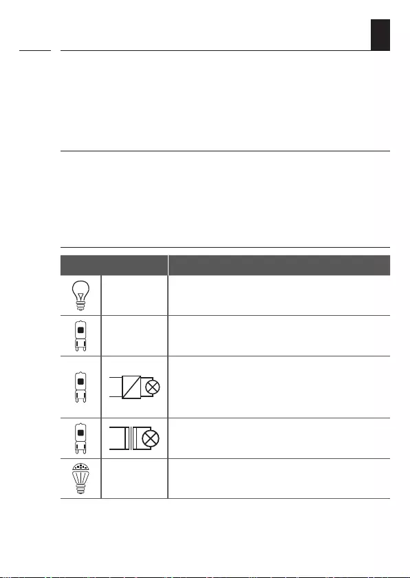
Light source
230 V Light bulbs
230 V High-voltage halogen lamps
Low-voltage halogen lamps or LED lamps
with a dimmable electronic ballast (electri-
cal transformer or switching power supply)
Low-voltage halogen lamps with a conven-
tional iron-core or toroidal transformer
230 V dimmable retrot LEDs
The illustrations serve as an example. All shapes and versions of
the above-mentioned light sources can be used.
i

8
EN
Manual setting of the load type and brightness
The load type (R, L and C) can be selected manually as an
alternative to the automatic detection of the light source.
This enables the minimum and maximum brightness to be
adjusted manually to each light source.
On-site operation using an external button
The DuoFern Universal Dimmer can be operated on site using
an external button. The DuoFern Universal Dimmer has a
corresponding input [ E ] to connect the external button.
i
5. Product description

9
EN
5. Product description
i
Supports the following functions:
◆Can be fully integrated into the DuoFern radio system
(HomePilot®)
◆Universal dimmer with automatic load detection (detec-
tion works from approx. 15 W)
◆Connection option (input) for an external 230 V button
for control on site.
◆Either trailing-edge phase control (mode R, C) or lead-
ing-edge phase control / “triac mode” (mode L) depend-
ing on the load type
◆Also suitable for old installations with halogen lamps or
light bulbs due to the high load range (up to 400 W)
◆Automatic timer, automatic solar function, automatic
dusk function, automatic dawn function, manual opera-
tion
◆Staircase function - switches o automatically after
approx. 0.1 seconds up to 54 minutes
◆Intermediate value function
Adjustable via the HomePilot®, factory pre-congured.
Intermediate values are adopted when a stop command
is given or by dimming with the external button (press
and hold).
◆Adjustable dimming speed of 2 - 255 seconds via the
HomePilot® for radio commands (factory setting =
5 seconds).
◆Remote log on / o
via the HomePilot® or DuoFern manual central operating
unit
10
EN
i
Mains supply [
L / N
]
Supply voltage: 230 V AC / 50 Hz
Standby consumption: < 0.5 W
Output [ ]
Voltage: 230 V / 50 Hz
Maximum connected load:
up to 400 W/VA
Depending on the inrush
currents of the light sources
used.
Dimmable load type:
Automatic
load detection *
Dimmer mode:
(depending on the load type)
◆ Leading-edge phase
control (triac mode) *
◆ Trailing-edge phase
control *
* see page 21
Input [
E
] (external button)
Switching voltage: 230 V / 50 Hz
Maximum length of lead for
the button connection: 15 m
6. Technical specications
11
EN
i
General information
Protection class:
0 (basic insulation for
tting into a ush-
mounted box)
Protection type: IP00 (only for use in dry
rooms)
Permissible ambient
temperature: 0 to 40°C
Connecting terminals:
Screw terminals for
max. 1.5 mm2 cable
cross-section
Dimensions (W x H x D): 48.5 x 45.7 x 19.7 mm
DuoFern radio technology
Transmission frequency: 434.5 MHz
Transmission power: max. 10 mW
Range:
Indoors approx. 30 m*
Outdoors approx. 100 m
* depending on the building
structure
Maximum number of
DuoFern devices: 20
6. Technical specications

12
EN
7. Safety instructions
The use of defective devices can lead to personal injury
and damage to property from electric shocks or short
circuiting.
◆Never use defective or damaged devices.
◆Check that the DuoFern Universal Dimmer is intact.
◆Consult our customer service department in the event
that you discover damage, see page 32.
i
Potential device damage caused by the unauthorised
combination of dierent transformer types!
Conventional and electronic transformers
must not be dimmed together.
All other load combinations are possible.

13
EN
7.1 Intended use
i
Only use the DuoFern Universal Dimmer for dimming
230 V dimmable light sources, see table in chapter
“5. Product description”.
Operating conditions
◆Only use the DuoFern Universal Dimmer in dry rooms.
◆A 230 V / 50 Hz power supply, together with a site-pro-
vided
disconnecting device (fuse), must be available at the
installation location
◆The installation and operation of radio systems is only
permitted for systems and devices where a malfunction
in the transmitter or receiver would not cause a danger
to persons or property or where this risk is already cov-
ered by other safety equipment.
i
Other radio systems that transmit on the same
frequency can cause transmission problems.
14
EN
7.2 Improper use
i
i
7.3 Required expert knowledge of the installer
Using the DuoFern Universal Dimmer for any other purpose
than previously mentioned is not permissible.
Improper use can lead to serious injuries or property
damage.
◆Never use the radio system (e.g. DuoFern radio system)
and its components for the remote control of appliances
and systems with increased safety-relevant require-
ments or where there is an accident risk. Such applica-
tions require additional safety equipment. Observe the
respective statutory regulations for the installation of
such systems.
There is a risk of fatal injury caused by short circuiting
and electric shocks if the DuoFern Universal Dimmer is
used outdoors or in damp rooms.
◆Do not install and use the DuoFern Universal Dimmer
outdoors or in damp rooms.
The electrical connection, installation and commissioning of
the DuoFern Universal Dimmer must only be carried out by
a qualied electrician in accordance with the instructions in
this manual.
15
EN
i
8. Safety instructions for the electrical
connection
Prior to the electrical connection, check that the voltage /
frequency on the type plate corresponds to that of the local
mains supply.
Mortal danger and a risk of re in the event of
connecting unsuitable light sources.
Overloading the DuoFern Universal Dimmer by connecting
unsuitable light sources can lead to malfunctions and there-
fore to short circuits and re under certain circumstances.
◆Only use light sources within the permissible load limits,
see page 10, Technical specications.
◆Only connect light sources to the DuoFern Universal
Dimmer as specied in chapter “5. Product description”.
DANGER!
There is a risk of fatal electric shock when touching
electrical components.
◆All connection and installation work must only be carried
out in a de-energised state.
◆Disconnect all phases of the mains power cable and
secure it to prevent any reconnection.
◆Check that the system is de-energised.
16
EN
i
8. Safety instructions for the electrical
connection
DANGER!
There is a risk of fatal electric shock when touching a
damaged antenna.
◆Never touch a damaged antenna lead.
◆The antenna lead must not be shortened or damaged.
◆Disconnect all phases of the mains power supply cable and
replace the DuoFern Universal Dimmer with a new device.
WARNING!
Incorrect wiring may lead to short circuits and destroy
the device.
Follow the pin assignment detailed in the connection dia-
gram.
17
EN
i
◆The DuoFern Universal Dimmer is intended for ush
mounting. We recommend installation in a deep 58 mm
ush-mounted box or in an electronic socket.
◆Select an installation place that is easily accessible -
e.g. for maintenance purposes, for logging on and o
the DuoFern devices and for changing the operating
mode on the setting dial.
◆
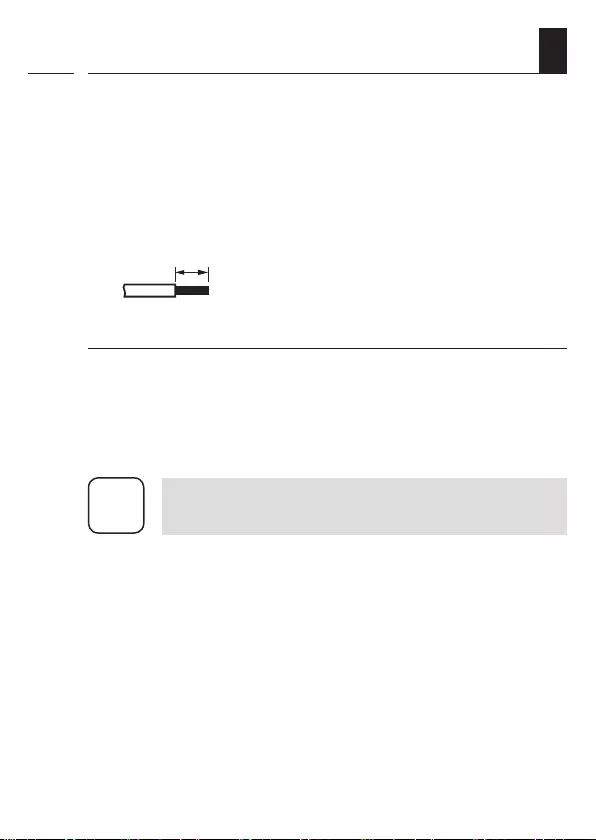
5 mm
All leads must be stripped to
5 mm.
Connecting an external button (optional)
◆Only buttons may be connected to the input [ E ].
Switches are not suitable due to the operating concept.
◆The maximum length of lead to connect the external
button must not exceed 15 m.
i
Read and observe the specications given by the
respective manufacture for the light source used.
8.1 Important information prior to the
electrical connection and mounting
18
EN
8.2 Electrical connection and mounting
i
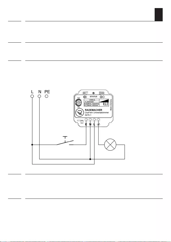
1. Ensure the mains is disconnected and check whether the
mains power cables are current-free.
2. Securely lay all connecting cables right into the ush-mount-
ed box (if necessary, also the external button cables).
3. Remove the insulation on all leads down to 5 mm in length
and connect them according to the connection diagram.
230 V / 50 Hz
4. Insert the DuoFern Universal Dimmer into the ush-mount-
ed box and lay the connecting cables as well as the anten-
na in the box.
5. Finally, place the cover on the ush-mounted box and
switch the mains power on again.
max. length
of lead: 15 m
External button
(optional)

19
EN
9. Commissioning
i
Automatic load detection
The automatic load detection is factory preset to active; the
setting dial of the DuoFern Universal
Dimmer
is in position A (AUTO) for this purpose. The connected
load and its properties (R, L and C) are evaluated when the
light source is turned on for the rst time after switching on
the mains voltage. The required dimmer mode is set auto-
matically depending on the connected load.
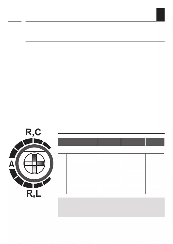
9.1 Manual setting of the load type
i
The setting dial of the DuoFern Universal Dimmer is factory
set to position A (AUTO). You can adjust the desired load
type and dimming range by turning the setting dial with a
small screwdriver.
Select the required load type - depending on the type of
light source or ballast used
◆In accordance with the table on page 21.
◆Information about this can be found in the manual
(packaging) of the light source or ballast.

20
EN
i
When does the load type have to be set manually or
changed?
The automatic load detection may fail at low loads (< 15 watts)
or at very large inrush currents due to very high loads.
◆This is reected by the ickering or humming of the light
source
or
◆The status LED ashes red.
Automatic load detection after changing the
light source / load
Briey disconnect the DuoFern Universal Dimmer after
changing the light source / load type and switch it back on
again so that the dimmer can detect the new light source.
9.1 Manual setting of the load type
21
EN
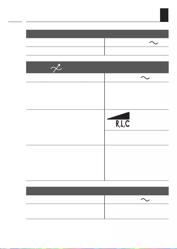
Load
type
Ohmic load
R
Inductive
load
L
Capacitive
load
C
Light
source
230 V 230 V
Light bulbs LED retrot
lamps
230 V
High-voltage
halogen lamps
Low-voltage halogen lamps ...
... with a
conventional
transformer
... with an
upstream
switching
power supply
Setting the operating mode and range on the
setting dial
R,L
R,C
A
R, C R, L R, C
Operating
mode
Trailing edge
control
Leading-edge
control
(triac mode)
Trailing edge
control
The illustrations serve as an example. All shapes and versions of
the above-mentioned light sources can be used.
9.1 Manual setting of the load type
i
22
EN
9.2 Setting the dimming range
When does the dimming range have to be set
manually?
Internal power supplies and circuits in some light sources may
interfere with the DuoFern Universal Dimmer when dimming
the light.
◆In this case, the light source ickers, especially in the
upper and/or lower brightness range.
◆The DuoFern Universal Dimmer continuously adjusts
and switches o.
Finding the suitable setting
The suitable setting must be determined experimentally.
The status LED ashes to indicate the set range.
i
Assigning the dimming range
R,L
R,C
A
5
4321
5
4321
Set load type: R, C R, L A
Dimming ranges The status LED ashes ...
1 25 - 70 % 1 x red 1 x green
2 20 - 75 % 2 x red 2 x green
3 15 - 85 % 3 x red 3 x green
4 10 - 95 % 4 x red 4 x green
5 0 - 100 % 5 x red 5 x green yellow
Some light sources can exhibit a slight ickering or
twinkling despite the correct dimmer function. Select
an alternative light source in this case.
23
EN
9.3 Switching the minimum brightness
function on and o
i
Normative safety regulations stipulate that the light from a
light source can still be detected at the light source’s lowest
brightness level. The corresponding functionality is stored in
the dimmer.
As many (retrot) LED light sources light up very brightly even
at the preset minimum brightness value, this function can be
switched o. This way, darker light scenes can be created
with many light sources.
How to switch the minimum brightness function
on and o
Pay attention to the following information
Always make sure that the light from the light source used
can still be detected at the lowest brightness level in order
to meet the normative safety requirements.
It is also important to make sure that the light source moves
from the “o” position and actually switches on (“lights up”)
to the lowest brightness level when turned on.
1. 10 sec. Press the log-on button for approx.
10 sec. until the status LED lights up
correspondingly:
◆green = the function is
switched on
◆red = the function is
switched o

24
EN
9.4 Overload protection - conduct in the
event of an overload
i
Very high loads can cause inrush currents that are much
greater than 400 watts/VA.
In this case...
◆The internal overcurrent shutdown has tripped.
The DuoFern Universal Dimmer switches o until it is
disconnected from the mains power.
◆The status LED ashes red.
Proceed as follows:
◆Disconnect the DuoFern Universal Dimmer from the
mains power.
◆Reduce the power of the connected light source (trans-
former etc.)
25
EN
10. Operation with an external button
i
The following functions are available when connecting an
external button to the input [ E ]:
Switching on and o (taking account of an
intermediate value)
Press the button The dimmer switches on or o (running
time approx. 2 s) depending on the
switching state.
Sequence when pressing the button:
1 x
2 x
If an intermediate value is set, this is acti-
vated when the dimmer is switched on.
Switching on and o (without taking account of an
intermediate value)
Press the button The dimmer or lighting is switched
on or o completely.
An intermediate value is not
taken into account.
Light >> Stop >> Dark >> Stop >>
26
EN
Dimming and setting an intermediate value
Press and hold
The dimming process starts in the opposite direction to the
last dimming direction.
The brightness achieved is saved (as an intermediate val-
ue) as soon as you release the button.
The next time you switch on the dimmer, the lighting is set
to the stored intermediate value by pressing the button
once, see page 25 - provided that the intermediate value
function is active.
i
10. Operation with an external button
i
The intermediate value function can be activated
or deactivated via the HomePilot®.
i
Radio operation is dependent on the respective
transmitter. You can obtain further information in
the service centre on our website at
“www.rademacher.de”.

27
EN
11. DuoFern device (logging on / logging o)
i
In order for your DuoFern Universal Dimmer to react to control
signals from the DuoFern network, it is necessary to log on
each DuoFern device (e.g. manual transmitter, ush-mounted
radio transmitter or a HomePilot® etc.).
Please read the instruction manual for the
respective DuoFern device.
Maximum number of connected devices
You can log on a maximum of 20 DuoFern devices.
28
EN
11.1 Logging on DuoFern devices
i
1. Switch the respective DuoFern
device to log-on mode.
2. Briey press the log-on button.
120 sec. The log-on mode remains
active for 120 seconds.
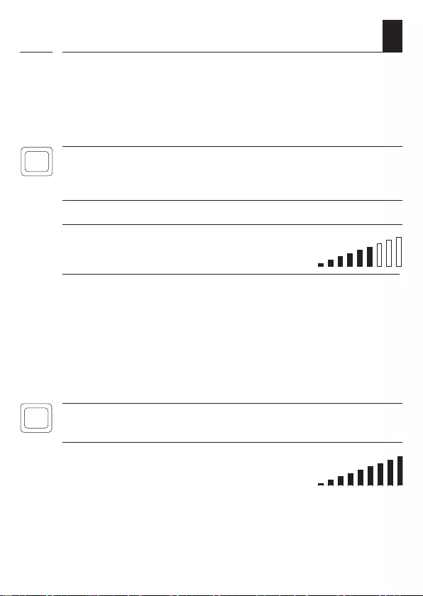
LED signals when logging on
◆Flashes green: during the login
◆Lights up green for 5 seconds: after a successful login
◆Lights up red: if the maximum number of participants
has already been reached
3. Terminate the log-on process or log on the next DuoFern
device.
The log-on process is terminated:
◆After a successful login
◆Automatically after 120 seconds
◆By pressing the log-o button
29
EN
i
11.2 Logging o DuoFern devices
1. Switch the respective DuoFern
device to log-o mode.
2. Press the log-o button.
120 sec. The log-o mode remains
active for 120 seconds.
LED signals when logging o
◆Flashes red: during the login
◆Lights up green for 5 seconds: after a successful log-o
3. Terminate the log-o process or log o the next DuoFern
device.
The log-o process is terminated:
◆After a successful log-o
◆Automatically after 120 seconds
◆By pressing the log-on button
30
EN
i
12. Deleting all settings
1. Press the log-o button
for ve seconds until...
The status LED lights up red
continuously. All settings are
deleted and reset to
the factory settings.
13. Simplied EU declaration of conformity
i
RADEMACHER Geräte-Elektronik GmbH, hereby declares
that the DuoFern Universal Dimmer complies with the Directive
2014/53/EU (Radio Equipment Directive).
The full text of the declaration of conformity is available at
the following website:
www.rademacher.de/ce

31
EN
i
14. Warranty terms and conditions
RADEMACHER Geräte-Elektronik GmbH provides a 24-month
warranty for new devices that have been installed in compliance
with the installation instructions. All construction faults, ma-
terial defects and manufacturing defects are covered by the
warranty. Your statutory warranty claims remain unaected
by this warranty.
The following are not covered by the warranty:
◆Incorrect tting or installation
◆Non-observance of the installation and operating manual
◆Improper operation or wear and tear
◆External inuences, such as impacts, knocks or weathering
◆Repairs and modications by third parties, unauthorised
persons
◆Use of unsuitable accessories
◆Damage caused by unacceptable excess voltages (e.g.
lightning)
◆Operational malfunctions caused by radio frequency
overlapping and other such radio interference
A prerequisite for the warranty is that the new device must
have been purchased from one of our approved specialist
retailers. Proof of this must be provided by presenting a copy
of the invoice.
RADEMACHER will remedy any defects that occur within the
warranty period free of charge either by repair or replacement
of the aected parts or by supplying a new replacement unit
or one to the same value. There is no general extension of
the original warranty period by delivery of a replacement or
by repair as per the terms of the warranty.

RADEMACHER
Geräte-Elektronik GmbH
Buschkamp 7
46414 Rhede (Germany)
info@rademacher.de
www.rademacher.de
Service:
Hotline 01807 933-171*
Fax +49 2872 933-253
service@rademacher.de
* 30 seconds free of charge, subsequently
14 cents / minute from German xed line
networks and max. 42 cents / minute
from German cellular networks.
Subject to technical modications, misprints and errors excepted. Illustrations not binding.