Table of Contents
- Important Safety Messages
- Safety and General Information
- Deenergizing safety
- Electrical safety
- Battery safety
- General information
- FCC Class A radio frequency warning
- Package Contents
- Inspect the contents upon receipt. Notify the carrier and dealer if the unit is damaged.
- Specifications
- Environmental
- Physical
- Battery
- Electrical
- Remove Battery Module
- Rack-Mount Installation
- Tower Installation
- Rear Panel Features
- Key to identify rear panel features
- UPS Configuration
- Connect Emergency Power Off feature
- Configure controllable outlet groups
- UPS Display Interface
- Display interface operation
- Menu overview
- LCD display interface angle adjustment
- Select models are ENERGY STAR® qualified. For more information go to www.apc.com/company/us/en/sustainability/energy-efficiency/
APC SRT2200RMXLI + AP9630 User Manual
Displayed below is the user manual for SRT2200RMXLI + AP9630 by APC which is a product in the Uninterruptible Power Supplies (UPSs) category. This manual has pages.
Related Manuals
Installation Guide Smart-UPS™On-Line
SRT2200/SRT3000 Tower/Rack-Mount 2U
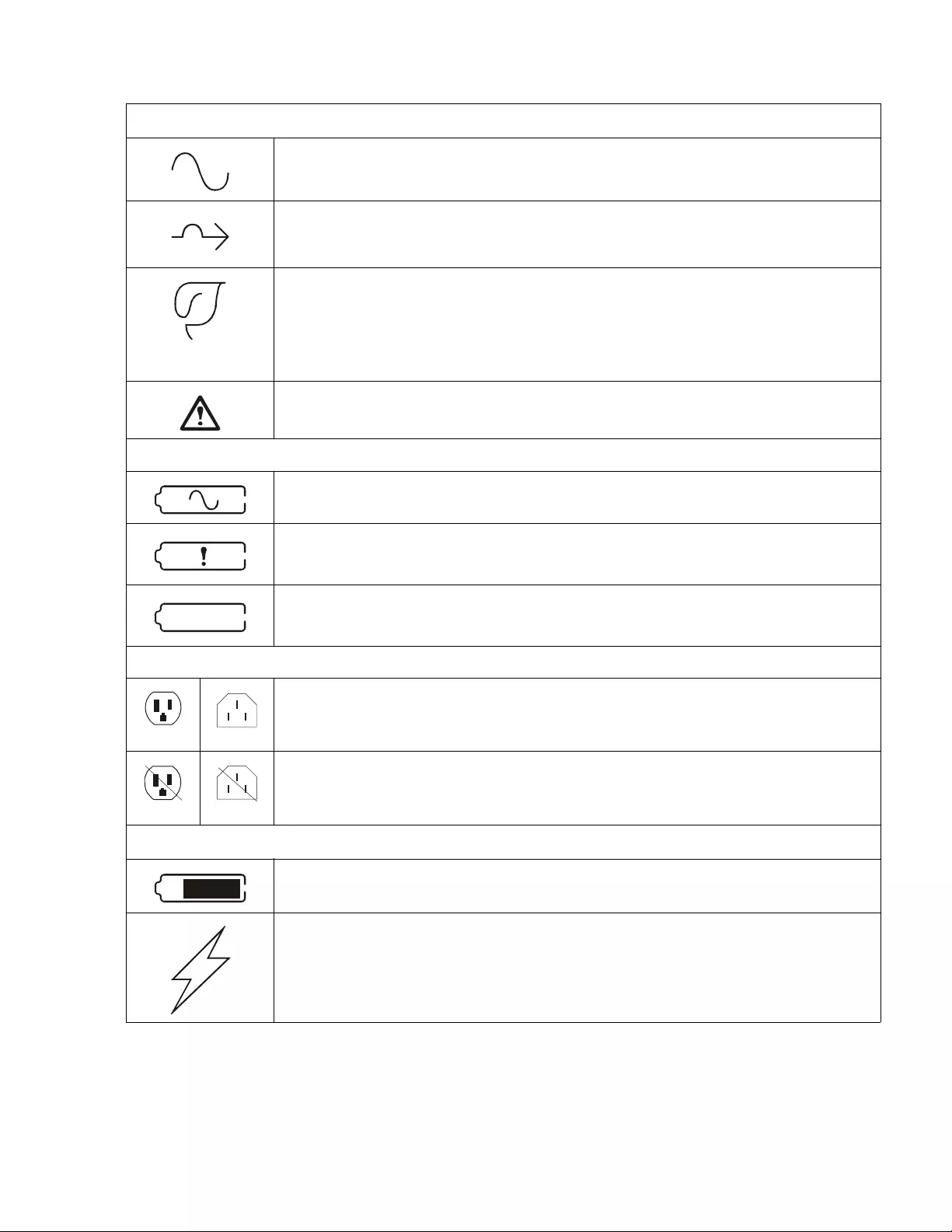
Important Safety Messages
Read the instructions carefully to become familiar with the equipment before attempting to install, operate, service or
maintain the UPS. The following special me ssages m ay appear throughout this manual or on the equipment to warn of
po t en t ial haza r d s or to cal l at tenti o n to in fo r m at i on th a t cl ar i fi e s or sim p l ifies a proc ed u r e.
The addition of t his symbol to a Danger or Warning product safety label indicates that an ele ctrical hazard
exists which will result in personal injury if the instructions are not followed.
The addition of this symbol to a Warnin g or Caut ion product safet y label indicat es that a hazard exis ts that
can result in injury and product damage if the instructions are not followed.
Information
Safety and General Information
• Adhere to all nationa l and local electric al c odes.
• All wiring m ust be performed b y a qualified electrician.
• Changes and modifications to this unit not expressly approved by APC could void the wa rranty.
• This UPS is intended for in door u se only.
• Do not operate th is UPS in direct sun light, in contact with flu id s, or where th ere is excessive dust or humid ity.
• Be sure the air vents on the UPS are not blocked. Allow a deq uate space for proper ventilation.
• For a UPS w it h a f a ctor y i ns ta l led po we r c ord, c onne ct th e UPS p o wer ca bl e dir e ctl y to a wall outl e t. Do not us e s urge
protectors or extension cords.
• The battery typically lasts for two to five years. Environmental factors impact battery life. Elevated ambien t
temperatures, po or quality mains power, and frequent short duration discharges will shorten battery life.
• Replace the battery immediately when the UPS indicates battery replacement is necessary .
• The equipment is he avy. A lwa ys pr actice sa fe lifting techniques adequate for the weight of th e equipment.
• Th e batterie s are heavy. Remove the batteries before in stalling the UPS and external battery pac ks (XLBPs), in a rack.
• Always install XLBPs at the bottom in rack-mount configurations. The UPS must be installed above the XLBPs.
• Always install peripheral equipment above the UPS in rack-mount configurations.
• Additional safety information can be fo u nd in the Saf ety Guid e s upplied with this unit.
WARNING
WARNING indicates a potentially hazardous situation which, if not avoided, can result in death or seri ous i njury.
CAUTION
CAUTION indicates a potential ly hazardous situation which, if not avoided, can re s u lt in minor or moderate injury.
NOTICE
NOTICE used to addr ess practices not related t o physical inj ury. The saf ety a lert symbol is not used with this signal word.

Smart-UPS On-Line SRT2200/SRT3000 Tower/R ack-Mount 2U2
Dee nergizing safety
The U PS contains internal batteries and may pr esent a shock hazard even when disconnected from the branch circuit (mains).
Before installing or servicing the equipme n t verify the following:
• Mains c ircuit breaker is in the OFF position. The UPS is disconnected from mains or wall outle t.
• Interna l UPS b atte ries are re moved
• XLBP battery modules are disconnected
Electrical safety
• For models with a hardwired input, the connection to the branch circuit (mains) must be performed by a qualified
electrician.
• 230 V mod els onl y: I n or de r to m ai nta i n com pl iance wit h the E MC di rect ive for pr oduc t s sol d in E ur ope , out p ut cor ds
attached to the UPS must not exceed 10 m eters in le ngth.
• The protective earth conductor for the UPS carries the le akage current from the load devices (computer equipment).
An insulated ground conductor is to be installed as part of the branch circuit that supplies the UPS. The conductor
must have the same size and insulation material as the grounded and ungrounded branch circuit supply conductors .
The conductor will typically be green and with or without a yellow stripe.
• The UPS input ground c onductor must be properly bonded to protec tive earth at the service panel.
• If the UPS input power is supplied by a separately derived syste m, the ground conductor must be prope rly
bonded at the supply transformer or motor generator s et.
Battery safety
• Before installing or replac ing the batteries, remove jewelry such as wristwatches and rings.
High short circuit current through conductive materials could cause severe burns.
• Do not dispose of batteries by burning them. The batteries may explode.
• Do not open or mutilate batteries. Rele as ed electr olyte is harmful to the skin and eyes, and may be toxic.
General information
• The UPS will recognize as many a s 10 external battery packs connected to the UPS.
Note: For each X LBP a d ded, inc reased recharge time will be required.
• The model a nd serial numbe rs a re located on a small, rear panel label. For some models, an additional label is located
on the chassis under the front beze l.
• Always recycle used batteries .
• Recycle the package materials or save them for r euse.
FCC Class A radio frequency warning
This equ ipment has been tested and found to comply with the limits for a Class A digital device, pursuant to part 1 5 of the
FCC Ru les. These limits are intended to pro vide reason able protection against harmful interf eren ce wh en the equipment is
operated in a commercial environment. This equipment generates, uses, and can radiate radio frequency energy and, if not
installed a nd use d in accordance with the instruction ma nua l, ma y ca use harmful interferenc e to radio communications.
Ope ration of this equipmen t in a residential area is likely to cause harmful interference in which case th e user will be required
to corr ec t the in terfe rence at his own exp ense.
Smart-UPS On-Line SRT2200/SRT3000 Tower /Rack-Mount 2U 3
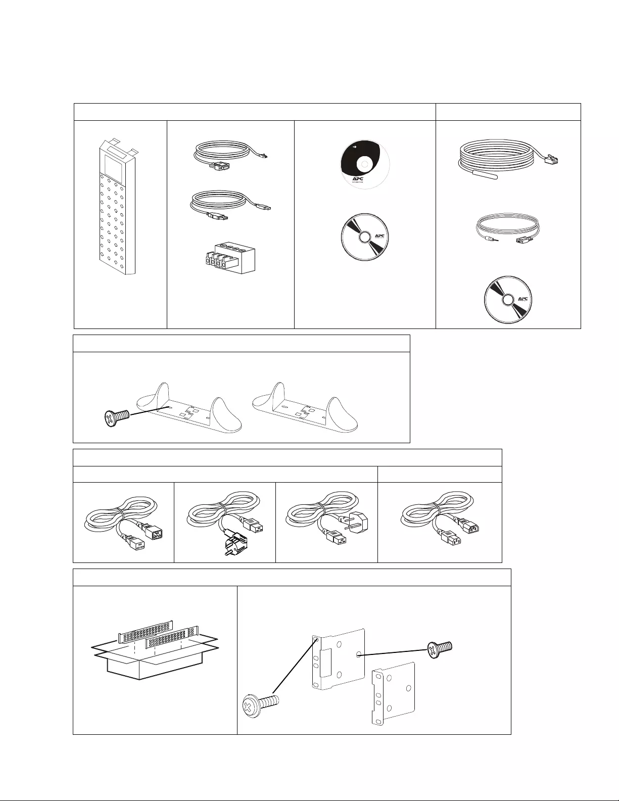
Package Contents
Inspect the contents upon receipt. Notify the carrier and dealer if the unit i s damaged.
Includ ed with all models NC models only
Front bezel RJ45 to DB9 cable
USB cable
EPO Terminal block
User Documentation CD.
PCBE Software CD
Temperature sensor probe
Serial c onfiguratio n cabl e
Network Mana gem ent Utility CD
In cl ude d w it h Tow er models only
• 2 pairs s t ab il ize r br acke ts
• 4 flat head screws to secure tower stabilizer brackets to the UPS
Included with XLI/XLW-IEC models only
3 input power co rds 1 output IEC jumper ca ble
Included with Rack-Mount models only
Rail Kit with instr uctions and h ardware
for installing rails in a ra ck. • 1 pair rac k-mount brackets
• 6 flat head screws to secure rack -mount brackets to the UPS
• 4 ornamenta l s cre ws to se cure rack-mount bracket s to t he rails
User Documentation
x4
su04
34a
x4
x6
Smart-UPS On-Line SRT2200/SRT3000 Tower/R ack-Mount 2U4
Specifications
For additional specifications refer t o the APC by Schneider Electric web s ite, www.apc.com.
Environmental
Physical
Temperature Operating 0º to 40º C (32º to 104º F)
Storage - 15º to 45º C (5º to 113º F)
Elevation Operating 0 - 3,000 m (0 - 10,000 ft)
Storage 0 - 15,000 m (50,000 ft)
Humidity 0 % to 95% relative humidi ty, non-condensing
Protection Class I P 20 rating
Note: Charge the battery modules every six m onths during storage.
Environmental fac tors impact battery life. Elevated ambient temperatur es , high hu mi dity, poor quality mains power, and
frequent short duration discharges will shorten batt ery life.
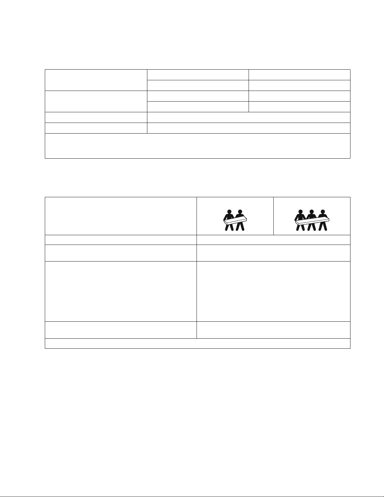
SRT2200XLI/SRT2200RMXLI/SRT2200RMXLI -NC model
The U PS is heavy. Follow all lifting guidelines.
Lif t ing guidelines 18 - 32 kg (40 - 70 lb) 32 - 55 kg (70 - 120 lb)
Unit weight batteries included, without packaging 25 kg (55 lb)
Unit weight batteries included, with packaging Rack-Mount models: 34 kg (75 lb)
Tow er m od els : 31 kg (68 lb )
Unit dimensions without packaging
Height x Width x Depth Rack-Mount models:
85 (2U) mm x 432 mm x 560mm
3.35 (2U) in x 17 in x 22 in
Tower models:
85 (2U) mm x 432 mm x 585mm
3.35 (2U) in x 17 in x 23 in
Unit dimensions with packaging
Height x Width x Depth 245 mm x 600 mm x 810 mm
9.7 in x 23. 6 in x 31.9 in
The model and serial numbers are on a small labe l located on the rear panel.
Smart-UPS On-Line SRT2200/SRT3000 Tower /Rack-Mount 2U 5
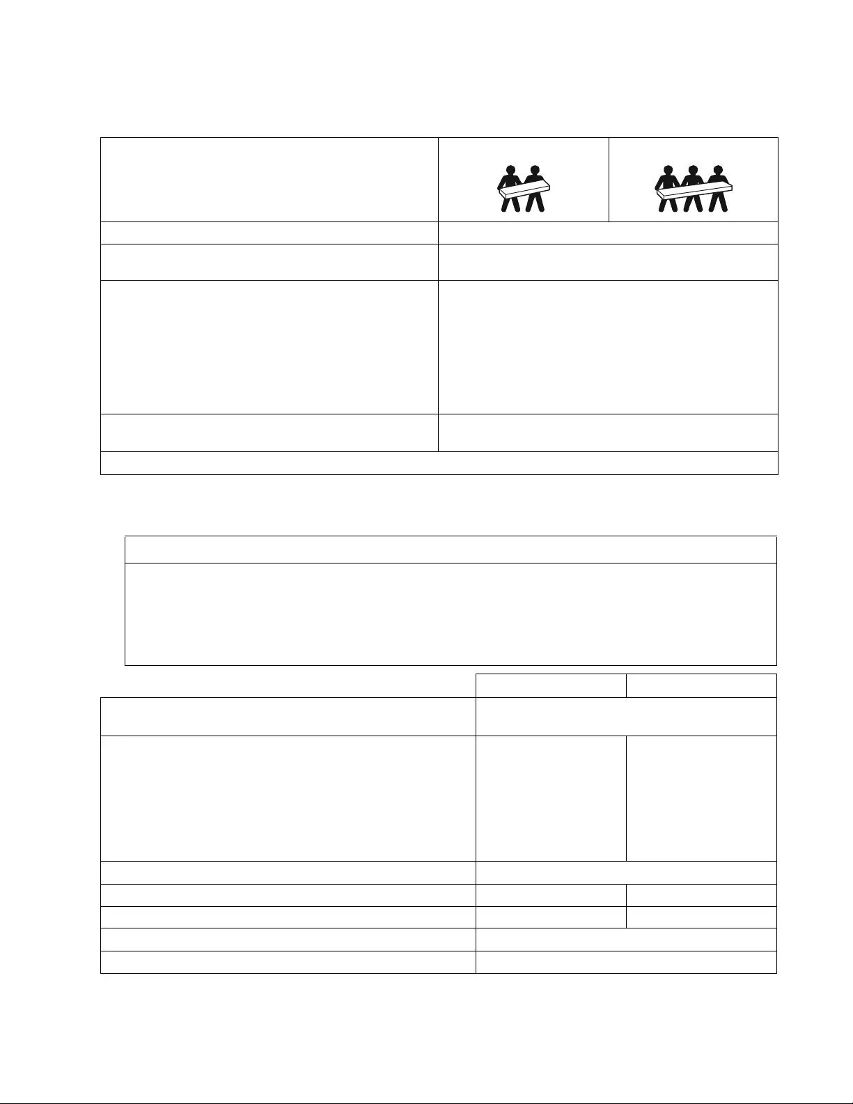
Battery
SRT3000XLI/SRT3000RMXLI/SRT3000RMXLI-NC/SRT3000XLT/SRT3000RMXLT/
SRT 3000RMXLT-NC/SRT 3000XLW-IEC/SRT3000RMXLW-IEC model
The UPS is heavy. Follow all lifting guidelines .
Lif t ing guidelines 18 - 32 kg (40 - 70 lb) 32 - 55 kg (70 - 120 lb)
Unit weight batteries included, without packaging 31 kg (69 lb)
Unit weight batteries included, with packaging Rack-Mount models: 40 kg (88 lb)
Tower models: 37 kg (81 lb)
Unit dimensions without packaging
Height x Width x Depth Rack-Mount models:
85 (2U) mm x 432 mm x 611mm
3.35 (2U) in x 17 in x 24 in
Tower models:
85 (2U) mm x 432 mm x 6 36mm
3.35 (2U) in x 17 in x 25 in
Unit dimensions with packaging
Height x Width x Depth 245 mm x 600 mm x 870 mm
9.7 in x 23.6 i n x 34.3 in
The model a nd serial numbers are on a small l abe l located on the rear panel.
NOTICE
RISK OF EQUIPMENT DAMAGE
• Replace the battery at least every 5 years.
• Replace the battery immediately when the UPS indicates battery replacement is necessary.
Failure to follow these instruc tions can result in e quipment damage
SRT 2200 models SRT 3000 models
Battery type Sealed, maintenance-free, Valve Regulated
Lead-Acid battery
Rep l acem e nt ba tt ery module
This UPS has s wappable batte r y modules.
Refer to the ap propriate repla ce ment battery user manua l for
installation instructions.
Contac t your dealer or go the APC by Schneider Electric web sit e,
www.apc.com for information on replacement batteries.
APCRBC141 APCRBC152
Number of battery modules 1 batte r y module
Voltage for ea ch battery module 72 VDC 96 VDC
Total voltage for the UPS 72 VDC 96 VDC
Ah rating 5.1 Ah per battery module
XL B P ca bl e leng t h 500 mm (19.7 in)
Smart-UPS On-Line SRT2200/SRT3000 Tower/R ack-Mount 2U6
Electrical
Models Rating Building Circuit B reaker
(CB) C urrent Rating
SRT2200XLI 2200 VA / 1980 W 16 A
SRT2200RMXLI
SRT2200RMXLI-NC
SRT3000XLI 3000 VA / 2700 W 20 A
SRT3000RMXLI
SRT3000RMXLI-NC
SRT3000XLT 20 A* / 2 pole
SRT3000RMXLT
SRT3000RMXLT-NC
SRT3000XLW-IEC 20 A IEC; 20 A UL* / 2 pole
SRT3000RMXLW-IEC
CAUTION
RISK OF FIRE, RISK OF DAMAGE T O EQUIPMENT OR PERSONNEL
* Connect the UPS m odels only to a circuit provided with 20 A maximum branch circuit overcur rent protection i n
accordance with the Nati onal Electrical Code, ANSI/NFPA 70 and the Canadian Electrical Code, Part I, C22.1.
Failure t o follow these instructions can re sult in fi re, equipment damage and minor or moderate injury.
Output
Output Frequency 50 Hz / 60 Hz
Nominal Output Voltage SRT2200XLI/SRT2200RMXLI /S RT2200RMXL I-NC/SRT3000XLI /S RT3000RMXLI/
SRT 3000RMXLI-NC: 220 V, 230 V, 240 V
SRT3000XLT/SRT3000RMXLT/SRT3000RMXLT-NC: 208 V, 240 V
SRT3000XLW-IEC/SRT3000RMXLW-IEC: 208V, 220V, 230V, 240V
Input
Input Frequency 40 Hz - 70 Hz
Nominal Input Volt age SRT2200XLI/SRT2200RMXLI /S RT2200RMXL I-NC/SRT3000XLI /S RT3000RMXLI/
SRT 3000RMXLI-NC: 220 V, 230 V, 240 V
SRT3000XLT/SRT3000RMXLT/SRT3000RMXLT-NC: 208 V, 240 V
SRT3000XLW-IEC/SRT3000RMXLW-IEC: 208V, 220V, 230V, 240V
Input current rating SRT2200 m odels: 13 A
SRT 3000 m odels: 16 A
Smart-UPS On-Line SRT2200/SRT3000 Tower /Rack-Mount 2U 7
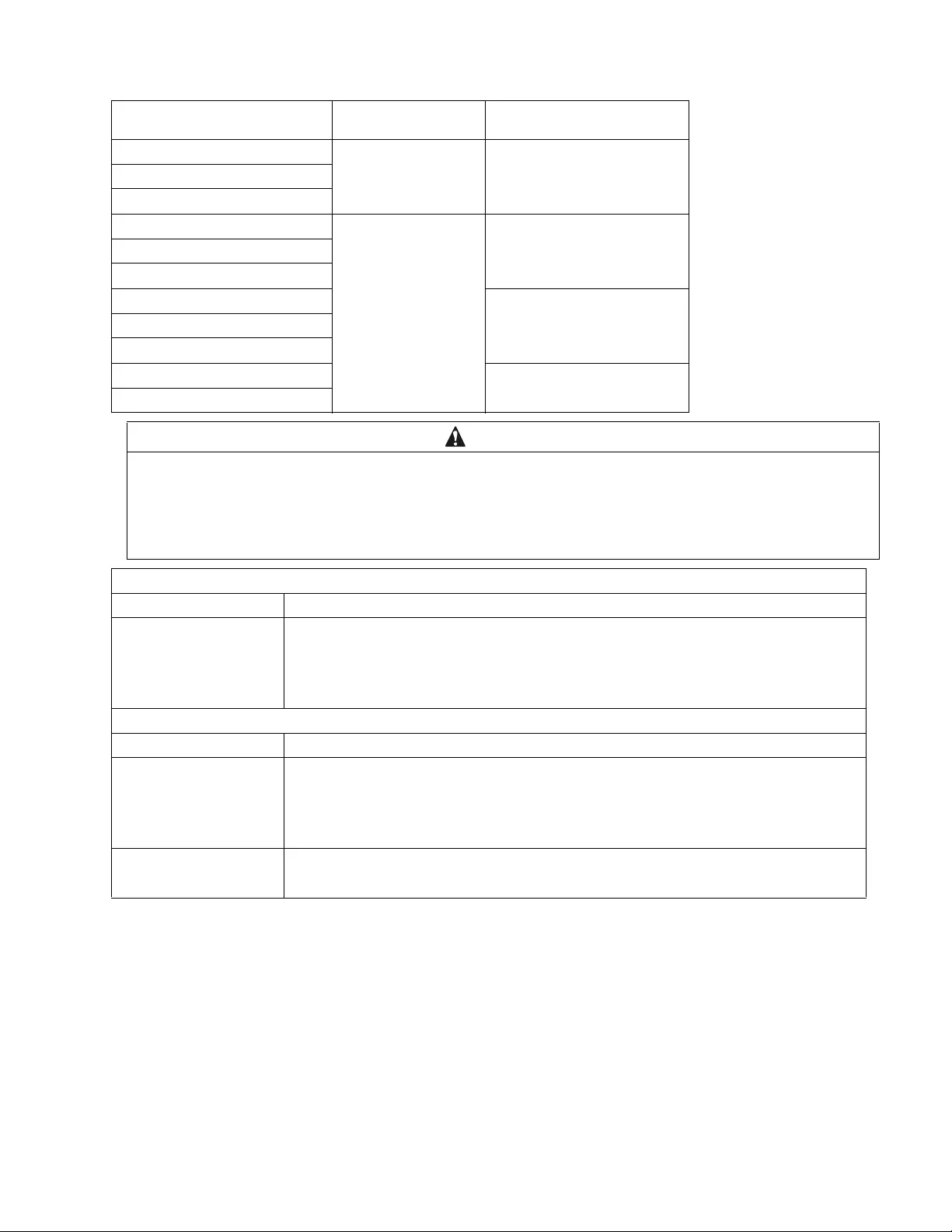
Remove Battery Module
Use the battery module handle to lift and sli d e the battery module ou t of the UPS.
CAUTION
DAMAGE TO EQUIPMENT OR PERSONNEL
• The equipment is heavy. Each APCRBC152 bat tery module weighs 16.4 kg (36. 2 lb) and each APCRBC141 battery module
weighs 12.5 kg (27.6lb).
• Always practice saf e li fting techn iques adequate for t he we ight of the equipment.
• Remove the battery modules before installing the UPS.
• Use the battery module handle to slide the battery modules in or out of the UPS.
• Do not use the bat tery module handle to lift or carry the battery module.
Failure to follow these instructi ons can result in equipment damage and minor or moderate injury.
SRT2200 models
SRT3000 models
suo0849b
x3
suo0850c
suo0858c
suo0851b
Smart-UPS On-Line SRT2200/SRT3000 Tower/R ack-Mount 2U8
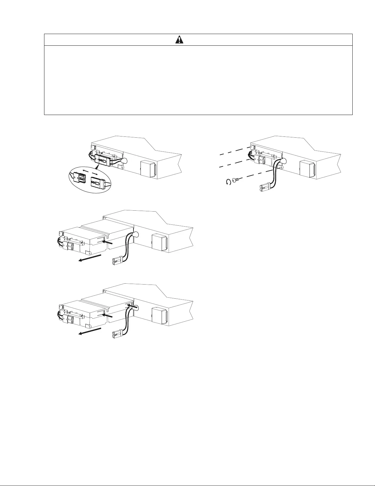
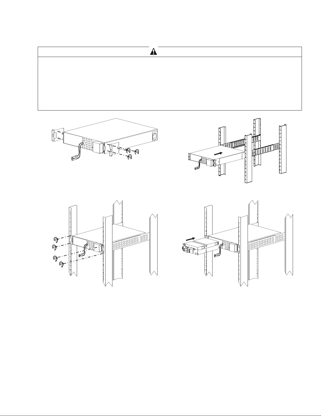
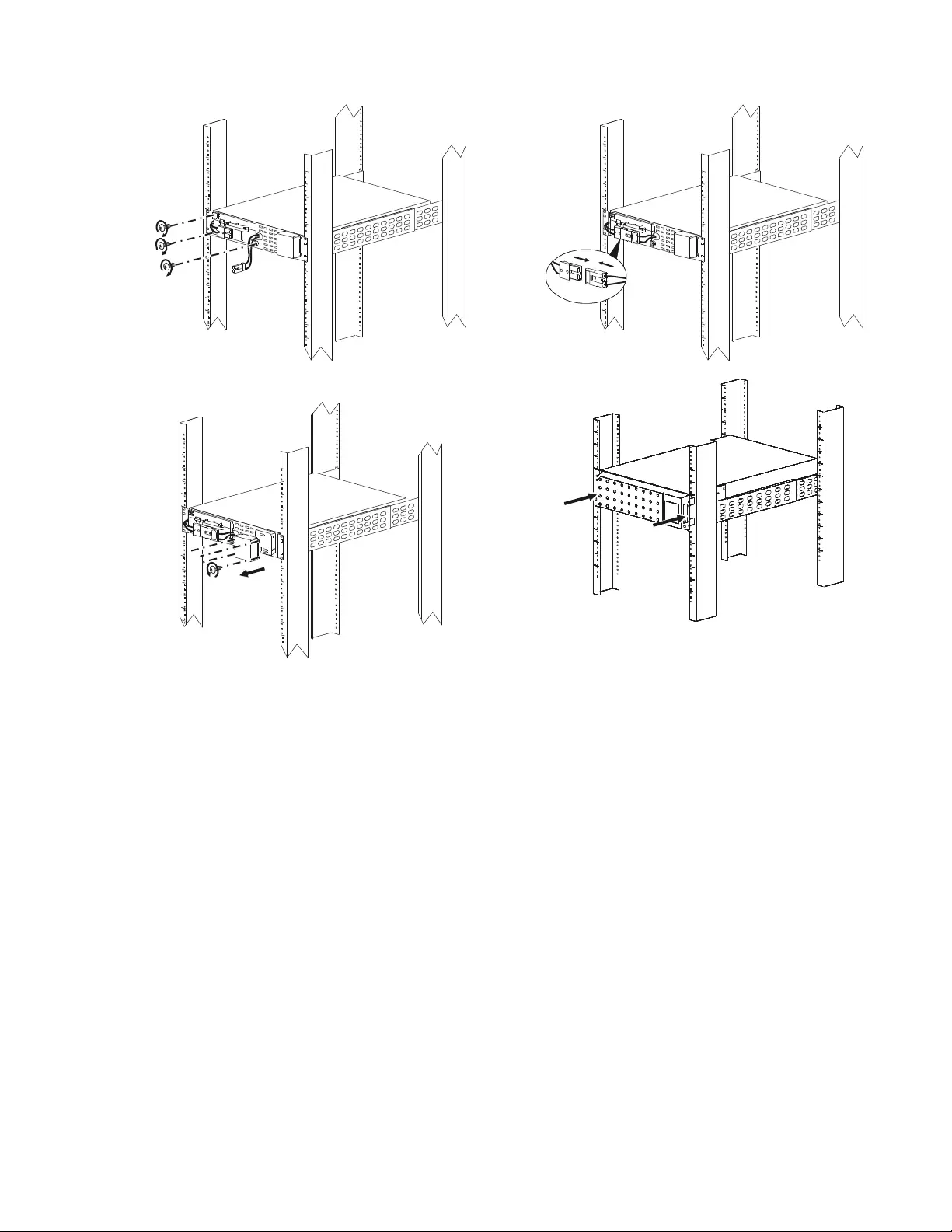
Rack-Mount Installation
Refer to the Rail Kit Installation Guide for i ns tructions on rail installation.
CAUTION
DAMAGE TO EQUIPMENT OR PERSONNEL
• The equipment is heavy. Always p ractice safe lifting t echniques adeq uate f or the weight of the equipment.
• Always use the recommended numbe r of sc rews to secure brackets t o the UPS.
• Always use the recommended numbe r of sc rews t o secure the UPS to the rack.
• Always install the UPS at th e bott om of th e rack.
• Always install the XLBP bel ow the UPS in the rac k.
Failur e to fol low these instructi ons can result in equipment da mag e and minor or moderate injury
suo0866c
x3
x3
suo0867b
suo0865b
x4
suo0868b
Smart-UPS On-Line SRT2200/SRT3000 Tower /Rack-Mount 2U 9
suo0869b
x3
suo0870b
suo1061a
x4
su0859a
Smart-UPS On-Line SRT2200/SRT3000 Tower/R ack-Mount 2U10
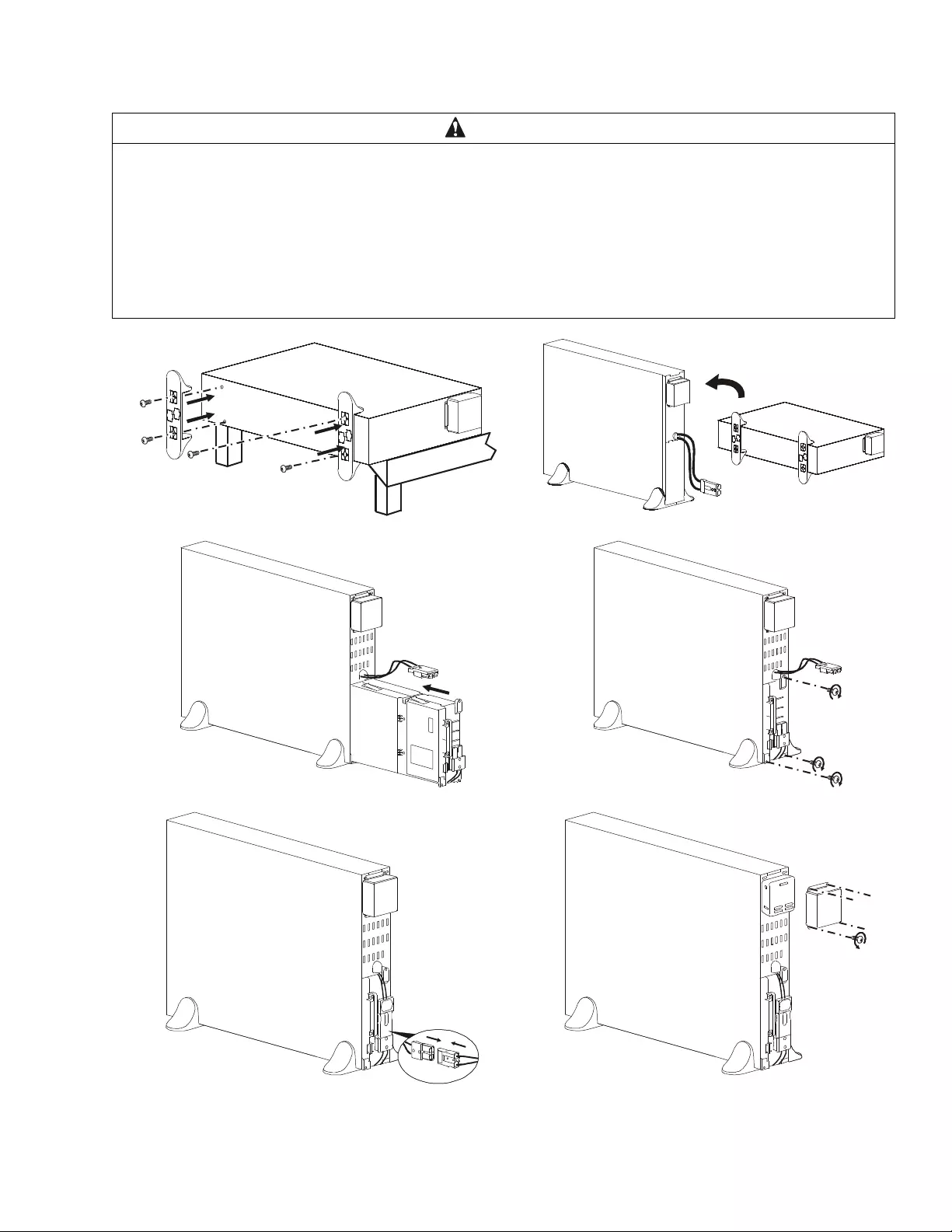
Tower Installation
CAUTION
DAMAGE TO EQUIPMENT OR PERSONNEL
• The equipment is h eavy. Each APCRBC152 battery module weighs 16. 4 kg (36. 2 lb) and each APCRBC141 battery m odule
weighs 12.5 kg (27.6lb).
• Always practice safe li fting techni ques adequate for th e weight of t he equipment.
• Remove the battery modules bef ore installing the UPS.
• Use t he batt ery module handle to slide the battery modules in or out of the UPS.
• Do not use the batter y module handle to lift or carry the battery modul e.
Failur e to fol low these instructi ons can result in equipment da mag e and minor or moderate injury
su0845c
suo0871c
suo0872c
suo0873c
x3
suo0874c
suo1062a
x4
Smart-UPS On-Line SRT2200/SRT3000 Tower /Rack-Mount 2U 11
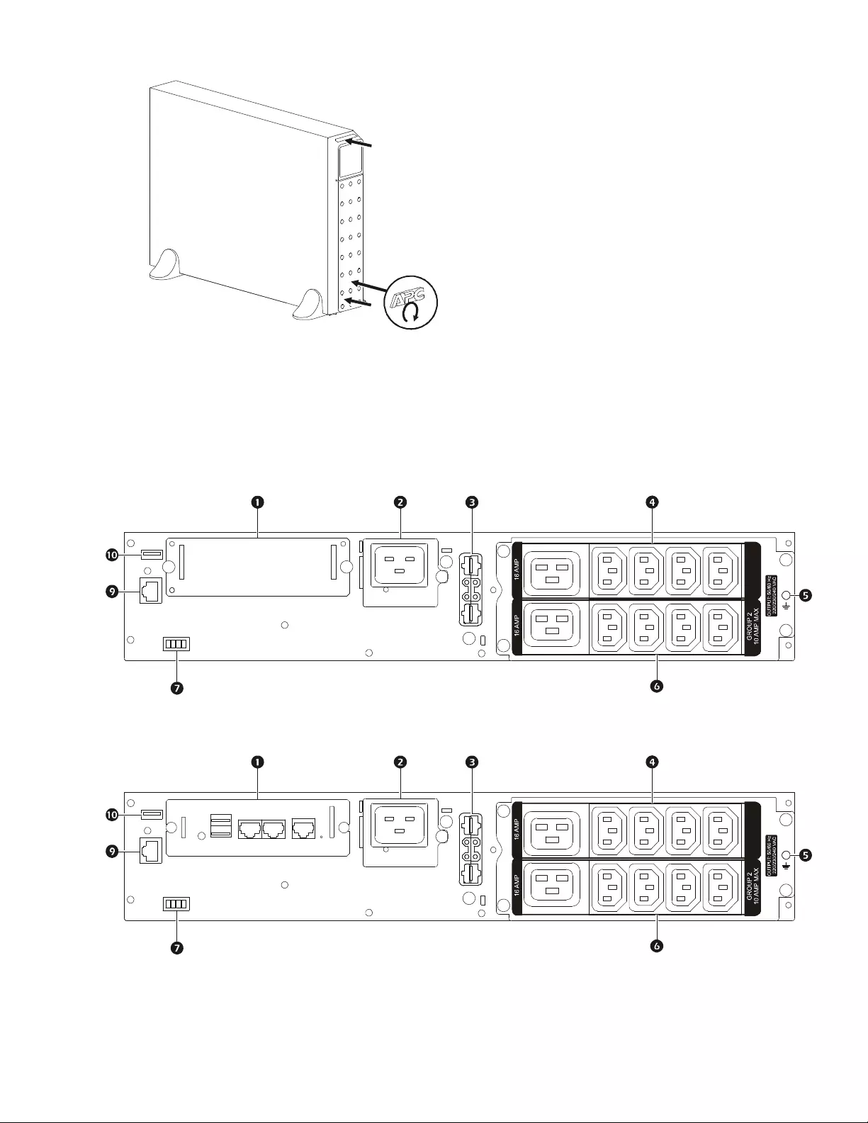
Rear Pane l Features
Note: Refer to the table “Key to identify rear panel f eatures” on page 13, that provides a key to the c allout numbers for
the rear panel graphics depicted in this manual.
SRT2200XLI/SRT2200RMXLI/SRT3000XLI/SRT3000RMXLI
SRT2200RMXLI-NC/SRT3000RMXLI-NC
suo0875c
GROUP 1
10 AMP MAX
suo0882a
GROUP 1
10 AMP MAX
suo0882b
Smart-UPS On-Line SRT2200/SRT3000 Tower/R ack-Mount 2U12
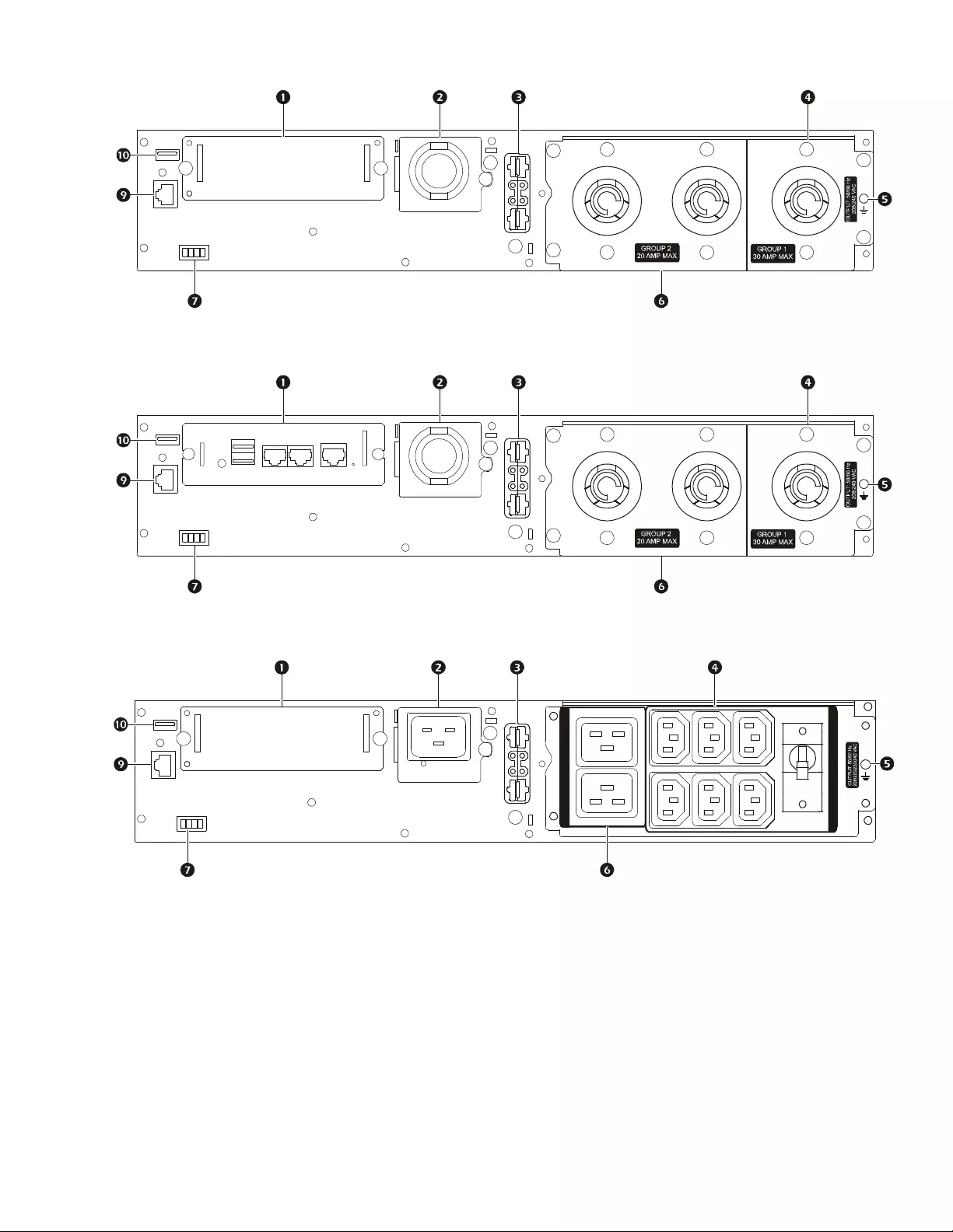
SRT3000XLT/SRT3000RMXLT
SRT3000RMXLT-NC
SRT3000XLW-IEC/SRT3000RMXLW-IEC
suo0883a
suo0883b
suo0884a
OVERLOAD
PROTECTO R
GROUP 2 MAX: 16 AMP IEC; 20 AMP UL
GROUP 1 MAX: 10 AMP IEC; 15 AMP UL

Smart-UPS On-Line SRT2200/SRT3000 Tower /Rack-Mount 2U 13
Key to identify rear panel features
UPS Configuration
Connect Emergency Power Off feature
For instructions on how to connect the Emergency Power Off (E PO) switch, refer to the Operation and Maintenance
manual on the User Docume ntation CD (supplied).
Configure controllable outlet groups
The outl ets on the UPS are grouped. To conf igure the controlled outlet fea tures, use the Advanced menus on the
display interface an d navigate to: Main Menu > Configuration > Outlets > Outlet Gr oup.
SmartSlot The Sm artSlot can be used to connect optional ma nagement accessories.
AC input
power cable or
ha rdw i re in put box
SRT3000XLT, SRT3000RMXLT, SRT3000RMXLT-NC models ha ve factory installed input
po w er cables.
External battery
power and
communication
connector
Use the ex te r n al bat tery cab l e on th e X LB P to co n ne ct th e U P S an d XL BP.
XLBPs provide e xtended runtime during p ower outages. The UPS will automatically
recognize up to 10 external battery packs.
Controllable
outl et group 1 Conn ect elec tronic devices to th ese outlets.
Chassis ground screws Th e UPS and XLBP s have groun d scre ws for conn ectin g the groun d leads . Pri or to conn ectin g
a ground lead, d is connect the UPS from mains power.
Controllable
outl et group 2 Conn ect elec tronic devices to th ese outlets.
EP O t e r mina l The Emergency Power Off (EPO ) terminal allows th e user to connect the UPS to a central
EPO system.
Serial Com The Serial Com port is used to comm unicate with the UPS.
Use only interface kits supplied or appro ve d by APC by Schneider Electric. Any other
serial interfa ce cable will be i ncompatible w ith the UPS co nnect o r.
USB port The USB port is us ed to connect eith er a server for native operating system communi cations,
or for software to communicate with the UPS.
Note: Serial and USB communication should not be u sed simultaneously. Use either the Serial
Com or the USB port.
Smart-UPS On-Line SRT2200/SRT3000 Tower/R ack-Mount 2U14
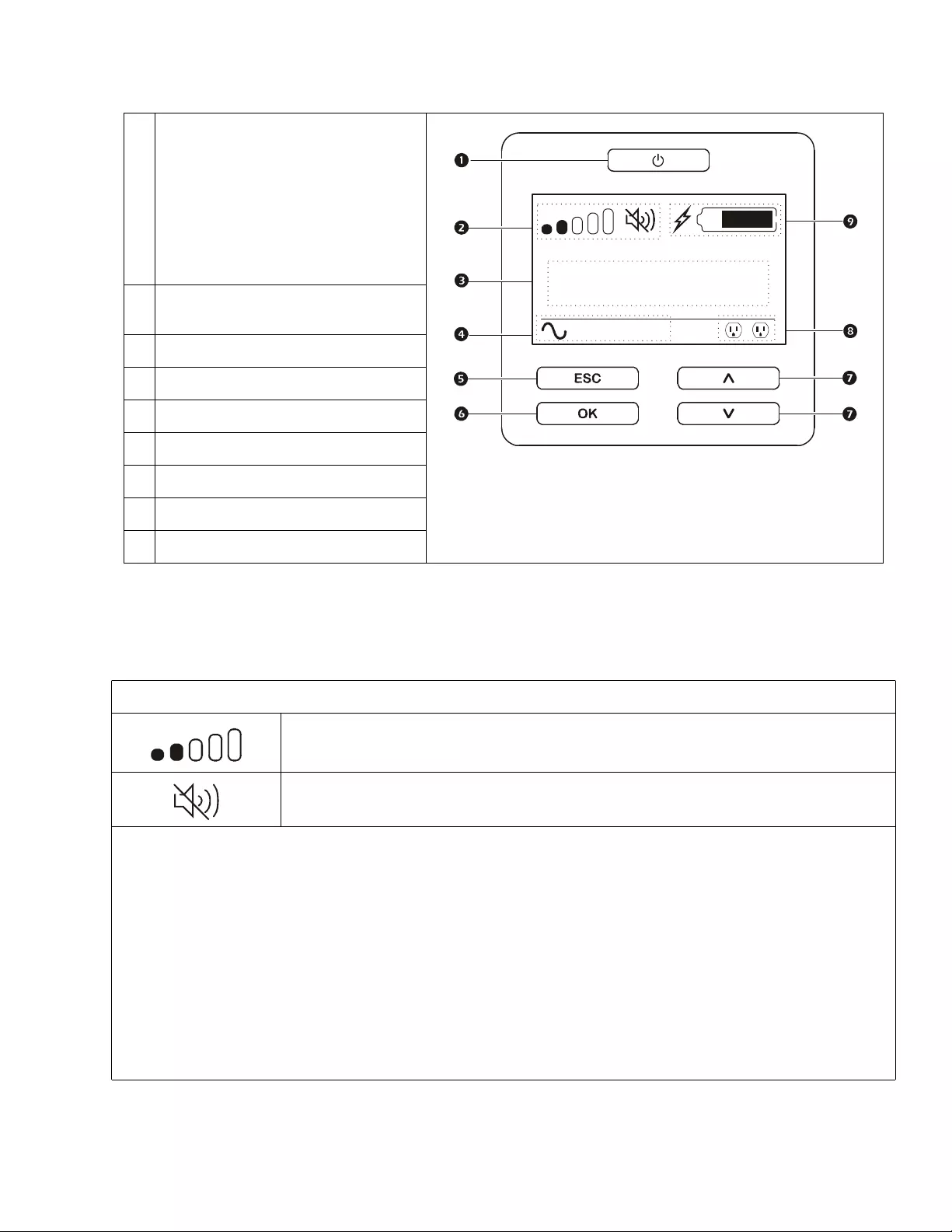
UPS Display Interface
Displa y interface operation
Use the UP/DOWN buttons to scrol l thro ugh the options. Press the OK button to acce pt the selected option. Press the
ESC button to return to the previous menu.
POWER ON/OFF button
Button illumination indic ations:
-No illumination, the UPS and the out put
power are off
-White illuminati on, t he UPS and the
output power are on
-Red illumination, the UPS is on and the
output power is off
Load ic on
Disable/ mute aud ible alarm icon
UPS status information
Oper ation mode icons
ESCAPE button
OK button
UP/DOWN buttons
Controllable outlet group statu s icons
Battery status icons
The icons on the L CD display interface screen may vary depe nding on the installed firmware version.
Load icon: The approximate load ca pacity percentage is ind icated by the number of loa d bar
sections illuminated. Each bar represents 16% of the load capacity.
Mute icon: Indicates the audible alarm is dis abled/mute.
UPS Status Inform ation
The status information fie ld provides key information on the status of th e UPS.
The Standard menu will allow the user to select one of t he f ive screens listed below. Use th e UP/DOWN butt ons to scrol l
through the sc reens.
The Advanced menu will scroll throu gh the five scree ns au tomatically.
•Input Vol tage
•Output Voltage
•Output Frequenc y
•Load
•Runtime
I n the case of a UPS event , s tatus updates will be di splayed defin ing the event or condit ion that ha s occurred.
The displ ay sc reen il lumi nates ye llo w to indic at e a Messa ge and re d to indica te an Aler t depen ding on th e severi ty of the eve nt
or condition.
su0870b
Output
230.0
v
LOAD
On-Line
12
LOAD
Smart-UPS On-Line SRT2200/SRT3000 Tower /Rack-Mount 2U 15
Operation Mode Icons
On-Line mode: The UPS is supplying conditioned mains power to connected equipment.
Bypa ss mode : Th e U PS is in Bypass mode and the connected equi pmen t wi ll receive mains
power as long as the input voltage and freque ncy a re within the configured limits.
Green mode: When in Green mode mains power i s sent d irectly to the load.
In the even t of a mains power outage, there will be an interrupt ion in powe r to the load of up to
10 ms while the UPS switches to On-Line or Battery mode.
When enabling Green mode consideration should be given to devices that may be sensitive to
power fluctuations .
Indicates a UPS alert that requires attention.
UPS Status Icon
Battery mode: T he UPS is supplying ba ttery power to connected equipment.
The UPS has detected an internal fault with the battery. Follow the instructions on the screen.
The UP S ha s detected a critical f ault with the batter y. The battery is at the end of its lif e and has
to be repla ce d.
Controllable Outlet Group Icons
Contr ollable Outlet Group Power Avail ab le: The number next to the icon identifies the
specific outlet groups that have available power.
Flashing icon indica tes the outlet group is turning from OFF to ON with delay.
Control lable Outlet Group Power Not Ava ilable: The number next to the ic on identifies
specific outlet groups that do not have available power.
Flashing icon indica tes the outlet group is turning from ON to OFF with dela y.
Battery Status Icon s
Battery Char ge Status: Ind i cates th e ba tt e ry ch ar ge sta tu s.
Battery Char ge In Progress : Indica tes the battery is cha rging.
X
Customer support and warranty information a re a vailable on the APC by Schneider Electric web site,
www.apc.com.
© 2015 APC by Schneider Electric. A PC, t he A PC logo, and Sma rt-UPS are own ed by Schneider
Electric Industries S.A.S. or their affiliated companies. All other trademarks are property of their
respective owners .
EN 990-526 8A
11/2015
Menu overview
The display int erface has Standard and Advanced m enu screens. The preference for Sta ndard or Advanced menu
selections is ma de during initial installation and can be changed at a ny time through the Configuration menu.
The Standard menus include the most commonly used options.
The Advanced menus provide additional option s .
Note: Ac tual me nu screens m ay differ by model and f irm ware version.
Refer to the UPS Oper ation Manual for menu confi guration detai ls .
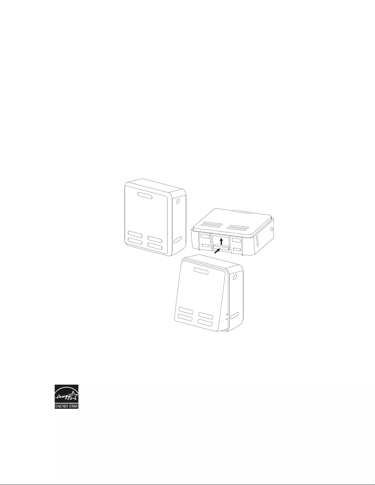
LCD display interface angle adjustment
The angle of the LCD di spl ay i nterface can be adjusted for ea se in viewing the displayed mes s ages.
1. Remove the front bezel.
2. Locate the button on the bottom of the display int erface panel.
3. Press the button and slide the bo ttom of the LCD display interface screen out . An audible click will be hea r d
when the screen reaches the maximum angle.
Select models are ENERGY STA R® qua lified.
For more in formation go to www.apc.com/com pany/us/en/sustainability/energy-efficiency/
su0926a