GAMDIAS KRATOS E1-500 User Manual
Displayed below is the user manual for KRATOS E1-500 by GAMDIAS which is a product in the Power Supply Units category. This manual has pages.
Related Manuals

QUICK
INSTALLATION
GUIDE
01
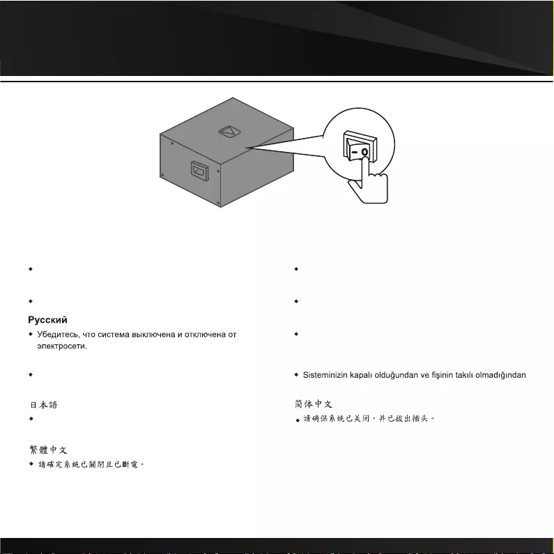
English
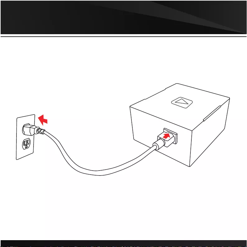
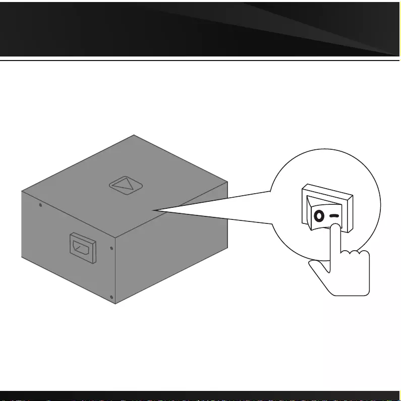
Make sure that your system is turned off and unplugged.
Deutsch
Stellen Sie sicher, dass Ihr System ausgeschaltet und alle
Stromkabel gezogen sind.
Français
Assurez-vous que le système est éteint et débranché.
Español
Asegúrese de que el sistema está apagado y desenchufado.
Italiano
verificare che il sistema sia spento e scollegato.
Português
Certifique-se que o seu sistema está desligado e sem corrente
eléctrica.
Türk dili
emin olun.
システムがオフになっており、プラグを抜いていることを確認
してください。
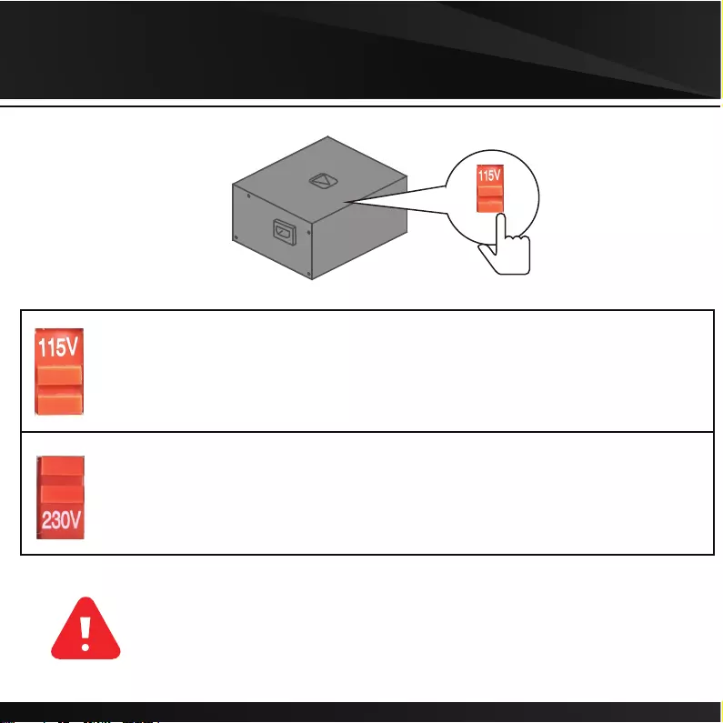
02. Voltage Switch
▼If AC voltage of your region is 100~130V, voltage switch must be set to this position
▼For example, if you live in the United States, the voltage switch must be set to this position
▼If AC voltage of your region is 220~240V, voltage switch must be set to this position
▼For example, if you live in France, the voltage switch must be set to this position
● Make sure voltage switch is correctly set for your region before powered on
● Incorrect voltage switch setting will destroy the PSU
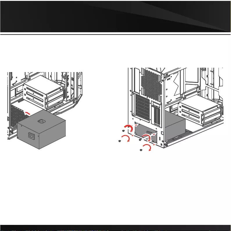
03
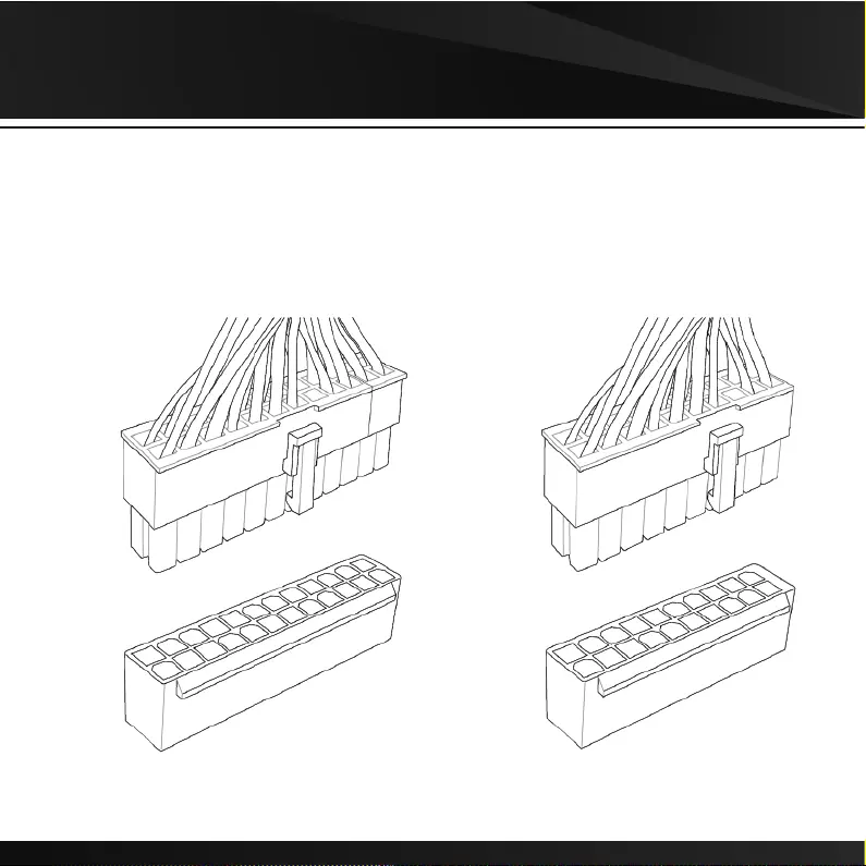
04. Motherboard
20+4 Pin 20 Pin
05. CPU
4+4 Pin 4 Pin
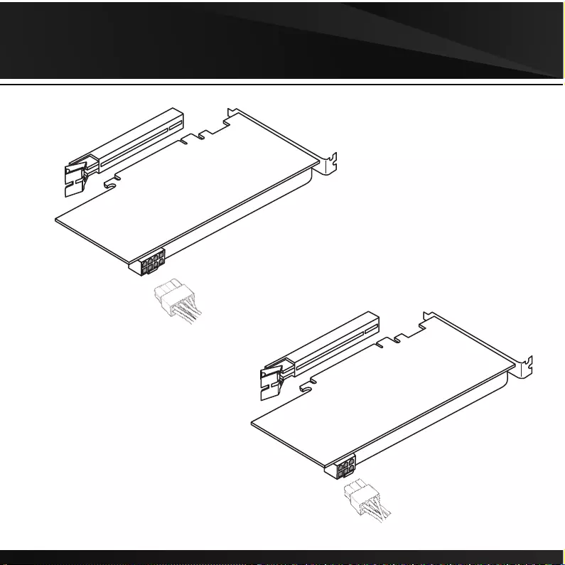
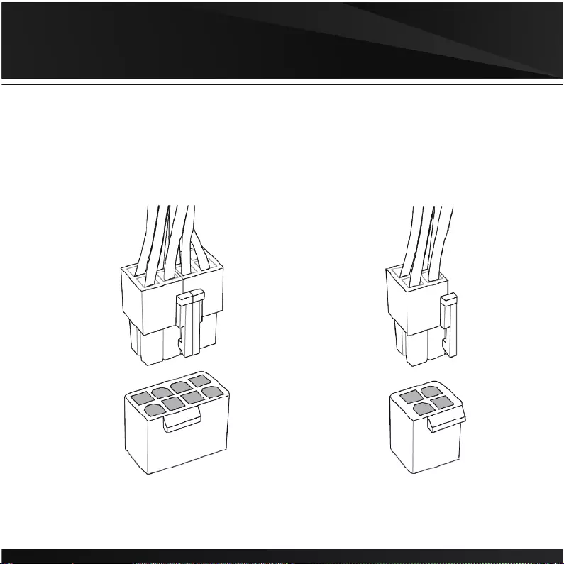
06. PCIE
6+2 Pin
6 Pin
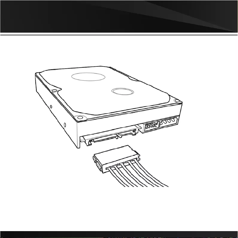
07.SATA
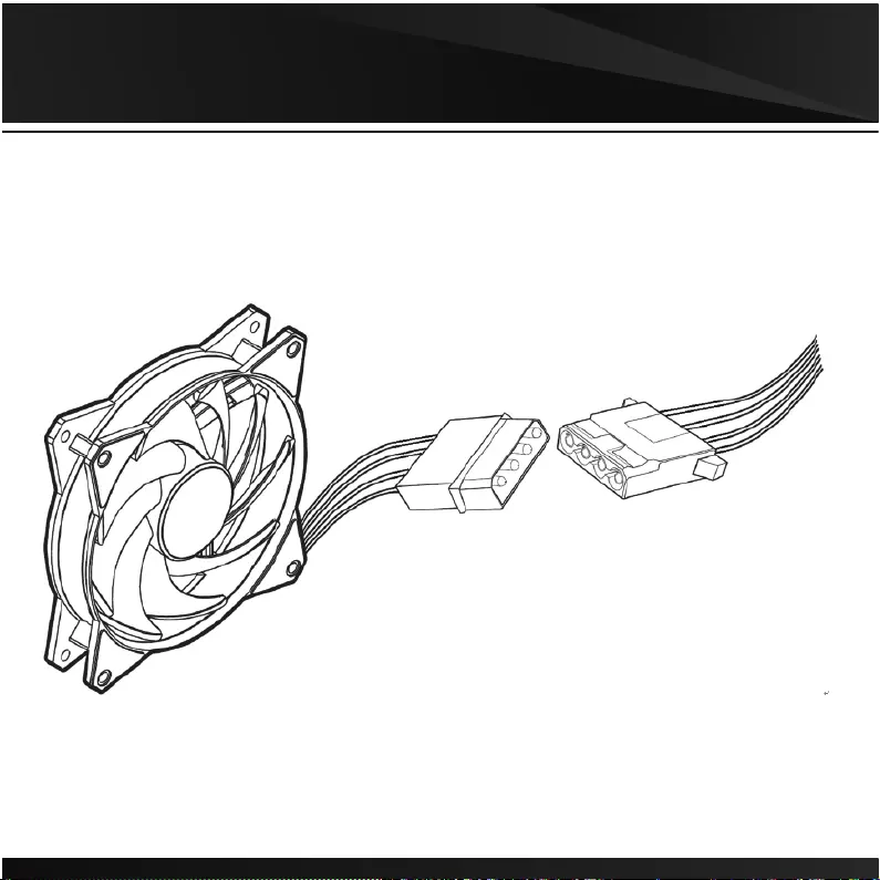
08. Molex
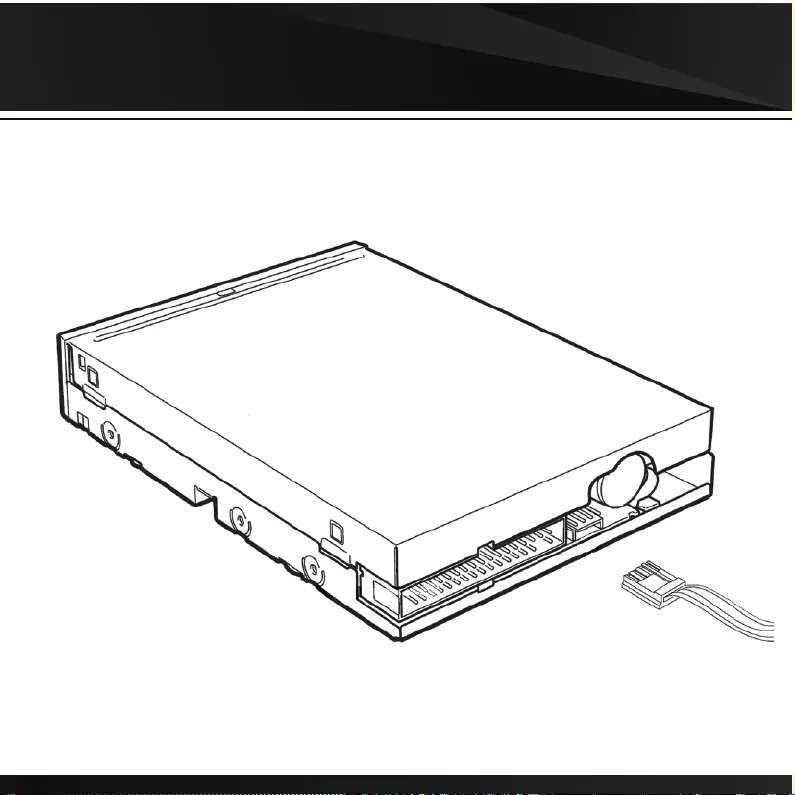
09. FDD
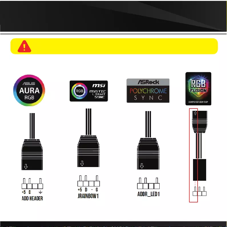
11. RGB Lighting
VDG
The circuit extending from the arrow must be inserted into motherboard’s V-Pin.
10 If your motherboard has 5V 3-Pin addressable (digital) LED header,
you can customize RGB lighting via motherboard manufacture sync software
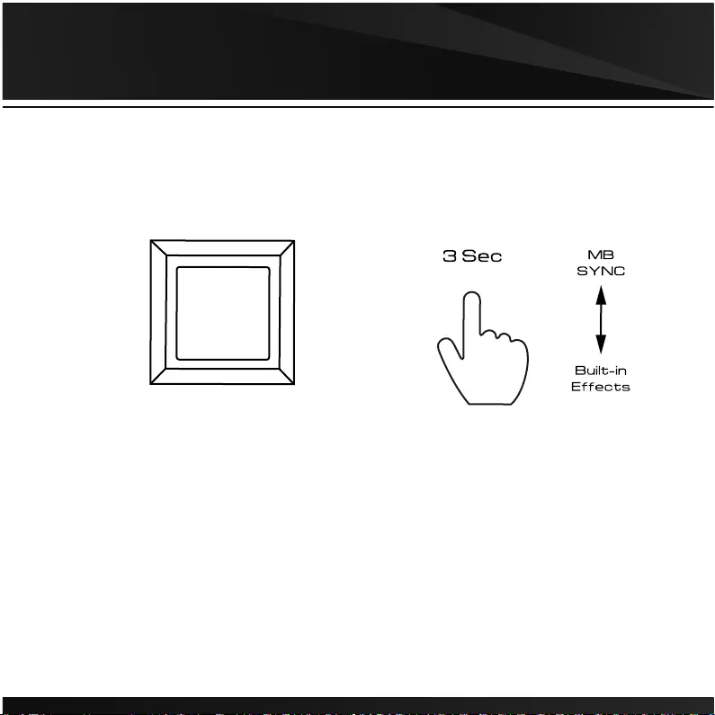
11. RGB Lighting
RGB Lighting
Easily switch to motherboard manufacture sync software
or built-in 30 lighting effects by long pressing button for 3 seconds.
12
13