Intellinet 561112 User Manual
Displayed below is the user manual for 561112 by Intellinet which is a product in the Network Switches category. This manual has pages.
Related Manuals

48‐PORTGIGABITETHERNETPOE+LAYER2+MANAGED
SWITCHWITH10GBEUPLINK
USERMANUAL
Model561112

TableofContents
Intelinet48‐PortGigabitEthernetPoE+Layer2+ManagedSwitchUserManual|2
FCCWarning
ThisEquipmenthasbeentestedandfoundtocomplywiththelimitsforaClass‐Adigitaldevice,
pursuanttoPart15oftheFCCrules.Theselimitsaredesignedtoprovidereasonableprotection
againstharmfulinterferenceinaresidentialinstallation.Thisequipmentgenerates,uses,andcan
radiateradiofrequencyenergy.Itmaycauseharmfulinterferencetoradiocommunicationsifthe
equipmentisnotinstalledandusedinaccordancewiththeinstructions.However,thereisno
guaranteethatinterferencewillnotoccurinaparticularinstallation.Ifthisequipmentdoescause
harmfulinterferencetoradioortelevisionreception,whichcanbedeterminedbyturningthe
equipmentoffandon,theuserisencouragedtotrytocorrecttheinterferencebyoneormoreofthe
followingmeasures:
Reorientorrelocatethereceivingantenna.
Increasetheseparationbetweentheequipmentandreceiver.
Connecttheequipmentintoanoutletonacircuitdifferentfromthattowhichthereceiveris
connected.
Consultthedealeroranexperiencedradio/TVtechnicianforhelp.
CEMarkWarning
ThisisaClass‐Bproduct.Inadomesticenvironmentthisproductmaycauseradiointerferencein
whichcasetheusermayberequiredtotakeadequatemeasures.

TableofContents
Intelinet48‐PortGigabitEthernetPoE+Layer2+ManagedSwitchUserManual|3
Table of Contents
BeforeStarting................................................................................................................................................9
IntendedReaders......................................................................................................................................10
IconsforNote,Caution,andWarning......................................................................................................10
ProductPackageContents........................................................................................................................11
Chapter1:ProductOverview....................................................................................................................12
1.1.ProductBriefDescription..................................................................................................................13
1.2.ProductSpecification.........................................................................................................................14
1.3.HardwareDescription........................................................................................................................17
1.4.HardwareInstallation........................................................................................................................19
Chapter2:PreparingforManagement.....................................................................................................20
2.1.PreparationforWebInterface...........................................................................................................21
Chapter3:WebManagement...................................................................................................................23
3.1.WebManagement‐Configure..........................................................................................................24
3.1.1.Configuration‐System...............................................................................................................26
3.1.1.1.System‐Information...........................................................................................................26
3.1.1.2.System‐IP............................................................................................................................27
3.1.1.3.System‐NTP........................................................................................................................31
3.1.1.4.System‐Time.......................................................................................................................32
3.1.1.5.System‐Log.........................................................................................................................34
3.1.2.Configuration‐GreenEthernet..................................................................................................35
3.1.2.1.GreenEthernet‐LED...........................................................................................................35
3.1.2.2.GreenEthernet‐PortPowerSavings..................................................................................37
3.1.3.Configuration‐Ports...................................................................................................................39
3.1.4.Configuration‐DHCP..................................................................................................................41
3.1.4.1.DHCP‐Server.......................................................................................................................41
3.1.4.1.1.DHCP‐Server‐Mode...................................................................................................41
3.1.4.1.2.DHCP‐Server‐ExcludedIP..........................................................................................43
3.1.4.1.3.DHCP‐Server‐Pool.....................................................................................................44
3.1.4.2.DHCP‐Snooping..................................................................................................................46
3.1.4.3.DHCP‐Relay.........................................................................................................................47
3.1.5.Configuration‐Security..............................................................................................................49
3.1.5.1.Security‐Switch‐Users......................................................................................................49
3.1.5.2.Security‐Switch‐PrivilegeLevel........................................................................................51
3.1.5.3.Security‐Switch‐AuthenticationMethod.........................................................................53

TableofContents
Intelinet48‐PortGigabitEthernetPoE+Layer2+ManagedSwitchUserManual|4
3.1.5.4.Security‐Switch‐SSH.........................................................................................................54
3.1.5.5.Security‐Switch‐HTTPS.....................................................................................................55
3.1.5.6.Security‐Switch‐AccessManagement..............................................................................56
3.1.5.7.Security‐Switch‐SNMP.....................................................................................................58
3.1.5.7.1.Security‐Switch‐SNMP‐System...............................................................................58
3.1.5.7.2.Security‐Switch‐SNMP‐Community........................................................................62
3.1.5.7.3.Security‐Switch‐SNMP‐User....................................................................................63
3.1.5.7.4.Security‐Switch‐SNMP‐Groups...............................................................................65
3.1.5.7.5.Security‐Switch‐SNMP‐Views.................................................................................66
3.1.5.7.6.Security‐Switch‐SNMP‐Access................................................................................67
3.1.5.8.Security‐Switch‐RMON....................................................................................................67
3.1.5.8.1.Security‐Switch‐RMON‐Statistics............................................................................68
3.1.5.8.2.Security‐Switch‐RMON‐History..............................................................................69
3.1.5.8.3.Security‐Switch‐RMON‐Alarm................................................................................70
3.1.5.8.4.Security‐Switch‐RMON‐Event.................................................................................72
3.1.5.9.Security‐Network‐LimitControl.......................................................................................73
3.1.5.10.Security‐Network‐NAS(NetworkAccessServer)..........................................................77
3.1.5.11.Security‐Network‐ACL....................................................................................................90
3.1.5.11.1.Security‐Network‐ACL‐Ports.................................................................................90
3.1.5.11.2.Security‐Network‐ACL‐RateLimiter......................................................................92
3.1.5.11.3.Security‐Network‐ACL‐AccessControlList...........................................................93
3.1.5.12.Security‐Network‐IPSourceGuard..............................................................................110
3.1.5.12.1.Security‐Network‐IPSourceGuard‐Configuration.............................................110
3.1.5.12.2.Security‐Network‐IPSourceGuard‐StaticTable.................................................111
3.1.5.13.Security‐Network‐ARPInspection...............................................................................112
3.1.5.13.1.Security‐Network‐ARPInspection‐Configuration..............................................112
3.1.5.13.2.Security‐Network‐ARPInspection‐StaticTable..................................................113
3.1.5.14.Security‐AAA..................................................................................................................114
3.1.6.Configuration‐Aggregation.....................................................................................................118
3.1.6.1.Aggregation‐Static............................................................................................................118
3.1.6.2.Aggregation‐LACP............................................................................................................120
3.1.7.Configuration‐LoopProtection...............................................................................................123
3.1.8.Configuration‐SpanningTree..................................................................................................125
3.1.8.1.SpanningTree‐BridgeSettings.........................................................................................125
3.1.8.2.SpanningTree‐MSTIMapping.........................................................................................127
3.1.8.3.SpanningTree‐MSTIPriorities.........................................................................................129

TableofContents
Intelinet48‐PortGigabitEthernetPoE+Layer2+ManagedSwitchUserManual|5
3.1.8.4.SpanningTree‐CISTPorts.................................................................................................130
3.1.8.5.SpanningTree‐MSTIPorts................................................................................................133
3.1.9.Configuration‐IPMCProfile.....................................................................................................135
3.1.9.1.IPMCProfile‐ProfileTable................................................................................................135
3.1.9.2.IPMCProfile‐AddressEntry.............................................................................................137
3.1.10.Configuration‐MVR...............................................................................................................138
3.1.11.Configuration‐IPMC...............................................................................................................142
3.1.11.1.IPMC‐IGMPSnooping....................................................................................................142
3.1.11.1.1.IPMC‐IGMPSnooping‐BasicConfiguration..........................................................142
3.1.11.1.2.IPMC‐IGMPSnooping‐VLANConfiguration..........................................................144
3.1.11.1.3.IPMC‐IGMPSnooping‐PortGroupFiltering.........................................................146
3.1.11.2.IPMC‐MLDSnooping......................................................................................................147
3.1.11.2.1.IPMC‐MLDSnooping‐BasicConfiguration............................................................147
3.1.11.2.2.IPMC‐MLDSnooping‐VLANConfiguration...........................................................149
3.1.11.2.3.IPMC‐MLDSnooping‐PortGroupFiltering...........................................................151
3.1.12.Configuration‐LLDP...............................................................................................................152
3.1.12.1.LLDP‐LLDP.......................................................................................................................152
3.1.12.2.LLDP‐LLDP‐MED..............................................................................................................155
3.1.13.Configuration‐PoE.................................................................................................................163
3.1.14.Configuration‐MACTable......................................................................................................166
3.1.15.Configuration‐VLANs.............................................................................................................168
3.1.15.1.VLANs‐VLANMembership.............................................................................................168
3.1.15.2.VLANs‐Ports...................................................................................................................170
3.1.16.Configuration‐PrivateVLAN..................................................................................................172
3.1.16.1.PrivateVLAN‐PortIsolation.......................................................................................172
3.1.17.Configuration‐VCL.................................................................................................................173
3.1.17.1.VCL‐MAC‐basedVLAN....................................................................................................173
3.1.17.2.VCL‐Port‐basedVLAN.....................................................................................................175
3.1.17.2.1.VCL‐Port‐basedVLAN‐ProtocoltoGroup.............................................................175
3.1.17.2.2.VCL‐Port‐basedVLAN‐GrouptoVLAN..................................................................177
3.1.17.3.VCL‐IPSubnet‐basedVLAN............................................................................................178
3.1.18.Configuration‐VoiceVLAN....................................................................................................180
3.1.18.1.VoiceVLAN‐Configuration.............................................................................................180
3.1.18.2.VoiceVLAN‐OUI.............................................................................................................183
3.1.19.Configuration‐QoS.................................................................................................................184
3.1.19.1.QoS‐PortClassification..................................................................................................184

TableofContents
Intelinet48‐PortGigabitEthernetPoE+Layer2+ManagedSwitchUserManual|6
3.1.19.2.QoS‐PortPolicing...........................................................................................................186
3.1.19.3.QoS‐PortScheduler........................................................................................................187
3.1.19.4.QoS‐PortShaping...........................................................................................................192
3.1.19.5.QoS‐PortTagRemarking................................................................................................197
3.1.19.6.QoS‐PortDSCP...............................................................................................................200
3.1.19.7.QoS‐DSCP‐BasedQoS.....................................................................................................202
3.1.19.8.QoS‐DSCPTranslation....................................................................................................203
3.1.19.9.QoS‐DSCPClassification.................................................................................................204
3.1.19.10.QoS‐StormControl.......................................................................................................205
3.1.19.11.QoS‐WRED....................................................................................................................206
3.1.20.Configuration‐Mirroring.......................................................................................................208
3.1.21.Configuration‐UPnP..............................................................................................................210
3.1.22.Configuration‐GVRP..............................................................................................................211
3.1.22.1.GVRP‐GlobalConfig.......................................................................................................211
3.1.22.2.GVRP‐PortConfig...........................................................................................................212
3.1.23.Configuration‐sFlow..............................................................................................................213
3.2.WebManagement‐Monitor...........................................................................................................216
3.2.1.Monitor‐System......................................................................................................................216
3.2.1.1.System‐Information.........................................................................................................216
3.2.1.2.System‐CPULoad.............................................................................................................218
3.2.1.3.System‐IPStatus...............................................................................................................219
3.2.1.4.System‐Log.......................................................................................................................221
3.2.1.5.System‐DetailedLog........................................................................................................222
3.2.2.Monitor‐GreenEthernet.........................................................................................................223
3.2.2.1.GreenEthernet‐PortPowerSavingsStatus.....................................................................223
3.2.3.Monitor‐Ports..........................................................................................................................224
3.2.3.1.Ports‐State........................................................................................................................224
3.2.3.2.Ports‐TrafficOverview.....................................................................................................225
3.2.3.3.Ports‐QoSStatistics..........................................................................................................227
3.2.3.4.Ports‐DetailedStatistics...................................................................................................228
3.2.4.Monitor‐DHCP.........................................................................................................................231
3.2.4.1.DHCP‐Server.....................................................................................................................231
3.2.4.1.1.DHCP‐Server‐Statistics............................................................................................231
3.2.4.1.2.DHCP‐Server‐Binding..............................................................................................233
3.2.4.1.3.DHCP‐Server‐DeclinedIP........................................................................................234
3.2.4.2.DHCP‐SnoopingTable......................................................................................................235

TableofContents
Intelinet48‐PortGigabitEthernetPoE+Layer2+ManagedSwitchUserManual|7
3.2.4.3.DHCP‐RelayStatistics.......................................................................................................237
3.2.4.4.DHCP‐DetailedStatistics..................................................................................................239
3.2.5.Monitor‐Security.....................................................................................................................242
3.2.5.1.Security‐AccessManagementStatistics..........................................................................242
3.2.5.2.Security‐Network.............................................................................................................243
3.2.5.2.1.Security‐Network‐PortSecurity‐Switch................................................................243
3.2.5.2.2.Security‐Network‐PortSecurity‐Port....................................................................246
3.2.5.2.3.Security‐Network‐NAS‐Switch..............................................................................247
3.2.5.2.4.Security‐Network‐NAS‐Port..................................................................................249
3.2.5.2.5.Security‐Network‐ACLStatus..................................................................................254
3.2.5.2.6.Security‐Network‐ARPInspection..........................................................................256
3.2.5.3.Security‐Network.............................................................................................................260
3.2.5.3.1.Security‐AAA‐RADIUSOverview.............................................................................260
3.2.5.3.2.Security‐AAA‐RADIUSDetails.................................................................................262
3.2.5.4.Security‐Switch‐RMON..................................................................................................266
3.2.5.4.1.Security‐Switch‐RMON‐Statistics..........................................................................266
3.2.5.4.2.Security‐Switch‐RMON‐History............................................................................269
3.2.5.4.3.Security‐Switch‐RMON‐Alarm..............................................................................271
3.2.5.4.4.Security‐Switch‐RMON‐Events..............................................................................273
3.2.6.Monitor‐LACP..........................................................................................................................275
3.2.6.1.LACP‐SystemStatus.........................................................................................................275
3.2.6.2.LACP‐PortStatus..............................................................................................................276
3.2.6.3.LACP‐PortStatistics..........................................................................................................278
3.2.7.Monitor‐LoopProtection........................................................................................................279
3.2.8.Monitor‐SpanningTree...........................................................................................................280
3.2.8.1.SpanningTree‐BridgeStatus............................................................................................280
3.2.8.2.SpanningTree‐PortStatus...............................................................................................281
3.2.8.3.SpanningTree‐PortStatistics...........................................................................................282
3.2.9.Monitor‐MVR..........................................................................................................................283
3.2.9.1.MVR‐Statistics..................................................................................................................283
3.2.9.2.MVR‐MVRChannelGroups.............................................................................................284
3.2.9.3.MVR‐MVRSFMInformation............................................................................................286
3.2.10.Monitor‐IPMC.......................................................................................................................288
3.2.10.1.IPMC‐IGMPSnooping....................................................................................................288
3.2.10.1.1.IPMC‐IGMPSnooping‐Status................................................................................288
3.2.10.1.2.IPMC‐IGMPSnooping‐GroupsInformation..........................................................290

TableofContents
Intelinet48‐PortGigabitEthernetPoE+Layer2+ManagedSwitchUserManual|8
3.2.10.1.3.IPMC‐IGMPSnooping‐IPv4SFMInformation......................................................292
3.2.10.2.IPMC‐MLDSnooping......................................................................................................294
3.2.10.2.1.IPMC‐MLDSnooping‐Status..................................................................................294
3.2.10.2.2.IPMC‐MLDSnooping‐GroupsInformation...........................................................296
3.2.10.2.3.IPMC‐MLDSnooping‐IPv6GroupInformation.....................................................297
3.2.11.Monitor‐LLDP........................................................................................................................299
3.2.11.1.LLDP‐Neighbours............................................................................................................299
3.2.11.2.LLDP‐LLDP‐MEDNeighbours..........................................................................................301
3.2.11.3.LLDP‐PoE.........................................................................................................................305
3.2.11.4.LLDP‐EEE.........................................................................................................................307
3.2.11.5.LLDP‐PortStatistics........................................................................................................309
3.2.12.Monitor‐PoE..........................................................................................................................311
3.2.13.Monitor‐MACTable...............................................................................................................314
3.2.14.Monitor‐VLANs.....................................................................................................................317
3.2.14.1.VLANs‐VLANMembership.............................................................................................317
3.2.14.2.VLANs‐VLANPorts.........................................................................................................319
3.2.15.Monitor‐sFlow.......................................................................................................................321
3.3.WebManagement‐Diagnostics.....................................................................................................323
3.3.1.Diagnostics‐Ping......................................................................................................................323
3.3.2.Diagnostics‐Ping6....................................................................................................................325
3.3.3.Diagnostics‐VeriPHY................................................................................................................326
3.4.WebManagement‐Maintenance..................................................................................................328
3.4.1.Maintenance‐RestartDevice..................................................................................................328
3.4.2.Maintenance‐FactoryDefaults...............................................................................................329
3.4.3.Maintenance‐SoftwareUpload..............................................................................................330
3.4.3.Maintenance‐Configuration....................................................................................................331
3.4.3.1.Configuration‐Save...........................................................................................................331
3.4.3.2.Configuration‐Load..........................................................................................................332
AppendixA:ProductSafety........................................................................................................................333
AppendixB:IPConfigurationforYourPC..................................................................................................334
AppendixC:Glossary..................................................................................................................................338

BeforeYouBegin
Thissectioncontainsintroductoryinformation,whichincludes:
IntendedReaders
IconsforNote,Caution,andWarning
ProductPackageContents

BeforeStarting
IntendedReaders
Thismanualprovidesinformationregardingtoalltheaspectsandfunctionsneededtoinstall,
configure,use,andmaintaintheproductyou’vepurchased.
Thismanualisintendedfortechnicianswhoarefamiliarwithin‐depthconceptsofnetworking
managementandterminologies.
IconsforNote,Caution,andWarning
Toinstall,configure,use,andmaintainthisproductproperly,pleasepayattentionwhenyousee
theseiconsinthismanual:
ANoteiconindicatesimportantinformationwhichwillguideyoutousethis
productproperly.
ACautioniconindicateseitherapotentialforhardwaredamageordataloss,
includinginformationthatwillguideyoutoavoidthesesituations.
AWarningiconindicatespotentialsforpropertydamageandpersonalinjury.

BeforeStarting
Intelinet48‐PortGigabitEthernetPoE+Layer2+ManagedSwitchUserManual|11
ProductPackageContents
Beforestartinginstallthisproduct,pleasecheckandverifythecontentsoftheproductpackage,
whichshouldincludethefollowingitems:
OneNetworkSwitch
OnePowerCord
OneUserManualCD
OnepairRack‐mountkit+8Screws
Note:Ifanyitemlistedinthistableaboveismissingordamaged,pleasecontactyourdistributoror
retailerassoonaspossible.

Chapter1:
ProductOverview
InProductOverview:
Thissectionwillgiveyouanoverviewofthisproduct,includingitsfeaturefunctionsand
hardware/softwarespecifications.
ProductBriefDescription
ProductSpecification
HardwareDescription
HardwareInstallation

Chapter1:ProductOverview
ProductBriefDescription
1.1.ProductBriefDescription
Introduction
Theswitchis48‐port10/100/1000Base‐T+2×10GigabitSFP+PortsRack‐mountL2+Full
ManagementNetworkSwitchthatisdesignedformediumorlargenetworkenvironmentto
strengthenitsnetworkconnection.Theswitchsupports136Gnon‐blockingswitchfabric,the48
gigabitportsand2uplink10Gportscantransmitandreceivedatatrafficwithoutanylost.TheEEE
featurereducesthepowerconsumptionwhenthereisnotrafficforwardingevenportisstill
connected.TheswitchalsosupportsLayer2+fullmanagementsoftwarefeatures.Thesefeaturesare
powerfultoprovidenetworkcontrol,management,monitorandsecurityfeaturerequests.Including
rack‐mountbrackets,the19"sizefitsintoyourrackenvironment.Itisasuperbchoicetoboostyour
networkwithbetterperformanceandefficiency.
210GigabitSFP+OpenSlots
Theswitchequipswith210GSFP+openslotsastheuplinkports,the10Guplinkdesignprovidesan
excellentsolutionforexpandingyournetworkfrom1Gto10G.By10Gspeed,thisproductprovides
highflexibilityandhighbandwidthconnectivitytoanother10GswitchortheServers,Workstations
andotherattacheddeviceswhichsupport10Ginterfaces.Theusercanalsoaggregatethe10Gports
asTrunkgrouptoenlargethebandwidth.
FullLayer2ManagementFeatures
TheswitchincludesfullLayer2+Managementfeatures.Thesoftwaresetincludesupto4K802.1Q
VLANandadvancedProtocolVLAN,PrivateVLAN,MVR…features.Thereare8physicalqueues
QualityofService,IPv4/v6Multicastfiltering,RapidSpanningTreeprotocoltoavoidnetworkloop,
MultipleSpanningTreeProtocoltointegrateVLANandSpanningTree,LACP,LLDP;sFlow,port
mirroring,cablediagnosticandadvancedNetworkSecurityfeatures.ItalsoprovidesConsoleCLIfor
outofbandmanagementandSNMP,WebGUIforinbandManagement.

Chapter1:ProductOverview
ProductSpecification
1.2.ProductSpecification
Interface
10/100/1000BaseRJ45Ports48
10GUplinkSFP+Slot2
ConsolePortforCLIManagement1
SystemPerformance
PacketBuffer64Mb
MACAddressTableSize64K
SwitchingCapacity136Gbps
PoEFeatures
IEEE802.3af/at IEEE802.3af/at
NumberofPSEPorts48
Max.PowerConsumption500W
External/InternalPowerInternalPower
PowerFeedingDetectingCapabilityonPD
PDAliveCheck
PDClassification
PowerManagement
(per‐port)
Enable/DisablePoEPerPort
PrioritySettingPerPort
PowerLevelSettingPerPort
OverloadingProtection
L2Features
Auto‐negotiation
AutoMDI/MDIX
FlowControl(duplex)802.3x(Full)
Back‐Pressure(Half)
SpanningTree
IEEE802.1D(STP)
IEEE802.1w(RSTP)
IEEE802.1s(MSTP)
VLAN
VLANGroup 4K
TaggedBased
Port‐based
LinkAggregation
IEEE802.3adwithLACP
StaticTrunk
Max.LACPLinkAggregationGroup26
IGMPSnooping
IGMPSnoopingv1/v2/v3
IPv6MLDSnooping
Querier,ImmediateLeave
StormControl(Broadcast/Multi‐cast/Un‐knownUnicast)
JumboFrameSupport10K

Chapter1:ProductOverview
ProductSpecification
Intelinet48‐PortGigabitEthernetPoE+Layer2+ManagedSwitchUserManual|15
QoSFeatures
Numberofpriorityqueue8queues/port
RateLimitingIngressYes,1KBps/1pps
EgressYes,1KBps/1pps
DiffServ(RFC2474Remarking)
Scheduling(WRR,Strict,Hybrid)
CoSIEEE802.1p
IPToSprecedence,IPDSCP
Security
ManagementSystemUserName/PasswordProtection
UserPrivilegeSetuserprivilegeupto15Level
PortSecurity(MAC‐based)
IEEE802.1xPort‐basedAccessControl
ACL(L2/L3/L4)
IPSourceGuard
RADIUS(Authentication,Authorization,Accounting)
TACACS+
HTTP&SSL(SecureWeb)
SSHv2.0(SecuredTelnetSession)
MAC/IPFilter
Management
CommandLineInterface(CLI)
WebBasedManagement
Telnet
AccessManagementFilteringSNMP/WEB/SSH/TELNET
FirmwareUpgradeviaHTTP
DualFirmwareImages
ConfigurationDownload/Upload
SNMP(v1/v2c/v3)
RMON(1,2,3,&9groups)
DHCP(Client/Relay/Option82/Snooping)
SystemEvent/ErrorLog
NTP/LLDP
CableDiagnostics
IPv6Configuration
PortMirroringOnetoOneorManytoOne
Mechanical
PowerInput100~240VAC
Dimension(H*W*D)44*440*331mm
LEDLink,PoE,SFP+
OperatingTemperature0~45°C
OperatingHumidity5~90%(non‐condensing)
Weight4.8KG
Certification CE,FCCClassB

Chapter1:ProductOverview
ProductSpecification
Intelinet48‐PortGigabitEthernetPoE+Layer2+ManagedSwitchUserManual|16
Standard
IEEE802.3–10BaseT
IEEE802.3u‐100BaseTX
IEEE802.3ab‐1000BaseT
IEEE802.3ae10GBaseSX/LX
IEEE802.3afPoweroverEthernet(PoE)
IEEE802.3atPoweroverEthernet(PoE+)
IEEE802.3az‐EnergyEfficientEthernet(EEE)
IEEE802.3x‐FlowControl
IEEE802.1Q‐VLAN
IEEE802.1v‐ProtocolVLAN
IEEE802.1p‐ClassofService
IEEE802.1D‐SpanningTree
IEEE802.1w‐RapidSpanningTree
IEEE802.1s‐MultipleSpanningTree
IEEE802.3ad‐LinkAggregationControlProtocol(LACP)
IEEE802.1AB‐LLDP(LinkLayerDiscoveryProtocol)
IEEE802.1X‐AccessControl

Chapter1:ProductOverview
HardwareDescription
1.3.HardwareDescription
ThissectionmainlydescribesthehardwareofFull‐ManagementPoEswitchandgivesaphysicaland
functionaloverviewonthecertainswitch.
FrontPanel
Thefrontpaneloftheswitchconsistsof4810/100/1000Base‐TXRJ‐45portsand210GigabitSFP+
ports.TheLEDsarealsolocatedonthefrontpanel.
LEDIndicators
TheLEDIndicatorspresentreal‐timeinformationofsystematicoperationstatus.Eachoftheswitch’s
RJ45porthastwoLEDs,thegreenLEDindicatesRJ45connectionstatus/datalink,andtheamberLED
indicatesifthatportisprovidingelectricalpower.
Also,port49andport50(SFP+Ports)hastheirownLEDsthatindicatedatalinkstatusasshownin
thefigurebelow:
LEDColor/StatusDescriptionNo.ofLEDs
10/100/1000MGreenOnLinkUp1~48
GreenBlinking DataActivating
PoEAmberOn PDisconnected 1~48
SFP+
GreenOn FiberConnected 49~50
GreenBlinkingReceiving/Transmitting
Data49~50

Chapter1:ProductOverview
ProductSpecification
Intelinet48‐PortGigabitEthernetPoE+Layer2+ManagedSwitchUserManual|18
RearPanel
TherearpaneloftheFull‐ManagementPoEswitchcontains2ventilationfans,apowerswitch,and
anIEC60320plugforpowersupply.

Chapter1:ProductOverview
HardwareInstallation
1.4.HardwareInstallation
ToinstalltheFull‐ManagementPoEswitch,pleaseplaceitonalargeflatsurfacewithapowersocket
closeby.Thissurfaceshouldbeclean,smooth,andlevel.Also,pleasemakesurethatthereisenough
spacearoundtheFull‐ManagementPoEswitchforRJ45cable,powercordandventilation.
Ifyou’reinstallingthisFull‐ManagementPoEswitchona19‐inchrack,pleasemakesuretousethe
rack‐mountkit(Lbrackets)andscrewscomewiththeproductpackage.Allscrewsmustbefastened
sotherack‐mountkitandyourproductaretightlyconjoinedbeforeinstallingitonyour19‐inchrack.
EthernetcableRequest
Thewiringcabletypesareasbelow:
10Base‐T:2‐pairUTP/STPCAT.3,4,5cable,EIA/TIA‐568100‐ohm(Max.100m)
100Base‐TX:2‐pairUTP/STPCAT.5cable,EIA/TIA‐568100‐ohm(Max.100m)
1000Base‐T:4‐pairUTP/STPCAT.5cable,EIA/TIA‐568100‐ohm(Max.100m)
PoE:Todeliverypowerproperly,itisrecommendedtouseCAT5eandCAT6cable.Ethernet
cablesofhigherqualitiescanreducethepowerlostduringtransmission.
SFPInstallation
WhileinstalltheSFPtransceiver,makesuretheSFPtypeofthe2endsisthesameandthe
transmissiondistance,wavelength,fibercablecanmeetyourrequest.Itissuggestedtopurchasethe
SFPtransceiverwiththeswitchprovidertoavoidanyincompatibleissue.
ThewaytoconnecttheSFPtransceiveristoPluginSFPfibertransceiverfist.TheSFPtransceiverhas
2plugforfibercable,oneisTX(transmit),theotherisRX(receive).Cross‐connectthetransmit
channelateachendtothereceivechannelattheoppositeend.
Formoreinformationregardingtotheproductsafetyandmaintenanceguide,pleasereferto
AppendixA:ProductSafety.

Chapter2:
PreparingforManagement
InPreparingforManagement:
Thissectionwillguideyourhowtomanagethisproductviamanagementwebpage.
PreparationforWebInterface

Chapter2:PreparingforManagement
PreparationforWebInterface
2.1.PreparationforWebInterface
Themanagementwebpageallowsyoutouseawebbrowser(suchasMicrosoftIE,GoogleChrome,
orMozillaFirefox)toconfigureandmonitortheswitchfromanywhereonthenetwork.
Beforeusingthewebinterfacetomanageyourswitch,pleaseverifythatyourswitchandyourPCare
onthesamenetwork.PleasefollowthestepsdownbelowtoconfigureyourPCproperly:
1. Verifythatthenetworkinterfacecard(NIC)ofyourPCisoperationalandproperlyinstalled,and
thatyouroperatingsystemsupportsTCP/IPprotocol.
2. ConnectyourPCwiththeswitchviaanRJ45cable.
3. ThedefaultIPaddressoftheswitchis192.168.2.1.TheswitchandyourPCshouldlocatewithin
thesameIPSubnet.ChangeyourPC'sIPaddressto192.168.2.X,whereXcanbeanynumber
from2to254.PleasemakesurethattheIPaddressyou’veassignedtoyourPCcannotbethe
samewiththeswitch.
4. Launchthewebbrowser(IE,Firefox,orChrome)onyourPC.
5. Type192.168.2.1(ortheIPaddressoftheswitch)inthewebbrowser’sURLfield,andpress
Enter.

Chapter2:PreparingforManagement
PreparationforWebInterface
Intelinet48‐PortGigabitEthernetPoE+Layer2+ManagedSwitchUserManual|22
6. Thewebbrowserwillpromptyoutosignin.Thedefaultusername/passwordforthe
configurationwebpageisadmin/1234.
Formoreinformation,pleasereferto
AppendixB:IPConfigurationforYourPC.

Chapter3:
WebManagement
InWebManagement:
AsmentionedinChapter2.2.PreparationforWebInterface,Thisswitchprovidesa
web‐basedmanagementinterface.Youcanmakeallsettingsandmonitorsystemstatus
withthismanagementwebpage.
Configuration/Monitoroptionsincludedinthemanagementwebpagecanbedivided
intothefollowing4categories,whichwillbediscussedindetailinthischapter:
WebManagement‐Configure
WebManagement‐Monitor
WebManagement‐Diagnostic
WebManagement‐Maintenance

Chapter3:WebManagement
WebManagement‐Configure
3.1.WebManagement‐Configure
Inhereyoucanaccessalltheconfigurationoptionsoftheswitch.Theconfigurationoptionshere
include:
System:Hereyoucanconfigurebasicsystemsettingssuchassysteminformation,switchIP,NTP,
systemtimeandlog.
GreenEthernet:YoucanenableEEE(EnergyEfficientEthernet)functiononeachportoradjust
LEDflashingintensitytoconserveandsavepowerusedbytheswitch.
Ports:Youcanviewtheconnectionstatusofalltheportsontheswitch,aswellassetport
connectionspeed,flowcontrol,maximumframelength,andpowercontrolmode.
DHCP:HereyoucansetDHCPsnoopingandDHCPrelay,aswellasIPsettings.
Security:TheSecurityoptionallowsyoutomakesettingsthatsecuresboththeswitchitselfor
yournetwork.
Aggregation:Aggregationallowsyoutocombinemultiplephysicalportsintoalogicalport,thus
allowsthetransmittingspeedexceedingthelimitofasingleport.
LoopProtection:Anetworkloopmightcausebroadcaststormandparalyzeyourentire
network.Youcanenableloopprotectionfunctionheretopreventnetworkloop.
SpanningTree:SpanningTreeProtocolisanetworkdesignedtoensurealoop‐freenetwork
andprovideredundantlinksthatserveasautomaticbackuppathsifanactivelinkfails.This
switchsupportsSTP,RSTP(RapidSTP),andMSTP(MultipleSTP).
IPMCProfile:IPMCstandsforIPMulti‐Cast.TheIPMCprofileisusedtodeploytheaccess
controlonIPmulticaststreams.Itisallowedtocreateatmaximum64Profileswithat
maximum128correspondingrulesforeach.
MVR:MVRstandsforMultipleVLANRegistration,aprotocolthatallowssharingmulticastVLAN
informationandconfiguringitdynamicallywhenneeded.
IPMC:HereyoucansetIGMPsnooping(forIPv4)orMLDsnooping(forIPv6).Theseprotocols
canreducethenetworkloadingwhilerunningband‐widthdemandingapplicationssuchas
streamingvideosbyeliminatingexcessivedatatransmitting.
LLDP:LLDPstandsforLinkLayerDiscoveryProtocol,aprotocolthatallowstheswitchto
advertiseitsidentity,capabilities,andneighborsonthenetwork.
PoE:Hereyoucanenable/disablethePoEfunctiononeachportorassignthepower(inWatt)
foreachport.
MACTable:Whenanetworkdeviceisconnectedtotheswitch,theswitchwillkeepitsMAC
addressontheMACtable.Thissectionprovidessettingsfortheswitch’sMACaddresstable.

Chapter3:WebManagement
WebManagement‐Configure
Intelinet48‐PortGigabitEthernetPoE+Layer2+ManagedSwitchUserManual|25
VLANs:VLANstandsforVirtualLAN,whichallowsyoutoseparateportsintodifferentVLAN
groups.OnlymemberofthesameVLANgroupcantransmit/receivepacketsamongeachother,
whileotherportsindifferentVLANgroupcan’t.Hereyoucansetport‐basedVLAN.
PrivateVLANs:Alsoknownasportisolation.OnlythesamememberintheprivateVLANcan
communicatewitheachother.
VCL:HereyoucansetMAC‐basedVLAN,Protocol‐basedVLAN,andIPSubnet‐basedVLAN.
VoiceVLAN:VoiceVLANisaspecificVLANforvoicecommunication(suchasVoIPphones)that
canensurethetransmissionpriorityofvoicetrafficandvoicequality.
QoS:QoSstandsforQualityofService,whichallowsyoutocontrolthenetworkpriority(which
packetgetstopprioritytotransmitandwhichgetslowpriority)viaIEEE802.1porDSCP.
Mirroring:Forpurposessuchasnetworkdiagnostics,youcandirectpackets
transmitted/receivedto/fromaport(ormultipleports)toadesignatedport.
UPnP:UPnPstandsforUniversalPlugandPlay,aprotocolthatallowsallthedevicesonthe
samenetworkcandiscovereachotherandestablishingnetworkservicessuchasdatasharing.
YoucansetUPnPhereinthismanagementpage.
GVRP:GVRPstandsforGARPVLANRegistrationProtocol,aprotocolthatfacilitatescontrolof
virtuallocalareanetworks(VLANs)withinalargernetwork.
sFlow:sFlowisanindustrystandardtechnologyformonitoringswitchednetworksthrough
randomsamplingofpacketsonswitchportsandtime‐basedsamplingofportcounters.The
sampledpacketswillbesenttothedesignatedsFlowreceiver(host)forsystemadministrator
foranalysis.

Chapter3:WebManagement
System‐Information
3.1.1.Configuration‐System
3.1.1.1.System‐Information
Theswitchsysteminformationisprovidedhere.
SystemContact
Thetextualidentificationofthecontactpersonforthismanagednode,togetherwithinformationon
howtocontactthisperson.Theallowedstringlengthis0to255,andtheallowedcontentistheASCII
charactersfrom32to126.
SystemName
Youcaninputanassignednameforthisswitch.Byconvention,thisistheswitch'sfully‐qualified
domainname.Adomainnameisatextstringdrawnfromthealphabet(A‐Z&a‐z),digits(0‐9),minus
sign(‐).Nospacecharactersarepermittedaspartofaname.Thefirstcharactermustbeanalpha
character.Andthefirstorlastcharactermustnotbeaminussign.Theallowedstringlengthis0to
255.
SystemLocation
Thephysicallocationofthisnode(e.g.,telephonecloset,3rdfloor).Theallowedstringlengthis0to
255,andtheallowedcontentistheASCIIcharactersfrom32to126.
Buttons
Save:Clicktosavechanges.
Reset:Clicktoundoanychangesmadelocallyandreverttopreviouslysavedvalues.

Chapter3:WebManagement
System‐IPv6
3.1.1.2.System‐IP
ConfigureIPbasicsettings,controlIPinterfacesandIProutes.
Themaximumnumberofinterfacessupportedis128andthemaximumnumberofroutesis32.
BasicSettings
Mode
ConfigurewhethertheIPstackshouldactasaHostoraRouter.InHostmode,IPtrafficbetween
interfaceswillnotberouted.InRoutermodetrafficisroutedbetweenallinterfaces.
DNSServer
ThissettingcontrolstheDNSnameresolutiondonebytheswitch.Thefollowingmodesare
supported:
FromanyDHCPinterfaces:ThefirstDNSserverofferedfromaDHCPleasetoaDHCP‐enabled
interfacewillbeused.
NoDNSserver:NoDNSserverwillbeused.
Configured:ExplicitlyprovidetheIPaddressoftheDNSServerindotteddecimalnotation.
FromthisDHCPinterface:SpecifyfromwhichDHCP‐enabledinterfaceaprovidedDNSserver
shouldbepreferred.
DNSProxy
WhenDNSproxyisenabled,systemwillrelayDNSrequeststothecurrentlyconfiguredDNSserver,
andreplyasaDNSresolvertotheclientdevicesonthenetwork.

Chapter3:WebManagement
WebManagement‐Configure
Intelinet48‐PortGigabitEthernetPoE+Layer2+ManagedSwitchUserManual|28
IPInterfaces
Delete
SelectthisoptiontodeleteanexistingIPinterface.
VLAN
TheVLANassociatedwiththeIPinterface.OnlyportsinthisVLANwillbeabletoaccesstheIP
interface.Thisfieldisonlyavailableforinputwhencreatingannewinterface.
IPv4DHCPEnabled
EnabletheDHCPclientbycheckingthisbox.Ifthisoptionisenabled,thesystemwillconfigurethe
IPv4addressandmaskoftheinterfaceusingtheDHCPprotocol.TheDHCPclientwillannouncethe
configuredSystemNameashostnametoprovideDNSlookup.
IPv4DHCPFallbackTimeout
ThenumberofsecondsfortryingtoobtainaDHCPlease.Afterthisperiodexpires,aconfiguredIPv4
addresswillbeusedasIPv4interfaceaddress.Avalueofzerodisablesthefallbackmechanism,such
thatDHCPwillkeepretryinguntilavalidleaseisobtained.Legalvaluesare0to4294967295seconds.
IPv4DHCPCurrentLease
ForDHCPinterfaceswithanactivelease,thiscolumnshowthecurrentinterfaceaddress,asprovided
bytheDHCPserver.
IPv4Address
TheIPv4addressoftheinterfaceindotteddecimalnotation.
IfDHCPisenabled,thisfieldconfiguresthefallbackaddress.ThefieldmaybeleftblankifIPv4
operationontheinterfaceisnotdesired‐ornoDHCPfallbackaddressisdesired.
IPv4Mask
TheIPv4networkmask,innumberofbits(prefixlength).Validvaluesarebetween0and30bitsfora
IPv4address.
IfDHCPisenabled,thisfieldconfiguresthefallbackaddressnetworkmask.Thefieldmaybeleft
blankifIPv4operationontheinterfaceisnotdesired‐ornoDHCPfallbackaddressisdesired.
IPv6Address
TheIPv6addressoftheinterface.AIPv6addressisin128‐bitrecordsrepresentedaseightfieldsof
uptofourhexadecimaldigitswithacolonseparatingeachfield(:).Forexample,
fe80::215:c5ff:fe03:4dc7.Thesymbol::isaspecialsyntaxthatcanbeusedasashorthandwayof
representingmultiple16‐bitgroupsofcontiguouszeros;butitcanappearonlyonce.

Chapter3:WebManagement
WebManagement‐Configure
Intelinet48‐PortGigabitEthernetPoE+Layer2+ManagedSwitchUserManual|29
SystemacceptsthevalidIPv6unicastaddressonly,exceptIPv4‐Compatibleaddressand
IPv4‐Mappedaddress.
ThefieldmaybeleftblankifIPv6operationontheinterfaceisnotdesired.
IPv6Mask
TheIPv6networkmask,innumberofbits(prefixlength).Validvaluesarebetween1and128bitsfor
aIPv6address.
ThefieldmaybeleftblankifIPv6operationontheinterfaceisnotdesired.
IPRoutes
Delete
SelectthisoptiontodeleteanexistingIProute.
Network
ThedestinationIPnetworkorhostaddressofthisroute.Validformatisdotteddecimalnotationora
validIPv6notation.Adefaultroutecanusethevalue0.0.0.0orIPv6::notation.
MaskLength
ThedestinationIPnetworkorhostmask,innumberofbits(prefixlength).Itdefineshowmuchofa
networkaddressthatmustmatch,inordertoqualifyforthisroute.Validvaluesarebetween0and
32bitsrespectively128forIPv6routes.Onlyadefaultroutewillhaveamasklengthof0(asitwill
matchanything).
Gateway
TheIPaddressoftheIPgateway.ValidformatisdotteddecimalnotationoravalidIPv6notation.
GatewayandNetworkmustbeofthesametype.
NextHopVLAN(OnlyforIPv6)
TheVLANID(VID)ofthespecificIPv6interfaceassociatedwiththegateway.
ThegivenVIDrangesfrom1to4094andwillbeeffectiveonlywhenthecorrespondingIPv6interface
isvalid.
IftheIPv6gatewayaddressislink‐local,itmustspecifythenexthopVLANforthegateway.
IftheIPv6gatewayaddressisnotlink‐local,systemignoresthenexthopVLANforthegateway.
Buttons
AddInterface:ClicktoaddanewIPinterface.Amaximumof128interfacesissupported.
AddRoute:ClicktoaddanewIProute.Amaximumof32routesissupported.
Save:Clicktosavechanges.

Chapter3:WebManagement
WebManagement‐Configure
Intelinet48‐PortGigabitEthernetPoE+Layer2+ManagedSwitchUserManual|30
Reset:Clicktoundoanychangesmadelocallyandreverttopreviouslysavedvalues.
Chapter3:WebManagement
System‐NTP
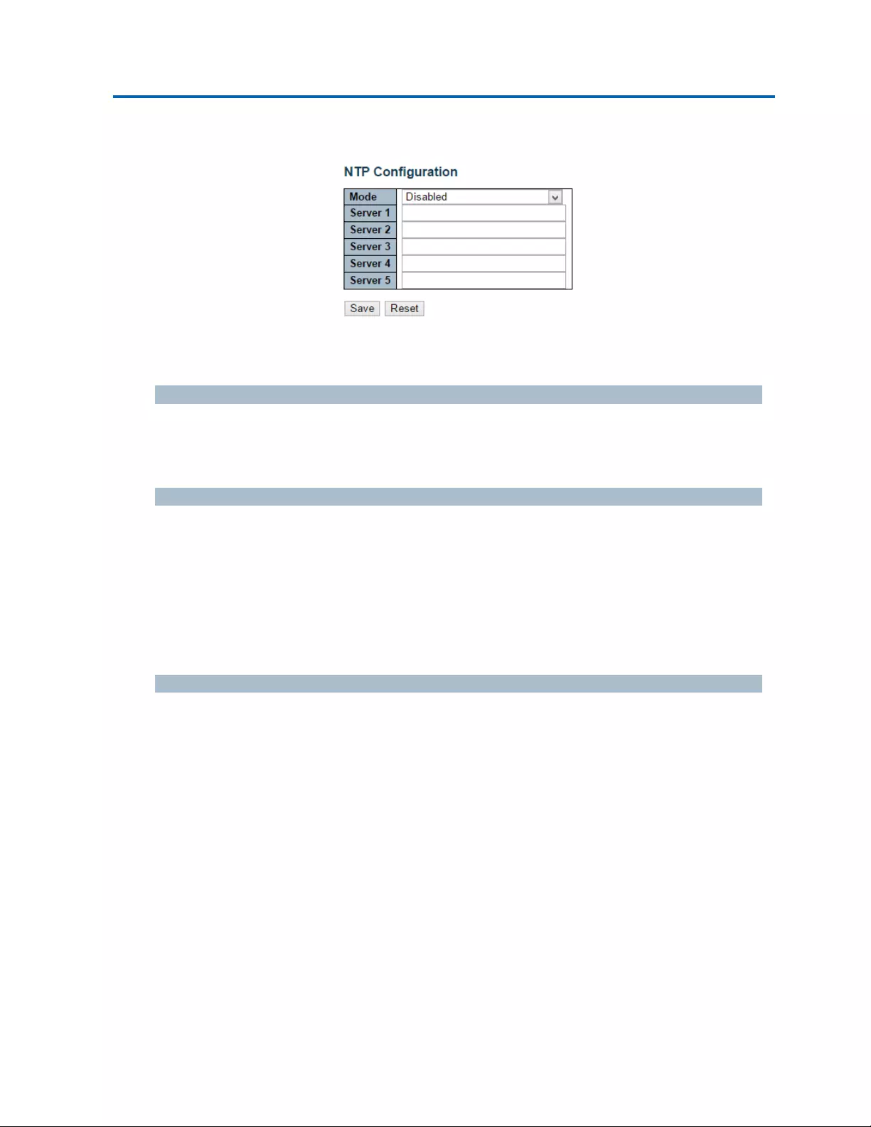
3.1.1.3.System‐NTP
NTPstandsforNetworkTimeProtocol,whichallowsswitchtoperformclocksynchronizationwith
theNTPserver.
Mode
YoucanenableordisableNTPfunctiononthisswitch:
Enabled:EnableNTPclientmode.
Disabled:DisableNTPclientmode.
Server1~5
ProvidetheIPv4orIPv6addressofaNTPserver.IPv6addressisin128‐bitrecordsrepresentedas
eightfieldsofuptofourhexadecimaldigitswithacolonseparatingeachfield(:).Forexample,
'fe80::215:c5ff:fe03:4dc7'.Thesymbol'::'isaspecialsyntaxthatcanbeusedasashorthandwayof
representingmultiple16‐bitgroupsofcontiguouszeros;butitcanappearonlyonce.Itcanalso
representalegallyvalidIPv4address.Forexample,'::192.1.2.34'.
Also,youcanjustinputNTPserver’sURLhereaswell.
Buttons
Save:Clicktosavechanges.
Reset:Clicktoundoanychangesmadelocallyandreverttopreviouslysavedvalues.
Chapter3:WebManagement
System‐Time
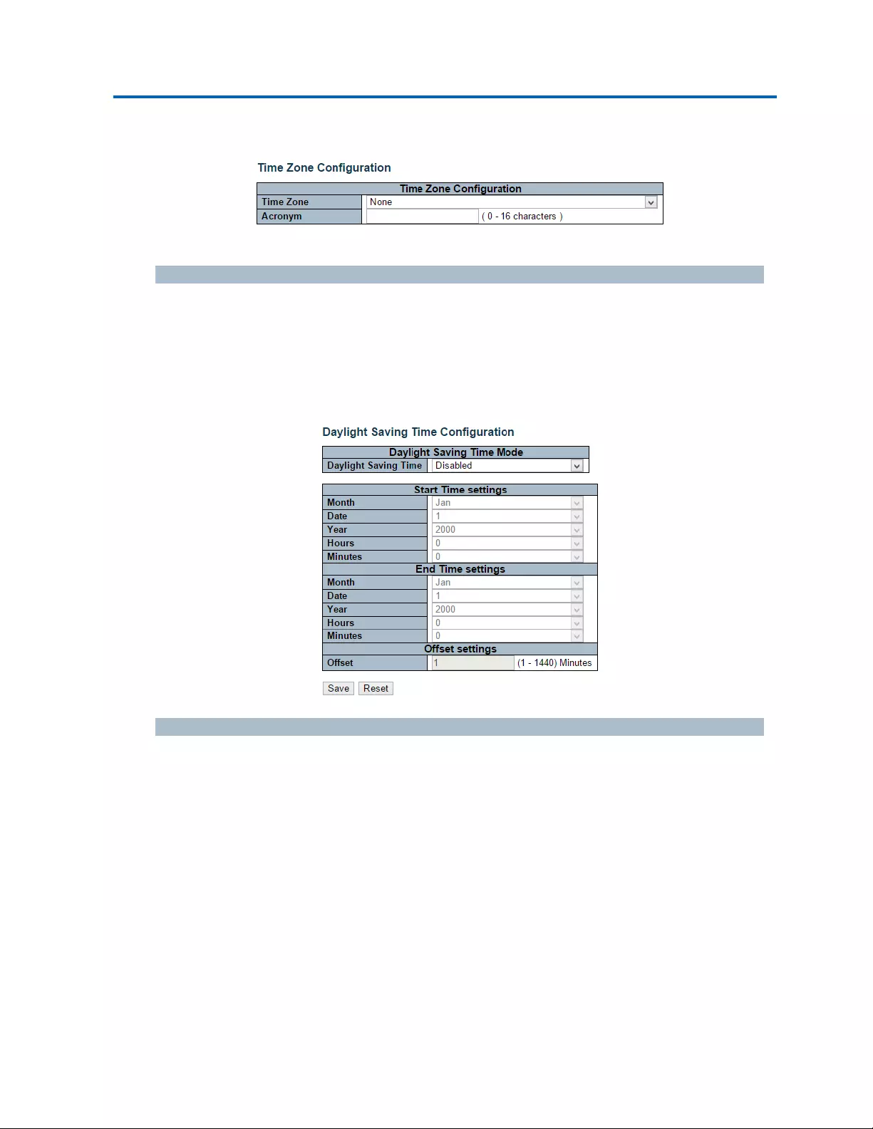
3.1.1.4.System‐Time
ThispageallowsyoutoconfiguretheTimeZoneanddaylightsavingtime.
TimeZoneConfiguration
TimeZone:ListsvariousTimeZonesworldwide.SelectappropriateTimeZonefromthedrop
downandclickSavetoset.
Acronym:Usercansettheacronymofthetimezone.ThisisaUserconfigurableacronymto
identifythetimezone.Youcanuseupto16alphanumericcharactersandpunctuationssuch
as“‐”,“_”,and“.”.
DaylightSavingTimeConfiguration
Whenenabled,theswitchwillsettheclockforwardorbackwardaccordingtotheconfigurationsset
belowforadefinedDaylightSavingTimeduration.
Disable:DisabletheDaylightSavingTimeconfiguration.Thisisthedefaultsetting.
Recurring:Theconfigurationofthedaylightsavingtimedurationwillbeappliedeveryyear.
Non‐Recurring:Theconfigurationofthedaylightsavingtimedurationwillbeappliedonly
once.

Chapter3:WebManagement
System‐Time
Intelinet48‐PortGigabitEthernetPoE+Layer2+ManagedSwitchUserManual|33
Starttimesettings
Week‐Selectthestartingweeknumber.
Day‐Selectthestartingday.
Month‐Selectthestartingmonth.
Hours‐Selectthestartinghour.
Minutes‐Selectthestartingminute.
Endtimesettings
Week‐Selecttheendingweeknumber.
Day‐Selecttheendingday.
Month‐Selecttheendingmonth.
Hours‐Selecttheendinghour.
Minutes‐Selecttheendingminute.
Offsetsettings
Offset‐EnterthenumberofminutestoaddduringDaylightSavingTime.(Range:1to1440)
Buttons
Save:Clicktosavechanges.
Reset:Clicktoundoanychangesmadelocallyandreverttopreviouslysavedvalues.

Chapter3:WebManagement
System‐Log
3.1.1.5.System‐Log
ConfigureSystemLogonthispage.
ServerMode
Whenenabled,thesystemlogmessagewillbesentouttothesystemlogserveryousethere.The
systemlogprotocolisbasedonUDPcommunicationandreceivedonUDPport514andthesystem
logserverwillnotsendacknowledgmentsbacksendersinceUDPisaconnectionlessprotocolandit
doesnotprovideacknowledgments.Thesystemlogpacketwillalwayssendoutevenifthesystem
logserverdoesnotexist.Possiblemodesare:
Enabled:Enableservermodeoperation.
Disabled:Disableservermodeoperation.
ServerAddress
IndicatestheIPv4hostaddressofsystemlogserver.IftheswitchprovideDNSfeature,italsocanbe
ahostname.
SystemlogLevel
Indicateswhatkindofmessagewillsendtosystemlogserver.Possiblemodesare:
Info:Sendinformation,warningsanderrors.
Warning:Sendwarningsanderrors.
Error:Senderrors.
Buttons
Save:Clicktosavechanges.
Reset:Clicktoundoanychangesmadelocallyandreverttopreviouslysavedvalues.

Chapter3:WebManagement
GreenEthernet‐LED
3.1.2.Configuration‐GreenEthernet
3.1.2.1.GreenEthernet‐LED
StatusLED
ThesystemstatusLEDshowswhetherthesystemisrunning.TheLEDisgreenwhensystemis
runningandnoerrorsaredetected.IferrorshasbeendetectedthestatusLEDwillindicatethisby
blinkingred
FrontEthernetPortLEDs
ThefrontEthernetportshaveadualcolorLEDsperport.TheportLEDsisplacedinablock(1‐high
forSFPs,2‐highforRJ45s)totheleftoftheports.
Apushbuttonanda4‐hightowerofLEDsisplacednexttothefrontEthernetportLEDs.The
pushbuttonselectsbetweenfourdifferentportLEDmodes,indicatedbythe4‐highLEDmodetower.
After30secondstheLEDmodefallsbacktomodeA.
TheportLEDmodesarenamedAthroughDandshowsthefollowing
PortLEDIndicationmodeD:
Green(1000Mbit):Solid=Link,Blink=Activity
Orange(10/100Mbit):Solid=Link,Blink=Activity
PortLEDIndicationmodeC:
Green:Solid=FullDuplexOff=Nolink
Orange:Solid=HalfDuplex,Blink:Collisions
PortLEDIndicationmodeB:
Green:Solid=Link,Blink=Activity
Orange:Solid=Portdisabledbymanagement,Blink=Errorsreceived
PortLEDIndicationmodeA:
Powersavemode‐LEDsareoff.

Chapter3:WebManagement
GreenEthernet‐LED
Intelinet48‐PortGigabitEthernetPoE+Layer2+ManagedSwitchUserManual|36
LEDsIntensity
TheLEDspowerconsumptioncanbereducedbyloweringtheLEDsintensity.LEDsintensitycouldfor
examplebeloweredduringnighttime,ortheycouldbeturncompletelyoff.Itispossibleto
configure24differenthoursoftheday,atwheretheLEDsintensityshouldbeset.
StartTime
ThetimeatwhichtheLEDsintensityshallbesettothecorrespondingintensity.
EndTime
ThetimeatwhichtheLEDsintensityshallbesettoanewintensity.Ifnointensityisspecifiedforthe
nexthour,theintensityissettodefaultintensity.
Intensity
TheLEDsintensity(100%=Fullpower,0%=LEDoff).
Maintenance
MaintenanceTime
Whenanetworkadministratordoesmaintenanceoftheswitch(e.g.addingormovingusers)he
mightwanttohavefullLEDintensityduringthemaintenanceperiod.Thereforeitispossibleto
specifythattheLEDsshallusefullintensityaspecificperiodoftime.MaintenanceTimeisthe
numberofsecondsthattheLEDswillhavefullintensityaftereitheraporthaschangedlinkstate,or
theLEDpushbuttonhasbeenpushed.
Buttons
Save:Clicktosavechanges.
Reset:Clicktoundoanychangesmadelocallyandreverttopreviouslysavedvalues.

Chapter3:WebManagement
GreenEthernet‐PortPowerSavings
3.1.2.2.GreenEthernet‐PortPowerSavings
EEEisapowersavingoptionthatreducesthepowerusagewhenthereislowornotrafficutilization.
EEEworksbypoweringdowncircuitswhenthereisnotraffic.Whenaportgetsdatatobe
transmittedallcircuitsarepoweredup.Thetimeittakestopowerupthecircuitsisnamedwakeup
time.Thedefaultwakeuptimeis17usfor1Gbitlinksand30usforotherlinkspeeds.EEEdevices
mustagreeuponthevalueofthewakeuptimeinordertomakesurethatboththereceivingand
transmittingdevicehasallcircuitspoweredupwhentrafficistransmitted.Thedevicescanexchange
wakeuptimeinformationusingtheLLDPprotocol.
EEEworksforportsinauto‐negotiationmode,wheretheportisnegotiatedtoeither1Gor100Mbit
fullduplexmode.
ForportsthatarenotEEE‐capablethecorrespondingEEEcheckboxesaregrayedoutandthus
impossibletoenableEEEfor.
Whenaportispowereddownforsavingpower,outgoingtrafficisstoredinabufferuntiltheportis
poweredupagain.Becausetherearesomeoverheadinturningtheportdownandup,morepower
canbesavedifthetrafficcanbebufferedupuntilalargeburstoftrafficcanbetransmitted.
Bufferingtrafficwillgivesomelatencyinthetraffic.

Chapter3:WebManagement
GreenEthernet‐LED
Intelinet48‐PortGigabitEthernetPoE+Layer2+ManagedSwitchUserManual|38
PortConfiguration
Port
Theswitchportnumberofthelogicalport.
ActiPHY
Linkdownpowersavingsenabled.
ActiPHYworksbyloweringthepowerforaportwhenthereisnolink.Theportispowerupforshort
momentinordertodetermineifcableisinserted.
PerfectReach
Cablelengthpowersavingsenabled.
PerfectReachworksbydeterminingthecablelengthandloweringthepowerforportswithshort
cables.
EEE
ControlswhetherEEEisenabledforthisswitchport.
Buttons
Save:Clicktosavechanges.
Reset:Clicktoundoanychangesmadelocallyandreverttopreviouslysavedvalues.

Chapter3:WebManagement
Configuration‐Ports
3.1.3.Configuration‐Ports
Thispagedisplayscurrentportconfigurations.Portscanalsobeconfiguredhere.
Theportsettingsrelatetothecurrentlyselectedstackunit,asreflectedbythepageheader.
Port
Thisisthelogicalportnumberforthisrow.
Link
Thecurrentlinkstateisdisplayedgraphically.Greenindicatesthelinkisupandredthatitisdown.
CurrentLinkSpeed
Thecurrentlinkspeedoftheport.
ConfiguredLinkSpeed
Selectsanyavailablelinkspeedforthegivenswitchport.Onlyspeedssupportedbythespecificport
isshown.Possiblespeedsare:
Disabled‐Disablestheswitchportoperation.
Auto‐Cuportautonegotiatingspeedwiththelinkpartnerandselectsthehighestspeedthat
iscompatiblewiththelinkpartner.
10MbpsHDX‐Forcesthecuportin10Mbpshalfduplexmode.
10MbpsFDX‐Forcesthecuportin10Mbpsfullduplexmode.
100MbpsHDX‐Forcesthecuportin100Mbpshalfduplexmode.
100MbpsFDX‐Forcesthecuportin100Mbpsfullduplexmode.
1GbpsFDX‐Forcesthecuportin1Gbpsfullduplexmode.
FlowControl
WhenAutoSpeedisselectedonaport,thissectionindicatestheflowcontrolcapabilitythatis
advertisedtothelinkpartner.
Whenafixed‐speedsettingisselected,thatiswhatisused.TheCurrentRxcolumnindicateswhether
pauseframesontheportareobeyed,andtheCurrentTxcolumnindicateswhetherpauseframeson
theportaretransmitted.TheRxandTxsettingsaredeterminedbytheresultofthelast

Chapter3:WebManagement
Configuration‐Ports
Intelinet48‐PortGigabitEthernetPoE+Layer2+ManagedSwitchUserManual|40
Auto‐Negotiation.
Checktheconfiguredcolumntouseflowcontrol.ThissettingisrelatedtothesettingforConfigured
LinkSpeed.
MaximumFrameSize
Enterthemaximumframesizeallowedfortheswitchport,includingFCS.
ExcessiveCollisionMode
Configureporttransmitcollisionbehavior.
Discard:Discardframeafter16collisions(default).
Restart:Restartbackoffalgorithmafter16collisions.
Buttons
Save:Clicktosavechanges.
Reset:Clicktoundoanychangesmadelocallyandreverttopreviouslysavedvalues.
Refresh:Clicktorefreshthepage.Anychangesmadelocallywillbeundone.

Chapter3:WebManagement
DHCP‐Server‐Mode
3.1.4.Configuration‐DHCP
3.1.4.1.DHCP‐Server
3.1.4.1.1.DHCP‐Server‐Mode
ThispageconfiguresglobalmodeandVLANmodetoenable/disableDHCPserverpersystemand
perVLAN.
GlobalMode
Configureoperationmodetoenable/disableDHCPserverpersystem.
Mode
Configuretheoperationmodepersystem.Possiblemodesare:
Enabled:EnableDHCPserverpersystem.
Disabled:DisableDHCPserverpresystem.
VLANMode
Configureoperationmodetoenable/disableDHCPserverperVLAN.
VLANRange
IndicatetheVLANrangeinwhichDHCPserverisenabledordisabled.ThefirstVLANIDmustbe
smallerthanorequaltothesecondVLANID.BUT,iftheVLANrangecontainsonly1VLANID,then
youcanjustinputitintoeitheroneofthefirstandsecondVLANIDorboth.
Ontheotherhand,ifyouwanttodisableexistedVLANrange,thenyoucanfollowthesteps.
1. Press“AddVLANRange”toaddanewVLANrange.
2. InputtheVLANrangethatyouwanttodisable.
3. ChooseModetobeDisabled.
4. Press“Save”toapplythechange.
Then,youwillseethedisabledVLANrangeisremovedfromtheDHCPServermodeconfiguration
page.

Chapter3:WebManagement
DHCP‐Server‐Mode
Intelinet48‐PortGigabitEthernetPoE+Layer2+ManagedSwitchUserManual|42
Mode
IndicatethetheoperationmodeperVLAN.Possiblemodesare:
Enabled:EnableDHCPserverperVLAN.
Disabled:DisableDHCPserverpreVLAN.
Buttons
AddVLANRange:ClicktoaddanewVLANrange.
Save:Clicktosavechanges.
Reset:Clicktoundoanychangesmadelocallyandreverttopreviouslysavedvalues.

Chapter3:WebManagement
DHCP‐Server‐ExcludedIP
3.1.4.1.2.DHCP‐Server‐ExcludedIP
ThispageconfiguresexcludedIPaddresses.DHCPserverwillnotallocatetheseexcludedIP
addressestoDHCPclient.
ExcludedIPAddress
ConfigureexcludedIPaddresses.
IPRange
DefinetheIPrangetobeexcludedIPaddresses.ThefirstexcludedIPmustbesmallerthanor
equaltothesecondexcludedIP.BUT,iftheIPrangecontainsonly1excludedIP,thenyoucanjust
inputittoeitheroneofthefirstandsecondexcludedIPorboth.
Buttons
AddIPRange:ClicktoaddanewexcludedIPrange.
Save:Clicktosavechanges.
Reset:Clicktoundoanychangesmadelocallyandreverttopreviouslysavedvalues.

Chapter3:WebManagement
DHCP‐Server‐Pool
3.1.4.1.3.DHCP‐Server‐Pool
ThispagemanagesDHCPpools.AccordingtotheDHCPpool,DHCPserverwillallocateIPaddress
anddeliverconfigurationparameterstoDHCPclient.
PoolSetting
Addordeletepools.
Addingapoolandgivinganameistocreateanewpoolwith"default"configuration.Ifyouwant
toconfigureallsettingsincludingtype,IPsubnetmaskandleasetime,youcanclickthepoolname
togointotheconfigurationpage.
Name
Configurethepoolnamethatacceptsallprintablecharacters,exceptwhitespace.Ifyouwantto
configurethedetailsettings,youcanclickthepoolnametogointotheconfigurationpage.
Type
Displaywhichtypeofthepoolis.
Network:thepooldefinesapoolofIPaddressestoservicemorethanoneDHCPclient.
Host:thepoolservicesforaspecificDHCPclientidentifiedbyclientidentifierorhardware
address.
If"‐"isdisplayed,itmeansnotdefined.
IP
DisplaynetworknumberoftheDHCPaddresspool.
If"‐"isdisplayed,itmeansnotdefined.
SubnetMask
DisplaysubnetmaskoftheDHCPaddresspool.
If"‐"isdisplayed,itmeansnotdefined.

Chapter3:WebManagement
DHCP‐Server‐Pool
Intelinet48‐PortGigabitEthernetPoE+Layer2+ManagedSwitchUserManual|45
LeaseTime
Displayleasetimeofthepool.
Buttons
AddNewPool:ClicktoaddanewDHCPpool.
Save:Clicktosavechanges.
Reset:Clicktoundoanychangesmadelocallyandreverttopreviouslysavedvalues.
Chapter3:WebManagement
DHCP‐Snooping
Intelinet48‐PortGigabitEthernetPoE+Layer2+ManagedSwitchUserManual|46
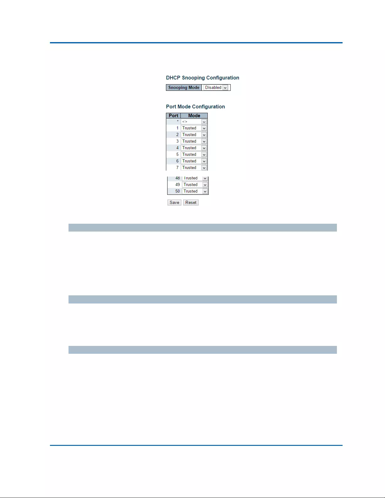
3.1.4.2.DHCP‐Snooping
ConfigureDHCPSnoopingonthispage.
SnoopingMode
IndicatestheDHCPsnoopingmodeoperation.Possiblemodesare:
Enabled:EnableDHCPsnoopingmodeoperation.WhenDHCPsnoopingmodeoperationis
enabled,theDHCPrequestmessageswillbeforwardedtotrustedportsandonlyallowreply
packetsfromtrustedports.
Disabled:DisableDHCPsnoopingmodeoperation.
PortModeConfiguration
IndicatestheDHCPsnoopingportmode.Possibleportmodesare:
Trusted:ConfigurestheportastrustedsourceoftheDHCPmessages.
Untrusted:ConfigurestheportasuntrustedsourceoftheDHCPmessages.
Buttons
Save:Clicktosavechanges.
Reset:Clicktoundoanychangesmadelocallyandreverttopreviouslysavedvalues.

Chapter3:WebManagement
DHCP‐Relay
Intelinet48‐PortGigabitEthernetPoE+Layer2+ManagedSwitchUserManual|47
3.1.4.3.DHCP‐Relay
ADHCPrelayagentisusedtoforwardandtotransferDHCPmessagesbetweentheclientsandthe
serverwhentheyarenotinthesamesubnetdomain.ItstorestheincominginterfaceIPaddressin
theGIADDRfieldoftheDHCPpacket.TheDHCPservercanusethevalueofGIADDRfieldto
determinetheassignedsubnet.Forsuchcondition,pleasemakesuretheswitchconfigurationof
VLANinterfaceIPaddressandPVID(PortVLANID)correctly.
RelayMode
IndicatestheDHCPrelaymodeoperation.
Possiblemodesare:
Enabled:EnableDHCPrelaymodeoperation.WhenDHCPrelaymodeoperationisenabled,
theagentforwardsandtransfersDHCPmessagesbetweentheclientsandtheserverwhen
theyarenotinthesamesubnetdomain.AndtheDHCPbroadcastmessagewon'tbeflooded
forsecurityconsiderations.
Disabled:DisableDHCPrelaymodeoperation.
RelayServer
IndicatestheDHCPrelayserverIPaddress.
RelayInformationMode
IndicatestheDHCPrelayinformationmodeoptionoperation.Theoption82circuitIDformatas
"[vlan_id][module_id][port_no]".ThefirstfourcharactersrepresenttheVLANID,thefifthandsixth
charactersarethemoduleID(instandalonedeviceitalwaysequal0,instackabledeviceitmeans
switchID),andthelasttwocharactersaretheportnumber.Forexample,"00030108"meansthe
DHCPmessagereceiveformVLANID3,switchID1,portNo8.Andtheoption82remoteIDvalueis
equaltheswitchMACaddress.
Possiblemodesare:
Enabled:EnableDHCPrelayinformationmodeoperation.WhenDHCPrelayinformation
modeoperationisenabled,theagentinsertsspecificinformation(option82)intoaDHCP
messagewhenforwardingtoDHCPserverandremovesitfromaDHCPmessagewhen
transferringtoDHCPclient.ItonlyworkswhenDHCPrelayoperationmodeisenabled.

Chapter3:WebManagement
DHCP‐Relay
Intelinet48‐PortGigabitEthernetPoE+Layer2+ManagedSwitchUserManual|48
Disabled:DisableDHCPrelayinformationmodeoperation.
RelayInformationPolicy
IndicatestheDHCPrelayinformationoptionpolicy.WhenDHCPrelayinformationmodeoperationis
enabled,iftheagentreceivesaDHCPmessagethatalreadycontainsrelayagentinformationitwill
enforcethepolicy.The'Replace'policyisinvalidwhenrelayinformationmodeisdisabled.Possible
policiesare:
Replace:ReplacetheoriginalrelayinformationwhenaDHCPmessagethatalreadycontainsit
isreceived.
Keep:KeeptheoriginalrelayinformationwhenaDHCPmessagethatalreadycontainsitis
received.
Drop:DropthepackagewhenaDHCPmessagethatalreadycontainsrelayinformationis
received.
Buttons
Save:Clicktosavechanges.
Reset:Clicktoundoanychangesmadelocallyandreverttopreviouslysavedvalues.

Chapter3:WebManagement
Security‐Switch‐Users
3.1.5.Configuration‐Security
Thissectionprovidessettingsregardingtotheswitch’ssecurityfunctions.Settingsprovided
herecanbedividedinto3categories:
Switch:Hereyoucanmakesecuritysettingsregardingtotheswitchitself.
Network:Providingsecuritysettingsregardingtothenetwork.
AAA:HereyoucansetRADIUSandTACACS+authenticationsettings.
3.1.5.1.Security‐Switch‐Users
Thispageprovidesanoverviewofthecurrentusers.Currentlytheonlywaytologinasanotheruser
onthewebserveristocloseandreopenthebrowser.
UserName
Thenameoftheuser.Youcanalsoclickonthelinktoconfigureuseraccount.
PrivilegeLevel
Theprivilegeleveloftheuser.Theallowedrangeis1to15.Iftheprivilegelevelvalueis15,itcan
accessallgroups,i.e.thatisgrantedthefullycontrolofthedevice.Butothersvalueneedtoreferto
eachgroupprivilegelevel.User'sprivilegeshouldbesameorgreaterthanthegroupprivilegelevel
tohavetheaccessofthatgroup.Bydefaultsetting,mostgroupprivilegeslevel5hastheread‐only
accessandprivilegelevel10hastheread‐writeaccess.Andthesystemmaintenance(software
upload,factorydefaultsandetc.)needuserprivilegelevel15.Generally,theprivilegelevel15canbe
usedforanadministratoraccount,privilegelevel10forastandarduseraccountandprivilegelevel5
foraguestaccount.
Buttons
AddNewUser:Clicktoaddanewuser.

Chapter3:WebManagement
Security‐Switch‐Users
Intelinet48‐PortGigabitEthernetPoE+Layer2+ManagedSwitchUserManual|50
Thispageconfiguresauser.
UserName
Astringidentifyingtheusernamethatthisentryshouldbelongto.Theallowedstringlengthis1to
31.Thevalidusernameisacombinationofletters,numbersandunderscores.
Password
Thepasswordoftheuser.Theallowedstringlengthis0to31.
PrivilegeLevel
Theprivilegeleveloftheuser.Theallowedrangeis1to15.Iftheprivilegelevelvalueis15,itcan
accessallgroups,i.e.thatisgrantedthefullycontrolofthedevice.Butothersvalueneedtoreferto
eachgroupprivilegelevel.User'sprivilegeshouldbesameorgreaterthanthegroupprivilegelevel
tohavetheaccessofthatgroup.
Bydefaultsetting,mostgroupsprivilegelevel5hastheread‐onlyaccessandprivilegelevel10has
theread‐writeaccess.Andthesystemmaintenance(softwareupload,factorydefaultsandetc.)need
userprivilegelevel15.Generally,theprivilegelevel15canbeusedforanadministratoraccount,
privilegelevel10forastandarduseraccountandprivilegelevel5foraguestaccount.
Buttons
Save:Clicktosavechanges.
Reset:Clicktoundoanychangesmadelocallyandreverttopreviouslysavedvalues.
Cancel:ClicktoundoanychangesmadelocallyandreturntotheUsers.
DeleteUser:Deletethecurrentuser.Pleasenotethatthedefaultuser(admin)cannotbe
deleted.

Chapter3:WebManagement
Security‐Switch‐PrivilegeLevel
3.1.5.2.Security‐Switch‐PrivilegeLevel
Thispageprovidesanoverviewoftheprivilegelevels.
GroupName
Thenameidentifyingtheprivilegegroup.Inmostcases,aprivilegelevelgroupconsistsofasingle
module(e.g.LACP,RSTPorQoS),butafewofthemcontainsmorethanone.Thefollowing
descriptiondefinestheseprivilegelevelgroupsindetails:
System:Contact,Name,Location,Timezone,DaylightSavingTime,Log.
Security:Authentication,SystemAccessManagement,Port(containsDot1xport,MACbased
andtheMACAddressLimit),ACL,HTTPS,SSH,ARPInspection,IPsourceguard.
IP:Everythingexcept'ping'.
Port:Everythingexcept'VeriPHY'.
Diagnostics:'ping'and'VeriPHY'.
Maintenance:CLI‐SystemReboot,SystemRestoreDefault,SystemPassword,Configuration
Save,ConfigurationLoadandFirmwareLoad.Web‐Users,PrivilegeLevelsandeverythingin
Maintenance.
Debug:OnlypresentinCLI.

Chapter3:WebManagement
Security‐Switch‐PrivilegeLevel
Intelinet48‐PortGigabitEthernetPoE+Layer2+ManagedSwitchUserManual|52
PrivilegeLevels
EverygrouphasanauthorizationPrivilegelevelforthefollowingsubgroups:configurationread‐only,
configuration/executeread‐write,status/statisticsread‐only,status/statisticsread‐write(e.g.for
clearingofstatistics).UserPrivilegeshouldbesameorgreaterthantheauthorizationPrivilegelevel
tohavetheaccesstothatgroup.
Buttons
Save:Clicktosavechanges.
Reset:Clicktoundoanychangesmadelocallyandreverttopreviouslysavedvalues.

Chapter3:WebManagement
Security‐Switch‐AuthenticationMethod
3.1.5.3.Security‐Switch‐AuthenticationMethod
Thispageallowsyoutoconfigurehowauserisauthenticatedwhenhelogsintothestackviaoneof
themanagementclientinterfaces.
Client
Themanagementclientforwhichtheconfigurationbelowapplies.
AuthenticationMethod
AuthenticationMethodcanbesettooneofthefollowingvalues:
None:authenticationisdisabledandloginisnotpossible.
Local:usethelocaluserdatabaseonthestackforauthentication.
RADIUS:usearemoteRADIUSserverforauthentication.
TACACS+:usearemoteTAC ACS+serverforauthentication.
Fallback
Enablefallbacktolocalauthenticationbycheckingthisbox.
Ifnoneoftheconfiguredauthenticationserversarealive,thelocaluserdatabaseisusedfor
authentication.
ThisisonlypossibleiftheAuthenticationMethodissettoavalueotherthan'none'or'local'.
Buttons
Save:Clicktosavechanges.
Reset:Clicktoundoanychangesmadelocallyandreverttopreviouslysavedvalues.

Chapter3:WebManagement
Security‐Switch‐SSH
3.1.5.4.Security‐Switch‐SSH
ConfigureSSHonthispage.
Mode
IndicatestheSSHmodeoperation.Possiblemodesare:
Enabled:EnableSSHmodeoperation.
Disabled:DisableSSHmodeoperation.
Buttons
Save:Clicktosavechanges.
Reset:Clicktoundoanychangesmadelocallyandreverttopreviouslysavedvalues.

Chapter3:WebManagement
Security‐Switch‐HTTPS
3.1.5.5.Security‐Switch‐HTTPS
ConfigureHTTPSonthispage.
Mode
IndicatestheHTTPSmodeoperation.WhenthecurrentconnectionisHTTPS,toapplyHTTPS
disabledmodeoperationwillautomaticallyredirectwebbrowsertoanHTTPconnection.Possible
modesare:
Enabled:EnableHTTPSmodeoperation.
Disabled:DisableHTTPSmodeoperation.
AutomaticRedirect
IndicatestheHTTPSredirectmodeoperation.AutomaticallyredirectswebbrowsertoanHTTPS
connectionwhenbothHTTPSmodeandAutomaticRedirectareenabled.Possiblemodesare:
Enabled:EnableHTTPSredirectmodeoperation.
Disabled:DisableHTTPSredirectmodeoperation.
Buttons
Save:Clicktosavechanges.
Reset:Clicktoundoanychangesmadelocallyandreverttopreviouslysavedvalues.

Chapter3:WebManagement
Security‐Switch‐AccessManagement
3.1.5.6.Security‐Switch‐AccessManagement
Configureaccessmanagementtableonthispage.Themaximumnumberofentriesis16.Ifthe
application'stypematchanyoneoftheaccessmanagemententries,itwillallowaccesstothe
switch.
Mode
Indicatestheaccessmanagementmodeoperation.Possiblemodesare:
Enabled:Enableaccessmanagementmodeoperation.
Disabled:Disableaccessmanagementmodeoperation.
Delete
Checktodeletetheentry.Itwillbedeletedduringthenextsave.
StartIPaddress
IndicatesthestartIPaddressfortheaccessmanagemententry.
EndIPaddress
IndicatestheendIPaddressfortheaccessmanagemententry.
HTTP/HTTPS
IndicatesthatthehostcanaccesstheswitchfromHTTP/HTTPSinterfaceifthehostIPaddress
matchestheIPaddressrangeprovidedintheentry.
SNMP
IndicatesthatthehostcanaccesstheswitchfromSNMPinterfaceifthehostIPaddressmatchesthe
IPaddressrangeprovidedintheentry.
TELNET/SSH
IndicatesthatthehostcanaccesstheswitchfromTELNET/SSHinterfaceifthehostIPaddress
matchestheIPaddressrangeprovidedintheentry.
Buttons
AddNewEntry:Clicktoaddanewaccessmanagemententry.
Save:Clicktosavechanges.
Reset:Clicktoundoanychangesmadelocallyandreverttopreviouslysavedvalues.

Chapter3:WebManagement
Security‐Switch‐PrivilegeLevel
Intelinet48‐PortGigabitEthernetPoE+Layer2+ManagedSwitchUserManual|57

Chapter3:WebManagement
Security‐Switch‐SNMP‐System
3.1.5.7.Security‐Switch‐SNMP
3.1.5.7.1.Security‐Switch‐SNMP‐System
ConfigureSNMPonthispage.
Mode
IndicatestheSNMPmodeoperation.Possiblemodesare:
Enabled:EnableSNMPmodeoperation.
Disabled:DisableSNMPmodeoperation.
Version
IndicatestheSNMPsupportedversion.Possibleversionsare:
SNMPv1:SetSNMPsupportedversion1.
SNMPv2c:SetSNMPsupportedversion2c.
SNMPv3:SetSNMPsupportedversion3.
ReadCommunity
IndicatesthecommunityreadaccessstringtopermitaccesstoSNMPagent.Theallowedstring
lengthis0to255,andtheallowedcontentistheASCIIcharactersfrom33to126.
ThefieldisapplicableonlywhenSNMPversionisSNMPv1orSNMPv2c.IfSNMPversionis
SNMPv3,thecommunitystringwillbeassociatedwithSNMPv3communitiestable.Itprovides
moreflexibilitytoconfiguresecuritynamethanaSNMPv1orSNMPv2ccommunitystring.In
additiontocommunitystring,aparticularrangeofsourceaddressescanbeusedtorestrictsource
subnet.
WriteCommunity
IndicatesthecommunitywriteaccessstringtopermitaccesstoSNMPagent.Theallowedstring
lengthis0to255,andtheallowedcontentistheASCIIcharactersfrom33to126.
ThefieldisapplicableonlywhenSNMPversionisSNMPv1orSNMPv2c.IfSNMPversionis
SNMPv3,thecommunitystringwillbeassociatedwithSNMPv3communitiestable.Itprovides
moreflexibilitytoconfiguresecuritynamethanaSNMPv1orSNMPv2ccommunitystring.In
additiontocommunitystring,aparticularrangeofsourceaddressescanbeusedtorestrictsource
subnet.

Chapter3:WebManagement
Security‐Switch‐SNMP‐System
Intelinet48‐PortGigabitEthernetPoE+Layer2+ManagedSwitchUserManual|59
EngineID
IndicatestheSNMPv3engineID.Thestringmustcontainanevennumber(inhexadecimalformat)
withnumberofdigitsbetween10and64,butall‐zerosandall‐'F'sarenotallowed.Changeofthe
EngineIDwillclearalloriginallocalusers.
SNMPTrapConfiguration
ConfigureSNMPtraponthispage.
TrapMode
IndicatestheSNMPtrapmodeoperation.Possiblemodesare:
Enabled:EnableSNMPtrapmodeoperation.
Disabled:DisableSNMPtrapmodeoperation.
TrapVersion
IndicatestheSNMPtrapsupportedversion.Possibleversionsare:
SNMPv1:SetSNMPtrapsupportedversion1.
SNMPv2c:SetSNMPtrapsupportedversion2c.
SNMPv3:SetSNMPtrapsupportedversion3.
TrapCommunity
IndicatesthecommunityaccessstringwhensendingSNMPtrappacket.Theallowedstringlength
is0to255,andtheallowedcontentisASCIIcharactersfrom33to126.
TrapDestinationAddress
IndicatestheSNMPtrapdestinationaddress.ItallowavalidIPaddressindotteddecimalnotation
('x.y.z.w').
Anditalsoallowavalidhostname.Avalidhostnameisastringdrawnfromthealphabet(A‐Za‐z),
digits(0‐9),dot(.),dash(‐).Spacesarenotallowed,thefirstcharactermustbeanalphacharacter,
andthefirstandlastcharactersmustnotbeadotoradash.

Chapter3:WebManagement
Security‐Switch‐SNMP‐System
Intelinet48‐PortGigabitEthernetPoE+Layer2+ManagedSwitchUserManual|60
TrapDestinationIPv6Address
IndicatestheSNMPtrapdestinationIPv6address.IPv6addressisin128‐bitrecordsrepresentedas
eightfieldsofuptofourhexadecimaldigitswithacolonseparatingeachfield(:).Forexample,
'fe80::215:c5ff:fe03:4dc7'.Thesymbol'::'isaspecialsyntaxthatcanbeusedasashorthandway
ofrepresentingmultiple16‐bitgroupsofcontiguouszeros;butitcanappearonlyonce.Itcanalso
representalegallyvalidIPv4address.Forexample,'::192.1.2.34'.
TrapAuthenticationFailure
IndicatesthattheSNMPentityispermittedtogenerateauthenticationfailuretraps.Possible
modesare:
Enabled:EnableSNMPtrapauthenticationfailure.
Disabled:DisableSNMPtrapauthenticationfailure.
TrapLink‐upandLink‐down
IndicatestheSNMPtraplink‐upandlink‐downmodeoperation.Possiblemodesare:
Enabled:EnableSNMPtraplink‐upandlink‐downmodeoperation.
Disabled:DisableSNMPtraplink‐upandlink‐downmodeoperation.
TrapInformMode
IndicatestheSNMPtrapinformmodeoperation.Possiblemodesare:
Enabled:EnableSNMPtrapinformmodeoperation.
Disabled:DisableSNMPtrapinformmodeoperation.
TrapInformTimeout(seconds)
IndicatestheSNMPtrapinformtimeout.Theallowedrangeis0to2147.
TrapInformRetryTimes
IndicatestheSNMPtrapinformretrytimes.Theallowedrangeis0to255.
TrapProbeSecurityEngineID
IndicatestheSNMPtrapprobesecurityengineIDmodeofoperation.Possiblevaluesare:
Enabled:EnableSNMPtrapprobesecurityengineIDmodeofoperation.
Disabled:DisableSNMPtrapprobesecurityengineIDmodeofoperation.
TrapSecurityEngineID
IndicatestheSNMPtrapsecurityengineID.SNMPv3sendstrapsandinformsusingUSMfor
authenticationandprivacy.AuniqueengineIDforthesetrapsandinformsisneeded.When"Trap
ProbeSecurityEngineID"isenabled,theIDwillbeprobedautomatically.Otherwise,theID
specifiedinthisfieldisused.Thestringmustcontainanevennumber(inhexadecimalformat)with
numberofdigitsbetween10and64,butall‐zerosandall‐'F'sarenotallowed.
TrapSecurityName

Chapter3:WebManagement
Security‐Switch‐SNMP‐System
Intelinet48‐PortGigabitEthernetPoE+Layer2+ManagedSwitchUserManual|61
IndicatestheSNMPtrapsecurityname.SNMPv3trapsandinformsusingUSMforauthentication
andprivacy.Auniquesecuritynameisneededwhentrapsandinformsareenabled.
Buttons
Save:Clicktosavechanges.
Reset:Clicktoundoanychangesmadelocallyandreverttopreviouslysavedvalues.

Chapter3:WebManagement
Security‐Switch‐SNMP‐Community
3.1.5.7.2.Security‐Switch‐SNMP‐Community
ConfigureSNMPv3communitytableonthispage.TheentryindexkeyisCommunity.
Delete
Checktodeletetheentry.Itwillbedeletedduringthenextsave.
Community
IndicatesthecommunityaccessstringtopermitaccesstoSNMPv3agent.Theallowedstring
lengthis1to32,andtheallowedcontentisASCIIcharactersfrom33to126.Thecommunitystring
willbetreatedassecuritynameandmapaSNMPv1orSNMPv2ccommunitystring.
SourceIP
IndicatestheSNMPaccesssourceaddress.Aparticularrangeofsourceaddressescanbeusedto
restrictsourcesubnetwhencombinedwithsourcemask.
SourceMask
IndicatestheSNMPaccesssourceaddressmask.
Buttons
AddNewEntry:Clicktoaddanewcommunityentry.
Save:Clicktosavechanges.
Reset:Clicktoundoanychangesmadelocallyandreverttopreviouslysavedvalues.

Chapter3:WebManagement
Security‐Switch‐SNMP‐User
3.1.5.7.3.Security‐Switch‐SNMP‐User
ConfigureSNMPv3usertableonthispage.TheentryindexkeysareEngineIDandUserName.
Delete
Checktodeletetheentry.Itwillbedeletedduringthenextsave.
EngineID
AnoctetstringidentifyingtheengineIDthatthisentryshouldbelongto.Thestringmustcontain
anevennumber(inhexadecimalformat)withnumberofdigitsbetween10and64,butall‐zeros
andall‐'F'sarenotallowed.TheSNMPv3architectureusestheUser‐basedSecurityModel(USM)
formessagesecurityandtheView‐basedAccessControlModel(VACM)foraccesscontrol.Forthe
USMentry,theusmUserEngineIDandusmUserNamearetheentry'skeys.Inasimpleagent,
usmUserEngineIDisalwaysthatagent'sownsnmpEngineIDvalue.Thevaluecanalsotakethe
valueofthesnmpEngineIDofaremoteSNMPenginewithwhichthisusercancommunicate.In
otherwords,ifuserengineIDequalsystemengineIDthenitislocaluser;otherwiseit'sremote
user.
UserName
Astringidentifyingtheusernamethatthisentryshouldbelongto.Theallowedstringlengthis1
to32,andtheallowedcontentisASCIIcharactersfrom33to126.
SecurityLevel
Indicatesthesecuritymodelthatthisentryshouldbelongto.Possiblesecuritymodelsare:
NoAuth,NoPriv:Noauthenticationandnoprivacy.
Auth,NoPriv:Authenticationandnoprivacy.
Auth,Priv:Authenticationandprivacy.
Thevalueofsecuritylevelcannotbemodifiedifentryalreadyexists.Thatmeansitmustfirstbe
ensuredthatthevalueissetcorrectly.

Chapter3:WebManagement
Security‐Switch‐SNMP‐User
Intelinet48‐PortGigabitEthernetPoE+Layer2+ManagedSwitchUserManual|64
AuthenticationProtocol
Indicatestheauthenticationprotocolthatthisentryshouldbelongto.Possibleauthentication
protocolsare:
None:Noauthenticationprotocol.
MD5:AnoptionalflagtoindicatethatthisuserusesMD5authenticationprotocol.
SHA:AnoptionalflagtoindicatethatthisuserusesSHAauthenticationprotocol.
Thevalueofsecuritylevelcannotbemodifiedifentryalreadyexists.Thatmeansmustfirstensure
thatthevalueissetcorrectly.
AuthenticationPassword
Astringidentifyingtheauthenticationpasswordphrase.ForMD5authenticationprotocol,the
allowedstringlengthis8to32.ForSHAauthenticationprotocol,theallowedstringlengthis8to
40.TheallowedcontentisASCIIcharactersfrom33to126.
PrivacyProtocol
Indicatestheprivacyprotocolthatthisentryshouldbelongto.Possibleprivacyprotocolsare:
None:Noprivacyprotocol.
DES:AnoptionalflagtoindicatethatthisuserusesDESauthenticationprotocol.
PrivacyPassword
Astringidentifyingtheprivacypasswordphrase.Theallowedstringlengthis8to32,andthe
allowedcontentisASCIIcharactersfrom33to126.
Buttons
AddNewEntry:Clicktoaddanewcommunityentry.
Save:Clicktosavechanges.
Reset:Clicktoundoanychangesmadelocallyandreverttopreviouslysavedvalues.
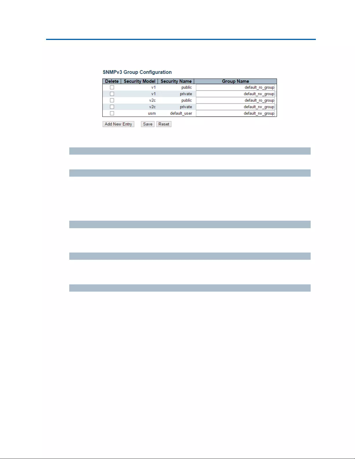
Chapter3:WebManagement
Security‐Switch‐SNMP‐Groups
3.1.5.7.4.Security‐Switch‐SNMP‐Groups
ConfigureSNMPv3grouptableonthispage.
Delete
Checktodeletetheentry.Itwillbedeletedduringthenextsave.
SecurityModel
Indicatesthesecuritymodelthatthisentryshouldbelongto.Possiblesecuritymodelsare:
v1:ReservedforSNMPv1.
v2c:ReservedforSNMPv2c.
usm:User‐basedSecurityModel(USM).
SecurityName
Astringidentifyingthesecuritynamethatthisentryshouldbelongto.Theallowedstringlengthis
1to32,andtheallowedcontentisASCIIcharactersfrom33to126.
GroupName
Astringidentifyingthegroupnamethatthisentryshouldbelongto.Theallowedstringlengthis1
to32,andtheallowedcontentisASCIIcharactersfrom33to126.
Buttons
AddNewEntry:Clicktoaddanewcommunityentry.
Save:Clicktosavechanges.
Reset:Clicktoundoanychangesmadelocallyandreverttopreviouslysavedvalues.

Chapter3:WebManagement
Security‐Switch‐SNMP‐Views
3.1.5.7.5.Security‐Switch‐SNMP‐Views
ConfigureSNMPv3viewtableonthispage.TheentryindexkeysareViewNameandOIDSubtree.
Delete
Checktodeletetheentry.Itwillbedeletedduringthenextsave.
ViewName
Astringidentifyingtheviewnamethatthisentryshouldbelongto.Theallowedstringlengthis1
to32,andtheallowedcontentisASCIIcharactersfrom33to126.
ViewType
Indicatestheviewtypethatthisentryshouldbelongto.Possibleviewtypesare:
included:Anoptionalflagtoindicatethatthisviewsubtreeshouldbeincluded.
excluded:Anoptionalflagtoindicatethatthisviewsubtreeshouldbeexcluded.
Ingeneral,ifaviewentry'sviewtypeis'excluded',thereshouldbeanotherviewentryexisting
withviewtypeas'included'andit'sOIDsubtreeshouldoverstepthe'excluded'viewentry.
OIDSubtree
TheOIDdefiningtherootofthesubtreetoaddtothenamedview.TheallowedOIDlengthis1to
128.Theallowedstringcontentisdigitalnumberorasterisk(*).
Buttons
AddNewEntry:Clicktoaddanewcommunityentry.
Save:Clicktosavechanges.
Reset:Clicktoundoanychangesmadelocallyandreverttopreviouslysavedvalues.

Chapter3:WebManagement
Security‐Switch‐SNMP‐Access
3.1.5.7.6.Security‐Switch‐SNMP‐Access
ConfigureSNMPv3accesstableonthispage.
Delete
Checktodeletetheentry.Itwillbedeletedduringthenextsave.
GroupName
Astringidentifyingthegroupnamethatthisentryshouldbelongto.Theallowedstringlengthis1
to32,andtheallowedcontentisASCIIcharactersfrom33to126.
SecurityModel
Indicatesthesecuritymodelthatthisentryshouldbelongto.Possiblesecuritymodelsare:
any:Anysecuritymodelaccepted(v1|v2c|usm).
v1:ReservedforSNMPv1.
v2c:ReservedforSNMPv2c.
usm:User‐basedSecurityModel(USM).
SecurityLevel
Indicatesthesecuritymodelthatthisentryshouldbelongto.Possiblesecuritymodelsare:
NoAuth,NoPriv:Noauthenticationandnoprivacy.
Auth,NoPriv:Authenticationandnoprivacy.
Auth,Priv:Authenticationandprivacy.
ReadViewName
ThenameoftheMIBviewdefiningtheMIBobjectsforwhichthisrequestmayrequestthecurrent
values.Theallowedstringlengthis1to32,andtheallowedcontentisASCIIcharactersfrom33to
126.
WriteViewName
ThenameoftheMIBviewdefiningtheMIBobjectsforwhichthisrequestmaypotentiallysetnew
values.Theallowedstringlengthis1to32,andtheallowedcontentisASCIIcharactersfrom33to
126.
Buttons
AddNewEntry:Clicktoaddanewcommunityentry.
Save:Clicktosavechanges.
Reset:Clicktoundoanychangesmadelocallyandreverttopreviouslysavedvalues.
3.1.5.8.Security‐Switch‐RMON

Chapter3:WebManagement
Security‐Switch‐RMON‐Statistics
Intelinet48‐PortGigabitEthernetPoE+Layer2+ManagedSwitchUserManual|68
3.1.5.8.1.Security‐Switch‐RMON‐Statistics
ConfigureRMONStatisticstableonthispage.TheentryindexkeyisID.
Delete
Checktodeletetheentry.Itwillbedeletedduringthenextsave.
ID
Indicatestheindexoftheentry.Therangeisfrom1to65535.
DataSource
IndicatestheportIDwhichwantstobemonitored.Ifinstackingswitch,thevaluemustadd
1000*(switchID‐1),forexample,iftheportisswitch3port5,thevalueis2005
Buttons
AddNewEntry:Clicktoaddanewcommunityentry.
Save:Clicktosavechanges.
Reset:Clicktoundoanychangesmadelocallyandreverttopreviouslysavedvalues.

Chapter3:WebManagement
Security‐Switch‐RMON‐History
3.1.5.8.2.Security‐Switch‐RMON‐History
ConfigureRMONHistorytableonthispage.TheentryindexkeyisID.
Delete
Checktodeletetheentry.Itwillbedeletedduringthenextsave.
ID
Indicatestheindexoftheentry.Therangeisfrom1to65535.
DataSource
IndicatestheportIDwhichwantstobemonitored.Ifinstackingswitch,thevaluemustadd
1000*(switchID‐1),forexample,iftheportisswitch3port5,thevalueis2005.
Interval
Indicatestheintervalinsecondsforsamplingthehistorystatisticsdata.Therangeisfrom1to
3600,defaultvalueis1800seconds.
Buckets
IndicatesthemaximumdataentriesassociatedthisHistorycontrolentrystoredinRMON.The
rangeisfrom1to3600,defaultvalueis50.
BucketsGranted
ThenumberofdatashallbesavedintheRMON.
Buttons
AddNewEntry:Clicktoaddanewcommunityentry.
Save:Clicktosavechanges.
Reset:Clicktoundoanychangesmadelocallyandreverttopreviouslysavedvalues.

Chapter3:WebManagement
Security‐Switch‐RMON‐Alarm
3.1.5.8.3.Security‐Switch‐RMON‐Alarm
ConfigureRMONAlarmtableonthispage.TheentryindexkeyisID.
Delete
Checktodeletetheentry.Itwillbedeletedduringthenextsave.
ID
Indicatestheindexoftheentry.Therangeisfrom1to65535.
Interval
Indicatestheintervalinsecondsforsamplingandcomparingtherisingandfallingthreshold.The
rangeisfrom1to2^31‐1.
Variable
Indicatestheparticularvariabletobesampled,thepossiblevariablesare:
InOctets:Thetotalnumberofoctetsreceivedontheinterface,includingframingcharacters.
InUcastPkts:Thenumberofuni‐castpacketsdeliveredtoahigher‐layerprotocol.
InNUcastPkts:Thenumberofbroad‐castandmulti‐castpacketsdeliveredtoahigher‐layer
protocol.
InDiscards:Thenumberofinboundpacketsthatarediscardedeventhepacketsarenormal.
InErrors:Thenumberofinboundpacketsthatcontainederrorspreventingthemfrombeing
deliverabletoahigher‐layerprotocol.
InUnknownProtos:thenumberoftheinboundpacketsthatwerediscardedbecauseofthe
unknownorun‐supportprotocol.
OutOctets:Thenumberofoctetstransmittedoutoftheinterface,includingframing
characters.
OutUcastPkts:Thenumberofuni‐castpacketsthatrequesttotransmit.
OutNUcastPkts:Thenumberofbroad‐castandmulti‐castpacketsthatrequesttotransmit.
OutDiscards:Thenumberofoutboundpacketsthatarediscardedeventthepacketsare
normal.
OutErrors:TheThenumberofoutboundpacketsthatcouldnotbetransmittedbecauseof
errors.
OutQLen:Thelengthoftheoutputpacketqueue(inpackets).
SampleType
Themethodofsamplingtheselectedvariableandcalculatingthevaluetobecomparedagainst
thethresholds,possiblesampletypesare:

Chapter3:WebManagement
Security‐Switch‐RMON‐Alarm
Intelinet48‐PortGigabitEthernetPoE+Layer2+ManagedSwitchUserManual|71
Absolute:Getthesampledirectly.
Delta:Calculatethedifferencebetweensamples(default).
Value
Thevalueofthestatisticduringthelastsamplingperiod.
StartupAlarm
Themethodofsamplingtheselectedvariableandcalculatingthevaluetobecomparedagainst
thethresholds,possiblesampletypesare:
RisingTriggeralarmwhenthefirstvalueislargerthantherisingthreshold.
FallingTriggeralarmwhenthefirstvalueislessthanthefallingthreshold.
RisingOrFallingTriggeralarmwhenthefirstvalueislargerthantherisingthresholdorless
thanthefallingthreshold(default).
RisingThreshold
Risingthresholdvalue(‐2147483648‐2147483647).
RisingIndex
Risingeventindex(1‐65535).
FallingThreshold
Fallingthresholdvalue(‐2147483648‐2147483647)
FallingIndex
Fallingeventindex(1‐65535).
Buttons
AddNewEntry:Clicktoaddanewcommunityentry.
Save:Clicktosavechanges.
Reset:Clicktoundoanychangesmadelocallyandreverttopreviouslysavedvalues.

Chapter3:WebManagement
Security‐Switch‐RMON‐Event
3.1.5.8.4.Security‐Switch‐RMON‐Event
ConfigureRMONEventtableonthispage.TheentryindexkeyisID.
Delete
Checktodeletetheentry.Itwillbedeletedduringthenextsave.
ID
Indicatestheindexoftheentry.Therangeisfrom1to65535.
Desc
Indicatesthisevent,thestringlengthisfrom0to127,defaultisanullstring.
Type
Indicatesthenotificationoftheevent,thepossibletypesare:
None:Thetotalnumberofoctetsreceivedontheinterface,includingframingcharacters.
Log:Thenumberofuni‐castpacketsdeliveredtoahigher‐layerprotocol.
snmptrap:Thenumberofbroad‐castandmulti‐castpacketsdeliveredtoahigher‐layer
protocol.
logandtrap:Thenumberofinboundpacketsthatarediscardedeventhepacketsarenormal.
Community
Specifythecommunitywhentrapissent,thestringlengthisfrom0to127,defaultis"public".
EventLastTime
IndicatesthevalueofsysUpTimeatthetimethisevententrylastgeneratedanevent.
Buttons
AddNewEntry:Clicktoaddanewcommunityentry.
Save:Clicktosavechanges.
Reset:Clicktoundoanychangesmadelocallyandreverttopreviouslysavedvalues.
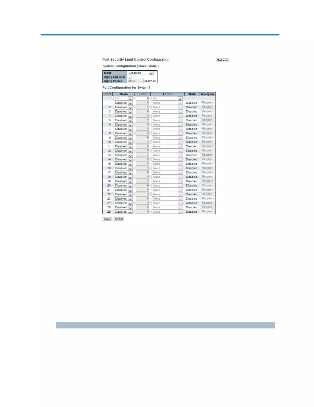
Chapter3:WebManagement
Security‐Network‐LimitControl
3.1.5.9.Security‐Network‐LimitControl
ThispageallowsyoutoconfigurethePortSecurityLimitControlsystemandportsettings.
LimitControlallowsforlimitingthenumberofusersonagivenport.AuserisidentifiedbyaMAC
addressandVLANID.IfLimitControlisenabledonaport,thelimitspecifiesthemaximumnumber
ofusersontheport.Ifthisnumberisexceeded,anactionistaken.Theactioncanbeoneofthefour
differentactionsasdescribedbelow.
TheLimitControlmoduleutilizesalower‐layermodule,PortSecuritymodule,whichmanagesMAC
addresseslearntontheport.
TheLimitControlconfigurationconsistsoftwosections,asystem‐andaport‐wide.
SystemConfiguration
Mode
IndicatesifLimitControlisgloballyenabledordisabledonthestack.Ifgloballydisabled,other
modulesmaystillusetheunderlyingfunctionality,butlimitchecksandcorrespondingactionsare
disabled.

Chapter3:WebManagement
Security‐Network‐LimitControl
Intelinet48‐PortGigabitEthernetPoE+Layer2+ManagedSwitchUserManual|74
AgingEnabled
Ifchecked,securedMACaddressesaresubjecttoagingasdiscussedunderAgingPeriod.
AgingPeriod
IfAgingEnabledischecked,thentheagingperiodiscontrolledwiththisinput.Ifothermodulesare
usingtheunderlyingportsecurityforsecuringMACaddresses,theymayhaveotherrequirementsto
theagingperiod.Theunderlyingportsecuritywillusetheshorterrequestedagingperiodofall
modulesthatusethefunctionality.
TheAgingPeriodcanbesettoanumberbetween10and10,000,000seconds.
Tounderstandwhyagingmaybedesired,considerthefollowingscenario:Supposeanend‐hostis
connectedtoa3rdpartyswitchorhub,whichinturnisconnectedtoaportonthisswitchonwhich
LimitControlisenabled.Theend‐hostwillbeallowedtoforwardifthelimitisnotexceeded.Now
supposethattheend‐hostlogsofforpowersdown.Ifitwasn'tforaging,theend‐hostwouldstill
takeupresourcesonthisswitchandwillbeallowedtoforward.Toovercomethissituation,enable
aging.Withagingenabled,atimerisstartedoncetheend‐hostgetssecured.Whenthetimerexpires,
theswitchstartslookingforframesfromtheend‐host,andifsuchframesarenotseenwithinthe
nextAgingPeriod,theend‐hostisassumedtobedisconnected,andthecorrespondingresourcesare
freedontheswitch.
PortConfiguration
Thetablehasonerowforeachportontheselectedswitchinthestackandanumberofcolumns,
whichare:
Port
Theportnumbertowhichtheconfigurationbelowapplies.
Mode
ControlswhetherLimitControlisenabledonthisport.BoththisandtheGlobalModemustbesetto
EnabledforLimitControltobeineffect.Noticethatothermodulesmaystillusetheunderlyingport
securityfeatureswithoutenablingLimitControlonagivenport.
Limit
ThemaximumnumberofMACaddressesthatcanbesecuredonthisport.Thisnumbercannot
exceed1024.Ifthelimitisexceeded,thecorrespondingactionistaken.
Thestackis"born"withatotalnumberofMACaddressesfromwhichallportsdrawwheneveranew
MACaddressisseenonaPortSecurity‐enabledport.Sinceallportsdrawfromthesamepool,itmay
happenthataconfiguredmaximumcannotbegranted,iftheremainingportshavealreadyusedall
availableMACaddresses.

Chapter3:WebManagement
Security‐Network‐LimitControl
Intelinet48‐PortGigabitEthernetPoE+Layer2+ManagedSwitchUserManual|75
Action
IfLimitisreached,theswitchcantakeoneofthefollowingactions:
None:DonotallowmorethanLimitMACaddressesontheport,buttakenofurtheraction.
Trap:IfLimit+1MACaddressesisseenontheport,sendanSNMPtrap.IfAgingisdisabled,
onlyoneSNMPtrapwillbesent,butwithAgingenabled,newSNMPtrapswillbesentevery
timethelimitgetsexceeded.
Shutdown:IfLimit+1MACaddressesisseenontheport,shutdowntheport.Thisimplies
thatallsecuredMACaddresseswillberemovedfromtheport,andnonewaddresswillbe
learned.Evenifthelinkisphysicallydisconnectedandreconnectedontheport(by
disconnectingthecable),theportwillremainshutdown.Therearethreewaystore‐openthe
port:
1. Bootthestackorelectanewmaster,
2. Disableandre‐enableLimitControlontheportorthestack,
3. ClicktheReopenbutton.
Trap&Shutdown:IfLimit+1MACaddressesisseenontheport,boththe"Trap"andthe
"Shutdown"actionsdescribedabovewillbetaken.
State
ThiscolumnshowsthecurrentstateoftheportasseenfromtheLimitControl'spointofview.The
statetakesoneoffourvalues:
Disabled:LimitControliseithergloballydisabledordisabledontheport.
Ready:Thelimitisnotyetreached.Thiscanbeshownforallactions.
LimitReached:Indicatesthatthelimitisreachedonthisport.Thisstatecanonlybeshownif
ActionissettoNoneorTrap.
Shutdown:IndicatesthattheportisshutdownbytheLimitControlmodule.Thisstatecan
onlybeshownifActionissettoShutdownorTrap&Shutdown.
Re‐openButton
Ifaportisshutdownbythismodule,youmayreopenitbyclickingthisbutton,whichwillonlybe
enabledifthisisthecase.Forothermethods,refertoShutdownintheActionsection.
Notethatclickingthereopenbuttoncausesthepagetoberefreshed,sonon‐committedchangeswill
belost.
Buttons
AddNewEntry:Clicktoaddanewcommunityentry.
Save:Clicktosavechanges.
Reset:Clicktoundoanychangesmadelocallyandreverttopreviouslysavedvalues.

Chapter3:WebManagement
Security‐Network‐LimitControl
Intelinet48‐PortGigabitEthernetPoE+Layer2+ManagedSwitchUserManual|76
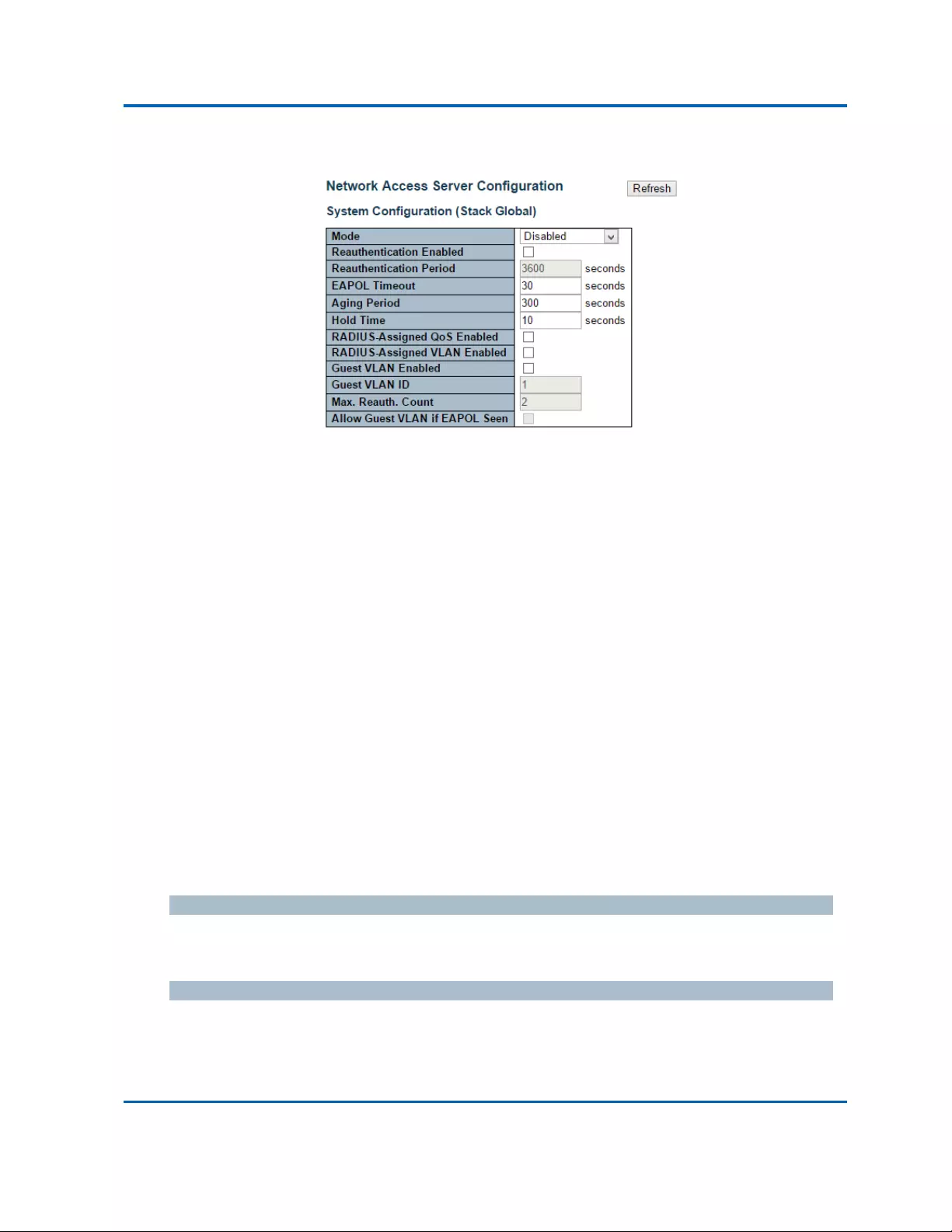
Chapter3:WebManagement
Security‐Network‐NAS(NetworkAccessServer)
Intelinet48‐PortGigabitEthernetPoE+Layer2+ManagedSwitchUserManual|77
3.1.5.10.Security‐Network‐NAS(NetworkAccessServer)
ThispageallowsyoutoconfiguretheIEEE802.1XandMAC‐basedauthenticationsystemandport
settings.
TheIEEE802.1Xstandarddefinesaport‐basedaccesscontrolprocedurethatpreventsunauthorized
accesstoanetworkbyrequiringuserstofirstsubmitcredentialsforauthentication.Oneormore
centralservers,thebackendservers,determinewhethertheuserisallowedaccesstothenetwork.
Thesebackend(RADIUS)serversareconfiguredonthe"Configuration→Security→AAA"page.The
IEEE802.1Xstandarddefinesport‐basedoperation,butnon‐standardvariantsovercomesecurity
limitationsasshallbeexploredbelow.
MAC‐basedauthenticationallowsforauthenticationofmorethanoneuseronthesameport,and
doesn'trequiretheusertohavespecial802.1Xsupplicantsoftwareinstalledonhissystem.The
switchusestheuser'sMACaddresstoauthenticateagainstthebackendserver.Intruderscancreate
counterfeitMACaddresses,whichmakesMAC‐basedauthenticationlesssecurethan802.1X
authentication.
TheNASconfigurationconsistsoftwosections,asystem‐andaport‐wide.
SystemConfiguration
Mode
IndicatesifNASisgloballyenabledordisabledonthestack.Ifgloballydisabled,allportsareallowed
forwardingofframes.
Re‐authenticationEnabled
Ifchecked,successfullyauthenticatedsupplicants/clientsarere‐authenticatedaftertheinterval
specifiedbytheRe‐authenticationPeriod.Re‐authenticationfor802.1X‐enabledportscanbeusedto
detectifanewdeviceispluggedintoaswitchportorifasupplicantisnolongerattached.

Chapter3:WebManagement
Security‐Network‐NAS(NetworkAccessServer)
Intelinet48‐PortGigabitEthernetPoE+Layer2+ManagedSwitchUserManual|78
ForMAC‐basedports,re‐authenticationisonlyusefuliftheRADIUSserverconfigurationhaschanged.
Itdoesnotinvolvecommunicationbetweentheswitchandtheclient,andthereforedoesn'timply
thataclientisstillpresentonaport(seeAgingPeriodbelow).
Re‐authenticationPeriod
Determinestheperiod,inseconds,afterwhichaconnectedclientmustbere‐authenticated.Thisis
onlyactiveiftheRe‐authenticationEnabledcheckboxischecked.Validvaluesareintherange1to
3600seconds.
EAPOLTimeout
DeterminesthetimeforretransmissionofRequestIdentityEAPOLframes.
Validvaluesareintherange1to65535seconds.ThishasnoeffectforMAC‐basedports.
AgingPeriod
Thissettingappliestothefollowingmodes,i.e.modesusingthePortSecurityfunctionalitytosecure
MACaddresses:
Single802.1X
Multi802.1X
MAC‐BasedAuth.
WhentheNASmoduleusesthePortSecuritymoduletosecureMACaddresses,thePortSecurity
moduleneedstocheckforactivityontheMACaddressinquestionatregularintervalsandfree
resourcesifnoactivityisseenwithinagivenperiodoftime.Thisparametercontrolsexactlythis
periodandcanbesettoanumberbetween10and1000000seconds.
Ifre‐authenticationisenabledandtheportisinan802.1X‐basedmode,thisisnotsocritical,since
supplicantsthatarenolongerattachedtotheportwillgetremoveduponthenextre‐authentication,
whichwillfail.Butifre‐authenticationisnotenabled,theonlywaytofreeresourcesisbyagingthe
entries.
ForportsinMAC‐basedAuth.mode,re‐authenticationdoesn'tcausedirectcommunicationbetween
theswitchandtheclient,sothiswillnotdetectwhethertheclientisstillattachedornot,andthe
onlywaytofreeanyresourcesistoagetheentry.
HoldTime
Thissettingappliestothefollowingmodes,i.e.modesusingthePortSecurityfunctionalitytosecure
MACaddresses:
Single802.1X
Multi802.1X
MAC‐BasedAuth.

Chapter3:WebManagement
Security‐Network‐NAS(NetworkAccessServer)
Intelinet48‐PortGigabitEthernetPoE+Layer2+ManagedSwitchUserManual|79
Ifaclientisdeniedaccess‐eitherbecausetheRADIUSserverdeniestheclientaccessorbecausethe
RADIUSserverrequesttimesout(accordingtothetimeoutspecifiedonthe"Configuration→Security
→AAA"page)‐theclientisputonholdintheUnauthorizedstate.Theholdtimerdoesnotcount
duringanon‐goingauthentication.
InMAC‐basedAuth.mode,theswitchwillignorenewframescomingfromtheclientduringthehold
time.
TheHoldTimecanbesettoanumberbetween10and1000000seconds.
RADIUS‐AssignedQoSEnabled
RADIUS‐assignedQoSprovidesameanstocentrallycontrolthetrafficclasstowhichtrafficcoming
fromasuccessfullyauthenticatedsupplicantisassignedontheswitch.TheRADIUSservermustbe
configuredtotransmitspecialRADIUSattributestotakeadvantageofthisfeature(see
RADIUS‐AssignedQoSEnabledbelowforadetaileddescription).
The"RADIUS‐AssignedQoSEnabled"checkboxprovidesaquickwaytogloballyenable/disable
RADIUS‐serverassignedQoSClassfunctionality.Whenchecked,theindividualports'dittosetting
determinewhetherRADIUS‐assignedQoSClassisenabledonthatport.Whenunchecked,
RADIUS‐serverassignedQoSClassisdisabledonallports.
RADIUS‐AssignedVLANEnabled
RADIUS‐assignedVLANprovidesameanstocentrallycontroltheVLANonwhichasuccessfully
authenticatedsupplicantisplacedontheswitch.Incomingtrafficwillbeclassifiedtoandswitched
ontheRADIUS‐assignedVLAN.TheRADIUSservermustbeconfiguredtotransmitspecialRADIUS
attributestotakeadvantageofthisfeature(seeRADIUS‐AssignedVLANEnabledbelowforadetailed
description).
The"RADIUS‐AssignedVLANEnabled"checkboxprovidesaquickwaytogloballyenable/disable
RADIUS‐serverassignedVLANfunctionality.Whenchecked,theindividualports'dittosetting
determinewhetherRADIUS‐assignedVLANisenabledonthatport.Whenunchecked,RADIUS‐server
assignedVLANisdisabledonallports.
GuestVLANEnabled
AGuestVLANisaspecialVLAN‐typicallywithlimitednetworkaccess‐onwhich802.1X‐unaware
clientsareplacedafteranetworkadministrator‐definedtimeout.Theswitchfollowsasetofrulesfor
enteringandleavingtheGuestVLANaslistedbelow.
The"GuestVLANEnabled"checkboxprovidesaquickwaytogloballyenable/disableGuestVLAN
functionality.Whenchecked,theindividualports'dittosettingdetermineswhethertheportcanbe
movedintoGuestVLAN.Whenunchecked,theabilitytomovetotheGuestVLANisdisabledonall

Chapter3:WebManagement
Security‐Network‐NAS(NetworkAccessServer)
Intelinet48‐PortGigabitEthernetPoE+Layer2+ManagedSwitchUserManual|80
ports.

Chapter3:WebManagement
Security‐Network‐NAS(NetworkAccessServer)
Intelinet48‐PortGigabitEthernetPoE+Layer2+ManagedSwitchUserManual|81
GuestVLANID
Thisisthevaluethataport'sPortVLANIDissettoifaportismovedintotheGuestVLAN.Itisonly
changeableiftheGuestVLANoptionisgloballyenabled.
Validvaluesareintherange[1;4095].
Max.Reauth.Count
ThenumberoftimestheswitchtransmitsanEAPOLRequestIdentityframewithoutresponsebefore
consideringenteringtheGuestVLANisadjustedwiththissetting.Thevaluecanonlybechangedif
theGuestVLANoptionisgloballyenabled.
Validvaluesareintherange[1;255].
AllowGuestVLANifEAPOLSeen
TheswitchremembersifanEAPOLframehasbeenreceivedontheportforthelife‐timeoftheport.
OncetheswitchconsiderswhethertoentertheGuestVLAN,itwillfirstcheckifthisoptionis
enabledordisabled.Ifdisabled(unchecked;default),theswitchwillonlyentertheGuestVLANifan
EAPOLframehasnotbeenreceivedontheportforthelife‐timeoftheport.Ifenabled(checked),the
switchwillconsiderenteringtheGuestVLANevenifanEAPOLframehasbeenreceivedontheport
forthelife‐timeoftheport.
ThevaluecanonlybechangediftheGuestVLANoptionisgloballyenabled.

Chapter3:WebManagement
Security‐Network‐NAS(NetworkAccessServer)
Intelinet48‐PortGigabitEthernetPoE+Layer2+ManagedSwitchUserManual|82
PortConfiguration
Thetablehasonerowforeachportontheselectedswitchinthestackandanumberofcolumns,
whichare:
Port
Theportnumberforwhichtheconfigurationbelowapplies.
AdminState
IfNASisgloballyenabled,thisselectioncontrolstheport'sauthenticationmode.Thefollowing
modesareavailable:
ForceAuthorized
Inthismode,theswitchwillsendoneEAPOLSuccessframewhentheportlinkcomesup,andany
clientontheportwillbeallowednetworkaccesswithoutauthentication.
ForceUnauthorized
Inthismode,theswitchwillsendoneEAPOLFailureframewhentheportlinkcomesup,andany
clientontheportwillbedisallowednetworkaccess.
Port‐based802.1X
Inthe802.1X‐world,theuseriscalledthesupplicant,theswitchistheauthenticator,andtheRADIUS
serveristheauthenticationserver.Theauthenticatoractsastheman‐in‐the‐middle,forwarding

Chapter3:WebManagement
Security‐Network‐NAS(NetworkAccessServer)
Intelinet48‐PortGigabitEthernetPoE+Layer2+ManagedSwitchUserManual|83
requestsandresponsesbetweenthesupplicantandtheauthenticationserver.Framessentbetween
thesupplicantandtheswitcharespecial802.1Xframes,knownasEAPOL(EAPOverLANs)frames.
EAPOLframesencapsulateEAPPDUs(RFC3748).FramessentbetweentheswitchandtheRADIUS
serverareRADIUSpackets.RADIUSpacketsalsoencapsulateEAPPDUstogetherwithother
attributesliketheswitch'sIPaddress,name,andthesupplicant'sportnumberontheswitch.EAPis
veryflexible,inthatitallowsfordifferentauthenticationmethods,likeMD5‐Challenge,PEAP,and
TLS.Theimportantthingisthattheauthenticator(theswitch)doesn'tneedtoknowwhich
authenticationmethodthesupplicantandtheauthenticationserverareusing,orhowmany
informationexchangeframesareneededforaparticularmethod.Theswitchsimplyencapsulates
theEAPpartoftheframeintotherelevanttype(EAPOLorRADIUS)andforwardsit.
Whenauthenticationiscomplete,theRADIUSserversendsaspecialpacketcontainingasuccessor
failureindication.Besidesforwardingthisdecisiontothesupplicant,theswitchusesittoopenupor
blocktrafficontheswitchportconnectedtothesupplicant.
Note:SupposetwobackendserversareenabledandthattheservertimeoutisconfiguredtoX
seconds(usingtheAAAconfigurationpage),andsupposethatthefirstserverinthelistiscurrently
down(butnotconsidereddead).Now,ifthesupplicantretransmitsEAPOLStartframesatarate
fasterthanXseconds,thenitwillnevergetauthenticated,becausetheswitchwillcancelon‐going
backendauthenticationserverrequestswheneveritreceivesanewEAPOLStartframefromthe
supplicant.Andsincetheserverhasn'tyetfailed(becausetheXsecondshaven'texpired),thesame
serverwillbecontacteduponthenextbackendauthenticationserverrequestfromtheswitch.This
scenariowillloopforever.Therefore,theservertimeoutshouldbesmallerthanthesupplicant's
EAPOLStartframeretransmissionrate.
Single802.1X
Inport‐based802.1Xauthentication,onceasupplicantissuccessfullyauthenticatedonaport,the
wholeportisopenedfornetworktraffic.Thisallowsotherclientsconnectedtotheport(forinstance
throughahub)topiggy‐backonthesuccessfullyauthenticatedclientandgetnetworkaccesseven
thoughtheyreallyaren'tauthenticated.Toovercomethissecuritybreach,usetheSingle802.1X
variant.
Single802.1XisreallynotanIEEEstandard,butfeaturesmanyofthesamecharacteristicsasdoes
port‐based802.1X.InSingle802.1X,atmostonesupplicantcangetauthenticatedontheportata
time.NormalEAPOLframesareusedinthecommunicationbetweenthesupplicantandtheswitch.
Ifmorethanonesupplicantisconnectedtoaport,theonethatcomesfirstwhentheport'slink
comesupwillbethefirstoneconsidered.Ifthatsupplicantdoesn'tprovidevalidcredentialswithina
certainamountoftime,anothersupplicantwillgetachance.Onceasupplicantissuccessfully

Chapter3:WebManagement
Security‐Network‐NAS(NetworkAccessServer)
Intelinet48‐PortGigabitEthernetPoE+Layer2+ManagedSwitchUserManual|84
authenticated,onlythatsupplicantwillbeallowedaccess.Thisisthemostsecureofallthe
supportedmodes.Inthismode,thePortSecuritymoduleisusedtosecureasupplicant'sMAC
addressoncesuccessfullyauthenticated.
Multi802.1X
Multi802.1Xis‐likeSingle802.1X‐notanIEEEstandard,butavariantthatfeaturesmanyofthe
samecharacteristics.InMulti802.1X,oneormoresupplicantscangetauthenticatedonthesame
portatthesametime.EachsupplicantisauthenticatedindividuallyandsecuredintheMACtable
usingthePortSecuritymodule.
InMulti802.1XitisnotpossibletousethemulticastBPDUMACaddressasdestinationMACaddress
forEAPOLframessentfromtheswitchtowardsthesupplicant,sincethatwouldcauseallsupplicants
attachedtotheporttoreplytorequestssentfromtheswitch.Instead,theswitchusesthe
supplicant'sMACaddress,whichisobtainedfromthefirstEAPOLStartorEAPOLResponseIdentity
framesentbythesupplicant.Anexceptiontothisiswhennosupplicantsareattached.Inthiscase,
theswitchsendsEAPOLRequestIdentityframesusingtheBPDUmulticastMACaddressas
destination‐towakeupanysupplicantsthatmightbeontheport.
ThemaximumnumberofsupplicantsthatcanbeattachedtoaportcanbelimitedusingthePort
SecurityLimitControlfunctionality.
MAC‐basedAuth.
Unlikeport‐based802.1X,MAC‐basedauthenticationisnotastandard,butmerelyabest‐practices
methodadoptedbytheindustry.InMAC‐basedauthentication,usersarecalledclients,andthe
switchactsasthesupplicantonbehalfofclients.Theinitialframe(anykindofframe)sentbyaclient
issnoopedbytheswitch,whichinturnusestheclient'sMACaddressasbothusernameand
passwordinthesubsequentEAPexchangewiththeRADIUSserver.The6‐byteMACaddressis
convertedtoastringonthefollowingform"xx‐xx‐xx‐xx‐xx‐xx",thatis,adash(‐)isusedasseparator
betweenthelower‐casedhexadecimaldigits.TheswitchonlysupportstheMD5‐Challenge
authenticationmethod,sotheRADIUSservermustbeconfiguredaccordingly.
Whenauthenticationiscomplete,theRADIUSserversendsasuccessorfailureindication,whichin
turncausestheswitchtoopenuporblocktrafficforthatparticularclient,usingthePortSecurity
module.Onlythenwillframesfromtheclientbeforwardedontheswitch.TherearenoEAPOL
framesinvolvedinthisauthentication,andtherefore,MAC‐basedAuthenticationhasnothingtodo
withthe802.1Xstandard.
TheadvantageofMAC‐basedauthenticationover802.1X‐basedauthenticationisthattheclients
don'tneedspecialsupplicantsoftwaretoauthenticate.ThedisadvantageisthatMACaddressescan

Chapter3:WebManagement
Security‐Network‐NAS(NetworkAccessServer)
Intelinet48‐PortGigabitEthernetPoE+Layer2+ManagedSwitchUserManual|85
bespoofedbymalicioususers‐equipmentwhoseMACaddressisavalidRADIUSusercanbeusedby
anyone.Also,onlytheMD5‐Challengemethodissupported.Themaximumnumberofclientsthat
canbeattachedtoaportcanbelimitedusingthePortSecurityLimitControlfunctionality.
RADIUS‐AssignedQoSEnabled
WhenRADIUS‐AssignedQoSisbothgloballyenabledandenabled(checked)onagivenport,the
switchreactstoQoSClassinformationcarriedintheRADIUSAccess‐Acceptpackettransmittedby
theRADIUSserverwhenasupplicantissuccessfullyauthenticated.Ifpresentandvalid,traffic
receivedonthesupplicant'sportwillbeclassifiedtothegivenQoSClass.If(re‐)authenticationfails
ortheRADIUSAccess‐AcceptpacketnolongercarriesaQoSClassorit'sinvalid,orthesupplicantis
otherwisenolongerpresentontheport,theport'sQoSClassisimmediatelyrevertedtotheoriginal
QoSClass(whichmaybechangedbytheadministratorinthemeanwhilewithoutaffectingthe
RADIUS‐assigned).
Thisoptionisonlyavailableforsingle‐clientmodes,i.e.
Port‐based802.1X
Single802.1X
RADIUSattributesusedinidentifyingaQoSClass:
TheUser‐Priority‐TableattributedefinedinRFC4675formsthebasisforidentifyingtheQoSClassin
anAccess‐Acceptpacket.
Onlythefirstoccurrenceoftheattributeinthepacketwillbeconsidered,andtobevalid,itmust
followthisrule:
All8octetsintheattribute'svaluemustbeidenticalandconsistofASCIIcharactersinthe
range'0'‐'7',whichtranslatesintothedesiredQoSClassintherange[0;7].
RADIUS‐AssignedVLANEnabled
WhenRADIUS‐AssignedVLANisbothgloballyenabledandenabled(checked)foragivenport,the
switchreactstoVLANIDinformationcarriedintheRADIUSAccess‐Acceptpackettransmittedbythe
RADIUSserverwhenasupplicantissuccessfullyauthenticated.Ifpresentandvalid,theport'sPort
VLANIDwillbechangedtothisVLANID,theportwillbesettobeamemberofthatVLANID,and
theportwillbeforcedintoVLANunawaremode.Onceassigned,alltrafficarrivingontheportwillbe
classifiedandswitchedontheRADIUS‐assignedVLANID.

Chapter3:WebManagement
Security‐Network‐NAS(NetworkAccessServer)
Intelinet48‐PortGigabitEthernetPoE+Layer2+ManagedSwitchUserManual|86
If(re‐)authenticationfailsortheRADIUSAccess‐AcceptpacketnolongercarriesaVLANIDorit's
invalid,orthesupplicantisotherwisenolongerpresentontheport,theport'sVLANIDis
immediatelyrevertedtotheoriginalVLANID(whichmaybechangedbytheadministratorinthe
meanwhilewithoutaffectingtheRADIUS‐assigned).
Thisoptionisonlyavailableforsingle‐clientmodes,i.e.
Port‐based802.1X
Single802.1X
Fortrouble‐shootingVLANassignments,usethe"Monitor→VLANs→VLANMembershipandVLAN
Port"pages.Thesepagesshowwhichmoduleshave(temporarily)overriddenthecurrentPortVLAN
configuration.
RADIUSattributesusedinidentifyingaVLANID:
RFC2868andRFC3580formthebasisfortheattributesusedinidentifyingaVLANIDinan
Access‐Acceptpacket.Thefollowingcriteriaareused:
TheTunnel‐Medium‐Type,Tunnel‐Type,andTunnel‐Private‐Group‐IDattributesmustallbe
presentatleastonceintheAccess‐Acceptpacket.
TheswitchlooksforthefirstsetoftheseattributesthathavethesameTagvalueandfulfilthe
followingrequirements(ifTag==0isused,theTunnel‐Private‐Group‐IDdoesnotneedto
includeaTag):
ValueofTunnel‐Medium‐Typemustbesetto"IEEE‐802"(ordinal6).
ValueofTunnel‐Typemustbesetto"VLAN"(ordinal13).
ValueofTunnel‐Private‐Group‐IDmustbeastringofASCIIcharsintherange'0'‐'9',
whichisinterpretedasadecimalstringrepresentingtheVLANID.Leading'0'sare
discarded.Thefinalvaluemustbeintherange[1;4095].
GuestVLANEnabled
WhenGuestVLANisbothgloballyenabledandenabled(checked)foragivenport,theswitch
considersmovingtheportintotheGuestVLANaccordingtotherulesoutlinedbelow.
ThisoptionisonlyavailableforEAPOL‐basedmodes,i.e.:
Port‐based802.1X
Single802.1X
Multi802.1X
Fortrouble‐shootingVLANassignments,usethe"Monitor→VLANs→VLANMembershipandVLAN
Port"pages.Thesepagesshowwhichmoduleshave(temporarily)overriddenthecurrentPortVLAN

Chapter3:WebManagement
Security‐Network‐NAS(NetworkAccessServer)
Intelinet48‐PortGigabitEthernetPoE+Layer2+ManagedSwitchUserManual|87
configuration.

Chapter3:WebManagement
Security‐Network‐NAS(NetworkAccessServer)
Intelinet48‐PortGigabitEthernetPoE+Layer2+ManagedSwitchUserManual|88
GuestVLANOperation:
WhenaGuestVLANenabledport'slinkcomesup,theswitchstartstransmittingEAPOLRequest
Identityframes.IfthenumberoftransmissionsofsuchframesexceedsMax.Reauth.Countandno
EAPOLframeshavebeenreceivedinthemeanwhile,theswitchconsidersenteringtheGuestVLAN.
TheintervalbetweentransmissionofEAPOLRequestIdentityframesisconfiguredwithEAPOL
Timeout.IfAllowGuestVLANifEAPOLSeenisenabled,theportwillnowbeplacedintheGuest
VLAN.Ifdisabled,theswitchwillfirstcheckitshistorytoseeifanEAPOLframehaspreviouslybeen
receivedontheport(thishistoryisclearediftheportlinkgoesdownortheport'sAdminStateis
changed),andifnot,theportwillbeplacedintheGuestVLAN.Otherwiseitwillnotmovetothe
GuestVLAN,butcontinuetransmittingEAPOLRequestIdentityframesattherategivenbyEAPOL
Timeout.
OnceintheGuestVLAN,theportisconsideredauthenticated,andallattachedclientsontheport
areallowedaccessonthisVLAN.TheswitchwillnottransmitanEAPOLSuccessframewhenentering
theGuestVLAN.
WhileintheGuestVLAN,theswitchmonitorsthelinkforEAPOLframes,andifonesuchframeis
received,theswitchimmediatelytakestheportoutoftheGuestVLANandstartsauthenticatingthe
supplicantaccordingtotheportmode.IfanEAPOLframeisreceived,theportwillneverbeableto
gobackintotheGuestVLANifthe"AllowGuestVLANifEAPOLSeen"isdisabled.
PortState
Thecurrentstateoftheport.Itcanundertakeoneofthefollowingvalues:
GloballyDisabled:NASisgloballydisabled.
LinkDown:NASisgloballyenabled,butthereisnolinkontheport.
Authorized:TheportisinForceAuthorizedorasingle‐supplicantmodeandthesupplicantis
authorized.
Unauthorized:TheportisinForceUnauthorizedorasingle‐supplicantmodeandthe
supplicantisnotsuccessfullyauthorizedbytheRADIUSserver.
XAuth/YUnauth:Theportisinamulti‐supplicantmode.CurrentlyXclientsareauthorized
andYareunauthorized.
Restart
Twobuttonsareavailableforeachrow.Thebuttonsareonlyenabledwhenauthenticationisglobally
enabledandtheport'sAdminStateisinanEAPOL‐basedorMAC‐basedmode.
Clickingthesebuttonswillnotcausesettingschangedonthepagetotakeeffect.

Chapter3:WebManagement
Security‐Network‐NAS(NetworkAccessServer)
Intelinet48‐PortGigabitEthernetPoE+Layer2+ManagedSwitchUserManual|89
Re‐authenticate:Schedulesare‐authenticationwheneverthequiet‐periodoftheportruns
out(EAPOL‐basedauthentication).ForMAC‐basedauthentication,re‐authenticationwillbe
attemptedimmediately.
Thebuttononlyhaseffectforsuccessfullyauthenticatedclientsontheportandwillnotcause
theclientstogettemporarilyunauthorized.
Reinitialize:Forcesareinitializationoftheclientsontheportandtherebyare‐authentication
immediately.Theclientswilltransfertotheunauthorizedstatewhilethere‐authenticationis
inprogress.
Buttons
AddNewEntry:Clicktoaddanewcommunityentry.
Save:Clicktosavechanges.
Reset:Clicktoundoanychangesmadelocallyandreverttopreviouslysavedvalues.
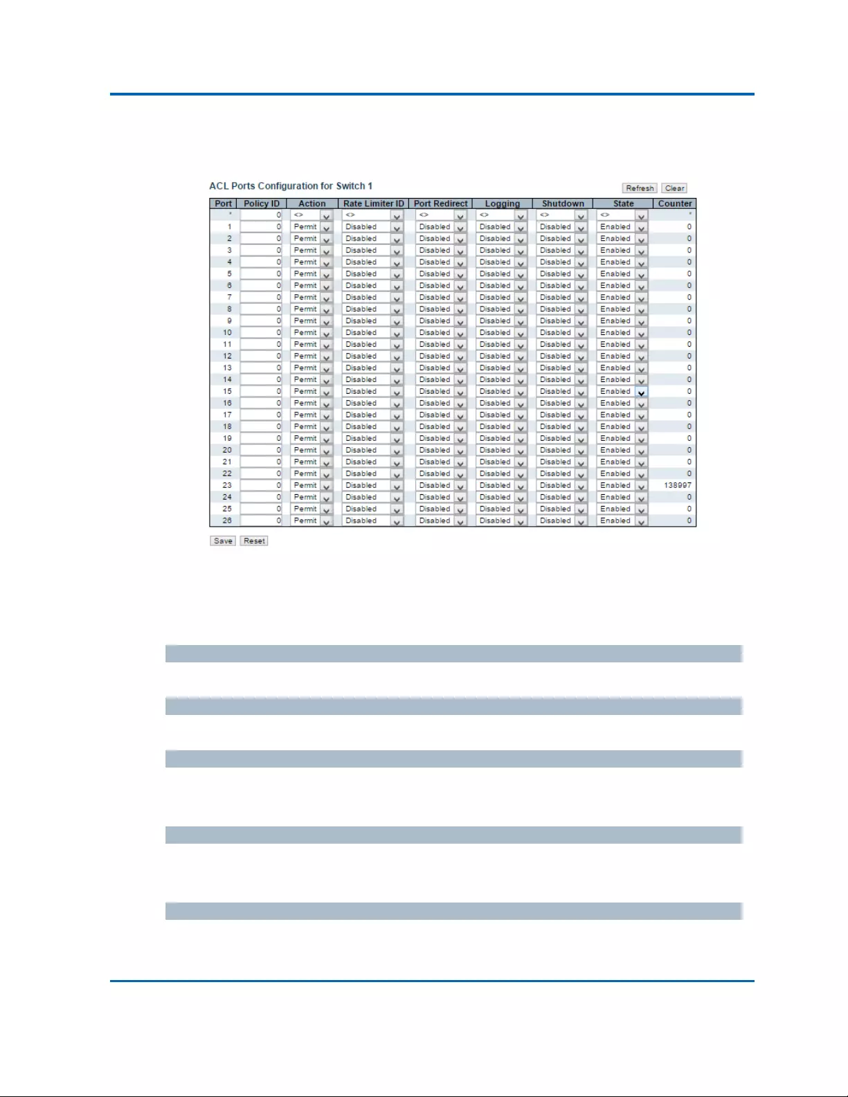
Chapter3:WebManagement
Security‐Network‐ACL‐Ports
Intelinet48‐PortGigabitEthernetPoE+Layer2+ManagedSwitchUserManual|90
3.1.5.11.Security‐Network‐ACL
3.1.5.11.1.Security‐Network‐ACL‐Ports
ConfiguretheACLparameters(ACE)ofeachswitchport.Theseparameterswillaffectframes
receivedonaportunlesstheframematchesaspecificACE.
Thesettingsrelatetothecurrentlyselectedstackunit,asreflectedbythepageheader.
Port
Thelogicalportforthesettingscontainedinthesamerow.
PolicyID
Selectthepolicytoapplytothisport.Theallowedvaluesare0through255.Thedefaultvalueis0.
Action
Selectwhetherforwardingispermitted("Permit")ordenied("Deny").Thedefaultvalueis
"Permit".
RateLimiterID
Selectwhichratelimitertoapplyonthisport.TheallowedvaluesareDisabledorthevalues1
through16.Thedefaultvalueis"Disabled".
PortRedirect
Selectwhichportframesareredirectedon.TheallowedvaluesareDisabledoraspecificport
numberanditcan'tbesetwhenactionispermitted.Thedefaultvalueis"Disabled".

Chapter3:WebManagement
Security‐Network‐ACL‐Ports
Intelinet48‐PortGigabitEthernetPoE+Layer2+ManagedSwitchUserManual|91
Logging
Specifytheloggingoperationofthisport.Theallowedvaluesare:
Enabled:FramesreceivedontheportarestoredintheSystemLog.
Disabled:Framesreceivedontheportarenotlogged.
Thedefaultvalueis"Disabled".PleasenotethattheSystemLogmemorysizeandloggingrateis
limited.
Shutdown
Specifytheportshutdownoperationofthisport.Theallowedvaluesare:
Enabled:Ifaframeisreceivedontheport,theportwillbedisabled.
Disabled:Portshutdownisdisabled.
Thedefaultvalueis"Disabled".
State
Specifytheportstateofthisport.Theallowedvaluesare:
Enabled:ToreopenportsbychangingthevolatileportconfigurationoftheACLuser
module.
Disabled:TocloseportsbychangingthevolatileportconfigurationoftheACLusermodule.
Thedefaultvalueis"Enabled".
Counter
CountsthenumberofframesthatmatchthisACE.
Buttons
Save:Clicktosavechanges.
Reset:Clicktoundoanychangesmadelocallyandreverttopreviouslysavedvalues.
Refresh:Clicktorefreshthepage;anychangesmadelocallywillbeundone.
Clear:Clicktoclearthecounters.

Chapter3:WebManagement
Security‐Network‐ACL‐RateLimiter
Intelinet48‐PortGigabitEthernetPoE+Layer2+ManagedSwitchUserManual|92
3.1.5.11.2.Security‐Network‐ACL‐RateLimiter
ConfiguretheratelimiterfortheACLoftheswitch.
RateLimiterID
TheratelimiterIDforthesettingscontainedinthesamerow.
Rate
Theallowedvaluesare:0‐131071inpps
Buttons
Save:Clicktosavechanges.
Reset:Clicktoundoanychangesmadelocallyandreverttopreviouslysavedvalues.

Chapter3:WebManagement
Security‐Network‐DHCP‐Relay
Intelinet48‐PortGigabitEthernetPoE+Layer2+ManagedSwitchUserManual|93
3.1.5.11.3.Security‐Network‐ACL‐AccessControlList
ThispageshowstheAccessControlList(ACL),whichismadeupoftheACEsdefinedonthisswitch.
EachrowdescribestheACEthatisdefined.ThemaximumnumberofACEsis512oneachswitch.
ClickonthelowestplussigntoaddanewACEtothelist.ThereservedACEsusedforinternal
protocol,cannotbeeditedordeleted,theordersequencecannotbechangedandthepriorityis
highest.
Notice:theACEwon'tapplytoanystackingornoneexistingport.
IngressPort
IndicatestheingressportoftheACE.Possiblevaluesare:
All:TheACEwillmatchallingressport.
Port:TheACEwillmatchaspecificingressport.
Policy/Bitmask
IndicatesthepolicynumberandbitmaskoftheACE.
FrameType
IndicatestheframetypeoftheACE.Possiblevaluesare:
Any:TheACEwillmatchanyframetype.
EType:TheACEwillmatchEthernetTypeframes.NotethatanEthernetTypebasedACEwill
notgetmatchedbyIPandARPframes.
ARP:TheACEwillmatchARP/RARPframes.
IPv4:TheACEwillmatchallIPv4frames.
IPv4/ICMP:TheACEwillmatchIPv4frameswithICMPprotocol.
IPv4/UDP:TheACEwillmatchIPv4frameswithUDPprotocol.
IPv4/TCP:TheACEwillmatchIPv4frameswithTCPprotocol.
IPv4/Other:TheACEwillmatchIPv4frames,whicharenotICMP/UDP/TCP.
IPv6:TheACEwillmatchallIPv6standardframes.
Action
IndicatestheforwardingactionoftheACE.
Permit:FramesmatchingtheACEmaybeforwardedandlearned.
Deny:FramesmatchingtheACEaredropped.
RateLimiter
IndicatestheratelimiternumberoftheACE.Theallowedrangeis1to16.WhenDisabledis
displayed,theratelimiteroperationisdisabled.

Chapter3:WebManagement
Security‐Network‐DHCP‐Relay
Intelinet48‐PortGigabitEthernetPoE+Layer2+ManagedSwitchUserManual|94
PortRedirect
IndicatestheportredirectoperationoftheACE.FramesmatchingtheACEareredirectedtothe
portnumber.TheallowedvaluesareDisabledoraspecificportnumber.WhenDisabledis
displayed,theportredirectoperationisdisabled.
Counter
ThecounterindicatesthenumberoftimestheACEwashitbyaframe.
ModificationButtons
YoucanmodifyeachACE(AccessControlEntry)inthetableusingthefollowingbuttons:
:InsertsanewACEbeforethecurrentrow.
:EditstheACErow.
:MovestheACEupthelist.
:MovestheACEdownthelist.
:DeletestheACE.
:ThelowestplussignaddsanewentryatthebottomoftheACElistings.
Buttons
Auto‐refresh:Checkthisboxtorefreshthepageautomatically.Automaticrefreshoccurs
every3seconds.
Refresh:Clicktorefreshthepage;anychangesmadelocallywillbeundone.
Clear:Clicktoclearthecounters.
RemoveAll:ClicktoremoveallACEs.

Chapter3:WebManagement
Security‐Network‐DHCP‐Relay
Intelinet48‐PortGigabitEthernetPoE+Layer2+ManagedSwitchUserManual|95
ConfigureanACE(AccessControlEntry)onthispage.
AnACEconsistsofseveralparameters.Theseparametersvaryaccordingtotheframetypethat
youselect.FirstselecttheingressportfortheACE,andthenselecttheframetype.Different
parameteroptionsaredisplayeddependingontheframetypeselected.
AframethathitsthisACEmatchestheconfigurationthatisdefinedhere.
IngressPort
SelecttheingressportforwhichthisACEapplies.
All:TheACEappliestoallport.
Portn:TheACEappliestothisportnumber,wherenisthenumberoftheswitchport.
PolicyFilter
SpecifythepolicynumberfilterforthisACE.
Any:Nopolicyfilterisspecified.(policyfilterstatusis"don't‐care".)
Specific:IfyouwanttofilteraspecificpolicywiththisACE,choosethisvalue.Twofieldfor
enteringanpolicyvalueandbitmaskappears.
PolicyValue
When"Specific"isselectedforthepolicyfilter,youcanenteraspecificpolicyvalue.Theallowed
rangeis0to255.
PolicyBitmask
When"Specific"isselectedforthepolicyfilter,youcanenteraspecificpolicybitmask.The
allowedrangeis0x0to0xff.
Switch
SelecttheswitchtowhichthisACEapplies.
Any:TheACEappliestoanyport.
Switchn:TheACEappliestothisswitchnumber,wherenisthenumberoftheswitch.

Chapter3:WebManagement
Security‐Network‐DHCP‐Relay
Intelinet48‐PortGigabitEthernetPoE+Layer2+ManagedSwitchUserManual|96
FrameType
SelecttheframetypeforthisACE.Theseframetypesaremutuallyexclusive.
Any:AnyframecanmatchthisACE.
EthernetType:OnlyEthernetTypeframescanmatchthisACE.TheIEEE802.3describesthe
valueofLength/TypeFieldspecificationstobegreaterthanorequalto1536decimal(equal
to0600hexadecimal).
ARP:OnlyARPframescanmatchthisACE.NoticetheARPframeswon'tmatchtheACEwith
ethernettype.
IPv4:OnlyIPv4framescanmatchthisACE.NoticetheIPv4frameswon'tmatchtheACEwith
ethernettype.
IPv6:OnlyIPv6framescanmatchthisACE.NoticetheIPv6frameswon'tmatchtheACEwith
Ethernettype.
Action
SpecifytheactiontotakewithaframethathitsthisACE.
Permit:TheframethathitsthisACEisgrantedpermissionfortheACEoperation.
Deny:TheframethathitsthisACEisdropped.
RateLimiter
Specifytheratelimiterinnumberofbaseunits.Theallowedrangeis1to16.Disabledindicates
thattheratelimiteroperationisdisabled.
PortRedirect
FramesthathittheACEareredirectedtotheportnumberspecifiedhere.Theallowedrangeisthe
sameastheswitchportnumberrange.Disabledindicatesthattheportredirectoperationis
disabledandthespecificportnumberof'PortRedirect'can'tbesetwhenactionispermitted.
Logging
SpecifytheloggingoperationoftheACE.Theallowedvaluesare:
Enabled:FramesmatchingtheACEarestoredintheSystemLog.
Disabled:FramesmatchingtheACEarenotlogged.
PleasenotethattheSystemLogmemorysizeandloggingrateislimited.
Shutdown
SpecifytheportshutdownoperationoftheACE.Theallowedvaluesare:
Enabled:IfaframematchestheACE,theingressportwillbedisabled.
Disabled:PortshutdownisdisabledfortheACE.
Counter
ThecounterindicatesthenumberoftimestheACEwashitbyaframe.

Chapter3:WebManagement
Security‐Network‐DHCP‐Relay
Intelinet48‐PortGigabitEthernetPoE+Layer2+ManagedSwitchUserManual|97
MACParameters
SMACFilter
(OnlydisplayedwhentheframetypeisEthernetTypeorARP.)
SpecifythesourceMACfilterforthisACE.
Any:NoSMACfilterisspecified.(SMACfilterstatusis"don't‐care".)
Specific:IfyouwanttofilteraspecificsourceMACaddresswiththisACE,choosethisvalue.
AfieldforenteringanSMACvalueappears.
SMACValue
When"Specific"isselectedfortheSMACfilter,youcanenteraspecificsourceMACaddress.The
legalformatis"xx‐xx‐xx‐xx‐xx‐xx"or"xx.xx.xx.xx.xx.xx"or"xxxxxxxxxxxx"(xisahexadecimaldigit).
AframethathitsthisACEmatchesthisSMACvalue.
DMACFilter
SpecifythedestinationMACfilterforthisACE.
Any:NoDMACfilterisspecified.(DMACfilterstatusis"don't‐care".)
MC:Framemustbemulticast.
BC:Framemustbebroadcast.
UC:Framemustbeunicast.
Specific:IfyouwanttofilteraspecificdestinationMACaddresswiththisACE,choosethis
value.AfieldforenteringaDMACvalueappears.
DMACValue
When"Specific"isselectedfortheDMACfilter,youcanenteraspecificdestinationMACaddress.
Thelegalformatis"xx‐xx‐xx‐xx‐xx‐xx"or"xx.xx.xx.xx.xx.xx"or"xxxxxxxxxxxx"(xisahexadecimal
digit).AframethathitsthisACEmatchesthisDMACvalue.

Chapter3:WebManagement
Security‐Network‐DHCP‐Relay
Intelinet48‐PortGigabitEthernetPoE+Layer2+ManagedSwitchUserManual|98
VLANParameters
VLANIDFilter
SpecifytheVLANIDfilterforthisACE.
Any:NoVLANIDfilterisspecified.(VLANIDfilterstatusis"don't‐care".)
Specific:IfyouwanttofilteraspecificVLANIDwiththisACE,choosethisvalue.Afieldfor
enteringaVLANIDnumberappears.
VLANID
When"Specific"isselectedfortheVLANIDfilter,youcanenteraspecificVLANIDnumber.The
allowedrangeis1to4095.AframethathitsthisACEmatchesthisVLANIDvalue.
TagPriority
SpecifythetagpriorityforthisACE.AframethathitsthisACEmatchesthistagpriority.The
allowednumberrangeis0to7.ThevalueAnymeansthatnotagpriorityisspecified(tagpriority
is"don't‐care".)

Chapter3:WebManagement
Security‐Network‐DHCP‐Relay
Intelinet48‐PortGigabitEthernetPoE+Layer2+ManagedSwitchUserManual|99
ARPParameters
TheARPparameterscanbeconfiguredwhenFrameType"ARP"isselected.
ARP/RARP
SpecifytheavailableARP/RARPopcode(OP)flagforthisACE.
Any:NoARP/RARPOPflagisspecified.(OPis"don't‐care".)
ARP:FramemusthaveARPopcodesettoARP.
RARP:FramemusthaveRARPopcodesettoRARP.
Other:FramehasunknownARP/RARPOpcodeflag.
Request/Reply
SpecifytheavailableRequest/Replyopcode(OP)flagforthisACE.
Any:NoRequest/ReplyOPflagisspecified.(OPis"don't‐care".)
Request:FramemusthaveARPRequestorRARPRequestOPflagset.
Reply:FramemusthaveARPReplyorRARPReplyOPflag.
SenderIPFilter
SpecifythesenderIPfilterforthisACE.
Any:NosenderIPfilterisspecified.(SenderIPfilteris"don't‐care".)
Host:SenderIPfilterissettoHost.SpecifythesenderIPaddressintheSIPAddressfield
thatappears.
Network:SenderIPfilterissettoNetwork.SpecifythesenderIPaddressandsenderIP
maskintheSIPAddressandSIPMaskfieldsthatappear.
SenderIPAddress
When"Host"or"Network"isselectedforthesenderIPfilter,youcanenteraspecificsenderIP
addressindotteddecimalnotation.
SenderIPMask
When"Network"isselectedforthesenderIPfilter,youcanenteraspecificsenderIPmaskin
dotteddecimalnotation.

Chapter3:WebManagement
Security‐Network‐DHCP‐Relay
Intelinet48‐PortGigabitEthernetPoE+Layer2+ManagedSwitchUserManual|100
TargetIPFilter
SpecifythetargetIPfilterforthisspecificACE.
Any:NotargetIPfilterisspecified.(TargetIPfilteris"don't‐care".)
Host:TargetIPfilterissettoHost.SpecifythetargetIPaddressintheTargetIPAddressfield
thatappears.Network:TargetIPfilterissettoNetwork.SpecifythetargetIPaddressand
targetIPmaskintheTargetIPAddressandTargetIPMaskfieldsthatappear.
TargetIPAddress
When"Host"or"Network"isselectedforthetargetIPfilter,youcanenteraspecifictargetIP
addressindotteddecimalnotation.
TargetIPMask
When"Network"isselectedforthetargetIPfilter,youcanenteraspecifictargetIPmaskindotted
decimalnotation.
ARPSenderMACMatch
Specifywhetherframescanhittheactionaccordingtotheirsenderhardwareaddressfield(SHA)
settings.
0:ARPframeswhereSHAisnotequaltotheSMACaddress.
1:ARPframeswhereSHAisequaltotheSMACaddress.
Any:Anyvalueisallowed("don't‐care").
RARPTargetMACMatch
Specifywhetherframescanhittheactionaccordingtotheirtargethardwareaddressfield(THA)
settings.
0:RARPframeswhereTHAisnotequaltothetargetMACaddress.
1:RARPframeswhereTHAisequaltothetargetMACaddress.
Any:Anyvalueisallowed("don't‐care").
IP/EthernetLength
SpecifywhetherframescanhittheactionaccordingtotheirARP/RARPhardwareaddresslength
(HLN)andprotocoladdresslength(PLN)settings.
0:ARP/RARPframeswheretheHLNisnotequaltoEthernet(0x06)orthe(PLN)isnotequal
toIPv4(0x04).
1:ARP/RARPframeswheretheHLNisequaltoEthernet(0x06)andthe(PLN)isequalto
IPv4(0x04).
Any:Anyvalueisallowed("don't‐care").

Chapter3:WebManagement
Security‐Network‐DHCP‐Relay
Intelinet48‐PortGigabitEthernetPoE+Layer2+ManagedSwitchUserManual|101
IP
SpecifywhetherframescanhittheactionaccordingtotheirARP/RARPhardwareaddressspace
(HRD)settings.
0:ARP/RARPframeswheretheHLDisnotequaltoEthernet(1).
1:ARP/RARPframeswheretheHLDisequaltoEthernet(1).
Any:Anyvalueisallowed("don't‐care").
Ethernet
SpecifywhetherframescanhittheactionaccordingtotheirARP/RARPprotocoladdressspace
(PRO)settings.
0:ARP/RARPframeswherethePROisnotequaltoIP(0x800).
1:ARP/RARPframeswherethePROisequaltoIP(0x800).
Any:Anyvalueisallowed("don't‐care").

Chapter3:WebManagement
Security‐Network‐DHCP‐Relay
Intelinet48‐PortGigabitEthernetPoE+Layer2+ManagedSwitchUserManual|102
IPParameters
TheIPparameterscanbeconfiguredwhenFrameType"IPv4"isselected.
IPProtocolFilter
SpecifytheIPprotocolfilterforthisACE.
Any:NoIPprotocolfilterisspecified("don't‐care").
Specific:IfyouwanttofilteraspecificIPprotocolfilterwiththisACE,choosethisvalue.A
fieldforenteringanIPprotocolfilterappears.
ICMP:SelectICMPtofilterIPv4ICMPprotocolframes.ExtrafieldsfordefiningICMP
parameterswillappear.Thesefieldsareexplainedlaterinthishelpfile.
UDP:SelectUDPtofilterIPv4UDPprotocolframes.ExtrafieldsfordefiningUDPparameters
willappear.Thesefieldsareexplainedlaterinthishelpfile.
TCP:SelectTCPtofilterIPv4TCPprotocolframes.ExtrafieldsfordefiningTCPparameters
willappear.Thesefieldsareexplainedlaterinthishelpfile.
IPProtocolValue
When"Specific"isselectedfortheIPprotocolvalue,youcanenteraspecificvalue.Theallowed
rangeis0to255.AframethathitsthisACEmatchesthisIPprotocolvalue.
IPTTL
SpecifytheTime‐to‐LivesettingsforthisACE.
zero:IPv4frameswithaTime‐to‐Livefieldgreaterthanzeromustnotbeabletomatchthis
entry.
non‐zero:IPv4frameswithaTime‐to‐Livefieldgreaterthanzeromustbeabletomatchthis
entry.
Any:Anyvalueisallowed("don't‐care").
IPFragment
SpecifythefragmentoffsetsettingsforthisACE.ThisinvolvesthesettingsfortheMoreFragments
(MF)bitandtheFragmentOffset(FRAGOFFSET)fieldforanIPv4frame.

Chapter3:WebManagement
Security‐Network‐DHCP‐Relay
Intelinet48‐PortGigabitEthernetPoE+Layer2+ManagedSwitchUserManual|103
No:IPv4frameswheretheMFbitissetortheFRAGOFFSETfieldisgreaterthanzeromustnotbe
abletomatchthisentry.
Yes:IPv4frameswheretheMFbitissetortheFRAGOFFSETfieldisgreaterthanzeromust
beabletomatchthisentry.
Any:Anyvalueisallowed("don't‐care").
IPOption
SpecifytheoptionsflagsettingforthisACE.
No:IPv4frameswheretheoptionsflagissetmustnotbeabletomatchthisentry.
Yes:IPv4frameswheretheoptionsflagissetmustbeabletomatchthisentry.
Any:Anyvalueisallowed("don't‐care").
SIPFilter
SpecifythesourceIPfilterforthisACE.
Any:NosourceIPfilterisspecified.(SourceIPfilteris"don't‐care".)
Host:SourceIPfilterissettoHost.SpecifythesourceIPaddressintheSIPAddressfieldthat
appears.
Network:SourceIPfilterissettoNetwork.SpecifythesourceIPaddressandsourceIPmask
intheSIPAddressandSIPMaskfieldsthatappear.
SIPAddress
When"Host"or"Network"isselectedforthesourceIPfilter,youcanenteraspecificSIPaddress
indotteddecimalnotation.
SIPMask
When"Network"isselectedforthesourceIPfilter,youcanenteraspecificSIPmaskindotted
decimalnotation.
DIPFilter
SpecifythedestinationIPfilterforthisACE.
Any:NodestinationIPfilterisspecified.(DestinationIPfilteris"don't‐care".)
Host:DestinationIPfilterissettoHost.SpecifythedestinationIPaddressintheDIPAddress
fieldthatappears.
Network:DestinationIPfilterissettoNetwork.SpecifythedestinationIPaddressand
destinationIPmaskintheDIPAddressandDIPMaskfieldsthatappear.
DIPAddress
When"Host"or"Network"isselectedforthedestinationIPfilter,youcanenteraspecificDIP
addressindotteddecimalnotation.
DIPMask

Chapter3:WebManagement
Security‐Network‐DHCP‐Relay
Intelinet48‐PortGigabitEthernetPoE+Layer2+ManagedSwitchUserManual|104
When"Network"isselectedforthedestinationIPfilter,youcanenteraspecificDIPmaskin
dotteddecimalnotation.

Chapter3:WebManagement
Security‐Network‐DHCP‐Relay
Intelinet48‐PortGigabitEthernetPoE+Layer2+ManagedSwitchUserManual|105
ICMPParameters
ICMPTypeFilter
SpecifytheICMPfilterforthisACE.
Any:NoICMPfilterisspecified(ICMPfilterstatusis"don't‐care").
Specific:IfyouwanttofilteraspecificICMPfilterwiththisACE,youcanenteraspecific
ICMPvalue.AfieldforenteringanICMPvalueappears.
ICMPTypeValue
When"Specific"isselectedfortheICMPfilter,youcanenteraspecificICMPvalue.Theallowed
rangeis0to255.AframethathitsthisACEmatchesthisICMPvalue.
ICMPCodeFilter
SpecifytheICMPcodefilterforthisACE.
Any:NoICMPcodefilterisspecified(ICMPcodefilterstatusis"don't‐care").
Specific:IfyouwanttofilteraspecificICMPcodefilterwiththisACE,youcanentera
specificICMPcodevalue.AfieldforenteringanICMPcodevalueappears.
ICMPCodeValue
When"Specific"isselectedfortheICMPcodefilter,youcanenteraspecificICMPcodevalue.The
allowedrangeis0to255.AframethathitsthisACEmatchesthisICMPcodevalue.

Chapter3:WebManagement
Security‐Network‐DHCP‐Relay
Intelinet48‐PortGigabitEthernetPoE+Layer2+ManagedSwitchUserManual|106
TCP/UDPParameters
TCP/UDPSourceFilter
SpecifytheTCP/UDPsourcefilterforthisACE.
Any:NoTCP/UDPsourcefilterisspecified(TCP/UDPsourcefilterstatusis"don't‐care").
Specific:IfyouwanttofilteraspecificTCP/UDPsourcefilterwiththisACE,youcanentera
specificTCP/UDPsourcevalue.AfieldforenteringaTCP/UDPsourcevalueappears.
Range:IfyouwanttofilteraspecificTCP/UDPsourcerangefilterwiththisACE,youcan
enteraspecificTCP/UDPsourcerangevalue.AfieldforenteringaTCP/UDPsourcevalue
appears.
TCP/UDPSourceNo.
When"Specific"isselectedfortheTCP/UDPsourcefilter,youcanenteraspecificTCP/UDPsource
value.Theallowedrangeis0to65535.AframethathitsthisACEmatchesthisTCP/UDPsource
value.
TCP/UDPSourceRange
When"Range"isselectedfortheTCP/UDPsourcefilter,youcanenteraspecificTCP/UDPsource
rangevalue.Theallowedrangeis0to65535.AframethathitsthisACEmatchesthisTCP/UDP
sourcevalue.
TCP/UDPDestinationFilter
SpecifytheTCP/UDPdestinationfilterforthisACE.
Any:NoTCP/UDPdestinationfilterisspecified(TCP/UDPdestinationfilterstatusis
"don't‐care").
Specific:IfyouwanttofilteraspecificTCP/UDPdestinationfilterwiththisACE,youcan

Chapter3:WebManagement
Security‐Network‐DHCP‐Relay
Intelinet48‐PortGigabitEthernetPoE+Layer2+ManagedSwitchUserManual|107
enteraspecificTCP/UDPdestinationvalue.AfieldforenteringaTCP/UDPdestinationvalue
appears.
Range:IfyouwanttofilteraspecificrangeTCP/UDPdestinationfilterwiththisACE,youcan
enteraspecificTCP/UDPdestinationrangevalue.AfieldforenteringaTCP/UDPdestination
valueappears.
TCP/UDPDestinationNumber
When"Specific"isselectedfortheTCP/UDPdestinationfilter,youcanenteraspecificTCP/UDP
destinationvalue.Theallowedrangeis0to65535.AframethathitsthisACEmatchesthis
TCP/UDPdestinationvalue.
TCP/UDPDestinationRange
When"Range"isselectedfortheTCP/UDPdestinationfilter,youcanenteraspecificTCP/UDP
destinationrangevalue.Theallowedrangeis0to65535.AframethathitsthisACEmatchesthis
TCP/UDPdestinationvalue.
TCPFIN
SpecifytheTCP"Nomoredatafromsender"(FIN)valueforthisACE.
0:TCPframeswheretheFINfieldissetmustnotbeabletomatchthisentry.
1:TCPframeswheretheFINfieldissetmustbeabletomatchthisentry.
Any:Anyvalueisallowed("don't‐care").
TCPSYN
SpecifytheTCP"Synchronizesequencenumbers"(SYN)valueforthisACE.
0:TCPframeswheretheSYNfieldissetmustnotbeabletomatchthisentry.
1:TCPframeswheretheSYNfieldissetmustbeabletomatchthisentry.
Any:Anyvalueisallowed("don't‐care").
TCPRST
SpecifytheTCP"Resettheconnection"(RST)valueforthisACE.
0:TCPframeswheretheRSTfieldissetmustnotbeabletomatchthisentry.
1:TCPframeswheretheRSTfieldissetmustbeabletomatchthisentry.
Any:Anyvalueisallowed("don't‐care").
TCPPSH
SpecifytheTCP"PushFunction"(PSH)valueforthisACE.
0:TCPframeswherethePSHfieldissetmustnotbeabletomatchthisentry.
1:TCPframeswherethePSHfieldissetmustbeabletomatchthisentry.
Any:Anyvalueisallowed("don't‐care").

Chapter3:WebManagement
Security‐Network‐DHCP‐Relay
Intelinet48‐PortGigabitEthernetPoE+Layer2+ManagedSwitchUserManual|108
TCPACK
SpecifytheTCP"Acknowledgmentfieldsignificant"(ACK)valueforthisACE.
0:TCPframeswheretheACKfieldissetmustnotbeabletomatchthisentry.
1:TCPframeswheretheACKfieldissetmustbeabletomatchthisentry.
Any:Anyvalueisallowed("don't‐care").
TCPURG
SpecifytheTCP"UrgentPointerfieldsignificant"(URG)valueforthisACE.
0:TCPframeswheretheURGfieldissetmustnotbeabletomatchthisentry.
1:TCPframeswheretheURGfieldissetmustbeabletomatchthisentry.
Any:Anyvalueisallowed("don't‐care").

Chapter3:WebManagement
Security‐Network‐DHCP‐Relay
Intelinet48‐PortGigabitEthernetPoE+Layer2+ManagedSwitchUserManual|109
EthernetTypeParameters
TheEthernetTypeparameterscanbeconfiguredwhenFrameType"EthernetType"isselected.
EtherTypeFilter
SpecifytheEthernettypefilterforthisACE.
Any:NoEtherTypefilterisspecified(EtherTypefilterstatusis"don't‐care").
Specific:IfyouwanttofilteraspecificEtherTypefilterwiththisACE,youcanenteraspecific
EtherTypevalue.AfieldforenteringaEtherTypevalueappears.
EthernetTypeValue
When"Specific"isselectedfortheEtherTypefilter,youcanenteraspecificEtherTypevalue.The
allowedrangeis0x600to0xFFFFbutexcluding0x800(IPv4),0x806(ARP)and0x86DD(IPv6).A
framethathitsthisACEmatchesthisEtherTypevalue.
Buttons
Save:Clicktosavechanges.
Reset:Clicktoundoanychangesmadelocallyandreverttopreviouslysavedvalues.
Cancel:Returntothepreviouspage.
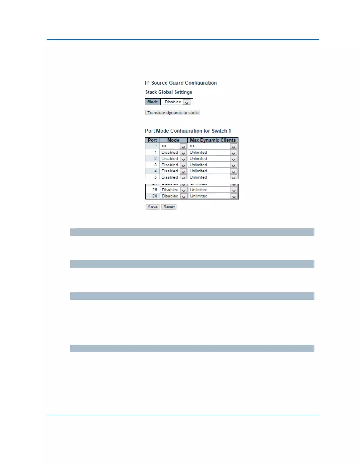
Chapter3:WebManagement
Security‐Network‐IPSourceGuard‐Configuration
Intelinet48‐PortGigabitEthernetPoE+Layer2+ManagedSwitchUserManual|110
3.1.5.12.Security‐Network‐IPSourceGuard
3.1.5.12.1.Security‐Network‐IPSourceGuard‐Configuration
ThispageprovidesIPSourceGuardrelatedconfiguration.
ModeofIPSourceGuardConfiguration
EnabletheGlobalIPSourceGuardordisabletheGlobalIPSourceGuard.AllconfiguredACEswill
belostwhenthemodeisenabled.
PortModeConfiguration
SpecifyIPSourceGuardisenabledonwhichports.OnlywhenbothGlobalModeandPortMode
onagivenportareenabled,IPSourceGuardisenabledonthisgivenport.
MaxDynamicClients
Specifythemaximumnumberofdynamicclientsthatcanbelearnedongivenport.Thisvaluecan
be0,1,2orunlimited.Iftheportmodeisenabledandthevalueofmaxdynamicclientisequalto
0,itmeansonlyallowtheIPpacketsforwardingthatarematchedinstaticentriesonthespecific
port.
Buttons
Save:Clicktosavechanges.
Reset:Clicktoundoanychangesmadelocallyandreverttopreviouslysavedvalues.
TranslateDynamictoStatic:Clicktotranslatealldynamicentriestostaticentries.

Chapter3:WebManagement
Security‐Network‐IPSourceGuard‐StaticTable
Intelinet48‐PortGigabitEthernetPoE+Layer2+ManagedSwitchUserManual|111
3.1.5.12.2.Security‐Network‐IPSourceGuard‐StaticTable
Delete
Checktodeletetheentry.Itwillbedeletedduringthenextsave.
Port
Thelogicalportforthesettings.
VLANID
Thevlanidforthesettings.
IPAddress
AllowedSourceIPaddress.
IPMask
ItcanbeusedforcalculatingtheallowednetworkwithIPaddress.
Buttons
AddNewEntry:ClicktoaddanewentrytotheStaticIPSourceGuardtable.
Save:Clicktosavechanges.
Reset:Clicktoundoanychangesmadelocallyandreverttopreviouslysavedvalues.
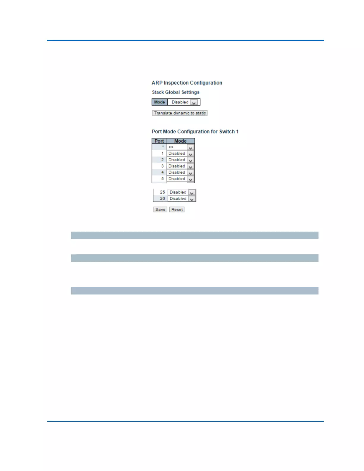
Chapter3:WebManagement
Security‐Network‐ARPInspection‐Configuration
Intelinet48‐PortGigabitEthernetPoE+Layer2+ManagedSwitchUserManual|112
3.1.5.13.Security‐Network‐ARPInspection
3.1.5.13.1.Security‐Network‐ARPInspection‐Configuration
ThispageprovidesARPInspectionrelatedconfiguration.
ModeofARPInspectionConfiguration
EnabletheGlobalARPInspectionordisabletheGlobalARPInspection.
PortModeConfiguration
SpecifyARPInspectionisenabledonwhichports.OnlywhenbothGlobalModeandPortModeon
agivenportareenabled,ARPInspectionisenabledonthisgivenport.
Buttons
Save:Clicktosavechanges.
Reset:Clicktoundoanychangesmadelocallyandreverttopreviouslysavedvalues.
TranslateDynamictoStatic:Clicktotranslatealldynamicentriestostaticentries.

Chapter3:WebManagement
Security‐Network‐ARPInspection‐StaticTable
Intelinet48‐PortGigabitEthernetPoE+Layer2+ManagedSwitchUserManual|113
3.1.5.13.2.Security‐Network‐ARPInspection‐StaticTable
Delete
Checktodeletetheentry.Itwillbedeletedduringthenextsave.
Port
Thelogicalportforthesettings.
VLANID
Thevlanidforthesettings.
MACAddress
AllowedSourceMACaddressinARPrequestpackets.
IPAddress
AllowedSourceIPaddressinARPrequestpackets.
Buttons
AddNewEntry:ClicktoaddanewentrytotheStaticIPSourceGuardtable.
Save:Clicktosavechanges.
Reset:Clicktoundoanychangesmadelocallyandreverttopreviouslysavedvalues.

Chapter3:WebManagement
Security‐AAA
Intelinet48‐PortGigabitEthernetPoE+Layer2+ManagedSwitchUserManual|114
3.1.5.14.Security‐AAA
CommonServerConfiguration
ThesesettingarecommonforalloftheAuthenticationServers.
Timeout
TheTimeout,whichcanbesettoanumberbetween3and3600seconds,isthemaximumtimeto
waitforareplyfromaserver.
Iftheserverdoesnotreplywithinthistimeframe,wewillconsiderittobedeadandcontinuewith
thenextenabledserver(ifany).
RADIUSserversareusingtheUDPprotocol,whichisunreliablebydesign.Inordertocopewithlost
frames,thetimeoutintervalisdividedinto3subintervalsofequallength.Ifareplyisnotreceived
withinthesubinterval,therequestistransmittedagain.ThisalgorithmcausestheRADIUSserverto
bequeriedupto3timesbeforeitisconsideredtobedead.
DeadTime
TheDeadTime,whichcanbesettoanumberbetween0and3600seconds,istheperiodduring
whichtheswitchwillnotsendnewrequeststoaserverthathasfailedtorespondtoaprevious
request.Thiswillstoptheswitchfromcontinuallytryingtocontactaserverthatithasalready
determinedasdead.
SettingtheDeadTimetoavaluegreaterthan0(zero)willenablethisfeature,butonlyifmorethan
oneserverhasbeenconfigured.

Chapter3:WebManagement
Security‐AAA
Intelinet48‐PortGigabitEthernetPoE+Layer2+ManagedSwitchUserManual|115
RADIUSAuthenticationServerConfiguration
ThetablehasonerowforeachRADIUSAuthenticationServerandanumberofcolumns,whichare:
#
TheRADIUSAuthenticationServernumberforwhichtheconfigurationbelowapplies.
Enabled
EnabletheRADIUSAuthenticationServerbycheckingthisbox.
IPAddress/Hostname
TheIPaddressorhostnameoftheRADIUSAuthenticationServer.IPaddressisexpressedindotted
decimalnotation.
Port
TheUDPporttouseontheRADIUSAuthenticationServer.Iftheportissetto0(zero),thedefault
port(1812)isusedontheRADIUSAuthenticationServer.
Secret
Thesecret‐upto29characterslong‐sharedbetweentheRADIUSAuthenticationServerandthe
stack.

Chapter3:WebManagement
Security‐AAA
Intelinet48‐PortGigabitEthernetPoE+Layer2+ManagedSwitchUserManual|116
RADIUSAccountingServerConfiguration
ThetablehasonerowforeachRADIUSAccountingServerandanumberofcolumns,whichare:
#
TheRADIUSAccountingServernumberforwhichtheconfigurationbelowapplies.
Enabled
EnabletheRADIUSAccountingServerbycheckingthisbox.
IPAddress/Hostname
TheIPaddressorhostnameoftheRADIUSAccountingServer.IPaddressisexpressedindotted
decimalnotation.
Port
TheUDPporttouseontheRADIUSAccountingServer.Iftheportissetto0(zero),thedefaultport
(1813)isusedontheRADIUSAccountingServer.
Secret
Thesecret‐upto29characterslong‐sharedbetweentheRADIUSAccountingServerandthestack.
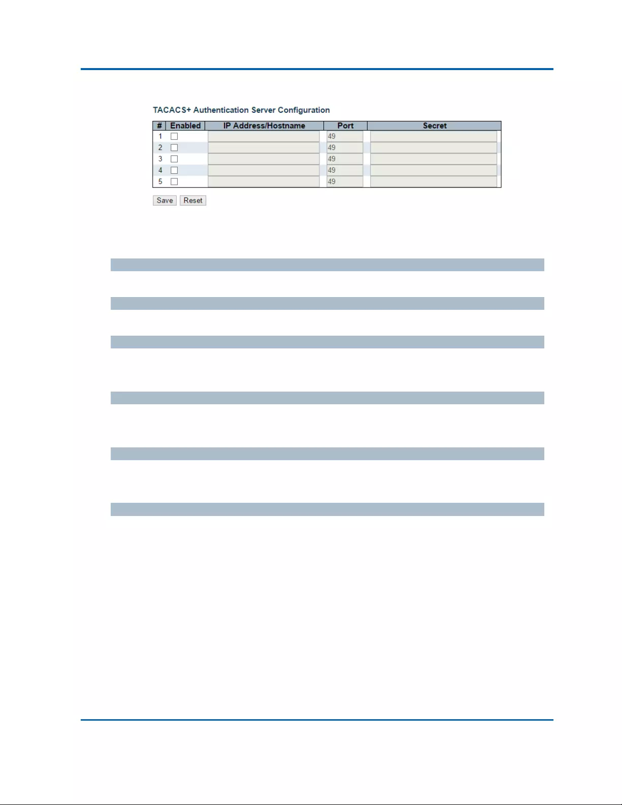
Chapter3:WebManagement
Security‐AAA
Intelinet48‐PortGigabitEthernetPoE+Layer2+ManagedSwitchUserManual|117
TACACS+AuthenticationServerConfiguration
ThetablehasonerowforeachTACACS+AuthenticationServerandanumberofcolumns,whichare:
#
TheTACACS+AuthenticationServernumberforwhichtheconfigurationbelowapplies.
Enabled
EnabletheTACACS+AuthenticationServerbycheckingthisbox.
IPAddress/Hostname
TheIPaddressorhostnameoftheTACACS+AuthenticationServer.IPaddressisexpressedindotted
decimalnotation.
Port
TheTCPporttouseontheTACACS+AuthenticationServer.Iftheportissetto0(zero),thedefault
port(49)isusedontheTACACS+AuthenticationServer.
Secret
Thesecret‐upto29characterslong‐sharedbetweentheTACACS+AuthenticationServerandthe
stack.
Buttons
Save:Clicktosavechanges.
Reset:Clicktoundoanychangesmadelocallyandreverttopreviouslysavedvalues.

Chapter3:WebManagement
Aggregation‐Static
Intelinet48‐PortGigabitEthernetPoE+Layer2+ManagedSwitchUserManual|118
3.1.6.Configuration‐Aggregation
3.1.6.1.Aggregation‐Static
ThispageisusedtoconfiguretheAggregationhashmodeandtheaggregationgroup.
HashCodeContributors
SourceMACAddress
TheSourceMACaddresscanbeusedtocalculatethedestinationportfortheframe.Checktoenable
theuseoftheSourceMACaddress,orunchecktodisable.Bydefault,SourceMACAddressis
enabled.
DestinationMACAddress
TheDestinationMACAddresscanbeusedtocalculatethedestinationportfortheframe.Checkto
enabletheuseoftheDestinationMACAddress,orunchecktodisable.Bydefault,DestinationMAC
Addressisdisabled.
IPAddress
TheIPaddresscanbeusedtocalculatethedestinationportfortheframe.Checktoenabletheuseof
theIPAddress,orunchecktodisable.Bydefault,IPAddressisenabled.
TCP/UDPPortNumber
TheTCP/UDPportnumbercanbeusedtocalculatethedestinationportfortheframe.Checkto
enabletheuseoftheTCP/UDPPortNumber,orunchecktodisable.Bydefault,TCP/UDPPort
Numberisenabled.
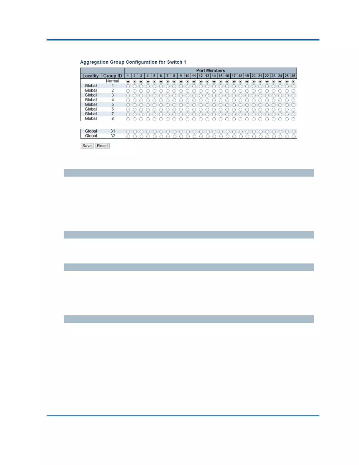
Chapter3:WebManagement
Aggregation‐Static
Intelinet48‐PortGigabitEthernetPoE+Layer2+ManagedSwitchUserManual|119
AggregationGroupConfiguration
Locality
Indicatestheaggregationgrouptype.Thisfieldisonlyvalidforstackableswitches.
Global:Thegroupmembersmayresideondifferentunitsinthestack.Eachglobalaggregation
mayconsistofupto8members.
Local:Thegroupmembersresideonthesameunit.Eachlocalaggregationmayconsistofup
to16members.
GroupID
IndicatesthegroupIDforthesettingscontainedinthesamerow.GroupID"Normal"indicatesthere
isnoaggregation.OnlyonegroupIDisvalidperport.
PortMembers
EachswitchportislistedforeachgroupID.Selectaradiobuttontoincludeaportinanaggregation,
orcleartheradiobuttontoremovetheportfromtheaggregation.Bydefault,noportsbelongtoany
aggregationgroup.Onlyfullduplexportscanjoinanaggregationandportsmustbeinthesame
speedineachgroup.
Buttons
Save:Clicktosavechanges.
Reset:Clicktoundoanychangesmadelocallyandreverttopreviouslysavedvalues.

Chapter3:WebManagement
Aggregation‐LACP
Intelinet48‐PortGigabitEthernetPoE+Layer2+ManagedSwitchUserManual|120
3.1.6.2.Aggregation‐LACP
ThispageallowstheusertoinspectthecurrentLACPportconfigurations,andpossiblychangethem
aswell.
TheLACPportsettingsrelatetothecurrentlyselectedstackunit,asreflectedbythepageheader.
Port
Theswitchportnumber.
LACPEnabled
ControlswhetherLACPisenabledonthisswitchport.LACPwillformanaggregationwhen2ormore
portsareconnectedtothesamepartner.LACPcanformmax12LLAGsperswitchand2GLAGsper
stack.
Key
TheKeyvalueincurredbytheport,range1‐65535.TheAutosettingwillsetthekeyasappropriate
bythephysicallinkspeed,10Mb=1,100Mb=2,1Gb=3.UsingtheSpecificsetting,auser‐defined
valuecanbeentered.PortswiththesameKeyvaluecanparticipateinthesameaggregationgroup,
whileportswithdifferentkeyscannot.
Role
TheRoleshowstheLACPactivitystatus.TheActivewilltransmitLACPpacketseachsecond,while

Chapter3:WebManagement
Aggregation‐LACP
Intelinet48‐PortGigabitEthernetPoE+Layer2+ManagedSwitchUserManual|121
PassivewillwaitforaLACPpacketfromapartner(speakifspokento).

Chapter3:WebManagement
Aggregation‐LACP
Intelinet48‐PortGigabitEthernetPoE+Layer2+ManagedSwitchUserManual|122
Timeout
TheTimeoutcontrolstheperiodbetweenBPDUtransmissions.FastwilltransmitLACPpacketseach
second,whileSlowwillwaitfor30secondsbeforesendingaLACPpacket.
Prio
ThePriocontrolsthepriorityoftheport.IftheLACPpartnerwantstoformalargergroupthanis
supportedbythisdevicethenthisparameterwillcontrolwhichportswillbeactiveandwhichports
willbeinabackuprole.Lowernumbermeansgreaterpriority.
Buttons
Save:Clicktosavechanges.
Reset:Clicktoundoanychangesmadelocallyandreverttopreviouslysavedvalues.

Chapter3:WebManagement
LoopProtection
Intelinet48‐PortGigabitEthernetPoE+Layer2+ManagedSwitchUserManual|123
3.1.7.Configuration‐LoopProtection
ThispageallowstheusertoinspectthecurrentLoopProtectionconfigurations,andpossiblychange
themaswell.
GeneralSettings
EnableLoopProtection
Controlswhetherloopprotectionsisenabled(asawhole).
TransmissionTime
TheintervalbetweeneachloopprotectionPDUsentoneachport.validvaluesare1to10seconds.
ShutdownTime
Theperiod(inseconds)forwhichaportwillbekeptdisabledintheeventofaloopisdetected(and
theportactionshutsdowntheport).Validvaluesare0to604800seconds(7days).Avalueofzero
willkeepaportdisabled(untilnextdevicerestart).

Chapter3:WebManagement
LoopProtection
Intelinet48‐PortGigabitEthernetPoE+Layer2+ManagedSwitchUserManual|124
PortConfiguration
Port
Theswitchportnumberoftheport.
Enable
Controlswhetherloopprotectionisenabledonthisswitchport.
Action
Configurestheactionperformedwhenaloopisdetectedonaport.ValidvaluesareShutdownPort,
ShutdownPortandLogorLogOnly.
TxMode
ControlswhethertheportisactivelygeneratingloopprotectionPDU's,orwhetheritisjustpassively
lookingforloopedPDU's.
Buttons
Save:Clicktosavechanges.
Reset:Clicktoundoanychangesmadelocallyandreverttopreviouslysavedvalues.

Chapter3:WebManagement
SpanningTree‐BridgeSettings
Intelinet48‐PortGigabitEthernetPoE+Layer2+ManagedSwitchUserManual|125
3.1.8.Configuration‐SpanningTree
3.1.8.1.SpanningTree‐BridgeSettings
ThispageallowsyoutoconfigureSTPsystemsettings.ThesettingsareusedbyallSTPBridge
instancesintheSwitchStack.
BasicSettings
ProtocolVersion
TheMSTP/RSTP/STPprotocolversionsetting.ValidvaluesareSTP,RSTPandMSTP.
BridgePriority
Controlsthebridgepriority.Lowernumericvalueshavebetterpriority.Thebridgepriorityplusthe
MSTIinstancenumber,concatenatedwiththe6‐byteMACaddressoftheswitchformsaBridge
Identifier.
ForMSTPoperation,thisisthepriorityoftheCIST.Otherwise,thisisthepriorityoftheSTP/RSTP
bridge.
ForwardDelay
ThedelayusedbySTPBridgestotransitRootandDesignatedPortstoForwarding(usedinSTP
compatiblemode).Validvaluesareintherange4to30seconds.
MaxAge
ThemaximumageoftheinformationtransmittedbytheBridgewhenitistheRootBridge.Valid
valuesareintherange6to40seconds,andMaxAgemustbe<=(FwdDelay‐1)*2.

Chapter3:WebManagement
SpanningTree‐BridgeSettings
Intelinet48‐PortGigabitEthernetPoE+Layer2+ManagedSwitchUserManual|126
MaximumHopCount
ThisdefinestheinitialvalueofremainingHopsforMSTIinformationgeneratedattheboundaryofan
MSTIregion.ItdefineshowmanybridgesarootbridgecandistributeitsBPDUinformationto.Valid
valuesareintherange6to40hops.
TransmitHoldCount
ThenumberofBPDU'sabridgeportcansendpersecond.Whenexceeded,transmissionofthenext
BPDUwillbedelayed.Validvaluesareintherange1to10BPDU'spersecond.
AdvancedSettings
EdgePortBPDUFiltering
ControlwhetheraportexplicitlyconfiguredasEdgewilltransmitandreceiveBPDUs.
EdgePortBPDUGuard
ControlwhetheraportexplicitlyconfiguredasEdgewilldisableitselfuponreceptionofaBPDU.The
portwillentertheerror‐disabledstate,andwillberemovedfromtheactivetopology.
PortErrorRecovery
Controlwhetheraportintheerror‐disabledstateautomaticallywillbeenabledafteracertaintime.
Ifrecoveryisnotenabled,portshavetobedisabledandre‐enabledfornormalSTPoperation.The
conditionisalsoclearedbyasystemreboot.
PortErrorRecoveryTimeout
Thetimetopassbeforeaportintheerror‐disabledstatecanbeenabled.Validvaluesarebetween
30and86400seconds(24hours).
Buttons
Save:Clicktosavechanges.
Reset:Clicktoundoanychangesmadelocallyandreverttopreviouslysavedvalues.

Chapter3:WebManagement
SpanningTree‐MSTIMapping
Intelinet48‐PortGigabitEthernetPoE+Layer2+ManagedSwitchUserManual|127
3.1.8.2.SpanningTree‐MSTIMapping
ThispageallowstheusertoinspectthecurrentSTPMSTIbridgeinstancepriorityconfigurations,and
possiblychangethemaswell.
ConfigurationIdentification
ConfigurationName
ThenameidentifyingtheVLANtoMSTImapping.Bridgesmustsharethenameandrevision(see
below),aswellastheVLAN‐to‐MSTImappingconfigurationinordertosharespanningtreesfor
MSTI's(Intra‐region).Thenameisatmost32characters.
ConfigurationRevision
TherevisionoftheMSTIconfigurationnamedabove.Thismustbeanintegerbetween0and65535.
MSTIMapping
MSTI
Thebridgeinstance.TheCISTisnotavailableforexplicitmapping,asitwillreceivetheVLANsnot
explicitlymapped.

Chapter3:WebManagement
SpanningTree‐MSTIMapping
Intelinet48‐PortGigabitEthernetPoE+Layer2+ManagedSwitchUserManual|128
VLANsMapped
ThelistofVLANsmappedtotheMSTI.TheVLANscanbegivenasasingle(xx,xxbeingbetween1
and4094)VLAN,orarange(xx‐yy),eachofwhichmustbeseparatedwithcommaand/orspace.A
VLANcanonlybemappedtooneMSTI.AnunusedMSTIshouldjustbeleftempty.(I.e.nothaving
anyVLANsmappedtoit.)Example:2,5,20‐40.
Buttons
Save:Clicktosavechanges.
Reset:Clicktoundoanychangesmadelocallyandreverttopreviouslysavedvalues.

Chapter3:WebManagement
SpanningTree‐MSTIPriorities
Intelinet48‐PortGigabitEthernetPoE+Layer2+ManagedSwitchUserManual|129
3.1.8.3.SpanningTree‐MSTIPriorities
ThispageallowstheusertoinspectthecurrentSTPMSTIbridgeinstancepriorityconfigurations,and
possiblychangethemaswell.
MSTI
Thebridgeinstance.TheCISTisthedefaultinstance,whichisalwaysactive.
Priority
Controlsthebridgepriority.Lowernumericvalueshavebetterpriority.Thebridgepriorityplusthe
MSTIinstancenumber,concatenatedwiththe6‐byteMACaddressoftheswitchformsaBridge
Identifier.
Buttons
Save:Clicktosavechanges.
Reset:Clicktoundoanychangesmadelocallyandreverttopreviouslysavedvalues.

Chapter3:WebManagement
SpanningTree‐CISTPorts
Intelinet48‐PortGigabitEthernetPoE+Layer2+ManagedSwitchUserManual|130
3.1.8.4.SpanningTree‐CISTPorts
ThispageallowstheusertoinspectthecurrentSTPCISTportconfigurations,andpossiblychange
themaswell.
Thispagecontainssettingsforphysicalandaggregatedports.Theaggregationsettingsarestack
global.
TheSTPportsettingsrelatetothecurrentlyselectedstackunit,asreflectedbythepageheader.
Port
TheswitchportnumberofthelogicalSTPport.
STPEnabled
ControlswhetherSTPisenabledonthisswitchport.

Chapter3:WebManagement
SpanningTree‐CISTPorts
Intelinet48‐PortGigabitEthernetPoE+Layer2+ManagedSwitchUserManual|131
PathCost
Controlsthepathcostincurredbytheport.TheAutosettingwillsetthepathcostasappropriateby
thephysicallinkspeed,usingthe802.1Drecommendedvalues.UsingtheSpecificsetting,a
user‐definedvaluecanbeentered.Thepathcostisusedwhenestablishingtheactivetopologyofthe
network.Lowerpathcostportsarechosenasforwardingportsinfavourofhigherpathcostports.
Validvaluesareintherange1to200000000.
Priority
Controlstheportpriority.Thiscanbeusedtocontrolpriorityofportshavingidenticalportcost.(See
above).
operEdge(stateflag)
Operationalflagdescribingwhethertheportisconnectingdirectlytoedgedevices.(NoBridges
attached).Transitiontotheforwardingstateisfasterforedgeports(havingoperEdgetrue)thanfor
otherports.ThevalueofthisflagisbasedonAdminEdgeandAutoEdgefields.Thisflagisdisplayed
asEdgeinMonitor‐>SpanningTree‐>STPDetailedBridgeStatus.
AdminEdge
ControlswhethertheoperEdgeflagshouldstartassetorcleared.(TheinitialoperEdgestatewhena
portisinitialized).
AutoEdge
Controlswhetherthebridgeshouldenableautomaticedgedetectiononthebridgeport.Thisallows
operEdgetobederivedfromwhetherBPDU'sarereceivedontheportornot.
RestrictedRole
Ifenabled,causestheportnottobeselectedasRootPortfortheCISToranyMSTI,evenifithasthe
bestspanningtreepriorityvector.SuchaportwillbeselectedasanAlternatePortaftertheRoot
Porthasbeenselected.Ifset,itcancauselackofspanningtreeconnectivity.Itcanbesetbya
networkadministratortopreventbridgesexternaltoacoreregionofthenetworkinfluencethe
spanningtreeactivetopology,possiblybecausethosebridgesarenotunderthefullcontrolofthe
administrator.ThisfeatureisalsoknownasRootGuard.
RestrictedTCN
Ifenabled,causestheportnottopropagatereceivedtopologychangenotificationsandtopology
changestootherports.Ifsetitcancausetemporarylossofconnectivityafterchangesinaspanning
tree'sactivetopologyasaresultofpersistentlyincorrectlearnedstationlocationinformation.Itis
setbyanetworkadministratortopreventbridgesexternaltoacoreregionofthenetwork,causing
addressflushinginthatregion,possiblybecausethosebridgesarenotunderthefullcontrolofthe
administratororthephysicallinkstateoftheattachedLANstransitsfrequently.

Chapter3:WebManagement
SpanningTree‐CISTPorts
Intelinet48‐PortGigabitEthernetPoE+Layer2+ManagedSwitchUserManual|132
BPDUGuard
Ifenabled,causestheporttodisableitselfuponreceivingvalidBPDU's.Contrarytothesimilar
bridgesetting,theportEdgestatusdoesnoteffectthissetting.
Aportenteringerror‐disabledstateduetothissettingissubjecttothebridgePortErrorRecovery
settingaswell.
Point‐to‐Point
Controlswhethertheportconnectstoapoint‐to‐pointLANratherthantoasharedmedium.Thiscan
beautomaticallydetermined,orforcedeithertrueorfalse.Transitiontotheforwardingstateis
fasterforpoint‐to‐pointLANsthanforsharedmedia.
Buttons
Save:Clicktosavechanges.
Reset:Clicktoundoanychangesmadelocallyandreverttopreviouslysavedvalues.

Chapter3:WebManagement
SpanningTree‐MSTIPorts
Intelinet48‐PortGigabitEthernetPoE+Layer2+ManagedSwitchUserManual|133
3.1.8.5.SpanningTree‐MSTIPorts
ThispageallowstheusertoinspectthecurrentSTPMSTIportconfigurations,andpossiblychange
themaswell.
AnMSTIportisavirtualport,whichisinstantiatedseparatelyforeachactiveCIST(physical)portfor
eachMSTIinstanceconfiguredonandapplicabletotheport.TheMSTIinstancemustbeselected
beforedisplayingactualMSTIportconfigurationoptions.

Chapter3:WebManagement
SpanningTree‐MSTIPorts
Intelinet48‐PortGigabitEthernetPoE+Layer2+ManagedSwitchUserManual|134
ThispagecontainsMSTIportsettingsforphysicalandaggregatedports.Theaggregationsettingsare
stackglobal.
ApartfromtheselectedMSTI,theSTPMSTIportsettingsalsorelatetothecurrentlyselectedstack
unit,asreflectedbythepageheader.
Port
TheswitchportnumberofthecorrespondingSTPCIST(andMSTI)port.
PathCost
Controlsthepathcostincurredbytheport.TheAutosettingwillsetthepathcostasappropriateby
thephysicallinkspeed,usingthe802.1Drecommendedvalues.UsingtheSpecificsetting,a
user‐definedvaluecanbeentered.Thepathcostisusedwhenestablishingtheactivetopologyofthe
network.Lowerpathcostportsarechosenasforwardingportsinfavourofhigherpathcostports.
Validvaluesareintherange1to200000000.
Priority
Controlstheportpriority.Thiscanbeusedtocontrolpriorityofportshavingidenticalportcost.(See
above).
Buttons
Get:ClicktoretrievesettingsforaspecificMSTI.
Save:Clicktosavechanges.
Reset:Clicktoundoanychangesmadelocallyandreverttopreviouslysavedvalues.

Chapter3:WebManagement
IPMCProfile‐ProfileTable
Intelinet48‐PortGigabitEthernetPoE+Layer2+ManagedSwitchUserManual|135
3.1.9.Configuration‐IPMCProfile
3.1.9.1.IPMCProfile‐ProfileTable
ThispageprovidesIPMCProfilerelatedconfigurations.
TheIPMCprofileisusedtodeploytheaccesscontrolonIPmulticaststreams.Itisallowedtocreate
atmaximum64Profileswithatmaximum128correspondingrulesforeach.
GlobalProfileMode
Enable/DisabletheGlobalIPMCProfile.
Systemstartstodofilteringbasedonprofilesettingsonlywhentheglobalprofilemodeisenabled.
Delete
Checktodeletetheentry.
Thedesignatedentrywillbedeletedduringthenextsave.
ProfileName
Thenameusedforindexingtheprofiletable.
Eachentryhastheuniquenamewhichiscomposedofatmaximum16alphabeticandnumeric
characters.Atleastonealphabetmustbepresent.
ProfileDescription
Additionaldescription,whichiscomposedofatmaximum64alphabeticandnumericcharacters,
abouttheprofile.
Noblankorspacecharactersarepermittedaspartofdescription.Use"_"or"‐"toseparatethe
descriptionsentence.

Chapter3:WebManagement
IPMCProfile‐ProfileTable
Intelinet48‐PortGigabitEthernetPoE+Layer2+ManagedSwitchUserManual|136
Rule
Whentheprofileiscreated,clicktheeditbuttontoentertherulesettingpageofthedesignated
profile.Summaryaboutthedesignatedprofilewillbeshownbyclickingtheviewbutton.Youcan
manageorinspecttherulesofthedesignatedprofilebyusingthefollowingbuttons:
Navigate:Listtherulesassociatedwiththedesignatedprofile.
Edit:Adjusttherulesassociatedwiththedesignatedprofile.
Buttons
AddNewIPMCProfile:ClicktoaddnewIPMCprofile.Specifythenameandconfigurethe
newentry.Click"Save".
Save:Clicktosavechanges.
Reset:Clicktoundoanychangesmadelocallyandreverttopreviouslysavedvalues.

Chapter3:WebManagement
IPMCProfile‐AddressEntry
Intelinet48‐PortGigabitEthernetPoE+Layer2+ManagedSwitchUserManual|137
3.1.9.2.IPMCProfile‐AddressEntry
ThispageprovidesaddressrangesettingsusedinIPMCprofile.
TheaddressentryisusedtospecifytheaddressrangethatwillbeassociatedwithIPMCProfile.Itis
allowedtocreateatmaximum128addressentriesinthesystem.
Delete
Checktodeletetheentry.
Thedesignatedentrywillbedeletedduringthenextsave.
EntryName
Thenameusedforindexingtheaddressentrytable.
Eachentryhastheuniquenamewhichiscomposedofatmaximum16alphabeticandnumeric
characters.Atleastonealphabetmustbepresent.
StartAddress
ThestartingIPv4/IPv6MulticastGroupAddressthatwillbeusedasanaddressrange.
EndAddress
TheendingIPv4/IPv6MulticastGroupAddressthatwillbeusedasanaddressrange.
Buttons
AddNewAddress(Range)Entry:Clicktoaddnewaddressrange.Specifythenameand
configuretheaddresses.Click"Save"
Save:Clicktosavechanges.
Reset:Clicktoundoanychangesmadelocallyandreverttopreviouslysavedvalues.
Refresh:Refreshesthedisplayedtablestartingfromtheinputfields.
|<<:UpdatesthetablestartingfromthefirstentryintheIPMCProfileAddressConfiguration.
>>:Updatesthetable,startingwiththeentryafterthelastentrycurrentlydisplayed.

Chapter3:WebManagement
MVR
Intelinet48‐PortGigabitEthernetPoE+Layer2+ManagedSwitchUserManual|138
3.1.10.Configuration‐MVR
ThispageprovidesMVRrelatedconfigurations.
Mostofthesettingsareglobal,whereastheImmediateLeaveandMVRPort‐Roleconfigurationis
relatedtothecurrentselectingstackunit,asreflectedbythepageheader.
TheMVRfeatureenablesmulticasttrafficforwardingontheMulticastVLANs.Inamulticast
televisionapplication,aPCoranetworktelevisionoraset‐topboxcanreceivethemulticaststream.
Multipleset‐topboxesorPCscanbeconnectedtoonesubscriberport,whichisaswitchport
configuredasanMVRreceiverport.Whenasubscriberselectsachannel,theset‐topboxorPC
sendsanIGMP/MLDreportmessagetoSwitchAtojointheappropriatemulticastgroupaddress.
UplinkportsthatsendandreceivemulticastdatatoandfromthemulticastVLANarecalledMVR
sourceports.Itisallowedtocreateatmaximum8MVRVLANswithcorrespondingchannelsettings
foreachMulticastVLAN.Therewillbetotallyatmaximum256groupaddressesforchannelsettings.
MVRMode
Enable/DisabletheGlobalMVR.
TheUnregisteredFloodingcontroldependsonthecurrentconfigurationinIGMP/MLDSnooping.
ItissuggestedtoenableUnregisteredFloodingcontrolwhentheMVRgrouptableisfull.
Delete
Checktodeletetheentry.Thedesignatedentrywillbedeletedduringthenextsave.
MVRVID
SpecifytheMulticastVLANID.
Note:MVRsourceportsarenotrecommendedtobeoverlappedwithmanagementVLANports.

Chapter3:WebManagement
MVR
Intelinet48‐PortGigabitEthernetPoE+Layer2+ManagedSwitchUserManual|139
MVRName
MVRNameisanoptionalattributetoindicatethenameofthespecificMVRVLAN.Maximumlength
oftheMVRVLANNamestringis32.MVRVLANNamecanonlycontainalphabetsornumbers.When
theoptionalMVRVLANnameisgiven,itshouldcontainatleastonealphabet.MVRVLANnamecan
beeditedfortheexistingMVRVLANentriesoritcanbeaddedtothenewentries.
Mode
SpecifytheMVRmodeofoperation.InDynamicmode,MVRallowsdynamicMVRmembership
reportsonsourceports.InCompatiblemode,MVRmembershipreportsareforbiddenonsource
ports.ThedefaultisDynamicmode.
Tag ging
SpecifywhetherthetraversedIGMP/MLDcontrolframeswillbesentasUntaggedorTaggedwith
MVRVID.ThedefaultisTagged.
Priority
SpecifyhowthetraversedIGMP/MLDcontrolframeswillbesentinprioritizedmanner.Thedefault
Priorityis0.
LLQI
DefinethemaximumtimetowaitforIGMP/MLDreportmembershipsonareceiverportbefore
removingtheportfrommulticastgroupmembership.Thevalueisinunitsoftenthsofaseconds.
Therangeisfrom0to31744.ThedefaultLLQIis5tenthsorone‐halfsecond.
InterfaceChannelSetting
WhentheMVRVLANiscreated,clicktheEditsymboltoexpandthecorrespondingmulticast
channelsettingsforthespecificMVRVLAN.SummaryabouttheInterfaceChannelSetting(ofthe
MVRVLAN)willbeshownbesidestheEditsymbol.
DetailinformationregardingtotheInterfaceChannelSettingwillbecoveredonpage122.
Port
Thelogicalportforthesettings.
PortRole
ConfigureanMVRportofthedesignatedMVRVLANasoneofthefollowingroles.
Inactive(I):ThedesignatedportdoesnotparticipateMVRoperations.
Source(S):Configureuplinkportsthatreceiveandsendmulticastdataassourceports.
Subscriberscannotbedirectlyconnectedtosourceports.
Receiver(R):Configureaportasareceiverportifitisasubscriberportandshouldonly
receivemulticastdata.Itdoesnotreceivedataunlessitbecomesamemberofthemulticast
groupbyissuingIGMP/MLDmessages.
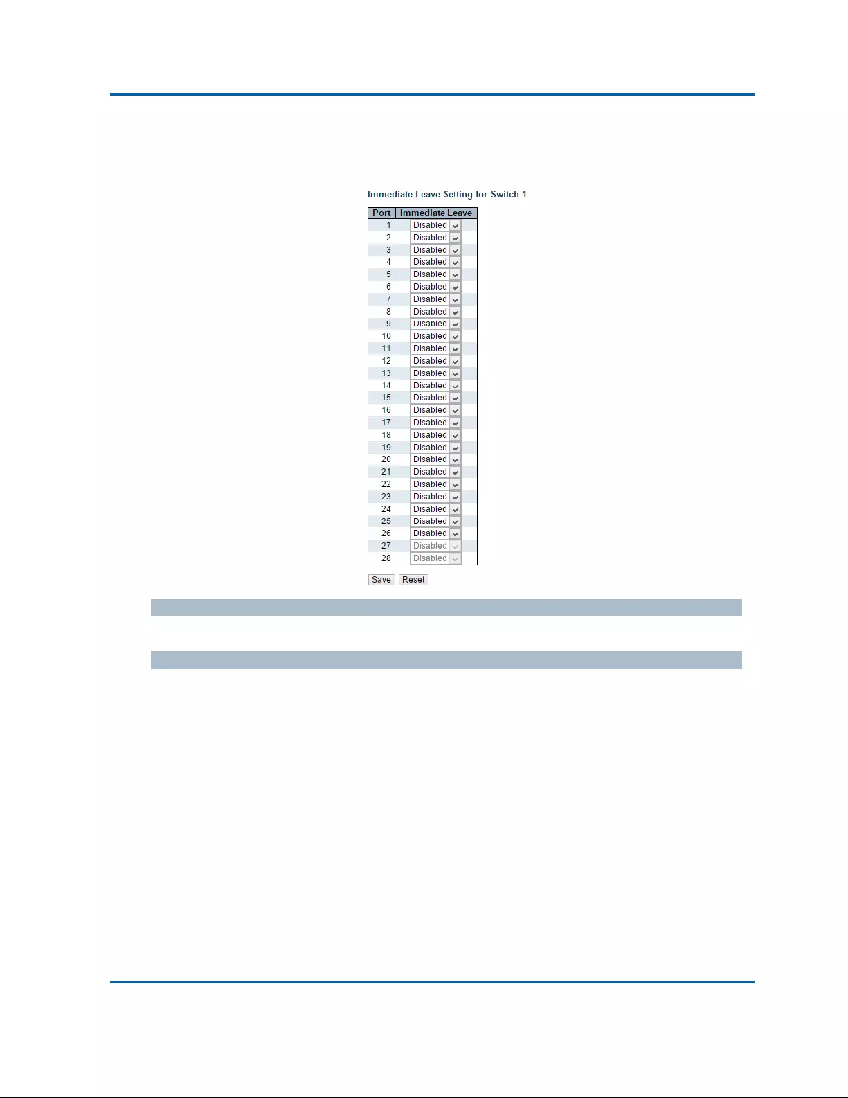
Chapter3:WebManagement
MVR
Intelinet48‐PortGigabitEthernetPoE+Layer2+ManagedSwitchUserManual|140
Note:MVRsourceportsarenotrecommendedtobeoverlappedwithmanagementVLANports.
SelecttheportrolebyclickingtheRolesymboltoswitchthesetting.
ImmediateLeave
Enablethefastleaveontheport.
Buttons
AddNewNVRVLAN:ClicktoaddnewMVRVLAN.SpecifytheVIDandconfigurethenew
entry.Click"Save".
Save:Clicktosavechanges.
Reset:Clicktoundoanychangesmadelocallyandreverttopreviouslysavedvalues.

Chapter3:WebManagement
MVR
Intelinet48‐PortGigabitEthernetPoE+Layer2+ManagedSwitchUserManual|141
ThispageprovidesMVRchannelsettingsforaspecificMVRVLAN.
Delete
Checktodeletetheentry.Thedesignatedentrywillbedeletedduringthenextsave.
VLANID
DisplaythespecificMulticastVLANID.Thisfieldisnoteditable.
VLANName
DisplaythenameofthespecificMulticastVLAN.Thisfieldisnoteditable.
StartAddress
ThestartingIPv4/IPv6MulticastGroupAddressthatwillbeusedasastreamingchannel.
EndAddress
TheendingIPv4/IPv6MulticastGroupAddressthatwillbeusedasastreamingchannel.
ChannelName
IndicatethenameoftheChannelofthespecificMulticastVLAN.MaximumlengthoftheChannel
Namestringis32.ChannelNamecanonlycontainalphabetsornumbers.Channelnameshould
containatleastonealphabet.ChannelnamecanbeeditedfortheexistingChannelentriesoritcan
beaddedtothenewentries.
Buttons
AddNewMVRChannel:ClicktoaddnewChannelforagivenMVRVLAN.SpecifytheAddress
andconfigurethenewentry.Click"Save"
Save:Clicktosavechanges.
Reset:Clicktoundoanychangesmadelocallyandreverttopreviouslysavedvalues.
Refresh:Refreshesthedisplayedtablestartingfromtheinputfields.
|<<:UpdatesthetablestartingfromthefirstentryintheMVRChannelConfigurationfora
specificMVRVLAN.
>>:Updatesthetable,startingwiththeentryafterthelastentrycurrentlydisplayed.
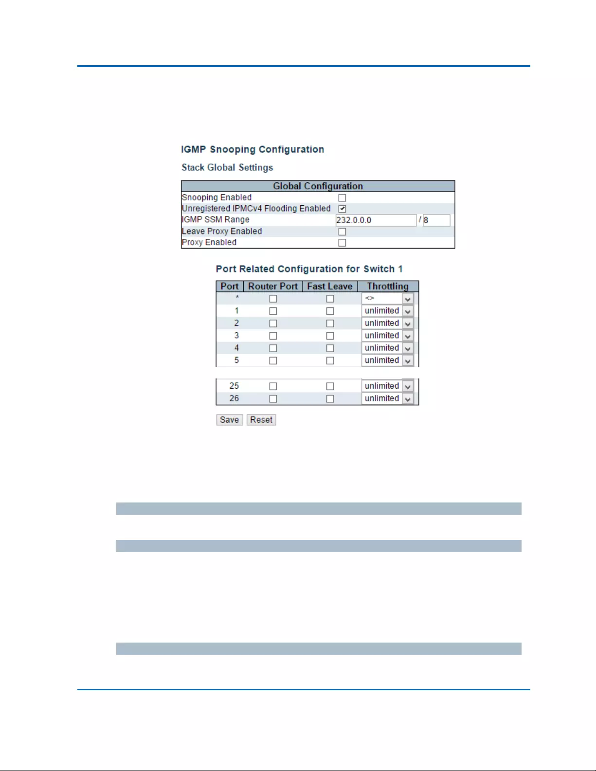
Chapter3:WebManagement
IPMC‐IGMPSnooping‐BasicConfiguration
Intelinet48‐PortGigabitEthernetPoE+Layer2+ManagedSwitchUserManual|142
3.1.11.Configuration‐IPMC
3.1.11.1.IPMC‐IGMPSnooping
3.1.11.1.1.IPMC‐IGMPSnooping‐BasicConfiguration
ThispageprovidesIGMPSnoopingrelatedconfiguration.
Mostofthesettingsareglobal,whereastheRouterPortconfigurationisrelatedtothecurrently
selectedstackunit,asreflectedbythepageheader.
SnoopingEnabled
EnabletheGlobalIGMPSnooping.
UnregisteredIPMCv4FloodingEnabled
EnableunregisteredIPMCv4trafficflooding.
ThefloodingcontroltakeseffectonlywhenIGMPSnoopingisenabled.
WhenIGMPSnoopingisdisabled,unregisteredIPMCv4trafficfloodingisalwaysactiveinspiteof
thissetting.
IGMPSSMRange
SSM(Source‐SpecificMulticast)RangeallowstheSSM‐awarehostsandroutersruntheSSM
servicemodelforthegroupsintheaddressrange.

Chapter3:WebManagement
IPMC‐IGMPSnooping‐BasicConfiguration
Intelinet48‐PortGigabitEthernetPoE+Layer2+ManagedSwitchUserManual|143
LeaveProxyEnabled
EnableIGMPLeaveProxy.Thisfeaturecanbeusedtoavoidforwardingunnecessaryleave
messagestotherouterside.
ProxyEnabled
EnableIGMPProxy.Thisfeaturecanbeusedtoavoidforwardingunnecessaryjoinandleave
messagestotherouterside.
RouterPort
Specifywhichportsactasrouterports.ArouterportisaportontheEthernetswitchthatleads
towardstheLayer3multicastdeviceorIGMPquerier.
Ifanaggregationmemberportisselectedasarouterport,thewholeaggregationwillactasa
routerport.
FastLeave
Enablethefastleaveontheport.
Throttling
Enabletolimitthenumberofmulticastgroupstowhichaswitchportcanbelong.
Buttons
Save:Clicktosavechanges.
Reset:Clicktoundoanychangesmadelocallyandreverttopreviouslysavedvalues.
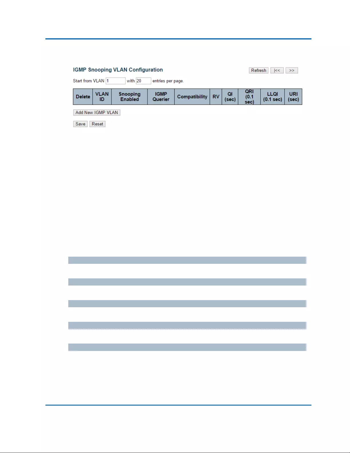
Chapter3:WebManagement
IPMC‐IGMPSnooping‐VLANConfiguration
Intelinet48‐PortGigabitEthernetPoE+Layer2+ManagedSwitchUserManual|144
3.1.11.1.2.IPMC‐IGMPSnooping‐VLANConfiguration
Eachpageshowsupto99entriesfromtheVLANtable,defaultbeing20,selectedthroughthe
"entriesperpage"inputfield.Whenfirstvisited,thewebpagewillshowthefirst20entriesfrom
thebeginningoftheVLANTable.ThefirstdisplayedwillbetheonewiththelowestVLANIDfound
intheVLANTable.
The"VLAN"inputfieldsallowtheusertoselectthestartingpointintheVLANTable.Clickingthe
RefreshbuttonwillupdatethedisplayedtablestartingfromthatorthenextclosestVLANTable
match.
The>>|willusethelastentryofthecurrentlydisplayedentryasabasisforthenextlookup.When
theendisreachedthetext"Nomoreentries"isshowninthedisplayedtable.Usethe<<buttonto
startover.
IGMPSnoopingVLANTableColumns
Delete
Checktodeletetheentry.Thedesignatedentrywillbedeletedduringthenextsave.
VLANID
TheVLANIDoftheentry.
IGMPSnoopingEnabled
Enabletheper‐VLANIGMPSnooping.Upto32VLANscanbeselectedforIGMPSnooping.
IGMPQuerier
EnabletheIGMPQuerierintheVLAN.
Compatibility
Compatibilityismaintainedbyhostsandrouterstakingappropriateactionsdependingonthe
versionsofIGMPoperatingonhostsandrouterswithinanetwork.Theallowedselectionis
IGMP‐Auto,ForcedIGMPv1,ForcedIGMPv2,ForcedIGMPv3,defaultcompatibilityvalueis
IGMP‐Auto.

Chapter3:WebManagement
IPMC‐IGMPSnooping‐VLANConfiguration
Intelinet48‐PortGigabitEthernetPoE+Layer2+ManagedSwitchUserManual|145
RV
RobustnessVariable.TheRobustnessVariableallowstuningfortheexpectedpacketlossona
network.Theallowedrangeis1to255,defaultrobustnessvariablevalueis2.
QI
QueryInterval.TheQueryIntervalistheintervalbetweenGeneralQueriessentbytheQuerier.
Theallowedrangeis1to31744seconds,defaultqueryintervalis125seconds.
QRI
QueryResponseInterval.TheMaximumResponseDelayusedtocalculatetheMaximumResponse
CodeinsertedintotheperiodicGeneralQueries.Theallowedrangeis0to31744intenthsof
seconds,defaultqueryresponseintervalis100intenthsofseconds(10seconds).
LLQI(LMQIforIGMP)
LastMemberQueryInterval.TheLastMemberQueryTimeisthetimevaluerepresentedbythe
LastMemberQueryInterval,multipliedbytheLastMemberQueryCount.Theallowedrangeis0
to31744intenthsofseconds,defaultlastmemberqueryintervalis10intenthsofseconds(1
second).
URI
UnsolicitedReportInterval.TheUnsolicitedReportIntervalisthetimebetweenrepetitionsofa
host'sinitialreportofmembershipinagroup.Theallowedrangeis0to31744seconds,default
unsolicitedreportintervalis1second.
Buttons
Refresh:Refreshesthedisplayedtablestartingfromthe"VLAN"inputfields.
|<<:UpdatesthetablestartingfromthefirstentryintheVLANTable,i.e.theentrywiththe
lowestVLANID.
>>:Updatesthetable,startingwiththeentryafterthelastentrycurrentlydisplayed.
AddNewIGMPVLAN:ClicktoaddnewIGMPVLAN.SpecifytheVIDandconfigurethenew
entry.Click"Save".ThespecificIGMPVLANstartsworkingafterthecorrespondingstatic
VLANisalsocreated.
Save:Clicktosavechanges.
Reset:Clicktoundoanychangesmadelocallyandreverttopreviouslysavedvalues.

Chapter3:WebManagement
IPMC‐IGMPSnooping‐PortGroupFiltering
Intelinet48‐PortGigabitEthernetPoE+Layer2+ManagedSwitchUserManual|146
3.1.11.1.3.IPMC‐IGMPSnooping‐PortGroupFiltering
Delete
Checktodeletetheentry.Itwillbedeletedduringthenextsave.
Port
Thelogicalportforthesettings.
FilteringGroups
TheIPMulticastGroupthatwillbefiltered.
AddNewFilteringGroup
Click“AddNewFilteringGroup”buttontoaddanewentrytotheGroupFilteringtable.Specify
thePort,andFilteringGroupofthenewentry.Click"Save".
Buttons
AddNewFilteringGroup:ClicktoaddanewentrytotheGroupFilteringtable.
Save:Clicktosavechanges.
Reset:Clicktoundoanychangesmadelocallyandreverttopreviouslysavedvalues.
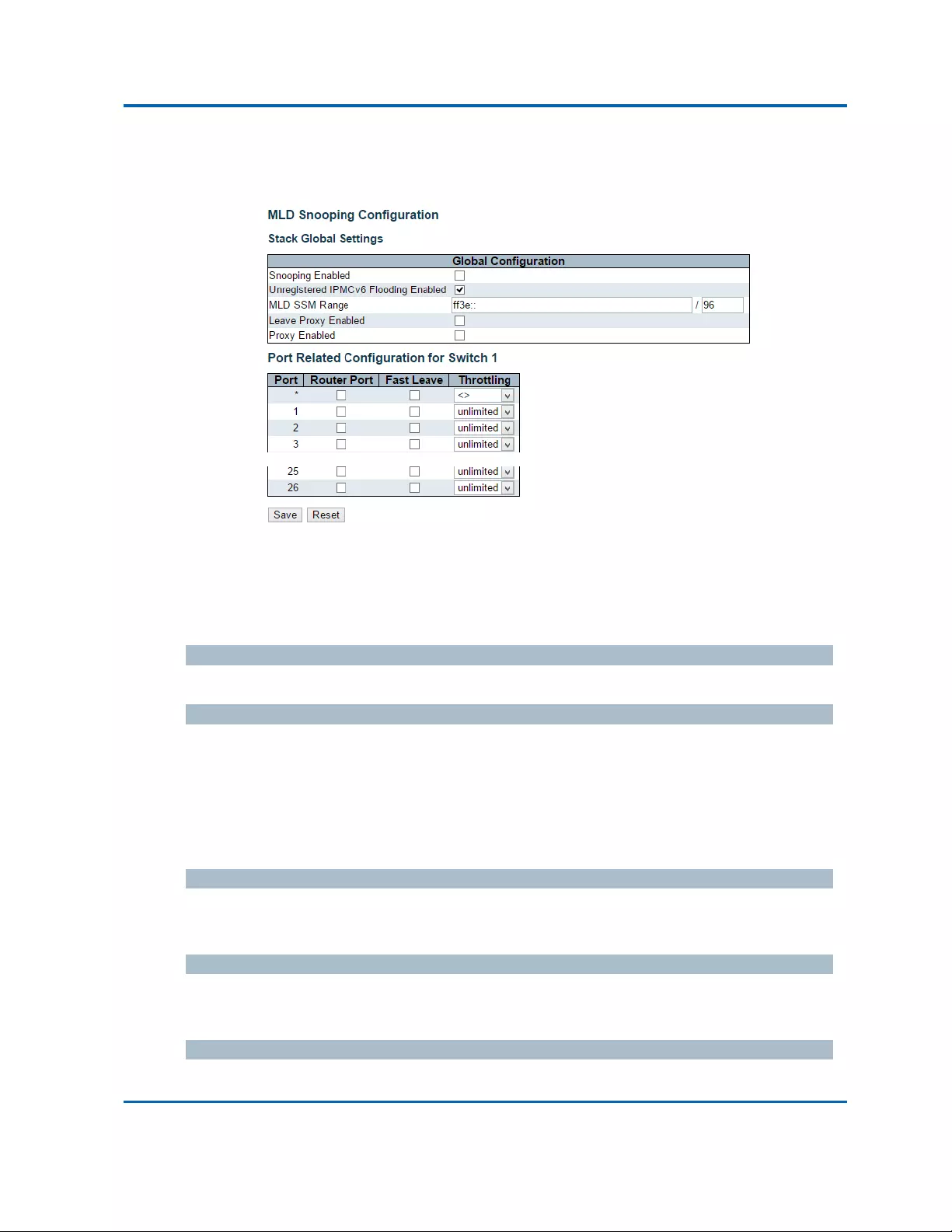
Chapter3:WebManagement
IPMC‐MLDSnooping‐BasicConfiguration
Intelinet48‐PortGigabitEthernetPoE+Layer2+ManagedSwitchUserManual|147
3.1.11.2.IPMC‐MLDSnooping
3.1.11.2.1.IPMC‐MLDSnooping‐BasicConfiguration
ThispageprovidesMLDSnoopingrelatedconfiguration.
Mostofthesettingsareglobal,whereastheRouterPortconfigurationisrelatedtothecurrently
selectedstackunit,asreflectedbythepageheader.
SnoopingEnabled
EnabletheGlobalMLDSnooping.
UnregisteredIPMCv6FloodingEnabled
EnableunregisteredIPMCv6trafficflooding.
ThefloodingcontroltakeseffectonlywhenMLDSnoopingisenabled.
WhenMLDSnoopingisdisabled,unregisteredIPMCv6trafficfloodingisalwaysactiveinspiteof
thissetting.
MLDSSMRange
SSM(Source‐SpecificMulticast)RangeallowstheSSM‐awarehostsandroutersruntheSSM
servicemodelforthegroupsintheaddressrange.
LeaveProxyEnabled
EnableMLDLeaveProxy.Thisfeaturecanbeusedtoavoidforwardingunnecessaryleavemessages
totherouterside.
ProxyEnabled
EnableMLDProxy.Thisfeaturecanbeusedtoavoidforwardingunnecessaryjoinandleave

Chapter3:WebManagement
IPMC‐MLDSnooping‐BasicConfiguration
Intelinet48‐PortGigabitEthernetPoE+Layer2+ManagedSwitchUserManual|148
messagestotherouterside.
RouterPort
Specifywhichportsactasrouterports.ArouterportisaportontheEthernetswitchthatleads
towardstheLayer3multicastdeviceorMLDquerier.
Ifanaggregationmemberportisselectedasarouterport,thewholeaggregationwillactasa
routerport.
FastLeave
Enablethefastleaveontheport.
Throttling
Enabletolimitthenumberofmulticastgroupstowhichaswitchportcanbelong.
Buttons
Save:Clicktosavechanges.
Reset:Clicktoundoanychangesmadelocallyandreverttopreviouslysavedvalues.

Chapter3:WebManagement
IPMC‐MLDSnooping‐VLANConfiguration
Intelinet48‐PortGigabitEthernetPoE+Layer2+ManagedSwitchUserManual|149
3.1.11.2.2.IPMC‐MLDSnooping‐VLANConfiguration
Eachpageshowsupto99entriesfromtheVLANtable,defaultbeing20,selectedthroughthe
"entriesperpage"inputfield.Whenfirstvisited,thewebpagewillshowthefirst20entriesfrom
thebeginningoftheVLANTable.ThefirstdisplayedwillbetheonewiththelowestVLANIDfound
intheVLANTable.
The"VLAN"inputfieldsallowtheusertoselectthestartingpointintheVLANTable.Clickingthe
RefreshbuttonwillupdatethedisplayedtablestartingfromthatorthenextclosestVLANTable
match.
The>>|willusethelastentryofthecurrentlydisplayedentryasabasisforthenextlookup.When
theendisreachedthetext"Nomoreentries"isshowninthedisplayedtable.Usethe<<buttonto
startover.
MLDSnoopingVLANTableColumns
Delete
Checktodeletetheentry.Thedesignatedentrywillbedeletedduringthenextsave.
VLANID
TheVLANIDoftheentry.
MLDSnoopingEnabled
Enabletheper‐VLANMLDSnooping.Upto32VLANscanbeselectedforMLDSnooping.
MLDQuerier
EnabletheIGMPQuerierintheVLAN.
Compatibility
Compatibilityismaintainedbyhostsandrouterstakingappropriateactionsdependingonthe
versionsofMLDoperatingonhostsandrouterswithinanetwork.Theallowedselectionis
MLD‐Auto,ForcedMLDv1,ForcedMLDv2,defaultcompatibilityvalueisMLD‐Auto.
RV
RobustnessVariable.TheRobustnessVariableallowstuningfortheexpectedpacketlossonalink.
Theallowedrangeis1to255,defaultrobustnessvariablevalueis2.

Chapter3:WebManagement
IPMC‐MLDSnooping‐VLANConfiguration
Intelinet48‐PortGigabitEthernetPoE+Layer2+ManagedSwitchUserManual|150
QI
QueryInterval.TheQueryIntervalistheintervalbetweenGeneralQueriessentbytheQuerier.
Theallowedrangeis1to31744seconds,defaultqueryintervalis125seconds.
QRI
QueryResponseInterval.TheMaximumResponseDelayusedtocalculatetheMaximumResponse
CodeinsertedintotheperiodicGeneralQueries.Theallowedrangeis0to31744intenthsof
seconds,defaultqueryresponseintervalis100intenthsofseconds(10seconds).
LLQI
LastListenerQueryInterval.TheLastListenerQueryIntervalistheMaximumResponseDelayused
tocalculatetheMaximumResponseCodeinsertedintoMulticastAddressSpecificQueriessentin
responsetoVersion1MulticastListenerDonemessages.ItisalsotheMaximumResponseDelay
usedtocalculatetheMaximumResponseCodeinsertedintoMulticastAddressandSource
SpecificQuerymessages.Theallowedrangeis0to31744intenthsofseconds,defaultlastlistener
queryintervalis10intenthsofseconds(1second).
URI
UnsolicitedReportInterval.TheUnsolicitedReportIntervalisthetimebetweenrepetitionsofa
node'sinitialreportofinterestinamulticastaddress.Theallowedrangeis0to31744seconds,
defaultunsolicitedreportintervalis1second.
Buttons
Refresh:Refreshesthedisplayedtablestartingfromthe"VLAN"inputfields.
|<<:UpdatesthetablestartingfromthefirstentryintheVLANTable,i.e.theentrywiththe
lowestVLANID.
>>:Updatesthetable,startingwiththeentryafterthelastentrycurrentlydisplayed.
AddNewMLDVLAN:ClicktoaddnewMLDVLAN.SpecifytheVIDandconfigurethenew
entry.Click"Save".ThespecificMLDVLANstartsworkingafterthecorrespondingstatic
VLANisalsocreated.
Save:Clicktosavechanges.
Reset:Clicktoundoanychangesmadelocallyandreverttopreviouslysavedvalues.

Chapter3:WebManagement
IPMC‐MLDSnooping‐PortGroupFiltering
Intelinet48‐PortGigabitEthernetPoE+Layer2+ManagedSwitchUserManual|151
3.1.11.2.3.IPMC‐MLDSnooping‐PortGroupFiltering
Delete
Checktodeletetheentry.Itwillbedeletedduringthenextsave.
Port
Thelogicalportforthesettings.
FilteringGroups
TheIPMulticastGroupthatwillbefiltered.
AddNewFilteringGroup
Click“AddNewFilteringGroup”buttontoaddanewentrytotheGroupFilteringtable.Specify
thePort,andFilteringGroupofthenewentry.Click"Save".
Buttons
AddNewFilteringGroup:ClicktoaddanewentrytotheGroupFilteringtable.
Save:Clicktosavechanges.
Reset:Clicktoundoanychangesmadelocallyandreverttopreviouslysavedvalues.
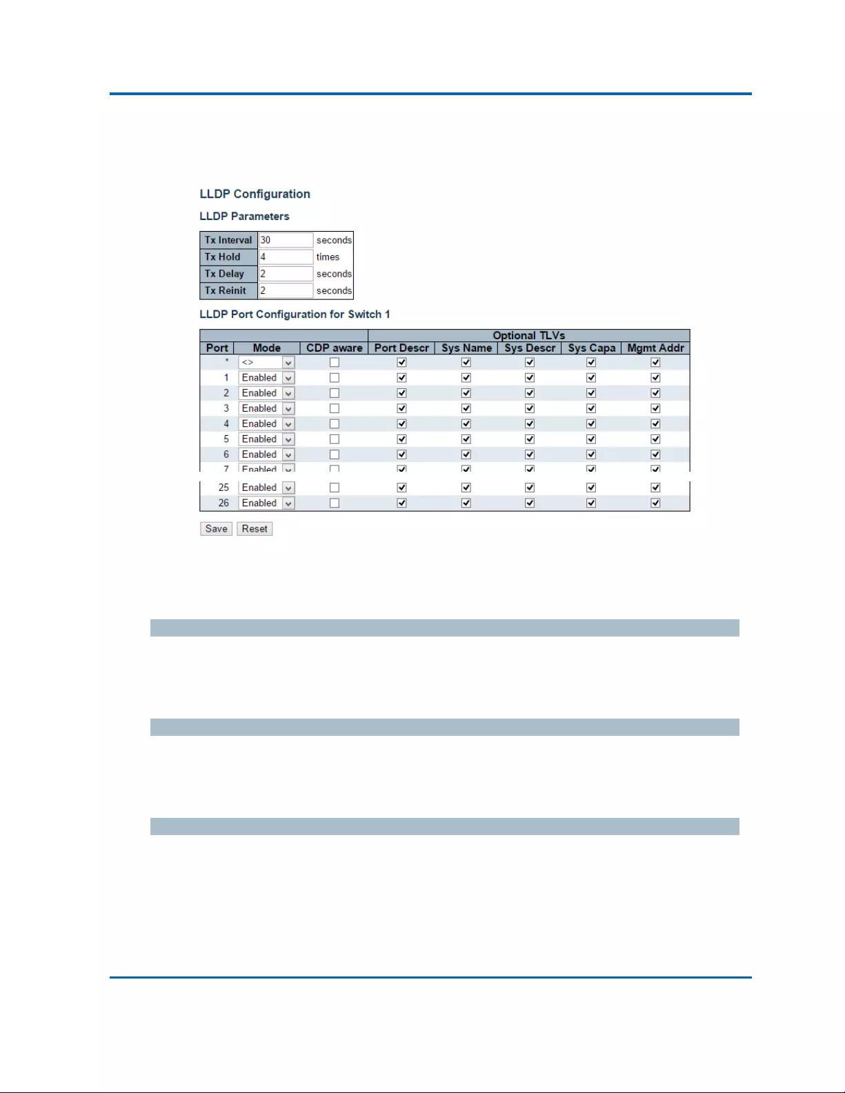
Chapter3:WebManagement
LLDP‐LLDP
Intelinet48‐PortGigabitEthernetPoE+Layer2+ManagedSwitchUserManual|152
3.1.12.Configuration‐LLDP
3.1.12.1.LLDP‐LLDP
ThispageallowstheusertoinspectandconfigurethecurrentLLDPportsettings.
LLDPParameters
TxInterval
TheswitchperiodicallytransmitsLLDPframestoitsneighborsforhavingthenetworkdiscovery
informationup‐to‐date.TheintervalbetweeneachLLDPframeisdeterminedbytheTxIntervalvalue.
Validvaluesarerestrictedto5‐32768seconds.
TxHold
EachLLDPframecontainsinformationabouthowlongtheinformationintheLLDPframeshallbe
consideredvalid.TheLLDPinformationvalidperiodissettoTxHoldmultipliedbyTxIntervalseconds.
Validvaluesarerestrictedto2‐10times.
TxDelay
Ifsomeconfigurationischanged(e.g.theIPaddress)anewLLDPframeistransmitted,butthetime
betweentheLLDPframeswillalwaysbeatleastthevalueofTxDelayseconds.TxDelaycannotbe
largerthan1/4 oftheTxIntervalvalue.Validvaluesarerestrictedto1‐8192seconds.

Chapter3:WebManagement
LLDP‐LLDP
Intelinet48‐PortGigabitEthernetPoE+Layer2+ManagedSwitchUserManual|153
TxReinit
Whenaportisdisabled,LLDPisdisabledortheswitchisrebooted,anLLDPshutdownframeis
transmittedtotheneighboringunits,SignalingthattheLLDPinformationisn'tvalidanymore.Tx
ReinitcontrolstheamountofsecondsbetweentheshutdownframeandanewLLDPinitialization.
Validvaluesarerestrictedto1‐10seconds.
LLDPPortConfiguration
TheLLDPportsettingsrelatetothecurrentlyselectedstackunit,asreflectedbythepageheader.
Port
TheswitchportnumberofthelogicalLLDPport.
Mode
SelectLLDPmode.
RxonlyTheswitchwillnotsendoutLLDPinformation,butLLDPinformationfromneighborunitsis
analyzed.
TxonlyTheswitchwilldropLLDPinformationreceivedfromneighbors,butwillsendoutLLDP
information.
DisabledTheswitchwillnotsendoutLLDPinformation,andwilldropLLDPinformationreceived
fromneighbors.
EnabledTheswitchwillsendoutLLDPinformation,andwillanalyzeLLDPinformationreceivedfrom
neighbors.
CDPAware
SelectCDPawareness.
TheCDPoperationisrestrictedtodecodingincomingCDPframes(Theswitchdoesn'ttransmitCDP
frames).CDPframesareonlydecodedifLLDPontheportisenabled.
OnlyCDPTLVsthatcanbemappedtoacorrespondingfieldintheLLDPneighbors'tablearedecoded.
AllotherTLVsarediscarded(UnrecognizedCDPTLVsanddiscardedCDPframesarenotshowninthe
LLDPstatistics.).CDPTLVsaremappedontoLLDPneighbors'tableasshownbelow.
CDPTLV"DeviceID"ismappedtotheLLDP"ChassisID"field.
CDPTLV"Address"ismappedtotheLLDP"ManagementAddress"field.TheCDPaddressTLVcan
containmultipleaddresses,butonlythefirstaddressisshownintheLLDPneighborstable.
CDPTLV"PortID"ismappedtotheLLDP"PortID"field.

Chapter3:WebManagement
LLDP‐LLDP
Intelinet48‐PortGigabitEthernetPoE+Layer2+ManagedSwitchUserManual|154
CDPTLV"VersionandPlatform"ismappedtotheLLDP"SystemDescription"field.
BoththeCDPandLLDPsupport"systemcapabilities",buttheCDPcapabilitiescovercapabilitiesthat
arenotpartoftheLLDP.Thesecapabilitiesareshownas"others"intheLLDPneighbors'table.
IfallportshaveCDPawarenessdisabledtheswitchforwardsCDPframesreceivedfromneighbor
devices.IfatleastoneporthasCDPawarenessenabledallCDPframesareterminatedbytheswitch.
Note:WhenCDPawarenessonaportisdisabledtheCDPinformationisn'tremovedimmediately,
butgetsremovedwhentheholdtimeisexceeded.
PortDescr
OptionalTLV:Whencheckedthe"portdescription"isincludedinLLDPinformationtransmitted.
SysName
OptionalTLV:Whencheckedthe"systemname"isincludedinLLDPinformationtransmitted.
SysDescr
OptionalTLV:Whencheckedthe"systemdescription"isincludedinLLDPinformationtransmitted.
SysCapa
OptionalTLV:Whencheckedthe"systemcapability"isincludedinLLDPinformationtransmitted.
MgmtAddr
OptionalTLV:Whencheckedthe"managementaddress"isincludedinLLDPinformationtransmitted.
Buttons
Save:Clicktosavechanges.
Reset:Clicktoundoanychangesmadelocallyandreverttopreviouslysavedvalues.

Chapter3:WebManagement
LLDP‐LLDP‐MED
Intelinet48‐PortGigabitEthernetPoE+Layer2+ManagedSwitchUserManual|155
3.1.12.2.LLDP‐LLDP‐MED
ThispageallowsyoutoconfiguretheLLDP‐MED.ThisfunctionappliestoVoIPdeviceswhichsupport
LLDP‐MED.
Faststartrepeatcount
Faststartrepeatcount
RapidstartupandEmergencyCallServiceLocationIdentificationDiscoveryofendpointsisacritically
importantaspectofVoIPsystemsingeneral.Inaddition,itisbesttoadvertiseonlythosepiecesof
informationwhicharespecificallyrelevanttoparticularendpointtypes(forexampleonlyadvertise
thevoicenetworkpolicytopermittedvoice‐capabledevices),bothinordertoconservethelimited
LLDPUspaceandtoreducesecurityandsystemintegrityissuesthatcancomewithinappropriate
knowledgeofthenetworkpolicy.
WiththisinmindLLDP‐MEDdefinesanLLDP‐MEDFastStartinteractionbetweentheprotocoland
theapplicationlayersontopoftheprotocol,inordertoachievetheserelatedproperties.Initially,a
NetworkConnectivityDevicewillonlytransmitLLDPTLVsinanLLDPDU.OnlyafteranLLDP‐MED
EndpointDeviceisdetected,willanLLDP‐MEDcapableNetworkConnectivityDevicestartto
advertiseLLDP‐MEDTLVsinoutgoingLLDPDUsontheassociatedport.TheLLDP‐MEDapplicationwill
temporarilyspeedupthetransmissionoftheLLDPDUtostartwithinasecond,whenanew
LLDP‐MEDneighborhasbeendetectedinordershareLLDP‐MEDinformationasfastaspossibleto
newneighbors.
BecausethereisariskofanLLDPframebeinglostduringtransmissionbetweenneighbors,itis

Chapter3:WebManagement
LLDP‐LLDP‐MED
Intelinet48‐PortGigabitEthernetPoE+Layer2+ManagedSwitchUserManual|156
recommendedtorepeatthefaststarttransmissionmultipletimestoincreasethepossibilityofthe
neighborsreceivingtheLLDPframe.WithFaststartrepeatcountitispossibletospecifythenumber
oftimesthefaststarttransmissionwouldberepeated.Therecommendedvalueis4times,given
that4LLDPframeswitha1secondintervalwillbetransmitted,whenanLLDPframewithnew
informationisreceived.
ItshouldbenotedthatLLDP‐MEDandtheLLDP‐MEDFastStartmechanismisonlyintendedtorun
onlinksbetweenLLDP‐MEDNetworkConnectivityDevicesandEndpointDevices,andassuchdoes
notapplytolinksbetweenLANinfrastructureelements,includingNetworkConnectivityDevices,or
othertypesoflinks.
CoordinatesLocation
Latitude
LatitudeSHOULDbenormalizedtowithin0‐90degreeswithamaximumof4digits.
ItispossibletospecifythedirectiontoeitherNorthoftheequatororSouthoftheequator.
Longitude
LongitudeSHOULDbenormalizedtowithin0‐180degreeswithamaximumof4digits.
ItispossibletospecifythedirectiontoeitherEastoftheprimemeridianorWestoftheprime
meridian.
Altitude
AltitudeSHOULDbenormalizedtowithin‐32767to32767withamaximumof4digits.
Itispossibletoselectbetweentwoaltitudetypes(floorsormeters).
Meters:RepresentingmetersofAltitudedefinedbytheverticaldatumspecified.
Floors:Representingaltitudeinaformmorerelevantinbuildingswhichhavedifferent
floor‐to‐floordimensions.Analtitude=0.0ismeaningfulevenoutsideabuilding,and
representsgroundlevelatthegivenlatitudeandlongitude.Insideabuilding,0.0represents
thefloorlevelassociatedwithgroundlevelatthemainentrance.
MapDatum
TheMapDatumisusedforthecoordinatesgivenintheseoptions:
WGS84:(Geographical3D)‐WorldGeodesicSystem1984,CRSCode4327,PrimeMeridian
Name:Greenwich.
NAD83/NAVD88:NorthAmericanDatum1983,CRSCode4269,PrimeMeridianName:
Greenwich;TheassociatedverticaldatumistheNorthAmericanVerticalDatumof1988
(NAVD88).Thisdatumpairistobeusedwhenreferencinglocationsonland,notneartidal

Chapter3:WebManagement
LLDP‐LLDP‐MED
Intelinet48‐PortGigabitEthernetPoE+Layer2+ManagedSwitchUserManual|157
water(whichwoulduseDatum=NAD83/MLLW).

Chapter3:WebManagement
LLDP‐LLDP‐MED
Intelinet48‐PortGigabitEthernetPoE+Layer2+ManagedSwitchUserManual|158
NAD83/MLLW:NorthAmericanDatum1983,CRSCode4269,PrimeMeridianName:
Greenwich;TheassociatedverticaldatumisMeanLowerLowWater(MLLW).Thisdatumpair
istobeusedwhenreferencinglocationsonwater/sea/ocean.
CivicAddressLocation
IETFGeoprivCivicAddressbasedLocationConfigurationInformation(CivicAddressLCI).
Countrycode
Thetwo‐letterISO3166countrycodeincapitalASCIIletters‐Example:DK,DEorUS.
State
Nationalsubdivisions(state,canton,region,province,prefecture).
County
County,parish,gun(Japan),district.
City
City,township,shi(Japan)‐Example:Copenhagen.
Citydistrict
Citydivision,borough,citydistrict,ward,chou(Japan).
Block(Neighborhood)
Neighborhood,block.
Street
Street‐Example:Poppelvej.
Leadingstreetdirection
Leadingstreetdirection‐Example:N.
Trailingstreetsuffix
Trailingstreetsuffix‐Example:SW.
Streetsuffix
Streetsuffix‐Example:Ave,Platz.
Houseno.
Housenumber‐Example:21.
Houseno.suffix
Housenumbersuffix‐Example:A,1/2 .
Landmark
Landmarkorvanityaddress‐Example:ColumbiaUniversity.

Chapter3:WebManagement
LLDP‐LLDP‐MED
Intelinet48‐PortGigabitEthernetPoE+Layer2+ManagedSwitchUserManual|159
Additionallocationinfo
Additionallocationinfo‐Example:SouthWing.
Name
Name(residenceandofficeoccupant)‐Example:FlemmingJahn.
Zipcode
Postal/zipcode‐Example:2791.
Building
Building(structure)‐Example:LowLibrary.
Apartment
Unit(Apartment,suite)‐Example:Apt42.
Floor
Floor‐Example:4.
Roomno.
Roomnumber‐Example:450F.
Placetype
Placetype‐Example:Office.
Postalcommunityname
Postalcommunityname‐Example:Leonia.
P.O. Box
Postofficebox(P.O.BOX)‐Example:12345.
Additionalcode
Additionalcode‐Example:1320300003.
EmergencyCallService
EmergencyCallService(e.g.E911andothers),suchasdefinedbyTIAorNENA.
EmergencyCallService
EmergencyCallServiceELINidentifierdataformatisdefinedtocarrytheELINidentifierasused
duringemergencycallsetuptoatraditionalCAMAorISDNtrunk‐basedPSAP.Thisformatconsistsof
anumericaldigitstring,correspondingtotheELINtobeusedforemergencycalling.
Policies
NetworkPolicyDiscoveryenablestheefficientdiscoveryanddiagnosisofmismatchissueswiththe
VLANconfiguration,alongwiththeassociatedLayer2andLayer3attributes,whichapplyforasetof
specificprotocolapplicationsonthatport.Impropernetworkpolicyconfigurationsareavery

Chapter3:WebManagement
LLDP‐LLDP‐MED
Intelinet48‐PortGigabitEthernetPoE+Layer2+ManagedSwitchUserManual|160
significantissueinVoIPenvironmentsthatfrequentlyresultinvoicequalitydegradationorlossof
service.
Policiesareonlyintendedforusewithapplicationsthathavespecific'real‐time'networkpolicy
requirements,suchasinteractivevoiceand/orvideoservices.
Thenetworkpolicyattributesadvertisedare:
1. Layer2VLANID(IEEE802.1Q‐2003)
2. Layer2priorityvalue(IEEE802.1D‐2004)
3. Layer3Diffservcodepoint(DSCP)value(IETFRFC2474)
Thisnetworkpolicyispotentiallyadvertisedandassociatedwithmultiplesetsofapplicationtypes
supportedonagivenport.Theapplicationtypesspecificallyaddressedare:
1. Voice
2. GuestVoice
3. SoftphoneVoice
4. VideoConferencing
5. StreamingVideo
6. Control/Signaling(conditionallysupportaseparatenetworkpolicyforthemediatypesabove)
AlargenetworkmaysupportmultipleVoIPpoliciesacrosstheentireorganization,anddifferent
policiesperapplicationtype.LLDP‐MEDallowsmultiplepoliciestobeadvertisedperport,each
correspondingtoadifferentapplicationtype.DifferentportsonthesameNetworkConnectivity
Devicemayadvertisedifferentsetsofpolicies,basedontheauthenticateduseridentityorport
configuration.
ItshouldbenotedthatLLDP‐MEDisnotintendedtorunonlinksotherthanbetweenNetwork
ConnectivityDevicesandEndpoints,andthereforedoesnotneedtoadvertisethemultitudeof
networkpoliciesthatfrequentlyrunonanaggregatedlinkinteriortotheLAN.
Delete
Checktodeletethepolicy.Itwillbedeletedduringthenextsave.
PolicyID
IDforthepolicy.Thisisautogeneratedandshallbeusedwhenselectingthepolicesthatshallbe
mappedtothespecificports.
ApplicationType
Intendeduseoftheapplicationtypes:
1. Voice‐forusebydedicatedIPTele pho nyhandsetsandothersimilarappliancessupporting

Chapter3:WebManagement
LLDP‐LLDP‐MED
Intelinet48‐PortGigabitEthernetPoE+Layer2+ManagedSwitchUserManual|161
interactivevoiceservices.ThesedevicesaretypicallydeployedonaseparateVLANforeaseof
deploymentandenhancedsecuritybyisolationfromdataapplications.
2. VoiceSignaling(conditional)‐foruseinnetworktopologiesthatrequireadifferentpolicyforthe
voiceSignalingthanforthevoicemedia.Thisapplicationtypeshouldnotbeadvertisedifallthe
samenetworkpoliciesapplyasthoseadvertisedintheVoiceapplicationpolicy.
3. GuestVoice‐supportaseparate'limitedfeature‐set'voiceserviceforguestusersandvisitors
withtheirownIPTelephonyhandsetsandothersimilarappliancessupportinginteractivevoice
services.
4. GuestVoiceSignaling(conditional)‐foruseinnetworktopologiesthatrequireadifferentpolicy
fortheguestvoiceSignalingthanfortheguestvoicemedia.Thisapplicationtypeshouldnotbe
advertisedifallthesamenetworkpoliciesapplyasthoseadvertisedintheGuestVoice
applicationpolicy.
5. SoftphoneVoice‐forusebysoftphoneapplicationsontypicaldatacentricdevices,suchasPCs
orlaptops.ThisclassofendpointsfrequentlydoesnotsupportmultipleVLANs,ifatall,andare
typicallyconfiguredtousean'untagged'VLANorasingle'tagged'dataspecificVLAN.Whena
networkpolicyisdefinedforusewithan'untagged'VLAN(seeTaggedflagbelow),thentheL2
priorityfieldisignoredandonlytheDSCPvaluehasrelevance.
6. VideoConferencing‐forusebydedicatedVideoConferencingequipmentandothersimilar
appliancessupportingreal‐timeinteractivevideo/audioservices.
7. StreamingVideo‐forusebybroadcastormulticastbasedvideocontentdistributionandother
similarapplicationssupportingstreamingvideoservicesthatrequirespecificnetworkpolicy
treatment.VideoapplicationsrelyingonTCPwithbufferingwouldnotbeanintendeduseofthis
applicationtype.
8. VideoSignaling(conditional)‐foruseinnetworktopologiesthatrequireaseparatepolicyforthe
videoSignalingthanforthevideomedia.Thisapplicationtypeshouldnotbeadvertisedifallthe
samenetworkpoliciesapplyasthoseadvertisedintheVideoConferencingapplicationpolicy.
Tag
Tagindicatingwhetherthespecifiedapplicationtypeisusinga'tagged'oran'untagged'VLAN.
Untaggedindicatesthatthedeviceisusinganuntaggedframeformatandassuchdoesnotincludea
tagheaderasdefinedbyIEEE802.1Q‐2003.Inthiscase,boththeVLANIDandtheLayer2priority
fieldsareignoredandonlytheDSCPvaluehasrelevance.
Tag gedindicatesthatthedeviceisusingtheIEEE802.1Qtaggedframeformat,andthatboththe
VLANIDandtheLayer2priorityvaluesarebeingused,aswellastheDSCPvalue.Thetaggedformat
includesanadditionalfield,knownasthetagheader.Thetaggedframeformatalsoincludespriority
taggedframesasdefinedbyIEEE802.1Q‐2003.

Chapter3:WebManagement
LLDP‐LLDP‐MED
Intelinet48‐PortGigabitEthernetPoE+Layer2+ManagedSwitchUserManual|162
VLANID
VLANidentifier(VID)fortheportasdefinedinIEEE802.1Q‐2003.
L2Priority
L2PriorityistheLayer2prioritytobeusedforthespecifiedapplicationtype.L2Prioritymayspecify
oneofeightprioritylevels(0through7),asdefinedbyIEEE802.1D‐2004.Avalueof0representsuse
ofthedefaultpriorityasdefinedinIEEE802.1D‐2004.
DSCP
DSCPvaluetobeusedtoprovideDiffservnodebehaviourforthespecifiedapplicationtypeas
definedinIETFRFC2474.DSCPmaycontainoneof64codepointvalues(0through63).Avalueof0
representsuseofthedefaultDSCPvalueasdefinedinRFC2475.
Addinganewpolicy
Click“AddNewPolicy”toaddanewpolicy.SpecifytheApplicationtype,Tag,VLANID,L2Priority
andDSCPforthenewpolicy.Click"Save".
Thenumberofpoliciessupportedis32
PortPoliciesConfiguration
Everyportmayadvertiseauniquesetofnetworkpoliciesordifferentattributesforthesame
networkpolicies,basedontheauthenticateduseridentityorportconfiguration.
Port
Theportnumbertowhichtheconfigurationapplies.
PolicyId
Thesetofpoliciesthatshallapplytoagivenport.Thesetofpoliciesisselectedbycheckmarkingthe
checkboxesthatcorrespondstothepolicies.
Buttons
Save:Clicktosavechanges.
Reset:Clicktoundoanychangesmadelocallyandreverttopreviouslysavedvalues.
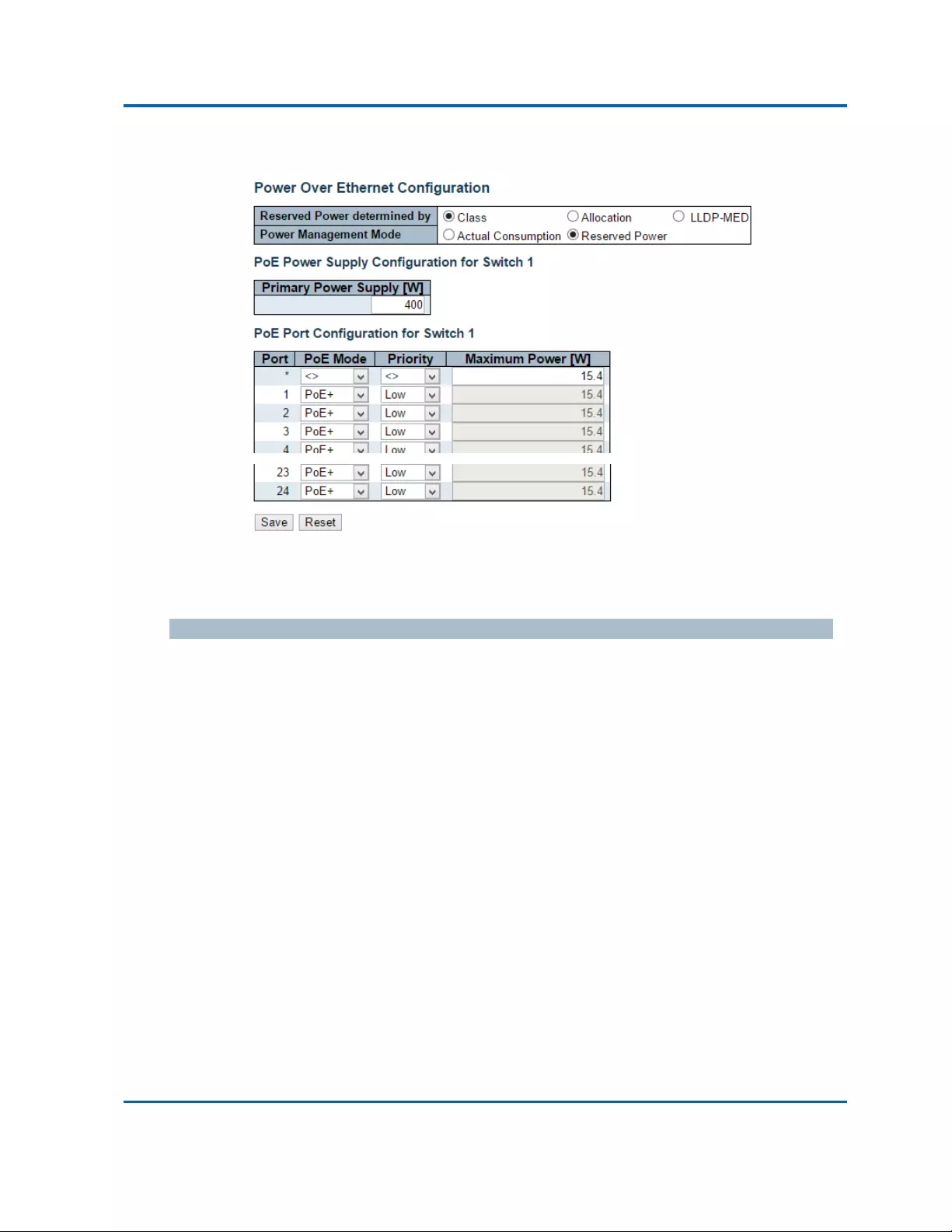
Chapter3:WebManagement
PoE
Intelinet48‐PortGigabitEthernetPoE+Layer2+ManagedSwitchUserManual|163
3.1.13.Configuration‐PoE
ThispageallowstheusertoinspectandconfigurethecurrentPoEportsettings.
PoweroverEthernetConfiguration
ReservedPowerdeterminedby
Therearethreemodesforconfiguringhowtheports/PDsmayreservepower.
1. Allocatedmode:Inthismodetheuserallocatestheamountofpowerthateachportmayreserve.
Theallocated/reservedpowerforeachport/PDisspecifiedintheMaximumPowerfields.
2. Classmode:Inthismodeeachportautomaticallydetermineshowmuchpowertoreserve
accordingtotheclasstheconnectedPDbelongsto,andreservesthepoweraccordingly.Four
differentportclassesexistandonefor4,7,15.4or30Watts.InthismodetheMaximumPower
fieldshavenoeffect.
3. LLDP‐MEDmode:ThismodeissimilartotheClassmodeexpectthateachportdeterminethe
amountpoweritreservesbyexchangingPoEinformationusingtheLLDPprotocolandreserves
poweraccordingly.IfnoLLDPinformationisavailableforaport,theportwillreservepower
usingtheclassmode.InthismodetheMaximumPowerfieldshavenoeffect
Forallmodes:Ifaportusesmorepowerthanthereservedpowerfortheport,theportisshutdown.

Chapter3:WebManagement
PoE
Intelinet48‐PortGigabitEthernetPoE+Layer2+ManagedSwitchUserManual|164
PowerManagementMode
Thereare2modesforconfiguringwhentoshutdowntheports:
1. ActualConsumption:Inthismodetheportsareshutdownwhentheactualpowerconsumption
forallportsexceedstheamountofpowerthatthepowersupplycandeliveroriftheactual
powerconsumptionforagivenportexceedsthereservedpowerforthatport.Theportsareshut
downaccordingtotheportspriority.Iftwoportshavethesameprioritytheportwiththe
highestportnumberisshutdown.
2. ReservedPower:Inthismodetheportsareshutdownwhentotalreservedpoweredexceedsthe
amountofpowerthatthepowersupplycandeliver.Inthismodetheportpowerisnotturned
onifthePDrequestsmorepowerthanavailablefromthepowersupply.
PowerSupplyConfiguration
PrimaryandBackupPowerSource
SomeswitchessupporthavingtwoPoEpowersupplies.Oneisusedasprimarypowersource,and
oneasbackuppowersource.Iftheswitchdoesn'tsupportbackuppowersupplyonlytheprimary
powersupplysettingswillbeshown.Incasethattheprimarypowersourcefailsthebackuppower
sourcewilltakeover.ForbeingabletodeterminetheamountofpowerthePDmayuse,itmustbe
definedwhatamountofpowertheprimaryandbackuppowersourcescandeliver.
Validvaluesareintherange0to2000Watts.
PortConfiguration
Port
Thisisthelogicalportnumberforthisrow.
PortsthatarenotPoE‐capablearegrayedoutandthusimpossibletoconfigurePoEfor.
PoEMode
ThePoEModerepresentsthePoEoperatingmodefortheport.
Disabled:PoEdisabledfortheport.
PoE:EnablesPoEIEEE802.3af(Class4PDslimitedto15.4W)
PoE+:EnablesPoE+IEEE802.3at(Class4PDslimitedto30W)

Chapter3:WebManagement
PoE
Intelinet48‐PortGigabitEthernetPoE+Layer2+ManagedSwitchUserManual|165
Priority
ThePriorityrepresentstheportspriority.TherearethreelevelsofpowerprioritynamedLow,High
andCritical.
Thepriorityisusedinthecasewheretheremotedevicesrequiresmorepowerthanthepower
supplycandeliver.Inthiscasetheportwiththelowestprioritywillbeturnoffstartingfromtheport
withthehighestportnumber.
MaximumPower
TheMaximumPowervaluecontainsanumericalvaluethatindicatesthemaximumpowerinwatts
thatcanbedeliveredtoaremotedevice.
Themaximumallowedvalueis30W.
Buttons
Save:Clicktosavechanges.
Reset:Clicktoundoanychangesmadelocallyandreverttopreviouslysavedvalues.

Chapter3:WebManagement
MACTable
Intelinet48‐PortGigabitEthernetPoE+Layer2+ManagedSwitchUserManual|166
3.1.14.Configuration‐MACTable
TheMACAddressTableisconfiguredonthispage.SettimeoutsforentriesinthedynamicMACTable
andconfigurethestaticMACtablehere.
AgingConfiguration
Bydefault,dynamicentriesareremovedfromtheMACtableafter300seconds.Thisremovalisalso
calledaging.
Configureagingtimebyenteringavaluehereinseconds.Theallowedrangeis10to1000000
seconds.
Disabletheautomaticagingofdynamicentriesbycheckingthe“Disableautomaticaging”
checkbox..
MACTableLearning
Ifthelearningmodeforagivenportisgreyedout,anothermoduleisincontrolofthemode,sothat
itcannotbechangedbytheuser.AnexampleofsuchamoduleistheMAC‐BasedAuthentication
under802.1X.
Eachportcandolearningbaseduponthefollowingsettings:
Auto
LearningisdoneautomaticallyassoonasaframewithunknownSMACisreceived.
Disable
Nolearningisdone.

Chapter3:WebManagement
MACTable
Intelinet48‐PortGigabitEthernetPoE+Layer2+ManagedSwitchUserManual|167
Secure
OnlystaticMACentriesarelearned,allotherframesaredropped.
Note:MakesurethatthelinkusedformanagingtheswitchisaddedtotheStaticMacTablebefore
changingtosecurelearningmode,otherwisethemanagementlinkislostandcanonlyberestored
byusinganothernon‐secureportorbyconnectingtotheswitchviatheserialinterface.
StaticMACTableConfiguration
ThestaticentriesintheMACtableareshowninthistable.ThestaticMACtablecancontain64
entries.
Themaximumof64entriesisforthewholestack,andnotperswitch.
TheMACtableissortedfirstbyVLANIDandthenbyMACaddress.
Delete
Checktodeletetheentry.Itwillbedeletedduringthenextsave.
VLANID
TheVLANIDoftheentry.
MACAddress
TheMACaddressoftheentry.
PortMembers
Checkmarksindicatewhichportsaremembersoftheentry.Checkoruncheckasneededtomodify
theentry.
AddingaNewStaticEntry
Click“AddNewStaticEntry”toaddanewentrytothestaticMACtable.SpecifytheVLANID,MAC
address,andportmembersforthenewentry.Click"Save".
Buttons
Save:Clicktosavechanges.
Reset:Clicktoundoanychangesmadelocallyandreverttopreviouslysavedvalues.
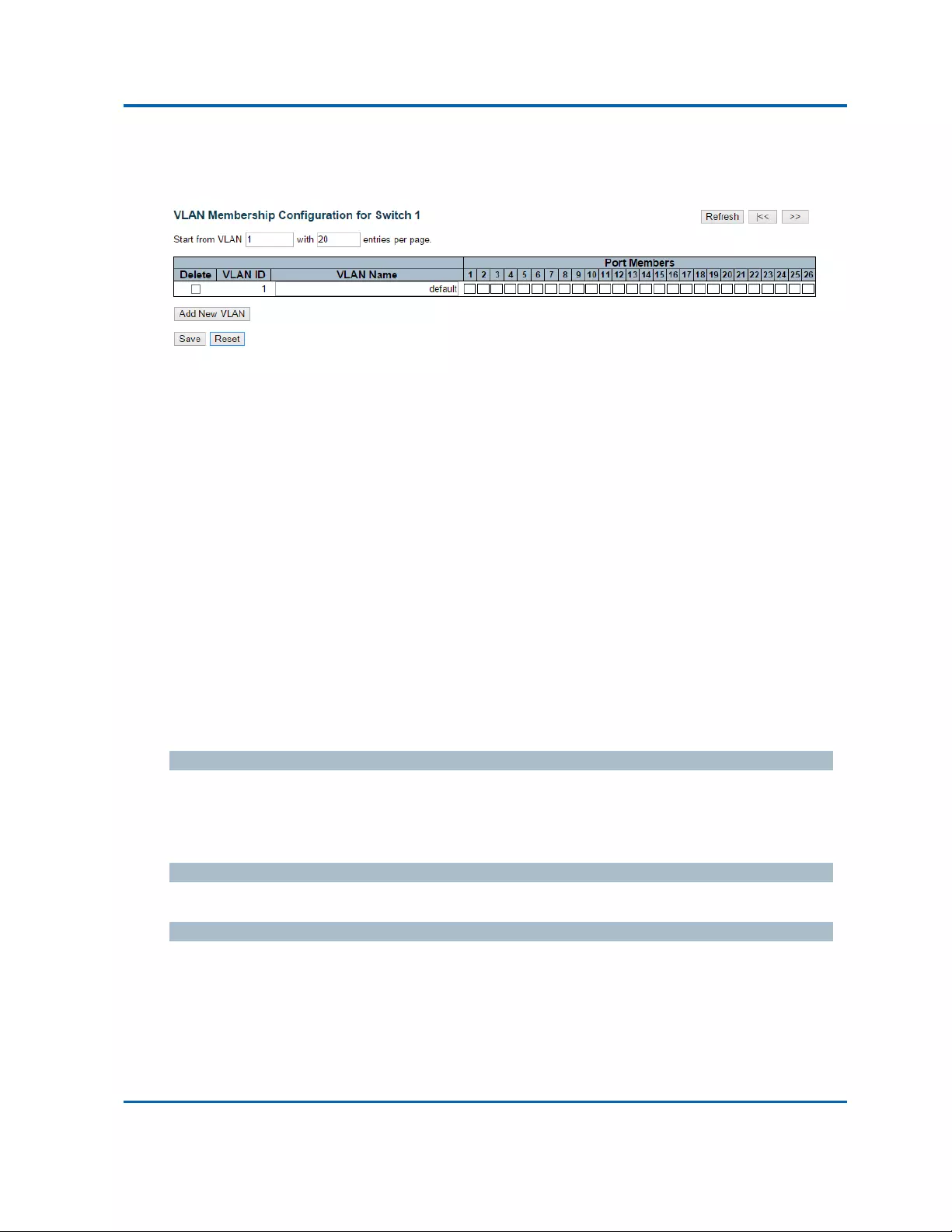
Chapter3:WebManagement
VLANs‐VLANMembership
Intelinet48‐PortGigabitEthernetPoE+Layer2+ManagedSwitchUserManual|168
3.1.15.Configuration‐VLANs
3.1.15.1.VLANs‐VLANMembership
TheVLANmembershipconfigurationfortheselectedstackswitchunitcanbemonitoredand
modifiedhere.Upto4096VLANsaresupported.ThispageallowsforaddinganddeletingVLANsas
wellasaddinganddeletingportmembersofeachVLAN.
NavigatingtheVLANTable
Eachpageshowsupto99entriesfromtheVLANtable,defaultbeing20,selectedthroughthe
"entriesperpage"inputfield.Whenfirstvisited,thewebpagewillshowthefirst20entriesfromthe
beginningoftheVLANTable.ThefirstdisplayedwillbetheonewiththelowestVLANIDfoundinthe
VLANTable.
The"VLAN"inputfieldsallowtheusertoselectthestartingpointintheVLANTable.Clickingthe
“Refresh”buttonwillupdatethedisplayedtablestartingfromthatortheclosestnextVLANTable
match.The“>>”willusethelastentryofthecurrentlydisplayedVLANentryasabasisforthenext
lookup.Whentheendisreachedthetext"Nomoreentries"isshowninthedisplayedtable.Usethe
“|<<”buttontostartover.
Delete
TodeleteaVLANentry,checkthisbox.Theentrywillbedeletedontheselectedswitchinthestack.
IfnoneoftheportsofthisswitcharemembersofaVLANthenthedeletecheckboxwillbegreyed
out(youcannotdeletethatentry.duringthenextSave.
VLANID
IndicatestheIDofthisparticularVLAN.
VLANName
IndicatesthenameoftheVLAN.MaximumlengthoftheVLANNameStringis32.VLANNamecanbe
null.Ifitisnotnull,itmustcontainalphabetsornumbers.Atleastonealphabetmustbepresentina
non‐nullVLANname.VLANnamecanbeeditedfortheexistingVLANentriesoritcanbeaddedto
thenewentries.

Chapter3:WebManagement
VLANs‐VLANMembership
Intelinet48‐PortGigabitEthernetPoE+Layer2+ManagedSwitchUserManual|169
PortMembers
ArowofcheckboxesforeachportisdisplayedforeachVLANID.
ToincludeaportinaVLAN,checktheboxasport.
Toincludeaportinaforbiddenportlist,checktheboxasshownforbid.
ToremoveorexcludetheportfromtheVLAN,makesuretheboxisuncheckedasshownmenu_o.
Bydefault,noportsaremembers,andforeverynewVLANentryallboxesareunchecked.
AddingaNewVLAN
Click“AddNewVLAN”toaddanewVLANID.Anemptyrowisaddedtothetable,andtheVLANcan
beconfiguredasneeded.LegalvaluesforaVLANIDare1through4095.
TheVLANisenabledontheselectedstackswitchunitwhenyouclickon"Save".TheVLANis
thereafterpresentontheotherstackswitchunits,butwithnoportmembers.Thecheckboxis
greyedoutwhenVLANisdisplayedonotherstackedswitches,butusercanaddmemberportstoit.
The“Delete”buttoncanbeusedtoundotheadditionofnewVLANs.
Buttons
Save:Clicktosavechanges.
Reset:Clicktoundoanychangesmadelocallyandreverttopreviouslysavedvalues.
Refresh:Refreshesthedisplayedtablestartingfromthe"VLANID"inputfields.
>>|:UpdatesthetablestartingfromthefirstentryintheVLANTable,i.e.theentrywiththe
lowestVLANID.
<<:Updatesthetable,startingwiththeentryafterthelastentrycurrentlydisplayed.

Chapter3:WebManagement
VLANs‐Ports
Intelinet48‐PortGigabitEthernetPoE+Layer2+ManagedSwitchUserManual|170
3.1.15.2.VLANs‐Ports
ThispageisusedforconfiguringtheselectedstackswitchunitportVLAN.
EthertypeforCustomS‐ports
ThisfieldspecifiestheethertypeusedforCustomS‐ports.ThisisaglobalsettingforalltheCustom
S‐ports.
Port
Thisisthelogicalportnumberofthisrow.
PortType
Portcanbeoneofthefollowingtypes:Unaware,Customerport(C‐port),Serviceport(S‐port),
CustomServiceport(S‐custom‐port)
IfPortTypeisUnaware,allframesareclassifiedtothePortVLANIDandtagsarenotremoved.
IngressFiltering
Enableingressfilteringonaportbycheckingthebox.ThisparameteraffectsVLANingressprocessing.
IfingressfilteringisenabledandtheingressportisnotamemberoftheclassifiedVLANoftheframe,
theframeisdiscarded.Bydefault,ingressfilteringisdisabled(nocheckmark).
FrameType
Determineswhethertheportacceptsallframesoronlytagged/untaggedframes.Thisparameter
affectsVLANingressprocessing.Iftheportonlyacceptstaggedframes,untaggedframesreceivedon
theportarediscarded.Bydefault,thefieldissettoAll.
PortVLANMode
ConfiguresthePortVLANMode.TheallowedvaluesareNoneorSpecific.Thisparameteraffects
VLANingressandegressprocessing.
IfNoneisselected,aVLANtagwiththeclassifiedVLANIDisinsertedinframestransmittedonthe
port.ThismodeisnormallyusedforportsconnectedtoVLANawareswitches.Txtagshouldbesetto

Chapter3:WebManagement
VLANs‐Ports
Intelinet48‐PortGigabitEthernetPoE+Layer2+ManagedSwitchUserManual|171
Untag_pvidwhenthismodeisused.
IfSpecific(thedefaultvalue)isselected,aPortVLANIDcanbeconfigured(seebelow).Untagged
framesreceivedontheportareclassifiedtothePortVLANID.IfVLANawarenessisdisabled,all
framesreceivedontheportareclassifiedtothePortVLANID.IftheclassifiedVLANIDofaframe
transmittedontheportisdifferentfromthePortVLANID,aVLANtagwiththeclassifiedVLANIDis
insertedintheframe.
PortVLANID
ConfigurestheVLANidentifierfortheport.Theallowedvaluesarefrom1through4095.Thedefault
valueis1.
Note:TheportmustbeamemberofthesameVLANasthePortVLANID.
TxTag
Determinesegresstaggingofaport.Untag_pvid‐AllVLANsexcepttheconfiguredPVIDwillbe
tagged.Tag_all‐AllVLANsaretagged.Untag_all‐AllVLANsareuntagged.
Buttons
Auto‐refresh:Checkthisboxtorefreshthepageautomatically.Automaticrefreshoccursevery
3seconds.
Refresh:Clicktorefreshthepageimmediately.
Save:Clicktosavechanges.
Reset:Clicktoundoanychangesmadelocallyandreverttopreviouslysavedvalues.

Chapter3:WebManagement
PrivateVLAN‐PortIsolation
Intelinet48‐PortGigabitEthernetPoE+Layer2+ManagedSwitchUserManual|172
3.1.16.Configuration‐PrivateVLAN
3.1.16.1.PrivateVLAN‐PortIsolation
Overview
ThispageisusedforenablingordisablingportisolationonportsinaPrivateVLAN.
AportmemberofaVLANcanbeisolatedtootherisolatedportsonthesameVLAN.
Theportsettingsrelatetothecurrentlyselectedstackunit,asreflectedbythepageheader.
Thisfeatureworksacrossthestack.
Configuration
PortMembers
AcheckboxisprovidedforeachportofaprivateVLAN.
Whenchecked,portisolationisenabledonthatport.
Whenunchecked,portisolationisdisabledonthatport.
Bydefault,portisolationisdisabledonallports.
Buttons
Auto‐refresh:Checkthisboxtorefreshthepageautomatically.Automaticrefreshoccursevery
3seconds.
Refresh:Clicktorefreshthepageimmediately.
Save:Clicktosavechanges.
Reset:Clicktoundoanychangesmadelocallyandreverttopreviouslysavedvalues.

Chapter3:WebManagement
VCL‐MAC‐basedVLAN
Intelinet48‐PortGigabitEthernetPoE+Layer2+ManagedSwitchUserManual|173
3.1.17.Configuration‐VCL
3.1.17.1.VCL‐MAC‐basedVLAN
TheMAC‐basedVLANentriescanbeconfiguredhere.Thispageallowsforaddinganddeleting
MAC‐basedVLANentriesandassigningtheentriestodifferentports.Thispageshowsonlystatic
entries.
Delete
TodeleteaMAC‐basedVLANentry,checkthisboxandpresssave.Theentrywillbedeletedonthe
selectedswitchinthestack.
MACAddress
IndicatestheMACaddress.
VLANID
IndicatestheVLANID.
PortMembers
ArowofcheckboxesforeachportisdisplayedforeachMAC‐basedVLANentry.Toincludeaportin
aMAC‐basedVLAN,checkthebox.ToremoveorexcludetheportfromtheMAC‐basedVLAN,make
suretheboxisunchecked.Bydefault,noportsaremembers,andallboxesareunchecked.
AddingaNewMAC‐basedVLAN
Click“AddingNewEntry”toaddanewMAC‐basedVLANentry.Anemptyrowisaddedtothetable,
andtheMAC‐basedVLANentrycanbeconfiguredasneeded.AnyunicastMACaddresscanbe
configuredfortheMAC‐basedVLANentry.NobroadcastormulticastMACaddressesareallowed.
LegalvaluesforaVLANIDare1through4095.
TheMAC‐basedVLANentryisenabledontheselectedstackswitchunitwhenyouclickon"Save".A
MAC‐basedVLANwithoutanyportmembersonanystackunitwillbedeletedwhenyouclick"Save".
The“Delete”buttoncanbeusedtoundotheadditionofnewMAC‐basedVLANs.Themaximum
possibleMAC‐basedVLANentriesarelimitedto256.

Chapter3:WebManagement
VCL‐MAC‐basedVLAN
Intelinet48‐PortGigabitEthernetPoE+Layer2+ManagedSwitchUserManual|174
Buttons
Save:Clicktosavechanges.
Reset:Clicktoundoanychangesmadelocallyandreverttopreviouslysavedvalues.
Auto‐refresh:Checkthisboxtorefreshthepageautomatically.Automaticrefreshoccursevery
3seconds.
Refresh:Clicktorefreshthepageimmediately.
|<<:UpdatesthetablestartingfromthefirstentryintheMAC‐basedVLANTable.
>>:Updatesthetable,startingwiththeentryafterthelastentrycurrentlydisplayed.

Chapter3:WebManagement
VCL‐Port‐basedVLAN‐ProtocoltoGroup
Intelinet48‐PortGigabitEthernetPoE+Layer2+ManagedSwitchUserManual|175
3.1.17.2.VCL‐Port‐basedVLAN
3.1.17.2.1.VCL‐Port‐basedVLAN‐ProtocoltoGroup
ThispageallowsyoutoaddnewprotocolstoGroupName(uniqueforeachGroup)mapping
entriesaswellasallowyoutoseeanddeletealreadymappedentriesfortheselectedstackswitch
unit.
Delete
TodeleteaProtocoltoGroupNamemapentry,checkthisbox.Theentrywillbedeletedonthe
switchduringthenextSave.
FrameType
FrameTypecanhaveoneofthefollowingvalues:
1. Ethernet
2. LLC
3. SNAP
Note:OnchangingtheFrametypefield,validvalueofthefollowingtextfieldwillvarydepending
onthenewframetypeyouselected.
Value
Validvaluethatcanbeenteredinthistextfielddependsontheoptionselectedfromthethe
precedingFrameTypeselectionmenu.
BelowisthecriteriaforthreedifferentFrameTypes:
1. ForEthernet:ValuesinthetextfieldwhenEthernetisselectedasaFrameTypeiscalled
etype.Validvaluesforetyperangesfrom0x0600‐0xffff
2. ForLLC:Validvalueinthiscaseiscomprisedoftwodifferentsub‐values.
a. DSAP:1‐bytelongstring(0x00‐0xff)
b. SSAP:1‐bytelongstring(0x00‐0xff)
3. ForSNAP:Validvalueinthiscasealsoiscomprisedoftwodifferentsub‐values.
a. OUI:OUI(OrganizationallyUniqueIdentifier)isvalueinformatofxx‐xx‐xxwhereeachpair
(xx)instringisahexadecimalvaluerangesfrom0x00‐0xff.
b. PID:IftheOUIishexadecimal000000,theprotocolIDistheEthernettype(EtherType)field

Chapter3:WebManagement
VCL‐Port‐basedVLAN‐ProtocoltoGroup
Intelinet48‐PortGigabitEthernetPoE+Layer2+ManagedSwitchUserManual|176
valuefortheprotocolrunningontopofSNAP;iftheOUIisanOUIforaparticular
organization,theprotocolIDisavalueassignedbythatorganizationtotheprotocol
runningontopofSNAP.
Inotherwords,ifvalueofOUIfieldis00‐00‐00thenvalueofPIDwillbeetype(0x0600‐0xffff)and
ifvalueofOUIisotherthan00‐00‐00thenvalidvalueofPIDwillbeanyvaluefrom0x0000to
0xffff.
GroupName
AvalidGroupNameisaunique16‐characterlongstringforeveryentrywhichconsistsofa
combinationofalphabets(a‐zorA‐Z)andintegers(0‐9).
Note:specialcharacterandunderscore(_)arenotallowed.
AddingaNewGrouptoVLANmappingentry
Click“AddNewEntry”toaddanewentryinmappingtable.Anemptyrowisaddedtothetable;
FrameType,ValueandtheGroupNamecanbeconfiguredasneeded.
The“Delete”buttoncanbeusedtoundotheadditionofnewentry.Themaximumpossible
ProtocoltoGroupmappingsarelimitedto128.
Buttons
Save:Clicktosavechanges.
Reset:Clicktoundoanychangesmadelocallyandreverttopreviouslysavedvalues.
Auto‐refresh:Checkthisboxtorefreshthepageautomatically.Automaticrefreshoccurs
every3seconds.
Refresh:Clicktorefreshthepageimmediately.

Chapter3:WebManagement
VCL‐Port‐basedVLAN‐GrouptoVLAN
Intelinet48‐PortGigabitEthernetPoE+Layer2+ManagedSwitchUserManual|177
3.1.17.2.2.VCL‐Port‐basedVLAN‐GrouptoVLAN
ThispageallowsyoutomapanalreadyconfiguredGroupNametoaVLANfortheselectedstack
switchunit.
Delete
TodeleteaGroupNametoVLANmapentry,checkthisbox.Theentrywillbedeletedonthe
switchduringthenextSave
GroupName
AvalidGroupNameisastringatthemost16characterswhichconsistsofacombinationof
alphabets(a‐zorA‐Z)andintegers(0‐9),nospecialcharacterisallowed.WhicheverGroupname
youtrymaptoaVLANmustbepresentinProtocoltoGroupmappingtableandmustnotbe
pre‐usedbyanyotherexistingmappingentryonthispage.
VLANID
IndicatestheIDtowhichGroupNamewillbemapped.AvalidVLANIDrangesfrom1‐4095.
PortMembers
ArowofcheckboxesforeachportisdisplayedforeachGroupNametoVLANIDmapping.To
includeaportinamapping,checkthebox.Toremoveorexcludetheportfromthemapping,
makesuretheboxisunchecked.Bydefault,noportsaremembers,andallboxesareunchecked.
AddingaNewGrouptoVLANmappingentry
Click“AddNewEntry”toaddanewentryinmappingtable.Anemptyrowisaddedtothetable,
theGroupName,VLANIDandportmemberscanbeconfiguredasneeded.Legalvaluesfora
VLANIDare1through4095.
The“Delete”buttoncanbeusedtoundotheadditionofnewentry.ThemaximumpossibleGroup
toVLANmappingsarelimitedto64.
Buttons
Save:Clicktosavechanges.
Reset:Clicktoundoanychangesmadelocallyandreverttopreviouslysavedvalues.
Auto‐refresh:Checkthisboxtorefreshthepageautomatically.Automaticrefreshoccurs
every3seconds.
Refresh:Clicktorefreshthepageimmediately.

Chapter3:WebManagement
VCL‐IPSubnet‐basedVLAN
Intelinet48‐PortGigabitEthernetPoE+Layer2+ManagedSwitchUserManual|178
3.1.17.3.VCL‐IPSubnet‐basedVLAN
TheIPsubnet‐basedVLANentriescanbeconfiguredhere.Thispageallowsforadding,updatingand
deletingIPsubnet‐basedVLANentriesandassigningtheentriestodifferentports.Thispageshows
onlystaticentries.
Delete
TodeleteaIPsubnet‐basedVLANentry,checkthisboxandpresssave.Theentrywillbedeletedon
theselectedswitchinthestack.
VCEID
Indicatestheindexoftheentry.Itisuserconfigurable.It'svaluerangesfrom0‐128.IfaVCEIDis0,
applicationwillauto‐generatetheVCEIDforthatentry.DeletionandlookupofIPsubnet‐based
VLANarebasedonVCEID.
IPAddress
IndicatestheIPaddress.
MaskLength
Indicatesthenetworkmasklength.
VLANID
IndicatestheVLANID.VLANIDcanbechangedfortheexistingentries.
PortMembers
ArowofcheckboxesforeachportisdisplayedforeachIPsubnet‐basedVLANentry.Toincludea
portinaIPsubnet‐basedVLAN,checkthebox.ToremoveorexcludetheportfromtheIP
subnet‐basedVLAN,makesuretheboxisunchecked.Bydefault,noportsaremembers,andall
boxesareunchecked.
AddingaNewIPsubnet‐basedVLAN
Click“AddNewEntry”toaddanewIPsubnet‐basedVLANentry.Anemptyrowisaddedtothetable,
andtheIPsubnet‐basedVLANentrycanbeconfiguredasneeded.AnyIPaddress/maskcanbe
configuredfortheIPsubnet‐basedVLANentry.LegalvaluesforaVLANIDare1through4095.
TheIPsubnet‐basedVLANentryisenabledontheselectedstackswitchunitwhenyouclickon
"Save".The“Delete”buttoncanbeusedtoundotheadditionofnewIPsubnet‐basedVLANs.The
maximumpossibleIPsubnet‐basedVLANentriesarelimitedto128.

Chapter3:WebManagement
VCL‐IPSubnet‐basedVLAN
Intelinet48‐PortGigabitEthernetPoE+Layer2+ManagedSwitchUserManual|179
Buttons
Save:Clicktosavechanges.
Reset:Clicktoundoanychangesmadelocallyandreverttopreviouslysavedvalues.
Auto‐refresh:Checkthisboxtorefreshthepageautomatically.Automaticrefreshoccursevery
3seconds.
Refresh:Refreshesthedisplayedtable.

Chapter3:WebManagement
VoiceVLAN‐Configuration
Intelinet48‐PortGigabitEthernetPoE+Layer2+ManagedSwitchUserManual|180
3.1.18.Configuration‐VoiceVLAN
3.1.18.1.VoiceVLAN‐Configuration
TheVoiceVLANfeatureenablesvoicetrafficforwardingontheVoiceVLAN,thentheswitchcan
classifyandschedulenetworktraffic.ItisrecommendedthattherebetwoVLANsonaport‐onefor
voice,onefordata.BeforeconnectingtheIPdevicetotheswitch,theIPphoneshouldconfigurethe
voiceVLANIDcorrectly.ItshouldbeconfiguredthroughitsownGUI.
Mode
IndicatestheVoiceVLANmodeoperation.WemustdisableMSTPfeaturebeforeweenableVoice
VLAN.Itcanavoidtheconflictofingressfiltering.Possiblemodesare:
Enabled:EnableVoiceVLANmodeoperation.
Disabled:DisableVoiceVLANmodeoperation.
VLANID
IndicatestheVoiceVLANID.ItshouldbeauniqueVLANIDinthesystemandcannotequaleachport
PVID.ItisaconflictinconfigurationifthevalueequalsmanagementVID,MVRVID,PVIDetc.The
allowedrangeis1to4095.
AgingTime
IndicatestheVoiceVLANsecurelearningagingtime.Theallowedrangeis10to10000000seconds.It
isusedwhensecuritymodeorautodetectmodeisenabled.Inothercases,itwillbebasedon
hardwareagingtime.Theactualagingtimewillbesituatedbetweenthe[age_time;2*age_time]
interval.
TrafficClass

Chapter3:WebManagement
VoiceVLAN‐Configuration
Intelinet48‐PortGigabitEthernetPoE+Layer2+ManagedSwitchUserManual|181
IndicatestheVoiceVLANtrafficclass.AlltrafficontheVoiceVLANwillapplythisclass.

Chapter3:WebManagement
VoiceVLAN‐Configuration
Intelinet48‐PortGigabitEthernetPoE+Layer2+ManagedSwitchUserManual|182
PortMode
IndicatestheVoiceVLANportmode.
Possibleportmodesare:
Disabled:DisjoinfromVoiceVLAN.
Auto:Enableautodetectmode.ItdetectswhetherthereisVoIPphoneattachedtothe
specificportandconfigurestheVoiceVLANmembersautomatically.
Forced:ForcejointoVoiceVLAN.
PortSecurity
IndicatestheVoiceVLANportsecuritymode.Whenthefunctionisenabled,allnon‐telephonicMAC
addressesintheVoiceVLANwillbeblockedfor10seconds.Possibleportmodesare:
Enabled:EnableVoiceVLANsecuritymodeoperation.
Disabled:DisableVoiceVLANsecuritymodeoperation.
PortDiscoveryProtocol
IndicatestheVoiceVLANportdiscoveryprotocol.Itwillonlyworkwhenautodetectmodeisenabled.
WeshouldenableLLDPfeaturebeforeconfiguringdiscoveryprotocolto"LLDP"or"Both".Changing
thediscoveryprotocolto"OUI"or"LLDP"willrestartautodetectprocess.Possiblediscovery
protocolsare:
OUI:DetecttelephonydevicebyOUIaddress.
LLDP:DetecttelephonydevicebyLLDP.
Both:BothOUIandLLDP.
Buttons
Save:Clicktosavechanges.
Reset:Clicktoundoanychangesmadelocallyandreverttopreviouslysavedvalues.

Chapter3:WebManagement
VoiceVLAN‐OUI
Intelinet48‐PortGigabitEthernetPoE+Layer2+ManagedSwitchUserManual|183
3.1.18.2.VoiceVLAN‐OUI
ConfigureVOICEVLANOUItableonthispage.Themaximumnumberofentriesis16.Modifyingthe
OUItablewillrestartautodetectionofOUIprocess.
Delete
Checktodeletetheentry.Itwillbedeletedduringthenextsave.
TelephonyOUI
AtelephonyOUIaddressisagloballyuniqueidentifierassignedtoavendorbyIEEE.Itmustbe6
characterslongandtheinputformatis"xx‐xx‐xx"(xisahexadecimaldigit).
Description
ThedescriptionofOUIaddress.Normally,itdescribeswhichvendortelephonydeviceitbelongsto.
Theallowedstringlengthis0to32.
Buttons
AddNewEntry:Clicktoaddanewaccessmanagemententry.
Save:Clicktosavechanges.
Reset:Clicktoundoanychangesmadelocallyandreverttopreviouslysavedvalues.

Chapter3:WebManagement
QoS‐PortClassification
Intelinet48‐PortGigabitEthernetPoE+Layer2+ManagedSwitchUserManual|184
3.1.19.Configuration‐QoS
3.1.19.1.QoS‐PortClassification
ThispageallowsyoutoconfigurethebasicQoSIngressClassificationsettingsforallswitchports.
Thesettingsrelatetothecurrentlyselectedstackunit,asreflectedbythepageheader.
Port
Theportnumberforwhichtheconfigurationbelowapplies.
QoSclass
ControlsthedefaultQoSclass.
AllframesareclassifiedtoaQoSclass.ThereisaonetoonemappingbetweenQoSclass,queueand
priority.AQoSclassof0(zero)hasthelowestpriority.
IftheportisVLANawareandtheframeistagged,thentheframeisclassifiedtoaQoSclassthatis
basedonthePCPvalueinthetagasshownbelow.Otherwisetheframeisclassifiedtothedefault
QoSclass.
PCPvalue:01234567
QoSclass:10234567
TheclassifiedQoSclasscanbeoverruledbyaQCLentry.
Note:IfthedefaultQoSclasshasbeendynamicallychanged,thentheactualdefaultQoSclassis
showninparenthesesaftertheconfigureddefaultQoSclass.

Chapter3:WebManagement
QoS‐PortClassification
Intelinet48‐PortGigabitEthernetPoE+Layer2+ManagedSwitchUserManual|185
DPlevel
ControlsthedefaultDropPrecedenceLevel.
AllframesareclassifiedtoaDPlevel.
IftheportisVLANawareandtheframeistagged,thentheframeisclassifiedtoaDPlevelthatis
equaltotheDEIvalueinthetag.OtherwisetheframeisclassifiedtothedefaultDPlevel.
TheclassifiedDPlevelcanbeoverruledbyaQCLentry.
DSCPBased
ClicktoEnableDSCPBasedQoSIngressPortClassification.
Buttons
Save:Clicktosavechanges.
Reset:Clicktoundoanychangesmadelocallyandreverttopreviouslysavedvalues.
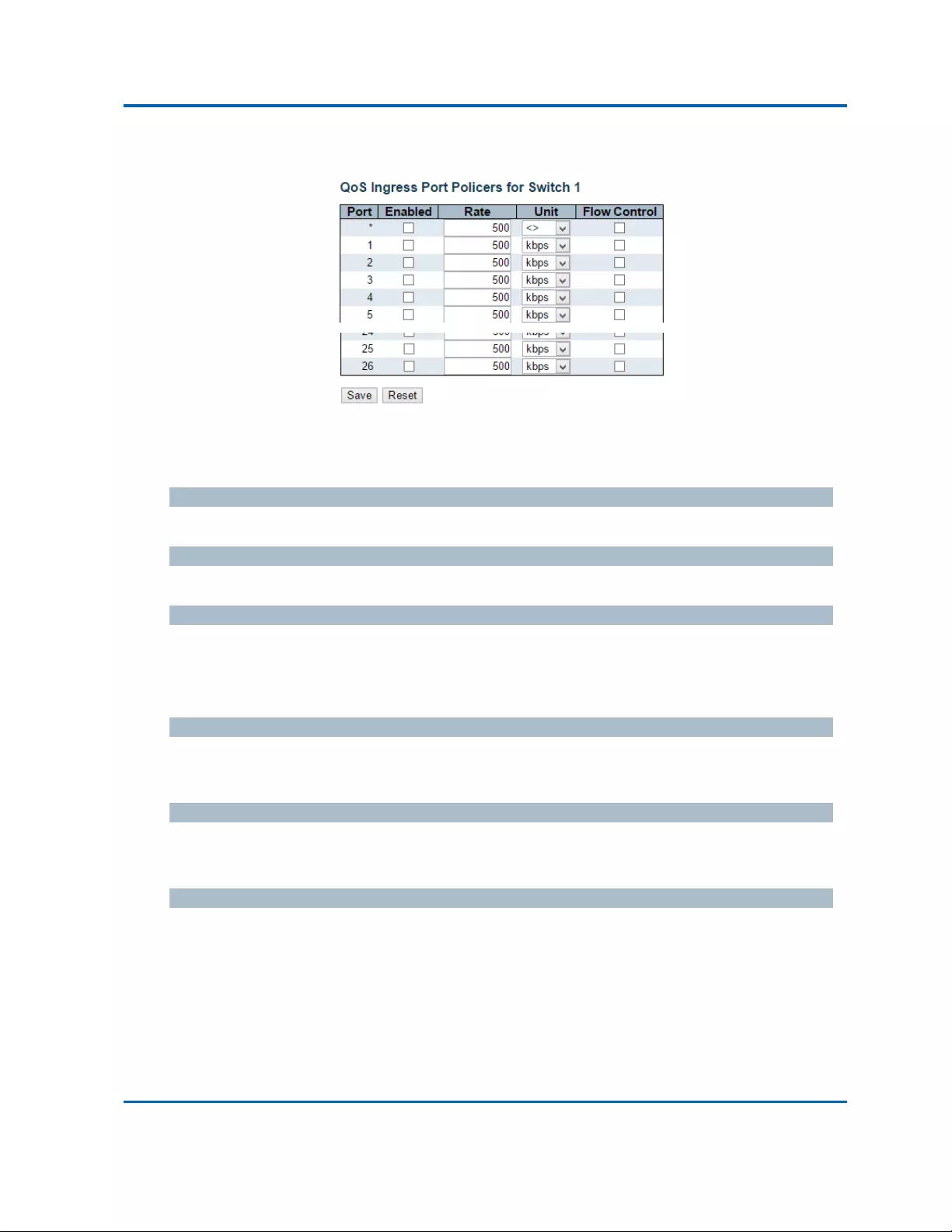
Chapter3:WebManagement
QoS‐PortPolicing
Intelinet48‐PortGigabitEthernetPoE+Layer2+ManagedSwitchUserManual|186
3.1.19.2.QoS‐PortPolicing
ThispageallowsyoutoconfigurethePolicersettingsforallswitchports.
Thesettingsrelatetothecurrentlyselectedstackunit,asreflectedbythepageheader.
Port
Theportnumberforwhichtheconfigurationbelowapplies.
Enabled
Controlswhetherthepolicerisenabledonthisswitchport.
Rate
Controlstherateforthepolicer.Thedefaultvalueis500.Thisvalueisrestrictedto100‐1000000
whenthe"Unit"is"kbps"or"fps",anditisrestrictedto1‐13200whenthe"Unit"is"Mbps"or
"kfps".
Unit
Controlstheunitofmeasureforthepolicerrateaskbps,Mbps,fpsorkfps.Thedefaultvalueis
"kbps".
FlowControl
Ifflowcontrolisenabledandtheportisinflowcontrolmode,thenpauseframesaresentinsteadof
discardingframes.
Buttons
Save:Clicktosavechanges.
Reset:Clicktoundoanychangesmadelocallyandreverttopreviouslysavedvalues.
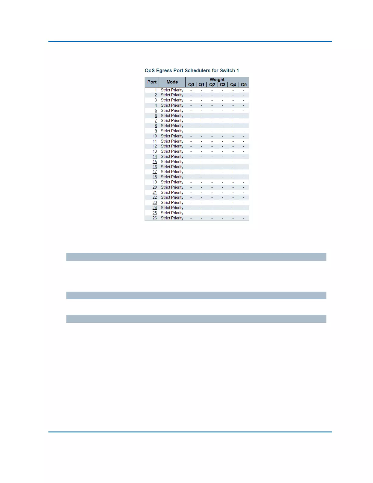
Chapter3:WebManagement
QoS‐PortScheduler
Intelinet48‐PortGigabitEthernetPoE+Layer2+ManagedSwitchUserManual|187
3.1.19.3.QoS‐PortScheduler
ThispageprovidesanoverviewofQoSEgressPortSchedulersforallswitchports.
Theportsbelongtothecurrentlyselectedstackunit,asreflectedbythepageheader.
Port
Thelogicalportforthesettingscontainedinthesamerow.
Clickontheportnumberinordertoconfiguretheschedulers.
Mode
Showstheschedulingmodeforthisport.
Qn
Showstheweightforthisqueueandport.

Chapter3:WebManagement
QoS‐PortScheduler
Intelinet48‐PortGigabitEthernetPoE+Layer2+ManagedSwitchUserManual|188
ThispageallowsyoutoconfiguretheSchedulerandShapersforaspecificport.
Thesettingsrelatetothecurrentlyselectedstackunit,asreflectedbythepageheader.
SchedulerMode
Controlswhethertheschedulermodeis"StrictPriority"or"Weighted"onthisswitchport.
QueueShaperEnable
Controlswhetherthequeueshaperisenabledforthisqueueonthisswitchport.
QueueShaperRate
Controlstherateforthequeueshaper.Thedefaultvalueis500.Thisvalueisrestrictedto
100‐1000000whenthe"Unit"is"kbps",anditisrestrictedto1‐13200whenthe"Unit"is"Mbps".
QueueShaperUnit
Controlstheunitofmeasureforthequeueshaperrateas"kbps"or"Mbps".Thedefaultvalueis
"kbps".
QueueShaperExcess
Controlswhetherthequeueisallowedtouseexcessbandwidth.
QueueSchedulerWeight
Controlstheweightforthisqueue.Thedefaultvalueis"17".Thisvalueisrestrictedto1‐100.This
parameterisonlyshownif"SchedulerMode"issetto"Weighted".

Chapter3:WebManagement
QoS‐PortScheduler
Intelinet48‐PortGigabitEthernetPoE+Layer2+ManagedSwitchUserManual|189
QueueSchedulerPercent
Showstheweightinpercentforthisqueue.Thisparameterisonlyshownif"SchedulerMode"isset
to"Weighted".
PortShaperEnable
Controlswhethertheportshaperisenabledforthisswitchport.
PortShaperRate
Controlstheratefortheportshaper.Thedefaultvalueis500.Thisvalueisrestrictedto100‐1000000
whenthe"Unit"is"kbps",anditisrestrictedto1‐13200whenthe"Unit"is"Mbps".
PortShaperUnit
Controlstheunitofmeasurefortheportshaperrateas"kbps"or"Mbps".Thedefaultvalueis
"kbps".
Buttons
Save:Clicktosavechanges.
Reset:Clicktoundoanychangesmadelocallyandreverttopreviouslysavedvalues.
Cancel:Clicktoundoanychangesmadelocallyandreturntothepreviouspage.
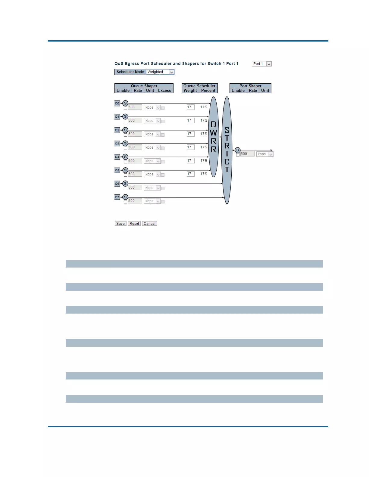
Chapter3:WebManagement
QoS‐PortScheduler
Intelinet48‐PortGigabitEthernetPoE+Layer2+ManagedSwitchUserManual|190
ThispageallowsyoutoconfiguretheSchedulerandShapersforaspecificport.
Thesettingsrelatetothecurrentlyselectedstackunit,asreflectedbythepageheader.
SchedulerMode
Controlswhethertheschedulermodeis"StrictPriority"or"Weighted"onthisswitchport.
QueueShaperEnable
Controlswhetherthequeueshaperisenabledforthisqueueonthisswitchport.
QueueShaperRate
Controlstherateforthequeueshaper.Thedefaultvalueis500.Thisvalueisrestrictedto
100‐1000000whenthe"Unit"is"kbps",anditisrestrictedto1‐13200whenthe"Unit"is"Mbps".
QueueShaperUnit
Controlstheunitofmeasureforthequeueshaperrateas"kbps"or"Mbps".Thedefaultvalueis
"kbps".
QueueShaperExcess
Controlswhetherthequeueisallowedtouseexcessbandwidth.
QueueSchedulerWeight
Controlstheweightforthisqueue.Thedefaultvalueis"17".Thisvalueisrestrictedto1‐100.This
parameterisonlyshownif"SchedulerMode"issetto"Weighted".

Chapter3:WebManagement
QoS‐PortScheduler
Intelinet48‐PortGigabitEthernetPoE+Layer2+ManagedSwitchUserManual|191
QueueSchedulerPercent
Showstheweightinpercentforthisqueue.Thisparameterisonlyshownif"SchedulerMode"isset
to"Weighted".
PortShaperEnable
Controlswhethertheportshaperisenabledforthisswitchport.
PortShaperRate
Controlstheratefortheportshaper.Thedefaultvalueis500.Thisvalueisrestrictedto100‐1000000
whenthe"Unit"is"kbps",anditisrestrictedto1‐13200whenthe"Unit"is"Mbps".
PortShaperUnit
Controlstheunitofmeasurefortheportshaperrateas"kbps"or"Mbps".Thedefaultvalueis
"kbps".
Buttons
Save:Clicktosavechanges.
Reset:Clicktoundoanychangesmadelocallyandreverttopreviouslysavedvalues.
Cancel:Clicktoundoanychangesmadelocallyandreturntothepreviouspage.

Chapter3:WebManagement
QoS‐PortShaping
Intelinet48‐PortGigabitEthernetPoE+Layer2+ManagedSwitchUserManual|192
3.1.19.4.QoS‐PortShaping
ThispageprovidesanoverviewofQoSEgressPortShapersforallswitchports.
Theportsbelongtothecurrentlyselectedstackunit,asreflectedbythepageheader.
Port
Thelogicalportforthesettingscontainedinthesamerow.
Clickontheportnumberinordertoconfiguretheshapers.
Qn
Shows"disabled"oractualqueueshaperrate‐e.g."800Mbps".
Port
Shows"disabled"oractualportshaperrate‐e.g."800Mbps".

Chapter3:WebManagement
QoS‐PortShaping
Intelinet48‐PortGigabitEthernetPoE+Layer2+ManagedSwitchUserManual|193
ThispageallowsyoutoconfiguretheSchedulerandShapersforaspecificport.
Thesettingsrelatetothecurrentlyselectedstackunit,asreflectedbythepageheader.
SchedulerMode
Controlswhethertheschedulermodeis"StrictPriority"or"Weighted"onthisswitchport.
QueueShaperEnable
Controlswhetherthequeueshaperisenabledforthisqueueonthisswitchport.
QueueShaperRate
Controlstherateforthequeueshaper.Thedefaultvalueis500.Thisvalueisrestrictedto
100‐1000000whenthe"Unit"is"kbps",anditisrestrictedto1‐13200whenthe"Unit"is"Mbps".
QueueShaperUnit
Controlstheunitofmeasureforthequeueshaperrateas"kbps"or"Mbps".Thedefaultvalueis
"kbps".
QueueShaperExcess
Controlswhetherthequeueisallowedtouseexcessbandwidth.
QueueSchedulerWeight
Controlstheweightforthisqueue.Thedefaultvalueis"17".Thisvalueisrestrictedto1‐100.This
parameterisonlyshownif"SchedulerMode"issetto"Weighted".

Chapter3:WebManagement
QoS‐PortShaping
Intelinet48‐PortGigabitEthernetPoE+Layer2+ManagedSwitchUserManual|194
QueueSchedulerPercent
Showstheweightinpercentforthisqueue.Thisparameterisonlyshownif"SchedulerMode"isset
to"Weighted".
PortShaperEnable
Controlswhethertheportshaperisenabledforthisswitchport.
PortShaperRate
Controlstheratefortheportshaper.Thedefaultvalueis500.Thisvalueisrestrictedto100‐1000000
whenthe"Unit"is"kbps",anditisrestrictedto1‐13200whenthe"Unit"is"Mbps".
PortShaperUnit
Controlstheunitofmeasurefortheportshaperrateas"kbps"or"Mbps".Thedefaultvalueis
"kbps".
Buttons
Save:Clicktosavechanges.
Reset:Clicktoundoanychangesmadelocallyandreverttopreviouslysavedvalues.
Cancel:Clicktoundoanychangesmadelocallyandreturntothepreviouspage.
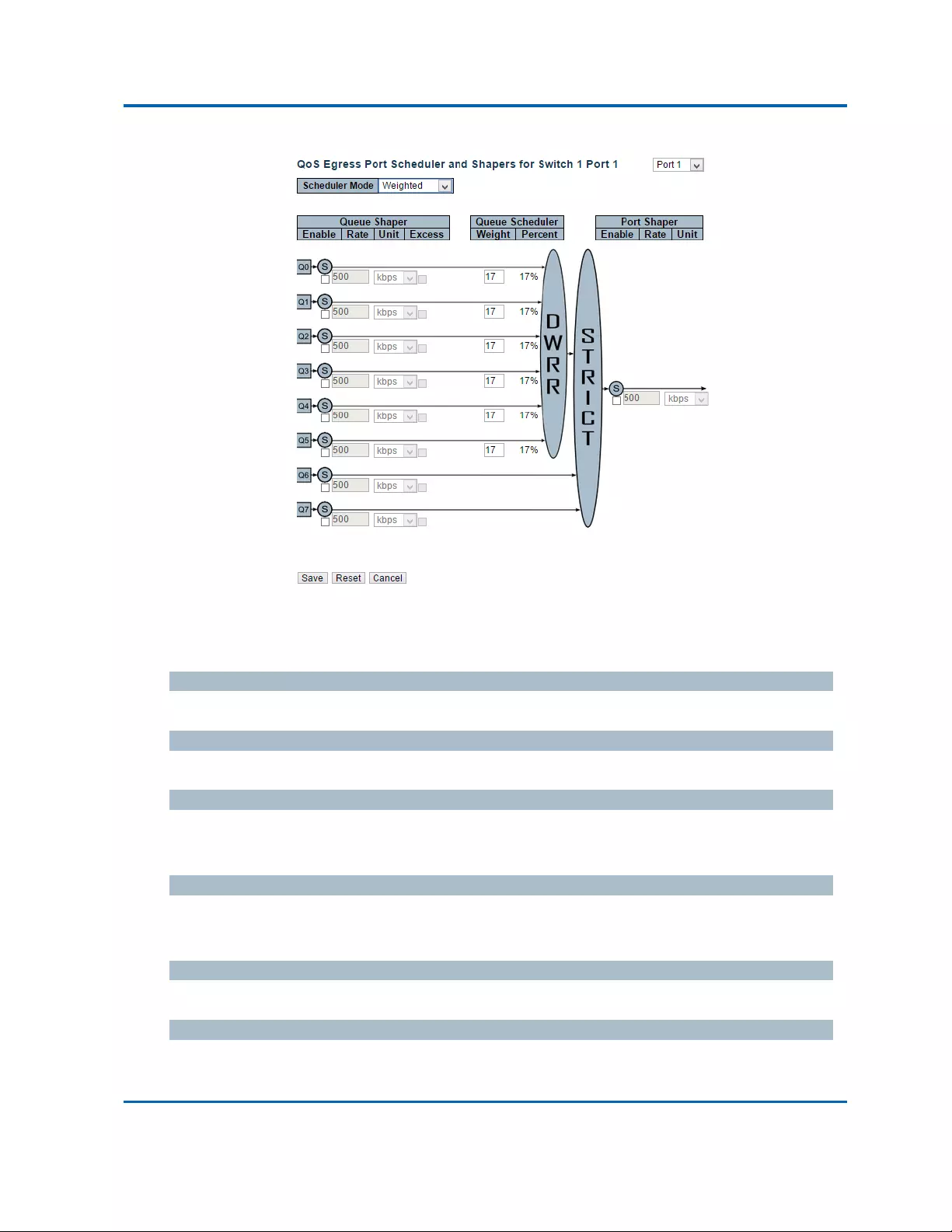
Chapter3:WebManagement
QoS‐PortShaping
Intelinet48‐PortGigabitEthernetPoE+Layer2+ManagedSwitchUserManual|195
ThispageallowsyoutoconfiguretheSchedulerandShapersforaspecificport.
Thesettingsrelatetothecurrentlyselectedstackunit,asreflectedbythepageheader.
SchedulerMode
Controlswhethertheschedulermodeis"StrictPriority"or"Weighted"onthisswitchport.
QueueShaperEnable
Controlswhetherthequeueshaperisenabledforthisqueueonthisswitchport.
QueueShaperRate
Controlstherateforthequeueshaper.Thedefaultvalueis500.Thisvalueisrestrictedto
100‐1000000whenthe"Unit"is"kbps",anditisrestrictedto1‐13200whenthe"Unit"is"Mbps".
QueueShaperUnit
Controlstheunitofmeasureforthequeueshaperrateas"kbps"or"Mbps".Thedefaultvalueis
"kbps".
QueueShaperExcess
Controlswhetherthequeueisallowedtouseexcessbandwidth.
QueueSchedulerWeight
Controlstheweightforthisqueue.Thedefaultvalueis"17".Thisvalueisrestrictedto1‐100.This
parameterisonlyshownif"SchedulerMode"issetto"Weighted".

Chapter3:WebManagement
QoS‐PortShaping
Intelinet48‐PortGigabitEthernetPoE+Layer2+ManagedSwitchUserManual|196
QueueSchedulerPercent
Showstheweightinpercentforthisqueue.Thisparameterisonlyshownif"SchedulerMode"isset
to"Weighted".
PortShaperEnable
Controlswhethertheportshaperisenabledforthisswitchport.
PortShaperRate
Controlstheratefortheportshaper.Thedefaultvalueis500.Thisvalueisrestrictedto100‐1000000
whenthe"Unit"is"kbps",anditisrestrictedto1‐13200whenthe"Unit"is"Mbps".
PortShaperUnit
Controlstheunitofmeasurefortheportshaperrateas"kbps"or"Mbps".Thedefaultvalueis
"kbps".
Buttons
Save:Clicktosavechanges.
Reset:Clicktoundoanychangesmadelocallyandreverttopreviouslysavedvalues.
Cancel:Clicktoundoanychangesmadelocallyandreturntothepreviouspage.
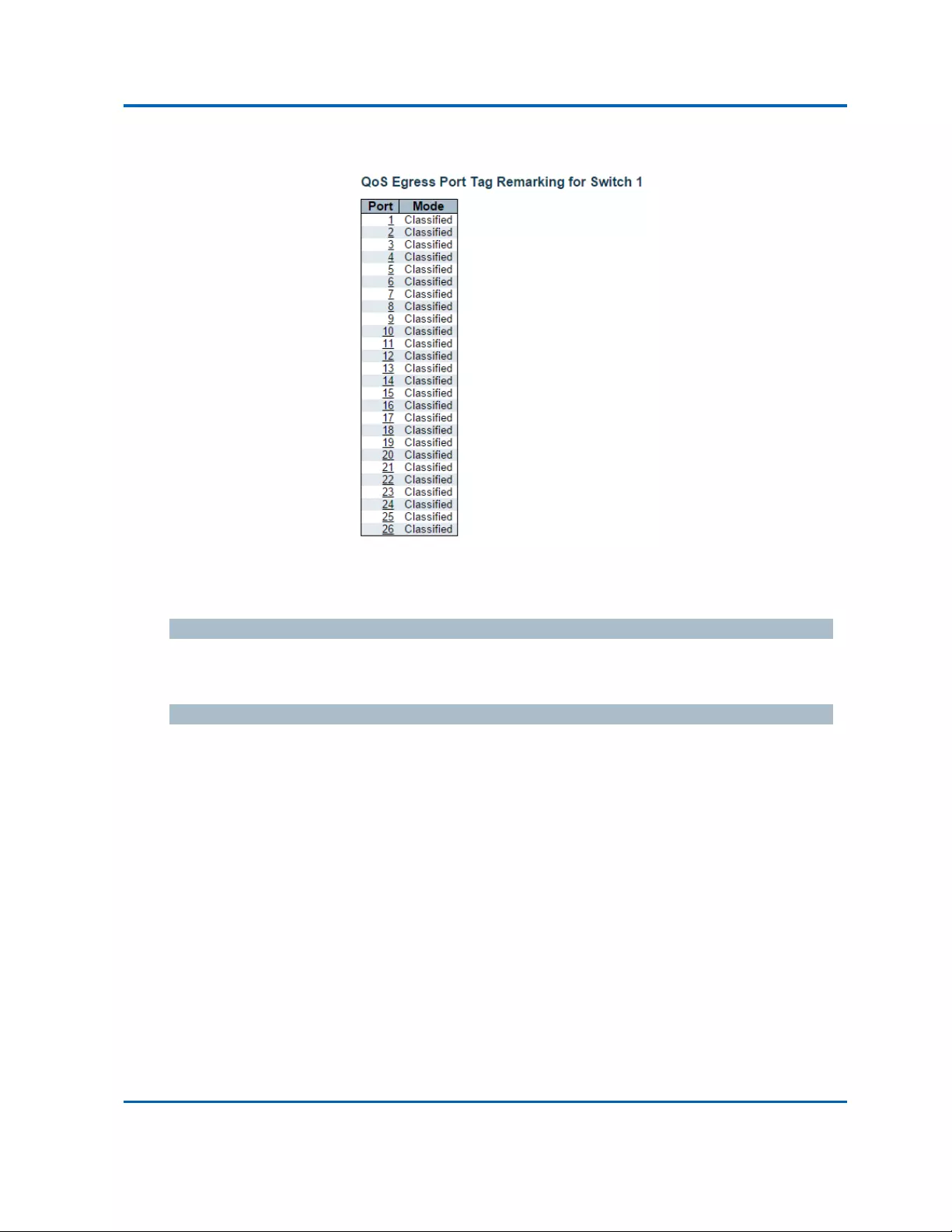
Chapter3:WebManagement
QoS‐PortTagRemarking
Intelinet48‐PortGigabitEthernetPoE+Layer2+ManagedSwitchUserManual|197
3.1.19.5.QoS‐PortTagRemarking
ThispageprovidesanoverviewofQoSEgressPortTagRemarkingforallswitchports.
Theportsbelongtothecurrentlyselectedstackunit,asreflectedbythepageheader.
Port
Thelogicalportforthesettingscontainedinthesamerow.
Clickontheportnumberinordertoconfiguretagremarking.
Mode
Showsthetagremarkingmodeforthisport.
Classified:UseclassifiedPCP/DEIvalues.
Default:UsedefaultPCP/DEIvalues.
Mapped:UsemappedversionsofQoSclassandDPlevel.

Chapter3:WebManagement
QoS‐PortTagRemarking
Intelinet48‐PortGigabitEthernetPoE+Layer2+ManagedSwitchUserManual|198
TheQoSEgressPortTagRemarkingforaspecificportareconfiguredonthispage.
Mode
Controlsthetagremarkingmodeforthisport.
Classified:UseclassifiedPCP/DEIvalues.
Default:UsedefaultPCP/DEIvalues.
Mapped:UsemappedversionsofQoSclassandDPlevel.
PCP/DEIConfiguration
ControlsthedefaultPCPandDEIvaluesusedwhenthemodeissettoDefault.

Chapter3:WebManagement
QoS‐PortTagRemarking
Intelinet48‐PortGigabitEthernetPoE+Layer2+ManagedSwitchUserManual|199
DPlevelConfiguration
ControlstheDropPrecedenceleveltranslationtablewhenthemodeissettoMapped.
Thepurposeofthistableistoreducethe2bitclassifiedDPleveltoa1bitDPlevelusedinthe(QoS
class,DPlevel)to(PCP,DEI)mappingprocess.
(QoSclass,DPlevel)to(PCP,DEI)Mapping
Controlsthemappingoftheclassified(QoSclass,DPlevel)to(PCP,DEI)valueswhenthemodeisset
toMapped.
Buttons
Save:Clicktosavechanges.
Reset:Clicktoundoanychangesmadelocallyandreverttopreviouslysavedvalues.
Cancel:Clicktoundoanychangesmadelocallyandreturntothepreviouspage.

Chapter3:WebManagement
QoS‐PortDSCP
Intelinet48‐PortGigabitEthernetPoE+Layer2+ManagedSwitchUserManual|200
3.1.19.6.QoS‐PortDSCP
ThispageallowsyoutoconfigurethebasicQoSPortDSCPConfigurationsettingsforallswitchports.
Thesettingsrelatetothecurrentlyselectedstackunit,asreflectedbythepageheader.
Port
ThePortcolumnshowsthelistofportsforwhichyoucanconfiguredscpingressandegresssettings.
Ingress
InIngresssettingsyoucanchangeingresstranslationandclassificationsettingsforindividualports.
TherearetwoconfigurationparametersavailableinIngress:
1. Translate
2. Classify
1.Translate
ToEnabletheIngressTranslationclickthecheckbox.
2.Classify
Classificationforaporthave4differentvalues.
Disable:NoIngressDSCPClassification.
DSCP=0:Classifyifincoming(ortranslatedifenabled)DSCPis0.
Selected:ClassifyonlyselectedDSCPforwhichclassificationisenabledasspecifiedinDSCP
TranslationwindowforthespecificDSCP.
All:ClassifyallDSCP.

Chapter3:WebManagement
QoS‐PortDSCP
Intelinet48‐PortGigabitEthernetPoE+Layer2+ManagedSwitchUserManual|201
Egress
PortEgressRewritingcanbeoneof‐
Disable:NoEgressrewrite.
Enable:Rewriteenabledwithoutremapping.
Remap:DSCPfromanalyzerisremappedandframeisremarkedwithremappedDSCPvalue.
Buttons
Save:Clicktosavechanges.
Reset:Clicktoundoanychangesmadelocallyandreverttopreviouslysavedvalues.

Chapter3:WebManagement
QoS‐DSCP‐BasedQoS
Intelinet48‐PortGigabitEthernetPoE+Layer2+ManagedSwitchUserManual|202
3.1.19.7.QoS‐DSCP‐BasedQoS
ThispageallowsyoutoconfigurethebasicQoSDSCPbasedQoSIngressClassificationsettingsforall
switches.
DSCP
MaximumnumberofsupportedDSCPvaluesare64.
Trust
ControlswhetheraspecificDSCPvalueistrusted.OnlyframeswithtrustedDSCPvaluesaremapped
toaspecificQoSclassandDropPrecedenceLevel.FrameswithuntrustedDSCPvaluesaretreatedas
anon‐IPframe.
QoSClass
QoSclassvaluecanbeanyof(0‐7)
DPL
DropPrecedenceLevel(0‐3)
Buttons
Save:Clicktosavechanges.
Reset:Clicktoundoanychangesmadelocallyandreverttopreviouslysavedvalues.

Chapter3:WebManagement
QoS‐DSCPTranslation
Intelinet48‐PortGigabitEthernetPoE+Layer2+ManagedSwitchUserManual|203
3.1.19.8.QoS‐DSCPTranslation
ThispageallowsyoutoconfigurethebasicQoSDSCPTranslationsettingsforallswitches.DSCP
translationcanbedoneinIngressorEgress.
DSCP
MaximumnumberofsupportedDSCPvaluesare64andvalidDSCPvaluerangesfrom0to63.
Ingress
IngresssideDSCPcanbefirsttranslatedtonewDSCPbeforeusingtheDSCPforQoSclassandDPL
map.
TherearetwoconfigurationparametersforDSCPTranslation‐
1. Translate
2. Classify
1.Translate
DSCPatIngresssidecanbetranslatedtoanyof(0‐63)DSCPvalues.
2.Classify
ClicktoenableClassificationatIngressside.
Egress
ThereisthefollowingconfigurableparameterforEgressside‐
Remap
Remap
SelecttheDSCPvaluefromselectmenutowhichyouwanttoremap.DSCPvaluerangesform0to
63.
Buttons
Save:Clicktosavechanges.
Reset:Clicktoundoanychangesmadelocallyandreverttopreviouslysavedvalues.

Chapter3:WebManagement
QoS‐DSCPClassification
Intelinet48‐PortGigabitEthernetPoE+Layer2+ManagedSwitchUserManual|204
3.1.19.9.QoS‐DSCPClassification
ThispageallowsyoutoconfigurethemappingofQoSclasstoDSCPvalue.
Thesettingsrelatetothecurrentlyselectedstackunit,asreflectedbythepageheader.
QoSClass
ActualQoSclass.
DSCP
SelecttheclassifiedDSCPvalue(0‐63).
Buttons
Save:Clicktosavechanges.
Reset:Clicktoundoanychangesmadelocallyandreverttopreviouslysavedvalues.

Chapter3:WebManagement
QoS‐StormControl
Intelinet48‐PortGigabitEthernetPoE+Layer2+ManagedSwitchUserManual|205
3.1.19.10.QoS‐StormControl
Thispageallowsyoutoconfigurethestormcontrolsettingsforallswitchports.
Thereisastormratecontrolforunicastframes,broadcastframesandunknown(flooded)frames.
Thesettingsrelatetothecurrentlyselectedstackunit,asreflectedbythepageheader.
Port
Theportnumberforwhichtheconfigurationbelowapplies.
Enabled
Controlswhetherthestormcontrolisenabledonthisswitchport.
Rate
Controlstherateforthestormcontrol.Thedefaultvalueis500.Thisvalueisrestrictedto
100‐1000000whenthe"Unit"is"kbps"or"fps",anditisrestrictedto1‐13200whenthe"Unit"is
"Mbps"or"kfps".
Unit
Controlstheunitofmeasureforthestormcontrolrateaskbps,Mbps,fpsorkfps.Thedefaultvalue
is"kbps".
Buttons
Save:Clicktosavechanges.
Reset:Clicktoundoanychangesmadelocallyandreverttopreviouslysavedvalues.

Chapter3:WebManagement
QoS‐WRED
Intelinet48‐PortGigabitEthernetPoE+Layer2+ManagedSwitchUserManual|206
3.1.19.11.QoS‐WRED
ThispageallowsyoutoconfiguretheRandomEarlyDetection(RED)settingsforqueue0to5.
REDcannotbeappliedtoqueue6and7.
ThroughdifferentREDconfigurationforthequeues(QoSclasses)itispossibletoobtainWeighted
RandomEarlyDetection(WRED)operationbetweenqueues.
Thesettingsareglobalforallportsinthestack.
Queue
Thequeuenumber(QoSclass)forwhichtheconfigurationbelowapplies.
Enable
ControlswhetherREDisenabledforthisqueue.
Min.Threshold
ControlsthelowerREDthreshold.Iftheaveragequeuefillinglevelisbelowthisthreshold,thedrop
probabilityiszero.Thisvalueisrestrictedto0‐100.
Max.DP1
ControlsthedropprobabilityforframesmarkedwithDropPrecedenceLevel1whentheaverage
queuefillinglevelis100%.Thisvalueisrestrictedto0‐100.
Max.DP2
ControlsthedropprobabilityforframesmarkedwithDropPrecedenceLevel2whentheaverage
queuefillinglevelis100%.Thisvalueisrestrictedto0‐100.
Max.DP3
ControlsthedropprobabilityforframesmarkedwithDropPrecedenceLevel3whentheaverage
queuefillinglevelis100%.Thisvalueisrestrictedto0‐100.

Chapter3:WebManagement
QoS‐WRED
Intelinet48‐PortGigabitEthernetPoE+Layer2+ManagedSwitchUserManual|207
REDDropProbabilityFunction
Thefollowingillustrationshowsthedropprobabilityfunctionwithassociatedparameters.
REDDropProbabilityFunction
Max.DP1‐3isthedropprobabilitywhentheaveragequeuefillinglevelis100%.Framesmarkedwith
DropPrecedenceLevel0areneverdropped.Min.Thresholdistheaveragequeuefillinglevelwhere
thequeuesrandomlystartdroppingframes.ThedropprobabilityforframesmarkedwithDrop
PrecedenceLevelnincreaseslinearlyfromzero(atMin.Thresholdaveragequeuefillinglevel)toMax.
DPn(at100%averagequeuefillinglevel).
Buttons
Save:Clicktosavechanges.
Reset:Clicktoundoanychangesmadelocallyandreverttopreviouslysavedvalues.

Chapter3:WebManagement
Configuration‐Mirroring
Intelinet48‐PortGigabitEthernetPoE+Layer2+ManagedSwitchUserManual|208
3.1.20.Configuration‐Mirroring
ConfigureportMirroringonthispage.
Todebugnetworkproblems,selectedtrafficcanbecopied,ormirrored,onamirrorportwherea
frameanalyzercanbeattachedtoanalyzetheframeflow.
Thetraffictobecopiedonthemirrorportisselectedasfollows:
Allframesreceivedonagivenport(alsoknownasingressorsourcemirroring).
Allframestransmittedonagivenport(alsoknownasegressordestinationmirroring).
Porttomirrorto
Porttomirroralsoknownasthemirrorport.Framesfromportsthathaveeithersource(rx)or
destination(tx)mirroringenabledaremirroredonthisport.Disableddisablesmirroring.
Switchtomirrorto
Framesfromportsthathaveeithersource(rx)ordestination(tx)mirroringenabledaremirroredto
thisswitch.
MirrorPortConfiguration
ThefollowingtableisusedforRxandTxenabling.
Port
Thelogicalportforthesettingscontainedinthesamerow.

Chapter3:WebManagement
Configuration‐Mirroring
Intelinet48‐PortGigabitEthernetPoE+Layer2+ManagedSwitchUserManual|209
Mode
Selectmirrormode.
Rxonly:Framesreceivedonthisportaremirroredonthemirrorport.Framestransmittedare
notmirrored.
Txonly:Framestransmittedonthisportaremirroredonthemirrorport.Framesreceivedare
notmirrored.
Disabled:Neitherframestransmittednorframesreceivedaremirrored.
Enabled:Framesreceivedandframestransmittedaremirroredonthemirrorport.
Note:Foragivenport,aframeisonlytransmittedonce.Itisthereforenotpossibletomirrormirror
portTxframes.Becauseofthis,modefortheselectedmirrorportislimitedtoDisabledorRxonly.
Buttons
Save:Clicktosavechanges.
Reset:Clicktoundoanychangesmadelocallyandreverttopreviouslysavedvalues.

Chapter3:WebManagement
Configuration‐UPnP
Intelinet48‐PortGigabitEthernetPoE+Layer2+ManagedSwitchUserManual|210
3.1.21.Configuration‐UPnP
ConfigureUPnPonthispage.
Mode
IndicatestheUPnPoperationmode.Possiblemodesare:
Enabled:EnableUPnPmodeoperation.
Disabled:DisableUPnPmodeoperation.
Whenthemodeisenabled,twoACEsareaddedautomaticallytotrapUPNPrelatedpacketstoCPU.
TheACEsareautomaticallyremovedwhenthemodeisdisabled.
TTL
TheTTLvalueisusedbyUPnPtosendSSDPadvertisementmessages.Validvaluesareintherange1
to255.
AdvertisingDuration
Theduration,carriedinSSDPpackets,isusedtoinformacontrolpointorcontrolpointshowoftenit
ortheyshouldreceiveanSSDPadvertisementmessagefromthisswitch.Ifacontrolpointdoesnot
receiveanymessagewithintheduration,itwillthinkthattheswitchnolongerexists.Duetothe
unreliablenatureofUDP,inthestandarditisrecommendedthatsuchrefreshingofadvertisements
tobedoneatlessthanone‐halfoftheadvertisingduration.Intheimplementation,theswitchsends
SSDPmessagesperiodicallyattheintervalone‐halfoftheadvertisingdurationminus30seconds.
Validvaluesareintherange100to86400.
Buttons
Save:Clicktosavechanges.
Reset:Clicktoundoanychangesmadelocallyandreverttopreviouslysavedvalues.

Chapter3:WebManagement
GVRP‐GlobalConfig
Intelinet48‐PortGigabitEthernetPoE+Layer2+ManagedSwitchUserManual|211
3.1.22.Configuration‐GVRP
3.1.22.1.GVRP‐GlobalConfig
ThispageallowsyoutoconfigurethebasicGVRPConfigurationsettingsforallswitchports.
EnableGVRPglobally
TheGVRPfeatureisenabledbysettingthecheckmarkinthecheckboxnamedEnableGVRP.
GVRPprotocoltimers
Join‐timeisavalueintherange1‐20intheunitsofcentiseconds,i.e.inunitsofonehundredthofa
second.Thedefaultis20.
Leave‐timeisavalueintherange60‐300intheunitsofcentiseconds,i.e.inunitsofonehundredth
ofasecond.Thedefaultis60.
LeaveAll‐timeisavalueintherange1000‐5000intheunitsofcentiseconds,i.e.inunitsofone
hundredthofasecond.Thedefaultis1000.
MaxnumberofVLANs
WhenGVRPisenabledamaximumnumberofVLANssupportedbyGVRPisspecified.Bydefaultthis
numberis20.ThisnumbercanonlybechangedwhenGVRPisturnedoff.
Buttons
Save:Clicktosavechanges.

Chapter3:WebManagement
GVRP‐PortConfig
Intelinet48‐PortGigabitEthernetPoE+Layer2+ManagedSwitchUserManual|212
3.1.22.2.GVRP‐PortConfig
ThispageallowsyoutoenableaportforGVRP.
Button
Save:Clicktosavechanges.
Reset:Clicktoundoanychangesmadelocallyandreverttopreviouslysavedvalues.

Chapter3:WebManagement
Configuration‐sFlow
Intelinet48‐PortGigabitEthernetPoE+Layer2+ManagedSwitchUserManual|213
3.1.23.Configuration‐sFlow
ThispageallowsforconfiguringsFlow.Theconfigurationisdividedintotwoparts:Configurationof
thesFlowreceiver(a.k.a.sFlowcollector)andconfigurationofper‐portflowandcountersamplers.
sFlowconfigurationisnotpersistedtonon‐volatilememory,whichmeansthatarebootormaster
changewilldisablesFlowsampling.
ReceiverConfiguration
Owner
Basically,sFlowcanbeconfiguredintwoways:ThroughlocalmanagementusingtheWeborCLI
interfaceorthroughSNMP.Thisread‐onlyfieldshowstheownerofthecurrentsFlowconfiguration
andassumesvaluesasfollows:
IfsFlowiscurrentlyunconfigured/unclaimed,Ownercontains<none>.
IfsFlowiscurrentlyconfiguredthroughWeborCLI,Ownercontains<Configuredthroughlocal
management>.
IfsFlowiscurrentlyconfiguredthroughSNMP,OwnercontainsastringidentifyingthesFlow
receiver.
IfsFlowisconfiguredthroughSNMP,allcontrols‐exceptfortheRelease‐button‐aredisabledto
avoidinadvertentreconfiguration.
The“Release”buttonallowsforreleasingthecurrentowneranddisablesFlowsampling.Thebutton
isdisabledifsFlowiscurrentlyunclaimed.IfconfiguredthroughSNMP,thereleasemustbe

Chapter3:WebManagement
Configuration‐sFlow
Intelinet48‐PortGigabitEthernetPoE+Layer2+ManagedSwitchUserManual|214
confirmed(aconfirmationrequestwillappear).
IPAddress/Hostname
TheIPaddressorhostnameofthesFlowreceiver.BothIPv4andIPv6addressesaresupported.
UDPPort
TheUDPportonwhichthesFlowreceiverlistenstosFlowdatagrams.Ifsetto0(zero),thedefault
port(6343)isused.
Timeout
ThenumberofsecondsremainingbeforesamplingstopsandthecurrentsFlowownerisreleased.
Whileactive,thecurrenttimeleftcanbeupdatedwithaclickontheRefresh‐button.Iflocally
managed,thetimeoutcanbechangedontheflywithoutaffectinganyothersettings.
Max.DatagramSize
Themaximumnumberofdatabytesthatcanbesentinasinglesampledatagram.Thisshouldbeset
toavaluethatavoidsfragmentationofthesFlowdatagrams.Validrangeis200to1468byteswith
defaultbeing1400bytes.
PortConfiguration
Port
Theportnumberforwhichtheconfigurationbelowapplies.
FlowSamplerEnabled
Enables/disablesflowsamplingonthisport.
FlowSamplerSamplingRate
Thestatisticalsamplingrateforpacketsampling.SettoNtosampleonaverage1/ N t h ofthepackets
transmitted/receivedontheport.
Notallsamplingratesareachievable.Ifanunsupportedsamplingrateisrequested,theswitchwill
automaticallyadjustittotheclosestachievable.Thiswillbereportedbackinthisfield.
FlowSamplerMax.Header
ThemaximumnumberofbytesthatshouldbecopiedfromasampledpackettothesFlowdatagram.
Validrangeis14to200byteswithdefaultbeing128bytes.
Ifthemaximumdatagramsizedoesnottakeintoaccountthemaximumheadersize,samplesmaybe
dropped.
CounterPollerEnabled
Enables/disablescounterpollingonthisport.
CounterPollerInterval

Chapter3:WebManagement
Configuration‐sFlow
Intelinet48‐PortGigabitEthernetPoE+Layer2+ManagedSwitchUserManual|215
Withcounterpollingenabled,thisspecifiestheinterval‐inseconds‐betweencounterpoller
samples.
Buttons
Release:SeedescriptionunderOwner.
Refresh:Clicktorefreshthepage.Notethatunsavedchangeswillbelost.
Save:Clicktosavechanges.NotethatsFlowconfigurationisnotpersistedtonon‐volatile
memory.
Reset:Clicktoundoanychangesmadelocallyandreverttopreviouslysavedvalues.

Chapter3:WebManagement
System‐Information
Intelinet48‐PortGigabitEthernetPoE+Layer2+ManagedSwitchUserManual|216
3.2.WebManagement‐Monitor
Youcanmonitorandviewsystemstatushere.Also,allthesettingsyou’vemadeintheConfiguration
sectionofthemanagementwebpagecanbeviewedhereaswell.
3.2.1.Monitor‐System
3.2.1.1.System‐Information
Theswitchsysteminformationisprovidedhere.
Contact
ThesystemcontactconfiguredinConfiguration|System|Information|SystemContact.
Name
ThesystemnameconfiguredinConfiguration|System|Information|SystemName.
Location
ThesystemlocationconfiguredinConfiguration|System|Information|SystemLocation.
MACAddress
TheMACAddressofthisswitch.
SystemDate
Thecurrent(GMT)systemtimeanddate.ThesystemtimeisobtainedthroughtheTimingserver
runningontheswitch,ifany.
SystemUptime
Theperiodoftimethedevicehasbeenoperational.
SwitchID
TheswitchID.
ChipID
TheChipIDofthisswitch.
SoftwareVersion
Thesoftwareversionofthisswitch.

Chapter3:WebManagement
System‐Information
Intelinet48‐PortGigabitEthernetPoE+Layer2+ManagedSwitchUserManual|217
SoftwareDate
Thedatewhentheswitchsoftwarewasproduced.
Buttons
Auto‐refresh:Checkthisboxtorefreshthepageautomatically.Automaticrefreshoccursevery
3seconds.
Refresh:Clicktorefreshthepage.

Chapter3:WebManagement
System‐CPULoad
Intelinet48‐PortGigabitEthernetPoE+Layer2+ManagedSwitchUserManual|218
3.2.1.2.System‐CPULoad
ThispagedisplaystheCPUload,usinganSVGgraph.
Theloadismeasuredasaveragedoverthelast100ms,1secand10secondsintervals.Thelast120
samplesaregraphed,andthelastnumbersaredisplayedastextaswell.
InordertodisplaytheSVGgraph,yourbrowsermustsupporttheSVGformat.ConsulttheSVGWiki
formoreinformationonbrowsersupport.Specifically,atthetimeofwriting,MicrosoftInternet
ExplorerwillneedtohaveaplugininstalledtosupportSVG.
Buttons
Auto‐refresh:Checkthisboxtorefreshthepageautomatically.Automaticrefreshoccursevery
3seconds.

Chapter3:WebManagement
System‐IPStatus
Intelinet48‐PortGigabitEthernetPoE+Layer2+ManagedSwitchUserManual|219
3.2.1.3.System‐IPStatus
ThispagedisplaysthestatusoftheIPprotocollayer.ThestatusisdefinedbytheIPinterfaces,theIP
routesandtheneighbourcache(ARPcache)status.
IPInterfaces
Interface
Thenameoftheinterface.
Type
Theaddresstypeoftheentry.ThismaybeLINKorIPv4.
Address
Thecurrentaddressoftheinterface(ofthegiventype).
Status
Thestatusflagsoftheinterface(and/oraddress).
IPRoutes
Network
ThedestinationIPnetworkorhostaddressofthisroute.
Gateway
Thegatewayaddressofthisroute.
Status
Thestatusflagsoftheroute.
Neighbourcache
IPAddress
TheIPaddressoftheentry.
LinkAddress

Chapter3:WebManagement
System‐IPStatus
Intelinet48‐PortGigabitEthernetPoE+Layer2+ManagedSwitchUserManual|220
TheLink(MAC)addressforwhichabindingtotheIPaddressgivenexist..
Buttons
Refresh:Clicktorefreshthepageimmediately.
Auto‐refresh:Checkthisboxtorefreshthepageautomatically.Automaticrefreshoccursevery
3seconds.

Chapter3:WebManagement
System‐Log
Intelinet48‐PortGigabitEthernetPoE+Layer2+ManagedSwitchUserManual|221
3.2.1.4.System‐Log
Theswitchsystemloginformationisprovidedhere.
ID
TheID(>=1)ofthesystemlogentry.
Level
Thelevelofthesystemlogentry.Thefollowingleveltypesaresupported:
Info:Informationlevelofthesystemlog.
Warning:Warninglevelofthesystemlog.
Error:Errorlevelofthesystemlog.
All:Alllevels.
Time
Thetimeofthesystemlogentry.
Message
Themessageofthesystemlogentry.
Buttons
Auto‐refresh:Checkthisboxtorefreshthepageautomatically.Automaticrefreshoccursevery
3seconds.
Refresh:Updatesthesystemlogentries,startingfromthecurrententryID.
Clear:Flushestheselectedlogentries.
|<<:Updatesthesystemlogentries,startingfromthefirstavailableentryID.
<<:Updatesthesystemlogentries,endingatthelastentrycurrentlydisplayed.
>>:Updatesthesystemlogentries,startingfromthelastentrycurrentlydisplayed.
>>|:Updatesthesystemlogentries,endingatthelastavailableentryID.

Chapter3:WebManagement
System‐DetailedLog
Intelinet48‐PortGigabitEthernetPoE+Layer2+ManagedSwitchUserManual|222
3.2.1.5.System‐DetailedLog
Theswitchsystemdetailedloginformationisprovidedhere.
ID
TheID(>=1)ofthesystemlogentry.
Message
Thedetailedmessageofthesystemlogentry.
Buttons
Refresh:UpdatesthesystemlogentrytothecurrententryID.
|<<:UpdatesthesystemlogentrytothefirstavailableentryID.
<<:UpdatesthesystemlogentrytothepreviousavailableentryID.
>>:UpdatesthesystemlogentrytothenextavailableentryID.
>>|:UpdatesthesystemlogentrytothelastavailableentryID.

Chapter3:WebManagement
GreenEthernet‐PortPowerSavingsStatus
Intelinet48‐PortGigabitEthernetPoE+Layer2+ManagedSwitchUserManual|223
3.2.2.Monitor‐GreenEthernet
3.2.2.1.GreenEthernet‐PortPowerSavingsStatus
ThispageprovidesthecurrentstatusforEEE.
LocalPort
Thisisthelogicalportnumberforthisrow.
Link
Showsifthelinkisupfortheport(green=linkup,red=linkdown).
EEEcap
ShowsiftheportisEEEcapable.
EEEEna
ShowsifEEEisenabledfortheport(reflectsthesettingsatthePortPowerSavingsconfiguration
page).
LPEEEcap
ShowsifthelinkpartnerisEEEcapable.
EEEInpowersave
ShowsifthesystemiscurrentlysavingpowerduetoEEE.WhenEEEisenabled,thesystemwill
powereddownifnoframehasbeenreceivedortransmittedin5uSec.
ActiphySavings
ShowsifthesystemiscurrentlysavingpowerduetoActiPhy.
PerfectReachSavings
ShowsifthesystemiscurrentlysavingpowerduetoPerfectReach.
Buttons
Auto‐refresh:Checkthisboxtorefreshthepageautomatically.Automaticrefreshoccursevery
3seconds.
Refresh:Clicktorefreshthepage.

Chapter3:WebManagement
Ports‐State
Intelinet48‐PortGigabitEthernetPoE+Layer2+ManagedSwitchUserManual|224
3.2.3.Monitor‐Ports
3.2.3.1.Ports‐State
Thispageprovidesanoverviewofthecurrentswitchportstates.
Theportstatesareillustratedasfollows:
StatusDisabledDownLink
RJ45ports
SFPports
X2ports
Buttons
Auto‐refresh:Checkthisboxtorefreshthepageautomatically.Automaticrefreshoccursevery
3seconds.
Refresh:Clicktorefreshthepage.

Chapter3:WebManagement
Ports‐TrafficOverview
Intelinet48‐PortGigabitEthernetPoE+Layer2+ManagedSwitchUserManual|225
3.2.3.2.Ports‐TrafficOverview
Thispageprovidesanoverviewofgeneraltrafficstatisticsforallswitchports.
Theportsbelongtothecurrentlyselectedstackunit,asreflectedbythepageheader.
Port
Thelogicalportforthesettingscontainedinthesamerow.
Packets
Thenumberofreceivedandtransmittedpacketsperport.
Bytes
Thenumberofreceivedandtransmittedbytesperport.
Errors
Thenumberofframesreceivedinerrorandthenumberofincompletetransmissionsperport.
Drops
Thenumberofframesdiscardedduetoingressoregresscongestion.
Filtered
Thenumberofreceivedframesfilteredbytheforwardingprocess.
Buttons
Refresh:Clicktorefreshthepageimmediately.
Clear:Clearsthecountersforallports.
Auto‐refresh:Checkthisboxtorefreshthepageautomatically.Automaticrefreshoccursevery
3seconds.

Chapter3:WebManagement
Ports‐TrafficOverview
Intelinet48‐PortGigabitEthernetPoE+Layer2+ManagedSwitchUserManual|226

Chapter3:WebManagement
Ports‐QoSStatistics
Intelinet48‐PortGigabitEthernetPoE+Layer2+ManagedSwitchUserManual|227
3.2.3.3.Ports‐QoSStatistics
Thispageprovidesstatisticsforthedifferentqueuesforallswitchports.
Theportsbelongtothecurrentlyselectedstackunit,asreflectedbythepageheader.
Port
Thelogicalportforthesettingscontainedinthesamerow.
Qn
Thereare8QoSqueuesperport.Q0isthelowestpriorityqueue.
Rx/Tx
Thenumberofreceivedandtransmittedpacketsperqueue.
Buttons
Auto‐refresh:Checkthisboxtorefreshthepageautomatically.Automaticrefreshoccursevery
3seconds.
Refresh:Clicktorefreshthepageimmediately.
Clear:Clearsthecountersforallports.
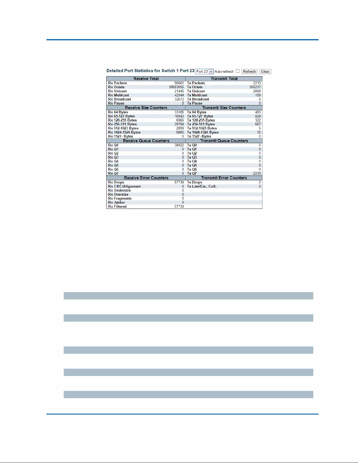
Chapter3:WebManagement
Ports‐DetailedStatistics
Intelinet48‐PortGigabitEthernetPoE+Layer2+ManagedSwitchUserManual|228
3.2.3.4.Ports‐DetailedStatistics
Thispageprovidesdetailedtrafficstatisticsforaspecificswitchport.Usetheportselectboxtoselect
whichswitchportdetailstodisplay.
Theselectedportbelongstothecurrentlyselectedstackunit,asreflectedbythepageheader.
Thedisplayedcountersarethetotalsforreceiveandtransmit,thesizecountersforreceiveand
transmit,andtheerrorcountersforreceiveandtransmit.
ReceiveTotalandTransmitTotal
RxandTxPackets
Thenumberofreceivedandtransmitted(goodandbad)packets.
RxandTxOctets
Thenumberofreceivedandtransmitted(goodandbad)bytes.IncludesFCS,butexcludesframing
bits.
RxandTxUnicast
Thenumberofreceivedandtransmitted(goodandbad)unicastpackets.
RxandTxMulticast
Thenumberofreceivedandtransmitted(goodandbad)multicastpackets.
RxandTxBroadcast
Thenumberofreceivedandtransmitted(goodandbad)broadcastpackets.

Chapter3:WebManagement
Ports‐DetailedStatistics
Intelinet48‐PortGigabitEthernetPoE+Layer2+ManagedSwitchUserManual|229
RxandTxPause
AcountoftheMACControlframesreceivedortransmittedonthisportthathaveanopcode
indicatingaPAUSEoperation.
ReceiveandTransmitSizeCounters
Thenumberofreceivedandtransmitted(goodandbad)packetssplitintocategoriesbasedontheir
respectiveframesizes.
ReceiveandTransmitQueueCounters
Thenumberofreceivedandtransmittedpacketsperinputandoutputqueue.
ReceiveErrorCounters
RxDrops
Thenumberofframesdroppedduetolackofreceivebuffersoregresscongestion.
RxCRC/Alignment
ThenumberofframesreceivedwithCRCoralignmenterrors.
RxUndersize
Thenumberofshort1framesreceivedwithvalidCRC.
RxOversize
Thenumberoflong2framesreceivedwithvalidCRC.
RxFragments
Thenumberofshort1framesreceivedwithinvalidCRC.
RxJabber
Thenumberoflong2framesreceivedwithinvalidCRC.
RxFiltered
Thenumberofreceivedframesfilteredbytheforwardingprocess.
Note1:Shortframesareframesthataresmallerthan64bytes.
Note2:Longframesareframesthatarelongerthantheconfiguredmaximumframelengthforthisport.
TransmitErrorCounters
TxDrops
Thenumberofframesdroppedduetooutputbuffercongestion.
TxLate/Exc.Coll.
Thenumberofframesdroppedduetoexcessiveorlatecollisions.

Chapter3:WebManagement
Ports‐DetailedStatistics
Intelinet48‐PortGigabitEthernetPoE+Layer2+ManagedSwitchUserManual|230
Buttons
Refresh:Clicktorefreshthepageimmediately.
Clear:Clearsthecountersfortheselectedport.
Auto‐refresh:Checkthisboxtorefreshthepageautomatically.Automaticrefreshoccursevery
3seconds.
Note:Theportselectboxdetermineswhichportisaffectedbyclickingthebuttons.

Chapter3:WebManagement
DHCP‐Server‐Statistics
Intelinet48‐PortGigabitEthernetPoE+Layer2+ManagedSwitchUserManual|231
3.2.4.Monitor‐DHCP
3.2.4.1.DHCP‐Server
3.2.4.1.1.DHCP‐Server‐Statistics
ThispagedisplaysthedatabasecountersandthenumberofDHCPmessagessentandreceivedby
DHCPserver.
DatabaseCounters
Displaycountersofvariousdatabases.
Pool
Numberofpools.
ExcludedIPAddress
NumberofexcludedIPaddressranges.
DeclinedIPAddress
NumberofseclinedIPaddresses.
BindingCounters
Displaycountersofvariousdatabases.
AutomaticBinding
Numberofbindingswithnetwork‐typepools.
ManualBinding
NumberofbindingsthatadministratorassignsanIPaddresstoaclient.Thatis,thepoolisofhost
type.
ExpiredBinding
NumberofbindingsthattheirleasetimeexpiredortheyareclearedfromAutomatic/Manualtype
bindings.

Chapter3:WebManagement
DHCP‐Server‐Statistics
Intelinet48‐PortGigabitEthernetPoE+Layer2+ManagedSwitchUserManual|232
DHCPMessageReceivedCounters
DisplaycountersofDHCPmessagesreceivedbyDHCPserver.
DISCOVER
NumberofDHCPDISCOVERmessagesreceived.
REQUEST
NumberofDHCPREQUESTmessagesreceived.
DECLINE
NumberofDHCPDECLINEmessagesreceived.
RELEASE
NumberofDHCPRELEASEmessagesreceived.
INFORM
NumberofDHCPINFORMmessagesreceived.
DHCPMessageSentCounters
DisplaycountersofDHCPmessagessentbyDHCPserver.
OFFER
NumberofDHCPOFFERmessagessent.
ACK
NumberofDHCPACKmessagessent.
NAK
NumberofDHCPNAKmessagessent.
Buttons
Auto‐refresh:Checkthisboxtorefreshthepageautomatically.Automaticrefreshoccurs
every3seconds.
Refresh:Clicktorefreshthepageimmediately.
Clear:ClicktoClearsDHCPMessageReceivedCountersandDHCPMessageSentCounters.

Chapter3:WebManagement
DHCP‐Server‐Binding
Intelinet48‐PortGigabitEthernetPoE+Layer2+ManagedSwitchUserManual|233
3.2.4.1.2.DHCP‐Server‐Binding
ThispagedisplaysbindingsgeneratedforDHCPclients.
BindingIPAddress
Displayallbindings.
IP
IPaddressallocatedtoDHCPclient.
Type
Typeofbinding.PossibletypesareAutomatic,Manual,Expired.
State
Stateofbinding.PossiblestatesareCommitted,Allocated,Expired.
PoolName
Thepoolthatgeneratesthebinding.
ServerID
ServerIPaddresstoservicethebinding.
Buttons
Refresh:Clicktorefreshthepageimmediately.
Auto‐refresh:Checkthisboxtorefreshthepageautomatically.Automaticrefreshoccurs
every3seconds.
ClearSelected:Clicktoclearselectedbindings.IftheselectedbindingisAutomaticor
Manual,thenitischangedtobeExpired.IftheselectedbindingisExpired,thenitisfreed.
ClearAutomatic:ClicktoclearallAutomaticbindingsandChangethemtoExpiredbindings.
ClearManual:ClicktoclearallManualbindingsandChangethemtoExpiredbindings.
ClearExpired:ClicktoclearallExpiredbindingsandfreethem.

Chapter3:WebManagement
DHCP‐Server‐DeclinedIP
Intelinet48‐PortGigabitEthernetPoE+Layer2+ManagedSwitchUserManual|234
3.2.4.1.3.DHCP‐Server‐DeclinedIP
ThispagedisplaysdeclinedIPaddresses.
DeclinedIPAddresses
DisplayIPaddressesdeclinedbyDHCPclients.
DeclinedIP
ListofIPaddressesdeclined.
Buttons
Auto‐refresh:Checkthisboxtorefreshthepageautomatically.Automaticrefreshoccurs
every3seconds.
Refresh:Clicktorefreshthepageimmediately.

Chapter3:WebManagement
DHCP‐SnoopingTable
Intelinet48‐PortGigabitEthernetPoE+Layer2+ManagedSwitchUserManual|235
3.2.4.2.DHCP‐SnoopingTable
ThispagedisplaythedynamicIPassignedinformationafterDHCPSnoopingmodeisdisabled.All
DHCPclientsobtainedthedynamicIPaddressfromtheDHCPserverwillbelistedinthistableexcept
forlocalVLANinterfaceIPaddresses.EntriesintheDynamicDHCPsnoopingTableareshownonthis
page.
NavigatingtheDHCPsnoopingTable
Eachpageshowsupto99entriesfromtheDynamicDHCPsnoopingtable,defaultbeing20,selected
throughthe"entriesperpage"inputfield.Whenfirstvisited,thewebpagewillshowthefirst20
entriesfromthebeginningoftheDynamicDHCPsnoopingTable.
The"MACaddress"and"VLAN"inputfieldsallowstheusertoselectthestartingpointinthe
DynamicDHCPsnoopingTable.ClickingtheRefreshbuttonwillupdatethedisplayedtablestarting
fromthatortheclosestnextDynamicDHCPsnoopingTablematch.Inaddition,thetwoinputfields
will‐uponaRefreshbuttonclick‐assumethevalueofthefirstdisplayedentry,allowingfor
continuousrefreshwiththesamestartaddress.
The>>willusethelastentryofthecurrentlydisplayedtableasabasisforthenextlookup.Whenthe
endisreachedthetext"Nomoreentries"isshowninthedisplayedtable.Usethe|<<buttontostart
over.
DHCPsnoopingTableColumns
MACAddress
UserMACaddressoftheentry.
VLANID
VLAN‐IDinwhichtheDHCPtrafficispermitted.
SourcePort
SwitchPortNumberforwhichtheentriesaredisplayed.
IPAddress
UserIPaddressoftheentry.
IPSubnetMask
UserIPsubnetmaskoftheentry.
DHCPServerAddress
DHCPServeraddressoftheentry.

Chapter3:WebManagement
DHCP‐SnoopingTable
Intelinet48‐PortGigabitEthernetPoE+Layer2+ManagedSwitchUserManual|236
Buttons
Auto‐refresh:Checkthisboxtorefreshthepageautomatically.Automaticrefreshoccursevery
3seconds.
Refresh:Refreshesthedisplayedtablestartingfromtheinputfields.
Clear:Flushesalldynamicentries.
|<<:UpdatesthetablestartingfromthefirstentryintheDynamicDHCPsnoopingTable.
>>:Updatesthetable,startingwiththeentryafterthelastentrycurrentlydisplayed.

Chapter3:WebManagement
DHCP‐RelayStatistics
Intelinet48‐PortGigabitEthernetPoE+Layer2+ManagedSwitchUserManual|237
3.2.4.3.DHCP‐RelayStatistics
ThispageprovidesstatisticsforDHCPrelay.
ServerStatistics
TransmittoServer
Thenumberofpacketsthatarerelayedfromclienttoserver.
TransmitError
Thenumberofpacketsthatresultedinerrorswhilebeingsenttoclients.
ReceivefromServer
Thenumberofpacketsreceivedfromserver.
ReceiveMissingAgentOption
Thenumberofpacketsreceivedwithoutagentinformationoptions.
ReceiveMissingCircuitID
ThenumberofpacketsreceivedwiththeCircuitIDoptionmissing.
ReceiveMissingRemoteID
ThenumberofpacketsreceivedwiththeRemoteIDoptionmissing.
ReceiveBadCircuitID
ThenumberofpacketswhoseCircuitIDoptiondidnotmatchknowncircuitID.
ReceiveBadRemoteID
ThenumberofpacketswhoseRemoteIDoptiondidnotmatchknownRemoteID.
ClientStatistics
TransmittoClient
Thenumberofrelayedpacketsfromservertoclient.
TransmitError
Thenumberofpacketsthatresultedinerrorwhilebeingsenttoservers.
ReceivefromClient
Thenumberofreceivedpacketsfromserver.

Chapter3:WebManagement
DHCP‐RelayStatistics
Intelinet48‐PortGigabitEthernetPoE+Layer2+ManagedSwitchUserManual|238
ReceiveAgentOption
Thenumberofreceivedpacketswithrelayagentinformationoption.
ReplaceAgentOption
Thenumberofpacketswhichwerereplacedwithrelayagentinformationoption.
KeepAgentOption
Thenumberofpacketswhoserelayagentinformationwasretained.
DropAgentOption
Thenumberofpacketsthatweredroppedwhichwerereceivedwithrelayagentinformation.
Buttons
Auto‐refresh:Checkthisboxtorefreshthepageautomatically.Automaticrefreshoccursevery
3seconds.
Refresh:Clicktorefreshthepageimmediately.
Clear:Clearallstatistics.
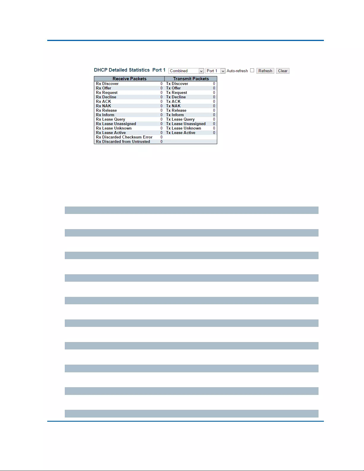
Chapter3:WebManagement
DHCP‐DetailedStatistics
Intelinet48‐PortGigabitEthernetPoE+Layer2+ManagedSwitchUserManual|239
3.2.4.4.DHCP‐DetailedStatistics
ThispageprovidesstatisticsforDHCPsnooping.Noticethatthenormalforwardper‐portTXstatistics
isn'tincreasediftheincomingDHCPpacketisdonebyL3forwardingmechanism.Andclearthe
statisticsonspecificportmaynottakeeffectonglobalstatisticssinceitgathersthedifferentlayer
overview.
ReceiveandTransmitPackets
RxandTxDiscover
Thenumberofdiscover(option53withvalue1)packetsreceivedandtransmitted.
RxandTxOffer
Thenumberofoffer(option53withvalue2)packetsreceivedandtransmitted.
RxandTxRequest
Thenumberofrequest(option53withvalue3)packetsreceivedandtransmitted.
RxandTxDecline
Thenumberofdecline(option53withvalue4)packetsreceivedandtransmitted.
RxandTxACK
ThenumberofACK(option53withvalue5)packetsreceivedandtransmitted.
RxandTxNAK
ThenumberofNAK(option53withvalue6)packetsreceivedandtransmitted.
RxandTxRelease
Thenumberofrelease(option53withvalue7)packetsreceivedandtransmitted.
RxandTxInform
Thenumberofinform(option53withvalue8)packetsreceivedandtransmitted.
RxandTxLeaseQuery
Thenumberofleasequery(option53withvalue10)packetsreceivedandtransmitted.
RxandTxLeaseUnassigned

Chapter3:WebManagement
DHCP‐DetailedStatistics
Intelinet48‐PortGigabitEthernetPoE+Layer2+ManagedSwitchUserManual|240
Thenumberofleaseunassigned(option53withvalue11)packetsreceivedandtransmitted.

Chapter3:WebManagement
DHCP‐DetailedStatistics
Intelinet48‐PortGigabitEthernetPoE+Layer2+ManagedSwitchUserManual|241
RxandTxLeaseUnknown
Thenumberofleaseunknown(option53withvalue12)packetsreceivedandtransmitted.
RxandTxLeaseActive
Thenumberofleaseactive(option53withvalue13)packetsreceivedandtransmitted.
RxDiscardedchecksumerror
ThenumberofdiscardpacketthatIP/UDPchecksumiserror.
RxDiscardedfromUntrusted
Thenumberofdiscardedpacketthatarecomingfromuntrustedport.
Buttons
Auto‐refresh:Checkthisboxtorefreshthepageautomatically.Automaticrefreshoccursevery
3seconds.
Refresh:Clicktorefreshthepageimmediately.
Clear:Clearsthecountersfortheselectedport.
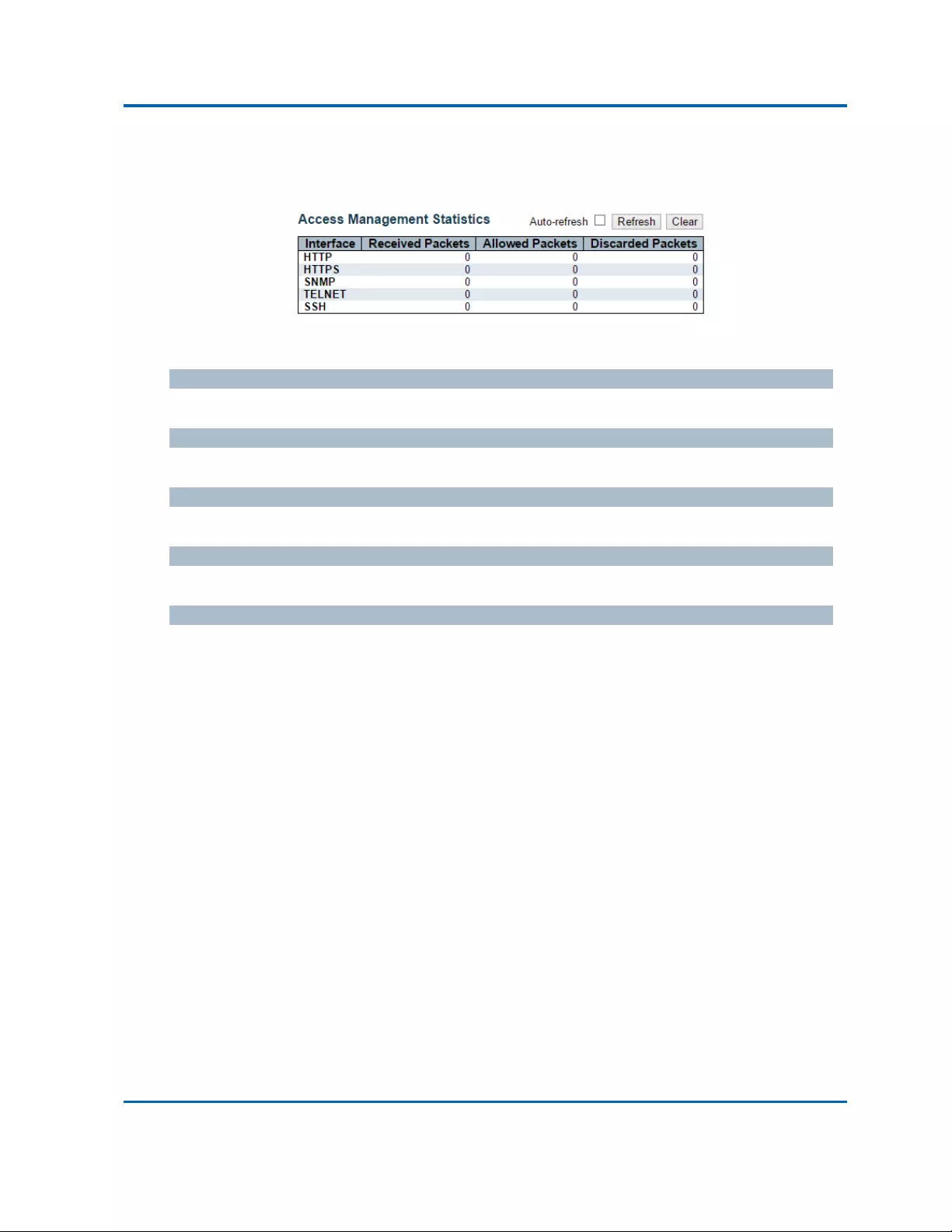
Chapter3:WebManagement
Security‐AccessManagementStatistics
Intelinet48‐PortGigabitEthernetPoE+Layer2+ManagedSwitchUserManual|242
3.2.5.Monitor‐Security
3.2.5.1.Security‐AccessManagementStatistics
Thispageprovidesstatisticsforaccessmanagement.
Interface
Theinterfacetypethroughwhichtheremotehostcanaccesstheswitch.
ReceivedPackets
Numberofreceivedpacketsfromtheinterfacewhenaccessmanagementmodeisenabled.
AllowedPackets
Numberofallowedpacketsfromtheinterfacewhenaccessmanagementmodeisenabled.
DiscardedPackets
Numberofdiscardedpacketsfromtheinterfacewhenaccessmanagementmodeisenabled.
Buttons
Auto‐refresh:Checkthisboxtorefreshthepageautomatically.Automaticrefreshoccursevery
3seconds.
Refresh:Clicktorefreshthepageimmediately.
Clear:Clearallstatistics.
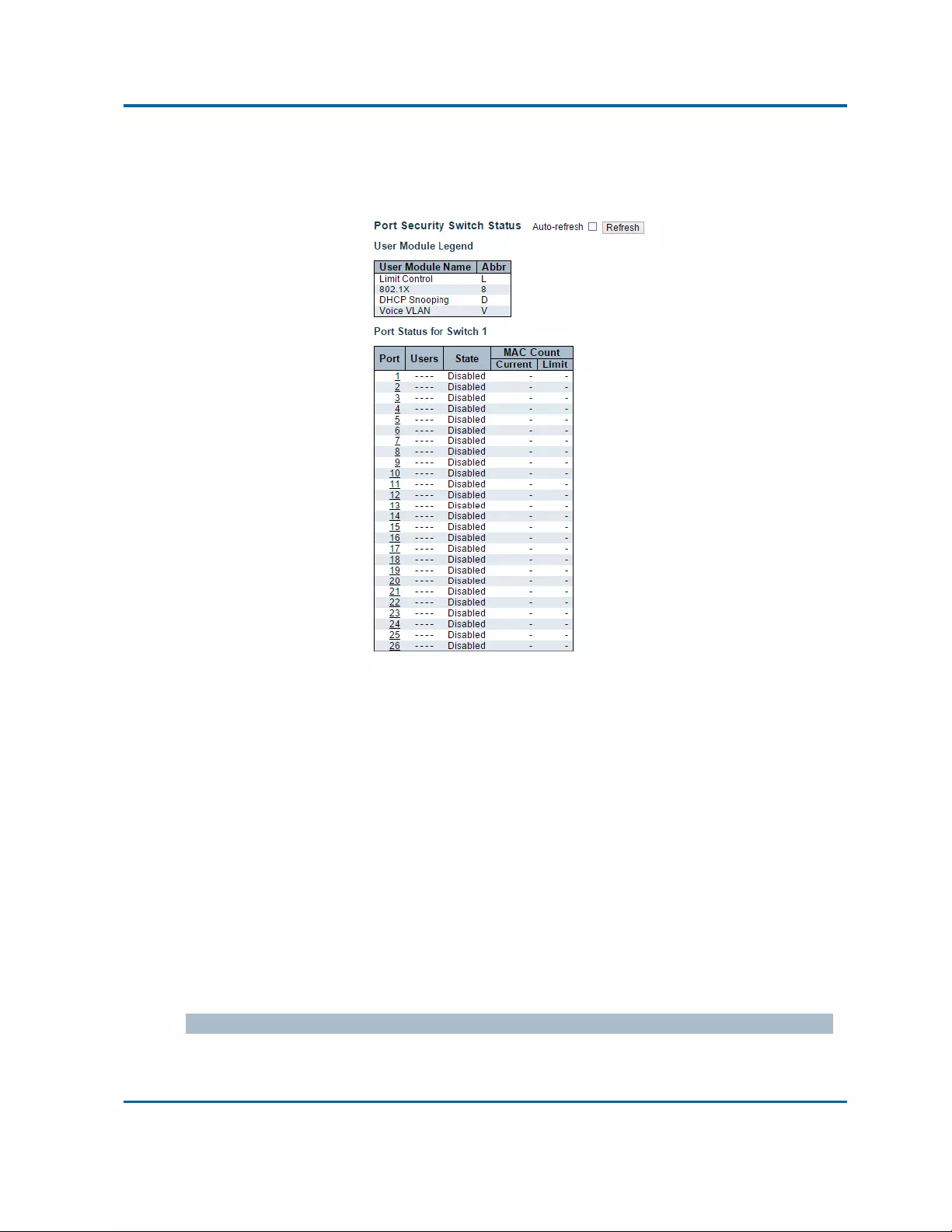
Chapter3:WebManagement
Security‐Network‐PortSecurity‐Switch
Intelinet48‐PortGigabitEthernetPoE+Layer2+ManagedSwitchUserManual|243
3.2.5.2.Security‐Network
3.2.5.2.1.Security‐Network‐PortSecurity‐Switch
ThispageshowsthePortSecuritystatus.PortSecurityisamodulewithnodirectconfiguration.
Configurationcomesindirectlyfromothermodules‐theusermodules.Whenausermodulehas
enabledportsecurityonaport,theportisset‐upforsoftware‐basedlearning.Inthismode,
framesfromunknownMACaddressesarepassedontotheportsecuritymodule,whichinturn
asksallusermoduleswhethertoallowthisnewMACaddresstoforwardorblockit.ForaMAC
addresstobesetintheforwardingstate,allenabledusermodulesmustunanimouslyagreeon
allowingtheMACaddresstoforward.Ifonlyonechoosestoblockit,itwillbeblockeduntilthat
usermoduledecidesotherwise.
Thestatuspageisdividedintotwosections‐onewithalegendofusermodulesandonewiththe
actualportstatus.
UserModuleLegend
ThelegendshowsallusermodulesthatmayrequestPortSecurityservices.
UserModuleName
ThefullnameofamodulethatmayrequestPortSecurityservices.

Chapter3:WebManagement
Security‐Network‐PortSecurity‐Switch
Intelinet48‐PortGigabitEthernetPoE+Layer2+ManagedSwitchUserManual|244
Abbr
Aone‐letterabbreviationoftheusermodule.ThisisusedintheUserscolumnintheportstatus
table.
PortStatus
Thetablehasonerowforeachportontheselectedswitchinthestackandanumberofcolumns.
Port
Theportnumberforwhichthestatusapplies.Clicktheportnumbertoseethestatusforthis
particularport.
Users
EachoftheusermoduleshasacolumnthatshowswhetherthatmodulehasenabledPortSecurity
ornot.A'‐'meansthatthecorrespondingusermoduleisnotenabled,whereasaletterindicates
thattheusermoduleabbreviatedbythatletter(seeAbbr)hasenabledportsecurity.
State
Showsthecurrentstateoftheport.Itcantakeoneoffourvalues:
Disabled:NousermodulesarecurrentlyusingthePortSecurityservice.
Ready:ThePortSecurityserviceisinusebyatleastoneusermodule,andisawaiting
framesfromunknownMACaddressestoarrive.
LimitReached:ThePortSecurityserviceisenabledbyatleasttheLimitControlusermodule,
andthatmodulehasindicatedthatthelimitisreachedandnomoreMACaddressesshould
betakenin.
Shutdown:ThePortSecurityserviceisenabledbyatleasttheLimitControlusermodule,
andthatmodulehasindicatedthatthelimitisexceeded.NoMACaddressescanbelearned
ontheportuntilitisadministrativelyre‐openedontheLimitControlconfiguration
Web‐page.
MACCount(Current,Limit)
ThetwocolumnsindicatethenumberofcurrentlylearnedMACaddresses(forwardingaswellas
blocked)andthemaximumnumberofMACaddressesthatcanbelearnedontheport,
respectively.
Ifnousermodulesareenabledontheport,theCurrentcolumnwillshowadash(‐).
IftheLimitControlusermoduleisnotenabledontheport,theLimitcolumnwillshowadash(‐).

Chapter3:WebManagement
Security‐Network‐PortSecurity‐Switch
Intelinet48‐PortGigabitEthernetPoE+Layer2+ManagedSwitchUserManual|245
Buttons
Auto‐refresh:Checkthisboxtorefreshthepageautomatically.Automaticrefreshoccurs
every3seconds.
Refresh:Clicktorefreshthepageimmediately.

Chapter3:WebManagement
Security‐Network‐PortSecurity‐Port
Intelinet48‐PortGigabitEthernetPoE+Layer2+ManagedSwitchUserManual|246
3.2.5.2.2.Security‐Network‐PortSecurity‐Port
ThispageshowstheMACaddressessecuredbythePortSecuritymodule.PortSecurityisa
modulewithnodirectconfiguration.Configurationcomesindirectlyfromothermodules‐theuser
modules.Whenausermodulehasenabledportsecurityonaport,theportisset‐upfor
software‐basedlearning.Inthismode,framesfromunknownMACaddressesarepassedontothe
portsecuritymodule,whichinturnasksallusermoduleswhethertoallowthisnewMACaddress
toforwardorblockit.ForaMACaddresstobesetintheforwardingstate,allenableduser
modulesmustunanimouslyagreeonallowingtheMACaddresstoforward.Ifonlyonechoosesto
blockit,itwillbeblockeduntilthatusermoduledecidesotherwise.
MACAddress&VLANID
TheMACaddressandVLANIDthatisseenonthisport.IfnoMACaddressesarelearned,asingle
rowstating"NoMACaddressesattached"isdisplayed.
State
IndicateswhetherthecorrespondingMACaddressisblockedorforwarding.Intheblockedstate,it
willnotbeallowedtotransmitorreceivetraffic.
TimeofAddition
ShowsthedateandtimewhenthisMACaddresswasfirstseenontheport.
Age/Hold
IfatleastoneusermodulehasdecidedtoblockthisMACaddress,itwillstayintheblockedstate
untiltheholdtime(measuredinseconds)expires.Ifallusermoduleshavedecidedtoallowthis
MACaddresstoforward,andagingisenabled,thePortSecuritymodulewillperiodicallycheck
thatthisMACaddressstillforwardstraffic.Iftheageperiod(measuredinseconds)expiresandno
frameshavebeenseen,theMACaddresswillberemovedfromtheMACtable.Otherwiseanew
ageperiodwillbegin.
IfagingisdisabledorausermodulehasdecidedtoholdtheMACaddressindefinitely,adash(‐)
willbeshown.
Buttons
Auto‐refresh:Checkthisboxtorefreshthepageautomatically.Automaticrefreshoccurs
every3seconds.
Refresh:Clicktorefreshthepageimmediately.

Chapter3:WebManagement
Security‐Network‐NAS‐Switch
Intelinet48‐PortGigabitEthernetPoE+Layer2+ManagedSwitchUserManual|247
3.2.5.2.3.Security‐Network‐NAS‐Switch
ThispageprovidesanoverviewofthecurrentNASportstatesfortheselectedswitch.
Port
Theswitchportnumber.ClicktonavigatetodetailedNASstatisticsforthisport.
AdminState
Theport'scurrentadministrativestate.RefertoNASAdminStateforadescriptionofpossible
values.
PortState
Thecurrentstateoftheport.RefertoNASPortStateforadescriptionoftheindividualstates.
LastSource
ThesourceMACaddresscarriedinthemostrecentlyreceivedEAPOLframeforEAPOL‐based
authentication,andthemostrecentlyreceivedframefromanewclientforMAC‐based
authentication.
LastID
Theusername(supplicantidentity)carriedinthemostrecentlyreceivedResponseIdentityEAPOL
frameforEAPOL‐basedauthentication,andthesourceMACaddressfromthemostrecently
receivedframefromanewclientforMAC‐basedauthentication.

Chapter3:WebManagement
Security‐Network‐NAS‐Switch
Intelinet48‐PortGigabitEthernetPoE+Layer2+ManagedSwitchUserManual|248
QoSClass
QoSClassassignedtotheportbytheRADIUSserverifenabled.
PortVLANID
TheVLANIDthatNAShasputtheportin.Thefieldisblank,ifthePortVLANIDisnotoverridden
byNAS.
IftheVLANIDisassignedbytheRADIUSserver,"(RADIUS‐assigned)"isappendedtotheVLANID.
ReadmoreaboutRADIUS‐assignedVLANshere.
IftheportismovedtotheGuestVLAN,"(Guest)"isappendedtotheVLANID.Readmoreabout
GuestVLANshere.
Buttons
Auto‐refresh:Checkthisboxtorefreshthepageautomatically.Automaticrefreshoccurs
every3seconds.
Refresh:Clicktorefreshthepageimmediately.

Chapter3:WebManagement
Security‐Network‐NAS‐Port
Intelinet48‐PortGigabitEthernetPoE+Layer2+ManagedSwitchUserManual|249
3.2.5.2.4.Security‐Network‐NAS‐Port
ThispageprovidesdetailedNASstatisticsforaspecificswitchportrunningEAPOL‐basedIEEE
802.1Xauthentication.ForMAC‐basedports,itshowsselectedbackendserver(RADIUS
AuthenticationServer)statisticsonly.
Usetheportselectboxtoselectwhichportdetailstobedisplayed.Theselectedportbelongsto
thecurrentlyselectedstackunitasreflectedbythetableheader.
PortState
AdminState
Theport'scurrentadministrativestate.RefertoNASAdminStateforadescriptionofpossible
values.
PortState
Thecurrentstateoftheport.RefertoNASPortStateforadescriptionoftheindividualstates.
QoSClass
TheQoSclassassignedbytheRADIUSserver.ThefieldisblankifnoQoSclassisassigned.
PortVLANID
TheVLANIDthatNAShasputtheportin.Thefieldisblank,ifthePortVLANIDisnotoverridden
byNAS.
IftheVLANIDisassignedbytheRADIUSserver,"(RADIUS‐assigned)"isappendedtotheVLANID.
ReadmoreaboutRADIUS‐assignedVLANshere.
IftheportismovedtotheGuestVLAN,"(Guest)"isappendedtotheVLANID.Readmoreabout
GuestVLANshere.
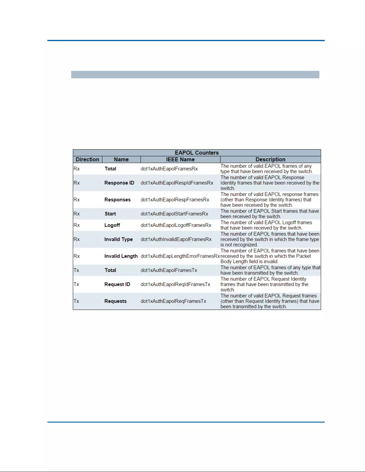
Chapter3:WebManagement
Security‐Network‐NAS‐Port
Intelinet48‐PortGigabitEthernetPoE+Layer2+ManagedSwitchUserManual|250
PortCounters
EAPOLCounters
Thesesupplicantframecountersareavailableforthefollowingadministrativestates:
ForceAuthorized
ForceUnauthorized
Port‐based802.1X
Single802.1X
Multi802.1X

Chapter3:WebManagement
Security‐Network‐NAS‐Port
Intelinet48‐PortGigabitEthernetPoE+Layer2+ManagedSwitchUserManual|251
BackendServerCounters
Thesebackend(RADIUS)framecountersareavailableforthefollowingadministrativestates:
Port‐based802.1X
Single802.1X
Multi802.1X
MAC‐basedAuth.
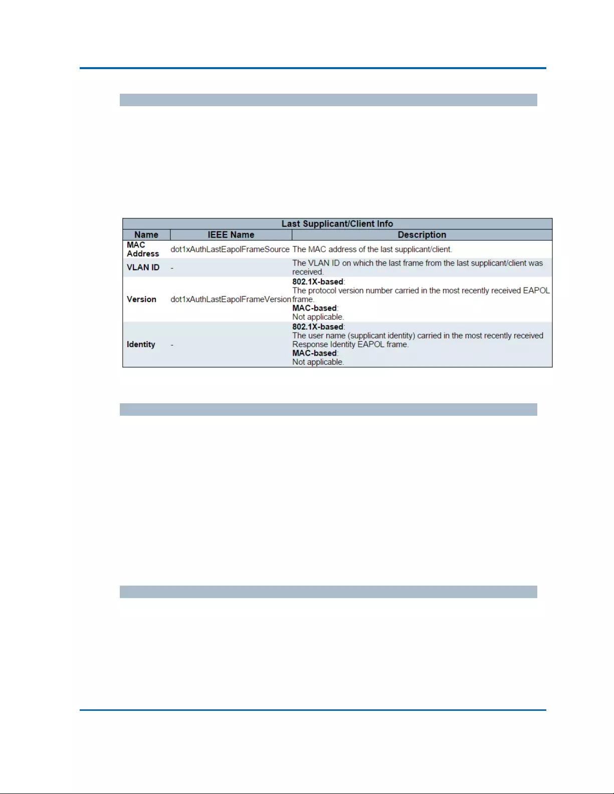
Chapter3:WebManagement
Security‐Network‐NAS‐Port
Intelinet48‐PortGigabitEthernetPoE+Layer2+ManagedSwitchUserManual|252
LastSupplicant/ClientInfo
Informationaboutthelastsupplicant/clientthatattemptedtoauthenticate.Thisinformationis
availableforthefollowingadministrativestates:
Port‐based802.1X
Single802.1X
Multi802.1X
MAC‐basedAuth.
SelectedCounters
SelectedCounters
TheSelectedCounterstableisvisiblewhentheportisinoneofthefollowingadministrative
states:
Multi802.1X
MAC‐basedAuth.
ThetableisidenticaltoandisplacednexttothePortCounterstable,andwillbeemptyifnoMAC
addressiscurrentlyselected.Topopulatethetable,selectoneoftheattachedMACAddresses
fromthetablebelow.
AttachedMACAddresses
Identity
Showstheidentityofthesupplicant,asreceivedintheResponseIdentityEAPOLframe.
Clickingthelinkcausesthesupplicant'sEAPOLandBackendServercounterstobeshowninthe
SelectedCounterstable.Ifnosupplicantsareattached,itshowsNosupplicantsattached.
ThiscolumnisnotavailableforMAC‐basedAuth.

Chapter3:WebManagement
Security‐Network‐NAS‐Port
Intelinet48‐PortGigabitEthernetPoE+Layer2+ManagedSwitchUserManual|253
MACAddress
ForMulti802.1X,thiscolumnholdstheMACaddressoftheattachedsupplicant.
ForMAC‐basedAuth.,thiscolumnholdstheMACaddressoftheattachedclient.
Clickingthelinkcausestheclient'sBackendServercounterstobeshownintheSelectedCounters
table.Ifnoclientsareattached,itshowsNoclientsattached.
VLANID
ThiscolumnholdstheVLANIDthatthecorrespondingclientiscurrentlysecuredthroughthePort
Securitymodule.
State
Theclientcaneitherbeauthenticatedorunauthenticated.Intheauthenticatedstate,itisallowed
toforwardframesontheport,andintheunauthenticatedstate,itisblocked.Aslongasthe
backendserverhasn'tsuccessfullyauthenticatedtheclient,itisunauthenticated.Ifan
authenticationfailsforoneortheotherreason,theclientwillremainintheunauthenticatedstate
forHoldTimeseconds.
LastAuthentication
Showsthedateandtimeofthelastauthenticationoftheclient(successfulaswellas
unsuccessful).
Buttons
Auto‐refresh:Checkthisboxtorefreshthepageautomatically.Automaticrefreshoccurs
every3seconds.
Refresh:Clicktorefreshthepageimmediately.
Clear:Thisbuttonisavailableinthefollowingmodes:
ForceAuthorized
ForceUnauthorized
Port‐based802.1X
Single802.1X
Clear:Clicktoclearthecountersfortheselectedport.
ClearAll:Thisbuttonisavailableinthefollowingmodes:
Multi802.1X
MAC‐basedAuth.X
ClearThis:Clicktoclearboththeportcountersandalloftheattachedclient'scounters.The
"LastClient"willnotbecleared,however.Thisbuttonisavailableinthefollowingmodes:
Multi802.1X
MAC‐basedAuth.X

Chapter3:WebManagement
Security‐Network‐ACLStatus
Intelinet48‐PortGigabitEthernetPoE+Layer2+ManagedSwitchUserManual|254
3.2.5.2.5.Security‐Network‐ACLStatus
ThispageshowstheACLstatusbydifferentACLusers.EachrowdescribestheACEthatisdefined.
ItisaconflictifaspecificACEisnotappliedtothehardwareduetohardwarelimitations.The
maximumnumberofACEsis512oneachswitch.
User
IndicatestheACLuser.
IngressPort
IndicatestheingressportoftheACE.Possiblevaluesare:
All:TheACEwillmatchallingressport.
Port:TheACEwillmatchaspecificingressport.
FrameType
IndicatestheframetypeoftheACE.Possiblevaluesare:
Any:TheACEwillmatchanyframetype.
EType:TheACEwillmatchEthernetTypeframes.NotethatanEthernetTypebasedACEwill
notgetmatchedbyIPandARPframes.
ARP:TheACEwillmatchARP/RARPframes.
IPv4:TheACEwillmatchallIPv4frames.
IPv4/ICMP:TheACEwillmatchIPv4frameswithICMPprotocol.
IPv4/UDP:TheACEwillmatchIPv4frameswithUDPprotocol.
IPv4/TCP:TheACEwillmatchIPv4frameswithTCPprotocol.
IPv4/Other:TheACEwillmatchIPv4frames,whicharenotICMP/UDP/TCP.
IPv6:TheACEwillmatchallIPv6standardframes.
Action
IndicatestheforwardingactionoftheACE.
Permit:FramesmatchingtheACEmaybeforwardedandlearned.
Deny:FramesmatchingtheACEaredropped.
RateLimiter
IndicatestheratelimiternumberoftheACE.Theallowedrangeis1to16.WhenDisabledis
displayed,theratelimiteroperationisdisabled.

Chapter3:WebManagement
Security‐Network‐ACLStatus
Intelinet48‐PortGigabitEthernetPoE+Layer2+ManagedSwitchUserManual|255
CPU
ForwardpacketthatmatchedthespecificACEtoCPU.
CPUOnce
ForwardfirstpacketthatmatchedthespecificACEtoCPU.
Counter
ThecounterindicatesthenumberoftimestheACEwashitbyaframe.
Conflict
IndicatesthehardwarestatusofthespecificACE.ThespecificACEisnotappliedtothehardware
duetohardwarelimitations.
Buttons
TheselectboxdetermineswhichACLuserisaffectedbyclickingthebuttons.
Auto‐refresh:Checkthisboxtorefreshthepageautomatically.Automaticrefreshoccurs
every3seconds.
Refresh:Clicktorefreshthepage.

Chapter3:WebManagement
Security‐Network‐ARPInspection
Intelinet48‐PortGigabitEthernetPoE+Layer2+ManagedSwitchUserManual|256
3.2.5.2.6.Security‐Network‐ARPInspection
EntriesintheDynamicARPInspectionTableareshownonthispage.TheDynamicARPInspection
Tablecontainsupto1024entries,andissortedfirstbyport,thenbyVLANID,thenbyMAC
address,andthenbyIPaddress.
NavigatingtheARPInspectionTable
Eachpageshowsupto99entriesfromtheDynamicARPInspectiontable,defaultbeing20,
selectedthroughthe"entriesperpage"inputfield.Whenfirstvisited,thewebpagewillshowthe
first20entriesfromthebeginningoftheDynamicARPInspectionTable.
The"Startfromportaddress","VLAN","MACaddress"and"IPaddress"inputfieldsallowtheuser
toselectthestartingpointintheDynamicARPInspectionTable.ClickingtheRefreshbuttonwill
updatethedisplayedtablestartingfromthatortheclosestnextDynamicARPInspectionTable
match.Inaddition,thetwoinputfieldswill‐uponaRefreshbuttonclick‐assumethevalueofthe
firstdisplayedentry,allowingforcontinuousrefreshwiththesamestartaddress.
The“<<”buttonwillusethelastentryofthecurrentlydisplayedtableasabasisforthenext
lookup.Whentheendisreachedthetext"Nomoreentries"isshowninthedisplayedtable.Use
the“>>|”buttontostartover.
ARPInspectionTableColumns
Port
SwitchPortNumberforwhichtheentriesaredisplayed.
VLANID
VLAN‐IDinwhichtheARPtrafficispermitted.
MACAddress
UserMACaddressoftheentry.
IPAddress
UserIPaddressoftheentry.

Chapter3:WebManagement
Security‐Network‐ARPInspection
Intelinet48‐PortGigabitEthernetPoE+Layer2+ManagedSwitchUserManual|257
Buttons
Auto‐refresh:Checkthisboxtorefreshthepageautomatically.Automaticrefreshoccurs
every3seconds.
Refresh:Refreshesthedisplayedtablestartingfromtheinputfields.
Clear:Flushesalldynamicentries.
|<<:UpdatesthetablestartingfromthefirstentryintheDynamicARPInspectionTable.
>>:Updatesthetable,startingwiththeentryafterthelastentrycurrentlydisplayed.

Chapter3:WebManagement
Security‐Network‐IPSourceGuard
Intelinet48‐PortGigabitEthernetPoE+Layer2+ManagedSwitchUserManual|258
3.2.5.2.7.Security‐Network‐IPSourceGuard
EntriesintheDynamicIPSourceGuardTableareshownonthispage.TheDynamicIPSource
GuardTableissortedfirstbyport,thenbyVLANID,thenbyIPaddress,andthenbyMACaddress.
NavigatingtheIPSourceGuardTable
Eachpageshowsupto99entriesfromtheDynamicIPSourceGuardtable,defaultbeing20,
selectedthroughthe"entriesperpage"inputfield.Whenfirstvisited,thewebpagewillshowthe
first20entriesfromthebeginningoftheDynamicIPSourceGuardTable.
The"Startfromportaddress","VLAN"and"IPaddress"inputfieldsallowtheusertoselectthe
startingpointintheDynamicIPSourceGuardTable.ClickingtheRefreshbuttonwillupdatethe
displayedtablestartingfromthatortheclosestnextDynamicIPSourceGuardTablematch.In
addition,thetwoinputfieldswill‐uponaRefreshbuttonclick‐assumethevalueofthefirst
displayedentry,allowingforcontinuousrefreshwiththesamestartaddress.
The>>willusethelastentryofthecurrentlydisplayedtableasabasisforthenextlookup.When
theendisreachedthetext"Nomoreentries"isshowninthedisplayedtable.Usethe|<<button
tostartover.
IPSourceGuardTableColumns
Port
SwitchPortNumberforwhichtheentriesaredisplayed.
VLANID
VLAN‐IDinwhichtheIPtrafficispermitted.
IPAddress
UserIPaddressoftheentry.
MACAddress
SourceMACaddress.
Buttons
Auto‐refresh:Checkthisboxtorefreshthepageautomatically.Automaticrefreshoccurs
every3seconds.
Refresh:Refreshesthedisplayedtablestartingfromtheinputfields.
Clear:Flushesalldynamicentries.

Chapter3:WebManagement
Security‐Network‐IPSourceGuard
Intelinet48‐PortGigabitEthernetPoE+Layer2+ManagedSwitchUserManual|259
|<<:UpdatesthetablestartingfromthefirstentryintheDynamicIPSourceGuardTable.
>>:Updatesthetable,startingwiththeentryafterthelastentrycurrentlydisplayed.

Chapter3:WebManagement
Security‐AAA‐RADIUSOverview
Intelinet48‐PortGigabitEthernetPoE+Layer2+ManagedSwitchUserManual|260
3.2.5.3.Security‐Network
3.2.5.3.1.Security‐AAA‐RADIUSOverview
ThispageprovidesanoverviewofthestatusoftheRADIUSserversconfigurableonthe
Authenticationconfigurationpage.
RADIUSAuthenticationServers
#
TheRADIUSservernumber.Clicktonavigatetodetailedstatisticsforthisserver.
IPAddress
TheIPaddressandUDPportnumber(in<IPAddress>:<UDPPort>notation)ofthisserver.
Status
Thecurrentstatusoftheserver.Thisfieldtakesoneofthefollowingvalues:
Disabled:Theserverisdisabled.
NotReady:Theserverisenabled,butIPcommunicationisnotyetupandrunning.
Ready:Theserverisenabled,IPcommunicationisupandrunning,andtheRADIUSmodule
isreadytoacceptaccessattempts.
Dead(Xsecondsleft):Accessattemptsweremadetothisserver,butitdidnotreplywithin
theconfiguredtimeout.Theserverhastemporarilybeendisabled,butwillgetre‐enabled
whenthedead‐timeexpires.Thenumberofsecondsleftbeforethisoccursisdisplayedin
parentheses.Thisstateisonlyreachablewhenmorethanoneserverisenabled.
RADIUSAccountingServers
#
TheRADIUSservernumber.Clicktonavigatetodetailedstatisticsforthisserver.

Chapter3:WebManagement
Security‐AAA‐RADIUSOverview
Intelinet48‐PortGigabitEthernetPoE+Layer2+ManagedSwitchUserManual|261
IPAddress
TheIPaddressandUDPportnumber(in<IPAddress>:<UDPPort>notation)ofthisserver.
Status
Thecurrentstatusoftheserver.Thisfieldtakesoneofthefollowingvalues:
Disabled:Theserverisdisabled.
NotReady:Theserverisenabled,butIPcommunicationisnotyetupandrunning.
Ready:Theserverisenabled,IPcommunicationisupandrunning,andtheRADIUSmodule
isreadytoacceptaccountingattempts.
Dead(Xsecondsleft):Accountingattemptsweremadetothisserver,butitdidnotreply
withintheconfiguredtimeout.Theserverhastemporarilybeendisabled,butwillget
re‐enabledwhenthedead‐timeexpires.Thenumberofsecondsleftbeforethisoccursis
displayedinparentheses.Thisstateisonlyreachablewhenmorethanoneserverisenabled.
Buttons
Auto‐refresh:Checkthisboxtorefreshthepageautomatically.Automaticrefreshoccurs
every3seconds.
Refresh:Clicktorefreshthepageimmediately.
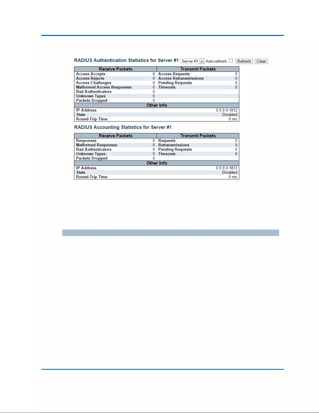
Chapter3:WebManagement
Security‐AAA‐RADIUSDetails
Intelinet48‐PortGigabitEthernetPoE+Layer2+ManagedSwitchUserManual|262
3.2.5.3.2.Security‐AAA‐RADIUSDetails
ThispageprovidesdetailedstatisticsforaparticularRADIUSserver.
RADIUSAuthenticationStatistics
ThestatisticsmapcloselytothosespecifiedinRFC4668‐RADIUSAuthenticationClientMIB.
Usetheserverselectboxtoswitchbetweenthebackendserverstoshowdetailsfor.
PacketCounters
RADIUSauthenticationserverpacketcounter.Therearesevenreceiveandfourtransmitcounters.
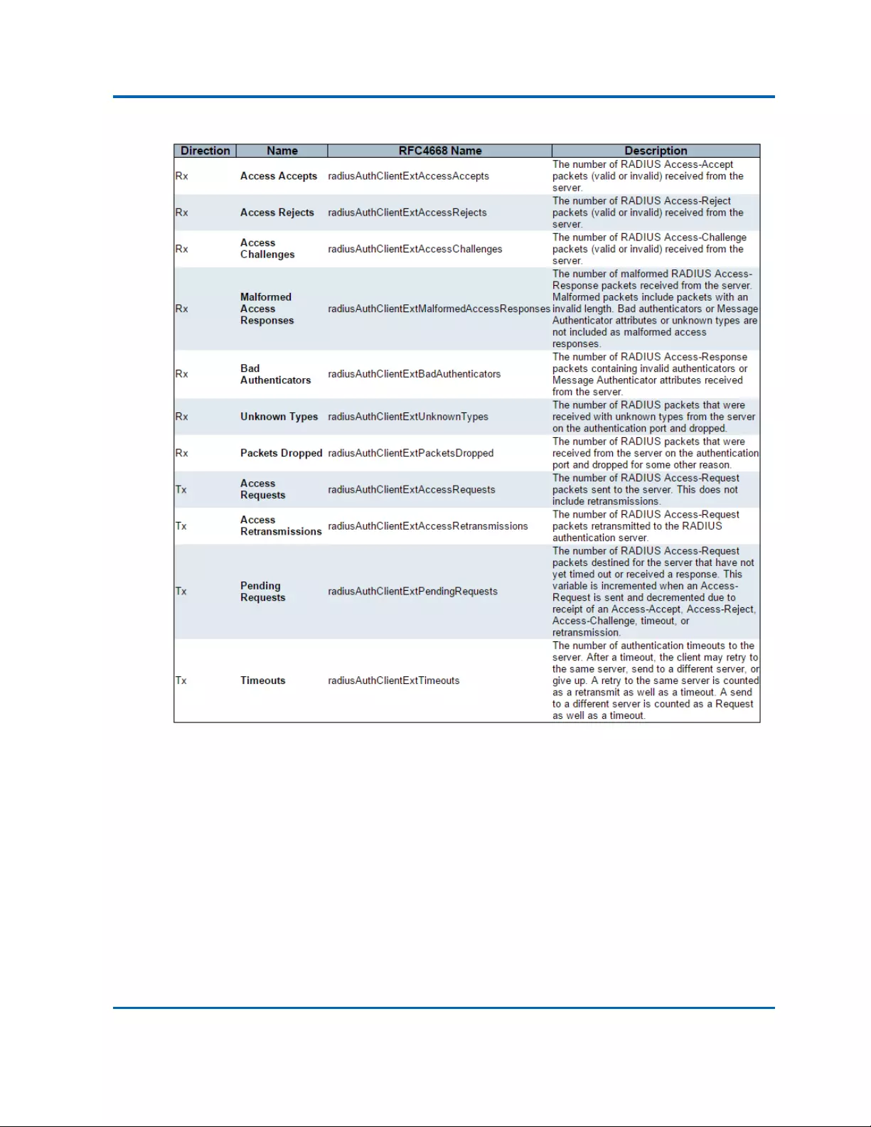
Chapter3:WebManagement
Security‐AAA‐RADIUSDetails
Intelinet48‐PortGigabitEthernetPoE+Layer2+ManagedSwitchUserManual|263
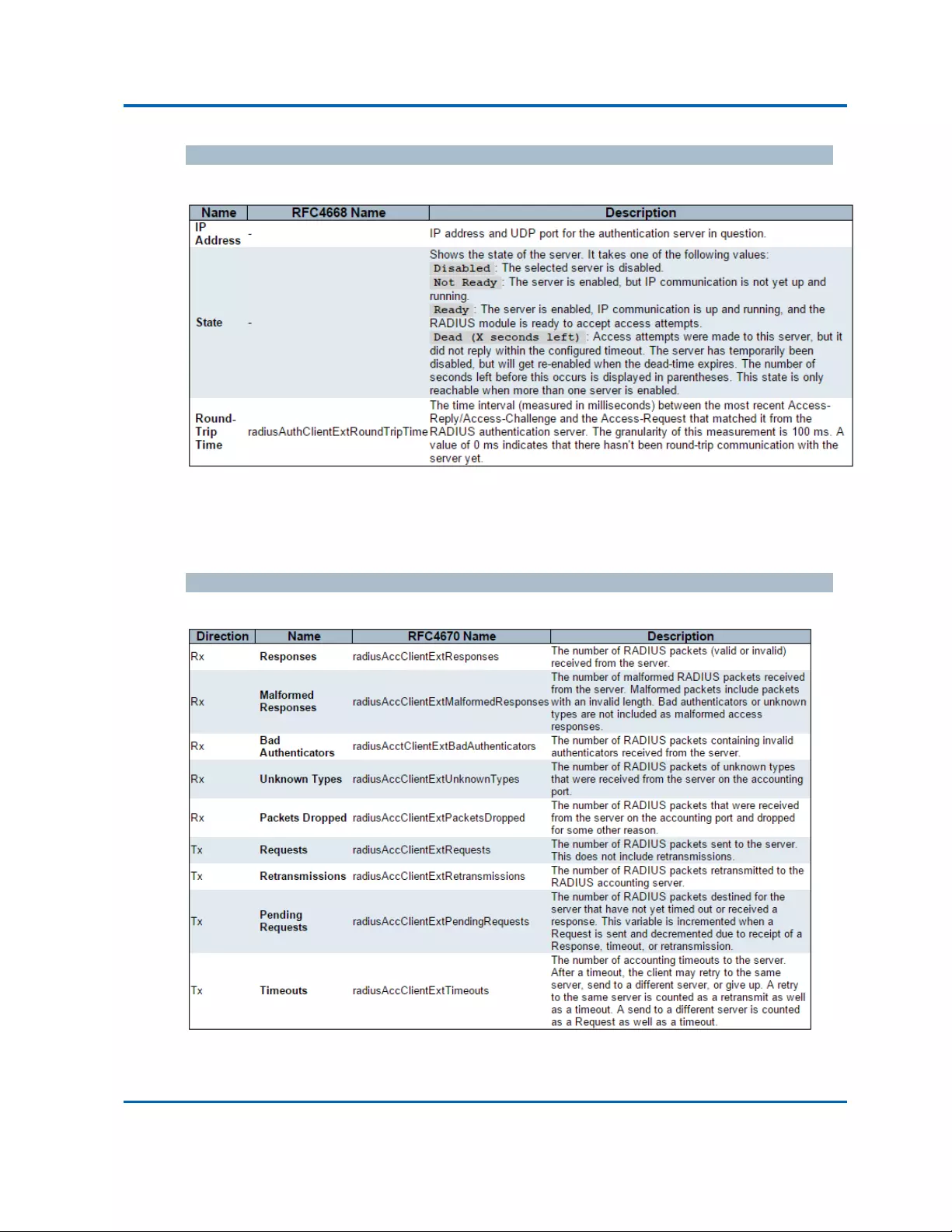
Chapter3:WebManagement
Security‐AAA‐RADIUSDetails
Intelinet48‐PortGigabitEthernetPoE+Layer2+ManagedSwitchUserManual|264
OtherInfo
Thissectioncontainsinformationaboutthestateoftheserverandthelatestround‐triptime.
RADIUSAccountingStatistics
ThestatisticsmapcloselytothosespecifiedinRFC4670‐RADIUSAccountingClientMIB.
Usetheserverselectboxtoswitchbetweenthebackendserverstoshowdetailsfor.
PacketCounters
RADIUSaccountingserverpacketcounter.Therearefivereceiveandfourtransmitcounters.

Chapter3:WebManagement
Security‐AAA‐RADIUSDetails
Intelinet48‐PortGigabitEthernetPoE+Layer2+ManagedSwitchUserManual|265
OtherInfo
Thissectioncontainsinformationaboutthestateoftheserverandthelatestround‐triptime.
Buttons
Theserverselectboxdetermineswhichserverisaffectedbyclickingthebuttons.
Auto‐refresh:Checkthisboxtorefreshthepageautomatically.Automaticrefreshoccurs
every3seconds.
Refresh:Clicktorefreshthepageimmediately.
Clear:Clearsthecountersfortheselectedserver.The"PendingRequests"counterwillnot
beclearedbythisoperation.

Chapter3:WebManagement
Security‐Switch‐RMON‐Statistics
Intelinet48‐PortGigabitEthernetPoE+Layer2+ManagedSwitchUserManual|266
3.2.5.4.Security‐Switch‐RMON
3.2.5.4.1.Security‐Switch‐RMON‐Statistics
ThispageprovidesanoverviewofRMONStatisticsentries.Eachpageshowsupto99entriesfrom
theStatisticstable,defaultbeing20,selectedthroughthe"entriesperpage"inputfield.When
firstvisited,thewebpagewillshowthefirst20entriesfromthebeginningoftheStatisticstable.
ThefirstdisplayedwillbetheonewiththelowestIDfoundintheStatisticstable.
The"StartfromControlIndex"allowstheusertoselectthestartingpointintheStatisticstable.
ClickingtheRefreshbuttonwillupdatethedisplayedtablestartingfromthatorthenextclosest
Statisticstablematch.
The>>buttonwillusethelastentryofthecurrentlydisplayedentryasabasisforthenextlookup.
Whentheendisreachedthetext"Nomoreentries"isshowninthedisplayedtable.Usethe|<<
buttontostartover.
ID
IndicatestheindexofStatisticsentry.
DataSource(ifIndex)
TheportIDwhichwantstobemonitored.
Drop
Thetotalnumberofeventsinwhichpacketsweredroppedbytheprobeduetolackofresources.
Octets
Thetotalnumberofoctetsofdata(includingthoseinbadpackets)receivedonthenetwork.
Pkts
Thetotalnumberofpackets(includingbadpackets,broadcastpackets,andmulticastpackets)
received.
Broad‐cast
Thetotalnumberofgoodpacketsreceivedthatweredirectedtothebroadcastaddress.
Multi‐cast
Thetotalnumberofgoodpacketsreceivedthatweredirectedtoamulticastaddress.

Chapter3:WebManagement
Security‐Switch‐RMON‐Statistics
Intelinet48‐PortGigabitEthernetPoE+Layer2+ManagedSwitchUserManual|267
CRCErrors
Thetotalnumberofpacketsreceivedthathadalength(excludingframingbits,butincludingFCS
octets)ofbetween64and1518octets,inclusive,buthadeitherabadFrameCheckSequence(FCS)
withanintegralnumberofoctets(FCSError)orabadFCSwithanon‐integralnumberofoctets
(AlignmentError).
Under‐size
Thetotalnumberofpacketsreceivedthatwerelessthan64octets.
Over‐size
Thetotalnumberofpacketsreceivedthatwerelongerthan1518octets.
Frag.
Thenumberofframeswhichsizeislessthan64octetsreceivedwithinvalidCRC.
Jabb.
Thenumberofframeswhichsizeislargerthan64octetsreceivedwithinvalidCRC.
Coll.
ThebestestimateofthetotalnumberofcollisionsonthisEthernetsegment.
64
Thetotalnumberofpackets(includingbadpackets)receivedthatwere64octetsinlength.
65~127
Thetotalnumberofpackets(includingbadpackets)receivedthatwerebetween65to127octets
inlength.
128~255
Thetotalnumberofpackets(includingbadpackets)receivedthatwerebetween128to255octets
inlength.
256~511
Thetotalnumberofpackets(includingbadpackets)receivedthatwerebetween256to511octets
inlength.
512~1023
Thetotalnumberofpackets(includingbadpackets)receivedthatwerebetween512to1023
octetsinlength.
1024~1588
Thetotalnumberofpackets(includingbadpackets)receivedthatwerebetween1024to1588
octetsinlength.

Chapter3:WebManagement
Security‐Switch‐RMON‐Statistics
Intelinet48‐PortGigabitEthernetPoE+Layer2+ManagedSwitchUserManual|268
Buttons
Auto‐refresh:Checkthisboxtorefreshthepageautomatically.Automaticrefreshoccurs
every3seconds.
Refresh:Clicktorefreshthepageimmediately.
|<<:UpdatesthetablestartingfromthefirstentryintheStatisticstable,i.e.theentrywith
thelowestID.
>>:Updatesthetable,startingwiththeentryafterthelastentrycurrentlydisplayed.

Chapter3:WebManagement
Security‐Switch‐RMON‐History
Intelinet48‐PortGigabitEthernetPoE+Layer2+ManagedSwitchUserManual|269
3.2.5.4.2.Security‐Switch‐RMON‐History
ThispageprovidesanoverviewofRMONHistoryentries.Eachpageshowsupto99entriesfrom
theHistorytable,defaultbeing20,selectedthroughthe"entriesperpage"inputfield.Whenfirst
visited,thewebpagewillshowthefirst20entriesfromthebeginningoftheHistorytable.The
firstdisplayedwillbetheonewiththelowestHistoryIndexandSampleIndexfoundintheHistory
table.
The"StartfromHistoryIndexandSampleIndex"allowstheusertoselectthestartingpointinthe
Historytable.ClickingtheRefreshbuttonwillupdatethedisplayedtablestartingfromthatorthe
nextclosestHistorytablematch.
The“>>”willusethelastentryofthecurrentlydisplayedentryasabasisforthenextlookup.
Whentheendisreachedthetext"Nomoreentries"isshowninthedisplayedtable.Usethe“|<<”
buttontostartover.
HistoryIndex
IndicatestheindexofHistorycontrolentry.
SampleIndex
Indicatestheindexofthedataentryassociatedwiththecontrolentry.
SampleStart
ThevalueofsysUpTimeatthestartoftheintervaloverwhichthissamplewasmeasured.
Drop
Thetotalnumberofeventsinwhichpacketsweredroppedbytheprobeduetolackofresources.
Octets
Thetotalnumberofoctetsofdata(includingthoseinbadpackets)receivedonthenetwork.
Pkts
Thetotalnumberofpackets(includingbadpackets,broadcastpackets,andmulticastpackets)
received.
Broadcast
Thetotalnumberofgoodpacketsreceivedthatweredirectedtothebroadcastaddress.
Multicast
Thetotalnumberofgoodpacketsreceivedthatweredirectedtoamulticastaddress.

Chapter3:WebManagement
Security‐Switch‐RMON‐History
Intelinet48‐PortGigabitEthernetPoE+Layer2+ManagedSwitchUserManual|270
CRCErrors
Thetotalnumberofpacketsreceivedthathadalength(excludingframingbits,butincludingFCS
octets)ofbetween64and1518octets,inclusive,buthadeitherabadFrameCheckSequence(FCS)
withanintegralnumberofoctets(FCSError)orabadFCSwithanon‐integralnumberofoctets
(AlignmentError).
Undersize
Thetotalnumberofpacketsreceivedthatwerelessthan64octets.
Oversize
Thetotalnumberofpacketsreceivedthatwerelongerthan1518octets.
Frag.
Thenumberofframeswhichsizeislessthan64octetsreceivedwithinvalidCRC.
Jabb.
Thenumberofframeswhichsizeislargerthan64octetsreceivedwithinvalidCRC.
Coll.
ThebestestimateofthetotalnumberofcollisionsonthisEthernetsegment.
Utilization
Thebestestimateofthemeanphysicallayernetworkutilizationonthisinterfaceduringthis
samplinginterval,inhundredthsofapercent.
Buttons
Auto‐refresh:Checkthisboxtorefreshthepageautomatically.Automaticrefreshoccurs
every3seconds.
Refresh:Clicktorefreshthepageimmediately.
|<<:UpdatesthetablestartingfromthefirstentryintheHistorytable,i.e.,theentrywith
thelowestHistoryIndexandSampleIndex
>>:Updatesthetable,startingwiththeentryafterthelastentrycurrentlydisplayed.

Chapter3:WebManagement
Security‐Switch‐RMON‐Alarm
Intelinet48‐PortGigabitEthernetPoE+Layer2+ManagedSwitchUserManual|271
3.2.5.4.3.Security‐Switch‐RMON‐Alarm
ThispageprovidesanoverviewofRMONAlarmentries.Eachpageshowsupto99entriesfrom
theAlarmtable,defaultbeing20,selectedthroughthe"entriesperpage"inputfield.Whenfirst
visited,thewebpagewillshowthefirst20entriesfromthebeginningoftheAlarmtable.Thefirst
displayedwillbetheonewiththelowestIDfoundintheAlarmtable.
The"StartfromControlIndex"allowstheusertoselectthestartingpointintheAlarmtable.
ClickingtheRefreshbuttonwillupdatethedisplayedtablestartingfromthatorthenextclosest
Alarmtablematch.
The“>>”willusethelastentryofthecurrentlydisplayedentryasabasisforthenextlookup.
Whentheendisreachedthetext"Nomoreentries"isshowninthedisplayedtable.Usethe“|<<”
buttontostartover.
ID
IndicatestheindexofAlarmcontrolentry.
Interval
Indicatestheintervalinsecondsforsamplingandcomparingtherisingandfallingthreshold.
Variable
Indicatestheparticularvariabletobesampled
SampleType
Themethodofsamplingtheselectedvariableandcalculatingthevaluetobecomparedagainst
thethresholds.
Value
Thevalueofthestatisticduringthelastsamplingperiod.
StartupAlarm
Thealarmthatmaybesentwhenthisentryisfirstsettovalid.
RisingThreshold
Risingthresholdvalue.
RisingIndex
Risingeventindex.

Chapter3:WebManagement
Security‐Switch‐RMON‐Alarm
Intelinet48‐PortGigabitEthernetPoE+Layer2+ManagedSwitchUserManual|272
FallingThreshold
Fallingthresholdvalue.
FallingIndex
Fallingeventindex.
Buttons
Auto‐refresh:Checkthisboxtorefreshthepageautomatically.Automaticrefreshoccurs
every3seconds.
Refresh:Clicktorefreshthepageimmediately.
|<<:UpdatesthetablestartingfromthefirstentryintheAlarmTable,i.e.theentrywiththe
lowestID.
>>:Updatesthetable,startingwiththeentryafterthelastentrycurrentlydisplayed.

Chapter3:WebManagement
Security‐Switch‐RMON‐Events
Intelinet48‐PortGigabitEthernetPoE+Layer2+ManagedSwitchUserManual|273
3.2.5.4.4.Security‐Switch‐RMON‐Events
ThispageprovidesanoverviewofRMONEventtableentries.Eachpageshowsupto99entries
fromtheEventtable,defaultbeing20,selectedthroughthe"entriesperpage"inputfield.When
firstvisited,thewebpagewillshowthefirst20entriesfromthebeginningoftheEventtable.The
firstdisplayedwillbetheonewiththelowestEventIndexandLogIndexfoundintheEventtable
table.
The"StartfromEventIndexandLogIndex"allowstheusertoselectthestartingpointintheEvent
table.ClickingtheRefreshbuttonwillupdatethedisplayedtablestartingfromthatorthenext
closestEventtablematch.
The“>>”willusethelastentryofthecurrentlydisplayedentryasabasisforthenextlookup.
Whentheendisreachedthetext"Nomoreentries"isshowninthedisplayedtable.Usethe“|<<”
buttontostartover.
EventIndex
Indicatestheindexoftheevententry.
LogIndex
Indicatestheindexofthelogentry.
LogTIme
IndicatesEventlogtime
LogDescription
IndicatestheEventdescription.
Buttons
Auto‐refresh:Checkthisboxtorefreshthepageautomatically.Automaticrefreshoccurs
every3seconds.
Refresh:Clicktorefreshthepageimmediately.
|<<:UpdatesthetablestartingfromthefirstentryintheEventTable,i.e.theentrywiththe
lowestEventIndexandLogIndex.
>>:Updatesthetable,startingwiththeentryafterthelastentrycurrentlydisplayed.

Chapter3:WebManagement
Security‐Switch‐RMON‐Events
Intelinet48‐PortGigabitEthernetPoE+Layer2+ManagedSwitchUserManual|274

Chapter3:WebManagement
LACP‐SystemStatus
Intelinet48‐PortGigabitEthernetPoE+Layer2+ManagedSwitchUserManual|275
3.2.6.Monitor‐LACP
3.2.6.1.LACP‐SystemStatus
ThispageprovidesastatusoverviewforallLACPinstances.
AggrID
TheAggregationIDassociatedwiththisaggregationinstance.ForLLAGtheidisshownas
'isid:aggr‐id'andforGLAGsas'aggr‐id'
PartnerSystemID
ThesystemID(MACaddress)oftheaggregationpartner.
PartnerKey
TheKeythatthepartnerhasassignedtothisaggregationID.
Lastchanged
Thetimesincethisaggregationchanged.
LocalPorts
Showswhichportsareapartofthisaggregationforthisswitch/stack.Theformatis:"SwitchID:Port".
Buttons
Auto‐refresh:Checkthisboxtorefreshthepageautomatically.Automaticrefreshoccursevery
3seconds.
Refresh:Clicktorefreshthepage.

Chapter3:WebManagement
LACP‐PortStatus
Intelinet48‐PortGigabitEthernetPoE+Layer2+ManagedSwitchUserManual|276
3.2.6.2.LACP‐PortStatus
ThispageprovidesastatusoverviewforLACPstatusforallports.
Port
Theswitchportnumber.
LACP
'Yes'meansthatLACPisenabledandtheportlinkisup.'No'meansthatLACPisnotenabledorthat
theportlinkisdown.'Backup'meansthattheportcouldnotjointheaggregationgroupbutwilljoin
ifotherportleaves.Meanwhileit'sLACPstatusisdisabled.
Key
Thekeyassignedtothisport.Onlyportswiththesamekeycanaggregatetogether.
AggrID
TheAggregationIDassignedtothisaggregationgroup.IDs1and2areGLAGswhileIDs3‐14are
LLAGs.
PartnerSystemID
Thepartner'sSystemID(MACaddress).
PartnerPort
Thepartner'sportnumberconnectedtothisport.
PartnerPrio
Thepartner'sportpriority.
Buttons
Auto‐refresh:Checkthisboxtorefreshthepageautomatically.Automaticrefreshoccursevery
3seconds.

Chapter3:WebManagement
LACP‐PortStatus
Intelinet48‐PortGigabitEthernetPoE+Layer2+ManagedSwitchUserManual|277
Refresh:Clicktorefreshthepage.

Chapter3:WebManagement
LACP‐PortStatistics
Intelinet48‐PortGigabitEthernetPoE+Layer2+ManagedSwitchUserManual|278
3.2.6.3.LACP‐PortStatistics
ThispageprovidesanoverviewforLACPstatisticsforallports.
Port
Theswitchportnumber.
LACPReceived
ShowshowmanyLACPframeshavebeenreceivedateachport.
LACPTransmitted
ShowshowmanyLACPframeshavebeensentfromeachport.
Discarded
ShowshowmanyunknownorillegalLACPframeshavebeendiscardedateachport.
Buttons
Auto‐refresh:Automaticrefreshoccursevery3seconds.
Refresh:Clicktorefreshthepageimmediately.
Clear:Clearsthecountersforallports.

Chapter3:WebManagement
Monitor‐LoopProtection
Intelinet48‐PortGigabitEthernetPoE+Layer2+ManagedSwitchUserManual|279
3.2.7.Monitor‐LoopProtection
Thispagedisplaystheloopprotectionportstatustheportsofthecurrentlyselectedswitch.
Port
Theswitchportnumberofthelogicalport.
Action
Thecurrentlyconfiguredportaction.
Transmit
Thecurrentlyconfiguredporttransmitmode.
Loops
Thenumberofloopsdetectedonthisport.
Status
Thecurrentloopprotectionstatusoftheport.
Loop
Whetheraloopiscurrentlydetectedontheport.
TimeofLastLoop
Thetimeofthelastloopeventdetected.
Buttons
Refresh:Clicktorefreshthepageimmediately.
Auto‐refresh:Checkthisboxtoenableanautomaticrefreshofthepageatregularintervals.

Chapter3:WebManagement
SpanningTree‐BridgeStatus
Intelinet48‐PortGigabitEthernetPoE+Layer2+ManagedSwitchUserManual|280
3.2.8.Monitor‐SpanningTree
3.2.8.1.SpanningTree‐BridgeStatus
ThispageprovidesastatusoverviewofallSTPbridgeinstances.
ThedisplayedtablecontainsarowforeachSTPbridgeinstance,wherethecolumndisplaysthe
followinginformation:
MSTI
TheBridgeInstance.ThisisalsoalinktotheSTPDetailedBridgeStatus.
BridgeID
TheBridgeIDofthisBridgeinstance.
RootID
TheBridgeIDofthecurrentlyelectedrootbridge.
RootPort
Theswitchportcurrentlyassignedtherootportrole.
RootCost
RootPathCost.FortheRootBridgeitiszero.ForallotherBridges,itisthesumofthePortPathCosts
ontheleastcostpathtotheRootBridge.
TopologyFlag
ThecurrentstateoftheTopologyChangeFlagofthisBridgeinstance.
TopologyChangeLast
ThetimesincelastTopologyChangeoccurred.
Buttons
Refresh:Clicktorefreshthepageimmediately.
Auto‐refresh:Checkthisboxtoenableanautomaticrefreshofthepageatregularintervals.

Chapter3:WebManagement
SpanningTree‐PortStatus
Intelinet48‐PortGigabitEthernetPoE+Layer2+ManagedSwitchUserManual|281
3.2.8.2.SpanningTree‐PortStatus
ThispagedisplaystheSTPportstatisticscountersofbridgeportsinthecurrentlyselectedswitch.
Port
TheswitchportnumberofthelogicalSTPport.
MSTP
ThenumberofMSTPBPDU'sreceived/transmittedontheport.
RSTP
ThenumberofRSTPBPDU'sreceived/transmittedontheport.
STP
ThenumberoflegacySTPConfigurationBPDU'sreceived/transmittedontheport.
TCN
Thenumberof(legacy)TopologyChangeNotificationBPDU'sreceived/transmittedontheport.
DiscardedUnknown
ThenumberofunknownSpanningTreeBPDU'sreceived(anddiscarded)ontheport.
DiscardedIllegal
ThenumberofillegalSpanningTreeBPDU'sreceived(anddiscarded)ontheport.
Buttons
Refresh:Clicktorefreshthepageimmediately.
Clear:Clicktoresetthecounters.
Auto‐refresh:Checkthisboxtoenableanautomaticrefreshofthepageatregularintervals.

Chapter3:WebManagement
SpanningTree‐PortStatistics
Intelinet48‐PortGigabitEthernetPoE+Layer2+ManagedSwitchUserManual|282
3.2.8.3.SpanningTree‐PortStatistics
ThispagedisplaystheSTPportstatisticscountersofbridgeportsinthecurrentlyselectedswitch.
Port
TheswitchportnumberofthelogicalSTPport.
MSTP
ThenumberofMSTPBPDU'sreceived/transmittedontheport.
RSTP
ThenumberofRSTPBPDU'sreceived/transmittedontheport.
STP
ThenumberoflegacySTPConfigurationBPDU'sreceived/transmittedontheport.
TCN
Thenumberof(legacy)TopologyChangeNotificationBPDU'sreceived/transmittedontheport.
DiscardedUnknown
ThenumberofunknownSpanningTreeBPDU'sreceived(anddiscarded)ontheport.
DiscardedIllegal
ThenumberofillegalSpanningTreeBPDU'sreceived(anddiscarded)ontheport.
Buttons
Refresh:Clicktorefreshthepageimmediately.
Clear:Clicktoresetthecounters.
Auto‐refresh:Checkthisboxtoenableanautomaticrefreshofthepageatregularintervals.

Chapter3:WebManagement
MVR‐Statistics
Intelinet48‐PortGigabitEthernetPoE+Layer2+ManagedSwitchUserManual|283
3.2.9.Monitor‐MVR
3.2.9.1.MVR‐Statistics
ThispageprovidesMVRStatisticsinformation.
Thestatisticsisrelatedtothecurrentlyselectingstackunit,asreflectedbythepageheader.
VLANID
TheMulticastVLANID.
IGMP/MLDQueriesReceived
ThenumberofReceivedQueriesforIGMPandMLD,respectively.
IGMP/MLDQueriesTransmitted
ThenumberofTransmittedQueriesforIGMPandMLD,respectively.
IGMPv1JoinsReceived
ThenumberofReceivedIGMPv1Join's.
IGMPv2/MLDv1Report'sReceived
ThenumberofReceivedIGMPv2Join'sandMLDv1Report's,respectively.
IGMPv3/MLDv2Report'sReceived
ThenumberofReceivedIGMPv1Join'sandMLDv2Report's,respectively.
IGMPv2/MLDv1Leave'sReceived
ThenumberofReceivedIGMPv2Leave'sandMLDv1Done's,respectively.
Buttons
Auto‐refresh:Checkthisboxtoenableanautomaticrefreshofthepageatregularintervals.
Refresh:Clicktorefreshthepageimmediately.
Clear:ClearsallStatisticscounters.

Chapter3:WebManagement
MVR‐MVRChannelGroups
Intelinet48‐PortGigabitEthernetPoE+Layer2+ManagedSwitchUserManual|284
3.2.9.2.MVR‐MVRChannelGroups
EntriesintheMVRChannels(Groups)InformationTableareshownonthispage.TheMVRChannels
(Groups)InformationTableissortedfirstbyVLANID,andthenbygroup.
NavigatingtheMVRChannels(Groups)InformationTable
Eachpageshowsupto99entriesfromtheMVRGrouptable,defaultbeing20,selectedthroughthe
"entriesperpage"inputfield.Whenfirstvisited,thewebpagewillshowthefirst20entriesfromthe
beginningoftheMVRChannels(Groups)InformationTable.
The"StartfromVLAN",and"GroupAddress"inputfieldsallowtheusertoselectthestartingpointin
theMVRChannels(Groups)InformationTable.ClickingtheRefreshbuttonwillupdatethedisplayed
tablestartingfromthatortheclosestnextMVRChannels(Groups)InformationTablematch.In
addition,thetwoinputfieldswill‐uponaRefreshbuttonclick‐assumethevalueofthefirst
displayedentry,allowingforcontinuousrefreshwiththesamestartaddress.
The“>>”willusethelastentryofthecurrentlydisplayedtableasabasisforthenextlookup.When
theendisreachedthetext"Nomoreentries"isshowninthedisplayedtable.Usethe“|<<”button
tostartover.
MVRChannels(Groups)InformationTableColumns
VLANID
VLANIDofthegroup.
Groups
GroupIDofthegroupdisplayed.
PortMembers
Portsunderthisgroup.
Buttons
Auto‐refresh:Automaticrefreshoccursevery3seconds.
Refresh:Refreshesthedisplayedtablestartingfromtheinputfields.
|<<:UpdatesthetablestartingfromthefirstentryintheMVRChannels(Groups)Information
Table.

Chapter3:WebManagement
MVR‐MVRChannelGroups
Intelinet48‐PortGigabitEthernetPoE+Layer2+ManagedSwitchUserManual|285
>>:Updatesthetable,startingwiththeentryafterthelastentrycurrentlydisplayed.

Chapter3:WebManagement
MVR‐MVRSFMInformation
Intelinet48‐PortGigabitEthernetPoE+Layer2+ManagedSwitchUserManual|286
3.2.9.3.MVR‐MVRSFMInformation
EntriesintheMVRSFMInformationTableareshownonthispage.TheMVRSFM(Source‐Filtered
Multicast)InformationTablealsocontainstheSSM(Source‐SpecificMulticast)information.Thistable
issortedfirstbyVLANID,thenbygroup,andthenbyPort.Differentsourceaddressesbelongtothe
samegrouparetreatedassingleentry.
NavigatingtheMVRSFMInformationTable
Eachpageshowsupto99entriesfromtheMVRSFMInformationTable,defaultbeing20,selected
throughthe"entriesperpage"inputfield.Whenfirstvisited,thewebpagewillshowthefirst20
entriesfromthebeginningoftheMVRSFMInformationTable.
The"StartfromVLAN",and"GroupAddress"inputfieldsallowtheusertoselectthestartingpointin
theMVRSFMInformationTable.ClickingtheRefreshbuttonwillupdatethedisplayedtablestarting
fromthatortheclosestnextMVRSFMInformationTablematch.Inaddition,thetwoinputfieldswill
‐uponaRefreshbuttonclick‐assumethevalueofthefirstdisplayedentry,allowingforcontinuous
refreshwiththesamestartaddress.
The“>>”willusethelastentryofthecurrentlydisplayedtableasabasisforthenextlookup.When
theendisreachedthetext"Nomoreentries"isshowninthedisplayedtable.Usethe“|<<”button
tostartover.
MVRSFMInformationTableColumns
VLANID
VLANIDofthegroup.
Group
Groupaddressofthegroupdisplayed.
Port
Switchportnumber.
Mode
Indicatesthefilteringmodemaintainedper(VLANID,portnumber,GroupAddress)basis.Itcanbe
eitherIncludeorExclude.
SourceAddress

Chapter3:WebManagement
MVR‐MVRSFMInformation
Intelinet48‐PortGigabitEthernetPoE+Layer2+ManagedSwitchUserManual|287
IPAddressofthesource.Currently,systemlimitsthetotalnumberofIPsourceaddressesforfiltering
tobe128.Whenthereisnoanysourcefilteringaddress,thetext"None"isshownintheSource
Addressfield.
Type
IndicatestheType.ItcanbeeitherAlloworDeny.
HardwareFilter/Switch
IndicateswhetherdataplanedestinedtothespecificgroupaddressfromthesourceIPv4/IPv6
addresscouldbehandledbychipornot.
Buttons
Auto‐refresh:Automaticrefreshoccursevery3seconds.
Refresh:Refreshesthedisplayedtablestartingfromtheinputfields.
|<<:UpdatesthetablestartingfromthefirstentryintheMVRSFMInformationTable.
>>:Updatesthetable,startingwiththeentryafterthelastentrycurrentlydisplayed
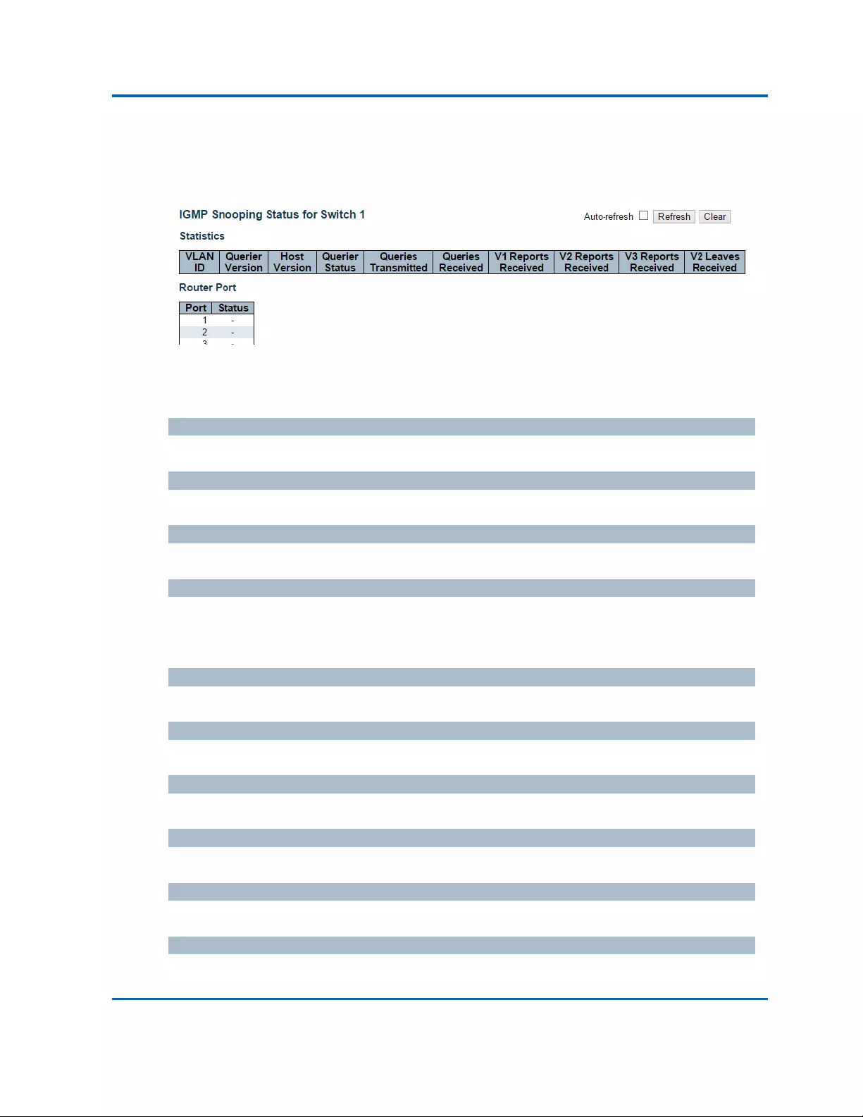
Chapter3:WebManagement
IPMC‐IGMPSnooping‐Status
Intelinet48‐PortGigabitEthernetPoE+Layer2+ManagedSwitchUserManual|288
3.2.10.Monitor‐IPMC
3.2.10.1.IPMC‐IGMPSnooping
3.2.10.1.1.IPMC‐IGMPSnooping‐Status
ThispageprovidesIGMPSnoopingstatus.
Thestatusrelatedtothecurrentlyselectedstackunit,asreflectedbythepageheader.
VLANID
TheVLANIDoftheentry.
QuerierVersion
WorkingQuerierVersioncurrently.
HostVersion
WorkingHostVersioncurrently.
QuerierStatus
ShowstheQuerierstatusis"ACTIVE"or"IDLE".
"DISABLE"denotesthespecificinterfaceisadministrativelydisabled.
QueriesTransmitted
ThenumberofTransmittedQueries.
QueriesReceived
ThenumberofReceivedQueries.
V1ReportsReceived
ThenumberofReceivedV1Reports.
V2ReportsReceived
ThenumberofReceivedV2Reports.
V3ReportsReceived
ThenumberofReceivedV3Reports.
V2LeavesReceived
ThenumberofReceivedV2Leaves.

Chapter3:WebManagement
IPMC‐IGMPSnooping‐Status
Intelinet48‐PortGigabitEthernetPoE+Layer2+ManagedSwitchUserManual|289
RouterPort
Displaywhichportsactasrouterports.ArouterportisaportontheEthernetswitchthatleads
towardstheLayer3multicastdeviceorIGMPquerier.
Staticdenotesthespecificportisconfiguredtobearouterport.
Dynamicdenotesthespecificportislearnttobearouterport.
Bothdenotethespecificportisconfiguredorlearnttobearouterport.
Port
Switchportnumber.
Status
Indicatewhetherspecificportisarouterportornot.
Buttons
Auto‐refresh:Automaticrefreshoccursevery3seconds.
Refresh:Clicktorefreshthepageimmediately.
Clear:ClearsallStatisticscounters.

Chapter3:WebManagement
IPMC‐IGMPSnooping‐GroupsInformation
Intelinet48‐PortGigabitEthernetPoE+Layer2+ManagedSwitchUserManual|290
3.2.10.1.2.IPMC‐IGMPSnooping‐GroupsInformation
EntriesintheIGMPGroupTableareshownonthispage.TheIGMPGroupTableissortedfirstby
VLANID,andthenbygroup.
NavigatingtheIGMPGroupTable
Eachpageshowsupto99entriesfromtheIGMPGrouptable,defaultbeing20,selectedthrough
the"entriesperpage"inputfield.Whenfirstvisited,thewebpagewillshowthefirst20entries
fromthebeginningoftheIGMPGroupTable.
The"StartfromVLAN",and"group"inputfieldsallowtheusertoselectthestartingpointinthe
IGMPGroupTable.ClickingtheRefreshbuttonwillupdatethedisplayedtablestartingfromthator
theclosestnextIGMPGroupTablematch.Inaddition,thetwoinputfieldswill‐uponaRefresh
buttonclick‐assumethevalueofthefirstdisplayedentry,allowingforcontinuousrefreshwith
thesamestartaddress.
The>>willusethelastentryofthecurrentlydisplayedtableasabasisforthenextlookup.When
theendisreachedthetext"Nomoreentries"isshowninthedisplayedtable.Usethe|<<button
tostartover.
IGMPGroupTableColumns
VLANID
VLANIDofthegroup.
Groups
Groupaddressofthegroupdisplayed.
PortMembers
Portsunderthisgroup.
Buttons
Auto‐refresh:Automaticrefreshoccursevery3seconds.
Refresh:Refreshesthedisplayedtablestartingfromtheinputfields.
|<<:Updatesthetable,startingwiththefirstentryintheIGMPGroupTable.
>>:Updatesthetable,startingwiththeentryafterthelastentrycurrentlydisplayed.

Chapter3:WebManagement
IPMC‐IGMPSnooping‐GroupsInformation
Intelinet48‐PortGigabitEthernetPoE+Layer2+ManagedSwitchUserManual|291

Chapter3:WebManagement
IPMC‐IGMPSnooping‐IPv4SFMInformation
Intelinet48‐PortGigabitEthernetPoE+Layer2+ManagedSwitchUserManual|292
3.2.10.1.3.IPMC‐IGMPSnooping‐IPv4SFMInformation
EntriesintheIGMPSFMInformationTableareshownonthispage.TheIGMPSFM
(Source‐FilteredMulticast)InformationTablealsocontainstheSSM(Source‐SpecificMulticast)
information.ThistableissortedfirstbyVLANID,thenbygroup,andthenbyPort.Differentsource
addressesbelongtothesamegrouparetreatedassingleentry.
NavigatingtheIGMPSFMInformationTable
Eachpageshowsupto99entriesfromtheIGMPSFMInformationtable,defaultbeing20,selected
throughthe"entriesperpage"inputfield.Whenfirstvisited,thewebpagewillshowthefirst20
entriesfromthebeginningoftheIGMPSFMInformationTable.
The"StartfromVLAN",and"group"inputfieldsallowtheusertoselectthestartingpointinthe
IGMPSFMInformationTable.ClickingtheRefreshbuttonwillupdatethedisplayedtablestarting
fromthatortheclosestnextIGMPSFMInformationTablematch.Inaddition,thetwoinputfields
will‐uponaRefreshbuttonclick‐assumethevalueofthefirstdisplayedentry,allowingfor
continuousrefreshwiththesamestartaddress.
The“>>”willusethelastentryofthecurrentlydisplayedtableasabasisforthenextlookup.
Whentheendisreachedthetext"Nomoreentries"isshowninthedisplayedtable.Usethe“|<<”
buttontostartover.
IGMPSFMInformationTableColumns
VLANID
VLANIDofthegroup.
Group
Groupaddressofthegroupdisplayed.
Port
Switchportnumber.
Mode
Indicatesthefilteringmodemaintainedper(VLANID,portnumber,GroupAddress)basis.Itcanbe
eitherIncludeorExclude.
SourceAddress
IPAddressofthesource.Currently,systemlimitsthetotalnumberofIPsourceaddressesfor

Chapter3:WebManagement
IPMC‐IGMPSnooping‐IPv4SFMInformation
Intelinet48‐PortGigabitEthernetPoE+Layer2+ManagedSwitchUserManual|293
filteringtobe128.
Type
IndicatestheType.ItcanbeeitherAlloworDeny.
HardwareFilter/Switch
IndicateswhetherdataplanedestinedtothespecificgroupaddressfromthesourceIPv4address
couldbehandledbychipornot.
Buttons
Auto‐refresh:Automaticrefreshoccursevery3seconds.
Refresh:Refreshesthedisplayedtablestartingfromtheinputfields.
|<<:UpdatesthetablestartingfromthefirstentryintheIGMPSFMInformationTable
>>:Updatesthetable,startingwiththeentryafterthelastentrycurrentlydisplayed.

Chapter3:WebManagement
IPMC‐MLDSnooping‐Status
Intelinet48‐PortGigabitEthernetPoE+Layer2+ManagedSwitchUserManual|294
3.2.10.2.IPMC‐MLDSnooping
3.2.10.2.1.IPMC‐MLDSnooping‐Status
ThispageprovidesMLDSnoopingstatus.
Thestatusrelatedtothecurrentlyselectedstackunit,asreflectedbythepageheader.
VLANID
TheVLANIDoftheentry.
QuerierVersion
WorkingQuerierVersioncurrently.
HostVersion
WorkingHostVersioncurrently.
QuerierStatus
ShowstheQuerierstatusis"ACTIVE"or"IDLE".
"DISABLE"denotesthespecificinterfaceisadministrativelydisabled.
QueriesTransmitted
ThenumberofTransmittedQueries.
QueriesReceived
ThenumberofReceivedQueries.
V1ReportsReceived
ThenumberofReceivedV1Reports.
V2ReportsReceived
ThenumberofReceivedV2Reports.
V1LeavesReceived
ThenumberofReceivedV1Leaves.
RouterPort
Displaywhichportsactasrouterports.ArouterportisaportontheEthernetswitchthatleads
towardstheLayer3multicastdeviceorIGMPquerier.

Chapter3:WebManagement
IPMC‐MLDSnooping‐Status
Intelinet48‐PortGigabitEthernetPoE+Layer2+ManagedSwitchUserManual|295
Staticdenotesthespecificportisconfiguredtobearouterport.
Dynamicdenotesthespecificportislearnttobearouterport.
Bothdenotethespecificportisconfiguredorlearnttobearouterport.
Port
Switchportnumber.
Status
Indicatewhetherspecificportisarouterportornot.
Buttons
Auto‐refresh:Automaticrefreshoccursevery3seconds.
Refresh:Clicktorefreshthepageimmediately.
Clear:ClearsallStatisticscounters.

Chapter3:WebManagement
IPMC‐MLDSnooping‐GroupsInformation
Intelinet48‐PortGigabitEthernetPoE+Layer2+ManagedSwitchUserManual|296
3.2.10.2.2.IPMC‐MLDSnooping‐GroupsInformation
EntriesintheMLDGroupTableareshownonthispage.TheMLDGroupTableissortedfirstby
VLANID,andthenbygroup.
NavigatingtheMLDGroupTable
Eachpageshowsupto99entriesfromtheMLDGrouptable,defaultbeing20,selectedthrough
the"entriesperpage"inputfield.Whenfirstvisited,thewebpagewillshowthefirst20entries
fromthebeginningoftheMLDGroupTable.
The"StartfromVLAN",and"group"inputfieldsallowtheusertoselectthestartingpointinthe
MLDGroupTable.ClickingtheRefreshbuttonwillupdatethedisplayedtablestartingfromthator
theclosestnextMLDGroupTablematch.Inaddition,thetwoinputfieldswill‐uponaRefresh
buttonclick‐assumethevalueofthefirstdisplayedentry,allowingforcontinuousrefreshwith
thesamestartaddress.
The“>>”willusethelastentryofthecurrentlydisplayedtableasabasisforthenextlookup.
Whentheendisreachedthetext"Nomoreentries"isshowninthedisplayedtable.Usethe“|<<”
buttontostartover.
MLDGroupTableColumns
VLANID
VLANIDofthegroup.
Groups
Groupaddressofthegroupdisplayed.
PortMembers
Portsunderthisgroup.
Buttons
Auto‐refresh:Automaticrefreshoccursevery3seconds.
Refresh:Refreshesthedisplayedtablestartingfromtheinputfields.
|<<:Updatesthetable,startingwiththefirstentryintheMLDGroupTable.
>>:Updatesthetable,startingwiththeentryafterthelastentrycurrentlydisplayed.

Chapter3:WebManagement
IPMC‐MLDSnooping‐IPv6GroupInformation
Intelinet48‐PortGigabitEthernetPoE+Layer2+ManagedSwitchUserManual|297
3.2.10.2.3.IPMC‐MLDSnooping‐IPv6GroupInformation
EntriesintheMLDSFMInformationTableareshownonthispage.TheMLDSFM(Source‐Filtered
Multicast)InformationTablealsocontainstheSSM(Source‐SpecificMulticast)information.This
tableissortedfirstbyVLANID,thenbygroup,andthenbyPort.Differentsourceaddressesbelong
tothesamegrouparetreatedassingleentry.
NavigatingtheMLDSFMInformationTable
Eachpageshowsupto99entriesfromtheMLDSFMInformationtable,defaultbeing20,selected
throughthe"entriesperpage"inputfield.Whenfirstvisited,thewebpagewillshowthefirst20
entriesfromthebeginningoftheMLDSFMInformationTable.
The"StartfromVLAN",and"group"inputfieldsallowtheusertoselectthestartingpointinthe
MLDSFMInformationTable.ClickingtheRefreshbuttonwillupdatethedisplayedtablestarting
fromthatortheclosestnextMLDSFMInformationTablematch.Inaddition,thetwoinputfields
will‐uponaRefreshbuttonclick‐assumethevalueofthefirstdisplayedentry,allowingfor
continuousrefreshwiththesamestartaddress.
The“<<”willusethelastentryofthecurrentlydisplayedtableasabasisforthenextlookup.
Whentheendisreachedthetext"Nomoreentries"isshowninthedisplayedtable.Usethe“|<<”
buttontostartover.
MLDSFMInformationTableColumns
VLANID
VLANIDofthegroup.
Group
Groupaddressofthegroupdisplayed.
Port
Switchportnumber.
Mode
Indicatesthefilteringmodemaintainedper(VLANID,portnumber,GroupAddress)basis.Itcanbe
eitherIncludeorExclude.

Chapter3:WebManagement
IPMC‐MLDSnooping‐IPv6GroupInformation
Intelinet48‐PortGigabitEthernetPoE+Layer2+ManagedSwitchUserManual|298
SourceAddress
IPAddressofthesource.Currently,systemlimitsthetotalnumberofIPsourceaddressesfor
filteringtobe128.
Type
IndicatestheType.ItcanbeeitherAlloworDeny.
HardwareFilter/Switch
IndicateswhetherdataplanedestinedtothespecificgroupaddressfromthesourceIPv6address
couldbehandledbychipornot.
Buttons
Auto‐refresh:Automaticrefreshoccursevery3seconds.
Refresh:Refreshesthedisplayedtablestartingfromtheinputfields.
|<<:UpdatesthetablestartingfromthefirstentryintheMLDSFMInformationTable.
>>:Updatesthetable,startingwiththeentryafterthelastentrycurrentlydisplayed.

Chapter3:WebManagement
LLDP‐Neighbours
Intelinet48‐PortGigabitEthernetPoE+Layer2+ManagedSwitchUserManual|299
3.2.11.Monitor‐LLDP
3.2.11.1.LLDP‐Neighbours
ThispageprovidesastatusoverviewforallLLDPneighbours.Thedisplayedtablecontainsarowfor
eachportonwhichanLLDPneighbourisdetected.Thecolumnsholdthefollowinginformation:
LocalPort
TheportonwhichtheLLDPframewasreceived.
ChassisID
TheChassisIDistheidentificationoftheneighbour'sLLDPframes.
PortID
ThePortIDistheidentificationoftheneighbourport.
PortDescription
PortDescriptionistheportdescriptionadvertisedbytheneighbourunit.
SystemName
SystemNameisthenameadvertisedbytheneighbourunit.
SystemCapabilities
SystemCapabilitiesdescribestheneighbourunit'scapabilities.Thepossiblecapabilitiesare:
1. Other
2. Repeater
3. Bridge
4. WLANAccessPoint
5. Router
6. Telephone
7. DOCSIScabledevice
8. Stationonly
9. Reserved
Whenacapabilityisenabled,thecapabilityisfollowedby(+).Ifthecapabilityisdisabled,the
capabilityisfollowedby(‐).

Chapter3:WebManagement
LLDP‐Neighbours
Intelinet48‐PortGigabitEthernetPoE+Layer2+ManagedSwitchUserManual|300
ManagementAddress
ManagementAddressistheneighbourunit'saddressthatisusedforhigherlayerentitiestoassist
discoverybythenetworkmanagement.Thiscouldforinstanceholdtheneighbour'sIPaddress.
Buttons
Auto‐refresh:Checkthisboxtorefreshthepageautomatically.Automaticrefreshoccursevery
3seconds.
Refresh:Clicktorefreshthepage.

Chapter3:WebManagement
LLDP‐LLDP‐MEDNeighbours
Intelinet48‐PortGigabitEthernetPoE+Layer2+ManagedSwitchUserManual|301
3.2.11.2.LLDP‐LLDP‐MEDNeighbours
ThispageprovidesastatusoverviewofallLLDP‐MEDneighbours.Thedisplayedtablecontainsarow
foreachportonwhichanLLDPneighbourisdetected.ThisfunctionappliestoVoIPdeviceswhich
supportLLDP‐MED.Thecolumnsholdthefollowinginformation:
Port
TheportonwhichtheLLDPframewasreceived.
DeviceType
LLDP‐MEDDevicesarecomprisedoftwoprimaryDeviceTypes:NetworkConnectivityDevicesand
EndpointDevices.
LLDP‐MEDNetworkConnectivityDeviceDefinition
LLDP‐MEDNetworkConnectivityDevices,asdefinedinTIA‐1057,provideaccesstotheIEEE802
basedLANinfrastructureforLLDP‐MEDEndpointDevices.AnLLDP‐MEDNetworkConnectivity
DeviceisaLANaccessdevicebasedonanyofthefollowingtechnologies:
1. LANSwitch/Router
2. IEEE802.1Bridge
3. IEEE802.3Repeater(includedforhistoricalreasons)
4. IEEE802.11WirelessAccessPoint
5. AnydevicethatsupportstheIEEE802.1ABandMEDextensionsdefinedbyTIA‐1057and
canrelayIEEE802framesviaanymethod.
LLDP‐MEDEndpointDeviceDefinition
LLDP‐MEDEndpointDevices,asdefinedinTIA‐1057,arelocatedattheIEEE802LANnetworkedge,
andparticipateinIPcommunicationserviceusingtheLLDP‐MEDframework.
WithintheLLDP‐MEDEndpointDevicecategory,theLLDP‐MEDschemeisbrokenintofurther
EndpointDeviceClasses,asdefinedinthefollowing.
EachLLDP‐MEDEndpointDeviceClassisdefinedtobuilduponthecapabilitiesdefinedforthe
previousEndpointDeviceClass.For‐examplewillanyLLDP‐MEDEndpointDeviceclaiming
complianceasaMediaEndpoint(ClassII)alsosupportallaspectsofTIA‐1057applicabletoGeneric
Endpoints(ClassI),andanyLLDP‐MEDEndpointDeviceclaimingcomplianceasaCommunication
Device(ClassIII)willalsosupportallaspectsofTIA‐1057applicabletobothMediaEndpoints(ClassII)
andGenericEndpoints(ClassI).

Chapter3:WebManagement
LLDP‐LLDP‐MEDNeighbours
Intelinet48‐PortGigabitEthernetPoE+Layer2+ManagedSwitchUserManual|302
LLDP‐MEDGenericEndpoint(ClassI)
TheLLDP‐MEDGenericEndpoint(ClassI)definitionisapplicabletoallendpointproductsthatrequire
thebaseLLDPdiscoveryservicesdefinedinTIA‐1057,howeverdonotsupportIPmediaoractasan
end‐usercommunicationappliance.Suchdevicesmayinclude(butarenotlimitedto)IP
CommunicationControllers,othercommunicationrelatedservers,oranydevicerequiringbasic
servicesasdefinedinTIA‐1057.
DiscoveryservicesdefinedinthisclassincludeLANconfiguration,devicelocation,networkpolicy,
powermanagement,andinventorymanagement.
LLDP‐MEDMediaEndpoint(ClassII)
TheLLDP‐MEDMediaEndpoint(ClassII)definitionisapplicabletoallendpointproductsthathaveIP
mediacapabilitieshowevermayormaynotbeassociatedwithaparticularenduser.Capabilities
includeallofthecapabilitiesdefinedforthepreviousGenericEndpointClass(ClassI),andare
extendedtoincludeaspectsrelatedtomediastreaming.Exampleproductcategoriesexpectedto
adheretothisclassinclude(butarenotlimitedto)Voice/MediaGateways,ConferenceBridges,
MediaServers,andsimilar.
Discoveryservicesdefinedinthisclassincludemedia‐type‐specificnetworklayerpolicydiscovery.
LLDP‐MEDCommunicationEndpoint(ClassIII)
TheLLDP‐MEDCommunicationEndpoint(ClassIII)definitionisapplicabletoallendpointproducts
thatactasendusercommunicationappliancessupportingIPmedia.Capabilitiesincludeallofthe
capabilitiesdefinedforthepreviousGenericEndpoint(ClassI)andMediaEndpoint(ClassII)classes,
andareextendedtoincludeaspectsrelatedtoenduserdevices.Exampleproductcategories
expectedtoadheretothisclassinclude(butarenotlimitedto)endusercommunicationappliances,
suchasIPPhones,PC‐basedsoftphones,orothercommunicationappliancesthatdirectlysupport
theenduser.
Discoveryservicesdefinedinthisclassincludeprovisionoflocationidentifier(includingECS/E911
information),embeddedL2switchsupport,inventorymanagement.
LLDP‐MEDCapabilities
LLDP‐MEDCapabilitiesdescribestheneighbourunit'sLLDP‐MEDcapabilities.Thepossible
capabilitiesare:
1. LLDP‐MEDcapabilities
2. NetworkPolicy
3. LocationIdentification
4. ExtendedPowerviaMDI‐PSE

Chapter3:WebManagement
LLDP‐LLDP‐MEDNeighbours
Intelinet48‐PortGigabitEthernetPoE+Layer2+ManagedSwitchUserManual|303
5. ExtendedPowerviaMDI‐PD
6. Inventory
7. Reserved
ApplicationType
ApplicationTypeindicatingtheprimaryfunctionoftheapplication(s)definedforthisnetworkpolicy,
advertisedbyanEndpointorNetworkConnectivityDevice.Thepossibleapplicationtypesareshown
below.
1. Voice‐forusebydedicatedIPTelephonyhandsetsandothersimilarappliances
supportinginteractivevoiceservices.Thesedevicesaretypicallydeployedonaseparate
VLANforeaseofdeploymentandenhancedsecuritybyisolationfromdataapplications.
2. VoiceSignaling‐foruseinnetworktopologiesthatrequireadifferentpolicyforthevoice
Signalingthanforthevoicemedia.
3. GuestVoice‐tosupportaseparatelimitedfeature‐setvoiceserviceforguestusersand
visitorswiththeirownIPTel ephonyhandsetsandothersimilarappliancessupporting
interactivevoiceservices.
4. GuestVoiceSignaling‐foruseinnetworktopologiesthatrequireadifferentpolicyforthe
guestvoiceSignalingthanfortheguestvoicemedia.
5. SoftphoneVoice‐forusebysoftphoneapplicationsontypicaldatacentricdevices,such
asPCsorlaptops.
6. VideoConferencing‐forusebydedicatedVideoConferencingequipmentandother
similarappliancessupportingreal‐timeinteractivevideo/audioservices.
7. StreamingVideo‐forusebybroadcastormulticastbasedvideocontentdistributionand
othersimilarapplicationssupportingstreamingvideoservicesthatrequirespecific
networkpolicytreatment.VideoapplicationsrelyingonTCPwithbufferingwouldnotbe
anintendeduseofthisapplicationtype.
8. VideoSignaling‐foruseinnetworktopologiesthatrequireaseparatepolicyforthevideo
Signalingthanforthevideomedia.
Policy
PolicyindicatesthatanEndpointDevicewantstoexplicitlyadvertisethatthepolicyisrequiredby
thedevice.CanbeeitherDefinedorUnknown
Unknown:Thenetworkpolicyforthespecifiedapplicationtypeiscurrentlyunknown.
Defined:Thenetworkpolicyisdefined.

Chapter3:WebManagement
LLDP‐LLDP‐MEDNeighbours
Intelinet48‐PortGigabitEthernetPoE+Layer2+ManagedSwitchUserManual|304
TAG
TAGisindicativeofwhetherthespecifiedapplicationtypeisusingataggedoranuntaggedVLAN.
CanbeTaggedorUntagged.
Untagged:Thedeviceisusinganuntaggedframeformatandassuchdoesnotincludeatag
headerasdefinedbyIEEE802.1Q‐2003.
Tag ged:ThedeviceisusingtheIEEE802.1Qtaggedframeformat.
VLANID
VLANIDistheVLANidentifier(VID)fortheportasdefinedinIEEE802.1Q‐2003.Avalueof1through
4094isusedtodefineavalidVLANID.Avalueof0(PriorityTagged)isusedifthedeviceisusing
prioritytaggedframesasdefinedbyIEEE802.1Q‐2003,meaningthatonlytheIEEE802.1Dpriority
levelissignificantandthedefaultPVIDoftheingressportisusedinstead.
Priority
PriorityistheLayer2prioritytobeusedforthespecifiedapplicationtype.Oneoftheeightpriority
levels(0through7).
DSCP
DSCPistheDSCPvaluetobeusedtoprovideDiffservnodebehaviorforthespecifiedapplication
typeasdefinedinIETFRFC2474.Containoneof64codepointvalues(0through63).
Auto‐negotiation
Auto‐negotiationidentifiesifMAC/PHYauto‐negotiationissupportedbythelinkpartner.
Auto‐negotiationstatus
Auto‐negotiationstatusidentifiesifauto‐negotiationiscurrentlyenabledatthelinkpartner.If
Auto‐negotiationissupportedandAuto‐negotiationstatusisdisabled,the802.3PMDoperating
modewillbedeterminedtheoperationalMAUtypefieldvalueratherthanbyauto‐negotiation.
Auto‐negotiationCapabilities
Auto‐negotiationCapabilitiesshowsthelinkpartnersMAC/PHYcapabilities.
Buttons
Auto‐refresh:Checkthisboxtorefreshthepageautomatically.Automaticrefreshoccursevery
3seconds.
Refresh:Clicktorefreshthepage.
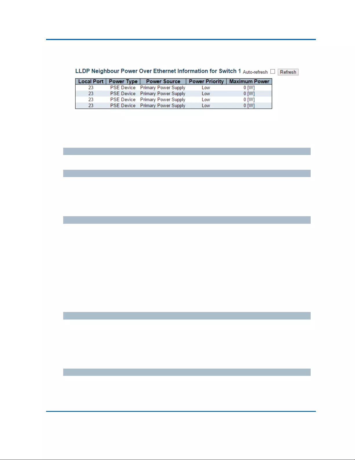
Chapter3:WebManagement
LLDP‐PoE
Intelinet48‐PortGigabitEthernetPoE+Layer2+ManagedSwitchUserManual|305
3.2.11.3.LLDP‐PoE
ThispageprovidesastatusoverviewforallLLDPPoEneighbours.Thedisplayedtablecontainsarow
foreachportonwhichanLLDPPoEneighbourisdetected.Thecolumnsholdthefollowing
information:
LocalPort
TheportforthisswitchonwhichtheLLDPframewasreceived.
PowerType
ThePowerTyperepresentswhetherthedeviceisaPowerSourcingEntity(PSE)orPowerDevice
(PD).
IfthePowerTypeisunknownitisrepresentedas"Reserved".
PowerSource
ThePowerSourcerepresentsthepowersourcebeingutilizedbyaPSEorPDdevice.
IfthedeviceisaPSEdeviceitcaneitherrunonitsPrimaryPowerSourceoritsBackupPowerSource.
IfitisunknownwhetherthePSEdeviceisusingitsPrimaryPowerSourceoritsBackupPowerSource
itisindicatedas"Unknown"
IfthedeviceisaPDdeviceitcaneitherrunonitslocalpowersupplyoritcanusethePSEaspower
source.ItcanalsousebothitslocalpowersupplyandthePSE.
IfitisunknownwhatpowersupplythePDdeviceisusingitisindicatedas"Unknown"
PowerPriority
PowerPriorityrepresentsthepriorityofthePDdevice,orthepowerpriorityassociatedwiththePSE
typedevice'sportthatissourcingthepower.Therearethreelevelsofpowerpriority.Thethree
levelsare:Critical,HighandLow.
Ifthepowerpriorityisunknownitisindicatedas"Unknown"
MaximumPower
TheMaximumPowerValuecontainsanumericalvaluethatindicatesthemaximumpowerinwatts
requiredbyaPDdevicefromaPSEdevice,ortheminimumpoweraPSEdeviceiscapableof
sourcingoveramaximumlengthcablebasedonitscurrentconfiguration.

Chapter3:WebManagement
LLDP‐PoE
Intelinet48‐PortGigabitEthernetPoE+Layer2+ManagedSwitchUserManual|306
Themaximumallowedvalueis102.3W.Ifthedeviceindicatesvaluehigherthan102.3W,itis
representedas"reserved"
Buttons
Auto‐refresh:Checkthisboxtorefreshthepageautomatically.Automaticrefreshoccursevery
3seconds.
Refresh:Clicktorefreshthepage.

Chapter3:WebManagement
LLDP‐EEE
Intelinet48‐PortGigabitEthernetPoE+Layer2+ManagedSwitchUserManual|307
3.2.11.4.LLDP‐EEE
ByusingEEEpowersavingscanbeachievedattheexpenseoftrafficlatency.Thislatencyoccursdue
tothatthecircuitsEEEturnofftosavepower,needtimetobootupbeforesendingtrafficoverthe
link.Thistimeiscalled"wakeuptime".Toachieveminimallatency,devicescanuseLLDPtoexchange
informationabouttheirrespectivetxandrx"wakeuptime",asawaytoagreeupontheminimum
wakeuptimetheyneed.
ThispageprovidesanoverviewofEEEinformationexchangedbyLLDP.
LLDPNeighborsEEEInformation
Thedisplayedtablecontainsarowforeachport.Thecolumnsholdthefollowinginformation:
LocalPort
TheportonwhichLLDPframesarereceivedortransmitted.
TxTw
Thelinkpartner'smaximumtimethattransmitpathcanhold‐offsendingdataafterdeassertionof
LPI.
RxTw
Thelinkpartner'stimethatreceiverwouldlikethetransmittertohold‐offtoallowtimeforthe
receivertowakefromsleep.
FallbackReceiveTw
Thelinkpartner'sfallbackreceiveTw.
AreceivinglinkpartnermayinformthetransmitterofanalternatedesiredTw_sys_tx.Sincea
receivinglinkpartnerislikelytohavediscretelevelsforsavings,thisprovidesthetransmitterwith
additionalinformationthatitmayuseforamoreefficientallocation.Systemsthatdonotimplement
thisoptiondefaultthevaluetobethesameasthatoftheReceiveTw_sys_tx.
EchoTxTw
Thelinkpartner'sEchoTxTwvalue.
Therespectiveechovaluesshallbedefinedasthelocallinkpartnersreflection(echo)oftheremote
linkpartnersrespectivevalues.Whenalocallinkpartnerreceivesitsechoedvaluesfromtheremote
linkpartneritcandeterminewhetherornottheremotelinkpartnerhasreceived,registeredand
processeditsmostrecentvalues.Forexample,ifthelocallinkpartnerreceivesechoedparameters
thatdonotmatchthevaluesinitslocalMIB,thenthelocallinkpartnerinfersthattheremotelink
partnersrequestwasbasedonstaleinformation.

Chapter3:WebManagement
LLDP‐EEE
Intelinet48‐PortGigabitEthernetPoE+Layer2+ManagedSwitchUserManual|308
EchoRxTw
Thelinkpartner'sEchoRxTwvalue.
ResolvedTxTw
TheresolvedTxTwforthislink.Note:NOTthelinkpartner
Theresolvedvaluethatistheactual"txwakeuptime"usedforthislink(basedonEEEinformation
exchangedviaLLDP).
ResolvedRxTw
TheresolvedRxTwforthislink.Note:NOTthelinkpartner
Theresolvedvaluethatistheactual"txwakeuptime"usedforthislink(basedonEEEinformation
exchangedviaLLDP).
EEEinSync
Showswhethertheswitchandthelinkpartnerhaveagreedonwaketimes.
Red‐Switchandlinkpartnerhavenotagreedonwakeuptimes.
Green‐Switchandlinkpartnerhaveagreedonwakeuptimes.
Buttons
Auto‐refresh:Checkthisboxtorefreshthepageautomatically.Automaticrefreshoccursevery
3seconds.
Refresh:Clicktorefreshthepage.

Chapter3:WebManagement
LLDP‐PortStatistic
Intelinet48‐PortGigabitEthernetPoE+Layer2+ManagedSwitchUserManual|309
3.2.11.5.LLDP‐PortStatistics
ThispageprovidesanoverviewofallLLDPtraffic.
Twotypesofcountersareshown.Globalcountersarecountersthatrefertothewholestack,while
localcountersrefertoperportcountersforthecurrentlyselectedswitch.
GlobalCounters
Neighbourentrieswerelastchanged
Showsthetimewhenthelastentrywaslastdeletedoradded.Italsoshowsthetimeelapsedsince
thelastchangewasdetected.
Tot alNeighboursEntriesAdded
Showsthenumberofnewentriesaddedsinceswitchreboot.
Tot alNeighboursEntriesDeleted
Showsthenumberofnewentriesdeletedsinceswitchreboot.
Tot alNeighboursEntriesDropped
ShowsthenumberofLLDPframesdroppedduetotheentrytablebeingfull.
Tot alNeighboursEntriesAgedOut
ShowsthenumberofentriesdeletedduetoTime‐To‐Liveexpiring.
LocalCounters
Thedisplayedtablecontainsarowforeachport.Thecolumnsholdthefollowinginformation:
LocalPort
TheportonwhichLLDPframesarereceivedortransmitted.
TxFrames
ThenumberofLLDPframestransmittedontheport.
RxFrames
ThenumberofLLDPframesreceivedontheport.

Chapter3:WebManagement
LLDP‐PortStatistic
Intelinet48‐PortGigabitEthernetPoE+Layer2+ManagedSwitchUserManual|310
RxErrors
ThenumberofreceivedLLDPframescontainingsomekindoferror.
FramesDiscarded
IfanLLDPframeisreceivedonaport,andtheswitch'sinternaltablehasrunfull,theLLDPframeis
countedanddiscarded.Thissituationisknownas"TooManyNeighbours"intheLLDPstandard.LLDP
framesrequireanewentryinthetablewhentheChassisIDorRemotePortIDisnotalready
containedwithinthetable.Entriesareremovedfromthetablewhenagivenport'slinkisdown,an
LLDPshutdownframeisreceived,orwhentheentryagesout.
TLVsDiscarded
EachLLDPframecancontainmultiplepiecesofinformation,knownasTLVs(TLVisshortfor"Type
LengthValue").IfaTLVismalformed,itiscountedanddiscarded.
TLVsUnrecognized
Thenumberofwell‐formedTLVs,butwithanunknowntypevalue.
Org.Discarded
ThenumberoforganizationallyreceivedTLVs.
Age‐Outs
EachLLDPframecontainsinformationabouthowlongtimetheLLDPinformationisvalid(age‐out
time).IfnonewLLDPframeisreceivedwithintheageouttime,theLLDPinformationisremoved,
andtheAge‐Outcounterisincremented.
Buttons
Auto‐refresh:Checkthisboxtorefreshthepageautomatically.Automaticrefreshoccursevery
3seconds.
Refresh:Clicktorefreshthepage.
Clear:Clearsthelocalcounters.Allcounters(includingglobalcounters)areclearedupon
reboot.
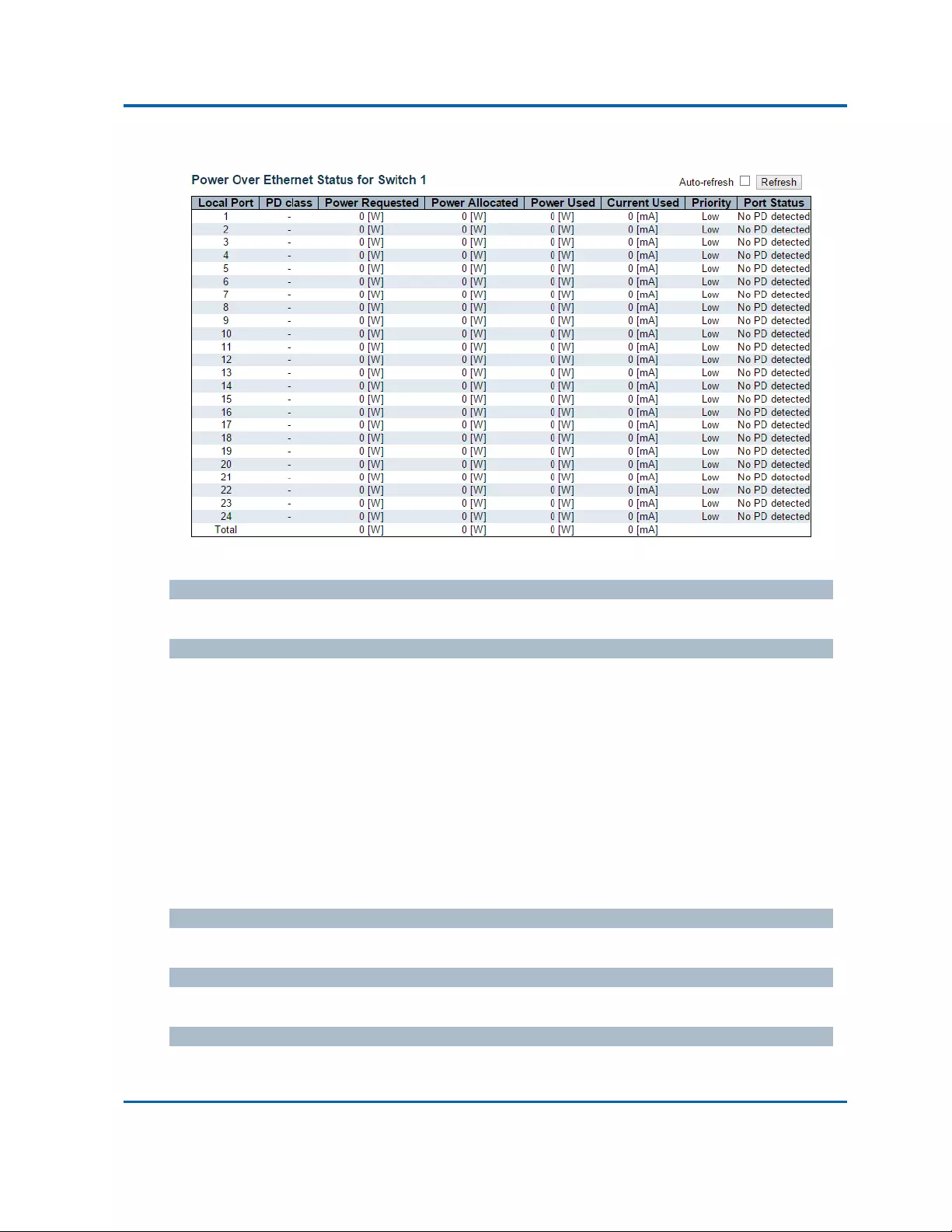
Chapter3:WebManagement
Monitor‐PoE
Intelinet48‐PortGigabitEthernetPoE+Layer2+ManagedSwitchUserManual|311
3.2.12.Monitor‐PoE
ThispageallowstheusertoinspectthecurrentstatusforallPoEports.
LocalPort
Thisisthelogicalportnumberforthisrow.
PDClass
EachPDisclassifiedaccordingtoaclassthatdefinesthemaximumpowerthePDwilluse.ThePD
ClassshowsthePDsclass.
FiveClassesaredefined:
Class0:Max.power15.4W
Class1:Max.power4.0W
Class2:Max.power7.0W
Class3:Max.power15.4W
Class4:Max.power30.0W
PowerRequested
ThePowerRequestedshowstherequestedamountofpowerthePDwantstobereserved.
PowerAllocated
ThePowerAllocatedshowstheamountofpowertheswitchhasallocatedforthePD.
PowerUsed
ThePowerUsedshowshowmuchpowerthePDcurrentlyisusing.

Chapter3:WebManagement
Monitor‐PoE
Intelinet48‐PortGigabitEthernetPoE+Layer2+ManagedSwitchUserManual|312
CurrentUsed
ThePowerUsedshowshowmuchcurrentthePDcurrentlyisusing.

Chapter3:WebManagement
Monitor‐PoE
Intelinet48‐PortGigabitEthernetPoE+Layer2+ManagedSwitchUserManual|313
Priority
ThePriorityshowstheport'spriorityconfiguredbytheuser.
PortStatus
ThePortStatusshowstheport'sstatus.Thestatuscanbeoneofthefollowingvalues:
PoEnotavailable‐NoPoEchipfound‐PoEnotsupportedfortheport.
PoEturnedOFF‐PoEdisabled:PoEisdisabledbyuser.
PoEturnedOFF‐Powerbudgetexceeded‐ThetotalrequestedorusedpowerbythePDs
exceedsthemaximumpowerthePowerSupplycandeliver,andport(s)withthelowest
priorityis/arepowereddown.
NoPDdetected‐NoPDdetectedfortheport.
PoEturnedOFF‐PDoverload‐ThePDhasrequestedorusedmorepowerthantheportcan
deliver,andispowereddown.
PoEturnedOFF‐PDisoff.
InvalidPD‐PDdetected,butisnotworkingcorrectly.
Buttons
Auto‐refresh:Checkthisboxtorefreshthepageautomatically.Automaticrefreshoccursevery
3seconds.
Refresh:Clicktorefreshthepage.
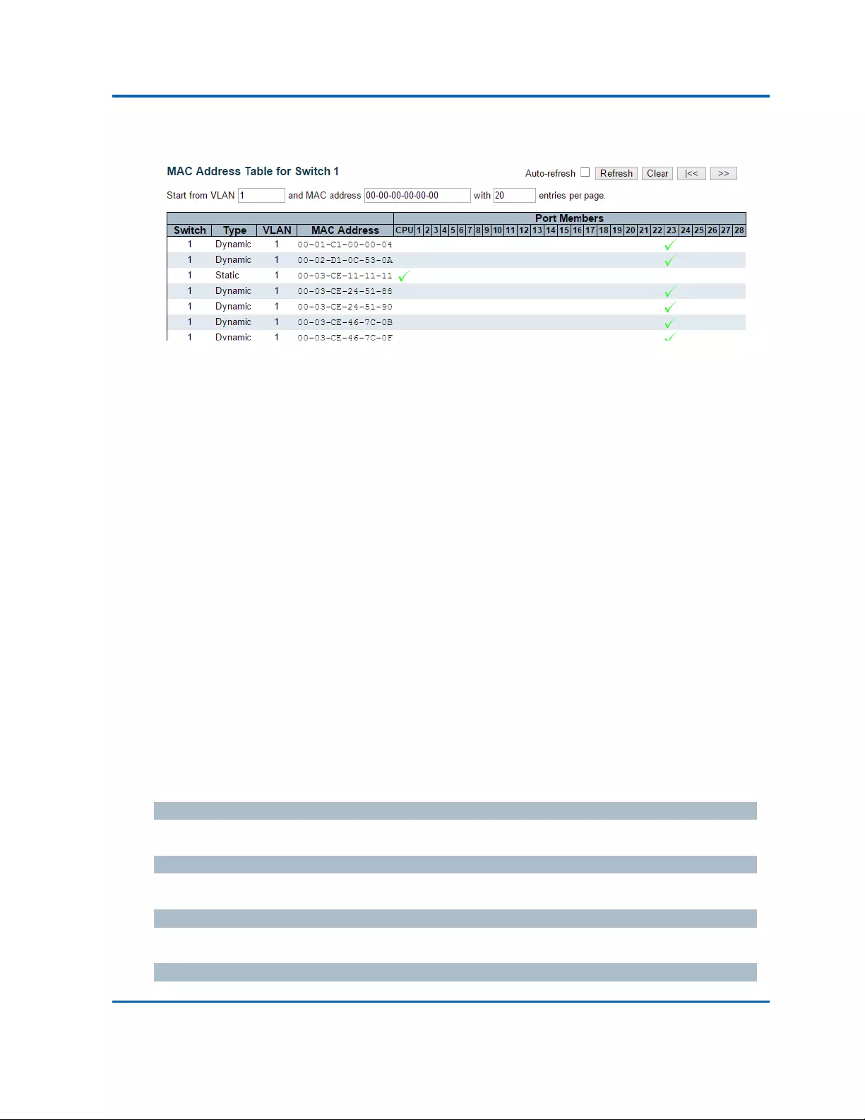
Chapter3:WebManagement
Monitor‐MACTable
Intelinet48‐PortGigabitEthernetPoE+Layer2+ManagedSwitchUserManual|314
3.2.13.Monitor‐MACTable
EntriesintheMACTableareshownonthispage.TheMACTablecontainsupto8192entries,andis
sortedfirstbyVLANID,thenbyMACaddress.
NavigatingtheMACTable
Eachpageshowsupto999entriesfromtheMACtable,defaultbeing20,selectedthroughthe
"entriesperpage"inputfield.Whenfirstvisited,thewebpagewillshowthefirst20entriesfromthe
beginningoftheMACTable.ThefirstdisplayedwillbetheonewiththelowestVLANIDandthe
lowestMACaddressfoundintheMACTable.
The"StartfromMACaddress"and"VLAN"inputfieldsallowtheusertoselectthestartingpointin
theMACTable.ClickingtheRefreshbuttonwillupdatethedisplayedtablestartingfromthatorthe
closestnextMACTablematch.Inaddition,thetwoinputfieldswill‐uponaRefreshbuttonclick‐
assumethevalueofthefirstdisplayedentry,allowingforcontinuousrefreshwiththesamestart
address.
The>>willusethelastentryofthecurrentlydisplayedVLAN/MACaddresspairsasabasisforthe
nextlookup.Whentheendisreachedthetext"Nomoreentries"isshowninthedisplayedtable.Use
the|<<buttontostartover.
MACTableColumns
Switch(stackonly)
Thestackunitwheretheentryislearned.
Type
Indicateswhethertheentryisastaticoradynamicentry.
MACaddress
TheMACaddressoftheentry.
VLAN

Chapter3:WebManagement
Monitor‐MACTable
Intelinet48‐PortGigabitEthernetPoE+Layer2+ManagedSwitchUserManual|315
TheVLANIDoftheentry.

Chapter3:WebManagement
Monitor‐MACTable
Intelinet48‐PortGigabitEthernetPoE+Layer2+ManagedSwitchUserManual|316
PortMembers
Theportsthataremembersoftheentry.
Buttons
Auto‐refresh:Automaticrefreshoccursevery3seconds.
Refresh:Refreshesthedisplayedtablestartingfromthe"StartfromMACaddress"and
"VLAN"inputfields.
Clear:Flushesalldynamicentries.
|<<:UpdatesthetablestartingfromthefirstentryintheMACTable,i.e.theentrywiththe
lowestVLANIDandMACaddress.
>>:Updatesthetable,startingwiththeentryafterthelastentrycurrentlydisplayed.

Chapter3:WebManagement
VLANs‐VLANMembership
Intelinet48‐PortGigabitEthernetPoE+Layer2+ManagedSwitchUserManual|317
3.2.14.Monitor‐VLANs
3.2.14.1.VLANs‐VLANMembership
ThispageprovidesanoverviewofmembershipstatusofVLANusers.
VLANUser
VariousinternalsoftwaremodulesmayuseVLANservicestoconfigureVLANmembershipsonthefly.
Thedrop‐downlistontherightallowsforselectingbetweenshowingVLANmembershipsas
configuredbyanadministrator(Admin)orasconfiguredbyoneoftheseinternalsoftwaremodules.
The"Combined"entrywillshowacombinationoftheadministratorandinternalsoftwaremodules
configuration,andbasicallyreflectswhatisactuallyconfiguredinhardware.
VLANID
VLANIDforwhichthePortmembersaredisplayed.
PortMembers
ArowofcheckboxesforeachportisdisplayedforeachVLANID.
IfaportisincludedinaVLAN,thefollowingimagewillbedisplayed:
Ifaportisintheforbiddenportlist,thefollowingimagewillbedisplayed:
IfaportisintheforbiddenportlistandatthesametimeattemptedincludedintheVLAN,the
followingimagewillbedisplayed.TheportwillnotbeamemberoftheVLANinthiscase.
NavigatingtheVLANMembershipStatuspage
Eachpageshowsupto99entriesfromtheVLANtable(defaultbeing20),selectedthroughthe
"entriesperpage"inputfield.Whenfirstvisited,thewebpagewillshowthefirst20entriesfromthe
beginningoftheVLANTable.ThefirstdisplayedwillbetheonewiththelowestVLANIDfoundinthe
VLANTable.
The"VLAN"inputfieldallowstheusertoselectthestartingpointintheVLANTable.
Clickingthe“Refresh”buttonwillupdatethedisplayedtablestartingfromthatortheclosestnext
VLANTablematch.
The“>>”buttonwillusethelastentryofthecurrentlydisplayedVLANentryasabasisforthenext
lookup.Whentheendisreached,thetext"Nodataexistsfortheselecteduser"isshowninthetable.
Usethe“|<<”buttontostartover.

Chapter3:WebManagement
VLANs‐VLANMembership
Intelinet48‐PortGigabitEthernetPoE+Layer2+ManagedSwitchUserManual|318
Buttons
:SelectVLANUsersfromthisdropdownlist.
Auto‐refresh:Checkthisboxtorefreshthepageautomatically.Automaticrefreshoccursevery
3seconds.
Refresh:Clicktorefreshthepageimmediately.

Chapter3:WebManagement
VCL‐MAC‐basedVLAN
Intelinet48‐PortGigabitEthernetPoE+Layer2+ManagedSwitchUserManual|319
3.2.14.2.VLANs‐VLANPorts
ThispageprovidesVLANPortStatus.
Theportsbelongtothecurrentlyselectedstackunit,asreflectedbythepageheader.
VLANUSER
VLANUsermoduleusesservicesoftheVLANmanagementfunctionalitytoconfigureVLAN
membershipsandVLANportconfigurationsuchasPVID,UVID.CurrentlywesupportfollowingVLAN
Usertypes:
CLI/Web/SNMP:Thesearereferredtoasstatic.
NAS:NASprovidesport‐basedauthentication,whichinvolvescommunicationsbetweena
Supplicant,Authenticator,andanAuthenticationServer.
VoiceVLAN:VoiceVLANisaVLANconfiguredspeciallyforvoicetraffictypicallyoriginating
fromIPphones.
MVR:MVRisusedtoeliminatetheneedtoduplicatemulticasttrafficforsubscribersineach
VLAN.Multicasttrafficforallchannelsissentonlyonasingle(multicast)VLAN.
MSTP:The802.1sMultipleSpanningTreeprotocol(MSTP)usesVLANstocreatemultiple
spanningtreesinanetwork,whichsignificantlyimprovesnetworkresourceutilizationwhile
maintainingaloop‐freeenvironment.
Port
Thelogicalportforthesettingscontainedinthesamerow.

Chapter3:WebManagement
VCL‐MAC‐basedVLAN
Intelinet48‐PortGigabitEthernetPoE+Layer2+ManagedSwitchUserManual|320
PVID
ShowstheVLANidentifierforthatport.Theallowedvaluesare1through4095.Thedefaultvalueis
1.
PortType
ShowsthePortType.PorttypecanbeanyofUnaware,C‐port,S‐port,CustomS‐port.
IfPortTypeisUnaware,allframesareclassifiedtothePortVLANIDandtagsarenotremoved.
C‐portisCustomerPort.S‐portisServiceport.CustomS‐portisS‐portwithCustomTPID.
IngressFiltering
Showstheingressfilteringonaport.ThisparameteraffectsVLANingressprocessing.Ifingress
filteringisenabledandtheingressportisnotamemberoftheclassifiedVLAN,theframeis
discarded.
FrameType
Showswhethertheportacceptsallframesoronlytaggedframes.ThisparameteraffectsVLAN
ingressprocessing.Iftheportonlyacceptstaggedframes,untaggedframesreceivedonthatportare
discarded.
TxTag
Showsegressfilteringframestatuswhethertaggedoruntagged.
UVID
ShowsUVID(untaggedVLANID).Port'sUVIDdeterminesthepacket'sbehaviourattheegressside.
Conflicts
ShowsstatusofConflictswhetherexistsornot.WhenaVolatileVLANUserrequeststosetVLAN
membershiporVLANportconfiguration,thefollowingconflictscanoccur:
FunctionalConflictsbetweenfeatures.
Conflictsduetohardwarelimitation.
Directconflictbetweenusermodules.
Buttons
:SelectVLANUsersfromthisdropdownlist.
Auto‐refresh:Checkthisboxtorefreshthepageautomatically.Automaticrefreshoccursevery
3seconds.
Refresh:Clicktorefreshthepageimmediately.
>>:Updatesthetable,startingwiththeentryafterthelastentrycurrentlydisplayed.
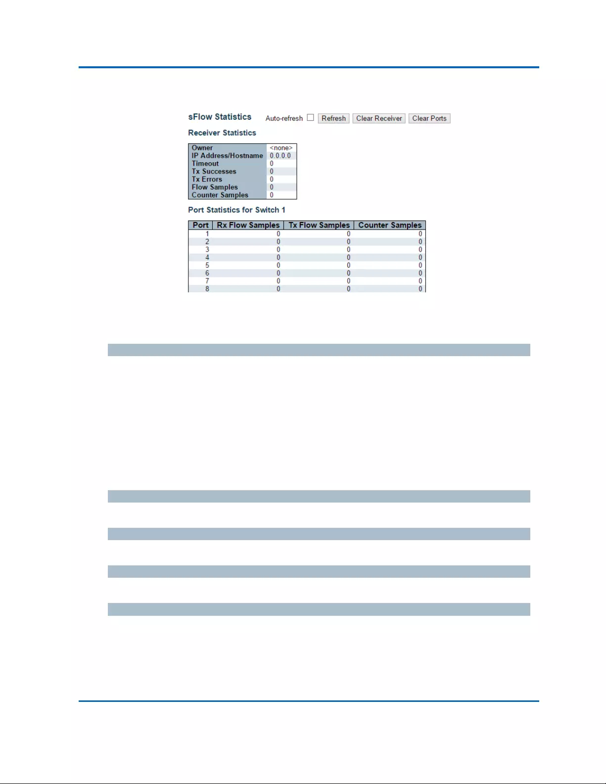
Chapter3:WebManagement
Monitor‐sFlow
Intelinet48‐PortGigabitEthernetPoE+Layer2+ManagedSwitchUserManual|321
3.2.15.Monitor‐sFlow
Thispageshowsreceiverandper‐portsFlowstatistics.
ReceiverStatistics
Owner
ThisfieldshowsthecurrentownerofthesFlowconfiguration.Itassumesoneofthreevaluesas
follows:
IfsFlowiscurrentlyunconfigured/unclaimed,Ownercontains<none>.
IfsFlowiscurrentlyconfiguredthroughWeborCLI,Ownercontains<Configuredthroughlocal
management>.
IfsFlowiscurrentlyconfiguredthroughSNMP,OwnercontainsastringidentifyingthesFlow
receiver.
IPAddress/Hostname
TheIPaddressorhostnameofthesFlowreceiver.
Timeout
ThenumberofsecondsremainingbeforesamplingstopsandthecurrentsFlowownerisreleased.
TxSuccesses
ThenumberofUDPdatagramssuccessfullysenttothesFlowreceiver.
TxErrors
ThenumberofUDPdatagramsthathasfailedtransmission.
ThemostcommonsourceoferrorsisinvalidsFlowreceiverIP/hostnameconfiguration.Todiagnose,
pastethereceiver'sIPaddress/hostnameintothePingWebpage(Diagnostics→Ping/Ping6).

Chapter3:WebManagement
Monitor‐sFlow
Intelinet48‐PortGigabitEthernetPoE+Layer2+ManagedSwitchUserManual|322
FlowSamples
ThetotalnumberofflowsamplessenttothesFlowreceiver.
CounterSamples
ThetotalnumberofcountersamplessenttothesFlowreceiver.
PortStatistics
Port
Theportnumberforwhichthefollowingstatisticsapplies.
RxandTxFlowSamples
ThenumberofflowsamplessenttothesFlowreceiveroriginatingfromthisport.Here,flowsamples
aredividedintoRxandTxflowsamples,whereRxflowsamplescontainsthenumberofpacketsthat
weresampleduponreception(ingress)ontheportandTxflowsamplescontainsthenumberof
packetsthatweresampledupontransmission(egress)ontheport.
CounterSamples
ThetotalnumberofcountersamplessenttothesFlowreceiveroriginatingfromthisport.
Buttons
Auto‐refresh:Checkthisboxtorefreshthepageautomatically.Automaticrefreshoccursevery
3seconds(onlypresentifstackingisenabled).
Refresh:Clicktorefreshthepage.
ClearReceiver:ClearsthesFlowreceivercounters.
ClearPort:Clearstheper‐portcounters.
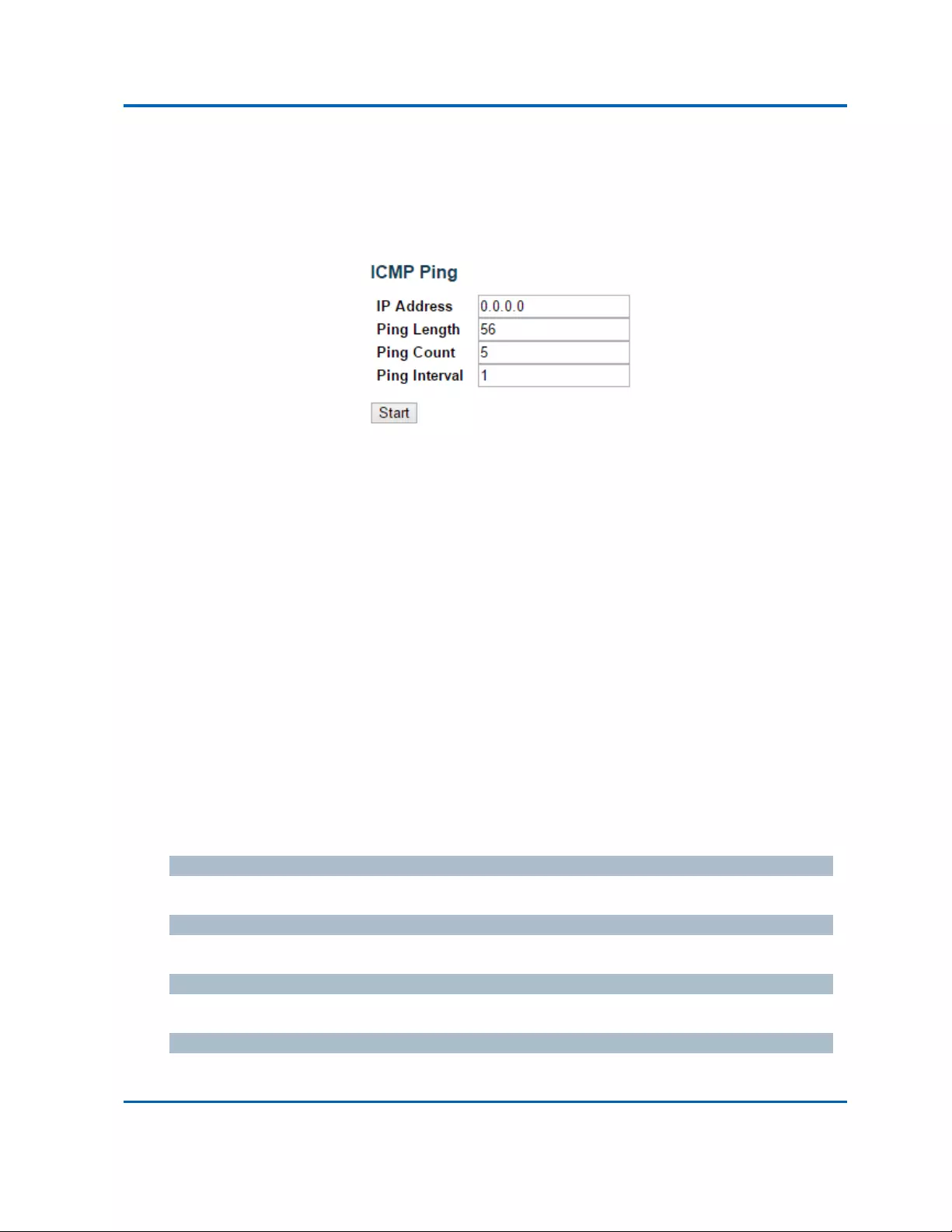
Chapter3:WebManagement
Diagnostics‐Ping
Intelinet48‐PortGigabitEthernetPoE+Layer2+ManagedSwitchUserManual|323
3.3.WebManagement‐Diagnostics
Thissectionofthemanagementwebpageprovidesyoutoolsfordiagnosingyournetwork.
3.3.1.Diagnostics‐Ping
ThispageallowsyoutoissueICMPPINGpacketstotroubleshootIPconnectivityissues.
Afteryoupressthe“Start”button,ICMPpacketsaretransmitted,andthesequencenumberand
roundtriptimearedisplayeduponreceptionofareply.TheamountofdatareceivedinsideofanIP
packetoftypeICMPECHO_REPLYwillalwaysbe8bytesmorethantherequesteddataspace(the
ICMPheader).Thepagerefreshesautomaticallyuntilresponsestoallpacketsarereceived,oruntila
timeoutoccurs.
PINGserver10.10.132.20,56bytesofdata.
64bytesfrom10.10.132.20:icmp_seq=0,time=0ms
64bytesfrom10.10.132.20:icmp_seq=1,time=0ms
64bytesfrom10.10.132.20:icmp_seq=2,time=0ms
64bytesfrom10.10.132.20:icmp_seq=3,time=0ms
64bytesfrom10.10.132.20:icmp_seq=4,time=0ms
Sent5packets,received5OK,0bad
YoucanconfigurethefollowingpropertiesoftheissuedICMPpackets:
IPAddress
ThedestinationIPAddress.
PingLength
ThepayloadsizeoftheICMPpacket.Valuesrangefrom2bytesto1452bytes.
PingCount
ThecountoftheICMPpacket.Valuesrangefrom1timeto60times.
PingInterval
TheintervaloftheICMPpacket.Valuesrangefrom0secondto30seconds.

Chapter3:WebManagement
Diagnostics‐Ping
Intelinet48‐PortGigabitEthernetPoE+Layer2+ManagedSwitchUserManual|324
Buttons
Start:ClicktostarttransmittingICMPpackets.
NewPing:Clicktore‐startdiagnosticswithPING.

Chapter3:WebManagement
Diagnostics‐Ping6
Intelinet48‐PortGigabitEthernetPoE+Layer2+ManagedSwitchUserManual|325
3.3.2.Diagnostics‐Ping6
ThispageallowsyoutoissueICMPv6PINGpacketstotroubleshootIPv6connectivityissues.
Afteryoupressthe“Start”button,ICMPv6packetsaretransmitted,andthesequencenumberand
roundtriptimearedisplayeduponreceptionofareply.Thepagerefreshesautomaticallyuntil
responsestoallpacketsarereceived,oruntilatimeoutoccurs.
PING6server::10.10.132.20,56bytesofdata.
64bytesfrom::10.10.132.20:icmp_seq=0,time=0ms
64bytesfrom::10.10.132.20:icmp_seq=1,time=0ms
64bytesfrom::10.10.132.20:icmp_seq=2,time=0ms
64bytesfrom::10.10.132.20:icmp_seq=3,time=0ms
64bytesfrom::10.10.132.20:icmp_seq=4,time=0ms
Sent5packets,received5OK,0bad
YoucanconfigurethefollowingpropertiesoftheissuedICMPpackets:
IPAddress
ThedestinationIPAddress.
PingLength
ThepayloadsizeoftheICMPpacket.Valuesrangefrom2bytesto1452bytes.
PingCount
ThecountoftheICMPpacket.Valuesrangefrom1timeto60times.
PingInterval
TheintervaloftheICMPpacket.Valuesrangefrom0secondto30seconds.
Buttons
Start:ClicktostarttransmittingICMPpackets.
NewPing:Clicktore‐startdiagnosticswithPING.
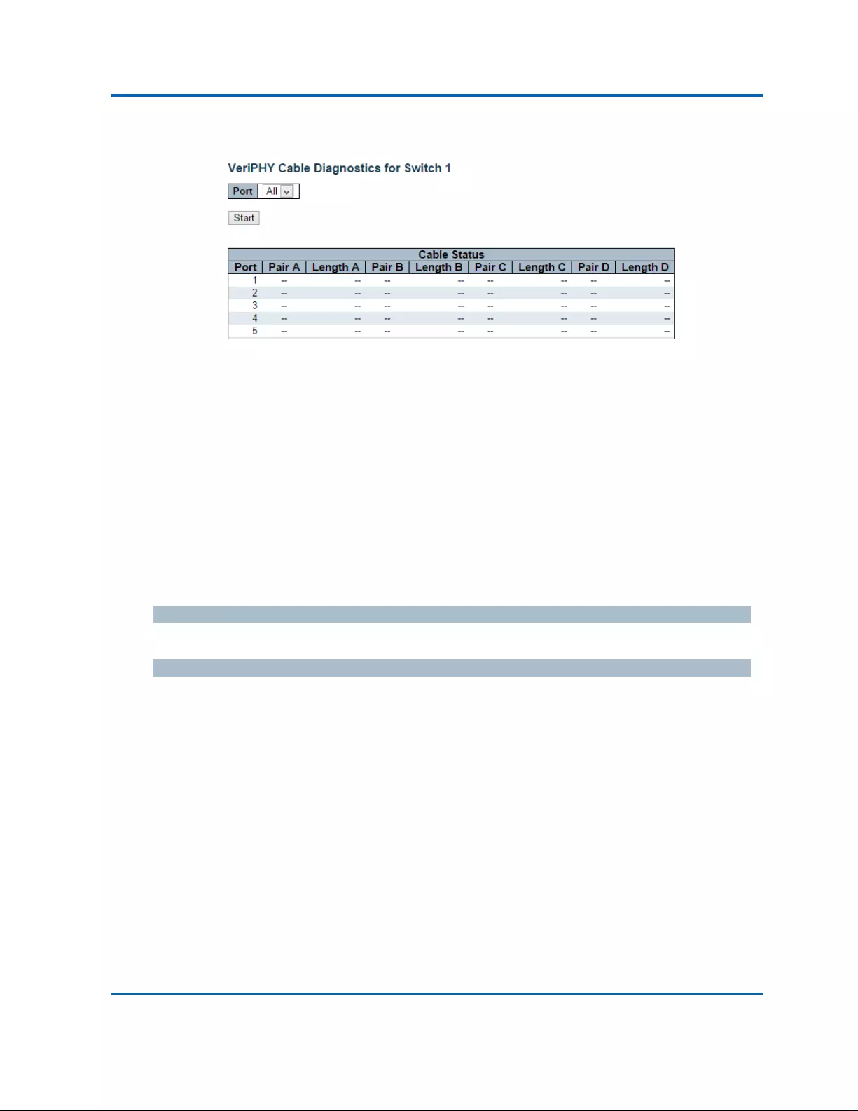
Chapter3:WebManagement
Diagnostics‐VeriPHY
Intelinet48‐PortGigabitEthernetPoE+Layer2+ManagedSwitchUserManual|326
3.3.3.Diagnostics‐VeriPHY
ThispageisusedforrunningtheVeriPHYCableDiagnosticsfor10/100and1Gcopperports.
Pressthe“Start”buttontorunthediagnostics.Thiswilltakeapproximately5seconds.Ifallportsare
selected,thiscantakeapproximately15seconds.Whencompleted,thepagerefreshesautomatically,
andyoucanviewthecablediagnosticsresultsinthecablestatustable.NotethatVeriPHYisonly
accurateforcablesoflength7‐140meters.
10and100MbpsportswillbelinkeddownwhilerunningVeriPHY.Therefore,runningVeriPHYona
10or100MbpsmanagementportwillcausetheswitchtostoprespondinguntilVeriPHYis
complete.
Theportsbelongtothecurrentlyselectedstackunit,asreflectedbythepageheader.
Port
TheportwhereyouarerequestingVeriPHYCableDiagnostics.
CableStatus
Port:
Portnumber
Pair:Thestatusofthecablepair.
OK‐Correctlyterminatedpair
Open‐Openpair
Short‐Shortedpair
ShortA‐Cross‐pairshorttopairA
ShortB‐Cross‐pairshorttopairB
ShortC‐Cross‐pairshorttopairC
ShortD‐Cross‐pairshorttopairD
CrossA‐Abnormalcross‐paircouplingwithpairA
CrossB‐Abnormalcross‐paircouplingwithpairB
CrossC‐Abnormalcross‐paircouplingwithpairC

Chapter3:WebManagement
Diagnostics‐VeriPHY
Intelinet48‐PortGigabitEthernetPoE+Layer2+ManagedSwitchUserManual|327
CrossD‐Abnormalcross‐paircouplingwithpairD
Length:
Thelength(inmeters)ofthecablepair.Theresolutionis3meters

Chapter3:WebManagement
Maintenance‐RestartDevice
Intelinet48‐PortGigabitEthernetPoE+Layer2+ManagedSwitchUserManual|328
3.4.WebManagement‐Maintenance
HereyoucanmakesystemmaintenancesuchrebootingthePoEswitch,resetallsettings(except
Switch’sIPaddress)backtodefaultvalue,updatingswitchfirmware,orupload/downloadallsystem
settings.
3.4.1.Maintenance‐RestartDevice
Youcanrestartthestackonthispage.Afterrestart,thestackwillbootnormally.
Buttons
Yes:Clicktorestartdevice.
No:ClicktoreturntothePortStatepagewithoutrestarting.

Chapter3:WebManagement
Maintenance‐FactoryDefaults
Intelinet48‐PortGigabitEthernetPoE+Layer2+ManagedSwitchUserManual|329
3.4.2.Maintenance‐FactoryDefaults
Youcanresettheconfigurationofthestackonthispage.OnlytheIPconfigurationisretained.
Thenewconfigurationisavailableimmediately,whichmeansthatnorestartisnecessary.
Buttons
Yes:ClicktoresettheconfigurationtoFactoryDefaults.
No:ClicktoreturntothePortStatepagewithoutresettingtheconfiguration.
Note:Restoringfactorydefaultcanalsobeperformedbymakingaphysicalloopbackbetweenport1
andport2withinthefirstminutefromswitchreboot.Inthefirstminuteafterboot,'loopback'
packetswillbetransmittedatport1.Ifa'loopback'packetisreceivedatport2theswitchwilldoa
restoretodefault

Chapter3:WebManagement
Maintenance‐SoftwareUpload
Intelinet48‐PortGigabitEthernetPoE+Layer2+ManagedSwitchUserManual|330
3.4.3.Maintenance‐SoftwareUpload
Youcanupdatetheswitch’sfirmwarehere.
Buttons
ChooseFile:Clickthisbuttontochoosethefirmwarefile.
Update:Clickthisbuttontostartuploadthefirmware.
Thesystemwillinformyouwhenthenewfirmwareisuploadedtotheswitch.Afterupdatingthe
firmware,theswitchwillreboot.
Warning:Themanagementwebpagewillstopfunctioningduringthefirmwareupdatingprocess.Do
notrestartorpoweroffthedeviceatthistimeortheswitchmaymalfunction.

Chapter3:WebManagement
Configuration‐Save
Intelinet48‐PortGigabitEthernetPoE+Layer2+ManagedSwitchUserManual|331
3.4.3.Maintenance‐Configuration
3.4.3.1.Configuration‐Save
YoucansaveallthecurrentsettingvaluesasafileinXMLformat.
Buttons
SaveConfiguration:Clicktosavetheconfigurationfile.

Chapter3:WebManagement
Configuration‐Load
Intelinet48‐PortGigabitEthernetPoE+Layer2+ManagedSwitchUserManual|332
3.4.3.2.Configuration‐Load
Buttons
ChooseFile:Clickthisbuttontochoosetheconfigurationfilethatyou’vesaved..
Upload:Clicktouploadtheconfigurationfile.

AppendixA:
ProductSafety
AppendixA:ProductSafety
Thisappendixdescribessafetyissuesregardingtothisproduct.Tousethisproductsafely,itishighly
recommendedtoreadthisappendixbeforeinstallingandusingthisproduct.
Failuretofollowtheseprecautionsandwarningsmightcauseproductmalfunction,electricalshock,
orevenfire.Ifthisproductisworkingabnormally(e.g.generatingsmoke),pleasestopusingthis
productandcontactyourdistributororretailerimmediately.
DONOTinstallthisproductunderconditionslistedbelow:
DONOTinstallthisproductinanenvironmentwithconditionsexceedingitsspecified
operatingenvironment.
DONOTinstallthisproductinanenvironmentthatissubjectedtodirectsunlightornear
anyheatingequipment.
DONOTinstallthisproductinanenvironmentwithextremetemperaturechanges.Extreme
temperaturechanges,evenwithintheproduct’soperatingtemperaturerange,maycause
malfunctions.
DONOTinstallthisproductinalocationnearanysourcesofwaterorliquid.
DONOTstackthisproductwithothernetworkdevicesdirectlyontopofoneanother.
Stackingnetworkdevicesdirectlywithoutapplyingamountingrackwillcausethisproduct
tooverheat.
DONOTinstallthisproductonanunstablesurface.Doingsomightcausethisproducttofall,
resultingmalfunction.
ProductMaintenanceGuide:
DONOTdisassemblethisproduct.Doingsomightcausemalfunctionandvoidyour
product’swarranty.
Itisrecommendedtokeepyourproductclearofdust.Toremovedustfromyourproduct,
pleaseuseadrybrushandbrushitoffgently.
Whennotusingthisproduct,pleasestoreitinanenvironmentwithlowhumidity,cool
temperature,andfreeofdust.Failuretodosomightcausemalfunction.
Beforepoweringupthisproduct,pleasemakesurethattheelectricpowersourcemeets
thisproduct’srequirement.DONOTuseotherpoweradaptersifthisproductcomeswithits
ownpoweradapterinthepackage.

AppendixB:
IPConfigurationforYourPC
AppendixB:IPConfigurationforYourPC
ThisappendixdescribeshowtosettheIPaddressofyourPCsoyoucanconnecttoproduct
configurationwebpage.Theconfigurationwebpageallowsyoutosetsystemvariablesormonitor
systemstatus.
ThefollowingsectionwillguideyoutosettheIPaddressproperlyinaMicrosoftWindows8
environment.SettingIPaddressinotherMicrosoftoperatingsystem(suchasWindowsVistaor
Windows7)isquitethesameandcanberelated.
1. OpenNetworkandSharingCenterinControlPanel,andclickonChangeadaptersettings
asshowninthefiguredownbelow.
2. ANetworkConnectionswindowwillpopup,showingallthenetworkconnectionsavailable
onyourPC.Pleasedouble‐clickonthenetworkconnectionyouareusingtoconnectthe

AppendixB:
IPConfigurationforYourPC
Intelinet48‐PortGigabitEthernetPoE+Layer2+ManagedSwitchUserManual|335
3. AnEthernetStatuswindowwillpopup.PleaseclickonthePropertiesbuttonasshownin
thefiguredownbelow.
4. AnEthernetPropertieswindowwillpopup.PleasedoubleclickontheInternetProtocol
Version4(TCP/IPv4).

AppendixB:
IPConfigurationforYourPC
Intelinet48‐PortGigabitEthernetPoE+Layer2+ManagedSwitchUserManual|336
5. AnInternetProtocolVersion4(TCP/IPv4)Propertieswindowwillpopup.Pleasesetyour
PC’sIPaddressandsubnetmaskasshowninthefiguredownbelow.
Bydefault,yourproduct’sIPaddressshouldbe192.168.2.1.YoucansetanyIPaddressas
longasit’snotthesamewithyourproduct’sIPaddressandisinthesamenetworksegment
withyourproduct’sIPaddress.
PressOKtoapplytheTCP/IPv4settingsyoujustmade.Nowyoucanconnecttoyour
productusingawebbrowser(i.e.InternetExplorer,Chrome,orFirefox).

AppendixB:
IPConfigurationforYourPC
Intelinet48‐PortGigabitEthernetPoE+Layer2+ManagedSwitchUserManual|337

AppendixC:
Glossary
AppendixC:Glossary
Thisappendixcontainsthetermsandglossariesthatareusedinthisusermanual.
A
ACE
ACEisanacronymforAccessControlEntry.Itdescribesaccesspermissionassociatedwitha
particularACEID.
TherearethreeACEframetypes(EthernetType,ARP,andIPv4)andtwoACEactions(permitand
deny).TheACEalsocontainsmanydetailed,differentparameteroptionsthatareavailablefor
individualapplication.
ACL
ACLisanacronymforAccessControlList.ItisthelisttableofACEs,containingaccesscontrolentries
thatspecifyindividualusersorgroupspermittedordeniedtospecifictrafficobjects,suchasa
processoraprogram.
EachaccessibletrafficobjectcontainsanidentifiertoitsACL.Theprivilegesdeterminewhether
therearespecifictrafficobjectaccessrights.
ACLimplementationscanbequitecomplex,forexample,whentheACEsareprioritizedforthe
varioussituation.Innetworking,theACLreferstoalistofserviceportsornetworkservicesthatare
availableonahostorserver,eachwithalistofhostsorserverspermittedordeniedtousethe
service.ACLcangenerallybeconfiguredtocontrolinboundtraffic,andinthiscontext,theyare
similartofirewalls.
Thereare3web‐pagesassociatedwiththemanualACLconfiguration:
ACL|Access Control List:ThewebpageshowstheACEsinaprioritizedway,highest(top)to
lowest(bottom).Defaultthetableisempty.AningressframewillonlygetahitononeACEeven
thoughtherearemorematchingACEs.ThefirstmatchingACEwilltakeaction(permit/deny)onthat
frameandacounterassociatedwiththatACEisincremented.AnACEcanbeassociatedwithaPolicy,
1ingressport,oranyingressport(thewholeswitch).IfanACEPolicyiscreatedthenthatPolicycan
beassociatedwithagroupofportsunderthe"Ports"web‐page.Therearenumberofparameters
thatcanbeconfiguredwithanACE.ReadtheWebpagehelptexttogetfurtherinformationforeach
ofthem.ThemaximumnumberofACEsis64.

AppendixC:
Glossary
Intelinet48‐PortGigabitEthernetPoE+Layer2+ManagedSwitchUserManual|339
ACL|Ports:TheACLPortsconfigurationisusedtoassignaPolicyIDtoaningressport.Thisisuseful
togroupportstoobeythesametrafficrules.TrafficPolicyiscreatedunderthe"AccessControlList"‐
page.Youcanyoualsosetupspecifictrafficproperties(Action/RateLimiter/Portcopy,etc)for
eachingressport.TheywillthoughonlyapplyiftheframegetspasttheACEmatchingwithout
gettingmatched.Inthatcaseacounterassociatedwiththatportisincremented.SeetheWebpage
helptextforeachspecificportproperty.
ACL|Rate Limiters:Underthispageyoucanconfiguretheratelimiters.Therecanbe15different
ratelimiters,eachrangingfrom1‐1024Kpacketsperseconds.Under"Ports"and"AccessControl
List"web‐pagesyoucanassignaRateLimiterIDtotheACE(s)oringressport(s).
Aggregation
Usingmultipleportsinparalleltoincreasethelinkspeedbeyondthelimitsofaportandtoincrease
theredundancyforhigheravailability.
ARP
ARPisanacronymforAddressResolutionProtocol.ItisaprotocolthatusedtoconvertanIPaddress
intoaphysicaladdress,suchasanEthernetaddress.ARPallowsahosttocommunicatewithother
hostswhenonlytheInternetaddressofitsneighborsisknown.BeforeusingIP,thehostsendsa
broadcastARPrequestcontainingtheInternetaddressofthedesireddestinationsystem.
ARPInspection
ARPInspectionisasecurefeature.Severaltypesofattackscanbelaunchedagainstahostordevices
connectedtoLayer2networksby"poisoning"theARPcaches.Thisfeatureisusedtoblocksuch
attacks.OnlyvalidARPrequestsandresponsescangothroughtheswitchdevice.
Auto‐Negotiation
Auto‐negotiationistheprocesswheretwodifferentdevicesestablishthemodeofoperationandthe
speedsettingsthatcanbesharedbythosedevicesforalink.
C
CDP
CDPisanacronymforCiscoDiscoveryProtocol.

AppendixC:
Glossary
Intelinet48‐PortGigabitEthernetPoE+Layer2+ManagedSwitchUserManual|340
D
DEI
DEIisanacronymforDropEligibleIndicator.Itisa1‐bitfieldintheVLANtag.
DES
DESisanacronymforDataEncryptionStandard.Itprovidesacompletedescriptionofa
mathematicalalgorithmforencrypting(enciphering)anddecrypting(deciphering)binarycoded
information.
Encryptingdataconvertsittoanunintelligibleformcalledcipher.Decryptingcipherconvertsthe
databacktoitsoriginalformcalledplaintext.Thealgorithmdescribedinthisstandardspecifiesboth
encipheringanddecipheringoperationswhicharebasedonabinarynumbercalledakey.
DHCP
DHCPisanacronymforDynamicHostConfigurationProtocol.Itisaprotocolusedforassigning
dynamicIPaddressestodevicesonanetwork.
DHCPusedbynetworkedcomputers(clients)toobtainIPaddressesandotherparameterssuchas
thedefaultgateway,subnetmask,andIPaddressesofDNSserversfromaDHCPserver.
TheDHCPserverensuresthatallIPaddressesareunique,forexample,noIPaddressisassignedtoa
secondclientwhilethefirstclient'sassignmentisvalid(itsleasehasnotexpired).Therefore,IP
addresspoolmanagementisdonebytheserverandnotbyahumannetworkadministrator.
DynamicaddressingsimplifiesnetworkadministrationbecausethesoftwarekeepstrackofIP
addressesratherthanrequiringanadministratortomanagethetask.Thismeansthatanew
computercanbeaddedtoanetworkwithoutthehassleofmanuallyassigningitauniqueIPaddress.
DHCPRelay
DHCPRelayisusedtoforwardandtotransferDHCPmessagesbetweentheclientsandtheserver
whentheyarenotonthesamesubnetdomain.
TheDHCPoption82enablesaDHCPrelayagenttoinsertspecificinformationintoaDHCPrequest
packetswhenforwardingclientDHCPpacketstoaDHCPserverandremovethespecificinformation
fromaDHCPreplypacketswhenforwardingserverDHCPpacketstoaDHCPclient.TheDHCPserver
canusethisinformationtoimplementIPaddressorotherassignmentpolicies.Specificallytheoption
worksbysettingtwosub‐options:CircuitID(option1)andRemoteID(option2).TheCircuitID
sub‐optionissupposedtoincludeinformationspecifictowhichcircuittherequestcameinon.The
RemoteIDsub‐optionwasdesignedtocarryinformationrelatingtotheremotehostendofthe
circuit.

AppendixC:
Glossary
Intelinet48‐PortGigabitEthernetPoE+Layer2+ManagedSwitchUserManual|341
ThedefinitionofCircuitIDintheswitchis4bytesinlengthandtheformatis"vlan_id""module_id"
"port_no".Theparameterof"vlan_id"isthefirsttwobytesrepresenttheVLANID.Theparameterof
"module_id"isthethirdbyteforthemoduleID(instandaloneswitchitalwaysequal0,instackable
switchitmeansswitchID).Theparameterof"port_no"isthefourthbyteanditmeanstheport
number.
TheRemoteIDis6bytesinlength,andthevalueisequaltheDHCPrelayagentsMACaddress.
DHCPSnooping
DHCPSnoopingisusedtoblockintruderontheuntrustedportsoftheswitchdevicewhenittriesto
intervenebyinjectingabogusDHCPreplypackettoalegitimateconversationbetweentheDHCP
clientandserver.
DNS
DNSisanacronymforDomainNameSystem.Itstoresandassociatesmanytypesofinformationwith
domainnames.Mostimportantly,DNStranslateshuman‐friendlydomainnamesandcomputer
hostnamesintocomputer‐friendlyIPaddresses.Forexample,thedomainnamewww.example.com
mighttranslateto192.168.0.1.
DottedDecimalNotation
DottedDecimalNotationreferstoamethodofwritingIPaddressesusingdecimalnumbersanddots
asseparatorsbetweenoctets.
AnIPv4dotteddecimaladdresshastheformx.y.z.w,wherex,y,z,andwaredecimalnumbers
between0and255.
DropPrecedenceLevel
EveryincomingframeisclassifiedtoaDropPrecedenceLevel(DPlevel),whichisusedthroughout
thedeviceforprovidingcongestioncontrolguaranteestotheframeaccordingtowhatwas
configuredforthatspecificDPlevel.ADPlevelof0(zero)correspondsto'Committed'(Green)
framesandaDPlevelof1orhighercorrespondsto'DiscardEligible'(Yellow)frames.
DSCP
DSCPisanacronymforDifferentiatedServicesCodePoint.ItisafieldintheheaderofIPpacketsfor
packetclassificationpurposes.

AppendixC:
Glossary
Intelinet48‐PortGigabitEthernetPoE+Layer2+ManagedSwitchUserManual|342
E
EEE
EEEisanabbreviationforEnergyEfficientEthernetdefinedinIEEE802.3az.
EPS
EPSisanabbreviationforEthernetProtectionSwitchingdefinedinITU/TG.8031.
EthernetType
EthernetType,orEtherType,isafieldintheEthernetMACheader,definedbytheEthernet
networkingstandard.ItisusedtoindicatewhichprotocolisbeingtransportedinanEthernetframe.
F
FastLeave
MulticastsnoopingFastLeaveprocessingallowstheswitchtoremoveaninterfacefromthe
forwarding‐tableentrywithoutfirstsendingoutgroupspecificqueriestotheinterface.TheVLAN
interfaceisprunedfromthemulticasttreeforthemulticastgroupspecifiedintheoriginalleave
message.Fast‐leaveprocessingensuresoptimalbandwidthmanagementforallhostsonaswitched
network,evenwhenmultiplemulticastgroupsareinusesimultaneously.Thisprocessingappliesto
IGMPandMLD.
H
HTTP
HTTPisanacronymforHypertextTransferProtocol.Itisaprotocolthatusedtotransferorconvey
informationontheWorldWideWeb(WWW).
HTTPdefineshowmessagesareformattedandtransmitted,andwhatactionsWebserversand
browsersshouldtakeinresponsetovariouscommands.Forexample,whenyouenteraURLinyour
browser,thisactuallysendsanHTTPcommandtotheWebserverdirectingittofetchandtransmit
therequestedWebpage.TheothermainstandardthatcontrolshowtheWorldWideWebworksis
HTML,whichcovershowWebpagesareformattedanddisplayed.
AnyWebservermachinecontains,inadditiontotheWebpagefilesitcanserve,anHTTPdaemon,a
programthatisdesignedtowaitforHTTPrequestsandhandlethemwhentheyarrive.TheWeb
browserisanHTTPclient,sendingrequeststoservermachines.AnHTTPclientinitiatesarequestby
establishingaTransmissionControlProtocol(TCP)connectiontoaparticularportonaremotehost
(port80bydefault).AnHTTPserverlisteningonthatportwaitsfortheclienttosendarequest
message.

AppendixC:
Glossary
Intelinet48‐PortGigabitEthernetPoE+Layer2+ManagedSwitchUserManual|343
HTTPS
HTTPSisanacronymforHypertextTransferProtocoloverSecureSocketLayer.Itisusedtoindicatea
secureHTTPconnection.
HTTPSprovideauthenticationandencryptedcommunicationandiswidelyusedontheWorldWide
Webforsecurity‐sensitivecommunicationsuchaspaymenttransactionsandcorporatelogons.
HTTPSisreallyjusttheuseofNetscape'sSecureSocketLayer(SSL)asasublayerunderitsregular
HTTPapplicationlayering.(HTTPSusesport443insteadofHTTPport80initsinteractionswiththe
lowerlayer,TCP/IP.)SSLusesa40‐bitkeysizefortheRC4streamencryptionalgorithm,whichis
consideredanadequatedegreeofencryptionforcommercialexchange.
I
ICMP
ICMPisanacronymforInternetControlMessageProtocol.Itisaprotocolthatgeneratedtheerror
response,diagnosticorroutingpurposes.ICMPmessagesgenerallycontaininformationabout
routingdifficultiesorsimpleexchangessuchastime‐stamporechotransactions.Forexample,
thePINGcommandusesICMPtotestanInternetconnection.
IEEE802.1X
IEEE802.1XisanIEEEstandardforport‐basedNetworkAccessControl.Itprovidesauthenticationto
devicesattachedtoaLANport,establishingapoint‐to‐pointconnectionorpreventingaccessfrom
thatportifauthenticationfails.With802.1X,accesstoallswitchportscanbecentrallycontrolled
fromaserver,whichmeansthatauthorizeduserscanusethesamecredentialsforauthentication
fromanypointwithinthenetwork.
IGMP
IGMPisanacronymforInternetGroupManagementProtocol.Itisacommunicationsprotocolused
tomanagethemembershipofInternetProtocolmulticastgroups.IGMPisusedbyIPhostsand
adjacentmulticastrouterstoestablishmulticastgroupmemberships.ItisanintegralpartoftheIP
multicastspecification,likeICMPforunicastconnections.IGMPcanbeusedforonlinevideoand
gaming,andallowsmoreefficientuseofresourceswhensupportingtheseuses.
IGMPQuerier
AroutersendsIGMPQuerymessagesontoaparticularlink.ThisrouteriscalledtheQuerier.

AppendixC:
Glossary
Intelinet48‐PortGigabitEthernetPoE+Layer2+ManagedSwitchUserManual|344
IMAP
IMAPisanacronymforInternetMessageAccessProtocol.Itisaprotocolforemailclientstoretrieve
emailmessagesfromamailserver.
IMAPistheprotocolthatIMAPclientsusetocommunicatewiththeservers,andSMTPisthe
protocolusedtotransportmailtoanIMAPserver.
ThecurrentversionoftheInternetMessageAccessProtocolisIMAP4.ItissimilartoPostOffice
Protocolversion3(POP3),butoffersadditionalandmorecomplexfeatures.Forexample,theIMAP4
protocolleavesyouremailmessagesontheserverratherthandownloadingthemtoyourcomputer.
Ifyouwishtoremoveyourmessagesfromtheserver,youmustuseyourmailclienttogeneratelocal
folders,copymessagestoyourlocalharddrive,andthendeleteandexpungethemessagesfromthe
server.
IP
IPisanacronymforInternetProtocol.Itisaprotocolusedforcommunicatingdataacrossaninternet
network.
IPisa"besteffort"system,whichmeansthatnopacketofinformationsentoverisassuredtoreach
itsdestinationinthesameconditionitwassent.EachdeviceconnectedtoaLocalAreaNetwork
(LAN)orWideAreaNetwork(WAN)isgivenanInternetProtocoladdress,andthisIPaddressisused
toidentifythedeviceuniquelyamongallotherdevicesconnectedtotheextendednetwork.
ThecurrentversionoftheInternetprotocolisIPv4,whichhas32‐bitsInternetProtocoladdresses
allowingforinexcessoffourbillionuniqueaddresses.Thisnumberisreduceddrasticallybythe
practiceofwebmasterstakingaddressesinlargeblocks,thebulkofwhichremainunused.Thereisa
rathersubstantialmovementtoadoptanewversionoftheInternetProtocol,IPv6,whichwould
have128‐bitsInternetProtocoladdresses.Thisnumbercanberepresentedroughlybyathreewith
thirty‐ninezeroesafterit.However,IPv4isstilltheprotocolofchoiceformostoftheInternet.
IPMC
IPMCisanacronymforIPMultiCast.
IPMCsupportsIPv4andIPv6multicasting.IPMCv4denotesmulticastforIPv4.IPMCv6denotes
multicastforIPv6.

AppendixC:
Glossary
Intelinet48‐PortGigabitEthernetPoE+Layer2+ManagedSwitchUserManual|345
IPSourceGuard
IPSourceGuardisasecurefeatureusedtorestrictIPtrafficonDHCPsnoopinguntrustedportsby
filteringtrafficbasedontheDHCPSnoopingTableormanuallyconfiguredIPSourceBindings.Ithelps
preventIPspoofingattackswhenahosttriestospoofandusetheIPaddressofanotherhost.
L
LACP
LACPisanIEEE802.3adstandardprotocol.TheLinkAggregationControlProtocol,allowsbundling
severalphysicalportstogethertoformasinglelogicalport.
LLC
TheIEEE802.2LogicalLinkControl(LLC)protocolprovidesalinkmechanismforupperlayer
protocols.Itistheuppersub‐layeroftheDataLinkLayerandprovidesmultiplexingmechanismsthat
makeitpossibleforseveralnetworkprotocols(IP,IPX)tocoexistwithinamultipointnetwork.LLC
headerconsistsof1byteDSAP(DestinationServiceAccessPoint),1byteSSAP(SourceServiceAccess
Point),1or2bytesControlfieldfollowedbyLLCinformation.
LLDP
LLDPisanIEEE802.1abstandardprotocol.
TheLinkLayerDiscoveryProtocol(LLDP)specifiedinthisstandardallowsstationsattachedtoanIEEE
802LANtoadvertise,tootherstationsattachedtothesameIEEE802LAN,themajorcapabilities
providedbythesystemincorporatingthatstation,themanagementaddressoraddressesofthe
entityorentitiesthatprovidemanagementofthosecapabilities,andtheidentificationofthe
stationspointofattachmenttotheIEEE802LANrequiredbythosemanagemententityorentities.
TheinformationdistributedviathisprotocolisstoredbyitsrecipientsinastandardManagement
InformationBase(MIB),makingitpossiblefortheinformationtobeaccessedbyaNetwork
ManagementSystem(NMS)usingamanagementprotocolsuchastheSimpleNetworkManagement
Protocol(SNMP).
LLDP‐MED
LLDP‐MEDisanextensionofIEEE802.1abandisdefinedbythetelecommunicationindustry
association(TIA‐1057).
LLQI
LLQI(LastListenerQueryInterval)isthemaximumresponsetimeusedtocalculatetheMaximum
ResponseCodeinsertedintoSpecificQueries.Itisusedtodetectthedepartureofthelastlistenerfora
multicastaddressorsource.InIGMP,thistermiscalledLMQI(LastMemberQueryInterval).
LOC

AppendixC:
Glossary
Intelinet48‐PortGigabitEthernetPoE+Layer2+ManagedSwitchUserManual|346
LOCisanacronymforLossOfConnectivityandisdetectedbyaMEPandisindicatinglost
connectivityinthenetwork.CanbeusedasaswitchcriteriabyEPS
M
MACTable
SwitchingofframesisbasedupontheDMACaddresscontainedintheframe.Theswitchbuildsupa
tablethatmapsMACaddressestoswitchportsforknowingwhichportstheframesshouldgoto
(basedupontheDMACaddressintheframe).Thistablecontainsbothstaticanddynamicentries.
Thestaticentriesareconfiguredbythenetworkadministratoriftheadministratorwantstodoa
fixedmappingbetweentheDMACaddressandswitchports.
TheframesalsocontainaMACaddress(SMACaddress),whichshowstheMACaddressofthe
equipmentsendingtheframe.TheSMACaddressisusedbytheswitchtoautomaticallyupdate
theMACtablewiththesedynamicMACaddresses.DynamicentriesareremovedfromtheMAC
tableifnoframewiththecorrespondingSMACaddresshasbeenseenafteraconfigurableagetime.
Mirroring
Fordebuggingnetworkproblemsormonitoringnetworktraffic,theswitchsystemcanbeconfigured
tomirrorframesfrommultipleportstoamirrorport.(Inthiscontext,mirroringaframeisthesame
ascopyingtheframe.)
Bothincoming(source)andoutgoing(destination)framescanbemirroredtothemirrorport.
MLD
MLDisanacronymforMulticastListenerDiscoveryforIPv6.MLDisusedbyIPv6routerstodiscover
multicastlistenersonadirectlyattachedlink,muchasIGMPisusedinIPv4.Theprotocolis
embeddedinICMPv6insteadofusingaseparateprotocol.
MSTP
In2002,theIEEEintroducedanevolutionofRSTP:theMultipleSpanningTreeProtocol.TheMSTP
protocolprovidesformultiplespanningtreeinstances,whileensuringRSTPandSTPcompatibility.
ThestandardwasoriginallydefinedbyIEEE802.1s,butwaslaterincorporatedinIEEE802.1D‐2005.

AppendixC:
Glossary
Intelinet48‐PortGigabitEthernetPoE+Layer2+ManagedSwitchUserManual|347
MVR
MulticastVLANRegistration(MVR)isaprotocolforLayer2(IP)‐networksthatenables
multicast‐trafficfromasourceVLANtobesharedwithsubscriber‐VLANs.
ThemainreasonforusingMVRistosavebandwidthbypreventingduplicatemulticaststreamsbeing
sentinthecorenetwork,insteadthestream(s)arereceivedontheMVR‐VLANandforwardedtothe
VLANswherehostshaverequestedit/them(Wikipedia).
N
NTP
NTPisanacronymforNetworkTimeProtocol,anetworkprotocolforsynchronizingtheclocksof
computersystems.NTPusesUDP(datagrams)astransportlayer.
O
OptionalTLVs.
ALLDPframecontainsmultipleTLVs
ForsomeTLVsitisconfigurableiftheswitchshallincludetheTLVintheLLDPframe.TheseTLVsare
knownasoptionalTLVs.IfanoptionalTLVsisdisabledthecorrespondinginformationisnotincluded
intheLLDPframe.
OUI
OUIistheorganizationallyuniqueidentifier.AnOUIaddressisagloballyuniqueidentifierassignedto
avendorbyIEEE.YoucandeterminewhichvendoradevicebelongstoaccordingtotheOUIaddress
whichformsthefirst24bitsofaMACaddress.
P
PCP
PCPisanacronymforPriorityCodePoint.Itisa3‐bitfieldstoringtheprioritylevelforthe802.1Q
frame.ItisalsoknownasUserPriority.
PD
PDisanacronymforPoweredDevice.InaPoEsystemthepowerisdeliveredfromaPSE(power
sourcingequipment)toaremotedevice.TheremotedeviceiscalledaPD.
PHY
PHYisanabbreviationforPhysicalInterfaceTransceiverandisthedevicethatimplementthe
Ethernetphysicallayer(IEEE‐802.3).

AppendixC:
Glossary
Intelinet48‐PortGigabitEthernetPoE+Layer2+ManagedSwitchUserManual|348
PING
PingisaprogramthatsendsaseriesofpacketsoveranetworkortheInternettoaspecific
computerinordertogeneratearesponsefromthatcomputer.Theothercomputerrespondswithan
acknowledgmentthatitreceivedthepackets.Pingwascreatedtoverifywhetheraspecificcomputer
onanetworkortheInternetexistsandisconnected.
PingusesInternetControlMessageProtocol(ICMP)packets.ThePINGRequestisthepacketfrom
theorigincomputer,andthePINGReplyisthepacketresponsefromthetarget.
PoE
PoEisanacronymforPowerOverEthernet.
PowerOverEthernetisusedtotransmitelectricalpower,toremotedevicesoverstandardEthernet
cable.ItcouldforexamplebeusedforpoweringIPtelephones,wirelessLANaccesspointsandother
equipment,whereitwouldbedifficultorexpensivetoconnecttheequipmenttomainpowersupply.
Policer
Apolicercanlimitthebandwidthofreceivedframes.Itislocatedinfrontoftheingressqueue.
PrivateVLAN
InaprivateVLAN,PVLANsprovidelayer2isolationbetweenportswithinthesamebroadcastdomain.
IsolatedportsconfiguredaspartofPVLANcannotcommunicatewitheachother.Memberportsofa
PVLANcancommunicatewitheachother.
PTP
PTPisanacronymforPrecisionTimeProtocol,anetworkprotocolforsynchronizingtheclocksof
computersystems.
Q
QCE
QCEisanacronymforQoSControlEntry.ItdescribesQoSclassassociatedwithaparticularQCEID.
TherearesixQCEframetypes:EthernetType,VLAN,UDP/TCPPort,DSCP,TOS,andTagPriority.
Framescanbeclassifiedbyoneof4differentQoSclasses:"Low","Normal","Medium",and"High"
forindividualapplication.

AppendixC:
Glossary
Intelinet48‐PortGigabitEthernetPoE+Layer2+ManagedSwitchUserManual|349
QCL
QCLisanacronymforQoSControlList.ItisthelisttableofQCEs,containingQoScontrolentriesthat
classifytoaspecificQoSclassonspecifictrafficobjects.
EachaccessibletrafficobjectcontainsanidentifiertoitsQCL.Theprivilegesdeterminespecifictraffic
objecttospecificQoSclass.
QL
QLInSyncEthisistheQualityLevelofagivenclocksource.Thisisreceivedonaportin
aSSMindicatingthequalityoftheclockreceivedintheport.
QoS
QoSisanacronymforQualityofService.Itisamethodtoguaranteeabandwidthrelationship
betweenindividualapplicationsorprotocols.
Acommunicationsnetworktransportsamultitudeofapplicationsanddata,includinghigh‐quality
videoanddelay‐sensitivedatasuchasreal‐timevoice.Networksmustprovidesecure,predictable,
measurable,andsometimesguaranteedservices.
AchievingtherequiredQoSbecomesthesecrettoasuccessfulend‐to‐endbusinesssolution.
Therefore,QoSisthesetoftechniquestomanagenetworkresources.
QoSclass
EveryincomingframeisclassifiedtoaQoSclass,whichisusedthroughoutthedeviceforproviding
queuing,schedulingandcongestioncontrolguaranteestotheframeaccordingtowhatwas
configuredforthatspecificQoSclass.ThereisaonetoonemappingbetweenQoSclass,queueand
priority.AQoSclassof0(zero)hasthelowestpriority.
R
RARP
RARPisanacronymforReverseAddressResolutionProtocol.Itisaprotocolthatisusedtoobtain
anIPaddressforagivenhardwareaddress,suchasanEthernetaddress.RARPisthecomplement
ofARP.
RADIUS
RADIUSisanacronymforRemoteAuthenticationDialInUserService.Itisanetworkingprotocol
thatprovidescentralizedaccess,authorizationandaccountingmanagementforpeopleorcomputers
toconnectanduseanetworkservice.

AppendixC:
Glossary
Intelinet48‐PortGigabitEthernetPoE+Layer2+ManagedSwitchUserManual|350
RSTP
In1998,theIEEEwithdocument802.1wintroducedanevolutionofSTP:
theRapidSpanningTreeProtocol,whichprovidesforfasterspanningtreeconvergenceaftera
topologychange.StandardIEEE802.1D‐2004nowincorporatesRSTPandobsoletesSTP,whileatthe
sametimebeingbackwards‐compatiblewithSTP.
S
sFlow
sFlowisanindustrystandardtechnologyformonitoringswitchednetworksthroughrandom
samplingofpacketsonswitchportsandtime‐basedsamplingofportcounters.Thesampledpackets
andcounters(referredtoasflowsamplesandcountersamples,respectively)aresentas
sFlowUDPdatagramstoacentralnetworktrafficmonitoringserver.Thiscentralserveriscalledan
sFlowreceiverorsFlowcollector.
Shaper
Ashapercanlimitthebandwidthoftransmittedframes.Itislocatedaftertheingressqueues.
SMTP
SMTPisanacronymforSimpleMailTransferProtocol.Itisatext‐basedprotocolthatusesthe
TransmissionControlProtocol(TCP)andprovidesamailservicemodeledontheFTPfiletransfer
service.SMTPtransfersmailmessagesbetweensystemsandnotificationsregardingincomingmail.
SNAP
TheSubNetworkAccessProtocol(SNAP)isamechanismformultiplexing,onnetworksusingIEEE
802.2LLC,moreprotocolsthancanbedistinguishedbythe8‐bit802.2ServiceAccessPoint(SAP)
fields.SNAPsupportsidentifyingprotocolsbyEthernettypefieldvalues;italsosupports
vendor‐privateprotocolidentifier.
SNMP
SNMPisanacronymforSimpleNetworkManagementProtocol.ItispartoftheTransmissionControl
Protocol/InternetProtocol(TCP/IP)protocolfornetworkmanagement.SNMPallowdiversenetwork
objectstoparticipateinanetworkmanagementarchitecture.Itenablesnetworkmanagement
systemstolearnnetworkproblemsbyreceivingtrapsorchangenoticesfromnetworkdevices
implementingSNMP.
SNTP
SNTPisanacronymforSimpleNetworkTimeProtocol,anetworkprotocolforsynchronizingthe
clocksofcomputersystems.SNTPusesUDP(datagrams)astransportlayer.

AppendixC:
Glossary
Intelinet48‐PortGigabitEthernetPoE+Layer2+ManagedSwitchUserManual|351
SSH
SSHisanacronymforSecureSHell.Itisanetworkprotocolthatallowsdatatobeexchangedusinga
securechannelbetweentwonetworkeddevices.TheencryptionusedbySSHprovidesconfidentiality
andintegrityofdataoveraninsecurenetwork.ThegoalofSSHwastoreplacetheearlier
rlogin,TELNETandrshprotocols,whichdidnotprovidestrongauthenticationorguarantee
confidentiality.
SSM
SSMInSyncEthisisanabbreviationforSynchronizationStatusMessageandiscontaining
aQLindication.
STP
SpanningTreeProtocolisanOSIlayer‐2protocolwhichensuresaloopfreetopologyforanybridged
LAN.TheoriginalSTPprotocolisnowobsoletebyRSTP.
SyncE
SyncEIsanabbreviationforSynchronousEthernet.Thisfunctionalityisusedtomakeanetwork
'clockfrequency'synchronized.Nottobeconfusedwithrealtimeclocksynchronized(IEEE1588).
T
TACACS+
TACACS+isanacronymforTerminalAcessControllerAccessControlSystemPlus.Itisanetworking
protocolwhichprovidesaccesscontrolforrouters,networkaccessserversandothernetworked
computingdevicesviaoneormorecentralizedservers.TACACS+providesseparateauthentication,
authorizationandaccountingservices.
TagPriority
TagPriorityisa3‐bitfieldstoringtheprioritylevelforthe802.1Qframe.
TCP
TCPisanacronymforTransmissionControlProtocol.Itisacommunicationsprotocolthatusesthe
InternetProtocol(IP)toexchangethemessagesbetweencomputers.
TheTCPprotocolguaranteesreliableandin‐orderdeliveryofdatafromsendertoreceiverand
distinguishesdataformultipleconnectionsbyconcurrentapplications(forexample,Webserverand
e‐mailserver)runningonthesamehost.
TheapplicationsonnetworkedhostscanuseTCPtocreateconnectionstooneanother.Itisknown
asaconnection‐orientedprotocol,whichmeansthataconnectionisestablishedandmaintained
untilsuchtimeasthemessageormessagestobeexchangedbytheapplicationprogramsateach
endhavebeenexchanged.TCPisresponsibleforensuringthatamessageisdividedintothepackets

AppendixC:
Glossary
Intelinet48‐PortGigabitEthernetPoE+Layer2+ManagedSwitchUserManual|352
thatIPmanagesandforreassemblingthepacketsbackintothecompletemessageattheotherend.
CommonnetworkapplicationsthatuseTCPincludetheWorldWideWeb(WWW),e‐mail,andFile
TransferProtocol(FTP).
TELNET
TELNETisanacronymforTELetypeNETwork.Itisaterminalemulationprotocolthatusesthe
TransmissionControlProtocol(TCP)andprovidesavirtualconnectionbetweenTELNETserverand
TELNETclient.
TELNETenablestheclienttocontroltheserverandcommunicatewithotherserversonthenetwork.
TostartaTelnet session,theclientusermustlogintoaserverbyenteringavalidusernameand
password.Then,theclientusercanentercommandsthroughtheTelnetprogramjustasiftheywere
enteringcommandsdirectlyontheserverconsole.
TFTP
TFTPisanacronymforTrivialFileTransferProtocol.ItistransferprotocolthatusestheUser
DatagramProtocol(UDP)andprovidesfilewritingandreading,butitdoesnotprovidedirectory
serviceandsecurityfeatures.
ToS
ToSisanacronymforTypeofService.ItisimplementedastheIPv4ToSprioritycontrol.Itisfully
decodedtodeterminethepriorityfromthe6‐bitToSfieldintheIPheader.Themostsignificant6bits
oftheToSfieldarefullydecodedinto64possibilities,andthesingularcodethatresultsiscompared
againstthecorrespondingbitintheIPv4To Sprioritycontrolbit(0~63).
TLV
TLVisanacronymforTypeLengthValue.ALLDPframecancontainmultiplepiecesofinformation.
EachofthesepiecesofinformationisknownasTLV.
U
UDP
UDPisanacronymforUserDatagramProtocol.Itisacommunicationsprotocolthatusesthe
InternetProtocol(IP)toexchangethemessagesbetweencomputers.
UDPisanalternativetotheTransmissionControlProtocol(TCP)thatusestheInternetProtocol(IP).
UnlikeTCP,UDPdoesnotprovidetheserviceofdividingamessageintopacketdatagrams,andUDP
doesn'tprovidereassemblingandsequencingofthepackets.Thismeansthattheapplication
programthatusesUDPmustbeabletomakesurethattheentiremessagehasarrivedandisinthe
rightorder.Networkapplicationsthatwanttosaveprocessingtimebecausetheyhaveverysmall

AppendixC:
Glossary
Intelinet48‐PortGigabitEthernetPoE+Layer2+ManagedSwitchUserManual|353
dataunitstoexchangemaypreferUDPtoTCP.
UDPprovidestwoservicesnotprovidedbytheIPlayer.Itprovidesportnumberstohelpdistinguish
differentuserrequestsand,optionally,achecksumcapabilitytoverifythatthedataarrivedintact.
CommonnetworkapplicationsthatuseUDPincludetheDomainNameSystem(DNS),streaming
mediaapplicationssuchasIPTV,VoiceoverIP(VoIP),andTrivialFileTransferProtocol(TFTP).
UPnP
UPnPisanacronymforUniversalPlugandPlay.ThegoalsofUPnParetoallowdevicestoconnect
seamlesslyandtosimplifytheimplementationofnetworksinthehome(datasharing,
communications,andentertainment)andincorporateenvironmentsforsimplifiedinstallationof
computercomponents
UserPriority
UserPriorityisa3‐bitfieldstoringtheprioritylevelforthe802.1Qframe.ItisalsoknownasPCP.
V
VLAN
VirtualLAN.Amethodtorestrictcommunicationbetweenswitchports.VLANscanbeusedforthe
followingapplications:
VLANunawareswitching:Thisisthedefaultconfiguration.AllportsareVLANunawarewith
PortVLANID1andmembersofVLAN1.ThismeansthatMACaddressesarelearnedinVLAN1,and
theswitchdoesnotremoveorinsertVLANtags.
VLANawareswitching:ThisisbasedontheIEEE802.1Qstandard.AllportsareVLANaware.Ports
connectedtoVLANawareswitchesaremembersofmultipleVLANsandtransmittaggedframes.
OtherportsaremembersofoneVLAN,setupwiththisPortVLANID,andtransmituntaggedframes.
Providerswitching:ThisisalsoknownasQ‐in‐Qswitching.PortsconnectedtosubscribersareVLAN
unaware,membersofoneVLAN,andsetupwiththisuniquePortVLANID.Portsconnectedtothe
serviceproviderareVLANaware,membersofmultipleVLANs,andsetuptotagallframes.Untagged
framesreceivedonasubscriberportareforwardedtotheproviderportwithasingleVLANtag.
Tag gedframesreceivedonasubscriberportareforwardedtotheproviderportwithadoubleVLAN
tag.
VLANID
VLANIDisa12‐bitfieldspecifyingtheVLANtowhichtheframebelongs.
VoiceVLAN

AppendixC:
Glossary
Intelinet48‐PortGigabitEthernetPoE+Layer2+ManagedSwitchUserManual|354
VoiceVLANisVLANconfiguredspeciallyforvoicetraffic.Byaddingtheportswithvoicedevices
attachedtovoiceVLAN,wecanperformQoS‐relatedconfigurationforvoicedata,ensuringthe
transmissionpriorityofvoicetrafficandvoicequality.